Part E. Host Controller Interface Functional Specification
vAtlanta r00
This Part describes the functional specification for the Host Controller interface (HCI). The HCI provides a uniform command interface to a Controller.
1. Introduction
This Part of the specification describes the functional specifications for the Host Controller interface (HCI). The HCI provides a uniform command method for the Host to access Controller capabilities and to control connections to other Controllers. For the BR/EDR or LE Controller, these commands typically involve the Link Manager (LM) to exchange LMP commands or the Link Layer (LL) to exchange LL Control packets with remote Bluetooth devices. For details, see [Vol 2] Part C, Link Manager Protocol Specification and [Vol 6] Part B, Link Layer Specification.
The rest of this section provides a brief overview of the lower layers of the Bluetooth software stack and of the Bluetooth hardware. Section 2 provides an overview of the Lower HCI Device Driver Interface on the Host device. Section 3 lists the HCI commands and events and specifies the support requirements on different types of implementation. Section 4 describes the flow control used between the Host and the Controller. Section 5 describes the various data formats used by HCI. Section 6 further describes certain parameters that are common to several commands. Section 7 describes each of the HCI commands in detail, identifies parameters for each of the commands, and lists events associated with each command.
The specification is applicable to the following types of Controllers:
BR/EDR Controller
BR/EDR/LE Controller
LE Controller
A Controller shall support one of the following sets of functionality:
BR/EDR only
LE only
BR/EDR/LE
In the following sections, the term “BR/EDR Controller” is used to describe the BR/EDR functionality of a Controller which may be either a BR/EDR only Controller or a BR/EDR/LE Controller. Similarly, the term “LE Controller” is used to describe the LE functionality of a Controller which may be either an LE only Controller or a BR/EDR/LE Controller.
A BR/EDR Controller supports BR/EDR functionality only. A BR/EDR/LE Controller supports BR/EDR functionality and LE functionality. An LE Controller supports LE functionality only.
1.1. Lower Layers of the Bluetooth software stack
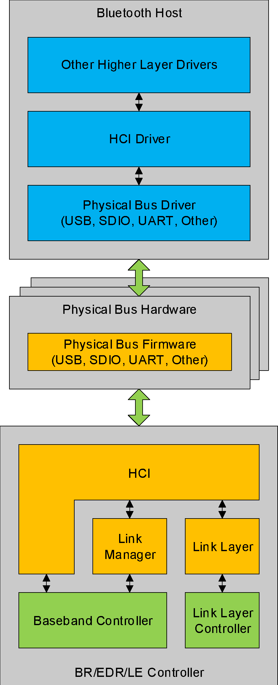
Figure 1.1 provides an overview of the lower software layers.
Several layers may exist between the HCI driver on the Host system and the HCI layer in the Controller(s). These intermediate layers, the Host Controller Transport Layer, provide the ability to transfer data without intimate knowledge of the data.
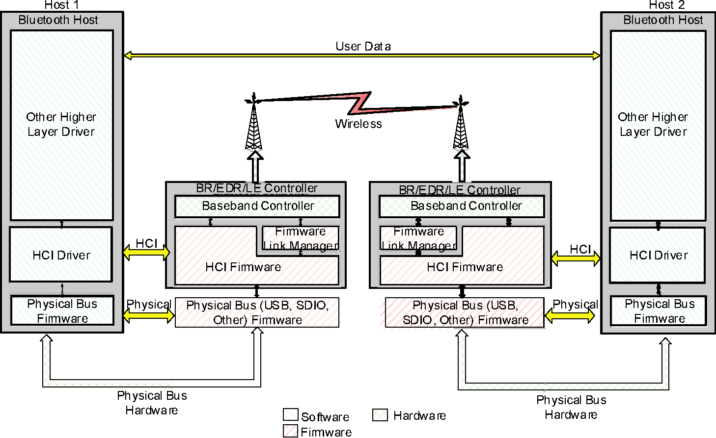
Figure 1.2 illustrates the path of a data transfer from one device to another. The HCI driver on the Host exchanges data and commands with the HCI firmware on the Bluetooth hardware. The Host Control Transport Layer (i.e. physical bus) driver provides both HCI layers with the ability to exchange information with each other.
The Host will receive asynchronous notifications of HCI events independent of which Host Controller Transport Layer is used. HCI events are used for notifying the Host when something occurs. When the Host discovers that an event has occurred it will then parse the received event packet to determine which event occurred.
A BR/EDR/LE Controller uses one shared command buffer and flow control for BR/EDR and LE. Data buffers can be either shared between BR/EDR and LE or there may be separate data buffers for BR/EDR and LE. The configuration of a Controller is determined through HCI.
LE Controllers use a reduced set of HCI commands and events. Some commands and events are re-used for multiple Controller types.
1.2. Cross-version issues
The Host and Controller communicating through HCI are not required to support the same version of this specification (see [Vol 1] Part D, Section 1).
If the Controller conforms to a newer version of the specification than the Host, events (including HCI_Command_Status and HCI_Command_Complete) may include values that are reserved for future use in the version supported by the Host. In the case of the Status parameter of the HCI_Command_Status and HCI_Command_Complete events, a value that is reserved for future use must be treated as if it were the error code Unspecified Error (0x1F) (see [Vol 1] Part F, Section 1.3). In all other circumstances the Host must obey the requirements for devices receiving reserved values (see [Vol 1] Part E, Section 2.4).
Note
Note: If the Host conforms to a newer version of the specification than the Controller and uses a command feature that is not part of the older specification version, then the Controller will report an error. Failure to handle such errors could result in unexpected behavior.
2. Overview of Host Controller transport layer
The Host driver stack has a transport layer between the Host Controller Interface driver and the Host.
The main goal of this transport layer is transparency. The Host Controller Interface driver (which interfaces to the Controller) should be independent of the underlying transport technology. In addition, the transport should not require any understanding of the data that the Host Controller Interface driver passes to the Controller. This allows the logical interface (HCI) or the Controller to be upgraded without affecting the transport layer.
The specified Host Controller Transport Layers are described in the other parts of Volume 4.
2.1. [This section is no longer used]
3. Overview of commands and events
The commands and events are sent between the Host and the Controller.
Table 3.1 lists each HCI command and event together with specification version information, a summary description, and the support requirements.
A command or event may have more than one version. All versions of a command or event implement the same basic functionality but with detail differences, such as additional parameters relating to newer features. The different versions are indicated by "[v1]", etc. where necessary; if no version number is given, a reference to the command or event applies to all versions.
The specification version information gives the version number of the specification which first specified this command or event or, where more than one specification version number is shown, each version of this command or event.
Table 3.1 lists the requirements for a Controller to support each command or event or version thereof. Subject to Section 3.2, a Controller shall support the command or event if it is shown as mandatory for at least one of the transports (i.e., BR/EDR or LE) that the Controller supports, otherwise the Controller may support the command or event if it is shown as optional for at least one of the transports that the Controller supports, otherwise it shall not support the command or event. If the command or event has more than one version, then this determination is made for each version separately using the requirements listed in the table for that version. The LMP features mentioned in the conditions are defined in [Vol 2] Part C, Section 3.2 and the Link Layer features in [Vol 6] Part B, Section 4.6.
Name | Vers. | Summary Description | BR/EDR | LE |
|---|---|---|---|---|
1.1 | The HCI_Accept_Connection_Request command is used to accept a new incoming BR/EDR connection request. | M | E | |
1.2 | The HCI_Accept_Synchronous_Connection_Request command is used to accept an incoming request for a synchronous connection and to inform the local Link Manager about the acceptable parameter values for the synchronous connection. | C.134 | E | |
4.1 | The HCI_Authenticated_Payload_Timeout_Expired event is used to indicate that a packet containing a valid MIC on the Handle was not received within the authenticatedPayloadTO. | C.155 | C.155 | |
1.1 | The HCI_Authentication_Complete event occurs when authentication has been completed for the specified connection. | C.101 | E | |
1.1 | The HCI_Authentication_Requested command is used to establish authentication between the two devices associated with the specified Connection_Handle. | O | E | |
1.1 | The HCI_Change_Connection_Link_Key command is used to force both devices of a connection associated to the Connection_Handle, to generate a new link key. | O | E | |
1.1 | The HCI_Change_Connection_Link_Key_Complete event is used to indicate that the change in the Link Key for the Connection_Handle specified by the Connection_Handle event parameter had been completed. | C.102 | E | |
1.1 | The HCI_Change_Connection_Packet_Type command is used to change which packet types can be used for a connection that is currently established. | C.133 | E | |
1.1 | The HCI_Command_Complete event is used by the Controller to pass the return status of a command and the other event parameters for each HCI command. | M | M | |
1.1 | The HCI_Command_Status event is used to indicate that the command described by the Command_Opcode parameter has been received and the Controller is currently performing the task for this command. | M | M | |
5.2 | The HCI_Configure_Data_Path command is used by a Host to configure a data path to enable codec operation in the Controller. | C.156 | C.156 | |
1.1 | The HCI_Connection_Complete event indicates to both of the Hosts forming the connection that a new BR/EDR connection has been established. | M | E | |
1.1 | The HCI_Connection_Packet_Type_Changed event is used to indicate the completion of the process of the Link Manager changing the packet type mask used for the specified Connection_Handle. | C.133 | E | |
1.1 | The HCI_Connection_Request event is used to indicate that a new incoming BR/EDR connection is trying to be established. | M | E | |
Connectionless Peripheral Broadcast Channel Map Change event | CSA4 | The HCI_Connectionless_Peripheral_Broadcast_Channel_Map_Change event indicates to the Host that the BR/EDR Controller has moved to a new AFH channel map for the PBD logical link. | C.201 | E |
CSA4 | The HCI_Connectionless_Peripheral_Broadcast_Receive event provides the Host with the data received from a Connectionless Peripheral Broadcast packet. | C.202 | E | |
CSA4 | On the Connectionless Peripheral Broadcast Receiver, the HCI_Connectionless_Peripheral_Broadcast_Timeout event indicates to the Host that the BR/EDR Controller has lost synchronization with the Connectionless Peripheral Broadcast Transmitter. On the Connectionless Peripheral Broadcast Transmitter, the HCI_Connectionless_Peripheral_Broadcast_Timeout event indicates to the Host that the BR/EDR Controller has been unable to transmit a Connectionless Peripheral Broadcast packet for the timeout interval specified in the HCI_Set_Connectionless_Peripheral_Broadcast command. | C.202 | E | |
1.2 | The HCI_Create_Connection_Cancel command is used to cancel an ongoing Create Connection. | M | E | |
1.1 | The HCI_Create_Connection command will cause the BR/EDR Link Manager to create an ACL connection to the BR/EDR Controller with the BD_ADDR specified by the command parameters. | M | E | |
1.1 | The HCI_Data_Buffer_Overflow event is used to indicate that the Controller's data buffers have overflowed, because the Host has sent more packets than allowed. | O | O | |
CSA4 | The HCI_Delete_Reserved_LT_ADDR command requests that the BR/EDR Controller cancel the reservation of a specific LT_ADDR reserved for the purposes of Connectionless Peripheral Broadcast. | C.201 | E | |
1.1 | The HCI_Delete_Stored_Link_Key command provides the ability to remove one or more of the link keys stored in the Controller. | C.121 | E | |
1.1 | The HCI_Disconnect command is used to terminate an existing BR/EDR or LE connection. | M | C.3 | |
1.1 | The HCI_Disconnection_Complete event occurs when a connection has been terminated. | M | C.3 | |
1.1 | The HCI_Enable_Device_Under_Test_Mode command will allow the local Controller to enter test mode via LMP test commands. The Host issues this command when it wants the local device to be the DUT for the Testing scenarios as described in the Bluetooth Test Mode document. | C.123 | E | |
1.1 5.3 | The HCI_Encryption_Change event is used to indicate that the change in encryption has been completed for the specified Connection_Handle. | [v1] M [v2] C.158 | [v1] C.4 [v2] C.56 | |
2.1 + EDR | The HCI_Encryption_Key_Refresh_Complete event is used to indicate to the Host that the encryption key was refreshed on the given Connection_Handle any time encryption is paused and then resumed. | M | C.4 | |
CSA2 | The HCI_Enhanced_Accept_Synchronous_Connection_Request command is used to accept an incoming request for a synchronous connection and to inform the local Link Manager about the acceptable parameter values for the synchronous connection. | C.135 | E | |
2.1 + EDR | The HCI_Enhanced_Flush command is used to discard specific packets currently pending for transmission in the Controller for the specified Handle. This command takes a parameter specifying the type of packets to be flushed. | M | E | |
2.1 + EDR | The HCI_Enhanced_Flush_Complete event is used to indicate that an Enhanced Flush is complete. | M | E | |
CSA2 | The HCI_Enhanced_Setup_Synchronous_Connection command adds a new or modifies an existing synchronous logical transport (SCO or eSCO) on a physical link depending on the Connection_Handle parameter specified. | C.135 | E | |
1.1 | The HCI_Exit_Periodic_Inquiry_Mode command is used to end the Periodic Inquiry mode when the local device is in Periodic Inquiry Mode. | C.103 | E | |
1.1 | The HCI_Exit_Sniff_Mode command is used to end Sniff mode for a Connection_Handle which is currently in Sniff mode. | C.214 | E | |
2.1 + EDR | The HCI_Extended_Inquiry_Result event indicates that a BR/EDR Controller has responded with an extended inquiry response during the current Inquiry process. | C.147 | E | |
1.2 | The HCI_Flow_Specification command is used to specify the flow parameters for the traffic carried over the ACL connection identified by the Connection_Handle. | M | E | |
1.2 | The HCI_Flow_Specification_Complete event is used to inform the Host about the Quality of Service for the ACL connection the Controller is able to support. | M | E | |
1.1 | The HCI_Flush command is used to discard all data that is currently pending for transmission in the Controller for the specified Connection_Handle. | M | E | |
1.1 | The HCI_Flush_Occurred event is used to indicate that, for the specified Handle, the data to be transmitted has been discarded. | M | E | |
CSA3 | The HCI_Get_MWS_Transport_Layer_Configuration command reads the supported baud rates from the Controller. | C.109 | C.109 | |
1.1 | The HCI_Hardware_Error event is used to indicate some type of hardware failure for the Controller. | O | O | |
1.1 | The HCI_Hold_Mode command is used to initiate Hold mode. | C.213 | E | |
1.1 | The HCI_Host_Buffer_Size command is used by the Host to notify the Controller about its buffer sizes for ACL and synchronous data. The Controller will segment the data to be transmitted from the Controller to the Host, so that data contained in HCI Data packets will not exceed these sizes. | C.107 | C.107 | |
1.1 | The HCI_Host_Number_Of_Completed_Packets command is used by the Host to indicate to the Controller when the Host is ready to receive more HCI packets for any Connection_Handle. | C.107 | C.107 | |
1.1 | The HCI_Inquiry_Cancel command will cause the BR/EDR Controller to stop the current Inquiry if the BR/EDR Controller is in Inquiry Mode. | C.127 | E | |
1.1 | The HCI_Inquiry command will cause the BR/EDR Controller to enter Inquiry Mode. Inquiry Mode is used to discovery other nearby BR/EDR Controllers. | C.127 | E | |
1.1 | The HCI_Inquiry_Complete event indicates that the Inquiry is finished. | C.127 | E | |
CSA4 | The HCI_Inquiry_Response_Notification event indicates to the Host that the BR/EDR Controller responded to an inquiry message. | C.126 | E | |
1.1 | The HCI_Inquiry_Result event indicates that a BR/EDR Controller or multiple BR/EDR Controllers have responded so far during the current Inquiry process. | C.127 | E | |
1.2 | The HCI_Inquiry_Result_with_RSSI event indicates that a BR/EDR Controller or multiple BR/EDR Controllers have responded so far during the current Inquiry process. | C.128 | E | |
2.1 + EDR | The HCI_IO_Capability_Request event is used to indicate that the IO capabilities of the Host are required for a Secure Simple Pairing process. | M | E | |
2.1 + EDR | The HCI_IO_Capability_Request_Negative_Reply command is used to reject a pairing attempt after an HCI_IO_Capability_Request event has been received by the Host. | M | E | |
2.1 + EDR | The HCI_IO_Capability_Request_Reply command is used to reply to an HCI_IO_Capability_Request event from the Controller, and specifies the current I/O capabilities of the Host. | M | E | |
2.1 + EDR | The HCI_IO_Capability_Response event is used to indicate to the Host that IO capabilities from a remote device specified by BD_ADDR have been received during a Secure Simple Pairing process. | M | E | |
2.1 + EDR | The HCI_Keypress_Notification event is sent to the Host after a passkey notification has been received by the Link Manager on the given BD_ADDR. | M | E | |
5.2 | The HCI_LE_Accept_CIS_Request command is used by the Peripheral’s Host to inform the Controller to accept the request for creating the CIS. | E | C.40 | |
4.0 | The HCI_LE_Add_Device_To_Filter_Accept_List command will add a device to the Filter Accept List. | E | M | |
5.0 | The HCI_LE_Add_Device_To_Periodic_Advertiser_List command will add a device to the Periodic Advertiser List. | E | C.21 | |
4.2 | The HCI_LE_Add_Device_To_Resolving_List command is used to add one device to the resolving list used to resolve Resolvable Private Addresses in the Controller. | E | C.9 | |
4.0 | The HCI_LE_Advertising_Report event indicates that an advertising or scan response packet has been received. | E | C.98 | |
5.0 | The HCI_LE_Advertising_Set_Terminated event indicates that advertising in a given advertising set has stopped. | E | C.17 | |
5.2 | The HCI_LE_BIG_Create_Sync synchronizes and receives PDUs from one or more BISes. | E | C.42 | |
5.2 | The HCI_LE_BIG_Sync_Established event indicates that the Controller has completed an attempt to synchronize with the requested BISes. | E | C.42 | |
5.2 | The HCI_LE_BIG_Sync_Lost event indicates that the Controller stopped synchronizing with a BIG. | E | C.42 | |
5.2 | The HCI_LE_BIG_Terminate_Sync command stops or cancels synchronizing with a BIG. | E | C.42 | |
5.2 | The HCI_LE_BIGInfo_Advertising_Report event indicates that the Controller has received an Advertising PDU that contained a BIGInfo field. | E | C.54 | |
5.0 | The HCI_LE_Channel_Selection_Algorithm event indicates the channel selection algorithm used on a connection. | E | C.23 | |
5.2 | The HCI_LE_CIS_Established event indicates that the Controller established a CIS. | E | C.38 | |
5.2 | The HCI_LE_CIS_Request event indicates that the Peripheral’s Controller received a request from the Central to create a CIS. | E | C.40 | |
5.0 | The HCI_LE_Clear_Advertising_Sets command will remove all existing advertising sets from the Controller. | E | C.17 | |
4.0 | The HCI_LE_Clear_Filter_Accept_List command will clear the Filter Accept List. | E | M | |
5.0 | The HCI_LE_Clear_Periodic_Advertiser_List command will clear the Periodic Advertiser List. | E | C.21 | |
4.2 | The HCI_LE_Clear_Resolving_List command is used to remove all devices from the resolving list used to resolve Resolvable Private Addresses in the Controller. | E | C.9 | |
4.0 | The HCI_LE_Connection_Complete event indicates to the Host that a new connection has been created. | E | C.3 | |
5.1 | The HCI_LE_Connection_CTE_Request_Enable command will request the Controller to start or stop sending of LL_CTE_REQ PDUs on a connection. | E | C.25 | |
5.1 | The HCI_LE_Connection_CTE_Response_Enable command will command the Controller to respond to LL_CTE_REQ PDUs with LL_CTE_RSP PDUs. | E | C.26 | |
5.1 | The HCI_LE_Connection_IQ_Report event is used to report IQ samples from the Constant Tone Extension field of a received packet containing an LL_CTE_RSP PDU. | E | C.25 | |
4.0 | The HCI_LE_Connection_Update command will be used to change the connection parameters of an existing connection. | E | C.62 | |
4.0 | The HCI_LE_Connection_Update_Complete event indicates the completion of the process to change the connection parameters. | E | C.3 | |
5.1 | The HCI_LE_Connectionless_IQ_Report event reports IQ information from the Constant Tone Extension of a received advertising packet. | E | C.28 | |
5.2 | The HCI_LE_Create_BIG command creates one or more BISes of a BIG. | E | C.41 | |
5.2 | The HCI_LE_Create_BIG_Complete event indicates that the Controller completed an attempt to create the BISes that were requested by the Host. | E | C.41 | |
5.2 | The HCI_LE_Create_BIG_Test command is used to create one or more BISes of a BIG for testing purposes. | E | C.41 | |
5.2 | The HCI_LE_Create_CIS command is used by the Central’s Host to create one or more CISes. | E | C.39 | |
4.0 | The HCI_LE_Create_Connection_Cancel command is used to cancel an ongoing HCI_LE_Create_Connection command. | E | C.94 | |
4.0 | The HCI_LE_Create_Connection command is used to create a new connection. | E | C.59 | |
5.1 | The HCI_LE_CTE_Request_Failed event indicates a problem with a request generated by an HCI_LE_Connection_CTE_Request_Enable command for a peer device to send Constant Tone Extensions. | E | C.25 | |
4.2 | The HCI_LE_Data_Length_Change event is used to indicate a change in the maximum packet sizes by the Link Layer. | E | C.8 | |
4.2 | The HCI_LE_Directed_Advertising_Report event indicates that directed advertisements have been received where the advertiser is using a resolvable private address for the TargetA field in the ADV_DIRECT_IND PDU and the scanning filter policy is set to send this event to the Host. | E | C.63 | |
4.0 | The HCI_LE_Enable_Encryption command is used to enable link level encryption. | E | C.60 | |
4.0 | The HCI_LE_Encrypt command will encrypt a block of unencrypted data against a key and generate a block of encrypted data. | E | C.4 | |
4.2 5.4 | The HCI_LE_Enhanced_Connection_Complete event indicates to the Host that a new connection has been created. This event contains the additional parameters of the local and peer resolvable private addresses. | E | [v1] C.24 [v2] C.69 | |
5.2 | The HCI_LE_Enhanced_Read_Transmit_Power_Level command is used to read the current and maximum transmit power levels used by the local Controller on a specified PHY on an ACL connection. | E | C.51 | |
5.0 | The HCI_LE_Extended_Advertising_Report event indicates that an advertising packet has been received. | E | C.19 | |
5.0 5.4 | The LE Extended Create Connection Command is used to create a new connection supporting different initiating PHYs and to initiate a connection with a synchronized device. | E | [v1] C.20 [v2] C.67 | |
4.2 5.1 | The HCI_LE_Generate_DHKey command is used to initiate generation of a Diffie-Hellman key in the Controller for use over the LE transport. | E | [v1] C.99 [v2] O | |
4.2 | The HCI_LE_Generate_DHKey_Complete event indicates that LE Diffie-Hellman key generation has been completed by the Controller. | E | O | |
5.2 | The HCI_LE_ISO_Read_Test_Counters command reads the test counters in the Controller which is configured in ISO Receive Test mode. | E | C.46 | |
5.2 | The HCI_LE_ISO_Receive_Test command configures a Link Layer to receive test payloads from an established CIS or a synchronized BIS. | E | C.46 | |
5.2 | The HCI_LE_ISO_Test_End command terminates the ISO Transmit and/or Receive Test mode. | E | C.47 | |
5.2 | The HCI_LE_ISO_Transmit_Test command configures an established CIS or BIS to transmit test payloads that are generated by the Controller. | E | C.45 | |
4.0 | The HCI_LE_Long_Term_Key_Request event indicates that a Long Term Key is required for a connection. | E | C.61 | |
4.0 | The HCI_LE_Long_Term_Key_Request_Negative_Reply command is used to reply to an HCI_LE_Long_Term_Key_Request event and indicates that the Host does not have a Long Term Key for that connection. | E | C.61 | |
4.0 | The HCI_LE_Long_Term_Key_Request_Reply command is used to reply to an HCI_LE_Long_Term_Key_Request event and includes the Long Term Key stored in the Host for that connection. | E | C.61 | |
5.1 | The HCI_LE_Modify_Sleep_Clock_Accuracy command requests the Controller changes its sleep clock accuracy for testing purposes. | E | C.37 | |
5.2 | The HCI_LE_Path_Loss_Threshold event is used to report a path loss threshold crossing on an ACL connection. | E | C.52 | |
5.0 | The HCI_LE_Periodic_Advertising_Create_Sync_Cancel command is used to cancel a pending HCI_LE_Periodic_Advertising_Create_Sync command. | E | C.16 | |
5.0 | The HCI_LE_Periodic_Advertising_Create_Sync command is used to start receiving periodic advertising packets from an advertiser. | E | C.16 | |
5.0 5.4 | The HCI_LE_Periodic_Advertising_Report event indicates that a periodic advertising packet has been received. | E | [v1] C.21 [v2] C.68 | |
5.1 | The HCI_LE_Periodic_Advertising_Set_Info_Transfer command is used to send periodic advertising synchronization information, describing periodic advertising events that the Controller is transmitting, to a connected Controller. | E | C.34 | |
5.4 | The HCI_LE_Periodic_Advertising_Response_Report event is used to report response data to a Host. | E | C.67 | |
5.4 | The HCI_LE_Periodic_Advertising_Subevent_Data_Request event is used to request subevent data from a Host. | E | C.67 | |
5.0 5.4 | The HCI_LE_Periodic_Advertising_Sync_Established event indicates that the Controller has started receiving periodic advertising packets from an advertiser. | E | [v1] C.16 [v2] C.68 | |
5.0 | The HCI_LE_Periodic_Advertising_Sync_Lost event indicates the Controller has ended receiving a periodic advertising train. | E | C.21 | |
5.1 | The HCI_LE_Periodic_Advertising_Sync_Transfer command is used to send periodic advertising synchronization information to a connected Controller. | E | C.33 | |
5.1 5.4 | The HCI_LE_Periodic_Advertising_Sync_Transfer_Received event reports reception of periodic advertising synchronization information from a connected Controller. | E | [v1] C.35 [v2] C.68 | |
5.0 | The HCI_LE_Periodic_Advertising_Terminate_Sync command is used to end receiving of a periodic advertising train. | E | C.21 | |
5.0 | The HCI_LE_PHY_Update_Complete event is used to inform the Host of the current PHY. | E | C.11 | |
4.0 | The HCI_LE_Rand command will generate a random number. | E | C.4 | |
4.0 | The HCI_LE_Read_Advertising_Physical_Channel_Tx_Power command will read the transmit power level that will be used for advertising. | E | C.97 | |
5.1 | The HCI_LE_Read_Antenna_Information command allows the Host to read the switching rates, the sampling rates, the number of antennae, and the maximum length of the Constant Tone Extension supported by the Controller. | E | C.31 | |
4.0 | The HCI_LE_Read_Buffer_Size command returns the size of the HCI buffers. These buffers are used by the LE Controller to buffer data that is to be transmitted. | E | [v1] C.3 [v2] C.55 | |
4.0 | The HCI_LE_Read_Channel_Map command will read the current state of the channel map for a connection. | E | C.3 | |
4.0 | The HCI_LE_Read_Filter_Accept_List_Size command will read the maximum number of Filter Accept List entries that this Controller supports. | E | M | |
5.2 | The HCI_LE_Read_ISO_Link_Quality command returns the value of various counters related to link quality on an isochronous stream. | E | C.50 | |
5.2 | The HCI_LE_Read_ISO_TX_Sync command is used to read the Time_Stamp and Time_Offset of a transmitted SDU. | E | C.45 | |
4.2 | The HCI_LE_Read_Local_P-256_Public_Key command is used to return the local P-256 public key from the Controller. | E | O | |
4.2 | The HCI_LE_Read_Local_P-256_Public_Key_Complete event is generated when local P-256 key generation is complete. | E | O | |
4.2 | The HCI_LE_Read_Local_Resolvable_Address command is used to get the current local Resolvable Private Address being used for the corresponding peer Identity Address. | E | C.10 | |
4.0 | The HCI_LE_Read_Local_Supported_Features command will read the version information for the local LE Controller. | E | M | |
5.0 | The HCI_LE_Read_Maximum_Advertising_Data_Length command will read the maximum length of advertising data that the advertising Controller supports in a given advertising set. | E | C.17 | |
4.2 | The HCI_LE_Read_Maximum_Data_Length command allows the Host to read the Controller’s supportedMaxTxOctets, supportedMaxTxTime, supportedMaxRxOctets, and supportedMaxRxTime parameters. | E | C.8 | |
5.0 | The HCI_LE_Read_Number_of_Supported_Advertising_Sets command will read the maximum number of advertising sets supported by the advertising Controller at the same time. | E | C.17 | |
4.2 | The HCI_LE_Read_Peer_Resolvable_Address command is used to get the current peer Resolvable Private Address being used for the corresponding peer Public and Random (static) Identity Address. | E | C.10 | |
5.0 | The HCI_LE_Read_Periodic_Advertiser_List_Size command will read the maximum number of Periodic Advertiser List entries that the Controller supports. | E | C.21 | |
5.0 | The HCI_LE_Read_PHY command will read the current PHY. | E | C.11 | |
4.0 | The HCI_LE_Read_Remote_Features command is used to read the features used on a connection and the features supported by a remote LE device. | E | C.3 | |
4.0 | The HCI_LE_Read_Remote_Features_Complete event indicates the completion of the process to read the features used on a connection and the features supported by a remote LE device. | E | C.3 | |
5.2 | The HCI_LE_Read_Remote_Transmit_Power_Level command is used to read the transmit power level used by the remote Controller on a specified PHY on an ACL connection. | E | C.51 | |
4.2 | The HCI_LE_Read_Resolving_List_Size command is used to read the total number of entries in the resolving list that can be stored in the Controller. | E | C.9 | |
5.0 | The HCI_LE_Read_RF_Path_Compensation command is used to read the RF Path Compensation Value. | E | C.22 | |
4.2 | The HCI_LE_Read_Suggested_Default_Data_Length command allows the Host to read the initial MaxTxOctets and MaxTxTime values for new connections it suggested to the Controller. | E | C.8 | |
4.0 | The HCI_LE_Read_Supported_States command will read the current supported state and role combinations for the local LE Controllers. | E | M | |
5.0 | The HCI_LE_Read_Transmit_Power command will read the minimum and maximum transmit powers supported by the Controller. | E | C.64 | |
4.0 5.0 5.1 | The HCI_LE_Receiver_Test command will run the LE receiver test. | E | [v1] C.2 [v2] C.13 [v3] C.30 | |
5.2 | The HCI_LE_Reject_CIS_Request command is used by the Peripheral’s Host to inform the Controller to reject the request for creating the CIS. | E | C.40 | |
4.1 | The LE Remote Connection Parameter Request event is used to indicate to the Host that the remote device is requesting a change in the connection parameters. | E | C.6 | |
LE Remote Connection Parameter Request Negative Reply command | 4.1 | The HCI_LE_Remote_Connection_Parameter_Request_Negative_Reply command is used to reject the remote device’s request to change the connection parameters of the LE connection. | E | C.6 |
4.1 | The HCI_LE_Remote_Connection_Parameter_Request_Reply command is used to accept the remote device’s request to change the connection parameters of the LE connection. | E | C.6 | |
5.0 | The HCI_LE_Remove_Advertising_Set command will remove an advertising set from the Controller. | E | C.17 | |
5.2 | The HCI_LE_Remove_CIG command is used by the Central’s Host to remove a CIG from the Controller. | E | C.39 | |
4.0 | The HCI_LE_Remove_Device_From_Filter_Accept_List command will remove a single device from the Filter Accept List. | E | M | |
5.0 | The HCI_LE_Remove_Device_From_Periodic_Advertiser_List command will remove a single device from the Periodic Advertiser List. | E | C.21 | |
4.2 | The HCI_LE_Remove_Device_From_Resolving_List command is used to remove one device from the resolving list used to resolve Resolvable Private Addresses in the Controller. | E | C.9 | |
5.2 | The HCI_LE_Remove_ISO_Data_Path command removes an isochronous data path between the Host and the Controller. | E | C.47 | |
5.2 | The HCI_LE_Request_Peer_SCA command requests the Sleep Clock Accuracy of the peer device. | E | C.44 | |
5.2 | The HCI_LE_Request_Peer_SCA_Complete event indicates that the Controller completed the attempt to read the Sleep Clock Accuracy (SCA) of the peer device. | E | C.95 | |
5.0 | The HCI_LE_Scan_Request_Received event indicates that a scan request has been received. | E | C.17 | |
5.0 | The HCI_LE_Scan_Timeout event indicates that scanning has finished. | E | C.19 | |
4.2 | The HCI_LE_Set_Address_Resolution_Enable command is used to enable resolution of Resolvable Private Addresses in the Controller. | E | C.9 | |
4.0 | The HCI_LE_Set_Advertising_Data command will set the data transmitted when advertising. | E | C.97 | |
4.0 | The HCI_LE_Set_Advertising_Enable command will enable or disable advertising. | E | C.97 | |
4.0 | The HCI_LE_Set_Advertising_Parameters command will set the parameters used for advertising. | E | C.97 | |
5.0 | The HCI_LE_Set_Advertising_Set_Random_Address command will set the random address used in advertising. | E | C.17 | |
5.2 | The HCI_LE_Set_CIG_Parameters command is used by a Central’s Host to set the parameters of one or more Connected Isochronous Streams (CISes) that are associated with a CIG in the Controller. | E | C.39 | |
5.2 | The HCI_LE_Set_CIG_Parameters_Test command is used by a Central’s Host to set the parameters of one or more CISes that are associated with a CIG in the Controller for testing purposes. | E | C.39 | |
5.1 | The HCI_LE_Set_Connection_CTE_Receive_Parameters command will set the antenna-switching pattern, switching and sampling slot durations for receiving the Constant Tone Extension on a connection. | E | C.25 | |
5.1 | The HCI_LE_Set_Connection_CTE_Transmit_Parameters command will set the antenna-switching pattern, switching and sampling slot durations for transmitting the Constant Tone Extension on a connection. | E | C.26 | |
5.1 | The HCI_LE_Set_Connectionless_CTE_Transmit_Enable command will request the Controller to enable or disable sending packets containing a Constant Tone Extension. | E | C.27 | |
5.1 | The HCI_LE_Set_Connectionless_CTE_Transmit_Parameters command will set the antenna-switching pattern and switching and sampling slot durations for the transmission of Constant Tone Extensions. | E | C.27 | |
5.1 | The HCI_LE_Set_Connectionless_IQ_Sampling_Enable command will request the Controller to enable or disable taking IQ samples from the Constant Tone Extension of advertising packets. | E | C.28 | |
4.2 | The HCI_LE_Set_Data_Length command is used to suggest maximum packet sizes to the Controller. | E | C.8 | |
5.3 | The HCI_LE_Set_Data_Related_Address_Changes command specifies circumstances when the Controller shall refresh any Resolvable Private Address used by an advertising set, whether or not the address timeout period has been reached. | E | C.10 | |
LE Set Default Periodic Advertising Sync Transfer Parameters command | 5.1 | The HCI_LE_Set_Default_Periodic_Advertising_Sync_Transfer_Parameters command is used to specify the default behavior of the Controller when periodic advertising synchronization information is received from a connected Controller. | E | C.35 |
5.0 | The HCI_LE_Set_Default_PHY command is used to configure preferred PHYs for new connections for the local device. | E | C.11 | |
5.3 | The HCI_LE_Set_Default_Subrate command sets the range of the min and max subrates and other subrate parameters on a Central that may be requested by a Peripheral. | E | C.57 | |
4.0 | The HCI_LE_Set_Event_Mask command is used to control which events are generated by the HCI for the Host. | E | M | |
5.0 | The HCI_LE_Set_Extended_Advertising_Data command will set the advertising data transmitted when advertising. | E | C.17 | |
5.0 | The HCI_LE_Set_Extended_Advertising_Enable command will enable or disable advertising. | E | C.17 | |
5.0 5.4 | The HCI_LE_Set_Extended_Advertising_Parameters command will set the parameters used for advertising. | E | [v1] C.65 [v2] C.66 | |
5.0 | The HCI_LE_Set_Extended_Scan_Enable command will enable or disable scanning on the primary advertising physical channels. | E | C.19 | |
5.0 | The HCI_LE_Set_Extended_Scan_Parameters command will set the parameters used for scanning on the primary advertising physical channel. | E | C.19 | |
5.0 | The HCI_LE_Set_Extended_Scan_Response_Data command will set the data transmitted in a scan response. | E | C.17 | |
4.0 | The HCI_LE_Set_Host_Channel_Classification command allows the Host to specify a channel classification based on its “local information”. | E | C.36 | |
5.2 | The HCI_LE_Set_Host_Feature command is used to set or clear a bit controlled by the Host in the Link Layer FeatureSet stored in the Controller. | E | C.49 | |
5.2 | The HCI_LE_Set_Path_Loss_Reporting_Enable command is used to enable or disable path loss reporting events for an ACL connection. | E | C.52 | |
5.2 | The HCI_LE_Set_Path_Loss_Reporting_Parameters command is used to set the path loss threshold and related parameters used to trigger reports for an ACL connection. | E | C.52 | |
5.0 | The HCI_LE_Set_Periodic_Advertising_Data command will set the periodic advertising data transmitted when advertising. | E | C.18 | |
5.0 | The HCI_LE_Set_Periodic_Advertising_Enable command will enable or disable periodic advertising. | E | C.18 | |
5.0 5.4 | The HCI_LE_Set_Periodic_Advertising_Parameters command will set the parameters used for periodic advertising. | E | [v1] C.18 [v2] C.67 | |
5.1 | The HCI_LE_Set_Periodic_Advertising_Receive_Enable command will enable or disable periodic advertising reports once synchronized. | E | C.32 | |
5.4 | The HCI_LE_Set_Periodic_Advertising_Response_Data command is used to set the data for a response slot. | E | C.68 | |
5.4 | The HCI_LE_Set_Periodic_Advertising_Subevent_Data command is used to send subevent data for one or more subevents. | E | C.67 | |
5.4 | The HCI_LE_Set_Periodic_Sync_Subevent command is used to configure the subset of subevents a device will synchronize with. | E | C.68 | |
LE Set Periodic Advertising Sync Transfer Parameters command | 5.1 | The HCI_LE_Set_Periodic_Advertising_Sync_Transfer_Parameters command is used to allow the Host to specify the behavior of the Controller when periodic advertising synchronization information is received from a connected Controller. | E | C.35 |
5.0 | The HCI_LE_Set_PHY command is used to request a change of the PHY for a Connection_Handle. | E | C.11 | |
5.0 | The HCI_LE_Set_Privacy_Mode command is used to allow the Host to specify the privacy mode for an entry on the resolving list. | E | C.9 | |
4.0 | The HCI_LE_Set_Random_Address command will set the Random Device Address that may be used in a packet sent on the advertising physical channel. | E | C.1 | |
4.2 | The HCI_LE_Set_Resolvable_Private_Address_Timeout sets the length of time the Controller uses a random private address before a new random private address is generated and starts being used. | E | C.9 | |
4.0 | The HCI_LE_Set_Scan_Enable command will enable or disable scanning. | E | C.98 | |
4.0 | The HCI_LE_Set_Scan_Parameters command will set the parameters used for scanning. | E | C.98 | |
4.0 | The HCI_LE_Set_Scan_Response_Data command will set the data transmitted in a scan response. | E | C.15 | |
5.2 | The HCI_LE_Set_Transmit_Power_Reporting_Enable command is used to enable or disable reporting to the local Host of transmit power level changes on an ACL connection. | E | C.51 | |
5.2 | The HCI_LE_Setup_ISO_Data_Path command identifies and creates the isochronous data path between the Host and the Controller and optionally configures the codec in the Controller. | E | C.47 | |
5.3 | The HCI_LE_Subrate_Change event indicates that a new subrate factor has been applied to an existing ACL connection. | E | C.57 | |
5.3 | The HCI_LE_Subrate_Request command modifies an existing ACL connection by applying a subrate factor. | E | C.57 | |
5.2 | The HCI_LE_Terminate_BIG command terminates the transmission of all BISes of a BIG or cancels the process of creating a BIG. | E | C.41 | |
5.2 | The HCI_LE_Terminate_BIG_Complete event indicates that the transmission of all the BISes in the BIG have been terminated. | E | C.41 | |
4.0 | The HCI_LE_Test_End command will end the current the receiver or transmitter test. | E | M | |
5.2 | The HCI_LE_Transmit_Power_Reporting event is used to report the transmit power level on the ACL connection. | E | C.51 | |
4.0 5.0 5.1 5.2 | The HCI_LE_Transmitter_Test command will run the LE transmitter test. | E | [v1] C.1 [v2] C.12 [v3] C.29 [v4] C.53 | |
5.0 | The HCI_LE_Write_RF_Path_Compensation command is used to indicate the RF path gain or loss from the RF transceiver output to the antenna output contributed by intermediate components. | E | C.22 | |
4.2 | The HCI_LE_Write_Suggested_Default_Data_Length command allows the Host to suggest initial MaxTxOctets and MaxTxTime values for new connections. | E | C.8 | |
1.1 | The HCI_Link_Key_Notification event is used to indicate to the Host that a new Link Key has been created for the connection with the BR/EDR Controller specified in BD_ADDR. | M | E | |
1.1 | The HCI_Link_Key_Request event is used to indicate that a Link Key is required for the connection with the device specified in BD_ADDR. | M | E | |
1.1 | The HCI_Link_Key_Request_Negative_Reply command is used to reply to an HCI_Link_Key_Request event from the BR/EDR Controller if the Host does not have a stored Link Key for the connection with the other BR/EDR Controller specified by BD_ADDR. | M | E | |
1.1 | The HCI_Link_Key_Request_Reply command is used to reply to an HCI_Link_Key_Request event from the BR/EDR Controller, and specifies the Link Key stored on the Host to be used as the link key for the connection with the other BR/EDR Controller specified by BD_ADDR. | M | E | |
1.1 | The HCI_Link_Key_Selection command is used to force both BR/EDR Controllers of a connection associated to the Connection_Handle to use the temporary link key of the Central or the regular link keys. | C.215 | E | |
1.1 | The HCI_Link_Key_Type_Changed event is used to indicate that the change in the temporary Link Key or in the semi-permanent link keys on the Bluetooth Central side has been completed. | C.215 | E | |
2.1 + EDR | The HCI_Link_Supervision_Timeout_Changed event indicates that the remote device changed the Link Supervision Timeout. | M | E | |
1.1 | The HCI_Loopback_Command event is used to loop back all commands that the Host sends to the BR/EDR Controller with some exceptions. | C.123 | E | |
1.1 | The HCI_Max_Slots_Change event is used to indicate a change in the max slots by the LM. | C.132 | E | |
1.1 | The HCI_Mode_Change event is used to indicate that the current mode has changed. | C.144 | E | |
3.0 + HS | The HCI_Number_Of_Completed_Data_Blocks event is used by the Controller to indicate to the Host how many HCI ACL Data packets have been completed and how many data block buffers have been freed for each Handle since the previous HCI_Number_Of_Completed_Data_Blocks event was sent. | C.124 | E | |
1.1 | The HCI_Number_Of_Completed_Packets event is used by the Controller to indicate to the Host how many HCI Data packets have been completed for each Connection_Handle since the previous HCI_Number_Of_Completed_Packets event was sent. | M | C.3 | |
1.1 | The HCI_Page_Scan_Repetition_Mode_Change event indicates that the connected remote BR/EDR Controller with the specified Connection_Handle has successfully changed the Page Scan Repetition Mode (SR). | O | E | |
1.1 | The HCI_Periodic_Inquiry_Mode command is used to configure the BR/EDR Controller to perform an automatic Inquiry based on a specified period range. | C.128 | E | |
CSA4 | The HCI_Peripheral_Page_Response_Timeout event indicates to the Host that the pagerespTO has been exceeded on the BR/EDR Controller after the Controller responded to an ID packet. | O | E | |
1.1 | The HCI_PIN_Code_Request event is used to indicate that a PIN code is required to create a new link key for a connection. | M | E | |
1.1 | The HCI_PIN_Code_Request_Negative_Reply command is used to reply to an HCI_PIN_Code_Request event from the Controller when the Host cannot specify a PIN code to use for a connection. | M | E | |
1.1 | The HCI_PIN_Code_Request_Reply command is used to reply to an HCI_PIN_Code_Request event from the Controller and specifies the PIN code to use for a connection. | M | E | |
1.1 | The HCI_QoS_Setup command is used to specify Quality of Service parameters for a Connection_Handle. | M | E | |
1.1 | The HCI_QoS_Setup_Complete event is used to indicate that QoS is set up. | M | E | |
1.1 | The HCI_QoS_Violation event is used to indicate the Controller’s Link Manager is unable to provide the current QoS requirement for the Handle. | M | E | |
1.2 | The HCI_Read_AFH_Channel_Assessment_Mode command will read the value for the AFH Channel Classification Mode parameter. This value is used to enable or disable the Controller’s channel assessment scheme. | C.140 | C.58 | |
1.2 | The HCI_Read_AFH_Channel_Map command will read the current state of the channel map for a connection. | C.139 | E | |
4.1 | The HCI_Read_Authenticated_Payload_Timeout command is used to read the Authenticated Payload Timeout parameter, which is used to set the maximum time between packets being received from the remote device without a valid MIC. | C.155 | C.155 | |
1.1 | The HCI_Read_Authentication_Enable command will read the value for the Authentication Enable parameter, which controls whether the Bluetooth device will require authentication for each connection with other Bluetooth devices. | C.111 | E | |
1.1 | The HCI_Read_Automatic_Flush_Timeout command will read the value for the Flush Timeout configuration parameter for the specified Connection_Handle. The Flush Timeout parameter is only used for ACL connections. | M | E | |
1.1 | The HCI_Read_BD_ADDR command will read the value for the BD_ADDR parameter. | M | M | |
1.1 | The HCI_Read_Buffer_Size command returns the size of the HCI buffers. These buffers are used by the Controller to buffer data that is to be transmitted. | M | E | |
1.1 | The HCI_Read_Class_of_Device command will read the value for the Class of Device configuration parameter, which is used to indicate its capabilities to other devices. | M | E | |
1.2 | The HCI_Read_Clock command will read an estimate of a piconet or the local Bluetooth Clock. | O | E | |
1.1 | The HCI_Read_Clock_Offset command allows the Host to read the clock offset of remote BR/EDR Controllers. | O | E | |
1.1 | The HCI_Read_Clock_Offset_Complete event is used to indicate the completion of the process of the LM obtaining the Clock offset information. | C.104 | E | |
1.1 | The HCI_Read_Connection_Accept_Timeout command will read the value for the Connection Accept Timeout configuration parameter, which allows the Controller to automatically deny a connection request after a specified period has occurred, and to refuse a new connection. | M | C.40 | |
1.1 | The HCI_Read_Current_IAC_LAP command will read the LAP(s) used to create the Inquiry Access Codes (IAC) that the local BR/EDR Controller is simultaneously scanning for during Inquiry Scans. | C.125 | E | |
3.0 + HS | The HCI_Read_Data_Block_Size command returns the maximum size of the HCI buffers. These buffers are used by the Controller to buffer data that is to be transmitted. | C.124 | E | |
2.1 + EDR | The HCI_Read_Default_Erroneous_Data_Reporting command will read the value for the Erroneous Data Reporting configuration parameter, which controls whether the BR/EDR Controller will provide data for every (e)SCO interval, with the Packet_Status_Flag in HCI Synchronous Data packets set according to HCI Synchronous Data packets. | C.112 | E | |
1.2 | The HCI_Read_Default_Link_Policy_Settings command will read the Default Link Policy configuration parameter for all new connections. | C.141 | E | |
3.0 + HS | The HCI_Read_Encryption_Key_Size command is used to read the encryption key size on a given Connection_Handle. | M | E | |
3.0 + HS | The HCI_Read_Enhanced_Transmit_Power_Level command will read the values for the GFSK, π/4-DQPSK and 8DPSK Transmit Power Level parameters for the specified Connection_Handle. | C.217 | E | |
4.1 | The HCI_Read_Extended_Inquiry_Length command is used to read the Extended Inquiry Length parameter from the Controller. | C.113 | E | |
2.1 + EDR | The HCI_Read_Extended_Inquiry_Response command will read the data that the BR/EDR Controller sends in the extended inquiry response packet during inquiry response. | C.205 | E | |
4.1 | The HCI_Read_Extended_Page_Timeout command is used to read the Extended Page Timeout parameter from the Controller. | C.114 | E | |
1.1 | The HCI_Read_Failed_Contact_Counter command will read the value for the Failed Contact Counter configuration parameter for a particular connection to another device. | M | E | |
3.0 + HS | The HCI_Read_Flow_Control_Mode command returns the value of the Flow_Control_Mode configuration parameter supported by this Controller. | C.124 | E | |
1.1 | The HCI_Read_Hold_Mode_ Activity command is used to read which activities should be suspended when the BR/EDR Controller is in Hold mode. | C.213 | E | |
1.2 | The HCI_Read_Inquiry_Mode command is used to read the Inquiry Mode configuration parameter of the local BR/EDR Controller. | C.115 | E | |
2.1 + EDR | The HCI_Read_Inquiry_Response_Transmit_Power_Level command will read the inquiry response Transmit Power level used to transmit the FHS and EIR data packets. This can be used directly in the Tx Power Level EIR data type. | C.125 | E | |
1.1 | The HCI_Read_Inquiry_Scan_Activity command will read the value for Inquiry Scan Interval and Inquiry Scan Window configuration parameters. Inquiry Scan Interval defines the amount of time between consecutive inquiry scans. Inquiry Scan Window defines the amount of time for the duration of the inquiry scan. | C.125 | E | |
1.2 | The HCI_Read_Inquiry_Scan_Type command is used to read the Inquiry Scan Type configuration parameter of the local BR/EDR Controller. The Inquiry Scan Type configuration parameter can set the inquiry scan to either normal or interlaced scan. | C.125 | E | |
4.0 | The HCI_Read_LE_Host_Support command reads the LE Supported Host setting from the BR/EDR Controller. | C.116 | E | |
1.1 | The HCI_Read_Link_Policy_Settings command will read the Link Policy configuration parameter for the specified Connection_Handle. The Link Policy settings allow the Host to specify which Link Modes the Link Manager can use for the specified Connection_Handle. | C.141 | E | |
1.1 | The HCI_Read_Link_Quality command will read the value for the Link Quality for the specified Connection_Handle. | O | E | |
1.1 | The HCI_Read_Link_Supervision_Timeout command will read the value for the Link Supervision Timeout configuration parameter for the device. This parameter is used by the Controller to determine link loss. | C.117 | E | |
1.2 | The HCI_Read_LMP_Handle command will read the current LMP Handle associated with the Connection_Handle. | C.134 | E | |
1.2 | The HCI_Read_Local_Extended_Features command requests a list of the supported extended features for the local device. | C.220 | E | |
1.1 | The HCI_Read_Local_Name command provides the ability to read the stored user-friendly name for the BR/EDR Controller. | M | E | |
2.1 + EDR | The HCI_Read_Local_OOB_Data command is used to obtain a Secure Simple Pairing Hash C and Randomizer R which are intended to be transferred to a remote device using an OOB mechanism. | M | E | |
4.1 | The HCI_Read_Local_OOB_Extended_Data command is used to obtain a Secure Simple Pairing Hash C and Randomizer R associated with both P-192 and P-256 public keys, which are intended to be transferred to a remote device using an OOB mechanism. | C.142 | E | |
Erratum 10734 | The HCI_Read_Local_Simple_Pairing_Options command is used to read the Secure Simple Pairing options and the maximum encryption key size supported. | O | E | |
5.2 | The HCI_Read_Local_Supported_Codec_Capabilities command is used by a Host to query codec capabilities. | C.156 | C.156 | |
CSA2 5.2 | The HCI_Read_Local_Supported_Codecs command is used by a Host to query a Controller’s supported codecs. | [v1] C.157 [v2] O | [v1] E [v2] O | |
1.2 | The HCI_Read_Local_Supported_Commands command requests a list of the supported HCI commands for the local device. | M | M | |
5.2 | The HCI_Read_Local_Supported_Controller_Delay command is used by a Host to query a range of supported Controller delays for a given codec configuration. | C.156 | C.156 | |
1.1 | The HCI_Read_Local_Supported_Features command requests a list of the supported features for the local device. | M | M | |
1.1 | The HCI_Read_Local_Version_Information command will read the version information for the local Controller. | M | M | |
1.1 | The HCI_Read_Loopback_Mode command will read the value for the setting of the BR/EDR Controller’s Loopback Mode. The setting of the Loopback Mode will determine the path of information. | C.123 | E | |
1.1 | The HCI_Read_Num_Broadcast_Retransmissions command will read the parameter value for the Number of Broadcast Retransmissions for the BR/EDR Controller. | C.118 | E | |
1.1 | The HCI_Read_Number_Of_Supported_IAC command will read the value for the number of Inquiry Access Codes (IAC) that the local BR/EDR Controller can simultaneously listen for during an Inquiry Scan. | C.125 | E | |
1.1 | The HCI_Read_Page_Scan_Activity command will read the values for the Page Scan Interval and Page Scan Window configuration parameters. Page Scan Interval defines the amount of time between consecutive page scans. Page Scan Window defines the duration of the page scan. | M | E | |
1.2 | The HCI_Read_Page_Scan_Type command is used to read the page scan type of the local BR/EDR Controller. The Page Scan Type configuration parameter can set the page scan to either normal or interlaced scan. | C.119 | E | |
1.1 | The HCI_Read_Page_Timeout command will read the value for the Page Reply Timeout configuration parameter, which determines the time the BR/EDR Controller will wait for the remote device to respond to a connection request before the local device returns a connection failure. | M | E | |
1.1 | The HCI_Read_PIN_Type command is used for the Host to read the value that is specified to indicate whether the Host supports variable PINs or only fixed PINs. | C.120 | E | |
1.2 | The HCI_Read_Remote_Extended_Features command requests a list of the supported extended features of a remote device. | C.220 | E | |
1.2 | The HCI_Read_Remote_Extended_Features_Complete event is used to indicate the completion of the process of the Link Manager obtaining the supported Extended features of the remote BR/EDR Controller specified by the Connection_Handle event parameter. | C.220 | E | |
1.1 | The HCI_Read_Remote_Supported_Features command requests a list of the supported features of a remote device. | M | E | |
1.1 | The HCI_Read_Remote_Supported_Features_Complete event is used to indicate the completion of the process of the Link Manager obtaining the supported features of the remote BR/EDR Controller specified by the Connection_Handle event parameter. | M | E | |
1.1 | The HCI_Read_Remote_Version_Information command will read the values for the version information for the remote device associated with the Connection_Handle. | O | C.3 | |
1.1 | The HCI_Read_Remote_Version_Information_Complete event is used to indicate the completion of the process of the Link Manager obtaining the version information of the remote device associated with the Connection_Handle event parameter. | C.105 | C.3 | |
1.1 | The HCI_Read_RSSI command will read the value for the Received Signal Strength Indication (RSSI) for a Connection_Handle to another Controller. | O | C.3 | |
1.1 | The HCI_Read_Scan_Enable command will read the value for the Scan Enable configuration parameter, which controls whether or not the BR/EDR Controller will periodically scan for page attempts and/or inquiry requests from other BR/EDR Controllers. | M | E | |
4.1 | The HCI_Read_Secure_Connections_Host_Support command is used to read the Secure Connections Host Supports parameter from the Controller. | C.218 | E | |
2.1 + EDR | The HCI_Read_Simple_Pairing_Mode command reads the Secure Simple Pairing mode setting in the BR/EDR Controller. | M | E | |
1.1 | The HCI_Read_Stored_Link_Key command provides the ability to read whether one or more link keys are stored in the Controller. | C.121 | E | |
CSA4 | The HCI_Read_Synchronization_Train_Parameters command returns the currently configured values for the Synchronization Train functionality in the BR/EDR Controller. | C.201 | E | |
1.1 | The HCI_Read_Synchronous_Flow_Control_Enable command provides the ability to read the Synchronous Flow Control Enable setting. By using this setting, the Host can decide if the Controller will send HCI_Number_Of_Completed_Packets events for synchronous Connection_Handles. | C.122 | E | |
1.1 | The HCI_Read_Transmit_Power_Level command will read the values for the Transmit Power Level parameter for the specified Connection_Handle. | C.152 | C.3 | |
1.1 | The HCI_Read_Voice_Setting command will read the values for the Voice Setting configuration parameter, which controls all the various settings for the voice connections. | C.134 | E | |
CSA4 | The HCI_Receive_Synchronization_Train command requests synchronization with the specified Connectionless Peripheral Broadcast transmitter. | C.202 | E | |
2.1 + EDR | The HCI_Refresh_Encryption_Key command is used by the Host to cause the Controller to refresh the encryption key by pausing and resuming encryption | M | E | |
1.1 | The HCI_Reject_Connection_Request command is used to decline a new incoming BR/EDR connection request. | M | E | |
1.2 | The HCI_Reject_Synchronous_Connection_Request command is used to decline an incoming request for a synchronous link. | C.134 | E | |
2.1 + EDR | The HCI_Remote_Host_Supported_Features_Notification event is used to return the LMP extended features page containing the Host features. | C.106 | E | |
1.2 | The HCI_Remote_Name_Request_Cancel command is used to cancel an ongoing Remote Name Request. | C.106 | E | |
1.1 | The HCI_Remote_Name_Request command is used to obtain the user-friendly name of another BR/EDR Controller. | O | E | |
1.1 | The HCI_Remote_Name_Request_Complete event is used to indicate a remote name request has been completed. | C.106 | E | |
2.1 + EDR | The HCI_Remote_OOB_Data_Request event is used to indicate that the Secure Simple Pairing Hash C and Randomizer R is required for the Secure Simple Pairing process involving the device identified by BD_ADDR. | M | E | |
2.1 + EDR | The HCI_Remote_OOB_Data_Request_Negative_Reply command is used to reply to an HCI_Remote_OOB_Data_Request event that the Host does not have the C and R | M | E | |
2.1 + EDR | The HCI_Remote_OOB_Data_Request_Reply command is used to reply to an HCI_Remote_OOB_Data_Request event with the C and R values received via an OOB transfer from a remote BR/EDR Controller identified by BD_ADDR. | M | E | |
4.1 | The HCI_Remote_OOB_Extended_Data_Request_Reply command is used to reply to an HCI_Remote_OOB_Data_Request event with the C and R values received via an OOB transfer from a remote BR/EDR Controller identified by the BD_ADDR. | C.142 | E | |
1.1 | For a BR/EDR Controller, the HCI_Reset command resets HCI, the Link Manager, and the Bluetooth radio. For an LE Controller, the HCI_Reset command resets HCI, the Link Layer, and LE PHY. | M | M | |
1.1 | The HCI_Reset_Failed_Contact_Counter command will reset the value for the Failed Contact Counter configuration parameter for a particular connection to another device. | M | E | |
1.1 | The HCI_Return_Link_Keys event is used to return stored link keys after an HCI_Read_Stored_Link_Key command is used. | C.121 | E | |
1.1 | The HCI_Role_Change event is used to indicate that the current BR/EDR Controller role related to the particular connection has been changed. | C.212 | E | |
1.1 | The HCI_Role_Discovery command is used for a BR/EDR Controller to determine which role the device is performing for a particular Connection_Handle. | O | E | |
5.0 | The HCI_SAM_Status_Change event is used to indicate that either the local or remote SAM slot map on a particular connection has been changed. | C.219 | E | |
2.1 + EDR | The HCI_Send_Keypress_Notification command is used during the Passkey Entry protocol by a device with KeyboardOnly IO capabilities. It is used by a Host to inform the remote device when keys have been entered or erased. | M | E | |
1.2 | The HCI_Set_AFH_Host_Channel_Classification command allows the Host to specify a channel classification based on its “local information”. | C.140 | E | |
1.1 | The HCI_Set_Connection_Encryption command is used to enable and disable the link level encryption. | M | E | |
CSA4 | The HCI_Set_Connectionless_Peripheral_Broadcast command controls Connectionless Peripheral Broadcast functionality (for transmission) in the BR/EDR Controller including enabling and disabling the broadcast. | C.201 | E | |
CSA4 | The HCI_Set_Connectionless_Peripheral_Broadcast_Data command is used by the Host to set Connectionless Peripheral Broadcast data in the BR/EDR Controller. | C.201 | E | |
CSA4 | The HCI_Set_Connectionless_Peripheral_Broadcast_Receive command enables and disables Connectionless Peripheral Broadcast reception in the BR/EDR Controller. | C.202 | E | |
1.1 | The HCI_Set_Controller_To_Host_Flow_Control command is used by the Host to turn flow control on or off in the direction from the Controller to the Host. | O | C.96 | |
5.2 | The HCI_Set_Ecosystem_Base_Interval command indicates to the Controller the base interval of the ecosystem. | O | O | |
1.1 | The HCI_Set_Event_Filter command is used by the Host to specify different event filters. The Host may issue this command multiple times to request various conditions for the same type of event filter and for different types of event filters. | C.148 | E | |
1.1 | The HCI_Set_Event_Mask command is used to control which events are generated by the HCI for the Host. | M | M | |
3.0 + HS | The HCI_Set_Event_Mask_Page 2 command is used to control which events are generated by the HCI for the Host. | C.145 | C.145 | |
CSA3 | The HCI_Set_External_Frame_Configuration command enables an external device to describe a frame structure to the Controller. | C.108 | O | |
5.3 | The HCI_Set_Min_Encryption_Key_Size command is used to modify the minimum encryption key size that may be negotiated by the Controller. | O | E | |
CSA3 | The HCI_Set_MWS_Channel_Parameters command enables an MWS device to inform the Controller about the MWS channel configuration. | O | O | |
CSA3 | The HCI_Set_MWS_Scan_Frequency_Table command specifies the frequencies represented by the frequency index supplied by the MWS_SCAN_FREQUENCY signal. | O | O | |
CSA3 | The HCI_Set_MWS_Signaling command enables an MWS device to inform the Controller about the timing parameters for the MWS coexistence interface. | O | O | |
CSA3 | The HCI_Set_MWS_Transport_Layer command selects the MWS coexistence signaling transport layer in the Controller. | C.109 | C.109 | |
CSA3 | The HCI_Set_MWS_PATTERN_Configuration command specifies the configuration of the pattern indicated over the MWS Coexistence Transport Layer. | C.136 | E | |
CSA4 | The HCI_Set_Reserved_LT_ADDR command requests that the BR/EDR Controller reserve a specific LT_ADDR for the purposes of Connectionless Peripheral Broadcast. | C.201 | E | |
CSA4 | The HCI_Set_Triggered_Clock_Capture command is used to configure the Controller to return events containing an estimate of a piconet or the local Bluetooth clock. | O | E | |
1.2 | The HCI_Setup_Synchronous_Connection command adds a new or modifies an existing synchronous logical transport (SCO or eSCO) on a physical link depending on the Connection_Handle parameter specified. | C.134 | E | |
2.1 + EDR | The HCI_Simple_Pairing_Complete event is used to indicate that the Secure Simple Pairing process has completed. | M | E | |
1.1 | The HCI_Sniff_Mode command is used to alter the behavior of the LM and have the LM place the local or remote device into Sniff mode. | C.214 | E | |
2.1 + EDR | The HCI_Sniff_Subrating command is used to configure the sniff subrating parameters in the local device. | C.221 | E | |
2.1 + EDR | The HCI_Sniff_Subrating event is used to inform the Host of the local and remote transmit and receive latencies. | C.221 | E | |
CSA4 | The HCI_Start_Synchronization_Train command enables the Synchronization Train on the BR/EDR Controller using the currently configured Synchronization Train parameters. | C.201 | E | |
1.1 | The HCI_Switch_Role command is used to switch Central and Peripheral roles of the devices on either side of a connection. | C.212 | E | |
CSA4 | The HCI_Synchronization_Train_Complete event indicates that the Synchronization Train has completed. | C.201 | E | |
CSA4 | The HCI_Synchronization_Train_Received event provides the status of Synchronization Train packets received from the device with the given BD_ADDR. | C.202 | E | |
1.2 | The HCI_Synchronous_Connection_Changed event indicates to the Host that an existing synchronous connection has been reconfigured. | C.134 | E | |
1.2 | The HCI_Synchronous_Connection_Complete event indicates to both the Hosts that a new synchronous connection has been established. | C.134 | E | |
CSA4 | The HCI_Triggered_Clock_Capture event reports the Bluetooth clock when an external trigger occurred. | C.110 | E | |
CSA4 | The HCI_Truncated_Page_Cancel command is used to cancel an ongoing Truncated Page. | C.129 | E | |
CSA4 | The HCI_Truncated_Page command will cause the BR/EDR Controller to page the BR/EDR Controller with the BD_ADDR specified by the command parameters and abort the page sequence after receiving the ID response packet. | C.129 | E | |
CSA4 | The HCI_Truncated_Page_Complete event indicates to the Host that a Truncated Page has completed. | C.129 | E | |
2.1 + EDR | The HCI_User_Confirmation_Request event is used to indicate that user confirmation of a numeric value is required. | M | E | |
2.1 + EDR | The HCI_User_Confirmation_Request_Negative_Reply command is used to reply to an HCI_User_Confirmation_Request event and indicates that the user selected “no”. This command will terminate Secure Simple Pairing. | M | E | |
2.1 + EDR | The HCI_User_Confirmation_Request_Reply command is used to reply to an HCI_User_Confirmation_Request event and indicates that the user selected “yes”. It is also used when the Host has no input and no output capabilities. | M | E | |
2.1 + EDR | The HCI_User_Passkey_Notification event is used to provide a passkey for the Host to display to the user as required as part of a Secure Simple Pairing process. | M | E | |
2.1 + EDR | The HCI_User_Passkey_Request event is used to indicate that a passkey is required as part of a Secure Simple Pairing process. | M | E | |
2.1 + EDR | The HCI_User_Passkey_Request_Negative_Reply command is used to reply to an HCI_User_Passkey_Request event and indicates the Host could not provide a passkey. This command will terminate Secure Simple Pairing. | M | E | |
2.1 + EDR | The HCI_User_Passkey_Request_Reply command is used to reply to an HCI_User_Passkey_Request event and specifies the Numeric_Value (passkey) entered by the user to be used in the Secure Simple Pairing process. | M | E | |
1.2 | The HCI_Write_AFH_Channel_Assessment_Mode command will write the value for the Channel Classification Mode configuration parameter. This value is used to enable or disable the Controller’s channel assessment scheme. | C.140 | C.58 | |
4.1 | The HCI_Write_Authenticated_Payload_Timeout command is used to write the Authenticated Payload Timeout parameter, which is used to set the maximum time between packets being received from the remote device without a valid MIC. | C.151 | C.7 | |
1.1 | The HCI_Write_Authentication_Enable command will write the value for the Authentication Enable parameter, which controls whether the Bluetooth device will require authentication for each connection with other Bluetooth devices. | O | E | |
1.1 | The HCI_Write_Automatic_Flush_Timeout command will write the value for the Flush Timeout configuration parameter for the specified Connection_Handle. The Flush Timeout parameter is only used for ACL connections. | M | E | |
1.1 | The HCI_Write_Class_of_Device command will write the value for the Class_of_Device configuration parameter, which is used to indicate its capabilities to other devices. | M | E | |
1.1 | The HCI_Write_Connection_Accept_Timeout command will write the value for the Connection Accept Timeout configuration parameter, which allows the Controller to automatically deny a connection request after a specified period has occurred, and to refuse a new connection. | M | C.40 | |
1.1 | The HCI_Write_Current_IAC_LAP command will write the LAP(s) used to create the Inquiry Access Codes (IAC) that the local BR/EDR Controller is simultaneously scanning for during Inquiry Scans. | C.125 | E | |
2.1 + EDR | The HCI_Write_Default_Erroneous_Data_Reporting command will write the value for the Erroneous Data Reporting configuration parameter, which controls whether the Bluetooth Controller will provide data for every (e)SCO interval, with the Packet_Status_Flag in HCI Synchronous Data packets set according to HCI Synchronous Data packets. | C.135 | E | |
1.2 | The HCI_Write_Default_Link_Policy_Settings command will write the Default Link Policy configuration parameter for all new connections. | C.141 | E | |
4.1 | The HCI_Write_Extended_Inquiry_Length command is used to write the Extended Inquiry Length parameter to the Controller. | C.128 | E | |
2.1 + EDR | The HCI_Write_Extended_Inquiry_Response command will write the data that the BR/EDR Controller sends in the extended inquiry response packet during inquiry response. | C.205 | E | |
4.1 | The HCI_Write_Extended_Page_Timeout command is used to write the Extended Page Timeout parameter to the Controller. | O | E | |
3.0 + HS | The HCI_Write_Flow_Control_Mode command sets the value of the Flow_Control_Mode configuration parameter for this Controller. | C.124 | E | |
1.1 | The HCI_Write_Hold_Mode_Activity command is used to write which activities should be suspended when the BR/EDR Controller is in Hold mode. | C.213 | E | |
1.2 | The HCI_Write_Inquiry_Mode command is used to write the Inquiry Mode configuration parameter of the local BR/EDR Controller. | C.146 | E | |
1.1 | The HCI_Write_Inquiry_Scan_Activity command will write the value for Inquiry Scan Interval and Inquiry Scan Window configuration parameters. Inquiry Scan Interval defines the amount of time between consecutive inquiry scans. Inquiry Scan Window defines the amount of time for the duration of the inquiry scan. | C.125 | E | |
1.2 | The HCI_Write_Inquiry_Scan_Type command is used to write the Inquiry Scan Type configuration parameter of the local BR/EDR Controller. The Inquiry Scan Type configuration parameter can set the inquiry scan to either normal or interlaced scan. | C.125 | E | |
2.1 + EDR | The HCI_Write_Inquiry_Transmit_Power_Level command is used to write the transmit power level used to transmit the inquiry (ID) data packets. | C.127 | E | |
4.0 | The HCI_Write_LE_Host_Support command writes the LE Supported Host setting to the BR/EDR Controller. | C.153 | E | |
1.1 | The HCI_Write_Link_Policy_Settings command will write the Link Policy configuration parameter for the specified Connection_Handle. The Link Policy settings allow the Host to specify which Link Modes the Link Manager can use for the specified Connection_Handle. | C.141 | E | |
1.1 | The HCI_Write_Link_Supervision_Timeout command will write the value for the Link Supervision Timeout configuration parameter for the device. This parameter is used by the Controller to determine link loss. | O | E | |
1.1 | The HCI_Write_Local_Name command provides the ability to modify the user-friendly name for the BR/EDR Controller. | M | E | |
1.1 | The HCI_Write_Loopback_Mode command will write the value for the setting of the BR/EDR Controllers Loopback Mode. The setting of the Loopback Mode will determine the path of information. | C.123 | E | |
1.1 | The HCI_Write_Num_Broadcast_Retransmissions command will write the parameter value for the Number of Broadcast Retransmissions for the BR/EDR Controller. | O | E | |
1.1 | The HCI_Write_Page_Scan_Activity command will write the value for Page Scan Interval and Page Scan Window configuration parameters. Page Scan Interval defines the amount of time between consecutive page scans. Page Scan Window defines the duration of the page scan. | M | E | |
1.2 | The HCI_Write_Page_Scan_Type command is used to write the page scan type of the local BR/EDR Controller. The Page Scan Type configuration parameter can set the page scan to either normal or interlaced scan. | C.154 | E | |
1.1 | The HCI_Write_Page_Timeout command will write the value for the Page Reply Timeout configuration parameter, which allows the BR/EDR Controller to define the amount of time a connection request will wait for the remote device to respond before the local device returns a connection failure. | M | E | |
1.1 | The HCI_Write_PIN_Type command is used for the Host to specify whether the Host supports variable PIN or only fixed PINs. | O | E | |
1.1 | The HCI_Write_Scan_Enable command will write the value for the Scan Enable configuration parameter, which controls whether or not the BR/EDR Controller will periodically scan for page attempts and/or inquiry requests from other BR/EDR Controllers. | M | E | |
4.1 | The HCI_Write_Secure_Connections_Host_Support command is used to write the Secure Connections Host Supports parameter to the Controller. | C.218 | E | |
4.1 | The HCI_Write_Secure_Connections_Test_Mode command is used to put the Controller in a test mode where DM1 packets are not allowed to be used for ACL-U traffic and/or the contents of eSCO payloads can be looped back. | C.138 | E | |
2.1 + EDR | The HCI_Write_Simple_Pairing_Debug_Mode command configures the BR/EDR Controller to use a predefined Diffie Hellman private key for Secure Simple Pairing to enable debug equipment to monitor the encrypted connection. | M | E | |
2.1 + EDR | The HCI_Write_Simple_Pairing_Mode command writes the Secure Simple Pairing mode setting in the BR/EDR Controller. | M | E | |
1.1 | The HCI_Write_Stored_Link_Key command provides the ability to write one or more link keys to be stored in the Controller. | O | E | |
CSA4 | The HCI_Write_Synchronization_Train_Parameters command configures the Synchronization Train functionality in the BR/EDR Controller. | C.201 | E | |
1.1 | The HCI_Write_Synchronous_Flow_Control_Enable command provides the ability to write the Synchronous Flow Control Enable setting. By using this setting, the Host can decide if the Controller will send HCI_Number_Of_Completed_Packets events for synchronous Connection_Handles. | C.135 | E | |
1.1 | The HCI_Write_Voice_Setting command will write the values for the Voice Setting configuration parameter, which controls all the various settings for the voice connections. | C.134 | E |
- C.1:
Mandatory if the LE Controller supports transmitting packets, otherwise excluded.
- C.2:
Mandatory if the LE Controller supports receiving packets, otherwise excluded.
- C.3:
Mandatory if the LE Controller supports Connection State, otherwise excluded.
- C.4:
Mandatory if LE Feature (LE Encryption) is supported, otherwise excluded.
- C.6:
Mandatory if LE Feature (Connection Parameters Request procedure) is supported, otherwise excluded.
- C.7:
Mandatory if LE Feature (LE Encryption) and LE Feature (LE Ping) are supported, otherwise excluded.
- C.8:
Mandatory if LE Feature (LE Data Packet Length Extension) is supported, otherwise optional.
- C.9:
Mandatory if LE Feature (LL Privacy) is supported, otherwise excluded.
- C.10:
Optional if LE Feature (LL Privacy) is supported, otherwise excluded.
- C.11:
Mandatory if LE Feature (LE 2M PHY) or LE Feature (LE Coded PHY) is supported, otherwise optional.
- C.12:
Mandatory if LE Feature (LE 2M PHY) or LE Feature (LE Coded PHY) or LE Feature (Stable Modulation Index - Transmitter) is supported, otherwise optional if the LE Controller supports transmitting packets, otherwise excluded.
- C.13:
Mandatory if LE Feature (LE 2M PHY) or LE Feature (LE Coded PHY) or LE Feature (Stable Modulation Index - Receiver) is supported, otherwise optional if the LE Controller supports receiving packets, otherwise excluded.
- C.15:
Mandatory if LE Controller supports transmitting scannable advertisements, otherwise excluded.
- C.16:
Mandatory if LE Feature (Periodic Advertising) is supported and the LE Controller supports both Scanning State and Synchronization State, otherwise excluded.
- C.17:
Mandatory if LE Feature (Extended Advertising) is supported and the LE Controller supports Advertising State, otherwise excluded.
- C.18:
Mandatory if LE Feature (Periodic Advertising) is supported and the LE Controller supports Advertising State, otherwise excluded.
- C.19:
Mandatory if LE Feature (Extended Advertising) is supported and the LE Controller supports Scanning State, otherwise excluded.
- C.20:
Mandatory if LE Feature (Extended Advertising) is supported and the LE Controller supports Initiating State, otherwise excluded.
- C.21:
Mandatory if LE Feature (Periodic Advertising) is supported and the LE Controller supports Synchronization State, otherwise excluded.
- C.22:
Mandatory if the LE Controller supports sending Transmit Power in advertisements or if LE Feature (LE Power Control Request) is supported, otherwise optional.
- C.23:
Mandatory if LE Feature (LE Channel Selection Algorithm #2) is supported, otherwise excluded.
- C.24:
Mandatory if the LE Controller supports Connection State and either LE Feature (LL Privacy) or LE Feature (Extended Advertising) is supported, otherwise optional if the LE Controller supports Connection State, otherwise excluded.
- C.25:
Mandatory if LE Feature (Connection CTE Request) is supported, otherwise excluded.
- C.26:
Mandatory if LE Feature (Connection CTE Response) is supported, otherwise excluded.
- C.27:
Mandatory if LE Feature (Connectionless CTE Transmitter) is supported, otherwise excluded.
- C.28:
Mandatory if LE Feature (Connectionless CTE Receiver) is supported, otherwise excluded.
- C.29:
Mandatory if LE Feature (Connection CTE Response) or LE Feature (Connectionless CTE Transmitter) is supported, otherwise optional if the LE Controller supports transmitting packets, otherwise excluded.
- C.30:
Mandatory if LE Feature (Connection CTE Request) or LE Feature (Connectionless CTE Receiver) is supported, otherwise optional if the LE Controller supports receiving packets, otherwise excluded.
- C.31:
Mandatory if LE Feature (Connection CTE Request) or LE Feature (Connection CTE Response) or LE Feature (Connectionless CTE Transmitter) or LE Feature (Connectionless CTE Receiver) is supported, otherwise excluded.
- C.32:
Mandatory if LE Feature (Periodic Advertising Sync Transfer – Recipient) is supported, otherwise optional if LE Feature (Periodic Advertising) is supported and the LE Controller supports Synchronization State, otherwise excluded.
- C.33:
Mandatory if LE Feature (Periodic Advertising Sync Transfer – Sender) is supported and the LE Controller supports Scanning State, otherwise excluded.
- C.34:
Mandatory if LE Feature (Periodic Advertising Sync Transfer – Sender) is supported and the LE Controller supports Advertising State, otherwise excluded.
- C.35:
Mandatory if LE Feature (Periodic Advertising Sync Transfer – Recipient) is supported, otherwise excluded.
- C.36:
Mandatory if the LE Controller supports Central role or supports both Peripheral role and LE Feature (Channel Classification), otherwise optional if LE Feature (Extended Advertising) is supported and the LE Controller supports Advertising State or if LE Feature (Isochronous Broadcaster) is supported, otherwise excluded.
- C.37:
Mandatory if the LE Controller can change its sleep clock accuracy, otherwise excluded.
- C.38:
Mandatory if LE Feature (Connected Isochronous Stream - Central) or LE Feature (Connected Isochronous Stream - Peripheral) is supported, otherwise excluded.
- C.39:
Mandatory if LE Feature (Connected Isochronous Stream - Central) is supported, otherwise excluded.
- C.40:
Mandatory if LE Feature (Connected Isochronous Stream - Peripheral) is supported, otherwise excluded.
- C.41:
Mandatory if LE Feature (Isochronous Broadcaster) is supported, otherwise excluded.
- C.42:
Mandatory if LE Feature (Synchronized Receiver role) is supported, otherwise excluded.
- C.44:
Mandatory if LE Feature (Sleep Clock Accuracy Updates) and either LE Feature (Connected Isochronous Stream - Central) or LE Feature (Connected Isochronous Stream - Peripheral) are supported, otherwise optional if LE Feature (Sleep Clock Accuracy Updates) is supported, otherwise excluded.
- C.45:
Mandatory if LE Feature (Connected Isochronous Stream - Central), or LE Feature (Connected Isochronous Stream - Peripheral), or LE Feature (Isochronous Broadcaster) is supported, otherwise excluded.
- C.46:
Mandatory if LE Feature (Connected Isochronous Stream - Central), or LE Feature (Connected Isochronous Stream - Peripheral), or LE Feature (Synchronized Receiver role) is supported, otherwise excluded.
- C.47:
Mandatory if LE Feature (Connected Isochronous Stream - Central), or LE Feature (Connected Isochronous Stream - Peripheral), or LE Feature (Isochronous Broadcaster), or LE Feature (Synchronized Receiver role) is supported, otherwise excluded.
- C.49:
Mandatory if LE Feature (Connected Isochronous Stream - Central) or LE Feature (Connected Isochronous Stream - Peripheral) or LE Feature (Connection Subrating) is supported, otherwise optional.
- C.50:
Optional if LE Feature (Connected Isochronous Stream - Central), or LE Feature (Connected Isochronous Stream - Peripheral), or LE Feature (Synchronized Receiver role) is supported, otherwise excluded.
- C.51:
Mandatory if LE Feature (LE Power Control Request) is supported, otherwise excluded.
- C.52:
Mandatory if LE Feature (LE Path Loss Monitoring) is supported, otherwise excluded.
- C.53:
Mandatory if LE Feature (LE Power Control Request) is supported, otherwise optional if the LE Controller supports transmitting packets, otherwise excluded.
- C.54:
Mandatory if LE Feature (Synchronized Receiver) is supported, otherwise optional.
- C.55:
Mandatory if LE Feature (Connected Isochronous Stream - Central), or LE Feature (Connected Isochronous Stream - Peripheral), or LE Feature (Isochronous Broadcaster) is supported, otherwise optional if the LE Controller supports Connection State, otherwise excluded.
- C.56:
Optional if LE Feature (LE Encryption) is supported, otherwise excluded.
- C.57:
Mandatory if LE Feature (Connection Subrating) is supported, otherwise excluded.
- C.58:
Mandatory if LE Feature (Channel Classification) is supported, otherwise excluded.
- C.59:
Mandatory if the LE Controller supports Central role, otherwise excluded.
- C.60:
Mandatory if the LE Controller supports Central role and LE Feature (LE Encryption), otherwise excluded.
- C.61:
Mandatory if the LE Controller supports Peripheral role and LE Feature (LE Encryption), otherwise excluded.
- C.62:
Mandatory if the LE Controller supports Central role or supports both Peripheral role and LE Feature (Connection Parameters Request Procedure), otherwise excluded.
- C.63:
Mandatory if the LE Controller supports Scanning state and LE Feature (LL Privacy), otherwise excluded.
- C.64:
Optional if the Controller supports transmitting packets, otherwise excluded.
- C.65:
Mandatory if LE Set Extended Advertising Parameters command [v2] is supported, otherwise mandatory if LE Feature (Extended Advertising) is supported and the LE Controller supports Advertising State, otherwise excluded.
- C.66:
Mandatory if LE Feature (Advertising Coding Selection) is supported, otherwise optional if LE Feature (Extended Advertising) is supported and the LE Controller supports Advertising state, otherwise excluded.
- C.67:
Mandatory if LE Feature (Periodic Advertising with Responses - Advertiser) is supported, otherwise excluded.
- C.68:
Mandatory if LE Feature (Periodic Advertising with Responses - Scanner) is supported, otherwise excluded.
- C.69:
Mandatory if LE Feature (Periodic Advertising with Responses - Advertiser) or LE Feature (Periodic Advertising with Responses - Scanner) is supported, otherwise excluded.
- C.94:
Mandatory if the LE Create Connection or LE Extended Create Connection command is supported, otherwise excluded.
- C.95:
Mandatory if the LE Request Peer SCA command is supported, otherwise excluded.
- C.96:
Optional if the LE Controller supports Connection State, otherwise excluded.
- C.97:
Mandatory if Advertising State is supported, otherwise excluded.
- C.98:
Mandatory if Scanning State is supported, otherwise excluded.
- C.99:
Mandatory if LE Generate DHKey command [v2] is supported, otherwise optional.
- C.101:
Mandatory if the Authentication Requested command is supported, otherwise excluded.
- C.102:
Mandatory if the Change Connection Link Key command is supported, otherwise excluded.
- C.103:
Mandatory if the Periodic Inquiry Mode command is supported, otherwise excluded.
- C.104:
Mandatory if the Read Clock Offset command is supported, otherwise excluded.
- C.105:
Mandatory if the Read Remote Version Information command is supported, otherwise excluded.
- C.106:
Mandatory if the Remote Name Request command is supported, otherwise excluded.
- C.107:
Mandatory if the Set Controller To Host Flow Control command is supported, otherwise excluded.
- C.108:
Mandatory if the Set MWS_PATTERN Configuration command is supported, otherwise optional.
- C.109:
Mandatory if the Set MWS Signaling command is supported, otherwise excluded.
- C.110:
Mandatory if the Set Triggered Clock Capture command is supported, otherwise excluded.
- C.111:
Mandatory if the Write Authentication Enable command is supported, otherwise excluded.
- C.112:
Mandatory if the Write Default Erroneous Data Reporting command is supported, otherwise excluded.
- C.113:
Mandatory if the Write Extended Inquiry Length command is supported, otherwise excluded.
- C.114:
Mandatory if the Write Extended Page Timeout command is supported, otherwise excluded.
- C.115:
Mandatory if the Write Inquiry Mode command is supported, otherwise excluded.
- C.116:
Mandatory if the Write LE Host Support command is supported, otherwise excluded.
- C.117:
Mandatory if the Write Link Supervision Timeout command is supported, otherwise excluded.
- C.118:
Mandatory if the Write Num Broadcast Retransmissions command is supported, otherwise excluded.
- C.119:
Mandatory if the Write Page Scan Type command is supported, otherwise excluded.
- C.120:
Mandatory if the Write PIN Type command is supported, otherwise excluded.
- C.121:
Mandatory if the Write Stored Link Key command is supported, otherwise excluded.
- C.122:
Mandatory if the Write Synchronous Flow Control Enable command is supported, otherwise excluded.
- C.123:
Mandatory if BR/EDR test mode is supported, otherwise excluded.
- C.124:
Mandatory if Data block based flow control is supported, otherwise excluded.
- C.125:
Mandatory if Inquiry Scan is supported, otherwise excluded.
- C.126:
Optional if Inquiry Scan is supported, otherwise excluded.
- C.127:
Mandatory if Inquiry is supported, otherwise excluded.
- C.128:
Optional if Inquiry is supported, otherwise excluded.
- C.129:
Mandatory if Truncated page state is supported, otherwise excluded.
- C.130:
Previously used
- C.131:
Previously used
- C.132:
Mandatory if multi-slot ACL packets are is supported, otherwise excluded.
- C.133:
Mandatory if HV2, HV3, or multi-slot or EDR ACL packets are is supported, otherwise excluded.
- C.134:
Mandatory if SCO or eSCO is supported, otherwise excluded.
- C.135:
Optional if SCO or eSCO is supported, otherwise excluded.
- C.136:
Optional if Slot Availability Mask is supported, otherwise excluded.
- C.138:
Mandatory if Secure Connections (Controller) is supported, otherwise optional if eSCO is supported, otherwise excluded.
- C.139:
Mandatory if the Controller is AFH capable in either role, otherwise excluded.
- C.140:
Mandatory if the Controller supports AFH classification in either role or is an AFH capable Central, otherwise excluded.
- C.141:
Mandatory if Role Switch, Hold mode, or Sniff mode is supported, otherwise excluded.
- C.142:
Mandatory if Secure Connections (Host) is supported, otherwise excluded.
- C.143:
Previously used
- C.144:
Mandatory if Hold Mode or Sniff Mode is supported, otherwise excluded.
- C.145:
Mandatory if any event in event mask page 2 is supported, otherwise optional.
- C.146:
Mandatory if the Extended Inquiry Result event or the IO Capability Request event is supported, otherwise optional if Inquiry is supported, otherwise excluded.
- C.147:
Optional if the Inquiry Result with RSSI event is supported, otherwise excluded.
- C.148:
Optional if any of the Connection Complete, Connection Request, Extended Inquiry Result, Inquiry Result with RSSI, IO Capability Request, or Synchronous Connection Complete events is supported, otherwise excluded.
- C.149:
Previously used
- C.150:
Previously used
- C.151:
Mandatory if Secure Connections (Controller) and Ping are supported, otherwise excluded.
- C.152:
Mandatory if Power Control is supported, otherwise optional.
- C.153:
Mandatory if LE supported in the Controller, otherwise optional.
- C.154:
Mandatory if Interlaced Page Scan is supported, otherwise optional.
- C.155:
Mandatory if the Write Authenticated Payload Timeout command is supported, otherwise excluded.
- C.156:
Mandatory if the Read Local Supported Codecs command [v2] is supported, otherwise excluded.
- C.157:
Mandatory if the Read Local Supported Codecs command [v2] is supported, otherwise optional.
- C.158:
Mandatory if the Set Min Encryption Key Size command is supported, otherwise optional.
- C.201:
Mandatory if Connectionless Peripheral Broadcast - Transmitter is supported, otherwise excluded.
- C.202:
Mandatory if Connectionless Peripheral Broadcast - Receiver is supported, otherwise excluded.
- C.203:
Previously used
- C.204:
Previously used
- C.205:
Mandatory if Extended Inquiry Response is supported, otherwise excluded.
- C.212:
Mandatory if Role Switch is supported, otherwise excluded.
- C.213:
Mandatory if Hold mode is supported, otherwise excluded.
- C.214:
Mandatory if Sniff mode is supported, otherwise excluded.
- C.215:
Mandatory if Broadcast Encryption is supported, otherwise excluded.
- C.217:
Mandatory if BR/EDR Enhanced Power Control is supported, otherwise excluded.
- C.218:
Mandatory if Secure Connections (Controller) is supported, otherwise excluded.
- C.219:
Mandatory if Slot Availability Mask is supported, otherwise excluded.
- C.220:
Mandatory if LMP Extended Features mask is supported, otherwise excluded.
- C.221:
Mandatory if Sniff subrating is supported, otherwise excluded.
3.1. LE Controller requirements
3.1.1. Legacy and extended advertising
Table 3.2 lists the legacy and extended advertising commands and events.
If a Controller supports any legacy advertising command or event listed in the table and also supports the LE Feature (Extended Advertising), it shall support the corresponding extended advertising command or event in the same row of the table.
If, since the last power-on or reset, the Host has ever issued a legacy advertising command and then issues an extended advertising command, or has ever issued an extended advertising command and then issues a legacy advertising command, the Controller shall return the error code Command Disallowed (0x0C).
A Host should not issue legacy commands to a Controller that supports the LE Feature (Extended Advertising).
Legacy advertising command or event | Extended advertising command or event |
|---|---|
HCI_LE_Advertising_Report event | HCI_LE_Extended_Advertising_Report event |
HCI_LE_Directed_Advertising_Report event | HCI_LE_Extended_Advertising_Report event |
HCI_LE_Set_Advertising_Parameters command | HCI_LE_Set_Extended_Advertising_Parameters command |
HCI_LE_Read_Advertising_Physical_Channel_Tx_Power command | none |
HCI_LE_Set_Advertising_Data command | HCI_LE_Set_Extended_Advertising_Data command |
HCI_LE_Set_Scan_Response_Data command | HCI_LE_Set_Extended_Scan_Response_Data command |
HCI_LE_Set_Advertising_Enable command | HCI_LE_Set_Extended_Advertising_Enable command |
none | HCI_LE_Read_Maximum_Advertising_Data_Length command |
none | HCI_LE_Read_Number_of_Supported_Advertising_Sets command |
none | HCI_LE_Remove_Advertising_Set command |
none | HCI_LE_Clear_Advertising_Sets command |
none | HCI_LE_Set_Periodic_Advertising_Parameters command |
none | HCI_LE_Set_Periodic_Advertising_Data command |
none | HCI_LE_Set_Periodic_Advertising_Enable command |
HCI_LE_Set_Scan_Parameters command | HCI_LE_Set_Extended_Scan_Parameters command |
HCI_LE_Set_Scan_Enable command | HCI_LE_Set_Extended_Scan_Enable command |
HCI_LE_Create_Connection command | HCI_LE_Extended_Create_Connection command |
none | HCI_LE_Periodic_Advertising_Create_Sync command |
none | HCI_LE_Periodic_Advertising_Create_Sync_Cancel command |
none | HCI_LE_Periodic_Advertising_Terminate_Sync command |
none | HCI_LE_Add_Device_To_Periodic_Advertiser_List command |
none | HCI_LE_Remove_Device_From_Periodic_Advertiser_List command |
none | HCI_LE_Clear_Periodic_Advertiser_List command |
none | HCI_LE_Read_Periodic_Advertiser_List_Size command |
none | HCI_LE_Set_Periodic_Advertising_Sync_Transfer_Parameters command |
none | HCI_LE_Set_Default_Periodic_Advertising_Sync_Transfer_Parameters command |
none | HCI_LE_Periodic_Advertising_Sync_Transfer_Received event |
3.2. Underlying Support
Except as stated in this section, if a command or event is supported by a Controller then the feature underlying the command or event shall also be fully supported. If the feature applies to more than one transport, it shall be supported on all supported transports.
If the Controller supports ACL connections on BR/EDR but does not support Connection State on LE then, for each command or event that it supports that has a handle parameter, it shall only support the underlying functionality on BR/EDR (such Controllers will not support the commands or events that create LE connections and therefore all valid handles will represent BR/EDR connections).
For each of the commands and events in Table 3.3, the requirements in Table 3.1 shall be evaluated separately for each supported transport. If the requirement for a given supported transport evaluates to Mandatory, or evaluates to Optional and the Controller supports the command or event on that transport, then the underlying feature shall be fully supported on that transport. Otherwise the Controller shall not support the underlying feature on that transport and:
For a command, if the Host issues the command with the Handle or Connection_Handle parameter referring to a connection on that transport, the Controller shall return the error code Unsupported Feature or Parameter Value (0x11).
For an event, the Controller shall not generate that event with the Connection_Handle parameter referring to a connection on that transport.
HCI_Authenticated_Payload_Timeout_Expired event |
HCI_Encryption_Change event |
HCI_Encryption_Key_Refresh_Complete event |
HCI_Read_Authenticated_Payload_Timeout command |
HCI_Read_Remote_Version_Information command |
HCI_Read_Remote_Version_Information_Complete event |
HCI_Read_RSSI command |
HCI_Read_Transmit_Power_Level command |
HCI_Write_Authenticated_Payload_Timeout command |
3.3. Feature Exchange
If a command has a Connection_Handle parameter, returns an HCI_Command_Status event followed by a completion event (see Section 4.4), and the specification of that command does not refer to feature exchange, then the command may perform feature exchange on the specified connection before any other procedure in order to determine whether the peer device supports a necessary feature.
4. HCI flow control
Flow control for data shall be used in the direction from the Host to the Controller to avoid overflowing the Controller data buffers with data destined for a remote device (using a Connection_Handle) that is not responding. The Host manages the data buffers of the Controller. Packet based flow control is the default for BR/EDR traffic and the only option for LE traffic. Flow control for data moving from the Controller to the Host may be in accordance with Section 4.2.
Command flow control is covered in Section 4.4 and Section 4.5.
4.1. Host to Controller data flow control
Two methods of data flow control are defined: 'packet-based' flow control and 'data-block-based' flow control, known as buffer management. Selection of the data flow control mechanism is performed with the HCI_Write_Flow_Control_Mode command (see Section 7.3.73).
If a BR/EDR/LE Controller implements separate buffers for ACL Data:
The Host shall use the HCI_LE_Read_Buffer_Size command to determine the buffers that are used for ACL Data on an LE-U logical link.
The Host shall use separate packet based flow control for each set of buffers.
The Connection_Handle contained in the ACL Data packet shall be used by the Controller to determine which set of buffers to use and the logical link (ACL-U, APB-U, or LE-U) over which the data is to be sent.
If a BR/EDR/LE Controller does not implement separate buffers, then all ACL Data shall use the BR/EDR buffer management as described below, and only the logical link (ACL-U, APB-U, or LE-U) shall be determined by the Connection_Handle.
A packet is said to have completed when the Controller no longer needs the buffer space to store the data from the packet and has freed the corresponding buffer for re-use. This nominally happens when the data is transmitted or flushed, but can be delayed for implementation reasons or can happen early if the implementation transfers the data to other storage.
For each individual Connection_Handle, the data shall be sent to the Controller in HCI Data packets in the order in which it was provided by the Host and shall arrive at the Controller in that order.
4.1.1. Packet-based data flow control
When the packet based flow control mechanism is enabled, on initialization, a Host that supports LE shall issue the HCI_LE_Read_Buffer_Size command (see Section 7.8.2). Two of the return parameters of this command determine the maximum size of HCI ACL (excluding header) Data packets that can be used to transmit ACL data for an LE transport sent from the Host to the Controller. There is an additional return parameter that specifies the total number of HCI ACL Data packets that the Controller may have waiting for transmission in those buffers. A Controller that supports BR/EDR and LE may return zero for the total number of HCI ACL packets used to transmit ACL data for an LE transport. In this case the Host shall then send all BR/EDR and LE data using the HCI ACL Data packets into the buffers identified using the HCI_Read_Buffer_Size command. A Controller that does not support BR/EDR shall not return zero for the total number of HCI ACL packets used to transmit ACL data for an LE transport.
When the packet-based flow control mechanism is enabled, on initialization, a Host that supports isochronous data over HCI in either the Connected Isochronous Stream Central role, Connected Isochronous Stream Peripheral role, or Isochronous Broadcaster role shall issue the HCI_LE_Read_Buffer_Size command.
An HCI ISO Data packet is used to transfer isochronous data between the Host and Controller for transmission of isochronous data on an isochronous transport. The ISO_Data_Packet_Length parameter of this command specifies the maximum buffer size for each HCI ISO Data packet (excluding the header but including optional fields such as ISO_SDU_Length). The return parameter Total_Num_ISO_Data_Packets of this command specifies the maximum number of HCI ISO Data packets that the Controller can have waiting for transmission in its buffers.
Note
Note: The ISO_Data_Packet_Length and Total_Num_ISO_Data_Packets return parameters are only available when using v2 or above of the HCI_LE_Read_Buffer_Size command (see Section 7.8.2).
In a BR/EDR Controller, when the packet based flow control mechanism is enabled, on initialization, the Host shall issue the HCI_Read_Buffer_Size command. Two of the return parameters of this command determine the maximum size of HCI ACL and Synchronous Data packets (excluding header) sent from the Host to the Controller. There are also two additional return parameters that specify the total number of HCI ACL and Synchronous Data packets that the Controller may have waiting for transmission in its buffers. A Controller that supports BR/EDR shall not return zero for the total number of HCI ACL Data packets or their maximum size. A Controller that supports SCO or eSCO over HCI shall not return zero for the total number of HCI Synchronous Data packets or their maximum size.
When there is at least one connection to another device, or when in local loopback mode on a BR/EDR Controller, the Controller shall use the HCI_Number_Of_Completed_Packets event to control the flow of data from the Host. This event contains a list of Connection_Handles and a corresponding number of HCI Data packets and/or HCI ISO Data packets that have been completed since the previous time the event was returned (or since the connection was established, if the event has not been returned before for a particular Connection_Handle).
The Host chooses the Connection_Handles for the following HCI Data packets and/or HCI ISO Data packets based on the information returned in this event, and/or the HCI_LE_Read_Buffer_Size commands.
Every time it has sent an HCI Data packet, the Host shall assume that the free buffer space for the corresponding link type (ACL, SCO, or eSCO) in the Controller has decreased by one HCI Data packet.
Every time the Host sends an HCI ISO Data packet, the Host shall assume that the free buffer space for the corresponding logical link type (LE-S or LE-F) in the Controller has decreased by one HCI ISO Data packet.
Each HCI_Number_Of_Completed_Packets event received by the Host provides information about how many HCI Data packets and/or HCI ISO Data packets have been completed for each Connection_Handle since the previous HCI_Number_Of_Completed_Packets event was sent to the Host. It can then calculate the actual current buffer usage.
When the Controller has completed one or more HCI Data packet(s) and/or HCI ISO Data packet(s) it shall send an HCI_Number_Of_Completed_Packets event to the Host, until it finally reports that all the pending HCI Data packets have been completed. The frequency at which this event is sent is manufacturer specific.
Note
Note: The HCI_Number_Of_Completed_Packets events will not report on synchronous Connection_Handles if Synchronous Flow Control is disabled. (See Read Synchronous Flow Control Enable command, and Write Synchronous Flow Control Enable command.)
4.1.2. Data-block-based data flow control
When the data-block-based flow control mechanism is enabled, on initialization the Host shall issue the Read Data Block Size command. Two of the return parameters of this command determine the maximum size of HCI ACL Data packets (excluding header) sent from the Host to the Controller. A further return parameter specifies the total number of HCI ACL Data packets that the Controller may have waiting for transmission in its buffers.
The Controller shall use the HCI_Number_Of_Completed_Data_Blocks event to control the flow of data from the Host. This event contains a list of Handles and a corresponding number of HCI Data packets that have been completed since the previous time the event was returned (or since the link was established, if the event has not been returned before for a particular Handle).
Based on the information returned in this event, and the return parameters of the HCI_Read_Data_Block_Size command that specify the total number of HCI ACL Data packets that can be stored in the Controller, the Host decides for which Handles the following HCI Data packets should be sent.
Every time it has sent an HCI Data packet, the Host shall assume that the free buffer space for the corresponding ACL link type in the Controller has decreased by one HCI Data packet.
Each HCI_Number_Of_Completed_Data_Blocks event received by the Host provides information about how many HCI Data packets have been completed for each Handle since the previous HCI_Number_Of_Completed_Data_Blocks event was sent to the Host. It can then calculate the actual current buffer usage.
When the Controller has completed one or more HCI Data packet(s) it shall send an HCI_Number_Of_Completed_Data_Blocks event to the Host until it finally reports that all the pending HCI Data packets have been completed. The frequency at which this event is sent is manufacturer specific.
4.2. Controller to Host data flow control
In some implementations, flow control may also be necessary in the direction from the Controller to the Host. The HCI_Set_Controller_To_Host_Flow_Control command can be used to turn flow control on or off in that direction.
On initialization, the Host uses the HCI_Host_Buffer_Size command to notify the Controller about the maximum size of HCI ACL and Synchronous Data packets sent from the Controller to the Host. The command also contains two additional command parameters to notify the Controller about the total number of ACL and Synchronous Data packets that can be stored in the data buffers of the Host.
The Host uses the HCI_Host_Number_Of_Completed_Packets command in exactly the same way as the Controller uses the HCI_Number_Of_Completed_Packets event as was previously described in this section, but a packet is completed when the Host is ready to free the corresponding buffer.
The HCI_Host_Number_Of_Completed_Packets command is a special command for which no command flow control is used, and which can be sent anytime there is a connection or when in local loopback mode. The command also has no event after the command has completed. This makes it possible for the flow control to work in exactly the same way in both directions, and the flow of normal commands will not be disturbed.
For each individual Connection_Handle, the data shall be sent to the Host in HCI Data packets in the order in which it was provided by the Controller and shall arrive at the Host in that order.
4.3. Disconnection behavior
When the Host receives an HCI_Disconnection_Complete event, the Host shall assume that all unacknowledged HCI Data packets that have been sent to the Controller for the returned Handle have been flushed, and that the corresponding data buffers have been freed. A Controller does not have to notify the Host about this in an HCI_Number_Of_Completed_Packets or an HCI_Number_Of_Completed_Data_Blocks event before the disconnection event.
If flow control is also enabled in the direction from the Controller to the Host, the Controller may, after it has sent an HCI_Disconnection_Complete event, assume that the Host will flush its data buffers for the sent Handle when it receives the HCI_Disconnection_Complete event. The Host does not have to notify the Controller about this in an HCI_Host_Number_Of_Completed_Packets command.
4.4. Command flow control
On initial power-on, and after a reset, the Host shall send a maximum of one outstanding HCI Command packet until an HCI_Command_Complete or HCI_Command_Status event has been received.
The HCI_Command_Complete and HCI_Command_Status events contain a parameter called Num_HCI_Command_Packets, which indicates the number of HCI Command packets the Host is currently allowed to send to the Controller. The Controller may buffer one or more HCI Command packets, but the Controller shall start performing the commands in the order in which they are received. The Controller can start performing a command before it completes previous commands. Therefore, the commands do not always complete in the order they are started.
To indicate to the Host that the Controller is ready to receive HCI command packets, the Controller may generate an HCI_Command_Complete or HCI_Command_Status event with the Command Opcode set to 0x0000 and the Num_HCI_Command_Packets event parameter set to 1 or more. Command Opcode 0x0000 is a special value indicating that this event is not associated with a command sent by the Host. The Controller can send an HCI_Command_Complete or HCI_Command_Status event with Command Opcode 0x0000 at any time to change the number of outstanding HCI Command packets that the Host can send before waiting. If the Controller generates an HCI_Command_Complete or HCI_Command_Status event with the Num_HCI_Command_Packets event parameter set to zero, the Host shall stop sending commands.
HCI commands may take different amounts of time to be completed. Therefore, the results of commands will be reported back to the Host in the form of an event. For example, for most HCI commands the Controller will generate the HCI_Command_Complete event when a command is completed. This event contains the return parameters for the completed HCI command. For enabling the Host to detect errors on the HCI-Transport Layer, there needs to be a timeout between the transmission of the Host’s command and the reception of the Controller’s response (e.g. an HCI_Command_Complete or HCI_Command_Status event). Since the maximum response timeout is strongly dependent on the HCI-Transport Layer used, it is recommended to use a default value of one second for this timer. This amount of time is also dependent on the number of commands unprocessed in the command queue.
There are two separate patterns of command execution. For the first type (used by those commands which are expected to complete quickly and are carried out entirely in the local Controller), the Controller shall send the Host an HCI_Command_Complete event when it has completed the command. For the second type (used by those commands that are expected to take a significant length of time, usually because they involve interaction with a peer device), the Controller shall send the Host an HCI_Command_Status event when it has received the command and checked the parameters. When the actions associated with the command have finished, a separate event that is associated with the command (the "completion event") shall be sent by the Controller to the Host. Between the times that these two events are generated (even if they have not yet been received by the Host), this type of command is described as "pending".
If a command of the second type does not begin to execute (for example, if there was a parameter error or the command is currently not allowed), the HCI_Command_Status event shall be returned with the appropriate error code in the Status parameter and no completion event is generated.
When a Connection_Handle is deleted and there are pending commands relating to that Connection_Handle, the Controller may return the completion event for each command to the Host. Each such event shall have a non-zero status and shall precede the event indicating the deletion of the Connection_Handle. No events for that Connection_Handle shall be sent after the event indicating the deletion of the Connection_Handle.
4.5. Command error handling
Unless explicitly stated otherwise in the description of a command, any error in any parameter means that the command will not begin to execute; it will only return an error code. If more than one error code is applicable, the implementation shall choose one of them.
If an error occurs for a command for which an HCI_Command_Complete event is returned, the error shall be reported in the Status parameter.
If an error occurs for a command for which an HCI_Command_Status event and a completion event are returned, there are two possibilities; which happens will depend on the specific error. If the error is one which means the command will not begin to execute (including any errors in parameters), the error shall be returned as a non-zero Status parameter in the HCI_Command_Status event and no completion event will be returned. If the error is not detected until after the HCI_Command_Status event has been generated, the HCI_Command_Status event shall have the Status parameter set to zero and the error shall be returned in the Status parameter of the completion event.
If the Controller does not support an issued command, it shall return the error code Unknown HCI command (0x01) in the Status parameter of either an HCI_Command_Complete event or an HCI_Command_Status event; which event is used is vendor-specific.
If an error occurs for a command for which an HCI_Command_Complete event is returned, the Return Parameters field may only contain some of the return parameters specified for the command. The Status parameter, which explains the error reason and which is the first return parameter, shall always be returned. If there is a Handle parameter or a BD_ADDR parameter right after the Status parameter, this parameter shall also be returned so that the Host can identify to which instance of a command the HCI_Command_Complete event belongs. In this case, the Handle or BD_ADDR parameter shall have exactly the same value as that in the corresponding command parameter. It is implementation specific whether more parameters will be returned in case of an error; if they are not, the event will be shorter than if they were.
The above also applies to commands that have associated command specific completion events with a Status parameter in their completion event, with the exceptions shown in Table 4.1, which indicates the only parameters (other than Status) that are valid. The validity of other parameters is likewise implementation specific for failed commands in this group, but they shall be sent in any case.
Event | Valid parameters |
|---|---|
Connection_Complete | BD_ADDR |
Synchronous_Connection_Complete | BD_ADDR |
LE_Connection_Complete | none |
LE_Enhanced_Connection_Complete | none |
LE_Periodic_Advertising_Sync_Established | none |
LE_CIS_Established | Connection_Handle |
LE_CIS_Request | none |
LE_Create_BIG_Complete | BIG_Handle |
LE_Terminate_BIG_Complete | BIG_Handle |
LE_BIG_Sync_Established | BIG_Handle |
LE_Request_Peer_SCA_Complete | Connection_Handle |
For the purposes of this section, the Subevent_Code parameter of the HCI_LE_Meta event (see Section 7.7.65) is not treated as a parameter and is always valid.
Note
Note: The BD_ADDR return parameter of the command HCI_Read_BD_ADDR is not used to identify to which instance of the HCI_Read_BD_ADDR command the HCI_Command_Complete event belongs. It is optional for the Controller to return this parameter in case of an error.
4.6. LMP transaction and LL procedure collisions
If the Host issues a command that returns a successful HCI_Command_Status event but then triggers an LMP transaction or Link Layer procedure that terminates with the error code LMP Error Transaction Collision / LL Procedure Collision (0x23) because the peer has also initiated the same transaction or procedure, then the Controller shall take one of the following actions:
The Controller shall wait until the peer-initiated transaction or procedure has completed and use the result to generate the command-specific completion event. In this case, the collision is not reported to the Host.
The Controller shall generate the command-specific completion event with the error code LMP Error Transaction Collision / LL Procedure Collision (0x23).
4.7. LE Host and Controller synchronization
To synchronize the timing of isochronous data received in the Host with the timing of the isochronous data received in the Controller from the isochronous physical channel, the Controller can include a time stamp (see [Vol 6] Part G, Section 1) in each HCI ISO Data packet. Similarly, the Host can include a time stamp in each SDU (see [Vol 6] Part G, Section 1) sent to the Controller.
A Host can use the HCI_LE_Read_ISO_TX_Sync command at any time to read the time stamp and packet sequence number of the last SDU scheduled for transmission.
4.8. Versioned events
If an event has more than one version and the event is generated, the Controller shall use the latest version that is enabled (“unmasked”) in the relevant event mask (see Section 7.3.1, Section 7.3.69, and Section 7.8.1).
5. HCI data formats
5.1. Correctness
The Controller shall set the value of return and event parameters so as to correctly represent the data or circumstances being reported. For example, in the HCI_Connection_Complete event (see [Vol 4] Part E, Section 7.7.3), the value of the Link_Type parameter must correctly indicate the type of connection being reported.
5.2. Data and parameter formats
All values are in binary and hexadecimal little-endian formats unless otherwise noted.
In addition, all parameters which can have negative values shall use two's complement when specifying values.
Unless noted otherwise, the order of parameters in an HCI Command packet or HCI Event packet is the order the parameters are listed in the command or event.
Arrayed parameters are specified using the following notation: ParameterA[i]. If more than one set of arrayed parameters are specified (e.g. ParameterA[i], ParameterB[i]), then, unless noted otherwise, the order of the parameters are as follows: ParameterA[0], ParameterB[0], ParameterA[1], ParameterB[1], ParameterA[2], ParameterB[2], ... ParameterA[n], ParameterB[n]. The description of an arrayed parameter will actually describe a single element of the array.
Unless noted otherwise, all parameter values are sent and received in little-endian format (i.e. for multi-octet parameters the rightmost (Least Significant Octet) is transmitted first).
Most command and event parameters that are not-arrayed and all elements in an arrayed parameter have fixed sizes (an integer number of octets). Where a parameter, or an element of an arrayed parameter, has a variable length, this will be noted in the specific command; the length will then be specified in another parameter.The parameters and the size of each not-arrayed parameter (or of each element in an arrayed parameter) contained in a command or an event is specified for each command or event. The number of elements in an arrayed parameter is not fixed.
Where a command or event has one or more arrayed parameters, the maximum value specified for the parameter that determines the array size can result in an array that is too big to fit in the HCI command or event packet. When this happens, the effective maximum of that parameter will be less than the specified maximum and can depend on the size or value of other parameters.
Where bit strings are specified, the low order bit is the right hand bit, e.g. 0 is the low order bit in 0b10.
Where a parameter value is described as "0xXX" or "N = 0xXX" (with an appropriate number of "X"s), then the description applies to all possible values other than any for which a separate description is given. Where the description specifies a range, values outside that range (if any) are reserved for future use.
Parameter values or opcodes that an implementation does not know how to interpret shall be ignored and the operation that is being attempted shall be completed with the correct signaling. The Host or Controller shall not stop functioning because of receiving a reserved value.
Unless noted otherwise, such as in a "Mandatory Range" statement or because a value relates to an optional feature that is not supported, the Controller shall support all valid values of all parameters (values reserved for future use are not valid).
5.3. IDs and Handles
Two types of identifiers are used in HCI commands and events.
IDs, assigned by the Host, are identifiers used between two peer devices and sent over the air in PDUs. Each different type of ID has a separate number space. The CIS_ID has a separate number space for each CIG_ID.
Handles, assigned by either the Host in a command or by the Controller in an event, are identifiers used between the Host and the Controller but not sent over the air. Some handles share the same number spaces and others have separate number spaces.
When a device allocates an ID or Handle for a new object (e.g. when the Controller allocates a Connection_Handle for a new ACL connection), it shall not use a handle that is currently allocated to another object in the same number space.
After a device deletes an ID or Handle (e.g. after the Controller deletes a Connection_Handle for a disconnected ACL connection), it may reuse the ID or Handle.
5.3.1. Controller handles
Connection_Handles, Sync_Handles, Advertising_Handles, and BIG_Handles are Controller Handles used to identify logical channels between the Host and the Controller.
Connection_Handles are assigned by the Controller when a new logical transport is created or reserved and reported to the Host in one of the following events: Connection Complete, Synchronous Connection Complete, LE Connection Complete, LE Enhanced Connection Complete, LE CIS Request, LE Create BIG Complete, HCI_LE_BIG_Sync_Established, or Command Complete events following the LE Set CIG Parameters command. Broadcast Connection_Handles that use the BR/EDR transport are handled differently, and are described in Section 5.3.1.1.
Sync_Handles are assigned by the Controller when a new logical transport is created and reported to the Host in the LE Periodic Advertising Sync Established event.
Advertising_Handles are assigned by the Host when a new advertising set is created by using the LE Set Extended Advertising Parameters command.
BIG_Handles are assigned by the Host when a new BIG is created using one of the following commands: LE Create BIG, LE Create BIG Test, and LE_BIG_Create_Sync.
All connection handles that are assigned by the Controller shall be derived from the same number space. Sync handles shall be assigned by the Controller from a separate number space.
Advertising handles and BIG handles are assigned by the Host from separate number spaces.
5.3.1.1. Broadcast Connection_Handles
The first time the Host sends an HCI ACL Data packet with Broadcast_Flag set to 0b01 (active Peripheral broadcast) after a power-on or a reset, the value of the Connection_Handle parameter shall be a value which is not currently assigned by the Controller.
The BR/EDR Controller shall then continue to use the same Connection_Handle for broadcast until a reset is made. The Controller shall not re-allocate a Connection_Handle that it knows is used for broadcast.
In some situations, it may happen that the Controller sends a Connection Complete event before having interpreted a Broadcast packet received from the Host, and that the Connection_Handles of both Connection Complete event and HCI ACL Data packet are the same. This conflict is avoided as follows:
If a Connection Complete event is received containing the Connection_Handle used for broadcast, the Host shall wait before sending any packets for the new connection until it receives a Number Of Completed Packets event indicating that there are no pending broadcast packets belonging to the Connection_Handle. The Host shall also change the Connection_Handle used for broadcast to a Connection_Handle which is currently not assigned by the Controller. This Connection_Handle shall then be used for all following broadcasts of until a reset is performed or the same conflict situation happens again. However, this will occur very rarely.
By following this procedure, the Controller can distinguish between the Broadcast message sent by the Host and the new connection made (this could be even a new synchronous link) even though the Connection_Handles are the same.
For an HCI ACL Data packet sent from the Controller to the Host where the Broadcast_Flag is 01, the Connection_Handle parameter should contain the Connection_Handle for the ACL connection to the Central that sent the broadcast.
For Connectionless Peripheral Broadcast, no Connection_Handle is assigned.
5.3.2. [This section is no longer used]
5.4. Exchange of HCI-specific information
The Host Controller Transport Layer provides transparent exchange of HCI specific information. These transporting mechanisms provide the ability for the Host to send HCI commands, receive HCI events, and send and receive data to the Controller. Since the Host Controller Transport Layer provides transparent exchange of HCI-specific information, the HCI specification specifies the format of the commands, events, and data exchange between the Host and the Controller(s). The next sections specify the HCI packet formats.
5.4.1. HCI Command packet
The HCI Command packet is used to send commands to the Controller from the Host. The format of the HCI Command packet is shown in Figure 5.1, and the definition of each field is explained below.
Controllers shall be able to accept HCI Command packets with up to 255 bytes of data excluding the HCI Command packet header. The HCI Command packet header is the first 3 octets of the packet.
Each command is assigned a 2 byte Opcode used to uniquely identify different types of commands. The Opcode parameter is divided into two fields, called the Opcode Group Field (OGF) and Opcode Command Field (OCF). The OGF occupies the upper 6 bits of the Opcode, while the OCF occupies the remaining 10 bits. Any opcode not mentioned in this Part is reserved for future use.
The OGF value 0x3E is reserved for future use (used for specification development purposes).
The OGF of 0x3F is reserved for vendor-specific debug commands. The organization of the opcodes allows additional information to be inferred without fully decoding the entire Opcode.
Note
Note: The OGF composed of all ‘ones’ has been reserved for vendor-specific debug commands. These commands are vendor-specific and are used during manufacturing, for a possible method for updating firmware, and for debugging.
On receipt of a Vendor Specific Debug command the Controller should respond with either:
An HCI_Command_Status event. If the status indicates success ( Section 7.7.15) then this event shall be followed by an HCI event with Event Code field of 0xFF ( Section 5.4.4).
An HCI_Command_Complete event specifying the corresponding Vendor Specific Debug command opcode.
The Host shall assume that sending of an HCI_Vendor_Specific_Debug command will consume an HCI command credit.
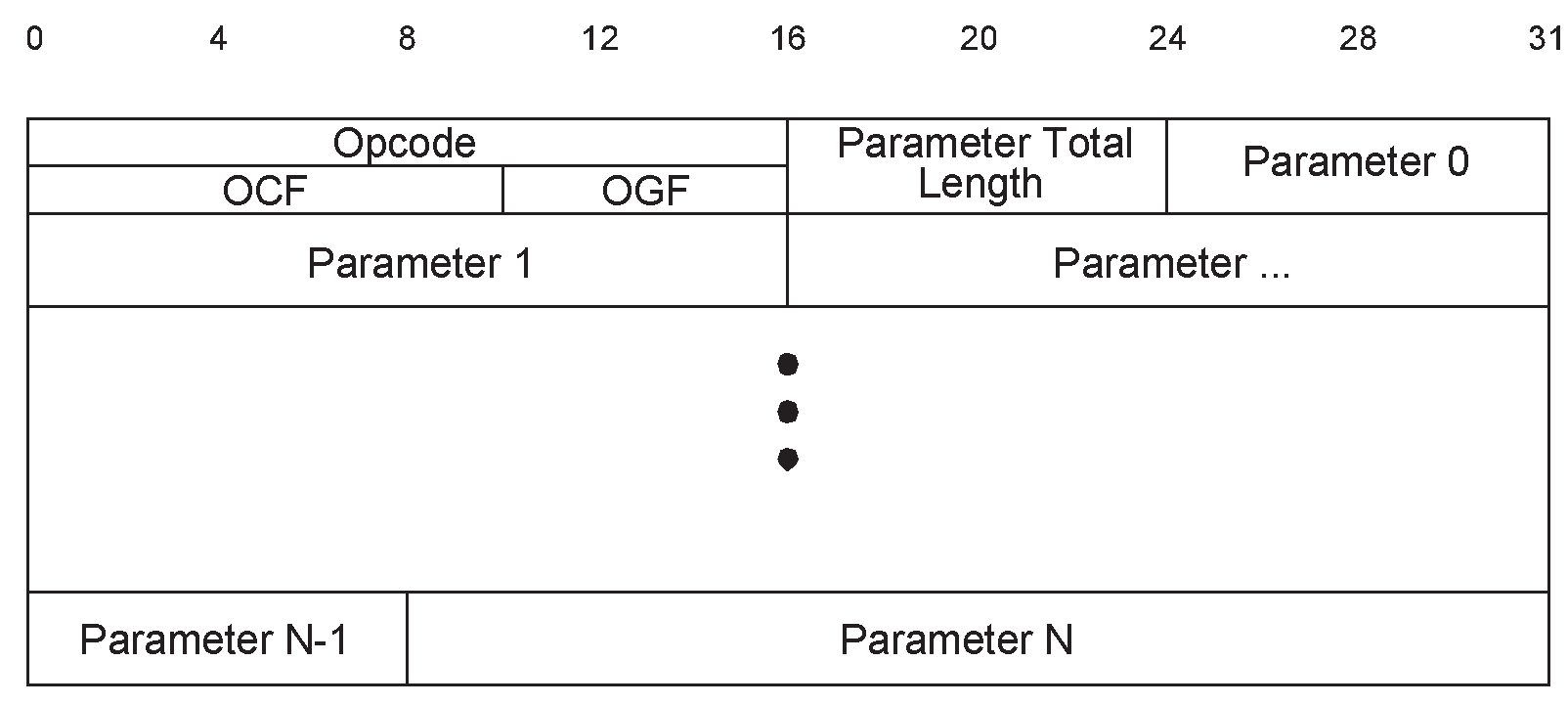
Opcode: | Size: 2 octets |
Value | Parameter Description |
|---|---|
0xXXXX | OGF Range (6 bits): 0x00 to 0x3F (0x3F reserved for vendor-specific debug commands) OCF Range (10 bits): 0x0000 to 0x03FF |
Parameter_Total_Length: | Size: 1 octet |
Value | Parameter Description |
|---|---|
0xXX | Lengths of all of the parameters contained in this packet measured in octets. (N.B.: total length of parameters, not number of parameters) |
Parameter 0 - N: | Size: Parameter_Total_Length |
Value | Parameter Description |
|---|---|
0xXX | Each command has a specific number of parameters associated with it. These parameters and the size of each of the parameters are defined for each command. Each parameter is an integer number of octets in size. |
5.4.2. HCI ACL Data packets
HCI ACL Data packets are used to exchange data between the Host and Controller. There are two types of HCI ACL Data packets:
Automatically-Flushable
Non-Automatically-Flushable
Automatically-Flushable HCI ACL Data packets are flushed based on the setting of an automatic flush timer (see Read Automatic Flush Timeout command). Non-Automatically-Flushable HCI ACL Data packets are not controlled by the automatic flush timeout and shall not be automatically flushed. The format of the HCI ACL Data packet is shown in Figure 5.2. The definition for each of the fields in the data packets is explained below.
Hosts and Controllers shall be able to accept HCI ACL Data packets with up to 27 bytes of data excluding the HCI ACL Data packet header on Connection_Handles associated with an LE-U logical link.The HCI ACL Data packet header is the first 4 octets of the packet.
Note
Note: HCI ACL Data packets with a Connection_Handle associated with an LE-U logical link will not be affected by the automatic flush timer because only non-flushable packet boundary flags are allowed.
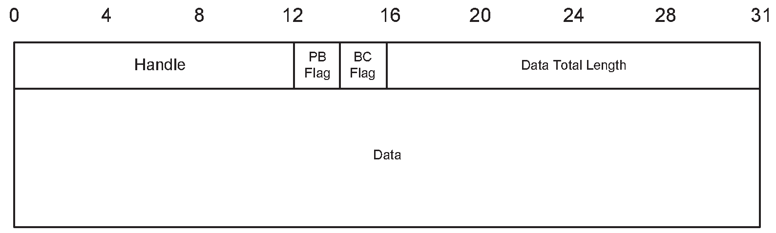
Handle: | Size: 12 Bits |
Value | Parameter Description |
|---|---|
0xXXX | Connection_Handle to be used for transmitting a data packet or segment over a Controller. Range: 0x000 to 0xEFF (all other values reserved for future use) |
The Flag Bits consist of the Packet_Boundary_Flag and Broadcast_Flag. The Packet_Boundary_Flag is located in bit 4 and bit 5, and the Broadcast_Flag is located in bit 6 and bit 7 in the second octet of the HCI ACL Data packet.
Packet_Boundary_Flag: | Size: 2 Bits |
Value | Parameter Description | APB-U | ACL-U | LE-U | |
|---|---|---|---|---|---|
0b00 | First non-automatically-flushable packet of a higher layer message (start of a non-automatically-flushable L2CAP PDU) from Host to Controller. | Host to Controller | Not allowed | Allowed | Allowed |
Controller to Host | Not allowed | Not allowed (except during loopback) | Not allowed | ||
0b01 | Continuing fragment of a higher layer message | Host to Controller | Allowed | Allowed | Allowed |
Controller to Host | Allowed | Allowed | Allowed | ||
0b10 | First automatically flushable packet of a higher layer message (start of an automatically-flushable L2CAP PDU). | Host to Controller | Allowed | Allowed | Not Allowed |
Controller to Host | Allowed | Allowed | Allowed | ||
0b11 | Previously used |
The start of a non-flushable packet of a higher layer message (start of a non-automatically-flushable L2CAP PDU) with the PBF of 0b00 shall be transmitted with an LLID of 0b10. All continuing fragment packets of a higher layer message shall be transmitted with an LLID of 0b01.
Broadcast_Flag: | Size: 2 Bits |
Value | Parameter Description |
|---|---|
0b00 | Point-to-point (ACL-U or LE-U) |
0b01 | BR/EDR broadcast (APB-U) |
0b10 | Reserved for future use. |
0b11 | Reserved for future use. |
Note
Note: The Broadcast_Flag value 0b01 may only be used in packets from Host to Controller on the Central of a piconet and from Controller to Host on the Peripheral of a piconet. Peripherals in Sniff mode will only receive a broadcast packet if it happens to be sent in a sniff slot when the Peripheral is listening.
Data_Total_Length: | Size: 2 octets |
Value | Parameter Description |
|---|---|
0xXXXX | Length of data measured in octets. |
5.4.3. HCI Synchronous Data packets
HCI Synchronous Data packets are used to exchange synchronous data (SCO and eSCO) between the Host and Controller. The format of the HCI Synchronous Data packet is shown in Figure 5.3. The definition for each of the fields in the data packets is explained below. The HCI Synchronous Data packet header is the first 3 octets of the packet.
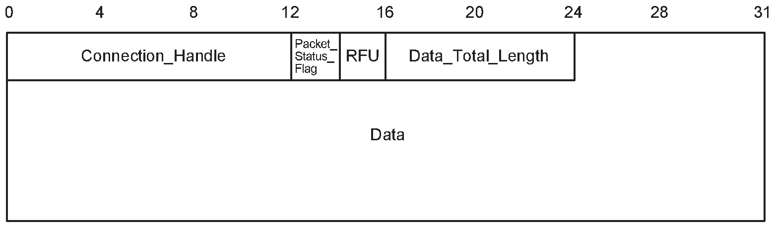
Connection_Handle: | Size: 12 Bits |
Value | Parameter Description |
|---|---|
0xXXX | Connection_Handle to be used to for transmitting a synchronous data packet or segment. Range: 0x0000 to 0x0EFF |
The Packet_Status_Flag bits consist of two bits, which are located from bit 4 to 5 in the second octet of the HCI Synchronous Data packet.
The Host shall set the Packet_Status_Flag bits to 0b00.
If the Erroneous_Data_Reporting parameter was set to disabled when the synchronous connection was created, the Controller shall set the Packet_Status_Flag bits to 0b00 and whether or not data is provided for cases when a valid (e)SCO packet was not received is unspecified.
If the Erroneous_Data_Reporting parameter was set to enabled when the synchronous connection was created, the Controller shall set the Packet_Status_Flag according to the following table.
Packet_Status_Flag (in packets sent by the Controller): | Size: 2 Bits |
Value | Parameter Description |
|---|---|
0b00 | Correctly received data. The payload data belongs to received eSCO or SCO packets that the Baseband marked as “good data”. |
0b01 | Possibly invalid data. At least one eSCO packet has been marked by the Baseband as “data with possible errors” and all others have been marked as “good data” in the eSCO interval(s) corresponding to the HCI Synchronous Data packet. |
0b10 | No data received. All data from the Baseband received during the (e)SCO interval(s) corresponding to the HCI Synchronous Data packet have been marked as "lost data" by the Baseband. The Payload data octets shall be set to 0. |
0b11 | Data partially lost. Not all, but at least one (e)SCO packet has been marked as “lost data” by the Baseband in the (e)SCO intervals corresponding to the HCI Synchronous Data packet. The payload data octets corresponding to the missing (e)SCO packets shall be set to 0. |
Note
Note: Some HCI transports and/or Controller implementations will align the HCI Synchronous Data packets with the (e)SCO Baseband packets such that data integrity can be explicitly marked in the Packet_Status_Flag. For HCI transports or Controller implementations that do not preserve this alignment, information in the Packet_Status_Flag may be ambiguous.
Data_Total_Length: | Size: 1 octet |
Value | Parameter Description |
|---|---|
0xXX | Length of synchronous data measured in octets |
5.4.4. HCI Event packet
The HCI Event packet is used by the Controller to notify the Host when events occur. If the Controller sends an HCI Event Packet containing an Event Code or an LE subevent code that the Host has not masked out and does not support, the Host shall ignore that packet. Any event code or LE subevent code not mentioned in this Part is reserved for future use. The Host shall be able to accept HCI Event packets with up to 255 octets of data excluding the HCI Event packet header. The format of the HCI Event packet is shown in Figure 5.4, and the definition of each field is explained below. The HCI Event packet header is the first 2 octets of the packet.
The event code 0xFE is reserved for future use (used for specification development purposes). The event code 0xFF is reserved for vendor-specific debugging events.
Note
Note: An LE Controller uses a single Event Code (see Section 7.7.65) to transmit all LE specific events from the Controller to the Host. The first Event Parameter is always a subevent code identifying the specific event. Controllers should use subevent codes with Event Codes 0xFE and 0xFF.
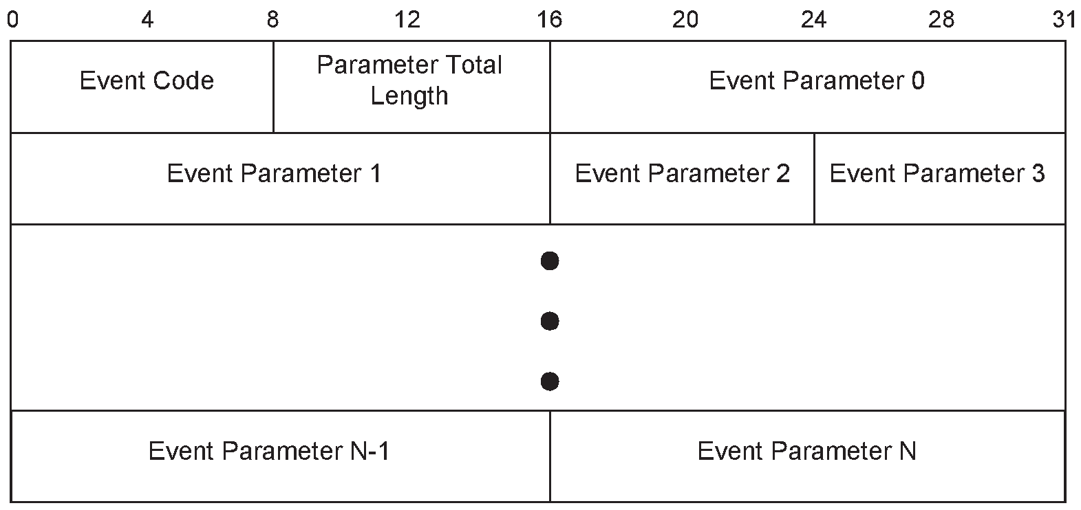
Event_Code: | Size: 1 octet |
Value | Parameter Description |
|---|---|
0xXX | Each event is assigned a 1-Octet event code used to uniquely identify different types of events. |
Parameter_Total_Length: | Size: 1 octet |
Value | Parameter Description |
|---|---|
0xXX | Length of all of the parameters contained in this packet, measured in octets |
Event_Parameter 0 - N: | Size: Parameter_Total_Length |
Value | Parameter Description |
|---|---|
0xXX | Each event has a specific number of parameters associated with it. These parameters and the size of each of the parameters are defined for each event. Each parameter is an integer number of octets in size. |
5.4.5. HCI ISO Data packets
HCI ISO Data packets are used to exchange isochronous data between the Host and Controller. An HCI ISO Data packet holds either an SDU or part of an SDU. In the Host to Controller direction, it cannot contain more data than the size of the buffer supported by the Controller. If the length of an SDU is greater than the Controller's buffer size, the Host may need to fragment that SDU. The Controller shall not start sending an SDU or fragments of an SDU to the Host until all the PDUs containing data from that SDU have either been received or can no longer be received because the last opportunity for them to be transmitted has passed. SDU fragments generated over HCI are unrelated to the SDU fragments generated by ISOAL.
The format of the HCI ISO Data packet is shown in Figure 5.5. The definition of each field in the packet is given below. The HCI ISO Data packet header is the first 4 octets of the packet.
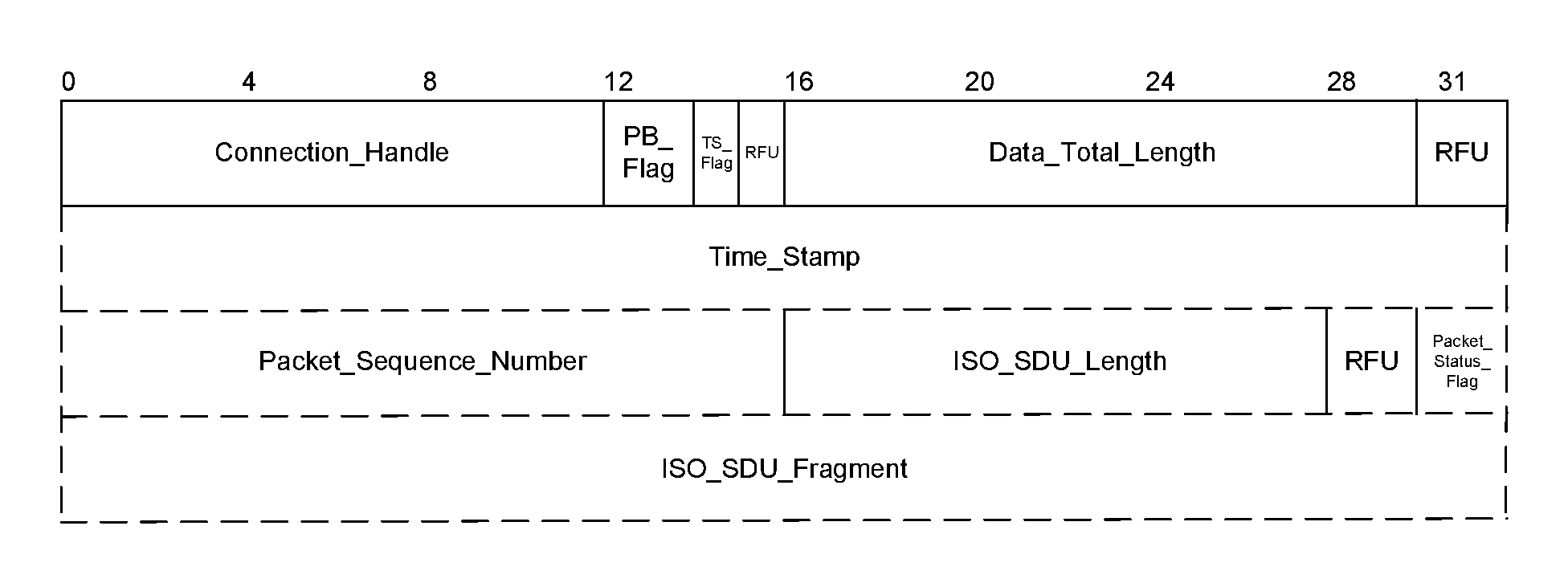
If PB_Flag equals 0b00 or 0b10, then the Packet_Sequence_Number, ISO_SDU_Length, and Packet_Status_Flag fields (plus the intermediate RFU field) shall all be present in the packet and the Time_Stamp field may be present. If PB_Flag equals 0b01 or 0b11, then none of these fields shall be included in the packet.
Connection_Handle: | Size: 12 bits |
Value | Parameter Description |
|---|---|
0xXXX | Connection_Handle to be used for transmitting an ISO SDU or fragment. Range: 0x000 to 0xEFF |
PB_Flag: | Size: 2 bits |
Value | Parameter Description |
|---|---|
0b00 | The ISO_SDU_Fragment field contains the first fragment of a fragmented SDU. |
0b01 | The ISO_SDU_Fragment field contains an intermediate fragment of an SDU. |
0b10 | The ISO_SDU_Fragment field contains a complete SDU. |
0b11 | The ISO_SDU_Fragment field contains the last fragment of an SDU. |
TS_Flag: | Size: 1 bit |
Value | Parameter Description |
|---|---|
0 | The Time_Stamp field is not present in the packet. |
1 | The Time_Stamp field is present in the packet. |
Data_Total_Length: | Size: 14 bits |
Value | Parameter Description |
|---|---|
0xXXXX | Length of the packet, excluding the packet header, in octets. |
In the Host to Controller direction, Data_Total_Length shall be less than or equal to the size of the buffer supported by the Controller (which is returned using the ISO_Data_Packet_Length return parameter of the LE Read Buffer Size command).
If PB_Flag is 0b01 or 0b11, then Data_Total_Length may be zero. Otherwise Data_Total_Length is at least 4 if TS_Flag is 0 and at least 8 if TS_Flag is 1.
Time_Stamp: | Size: 32 bits |
Value | Parameter Description |
|---|---|
0xXXXXXXXX | A time in microseconds (see [Vol 6] Part G, Section 3). |
Packet_Sequence_Number: | Size: 16 bits |
Value | Parameter Description |
|---|---|
0xXXXX | The sequence number of the SDU (see [Vol 6] Part G, Section 1). |
ISO_SDU_Length: | Size: 12 bits |
Value | Parameter Description |
|---|---|
0xXXXX | The total length of the SDU (and not of any individual fragments), in octets. |
The Packet_Status_Flag field indicates the status of the packet that the Controller receives over the isochronous physical channel. The Packet_Status_Flag field is only valid in HCI ISO Data packets sent by the Controller and is reserved for future use in packets sent by the Host.
Packet_Status_Flag (in packets sent by the Controller) | Size: 2 bits |
Value | Parameter Description |
|---|---|
0b00 | Valid data. The complete SDU was received correctly. |
0b01 | Possibly invalid data. The contents of the ISO_SDU_Fragment may contain errors or part of the SDU may be missing. This is reported as "data with possible errors". |
0b10 | Part(s) of the SDU were not received correctly. This is reported as "lost data". |
All other values | Reserved for future use |
The ISO_SDU_Fragment field shall contain the isochronous data (the SDU or fragment of the SDU). This field may be empty. When Packet_Status_Flag is set to 0b10 in packets from the Controller to the Host, there is no data, PB_Flag shall be set to 0b10, and ISO_SDU_Length shall be set to zero.
5.5. Ignored parameters
When a parameter of a command or event is described as “ignored” (this is usually only in a specific circumstance), then the value of this parameter shall not affect the behavior of the recipient (whether Controller or Host ) in any way. In particular, the Controller shall not report an error because the value is out of range, reserved for future use, or represents an inappropriate entity (e.g. a Connection_Handle may be unassigned or for the wrong logical channel), or because two related values have the wrong relationship (e.g. minimum > maximum).
6. HCI configuration parameters
6.1. Scan Enable
The Scan_Enable parameter controls whether or not the BR/EDR Controller will periodically scan for page attempts and/or inquiry requests from other BR/EDR Controllers. If Page Scan is enabled, then the device will enter page scan mode based on the value of the Page_Scan_Interval and Page_Scan_Window parameters. If Inquiry Scan is enabled, then the BR/EDR Controller will enter Inquiry Scan mode based on the value of the Inquiry_Scan_Interval and Inquiry_Scan_Window parameters.
Scan_Enable: | Size: 1 octet |
Value | Parameter Description |
|---|---|
0x00 | No Scans enabled. |
0x01 | Inquiry Scan enabled. Page Scan always disabled. |
0x02 | Inquiry Scan disabled. Page Scan enabled. |
0x03 | Inquiry Scan enabled. Page Scan enabled. |
All other values | Reserved for future use |
6.2. Inquiry Scan Interval
The Inquiry_Scan_Interval configuration parameter defines the amount of time between consecutive inquiry scans. This is defined as the time interval from when the BR/EDR Controller started its last inquiry scan until it begins the next inquiry scan.
Inquiry_Scan_Interval: | Size: 2 octets |
Value | Parameter Description |
|---|---|
N = 0xXXXX | Range: 0x0012 to 0x1000; only even values are valid Default: 0x1000 Time = N × 0.625 ms Time Range: 11.25 to 2560 ms Time Default: 2.56 s |
6.3. Inquiry Scan Window
The Inquiry_Scan_Window configuration parameter defines the amount of time for the duration of the inquiry scan. The Inquiry_Scan_Window can only be less than or equal to the Inquiry_Scan_Interval.
Inquiry_Scan_Window: | Size: 2 octets |
Value | Parameter Description |
|---|---|
N = 0xXXXX | Range: 0x0011 to 0x1000 Default: 0x0012 Mandatory Range: 0x0011 to Inquiry Scan Interval Time = N × 0.625 ms Time Range: 10.625 ms to 2560 ms Time Default: 11.25 ms |
6.4. Inquiry Scan Type
The Inquiry_Scan_Type configuration parameter indicates whether inquiry scanning will be done using non-interlaced scan or interlaced scan. Currently, one mandatory inquiry scan type and one optional inquiry scan type are defined. For details, see [Vol 2] Part B, Section 8.4.1.
Inquiry_Scan_Type: | Size: 1 octet |
Value | Parameter Description |
|---|---|
0x00 | Mandatory: Standard Scan (default) |
0x01 | Optional: Interlaced Scan |
All other values | Reserved for future use |
6.5. Inquiry mode
The Inquiry_Mode configuration parameter indicates whether inquiry returns Inquiry Result events in the standard format, with RSSI, or with RSSI and extended inquiry response information.
Inquiry_Mode: | Size: 1 octet |
Value | Parameter Description |
|---|---|
0x00 | Standard Inquiry Result event format |
0x01 | Inquiry Result format with RSSI |
0x02 | Inquiry Result with RSSI format or Extended Inquiry Result format |
All other values | Reserved for future use |
6.6. Page Timeout
The Page_Timeout configuration parameter together with Extended_Page_Timeout defines the maximum time the local Link Manager will wait for a Baseband page response from the remote device at a locally initiated connection attempt. If this time expires and the remote BR/EDR Controller has not responded to the page at Baseband level, the connection attempt will be considered to have failed.
Page_Timeout: | Size: 2 octets |
Value | Parameter Description |
|---|---|
N = 0xXXXX | Range: 0x0001 to 0xFFFF Default: 0x2000 Mandatory Range: 0x0016 to 0xFFFF Time = N × 0.625 ms Time Range: 0.625 ms to 40.9 s Time Default: 5.12 s |
6.7. Connection Accept Timeout
The Connection_Accept_Timeout configuration parameter allows the BR/EDR or LE Controller to automatically deny a connection request after a specified time period has occurred and the new connection is not accepted. The parameter defines the time duration from when the BR/EDR Controller sends an HCI_Connection_Request event or the LE Controller sends an HCI_LE_CIS_Request event until the Controller will automatically reject an incoming connection.
Connection_Accept_Timeout: | Size: 2 octets |
Value | Parameter Description |
|---|---|
N = 0xXXXX | Range: 0x0001 to 0xB540 Default: 0x1F40 Mandatory Range: 0x00A0 to 0xB540 Time = N × 0.625 ms Time Range: 0.625 ms to 29 s Time Default: BR/EDR 5 s |
6.8. Page Scan Interval
The Page_Scan_Interval configuration parameter defines the amount of time between consecutive page scans. This time interval is defined from when the Controller started its last page scan until it begins the next page scan.
Page_Scan_Interval: | Size: 2 octets |
Value | Parameter Description |
|---|---|
N = 0xXXXX | Range: 0x0012 to 0x1000; only even values are valid Default: 0x0800 Time = N × 0.625 ms Time Range: 11.25 ms to 2560 ms Time Default: 1.28 s |
6.9. Page Scan Window
The Page_Scan_Window configuration parameter defines the amount of time for the duration of the page scan. The Page_Scan_Window can only be less than or equal to the Page_Scan_Interval.
Page_Scan_Window: | Size: 2 octets |
Value | Parameter Description |
|---|---|
N = 0xXXXX | Range: 0x0011 to 0x1000 Default: 0x0012 Mandatory Range: 0x0011 to Page Scan Interval Time = N × 0.625 ms Time Range: 10.625 ms to Page Scan Interval Time Default: 11.25 ms |
6.10. [This section is no longer used]
6.11. Page Scan Type
The Page_Scan_Type parameter indicates whether page scanning will be done using non-interlaced scan or interlaced scan. For details, see [Vol 2] Part B, Section 8.3.1.
Page_Scan_Type: | Size: 1 octet |
Value | Parameter Description |
|---|---|
0x00 | Mandatory: Standard Scan (default) |
0x01 | Optional: Interlaced Scan |
All other values | Reserved for future use |
6.12. Voice Setting
The Voice_Setting parameter controls all the various settings for voice connections. The Voice_Setting parameter controls the configuration for voice connections: Input Coding, Air coding format, input data format, Input sample size, and linear PCM parameter. The air coding format bits in the Voice_Setting command parameter specify which air coding format the local device requests. The air coding format bits do not specify which air coding format(s) the local device accepts when a remote device requests an air coding format. This is determined by the hardware capabilities of the local BR/EDR Controller.
Voice_Setting: | Size: 1 octet |
Bit number | Parameter description | |
|---|---|---|
0 – 1 | Air coding format | 0: CVSD 1: µ-law 2: A-law 3. transparent data |
2 – 4 | Linear PCM bit position - number of bit positions that the MSB of the sample is from the MSB of the value (only for linear PCM) | |
5 | Input sample size (only for linear PCM) | 0: 8 bits 1: 16 bits |
6 – 7 | Input data format | 0: one’s complement 1: two’s complement 2: sign and magnitude 3: unsigned |
8 – 9 | Input coding format | 0: linear 1: µ-law 2: A-law 3: Reserved for future use |
10 – 15 | Reserved for future use | |
6.13. PIN Type
The PIN_Type configuration parameter determines whether the Link Manager assumes that the Host supports variable PIN codes or a fixed PIN code. The Controller uses the PIN_Type information during pairing.
PIN_Type: | Size: 1 octet |
Value | Parameter Description |
|---|---|
0x00 | Variable PIN. |
0x01 | Fixed PIN. |
6.14. Link key
The Controller can store a limited number of link keys for other BR/EDR Controllers. Link keys are shared between two BR/EDR Controllers, and are used for all security transactions between the two BR/EDR Controllers. A Host device may have additional storage capabilities, which can be used to save additional link keys to be reloaded to the BR/EDR Controller when needed. A Link_Key is associated with a BD_ADDR.
Link_Key: | Size: 16 octets |
Value | Parameter Description |
|---|---|
0xXXXXXXXXXXXXXXXXXXXXXXXXXXXXXXXX | Link Key for an associated BD_ADDR. |
6.15. Failed Contact Counter
The Failed_Contact_Counter records the number of consecutive incidents in which either the local or remote device did not respond after the flush timeout had expired, and the L2CAP PDU that was currently being transmitted was automatically ‘flushed’. When this occurs, the Failed_Contact_Counter is incremented by 1.
The Failed_Contact_Counter is maintained for each Connection_Handle.
The Failed_Contact_Counter for a connection is reset to zero on the following conditions:
When a new connection is established
When the Failed_Contact_Counter is not zero and an L2CAP PDU is acknowledged for that connection
When the HCI_Reset_Failed_Contact_Counter command has been issued
Failed_Contact_Counter: | Size: 2 octets |
Value | Parameter Description |
|---|---|
0xXXXX | Number of consecutive failed contacts for a connection corresponding to the Connection_Handle |
6.16. Authentication Enable
The Authentication_Enable parameter controls if the local device requires to authenticate the remote device at connection setup (between the HCI_Create_Connection command or acceptance of an incoming ACL connection and the corresponding Connection Complete event). At connection setup, only the device(s) with the Authentication_Enable parameter enabled will try to authenticate the other device.
Note
Note: Changing this parameter does not affect existing connections.
Authentication_Enable: | Size: 1 octet |
Value | Parameter Description |
|---|---|
0x00 | Authentication not required. |
0x01 | Authentication required for all connections. |
All other values | Reserved for future use |
6.17. Hold Mode Activity
The Hold_Mode_Activity value is used to determine what activities should be suspended when the BR/EDR Controller is in Hold mode. After the hold period has expired, the device will return to the previous mode of operation. If no activities are suspended, then all of the current Periodic Inquiry, Inquiry Scan, and Page Scan settings remain valid during the Hold mode. If the Hold_Mode_Activity parameter is set to Suspend Page Scan, Suspend Inquiry Scan, and Suspend Periodic Inquiries, then the device can enter a low-power state during the Hold mode period and all activities are suspended. The Hold Mode Activity is only valid if all connections are in Hold mode.
Hold_Mode_Activity: | Size: 1 octet |
Bit | Parameter Description |
|---|---|
0 | Suspend Page Scan. |
1 | Suspend Inquiry Scan. |
2 | Suspend Periodic Inquiries. |
All other bits | Reserved for future use. |
6.18. Link Policy Settings
The Link_Policy_Settings parameter determines the behavior of the local Link Manager when it receives a request from a remote Link Manager or it determines itself to change role or to enter Hold or Sniff mode. The local Link Manager will automatically accept or reject such a request from the remote device, and may even autonomously request itself, depending on the value of the Link_Policy_Settings parameter for the corresponding Connection_Handle. When the value of the Link_Policy_Settings parameter is changed for a certain Connection_Handle, the new value will only be used for requests from a remote device or from the local Link Manager itself made after this command has been completed. By enabling each mode individually, the Host can choose any combination needed to support various modes of operation. Multiple LM policies may be specified for the Link_Policy_Settings parameter by performing a bitwise OR operation of the different activity types.
Note
Note: The local BR/EDR Controller may be forced into Hold mode (regardless of whether the local device is Central or Peripheral) by the remote device regardless of the value of the Link_Policy_Settings parameter. The forcing of Hold mode can however only be done once the connection has already been placed into Hold mode through an LMP request (the Link_Policy_Settings determine if requests from a remote device should be accepted or rejected). The forcing of Hold mode can after that be done as long as the connection lasts regardless of the setting for Hold mode in the Link_Policy_Settings parameter.
Note
Note: If the implementation in the remote device is a “polite” implementation that does not force another device into Hold mode via LMP PDUs, then the Link_Policy_Settings will never be overruled.
Link_Policy_Settings: | Size: 1 octet |
Bit Number | Parameter Description |
|---|---|
0 | Enable Role switch. |
1 | Enable Hold mode. |
2 | Enable Sniff mode. |
All other bits | Reserved for future use. |
6.19. Flush Timeout
The Flush_Timeout configuration parameter is used for ACL connections on a BR/EDR Controller only. The Flush Timeout is defined in [Vol 2] Part B, Section 7.6.3. This parameter allows automatically-flushable ACL packets to be automatically flushed without the Host device issuing an HCI_Flush command. This provides support for isochronous data, such as audio. Non-automatically-flushable ACL packets shall not be affected by this parameter (see Section 5.4.2) providing support for both asynchronous and isochronous data on the same ACL connection. When the L2CAP packet that is currently being transmitted is automatically ‘flushed’, the Failed _Contact_Counter is incremented by one.
Flush_Timeout: | Size: 2 octets |
Value | Parameter Description |
|---|---|
0x0000 | Timeout = ∞; No Automatic Flush |
N = 0xXXXX | Range: 0x0001 to 0x07FF Mandatory Range: 0x0002 to 0x07FF Time = N × 0.625 ms Time Range: 0.625 ms to 1279.375 ms |
6.20. Num Broadcast Retransmissions
Broadcast packets are not acknowledged and are unreliable. The Num_Broadcast_Retransmissions parameter, N, is used to increase the reliability of a broadcast message by retransmitting the broadcast message multiple times. This sets the value NBC in the Baseband to one greater than the Num_Broadcast_Retransmissions value. (See [Vol 2] Part B, Section 7.6.5) This parameter should be adjusted as the link quality measurement changes.
Num_Broadcast_Retransmissions: | Size: 1 octet |
Value | Parameter Description |
|---|---|
N = 0xXX | NBC = N + 1 Range: 0x00 to 0xFE |
6.21. Link Supervision Timeout
The Link_Supervision_Timeout parameter is used by the Controller to monitor link loss. If, for any reason, no packets are received from that Connection_Handle for a duration longer than the Link_Supervision_Timeout, the connection shall be disconnected. For the BR/EDR Controller, the same timeout value is used for both synchronous and ACL connections for the device specified by the Connection_Handle.
Note
Note: Setting the Link_Supervision_Timeout to No link supervision timeout (0x0000) on a BR/EDR Controller will disable the Link_Supervision_Timeout check for the specified Connection_Handle.
Link_Supervision_TImeout: | Size: 2 octets |
Value | Parameter Description |
|---|---|
0x0000 | No link supervision timeout. |
N = 0xXXXX | Range: 0x0001 to 0xFFFF Default: 0x7D00 Mandatory Range: 0x0190 to 0xFFFF Time = N × 0.625 ms Time Range: 0.625 ms to 40.9 s Time Default: BR/EDR 20 s |
6.22. Synchronous Flow Control Enable
The Synchronous_Flow_Control_Enable configuration parameter allows the Host to decide if the BR/EDR Controller will send HCI_Number_Of_Completed_Packets events for synchronous Connection_Handles. This setting allows the Host to enable and disable synchronous flow control.
Synchronous_Flow_Control_Enable: | Size: 1 octet |
Value | Parameter Description |
|---|---|
0x00 | Synchronous Flow Control is disabled. No HCI_Number_Of_Completed_Packets events will be sent from the BR/EDR Controller for synchronous Connection_Handles. |
0x01 | Synchronous Flow Control is enabled. HCI_Number_Of_Completed_Packets events will be sent from the BR/EDR Controller for synchronous Connection_Handles. |
6.23. Local Name
The user-friendly Local_Name provides the user the ability to distinguish one BR/EDR Controller from another. The Local_Name configuration parameter is a UTF-8 encoded string with the type utf8{248} defined in [Vol 1] Part E, Section 2.9.3.
Note
Note: The Local_Name configuration parameter is a string parameter. Endianness does therefore not apply to the Local_Name configuration parameter. The first octet of the name is received first.
Local_Name: | Size: 248 octets |
Value | Parameter Description |
|---|---|
A UTF-8 encoded User Friendly Descriptive Name for the device with type utf8{248}. |
6.24. Extended Inquiry response
The Extended_Inquiry_Response provides information about the local device in response to inquiry from remote devices. The configuration parameter has two parts, a significant part followed by a non-significant part. The non-significant part contains only zero octets. The data format of the significant part is defined in [Vol 3] Part C, Section 8.
Extended_Inquiry_Response: | Size: 240 octets |
Value | Parameter Description |
|---|---|
Information about the local device that will be sent in an extended inquiry response packet to remote devices during inquiry response. |
6.25. Erroneous Data Reporting
The Erroneous_Data_Reporting configuration parameter shall be used for SCO and eSCO connections only. This parameter determines if the BR/EDR Controller is required to provide data to the Host for every (e)SCO interval, with the Packet_Status_Flag in HCI Synchronous Data packets set according to Section 5.4.3.
Erroneous_Data_Reporting: | Size: 1 octet |
Value | Parameter Description |
|---|---|
0x00 | Erroneous data reporting disabled |
0x01 | Erroneous data reporting enabled. |
All other values | Reserved for future use |
6.26. Class of Device
The Class_Of_Device parameter is used to indicate the capabilities of the local device to other devices.
Class_Of_Device: | Size: 3 octets |
Value | Parameter Description |
|---|---|
0xXXXXXX | Class of Device for the device. |
6.27. Supported commands
The Supported_Commands configuration parameter lists which HCI commands the local Controller supports.
The Supported_Commands is a 64 octet bit field. If a bit is set to 1, then this command is supported.
Supported_Commands: | Size: 64 octets |
Octet | Bit | Command Supported |
|---|---|---|
0 | 0 | HCI_Inquiry |
1 | HCI_Inquiry_Cancel | |
2 | HCI_Periodic_Inquiry_Mode | |
3 | HCI_Exit_Periodic_Inquiry_Mode | |
4 | HCI_Create_Connection | |
5 | HCI_Disconnect | |
6 | Previously used | |
7 | HCI_Create_Connection_Cancel | |
1 | 0 | HCI_Accept_Connection_Request |
1 | HCI_Reject_Connection_Request | |
2 | HCI_Link_Key_Request_Reply | |
3 | HCI_Link_Key_Request_Negative_Reply | |
4 | HCI_PIN_Code_Request_Reply | |
5 | HCI_PIN_Code_Request_Negative_Reply | |
6 | HCI_Change_Connection_Packet_Type | |
7 | HCI_Authentication_Requested | |
2 | 0 | HCI_Set_Connection_Encryption |
1 | HCI_Change_Connection_Link_Key | |
2 | HCI_Link_Key_Selection | |
3 | HCI_Remote_Name_Request | |
4 | HCI_Remote_Name_Request_Cancel | |
5 | HCI_Read_Remote_Supported_Features | |
6 | HCI_Read_Remote_Extended_Features | |
7 | HCI_Read_Remote_Version_Information | |
3 | 0 | HCI_Read_Clock_Offset |
1 | HCI_Read_LMP_Handle | |
2 | Reserved for future use | |
3 | Reserved for future use | |
4 | Reserved for future use | |
5 | Reserved for future use | |
6 | Reserved for future use | |
7 | Reserved for future use | |
4 | 0 | Reserved for future use |
1 | HCI_Hold_Mode | |
2 | HCI_Sniff_Mode | |
3 | HCI_Exit_Sniff_Mode | |
4 | Previously used | |
5 | Previously used | |
6 | HCI_QoS_Setup | |
7 | HCI_Role_Discovery | |
5 | 0 | HCI_Switch_Role |
1 | HCI_Read_Link_Policy_Settings | |
2 | HCI_Write_Link_Policy_Settings | |
3 | HCI_Read_Default_Link_Policy_Settings | |
4 | HCI_Write_Default_Link_Policy_Settings | |
5 | HCI_Flow_Specification | |
6 | HCI_Set_Event_Mask | |
7 | HCI_Reset | |
6 | 0 | HCI_Set_Event_Filter |
1 | HCI_Flush | |
2 | HCI_Read_PIN_Type | |
3 | HCI_Write_PIN_Type | |
4 | Previously used | |
5 | HCI_Read_Stored_Link_Key | |
6 | HCI_Write_Stored_Link_Key | |
7 | HCI_Delete_Stored_Link_Key | |
7 | 0 | HCI_Write_Local_Name |
1 | HCI_Read_Local_Name | |
2 | HCI_Read_Connection_Accept_Timeout | |
3 | HCI_Write_Connection_Accept_Timeout | |
4 | HCI_Read_Page_Timeout | |
5 | HCI_Write_Page_Timeout | |
6 | HCI_Read_Scan_Enable | |
7 | HCI_Write_Scan_Enable | |
8 | 0 | HCI_Read_Page_Scan_Activity |
1 | HCI_Write_Page_Scan_Activity | |
2 | HCI_Read_Inquiry_Scan_Activity | |
3 | HCI_Write_Inquiry_Scan_Activity | |
4 | HCI_Read_Authentication_Enable | |
5 | HCI_Write_Authentication_Enable | |
6 | Previously used | |
7 | Previously used | |
9 | 0 | HCI_Read_Class_Of_Device |
1 | HCI_Write_Class_Of_Device | |
2 | HCI_Read_Voice_Setting | |
3 | HCI_Write_Voice_Setting | |
4 | HCI_Read_Automatic_Flush_Timeout | |
5 | HCI_Write_Automatic_Flush_Timeout | |
6 | HCI_Read_Num_Broadcast_Retransmissions | |
7 | HCI_Write_Num_Broadcast_Retransmissions | |
10 | 0 | HCI_Read_Hold_Mode_Activity |
1 | HCI_Write_Hold_Mode_Activity | |
2 | HCI_Read_Transmit_Power_Level | |
3 | HCI_Read_Synchronous_Flow_Control_Enable | |
4 | HCI_Write_Synchronous_Flow_Control_Enable | |
5 | HCI_Set_Controller_To_Host_Flow_Control | |
6 | HCI_Host_Buffer_Size | |
7 | HCI_Host_Number_Of_Completed_Packets | |
11 | 0 | HCI_Read_Link_Supervision_Timeout |
1 | HCI_Write_Link_Supervision_Timeout | |
2 | HCI_Read_Number_Of_Supported_IAC | |
3 | HCI_Read_Current_IAC_LAP | |
4 | HCI_Write_Current_IAC_LAP | |
5 | Previously used | |
6 | Previously used | |
7 | Previously used | |
12 | 0 | Previously used |
1 | HCI_Set_AFH_Host_Channel_Classification | |
2 | Reserved for future use | |
3 | Reserved for future use | |
4 | HCI_Read_Inquiry_Scan_Type | |
5 | HCI_Write_Inquiry_Scan_Type | |
6 | HCI_Read_Inquiry_Mode | |
7 | HCI_Write_Inquiry_Mode | |
13 | 0 | HCI_Read_Page_Scan_Type |
1 | HCI_Write_Page_Scan_Type | |
2 | HCI_Read_AFH_Channel_Assessment_Mode | |
3 | HCI_Write_AFH_Channel_Assessment_Mode | |
4 | Reserved for future use | |
5 | Reserved for future use | |
6 | Reserved for future use | |
7 | Reserved for future use | |
14 | 0 | Reserved for future use |
1 | Reserved for future use | |
2 | Reserved for future use | |
3 | HCI_Read_Local_Version_Information | |
4 | Reserved for future use | |
5 | HCI_Read_Local_Supported_Features | |
6 | HCI_Read_Local_Extended_Features | |
7 | HCI_Read_Buffer_Size | |
15 | 0 | Previously used |
1 | HCI_Read_BD_ADDR | |
2 | HCI_Read_Failed_Contact_Counter | |
3 | HCI_Reset_Failed_Contact_Counter | |
4 | HCI_Read_Link_Quality | |
5 | HCI_Read_RSSI | |
6 | HCI_Read_AFH_Channel_Map | |
7 | HCI_Read_Clock | |
16 | 0 | HCI_Read_Loopback_Mode |
1 | HCI_Write_Loopback_Mode | |
2 | HCI_Enable_Device_Under_Test_Mode | |
3 | HCI_Setup_Synchronous_Connection_Request | |
4 | HCI_Accept_Synchronous_Connection_Request | |
5 | HCI_Reject_Synchronous_Connection_Request | |
6 | Reserved for future use | |
7 | Reserved for future use | |
17 | 0 | HCI_Read_Extended_Inquiry_Response |
1 | HCI_Write_Extended_Inquiry_Response | |
2 | HCI_Refresh_Encryption_Key | |
3 | Reserved for future use | |
4 | HCI_Sniff_Subrating | |
5 | HCI_Read_Simple_Pairing_Mode | |
6 | HCI_Write_Simple_Pairing_Mode | |
7 | HCI_Read_Local_OOB_Data | |
18 | 0 | HCI_Read_Inquiry_Response_Transmit_Power_Level |
1 | HCI_Write_Inquiry_Transmit_Power_Level | |
2 | HCI_Read_Default_Erroneous_Data_Reporting | |
3 | HCI_Write_Default_Erroneous_Data_Reporting | |
4 | Reserved for future use | |
5 | Reserved for future use | |
6 | Reserved for future use | |
7 | HCI_IO_Capability_Request_Reply | |
19 | 0 | HCI_User_Confirmation_Request_Reply |
1 | HCI_User_Confirmation_Request_Negative_Reply | |
2 | HCI_User_Passkey_Request_Reply | |
3 | HCI_User_Passkey_Request_Negative_Reply | |
4 | HCI_Remote_OOB_Data_Request_Reply | |
5 | HCI_Write_Simple_Pairing_Debug_Mode | |
6 | HCI_Enhanced_Flush | |
7 | HCI_Remote_OOB_Data_Request_Negative_Reply | |
20 | 0 | Reserved for future use |
1 | Reserved for future use | |
2 | HCI_Send_Keypress_Notification | |
3 | HCI_IO_Capability_Request_Negative_Reply | |
4 | HCI_Read_Encryption_Key_Size | |
5 | Reserved for future use | |
6 | Reserved for future use | |
7 | Reserved for future use | |
21 | 0 | Previously used |
1 | Previously used | |
2 | Previously used | |
3 | Previously used | |
4 | Previously used | |
5 | Previously used | |
6 | Previously used | |
7 | Previously used | |
22 | 0 | Previously used |
1 | Previously used | |
2 | HCI_Set_Event_Mask_Page_2 | |
3 | Previously used | |
4 | Previously used | |
5 | Previously used | |
6 | Previously used | |
7 | Previously used | |
23 | 0 | HCI_Read_Flow_Control_Mode |
1 | HCI_Write_Flow_Control_Mode | |
2 | HCI_Read_Data_Block_Size | |
3 | Reserved for future use | |
4 | Reserved for future use | |
5 | Previously used | |
6 | Previously used | |
7 | Previously used | |
24 | 0 | HCI_Read_Enhanced_Transmit_Power_Level |
1 | Reserved for future use | |
2 | Previously used | |
3 | Previously used | |
4 | Previously used | |
5 | HCI_Read_LE_Host_Support | |
6 | HCI_Write_LE_Host_Support | |
7 | Reserved for future use | |
25 | 0 | HCI_LE_Set_Event_Mask |
1 | HCI_LE_Read_Buffer_Size [v1] | |
2 | HCI_LE_Read_Local_Supported_Features | |
3 | Reserved for future use | |
4 | HCI_LE_Set_Random_Address | |
5 | HCI_LE_Set_Advertising_Parameters | |
6 | HCI_LE_Read_Advertising_Physical_Channel_Tx_Power | |
7 | HCI_LE_Set_Advertising_Data | |
26 | 0 | HCI_LE_Set_Scan_Response_Data |
1 | HCI_LE_Set_Advertising_Enable | |
2 | HCI_LE_Set_Scan_Parameters | |
3 | HCI_LE_Set_Scan_Enable | |
4 | HCI_LE_Create_Connection | |
5 | HCI_LE_Create_Connection_Cancel | |
6 | HCI_LE_Read_Filter_Accept_List_Size | |
7 | HCI_LE_Clear_Filter_Accept_List | |
27 | 0 | HCI_LE_Add_Device_To_Filter_Accept_List |
1 | HCI_LE_Remove_Device_From_Filter_Accept_List | |
2 | HCI_LE_Connection_Update | |
3 | HCI_LE_Set_Host_Channel_Classification | |
4 | HCI_LE_Read_Channel_Map | |
5 | HCI_LE_Read_Remote_Features | |
6 | HCI_LE_Encrypt | |
7 | HCI_LE_Rand | |
28 | 0 | HCI_LE_Enable_Encryption |
1 | HCI_LE_Long_Term_Key_Request_Reply | |
2 | HCI_LE_Long_Term_Key_Request_Negative_Reply | |
3 | HCI_LE_Read_Supported_States | |
4 | HCI_LE_Receiver_Test [v1] | |
5 | HCI_LE_Transmitter_Test [v1] | |
6 | HCI_LE_Test_End | |
7 | Reserved for future use | |
29 | 0 | Reserved for future use |
1 | Reserved for future use | |
2 | Reserved for future use | |
3 | HCI_Enhanced_Setup_Synchronous_Connection | |
4 | HCI_Enhanced_Accept_Synchronous_Connection | |
5 | HCI_Read_Local_Supported_Codecs | |
6 | HCI_Set_MWS_Channel_Parameters | |
7 | HCI_Set_External_Frame_Configuration | |
30 | 0 | HCI_Set_MWS_Signaling |
1 | HCI_Set_MWS_Transport_Layer | |
2 | HCI_Set_MWS_Scan_Frequency_Table | |
3 | HCI_Get_MWS_Transport_Layer_Configuration | |
4 | HCI_Set_MWS_PATTERN_Configuration | |
5 | HCI_Set_Triggered_Clock_Capture | |
6 | HCI_Truncated_Page | |
7 | HCI_Truncated_Page_Cancel | |
31 | 0 | HCI_Set_Connectionless_Peripheral_Broadcast |
1 | HCI_Set_Connectionless_Peripheral_Broadcast_Receive | |
2 | HCI_Start_Synchronization_Train | |
3 | HCI_Receive_Synchronization_Train | |
4 | HCI_Set_Reserved_LT_ADDR | |
5 | HCI_Delete_Reserved_LT_ADDR | |
6 | HCI_Set_Connectionless_Peripheral_Broadcast_Data | |
7 | HCI_Read_Synchronization_Train_Parameters | |
32 | 0 | HCI_Write_Synchronization_Train_Parameters |
1 | HCI_Remote_OOB_Extended_Data_Request_Reply | |
2 | HCI_Read_Secure_Connections_Host_Support | |
3 | HCI_Write_Secure_Connections_Host_Support | |
4 | HCI_Read_Authenticated_Payload_Timeout | |
5 | HCI_Write_Authenticated_Payload_Timeout | |
6 | HCI_Read_Local_OOB_Extended_Data | |
7 | HCI_Write_Secure_Connections_Test_Mode | |
33 | 0 | HCI_Read_Extended_Page_Timeout |
1 | HCI_Write_Extended_Page_Timeout | |
2 | HCI_Read_Extended_Inquiry_Length | |
3 | HCI_Write_Extended_Inquiry_Length | |
4 | HCI_LE_Remote_Connection_Parameter_Request_Reply | |
5 | HCI_LE_Remote_Connection_Parameter_Request_Negative_Reply | |
6 | HCI_LE_Set_Data_Length | |
7 | HCI_LE_Read_Suggested_Default_Data_Length | |
34 | 0 | HCI_LE_Write_Suggested_Default_Data_Length |
1 | HCI_LE_Read_Local_P-256_Public_Key | |
2 | HCI_LE_Generate_DHKey [v1] | |
3 | HCI_LE_Add_Device_To_Resolving_List | |
4 | HCI_LE_Remove_Device_From_Resolving_List | |
5 | HCI_LE_Clear_Resolving_List | |
6 | HCI_LE_Read_Resolving_List_Size | |
7 | HCI_LE_Read_Peer_Resolvable_Address | |
35 | 0 | HCI_LE_Read_Local_Resolvable_Address |
1 | HCI_LE_Set_Address_Resolution_Enable | |
2 | HCI_LE_Set_Resolvable_Private_Address_Timeout | |
3 | HCI_LE_Read_Maximum_Data_Length | |
4 | HCI_LE_Read_PH | |
5 | HCI_LE_Set_Default_PHY | |
6 | HCI_LE_Set_PHY | |
7 | HCI_LE_Receiver_Test [v2] | |
36 | 0 | HCI_LE_Transmitter_Test [v2] |
1 | HCI_LE_Set_Advertising_Set_Random_Address | |
2 | HCI_LE_Set_Extended_Advertising_Parameters [v1] | |
3 | HCI_LE_Set_Extended_Advertising_Data | |
4 | HCI_LE_Set_Extended_Scan_Response_Data | |
5 | HCI_LE_Set_Extended_Advertising_Enable | |
6 | HCI_LE_Read_Maximum_Advertising_Data_Length | |
7 | HCI_LE_Read_Number_of_Supported_Advertising_Sets | |
37 | 0 | HCI_LE_Remove_Advertising_Set |
1 | HCI_LE_Clear_Advertising_Sets | |
2 | HCI_LE_Set_Periodic_Advertising_Parameters | |
3 | HCI_LE_Set_Periodic_Advertising_Data | |
4 | HCI_LE_Set_Periodic_Advertising_Enable | |
5 | HCI_LE_Set_Extended_Scan_Parameters | |
6 | HCI_LE_Set_Extended_Scan_Enable | |
7 | HCI_LE_Extended_Create_Connection | |
38 | 0 | HCI_LE_Periodic_Advertising_Create_Sync |
1 | HCI_LE_Periodic_Advertising_Create_Sync_Cancel | |
2 | HCI_LE_Periodic_Advertising_Terminate_Sync | |
3 | HCI_LE_Add_Device_To_Periodic_Advertiser_List | |
4 | HCI_LE_Remove_Device_From_Periodic_Advertiser_List | |
5 | HCI_LE_Clear_Periodic_Advertiser_List | |
6 | HCI_LE_Read_Periodic_Advertiser_List_Size | |
7 | HCI_LE_Read_Transmit_Power | |
39 | 0 | HCI_LE_Read_RF_Path_Compensation |
1 | HCI_LE_Write_RF_Path_Compensation | |
2 | HCI_LE_Set_Privacy_Mode | |
3 | HCI_LE_Receiver_Test [v3] | |
4 | HCI_LE_Transmitter_Test [v3] | |
5 | HCI_LE_Set_Connectionless_CTE_Transmit_Parameters | |
6 | HCI_LE_Set_Connectionless_CTE_Transmit_Enable | |
7 | HCI_LE_Set_Connectionless_IQ_Sampling_Enable | |
40 | 0 | HCI_LE_Set_Connection_CTE_Receive_Parameters |
1 | HCI_LE_Set_Connection_CTE_Transmit_Parameters | |
2 | HCI_LE_Connection_CTE_Request_Enable | |
3 | HCI_LE_Connection_CTE_Response_Enable | |
4 | HCI_LE_Read_Antenna_Information | |
5 | HCI_LE_Set_Periodic_Advertising_Receive_Enable | |
6 | HCI_LE_Periodic_Advertising_Sync_Transfer | |
7 | HCI_LE_Periodic_Advertising_Set_Info_Transfer | |
41 | 0 | HCI_LE_Set_Periodic_Advertising_Sync_Transfer_Parameters |
1 | HCI_LE_Set_Default_Periodic_Advertising_Sync_Transfer_Parameters | |
2 | HCI_LE_Generate_DHKey [v2] | |
3 | HCI_Read_Local_Simple_Pairing_Options | |
4 | HCI_LE_Modify_Sleep_Clock_Accuracy | |
5 | HCI_LE_Read_Buffer_Size [v2] | |
6 | HCI_LE_Read_ISO_TX_Sync | |
7 | HCI_LE_Set_CIG_Parameters | |
42 | 0 | HCI_LE_Set_CIG_Parameters_Test |
1 | HCI_LE_Create_CIS | |
2 | HCI_LE_Remove_CIG | |
3 | HCI_LE_Accept_CIS_Request | |
4 | HCI_LE_Reject_CIS_Request | |
5 | HCI_LE_Create_BIG | |
6 | HCI_LE_Create_BIG_Test | |
7 | HCI_LE_Terminate_BIG | |
43 | 0 | HCI_LE_BIG_Create_Sync |
1 | HCI_LE_BIG_Terminate_Sync | |
2 | HCI_LE_Request_Peer_SCA | |
3 | HCI_LE_Setup_ISO_Data_Path | |
4 | HCI_LE_Remove_ISO_Data_Path | |
5 | HCI_LE_ISO_Transmit_Test | |
6 | HCI_LE_ISO_Receive_Test | |
7 | HCI_LE_ISO_Read_Test_Counters | |
44 | 0 | HCI_LE_ISO_Test_End |
1 | HCI_LE_Set_Host_Feature | |
2 | HCI_LE_Read_ISO_Link_Quality | |
3 | HCI_LE_Enhanced_Read_Transmit_Power_Level | |
4 | HCI_LE_Read_Remote_Transmit_Power_Level | |
5 | HCI_LE_Set_Path_Loss_Reporting_Parameters | |
6 | HCI_LE_Set_Path_Loss_Reporting_Enable | |
7 | HCI_LE_Set_Transmit_Power_Reporting_Enable | |
45 | 0 | HCI_LE_Transmitter_Test [v4] |
1 | HCI_Set_Ecosystem_Base_Interval | |
2 | HCI_Read_Local_Supported_Codecs [v2] | |
3 | HCI_Read_Local_Supported_Codec_Capabilities | |
4 | HCI_Read_Local_Supported_Controller_Delay | |
5 | HCI_Configure_Data_Path | |
6 | HCI_LE_Set_Data_Related_Address_Changes | |
7 | HCI_Set_Min_Encryption_Key_Size | |
46 | 0 | HCI_LE_Set_Default_Subrate command |
1 | HCI_LE_Subrate_Request command | |
2 | HCI_LE_Set_Extended_Advertising_Parameters [v2] | |
3 | Reserved for future use | |
4 | Reserved for future use | |
5 | HCI_LE_Set_Periodic_Advertising_Subevent_Data | |
6 | HCI_LE_Set_Periodic_Advertising_Response_Data | |
7 | HCI_LE_Set_Periodic_Sync_Subevent | |
47 | 0 | HCI_LE_Extended_Create_Connection [v2] |
1 | HCI_LE_Set_Periodic_Advertising_Parameters [v2] | |
All other octets | Reserved for future use | |
6.28. [This section is no longer used]
6.29. [This section is no longer used]
6.30. [This section is no longer used]
6.31. [This section is no longer used]
6.32. [This section is no longer used]
6.33. Flow Control mode
The Flow_Control_Mode configuration parameter allows the Host to select the HCI Data flow control mode used by the Controller for ACL Data traffic other than LE traffic, which shall always use packet-based data flow control mode.
Flow_Control_Mode: | Size: 1 octet |
Value | Parameter Description |
|---|---|
0x00 | Packet based data flow control mode (default) |
0x01 | Data block based data flow control mode |
All other values | Reserved for future use |
6.34. LE Supported Host
The LE_Supported_Host parameter allows the Host to read and set the Link Manager Protocol feature bit LE Supported (Host). See [Vol 2] Part C, Section 3.2.
LE_Supported_Host: | Size: 1 octet |
Value | Parameter Description |
|---|---|
0x00 | LE Supported (Host) disabled (default) |
0x01 | LE Supported (Host) enabled |
All other values | Reserved for future use |
6.35. [This section is no longer used]
6.36. Sync Train Interval
The Sync_Train_Interval configuration parameter defines the time between Synchronization Train transmit events on a single transmit RF channel.
Sync_Train_Interval: | Size: 2 octets |
Value | Parameter Description |
|---|---|
N = 0xXXXX | Range: 0x0020 to 0xFFFE; only even values are valid Default: 0x0080 Mandatory Range: 0x0020 to 0x1000 Time = N × 0.625 ms Time Range: 20 ms to 40.9 s Time Default: 80 ms |
6.37. Sync Train Timeout
The Sync_Train_Timeout configuration parameter is used by the Controller to terminate the Synchronization Train after it has been started via the HCI_Start_Synchronization_Train command.
Sync_Train_Timeout: | Size: 4 octets |
Value | Parameter Description |
|---|---|
N = 0xXXXXXXXX | Range: 0x00000002 to 0x07FFFFFE; only even values are valid Default: 0x0002EE00 Time = N × 0.625 ms Time Range: 1.25 ms to 23.3 hours Time Default: 120 s |
6.38. Service Data
The Service_Data configuration parameter defines the value of the service data field in the Synchronization Train.
Service_Data: | Size: 1 octet |
Value | Parameter Description |
|---|---|
0xXX | Range: 0x00 to 0xFF Default: 0x00 |
6.39. Secure Connections Host Support
The Secure_Connections_Host_Support configuration parameter allows the Host to indicate whether it supports Secure Connections or not. When Secure Connections Host Support is set to 'enabled' the Controller shall use the enhanced reporting mechanisms for the Encryption_Enabled parameter in the HCI_Encryption_Change event (see Section 7.7.8) and the Key_Type parameter in the HCI_Link_Key_Notification event (see Section 7.7.24).
Secure_Connections_Host_Support: | Size: 1 octet |
Value | Parameter Description |
|---|---|
0x00 | Secure_Conections_Host_Support is ‘disabled’. Host does not support Secure Connections (default) |
0x01 | Secure_Connections_Host_Support is ‘enabled’. Host supports Secure Connections |
All other values | Reserved for future use |
6.40. Authenticated Payload Timeout
The Authenticated_Payload_Timeout configuration parameter allows the Host to configure the maximum interval between packets containing a MIC received from the remote device when AES-CCM encryption is enabled.
Authenticated_Payload_Timeout: | Size: 2 octets |
Value | Parameter Description |
|---|---|
N = 0xXXXX | Maximum amount of time specified between packets authenticated by a MIC. Range: 0x0001 to 0xFFFF Time = N × 10 ms Time Range: 10 ms to 655,350 ms |
6.41. Extended Page Timeout
The Extended_Page_Timeout configuration parameter together with Page_Timeout defines the maximum time the local Link Manager will wait for a Baseband page response from the remote device at a locally initiated connection attempt. If this time expires and the remote device has not responded to the page at Baseband level, the connection attempt will be considered to have failed.
Extended_Page_Timeout: | Size: 2 octets |
Value | Parameter Description |
|---|---|
N = 0xXXXX | Range: 0x0000 to 0xFFFF Default: 0x0000 Time = N × 0.625 ms Time Range: 0 to 40.9 s Time Default: 0 s |
6.42. Extended Inquiry Length
The Extended_Inquiry_Length configuration parameter together with Inquiry_Length defines the maximum time the local Link Manager will wait for a Baseband inquiry response messages from the remote device at a locally initiated inquiry or periodic inquiry.
Extended_Inquiry_Length: | Size: 2 octets |
Value | Parameter Description |
|---|---|
N = 0xXXXX | Range: 0x0000 to 0xFFFF Default: 0x0000 Time = N × 0.625 ms Time Range: 0 to 40.9 s Time Default: 0 s |
7. HCI commands and events
7.1. Link Control commands
The Link Control commands allow a Controller to control connections to other BR/EDR Controllers. Some Link Control commands are used only with a BR/EDR Controller whereas other Link Control commands are also used with an LE Controller.
In the BR/EDR Controller, when the Link Control commands are used, the Link Manager (LM) controls how the Bluetooth piconets and scatternets are established and maintained. These commands instruct the LM to create and modify Link Layer connections with Bluetooth remote devices, perform Inquiries of other BR/EDR Controllers in range, and other LMP commands.
In the LE Controller, Link Control commands are used to disconnect physical links.
For the Link Control commands, the OGF is defined as 0x01.
7.1.1. Inquiry command
Command | OCF | Command Parameters | Return Parameters |
|---|---|---|---|
HCI_Inquiry | 0x0001 | LAP, Inquiry_Length, Num_Responses | none |
Description:
This command causes the BR/EDR Controller to enter Inquiry Mode. Inquiry Mode is used to discover other nearby BR/EDR Controllers. The LAP input parameter contains the LAP from which the inquiry access code shall be derived when the inquiry procedure is made. The Inquiry_Length parameter, added to Extended_Inquiry_Length (see Section 6.42), specifies the total duration of the Inquiry Mode and, when this time expires, Inquiry will be halted. The Num_Responses parameter specifies the number of responses that can be received before the Inquiry is halted. HCI_Inquiry_Result, HCI_Inquiry_Result_with_RSSI, or HCI_Extended_Inquiry_Result events will be sent to report the details of nearby BR/EDR Controllers that have responded to this inquiry. The HCI_Inquiry_Complete event is sent to report that Inquiry Mode has ended.
A device which responds during an inquiry or inquiry period should always be reported to the Host in an HCI_Inquiry_Result, HCI_Inquiry_Result_with_RSSI, or HCI_Extended_Inquiry_Result event if the device has not been reported earlier during the current inquiry or inquiry period and the device has not been filtered out using the command HCI_Set_Event_Filter. If the device has been reported earlier during the current inquiry or inquiry period, whether it is reported again will depend on the implementation (e.g. whether earlier results have been saved in the BR/EDR Controller and in that case how many responses have been saved). It is recommended that the BR/EDR Controller tries to report a particular device only once during an inquiry or inquiry period.
Command parameters:
LAP: | Size: 3 octets |
Value | Parameter Description |
|---|---|
0xXXXXXX | The LAP from which the inquiry access code should be derived when the inquiry procedure is made; see Assigned Numbers. Range: 0x9E8B00 to 0x9E8B3F |
Inquiry_Length: | Size: 1 octet |
Value | Parameter Description |
|---|---|
N = 0xXX | Maximum amount of time (added to Extended_Inquiry_Length) specified before the Inquiry is halted. Range: 0x01 to 0x30 Time = N × 1.28 s Range: 1.28 to 61.44 s |
Num_Responses: | Size: 1 octet |
Value | Parameter Description |
|---|---|
0x00 | Unlimited number of responses. |
0xXX | Maximum number of responses from the Inquiry before the Inquiry is halted. Range: 0x01 to 0xFF |
Return parameters:
None.
Event(s) generated (unless masked away):
An HCI_Command_Status event shall be sent from the BR/EDR Controller to the Host when the BR/EDR Controller has started the Inquiry process. Unless filtered, an HCI_Inquiry_Result, HCI_Inquiry_Result_with_RSSI, or HCI_Extended_Inquiry_Result event shall be created for each BR/EDR Controller which responds to the Inquiry message. In addition, multiple BR/EDR Controllers which respond to the Inquire message may be combined into the same event. An HCI_Inquiry_Complete event shall be generated when the Inquiry process has completed.
7.1.2. Inquiry Cancel command
Command | OCF | Command Parameters | Return Parameters |
|---|---|---|---|
HCI_Inquiry_Cancel | 0x0002 | none | Status |
Description:
This command shall cause the BR/EDR Controller to stop the current Inquiry if the BR/EDR Controller is in Inquiry Mode. This command allows the Host to interrupt the BR/EDR Controller and request the BR/EDR Controller to perform a different task. The command should only be issued after the HCI_Inquiry command has been issued, an HCI_Command_Status event has been received for the Inquiry command, and before the HCI_Inquiry_Complete event occurs.
Command parameters:
None.
Return parameters:
Status: | Size: 1 octet |
Value | Parameter Description |
|---|---|
0x00 | HCI_Inquiry_Cancel command succeeded. |
0x01 to 0xFF | HCI_Inquiry_Cancel command failed. See [Vol 1] Part F, Controller Error Codes for a list of error codes and descriptions. |
Event(s) generated (unless masked away):
When the HCI_Inquiry_Cancel command has completed, an HCI_Command_Complete event shall be generated. No HCI_Inquiry_Complete event will be generated for the cancelled Inquiry process.
7.1.3. Periodic Inquiry Mode command
Command | OCF | Command Parameters | Return Parameters |
|---|---|---|---|
HCI_Periodic_Inquiry_Mode | 0x0003 | Max_Period_Length, Min_Period_Length, LAP, Inquiry_Length, Num_Responses | Status |
Description:
The HCI_Periodic_Inquiry_Mode command is used to configure the BR/EDR Controller to enter the Periodic Inquiry Mode that performs an automatic Inquiry. Max_Period_Length and Min_Period_Length define the time range between two consecutive inquiries, from the beginning of an inquiry until the start of the next inquiry. The BR/EDR Controller shall use this range to determine a new random time between two consecutive inquiries for each Inquiry. The LAP input parameter contains the LAP from which the inquiry access code shall be derived when the inquiry procedure is made. The Inquiry_Length parameter, added to Extended_Inquiry_Length (see Section 6.42), specifies the total duration of the Inquiry Mode and, when time expires, Inquiry will be halted. The Num_Responses parameter specifies the number of responses that can be received before the Inquiry is halted. This command is completed when the Inquiry process has been started by the BR/EDR Controller, and an HCI_Command_Complete event is sent from the Controller to the Host. When each of the periodic Inquiry processes are completed, the Controller will send an HCI_Inquiry_Complete event to the Host indicating that the latest periodic Inquiry process has finished. When a BR/EDR Controller responds to the Inquiry message, an HCI_Inquiry_Result, HCI_Inquiry_Result_with_RSSI, or HCI_Extended_Inquiry_Result event will occur to notify the Host of the discovery.
Max_Period_Length shall be greater than Min_Period_Length. Min_Period_Length shall be greater than (Inquiry_Length + Extended Inquiry_Length).
A device which responds during an inquiry or inquiry period should always be reported to the Host in an HCI_Inquiry_Result, HCI_Inquiry_Result_with_RSSI, or HCI_Extended_Inquiry_Result event if the device has not been reported earlier during the current inquiry or inquiry period and the device has not been filtered out using the command HCI_Set_Event_Filter. If the device has been reported earlier during the current inquiry or inquiry period, whether it is reported again will depend on the implementation (e.g. whether earlier results have been saved in the BR/EDR Controller and in that case how many responses have been saved). It is recommended that the BR/EDR Controller tries to report a particular device only once during an inquiry or inquiry period.
Command parameters:
Max_Period_Length: | Size: 2 octets |
Value | Parameter Description |
|---|---|
N = 0xXXXX | Maximum amount of time specified between consecutive inquiries. Range: 0x0003 to 0xFFFF Time = N × 1.28 s Range: 3.84 to 83884.8 s 0.0 to 23.3 hours |
Min_Period_Length: | Size: 2 octets |
Value | Parameter Description |
|---|---|
N = 0xXXXX | Minimum amount of time specified between consecutive inquiries. Range: 0x0002 to 0xFFFE Time = N × 1.28 s Range: 2.56 to 83883.52 s 0.0 to 23.3 hours |
LAP: | Size: 3 octets |
Value | Parameter Description |
|---|---|
0xXXXXXX | The LAP from which the inquiry access code should be derived when the inquiry procedure is made; see Assigned Numbers. Range: 0x9E8B00 to 0x9E8B3F |
Inquiry_Length: | Size: 1 octet |
Value | Parameter Description |
|---|---|
N = 0xXX | Maximum amount of time (added to Extended_Inquiry_Length) specified before the Inquiry is halted. Range: 0x01 to 0x30 Time = N × 1.28 s Range: 1.28 to 61.44 s |
Num_Responses: | Size: 1 octet |
Value | Parameter Description |
|---|---|
0x00 | Unlimited number of responses. |
0xXX | Maximum number of responses from the Inquiry before the Inquiry is halted. Range: 0x01 to 0xFF |
Return parameters:
Status: | Size: 1 octet |
Value | Parameter Description |
|---|---|
0x00 | HCI_Periodic_Inquiry_Mode command succeeded. |
0x01 to 0xFF | HCI_Periodic_Inquiry_Mode command failed. See [Vol 1] Part F, Controller Error Codes for a list of error codes and descriptions. |
Event(s) generated (unless masked away):
The HCI Periodic Inquiry Mode begins when the BR/EDR Controller sends the HCI_Command_Complete event for this command to the Host. Unless filtered, an HCI_Inquiry_Result, HCI_Inquiry_Result_with_RSSI, or HCI_Extended_Inquiry_Result event shall be created for each remote device that has responded to the Inquiry message. In addition, multiple BR/EDR Controllers which response to the Inquiry message may be combined into the same event. An HCI_Inquiry_Complete event shall be generated when each of the periodic Inquiry processes has completed. No HCI_Inquiry_Complete event will be generated for the cancelled Inquiry process.
7.1.4. Exit Periodic Inquiry Mode command
Command | OCF | Command Parameters | Return Parameters |
|---|---|---|---|
HCI_Exit_Periodic_Inquiry_Mode | 0x0004 | none | Status |
Description:
The HCI_Exit_Periodic_Inquiry_Mode command is used to end the Periodic Inquiry mode when the local device is in Periodic Inquiry Mode. If the BR/EDR Controller is currently in an Inquiry process, the Inquiry process shall be stopped directly and the BR/EDR Controller shall no longer perform periodic inquiries until the HCI_Periodic_Inquiry_Mode command is reissued.
Command parameters:
None.
Return parameters:
Status: | Size: 1 octet |
Value | Parameter Description |
|---|---|
0x00 | HCI_Exit_Periodic_Inquiry_Mode command succeeded. |
0x01 to 0xFF | HCI_Exit_Periodic_Inquiry_Mode command failed. See [Vol 1] Part F, Controller Error Codes for a list of error codes and descriptions. |
Event(s) generated (unless masked away):
An HCI_Command_Complete event for this command shall occur when the local device is no longer in Periodic Inquiry Mode. No HCI_Inquiry_Complete event will be generated for the cancelled Inquiry process.
7.1.5. Create Connection command
Command | OCF | Command Parameters | Return Parameters |
|---|---|---|---|
HCI_Create_Connection | 0x0005 | BD_ADDR, Packet_Type, Page_Scan_Repetition_Mode, Reserved, Clock_Offset, Allow_Role_Switch | none |
Description:
This command causes the Link Manager to create a connection to the remote device with the BD_ADDR specified by the command parameters. This command causes the local BR/EDR Controller to begin the Page process to create a link level connection. The Link Manager will determine how the new ACL connection is established. This ACL connection is determined by the current state of the device, its piconet, and the state of the device to be connected. The Packet_Type command parameter specifies which packet types the Link Manager shall use for the ACL connection; the Host shall not specify packet types that the local Controller does not support. When sending HCI ACL Data packets the Link Manager shall only use the packet type(s) specified by the Packet_Type command parameter or the always-allowed DM1 packet type. Multiple packet types may be specified for the Packet Type parameter by performing a bit-wise OR operation of the different packet types. The Link Manager may choose which packet type to be used from the list of acceptable packet types. The Page_Scan_Repetition_Mode parameter specifies the Page Scan Repetition mode supported by the remote device with the BD_ADDR. This is the most recent version of the information that was acquired either during the inquiry process or from an HCI_Page_Scan_Repetition_Mode_Change event (see Section 7.7.31). The Clock_Offset parameter is the difference between its own clock and the clock of the remote device with BD_ADDR. Only bits 2 to 16 of the difference are used, and they are mapped to this parameter as bits 0 to 14 respectively. A Clock_Offset_Valid_Flag, located in bit 15 of the Clock_Offset parameter, is used to indicate if the Clock Offset is valid or not. A Connection_Handle for this connection is returned in the HCI_Connection_Complete event (see below). The Allow_Role_Switch parameter specifies if the local device accepts or rejects the request from the remote device to switch roles at connection setup (in the Role parameter of the HCI_Accept_Connection_Request command) (before the local Controller returns an HCI_Connection_Complete event). For a definition of the different packet types see [Vol 2] Part B, Section 6.5.
Note
Note: The Host should enable as many packet types as possible for the Link Manager to perform efficiently.
Command parameters:
BD_ADDR: | Size: 6 octets |
Value | Parameter Description |
|---|---|
0xXXXXXXXXXXXX | BD_ADDR of the Device to be connected. |
Packet_Type: | Size: 2 octets |
Bit Number | Parameter Description |
|---|---|
1 | 2-DH1 shall not be used. |
2 | 3-DH1 shall not be used. |
3 | Ignored; DM1 may be used whether or not this bit is set. |
4 | DH1 may be used. |
8 | 2-DH3 shall not be used. |
9 | 3-DH3 shall not be used. |
10 | DM3 may be used. |
11 | DH3 may be used. |
12 | 2-DH5 shall not be used. |
13 | 3-DH5 shall not be used. |
14 | DM5 may be used. |
15 | DH5 may be used. |
All other bits | Reserved for future use. |
Page_Scan_Repetition_Mode: | Size: 1 octet |
Value | Parameter Description |
|---|---|
0x00 | R0 |
0x01 | R1 |
0x02 | R2 |
All other values | Reserved for future use. |
Reserved: | Size: 1 octet |
Value | Parameter Description |
|---|---|
0x00 | Reserved, shall be set to 0x00. |
Clock_Offset: | Size: 2 octets |
Bit Number | Parameter Description |
|---|---|
0-14 | Bits 16-2 of CLKNPeripheral - CLK |
15 | Clock_Offset_Valid_Flag Invalid Clock Offset = 0 Valid Clock Offset = 1 |
Allow_Role_Switch: | Size: 1 octet |
Value | Parameter Description |
|---|---|
0x00 | The local device will be a Central, and will not accept a role switch requested by the remote device at the connection setup. |
0x01 | The local device may be a Central, or may become a Peripheral after accepting a role switch requested by the remote device at the connection setup. |
All other values | Reserved for future use. |
Return parameters:
None.
Event(s) generated (unless masked away):
When the BR/EDR Controller receives the HCI_Create_Connection command, the BR/EDR Controller shall send the HCI_Command_Status event to the Host. In addition, when the Link Manager determines the connection is established, the BR/EDR Controller, on both BR/EDR Controllers that form the connection, shall send an HCI_Connection_Complete event to each Host. The HCI_Connection_Complete event contains the Connection_Handle if this command is successful.
7.1.6. Disconnect command
Command | OCF | Command Parameters | Return Parameters |
|---|---|---|---|
HCI_Disconnect | 0x0006 | Connection_Handle, Reason | none |
Description:
The HCI_Disconnect command is used to terminate an existing connection. The Connection_Handle command parameter indicates which connection is to be disconnected. The Reason command parameter indicates the reason for ending the connection and is copied into the error code field of the LMP_DETACH PDU on a BR/EDR connection or the error code field of the LL_TERMINATE_IND or LL_CIS_TERMINATE_IND PDU on an LE connection. All SCO, eSCO, and CIS connections on a physical link should be disconnected before the ACL connection on the same physical connection is disconnected. If it does not, they will be implicitly disconnected as part of the ACL disconnection.
If, on the Central, the Host issues this command before issuing the HCI_LE_Create_CIS command for the same CIS (including if a previous CIS with the same CIS_ID in the same CIG has been terminated or considered lost), then the Controller shall return the error code Command Disallowed (0x0C).
If, on the Peripheral, the Host issues this command before the Controller has generated the HCI_LE_CIS_Established event for that CIS, then the Controller shall return the error code Command Disallowed (0x0C).
Note
Note: As specified in Section 7.7.5, on the Central, the handle for a CIS remains valid even after disconnection and, therefore, the Host can recreate a disconnected CIS at a later point in time using the same connection handle.
Command parameters:
Connection_Handle: | Size: 2 octets (12 bits meaningful) |
Value | Parameter Description |
|---|---|
0xXXXX | Connection_Handle Range: 0x0000 to 0x0EFF |
Reason: | Size: 1 octet |
Value | Parameter Description |
|---|---|
0x05, 0x13 to 0x15, 0x1A, 0x29, 0x3B | Authentication Failure error code (0x05), Other End Terminated Connection error codes (0x13 to 0x15), Unsupported Remote Feature error code (0x1A), Pairing with Unit Key Not Supported error code (0x29) and Unacceptable Connection Parameters error code (0x3B), see [Vol 1] Part F, Controller Error Codes for a list of error codes and descriptions. |
Return parameters:
None.
Event(s) generated (unless masked away):
When the Controller receives the HCI_Disconnect command, it shall send the HCI_Command_Status event to the Host. The HCI_Disconnection_Complete event will occur at each Host when the termination of the connection has completed, and on the local Host also indicates that this command has been completed. The Reason event parameter in the event on the local Host shall be set to the value Connection Terminated by Local Host (0x16), while that on the remote Host shall be set to the value of the Reason command parameter. However, if the termination procedure completes because a timer expires and, therefore, the local Controller cannot determine whether or not the Reason command parameter was received by the remote Controller, the Reason event parameter on the local Host should instead be set to the value LMP Response Timeout / LL Response Timeout (0x22).
If this command is issued for a CIS on the Central and the CIS is successfully terminated before being established, then an HCI_LE_CIS_Established event shall also be sent for this CIS with the Status Operation Cancelled by Host (0x44).
7.1.7. Create Connection Cancel command
Command | OCF | Command Parameters | Return Parameters |
|---|---|---|---|
HCI_Create_Connection_Cancel | 0x0008 | BD_ADDR | Status, BD_ADDR |
Description:
This command is used to request cancellation of the ongoing connection creation process, which was started by an HCI_Create_Connection command of the local BR/EDR Controller.
Command parameters:
BD_ADDR: | Size: 6 octets |
Value | Parameter Description |
|---|---|
0xXXXXXXXXXXXX | BD_ADDR of the HCI_Create_Connection command that was issued before and is the subject of this cancellation request. |
Return parameters:
Status: | Size: 1 octet |
Value | Parameter Description |
|---|---|
0x00 | HCI_Create_Connection_Cancel command succeeded |
0x01 to 0xFF | HCI_Create_Connection_Cancel command failed. See [Vol 1] Part F, Controller Error Codes for list of error codes |
BD_ADDR: | Size: 6 octets |
Value | Parameter Description |
|---|---|
0xXXXXXXXXXXXX | BD_ADDR of the HCI_Create_Connection command that was issued before and is the subject of this cancellation request. |
Event(s) generated (unless masked away):
When the HCI_Create_Connection_Cancel command has completed, an HCI_Command_Complete event shall be generated.
If the connection is already established by the Baseband, but the BR/EDR Controller has not yet sent the HCI_Connection_Complete event, then the local device shall detach the link and return an HCI_Command_Complete event with the status “Success”.
If the connection is already established, and the HCI_Connection_Complete event has been sent, then the Controller shall return an HCI_Command_Complete event with the error code Connection Already Exists (0x0B).
If the HCI_Create_Connection_Cancel command is sent to the Controller without a preceding HCI_Create_Connection command to the same device, the BR/EDR Controller shall return an HCI_Command_Complete event with the error code Unknown Connection Identifier (0x02).
The HCI_Connection_Complete event for the corresponding HCI_Create_Connection command shall always be sent. The HCI_Connection_Complete event shall be sent after the HCI_Command_Complete event for the HCI_Create_Connection_Cancel command. If the cancellation was successful, the HCI_Connection_Complete event will be generated with the error code Unknown Connection Identifier (0x02).
7.1.8. Accept Connection Request command
Command | OCF | Command Parameters | Return Parameters |
|---|---|---|---|
HCI_Accept_Connection_Request | 0x0009 | BD_ADDR, Role | none |
Description:
The HCI_Accept_Connection_Request command is used to accept a new incoming connection request. The HCI_Accept_Connection_Request command shall only be issued after an HCI_Connection_Request event has occurred. The HCI_Connection_Request event will return the BD_ADDR of the device which is requesting the connection. This command will cause the Link Manager to create a connection to the BR/EDR Controller, with the BD_ADDR specified by the command parameters. The Link Manager will determine how the new connection will be established. This will be determined by the current state of the device, its piconet, and the state of the device to be connected. The Role command parameter allows the Host to specify if the Link Manager shall request a role switch and become the Central for this connection. This is a preference and not a requirement. If the Role Switch fails then the connection will still be accepted, and the HCI_Role_Discovery command will reflect the current role.
The Link Manager may terminate the connection if it would be low on resources if the role switch fails. The decision to accept a connection should be completed before the connection accept timeout expires on the local Bluetooth Module.
Note
Note: When accepting a synchronous connection request, the Role parameter is not used and will be ignored by the BR/EDR Controller.
Note
Note: See Section 7.3.3 for the behavior when the HCI_Connection_Request event is masked or the connection is auto accepted.
Command parameters:
BD_ADDR: | Size: 6 octets |
Value | Parameter Description |
|---|---|
0xXXXXXXXXXXXX | BD_ADDR of the Device to be connected |
Role: | Size: 1 octet |
Value | Parameter Description |
|---|---|
0x00 | Become the Central for this connection. The LM will perform the role switch. |
0x01 | Remain the Peripheral for this connection. The LM will NOT perform the role switch. |
Return parameters:
None.
Event(s) generated (unless masked away):
The HCI_Accept_Connection_Request command shall cause the HCI_Command_Status event to be sent from the BR/EDR Controller when the BR/EDR Controller begins setting up the connection. In addition, when the Link Manager determines the connection is established, the local BR/EDR Controller shall send an HCI_Connection_Complete event to its Host, and the remote Controller will send an HCI_Connection_Complete event or an HCI_Synchronous_Connection_Complete event to the Host. The HCI_Connection_Complete event contains the Connection_Handle if this command is successful.
7.1.9. Reject Connection Request command
Command | OCF | Command Parameters | Return Parameters |
|---|---|---|---|
HCI_Reject_Connection_Request | 0x000A | BD_ADDR, Reason | none |
Description:
The HCI_Reject_Connection_Request command is used to decline a new incoming connection request. The HCI_Reject_Connection_Request command shall only be called after an HCI_Connection_Request event has occurred. The HCI_Connection_Request event will return the BD_ADDR of the device that is requesting the connection. The Reason command parameter will be returned to the connecting device in the Status parameter of the HCI_Connection_Complete event returned to the Host of the connection device, to indicate why the connection was declined.
Command parameters:
BD_ADDR: | Size: 6 octets |
Value | Parameter Description |
|---|---|
0xXXXXXXXXXXXX | BD_ADDR of the Device to reject the connection from. |
Reason: | Size: 1 octet |
Value | Parameter Description |
|---|---|
0x0D to 0x0F | Host Reject error code. See [Vol 1] Part F, Controller Error Codes for list of error codes and descriptions. |
Return parameters:
None.
Event(s) generated (unless masked away):
When the Controller receives the HCI_Reject_Connection_Request command, the Controller shall send the HCI_Command_Status event to the Host. Then, the local BR/EDR Controller will send an HCI_Connection_Complete event to its Host, and the remote device shall send an HCI_Connection_Complete event or an HCI_Synchronous_Connection_Complete event to the Host. The Status parameter of the HCI_Connection_Complete event, which is sent to the Host of the device attempting to make the connection, will contain the Reason command parameter from this command.
7.1.10. Link Key Request Reply command
Command | OCF | Command Parameters | Return Parameters |
|---|---|---|---|
HCI_Link_Key_Request_Reply | 0x000B | BD_ADDR, Link_Key | Status, BD_ADDR |
Description:
The HCI_Link_Key_Request_Reply command is used to reply to an HCI_Link_Key_Request event from the Controller, and specifies the Link Key stored on the Host to be used as the link key for the connection with the other BR/EDR Controller specified by BD_ADDR. The HCI_Link_Key_Request event will be generated when the BR/EDR Controller needs a Link Key for a connection.
When the BR/EDR Controller generates an HCI_Link_Key_Request event in order for the local Link Manager to respond to the request from the remote Link Manager (as a result of an HCI_Create_Connection or HCI_Authentication_Requested command from the remote Host), the local Host shall respond with either an HCI_Link_Key_Request_Reply or HCI_Link_Key_Request_Negative_Reply command before the remote Link Manager detects LMP response timeout. (See [Vol 2] Part C.)
When the BR/EDR Controller supports the Secure Connections (Controller Support) feature, it shall discard the Link Key once the connection has been disconnected.
Command parameters:
BD_ADDR: | Size: 6 octets |
Value | Parameter Description |
|---|---|
0xXXXXXXXXXXXX | BD_ADDR of the Device of which the Link Key is for. |
Link_Key: | Size: 16 octets |
Value | Parameter Description |
|---|---|
0xXXXXXXXXXXXXXXXXXXXXXXXXXXXXXXXX | Link Key for the associated BD_ADDR. |
Return parameters:
Status: | Size: 1 octet |
Value | Parameter Description |
|---|---|
0x00 | HCI_Link_Key_Request_Reply command succeeded. |
0x01 to 0xFF | HCI_Link_Key_Request_Reply command failed. See [Vol 1] Part F, Controller Error Codes for error codes and descriptions. |
BD_ADDR: | Size: 6 octets |
Value | Parameter Description |
|---|---|
0xXXXXXXXXXXXX | BD_ADDR of the Device of which the Link Key request reply has completed. |
Event(s) generated (unless masked away):
When the HCI_Link_Key_Request_Reply command has completed, an HCI_Command_Complete event shall be generated.
7.1.11. Link Key Request Negative Reply command
Command | OCF | Command Parameters | Return Parameters |
|---|---|---|---|
HCI_Link_Key_Request_Negative_Reply | 0x000C | BD_ADDR | Status, BD_ADDR |
Description:
The HCI_Link_Key_Request_Negative_Reply command is used to reply to an HCI_Link_Key_Request event from the BR/EDR Controller if the Host does not have a stored Link Key for the connection with the other BR/EDR Controller specified by BD_ADDR. The HCI_Link_Key_Request event will be generated when the BR/EDR Controller needs a Link Key for a connection.
When the Controller generates an HCI_Link_Key_Request event in order for the local Link Manager to respond to the request from the remote Link Manager (as a result of an HCI_Create_Connection or HCI_Authentication_Requested command from the remote Host), the local Host shall respond with either an HCI_Link_Key_Request_Reply or HCI_Link_Key_Request_Negative_Reply command before the remote Link Manager detects LMP response timeout. (See [Vol 2] Part C, Link Manager Protocol Specification.)
Command parameters:
BD_ADDR: | Size: 6 octets |
Value | Parameter Description |
|---|---|
0xXXXXXXXXXXXX | BD_ADDR of the Device which the Link Key is for. |
Return parameters:
Status: | Size: 1 octet |
Value | Parameter Description |
|---|---|
0x00 | HCI_Link_Key_Request_Negative_Reply command succeeded. |
0x01 to 0xFF | HCI_Link_Key_Request_Negative_Reply command failed. See [Vol 1] Part F, Controller Error Codes for a list of error codes and descriptions. |
BD_ADDR: | Size: 6 octets |
Value | Parameter Description |
|---|---|
0xXXXXXXXXXXXX | BD_ADDR of the Device for which the HCI_Link_Key_Request_Negative_Reply command has completed. |
Event(s) generated (unless masked away):
When the HCI_Link_Key_Request_Negative_Reply command has completed, an HCI_Command_Complete event shall be generated.
7.1.12. PIN Code Request Reply command
Command | OCF | Command Parameters | Return Parameters |
|---|---|---|---|
HCI_PIN_Code_Request_Reply | 0x000D | BD_ADDR, PIN_Code_Length, PIN_Code | Status, BD_ADDR |
Description:
The HCI_PIN_Code_Request_Reply command is used to reply to an HCI_PIN_Code_Request event from the BR/EDR Controller, and specifies the PIN code to use for a connection. The HCI_PIN_CodeRequest event will be generated when a connection with remote initiating device has requested pairing.
When the BR/EDR Controller generates an HCI_PIN_Code_Request event in order for the local Link Manager to respond to the request from the remote Link Manager (as a result of an HCI_Create_Connection or HCI_Authentication_Requested command from the remote Host), the local Host shall respond with either an HCI_PIN_Code_Request_Reply or HCI_PIN_Code_Request_Negative_Reply command before the remote Link Manager detects LMP response timeout. (See [Vol 2] Part C, Link Manager Protocol Specification.)
Command parameters:
BD_ADDR: | Size: 6 octets |
Value | Parameter Description |
|---|---|
0xXXXXXXXXXXXX | BD_ADDR of the Device which the PIN code is for. |
PIN_Code_Length: | Size: 1 octet |
Value | Parameter Description |
|---|---|
0xXX | The PIN code length specifics the length, in octets, of the PIN code to be used. Range: 0x01 to 0x10 |
PIN_Code: | Size: 16 octets |
Value | Parameter Description |
|---|---|
0xXXXXXXXXXXXXXXXXXXXXXXXXXXXXXXXX | PIN code for the device that is to be connected. The Host should ensure that strong PIN Codes are used. PIN Codes can be up to a maximum of 128 bits. Note: The PIN_Code parameter is a string parameter. Endianness does therefore not apply to the PIN_Code parameter. |
Return parameters:
Status: | Size: 1 octet |
Value | Parameter Description |
|---|---|
0x00 | HCI_PIN_Code_Request_Reply command succeeded. |
0x01 to 0xFF | HCI_PIN_Code_Request_Reply command failed. See [Vol 1] Part F, Controller Error Codes for a list of error codes and descriptions. |
BD_ADDR: | Size: 6 octets |
Value | Parameter Description |
|---|---|
0xXXXXXXXXXXXX | BD_ADDR of the Device for which the HCI_PIN_Code_Request_Reply command has completed. |
Event(s) generated (unless masked away):
When the HCI_PIN_Code_Request_Reply command has completed, an HCI_Command_Complete event shall be generated.
7.1.13. PIN Code Request Negative Reply command
Command | OCF | Command Parameters | Return Parameters |
|---|---|---|---|
HCI_PIN_Code_Request_Negative_Reply | 0x000E | BD_ADDR | Status, BD_ADDR |
Description:
The HCI_PIN_Code_Request_Negative_Reply command is used to reply to a PIN Code request event from the BR/EDR Controller when the Host cannot specify a PIN code to use for a connection. This command will cause the pair request with remote device to fail.
When the BR/EDR Controller generates an HCI_PIN_Code_Request event in order for the local Link Manager to respond to the request from the remote Link Manager (as a result of an HCI_Create_Connection or HCI_Authentication_Requested command from the remote Host), the local Host shall respond with either an HCI_PIN_Code_Request_Reply or HCI_PIN_Code_Request_Negative_Reply command before the remote Link Manager detects LMP response timeout. (See [Vol 2] Part C, Link Manager Protocol Specification.)
Command parameters:
BD_ADDR: | Size: 6 octets |
Value | Parameter Description |
|---|---|
0xXXXXXXXXXXXX | BD_ADDR of the Device which this command is responding to. |
Return parameters:
Status: | Size: 1 octet |
Value | Parameter Description |
|---|---|
0x00 | HCI_PIN_Code_Request_Negative_Reply command succeeded. |
0x01 to 0xFF | HCI_PIN_Code_Request_Negative_Reply command failed. See [Vol 1] Part F, Controller Error Codes for a list of error codes and descriptions. |
BD_ADDR: | Size: 6 octets |
Value | Parameter Description |
|---|---|
0xXXXXXXXXXXXX | BD_ADDR of the Device for which the HCI_PIN_Code_Request_Negative_Reply command has completed. |
Event(s) generated (unless masked away):
When the HCI_PIN_Code_Request_Negative_Reply command has completed, an HCI_Command_Complete event shall be generated.
7.1.14. Change Connection Packet Type command
Command | OCF | Command Parameters | Return Parameters |
|---|---|---|---|
HCI_Change_Connection_Packet_Type | 0x000F | Connection_Handle, Packet_Type | none |
Description:
The HCI_Change_Connection_Packet_Type command is used to change which packet types can be used for a connection that is currently established. This allows current connections to be dynamically modified to support different types of user data. The Packet_Type command parameter specifies which packet types the Link Manager can use for the connection; the Host shall not specify packet types that the local Controller does not support. When sending HCI ACL Data packets the Link Manager shall only use the packet type(s) specified by the Packet_Type command parameter or the always-allowed DM1 packet type. The interpretation of the value for the Packet_Type command parameter will depend on the Link_Type command parameter returned in the HCI_Connection_Complete event at the connection setup. Multiple packet types may be specified for the Packet_Type command parameter by bitwise OR operation of the different packet types. For a definition of the different packet types see [Vol 2] Part B, Section 6.5.
Note
Note: The Host should enable as many packet types as possible for the Link Manager to perform efficiently.
Note
Note: Use the HCI_Setup_Synchronous_Connection command to change an eSCO connection.
Command parameters:
Connection_Handle: | Size: 2 octets (12 bits meaningful) |
Value | Parameter Description |
|---|---|
0xXXXX | Connection_Handle Range: 0x0000 to 0x0EFF |
Packet_Type: For ACL Link_Type | Size: 2 octets |
Bit Number | Parameter Description |
|---|---|
1 | 2-DH1 shall not be used. |
2 | 3-DH1 shall not be used. |
3 | Ignored; DM1 may be used whether or not this bit is set. |
4 | DH1 may be used. |
8 | 2-DH3 shall not be used. |
9 | 3-DH3 shall not be used. |
10 | DM3 may be used. |
11 | DH3 may be used. |
12 | 2-DH5 shall not be used. |
13 | 3-DH5 shall not be used. |
14 | DM5 may be used. |
15 | DH5 may be used. |
All other bits | Reserved for future use. |
For SCO Link_Type |
Bit Number | Parameter Description |
|---|---|
5 | HV1 may be used. |
6 | HV2 may be used. |
7 | HV3 may be used. |
All other bits | Reserved for future use. |
Return parameters:
None.
Event(s) generated (unless masked away):
When the BR/EDR Controller receives the HCI_Change_Connection_Packet_Type command, the Controller shall send the HCI_Command_Status event to the Host. In addition, when the Link Manager determines the packet type has been changed for the connection, the Controller on the local device will send an HCI_Connection_Packet_Type_Changed event to the Host. This will be done at the local side only.
7.1.15. Authentication Requested command
Command | OCF | Command Parameters | Return Parameters |
|---|---|---|---|
HCI_Authentication_Requested | 0x0011 | Connection_Handle | none |
Description:
The HCI_Authentication_Requested command is used to try to authenticate the remote device associated with the specified Connection_Handle. On an authentication failure, the BR/EDR Controller or Link Manager shall not automatically detach the link. The Host is responsible for issuing an HCI_Disconnect command to terminate the link if the action is appropriate.
The Controller shall always perform the authentication with the remote device even if the link has already been authenticated or the Controller already has a stored link key.
Note: The Connection_Handle command parameter is used to identify the other BR/EDR Controller which forms the connection. The Connection_Handle should be a Connection_Handle for an ACL connection. The authentication will apply to all Connection_Handles with the same remote BR/EDR Controller.
Command parameters:
Connection_Handle: | Size: 2 octets (12 bits meaningful) |
Value | Parameter Description |
|---|---|
0xXXXX | Connection_Handle Range: 0x0000 to 0x0EFF |
Return parameters:
None.
Event(s) generated (unless masked away):
When the Controller receives the HCI_Authentication_Requested command, it shall send the HCI_Command_Status event to the Host.
If Secure Simple Pairing Mode is enabled, the HCI_Link_Key_Request event shall be generated, and Secure Simple Pairing shall be started only if the Host replies to it with the HCI_Link_Key_Request_Negative_Reply command; if the Host replies to it with the HCI_Link_Key_Request_Reply command, only the authentication procedure (see [Vol 2] Part C, Section 4.2.1) shall be performed and no Secure Simple Pairing shall be started.
If Secure Simple Pairing Mode is not enabled, then the BR/EDR Controller may, but should not, use an existing stored link key. If authentication fails, the HCI_PIN_Code_Request event may be generated.
Using an existing stored link key when Secure Simple Pairing mode is disabled is discouraged because it does not offer the Host a method for enhancing the security of an existing link (e.g., in the case where a profile mandating a minimum passkey length is started over a link that is already authenticated with shorter passkey than the new service requires).
The HCI_Authentication_Complete event is generated when the authentication has been completed for the connection and is the indication that this command has been completed.
7.1.16. Set Connection Encryption command
Command | OCF | Command Parameters | Return Parameters |
|---|---|---|---|
HCI_Set_Connection_Encryption | 0x0013 | Connection_Handle, Encryption_Enable | none |
Description:
The HCI_Set_Connection_Encryption command is used to enable and disable the link level encryption. The Connection_Handle command parameter is used to identify the other BR/EDR Controller which forms the connection. The Connection_Handle should be a Connection_Handle for an ACL connection. The encryption setting will apply to all Connection_Handles with the same remote BR/EDR Controller. While the encryption is being changed, the Link Manager will suspend all ACL-U traffic on the connection.
If both devices support both the Secure Connections (Controller Support) and Secure Connections (Host Support) features, and Encryption_Enable is set to Turn Link Level Encryption OFF when encryption is currently enabled on the specified Connection_Handle, the Controller shall return the error code Encryption Mode Not Acceptable (0x25).
Command parameters:
Connection_Handle: | Size: 2 octets (12 bits meaningful) |
Value | Parameter Description |
|---|---|
0xXXXX | Connection_Handle Range: 0x0000 to 0x0EFF |
Encryption_Enable: | Size: 1 octet |
Value | Parameter Description |
|---|---|
0x00 | Turn Link Level Encryption OFF. |
0x01 | Turn Link Level Encryption ON. |
Return parameters:
None.
Event(s) generated (unless masked away):
When the BR/EDR Controller receives the HCI_Set_Connection_Encryption command, the BR/EDR Controller shall send the HCI_Command_Status event to the Host. When the Link Manager has completed enabling/disabling encryption for the connection, the local BR/EDR Controller shall send an HCI_Encryption_Change event to the Host, and the BR/EDR Controller on the remote device will also generate an HCI_Encryption_Change event.
7.1.17. Change Connection Link Key command
Command | OCF | Command Parameters | Return Parameters |
|---|---|---|---|
HCI_Change_Connection_Link_Key | 0x0015 | Connection_Handle | none |
Description:
The HCI_Change_Connection_Link_Key command is used to force both devices of a connection associated with the Connection_Handle to generate a new link key. The link key is used for authentication and encryption of connections.
Note: The Connection_Handle command parameter is used to identify the other BR/EDR Controller forming the connection. The Connection_Handle should be a Connection_Handle for an ACL connection.
Note: The resulting link key, generated as a result of HCI_Change_Connection_Link_Key command, will be of equal link key strength to the previously used link key.
Command parameters:
Connection_Handle: | Size: 2 octets (12 bits meaningful) |
Value | Parameter Description |
|---|---|
0xXXXX | Connection_Handle Range: 0x0000 to 0x0EFF |
Return parameters:
None.
Event(s) generated (unless masked away):
When the Controller receives the HCI_Change_Connection_Link_Key command, the BR/EDR Controller shall send the HCI_Command_Status event to the Host. When the Link Manager has changed the Link Key for the connection, the local BR/EDR Controller shall send an HCI_Link_Key_Notification event and an HCI_Change_Connection_Link_Key_Complete event to the Host, and the remote BR/EDR Controller will also generate an HCI_Link_Key_Notification event. The HCI_Link_Key_Notification event indicates that a new connection link key is valid for the connection.
7.1.18. Link Key Selection command
Command | OCF | Command Parameters | Return Parameters |
|---|---|---|---|
HCI_Link_Key_Selection | 0x0017 | Key_Flag | none |
Description:
The HCI_Link_Key_Selection command is used to force the device that is Central of the piconet to use the temporary link key or the semi-permanent link keys. The temporary link key is used for encryption of broadcast messages within a piconet, and the semi-permanent link keys are used for private encrypted point-to-point communication. The Key_Flag command parameter is used to indicate which Link Key (temporary link key or the semi-permanent link keys) shall be used.
The HCI_Link_Key_Selection command shall be rejected with error code Command Disallowed (0x0C) when all Peripherals in the piconet support AES-CCM encryption and Key_Flag is set to “Use Temporary Link Key”.
Note: When at least one Peripheral in the piconet cannot support AES-CCM encryption, encrypted broadcast packets will not be received by Peripherals where both the Controller and Host support Secure Connections. When all Peripherals in the piconet support AES-CCM encryption, broadcast packets will not be encrypted and may be received by Peripherals that have AES-CCM encryption enabled.
Command parameters:
Key_Flag: | Size: 1 octet |
Value | Parameter Description |
|---|---|
0x00 | Use semi-permanent Link Keys. |
0x01 | Use Temporary Link Key. |
Return parameters:
None.
Event(s) generated (unless masked away):
When the BR/EDR Controller receives the HCI_Link_Key_Selection command, the BR/EDR Controller shall send the HCI_Command_Status event to the Host. When the Link Manager has changed link key, the BR/EDR Controller on both the local and the remote device shall send an HCI_Link_Key_Type_Changed event to the Host. If no change is required or the command fails, only the Controller on the local device shall send the event. The Connection_Handle on the Central side shall be a Connection_Handle for one of the existing connections to a Peripheral. On the Peripheral side, the Connection_Handle shall be a Connection_Handle to the initiating Central.
The HCI_Link_Key_Type_Changed event contains the status of this command.
7.1.19. Remote Name Request command
Command | OCF | Command Parameters | Return Parameters |
|---|---|---|---|
HCI_Remote_Name_Request | 0x0019 | BD_ADDR, Page_Scan_Repetition_Mode, Reserved, Clock_Offset | none |
Description:
The HCI_Remote_Name_Request command is used to obtain the user-friendly name of another BR/EDR Controller. The user-friendly name is used to enable the user to distinguish one BR/EDR Controller from another. The BD_ADDR command parameter is used to identify the device for which the user-friendly name is to be obtained. The Page_Scan_Repetition_Mode parameter specifies the Page Scan Repetition mode supported by the remote device with the BD_ADDR. This is the most recent version of the information that was acquired either during the inquiry process or from an HCI_Page_Scan_Repetition_Mode_Change event (see Section 7.7.31). The Clock_Offset parameter is the difference between its own clock and the clock of the remote device with BD_ADDR. Only bits 2 to 16 of the difference are used and they are mapped to this parameter as bits 0 to 14 respectively. A Clock_Offset_Valid_Flag, located in bit 15 of the Clock_Offset command parameter, is used to indicate if the Clock Offset is valid or not.
When the HCI_Remote_Supported_Host_Features_Notification event is unmasked and when the HCI_Remote_Name_Request command initiates a connection, the Link Manager shall read the remote LMP features mask pages 0 and 1.
Note
Note: If no connection exists between the local device and the device corresponding to the BD_ADDR, a temporary Link Layer connection will be established to obtain the LMP features and name of the remote device.
Command parameters:
BD_ADDR: | Size: 6 octets |
Value | Parameter Description |
|---|---|
0xXXXXXXXXXXXX | BD_ADDR for the device whose name is requested. |
Page_Scan_Repetition_Mode: | Size: 1 octet |
Value | Parameter Description |
|---|---|
0x00 | R0 |
0x01 | R1 |
0x02 | R2 |
All other values | Reserved for future use. |
Reserved: | Size: 1 octet |
Value | Parameter Description |
|---|---|
0x00 | Reserved, shall be set to 0x00. |
Clock_Offset: | Size: 2 octets |
Bit Number | Parameter Description |
|---|---|
0 to 14 | Bits 2 to 16 of CLKNPeripheral - CLK |
15 | Clock_Offset_Valid_Flag Invalid Clock Offset = 0 Valid Clock Offset = 1 |
Return parameters:
None.
Event(s) generated (unless masked away):
When the BR/EDR Controller receives the HCI_Remote_Name_Request command, the BR/EDR Controller shall send the HCI_Command_Status event to the Host. If a temporary Link Layer connection was established, then when the Link Manager has completed the LMP sequence to obtain the remote Host supported features, if present, the BR/EDR Controller on the local device shall send an HCI_Remote_Host_Supported_Features_Notification event. When the Link Manager has completed the LMP messages to obtain the remote name, the local BR/EDR Controller shall send an HCI_Remote_Name_Request_Complete event to the Host. If the remote Host supported features page is present, the HCI_Remote_Host_Supported_Features_Notification event shall be sent before the HCI_Remote_Name_Request_Complete event. If not, only the HCI_Remote_Name_Request_Complete event shall be sent.
7.1.20. Remote Name Request Cancel command
Command | OCF | Command Parameters | Return Parameters |
|---|---|---|---|
HCI_Remote_Name_Request_Cancel | 0x001A | BD_ADDR | Status, BD_ADDR |
Description:
This command is used to request cancellation of the ongoing remote name request process, which was started by the HCI_Remote_Name_Request command.
Command parameters:
BD_ADDR: | Size: 6 octets |
Value | Parameter Description |
|---|---|
0xXXXXXXXXXXXX | BD_ADDR of the HCI_Remote_Name_Request command that was issued before and that is subject of this cancellation request |
Return parameters:
Status: | Size: 1 octet |
Value | Parameter Description |
|---|---|
0x00 | HCI_Remote_Name_Request_Cancel command succeeded |
0x01 to 0xFF | HCI_Remote_Name_Request_Cancel command failed. See [Vol 1] Part F, Controller Error Codes for list of error codes |
BD_ADDR: | Size: 6 octets |
Value | Parameter Description |
|---|---|
0xXXXXXXXXXXXX | BD_ADDR of the HCI_Remote_Name_Request_Cancel command that was issued before and that was subject of this cancellation request |
Event(s) generated (unless masked away):
When the HCI_Remote_Name_Request_Cancel command has completed, an HCI_Command_Complete event shall be generated.
If the HCI_Remote_Name_Request_Cancel command is sent to the BR/EDR Controller without a preceding HCI_Remote_Name_Request command to the same device, the Controller shall return an HCI_Command_Complete event with the error code Invalid HCI Command Parameters (0x12).
The HCI_Remote_Name_Request_Complete event for the corresponding HCI_Remote_Name_Request command shall always be sent. The HCI_Remote_Name_Request_Complete event shall be sent after the HCI_Command_Complete event for the HCI_Remote_Name_Request_Cancel command. If the cancellation was successful, the HCI_Remote_Name_Request_Complete event shall be generated with the error code Unknown Connection Identifier (0x02).
7.1.21. Read Remote Supported Features command
Command | OCF | Command Parameters | Return Parameters |
|---|---|---|---|
HCI_Read_Remote_Supported_Features | 0x001B | Connection_Handle | none |
Description:
This command requests a list of the supported features for the remote device identified by the Connection_Handle parameter. The Connection_Handle shall be a Connection_Handle for an ACL-U logical link. The HCI_Read_Remote_Supported_Features_Complete event will return a list of the LMP features. For details see [Vol 2] Part C, Link Manager Protocol Specification.
Command parameters:
Connection_Handle: | Size: 2 octets (12 bits meaningful) |
Value | Parameter Description |
|---|---|
0xXXXX | Connection_Handle Range: 0x0000 to 0x0EFF |
Return parameters:
None.
Event(s) generated (unless masked away):
When the BR/EDR Controller receives the HCI_Read_Remote_Supported_Features command, the BR/EDR Controller shall send the HCI_Command_Status event to the Host. When the Link Manager has completed the LMP sequence to determine the remote features or has determined that it will be using a cached copy, the BR/EDR Controller on the local device shall send an HCI_Read_Remote_Supported_Features_Complete event to the Host. The HCI_Read_Remote_Supported_Features_Complete event contains the status of this command, and parameters describing the supported features of the remote device.
7.1.22. Read Remote Extended Features command
Command | OCF | Command Parameters | Return Parameters |
|---|---|---|---|
HCI_Read_Remote_Extended_Features | 0x001C | Connection_Handle, Page_Number | none |
Description:
The HCI_Read_Remote_Extended_Features command returns the requested page of the extended LMP features for the remote device identified by the specified Connection_Handle. The Connection_Handle shall be the Connection_Handle for an ACL-U logical link. This command is only available if the extended features feature is implemented by the remote device. The HCI_Read_Remote_Extended_Features_Complete event will return the requested information. For details see [Vol 2] Part C, Link Manager Protocol Specification.
Command parameters:
Connection_Handle: | Size: 2 octets (12 bits meaningful) |
Value | Parameter Description |
|---|---|
0xXXXX | Connection_Handle Range: 0x0000 to 0x0EFF |
Page_Number: | Size: 1 octet |
Value | Parameter Description |
|---|---|
0x00 | Requests the normal LMP features as returned by the HCI_Read_Remote_Supported_Features command |
0x01 to 0xFF | Return the corresponding page of features |
Return parameters:
None.
Event(s) generated (unless masked away):
When the BR/EDR Controller receives the HCI_Read_Remote_Extended_Features command the BR/EDR Controller shall send the HCI_Command_Status event to the Host. When the Link Manager has completed the LMP sequence to determine the remote extended features or has determined that it will be using a cached copy, the Controller on the local device shall generate an HCI_Read_Remote_Extended_Features_Complete event to the Host. The HCI_Read_Remote_Extended_Features_Complete event contains the page number and the remote features returned by the remote device.
7.1.23. Read Remote Version Information command
Command | OCF | Command Parameters | Return Parameters |
|---|---|---|---|
HCI_Read_Remote_Version_Information | 0x001D | Connection_Handle | none |
Description:
This command will obtain the values for the version information for the remote device identified by the Connection_Handle parameter. The Connection_Handle shall be a Connection_Handle for an ACL-U or LE-U logical link.
Command parameters:
Connection_Handle: | Size: 2 octets (12 bits meaningful) |
Value | Parameter Description |
|---|---|
0xXXXX | Connection_Handle Range: 0x0000 to 0x0EFF |
Return parameters:
None.
Event(s) generated (unless masked away):
When the Controller receives the HCI_Read_Remote_Version_Information command, the Controller shall send the HCI_Command_Status event to the Host. When the Link Manager or Link Layer has completed the sequence to determine the remote version information, the local Controller shall send an HCI_Read_Remote_Version_Information_Complete event to the Host. The HCI_Read_Remote_Version_Information_Complete event contains the status of this command, and parameters describing the version and subversion of the LMP or Link Layer used by the remote device.
7.1.24. Read Clock Offset command
Command | OCF | Command Parameters | Return Parameters |
|---|---|---|---|
HCI_Read_Clock_Offset | 0x001F | Connection_Handle | none |
Description:
Both the System Clock and the clock offset to a remote device are used to determine what hopping frequency is used by a remote device for page scan. This command allows the Host to read the clock offset of remote devices. The clock offset can be used to speed up the paging procedure when the local device tries to establish a connection to a remote device, for example, when the local Host has issued an HCI_Create_Connection or HCI_Remote_Name_Request command. The Connection_Handle shall be a Connection_Handle for an ACL-U logical link.
Command parameters:
Connection_Handle: | Size: 2 octets (12 bits meaningful) |
Value | Parameter Description |
|---|---|
0xXXXX | Connection_Handle Range: 0x0000 to 0x0EFF |
Return parameters:
None.
Event(s) generated (unless masked away):
When the BR/EDR Controller receives the HCI_Read_Clock_Offset command, the BR/EDR Controller shall send the HCI_Command_Status event to the Host. If this command is requested at the Central then, when the Link Manager has completed the LMP messages to obtain the Clock Offset information, the BR/EDR Controller on the local BR/EDR Controller shall send an HCI_Read_Clock_Offset_Complete event to the Host. If this command is requested at the Peripheral, the LM shall immediately send an HCI_Read_Clock_Offset_Complete event to the Host, without an exchange of LMP PDUs.
7.1.25. Read LMP Handle command
Command | OCF | Command Parameters | Return Parameters |
|---|---|---|---|
HCI_Read_LMP_Handle | 0x0020 | Connection_Handle | Status, Connection_Handle, LMP_Handle, Reserved |
Description:
This command reads the current LMP Handle associated with the Connection_Handle. The Connection_Handle shall identify a SCO or eSCO connection. If the Connection_Handle is a SCO Connection_Handle, then this command shall read the LMP SCO Handle for this connection. If the Connection_Handle is an eSCO Connection_Handle, then this command shall read the LMP eSCO Handle for this connection.
Command parameters:
Connection_Handle: | Size: 2 octets (12 bits meaningful) |
Value | Parameter Description |
|---|---|
0xXXXX | Connection_Handle Range: 0x0000 to 0x0EFF |
Return parameters:
Status: | Size: 1 octet |
Value | Parameter Description |
|---|---|
0x00 | HCI_Read_LMP_Handle command succeeded. |
0x01 to 0xFF | HCI_Read_LMP_Handle command failed. See [Vol 1] Part F, Controller Error Codes for a list of error codes and descriptions. |
Connection_Handle: | Size: 2 octets (12 bits meaningful) |
Value | Parameter Description |
|---|---|
0xXXXX | Connection_Handle Range: 0x0000 to 0x0EFF |
LMP_Handle: | Size: 1 octet |
Value | Parameter Description |
|---|---|
0xXX | The LMP Handle is the LMP Handle that is associated with this Connection_Handle. For a synchronous handle, this would be the LMP Synchronous Handle used when negotiating the synchronous connection in the link manager. |
Reserved: | Size: 4 octets |
Value | Parameter Description |
|---|---|
0x00000000 | This parameter is reserved and shall be set to zero. |
Event(s) generated (unless masked away):
When the HCI_Read_LMP_Handle command has completed, an HCI_Command_Complete event shall be generated.
7.1.26. Setup Synchronous Connection command
Command | OCF | Command Parameters | Return Parameters |
|---|---|---|---|
HCI_Setup_Synchronous_Connection | 0x0028 | Connection_Handle, Transmit_Bandwidth, Receive_Bandwidth, Max_Latency, Voice_Setting, Retransmission_Effort, Packet_Type | none |
Description:
The HCI_Setup_Synchronous_Connection command adds a new or modifies an existing synchronous logical transport (SCO or eSCO) on a physical link depending on the Connection_Handle parameter specified. If the Connection_Handle refers to an ACL link a new synchronous logical transport will be added. If the ACL link has encryption enabled using AES-CCM and the Controller cannot establish an eSCO transport (e.g. the Host parameters restricting the packet types to only SCO packet types), the Controller shall return the error code Connection Rejected Due to Security Reasons (0x0E) and a SCO transport will not be established. If the Connection_Handle refers to an already existing synchronous logical transport (eSCO only) this link will be modified. The parameters are specified per connection. This synchronous connection can be used to transfer synchronous voice at 64 kb/s or transparent synchronous data.
When used to setup a new synchronous logical transport, the Connection_Handle parameter shall specify an ACL connection with which the new synchronous connection will be associated. The other parameters relate to the negotiation of the link, and may be reconfigured during the lifetime of the link. The transmit and receive bandwidth specify how much bandwidth shall be available for transmitting and for receiving data. While in many cases the receive and transmit bandwidth parameters may be equal, they may be different. The latency specifies an upper limit to the time in milliseconds between the eSCO (or SCO) instants, plus the size of the retransmission window, plus the length of the reserved synchronous slots for this logical transport. The content format specifies the settings for voice or transparent data on this connection. The retransmission effort specifies the extra resources that are allocated to this connection if a packet may need to be retransmitted. The Retransmission_Effort parameter shall be set to indicate the required behavior, or to don't care.
When used to modify an existing synchronous logical transport, the Transmit_Bandwidth, Receive_Bandwidth and Voice_Setting shall be set to the same values as were used during the initial setup. The Packet_Type, Retransmission_Effort and Max_Latency parameters may be modified.
The Packet_Type field is a bitmap specifying which packet types the LM shall accept in the negotiation of the link parameters. Multiple packet types are specified by bitwise OR of the packet type codes in the table. At least one packet type shall be specified for each negotiation. It is recommended to enable as many packet types as possible. The Host may enable packet types that are not supported by the local Controller.
A Connection_Handle for the new synchronous connection will be returned in an HCI_Synchronous_Connection_Complete event.
Note
Note: The link manager may choose any combination of packet types, timing, and retransmission window sizes that satisfy the parameters given. This may be achieved by using more frequent transmissions of smaller packets. The link manager may choose to set up either a SCO or an eSCO connection, if the parameters allow, using the corresponding LMP sequences.
Note
Note: To modify a SCO connection, use the HCI_Change_Connection_Packet_Type command.
If the lower layers cannot achieve the exact transmit and receive bandwidth requested subject to the other parameters, then the link shall be rejected.
A synchronous connection may only be created when an ACL connection already exists.
Command parameters:
Connection_Handle: | Size: 2 octets (12 bits meaningful) |
Value | Parameter Description |
|---|---|
0xXXXX | Connection_Handle Range: 0x0000 to 0x0EFF |
Transmit_Bandwidth: | Size: 4 octets |
Value | Parameter Description |
|---|---|
0xXXXXXXXX | Transmit bandwidth in octets per second. |
Receive_Bandwidth: | Size: 4 octets |
Value | Parameter Description |
|---|---|
0xXXXXXXXX | Receive bandwidth in octets per second. |
Max_Latency: | Size: 2 octets |
Value | Parameter Description |
|---|---|
0x0000 to 0x0003 | Reserved for future use |
0x0004 to 0xFFFE | This is a value in milliseconds representing the upper limit of the sum of the synchronous interval, and the size of the eSCO window, where the eSCO window is the reserved slots plus the retransmission window. (See [Vol 2] Part B, Figure 8.9) |
0xFFFF | Don't care. |
Voice_Setting: | Size: 2 octets (10 bits meaningful) |
Value | Parameter Description |
|---|---|
See Section 6.12. | |
Retransmission_Effort: | Size: 1 octet |
Value | Parameter Description |
|---|---|
0x00 | No retransmissions (SCO or eSCO connection allowed) |
0x01 | At least one retransmission, optimize for power consumption (eSCO connection required). |
0x02 | At least one retransmission, optimize for link quality (eSCO connection required) |
0xFF | Don’t care (SCO or eSCO connection allowed) |
All other values | Reserved for future use |
Packet_Type: | Size: 2 octets |
Bit Number | Parameter Description |
|---|---|
0 | HV1 may be used. |
1 | HV2 may be used. |
2 | HV3 may be used. |
3 | EV3 may be used. |
4 | EV4 may be used. |
5 | EV5 may be used. |
6 | 2-EV3 shall not be used. |
7 | 3-EV3 shall not be used. |
8 | 2-EV5 shall not be used. |
9 | 3-EV5 shall not be used. |
All other bits | Reserved for future use |
Return parameters:
None.
Event(s) generated (unless masked away):
When the BR/EDR Controller receives the HCI_Setup_Synchronous_Connection command, it shall send the HCI_Command_Status event to the Host. In addition, when the LM determines the connection is established, the local BR/EDR Controller shall send an HCI_Synchronous_Connection_Complete event to the local Host, and the remote Controller will send an HCI_Synchronous_Connection_Complete event or an HCI_Connection_Complete event to the remote Host. The HCI_Synchronous_Connection_Complete event contains the Connection_Handle if this command is successful.
If this command is used to change the parameters of an existing eSCO link, the HCI_Synchronous_Connection_Changed event is sent to both Hosts. In this case no HCI_Synchronous_Connection_Complete event, HCI_Connection_Request event, or HCI_Connection_Complete event will be sent to either Host. This command cannot be used to change the parameters of a SCO link.
7.1.27. Accept Synchronous Connection Request command
Command | OCF | Command Parameters | Return Parameters |
|---|---|---|---|
HCI_Accept_Synchronous_Connection_Request | 0x0029 | BD_ADDR, Transmit_Bandwidth, Receive_Bandwidth, Max_Latency, Voice_Setting, Retransmission_Effort, Packet_Type | none |
Description:
The HCI_Accept_Synchronous_Connection_Request command is used to accept an incoming request for a synchronous connection and to inform the local Link Manager about the acceptable parameter values for the synchronous connection.
The command shall only be issued after an HCI_Connection_Request event with link type SCO or eSCO has occurred. The HCI_Connection_Request event contains the BD_ADDR of the device requesting the connection. The decision to accept a connection should be taken before the timer Connection_Accept_Timeout expires on the local device.
The Host shall include in the Packet_Type parameter at least one packet type for the transport (SCO or eSCO) specified in the incoming request. The Controller shall ignore any packet types in the Packet_Type parameter for the other transport.
If the ACL link has encryption enabled using AES-CCM then the Host shall not accept a request where the link type is SCO.
The parameter set of the HCI_Accept_Synchronous_Connection_Request command is the same as for the HCI_Setup_Synchronous_Connection command. The Transmit_Bandwidth and Receive_Bandwidth values are required values for the new link and shall be met. The Max_Latency is an upper bound to the acceptable latency for the Link, as defined in Section 7.1.26 Setup_Synchronous_Connection and shall not be exceeded. Voice_Setting specifies the encoding in the same way as in the HCI_Setup_Synchronous_Connection command and shall be met. The Retransmission_Effort parameter shall be set to indicate the required behavior, or to don't care. The Packet_Type parameter is a bit mask specifying the synchronous packet types that are allowed on the link.
If the Link Type of the incoming request is SCO, then the Controller shall ignore the Receive_Bandwidth and Retransmission_Effort parameters.
Note
Note: See Section 7.3.3 for the behavior when the HCI_Connection_Request event is masked or the connection is auto accepted.
Command parameters:
BD_ADDR: | Size: 6 octets |
Value | Parameter Description |
|---|---|
0xXXXXXXXXXXXX | BD_ADDR of the device requesting the connection |
Transmit_Bandwidth: | Size: 4 octets |
Value | Parameter Description |
|---|---|
0x00000000 to 0xFFFFFFFE | Transmit bandwidth in octets per second. |
0xFFFFFFFF | Don’t care |
Default: Don’t care
Receive_Bandwidth: | Size: 4 octets |
Value | Parameter Description |
|---|---|
0x00000000 to 0xFFFFFFFE | Receive bandwidth in octets per second. |
0xFFFFFFFF | Don’t care |
Default: Don’t care
Max_Latency: | Size: 2 octets |
Value | Parameter Description |
|---|---|
0x0000 to 0x0003 | Reserved for future use |
0x0004 to 0xFFFE | This is a value in milliseconds representing the upper limit of the sum of the synchronous interval and the size of the eSCO window, where the eSCO window is the reserved slots plus the retransmission window. (See [Vol 2] Part B, Figure 8.9) |
0xFFFF | Don't care. |
Default: Don't care
Voice_Setting: | Size: 2 octets (10 bits meaningful) |
Value | Parameter Description |
|---|---|
See Section 6.12. | |
Default: When links are auto-accepted, the values written by the HCI_Write_Voice_Setting command are used.
Retransmission_Effort: | Size: 1 octet |
Value | Parameter Description |
|---|---|
0x00 | No retransmissions |
0x01 | At least one retransmission, optimize for power consumption |
0x02 | At least one retransmission, optimize for link quality |
0xFF | Don’t care |
All other values | Reserved for future use |
Default: Don't care
Packet_Type: | Size: 2 octets |
Bit Number | Parameter Description |
|---|---|
0 | HV1 may be used. |
1 | HV2 may be used. |
2 | HV3 may be used. |
3 | EV3 may be used. |
4 | EV4 may be used. |
5 | EV5 may be used. |
6 | 2-EV3 shall not be used. |
7 | 3-EV3 shall not be used |
8 | 2-EV5 shall not be used. |
9 | 3-EV5 shall not be used. |
All other bits | Reserved for future use |
Default: 0x003F - means all defined packet types may be used.
Return parameters:
None.
Event(s) generated (unless masked away):
The HCI_Accept_Synchronous_Request command shall cause the HCI_Command_Status event to be sent from the BR/EDR Controller when the BR/EDR Controller starts setting up the connection. When the link setup is complete, the local BR/EDR Controller shall send an HCI_Synchronous_Connection_Complete event to its Host, and the remote BR/EDR Controller will send an HCI_Synchronous_Connection_Complete event to the Host. The HCI_Synchronous_Connection_Complete will contain the Connection_Handle and the link parameters if the setup is successful.
7.1.28. Reject Synchronous Connection Request command
Command | OCF | Command Parameters | Return Parameters |
|---|---|---|---|
HCI_Reject_Synchronous_Connection_Request | 0x002A | BD_ADDR, Reason | none |
Description:
The HCI_Reject_Synchronous_Connection_Request command is used to decline an incoming request for a synchronous link. It shall only be issued after an HCI_Connection_Request event with Link Type equal to SCO or eSCO has occurred. The HCI_Connection_Request event contains the BD_ADDR of the device requesting the connection. The Reason parameter will be returned to the initiating Host in the Status parameter of the HCI_Synchronous_Connection_Complete event on the remote side.
If the ACL link has encryption enabled using AES-CCM and the requested link type was SCO, the Host shall reject the request using this command with the Reason parameter set to Connection Rejected Due to Security Reasons (0x0E).
Command parameters:
BD_ADDR: | Size: 6 octets |
Value | Parameter Description |
|---|---|
0xXXXXXXXXXXXX | BD_ADDR of the device requesting the connection |
Reason: | Size: 1 octet |
Value | Parameter Description |
|---|---|
0x0D to 0x0F | Host Reject error code. See [Vol 1] Part F, Controller Error Codes for error codes and descriptions. |
Return parameters:
None.
Event(s) generated (unless masked away):
When the Controller receives the HCI_Reject_Synchronous_Connection_Request, it shall send an HCI_Command_Status event to the Host. When the setup is terminated, the local Controller shall send an HCI_Synchronous_Connection_Complete event to its Host, and the remote Controller will send an HCI_Synchronous_Connection_Complete event to the Host with the Reason code from this command.
7.1.29. IO Capability Request Reply command
Command | OCF | Command Parameters | Return Parameters |
|---|---|---|---|
HCI_IO_Capability_Request_Reply | 0x002B | BD_ADDR, IO_Capability, OOB_Data_Present, Authentication_Requirements | Status, BD_ADDR |
Description:
The HCI_IO_Capability_Request_Reply command is used to reply to an HCI_IO_Capability_Request event from the Controller, and specifies the current I/O capabilities of the Host. This includes the Host input, output and out-of-band (OOB) capabilities.
If an authenticated link key is not required by the Host, the Authentication Requirements parameter may be set to one of the following:
MITM Protection Not Required – No Bonding
MITM Protection Not Required – Dedicated Bonding
MITM Protection Not Required – General Bonding
If both Hosts set the Authentication_Requirements parameter to one of the above values, the Link Managers shall use the numeric comparison authentication procedure and the Hosts shall use the Just Works association model.
If an authenticated link key is required by the Host, the Authentication Requirements parameter shall be set to one of the following:
MITM Protection Required – No Bonding
MITM Protection Required – Dedicated Bonding
MITM Protection Required – General Bonding
In addition, the following requirements apply:
If one or both Hosts set the Authentication Requirements parameter to one of the above values, the Link Managers shall use the IO_Capability parameter to determine the authentication procedure.
A Host that sets the Authentication_Requirements parameter to one of the above values shall verify that the resulting Link Key type meets the security requirements requested.
If the Host has received OOB authentication data from a device with the same BD_ADDR sent in the HCI_IO_Capabilty_Request event, then the OOB_Data_Present parameter shall be set to:
"P-192 OOB authentication data from remote device present" when the Host has received only P-192 OOB data,
"P-256 OOB authentication data from remote device present" when the Host has received only P-256 OOB data, or
"P-192 and P-256 OOB authentication data from remote device present" when the Host has received both P-192 and P-256 OOB data.
Otherwise OOB_Data_Present shall be set to "OOB authentication data not present".
Command parameters:
BD_ADDR: | Size: 6 octets |
Value | Parameter Description |
|---|---|
0xXXXXXXXXXXXX | BD_ADDR of remote device involved in the Secure Simple Pairing process |
IO_Capability: | Size: 1 octet |
Value | Parameter Description |
|---|---|
0x00 | DisplayOnly |
0x01 | DisplayYesNo |
0x02 | KeyboardOnly |
0x03 | NoInputNoOutput |
All other values | Reserved for future use |
OOB_Data_Present: | Size: 1 octet |
Value | Parameter Description |
|---|---|
0x00 | OOB authentication data not present |
0x01 | P-192 OOB authentication data from remote device present |
0x02 | P-256 OOB authentication data from remote device present |
0x03 | P-192 and P-256 OOB authentication data from remote device present |
All other values | Reserved for future use |
Authentication_Requirements: | Size: 1 octet |
Value | Parameter Description |
|---|---|
0x00 | MITM Protection Not Required – No Bonding. Numeric comparison with automatic accept allowed. |
0x01 | MITM Protection Required – No Bonding. Use IO Capabilities to determine authentication procedure |
0x02 | MITM Protection Not Required – Dedicated Bonding. Numeric comparison with automatic accept allowed. |
0x03 | MITM Protection Required – Dedicated Bonding. Use IO Capabilities to determine authentication procedure |
0x04 | MITM Protection Not Required – General Bonding. Numeric Comparison with automatic accept allowed. |
0x05 | MITM Protection Required – General Bonding. Use IO capabilities to determine authentication procedure. |
All other values | Reserved for future use |
Return parameters:
Status: | Size: 1 octet |
Value | Parameter Description |
|---|---|
0x00 | HCI_IO_Capability_Request_Reply command succeeded |
0x01 to 0xFF | HCI_IO_Capability_Request_Reply command failed. See [Vol 1] Part F, Controller Error Codes for a list of error codes and descriptions. |
BD_ADDR: | Size: 6 octets |
Value | Parameter Description |
|---|---|
0xXXXXXXXXXXXX | BD_ADDR of remote device involved in the Secure Simple Pairing process |
Event(s) generated (unless masked away):
When the HCI_IO_Capability_Request_Reply command has completed, an HCI_Command_Complete event shall be generated. When the device is the initiator of Secure Simple Pairing, an HCI_IO_Capability_Response event shall be generated. Additionally, when the OOB_Data_Present parameter indicates that OOB authentication data from the remote device is present, the HCI_Remote_OOB_Data_Request event shall be generated.
7.1.30. User Confirmation Request Reply command
Command | OCF | Command Parameters | Return Parameters |
|---|---|---|---|
HCI_User_Confirmation_Request_Reply | 0x002C | BD_ADDR | Status, BD_ADDR |
Description:
The HCI_User_Confirmation_Request_Reply command is used to reply to an HCI_User_Confirmation_Request event and indicates that the user selected "yes". It is also used when the Host has no input and no output capabilities.
Command parameters:
BD_ADDR: | Size: 6 octets |
Value | Parameter Description |
|---|---|
0xXXXXXXXXXXXX | BD_ADDR of remote device involved in the Secure Simple Pairing process |
Return parameters:
Status: | Size: 1 octet |
Value | Parameter Description |
|---|---|
0x00 | HCI_User_Confirmation_Request_Reply command succeeded |
0x01 to 0xFF | HCI_User_Confirmation_Request_Reply command failed. See [Vol 1] Part F, Controller Error Codes for a list of error codes and descriptions. |
BD_ADDR: | Size: 6 octets |
Value | Parameter Description |
|---|---|
0xXXXXXXXXXXXX | BD_ADDR of remote device involved in the Secure Simple Pairing process |
Event(s) generated (unless masked away):
When the HCI_User_Confirmation_Request_Reply command has completed, an HCI_Command_Complete event shall be generated.
7.1.31. User Confirmation Request Negative Reply command
Command | OCF | Command Parameters | Return Parameters |
|---|---|---|---|
HCI_User_Confirmation_Request_Negative_Reply | 0x002D | BD_ADDR | Status, BD_ADDR |
Description:
The HCI_User_Confirmation_Request_Negative_Reply command is used to reply to an HCI_User_Confirmation_Request event and indicates that the user selected "no". This command shall cause the initiating Link Manager to transmit an LMP_NUMERIC_COMPARISON_FAILED PDU and terminate Secure Simple Pairing.
Command parameters:
BD_ADDR: | Size: 6 octets |
Value | Parameter Description |
|---|---|
0xXXXXXXXXXXXX | BD_ADDR of remote device involved in the Secure Simple Pairing process |
Return parameters:
Status: | Size: 1 octet |
Value | Parameter Description |
|---|---|
0x00 | HCI_User_Confirmation_Request_Negative_Reply command succeeded |
0x01 to 0xFF | HCI_User_Confirmation_Request_Negative_Reply command failed. See [Vol 1] Part F, Controller Error Codes for a list of error codes and descriptions. |
BD_ADDR: | Size: 6 octets |
Value | Parameter Description |
|---|---|
0xXXXXXXXXXXXX | BD_ADDR of remote device involved in the Secure Simple Pairing process |
Event(s) generated (unless masked away):
When the HCI_User_Confirmation_Request_Negative_Reply command has completed, an HCI_Command_Complete event shall be generated.
7.1.32. User Passkey Request Reply command
Command | OCF | Command Parameters | Return Parameters |
|---|---|---|---|
HCI_User_Passkey_Request_Reply | 0x002E | BD_ADDR, Numeric_Value | Status, BD_ADDR |
Description:
The HCI_User_Passkey_Request_Reply command is used to reply to an HCI_User_Passkey_Request event and specifies the Numeric_Value (passkey) entered by the user to be used in the Secure Simple Pairing process.
Command parameters:
BD_ADDR: | Size: 6 octets |
Value | Parameter Description |
|---|---|
0xXXXXXXXXXXXX | BD_ADDR of remote device involved in the Secure Simple Pairing process |
Numeric_Value: | Size: 4 octets |
Value | Parameter Description |
|---|---|
0x00000000 to 0x000F423F | Numeric value (passkey) entered by user. Valid values are decimal 000000 to 999999. |
Return parameters:
Status: | Size: 1 octet |
Value | Parameter Description |
|---|---|
0x00 | HCI_User_Passkey_Request_Reply command succeeded |
0x01 to 0xFF | HCI_User_Passkey_Request_Reply command failed. See [Vol 1] Part F, Controller Error Codes for a list of error codes and descriptions. |
BD_ADDR: | Size: 6 octets |
Value | Parameter Description |
|---|---|
0xXXXXXXXXXXXX | BD_ADDR of remote device involved in the Secure Simple Pairing process |
Event(s) generated (unless masked away):
When the HCI_User_Passkey_Request_Reply command has completed, an HCI_Command_Complete event shall be generated.
7.1.33. User Passkey Request Negative Reply command
Command | OCF | Command Parameters | Return Parameters |
|---|---|---|---|
HCI_User_Passkey_Request_Negative_Reply | 0x002F | BD_ADDR | Status, BD_ADDR |
Description:
The HCI_User_Passkey_Request_Negative_Reply command is used to reply to an HCI_User_Passkey_Request event and indicates the Host could not provide a passkey. This command shall cause the initiating Link Manager to transmit an LMP_PASSKEY_ENTRY_FAILED PDU and terminate Simple Pairing.
Command parameters:
BD_ADDR: | Size: 6 octets |
Value | Parameter Description |
|---|---|
0xXXXXXXXXXXXX | BD_ADDR of remote device involved in the Secure Simple Pairing process |
Return parameters:
Status: | Size: 1 octet |
Value | Parameter Description |
|---|---|
0x00 | HCI_User_Passkey_Request_Negative_Reply command succeeded |
0x01 to 0xFF | HCI_User_Passkey_Request_Negative_Reply command failed. See [Vol 1] Part F, Controller Error Codes for a list of error codes and descriptions. |
BD_ADDR: | Size: 6 octets |
Value | Parameter Description |
|---|---|
0xXXXXXXXXXXXX | BD_ADDR of remote device involved in the Secure Simple Pairing process |
Event(s) generated (unless masked away):
When the HCI_User_Passkey_Negative_Request_Reply command has completed, an HCI_Command_Complete event shall be generated.
7.1.34. Remote OOB Data Request Reply command
Command | OCF | Command Parameters | Return Parameters |
|---|---|---|---|
HCI_Remote_OOB_Data_Request_Reply | 0x0030 | BD_ADDR, C, R | Status, BD_ADDR |
Description:
The HCI_Remote_OOB_Data_Request_Reply command is used to reply to an HCI_Remote_OOB_Data_Request event with the C and R values received via an OOB transfer from a remote device identified by BD_ADDR. If the R value is not present in the received OOB data from the remote device, the Host shall set R to zeros.
Command parameters:
BD_ADDR: | Size: 6 octets |
Value | Parameter Description |
|---|---|
0xXXXXXXXXXXXX | BD_ADDR of remote device from which the C and R values were received |
C: | Size: 16 octets |
Value | Parameter Description |
|---|---|
0xXXXXXXXXXXXXXXXXXXXXXXXXXXXXXXXX | Secure Simple Pairing Hash C |
R: | Size: 16 octets |
Value | Parameter Description |
|---|---|
0xXXXXXXXXXXXXXXXXXXXXXXXXXXXXXXXX | Secure Simple Pairing Randomizer R |
Return parameters:
Status: | Size: 1 octet |
Value | Parameter Description |
|---|---|
0x00 | HCI_Remote_OOB_Data_Request_Reply command succeeded |
0x01to 0xFF | HCI_Remote_OOB_Data_Request_Reply command failed. See [Vol 1] Part F, Controller Error Codes for a list of error codes and descriptions. |
BD_ADDR: | Size: 6 octets |
Value | Parameter Description |
|---|---|
0xXXXXXXXXXXXX | BD_ADDR of remote device involved in the Secure Simple Pairing process |
Event(s) generated (unless masked away):
When the HCI_Remote_OOB_Data_Request_Reply command has completed, an HCI_Command_Complete event shall be generated.
7.1.35. Remote OOB Data Request Negative Reply command
Command | OCF | Command Parameters | Return Parameters |
|---|---|---|---|
HCI_Remote_OOB_Data_Request_Negative_Reply | 0x0033 | BD_ADDR | Status, BD_ADDR |
Description:
The HCI_Remote_OOB_Data_Request_Negative_Reply command is used to reply to an HCI_Remote_OOB_Data_Request event that the Host does not have the C and R values associated with the remote device identified by BD_ADDR.
Command parameters:
BD_ADDR: | Size: 6 octets |
Value | Parameter Description |
|---|---|
0xXXXXXXXXXXXX | BD_ADDR of remote device |
Return parameters:
Status: | Size: 1 octet |
Value | Parameter Description |
|---|---|
0x00 | HCI_Remote_OOB_Data_Request_Negative_Reply command succeeded |
0x01 to 0xFF | HCI_Remote_OOB_Data_Request_Negative_Reply command failed. See [Vol 1] Part F, Controller Error Codes for a list of error codes and descriptions. |
BD_ADDR: | Size: 6 octets |
Value | Parameter Description |
|---|---|
0xXXXXXXXXXXXX | BD_ADDR of remote device involved in the Secure Simple Pairing process |
Event(s) generated (unless masked away):
When the HCI_Remote_OOB_Data_Request_Negative_Reply command has completed, an HCI_Command_Complete event shall be generated.
7.1.36. IO Capability Request Negative Reply command
Command | OCF | Command Parameters | Return Parameters |
|---|---|---|---|
HCI_IO_Capability_Request_Negative_Reply | 0x0034 | BD_ADDR, Reason | Status, BD_ADDR |
Description:
The HCI_IO_Capability_Request_Negative_Reply command shall be used to reject a pairing attempt after an HCI_IO_Capability_Request event has been received by the Host. The reason for the rejection is given in the Reason parameter. The error code Secure Simple Pairing not Supported by Host (0x37) shall not be used in the Reason parameter.
Command parameters:
BD_ADDR: | Size: 6 octets |
Value | Parameter Description |
|---|---|
0xXXXXXXXXXXXX | BD_ADDR of remote device involved in the Secure Simple Pairing process |
Reason: | Size: 1 octet |
Value | Parameter Description |
|---|---|
0xXX | Reason that Secure Simple Pairing rejected. See [Vol 1] Part F, Controller Error Codes for a list of error codes and descriptions. |
Return parameters:
Status: | Size: 1 octet |
Value | Parameter Description |
|---|---|
0x00 | HCI_IO_Capability_Request_Negative_Reply command succeeded. |
0x01 to 0xFF | HCI_IO_Capability_Request_Negative_Reply command failed. See [Vol 1] Part F, Controller Error Codes for a list of error codes and descriptions. |
BD_ADDR: | Size: 6 octets |
Value | Parameter Description |
|---|---|
0xXXXXXXXXXXXX | BD_ADDR of remote device involved in the Secure Simple Pairing process |
Event(s) generated (unless masked away):
When the HCI_IO_Capability_Request_Negative_Reply command has completed, an HCI_Command_Complete event shall be generated.
7.1.37. [This section is no longer used]
7.1.38. [This section is no longer used]
7.1.39. [This section is no longer used]
7.1.40. [This section is no longer used]
7.1.41. [This section is no longer used]
7.1.42. [This section is no longer used]
7.1.43. [This section is no longer used]
7.1.44. [This section is no longer used]
7.1.45. Enhanced Setup Synchronous Connection command
Command | OCF | Command Parameters | Return Parameters |
|---|---|---|---|
HCI_Enhanced_Setup_Synchronous_Connection | 0x003D | Connection_Handle, Transmit_Bandwidth, Receive_Bandwidth, Transmit_Coding_Format, Receive_Coding_Format, Transmit_Codec_Frame_Size, Receive_Codec_Frame_Size, Input_Bandwidth, Output_Bandwidth, Input_Coding_Format, Output_Coding_Format, Input_Coded_Data_Size, Output_Coded_Data_Size, Input_PCM_Data_Format, Output_PCM_Data_Format, Input_PCM_Sample_Payload_MSB_Position, Output_PCM_Sample_Payload_MSB_Position, Input_Data_Path, Output_Data_Path, Input_Transport_Unit_Size, Output_Transport_Unit_Size, Max_Latency, Packet_Type, Retransmission_Effort | none |
Description:
The HCI_Enhanced_Setup_Synchronous_Connection command adds a new, or modifies an existing, synchronous logical transport (SCO or eSCO) on a physical link depending on the Connection_Handle parameter specified. If the Connection_Handle refers to an ACL link, then a new synchronous logical transport shall be added. If the Connection_Handle refers to an existing synchronous logical transport (eSCO only), then this link shall be modified. The parameters are specified per connection. This synchronous connection can be used to transfer synchronous voice data or transparent synchronous data. If the ACL link has encryption enabled using AES-CCM and the Controller cannot establish an eSCO transport (e.g. the Host parameters restricting the packet types to SCO packet types), the Controller shall return the error code Connection Rejected Due to Security Reasons (0x0E) and a SCO transport will not be established.
When used to setup a new synchronous logical transport, the Connection_Handle parameter shall specify an ACL connection with which the new synchronous connection shall be associated. The other parameters relate to the negotiation of the link, and may be reconfigured during the lifetime of the link.
The following terms are used to describe the four different audio paths: Transmit, Receive, Input and Output. The Transmit and Receive paths are from the perspective of the local Controller’s radio. The Input and Output paths are from the perspective of the Controller.
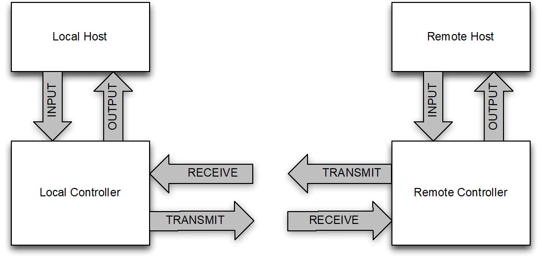
The following parameters are used to describe the transmit and receive paths over the air:
The Transmit_Bandwidth and Receive_Bandwidth parameters specify how much bandwidth shall be available for transmitting and for receiving data. The Host shall set the Transmit_Bandwidth and Receive_Bandwidth parameters to be equal or shall set one of them to be zero and the other non-zero.
The Transmit_Coding_Format and Receive_Coding_Format parameters specify the coding format used for transmitted or received data. The Host shall set the Transmit_Coding_Format and Receive_Coding_Formats to be equal. When the Transmit_Coding_Format and Receive_Coding_Format parameters are not equal to CVSD, A-law or µ-law, the Link Manager shall map these to Transparent air mode.
The Transmit_Codec_Frame_Size and Receive_Codec_Frame_Size parameters specify the frame size produced by the codecs in the context of over-the-air coding. The over-the-air packet size should have the following relationship with the codec frame size:
where N is an integer.
The following parameters are used to describe the coding format used prior to encapsulating over the audio data transport path:
The Input_Bandwidth and Output_Bandwidth specify the nominal rate at which the Host or Controller transfers data (for HCI transports this excludes the HCI header). The Host shall either set the Input_Bandwidth and Output_Bandwidth to be equal, or shall set one of them to be zero and the other non-zero.
The Input_Coding_Format and Output_Coding_Format parameters specify the coding format used over the transport. The Host shall set the Input_Coding_Format and Output_Coding_Format to be equal.
The Input_Coded_Data_Size and Output_Coded_Data_Size specify the number of bits in each sample or frame of data. For CVSD, a frame of data shall be 8 bits.
The Input_PCM_Data_Format and Output_PCM_Data_Format parameters specify the data format over the transport for linear samples. They shall be ignored when the data is encoded in any other way.
The Input_PCM_Sample_Payload_MSB_Position and Output_PCM_Sample_Payload_MSB_Position parameters indicate, for linear samples, how many bit positions that the MSB of the sample is away from starting at the MSB of the data. They shall be ignored when the data is encoded in any other way. For example, if Input_Coded_Data_Size =16 and Input_PCM_Sample_Payload_MSB_Position = 3, then each sample is actually only 13 bits, the MSB (which is the sign bit for signed formats) is bit 12 (counting from the LSB at bit 0), and the contents of bits 13, 14, and 15 of each sample shall be ignored.
The following parameters describe the audio data transport path characteristics:
The Input_Data_Path and Output_Data_Path parameters specify the audio data transport path. When set to 0x00, the audio data path shall be over the HCI transport. When set to 0xFF, audio test mode (see Section 7.6.2) is selected (this is only applicable during test mode). When set to 0x01 to 0xFE, the audio data path shall use non-HCI transport data paths (e.g. PCM interface) with logical transport channel numbers. The meanings of these logical transport channel numbers are vendor specific.
The Input_Transport_Unit_Size and Output_Transport_Unit_Size indicate how many bits are in each unit of data delivered by the audio data transport. Except for HCI, the meaning of “unit” depends on the Host transport used and, therefore, is vendor specific (for example, on a PCM transport this should indicate the number of bits transported per sync pulse, and would normally be 8 or 16). The Host shall set the Input_Transport_Unit_Size and Output_Transport_Unit_Size to be equal. For HCI Host transport the Host shall set them to 0.
The following parameters are used by the Link Manager to negotiate the synchronous transport:
The Max_Latency parameter specifies an upper limit to the time in milliseconds between the eSCO (or SCO) instants, plus the size of the retransmission window, plus the length of the reserved synchronous slots for this logical transport.
The Packet_Type parameter is a bitmap specifying which synchronous packet types may be used by the Link Manager in the negotiation of the link parameters. Multiple packet types are specified by bitwise OR of the packet type codes in the table. At least one packet type shall be specified for each negotiation. It is recommended to enable as many packet types as possible. The Host may enable packet types that are not supported by the local Controller.
The Retransmission_Effort parameter specifies the extra resources that are allocated to this connection if a packet may need to be retransmitted. The Retransmission_Effort parameter shall be set to indicate the required behavior, or to “Don’t care”.
The following restrictions shall apply:
Either both the Transmit_Coding_Format and Input_Coding_Format shall be “transparent” or neither shall be. If both are “transparent”, the Transmit_Bandwidth and the Input_Bandwidth shall be the same and the Controller shall not modify the data sent to the remote device.
Either both the Receive_Coding_Format and Output_Coding_Format shall be “transparent” or neither shall be. If both are “transparent”, the Receive_Bandwidth and the Output_Bandwidth shall be the same and the Controller shall not modify the data sent to the Host.
A Connection_Handle for the new synchronous connection will be returned in the HCI_Synchronous_Connection_Complete event if the command is used to set up a new synchronous connection.
When used to modify an existing synchronous logical transport, only the Packet_Type, Retransmission_Effort and Max_Latency parameters may be modified.
Note
Note: The Link Manager may choose any combination of packet types, timing, and retransmission window sizes that satisfy the parameters given. This may be achieved by using more frequent transmissions of smaller packets. The link manager may choose to set up either a SCO or an eSCO connection, if the parameters allow, using the corresponding LMP sequences.
Note
Note: To modify a SCO connection, use the HCI_Change_Connection_Packet_Type command.
If the lower layers cannot achieve the exact transmit and receive bandwidth requested subject to the other parameters, or cannot achieve the transcoding or resampling implied by the parameters, then the link creation or link modification shall be rejected. A synchronous connection may only be created when an ACL connection already exists.
The data at the audio data transport interface shall be treated as a stream of bits. The bits in each unit of data delivered by the transport shall be taken LSB first, and the units shall be taken in the order of delivery. The samples, encoded samples, frames, or other entity to be transcoded for transmission, or that has been transcoded after reception, shall be taken in the order of transmission or reception, with each entity taken LSB first.
For example, if the audio data transport uses 16 bit units and the Input or Output coding format is A-law, each unit represents two samples with the first in the 8 least significant bits and the second in the 8 most significant bits. Similarly, if the audio data transport uses 8 bit units and the Input or Output coding format is linear PCM with a size of 16 bits, the 8 least significant bits of each sample are transmitted first.
Command parameters:
Connection_Handle: | Size: 2 octets (12 bits meaningful) |
Value | Parameter Description |
|---|---|
0xXXXX | Connection_Handle Range: 0x0000 to 0x0EFF |
Transmit_Bandwidth: | Size: 4 octets |
Value | Parameter Description |
|---|---|
0x00000000 to 0xFFFFFFFE | Transmit bandwidth in octets per second. |
0xFFFFFFFF | Don’t care |
Receive_Bandwidth: | Size: 4 octets |
Value | Parameter Description |
|---|---|
0x00000000 to 0xFFFFFFFE | Receive bandwidth in octets per second. |
0xFFFFFFFF | Don’t care |
Transmit_Coding_Format: | Size: 5 octets |
Value | Parameter Description |
|---|---|
Octet 0 | See Assigned Numbers for Coding_Format |
Octets 1 to 4 | Octet 1 to 2: Company ID, see Assigned Numbers for Company Identifier Octet 3 to 4: Vendor specific codec ID. Shall be ignored if octet 0 of Transmit_Coding_Format is not 0xFF. |
Receive_Coding_Format: | Size: 5 octets |
Value | Parameter Description |
|---|---|
Octet 0 | See Assigned Numbers for Coding_Format |
Octets 1 to 4 | Octet 1 to 2: Company ID, see Assigned Numbers for Company Identifier. Octet 3 to 4: Vendor specific codec ID. Shall be ignored if octet 0 of Receive_Coding_Format is not 0xFF. |
Transmit_Codec_Frame_Size: | Size: 2 octets |
Value | Parameter Description |
|---|---|
0xXXXX | Range: 0x0001 to 0xFFFF, the actual size of the over-the-air encoded frame in octets. |
Receive_Codec_Frame_Size: | Size: 2 octets |
Value | Parameter Description |
|---|---|
0xXXXX | Range: 0x0001 to 0xFFFF, the actual size of the over-the-air encoded frame in octets. |
Input_Bandwidth: | Size: 4 octets |
Value | Parameter Description |
|---|---|
0xXXXXXXXX | Host to Controller nominal data rate in octets per second. |
Output_Bandwidth: | Size: 4 octets |
Value | Parameter Description |
|---|---|
0xXXXXXXXX | Controller to Host nominal data rate in octets per second. |
Input_Coding_Format: | Size: 5 octets |
Value | Parameter Description |
|---|---|
Octet 0 | See Assigned Numbers for Coding_Format |
Octets 1 to 4 | Octet 1 to 2: Company ID, see Assigned Numbers for Company Identifier. Octet 3 to 4: Vendor specific codec ID. Shall be ignored if octet 0 of Input_Coding_Format is not 0xFF. |
Output_Coding_Format: | Size: 5 octets |
Value | Parameter Description |
|---|---|
Octet 0 | See Assigned Numbers for Coding_Format |
Octets 1 to 4 | Octet 1 to 2: Company ID, see Assigned Numbers for Company Identifier. Octet 3 to 4: Vendor specific codec ID. Shall be ignored if octet 0 of Output_Coding_Format is not 0xFF. |
Input_Coded_Data_Size: | Size: 2 octets |
Value | Parameter Description |
|---|---|
0xXXXX | Size, in bits, of the sample or framed data |
Output_Coded_Data_Size: | Size: 2 octets |
Value | Parameter Description |
|---|---|
0xXXXX | Size, in bits, of the sample or framed data |
Input_PCM_Data_Format: | Size: 1 octet |
Value | Parameter Description |
|---|---|
0xXX | See Assigned Numbers for PCM_Data_Format |
Output_PCM_Data_Format: | Size: 1 octet |
Value | Parameter Description |
|---|---|
0xXX | See Assigned Numbers for PCM_Data_Format |
Input_PCM_Sample_Payload_MSB_Position: | Size: 1 octet |
Value | Parameter Description |
|---|---|
0xXX | The number of bit positions within an audio sample that the MSB of the sample is away from starting at the MSB of the data. |
Output_PCM_Sample_Payload_MSB_Position: | Size: 1 octet |
Value | Parameter Description |
|---|---|
0xXX | The number of bit positions within an audio sample that the MSB of the sample is away from starting at the MSB of the data. |
Input_Data_Path: | Size: 1 octet |
Value | Parameter Description |
|---|---|
0x00 | HCI |
0x01 to 0xFE | Logical_Channel_Number. The meaning of the logical channels will be vendor specific. |
0xFF | Audio test mode |
Output_Data_Path: | Size: 1 octet |
Value | Parameter Description |
|---|---|
0x00 | HCI |
0x01 to 0xFE | Logical_Channel_Number. The meaning of the logical channels will be vendor specific. |
0xFF | Audio test mode |
Input_Transport_Unit_Size: | Size: 1 octet |
Value | Parameter Description |
|---|---|
1 to 255 | The number of bits in each unit of data received from the Host over the audio data transport. |
0 | Not applicable (implied by the choice of audio data transport) |
Output_Transport_Unit_Size: | Size: 1 octet |
Value | Parameter Description |
|---|---|
1 to 255 | The number of bits in each unit of data sent to the Host over the audio data transport. |
0 | Not applicable (implied by the choice of audio data transport) |
Max_Latency: | Size: 2 octets |
Value | Parameter Description |
|---|---|
0x0000 to 0x0003 | Reserved for future use |
0x0004 to 0xFFFE | The value in milliseconds representing the upper limit of the sum of the synchronous interval, and the size of the eSCO window, where the eSCO window is the reserved slots plus the retransmission window. (See [Vol 2] Part B, Figure 8.9) |
0xFFFF | Don’t care. |
Packet_Type: | Size: 2 octets |
Bit Number | Parameter Description |
|---|---|
0 | HV1 may be used |
1 | HV2 may be used |
2 | HV3 may be used |
3 | EV3 may be used |
4 | EV4 may be used |
5 | EV5 may be used |
6 | 2-EV3 shall not be used |
7 | 3-EV3 shall not be used |
8 | 2-EV5 shall not be used |
9 | 3-EV5 shall not be used |
All other bits | Reserved for future use |
Note: 0x003F means all packet types may be used.
Retransmission_Effort: | Size: 1 octet |
Value | Parameter Description |
|---|---|
0x00 | No retransmission (SCO or eSCO connection allowed) |
0x01 | At least one retransmission, optimize for power consumption (eSCO connection required) |
0x02 | At least one retransmission, optimize for link quality (eSCO connection required) |
0xFF | Don’t care (SCO or eSCO connection allowed) |
All other values | Reserved for future use |
Return parameters:
None.
Event(s) generated (unless masked away):
When the BR/EDR Controller receives the HCI_Enhanced_Setup_Synchronous_Connection command, it shall send the HCI_Command_Status event to the Host. In addition, when the LM determines that the connection is established, the local BR/EDR Controller shall send an HCI_Synchronous_Connection_Complete event to the local Host, and the remote Controller will send an HCI_Synchronous_Connection_Complete event or an HCI_Connection_Complete event to the remote Host. The HCI_Synchronous_Connection_Complete event contains the Connection_Handle if this command is successful.
This command cannot be used to change the parameters of a SCO link.
7.1.46. Enhanced Accept Synchronous Connection Request command
Command | OCF | Command Parameters | Return Parameters |
|---|---|---|---|
HCI_Enhanced_Accept_Synchronous_Connection_Request | 0x003E | BD_ADDR, Transmit_Bandwidth, Receive_Bandwidth, Transmit_Coding_Format, Receive_Coding_Format, Transmit_Codec_Frame_Size, Receive_Codec_Frame_Size, Input_Bandwidth, Output_Bandwidth, Input_Coding_Format, Output_Coding_Format, Input_Coded_Data_Size, Output_Coded_Data_Size, Input_PCM_Data_Format, Output_PCM_Data_Format, Input_PCM_Sample_Payload_MSB_Position, Output_PCM_Sample_Payload_MSB_Position, Input_Data_Path, Output_Data_Path, Input_Transport_Unit_Size, Output_Transport_Unit_Size, Max_Latency, Packet_Type, Retransmission_Effort | none |
Description:
The HCI_Enhanced_Accept_Synchronous_Connection_Request command is used to accept an incoming request for a synchronous connection and to present the local Link Manager with the acceptable parameter values for the synchronous connection. This command shall only be issued after an HCI_Connection_Request event, with link type SCO or eSCO, has occurred. An HCI_Connection_Request event contains the BD_ADDR of the device requesting the connection. The command to accept a connection must be received by the Controller before the timer Connection_Accept_Timeout expires on the local device.
The parameter set of the HCI_Enhanced_Accept_Synchronous_Connection_Request command is the same as for the HCI_Enhanced_Setup_Synchronous_Connection command except for the Connection_Handle in the HCI_Enhanced_Setup_Synchronous_Connection command, which is replaced by the BD_ADDR in the HCI_Enhanced_Accept_Synchronous_Connection_Request command. See Section 7.1.45 for the descriptions of these parameters.
The Host shall include in the Packet_Type parameter at least one packet type for the transport (SCO or eSCO) specified in the incoming request. The Controller shall ignore any packet types in the Packet_Type parameter for the other transport.
If the Link Type of the incoming request is SCO, then the Retransmission_Effort parameter shall be ignored.
Note
Note: See Section 7.3.3 for the behavior when the HCI_Connection_Request event is masked or the connection is auto accepted.
If the ACL link has encryption enabled using AES-CCM then the Host shall not accept a request where the link type is SCO.
Command parameters:
BD_ADDR: | Size: 6 octets |
Value | Parameter Description |
|---|---|
0xXXXXXXXXXXXX | BD_ADDR of the device requesting the connection |
Transmit_Bandwidth: | Size: 4 octets |
Value | Parameter Description |
|---|---|
0x00000000 to 0xFFFFFFFE | Transmit bandwidth in octets per second. |
0xFFFFFFFF | Don’t care |
Receive_Bandwidth: | Size: 4 octets |
Value | Parameter Description |
|---|---|
0x00000000 to 0xFFFFFFFE | Receive bandwidth in octets per second. |
0xFFFFFFFF | Don’t care |
Transmit_Coding_Format: | Size: 5 octets |
Value | Parameter Description |
|---|---|
Octet 0 | See Assigned Numbers for Coding_Format |
Octets 1 to 4 | Octet 1 to 2: Company ID, see Assigned Numbers for Company Identifier. Octet 3 to 4: Vendor specific codec ID. Shall be ignored if octet 0 of Transmit_Coding_Format is not 0xFF. |
Receive_Coding_Format: | Size: 5 octets |
Value | Parameter Description |
|---|---|
Octet 0 | See Assigned Numbers for Coding_Format |
Octets 1 to 4 | Octet 1 to 2: Company ID, see Assigned Numbers for Company Identifier. Octet 3 to 4: Vendor specific codec ID. Shall be ignored if octet 0 of Receive_Coding_Format is not 0xFF. |
Transmit_Codec_Frame_Size: | Size: 2 octets |
Value | Parameter Description |
|---|---|
0xXXXX | Range: 0x0001 to 0xFFFF, the actual size of the over-the-air encoded frame in octets. |
Receive_Codec_Frame_Size: | Size: 2 octets |
Value | Parameter Description |
|---|---|
0xXXXX | Range: 0x0001 to 0xFFFF, the actual size of the over-the-air encoded frame in octets. |
Input_Bandwidth: | Size: 4 octets |
Value | Parameter Description |
|---|---|
0xXXXXXXXX | Host to Controller nominal data rate in octets per second. |
Output_Bandwidth: | Size: 4 octets |
Value | Parameter Description |
|---|---|
0xXXXXXXXX | Controller to Host nominal data rate in octets per second. |
Input_Coding_Format: | Size: 5 octets |
Value | Parameter Description |
|---|---|
Octet 0 | See Assigned Numbers for Coding_Format |
Octets 1 to 4 | Octet 1 to 2: Company ID, see Assigned Numbers for Company Identifier. Octet 3 to 4: Vendor specific codec ID. Shall be ignored if octet 0 of Input_Coding_Format is not 0xFF. |
Output_Coding_Format: | Size: 5 octets |
Value | Parameter Description |
|---|---|
Octet 0 | See Assigned Numbers for Coding_Format |
Octets 1 to 4 | Octet 1 to 2: Company ID, see Assigned Numbers for Company Identifier. Octet 3 to 4: Vendor specific codec ID. Shall be ignored if octet 0 of Output_Coding_Format is not 0xFF. |
Input_Coded_Data_Size: | Size: 2 octets |
Value | Parameter Description |
|---|---|
0xXXXX | Size, in bits, of the sample or framed data |
Output_Coded_Data_Size: | Size: 2 octets |
Value | Parameter Description |
|---|---|
0xXXXX | Size, in bits, of the sample or framed data |
Input_PCM_Data_Format: | Size: 1 octet |
Value | Parameter Description |
|---|---|
0xXX | See Assigned Numbers for PCM_Data_Format |
Output_PCM_Data_Format: | Size: 1 octet |
Value | Parameter Description |
|---|---|
0xXX | See Assigned Numbers for PCM_Data_Format |
Input_PCM_Sample_Payload_MSB_Position: | Size: 1 octet |
Value | Parameter Description |
|---|---|
0xXX | The number of bit positions within an audio sample that the MSB of the sample is away from starting at the MSB of the data. |
Output_PCM_Sample_Payload_MSB_Position: | Size: 1 octet |
Value | Parameter Description |
|---|---|
0xXX | The number of bit positions within an audio sample that the MSB of the sample is away from starting at the MSB of the data. |
Input_Data_Path: | Size: 1 octet |
Value | Parameter Description |
|---|---|
0x00 | HCI |
0x01 to 0xFE | Logical_Channel_Number. The meaning of the logical channels will be vendor specific. |
0xFF | Audio test mode |
Output_Data_Path: | Size: 1 octet |
Value | Parameter Description |
|---|---|
0x00 | HCI |
0x01 to 0xFE | Logical_Channel_Number. The meaning of the logical channels will be vendor specific. |
0xFF | Audio test mode |
Input_Transport_Unit_Size: | Size: 1 octet |
Value | Parameter Description |
|---|---|
1 to 255 | The number of bits in each unit of data received from the Host over the audio data transport. |
0 | Not applicable (implied by the choice of audio data transport) |
Output_Transport_Unit_Size: | Size: 1 octet |
Value | Parameter Description |
|---|---|
1 to 255 | The number of bits in each unit of data sent to the Host over the audio data transport. |
0 | Not applicable (implied by the choice of audio data transport) |
Max_Latency: | Size: 2 octets |
Value | Parameter Description |
|---|---|
0x0000 to 0x0003 | Reserved for future use |
0x0004 to 0xFFFE | The value in milliseconds representing the upper limit of the sum of the synchronous interval, and the size of the eSCO window, where the eSCO window is the reserved slots plus the retransmission window. (See [Vol 2] Part B, Figure 8.9) |
0xFFFF | Don’t care. |
Packet_Type: | Size: 2 octets |
Bit Number | Parameter Description |
|---|---|
0 | HV1 may be used |
1 | HV2 may be used |
2 | HV3 may be used |
3 | EV3 may be used |
4 | EV4 may be used |
5 | EV5 may be used |
6 | 2-EV3 shall not be used |
7 | 3-EV3 shall not be used |
8 | 2-EV5 shall not be used |
9 | 3-EV5 shall not be used |
All other bits | Reserved for future use |
Note
Note: 0x003F means all packet types may be used.
Retransmission_Effort: | Size: 1 octet |
Value | Parameter Description |
|---|---|
0x00 | No retransmission |
0x01 | At least one retransmission, optimize for power consumption |
0x02 | At least one retransmission, optimize for link quality |
0xFF | Don’t care |
All other values | Reserved for future use |
Return parameters:
None.
Event(s) generated (unless masked away):
The HCI_Enhanced_Accept_Synchronous_Request command requests the local BR/EDR Controller to start setting up the connection. When this action commences, the HCI_Command_Status event shall be sent by the BR/EDR Controller. When the link setup is complete, the BR/EDR Controller shall send an HCI_Synchronous_Connection_Complete event to its Host, and the remote BR/EDR Controller will send an HCI_Synchronous_Connection_Complete event to its Host. The HCI_Synchronous_Connection_Complete will contain the Connection_Handle and the link parameters if the setup is successful.
7.1.47. Truncated Page command
Command | OCF | Command Parameters | Return Parameters |
|---|---|---|---|
HCI_Truncated_Page | 0x003F | BD_ADDR, Page_Scan_Repetition_Mode, Clock_Offset | none |
Description:
The HCI_Truncated_Page command is used to page the BR/EDR Controller with the specified BD_ADDR and then abort the paging sequence after an ID response has been received. See [Vol 2] Part B, Section 8.3.3 for additional information.
The Page_Scan_Repetition_Mode parameter specifies the Page Scan Repetition mode supported by the remote BR/EDR Controller with the BD_ADDR. This is the most recent version of the information that was acquired either during the inquiry process or from an HCI_Page_Scan_Repetition_Mode_Change event (see Section 7.7.31).
The Clock_Offset parameter is the difference between the local BR/EDR Controller’s own clock and the clock of the remote BR/EDR Controller with BD_ADDR. Only bits 2 to 16 of the difference are used, and they are mapped to this parameter as bits 0 to 14 respectively. A Clock_Offset_Valid_Flag, located in bit 15 of the Clock_Offset parameter, indicates if the Clock Offset is valid or not.
Command parameters:
BD_ADDR: | Size: 6 octets |
Value | Parameter Description |
|---|---|
0xXXXXXXXXXXXX | BD_ADDR of the Device to page |
Page_Scan_Repetition_Mode: | Size: 1 octet |
Value | Parameter Description |
|---|---|
0x00 | R0 |
0x01 | R1 |
0x02 | R2 |
All other values | Reserved for future use. |
Clock_Offset: | Size: 2 octets |
Bit Number | Parameter Description |
|---|---|
0 to 14 | Bits 2 to 16 of CLKNPeripheral - CLK |
15 | Clock Offset is valid |
Return parameters:
None.
Event(s) generated (unless masked away):
When the BR/EDR Controller receives the HCI_Truncated_Page command the BR/EDR Controller shall send the HCI_Command_Status event to the Host. In addition, when the Truncated Page procedure has completed, the BR/EDR Controller shall send an HCI_Truncated_Page_Complete event to the Host.
7.1.48. Truncated Page Cancel command
Command | OCF | Command Parameters | Return Parameters |
|---|---|---|---|
HCI_Truncated_Page_Cancel | 0x0040 | BD_ADDR | Status, BD_ADDR |
Description:
The HCI_Truncated_Page_Cancel command is used to request cancellation of an ongoing Truncated_Page process previously started by an HCI_Truncated_Page command.
Command parameters:
BD_ADDR: | Size: 6 octets |
Value | Parameter Description |
|---|---|
0xXXXXXXXXXXXX | BD_ADDR of the device to which the HCI_Truncated_Page command was previously issued and that is the subject of the cancellation request. |
Return parameters:
Status: | Size: 1 octet |
Value | Parameter Description |
|---|---|
0x00 | HCI_Truncated_Page_Cancel command succeeded. |
0x01 to 0xFF | HCI_Truncated_Page_Cancel command failed. See [Vol 1] Part F, Controller Error Codes, for error codes and descriptions |
BD_ADDR: | Size: 6 octets |
Value | Parameter Description |
|---|---|
0xXXXXXXXXXXXX | BD_ADDR of the device to which the HCI_Truncated_Page command was previously issued before and that is the subject of the cancellation request. |
Event(s) generated (unless masked away):
When the HCI_Truncated_Page_Cancel command has completed, an HCI_Command_Complete event shall be generated.
If the truncated page procedure has already completed, but the BR/EDR Controller has not yet sent the HCI_Truncated_Page_Complete event, then the local device shall return an HCI_Command_Complete event with status “Success”.
If the HCI_Truncated_Page_Cancel command is sent to the BR/EDR Controller without a pending HCI_Truncated_Page command to the same device, the BR/EDR Controller shall return an HCI_Command_Complete event with the error code Unknown Connection Identifier (0x02).
Note
Note: From the BR/EDR Controller perspective this is identical to the situation where the HCI_Truncated_Page command has already completed and the HCI_Truncated_Page_Complete event already sent.
7.1.49. Set Connectionless Peripheral Broadcast command
Command | OCF | Command Parameters | Return Parameters |
|---|---|---|---|
HCI_Set_Connectionless_Peripheral_Broadcast | 0x0041 | Enable, LT_ADDR, LPO_Allowed, Packet_Type, Interval_Min, Interval_Max, Supervision_Timeout | Status, LT_ADDR, Interval |
Description:
The HCI_Set_Connectionless_Peripheral_Broadcast command controls the Connectionless Peripheral Broadcast functionality in the BR/EDR Controller. Connectionless Peripheral Broadcast mode may be enabled or disabled by the Enable parameter. If Enable is set to 0x00 and the Synchronization Train substate is active, then the Controller shall also exit the Synchronization Train substate. If Enable is set to 0x00, the remaining parameters shall be ignored.
The LT_ADDR indicated in the Set_Connectionless_Peripheral_Broadcast shall be pre-allocated using the HCI_Set_Reserved_LT_ADDR command. If the LT_ADDR has not been reserved, the Unknown Connection Identifier (0x02) error code shall be returned. If the Controller is unable to reserve sufficient bandwidth for the requested activity, the Connection Rejected Due to Limited Resources (0x0D) error code shall be returned.
The LPO_Allowed parameter informs the BR/EDR Controller whether it is allowed to sleep.
The Packet_Type parameter specifies which packet types are allowed. The Host shall either enable BR packet types only, or shall enable EDR and DM1 packet types only.
The Interval_Min and Interval_Max parameters specify the range from which the BR/EDR Controller shall select the Connectionless Peripheral Broadcast Interval. The selected Interval is returned.
Command parameters:
Enable: | Size: 1 octet |
Value | Parameter Description |
|---|---|
0x00 | Disabled |
0x01 | Enabled |
All other values | Reserved for future use |
LT_ADDR: | Size: 1 octet |
Value | Parameter Description |
|---|---|
0x01 to 0x07 | LT_ADDR used for Connectionless Peripheral Broadcast |
All other values | Reserved for future use |
LPO_Allowed: | Size: 1 octet |
Value | Parameter Description |
|---|---|
0x00 | BR/EDR Controller shall not sleep (that is, clock accuracy shall be equal to or better than ± 20 ppm) |
0x01 | BR/EDR Controller may sleep (that is, clock accuracy shall be equal to or better than ± 250 ppm) |
All other values | Reserved for future use |
Packet_Type: | Size: 2 octets |
Bit Number | Parameter Description |
|---|---|
1 | 2-DH1 shall not be used |
2 | 3-DH1 shall not be used |
3 | DM1 may be used |
4 | DH1 may be used |
8 | 2-DH3 shall not be used |
9 | 3-DH3 shall not be used |
10 | DM3 may be used |
11 | DH3 may be used |
12 | 2-DH5 shall not be used |
13 | 3-DH5 shall not be used |
14 | DM5 may be used |
15 | DH5 may be used |
All other bits | Reserved for future use. |
Interval_Min: | Size: 2 octets |
Value | Parameter Description |
|---|---|
0xXXXX | Minimum interval between Connectionless Peripheral Broadcast packets in slots. Range: 0x0002 to 0xFFFE; only even values are valid |
Interval_Max: | Size: 2 octets |
Value | Parameter Description |
|---|---|
0xXXXX | Maximum interval between Connectionless Peripheral Broadcast packets in slots. Range: 0x0002 to 0xFFFE; only even values are valid |
Supervision_Timeout: | Size: 2 octets |
Value | Parameter Description |
|---|---|
0xXXXX | Duration in slots after which the BR/EDR Controller reports an HCI_Connectionless_Peripheral_Broadcast_Timeout event if it is unable to transmit a Connectionless Peripheral Broadcast packet. Range: 0x0002 to 0xFFFE; only even values are valid |
Return parameters:
Status: | Size: 1 octet |
Value | Parameter Description |
|---|---|
0x00 | HCI_Set_Connectionless_Peripheral_Broadcast command succeeded. |
0x01 to 0xFF | HCI_Set_Connectionless_Peripheral_Broadcast command failed. See [Vol 1] Part F, Controller Error Codes, for error codes and descriptions. |
LT_ADDR: | Size: 1 octet |
Value | Parameter Description |
|---|---|
0x01 to 0x07 | LT_ADDR used for Connectionless Peripheral Broadcast |
All other values | Reserved for future use |
Interval: | Size: 2 octets |
Value | Parameter Description |
|---|---|
0xXXXX | Actual interval between Connectionless Peripheral Broadcast packets in slots. Range: 0x0002 to 0xFFFE; only even values are valid |
Event(s) generated (unless masked away):
When the HCI_Set_Connectionless_Peripheral_Broadcast command has completed, an HCI_Command_Complete event shall be generated.
If the BR/EDR Controller is unable to transmit a Connectionless Peripheral Broadcast packet for Supervision_Timeout slots, it shall generate an HCI_Connectionless_Peripheral_Broadcast_Timeout event.
7.1.50. Set Connectionless Peripheral Broadcast Receive command
Command | OCF | Command Parameters | Return Parameters |
|---|---|---|---|
HCI_Set_Connectionless_Peripheral_Broadcast_Receive | 0x0042 | Enable, BD_ADDR, LT_ADDR, Interval, Clock_Offset, Next_Connectionless_Peripheral_Broadcast_Clock, Supervision_Timeout, Remote_Timing_Accuracy, Skip, Packet_Type, AFH_Channel_Map | Status, BD_ADDR, LT_ADDR |
Description:
The HCI_Set_Connectionless_Peripheral_Broadcast_Receive command controls the reception of Connectionless Peripheral Broadcast packets in the BR/EDR Controller of a Connectionless Peripheral Broadcast Receiver. If the Enable parameter is set to Disabled, the BR/EDR Controller does not attempt to receive Connectionless Peripheral Broadcast packets and the remaining parameters shall be ignored. If the Enable parameter is set to Enabled, the BR/EDR Controller starts attempting to receive Connectionless Peripheral Broadcast packets on the specified LT_ADDR.
The Interval parameter specifies the interval of the Connectionless Peripheral Broadcast to be used by the BR/EDR Controller.
The Skip parameter specifies the number of consecutive Connectionless Peripheral Broadcast instants which the receiver may skip after successfully receiving a Connectionless Peripheral Broadcast packet.
The Packet_Type parameter specifies which packet types are allowed. The Host shall either enable BR packet types only or shall enable EDR and DM1 packet types only.
The AFH_Channel_Map parameter is the AFH channel map used by the Transmitter for the PBD logical link, and is obtained by the Receiver’s Host from the HCI_Synchronization_Train_Received event.
Command parameters:
Enable: | Size: 1 octet |
Value | Parameter Description |
|---|---|
0x00 | Disabled |
0x01 | Enabled |
All other values | Reserved for future use |
BD_ADDR: | Size: 6 octets |
Value | Parameter Description |
|---|---|
0xXXXXXXXXXXXX | BD_ADDR of the Connectionless Peripheral Broadcast transmitter |
LT_ADDR: | Size: 1 octet |
Value | Parameter Description |
|---|---|
0x01 to 0x07 | LT_ADDR to use for receiving Connectionless Peripheral Broadcast messages |
All other values | Reserved for future use |
Interval: | Size: 2 octets |
Value | Parameter Description |
|---|---|
0xXXXX | Interval between Connectionless Peripheral Broadcast packets instants in slots. Range: 0x0002 to 0xFFFE; only even values are valid |
Clock_Offset: | Size: 4 octets (28 bits meaningful) |
Value | Parameter Description |
|---|---|
0xXXXXXXXX | (CLKNreceiver - CLKNtransmitter) mod 228 |
Next_Connectionless_Peripheral_Broadcast_Clock: | Size: 4 octets (28 bits meaningful) |
Value | Parameter Description |
|---|---|
0xXXXXXXXX | CLK for next Connectionless Peripheral Broadcast instant |
Supervision_Timeout: | Size: 2 octets |
Value | Parameter Description |
|---|---|
0xXXXX | Duration in slots to continue listening for Connectionless Peripheral Broadcast packets after the last successfully received Connectionless Peripheral Broadcast packet. Range: 0x0002 to 0xFFFE; only even values are valid |
Remote_Timing_Accuracy: | Size: 1 octet |
Value | Parameter Description |
|---|---|
0xXX | Timing accuracy of the Transmitter in ppm. Typical values are 20 ppm and 250 ppm. |
Skip: | Size: 1 octet |
Value | Parameter Description |
|---|---|
0xXX | Number of Connectionless Peripheral Broadcast instants to skip after successfully receiving a Broadcast packet. |
Packet_Type: | Size: 2 octets |
Bit Number | Parameter Description |
|---|---|
1 | 2-DH1 shall not be used |
2 | 3-DH1 shall not be used |
3 | DM1 may be used |
4 | DH1 may be used |
8 | 2-DH3 shall not be used |
9 | 3-DH3 shall not be used |
10 | DM3 may be used |
11 | DH3 may be used |
12 | 2-DH5 shall not be used |
13 | 3-DH5 shall not be used |
14 | DM5 may be used |
15 | DH5 may be used |
All other bits | Reserved for future use. |
AFH_Channel_Map: | Size: 10 octets (79 bits meaningful) |
Value | Parameter Description |
|---|---|
0xXXXXXXXX XXXXXXXXXX XX | This parameter contains 80 1-bit fields. The nth such field (in the range 0 to 78) contains the value for channel n: 0: channel n is unused 1: channel n is used The most significant bit (bit 79) is reserved for future use At least Nmin channels shall be marked as used (see [Vol 2] Part B, Section 2.3.1) |
Return parameters:
Status: | Size: 1 octet |
Value | Parameter Description |
|---|---|
0x00 | HCI_Set_Connectionless_Peripheral_Broadcast_Receive command succeeded. |
0x01 to 0xFF | HCI_Set_Connectionless_Peripheral_Broadcast_Receive command failed. See [Vol 1] Part F, Controller Error Codes, for error codes and descriptions. |
BD_ADDR: | Size: 6 octets |
Value | Parameter Description |
|---|---|
0xXXXXXXXXXXXX | BD_ADDR of the Connectionless Peripheral Broadcast transmitter |
LT_ADDR: | Size: 1 octet |
Value | Parameter Description |
|---|---|
0x01 to 0x07 | LT_ADDR used for receiving Connectionless Peripheral Broadcast messages |
All other values | Reserved for future use |
Event(s) generated (unless masked away):
When the HCI_Set_Connectionless_Peripheral_Broadcast_Receive command has been received, an HCI_Command_Complete event shall be generated. Completion of the HCI_Set_Connectionless_Peripheral_Broadcast_Receive command does not require reception of a Connectionless Peripheral Broadcast packet. If the BR/EDR Controller does not receive a Connectionless Peripheral Broadcast packet for CPB_supervisionTO slots, it shall generate an HCI_Connectionless_Peripheral_Broadcast_Timeout event.
7.1.51. Start Synchronization Train command
Command | OCF | Command Parameters | Return Parameters |
|---|---|---|---|
HCI_Start_Synchronization_Train | 0x0043 | none | none |
Description:
The HCI_Start_Synchronization_Train command controls the Synchronization Train functionality in the BR/EDR Controller. Connectionless Peripheral Broadcast mode shall be enabled on the BR/EDR Controller before this command may be used. If Connectionless Peripheral Broadcast mode is not enabled, the Command Disallowed (0x0C) error code shall be returned. After receiving this command and returning an HCI_Command_Status event, the Baseband starts attempting to send synchronization train packets containing information related to the enabled Connectionless Peripheral Broadcast packet timing.
Note
Note: The AFH_Channel_Map used in the synchronization train packets is configured by the HCI_Set_AFH_Host_Channel_Classification command and the local channel classification in the BR/EDR Controller.
The synchronization train packets will be sent using the parameters specified by the latest HCI_Write_Synchronization_Train_Parameters command. The Synchronization Train will continue until synchronization_trainTO slots (as specified in the last HCI_Write_Synchronization_Train_Parameters command) have passed or until the Host disables the Connectionless Peripheral Broadcast logical transport.
Command parameters:
None.
Return parameters:
None
Event(s) generated (unless masked away):
When the BR/EDR Controller receives the HCI_Start_Synchronization_Train command, it shall send an HCI_Command_Status event to the Host.
7.1.52. Receive Synchronization Train command
Command | OCF | Command Parameters | Return Parameters |
|---|---|---|---|
HCI_Receive_Synchronization_Train | 0x0044 | BD_ADDR, Sync_Scan_Timeout, Sync_Scan_Window, Sync_Scan_Interval | none |
Description:
The HCI_Receive_Synchronization_Train command requests synchronization with the specified Connectionless Peripheral Broadcast Transmitter. The Sync_Scan_Window parameter specifies the duration of each scan and the Sync_Scan_Interval parameter specifies the interval between the start of consecutive scan windows. An HCI_Synchronization_Train_Received event shall be sent if a synchronization train packet is received with a non-zero Connectionless Peripheral Broadcast LT_ADDR or if the BR/EDR Controller fails to receive a synchronization train packet for synchronization_scanTO slots.
Command parameters:
BD_ADDR: | Size: 6 octets |
Value | Parameter Description |
|---|---|
0xXXXXXXXXXXXX | BD_ADDR of the Connectionless Peripheral Broadcast transmitter |
Sync_Scan_Timeout: | Size: 2 octets |
Value | Parameter Description |
|---|---|
0xXXXX | Duration in slots to search for the synchronization train Shall be greater than or equal to Sync_Scan_Window; only even values are valid |
Sync_Scan_Window: | Size: 2 octets |
Value | Parameter Description |
|---|---|
0xXXXX | Duration in slots to listen for a synchronization train packet on a single frequency Range: 0x0022 to 0xFFFC; only even values are valid |
Sync_Scan_Interval: | Size: 2 octets |
Value | Parameter Description |
|---|---|
0xXXXX | Duration in slots between the start of consecutive scan windows Shall be greater than or equal to Sync_Scan_Window+0x0002; only even values are valid |
Return parameters:
None.
Event(s) generated (unless masked away):
When the BR/EDR Controller receives the HCI_Receive_Synchronization_Train command, it shall send an HCI_Command_Status event to the Host. In addition, when the BR/EDR Controller receives, or fails to receive within the duration specified by Sync_Scan_Timeout, the synchronization train from the Connectionless Peripheral Broadcast transmitter, it shall send an HCI_Synchronization_Train_Received event to the Host.
7.1.53. Remote OOB Extended Data Request Reply command
Command | OCF | Command Parameters | Return Parameters |
|---|---|---|---|
HCI_Remote_OOB_Extended_Data_Request_Reply | 0x0045 | BD_ADDR, C_192, R_192, C_256, R_256 | Status, BD_ADDR |
Description:
The HCI_Remote_OOB_Extended_Data_Request_Reply command is used to reply to an HCI_Remote_OOB_Data_Request event with the C and R values derived with the P-192 public key and the C and R values associated with the P-256 public key received via an OOB transfer from a remote device identified by BD_ADDR. If the C_192 and R_192 values are not present in the received OOB data from the remote device, the Host shall set C_192 and R_192 to zeros. If the C_256 and R_256 values are not present in the received OOB data from the remote device, the Host shall set C_256 and R_256 to zeros.
Command parameters:
BD_ADDR: | Size: 6 octets |
Value | Parameter Description |
|---|---|
0xXXXXXXXXXXXX | BD_ADDR of remote device from which the C and R values were received |
C_192: | Size: 16 octets |
Value | Parameter Description |
|---|---|
0xXXXXXXXXXXX XXXXXXXXXXXX XXXXXXXXX | Secure Simple Pairing Hash C derived from the P-192 public key. |
R_192: | Size: 16 octets |
Value | Parameter Description |
|---|---|
0xXXXXXXXXXXX XXXXXXXXXXXX XXXXXXXXX | Secure Simple Pairing Randomizer associated with the P-192 public key. |
C_256: | Size: 16 octets |
Value | Parameter Description |
|---|---|
0xXXXXXXXXXXX XXXXXXXXXXXX XXXXXXXXX | Secure Simple Pairing Hash C derived from the P-256 public key. |
R_256: | Size: 16 octets |
Value | Parameter Description |
|---|---|
0xXXXXXXXXXXX XXXXXXXXXXXX XXXXXXXXX | Secure Simple Pairing Randomizer associated with the P-256 public key. |
Return parameters:
Status: | Size: 1 octet |
Value | Parameter Description |
|---|---|
0x00 | HCI_Remote_OOB_Extended_Data_Request_Reply command succeeded. |
0x01 to 0xFF | HCI_Remote_OOB_Extended_Data_Request_Reply command failed. See [Vol 1] Part F, Controller Error Codes for a list of error codes and descriptions. |
BD_ADDR: | Size: 6 octets |
Value | Parameter Description |
|---|---|
0xXXXXXXXXXXXX | BD_ADDR of remote device from which the C and R values were received |
Event(s) generated (unless masked away):
When the HCI_Remote_OOB_Extended_Data_Request_Reply command has completed, an HCI_Command_Complete event shall be generated.
7.2. Link Policy commands
The Link Policy commands provide methods for the Host to affect how the Link Manager manages the piconet. When Link Policy commands are used, the LM still controls how Bluetooth piconets and scatternets are established and maintained, depending on adjustable policy parameters. These policy commands modify the Link Manager behavior that can result in changes to the Link Layer connections with Bluetooth remote devices.
Note
Note: Only one ACL connection can exist between two BR/EDR Controllers, and therefore there can only be one ACL HCI Connection_Handle for each physical Link Layer Connection. The BR/EDR Controller provides policy adjustment mechanisms to provide support for a number of different policies. This capability allows one Bluetooth module to be used to support many different usage models, and the same Bluetooth module can be incorporated in many different types of BR/EDR Controllers.
For the Link Policy commands, the OGF is defined as 0x02.
7.2.1. Hold Mode command
Command | OCF | Command Parameters | Return Parameters |
|---|---|---|---|
HCI_Hold_Mode | 0x0001 | Connection_Handle, Hold_Mode_Max_Interval, Hold_Mode_Min_Interval | none |
Description:
The HCI_Hold_Mode command is used to alter the behavior of the Link Manager, and have it place the ACL Baseband connection associated by the specified Connection_Handle into the Hold mode. The Connection_Handle shall identify an ACL connection and not a SCO or eSCO connection. The Hold_Mode_Max_Interval and Hold_Mode_Min_Interval command parameters specify the length of time the Host wants to put the connection into the Hold mode. The local and remote devices will negotiate the length in the Hold mode. The Hold_Mode_Max_Interval parameter is used to specify the maximum length of the Hold interval for which the Host may actually enter into the Hold mode after negotiation with the remote device. The Hold interval defines the amount of time between when the Hold mode begins and when the Hold mode is completed. The Hold_Mode_Min_Interval parameter is used to specify the minimum length of the Hold interval for which the Host may actually enter into the Hold mode after the negotiation with the remote device. Therefore the Hold_Mode_Min_Interval shall not be greater than the Hold_Mode_Max_Interval. The BR/EDR Controller will return the actual Hold interval in the Interval parameter of the HCI_Mode_Change event, if the command is successful. This command enables the Host to support a low-power policy for itself or several other BR/EDR Controllers, and allows the devices to enter Inquiry Scan, Page Scan, and a number of other possible actions.
Note
Note: If the Host sends data to the BR/EDR Controller with a Connection_Handle corresponding to a connection in Hold mode, the BR/EDR Controller will keep the data in its buffers until either the data can be transmitted (the Hold mode has ended) or a flush, a flush timeout or a disconnection occurs. This is valid even if the Host has not yet been notified of the Hold mode through an HCI_Mode_Change event when it sends the data.
Note
Note: The above is not valid for an HCI ACL Data packet sent from the Host to the BR/EDR Controller on the Central side where the Connection_Handle is a Connection_Handle used for broadcast and the Broadcast_Flag is set to Active Broadcast. The broadcast data will then never be received by Peripherals in Hold mode.
The Hold_Mode_Max_Interval shall be less than the Link Supervision Timeout configuration parameter.
Command parameters:
Connection_Handle: | Size: 2 octets (12 bits meaningful) |
Value | Parameter Description |
|---|---|
0xXXXX | Connection_Handle Range: 0x0000 to 0x0EFF |
Hold_Mode_Max_Interval: | Size: 2 octets |
Value | Parameter Description |
|---|---|
N = 0xXXXX | Maximum acceptable number of Baseband slots to wait in Hold mode. Time Length of the Hold = N × 0.625 ms (1 Baseband slot) Range: 0x0002 to 0xFFFE; only even values are valid. Time Range: 1.25 ms to 40.9 s Mandatory Range: 0x0014 to 0x8000 |
Hold_Mode_Min_Interval: | Size: 2 octets |
Value | Parameter Description |
|---|---|
N = 0xXXXX | Minimum acceptable number of Baseband slots to wait in Hold mode. Time Length of the Hold = N × 0.625 ms (1 Baseband slot) Range: 0x0002 to 0xFF00; only even values are valid Time Range: 1.25 ms to 40.9 s Mandatory Range: 0x0014 to 0x8000 |
Return parameters:
None.
Event(s) generated (unless masked away):
When the BR/EDR Controller receives the HCI_Hold_Mode command, the BR/EDR Controller shall send the HCI_Command_Status event to the Host. The HCI_Mode_Change event shall occur when the Hold mode has started and the HCI_Mode_Change event shall occur again when the Hold mode has completed for the specified Connection_Handle. The HCI_Mode_Change event signaling the end of the Hold mode is an estimation of the Hold mode ending if the event is for a remote BR/EDR Controller.
7.2.2. Sniff Mode command
Command | OCF | Command Parameters | Return Parameters |
|---|---|---|---|
HCI_Sniff_Mode | 0x0003 | Connection_Handle, Sniff_Max_Interval, Sniff_Min_Interval, Sniff_Attempt, Sniff_Timeout | none |
Description:
The HCI_Sniff_Mode command is used to alter the behavior of the Link Manager and have it place the ACL Baseband connection associated with the specified Connection_Handle into Sniff mode. The Connection_Handle command parameter is used to identify which ACL link connection is to be placed in Sniff mode and shall identify an ACL connection, not a SCO or eSCO, connection. The Sniff_Max_Interval and Sniff_Min_Interval command parameters are used to specify the requested acceptable maximum and minimum periods in Sniff mode. The Sniff_Min_Interval shall not be greater than the Sniff_Max_Interval. The sniff interval defines the amount of time between each consecutive sniff period. The BR/EDR Controller will return the actual sniff interval in the Interval parameter of the HCI_Mode_Change event, if the command is successful. For a description of the meaning of the Sniff_Attempt and Sniff_Timeout parameters, see [Vol 2] Part B, Section 8.7. Sniff_Attempt is there called Nsniff attempt and Sniff_Timeout is called Nsniff timeout. This command enables the Host to support a low-power policy for itself or several other BR/EDR Controllers, and allows the devices to enter Inquiry Scan, Page Scan, and a number of other possible actions.
Note
Note: If the Host sends data to the BR/EDR Controller with a Connection_Handle corresponding to a connection in Sniff mode, the BR/EDR Controller will keep the data in its buffers until either the data can be transmitted or a flush, a flush timeout or a disconnection occurs. This is valid even if the Host has not yet been notified of Sniff mode through an HCI_Mode_Change event when it sends the data.
Note
Note: It is possible for the Central to transmit data to a Peripheral without exiting Sniff mode (see description in [Vol 2] Part B, Section 8.7).
Note
Note: The above is not valid for an HCI ACL Data packet sent from the Host to the BR/EDR Controller on the Central side where the Connection_Handle is a Connection_Handle used for broadcast and the Broadcast_Flag is set to Active Broadcast. In that case, the broadcast data will only be received by a Peripheral in Sniff mode if that Peripheral happens to listen to the Central when the broadcast is made.
The Sniff_Max_Interval shall be less than the Link Supervision Timeout configuration parameter.
Command parameters:
Connection_Handle: | Size: 2 octets (12 bits meaningful) |
Value | Parameter Description |
|---|---|
0xXXXX | Connection_Handle Range: 0x0000 to 0x0EFF |
Sniff_Max_Interval: | Size: 2 octets |
Value | Parameter Description |
|---|---|
N = 0xXXXX | Range: 0x0002 to 0xFFFE; only even values are valid Mandatory Range: 0x0006 to 0x0540 Time = N × 0.625 ms Time Range: 1.25 ms to 40.9 s |
Sniff_Min_Interval: | Size: 2 octets |
Value | Parameter Description |
|---|---|
N = 0xXXXX | Range: 0x0002 to 0xFFFE; only even values are valid Mandatory Range: 0x0006 to 0x0540 Time = N × 0.625 ms Time Range: 1.25 ms to 40.9 s |
Sniff_Attempt: | Size: 2 octets |
Value | Parameter Description |
|---|---|
N = 0xXXXX | Number of Baseband receive slots for sniff attempt. Length = N × 1.25 ms Range: 0x0001 to 0x7FFF Time Range: 1.25 ms to 40.9 s Mandatory Range for Controller: 1 to Tsniff/2 |
Sniff_Timeout: | Size: 2 octets |
Value | Parameter Description |
|---|---|
N = 0xXXXX | Number of Baseband receive slots for sniff timeout. Length = N × 1.25 ms Range: 0x0000 to 0x7FFF Time Range: 0 ms to 40.9 s Mandatory Range for Controller: 0 to 0x0028 |
Return parameters:
None.
Event(s) generated (unless masked away):
When the BR/EDR Controller receives the HCI_Sniff_Mode command, the BR/EDR Controller shall send the HCI_Command_Status event to the Host. The HCI_Mode_Change event shall occur when Sniff mode has started for the specified Connection_Handle.
7.2.3. Exit Sniff Mode command
Command | OCF | Command Parameters | Return Parameters |
|---|---|---|---|
HCI_Exit_Sniff_Mode | 0x0004 | Connection_Handle | none |
Description:
The HCI_Exit_Sniff_Mode command is used to end Sniff mode for a Connection_Handle, which is currently in Sniff mode. The Connection_Handle shall identify an ACL connection and not a SCO or eSCO connection. The Link Manager will determine and issue the appropriate LMP commands to remove Sniff mode for the associated Connection_Handle.
Command parameters:
Connection_Handle: | Size: 2 octets (12 bits meaningful) |
Value | Parameter Description |
|---|---|
0xXXXX | Connection_Handle Range: 0x0000 to 0x0EFF |
Return parameters:
None.
Event(s) generated (unless masked away):
When BR/EDR Controller receives the HCI_Exit_Sniff_Mode command, the BR/EDR Controller shall send the HCI_Command_Status event to the Host. The HCI_Mode_Change event shall occur when Sniff mode has ended for the specified Connection_Handle.
7.2.4. [This section is no longer used]
7.2.5. [This section is no longer used]
7.2.6. QoS Setup command
Command | OCF | Command Parameters | Return Parameters |
|---|---|---|---|
HCI_QoS_Setup | 0x0007 | Connection_Handle, Unused, Service_Type, Token_Rate, Peak_Bandwidth, Latency, Delay_Variation | none |
Description:
The HCI_QoS_Setup command is used to specify Quality of Service parameters for a Connection_Handle. The Connection_Handle shall be a Connection_Handle for an ACL connection. These QoS parameter are the same parameters as L2CAP QoS. For more detail see [Vol 3] Part A, Logical Link Control and Adaptation Protocol Specification. This allows the Link Manager to have all of the information about what the Host is requesting for each connection. The LM will determine if the QoS parameters can be met. BR/EDR Controllers that are both Peripherals and Centrals can use this command. When a device is a Peripheral, this command will trigger an LMP request to the Central to provide the Peripheral with the specified QoS as determined by the LM. When a device is a Central, this command is used to request a Peripheral to accept the specified QoS as determined by the LM of the Central. The Connection_Handle command parameter is used to identify for which connection the QoS request is requested.
The Unused parameter is reserved for future use.
Command parameters:
Connection_Handle: | Size: 2 octets (12 bits meaningful) |
Value | Parameter Description |
|---|---|
0xXXXX | Connection_Handle Range: 0x0000 to 0x0EFF |
Unused: | Size: 1 octet |
Value | Parameter Description |
|---|---|
0x00 | This value shall be used by the Host. |
All other values | Reserved for future use. |
Service_Type: | Size: 1 octet |
Value | Parameter Description |
|---|---|
0x00 | No Traffic. |
0x01 | Best Effort. |
0x02 | Guaranteed. |
All other values | Reserved for future use. |
Token_Rate: | Size: 4 octets |
Value | Parameter Description |
|---|---|
0xXXXXXXXX | Token Rate in octets per second. |
Peak_Bandwidth: | Size: 4 octets |
Value | Parameter Description |
|---|---|
0xXXXXXXXX | Peak Bandwidth in octets per second. |
Latency: | Size: 4 octets |
Value | Parameter Description |
|---|---|
0xXXXXXXXX | Latency in microseconds. |
Delay_Variation: | Size: 4 octets |
Value | Parameter Description |
|---|---|
0xXXXXXXXX | Delay Variation in microseconds. |
Return parameters:
None.
Event(s) generated (unless masked away):
When the BR/EDR Controller receives the HCI_QoS_Setup command, the BR/EDR Controller shall send the HCI_Command_Status event to the Host. When the Link Manager has completed the LMP messages to establish the requested QoS parameters, the BR/EDR Controller shall send an HCI_QoS_Setup_Complete event to the Host, and the event may also be generated on the remote side if there was LMP negotiation. The values of the parameters of the HCI_QoS_Setup_Complete event may, however, be different on the initiating and the remote side. The HCI_QoS_Setup_Complete event returned by the BR/EDR Controller on the local side contains the status of this command, and returned QoS parameters describing the supported QoS for the connection.
Note
Note: If the Link Manager performs an LMP transaction that involves the flow parameter values on the remote side, the remote Controller can send an HCI_Flow_Specification_Complete event or HCI_QoS_Setup_Complete event to the remote Host.
7.2.7. Role Discovery command
Command | OCF | Command Parameters | Return Parameters |
|---|---|---|---|
HCI_Role_Discovery | 0x0009 | Connection_Handle | Status, Connection_Handle, Current_Role |
Description:
The HCI_Role_Discovery command is used for a Host to determine which role the device is performing for a particular Connection_Handle. The Connection_Handle shall be a Connection_Handle for an ACL connection.
Command parameters:
Connection_Handle: | Size: 2 octets (12 bits meaningful) |
Value | Parameter Description |
|---|---|
0xXXXX | Connection_Handle Range: 0x0000 to 0x0EFF |
Return parameters:
Status: | Size: 1 octet |
Value | Parameter Description |
|---|---|
0x00 | HCI_Role_Discovery command succeeded |
0x01 to 0xFF | HCI_Role_Discovery command failed. See [Vol 1] Part F, Controller Error Codes for a list of error codes and descriptions. |
Connection_Handle: | Size: 2 octets (12 bits meaningful) |
Value | Parameter Description |
|---|---|
0xXXXX | Connection_Handle Range: 0x0000 to 0x0EFF |
Current_Role: | Size: 1 octet |
Value | Parameter Description |
|---|---|
0x00 | Current Role is Central for this Connection_Handle. |
0x01 | Current Role is Peripheral for this Connection_Handle. |
Event(s) generated (unless masked away):
When the HCI_Role_Discovery command has completed, an HCI_Command_Complete event shall be generated.
7.2.8. Switch Role command
Command | OCF | Command Parameters | Return Parameters |
|---|---|---|---|
HCI_Switch_Role | 0x000B | BD_ADDR, Role | none |
Description:
The HCI_Switch_Role command is used to switch the current BR/EDR role the device is performing for a particular connection with another specified BR/EDR Controller. The BD_ADDR command parameter indicates for which connection the role switch is to be performed and shall specify a BR/EDR Controller for which a connection already exists. The Role parameter indicates the requested new role that the local device performs.
If there is an (e)SCO connection between the local device and the device identified by the BD_ADDR parameter, an attempt to perform a role switch shall be rejected by the local device.
If the connection between the local device and the device identified by the BD_ADDR parameter is placed in Sniff mode, an attempt to perform a role switch shall be rejected by the local device.
Command parameters:
BD_ADDR: | Size: 6 octets |
Value | Parameter Description |
|---|---|
0xXXXXXXXXXXXX | BD_ADDR for the connected device with which a role switch is to be performed. |
Role: | Size: 1 octet |
Value | Parameter Description |
|---|---|
0x00 | Change own Role to Central for this BD_ADDR. |
0x01 | Change own Role to Peripheral for this BD_ADDR. |
Return parameters:
None.
Event(s) generated (unless masked away):
When the BR/EDR Controller receives the HCI_Switch_Role command, the BR/EDR Controller shall send the HCI_Command_Status event to the Host. When the role switch is performed, an HCI_Role_Change event shall occur to indicate that the roles have been changed, and will be communicated to both Hosts. If no change is required, only the Controller on the local device shall send the event. If a Baseband role switch is attempted but fails, the local Controller shall send the event and the remote Controller may send it.
7.2.9. Read Link Policy Settings command
Command | OCF | Command Parameters | Return Parameters |
|---|---|---|---|
HCI_Read_Link_Policy_Settings | 0x000C | Connection_Handle | Status, Connection_Handle, Link_Policy_Settings |
Description:
This command will read the Link Policy setting for the specified Connection_Handle. The Connection_Handle shall be a Connection_Handle for an ACL connection. Section 6.18.
Command parameters:
Connection_Handle: | Size: 2 octets (12 bits meaningful) |
Value | Parameter Description |
|---|---|
0xXXXX | Connection_Handle Range: 0x0000 to 0x0EFF |
Return parameters:
Status: | Size: 1 octet |
Value | Parameter Description |
|---|---|
0x00 | HCI_Read_Link_Policy_Settings command succeeded. |
0x01 to 0xFF | HCI_Read_Link_Policy_Settings command failed. See [Vol 1] Part F, Controller Error Codes for a list of error codes and descriptions. |
Connection_Handle: | Size: 2 octets (12 bits meaningful) |
Value | Parameter Description |
|---|---|
0xXXXX | Connection_Handle Range: 0x0000 to 0x0EFF |
Link_Policy_Settings: | Size: 2 octets |
Bit Number | Parameter Description |
|---|---|
0 | Enable Role Switch. |
1 | Enable Hold mode. |
2 | Enable Sniff mode. |
All other bits | Reserved for future use. |
Event(s) generated (unless masked away):
When the HCI_Read_Link_Policy_Settings command has completed, an HCI_Command_Complete event shall be generated.
7.2.10. Write Link Policy Settings command
Command | OCF | Command Parameters | Return Parameters |
|---|---|---|---|
HCI_Write_Link_Policy_Settings | 0x000D | Connection_Handle, Link_Policy_Settings | Status, Connection_Handle |
Description:
This command writes the Link Policy setting for the specified Connection_Handle. The Connection_Handle shall be a Connection_Handle for an ACL connection. See Section 6.18.
The default value is the value set by the HCI_Write_Default_Link_Policy_Settings command.
Command parameters:
Connection_Handle: | Size: 2 octets (12 bits meaningful) |
Value | Parameter Description |
|---|---|
0xXXXX | Connection_Handle Range: 0x0000 to 0x0EFF |
Link_Policy_Settings: | Size: 2 octets |
Bit Number | Parameter Description |
|---|---|
0 | Enable Role Switch. |
1 | Enable Hold mode. |
2 | Enable Sniff mode. |
All other bits | Reserved for future use. |
Return parameters:
Status: | Size: 1 octet |
Value | Parameter Description |
|---|---|
0x00 | HCI_Write_Link_Policy_Settings command succeeded. |
0x01 to 0xFF | HCI_Write_Link_Policy_Settings command failed. See [Vol 1] Part F, Controller Error Codes for error codes and descriptions. |
Connection_Handle: | Size: 2 octets (12 bits meaningful) |
Value | Parameter Description |
|---|---|
0xXXXX | Connection_Handle Range: 0x0000 to 0x0EFF |
Event(s) generated (unless masked away):
When the HCI_Write_Link_Policy_Settings command has completed, an HCI_Command_Complete event shall be generated.
7.2.11. Read Default Link Policy Settings command
Command | OCF | Command Parameters | Return Parameters |
|---|---|---|---|
HCI_Read_Default_Link_Policy_Settings | 0x000E | none | Status, Default_Link_Policy_Settings |
Description:
This command reads the Default Link Policy setting for all new BR/EDR connections.
Note
Note: See the Link Policy Settings configuration parameter for more information. See Section 6.18.
Command parameters:
None.
Return parameters:
Status: | Size: 1 octet |
Value | Parameter Description |
|---|---|
0x00 | HCI_Read_Link_Policy_Settings command succeeded |
0x01 to 0xFF | HCI_Read_Link_Policy_Settings command failed. See [Vol 1] Part F, Controller Error Codes for a list of error codes and descriptions. |
Default_Link_Policy_Settings: | Size: 2 octets |
Bit Number | Parameter Description |
|---|---|
0 | Enable Role Switch |
1 | Enable Hold mode |
2 | Enable Sniff mode |
All other bits | Reserved for future use |
Event(s) generated (unless masked away):
When the HCI_Read_Default_Link_Policy_Settings command has completed, an HCI_Command_Complete event shall be generated.
7.2.12. Write Default Link Policy Settings command
Command | OCF | Command Parameters | Return Parameters |
|---|---|---|---|
HCI_Write_Default_Link_Policy_Settings | 0x000F | Default_Link_Policy_Settings | Status |
Description:
This command writes the Default Link Policy configuration value. The Default_Link_Policy_Settings parameter determines the initial value of the Link_Policy_Settings for all new BR/EDR connections.
Note
Note: See the Link Policy Settings configuration parameter for more information. See Section 6.18.
Command parameters:
Default_Link_Policy_Settings: | Size: 2 octets |
Bit Number | Parameter Description |
|---|---|
0 | Enable Role Switch |
1 | Enable Hold mode |
2 | Enable Sniff mode |
All other bits | Reserved for future use |
The default value is 0x0000.
Return parameters:
Status: | Size: 1 octet |
Value | Parameter Description |
|---|---|
0x00 | HCI_Write_Link_Policy_Settings command succeeded |
0x01 to 0xFF | HCI_Write_Link_Policy_Settings command failed. See [Vol 1] Part F, Controller Error Codes for a list of error codes and descriptions. |
Event(s) generated (unless masked away):
When the HCI_Write_Default_Link_Policy_Settings command has completed, an HCI_Command_Complete event will be generated.
7.2.13. Flow Specification command
Command | OCF | Command Parameters | Return Parameters |
|---|---|---|---|
HCI_Flow_Specification | 0x0010 | Connection_Handle, Unused, Flow_Direction, Service_Type, Token_Rate, Token_Bucket_Size, Peak_Bandwidth, Access_Latency | none |
Description:
The HCI_Flow_Specification command is used to specify the flow parameters for the traffic carried over the ACL connection identified by the Connection_Handle. The Connection_Handle shall be a Connection_Handle for an ACL connection. The Connection_Handle command parameter is used to identify for which connection the Flow Specification is requested. The flow parameters refer to the outgoing or incoming traffic of the ACL link, as indicated by the Flow_Direction field. The HCI_Flow_Specification command allows the Link Manager to have the parameters of the outgoing as well as the incoming flow for the ACL connection. The flow parameters are defined in the L2CAP specification [Vol 3] Part A, Section 5.3, Quality of Service (QoS) option. The Link Manager will determine if the flow parameters can be supported. BR/EDR Controllers that are both Central and Peripheral can use this command.
The Unused parameter is reserved for future use.
Command parameters:
Connection_Handle: | Size: 2 octets (12 bits meaningful) |
Value | Parameter Description |
|---|---|
0xXXXX | Connection_Handle Range: 0x0000 to 0x0EFF |
Unused: | Size: 1 octet |
Value | Parameter Description |
|---|---|
0x00 | This value shall be used by the Host. |
All other values | Reserved for future use. |
Flow_Direction: | Size: 1 octet |
Value | Parameter Description |
|---|---|
0x00 | Outgoing Flow i.e., traffic sent over the ACL connection |
0x01 | Incoming Flow i.e., traffic received over the ACL connection |
All other values | Reserved for future use. |
Service_Type: | Size: 1 octet |
Value | Parameter Description |
|---|---|
0x00 | No Traffic |
0x01 | Best Effort |
0x02 | Guaranteed |
All other values | Reserved for future use |
Token_Rate: | Size: 4 octets |
Value | Parameter Description |
|---|---|
0xXXXXXXXX | Token Rate in octets per second |
Token_Bucket_Size: | Size: 4 octets |
Value | Parameter Description |
|---|---|
0xXXXXXXXX | Token Bucket Size in octets |
Peak_Bandwidth: | Size: 4 octets |
Value | Parameter Description |
|---|---|
0xXXXXXXXX | Peak Bandwidth in octets per second |
Access_Latency: | Size: 4 octets |
Value | Parameter Description |
|---|---|
0xXXXXXXXX | Latency in microseconds |
Return parameters:
None.
Event(s) generated (unless masked away):
When the Controller receives the HCI_Flow_Specification command, the BR/EDR Controller shall send the HCI_Command_Status event to the Host. When the Link Manager has determined if the Flow specification can be supported, the BR/EDR Controller on the local BR/EDR Controller shall send an HCI_Flow_Specification_Complete event to the Host. The HCI_Flow_Specification_Complete event returned by the Controller on the local side contains the status of this command, and returned Flow parameters describing the supported QoS for the ACL connection.
Note
Note: If the Link Manager performs an LMP transaction that involves the flow parameter values on the remote side, the remote Controller can send an HCI_Flow_Specification_Complete event or HCI_QoS_Setup_Complete event to the remote Host.
7.2.14. Sniff Subrating command
Command | OCF | Command Parameters | Return Parameters |
|---|---|---|---|
HCI_Sniff_Subrating | 0x0011 | Connection_Handle, Max_Latency, Min_Remote_Timeout, Min_Local_Timeout | Status, Connection_Handle |
Description:
The HCI_Sniff_Subrating command specifies the parameters for sniff subrating for a given link. The interval shall be determined from the sniff interval and the maximum subrate latency parameters from the command. The link may have smaller subrates and therefore lower latencies and longer timeouts than those specified. When the sniff subrate has been exchanged an HCI_Sniff_Subrating event shall be generated. If this command is used on a link in Sniff mode this shall cause sniff subrating to be negotiated at the Link Manager, otherwise sniff subrating shall be negotiated only after the device has entered Sniff mode.
The Connection_Handle shall be the primary Connection_Handle between the two devices.
The Maximum Latency parameter shall define the maximum allowed sniff subrate of the remote device.
If the Host does not write the sniff subrating parameters prior to sniff subrating being initiated by the Link Manager the default values shall be used.
Command parameters:
Connection_Handle: | Size: 2 octets (12 bits meaningful) |
Value | Parameter Description |
|---|---|
0xXXXX | Connection_Handle Range: 0x0000 to 0x0EFF |
Max_Latency: | Size: 2 octets |
Value | Parameter Description |
|---|---|
N = 0xXXXX | The Maximum Latency parameter shall be used to calculate the maximum_sniff subrate that the remote device may use. Default: Tsniff Latency = N × 0.625 ms (1 Baseband slot) Range: 0x0002 to 0xFFFE Time Range: 1.25 ms to 40.9 s |
Min_Remote_Timeout: | Size: 2 octets |
Value | Parameter Description |
|---|---|
N = 0xXXXX | Minimum sniff mode timeout (Tsniff_mode_timeout) that the remote device may use Default: 0x0000 Timeout = N × 0.625 ms (1 Baseband slot) Range: 0x0000 to 0xFFFE Time Range: 0 s to 40.9 s |
Min_Local_Timeout: | Size: 2 octets |
Value | Parameter Description |
|---|---|
N = 0xXXXX | Minimum sniff mode timeout (Tsniff_mode_timeout) that the local device may use. Default: 0x0000 Timeout = N × 0.625 ms (1 Baseband slot) Range: 0x0000 to 0xFFFE Time Range: 0 s to 40.9 s |
Return parameters:
Status: | Size: 1 octet |
Value | Parameter Description |
|---|---|
0x00 | The HCI_Sniff_Subrating command succeeded. |
0x01 to 0xFF | HCI_Sniff_Subrating command failed. See [Vol 1] Part F, Controller Error Codes for a list of error codes and descriptions. |
Connection_Handle: | Size: 2 octets (12 bits meaningful) |
Value | Parameter Description |
|---|---|
0xXXXX | Connection_Handle Range: 0x0000 to 0x0EFF |
Event(s) generated (unless masked away):
When the HCI_Sniff_Subrating command has been received by the BR/EDR Controller, an HCI_Command_Complete event shall be generated.
An HCI_Sniff_Subrating event shall occur when the sniff subrating has been negotiated for the specified Connection_Handle.
7.3. Controller & Baseband commands
The Controller & Baseband commands provide access and control to various capabilities of the Bluetooth hardware. These parameters provide control of BR/EDR Controllers and of the capabilities of the Link Manager and Baseband in the BR/EDR Controller and the Link Layer in an LE Controller. The Host can use these commands to modify the behavior of the local Controller.
For the HCI Control and Baseband commands, the OGF is defined as 0x03.
7.3.1. Set Event Mask command
Command | OCF | Command Parameters | Return Parameters |
|---|---|---|---|
HCI_Set_Event_Mask | 0x0001 | Event_Mask | Status |
Description:
The HCI_Set_Event_Mask command is used to control which events are generated by the HCI for the Host. If the bit in the Event_Mask is set to a one, then the event associated with that bit will be enabled. For an LE Controller, the “LE Meta event” bit in the event_Mask shall enable or disable all LE events in the LE Meta event (see Section 7.7.65). The event mask allows the Host to control how much it is interrupted.
The Controller shall ignore those bits which are reserved for future use or represent events which it does not support. If the Host sets any of these bits to 1, the Controller shall act as if they were set to 0.
Command parameters:
Event_Mask: | Size: 8 octets |
Bit | Parameter Description |
|---|---|
0 | |
1 | |
2 | |
3 | |
4 | |
5 | |
6 | |
7 | |
8 | |
9 | |
10 | |
11 | |
12 | |
15 | |
16 | |
17 | |
19 | |
20 | |
21 | |
22 | |
23 | |
24 | |
25 | |
26 | |
27 | |
28 | |
29 | |
30 | Previously used |
31 | |
32 | |
33 | |
34 | |
43 | |
44 | |
45 | |
46 | |
47 | |
48 | |
49 | |
50 | |
51 | |
52 | |
53 | |
55 | |
56 | |
58 | |
59 | |
60 | |
61 | |
All other bits | Reserved for future use |
The value with all bits set to 0 indicates that no events are specified. The default is for bits 0 to 44 (the value 0x0000 1FFF FFFF FFFF) to be set.
Return parameters:
Status: | Size: 1 octet |
Value | Parameter Description |
|---|---|
0x00 | HCI_Set_Event_Mask command succeeded. |
0x01 to 0xFF | HCI_Set_Event_Mask command failed. See [Vol 1] Part F, Controller Error Codes for error codes and descriptions. |
Event(s) generated (unless masked away):
When the HCI_Set_Event_Mask command has completed, an HCI_Command_Complete event shall be generated.
7.3.2. Reset command
Command | OCF | Command Parameters | Return Parameters |
|---|---|---|---|
HCI_Reset | 0x0003 | none | Status |
Description:
The HCI_Reset command will reset the Controller and the Link Manager on the BR/EDR Controller or the Link Layer on an LE Controller. If the Controller supports both BR/EDR and LE then the HCI_Reset command shall reset the Link Manager, Baseband and Link Layer. The HCI_Reset command shall not affect the used HCI transport layer since the HCI transport layers may have reset mechanisms of their own. After the reset is completed, the current operational state will be lost, the Controller will enter standby mode and the Controller will automatically revert to the default values for the parameters for which default values are defined in the specification.
Note
Note: The HCI_Reset command will not necessarily perform a hardware reset. This is implementation defined.
The Host shall not send additional HCI commands before the HCI_Command_Complete event related to the HCI_Reset command has been received.
Command parameters:
None.
Return parameters:
Status: | Size: 1 octet |
Value | Parameter Description |
|---|---|
0x00 | HCI_Reset command succeeded, was received and will be executed. |
0x01 to 0xFF | HCI_Reset command failed. See [Vol 1] Part F, Controller Error Codes for a list of error codes and descriptions. |
Event(s) generated (unless masked away):
When the reset has been performed, an HCI_Command_Complete event shall be generated.
7.3.3. Set Event Filter command
Command | OCF | Command Parameters | Return Parameters |
|---|---|---|---|
HCI_Set_Event_Filter | 0x0005 | Filter_Type, Filter_Condition_Type, Condition | Status |
Description:
The HCI_Set_Event_Filter command is used by the Host to specify different event filters. The Host may issue this command multiple times to request various conditions for the same type of event filter and for different types of event filters. The event filters are used by the Host to specify items of interest, which allow the BR/EDR Controller to send only events which interest the Host. Only some of the events have event filters. By default (before this command has been issued after power-on or Reset) no filters are set, and the Auto_Accept_Flag is off (incoming connections are not automatically accepted). An event filter is added each time this command is sent from the Host and the Filter_Condition_Type is not equal to 0x00. (The old event filters will not be overwritten). To clear all event filters, the Filter_Type = 0x00 is used. The Auto_Accept_Flag will then be set to off. To clear event filters for only a certain Filter_Type, the Filter_Condition_Type = 0x00 is used.
The Inquiry Result filter allows the BR/EDR Controller to filter out HCI_Inquiry_Result, HCI_Inquiry_Result_with_RSSI, or HCI_Extended_Inquiry_Result events. The Inquiry Result filter allows the Host to specify that the BR/EDR Controller only sends Inquiry Results to the Host if the report meets one of the specified conditions set by the Host. For the Inquiry Result filter, the Host can specify one or more of the following Filter Condition Types:
Return responses from all devices during the Inquiry process
A device with a specific Class of Device responded to the Inquiry process
A device with a specific BD_ADDR responded to the Inquiry process
The Inquiry Result filter is used in conjunction with the HCI_Inquiry and HCI_Periodic_Inquiry_Mode commands.
The Connection Setup filter allows the Host to specify that the Controller only sends an HCI_Connection_Complete, HCI_Synchronous_Connection_Complete, or HCI_Connection_Request event to the Host if the event meets one of the specified conditions set by the Host. For the Connection Setup filter, the Host can specify one or more of the following Filter Condition Types:
Allow Connections from all devices
Allow Connections from a device with a specific Class of Device
Allow Connections from a device with a specific BD_ADDR
For each of these conditions, an Auto_Accept_Flag parameter allows the Host to specify what action should be done when the condition is met. The Auto_Accept_Flag allows the Host to specify if the incoming connection should be auto accepted (in which case the BR/EDR Controller will send a HCI_Connection_Complete event to the Host when an ACL or SCO connection is completed or an HCI_Synchronous_Connection_Complete event when an eSCO connection is completed) or if the Host should make the decision (in which case the BR/EDR Controller will send the HCI_Connection_Request event to the Host, to elicit a decision on the connection). If the Auto_Accept_Flag is off and the Host has masked the HCI_Connection_Request event, the Controller shall reject the connection attempt.
Note
Note: Auto-accept does not override any requirement to reject a connection in this specification, such as the requirement in [Vol 2] Part C, Section 4.5.1 to reject a SCO connection when AES-CCM encryption is in use.
If a synchronous connection is auto-accepted, then the default parameter settings of the Accept_Synchronous_Connection_Request command (see Section 7.1.27) should be used by the local Link Manager when negotiating the SCO or eSCO link parameters.
The Connection Setup filter is used in conjunction with the HCI_Read/Write_Scan_Enable commands. If the local device is in the process of a page scan, and is paged by another device which meets one on the conditions set by the Host, and the Auto_Accept_Flag is off for this device, then an HCI_Connection_Request event will be sent to the Host by the BR/EDR Controller. An HCI_Connection_Complete event will be sent later on after the Host has responded to the incoming connection attempt. In this same example, if the Auto_Accept_Flag is on, then an HCI_Connection_Complete event will be sent to the Host by the Controller. (No HCI_Connection_Request event will be sent in that case.)
The BR/EDR Controller will store these filters in volatile memory until the Host clears the event filters using the HCI_Set_Event_Filter command or until the HCI_Reset command is issued. The number of event filters the BR/EDR Controller can store is implementation dependent. If the Host tries to set more filters than the BR/EDR Controller can store, the BR/EDR Controller will return the error code Memory Capacity Exceeded (0x07) and the filter will not be installed.
Note
Note: The Clear All Filters has no Filter Condition Types or Conditions.
Note
Note: In the condition that a connection is auto accepted, an HCI_Link_Key_Request event and possibly also an HCI_PIN_Code_Request event and an HCI_Link_Key_Notification event could be sent to the Host by the Controller before the HCI_Connection_Complete event is sent.
If there is a contradiction between event filters, the latest set event filter will override older ones. An example is an incoming connection attempt where more than one Connection Setup filter matches the incoming connection attempt, but the Auto-Accept_Flag has different values in the different filters.
Command parameters:
Filter_Type: | Size: 1 octet |
Value | Parameter Description |
|---|---|
0x00 | Clear All Filters Note: In this case, the Filter_Condition_Type and Condition parameters should not be given; they should have a length of 0 octets. Filter_Type should be the only parameter. |
0x01 | Inquiry Result. |
0x02 | Connection Setup. |
All other values | Reserved for future use. |
Filter Condition Types: For each Filter Type one or more Filter Condition types exists.
Inquiry_Result_Filter_Condition_Type: | Size: 1 octet |
Value | Parameter Description |
|---|---|
0x00 | Return responses from all devices during the Inquiry process. Note: A device may be reported to the Host in an HCI_Inquiry_Result, HCI_Inquiry_Result_with_RSSI, or HCI_Extended_Inquiry_Result event more than once during an inquiry or inquiry period depending on the implementation; see description in Section 7.1.1 and Section 7.1.3. |
0x01 | A device with a specific Class of Device responded to the Inquiry process. |
0x02 | A device with a specific BD_ADDR responded to the Inquiry process. |
All other values | Reserved for future use |
Connection_Setup_Filter_Condition_Type: | Size: 1 octet |
Value | Parameter Description |
|---|---|
0x00 | Allow Connections from all devices. |
0x01 | Allow Connections from a device with a specific Class of Device. |
0x02 | Allow Connections from a device with a specific BD_ADDR. |
All other values | Reserved for future use. |
Condition: For each Filter Condition Type defined for the Inquiry Result Filter and the Connection Setup Filter, zero or more Condition parameters are required – depending on the filter condition type and filter type.
Condition for Inquiry_Result_Filter_Condition_Type = 0x00
Condition: | Size: 0 octet |
Value | Parameter Description |
|---|---|
The Condition parameter is not used. |
Condition for Inquiry_Result_Filter_Condition_Type = 0x01
Class_Of_Device: | Size: 3 octets |
Value | Parameter Description |
|---|---|
0x000000 | Default, Return All Devices. |
0xXXXXXX | Class of Device of Interest. |
Class_Of_Device_Mask: | Size: 3 octets |
Value | Parameter Description |
|---|---|
0xXXXXXX | Bit Mask used to determine which bits of the Class of Device parameter are ‘don’t care’. Zero-value bits in the mask indicate the ‘don’t care’ bits of the Class of Device. |
Condition for Inquiry_Result_Filter_Condition_Type = 0x02
BD_ADDR: | Size: 6 octets |
Value | Parameter Description |
|---|---|
0xXXXXXXXXXXXX | BD_ADDR of the Device of Interest |
Condition for Connection_Setup_Filter_Condition_Type = 0x00
Auto_Accept_Flag: | Size: 1 octet |
Value | Parameter Description |
|---|---|
0x01 | Do NOT Auto accept the connection. (Auto accept is off) |
0x02 | Do Auto accept the connection with role switch disabled. (Auto accept is on). |
0x03 | Do Auto accept the connection with role switch enabled. (Auto accept is on). Note: When auto accepting an incoming synchronous connection, no role switch will be performed. The value 0x03 of the Auto_Accept_Flag will then get the same effect as if the value had been 0x02. |
All other values | Reserved for future use. |
Condition for Connection_Setup_Filter_Condition_Type = 0x01
Class_Of_Device: | Size: 3 octets |
Value | Parameter Description |
|---|---|
0x000000 | Default, Return All Devices. |
0xXXXXXX | Class of Device of Interest. |
Class_Of_Device_Mask: | Size: 3 octets |
Value | Parameter Description |
|---|---|
0xXXXXXX | Bit Mask used to determine which bits of the Class of Device parameter are ‘don’t care’. Zero-value bits in the mask indicate the ‘don’t care’ bits of the Class of Device. Note: For an incoming SCO connection, if the Class of Device is unknown then the connection will be accepted. |
Auto_Accept_Flag: | Size: 1 octet |
Value | Parameter Description |
|---|---|
0x01 | Do NOT Auto accept the connection. (Auto accept is off) |
0x02 | Do Auto accept the connection with role switch disabled. (Auto accept is on). |
0x03 | Do Auto accept the connection with role switch enabled. (Auto accept is on). Note: When auto accepting an incoming synchronous connection, no role switch will be performed. The value 0x03 of the Auto_Accept_Flag will then get the same effect as if the value had been 0x02. |
All other values | Reserved for future use. |
Condition for Connection_Setup_Filter_Condition_Type = 0x02
BD_ADDR: | Size: 6 octets |
Value | Parameter Description |
|---|---|
0xXXXXXXXXXXXX | BD_ADDR of the Device of Interest. |
Auto_Accept_Flag: | Size: 1 octet |
Value | Parameter Description |
|---|---|
0x01 | Do NOT Auto accept the connection. (Auto accept is off) |
0x02 | Do Auto accept the connection with role switch disabled. (Auto accept is on). |
0x03 | Do Auto accept the connection with role switch enabled. (Auto accept is on). Note: When auto accepting an incoming synchronous connection, no role switch will be performed. The value 0x03 of the Auto_Accept_Flag will then get the same effect as if the value had been 0x02. |
All other values | Reserved for future use. |
Return parameters:
Status: | Size: 1 octet |
Value | Parameter Description |
|---|---|
0x00 | HCI_Set_Event_Filter command succeeded. |
0x01 to 0xFF | HCI_Set_Event_Filter command failed. See [Vol 1] Part F, Controller Error Codes for a list of error codes and descriptions. |
Event(s) generated (unless masked away):
An HCI_Command_Complete event for this command shall occur when the Controller has enabled the filtering of events. When one of the conditions are met, a specific event shall occur.
7.3.4. Flush command
Command | OCF | Command Parameters | Return Parameters |
|---|---|---|---|
HCI_Flush | 0x0008 | Connection_Handle | Status, Connection_Handle |
Description:
The HCI_Flush command is used to discard all data that is currently pending for transmission in the Controller for the specified Connection_Handle, even if there currently are chunks of data that belong to more than one L2CAP packet in the Controller. Both automatically-flushable and non-automatically-flushable packets shall be discarded (see Section 5.4.2). After this, all data that is sent to the Controller for the same Connection_Handle will be discarded by the Controller until an HCI ACL Data packet with one of the start Packet_Boundary_Flag values (0x00 or 0x02) is received. When this happens, a new transmission attempt can be made.
This command, when used on a BR/EDR Controller, will allow higher-level software to control how long the Baseband should try to retransmit a Baseband packet for a Connection_Handle before all data that is currently pending for transmission in the Controller should be flushed.
Note: The HCI_Flush command is used for ACL connections only. In addition to the HCI_Flush command, the automatic flush timers (see Section 7.3.29) can be used to automatically flush an automatically-flushable L2CAP packet that is currently being transmitted after the specified flush timer has expired.
Command parameters:
Connection_Handle: | Size: 2 octets (12 bits meaningful) |
Value | Parameter Description |
|---|---|
0xXXXX | Connection_Handle Range: 0x0000 to 0x0EFF |
Return parameters:
Status: | Size: 1 octet |
Value | Parameter Description |
|---|---|
0x00 | HCI_Flush command succeeded. |
0x01 to 0xFF | HCI_Flush command failed. See [Vol 1] Part F, Controller Error Codes for a list of error codes and descriptions. |
Connection_Handle: | Size: 2 octets (12 bits meaningful) |
Value | Parameter Description |
|---|---|
0xXXXX | Connection_Handle Range: 0x0000 to 0x0EFF |
Event(s) generated (unless masked away):
The HCI_Flush_Occurred event shall occur once the flush is completed. An HCI_Flush_Occurred event could be from an automatic Flush or could be caused by the Host issuing the HCI_Flush command. When the HCI_Flush command has completed, an HCI_Command_Complete event shall be generated, to indicate that the Host caused the Flush.
7.3.5. Read PIN Type command
Command | OCF | Command Parameters | Return Parameters |
|---|---|---|---|
HCI_Read_PIN_Type | 0x0009 | none | Status, PIN_Type |
Description:
The HCI_Read_PIN_Type command is used to read the PIN_Type configuration parameter. See Section 6.13.
Command parameters:
None.
Return parameters:
Status: | Size: 1 octet |
Value | Parameter Description |
|---|---|
0x00 | HCI_Read_PIN_Type command succeeded. |
0x01 to 0xFF | HCI_Read_PIN_Type command failed. See [Vol 1] Part F, Controller Error Codes for a list of error codes and descriptions. |
PIN_Type: | Size: 1 octet |
Value | Parameter Description |
|---|---|
0x00 | Variable PIN. |
0x01 | Fixed PIN. |
Event(s) generated (unless masked away):
When the HCI_Read_PIN_Type command has completed, an HCI_Command_Complete event will be generated.
7.3.6. Write PIN Type command
Command | OCF | Command Parameters | Return Parameters |
|---|---|---|---|
HCI_Write_PIN_Type | 0x000A | PIN_Type | Status |
Description:
The HCI_Write_PIN_Type command is used to write the PIN Type configuration parameter. See Section 6.13.
Command parameters:
PIN_Type: | Size: 1 octet |
Value | Parameter Description |
|---|---|
0x00 | Variable PIN. |
0x01 | Fixed PIN. |
Return parameters:
Status: | Size: 1 octet |
Value | Parameter Description |
|---|---|
0x00 | HCI_Write_PIN_Type command succeeded. |
0x01 to 0xFF | HCI_Write_PIN_Type command failed. See [Vol 1] Part F, Controller Error Codes for a list of error codes and descriptions. |
Event(s) generated (unless masked away):
When the HCI_Write_PIN_Type command has completed, an HCI_Command_Complete event shall be generated.
7.3.7. [This section is no longer used]
7.3.8. Read Stored Link Key command
Command | OCF | Command Parameters | Return Parameters |
|---|---|---|---|
HCI_Read_Stored_Link_Key | 0x000D | BD_ADDR, Read_All | Status, Max_Num_Keys, Num_Keys_Read |
Description:
The HCI_Read_Stored_Link_Key command provides the ability to read whether one or more link keys are stored in the BR/EDR Controller. The BR/EDR Controller can store a limited number of link keys for other BR/EDR Controllers. Link keys are shared between two BR/EDR Controllers, and are used for all security transactions between the two devices. The HCI_Read_Stored_Link_Key command shall not return the link key’s value. A Host device may have additional storage capabilities, which can be used to save additional link keys to be reloaded to the BR/EDR Controller when needed. The Read_All parameter is used to indicate if all of the stored Link Keys should be returned. If Read_All indicates that all Link Keys are to be returned, then the BD_ADDR command parameter shall be ignored. The BD_ADDR command parameter is used to identify which link key to read. The stored Link Keys are returned by one or more HCI_Return_Link_Keys events. See Section 6.14.
Command parameters:
BD_ADDR: | Size: 6 octets |
Value | Parameter Description |
|---|---|
0xXXXXXXXXXXXX | BD_ADDR for the stored link key to be read. |
Read_All: | Size: 1 octet |
Value | Parameter Description |
|---|---|
0x00 | Return Link Key for specified BD_ADDR. |
0x01 | Return all stored Link Keys. |
All other values | Reserved for future use. |
Return parameters:
Status: | Size: 1 octet |
Value | Parameter Description |
|---|---|
0x00 | HCI_Read_Stored_Link_Key command succeeded. |
0x01 to 0xFF | HCI_Read_Stored_Link_Key command failed. See [Vol 1] Part F, Controller Error Codes for error codes and descriptions. |
Max_Num_Keys: | Size: 2 octets |
Value | Parameter Description |
|---|---|
0xXXXX | Total Number of Link Keys that the Controller can store. Range: 0x0000 to 0xFFFF |
Num_Keys_Read: | Size: 2 octets |
Value | Parameter Description |
|---|---|
0xXXXX | Number of Link Keys Read. Range: 0x0000 to 0xFFFF |
Event(s) generated (unless masked away):
Zero or more instances of the HCI_Return_Link_Keys event shall occur after the command is issued. When there are no link keys stored, no HCI_Return_Link_Keys events will be returned. When there are link keys stored, the number of link keys returned in each HCI_Return_Link_Keys event is implementation specific. When the HCI_Read_Stored_Link_Key command has completed an HCI_Command_Complete event shall be generated.
7.3.9. Write Stored Link Key command
Command | OCF | Command Parameters | Return Parameters |
|---|---|---|---|
HCI_Write_Stored_Link_Key | 0x0011 | Num_Keys_To_Write, BD_ADDR[i], Link_Key[i] | Status, Num_Keys_Written |
Description:
The HCI_Write_Stored_Link_Key command provides the ability to write one or more link keys to be stored in the BR/EDR Controller. The BR/EDR Controller can store a limited number of link keys for other BR/EDR Controllers. If no additional space is available in the BR/EDR Controller then no additional link keys will be stored. If space is limited and if all the link keys to be stored will not fit in the limited space, then the order of the list of link keys without any error will determine which link keys are stored. Link keys at the beginning of the list will be stored first. The Num_Keys_Written parameter will return the number of link keys that were successfully stored. If no additional space is available, then the Host must delete one or more stored link keys before any additional link keys are stored. The link key replacement algorithm is implemented by the Host and not the BR/EDR Controller. Link keys are shared between two BR/EDR Controllers and are used for all security transactions between the two devices. A Host device may have additional storage capabilities, which can be used to save additional link keys to be reloaded to the BR/EDR Controller when needed. See Section 6.14.
Note
Note: Link Keys are only stored by issuing this command.
A Host in Secure Connections Only Mode should not store link keys in the Controller.
Command parameters:
Num_Keys_To_Write: | Size: 1 octet |
Value | Parameter Description |
|---|---|
0xXX | Number of Link Keys to Write. Range: 0x01 to 0x0B |
BD_ADDR[i]: | Size: Num_Keys_To_Write × 6 octets |
Value | Parameter Description |
|---|---|
0xXXXXXXXXXXXX | BD_ADDR for the associated Link Key. |
Link_Key[i]: | Size: Num_Keys_To_Write × 16 octets |
Value | Parameter Description |
|---|---|
0xXXXXXXXXXXXXXXXXXXXXXXXXXXXXXXXX | Link Key for an associated BD_ADDR. |
Return parameters:
Status: | Size: 1 octet |
Value | Parameter Description |
|---|---|
0x00 | HCI_Write_Stored_Link_Key command succeeded. |
0x01 to 0xFF | HCI_Write_Stored_Link_Key command failed. See [Vol 1] Part F, Controller Error Codes for a list of error codes and descriptions. |
Num_Keys_Written: | Size: 1 octet |
Value | Parameter Description |
|---|---|
0xXX | Number of Link Keys successfully written. Range: 0x00 to 0x0B |
Event(s) generated (unless masked away):
When the HCI_Write_Stored_Link_Key command has completed, an HCI_Command_Complete event shall be generated.
7.3.10. Delete Stored Link Key command
Command | OCF | Command Parameters | Return Parameters |
|---|---|---|---|
HCI_Delete_Stored_Link_Key | 0x0012 | BD_ADDR, Delete_All | Status, Num_Keys_Deleted |
Description:
The HCI_Delete_Stored_Link_Key command provides the ability to remove one or more of the link keys stored in the BR/EDR Controller. The BR/EDR Controller can store a limited number of link keys for other BR/EDR devices. Link keys are shared between two BR/EDR devices and are used for all security transactions between the two devices. The Delete_All parameter is used to indicate if all of the stored Link Keys should be deleted. If the Delete_All indicates that all Link Keys are to be deleted, then the BD_ADDR command parameter shall be ignored This command provides the ability to negate all security agreements between two devices. The BD_ADDR command parameter is used to identify which link key to delete. If a link key is currently in use for a connection, then the link key will be deleted when all of the connections are disconnected. See Section 6.14.
Command parameters:
BD_ADDR: | Size: 6 octets |
Value | Parameter Description |
|---|---|
0xXXXXXXXXXXXX | BD_ADDR for the link key to be deleted. |
Delete_All: | Size: 1 octet |
Value | Parameter Description |
|---|---|
0x00 | Delete only the Link Key for specified BD_ADDR. |
0x01 | Delete all stored Link Keys. |
All other values | Reserved for future use. |
Return parameters:
Status: | Size: 1 octet |
Value | Parameter Description |
|---|---|
0x00 | HCI_Delete_Stored_Link_Key command succeeded. |
0x01 to 0xFF | HCI_Delete_Stored_Link_Key command failed. See [Vol 1] Part F, Controller Error Codes for error codes and descriptions. |
Num_Keys_Deleted: | Size: 2 octets |
Value | Parameter Description |
|---|---|
0xXXXX | Number of Link Keys Deleted |
Event(s) generated (unless masked away):
When the HCI_Delete_Stored_Link_Key command has completed, an HCI_Command_Complete event shall be generated.
7.3.11. Write Local Name command
Command | OCF | Command Parameters | Return Parameters |
|---|---|---|---|
HCI_Write_Local_Name | 0x0013 | Local_Name | Status |
Description:
The HCI_Write_Local_Name command provides the ability to modify the user-friendly name for the BR/EDR Controller. See Section 6.23.
Command parameters:
Local_Name: | Size: 248 octets |
Value | Parameter Description |
|---|---|
A UTF-8 encoded User-Friendly Descriptive Name for the device with type utf8{248} (see [Vol 1] Part E, Section 2.9.3). |
Return parameters:
Status: | Size: 1 octet |
Value | Parameter Description |
|---|---|
0x00 | HCI_Write_Local_Name command succeeded. |
0x01 to 0xFF | HCI_Write_Local_Name command failed. See [Vol 1] Part F, Controller Error Codes for a list of error codes and descriptions. |
Event(s) generated (unless masked away):
When the HCI_Write_Local_Name command has completed, an HCI_Command_Complete event shall be generated.
7.3.12. Read Local Name command
Command | OCF | Command Parameters | Return Parameters |
|---|---|---|---|
HCI_Read_Local_Name | 0x0014 | none | Status, Local_Name |
Description:
The HCI_Read_Local_Name command provides the ability to read the stored user-friendly name for the BR/EDR Controller. See Section 6.23.
Command parameters:
None.
Return parameters:
Status: | Size: 1 octet |
Value | Parameter Description |
|---|---|
0x00 | HCI_Read_Local_Name command succeeded |
0x01 to 0xFF | HCI_Read_Local_Name command failed (see [Vol 1] Part F, Controller Error Codes for list of error codes). |
Local_Name: | Size: 248 octets |
Parameter Description |
|---|
A UTF-8 encoded User Friendly Descriptive Name for the device with type utf8{248} (see [Vol 1] Part E, Section 2.9.3) |
Event(s) generated (unless masked away):
When the HCI_Read_Local_Name command has completed an HCI_Command_Complete event shall be generated.
7.3.13. Read Connection Accept Timeout command
Command | OCF | Command Parameters | Return Parameters |
|---|---|---|---|
HCI_Read_Connection_Accept_Timeout | 0x0015 | none | Status, Connection_Accept_Timeout |
Description:
This command reads the value for the Connection_Accept_Timeout configuration parameter. See Section 6.7.
Command parameters:
None.
Return parameters:
Status: | Size: 1 octet |
Value | Parameter Description |
|---|---|
0x00 | HCI_Read_Connection_Accept_Timeout command succeeded. |
0x01 to 0xFF | HCI_Read_Connection_Accept_Timeout command failed. See [Vol 1] Part F, Controller Error Codes for a list of error codes and descriptions. |
Connection_Accept_Timeout: | Size: 2 octets |
Value | Parameter Description |
|---|---|
N = 0xXXXX | Connection Accept Timeout measured in number of BR/EDR Baseband slots. Interval Length = N × 0.625 ms (1 Baseband slot) Range: 0x0001 to 0xB540 Time Range: 0.625 ms to 29 s |
Event(s) generated (unless masked away):
When the HCI_Read_Connection_Timeout command has completed, an HCI_Command_Complete event shall be generated.
7.3.14. Write Connection Accept Timeout command
Command | OCF | Command Parameters | Return Parameters |
|---|---|---|---|
HCI_Write_Connection_Accept_Timeout | 0x0016 | Connection_Accept_Timeout | Status |
Description:
This command writes the value for the Connection_Accept_Timeout configuration parameter. See Section 6.7.
Command parameters:
Connection_Accept_Timeout: | Size: 2 octets |
Value | Parameter Description |
|---|---|
N = 0xXXXX | Connection Accept Timeout measured in number of BR/EDR Baseband slots. Interval Length = N × 0.625 ms (1 Baseband slot) Range: 0x0001 to 0xB540 Time Range: 0.625 ms to 29 s Default: 0x1FA0 Time = 5.06 s Mandatory Range for Controller: 0x00A0 to 0xB540 |
Return parameters:
Status: | Size: 1 octet |
Value | Parameter Description |
|---|---|
0x00 | HCI_Write_Connection_Accept_Timeout command succeeded. |
0x01 to 0xFF | HCI_Write_Connection_Accept_Timeout command failed. See [Vol 1] Part F, Controller Error Codes for a list of error codes and descriptions. |
Event(s) generated (unless masked away):
When the HCI_Write_Connection_Accept_Timeout command has completed, an HCI_Command_Complete event shall be generated.
7.3.15. Read Page Timeout command
Command | OCF | Command Parameters | Return Parameters |
|---|---|---|---|
HCI_Read_Page_Timeout | 0x0017 | none | Status, Page_Timeout |
Description:
This command reads the value for the Page_Timeout configuration parameter. See Section 6.6.
Command parameters:
None.
Return parameters:
Status: | Size: 1 octet |
Value | Parameter Description |
|---|---|
0x00 | HCI_Read_Page_Timeout command succeeded. |
0x01 to 0xFF | HCI_Read_Page_Timeout command failed. See [Vol 1] Part F, Controller Error Codes for a list of error codes and descriptions. |
Page_Timeout: | Size: 2 octets |
Value | Parameter Description |
|---|---|
N = 0xXXXX | Page Timeout measured in number of Baseband slots. Interval Length = N × 0.625 ms (1 Baseband slot) Range: 0x0001 to 0xFFFF Time Range: 0.625 ms to 40.9 s |
Event(s) generated (unless masked away):
When the HCI_Read_Page_Timeout command has completed, an HCI_Command_Complete event shall be generated.
7.3.16. Write Page Timeout command
Command | OCF | Command Parameters | Return Parameters |
|---|---|---|---|
HCI_Write_Page_Timeout | 0x0018 | Page_Timeout | Status |
Description:
This command writes the value for the Page_Timeout configuration parameter. See Section 6.6.
Command parameters:
Page_Timeout: | Size: 2 octets |
Value | Parameter Description |
|---|---|
N = 0xXXXX | Page Timeout measured in number of Baseband slots. Interval Length = N × 0.625 ms (1 Baseband slot) Range: 0x0001 to 0xFFFF Time Range: 0.625 ms to 40.9 s Default: 0x2000 Time = 5.12 s Mandatory Range for Controller: 0x0016 to 0xFFFF |
Return parameters:
Status: | Size: 1 octet |
Value | Parameter Description |
|---|---|
0x00 | HCI_Write_Page_Timeout command succeeded. |
0x01 to 0xFF | HCI_Write_Page_Timeout command failed. See [Vol 1] Part F, Controller Error Codes for a list of error codes and descriptions. |
Event(s) generated (unless masked away):
When the HCI_Write_Page_Timeout command has completed, an HCI_Command_Complete event shall be generated.
7.3.17. Read Scan Enable command
Command | OCF | Command Parameters | Return Parameters |
|---|---|---|---|
HCI_Read_Scan_Enable | 0x0019 | none | Status, Scan_Enable |
Description:
This command reads the value for the Scan_Enable parameter configuration parameter. See Section 6.1.
Command parameters:
None.
Return parameters:
Status: | Size: 1 octet |
Value | Parameter Description |
|---|---|
0x00 | HCI_Read_Scan_Enable command succeeded. |
0x01 to 0xFF | HCI_Read_Scan_Enable command failed. See [Vol 1] Part F, Controller Error Codes for a list of error codes and descriptions. |
Scan_Enable: | Size: 1 octet |
Value | Parameter Description |
|---|---|
0x00 | No Scans enabled. |
0x01 | Inquiry Scan enabled. Page Scan disabled. |
0x02 | Inquiry Scan disabled. Page Scan enabled. |
0x03 | Inquiry Scan enabled. Page Scan enabled. |
All other values | Reserved for future use |
Event(s) generated (unless masked away):
When the HCI_Read_Scan_Enable command has completed, an HCI_Command_Complete event shall be generated.
7.3.18. Write Scan Enable command
Command | OCF | Command Parameters | Return Parameters |
|---|---|---|---|
HCI_Write_Scan_Enable | 0x001A | Scan_Enable | Status |
Description:
This command writes the value for the Scan_Enable configuration parameter. See Section 6.1.
Command parameters:
Scan_Enable: | Size: 1 octet |
Value | Parameter Description |
|---|---|
0x00 | No Scans enabled. Default. |
0x01 | Inquiry Scan enabled. Page Scan disabled. |
0x02 | Inquiry Scan disabled. Page Scan enabled. |
0x03 | Inquiry Scan enabled. Page Scan enabled. |
All other values | Reserved for future use |
Return parameters:
Status: | Size: 1 octet |
Value | Parameter Description |
|---|---|
0x00 | HCI_Write_Scan_Enable command succeeded. |
0x01 to 0xFF | HCI_Write_Scan_Enable command failed. See [Vol 1] Part F, Controller Error Codes for a list of error codes and descriptions. |
Event(s) generated (unless masked away):
When the HCI_Write_Scan_Enable command has completed, an HCI_Command_Complete event shall be generated.
7.3.19. Read Page Scan Activity command
Command | OCF | Command Parameters | Return Parameters |
|---|---|---|---|
HCI_Read_Page_Scan_Activity | 0x001B | none | Status, Page_Scan_Interval, Page_Scan_Window |
Description:
This command reads the value for Page_Scan_Interval and Page_Scan_Window configuration parameters. See Section 6.8 and Section 6.9.
Note
Note: Page Scan is only performed when Page_Scan is enabled (see 6.1, 7.3.17 and 7.3.18). A changed Page_Scan_Interval could change the local Page Scan Repetition Mode (see [Vol 2] Part B, Section 8.3.1).
Command parameters:
None.
Return parameters:
Status: | Size: 1 octet |
Value | Parameter Description |
|---|---|
0x00 | HCI_Read_Page_Scan_Activity command succeeded. |
0x01 to 0xFF | HCI_Read_Page_Scan_Activity command failed. See [Vol 1] Part F, Controller Error Codes for a list of error codes and descriptions. |
Page_Scan_Interval: | Size: 2 octets |
Value | Parameter Description |
|---|---|
N = 0xXXXX | Range: 0x0012 to 0x1000 Time = N × 0.625 ms Range: 11.25 ms to 2560 ms; only even values are valid |
Page_Scan_Window: | Size: 2 octets |
Value | Parameter Description |
|---|---|
N = 0xXXXX | Range: 0x0011 to 0x1000 Time = N × 0.625 ms Range: 10.625 ms to 2560 ms |
Event(s) generated (unless masked away):
When the HCI_Read_Page_Scan_Activity command has completed, an HCI_Command_Complete event shall be generated.
7.3.20. Write Page Scan Activity command
Command | OCF | Command Parameters | Return Parameters |
|---|---|---|---|
HCI_Write_Page_Scan_Activity | 0x001C | Page_Scan_Interval, Page_Scan_Window | Status |
Description:
This command writes the values for the Page_Scan_Interval and Page_Scan_Window configuration parameters. The Page_Scan_Window shall be less than or equal to the Page_Scan_Interval. See Section 6.8 and Section 6.9.
Note: Page Scan is only performed when Page_Scan is enabled (see 6.1, 7.3.17 and 7.3.18). A changed Page_Scan_Interval could change the local Page Scan Repetition Mode (see [Vol 2] Part B, Section 8.3.1).
Command parameters:
Page_Scan_Interval: | Size: 2 octets |
Value | Parameter Description |
|---|---|
See Section 6.8 | |
Page_Scan_Window: | Size: 2 octets |
Value | Parameter Description |
|---|---|
See Section 6.9 | |
Return parameters:
Status: | Size: 1 octet |
Value | Parameter Description |
|---|---|
0x00 | HCI_Write_Page_Scan_Activity command succeeded. |
0x01 to 0xFF | HCI_Write_Page_Scan_Activity command failed. See [Vol 1] Part F, Controller Error Codes for a list of error codes and descriptions. |
Event(s) generated (unless masked away):
When the HCI_Write_Page_Scan_Activity command has completed, an HCI_Command_Complete event shall be generated.
7.3.21. Read Inquiry Scan Activity command
Command | OCF | Command Parameters | Return Parameters |
|---|---|---|---|
HCI_Read_Inquiry_Scan_Activity | 0x001D | none | Status, Inquiry_Scan_Interval, Inquiry_Scan_Window |
Description:
This command reads the value for Inquiry_Scan_Interval and Inquiry_Scan_Window configuration parameter. See Section 6.2 and Section 6.3.
Note: Inquiry Scan is only performed when Inquiry_Scan is enabled see 6.1, 7.3.17 and 7.3.18).
Command parameters:
None.
Return parameters:
Status: | Size: 1 octet |
Value | Parameter Description |
|---|---|
0x00 | HCI_Read_Inquiry_Scan_Activity command succeeded. |
0x01 to 0xFF | HCI_Read_Inquiry_Scan_Activity command failed. See [Vol 1] Part F, Controller Error Codes for a list of error codes and descriptions. |
Inquiry_Scan_Interval: | Size: 2 octets |
Value | Parameter Description |
|---|---|
N = 0xXXXX | Range: 0x0012 to 0x1000 Time = N × 0.625 ms Range: 11.25 to 2560 ms; only even values are valid |
Inquiry_Scan_Window: | Size: 2 octets |
Value | Parameter Description |
|---|---|
N = 0xXXXX | Range: 0x0011 to 0x1000 Time = N × 0.625 ms Range: 10.625 ms to 2560 ms |
Event(s) generated (unless masked away):
When the HCI_Read_Inquiry_Scan_Activity command has completed, an HCI_Command_Complete event shall be generated.
7.3.22. Write Inquiry Scan Activity command
Command | OCF | Command Parameters | Return Parameters |
|---|---|---|---|
HCI_Write_Inquiry_Scan_Activity | 0x001E | Inquiry_Scan_Interval, Inquiry_Scan_Window | Status |
Description:
This command writes the values for the Inquiry_Scan_Interval and Inquiry_Scan_Window configuration parameters. The Inquiry_Scan_Window shall be less than or equal to the Inquiry_Scan_Interval. See Section 6.2 and Section 6.3.
Command parameters:
Inquiry_Scan_Interval: | Size: 2 octets |
Value | Parameter Description |
|---|---|
See Section 6.2. | |
Inquiry_Scan_Window: | Size: 2 octets |
Value | Parameter Description |
|---|---|
See Section 6.3. | |
Return parameters:
Status: | Size: 1 octet |
Value | Parameter Description |
|---|---|
0x00 | HCI_Write_Inquiry_Scan_Activity command succeeded. |
0x01 to 0xFF | HCI_Write_Inquiry_Scan_Activity command failed. See [Vol 1] Part F, Controller Error Codes for a list of error codes and descriptions. |
Event(s) generated (unless masked away):
When the HCI_Write_Inquiry_Scan_Activity command has completed, an HCI_Command_Complete event shall be generated.
7.3.23. Read Authentication Enable command
Command | OCF | Command Parameters | Return Parameters |
|---|---|---|---|
HCI_Read_Authentication_Enable | 0x001F | none | Status, Authentication_Enable |
Description:
This command reads the value for the Authentication_Enable configuration parameter. See Section 6.16 Authentication Enable.
Command parameters:
None.
Return parameters:
Status: | Size: 1 octet |
Value | Parameter Description |
|---|---|
0x00 | HCI_Read_Authentication_Enable command succeeded. |
0x01 to 0xFF | HCI_Read_Authentication_Enable command failed. See [Vol 1] Part F, Controller Error Codes for a list of error codes and descriptions. |
Authentication_Enable: | Size: 1 octet |
Value | Parameter Description |
|---|---|
0x00 | Authentication not required. |
0x01 | Authentication required for all connections. |
All other values | Reserved for future use |
Event(s) generated (unless masked away):
When the HCI_Read_Authentication_Enable command has completed, an HCI_Command_Complete event shall be generated.
7.3.24. Write Authentication Enable command
Command | OCF | Command Parameters | Return Parameters |
|---|---|---|---|
HCI_Write_Authentication_Enable | 0x0020 | Authentication_Enable | Status |
Description:
This command writes the value for the Authentication_Enable configuration parameter. See Section 6.16 Authentication Enable.
The Authentication_Enable configuration parameter shall only apply to connections (e.g. send an LMP_IN_RAND or LMP_AU_RAND) when the remote device’s Host or BR/EDR Controller does not support Secure Simple Pairing or when the local Host does not support Secure Simple Pairing.
Note: Requires LM to read Host features during connection setup.
Command parameters:
Authentication_Enable: | Size: 1 octet |
Value | Parameter Description |
|---|---|
0x00 | Authentication not required. Default. |
0x01 | Authentication required for all connections. |
All other values | Reserved for future use |
Return parameters:
Status: | Size: 1 octet |
Value | Parameter Description |
|---|---|
0x00 | HCI_Write_Authentication_Enable command succeeded. |
0x01 to 0xFF | HCI_Write_Authentication_Enable command failed. See [Vol 1] Part F, Controller Error Codes for a list of error codes and descriptions. |
Event(s) generated (unless masked away):
When the HCI_Write_Authentication_Enable command has completed, an HCI_Command_Complete event shall be generated.
7.3.25. Read Class of Device command
Command | OCF | Command Parameters | Return Parameters |
|---|---|---|---|
HCI_Read_Class_Of_Device | 0x0023 | none | Status, Class_Of_Device |
Description:
This command reads the value for the Class_Of_Device parameter. See Section 6.26.
Command parameters:
None.
Return parameters:
Status: | Size: 1 octet |
Value | Parameter Description |
|---|---|
0x00 | HCI_Read_Class_Of_Device command succeeded. |
0x01 to 0xFF | HCI_Read_Class_Of_Device command failed. See [Vol 1] Part F, Controller Error Codes for a list of error codes and descriptions. |
Class_Of_Device: | Size: 3 octets |
Value | Parameter Description |
|---|---|
0xXXXXXX | Class of Device for the device. |
Event(s) generated (unless masked away):
When the HCI_Read_Class_Of_Device command has completed, an HCI_Command_Complete event shall be generated.
7.3.26. Write Class of Device command
Command | OCF | Command Parameters | Return Parameters |
|---|---|---|---|
HCI_Write_Class_Of_Device | 0x0024 | Class_Of_Device | Status |
Description:
This command writes the value for the Class_Of_Device parameter.
See Section 6.26.
Command parameters:
Class_Of_Device: | Size: 3 octets |
Value | Parameter Description |
|---|---|
0xXXXXXX | Class of Device for the device. |
Return parameters:
Status: | Size: 1 octet |
Value | Parameter Description |
|---|---|
0x00 | HCI_Write_Class_Of_Device command succeeded. |
0x01 to 0xFF | HCI_Write_Class_Of_Device command failed. See [Vol 1] Part F, Controller Error Codes for a list of error codes and descriptions. |
Event(s) generated (unless masked away):
When the HCI_Write_Class_Of_Device command has completed, an HCI_Command_Complete event shall be generated.
7.3.27. Read Voice Setting command
Command | OCF | Command Parameters | Return Parameters |
|---|---|---|---|
HCI_Read_Voice_Setting | 0x0025 | none | Status, Voice_Setting |
Description:
This command reads the values for the Voice_Setting configuration parameter. See Section 6.12.
Command parameters:
None.
Return parameters:
Status: | Size: 1 octet |
Value | Parameter Description |
|---|---|
0x00 | HCI_Read_Voice_Setting command succeeded. |
0x01 to 0xFF | HCI_Read_Voice_Setting command failed. See [Vol 1] Part F, Controller Error Codes for a list of error codes and descriptions. |
Voice_Setting: | Size: 2 octets (10 bits meaningful) |
Value | Parameter Description |
|---|---|
See Section 6.12. | |
Event(s) generated (unless masked away):
When the HCI_Read_Voice_Setting command has completed, an HCI_Command_Complete event shall be generated.
7.3.28. Write Voice Setting command
Command | OCF | Command Parameters | Return Parameters |
|---|---|---|---|
HCI_Write_Voice_Setting | 0x0026 | Voice_Setting | Status |
Description:
This command writes the values for the Voice_Setting configuration parameter. See Section 6.12.
Command parameters:
Voice_Setting: | Size: 2 octets (10 bits meaningful) |
Value | Parameter Description |
|---|---|
See Section 6.12. | |
Return parameters:
Status: | Size: 1 octet |
Value | Parameter Description |
|---|---|
0x00 | HCI_Write_Voice_Setting command succeeded. |
0x01 to 0xFF | HCI_Write_Voice_Setting command failed. See [Vol 1] Part F, Controller Error Codes for a list of error codes and descriptions. |
Event(s) generated (unless masked away):
When the HCI_Write_Voice_Setting command has completed, an HCI_Command_Complete event shall be generated.
7.3.29. Read Automatic Flush Timeout command
Command | OCF | Command Parameters | Return Parameters |
|---|---|---|---|
HCI_Read_Automatic_Flush_Timeout | 0x0027 | Connection_Handle | Status, Connection_Handle, Flush_Timeout |
Description:
This command reads the value for the Flush_Timeout parameter for the specified Connection_Handle. See Section 6.19.
Command parameters:
Connection_Handle: | Size: 2 octets (12 bits meaningful) |
Value | Parameter Description |
|---|---|
0xXXXX | Connection_Handle Range: 0x0000 to 0x0EFF |
Return parameters:
Status: | Size: 1 octet |
Value | Parameter Description |
|---|---|
0x00 | HCI_Read_Automatic_Flush_Timeout command succeeded. |
0x01 to 0xFF | HCI_Read_Automatic_Flush_Timeout command failed. See [Vol 1] Part F, Controller Error Codes for a list of error codes and descriptions. |
Connection_Handle: | Size: 2 octets (12 bits meaningful) |
Value | Parameter Description |
|---|---|
0xXXXX | Connection_Handle Range: 0x0000 to 0x0EFF |
Flush_Timeout: | Size: 2 octets |
Value | Parameter Description |
|---|---|
0x0000 | Timeout = ∞; No Automatic Flush |
N = 0xXXXX | Flush Timeout = N × 0.625 ms Range: 0x0001 to 0x07FF |
Event(s) generated (unless masked away):
When the HCI_Read_Automatic_Flush_Timeout command has completed, an HCI_Command_Complete event shall be generated.
7.3.30. Write Automatic Flush Timeout command
Command | OCF | Command Parameters | Return Parameters |
|---|---|---|---|
HCI_Write_Automatic_Flush_Timeout | 0x0028 | Connection_Handle, Flush_Timeout | Status, Connection_Handle |
Description:
This command writes the value for the Flush_Timeout parameter for the specified Connection_Handle. See Section 6.19.
Command parameters:
Connection_Handle: | Size: 2 octets (12 bits meaningful) |
Value | Parameter Description |
|---|---|
0xXXXX | Connection_Handle Range: 0x0000 to 0x0EFF |
Flush_Timeout: | Size: 2 octets |
Value | Parameter Description |
|---|---|
0x0000 | Timeout = ∞; No Automatic Flush. Default. |
N = 0xXXXX | Flush Timeout = N × 0.625 ms Range: 0x0001 to 0x07FF Mandatory Range for Controller: 0x0002 to 0x07FF |
Return parameters:
Status: | Size: 1 octet |
Value | Parameter Description |
|---|---|
0x00 | HCI_Write_Automatic_Flush_Timeout command succeeded. |
0x01 to 0xFF | HCI_Write_Automatic_Flush_Timeout command failed. See [Vol 1] Part F, Controller Error Codes for a list of error codes and descriptions. |
Connection_Handle: | Size: 2 octets (12 bits meaningful) |
Value | Parameter Description |
|---|---|
0xXXXX | Connection_Handle Range: 0x0000 to 0x0EFF |
Event(s) generated (unless masked away):
When the HCI_Write_Automatic_Flush_Timeout command has completed, an HCI_Command_Complete event shall be generated.
7.3.31. Read Num Broadcast Retransmissions command
Command | OCF | Command Parameters | Return Parameters |
|---|---|---|---|
HCI_Read_Num_Broadcast_Retransmissions | 0x0029 | none | Status, Num_Broadcast_Retransmissions |
Description:
This command reads the device’s parameter value for the Number of Broadcast Retransmissions. See Section 6.20
Command parameters:
None.
Return parameters:
Status: | Size: 1 octet |
Value | Parameter Description |
|---|---|
0x00 | HCI_Read_Num_Broadcast_Retransmissions command succeeded. |
0x01 to 0xFF | HCI_Read_Num_Broadcast_Retransmissions command failed. See [Vol 1] Part F, Controller Error Codes for a list of error codes and descriptions. |
Num_Broadcast_Retransmissions: | Size: 1 octet |
Value | Parameter Description |
|---|---|
See Section 6.20. | |
Event(s) generated (unless masked away):
When the HCI_Read_Num_Broadcast_Retransmission command has completed, an HCI_Command_Complete event shall be generated.
7.3.32. Write Num Broadcast Retransmissions command
Command | OCF | Command Parameters | Return Parameters |
|---|---|---|---|
HCI_Write_Num_Broadcast_Retransmissions | 0x002A | Num_Broadcast_Retransmissions | Status |
Description:
This command writes the device’s parameter value for the Number of Broadcast Retransmissions. See Section 6.20.
Command parameters:
Num_Broadcast_Retransmissions: | Size: 1 octet |
Value | Parameter Description |
|---|---|
See Section 6.20. | |
Return parameters:
Status: | Size: 1 octet |
Value | Parameter Description |
|---|---|
0x00 | HCI_Write_Num_Broadcast_Retransmissions command succeeded. |
0x01 to 0xFF | HCI_Write_Num_Broadcast_Retransmissions command failed. See [Vol 1] Part F, Controller Error Codes for a list of error codes and descriptions. |
Event(s) generated (unless masked away):
When the HCI_Write_Num_Broadcast_Retransmissions command has completed, an HCI_Command_Complete event shall be generated.
7.3.33. Read Hold Mode Activity command
Command | OCF | Command Parameters | Return Parameters |
|---|---|---|---|
HCI_Read_Hold_Mode_Activity | 0x002B | none | Status, Hold_Mode_Activity |
Description:
This command reads the value for the Hold_Mode_Activity parameter.
See Section 6.16.
Command parameters:
None.
Return parameters:
Status: | Size: 1 octet |
Value | Parameter Description |
|---|---|
0x00 | HCI_Read_Hold_Mode_Activity command succeeded. |
0x01 to 0xFF | HCI_Read_Hold_Mode_Activity command failed. See [Vol 1] Part F, Controller Error Codes for a list of error codes and descriptions. |
Hold_Mode_Activity: | Size: 1 octet |
Value | Parameter Description |
|---|---|
0x00 | Maintain current Power State. |
0x01 | Suspend Page Scan. |
0x02 | Suspend Inquiry Scan. |
0x04 | Suspend Periodic Inquiries. |
All other values | Reserved for future use. |
Event(s) generated (unless masked away):
When the HCI_Read_Hold_Mode_Activity command has completed, an HCI_Command_Complete event shall be generated.
7.3.34. Write Hold Mode Activity command
Command | OCF | Command Parameters | Return Parameters |
|---|---|---|---|
HCI_Write_Hold_Mode_Activity | 0x002C | Hold_Mode_Activity | Status |
Description:
This command writes the value for the Hold_Mode_Activity parameter.
See Section 6.16.
Command parameters:
Hold_Mode_Activity: | Size: 1 octet |
Value | Parameter Description |
|---|---|
0x00 | Maintain current Power State. Default. |
0x01 | Suspend Page Scan. |
0x02 | Suspend Inquiry Scan. |
0x04 | Suspend Periodic Inquiries. |
All other values | Reserved for future use. |
Return parameters:
Status: | Size: 1 octet |
Value | Parameter Description |
|---|---|
0x00 | HCI_Write_Hold_Mode_Activity command succeeded. |
0x01 to 0xFF | HCI_Write_Hold_Mode_Activity command failed. See [Vol 1] Part F, Controller Error Codes for a list of error codes and descriptions. |
Event(s) generated (unless masked away):
When the HCI_Write_Hold_Mode_Activity command has completed, an HCI_Command_Complete event shall be generated.
7.3.35. Read Transmit Power Level command
Command | OCF | Command Parameters | Return Parameters |
|---|---|---|---|
HCI_Read_Transmit_Power_Level | 0x002D | Connection_Handle, Type | Status, Connection_Handle, TX_Power_Level |
Description:
This command reads the values for the TX_Power_Level parameter for the specified Connection_Handle. The Connection_Handle shall be a Connection_Handle for an ACL connection.
Command parameters:
Connection_Handle: | Size: 2 octets (12 bits meaningful) |
Value | Parameter Description |
|---|---|
0xXXXX | Connection_Handle Range: 0x0000 to 0x0EFF |
Type: | Size: 1 octet |
Value | Parameter Description |
|---|---|
0x00 | Read Current Transmit Power Level. |
0x01 | Read Maximum Transmit Power Level. |
All other values | Reserved for future use |
Return parameters:
Status: | Size: 1 octet |
Value | Parameter Description |
|---|---|
0x00 | HCI_Read_Transmit_Power_Level command succeeded. |
0x01 to 0xFF | HCI_Read_Transmit_Power_Level command failed. See [Vol 1] Part F, Controller Error Codes for a list of error codes and descriptions. |
Connection_Handle: | Size: 2 octets (12 bits meaningful) |
Value | Parameter Description |
|---|---|
0xXXXX | Connection_Handle Range: 0x0000 to 0x0EFF |
TX_Power_Level: | Size: 1 octet |
Value | Parameter Description |
|---|---|
0xXX | Range: -30 to 20 Units: dBm |
Event(s) generated (unless masked away):
When the HCI_Read_Transmit_Power_Level command has completed, an HCI_Command_Complete event shall be generated.
7.3.36. Read Synchronous Flow Control Enable command
Command | OCF | Command Parameters | Return Parameters |
|---|---|---|---|
HCI_Read_Synchronous_Flow_Control_Enable | 0x002E | none | Status, Synchronous_Flow_Control_Enable |
Description:
The HCI_Read_Synchronous_Flow_Control_Enable command provides the ability to read the Synchronous_Flow_Control_Enable parameter. See Section 6.22.
The Synchronous_Flow_Control_Enable parameter shall only be changed if no connection exists.
Command parameters:
None.
Return parameters:
Status: | Size: 1 octet |
Value | Parameter Description |
|---|---|
0x00 | HCI_Read_Synchronous_Flow_Control_Enable command succeeded |
0x01 to 0xFF | HCI_Read_Synchronous_Flow_Control_Enable command failed (see [Vol 1] Part F, Controller Error Codes for list of error codes). |
Synchronous_Flow_Control_Enable: | Size: 1 octet |
Value | Parameter Description |
|---|---|
0x00 | Synchronous Flow Control is disabled. No HCI_Number_Of_Completed_Packets events will be sent from the Controller for synchronous Connection_Handles. |
0x01 | Synchronous Flow Control is enabled. HCI_Number_Of_Completed_Packets events will be sent from the Controller for synchronous Connection_Handles. |
Event(s) generated (unless masked away):
When the HCI_Read_Synchronous_Flow_Control_Enable command has completed an HCI_Command_Complete event shall be generated.
7.3.37. Write Synchronous Flow Control Enable command
Command | OCF | Command Parameters | Return Parameters |
|---|---|---|---|
HCI_Write_Synchronous_Flow_Control_Enable | 0x002F | Synchronous_Flow_Control_Enable | Status |
Description:
The HCI_Write_Synchronous_Flow_Control_Enable command provides the ability to write the Synchronous_Flow_Control_Enable parameter. See Section 6.22.
The Synchronous_Flow_Control_Enable parameter can only be changed if no connections exist.
Command parameters:
Synchronous_Flow_Control_Enable: | Size: 1 octet |
Value | Parameter Description |
|---|---|
0x00 | Synchronous Flow Control is disabled. No HCI_Number_Of_Completed_Packets events shall be sent from the Controller for synchronous Connection_Handles. Default |
0x01 | Synchronous Flow Control is enabled. HCI_Number_Of_Completed_Packets events shall be sent from the Controller for synchronous Connection_Handles. |
Return parameters:
Status: | Size: 1 octet |
Value | Parameter Description |
|---|---|
0x00 | HCI_Write_Synchronous_Flow_Control_Enable command succeeded |
0x01 to 0xFF | HCI_Write_Synchronous_Flow_Control_Enable command failed (see [Vol 1] Part F, Controller Error Codes for list of error codes.) |
Event(s) generated (unless masked away):
When the HCI_Write_Synchronous_Flow_Control_Enable command has completed an HCI_Command_Complete event shall be generated.
7.3.38. Set Controller To Host Flow Control command
Command | OCF | Command Parameters | Return Parameters |
|---|---|---|---|
HCI_Set_Controller_To_Host_Flow_Control | 0x0031 | Flow_Control_Enable | Status |
Description:
This command is used by the Host to turn flow control on or off for data and/or voice sent in the direction from the Controller to the Host. If flow control is turned off, the Host should not send the HCI_Host_Number_Of_Completed_Packets command. That command will be ignored by the Controller if it is sent by the Host and flow control is off. If flow control is turned on for HCI ACL Data packets and off for HCI Synchronous Data packets, HCI_Host_Number_Of_Completed_Packets commands sent by the Host should only contain Connection_Handles for ACL connections. If flow control is turned off for HCI ACL Data packets and on for HCI Synchronous Data packets, HCI_Host_Number_Of_Completed_Packets commands sent by the Host should only contain Connection_Handles for synchronous connections. If flow control is turned on for HCI ACL Data packets and HCI Synchronous Data packets, the Host will send HCI_Host_Number_Of_Completed_Packets commands both for ACL connections and synchronous connections.
The Flow_Control_Enable parameter shall only be changed if no connections exist.
Command parameters:
Flow_Control_Enable: | Size: 1 octet |
Value | Parameter Description |
|---|---|
0x00 | Flow control off in direction from Controller to Host. Default. |
0x01 | Flow control on for HCI ACL Data packets and off for HCI Synchronous Data packets in direction from Controller to Host. |
0x02 | Flow control off for HCI ACL Data packets and on for HCI Synchronous Data packets in direction from Controller to Host. |
0x03 | Flow control on both for HCI ACL Data packets and HCI Synchronous Data packets in direction from Controller to Host. |
All other values | Reserved for future use |
Return parameters:
Status: | Size: 1 octet |
Value | Parameter Description |
|---|---|
0x00 | HCI_Set_Controller_To_Host_Flow_Control command succeeded. |
0x01 to 0xFF | HCI_Set_Controller_To_Host_Flow_Control command failed. See [Vol 1] Part F, Controller Error Codes for a list of error codes and descriptions. |
Event(s) generated (unless masked away):
When the HCI_Set_Controller_To_Host_Flow_Control command has completed, an HCI_Command_Complete event shall be generated.
7.3.39. Host Buffer Size command
Command | OCF | Command Parameters | Return Parameters |
|---|---|---|---|
HCI_Host_Buffer_Size | 0x0033 | Host_ACL_Data_Packet_Length, Host_Synchronous_Data_Packet_Length, Host_Total_Num_ACL_Data_Packets, Host_Total_Num_Synchronous_Data_Packets | Status |
Description:
The HCI_Host_Buffer_Size command is used by the Host to notify the Controller about the maximum size of the data portion of HCI ACL and Synchronous Data packets sent from the Controller to the Host. The Controller shall segment the data to be transmitted from the Controller to the Host according to these sizes, so that the HCI Data packets will contain data with up to these sizes. The HCI_Host_Buffer_Size command also notifies the Controller about the total number of HCI ACL and Synchronous Data packets that can be stored in the data buffers of the Host. If flow control from the Controller to the Host is turned off, and the HCI_Host_Buffer_Size command has not been issued by the Host, this means that the Controller will send HCI Data packets to the Host with any lengths the Controller wants to use, and it is assumed that the data buffer sizes of the Host are unlimited. If flow control from the Controller to the Host is turned on, the HCI_Host_Buffer_Size command shall after a power-on or a reset always be sent by the Host before the first HCI_Host_Number_Of_Completed_Packets command is sent.
The Set Controller To Host Flow Control command is used to turn flow control on or off. The Host_ACL_Data_Packet_Length command parameter will be used to determine the size of the L2CAP segments contained in ACL Data packets, which are transferred from the Controller to the Host. The Host_Synchronous_Data_Packet_Length command parameter is used to determine the maximum size of HCI Synchronous Data packets. Both the Host and the Controller shall support command and event packets, where the data portion (excluding header) contained in the packets is 255 octets in size.
The Host_Total_Num_ACL_Data_Packets command parameter contains the total number of HCI ACL Data packets that can be stored in the data buffers of the Host. The Controller will determine how the buffers are to be divided between different Connection_Handles. The Host_Total_Num_Synchronous_Data_Packets command parameter gives the same information for HCI Synchronous Data packets. If the Host does not support SCO or eSCO over HCI, then it shall set Host_Total_Num_Synchronous_Data_Packets to zero, in which case the Controller shall ignore the Host_Synchronous_Data_Packet_Length parameter.
Note
Note: The Host_ACL_Data_Packet_Length and Host_Synchronous_Data_Packet_Length command parameters do not include the length of the HCI ACL Data packet header or the HCI Synchronous Data packet header respectively.
Command parameters:
Host_ACL_Data_Packet_Length: | Size: 2 octets |
Value | Parameter Description |
|---|---|
0xXXXX | Maximum length (in octets) of the data portion of each HCI ACL Data packet that the Host is able to accept. Range: 0x0001 to 0xFFFF |
Host_Synchronous_Data_Packet_Length: | Size: 1 octet |
Value | Parameter Description |
|---|---|
0xXX | Maximum length (in octets) of the data portion of each HCI Synchronous Data packet that the Host is able to accept. Range: 0x01 to 0xFF |
Host_Total_Num_ACL_Data_Packets: | Size: 2 octets |
Value | Parameter Description |
|---|---|
0xXXXX | Total number of HCI ACL Data packets that can be stored in the data buffers of the Host. Range: 0x0001 to 0xFFFF |
Host_Total_Num_Synchronous_Data_Packets: | Size: 2 octets |
Value | Parameter Description |
|---|---|
0x0000 | The Host does not support SCO or eSCO over HCI. |
0xXXXX | Total number of HCI Synchronous Data packets that can be stored in the data buffers of the Host. |
Return parameters:
Status: | Size: 1 octet |
Value | Parameter Description |
|---|---|
0x00 | HCI_Host_Buffer_Size command succeeded. |
0x01 to 0xFF | HCI_Host_Buffer_Size command failed. See [Vol 1] Part F, Controller Error Codes for a list of error codes and descriptions. |
Event(s) generated (unless masked away):
When the HCI_Host_Buffer_Size command has completed, an HCI_Command_Complete event shall be generated.
7.3.40. Host Number Of Completed Packets command
Command | OCF | Command Parameters | Return Parameters |
|---|---|---|---|
HCI_Host_Number_Of_Completed_Packets | 0x0035 | Num_Handles, Connection_Handle[i], Host_Num_Completed_Packets[i] | none |
Description:
The HCI_Host_Number_Of_Completed_Packets command is used by the Host to indicate to the Controller the number of HCI Data packets that have been completed for each Connection_Handle since the previous HCI_Host_Number_Of_Completed_Packets command was sent to the Controller. This means that the corresponding buffer space has been freed in the Host and is available for new packets to be sent. Based on this information, and the Host_Total_Num_ACL_Data_Packets and Host_Total_Num_Synchronous_Data_Packets command parameters of the HCI_Host_Buffer_Size command, the Controller can determine for which Connection_Handles the following HCI Data packets should be sent to the Host. When the Host has completed one or more HCI Data packet(s) it shall send an HCI_Host_Number_Of_Completed_Packets command to the Controller, until it finally reports that all pending HCI Data packets have been completed. The frequency at which this command is sent is manufacturer specific.
The Set Controller To Host Flow Control command is used to turn flow control on or off. If flow control from the Controller to the Host is turned on, the HCI_Host_Buffer_Size command shall always be sent by the Host after a power-on or a reset before the first HCI_Host_Number_Of_Completed_Packets command is sent.
The HCI_Host_Number_Of_Completed_Packets command may be sent at any time by the Host when there is at least one connection, or if the Controller is in local loopback mode, independent of other commands. If the Host issues this command when neither of these cases applies, the Controller shall ignore it.
Command parameters:
Num_Handles: | Size: 1 octet |
Value | Parameter Description |
|---|---|
0xXX | The number of Connection_Handles and Host_Num_Completed_Packets parameters pairs contained in this command. Range: 0 to 255 |
Connection_Handle[i]: | Size: Num_Handles × 2 octets (12 bits meaningful) |
Value | Parameter Description |
|---|---|
0xXXXX | Connection_Handle Range: 0x0000 to 0x0EFF |
Host_Num_Completed_Packets[i]: | Size: Num_Handles × 2 octets |
Value | Parameter Description |
|---|---|
0xXXXX | The number of HCI Data packets that have been completed for the associated Connection_Handle since the previous time the event was returned. Range: 0x0000 to 0xFFFF |
Return parameters:
None.
Event(s) generated (unless masked away):
Normally, no event is generated after the HCI_Host_Number_Of_Completed_Packets command has completed. However, if the HCI_Host_Number_Of_Completed_Packets command contains one or more invalid parameters, the Controller shall return an HCI_Command_Complete event containing the error code Invalid HCI Command Parameters (0x12). The normal flow control for commands is not used for this command.
7.3.41. Read Link Supervision Timeout command
Command | OCF | Command Parameters | Return Parameters |
|---|---|---|---|
HCI_Read_Link_Supervision_Timeout | 0x0036 | Handle | Status, Handle, Link_Supervision_Timeout |
Description:
This command reads the value for the Link_Supervision_Timeout parameter for the Controller.
The Handle used for this command shall be the ACL connection to the appropriate device. See Section 6.21.
Command parameters:
Handle: | Size: 2 octets (12 bits meaningful) |
Value | Parameter Description |
|---|---|
0xXXXX | Specifies which Connection_Handle’s Link Supervision Timeout value is to be read. The Handle is a Connection_Handle for a BR/EDR Controller. Range: 0x0000 to 0x0EFF |
Return parameters:
Status: | Size: 1 octet |
Value | Parameter Description |
|---|---|
0x00 | HCI_Read_Link_Supervision_Timeout command succeeded. |
0x01 to 0xFF | HCI_Read_Link_Supervision_Timeout command failed. See [Vol 1] Part F, Controller Error Codes for a list of error codes and descriptions. |
Handle: | Size: 2 octets (12 bits meaningful) |
Value | Parameter Description |
|---|---|
0xXXXX | Specifies which Connection_Handle’s Link Supervision Timeout value was read. The Handle is a Connection_Handle for a BR/EDR Controller. Range: 0x0000 to 0x0EFF |
Link_Supervision_Timeout: | Size: 2 octets |
Value | Parameter Description |
|---|---|
0x0000 | No Link_Supervision_Timeout. |
N = 0xXXXX | Measured in number of BR/EDR Baseband slots Link_Supervision_Timeout = N × 0.625 ms (1 Baseband slot) Range: 0x0001 to 0xFFFF Time Range: 0.625 ms to 40.9 s |
Event(s) generated (unless masked away):
When the HCI_Read_Link_Supervision_Timeout command has completed, an HCI_Command_Complete event shall be generated.
7.3.42. Write Link Supervision Timeout command
Command | OCF | Command Parameters | Return Parameters |
|---|---|---|---|
HCI_Write_Link_Supervision_Timeout | 0x0037 | Handle, Link_Supervision_Timeout | Status, Handle |
Description:
This command writes the value for the Link_Supervision_Timeout parameter for a BR/EDR Controller. If the Host issues this command with a Connection_Handle where the Controller is the Peripheral, the Controller shall return the error code Command Disallowed (0x0C).
The Handle used for this command shall be the ACL connection to the appropriate device. This command will set the Link_Supervision_Timeout values for other Synchronous Handles to that device. See Section 6.21.
Command parameters:
Handle: | Size: 2 octets (12 bits meaningful) |
Value | Parameter Description |
|---|---|
0xXXXX | Specifies which Handle’s Link Supervision Timeout value is to be written. The Handle is a Connection_Handle for a BR/EDR Controller. Range: 0x0000 to 0x0EFF |
Link_Supervision_Timeout: | Size: 2 octets |
Value | Parameter Description |
|---|---|
0x0000 | No Link_Supervision_Timeout. |
N = 0xXXXX | Measured in number of BR/EDR Baseband slots Link_Supervision_Timeout = N × 0.625 ms (1 Baseband slot) Range: 0x0001 to 0xFFFF Time Range: 0.625 ms to 40.9 s Default: 0x7D00 Link_Supervision_Timeout = 20 s Mandatory Range for Controller: 0x0190 to 0xFFFF; plus 0 for infinite timeout |
Return parameters:
Status: | Size: 1 octet |
Value | Parameter Description |
|---|---|
0x00 | HCI_Write_Link_Supervision_Timeout command succeeded. |
0x01 to 0xFF | HCI_Write_Link_Supervision_Timeout command failed. See [Vol 1] Part F, Controller Error Codes for a list of error codes and descriptions. |
Handle: | Size: 2 octets (12 bits meaningful) |
Value | Parameter Description |
|---|---|
0xXXXX | Specifies which Handle’s Link Supervision Timeout value was written. The Handle is a Connection_Handle for a BR/EDR Controller. Range: 0x0000 to 0x0EFF |
Event(s) generated (unless masked away):
When the HCI_Write_Link_Supervision_Timeout command has completed, an HCI_Command_Complete event shall be generated.
7.3.43. Read Number Of Supported IAC command
Command | OCF | Command Parameters | Return Parameters |
|---|---|---|---|
HCI_Read_Number_Of_Supported_IAC | 0x0038 | none | Status, Num_Supported_IAC |
Description:
This command reads the value for the number of Inquiry Access Codes (IAC) that the local BR/EDR Controller can simultaneous listen for during an Inquiry Scan. All BR/EDR Controllers are required to support at least one IAC, the General Inquiry Access Code (the GIAC). Some BR/EDR Controllers support additional IACs.
Command parameters:
None.
Return parameters:
Status: | Size: 1 octet |
Value | Parameter Description |
|---|---|
0x00 | HCI_Read_Number_Of_Supported_IAC command succeeded. |
0x01 to 0xFF | HCI_Read_Number_Of_Supported_IAC command failed. See [Vol 1] Part F, Controller Error Codes for a list of error codes and descriptions. |
Num_Supported_IAC: | Size: 1 octet |
Value | Parameter Description |
|---|---|
0xXX | Specifies the number of Supported IAC that the local BR/EDR Controller can simultaneous listen for during an Inquiry Scan. Range: 0x01 to 0x40 |
Event(s) generated (unless masked away):
When the HCI_Read_Number_Of_Supported_IAC command has completed, an HCI_Command_Complete event shall be generated.
7.3.44. Read Current IAC LAP command
Command | OCF | Command Parameters | Return Parameters |
|---|---|---|---|
HCI_Read_Current_IAC_LAP | 0x0039 | none | Status, Num_Current_IAC, IAC_LAP[i] |
Description:
This command reads the LAP(s) used to create the Inquiry Access Codes (IAC) that the local BR/EDR Controller is simultaneously scanning for during Inquiry Scans. All BR/EDR Controllers shall support at least one IAC, the General Inquiry Access Code (the GIAC). Some BR/EDR Controllers support additional IACs.
Command parameters:
None.
Return parameters:
Status: | Size: 1 octet |
Value | Parameter Description |
|---|---|
0x00 | HCI_Read_Current_IAC_LAP command succeeded. |
0x01 to 0xFF | HCI_Read_Current_IAC_LAP command failed. See [Vol 1] Part F, Controller Error Codes for a list of error codes and descriptions. |
Num_Current_IAC: | Size: 1 octet |
Value | Parameter Description |
|---|---|
0xXX | Specifies the number of IACs which are currently in use by the local BR/EDR Controller to simultaneously listen for during an Inquiry Scan. Range: 0x01 to 0x40 |
IAC_LAP[i]: | Size: Num_Current_IAC × 3 octets |
Value | Parameter Description |
|---|---|
0xXXXXXX | LAP used to create the IAC which is currently in use by the local BR/EDR Controller to simultaneously listen for during an Inquiry Scan. Range: 0x9E8B00 to 0x9E8B3F |
Event(s) generated (unless masked away):
When the HCI_Read_Current_IAC_LAP command has completed, an HCI_Command_Complete event shall be generated.
7.3.45. Write Current IAC LAP command
Command | OCF | Command Parameters | Return Parameters |
|---|---|---|---|
HCI_Write_Current_IAC_LAP | 0x003A | Num_Current_IAC, IAC_LAP[i] | Status |
Description:
This command writes the LAP(s) used to create the Inquiry Access Codes (IAC) that the local BR/EDR Controller is simultaneously scanning for during Inquiry Scans. All BR/EDR Controller shall support at least one IAC, the General Inquiry Access Code (the GIAC). Some BR/EDR Controllers support additional IACs.
This command shall clear any existing IACs and stores Num_Current_IAC and the IAC_LAPs in to the Controller. If Num_Current_IAC is greater than Num_Supported_IAC then only the first Num_Supported_IAC shall be stored in the Controller, and an HCI_Command_Complete event with error code Success (0x00) shall be generated.
Command parameters:
Num_Current_IAC: | Size: 1 octet |
Value | Parameter Description |
|---|---|
0xXX | Specifies the number of IACs that will be used by the local BR/EDR Controller to simultaneously listen for during an Inquiry Scan. Range: 0x01 to 0x40 |
IAC_LAP[i]: | Size: Num_Current_IAC × 3 octets |
Value | Parameter Description |
|---|---|
0xXXXXXX | LAP that will be used to create the IACs that will be used by the local BR/EDR Controller to simultaneously listen for during an Inquiry Scan. Range: 0x9E8B00 to 0x9E8B3F. The default IAC(s) to be used shall be the GIAC and zero or more other IACs specified by the manufacturer. |
Return parameters:
Status: | Size: 1 octet |
Value | Parameter Description |
|---|---|
0x00 | HCI_Write_Current_IAC_LAP command succeeded. |
0x01 to 0xFF | HCI_Write_Current_IAC_LAP command failed. See [Vol 1] Part F, Controller Error Codes for a list of error codes and descriptions. |
Event(s) generated (unless masked away):
When the HCI_Write_Current_IAC_LAP command has completed, an HCI_Command_Complete event shall be generated.
7.3.46. Set AFH Host Channel Classification command
Command | OCF | Command Parameters | Return Parameters |
|---|---|---|---|
HCI_Set_AFH_Host_Channel_Classification | 0x003F | AFH_Host_Channel_Classification | Status |
Description:
The HCI_Set_AFH_Host_Channel_Classification command allows the Host to specify a channel classification based on its “local information”. This classification persists until overwritten with a subsequent HCI_Set_AFH_Host_Channel_Classification command or until the BR/EDR Controller is reset.
If this command is used, updates should be sent within 10 seconds of the Host knowing that the channel classification has changed. The interval between two successive commands sent shall be at least 1 second.
Command parameters:
AFH_Host_Channel_Classification: | Size: 10 octets (79 bits meaningful) |
Value | Parameter Description |
|---|---|
0xXXXXXXXXXXXXXXXXXXXX | This parameter contains 80 1-bit fields. The nth such field (in the range 0 to 78) contains the value for channel n: 0: channel n is bad 1: channel n is unknown The most significant bit (bit 79) is reserved for future use At least Nmin channels shall be marked as unknown. (See [Vol 2] Part B, Section 2.3.1). If the device supports Synchronizable mode, then the synchronization train channels (see [Vol 2] Part B, Section 2.6.4.8) shall be excluded when checking this requirement. |
Return parameters:
Status: | Size: 1 octet |
Value | Parameter Description |
|---|---|
0x00 | HCI_Set_AFH_Host_Channel_Classification command succeeded. |
0x01 to 0xFF | HCI_Set_AFH_Host_Channel_Classification command failed. [Vol 1] Part F, Controller Error Codes for a list of error codes and descriptions. |
Event(s) generated (unless masked away):
When the HCI_Set_AFH_Host_Channel_Classification command has completed, an HCI_Command_Complete event shall be generated.
7.3.47. Read Inquiry Scan Type command
Command | OCF | Command Parameters | Return Parameters |
|---|---|---|---|
HCI_Read_Inquiry_Scan_Type | 0x0042 | none | Status, Inquiry_Scan_Type |
Description:
This command reads the Inquiry_Scan_Type configuration parameter from the local BR/EDR Controller. See Section 6.4.
Command parameters:
None.
Return parameters:
Status: | Size: 1 octet |
Value | Parameter Description |
|---|---|
0x00 | HCI_Read_Inquiry_Scan_Type command succeeded |
0x01 to 0xFF | HCI_Read_Inquiry_Scan_Type command failed. See [Vol 1] Part F, Controller Error Codes for a list of error codes and descriptions. |
Inquiry_Scan_Type: | Size: 1 octet |
Value | Parameter Description |
|---|---|
0x00 | Standard Scan (default) |
0x01 | Interlaced Scan |
All other values | Reserved for future use |
Event(s) generated (unless masked away):
When the HCI_Read_Inquiry_Scan_Type command has completed, an HCI_Command_Complete event shall be generated.
7.3.48. Write Inquiry Scan Type command
Command | OCF | Command Parameters | Return Parameters |
|---|---|---|---|
HCI_Write_Inquiry_Scan_Type | 0x0043 | Scan_Type | Status |
Description:
This command writes the Inquiry Scan Type configuration parameter of the local BR/EDR Controller. See Section 6.4.
Command parameters:
Scan_Type: | Size: 1 octet |
Value | Parameter Description |
|---|---|
0x00 | Standard Scan (default) |
0x01 | Interlaced Scan |
All other values | Reserved for future use |
Return parameters:
Status: | Size: 1 octet |
Value | Parameter Description |
|---|---|
0x00 | HCI_Write_Inquiry_Scan_Type command succeeded |
0x01 to 0xFF | HCI_Write_Inquiry_Scan_Type command failed. See [Vol 1] Part F, Controller Error Codes for a list of error codes and descriptions. |
Event(s) generated (unless masked away):
When the HCI_Write_Inquiry_Scan_Type command has completed, an HCI_Command_Complete event shall be generated.
7.3.49. Read Inquiry Mode command
Command | OCF | Command Parameters | Return Parameters |
|---|---|---|---|
HCI_Read_Inquiry_Mode | 0x0044 | none | Status, Inquiry_Mode |
Description:
This command reads the Inquiry_Mode configuration parameter of the local BR/EDR Controller. See Section 6.5.
Command parameters:
None.
Return parameters:
Status: | Size: 1 octet |
Value | Parameter Description |
|---|---|
0x00 | HCI_Read_Inquiry_Mode command succeeded. |
0x01 to 0xFF | HCI_Read_Inquiry_Mode command failed. See [Vol 1] Part F, Controller Error Codes for list of error codes. |
Inquiry_Mode: | Size: 1 octet |
Value | Parameter Description |
|---|---|
0x00 | Standard Inquiry Result event format |
0x01 | Inquiry Result format with RSSI |
0x02 | Inquiry Result with RSSI format or Extended Inquiry Result format |
All other values | Reserved for future use |
Event(s) generated (unless masked away):
When the HCI_Read_Inquiry_Mode command has completed, an HCI_Command_Complete event shall be generated.
7.3.50. Write Inquiry Mode command
Command | OCF | Command Parameters | Return Parameters |
|---|---|---|---|
HCI_Write_Inquiry_Mode | 0x0045 | Inquiry_Mode | Status |
Description:
This command writes the Inquiry_Mode configuration parameter of the local BR/EDR Controller. See Section 6.5.
Command parameters:
Inquiry_Mode: | Size: 1 octet |
Value | Parameter Description |
|---|---|
0x00 | Standard Inquiry Result event format (default) |
0x01 | Inquiry Result format with RSSI |
0x02 | Inquiry Result with RSSI format or Extended Inquiry Result format |
All other values | Reserved for future use |
Return parameters:
Status: | Size: 1 octet |
Value | Parameter Description |
|---|---|
0x00 | HCI_Write_Inquiry_Mode command succeeded. |
0x01 to 0xFF | HCI_Write_Inquiry_Mode command failed. See [Vol 1] Part F, Controller Error Codes for a list of error codes and descriptions. |
Event(s) generated (unless masked away):
When the HCI_Write_Inquiry_Mode command has completed, an HCI_Command_Complete event shall be generated.
7.3.51. Read Page Scan Type command
Command | OCF | Command Parameters | Return Parameters |
|---|---|---|---|
HCI_Read_Page_Scan_Type | 0x0046 | none | Status, Page_Scan_Type |
Description:
This command reads the Page Scan Type configuration parameter of the local BR/EDR Controller. See Section 6.11.
Command parameters:
None.
Return parameters:
Status: | Size: 1 octet |
Value | Parameter Description |
|---|---|
0x00 | HCI_Read_Page_Scan_Type command succeeded. |
0x01 to 0xFF | HCI_Read_Page_Scan_Type command failed. See [Vol 1] Part F, Controller Error Codes for a list of error codes and descriptions |
Page_Scan_Type: | Size: 1 octet |
Value | Parameter Description |
|---|---|
0x00 | Mandatory: Standard Scan (default) |
0x01 | Optional: Interlaced Scan |
All other values | Reserved for future use |
Event(s) generated (unless masked away):
When the HCI_Read_Page_Scan_Type command has completed, an HCI_Command_Complete event shall be generated.
7.3.52. Write Page Scan Type command
Command | OCF | Command Parameters | Return Parameters |
|---|---|---|---|
HCI_Write_Page_Scan_Type | 0x0047 | Page_Scan_Type | Status |
Description:
This command writes the Page Scan Type configuration parameter of the local BR/EDR Controller. See Section 6.11.
Command parameters:
Page_Scan_Type: | Size: 1 octet |
Value | Parameter Description |
|---|---|
0x00 | Mandatory: Standard Scan (default) |
0x01 | Optional: Interlaced Scan |
All other values | Reserved for future use |
Return parameters:
Status: | Size: 1 octet |
Value | Parameter Description |
|---|---|
0x00 | HCI_Write_Page_Scan_Type command succeeded. |
0x01 to 0xFF | HCI_Write_Page_Scan_Type command failed. See [Vol 1] Part F, Controller Error Codes for a list of error codes and descriptions. |
Event(s) generated (unless masked away):
When the HCI_Write_Page_Scan_Type command has completed, an HCI_Command_Complete event shall be generated.
7.3.53. Read AFH Channel Assessment Mode command
Command | OCF | Command Parameters | Return Parameters |
|---|---|---|---|
HCI_Read_AFH_Channel_Assessment_Mode | 0x0048 | none | Status, AFH_Channel_Assessment_Mode |
Description:
The HCI_Read_AFH_Channel_Assessment_Mode command reads the value for the AFH_Channel_Assessment_Mode parameter. The AFH_Channel_Assessment_Mode parameter controls whether the Controller’s channel assessment scheme is enabled or disabled.
Command parameters:
None.
Return parameters:
Status: | Size: 1 octet |
Value | Parameter Description |
|---|---|
0x00 | HCI_Read_AFH_Channel_Assessment_Mode command succeeded. |
0x01 to 0xFF | HCI_Read_AFH_Channel_Assessment_Mode command failed. See [Vol 1] Part F, Controller Error Codes for a list of error codes and descriptions. |
AFH_Channel_Assessment_Mode: | Size: 1 octet |
Value | Parameter Description |
|---|---|
0x00 | Controller channel assessment disabled. |
0x01 | Controller channel assessment enabled. |
All other values | Reserved for future use. |
Event(s) generated (unless masked away):
When the HCI_Read_AFH_Channel_Assessment_Mode command has completed, an HCI_Command_Complete event shall be generated.
7.3.54. Write AFH Channel Assessment Mode command
Command | OCF | Command Parameters | Return Parameters |
|---|---|---|---|
HCI_Write_AFH_Channel_Assessment_Mode | 0x0049 | AFH_Channel_Assessment_Mode | Status |
Description:
The HCI_Write_AFH_Channel_Assessment_Mode command writes the value for the AFH_Channel_Assessment_Mode parameter. The AFH_Channel_Assessment_Mode parameter controls whether the Controller’s channel assessment scheme is enabled or disabled.
Disabling channel assessment forces all channels to be unknown in the local classification for the BR/EDR physical transport, but does not affect the AFH_reporting_mode or support for the HCI_Set_AFH_Host_Channel_Classification command. A BR/EDR Peripheral in the AFH_reporting_enabled state shall continue to send LMP channel classification messages for any changes to the channel classification caused by either this command (altering the AFH_Channel_Assessment_Mode) or HCI_Set_AFH_Host_Channel_Classification command (providing a new channel classification from the Host).
Disabling channel assessment also forces all channels to be unknown in the local classification for the LE physical transport. If channel classification reporting is enabled by the Central, then the following rules apply to the Peripheral:
Irrespective of whether channel assessment is enabled or disabled by the Host, the Controller shall continue to send LL_CHANNEL_STATUS_IND PDUs for any changes to the channel classification caused by the HCI_LE_Set_Host_Channel_Classification command.
If channel assessment has been enabled by the Host, the Controller shall send LL_CHANNEL_STATUS_IND PDUs for any changes to the channel classification caused by the HCI_LE_Set_Host_Channel_Classification command and for any changes reported by the channel assessment scheme.
The Controller shall send an LL_CHANNEL_STATUS_IND PDU whenever the channel classification changes because this command changes the channel assessment mode.
If the AFH_Channel_Assessment_Mode parameter is enabled and the Controller does not support a channel assessment scheme, other than via the HCI_Set_AFH_Host_Channel_Classification command (for BR/EDR) or via the HCI_LE_Set_Host_Channel_Classification command (for LE), then a Status parameter of ‘Channel Assessment Not Supported’ should be returned. See Part F, Controller Error Codes for a list of error codes and descriptions.
If the Controller supports a channel assessment scheme then the default AFH_Channel_Assessment_Mode is enabled, otherwise the default is disabled.
Command parameters:
AFH_Channel_Assessment_Mode: | Size: 1 octet |
Value | Parameter Description |
|---|---|
0x00 | Controller channel assessment disabled. |
0x01 | Controller channel assessment enabled. |
All other values | Reserved for future use. |
Return parameters:
Status: | Size: 1 octet |
Value | Parameter Description |
|---|---|
0x00 | HCI_Write_AFH_Channel_Assessment_Mode command succeeded. |
0x01 to 0xFF | HCI_Write_AFH_Channel_Assessment_Mode command failed. See [Vol 1] Part F, Controller Error Codes for a list of error codes and descriptions. |
Event(s) generated (unless masked away):
When the HCI_Write_AFH_Channel_Assessment_Mode command has completed, an HCI_Command_Complete event shall be generated.
7.3.55. Read Extended Inquiry Response command
Command | OCF | Command Parameters | Return Parameters |
|---|---|---|---|
HCI_Read_Extended_Inquiry_Response | 0x0051 | none | Status, FEC_Required, Extended_Inquiry_Response |
Description:
The HCI_Read_Extended_Inquiry_Response command reads the extended inquiry response to be sent during the extended inquiry response procedure. The FEC_Required parameter states if FEC encoding is required.
Command parameters:
None.
Return parameters:
Status: | Size: 1 octet |
Value | Parameter Description |
|---|---|
0x00 | HCI_Read_Extended_Inquiry_Response command succeeded. |
0x01 to 0xFF | HCI_Read_Extended_Inquiry_Response command failed. See [Vol 1] Part F, Controller Error Codes for a list of error codes and descriptions. |
FEC_Required: | Size: 1 octet |
Value | Parameter Description |
|---|---|
0x00 | FEC is not required |
0x01 | FEC is required |
All other values | Reserved for future use |
Extended_Inquiry_Response: | Size: 240 octets |
Value | Parameter Description |
|---|---|
Extended inquiry response data as defined in [Vol 3] Part C, Section 8. |
Event(s) generated (unless masked away):
When the HCI_Read_Extended_Inquiry_Response command has completed, an HCI_Command_Complete event shall be generated.
7.3.56. Write Extended Inquiry Response command
Command | OCF | Command Parameters | Return Parameters |
|---|---|---|---|
HCI_Write_Extended_Inquiry_Response | 0x0052 | FEC_Required, Extended_Inquiry_Response | Status |
Description:
The HCI_Write_Extended_Inquiry_Response command writes the extended inquiry response to be sent during the extended inquiry response procedure. The Controller shall not modify or use the extended inquiry response data for any other purpose except removing some or all of the non-significant part. The FEC_Required command parameter states if FEC encoding is required. The extended inquiry response data is not preserved over a reset. The initial value of the inquiry response data is all zero octets.
Command parameters:
FEC_Required: | Size: 1 octet |
Value | Parameter Description |
|---|---|
0x00 | FEC is not required |
0x01 | FEC is required |
All other values | Reserved for future use |
Extended_Inquiry_Response: | Size: 240 octets |
Value | Parameter Description |
|---|---|
Extended inquiry response data as defined in [Vol 3] Part C, Section 8. | |
All octets zero (default). |
Return parameters:
Status: | Size: 1 octet |
Value | Parameter Description |
|---|---|
0x00 | HCI_Write_Extended_Inquiry_Response command succeeded |
0x01 to 0xFF | HCI_Write_Extended_Inquiry_Response command failed. See [Vol 1] Part F, Controller Error Codes for a list of error codes and descriptions. |
Event(s) generated (unless masked away):
When the HCI_Write_Extended_Inquiry_Response command has completed, an HCI_Command_Complete event shall be generated.
7.3.57. Refresh Encryption Key command
Command | OCF | Command Parameters | Return Parameters |
|---|---|---|---|
HCI_Refresh_Encryption_Key | 0x0053 | Connection_Handle | none |
Description:
This command is used by the Host to cause the BR/EDR Controller to refresh the encryption key on an ACL connection identified by a Connection_Handle by pausing and resuming encryption.
Command parameters:
Connection_Handle: | Size: 2 octets (12 bits meaningful) |
Value | Parameter Description |
|---|---|
0xXXXX | Connection_Handle Range: 0x0000 to 0x0EFF |
Return parameters:
None.
Event(s) generated (unless masked away):
An HCI_Command_Status event is sent from the BR/EDR Controller to the Host when the Controller has started the Refresh Encryption Key procedure. An HCI_Encryption_Key_Refresh_Complete event shall be generated when the Refresh Encryption Key procedure has completed.
7.3.58. Read Simple Pairing Mode command
Command | OCF | Command Parameters | Return Parameters |
|---|---|---|---|
HCI_Read_Simple_Pairing_Mode | 0x0055 | none | Status, Simple_Pairing_Mode |
Description:
This command reads the Simple_Pairing_Mode parameter in the BR/EDR Controller.
Command parameters:
None.
Return parameters:
Status: | Size: 1 octet |
Value | Parameter Description |
|---|---|
0x00 | HCI_Read_Simple_Pairing_Mode command succeeded. |
0x01 to 0xFF | HCI_Read_Simple_Pairing_Mode command failed. See [Vol 1] Part F, Controller Error Codes for a list of error codes and descriptions. |
Simple_Pairing_Mode: | Size: 1 octet |
Value | Parameter Description |
|---|---|
0x00 | Secure Simple Pairing not set (default) |
0x01 | Secure Simple Pairing enabled |
All other values | Reserved for future use |
Event(s) generated (unless masked away):
When the HCI_Read_Simple_Pairing_Mode command has completed, an HCI_Command_Complete event shall be generated.
7.3.59. Write Simple Pairing Mode command
Command | OCF | Command Parameters | Return Parameters |
|---|---|---|---|
HCI_Write_Simple_Pairing_Mode | 0x0056 | Simple_Pairing_Mode | Status |
Description:
This command enables Secure Simple Pairing mode in the BR/EDR Controller. When Secure Simple Pairing Mode is set to 'enabled' the Link Manager shall respond to an LMP_IO_CAPABILITY_REQ PDU with an LMP_IO_CAPABILITY_RES PDU and continue with the subsequent pairing procedure. When Secure Simple Pairing mode is set to 'disabled', the Link Manager shall reject an IO capability request. A Host shall not set the Secure Simple Pairing Mode to ‘disabled.’
Until Write_Simple_Pairing_Mode is received by the BR/EDR Controller, it shall not support any Secure Simple Pairing sequences, and shall return the error code Secure Simple Pairing not Supported by Host (0x37). This command shall be written before initiating page scan or paging procedures.
The Link Manager Secure Simple Pairing (Host Support) feature bit shall be set to the Simple_Pairing_Mode parameter. The default value for Simple_Pairing_Mode shall be 'disabled.' When Simple_Pairing_Mode is set to 'enabled,' the bit in the LMP features mask indicating support for Secure Simple Pairing (Host Support) shall be set to enabled in subsequent responses to an LMP_FEATURES_REQ from a remote device.
Command parameters:
Simple_Pairing_Mode: | Size: 1 octet |
Value | Parameter Description |
|---|---|
0x00 | Secure Simple Pairing disabled (default) |
0x01 | Secure Simple Pairing enabled |
All other values | Reserved for future use |
Return parameters:
Status: | Size: 1 octet |
Value | Parameter Description |
|---|---|
0x00 | HCI_Write_Simple_Pairing_Mode command succeeded. |
0x01 to 0xFF | HCI_Write_Simple_Pairing_Mode command failed. See [Vol 1] Part F, Controller Error Codes for a list of error codes and descriptions. |
Event(s) generated (unless masked away):
When the HCI_Write_Simple_Pairing_Mode command has completed, an HCI_Command_Complete event shall be generated.
7.3.60. Read Local OOB Data command
Command | OCF | Command Parameters | Return Parameters |
|---|---|---|---|
HCI_Read_Local_OOB_Data | 0x0057 | none | Status, C, R |
Description:
This command obtains a Secure Simple Pairing Hash C and Randomizer R which are intended to be transferred to a remote device using an OOB mechanism. The BR/EDR Controller shall create new values for C and R for each invocation of this command.
Note
Note: Each OOB transfer will have unique C and R values.
After each OOB transfer this command shall be used to obtain a new set of values for the next OOB transfer.
Note
Note: The Controller keeps information used to generate these values for later use in the Secure Simple Pairing process. If the BR/EDR Controller is powered off or reset then this information is lost and the values obtained before the power off or reset are invalid.
Command parameters:
None.
Return parameters:
Status: | Size: 1 octet |
Value | Parameter Description |
|---|---|
0x00 | HCI_Read_Local_OOB_Data command succeeded. |
0x01 to 0xFF | HCI_Read_Local_OOB_Data command failed. See [Vol 1] Part F, Controller Error Codes for a list of error codes and descriptions. |
C: | Size: 16 octets |
Value | Parameter Description |
|---|---|
0xXXXXXXXXXXXXXXXXXXXXXXXXXXXXXXXX | Secure Simple Pairing Hash C |
R: | Size: 16 octets |
Value | Parameter Description |
|---|---|
0xXXXXXXXXXXXXXXXXXXXXXXXXXXXXXXXX | Secure Simple Pairing Randomizer R |
Event(s) generated (unless masked away):
When the HCI_Read_Local_OOB_Data command has completed, an HCI_Command_Complete event shall be generated.
7.3.61. Read Inquiry Response Transmit Power Level command
Command | OCF | Command Parameters | Return Parameters |
|---|---|---|---|
HCI_Read_Inquiry_Response_Transmit_Power_Level | 0x0058 | none | Status, TX_Power |
Description:
This command reads the power level used to transmit the FHS and EIR data packets. This can be used directly in the Tx Power Level EIR data type.
Command parameters:
None.
Return parameters:
Status: | Size: 1 octet |
Value | Parameter Description |
|---|---|
0x00 | HCI_Read_Inquiry_Response_Transmit_Power_Level command succeeded. |
0x01 to 0xFF | HCI_Read_Inquiry_Response_Transmit_Power_Level command failed. See [Vol 1] Part F, Controller Error Codes for a list of error codes and descriptions. |
TX_Power: | Size: 1 octet |
Value | Parameter Description |
|---|---|
0xXX | Range: -70 to 20 Units: dBm |
Event(s) generated (unless masked away):
When the HCI_Read_Inquiry_Response_Transmit_Power_Level command has completed, an HCI_Command_Complete event shall be generated.
7.3.62. Write Inquiry Transmit Power Level command
Command | OCF | Command Parameters | Return Parameters |
|---|---|---|---|
HCI_Write_Inquiry_Transmit_Power_Level | 0x0059 | TX_Power | Status |
Description:
This command writes the inquiry transmit power level used to transmit the inquiry (ID) data packets. The Controller should use the supported TX power level closest to the TX_Power parameter.
Command parameters:
TX_Power: | Size: 1 octet |
Value | Parameter Description |
|---|---|
0xXX | Range: -70 to 20 Units: dBm |
Return parameters:
Status: | Status: |
Size: 1 octet
Value | Parameter Description |
|---|---|
0x00 | HCI_Write_Inquiry_Transmit_Power_Level command succeeded |
0x01 to 0xFF | HCI_Write_Inquiry_Transmit_Power_Level command failed. See [Vol 1] Part F, Controller Error Codes for a list of error codes and descriptions. |
Event(s) generated (unless masked away):
When the HCI_Write_Inquiry_Transmit_Power_Level command has completed, an HCI_Command_Complete event shall be generated.
7.3.63. Send Keypress Notification command
Command | OCF | Command Parameters | Return Parameters |
|---|---|---|---|
HCI_Send_Keypress_Notification | 0x0060 | BD_ADDR, Notification_Type | Status, BD_ADDR |
Description:
This command is used during the Passkey Entry protocol by a device with KeyboardOnly IO capabilities. It is used by a Host to inform the remote device when keys have been entered or erased.
Command parameters:
BD_ADDR: | Size: 6 octets |
Value | Parameter Description |
|---|---|
0xXXXXXXXXXXXX | BD_ADDR of remote device involved in the Secure Simple Pairing process |
Notification_Type: | Size: 1 octet |
Value | Parameter Description |
|---|---|
0 | Passkey entry started |
1 | Passkey digit entered |
2 | Passkey digit erased |
3 | Passkey cleared |
4 | Passkey entry completed |
All other values | Reserved for future use |
Return parameters:
Status: | Size: 1 octet |
Value | Parameter Description |
|---|---|
0x00 | HCI_Send_Keypress_Notification command succeeded |
0x01 to 0xFF | HCI_Send_Keypress_Notification command failed |
BD_ADDR: | Size: 6 octets |
Value | Parameter Description |
|---|---|
0xXXXXXXXXXXXX | BD_ADDR of remote device involved in the Secure Simple Pairing process |
Event(s) generated (unless masked away):
When the HCI_Send_Keypress_Notification command has completed, an HCI_Command_Complete event shall be generated.
7.3.64. Read Default Erroneous Data Reporting command
Command | OCF | Command Parameters | Return Parameters |
|---|---|---|---|
HCI_Read_Default_Erroneous_Data_Reporting | 0x005A | none | Status, Erroneous_Data_Reporting |
Description:
This command reads the Erroneous_Data_Reporting parameter.
Command parameters:
None.
Return parameters:
Status: | Size: 1 octet |
Value | Parameter Description |
|---|---|
0x00 | HCI_Read_Default_Erroneous_Data_Reporting command succeeded. |
0x01 to 0xFF | HCI_Read_Default_Erroneous_Data_Reporting command failed. See [Vol 1] Part F, Controller Error Codes for a list of error codes and descriptions. |
Erroneous_Data_Reporting: | Size: 1 octet |
Value | Parameter Description |
|---|---|
0x00 | Erroneous data reporting disabled. |
0x01 | Erroneous data reporting enabled. |
All other values | Reserved for future use. |
Event(s) generated (unless masked away):
When the HCI_Read_Default_Erroneous_Data_Reporting command has completed, an HCI_Command_Complete event shall be generated.
7.3.65. Write Default Erroneous Data Reporting command
Command | OCF | Command Parameters | Return Parameters |
|---|---|---|---|
HCI_Write_Default_Erroneous_Data_Reporting | 0x005B | Erroneous_Data_Reporting | Status |
Description:
This command writes the Erroneous_Data_Reporting parameter. The BR/EDR Controller shall set the Packet_Status_Flag as defined in Section 5.4.3 HCI Synchronous Data packets, depending on the value of this parameter. The new value for the Erroneous_Data_Reporting parameter shall not apply to existing synchronous connections.
Command parameters:
Erroneous_Data_Reporting: | Size: 1 octet |
Value | Parameter Description |
|---|---|
0x00 | Erroneous Data reporting disabled (default). |
0x01 | Erroneous data reporting enabled. |
All other values | Reserved for future use. |
Return parameters:
Status: | Size: 1 octet |
Value | Parameter Description |
|---|---|
0x00 | HCI_Write_Default_Erroneous_Data_Reporting command succeeded. |
0x01 to 0xFF | HCI_Write_Default_Erroneous_Data_Reporting command failed. See [Vol 1] Part F, Controller Error Codes for a list of error codes and descriptions. |
Event(s) generated (unless masked away):
When the HCI_Write_Default_Erroneous_Data_Reporting command has completed, an HCI_Command_Complete event shall be generated.
7.3.66. Enhanced Flush command
Command | OCF | Command Parameters | Return Parameters |
|---|---|---|---|
HCI_Enhanced_Flush | 0x005F | Handle, Packet_Type | none |
Description:
The HCI_Enhanced_Flush command is used to discard all L2CAP packets identified by Packet_Type that are currently pending for transmission in the Controller for the specified Handle, even if there currently are chunks of data that belong to more than one L2CAP packet of the same type in the Controller. The only packet type defined is automatically-flushable. Packets not identified by Packet_Type will not be flushed and will be processed normally by the Controller.
After flushing the packets, all data that is sent to the BR/EDR Controller for the same Handle and packet type shall be discarded by the Controller until an HCI ACL Data packet with the start Packet_Boundary_Flag (0x00 or 0x02) is received. This command allows higher-level software to control how long the Baseband should try to retransmit a Baseband packet of a specific type for a Handle before all data of that type currently pending for transmission in the Controller should be flushed. The HCI_Enhanced_Flush command shall be used for ACL-U connections only. On the BR/EDR Controller, the HCI_Flush command can be used to flush all packets (see Section 7.3.4). In addition to the HCI_Enhanced_Flush and HCI_Flush commands, the automatic flush timers (see Section 7.3.29) can be used to automatically flush an automatically-flushable L2CAP packet that is currently being transmitted after the specified flush timer has expired.
Command parameters:
Handle: | Size: 2 octets (12 bits meaningful) |
Value | Parameter Description |
|---|---|
0xXXXX | Handle to be used to identify a connection. Range: 0x0000 to 0x0EFF |
Packet_Type: | Size: 1 octet |
Value | Parameter Description |
|---|---|
0x00 | Automatically flushable only. |
All other values | Reserved for future use. |
Return parameters:
None.
Event(s) generated (unless masked away):
When the Controller receives the HCI_Enhanced_Flush command, the Controller shall send the HCI_Command_Status event to the Host. In addition, when all the packets identified by Packet_Type have been flushed for the specified Handle, the Controller shall send an HCI_Enhanced_Flush_Complete event to the Host. The Controller may send the HCI_Enhanced_Flush_Complete event immediately after flushing all the packets of type Packet_Type for the specified Handle, or it may wait until all packets for the specified Handle, independent of Packet_Type, buffered in the Controller at the time of the receipt of the HCI_Enhanced_Flush command, have been either flushed or transmitted.
7.3.67. [This section is no longer used]
7.3.68. [This section is no longer used]
7.3.69. Set Event Mask Page 2 command
Command | OCF | Command Parameters | Return Parameters |
|---|---|---|---|
HCI_Set_Event_Mask_Page_2 | 0x0063 | Event_Mask_Page_2 | Status |
Description:
The HCI_Set_Event_Mask_Page_2 command is used to control which events are generated by the HCI for the Host. The Event_Mask_Page_2 is a logical extension to the Event_Mask parameter of the HCI_Set_Event_Mask command. If the bit in the Event_Mask_Page_2 is set to a one, then the event associated with that bit shall be enabled. The event mask allows the Host to control how much it is interrupted.
The Controller shall ignore those bits which are reserved for future use or represent events which it does not support. If the Host sets any of these bits to 1, the Controller shall act as if they were set to 0.
Command parameters:
Event_Mask_Page_2: | Size: 8 octets |
Bit | Parameter Description |
|---|---|
0 | Previously used |
1 | Previously used |
2 | Previously used |
3 | Previously used |
4 | Previously used |
5 | Previously used |
6 | Previously used |
7 | Previously used |
8 | |
9 | Previously used |
10 | Previously used |
11 | Previously used |
12 | Previously used |
13 | Previously used |
14 | |
15 | |
16 | |
17 | |
18 | |
19 | |
20 | |
21 | Connectionless Peripheral Broadcast Channel Map Change event |
22 | |
23 | |
24 | |
25 | |
60 to 63 | Reserved for future use (used for specification development purposes) |
The value with all bits set to 0 (which is the default) indicates that no events are specified.
All bits not listed in this table are reserved for future use.
Return parameters:
Status: | Size: 1 octet |
Value | Parameter Description |
|---|---|
0x00 | HCI_Set_Event_Mask_Page_2 command succeeded. |
0x01 to 0xFF | HCI_Set_Event_Mask_Page_2 command failed. See [Vol 1] Part F, Controller Error Codes for error codes and descriptions. |
Event(s) generated (unless masked away):
When the HCI_Set_Event_Mask_Page_2 command has completed, an HCI_Command_Complete event shall be generated.
7.3.70. [This section is no longer used]
7.3.71. [This section is no longer used]
7.3.72. Read Flow Control Mode command
Command | OCF | Command Parameters | Return Parameters |
|---|---|---|---|
HCI_Read_Flow_Control_Mode | 0x0066 | none | Status, Flow_Control_Mode |
Description:
This command reads the value for the Flow_Control_Mode configuration parameter. See Section 6.33.
Command parameters:
None.
Return parameters:
Status: | Size: 1 octet |
Value | Parameter Description |
|---|---|
0x00 | HCI_Read_Flow_Control_Mode command succeeded. |
0x01 to 0xFF | HCI_Read_Flow_Control_Mode command failed. See [Vol 1] Part F, Controller Error Codes for a list of error codes and descriptions. |
Flow_Control_Mode: | Size: 1 octet |
Value | Parameter Description |
|---|---|
0x00 | Packet based data flow control mode |
0x01 | Data block based data flow control mode |
All other values | Reserved for future use |
Event(s) generated (unless masked away):
When the HCI_Read_Flow_Control_Mode command has completed, an HCI_Command_Complete event shall be generated.
7.3.73. Write Flow Control Mode command
Command | OCF | Command Parameters | Return Parameters |
|---|---|---|---|
HCI_Write_Flow_Control_Mode | 0x0067 | Flow_Control_Mode | Status |
Description:
This command writes the value for the Flow_Control_Mode configuration parameter. See Section 6.33.
Command parameters:
Flow_Control_Mode: | Size: 1 octet |
Value | Parameter Description |
|---|---|
0x00 | Packet based data flow control mode (default) |
0x01 | Data block based data flow control mode |
All other values | Reserved for future use |
Return parameters:
Status: | Size: 1 octet |
Value | Parameter Description |
|---|---|
0x00 | HCI_Write_Flow_Control_Mode command succeeded. |
0x01 to 0xFF | HCI_Write_Flow_Control_Mode command failed. See [Vol 1] Part F, Controller Error Codes for a list of error codes and descriptions. |
Event(s) generated (unless masked away):
When the HCI_Write_Flow_Control_Mode command has completed, an HCI_Command_Complete event shall be generated. If the set fails then the Controller continues using its current mode.
7.3.74. Read Enhanced Transmit Power Level command
Command | OCF | Command Parameters | Return Parameters |
|---|---|---|---|
HCI_Read_Enhanced_Transmit_Power_Level | 0x0068 | Connection_Handle, Type | Status, Connection_Handle, TX_Power_Level_GFSK, TX_Power_Level_DQPSK, TX_Power_Level_8DPSK |
Description:
This command reads the values for the Enhanced_Transmit_Power_Level parameters for the specified Connection_Handle. The Connection_Handle shall be a Connection_Handle for an ACL connection.
Command parameters:
Connection_Handle: | Size: 2 octets (12 bits meaningful) |
Value | Parameter Description |
|---|---|
0xXXXX | Connection_Handle Range: 0x0000 to 0x0EFF |
Type: | Size: 1 octet |
Value | Parameter Description |
|---|---|
0x00 | Read Current Transmit Power Level |
0x01 | Read Maximum Transmit Power Level |
All other values | Reserved for future use. |
Return parameters:
Status: | Size: 1 octet |
Value | Parameter Description |
|---|---|
0x00 | HCI_Read_Enhanced_Transmit_Power_Level command succeeded. |
0x01 to 0xFF | HCI_Read_Enhanced_Transmit_Power_Level command failed. See [Vol 1] Part F, Controller Error Codes for a list of error codes and descriptions. |
Connection_Handle: | Size: 2 octets (12 bits meaningful) |
Value | Parameter Description |
|---|---|
0xXXXX | Connection_Handle Range: 0x0000 to 0x0EFF |
TX_Power_Level_GFSK: | Size: 1 octet |
Value | Parameter Description |
|---|---|
0xXX | Range: -100 to 20 Units: dBm |
TX_Power_Level_DQPSK: | Size: 1 octet |
Value | Parameter Description |
|---|---|
0xXX | Range: -100 to 20 Units: dBm |
TX_Power_Level_8DPSK: | Size: 1 octet |
Value | Parameter Description |
|---|---|
0xXX | Range: -100 to 20 Units: dBm |
Event(s) generated (unless masked away):
When the HCI_Read_Enhanced_Transmit_Power_Level command has completed, an HCI_Command_Complete event shall be generated.
7.3.75. [This section is no longer used]
7.3.76. [This section is no longer used]
7.3.77. [This section is no longer used]
7.3.78. Read LE Host Support command
Command | OCF | Command Parameters | Return Parameters |
|---|---|---|---|
HCI_Read_LE_Host_Support | 0x006C | none | Status, LE_Supported_Host, Unused |
Description:
The HCI_Read_LE_Host_Support command is used to read the LE Supported (Host) Link Manager Protocol feature bit. See [Vol 2] Part C, Section 3.2.
The Unused parameter was previously used.
Command parameters:
None.
Return parameters:
Status: | Size: 1 octet |
Value | Parameter Description |
|---|---|
0x00 | HCI_Read_LE_Host_Support command succeeded. |
0x01 to 0xFF | HCI_Read_LE_Host_Support command failed. See [Vol 1] Part F, Controller Error Codes for a list of error codes and descriptions. |
LE_Supported_Host: | Size: 1 octet |
Value | Parameter Description |
|---|---|
0xXX | LE_Supported_Host parameter, see Section 6.34. |
Unused: | Size: 1 octet |
Value | Parameter Description |
|---|---|
0x00 | This value shall be returned by the Controller. |
All other values | Reserved for future use |
Event(s) generated (unless masked away):
When the HCI_Read_LE_Host_Support command has completed, an HCI_Command_Complete event shall be generated.
7.3.79. Write LE Host Support command
Command | OCF | Command Parameters | Return Parameters |
|---|---|---|---|
HCI_Write_LE_Host_Support | 0x006D | LE_Supported_Host, Unused | Status |
Description:
The HCI_Write_LE_Host_Support command is used to set the LE Supported (Host) Link Manager Protocol feature bit. See [Vol 2] Part C, Section 3.2.
The default value for this feature bit shall be disabled. When LE_Supported_Host is set to enabled the bit in LMP features mask indicating support for LE Support (Host) shall be set.
The Unused parameter was previously used.
Command parameters:
LE_Supported_Host: | Size: 1 octet |
Value | Parameter Description |
|---|---|
0xXX | LE_Supported_Host parameter. See Section 6.34 |
Unused: | Size: 1 octet |
Value | Parameter Description |
|---|---|
0xXX | This value shall be ignored by the Controller. |
Return parameters:
Status: | Size: 1 octet |
Value | Parameter Description |
|---|---|
0x00 | HCI_Write_LE_Host_Support command succeeded. |
0x01 to 0xFF | HCI_Write_LE_Host_Support command failed. See [Vol 1] Part F, Controller Error Codes for a list of error codes and descriptions. |
Event(s) generated (unless masked away):
When the HCI_Write_LE_Host_Support command has completed, an HCI_Command_Complete event shall be generated.
7.3.80. Set MWS Channel Parameters command
Command | OCF | Command Parameters | Return Parameters |
|---|---|---|---|
HCI_Set_MWS_Channel_Parameters | 0x006E | MWS_Channel_Enable, MWS_RX_Center_Frequency, MWS_TX_Center_Frequency, MWS_RX_Channel_Bandwidth, MWS_TX_Channel_Bandwidth, MWS_Channel_Type | Status |
Description:
The HCI_Set_MWS_Channel_Parameters command is used to inform the Controller of the MWS channel parameters.
The MWS_Channel_Enable parameter is used to enable or disable the MWS channel. If it is set to 0x00, the remaining parameters shall be ignored.
The MWS_RX_Center_Frequency and MWS_TX_Center_Frequency parameters are used to indicate the center frequency of the MWS device’s uplink (TX) and downlink (RX) channels. The uplink and downlink channel centers may be the same value or different values.
The MWS_RX_Channel_Bandwidth and MWS_TX_Channel_Bandwidth parameters are used to indicate the bandwidth, in kHz, of the MWS device’s uplink and downlink channels.
The MWS_Channel_Type parameter describes the type of channel. The types are defined in Assigned Numbers.
Command parameters:
MWS_Channel_Enable: | Size: 1 octet |
Value | Parameter Description |
|---|---|
0x00 | MWS channel is disabled. |
0x01 | MWS channel is enabled. |
All other values | Reserved for future use. |
MWS_RX_Center_Frequency: | Size: 2 octets |
Value | Parameter Description |
|---|---|
0xXXXX | MWS RX center frequency in MHz. |
MWS_TX_Center_Frequency: | Size: 2 octets |
Value | Parameter Description |
|---|---|
0xXXXX | MWS TX center frequency in MHz |
MWS_RX_Channel_Bandwidth: | Size: 2 octets |
Value | Parameter Description |
|---|---|
0xXXXX | MWS RX channel bandwidth in kHz. |
MWS_TX_Channel_Bandwidth: | Size: 2 octets |
Value | Parameter Description |
|---|---|
0xXXXX | MWS TX channel bandwidth in kHz. |
MWS_Channel_Type: | Size: 1 octet |
Value | Parameter Description |
|---|---|
0xXX | See Assigned Numbers. |
Return parameters:
Status: | Size: 1 octet |
Value | Parameter Description |
|---|---|
0x00 | HCI_Set_MWS_Channel_Parameters command succeeded. |
0x01 to 0xFF | HCI_Set_MWS_Channel_Parameters command failed. See [Vol 1] Part F, Controller Error Codes, for error codes and descriptions |
Event(s) generated (unless masked away):
When the HCI_Set_MWS_Channel_Parameters command has completed, an HCI_Command_Complete event shall be generated.
7.3.81. Set External Frame Configuration command
Command | OCF | Command Parameters | Return Parameters |
|---|---|---|---|
HCI_Set_External_Frame_Configuration | 0x006F | MWS_Frame_Duration, MWS_Frame_Sync_Assert_Offset, MWS_Frame_Sync_Assert_Jitter, MWS_Num_Periods, Period_Duration[i], Period_Type[i] | Status |
Description:
The HCI_Set_External_Frame_Configuration command allows the Host to specify a frame configuration for an external collocated MWS system. This frame configuration persists until overwritten with a subsequent Set_External_Frame_Configuration or until the Controller is reset.
This command can be used to allow the Controller to align the piconet clock with an external frame structure.
When the external frame structure is a multiple of 1.25 ms, it can be aligned in a stable manner with the piconet clock.
The start of the external frame structure is defined as an offset from an external frame synchronization signal. This offset is defined by the MWS_Frame_Sync_Assert_Offset parameter. The offset is represented as the time (in microseconds) from the start of the next MWS frame to the FRAME_SYNC signal.
An external frame consists of downlink periods, uplink periods and guard periods. Downlink means the collocated MWS system is receiving, thus may be interfered with by Bluetooth transmissions. Uplink means the collocated MWS system is transmitting, thus may cause interference to Bluetooth receptions. A guard period may be used by the MWS system to compensate for propagation delays; in this case it should be regarded as split equally between downlink and uplink durations.
The number of specified periods is given by MWS_Num_Periods.
The duration in microseconds of each period is defined by the Period_Duration[i] parameters.
The Period_Type[i] parameter indicates if the specified period is an uplink, downlink, bi-directional or guard period.
The sum of all Period_Duration[i] parameters shall be equal to the MWS_Frame_Duration parameter.
Upon reception of an HCI_Set_External_Frame_Configuration command and a FRAME_SYNC signal from the MWS Coexistence Logical Interface, the Controller may compute the type 0 submap for local SAM slot maps. The Controller may then initiate the SAM set type 0 and SAM define map LMP sequences with the remote device.
Command parameters:
MWS_Frame_Duration: | Size: 2 octets |
Value | Parameter Description |
|---|---|
0xXXXX | External frame duration in microseconds |
MWS_Frame_Sync_Assert_Offset: | Size: 2 octets |
Value | Parameter Description |
|---|---|
0xXXXX | External frame offset in microseconds (signed integer) |
MWS_Frame_Sync_Assert_Jitter: | Size: 2 octets |
Value | Parameter Description |
|---|---|
0xXXXX | External frame sync jitter in microseconds (unsigned integer) |
MWS_Num_Periods: | Size: 1 octet |
Value | Parameter Description |
|---|---|
0xXX | Number of specified periods in an external frame. Valid range: 1 to 32 |
Period_Duration[i]: | Size: MWS_Num_Periods × 2 octets |
Value | Parameter Description |
|---|---|
0xXXXX | Duration of the period in microseconds |
Period_Type[i]: | Size: MWS_Num_Periods × 1 octet |
Value | Parameter Description |
|---|---|
0x00 | Downlink |
0x01 | Uplink |
0x02 | Bi-Directional |
0x03 | Guard Period |
All other values | Reserved for future use |
Return parameters:
Status: | Size: 1 octet |
Value | Parameter Description |
|---|---|
0x00 | HCI_Set_External_Frame_Configuration command succeeded. |
0x01 to 0xFF | HCI_Set_External_Frame_Configuration command failed. See [Vol 1] Part F, Controller Error Codes, for error codes and descriptions |
Event(s) generated (unless masked away):
When the HCI_Set_External_Frame_Configuration command has completed, an HCI_Command_Complete event shall be generated.
7.3.82. Set MWS Signaling command
Command | OCF | Command Parameters | Return Parameters |
|---|---|---|---|
HCI_Set_MWS_Signaling | 0x0070 | MWS_RX_Assert_Offset, MWS_RX_Assert_Jitter, MWS_RX_Deassert_Offset, MWS_RX_Deassert_Jitter, MWS_TX_Assert_Offset, MWS_TX_Assert_Jitter, MWS_TX_Deassert_Offset, MWS_TX_Deassert_Jitter, MWS_Pattern_Assert_Offset, MWS_Pattern_Assert_Jitter, MWS_Inactivity_Duration_Assert_Offset, MWS_Inactivity_Duration_Assert_Jitter, MWS_Scan_Frequency_Assert_Offset, MWS_Scan_Frequency_Assert_Jitter, MWS_Priority_Assert_Offset_Request | Status, Bluetooth_RX_Priority_Assert_Offset, Bluetooth_RX_Priority_Assert_Jitter, Bluetooth_RX_Priority_Deassert_Offset, Bluetooth_RX_Priority_Deassert_Jitter, 802_RX_Priority_Assert_Offset, 802_RX_Priority_Assert_Jitter, 802_RX_Priority_Deassert_Offset, 802_RX_Priority_Deassert_Jitter, Bluetooth_TX_On_Assert_Offset, Bluetooth_TX_On_Assert_Jitter, Bluetooth_TX_On_Deassert_Offset, Bluetooth_TX_On_Deassert_Jitter, 802_TX_On_Assert_Offset, 802_TX_On_Assert_Jitter, 802_TX_On_Deassert_Offset, 802_TX_On_Deassert_Jitter |
Description:
The HCI_Set_MWS_Signaling command is used to inform the Bluetooth Controller of the MWS signaling interface logical layer parameters.
All signals are defined in [Vol 7] Part A.
Command parameters:
MWS_RX_Assert_Offset: | Size: 2 octets |
Value | Parameter Description |
|---|---|
0xXXXX | MWS_RX signal assert offset in microseconds (signed integer). |
MWS_RX_Assert_Jitter: | Size: 2 octets |
Value | Parameter Description |
|---|---|
0xXXXX | MWS_RX signal assert jitter in microseconds (unsigned integer). |
MWS_RX_Deassert_Offset: | Size: 2 octets |
Value | Parameter Description |
|---|---|
0xXXXX | MWS_RX signal de-assert offset in microseconds (signed integer). |
MWS_RX_Deassert_Jitter: | Size: 2 octets |
Value | Parameter Description |
|---|---|
0xXXXX | MWS_RX signal de-assert jitter in microseconds (unsigned integer). |
MWS_TX_Assert_Offset: | Size: 2 octets |
Value | Parameter Description |
|---|---|
0xXXXX | MWS_TX signal assert offset in microseconds (signed integer). |
MWS_TX_Assert_Jitter: | Size: 2 octets |
Value | Parameter Description |
|---|---|
0xXXXX | MWS_TX signal assert jitter in microseconds (unsigned integer). |
MWS_TX_Deassert_Offset: | Size: 2 octets |
Value | Parameter Description |
|---|---|
0xXXXX | MWS_TX signal de-assert offset in microseconds (signed integer). |
MWS_TX_Deassert_Jitter: | Size: 2 octets |
Value | Parameter Description |
|---|---|
0xXXXX | MWS_TX signal de-assert jitter in microseconds (unsigned integer). |
MWS_Pattern_Assert_Offset: | Size: 2 octets |
Value | Parameter Description |
|---|---|
0xXXXX | MWS_PATTERN signal assert offset in microseconds (signed integer). |
MWS_Pattern_Assert_Jitter: | Size: 2 octets |
Value | Parameter Description |
|---|---|
0xXXXX | MWS_PATTERN signal assert jitter in microseconds (unsigned integer). |
MWS_Inactivity_Duration_Assert_Offset: | Size: 2 octets |
Value | Parameter Description |
|---|---|
0xXXXX | MWS_INACTIVITY_DURATION signal assert offset in microseconds (signed integer). |
MWS_Inactivity_Duration_Assert_Jitter: | Size: 2 octets |
Value | Parameter Description |
|---|---|
0xXXXX | MWS_INACTIVITY_DURATION signal assert jitter in microseconds (unsigned integer). |
MWS_Scan_Frequency_Assert_Offset: | Size: 2 octets |
Value | Parameter Description |
|---|---|
0xXXXX | MWS_SCAN_FREQUENCY signal assert offset in microseconds (signed integer). |
MWS_Scan_Frequency_Assert_Jitter: | Size: 2 octets |
Value | Parameter Description |
|---|---|
0xXXXX | MWS_SCAN_FREQUENCY signal assert jitter in microseconds (unsigned integer). |
MWS_Priority_Assert_Offset_Request: | Size: 2 octets |
Value | Parameter Description |
|---|---|
0xXXXX | Minimum advance notification from the beginning of an MWS Uplink period in microseconds (unsigned integer) before which the BLUETOOTH_RX_PRI or 802_RX_PRI signal shall be asserted to be recognized by the MWS. |
Return parameters:
Status: | Size: 1 octet |
Value | Parameter Description |
|---|---|
0x00 | HCI_Set_MWS_Signaling command succeeded. |
0x01 to 0xFF | HCI_Set_MWS_Signaling command failed. See [Vol 1] Part F, Controller Error Codes, for error codes and descriptions |
Bluetooth_RX_Priority_Assert_Offset: | Size: 2 octets |
Value | Parameter Description |
|---|---|
0xXXXX | BLUETOOTH_RX_PRI signal assert offset in microseconds (signed integer). |
Bluetooth_RX_Priority_Assert_Jitter: | Size: 2 octets |
Value | Parameter Description |
|---|---|
0xXXXX | BLUETOOTH_RX_PRI signal assert jitter in microseconds (unsigned integer). |
Bluetooth_RX_Priority_Deassert_Offset: | Size: 2 octets |
Value | Parameter Description |
|---|---|
0xXXXX | BLUETOOTH_RX_PRI signal de-assert offset in microseconds (signed integer). |
Bluetooth_RX_Priority_Deassert_Jitter: | Size: 2 octets |
Value | Parameter Description |
|---|---|
0xXXXX | BLUETOOTH_RX_PRI signal de-assert jitter in microseconds (unsigned integer). |
802_RX_Priority_Assert_Offset: | Size: 2 octets |
Value | Parameter Description |
|---|---|
0xXXXX | 802_RX_PRI signal assert offset in microseconds (signed integer). |
802_RX_Priority_Assert_Jitter: | Size: 2 octets |
Value | Parameter Description |
|---|---|
0xXXXX | 802_RX_PRI signal assert jitter in microseconds (unsigned integer). |
802_RX_Priority_Deassert_Offset: | Size: 2 octets |
Value | Parameter Description |
|---|---|
0xXXXX | 802_RX_PRI signal de-assert offset in microseconds (signed integer). |
802_RX_Priority_Deassert_Jitter: | Size: 2 octets |
Value | Parameter Description |
|---|---|
0xXXXX | 802_RX_PRI signal de-assert jitter in microseconds (unsigned integer). |
Bluetooth_TX_On_Assert_Offset: | Size: 2 octets |
Value | Parameter Description |
|---|---|
0xXXXX | BLUETOOTH_TX_ON signal assert offset in microseconds (signed integer). |
Bluetooth_TX_On_Assert_Jitter: | Size: 2 octets |
Value | Parameter Description |
|---|---|
0xXXXX | BLUETOOTH_TX_ON signal assert jitter in microseconds (unsigned integer). |
Bluetooth_TX_On_Deassert_Offset: | Size: 2 octets |
Value | Parameter Description |
|---|---|
0xXXXX | BLUETOOTH_TX_ON signal de-assert offset in microseconds (signed integer). |
Bluetooth_TX_On_Deassert_Jitter: | Size: 2 octets |
Value | Parameter Description |
|---|---|
0xXXXX | BLUETOOTH_TX_ON signal de-assert jitter in microseconds (unsigned integer). |
802_TX_On_Assert_Offset: | Size: 2 octets |
Value | Parameter Description |
|---|---|
0xXXXX | 802_TX_ON signal assert offset in microseconds (signed integer). |
802_TX_On_Assert_Jitter: | Size: 2 octets |
Value | Parameter Description |
|---|---|
0xXXXX | 802_TX_ON signal assert jitter in microseconds (unsigned integer). |
802_TX_On_Deassert_Offset: | Size: 2 octets |
Value | Parameter Description |
|---|---|
0xXXXX | 802_TX_ON signal de-assert offset in microseconds (signed integer). |
802_TX_On_Deassert_Jitter: | Size: 2 octets |
Value | Parameter Description |
|---|---|
0xXXXX | 802_TX_ON signal de-assert jitter in microseconds (unsigned integer). |
Event(s) generated (unless masked away):
When the HCI_Set_MWS_Signaling command has completed, an HCI_Command_Complete event shall be generated.
7.3.83. Set MWS Transport Layer command
Command | OCF | Command Parameters | Return Parameters |
|---|---|---|---|
HCI_Set_MWS_Transport_Layer | 0x0071 | Transport_Layer, To_MWS_Baud_Rate, From_MWS_Baud_Rate | Status |
Description:
The HCI_Set_MWS_Transport_Layer command configures the transport layer between the Bluetooth Controller and MWS device.
Command parameters:
Transport_Layer: | Size: 1 octet |
Value | Parameter Description |
|---|---|
0xXX | See Assigned Numbers. |
To_MWS_Baud_Rate: | Size: 4 octets |
Value | Parameter Description |
|---|---|
0xXXXXXXXX | Baud rate in the Bluetooth to MWS direction in Baud. |
From_MWS_Baud_Rate: | Size: 4 octets |
Value | Parameter Description |
|---|---|
0xXXXXXXXX | Baud rate in the MWS to Bluetooth direction in Baud. |
Return parameters:
Status: | Size: 1 octet |
Value | Parameter Description |
|---|---|
0x00 | HCI_Set_MWS_Transport_Layer command succeeded. |
0x01 to 0xFF | HCI_Set_MWS_Transport_Layer command failed. See [Vol 1] Part F, Controller Error Codes, for error codes and descriptions |
Event(s) generated (unless masked away):
When the HCI_Set_MWS_Transport_Layer command has completed, an HCI_Command_Complete event shall be generated.
7.3.84. Set MWS Scan Frequency Table command
Command | OCF | Command Parameters | Return Parameters |
|---|---|---|---|
HCI_Set_MWS_Scan_Frequency_Table | 0x0072 | Num_Scan_Frequencies, Scan_Frequency_Low[i], Scan_Frequency_High[i] | Status |
Description:
The HCI_Set_MWS_Scan_Frequency_Table command configures the MWS scan frequency table in the Controller.
The Num_Scan_Frequencies parameter indicates the number of MWS scan frequencies to be set. A Controller shall support at least 8 table entries.
The Scan_Frequency_Low[i] and Scan_Frequency_High[i] parameters indicate the lower and upper edges for each scan frequency.
Command parameters:
Num_Scan_Frequencies: | Size: 1 octet |
Value | Parameter Description |
|---|---|
N | Number of MWS scan frequencies to be set in the table. |
Scan_Frequency_Low[i]: | Size: Num_Scan_Frequencies × 2 octets |
Value | Parameter Description |
|---|---|
0xXXXX | Lower edge of the MWS scan frequency in MHz. |
Scan_Frequency_High[i]: | Size: Num_Scan_Frequencies × 2 octets |
Value | Parameter Description |
|---|---|
0xXXXX | Upper edge of the MWS scan frequency in MHz. |
Return parameters:
Status: | Size: 1 octet |
Value | Parameter Description |
|---|---|
0x00 | HCI_Set_MWS_Scan_Frequency_Table command succeeded. |
0x01 to 0xFF | HCI_Set_MWS_Scan_Frequency_Table command failed. See [Vol 1] Part F, Controller Error Codes, for error codes and descriptions |
Event(s) generated (unless masked away):
When the HCI_Set_MWS_Scan_Frequency_Table command has completed, an HCI_Command_Complete event shall be generated.
7.3.85. Set MWS_PATTERN Configuration command
Command | OCF | Command Parameters | Return Parameters |
|---|---|---|---|
HCI_Set_MWS_PATTERN_Configuration | 0x0073 | MWS_Pattern_Index, MWS_Pattern_Num_Intervals, MWS_Pattern_Interval_Duration[i], MWS_Pattern_Interval_Type[i] | Status |
Description:
The HCI_Set_MWS_PATTERN_Configuration command is used by the Host to specify, in conjunction with the HCI_Set_External_Frame_Configuration command, local MWS_PATTERN parameters for an external collocated system.
An MWS_PATTERN configuration shall persist until overwritten by a subsequent Set_MWS_PATTERN_Configuration. All MWS_PATTERN configurations are deleted when an HCI_Set_External_Frame_Configuration command is received or when the Controller is reset.
The sum of the MWS_Pattern_Interval_Duration parameters shall be an integer multiple of the length of a frame as defined by the most recent HCI_Set_External_Frame_Configuration command.
If any interval with type 4 either has an MWS_Pattern_Interval_Duration greater than the length of a frame or the sum of the MWS_Pattern_Interval_Duration parameters for the previous intervals is not a multiple of the length of the frame, the Controller shall return the error code Invalid HCI Command Parameters (0x12).
Upon reception of an HCI_Set_MWS_PATTERN_Configuration command, the Controller may compute the local SAM slot map with SAM_Index equal to MWS_Pattern_Index. If the SAM slot map does not exist, it should be created; if the SAM slot map already exists, its parameters should be replaced. The Controller may then initiate the SAM define map LMP sequence with the remote device.
Upon reception of an MWS_PATTERN signal, with a value other than 3, from the MWS Coexistence Logical Interface (see [Vol 7] Part A), the Controller should check the MWS_PATTERN value against the SAM_Index of those SAM slot maps that have been configured by previous HCI_Set_MWS_PATTERN_Configuration commands. It should then take the following course of action:
If MWS_PATTERN does not match any configured SAM slot map, it should take no further action.
If MWS_PATTERN matches an available SAM slot map that is already active or is being activated, it should take no further action (i.e. let the current or pending active SAM slot map continue).
If MWS_PATTERN matches an available SAM slot map that is neither active nor is being activated, then:
If the SAM slot map has been activated previously using the LMP_SAM_SET_TYPE0 (if relevant) and LMP_SAM_DEFINE_MAP LMP sequences, the Controller should start the SAM switch LMP sequence to activate the matched SAM slot map;
Otherwise the Controller should start or complete the SAM set type 0 (if relevant), SAM define map, and SAM switch LMP sequences to activate the matched SAM slot map.
Command parameters:
MWS_Pattern_Index: | Size: 1 octet |
Value | Parameter Description |
|---|---|
0xXX | Index of the MWS_PATTERN instance to be configured. Range: 0 to 2. |
MWS_Pattern_Num_Intervals: | Size: 1 octet |
Value | Parameter Description |
|---|---|
0xXX | The number of intervals in the following arrays. |
MWS_Pattern_Interval_Duration[i]: | Size: MWS_Pattern_Num_Intervals × 2 octets |
Value | Parameter Description |
|---|---|
0xXXXX | The duration of this Bluetooth activity interval in microseconds. |
MWS_Pattern_Interval_Type[i]: | Size: MWS_Pattern_Num_Intervals × 1 octet |
Value | Parameter Description |
|---|---|
0x00 | Neither transmission nor reception is allowed in this interval. |
0x01 | Transmission is allowed in this interval. |
0x02 | Reception is allowed in this interval. |
0x03 | Both transmission and reception are allowed in this interval. |
0x04 | Interval for the MWS frame as defined by the HCI_Set_External_Frame_Configuration command. |
All other values | Reserved for future use |
Return parameters:
Status: | Size: 1 octet |
Value | Parameter Description |
|---|---|
0x00 | HCI_Set_MWS_PATTERN_Configuration command succeeded |
0x01 to 0xFF | HCI_Set_MWS_PATTERN_Configuration command failed. See [Vol 1] Part F, Controller Error Codes for a list of error codes and descriptions. |
Event(s) generated (unless masked away):
When the HCI_Set_MWS_PATTERN_Configuration command has completed, an HCI_Command_Complete event shall be generated.
7.3.86. Set Reserved LT_ADDR command
Command | OCF | Command Parameters | Return Parameters |
|---|---|---|---|
HCI_Set_Reserved_LT_ADDR | 0x0074 | LT_ADDR | Status, LT_ADDR |
Description:
The HCI_Set_Reserved_LT_ADDR command allows the Host to request that the BR/EDR Controller reserve a specific LT_ADDR for Connectionless Peripheral Broadcast.
If the LT_ADDR indicated in the LT_ADDR parameter is already in use by the BR/EDR Controller, it shall return the Connection Already Exists (0x0B) error code. If the LT_ADDR indicated in the LT_ADDR parameter is out of range, the Controller shall return the Invalid HCI Command Parameters (0x12) error code. If the command succeeds, then the reserved LT_ADDR shall be used when issuing subsequent HCI_Set_Connectionless_Peripheral_Broadcast_Data and HCI_Set_Connectionless_Peripheral_Broadcast commands.
To ensure that the reserved LT_ADDR is not already allocated, it is recommended that this command be issued at some point after HCI_Reset is issued but before page scanning is enabled or paging is initiated.
Command parameters:
LT_ADDR: | Size: 1 octet |
Value | Parameter Description |
|---|---|
0x01 to 0x07 | LT_ADDR to reserve for Connectionless Peripheral Broadcast |
All other values | Reserved for future use |
Return parameters:
Status: | Size: 1 octet |
Value | Parameter Description |
|---|---|
0x00 | HCI_Set_Reserved_LT_ADDR command succeeded. |
0x01 to 0xFF | HCI_Set_Reserved_LT_ADDR command failed. See [Vol 1] Part F, Controller Error Codes, for error codes and descriptions. |
LT_ADDR: | Size: 1 octet |
Value | Parameter Description |
|---|---|
0x01 to 0x07 | LT_ADDR reserved for Connectionless Peripheral Broadcast. This parameter shall have the same value as the Command Parameter LT_ADDR. |
All other values | Reserved for future use |
Event(s) generated (unless masked away):
When the HCI_Set_Reserved_LT_ADDR command has completed, an HCI_Command_Complete event shall be generated.
7.3.87. Delete Reserved LT_ADDR command
Command | OCF | Command Parameters | Return Parameters |
|---|---|---|---|
HCI_Delete_Reserved_LT_ADDR | 0x0075 | LT_ADDR | Status, LT_ADDR |
Description:
The HCI_Delete_Reserved_LT_ADDR command requests that the BR/EDR Controller cancel the reservation for a specific LT_ADDR reserved for the purposes of Connectionless Peripheral Broadcast.
If the LT_ADDR indicated in the LT_ADDR parameter is not reserved by the BR/EDR Controller, it shall return the Unknown Connection Identifier (0x02) error code.
If Connectionless Peripheral Broadcast mode is still active, then the Controller shall return the Command Disallowed (0x0C) error code.
Command parameters:
LT_ADDR: | Size: 1 octet |
Value | Parameter Description |
|---|---|
0x01 to 0x07 | LT_ADDR currently reserved for Connectionless Peripheral Broadcast and for which reservation is to be cancelled |
All other values | Reserved for future use |
Return parameters:
Status: | Size: 1 octet |
Value | Parameter Description |
|---|---|
0x00 | HCI_Delete_Reserved_LT_ADDR command succeeded. |
0x01 to 0xFF | HCI_Delete_Reserved_LT_ADDR command failed. See [Vol 1] Part F, Controller Error Codes, for error codes and descriptions. |
LT_ADDR: | Size: 1 octet |
Value | Parameter Description |
|---|---|
0x01 to 0x07 | LT_ADDR whose reservation the Host has requested to cancel. |
All other values | Reserved for future use |
Event(s) generated (unless masked away):
When the HCI_Delete_Reserved_LT_ADDR command has completed, an HCI_Command_Complete event shall be generated.
7.3.88. Set Connectionless Peripheral Broadcast Data command
Command | OCF | Command Parameters | Return Parameters |
|---|---|---|---|
HCI_Set_Connectionless_Peripheral_Broadcast_Data | 0x0076 | LT_ADDR, Fragment, Data_Length, Data | Status, LT_ADDR |
Description:
The HCI_Set_Connectionless_Peripheral_Broadcast_Data command provides the ability for the Host to set Connectionless Peripheral Broadcast data in the BR/EDR Controller. This command may be issued at any time after an LT_ADDR has been reserved regardless of whether Connectionless Peripheral Broadcast mode has been enabled or disabled by the Enable parameter in the HCI_Set_Connectionless_Peripheral_Broadcast command. If the command is issued without the LT_ADDR reserved, the Unknown Connection Identifier (0x02) error code shall be returned.
If Connectionless Peripheral Broadcast mode is disabled, this data shall be kept by the BR/EDR Controller and used once Connectionless Peripheral Broadcast mode is enabled. If Connectionless Peripheral Broadcast mode is enabled, and this command is successful, this data will be sent starting with the next Connectionless Peripheral Broadcast instant.
The Data_Length field may be zero, in which case no data needs to be provided.
The Host may fragment the data using the Fragment field in the command. If the combined length of the fragments exceeds the capacity of the largest allowed packet size specified in the HCI_Set_Connectionless_Peripheral_Broadcast command, all fragments associated with the data being assembled shall be discarded and the Invalid HCI Command Parameters error code (0x12) shall be returned.
Command parameters:
LT_ADDR: | Size: 1 octet |
Value | Parameter Description |
|---|---|
0x01 to 0x07 | LT_ADDR on which to send Connectionless Peripheral Broadcast data |
All other values | Reserved for future use |
Fragment: | Size: 1 octet |
Value | Parameter Description |
|---|---|
0x00 | Continuation fragment |
0x01 | Starting fragment |
0x02 | Ending fragment |
0x03 | No fragmentation (single fragment) |
All other values | Reserved for future use |
Data_Length: | Size: 1 octet |
Value | Parameter Description |
|---|---|
0xXX | Length of the Data field |
Data: Size: | Data_Length octets |
Value | Parameter Description |
|---|---|
Variable | Data to send in future Connectionless Peripheral Broadcast packets. This data will be repeated in future Connectionless Peripheral Broadcast instants until new data is provided |
Return parameters:
Status: | Size: 1 octet |
Value | Parameter Description |
|---|---|
0x00 | HCI_Set_Connectionless_Peripheral_Broadcast_Data command succeeded. |
0x01 to 0xFF | HCI_Set_Connectionless_Peripheral_Broadcast_Data command failed. See [Vol 1] Part F, Controller Error Codes, for error codes and descriptions |
LT_ADDR: | Size: 1 octet |
Value | Parameter Description |
|---|---|
0x01 to 0x07 | LT_ADDR on which Connectionless Peripheral Broadcast data will be sent |
All other values | Reserved for future use |
Event(s) generated (unless masked away):
When the HCI_Set_Connectionless_Peripheral_Broadcast_Data command has completed, an HCI_Command_Complete event shall be generated.
7.3.89. Read Synchronization Train Parameters command
Command | OCF | Command Parameters | Return Parameters |
|---|---|---|---|
HCI_Read_Synchronization_Train_Parameters | 0x0077 | none | Status, Sync_Train_Interval, Sync_Train_Timeout, Service_Data |
Description:
The HCI_Read_Synchronization_Train_Parameters command returns the currently configured values for the Synchronization Train functionality in the Central’s BR/EDR Controller. This command may be issued at any time.
Command parameters:
None.
Return parameters:
Status: | Size: 1 octet |
Value | Parameter Description |
|---|---|
0x00 | HCI_Read_Synchronization_Train_Parameters command succeeded. |
0x01 to 0xFF | HCI_Read_Synchronization_Train_Parameters command failed. See [Vol 1] Part F, Controller Error Codes, for error codes and descriptions. |
Sync_Train_Interval: | Size: 2 octets |
Value | Parameter Description |
|---|---|
0xXXXX | Interval in slots between consecutive Synchronization Train events on the same channel. Range: 0x0020 to 0xFFFE; only even values are valid |
Sync_Train_Timeout: | Size: 4 octets |
Value | Parameter Description |
|---|---|
0xXXXXXXXX | Duration in slots to continue sending the synchronization train Range: 0x00000002 to 0x07FFFFFE; only even values are valid |
Service_Data: | Size: 1 octet |
Value | Parameter Description |
|---|---|
0xXX | Host provided value included in Synchronization Train packet, octet 27; see [Vol 2] Part B, Table 8.11. |
Event(s) generated (unless masked away):
When the BR/EDR Controller receives the HCI_Read_Synchronization_Train_Parameters command, it shall send an HCI_Command_Complete event to the Host.
7.3.90. Write Synchronization Train Parameters command
Command | OCF | Command Parameters | Return Parameters |
|---|---|---|---|
HCI_Write_Synchronization_Train_Parameters | 0x0078 | Interval_Min, Interval_Max, Sync_Train_Timeout, Service_Data | Status, Sync_Train_Interval |
Description:
The HCI_Write_Synchronization_Train_Parameters command configures the Synchronization Train functionality in the BR/EDR Controller. This command may be issued at any time.
Note
Note: The AFH_Channel_Map used in the Synchronization Train packets is configured by the HCI_Set_AFH_Host_Channel_Classification command and the local channel classification in the BR/EDR Controller.
Interval_Min and Interval_Max specify the allowed range of Sync_Train_Interval. Refer to [Vol 2] Part B, Section 2.7.2 for a detailed description of Sync_Train_Interval. The BR/EDR Controller shall select an interval from this range and return it in Sync_Train_Interval. If the Controller is unable to select a value from this range, it shall return the Invalid HCI Command Parameters (0x12) error code.
Once started (via the HCI_Start_Synchronization_Train command) the Synchronization Train will continue until Sync_Train_Timeout slots have passed or Connectionless Peripheral Broadcast has been disabled.
Command parameters:
Interval_Min: | Size: 2 octets |
Value | Parameter Description |
|---|---|
0xXXXX | Minimum value allowed for the interval Sync_Train_Interval in slots. Range: 0x0020 to 0xFFFE; only even values are valid |
Interval_Max: | Size: 2 octets |
Value | Parameter Description |
|---|---|
0xXXXX | Maximum value allowed for the interval Sync_Train_Interval in slots. Range: 0x0020 to 0xFFFE; only even values are valid |
Sync_Train_Timeout: | Size: 4 octets |
Value | Parameter Description |
|---|---|
0xXXXXXXXX | Duration in slots to continue sending the synchronization train Range: 0x00000002 to 0x07FFFFFE; only even values are valid |
Service_Data: | Size: 1 octet |
Value | Parameter Description |
|---|---|
0xXX | Host provided value to be included in octet 27 of the Synchronization Train packet payload body; see [Vol 2] Part B, Table 8.11. |
Return parameters:
Status: | Size: 1 octet |
Value | Parameter Description |
|---|---|
0x00 | HCI_Write_Synchronization_Train_Parameters command succeeded. |
0x01 to 0xFF | HCI_Write_Synchronization_Train_Parameters command failed. See [Vol 1] Part F, Controller Error Codes, for error codes and descriptions. |
Sync_Train_Interval: | Size: 2 octets |
Value | Parameter Description |
|---|---|
0xXXXX | Interval in slots between consecutive Synchronization Train packets on the same channel. Range: 0x0020 to 0xFFFE; only even values are valid |
Event(s) generated (unless masked away):
When the BR/EDR Controller receives the HCI_Write_Synchronization_Train_Parameters command, it shall send an HCI_Command_Complete event to the Host.
7.3.91. Read Secure Connections Host Support command
Command | OCF | Command Parameters | Return Parameters |
|---|---|---|---|
HCI_Read_Secure_Connections_Host_Support | 0x0079 | none | Status, Secure_Connections_Host_Support |
Description:
This command reads the Secure_Connections_Host_Support parameter in the BR/EDR Controller. When Secure Connections Host Support is set to 'enabled' the Controller uses the enhanced reporting mechanisms for the Encryption_Enabled parameter in the HCI_Encryption_Change event (see Section 7.7.8) and the Key_Type parameter in the HCI_Link_Key_Notification event (see Section 7.7.24).
Command parameters:
None.
Return parameters:
Status: | Size: 1 octet |
Value | Parameter Description |
|---|---|
0x00 | HCI_Read_Secure_Connections_Host_Support command succeeded. |
0x01 to 0xFF | HCI_Read_Secure_Connections_Host_Support command failed. See [Vol 1] Part F, Controller Error Codes for a list of error codes and descriptions. |
Secure_Connections_Host_Support: | Size: 1 octet |
Value | Parameter Description |
|---|---|
0x00 | Secure_Connections_Host_Support is ‘disabled’. Host does not support Secure Connections (default) |
0x01 | Secure_Connections_Host_Support is ‘enabled’. Host supports Secure Connections |
All other values | Reserved for future use |
Event(s) generated (unless masked away):
When the HCI_Read_Secure_Connections_Host_Support command has completed, an HCI_Command_Complete event shall be generated.
7.3.92. Write Secure Connections Host Support command
Command | OCF | Command Parameters | Return Parameters |
|---|---|---|---|
HCI_Write_Secure_Connections_Host_Support | 0x007A | Secure_Connections_Host_Support | Status |
Description:
This command writes the Secure_Connections_Host_Support parameter in the BR/EDR Controller. When Secure Connections Host Support is set to 'enabled' the Controller shall use the enhanced reporting mechanisms for the Encryption_Enabled parameter in the HCI_Encryption_Change event (see Section 7.7.8) and the Key_Type parameter in the HCI_Link_Key_Notification event (see Section 7.7.24). If the Host issues this command while the Controller is paging, has page scanning enabled, or has an ACL connection, the Controller shall return the error code Command Disallowed (0x0C).
The Link Manager Secure Connections (Host Support) feature bit shall be set to the Secure_Connections_Host_Support parameter. The default value for Secure_Connections_Host_Support shall be 'disabled.' When Secure_Connections_Host_Support is set to 'enabled,' the bit in the LMP features mask indicating support for Secure Connections (Host Support) shall be set to enabled in subsequent responses to an LMP_FEATURES_REQ from a remote device.
Command parameters:
Secure_Connections_Host_Support: | Size: 1 octet |
Value | Parameter Description |
|---|---|
0x00 | Secure_Connections_Host_Support is ‘disabled’. Host does not support Secure Connections (default) |
0x01 | Secure_Connections_Host_Support is ‘enabled’. Host supports Secure Connections |
All other values | Reserved for future use |
Return parameters:
Status: | Size: 1 octet |
Value | Parameter Description |
|---|---|
0x00 | HCI_Write_Secure_Connections_Host_Support command succeeded. |
0x01 to 0xFF | HCI_Write_Secure_Connections_Host_Support command failed. See [Vol 1] Part F, Controller Error Codes for a list of error codes and descriptions. |
Event(s) generated (unless masked away):
When the HCI_Write_Secure_Connections_Host_Support command has completed, an HCI_Command_Complete event shall be generated.
7.3.93. Read Authenticated Payload Timeout command
Command | OCF | Command Parameters | Return Parameters |
|---|---|---|---|
HCI_Read_Authenticated_Payload_Timeout | 0x007B | Connection_Handle | Status, Connection_Handle, Authenticated_Payload_Timeout |
Description:
This command reads the Authenticated_Payload_Timeout (authenticatedPayloadTO, see [Vol 2] Part B, Appendix B for BR/EDR connections and [Vol 6] Part B, Section 5.4 for LE connections) parameter in the Controller on the specified Connection_Handle.
When the Connection_Handle identifies a BR/EDR synchronous connection, the Controller shall return the error code Command Disallowed (0x0C).
Command parameters:
Connection_Handle: | Size: 2 octets (12 bits meaningful) |
Value | Parameter Description |
|---|---|
0xXXXX | Connection_Handle Range: 0x0000 to 0x0EFF |
Return parameters:
Status: | Size: 1 octet |
Value | Parameter Description |
|---|---|
0x00 | HCI_Read_Authenticated_Payload_Timeout command succeeded. |
0x01 to 0xFF | HCI_Read_Authenticated_Payload_Timeout command failed. See [Vol 1] Part F, Controller Error Codes for a list of error codes and descriptions. |
Connection_Handle: | Size: 2 octets (12 bits meaningful) |
Value | Parameter Description |
|---|---|
0xXXXX | Connection_Handle Range: 0x0000 to 0x0EFF |
Authenticated_Payload_Timeout: | Size: 2 octets |
Value | Parameter Description |
|---|---|
N = 0xXXXX | Maximum amount of time specified between packets authenticated by a MIC. Default = 0x0BB8 (30 s) Range: 0x0001 to 0xFFFF Time = N × 10 ms Time Range: 10 ms to 655,350 ms |
Event(s) generated (unless masked away):
When the HCI_Read_Authenticated_Payload_Timeout command has completed, an HCI_Command_Complete event shall be generated.
7.3.94. Write Authenticated Payload Timeout command
Command | OCF | Command Parameters | Return Parameters |
|---|---|---|---|
HCI_Write_Authenticated_Payload_Timeout | 0x007C | Connection_Handle, Authenticated_Payload_Timeout | Status, Connection_Handle |
Description:
This command writes the Authenticated_Payload_Timeout (authenticatedPayloadTO, see [Vol 2] Part B, Appendix B and [Vol 6] Part B, Section 5.4 for the LE connection) parameter in the Controller for the specified Connection_Handle.
When the Connection_Handle identifies a BR/EDR ACL connection:
If the connection is in Sniff mode, the Authenticated_Payload_Timeout shall be equal to or greater than Tsniff.
If the connection is in Sniff Subrating mode, the Authenticated_Payload_Timeout shall be equal to or greater than
(max subrate)xTsniff.
If the connection is in Hold mode, the Authenticated_Payload_Timeout shall be equal to or greater than the holdTO value.
When the Connection_Handle identifies a BR/EDR synchronous connection, this command shall be rejected with the error code Command Disallowed (0x0C).
When the Connection_Handle identifies an LE connection, the Authenticated_Payload_Timeout shall be equal to or greater than
connInterval × connSubrateFactor × (1 + connPeripheralLatency).
When the Connection_Handle is associated with an ACL connection, the Link Manager will use this parameter to determine when to use the LMP ping sequence.
When the Connection_Handle is associated with an LE connection, the Link Layer will use this parameter to determine when to use the LE ping sequence.
Command parameters:
Connection_Handle: | Size: 2 octets (12 bits meaningful) |
Value | Parameter Description |
|---|---|
0xXXXX | Connection_Handle Range: 0x0000 to 0x0EFF |
Authenticated_Payload_Timeout: | Size: 2 octets |
Value | Parameter Description |
|---|---|
N = 0xXXXX | Maximum amount of time specified between packets authenticated by a valid MIC. Range: 0x0001 to 0xFFFF Time = N × 10 ms Time Range: 10 ms to 655,350 ms |
Return parameters:
Status: | Size: 1 octet |
Value | Parameter Description |
|---|---|
0x00 | HCI_Write_Authenticated_Payload_Timeout command succeeded. |
0x01 to 0xFF | HCI_Write_Authenticated_Payload_Timeout command failed. See [Vol 1] Part F, Controller Error Codes for a list of error codes and descriptions. |
Connection_Handle: | Size: 2 octets (12 bits meaningful) |
Value | Parameter Description |
|---|---|
0xXXXX | Connection_Handle Range: 0x0000 to 0x0EFF |
Event(s) generated (unless masked away):
When the HCI_Write_Authenticated_Payload_Timeout command has completed, an HCI_Command_Complete event shall be generated.
7.3.95. Read Local OOB Extended Data command
Command | OCF | Command Parameters | Return Parameters |
|---|---|---|---|
HCI_Read_Local_OOB_Extended_Data | 0x007D | none | Status, C_192, R_192, C_256, R_256 |
Description:
This command obtains the Secure Simple Pairing Hash C_192, Randomizer R_192, Hash C_256, and Randomizer R_256, which are intended to be transferred to a remote device using an OOB mechanism. The BR/EDR Controller shall create new values for C_192, R_192, C_256, and R_256 for each invocation of this command. Each random number (R_192 and R_256) shall be created according to [Vol 2] Part H, Section 2.
If the Host issues this command before enabling Secure Connections Host Support, the Controller shall return the error code Command Disallowed (0x0C).
Note
Note: Each OOB transfer will have unique C_192, R_192, C_256, and R_256 values.
After each OOB transfer this command shall be used to obtain a new set of values for the next OOB transfer.
Note
Note: The Controller keeps information used to generate these values for later use in the Secure Simple Pairing process. If the BR/EDR Controller is powered off or reset then this information is lost and the values obtained before the power off or reset are invalid.
Command parameters:
None.
Return parameters:
Status: | Size: 1 octet |
Value | Parameter Description |
|---|---|
0x00 | HCI_Read_Local_OOB_Extended_Data command succeeded. |
0x01 to 0xFF | HCI_Read_Local_OOB_Extended_Data command failed. See [Vol 1] Part F, Controller Error Codes for a list of error codes and descriptions. |
C_192: | Size: 16 octets |
Value | Parameter Description |
|---|---|
0xXXXXXXXXXXX XXXXXXXXXXXX XXXXXXXXX | Secure Simple Pairing Hash C derived from the P-192 public key. |
R_192: | Size: 16 octets |
Value | Parameter Description |
|---|---|
0xXXXXXXXXXXX XXXXXXXXXXXX XXXXXXXXX | Secure Simple Pairing Randomizer associated with the P-192 public key. |
C_256: | Size: 16 octets |
Value | Parameter Description |
|---|---|
0xXXXXXXXXXXX XXXXXXXXXXXX XXXXXXXXX | Secure Simple Pairing Hash C derived from the P-256 public key. |
R_256: | Size: 16 octets |
Value | Parameter Description |
|---|---|
0xXXXXXXXXXXX XXXXXXXXXXXX XXXXXXXXX | Secure Simple Pairing Randomizer associated with the P-256 public key. |
Event(s) generated (unless masked away):
When the HCI_Read_Local_OOB_Extended_Data command has completed, an HCI_Command_Complete event shall be generated.
7.3.96. Read Extended Page Timeout command
Command | OCF | Command Parameters | Return Parameters |
|---|---|---|---|
HCI_Read_Extended_Page_Timeout | 0x007E | none | Status, Extended_Page_Timeout |
Description:
The HCI_Read_Extended_Page_Timeout command will read the value for the Extended_Page_Timeout configuration parameter. See Section 6.41.
Command parameters:
None.
Return parameters:
Status: | Size: 1 octet |
Value | Parameter Description |
|---|---|
0x00 | HCI_Read_Extended_Page_Timeout command succeeded. |
0x01 to 0x0F | HCI_Read_Extended_Page_Timeout command failed. See [Vol 1] Part F, Controller Error Codes for a list of error codes and descriptions. |
Extended_Page_Timeout: | Size: 2 octets |
Value | Parameter Description |
|---|---|
0xXXXX | Extended Page Timeout measured in number of Baseband slots. Interval Length = N × 0.625 ms (1 Baseband slot) Range: 0x0000 (default) to 0xFFFF Time Range: 0 to 40.9 s |
Event(s) generated (unless masked away):
When the HCI_Read_Extended_Page_Timeout command has completed, an HCI_Command_Complete event shall be generated.
7.3.97. Write Extended Page Timeout command
Command | OCF | Command Parameters | Return Parameters |
|---|---|---|---|
HCI_Write_Extended_Page_Timeout | 0x007F | Extended_Page_Timeout | Status |
Description:
The HCI_Write_Extended_Page_Timeout command will write the value for the Extended_Page_Timeout configuration parameter. See Section 6.41.
Command parameters:
Extended_Page_Timeout: | Size: 2 octets |
Value | Parameter Description |
|---|---|
N = 0xXXXX | Extended Page Timeout measured in number of Baseband slots. Interval Length = N × 0.625 ms (1 Baseband slot) Range: 0x0000 (default) to 0xFFFF Time Range: 0 to 40.9 s |
Return parameters:
Status: | Size: 1 octet |
Value | Parameter Description |
|---|---|
0x00 | HCI_Write_Extended_Page_Timeout command succeeded. |
0x01 to 0x0F | HCI_Write_Extended_Page_Timeout command failed. See [Vol 1] Part F, Controller Error Codes for a list of error codes and descriptions. |
Event(s) generated (unless masked away):
When the HCI_Write_Extended_Page_Timeout command has completed, an HCI_Command_Complete event shall be generated.
7.3.98. Read Extended Inquiry Length command
Command | OCF | Command Parameters | Return Parameters |
|---|---|---|---|
HCI_Read_Extended_Inquiry_Length | 0x0080 | none | Status, Extended_Inquiry_Length |
Description:
The HCI_Read_Extended_Inquiry_Length command will read the value for the Extended_Inquiry_Length configuration parameter. See Section 6.42.
Command parameters:
None.
Return parameters:
Status: | Size: 1 octet |
Value | Parameter Description |
|---|---|
0x00 | HCI_Read_Extended_Inquiry_Length command succeeded. |
0x01 to 0x0F | HCI_Read_Extended_Inquiry_Length command failed. See [Vol 1] Part F, Controller Error Codes for a list of error codes and descriptions. |
Extended_Inquiry_Length: | Size: 2 octets |
Value | Parameter Description |
|---|---|
0xXXXX | Extended_Inquiry_Length measured in number of Baseband slots. Interval Length = N × 0.625 ms (1 Baseband slot) Range: 0x0000 (default) to 0xFFFF Time Range: 0 to 40.9 s |
Event(s) generated (unless masked away):
When the HCI_Read_Extended_Inquiry_Length command has completed, an HCI_Command_Complete event shall be generated.
7.3.99. Write Extended Inquiry Length command
Command | OCF | Command Parameters | Return Parameters |
|---|---|---|---|
HCI_Write_Extended_Inquiry_Length | 0x0081 | Extended_Inquiry_Length | Status |
Description:
The HCI_Write_Extended_Inquiry_Length command will write the value for the Extended_Inquiry_Length configuration parameter. The Extended_Inquiry_Length configuration parameter defines the maximum time after the Inquiry_Length expires that the local Link Manager may wait for a Baseband inquiry response from the remote device at a locally initiated connection attempt. If this time expires and the remote device has not responded to the inquiry at Baseband level, the inquiry will be considered to have failed.
Command parameters:
Extended_Inquiry_Length: | Size: 2 octets |
Value | Parameter Description |
|---|---|
0xXXXX | Extended_Inquiry_Length measured in number of Baseband slots. Interval Length = N × 0.625 ms (1 Baseband slot) Range: 0x0000 (default) to 0xFFFF Time Range: 0 to 40.9 s |
Return parameters:
Status: | Size: 1 octet |
Value | Parameter Description |
|---|---|
0x00 | HCI_Write_Extended_Inquiry_Length command succeeded. |
0x01 to 0x0F | HCI_Write_Extended_Inquiry_Length command failed. See [Vol 1] Part F, Controller Error Codes for a list of error codes and descriptions. |
Event(s) generated (unless masked away):
When the HCI_Write_Extended_Inquiry_Length command has completed, an HCI_Command_Complete event shall be generated.
7.3.100. Set Ecosystem Base Interval command
Command | OCF | Command Parameters | Return Parameters |
|---|---|---|---|
HCI_Set_Ecosystem_Base_Interval | 0x0082 | Interval | Status |
Description:
The HCI_Set_Ecosystem_Base_Interval command provides a hint to the Controller specifying the base communication interval the Controller can expect current and future communications to use. The Controller can assume that future activities will use an interval that is a multiple of the hint and may use that assumption when scheduling future activities. For example, if the Host expects to set up an LE ACL with a connection interval of 15 ms and a periodic advertisement with an interval of 40 ms, it would issue this command with Interval set to 5 ms. If the Host gives a range of possible intervals for an activity, the Controller could use a value in that range that is a multiple of the hint; e.g., if it gives the range 37.5 to 42.5 ms, the Controller could use 40 ms in preference to any other value. Communications being scheduled can include, but are not limited to, (e)SCO connections, BR/EDR ACL connections in Sniff mode, LE ACL connections, periodic advertisements, CISes, and BISes.
The Host may use an interval of zero to indicate that the most recently provided hint is no longer valid.
Command parameters:
Interval: | Size: 2 octets |
Value | Parameter Description |
|---|---|
0x0000 | Ignore any previous hint |
N = 0xXXXX | Base interval of the ecosystem Range: 0x0002 to 0x7DF0 Time = N × 1.25 ms Time Range: 2.5 ms to 40.9 s. |
Return parameters:
Status: | Size: 1 octet |
Value | Parameter Description |
|---|---|
0x00 | HCI_Set_Ecosystem_Base_Interval command succeeded. |
All other values | HCI_Set_Ecosystem_Base_Interval command failed. See [Vol 1] Part F, Controller Error Codes for a list of error codes and descriptions. |
Event(s) generated (unless masked away):
When the HCI_Set_Ecosystem_Base_Interval command has completed, an HCI_Command_Complete event shall be generated.
7.3.101. Configure Data Path command
Command | OCF | Command Parameters | Return Parameters |
|---|---|---|---|
HCI_Configure_Data_Path | 0x0083 | Data_Path_Direction, Data_Path_ID, Vendor_Specific_Config_Length, Vendor_Specific_Config | Status |
Description:
The HCI_Configure_Data_Path command is used to request the Controller to configure the data transport path in a given direction between the Controller and the Host.
The Data_Path_Direction parameter specifies the direction to be configured.
The Data_Path_ID parameter shall indicate the logical transport channel number for the non-HCI transport data path (e.g PCM interface) to be configured. The meaning of these logical transport channel numbers is vendor-specific.
The Vendor_Specific_Config parameter specifies additional vendor-specific configuration information that a Host may provide to the Controller.
If the Host issues this command with a value of Data_Path_ID that is not supported, the Controller shall return the error code Invalid HCI Command Parameters (0x12).
Command parameters:
Data_Path_Direction: | Size: 1 octet |
Value | Parameter Description |
|---|---|
0x00 | Input (Host to Controller) |
0x01 | Output (Controller to Host) |
All other values | Reserved for future use |
Data_Path_ID: | Size: 1 octet |
Value | Parameter Description |
|---|---|
0x00 | Reserved for future use |
0x01 to 0xFE | Logical channel number; the meaning is vendor-specific. |
0xFF | Reserved for future use |
Vendor_Specific_Config_Length: | Size: 1 octet |
Value | Parameter Description |
|---|---|
0xXX | Length of the vendor-specific configuration data |
Vendor_Specific_Config: Size: | Vendor_Specific_Config_Length octets |
Value | Parameter Description |
|---|---|
Variable | Vendor-specific configuration data for the data path being configured |
Return parameters:
Status: | Size: 1 octet |
Value | Parameter Description |
|---|---|
0x00 | HCI_Configure_Data_Path command succeeded |
0x01 to 0xFF | HCI_Configure_Data_Path command failed. See [Vol 1] Part F, Controller Error Codes for a list of error codes and descriptions. |
Event(s) generated (unless masked away):
When the HCI_Configure_Data_Path command has completed, an HCI_Command_Complete event shall be generated.
7.3.102. Set Min Encryption Key Size command
Command | OCF | Command Parameters | Return Parameters |
|---|---|---|---|
HCI_Set_Min_Encryption_Key_Size | 0x0084 | Min_Encryption_Key_Size | Status |
Description:
The HCI_Set_Min_Encryption_Key_Size command is used by the Host to configure the minimum encryption key size. The Controller shall not negotiate a key size smaller than this value for any subsequent connection over the
BR/EDR transport. This command shall not affect any existing connections.
The Min_Encryption_Key_Size parameter specifies the new minimum encryption key size in octets. See [Vol 3] Part C, Section 5.2.2.8 for recommendations concerning key sizes.
If the Host specifies a minimum encryption key size that the Controller does not support, the Controller shall return the error code Unsupported Feature or Parameter Value (0x11).
Command parameters:
Min_Encryption_Key_Size: | Size: 1 octet |
Value | Parameter Description |
|---|---|
0xXX | Minimum encryption key size in octets. Range: 0x01 to 0x10 Default: vendor-specific |
Return parameters:
Status: | Size: 1 octet |
Value | Parameter Description |
|---|---|
0x00 | HCI_Set_Min_Encryption_Key_Size command succeeded |
0x01-0xFF | HCI_Set_Min_Encryption_Key_Size command failed. See [Vol 1] Part F, Controller Error Codes for a list of error codes and descriptions. |
Event(s) generated (unless masked away):
When the HCI_Set_Min_Encryption_Key_Size command has completed, an HCI_Command_Complete event shall be generated.
7.4. Informational parameters
The informational parameters are fixed by the manufacturer of the Bluetooth hardware. These parameters provide information about the BR/EDR Controller and the capabilities of the Link Manager and Baseband in the BR/EDR Controller. The Host device cannot modify any of these parameters.
For Informational Parameters commands, the OGF is defined as 0x04.
7.4.1. Read Local Version Information command
Command | OCF | Command Parameters | Return Parameters |
|---|---|---|---|
HCI_Read_Local_Version_Information | 0x0001 | none | Status, HCI_Version, HCI_Subversion, LMP_Version, Company_Identifier, LMP_Subversion |
Description:
This command reads the values for the version information for the local Controller.
The HCI_Version information defines the version information of the HCI layer. The LMP_Version information defines the version of the LMP. The Company_Identifier information indicates the manufacturer of the local device.
The HCI_Subversion and LMP_Subversion are vendor-specific.
Command parameters:
None.
Return parameters:
Status: | Size: 1 octet |
Value | Parameter Description |
|---|---|
0x00 | HCI_Read_Local_Version_Information command succeeded. |
0x01 to 0xFF | HCI_Read_Local_Version_Information command failed. See [Vol 1] Part F, Controller Error Codes for a list of error codes and descriptions. |
HCI_Version: | Size: 1 octet |
Value | Parameter Description |
|---|---|
0xXX | Version of the HCI Specification supported by the Controller See Assigned Numbers |
HCI_Subversion: | Size: 2 octets |
Value | Parameter Description |
|---|---|
0xXXXX | Revision of the HCI implementation in the Controller. This value is vendor-specific. |
LMP_Version: | Size: 1 octet |
Value | Parameter Description |
|---|---|
0xXX | Version of the Current LMP supported by the Controller. See Assigned Numbers |
Company_Identifier: | Size: 2 octets |
Value | Parameter Description |
|---|---|
0xXXXX | Company identifier for the manufacturer of the Controller. See Assigned Numbers |
LMP_Subversion: | Size: 2 octets |
Value | Parameter Description |
|---|---|
0xXXXX | Subversion of the Current LMP in the Controller. This value is vendor-specific. |
Event(s) generated (unless masked away):
When the HCI_Read_Local_Version_Information command has completed, an HCI_Command_Complete event shall be generated.
7.4.2. Read Local Supported Commands command
Command | OCF | Command Parameters | Return Parameters |
|---|---|---|---|
HCI_Read_Local_Supported_Commands | 0x0002 | none | Status, Supported_Commands |
Description:
This command reads the list of HCI commands supported for the local Controller.
This command shall return the Supported_Commands configuration parameter.
See Section 6.27 for more information.
Command parameters:
None.
Return parameters:
Status: | Size: 1 octet |
Value | Parameter Description |
|---|---|
0 | HCI_Read_Local_Supported_Commands command succeeded |
0x01 to 0xFF | HCI_Read_Local_Supported_Commands command failed. See [Vol 1] Part F, Controller Error Codes for a list of error codes and descriptions. |
Supported_Commands: | Size: 64 octets |
Value | Parameter Description |
|---|---|
Bit mask for each HCI command. If a bit is 1, the Controller supports the corresponding command and the features required for the command. Unsupported or undefined commands shall be set to 0. See Section 6.27. |
Event(s) generated (unless masked away):
When the HCI_Read_Local_Supported_Commands command has completed, an HCI_Command_Complete event shall be generated.
7.4.3. Read Local Supported Features command
Command | OCF | Command Parameters | Return Parameters |
|---|---|---|---|
HCI_Read_Local_Supported_Features | 0x0003 | none | Status, LMP_Features |
Description:
This command requests a list of the supported features for the local BR/EDR Controller. This command will return a list of the LMP features. For details see [Vol 2] Part C, Link Manager Protocol Specification.
Command parameters:
None.
Return parameters:
Status: | Size: 1 octet |
Value | Parameter Description |
|---|---|
0x00 | HCI_Read_Local_Supported_Features command succeeded. |
0x01 to 0xFF | HCI_Read_Local_Supported_Features command failed. See [Vol 1] Part F, Controller Error Codes. |
LMP_Features: | Size: 8 octets |
Value | Parameter Description |
|---|---|
0xXXXXXXXXXXXXXXXX | Bit Mask List of LMP features. For details see [Vol 2] Part C, Link Manager Protocol Specification. |
Event(s) generated (unless masked away):
When the HCI_Read_Local_Supported_Features command has completed, an HCI_Command_Complete event shall be generated.
7.4.4. Read Local Extended Features command
Command | OCF | Command Parameters | Return Parameters |
|---|---|---|---|
HCI_Read_Local_Extended_Features | 0x0004 | Page_Number | Status, Page_Number, Max_Page_Number, Extended_LMP_Features |
Description:
The HCI_Read_Local_Extended_Features command returns the requested page of the extended LMP features.
Command parameters:
Page_Number: | Size: 1 octet |
Value | Parameter Description |
|---|---|
0x00 | Requests the normal LMP features as returned by Read_Local_Supported_Features. |
0x01 to 0xFF | Return the corresponding page of features. |
Return parameters:
Status: | Size: 1 octet |
Value | Parameter Description |
|---|---|
0x00 | HCI_Read_Local_Extended_Features command succeeded |
0x01 to 0xFF | HCI_Read_Local_Extended_Features command failed. See [Vol 1] Part F, Controller Error Codes for list of error codes. |
Page_Number: | Size: 1 octet |
Value | Parameter Description |
|---|---|
0x00 | The normal LMP features as returned by Read_Local_Supported_Features. |
0x01 to 0xFF | The page number of the features returned. |
Max_Page_Number: | Size: 1 octet |
Value | Parameter Description |
|---|---|
0x00 to 0xFF | The highest features page number which contains non-zero bits for the local device. |
Extended_LMP_Features: | Size: 8 octets |
Value | Parameter Description |
|---|---|
0xXXXXXXXXXXXXXXXX | Bit map of requested page of LMP features. See LMP specification for details. |
Event(s) generated (unless masked away):
When the HCI_Read_Local_Extended_Features command has completed, an HCI_Command_Complete event shall be generated.
7.4.5. Read Buffer Size command
Command | OCF | Command Parameters | Return Parameters |
|---|---|---|---|
HCI_Read_Buffer_Size | 0x0005 | none | Status, ACL_Data_Packet_Length, Synchronous_Data_Packet_Length, Total_Num_ACL_Data_Packets, Total_Num_Synchronous_Data_Packets |
Description:
The HCI_Read_Buffer_Size command is used to read the maximum size of the data portion of HCI ACL and Synchronous Data packets sent from the Host to the Controller. The Host will segment the data to be transmitted from the Host to the Controller according to these sizes, so that the HCI Data packets will contain data with up to these sizes. The HCI_Read_Buffer_Size command also returns the total number of HCI ACL and Synchronous Data packets that can be stored in the data buffers of the Controller. The HCI_Read_Buffer_Size command shall be issued by the Host before it sends any data to the Controller.
For a device supporting BR/EDR and LE, if the HCI_LE_Read_Buffer_Size command returned zero for the number of buffers, then buffers returned by Read_Buffer_Size are shared between BR/EDR and LE.
The ACL_Data_Packet_Length return parameter will be used to determine the size of the L2CAP segments contained in ACL Data packets, which are transferred from the Host to the Controller to be broken up into Baseband packets by the Link Manager. The Synchronous_Data_Packet_Length return parameter is used to determine the maximum size of HCI Synchronous Data packets. The Total_Num_ACL_Data_Packets return parameter contains the total number of HCI ACL Data packets that can be stored in the data buffers of the Controller. The Host will determine how the buffers are to be divided between different Connection_Handles. The Total_Num_Synchronous_Data_Packets return parameter gives the same information but for HCI Synchronous Data packets. If the Controller does not support SCO or eSCO over HCI, then it shall set Total_Num_Synchronous_Data_Packets to zero, in which case the Host shall ignore the Synchronous_Data_Packet_Length parameter.
The ACL_Data_Packet_Length and Synchronous_Data_Packet_Length return parameters do not include the length of the HCI ACL Data packet header or the HCI Synchronous Data packet header respectively.
Command parameters:
None.
Return parameters:
Status: | Size: 1 octet |
Value | Parameter Description |
|---|---|
0x00 | HCI_Read_Buffer_Size command succeeded. |
0x01 to 0xFF | HCI_Read_Buffer_Size command failed. See [Vol 1] Part F, Controller Error Codes for a list of error codes and descriptions. |
ACL_Data_Packet_Length: | Size: 2 octets |
Value | Parameter Description |
|---|---|
0xXXXX | Maximum length (in octets) of the data portion of each HCI ACL Data packet that the Controller is able to accept. Range: 0x0001 to 0xFFFF |
Synchronous_Data_Packet_Length: | Size: 1 octet |
Value | Parameter Description |
|---|---|
0xXX | Maximum length (in octets) of the data portion of each HCI Synchronous Data packet that the Controller is able to accept. Range: 0x01 to 0xFF |
Total_Num_ACL_Data_Packets: | Size: 2 octets |
Value | Parameter Description |
|---|---|
0xXXXX | Total number of HCI ACL Data packets that can be stored in the data buffers of the Controller. Range: 0x0001 to 0xFFFF |
Total_Num_Synchronous_Data_Packets: | Size: 2 octets |
Value | Parameter Description |
|---|---|
0x0000 | The Controller does not support SCO or eSCO over HCI. |
0xXXXX | Total number of HCI Synchronous Data packets that can be stored in the data buffers of the Controller. |
Event(s) generated (unless masked away):
When the HCI_Read_Buffer_Size command has completed, an HCI_Command_Complete event shall be generated.
7.4.6. Read BD_ADDR command
Command | OCF | Command Parameters | Return Parameters |
|---|---|---|---|
HCI_Read_BD_ADDR | 0x0009 | none | Status, BD_ADDR |
Description:
On a BR/EDR Controller, this command reads the Bluetooth Controller address (BD_ADDR). (See [Vol 2] Part B, Section 1.2 and [Vol 3] Part C, Section 3.2.1).
On an LE Controller, this command shall read the Public Device Address as defined in [Vol 6] Part B, Section 1.3. If this Controller does not have a Public Device Address, the value 0x000000000000 shall be returned.
On a BR/EDR/LE Controller, the public address shall be the same as the BD_ADDR.
Command parameters:
None.
Return parameters:
Status: | Size: 1 octet |
Value | Parameter Description |
|---|---|
0x00 | HCI_Read_BD_ADDR command succeeded. |
0x01 to 0xFF | HCI_Read_BD_ADDR command failed. See [Vol 1] Part F, Controller Error Codes for a list of error codes and descriptions. |
BD_ADDR: | Size: 6 octets |
Value | Parameter Description |
|---|---|
0xXXXXXXXXXXXX | BD_ADDR of the Device |
Event(s) generated (unless masked away):
When the HCI_Read_BD_ADDR command has completed, an HCI_Command_Complete event shall be generated.
7.4.7. Read Data Block Size command
Command | OCF | Command Parameters | Return Parameters |
|---|---|---|---|
HCI_Read_Data_Block_Size | 0x000A | none | Status, Max_ACL_Data_Packet_Length, Data_Block_Length, Total_Num_Data_Blocks |
Description:
The HCI_Read_Data_Block_Size command is used to read values regarding the maximum permitted data transfers over the Controller and the data buffering available in the Controller.
The Host uses this information when fragmenting data for transmission, and when performing block-based flow control, based on the HCI_Number_Of_Completed_Data_Blocks event. The HCI_Read_Data_Block_Size command shall be issued by the Host before it sends any data to the Controller.
Command parameters:
None.
Return parameters:
Status: | Size: 1 octet |
Value | Parameter Description |
|---|---|
0x00 | HCI_Read_Data_Block_Size command succeeded. |
0x01 to 0xFF | HCI_Read_Data_Block_Size command failed. See [Vol 1] Part F, Controller Error Codes for a list of error codes and descriptions. |
Max_ACL_Data_Packet_Length: | Size: 2 octets |
Value | Parameter Description |
|---|---|
0xXXXX | Maximum length (in octets) of the data portion of an HCI ACL Data packet that the Controller is able to accept for transmission. |
Data_Block_Length: | Size: 2 octets |
Value | Parameter Description |
|---|---|
0xXXXX | Maximum length (in octets) of the data portion of each HCI ACL Data packet that the Controller is able to hold in each of its data block buffers. |
Total_Num_Data_Blocks: | Size: 2 octets |
Value | Parameter Description |
|---|---|
0xXXXX | Total number of data block buffers available in the Controller for the storage of data packets scheduled for transmission. |
Event(s) generated (unless masked away):
When the HCI_Read_Data_Block_Size command has completed, an HCI_Command_Complete event shall be generated.
7.4.8. Read Local Supported Codecs command
Command | OCF | Command Parameters | Return Parameters |
|---|---|---|---|
HCI_Read_Local_Supported_Codecs [v2] | 0x000D | none | Status, Num_Supported_Standard_Codecs, Standard_Codec_ID[i], Standard_Codec_Transport[i], Num_Supported_Vendor_Specific_Codecs, Vendor_Specific_Codec_ID[k], Vendor_Specific_Codec_Transport[k] |
HCI_Read_Local_Supported_Codecs [v1] | 0x000B | none | Status, Num_Supported_Standard_Codecs, Standard_Codec_ID[i], Num_Supported_Vendor_Specific_Codecs, Vendor_Specific_Codec_ID[k] |
The order of the return parameters in an HCI event packet is:
Status Num_Supported_Standard_Codecs Standard_Codec ID[0] Standard_Codec_Transport[0] . . . Standard_Codec_ID[m] Standard_Codec_Transport[m] Num_Supported_Vendor_Specific_Codecs Vendor_Specific_Codec ID[0] Vendor_Specific_Codec_Transport[0] . . . Vendor_Specific_Codec ID[n] Vendor_Specific_Codec_Transport[n]
Description:
This command reads a list of the Bluetooth SIG approved codecs supported by the Controller, as well as vendor specific codecs, which are defined by an individual manufacturer. The [v1] version of this command shall only return codecs supported on the BR/EDR physical transport, while the [v2] version shall return codecs supported on all physical transports.
Command parameters:
None
Return parameters:
Status: | Size: 1 octet |
Value | Parameter Description |
|---|---|
0x00 | HCI_Read_Local_Supported_Codecs command succeeded. |
0x01 to 0xFF | HCI_Read_Local_Supported_Codecs command failed. See [Vol 1] Part F, Controller Error Codes for a list of error codes and descriptions. |
Num_Supported_Standard_Codecs: | Size: 1 octet |
Value | Parameter Description |
|---|---|
0xXX | Total number of codecs supported |
Standard_Codec_ID[i]: | Size: Num_Supported_Standard_Codecs × 1 octet |
Value | Parameter Description |
|---|---|
0xXX | Codec identifier. See Assigned Numbers |
Standard_Codec_Transport[i]: | Size: Num_Supported_Standard_Codecs × 1 octet |
Bit Number | Parameter Description |
|---|---|
0 | Codec supported over BR/EDR ACL |
1 | Codec supported over BR/EDR SCO and eSCO |
2 | Codec supported over LE CIS |
3 | Codec supported over LE BIS |
All other bits | Reserved for future use |
Num_Supported_Vendor_Specific_Codecs: | Size: 1 octet |
Value | Parameter Description |
|---|---|
0xXX | Total number of vendor-specific codecs supported |
Vendor_Specific_Codec_ID[k]: | Size: Num_Supported_Vendor_Specific_Codecs × 4 octets |
Value | Parameter Description |
|---|---|
Octets 0 and 1 | Company ID, see Assigned Numbers for Company Identifier |
Octets 2 and 3 | Vendor-defined codec ID |
Vendor_Specific_Codec_Transport[k]: | Size: Num_Supported_Vendor_Specific_Codecs × 1 octet |
Bit Number | Parameter Description |
|---|---|
0 | Codec supported over BR/EDR ACL |
1 | Codec supported over BR/EDR SCO and eSCO |
2 | Codec supported over LE CIS |
3 | Codec supported over LE BIS |
All other bits | Reserved for future use |
Event(s) generated (unless masked away):
When the HCI_Read_Local_Supported_Codecs command has completed, an HCI_Command_Complete event shall be generated.
7.4.9. Read Local Simple Pairing Options command
Command | OCF | Command Parameters | Return Parameters |
|---|---|---|---|
HCI_Read_Local_Simple_Pairing_Options | 0x000C | none | Status, Simple_Pairing_Options, Max_Encryption_Key_Size |
Description:
The HCI_Read_Local_Simple_Pairing_Options command is used to read the Secure Simple Pairing options and the maximum encryption key size supported. Bit 0 of the Simple_Pairing_Options return parameter shall be set to 1.
Note: If this command is supported, then the Controller must support remote public key validation (see [Vol 2] Part H, Section 7.6).
Command parameters:
None
Return parameters:
Status: | Size: 1 octet |
Value | Parameter Description |
|---|---|
0x00 | HCI_Read_Local_Simple_Pairing_Options command succeeded. |
0x01 to 0xFF | HCI_Read_Local_Simple_Pairing_Options command failed. See [Vol 1] Part F, Controller Error Codes for a list of error codes and descriptions. |
Simple_Pairing_Options: | Size: 1 octet |
Bit Number | Parameter Description |
|---|---|
0 | Remote public key validation is always performed. |
All other bits | Reserved for future use. |
Max_Encryption_Key_Size: | Size: 1 octet |
Value | Parameter Description |
|---|---|
0x07 to 0x10 | Maximum encryption key size (in octets) supported. |
All other values | Reserved for future use. |
Event(s) generated (unless masked away):
When the HCI_Read_Local_Simple_Pairing_Options command has completed, an HCI_Command_Complete event shall be generated.
7.4.10. Read Local Supported Codec Capabilities command
Command | OCF | Command Parameters | Return Parameters |
|---|---|---|---|
HCI_Read_Local_Supported_Codec_Capabilities | 0x000E | Codec_ID, Logical_Transport_Type, Direction | Status, Num_Codec_Capabilities, Codec_Capability_Length[i], Codec_Capability[i] |
Description:
The HCI_Read_Local_Supported_Codec_Capabilities command returns a list of codec capabilities supported by the Controller for a given codec. Only capabilities for the codec specified by the Codec_ID parameter and that match the transport specified by the Logical_Transport_Type parameter and direction specified by the Direction parameter are returned.
Note
Note: The Controller cannot provide more information than will fit in an HCI Event packet. If more capabilities than that are available, it must select which ones to return. How this is done is not specified.
Command parameters:
Codec_ID: | Size: 5 octets |
Value | Parameter Description |
|---|---|
Octet 0 | See Assigned Numbers |
Octets 1 to 2 | Company ID, see Assigned Numbers for Company Identifier. Shall be ignored if octet 0 is not 0xFF. |
Octets 3 to 4 | Vendor-defined codec ID. Shall be ignored if octet 0 is not 0xFF. |
Logical_Transport_Type: | Size: 1 octet |
Value | Parameter Description |
|---|---|
0x00 | BR/EDR ACL |
0x01 | BR/EDR SCO or eSCO |
0x02 | LE CIS |
0x03 | LE BIS |
All other values | Reserved for future use |
Direction: | Size: 1 octet |
Value | Parameter Description |
|---|---|
0x00 | Input (Host to Controller) |
0x01 | Output (Controller to Host) |
All other values | Reserved for future use |
Return parameters:
Status: | Size: 1 octet |
Value | Parameter Description |
|---|---|
0x00 | HCI_Read_Local_Supported_Codec_Capabilities command succeeded |
0x01 to 0xFF | HCI_Read_Local_Supported_Codec_Capabilities command failed. See [Vol 1] Part F, Controller Error Codes for a list of error codes and descriptions |
Num_Codec_Capabilities: | Size: 1 octet |
Value | Parameter Description |
|---|---|
0xXX | Total number of codec capabilities returned |
Codec_Capability_Length[i]: | Size: Num_Codec_Capabilities × 1 octet |
Value | Parameter Description |
|---|---|
0xXX | Length of the Codec_Capability[i] field |
Codec_Capability[i]: | Size: SUM(Codec_Capability_Length[i]) octets |
Value | Parameter Description |
|---|---|
Variable | Codec_Capability_Length[i] octets of codec-specific capability data Note: Each element of this array has a variable length. |
Event(s) generated (unless masked away):
When the HCI_Read_Local_Supported_Codec_Capabilities command has completed, an HCI_Command_Complete event shall be generated.
7.4.11. Read Local Supported Controller Delay command
Command | OCF | Command Parameters | Return Parameters |
|---|---|---|---|
HCI_Read_Local_Supported_Controller_Delay | 0x000F | Codec_ID, Logical_Transport_Type, Direction, Codec_Configuration_Length, Codec_Configuration | Status, Min_Controller_Delay, Max_Controller_Delay |
Description:
The HCI_Read_Local_Supported_Controller_Delay command returns the range of supported Controller delays for the codec specified by the Codec_ID parameter on a given transport type specified by the Logical_Transport_Type parameter, in the direction specified by the Direction parameter, and with the codec configuration specified by the Codec_Configuration parameter.
The Min_Controller_Delay and Max_Controller_Delay parameters returned by the Controller provide a range of allowed values to be used by the Host when issuing the HCI_LE_Setup_ISO_Data_Path command.
The Min_Controller_Delay parameter returned by the Controller shall be greater than or equal to the codec processing delay for the specified direction and codec configuration.
The Max_Controller_Delay parameter returned by the Controller shall be less than or equal to the sum of the codec processing delay and the maximum time the Controller can buffer the data for the specified direction and codec configuration. Max_Controller_Delay shall be greater than or equal to Min_Controller_Delay.
Command parameters:
Codec_ID: | Size: 5 octets |
Value | Parameter Description |
|---|---|
Octet 0 | See Assigned Numbers for Coding Format |
Octets 1 to 2 | Company ID, see Assigned Numbers for Company Identifier. Shall be ignored if octet 0 is not 0xFF. |
Octets 3 to 4 | Vendor-defined codec ID. Shall be ignored if octet 0 is not 0xFF. |
Logical_Transport_Type: | Size: 1 octet |
Value | Parameter Description |
|---|---|
0x00 | BR/EDR ACL |
0x01 | BR/EDR SCO or eSCO |
0x02 | LE CIS |
0x03 | LE BIS |
All other values | Reserved for future use |
Direction: | Size: 1 octet |
Value | Parameter Description |
|---|---|
0x00 | Input (Host to Controller) |
0x01 | Output (Controller to Host) |
All other values | Reserved for future use |
Codec_Configuration_Length: | Size: 1 octet |
Value | Parameter Description |
|---|---|
0xXX | Length of codec configuration |
Codec_Configuration: | Size: Codec_Configuration_Length octets |
Value | Parameter Description |
|---|---|
Variable | Codec-specific configuration data |
Return parameters:
Status: | Size: 1 octet |
Value | Parameter Description |
|---|---|
0x00 | HCI_Read_Local_Supported_Controller_Delay command succeeded |
0x01 to 0xFF | HCI_Read_Local_Supported_Controller_Delay command failed. See [Vol 1] Part F, Controller Error Codes for a list of error codes and descriptions. |
Min_Controller_Delay: | Size: 3 octets |
Value | Parameter Description |
|---|---|
0xXXXXXX | Minimum Controller delay in microseconds for the specified configuration Range: 0x000000 to 0x3D0900 Time range: 0 s to 4 s |
Max_Controller_Delay: | Size: 3 octets |
Value | Parameter Description |
|---|---|
0xXXXXXX | Maximum Controller delay in microseconds for the specified configuration Range: 0x000000 to 0x3D0900 Time range: 0 s to 4 s |
Event(s) generated (unless masked away):
When the HCI_Read_Local_Supported_Controller_Delay command has completed, an HCI_Command_Complete event shall be generated.
7.5. Status parameters
The Controller modifies all status parameters. These parameters provide information about the current state of the Link Manager and Baseband in the BR/EDR Controller. The Host device cannot modify any of these parameters other than to reset certain specific parameters.
For the status parameters commands, the OGF is defined as 0x05.
7.5.1. Read Failed Contact Counter command
Command | OCF | Command Parameters | Return Parameters |
|---|---|---|---|
HCI_Read_Failed_Contact_Counter | 0x0001 | Handle | Status, Handle, Failed_Contact_Counter |
Description:
This command reads the value for the Failed_Contact_Counter parameter for a particular connection to another device. The Handle shall be a Connection_Handle for an ACL connection. See Section 6.15.
Command parameters:
Handle: | Size: 2 octets (12 bits meaningful) |
Value | Parameter Description |
|---|---|
0xXXXX | The Handle for the Connection for which the Failed Contact Counter should be read. Range: 0x0000 to 0x0EFF |
Return parameters:
Status: | Size: 1 octet |
Value | Parameter Description |
|---|---|
0x00 | HCI_Read_Failed_Contact_Counter command succeeded. |
0x01 to 0xFF | HCI_Read_Failed_Contact_Counter command failed. See [Vol 1] Part F, Controller Error Codes for a list of error codes and descriptions. |
Handle: | Size: 2 octets (12 bits meaningful) |
Value | Parameter Description |
|---|---|
0xXXXX | The Handle for the connection for which the Failed Contact Counter has been read. Range: 0x0000 to 0x0EFF |
Failed_Contact_Counter: | Size: 2 octets |
Value | Parameter Description |
|---|---|
0xXXXX | Number of consecutive failed contacts for a connection corresponding to the Handle. |
Event(s) generated (unless masked away):
When the HCI_Read_Failed_Contact_Counter command has completed, an HCI_Command_Complete event shall be generated.
7.5.2. Reset Failed Contact Counter command
Command | OCF | Command Parameters | Return Parameters |
|---|---|---|---|
HCI_Reset_Failed_Contact_Counter | 0x0002 | Handle | Status, Handle |
Description:
This command resets the value for the Failed_Contact_Counter parameter for a particular connection to another device. The Handle shall be a Connection_Handle for an ACL connection. See Section 6.15.
Command parameters:
Handle: | Size: 2 octets (12 bits meaningful) |
Value | Parameter Description |
|---|---|
0xXXXX | The Handle for the connection for which the Failed Contact Counter should be reset. Range: 0x0000 to 0x0EFF |
Return parameters:
Status: | Size: 1 octet |
Value | Parameter Description |
|---|---|
0x00 | HCI_Reset_Failed_Contact_Counter command succeeded. |
0x01 to 0xFF | HCI_Reset_Failed_Contact_Counter command failed. See [Vol 1] Part F, Controller Error Codes for a list of error codes and descriptions. |
Handle: | Size: 2 octets (12 bits meaningful) |
Value | Parameter Description |
|---|---|
0xXXXX | The Handle for the connection for which the Failed Contact Counter has been reset. Range: 0x0000 to 0x0EFF |
Event(s) generated (unless masked away):
When the HCI_Reset_Failed_Contact_Counter command has completed, an HCI_Command_Complete event shall be generated.
7.5.3. Read Link Quality command
Command | OCF | Command Parameters | Return Parameters |
|---|---|---|---|
HCI_Read_Link_Quality | 0x0003 | Handle | Status, Handle, Link_Quality |
Description:
This command returns the value for the Link_Quality for the specified Handle. The Handle shall be a Connection_Handle for an ACL connection. This command shall return a Link_Quality value from 0 to 255, which represents the quality of the link between two Controllers. The higher the value, the better the link quality is. Each Bluetooth module vendor will determine how to measure the link quality.
If the Host specifies a connection handle for an LE ACL connection and the Controller does not support the Connected Isochronous Stream - Central or Connected Isochronous Stream - Peripheral feature (see [Vol 6] Part B, Section 4.6), the Controller shall either begin to execute the command or return an error.
Command parameters:
Handle: | Size: 2 octets (12 bits meaningful) |
Value | Parameter Description |
|---|---|
0xXXXX | The Handle for the connection for which link quality parameters are to be read. Range: 0x0000 to 0x0EFF |
Return parameters:
Status: | Size: 1 octet |
Value | Parameter Description |
|---|---|
0x00 | HCI_Read_Link_Quality command succeeded. |
0x01 to 0xFF | HCI_Read_Link_Quality command failed. See [Vol 1] Part F, Controller Error Codes for a list of error codes and descriptions. |
Handle: | Size: 2 octets (12 bits meaningful) |
Value | Parameter Description |
|---|---|
0xXXXX | The Handle for the connection for which the link quality parameter has been read. Range: 0x0000 to 0x0EFF |
Link_Quality: | Size: 1 octet |
Value | Parameter Description |
|---|---|
0xXX | The current quality of the Link connection between the local device and the remote device specified by the Handle. Range: 0x00 to 0xFF The higher the value, the better the link quality is. |
Event(s) generated (unless masked away):
When the HCI_Read_Link_Quality command has completed, an HCI_Command_Complete event shall be generated.
7.5.4. Read RSSI command
Command | OCF | Command Parameters | Return Parameters |
|---|---|---|---|
HCI_Read_RSSI | 0x0005 | Handle | Status, Handle, RSSI |
Description:
This command reads the Received Signal Strength Indication (RSSI) value from a Controller.
For a BR/EDR Controller, the RSSI parameter returns the difference between the measured Received Signal Strength Indication (RSSI) and the limits of a range selected by the Controller. The lower limit shall correspond to a received power not less than -56 dBm and not greater than 6 dB above the actual sensitivity of the receiver. The upper limit shall be 20±6 dB above the lower limit. A positive RSSI value shall indicate how many dB the RSSI is above the upper limit, a negative value shall indicate how many dB the RSSI is below the lower limit, and zero shall indicate that the RSSI is inside the range.
The returned RSSI value is not required to have any specific accuracy provided that it correctly indicates whether the received signal strength was above the upper limit, below the lower limit, or between the limits.
For an LE transport, the RSSI parameter returns the absolute received signal strength value in dBm to ±6 dB accuracy. If the RSSI cannot be read, the RSSI parameter shall be set to 127.
Command parameters:
Handle: | Size: 2 octets (12 bits meaningful) |
Value | Parameter Description |
|---|---|
0xXXXX | The Handle for the connection for which the RSSI is to be read. The Handle is a Connection_Handle for an ACL-U or LE-U connection. Range: 0x0000 to 0x0EFF |
Return parameters:
Status: | Size: 1 octet |
Value | Parameter Description |
|---|---|
0x00 | HCI_Read_RSSI command succeeded. |
0x01 to 0xFF | HCI_Read_RSSI command failed. See [Vol 1] Part F, Controller Error Codes for a list of error codes and descriptions. |
Handle: | Size: 2 octets (12 bits meaningful) |
Value | Parameter Description |
|---|---|
0xXXXX | The Handle for the connection for which the RSSI has been read. Range: 0x0000 to 0x0EFF |
RSSI: | Size: 1 octet |
Value | Parameter Description |
|---|---|
0xXX | BR/EDR LE: |
Event(s) generated (unless masked away):
When the HCI_Read_RSSI command has completed, an HCI_Command_Complete event shall be generated.
7.5.5. Read AFH Channel Map command
Command | OCF | Command Parameters | Return Parameters |
|---|---|---|---|
HCI_Read_AFH_Channel_Map | 0x0006 | Connection_Handle | Status, Connection_Handle, AFH_Mode, AFH_Channel_Map |
Description:
This command returns the values for the AFH_Mode and AFH_Channel_Map for the specified Connection_Handle. The Connection_Handle shall be a Connection_Handle for an ACL connection.
The returned values indicate the state of the hop sequence specified by the most recent LMP_SET_AFH message for the specified Connection_Handle, regardless of whether the Central has received the Baseband acknowledgment or whether the AFH_Instant has passed.
Command parameters:
Connection_Handle: | Size: 2 octets (12 bits meaningful) |
Value | Parameter Description |
|---|---|
0xXXXX | Connection_Handle Range: 0x0000 to 0x0EFF |
Return parameters:
Status: | Size: 1 octet |
Value | Parameter Description |
|---|---|
0x00 | HCI_Read_AFH_Channel_Map command succeeded. |
0x01 to 0xFF | HCI_Read_AFH_Channel_Map command failed. See [Vol 1] Part F, Controller Error Codes for a list of error codes and descriptions. |
Connection_Handle: | Size: 2 octets (12 bits meaningful) |
Value | Parameter Description |
|---|---|
0xXXXX | Connection_Handle Range: 0x0000 to 0x0EFF |
AFH_Mode: | Size: 1 octet |
Value | Parameter Description |
|---|---|
0x00 | AFH disabled. |
0x01 | AFH enabled. |
All other values | Reserved for future use. |
AFH_Channel_Map: | Size: 10 octets (79 bits meaningful) |
Value | Parameter Description |
|---|---|
0xXXXXXXXXXXXXXXXXXXXX | If AFH_Mode is not AFH enabled then the contents of this parameter are reserved for future use. Otherwise: This parameter contains 80 1-bit fields. The nthsuch field (in the range 0 to 78) contains the value for channel n: 0: channel n is unused 1: channel n is used The most significant bit (bit 79) is reserved for future use |
Event(s) generated (unless masked away):
When the HCI_Read_AFH_Channel_Map command has completed, an HCI_Command_Complete event shall be generated.
7.5.6. Read Clock command
Command | OCF | Command Parameters | Return Parameters |
|---|---|---|---|
HCI_Read_Clock | 0x0007 | Connection_Handle, Which_Clock | Status, Connection_Handle, Clock, Accuracy |
Description:
This command reads the estimate of the value of the Bluetooth Clock from the BR/EDR Controller.
If the Which_Clock value is 0, then the Connection_Handle shall be ignored, the local Bluetooth Clock value shall be returned and the accuracy parameter shall be set to 0.
If the Which_Clock value is 1, then the Connection_Handle shall be a valid ACL Connection_Handle. If the current role of this ACL connection is Central, then the Bluetooth Clock of this device shall be returned. If the current role is Peripheral, then an estimate of the Bluetooth Clock of the remote Central and the accuracy of this value shall be returned.
The accuracy reflects the clock drift that might have occurred since the Peripheral last received a valid transmission from the Central.
Note
Note: The Bluetooth Clock has a minimum accuracy of 250 ppm, or about 22 seconds drift in one day.
Note
Note: See [Vol 2] Part B, Section 1.1 for more information about the Bluetooth Clock.
Command parameters:
Connection_Handle: | Size: 2 octets (12 bits meaningful) |
Value | Parameter Description |
|---|---|
0xXXXX | Connection_Handle Range: 0x0000 to 0x0EFF |
Which_Clock: | Size 1 octet |
Value | Parameter Description |
|---|---|
0xXX | 0x00 = Local Clock (Connection_Handle does not have to be valid) 0x01 = Piconet Clock (Connection_Handle shall be valid) 0x02 to 0xFF = Reserved for future use |
Return parameters:
Status: | Size: 1 octet |
Value | Parameter Description |
|---|---|
0x00 | HCI_Read_Clock command succeeded. |
0x01 to 0xFF | HCI_Read_Clock command failed. See [Vol 1] Part F, Controller Error Codes for a list of error codes and descriptions. |
Connection_Handle: | Size: 2 octets(12 bits meaningful) |
Value | Parameter Description |
|---|---|
0xXXXX | The Connection_Handle for the connection for which the Central's clock has been read. If the Which_Clock parameter was 0, then the Connection_Handle is reserved for future use. Range: 0x0000 to 0x0EFF |
Clock: | Size: 4 octets (28 bits meaningful) |
Value | Parameter Description |
|---|---|
0xXXXXXXXX | Bluetooth Clock of the device requested. |
Accuracy: | Size: 2 octets |
Value | Parameter Description |
|---|---|
0xXXXX | Maximum (absolute) error in the Bluetooth Clock. Value of 0xFFFF means Unknown. Accuracy = ±N × 0.3125 ms (1 Bluetooth Clock) Range: 0x0000 to 0xFFFE Time Range: 0 to 20479.375 ms |
Event(s) generated (unless masked away):
When the HCI_Read_Clock command has completed, an HCI_Command_Complete event shall be generated.
7.5.7. Read Encryption Key Size command
Command | OCF | Command Parameters | Return Parameters |
|---|---|---|---|
HCI_Read_Encryption_Key_Size | 0x0008 | Connection_Handle | Status, Connection_Handle, Key_Size |
Description:
This command reads the current encryption key size associated with the Connection_Handle. The Connection_Handle shall be a Connection_Handle for an active ACL connection.
All BR/EDR Controllers shall implement this command.
Command parameters:
Connection_Handle: | Size: 2 octets (12 bits meaningful) |
Value | Parameter Description |
|---|---|
0xXXXX | Connection_Handle Range: 0x0000 to 0x0EFF |
Return parameters:
Status: | Size: 1 octet |
Value | Parameter Description |
|---|---|
0x00 | Read_Encryption_Key_Size succeeded |
0x01 to 0xFF | Read_Encryption_Key_Size failed. See [Vol 1] Part F, Controller Error Codes for a list of error codes and descriptions. |
Connection_Handle: | Size: 2 octets (12 bits meaningful) |
Value | Parameter Description |
|---|---|
0xXXXX | Connection_Handle Range: 0x0000 to 0x0EFF |
Key_Size: | Size: 1 octet |
Value | Parameter Description |
|---|---|
0xXX | Encryption key size. See [Vol 2] Part C, Section 5.2. |
Event(s) generated (unless masked away):
When the HCI_Read_Encryption_Key_Size command has completed, an HCI_Command_Complete event shall be generated.
If the ACL connection associated with the Connection_Handle is not encrypted, the Controller shall return an HCI_Command_Complete event with the error code Insufficient Security (0x2F).
7.5.8. [This section is no longer used]
7.5.9. [This section is no longer used]
7.5.10. [This section is no longer used]
7.5.11. Get MWS Transport Layer Configuration command
Command | OCF | Command Parameters | Return Parameters |
|---|---|---|---|
HCI_Get_MWS_Transport_Layer_Configuration | 0x000C | none | Status, Num_Transports, Transport_Layer[i], Num_Baud_Rates[i], To_MWS_Baud_Rate[k], From_MWS_Baud_Rate[k] |
The order of the return parameters in an HCI event packet is:
Status Num_Transports Transport_Layer[0] Num_Baud_Rates[0] . . . Transport_Layer[n] Num_Baud_Rates[n] To_MWS_Baud_Rate[0] From_MWS_Baud_Rate[0] . . . To_MWS_Baud_Rate[m] From_MWS_Baud_Rate[m]
Description:
The HCI_Get_MWS_Transport_Layer_Configuration command is used to inform the Host of the Baud rates supported by the Controller for the transport layer.
The Num_Transports parameter is used to indicate the number of MWS coexistence transport interfaces supported by the Controller.
The Num_Baud_Rates[i] parameter indicates the number of supported baud rates for each transport.
The To_MWS_Baud_Rate[k] parameters indicate the supported baud rates in the direction from Bluetooth to MWS for each transport.
The From_MWS_Baud_Rate[k] parameters indicate the supported baud rates in the direction from MWS to Bluetooth for each transport.
If one direction has more supported rates than the other direction, the Controller shall - in the direction with less supported rates - fill with sufficient zeros to produce the same number of values. The rates for the two directions are not necessarily paired.
Command parameters:
None.
Return parameters:
Status: | Size: 1 octet |
Value | Parameter Description |
|---|---|
0x00 | HCI_Get_MWS_Transport_Layer_Configuration command succeeded. |
0x01 to 0xFF | HCI_Get_MWS_Transport_Layer_Configuration command failed. See [Vol 1] Part F, Controller Error Codes, for error codes and descriptions. |
Num_Transports: | Size: 1 octet |
Value | Parameter Description |
|---|---|
0xXX | Number of supported MWS coexistence transport layers. |
Transport_Layer[i]: | Size: Num_Transports × 1 octet |
Value | Parameter Description |
|---|---|
0xXX | See Assigned Numbers. |
Num_Baud_Rates[i]: | Size: Num_Transports × 1 octet |
Value | Parameter Description |
|---|---|
0xXX | Number of different baud rates supported for one transport. |
To_MWS_Baud_Rate[k]: | Size: SUM (Num_Baud_Rates [i])× 4 octets |
Value | Parameter Description |
|---|---|
0xXXXXXXXX | A supported Baud rate in the Bluetooth Controller to MWS Device direction in Baud. The list shall start with the first baud rate for the first transport, followed by the remaining baud rates for the first transport, followed by the baud rates for the second transport (if any), followed by baud rates for subsequent transports (if any). |
From_MWS_Baud_Rate[k]: | Size: SUM (Num_Baud_Rates[i]) × 4 octets |
Value | Parameter Description |
|---|---|
0xXXXXXXXX | A supported Baud rate in the Bluetooth Controller for signals in the MWS to Bluetooth Controller Device direction in Baud. The list shall start with the first baud rate for the first transport, followed by the remaining baud rates for the first transport, followed by the baud rates for the second transport (if any), followed by baud rates for subsequent transports (if any). |
Event(s) generated (unless masked away):
When the HCI_Get_MWS_Transport_Layer_Configuration command has completed, an HCI_Command_Complete event shall be generated.
7.5.12. Set Triggered Clock Capture command
Command | OCF | Command Parameters | Return Parameters |
|---|---|---|---|
HCI_Set_Triggered_Clock_Capture | 0x000D | Connection_Handle, Enable, Which_Clock, LPO_Allowed, Num_Clock_Captures_To_Filter | Status |
Description:
The HCI_Set_Triggered_Clock_Capture command configures the BR/EDR Controller for triggered clock capturing.
Triggered clock capturing is enabled or disabled by the Enable parameter. If Enable is set to 0x00, all the other parameters (including Connection_Handle) shall be ignored.
If the Which_Clock value is 0, then the Connection_Handle shall be ignored. If the Which_Clock value is 1, then the Connection_Handle shall be a valid ACL Connection_Handle.
The LPO_Allowed parameter informs the BR/EDR Controller whether it may use a lower accuracy clock or not.
The Num_Clock_Captures_To_Filter parameter is used to filter triggered clock captures between sending HCI_Triggered_Clock_Capture events to the Host. When set to zero, all triggered clock captures shall result in an HCI_Triggered_Clock_Capture event sent to the Host. When set to a non-zero value, after every HCI_Triggered_Clock_Capture event, Num_Clock_Captures_To_Filter triggered clock captures in a row shall not trigger an event to be sent to the Host.
Note
Note: An implementation should ensure that the rate of triggered clock captures does not overwhelm the HCI event queue and processing.
Note
Note: See [Vol 2] Part B, Section 1.1 for more information about the Bluetooth Clock.
Command parameters:
Connection_Handle: | Size: 2 octets (12 bits meaningful) |
Value | Parameter Description |
|---|---|
0xXXXX | Connection_Handle Range: 0x0000 to 0x0EFF |
Enable: | Size: 1 octet |
Value | Parameter Description |
|---|---|
0x00 | Disable triggered clock capturing on the specified Connection_Handle (Default) |
0x01 | Enable triggered clock capturing on the specified Connection_Handle |
All other values | Reserved for future use |
Which_Clock: | Size: 1 octet |
Value | Parameter Description |
|---|---|
0x00 | Local Clock |
0x01 | Piconet Clock for the specified connection |
All other values | Reserved for future use |
LPO_Allowed: | Size: 1 octet |
Value | Parameter Description |
|---|---|
0x00 | Controller shall not sleep (that is, clock accuracy shall be equal to or better than ± 20 ppm) |
0x01 | Controller may sleep (that is, clock accuracy shall be equal to or better than ± 250 ppm) |
All other values | Reserved for future use |
Num_Clock_Captures_To_Filter: | Size: 1 octet |
Value | Parameter Description |
|---|---|
0x00 | All triggered clock captures result in an HCI_Triggered_Clock_Capture event sent to the Host |
0x01 to 0xFF | Number of triggered clock captures filtered between sending an HCI_Triggered_Clock_Capture event to the Host. |
Return parameters:
Status: | Size: 1 octet |
Value | Parameter Description |
|---|---|
0x00 | HCI_Set_Triggered_Clock_Capture command succeeded. |
0x01 to 0xFF | HCI_Set_Triggered_Clock_Capture command failed. See [Vol 1] Part F, Controller Error Codes, for error codes and descriptions. |
Event(s) generated (unless masked away):
When the HCI_Set_Triggered_Clock_Capture command has completed, an HCI_Command_Complete event shall be sent to the Host.
When Triggered Clock Capturing is enabled, HCI_Triggered_Clock_Capture events are returned until Triggered Clock Capturing is disabled.
7.6. Testing commands
The Testing commands are used to provide the ability to test various functional capabilities of the Bluetooth hardware. These commands provide the ability to arrange various conditions for testing.
For the Testing commands, the OGF is defined as 0x06.
7.6.1. Read Loopback Mode command
Command | OCF | Command Parameters | Return Parameters |
|---|---|---|---|
HCI_Read_Loopback_Mode | 0x0001 | none | Status, Loopback_Mode |
Description:
This command reads the value for the setting of the Controller’s Loopback mode. The setting of the Loopback_Mode parameter shall determine the path of information. In Non-testing Mode operation, the Loopback_Mode parameter is set to Non-testing Mode and the path of the information is as specified by the Bluetooth specifications. In Local Loopback Mode, every data packet (ACL, SCO and eSCO) and command packet that is sent from the Host to the Controller is sent back with no modifications by the Controller, as shown in Figure 7.1. For details of loopback modes see Section 7.6.2.
Command parameters:
None.
Return parameters:
Status: | Size: 1 octet |
Value | Parameter Description |
|---|---|
0x00 | HCI_Read_Loopback_Mode command succeeded. |
0x01 to 0xFF | HCI_Read_Loopback_Mode command failed. See [Vol 1] Part F, Controller Error Codes for a list of error codes and descriptions. |
Loopback_Mode: | Size: 1 octet |
Value | Parameter Description |
|---|---|
0x00 | No Loopback mode enabled (default). |
0x01 | Enable Local Loopback. |
0x02 | Enable Remote Loopback. |
All other values | Reserved for future use. |
Event(s) generated (unless masked away):
When the HCI_Read_Loopback_Mode command has completed, an HCI_Command_Complete event shall be generated.
7.6.2. Write Loopback Mode command
Command | OCF | Command Parameters | Return Parameters |
|---|---|---|---|
HCI_Write_Loopback_Mode | 0x0002 | Loopback_Mode | Status |
Description:
This command writes the value for the setting of the BR/EDR Controller’s Loopback mode. The setting of the Loopback_Mode parameter shall determine the path of information. In Non-testing mode operation, the Loopback_Mode parameter is set to Non-testing mode and the path of the information as specified by the Bluetooth specifications. In Local Loopback mode, every data packet (ACL, SCO and eSCO) and command packet that is sent from the Host to the BR/EDR Controller is sent back with no modifications by the BR/EDR Controller, as shown in Figure 7.1.
When the BR/EDR Controller enters Local Loopback mode, it shall respond with one to four Connection_Handles, one for an ACL connection and zero to three for synchronous connections. The Host should use these Connection_Handles when sending data in Local Loopback mode. The number of Connection_Handles returned for synchronous connections (between zero and three) is implementation specific. When in Local Loopback mode, the BR/EDR Controller loops back commands and data to the Host. The HCI_Loopback_Command event is used to loop back commands that the Host sends to the Controller.
There are some commands that are not looped back in Local Loopback mode: HCI_Reset, HCI_Set_Controller_To_Host_Flow_Control, HCI_Host_Buffer_Size, HCI_Host_Number_Of_Completed_Packets, HCI_Read_Buffer_Size, HCI_Read_Loopback_Mode and HCI_Write_Loopback_Mode. These commands should be executed in the way they are normally executed. The commands HCI_Reset and HCI_Write_Loopback_Mode can be used to exit Local Loopback mode.
If HCI_Write_Loopback_Mode is used to exit Local Loopback mode on a BR/EDR Controller, HCI_Disconnection_Complete events corresponding to the HCI_Connection_Complete events that were sent when entering Local Loopback mode should be sent to the Host. Furthermore, no connections are allowed in Local Loopback mode. If there is a connection, and there is an attempt to set the device to Local Loopback mode, the attempt will be refused. When the device is in Local Loopback mode, the Controller will refuse incoming connection attempts. This allows the Host BR/EDR Controller Transport Layer to be tested without any other variables.
If a BR/EDR Controller is set to Remote Loopback mode, it will send back all data (ACL, SCO and eSCO) that comes over the air. It will only allow a maximum of one ACL connection and three synchronous connections, and these shall all be to the same remote device. If there are existing connections to a remote device and there is an attempt to set the local device to Remote Loopback mode, the attempt shall be refused.
See Figure 7.2, where the rightmost device is set to Remote Loopback mode and the leftmost device is set to Non-testing mode. This allows the BR/EDR Air link to be tested without any other variables.
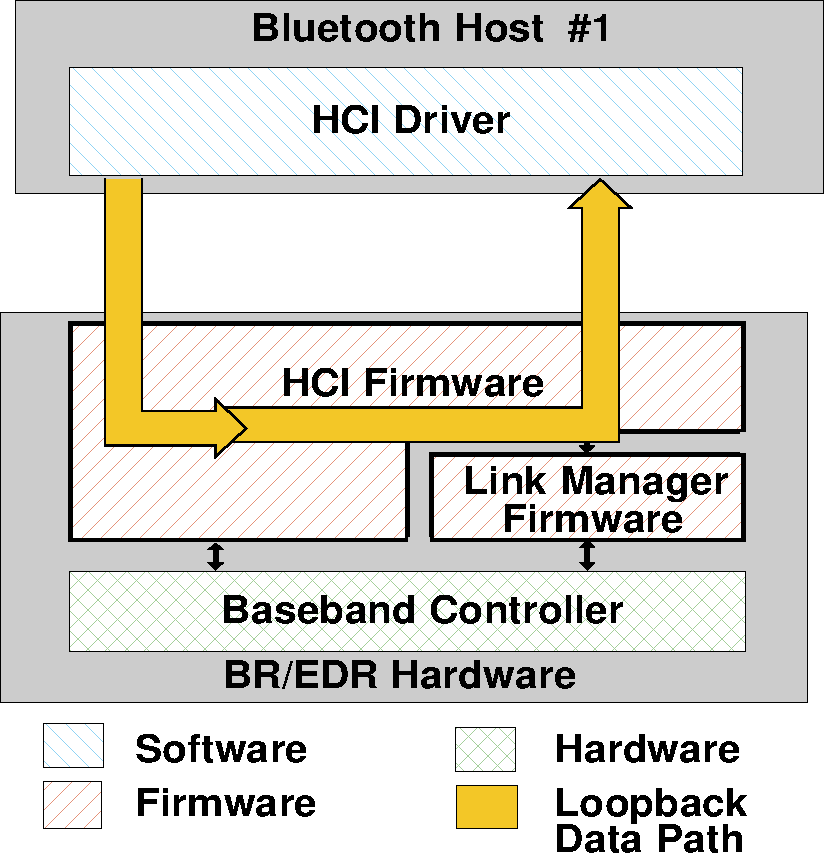
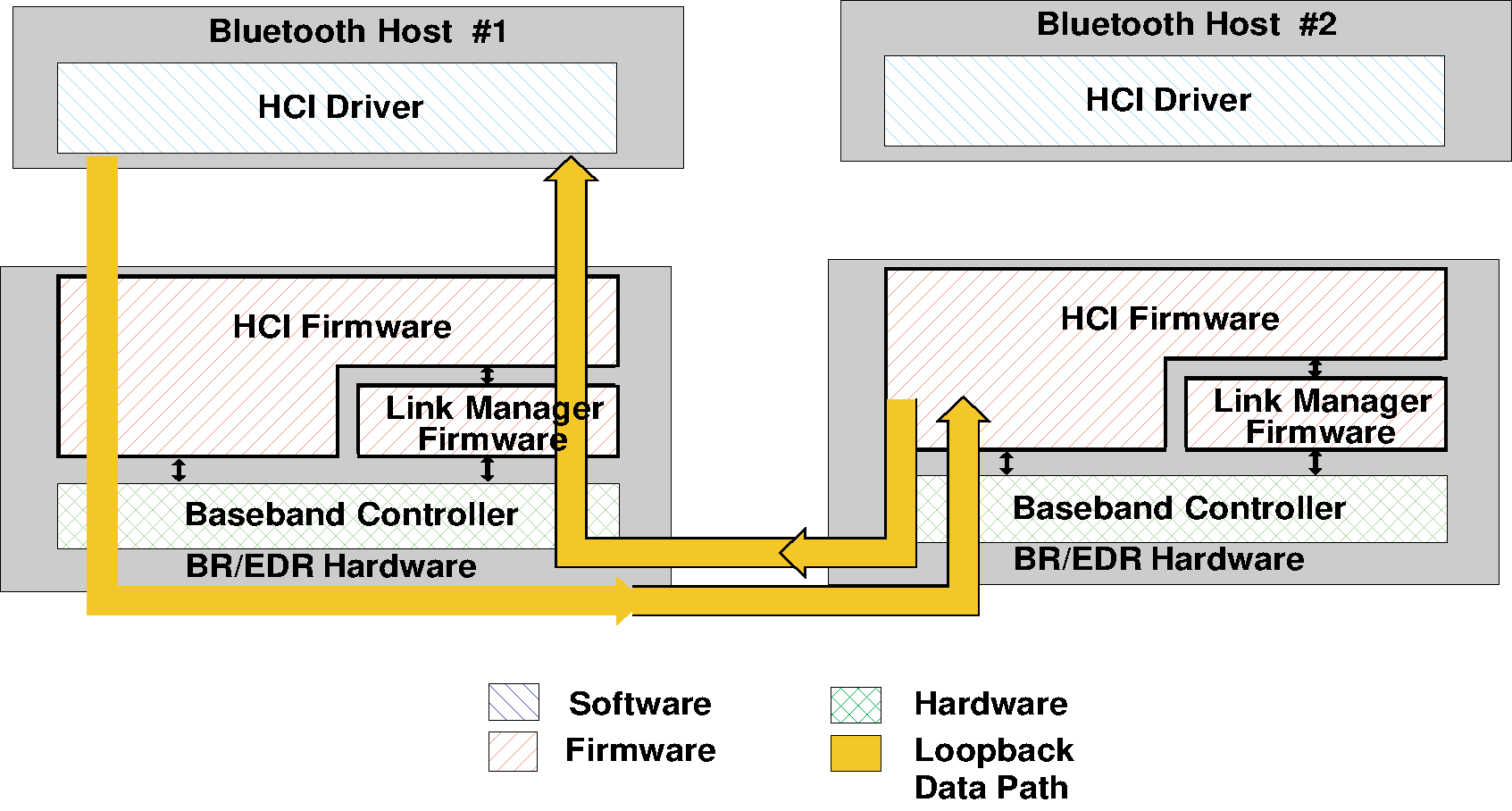
Command parameters:
Loopback_Mode: | Size: 1 octet |
Value | Parameter Description |
|---|---|
0x00 | No Loopback mode enabled (default). |
0x01 | Enable Local Loopback. |
0x02 | Enable Remote Loopback. |
All other values | Reserved for future use. |
Return parameters:
Status: | Size: 1 octet |
Value | Parameter Description |
|---|---|
0x00 | HCI_Write_Loopback_Mode command succeeded. |
0x01 to 0xFF | HCI_Write_Loopback_Mode command failed. See [Vol 1] Part F, Controller Error Codes for a list of error codes and descriptions. |
Event(s) generated (unless masked away):
When the HCI_Write_Loopback_Mode command has completed, an HCI_Command_Complete event shall be generated.
7.6.3. Enable Device Under Test Mode command
Command | OCF | Command Parameters | Return Parameters |
|---|---|---|---|
HCI_Enable_Device_Under_Test_Mode | 0x0003 | none | Status |
Description:
The HCI_Enable_Device_Under_Test_Mode command allows the local BR/EDR Controller to enter test mode via LMP test commands for BR/EDR Controllers. For details see [Vol 2] Part C, Link Manager Protocol Specification. The Host issues this command when it wants the local device to be the DUT for the Testing scenarios as described in [Vol 3] Part D, Section 1. When the BR/EDR Controller receives this command, it shall complete the command with an HCI_Command_Complete event. The BR/EDR Controller functions as normal until the remote tester issues the LMP test command to place the local device into Device Under Test mode. To disable and exit the Device Under Test Mode, the Host may issue the HCI_Reset command. The local BR/EDR Controller shall not enter test mode, even if instructed by the remote BR/EDR Controller, before this command is issued.
Command parameters:
None.
Return parameters:
Status: | Size: 1 octet |
Value | Parameter Description |
|---|---|
0x00 | HCI_Enter_Device_Under_Test_Mode command succeeded. |
0x01 to 0xFF | HCI_Enter_Device_Under_Test_Mode command failed. See [Vol 1] Part F, Controller Error Codes for a list of error codes and descriptions. |
Event(s) generated (unless masked away):
When the HCI_Enter_Device_Under_Test_Mode command has completed, an HCI_Command_Complete event shall be generated.
7.6.4. Write Simple Pairing Debug Mode command
Command | OCF | Command Parameters | Return Parameters |
|---|---|---|---|
HCI_Write_Simple_Pairing_Debug_Mode | 0x0004 | Simple_Pairing_Debug_Mode | Status |
Description:
This command configures the BR/EDR Controller to use a predefined Diffie Hellman private key for Secure Simple Pairing to enable debug equipment to monitor the encrypted connection.
Note
Note: Only one side (initiator or responder) needs to set Secure Simple Pairing debug mode in order for debug equipment to be able to determine the link key and, therefore, be able to monitor the encrypted connection.
When the Simple_Pairing_Debug_Mode parameter is set to enabled the BR/EDR Controller shall use the predefined Diffie Hellman private key. The BR/EDR Controller shall also set the resulting Link_Key type to "Debug Combination Key."
When in Secure Simple Pairing debug mode, the Link Manager shall use the following Diffie Hellman private / public key pairs:
For P-192: | |
Private key: | 07915f86918ddc27005df1d6cf0c142b625ed2eff4a518ff |
Public key (X): | 15207009984421a6586f9fc3fe7e4329d2809ea51125f8ed |
Public key (Y): | b09d42b81bc5bd009f79e4b59dbbaa857fca856fb9f7ea25 |
For P-256: | |
Private key: | 3f49f6d4 a3c55f38 74c9b3e3 d2103f50 4aff607b eb40b799 5899b8a6 cd3c1abd |
Public key (X): | 20b003d2 f297be2c 5e2c83a7 e9f9a5b9 eff49111 acf4fddb cc030148 0e359de6 |
Public key (Y): | dc809c49 652aeb6d 63329abf 5a52155c 766345c2 8fed3024 741c8ed0 1589d28b |
Command parameters:
Simple_Pairing_Debug_Mode: | Size: 1 octet |
Value | Parameter Description |
|---|---|
0x00 | Secure Simple Pairing debug mode disabled (default) |
0x01 | Secure Simple Pairing debug mode enabled |
All other values | Reserved for future use |
Return parameters:
Status: | Size: 1 octet |
Value | Parameter Description |
|---|---|
0x00 | HCI_Write_Simple_Pairing_Debug_Mode command succeeded. |
0x01 to 0xFF | HCI_Write_Simple_Pairing_Debug_Mode command failed. See [Vol 1] Part F, Controller Error Codes for a list of error codes and descriptions. |
Event(s) generated (unless masked away):
When the HCI_Write_Simple_Pairing_Debug_Mode command has completed, an HCI_Command_Complete event shall be generated.
7.6.5. [This section is no longer used]
7.6.6. [This section is no longer used]
7.6.7. [This section is no longer used]
7.6.8. Write Secure Connections Test Mode command
Command | OCF | Command Parameters | Return Parameters |
|---|---|---|---|
HCI_Write_Secure_Connections_Test_Mode | 0x000A | Connection_Handle, DM1_ACL-U_Mode, eSCO_Loopback_Mode | Status, Connection_Handle |
Description:
This command configures the BR/EDR Controller to enable and disable the two test modes used for verifying the Secure Connections feature during qualification. The DM1_ACL-U_Mode parameter enables and disables the use of DM1 packets for transmitting ACL-U data. When DM1 ACL-U Mode is disabled, ACL-U traffic may use DM1 packets. When DM1 ACL-U Mode is enabled, ACL-U traffic shall not use DM1 packets unless the Packet_Type parameter only allows DM1 packets (e.g. set to 0x3306 or 0x330E).
The command is used during testing to help make transmit ACL packet selection predictable.
The eSCO_Loopback_Mode parameter enables and disables the loopback of received eSCO payloads. When the eSCO_Loopback_Mode parameter is set to Enabled, the BR/EDR Controller will send back all eSCO data that comes over the air irrespective of whether the CRC check in the received eSCO packet passes or fails. It will only allow one synchronous connection. If there is more than one synchronous connection and there is an attempt to set the local device to eSCO_Loopback_Mode, the attempt shall be refused.
See Figure 7.3, where the rightmost device has the eSCO_Loopback_Mode parameter set to enabled and the leftmost device is in a normal mode of operation. This allows the encryption and decryption of eSCO packets to be tested without any other variables.
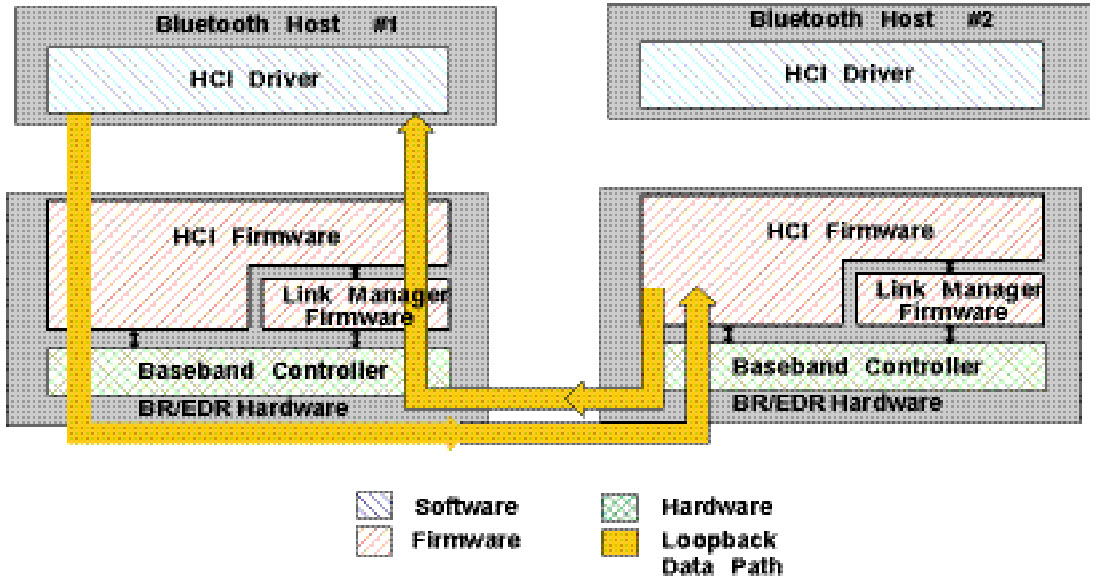 |
The Connection_Handle shall be for an ACL connection.
When the eSCO_Loopback_Mode parameter is set to enabled, received eSCO payloads are looped back as subsequent transmitted eSCO payloads. There may be a delay of 0 or more eSCO intervals before the Controller loops back the payload. This is illustrated in Figure 7.4, Figure 7.5, and Figure 7.6.
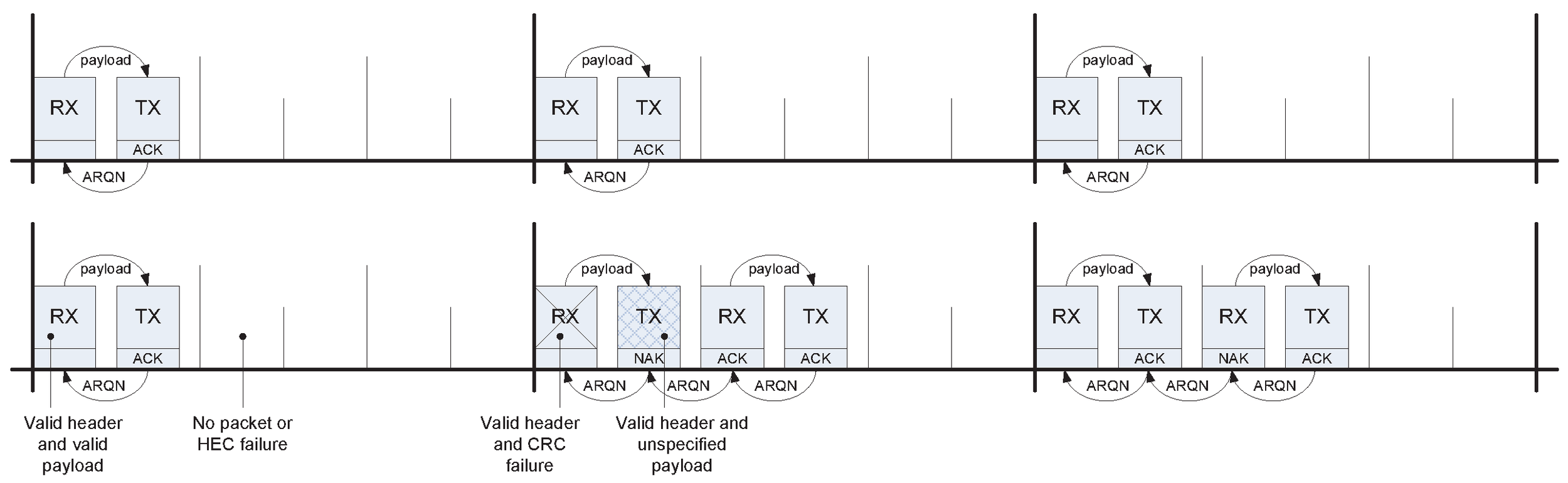
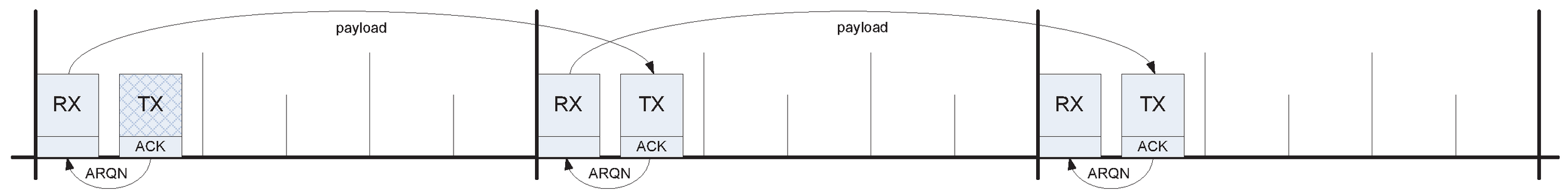
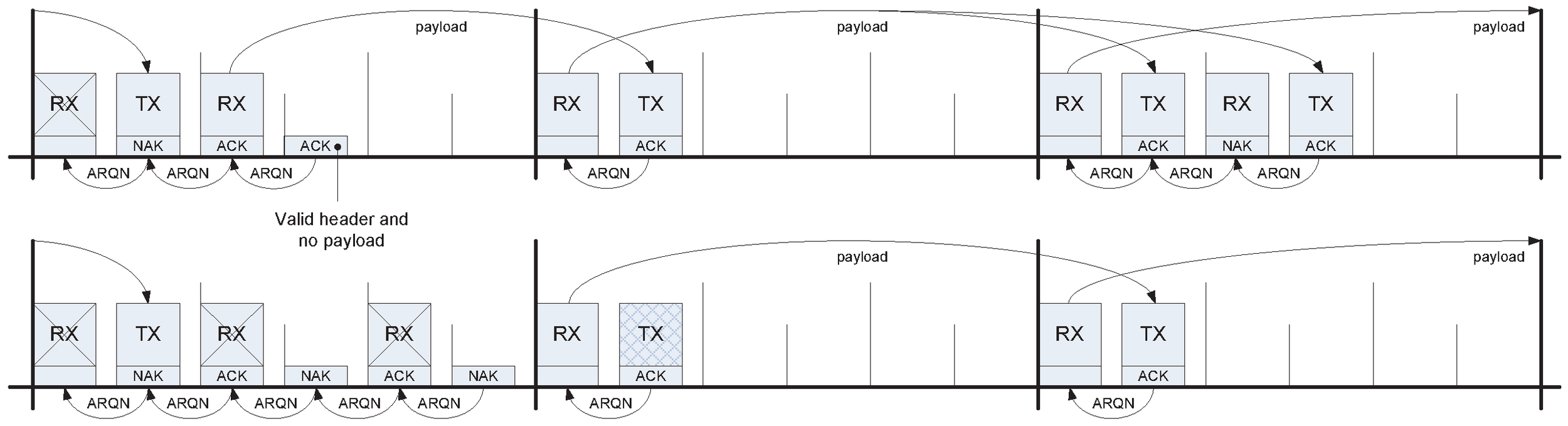
Command parameters:
Connection_Handle: | Size: 2 octets (12 bits meaningful) |
Value | Parameter Description |
|---|---|
0xXXXX | Connection_Handle Range: 0x0000 to 0x0EFF |
DM1_ACL-U_Mode: | Size: 1 octet |
Value | Parameter Description |
|---|---|
0x00 | DM1 ACL-U mode disabled (default) |
0x01 | DM1 ACL-U mode enabled |
All other values | Reserved for future use |
eSCO_Loopback_Mode: | Size: 1 octet |
Value | Parameter Description |
|---|---|
0x00 | eSCO loopback mode disabled (default) |
0x01 | eSCO loopback mode enabled |
All other values | Reserved for future use |
Return parameters:
Status: | Size: 1 octet |
Value | Parameter Description |
|---|---|
0x00 | HCI_Write_Secure_Connections_Test_Mode command succeeded. |
0x01 to 0xFF | HCI_Write_Secure_Connections_Test_Mode command failed. See [Vol 1] Part F, Controller Error Codes for a list of error codes and descriptions. |
Connection_Handle: | Size: 2 octets (12 bits meaningful) |
Value | Parameter Description |
|---|---|
0xXXXX | Connection_Handle Range: 0x0000 to 0x0EFF |
Event(s) generated (unless masked away):
When the HCI_Write_Secure_Connections_Test_Mode command has completed, an HCI_Command_Complete event shall be generated.
7.7. Events
7.7.1. Inquiry Complete event
Event | Event Code | Event Parameters |
|---|---|---|
HCI_Inquiry_Complete | 0x01 | Status |
Description:
The HCI_Inquiry_Complete event indicates that the Inquiry is finished. This event contains a Status parameter, which is used to indicate if the Inquiry completed successfully or if the Inquiry was not completed.
Event parameters:
Status: | Size: 1 octet |
Value | Parameter Description |
|---|---|
0x00 | HCI_Inquiry command completed successfully. |
0x01 to 0xFF | HCI_Inquiry command failed. See [Vol 1] Part F, Controller Error Codes for a list of error codes and descriptions. |
7.7.2. Inquiry Result event
Event | Event Code | Event Parameters |
|---|---|---|
HCI_Inquiry_Result | 0x02 | Num_Responses, BD_ADDR[i], Page_Scan_Repetition_Mode[i], Reserved[i], Class_Of_Device[i] Clock_Offset[i] |
Description:
The HCI_Inquiry_Result event indicates that a BR/EDR Controller or multiple BR/EDR Controllers have responded so far during the current Inquiry process. This event will be sent from the BR/EDR Controller to the Host as soon as an Inquiry Response from a remote device is received if the remote device supports only mandatory paging scheme. The BR/EDR Controller may queue these Inquiry Responses and send multiple BR/EDR Controllers information in one HCI_Inquiry_Result event. The event can be used to return one or more Inquiry responses in one event.
This event is only generated if the Inquiry_Mode parameter of the last HCI_Write_Inquiry_Mode command was set to 0x00 (Standard Inquiry Result event format) or if the HCI_Write_Inquiry_Mode command has not been used.
Event parameters:
Num_Responses: | Size: 1 octet |
Value | Parameter Description |
|---|---|
0xXX | Number of responses from the Inquiry. |
BD_ADDR[i]: | Size: Num_Responses × 6 octets |
Value | Parameter Description |
|---|---|
0xXXXXXXXXXXXX | BD_ADDR for a device which responded. |
Page_Scan_Repetition_Mode[i]: | Size: Num_Responses × 1 octet |
Value | Parameter Description |
|---|---|
0x00 | R0 |
0x01 | R1 |
0x02 | R2 |
All other values | Reserved for future use |
Reserved[i]: | Size: Num_Responses × 2 octets |
Value | Parameter Description |
|---|---|
0xXXXX | Reserved for future use. |
Class_Of_Device[i]: | Size: Num_Responses × 3 octets |
Value | Parameter Description |
|---|---|
0xXXXXXX | Class of Device for the device |
Clock_Offset[i]: | Size: Num_Responses × 2 octets |
Bit Number | Parameter Description |
|---|---|
0-14 | Bits 16-2 of CLKNPeripheral - CLK |
15 | Reserved for future use |
7.7.3. Connection Complete event
Event | Event Code | Event Parameters |
|---|---|---|
HCI_Connection_Complete | 0x03 | Status, Connection_Handle, BD_ADDR, Link_Type, Encryption_Enabled |
Description:
The HCI_Connection_Complete event indicates to both of the Hosts forming the connection that a new connection has been established. This event also indicates to the Host which issued the HCI_Create_Connection, HCI_Accept_Connection_Request, or HCI_Reject_Connection_Request command, and then received an HCI_Command_Status event, if the issued command failed or was successful.
Event parameters:
Status: | Size: 1 octet |
Value | Parameter Description |
|---|---|
0x00 | Connection successfully completed. |
0x01 to 0xFF | Connection failed to Complete. See [Vol 1] Part F, Controller Error Codes for a list of error codes and descriptions. |
Connection_Handle: | Size: 2 octets (12 bits meaningful) |
Value | Parameter Description |
|---|---|
0xXXXX | Connection_Handle for the new connection Range: 0x0000 to 0x0EFF |
BD_ADDR: | Size: 6 octets |
Value | Parameter Description |
|---|---|
0xXXXXXXXXXXXX | BD_ADDR of the other connected Device forming the connection. |
Link_Type: | Size: 1 octet |
Value | Parameter Description |
|---|---|
0x00 | SCO connection. |
0x01 | ACL connection (Data Channels). |
All other values | Reserved for future use. |
Encryption_Enabled: | Size: 1 octet |
Value | Parameter Description |
|---|---|
0x00 | Link level encryption disabled. |
0x01 | Link level encryption enabled. |
All other values | Reserved for future use. |
7.7.4. Connection Request event
Event | Event Code | Event Parameters |
|---|---|---|
HCI_Connection_Request | 0x04 | BD_ADDR, Class_Of_Device, Link_Type |
Description:
The HCI_Connection_Request event is used to indicate that a new incoming connection is trying to be established. The connection may either be accepted or rejected. When the Host receives this event and the link type parameter is ACL, it should respond with either an HCI_Accept_Connection_Request or HCI_Reject_Connection_Request command before the timer Connection_Accept_Timeout expires. If the link type is SCO or eSCO, the Host should reply with the HCI_Accept_Synchronous_Connection_Request command, the HCI_Enhanced_Accept_Synchronous_Connection_Request command, or the HCI_Reject_Synchronous_Connection_Request command. If the link type is SCO, the Host may respond with the HCI_Accept_Connection_Request command. If the event is responded to with the HCI_Accept_Connection_Request command, then the default parameter settings of the HCI_Accept_Synchronous_Connection_Request command (see Section 7.1.27) should be used by the local Link Manager when negotiating the SCO link parameters. In that case, the HCI_Connection_Complete event and not the HCI_Synchronous_Connection_Complete event, shall be returned on completion of the connection.
Note
Note: See Section 7.3.3 for the behavior when the HCI_Connection_Request event is masked or the connection is auto accepted.
Event parameters:
BD_ADDR: | Size: 6 octets |
Value | Parameter Description |
|---|---|
0xXXXXXXXXXXXX | BD_ADDR of the device that requests the connection. |
Class_Of_Device: | Size: 3 octets |
Value | Parameter Description |
|---|---|
0xXXXXXX | Class of Device for the device, which requests the connection. |
0x000000 | Unknown Class of Device |
Link_Type: | Size: 1 octet |
Value | Parameter Description |
|---|---|
0x00 | SCO connection requested |
0x01 | ACL connection requested |
0x02 | eSCO connection requested |
All other values | Reserved for future use. |
7.7.5. Disconnection Complete event
Event | Event Code | Event Parameters |
|---|---|---|
HCI_Disconnection_Complete | 0x05 | Status, Connection_Handle, Reason |
Description:
The HCI_Disconnection_Complete event occurs when a connection is terminated. The status parameter indicates if the disconnection was successful or not. The reason parameter indicates the reason for the disconnection if the disconnection was successful. If the disconnection was not successful, the value of the reason parameter shall be ignored by the Host. For example, this can be the case if the Host has issued the HCI_Disconnect command and there was a parameter error, or the command was not presently allowed, or a Connection_Handle that didn’t correspond to a connection was given.
If Connection_Handle identifies a CIS on the Central, the handle and the associated data paths of that CIS shall remain valid (irrespective of whether the disconnection was successful or not). If Connection_Handle identifies a CIS on the Peripheral and Status is zero, the handle and the associated data path of that CIS shall be deleted. If Connection_Handle identifies any other kind of connection and Status is zero, the handle shall be deleted.
Note
Note: When a physical link fails, one HCI_Disconnection_Complete event will be returned for each logical channel on the physical link with the corresponding Connection_Handle as a parameter.
Event parameters:
Status: | Size: 1 octet |
Value | Parameter Description |
|---|---|
0x00 | Disconnection has occurred. |
0x01 to 0xFF | Disconnection failed to complete. See [Vol 1] Part F, Controller Error Codes for a list of error codes and descriptions. |
Connection_Handle: | Size: 2 octets (12 bits meaningful) |
Value | Parameter Description |
|---|---|
0xXXXX | Connection_Handle which was disconnected. Range: 0x0000 to 0x0EFF |
Reason: | Size: 1 octet |
Value | Parameter Description |
|---|---|
0xXX | Reason for disconnection. See [Vol 1] Part F, Controller Error Codes for error codes and descriptions. |
7.7.6. Authentication Complete event
Event | Event Code | Event Parameters |
|---|---|---|
HCI_Authentication_Complete | 0x06 | Status, Connection_Handle |
Description:
The HCI_Authentication_Complete event occurs when authentication has been completed for the specified connection. The Connection_Handle shall be a Connection_Handle for an ACL connection.
Note
Note: This event is only generated on the initiator of the authentication and not on the responder.
Event parameters:
Status: | Size: 1 octet |
Value | Parameter Description |
|---|---|
0x00 | Authentication Request successfully completed. |
0x01 to 0xFF | Authentication Request failed to complete. See [Vol 1] Part F, Controller Error Codes for a list of error codes and descriptions. |
Connection_Handle: | Size: 2 octets (12 bits meaningful) |
Value | Parameter Description |
|---|---|
0xXXXX | Connection_Handle Range: 0x0000 to 0x0EFF |
7.7.7. Remote Name Request Complete event
Event | Event Code | Event Parameters |
|---|---|---|
HCI_Remote_Name_Request_Complete | 0x07 | Status, BD_ADDR, Remote_Name |
Description:
The HCI_Remote_Name_Request_Complete event is used to indicate that a remote name request has been completed. The Remote_Name event parameter is a UTF-8 encoded string with the type utf8{248} defined in [Vol 1] Part E, Section 2.9.3. The BD_ADDR event parameter is used to identify which device the user-friendly name was obtained from.
Note
Note: The Remote_Name parameter is a string parameter. Endianness does therefore not apply to the Remote_Name parameter. The first octet of the name is received first.
Event parameters:
Status: | Size: 1 octet |
Value | Parameter Description |
|---|---|
0x00 | HCI_Remote_Name_Request command succeeded. |
0x01 to 0xFF | HCI_Remote_Name_Request command failed. See [Vol 1] Part F, Controller Error Codes for a list of error codes and descriptions. |
BD_ADDR: | Size: 6 octets |
Value | Parameter Description |
|---|---|
0xXXXXXXXXXXXX | BD_ADDR for the device whose name was requested. |
Remote_Name: | Size: 248 octets |
Value | Parameter Description |
|---|---|
Name[248] | A UTF-8 encoded user-friendly descriptive name for the remote device with type utf8{248}. |
7.7.8. Encryption Change event
Event | Event Code | Event Parameters |
|---|---|---|
HCI_Encryption_Change [v2] | 0x59 | Status, Connection_Handle, Encryption_Enabled, Encryption_Key_Size |
HCI_Encryption_Change [v1] | 0x08 | Status, Connection_Handle, Encryption_Enabled |
Description:
The HCI_Encryption_Change event is used to indicate that the change of the encryption mode has been completed. The Connection_Handle event parameter will be a Connection_Handle for an ACL connection and is used to identify the remote device. The Encryption_Enabled event parameter specifies the new encryption state for the connection specified by Connection_Handle. The Encryption_Key_Size event parameter specifies the size, in octets, of the key used to encrypt the link. This event will occur on both devices to notify the Hosts when encryption has changed for all connections between the two devices. This event shall not be generated if encryption is paused or resumed; during a role switch, for example.
Event parameters:
Status: | Size: 1 octet |
Value | Parameter Description |
|---|---|
0x00 | An encryption change has occurred. |
0x01 to 0xFF | An attempt to change encryption failed. See [Vol 1] Part F, Controller Error Codes for a list of error codes and descriptions. |
Connection_Handle: | Size: 2 octets (12 bits meaningful) |
Value | Parameter Description |
|---|---|
0xXXXX | Connection_Handle Range: 0x0000 to 0x0EFF |
Encryption_Enabled: | Size: 1 octet |
Value | Parameter Description |
|---|---|
0x00 | Link Level Encryption is OFF. |
0x01 | Link Level Encryption is ON with E0 for BR/EDR. Link Level Encryption is ON with AES-CCM for LE. |
0x02 | Link Level Encryption is ON with AES-CCM for BR/EDR. |
All other values | Reserved for future use. |
Encryption_Key_Size: | Size: 1 octet |
Value | Parameter Description |
|---|---|
0xXX | Encryption key size in octets. This parameter shall be ignored for LE connections and shall be ignored when Link Level Encryption is OFF. Range: 0x01 to 0x10 |
7.7.9. Change Connection Link Key Complete event
Event | Event Code | Event Parameters |
|---|---|---|
HCI_Change_Connection_Link_Key_Complete | 0x09 | Status, Connection_Handle |
Description:
The HCI_Change_Connection_Link_Key_Complete event is used to indicate that the change in the Link Key for all connections to a given remote BR/EDR Controller has been completed.
The Connection_Handle will be a Connection_Handle for an ACL connection to the remote Controller. The HCI_Change_Connection_Link_Key_Complete event is sent only to the Host which issued the HCI_Change_Connection_Link_Key command.
Event parameters:
Status: | Size: 1 octet |
Value | Parameter Description |
|---|---|
0x00 | HCI_Change_Connection_Link_Key command succeeded. |
0x01 to 0xFF | HCI_Change_Connection_Link_Key command failed. See [Vol 1] Part F, Controller Error Codes for a list of error codes and descriptions. |
Connection_Handle: | Size: 2 octets (12 bits meaningful) |
Value | Parameter Description |
|---|---|
0xXXXX | Connection_Handle Range: 0x0000 to 0x0EFF |
7.7.10. Link Key Type Changed event
Event | Event Code | Event Parameters |
|---|---|---|
HCI_Link_Key_Type_Changed | 0x0A | Status, Connection_Handle, Key_Flag |
Description:
The HCI_Link_Key_Type_Changed event is used to indicate that the Link Key managed by the Central of the piconet has been changed. The Connection_Handle will be a Connection_Handle for an ACL connection within that piconet. The link key used for the connection will be the temporary link key or the semi-permanent link key indicated by the Key_Flag. The Key_Flag event parameter is used to indicate which Link Key (temporary link key or the semi-permanent link keys) is now being used in the piconet.
This event is also generated on the local Controller when the HCI_Link_Key_Selection command finishes because no change was requested or an error occurred. If a key change was attempted but failed, the remote Controller may generate the event.
Note
Note: For a Central, the change from a semi-permanent Link Key to temporary Link Key will affect all Connection_Handles related to the piconet. For a Peripheral, this change affects only this particular Connection_Handle. A temporary link key must be used when both broadcast and point-to-point traffic are being encrypted (see [Vol 2] Part H, Section 3.2.6 and [Vol 2] Part H, Section 4.2).
Event parameters:
Status: | Size: 1 octet |
Value | Parameter Description |
|---|---|
0x00 | HCI_Link_Key_Selection command succeeded. |
0x01 to 0xFF | HCI_Link_Key_Selection command failed. See [Vol 1] Part F, Controller Error Codes for a list of error codes and descriptions. |
Connection_Handle: | Size: 2 octets (12 bits meaningful) |
Value | Parameter Description |
|---|---|
0xXXXX | Connection_Handle Range: 0x0000 to 0x0EFF |
Key_Flag: | Size: 1 octet |
Value | Parameter Description |
|---|---|
0x00 | Using Semi-permanent Link Key. |
0x01 | Using Temporary Link Key. |
7.7.11. Read Remote Supported Features Complete event
Event | Event Code | Event Parameters |
|---|---|---|
HCI_Read_Remote_Supported_Features_Complete | 0x0B | Status, Connection_Handle, LMP_Features |
Description:
The HCI_Read_Remote_Supported_Features_Complete event is used to indicate the completion of the process of the Link Manager obtaining the supported features of the remote BR/EDR Controller specified by the Connection_Handle event parameter. The Connection_Handle will be a Connection_Handle for an ACL connection. The event parameters include a list of LMP features. For details see [Vol 2] Part C, Link Manager Protocol Specification.
Note
Note: If the features are requested more than once while a connection exists between the two devices, the second and subsequent requests may report a cached copy of the features rather than fetching the feature mask again.
Event parameters:
Status: | Size: 1 octet |
Value | Parameter Description |
|---|---|
0x00 | HCI_Read_Remote_Supported_Features command succeeded. |
0x01 to 0xFF | HCI_Read_Remote_Supported_Features command failed. See [Vol 1] Part F, Controller Error Codes for a list of error codes and descriptions. |
Connection_Handle: | Size: 2 octets (12 bits meaningful) |
Value | Parameter Description |
|---|---|
0xXXXX | Connection_Handle Range: 0x0000 to 0x0EFF |
LMP_Features: | Size: 8 octets |
Value | Parameter Description |
|---|---|
0xXXXXXXXXXXXXXXXX | Bit Mask List of LMP features. See [Vol 2] Part C, Link Manager Protocol Specification. |
7.7.12. Read Remote Version Information Complete event
Event | Event Code | Event Parameters |
|---|---|---|
HCI_Read_Remote_Version_Information_Complete | 0x0C | Status, Connection_Handle, Version, Company_Identifier, Subversion |
Description:
The HCI_Read_Remote_Version_Information_Complete event is used to indicate the completion of the process obtaining the version information of the remote Controller specified by the Connection_Handle event parameter. The Connection_Handle shall be for an ACL connection.
The Version event parameter defines the specification version of the BR/EDR or LE Controller. The Company_Identifier event parameter indicates the manufacturer of the remote Controller. The Subversion event parameter is controlled by the manufacturer and is vendor-specific. These parameters shall contain the same values as the CompanyID and SubVersion parameters in [Vol 2] Part C, Section 4.3.3 and [Vol 6] Part B, Section 2.4.2.13.
Event parameters:
Status: | Size: 1 octet |
Value | Parameter Description |
|---|---|
0x00 | HCI_Read_Remote_Version_Information command succeeded. |
0x01 to 0xFF | HCI_Read_Remote_Version_Information command failed. See [Vol 1] Part F, Controller Error Codes for a list of error codes and descriptions. |
Connection_Handle: | Size: 2 octets (12 bits meaningful) |
Value | Parameter Description |
|---|---|
0xXXXX | Connection_Handle Range: 0x0000 to 0x0EFF |
Version: | Size: 1 octet |
Value | Parameter Description |
|---|---|
0xXX | Version of the Current LMP or Link Layer supported by the remote Controller. See Assigned Numbers. |
Company_Identifier: | Size: 2 octets |
Value | Parameter Description |
|---|---|
0xXXXX | Company identifier for the manufacturer of the remote Controller. See Assigned Numbers. |
Subversion: | Size: 2 octets |
Value | Parameter Description |
|---|---|
0xXXXX | Revision of the LMP or Link Layer implementation in the remote Controller. This value is vendor-specific. |
7.7.13. QoS Setup Complete event
Event | Event Code | Event Parameters |
|---|---|---|
HCI_QoS_Setup_Complete | 0x0D | Status, Connection_Handle, Unused, Service_Type, Token_Rate, Peak_Bandwidth, Latency, Delay_Variation |
Description:
The HCI_QoS_Setup_Complete event is used to indicate the completion of the process of the Link Manager setting up QoS with the remote BR/EDR Controller specified by the Connection_Handle event parameter. The Connection_Handle will be a Connection_Handle for an ACL connection. For more detail see [Vol 3] Part A, Logical Link Control and Adaptation Protocol Specification.
The Unused parameter is reserved for future use.
This event is generated following an HCI_QoS_Setup command issued by the local Host.
Note
Note: This event or the HCI_Flow_Specification_Complete event can be generated if the remote device performs an LMP transaction involving the flow parameter values.
Event parameters:
Status: | Size: 1 octet |
Value | Parameter Description |
|---|---|
0x00 | HCI_QoS_Setup command succeeded. |
0x01 to 0xFF | HCI_QoS_Setup command failed. See [Vol 1] Part F, Controller Error Codes for a list of error codes and descriptions. |
Connection_Handle: | Size: 2 octets (12 bits meaningful) |
Value | Parameter Description |
|---|---|
0xXXXX | Connection_Handle Range: 0x0000 to 0x0EFF |
Unused: | Size: 1 octet |
Value | Parameter Description |
|---|---|
0x00 | This value shall be used by the Controller. |
All other values | Reserved for future use. |
Service_Type: | Size: 1 octet |
Value | Parameter Description |
|---|---|
0x00 | No Traffic Available. |
0x01 | Best Effort Available. |
0x02 | Guaranteed Available. |
All other values | Reserved for future use. |
Token_Rate: | Size: 4 octets |
Value | Parameter Description |
|---|---|
0xXXXXXXXX | Available Token Rate, in octets per second. |
Peak_Bandwidth: | Size: 4 octets |
Value | Parameter Description |
|---|---|
0xXXXXXXXX | Available Peak Bandwidth, in octets per second. |
Latency: | Size: 4 octets |
Value | Parameter Description |
|---|---|
0xXXXXXXXX | Available Latency, in microseconds. |
Delay_Variation: | Size: 4 octets |
Value | Parameter Description |
|---|---|
0xXXXXXXXX | Available Delay Variation, in microseconds. |
7.7.14. Command Complete event
Event | Event Code | Event Parameters |
|---|---|---|
HCI_Command_Complete | 0x0E | Num_HCI_Command_Packets, Command_Opcode, Return_Parameters |
Description:
The HCI_Command_Complete event is used by the Controller for most commands to transmit return status of a command and the other event parameters that are specified for the issued HCI command.
The Num_HCI_Command_Packets event parameter allows the Controller to indicate the number of HCI command packets the Host can send to the Controller. If the Controller requires the Host to stop sending commands, the Num_HCI_Command_Packets event parameter will be set to zero. To indicate to the Host that the Controller is ready to receive HCI command packets, the Controller generates an HCI_Command_Complete event with the Command_Opcode set to 0x0000 and the Num_HCI_Command_Packets event parameter set to 1 or more. Command_Opcode 0x0000 is a special value indicating that this event is not associated with a command sent by the Host. The Controller can send an HCI_Command_Complete event with Command Opcode 0x0000 at any time to change the number of outstanding HCI command packets that the Host can send before waiting. See each command for the parameters that are returned by this event.
Event parameters:
Num_HCI_Command_Packets: | Size: 1 octet |
Value | Parameter Description |
|---|---|
0xXX | The Number of HCI Command packets which are allowed to be sent to the Controller from the Host. Range: 0 to 255 |
Command_Opcode: | Size: 2 octets |
Value | Parameter Description |
|---|---|
0x0000 | No associated command |
0xXXXX | (non-zero) Opcode of the command which caused this event. |
Return_Parameters: | Size: Depends on command |
Value | Parameter Description |
|---|---|
0xXX | This is the return parameter(s) for the command specified in the Command_Opcode event parameter. See each command’s definition for the list of return parameters associated with that command. |
7.7.15. Command Status event
Event | Event Code | Event Parameters |
|---|---|---|
HCI_Command_Status | 0x0F | Status, Num_HCI_Command_Packets, Command_Opcode |
Description:
The HCI_Command_Status event is used to indicate that the command described by the Command_Opcode parameter has been received, and that the Controller is currently performing the task for this command. This event is needed to provide mechanisms for asynchronous operation, which avoids the need for the Host to wait for a command to finish. If the command cannot begin to execute (a parameter error may have occurred, or the command may currently not be allowed), the Status event parameter will contain the corresponding error code, and no complete event will follow since the command was not started. The Num_HCI_Command_Packets event parameter allows the Controller to indicate the number of HCI command packets the Host can send to the Controller. If the Controller requires the Host to stop sending commands, the Num_HCI_Command_Packets event parameter will be set to zero. To indicate to the Host that the Controller is ready to receive HCI command packets, the Controller generates an HCI_Command_Status event with Status 0x00 and Command_Opcode 0x0000 and the Num_HCI_Command_Packets event parameter set to 1 or more. Command_Opcode 0x0000 is a special value indicating that this event is not associated with a command sent by the Host. The Controller can send an HCI_Command_Status event with Command Opcode 0x0000 at any time to change the number of outstanding HCI command packets that the Host can send before waiting.
Event parameters:
Status: | Size: 1 octet |
Value | Parameter Description |
|---|---|
0x00 | Command now pending. |
0x01 to 0xFF | Command failed. See [Vol 1] Part F, Controller Error Codes for a list of error codes and descriptions. |
Num_HCI_Command_Packets: | Size: 1 octet |
Value | Parameter Description |
|---|---|
0xXX | The Number of HCI Command packets which are allowed to be sent to the Controller from the Host. Range: 0 to 255 |
Command_Opcode: | Size: 2 octets |
Value | Parameter Description |
|---|---|
0x0000 | No associated command |
0xXXXX | (non-zero) Opcode of the command which caused this event and is now pending. |
7.7.16. Hardware Error event
Event | Event Code | Event Parameters |
|---|---|---|
HCI_Hardware_Error | 0x10 | Hardware_Code |
Description:
The HCI_Hardware_Error event is used to notify the Host that a hardware failure has occurred in the Controller.
Event parameters:
Hardware_Code: | Size: 1 octet |
Value | Parameter Description |
|---|---|
0x00 to 0xFF | These Hardware_Codes will be implementation-specific, and can be assigned to indicate various hardware problems. |
7.7.17. Flush Occurred event
Event | Event Code | Event Parameters |
|---|---|---|
HCI_Flush_Occurred | 0x11 | Handle |
Description:
The HCI_Flush_Occurred event is used to indicate that, for the specified Handle, the current user data to be transmitted has been removed. The Handle shall be a Connection_Handle for an ACL connection. This could result from the HCI_Flush command, or be due to the automatic flush. Multiple blocks of an L2CAP packet could have been pending in the Controller. If one Baseband packet part of an L2CAP PDU is flushed, then the rest of the HCI ACL Data packets for the L2CAP PDU shall also be flushed.
Event parameters:
Handle: | Size: 2 octets (12 bits meaningful) |
Value | Parameter Description |
|---|---|
0xXXXX | Handle that was flushed. Range: 0x0000 to 0x0EFF |
7.7.18. Role Change event
Event | Event Code | Event Parameters |
|---|---|---|
HCI_Role_Change | 0x12 | Status, BD_ADDR, New_Role |
Description:
The HCI_Role_Change event is used to indicate that the current role of the BR/EDR Controller related to the particular connection has changed. This event occurs (with Status set to zero) when both the remote and local BR/EDR Controllers have completed their role change for the BR/EDR Controller associated with the BD_ADDR event parameter, allowing both affected Hosts to be notified when the Role has been changed.
This event is also generated on the local Controller when the HCI_Switch_Role command finishes because no change was requested or an error occurred. If a Baseband role switch was attempted but failed, the remote Controller may generate the event.
Event parameters:
Status: | Size: 1 octet |
Value | Parameter Description |
|---|---|
0x00 | A role change has occurred. |
0x01 to 0xFF | A role change failed. See [Vol 1] Part F, Controller Error Codes for a list of error codes and descriptions. |
BD_ADDR: | Size: 6 octets |
Value | Parameter Description |
|---|---|
0xXXXXXXXXXXXX | BD_ADDR of the Device for which a role change has completed. |
New_Role: | Size: 1 octet |
Value | Parameter Description |
|---|---|
0x00 | Currently the Central for specified BD_ADDR. |
0x01 | Currently the Peripheral for specified BD_ADDR. |
7.7.19. Number Of Completed Packets event
Event | Event Code | Event Parameters |
|---|---|---|
HCI_Number_Of_Completed_Packets | 0x13 | Num_Handles, Connection_Handle[i], Num_Completed_Packets[i] |
Description:
The HCI_Number_Of_Completed_Packets event is used by the Controller to indicate to the Host how many HCI Data packets or HCI ISO Data packets have been completed for each Connection_Handle since the previous HCI_Number_Of_Completed_Packets event was sent to the Host. This means that the corresponding buffer space has been freed in the Controller and is available for new packets to be sent. Based on this information and the return parameters of the HCI_Read_Buffer_Size and HCI_LE_Read_Buffer_Size commands, the Host can determine for which Connection_Handles the following HCI packets should be sent to the Controller. The HCI_Number_Of_Completed_Packets event shall not specify a given Connection_Handle before the event indicating the corresponding connection has been created or after an event indicating disconnection of the corresponding connection. While the Controller has HCI Data packets or HCI ISO Data packets in its buffer, it shall keep sending the HCI_Number_Of_Completed_Packets event to the Host at least periodically, until it finally reports that all the pending packets have been completed. The rate with which this event is sent is manufacturer specific.
Note
Note: HCI_Number_Of_Completed_Packets events will not report on synchronous Connection_Handles if synchronous Flow Control is disabled. (See Section 7.3.36 and Section 7.3.37.)
Event parameters:
Num_Handles: | Size: 1 octet |
Value | Parameter Description |
|---|---|
0xXX | The number of Connection_Handles and Num_HCI_Data_Packets parameters pairs contained in this event. Range: 0 to 255 |
Connection_Handle[i]: | Size: Num_Handles × 2 octets (12 bits meaningful) |
Value | Parameter Description |
|---|---|
0xXXXX | Connection_Handle. Range: 0x0000 to 0x0EFF |
Num_Completed_Packets[i]: | Size: Num_Handles × 2 octets |
Value | Parameter Description |
|---|---|
0xXXXX | The number of packets that have been completed for the associated Connection_Handle since the previous time the event was returned. Range: 0x0000 to 0xFFFF |
7.7.20. Mode Change event
Event | Event Code | Event Parameters |
|---|---|---|
HCI_Mode_Change | 0x14 | Status, Connection_Handle, Current_Mode, Interval |
Description:
The HCI_Mode_Change event is used to indicate when the device associated with the Connection_Handle changes between Active mode, Hold mode, and Sniff mode. The Connection_Handle will be a Connection_Handle for an ACL connection. The Connection_Handle event parameter is used to indicate which connection the HCI_Mode_Change event is for. The Current_Mode event parameter is used to indicate which state the connection is currently in. The Interval parameter is used to specify a time amount specific to each state. Each Controller that is associated with the Connection_Handle which has changed modes shall send the HCI_Mode_Change event to its Host.
Event parameters:
Status: | Size: 1 octet |
Value | Parameter Description |
|---|---|
0x00 | A Mode Change has occurred. |
0x01 to 0xFF | HCI_Hold_Mode, HCI_Sniff_Mode, or HCI_Exit_Sniff_Mode command failed. See [Vol 1] Part F, Controller Error Codes for a list of error codes and descriptions. |
Connection_Handle: | Size: 2 octets (12 bits meaningful) |
Value | Parameter Description |
|---|---|
0xXXXX | Connection_Handle. Range: 0x0000 to 0x0EFF |
Current_Mode: | Size: 1 octet |
Value | Parameter Description |
|---|---|
0x00 | Active mode. |
0x01 | Hold mode. |
0x02 | Sniff mode. |
All other values | Reserved for future use. |
Interval: | Size: 2 octets |
Value | Parameter Description |
|---|---|
N = 0xXXXX | Hold: Number of Baseband slots to wait in Hold mode. Hold Interval = N × 0.625 ms (1 Baseband slot) Range: 0x0002 to 0xFFFE Time Range: 1.25 ms to 40.9 s Sniff: Number of Baseband slots between sniff anchor points. Time between sniff anchor points = N × 0.625 ms (1 Baseband slot) Range: 0x0002 to 0xFFFE Time Range: 1.25 ms to 40.9 s |
7.7.21. Return Link Keys event
Event | Event Code | Event Parameters |
|---|---|---|
HCI_Return_Link_Keys | 0x15 | Num_Keys, BD_ADDR[i], Link_Key[i] |
Description:
The HCI_Return_Link_Keys event is used by the BR/EDR Controller to send the Host the BD_ADDRs associated with one or more stored Link Keys. Zero or more instances of this event will occur after the HCI_Read_Stored_Link_Key command. When there are no link keys stored, no HCI_Return_Link_Keys events shall be returned. When there are link keys stored, the number of link keys returned in each HCI_Return_Link_Keys event is implementation specific. This event shall never return the value of the link keys. The link keys value parameter shall always contain the value of zero.
Event parameters:
Num_Keys: | Size: 1 octet |
Value | Parameter Description |
|---|---|
0xXX | Number of Link Keys contained in this event. Range: 0x01 to 0x0B |
BD_ADDR[i]: | Size: Num_Keys × 6 octets |
Value | Parameter Description |
|---|---|
0xXXXXXXXXXXXX | BD_ADDR for the associated Link Key. |
Link_Key[i]: | Size: Num_Keys × 16 octets |
Value | Parameter Description |
|---|---|
0x00000000000000000000000000000000 | Shall be zero. |
7.7.22. PIN Code Request event
Event | Event Code | Event Parameters |
|---|---|---|
HCI_PIN_Code_Request | 0x16 | BD_ADDR |
Description:
The HCI_PIN_Code_Request event is used to indicate that a PIN code is required to create a new link key. The Host shall respond using either the HCI_PIN_Code_Request_Reply or the HCI_PIN_Code_Request_Negative_Reply command, depending on whether the Host can provide the Controller with a PIN code or not.
Note: If the HCI_PIN_Code_Request event is masked away, then the BR/EDR Controller will assume that the Host has no PIN Code.
When the BR/EDR Controller generates an HCI_PIN_Code_Request event in order for the local Link Manager to respond to the request from the remote Link Manager (as a result of an HCI_Create_Connection or HCI_Authentication_Requested command from the remote Host), the local Host shall respond with either an HCI_PIN_Code_Request_Reply or HCI_PIN_Code_Request_Negative_Reply command before the remote Link Manager detects LMP response timeout. (See [Vol 2] Part C, Link Manager Protocol Specification.)
Event parameters:
BD_ADDR: | Size: 6 octets |
Value | Parameter Description |
|---|---|
0xXXXXXXXXXXXX | BD_ADDR of the Device for which a new link key is being created. |
7.7.23. Link Key Request event
Event | Event Code | Event Parameters |
|---|---|---|
HCI_Link_Key_Request | 0x17 | BD_ADDR |
Description:
The HCI_Link_Key_Request event is used to indicate that a Link Key is required for the connection with the device specified in BD_ADDR. If the Host has the requested stored Link Key, then the Host shall pass the requested Key to the Controller using the HCI_Link_Key_Request_Reply command. If the Host does not have the requested stored Link Key, or the stored Link Key does not meet the security requirements for the requested service, then the Host shall use the HCI_Link_Key_Request_Negative_Reply command to indicate to the Controller that the Host does not have the requested key.
Note
Note: If the HCI_Link_Key_Request event is masked away, then the BR/EDR Controller will assume that the Host has no additional link keys.
If the Host uses the HCI_Link_Key_Request_Negative_Reply command when the requested service requires an authenticated Link Key and the current Link Key is unauthenticated, the Host should set the Authentication_Requirements parameter one of the MITM Protection Required options.
When the Controller generates an HCI_Link_Key_Request event in order for the local Link Manager to respond to the request from the remote Link Manager (as a result of an HCI_Create_Connection or HCI_Authentication_Requested command from the remote Host), the local Host shall respond with either an HCI_Link_Key_Request_Reply or HCI_Link_Key_Request_Negative_Reply command before the remote Link Manager detects LMP response timeout. (See [Vol 2] Part C, Link Manager Protocol Specification.)
Event parameters:
BD_ADDR: | Size: 6 octets |
Value | Parameter Description |
|---|---|
0xXXXXXXXXXXXX | BD_ADDR of the Device for which a stored link key is being requested. |
7.7.24. Link Key Notification event
Event | Event Code | Event Parameters |
|---|---|---|
HCI_Link_Key_Notification | 0x18 | BD_ADDR, Link_Key, Key_Type |
Description:
The HCI_Link_Key_Notification event is used to indicate to the Host that a new Link Key has been created for the connection with the device specified in BD_ADDR. The Host can save this new Link Key in its own storage for future use. Also, the Host can decide to store the Link Key in the BR/EDR Controller’s Link Key Storage by using the HCI_Write_Stored_Link_Key command. The Key_Type event parameter informs the Host about which key type (combination key, debug combination key, unauthenticated combination key, authenticated combination key or changed combination key) was used during pairing. If the key type is not supported or is reserved for future use, the Host may discard the key or disconnect the link.
The combination key Key_Type is used when standard pairing was used. The debug combination key Key_Type is used when Secure Simple Pairing was used and the debug public key is sent or received. The unauthenticated combination key Key_Type is used when the Just Works Secure Simple Pairing association model was used. The authenticated combination key Key_Type is used when Secure Simple Pairing was used and the Just Works association mode was not used. The changed combination key Key_Type is used when the link key has been changed using the Change Connection Link Key procedure and Secure Simple Pairing Mode is set to enabled.
Note
Note: It is the responsibility of the Host to remember the Key_Type (combination, debug combination, unauthenticated combination, or authenticated combination) prior to changing the link key.
When the unauthenticated or authenticated combination key Key_Type is used, the Controller shall use values 0x04 and 0x05 to indicate keys created with the P-192 elliptic curve and values 0x07 and 0x08 to indicate keys created with the P-256 elliptic curve. The values 0x07 and 0x08 shall only be used when the Host has indicated support for Secure Connections in the Secure_Connections_Host_Support parameter.
Event parameters:
BD_ADDR: | Size: 6 octets |
Value | Parameter Description |
|---|---|
0xXXXXXXXXXXXX | BD_ADDR of the Device for which the new link key has been generated. |
Link_Key: | Size: 16 octets |
Value | Parameter Description |
|---|---|
0xXXXXXXXXXXXXXXXXXXXXXXXXXXXXXXXX | Link Key for the associated BD_ADDR. |
Key_Type: | Size: 1 octet |
Value | Parameter Description |
|---|---|
0x00 | Combination Key |
0x03 | Debug Combination Key |
0x04 | Unauthenticated Combination Key generated from P-192 |
0x05 | Authenticated Combination Key generated from P-192 |
0x06 | Changed Combination Key |
0x07 | Unauthenticated Combination Key generated from P-256 |
0x08 | Authenticated Combination Key generated from P-256 |
All other values | Reserved for future use |
7.7.25. Loopback Command event
Event | Event Code | Event Parameters |
|---|---|---|
HCI_Loopback_Command | 0x19 | HCI_Command_Packet |
Description:
When in Local Loopback mode, the BR/EDR Controller loops back commands and data to the Host. The HCI_Loopback_Command event is used to loop back all commands that the Host sends to the Controller with some exceptions. See Section 7.6.1 for a description of which commands that are not looped back. The HCI_Command_Packet event parameter contains the entire HCI Command Packet including the header.
Note
Note: The event packet is limited to a maximum of 255 octets in the payload; since an HCI Command packet has 3 octets of header data, only the first 252 octets of the command parameters will be returned.
Event parameters:
HCI_Command_Packet: | Size: Depends on command |
Value | Parameter Description |
|---|---|
0xXXXXXX | HCI Command packet, including header. |
7.7.26. Data Buffer Overflow event
Event | Event Code | Event Parameters |
|---|---|---|
HCI_Data_Buffer_Overflow | 0x1A | Link_Type |
Description:
This event is used to indicate that the Controller’s data buffers have been overflowed. This can occur if the Host has sent more packets than allowed. The Link_Type parameter is used to indicate the type of data whose buffers overflowed.
Event parameters:
Link_Type: | Size: 1 octet |
Value | Parameter Description |
|---|---|
0x00 | Synchronous Data packet buffers |
0x01 | ACL Data packet buffers |
0x02 | ISO Data packet buffers |
All other values | Reserved for future use. |
7.7.27. Max Slots Change event
Event | Event Code | Event Parameters |
|---|---|---|
HCI_Max_Slots_Change | 0x1B | Connection_Handle, LMP_Max_Slots |
Description:
This event is used to notify the Host about the LMP_Max_Slots parameter when the value of this parameter changes. It shall be sent each time the maximum allowed length, in number of slots, for Baseband packets transmitted by the local device, changes. The Connection_Handle will be a Connection_Handle for an ACL connection.
Event parameters:
Connection_Handle: | Size: 2 octets (12 bits meaningful) |
Value | Parameter Description |
|---|---|
0xXXXX | Connection_Handle. Range: 0x0000 to 0x0EFF |
LMP_Max_Slots: | Size: 1 octet |
Value | Parameter Description |
|---|---|
0x01, 0x03, 0x05 | Maximum number of slots allowed to use for Baseband packets, see [Vol 2] Part C, Section 4.1.10 and Section 5.2. |
7.7.28. Read Clock Offset Complete event
Event | Event Code | Event Parameters |
|---|---|---|
HCI_Read_Clock_Offset_Complete | 0x1C | Status, Connection_Handle, Clock_Offset |
Description:
The HCI_Read_Clock_Offset_Complete event is used to indicate the completion of the process of the Link Manager obtaining the Clock Offset information of the BR/EDR Controller specified by the Connection_Handle event parameter. The Connection_Handle will be a Connection_Handle for an ACL connection.
Event parameters:
Status: | Size: 1 octet |
Value | Parameter Description |
|---|---|
0x00 | HCI_Read_Clock_Offset command succeeded. |
0x01 to 0xFF | HCI_Read_Clock_Offset command failed. See [Vol 1] Part F for a list of error codes and descriptions. |
Connection_Handle: | Size: 2 octets (12 bits meaningful) |
Value | Parameter Description |
|---|---|
0xXXXX | Connection_Handle Range: 0x0000 to 0x0EFF |
Clock_Offset: | Size: 2 octets |
Bit Number | Parameter Description |
|---|---|
0-14 | Bits 16-2 of CLKNPeripheral - CLK |
15 | Reserved for future use. |
7.7.29. Connection Packet Type Changed event
Event | Event Code | Event Parameters |
|---|---|---|
HCI_Connection_Packet_Type_Changed | 0x1D | Status, Connection_Handle, Packet_Type |
Description:
The HCI_Connection_Packet_Type_Changed event is used to indicate that the process has completed of the Link Manager changing which packet types can be used for the connection. This allows current connections to be dynamically modified to support different types of user data. The Packet_Type event parameter specifies which packet types the Link Manager can use for the connection identified by the Connection_Handle event parameter for sending L2CAP data or voice. The Packet_Type event parameter does not decide which packet types the LM is allowed to use for sending LMP PDUs.
Event parameters:
Status: | Size: 1 octet |
Value | Parameter Description |
|---|---|
0x00 | HCI_Change_Connection_Packet_Type command succeeded. |
0x01 to 0xFF | HCI_Change_Connection_Packet_Type command failed. See [Vol 1] Part F, Controller Error Codes for a list of error codes and descriptions. |
Connection_Handle: | Size: 2 octets (12 bits meaningful) |
Value | Parameter Description |
|---|---|
0xXXXX | Connection_Handle. Range: 0x0000 to 0x0EFF |
Packet_Type: For ACL_Link_Type | Size: 2 octets |
Bit Number | Parameter Description |
|---|---|
1 | 2-DH1 shall not be used. |
2 | 3-DH1 shall not be used. |
3 | Ignored; DM1 may be used whether or not this bit is set. |
4 | DH1 may be used. |
8 | 2-DH3 shall not be used. |
9 | 3-DH3 shall not be used. |
10 | DM3 may be used. |
11 | DH3 may be used. |
12 | 2-DH5 shall not be used. |
13 | 3-DH5 shall not be used. |
14 | DM5 may be used. |
15 | DH5 may be used. |
All other bits | Reserved for future use. |
For SCO_Link_Type |
Bit Number | Parameter Description |
|---|---|
5 | HV1 may be used. |
6 | HV2 may be used. |
7 | HV3 may be used. |
All other bits | Reserved for future use. |
7.7.30. QoS Violation event
Event | Event Code | Event Parameters |
|---|---|---|
HCI_QoS_Violation | 0x1E | Handle |
Description:
The HCI_QoS_Violation event is used to indicate the Controller is unable to provide the current QoS requirement for the Connection identified by the Handle. This event indicates that the Controller is unable to provide one or more of the agreed QoS parameters.
The Host chooses what action should be done; for example, it can reissue the HCI_QoS_Setup command to renegotiate the QoS setting for Connection_Handle.
Event parameters:
Handle: | Size: 2 octets (12 bits meaningful) |
Value | Parameter Description |
|---|---|
0xXXXX | Handle for the link that the Controller cannot provide the current QoS requested. The Handle is a Connection_Handle for a BR/EDR Controller. Range: 0x0000 to 0x0EFF |
7.7.31. Page Scan Repetition Mode Change event
Event | Event Code | Event Parameters |
|---|---|---|
HCI_Page_Scan_Repetition_Mode_Change | 0x20 | BD_ADDR, Page_Scan_Repetition_Mode |
Description:
The HCI_Page_Scan_Repetition_Mode_Change event indicates that the remote BR/EDR Controller with the specified BD_ADDR has successfully changed the Page Scan Repetition Mode (see [Vol 2] Part B, Section 8.3.1).
Event parameters:
BD_ADDR: | Size: 6 octets |
Value | Parameter Description |
|---|---|
0xXXXXXXXXXXXX | BD_ADDR of the remote device. |
Page_Scan_Repetition_Mode: | Size: 1 octet |
Value | Parameter Description |
|---|---|
0x00 | R0 |
0x01 | R1 |
0x02 | R2 |
All other values | Reserved for future use |
7.7.32. Flow Specification Complete event
Event | Event Code | Event Parameters |
|---|---|---|
HCI_Flow_Specification_Complete | 0x21 | Status, Connection_Handle, Unused, Flow_Direction, Service_Type, Token_Rate, Token_Bucket_Size, Peak_Bandwidth, Access_Latency |
Description:
The HCI_Flow_Specification_Complete event is used to inform the Host about the Quality of Service for the ACL connection the Controller is able to support. The Connection_Handle will be a Connection_Handle for an ACL connection. The flow parameters refer to the outgoing or incoming traffic of the ACL link, as indicated by the Flow_Direction field. The flow parameters are defined in the L2CAP specification [Vol 3] Part A, Section 5.3. When the Status parameter indicates a successful completion, the flow parameters specify the agreed values by the Controller. When the Status parameter indicates a failed completion with the error code QoS Unacceptable Parameter (0x2C), the flow parameters specify the acceptable values of the Controller. This enables the Host to continue the 'QoS negotiation' with a new HCI_Flow_Specification command with flow parameter values that are acceptable for the Controller. When the Status parameter indicates a failed completion with the error code QoS Rejected (0x2D), this indicates a request of the Controller to discontinue the 'QoS negotiation'. When the Status parameter indicates a failed completion, the flow parameter values of the most recently successful completion shall be assumed (or the default values when there was no success completion).
The Unused parameter is reserved for future use.
This event is generated following an HCI_Flow_Specification command issued by the local Host.
Note
Note: This event or the HCI_QoS_Setup_Complete event can be generated if the remote device performs an LMP transaction involving the flow parameter values.
Event parameters:
Status: | Size: 1 octet |
Value | Parameter Description |
|---|---|
0x00 | HCI_Flow_Specification command succeeded |
0x01 to 0xFF | HCI_Flow_Specification command failed. See [Vol 1] Part F, Controller Error Codes for list of error codes |
Connection_Handle: | Size: 2 octets (12 bits meaningful) |
Value | Parameter Description |
|---|---|
0xXXXX | Connection_Handle Range: 0x0000 to 0x0EFF |
Unused: | Size: 1 octet |
Value | Parameter Description |
|---|---|
0x00 | This value shall be used by the Controller. |
All other values | Reserved for future use. |
Flow_Direction: | Size: 1 octet |
Value | Parameter Description |
|---|---|
0x00 | Outgoing Flow i.e., traffic sent over the ACL connection. |
0x01 | Incoming Flow i.e., traffic received over the ACL connection. |
All other values | Reserved for future use. |
Service_Type: | Size: 1 octet |
Value | Parameter Description |
|---|---|
0x00 | No Traffic |
0x01 | Best Effort |
0x02 | Guaranteed |
All other values | Reserved for future use |
Token_Rate: | Size: 4 octets |
Value | Parameter Description |
|---|---|
0xXXXXXXXX | Token Rate in octets per second |
Token_Bucket_Size: | Size: 4 octets |
Value | Parameter Description |
|---|---|
0xXXXXXXXX | Token Bucket Size in octets |
Peak_Bandwidth: | Size: 4 octets |
Value | Parameter Description |
|---|---|
0xXXXXXXXX | Peak Bandwidth in octets per second |
Access_Latency: | Size: 4 octets |
Value | Parameter Description |
|---|---|
0xXXXXXXXX | Access Latency in microseconds |
7.7.33. Inquiry Result with RSSI event
Event | Event Code | Event Parameters |
|---|---|---|
HCI_Inquiry_Result_with_RSSI | 0x22 | Num_Responses, BD_ADDR[i], Page_Scan_Repetition_Mode[i], Reserved[i], Class_Of_Device[i], Clock_Offset[i], RSSI[i] |
Description:
The HCI_Inquiry_Result_with_RSSI event indicates that a BR/EDR Controller or multiple BR/EDR Controllers have responded so far during the current Inquiry process. This event will be sent from the BR/EDR Controller to the Host as soon as an Inquiry Response from a remote device is received if the remote device supports only mandatory paging scheme. This BR/EDR Controller may queue these Inquiry Responses and send multiple BR/EDR Controllers information in one HCI_Inquiry_Result event. The event can be used to return one or more Inquiry responses in one event. The RSSI parameter is measured during the FHS packet returned by each responding Peripheral.
This event shall only be generated if the Inquiry Mode parameter of the last HCI_Write_Inquiry_Mode command was set to 0x01 (Inquiry Result format with RSSI), or was set to 0x02 (Inquiry Result with RSSI format or Extended Inquiry Result format) and the inquiry response packet had the EIR field set to 0.
Event parameters:
Num_Responses: | Size: 1 octet |
Value | Parameter Description |
|---|---|
0xXX | Number of responses from the Inquiry. |
BD_ADDR[i]: | Size: Num_Responses × 6 octets |
Value | Parameter Description |
|---|---|
0xXXXXXXXXXXXX | BD_ADDR for a device which responded. |
Page_Scan_Repetition_Mode[i]: | Size: Num_Responses × 1 octet |
Value | Parameter Description |
|---|---|
0x00 | R0 |
0x01 | R1 |
0x02 | R2 |
All other values | Reserved for future use |
Reserved[i]: | Size: Num_Responses × 1 octet |
Value | Parameter Description |
|---|---|
0xXX | Reserved for future use. |
Class_Of_Device[i]: | Size: Num_Responses × 3 octets |
Value | Parameter Description |
|---|---|
0xXXXXXX | Class of Device for the device |
Clock_Offset[i]: | Size: Num_Responses × 2 octets |
Bit Number | Parameter Description |
|---|---|
0-14 | Bits 16-2 of CLKNPeripheral - CLK |
15 | Reserved for future use |
RSSI[i]: | Size: Num_Responses × 1 octet |
Value | Parameter Description |
|---|---|
0xXX | Range: -127 to +20 Units: dBm |
7.7.34. Read Remote Extended Features Complete event
Event | Event Code | Event Parameters |
|---|---|---|
HCI_Read_Remote_Extended_Features_Complete | 0x23 | Status, Connection_Handle, Page_Number, Max_Page_Number, Extended_LMP_Features |
Description:
The HCI_Read_Remote_Extended_Features_Complete event is used to indicate the completion of the process of the Link Manager obtaining the remote extended LMP features of the remote device specified by the Connection_Handle event parameter. The Connection_Handle will be a Connection_Handle for an ACL connection. The event parameters include a page of the remote devices extended LMP features. For details see [Vol 2] Part C, Link Manager Protocol Specification.
Note
Note: If a feature page is requested more than once while a connection exists between the two devices, the second and subsequent requests may report a cached copy of that page rather than fetching it again.
Event parameters:
Status: | Size: 1 octet |
Value | Parameter Description |
|---|---|
0x00 | Request for remote extended features succeeded |
0x01 to 0xFF | Request for remote extended features failed. See [Vol 1] Part F, Controller Error Codes for error codes. |
Connection_Handle: | Size: 2 octets (12 bits meaningful) |
Value | Parameter Description |
|---|---|
0xXXXX | Connection_Handle Range: 0x0000 to 0x0EFF |
Page_Number: | Size: 1 octet |
Value | Parameter Description |
|---|---|
0x00 | The normal LMP features as returned by HCI_Read_Remote_Supported_Features command |
0x01 to 0xFF | The page number of the features returned |
Max_Page_Number: | Size: 1 octet |
Value | Parameter Description |
|---|---|
0x00 to 0xFF | The highest features page number which contains non-zero bits for the remote device |
Extended_LMP_Features: | Size: 8 octets |
Value | Parameter Description |
|---|---|
0xXXXXXXXXXXXXXXXX | Bit map of requested page of LMP features. See LMP [Vol 2] Part C, Section 3.3 for details. |
7.7.35. Synchronous Connection Complete event
Event | Event Code | Event Parameters |
|---|---|---|
HCI_Synchronous_Connection_Complete | 0x2C | Status, Connection_Handle, BD_ADDR, Link_Type, Transmission_Interval, Retransmission_Window, RX_Packet_Length, TX_Packet_Length, Air_Mode |
Description:
The HCI_Synchronous_Connection_Complete event is sent to indicate completion of any of the following commands:
HCI_Setup_Synchronous_Connection
HCI_Accept_Synchronous_Connection_Request
HCI_Reject_Synchronous_Connection_Request
HCI_Enhanced_Setup_Synchronous_Connection
HCI_Enhanced_Accept_Synchronous_Connection_Request
This event returns the completion status for the command.
If the HCI_Synchronous_Connection_Complete event was triggered by the HCI_Enhanced_Setup_Synchronous_Connection or HCI_Enhanced_Accept_Synchronous_Connection_Request commands, then the Controller shall set the Air_Mode parameter to the first octet of the Transmit_Coding_Format parameter of the original command. Otherwise the Controller should set the Air_Mode parameter to the Air_Mode that was negotiated over LMP for the connection.
Event parameters:
Status: | Size: 1 octet |
Value | Parameter Description |
|---|---|
0x00 | Connection successfully completed. |
0x01 to 0xFF | Connection failed to complete. See [Vol 1] Part F, Controller Error Codes for error codes and descriptions. |
Connection_Handle: | Size: 2 octets (12 bits meaningful) |
Value | Parameter Description |
|---|---|
0xXXXX | Connection_Handle Range: 0x0000 to 0x0EFF |
BD_ADDR: | Size: 6 octets |
Value | Parameter Description |
|---|---|
0xXXXXXXXXXXXX | BD_ADDR of the other connected device forming the connection. |
Link_Type: | Size: 1 octet |
Value | Parameter Description |
|---|---|
0x00 | SCO connection |
0x01 | Reserved for future use |
0x02 | eSCO connection |
All other values | Reserved for future use |
Transmission_Interval: | Size: 1 octet |
Value | Parameter Description |
|---|---|
0xXX | Time between two consecutive eSCO instants measured in slots. Shall be zero for SCO links. |
Retransmission_Window: | Size: 1 octet |
Value | Parameter Description |
|---|---|
0xXX | The size of the retransmission window measured in slots. Shall be zero for SCO links. |
RX_Packet_Length: | Size: 2 octets |
Value | Parameter Description |
|---|---|
0xXXXX | Length in bytes of the eSCO payload in the receive direction. Shall be zero for SCO links. |
TX_Packet_Length: | Size: 2 octets |
Value | Parameter Description |
|---|---|
0xXXXX | Length in bytes of the eSCO payload in the transmit direction. Shall be zero for SCO links. |
Air_Mode: | Size: 1 octet |
Value | Parameter Description |
|---|---|
0xXX | See Assigned Numbers for Coding_Format |
7.7.36. Synchronous Connection Changed event
Event | Event Code | Event Parameters |
|---|---|---|
HCI_Synchronous_Connection_Changed | 0x2D | Status, Connection_Handle, Transmission_Interval, Retransmission_Window, RX_Packet_Length, TX_Packet_Length |
Description:
The HCI_Synchronous_Connection_Changed event indicates to the Host that an existing synchronous connection has been reconfigured. This event also indicates to the initiating Host (if the change was Host initiated) if the issued command failed or was successful.
Event parameters:
Status: | Size: 1 octet |
Value | Parameter Description |
|---|---|
0x00 | Connection successfully reconfigured. |
0x01 to 0xFF | Reconfiguration failed to complete. See [Vol 1] Part F, Controller Error Codes for error codes and descriptions. |
Connection_Handle: | Size: 2 octets (12 bits meaningful) |
Value | Parameter Description |
|---|---|
0xXXXX | Connection_Handle Range: 0x0000 to 0x0EFF |
Transmission_Interval: | Size: 1 octet |
Value | Parameter Description |
|---|---|
0xXX | Time between two consecutive SCO/eSCO instants measured in slots. |
Retransmission_Window: | Size: 1 octet |
Value | Parameter Description |
|---|---|
0xXX | The size of the retransmission window measured in slots. Shall be zero for SCO links. |
RX_Packet_Length: | Size: 2 octets |
Value | Parameter Description |
|---|---|
0xXXXX | Length in bytes of the SCO/eSCO payload in the receive direction. |
TX_Packet_Length: | Size: 2 octets |
Value | Parameter Description |
|---|---|
0xXXXX | Length in bytes of the SCO/eSCO payload in the transmit direction. |
7.7.37. Sniff Subrating event
Event | Event Code | Event Parameters |
|---|---|---|
HCI_Sniff_Subrating | 0x2E | Status, Connection_Handle, Max_TX_Latency, Max_RX_Latency, Min_Remote_Timeout, Min_Local_Timeout |
Description:
The HCI_Sniff_Subrating event indicates that the device associated with the Connection_Handle has either enabled sniff subrating or the sniff subrating parameters have been renegotiated by the link manager. The Connection_Handle will be a Connection_Handle for an ACL connection. The Connection_Handle event parameter indicates which connection the HCI_Sniff_Subrating event is for.
Each BR/EDR Controller that is associated with the Connection_Handle that has changed its subrating parameters will send the Sniff Subrating event to its Host.
Event parameters:
Status: | Size: 1 octet |
Value | Parameter Description |
|---|---|
0x00 | HCI_Sniff_Subrating command succeeded |
0x01 to 0xFF | HCI_Sniff_Subrating command failed to complete. See [Vol 1] Part F, Controller Error Codes for error codes and descriptions. |
Connection_Handle: | Size: 2 octets (12 bits meaningful) |
Value | Parameter Description |
|---|---|
0xXXXX | Connection_Handle. Range: 0x0000 to 0x0EFF |
Max_TX_Latency: | Size: 2 octets |
Value | Parameter Description |
|---|---|
N = 0xXXXX | Maximum latency for data being transmitted from the local device to the remote device. Latency = N × 0.625 ms (1 Baseband slot) Range: 0x0000 to 0xFFFE Time Range: 0 s to 40.9 s |
Max_RX_Latency: | Size: 2 octets |
Value | Parameter Description |
|---|---|
N = 0xXXXX | Maximum latency for data being received by the local device from the remote device. Latency = N × 0.625 ms (1 Baseband slot) Range: 0x0000 to 0xFFFE Time Range: 0 s to 40.9 s |
Min_Remote_Timeout: | Size: 2 octets |
Value | Parameter Description |
|---|---|
N = 0xXXXX | The base sniff subrate timeout in Baseband slots that the remote device shall use. Timeout = N × 0.625 ms (1 Baseband slot) Range: 0x0000 to 0xFFFE Time Range: 0 s to 40.9 s |
Min_Local_Timeout: | Size: 2 octets |
Value | Parameter Description |
|---|---|
N = 0xXXXX | The base sniff subrate timeout in Baseband slots that the local device will use. Timeout = N × 0.625 ms (1 Baseband slot) Range: 0x0000 to 0xFFFE Time Range: 0 s to 40.9 s |
7.7.38. Extended Inquiry Result event
Event | Event Code | Event Parameters |
|---|---|---|
HCI_Extended_Inquiry_Result | 0x2F | Num_Responses, BD_ADDR, Page_Scan_Repetition_Mode, Reserved, Class_Of_Device, Clock_Offset, RSSI, Extended_Inquiry_Response |
Description:
The HCI_Extended_Inquiry_Result event indicates that a BR/EDR Controller has responded during the current inquiry process with extended inquiry response data. This event will be sent from the BR/EDR Controller to the Host upon reception of an Extended Inquiry Response from a remote device. One single Extended Inquiry Response is returned per event. This event contains RSSI and inquiry response data for the BR/EDR Controller that responded to the latest inquiry. The RSSI parameter is measured during the FHS packet returned by each responding Peripheral. The Num_Responses parameter shall be set to one.
This event is only generated if the Inquiry_Mode parameter of the last HCI_Write_Inquiry_Mode command was set to 0x02 (Inquiry Result with RSSI format or Extended Inquiry Result format).
Note
Note: This ensures that a Host that does not support Extended Inquiry Results will never receive the HCI_Extended_Inquiry_Result event.
If an inquiry response packet with the EIR field set to zero is received, the HCI_Inquiry_Result_with_RSSI event format shall be used. If the EIR bit is set to one the HCI_Extended_Inquiry_Result event format shall be used. If the EIR bit is set to one but the Controller failed to receive the extended inquiry response packet, the Extended_Inquiry_Response parameter is set to zeros. If an extended inquiry response packet from the same device is correctly received in a later response, another event shall be generated.
Note
Note: The only difference between the HCI_Extended_Inquiry_Result event and the HCI_Inquiry_Result_with_RSSI event is the additional Extended_Inquiry_Response parameter.
Note
Note: The Extended_Inquiry_Response parameter is not interpreted by the Controller. The tagged data set by the other Host should be passed unaltered if it has been correctly received.
Event parameters:
Num_Responses: | Size: 1 octet |
Value | Parameter Description |
|---|---|
0x01 | Number of responses from the inquiry. The HCI_Extended_Inquiry_Result event always contains a single response. |
BD_ADDR: | Size: 6 octets |
Value | Parameter Description |
|---|---|
0xXXXXXXXXXXXX | BD_ADDR for the device that responded. |
Page_Scan_Repetition_Mode: | Size: 1 octet |
Value | Parameter Description |
|---|---|
0x00 | R0 |
0x01 | R1 |
0x02 | R2 |
All other values | Reserved for future use |
Reserved: | Size: 1 octet |
Value | Parameter Description |
|---|---|
0xXX | Reserved for future use. |
Class_Of_Device: | Size: 3 octets |
Value | Parameter Description |
|---|---|
0xXXXXXX | Class of Device for the device that responded. |
Clock_Offset: | Size: 2 octets |
Bit Number | Parameter Description |
|---|---|
0-14 | Bits 16-2 of CLKNPeripheral - CLK |
15 | Reserved for future use. |
RSSI: | Size: 1 octet |
Value | Parameter Description |
|---|---|
0xXX | Range: -127 to +20 Units: dBm |
Extended_Inquiry_Response: | Size: 240 octets |
Value | Parameter Description |
|---|---|
none | Extended Inquiry Response data as defined in [Vol 3] Part C, Section 8 |
7.7.39. Encryption Key Refresh Complete event
Event | Event Code | Event Parameters |
|---|---|---|
HCI_Encryption_Key_Refresh_Complete | 0x30 | Status, Connection_Handle |
Description:
The HCI_Encryption_Key_Refresh_Complete event is used to indicate to the Host that the encryption key was refreshed on the given Connection_Handle any time encryption is paused and then resumed. The Controller shall send this event when the encryption key has been refreshed due to encryption being started or resumed.
If the HCI_Encryption_Key_Refresh_Complete event was generated due to an encryption pause and resume operation embedded within a change connection link key procedure, the HCI_Encryption_Key_Refresh_Complete event shall be sent prior to the HCI_Change_Connection_Link_Key_Complete event.
If the HCI_Encryption_Key_Refresh_Complete event was generated due to an encryption pause and resume operation embedded within a role switch procedure, the HCI_Encryption_Key_Refresh_Complete event shall be sent prior to the HCI_Role_Change event.
Event parameters:
Status: | Size: 1 octet |
Value | Parameter Description |
|---|---|
0x00 | Encryption key refresh completed successfully |
0x01 to 0xFF | Encryption key refresh failed. See [Vol 1] Part F, Controller Error Codes for list of error codes |
Connection_Handle: | Size: 2 octets (12 bits meaningful) |
Value | Parameter Description |
|---|---|
0xXXXX | Connection_Handle Range: 0x0000 to 0x0EFF |
7.7.40. IO Capability Request event
Event | Event Code | Event Parameters |
|---|---|---|
HCI_IO_Capability_Request | 0x31 | BD_ADDR |
Description:
The HCI_IO_Capability_Request event is used to indicate that the IO capabilities of the Host are required for a Secure Simple Pairing process. The Host shall respond with an HCI_IO_Capability_Request_Reply command or HCI_IO_Capability_Request_Negative_Reply command. This event shall only be generated if Secure Simple Pairing has been enabled with the HCI_Write_Simple_Pairing_Mode command.
Event parameters:
BD_ADDR: | Size: 6 octets |
Value | Parameter Description |
|---|---|
0xXXXXXXXXXXXX | BD_ADDR of remote device involved in the Secure Simple Pairing process |
7.7.41. IO Capability Response event
Event | Event Code | Event Parameters |
|---|---|---|
HCI_IO_Capability_Response | 0x32 | BD_ADDR, IO_Capability, OOB_Data_Present, Authentication_Requirements |
Description:
The HCI_IO_Capability_Response event is used to indicate to the Host that IO capabilities from a remote device specified by BD_ADDR have been received during a Secure Simple Pairing process. This event will only be generated if Secure Simple Pairing has been enabled with the HCI_Write_Simple_Pairing_Mode command.
Event parameters:
BD_ADDR: | Size: 6 octets |
Value | Parameter Description |
|---|---|
0xXXXXXXXXXXXX | BD_ADDR identifying the device to which the IO capabilities apply. |
IO_Capability: | Size: 1 octet |
Value | Parameter Description |
|---|---|
0x00 | DisplayOnly |
0x01 | DisplayYesNo |
0x02 | KeyboardOnly |
0x03 | NoInputNoOutput |
All other values | Reserved for future use |
OOB_Data_Present: | Size: 1 octet |
Value | Parameter Description |
|---|---|
0x00 | OOB authentication data not present |
0x01 | OOB authentication data from remote device present |
All other values | Reserved for future use |
Authentication_Requirements: | Size: 1 octet |
Value | Parameter Description |
|---|---|
0x00 | MITM Protection Not Required – No Bonding. Numeric comparison with automatic accept allowed. |
0x01 | MITM Protection Required – No Bonding. Use IO Capabilities to determine authentication procedure |
0x02 | MITM Protection Not Required – Dedicated Bonding. Numeric comparison with automatic accept allowed. |
0x03 | MITM Protection Required – Dedicated Bonding. Use IO Capabilities to determine authentication procedure |
0x04 | MITM Protection Not Required – General Bonding. Numeric Comparison with automatic accept allowed. |
0x05 | MITM Protection Required – General Bonding. Use IO capabilities to determine authentication procedure. |
All other values | Reserved for future use |
7.7.42. User Confirmation Request event
Event | Event Code | Event Parameters |
|---|---|---|
HCI_User_Confirmation_Request | 0x33 | BD_ADDR, Numeric_Value |
Description:
The HCI_User_Confirmation_Request event is used to indicate that user confirmation of a numeric value is required. The Host shall reply with either the HCI_User_Confirmation_Request_Reply or the HCI_User_Confirmation_Request_Negative_Reply command. If the Host has output capability (DisplayYesNo or KeyboardOnly), it shall display the Numeric_Value until the HCI_Simple_Pairing_Complete event is received. It shall reply based on the yes/no response from the user. If the Host has no input and no output it shall reply with the HCI_User_Confirmation_Request_Reply command. When the Controller generates an HCI_User_Confirmation_Request event, in order for the local Link Manager to respond to the request from the remote Link Manager, the local Host shall respond with either an HCI_User_Confirmation_Request_Reply or an HCI_User_Confirmation_Request_Negative_Reply command before the remote Link Manager detects LMP response timeout. (See [Vol 2] Part C, Link Manager Protocol Specification.)
Event parameters:
BD_ADDR: | Size: 6 octets |
Value | Parameter Description |
|---|---|
0xXXXXXXXXXXXX | BD_ADDR of device involved in the Secure Simple Pairing process. |
Numeric_Value: | Size: 4 octets |
Value | Parameter Description |
|---|---|
0x00000000 to 0x000F423F | Numeric value to be displayed. Valid values are decimal 000000 to 999999. |
7.7.43. User Passkey Request event
Event | Event Code | Event Parameters |
|---|---|---|
HCI_User_Passkey_Request | 0x34 | BD_ADDR |
Description:
The HCI_User_Passkey_Request event is used to indicate that a passkey is required as part of a Secure Simple Pairing process. The Host shall respond with either an HCI_User_Passkey_Request_Reply or HCI_User_Passkey_Request_Negative_Reply command. This event will only be generated if Secure Simple Pairing has been enabled with the HCI_Write_Simple_Pairing_Mode command. When the Controller generates an HCI_User_Passkey_Request event, in order for the local Link Manager to respond to the request from the remote Link Manager, the local Host shall respond with either an HCI_User_Passkey_Request_Reply or HCI_User_Passkey_Request_Negative_Reply command before the remote Link Manager detects LMP response timeout. (See [Vol 2] Part C, Link Manager Protocol Specification.)
Event parameters:
BD_ADDR: | Size: 6 octets |
Value | Parameter Description |
|---|---|
0xXXXXXXXXXXXX | BD_ADDR of the device involved in the Secure Simple Pairing process. |
7.7.44. Remote OOB Data Request event
Event | Event Code | Event Parameters |
|---|---|---|
HCI_Remote_OOB_Data_Request | 0x35 | BD_ADDR |
Description:
The HCI_Remote_OOB_Data_Request event is used to indicate that the Secure Simple Pairing Hash C and Randomizer R are required for the Secure Simple Pairing process involving the device identified by BD_ADDR. The C and R values were transferred to the Host from the remote device via an OOB mechanism. This event is sent by the Controller because the Host previously set the OOB Data Present parameter to "OOB authentication data from remote device present" in an HCI_IO_Capability_Request_Reply command. If both the Host and Controller support Secure Connections the Host shall respond with the values using the HCI_Remote_OOB_Extended_Data_Request_Reply command. Otherwise, the Host shall respond with the values using the HCI_Remote_OOB_Data_Request_Reply command. In either case, if the Host does not have the C and R values for the device, it shall respond with the HCI_Remote_OOB_Data_Request_Negative_Reply command.
Event parameters:
BD_ADDR: | Size: 6 octets |
Value | Parameter Description |
|---|---|
0xXXXXXXXXXXXX | BD_ADDR of the device from which the C and R values were received. |
7.7.45. Simple Pairing Complete event
Event | Event Code | Event Parameters |
|---|---|---|
HCI_Simple_Pairing_Complete | 0x36 | Status, BD_ADDR |
Description:
The HCI_Simple_Pairing_Complete event is used to indicate that the Secure Simple Pairing process has completed. A Host that is displaying a numeric value can use this event to change its UI.
When the LMP Secure Simple Pairing sequences fail for any reason, the HCI_Simple_Pairing_Complete event shall be sent to the Host. When HCI_Simple_Pairing_Complete event is sent in response to the IO capability exchange failing, the Status parameter shall be set to the error code received from the remote device. Otherwise, the Status shall be set to the error code Authentication Failure (0x05).
Event parameters:
Status: | Size: 1 octet |
Value | Parameter Description |
|---|---|
0x00 | Secure Simple Pairing succeeded |
0x01 to 0xFF | Secure Simple Pairing failed. See [Vol 1] Part F, Controller Error Codes for a list of error codes. |
BD_ADDR: | Size: 6 octets |
Value | Parameter Description |
|---|---|
0xXXXXXXXXXXXX | BD_ADDR of the device involved in the Secure Simple Pairing process. |
7.7.46. Link Supervision Timeout Changed event
Event | Event Code | Event Parameters |
|---|---|---|
HCI_Link_Supervision_Timeout_Changed | 0x38 | Connection_Handle, Link_Supervision_Timeout |
Description:
The HCI_Link_Supervision_Timeout_Changed event is used to notify the Peripheral's Host when the Link_Supervision_Timeout parameter is changed in the Peripheral’s Controller. This event shall only be sent to the Host by the Peripheral’s Controller upon receiving an LMP_SUPERVISION_TIMEOUT PDU from the Central.
Note
Note: The Connection_Handle used for this command shall be the ACL connection of the appropriate device.
Event parameters:
Connection_Handle: | Size: 2 octets (12 bits meaningful) |
Value | Parameter Description |
|---|---|
0xXXXX | Connection_Handle Range: 0x0000 to 0x0EFF |
Link_Supervision_Timeout: | Size: 2 octets |
Value | Parameter Description |
|---|---|
N = 0xXXXX | Measured in number of Baseband slots Link_Supervision_Timeout = N × 0.625 ms (1 Baseband slot) Range: 0x0001 to 0xFFFF Time Range: 0.625 ms to 40.9 s (0 means infinite timeout) |
7.7.47. Enhanced Flush Complete event
Event | Event Code | Event Parameters |
|---|---|---|
HCI_Enhanced_Flush_Complete | 0x39 | Handle |
Description:
The HCI_Enhanced_Flush_Complete event is used to indicate that an Enhanced Flush is complete for the specified Handle.
Event parameters:
Handle: | Size: 2 octets (12 bits meaningful) |
Value | Parameter Description |
|---|---|
0xXXXX | Handle of the connection for which the Enhanced Flush was done. The Handle is a Connection_Handle for a BR/EDR Controller. Range: 0x0000 to 0x0EFF |
7.7.48. User Passkey Notification event
Event | Event Code | Event Parameters |
|---|---|---|
HCI_User_Passkey_Notification | 0x3B | BD_ADDR, Passkey |
Description:
The HCI_User_Passkey_Notification event is used to provide a passkey for the Host to display to the user as required as part of a Secure Simple Pairing process. The Passkey parameter shall be a randomly generated number (see [Vol 2] Part H, Section 2) generated by the Controller mod 1,000,000.
This event will be generated if the IO capabilities of the local device are DisplayOnly or DisplayYesNo and the IO capabilities of the remote device are KeyboardOnly.
This event shall only be generated if Secure Simple Pairing has been enabled with the HCI_Write_Simple_Pairing_Mode command.
Event parameters:
BD_ADDR: | Size: 6 octets |
Value | Parameter Description |
|---|---|
0xXXXXXXXXXXXX | BD_ADDR of the device involved in the Secure Simple Pairing process. |
Passkey: | Size: 4 octets |
Value | Parameter Description |
|---|---|
0x00000000 to 0x000F423F | Passkey to be displayed. Valid values are decimal 000000 to 999999. |
7.7.49. Keypress Notification event
Event | Event Code | Event Parameters |
|---|---|---|
HCI_Keypress_Notification | 0x3C | BD_ADDR, Notification_Type |
Description:
The HCI_Keypress_Notification event is sent to the Host after a passkey notification has been received by the Link Manager on the given BD_ADDR. The Notification_Type parameter may be used by the Host's user interface.
Event parameters:
BD_ADDR: | Size: 6 octets |
Value | Parameter Description |
|---|---|
0xXXXXXXXXXXXX | BD_ADDR of remote device involved in the Secure Simple Pairing process |
Notification_Type: | Size: 1 octet |
Value | Parameter Description |
|---|---|
0 | Passkey entry started |
1 | Passkey digit entered |
2 | Passkey digit erased |
3 | Passkey cleared |
4 | Passkey entry completed |
All other values | Reserved for future use |
7.7.50. Remote Host Supported Features Notification event
Event | Event Code | Event Parameters |
|---|---|---|
HCI_Remote_Host_Supported_Features_Notification | 0x3D | BD_ADDR, Host_Supported_Features |
Description:
The HCI_Remote_Host_Supported_Features_Notification event is used to return the LMP extended features page containing the Host features. The BD_ADDR shall be the address of the remote device.
This event shall only be generated after the LMP extended features are read from the remote device during a connection initiated by an HCI_Remote_Name_Request command.
Note
Note: This event is not generated during a connection initiated by the HCI_Create_Connection command.
Event parameters:
BD_ADDR: | Size: 6 octets |
Value | Parameter Description |
|---|---|
0xXXXXXXXXXXXX | BD_ADDR of remote device. |
Host_Supported_Features: | Size: 8 octets |
Value | Parameter Description |
|---|---|
0xXXXXXXXXXXXXXXXX | Bit map of Host Supported Features page of LMP extended features. For more information, see [Vol 2] Part C, Link Manager Protocol Specification. |
7.7.51. [This section is no longer used]
7.7.52. [This section is no longer used]
7.7.53. [This section is no longer used]
7.7.54. [This section is no longer used]
7.7.55. [[This section is no longer used]
7.7.56. [This section is no longer used]
7.7.57. [This section is no longer used]
7.7.58. [This section is no longer used]
7.7.59. Number Of Completed Data Blocks event
Event | Event Code | Event Parameters |
|---|---|---|
HCI_Number_Of_Completed_Data_Blocks | 0x48 | Total_Num_Data_Blocks, Num_Handles, Connection_Handle[i], Num_Completed_Packets[i], Num_Completed_Blocks[i] |
Description:
The HCI_Number_Of_Completed_Data_Blocks event is used by the Controller to indicate to the Host how many HCI ACL Data packets have been completed (transmitted or flushed), and how many data block buffers have been freed, for each Connection_Handle since the previous HCI_Number_Of_Completed_Data_Blocks event was sent to the Host. This means that the corresponding buffer space has been freed in the Controller. Based on this information, and the Total_Num_Data_Blocks parameter, the Host can determine for which Handles the following HCI ACL Data packets should be sent to the Controller.
The Host should determine the number of blocks occupied by each ACL data packet by dividing the ACL data packet size by the Data_Block_Length parameter of the HCI_Read_Data_Block_Size command.
The Total_Num_Data_Blocks parameter indicates the total number of buffer blocks available in the Controller. Before any HCI_Number_Of_Completed_Data_Blocks event is received, the value of Total_Num_Data_Blocks from the HCI_Read_Data_Block_Size command is used. This allows the value to be updated at any time, which provides the Controller with some flexibility on its buffer allocation.
If the Controller were permitted to reduce its buffer pool in an arbitrary way then there is a potential race condition, in the case where the Host has just started to transmit a new packet. In order to prevent this race condition, the Total_Num_Data_Blocks parameter shall not indicate a reduction in the pool of blocks greater than the sum of the Num_Completed_Blocks values in this event. If a greater reduction in the block pool is required then the value 0 shall be indicated here. The value 0 has a special meaning and indicates that the Host shall re-issue the HCI_Read_Data_Block_Size command in order to find the new buffer pool size. The Host shall wait for any outstanding TX to complete and shall defer further TX until the HCI_Read_Data_Block_Size command has been issued and completed. The Controller shall reduce its allocation only after the HCI_Read_Data_Block_Size command has been issued and completed. This ensures that the race condition described above is avoided.
Event parameters:
Total_Num_Data_Blocks: | Size: 2 octets |
Value | Parameter Description |
|---|---|
0x0000 | The size of the buffer pool may have changed. The Host is requested to issue an HCI_Read_Data_Block_Size command in order to determine the new value of Total_Num_Data_Blocks. |
0xXXXX | Total number of data block buffers available in the Controller for the storage of data packets scheduled for transmission. This indicates the existing value is unchanged, or increased, or reduced by up to the sum of the Num_Completed_Blocks values in this command. |
Num_Handles: | Size: 1 octet |
Value | Parameter Description |
|---|---|
0xXX | The number of Handles and Num_Completed_Packets and Num_Completed_Blocks parameter triples contained in this event. Range: 0 to 255 |
Connection_Handle[i]: | Size: Num_Handles × 2 octets (12 bits meaningful) |
Value | Parameter Description |
|---|---|
0xXXXX | Connection_Handle for a BR/EDR connection. Range: 0x0000 to 0x0EFF |
Num_Completed_Packets[i]: | Size: Num_Handles × 2 octets |
Value | Parameter Description |
|---|---|
0xXXXX | The number of HCI ACL Data packets that have been completed (transmitted or flushed) for the associated Handle since the previous time that an HCI_Number_Of_Completed_Data_Blocks event provided information about this Handle. Range: 0x0000 to 0xFFFF |
Num_Completed_Blocks[i]: | Size: Num_Handles × 2 octets |
Value | Parameter Description |
|---|---|
0xXXXX | The number of data blocks that have been freed for the associated Handle since the previous time that an HCI_Number_Of_Completed_Data_Blocks event provided information about this Handle. Range: 0x0000 to 0xFFFF |
7.7.60. [This section is no longer used]
7.7.61. [This section is no longer used]
7.7.62. [This section is no longer used]
7.7.63. [This section is no longer used]
7.7.64. [This section is no longer used]
7.7.65. LE Meta event
Description:
The LE Meta event is used to encapsulate all LE Controller specific events. The Event Code of all LE Meta events shall be 0x3E. The Subevent_Code is the first octet of the event parameters. The Subevent_Code shall be set to one of the valid Subevent_Codes from an LE specific event. All other parameters are defined in the LE Controller specific events.
7.7.65.1. LE Connection Complete event
Event | Event Code | Event Parameters |
|---|---|---|
HCI_LE_Connection_Complete | 0x3E | Subevent_Code, Status, Connection_Handle, Role, Peer_Address_Type, Peer_Address, Connection_Interval, Peripheral_Latency, Supervision_Timeout, Central_Clock_Accuracy |
Description:
The HCI_LE_Connection_Complete event indicates to both of the Hosts forming the connection that a new connection has been created. Upon the creation of the connection a Connection_Handle shall be assigned by the Controller, and passed to the Host in this event. If the connection creation fails this event shall be provided to the Host that had issued the HCI_LE_Create_Connection command.
This event indicates to the Host which issued an HCI_LE_Create_Connection command and received an HCI_Command_Status event if the connection creation failed or was successful.
The Central_Clock_Accuracy parameter is only valid for a Peripheral. On a Central, this parameter shall be set to 0x00.
Note
Note: This event is not sent if the HCI_LE_Enhanced_Connection_Complete event (see Section 7.7.65.10) is unmasked.
Event parameters:
Subevent_Code: | Size: 1 octet |
Value | Parameter Description |
|---|---|
0x01 | Subevent code for the HCI_LE_Connection_Complete event |
Status: | Size: 1 octet |
Value | Parameter Description |
|---|---|
0x00 | Connection successfully completed. |
0x01 to 0xFF | Connection failed to complete. [Vol 1] Part F, Controller Error Codes for a list of error codes and descriptions. |
Connection_Handle: | Size: 2 octets (12 bits meaningful) |
Value | Parameter Description |
|---|---|
0xXXXX | Connection_Handle Range: 0x0000 to 0x0EFF |
Role: | Size: 1 octet |
Value | Parameter Description |
|---|---|
0x00 | Connection is Central |
0x01 | Connection is Peripheral |
All other values | Reserved for future use |
Peer_Address_Type: | Size: 1 octet |
Value | Parameter Description |
|---|---|
0x00 | Peer is using a Public Device Address |
0x01 | Peer is using a Random Device Address |
All other values | Reserved for future use |
Peer_Address: | Size: 6 octets |
Value | Parameter Description |
|---|---|
0xXXXXXXXXXXXX | Public Device Address or Random Device Address of the peer device |
Connection_Interval: | Size: 2 octets |
Value | Parameter Description |
|---|---|
0xXXXX | Connection interval used on this connection. Range: 0x0006 to 0x0C80 Time = N × 1.25 ms Time Range: 7.5 ms to 4000 ms. |
Peripheral_Latency: | Size: 2 octets |
Value | Parameter Description |
|---|---|
0xXXXX | Peripheral latency for the connection in number of connection events. Range: 0x0000 to 0x01F3 |
Supervision_Timeout: | Size: 2 octets |
Value | Parameter Description |
|---|---|
0xXXXX | Connection supervision timeout. Range: 0x000A to 0x0C80 Time = N × 10 ms Time Range: 100 ms to 32 s |
Central_Clock_Accuracy: | Size: 1 octet |
Value | Parameter Description |
|---|---|
0x00 | 500 ppm |
0x01 | 250 ppm |
0x02 | 150 ppm |
0x03 | 100 ppm |
0x04 | 75 ppm |
0x05 | 50 ppm |
0x06 | 30 ppm |
0x07 | 20 ppm |
All other values | Reserved for future use |
7.7.65.2. LE Advertising Report event
Event | Event Code | Event Parameters |
|---|---|---|
HCI_LE_Advertising_Report | 0x3E | Subevent_Code, Num_Reports, Event_Type[i], Address_Type[i], Address[i], Data_Length[i], Data[i], RSSI[i] |
Description:
The HCI_LE_Advertising_Report event indicates that one or more Bluetooth devices have responded to an active scan or have broadcast advertisements that were received during a passive scan. The Controller may queue these advertising reports and send information from multiple devices in one HCI_LE_Advertising_Report event.
This event shall only be generated if scanning was enabled using the HCI_LE_Set_Scan_Enable command. It only reports advertising events that used legacy advertising PDUs.
Event parameters:
Subevent_Code: | Size: 1 octet |
Value | Parameter Description |
|---|---|
0x02 | Subevent code for the HCI_LE_Advertising_Report event |
Num_Reports: | Size: 1 octet |
Value | Parameter Description |
|---|---|
0x01 to 0x19 | Number of responses in event. |
All other values | Reserved for future use |
Event_Type[i]: | Size: Num_Reports × 1 octet |
Value | Parameter Description |
|---|---|
0x00 | Connectable and scannable undirected advertising (ADV_IND) |
0x01 | Connectable directed advertising (ADV_DIRECT_IND) |
0x02 | Scannable undirected advertising (ADV_SCAN_IND) |
0x03 | Non connectable undirected advertising (ADV_NONCONN_IND) |
0x04 | Scan Response (SCAN_RSP) |
All other values | Reserved for future use |
Address_Type[i]: | Size: Num_Reports × 1 octet |
Value | Parameter Description |
|---|---|
0x00 | Public Device Address |
0x01 | Random Device Address |
0x02 | Public Identity Address (Corresponds to Resolved Private Address) |
0x03 | Random (static) Identity Address (Corresponds to Resolved Private Address) |
All other values | Reserved for future use |
Address[i]: | Size: Num_Reports × 6 octets |
Value | Parameter Description |
|---|---|
0xXXXXXXXXXXXX | Public Device Address, Random Device Address, Public Identity Address or Random (static) Identity Address of the advertising device. |
Data_Length[i]: | Size: Num_Reports × 1 octet |
Value | Parameter Description |
|---|---|
0x00 to 0x1F | Length of the Data[i] field for the device which responded. |
All other values | Reserved for future use. |
Data[i]: | Size: SUM (Data_Length[i]) octets |
Parameter Description |
|---|
Data_Length[i] octets of advertising or scan response data formatted as defined in [Vol 3] Part C, Section 11. NoteNote: Each element of this array has a variable length. |
RSSI[i]: | Size: Num_Reports × 1 octet |
Value | Parameter Description |
|---|---|
0xXX | Range: -127 to +20 Units: dBm |
0x7F | RSSI is not available |
7.7.65.3. LE Connection Update Complete event
Event | Event Code | Event Parameters |
|---|---|---|
HCI_LE_Connection_Update_Complete | 0x3E | Subevent_Code, Status, Connection_Handle, Connection_Interval, Peripheral_Latency, Supervision_Timeout |
Description:
The HCI_LE_Connection_Update_Complete event is used to indicate that the Connection Update procedure has completed.
This event shall be issued if the HCI_LE_Connection_Update command was issued by the Host or if the connection parameters are updated following a request from the peer device. If no parameters are updated following a request from the peer device or the parameters were changed using the Connection Subrate Update procedure, then this event shall not be issued.
If the Status parameter is zero and the connection interval has changed, then the Link Layer must have set the subrating factor to 1 and the continuation number to 0 (see [Vol 6] Part B, Section 5.1.1).
Note
Note: This event can be issued autonomously by the Central’s Controller if it decides to change the connection interval based on the range of allowable connection intervals for that connection.
Note
Note: The parameter values returned in this event may be different from the parameter values provided by the Host through the HCI_LE_Connection_Update command ( Section 7.8.18) or the HCI_LE_Remote_Connection_Parameter_Request_Reply command ( Section 7.8.31).
Event parameters:
Subevent_Code: | Size: 1 octet |
Value | Parameter Description |
|---|---|
0x03 | Subevent code for the HCI_LE_Connection_Update_Complete event |
Status: | Size: 1 octet |
Value | Parameter Description |
|---|---|
0x00 | HCI_LE_Connection_Update command successfully completed. |
0x01 to 0xFF | HCI_LE_Connection_Update command failed to complete. See [Vol 1] Part F, Controller Error Codes for a list of error codes and descriptions. |
Connection_Handle: | Size: 2 octets (12 bits meaningful) |
Value | Parameter Description |
|---|---|
0xXXXX | Connection_Handle Range: 0x0000 to 0x0EFF |
Connection_Interval: | Size: 2 octets |
Value | Parameter Description |
|---|---|
0xXXXX | Connection interval used on this connection. Range: 0x0006 to 0x0C80 Time = N × 1.25 ms Time Range: 7.5 ms to 4000 ms. |
Peripheral_Latency: | Size: 2 octets |
Value | Parameter Description |
|---|---|
0xXXXX | Peripheral latency for the connection in number of subrated connection events. Range: 0x0000 to 0x01F3 |
Supervision_Timeout: | Size: 2 octets |
Value | Parameter Description |
|---|---|
0xXXXX | Supervision timeout for this connection. Range: 0x000A to 0x0C80 Time = N × 10 ms Time Range: 100 ms to 32000 ms |
7.7.65.4. LE Read Remote Features Complete event
Event | Event Code | Event Parameters |
|---|---|---|
HCI_LE_Read_Remote_Features_Complete | 0x3E | Subevent_Code, Status, Connection_Handle, LE_Features |
Description:
The HCI_LE_Read_Remote_Features_Complete event is used to indicate the completion of the process of the Controller obtaining the features used on the connection and the features supported by the remote Bluetooth device specified by the Connection_Handle event parameter.
Note
Note: If the features are requested more than once while a connection exists between the two devices, the second and subsequent requests may report a cached copy of the features rather than fetching the feature mask again.
Event parameters:
Subevent_Code: | Size: 1 octet |
Value | Parameter Description |
|---|---|
0x04 | Subevent code for the HCI_LE_Read_Remote_Features_Complete event. |
Status: | Size: 1 octet |
Value | Parameter Description |
|---|---|
0x00 | HCI_LE_Read_Remote_Features command successfully completed. |
0x01 to 0xFF | HCI_LE_Read_Remote_Features command failed to complete. See [Vol 1] Part F, Controller Error Codes for a list of error codes and descriptions. |
Connection_Handle: | Size: 2 octets (12 bits meaningful) |
Value | Parameter Description |
|---|---|
0xXXXX | Connection_Handle Range: 0x0000 to 0x0EFF |
LE_Features: | Size: 8 octets |
Value | Parameter Description |
|---|---|
0xXXXXXXXXXXXXXXXX | Bit Mask List of LE features. See [Vol 6] Part B, Section 4.6. |
7.7.65.5. LE Long Term Key Request event
Event | Event Code | Event Parameters |
|---|---|---|
HCI_LE_Long_Term_Key_Request | 0x3E | Subevent_Code, Connection_Handle, Random_Number, Encrypted_Diversifier |
Description:
The HCI_LE_Long_Term_Key_Request event indicates that the peer device, in the Central role, is attempting to encrypt or re-encrypt the link and is requesting the Long Term Key from the Host. (See [Vol 6] Part B, Section 5.1.3).
This event shall only be generated when the local device’s role is Peripheral.
Event parameters:
Subevent_Code: | Size: 1 octet |
Value | Parameter Description |
|---|---|
0x05 | Subevent code for the HCI_LE_Long_Term_Key_Request event |
Connection_Handle: | Size: 2 octets (12 bits meaningful) |
Value | Parameter Description |
|---|---|
0xXXXX | Connection_Handle Range: 0x0000 to 0x0EFF |
Random_Number: | Size: 8 octets |
Value | Parameter Description |
|---|---|
0xXXXXXXXXXXXXXXXX | 64-bit random number. |
Encrypted_Diversifier: | Size: 2 octets |
Value | Parameter Description |
|---|---|
0xXXXX | 16-bit encrypted diversifier. |
7.7.65.6. LE Remote Connection Parameter Request event
Event | Event Code | Event Parameters |
|---|---|---|
HCI_LE_Remote_Connection_Parameter_Request | 0x3E | Subevent_Code, Connection_Handle, Interval_Min, Interval_Max, Max_Latency, Timeout |
Description:
This event indicates to the Central’s Host or the Peripheral’s Host that the remote device is requesting a change in the connection parameters using the Connection Update procedure. The Host replies either with the HCI_LE_Remote_Connection_Parameter_Request_Reply command or the HCI_LE_Remote_Connection_Parameter_Request_Negative_Reply command.
Event parameters:
Subevent_Code: | Size: 1 octet |
Value | Parameter Description |
|---|---|
0x06 | Subevent code for the HCI_LE_Remote_Connection_Parameter_Request event. |
Connection_Handle: | Size: 2 octets (12 bits meaningful) |
Value | Parameter Description |
|---|---|
0xXXXX | Connection_Handle Range 0x0000 to 0x0EFF |
Interval_Min: | Size: 2 octets |
Value | Parameter Description |
|---|---|
N = 0xXXXX | Minimum value of the connection interval requested by the remote device. Range: 0x0006 to 0x0C80 Time = N × 1.25 ms Time Range: 7.5 ms to 4 s |
Interval_Max: | Size: 2 octets |
Value | Parameter Description |
|---|---|
N = 0xXXXX | Maximum value of the connection interval requested by the remote device. Range: 0x0006 to 0x0C80 Time = N × 1.25 ms Time Range: 7.5 ms to 4 s |
Max_Latency: | Size: 2 octets |
Value | Parameter Description |
|---|---|
0xXXXX | Maximum allowed Peripheral latency for the connection specified as the number of subrated connection events requested by the remote device. Range: 0x0000 to 0x01F3 (499) |
Timeout: | Size: 2 octets |
Value | Parameter Description |
|---|---|
N = 0xXXXX | Supervision timeout for the connection requested by the remote device. Range: 0x000A to 0x0C80 Time = N × 10 ms Time Range: 100 ms to 32 s |
7.7.65.7. LE Data Length Change event
Event | Event Code | Event Parameters |
|---|---|---|
HCI_LE_Data_Length_Change | 0x3E | Subevent_Code, Connection_Handle, Max_TX_Octets, Max_TX_Time, Max_RX_Octets, Max_RX_Time |
Description:
The HCI_LE_Data_Length_Change event notifies the Host of a change to either the maximum LL Data PDU Payload length or the maximum transmission time of packets containing LL Data PDUs in either direction. The values reported are the limits imposed on the connection by the Link Layer following the change (see [Vol 6] Part B, Section 4.5.10); the actual maximum used on the connection may be less for other reasons. This event shall not be generated if the values have not changed.
Event parameters:
Subevent_Code: | Size: 1 octet |
Value | Parameter Description |
|---|---|
0x07 | Subevent code for the HCI_LE_Data_Length_Change event |
Connection_Handle: | Size: 2 octets (12 bits meaningful) |
Value | Parameter Description |
|---|---|
0xXXXX | Connection_Handle Range 0x0000 to 0x0EFF |
Max_TX_Octets: | Size: 2 octets |
Value | Parameter Description |
|---|---|
0xXXXX | The maximum number of payload octets in a LLData PDU that the local Controller will send on this connection (connEffectiveMaxTxOctets defined in [Vol 6] Part B, Section 4.5.10). Range 0x001B to 0x00FB |
Max_TX_Time: | Size: 2 octets |
Value | Parameter Description |
|---|---|
0xXXXX | The maximum time that the local Controller will take to send a Link Layer packet containing an LL Data PDU on this connection (connEffectiveMaxTxTime defined in [Vol 6] Part B, Section 4.5.10). Range 0x0148 to 0x4290 |
Max_RX_Octets: | Size: 2 octets |
Value | Parameter Description |
|---|---|
0xXXXX | The maximum number of payload octets in a Link Layer packet that the local Controller expects to receive on this connection (connEffectiveMaxRxOctets defined in [Vol 6] Part B, Section 4.5.10). Range 0x001B to 0x00FB |
Max_RX_Time: | Size: 2 octets |
Value | Parameter Description |
|---|---|
0xXXXX | The maximum time that the local Controller expects to take to receive a Link Layer packet on this connection (connEffectiveMaxRxTime defined in [Vol 6] Part B, Section 4.5.10). Range 0x0148 to 0x4290 |
7.7.65.8. LE Read Local P-256 Public Key Complete event
Event | Event Code | Event Parameters |
|---|---|---|
HCI_LE_Read_Local_P-256_Public_Key_Complete | 0x3E | Subevent_Code, Status, Key_X_Coordinate, Key_Y_Coordinate |
Description:
This event is generated when local P-256 key generation is complete.
Event parameters:
Subevent_Code: | Size: 1 octet |
Value | Parameter Description |
|---|---|
0x08 | Subevent code for the HCI_LE_Read_Local_P-256_Public_Key_Complete event. |
Status: | Size: 1 octet |
Value | Parameter Description |
|---|---|
0x00 | HCI_LE_Read_Local_P-256_Public_Key command completed successfully. |
0x01 to 0xFF | HCI_LE_Read_Local_P-256_Public_Key command failed. See [Vol 1] Part F, Controller Error Codes for a list of error codes and descriptions. |
Key_X_Coordinate: | Size: 32 octets |
Value | Parameter Description |
|---|---|
0xXXXXXXXXXXXXXXXX XXXXXXXXXXXXXXXX XXXXXXXXXXXXXXXX XXXXXXXXXXXXXXXX | Local P-256 public key X coordinate. |
Key_Y_Coordinate: | Size: 32 octets |
Value | Parameter Description |
|---|---|
0xXXXXXXXXXXXXXXXX XXXXXXXXXXXXXXXX XXXXXXXXXXXXXXXX XXXXXXXXXXXXXXXX | Local P-256 public key Y coordinate. |
7.7.65.9. LE Generate DHKey Complete event
Event | Event Code | Event Parameters |
|---|---|---|
HCI_LE_Generate_DHKey_Complete | 0x3E | Subevent_Code, Status, DH_Key |
Description:
This event indicates that LE Diffie Hellman key generation has been completed by the Controller.
If the Remote_P-256_Public_Key parameter of the HCI_LE_Generate_DHKey command (see Section 7.8.37) was invalid (see [Vol 3] Part H, Section 2.3.5.6.1), then all octets of the DH_Key event parameter should be set to 0xFF.
Event parameters:
Subevent_Code: | Size: 1 octet |
Value | Parameter Description |
|---|---|
0x09 | Subevent code for the HCI_LE_Generate_DHKey_Complete event. |
Status: | Size: 1 octet |
Value | Parameter Description |
|---|---|
0x00 | HCI_LE_Generate_DHKey command completed successfully. |
0x01 to 0xFF | HCI_LE_Generate_DHKey command failed. See [Vol 1] Part F, Controller Error Codes for a list of error codes and descriptions. |
DH_Key: | Size: 32 octets |
Value | Parameter Description |
|---|---|
0xXXXXXXXX XXXXXXXX XXXXXXXX XXXXXXXX XXXXXXXX XXXXXXXX XXXXXXXX XXXXXXXX | Diffie Hellman Key. |
7.7.65.10. LE Enhanced Connection Complete event
Event | Event Code | Event Parameters |
|---|---|---|
HCI_LE_Enhanced_Connection_Complete [v2] | 0x3E | Subevent_Code, Status, Connection_Handle, Role, Peer_Address_Type, Peer_Address, Local_Resolvable_Private_Address, Peer_Resolvable_Private_Address, Connection_Interval, Peripheral_Latency, Supervision_Timeout, Central_Clock_Accuracy, Advertising_Handle, Sync_Handle |
HCI_LE_Enhanced_Connection_Complete [v1] | 0x3E | Subevent_Code, Status, Connection_Handle, Role, Peer_Address_Type, Peer_Address, Local_Resolvable_Private_Address, Peer_Resolvable_Private_Address Connection_Interval, Peripheral_Latency, Supervision_Timeout, Central_Clock_Accuracy |
Description:
The HCI_LE_Enhanced_Connection_Complete event indicates to both of the Hosts forming the connection that a new connection has been created. Upon the creation of the connection a Connection_Handle shall be assigned by the Controller, and passed to the Host in this event. If the connection creation fails, this event shall be provided to the Host that had issued the HCI_LE_Create_Connection or HCI_LE_Extended_Create_Connection command.
If this event is unmasked and the HCI_LE_Connection_Complete event is unmasked, only the HCI_LE_Enhanced_Connection_Complete event is sent when a new connection has been created.
This event indicates to the Host that issued an HCI_LE_Create_Connection or HCI_LE_Extended_Create_Connection command and received an HCI_Command_Status event if the connection creation failed or was successful.
The Peer_Address, Peer_Resolvable_Private_Address, and Local_Resolvable_Private_Address shall always reflect the most recent packet sent and received on air.
The Central_Clock_Accuracy parameter is only valid for a Peripheral. On a Central, this parameter shall be set to 0x00.
If the connection is established from periodic advertising with responses and Role is 0x00, then the Advertising_Handle parameter shall be set according to the periodic advertising train the connection was established from. If the connection is established from periodic advertising with responses and Role is 0x01, then the Sync_Handle parameter shall be set according to the periodic advertising train the connection was established from. In all other circumstances, Advertising_Handle and Sync_Handle shall be set to No Advertising_Handle and No Sync_Handle and shall be ignored by the Host.
Event parameters:
Subevent_Code: | Size: 1 octet |
Value | Parameter Description |
|---|---|
0x29 | Subevent code for the HCI_LE_Enhanced_Connection_Complete [v2] event |
0x0A | Subevent code for the HCI_LE_Enhanced_Connection_Complete [v1] event |
Status: | Size: 1 octet |
Value | Parameter Description |
|---|---|
0x00 | Connection successfully completed. |
0x01 to 0xFF | Connection failed to complete. See [Vol 1] Part F for a list of error codes and descriptions. |
Connection_Handle: | Size: 2 octets (12 bits meaningful) |
Value | Parameter Description |
|---|---|
0xXXXX | Connection_Handle Range: 0x0000 to 0x0EFF |
Role: | Size: 1 octet |
Value | Parameter Description |
|---|---|
0x00 | Connection is Central |
0x01 | Connection is Peripheral |
All other values | Reserved for future use |
Peer_Address_Type: | Size: 1 octet |
Value | Parameter Description |
|---|---|
0x00 | Public Device Address (default) |
0x01 | Random Device Address |
0x02 | Public Identity Address (Corresponds to Resolved Private Address) |
0x03 | Random (Static) Identity Address (Corresponds to Resolved Private Address) |
All other values | Reserved for future use |
Peer_Address: | Size: 6 octets |
Value | Parameter Description |
|---|---|
0xXXXXXXXXXXXX | Public Device Address, or Random Device Address, Public Identity Address or Random (static) Identity Address of the device to be connected. |
Local_Resolvable_Private_Address: | Size: 6 octets |
Value | Parameter Description |
|---|---|
0xXXXXXXXXXXXX | Resolvable Private Address being used by the local device for this connection. This is only valid when the Own_Address_Type (from the HCI_LE_Create_Connection, HCI_LE_Set_Advertising_Parameters, HCI_LE_Set_Extended_Advertising_Parameters, or HCI_LE_Extended_Create_Connection commands) is set to 0x02 or 0x03, and the Controller generated a resolvable private address for the local device using a non-zero local IRK. For other Own_Address_Type values, the Controller shall return all zeros. |
Peer_Resolvable_Private_Address: | Size: 6 octets |
Value | Parameter Description |
|---|---|
0xXXXXXXXXXXXX | Resolvable Private Address being used by the peer device for this connection. This is only valid for Peer_Address_Type 0x02 and 0x03. For other Peer_Address_Type values, the Controller shall return all zeros. |
Connection_Interval: | Size: 2 octets |
Value | Parameter Description |
|---|---|
N = 0xXXXX | Connection interval used on this connection. Range: 0x0006 to 0x0C80 Time = N × 1.25 ms Time Range: 7.5 ms to 4000 ms. |
Peripheral_Latency: | Size: 2 octets |
Value | Parameter Description |
|---|---|
0xXXXX | Peripheral latency for the connection in number of connection events. Range: 0x0000 to 0x01F3 |
Supervision_Timeout: | Size: 2 octets |
Value | Parameter Description |
|---|---|
N = 0xXXXX | Connection supervision timeout. Range: 0x000A to 0x0C80 Time = N × 10 ms Time Range: 100 ms to 32 s |
Central_Clock_Accuracy: | Size: 1 octet |
Value | Parameter Description |
|---|---|
0x00 | 500 ppm |
0x01 | 250 ppm |
0x02 | 150 ppm |
0x03 | 100 ppm |
0x04 | 75 ppm |
0x05 | 50 ppm |
0x06 | 30 ppm |
0x07 | 20 ppm |
All other values | Reserved for future use |
Advertising_Handle: | Size: 1 octet |
Value | Parameter Description |
|---|---|
0xXX | Used to identify an advertising set Range: 0x00 to 0xEF |
0xFF | No Advertising_Handle |
Sync_Handle: | Size: 2 octets (12 bits meaningful) |
Value | Parameter Description |
|---|---|
0xXXXX | Sync_Handle identifying the periodic advertising train Range: 0x0000 to 0x0EFF |
0xFFFF | No Sync_Handle |
7.7.65.11. LE Directed Advertising Report event
Event | Event Code | Event Parameters |
|---|---|---|
HCI_LE_Directed_Advertising_Report | 0x3E | Subevent_Code, Num_Reports, Event_Type[i], Address_Type[i], Address[i], Direct_Address_Type[i], Direct_Address[i], RSSI[i] |
Description:
The HCI_LE_Directed_Advertising_Report event indicates that directed advertisements have been received where the advertiser is using a resolvable private address for the TargetA field of the advertising PDU which the Controller is unable to resolve and the Scanning_Filter_Policy is equal to 0x02 or 0x03, see Section 7.8.10. Direct_Address_Type and Direct_Address specify the address the directed advertisements are being directed to. Address_Type and Address specify the address of the advertiser sending the directed advertisements. The Controller may queue these advertising reports and send information from multiple advertisers in one HCI_LE_Directed_Advertising_Report event.
This event shall only be generated if scanning was enabled using the HCI_LE_Set_Scan_Enable command. It only reports advertising events that used legacy advertising PDUs.
Event parameters:
Subevent_Code: | Size: 1 octet |
Value | Parameter Description |
|---|---|
0x0B | Subevent code for the HCI_LE_Directed_Advertising_Report event |
Num_Reports: | Size: 1 octet |
Value | Parameter Description |
|---|---|
0x01 to 0x19 | Number of responses in event |
All other values | Reserved for future use |
Event_Type[i]: | Size: Num_Reports × 1 octet |
Value | Parameter Description |
|---|---|
0x01 | Connectable directed legacy advertising (ADV_DIRECT_IND) |
All other values | Reserved for future use |
Address_Type[i]: | Size: Num_Reports × 1 octet |
Value | Parameter Description |
|---|---|
0x00 | Public Device Address (default) |
0x01 | Random Device Address |
0x02 | Public Identity Address (Corresponds to Resolved Private Address) |
0x03 | Random (static) Identity Address (Corresponds to Resolved Private Address) |
All other values | Reserved for future use |
Address[i]: | Size: Num_Reports × 6 octets |
Value | Parameter Description |
|---|---|
0xXXXXXXXXXXXX | Public Device Address, Random Device Address, Public Identity Address or Random (static) Identity Address of the advertising device. |
Direct_Address_Type[i]: | Size: Num_Reports × 1 octet |
Value | Parameter Description |
|---|---|
0x01 | Random Device Address (default) |
All other values | Reserved for future use |
Direct_Address[i]: | Size: Num_Reports × 6 octets |
Value | Parameter Description |
|---|---|
0xXXXXXXXXXXXX | Random Device Address |
RSSI[i]: | Size: Num_Reports × 1 octet |
Value | Parameter Description |
|---|---|
0xXX | Range: -127 to +20 Units: dBm |
0x7F | RSSI is not available |
7.7.65.12. LE PHY Update Complete event
Event | Event Code | Event Parameters |
|---|---|---|
HCI_LE_PHY_Update_Complete | 0x3E | Subevent_Code, Status, Connection_Handle, TX_PHY, RX_PHY |
Description:
The HCI_LE_PHY_Update_Complete event is used to indicate that the Controller has changed the transmitter PHY or receiver PHY in use.
If the Controller changes the transmitter PHY, the receiver PHY, or both PHYs, this event shall be issued.
If an HCI_LE_Set_PHY command was sent and the Controller determines that neither PHY will change as a result, it issues this event immediately.
Event parameters:
Subevent_Code: | Size: 1 octet |
Value | Parameter Description |
|---|---|
0x0C | Subevent code for the HCI_LE_PHY_Update_Complete event |
Status: | Size: 1 octet |
Value | Parameter Description |
|---|---|
0x00 | HCI_LE_Set_PHY command succeeded or autonomous PHY update made by the Controller. |
0x01 to 0xFF | HCI_LE_Set_PHY command failed. See [Vol 1] Part F for a list of error codes and descriptions. |
Connection_Handle: | Size: 2 octets (12 bits meaningful) |
Value | Parameter Description |
|---|---|
0xXXXX | Connection_Handle Range: 0x0000 to 0x0EFF |
TX_PHY: | Size: 1 octet |
Value | Parameter Description |
|---|---|
0x01 | The transmitter PHY for the connection is LE 1M |
0x02 | The transmitter PHY for the connection is LE 2M |
0x03 | The transmitter PHY for the connection is LE Coded |
All other values | Reserved for future use |
RX_PHY: | Size: 1 octet |
Value | Parameter Description |
|---|---|
0x01 | The receiver PHY for the connection is LE 1M |
0x02 | The receiver PHY for the connection is LE 2M |
0x03 | The receiver PHY for the connection is LE Coded |
All other values | Reserved for future use |
7.7.65.13. LE Extended Advertising Report event
Event | Event Code | Event Parameters |
|---|---|---|
HCI_LE_Extended_Advertising_Report | 0x3E | Subevent_Code, Num_Reports, Event_Type[i], Address_Type[i], Address[i], Primary_PHY[i], Secondary_PHY[i], Advertising_SID[i], TX_Power[i], RSSI[i], Periodic_Advertising_Interval[i], Direct_Address_Type[i], Direct_Address[i], Data_Length[i], Data[i] |
Description:
The HCI_LE_Extended_Advertising_Report event indicates that one or more Bluetooth devices have responded to an active scan or have broadcast advertisements that were received during a passive scan. The Controller may coalesce multiple advertising reports from the same or different advertisers into a single HCI_LE_Extended_Advertising_Report event, provided all the parameters from all the advertising reports fit in a single HCI event.
This event shall only be generated if scanning was enabled using the HCI_LE_Set_Extended_Scan_Enable command. It reports advertising events using either legacy or extended advertising PDUs.
The Controller may split the data from a single advertisement or scan response (whether one PDU or several) into several reports. If so, each report except the last shall have an Event_Type with a data status field of "incomplete, more data to come", while the last shall have the value "complete"; the Address_Type, Address, Advertising_SID, Primary_PHY, and Secondary_PHY fields shall be the same in all the reports. No further reports shall be sent for a given advertisement or scan response after one with a Data_Status other than "incomplete, more data to come".
When a scan response is received, bits 0 to 2 and 4 of the event type shall indicate the properties of the original advertising event and the Advertising_SID field should be set to the value in the original scannable advertisement.
An Event_Type with a data status field of "incomplete, data truncated" shall indicate that the Controller attempted to receive an AUX_CHAIN_IND PDU but was not successful or received it but was unable to store the data.
Where the event being reported used a legacy advertising PDU, the Controller shall set the Event_Type to the value specified in Table 7.1.
PDU Type | Event_Type |
|---|---|
ADV_IND | 0b0010011 |
ADV_DIRECT_IND | 0b0010101 |
ADV_SCAN_IND | 0b0010010 |
ADV_NONCONN_IND | 0b0010000 |
SCAN_RSP to an ADV_IND | 0b0011011 |
SCAN_RSP to an ADV_SCAN_IND | 0b0011010 |
If the Event_Type indicates a legacy PDU (bit 4 = 1), the Primary_PHY parameter shall indicate the LE 1M PHY and the Secondary_PHY parameter shall be set to 0x00. Otherwise, the Primary_PHY parameter shall indicate the PHY used to send the advertising PDU on the primary advertising physical channel and the Secondary_PHY parameter shall indicate the PHY used to send the advertising PDU(s), if any, on the secondary advertising physical channel. If the Advertising Coding Selection (Host Support) Link Layer feature bit is set (see [Vol 6] Part B, Section 4.6) and the Primary_PHY or Secondary_PHY parameter indicates that the LE Coded PHY was used, then the parameter shall also indicate which coding was used.
The Periodic_Advertising_Interval event parameter shall be set to zero when no periodic advertising exists as part of the advertising set.
The Direct_Address_Type and Direct_Address parameters shall contain the TargetA address in the advertising PDU for directed advertising event types (bit 2 = 1). These parameters shall be ignored for undirected advertising event types (bit 2 = 0). If the TargetA address is a resolvable private address that the Controller successfully resolved, then the value of Direct_Address_Type shall depend on the value of the Own_Address_Type parameter of the command that set the extended scan parameters. Direct_Address shall be set as follows:
If Direct_Address_Type equals 0x02, then Direct_Address shall be set to either the TargetA field in the received advertisement or to the public device address of the scanning device.
If Direct_Address_Type equals 0x03, then Direct_Address shall be set to either the TargetA field in the received advertisement or to the address set by the HCI_LE_Set_Random_Address command.
Otherwise Direct_Address shall be set to the TargetA field in the received advertisement.
When multiple advertising packets are used to complete a single advertising report (e.g., a packet containing an ADV_EXT_IND PDU combined with one containing an AUX_ADV_IND PDU), the RSSI event parameter shall be set based on the last packet received and the TX_Power event parameter shall be based on the last packet of the current advertisement or scan response received that contains a TxPower field. However, if an event has been sent with a TX_Power value other than 0x7F and a Data_Status of "incomplete, more data to come", and if no subsequent PDU with a TxPower field has been received, then subsequent events may instead have a TX_Power value of 0x7F.
If the Controller receives an AUX_CHAIN_IND with no AdvData, it should send the report (or the last report if it has split the data) immediately without waiting for any subsequent AUX_CHAIN_IND PDUs.
Event parameters:
Subevent_Code: | Size: 1 octet |
Value | Parameter Description |
|---|---|
0x0D | Subevent code for the HCI_LE_Extended_Advertising_Report event |
Num_Reports: | Size: 1 octet |
Value | Parameter Description |
|---|---|
0x01 to 0x0A | Number of separate reports in the event |
All other values | Reserved for future use |
Event_Type[i]: | Size: Num_Reports × 2 octets |
Bit Number | Parameter Description |
|---|---|
0 | Connectable advertising |
1 | Scannable advertising |
2 | Directed advertising |
3 | Scan response |
4 | Legacy advertising PDUs used |
5 to 6 | Data status: 0b00 = Complete 0b01 = Incomplete, more data to come 0b10 = Incomplete, data truncated, no more to come 0b11 = Reserved for future use |
All other bits | Reserved for future use |
Address_Type[i]: | Size: Num_Reports × 1 octet |
Value | Parameter Description |
|---|---|
0x00 | Public Device Address |
0x01 | Random Device Address |
0x02 | Public Identity Address (corresponds to Resolved Private Address) |
0x03 | Random (static) Identity Address (corresponds to Resolved Private Address) |
0xFF | No address provided (anonymous advertisement) |
All other values | Reserved for future use |
Address[i]: | Size: Num_Reports × 6 octets |
Value | Parameter Description |
|---|---|
0xXXXXXXXXXXXX | Public Device Address, Random Device Address, Public Identity Address or Random (static) Identity Address of the advertising device. |
Primary_PHY[i]: | Size: Num_Reports × 1 octet |
Value | Parameter Description |
|---|---|
0x01 | Advertiser PHY is LE 1M |
0x03 | If the Advertising Coding Selection (Host Support) feature bit is set: Advertising PHY is LE Coded with S=8 data coding Otherwise: Advertiser PHY is LE Coded |
0x04 | If the Advertising Coding Selection (Host Support) feature bit is set: Advertising PHY is LE Coded with S=2 data coding Otherwise: Reserved for future use |
All other values | Reserved for future use |
Secondary_PHY[i]: | Size: Num_Reports × 1 octet |
Value | Parameter Description |
|---|---|
0x00 | No packets on the secondary advertising physical channel |
0x01 | Advertiser PHY is LE 1M |
0x02 | Advertiser PHY is LE 2M |
0x03 | If the Advertising Coding Selection (Host Support) feature bit is set: Advertising PHY is LE Coded with S=8 data coding Otherwise: Advertiser PHY is LE Coded |
0x04 | If the Advertising Coding Selection (Host Support) feature bit is set: Advertising PHY is LE Coded with S=2 data coding Otherwise: Reserved for future use |
All other values | Reserved for future use |
Advertising_SID[i]: | Size: Num_Reports × 1 octet |
Value | Parameter Description |
|---|---|
0x00 to 0x0F | Value of the Advertising SID subfield in the ADI field of the PDU or, for scan responses, in the ADI field of the original scannable advertisement |
0xFF | No ADI field provided |
All other values | Reserved for future use |
TX_Power[i]: | Size: Num_Reports × 1 octet |
Value | Parameter Description |
|---|---|
0xXX | Range: -127 to +20 Units: dBm |
0x7F | Tx Power information not available |
RSSI[i]: | Size: Num_Reports × 1 octet |
Value | Parameter Description |
|---|---|
0xXX | Range: -127 to +20 Units: dBm |
0x7F | RSSI is not available |
Periodic_Advertising_Interval[i]: | Size: Num_Reports × 2 octets |
Value | Parameter Description |
|---|---|
0x0000 | No periodic advertising |
N = 0xXXXX | Interval of the periodic advertising Range: 0x0006 to 0xFFFF Time = N × 1.25 ms Time Range : 7.5 ms to 81,918.75 s |
Direct_Address_Type[i]: | Size: Num_Reports × 1 octet |
Value | Parameter Description |
|---|---|
0x00 | Public Device Address |
0x01 | Non-resolvable Private Address or Static Device Address |
0x02 | Resolvable Private Address (resolved by Controller; Own_Address_Type was 0x00 or 0x02) |
0x03 | Resolvable Private Address (resolved by Controller; Own_Address_Type was 0x01 or 0x03) |
0xFE | Resolvable Private Address (Controller unable to resolve) |
All other values | Reserved for future use |
Direct_Address[i]: | Size: Num_Reports × 6 octets |
Value | Parameter Description |
|---|---|
0xXXXXXXXXXXXX | TargetA field in the advertisement or either Public Identity Address or Random (static) Identity Address of the target device |
Data_Length[i]: | Size: Num_Reports × 1 octet |
Value | Parameter Description |
|---|---|
0 to 229 | Length of the Data[i] field for each device which responded |
All other values | Reserved for future use |
Data[i]: | Size: SUM (Data_Length[i]) octets |
Parameter Description |
|---|
Data_Length[i] octets of advertising or scan response data formatted as defined in [Vol 3] Part C, Section 11. Note: Each element of this array has a variable length. |
7.7.65.14. LE Periodic Advertising Sync Established event
Event | Event Code | Event Parameters |
|---|---|---|
HCI_LE_Periodic_Advertising_Sync_Established [v2] | 0x3E | Subevent_Code, Status, Sync_Handle, Advertising_SID, Advertiser_Address_Type, Advertiser_Address, Advertiser_PHY, Periodic_Advertising_Interval, Advertiser_Clock_Accuracy, Num_Subevents, Subevent_Interval, Response_Slot_Delay, Response_Slot_Spacing |
HCI_LE_Periodic_Advertising_Sync_Established [v1] | 0x3E | Subevent_Code, Status, Sync_Handle, Advertising_SID, Advertiser_Address_Type, Advertiser_Address, Advertiser_PHY, Periodic_Advertising_Interval, Advertiser_Clock_Accuracy |
Description:
The HCI_LE_Periodic_Advertising_Sync_Established event indicates that the Controller has received the first periodic advertising packet from an advertiser after the HCI_LE_Periodic_Advertising_Create_Sync command has been sent to the Controller.
The Sync_Handle parameter identifies the periodic advertising train in subsequent commands and events and shall be assigned by the Controller.
The Advertising_SID parameter is set to the value of the Advertising SID subfield in the ADI field of the advertising PDU referring to the periodic advertising train.
The Advertiser_Address_Type and Advertiser_Address parameters specify the address of the periodic advertiser.
The Advertiser_PHY parameter specifies the PHY used for the periodic advertising.
The Periodic_Advertising_Interval parameter specifies the interval between the periodic advertising events.
The Advertiser_Clock_Accuracy parameter specifies the accuracy of the periodic advertiser's clock.
If the periodic advertising has subevents or response slots, then the Num_Subevents, Subevent_Interval, Response_Slot_Delay, and Response_Slot_Spacing specify the parameters for these subevents, otherwise these values shall be set to 0x00.
Event parameters:
Subevent_Code: | Size: 1 octet |
Value | Parameter Description |
|---|---|
0x24 | Subevent code for the HCI_LE_Periodic_Advertising_Sync_Established [v2] event |
0x0E | Subevent code for the HCI_LE_Periodic_Advertising_Sync_Established [v1] event |
Status: | Size: 1 octet |
Value | Parameter Description |
|---|---|
0x00 | Periodic advertising sync successful |
0x01 to 0xFF | Periodic advertising sync failed. See [Vol 1] Part F, Controller Error Codes for a list of error codes and descriptions |
Sync_Handle: | Size: 2 octets (12 bits meaningful) |
Value | Parameter Description |
|---|---|
0xXXXX | Sync_Handle identifying the periodic advertising train Range: 0x0000 to 0x0EFF |
Advertising_SID: | Size: 1 octet |
Value | Parameter Description |
|---|---|
0x00 to 0x0F | Value of the Advertising SID subfield in the ADI field of the PDU |
Advertiser_Address_Type: | Size: 1 octet |
Value | Parameter Description |
|---|---|
0x00 | Public Device Address |
0x01 | Random Device Address |
0x02 | Public Identity Address (corresponds to Resolved Private Address) |
0x03 | Random (static) Identity Address (corresponds to Resolved Private Address) |
All other values | Reserved for future use |
Advertiser_Address: | Size: 6 octets |
Value | Parameter Description |
|---|---|
0xXXXXXXXXXXXX | Public Device Address, Random Device Address, Public Identity Address, or Random (static) Identity Address of the advertiser |
Advertiser_PHY: | Size: 1 octet |
Value | Parameter Description |
|---|---|
0x01 | Advertiser PHY is LE 1M |
0x02 | Advertiser PHY is LE 2M |
0x03 | Advertiser PHY is LE Coded |
All other values | Reserved for future use |
Periodic_Advertising_Interval: | Size: 2 octets |
Value | Parameter Description |
|---|---|
N = 0xXXXX | Periodic advertising interval Range: 0x0006 to 0xFFFF Time = N × 1.25 ms Time Range: 7.5 ms to 81.91875 s |
Advertiser_Clock_Accuracy: | Size: 1 octet |
Value | Parameter Description |
|---|---|
0x00 | 500 ppm |
0x01 | 250 ppm |
0x02 | 150 ppm |
0x03 | 100 ppm |
0x04 | 75 ppm |
0x05 | 50 ppm |
0x06 | 30 ppm |
0x07 | 20 ppm |
All other values | Reserved for future use |
Num_Subevents: | Size: 1 octet |
Value | Parameter Description |
|---|---|
0x00 | No subevents |
N = 0xXX | Number of subevents. Range: 0x01 to 0x80 |
Subevent_Interval: | Size: 1 octet |
Value | Parameter Description |
|---|---|
0x00 | No subevents |
N = 0xXX | Subevent interval. Range: 0x06 to 0xFF Time = N × 1.25 ms Time Range: 7.5 ms to 318.75 ms |
Response_Slot_Delay: | Size: 1 octet |
Value | Parameter Description |
|---|---|
0x00 | No response slots |
N = 0xXX | Response slot delay. Range: 0x01 to 0xFE Time = N × 1.25 ms Time Range: 1.25 ms to 317.5 ms |
Response_Slot_Spacing: | Size: 1 octet |
Value | Parameter Description |
|---|---|
0x00 | No response slots |
N = XX | Response slot spacing Range: 0x02 to 0xFF Time = N × 0.125 ms Time Range: 0.25 ms to 31.875 |
7.7.65.15. LE Periodic Advertising Report event
Event | Event Code | Event Parameters |
|---|---|---|
HCI_LE_Periodic_Advertising_Report [v2] | 0x3E | Subevent_Code, Sync_Handle, Tx_Power, RSSI, CTE_Type, Periodic_Event_Counter, Subevent, Data_Status, Data_Length, Data |
HCI_LE_Periodic_Advertising_Report [v1] | 0x3E | Subevent_Code, Sync_Handle, TX_Power, RSSI, CTE_Type, Data_Status, Data_Length, Data |
Description:
The HCI_LE_Periodic_Advertising_Report event indicates that the Controller has received a periodic advertisement or has failed to receive an AUX_SYNC_SUBEVENT_IND PDU.
The Sync_Handle parameter identifies the periodic advertising train that the report relates to.
The RSSI parameter contains the RSSI value, excluding any Constant Tone Extension. If the Controller supports the Connectionless CTE Receiver feature, RSSI shall not be set to 0x7F. When multiple advertising packets are used to complete a periodic advertising report (e.g., a packet containing an AUX_SYNC_IND PDU combined with one containing an AUX_CHAIN PDU), the RSSI event parameter shall be set based on the last packet received and the TX_Power event parameter shall be set based on the AUX_SYNC_IND PDU. However, the second or subsequent events for the same periodic advertisement may instead have a TX_Power value of 0x7F.
The Controller may split the data from a single periodic advertisement (whether one PDU or several) into several reports. If so, each report except the last shall have a Data_Status of "incomplete, more data to come", while the last shall have the value "complete". No further reports shall be sent for a given periodic advertisement after one with a Data_Status other than "incomplete, more data to come".
A Data_Status of "incomplete, data truncated" indicates that the Controller attempted to receive an AUX_CHAIN_IND PDU but was not successful or received it but was unable to store the data.
The CTE_Type parameter indicates the type of Constant Tone Extension in the periodic advertising packets.
The Periodic_Event_Counter parameter indicates the periodic advertising event counter (paEventCounter) of the event that the periodic advertising packet was received in.
The Subevent parameter indicates the Periodic Advertising with Responses subevent that the periodic advertising packet was received in. If the Periodic Advertising does not have subevents, then Subevent shall be set to 0xFF.
If the Controller receives an AUX_CHAIN_IND PDU with no AdvData, it should send the report (or the last report if it has split the data) immediately without waiting for any subsequent AUX_CHAIN_IND PDUs.
Event parameters:
Subevent_Code: | Size: 1 octet |
Value | Parameter Description |
|---|---|
0x25 | Subevent code for the HCI_LE_Periodic_Advertising_Report [v2] event |
0x0F | Subevent code for the HCI_LE_Periodic_Advertising_Report [v1] event |
Sync_Handle: | Size: 2 octets (12 bits meaningful) |
Value | Parameter Description |
|---|---|
0xXXXX | Sync_Handle identifying the periodic advertising train. Range: 0x0000 to 0x0EFF |
TX_Power: | Size: 1 octet |
Value | Parameter Description |
|---|---|
0xXX | Range: -127 to +20 Units: dBm |
0x7F | Tx Power information not available |
RSSI: | Size: 1 octet |
Value | Parameter Description |
|---|---|
0xXX | Range: -127 to +20 Units: dBm |
0x7F | RSSI is not available |
CTE_Type: | Size: 1 octet |
Value | Parameter Description |
|---|---|
0x00 | AoA Constant Tone Extension |
0x01 | AoD Constant Tone Extension with 1 μs slots |
0x02 | AoD Constant Tone Extension with 2 μs slots |
0xFF | No Constant Tone Extension |
All other values | Reserved for future use |
Periodic_Event_Counter: | Size: 2 octets |
Value | Parameter Description |
|---|---|
0xXXXX | The value of paEventCounter (see [Vol 6] Part B, Section 4.4.2.1) for the reported periodic advertising packet |
Subevent: | Size: 1 octet |
Value | Parameter Description |
|---|---|
0xXX | The subevent number. Range: 0x00 to 0x7F |
0xFF | No subevents |
Data_Status: | Size: 1 octet |
Value | Parameter Description |
|---|---|
0x00 | Data complete |
0x01 | Data incomplete, more data to come |
0x02 | Data incomplete, data truncated, no more to come |
0xFF | Failed to receive an AUX_SYNC_SUBEVENT_IND PDU |
All other values | Reserved for future use |
Data_Length: | Size: 1 octet |
Value | Parameter Description |
|---|---|
0 to 247 | Length of the Data field |
All other values | Reserved for future use |
Data: | Size: Data_Length octets |
Value | Parameter Description |
|---|---|
Variable | Data received from a Periodic Advertising packet |
7.7.65.16. LE Periodic Advertising Sync Lost event
Event | Event Code | Event Parameters |
|---|---|---|
HCI_LE_Periodic_Advertising_Sync_Lost | 0x3E | Subevent_Code, Sync_Handle |
Description:
The HCI_LE_Periodic_Advertising_Sync_Lost event indicates that the Controller has not received a Periodic Advertising packet from the train identified by Sync_Handle within the timeout period.
Event parameters:
Subevent_Code: | Size: 1 octet |
Value | Parameter Description |
|---|---|
0x10 | Subevent code for the HCI_LE_Periodic_Advertising_Sync_Lost event |
Sync_Handle: | Size: 2 octets (12 bits meaningful) |
Value | Parameter Description |
|---|---|
0xXXXX | Sync_Handle identifying the periodic advertising train. Range: 0x0000 to 0x0EFF |
7.7.65.17. LE Scan Timeout event
Event | Event Code | Event Parameters |
|---|---|---|
HCI_LE_Scan_Timeout | 0x3E | Subevent_Code |
Description:
The HCI_LE_Scan_Timeout event indicates that scanning has ended because the duration has expired.
This event shall only be generated if scanning was enabled using the HCI_LE_Set_Extended_Scan_Enable command.
Event parameters:
Subevent_Code: | Size: 1 octet |
Value | Parameter Description |
|---|---|
0x11 | Subevent code for the HCI_LE_Scan_Timeout event |
7.7.65.18. LE Advertising Set Terminated event
Event | Event Code | Event Parameters |
|---|---|---|
HCI_LE_Advertising_Set_Terminated | 0x3E | Subevent_Code, Status, Advertising_Handle, Connection_Handle, Num_Completed_Extended_Advertising_Events |
Description:
The HCI_LE_Advertising_Set_Terminated event indicates that the Controller has terminated advertising in the advertising sets specified by the Advertising_Handle parameter.
This event shall be generated every time connectable advertising in an advertising set results in a connection being created or because the advertising duration or the maximum number of extended advertising events has been reached. It shall not be generated if the Host disables the advertising set.
This event shall only be generated if advertising was enabled using the HCI_LE_Set_Extended_Advertising_Enable command.
The Connection_Handle parameter is only valid when advertising ends because a connection was created.
If the Max_Extended_Advertising_Events parameter in the HCI_LE_Set_Extended_Advertising_Enable command was non-zero, the Num_Completed_Extended_Advertising_Events parameter shall be set to the number of completed extended advertising events the Controller had transmitted when either the duration elapsed or the maximum number of extended advertising events was reached; otherwise it shall be set to zero.
If advertising has terminated as a result of the advertising duration elapsing, the Status parameter shall be set to the error code Advertising Timeout (0x3C).
If advertising has terminated because the Max_Extended_Advertising_Events was reached, the Status parameter shall be set to the error code Limit Reached (0x43).
Event parameters:
Subevent_Code: | Size: 1 octet |
Value | Parameter Description |
|---|---|
0x12 | Subevent code for the HCI_LE_Advertising_Set_Terminated event |
Status: | Size: 1 octet |
Value | Parameter Description |
|---|---|
0x00 | Advertising successfully ended with a connection being created |
0x01 to 0xFF | Advertising ended for another reason. See [Vol 1] Part F, Controller Error Codes for a list of error codes and descriptions. |
Advertising_Handle: | Size: 1 octet |
Value | Parameter Description |
|---|---|
0xXX | Advertising_Handle in which advertising has ended Range: 0x00 to 0xEF |
Connection_Handle: | Size: 2 octets (12 bits meaningful) |
Value | Parameter Description |
|---|---|
0xXXXX | Connection_Handle of the connection whose creation ended the advertising Range: 0x0000 to 0x0EFF |
Num_Completed_Extended_Advertising_Events: | Size: 1 octet |
Value | Parameter Description |
|---|---|
0xXX | Number of completed extended advertising events transmitted by the Controller |
7.7.65.19. LE Scan Request Received event
Event | Event Code | Event Parameters |
|---|---|---|
HCI_LE_Scan_Request_Received | 0x3E | Subevent_Code, Advertising_Handle, Scanner_Address_Type, Scanner_Address |
Description:
The HCI_LE_Scan_Request_Received event indicates that a SCAN_REQ PDU or an AUX_SCAN_REQ PDU has been received by the advertiser. The request contains a device address from a scanner that is allowed by the advertising filter policy. The advertising set is identified by Advertising_Handle.
This event shall only be generated if advertising was enabled using the HCI_LE_Set_Extended_Advertising_Enable command.
The Scanner_Address_Type and Scanner_Address indicates the type of the address and the address of the scanner device.
Event parameters:
Subevent_Code: | Size: 1 octet |
Value | Parameter Description |
|---|---|
0x13 | Subevent code for the HCI_LE_Scan_Request_Received event |
Advertising_Handle: | Size: 1 octet |
Value | Parameter Description |
|---|---|
0xXX | Used to identify an advertising set Range: 0x00 to 0xEF |
Scanner_Address_Type: | Size: 1 octet |
Value | Parameter Description |
|---|---|
0x00 | Public Device Address |
0x01 | Random Device Address |
0x02 | Public Identity Address (corresponds to Resolved Private Address) |
0x03 | Random (static) Identity Address (corresponds to Resolved Private Address) |
All other values | Reserved for future use |
Scanner_Address: | Size: 6 octets |
Value | Parameter Description |
|---|---|
0xXXXXXXXXXXXX | Public Device Address, Random Device Address, Public Identity Address or Random (static) Identity Address of the advertising device |
7.7.65.20. LE Channel Selection Algorithm event
Event | Event Code | Event Parameters |
|---|---|---|
HCI_LE_Channel_Selection_Algorithm | 0x3E | Subevent_Code, Connection_Handle, Channel_Selection_Algorithm |
Description:
The HCI_LE_Channel_Selection_Algorithm event indicates which channel selection algorithm is used on a data physical channel connection (see [Vol 6] Part B, Section 4.5.8).
Event parameters:
Subevent_Code: | Size: 1 octet |
Value | Parameter Description |
|---|---|
0x14 | Subevent code for the HCI_LE_Channel_Selection_Algorithm event |
Connection_Handle: | Size: 2 octets (12 bits meaningful) |
Value | Parameter Description |
|---|---|
0xXXXX | Connection_Handle Range: 0x0000 to 0x0EFF |
Channel_Selection_Algorithm: | Size: 1 octet |
Value | Parameter Description |
|---|---|
0x00 | LE Channel Selection Algorithm #1 is used |
0x01 | LE Channel Selection Algorithm #2 is used |
All other values | Reserved for future use |
7.7.65.21. LE Connectionless IQ Report event
Event | Event Code | Event Parameters |
|---|---|---|
HCI_LE_Connectionless_IQ_Report | 0x3E | Subevent_Code, Sync_Handle, Channel_Index, RSSI, RSSI_Antenna_ID, CTE_Type, Slot_Durations, Packet_Status, Periodic_Event_Counter, Sample_Count, I_Sample[i], Q_Sample[i] |
Description:
The HCI_LE_Connectionless_IQ_Report event is used by the Controller to report IQ information from the Constant Tone Extension of a received advertising packet forming part of the periodic advertising train identified by Sync_Handle and to report IQ information from the Constant Tone Extension of a received Test Mode packet (see Section 7.8.28).
The index of the channel on which the packet was received, the RSSI of the packet (excluding the Constant Tone Extension), the ID of the antenna on which this was measured, the type of Constant Tone Extension, the value of paEventCounter, and the IQ samples of the Constant Tone Extension of the advertisement are reported in the corresponding parameters. For any given sample, either both or neither of I_Sample[i] and Q_Sample[i] shall equal 0x80.
The Slot_Durations parameter specifies the sampling rate used by the Controller.
The Packet_Status parameter indicates whether the received packet had a valid CRC and, if not, whether the Controller has determined the position and size of the Constant Tone Extension using the Length and CTETime fields.
Note
Note: A Controller is not required to generate this event for packets that have a bad CRC.
The Constant Tone Extension format is defined in [Vol 6] Part B, Section 2.5.1.
If the PDU contains AdvData, then any HCI_LE_Periodic_Advertising_Report event triggered by this PDU shall be generated before this event.
Not all PDUs in a periodic advertisement will necessarily trigger an HCI_LE_Periodic_Advertising_Report event. For example, PDUs without AdvData might not trigger that event (see [Vol 6] Part B, Section 4.4.5.1).
The Controller is not required to generate this event for a Constant Tone Extension with a type that it does not support.
This event is also used by the Controller to report that it has insufficient resources to report IQ samples for all received Constant Tone Extensions and has failed to sample at least once. In this case Packet_Status shall be set to 0xFF and Sample_Count to 0x00.
Event parameters:
Subevent_Code: | Size: 1 octet |
Value | Parameter Description |
|---|---|
0x15 | Subevent code for HCI_LE_Connectionless_IQ_Report event |
Sync_Handle: | Size: 2 octets (12 bits meaningful) |
Value | Parameter Description |
|---|---|
0xXXXX | Sync_Handle identifying the periodic advertising train. Range: 0x0000 to 0x0EFF |
0x0FFF | Receiver Test |
Channel_Index: | Size: 1 octet |
Value | Parameter Description |
|---|---|
0x00 to 0x27 | The index of the channel on which the packet was received. Note: 0x25 to 0x27 can be used only for packets generated during test modes. |
All other values | Reserved for future use |
RSSI: | Size: 2 octets |
Value | Parameter Description |
|---|---|
0xXXXX | RSSI of the packet Range: -1270 to +200 Units: 0.1 dBm |
RSSI_Antenna_ID: | Size: 1 octet |
Value | Parameter Description |
|---|---|
0xXX | Antenna ID |
CTE_Type: | Size: 1 octet |
Value | Parameter Description |
|---|---|
0x00 | AoA Constant Tone Extension |
0x01 | AoD Constant Tone Extension with 1 µs slots |
0x02 | AoD Constant Tone Extension with 2 µs slots |
All other values | Reserved for future use |
Slot_Durations: | Size: 1 octet |
Value | Parameter Description |
|---|---|
0x01 | Switching and sampling slots are 1 µs each |
0x02 | Switching and sampling slots are 2 µs each |
All other values | Reserved for future use |
Packet_Status: | Size: 1 octet |
Value | Parameter Description |
|---|---|
0x00 | CRC was correct |
0x01 | CRC was incorrect and the Length and CTETime fields of the packet were used to determine sampling points |
0x02 | CRC was incorrect but the Controller has determined the position and length of the Constant Tone Extension in some other way |
0xFF | Insufficient resources to sample (Channel_Index, CTE_Type, and Slot_Durations invalid). |
All other values | Reserved for future use |
Periodic_Event_Counter: | Size: 2 octets |
Value | Parameter Description |
|---|---|
0xXXXX | The value of paEventCounter (see [Vol 6] Part B, Section 4.4.2.1) for the reported AUX_SYNC_IND PDU |
Sample_Count: | Size: 1 octet |
Value | Parameter Description |
|---|---|
0x00 | No samples provided (only permitted if Packet_Status is 0xFF). |
0x09 to 0x52 | Total number of sample pairs (there shall be the same number of I samples and Q samples). Note: This number is dependent on the switch and sample slot durations used. |
All other values | Reserved for future use |
I_Sample[i]: | Size: Sample_Count × 1 octet |
Value | Parameter Description |
|---|---|
0x80 | No valid sample available |
All other values | I sample for the reported packet (signed integer). The list is in the order of the sampling points within the packet. |
Q_Sample[i]: | Size: Sample Count × 1 octet |
Value | Parameter Description |
|---|---|
0x80 | No valid sample available |
All other values | Q sample for the reported packet (signed integer). The list is in the order of the sampling points within the packet. |
7.7.65.22. LE Connection IQ Report event
Event | Event Code | Event Parameters |
|---|---|---|
HCI_LE_Connection_IQ_Report | 0x3E | Subevent_Code, Connection_Handle, RX_PHY, Data_Channel_Index, RSSI, RSSI_Antenna_ID, CTE_Type, Slot_Durations, Packet_Status, Connection_Event_Counter, Sample_Count, I_Sample[i], Q_Sample[i] |
Description:
The HCI_LE_Connection_IQ_Report event is used by the Controller to report the IQ samples from the Constant Tone Extension of a received packet (see [Vol 6] Part B, Section 2.4).
The Connection_Handle parameter identifies the connection that corresponds to the reported information.
The receiver PHY, the index of the data channel, the RSSI value of the packet (excluding the Constant Tone Extension), the ID of the antenna on which this was measured, the type of Constant Tone Extension, the value of connEventCounter, and the IQ samples of the Constant Tone Extension of the received packet are reported in the corresponding parameters. For any given sample, either both or neither of I_Sample[i] and Q_Sample[i] shall equal 0x80.
The Slot_Durations parameter specifies the sampling rate used by the Controller.
The Packet_Status parameter indicates whether the received packet had a valid CRC and, if not, whether the Controller has determined the position and size of the Constant Tone Extension using the Length and CTETime fields.
Note
Note: A Controller is not required to generate this event for packets that have a bad CRC.
This event is also used by the Controller to report that it has insufficient resources to report IQ samples for all received Constant Tone Extensions and has failed to sample at least once. In this case Packet_Status shall be set to 0xFF and Sample_Count to 0x00.
The Constant Tone Extension format is defined in [Vol 6] Part B, Section 2.1.5.
Event parameters:
Subevent_Code: | Size: 1 octet |
Value | Parameter Description |
|---|---|
0x16 | Subevent code for HCI_LE_Connection_IQ_Report event |
Connection_Handle: | Size: 2 octets (12 bits meaningful) |
Value | Parameter Description |
|---|---|
0xXXXX | Connection_Handle Range: 0x0000 to 0x0EFF |
RX_PHY: | Size: 1 octet |
Value | Parameter Description |
|---|---|
0x01 | The receiver PHY for the connection is LE 1M |
0x02 | The receiver PHY for the connection is LE 2M |
All other values | Reserved for future use |
Data_Channel_Index: | Size: 1 octet |
Value | Parameter Description |
|---|---|
0x00 to 0x24 | The index of the data channel on which the Data Physical Channel PDU was received. |
All other values | Reserved for future use |
RSSI: | Size: 2 octets |
Value | Parameter Description |
|---|---|
0xXXXX | RSSI of the packet Range: -1270 to +200 Units: 0.1 dBm |
RSSI_Antenna_ID: | Size: 1 octet |
Value | Parameter Description |
|---|---|
0xXX | ID of the antenna on which the RSSI is measured |
CTE_Type: | Size: 1 octet |
Value | Parameter Description |
|---|---|
0x00 | AoA Constant Tone Extension |
0x01 | AoD Constant Tone Extension with 1 µs slots |
0x02 | AoD Constant Tone Extension with 2 µs slots |
All other values | Reserved for future use |
Slot_Durations: | Size: 1 octet |
Value | Parameter Description |
|---|---|
0x01 | Switching and sampling slots are 1 µs each |
0x02 | Switching and sampling slots are 2 µs each |
All other values | Reserved for future use |
Packet_Status: | Size: 1 octet |
Value | Parameter Description |
|---|---|
0x00 | CRC was correct |
0x01 | CRC was incorrect and the Length and CTETime fields of the packet were used to determine sampling points |
0x02 | CRC was incorrect but the Controller has determined the position and length of the Constant Tone Extension in some other way |
0xFF | Insufficient resources to sample (Data_Channel_Index, CTE_Type, and Slot_Durations invalid). |
All other values | Reserved for future use |
Connection_Event_Counter: | Size: 2 octets |
Value | Parameter Description |
|---|---|
0xXXXX | The value of connEventCounter (see [Vol 6] Part B, Section 4.5.1) for the reported PDU |
Sample_Count: | Size: 1 octet |
Value | Parameter Description |
|---|---|
0x00 | No samples provided (only permitted if Packet_Status is 0xFF). |
0x09 to 0x52 | Total number of sample pairs (there shall be the same number of I samples and Q samples). Note: This number is dependent on the switch and sample slot durations used. |
All other values | Reserved for future use |
I_Sample[i]: | Size: Sample_Count × 1 octet |
Value | Parameter Description |
|---|---|
0x80 | No valid sample available |
All other values | I sample for the reported PDU (signed integer). The list is in the order of the sampling points within the PDU. |
Q_Sample[i]: | Size: Sample_Count × 1 octet |
Value | Parameter Description |
|---|---|
0x80 | No valid sample available |
All other values | Q sample for the reported PDU (signed integer). The list is in the order of the sampling points within the PDU. |
7.7.65.23. LE CTE Request Failed event
Event | Event Code | Event Parameters |
|---|---|---|
HCI_LE_CTE_Request_Failed | 0x3E | Subevent_Code, Status, Connection_Handle |
Description:
This event is used by the Controller to report an issue following a request to a peer device to reply with a packet containing an LL_CTE_RSP PDU and a Constant Tone Extension. It shall be generated if the packet containing the LL_CTE_RSP PDU sent in response did not contain a Constant Tone Extension or if the peer rejected the request. It shall not be generated if the packet containing the LL_CTE_RSP PDU had a CRC error or if the procedure response timeout timer (see [Vol 6] Part B, Section 5.2) expired.
Event parameters:
Subevent_Code: | Size: 1 octet |
Value | Parameter Description |
|---|---|
0x17 | Subevent code for HCI_LE_CTE_Request_Failed event |
Status: | Size: 1 octet |
Value | Parameter Description |
|---|---|
0x00 | LL_CTE_RSP PDU received successfully but without a Constant Tone Extension field. |
0x01 to 0xFF | Peer rejected the request. See [Vol 1] Part F, Controller Error Codes for a list of error codes and descriptions. |
Connection_Handle: | Size: 2 octets (12 bits meaningful) |
Value | Parameter Description |
|---|---|
0xXXXX | Connection_Handle Range 0x0000 to 0x0EFF |
7.7.65.24. LE Periodic Advertising Sync Transfer Received event
Event | Event Code | Event Parameters |
|---|---|---|
HCI_LE_Periodic_Advertising_Sync_Transfer_Received [v2] | 0x3E | Subevent_Code, Status, Connection_Handle, Service_Data, Sync_Handle, Advertising_SID, Advertiser_Address_Type, Advertiser_Address, Advertiser_PHY, Periodic_Advertising_Interval, Advertiser_Clock_Accuracy, Num_Subevents, Subevent_Interval, Response_Slot_Delay, Response_Slot_Spacing |
HCI_LE_Periodic_Advertising_Sync_Transfer_Received [v1] | 0x3E | Subevent_Code, Status, Connection_Handle, Service_Data, Sync_Handle, Advertising_SID, Advertiser_Address_Type, Advertiser_Address, Advertiser_PHY, Periodic_Advertising_Interval, Advertiser_Clock_Accuracy |
Description:
The HCI_LE_Periodic_Advertising_Sync_Transfer_Received event is used by the Controller to report that it has received periodic advertising synchronization information from the device referred to by the Connection_Handle parameter and either successfully synchronized to the periodic advertising train or timed out while attempting to synchronize. The Status will be zero if it successfully synchronized and non-zero otherwise.
The Service_Data value is provided by the Host of the device sending the information.
The Sync_Handle identifies the periodic advertising in subsequent commands and events and shall be assigned by the Controller.
The remaining parameters provide information about the periodic advertising (see Section 7.7.65.14). If there are no subevents or response slots, then the Controller shall set the Num_Subevents parameter to zero and the Host shall ignore the Subevent_Interval, Response_Slot_Delay, and Response_Slot_Spacing parameters.
If Status is non-zero, all parameter values are valid except Sync_Handle, which the Host shall ignore.
Note
Note: If the Controller is already synchronized to the periodic advertising train described in the received information, no event will be generated.
Event parameters:
Subevent_Code: | Size: 1 octet |
Value | Parameter Description |
|---|---|
0x26 | Subevent code for the HCI_LE_Periodic_Advertising_Sync_Transfer_Received [v2] event |
0x18 | Subevent code for the HCI_LE_Periodic_Advertising_Sync_Transfer_Received [v1] event |
Status: | Size: 1 octet |
Value | Parameter Description |
|---|---|
0x00 | Synchronization to the periodic advertising train succeeded. |
0x01 to 0xFF | Synchronization to the periodic advertising train failed. See [Vol 1] Part F, Controller Error Codes for a list of error codes and descriptions. |
Connection_Handle: | Size: 2 octets (12 bits meaningful) |
Value | Parameter Description |
|---|---|
0xXXXX | Connection_Handle Range: 0x0000 to 0x0EFF |
Service_Data: | Size: 2 octets |
Value | Parameter Description |
|---|---|
0xXXXX | A value provided by the peer device |
Sync_Handle: | Size: 2 octets (12 bits meaningful) |
Value | Parameter Description |
|---|---|
0xXXXX | Sync_Handle identifying the periodic advertising train. Range: 0x0000 to 0x0EFF |
Advertising_SID: | Size: 1 octet |
Value | Parameter Description |
|---|---|
0x00 to 0x0F | Value of the Advertising SID used to advertise the periodic advertising |
All other values | Reserved for future use |
Advertiser_Address_Type: | Size: 1 octet |
Value | Parameter Description |
|---|---|
0x00 | Public Device Address |
0x01 | Random Device Address |
0x02 | Public Identity Address (corresponds to Resolved Private Address) |
0x03 | Random (static) Identity Address (corresponds to Resolved Private Address) |
All other values | Reserved for future use |
Advertiser_Address: | Size: 6 octets |
Value | Parameter Description |
|---|---|
0xXXXXXXXXXXXX | Public Device Address, Random Device Address, Public Identity Address, or Random (static) Identity Address of the advertiser |
Advertiser_PHY: | Size: 1 octet |
Value | Parameter Description |
|---|---|
0x01 | Advertiser PHY is LE 1M |
0x02 | Advertiser PHY is LE 2M |
0x03 | Advertiser PHY is LE Coded |
All other values | Reserved for future use |
Periodic_Advertising_Interval: | Size: 2 octets |
Value | Parameter Description |
|---|---|
N = 0xXXXX | Periodic advertising interval Range: 0x0006 to 0xFFFF Time = N × 1.25 ms Time Range: 7.5 ms to 81.91875 s |
Advertiser_Clock_Accuracy: | Size: 1 octet |
Value | Parameter Description |
|---|---|
0x00 | 500 ppm |
0x01 | 250 ppm |
0x02 | 150 ppm |
0x03 | 100 ppm |
0x04 | 75 ppm |
0x05 | 50 ppm |
0x06 | 30 ppm |
0x07 | 20 ppm |
All other values | Reserved for future use |
Num_Subevents: | Size: 1 octet |
Value | Parameter Description |
|---|---|
0x00 | No subevents |
N=0xXX | Number of subevents. Range: 0x01 to 0x80 |
Subevent_Interval: | Size: 1 octet |
Value | Parameter Description |
|---|---|
N=0xXX | Subevent interval. Range: 0x06 to 0xFF Time = N × 1.25 ms Time Range: 7.5 ms to 318.75 ms |
Response_Slot_Delay: | Size: 1 octet |
Value | Parameter Description |
|---|---|
N=0xXX | Response slot delay. Range: 0x01 to 0xFE Time = N × 1.25 ms Time Range: 1.25 ms to 317.5 ms |
Response_Slot_Spacing: | Size: 1 octet |
Value | Parameter Description |
|---|---|
N=0xXX | Response slot spacing Range: 0x02 to 0xFF Time = N × 0.125 ms Time Range: 0.25 ms to 31.875 ms |
7.7.65.25. LE CIS Established event
Event | Event Code | Event Parameters |
|---|---|---|
HCI_LE_CIS_Established | 0x3E | Subevent_Code, Status, Connection_Handle, CIG_Sync_Delay, CIS_Sync_Delay, Transport_Latency_C_To_P, Transport_Latency_P_To_C, PHY_C_To_P, PHY_P_To_C, NSE, BN_C_To_P, BN_P_To_C, FT_C_To_P, FT_P_To_C, Max_PDU_C_To_P, Max_PDU_P_To_C, ISO_Interval |
Description:
The HCI_LE_CIS_Established event indicates that a CIS has been established, was considered lost before being established, or—on the Central—was rejected by the Peripheral. It is generated by the Controller in the Central and Peripheral. The Connection_Handle parameter shall be set to the value provided in the HCI_LE_Create_CIS command on the Central and in the HCI_LE_CIS_Request event on the Peripheral.
The CIG_Sync_Delay parameter is the maximum time, in microseconds, for transmission of PDUs of all CISes in a CIG event (see [Vol 6] Part B, Section 4.5.14.1).
The CIS_Sync_Delay parameter is the maximum time, in microseconds, for transmission of PDUs of the specified CIS in a CIG event (see [Vol 6] Part B, Section 4.5.14.1).
The Transport_Latency_C_To_P and Transport_Latency_P_To_C parameters are the actual transport latencies, in microseconds, as described in [Vol 6] Part G, Section 3.2.1 and [Vol 6] Part G, Section 3.2.2.
The PHY_C_To_P parameter indicates the PHY selected for packets from the Central to Peripheral.
The PHY_P_To_C parameter indicates the PHY selected for packets from the Peripheral to Central.
The NSE, BN_C_To_P, BN_P_To_C, FT_C_To_P, FT_P_To_C, Max_PDU_C_To_P, Max_PDU_P_To_C, and ISO_Interval parameters are the corresponding parameters of the CIS (see [Vol 6] Part B, Section 4.5.13.1).
If this event is generated on the Peripheral with a non-zero status, the Controller shall delete the Connection_Handle and any associated ISO data paths.
Event parameters:
Subevent_Code: | Size: 1 octet |
Value | Parameter Description |
|---|---|
0x19 | Subevent Code for HCI_LE_CIS_Established event |
Status: | Size: 1 octet |
Value | Parameter Description |
|---|---|
0x00 | The CIS is successfully established. |
0x01 to 0xFF | The CIS failed to be established. See [Vol 1] Part F, Controller Error Codes for a list of error codes and descriptions. |
Connection_Handle: | Size: 2 octets (12 bits meaningful) |
Value | Parameter Description |
|---|---|
0xXXXX | Connection handle of the CIS Range: 0x0000 to 0x0EFF |
CIG_Sync_Delay: | Size: 3 octets |
Value | Parameter Description |
|---|---|
0x0000EA to 0x7FFFFF | The maximum time, in microseconds, for transmission of PDUs of all CISes in a CIG event |
All other values | Reserved for future use |
CIS_Sync_Delay: | Size: 3 octets |
Value | Parameter Description |
|---|---|
0x0000EA to 0x7FFFFF | The maximum time, in microseconds, for transmission of PDUs of the specified CIS in a CIG event |
All other values | Reserved for future use |
Transport_Latency_C_To_P: | Size: 3 octets |
Value | Parameter Description |
|---|---|
0x0000EA to 0x7FFFFF | The actual transport latency, in microseconds, from Central to Peripheral |
All other values | Reserved for future use |
Transport_Latency_P_To_C: | Size: 3 octets |
Bit Number | Parameter Description |
|---|---|
0x0000EA to 0x7FFFFF | The actual transport latency, in microseconds, from Peripheral to Central |
All other values | Reserved for future use |
PHY_C_To_P: | Size: 1 octet |
Value | Parameter Description |
|---|---|
0x01 | The transmitter PHY of packets from the Central is LE 1M. |
0x02 | The transmitter PHY of packets from the Central is LE 2M. |
0x03 | The transmitter PHY of packets from the Central is LE Coded. |
All other values | Reserved for future use. |
PHY_P_To_C: | Size: 1 octet |
Value | Parameter Description |
|---|---|
0x01 | The transmitter PHY of packets from the Peripheral is LE 1M. |
0x02 | The transmitter PHY of packets from the Peripheral is LE 2M. |
0x03 | The transmitter PHY of packets from the Peripheral is LE Coded. |
All other values | Reserved for future use. |
NSE: | Size: 1 octet |
Value | Parameter Description |
|---|---|
0x01 to 0x1F | Maximum number of subevents in each CIS event |
All other values | Reserved for future use |
BN_C_To_P: | Size: 1 octet |
Value | Parameter Description |
|---|---|
0x00 | No isochronous data from the Central to the Peripheral |
0x01 to 0x0F | The burst number for Central to Peripheral transmission |
All other values | Reserved for future use |
BN_P_To_C: | Size: 1 octet |
Value | Parameter Description |
|---|---|
0x00 | No isochronous data from the Peripheral to the Central |
0x01 to 0x0F | The burst number for Peripheral to Central transmission |
All other values | Reserved for future use |
FT_C_To_P: | Size: 1 octet |
Value | Parameter Description |
|---|---|
0xXX | The flush timeout, in multiples of the ISO_Interval for the CIS, for each payload sent from the Central to the Peripheral. Range: 0x01 to 0xFF |
FT_P_To_C: | Size: 1 octet |
Value | Parameter Description |
|---|---|
0xXX | The flush timeout, in multiples of the ISO_Interval for the CIS, for each payload sent from the Peripheral to the Central. Range: 0x01 to 0xFF |
Max_PDU_C_To_P: | Size: 2 octets |
Value | Parameter Description |
|---|---|
0x0000 to 0x00FB | Maximum size, in octets, of the payload from Central to Peripheral |
All other values | Reserved for future use |
Max_PDU_P_To_C: | Size: 2 octets |
Value | Parameter Description |
|---|---|
0x0000 to 0x00FB | Maximum size, in octets, of the payload from Peripheral to Central |
All other values | Reserved for future use |
ISO_Interval: | Size: 2 octets |
Value | Parameter Description |
|---|---|
N = 0xXXXX | The time between two consecutive CIS anchor points. Range: 0x0004 to 0x0C80 Time = N × 1.25 ms Time Range: 5 ms to 4 s. |
7.7.65.26. LE CIS Request event
Event | Event Code | Event Parameters |
|---|---|---|
HCI_LE_CIS_Request | 0x3E | Subevent_Code, ACL_Connection_Handle, CIS_Connection_Handle, CIG_ID, CIS_ID |
Description:
The HCI_LE_CIS_Request event indicates that a Controller has received a request to establish a CIS. If the Controller receives such a request while the HCI_LE_CIS_Request event is masked away, it shall reject it. Otherwise the Controller shall assign a connection handle for the requested CIS and send the handle in the CIS_Connection_Handle parameter of the event.
When the Host receives this event it shall respond with either an HCI_LE_Accept_CIS_Request command or an HCI_LE_Reject_CIS_Request command before the timer Connection_Accept_Timeout expires. If it does not, the Controller shall reject the request and generate an HCI_LE_CIS_Established event with the status Connection Accept Timeout Exceeded (0x10).
The ACL_Connection_Handle is the connection handle of the ACL connection that is associated with the requested CIS.
The CIG_ID parameter contains the identifier of the CIG that contains the requested CIS. This parameter is sent by the Central in the request to establish the CIS.
The CIS_ID parameter contains the identifier of the requested CIS. This parameter is sent by the Central in the request to establish the CIS.
Event parameters:
Subevent_Code: | Size: 1 octet |
Value | Parameter Description |
|---|---|
0x1A | Subevent Code for the HCI_LE_CIS_Request event |
ACL_Connection_Handle: | Size: 2 octets (12 bits meaningful) |
Value | Parameter Description |
|---|---|
0xXXXX | Connection handle of the ACL Range: 0x0000 to 0x0EFF |
CIS_Connection_Handle: | Size: 2 octets (12 bits meaningful) |
Value | Parameter Description |
|---|---|
0xXXXX | Connection handle of the CIS Range: 0x0000 to 0x0EFF |
CIG_ID: | Size: 1 octet |
Value | Parameter Description |
|---|---|
0x00 to 0xEF | Identifier of the CIG |
All other values | Reserved for future use |
CIS_ID: | Size: 1 octet |
Value | Parameter Description |
|---|---|
0x00 to 0xEF | Identifier of the CIS |
All other values | Reserved for future use |
7.7.65.27. LE Create BIG Complete event
Event | Event Code | Event Parameters |
|---|---|---|
HCI_LE_Create_BIG_Complete | 0x3E | Subevent_Code, Status, BIG_Handle, BIG_Sync_Delay, Transport_Latency_BIG, PHY, NSE, BN, PTO, IRC, Max_PDU, ISO_Interval, Num_BIS, Connection_Handle[i] |
Description:
The HCI_LE_Create_BIG_Complete event indicates that the HCI_LE_Create_BIG or HCI_LE_Create_BIG_Test command has completed and, if successful, the Link Layer has entered the Isochronous Broadcasting state.
The BIG_Handle parameter shall be the same as the one specified in the command that has completed.
The BIG_Sync_Delay parameter is the maximum time, in microseconds, for transmission of PDUs of all BISes in a BIG event (see [Vol 6] Part B, Section 4.4.6.4).
The Transport_Latency_BIG parameter is the actual transport latency, in microseconds, as described in [Vol 6] Part G, Section 3.2.1 and [Vol 6] Part G, Section 3.2.2.
The Num_BIS parameter is the total number of BISes in the BIG. This parameter shall be the same as the parameter that is provided by the Host in the command that has completed.
The PHY parameter is the PHY used to create the BIG.
The NSE, BN, PTO, IRC, Max_PDU, and ISO_Interval parameters are the corresponding parameters of the BIS (see [Vol 6] Part B, Section 4.4.6.3).
The Connection_Handle arrayed parameter contains the connection handles of all the BIS in the BIG.
Event parameters:
Subevent_Code: | Size: 1 octet |
Value | Parameter Description |
|---|---|
0x1B | Subevent Code for the HCI_LE_Create_BIG_Complete event |
Status: | Size: 1 octet |
Value | Parameter Description |
|---|---|
0x00 | The BIG was successfully created. |
0x01 to 0xFF | There was an error creating the BIG. See [Vol 1] Part F, Controller Error Codes for a list of error codes and descriptions. |
BIG_Handle: | Size: 1 octet |
Value | Parameter Description |
|---|---|
0x00 to 0xEF | The identifier of the BIG |
All other values | Reserved for future use |
BIG_Sync_Delay: | Size: 3 octets |
Value | Parameter Description |
|---|---|
0x0000EA to 0x7FFFFF | The maximum time in microseconds for transmission of PDUs of all BISes in a BIG event |
All other values | Reserved for future use. |
Transport_Latency_BIG: | Size: 3 octets |
Value | Parameter Description |
|---|---|
0x0000EA to 0x7FFFFF | The actual transport latency, in microseconds |
All other values | Reserved for future use |
PHY: | Size: 1 octet |
Value | Parameter Description |
|---|---|
0x01 | The PHY used to create the BIG is LE 1M. |
0x02 | The PHY used to create the BIG is LE 2M. |
0x03 | The PHY used to create the BIG is LE Coded. |
All other values | Reserved for future use. |
NSE: | Size: 1 octet |
Value | Parameter Description |
|---|---|
0x01 to 0x1F | The number of subevents in each BIS event in the BIG |
All other values | Reserved for future use |
BN: | Size: 1 octet |
Value | Parameter Description |
|---|---|
0x01 to 0x07 | The number of new payloads in each BIS event |
All other values | Reserved for future use |
PTO: | Size: 1 octet |
Value | Parameter Description |
|---|---|
0x00 to 0x0F | Offset used for pre-transmissions |
All other values | Reserved for future use |
IRC: | Size: 1 octet |
Value | Parameter Description |
|---|---|
0x01 to 0x0F | The number of times a payload is transmitted in a BIS event |
All other values | Reserved for future use |
Max_PDU: | Size: 2 octets |
Value | Parameter Description |
|---|---|
0x0001 to 0x00FB | Maximum size, in octets, of the payload |
All other values | Reserved for future use |
ISO_Interval: | Size: 2 octets |
Value | Parameter Description |
|---|---|
N = 0xXXXX | The time between two consecutive BIG anchor points. Range: 0x0004 to 0x0C80 Time = N × 1.25 ms Time Range: 5 ms to 4 s. |
Num_BIS: | Size: 1 octet |
Value | Parameter Description |
|---|---|
0x01 to 0x1F | Total number of BISes in the BIG |
All other values | Reserved for future use |
Connection_Handle[i]: | Size: 2 octets (12 bits meaningful) × Num_BIS |
Value | Parameter Description |
|---|---|
0xXXXX | Connection handle of a BIS Range: 0x0000 to 0x0EFF |
7.7.65.28. LE Terminate BIG Complete event
Event | Event Code | Event Parameters |
|---|---|---|
HCI_LE_Terminate_BIG_Complete | 0x3E | Subevent_Code, BIG_Handle, Reason |
Description:
The HCI_LE_Terminate_BIG_Complete event indicates that the transmission of all the BISes in the BIG are terminated.
The BIG_Handle parameter is used to identify the BIG that is terminated. This parameter is provided by the Host in the HCI_LE_Terminate_BIG command.
If the BIG is terminated by the local Host, the Reason parameter shall be set to the error code Connection Terminated By Local Host (0x16).
Event parameters:
Subevent_Code: | Size: 1 octet |
Value | Parameter Description |
|---|---|
0x1C | Subevent Code for the HCI_LE_Terminate_BIG_Complete event |
BIG_Handle: | Size: 1 octet |
Value | Parameter Description |
|---|---|
0x00 to 0xEF | The identifier of the BIG |
All other values | Reserved for future use |
Reason: | Size: 1 octet |
Value | Parameter Description |
|---|---|
0xXX | Reason for termination. See [Vol 1] Part F, Controller Error Codes for a list of error codes and descriptions. |
7.7.65.29. LE BIG Sync Established event
Event | Event Code | Event Parameters |
|---|---|---|
HCI_LE_BIG_Sync_Established | 0x3E | Subevent_Code, Status, BIG_Handle, Transport_Latency_BIG, NSE, BN, PTO, IRC, Max_PDU, ISO_Interval, Num_BIS, Connection_Handle[i] |
Description:
The HCI_LE_BIG_Sync_Established event indicates that the HCI_LE_BIG_Create_Sync command has completed.
The BIG_Handle parameter is used to identify the BIG. This parameter is provided by the Host in the HCI_LE_BIG_Create_Sync command.
The Transport_Latency_BIG parameter is the actual transport latency, in microseconds, as described in [Vol 6] Part G, Section 3.2.1 and [Vol 6] Part G, Section 3.2.2.
The NSE, BN, PTO, IRC, Max_PDU, and ISO_Interval parameters are the corresponding parameters of the BIS (see [Vol 6] Part B, Section 4.4.6.3).
The Num_BIS parameter indicates the number of BISes in the synchronized BIG specified by the HCI_LE_BIG_Create_Sync command. This parameter shall be the same as the parameter that is provided by the Host in the HCI_LE_BIG_Create_Sync command.
The Connection_Handle arrayed parameter is the list of connection handle(s) of the BIS(es) that are requested in the HCI_LE_BIG_Create_Sync command. The order of the connection handle(s) shall correspond to the order of the BIS(s) that are requested in the BIS arrayed parameter field of the HCI_LE_BIG_Create_Sync command.
Event parameters:
Subevent_Code: | Size: 1 octet |
Value | Parameter Description |
|---|---|
0x1D | Subevent Code for the HCI_LE_BIG_Sync_Established event |
Status: | Size: 1 octet |
Value | Parameter Description |
|---|---|
0x00 | Synchronization to the BIG is completed. |
0x01 to 0xFF | Synchronization to the BIG failed to complete. See [Vol 1] Part F, Controller Error Codes for a list of error codes and descriptions. |
BIG_Handle: | Size: 1 octet |
Value | Parameter Description |
|---|---|
0x00 to 0xEF | The identifier of the BIG |
All other values | Reserved for future use |
Transport_Latency_BIG: | Size: 3 octets |
Value | Parameter Description |
|---|---|
0x0000EA to 0x7FFFFF | The actual transport latency, in microseconds |
All other values | Reserved for future use |
NSE: | Size: 1 octet |
Value | Parameter Description |
|---|---|
0x01 to 0x1F | The number of subevents in each BIS event in the BIG |
All other values | Reserved for future use |
BN: | Size: 1 octet |
Value | Parameter Description |
|---|---|
0x01 to 0x07 | The number of new payloads in each BIS event |
All other values | Reserved for future use |
PTO: | Size: 1 octet |
Value | Parameter Description |
|---|---|
0x00 to 0x0F | Offset used for pre-transmissions |
All other values | Reserved for future use |
IRC: | Size: 1 octet |
Value | Parameter Description |
|---|---|
0x01 to 0x0F | The number of times a payload is transmitted in a BIS event |
All other values | Reserved for future use |
Max_PDU: | Size: 2 octets |
Value | Parameter Description |
|---|---|
0x0001 to 0x00FB | Maximum size, in octets, of the payload |
All other values | Reserved for future use |
ISO_Interval: | Size: 2 octets |
Value | Parameter Description |
|---|---|
N = 0xXXXX | The time between two consecutive BIG anchor points. Range: 0x0004 to 0x0C80 Time = N × 1.25 ms Time Range: 5 ms to 4 s. |
Num_BIS: | Size: 1 octet |
Value | Parameter Description |
|---|---|
0x01 to 0x1F | Total number of BISes in the BIG |
All other values | Reserved for future use |
Connection_Handle[i]: | Size: Num_BIS × 2 octets (12 bits meaningful) |
Value | Parameter Description |
|---|---|
0xXXXX | Connection handle of a BIS in the BIG Range: 0x0000 to 0x0EFF |
7.7.65.30. LE BIG Sync Lost event
Event | Event Code | Event Parameters |
|---|---|---|
HCI_LE_BIG_Sync_Lost | 0x3E | Subevent_Code, BIG_Handle, Reason |
Description:
The HCI_LE_BIG_Sync_Lost event indicates that the Controller has not received any PDUs on a BIG within the timeout period BIG_Sync_Timeout or the BIG has been terminated by the remote device.
The BIG_Handle parameter is used to identify the BIG. This parameter is provided by the Host in the HCI_LE_BIG_Create_Sync command.
The Reason parameter is used to indicate the reason why the synchronization was lost or terminated. If synchronization was terminated due to the Broadcaster terminating the BIG, the Reason parameter shall be set to the error code Remote User Terminated Connection (0x13). If synchronization was terminated due to a timeout, the Reason parameter shall be set to the error code Connection Timeout (0x08). If synchronization was terminated due to a MIC failure, the Reason parameter shall be set to the error code Connection Terminated due to MIC Failure (0x3D).
When the HCI_LE_BIG_Sync_Lost event occurs, the Controller shall remove the connection handle(s) and data paths of all BIS(s) in the BIG with which the Controller was synchronized.
Event parameters:
Subevent_Code: | Size: 1 octet |
Value | Parameter Description |
|---|---|
0x1E | Subevent Code for the HCI_LE_BIG_Sync_Lost event |
BIG_Handle: | Size: 1 octet |
Value | Parameter Description |
|---|---|
0x00 to 0xEF | The identifier of a BIG |
All other values | Reserved for future use |
Reason: | Size: 1 octet |
Value | Parameter Description |
|---|---|
0xXX | The synchronization to BIG is terminated. See [Vol 1] Part F, Controller Error Codes for a list of error codes and descriptions. |
7.7.65.31. LE Request Peer SCA Complete event
Event | Event Code | Event Parameters |
|---|---|---|
HCI_LE_Request_Peer_SCA_Complete | 0x3E | Subevent_Code, Status, Connection_Handle, Peer_Clock_Accuracy |
Description:
The HCI_LE_Request_Peer_SCA_Complete event indicates that the HCI_LE_Request_Peer_SCA command has been completed.
The Peer_Clock_Accuracy parameter contains the sleep clock accuracy of the peer.
The Connection_Handle is the connection handle of the ACL connection in which the HCI_LE_Request_Peer_SCA command is issued.
Event parameters:
Subevent_Code: | Size: 1 octet |
Value | Parameter Description |
|---|---|
0x1F | Subevent Code for the HCI_LE_Request_Peer_SCA_Complete event |
Status: | Size: 1 octet |
Value | Parameter Description |
|---|---|
0x00 | The Peer_Clock_Accuracy parameter is successfully received. |
0x01 to 0xFF | The reception of Peer_Clock_Accuracy parameter failed. See [Vol 1] Part F, Controller Error Codes for a list of error codes and descriptions. |
Connection_Handle: | Size: 2 octets (12 bits meaningful) |
Value | Parameter Description |
|---|---|
0xXXXX | Connection handle of the ACL Range: 0x0000 to 0x0EFF |
Peer_Clock_Accuracy: | Size: 1 octet |
Value | Parameter Description |
|---|---|
0x00 | 251 ppm to 500 ppm |
0x01 | 151 ppm to 250 ppm |
0x02 | 101 ppm to 150 ppm |
0x03 | 76 ppm to 100 ppm |
0x04 | 51 ppm to 75 ppm |
0x05 | 31 ppm to 50 ppm |
0x06 | 21 ppm to 30 ppm |
0x07 | 0 ppm to 20 ppm |
All other values | Reserved for future use |
7.7.65.32. LE Path Loss Threshold event
Event | Event Code | Event Parameters |
|---|---|---|
HCI_LE_Path_Loss_Threshold | 0x3E | Subevent_Code, Connection_Handle, Current_Path_Loss, Zone_Entered |
Description:
The HCI_LE_Path_Loss_Threshold event is used to report a path loss threshold crossing (see [Vol 6] Part B, Section 4.5.16) on the ACL connection identified by the Connection_Handle parameter.
The Current_Path_Loss parameter indicates the current path loss value as calculated by the Controller.
The Zone_Entered parameter indicates which zone was entered. If Current_Path_Loss is set to 0xFF then Zone_Entered shall be ignored.
Event parameters:
Subevent_Code: | Size: 1 octet |
Value | Parameter Description |
|---|---|
0x20 | Subevent code for the HCI_LE_Path_Loss_Threshold event |
Connection_Handle: | Size: 2 octets (12 bits meaningful) |
Value | Parameter Description |
|---|---|
0xXXXX | Connection_Handle Range: 0x0000 to 0x0EFF |
Current_Path_Loss: | Size: 1 octet |
Value | Parameter Description |
|---|---|
0xXX | Current path loss (always zero or positive) Units: dB |
0xFF | Unavailable |
Zone_Entered: | Size: 1 octet |
Value | Parameter Description |
|---|---|
0x00 | Entered low zone |
0x01 | Entered middle zone |
0x02 | Entered high zone |
All other values | Reserved for future use |
7.7.65.33. LE Transmit Power Reporting event
Event | Event Code | Event Parameters |
|---|---|---|
HCI_LE_Transmit_Power_Reporting | 0x3E | Subevent_Code, Status, Connection_Handle, Reason, PHY, TX_Power_Level, TX_Power_Level_Flag, Delta |
Description:
The HCI_LE_Transmit_Power_Reporting event is used to report the transmit power level on the ACL connection identified by the Connection_Handle parameter.
The Reason parameter indicates why the event was sent and the device whose transmit power level is being reported.
Whenever the transmit power changes and local reporting has been enabled by the HCI_LE_Set_Transmit_Power_Reporting_Enable command, the Controller shall generate this event with Reason set to 0x00. In this case, the PHY, TX_Power_Level, TX_Power_Level_Flag and Delta parameters shall refer to the local device and the Status parameter shall be ignored.
Whenever the Controller becomes aware that the peer's transmitter power has changed other than through an HCI_LE_Read_Remote_Transmit_Power_Level command and remote reporting has been enabled by the HCI_LE_Set_Transmit_Power_Reporting_Enable command, the Controller shall generate this event with Reason set to 0x01. In this case, the PHY, TX_Power_Level, TX_Power_Level_Flag and Delta parameters shall refer to the remote device and the Status parameter shall be ignored.
When the Reason is set to 0x02, this event indicates completion of an HCI_LE_Read_Remote_Transmit_Power_Level command. In this case, the PHY, TX_Power_Level, TX_Power_Level_Flag and Delta parameters shall refer to the remote device.
The PHY parameter shall indicate the PHY involved (which might not be the current transmit PHY for the relevant device).
The TX_Power_Level parameter shall indicate the transmit power level for the PHY.
The TX_Power_Level_Flag parameter shall indicate whether the transmit power level that is being reported has reached its minimum and/or maximum level. TX_Power_Level_Flag shall be ignored if the TX_Power_Level parameter is set to 0x7E or 0x7F.
The Delta parameter shall be set to the change in power level for the transmitter being reported, whenever it changes its transmit power level. When this event is generated with Reason set to 0x02, Delta shall be set to zero. Delta shall be ignored if the TX_Power_Level parameter is set to 0x7E.
Event parameters:
Subevent_Code: | Size: 1 octet |
Value | Parameter Description |
|---|---|
0x21 | Subevent code for the HCI_LE_Transmit_Power_Reporting event |
Status: | Size: 1 octet |
Value | Parameter Description |
|---|---|
0x00 | HCI_LE_Read_Remote_Transmit_Power_Level command succeeded. |
0x01 to 0xFF | HCI_LE_Read_Remote_Transmit_Power_Level command failed. See [Vol 1] Part F, Controller Error Codes for a list of error codes and descriptions. |
Connection_Handle: | Size: 2 octets (12 bits meaningful) |
Value | Parameter Description |
|---|---|
0xXXXX | Connection_Handle Range: 0x0000 to 0x0EFF |
Reason: | Size: 1 octet |
Value | Parameter Description |
|---|---|
0x00 | Local transmit power changed |
0x01 | Remote transmit power changed |
0x02 | HCI_LE_Read_Remote_Transmit_Power_Level command completed |
All other values | Reserved for future use |
PHY: | Size: 1 octet |
Value | Parameter Description |
|---|---|
0x01 | LE 1M PHY |
0x02 | LE 2M PHY |
0x03 | LE Coded PHY with S=8 data coding |
0x04 | LE Coded PHY with S=2 data coding |
All other values | Reserved for future use |
TX_Power_Level: | Size: 1 octet |
Value | Parameter Description |
|---|---|
0xXX | Transmit power level Range: -127 to 20 Units: dBm |
0x7E | Remote device is not managing power levels on this PHY. |
0x7F | Transmit power level is not available |
TX_Power_Level_Flag: | Size: 1 octet |
Bit Number | Meaning |
|---|---|
0 | Transmit power level is at minimum level |
1 | Transmit power level is at maximum level |
All other bits | Reserved for future use |
Delta: | Size: 1 octet |
Value | Parameter Description |
|---|---|
0xXX | Change in transmit power level (positive indicates increased power, negative indicates decreased power, zero indicates unchanged) Units: dB |
0x7F | Change is not available or is out of range. |
7.7.65.34. LE BIGInfo Advertising Report event
Event | Event Code | Event Parameters |
|---|---|---|
HCI_LE_BIGInfo_Advertising_Report | 0x3E | Subevent_Code, Sync_Handle Num_BIS, NSE, ISO_Interval, BN, PTO, IRC, Max_PDU, SDU_Interval, Max_SDU, PHY, Framing, Encryption |
Description:
The HCI_LE_BIGInfo_Advertising_Report event indicates that the Controller has received an Advertising PDU that contained a BIGInfo field. If the Controller also generates an HCI_LE_Periodic_Advertising_Report event, the HCI_LE_BIGInfo_Advertising_Report event shall immediately follow that event.
An HCI_LE_BIGInfo_Advertising_Report event shall be generated even if the Controller is already synchronized to the BIG.
The Sync_Handle parameter shall identify the periodic advertising train containing the BIGInfo field and shall be the same as the corresponding field in the HCI_LE_Periodic_Advertising_Report event if one is generated.
The Num_BIS, NSE, ISO_Interval, BN, PTO, IRC, Max_PDU, SDU_Interval, Max_SDU, PHY, and Framing parameters correspond to the associated fields in the BIGInfo field of the Advertising PDU.
If the BIGInfo field indicates that the corresponding BIG is encrypted, the Encryption parameter shall be set to 0x01. Otherwise, the Encryption parameter shall be set to 0x00.
Event parameters:
Subevent_Code: | Size: 1 octet |
Value | Parameter Description |
|---|---|
0x22 | Subevent code for the HCI_LE_BIGInfo_Advertising_Report event |
Sync_Handle: | Size: 2 octets (12 bits meaningful) |
Value | Parameter Description |
|---|---|
0xXXXX | Sync_Handle identifying the periodic advertising train. Range: 0x0000 to 0x0EFF |
Num_BIS: | Size: 1 octet |
Value | Parameter Description |
|---|---|
0x01 to 0x1F | Value of the Num_BIS subfield of the BIGInfo field |
All other values | Reserved for future use |
NSE: | Size: 1 octet |
Value | Parameter Description |
|---|---|
0x01 to 0x1F | Value of the NSE subfield of the BIGInfo field |
All other values | Reserved for future use |
ISO_Interval: | Size: 2 octets |
Value | Parameter Description |
|---|---|
0xXXXX | Value of the ISO_Interval subfield of the BIGInfo field |
BN: | Size: 1 octet |
Value | Parameter Description |
|---|---|
0x01 to 0x07 | Value of the BN subfield of the BIGInfo field |
All other values | Reserved for future use |
PTO: | Size: 1 octet |
Value | Parameter Description |
|---|---|
0x00 to 0x0F | Value of the PTO subfield of the BIGInfo field |
All other values | Reserved for future use |
IRC: | Size: 1 octet |
Value | Parameter Description |
|---|---|
0x01 to 0x0F | Value of the IRC subfield of the BIGInfo field |
All other values | Reserved for future use |
Max_PDU: | Size: 2 octets |
Value | Parameter Description |
|---|---|
0x0001 to 0x00FB | Value of the Max_PDU subfield of the BIGInfo |
All other values | Reserved for future use |
SDU_Interval: | Size: 3 octets |
Value | Parameter Description |
|---|---|
0x0000FF to 0x0FFFFF | Value of the SDU_Interval subfield of the BIGInfo field |
All other values | Reserved for future use |
Max_SDU: | Size: 2 octets |
Value | Parameter Description |
|---|---|
0x0001 to 0x0FFF | Value of the Max_SDU subfield of the BIGInfo field in the Advertising PDU |
All other values | Reserved for future use |
PHY: | Size: 1 octet |
Value | Parameter Description |
|---|---|
0x01 | The BIG is transmitted on the LE 1M PHY |
0x02 | The BIG is transmitted on the LE 2M PHY |
0x03 | The BIG is transmitted on the LE Coded PHY |
All other values | Reserved for future use |
Framing: | Size: 1 octet |
Value | Parameter Description |
|---|---|
0x00 | Unframed |
0x01 | Framed |
All other values | Reserved for future use |
Encryption: | Size: 1 octet |
Value | Parameter Description |
|---|---|
0x00 | BIG carries unencrypted data |
0x01 | BIG carries encrypted data |
All other values | Reserved for future use |
7.7.65.35. LE Subrate Change event
Event | Event Code | Event Parameters |
|---|---|---|
HCI_LE_Subrate_Change | 0x3E | Subevent_Code, Status, Connection_Handle, Subrate_Factor, Peripheral_Latency, Continuation_Number, Supervision_Timeout |
Description:
The HCI_LE_Subrate_Change event is used to indicate that a Connection Subrate Update procedure has completed and some parameters of the specified connection have changed.
This event shall be issued if the HCI_LE_Subrate_Request command was issued by the Host or the parameters are updated successfully following a request from the peer device. If no parameters are updated following a request from the peer device or the parameters were changed using the Connection Update procedure, then this event shall not be issued.
Event parameters:
Subevent_Code: | Size: 1 octet |
Value | Parameter Description |
|---|---|
0x23 | Subevent Code for the HCI_LE_Subrate_Change event |
Status: | Size: 1 octet |
Value | Parameter Description |
|---|---|
0x00 | The HCI_LE_Subrate_Request command succeeded or this event was generated following a request from the peer device. |
0x01 to 0xFF | The HCI_LE_Subrate_Request command failed. See [Vol 1] Part F, Controller Error Codes for a list of error codes and descriptions. |
Connection_Handle: | Size: 2 octets (12 bits meaningful) |
Value | Parameter Description |
|---|---|
0xXXXX | Connection handle Range: 0x0000 to 0x0EFF |
Subrate_Factor: | Size: 2 octets |
Value | Parameter Description |
|---|---|
0xXXXX | New subrate factor applied to the specified underlying connection interval Range 0x0001 to 0x01F4 |
All other values | Reserved for future use |
Peripheral_Latency: | Size: 2 octets |
Value | Parameter Description |
|---|---|
0xXXXX | New Peripheral latency for the connection in number of subrated connection events Range: 0x0000 to 0x01F3 |
All other values | Reserved for future use |
Continuation_Number: | Size: 2 octets |
Value | Parameter Description |
|---|---|
0xXXXX | Number of underlying connection events to remain active after a packet containing a Link Layer PDU with a non-zero Length field is sent or received Range: 0x0000 to 0x01F3 |
All other values | Reserved for future use |
Supervision_Timeout: | Size: 2 octets |
Value | Parameter Description |
|---|---|
N = 0xXXXX | New supervision timeout for this connection. Range: 0x000A to 0x0C80 Time = N × 10 ms Time Range: 100 ms to 32 s |
7.7.65.36. LE Periodic Advertising Subevent Data Request event
Event | Event Code | Event Parameters |
|---|---|---|
HCI_LE_Periodic_Advertising_Subevent_Data_Request | 0x3E | Subevent_Code, Advertising_Handle, Subevent_Start, Subevent_Data_Count |
Description:
The HCI_LE_Periodic_Advertising_Subevent_Data_Request event is used to allow the Controller to indicate that it is ready to transmit one or more subevents and is requesting the advertising data for these subevents. The Subevent_Data_Count parameter shall be less than or equal to the number of subevents. The Subevent_Start parameter is the first subevent being requested and the Subevent_Data_Count parameter determines the subsequent subevents being requested. The subevent numbers wrap from one less than the number of subevents to zero.
This event should be sent from the Controller when it has no data for upcoming subevents. The Controller should request data for as many subevents as it has memory to accept to minimize the number of events generated by the Controller.
Event parameters:
Subevent_Code: | Size: 1 octet |
Value | Parameter Description |
|---|---|
0x27 | Subevent code for the HCI_LE_Periodic_Advertising_Subevent_Data_Request event |
Advertising_Handle: | Size: 1 octet |
Value | Parameter Description |
|---|---|
0xXX | Used to identify a periodic advertising train Range: 0x00 to 0xEF |
Subevent_Start: | Size: 1 octet |
Value | Parameter Description |
|---|---|
0xXX | The first subevent that data is requested for. Range: 0x00 to 0x7F |
Subevent_Data_Count: | Size: 1 octet |
Value | Parameter Description |
|---|---|
0xXX | The number of subevents that data is requested for. Range: 0x01 to 0x80 |
7.7.65.37. LE Periodic Advertising Response Report event
Event | Event Code | Event Parameters |
|---|---|---|
HCI_LE_Periodic_Advertising_Response_Report | 0x3E | Subevent_Code, Advertising_Handle, Subevent, Tx_Status, Num_Responses, Tx_Power[i], RSSI[i], CTE_Type[i], Response_Slot[i] Data_Status[i], Data_Length[i], Data[i] |
Description:
The HCI_LE_Periodic_Advertising_Response_Report event indicates that one or more Bluetooth devices have responded to a periodic advertising subevent during a PAwR train. The Controller may queue these advertising reports and send information from multiple devices in one HCI_LE_Periodic_Advertising_Response_Report event.
The Controller may fail to transmit the synchronization packet required to enable the response packets to be sent. If this happens, the Controller can report this to the Host using the Tx_Status parameter.
The Controller may split the data from a single response into several reports. If so, each report except the last shall have a Data_Status of "incomplete, more data to come", while the last shall have the value "complete". No further reports shall be sent for a given periodic advertisement after one with a Data_Status other than "incomplete, more data to come".
Event parameters:
Subevent_Code: | Size: 1 octet |
Value | Parameter Description |
|---|---|
0x28 | Subevent code for the HCI_LE_Periodic_Advertising_Response_Report event |
Advertising_Handle: | Size: 1 octet |
Value | Parameter Description |
|---|---|
0xXX | Used to identify a periodic advertising train Range: 0x00 to 0xEF |
Subevent: | Size: 1 octet |
Value | Parameter Description |
|---|---|
0xXX | The subevent number. Range: 0x00 to 0x7F |
Tx_Status: | Size: 1 octet |
Value | Parameter Description |
|---|---|
0x00 | AUX_SYNC_SUBEVENT_IND packet was transmitted. |
0x01 | AUX_SYNC_SUBEVENT_IND packet was not transmitted. |
All other values | Reserved for future use |
Num_Responses: | Size: 1 octet |
Value | Parameter Description |
|---|---|
0x00 to 0x19 | Number of responses in event. |
All other values | Reserved for future use |
TX_Power[i]: | Size: Num_Responses × 1 octet |
Value | Parameter Description |
|---|---|
0xXX | Range: -127 to +20 Units: dBm |
0x7F | Tx Power information not available |
RSSI[i]: | Size: Num_Responses × 1 octet |
Value | Parameter Description |
|---|---|
0xXX | Range: -127 to +20 Units: dBm |
0x7F | RSSI is not available |
CTE_Type[i]: | Size: Num_Responses × 1 octet |
Value | Parameter Description |
|---|---|
0x00 | AoA Constant Tone Extension |
0x01 | AoA Constant Tone Extension with 1 µs slots |
0x02 | AoA Constant Tone Extension with 2 µs slots |
0xFF | No Constant Tone Extension |
All other values | Reserved for future use |
Response_Slot[i]: | Size: Num_Responses × 1 octet |
Value | Parameter Description |
|---|---|
0xXX | The response slot the data was received in. Range: 0x00 to 0xFF |
Data_Status[i]: | Size: Num_Responses × 1 octet |
Value | Parameter Description |
|---|---|
0x00 | Data complete |
0x01 | Data incomplete, more data to come |
0xFF | Failed to receive an AUX_SYNC_SUBEVENT_RSP PDU |
All other values | Reserved for future use |
Data_Length[i]: | Size: Num_Responses × 1 octet |
Value | Parameter Description |
|---|---|
0xXX | Length of the Data field |
Data[i]: | Size: SUM (Data_Length[i]) octets |
Value | Parameter Description |
|---|---|
Variable | Periodic advertising response data formatted as defined in [Vol 3] Part C, Section 11. Note: Each element of this array has a variable length. |
7.7.66. Triggered Clock Capture event
Event | Event Code | Event Parameters |
|---|---|---|
HCI_Triggered_Clock_Capture | 0x4E | Connection_Handle, Which_Clock, Clock, Slot_Offset |
Description:
The HCI_Triggered_Clock_Capture event is sent to indicate that a triggering event has occurred at the specified clock and offset value. The Which_Clock parameter indicates whether the clock is local or a piconet clock. The Connection_Handle parameter is used when the clock is a piconet clock to indicate which piconet’s clock was reported.
The Clock parameter indicates the value of the selected clock at the instant of the triggering event, with bits 1 and 0 set to 0b00.
The Slot_Offset parameter indicates the number of microseconds (from 0 to 1249) from the instant at which the selected clock took the value Clock until the triggering event.
Note
Note: What constitutes a triggering event is defined by the Controller implementation. For example, it could be an interrupt signal received by the Controller hardware.
Event parameters:
Connection_Handle: | Size: 2 octets (12 bits meaningful) |
Value | Parameter Description |
|---|---|
0xXXXX | Connection_Handle Range: 0x0000 to 0x0EFF |
Which_Clock: | Size: 1 octet |
Value | Parameter Description |
|---|---|
0xXX | 0x00 = Local Clock (Connection_Handle does not have to be valid) 0x01 = Piconet Clock (Connection_Handle shall be valid) 0x02 to 0xFF = Reserved for future use |
Clock: | Size: 4 octets (28 bits meaningful) |
Value | Parameter Description |
|---|---|
0xXXXXXXXX | Bluetooth clock of the device requested with bits 1 and 0 set to 0b00. |
Slot_Offset: | Size: 2 octets |
Value | Parameter Description |
|---|---|
0xXXXX | Number of microseconds from the selected clock attaining the value Clock until the triggering event. Range: 0 to 1249. |
7.7.67. Synchronization Train Complete event
Event | Event Code | Event Parameters |
|---|---|---|
HCI_Synchronization_Train_Complete | 0x4F | Status |
Description:
The HCI_Synchronization_Train_Complete event indicates that the HCI_Start_Synchronization_Train command has completed.
Event parameters:
Status: | Size: 1 octet |
Value | Parameter Description |
|---|---|
0x00 | HCI_Start_Synchronization_Train command completed successfully. |
0x01 to 0xFF | HCI_Start_Synchronization_Train command failed. See [Vol 1] Part F, Controller Error Codes, for error codes and descriptions. |
7.7.68. Synchronization Train Received event
Event | Event Code | Event Parameters |
|---|---|---|
HCI_Synchronization_Train_Received | 0x50 | Status, BD_ADDR, Clock_Offset, AFH_Channel_Map, LT_ADDR, Next_Broadcast_Instant, Connectionless_Peripheral_Broadcast_Interval, Service_Data |
Description:
The HCI_Synchronization_Train_Received event provides information received from a synchronization train packet transmitted by a Connectionless Peripheral Broadcast transmitter with the given BD_ADDR. If synchronization was successful, it provides the clock offset, AFH channel map, LT_ADDR, next broadcast instant, broadcast interval, and service data as received from the synchronization train payload. If the command returns a status of 0x01 to 0xFF, then all other parameters are undefined and shall be ignored.
A packet with the Connectionless Peripheral Broadcast LT_ADDR field in the payload set to zero shall be ignored for the purposes of this event.
Event parameters:
Status: | Size: 1 octet |
Value | Parameter Description |
|---|---|
0x00 | HCI_Receive_Synchronization_Train command completed successfully. |
0x01 to 0xFF | HCI_Receive_Synchronization_Train command failed. See [Vol 1] Part F, for error codes and descriptions. |
BD_ADDR: | Size: 6 octets |
Value | Parameter Description |
|---|---|
0xXXXXXXXXXXXX | BD_ADDR of the Connectionless Peripheral Broadcast transmitter. |
Clock_Offset: | Size: 4 octets (28 bits meaningful) |
Value | Parameter Description |
|---|---|
0xXXXXXXXX | (CLKNreceiver - CLKNtransmitter) mod 228 |
AFH_Channel_Map: | Size: 10 octets (79 bits meaningful) |
Value | Parameter Description |
|---|---|
0xXXXXXXXX XXXXXXXXXX XX | This parameter contains 80 1-bit fields. The nth such field (in the range 0 to 78) contains the value for channel n: 0: channel n is unused 1: channel n is used The most significant bit (bit 79) is reserved for future use |
LT_ADDR: | Size: 1 octet |
Value | Parameter Description |
|---|---|
0x01 to 0x07 | LT_ADDR of Connectionless Peripheral Broadcast channel. |
All other values | Reserved for future use |
Next_Broadcast_Instant: | Size: 4 octets (28 bits meaningful) |
Value | Parameter Description |
|---|---|
0xXXXXXXXX | CLK of a future broadcast on this channel |
Connectionless_Peripheral_Broadcast_Interval: | Size: 2 octets |
Value | Parameter Description |
|---|---|
0xXXXX | Interval between Connectionless Peripheral Broadcast instants in slots. Range: 0x0002 to 0xFFFE; only even values are valid |
Service_Data: | Size: 1 octet |
Value | Parameter Description |
|---|---|
0xXX | Value from octet 27 of the Synchronization Train packet; see [Vol 2] Part B, Table 8.11. |
7.7.69. Connectionless Peripheral Broadcast Receive event
Event | Event Code | Event Parameters |
|---|---|---|
HCI_Connectionless_Peripheral_Broadcast_Receive | 0x51 | BD_ADDR, LT_ADDR, Clock, Offset, RX_Status, Fragment, Data_Length, Data |
Description:
The HCI_Connectionless_Peripheral_Broadcast_Receive event shall be sent by the BR/EDR Controller every Connectionless Peripheral Broadcast Instant on which the BR/EDR Controller is scheduled to receive a Connectionless Peripheral Broadcast packet. If the packet is not received successfully, the event returns a RX_Status of 0x01. Otherwise, the event returns the payload Data along with the Piconet Clock and the offset from the local CLKN when the packet was received.
The BR/EDR Controller shall send multiple HCI_Connectionless_Peripheral_Broadcast_Receive events if the length of the received data exceeds the capacity of a single HCI_Connectionless_Peripheral_Broadcast_Receive event. The fragments shall be marked as starting, continuation, or ending to allow the Host to reassemble the received packet. Only a single event shall be generated for a Connectionless Peripheral Broadcast instant on which a Connectionless Peripheral Broadcast packet was scheduled for reception but the BR/EDR Controller failed to successfully receive it.
Event parameters:
BD_ADDR: | Size: 6 octets |
Value | Parameter Description |
|---|---|
0xXXXXXXXXXXXX | BD_ADDR of the broadcasting (transmitter) device |
LT_ADDR: | Size: 1 octet |
Value | Parameter Description |
|---|---|
0x01 to 0x07 | LT_ADDR of the Connectionless Peripheral Broadcast |
All other values | Reserved for future use |
Clock: | Size: 4 octets (28 bits meaningful) |
Value | Parameter Description |
|---|---|
0xXXXXXXXX | CLK when Connectionless Peripheral Broadcast data was received |
Offset: | Size: 4 octets (28 bits meaningful) |
Value | Parameter Description |
|---|---|
0xXXXXXXXX | (CLKNreceiver - CLKNtransmitter) mod 228 |
RX_Status: | Size: 1 octet |
Value | Parameter Description |
|---|---|
0x00 | Packet received successfully |
0x01 | Packet not received successfully (Fragment, Data_Length, and Data fields invalid) |
All other values | Reserved for future use |
Fragment: | Size: 1 octet |
Value | Parameter Description |
|---|---|
0x00 | Continuation fragment |
0x01 | Starting fragment |
0x02 | Ending fragment |
0x03 | No fragmentation (single fragment) |
All other values | Reserved for future use |
Data_Length: | Size: 1 octet |
Value | Parameter Description |
|---|---|
0xXX | Length of Data field |
Data: | Size: Data_Length octets |
Value | Parameter Description |
|---|---|
Variable | Data received from a Connectionless Peripheral Broadcast packet. |
7.7.70. Connectionless Peripheral Broadcast Timeout event
Event | Event Code | Event Parameters |
|---|---|---|
HCI_Connectionless_Peripheral_Broadcast_Timeout | 0x52 | BD_ADDR, LT_ADDR |
Description:
On the Connectionless Peripheral Broadcast Receiver, the HCI_Connectionless_Peripheral_Broadcast_Timeout event indicates to the Host that the BR/EDR Controller has lost synchronization with the Connectionless Peripheral Broadcast because no Connectionless Peripheral Broadcast packets have been received for the timeout interval, CPB_supervisionTO, specified in the HCI_Set_Connectionless_Peripheral_Broadcast_Receive command.
On the Connectionless Peripheral Broadcast Transmitter, the HCI_Connectionless_Peripheral_Broadcast_Timeout event indicates to the Host that the BR/EDR Controller has been unable to transmit a Connectionless Peripheral Broadcast packet for the timeout interval, CPB_supervisionTO, specified in the HCI_Set_Connectionless_Peripheral_Broadcast command.
Event parameters:
BD_ADDR: | Size: 6 octets |
Value | Parameter Description |
|---|---|
0xXXXXXXXXXXXX | BD_ADDR of the broadcasting (transmitter) device |
LT_ADDR: | Size: 1 octet |
Value | Parameter Description |
|---|---|
0x01 to 0x07 | LT_ADDR of the Connectionless Peripheral Broadcast |
All other values | Reserved for future use |
7.7.71. Truncated Page Complete event
Event | Event Code | Event Parameters |
|---|---|---|
HCI_Truncated_Page_Complete | 0x53 | Status, BD_ADDR |
Description:
The HCI_Truncated_Page_Complete event indicates to the Host that an HCI_Truncated_Page command completed. Truncated Paging is considered to be successful when a Peripheral page response ID packet has been received by the local BR/EDR Controller. See [Vol 2] Part B, Section 8.3.3 for more information.
An HCI_Truncated_Page_Complete event shall always be sent for each HCI_Truncated_Page command. If the Host issues an HCI_Truncated_Page_Cancel command before the Controller returns the HCI_Truncated_Page_Complete event, then the HCI_Truncated_Page_Complete event shall be sent after the HCI_Command_Complete event for the HCI_Truncated_Page_Cancel command. If the cancellation was successful, the HCI_Truncated_Page_Complete event shall be generated with the error code Unknown Connection Identifier (0x02).
Event parameters:
Status: | Size: 1 octet |
Value | Parameter Description |
|---|---|
0x00 | HCI_Truncated_Page command completed successfully. |
0x01 to 0xFF | HCITruncated_Page command failed. See [Vol 1] Part F, Controller Error Codes for a list of error codes and descriptions. |
BD_ADDR: | Size: 6 octets |
Value | Parameter Description |
|---|---|
0xXXXXXXXXXXXX | BD_ADDR of the paged (Peripheral) device |
7.7.72. Peripheral Page Response Timeout event
Event | Event Code | Event Parameters |
|---|---|---|
HCI_Peripheral_Page_Response_Timeout | 0x54 | none |
Description:
The HCI_Peripheral_Page_Response_Timeout event indicates to the Host that a Peripheral page response timeout has occurred in the BR/EDR Controller.
Note: This event will be generated if the Peripheral BR/EDR Controller responds to a page but does not receive the Central FHS packet (see [Vol 2] Part B, Section 8.3.3) within pagerespTO.
Event parameters:
None
7.7.73. Connectionless Peripheral Broadcast Channel Map Change event
Event | Event Code | Event Parameters |
|---|---|---|
HCI_Connectionless_Peripheral_Broadcast_Channel_Map_Change | 0x55 | Channel_Map |
Description:
The HCI_Connectionless_Peripheral_Broadcast_Channel_Map_Change event is sent by the Transmitter's BR/EDR Controller to the Transmitter's Host to indicate that the Transmitter’s BR/EDR Controller has moved to a new AFH channel map for the PBD logical link.
After an AFH channel map change takes effect for the PBD logical link, the Connectionless Peripheral Broadcast Transmitter BR/EDR Controller shall send this event to the Host. Upon reception of this event, the Host may restart the synchronization train to allow receivers to obtain the updated AFH channel map.
This event shall also be sent if the Host issues an HCI_Set_AFH_Host_Channel_Classification command which causes the Connectionless Peripheral Broadcast Channel Map to change.
Event parameters:
Channel_Map: | Size: 10 octets (79 bits meaningful) |
Value | Parameter Description |
|---|---|
0xXXXXXXXX XXXXXXXXXX XX | This parameter contains 80 1-bit fields. The nth such field (in the range 0 to 78) contains the value for channel n: 0: channel n is unused 1: channel n is used The most significant bit (bit 79) is reserved for future use |
7.7.74. Inquiry Response Notification event
Event | Event Code | Event Parameters |
|---|---|---|
HCI_Inquiry_Response_Notification | 0x56 | LAP, RSSI |
Description:
The HCI_Inquiry_Response_Notification event indicates to the Host that the BR/EDR Controller responded to an Inquiry message. The LAP parameter in the event indicates the LAP used to create the access code received. The parameter may be used by the Host to determine which access code was used in cases where the BR/EDR Controller is performing inquiry scan on multiple inquiry access codes using parallel scanning or sequential scanning. See [Vol 3] Part C, Section 4.1.2.1 for details on sequential and parallel scanning.
The LAP parameter returned by the BR/EDR Controller shall be one of the LAPs currently enabled. LAPs are enabled via the HCI_Write_Current_IAC_LAP command.
The RSSI parameter indicates the signal strength of the received ID packet.
Event parameters:
LAP: | Size: 3 octets |
Value | Parameter Description |
|---|---|
0xXXXXXX | The LAP from which the IAC was derived; see Assigned Numbers. Range: 0x9E8B00 to 0x9E8B3F |
RSSI: | Size: 1 octet |
Value | Parameter Description |
|---|---|
0xXX | Range: -100 to 20, +127 indicates unknown RSSI Units: dBm |
7.7.75. Authenticated Payload Timeout Expired event
Event | Event Code | Event Parameters |
|---|---|---|
HCI_Authenticated_Payload_Timeout_Expired | 0x57 | Connection_Handle |
Description:
The HCI_Authenticated_Payload_Timeout_Expired event is used to indicate that a packet containing a valid MIC on the Connection_Handle was not received within the authenticatedPayloadTO (see [Vol 2] Part B, Appendix B for the BR/EDR and [Vol 6] Part B, Section 5.4 for the LE connection).
Note: A Host may choose to disconnect the link when this occurs.
Event parameters:
Connection_Handle: | Size: 2 octet (12 bits meaningful) |
Value | Parameter Description |
|---|---|
0xXXXX | Connection_Handle Range: 0x0000 to 0x0EFF |
7.7.76. SAM Status Change event
Event | Event Code | Event Parameters |
|---|---|---|
HCI_SAM_Status_Change | 0x58 | Connection_Handle, Local_SAM_Index, Local_SAM_TX_Availability, Local_SAM_RX_Availability, Remote_SAM_Index, Remote_SAM_TX_Availability, Remote_SAM_RX_Availability |
Description:
The HCI_SAM_Status_Change event indicates that the Controller has changed the SAM status for the connection identified by the Connection_Handle; i.e., a new SAM slot map has been enabled or the existing one disabled.
Note
Note: A change from one SAM slot map to another only generates one event, not two.
Event parameters:
Connection_Handle: | Size: 2 octets (12 bits meaningful) |
Value | Parameter Description |
|---|---|
0xXXXX | Connection_Handle Range: 0x0000 to 0x0EFF |
Local_SAM_Index: | Size: 1 octet |
Value | Parameter Description |
|---|---|
0xXX | The index of the current SAM slot map used by the local device.0xFF means SAM is disabled (i.e. all slots are available) |
Local_SAM_TX_Availability: | Size: 1 octet |
Value | Parameter Description |
|---|---|
0xXX | The proportion of slots available for the local device to transmit. 0 represents "less than 1 in 255" and 255 represents "all"; other proportions shall be linearly scaled. That is, Local_SAM_TX_Availability = (total_available_TX_slots / local_TSAM) × 255, rounded to the integer below, where total_available_TX_slots is the total number of slots available for transmission in the current local SAM slot map and local_TSAM is TSAM for the current local SAM slot map. |
Local_SAM_RX_Availability: | Size: 1 octet |
Value | Parameter Description |
|---|---|
0xXX | The proportion of slots available for the local device to receive. 0 represents "less than 1 in 255" and 255 represents "all"; other proportions shall be linearly scaled. That is, Local_SAM_RX_Availability = (total_available_RX_slots / local_TSAM) × 255, rounded to the integer below, where total_available_RX_slots is the total number of slots available for reception in the current local SAM slot map and local_ TSAM is TSAM for the current local SAM slot map. |
Remote_SAM_Index: | Size: 1 octet |
Value | Parameter Description |
|---|---|
0xXX | The index of the current SAM slot map used by the remote device.0xFF means SAM is disabled (i.e. all slots are available) |
Remote_SAM_TX_Availability: | Size: 1 octet |
Value | Parameter Description |
|---|---|
0xXX | The proportion of slots available for the remote device to transmit. 0 represents "less than 1 in 255" and 255 represents "all"; other proportions shall be linearly scaled. That is, Remote_SAM_TX_Availability = (total_available_TX_slots / remote_TSAM) × 255, rounded to the integer below, where total_available_TX_slots is the total number of slots available for transmission in the current remote SAM slot map and remote_TSAM is TSAM for the current remote SAM slot map. |
Remote_SAM_RX_Availability: | Size: 1 octet |
Value | Parameter Description |
|---|---|
0xXX | The proportion of slots available for the remote device to receive. 0 represents "less than 1 in 255" and 255 represents "all"; other proportions shall be linearly scaled. That is, Remote_SAM_RX_Availability = (total_available_RX_slots / remote_TSAM) × 255, rounded to the integer below, where total_available_RX_slots is the total number of slots available for reception in the current remote SAM slot map and remote_TSAM is TSAM for the current remote SAM slot map. |
7.8. LE Controller commands
The LE Controller commands provide access and control to various capabilities of the Bluetooth hardware, as well as methods for the Host to affect how the Link Layer manages the piconet and controls connections.
For the LE Controller commands, the OGF code is defined as 0x08.
7.8.1. LE Set Event Mask command
Command | OCF | Command Parameters | Return Parameters |
|---|---|---|---|
HCI_LE_Set_Event_Mask | 0x0001 | LE_Event_Mask | Status |
Description:
The HCI_LE_Set_Event_Mask command is used to control which LE events are generated by the HCI for the Host. If the bit in the LE_Event_Mask is set to a one, then the event associated with that bit will be enabled. The event mask allows the Host to control which events will interrupt it.
The Controller shall ignore those bits which are reserved for future use or represent events which it does not support. If the Host sets any of these bits to 1, the Controller shall act as if they were set to 0.
For LE events to be generated, the LE Meta event bit in the Event_Mask shall also be set. If that bit is not set, then LE events shall not be generated, regardless of how the LE_Event_Mask is set.
Command parameters:
LE_Event_Mask: | Size: 8 octets |
Bit | LE Subevent Types |
|---|---|
0 | |
1 | |
2 | |
3 | |
4 | |
5 | |
6 | |
7 | |
8 | |
9 | |
10 | |
11 | |
12 | |
13 | |
14 | |
15 | |
16 | |
17 | |
18 | |
19 | |
20 | |
21 | |
22 | |
23 | |
24 | |
25 | |
26 | |
27 | |
28 | |
29 | |
30 | |
31 | |
32 | |
33 | |
34 | |
35 | |
36 | |
37 | |
38 | |
39 | |
40 | |
60 to 63 | Reserved for future use (used for specification development purposes) |
The value with all bits set to 0 indicates that no events are specified. The default is for bits 0 to 4 (the value 0x0000 0000 0000 001F) to be set.
All bits not listed in this table are reserved for future use.
Return parameters:
Status: | Size: 1 octet |
Value | Parameter Description |
|---|---|
0x00 | HCI_LE_Set_Event_Mask command succeeded. |
0x01 to 0xFF | HCI_LE_Set_Event_Mask command failed. See [Vol 1] Part F, Controller Error Codes for a list of error codes and descriptions. |
Event(s) generated (unless masked away):
When the HCI_LE_Set_Event_Mask command has completed, an HCI_Command_Complete event shall be generated.
7.8.2. LE Read Buffer Size command
Command | OCF | Command Parameters | Return Parameters |
|---|---|---|---|
HCI_LE_Read_Buffer_Size [v2] | 0x0060 | none | Status, LE_ACL_Data_Packet_Length, Total_Num_LE_ACL_Data_Packets, ISO_Data_Packet_Length, Total_Num_ISO_Data_Packets |
HCI_LE_Read_Buffer_Size [v1] | 0x0002 | none | Status, LE_ACL_Data_Packet_Length, Total_Num_LE_ACL_Data_Packets |
Description:
This command is used to read the maximum size of the data portion of ACL data packets and isochronous data packets sent from the Host to the Controller. The Host shall segment the data transmitted to the Controller according to these values so that the HCI ACL Data packets and HCI ISO Data packets will contain data up to this size (“data” includes optional fields in the HCI ISO Data packet, such as ISO_SDU_Length). The HCI_LE_Read_Buffer_Size command also returns the total number of HCI LE ACL Data packets and isochronous data packets that can be stored in the data buffers of the Controller. The HCI_LE_Read_Buffer_Size command shall be issued by the Host before it sends any data to an LE Controller (see Section 4.1.1). If the Controller supports HCI ISO Data packets, it shall return non-zero values for the ISO_Data_Packet_Length and Total_Num_ISO_Data_Packets parameters.
If the Controller returns a length value of zero for ACL data packets, the Host shall use the HCI_Read_Buffer_Size command to determine the size of the data buffers (shared between BR/EDR and LE transports).
Note
Note: Both the HCI_Read_Buffer_Size command and the HCI_LE_Read_Buffer_Size command may return buffer length and number of packets parameter values that are nonzero. This allows a Controller to offer different buffers and number of buffers for BR/EDR data packets and LE data packets.
The LE_ACL_Data_Packet_Length return parameter shall be used to determine the maximum size of the L2CAP PDU segments that are contained in ACL data packets, and which are transferred from the Host to the Controller to be broken up into packets by the Link Layer. The Total_Num_LE_ACL_Data_Packets return parameter contains the total number of HCI ACL Data packets that can be stored in the data buffers of the Controller. The Host determines how to divide the buffers between different connection handles.
The ISO_Data_Packet_Length return parameter shall be used to determine the maximum size of the SDU segments that are contained in isochronous data packets, and which are transferred from the Host to the Controller. The Total_Num_ISO_Data_Packets return parameter contains the total number of isochronous data packets that can be stored in the data buffers of the Controller. The Host determines how to divide the buffers between different connection handle(s).
Note: The LE_ACL_Data_Packet_Length and ISO_Data_Packet_Length return parameters do not include the length of the HCI ACL Data packet header or the HCI ISO Data packet header respectively.
Command parameters:
None
Return parameters:
Status: | Size: 1 octet |
Value | Parameter Description |
|---|---|
0x00 | The HCI_LE_Read_Buffer_Size command succeeded. |
0x01 to 0xFF | The HCI_LE_Read_Buffer_Size command failed. See [Vol 1] Part F, Controller Error Codes for a list of error codes and descriptions. |
LE_ACL_Data_Packet_Length: | Size: 2 octets |
Value | Parameter Description |
|---|---|
0x0000 | No dedicated LE Buffer exists. Use the HCI_Read_Buffer_Size command. |
0x0001 to 0x001A | Reserved for future use. |
0x001B to 0xFFFF | Maximum length (in octets) of the data portion of each HCI ACL data packet. |
Total_Num_LE_ACL_Data_Packets: | Size: 1 octet |
Value | Parameter Description |
|---|---|
0x00 | No dedicated LE Buffer exists. Use the HCI_Read_Buffer_Size command. |
0x01 to 0xFF | The total number of HCI ACL data packets that can be stored in the data buffers of the Controller. |
ISO_Data_Packet_Length: | Size: 2 octets |
Value | Parameter Description |
|---|---|
0x0000 | No dedicated ISO Buffer exists. |
0x0001 to 0xFFFF | The maximum length (in octets) of the data portion of each HCI ISO data packet. |
Total_Num_ISO_Data_Packets: | Size: 1 octet |
Value | Parameter Description |
|---|---|
0x00 | No dedicated ISO Buffer exists. |
0x01 to 0xFF | The total number of HCI ISO data packets that can be stored in the ISO buffers of the Controller. |
Event(s) generated (unless masked away):
When the HCI_LE_Read_Buffer_Size command has completed, an HCI_Command_Complete event shall be generated.
7.8.3. LE Read Local Supported Features command
Command | OCF | Command Parameters | Return Parameters |
|---|---|---|---|
HCI_LE_Read_Local_Supported_Features | 0x0003 | none | Status, LE_Features |
Description:
This command requests the list of the supported LE features for the Controller.
Command parameters:
None.
Return parameters:
Status: | Size: 1 octet |
Value | Parameter Description |
|---|---|
0x00 | HCI_LE_Read_Local_Supported_Features command succeeded. |
0x01 to 0xFF | HCI_LE_Read_Local_Supported_Features command failed. See [Vol 1] Part F, Controller Error Codes for a list of error codes and descriptions. |
LE_Features: | Size: 8 octets |
Value | Parameter Description |
|---|---|
0xXXXXXXXXXXXXXXXX | Bit Mask List of supported LE features. See [Vol 6] Part B, Section 4.6. |
Event(s) generated (unless masked away):
When the HCI_LE_Read_Local_Supported_Features command has completed, an HCI_Command_Complete event shall be generated.
7.8.4. LE Set Random Address command
Command | OCF | Command Parameters | Return Parameters |
|---|---|---|---|
HCI_LE_Set_Random_Address | 0x0005 | Random_Address | Status |
Description:
The HCI_LE_Set_Random_Address command is used by the Host to set the LE Random Device Address in the Controller (see [Vol 6] Part B, Section 1.3).
If this command is used to change the address, the new random address shall take effect for advertising no later than the next successful HCI_LE_Set_Advertising_Enable command, for scanning no later than the next successful HCI_LE_Set_Scan_Enable command or HCI_LE_Set_Extended_Scan_Enable command, and for initiating no later than the next successful HCI_LE_Create_Connection command or HCI_LE_Extended_Create_Connection command.
Note
Note: If the extended advertising commands are in use, this command only affects the address used for scanning and initiating. The addresses used for advertising are set by the HCI_LE_Set_Advertising_Set_Random_Address command (see Section 7.8.52).
If the Host issues this command when any of advertising (created using legacy advertising commands), scanning, or initiating are enabled, the Controller shall return the error code Command Disallowed (0x0C).
Command parameters:
Random_Address: | Size: 6 octets |
Value | Parameter Description |
|---|---|
0xXXXXXXXXXXXX | Random Device Address as defined by [Vol 6] Part B, Section 1.3. |
Return parameters:
Status: | Size: 1 octet |
Value | Parameter Description |
|---|---|
0x00 | HCI_LE_Set_Random_Address command succeeded. |
0x01 to 0xFF | HCI_LE_Set_Random_Address command failed. See [Vol 1] Part F, Controller Error Codes for a list of error codes and descriptions. |
Event(s) generated (unless masked away):
When the HCI_LE_Set_Random_Address command has completed, an HCI_Command_Complete event shall be generated.
7.8.5. LE Set Advertising Parameters command
Command | OCF | Command Parameters | Return Parameters |
|---|---|---|---|
HCI_LE_Set_Advertising_Parameters | 0x0006 | Advertising_Interval_Min, Advertising_Interval_Max, Advertising_Type, Own_Address_Type, Peer_Address_Type, Peer_Address, Advertising_Channel_Map, Advertising_Filter_Policy | Status |
Description:
The HCI_LE_Set_Advertising_Parameters command is used by the Host to set the advertising parameters.
The Advertising_Interval_Min shall be less than or equal to the Advertising_Interval_Max. The Advertising_Interval_Min and Advertising_Interval_Max should not be the same value to enable the Controller to determine the best advertising interval given other activities.
For high duty cycle directed advertising, i.e. when Advertising_Type is 0x01 (ADV_DIRECT_IND, high duty cycle), the Advertising_Interval_Min and Advertising_Interval_Max parameters are not used and shall be ignored.
The Advertising_Type is used to determine the packet type that is used for advertising when advertising is enabled.
Own_Address_Type parameter indicates the type of address being used in the advertising packets.
If Own_Address_Type equals 0x02 or 0x03, the Peer_Address parameter contains the peer’s Identity Address and the Peer_Address_Type parameter contains the Peer’s Identity Type (i.e. 0x00 or 0x01). These parameters are used to locate the corresponding local IRK in the resolving list; this IRK is used to generate the own address used in the advertisement.
If directed advertising is performed, i.e. when Advertising_Type is set to 0x01 (ADV_DIRECT_IND, high duty cycle) or 0x04 (ADV_DIRECT_IND, low duty cycle mode), then the Peer_Address_Type and Peer_Address shall be valid.
If Own_Address_Type equals 0x02 or 0x03, the Controller generates the peer’s Resolvable Private Address using the peer’s IRK corresponding to the peer’s Identity Address contained in the Peer_Address parameter and peer’s Identity Address Type (i.e. 0x00 or 0x01) contained in the Peer_Address_Type parameter.
The Advertising_Channel_Map is a bit field that indicates the advertising channel indices that shall be used when transmitting advertising packets. At least one channel bit shall be set in the Advertising_Channel_Map parameter.
The Advertising_Filter_Policy parameter shall be ignored when directed advertising is enabled.
The Host shall not issue this command when advertising is enabled in the Controller; if it is the Command Disallowed error code shall be used.
If the advertising interval range provided by the Host (Advertising_Interval_Min, Advertising_Interval_Max) does not overlap with the advertising interval range supported by the Controller, then the Controller shall return the Unsupported Feature or Parameter Value (0x11) error code.
Command parameters:
Advertising_Interval_Min: | Size: 2 octets |
Value | Parameter Description |
|---|---|
N = 0xXXXX | Minimum advertising interval for undirected and low duty cycle directed advertising. Range: 0x0020 to 0x4000 Default: 0x0800 (1.28 s) Time = N × 0.625 ms Time Range: 20 ms to 10.24 s |
Advertising_Interval_Max: | Size: 2 octets |
Value | Parameter Description |
|---|---|
N = 0xXXXX | Maximum advertising interval for undirected and low duty cycle directed advertising. Range: 0x0020 to 0x4000 Default: 0x0800 (1.28 s) Time = N × 0.625 ms Time Range: 20 ms to 10.24 s |
Advertising_Type: | Size: 1 octet |
Value | Parameter Description |
|---|---|
0x00 | Connectable and scannable undirected advertising (ADV_IND) (default) |
0x01 | Connectable high duty cycle directed advertising (ADV_DIRECT_IND, high duty cycle) |
0x02 | Scannable undirected advertising (ADV_SCAN_IND) |
0x03 | Non connectable undirected advertising (ADV_NONCONN_IND) |
0x04 | Connectable low duty cycle directed advertising (ADV_DIRECT_IND, low duty cycle) |
All other values | Reserved for future use |
Own_Address_Type: | Size: 1 octet |
Value | Parameter Description |
|---|---|
0x00 | Public Device Address (default) |
0x01 | Random Device Address |
0x02 | Controller generates Resolvable Private Address based on the local IRK from the resolving list. If the resolving list contains no matching entry, use the public address. |
0x03 | Controller generates Resolvable Private Address based on the local IRK from the resolving list. If the resolving list contains no matching entry, use the random address from LE_Set_Random_Address. |
All other values | Reserved for future use |
Peer_Address_Type: | Size: 1 octet |
Value | Parameter Description |
|---|---|
0x00 | Public Device Address (default) or Public Identity Address |
0x01 | Random Device Address or Random (static) Identity Address |
All other values | Reserved for future use |
Peer_Address: | Size: 6 octets |
Value | Parameter Description |
|---|---|
0xXXXXXXXXXXXX | Public Device Address, Random Device Address, Public Identity Address, or Random (static) Identity Address of the device to be connected. |
Advertising_Channel_Map: | Size: 1 octet |
Bit Number | Parameter Description |
|---|---|
0 | Channel 37 shall be used |
1 | Channel 38 shall be used |
2 | Channel 39 shall be used |
All other bits | Reserved for future use |
The default is 0x07 (all three channels enabled).
Advertising_Filter_Policy: | Size: 1 octet |
Value | Parameter Description |
|---|---|
0x00 | Process scan and connection requests from all devices (i.e., the Filter Accept List is not in use) (default). |
0x01 | Process connection requests from all devices and scan requests only from devices that are in the Filter Accept List. |
0x02 | Process scan requests from all devices and connection requests only from devices that are in the Filter Accept List. |
0x03 | Process scan and connection requests only from devices in the Filter Accept List. |
All other values | Reserved for future use. |
Return parameters:
Status: | Size: 1 octet |
Value | Parameter Description |
|---|---|
0x00 | HCI_LE_Set_Advertising_Parameters command succeeded. |
0x01 to 0xFF | HCI_LE_Set_Advertising_Parameters command failed. See [Vol 1] Part F, Controller Error Codes for a list of error codes and descriptions. |
Event(s) generated (unless masked away):
When the HCI_LE_Set_Advertising_Parameters command has completed, an HCI_Command_Complete event shall be generated.
7.8.6. LE Read Advertising Physical Channel Tx Power command
Command | OCF | Command Parameters | Return Parameters |
|---|---|---|---|
HCI_LE_Read_Advertising_Channel_Tx_Power | 0x0007 | none | Status, TX_Power_Level |
Description:
The HCI_LE_Read_Advertising_Physical_Channel_Tx_Power command is used by the Host to read the transmit power level used for LE advertising physical channel packets.
Command parameters:
None.
Return parameters:
Status: | Size: 1 octet |
Value | Parameter Description |
|---|---|
0x00 | HCI_LE_Read_Advertising_Physical_Channel_Tx_Power command succeeded. |
0x01 to 0xFF | HCI_LE_Read_Advertising_Physical_Channel_Tx_Power failed. See [Vol 1] Part F, Controller Error Codes for a list of error codes and descriptions. |
TX_Power_Level: | Size: 1 octet |
Value | Parameter Description |
|---|---|
0xXX | Range: -127 to 20 Units: dBm Accuracy: ±4 dB |
Event(s) generated (unless masked away):
When the HCI_LE_Read_Advertising_Physical_Channel_Tx_Power command has completed, an HCI_Command_Complete event shall be generated.
7.8.7. LE Set Advertising Data command
Command | OCF | Command Parameters | Return Parameters |
|---|---|---|---|
HCI_LE_Set_Advertising_Data | 0x0008 | Advertising_Data_Length, Advertising_Data | Status |
Description:
The HCI_LE_Set_Advertising_Data command is used to set the data used in advertising packets that have a data field.
Only the significant part of the Advertising_Data should be transmitted in the advertising packets, as defined in [Vol 3] Part C, Section 11.
If advertising is currently enabled, the Controller shall use the new data in subsequent advertising events. If an advertising event is in progress when this command is issued, the Controller may use the old or new data for that event. If advertising is currently disabled, the data shall be kept by the Controller and used once advertising is enabled.
The default Advertising_Data_Length shall be zero and the default Advertising_Data shall be 31 zero octets.
Command parameters:
Advertising_Data_Length: | Size: 1 octet |
Value | Parameter Description |
|---|---|
0x00 to 0x1F | The number of significant octets in the Advertising_Data. |
Advertising_Data: | Size: 31 octets |
Parameter Description |
|---|
31 octets of advertising data formatted as defined in [Vol 3] Part C, Section 11. |
Return parameters:
Status: | Size: 1 octet |
Value | Parameter Description |
|---|---|
0x00 | HCI_LE_Set_Advertising_Data command succeeded. |
0x01 to 0xFF | HCI_LE_Set_Advertising_Data command failed. See [Vol 1] Part F, Controller Error Codes for a list of error codes and descriptions. |
Event(s) generated (unless masked away):
When the HCI_LE_Set_Advertising_Data command has completed, an HCI_Command_Complete event shall be generated.
7.8.8. LE Set Scan Response Data command
Command | OCF | Command Parameters | Return Parameters |
|---|---|---|---|
HCI_LE_Set_Scan_Response_Data | 0x0009 | Scan_Response_Data_Length, Scan_Response_Data | Status |
Description:
This command is used to provide data used in Scanning Packets that have a data field.
Only the significant part of the Scan_Response_Data should be transmitted in the Scanning Packets, as defined in [Vol 3] Part C, Section 11.
If advertising is currently enabled, the Controller shall use the new data in subsequent advertising events. If an advertising event is in progress when this command is issued, the Controller may use the old or new data for that event. If advertising is currently disabled, the data shall be kept by the Controller and used once advertising is enabled.
The default Scan_Response_Data_Length shall be zero and the default Scan_Response_Data shall be 31 zero octets.
Command parameters:
Scan_Response_Data_Length: | Size: 1 octet |
Value | Parameter Description |
|---|---|
0x00 to 0x1F | The number of significant octets in the Scan_Response_Data. |
Scan_Response_Data: | Size: 31 octets |
Parameter Description |
|---|
31 octets of Scan_Response_Data formatted as defined in [Vol 3] Part C, Section 11. |
Return parameters:
Status: | Size: 1 octet |
Value | Parameter Description |
|---|---|
0x00 | HCI_LE_Set_Scan_Response_Data command succeeded. |
0x01 to 0xFF | HCI_LE_Set_Scan_Response_Data command failed. See [Vol 1] Part F, Controller Error Codes for a list of error codes and descriptions. |
Event(s) generated (unless masked away):
When the HCI_LE_Set_Scan_Response_Data command has completed, an HCI_Command_Complete event shall be generated.
7.8.9. LE Set Advertising Enable command[1] This command was formerly called “LE Set Advertise Enable”.
Command | OCF | Command Parameters | Return Parameters |
|---|---|---|---|
HCI_LE_Set_Advertising_Enable | 0x000A | Advertising_Enable | Status |
Description:
The HCI_LE_Set_Advertising_Enable command is used to request the Controller to start or stop advertising. The Controller manages the timing of advertisements as per the advertising parameters given in the HCI_LE_Set_Advertising_Parameters command.
The Controller shall continue advertising until the Host issues an HCI_LE_Set_Advertising_Enable command with Advertising_Enable set to 0x00 (Advertising is disabled). a connection is created using the advertising, or the Advertising is timed out due to high duty cycle Directed Advertising. In these cases, advertising is then disabled.
If Advertising_Enable is set to 0x01, the advertising parameters' Own_Address_Type parameter is set to 0x00, and the device does not have a public address, the Controller should return an error code which should be Invalid HCI Command Parameters (0x12).
If Advertising_Enable is set to 0x01, the advertising parameters' Own_Address_Type parameter is set to 0x01, and the random address for the device has not been initialized using the HCI_LE_Set_Random_Address command, the Controller shall return the error code Invalid HCI Command Parameters (0x12).
If Advertising_Enable is set to 0x01, the advertising parameters' Own_Address_Type parameter is set to 0x02, the Controller's resolving list did not contain a matching entry, and the device does not have a public address, the Controller should return an error code which should be Invalid HCI Command Parameters (0x12).
If Advertising_Enable is set to 0x01, the advertising parameters' Own_Address_Type parameter is set to 0x03, the Controller's resolving list did not contain a matching entry, and the random address for the device has not been initialized using the HCI_LE_Set_Random_Address command, the Controller shall return the error code Invalid HCI Command Parameters.(0x12).
Enabling advertising when it is already enabled can cause the random address to change. Disabling advertising when it is already disabled has no effect.
Command parameters:
Advertising_Enable: | Size: 1 octet |
Value | Parameter Description |
|---|---|
0x00 | Advertising is disabled (default) |
0x01 | Advertising is enabled. |
All other values | Reserved for future use |
Return parameters:
Status: | Size: 1 octet |
Value | Parameter Description |
|---|---|
0x00 | HCI_LE_Set_Advertising_Enable command succeeded. |
0x01 to 0xFF | HCI_LE_Set_Advertising_Enable command failed. See [Vol 1] Part F, Controller Error Codes for a list of error codes and descriptions. |
Event(s) generated (unless masked away):
When the HCI_LE_Set_Advertising_Enable command has completed, an HCI_Command_Complete event shall be generated.
If the Advertising_Type parameter is 0x01 (ADV_DIRECT_IND, high duty cycle) and the directed advertising fails to create a connection, an HCI_LE_Connection_Complete or HCI_LE_Enhanced_Connection_Complete event shall be generated with the Status code set to Advertising Timeout (0x3C).
If the Advertising_Type parameter is 0x00 (ADV_IND), 0x01 (ADV_DIRECT_IND, high duty cycle), or 0x04 (ADV_DIRECT_IND, low duty cycle) and a connection is created, an HCI_LE_Connection_Complete or HCI_LE_Enhanced_Connection_Complete event shall be generated.
Note: There is a possible race condition if the Advertising_Enable parameter is set to 0x00 (Disable) and the Advertising_Type parameter is 0x00, 0x01, or 0x04. The advertisements might not be stopped before a connection is created, and therefore both the HCI_Command_Complete event and either an HCI_LE_Connection_Complete event or an HCI_LE_Enhanced_Connection_Complete event could be generated. This can also occur when high duty cycle directed advertising is timed out and this command disables advertising.
7.8.10. LE Set Scan Parameters command
Command | OCF | Command Parameters | Return Parameters |
|---|---|---|---|
HCI_LE_Set_Scan_Parameters | 0x000B | LE_Scan_Type, LE_Scan_Interval, LE_Scan_Window, Own_Address_Type, Scanning_Filter_Policy | Status |
Description:
The HCI_LE_Set_Scan_Parameters command is used to set the scan parameters.
The LE_Scan_Type parameter controls the type of scan to perform.
The LE_Scan_Interval and LE_Scan_Window parameters are recommendations from the Host on how long (LE_Scan_Window) and how frequently (LE_Scan_Interval) the Controller should scan (See [Vol 6] Part B, Section 4.4.3). The LE_Scan_Window parameter shall always be set to a value smaller or equal to the value set for the LE_Scan_Interval parameter. If they are set to the same value scanning should be run continuously.
Own_Address_Type parameter indicates the type of address being used in the scan request packets.
The Host shall not issue this command when scanning is enabled in the Controller; if it is the Command Disallowed error code shall be used.
Command parameters:
LE_Scan_Type: | Size: 1 octet |
Value | Parameter Description |
|---|---|
0x00 | Passive Scanning. No scanning PDUs shall be sent (default) |
0x01 | Active scanning. Scanning PDUs may be sent. |
All other values | Reserved for future use |
LE_Scan_Interval: | Size: 2 octets |
Value | Parameter Description |
|---|---|
N = 0xXXXX | This is defined as the time interval from when the Controller started its last LE scan until it begins the subsequent LE scan. Range: 0x0004 to 0x4000 Default: 0x0010 (10 ms) Time = N × 0.625 ms Time Range: 2.5 ms to 10.24 s |
LE_Scan_Window: | Size: 2 octets |
Value | Parameter Description |
|---|---|
N = 0xXXXX | The duration of the LE scan. LE_Scan_Window shall be less than or equal to LE_Scan_Interval Range: 0x0004 to 0x4000 Default: 0x0010 (10 ms) Time = N × 0.625 ms Time Range: 2.5 ms to 10.24 s |
Own_Address_Type: | Size: 1 octet |
Value | Parameter Description |
|---|---|
0x00 | Public Device Address (default) |
0x01 | Random Device Address |
0x02 | Controller generates Resolvable Private Address based on the local IRK from the resolving list. If the resolving list contains no matching entry, use the public address. |
0x03 | Controller generates Resolvable Private Address based on the local IRK from the resolving list. If the resolving list contains no matching entry, use the random address from LE_Set_Random_Address. |
All other values | Reserved for future use. |
Scanning_Filter_Policy: | Size: 1 octet |
Value | Parameter Description |
|---|---|
0x00 | Basic unfiltered scanning filter policy |
0x01 | Basic filtered scanning filter policy |
0x02 | Extended unfiltered scanning filter policy |
0x03 | Extended filtered scanning filter policy |
All other values | Reserved for future use. |
Return parameters:
Status: | Size: 1 octet |
Value | Parameter Description |
|---|---|
0x00 | HCI_LE_Set_Scan_Parameters command succeeded. |
0x01 to 0xFF | HCI_LE_Set_Scan_Parameters command failed. See [Vol 1] Part F, Controller Error Codes for a list of error codes and descriptions. |
Event(s) generated (unless masked away):
When the HCI_LE_Set_Scan_Parameters command has completed, an HCI_Command_Complete event shall be generated.
7.8.11. LE Set Scan Enable command
Command | OCF | Command Parameters | Return Parameters |
|---|---|---|---|
HCI_LE_Set_Scan_Enable | 0x000C | LE_Scan_Enable, Filter_Duplicates | Status |
Description:
The HCI_LE_Set_Scan_Enable command is used to start and stop scanning for legacy PDUs (but not extended PDUs, even if the device supports extended advertising). Scanning is used to discover advertising devices nearby.
The Filter_Duplicates parameter controls whether the Link Layer should filter out duplicate advertising reports (Filtering_Enabled) to the Host, or if the Link Layer should generate advertising reports for each packet received (Filtering_Disabled). See [Vol 6] Part B, Section 4.4.3.5. If LE_Scan_Enable is set to 0x00 then Filter_Duplicates shall be ignored.
If LE_Scan_Enable is set to 0x01, the scanning parameters' Own_Address_Type parameter is set to 0x00 or 0x02, and the device does not have a public address, the Controller should return an error code which should be Invalid HCI Command Parameters (0x12).
If LE_Scan_Enable is set to 0x01, the scanning parameters' Own_Address_Type parameter is set to 0x01 or 0x03, and the random address for the device has not been initialized using the HCI_LE_Set_Random_Address command, the Controller shall return the error code Invalid HCI Command Parameters (0x12).
If the LE_Scan_Enable parameter is set to 0x01 and scanning is already enabled, any change to the Filter_Duplicates setting shall take effect.
Disabling scanning when it is disabled has no effect.
Command parameters:
LE_Scan_Enable: | Size: 1 octet |
Value | Parameter Description |
|---|---|
0x00 | Scanning disabled. |
0x01 | Scanning enabled. |
All other values | Reserved for future use. |
Filter_Duplicates: | Size: 1 octet |
Value | Parameter Description |
|---|---|
0x00 | Duplicate filtering disabled. |
0x01 | Duplicate filtering enabled. |
All other values | Reserved for future use. |
Return parameters:
Status: | Size: 1 octet |
Value | Parameter Description |
|---|---|
0x00 | HCI_LE_Set_Scan_Enable command succeeded. |
0x01 to 0xFF | HCI_LE_Set_Scan_Enable command failed. See [Vol 1] Part F, Controller Error Codes for a list of error codes and descriptions. |
Event(s) generated (unless masked away):
When the HCI_LE_Set_Scan_Enable command has completed, an HCI_Command_Complete event shall be generated.
Zero or more HCI_LE_Advertising_Report events are generated by the Controller based on legacy advertising packets received and the duplicate filtering. More than one advertising packet may be reported in each HCI_LE_Advertising_Report event. No report shall be issued for extended advertising PDUs.
When the Scanning_Filter_Policy is set to 0x02 or 0x03 (see Section 7.8.10) and a directed advertisement was received where the advertiser used a resolvable private address which the Controller is unable to resolve, an HCI_LE_Directed_Advertising_Report event shall be generated instead of an HCI_LE_Advertising_Report event.
7.8.12. LE Create Connection command
Command | OCF | Command Parameters | Return Parameters |
|---|---|---|---|
HCI_LE_Create_Connection | 0x000D | LE_Scan_Interval, LE_Scan_Window, Initiator_Filter_Policy, Peer_Address_Type, Peer_Address, Own_Address_Type, Connection_Interval_Min, Connection_Interval_Max, Max_Latency, Supervision_Timeout, Min_CE_Length, Max_CE_Length | none |
Description:
The HCI_LE_Create_Connection command is used to create an ACL connection, with the local device in the Central role, to a connectable advertiser.
If a connection is created with the local device in the Peripheral role while this command is pending, then this command remains pending.
The LE_Scan_Interval and LE_Scan_Window parameters are recommendations from the Host on how long (LE_Scan_Window) and how frequently (LE_Scan_Interval) the Controller should scan. The LE_Scan_Window parameter shall be set to a value smaller or equal to the value set for the LE_Scan_Interval parameter. If both are set to the same value, scanning should run continuously.
The Initiator_Filter_Policy is used to determine whether the Filter Accept List is used. If the Filter Accept List is not used, the Peer_Address_Type and the Peer_Address parameters specify the address type and address of the advertising device to connect to.
Peer_Address_Type parameter indicates the type of address used in the connectable advertisement sent by the peer. The Host shall not set Peer_Address_Type to either 0x02 or 0x03 if both the Host and the Controller support the HCI_LE_Set_Privacy_Mode command. If a Controller that supports the HCI_LE_Set_Privacy_Mode command receives the HCI_LE_Create_Connection command with Peer_Address_Type set to either 0x02 or 0x03, it may use either device privacy mode or network privacy mode for that peer device.
Peer_Address parameter indicates the Peer’s Public Device Address, Random (static) Device Address, Non-Resolvable Private Address or Resolvable Private Address depending on the Peer_Address_Type parameter.
Own_Address_Type parameter indicates the type of address being used in the connection request packets.
The Connection_Interval_Min and Connection_Interval_Max parameters define the minimum and maximum allowed connection interval. The Connection_Interval_Min parameter shall not be greater than the Connection_Interval_Max parameter.
The Max_Latency parameter defines the maximum allowed Peripheral latency (see [Vol 6] Part B, Section 4.5.1).
The Supervision_Timeout parameter defines the link supervision timeout for the connection. The Supervision_Timeout in milliseconds shall be larger than (1 + Max_Latency) × Connection_Interval_Max × 2, where Connection_Interval_Max is given in milliseconds. (See [Vol 6] Part B, Section 4.5.2).
The Min_CE_Length and Max_CE_Length parameters provide the Controller with the expected minimum and maximum length of the connection events. The Min_CE_Length parameter shall be less than or equal to the Max_CE_Length parameter. The Controller is not required to use these values.
If the Host issues this command when another HCI_LE_Create_Connection command is pending in the Controller, the Controller shall return the error code Command Disallowed (0x0C).
If the Own_Address_Type parameter is set to 0x00 and the device does not have a public address, the Controller should return an error code which should be Invalid HCI Command Parameters (0x12).
If the Own_Address_Type parameter is set to 0x01 and the random address for the device has not been initialized using the HCI_LE_Set_Random_Address command, the Controller shall return the error code Invalid HCI Command Parameters (0x12).
If the Own_Address_Type parameter is set to 0x02, the Initiator_Filter_Policy parameter is set to 0x00, the Controller's resolving list did not contain a matching entry, and the device does not have a public address, the Controller should return an error code which should be Invalid HCI Command Parameters (0x12).
If the Own_Address_Type parameter is set to 0x02, the Initiator_Filter_Policy parameter is set to 0x01, and the device does not have a public address, the Controller should return an error code which should be Invalid HCI Command Parameters (0x12).
If the Own_Address_Type parameter is set to 0x03, the Initiator_Filter_Policy parameter is set to 0x00, the Controller's resolving list did not contain a matching entry, and the random address for the device has not been initialized using the HCI_LE_Set_Random_Address command, the Controller shall return the error code Invalid HCI Command Parameters (0x12).
If the Own_Address_Type parameter is set to 0x03, the Initiator_Filter_Policy parameter is set to 0x01, and the random address for the device has not been initialized using the HCI_LE_Set_Random_Address command, the Controller shall return the error code Invalid HCI Command Parameters (0x12).
Command parameters:
LE_Scan_Interval: | Size: 2 octets |
Value | Parameter Description |
|---|---|
N = 0xXXXX | This is defined as the time interval from when the Controller started its last LE scan until it begins the subsequent LE scan. Range: 0x0004 to 0x4000 Time = N × 0.625 ms Time Range: 2.5 ms to 10.24 s |
LE_Scan_Window: | Size: 2 octets |
Value | Parameter Description |
|---|---|
N = 0xXXXX | Amount of time for the duration of the LE scan. LE_Scan_Window shall be less than or equal to LE_Scan_Interval Range: 0x0004 to 0x4000 Time = N × 0.625 ms Time Range: 2.5 ms to 10.24 s |
Initiator_Filter_Policy: | Size: 1 octet |
Value | Parameter Description |
|---|---|
0x00 | Filter Accept List is not used to determine which advertiser to connect to. Peer_Address_Type and Peer_Address shall be used. |
0x01 | Filter Accept List is used to determine which advertiser to connect to. Peer_Address_Type and Peer_Address shall be ignored. |
All other values | Reserved for future use. |
Peer_Address_Type: | Size: 1 octet |
Value | Parameter Description |
|---|---|
0x00 | Public Device Address |
0x01 | Random Device Address |
0x02 | Public Identity Address (Corresponds to peer’s Resolvable Private Address). This value shall only be used by the Host if either the Host or the Controller does not support the HCI_LE_Set_Privacy_Mode command. |
0x03 | Random (static) Identity Address (Corresponds to peer’s Resolvable Private Address). This value shall only be used by a Host if either the Host or the Controller does not support the HCI_LE_Set_Privacy_Mode command. |
All other values | Reserved for future use |
Peer_Address: | Size: 6 octets |
Value | Parameter Description |
|---|---|
0xXXXXXXXXXXXX | Public Device Address, Random Device Address, Public Identity Address, or Random (static) Identity Address of the device to be connected |
Own_Address_Type: | Size: 1 octet |
Value | Parameter Description |
|---|---|
0x00 | Public Device Address |
0x01 | Random Device Address |
0x02 | Controller generates Resolvable Private Address based on the local IRK from the resolving list. If the resolving list contains no matching entry, use the public address. |
0x03 | Controller generates Resolvable Private Address based on the local IRK from the resolving list. If the resolving list contains no matching entry, use the random address from the most recent successful HCI_LE_Set_Random_Address command. |
All other values | Reserved for future use |
Connection_Interval_Min: | Size: 2 octets |
Value | Parameter Description |
|---|---|
N = 0xXXXX | Minimum value for the connection interval. This shall be less than or equal to Connection_Interval_Max. Range: 0x0006 to 0x0C80 Time = N × 1.25 ms Time Range: 7.5 ms to 4 s. |
Connection_Interval_Max: | Size: 2 octets |
Value | Parameter Description |
|---|---|
N = 0xXXXX | Maximum value for the connection interval. This shall be greater than or equal to Connection_Interval_Min. Range: 0x0006 to 0x0C80 Time = N × 1.25 ms Time Range: 7.5 ms to 4 s. |
Max_Latency: | Size: 2 octets |
Value | Parameter Description |
|---|---|
0xXXXX | Maximum Peripheral latency for the connection in number of connection events. Range: 0x0000 to 0x01F3 |
Supervision_Timeout: | Size: 2 octets |
Value | Parameter Description |
|---|---|
N = 0xXXXX | Supervision timeout for the LE Link. (See [Vol 6] Part B, Section 4.5.2) Range: 0x000A to 0x0C80 Time = N × 10 ms Time Range: 100 ms to 32 s |
Min_CE_Length: | Size: 2 octets |
Value | Parameter Description |
|---|---|
N = 0xXXXX | The minimum length of connection event recommended for this LE connection. Range: 0x0000 to 0xFFFF Time = N × 0.625 ms. |
Max_CE_Length: | Size: 2 octets |
Value | Parameter Description |
|---|---|
N = 0xXXXX | The maximum length of connection event recommended for this LE connection. Range: 0x0000 to 0xFFFF Time = N × 0.625 ms. |
Return parameters:
None.
Event(s) generated (unless masked away):
When the Controller receives the HCI_LE_Create_Connection command, the Controller sends the HCI_Command_Status event to the Host. An HCI_LE_Connection_Complete or HCI_LE_Enhanced_Connection_Complete event shall be generated when a connection is created because of this command or the connection creation procedure is cancelled; until one of these events is generated, the command is considered pending. If a connection is created and the Controller supports the LE Channel Selection Algorithm #2 feature, this event shall be immediately followed by an HCI_LE_Channel_Selection_Algorithm event.
7.8.13. LE Create Connection Cancel command
Command | OCF | Command Parameters | Return Parameters |
|---|---|---|---|
HCI_LE_Create_Connection_Cancel | 0x000E | none | Status |
Description:
The HCI_LE_Create_Connection_Cancel command is used to cancel the HCI_LE_Create_Connection or HCI_LE_Extended_Create_Connection commands.
If no HCI_LE_Create_Connection or HCI_LE_Extended_Create_Connection command is pending, then the Controller shall return the error code Command Disallowed (0x0C).
Command parameters:
None.
Return parameters:
Status: | Size: 1 octet |
Value | Parameter Description |
|---|---|
0x00 | HCI_LE_Create_Connection_Cancel command succeeded. |
0x01 to 0xFF | HCI_LE_Create_Connection_Cancel command failed. See [Vol 1] Part F, Controller Error Codes for a list of error codes and descriptions. |
Event(s) generated (unless masked away):
When the HCI_LE_Create_Connection_Cancel command has completed, an HCI_Command_Complete event shall be generated.
If the cancellation was successful then, after the HCI_Command_Complete event for the HCI_LE_Create_Connection_Cancel command, either an HCI_LE_Connection_Complete or an HCI_LE_Enhanced_Connection_Complete event shall be generated. In either case, the event shall be sent with the error code Unknown Connection Identifier (0x02).
7.8.14. LE Read Filter Accept List Size command
Command | OCF | Command Parameters | Return Parameters |
|---|---|---|---|
HCI_LE_Read_Filter_Accept_List_Size | 0x000F | none | Status, Filter_Accept_List_Size |
Description:
The HCI_LE_Read_Filter_Accept_List_Size command is used to read the total number of Filter Accept List entries that can be stored in the Controller.
Note
Note: The number of entries that can be stored is not fixed and the Controller can change it at any time (e.g. because the memory used to store the Filter Accept List can also be used for other purposes).
Command parameters:
None.
Return parameters:
Status: | Size: 1 octet |
Value | Parameter Description |
|---|---|
0x00 | HCI_LE_Read_Filter_Accept_List_Size command succeeded. |
0x01 to 0xFF | HCI_LE_Read_Filter_Accept_List_Size command failed. See [Vol 1] Part F, Controller Error Codes for a list of error codes and descriptions. |
Filter_Accept_List_Size: | Size: 1 octet |
Value | Parameter Description |
|---|---|
0x01 to 0xFF | Total number of Filter Accept List entries that can be stored in the Controller. |
0x00 | Reserved for future use |
Event(s) generated (unless masked away):
When the HCI_LE_Read_Filter_Accept_List_Size command has completed, an HCI_Command_Complete event shall be generated.
7.8.15. LE Clear Filter Accept List command
Command | OCF | Command Parameters | Return Parameters |
|---|---|---|---|
HCI_LE_Clear_Filter_Accept_List | 0x0010 | none | Status |
Description:
The HCI_LE_Clear_Filter_Accept_List command is used to clear the Filter Accept List stored in the Controller.
This command shall not be used when:
any advertising filter policy uses the Filter Accept List and advertising is enabled,
the scanning filter policy uses the Filter Accept List and scanning is enabled, or
the initiator filter policy uses the Filter Accept List and an HCI_LE_Create_Connection or HCI_LE_Extended_Create_Connection command is pending.
Command parameters:
None.
Return parameters:
Status: | Size: 1 octet |
Value | Parameter Description |
|---|---|
0x00 | HCI_LE_Clear_Filter_Accept_List command succeeded. |
0x01 to 0xFF | HCI_LE_Clear_Filter_Accept_List command failed. See [Vol 1] Part F, Controller Error Codes for a list of error codes and descriptions. |
Event(s) generated (unless masked away):
When the HCI_LE_Clear_Filter_Accept_List command has completed, an HCI_Command_Complete event shall be generated.
7.8.16. LE Add Device To Filter Accept List command
Command | OCF | Command Parameters | Return Parameters |
|---|---|---|---|
HCI_LE_Add_Device_To_Filter_Accept_List | 0x0011 | Address_Type, Address | Status |
Description:
The HCI_LE_Add_Device_To_Filter_Accept_List command is used to add a single device to the Filter Accept List stored in the Controller.
This command shall not be used when:
any advertising filter policy uses the Filter Accept List and advertising is enabled,
the scanning filter policy uses the Filter Accept List and scanning is enabled, or
the initiator filter policy uses the Filter Accept List and an HCI_LE_Create_Connection or HCI_LE_Extended_Create_Connection command is pending.
When a Controller cannot add a device to the Filter Accept List because there is no space available, it shall return the error code Memory Capacity Exceeded (0x07).
If the device is already in the Filter Accept List, the Controller should not add the device to the Filter Accept List again and should return success.
Address shall be ignored when Address_Type is set to 0xFF.
Command parameters:
Address_Type: | Size: 1 octet |
Value | Parameter Description |
|---|---|
0x00 | Public Device Address |
0x01 | Random Device Address |
0xFF | Devices sending anonymous advertisements |
All other values | Reserved for future use. |
Address: | Size: 6 octets |
Value | Parameter Description |
|---|---|
0xXXXXXXXXXXXX | Public Device Address or Random Device Address of the device to be added to the Filter Accept List. |
Return parameters:
Status: | Size: 1 octet |
Value | Parameter Description |
|---|---|
0x00 | HCI_LE_Add_Device_To_Filter_Accept_List command succeeded. |
0x01 to 0xFF | HCI_LE_Add_Device_To_Filter_Accept_List command failed. See [Vol 1] Part F, Controller Error Codes for a list of error codes and descriptions. |
Event(s) generated (unless masked away):
When the HCI_LE_Add_Device_To_Filter_Accept_List command has completed, an HCI_Command_Complete event shall be generated.
7.8.17. LE Remove Device From Filter Accept List command
Command | OCF | Command Parameters | Return Parameters |
|---|---|---|---|
HCI_LE_Remove_Device_From_Filter_Accept_List | 0x0012 | Address_Type, Address | Status |
Description:
The HCI_LE_Remove_Device_From_Filter_Accept_List command is used to remove a single device from the Filter Accept List stored in the Controller.
This command shall not be used when:
any advertising filter policy uses the Filter Accept List and advertising is enabled,
the scanning filter policy uses the Filter Accept List and scanning is enabled, or
the initiator filter policy uses the Filter Accept List and an HCI_LE_Create_Connection or HCI_LE_Extended_Create_Connection command is pending.
Address shall be ignored when Address_Type is set to 0xFF.
Command parameters:
Address_Type: | Size: 1 octet |
Value | Parameter Description |
|---|---|
0x00 | Public Device Address |
0x01 | Random Device Address |
0xFF | Devices sending anonymous advertisements |
All other values | Reserved for future use. |
Address: | Size: 6 octets |
Value | Parameter Description |
|---|---|
0xXXXXXXXXXXXX | Public Device Address or Random Device Address of the device to be removed from the Filter Accept List. |
Return parameters:
Status: | Size: 1 octet |
Value | Parameter Description |
|---|---|
0x00 | HCI_LE_Remove_Device_From_Filter_Accept_List command succeeded. |
0x01 to 0xFF | HCI_LE_Remove_Device_From_Filter_Accept_List command failed. See [Vol 1] Part F, Controller Error Codes for a list of error codes and descriptions. |
Event(s) generated (unless masked away):
When the HCI_LE_Remove_Device_From_Filter_Accept_List command has completed, an HCI_Command_Complete event shall be generated.
7.8.18. LE Connection Update command
Command | OCF | Command Parameters | Return Parameters |
|---|---|---|---|
HCI_LE_Connection_Update | 0x0013 | Connection_Handle, Connection_Interval_Min, Connection_Interval_Max, Max_Latency, Supervision_Timeout, Min_CE_Length, Max_CE_Length | none |
Description:
The HCI_LE_Connection_Update command is used to change the ACL connection parameters. This command may be issued on both the Central and Peripheral.
The Connection_Interval_Min and Connection_Interval_Max parameters are used to define the minimum and maximum allowed connection interval. The Connection_Interval_Min parameter shall not be greater than the Connection_Interval_Max parameter.
The Max_Latency parameter shall define the maximum allowed Peripheral latency.
The Supervision_Timeout parameter shall define the link supervision timeout for the LE link. The Supervision_Timeout in milliseconds shall be larger than (1 + Max_Latency) × Subrate_Factor × Connection_Interval_Max × 2, where Connection_Interval_Max is given in milliseconds and Subrate_Factor is the current subrate factor of the connection.
The Min_CE_Length and Max_CE_Length are information parameters providing the Controller with a hint about the expected minimum and maximum length of the connection events. The Min_CE_Length shall be less than or equal to the Max_CE_Length.
The actual parameter values selected by the Link Layer may be different from the parameter values provided by the Host through this command.
If this command completes successfully and the connection interval has changed, then the subrating factor shall be set to 1 and the continuation number to 0. In this case, Max_Latency must be interpreted in underlying connection events. Otherwise the subrating factor and continuation number shall be unchanged and Max_Latency must be interpreted in subrated events.
Command parameters:
Connection_Handle: | Size: 2 octets (12 bits meaningful) |
Value | Parameter Description |
|---|---|
0xXXXX | Connection_Handle Range 0x0000 to 0x0EFF |
Connection_Interval_Min: | Size: 2 octets |
Value | Parameter Description |
|---|---|
N = 0xXXXX | Minimum value for the connection interval. This shall be less than or equal to Connection_Interval_Max. Range: 0x0006 to 0x0C80 Time = N × 1.25 ms Time Range: 7.5 ms to 4 s. |
Connection_Interval_Max: | Size: 2 octets |
Value | Parameter Description |
|---|---|
N = 0xXXXX | Maximum value for the connection interval. This shall be greater than or equal to Connection_Interval_Min. Range: 0x0006 to 0x0C80 Time = N × 1.25 ms Time Range: 7.5 ms to 4 s. |
Max_Latency: | Size: 2 octets |
Value | Parameter Description |
|---|---|
0xXXXX | Maximum Peripheral latency for the connection in number of subrated connection events. Range: 0x0000 to 0x01F3 |
Supervision_Timeout: | Size: 2 octets |
Value | Parameter Description |
|---|---|
N = 0xXXXX | Supervision timeout for the LE Link. Range: 0x000A to 0x0C80 Time = N × 10 ms Time Range: 100 ms to 32 s |
Min_CE_Length: | Size: 2 octets |
Value | Parameter Description |
|---|---|
N = 0xXXXX | Information parameter about the minimum length of connection event needed for this LE connection. How this value is used is outside the scope of this specification. Range: 0x0000 to 0xFFFF Time = N × 0.625 ms. |
Max_CE_Length: | Size: 2 octets |
Value | Parameter Description |
|---|---|
N = 0xXXXX | Information parameter about the maximum length of connection event needed for this LE connection. How this value is used is outside the scope of this specification. Range: 0x0000 to 0xFFFF Time = N × 0.625 ms. |
Return parameters:
None.
Event(s) generated (unless masked away):
When the Controller receives the HCI_LE_Connection_Update command, the Controller sends the HCI_Command_Status event to the Host. The HCI_LE_Connection_Update_Complete event shall be generated after the connection parameters have been applied by the Controller or if the command subsequently fails.
7.8.19. LE Set Host Channel Classification command
Command | OCF | Command Parameters | Return Parameters |
|---|---|---|---|
HCI_LE_Set_Host_Channel_Classification | 0x0014 | Channel_Map | Status |
Description:
The HCI_LE_Set_Host_Channel_Classification command allows the Host to specify a channel classification for the data, secondary advertising, periodic, and isochronous physical channels based on its “local information”. This classification persists until overwritten with a subsequent HCI_LE_Set_Host_Channel_Classification command or until the Controller is reset using the HCI_Reset command (see [Vol 6] Part B, Section 4.5.8.1).
If this command is used, the Host should send it within 10 seconds of knowing that the channel classification has changed. The interval between two successive commands sent shall be at least one second.
Command parameters:
Channel_Map: | Size: 5 octets (37 bits meaningful) |
Value | Parameter Description |
|---|---|
0xXXXXXXXXXX | This parameter contains 37 1-bit fields. The nth such field (in the range 0 to 36) contains the value for the Link Layer channel index n. Channel n is bad = 0. Channel n is unknown = 1. The most significant bits are reserved for future use. At least one channel shall be marked as unknown. |
Return parameters:
Status: | Size: 1 octet |
Value | Parameter Description |
|---|---|
0x00 | HCI_LE_Set_Host_Channel_Classification command succeeded. |
0x01 to 0xFF | HCI_LE_Set_Host_Channel_Classification command failed. See [Vol 1] Part F, Controller Error Codes for a list of error codes and descriptions. |
Event(s) generated (unless masked away):
When the HCI_LE_Set_Host_Channel_Classification command has completed, an HCI_Command_Complete event shall be generated.
7.8.20. LE Read Channel Map command
Command | OCF | Command Parameters | Return Parameters |
|---|---|---|---|
HCI_LE_Read_Channel_Map | 0x0015 | Connection_Handle | Status, Connection_Handle, Channel_Map |
Description:
The HCI_LE_Read_Channel_Map command returns the current Channel_Map for the specified Connection_Handle. The returned value indicates the state of the Channel_Map specified by the last transmitted or received Channel_Map (in a CONNECT_IND or LL_CHANNEL_MAP_IND message) for the specified Connection_Handle, regardless of whether the Central has received an acknowledgment. If the connection handle does not identify an ACL connection, the Controller shall reject the command and should return the error code Unknown Connection Identifier (0x02).
Command parameters:
Connection_Handle: | Size: 2 octets (12 bits meaningful) |
Value | Parameter Description |
|---|---|
0xXXXX | Connection_Handle Range 0x0000 to 0x0EFF |
Return parameters:
Status: | Size: 1 octet |
Value | Parameter Description |
|---|---|
0x00 | HCI_LE_Read_Channel_Map command succeeded. |
0x01 to 0xFF | HCI_LE_Read_Channel_Map command failed. See [Vol 1] Part F, Controller Error Codes for a list of error codes and descriptions. |
Connection_Handle: | Size: 2 octets (12 bits meaningful) |
Value | Parameter Description |
|---|---|
0xXXXX | Connection_Handle Range 0x0000 to 0x0EFF |
Channel_Map: | Size: 5 octets |
Value | Parameter Description |
|---|---|
0xXXXXXXXXXX | This parameter contains 37 1-bit fields. The nth such field (in the range 0 to 36) contains the value for the Link Layer channel index n. Channel n is unused = 0. Channel n is used = 1. The most significant bits are reserved for future use. |
Event(s) generated (unless masked away):
When the HCI_LE_Read_Channel_Map command has completed, an HCI_Command_Complete event shall be generated.
7.8.21. LE Read Remote Features command
Command | OCF | Command Parameters | Return Parameters |
|---|---|---|---|
HCI_LE_Read_Remote_Features | 0x0016 | Connection_Handle | none |
Description:
This command requests, from the remote device identified by the Connection_Handle, the features used on the connection and the features supported by the remote device. For details see [Vol 6] Part B, Section 4.6.
This command may be issued on both the Central and Peripheral.
Note: If a connection already exists between the two devices and the features have already been fetched on that connection, the Controller may use a cached copy of the features.
Command parameters:
Connection_Handle: | Size: 2 octets (12 bits meaningful) |
Value | Parameter Description |
|---|---|
0xXXXX | Connection_Handle Range 0x0000 to 0x0EFF |
Return parameters:
None.
Event(s) generated (unless masked away):
When the Controller receives the HCI_LE_Read_Remote_Features command, the Controller shall send the HCI_Command_Status event to the Host. When the Controller has completed the procedure to determine the remote features or has determined that it will be using a cached copy, the Controller shall send an HCI_LE_Read_Remote_Features_Complete event to the Host.
The HCI_LE_Read_Remote_Features_Complete event contains the status of this command and the parameter describing the features used on the connection and the features supported by the remote device.
7.8.22. LE Encrypt command
Command | OCF | Command Parameters | Return Parameters |
|---|---|---|---|
HCI_LE_Encrypt | 0x0017 | Key, Plaintext_Data | Status, Encrypted_Data |
Description:
The HCI_LE_Encrypt command is used to request the Controller to encrypt the Plaintext_Data in the command using the Key given in the command and returns the Encrypted_Data to the Host. The AES-128 bit block cypher is defined in NIST Publication FIPS-197 (http://csrc.nist.gov/publications/fips/fips197/fips-197.pdf).
Command parameters:
Key: | Size: 16 octets |
Value | Parameter Description |
|---|---|
0xXXXXXXXXXXXXXXXXXXXXXXXXXXXXXXXX | 128 bit key for the encryption of the data given in the command. The most significant octet of the key corresponds to key[0] using the notation specified in FIPS 197. |
Plaintext_Data: | Size: 16 octets |
Value | Parameter Description |
|---|---|
0xXXXXXXXXXXXXXXXXXXXXXXXXXXXXXXXX | 128 bit data block that is requested to be encrypted. The most significant octet of the PlainText_Data corresponds to in[0] using the notation specified in FIPS 197. |
Return parameters:
Status: | Size: 1 octet |
Value | Parameter Description |
|---|---|
0x00 | HCI_LE_Encrypt command succeeded. |
0x01 to 0xFF | HCI_LE_Encrypt command failed. See [Vol 1] Part F, Controller Error Codes for a list of error codes and descriptions. |
Encrypted_Data: | Size: 16 octets |
Value | Parameter Description |
|---|---|
0xXXXXXXXXXXXXXXXXXXXXXXXXXXXXXXXX | 128 bit encrypted data block. The most significant octet of the Encrypted_Data corresponds to out[0] using the notation specified in FIPS 197. |
Event(s) generated (unless masked away):
When the HCI_LE_Encrypt command has completed, an HCI_Command_Complete event shall be generated.
7.8.23. LE Rand command
Command | OCF | Command Parameters | Return Parameters |
|---|---|---|---|
HCI_LE_Rand | 0x0018 | none | Status, Random_Number |
Description:
The HCI_LE_Rand command is used to request the Controller to generate 8 octets of random data to be sent to the Host. The Random_Number shall be generated according to [Vol 2] Part H, Section 2 if the LE Feature (LE Encryption) is supported.
Command parameters:
None.
Return parameters:
Status: | Size: 1 octet |
Value | Parameter Description |
|---|---|
0x00 | HCI_LE_Rand command succeeded. |
0x01 to 0xFF | HCI_LE_Rand command failed. See [Vol 1] Part F, Controller Error Codes for a list of error codes and descriptions. |
Random_Number: | Size: 8 octets |
Value | Parameter Description |
|---|---|
0xXXXXXXXXXXXXXXXX | Random Number |
Event(s) generated (unless masked away):
When the HCI_LE_Rand command has completed, an HCI_Command_Complete event shall be generated.
7.8.24. LE Enable Encryption command
Command | OCF | Command Parameters | Return Parameters |
|---|---|---|---|
HCI_LE_Enable_Encryption | 0x0019 | Connection_Handle, Random_Number, Encrypted_Diversifier, Long_Term_Key | none |
Description:
The HCI_LE_Enable_Encryption command is used to authenticate the given encryption key associated with the remote device specified by the Connection_Handle, and once authenticated will encrypt the connection. The parameters are as defined in [Vol 3] Part H, Section 2.4.4.
If the connection is already encrypted then the Controller shall pause connection encryption before attempting to authenticate the given encryption key, and then re-encrypt the connection. While encryption is paused no user data shall be transmitted.
If the Connection_Handle parameter identifies an ACL with an associated CIS that has been created, the Controller shall return the error code Command Disallowed (0x0C).
On an authentication failure, the connection shall be automatically disconnected by the Link Layer. If this command succeeds, then the connection shall be encrypted.
This command shall only be used when the local device’s role is Central.
Command parameters:
Connection_Handle: | Size: 2 octets (12 bits meaningful) |
Value | Parameter Description |
|---|---|
0xXXXX | Connection_Handle Range 0x0000 to 0x0EFF |
Random_Number: | Size: 8 octets |
Value | Parameter Description |
|---|---|
0xXXXXXXXXXXXXXXXX | 64 bit random number. |
Encrypted_Diversifier: | Size: 2 octets |
Value | Parameter Description |
|---|---|
0xXXXX | 16 bit encrypted diversifier. |
Long_Term_Key: | Size: 16 octets |
Value | Parameter Description |
|---|---|
0xXXXXXXXXXXXXXXXXXXXXXXXXXXXXXXXX | 128 bit long term key. |
Return parameters:
None.
Event(s) generated (unless masked away):
When the Controller receives the HCI_LE_Enable_Encryption command it shall send the HCI_Command_Status event to the Host. If the connection is not encrypted when this command is issued, an HCI_Encryption_Change event shall occur when encryption has been started for the connection. If the connection is encrypted when this command is issued, an HCI_Encryption_Key_Refresh_Complete event shall occur when encryption has been resumed.
7.8.25. LE Long Term Key Request Reply command
Command | OCF | Command Parameters | Return Parameters |
|---|---|---|---|
HCI_LE_Long_Term_Key_Request_Reply | 0x001A | Connection_Handle, Long_Term_Key | Status, Connection_Handle |
Description:
The HCI_LE_Long_Term_Key_Request_Reply command is used to reply to an HCI_LE_Long_Term_Key_Request event from the Controller, and specifies the Long_Term_Key parameter that shall be used for this Connection_Handle. The Long_Term_Key is used as defined in [Vol 6] Part B, Section 5.1.3.
This command shall only be used when the local device’s role is Peripheral.
Command parameters:
Connection_Handle: | Size: 2 octets (12 bits meaningful) |
Value | Parameter Description |
|---|---|
0xXXXX | Connection_Handle Range 0x0000 to 0x0EFF |
Long_Term_Key: | Size: 16 octets |
Value | Parameter Description |
|---|---|
0xXXXXXXXXXXXXXXXXXXXXXXXXXXXXXXXX | 128 bit long term key for the given connection. |
Return parameters:
Status: | Size: 1 octet |
Value | Parameter Description |
|---|---|
0x00 | HCI_LE_Long_Term_Key_Request_Reply command succeeded. |
0x01 to 0xFF | HCI_LE_Long_Term_Key_Request_Reply command failed. See [Vol 1] Part F, Controller Error Codes for a list of error codes and descriptions. |
Connection_Handle: | Size: 2 octets (12 bits meaningful) |
Value | Parameter Description |
|---|---|
0xXXXX | Connection_Handle Range 0x0000 to 0x0EFF |
Event(s) generated (unless masked away):
When the HCI_LE_Long_Term_Key_Request_Reply command has completed, an HCI_Command_Complete event shall be generated.
7.8.26. LE Long Term Key Request Negative Reply command
Command | OCF | Command Parameters | Return Parameters |
|---|---|---|---|
HCI_LE_Long_Term_Key_Request_Negative_Reply | 0x001B | Connection_Handle | Status, Connection_Handle |
Description:
The HCI_LE_Long_Term_Key_Request_Negative_Reply command is used to reply to an HCI_LE_Long_Term_Key_Request event from the Controller if the Host cannot provide a Long Term Key for this Connection_Handle.
This command shall only be used when the local device’s role is Peripheral.
Command parameters:
Connection_Handle: | Size: 2 octets (12 bits meaningful) |
Value | Parameter Description |
|---|---|
0xXXXX | Connection_Handle Range 0x0000 to 0x0EFF |
Return parameters:
Status: | Size: 1 octet |
Value | Parameter Description |
|---|---|
0x00 | HCI_LE_Long_Term_Key_Request_Negative_Reply command succeeded. |
0x01 to 0xFF | HCI_LE_Long_Term_Key_Request_Negative_Reply command failed. See [Vol 1] Part F, Controller Error Codes for a list of error codes and descriptions. |
Connection_Handle: | Size: 2 octets (12 bits meaningful) |
Value | Parameter Description |
|---|---|
0xXXXX | Connection_Handle Range 0x0000 to 0x0EFF |
Event(s) generated (unless masked away):
When the HCI_LE_Long_Term_Key_Request_Negative_Reply command has completed, an HCI_Command_Complete event shall be generated.
7.8.27. LE Read Supported States command
Command | OCF | Command Parameters | Return Parameters |
|---|---|---|---|
HCI_LE_Read_Supported_States | 0x001C | none | Status, LE_States |
Description:
The HCI_LE_Read_Supported_States command reads the states, roles, and combinations of states and roles that the Link Layer supports. See [Vol 6] Part B, Section 1.1.1.
The LE_States parameter is a bit field. If a bit is set to 1 then this state, role, or combination is supported by the Controller; each combination consists of the states indicated by 'X' in the associated row of the table and excludes those states with an empty cell in that row. Multiple bits in LE_States may be set to 1 to indicate support for multiple combinations.
Note: This command only provides information about the supported states and roles that can be used with legacy advertising. It does not provide information about those that can only be used with the extended advertising commands (see Section 3.1.1).
Command parameters:
None.
Return parameters:
Status: | Size: 1 octet |
Value | Parameter Description |
|---|---|
0x00 | HCI_LE_Read_Supported_States command succeeded. |
0x01 to 0xFF | HCI_LE_Read_Supported_States command failed. See [Vol 1] Part F for a list of error codes and descriptions. |
LE_States: | Size: 8 octets |
SUPPORTED STATES & ROLES | ||||||||||
|---|---|---|---|---|---|---|---|---|---|---|
Scannable Undirected Advertising State | Connectable and Scannable Undirected Advertising State | Non-connectable and Non-Scannable Undirected Advertising State | High Duty Cycle Connectable Directed Advertising State | Low Duty Cycle Connectable Directed Advertising State | Active Scanning State | Passive Scanning State | Initiating State | Connection State (Central Role) | Connection State (Peripheral Role) | |
Bit | ||||||||||
0 | X | |||||||||
1 | X | |||||||||
2 | X | |||||||||
3 | X | |||||||||
4 | X | |||||||||
5 | X | |||||||||
6 | X | |||||||||
7 | X | |||||||||
8 | X | X | ||||||||
9 | X | X | ||||||||
10 | X | X | ||||||||
11 | X | X | ||||||||
12 | X | X | ||||||||
13 | X | X | ||||||||
14 | X | X | ||||||||
15 | X | X | ||||||||
16 | X | X | ||||||||
17 | X | X | ||||||||
18 | X | X | ||||||||
19 | X | X | ||||||||
20 | X | X | ||||||||
21 | X | X | ||||||||
22 | X | X | ||||||||
23 | X | X | ||||||||
24 | X | X | ||||||||
25 | X | X | ||||||||
26 | X | X | ||||||||
27 | X | X | ||||||||
28 | X | X | ||||||||
29 | X | |||||||||
30 | X | X | ||||||||
31 | X | X | ||||||||
32 | X | X | ||||||||
33 | X | X | ||||||||
34 | X | X | ||||||||
35 | X | X | ||||||||
36 | X | X | ||||||||
37 | X | X | ||||||||
38 | X | X | ||||||||
39 | X | X | ||||||||
40 | X | X | ||||||||
41 | X | X | ||||||||
All bits not listed in this table, and the value with all bits set to 0, are reserved for future use.
Event(s) generated (unless masked away):
When the HCI_LE_Read_Supported_States command has completed, an HCI_Command_Complete event will be generated.
7.8.28. LE Receiver Test command
Command | OCF | Command Parameters | Return Parameters |
|---|---|---|---|
HCI_LE_Receiver_Test [v3] | 0x004F | RX_Channel, PHY, Modulation_Index, Expected_CTE_Length, Expected_CTE_Type, Slot_Durations, Switching_Pattern_Length, Antenna_IDs[i] | Status |
HCI_LE_Receiver_Test [v2] | 0x0033 | RX_Channel, PHY, Modulation_Index | Status |
HCI_LE_Receiver_Test [v1] | 0x001D | RX_Channel | Status |
Description:
This command is used to start a test where the DUT receives test reference packets at a fixed interval. The tester generates the test reference packets.
The RX_Channel and PHY parameters specify the RF channel and PHY to be used by the receiver. If the Host sets the PHY parameter to a PHY that the Controller does not support, including a value that is reserved for future use, the Controller shall return the error code Unsupported Feature or Parameter Value (0x11).
The Modulation_Index parameter specifies whether or not the Controller should assume the receiver has a stable modulation index.
The Expected_CTE_Length and Expected_CTE_Type parameters specify the expected length and type of the Constant Tone Extensions in received test reference packets. When receiving on a PHY that allows Constant Tone Extensions, if the Constant Tone Extension in a received test reference packet does not match both of these, the DUT shall discard that packet. If Expected_CTE_Length is not zero and PHY specifies a PHY that does not allow Constant Tone Extensions, the Controller shall return the error code Command Disallowed (0x0C).
If the Slot_Durations parameter is set to 0x01 and the Controller does not support 1 µs switching and sampling, the Controller shall return the error code Unsupported Feature or Parameter Value (0x11).
Slot_Durations, Switching_Pattern_Length, and Antenna_IDs[i] are only used when expecting an AoA Constant Tone Extension and shall be ignored when expecting an AoD Constant Tone Extension.
If the Controller determines that any of the Antenna_IDs[i] values do not identify an antenna in the device's antenna array, it shall return the error code Unsupported Feature or Parameter Value (0x11).
Note
Note: Some Controllers may be unable to determine which values do or do not identify an antenna.
Missing parameters:
When a version of this command is issued that does not include all the parameters, the following values shall be used:
Parameter | Value |
|---|---|
PHY | 0x01 |
Modulation_Index | 0x00 |
Expected_CTE_Length | 0x00 |
Expected_CTE_Type | any valid value |
Slot_Durations | any valid value |
Switching_Pattern_Length | any valid value |
Antenna_IDs[i] | any valid value |
Command parameters:
RX_Channel: | Size: 1 octet |
Value | Parameter Description |
|---|---|
N = 0xXX | N = (F-2402) / 2 Range: 0x00 to 0x27. Frequency Range: 2402 MHz to 2480 MHz |
PHY: | Size: 1 octet |
Value | Parameter Description |
|---|---|
0x01 | Receiver set to use the LE 1M PHY |
0x02 | Receiver set to use the LE 2M PHY |
0x03 | Receiver set to use the LE Coded PHY |
All other values | Reserved for future use |
Modulation_Index: | Size: 1 octet |
Value | Parameter Description |
|---|---|
0x00 | Assume transmitter will have a standard modulation index |
0x01 | Assume transmitter will have a stable modulation index |
All other values | Reserved for future use |
Expected_CTE_Length: | Size: 1 octet |
Value | Parameter Description |
|---|---|
0x00 | No Constant Tone Extension expected (default) |
0x02 to 0x14 | Expected length of the Constant Tone Extension in 8 µs units |
All other values | Reserved for future use |
Expected_CTE_Type: | Size: 1 octet |
Value | Parameter Description |
|---|---|
0x00 | Expect AoA Constant Tone Extension |
0x01 | Expect AoD Constant Tone Extension with 1 µs slots |
0x02 | Expect AoD Constant Tone Extension with 2 µs slots |
All other values | Reserved for future use |
Slot_Durations: | Size: 1 octet |
Value | Parameter Description |
|---|---|
0x01 | Switching and sampling slots are 1 µs each |
0x02 | Switching and sampling slots are 2 µs each |
All other values | Reserved for future use |
Switching_Pattern_Length: | Size: 1 octet |
Value | Parameter Description |
|---|---|
0x02 to 0x4B | The number of Antenna IDs in the pattern |
All other values | Reserved for future use |
Antenna_IDs[i]: | Size: Switching_Pattern_Length × 1 octet |
Value | Parameter Description |
|---|---|
0xXX | Antenna ID in the pattern |
Return parameters:
Status: | Size: 1 octet |
Value | Parameter Description |
|---|---|
0x00 | HCI_LE_Receiver_Test command succeeded. |
0x01 to 0xFF | HCI_LE_Receiver_Test command failed. See [Vol 1] Part F, Controller Error Codes for a list of error codes and descriptions. |
Event(s) generated (unless masked away):
When the HCI_LE_Receiver_Test command has completed, an HCI_Command_Complete event shall be generated.
If the Expected_CTE_Length parameter is not set to zero, then HCI_LE_Connectionless_IQ_Report events may be generated by the Controller.
7.8.29. LE Transmitter Test command
Command | OCF | Command Parameters | Return Parameters |
|---|---|---|---|
HCI_LE_Transmitter_Test [v4] | 0x007B | TX_Channel, Test_Data_Length, Packet_Payload, PHY, CTE_Length, CTE_Type, Switching_Pattern_Length, Antenna_IDs[i], TX_Power_Level | Status |
HCI_LE_Transmitter_Test [v3] | 0x0050 | TX_Channel, Test_Data_Length, Packet_Payload, PHY, CTE_Length, CTE_Type, Switching_Pattern_Length, Antenna_IDs[i] | Status |
HCI_LE_Transmitter_Test [v2] | 0x0034 | TX_Channel, Test_Data_Length, Packet_Payload, PHY | Status |
HCI_LE_Transmitter_Test [v1] | 0x001E | TX_Channel, Test_Data_Length, Packet_Payload | Status |
The order of the command parameters in an HCI command packet is:
TX_Channel Test_Data_Length Packet_Payload PHY CTE_Length CTE_Type Switching_Pattern_Length Antenna_IDs[0] … Antenna_IDs[n] TX_Power_Level
Description:
This command is used to start a test where the DUT generates test reference packets at a fixed interval. The Controller shall transmit at the power level indicated by the TX_Power_Level parameter.
The TX_Channel and PHY parameters specify the RF channel and PHY to be used by the transmitter. If the Host sets the PHY parameter to a PHY that the Controller does not support, including a value that is reserved for future use, the Controller shall return the error code Unsupported Feature or Parameter Value (0x11).
The Test_Data_Length and Packet_Payload parameters specify the length and contents of the Payload of the test reference packets. An LE Controller supporting the HCI_LE_Transmitter_Test command shall support Packet_Payload values 0x00, 0x01 and 0x02. An LE Controller supporting the LE Coded PHY shall also support Packet_Payload value 0x04. An LE Controller may support other values of Packet_Payload.
The CTE_Length and CTE_Type parameters specify the length and type of the Constant Tone Extension in the test reference packets. If the CTE_Type parameter is set to 0x01 and the Controller does not support 1 µs switching, the Controller shall return the error code Unsupported Feature or Parameter Value (0x11). If CTE_Length is not zero and PHY specifies a PHY that does not allow Constant Tone Extensions, the Controller shall return the error code Command Disallowed (0x0C).
The Switching_Pattern_Length and Antenna_IDs[i] parameters specify the antenna switching pattern. They are only used when transmitting an AoD Constant Tone Extension and shall be ignored when transmitting an AoA Constant Tone Extension.
If the Controller determines that any of the Antenna_IDs[i] values do not identify an antenna in the device's antenna array, it shall return the error code Unsupported Feature or Parameter Value (0x11).
Note
Note: Some Controllers may be unable to determine which values do or do not identify an antenna.
The TX_Power_Level parameter specifies the transmit power level to be used by the transmitter. If the parameter is set to a value other than 0x7E or 0x7F, then the Controller shall make the requested change or shall make the nearest change that it is capable of doing.
Missing parameters:
When a version of this command is issued that does not include all the parameters, the following values shall be used:
Parameter | Value |
|---|---|
PHY | 0x01 |
CTE_Length | 0x00 |
CTE_Type | any valid value |
Switching_Pattern_Length | any valid value |
Antenna_IDs[i] | any valid value |
TX_Power_Level | 0x7F |
Command parameters:
TX_Channel: | Size: 1 octet |
Value | Parameter Description |
|---|---|
N = 0xXX | N = (F-2402) / 2 Range: 0x00 to 0x27 Frequency Range: 2402 MHz to 2480 MHz |
Test_Data_Length: | Size: 1 octet |
Value | Parameter Description |
|---|---|
0x00 to 0xFF | Length in bytes of payload data in each packet |
Packet_Payload: | Size: 1 octet |
Value | Parameter Description |
|---|---|
0x00 | PRBS9 sequence '11111111100000111101...' (in transmission order) as described in [Vol 6] Part F, Section 4.1.5 |
0x01 | Repeated '11110000' (in transmission order) sequence as described in [Vol 6] Part F, Section 4.1.5 |
0x02 | Repeated '10101010' (in transmission order) sequence as described in [Vol 6] Part F, Section 4.1.5 |
0x03 | PRBS15 sequence as described in [Vol 6] Part F, Section 4.1.5 |
0x04 | Repeated '11111111' (in transmission order) sequence |
0x05 | Repeated '00000000' (in transmission order) sequence |
0x06 | Repeated '00001111' (in transmission order) sequence |
0x07 | Repeated '01010101' (in transmission order) sequence |
All other values | Reserved for future use |
PHY: | Size: 1 octet |
Value | Parameter Description |
|---|---|
0x01 | Transmitter set to use the LE 1M PHY |
0x02 | Transmitter set to use the LE 2M PHY |
0x03 | Transmitter set to use the LE Coded PHY with S=8 data coding |
0x04 | Transmitter set to use the LE Coded PHY with S=2 data coding |
All other values | Reserved for future use |
CTE_Length: | Size: 1 octet |
Value | Parameter Description |
|---|---|
0x00 | Do not transmit a Constant Tone Extension |
0x02 to 0x14 | Length of the Constant Tone Extension in 8 µs units |
All other values | Reserved for future use |
CTE_Type: | Size: 1 octet |
Value | Parameter Description |
|---|---|
0x00 | AoA Constant Tone Extension |
0x01 | AoD Constant Tone Extension with 1 µs slots |
0x02 | AoD Constant Tone Extension with 2 µs slots |
All other values | Reserved for future use |
Switching_Pattern_Length: | Size: 1 octet |
Value | Parameter Description |
|---|---|
0x02 to 0x4B | The number of Antenna IDs in the pattern |
All other values | Reserved for future use |
Antenna_IDs[i]: | Size: Switching_Pattern_Length × 1 octet |
Value | Parameter Description |
|---|---|
0xXX | Antenna ID in the pattern |
TX_Power_Level: | Size: 1 octet |
Value | Parameter Description |
|---|---|
0xXX | Set transmitter to the specified or the nearest transmit power level. Range: -127 to +20 Units: dBm |
0x7E | Set transmitter to minimum transmit power level |
0x7F | Set transmitter to maximum transmit power level |
Return parameters:
Status: | Size: 1 octet |
Value | Parameter Description |
|---|---|
0x00 | HCI_LE_-Transmitter_-Test command succeeded. |
0x01 to 0xFF | HCI_LE_-Transmitter_-Test command failed. See [Vol 1] Part F, Controller Error Codes for a list of error codes and descriptions. |
Event(s) generated (unless masked away):
When the HCI_LE_Transmitter_Test command has completed, an HCI_Command_Complete event shall be generated.
7.8.30. LE Test End command
Command | OCF | Command Parameters | Return Parameters |
|---|---|---|---|
HCI_LE_Test_End | 0x001F | none | Status, Num_Packets |
Description:
This command is used to stop any test which is in progress. The Num_Packets for a transmitter test shall be reported as 0x0000. The Num_Packets is an unsigned number and contains the number of received packets.
Command parameters:
None.
Return parameters:
Status: | Size: 1 octet |
Value | Parameter Description |
|---|---|
0x00 | HCI_LE_Test_End command succeeded. |
0x01 to 0xFF | HCI_LE_Test_End command failed See [Vol 1] Part F, Controller Error Codes for a list of error codes and descriptions. |
Num_Packets: | Size: 2 octets |
Value | Parameter Description |
|---|---|
0xXXXX | Number of packets received |
Event(s) generated (unless masked away):
When the HCI_LE_Test_End command has completed, an HCI_Command_Complete event shall be generated.
7.8.31. LE Remote Connection Parameter Request Reply command
Command | OCF | Command Parameters | Return Parameters |
|---|---|---|---|
HCI_LE_Remote_Connection_Parameter_Request_Reply | 0x0020 | Connection_Handle, Interval_Min, Interval_Max, Max_Latency, Timeout, Min_CE_Length, Max_CE_Length | Status, Connection_Handle |
Description:
Both the Central’s Host and the Peripheral’s Host use this command to reply to the HCI_LE_Remote_Connection_Parameter_Request event. This indicates that the Host has accepted the remote device’s request to change connection parameters.
The Interval_Min and Interval_Max parameters define the minimum and maximum allowed connection interval. The Interval_Min parameter shall not be greater than the Interval_Max parameter.
The Max_Latency parameter shall define the maximum allowed Peripheral latency for the connection.
The Timeout parameter shall define the link supervision timeout for the LE link. The Timeout in milliseconds shall be larger than (1 + Max_Latency) × Subrate_Factor × Interval_Max × 2, where Interval_Max is given in milliseconds and Subrate_Factor is the current subrate factor of the connection.
The Min_CE_Length and Max_CE_Length are information parameters providing the Controller with a hint about the expected minimum and maximum length of the connection events. The Min_CE_Length shall be less than or equal to the Max_CE_Length.
The actual parameter values selected by the Link Layer may be different from the parameter values provided by the Host through this command.
If this command completes successfully and the connection interval has changed, then the subrating factor shall be set to 1 and the continuation number to 0. In this case, Max_Latency must be interpreted in underlying connection events. Otherwise the subrating factor and continuation number shall be unchanged and Max_Latency must be interpreted in subrated events.
Command parameters:
Connection_Handle: | Size: 2 octets (12 bits meaningful) |
Value | Parameter Description |
|---|---|
0xXXXX | Connection_Handle Range 0x0000 to 0x0EFF |
Interval_Min: | Size: 2 octets |
Value | Parameter Description |
|---|---|
N = 0xXXXX | Minimum value of the connection interval. Range: 0x0006 to 0x0C80 Time = N × 1.25 ms Time Range: 7.5 ms to 4 s |
Interval_Max: | Size: 2 octets |
Value | Parameter Description |
|---|---|
N = 0xXXXX | Maximum value of the connection interval. Range: 0x0006 to 0x0C80 Time = N × 1.25 ms Time Range: 7.5 ms to 4 s |
Max_Latency: | Size: 2 octets |
Value | Parameter Description |
|---|---|
0xXXXX | Maximum allowed Peripheral latency for the connection specified as the number of subrated connection events. Range: 0x0000 to 0x01F3 (499) |
Timeout: | Size: 2 octets |
Value | Parameter Description |
|---|---|
N = 0xXXXX | Supervision timeout for the connection. Range: 0x000A to 0x0C80 Time = N × 10 ms Time Range: 100 ms to 32 s |
Min_CE_Length: | Size: 2 octets |
Value | Parameter Description |
|---|---|
N = 0xXXXX | Information parameter about the minimum length of connection event needed for this LE connection. Range: 0x0000 to 0xFFFF Time = N × 0.625 ms Time Range: 0 ms to 40.9 s |
Max_CE_Length: | Size: 2 octets |
Value | Parameter Description |
|---|---|
N = 0xXXXX | Information parameter about the maximum length of connection event needed for this LE connection. Range: 0x0000 to 0xFFFF Time = N × 0.625 ms Time Range: 0 ms to 40.9 s |
Return parameters:
Status: | Size: 1 octet |
Value | Parameter Description |
|---|---|
0x00 | HCI_LE_Remote_Connection_Parameter_Request_Reply command succeeded. |
0x01 to 0xFF | HCI_LE_Remote_Connection_Parameter_Request_Reply command failed. See [Vol 1] Part F, Controller Error Codes for a list of error codes and descriptions. |
Connection_Handle: | Size: 2 octets (12 bits meaningful) |
Value | Parameter Description |
|---|---|
0xXXXX | Connection_Handle Range 0x0000 to 0x0EFF |
Event(s) generated (unless masked away):
When the HCI_LE_Remote_Connection_Parameter_Request_Reply command has completed, an HCI_Command_Complete event shall be generated.
7.8.32. LE Remote Connection Parameter Request Negative Reply command
Command | OCF | Command Parameters | Return Parameters |
|---|---|---|---|
HCI_LE_Remote_Connection_Parameter_Request_Negative_Reply | 0x0021 | Connection_Handle, Reason | Status, Connection_Handle |
Description:
Both the Central’s Host and the Peripheral’s Host use this command to reply to the HCI_LE_Remote_Connection_Parameter_Request event. This indicates that the Host has rejected the remote device’s request to change connection parameters. The reason for the rejection is given in the Reason parameter.
Instead of issuing this command, the Host should try to provide alternative connection parameters to the Link Layer via the HCI_LE_Remote_Connection_Parameter_Request_Reply command ( Section 7.8.31).
Command parameters:
Connection_Handle: | Size: 2 octets (12 bits meaningful) |
Value | Parameter Description |
|---|---|
0xXXXX | Connection_Handle Range 0x0000 to 0x0EFF |
Reason: | Size: 1 octet |
Value | Parameter Description |
|---|---|
0x3B | Reason that the connection parameter request was rejected: Unacceptable Connection Parameters. |
Return parameters:
Status: | Size: 1 octet |
Value | Parameter Description |
|---|---|
0x00 | HCI_LE_Remote_Connection_Parameter_Request_Negative_Reply command succeeded. |
0x01 to 0xFF | HCI_LE_Remote_Connection_Parameter_Request_Negative_Reply command failed. See [Vol 1] Part F, Controller Error Codes for a list of error codes and descriptions. |
Connection_Handle: | Size: 2 octets (12 bits meaningful) |
Value | Parameter Description |
|---|---|
0xXXXX | Connection_Handle Range 0x0000 to 0x0EFF |
Event(s) generated (unless masked away):
When the HCI_LE_Remote_Connection_Parameter_Request_Negative_Reply command has completed, an HCI_Command_Complete event shall be generated.
7.8.33. LE Set Data Length command
Command | OCF | Command Parameters | Return Parameters |
|---|---|---|---|
HCI_LE_Set_Data_Length | 0x0022 | Connection_Handle, TX_Octets, TX_Time | Status, Connection_Handle |
Description:
The HCI_LE_Set_Data_Length command allows the Host to suggest the maximum transmission payload size and maximum packet transmission time (connMaxTxOctets and connMaxTxTime - see [Vol 6] Part B, Section 4.5.10) to be used for LL Data PDUs on a given connection. The Controller may use smaller or larger values based on local information.
Command parameters:
Connection_Handle: | Size: 2 octets (12 bits meaningful) |
Value | Parameter Description |
|---|---|
0xXXXX | Connection_Handle Range 0x0000 to 0x0EFF |
TX_Octets: | Size: 2 octets |
Value | Parameter Description |
|---|---|
0xXXXX | Preferred maximum number of payload octets that the local Controller should include in a single LL Data PDU on this connection. Range 0x001B to 0x00FB |
TX_Time: | Size: 2 octets |
Value | Parameter Description |
|---|---|
0xXXXX | Preferred maximum number of microseconds that the local Controller should use to transmit a single Link Layer packet containing an LL Data PDU on this connection. Range 0x0148 to 0x4290 |
Return parameters:
Status: | Size: 1 octet |
Value | Parameter Description |
|---|---|
0x00 | HCI_LE_Set_Data_Length command succeeded. |
0x01 to 0xFF | HCI_LE_Set_Data_Length command failed. See [Vol 1] Part F, Controller Error Codes for a list of error codes and descriptions. |
Connection_Handle: | Size: 2 octets (12 bits meaningful) |
Value | Parameter Description |
|---|---|
0xXXXX | Connection_Handle Range 0x0000 to 0x0EFF |
Event(s) generated (unless masked away):
When the HCI_LE_Set_Data_Length command has completed, an HCI_Command_Complete event shall be generated.
If the command causes the maximum transmission packet size or maximum packet transmission time to change, an HCI_LE_Data_Length_Change event shall be generated.
7.8.34. LE Read Suggested Default Data Length command
Command | OCF | Command Parameters | Return Parameters |
|---|---|---|---|
HCI_LE_Read_Suggested_Default_Data_Length | 0x0023 | none | Status, Suggested_Max_TX_Octets, Suggested_Max_TX_Time |
Description:
The HCI_LE_Read_Suggested_Default_Data_Length command allows the Host to read the Host's suggested values (Suggested_Max_TX_Octets and Suggested_Max_TX_Time) for the Controller's maximum transmitted number of payload octets and maximum packet transmission time for packets containing LL Data PDUs to be used for new connections (see [Vol 6] Part B, Section 4.5.10).
Command parameters:
None.
Return parameters:
Status: | Size: 1 octet |
Value | Parameter Description |
|---|---|
0x00 | HCI_LE_Read_Suggested_Default_Data_Length command succeeded |
0x01 to 0xFF | HCI_LE_Read_Suggested_Default_Data_Length command failed. See [Vol 1] Part F, Controller Error Codes for a list of error codes and descriptions. |
Suggested_Max_TX_Octets: | Size: 2 octets |
Value | Parameter Description |
|---|---|
0xXXXX | The Host's suggested value for the Controller's maximum transmitted number of payload octets in LL Data PDUs to be used for new connections. Range 0x001B to 0x00FB Default: 0x001B |
Suggested_Max_TX_Time: | Size: 2 octets |
Value | Parameter Description |
|---|---|
0xXXXX | The Host's suggested value for the Controller's maximum packet transmission time for packets containing LL Data PDUs to be used for new connections. Range 0x0148 to 0x4290 Default: 0x0148 |
Event(s) generated (unless masked away):
When the HCI_LE_Read_Suggested_Default_Data_Length command has completed, an HCI_Command_Complete event shall be generated.
7.8.35. LE Write Suggested Default Data Length command
Command | OCF | Command Parameters | Return Parameters |
|---|---|---|---|
HCI_LE_Write_Suggested_Default_Data_Length | 0x0024 | Suggested_Max_TX_Octets, Suggested_Max_TX_Time | Status |
Description:
The HCI_LE_Write_Suggested_Default_Data_Length command allows the Host to specify its suggested values for the Controller's maximum transmission number of payload octets and maximum packet transmission time for packets containing LL Data PDUs to be used for new connections. The Controller may use smaller or larger values for connInitialMaxTxOctets and connInitialMaxTxTime based on local information. (See [Vol 6] Part B, Section 4.5.10).
Command parameters:
Suggested_Max_TX_Octets: | Size: 2 octets |
Value | Parameter Description |
|---|---|
0xXXXX | The Host's suggested value for the Controller's maximum transmitted number of payload octets in LL Data PDUs to be used for new connections. Range 0x001B to 0x00FB |
Suggested_Max_TX_Time: | Size: 2 octets |
Value | Parameter Description |
|---|---|
0xXXXX | The Host's suggested value for the Controller's maximum packet transmission time for packets containing LL Data PDUs to be used for new connections. Range 0x0148 to 0x4290 |
Return parameters:
Status: | Size: 1 octet |
Value | Parameter Description |
|---|---|
0x00 | HCI_LE_Write_Suggested_Default_Data_Length command succeeded. |
0x01 to 0xFF | HCI_LE_Write_Suggested_Default_Data_Length command failed. See [Vol 1] Part F, Controller Error Codes for a list of error codes and descriptions. |
Event(s) generated (unless masked away):
When the HCI_LE_Write_Suggested_Default_Data_Length command has completed, an HCI_Command_Complete event shall be generated.
7.8.36. LE Read Local P-256 Public Key command
Command | OCF | Command Parameters | Return Parameters |
|---|---|---|---|
HCI_LE_Read_Local_P-256_Public_Key | 0x0025 | none | none |
Description:
The HCI_LE_Read_Local_P-256_Public_Key command is used to return the local P-256 public key from the Controller. The Controller shall generate a new P-256 public/private key pair upon receipt of this command.
The keys returned via this command shall not be used when Secure Connections is used over the BR/EDR transport.
Command parameters:
None.
Return parameters:
None.
Event(s) generated (unless masked away):
When the Controller receives the HCI_LE_Read_Local_P-256_Public_Key command, the Controller shall send the HCI_Command_Status event to the Host. When the local P-256 public key generation finishes, an HCI_LE_Read_Local_P-256_Public_Key_Complete event shall be generated.
7.8.37. LE Generate DHKey command
Command | OCF | Command Parameters | Return Parameters |
|---|---|---|---|
HCI_LE_Generate_DHKey [v2] | 0x005E | Key_X_Coordinate, Key_Y_Coordinate, Key_Type | none |
HCI_LE_Generate_DHKey [v1] | 0x0026 | Key_X_Coordinate, Key_Y_Coordinate | none |
Description:
The HCI_LE_Generate_DHKey command is used to initiate generation of a Diffie-Hellman key in the Controller for use over the LE transport. This command takes the remote P-256 public key specified in the Key_X_Coordinate and Key_Y_Coordinate parameters as input. The Diffie-Hellman key generation uses the private key generated by the HCI_LE_Read_Local_P-256_Public_Key command or the private debug key (see [Vol 3] Part H, Section 2.3.5.6.1).
The Diffie-Hellman key returned via this command shall not be generated using any keys used for Secure Connections over the BR/EDR transport.
If the remote P-256 public key is invalid (see [Vol 3] Part H, Section 2.3.5.6.1), the Controller shall return an error and should use the error code Invalid HCI Command Parameters (0x12).
Missing parameters:
When a version of this command is issued that does not include all the parameters, the following values shall be used:
Parameter | Value |
|---|---|
Key_Type | 0x00 |
Command parameters:
Key_X_Coordinate: | Size: 32 octets |
Value | Parameter Description |
|---|---|
0xXXXXXXXXXXXXXXXX XXXXXXXXXXXXXXXX XXXXXXXXXXXXXXXX XXXXXXXXXXXXXXXX | The remote P-256 public key X coordinate |
Key_Y_Coordinate: | Size: 32 octets |
Value | Parameter Description |
|---|---|
0xXXXXXXXXXXXXXXXX XXXXXXXXXXXXXXXX XXXXXXXXXXXXXXXX XXXXXXXXXXXXXXXX | The remote P-256 public key Y coordinate |
Key_Type: | Size: 1 octet |
Value | Parameter Description |
|---|---|
0x00 | Use the generated private key |
0x01 | Use the debug private key |
All other values | Reserved for future use |
Return parameters:
None.
Event(s) generated (unless masked away):
When the Controller receives the HCI_LE_Generate_DHKey command, the Controller shall send the HCI_Command_Status event to the Host. When the DHKey generation finishes, an HCI_LE_Generate_DHKey_Complete event shall be generated.
7.8.38. LE Add Device To Resolving List command
Command | OCF | Command Parameters | Return Parameters |
|---|---|---|---|
HCI_LE_Add_Device_To_Resolving_List | 0x0027 | Peer_Identity_Address_Type, Peer_Identity_Address, Peer_IRK, Local_IRK | Status |
Description:
The HCI_LE_Add_Device_To_Resolving_List command is used to add one device to the resolving list used to generate and resolve Resolvable Private Addresses in the Controller.
This command shall not be used when address resolution is enabled in the Controller and:
Advertising (other than periodic advertising) is enabled,
Scanning is enabled, or
an HCI_LE_Create_Connection, HCI_LE_Extended_Create_Connection, or HCI_LE_Periodic_Advertising_Create_Sync command is pending.
This command may be used at any time when address resolution is disabled in the Controller.
The added device shall be set to Network Privacy mode.
If Peer_Identity_Address_Type is 0x01 and Peer_Identity_Address is not a static address, then the Controller should return the error code Invalid HCI Command Parameters (0x12).
When a Controller cannot add a device to the list because there is no space available, it shall return the error code Memory Capacity Exceeded (0x07).
If an entry already exists in the resolving list with the same four parameter values, the Controller shall either reject the command or not add the device to the resolving list again and return success. If the command is rejected then the error code Invalid HCI Command Parameters (0x12) should be used.
If there is an existing entry in the resolving list with the same Peer_Identity_Address and Peer_Identity_Address_Type, or with the same non-zero Peer_IRK, the Controller should return the error code Invalid HCI Command Parameters (0x12).
Command parameters:
Peer_Identity_Address_Type: | Size: 1 octet |
Value | Parameter Description |
|---|---|
0x00 | Public Identity Address |
0x01 | Random (static) Identity Address |
All other values | Reserved for future use |
Peer_Identity_Address: | Size: 6 octets |
Value | Parameter Description |
|---|---|
0xXXXXXXXXXXXX | Public or Random (static) Identity Address of the peer device |
Peer_IRK: | Size: 16 octets |
Value | Parameter Description |
|---|---|
0xXXXXXXXXXXXXXXXX XXXXXXXXXXXXXXXX | IRK of the peer device |
Local_IRK: | Size: 16 octets |
Value | Parameter Description |
|---|---|
0xXXXXXXXXXXXXXXXX XXXXXXXXXXXXXXXX | IRK of the local device |
Return parameters:
Status: | Size: 1 octet |
Value | Parameter Description |
|---|---|
0x00 | HCI_LE_Add_Device_To_Resolving_List command succeeded |
0x01 to 0xFF | HCI_LE_Add_Device_To_Resolving_List command failed. See [Vol 1] Part F, Controller Error Codes for a list of error codes and descriptions. |
Event(s) generated (unless masked away):
When the HCI_LE_Add_Device_To_Resolving_List command has completed, an HCI_Command_Complete event shall be generated.
7.8.39. LE Remove Device From Resolving List command
Command | OCF | Command Parameters | Return Parameters |
|---|---|---|---|
HCI_LE_Remove_Device_From_Resolving_List | 0x0028 | Peer_Identity_Address_Type, Peer_Identity_Address | Status |
Description:
The HCI_LE_Remove_Device_From_Resolving_List command is used to remove one device from the resolving list used to resolve Resolvable Private Addresses in the Controller.
This command shall not be used when address resolution is enabled in the Controller and:
Advertising (other than periodic advertising) is enabled,
Scanning is enabled, or
an HCI_LE_Create_Connection, HCI_LE_Extended_Create_Connection, or HCI_LE_Periodic_Advertising_Create_Sync command is pending.
This command may be used at any time when address resolution is disabled in the Controller.
When a Controller cannot remove a device from the resolving list because it is not found, it shall return the error code Unknown Connection Identifier (0x02).
Command parameters:
Peer_Identity_Address_Type: | Size: 1 octet |
Value | Parameter Description |
|---|---|
0x00 | Public Identity Address |
0x01 | Random (static) Identity Address |
All other values | Reserved for future use |
Peer_Identity_Address: | Size: 6 octets |
Value | Parameter Description |
|---|---|
0xXXXXXXXXXXXX | Public or Random (static) Identity Address of the peer device |
Return parameters:
Status: | Size: 1 octet |
Value | Parameter Description |
|---|---|
0x00 | HCI_LE_Remove_Device_From_Resolving_List command succeeded |
0x01 to 0xFF | HCI_LE_Remove_Device_From_Resolving_List command failed. See [Vol 1] Part F, Controller Error Codes for a list of error codes and descriptions. |
Event(s) generated (unless masked away):
When the HCI_LE_Remove_Device_From_Resolving_List command has completed, an HCI_Command_Complete event shall be generated.
7.8.40. LE Clear Resolving List command
Command | OCF | Command Parameters | Return Parameters |
|---|---|---|---|
HCI_LE_Clear_Resolving_List | 0x0029 | none | Status |
Description:
The HCI_LE_Clear_Resolving_List command is used to remove all devices from the resolving list used to resolve Resolvable Private Addresses in the Controller.
This command shall not be used when address resolution is enabled in the Controller and:
Advertising (other than periodic advertising) is enabled,
Scanning is enabled, or
an HCI_LE_Create_Connection, HCI_LE_Extended_Create_Connection, or HCI_LE_Periodic_Advertising_Create_Sync command is pending.
This command may be used at any time when address resolution is disabled in the Controller.
Command parameters:
None
Return parameters:
Status: | Size: 1 octet |
Value | Parameter Description |
|---|---|
0x00 | HCI_LE_Clear_Resolving_List command succeeded |
0x01 to 0xFF | HCI_LE_Clear_Resolving_List command failed. See [Vol 1] Part F, Controller Error Codes for a list of error codes and descriptions. |
Event(s) generated (unless masked away):
When the HCI_LE_Clear_Resolving_List command has completed, an HCI_Command_Complete event shall be generated.
7.8.41. LE Read Resolving List Size command
Command | OCF | Command Parameters | Return Parameters |
|---|---|---|---|
HCI_LE_Read_Resolving_List_Size | 0x002A | none | Status, Resolving_List_Size |
Description:
The HCI_LE_Read_Resolving_List_Size command is used to read the total number of entries in the resolving list that can be stored in the Controller.
Note
Note: The number of entries that can be stored is not fixed and the Controller can change it at any time (e.g. because the memory used to store the list can also be used for other purposes).
Command parameters:
None
Return parameters:
Status: | Size: 1 octet |
Value | Parameter Description |
|---|---|
0x00 | HCI_LE_Read_Resolving_List_Size command succeeded |
0x01 to 0xFF | HCI_LE_Read_Resolving_List_Size command failed. See [Vol 1] Part F, Controller Error Codes for a list of error codes and descriptions. |
Resolving_List_Size: | Size: 1 octet |
Value | Parameter Description |
|---|---|
0xXX | Number of entries in the resolving list |
Event(s) generated (unless masked away):
When the HCI_LE_Read_Resolving_List_Size command has completed, an HCI_Command_Complete event shall be generated.
7.8.42. LE Read Peer Resolvable Address command
Command | OCF | Command Parameters | Return Parameters |
|---|---|---|---|
HCI_LE_Read_Peer_Resolvable_Address | 0x002B | Peer_Identity_Address_Type, Peer_Identity_Address | Status, Peer_Resolvable_Address |
Description:
The HCI_LE_Read_Peer_Resolvable_Address command is used to get the current peer Resolvable Private Address being used for the corresponding peer Public and Random (static) Identity Address. The peer’s resolvable address being used may change after the command is called.
This command may be used at any time.
When a Controller cannot find a Resolvable Private Address associated with the Peer Identity Address, or if the Peer Identity Address cannot be found in the resolving list, it shall return the error code Unknown Connection Identifier (0x02).
Command parameters:
Peer_Identity_Address_Type: | Size: 1 octet |
Value | Parameter Description |
|---|---|
0x00 | Public Identity Address |
0x01 | Random (static) Identity Address |
All other values | Reserved for future use |
Peer_Identity_Address: | Size: 6 octets |
Value | Parameter Description |
|---|---|
0xXXXXXXXXXXXX | Public or Random (static) Identity Address of the peer device |
Return parameters:
Status: | Size: 1 octet |
Value | Parameter Description |
|---|---|
0x00 | HCI_LE_Read_Peer_Resolvable_Address command succeeded |
0x01 to 0xFF | HCI_LE_Read_Peer_Resolvable_Address command failed. See [Vol 1] Part F, Controller Error Codes for a list of error codes and descriptions. |
Peer_Resolvable_Address: | Size: 6 octets |
Value | Parameter Description |
|---|---|
0xXXXXXXXXXXXX | Resolvable Private Address being used by the peer device |
Event(s) generated (unless masked away):
When the HCI_LE_Read_Peer_Resolvable_Address command has completed, an HCI_Command_Complete event shall be generated.
7.8.43. LE Read Local Resolvable Address command
Command | OCF | Command Parameters | Return Parameters |
|---|---|---|---|
HCI_LE_Read_Local_Resolvable_Address | 0x002C | Peer_Identity_Address_Type, Peer_Identity_Address | Status, Local_Resolvable_Address |
Description:
The HCI_LE_Read_Local_Resolvable_Address command is used to get the current local Resolvable Private Address being used for the corresponding peer Identity Address. The local resolvable address being used may change after the command is called.
This command may be used at any time.
When a Controller cannot find a Resolvable Private Address associated with the Peer Identity Address, or if the Peer Identity Address cannot be found in the resolving list, it shall return the error code Unknown Connection Identifier (0x02).
Command parameters:
Peer_Identity_Address_Type: | Size: 1 octet |
Value | Parameter Description |
|---|---|
0x00 | Public Identity Address |
0x01 | Random (static) Identity Address |
All other values | Reserved for future use |
Peer_Identity_Address: | Size: 6 octets |
Value | Parameter Description |
|---|---|
0xXXXXXXXXXXXX | Public Identity Address or Random (static) Identity Address of the peer device, 48 bit value. |
Return parameters:
Status: | Size: 1 octet |
Value | Parameter Description |
|---|---|
0x00 | HCI_LE_Read_Local_Resolvable_Address command succeeded |
0x01 to 0xFF | HCI_LE_Read_Local_Resolvable_Address command failed. See [Vol 1] Part F, Controller Error Codes for a list of error codes and descriptions. |
Local_Resolvable_Address: | Size: 6 octets |
Value | Parameter Description |
|---|---|
0xXXXXXXXXXXXX | Resolvable Private Address being used by the local device |
Event(s) generated (unless masked away):
When the HCI_LE_Read_Local_Resolvable_Address command has completed, an HCI_Command_Complete event shall be generated.
7.8.44. LE Set Address Resolution Enable command
Command | OCF | Command Parameters | Return Parameters |
|---|---|---|---|
HCI_LE_Set_Address_Resolution_Enable | 0x002D | Address_Resolution_Enable | Status |
Description:
The HCI_LE_Set_Address_Resolution_Enable command is used to enable resolution of Resolvable Private Addresses in the Controller. This causes the Controller to use the resolving list whenever the Controller receives a local or peer Resolvable Private Address.
This command shall not be used when:
Advertising (other than periodic advertising) is enabled,
Scanning is enabled, or
an HCI_LE_Create_Connection, HCI_LE_Extended_Create_Connection, or HCI_LE_Periodic_Advertising_Create_Sync command is pending.
Enabling address resolution when it is already enabled, or disabling it when it is already disabled, has no effect.
The requirements in [Vol 6] Part B, Section 6 related to the generation of Resolvable Private Addresses and the privacy of the device are independent of this command.
Command parameters:
Address_Resolution_Enable: | Size: 1 octet |
Value | Parameter Description |
|---|---|
0x00 | Address Resolution in Controller disabled (default) |
0x01 | Address Resolution in Controller enabled |
All other values | Reserved for future use |
Return parameters:
Status: | Size: 1 octet |
Value | Parameter Description |
|---|---|
0x00 | HCI_LE_Set_Address_Resolution_Enable command succeeded |
0x01 to 0xFF | HCI_LE_Set_Address_Resolution_Enable command failed. See [Vol 1] Part F, Controller Error Codes for a list of error codes and descriptions. |
Event(s) generated (unless masked away):
When the HCI_LE_Set_Address_Resolution_Enable command has completed, an HCI_Command_Complete event shall be generated.
7.8.45. LE Set Resolvable Private Address Timeout command
Command | OCF | Command Parameters | Return Parameters |
|---|---|---|---|
HCI_LE_Set_Resolvable_Private_Address_Timeout | 0x002E | RPA_Timeout | Status |
Description:
The HCI_LE_Set_Resolvable_Private_Address_Timeout command set the length of time the Controller uses a Resolvable Private Address before a new resolvable private address is generated and starts being used.
This timeout applies to all resolvable private addresses generated by the Controller.
Command parameters:
RPA_Timeout: | Size: 2 octets |
Value | Parameter Description |
|---|---|
0xXXXX | RPA_Timeout measured in seconds Range: 0x0001 to 0x0E10 Time range: 1 s to 1 hour Default: 0x0384 (900 s or 15 minutes) |
Return parameters:
Status: | Size: 1 octet |
Value | Parameter Description |
|---|---|
0x00 | HCI_LE_Set_Resolvable_Private_Address_Timeout command succeeded |
0x01 to 0xFF | HCI_LE_Set_Resolvable_Private_Address_Timeout command failed. See [Vol 1] Part F, Controller Error Codes for a list of error codes and descriptions. |
Event(s) generated (unless masked away):
When the HCI_LE_Set_Resolvable_Private_Address_Timeout command has completed, an HCI_Command_Complete event shall be generated.
7.8.46. LE Read Maximum Data Length command
Command | OCF | Command Parameters | Return Parameters |
|---|---|---|---|
HCI_LE_Read_Maximum_Data_Length | 0x002F | none | Status, Supported_Max_TX_Octets, Supported_Max_TX_Time, Supported_Max_RX_Octets, Supported_Max_RX_Time |
Description:
The HCI_LE_Read_Maximum_Data_Length command allows the Host to read the Controller’s maximum supported payload octets and packet duration times for transmission and reception (Supported_Max_TX_Octets, Supported_Max_TX_Time, Supported_Max_RX_Octets, and Supported_Max_RX_Time, see [Vol 6] Part B, Section 4.5.10).
Command parameters:
None.
Return parameters:
Status: | Size: 1 octet |
Value | Parameter Description |
|---|---|
0x00 | HCI_LE_Read_Maximum_Data_Length command succeeded. |
0x01 to 0xFF | HCI_LE_Read_Maximum_Data_Length command failed. See [Vol 1] Part F, Controller Error Codes for a list of error codes and descriptions. |
Supported_Max_TX_Octets: | Size: 2 octets |
Value | Parameter Description |
|---|---|
0xXXXX | Maximum number of payload octets that the local Controller supports for transmission of a single Link Layer packet on an ACL connection. Range 0x001B to 0x00FB |
Supported_Max_TX_Time: | Size: 2 octets |
Value | Parameter Description |
|---|---|
0xXXXX | Maximum time, in microseconds, that the local Controller supports for transmission of a single Link Layer packet on an ACL connection. Range 0x0148 to 0x4290 |
Supported_Max_RX_Octets: | Size: 2 octets |
Value | Parameter Description |
|---|---|
0xXXXX | Maximum number of payload octets that the local Controller supports for reception of a single Link Layer packet on an ACL connection. Range 0x001B to 0x00FB |
Supported_Max_RX_Time: | Size: 2 octets |
Value | Parameter Description |
|---|---|
0xXXXX | Maximum time, in microseconds, that the local Controller supports for reception of a single Link Layer packet on an ACL connection. Range 0x0148 to 0x4290 |
Event(s) generated (unless masked away):
When the HCI_LE_Read_Maximum_Data_Length command has completed, an HCI_Command_Complete event shall be generated.
7.8.47. LE Read PHY command
Command | OCF | Command Parameters | Return Parameters |
|---|---|---|---|
HCI_LE_Read_PHY | 0x0030 | Connection_Handle | Status, Connection_Handle, TX_PHY, RX_PHY |
Description:
The HCI_LE_Read_PHY command is used to read the current transmitter PHY and receiver PHY on the connection identified by the Connection_Handle.
Command parameters:
Connection_Handle: | Size: 2 octets (12 bits meaningful) |
Value | Parameter Description |
|---|---|
0xXXXX | Connection_Handle Range:0x0000 to 0x0EFF |
Return parameters:
Status: | Size: 1 octet |
Value | Parameter Description |
|---|---|
0x00 | HCI_LE_Read_PHY command succeeded. |
0x01 to 0xFF | HCI_LE_Read_PHY command failed. See [Vol 1] Part F for a list of error codes and descriptions. |
Connection_Handle: | Size: 2 octets (12 bits meaningful) |
Value | Parameter Description |
|---|---|
0xXXXX | Connection_Handle Range:0x0000 to 0x0EFF |
TX_PHY: | Size: 1 octet |
Value | Parameter Description |
|---|---|
0x01 | The transmitter PHY for the connection is LE 1M |
0x02 | The transmitter PHY for the connection is LE 2M |
0x03 | The transmitter PHY for the connection is LE Coded |
All other values | Reserved for future use |
RX_PHY: | Size: 1 octet |
Value | Parameter Description |
|---|---|
0x01 | The receiver PHY for the connection is LE 1M |
0x02 | The receiver PHY for the connection is LE 2M |
0x03 | The receiver PHY for the connection is LE Coded |
All other values | Reserved for future use |
Event(s) generated (unless masked away):
When the HCI_LE_Read_PHY command has completed, an HCI_Command_Complete event shall be generated.
7.8.48. LE Set Default PHY command
Command | OCF | Command Parameters | Return Parameters |
|---|---|---|---|
HCI_LE_Set_Default_PHY | 0x0031 | All_PHYs, TX_PHYs, RX_PHYs | Status |
Description:
The HCI_LE_Set_Default_PHY command allows the Host to specify its preferred values for the transmitter PHY and receiver PHY to be used for all subsequent connections over the LE transport.
The All_PHYs parameter is a bit field that allows the Host to specify, for each direction, whether it has no preference among the PHYs that the Controller supports in a given direction or whether it has specified particular PHYs that it prefers in the TX_PHYs or RX_PHYs parameter.
The TX_PHYs parameter is a bit field that indicates the transmitter PHYs that the Host prefers the Controller to use. If the All_PHYs parameter specifies that the Host has no preference, the TX_PHYs parameter shall be ignored; otherwise at least one bit shall be set to 1.
The RX_PHYs parameter is a bit field that indicates the receiver PHYs that the Host prefers the Controller to use. If the All_PHYs parameter specifies that the Host has no preference, the RX_PHYs parameter shall be ignored; otherwise at least one bit shall be set to 1.
If the Host sets, in the TX_PHYs or RX_PHYs parameter, a bit for a PHY that the Controller does not support, including a bit that is reserved for future use, the Controller shall return the error code Unsupported Feature or Parameter Value (0x11).
If the Controller does not support asymmetric connections (see [Vol 6] Part B, Section 4.6.9.1) and the Host sets All_PHYs to 0x00 and TX_PHYs to a different value than RX_PHYs, the Controller shall return the error code Unsupported Feature or Parameter Value (0x11).
Command parameters:
All_PHYs: | Size: 1 octet |
Bit number | Meaning |
|---|---|
0 | The Host has no preference among the transmitter PHYs supported by the Controller |
1 | The Host has no preference among the receiver PHYs supported by the Controller |
All other bits | Reserved for future use |
TX_PHYs: | Size: 1 octet |
Bit number | Meaning |
|---|---|
0 | The Host prefers to use the LE 1M transmitter PHY (possibly among others) |
1 | The Host prefers to use the LE 2M transmitter PHY (possibly among others) |
2 | The Host prefers to use the LE Coded transmitter PHY (possibly among others) |
All other bits | Reserved for future use |
RX_PHYs: | Size: 1 octet |
Bit number | Meaning |
|---|---|
0 | The Host prefers to use the LE 1M receiver PHY (possibly among others) |
1 | The Host prefers to use the LE 2M receiver PHY (possibly among others) |
2 | The Host prefers to use the LE Coded receiver PHY (possibly among others) |
All other bits | Reserved for future use |
Return parameters:
Status: | Size: 1 octet |
Value | Parameter Description |
|---|---|
0x00 | HCI_LE_Set_Default_PHY command succeeded. |
0x01 to 0xFF | HCI_LE_Set_Default_PHY command failed. See [Vol 1] Part F, Controller Error Codes for a list of error codes and descriptions |
Event(s) generated (unless masked away):
When the HCI_LE_Set_Default_PHY command has completed, an HCI_Command_Complete event shall be generated.
7.8.49. LE Set PHY command
Command | OCF | Command Parameters | Return Parameters |
|---|---|---|---|
HCI_LE_Set_PHY | 0x0032 | Connection_Handle, All_PHYs, TX_PHYs, RX_PHYs, PHY_Options | none |
Description:
The HCI_LE_Set_PHY command is used to set the PHY preferences for the connection identified by the Connection_Handle. The Controller might not be able to make the change (e.g. because the peer does not support the requested PHY) or may decide that the current PHY is preferable (e.g., because it could not schedule other activities if the requested PHY was used or because it requires a PHY that supports Constant Tone Extensions).
The All_PHYs parameter is a bit field that allows the Host to specify, for each direction, whether it has no preference among the PHYs that the Controller supports in a given direction or whether it has specified particular PHYs that it prefers in the TX_PHYs or RX_PHYs parameter.
The TX_PHYs parameter is a bit field that indicates the transmitter PHYs that the Host prefers the Controller to use. If the All_PHYs parameter specifies that the Host has no preference, the TX_PHYs parameter shall be ignored; otherwise at least one bit shall be set to 1.
The RX_PHYs parameter is a bit field that indicates the receiver PHYs that the Host prefers the Controller to use. If the All_PHYs parameter specifies that the Host has no preference, the RX_PHYs parameter shall be ignored; otherwise at least one bit shall be set to 1.
The Controller shall request a change unless it determines that this is unnecessary or that the current PHY is preferable, in which case it may, but need not, request a change.
The PHY preferences provided by the HCI_LE_Set_PHY command override those provided via the HCI_LE_Set_Default_PHY command ( Section 7.8.48) or any preferences previously set using the HCI_LE_Set_PHY command on the same connection.
The PHY_Options parameter is a bit field that allows the Host to specify options for PHYs. The default value for a new connection shall be all zero bits. The Controller may override any preferred coding for transmitting on the LE Coded PHY.
The Host may specify a preferred coding even if it prefers not to use the LE Coded transmitter PHY since the Controller may override the PHY preference.
If the Host sets, in the TX_PHYs or RX_PHYs parameter, a bit for a PHY that the Controller does not support, including a bit that is reserved for future use, the Controller shall return the error code Unsupported Feature or Parameter Value (0x11).
If the Controller does not support asymmetric connections (see [Vol 6] Part B, Section 4.6.9.1) and the Host sets All_PHYs to 0x00 and TX_PHYs to a different value than RX_PHYs, the Controller shall return the error code Unsupported Feature or Parameter Value (0x11).
Command parameters:
Connection_Handle: | Size: 2 octets (12 bits meaningful) |
Value | Parameter Description |
|---|---|
0xXXXX | Connection_Handle Range: 0x0000 to 0x0EFF |
All_PHYs: | Size: 1 octet |
Bit number | Meaning |
|---|---|
0 | The Host has no preference among the transmitter PHYs supported by the Controller |
1 | The Host has no preference among the receiver PHYs supported by the Controller |
All other bits | Reserved for future use |
TX_PHYs: | Size: 1 octet |
Bit number | Meaning |
|---|---|
0 | The Host prefers to use the LE 1M transmitter PHY (possibly among others) |
1 | The Host prefers to use the LE 2M transmitter PHY (possibly among others) |
2 | The Host prefers to use the LE Coded transmitter PHY (possibly among others) |
All other bits | Reserved for future use |
RX_PHYs: | Size: 1 octet |
Bit number | Meaning |
|---|---|
0 | The Host prefers to use the LE 1M receiver PHY (possibly among others) |
1 | The Host prefers to use the LE 2M receiver PHY (possibly among others) |
2 | The Host prefers to use the LE Coded receiver PHY (possibly among others) |
All other bits | Reserved for future use |
PHY_Options: | Size: 2 octets |
Bit number | Meaning |
|---|---|
0 to 1 | 0 = the Host has no preferred coding when transmitting on the LE Coded PHY 1 = the Host prefers that S=2 coding be used when transmitting on the LE Coded PHY 2 = the Host prefers that S=8 coding be used when transmitting on the LE Coded PHY 3 = Reserved for future use |
All other bits | Reserved for future use |
Return parameters:
None.
Event(s) generated (unless masked away):
When the Controller receives the HCI_LE_Set_PHY command, the Controller shall send the HCI_Command_Status event to the Host. The HCI_LE_PHY_Update_Complete event shall be generated either when one or both PHY changes or when the Controller determines that neither PHY will change immediately.
Note
Note: If the peer negotiation resulted in no change to either PHY, this is not an error and the HCI_LE_PHY_Update_Complete event will contain a status indicating success.
7.8.50. [This section is no longer used]
See Section 7.8.28 for the LE Receiver Test command.
7.8.51. [This section is no longer used]
See Section 7.8.29 for the LE Transmitter Test command.
7.8.52. LE Set Advertising Set Random Address command
Command | OCF | Command Parameters | Return Parameters |
|---|---|---|---|
HCI_LE_Set_Advertising_Set_Random_Address | 0x0035 | Advertising_Handle, Random_Address | Status |
Description:
The HCI_LE_Set_Advertising_Set_Random_Address command is used by the Host to set the random device address specified by the Random_Address parameter. This address is used in the Controller (see [Vol 6] Part B, Section 1.3.2 ) for the advertiser's address contained in the advertising PDUs for the advertising set specified by the Advertising_Handle parameter.
This command may be issued at any time after an advertising set identified by the Advertising_Handle parameter has been created using the HCI_LE_Set_Extended_Advertising_Parameters command (see Section 7.8.53). However, if the Host issues this command while the advertising set identified by the Advertising_Handle parameter is using connectable advertising and is enabled, the Controller shall return the error code Command Disallowed (0x0C).
If this command is used to change the address, the new random address shall take effect for advertising no later than the next successful HCI_LE_Set_Extended_Advertising_Enable command and for periodic advertising no later than the next successful HCI_LE_Periodic_Advertising_Enable command.
Command parameters:
Advertising_Handle: | Size: 1 octet |
Value | Parameter Description |
|---|---|
0xXX | Used to identify an advertising set Range: 0x00 to 0xEF |
Random_Address: | Size: 6 octets |
Value | Parameter Description |
|---|---|
0xXXXXXXXXXXXX | Random Device Address as defined by [Vol 6] Part B, Section 1.3.2 |
Return parameters:
Status: | Size: 1 octet |
Value | Parameter Description |
|---|---|
0x00 | HCI_LE_Set_Advertising_Set_Random_Address command succeeded |
0x01 to 0xFF | HCI_LE_Set_Advertising_Set_Random_Address command failed. See [Vol 1] Part F, Controller Error Codes for a list of error codes and descriptions |
Event(s) generated (unless masked away):
When the HCI_LE_Set_Advertising_Set_Random_Address command has completed, an HCI_Command_Complete event shall be generated.
7.8.53. LE Set Extended Advertising Parameters command
Command | OCF | Command Parameters | Return Parameters |
|---|---|---|---|
HCI_LE_Set_Extended_Advertising_Parameters [v2] | 0x007F | Advertising_Handle, Advertising_Event_Properties, Primary_Advertising_Interval_Min, Primary_Advertising_Interval_Max, Primary_Advertising_Channel_Map, Own_Address_Type, Peer_Address_Type, Peer_Address, Advertising_Filter_Policy, Advertising_TX_Power, Primary_Advertising_PHY, Secondary_Advertising_Max_Skip, Secondary_Advertising_PHY, Advertising_SID, Scan_Request_Notification_Enable Primary_Advertising_PHY_Options, Secondary_Advertising_PHY_Options | Status, Selected_TX_Power |
HCI_LE_Set_Extended_Advertising_Parameters [v1] | 0x0036 | Advertising_Handle, Advertising_Event_Properties, Primary_Advertising_Interval_Min, Primary_Advertising_Interval_Max, Primary_Advertising_Channel_Map, Own_Address_Type, Peer_Address_Type, Peer_Address, Advertising_Filter_Policy, Advertising_TX_Power, Primary_Advertising_PHY, Secondary_Advertising_Max_Skip, Secondary_Advertising_PHY, Advertising_SID, Scan_Request_Notification_Enable | Status, Selected_TX_Power |
Description:
The HCI_LE_Set_Extended_Advertising_Parameters command is used by the Host to set the advertising parameters.
The Advertising_Handle parameter identifies the advertising set whose parameters are being configured.
The Advertising_Event_Properties parameter describes the type of advertising event that is being configured and its basic properties. The type shall be one supported by the Controller. In particular, the following restrictions apply to this parameter:
If legacy advertising PDU types are being used, then the parameter value shall be one of those specified in Table 7.2. If the advertising set already contains data, the type shall be one that supports advertising data and the amount of data shall not exceed 31 octets.
Event Type | PDU Type | Advertising Event Properties | Advertising Data |
|---|---|---|---|
Connectable and scannable undirected | ADV_IND | 0b00010011 | Supported |
Connectable directed (low duty cycle) | ADV_DIRECT_IND | 0b00010101 | Not allowed |
Connectable directed (high duty cycle) | ADV_DIRECT_IND | 0b00011101 | Not allowed |
Scannable undirected | ADV_SCAN_IND | 0b00010010 | Supported |
Non-connectable and non-scannable undirected | ADV_NONCONN_IND | 0b00010000 | Supported |
If extended advertising PDU types are being used (bit 4 = 0) then:
The advertisement shall not be both connectable and scannable. High duty cycle directed connectable advertising (≤ 3.75 ms advertising interval) shall not be used (bit 3 = 0).
If the Advertising_Event_Properties parameter does not describe an event type supported by the Controller, contains an invalid bit combination, or specifies a type that does not support advertising data when the advertising set already contains some, the Controller shall return the error code Invalid HCI Command Parameters (0x12).
The parameters beginning with “Secondary” are only valid when extended advertising PDU types are being used (bit 4 = 0).
The Own_Address_Type parameter shall be ignored for undirected anonymous advertising (bit 2 = 0 and bit 5 = 1).
If Directed advertising is selected, the Peer_Address_Type and Peer_Address shall be valid and the Advertising_Filter_Policy parameter shall be ignored.
The Primary_Advertising_Interval_Min parameter shall be less than or equal to the Primary_Advertising_Interval_Max parameter. The Primary_Advertising_Interval_Min and Primary_Advertising_Interval_Max parameters should not be the same value so that the Controller can choose the best advertising interval given other activities.
For high duty cycle connectable directed advertising event type (ADV_DIRECT_IND), the Primary_Advertising_Interval_Min and Primary_Advertising_Interval_Max parameters are not used and shall be ignored.
If the primary advertising interval range provided by the Host (Primary_Advertising_Interval_Min, Primary_Advertising_Interval_Max) does not overlap with the advertising interval range supported by the Controller, then the Controller shall return the error code Unsupported Feature or Parameter Value (0x11).
The Primary_Advertising_Channel_Map is a bit field that indicates the advertising channel indices that shall be used when transmitting advertising packets. At least one channel bit shall be set in the Primary_Advertising_Channel_Map parameter.
The Own_Address_Type parameter specifies the type of address being used in the advertising packets. For random addresses, the address is specified by the HCI_LE_Set_Advertising_Set_Random_Address command.
If Own_Address_Type equals 0x02 or 0x03, the Peer_Address parameter contains the peer’s Identity Address and the Peer_Address_Type parameter contains the peer’s Identity Type (i.e., 0x00 or 0x01). These parameters are used to locate the corresponding local IRK in the resolving list; this IRK is used to generate their own address used in the advertisement.
The Advertising_TX_Power parameter indicates the maximum power level at which the advertising packets are to be transmitted on the advertising physical channels. The Controller shall choose a power level lower than or equal to the one specified by the Host.
The Primary_Advertising_PHY parameter indicates the PHY on which the advertising packets are transmitted on the primary advertising physical channel. If legacy advertising PDUs are being used, the Primary_Advertising_PHY shall indicate the LE 1M PHY. The Secondary_Advertising_PHY parameter indicates the PHY on which the advertising packets are be transmitted on the secondary advertising physical channel. If the Host specifies a PHY that is not supported by the Controller, including a value that is reserved for future use, it should return the error code Unsupported Feature or Parameter Value (0x11). If Constant Tone Extensions are enabled for the advertising set and Secondary_Advertising_PHY specifies a PHY that does not allow Constant Tone Extensions, the Controller shall return the error code Command Disallowed (0x0C).
If the Primary_Advertising_PHY indicates the LE Coded PHY, then the Primary_Advertising_PHY_Options shall indicate the Host's preference or requirement concerning coding scheme. Otherwise, Primary_Advertising_PHY_Options shall be ignored. If the Secondary_Advertising_PHY indicates the LE Coded PHY, then the Secondary_Advertising_PHY_Options shall indicate the Host's preference or requirement concerning coding scheme (including for periodic advertising). Otherwise, Secondary_Advertising_PHY_Options shall be ignored. If the Host specifies that it requires a specific coding (i.e., value 0x03 or 0x04) in the Primary_Advertising_PHY_Options or Secondary_Advertising_PHY_Options and the Controller supports the LE Feature (Advertising Coding Selection) but is currently unable to provide all the required settings, then the Controller shall return the error code Command Disallowed (0x0C).
The Secondary_Advertising_Max_Skip parameter is the maximum number of advertising events that can be skipped before the AUX_ADV_IND can be sent.
The Advertising_SID parameter specifies the value to be transmitted in the Advertising SID subfield of the ADI field of the Extended Header of those advertising physical channel PDUs that have an ADI field. If the advertising set only uses PDUs that do not contain an ADI field, Advertising_SID shall be ignored.
The Scan_Request_Notification_Enable parameter indicates whether the Controller shall send notifications upon the receipt of a scan request PDU that is in response to an advertisement from the specified advertising set that contains its device address and is from a scanner that is allowed by the advertising filter policy.
The Controller shall set the Selected_TX_Power return parameter to the transmit power that it will use for transmitting the advertising packets for the specified advertising set. The Controller shall only change this value if requested by the Host. If the radiated power level will vary between packets (e.g., because of frequency-dependent properties of the transmitter) then the value should be the best estimate of the maximum power used.
If the Host issues this command when advertising is enabled for the specified advertising set, the Controller shall return the error code Command Disallowed (0x0C).
If the Host issues this command when periodic advertising is enabled for the specified advertising set and connectable, scannable, legacy, or anonymous advertising is specified, the Controller shall return the error code Invalid HCI Command Parameters (0x12).
If periodic advertising is enabled for the advertising set and the Secondary_Advertising_PHY parameter does not specify the PHY currently being used for the periodic advertising, the Controller shall return the error code Command Disallowed (0x0C).
If the Advertising_Handle does not identify an existing advertising set and the Controller is unable to support a new advertising set at present, the Controller shall return the error code Memory Capacity Exceeded (0x07).
If the advertising set already contains advertising data or scan response data, extended advertising is being used, and the length of the data is greater than the maximum that the Controller can transmit within the longest possible auxiliary advertising segment consistent with the parameters, the Controller shall return the error code Packet Too Long (0x45). If advertising on the LE Coded PHY, the S=8 coding shall be assumed unless the current advertising parameters require the use of S=2 for an advertising physical channel, in which case the S=2 coding shall be assumed for that advertising physical channel.
If the Controller does not support the LE Feature (Advertising Coding Selection) and the Host does not set both Primary_Advertising_PHY_Options and Secondary_Advertising_PHY_Options to zero, the Controller shall return the error code Unsupported Feature or Parameter Value (0x11).
Missing parameters:
When a version of this command is issued that does not include all the parameters, the following values shall be used:
Parameter | Value |
|---|---|
Primary_Advertising_PHY_Options | 0x00 |
Secondary_Advertising_PHY_Options | 0x00 |
Command parameters:
Advertising_Handle: | Size: 1 octet |
Value | Parameter Description |
|---|---|
0xXX | Used to identify an advertising set Range: 0x00 to 0xEF |
Advertising_Event_Properties: | Size: 2 octets |
Bit number | Parameter Description |
|---|---|
0 | Connectable advertising |
1 | Scannable advertising |
2 | Directed advertising |
3 | High Duty Cycle Directed Connectable advertising (≤ 3.75 ms Advertising Interval) |
4 | Use legacy advertising PDUs |
5 | Omit advertiser's address from all PDUs ("anonymous advertising") |
6 | Include TxPower in the extended header of at least one advertising PDU |
All other bits | Reserved for future use |
Primary_Advertising_Interval_Min: | Size: 3 octets |
Value | Parameter Description |
|---|---|
N = 0xXXXXXX | Minimum advertising interval for undirected and low duty cycle directed advertising. Range: 0x000020 to 0xFFFFFF Time = N × 0.625 ms Time Range: 20 ms to 10,485.759375 s |
Primary_Advertising_Interval_Max: | Size: 3 octets |
Value | Parameter Description |
|---|---|
N = 0xXXXXXX | Maximum advertising interval for undirected and low duty cycle directed advertising. Range: 0x000020 to 0xFFFFFF Time = N × 0.625 ms Time Range: 20 ms to 10,485.759375 s |
Primary_Advertising_Channel_Map: | Size: 1 octet |
Bit number | Parameter Description |
|---|---|
0 | Channel 37 shall be used |
1 | Channel 38 shall be used |
2 | Channel 39 shall be used |
All other bits | Reserved for future use |
Own_Address_Type: | Size: 1 octet |
Value | Parameter Description |
|---|---|
0x00 | Public Device Address |
0x01 | Random Device Address |
0x02 | Controller generates the Resolvable Private Address based on the local IRK from the resolving list. If the resolving list contains no matching entry, use the public address. |
0x03 | Controller generates the Resolvable Private Address based on the local IRK from the resolving list. If the resolving list contains no matching entry, use the random address from LE_Set_Advertising_Set_Random_Address. |
All other values | Reserved for future use |
Peer_Address_Type: | Size: 1 octet |
Value | Parameter Description |
|---|---|
0x00 | Public Device Address or Public Identity Address |
0x01 | Random Device Address or Random (static) Identity Address |
All other values | Reserved for future use |
Peer_Address: | Size: 6 octets |
Value | Parameter Description |
|---|---|
0xXXXXXXXXXXXX | Public Device Address, Random Device Address, Public Identity Address, or Random (static) Identity Address of the device to be connected. |
Advertising_Filter_Policy: | Size: 1 octet |
Value | Parameter Description |
|---|---|
0x00 | Process scan and connection requests from all devices (i.e., the Filter Accept List is not in use) |
0x01 | Process connection requests from all devices and scan requests only from devices that are in the Filter Accept List. |
0x02 | Process scan requests from all devices and connection requests only from devices that are in the Filter Accept List. |
0x03 | Process scan and connection requests only from devices in the Filter Accept List. |
All other values | Reserved for future use |
Advertising_TX_Power: | Size: 1 octet |
Value | Parameter Description |
|---|---|
0xXX | Range: -127 to +20 Units: dBm |
0x7F | Host has no preference |
Primary_Advertising_PHY: | Size: 1 octet |
Value | Parameter Description |
|---|---|
0x01 | Primary advertisement PHY is LE 1M |
0x03 | Primary advertisement PHY is LE Coded |
All other values | Reserved for future use |
Secondary_Advertising_Max_Skip: | Size: 1 octet |
Value | Parameter Description |
|---|---|
0x00 | AUX_ADV_IND shall be sent prior to the next advertising event |
0x01 to 0xFF | Maximum advertising events the Controller can skip before sending the AUX_ADV_IND packets on the secondary advertising physical channel |
Secondary_Advertising_PHY: | Size: 1 octet |
Value | Parameter Description |
|---|---|
0x01 | Secondary advertisement PHY is LE 1M |
0x02 | Secondary advertisement PHY is LE 2M |
0x03 | Secondary advertisement PHY is LE Coded |
All other values | Reserved for future use |
Advertising_SID: | Size: 1 octet |
Value | Parameter Description |
|---|---|
0x00 to 0x0F | Value of the Advertising SID subfield in the ADI field of the PDU |
All other values | Reserved for future use |
Scan_Request_Notification_Enable: | Size: 1 octet |
Value | Parameter Description |
|---|---|
0x00 | Scan request notifications disabled |
0x01 | Scan request notifications enabled |
All other values | Reserved for future use |
Primary_Advertising_PHY_Options: | Size: 1 octet |
Value | Parameter Description |
|---|---|
0x00 | The Host has no preferred or required coding when transmitting on the LE Coded PHY |
0x01 | The Host prefers that S=2 coding be used when transmitting on the LE Coded PHY |
0x02 | The Host prefers that S=8 coding be used when transmitting on the LE Coded PHY |
0x03 | The Host requires that S=2 coding be used when transmitting on the LE Coded PHY |
0x04 | The Host requires that S=8 coding be used when transmitting on the LE Coded PHY |
All other values | Reserved for future use |
Secondary_Advertising_PHY_Options: | Size: 1 octet |
Value | Parameter Description |
|---|---|
0x00 | The Host has no preferred or required coding when transmitting on the LE Coded PHY |
0x01 | The Host prefers that S=2 coding be used when transmitting on the LE Coded PHY |
0x02 | The Host prefers that S=8 coding be used when transmitting on the LE Coded PHY |
0x03 | The Host requires that S=2 coding be used when transmitting on the LE Coded PHY |
0x04 | The Host requires that S=8 coding be used when transmitting on the LE Coded PHY |
All other values | Reserved for future use |
Return parameters:
Status: | Size: 1 octet |
Value | Parameter Description |
|---|---|
0x00 | HCI_LE_Set_Extended_Advertising_Parameters command succeeded |
0x01 to 0xFF | HCI_LE_Set_Extended_Advertising_Parameters command failed. See [Vol 1] Part F, Controller Error Codes for a list of error codes and descriptions |
Selected_TX_Power: | Size: 1 octet |
Value | Parameter Description |
|---|---|
0xXX | Range: -127 to +20 Units: dBm |
Event(s) generated (unless masked away):
When the HCI_LE_Set_Extended_Advertising_Parameters command has completed, an HCI_Command_Complete event shall be generated.
7.8.54. LE Set Extended Advertising Data command
Command | OCF | Command Parameters | Return Parameters |
|---|---|---|---|
HCI_LE_Set_Extended_Advertising_Data | 0x0037 | Advertising_Handle, Operation, Fragment_Preference, Advertising_Data_Length, Advertising_Data | Status |
Description:
The HCI_LE_Set_Extended_Advertising_Data command is used to set the data used in advertising PDUs that have a data field. This command may be issued at any time after an advertising set identified by the Advertising_Handle parameter has been created using the HCI_LE_Set_Extended_Advertising_Parameters command (see Section 7.8.53), regardless of whether advertising in that set is enabled or disabled.
If advertising is currently enabled for the specified advertising set, the Controller shall use the new data in subsequent extended advertising events for this advertising set. If an extended advertising event is in progress when this command is issued, the Controller may use the old or new data for that event.
If advertising is currently disabled for the specified advertising set, the data shall be kept by the Controller and used once advertising is enabled for that set. The data shall be discarded when the advertising set is removed.
Only the significant part of the advertising data should be transmitted in the advertising packets as defined in [Vol 3] Part C, Section 11.
The Host may set the advertising data in one or more operations using the Operation parameter in the command. If the combined length of the data exceeds the capacity of the advertising set identified by the Advertising_Handle parameter (see Section 7.8.57 LE Read Maximum Advertising Data Length command) or the amount of memory currently available, all the data shall be discarded and the Controller shall return the error code Memory Capacity Exceeded (0x07).
If the advertising set uses extended advertising and the combined length of the data is greater than the maximum that the Controller can transmit within the longest possible auxiliary advertising segment consistent with the current parameters of the advertising set (using the current advertising interval if advertising is enabled), all the data shall be discarded and the Controller shall return the error code Packet Too Long (0x45). If advertising on the LE Coded PHY, the S=8 coding shall be assumed unless the current advertising parameters require the use of S=2 for an advertising physical channel, in which case the S=2 coding shall be assumed for that advertising physical channel.
If Operation indicates the start of new data (values 0x01 or 0x03), then any existing partial or complete advertising data shall be discarded.
If the advertising data is discarded by the command or the combined length of the data after the command completes is zero, the advertising set will have no advertising data.
If Operation is 0x04, the behavior is the same as if the current advertising data had been sent again; this can be used to cause the Advertising DID value to be updated (see [Vol 6] Part B, Section 4.4.2.11).
The Fragment_Preference parameter provides a hint to the Controller as to whether advertising data should be fragmented.
If the advertising set specifies a type that does not support advertising data, the Controller shall return the error code Invalid HCI Command Parameters (0x12).
If the advertising set uses legacy advertising PDUs that support advertising data and either Operation is not 0x03 or the Advertising_Data_Length parameter exceeds 31 octets, the Controller shall return the error code Invalid HCI Command Parameters (0x12).
If Operation is 0x04 and:
advertising is currently disabled for the advertising set;
the advertising set contains no data;
the advertising set uses legacy PDUs; or
Advertising_Data_Length is not zero;
then the Controller shall return the error code Invalid HCI Command Parameters (0x12).
If Operation is not 0x03 or 0x04 and Advertising_Data_Length is zero, the Controller shall return the error code Invalid HCI Command Parameters (0x12).
If advertising is currently enabled for the specified advertising set and Operation does not have the value 0x03 or 0x04, the Controller shall return the error code Command Disallowed (0x0C).
If the advertising set corresponding to the Advertising_Handle parameter does not exist, then the Controller shall return the error code Unknown Advertising Identifier (0x42).
Command parameters:
Advertising_Handle: | Size: 1 octet |
Value | Parameter Description |
|---|---|
0xXX | Used to identify an advertising set Range: 0x00 to 0xEF |
Operation: | Size: 1 octet |
Value | Parameter Description |
|---|---|
0x00 | Intermediate fragment of fragmented extended advertising data |
0x01 | First fragment of fragmented extended advertising data |
0x02 | Last fragment of fragmented extended advertising data |
0x03 | Complete extended advertising data |
0x04 | Unchanged data (just update the Advertising DID) |
All other values | Reserved for future use |
Fragment_Preference: | Size: 1 octet |
Value | Parameter Description |
|---|---|
0x00 | The Controller may fragment all Host advertising data |
0x01 | The Controller should not fragment or should minimize fragmentation of Host advertising data |
All other values | Reserved for future use |
Advertising_Data_Length: | Size: 1 octet |
Value | Parameter Description |
|---|---|
0 to 251 | The number of octets in the Advertising Data parameter |
All other values | Reserved for future use |
Advertising_Data: | Size: Advertising_Data_Length octets |
Parameter Description |
|---|
Advertising data formatted as defined in [Vol 3] Part C, Section 11 Note: This parameter has a variable length. |
Return parameters:
Status: | Size: 1 octet |
Value | Parameter Description |
|---|---|
0x00 | HCI_LE_Set_Extended_Advertising_Data command succeeded |
0x01 to 0xFF | HCI_LE_Set_Extended_Advertising_Data command failed. See [Vol 1] Part F, Controller Error Codes for a list of error codes and descriptions |
Event(s) generated (unless masked away):
When the HCI_LE_Set_Extended_Advertising_Data command has completed, an HCI_Command_Complete event shall be generated.
7.8.55. LE Set Extended Scan Response Data command
Command | OCF | Command Parameters | Return Parameters |
|---|---|---|---|
HCI_LE_Set_Extended_Scan_Response_Data | 0x0038 | Advertising_Handle, Operation, Fragment_Preference, Scan_Response_Data_Length, Scan_Response_Data | Status |
Description:
The HCI_LE_Set_Extended_Scan_Response_Data command is used to provide scan response data used in scanning response PDUs. This command may be issued at any time after the advertising set identified by the Advertising_Handle parameter has been created using the HCI_LE_Set_Extended_Advertising_Parameters command (see Section 7.8.53) regardless of whether advertising in that set is enabled or disabled.
If advertising is currently enabled for the specified advertising set, the Controller shall use the new data in subsequent extended advertising events for this advertising set. If an extended advertising event is in progress when this command is issued, the Controller may use the old or new data for that event.
If advertising is currently disabled for the specified advertising set, the data shall be kept by the Controller and used once advertising is enabled for that set. The data shall be discarded when the advertising set is removed.
Only the significant part of the scan response data should be transmitted in the advertising packets as defined in [Vol 3] Part C, Section 11.
The Host may set the scan response data in one or more operations using the Operation parameter in the command. If the combined length of the data exceeds the capacity of the advertising set identified by the Advertising_Handle parameter (see Section 7.8.57 LE Read Maximum Advertising Data Length command) or the amount of memory currently available, all the data shall be discarded and the Controller shall return the error code Memory Capacity Exceeded (0x07).
If Operation indicates the start of new data (values 0x01 or 0x03), then any existing partial or complete scan response data shall be discarded.
If the scan response data is discarded by the command or the combined length of the data after the command completes is zero, the advertising set will have no scan response data.
The Fragment_Preference parameter provides a hint to the Controller as to whether advertising data should be fragmented.
If the advertising set is non-scannable and the Host uses this command other than to discard existing data, the Controller shall return the error code Invalid HCI Command Parameters (0x12). If the advertising set uses scannable legacy advertising PDUs and either Operation is not 0x03 or the Scan_Response_Data_Length parameter exceeds 31 octets, the Controller shall return the error code Invalid HCI Command Parameters (0x12).
If Operation is not 0x03 and Scan_Response_Data_Length is zero, the Controller shall return the error code Invalid HCI Command Parameters (0x12).
If advertising is currently enabled for the specified advertising set and Operation does not have the value 0x03, the Controller shall return the error code Command Disallowed (0x0C).
If the advertising set uses extended advertising and the combined length of the data is greater than the maximum that the Controller can transmit within the longest possible auxiliary advertising segment consistent with the current parameters of the advertising set (using the current advertising interval if advertising is enabled), all the data shall be discarded and the Controller shall return the error code Packet Too Long (0x45). If advertising on the LE Coded PHY, the S=8 coding shall be assumed unless the current advertising parameters require the use of S=2 for an advertising physical channel, in which case the S=2 coding shall be assumed for that advertising physical channel.
If the advertising set uses scannable extended advertising PDUs, advertising is currently enabled for the specified advertising set, and Scan_Response_Data_Length is zero, the Controller shall return the error code Command Disallowed (0x0C).
If the advertising set corresponding to the Advertising_Handle parameter does not exist, then the Controller shall return the error code Unknown Advertising Identifier (0x42).
Command parameters:
Advertising_Handle: | Size: 1 octet |
Value | Parameter Description |
|---|---|
0xXX | Used to identify an advertising set Range: 0x00 to 0xEF |
Operation: | Size: 1 octet |
Value | Parameter Description |
|---|---|
0x00 | Intermediate fragment of fragmented scan response data |
0x01 | First fragment of fragmented scan response data |
0x02 | Last fragment of fragmented scan response data |
0x03 | Complete scan response data |
All other values | Reserved for future use |
Fragment_Preference: | Size: 1 octet |
Value | Parameter Description |
|---|---|
0x00 | The Controller may fragment all scan response data |
0x01 | The Controller should not fragment or should minimize fragmentation of scan response data |
All other values | Reserved for future use |
Scan_Response_Data_Length: | Size: 1 octet |
Value | Parameter Description |
|---|---|
0 to 251 | The number of octets in the Scan_Response Data parameter |
All other values | Reserved for future use |
Scan_Response_Data: | Size: Scan_Response_Data_Length octets |
Parameter Description |
|---|
Scan response data formatted as defined in [Vol 3] Part C, Section 11 Note: This parameter has a variable length. |
Return parameters:
Status: | Size: 1 octet |
Value | Parameter Description |
|---|---|
0x00 | HCI_LE_Set_Extended_Scan_Response_Data command succeeded |
0x01 to 0xFF | HCI_LE_Set_Extended_Scan_Response_Data command failed. See [Vol 1] Part F, Controller Error Codes for a list of error codes and descriptions |
Event(s) generated (unless masked away):
When the HCI_LE_Set_Extended_Scan_Response_Data command has completed, an HCI_Command_Complete event shall be generated.
7.8.56. LE Set Extended Advertising Enable command
Command | OCF | Command Parameters | Return Parameters |
|---|---|---|---|
HCI_LE_Set_Extended_Advertising_Enable | 0x0039 | Enable, Num_Sets, Advertising_Handle[i], Duration[i], Max_Extended_Advertising_Events[i] | Status |
Description:
The HCI_LE_Set_Extended_Advertising_Enable command is used to request the Controller to enable or disable one or more advertising sets using the advertising sets identified by the Advertising_Handle[i] parameter. The Controller manages the timing of advertisements in accordance with the advertising parameters given in the HCI_LE_Set_Extended_Advertising_Parameters command. The Num_Sets parameter is the number of advertising sets contained in the parameter arrays. If Enable and Num_Sets are both set to 0x00, then all advertising sets are disabled.
The Controller shall only start an advertising event when the corresponding advertising set is enabled. The Controller shall continue advertising until all advertising sets have been disabled. An advertising set shall be disabled when the Host issues an HCI_LE_Set_Extended_Advertising_Enable command with the Enable parameter set to 0x00 (Advertising is disabled), a connection is created using that advertising set, the duration specified in the Duration[i] parameter expires, or the number of extended advertising events transmitted for the set exceeds the Max_Extended_Advertising_Events[i] parameter.
The Duration[i] parameter indicates the duration for which that advertising set is enabled. The duration begins at the start of the first advertising event of this advertising set. The Controller should not start an extended advertising event that it cannot complete within the duration.
If the advertising is high duty cycle connectable directed advertising, then Duration[i] shall be less than or equal to 1.28 seconds and shall not be equal to 0.
The Max_Extended_Advertising_Events[i] parameter, if non-zero, indicates the maximum number of extended advertising events that shall be sent prior to disabling the extended advertising set even if the Duration[i] parameter has not expired.
Duration[i] and Max_Extended_Advertising_Events[i] shall be ignored when Enable is set to 0x00.
If the HCI_LE_Set_Extended_Advertising_Enable command is sent again for an advertising set while that set is enabled, the timer used for the duration and the number of events counter are reset and any change to the random address shall take effect.
Disabling the advertising set identified by the Advertising_Handle[i] parameter does not disable any periodic advertising associated with that set.
Disabling an advertising set that is already disabled has no effect.
If the same advertising set is identified by more than one entry in the Advertising_Handle[i] arrayed parameter, then the Controller shall return the error code Invalid HCI Command Parameters (0x12).
If the advertising set corresponding to the Advertising_Handle[i] parameter does not exist, then the Controller shall return the error code Unknown Advertising Identifier (0x42).
The remainder of this section only applies if Enable is set to 0x01.
If Num_Sets is set to 0x00, the Controller shall return the error code Invalid HCI Command Parameters (0x12).
If the advertising set contains partial advertising data or partial scan response data, the Controller shall return the error code Command Disallowed (0x0C).
If the advertising set uses scannable extended advertising PDUs and no scan response data is currently provided, the Controller shall return the error code Command Disallowed (0x0C).
If the advertising set uses connectable extended advertising PDUs and the advertising data in the advertising set will not fit in the AUX_ADV_IND PDU, the Controller shall return the error code Invalid HCI Command Parameters (0x12).
Note
Note: The maximum amount of data that will fit in the PDU depends on which options are selected and on the maximum length of PDU that the Controller is able to transmit.
If extended advertising is being used and the length of any advertising data or of any scan response data is greater than the maximum that the Controller can transmit within the longest possible auxiliary advertising segment consistent with the chosen advertising interval, the Controller shall return the error code Packet Too Long (0x45). If advertising on the LE Coded PHY, the S=8 coding shall be assumed unless the current advertising parameters require the use of S=2 for an advertising physical channel, in which case the S=2 coding shall be assumed for that advertising physical channel.
If the advertising set's Own_Address_Type parameter is set to 0x00 and the device does not have a public address, the Controller should return an error code which should be Invalid HCI Command Parameters (0x12).
If the advertising set's Own_Address_Type parameter is set to 0x01 and the random address for the advertising set has not been initialized using the HCI_LE_Set_Advertising_Set_Random_Address command, the Controller shall return the error code Invalid HCI Command Parameters (0x12).
If the advertising set's Own_Address_Type parameter is set to 0x02, the Controller's resolving list did not contain a matching entry, and the device does not have a public address, the Controller should return an error code which should be Invalid HCI Command Parameters (0x12).
If the advertising set's Own_Address_Type parameter is set to 0x03, the Controller's resolving list did not contain a matching entry, and the random address for the advertising set has not been initialized using the HCI_LE_Set_Advertising_Set_Random_Address command, the Controller shall return the error code Invalid HCI Command Parameters (0x12).
Command parameters:
Enable: | Size: 1 octet |
Value | Parameter Description |
|---|---|
0x00 | Advertising is disabled |
0x01 | Advertising is enabled |
All other values | Reserved for future use |
Num_Sets: | Size: 1 octet |
Value | Parameter Description |
|---|---|
0x00 | Disable all advertising sets |
0x01 to 0x3F | Number of advertising sets to enable or disable |
All other values | Reserved for future use |
Advertising_Handle[i]: | Size: Num_Sets × 1 octet |
Value | Parameter Description |
|---|---|
0x00 to 0xEF | Used to identify an advertising set |
All other values | Reserved for future use |
Duration[i]: | Size: Num_Sets × 2 octets |
Value | Parameter Description |
|---|---|
0x0000 | No advertising duration. Advertising to continue until the Host disables it. |
N = 0xXXXX | Advertising duration Range: 0x0001 to 0xFFFF Time = N × 10 ms Time Range: 10 ms to 655,350 ms |
Max_Extended_Advertising_Events[i]: | Size: Num_Sets × 1 octet |
Value | Parameter Description |
|---|---|
0xXX | Maximum number of extended advertising events the Controller shall attempt to send prior to terminating the extended advertising |
0x00 | No maximum number of advertising events. |
Return parameters:
Status: | Size: 1 octet |
Value | Parameter Description |
|---|---|
0x00 | HCI_LE_Set_Extended_Advertising_Enable command succeeded |
0x01 to 0xFF | HCI_LE_Set_Extended_Advertising_Enable command failed. See [Vol 1] Part F, Controller Error Codes for a list of error codes and descriptions. |
Event(s) generated (unless masked away):
When the HCI_LE_Set_Extended_Advertising_Enable command has completed, an HCI_Command_Complete event shall be generated.
If the Duration[i] parameter is set to a value other than 0x0000, an HCI_LE_Advertising_Set_Terminated event shall be generated when the duration specified in the Duration[i] parameter expires. However, if the advertising set is for high duty cycle connectable directed advertising and no connection is created before the duration expires, an HCI_LE_Connection_Complete or HCI_LE_Enhanced_Connection_Complete event with the Status parameter set to the error code Advertising Timeout (0x3C) may be generated instead of or in addition to the HCI_LE_Advertising_Set_Terminated event. If the Controller generates both events, they may be in either order.
If the Max_Extended_Advertising_Events[i] parameter is set to a value other than 0x00, an HCI_LE_Advertising_Set_Terminated event shall be generated when the maximum number of extended advertising events has been transmitted by the Controller.
If the advertising set is connectable and a connection gets created, an HCI_LE_Connection_Complete or HCI_LE_Enhanced_Connection_Complete event shall be generated followed by an HCI_LE_Advertising_Set_Terminated event with the Status parameter set to 0x00. The Controller should not send any other events in between these two events. If the Controller supports the LE Channel Selection Algorithm #2 feature, then the HCI_LE_Advertising_Set_Terminated event may be immediately preceded or followed by an HCI_LE_Channel_Selection_Algorithm event.
Note
Note: If this command is used to disable advertising at about the same time that a connection is established or the advertising duration expires, there is a possible race condition in that it is possible to receive both an HCI_LE_Connection_Complete, HCI_LE_Enhanced_Connection_Complete, or HCI_LE_Advertising_Set_Terminated event and the HCI_Command_Complete event for this command.
7.8.57. LE Read Maximum Advertising Data Length command
Command | OCF | Command Parameters | Return Parameters |
|---|---|---|---|
HCI_LE_Read_Maximum_Advertising_Data_Length | 0x003A | none | Status, Max_Advertising_Data_Length |
Description:
The HCI_LE_Read_Maximum_Advertising_Data_Length command is used to read the maximum length of data supported by the Controller for use as advertisement data or scan response data in an advertising event or as periodic advertisement data.
Note
Note: The maximum amount may be fragmented across multiple PDUs (see [Vol 6] Part B, Section 2.3.4.9).
Command parameters:
None.
Return parameters:
Status: | Size: 1 octet |
Value | Parameter Description |
|---|---|
0x00 | HCI_LE_Read_Maximum_Advertising_Data_Length command succeeded |
0x01 to 0xFF | HCI_LE_Read_Maximum_Advertising_Data_Length command failed. See [Vol 1] Part F, Controller Error Codes for a list of error codes and descriptions. |
Max_Advertising_Data_Length: | Size: 2 octets |
Value | Parameter Description |
|---|---|
0x001F to 0x0672 | Maximum supported advertising data length |
All other values | Reserved for future use |
Event(s) generated (unless masked away):
When the HCI_LE_Read_Maximum_Advertising_Data_Length command has completed, an HCI_Command_Complete event shall be generated.
7.8.58. LE Read Number of Supported Advertising Sets command
Command | OCF | Command Parameters | Return Parameters |
|---|---|---|---|
HCI_LE_Read_Number_of_Supported_Advertising_Sets | 0x003B | none | Status, Num_Supported_Advertising_Sets |
Description:
The HCI_LE_Read_Number_of_Supported_Advertising_Sets command is used to read the maximum number of advertising sets supported by the advertising Controller at the same time.
Note
Note: The number of advertising sets that can be supported is not fixed and the Controller can change it at any time because the memory used to store advertising sets can also be used for other purposes.
Command parameters:
None.
Return parameters:
Status: | Size: 1 octet |
Value | Parameter Description |
|---|---|
0x00 | HCI_LE_Read_Number_of_Supported_Advertising_Sets command succeeded |
0x01 to 0xFF | HCI_LE_Read_Number_of_Supported_Advertising_Sets command failed. See [Vol 1] Part F, Controller Error Codes for a list of error codes and descriptions. |
Num_Supported_Advertising_Sets: | Size: 1 octet |
Value | Parameter Description |
|---|---|
0x01 to 0xF0 | Number of advertising sets supported at the same time |
All other values | Reserved for future use |
Event(s) generated (unless masked away):
When the HCI_LE_Read_Number_of_Supported_Advertising_Sets command has completed, an HCI_Command_Complete event shall be generated.
7.8.59. LE Remove Advertising Set command
Command | OCF | Command Parameters | Return Parameters |
|---|---|---|---|
HCI_LE_Remove_Advertising_Set | 0x003C | Advertising_Handle | Status |
Description:
The HCI_LE_Remove_Advertising_Set command is used to remove an advertising set from the Controller.
If the advertising set corresponding to the Advertising_Handle parameter does not exist, then the Controller shall return the error code Unknown Advertising Identifier (0x42). If advertising or periodic advertising on the advertising set is enabled, then the Controller shall return the error code Command Disallowed (0x0C).
Command parameters:
Advertising_Handle: | Size: 1 octet |
Value | Parameter Description |
|---|---|
0xXX | Used to identify an advertising set Range: 0x00 to 0xEF |
Return parameters:
Status: | Size: 1 octet |
Value | Parameter Description |
|---|---|
0x00 | HCI_LE_Remove_Advertising_Set command succeeded |
0x01 to 0xFF | HCI_LE_Remove_Advertising_Set command failed. See [Vol 1] Part F, Controller Error Codes for a list of error codes and descriptions. |
Event(s) generated (unless masked away):
When the HCI_LE_Remove_Advertising_Set command has completed, an HCI_Command_Complete event shall be generated.
7.8.60. LE Clear Advertising Sets command
Command | OCF | Command Parameters | Return Parameters |
|---|---|---|---|
HCI_LE_Clear_Advertising_Sets | 0x003D | none | Status |
Description:
The HCI_LE_Clear_Advertising_Sets command is used to remove all existing advertising sets from the Controller.
If advertising or periodic advertising is enabled on any advertising set, then the Controller shall return the error code Command Disallowed (0x0C).
Note
Note: All advertising sets are cleared on HCI reset.
Command parameters:
None.
Return parameters:
Status: | Size: 1 octet |
Value | Parameter Description |
|---|---|
0x00 | HCI_LE_Clear_Advertising_Sets command succeeded |
0x01 to 0xFF | HCI_LE_Clear_Advertising_Sets command failed. See [Vol 1] Part F, Controller Error Codes for a list of error codes and descriptions. |
Event(s) generated (unless masked away):
When the HCI_LE_Clear_Advertising_Sets command has completed, an HCI_Command_Complete event shall be generated.
7.8.61. LE Set Periodic Advertising Parameters command
Command | OCF | Command Parameters | Return Parameters |
|---|---|---|---|
HCI_LE_Set_Periodic_Advertising_Parameters [v2] | 0x86 | Advertising_Handle, Periodic_Advertising_Interval_Min, Periodic_Advertising_Interval_Max, Periodic_Advertising_Properties, Num_Subevents, Subevent_Interval, Response_Slot_Delay, Response_Slot_Spacing, Num_Response_Slots | Status, Advertising_Handle |
HCI_LE_Set_Periodic_Advertising_Parameters [v1] | 0x003E | Advertising_Handle, Periodic_Advertising_Interval_Min, Periodic_Advertising_Interval_Max, Periodic_Advertising_Properties | Status |
Description:
The HCI_LE_Set_Periodic_Advertising_Parameters command is used by the Host to set the parameters for periodic advertising.
The Advertising_Handle parameter identifies the advertising set whose periodic advertising parameters are being configured. If the corresponding advertising set does not already exist, then the Controller shall return the error code Unknown Advertising Identifier (0x42).
The Periodic_Advertising_Interval_Min parameter shall be less than or equal to the Periodic_Advertising_Interval_Max parameter. The Periodic_Advertising_Interval_Min and Periodic_Advertising_Interval_Max parameters should not be the same value to enable the Controller to determine the best advertising interval given other activities.
If the periodic advertising interval range provided by the Host (Periodic_Advertising_Interval_Min, Periodic_Advertising_Interval_Max) does not overlap with the periodic advertising interval range supported by the Controller, then the Controller shall return an error which should use the error code Unsupported Feature or Parameter Value (0x11).
The Periodic_Advertising_Properties parameter indicates which fields should be included in the advertising packet.
The Num_Subevents parameter identifies the number of subevents that shall be transmitted for each periodic advertising event. If the Num_Subevents parameter value is 0x00, then the Subevent_Interval, Response_Slot_Delay, Response_Slot_Spacing, and Num_Response_Slots parameters shall be ignored.
The Subevent_Interval parameter identifies the time between the subevents of PAwR. The Subevent_Interval shall be less than or equal to the Periodic_Advertising_Interval_Min divided by the Num_Subevents of the advertising set.
The Response_Slot_Delay parameter identifies the time between the start of the advertising packet at the start of a subevent and the start of the first response slot. The Response_Slot_Delay shall be less than the Subevent_Interval.
The Response_Slot_Spacing parameter identifies the time between the start of two consecutive response slots. The Response_Slot_Spacing shall be less than or equal to 10 × (Subevent_Interval - Response_Slot_Delay) / Num_Response_Slots. If the Num_Response_Slots parameter is set to 1, then the Controller shall ignore the Response_Slot_Spacing parameter.
The Num_Response_Slots parameter identifies the number of response slots in a subevent. If the Num_Response_Slots parameter value is 0x00, then the Response_Slot_Delay and Response_Slot_Spacing parameters shall be ignored.
If the advertising set identified by the Advertising_Handle specified scannable, connectable, legacy, or anonymous advertising, the Controller shall return the error code Invalid HCI Command Parameters (0x12).
If the Host issues this command when periodic advertising is enabled for the specified advertising set, the Controller shall return the error code Command Disallowed (0x0C).
If the Advertising_Handle does not identify an advertising set that is already configured for periodic advertising and the Controller is unable to support more periodic advertising at present, the Controller shall return the error code Memory Capacity Exceeded (0x07).
If the advertising set already contains periodic advertising data and the length of the data is greater than the maximum that the Controller can transmit within a periodic advertising interval of Periodic_Advertising_Interval_Max, the Controller shall return the error code Packet Too Long (0x45). If advertising on the LE Coded PHY, the S=8 coding shall be assumed unless the current advertising parameters require the use of S=2 for an advertising physical channel, in which case the S=2 coding shall be assumed for that advertising physical channel.
Command parameters:
Advertising_Handle: | Size: 1 octet |
Value | Parameter Description |
|---|---|
0xXX | Used to identify a periodic advertising train Range: 0x00 to 0xEF |
Periodic_Advertising_Interval_Min: | Size: 2 octets |
Value | Parameter Description |
|---|---|
N =0xXXXX | Minimum advertising interval for periodic advertising. Range: 0x0006 to 0xFFFF Time = N × 1.25 ms Time Range: 7.5 ms to 81.91875 s |
Periodic_Advertising_Interval_Max: | Size: 2 octets |
Value | Parameter Description |
|---|---|
N = 0xXXXX | Maximum advertising interval for periodic advertising. Range: 0x0006 to 0xFFFF Time = N × 1.25 ms Time Range: 7.5 ms to 81.91875 s |
Periodic_Advertising_Properties: | Size: 2 octets |
Bit Number | Parameter Description |
|---|---|
6 | Include TxPower in the advertising PDU |
All other bits | Reserved for future use |
Num_Subevents: | Size: 1 octet |
Value | Parameter Description |
|---|---|
0xXX | Number of subevents. Range: 0x00 to 0x80 |
Subevent_Interval: | Size: 1 octet |
Value | Parameter Description |
|---|---|
N=0xXX | Interval between subevents. Range: 0x06 to 0xFF Time = N × 1.25 ms Time Range: 7.5 ms to 318.75 ms |
Response_Slot_Delay: | Size: 1 octet |
Value | Parameter Description |
|---|---|
0x00 | No response slots |
N=0xXX | Time between the advertising packet in a subevent and the first response slot. Range: 0x01 to 0xFE Time = N × 1.25 ms Time Range: 1.25 ms to 317.5 ms |
Response_Slot_Spacing: | Size: 1 octet |
Value | Parameter Description |
|---|---|
0x00 | No response slots |
N=0xXX | Time between response slots. Range: 0x02 to 0xFF Time = N × 0.125 ms Time Range: 0.25 ms to 31.875 ms |
Num_Response_Slots: | Size: 1 octet |
Value | Parameter Description |
|---|---|
0x00 | No response slots |
0xXX | Number of subevent response slots. Range: 0x01 to 0xFF |
Return parameters:
Status: | Size: 1 octet |
Value | Parameter Description |
|---|---|
0x00 | HCI_LE_Set_Periodic_Advertising_Parameters command succeeded |
0x01 to 0xFF | HCI_LE_Set_Periodic_Advertising_Parameters command failed. See [Vol 1] Part F, Controller Error Codes for a list of error codes and descriptions. |
Advertising_Handle: | Size: 1 octet |
Value | Parameter Description |
|---|---|
0xXX | Used to identify a periodic advertising train Range: 0x00 to 0xEF |
Event(s) generated (unless masked away):
When the HCI_LE_Set_Periodic_Advertising_Parameters command has completed, an HCI_Command_Complete event shall be generated.
7.8.62. LE Set Periodic Advertising Data command
Command | OCF | Command Parameters | Return Parameters |
|---|---|---|---|
HCI_LE_Set_Periodic_Advertising_Data | 0x003F | Advertising_Handle, Operation, Advertising_Data_Length, Advertising_Data | Status |
Description:
The HCI_LE_Set_Periodic_Advertising_Data command is used to set the data used in periodic advertising PDUs. This command may be issued at any time after the advertising set identified by the Advertising_Handle parameter has been configured for periodic advertising using the HCI_LE_Set_Periodic_Advertising_Parameters command (see Section 7.8.61), regardless of whether periodic advertising in that set is enabled or disabled. If the advertising set has not been configured for periodic advertising, then the Controller shall return the error code Command Disallowed (0x0C).
If periodic advertising is currently enabled for the specified advertising set, the Controller shall use the new data in subsequent periodic advertising events for this advertising set. If a periodic advertising event is in progress when this command is issued, the Controller may use the old or new data for that event.
If periodic advertising is currently disabled for the specified advertising set, the data shall be kept by the Controller and used once periodic advertising is enabled for that set. The data shall be discarded when the advertising set is removed.
Only the significant part of the periodic advertising data should be transmitted in the advertising packets as defined in [Vol 3] Part C, Section 11.
The Host may set the periodic advertising data in one or more operations using the Operation parameter in the command. If the combined length of the data exceeds the capacity of the advertising set identified by the Advertising_Handle parameter (see Section 7.8.57 LE Read Maximum Advertising Data Length command) or the amount of memory currently available, all the data shall be discarded and the Controller shall return the error code Memory Capacity Exceeded (0x07).
If the combined length of the data is greater than the maximum that the Controller can transmit within the current periodic advertising interval (if periodic advertising is currently enabled) or the Periodic_Advertising_Interval_Max for the advertising set (if currently disabled), all the data shall be discarded and the Controller shall return the error code Packet Too Long (0x45). If advertising on the LE Coded PHY, the S=8 coding shall be assumed unless the current advertising parameters require the use of S=2 for an advertising physical channel, in which case the S=2 coding shall be assumed for that advertising physical channel.
If Operation indicates the start of new data (values 0x01 or 0x03), then any existing partial or complete data shall be discarded.
If Operation is 0x04, then the behavior is the same as if the current periodic advertising data had been sent again; this can be used to cause the Advertising DID value to be updated (see [Vol 6] Part B, Section 4.4.2.11).
If Operation is 0x04 and:
periodic advertising is currently disabled for the advertising set;
the periodic advertising set contains no data; or
Advertising_Data_Length is not zero;
then the Controller shall return the error code Invalid HCI Command Parameters (0x12).
If Operation is not 0x03 or 0x04 and Advertising_Data_Length is zero, then the Controller shall return the error code Invalid HCI Command Parameters (0x12).
If the periodic advertising data is discarded by the command or the combined length of the data after the command completes is zero, the advertising set will have no periodic advertising data.
If periodic advertising is currently enabled for the specified advertising set and Operation does not have the value 0x03 or 0x04, then the Controller shall return the error code Command Disallowed (0x0C).
If the advertising set corresponding to the Advertising_Handle parameter does not exist, then the Controller shall return the error code Unknown Advertising Identifier (0x42).
Command parameters:
Advertising_Handle: | Size: 1 octet |
Value | Parameter Description |
|---|---|
0xXX | Used to identify an advertising set Range: 0x00 to 0xEF |
Operation: | Size: 1 octet |
Value | Parameter Description |
|---|---|
0x00 | Intermediate fragment of fragmented periodic advertising data |
0x01 | First fragment of fragmented periodic advertising data |
0x02 | Last fragment of fragmented periodic advertising data |
0x03 | Complete periodic advertising data |
0x04 | Unchanged data (just update the Advertising DID of the periodic advertising) |
All other values | Reserved for future use |
Advertising_Data_Length: | Size: 1 octet |
Value | Parameter Description |
|---|---|
0 to 252 | The number of octets in the Advertising Data parameter |
All other values | Reserved for future use |
Advertising_Data: | Size: Advertising_Data_Length octets |
Parameter Description |
|---|
Periodic advertising data formatted as defined in [Vol 3] Part C, Section 11. NoteNote: This parameter has a variable length. |
Return parameters:
Status: | Size: 1 octet |
Value | Parameter Description |
|---|---|
0x00 | HCI_LE_Set_Periodic_Advertising_Data command succeeded |
0x01 to 0xFF | HCI_LE_Set_Periodic_Advertising_Data command failed. See [Vol 1] Part F, Controller Error Codes for a list of error codes and descriptions. |
Event(s) generated (unless masked away):
When the HCI_LE_Set_Periodic_Advertising_Data command has completed, an HCI_Command_Complete event shall be generated.
7.8.63. LE Set Periodic Advertising Enable command
Command | OCF | Command Parameters | Return Parameters |
|---|---|---|---|
HCI_LE_Set_Periodic_Advertising_Enable | 0x0040 | Enable, Advertising_Handle | Status |
Description:
The HCI_LE_Set_Periodic_Advertising_Enable command is used to request the Controller to enable or disable the periodic advertising for the advertising set specified by the Advertising_Handle parameter (ordinary advertising is not affected).
If the advertising set is not currently enabled (see the HCI_LE_Set_Extended_Advertising_Enable command), the periodic advertising is not started until the advertising set is enabled. Once the advertising set has been enabled, the Controller shall continue periodic advertising until the Host issues an HCI_LE_Set_Periodic_Advertising_Enable command with bit 0 of Enable set to 0 (periodic advertising is disabled). Disabling the advertising set has no effect on the periodic advertising once the advertising set has been enabled.
The Controller manages the timing of advertisements in accordance with the advertising parameters given in the HCI_LE_Set_Periodic_Advertising_Parameters command.
If the advertising set corresponding to the Advertising_Handle parameter does not exist, the Controller shall return the error code Unknown Advertising Identifier (0x42).
If bit 0 of Enable is set to 1 (periodic advertising is enabled) and the advertising set contains partial periodic advertising data, the Controller shall return the error code Command Disallowed (0x0C).
If bit 0 of Enable is set to 1 and the Host has not issued the HCI_LE_Set_Periodic_Advertising_Parameters command for the advertising set, the Controller shall either use vendor-specified parameters or return the error code Command Disallowed (0x0C).
If bit 0 of Enable is set to 1 and the length of the periodic advertising data is greater than the maximum that the Controller can transmit within the chosen periodic advertising interval, the Controller shall return the error code Packet Too Long (0x45). If advertising on the LE Coded PHY, the S=8 coding shall be assumed unless the current advertising parameters require the use of S=2 for an advertising physical channel, in which case the S=2 coding shall be assumed for that advertising physical channel.
If bit 0 of Enable is set to 1 and the advertising set identified by the Advertising_Handle specified scannable, connectable, legacy, or anonymous advertising, the Controller shall return the error code Command Disallowed (0x0C).
If bit 0 of Enable is set to 0 and the Controller supports the Periodic Advertising ADI Support feature, then the Controller shall ignore bit 1.
If bit 1 of Enable is set to 1 and the Controller does not support the Periodic Advertising ADI Support feature, the Controller shall return an error which should use the error code Unsupported Feature or Parameter Value (0x11).
Enabling periodic advertising when it is already enabled can cause the random address to change. Disabling periodic advertising when it is already disabled has no effect.
Command parameters:
Enable: | Size: 1 octet |
Bit Number | Parameter Description |
|---|---|
0 | Enable periodic advertising |
1 | Include the ADI field in AUX_SYNC_IND PDUs |
All other bits | Reserved for future use |
Advertising_Handle: | Size: 1 octet |
Value | Parameter Description |
|---|---|
0xXX | Used to identify an advertising set Range: 0x00 to 0xEF |
Return parameters:
Status: | Size: 1 octet |
Value | Parameter Description |
|---|---|
0x00 | HCI_LE_Set_Periodic_Advertising_Enable command succeeded |
0x01 to 0xFF | HCI_LE_Set_Periodic_Advertising_Enable command failed. See [Vol 1] Part F, Controller Error Codes for a list of error codes and descriptions. |
Event(s) generated (unless masked away):
When the HCI_LE_Set_Periodic_Advertising_Enable command has completed, an HCI_Command_Complete event shall be generated.
7.8.64. LE Set Extended Scan Parameters command
Command | OCF | Command Parameters | Return Parameters |
|---|---|---|---|
HCI_LE_Set_Extended_Scan_Parameters | 0x0041 | Own_Address_Type, Scanning_Filter_Policy, Scanning_PHYs, Scan_Type[i], Scan_Interval[i], Scan_Window[i] | Status |
Description:
The HCI_LE_Set_Extended_Scan_Parameters command is used to set the extended scan parameters to be used on the advertising physical channels.
The Scanning_PHYs parameter indicates the PHY(s) on which the advertising packets should be received on the primary advertising physical channel. The Host may enable one or more scanning PHYs. If the Host specifies a PHY that is not supported by the Controller, including a bit that is reserved for future use, it should return the error code Unsupported Feature or Parameter Value (0x11). The Scan_Type[i], Scan_Interval[i], and Scan_Window[i] parameters array elements are ordered in the same order as the set bits in the Scanning_PHY parameter, starting from bit 0. The number of array elements is determined by the number of bits set in the Scanning_PHY parameter.
The Scan_Type[i] parameter specifies the type of scan to perform.
The Scan_Interval[i] and Scan_Window[i] parameters are recommendations from the Host on how long (Scan_Window[i]) and how frequently (Scan_Interval[i]) the Controller should scan (see [Vol 6] Part B, Section 4.4.3); however the frequency and length of the scan is implementation specific. If the requested scan cannot be supported by the implementation, the Controller shall return the error code Invalid HCI Command Parameters (0x12).
The Own_Address_Type parameter indicates the type of address being used in the scan request packets.
If the Host issues this command when scanning is enabled in the Controller, the Controller shall return the error code Command Disallowed (0x0C).
Command parameters:
Own_Address_Type: | Size: 1 octet |
Value | Parameter Description |
|---|---|
0x00 | Public Device Address |
0x01 | Random Device Address |
0x02 | Controller generates the Resolvable Private Address based on the local IRK from the resolving list. If the resolving list contains no matching entry, then use the public address. |
0x03 | Controller generates the Resolvable Private Address based on the local IRK from the resolving list. If the resolving list contains no matching entry, then use the random address from LE_Set_Random_Address. |
All other values | Reserved for future use |
Scanning_Filter_Policy: | Size: 1 octet |
Value | Parameter Description |
|---|---|
0x00 | Basic unfiltered scanning filter policy |
0x01 | Basic filtered scanning filter policy |
0x02 | Extended unfiltered scanning filter policy |
0x03 | Extended filtered scanning filter policy |
All other values | Reserved for future use |
Scanning_PHYs: | Size: 1 octet |
Bit number | Parameter Description |
|---|---|
0 | Scan advertisements on the LE 1M PHY |
2 | Scan advertisements on the LE Coded PHY |
All other bits | Reserved for future use |
Scan_Type[i]: | Size: Bits set in Scanning_PHYs × 1 octet |
Value | Parameter Description |
|---|---|
0x00 | Passive Scanning. No scan request PDUs shall be sent. |
0x01 | Active Scanning. Scan request PDUs may be sent. |
All other values | Reserved for future use |
Scan_Interval[i]: | Size: Bits set in Scanning_PHYs × 2 octets |
Value | Parameter Description |
|---|---|
N = 0xXXXX | Time interval from when the Controller started its last scan until it begins the subsequent scan on the primary advertising physical channel. Range: 0x0004 to 0xFFFF Time = N × 0.625 ms Time Range: 2.5 ms to 40.959375 s |
Scan_Window[i]: | Size: Bits set in Scanning_PHYs × 2 octets |
Value | Parameter Description |
|---|---|
N = 0xXXXX | Duration of the scan on the primary advertising physical channel. Range: 0x0004 to 0xFFFF Time = N × 0.625 ms Time Range: 2.5 ms to 40.959375 s |
Return parameters:
Status: | Size: 1 octet |
Value | Parameter Description |
|---|---|
0x00 | HCI_LE_Set_Extended_Scan_Parameters command succeeded |
0x01 to 0xFF | HCI_LE_Set_Extended_Scan_Parameters command failed. See [Vol 1] Part F, Controller Error Codes for a list of error codes and descriptions. |
Event(s) generated (unless masked away):
When the HCI_LE_Set_Extended_Scan_Parameters command has completed, an HCI_Command_Complete event shall be generated.
7.8.65. LE Set Extended Scan Enable command
Command | OCF | Command Parameters | Return Parameters |
|---|---|---|---|
HCI_LE_Set_Extended_Scan_Enable | 0x0042 | Enable, Filter_Duplicates, Duration, Period | Status |
Description:
The HCI_LE_Set_Extended_Scan_Enable command is used to enable or disable scanning for both legacy and extended advertising PDUs.
The Enable parameter determines whether scanning is enabled or disabled. If it is set to 0x00, the remaining parameters shall be ignored.
If Enable is set to 0x01 and the Host has not issued the HCI_LE_Set_Extended_Scan_Parameters command, the Controller shall either use vendor-specified parameters or return the error code Command Disallowed (0x0C).
The Filter_Duplicates parameter controls whether the Link Layer should filter out duplicate advertising reports (filtering duplicates enabled) to the Host or if the Link Layer should generate advertising reports for each packet received (filtering duplicates disabled). See [Vol 6] Part B, Section 4.4.3.5.
If the Filter_Duplicates parameter is set to 0x00, all advertisements received from advertisers shall be sent to the Host in advertising report events.
If the Filter_Duplicates parameter is set to 0x01, duplicate advertisements should not be sent to the Host in advertising report events until scanning is disabled.
If the Filter_Duplicates parameter is set to 0x02, duplicate advertisements in a single scan period should not be sent to the Host in advertising report events; this setting shall only be used if both Period and Duration are non-zero. If Filter_Duplicates is set to 0x02 and either Period or Duration to zero, the Controller shall return the error code Invalid HCI Command Parameters (0x12).
If the Duration parameter is zero or both the Duration parameter and Period parameter are non-zero, the Controller shall continue scanning until scanning is disabled by the Host issuing an HCI_LE_Set_Extended_Scan_Enable command with the Enable parameter set to 0x00 (Scanning is disabled). The Period parameter shall be ignored when the Duration parameter is zero.
If the Duration parameter is non-zero and the Period parameter is zero, the Controller shall continue scanning until the duration specified in the Duration parameter has expired.
If both the Duration and Period parameters are non-zero and the Duration is greater than or equal to the Period, the Controller shall return the error code Invalid HCI Command Parameters (0x12).
When the Duration and Period parameters are non-zero, the Controller shall scan for the duration of the Duration parameter within a scan period specified by the Period parameter. After the scan period has expired, a new scan period shall begin and scanning shall begin again for the duration specified. The scan periods continue until the Host disables scanning.
If the HCI_LE_Set_Extended_Scan_Enable command with Enable set to 0x01 is sent while scanning is already enabled, the timers used for duration and period are reset to the new parameter values and a new scan period is started. Any change to the Filter_Duplicates setting or the random address shall take effect.
Disabling scanning when it is disabled has no effect.
Note
Note: The duration of a scan period refers to the time spent scanning on both the primary and secondary advertising physical channels. However, expiry of the duration does not prevent the Link Layer from scanning for and receiving auxiliary packets of received advertisements.
If Enable is set to 0x01, the scanning parameters' Own_Address_Type parameter is set to 0x00 or 0x02, and the device does not have a public address, the Controller should return an error code which should be Invalid HCI Command Parameters (0x12).
If Enable is set to 0x01, the scanning parameters' Own_Address_Type parameter is set to 0x01 or 0x03, and the random address for the device has not been initialized using the HCI_LE_Set_Random_Address command, the Controller shall return the error code Invalid HCI Command Parameters (0x12).
Command parameters:
Enable: | Size: 1 octet |
Value | Parameter Description |
|---|---|
0x00 | Scanning disabled |
0x01 | Scanning enabled |
All other values | Reserved for future use |
Filter_Duplicates: | Size: 1 octet |
Value | Parameter Description |
|---|---|
0x00 | Duplicate filtering disabled |
0x01 | Duplicate filtering enabled |
0x02 | Duplicate filtering enabled, reset for each scan period |
All other values | Reserved for future use |
Duration: | Size: 2 octets |
Value | Parameter Description |
|---|---|
0x0000 | Scan continuously until explicitly disable |
N = 0xXXXX | Scan duration Range: 0x0001 to 0xFFFF Time = N × 10 ms Time Range: 10 ms to 655.35 s |
Period: | Size: 2 octets |
Value | Parameter Description |
|---|---|
0x0000 | Scan continuously |
N = 0xXXXX | Time interval from when the Controller started its last Scan_Duration until it begins the subsequent Scan_Duration. Range: 0x0001 to 0xFFFF Time = N × 1.28 sec Time Range: 1.28 s to 83,884.8 s |
Return parameters:
Status: | Size: 1 octet |
Value | Parameter Description |
|---|---|
0x00 | HCI_LE_Set_Extended_Scan_Enable command succeeded |
0x01 to 0xFF | HCI_LE_Set_Extended_Scan_Enable command failed. See [Vol 1] Part F, Controller Error Codes for a list of error codes and descriptions. |
Event(s) generated (unless masked away):
When the HCI_LE_Set_Extended_Scan_Enable command has completed, an HCI_Command_Complete event shall be generated.
Zero or more LE Extended Advertising Reports are generated by the Controller based on any advertising packets received and the duplicate filtering in effect. More than one advertising packet may be reported in each HCI_LE_Extended_Advertising_Report event.
At the end of a single scan (Duration non-zero but Period zero), an HCI_LE_Scan_Timeout event shall be generated.
7.8.66. LE Extended Create Connection command
Command | OCF | Command Parameters | Return Parameters |
|---|---|---|---|
HCI_LE_Extended_Create_Connection [v2] | 0x85 | Advertising_Handle, Subevent, Initiator_Filter_Policy, Own_Address_Type, Peer_Address_Type, Peer_Address, Initiating_PHYs, Scan_Interval[i] Scan_Window[i] Connection_Interval_Min[i], Connection_Interval_Max[i], Max_Latency[i], Supervision_Timeout[i], Min_CE_Length[i], Max_CE_Length[i] | none |
HCI_LE_Extended_Create_Connection [v1] | 0x0043 | Initiator_Filter_Policy, Own_Address_Type, Peer_Address_Type, Peer_Address, Initiating_PHYs, Scan_Interval[i], Scan_Window[i], Connection_Interval_Min[i], Connection_Interval_Max[i], Max_Latency[i], Supervision_Timeout[i], Min_CE_Length[i], Max_CE_Length[i] | none |
Description:
The HCI_LE_Extended_Create_Connection command is used to create an ACL connection, with the local device in the Central role, to a connectable advertiser. The command is also used to create an ACL connection between a periodic advertiser and a synchronized device.
If a connection is created with the local device in the Peripheral role while this command is pending, then this command remains pending.
The Advertising_Handle parameter is used to identify the periodic advertising train.
The Subevent parameter is used to identify the subevent where a connection request shall be initiated from a periodic advertising train.
The Advertising_Handle and Subevent parameters shall be set to 0xFF if these parameters are not used.
If the Advertising_Handle and Subevent parameters are set to valid values, then the Initiator_Filter_Policy, Initiating_PHYs, Scan_Interval[i], and Scan_Window[i] parameters shall be ignored.
The Initiator_Filter_Policy parameter is used to determine whether the Filter Accept List is used. If the Filter Accept List is not used, the Peer_Address_Type and the Peer_Address parameters specify the address type and address of the advertising device to connect to.
The Own_Address_Type parameter indicates the type of address being used in the connection request packets.
The Peer_Address_Type parameter indicates the type of address used in the connectable advertisement sent by the peer.
The Peer_Address parameter indicates the Peer’s Public Device Address, Random (static) Device Address, Non-Resolvable Private Address, or Resolvable Private Address depending on the Peer_Address_Type parameter.
The Initiating_PHYs parameter indicates the PHY(s) on which the advertising packets should be received on the primary advertising physical channel and the PHYs for which connection parameters have been specified. The Host may enable one or more initiating PHYs. If the Host specifies a PHY that is not supported by the Controller, including a bit that is reserved for future use, the latter should return the error code Unsupported Feature or Parameter Value (0x11). The array elements of the arrayed parameters are ordered in the same order as the set bits in the Initiating_PHYs parameter, starting from bit 0. The number of array elements is determined by the number of bits set in the Initiating_PHYs parameter. When a connectable advertisement is received and a connection request is sent on one PHY, scanning on any other PHYs is terminated.
The Scan_Interval[i] and Scan_Window[i] parameters are recommendations from the Host on how long (Scan_Window[i]) and how frequently (Scan_Interval[i]) the Controller should scan (see [Vol 6] Part B, Section 4.5.3); however the frequency and length of the scan is implementation specific. If the requested scan cannot be supported by the implementation, the Controller shall return the error code Invalid HCI Command Parameters (0x12). If bit 1 is set in Initiating_PHYs, the values for the LE 2M PHY shall be ignored.
The Connection_Interval_Min[i] and Connection_Interval_Max[i] parameters define the minimum and maximum allowed connection interval. The Connection_Interval_Min[i] parameter shall not be greater than the Connection_Interval_Max[i] parameter.
The Max_Latency[i] parameter defines the maximum allowed Peripheral latency (see [Vol 6] Part B, Section 4.5.1).
The Supervision_Timeout[i] parameter defines the link supervision timeout for the connection. The Supervision_Timeout[i] in milliseconds shall be larger than (1 + Max_Latency[i]) × Connection_Interval_Max[i] × 2, where Connection_Interval_Max[i] is given in milliseconds (see [Vol 6] Part B, Section 4.5.2).
The Min_CE_Length[i] and Max_CE_Length[i] parameters provide the Controller with the expected minimum and maximum length of the connection events. The Min_CE_Length[i] parameter shall be less than or equal to the Max_CE_Length[i] parameter. The Controller is not required to use these values.
Where the connection is made on a PHY whose bit is not set in the Initiating_PHYs parameter, the Controller shall use the Connection_Interval_Min[i], Connection_Interval_Max[i], Max_Latency[i], Supervision_Timeout[i], Min_CE_Length[i], and Max_CE_Length[i] parameters for an implementation-chosen PHY whose bit is set in the Initiating_PHYs parameter.
If the Host issues this command when another HCI_LE_Extended_Create_Connection command is pending in the Controller, the Controller shall return the error code Command Disallowed (0x0C).
If the Own_Address_Type parameter is set to 0x00 and the device does not have a public address, the Controller should return an error code which should be Invalid HCI Command Parameters (0x12).
If the Own_Address_Type parameter is set to 0x01 and the random address for the device has not been initialized using the HCI_LE_Set_Random_Address command, the Controller shall return the error code Invalid HCI Command Parameters (0x12).
If the Own_Address_Type parameter is set to 0x02, the Initiator_Filter_Policy parameter is set to 0x00, the Controller's resolving list did not contain a matching entry, and the device does not have a public address, the Controller should return an error code which should be Invalid HCI Command Parameters (0x12).
If the Own_Address_Type parameter is set to 0x02, the Initiator_Filter_Policy parameter is set to 0x01, and the device does not have a public address, the Controller should return an error code which should be Invalid HCI Command Parameters (0x12).
If the Own_Address_Type parameter is set to 0x03, the Initiator_Filter_Policy parameter is set to 0x00, the Controller's resolving list did not contain a matching entry, and the random address for the device has not been initialized using the HCI_LE_Set_Random_Address command, the Controller shall return the error code Invalid HCI Command Parameters (0x12).
If the Own_Address_Type parameter is set to 0x03, the Initiator_Filter_Policy parameter is set to 0x01, and the random address for the device has not been initialized using the HCI_LE_Set_Random_Address command, the Controller shall return the error code Invalid HCI Command Parameters (0x12).
If the Initiating_PHYs parameter does not have at least one bit set for a PHY allowed for scanning on the primary advertising physical channel, the Controller shall return the error code Invalid HCI Command Parameters (0x12).
If the Host issues this command and the Controller has insufficient resources to handle any more connections, the Controller shall return the error code Connection Rejected due to Limited Resources (0x0D).
Command parameters:
Advertising_Handle: | Size: 1 octet |
Value | Parameter Description |
|---|---|
0xXX | Advertising_Handle identifying the periodic advertising train Range: 0x00 to 0xEF or 0xFF |
Subevent: | Size: 1 octet |
Value | Parameter Description |
|---|---|
0xXX | Subevent where the connection request is to be sent. Range: 0x00 to 0x7F or 0xFF |
Initiator_Filter_Policy: | Size: 1 octet |
Value | Parameter Description |
|---|---|
0x00 | Filter Accept List is not used to determine which advertiser to connect to. Peer_Address_Type and Peer_Address shall be used. |
0x01 | Filter Accept List is used to determine which advertiser to connect to. Peer_Address_Type and Peer_Address shall be ignored. |
All other values | Reserved for future use |
Own_Address_Type: | Size: 1 octet |
Value | Parameter Description |
|---|---|
0x00 | Public Device Address |
0x01 | Random Device Address |
0x02 | Controller generates the Resolvable Private Address based on the local IRK from the resolving list. If the resolving list contains no matching entry, then use the public address. |
0x03 | Controller generates the Resolvable Private Address based on the local IRK from the resolving list. If the resolving list contains no matching entry, then use the random address from the most recent successful HCI_LE_Set_Random_Address command. |
All other values | Reserved for future use |
Peer_Address_Type: | Size: 1 octet |
Value | Parameter Description |
|---|---|
0x00 | Public Device Address or Public Identity Address |
0x01 | Random Device Address or Random (static) Identity Address |
All other values | Reserved for future use |
Peer_Address: | Size: 6 octets |
Value | Parameter Description |
|---|---|
0xXXXXXXXXXXXX | Public Device Address, Random Device Address, Public Identity Address, or Random (static) Identity Address of the device to be connected. |
Initiating_PHYs: | Size: 1 octet |
Bit number | Parameter Description |
|---|---|
0 | Scan connectable advertisements on the LE 1M PHY. Connection parameters for the LE 1M PHY are provided. |
1 | Connection parameters for the LE 2M PHY are provided. |
2 | Scan connectable advertisements on the LE Coded PHY. Connection parameters for the LE Coded PHY are provided. |
All other bits | Reserved for future use |
Scan_Interval[i]: | Size: Bits set in Initiating_PHYs × 2 octets |
Value | Parameter Description |
|---|---|
N = 0xXXXX | Time interval from when the Controller started its last scan until it begins the subsequent scan on the primary advertising physical channel. Range: 0x0004 to 0xFFFF Time = N × 0.625 ms Time Range: 2.5 ms to 40.959375 s |
Scan_Window[i]: | Size: Bits set in Initiating_PHYs × 2 octets |
Value | Parameter Description |
|---|---|
N = 0xXXXX | Duration of the scan on the primary advertising physical channel. Range: 0x0004 to 0xFFFF Time = N × 0.625 ms Time Range: 2.5 ms to 40.959375 s |
Connection_Interval_Min[i]: | Size: Bits set in Initiating_PHYs × 2 octets |
Value | Parameter Description |
|---|---|
N = 0xXXXX | Minimum value for the connection interval. This shall be less than or equal to Connection_Interval_Max[i]. Range: 0x0006 to 0x0C80 Time = N × 1.25 ms Time Range: 7.5 ms to 4 s |
All other values | Reserved for future use |
Connection_Interval_Max[i]: | Size: Bits set in Initiating_PHYs × 2 octets |
Value | Parameter Description |
|---|---|
N = 0xXXXX | Maximum value for the connection interval. This shall be greater than or equal to Connection_Interval_Min[i]. Range: 0x0006 to 0x0C80 Time = N × 1.25 ms Time Range: 7.5 ms to 4 s |
All other values | Reserved for future use |
Max_Latency[i]: | Size: Bits set in Initiating_PHYs × 2 octets |
Value | Parameter Description |
|---|---|
0xXXXX | Maximum Peripheral latency for the connection in number of connection events. Range: 0x0000 to 0x01F3 |
All other values | Reserved for future use |
Supervision_Timeout[i]: | Size: Bits set in Initiating_PHYs × 2 octets |
Value | Parameter Description |
|---|---|
N = 0xXXXX | Supervision timeout for the LE Link. (See [Vol 6] Part B, Section 4.5.2) Range: 0x000A to 0x0C80 Time = N × 10 ms Time Range: 100 ms to 32 s |
All other values | Reserved for future use |
Min_CE_Length[i]: | Size: Bits set in Initiating_PHYs × 2 octets |
Value | Parameter Description |
|---|---|
N = 0xXXXX | The minimum length of connection event recommended for this LE connection. Range: 0x0000 to 0xFFFF Time = N × 0.625 ms |
Max_CE_Length[i]: | Size: Bits set in Initiating_PHYs × 2 octets |
Value | Parameter Description |
|---|---|
N = 0xXXXX | The maximum length of connection event recommended for this LE connection. Range: 0x0000 to 0xFFFF Time = N × 0.625 ms |
Return parameters:
None.
Event(s) generated (unless masked away):
When the Controller receives the HCI_LE_Extended_Create_Connection command, the Controller sends the HCI_Command_Status event to the Host. An HCI_LE_Enhanced_Connection_Complete event shall be generated when a connection is created because of this command or the connection creation procedure is cancelled; until the event is generated, the command is considered pending. If a connection creation is discarded, then the error code Connection Failed to be Established / Synchronization Timeout (0x3E) shall be used. If a connection is created, this event shall be immediately followed by an HCI_LE_Channel_Selection_Algorithm event.
7.8.67. LE Periodic Advertising Create Sync command
Command | OCF | Command Parameters | Return Parameters |
|---|---|---|---|
HCI_LE_Periodic_Advertising_Create_Sync | 0x0044 | Options, Advertising_SID, Advertiser_Address_Type, Advertiser_Address, Skip, Sync_Timeout, Sync_CTE_Type | none |
Description:
The HCI_LE_Periodic_Advertising_Create_Sync command is used to synchronize with a periodic advertising train from an advertiser and begin receiving periodic advertising packets.
This command may be issued whether or not scanning is enabled and scanning may be enabled and disabled (see the LE Set Extended Scan Enable command) while this command is pending. However, synchronization can only occur when scanning is enabled. While scanning is disabled, no attempt to synchronize will take place.
The Options parameter is used to determine whether the Periodic Advertiser List is used, whether HCI_LE_Periodic_Advertising_Report events for this periodic advertising train are initially enabled or disabled, and whether duplicate reports are filtered or not. If the Periodic Advertiser List is not used, the Advertising_SID, Advertiser Address_Type, and Advertiser Address parameters specify the periodic advertising device to listen to; otherwise they shall be ignored.
The Advertising_SID parameter, if used, specifies the value that shall match the Advertising SID subfield in the ADI field of the received advertisement for it to be used to synchronize.
The Skip parameter specifies the maximum number of consecutive periodic advertising events that the receiver may skip after successfully receiving a periodic advertising packet.
The Sync_Timeout parameter specifies the maximum permitted time between successful receives. If this time is exceeded, synchronization is lost.
The Sync_CTE_Type parameter specifies whether to only synchronize to periodic advertising with certain types of Constant Tone Extension (a value of 0 indicates that the presence or absence of a Constant Tone Extension is irrelevant). If the periodic advertising has the wrong type of Constant Tone Extension then:
If bit 0 of Options is set, the Controller shall ignore this address and SID and continue to search for other periodic advertisements.
Otherwise, the Controller shall cancel the synchronization with the error code Unsupported Remote Feature (0x1A).
If the periodic advertiser changes the type of Constant Tone Extension after the scanner has synchronized with the periodic advertising, the scanner's Link Layer shall remain synchronized.
If the Host sets all the non-reserved bits of the Sync_CTE_Type parameter to 1, the Controller shall return the error code Command Disallowed (0x0C).
Irrespective of the value of the Skip parameter, the Controller should stop skipping packets before the Sync_Timeout would be exceeded.
If the Host issues this command when another HCI_LE_Periodic_Advertising_Create_Sync command is pending, the Controller shall return the error code Command Disallowed (0x0C).
If the Host issues this command with bit 0 of Options not set and with Advertising_SID, Advertiser_Address_Type, and Advertiser_Address the same as those of a periodic advertising train that the Controller is already synchronized to, the Controller shall return the error code Connection Already Exists (0x0B).
If the Host issues this command and the Controller has insufficient resources to handle any more periodic advertising trains, the Controller shall return the error code Memory Capacity Exceeded (0x07).
If bit 1 of Options is set to 1 and the Controller supports the Periodic Advertising ADI Support feature, then the Controller shall ignore bit 2.
If bit 1 of Options is set to 0, bit 2 is set to 1, and the Controller does not support the Periodic Advertising ADI Support feature, then the Controller shall return an error which should use the error code Unsupported Feature or Parameter Value (0x11).
If bit 1 of the Options parameter is set to 1 and the Controller does not support the HCI_LE_Set_Periodic_Advertising_Receive_Enable command, the Controller shall return the error code Connection Failed to be Established / Synchronization Timeout (0x3E).
Command parameters:
Options: | Size: 1 octet |
Bit Number | Parameter Description |
|---|---|
0 | 0: Use the Advertising_SID, Advertiser_Address_Type, and Advertiser_Address parameters to determine which advertiser to listen to 1: Use the Periodic Advertiser List to determine which advertiser to listen to. |
1 | 0: Reporting initially enabled 1: Reporting initially disabled |
2 | 0: Duplicate filtering initially disabled 1: Duplicate filtering initially enabled |
All other bits | Reserved for future use |
Advertising_SID: | Size: 1 octet |
Value | Parameter Description |
|---|---|
0x00 to 0x0F | Advertising SID subfield in the ADI field used to identify the Periodic Advertising |
All other values | Reserved for future use |
Advertiser_Address_Type: | Size: 1 octet |
Value | Parameter Description |
|---|---|
0x00 | Public Device Address or Public Identity Address |
0x01 | Random Device Address or Random (static) Identity Address |
All other values | Reserved for future use |
Advertiser_Address: | Size: 6 octets |
Value | Parameter Description |
|---|---|
0xXXXXXXXXXXXX | Public Device Address, Random Device Address, Public Identity Address, or Random (static) Identity Address of the advertiser |
Skip: | Size: 2 octets |
Value | Parameter Description |
|---|---|
0xXXXX | The maximum number of periodic advertising events that can be skipped after a successful receive Range: 0x0000 to 0x01F3 |
Sync_Timeout: | Size: 2 octets |
Value | Parameter Description |
|---|---|
N = 0xXXXX | Synchronization timeout for the periodic advertising train Range: 0x000A to 0x4000 Time = N × 10 ms Time Range: 100 ms to 163.84 s |
Sync_CTE_Type: | Size: 1 octet |
Bit Number | Parameter Description |
|---|---|
0 | Do not sync to packets with an AoA Constant Tone Extension |
1 | Do not sync to packets with an AoD Constant Tone Extension with 1 μs slots |
2 | Do not sync to packets with an AoD Constant Tone Extension with 2 μs slots |
3 | Do not sync to packets with a type 3 Constant Tone Extension (currently reserved for future use) |
4 | Do not sync to packets without a Constant Tone Extension |
All other bits | Reserved for future use |
Return parameters:
None.
Event(s) generated (unless masked away):
When the HCI_LE_Periodic_Advertising_Create_Sync command has been received, the Controller sends the HCI_Command_Status event to the Host. An HCI_LE_Periodic_Advertising_Sync_Established event shall be generated when the Controller starts receiving periodic advertising packets.
When the Controller receives periodic advertising packets then, if reporting is enabled, it sends HCI_LE_Periodic_Advertising_Report events to the Host.
Note
Note: The HCI_LE_Periodic_Advertising_Sync_Established event can be sent as a result of synchronization being canceled by an HCI_LE_Periodic_Advertising_Create_Sync_Cancel command.
7.8.68. LE Periodic Advertising Create Sync Cancel command
Command | OCF | Command Parameters | Return Parameters |
|---|---|---|---|
HCI_LE_Periodic_Advertising_Create_Sync_Cancel | 0x0045 | none | Status |
Description:
The HCI_LE_Periodic_Advertising_Create_Sync_Cancel command is used to cancel the HCI_LE_Periodic_Advertising_Create_Sync command while it is pending.
If the Host issues this command while no HCI_LE_Periodic_Advertising_Create_Sync command is pending, the Controller shall return the error code Command Disallowed (0x0C).
Command parameters:
None.
Return parameters:
Status: | Size: 1 octet |
Value | Parameter Description |
|---|---|
0x00 | HCI_LE_Periodic_Advertising_Create_Sync_Cancel command succeeded |
0x01 to 0xFF | HCI_LE_Periodic_Advertising_Create_Sync_Cancel command failed. See [Vol 1] Part F, Controller Error Codes for a list of error codes and descriptions. |
Event(s) generated (unless masked away):
When the HCI_LE_Periodic_Advertising_Create_Sync_Cancel command has completed, the Controller sends an HCI_Command_Complete event to the Host.
After the HCI_Command_Complete is sent and if the cancellation was successful, the Controller sends an HCI_LE_Periodic_Advertising_Sync_Established event to the Host with the error code Operation Cancelled by Host (0x44).
7.8.69. LE Periodic Advertising Terminate Sync command
Command | OCF | Command Parameters | Return Parameters |
|---|---|---|---|
HCI_LE_Periodic_Advertising_Terminate_Sync | 0x0046 | Sync_Handle | Status |
Description:
The HCI_LE_Periodic_Advertising_Terminate_Sync command is used to stop reception of the periodic advertising train identified by the Sync_Handle parameter.
If the periodic advertising train corresponding to the Sync_Handle parameter does not exist, then the Controller shall return the error code Unknown Advertising Identifier (0x42).
Following successful completion of this command the Sync_Handle is destroyed.
Command parameters:
Sync_Handle: | Size: 2 octets (12 bits meaningful) |
Value | Parameter Description |
|---|---|
0xXXXX | Sync_Handle identifying the periodic advertising train Range: 0x0000 to 0x0EFF |
Return parameters:
Status: | Size: 1 octet |
Value | Parameter Description |
|---|---|
0x00 | HCI_LE_Periodic_Advertising_Terminate_Sync command succeeded |
0x01 to 0xFF | HCI_LE_Periodic_Advertising_Terminate_Sync command failed. See [Vol 1] Part F, Controller Error Codes for a list of error codes and descriptions. |
Event(s) generated (unless masked away):
When the HCI_LE_Periodic_Advertising_Terminate_Sync command has completed, an HCI_Command_Complete event shall be generated.
7.8.70. LE Add Device To Periodic Advertiser List command
Command | OCF | Command Parameters | Return Parameters |
|---|---|---|---|
HCI_LE_Add_Device_To_Periodic_Advertiser_List | 0x0047 | Advertiser_Address_Type, Advertiser_Address, Advertising_SID | Status |
Description:
The HCI_LE_Add_Device_To_Periodic_Advertiser_List command is used to add an entry, consisting of a single device address and SID, to the Periodic Advertiser list stored in the Controller. Any additions to the Periodic Advertiser list take effect immediately. If the entry is already on the list, the Controller shall return the error code Invalid HCI Command Parameters (0x12).
If the Host issues this command when an HCI_LE_Periodic_Advertising_Create_Sync command is pending, the Controller shall return the error code Command Disallowed (0x0C).
When a Controller cannot add an entry to the Periodic Advertiser list because the list is full, the Controller shall return the error code Memory Capacity Exceeded (0x07).
Command parameters:
Advertiser_Address_Type: | Size: 1 octet |
Value | Parameter Description |
|---|---|
0x00 | Public Device Address or Public Identity Address |
0x01 | Random Device Address or Random (static) Identity Address |
All other values | Reserved for future use |
Advertiser_Address: | Size: 6 octets |
Value | Parameter Description |
|---|---|
0xXXXXXXXXXXXX | Public Device Address, Random Device Address, Public Identity Address, or Random (static) Identity Address of the advertiser |
Advertising_SID: | Size: 1 octet |
Value | Parameter Description |
|---|---|
0x00 to 0x0F | Advertising SID subfield in the ADI field used to identify the Periodic Advertising |
All other values | Reserved for future use |
Return parameters:
Status: | Size: 1 octet |
Value | Parameter Description |
|---|---|
0x00 | HCI_LE_Add_Device_To_Periodic_Advertiser_List command succeeded |
0x01 to 0xFF | HCI_LE_Add_Device_To_Periodic_Advertiser_List command failed. See [Vol 1] Part F, Controller Error Codes for a list of error codes and descriptions. |
Event(s) generated (unless masked away):
When the HCI_LE_Add_Device_To_Periodic_Advertiser_List command has completed, an HCI_Command_Complete event shall be generated.
7.8.71. LE Remove Device From Periodic Advertiser List command
Command | OCF | Command Parameters | Return Parameters |
|---|---|---|---|
HCI_LE_Remove_Device_From_Periodic_Advertiser_List | 0x0048 | Advertiser_Address_Type, Advertiser_Address, Advertising_SID | Status |
Description:
The HCI_LE_Remove_Device_From_Periodic_Advertiser_List command is used to remove one entry from the list of Periodic Advertisers stored in the Controller. Removals from the Periodic Advertisers List take effect immediately.
If the Host issues this command when an HCI_LE_Periodic_Advertising_Create_Sync command is pending, the Controller shall return the error code Command Disallowed (0x0C).
When a Controller cannot remove an entry from the Periodic Advertiser list because it is not found, the Controller shall return the error code Unknown Advertising Identifier (0x42).
Command parameters:
Advertiser_Address_Type: | Size: 1 octet |
Value | Parameter Description |
|---|---|
0x00 | Public Device Address or Public Identity Address |
0x01 | Random Device Address or Random (static) Identity Address |
All other values | Reserved for future use |
Advertiser_Address: | Size: 6 octets |
Value | Parameter Description |
|---|---|
0xXXXXXXXXXXXX | Public Device Address, Random Device Address, Public Identity Address, or Random (static) Identity Address of the advertiser |
Advertising_SID: | Size: 1 octet |
Value | Parameter Description |
|---|---|
0x00 to 0x0F | Advertising SID subfield in the ADI field used to identify the Periodic Advertising |
All other values | Reserved for future use |
Return parameters:
Status: | Size: 1 octet |
Value | Parameter Description |
|---|---|
0x00 | HCI_LE_Remove_Device_From_Periodic_Advertiser_List command succeeded |
0x01 to 0xFF | HCI_LE_Remove_Device_From_Periodic_Advertiser_List command failed. See [Vol 1] Part F, Controller Error Codes for a list of error codes and descriptions. |
Event(s) generated (unless masked away):
When the HCI_LE_Remove_Device_From_Periodic_Advertiser_List command has completed, an HCI_Command_Complete event shall be generated.
7.8.72. LE Clear Periodic Advertiser List command
Command | OCF | Command Parameters | Return Parameters |
|---|---|---|---|
HCI_LE_Clear_Periodic_Advertiser_List | 0x0049 | none | Status |
Description:
The HCI_LE_Clear_Periodic_Advertiser_List command is used to remove all entries from the list of Periodic Advertisers in the Controller.
If this command is used when an HCI_LE_Periodic_Advertising_Create_Sync command is pending, the Controller shall return the error code Command Disallowed (0x0C).
Command parameters:
None.
Return parameters:
Status: | Size: 1 octet |
Value | Parameter Description |
|---|---|
0x00 | HCI_LE_Clear_Periodic_Advertiser_List command succeeded |
0x01 to 0xFF | HCI_LE_Clear_Periodic_Advertiser_List command failed. See [Vol 1] Part F, Controller Error Codes for a list of error codes and descriptions. |
Event(s) generated (unless masked away):
When the HCI_LE_Clear_Periodic_Advertiser_List command has completed, an HCI_Command_Complete event shall be generated.
7.8.73. LE Read Periodic Advertiser List Size command
Command | OCF | Command Parameters | Return Parameters |
|---|---|---|---|
HCI_LE_Read_Periodic_Advertiser_List_Size | 0x004A | none | Status, Periodic_Advertiser_List_Size |
Description:
The HCI_LE_Read_Periodic_Advertiser_List_Size command is used to read the total number of Periodic Advertiser list entries that can be stored in the Controller.
Note
Note: The number of entries that can be stored is not fixed and the Controller can change it at any time (e.g., because the memory used to store the list can also be used for other purposes).
Command parameters:
None.
Return parameters:
Status: | Size: 1 octet |
Value | Parameter Description |
|---|---|
0x00 | HCI_LE_Read_Periodic_Advertiser_List_Size command succeeded |
0x01 to 0xFF | HCI_LE_Read_Periodic_Advertiser_List_Size command failed. See [Vol 1] Part F, Controller Error Codes for a list of error codes and descriptions. |
Periodic_Advertiser_List_Size: | Size: 1 octet |
Value | Parameter Description |
|---|---|
0x01 to 0xFF | Total number of Periodic Advertiser list entries that can be stored in the Controller |
0x00 | Reserved for future use |
Event(s) generated (unless masked away):
When the HCI_LE_Read_Periodic_Advertiser_List_Size command has completed, an HCI_Command_Complete event shall be generated.
7.8.74. LE Read Transmit Power command
Command | OCF | Command Parameters | Return Parameters |
|---|---|---|---|
HCI_LE_Read_Transmit_Power | 0x004B | none | Status, Min_TX_Power, Max_TX_Power |
Description:
The HCI_LE_Read_Transmit_Power command is used to read the minimum and maximum transmit powers supported by the Controller across all supported PHYs.
Command parameters:
None.
Return parameters:
Status: | Size: 1 octet |
Value | Parameter Description |
|---|---|
0x00 | HCI_LE_Read_Transmit_Power command succeeded |
0x01 to 0xFF | HCI_LE_Read_Transmit_Power command failed. See [Vol 1] Part F, Controller Error Codes for a list of error codes and descriptions. |
Min_TX_Power: | Size: 1 octet |
Value | Parameter Description |
|---|---|
0xXX | Range: -127 to +20 Units: dBm |
Max_TX_Power: | Size: 1 octet |
Value | Parameter Description |
|---|---|
0xXX | Range: -127 to +20 Units: dBm |
Event(s) generated (unless masked away):
When the HCI_LE_Read _Transmit_Power command has completed, an HCI_Command_Complete event shall be generated.
7.8.75. LE Read RF Path Compensation command
Command | OCF | Command Parameters | Return Parameters |
|---|---|---|---|
HCI_LE_Read_RF_Path_Compensation | 0x004C | none | Status, RF_TX_Path_Compensation_Value, RF_RX_Path_Compensation_Value |
Description:
The HCI_LE_Read_RF_Path_Compensation command is used to read the RF path compensation value parameters used in the Tx power level and RSSI calculation.
Command parameters:
None.
Return parameters:
Status: | Size: 1 octet |
Value | Parameter Description |
|---|---|
0x00 | HCI_LE_Read_RF_Path_Compensation command succeeded |
0x01 to 0xFF | HCI_LE_Read_RF_Path_Compensation command failed. See [Vol 1] Part F, Controller Error Codes for a list of error codes and descriptions. |
RF_TX_Path_Compensation_Value: | Size: 2 octets |
Value | Parameter Description |
|---|---|
0xXXXX | Range: -128.0 dB (0xFB00) to 128.0 dB (0x0500) Units: 0.1 dB |
RF_RX_Path_Compensation_Value: | Size: 2 octets |
Value | Parameter Description |
|---|---|
0xXXXX | Range: -128.0 dB (0xFB00) to 128.0 dB (0x0500) Units: 0.1 dB |
Event(s) generated (unless masked away):
When the HCI_LE_Read_RF_Path_Compensation command has completed, an HCI_Command_Complete event shall be generated.
7.8.76. LE Write RF Path Compensation command
Command | OCF | Command Parameters | Return Parameters |
|---|---|---|---|
HCI_LE_Write_RF_Path_Compensation | 0x004D | RF_TX_Path_Compensation_Value, RF_RX_Path_Compensation_Value | Status |
Description:
The HCI_LE_Write_RF_Path_Compensation command is used to indicate the RF path gain or loss between the RF transceiver and the antenna contributed by intermediate components. A positive value means a net RF path gain and a negative value means a net RF path loss. The RF_TX_Path_Compensation_Value parameter shall be used by the Controller to calculate the radiative Tx power level used in HCI commands, HCI events, Advertising physical channel PDUs, and Link Layer Control PDUs using the following equation:
Radiative Tx power level = Tx power level at RF transceiver output + RF_TX_Path_Compensation_Value
For example, if the Tx power level is +4 (dBm) at RF transceiver output and the RF_TX_Path_Compensation_Value is -1.5 (dB), the radiative Tx power level is +4+(-1.5) = 2.5 (dBm).
The RF_RX_Path_Compensation_Value parameter shall be used by the Controller to calculate the RSSI value reported to the Host using the following equation:
Rx power level at RF transceiver input = Rx power level at antenna + RF_RX_Path_Compensation_Value
For example, if the Rx power level is -45 (dBm) at RF transceiver input and the RF_RX_Path_Compensation_Value is -3.2 (dB), the Rx power level at antenna is -41.8 (dBm).
The default values for the RF path compensation are vendor-specific.
This command can be issued at any time. If this command is issued during an ongoing over-the-air RF activity, the Controller may apply the Tx path compensation immediately or after a vendor-specific delay.
The Controller shall apply a change to the Tx path compensation value either by leaving the power at the transceiver output unchanged and altering the radiative Tx power level or by altering the power at the transceiver output to maintain any previously chosen radiative Tx power level.
If the Host needs to maintain a specific radiative transmit power level for an advertising set, it should disable that set before issuing this command then, after the command completes, reissue the HCI_LE_Set_Extended_Advertising_Parameters command for that set and then re-enable it.
Command parameters:
RF_TX_Path_Compensation_Value: | Size: 2 octets |
Value | Parameter Description |
|---|---|
0xXXXX | Range: -128.0 dB (0xFB00) to 128.0 dB (0x0500) Units: 0.1 dB |
RF_RX_Path_Compensation_Value: | Size: 2 octets |
Value | Parameter Description |
|---|---|
0xXXXX | Range: -128.0 dB (0xFB00) to 128.0 dB (0x0500) Units: 0.1 dB |
Return parameters:
Status: | Size: 1 octet |
Value | Parameter Description |
|---|---|
0x00 | HCI_LE_Write_RF_Path_Compensation command succeeded |
0x01 to 0xFF | HCI_LE_Write_RF_Path_Compensation command failed. See [Vol 1] Part F, Controller Error Codes for a list of error codes and descriptions. |
Event(s) generated (unless masked away):
When the HCI_LE_Write_RF_Path_Compensation command has completed, an HCI_Command_Complete event shall be generated.
If the command leads to a change in the local radiative transmit power level for an LE ACL connection, then the Controller shall generate an HCI_LE_Transmit_Power_Reporting event if local reporting is enabled and initiate a Link Layer Power Change Indication procedure if remote reporting is enabled.
7.8.77. LE Set Privacy Mode command
Command | OCF | Command Parameters | Return Parameters |
|---|---|---|---|
HCI_LE_Set_Privacy_Mode | 0x004E | Peer_Identity_Address_Type, Peer_Identity_Address, Privacy_Mode | Status |
Description:
The HCI_LE_Set_Privacy_Mode command is used to allow the Host to specify the privacy mode to be used for a given entry on the resolving list. The effect of this setting is specified in [Vol 6] Part B, Section 4.7.
When an entry on the resolving list is removed, the mode associated with that entry shall also be removed.
This command shall not be used when address resolution is enabled in the Controller and:
Advertising (other than periodic advertising) is enabled,
Scanning is enabled, or
an HCI_LE_Create_Connection, HCI_LE_Extended_Create_Connection, or HCI_LE_Periodic_Advertising_Create_Sync command is pending.
This command may be used at any time when address resolution is disabled in the Controller.
If the device is not on the resolving list, the Controller shall return the error code Unknown Connection Identifier (0x02).
Command parameters:
Peer_Identity_Address_Type: | Size: 1 octet |
Value | Parameter Description |
|---|---|
0x00 | Public Identity Address |
0x01 | Random (static) Identity Address |
All other values | Reserved for future use |
Peer_Identity_Address: | Size: 6 octets |
Value | Parameter Description |
|---|---|
0xXXXXXXXXXXXX | Public Identity Address or Random (static) Identity Address of the advertiser |
Privacy_Mode: | Size: 1 octet |
Value | Parameter Description |
|---|---|
0x00 | Use Network Privacy Mode for this peer device (default) |
0x01 | Use Device Privacy Mode for this peer device |
All other values | Reserved for future use |
Return parameters:
Status: | Size: 1 octet |
Value | Parameter Description |
|---|---|
0x00 | HCI_LE_Set_Privacy_Mode command succeeded |
0x01 to 0xFF | HCI_LE_Set_Privacy_Mode command failed. See [Vol 1] Part F, Controller Error Codes for a list of error codes and descriptions. |
Event(s) generated (unless masked away):
When the HCI_LE_Set_Privacy_Mode command has completed, an HCI_Command_Complete event shall be generated.
7.8.78. [This section is no longer used]
See Section 7.8.28 for the LE Receiver Test command.
7.8.79. [This section is no longer used]
See Section 7.8.29 for the LE Transmitter Test command.
7.8.80. LE Set Connectionless CTE Transmit Parameters command
Command | OCF | Command Parameters | Return Parameters |
|---|---|---|---|
HCI_LE_Set_Connectionless_CTE_Transmit_Parameters | 0x0051 | Advertising_Handle, CTE_Length, CTE_Type, CTE_Count, Switching_Pattern_Length , Antenna_IDs[i] | Status |
Description:
The HCI_LE_Set_Connectionless_CTE_Transmit_Parameters command is used to set the type, length, and antenna switching pattern for the transmission of Constant Tone Extensions in any periodic advertising on the advertising set identified by the Advertising_Handle parameter.
The CTE_Count parameter specifies how many packets with a Constant Tone Extension are to be transmitted in each periodic advertising event. If the number of packets that would otherwise be transmitted is less than this, the Controller shall transmit sufficient AUX_CHAIN_IND PDUs with no AdvData to make up the number. However, if a change in circumstances since this command was issued means that the Controller can no longer schedule all of these packets, it should transmit as many as possible.
If the Host issues this command when Constant Tone Extensions have been enabled in the advertising set, the Controller shall return the error code Command Disallowed (0x0C).
The Switching_Pattern_Length and Antenna_IDs[i] parameters are only used when transmitting an AoD Constant Tone Extension and shall be ignored if CTE_Type specifies an AoA Constant Tone Extension.
If the CTE_Length parameter is greater than the maximum length of Constant Tone Extension supported, the Controller shall return the error code Unsupported Feature or Parameter Value (0x11).
If the Host requests a type of Constant Tone Extension that the Controller does not support, the Controller shall return the error code Unsupported Feature or Parameter Value (0x11).
If the Controller is unable to schedule CTE_Count packets in each event, the Controller shall return the error code Unsupported Feature or Parameter Value (0x11).
If the advertising set corresponding to the Advertising_Handle parameter does not exist, the Controller shall return the error code Unknown Advertising Identifier (0x42).
If Switching_Pattern_Length is greater than the maximum length of switching pattern supported by the Controller (see Section 7.8.87), the Controller shall return the error code Unsupported Feature or Parameter Value (0x11).
If the Controller determines that any of the Antenna_IDs[i] values do not identify an antenna in the device's antenna array, it shall return the error code Unsupported Feature or Parameter Value (0x11).
Note
Note: Some Controllers may be unable to determine which values do or do not identify an antenna.
Command parameters:
Advertising_Handle: | Size: 1 octet |
Value | Parameter Description |
|---|---|
0xXX | Used to identify an advertising set Range: 0x00 to 0xEF |
CTE_Length: | Size: 1 octet |
Value | Parameter Description |
|---|---|
0x02 to 0x14 | Constant Tone Extension length in 8 µs units |
All other values | Reserved for future use |
CTE_Type: | Size: 1 octet |
Value | Parameter Description |
|---|---|
0x00 | AoA Constant Tone Extension |
0x01 | AoD Constant Tone Extension with 1 µs slots |
0x02 | AoD Constant Tone Extension with 2 µs slots |
All other values | Reserved for future use |
CTE_Count: | Size: 1 octet |
Value | Parameter Description |
|---|---|
0xXX | The number of Constant Tone Extensions to transmit in each periodic advertising interval Range: 0x01 to 0x10 |
Switching_Pattern_Length: | Size: 1 octet |
Value | Parameter Description |
|---|---|
0x02 to 0x4B | The number of Antenna IDs in the pattern |
All other values | Reserved for future use |
Antenna_IDs[i]: | Size: Switching_Pattern_Length × 1 octet |
Value | Parameter Description |
|---|---|
0xXX | Antenna ID in the pattern. |
Return parameters:
Status: | Size: 1 octet |
Value | Parameter Description |
|---|---|
0x00 | HCI_LE_Set_Connectionless_CTE_Transmit_Parameters command succeeded. |
0x01 to 0xFF | HCI_LE_Set_Connectionless_CTE_Transmit_Parameters command failed. See [Vol 1] Part F, Controller Error Codes for a list of error codes and descriptions. |
Event(s) generated (unless masked away):
When the HCI_LE_Set_Connectionless_CTE_Transmit_Parameters command has completed, an HCI_Command_Complete event shall be generated.
7.8.81. LE Set Connectionless CTE Transmit Enable command
Command | OCF | Command Parameters | Return Parameters |
|---|---|---|---|
HCI_LE_Set_Connectionless_CTE_Transmit_Enable | 0x0052 | Advertising_Handle, CTE_Enable | Status |
Description:
The HCI_LE_Set_Connectionless_CTE_Transmit_Enable command is used to request that the Controller enables or disables the use of Constant Tone Extensions in any periodic advertising on the advertising set identified by Advertising_Handle.
In order to start sending periodic advertisements containing a Constant Tone Extension, the Host must also enable periodic advertising using the HCI_LE_Set_Periodic_Advertising_Enable command (see Section 7.8.63).
Note
Note: Periodic advertising can only be enabled when advertising is enabled on the same advertising set, but can continue after advertising has been disabled.
If the Host issues this command before it has issued the HCI_LE_Set_Periodic_Advertising_Parameters command (see Section 7.8.61) for the advertising set, the Controller shall return the error code Command Disallowed (0x0C).
Once enabled, the Controller shall continue advertising with Constant Tone Extensions until either one of the following occurs:
The Host issues an HCI_LE_Set_Connectionless_CTE_Transmit_Enable command with CTE_Enable set to 0x00 (disabling Constant Tone Extensions but allowing periodic advertising to continue).
The Host issues an HCI_LE_Set_Periodic_Advertising_Enable command (see Section 7.8.63) with Enable set to 0x00 (disabling periodic advertising). If periodic advertising is re-enabled then it shall continue to contain Constant Tone Extensions.
If the Host issues this command before it has issued the HCI_LE_Set_Connectionless_CTE_Transmit_Parameters command for the advertising set, the Controller shall return the error code Command Disallowed (0x0C).
If the periodic advertising is on a PHY that does not allow Constant Tone Extensions, the Controller shall return the error code Command Disallowed (0x0C).
If the advertising set corresponding to the Advertising_Handle parameter does not exist, the Controller shall return the error code Unknown Advertising Identifier (0x42).
The Host may issue this command when advertising or periodic advertising is enabled in the advertising set.
Command parameters:
Advertising_Handle: | Size: 1 octet |
Value | Parameter Description |
|---|---|
0xXX | Identifier for the advertising set in which Constant Tone Extension is being enabled or disabled Range: 0x00 to 0xEF |
CTE_Enable: | Size: 1 octet |
Value | Parameter Description |
|---|---|
0x00 | Advertising with Constant Tone Extension is disabled (default) |
0x01 | Advertising with Constant Tone Extension is enabled |
All other values | Reserved for future use |
Return parameters:
Status: | Size: 1 octet |
Value | Parameter Description |
|---|---|
0x00 | HCI_LE_Set_Connectionless_CTE_Transmit_Enable command succeeded. |
0x01 to 0xFF | HCI_LE_Set_Connectionless_CTE_Transmit_Enable command failed. See [Vol 1] Part F, Controller Error Codes for a list of error codes and descriptions. |
Event(s) generated (unless masked away):
When the HCI_LE_Set_Connectionless_CTE_Transmit_Enable command has completed, an HCI_Command_Complete event shall be generated.
7.8.82. LE Set Connectionless IQ Sampling Enable command
Command | OCF | Command Parameters | Return Parameters |
|---|---|---|---|
HCI_LE_Set_Connectionless_IQ_Sampling_Enable | 0x0053 | Sync_Handle, Sampling_Enable, Slot_Durations, Max_Sampled_CTEs, Switching_Pattern_Length, Antenna_IDs[i] | Status, Sync_Handle |
Description:
The HCI_LE_Set_Connectionless_IQ_Sampling_Enable command is used to request that the Controller enables or disables capturing IQ samples from the Constant Tone Extension of periodic advertising packets in the periodic advertising train identified by the Sync_Handle parameter. If that periodic advertising train does not exist, then the Controller shall return the error code Unknown Advertising Identifier (0x42).
The Max_Sampled_CTEs parameter specifies the maximum number of Constant Tone Extensions in each periodic advertising event that the Controller should collect and report IQ samples from. The Controller should sample all Constant Tone Extensions up to this number.
If the Sampling_Enable parameter is set to 0x01 (sampling is enabled), the Controller starts attempting to capture IQ samples from the periodic advertisements.
Once sampling has been enabled, the Controller shall continue taking IQ samples until the Host issues an HCI_LE_Set_Connectionless_IQ_Enable command with Sampling_Enable set to 0x00 (sampling is disabled) or synchronization with the periodic advertising train is lost.
If Sampling_Enable is set to 0x00, Slot_Durations, Max_Sampled_CTEs, Switching_Pattern_Length, and Antenna_IDs shall be ignored.
The command is also used to set the antenna switching pattern and switching and sampling slot durations to be used while receiving the Constant Tone Extension.
If Slot_Durations is set to 0x01 and the Controller does not support 1 µs switching and sampling, the Controller shall return the error code Unsupported Feature or Parameter Value (0x11).
The Slot_Durations, Switching_Pattern_Length, and Antenna_IDs parameters are only used when receiving an AoA Constant Tone Extension and do not affect the reception of an AoD Constant Tone Extension.
If Switching_Pattern_Length is greater than the maximum length of switching pattern supported by the Controller, the Controller shall return the error code Unsupported Feature or Parameter Value (0x11).
If the Controller determines that any of the Antenna_IDs[i] values do not identify an antenna in the device's antenna array, it shall return the error code Unsupported Feature or Parameter Value (0x11).
Note
Note: Some Controllers may be unable to determine which values do or do not identify an antenna.
If Sampling_Enable is set to 0x01 and the periodic advertising is on a PHY that does not allow Constant Tone Extensions, the Controller shall return the error code Command Disallowed (0x0C).
Command parameters:
Sync_Handle: | Size: 2 octets (12 bits meaningful) |
Value | Parameter Description |
|---|---|
0xXXXX | Sync_Handle identifying the periodic advertising train. Range: 0x0000 to 0x0EFF |
Sampling_Enable: | Size: 1 octet |
Value | Parameter Description |
|---|---|
0x00 | Connectionless IQ sampling is disabled (default) |
0x01 | Connectionless IQ sampling is enabled |
All other values | Reserved for future use |
Slot_Durations: | Size: 1 octet |
Value | Parameter Description |
|---|---|
0x01 | Switching and sampling slots are 1 µs each |
0x02 | Switching and sampling slots are 2 µs each |
All other values | Reserved for future use |
Max_Sampled_CTEs: | Size: 1 octet |
Value | Parameter Description |
|---|---|
0x00 | Sample and report all available Constant Tone Extensions |
0xXX | The maximum number of Constant Tone Extensions to sample and report in each periodic advertising interval Range: 0x01 to 0x10 |
Switching_Pattern_Length: | Size: 1 octet |
Value | Parameter Description |
|---|---|
0x02 to 0x4B | The number of Antenna IDs in the pattern |
All other values | Reserved for future use |
Antenna_IDs[i]: | Size: Switching_Pattern_Length × 1 octet |
Value | Parameter Description |
|---|---|
0xXX | Antenna ID in the pattern. |
Return parameters:
Status: | Size: 1 octet |
Value | Parameter Description |
|---|---|
0x00 | HCI_LE_Set_Connectionless_IQ_Sampling_Enable command succeeded. |
0x01 to 0xFF | HCI_LE_Set_Connectionless_IQ_Sampling_Enable command failed. See [Vol 1] Part F, Controller Error Codes for a list of error codes and descriptions. |
Sync_Handle: | Size: 2 octets (12 bits meaningful) |
Value | Parameter Description |
|---|---|
0xXXXX | Sync_Handle identifying the periodic advertising. Range: 0x0000 to 0x0EFF |
Event(s) generated (unless masked away):
When the HCI_LE_Set_Connectionless_IQ_Sampling_Enable command has completed, an HCI_Command_Complete event shall be generated.
HCI_LE_Connectionless_IQ_Report events are generated by the Controller based on the advertising packets received.
7.8.83. LE Set Connection CTE Receive Parameters command
Command | OCF | Command Parameters | Return Parameters |
|---|---|---|---|
HCI_LE_Set_Connection_CTE_Receive_Parameters | 0x0054 | Connection_Handle, Sampling_Enable, Slot_Durations, Switching_Pattern_Length, Antenna_IDs[i] | Status, Connection_Handle |
Description:
The HCI_LE_Set_Connection_CTE_Receive_Parameters command is used to enable or disable sampling received Constant Tone Extension fields on the connection identified by the Connection_Handle parameter and to set the antenna switching pattern and switching and sampling slot durations to be used.
If the Sampling_Enable parameter is set to 0x01, the Controller shall sample Constant Tone Extensions on the specified connection and report the samples to the Host. If it is set to 0x00, the Controller shall cease sampling on the specified connection; the remaining parameters shall be ignored.
If Slot_Durations is set to 0x01 and the Controller does not support 1 µs switching and sampling, the Controller shall return the error code Unsupported Feature or Parameter Value (0x11).
The Slot_Durations, Switching_Pattern_Length, and Antenna_IDs parameters are only used when receiving an AoA Constant Tone Extension and do not affect the reception of an AoD Constant Tone Extension.
If Switching_Pattern_Length is greater than the maximum length of switching pattern supported by the Controller, the Controller shall return the error code Unsupported Feature or Parameter Value (0x11).
If the Controller determines that any of the Antenna_IDs[i] values do not identify an antenna in the device's antenna array, it shall return the error code Unsupported Feature or Parameter Value (0x11).
Note
Note: Some Controllers may be unable to determine which values do or do not identify an antenna.
Command parameters:
Connection_Handle: | Size: 2 octets (12 bits meaningful) |
Value | Parameter Description |
|---|---|
0xXXXX | Connection_Handle Range: 0x0000 to 0x0EFF |
Sampling_Enable: | Size: 1 octet |
Value | Parameter Description |
|---|---|
0x00 | Connection IQ sampling is disabled (default) |
0x01 | Connection IQ sampling is enabled |
All other values | Reserved for future use |
Slot_Durations: | Size: 1 octet |
Value | Parameter Description |
|---|---|
0x01 | Switching and sampling slots are 1 µs each |
0x02 | Switching and sampling slots are 2 µs each |
All other values | Reserved for future use |
Switching_Pattern_Length: | Size: 1 octet |
Value | Parameter Description |
|---|---|
0x02 to 0x4B | The number of Antenna IDs in the pattern |
All other values | Reserved for future use |
Antenna_IDs[i]: | Size: Switching_Pattern_Length × 1 octet |
Value | Parameter Description |
|---|---|
0xXX | Antenna ID in the pattern. |
Return parameters:
Status: | Size: 1 octet |
Value | Parameter Description |
|---|---|
0x00 | HCI_LE_Set_Connection_CTE_Receive_Parameters command succeeded. |
0x01 to 0xFF | HCI_LE_Set_Connection_CTE_Receive_Parameters command failed. See [Vol 1] Part F, Controller Error Codes for a list of error codes and descriptions. |
Connection_Handle: | Size: 2 octets (12 bits meaningful) |
Value | Parameter Description |
|---|---|
0xXXXX | Connection_Handle Range: 0x0000 to 0x0EFF |
Event(s) generated (unless masked away):
When the HCI_LE_Set_Connection_CTE_Receive_Parameters command has completed, an HCI_Command_Complete event shall be generated.
7.8.84. LE Set Connection CTE Transmit Parameters command
Command | OCF | Command Parameters | Return Parameters |
|---|---|---|---|
HCI_LE_Set_Connection_CTE_Transmit_Parameters | 0x0055 | Connection_Handle, CTE_Types, Switching_Pattern_Length, Antenna_IDs[i] | Status, Connection_Handle |
Description:
The HCI_LE_Set_Connection_CTE_Transmit_Parameters command is used to set the antenna switching pattern and permitted Constant Tone Extension types used for transmitting Constant Tone Extensions requested by the peer device on the connection identified by the Connection_Handle parameter.
If the Host issues this command when Constant Tone Extension responses have been enabled on the connection, the Controller shall return the error code Command Disallowed (0x0C).
If the CTE_Types parameter has a bit set for a type of Constant Tone Extension that the Controller does not support, the Controller shall return the error code Unsupported Feature or Parameter Value (0x11).
The Switching_Pattern_Length and Antenna_IDs[i] parameters are only used when transmitting an AoD Constant Tone Extension and shall be ignored when CTE_Types does not have a bit set for an AoD Constant Tone Extension; they do not affect the transmission of an AoA Constant Tone Extension.
If Switching_Pattern_Length is greater than the maximum length of switching pattern supported by the Controller, the Controller shall return the error code Unsupported Feature or Parameter Value (0x11).
If the Controller determines that any of the Antenna_IDs[i] values do not identify an antenna in the device's antenna array, it shall return the error code Unsupported Feature or Parameter Value (0x11).
Note
Note: Some Controllers may be unable to determine which values do or do not identify an antenna.
Command parameters:
Connection_Handle: | Size: 2 octets (12 bits meaningful) |
Value | Parameter Description |
|---|---|
0xXXXX | Connection_Handle Range: 0x0000 to 0x0EFF |
CTE_Types: | Size: 1 octet |
Bit Number | Parameter Description |
|---|---|
0 | Allow AoA Constant Tone Extension Response |
1 | Allow AoD Constant Tone Extension Response with 1 µs slots |
2 | Allow AoD Constant Tone Extension Response with 2 µs slots |
All other values | Reserved for future use |
Switching_Pattern_Length: | Size: 1 octet |
Value | Parameter Description |
|---|---|
0x02 to 0x4B | The number of Antenna IDs in the pattern |
All other values | Reserved for future use |
Antenna_IDs[i]: | Size: Switching_Pattern_Length × 1 octet |
Value | Parameter Description |
|---|---|
0xXX | Antenna ID in the pattern. |
Return parameters:
Status: | Size: 1 octet |
Value | Parameter Description |
|---|---|
0x00 | HCI_LE_Set_Connection_CTE_Transmit_Parameters command succeeded. |
0x01 to 0xFF | HCI_LE_Set_Connection_CTE_Transmit_Parameters command failed. See [Vol 1] Part F, Controller Error Codes for a list of error codes and descriptions. |
Connection_Handle: | Size: 2 octets (12 bits meaningful) |
Value | Parameter Description |
|---|---|
0xXXXX | Connection_Handle Range: 0x0000 to 0x0EFF |
Event(s) generated (unless masked away):
When the HCI_LE_Set_Connection_CTE_Transmit_Parameters command has completed, an HCI_Command_Complete event shall be generated.
7.8.85. LE Connection CTE Request Enable command
Command | OCF | Command Parameters | Return Parameters |
|---|---|---|---|
HCI_LE_Connection_CTE_Request_Enable | 0x0056 | Connection_Handle, Enable, CTE_Request_Interval, Requested_CTE_Length, Requested_CTE_Type | Status, Connection_Handle |
Description:
The HCI_LE_Connection_CTE_Request_Enable command is used to request the Controller to start or stop initiating the Constant Tone Extension Request procedure (see [Vol 6] Part B, Section 5.1.12) on a connection identified by the Connection_Handle parameter.
If the Host issues this command when the Controller is aware (e.g. through a previous feature exchange) that the peer device's Link Layer does not support the Connection CTE Response feature, the Controller shall return the error code Unsupported Remote Feature (0x1A). If the Host issues this command when the Controller is aware that the peer device's Link Layer does not support the requested CTE type, the Controller should return the error code Unsupported Remote Feature (0x1A).
If Enable is set to 0x00, the remaining parameters shall be ignored. Any Constant Tone Extension Request procedures that have already been initiated are not affected.
The CTE_Request_Interval parameter defines whether the Constant Tone Extension Request procedure is initiated only once or periodically. In the case of periodic operation, the procedure is initiated every CTE_Request_Interval. However, the Controller may delay initiating the procedure beyond the requested interval (e.g., in order to prioritize other activities).
The Requested_CTE_Length parameter indicates the minimum length of the Constant Tone Extension and the Requested_CTE_Type parameter indicates the type of Constant Tone Extension that the Controller shall request from the remote device.
A request is active on a connection from when the Host issues a successful command with Enable set to 0x01 until a command with Enable set to 0x00 has succeeded or, if CTE_Request_Interval was set to zero, until the single Link Layer procedure has been performed, whichever happens first.
If the Host issues this command with Enable set to 0x01 while a request is active for the specified connection, the Controller shall return the error code Command Disallowed (0x0C).
Note
Note: The failed command will not affect the behavior of the Link Layer in respect of the currently-active request.
If the Host issues this command before issuing the HCI_LE_Set_Connection_CTE_Receive_Parameters command at least once on the connection, the Controller shall return the error code Command Disallowed (0x0C).
If the Host issues this command when the receiver PHY for the connection is not a PHY that allows Constant Tone Extensions, the Controller shall return the error code Command Disallowed (0x0C).
If the Host sets CTE_Request_Interval to a non-zero value less than connSubrateFactor × (connPeripheralLatency +1), the Controller shall return the error code Command Disallowed (0x0C).
If Enable is set to 0x01 and the receiver PHY for the connection changes to a PHY that does not allow Constant Tone Extensions, then the Controller shall automatically disable Constant Tone Extension requests as if the Host had issued this command with Enable set to 0x00.
Note
Note: If the PHY changes back to a PHY that allows Constant Tone Extensions, then the Controller will not automatically re-enable Constant Tone Extension requests.
Command parameters:
Connection_Handle: | Size: 2 octets (12 bits meaningful) |
Value | Parameter Description |
|---|---|
0xXXXX | Connection_Handle Range: 0x0000 to 0x0EFF |
Enable: | Size: 1 octet |
Value | Parameter Description |
|---|---|
0x00 | Disable Constant Tone Extension Request for the connection (default) |
0x01 | Enable Constant Tone Extension Request for the connection |
All other values | Reserved for future use |
CTE_Request_Interval: | Size: 2 octets |
Value | Parameter Description |
|---|---|
0x0000 | Initiate the Constant Tone Extension Request procedure once, at the earliest practical opportunity |
0x0001 to 0xFFFF | Requested interval for initiating the Constant Tone Extension Request procedure in number of underlying connection events. |
Requested_CTE_Length: | Size: 1 octet |
Value | Parameter Description |
|---|---|
0x02 to 0x14 | Minimum length of the Constant Tone Extension being requested in 8 µs units |
All other values | Reserved for future use |
Requested_CTE_Type: | Size: 1 octet |
Value | Parameter Description |
|---|---|
0x00 | AoA Constant Tone Extension |
0x01 | AoD Constant Tone Extension with 1 µs slots |
0x02 | AoD Constant Tone Extension with 2 µs slots |
All other values | Reserved for future use |
Return parameters:
Status: | Size: 1 octet |
Value | Parameter Description |
|---|---|
0x00 | HCI_LE_Connection_CTE_Request_Enable command succeeded. |
0x01 to 0xFF | HCI_LE_Connection_CTE_Request_Enable command failed. See [Vol 1] Part F, Controller Error Codes for a list of error codes and descriptions. |
Connection_Handle: | Size: 2 octets (12 bits meaningful) |
Value | Parameter Description |
|---|---|
0xXXXX | Connection_Handle Range: 0x0000 to 0x0EFF |
Event(s) generated (unless masked away):
When the HCI_LE_Connection_CTE_Request_Enable command has completed, an HCI_Command_Complete event shall be generated.
HCI_LE_Connection_IQ_Report events are generated by the Controller based on Constant Tone Extensions received, whether in packets containing an LL_CTE_RSP PDU or otherwise. If a packet is received containing an LL_CTE_RSP PDU but no Constant Tone Extension, or if the peer device rejects the request, an HCI_LE_CTE_Request_Failed event shall be generated.
7.8.86. LE Connection CTE Response Enable command
Command | OCF | Command Parameters | Return Parameters |
|---|---|---|---|
HCI_LE_Connection_CTE_Response_Enable | 0x0057 | Connection_Handle, Enable | Status, Connection_Handle |
Description:
The HCI_LE_Connection_CTE_Response_Enable command is used to request the Controller to respond to LL_CTE_REQ PDUs with LL_CTE_RSP PDUs on the specified connection.
If the Host issues this command before issuing the HCI_LE_Set_Connection_CTE_Transmit_Parameters command at least once on the connection, the Controller shall return the error code Command Disallowed (0x0C).
If the Host issues this command when the transmitter PHY for the connection is not a PHY that allows Constant Tone Extensions, the Controller shall return the error code Command Disallowed (0x0C).
If the transmitter PHY for the connection changes to a PHY that does not allow Constant Tone Extensions, then the Controller shall automatically disable Constant Tone Extension responses.
Command parameters:
Connection_Handle: | Size: 2 octets (12 bits meaningful) |
Value | Parameter Description |
|---|---|
0xXXXX | Connection_Handle Range: 0x0000 to 0x0EFF |
Enable: | Size: 1 octet |
Value | Parameter Description |
|---|---|
0x00 | Disable Constant Tone Extension Response for the connection (default) |
0x01 | Enable Constant Tone Extension Response for the connection |
All other values | Reserved for future use |
Return parameters:
Status: | Size: 1 octet |
Value | Parameter Description |
|---|---|
0x00 | HCI_LE_Connection_CTE_Response_Enable command succeeded. |
0x01 to 0xFF | HCI_LE_Connection_CTE_Response_Enable command failed. See [Vol 1] Part F, Controller Error Codes for a list of error codes and descriptions. |
Connection_Handle: | Size: 2 octets (12 bits meaningful) |
Value | Parameter Description |
|---|---|
0xXXXX | Connection_Handle Range: 0x0000 to 0x0EFF |
Event(s) generated (unless masked away):
When the HCI_LE_Connection_CTE_Response_Enable command has completed, an HCI_Command_Complete event shall be generated.
7.8.87. LE Read Antenna Information command
Command | OCF | Command Parameters | Return Parameters |
|---|---|---|---|
HCI_LE_Read_Antenna_Information | 0x0058 | none | Status, Supported_Switching_Sampling_Rates, Num_Antennae, Max_Switching_Pattern_Length, Max_CTE_Length |
Description:
The HCI_LE_Read_Antenna_Information command allows the Host to read the switching rates, the sampling rates, the number of antennae, and the maximum length of a transmitted Constant Tone Extension supported by the Controller.
If the Controller does not support antenna switching, the value of Max_Switching_Pattern_Length shall still be valid but will not be used by the Host.
Command parameters:
None.
Return parameters:
Status: | Size: 1 octet |
Value | Parameter Description |
|---|---|
0x00 | HCI_LE_Read_Antenna_Information command succeeded. |
0x01 to 0xFF | HCI_LE_Read_Antenna_Information command failed. See [Vol 1] Part F, Controller Error Codes for a list of error codes and descriptions. |
Supported_Switching_Sampling_Rates: | Size: 1 octet |
Bit Number | Meaning |
|---|---|
0 | 1 µs switching supported for AoD transmission |
1 | 1 µs sampling supported for AoD reception |
2 | 1 µs switching and sampling supported for AoA reception |
3 to 7 | Reserved for future use |
Num_Antennae: | Size: 1 octet |
Value | Parameter Description |
|---|---|
0x01 to 0x4B | The number of antennae supported by the Controller |
All other values | Reserved for future use |
Max_Switching_Pattern_Length: | Size: 1 octet |
Value | Parameter Description |
|---|---|
0x02 to 0x4B | Maximum length of antenna switching pattern supported by the Controller |
All other values | Reserved for future use |
Max_CTE_Length: | Size: 1 octet |
Value | Parameter Description |
|---|---|
0x02 to 0x14 | Maximum length of a transmitted Constant Tone Extension supported in 8 µs units |
All other values | Reserved for future use |
Event(s) generated (unless masked away):
When the HCI_LE_Read_Antenna_Information command has completed, an HCI_Command_Complete event shall be generated.
7.8.88. LE Set Periodic Advertising Receive Enable command
Command | OCF | Command Parameters | Return Parameters |
|---|---|---|---|
HCI_LE_Set_Periodic_Advertising_Receive_Enable | 0x0059 | Sync_Handle, Enable | Status |
Description:
The HCI_LE_Set_Periodic_Advertising_Receive_Enable command will enable or disable reports for the periodic advertising train identified by the Sync_Handle parameter.
The Enable parameter determines whether reporting and duplicate filtering are enabled or disabled. If the value is the same as the current state, the command has no effect.
If the periodic advertising train corresponding to the Sync_Handle parameter does not exist, the Controller shall return the error code Unknown Advertising Identifier (0x42).
If the Host sets both bits 0 and 1 of Enable and the Controller does not support the Periodic Advertising ADI Support feature, then the Controller shall return an error which should use the error code Unsupported Feature or Parameter Value (0x11).
Command parameters:
Sync_Handle: | Size: 2 octets (12 bits meaningful) |
Value | Parameter Description |
|---|---|
0xXXXX | Sync_Handle identifying the periodic advertising train. Range: 0x0000 to 0x0EFF |
Enable: | Size: 1 octet |
Bit Number | Parameter Description |
|---|---|
0 | Reporting enabled |
1 | Duplicate filtering enabled |
All other bits | Reserved for future use |
Return parameters:
Status: | Size: 1 octet |
Value | Parameter Description |
|---|---|
0x00 | HCI_LE_Set_Periodic_Advertising_Receive_Enable command succeeded. |
0x01 to 0xFF | HCI_LE_Set_Periodic_Advertising_Receive_Enable command failed. See [Vol 1] Part F, Controller Error Codes for a list of error codes and descriptions. |
Event(s) generated (unless masked away):
When the HCI_LE_Set_Periodic_Advertising_Receive_Enable command has completed, an HCI_Command_Complete event shall be generated.
7.8.89. LE Periodic Advertising Sync Transfer command
Command | OCF | Command Parameters | Return Parameters |
|---|---|---|---|
HCI_LE_Periodic_Advertising_Sync_Transfer | 0x005A | Connection_Handle, Service_Data, Sync_Handle | Status, Connection_Handle |
Description:
The HCI_LE_Periodic_Advertising_Sync_Transfer command is used to instruct the Controller to send synchronization information about the periodic advertising train identified by the Sync_Handle parameter to a connected device.
The Service_Data parameter is a value provided by the Host for use by the Host of the peer device. It is not used by the Controller.
The connected device is identified by the Connection_Handle parameter.
If the periodic advertising train corresponding to the Sync_Handle parameter does not exist, the Controller shall return the error code Unknown Advertising Identifier (0x42).
If the Connection_Handle parameter does not identify a current connection, the Controller shall return the error code Unknown Connection Identifier (0x02).
If the remote device has not indicated support for the Periodic Advertising Sync Transfer - Recipient feature, the Controller shall return the error code Unsupported Remote Feature (0x1A).
Note
Note: This command may complete before the periodic advertising synchronization information is sent. No indication is given as to how the recipient handled the information.
Command parameters:
Connection_Handle: | Size: 2 octets (12 bits meaningful) |
Value | Parameter Description |
|---|---|
0xXXXX | Connection_Handle Range: 0x0000 to 0x0EFF |
Service_Data: | Size: 2 octets |
Value | Parameter Description |
|---|---|
0xXXXX | A value provided by the Host |
Sync_Handle: | Size: 2 octets (12 bits meaningful) |
Value | Parameter Description |
|---|---|
0xXXXX | Sync_Handle identifying the periodic advertising train. Range: 0x0000 to 0x0EFF |
Return parameters:
Status: | Size: 1 octet |
Value | Parameter Description |
|---|---|
0x00 | HCI_LE_Periodic_Advertising_Sync_Transfer command succeeded. |
0x01 to 0xFF | HCI_LE_Periodic_Advertising_Sync_Transfer command failed. See [Vol 1] Part F, Controller Error Codes for a list of error codes and descriptions. |
Connection_Handle: | Size: 2 octets (12 bits meaningful) |
Value | Parameter Description |
|---|---|
0xXXXX | Connection_Handle Range: 0x0000 to 0x0EFF |
Event(s) generated (unless masked away):
When the HCI_LE_Periodic_Advertising_Sync_Transfer command has completed, an HCI_Command_Complete event shall be generated.
7.8.90. LE Periodic Advertising Set Info Transfer command
Command | OCF | Command Parameters | Return Parameters |
|---|---|---|---|
HCI_LE_Periodic_Advertising_Set_Info_Transfer | 0x005B | Connection_Handle, Service_Data, Advertising_Handle | Status, Connection_Handle |
Description:
The HCI_LE_Periodic_Advertising_Set_Info_Transfer command is used to instruct the Controller to send synchronization information about the periodic advertising in an advertising set to a connected device.
The Advertising_Handle parameter identifies the advertising set. If the parameters in the advertising set have changed since the periodic advertising was first enabled, the current parameters – not the original ones – are sent.
The Service_Data parameter is a value provided by the Host to identify the periodic advertising train to the peer device. It is not used by the Controller.
The connected device is identified by the Connection_Handle parameter.
If the advertising set corresponding to the Advertising_Handle parameter does not exist, the Controller shall return the error code Unknown Advertising Identifier (0x42).
If periodic advertising is not currently in progress for the advertising set, the Controller shall return the error code Command Disallowed (0x0C).
If the Connection_Handle parameter does not identify a current connection, the Controller shall return the error code Unknown Connection Identifier (0x02).
If the remote device has not indicated support for the Periodic Advertising Sync Transfer - Recipient feature, the Controller shall return the error code Unsupported Remote Feature (0x1A).
Note
Note: This command may complete before the periodic advertising synchronization information is sent. No indication is given as to how the recipient handled the information.
Command parameters:
Connection_Handle: | Size: 2 octets (12 bits meaningful) |
Value | Parameter Description |
|---|---|
0xXXXX | Connection_Handle Range: 0x0000 to 0x0EFF |
Service_Data: | Size: 2 octets |
Value | Parameter Description |
|---|---|
0xXXXX | A value provided by the Host |
Advertising_Handle: | Size: 1 octet |
Value | Parameter Description |
|---|---|
0x00 to 0xEF | Used to identify an advertising set |
All other values | Reserved for future use |
Return parameters:
Status: | Size: 1 octet |
Value | Parameter Description |
|---|---|
0x00 | HCI_LE_Periodic_Advertising_Set_Info_Transfer command succeeded. |
0x01 to 0xFF | HCI_LE_Periodic_Advertising_Set_Info_Transfer command failed. See [Vol 1] Part F, Controller Error Codes for a list of error codes and descriptions. |
Connection_Handle: | Size: 2 octets (12 bits meaningful) |
Value | Parameter Description |
|---|---|
0xXXXX | Connection_Handle Range: 0x0000 to 0x0EFF |
Event(s) generated (unless masked away):
When the HCI_LE_Periodic_Advertising_Set_Info_Transfer command has completed, an HCI_Command_Complete event shall be generated.
7.8.91. LE Set Periodic Advertising Sync Transfer Parameters command
Command | OCF | Command Parameters | Return Parameters |
|---|---|---|---|
HCI_LE_Set_Periodic_Advertising_Sync_Transfer_Parameters | 0x005C | Connection_Handle, Mode, Skip, Sync_Timeout, CTE_Type | Status, Connection_Handle |
Description:
The HCI_LE_Set_Periodic_Advertising_Sync_Transfer_Parameters command is used to specify how the Controller will process periodic advertising synchronization information received from the device identified by the Connection_Handle parameter (the "transfer mode").
The Mode parameter specifies the action to be taken when periodic advertising synchronization information is received. If Mode is 0x00, the Controller will ignore the information. Otherwise it will notify the Host and synchronize to the periodic advertising. Mode also specifies whether periodic advertising reports are initially enabled or disabled and whether duplicates are filtered.
The Skip parameter specifies the number of consecutive periodic advertising packets that the receiver may skip after successfully receiving a periodic advertising packet.
The Sync_Timeout parameter specifies the maximum permitted time between successful receives. If this time is exceeded, synchronization is lost.
Irrespective of the value of the Skip parameter, the Controller should stop skipping packets before the Sync_Timeout would be exceeded.
The CTE_Type parameter specifies whether to only synchronize to periodic advertising with certain types of Constant Tone Extension. If the periodic advertiser changes the type of the Constant Tone Extension after the Controller has synchronized with the periodic advertising, it shall remain synchronized.
Note
Note: A value of 0 (i.e. all bits clear) indicates that the presence or absence of a Constant Tone Extension is irrelevant.
This command does not affect any processing of any periodic advertising synchronization information already received from the peer device, whether or not the Controller has yet synchronized to the periodic advertising train it describes.
The parameter values provided by this command override those provided via the HCI_LE_Set_Default_Periodic_Advertising_Sync_Transfer_Parameters command ( Section 7.8.92) or any preferences previously set using the HCI_LE_Set_Periodic_Advertising_Sync_Transfer_Parameters command on the same connection.
If the Connection_Handle parameter does not identify a current connection, the Controller shall return the error code Unknown Connection Identifier (0x02).
If the Host sets Mode to 0x03 and the Controller does not support the Periodic Advertising ADI Support feature, then the Controller shall return an error which should use the error code Unsupported Feature or Parameter Value (0x11).
Command parameters:
Connection_Handle: | Size: 2 octets (12 bits meaningful) |
Value | Parameter Description |
|---|---|
0xXXXX | Connection_Handle Range: 0x0000 to 0x0EFF |
Mode: | Size: 1 octet |
Value | Parameter Description |
|---|---|
0x00 | No attempt is made to synchronize to the periodic advertising and no HCI_LE_Periodic_Advertising_Sync_Transfer_Received event is sent to the Host. |
0x01 | An HCI_LE_Periodic_Advertising_Sync_Transfer_Received event is sent to the Host. HCI_LE_Periodic_Advertising_Report events will be disabled. |
0x02 | An HCI_LE_Periodic_Advertising_Sync_Transfer_Received event is sent to the Host. HCI_LE_Periodic_Advertising_Report events will be enabled with duplicate filtering disabled. |
0x03 | An HCI_LE_Periodic_Advertising_Sync_Transfer_Received event is sent to the Host. HCI_LE_Periodic_Advertising_Report events will be enabled with duplicate filtering enabled. |
All other values | Reserved for future use |
Skip: | Size: 2 octets |
Value | Parameter Description |
|---|---|
0xXXXX | The number of periodic advertising packets that can be skipped after a successful receive Range: 0x0000 to 0x01F3 |
Sync_Timeout: | Size: 2 octets |
Value | Parameter Description |
|---|---|
N=0xXXXX | Synchronization timeout for the periodic advertising train Range: 0x000A to 0x4000 Time = N × 10 ms Time Range: 100 ms to 163.84 s |
CTE_Type: | Size: 1 octet |
Bit Number | Parameter Description |
|---|---|
0 | Do not sync to packets with an AoA Constant Tone Extension |
1 | Do not sync to packets with an AoD Constant Tone Extension with 1 μs slots |
2 | Do not sync to packets with an AoD Constant Tone Extension with 2 μs slots |
4 | Do not sync to packets without a Constant Tone Extension |
All other values | Reserved for future use |
Return parameters:
Status: | Size: 1 octet |
Value | Parameter Description |
|---|---|
0x00 | HCI_LE_Set_Periodic_Advertising_Sync_Transfer_Parameters command succeeded. |
0x01 to 0xFF | HCI_LE_Set_Periodic_Advertising_Sync_Transfer_Parameters command failed. See [Vol 1] Part F, Controller Error Codes for a list of error codes and descriptions. |
Connection_Handle: | Size: 2 octets (12 bits meaningful) |
Value | Parameter Description |
|---|---|
0xXXXX | Connection_Handle Range: 0x0000 to 0x0EFF |
Event(s) generated (unless masked away):
When the HCI_LE_Set_Periodic_Advertising_Sync_Transfer_Parameters command has completed, an HCI_Command_Complete event shall be generated.
7.8.92. LE Set Default Periodic Advertising Sync Transfer Parameters command
Command | OCF | Command Parameters | Return Parameters |
|---|---|---|---|
HCI_LE_Set_Default_Periodic_Advertising_Sync_Transfer_Parameters | 0x005D | Mode, Skip, Sync_Timeout, CTE_Type | Status |
Description:
The HCI_LE_Set_Default_Periodic_Advertising_Sync_Transfer_Parameters command is used to specify the initial value for the mode, skip, timeout, and Constant Tone Extension type (set by the HCI_LE_Set_Periodic_Advertising_Sync_Transfer_Parameters command; see Section 7.8.91) to be used for all subsequent connections over the LE transport.
The Mode parameter specifies the initial action to be taken. If Mode is 0x00, the Controller will ignore the information. Otherwise it will notify the Host and synchronize to the periodic advertising. Mode also specifies whether periodic advertising reports are initially enabled or disabled and whether duplicates are filtered.
The Skip parameter specifies the number of consecutive periodic advertising packets that the receiver may skip after successfully receiving a periodic advertising packet.
The Sync_Timeout parameter specifies the maximum permitted time between successful receives. If this time is exceeded, synchronization is lost.
The CTE_Type parameter specifies whether to only synchronize to periodic advertising with certain types of Constant Tone Extension. If the periodic advertiser changes the type of the Constant Tone Extension after the Controller has synchronized with the periodic advertising, it shall remain synchronized.
Note
Note: A value of 0 (i.e. all bits clear) indicates that the presence or absence of a Constant Tone Extension is irrelevant.
This command does not affect any existing connection.
If the Host sets Mode to 0x03 and the Controller does not support the Periodic Advertising ADI Support feature, then the Controller shall return an error which should use the error code Unsupported Feature or Parameter Value (0x11).
Command parameters:
Mode: | Size: 1 octet |
Value | Parameter Description |
|---|---|
0x00 | No attempt is made to synchronize to the periodic advertising and no HCI_LE_Periodic_Advertising_Sync_Transfer_Received event is sent to the Host (default). |
0x01 | An HCI_LE_Periodic_Advertising_Sync_Transfer_Received event is sent to the Host. HCI_LE_Periodic_Advertising_Report events will be disabled. |
0x02 | An HCI_LE_Periodic_Advertising_Sync_Transfer_Received event is sent to the Host. HCI_LE_Periodic_Advertising_Report events will be enabled with duplicate filtering disabled. |
0x03 | An HCI_LE_Periodic_Advertising_Sync_Transfer_Received event is sent to the Host. HCI_LE_Periodic_Advertising_Report events will be enabled with duplicate filtering enabled. |
All other values | Reserved for future use |
Skip: | Size: 2 octets |
Value | Parameter Description |
|---|---|
0xXXXX | The number of periodic advertising packets that can be skipped after a successful receive Range: 0x0000 to 0x01F3 |
Sync_Timeout: | Size: 2 octets |
Value | Parameter Description |
|---|---|
N=0xXXXX | Synchronization timeout for the periodic advertising train Range: 0x000A to 0x4000 Time = N × 10 ms Time Range: 100 ms to 163.84 s |
CTE_Type: | Size: 1 octet |
Bit Number | Parameter Description |
|---|---|
0 | Do not sync to packets with an AoA Constant Tone Extension |
1 | Do not sync to packets with an AoD Constant Tone Extension with 1 μs slots |
2 | Do not sync to packets with an AoD Constant Tone Extension with 2 μs slots |
4 | Do not sync to packets without a Constant Tone Extension |
All other values | Reserved for future use |
Return parameters:
Status: | Size: 1 octet |
Value | Parameter Description |
|---|---|
0x00 | HCI_LE_Set_Default_Periodic_Advertising_Sync_Transfer_Parameters command succeeded. |
0x01 to 0xFF | HCI_LE_Set_Default_Periodic_Advertising_Sync_Transfer_Parameters command failed. See [Vol 1] Part F, Controller Error Codes for a list of error codes and descriptions. |
Event(s) generated (unless masked away):
When the HCI_LE_Set_Default_Periodic_Advertising_Sync_Transfer_Parameters command has completed, an HCI_Command_Complete event shall be generated.
7.8.93. [This section is no longer used]
See Section 7.8.37 for the LE Generate DHKey command.
7.8.94. LE Modify Sleep Clock Accuracy command
Command | OCF | Command Parameters | Return Parameters |
|---|---|---|---|
HCI_LE_Modify_Sleep_Clock_Accuracy | 0x005F | Action | Status |
Description:
This command is used to request that the Controller changes its sleep clock accuracy for testing purposes. It should not be used under other circumstances.
The Action parameter specifies whether the sleep clock should be changed to one that is more accurate or one that is less accurate.
If Action is 0x00 and the Controller is already using its most accurate clock, or Action is 0x01 and the Controller is already using its least accurate clock, it shall return the error code Limit Reached (0x43).
If the Controller is unable to switch to a different clock accuracy because some other activity requires the current accuracy, it shall return the error code Controller Busy (0x3A).
If the Controller is unable to switch to a different sleep clock for any other reason, it shall return the error code Command Disallowed (0x0C).
Command parameters:
Action: | Size: 1 octet |
Value | Parameter Description |
|---|---|
0x00 | Switch to a more accurate clock |
0x01 | Switch to a less accurate clock |
All other values | Reserved for future use |
Return parameters:
Status: | Size: 1 octet |
Value | Parameter Description |
|---|---|
0x00 | HCI_LE_Modify_Sleep_Clock_Accuracy command succeeded |
0x01 to 0xFF | HCI_LE_Modify_Sleep_Clock_Accuracy command failed. See [Vol 1] Part F, Controller Error Codes for a list of error codes and descriptions. |
Event(s) generated (unless masked away):
When the HCI_LE_Modify_Sleep_Clock_Accuracy command has completed, an HCI_Command_Complete event shall be generated.
Note
Note: The Controller might not have changed the clock when it returns the HCI_Command_Complete event indicating success, for example because it still needs to notify peers of the pending change.
7.8.95. [This section is no longer used]
7.8.96. LE Read ISO TX Sync command
Command | OCF | Command Parameters | Return Parameters |
|---|---|---|---|
HCI_LE_Read_ISO_TX_Sync | 0x0061 | Connection_Handle | Status, Connection_Handle, Packet_Sequence_Number, TX_Time_Stamp, Time_Offset |
Description:
This command is used to read the TX_Time_Stamp and Time_Offset of a transmitted SDU identified by the Packet_Sequence_Number on a CIS or BIS identified by the Connection_Handle parameter on the Central or Peripheral.
The Packet_Sequence_Number parameter contains the sequence number of a transmitted SDU.
The TX_Time_Stamp and Time_Offset parameters are described in [Vol 6] Part G, Section 3.3 and [Vol 6] Part G, Section 3.1 respectively. When the Connection_Handle identifies a CIS or BIS that is transmitting unframed PDUs, the value of Time_Offset returned shall be zero.
If the Host issues this command with a connection handle that does not exist, or the connection handle is not associated with a CIS or BIS, the Controller shall return the error code Unknown Connection Identifier (0x02).
If the Host issues this command on an existing connection handle for a CIS or BIS that is not configured for transmitting SDUs, the Controller shall return the error code Command Disallowed (0x0C).
If the Host issues this command before an SDU has been transmitted by the Controller, the Controller shall return the error code Command Disallowed (0x0C).
Command parameters:
Connection_Handle: | Size: 2 octets (12 bits meaningful) |
Value | Parameter Description |
|---|---|
0xXXX | Connection handle of the CIS or BIS Range: 0x0000 to 0x0EFF |
Return parameters:
Status: | Size: 1 octet |
Value | Parameter Description |
|---|---|
0x00 | The HCI_LE_Read_ISO_TX_Sync command succeeded. |
0x01 to 0xFF | The HCI_LE_Read_ISO_TX_Sync command failed. See [Vol 1] Part F, Controller Error Codes for a list of error codes and descriptions. |
Connection_Handle: | Size: 2 octets (12 bits meaningful) |
Value | Parameter Description |
|---|---|
0xXXX | Connection handle of the CIS or BIS Range: 0x0000 to 0x0EFF |
Packet_Sequence_Number: | Size: 2 octets |
Value | Parameter Description |
|---|---|
0x0000 to 0xFFFF | The packet sequence number of an SDU |
TX_Time_Stamp: | Size: 4 octets |
Value | Parameter Description |
|---|---|
0x00000000 to 0xFFFFFFFF | The CIG reference point or BIG anchor point of a transmitted SDU derived using the Controller's free running reference clock (in microseconds). |
Time_Offset: | Size: 3 octets |
Value | Parameter Description |
|---|---|
0x000000 to 0xFFFFFF | The time offset, in microseconds, that is associated with a transmitted SDU. |
Event(s) generated (unless masked away):
When the HCI_LE_Read_ISO_TX_Sync command has completed, an HCI_Command_Complete event shall be generated.
7.8.97. LE Set CIG Parameters command
Command | OCF | Command Parameters | Return Parameters |
|---|---|---|---|
HCI_LE_Set_CIG_Parameters | 0x0062 | CIG_ID, SDU_Interval_C_To_P, SDU_Interval_P_To_C, Worst_Case_SCA, Packing, Framing, Max_Transport_Latency_C_To_P, Max_Transport_Latency_P_To_C, CIS_Count, CIS_ID[i], Max_SDU_C_To_P[i], Max_SDU_P_To_C[i], PHY_C_To_P[i], PHY_P_To_C[i], RTN_C_To_P[i] RTN_P_To_C[i] | Status, CIG_ID, CIS_Count, Connection_Handle[i] |
Description:
The HCI_LE_Set_CIG_Parameters command is used by a Central’s Host to create a CIG and to set the parameters of one or more CISes that are associated with a CIG in the Controller.
The CIG_ID parameter identifies a CIG. This parameter is allocated by the Central’s Host and passed to the Peripheral’s Host through the Link Layers during the process of creating a CIS. If the CIG_ID does not exist, then the Controller shall first create a new CIG. Once the CIG is created (whether through this command or previously), the Controller shall modify or add CIS configurations in the CIG that is identified by the CIG_ID and update all the parameters that apply to the CIG.
The SDU_Interval_C_To_P parameter specifies the time interval between the start of consecutive SDUs from the Central’s Host for all the CISes in the CIG. This parameter shall be ignored for all CISes that are unidirectional from Peripheral to Central.
The SDU_Interval_P_To_C parameter specifies the time interval between the start of consecutive SDUs from the Peripheral’s Host for all the CISes in the CIG. This parameter shall be ignored for all CISes that are unidirectional from Central to Peripheral.
The Worst_Case_SCA parameter shall be the worst-case sleep clock accuracy of all the Peripherals that will participate in the CIG. The Host should get the sleep clock accuracy from all the Peripherals before issuing this command. If the Host cannot get the sleep clock accuracy from all the Peripherals, it shall set the Worst_Case_SCA parameter to zero.
Note
Note: The Worst_Case_SCA parameter can be used by the Link Layer to better allow for clock drift when scheduling the CISes in the CIG. For example, if a CIS has more than two subevents, the Link Layer of the Central can set the timing of the subevents such that the worst case drift in the Peripheral's clock will not exceed 2 × Sub_Interval. This prevents the Peripheral from synchronizing its timing to the wrong subevent (adjacent subevents cannot be on the same channel).
The Packing parameter indicates the preferred method of arranging subevents of multiple CISes. The subevents can be arranged in Sequential or Interleaved arrangement (see [Vol 6] Part B, Section 4.5.14.2). This is a recommendation to the Controller which the Controller may ignore. This parameter shall be ignored when there is only one CIS in the CIG.
The Framing parameter indicates the format of the CIS Data PDUs of the specified CISes. If the Framing parameter is set to 1 then the CIS Data PDUs of the specified CISes shall be framed. If the Framing parameter is set to 0 the CIS Data PDUs of a given CIS may be either unframed or framed (determined separately for each specified CIS) (see [Vol 6] Part G, Section 1).
The Max_Transport_Latency_C_To_P parameter contains the maximum transport latency from the Central to the Peripheral, in milliseconds, as described in [Vol 6] Part G, Section 3.2.1 and [Vol 6] Part G, Section 3.2.2. This parameter shall be ignored for all CISes that are unidirectional from Peripheral to Central.
The Max_Transport_Latency_P_To_C parameter contains the maximum transport latency from the Peripheral to the Central, in milliseconds, as described in [Vol 6] Part G, Section 3.2.1 and [Vol 6] Part G, Section 3.2.2. This parameter shall be ignored for all CISes that are unidirectional from Central to Peripheral.
The CIS_Count parameter indicates the number of CIS configurations being modified or added by this command. The Controller shall set the CIS_Count return parameter equal to this.
The CIS_ID[i] parameter identifies a CIS and is set by the Central’s Host and passed to the Peripheral’s Host through the Link Layers during the process of establishing a CIS.
The Max_SDU_C_To_P[i] parameter identifies the maximum size of an SDU from the Central’s Host. If the CIS is unidirectional from Peripheral to Central, this parameter shall be set to 0. If a CIS configuration that is being modified has a data path set in the Central to Peripheral direction and the Host has specified that Max_SDU_C_To_P[i] shall be set to zero, the Controller shall return the error code Command Disallowed (0x0C).
The Max_SDU_P_To_C[i] parameter identifies the maximum size of an SDU from the Peripheral’s Host. If the CIS is unidirectional from Central to Peripheral, this parameter shall be set to 0. If a CIS configuration that is being modified has a data path set in the Peripheral to Central direction and the Host has specified that Max_SDU_P_To_C[i] shall be set to zero, the Controller shall return the error code Command Disallowed (0x0C).
The PHY_C_To_P[i] parameter identifies which PHY to use for transmission from the Central to the Peripheral. The Host shall set at least one bit in this parameter and the Controller shall pick a PHY from the bits that are set.
The PHY_P_To_C[i] parameter identifies which PHY to use for transmission from the Peripheral to the Central. The Host shall set at least one bit in this parameter and the Controller shall pick a PHY from the bits that are set.
The RTN_C_To_P[i] (Retransmission Number) parameter contains the number of times that a CIS Data PDU should be retransmitted from the Central to Peripheral before being acknowledged or flushed (irrespective of which CIS events the retransmission opportunities occur in). If the CIS is unidirectional from Peripheral to Central, this parameter shall be ignored. Otherwise, this parameter is a recommendation to the Controller which the Controller may ignore.
The RTN_P_To_C[i] parameter contains the number of times that a CIS Data PDU should be retransmitted from the Peripheral to Central before being acknowledged or flushed (irrespective of which CIS events the retransmission opportunities occur in). If the CIS is unidirectional from Central to Peripheral, this parameter shall be ignored. Otherwise, this parameter is a recommendation to the Controller which the Controller may ignore.
In each direction, if the Controller satisfies the recommendation, then every PDU will have at least RTN+1 opportunities for transmission (assuming that the initial transmission of that PDU happens at the earliest allowed subevent). The RTN value indicates that the Host is recommending that the Controller selects a combination of CIS parameters that satisfy the inequality:
If the Status return parameter is non-zero, then the state of the CIG and its CIS configurations shall not be changed by the command. If the CIG did not already exist, it shall not be created.
If the Status return parameter is zero, then the Controller shall set the Connection_Handle arrayed return parameter to the connection handle(s) corresponding to the CIS configurations specified in the CIS_IDs command parameter, in the same order. If the same CIS_ID is being reconfigured, the same connection handle shall be returned.
The connection handle of a CIS shall refer to the CIS when it exists and to the configuration of the CIS stored in a CIG when the CIG exists but the CIS with that CIS_ID does not.
If the Host issues this command when the CIG is not in the configurable state, the Controller shall return the error code Command Disallowed (0x0C).
If the Host attempts to create a CIG or set parameters that exceed the maximum supported resources in the Controller, the Controller shall return the error code Memory Capacity Exceeded (0x07).
If the Host attempts to set CIS parameters that exceed the maximum supported connections in the Controller, the Controller shall return the error code Connection Limit Exceeded (0x09).
If the Host sets, in the PHY_C_To_P[i] or PHY_P_To_C[i] parameters, a bit for a PHY that the Controller does not support, including a bit that is reserved for future use, the Controller shall return the error code Unsupported Feature or Parameter Value (0x11).
If the Controller does not support asymmetric PHYs and the Host sets PHY_C_To_P[i] to a different value than PHY_P_To_C[i], the Controller shall return the error code Unsupported Feature or Parameter Value (0x11).
If the Host specifies an invalid combination of CIS parameters, the Controller shall return the error code Invalid HCI Command Parameters (0x12) or the error code Unsupported Feature or Parameter Value (0x11); it should return the error code Invalid HCI Command Parameters (0x12).
Command parameters:
CIG_ID: | Size: 1 octet |
Value | Parameter Description |
|---|---|
0x00 to 0xEF | Used to identify the CIG. |
All other values | Reserved for future use |
SDU_Interval_C_To_P: | Size: 3 octets |
Value | Parameter Description |
|---|---|
0x0000FF to 0x0FFFFF | The interval, in microseconds, of periodic SDUs. |
All other values | Reserved for future use |
SDU_Interval_P_To_C: | Size: 3 octets |
Value | Parameter Description |
|---|---|
0x0000FF to 0x0FFFFF | The interval, in microseconds, of periodic SDUs. |
All other values | Reserved for future use |
Worst_Case_SCA: | Size: 1 octet |
Value | Parameter Description |
|---|---|
0x00 | 251 ppm to 500 ppm |
0x01 | 151 ppm to 250 ppm |
0x02 | 101 ppm to 150 ppm |
0x03 | 76 ppm to 100 ppm |
0x04 | 51 ppm to 75 ppm |
0x05 | 31 ppm to 50 ppm |
0x06 | 21 ppm to 30 ppm |
0x07 | 0 ppm to 20 ppm |
All other values | Reserved for future use |
Packing: | Size: 1 octet |
Value | Parameter Description |
|---|---|
0x00 | Sequential |
0x01 | Interleaved |
All other values | Reserved for future use |
Framing: | Size: 1 octet |
Value | Parameter Description |
|---|---|
0x00 | Unframed |
0x01 | Framed |
All other values | Reserved for future use |
Max_Transport_Latency_C_To_P: | Size: 2 octets |
Value | Parameter Description |
|---|---|
0x0005 to 0x0FA0 | Maximum transport latency, in milliseconds, from the Central’s Controller to the Peripheral’s Controller. |
All other values | Reserved for future use |
Max_Transport_Latency_P_To_C: | Size: 2 octets |
Value | Parameter Description |
|---|---|
0x0005 to 0x0FA0 | Maximum transport latency, in milliseconds, from the Peripheral’s Controller to the Central’s Controller. |
All other values | Reserved for future use |
CIS_Count: | Size: 1 octet |
Value | Parameter Description |
|---|---|
0x00 to 0x1F | Total number of CIS configurations in the CIG being added or modified. |
All other values | Reserved for future use |
CIS_ID[i]: | Size: CIS_Count × 1 octet |
Value | Parameter Description |
|---|---|
0x00 to 0xEF | Used to identify a CIS |
All other values | Reserved for future use |
Max_SDU_C_To_P[i]: | Size: CIS_Count × 2 octets |
Value | Parameter Description |
|---|---|
0x0000 to 0x0FFF | Maximum size, in octets, of the payload from the Central’s Host |
Max_SDU_P_To_C[i]: | Size: CIS_Count × 2 octets |
Value | Parameter Description |
|---|---|
0x0000 to 0x0FFF | Maximum size, in octets, of the payload from the Peripheral’s Host |
PHY_C_To_P[i]: | Size: CIS_Count × 1 octet |
Bit number | Parameter Description |
|---|---|
0 | The transmitter PHY of packets from the Central is LE 1M |
1 | The transmitter PHY of packets from the Central is LE 2M |
2 | The transmitter PHY of packets from the Central is LE Coded |
All other bits | Reserved for future use |
PHY_P_To_C[i]: | Size: CIS_Count × 1 octet |
Bit number | Parameter Description |
|---|---|
0 | The transmitter PHY of packets from the Peripheral is LE 1M |
1 | The transmitter PHY of packets from the Peripheral is LE 2M |
2 | The transmitter PHY of packets from the Peripheral is LE Coded |
All other bits | Reserved for future use |
RTN_C_To_P[i]: | Size: CIS_Count × 1 octet |
Value | Parameter Description |
|---|---|
0xXX | Number of times every CIS Data PDU should be retransmitted from the Central to the Peripheral |
RTN_P_To_C[i]: | Size: CIS_Count × 1 octet |
Value | Parameter Description |
|---|---|
0xXX | Number of times every CIS Data PDU should be retransmitted from the Peripheral to the Central |
Return parameters:
Status: | Size: 1 octet |
Value | Parameter Description |
|---|---|
0x00 | The HCI_LE_Set_CIG_Parameters.command succeeded |
0x01 to 0xFF | The HCI_LE_Set_CIG_Parameters command failed. See [Vol 1] Part F, Controller Error Codes for a list of error codes and descriptions. |
CIG_ID: | Size: 1 octet |
Value | Parameter Description |
|---|---|
0x00 to 0xEF | Used to identify a CIG |
All other values | Reserved for future use |
CIS_Count: | Size: 1 octet |
Value | Parameter Description |
|---|---|
0x00 to 0x1F | Total number of CIS configurations added or modified by this command |
All other values | Reserved for future use |
Connection_Handle[i]: | Size: CIS_Count × 2 octets (12 bits meaningful) |
Value | Parameter Description |
|---|---|
0xXXXX | Connection handle of the CIS in the CIG. Range: 0x0000 to 0x0EFF |
Event(s) generated (unless masked away):
When the HCI_LE_Set_CIG_Parameters command has completed, an HCI_Command_Complete event shall be generated.
7.8.98. LE Set CIG Parameters Test command
Command | OCF | Command Parameters | Return Parameters |
|---|---|---|---|
HCI_LE_Set_CIG_Parameters_Test | 0x0063 | CIG_ID, SDU_Interval_C_To_P, SDU_Interval_P_To_C, FT_C_To_P, FT_P_To_C, ISO_Interval, Worst_Case_SCA, Packing, Framing, CIS_Count, CIS_ID[i], NSE[i], Max_SDU_C_To_P,[i], Max_SDU_P_To_C[i], Max_PDU_C_To_P,[i], Max_PDU_P_To_C[i], PHY_C_To_P,[i], PHY_P_To_C[i], BN_C_To_P,[i], BN_P_To_C[i] | Status, CIG_ID, CIS_Count, Connection_Handle[i] |
Description:
The HCI_LE_Set_CIG_Parameters_Test command should only be used for testing purposes.
The command is used by a Central’s Host to create a CIG and to set the parameters of one or more CISes that are associated with a CIG in the Controller.
The CIG_ID parameter identifies a CIG. This parameter is allocated by the Central’s Host and passed to the Peripheral’s Host through the Link Layers during the process of creating a CIS. If the CIG_ID does not exist, then the Controller shall first create a new CIG. Once the CIG is created (whether through this command or previously), the Controller shall modify or add CIS configurations in the CIG that is identified by the CIG_ID and update all the parameters that apply to the CIG.
The SDU_Interval_C_To_P parameter specifies the time interval of periodic SDUs from the Central’s Host.
The SDU_Interval_P_To_C parameter specifies the time interval of periodic SDUs from the Peripheral’s Host.
The FT_C_To_P parameter identifies the maximum time for a payload from the Central to Peripheral to be transmitted and re-transmitted, after which it is flushed (see [Vol 6] Part B, Section 4.5.13.5). This parameter is expressed in multiples of ISO_Interval.
The FT_P_To_C parameter identifies the maximum time for a payload from the Peripheral to Central to be transmitted and re-transmitted, after which it is flushed (see [Vol 6] Part B, Section 4.5.13.5). This parameter is expressed in multiples of ISO_Interval.
The ISO_Interval parameter specifies the time between two consecutive CIS anchor points.
The CIS_Count parameter contains the number of CIS configurations being added or modified by this command. The Controller shall set the CIS_Count return parameter equal to this.
The CIS_ID[i] parameter identifies the CIS and is set by the Central’s Host and passed to the Peripheral’s Host through the Link Layers during the process of establishing a CIS.
The Worst_Case_SCA parameter is the worst-case sleep clock accuracy of all the Peripherals that will participate in the CIG. The Host should get the sleep clock accuracy from all the Peripherals before issuing this command. In case the Host cannot get the sleep clock accuracy from all the Peripherals, it shall set the Worst_Case_SCA parameter to zero.
Note
Note: The Worst_Case_SCA parameter can be used by the Link Layer to better allow for clock drift when scheduling the CISes in the CIG. For example, if a CIS has more than two subevents, the Link Layer of the Central can set the timing of the subevents such that the worst case drift in the Peripheral's clock will not exceed 2 × Sub_Interval. This prevents the Peripheral from synchronizing its timing to the wrong subevent (adjacent subevents cannot be on the same channel).
The Packing parameter is used to indicate the preferred method of arranging subevents of multiple CISes. The subevents can be arranged in Sequential or Interleaved arrangement. This is a recommendation to the Controller which it may ignore. This parameter shall be ignored when there is only one CIS in the CIG.
The Framing parameter indicates the format of the CIS Data PDUs of all the CISes. If the Framing parameter is set to 1 then the CIS Data PDUs of the specified CISes shall be framed, and when set to 0 they shall be unframed (see [Vol 6] Part G, Section 1).
The CIS_ID[i] parameter is used to identify a CIS.
The NSE[i] parameter identifies the maximum number of subevents for each CIS in a CIG event.
The Max_SDU_C_To_P[i] parameter identifies the maximum size of SDU from the Central’s Host. If the CIS is unidirectional from Peripheral to Central, this parameter shall be set to 0. If a CIS configuration that is being modified has a data path set in the Central to Peripheral direction and the Host has specified that Max_SDU_C_To_P[i] shall be set to zero, the Controller shall return the error code Command Disallowed (0x0C). The minimum value of the Max_SDU_Size parameter in the ISO Transmit Test mode when the Payload_Type = 1 or 2 shall be 4 octets.
The Max_SDU_P_To_C[i] parameter identifies the maximum size of SDU from the Peripheral’s Host. If the CIS is unidirectional from Central to Peripheral, this parameter shall be set to 0. If a CIS configuration that is being modified has a data path set in the Peripheral to Central direction and the Host has specified that Max_SDU_P_To_C[i] shall be set to zero, the Controller shall return the error code Command Disallowed (0x0C).The minimum value of the Max_SDU parameter in the ISO Transmit Test mode when the Payload_Type = 1 or 2 shall be 4 octets.
The Max_PDU_C_To_P[i] parameter identifies the maximum size PDU from the Central to Peripheral.
The Max_PDU_P_To_C[i] parameter identifies the maximum size PDU from the Peripheral to Central.
The PHY_C_To_P[i] parameter identifies the PHY to be used for transmission of packets from the Central to the Peripheral. The Host shall set only one bit in this parameter and the Controller shall use the PHY set by the Host.
The PHY_P_To_C[i] parameter identifies the PHY to be used for transmission of packets from the Peripheral to the Central. The Host shall set only one bit in this parameter and the Controller shall use the PHY set by the Host.
The BN_C_To_P[i] parameter identifies the burst number for Central to Peripheral (see [Vol 6] Part B, Section 4.5.13). If the CIS is unidirectional from Peripheral to Central, this parameter shall be set to zero.
The BN_P_To_C[i] parameter identifies the burst number for Peripheral to Central (see [Vol 6] Part B, Section 4.5.13). If the CIS is unidirectional from Central to Peripheral, this parameter shall be set to zero.
If the Status return parameter is non-zero, then the state of the CIG and its CIS configurations shall not be changed by the command. If the CIG did not already exist, it shall not be created.
If the Status return parameter is zero, then the Controller shall set the Connection_Handle arrayed return parameter to the connection handle(s) corresponding to the CIS configurations specified in the CIS_IDs command parameter, in the same order. If the same CIS_ID is being reconfigured, the same connection handle shall be returned.
If the Host issues this command when the CIG is not in the configurable state, the Controller shall return the error code Command Disallowed (0x0C).
If the Host attempts to create a CIG or set parameters that exceed the maximum supported resources in the Controller, the Controller shall return the error code Memory Capacity Exceeded (0x07).
If the Host attempts to set CIS parameters that exceed the maximum supported connections in the Controller, the Controller shall return the error code Connection Limit Exceeded (0x09).
If the Host attempts to set an invalid combination of CIS parameters, the Controller shall return the error code Invalid HCI Command Parameters (0x12) or the error code Unsupported Feature or Parameter Value (0x11); it should return the error code Invalid HCI Command Parameters (0x12).
If the Host sets, in the PHY_C_To_P[i] or PHY_P_To_C[i] parameters, a bit for a PHY that the Controller does not support, including a bit that is reserved for future use, the Controller shall return the error code Unsupported Feature or Parameter Value (0x11).
If the Controller does not support asymmetric PHYs and the Host sets PHY_C_To_P[i] to a different value than PHY_P_To_C[i], the Controller shall return the error code Unsupported Feature or Parameter Value (0x11).
Command parameters:
CIG_ID: | Size: 1 octet |
Value | Parameter Description |
|---|---|
0x00 to 0xEF | Used to identify the CIG. |
All other values | Reserved for future use. |
SDU_Interval_C_To_P: | Size: 3 octets |
Value | Parameter Description |
|---|---|
0x0000FF to 0x0FFFFF | The interval, in microseconds, of periodic SDUs. |
All other values | Reserved for future use. |
SDU_Interval_P_To_C: | Size: 3 octets |
Value | Parameter Description |
|---|---|
0x0000FF to 0x0FFFFF | The interval, in microseconds, of periodic SDUs. |
All other values | Reserved for future use. |
FT_C_To_P: | Size: 1 octet |
Value | Parameter Description |
|---|---|
0xXX | The flush timeout in multiples of ISO_Interval for each payload sent from the Central to Peripheral. Range: 0x01 to 0xFF |
FT_P_To_C: | Size: 1 octet |
Value | Parameter Description |
|---|---|
0xXX | The flush timeout in multiples of ISO_Interval for each payload sent from the Peripheral to Central. Range: 0x01 to 0xFF |
ISO_Interval: | Size: 2 octets |
Value | Parameter Description |
|---|---|
N = 0xXXXX | Time between consecutive CIS anchor points. Range: 0x0004 to 0x0C80 Time = N × 1.25 ms Time Range: 5 ms to 4 s |
Worst_Case_SCA: | Size: 1 octet |
Value | Parameter Description |
|---|---|
0x00 | 251 ppm to 500 ppm |
0x01 | 151 ppm to 250 ppm |
0x02 | 101 ppm to 150 ppm |
0x03 | 76 ppm to 100 ppm |
0x04 | 51 ppm to 75 ppm |
0x05 | 31 ppm to 50 ppm |
0x06 | 21 ppm to 30 ppm |
0x07 | 0 ppm to 20 ppm |
All other values | Reserved for future use |
Packing: | Size: 1 octet |
Value | Parameter Description |
|---|---|
0x00 | Sequential |
0x01 | Interleaved |
All other values | Reserved for future use |
Framing: | Size: 1 octet |
Value | Parameter Description |
|---|---|
0x00 | Unframed |
0x01 | Framed |
All other values | Reserved for future use |
CIS_Count: | Size: 1 octet |
Value | Parameter Description |
|---|---|
0x00 to 0x1F | Total number of CIS configurations in the CIG being added or modified. |
All other values | Reserved for future use |
CIS_ID[i]: | Size: CIS_Count × 1 octet |
Value | Parameter Description |
|---|---|
0x00 to 0xEF | Used to identify a CIS |
All other values | Reserved for future use |
NSE[i]: | Size: CIS_Count × 1 octet |
Value | Parameter Description |
|---|---|
0x01 to 0x1F | Maximum number of subevents in each CIS event |
All other values | Reserved for future use |
Max_SDU_C_To_P[i]: | Size: CIS_Count × 2 octets |
Value | Parameter Description |
|---|---|
0x0000 to 0x0FFF | Maximum size, in octets, of the payload from the Central’s Host |
All other values | Reserved for future use |
Max_SDU_P_To_C[i]: | Size: CIS_Count × 2 octets |
Value | Parameter Description |
|---|---|
0x0000 to 0x0FFF | Maximum size, in octets, of the payload from the Peripheral’s Host |
All other values | Reserved for future use |
Max_PDU_C_To_P[i]: | Size: CIS_Count × 2 octets |
Value | Parameter Description |
|---|---|
0x0000 to 0x00FB | Maximum size, in octets, of the payload from the Central’s Link Layer to the Peripheral’s Link Layer. |
All other values | Reserved for future use |
Max_PDU_P_To_C[i]: | Size: CIS_Count × 2 octets |
Value | Parameter Description |
|---|---|
0x0000 to 0x00FB | Maximum size, in octets, of the payload from the Peripheral’s Link Layer to the Central’s Link Layer. |
All other values | Reserved for future use |
PHY_C_To_P[i]: | Size: CIS_Count × 1 octet |
Bit number | Parameter Description |
|---|---|
0 | The transmitter PHY of packets from the Central is LE 1M |
1 | The transmitter PHY of packets from the Central is LE 2M |
2 | The transmitter PHY of packets from the Central is LE Coded |
All other bits | Reserved for future use |
PHY_P_To_C[i]: | Size: CIS_Count × 1 octet |
Bit number | Parameter Description |
|---|---|
0 | The transmitter PHY of packets from the Peripheral is LE 1M |
1 | The transmitter PHY of packets from the Peripheral is LE 2M |
2 | The transmitter PHY of packets from the Peripheral is LE Coded |
All other bits | Reserved for future use |
BN_C_To_P[i]: | Size: CIS_Count × 1 octet |
Value | Parameter Description |
|---|---|
0x00 | No isochronous data from the Central to the Peripheral |
0x01 to 0x0F | The burst number for Central to Peripheral transmission |
All other values | Reserved for future use |
BN_P_To_C[i]: | Size: CIS_Count × 1 octet |
Value | Parameter Description |
|---|---|
0x00 | No isochronous data from the Peripheral to the Central |
0x01 to 0x0F | The burst number for Peripheral to Central transmission |
All other values | Reserved for future use |
Return parameters:
Status: | Size: 1 octet |
Value | Parameter Description |
|---|---|
0x00 | The HCI_LE_Set_CIG_Parameters_Test command succeeded |
0x01 to 0xFF | The HCI_LE_Set_CIG_Parameters_Test command failed. See [Vol 1] Part F, Controller Error Codes for a list of error codes and descriptions. |
CIG_ID: | Size: 1 octet |
Value | Parameter Description |
|---|---|
0x00 to 0xEF | Used to identify a CIG |
All other values | Reserved for future use |
CIS_Count: | Size: 1 octet |
Value | Parameter Description |
|---|---|
0x00 to 0x1F | Total number of CIS configurations in the CIG being added or modified. |
All other values | Reserved for future use |
Connection_Handle[i]: | Size: CIS_Count × 2 octets (12 bits meaningful) |
Value | Parameter Description |
|---|---|
0xXXXX | Connection handle of the CIS in the CIG. Range: 0x0000 to 0x0EFF |
Event(s) generated (unless masked away):
When the HCI_LE_Set_CIG_Parameters_Test command has completed, an HCI_Command_Complete event shall be generated.
7.8.99. LE Create CIS command
Command | OCF | Command Parameters | Return Parameters |
|---|---|---|---|
HCI_LE_Create_CIS | 0x0064 | CIS_Count, CIS_Connection_Handle[i], ACL_Connection_Handle[i] | none |
Description:
The HCI_LE_Create_CIS command is used by the Central’s Host to create one or more CISes using the connections identified by the ACL_Connection_Handle arrayed parameter.
The CIS_Count parameter is the total number of CISes created by this command.
The CIS_Connection_Handle[i] parameter specifies the connection handle corresponding to the configuration of the CIS to be created and whose configuration is already stored in a CIG.
The ACL_Connection_Handle[i] parameter specifies the connection handle of the ACL connection associated with each CIS to be created. The list of the ACL_Connection_Handles shall be in the same order as the list of the CIS_Connection_Handles e.g., CIS_Connection_Handle[1] will connect to the Peripheral associated with the ACL_Connection_Handle[1].
If this command is issued on the Central before the devices have performed the Feature Exchange procedure, then the Controller shall complete that procedure before initiating the Connected Isochronous Stream Creation procedure (see [Vol 6] Part B, Section 5.1.15).
If any ACL_Connection_Handle[i] is not the handle of an existing ACL connection or any CIS_Connection_Handle[i] is not the handle of a CIS or CIS configuration, the Controller shall return the error code Unknown Connection Identifier (0x02).
If the Host attempts to create a CIS that has already been created, the Controller shall return the error code Connection Already Exists (0x0B).
If two different elements of the CIS_Connection_Handle arrayed parameter identify the same CIS, the Controller shall return the error code Invalid HCI Command Parameters (0x12).
If the Host issues this command before all the HCI_LE_CIS_Established events from the previous use of the command have been generated, the Controller shall return the error code Command Disallowed (0x0C).
If the Host issues this command on an ACL_Connection_Handle where the Controller is the Peripheral, the Controller shall return the error code Command Disallowed (0x0C).
Note: The order of the CIS connection handles in this command does not relate to the order of connection handles in the return parameters of the HCI_LE_Set_CIG_Parameters command or the HCI_LE_Set_CIG_Parameters_Test command.
If the Host issues this command when the Connected Isochronous Stream (Host Support) feature bit (see [Vol 6] Part B, Section 4.6.27) is not set, the Controller shall return the error code Command Disallowed (0x0C).
If the Host specified an invalid combination of parameters in the HCI_LE_Set_CIG_Parameters or HCI_LE_Set_CIG_Parameters_Test command that created the CIS configuration, but the Controller could not detect the problem without knowing the properties of the ACL connection associated with the CIS, then the Controller shall return an error which should use the error code Unsupported Feature or Parameter Value (0x11).
Note
Note: If an error is reported in the HCI_Command_Status event, it means that no CIS is created and the Host cannot determine which CIS had the error. Therefore, in the case of an error that only affects one CIS of several, reporting the error in the HCI_LE_CIS_Established event for that CIS means that the remaining CISes are still created and the Host can determine which CIS had the error.
Command parameters:
CIS_Count: | Size: 1 octet |
Value | Parameter Description |
|---|---|
0x01 to 0x1F | Total number of CISes to be created. |
All other values | Reserved for future use |
CIS_Connection_Handle[i]: | Size: CIS_Count × 2 octets (12 bits meaningful) |
Value | Parameter Description |
|---|---|
0xXXXX | Connection handle of a CIS Range: 0x0000 to 0x0EFF |
ACL_Connection_Handle[i]: | Size: CIS_Count × 2 octets (12 bits meaningful) |
Value | Parameter Description |
|---|---|
0xXXXX | Connection handle of an ACL connection Range: 0x0000 to 0x0EFF |
Return parameters:
None.
Event(s) generated (unless masked away):
When the Controller receives the HCI_LE_Create_CIS command, the Controller sends the HCI_Command_Status event to the Host. An HCI_LE_CIS_Established event will be generated for each CIS when it is established or if it is disconnected or considered lost before being established; until all the events are generated, the command remains pending.
7.8.100. LE Remove CIG command
Command | OCF | Command Parameters | Return Parameters |
|---|---|---|---|
HCI_LE_Remove_CIG | 0x0065 | CIG_ID | Status, CIG_ID |
Description:
The HCI_LE_Remove_CIG command is used by the Central’s Host to remove the CIG identified by CIG_ID.
The CIG_ID parameter contains the identifier of the CIG.
This command shall delete the CIG_ID and also delete the Connection_Handles of the CIS configurations stored in the CIG.
This command shall also remove the isochronous data paths that are associated with the Connection_Handles of the CIS configurations, which is equivalent to issuing the HCI_LE_Remove_ISO_Data_Path command (see Section 7.8.110).
If the Host tries to remove a CIG which is in the active state, then the Controller shall return the error code Command Disallowed (0x0C).
If the Host issues this command with a CIG_ID that does not exist, the Controller shall return the error code Unknown Connection Identifier (0x02).
Command parameters:
CIG_ID: | Size: 1 octet |
Value | Parameter Description |
|---|---|
0x00 to 0xEF | Identifier of a CIG |
All other values | Reserved for future use |
Return parameters:
Status: | Size: 1 octet |
Value | Parameter Description |
|---|---|
0x00 | The HCI_LE_Remove_CIG command succeeded |
0x01 to 0xFF | The HCI LE Remove_CIG command failed. See [Vol 1] Part F, Controller Error Codes for a complete list of error codes and descriptions. |
CIG_ID: | Size: 1 octet |
Value | Parameter Description |
|---|---|
0x00 to 0xEF | Identifier of a CIG |
All other values | Reserved for future use |
Event(s) generated (unless masked away):
When the HCI_LE_Remove_CIG command has completed, an HCI_Command_Complete event shall be generated.
7.8.101. LE Accept CIS Request command
Command | OCF | Command Parameters | Return Parameters |
|---|---|---|---|
HCI_LE_Accept_CIS_Request | 0x0066 | Connection_Handle | none |
Description:
The HCI_LE_Accept_CIS_Request command is used by the Peripheral’s Host to inform the Controller to accept the request for the CIS that is identified by the Connection_Handle.
The command shall only be issued after an HCI_LE_CIS_Request event has occurred. The event contains the Connection_Handle of the CIS.
If the Peripheral’s Host issues this command with a Connection_Handle that does not exist, or the Connection_Handle is not for a CIS, the Controller shall return the error code Unknown Connection Identifier (0x02).
If the Peripheral's Host issues this command with a Connection_Handle for a CIS that has already been established or that already has an HCI_LE_Accept_CIS_Request or HCI_LE_Reject_CIS_Request command in progress, the Controller shall return the error code Command Disallowed (0x0C).
If the Central’s Host issues this command, the Controller shall return the error code Command Disallowed (0x0C).
Command parameters:
Connection_Handle: | Size: 2 octets (12 bits meaningful) |
Value | Parameter Description |
|---|---|
0xXXXX | Connection handle of the CIS Range: 0x0000 to 0x0EFF |
Return parameters:
None.
Event(s) generated (unless masked away):
When the Controller receives the HCI_LE_Accept_CIS_Request command, the Controller sends the HCI_Command_Status event to the Host. An HCI_LE_CIS_Established event will be generated when the CIS is established or is considered lost before being established.
7.8.102. LE Reject CIS Request command
Command | OCF | Command Parameters | Return Parameters |
|---|---|---|---|
HCI_LE_Reject_CIS_Request | 0x0067 | Connection_Handle, Reason | Status, Connection_Handle |
Description:
The HCI_LE_Reject_CIS_Request command is used by the Peripheral’s Host to inform the Controller to reject the request for the CIS that is identified by the Connection_Handle.
The command shall only be issued after an HCI_LE_CIS_Request event has occurred. The event contains the Connection_Handle of the CIS.
When this command succeeds, the Controller shall delete the Connection_Handle of the requested CIS.
The Reason command parameter indicates the reason for rejecting the CIS request.
If the Peripheral's Host issues this command with a Connection_Handle that is not for a CIS, the Controller shall return the error code Unknown Connection Identifier (0x02).
If the Peripheral's Host issues this command with a Connection_Handle for a CIS that has already been established or that already has an HCI_LE_Accept_CIS_Request or HCI_LE_Reject_CIS_Request command in progress, the Controller shall return the error code Command Disallowed (0x0C).
If the Central’s Host issues this command, the Controller shall return the error code Command Disallowed (0x0C).
Command parameters:
Connection_Handle: | Size: 2 octets (12 bits meaningful) |
Value | Parameter Description |
|---|---|
0xXXXX | Connection handle of the CIS to be rejected Range: 0x0000 to 0x0EFF |
Reason: | Size: 1 octet |
Value | Parameter Description |
|---|---|
0xXX | Reason the CIS request was rejected. See [Vol 1] Part F, Controller Error Codes for a list of error codes and descriptions. |
Return parameters:
Status: | Size: 1 octet |
Value | Parameter Description |
|---|---|
0x00 | The HCI_LE_Reject_CIS_Request command succeeded. |
0x01 to 0xFF | The HCI_LE_Reject_CIS_Request command failed. See [Vol 1] Part F, Controller Error Codes for a list of error codes and descriptions. |
Connection_Handle: | Size: 2 octets (12 bits meaningful) |
Value | Parameter Description |
|---|---|
0xXXXX | The connection handle of the CIS to be rejected Range: 0x0000 to 0x0EFF |
Event(s) generated (unless masked away):
When the HCI_LE_Reject_CIS_Request command has completed, an HCI_Command_Complete event shall be generated.
7.8.103. LE Create BIG command
Command | OCF | Command Parameters | Return Parameters |
|---|---|---|---|
HCI_LE_Create_BIG | 0x0068 | BIG_Handle, Advertising_Handle, Num_BIS, SDU_Interval, Max_SDU, Max_Transport_Latency, RTN, PHY, Packing, Framing, Encryption, Broadcast_Code | none |
Description:
The HCI_LE_Create_BIG command is used to create a BIG with one or more BISes (see [Vol 6] Part B, Section 4.4.6). All BISes in a BIG have the same value for all parameters.
The BIG_Handle contains the identifier of the BIG. This parameter is allocated by the Host and used by the Controller and the Host to identify a BIG.
The Advertising_Handle identifies the associated periodic advertising train of the BIG (see [Vol 6] Part B, Section 4.4.5.1).
The Num_BIS parameter contains the total number of BISes in the BIG.
The SDU_Interval parameter contains the time interval of the periodic SDUs.
The Max_SDU parameter contains the maximum size of an SDU.
The Max_Transport_Latency parameter is the maximum transport latency (in milliseconds) as described in [Vol 6] Part G, Section 3.2.1 and [Vol 6] Part G, Section 3.2.2. This includes pre-transmissions.
The RTN (Retransmission Number) parameter contains the number of times every PDU should be retransmitted, irrespective of which BIG events the retransmissions occur in. This is a recommendation to the Controller which the Controller may ignore.
The PHY parameter is a bit field that indicates the PHY used for transmission of PDUs of BISes in the BIG. The Host shall set at least one bit in this parameter and the Controller shall pick a PHY from the bits set. If the Host sets, in the PHY parameter, a bit for a PHY that the Controller does not support, including a bit that is reserved for future use, the Controller shall return the error code Unsupported Feature or Parameter Value (0x11).
The Packing parameter is used to indicate the preferred method of arranging subevents of multiple BISes. The subevents can be arranged in Sequential or Interleaved arrangement. This is a recommendation to the Controller which it may ignore. This parameter shall be ignored when there is only one BIS in the BIG.
The Framing parameter indicates the format for sending BIS Data PDUs. If the Framing parameter is set to 1 then BIS Data PDUs shall be Framed and when set to 0 they may be unframed (see [Vol 6] Part G, Section 1).
The Encryption parameter identifies the encryption mode of the BISes. If the Encryption parameter is set to 1 (encrypted), the Broadcast_Code is used in the encryption of payloads (see [Vol 6] Part B, Section 4.4.6.10).
The Broadcast_Code parameter is used to generate the encryption key for encrypting payloads of all BISes. When the Encryption parameter is set to 0 (unencrypted), the Broadcast_Code parameter shall be set to zero by the Host and ignored by the Controller.
If the Controller cannot create all BISes of the BIG or if Num_BIS exceeds the maximum value supported by the Controller, it shall return the error code Connection Rejected due to Limited Resources (0x0D).
If the Advertising_Handle does not identify a periodic advertising train or the periodic advertising train is associated with another BIG, the Controller shall return the error code Unknown Advertising Identifier (0x42).
If the Host issues this command with a BIG_Handle for a BIG that is already created, the Controller shall return the error code Command Disallowed (0x0C).
If the Host specifies an invalid combination of BIG parameters, the Controller shall return an error which should use the error code Invalid HCI Command Parameters (0x12).
If the length of the associated periodic advertising, with the BIGInfo added to the ACAD, is greater than the maximum that the Controller can transmit within the periodic advertising interval, then the Controller shall return an error and should use the error code Packet Too Long (0x45). If advertising on the LE Coded PHY, then the S=8 coding shall be assumed unless the current advertising parameters require the use of S=2 for an advertising physical channel, in which case the S=2 coding shall be assumed for that advertising physical channel.
Command parameters:
BIG_Handle: | Size: 1 octet |
Value | Parameter Description |
|---|---|
0x00 to 0xEF | Used to identify the BIG. |
All other values | Reserved for future use |
Advertising_Handle: | Size: 1 octet |
Value | Parameter Description |
|---|---|
0x00 to 0xEF | Used to identify the periodic advertising train. |
All other values | Reserved for future use |
Num_BIS: | Size: 1 octet |
Value | Parameter Description |
|---|---|
0x01 to 0x1F | Total number of BISes in the BIG. |
All other values | Reserved for future use |
SDU_Interval: | Size: 3 octets |
Value | Parameter Description |
|---|---|
0x0000FF to 0x0FFFFF | The interval, in microseconds, of periodic SDUs. |
All other values | Reserved for future use |
Max_SDU: | Size: 2 octets |
Value | Parameter Description |
|---|---|
0x0001 to 0x0FFF | Maximum size of an SDU, in octets. |
All other values | Reserved for future use |
Max_Transport_Latency: | Size: 2 octets |
Value | Parameter Description |
|---|---|
0x0005 to 0x0FA0 | Maximum transport latency, in milliseconds. |
All other values | Reserved for future use |
RTN: | Size: 1 octet |
Value | Parameter Description |
|---|---|
0x00 to 0x1E | The number of times that every BIS Data PDU should be retransmitted. |
All other values | Reserved for future use |
PHY: | Size: 1 octet |
Bit number | Parameter Description |
|---|---|
0 | The transmitter PHY of packets is LE 1M. |
1 | The transmitter PHY of packets is LE 2M. |
2 | The transmitter PHY of packets is LE Coded. |
All other bits | Reserved for future use |
Packing: | Size: 1 octet |
Value | Parameter Description |
|---|---|
0x00 | Sequential |
0x01 | Interleaved |
All other values | Reserved for future use |
Framing: | Size: 1 octet |
Value | Parameter Description |
|---|---|
0x00 | Unframed |
0x01 | Framed |
All other values | Reserved for future use |
Encryption: | Size: 1 octet |
Value | Parameter Description |
|---|---|
0x00 | Unencrypted |
0x01 | Encrypted |
All other values | Reserved for future use |
Broadcast_Code: | Size: 16 octets |
Value | Parameter Description |
|---|---|
0xXXXXXXXXXXXXXXXXXXXXXXXXXXXXXXXX | The code used to derive the session key that is used to encrypt and decrypt BIS payloads. |
Return parameters:
None.
Event(s) generated (unless masked away):
When the Controller receives the HCI_LE_Create_BIG command, the Controller sends the HCI_Command_Status event to the Host. When the HCI_LE_Create_BIG command has completed, the HCI_LE_Create_BIG_Complete event is generated.
7.8.104. LE Create BIG Test command
Command | OCF | Command Parameters | Return Parameters |
|---|---|---|---|
HCI_LE_Create_BIG_Test | 0x0069 | BIG_Handle, Advertising_Handle, Num_BIS, SDU_Interval, ISO_Interval, NSE, Max_SDU, Max_PDU, PHY, Packing, Framing, BN, IRC, PTO, Encryption, Broadcast_Code | none |
Description:
The HCI_LE_Create_BIG_Test command should only be used for testing purposes.
The command is used to create one or more BISes of a BIG (see [Vol 6] Part B, Section 4.4.6). All BISes in the BIG have the same values for all parameters.
The BIG_Handle contains the identifier of the BIG. This parameter is allocated by the Host and used by the Controller and the Host to identify a BIG.
The Advertising_Handle identifies the associated periodic advertising train of the BIG.
The Num_BIS parameter contains the total number of BISes in the BIG.
The SDU_Interval parameter specifies the time interval of the periodic SDUs.
The ISO_Interval parameter contains the time duration between two consecutive BIG anchor points.
The NSE (Number of SubEvents) parameter contains the total number of subevents that are used to transmit BIS Data PDUs for each BIS in a BIG event. The NSE parameter shall be greater than or equal to IRC × BN.
The Max_SDU parameter contains the maximum size, in octets, of an SDU. The minimum value of the Max_SDU parameter in the ISO Transmit Test mode when the Payload_Type = 1 or 2 shall be 4.
The Max_PDU parameter contains the maximum size of every BIS Data PDU for every BIS in the BIG.
The PHY parameter is a bit field that indicates the PHY used for transmission of PDUs of BISes in the BIG. The Host shall set only one bit in this parameter and the Controller shall use the PHY set by the Host. If the Host sets, in the PHY parameter, a bit for a PHY that the Controller does not support, including a bit that is reserved for future use, the Controller shall return the error code Unsupported Feature or Parameter Value (0x11).
The Packing parameter indicates the preferred method of arranging subevents of multiple BISes. The subevents can be arranged in Sequential or Interleaved arrangement. This is a recommendation to the Controller which it may ignore. This parameter shall be ignored when there is only one BIS in the BIG.
The Framing parameter indicates the format of BIS Data PDUs. If the Framing parameter is set to 1 then BIS Data PDUs shall be Framed and when set to 0 the BIS Data PDUs shall be unframed (see [Vol 6] Part G, Section 1).
The BN (Burst Number) parameter contains the number of new payloads for each BIS in a BIS event.
The IRC (Immediate Repetition Count) parameter contains the number of times the scheduled data packet is transmitted (see [Vol 6] Part B, Section 4.4.6). The IRC parameter shall be an integer in the range 1 to (NSE ÷ BN).
The PTO (Pre_Transmission_Offset) parameter contains the offset in number of ISO_Intervals for pre transmissions of data packets (see [Vol 6] Part B, Section 4.4.6).
The Encryption parameter identifies the encryption mode of the BISes in the BIG. If the Encryption parameter is set to 1 (encrypted), the Broadcast_Code is used in the encryption of payloads (see [Vol 6] Part B, Section 4.4.6).
The Broadcast_Code parameter is a 16-octet field that is used to generate the session key to encrypt payloads of all BISes in the BIG. When the Encryption parameter is set to 0 (unencrypted), all 16 octets of the Broadcast_Code parameter shall be set to zero by the Host and ignored by the Controller.
If the Controller cannot create all BISes of the BIG or if Num_BIS exceeds the maximum value supported by the Controller, it shall return the error code Connection Rejected due to Limited Resources (0x0D).
If the Advertising_Handle does not identify a periodic advertising train or the periodic advertising train is associated with another BIG, the Controller shall return the error code Unknown Advertising Identifier (0x42).
If the Host issues this command with a BIG_Handle for a BIG that is already created, the Controller shall return the error code Command Disallowed (0x0C).
If the value of the Max_PDU, NSE, BN, IRC or PTO parameters exceeds the values supported by the Controller, the Controller shall return the error code Unsupported Feature or Parameter Value (0x11).
If the Host specifies an invalid combination of BIG parameters, the Controller shall return an error. If the value of the NSE parameter is not an integer multiple of BN, or NSE is less than (IRC × BN), or the parameters are not in the specified range, these errors shall use the error code Unsupported Feature or Parameter Value (0x11). The errors in all other circumstances should use the error code Invalid HCI Command Parameters (0x12).
If the length of the associated periodic advertising, with the BIGInfo added to the ACAD, is greater than the maximum that the Controller can transmit within the periodic advertising interval, then the Controller shall return an error and should use the error code Packet Too Long (0x45). If advertising on the LE Coded PHY, then the S=8 coding shall be assumed unless the current advertising parameters require the use of S=2 for an advertising physical channel, in which case the S=2 coding shall be assumed for that advertising physical channel.
Command parameters:
BIG_Handle: | Size: 1 octet |
Value | Parameter Description |
|---|---|
0x00 to 0xEF | Used to identify the BIG |
All other values | Reserved for future use |
Advertising_Handle: | Size: 1 octet |
Value | Parameter Description |
|---|---|
0x00 to 0xEF | Used to identify the periodic advertising train |
All other values | Reserved for future use |
Num_BIS: | Size: 1 octet |
Value | Parameter Description |
|---|---|
0x01 to 0x1F | Total number of BISes in the BIG |
All other values | Reserved for future use |
SDU_Interval: | Size: 3 octets |
Value | Parameter Description |
|---|---|
0x0000FF to 0x0FFFFF | The interval, in microseconds, of periodic SDUs. |
All other values | Reserved for future use |
ISO_Interval: | Size: 2 octets |
Value | Parameter Description |
|---|---|
N = 0xXXXX | The time between consecutive BIG anchor points. Range: 0x0004 to 0x0C80 Time = N × 1.25 ms Time Range: 5 ms to 4 s |
NSE: | Size: 1 octet |
Value | Parameter Description |
|---|---|
0x01 to 0x1F | The total number of subevents in each interval of each BIS in the BIG. |
All other values | Reserved for future use |
Max_SDU: | Size: 2 octets |
Value | Parameter Description |
|---|---|
0x0001 to 0x0FFF | Maximum size, in octets, of an SDU |
All other values | Reserved for future use |
Max_PDU: | Size: 2 octets |
Value | Parameter Description |
|---|---|
0x0001 to 0x00FB | Maximum size, in octets, of payload |
All other values | Reserved for future use |
PHY: | Size: 1 octet |
Bit number | Parameter Description |
|---|---|
0 | The transmitter PHY of packets is LE 1M. |
1 | The transmitter PHY of packets is LE 2M. |
2 | The transmitter PHY of packets is LE Coded. |
All other bits | Reserved for future use |
Packing: | Size: 1 octet |
Value | Parameter Description |
|---|---|
0x00 | Sequential |
0x01 | Interleaved |
All other values | Reserved for future use |
Framing: | Size: 1 octet |
Value | Parameter Description |
|---|---|
0x00 | Unframed |
0x01 | Framed |
All other values | Reserved for future use |
BN: | Size: 1 octet |
Value | Parameter Description |
|---|---|
0x01 to 0x07 | The number of new payloads in each interval for each BIS. |
All other values | Reserved for future use |
IRC: | Size: 1 octet |
Value | Parameter Description |
|---|---|
0x01 to 0x0F | The number of times the scheduled payloads are transmitted in a given event. |
All other values | Reserved for future use |
PTO: | Size: 1 octet |
Value | Parameter Description |
|---|---|
0x00 to 0x0F | Offset used for pre-transmissions |
All other values | Reserved for future use |
Encryption: | Size: 1 octet |
Value | Parameter Description |
|---|---|
0x00 | Unencrypted |
0x01 | Encrypted |
All other values | Reserved for future use |
Broadcast_Code: | Size: 16 octets |
Value | Parameter Description |
|---|---|
0xXXXXXXXXXXXXXXXXXXXXXXXXXXXXXXXX | The code used to derive the session key that is used to encrypt and decrypt BIS payloads. |
Return parameters:
None.
Event(s) generated (unless masked away):
When the Controller receives the HCI_LE_Create_BIG_Test command, the Controller sends the HCI_Command_Status event to the Host. When the HCI_LE_Create_BIG_Test command has completed, the HCI_LE_Create_BIG_Complete event is generated.
7.8.105. LE Terminate BIG command
Command | OCF | Command Parameters | Return Parameters |
|---|---|---|---|
HCI_LE_Terminate_BIG | 0x006A | BIG_Handle, Reason | none |
Description:
The HCI_LE_Terminate_BIG command is used to terminate a BIG identified by the BIG_Handle parameter. The command also terminates the transmission of all BISes of the BIG, destroys the associated connection handles of the BISes in the BIG and removes the data paths for all BISes in the BIG.
The Reason parameter is used to indicate the reason why the BIG is to be terminated.
If the BIG_Handle does not identify a BIG, the Controller shall return the error code Unknown Advertising Identifier (0x42).
If the Controller is not the Isochronous Broadcaster for the BIG identified by BIG_Handle, the Controller shall return the error code Command Disallowed (0x0C).
Command parameters:
BIG_Handle: | Size: 1 octet |
Value | Parameter Description |
|---|---|
0x00 to 0xEF | Used to identify the BIG. |
All other values | Reserved for future use |
Reason: | Size: 1 octet |
Value | Parameter Description |
|---|---|
0xXX | Reason the BIG is terminated. See [Vol 1] Part F, Controller Error Codes for a list of error codes and descriptions. |
Return parameters:
None.
Event(s) generated (unless masked away):
When the Controller receives the HCI_LE_Terminate_BIG command, the Controller sends the HCI_Command_Status event to the Host.
When the HCI_LE_Terminate_BIG command has completed, the HCI_LE_Terminate_BIG_Complete event will be generated.
If the Host attempts to terminate a BIG while the process of establishment of the BIG is in progress (i.e. HCI_LE_Create_BIG_Complete event has not been generated) the process of establishment shall stop and the Controller shall generate the HCI_LE_Create_BIG_Complete event to the Host with the error code Operation Cancelled by Host (0x44).
7.8.106. LE BIG Create Sync command
Command | OCF | Command Parameters | Return Parameters |
|---|---|---|---|
HCI_LE_BIG_Create_Sync | 0x006B | BIG_Handle, Sync_Handle, Encryption, Broadcast_Code, MSE, BIG_Sync_Timeout, Num_BIS, BIS[i] | none |
Description:
The HCI_LE_BIG_Create_Sync command is used to synchronize to a BIG described in the periodic advertising train specified by the Sync_Handle parameter.
The BIG_Handle parameter is assigned by the Host to identify the synchronized BIG.
The Encryption parameter indicates whether the Broadcast_Code parameter is valid.
The Broadcast_Code parameter is a 16-octet field that is used to generate the session key to encrypt or decrypt payloads of an encrypted BIS. Broadcast_Code shall be ignored by the Controller if Encryption is set to 0x00.
If Encryption is set to 0x00 for an encrypted BIG or is set to 0x01 for an unencrypted BIG, then the Controller shall return the error Encryption Mode Not Acceptable (0x25).
The MSE (Maximum Subevents) parameter is the maximum number of subevents that a Controller should use to receive data payloads in each interval for a BIS.
The BIG_Sync_Timeout parameter specifies the maximum permitted time between successful receptions of BIS PDUs. If this time is exceeded, synchronization is lost. When the Controller establishes synchronization and if the BIG_Sync_Timeout set by the Host is less than 6 × ISO_Interval, the Controller shall set the timeout to 6 × ISO_Interval.
The Num_BIS parameter contains the number of BIS indices specified in the BIS arrayed parameter. The number of BISes requested may be a subset of the BISes available in the BIG.
The BIS arrayed parameter is a list of indices corresponding to BIS(es) in the synchronized BIG. The list of BIS indices shall be in ascending order and shall not contain any duplicates. This list of specified BIS(es) may be all or a subset of BISes available in the BIG.
If the Sync_Handle does not exist, the Controller shall return the error code Unknown Advertising Identifier (0x42).
If the Host sends this command with a BIG_Handle that is already allocated, the Controller shall return the error code Command Disallowed (0x0C).
If the information describing the BIG does not specify a PHY supported by the Controller or does not specify exactly one PHY, the Controller shall return the error code Unsupported Feature or Parameter Value (0x11).
If the Num_BIS parameter is greater than the total number of BISes in the BIG, the Controller shall return the error code Unsupported Feature or Parameter Value (0x11).
If the Host sends this command when the Controller is in the process of synchronizing to any BIG, i.e. the HCI_LE_BIG_Sync_Established event has not been generated, the Controller shall return the error code Command Disallowed (0x0C).
If the Controller is unable to receive PDUs from the specified number of BISes in the synchronized BIG, it shall return the error code Connection Rejected Due To Limited Resources (0x0D).
Command parameters:
BIG_Handle: | Size: 1 octet |
Value | Parameter Description |
|---|---|
0x00 to 0xEF | Used to identify the BIG |
All other values | Reserved for future use |
Sync_Handle: | Size: 2 octets (12 bits meaningful) |
Value | Parameter Description |
|---|---|
0xXXXX | Identifier of the periodic advertising train Range: 0x0000 to 0x0EFF |
Encryption: | Size: 1 octet |
Value | Parameter Description |
|---|---|
0x00 | Broadcast_Code invalid |
0x01 | Broadcast_Code valid |
All other values | Reserved for future use |
Broadcast_Code: | Size: 16 octets |
Value | Parameter Description |
|---|---|
0xXXXXXXXXXXXXXXXXXXXXXXXXXXXXXXXX | 128-bit code used for deriving the session key for decrypting payloads of BISes in the BIG. |
MSE: | Size: 1 octet |
Value | Parameter Description |
|---|---|
0x00 | The Controller can schedule reception of any number of subevents up to NSE. |
0x01 to 0x1F | Maximum number of subevents that should be used to receive data payloads in each BIS event |
All other values | Reserved for future use |
BIG_Sync_Timeout: | Size: 2 octets |
Value | Parameter Description |
|---|---|
N = 0xXXXX | Synchronization timeout for the BIG Range: 0x000A to 0x4000 Time = N × 10 ms Time Range: 100 ms to 163.84 s |
Num_BIS: | Size: 1 octet |
Value | Parameter Description |
|---|---|
0x01 to 0x1F | Total number of BISes to synchronize |
All other values | Reserved for future use |
BIS[i]: | Size: Num_BIS × 1 octet |
Value | Parameter Description |
|---|---|
0x01 to 0x1F | Index of a BIS |
All other values | Reserved for future use |
Return parameters:
None.
Event(s) generated (unless masked away):
When the Controller receives the HCI_LE_BIG_Create_Sync command, the Controller sends the HCI_Command_Status event to the Host. When the HCI_LE_BIG_Create_Sync command has completed, the HCI_LE_BIG_Sync_Established event will be generated.
7.8.107. LE BIG Terminate Sync command
Command | OCF | Command Parameters | Return Parameters |
|---|---|---|---|
HCI_LE_BIG_Terminate_Sync | 0x006C | BIG_Handle | Status, BIG_Handle |
Description:
The HCI_LE_BIG_Terminate_Sync command is used to stop synchronizing or cancel the process of synchronizing to the BIG identified by the BIG_Handle parameter. The command also terminates the reception of BISes in the BIG specified in the HCI_LE_BIG_Create_Sync command, destroys the associated connection handles of the BISes in the BIG and removes the data paths for all BISes in the BIG.
If the Host issues this command with a BIG_Handle that does not exist, the Controller shall return the error code Unknown Advertising Identifier (0x42).
If the Host issues this command for a BIG which it is neither synchronized to nor in the process of synchronizing to, then the Controller shall return the error code Command Disallowed (0x0C).
Command parameters:
BIG_Handle: | Size: 1 octet |
Value | Parameter Description |
|---|---|
0x00 to 0xEF | Identifer of the BIG |
All other values | Reserved for future use |
Return parameters:
Status: | Size: 1 octet |
Value | Parameter Description |
|---|---|
0x00 | The HCI_LE_BIG_Terminate_Sync command succeeded |
0x01 to 0xFF | The HCI_LE_BIG_Terminate_Sync command failed. See [Vol 1] Part F, Controller Error Codes for a list of error codes and descriptions. |
BIG_Handle: | Size: 1 octet |
Value | Parameter Description |
|---|---|
0x00 to 0xEF | Identifer of the BIG |
All other values | Reserved for future use |
Event(s) generated (unless masked away):
When the HCI_LE_BIG_Terminate_Sync command has completed, an HCI_Command_Complete event shall be generated.
If the Host attempts to terminate synchronization with a BIG while the process of synchronization with that BIG is in progress (i.e. HCI_LE_BIG_Sync_Established event has not been generated) the process of synchronization shall stop, and the Controller shall generate the HCI_LE_BIG_Sync_Established event to the Host with the error code Operation Cancelled by Host (0x44).
7.8.108. LE Request Peer SCA command
Command | OCF | Command Parameters | Return Parameters |
|---|---|---|---|
HCI_LE_Request_Peer_SCA | 0x006D | Connection_Handle | none |
Description:
This command is used to read the Sleep Clock Accuracy (SCA) of the peer device.
The Connection_Handle parameter is the connection handle of the ACL connection.
If the Host sends this command with a Connection_Handle that does not exist, or the Connection_Handle is not for an ACL the Controller shall return the error code Unknown Connection Identifier (0x02).
If the Host sends this command and the peer device does not support the Sleep Clock Accuracy Updates feature, the Controller shall return the error code Unsupported Feature or Parameter Value (0x11) in the HCI_LE_Request_Peer_SCA_Complete event.
If the Host issues this command when the Controller is aware (e.g., through a previous feature exchange) that the peer device's Link Layer does not support the Sleep Clock Accuracy Updates feature, the Controller shall return the error code Unsupported Remote Feature (0x1A).
Command parameters:
Connection_Handle: | Size: 2 octets (12 bits meaningful) |
Value | Parameter Description |
|---|---|
0xXXXX | Connection handle of the ACL Range 0x0000 to 0x0EFF |
Return parameters:
None.
Event(s) generated (unless masked away):
When the Controller receives the HCI_LE_Request_Peer_SCA command, the Controller sends the HCI_Command_Status event to the Host. When the HCI_LE_Request_Peer_SCA command has completed, the HCI_LE_Request_Peer_SCA_Complete event shall be generated.
7.8.109. LE Setup ISO Data Path command
Command | OCF | Command Parameters | Return Parameters |
|---|---|---|---|
HCI_LE_Setup_ISO_Data_Path | 0x006E | Connection_Handle, Data_Path_Direction, Data_Path_ID, Codec_ID, Controller_Delay, Codec_Configuration_Length, Codec_Configuration | Status, Connection_Handle |
Description:
The HCI_LE_Setup_ISO_Data_Path command is used to identify and create the isochronous data path between the Host and the Controller for a CIS, CIS configuration, or BIS identified by the Connection_Handle parameter. This command can also be used to configure a codec for each data path. When a connection is created no data paths are set up for that connection.
The input and output directions are defined from the perspective of the Controller, so "input" refers to data flowing from the Host to the Controller.
If the Host issues this command more than once for the same Connection_Handle and direction before issuing the HCI_LE_Remove_ISO_Data_Path command for that Connection_Handle and direction, the Controller shall return the error code Command Disallowed (0x0C).
If the Host issues this command for a CIS on a Peripheral before it has issued the HCI_LE_Accept_CIS_Request command for that CIS, then the Controller shall return the error code Command Disallowed (0x0C).
The Data_Path_Direction parameter specifies the direction for which the data path is being configured.
The Data_Path_ID parameter specifies the data transport path used. When set to 0x00, the data path shall be over the HCI transport. When set to a value in the range 0x01 to 0xFE, the data path shall use a vendor-specific transport interface (e.g., a PCM interface) with logical transport numbers. The meanings of these logical transport numbers are vendor-specific.
If the Host issues this command for a vendor-specific data transport path that has not been configured, the Controller shall return the error code Command Disallowed (0x0C).
If the Host attempts to set a data path with a Connection Handle that does not exist or that is not for a CIS, CIS configuration, or BIS, the Controller shall return the error code Unknown Connection Identifier (0x02).
If the Host attempts to set an output data path using a connection handle that is for an Isochronous Broadcaster, for an input data path on a Synchronized Receiver, or for a data path for the direction on a unidirectional CIS where BN is set to 0, the Controller shall return the error code Command Disallowed (0x0C).
The Codec_ID parameter specifies the coding format used over the air.
When Data_Path_Direction is set to 0x00 (input), the Controller_Delay parameter specifies the delay at the data source from the reference time of an SDU to the CIG reference point (see [Vol 6] Part B, Section 4.5.14.1) or BIG anchor point (see [Vol 6] Part B, Section 4.4.6.4). When Data_Path_Direction is set to 0x01 (output), Controller_Delay specifies the delay from the SDU_Synchronization_Reference to the point in time at which the Controller begins to transfer the corresponding data to the data path interface. The Host should use the HCI_Read_Local_Supported_Controller_Delay command to obtain a suitable value for Controller_Delay.
Note
Note: Controller vendors may provide additional guidance to the Host on how to select a suitable Controller_Delay value from the range of values provided by the HCI_Read_Local_Supported_Controller_Delay command for various configurations of the data path interface.
The Codec_Configuration parameter specifies codec-specific configuration information for the specified direction.
If the Host issues this command with Codec_Configuration_Length non-zero and Codec_ID set to transparent air mode, the Controller shall return the error code Invalid HCI Command Parameters (0x12).
If the Host issues this command with codec-related parameters that exceed the bandwidth and latency allowed on the established CIS or BIS identified by the Connection_Handle parameter, the Controller shall return the error code Invalid HCI Command Parameters (0x12).
Command parameters:
Connection_Handle: | Size: 2 octets (12 bits meaningful) |
Value | Parameter Description |
|---|---|
0xXXXX | Connection handle of the CIS or BIS Range: 0x0000 to 0x0EFF |
Data_Path_Direction: | Size: 1 octet |
Value | Parameter Description |
|---|---|
0x00 | Input (Host to Controller) |
0x01 | Output (Controller to Host) |
All other values | Reserved for future use |
Data_Path_ID: | Size: 1 octet |
Value | Parameter Description |
|---|---|
0x00 | HCI |
0x01 to 0xFE | Logical_Channel_Number. The meaning of the logical channel is vendor-specific. |
0xFF | Reserved for future use |
Codec_ID: | Size: 5 octets |
Value | Parameter Description |
|---|---|
Octet 0 | See Assigned Numbers for Coding Format |
Octets 1 to 2 | Company ID, see Assigned Numbers for Company Identifier. Shall be ignored if octet 0 is not 0xFF. |
Octets 3 to 4 | Vendor-defined codec ID. Shall be ignored if octet 0 is not 0xFF. |
Controller_Delay: | Size: 3 octets |
Value | Parameter Description |
|---|---|
0xXXXXXX | Controller delay in microseconds Range: 0x000000 to 0x3D0900 Time range: 0 s to 4 s |
Codec_Configuration_Length: | Size: 1 octet |
Value | Parameter Description |
|---|---|
0xXX | Length of codec configuration |
Codec_Configuration: | Size: Codec_Configuration_Length octets |
Value | Parameter Description |
|---|---|
Variable | Codec-specific configuration data |
Return parameters:
Status: | Size: 1 octet |
Value | Parameter Description |
|---|---|
0x00 | HCI_LE_Setup_ISO_Data_Path command succeeded |
0x01 to 0xFF | HCI_LE_Setup_ISO_Data_Path command failed. See [Vol 1] Part F, Controller Error Codes for a list of error codes and descriptions. |
Connection_Handle: | Size: 2 octets (12 bits meaningful) |
Value | Parameter Description |
|---|---|
0xXXXX | Connection handle of the CIS or BIS Range: 0x0000 to 0x0EFF |
Event(s) generated (unless masked away):
When the HCI_LE_Setup_ISO_Data_Path command has completed, an HCI_Command_Complete event shall be generated.
7.8.110. LE Remove ISO Data Path command
Command | OCF | Command Parameters | Return Parameters |
|---|---|---|---|
HCI_LE_Remove_ISO_Data_Path | 0x006F | Connection_Handle, Data_Path_Direction | Status, Connection_Handle |
Description:
The HCI_LE_Remove_ISO_Data_Path command is used to remove the input and/or output data path(s) associated with a CIS, CIS configuration, or BIS identified by the Connection_Handle parameter.
The Data_Path_Direction parameter specifies which directions are to have the data path removed.
If the Host issues this command with a Connection_Handle that does not exist or is not for a CIS, CIS configuration, or BIS, the Controller shall return the error code Unknown Connection Identifier (0x02).
If the Host issues this command for a data path that has not been set up (using the HCI_LE_Setup_ISO_Data_Path command), the Controller shall return the error code Command Disallowed (0x0C).
Command parameters:
Connection_Handle: | Size: 2 octets (12 bits meaningful) |
Value | Parameter Description |
|---|---|
0xXXXX | Connection handle of the CIS or BIS. Range: 0x0000 to 0x0EFF |
Data_Path_Direction: | Size: 1 octet |
Bit number | Parameter Description |
|---|---|
0 | Remove input data path |
1 | Remove output data path |
All other bits | Reserved for future use |
Return parameters:
Status: | Size: 1 octet |
Value | Parameter Description |
|---|---|
0x00 | The HCI_LE_Remove_ISO_Data_Path command succeeded |
0x01 to 0xFF | The HCI_LE_Remove_ISO_Data_Path command failed. See [Vol 1] Part F, Controller Error Codes for a list of error codes and descriptions. |
Connection_Handle: | Size: 2 octets (12 bits meaningful) |
Value | Parameter Description |
|---|---|
0xXXXX | Connection handle of the CIS or BIS Range: 0x0000 to 0x0EFF |
Event(s) generated (unless masked away):
When the HCI_LE_Remove_ISO_Data_Path command has completed, an HCI_Command_Complete event shall be generated.
7.8.111. LE ISO Transmit Test command
Command | OCF | Command Parameters | Return Parameters |
|---|---|---|---|
HCI_LE_ISO_Transmit_Test | 0x0070 | Connection_Handle, Payload_Type | Status, Connection_Handle |
Description:
The HCI_LE_ISO_Transmit_Test command should only be used in the ISO Test mode and only for testing purposes.
The command is used to configure an established CIS or BIS specified by the Connection_Handle parameter, and transmit test payloads which are generated by the Controller.
The Payload_Type parameter defines the configuration of SDUs in the payload.
If the Host issues this command with a connection handle that does not exist, or the Connection_Handle command parameter is not associated with a CIS or a BIS, the Controller shall return the error code Unknown Connection Identifier (0x02).
If the Host issues this command when the value of the transmit BN parameter of the CIS is set to zero, the Controller shall return the error code Unsupported Feature or Parameter Value (0x11).
If the Host has set the input data path for the CIS or BIS identified by the connection handle, the Controller shall return the error code Command Disallowed (0x0C).
Command parameters:
Connection_Handle: | Size: 2 octets (12 bits meaningful) |
Value | Parameter Description |
|---|---|
0xXXXX | Connection handle of the CIS or BIS Range 0x0000 to 0x0EFF |
Payload_Type: | Size: 1 octet |
Value | Parameter Description |
|---|---|
0x00 | Zero length payload |
0x01 | Variable length payload |
0x02 | Maximum length payload |
All other values | Reserved for future use |
Return parameters:
Status: | Size: 1 octet |
Value | Parameter Description |
|---|---|
0x00 | HCI_LE_ISO_Transmit_Test command succeeded |
0x01 to 0xFF | HCI_LE_ISO_Transmit_Test command failed. See [Vol 1] Part F, Controller Error Codes for a list of error codes and descriptions. |
Connection_Handle: | Size: 2 octets (12 bits meaningful) |
Value | Parameter Description |
|---|---|
0xXXXX | Connection handle of a CIS or BIS Range: 0x0000 to 0x0EFF |
Event(s) generated (unless masked away):
When the HCI_LE_ISO_Transmit_Test command has completed, an HCI_Command_Complete event shall be generated.
7.8.112. LE ISO Receive Test command
Command | OCF | Command Parameters | Return Parameters |
|---|---|---|---|
HCI_LE_ISO_Receive_Test | 0x0071 | Connection_Handle, Payload_Type | Status, Connection_Handle |
Description:
The HCI_LE_ISO_Receive_Test command should only be used in the ISO Test mode and only for testing purposes.
The command is used to configure an established CIS or a synchronized BIG specified by the Connection_Handle parameter to receive payloads.
When using this command for a BIS, the Host shall synchronize with a BIG using the HCI_LE_BIG_Create_Sync command before invoking this command.
The Payload_Type parameter defines the configuration of SDUs in the payload.
If the Host issues this command with a connection handle that is not for an established CIS or a BIS, the Controller shall return the error code Unknown Connection Identifier (0x02).
If the Host issues this command when the value of the receive BN parameter of the CIS or BIS is set to zero, the Controller shall return the error code Unsupported Feature or Parameter Value (0x11).
If the Host has set the output data path for the CIS or BIS identified by the Connection_Handle parameter, the Controller shall return the error code Command Disallowed (0x0C).
Command parameters:
Connection_Handle: | Size: 2 octets (12 bits meaningful) |
Value | Parameter Description |
|---|---|
0xXXXX | Connection handle of a CIS or BIS Range 0x0000 to 0x0EFF |
Payload_Type: | Size: 1 octet |
Value | Parameter Description |
|---|---|
0x00 | Zero length payload |
0x01 | Variable length payload |
0x02 | Maximum length payload |
All other values | Reserved for future use |
Return parameters:
Status: | Size: 1 octet |
Value | Parameter Description |
|---|---|
0x00 | HCI_LE_ISO_Receive_Test command succeeded |
0x01 to 0xFF | HCI_LE_ISO_Receive_Test command failed. See [Vol 1] Part F, Controller Error Codes for a list of error codes and descriptions. |
Connection_Handle: | Size: 2 octets (12 bits meaningful) |
Value | Parameter Description |
|---|---|
0xXXXX | Connection handle of a CIS or BIS Range: 0x0000 to 0x0EFF |
Event(s) generated (unless masked away):
When the HCI_LE_ISO_Receive_Test command has completed, an HCI_Command_Complete event shall be generated.
7.8.113. LE ISO Read Test Counters command
Command | OCF | Command Parameters | Return Parameters |
|---|---|---|---|
HCI_LE_ISO_Read_Test_Counters | 0x0072 | Connection_Handle | Status, Connection_Handle, Received_SDU_Count, Missed_SDU_Count, Failed_SDU_Count |
Description:
The HCI_LE_ISO_Read_Test_Counters command should only be used in the ISO Test mode and only for testing purposes.
The command is used to read the test counters (see [Vol 6] Part B, Section 7) in the Controller which is configured in ISO Receive Test mode for a CIS or BIS specified by the Connection_Handle. Reading the test counters does not reset the test counters.
The Received_SDU_Count, Missed_SDU_Count and Failed_SDU_Count parameters are set in the ISO Receive Test mode (see [Vol 6] Part B, Section 7.2).
If the Host issues this command with a Connection_Handle parameter that is not for an established CIS or a BIS, the Controller shall return the error code Unknown Connection Identifier (0x02).
If the Host issues this command for a CIS or BIS that is not configured in the ISO Receive Test mode, the Controller shall return the error code Unsupported Feature or Parameter Value (0x11).
Command parameters:
Connection_Handle: | Size: 2 octets (12 bits meaningful) |
Value | Parameter Description |
|---|---|
0xXXXX | Connection handle of a CIS or BIS Range 0x0000 to 0x0EFF |
Return parameters:
Status: | Size: 1 octet |
Value | Parameter Description |
|---|---|
0x00 | HCI_LE_ISO_Read_Test_Counters command succeeded |
0x01 to 0xFF | HCI_LE_ISO_Read_Test_Counters command failed. See [Vol 1] Part F, Controller Error Codes for a list of error codes and descriptions. |
Connection_Handle: | Size: 2 octets (12 bits meaningful) |
Value | Parameter Description |
|---|---|
0xXXXX | The connection handle of a CIS or BIS Range: 0x0000 to 0x0EFF |
Received_SDU_Count: | Size: 4 octets |
Value | Parameter Description |
|---|---|
0xXXXXXXXX | Number in the Received_SDU_Count |
Missed_SDU_Count: | Size: 4 octets |
Value | Parameter Description |
|---|---|
0xXXXXXXXX | Number in the Missed_SDU_Count |
Failed_SDU_Count: | Size: 4 octets |
Value | Parameter Description |
|---|---|
0xXXXXXXXX | Number in the Failed_SDU_Count |
Event(s) generated (unless masked away):
When the HCI_LE_ISO_Read_Test_Counters command has completed, an HCI_Command_Complete event shall be generated.
7.8.114. LE ISO Test End command
Command | OCF | Command Parameters | Return Parameters |
|---|---|---|---|
HCI_LE_ISO_Test_End | 0x0073 | Connection_Handle | Status, Connection_Handle, Received_SDU_Count, Missed_SDU_Count, Failed_SDU_Count |
Description:
The HCI_LE_ISO_Test_End command should only be used in the ISO Test mode and only for testing purposes.
The command is used to terminate the ISO Transmit and/or Receive Test mode for a CIS or BIS specified by the Connection_Handle parameter but does not terminate the CIS or BIS.
When the Host terminates the ISO Test mode for a CIS or BIS that is set to ISO Transmit Test mode only, the test counters in the return parameters shall be set to zero.
When the Host terminates the ISO Test mode for a CIS or BIS that is set to the ISO Receive Test mode, the return parameters contain the values of the test counters as defined in [Vol 6] Part B, Section 7.
If the Host issues this command with a Connection_Handle that is not for an established CIS or a BIS, the Controller shall return the error code Unknown Connection Identifier (0x02).
If the Host issues this command for a CIS or BIS that is not configured in the ISO Transmit or Receive Test mode, the Controller shall return the error code Unsupported Feature or Parameter Value (0x11).
Command parameters:
Connection_Handle: | Size: 2 octets (12 bits meaningful) |
Value | Parameter Description |
|---|---|
0xXXXX | Connection handle of a CIS or BIS Range 0x0000 to 0x0EFF |
Return parameters:
Status: | Size: 1 octet |
Value | Parameter Description |
|---|---|
0x00 | HCI_LE_ISO_Test_End command succeeded |
0x01 to 0xFF | HCI_LE_ISO_Test_End command failed. See [Vol 1] Part F, Controller Error Codes for a list of error codes and descriptions. |
Connection_Handle: | Size: 2 octets (12 bits meaningful) |
Value | Parameter Description |
|---|---|
0xXXXX | Connection handle of a CIS or BIS Range: 0x0000 to 0x0EFF |
Received_SDU_Count: | Size: 4 octets |
Value | Parameter Description |
|---|---|
0xXXXXXXXX | Number in the Received_SDU_Count |
Missed_SDU_Count: | Size: 4 octets |
Value | Parameter Description |
|---|---|
0xXXXXXXXX | Number in the Missed_SDU_Count |
Failed_SDU_Count: | Size: 4 octets |
Value | Parameter Description |
|---|---|
0xXXXXXXXX | Number in the Failed_SDU_Count |
Event(s) generated (unless masked away):
When the HCI_LE_ISO_Test_End command has completed, an HCI_Command_Complete event shall be generated.
7.8.115. LE Set Host Feature command
Command | OCF | Command Parameters | Return Parameters |
|---|---|---|---|
HCI_LE_Set_Host_Feature | 0x0074 | Bit_Number, Bit_Value | Status |
Description:
The HCI_LE_Set_Host_Feature command is used by the Host to set or clear a bit controlled by the Host in the Link Layer FeatureSet stored in the Controller (see [Vol 6] Part B, Section 4.6).
The Bit_Number parameter specifies the bit position in the FeatureSet.
The Bit_Value parameter specifies whether the feature is enabled or disabled.
If Bit_Number specifies a feature bit that is not controlled by the Host, the Controller shall return the error code Unsupported Feature or Parameter Value (0x11).
If Bit_Value is set to 0x01 and Bit_Number specifies a feature bit that requires support of a feature that the Controller does not support, the Controller shall return the error code Unsupported Feature or Parameter Value (0x11).
If the Host issues this command while the Controller has a connection to another device, the Controller shall return the error code Command Disallowed (0x0C).
Command parameters:
Bit_Number: | Size: 1 octet |
Value | Parameter Description |
|---|---|
0x00 to 0x3F | Bit position in the FeatureSet |
All other values | Reserved for future use |
Bit_Value: | Size: 1 octet |
Value | Parameter Description |
|---|---|
0x00 | The Host feature is disabled and so the bit in the FeatureSet shall be set to 0 |
0x01 | The Host feature is enabled and so the bit in the FeatureSet shall be set to 1 |
All other values | Reserved for future use |
Return parameters:
Status: | Size: 1 octet |
Value | Parameter Description |
|---|---|
0x00 | HCI_LE_Set_Host_Feature command succeeded |
0x01 to 0xFF | HCI_LE_Set_Host_Feature command failed. See [Vol 1] Part F, Controller Error Codes for a list of error codes and descriptions. |
Event(s) generated (unless masked away):
When the HCI_LE_Set_Host_Feature command has completed, an HCI_Command_Complete event shall be generated.
7.8.116. LE Read ISO Link Quality command
Command | OCF | Command Parameters | Return Parameters |
|---|---|---|---|
HCI_LE_Read_ISO_Link_Quality | 0x0075 | Connection_Handle | Status, Connection_Handle, TX_UnACKed_Packets, TX_Flushed_Packets, TX_Last_Subevent_Packets, Retransmitted_Packets, CRC_Error_Packets, RX_Unreceived_Packets, Duplicate_Packets |
Description:
This command returns the values of various counters related to link quality that are associated with the isochronous stream specified by the Connection_Handle parameter.
This command may be issued on both the Central and Peripheral if the connection handle identifies a CIS and on the Synchronized Receiver if the connection handle identifies a BIS.
Each of the remaining return parameters shall contain the current value of the corresponding counter; all the values shall be recorded at the same moment. Each counter shall be a 32-bit unsigned value, shall be initialized to zero when the isochronous stream is created, and shall be incremented as described below. If a counter is not associated with the type of isochronous stream specified, the value of the parameter shall be ignored.
Counter | Associated Streams | When Incremented |
|---|---|---|
TX_UnACKed_Packets | CIS | The Link Layer does not receive an acknowledgment for a CIS Data PDU that it transmitted at least once by its flush point (see [Vol 6] Part B, Section 4.5.13.5). |
TX_Flushed_Packets | CIS | The Link Layer does not transmit a specific payload by its flush point. |
TX_Last_Subevent_Packets | CIS in Peripheral role | The Link Layer transmits a CIS Data PDU in the last subevent of a CIS event. |
Retransmitted_Packets | CIS | The Link Layer retransmits a CIS Data PDU. |
CRC_Error_Packets | CIS and BIS | The Link Layer receives a packet with a CRC error. |
RX_Unreceived_Packets | CIS and BIS | The Link Layer does not receive a specific payload by its flush point (on a CIS) or the end of the event it is associated with (on a BIS; see [Vol 6] Part B, Section 4.4.6.6). |
Duplicate_Packets | CIS | The Link Layer receives a retransmission of a CIS Data PDU. |
If the Connection_Handle parameter does not identify a current CIS connection or a BIS that the Controller is synchronized to, the Controller shall return the error code Unknown Connection Identifier (0x02).
Command parameters:
Connection_Handle: | Size: 2 octets (12 bits meaningful) |
Value | Parameter Description |
|---|---|
0xXXXX | Connection handle of a CIS or BIS Range 0x0000 to 0x0EFF |
Return parameters:
Status: | Size: 1 octet |
Value | Parameter Description |
|---|---|
0x00 | HCI_LE_Read_ISO_Link_Quality command succeeded |
0x01 to 0xFF | HCI_LE_Read_ISO_Link_Quality command failed. See [Vol 1] Part F, Controller Error Codes for a list of error codes and descriptions. |
Connection_Handle: | Size: 2 octets (12 bits meaningful) |
Value | Parameter Description |
|---|---|
0xXXXX | Connection handle of a CIS or BIS Range: 0x0000 to 0x0EFF |
TX_UnACKed_Packets: | Size: 4 octets |
Value | Parameter Description |
|---|---|
0xXXXXXXXX | Value of the Tx_UnACKed_Packets counter |
TX_Flushed_Packets: | Size: 4 octets |
Value | Parameter Description |
|---|---|
0xXXXXXXXX | Value of the Tx_Flushed_Packets counter |
TX_Last_Subevent_Packets: | Size: 4 octets |
Value | Parameter Description |
|---|---|
0xXXXXXXXX | Value of the Tx_Last_Subevent_Packets counter |
Retransmitted_Packets: | Size: 4 octets |
Value | Parameter Description |
|---|---|
0xXXXXXXXX | Value of the Retransmitted_Packets counter |
CRC_Error_Packets: | Size: 4 octets |
Value | Parameter Description |
|---|---|
0xXXXXXXXX | Value of the CRC_Error_Packets counter |
RX_Unreceived_Packets: | Size: 4 octets |
Value | Parameter Description |
|---|---|
0xXXXXXXXX | Value of the Rx_Unreceived_Packets counter |
Duplicate_Packets: | Size: 4 octets |
Value | Parameter Description |
|---|---|
0xXXXXXXXX | Value of the Duplicate_Packets counter |
Event(s) generated (unless masked away):
When the HCI_LE_Read_ISO_Link_Quality command has completed, an HCI_Command_Complete event shall be generated.
7.8.117. LE Enhanced Read Transmit Power Level command
Command | OCF | Command Parameters | Return Parameters |
|---|---|---|---|
HCI_LE_Enhanced_Read_Transmit_Power_Level | 0x0076 | Connection_Handle, PHY | Status, Connection_Handle, PHY, Current_TX_Power_Level, Max_TX_Power_Level |
Description:
The HCI_LE_Enhanced_Read_Transmit_Power_Level command is used to read the current and maximum transmit power levels of the local Controller on the ACL connection identified by the Connection_Handle parameter and the PHY indicated by the PHY parameter.
If the Host sets PHY to a value that the Controller does not support, including a value that is reserved for future use, the Controller shall return the error code Unsupported Feature or Parameter Value (0x11).
If the Connection_Handle parameter does not identify a current ACL connection, the Controller shall return the error code Unknown Connection Identifier (0x02).
Command parameters:
Connection_Handle: | Size: 2 octets (12 bits meaningful) |
Value | Parameter Description |
|---|---|
0xXXXX | Connection_Handle Range: 0x0000 to 0x0EFF |
PHY: | Size: 1 octet |
Value | Parameter Description |
|---|---|
0x01 | LE 1M PHY |
0x02 | LE 2M PHY |
0x03 | LE Coded PHY with S=8 data coding |
0x04 | LE Coded PHY with S=2 data coding |
All other values | Reserved for future use |
Return parameters:
Status: | Size: 1 octet |
Value | Parameter Description |
|---|---|
0x00 | HCI_LE_Enhanced_Read_Transmit_Power_Level command succeeded. |
0x01 to 0xFF | HCI_LE_Enhanced_Read_Transmit_Power_Level command failed. See [Vol 1] Part F, Controller Error Codes for a list of error codes and descriptions. |
Connection_Handle: | Size: 2 octets (12 bits meaningful) |
Value | Parameter Description |
|---|---|
0xXXXX | Connection_Handle Range: 0x0000 to 0x0EFF |
PHY: | Size: 1 octet |
Value | Parameter Description |
|---|---|
0x01 | LE 1M PHY |
0x02 | LE 2M PHY |
0x03 | LE Coded PHY with S=8 data coding |
0x04 | LE Coded PHY with S=2 data coding |
All other values | Reserved for future use |
Current_TX_Power_Level: | Size: 1 octet |
Value | Parameter Description |
|---|---|
0xXX | Current transmit power level Range: -127 to 20 Units: dBm |
0x7F | Current transmit power level is unavailable |
Max_TX_Power_Level: | Size: 1 octet |
Value | Parameter Description |
|---|---|
0xXX | Maximum transmit power level Range: -127 to 20 Units: dBm |
Event(s) generated (unless masked away):
When the HCI_LE_Enhanced_Read_Transmit_Power_Level command has completed, an HCI_Command_Complete event shall be generated.
7.8.118. LE Read Remote Transmit Power Level command
Command | OCF | Command Parameters | Return Parameters |
|---|---|---|---|
HCI_LE_Read_Remote_Transmit_Power_Level | 0x0077 | Connection_Handle, PHY | none |
Description:
The HCI_LE_Read_Remote_Transmit_Power_Level command is used to read the transmit power level used by the remote Controller on the ACL connection that is identified by the Connection_Handle parameter and the PHY indicated by the PHY parameter.
The local Controller may use the remote transmit power level value obtained from a prior Power Change Indication or Power Control Request procedure (see [Vol 6] Part B, Section 5.1.17 and [Vol 6] Part B, Section 5.1.18). If the Controller chooses not to use these prior values, or if no prior value is available for one or more of the remote transmit power level, maximum transmit power level, or minimum transmit power level, the local Controller shall initiate a new Power Control Request procedure to obtain the remote transmit power level.
If the Host sets PHY to a value that the Controller does not support, including a value that is reserved for future use, the Controller shall return the error code Unsupported Feature or Parameter Value (0x11).
If the Connection_Handle parameter does not identify a current ACL connection, the Controller shall return the error code Unknown Connection Identifier (0x02).
Command parameters:
Connection_Handle: | Size: 2 octets (12 bits meaningful) |
Value | Parameter Description |
|---|---|
0xXXXX | Connection_Handle Range: 0x0000 to 0x0EFF |
PHY: | Size: 1 octet |
Value | Parameter Description |
|---|---|
0x01 | LE 1M PHY |
0x02 | LE 2M PHY |
0x03 | LE Coded PHY with S=8 data coding |
0x04 | LE Coded PHY with S=2 data coding |
All other values | Reserved for future use |
Return parameters:
None.
Event(s) generated (unless masked away):
When the Controller receives the HCI_LE_Read_Remote_Transmit_Power_Level command, the Controller shall send the HCI_Command_Status event to the Host. When the Controller has determined the remote transmit power, it shall generate an HCI_LE_Transmit_Power_Reporting event with Reason 0x02.
7.8.119. LE Set Path Loss Reporting Parameters command
Command | OCF | Command Parameters | Return Parameters |
|---|---|---|---|
HCI_LE_Set_Path_Loss_Reporting_Parameters | 0x0078 | Connection_Handle, High_Threshold, High_Hysteresis, Low_Threshold, Low_Hysteresis, Min_Time_Spent | Status, Connection_Handle |
Description:
The HCI_LE_Set_Path_Loss_Reporting_Parameters command is used to set the path loss threshold reporting parameters for the ACL connection identified by the Connection_Handle parameter.
The path loss threshold-based mechanism is described in [Vol 6] Part B, Section 4.5.16. For each zone boundary, the upwards boundary shall equal the threshold plus the hysteresis and the downwards boundary shall equal the threshold minus the hysteresis.
If the Host issues this command with High_Threshold+High_Hysteresis greater than 0xFF or with Low_Threshold less than Low_Hysteresis, the Controller shall return the error code Invalid HCI Command Parameters (0x12).
If the Host issues this command with Low_Threshold greater than High_Threshold or with Low_Threshold+Low_Hysteresis greater than High_Threshold–High_Hysteresis, the Controller shall return the error code Invalid HCI Command Parameters (0x12).
The Min_Time_Spent parameter indicates the minimum time that the Controller shall observe the path loss has crossed the threshold before the Controller generates an event for the threshold crossing. The Host should specify a suitable value based on the connection interval, subrate factor, and Peripheral latency.
If the Host issues this command when path loss monitoring is enabled, the Controller shall override the existing path loss threshold reporting parameters with the parameters provided in this command.
The High_Threshold and the Low_Threshold parameters are common to all PHYs supported by the Controller. However, the Host can reissue this command with suitable parameters whenever a PHY switch is detected.
If the Connection_Handle parameter does not identify a current ACL connection, the Controller shall return the error code Unknown Connection Identifier (0x02).
Command parameters:
Connection_Handle: | Size: 2 octets (12 bits meaningful) |
Value | Parameter Description |
|---|---|
0xXXXX | Connection_Handle Range: 0x0000 to 0x0EFF |
High_Threshold: | Size: 1 octet |
Value | Parameter Description |
|---|---|
0xXX | High threshold for the path loss Units: dB |
0xFF | High Threshold unused |
High_Hysteresis: | Size: 1 octet |
Value | Parameter Description |
|---|---|
0xXX | Hysteresis value for the high threshold Units: dB |
Low_Threshold: | Size: 1 octet |
Value | Parameter Description |
|---|---|
0xXX | Low threshold for the path loss Units: dB |
Low_Hysteresis: | Size: 1 octet |
Value | Parameter Description |
|---|---|
0xXX | Hysteresis value for the low threshold Units: dB |
Min_Time_Spent: | Size: 2 octets |
Value | Parameter Description |
|---|---|
0xXXXX | Minimum time in number of connection events to be observed once the path loss crosses the threshold before an event is generated. |
Return parameters:
Status: | Size: 1 octet |
Value | Parameter Description |
|---|---|
0x00 | HCI_LE_Set_Path_Loss_Reporting_Parameters command succeeded. |
0x01 to 0xFF | HCI_LE_Set_Path_Loss_Reporting_Parameters command failed. See [Vol 1] Part F, Controller Error Codes for a list of error codes and descriptions. |
Connection_Handle: | Size: 2 octets (12 bits meaningful) |
Value | Parameter Description |
|---|---|
0xXXXX | Connection_Handle Range: 0x0000 to 0x0EFF |
Event(s) generated (unless masked away):
When the HCI_LE_Set_Path_Loss_Reporting_Parameters command has completed, an HCI_Command_Complete event shall be generated.
If the Host issues this command when path loss monitoring is enabled, and if the new parameters mean that the path loss is now in a different zone, an HCI_LE_Path_Loss_Threshold event shall be generated as soon as possible irrespective of the Min_Time_Spent parameter and the timer shall be reset.
If the Host issues this command with High_Threshold parameter set to 0xFF, then the Controller shall not generate an HCI_LE_Path_Loss_Threshold event with Zone_Entered set to 0x02.
7.8.120. LE Set Path Loss Reporting Enable command
Command | OCF | Command Parameters | Return Parameters |
|---|---|---|---|
HCI_LE_Set_Path_Loss_Reporting_Enable | 0x0079 | Connection_Handle, Enable | Status, Connection_Handle |
Description:
The HCI_LE_Set_Path_Loss_Reporting_Enable command is used to enable or disable path loss reporting for the ACL connection identified by the Connection_Handle parameter.
If the Enable parameter is set to 0x01 and no prior LE Power Control Request procedure has been initiated on the ACL connection, then the Controller may need to initiate a new LE Power Control Request procedure on that ACL.
Path loss reporting is disabled when the connection is first created.
If the Host issues this command before it has issued the HCI_LE_Set_Path_Loss_Reporting_Parameters command on this connection, the Controller shall return the error code Command Disallowed (0x0C).
If the Connection_Handle parameter does not identify a current ACL connection, the Controller shall return the error code Unknown Connection Identifier (0x02).
Enabling path loss monitoring when it is already enabled or disabling path loss monitoring when it is already disabled has no effect.
Command parameters:
Connection_Handle: | Size: 2 octets (12 bits meaningful) |
Value | Parameter Description |
|---|---|
0xXXXX | Connection_Handle Range: 0x0000 to 0x0EFF |
Enable: | Size: 1 octet |
Value | Parameter Description |
|---|---|
0x00 | Reporting disabled |
0x01 | Reporting enabled |
All other values | Reserved for future use |
Return parameters:
Status: | Size: 1 octet |
Value | Parameter Description |
|---|---|
0x00 | HCI_LE_Set_Path_Loss_Reporting_Enable command succeeded. |
0x01 to 0xFF | HCI_LE_Set_Path_Loss_Reporting_Enable command failed. See [Vol 1] Part F, Controller Error Codes for a list of error codes and descriptions. |
Connection_Handle: | Size: 2 octets (12 bits meaningful) |
Value | Parameter Description |
|---|---|
0xXXXX | Connection_Handle Range: 0x0000 to 0x0EFF |
Event(s) generated (unless masked away):
When the HCI_LE_Set_Path_Loss_Reporting_Enable command has completed, an HCI_Command_Complete event shall be generated.
When reporting is enabled and was previously disabled, the Controller shall generate an HCI_LE_Path_Loss_Threshold event as soon as it has a reliable measurement of the path loss. If the Controller has to query the remote Controller for its transmit power level, then it shall generate this event within Tpath_loss_enable from the time it receives a response to its query. Otherwise, the Controller shall generate this event within Tpath_loss_enable from the time the command is issued. Tpath_loss_enable shall be Min_Time_Spent + 6 connection events or, if longer, 2 connection events where the Controller actually receives a packet from the peer, where Min_Time_Spent is specified by the HCI_LE_Set_Path_Loss_Reporting_Parameters command.
After the initial event on reporting being enabled, the Controller shall generate this event each time it determines that the path loss has moved to a different zone and stayed in that zone for Min_Time_Spent.As stated in [Vol 6] Part B, Section 4.5.16, two consecutive events must not indicate the same zone.
7.8.121. LE Set Transmit Power Reporting Enable command
Command | OCF | Command Parameters | Return Parameters |
|---|---|---|---|
HCI_LE_Set_Transmit_Power_Reporting_Enable | 0x007A | Connection_Handle, Local_Enable, Remote_Enable | Status, Connection_Handle |
Description:
The HCI_LE_Set_Transmit_Power_Reporting_Enable command is used to enable or disable the reporting to the local Host of transmit power level changes in the local and remote Controllers for the ACL connection identified by the Connection_Handle parameter.
If the Remote_Enable parameter is set to 0x01 and no prior LE Power Control Request procedure has been initiated on the ACL connection, then the Controller shall initiate a new LE Power Control Request procedure on that ACL.
Reporting is disabled when the connection is first created.
If the Connection_Handle parameter does not identify a current ACL connection, the Controller shall return the error code Unknown Connection Identifier (0x02).
Command parameters:
Connection_Handle: | Size: 2 octets (12 bits meaningful) |
Value | Parameter Description |
|---|---|
0xXXXX | Connection_Handle Range: 0x0000 to 0x0EFF |
Local_Enable: | Size: 1 octet |
Value | Parameter Description |
|---|---|
0x00 | Disable local transmit power reports |
0x01 | Enable local transmit power reports |
All other values | Reserved for future use |
Remote_Enable: | Size: 1 octet |
Value | Parameter Description |
|---|---|
0x00 | Disable remote transmit power reports |
0x01 | Enable remote transmit power reports |
All other values | Reserved for future use |
Return parameters:
Status: | Size: 1 octet |
Value | Parameter Description |
|---|---|
0x00 | HCI_LE_Set_Transmit_Power_Reporting_Enable command succeeded. |
0x01 to 0xFF | HCI_LE_Set_Transmit_Power_Reporting_Enable command failed. See [Vol 1] Part F, Controller Error Codes for a list of error codes and descriptions. |
Connection_Handle: | Size: 2 octets (12 bits meaningful) |
Value | Parameter Description |
|---|---|
0xXXXX | Connection_Handle Range: 0x0000 to 0x0EFF |
Event(s) generated (unless masked away):
When the HCI_LE_Set_Transmit_Power_Reporting_Enable command has completed, an HCI_Command_Complete event shall be generated.
When local reporting is enabled, the Controller shall generate an HCI_LE_Transmit_Power_Reporting event with Reason 0x00 each time the local transmit power level is changed.
When remote reporting is enabled, the Controller shall generate an HCI_LE_Transmit_Power_Reporting event with Reason 0x01 each time it becomes aware that the remote transmit power level has changed.
7.8.122. LE Set Data Related Address Changes command
Command | OCF | Command Parameters | Return Parameters |
|---|---|---|---|
HCI_LE_Set_Data_Related_Address_Changes | 0x007C | Advertising_Handle, Change_Reasons | Status |
Description:
The HCI_LE_Set_Data_Related_Address_Changes command specifies circumstances when the Controller shall refresh any Resolvable Private Address used by the advertising set identified by the Advertising_Handle parameter, whether or not the address timeout period has been reached. This command may be used while advertising is enabled.
The Change_Reasons parameter specifies the reason(s) for refreshing addresses. The default when an advertising set is created, or if legacy advertising commands (see Section 3.1.1) are used, is for all bits to be clear.
If extended advertising commands (see Section 3.1.1) are being used and the advertising set corresponding to the Advertising_Handle parameter does not exist, or if no command specified in Table 3.2 has been used, then the Controller shall return the error code Unknown Advertising Identifier (0x42).
If legacy advertising commands are being used, the Controller shall ignore the Advertising_Handle parameter.
Command parameters:
Advertising_Handle: | Size: 1 octet |
Value | Parameter Description |
|---|---|
0xXX | Used to identify an advertising set Range: 0x00 to 0xEF |
Change_Reasons: | Size: 1 octet |
Bit number | Parameter Description |
|---|---|
0 | Change the address whenever the advertising data changes. |
1 | Change the address whenever the scan response data changes. |
All other bits | Reserved for future use |
Return parameters:
Status: | Size: 1 octet |
Value | Parameter Description |
|---|---|
0x00 | HCI_LE_Set_Data_Related_Address_Changes command succeeded |
0x01 to 0xFF | HCI_LE_Set_Data_Related_Address_Changes command failed. See [Vol 1] Part F, Controller Error Codes for a list of error codes and descriptions. |
Event(s) generated (unless masked away):
When the HCI_LE_Set_Data_Related_Address_Changes command has completed, an HCI_Command_Complete event shall be generated.
7.8.123. LE Set Default Subrate command
Command | OCF | Command Parameters | Return Parameters |
|---|---|---|---|
HCI_LE_Set_Default_Subrate | 0x007D | Subrate_Min, Subrate_Max, Max_Latency, Continuation_Number, Supervision_Timeout | Status |
Description:
The HCI_LE_Set_Default_Subrate command is used by the Host to set the initial values for the acceptable parameters for subrating requests, as defined by the HCI_LE Subrate_Request command (see Section 7.8.124), for all future ACL connections where the Controller is the Central. This command does not affect any existing connection.
The parameters have the same meanings and restrictions as those in the HCI_LE_Subrate_Request command.
Command parameters:
Subrate_Min: | Size: 2 octets |
Value | Parameter Description |
|---|---|
0xXXXX | Minimum subrate factor allowed in requests by a Peripheral Range: 0x0001 to 0x01F4 Default: 0x0001 |
Subrate_Max: | Size: 2 octets |
Value | Parameter Description |
|---|---|
0xXXXX | Maximum subrate factor allowed in requests by a Peripheral Range: 0x0001 to 0x01F4 Default: 0x0001 |
Max_Latency: | Size: 2 octets |
Value | Parameter Description |
|---|---|
0xXXXX | Maximum Peripheral latency allowed in requests by a Peripheral, in units of subrated connection intervals Range: 0x0000 to 0x01F3 Default: 0x0000 |
Continuation_Number: | Size: 2 octets |
Value | Parameter Description |
|---|---|
0xXXXX | Minimum number of underlying connection events to remain active after a packet containing a Link Layer PDU with a non-zero Length field is sent or received in requests by a Peripheral Range: 0x0000 to 0x01F3 Default: 0x0000 |
Supervision_Timeout: | Size: 2 octets |
Value | Parameter Description |
|---|---|
N = 0xXXXX | Maximum supervision timeout allowed in requests by a Peripheral Range: 0x000A to 0x0C80 Time = N × 10 ms Time Range: 100 ms to 32 s Default: 0x0C80 |
Return parameters:
Status: | Size: 1 octet |
Value | Parameter Description |
|---|---|
0x00 | HCI_LE_Set_Default_Subrate command succeeded. |
0x01 to 0xFF | HCI_LE_Set_Default_Subrate command failed. See [Vol 1] Part F, Controller Error Codes for a list of error codes and descriptions. |
Event(s) Generated (unless masked away):
When the Controller receives the HCI_LE_Set_Default_Subrate command, the Controller sends the HCI_Command_Complete event to the Host.
7.8.124. LE Subrate Request command
Command | OCF | Command Parameters | Return Parameters |
|---|---|---|---|
HCI_LE_Subrate_Request | 0x007E | Connection_Handle, Subrate_Min, Subrate_Max, Max_Latency, Continuation_Number, Supervision_Timeout | none |
Description:
The HCI_LE_Subrate_Request command is used by a Central or a Peripheral to request a change to the subrating factor and/or other parameters (see [Vol 6] Part B, Section 4.5.1) applied to an existing connection using the Connection Subrate Update procedure.
The Subrate_Min and Subrate_Max parameters specify the range of acceptable subrating factors being requested.
The Max_Latency parameter specifies the maximum Peripheral latency in units of subrated connection events. The same maximum shall apply irrespective of the subrating factor actually chosen.
The Continuation_Number parameter specifies the number of underlying connection intervals to remain active after a packet (other than an empty packet) is transmitted or received.
The Supervision_Timeout parameter specifies the link supervision timeout for the connection. The Supervision_Timeout, in milliseconds, shall be greater than 2 × current connection interval × Subrate_Max × (Max_Latency + 1).
If this command is issued on the Central, the following rules shall apply when the Controller initiates the Connection Subrate Update procedure (see [Vol 6] Part B, Section 5.1.19):
The Peripheral latency shall be less than or equal to Max_Latency.
The subrate factor shall be between Subrate_Min and Subrate_Max.
The continuation number shall be equal to the lesser of Continuation_Number and (subrate factor - 1).
The connection supervision timeout shall be equal to Supervision_Timeout.
If this command is issued on the Central, it also sets the acceptable parameters for requests from the Peripheral (see [Vol 6] Part B, Section 5.1.20). The acceptable parameters set by this command override those provided via the HCI_LE_Set_Default_Subrate command or any values set by previous uses of this command on the same connection.
If this command is issued on the Central before the devices have performed the Feature Exchange procedure, then the Controller shall complete that procedure before initiating the Connection Subrate Update procedure.
If this command is issued on the Peripheral, the following rules shall apply when the Controller initiates the Connection Subrate Request procedure:
The Peripheral latency shall be less than or equal to Max_Latency.
The minimum and maximum subrate factors shall be between Subrate_Min and Subrate_Max.
The continuation number shall be equal to the lesser of Continuation_Number and (maximum subrate factor - 1).
The connection supervision timeout shall be equal to Supervision_Timeout.
If the Connection_Handle parameter does not identify a current ACL connection, the Controller shall return the error code Unknown Connection Identifier (0x02).
If the Host issues this command with parameters such that Subrate_Max × (Max_Latency + 1) is greater than 500 or the current connection interval × Subrate_Max × (Max_Latency + 1) is greater than or equal to half the Supervision_Timeout parameter, the Controller shall return the error code Invalid HCI Command Parameters (0x12).
If the Host issues this command with Subrate_Max less than Subrate_Min, the Controller shall return the error code Invalid HCI Command Parameters (0x12).
If the Host issues this command with Continuation_Number greater than or equal to Subrate_Max, then the Controller shall return the error code Invalid HCI Command Parameters (0x12).
If the Central's Host issues this command when the Connection Subrating (Host Support) bit is not set in the Peripheral's FeatureSet, the Controller shall return the error code Unsupported Remote Feature (0x1A).
Command parameters:
Connection_Handle: | Size: 2 octets (12 bits meaningful) |
Value | Parameter Description |
|---|---|
0xXXXX | Connection handle of the ACL Range: 0x0000 to 0x0EFF |
Subrate_Min: | Size: 2 octets |
Value | Parameter Description |
|---|---|
0xXXXX | Minimum subrate factor to be applied to the underlying connection interval Range: 0x0001 to 0x01F4 |
Subrate_Max: | Size: 2 octets |
Value | Parameter Description |
|---|---|
0xXXXX | Maximum subrate factor to be applied to the underlying connection interval Range: 0x0001 to 0x01F4 |
Max_Latency: | Size: 2 octets |
Value | Parameter Description |
|---|---|
0xXXXX | Maximum Peripheral latency for the connection in units of subrated connection intervals Range: 0x0000 to 0x01F3 |
Continuation_Number: | Size: 2 octets |
Value | Parameter Description |
|---|---|
0xXXXX | Minimum number of underlying connection events to remain active after a packet containing a Link Layer PDU with a non-zero Length field is sent or received Range: 0x0000 to 0x01F3 |
Supervision_Timeout: | Size: 2 octets |
Value | Parameter Description |
|---|---|
N = 0xXXXX | Supervision timeout for this connection Range: 0x000A to 0x0C80 Time = N × 10 ms Time Range: 100 ms to 32 s |
Return parameters:
None.
Event(s) Generated (unless masked away):
When the Controller receives the HCI_LE_Subrate_Request command, the Controller sends the HCI_Command_Status event to the Host. An HCI_LE_Subrate_Change event shall be generated when the Connection Subrate Update procedure has completed.
7.8.125. LE Set Periodic Advertising Subevent Data command
Command | OCF | Command Parameters | Return Parameters |
|---|---|---|---|
HCI_LE_Set_Periodic_Advertising_Subevent_Data | 0x82 | Advertising_Handle, Num_Subevents, Subevent[i], Response_Slot_Start[i] Response_Slot_Count[i] Subevent_Data_Length[i], Subevent_Data[i] | Status, Advertising_Handle |
Description:
The HCI_LE_Set_Periodic_Advertising_Subevent_Data command is used by the Host to set the data for one or more subevents of PAwR in reply to an HCI_LE_Periodic_Advertising_Subevent_Data_Request event. The data for a subevent shall be transmitted only once.
The Advertising_Handle parameter identifies the advertising set whose periodic advertising subevent data is being set. If the corresponding advertising set does not already exist, then the Controller shall return the error code Unknown Advertising Identifier (0x42).
The Num_Subevents parameter is the number of subevent data contained in the parameter arrays.
The Subevent arrayed parameter identifies the subevent of the PAwR that is being set. If the Host provides a subevent value that is outside of the range of subevents requested using the HCI_LE_Periodic_Advertising_Subevent_Data_Request event, then the Controller shall return the error code Command Disallowed (0x0C).
The Response_Slot_Start and Response_Slot_Count arrayed parameters identify the starting response slot and the number of response slots that are expected to be used in this subevent.
The Subevent_Data_Length arrayed parameter determines the length of the Subevent_Data that is significant.
The Subevent_Data arrayed parameter contains the advertising data to be transmitted in the subevent of the advertising set. If the combined data length is greater than the maximum that the Controller can transmit within the current subevent interval, then all data shall be discarded and the Controller shall return the error code Packet Too Long (0x45). If advertising on the LE Coded PHY, then the S=8 coding shall be assumed unless the current advertising parameters require the use of S=2 for an advertising physical channel, in which case the S=2 coding shall be assumed for that advertising physical channel.
If the Subevent_Data cannot be transmitted because, for example, the subevent where this data would have been sent has already passed or is too early, then the Controller shall return the error code Too Late (0x46) or Too Early (0x47) and discard the data.
Command parameters:
Advertising_Handle: | Size: 1 octet |
Value | Parameter Description |
|---|---|
0xXX | Used to identify a periodic advertising train Range: 0x00 to 0xEF |
Num_Subevents: | Size: 1 octet |
Value | Parameter Description |
|---|---|
0x01 to 0x0F | Number of subevent data in the command. |
All other values | Reserved for future use |
Subevent[i]: | Size: Num_Subevents × 1 octet |
Value | Parameter Description |
|---|---|
0xXX | The subevent index of the data contained in this command. Range: 0x00 to 0x7F |
Response_Slot_Start[i]: | Size: Num_Subevents × 1 octet |
Value | Parameter Description |
|---|---|
0xXX | The first response slots to be used in this subevent. |
Response_Slot_Count[i]: | Size: Num_Subevents × 1 octet |
Value | Parameter Description |
|---|---|
0xXX | The number of response slots to be used. |
Subevent_Data_Length[i]: | Size: Num_Subevents × 1 octet |
Value | Parameter Description |
|---|---|
0 to 251 | The number of octets in the Subevent_Data parameter. |
All other values | Reserved for future use |
Subevent_Data[i]: | Size: SUM (Subevent_Data_Length[i]) octets |
Value | Parameter Description |
|---|---|
Variable | Advertising data formatted as defined in [Vol 3] Part C, Section 11. |
Return parameters:
Status: | Size: 1 octet |
Value | Parameter Description |
|---|---|
0x00 | HCI_LE_Set_Periodic_Advertising_Subevent_Data command succeeded. |
0x01 to 0xFF | HCI_LE_Set_Periodic_Advertising_Subevent_Data command failed. See [Vol 1] Part F, Controller Error Codes for a list of error codes and descriptions. |
Advertising_Handle: | Size: 1 octet |
Value | Parameter Description |
|---|---|
0xXX | Used to identify a periodic advertising train Range: 0x00 to 0xEF |
Event(s) Generated (unless masked away):
When the HCI_LE_Set_Periodic_Advertising_Subevent_Data command has completed, an HCI_Command_Complete event shall be generated.
7.8.126. LE Set Periodic Advertising Response Data command
Command | OCF | Command Parameters | Return Parameters |
|---|---|---|---|
HCI_LE_Set_Periodic_Advertising_Response_Data | 0x83 | Sync_Handle, Request_Event, Request_Subevent, Response_Subevent, Response_Slot, Response_Data_Length, Response_Data | Status, Sync_Handle |
Description:
The HCI_LE_Set_Periodic_Advertising_Response_Data command is used by the Host to set the data for a response slot in a specific subevent of the PAwR identified by the Sync_Handle. The data for a response slot shall be transmitted only once.
The Request_Event parameter identifies the periodic advertising event in which the periodic advertising packet that the Host is responding to was received.
The Request_Subevent parameter identifies the subevent in which the periodic advertising packet that the Host is responding to was received.
The Response_Subevent parameter identifies the subevent that the response shall be sent in.
The Response_Slot parameter identifies the response slot in the subevent identified by the Response_Subevent parameter in which this response data is to be transmitted.
The Response_Data_Length specifies the length of the Response_Data that is significant.
The Response_Data contains the advertising data to be transmitted in the response slot. If the Response_Data_Length is greater than the maximum that the Controller can transmit within the response slot, then the Response_Data shall be discarded and the Controller shall return the error code Packet Too Long (0x45). If advertising on the LE Coded PHY, then the S=8 coding shall be assumed unless the current advertising parameters require the use of S=2 for an advertising physical channel, in which case the S=2 coding shall be assumed for that advertising physical channel.
If the response slot identified by the Response_Slot parameter has passed by the time this command is received by the Controller, the Controller shall return the error code Too Late (0x46) and discard the Response_Data parameter.
Command parameters:
Sync_Handle: | Size: 2 octets (12 bits meaningful) |
Value | Parameter Description |
|---|---|
0xXXXX | Sync_Handle identifying the PAwR train Range: 0x0000 to 0x0EFF |
Request_Event: | Size: 2 octets |
Value | Parameter Description |
|---|---|
0xXXXX | The value of paEventCounter (see [Vol 6] Part B, Section 4.4.2.1) for the periodic advertising packet that the Host is responding to |
Request_Subevent: | Size: 1 octet |
Value | Parameter Description |
|---|---|
0xXX | The subevent for the periodic advertising packet that the Host is responding to |
Response_Subevent: | Size: 1 octet |
Value | Parameter Description |
|---|---|
0xXX | Used to identify the subevent of the PAwR train. Range: 0x00 to 0x7F |
Response_Slot: | Size: 1 octet |
Value | Parameter Description |
|---|---|
0xXX | Used to identify the response slot of the PAwR train. Range: 0x00 to 0xFF |
Response_Data_Length: | Size: 1 octet |
Value | Parameter Description |
|---|---|
0 to 251 | The number of octets in the Response_Data parameter. |
All other values | Reserved for future use |
Response_Data: | Size: Response_Data_Length octets |
Value | Parameter Description |
|---|---|
Variable | Response data formatted as defined in [Vol 3] Part C, Section 11. |
Return parameters:
Status: | Size: 1 octet |
Value | Parameter Description |
|---|---|
0x00 | HCI_LE_Periodic_Advertising_Response_Data command succeeded. |
0x01 to 0xFF | HCI_LE_Periodic_Advertising_Response_Data command failed. See [Vol 1] Part F, Controller Error Codes for a list of error codes and descriptions. |
Sync_Handle: | Size: 2 octets (12 bits meaningful) |
Value | Parameter Description |
|---|---|
0xXXXX | Sync_Handle identifying the periodic advertising train. Range: 0x0000 to 0x0EFF |
Event(s) Generated (unless masked away):
When the HCI_LE_Periodic_Advertising_Response_Data command has completed, an HCI_Command_Complete event shall be generated.
7.8.127. LE Set Periodic Sync Subevent command
Command | OCF | Command Parameters | Return Parameters |
|---|---|---|---|
HCI_LE_Set_Periodic_Sync_Subevent | 0x84 | Sync_Handle, Periodic_Advertising_Properties, Num_Subevents, Subevent[i] | Status, Sync_Handle |
Description:
The HCI_LE_Set_Periodic_Sync_Subevent command is used to instruct the Controller to synchronize with a subset of the subevents within a PAwR train identified by the Sync_Handle parameter, listen for packets sent by the peer device and pass any received data up to the Host. If the Controller is synchronized with any subevents that are not in the subset of subevents in this command, then the Controller shall no longer synchronize with those subevents.
The Periodic_Advertising_Properties parameter indicates which fields should be included in the AUX_SYNC_SUBEVENT_RSP PDUs.
The Num_Subevents parameter identifies the number of values in the sub-events parameter.
The Subevents arrayed parameter identifies the subevents that the Controller shall synchronize with.
Command parameters:
Sync_Handle: | Size: 2 octets (12 bits meaningful) |
Value | Parameter Description |
|---|---|
0xXXXX | Sync_Handle identifying the PAwR train Range: 0x0000 to 0x0EFF |
Periodic_Advertising_Properties: | Size: 2 octets |
Bit Number | Parameter Description |
|---|---|
6 | Include TxPower in the advertising PDU |
All other bits | Reserved for future use |
Num_Subevents: | Size: 1 octet |
Value | Parameter Description |
|---|---|
0xXX | Number of subevents. Range: 0x01 to 0x80 |
Subevent[i]: | Size: Num_Subevents × 1 octet |
Value | Parameter Description |
|---|---|
0xXX | The subevent to synchronize with. Range 0x00 to 0x7F |
Return parameters:
Status: | Size: 1 octet |
Value | Parameter Description |
|---|---|
0x00 | HCI_LE_Set_Periodic_Sync_Subevent command succeeded. |
0x01 to 0xFF | HCI_LE_Set_Periodic_Sync_Subevent command failed. See [Vol 1] Part F, Controller Error Codes for a list of error codes and descriptions. |
Sync_Handle: | Size: 2 octets (12 bits meaningful) |
Value | Parameter Description |
|---|---|
0xXXXX | Sync_Handle identifying the periodic advertising train Range: 0x0000 to 0x0EFF |
Event(s) Generated (unless masked away):
When the HCI_LE_Set_Periodic_Sync_Subevent command has completed, an HCI_Command_Complete event shall be generated.
Appendix A. [This Appendix is no longer used]
Appendix B. Removed commands and events
Table B.1 lists commands that have been removed from the specification. The OGF/OCF combinations in this table are previously used (see [Vol 1] Part E, Section 2.4).
OGF | OCF | Removed command name |
|---|---|---|
0x01 | 0x0007 | Add SCO Connection command |
0x01 | 0x0035 | Create Physical Link command |
0x01 | 0x0036 | Accept Physical Link command |
0x01 | 0x0037 | Disconnect Physical Link command |
0x01 | 0x0038 | Create Logical Link command |
0x01 | 0x0039 | Accept Logical Link command |
0x01 | 0x003A | Disconnect Logical Link command |
0x01 | 0x003B | Logical Link Cancel command |
0x01 | 0x003C | Flow Spec Modify command |
0x02 | 0x0005 | Park State command |
0x02 | 0x0006 | Exit Park State command |
0x03 | 0x000B | Create New Unit Key command |
0x03 | 0x0021 | Read Encryption Mode command |
0x03 | 0x0022 | Write Encryption Mode command |
0x03 | 0x003B | Read Page Scan Period Mode command |
0x03 | 0x003C | Write Page Scan Period Mode command |
0x03 | 0x003D | Read Page Scan Mode command |
0x03 | 0x003E | Write Page Scan Mode command |
0x03 | 0x0061 | Read Logical Link Accept Timeout command |
0x03 | 0x0062 | Write Logical Link Accept Timeout command |
0x03 | 0x0064 | Read Location Data command |
0x03 | 0x0065 | Write Location Data command |
0x03 | 0x0069 | Read Best Effort Flush Timeout command |
0x03 | 0x006A | Write Best Effort Flush Timeout command |
0x03 | 0x006B | Short Range Mode command |
0x04 | 0x0007 | Read Country Code command |
0x05 | 0x0009 | Read Local AMP Info command |
0x05 | 0x000A | Write Local AMP ASSOC command |
0x05 | 0x000B | Write Remote AMP ASSOC command |
0x06 | 0x0007 | Enable AMP Receiver Reports command |
0x06 | 0x0008 | AMP Test End command |
0x06 | 0x0009 | AMP Test command |
Table B.2 lists events that have been removed from the specification. The event codes in this table are previously used.
Event code | Removed event name |
|---|---|
0x1F | Page Scan Mode Change event |
0x40 | Physical Link Complete event |
0x41 | Channel Selected event |
0x42 | Disconnection Physical Link Complete event |
0x43 | Physical Link Loss Early Warning event |
0x44 | Physical Link Recovery event |
0x45 | Logical Link Complete event |
0x46 | Disconnection Logical Link Complete event |
0x47 | Flow Spec Modify Complete event |
0x49 | AMP Start Test event |
0x4A | AMP Test End event |
0x4B | AMP Receiver Report event |
0x4C | Short Range Mode Change Complete event |
0x4D | AMP Status Change event |