Part B. Wireless Coexistence Interface 1 (WCI-1) Transport Specification
vAtlanta r00
This Part specifies the MWS Wireless Coexistence Interface 1 (WCI-1) Transport Interface between the Bluetooth Controller and an MWS device.
1. Introduction
This Part of the specification describes the MWS Wireless Coexistence Interface 1 (WCI-1) Transport for a Bluetooth Controller. It provides a half-duplex UART carrying logical signals framed as UART characters. Only the TXD and RXD UART signals are used.
Note
Note: The physical layers for WCI-1 and WCI-2 (see [Vol 7] Part C) differ but the transport layers are identical.
2. Physical layer
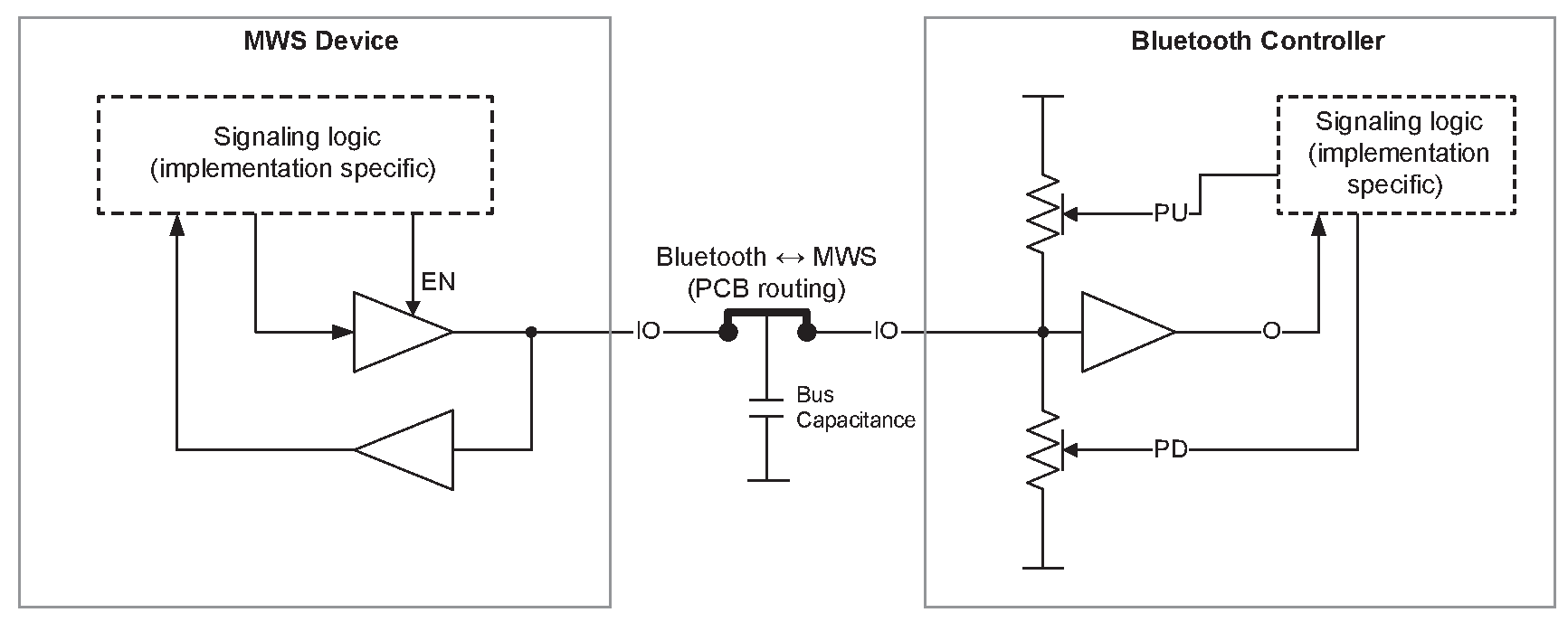
The WCI-1 physical layer multiplexes the UART TXD and RXD onto a single wire, using drive strengths to resolve contention. The MWS device uses direct drive to transmit its signals, while the Bluetooth Controller uses a pull up / pull down drive to transmit its signals. The configuration is illustrated in Figure 2.1.
 |
A high voltage on the wire shall be interpreted as a logical 1 and a low voltage shall be interpreted as a logical 0. The actual voltage levels are vendor specific.
The MWS device output buffer shall be in the high impedance state when it is not transmitting. The Bluetooth Controller shall be in the pulled-up state when it is not transmitting.
The MWS device may transmit at any time, using the waveform illustrated in Figure 2.2.

Every MWS-to-Bluetooth message shall be preceded by a preamble, which consists of 5 bits ‘01011’ (in transmission order). The preamble is sent at a baud rate that is at least twice the baud rate of Bluetooth-to-MWS signals[1]. The nominal drive strength for the preamble should be targeted at no more than 250 Ω equivalent output resistance. The Bluetooth Controller shall be able to detect the preamble and go into the reception mode to receive the message that follows. If the Bluetooth Controller detects a preamble while it is transmitting, it shall stop the transmission and go into the reception mode. After completion of the reception, it may retransmit the message that was interrupted.
When the Bluetooth Controller is not in the reception mode, it may transmit a message using the pull up / pull down mechanism. The nominal pull strength should be targeted at 4 kΩ ± 1 kΩ equivalent resistance for both pull up and pull down. The Bluetooth-to-MWS waveform is illustrated in Figure 2.3.

2.1. Physical signal specifications
Table 2.1 and Table 2.2 provide more complete specifications for the physical signals. They are provided as a reference to device makers:
Symbol | Parameter | Condition | Value | |
|---|---|---|---|---|
Min | Max | |||
VIL | Low level input voltage | VDD in the range 1.8 V to 2.5 V1 | -0.5 V | 0.2 × VDD |
VIH | High level input voltage | VDD in the range 1.8 V to 2.5 V1 | 0.8 × VDD | VDD + 0.5 V |
VOL | Low level output voltage (with extra pull high RB) | VDD in the range 1.8 V to 2.5 V1 RB = 2.5 kΩ | 0 V | 0.1 × VDD |
VOH | High level output voltage (with extra pull low RB) | VDD in the range 1.8 V to 2.5 V1 RB = 2.5 kΩ | 0.9 × VDD | VDD |
CIO | Capacitance for I/O | none | 0 F | 5 pF |
CB | Capacitive load for bus | none | 0 F | 10 pF |
RON | Turn on impedance | none | 0 Ω | 250 Ω |
TR | Rise time (10% to 90% swing time, with extra pull low RB and capacitive load CL = CB + other IO) | RB = 2.5 kΩ CL = 15 pF | 0 s | 50 ns |
TF | Fall time (90% to 10% swing time, with extra pull high RB and capacitive load CL = CB + other IO) | RB = 2.5 kΩ CL = 15 pF | 0 s | 50 ns |
CLKj | Clock jitter | none | none | 1% |
Symbol | Parameter | Condition | Value | |
|---|---|---|---|---|
Min | Max | |||
VIL | Low level input voltage | VDD in the range 1.8 V to 2.5 V1 | -0.5 V | 0.2 × VDD |
VIH | High level input voltage | VDD in the range 1.8 V to 2.5 V1 | 0.8 × VDD | VDD + 0.5 V |
VOL | Low level output voltage | VDD in the range 1.8 V to 2.5 V1 | 0 V | 0.1 × VDD |
VOH | High level output voltage | VDD in the range 1.8 V to 2.5 V1 | 0.9 × VDD | VDD |
CIO | Capacitance for I/O | none | 0 F | 5 pF |
CB | Capacitive load for bus | none | 0 F | 10 pF |
RP | Pull up/pull down resistance | none | 3 kΩ | 5 kΩ |
TR | Rise time (10% to 90% swing time, with capacitive load C L = C B + other IO) | CL = 15 pF | 0 s | 220 ns |
TF | Fall time (90% to 10% swing time, with capacitive load CL = CB + other IO) | CL = 15 pF | 0 s | 220 ns |
CLKj | Clock jitter | none | none | 1% |
Notes:
The voltage levels are vendor specific. Table 2.1 and Table 2.2 do not cover all possible ranges of voltage for all devices, nor is it required that a single device be able to operate in the full range indicated here.
The values in these tables are based on a MWS-to-Bluetooth baud rate of 4 megabits per second and a Bluetooth-to-MWS baud rate of 1 megabit per second, in each case ±1%. The actual baud rates used are vendor-specific.
3. Transport layer
The transport layer defines the mapping of the logical coexistence signals (see [Vol 7] Part A) onto the physical transport channel.
The 8-bit UART character is divided into two portions with three bits for the message type indicator and five bits for the message body. The bit with index 0 is the LSB and shall be transmitted first.
b0 | b1 | b2 | b3 | b4 | b5 | b6 | b7 |
|---|---|---|---|---|---|---|---|
Type[0] | Type[1] | Type[2] | MSG[0] | MSG[1] | MSG[2] | MSG[3] | MSG[4] |
3.1. Message types
This section describes the message formats for the logical coexistence signals. The message types are listed in Table 3.2.
Message Type Indicator | Direction | Message Type |
|---|---|---|
0 | MWS ↔ Bluetooth | Real-time Signal message |
1 | MWS ↔ Bluetooth | Transport Control message |
2 | MWS ↔ Bluetooth | Transparent Data message |
3 | MWS → Bluetooth Bluetooth → MWS | MWS Inactivity Duration message RFU |
4 | MWS → Bluetooth Bluetooth → MWS | MWS Scan Frequency message RFU |
5 | MWS → Bluetooth Bluetooth → MWS | RFU RFU |
6 | Vendor-specific | |
7 | Vendor-specific | |
The logical coexistence signals are listed in Table 3.3.
Signal Name | Description |
|---|---|
FRAME_SYNC | |
MWS_RX | |
BLUETOOTH_RX_PRI | |
BLUETOOTH_TX_ON | |
MWS_PATTERN | |
MWS_TX | |
802_TX_ON | |
802_RX_PRI | |
MWS_INACTIVITY_DURATION | |
MWS_SCAN_FREQUENCY |
3.1.1. Real-time Signal message (Type 0)
The Real-time Signal message is used to transport the real-time coexistence signals (see [Vol 7] Part A) over the WCI-1 transport interface.
The Real-time Signal message conveys all the real-time coexistence signals in one message. The time reference point for the Real-time Signal message is the end of MSG[4] (i.e. the transition to the STOP bit).
Two Real-time Signal messages are defined, one from the Bluetooth Controller to the MWS device and another from the MWS device to the Bluetooth Controller.
MSG[0] | MSG[1] | MSG[2] | MSG[3] | MSG[4] |
|---|---|---|---|---|
FRAME_SYNC | MWS_RX | MWS_TX | MWS_PATTERN[0] | MWS_PATTERN[1] |
MSG[0] | MSG[1] | MSG[2] | MSG[3] | MSG[4] |
|---|---|---|---|---|
BLUETOOTH_RX_PRI | BLUETOOTH_TX_ON | 802_RX_PRI | 802_TX_ON | RFU |
3.1.2. Transport Control message (Type 1)
The Transport Control message can request state information from the MWS device’s coexistence interface.
MSG[0] | MSG[1] | MSG[2] | MSG[3] | MSG[4] |
|---|---|---|---|---|
RESEND_REAL_TIME | RFU | RFU | RFU | RFU |
Signal Name | Description |
|---|---|
RESEND_REAL_TIME | This bit is set if a device wants to get a status update of the real-time coexistence signals. The signal is usually used after wake-up from sleep of the transport interface. If the receiving device’s transport interface is awake it shall send a Real-time message with the current status of the real-time coexistence signals within 4 UART character periods. If the signal is not received within 4 UART character periods the device is considered asleep. |
3.1.3. Transparent Data message (Type 2)
The Transparent Data message can be used to exchange non-time critical signals between the MWS device and the Bluetooth Controller. The interface does not guarantee the delivery of a message. Protocol and content of the message are vendor specific.
Each octet to be transmitted is split into two 4-bit parts, called "nibbles". The least significant nibble consists of bits 0 to 3 of the octet and shall be transmitted first. The most significant nibble consists of bits 4 to 7 of the octet and shall be transmitted after the least significant nibble.
A least significant nibble shall be discarded if the next nibble is a least significant nibble. A most significant nibble shall only be accepted if the preceding nibble was a least significant nibble.
MSG[0] | MSG[1] | MSG[2] | MSG[3] | MSG[4] |
|---|---|---|---|---|
NIBBLE_POSITION | DATA[0] / DATA[4] | DATA[1] / DATA[5] | DATA[2] / DATA[6] | DATA[3] / DATA[7] |
Signal Name | Description |
|---|---|
NIBBLE_POSITION | 0 – Least Significant Nibble 1 – Most Significant Nibble |
DATA[n]; n = 0..7 | Data bits of the message octet |
3.1.4. MWS Inactivity Duration message (Type 3)
The MWS Inactivity Duration message is used to send the MWS_INACTIVITY_DURATION signal from the MWS device to the Bluetooth Controller.
The message is sent at the beginning of an MWS inactivity period.
MSG[0] | MSG[1] | MSG[2] | MSG[3] | MSG[4] |
|---|---|---|---|---|
DURATION[0] | DURATION[1] | DURATION[2] | DURATION[3] | DURATION[4] |
The MWS Inactivity Duration is encoded in 5 bits. DURATION is unsigned.
When DURATION = 0, MWS_INACTIVITY_DURATION is cancelled.
When DURATION = 31, MWS_INACTIVITY_DURATION is infinite.
Otherwise, MWS_INACTIVITY_DURATION is given by the formula:
MWS_INACTIVITY_DURATION = DURATION * 5 ms
3.1.5. MWS Scan Frequency message (Type 4)
The MWS Scan Frequency message is used to send the MWS_SCAN_FREQUENCY signal from the MWS device to the Bluetooth Controller.
MSG[0] | MSG[1] | MSG[2] | MSG[3] | MSG[4] |
|---|---|---|---|---|
FREQ[0] | FREQ[1] | FREQ[2] | FREQ[3] | FREQ[4] |
The MWS Scan Frequency index is encoded in 5 bits. FREQ is unsigned.
[1] The preamble baud rate should be one that is supported by the underlying UART of the Bluetooth device.