Part D. Message Sequence Charts
vAtlanta r00
Examples of message sequence charts showing the interactions of the Host Controller Interface with the Link Layer.
1. Introduction
This section shows typical interactions between Host Controller interface (HCI) commands and events and the Link Layer (LL). It focuses on the message sequence charts (MSCs) for the procedures specified in “Bluetooth Host Controller Interface Functional Specification” with regard to Link Layer control procedures from “Link Layer”. This section illustrates only the most useful scenarios; it does not cover all possible alternatives. Furthermore, the message sequence charts do not consider errors over the air interface or Host interface. In all message sequence charts it is assumed that all events are not masked, so the Controller will not filter out any events.
The sequence of messages in these message sequence charts is for illustrative purposes. The messages may be sent in a different order where allowed by the Link Layer or HCI. If any of these charts differ with text in the Link Layer or HCI Parts, the text in those Parts overrides these charts.
1.1. Notation
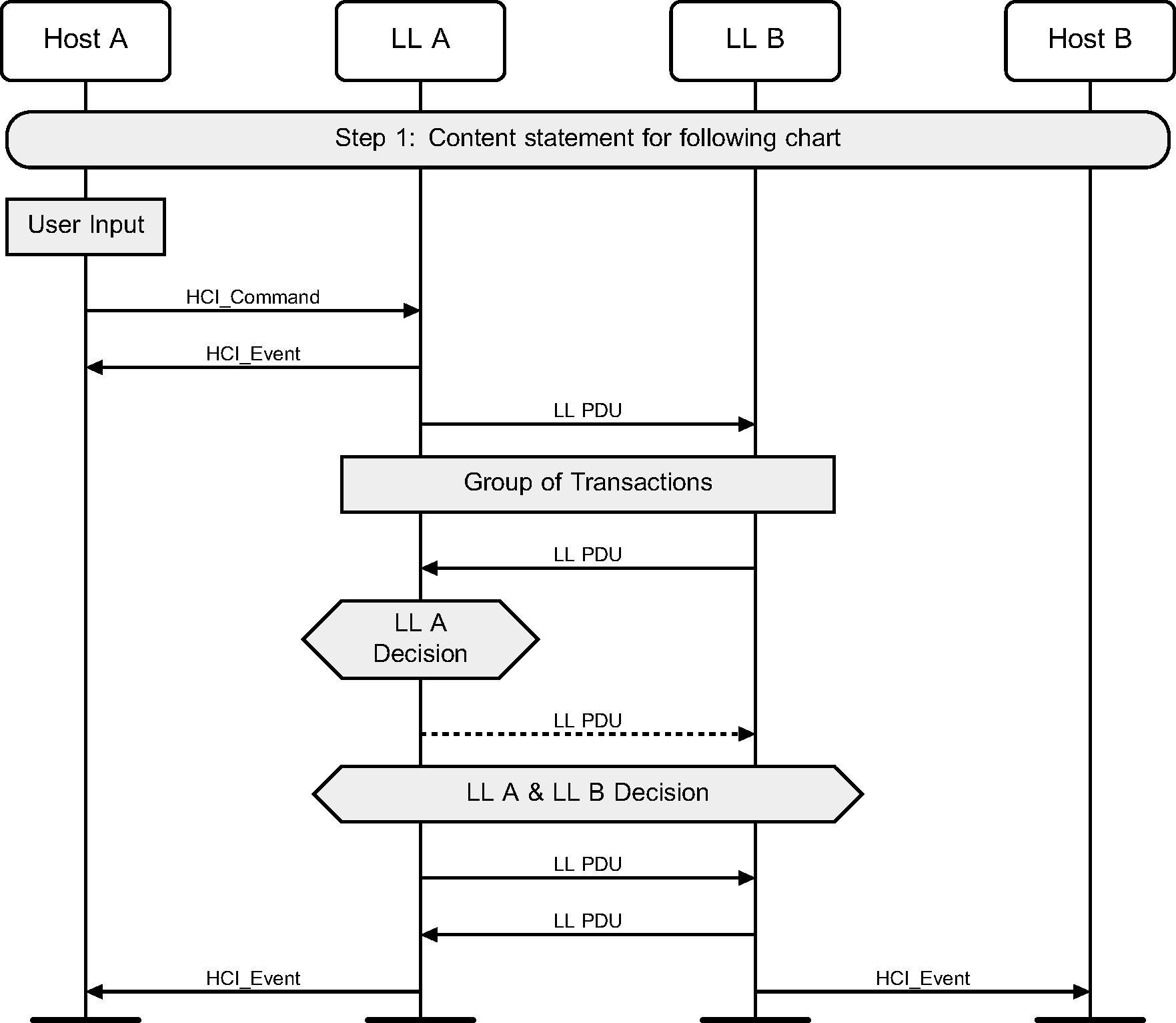
The notation used in the message sequence charts (MSCs) consists of ovals, elongated hexagons, boxes, lines, and arrows. The vertical lines terminated on the top by a shadow box and at the bottom by solid oval indicate a protocol entity that resides in a device. MSCs describe interactions between these entities and states those entities may be in.
The following symbols represent interactions and states:
Oval | Defines the context for the message sequence chart |
Hexagon | Indicates a condition needed to start the transactions below this hexagon. The location and width of the Hexagon indicates which entity or entities make this decision. |
Box | Replaces a group of transactions. May indicate a user action, or a procedure in the Link Layer. |
Dashed Box | Optional group of transactions. |
Solid Arrow | Represents a message, signal or transaction. Can be used to show Link Layer and HCI traffic. |
Dashed Arrow | Represents an optional message, signal or transaction. Can be used to show Link Layer and HCI traffic. |
1.2. Control flow
Some message sequences are split into several charts. In these charts, numbers indicate normal or required ordering and letters represent alternative paths. For example, Step 4 is after Step 3, and Step 5a could be executed instead of Step 5b.
1.3. Example MSC
The protocol entities represented in the example shown in Figure 1.1 illustrate the interactions of two devices named A and B; each device includes a Host and a LL entity in this example. Other MSCs in this section may show the interactions of more than two devices.
1.4. Forward compatibility
Many of the message sequences in this Part use HCI commands or events that have enhanced or extended variants that were added to the specification later than the relevant sequence. Such variants can be related commands or events with different names (e.g,. HCI_LE_Advertising_Report and HCI_LE_Extended_Advertising_Report events) or commands or events with multiple versions (e.g., HCI_LE_Generate_DHKey command). In some instances (for example, see [Vol 4] Part E, Section 3.1.1), a Host is required to use the new variant rather than the one shown in the MSC. Even when this is not a requirement, Host implementers may prefer to use the newer variants.
In these circumstances, the MSCs have not been rewritten to use newer features but have been left unchanged. In general, the new commands and events will directly replace the old ones, but this is not always the case and readers should not assume it.
2. Standby state
2.1. Initial setup
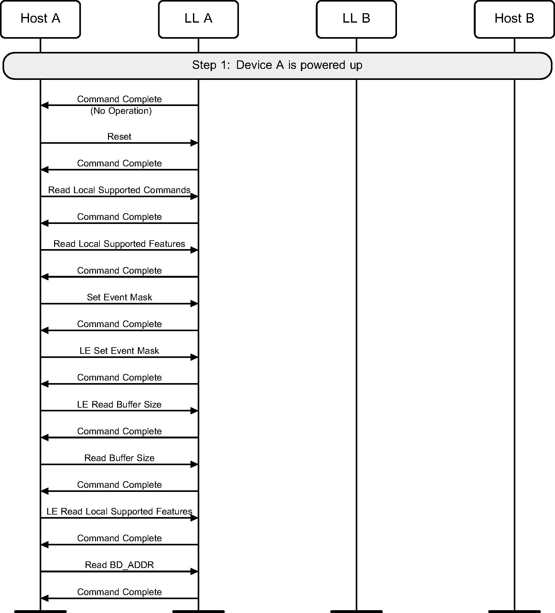
To perform initial setup of a LE Controller, the following sequence of actions may be required.
First, the Host would wait for the Controller to indicate the number of HCI Command packets the Host is currently allowed to send using a Command Complete event on a No OPeration command opcode. Then it would reset the Controller to a known state. Then it needs to read the local supported features to check that low energy is supported on this Controller. It would then set the event mask and LE event mask to enable the events that it wants the Controller to generate to the Host. Next, it will check the buffers that are available for data flow, using the Read Buffer Size and LE Read Buffer Size commands. Then it would read the locally supported LE features and select the features that it wishes to use. Finally, it will read the public device address if the Controller has one (see Figure 2.1).
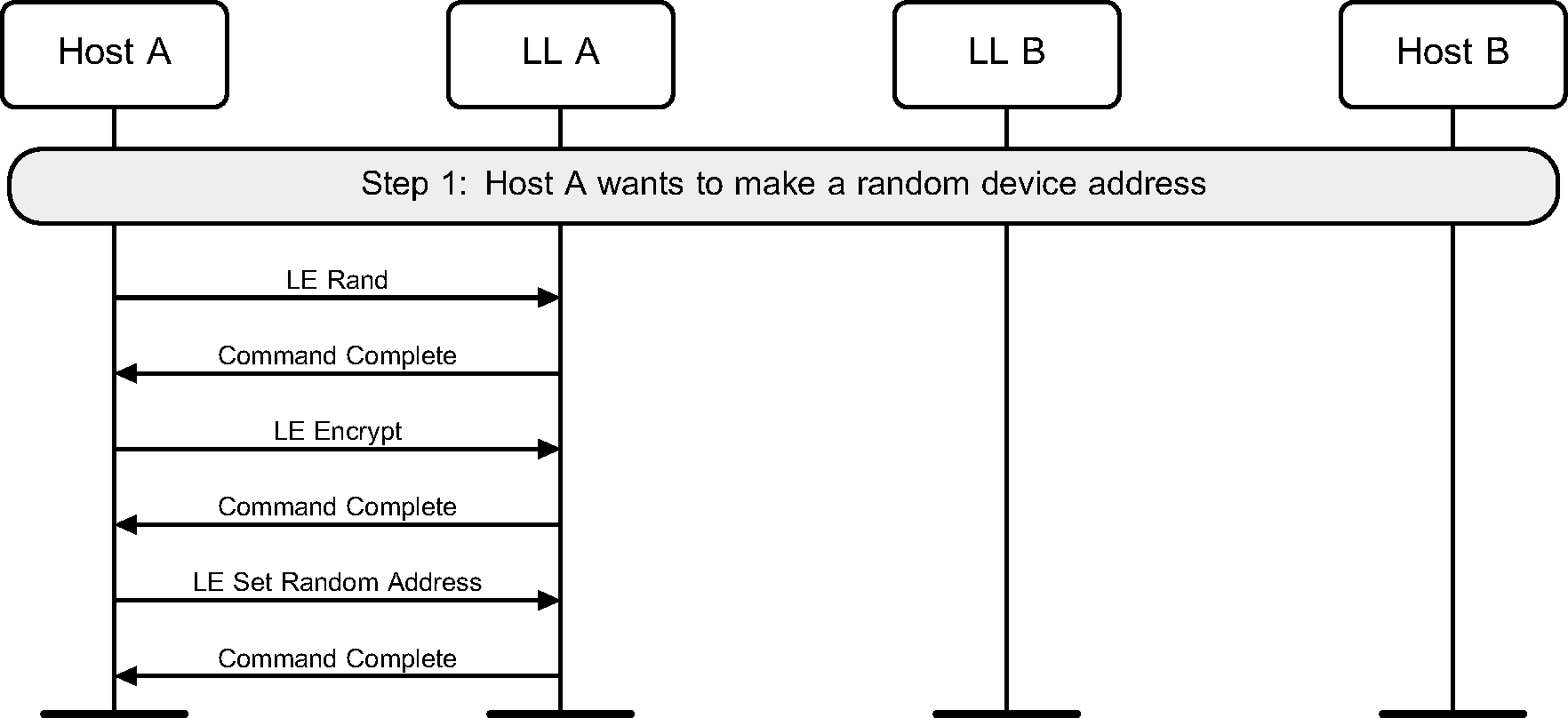
2.2. Random Device address
A device may use a random device address, but this address has to be configured before being used during advertising, scanning or initiating (see Figure 2.2).
2.3. Filter Accept List
Before advertising, scanning or initiating can use a Filter Accept List, the Filter Accept List may be cleared and devices added in as required (see Figure 2.3).

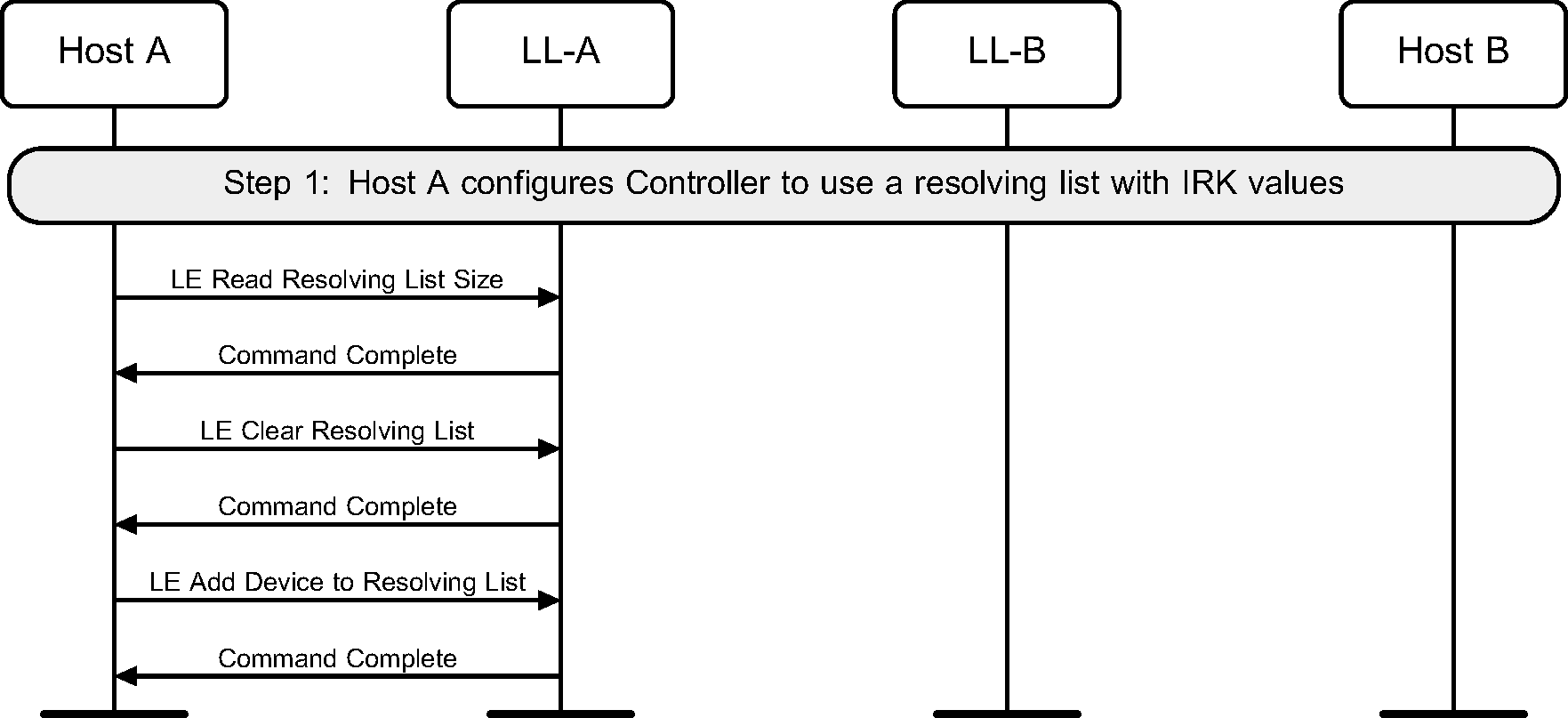
2.4. Adding IRK to resolving list
Before advertising, scanning or initiating can use resolving lists, the resolving list may be cleared and devices added in as required (see Figure 2.4).
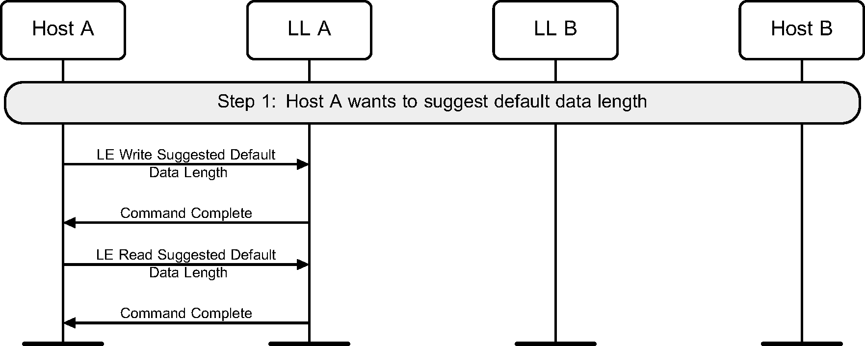
2.5. Default data length
Before creating a connection, the Host may specify its preferred values for the Controller’s maximum transmission packet size and maximum packet transmission time to be used for new connections. This may be done on either the Central or the Peripheral.
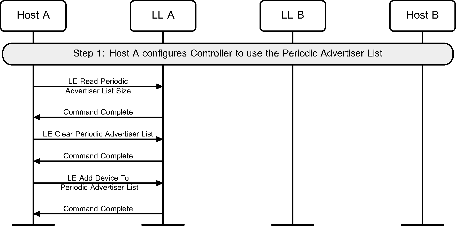
2.6. Periodic Advertiser List
The Periodic Advertiser List may be cleared and entries added as required, before it is made use of (see Figure 2.6).
3. Advertising state
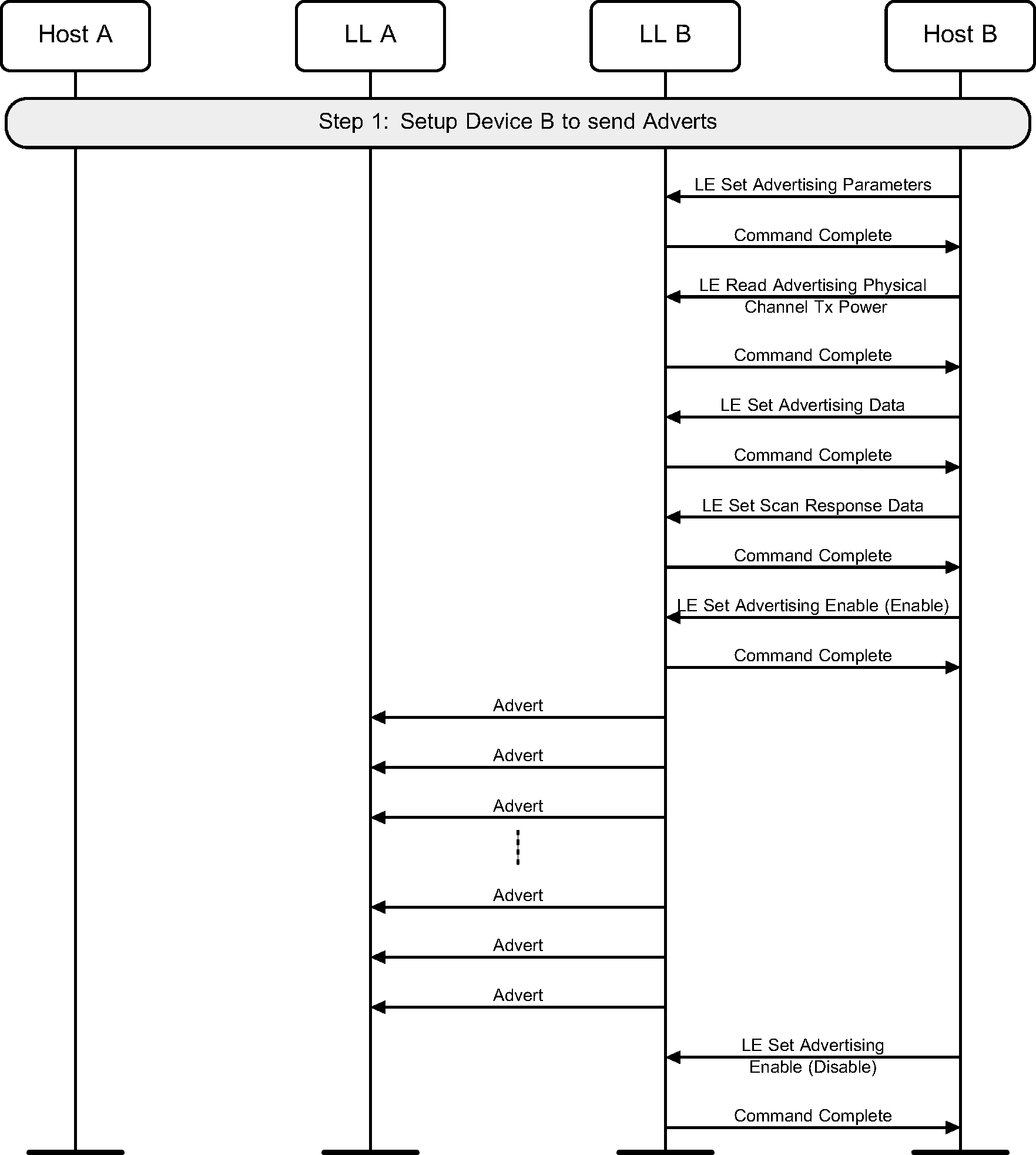
3.1. Undirected advertising
A device may enter the Advertising state by enabling advertising. It should also configure the advertising parameters before doing this (see Figure 3.1).
3.2. Directed advertising
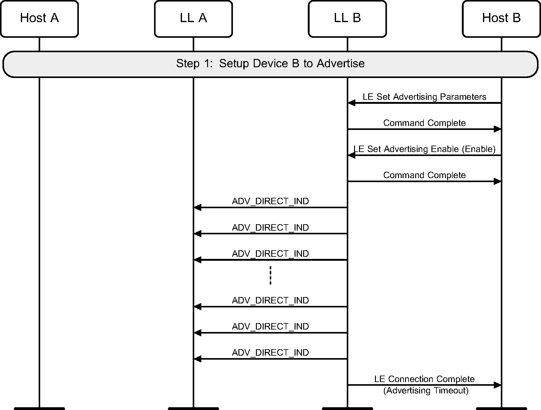
A device may use directed advertising to allow an initiator to connect to it. High duty cycle directed advertising is time limited in the Controller and therefore this may fail before a connection is created. This example only shows the failure case (see Figure 3.2).
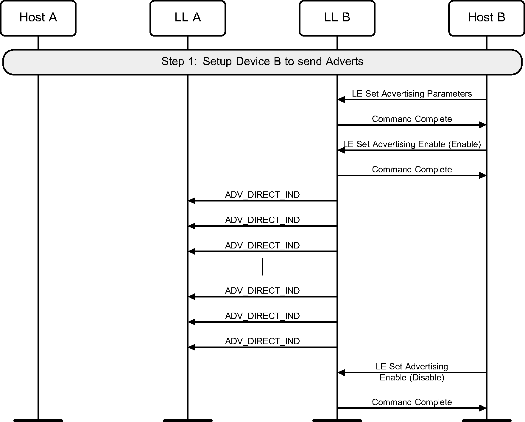
Low duty cycle directed advertising is not time-limited. This example shows the case where no connection is made. A device should also configure the advertising parameters before doing this (see Figure 3.3).
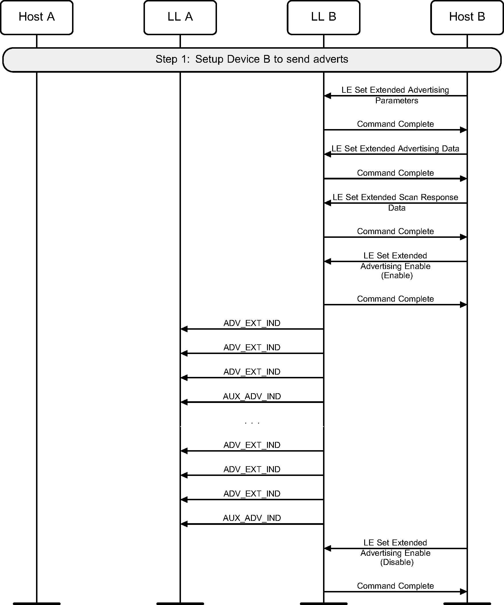
3.3. Advertising using ADV_EXT_IND
A device may enter the Advertising state by enabling advertising a set. It should also configure the advertising set parameters before doing this (see Figure 3.4).
3.4. Scan request notifications
A device may enable scan request notifications in an advertising set (see Figure 3.5).

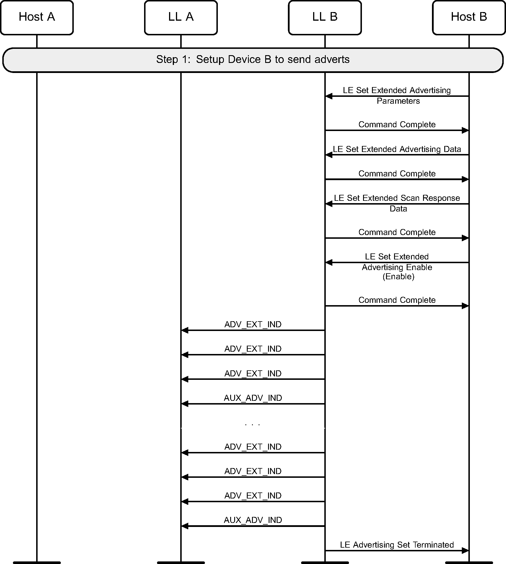
3.5. Advertising duration ended
A device may enter the Advertising State by enabling advertising a set for a limited duration of time (see Figure 3.6).
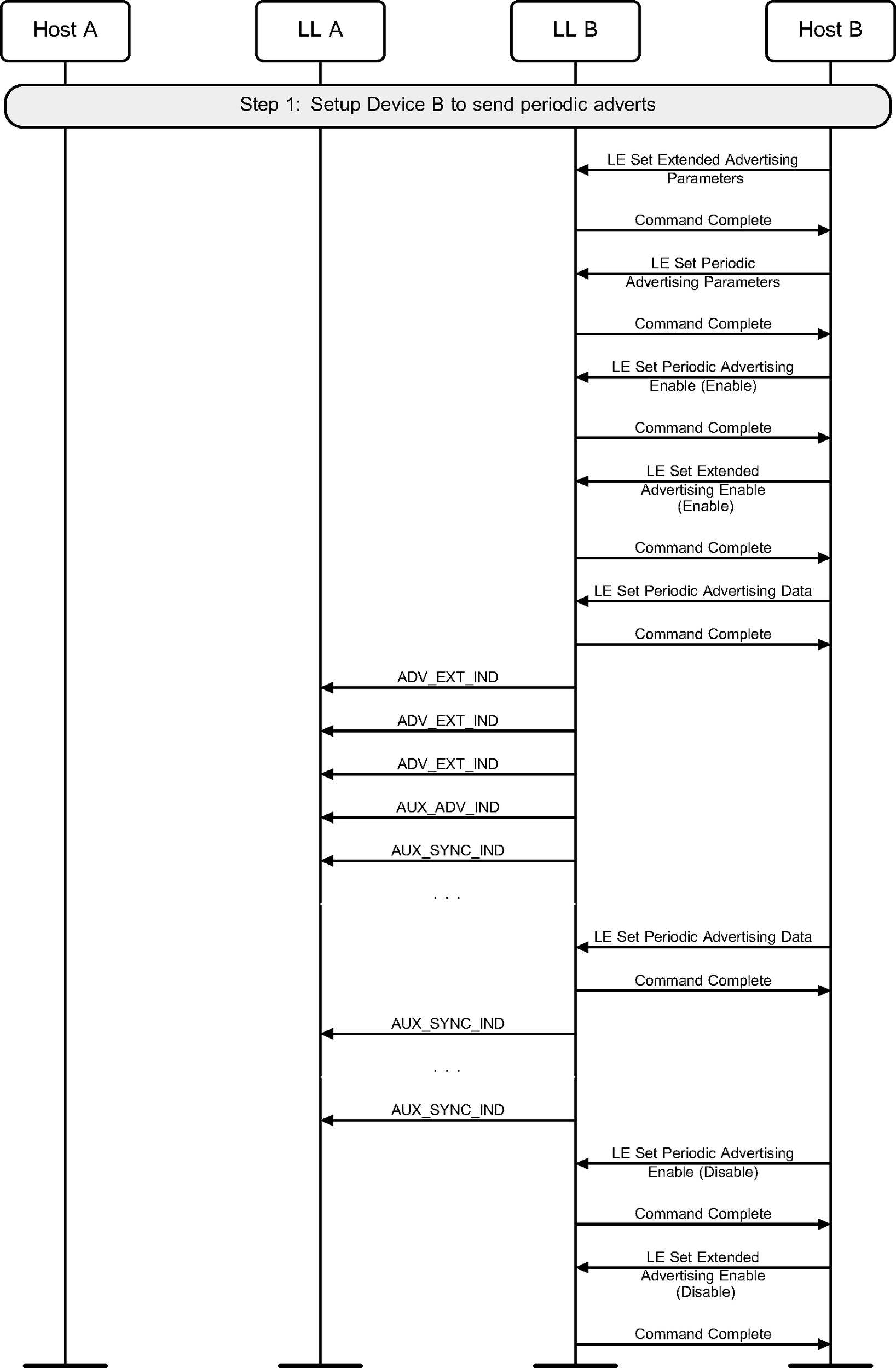
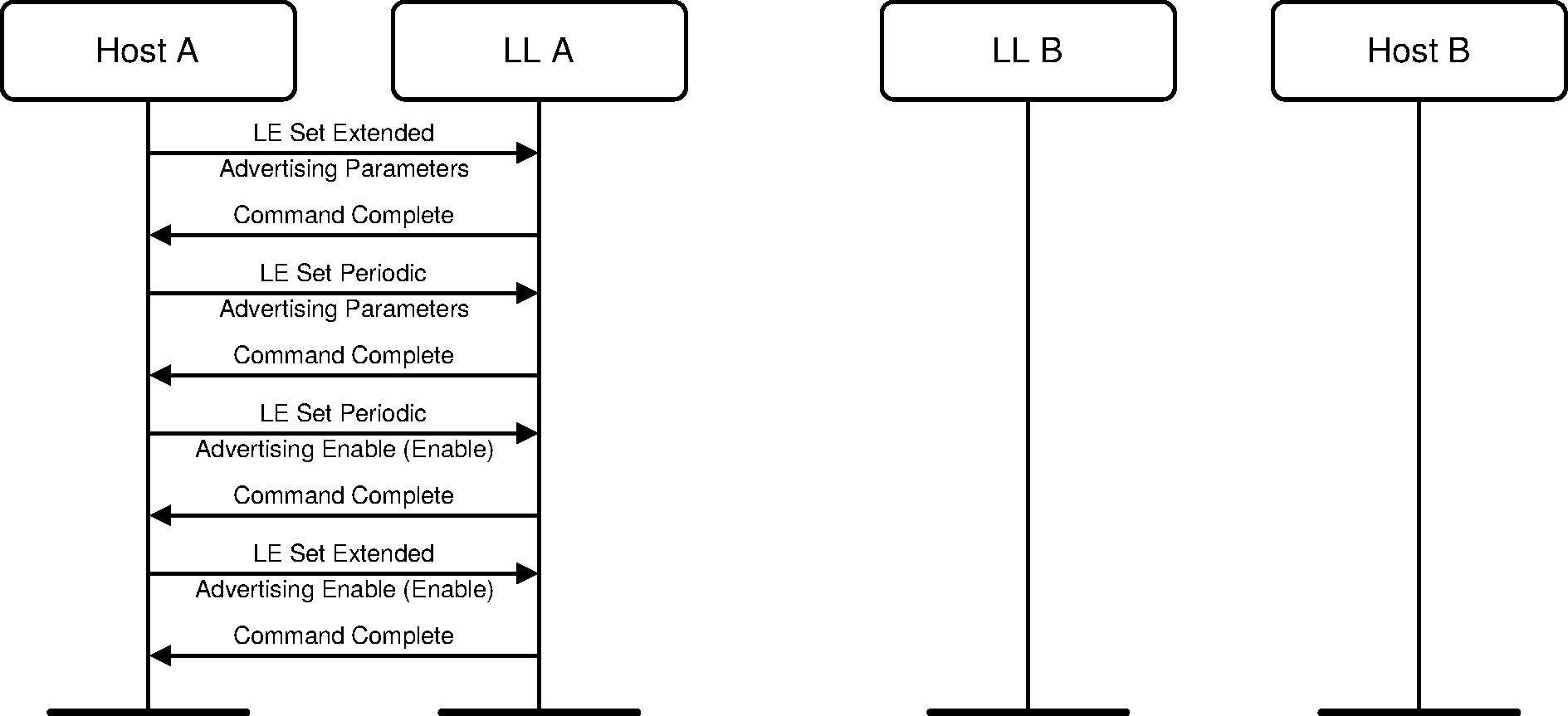
3.6. Periodic advertising
A device may enter the Advertising State by enabling periodic advertising in a set. It should also configure the advertising set parameters before doing this (see Figure 3.7).
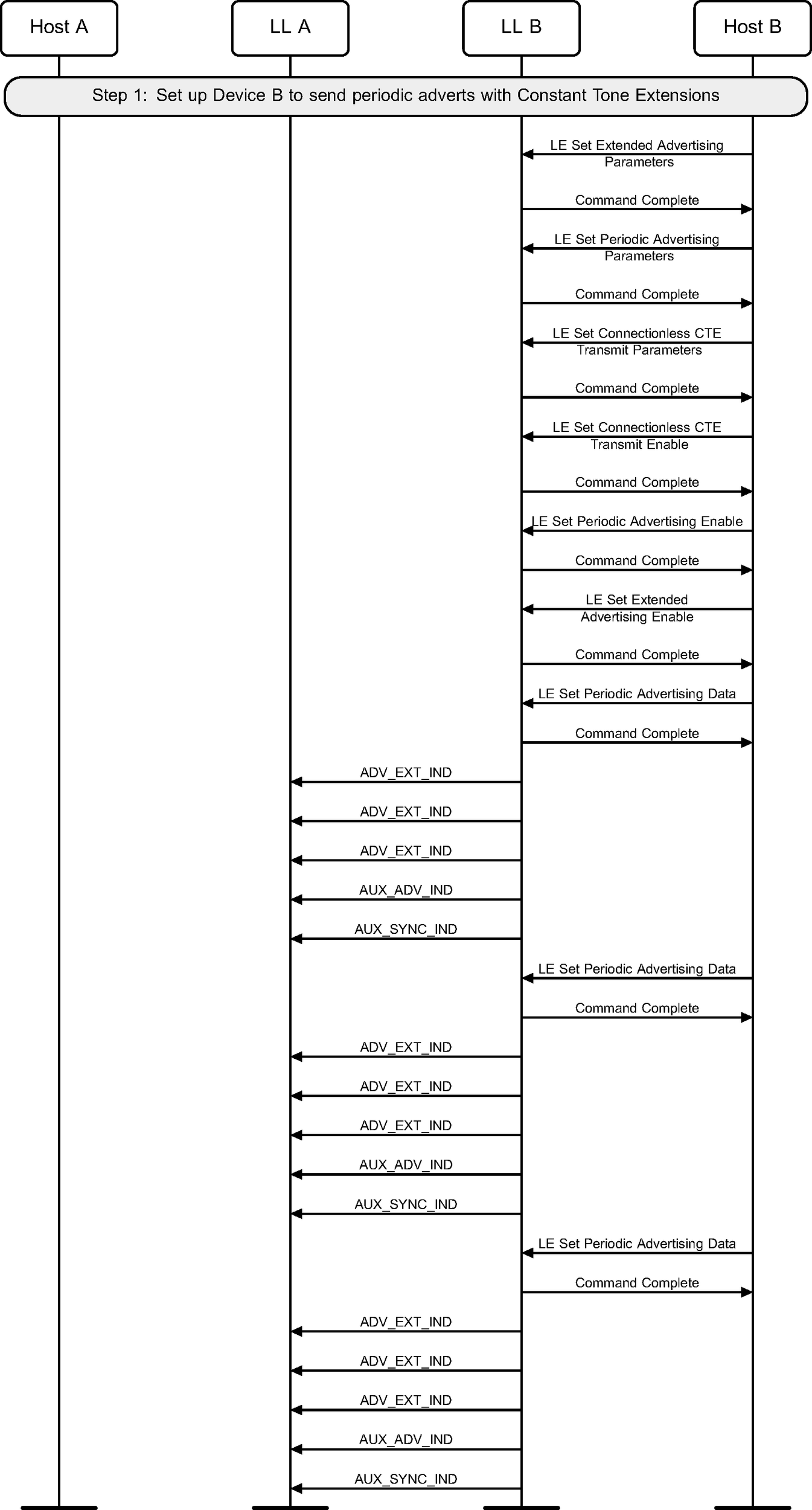
3.7. Connectionless Constant Tone Extension transmission
A device may send periodic advertising packets containing a Constant Tone Extension (see Figure 3.8).
3.8. Isochronous Broadcasting State
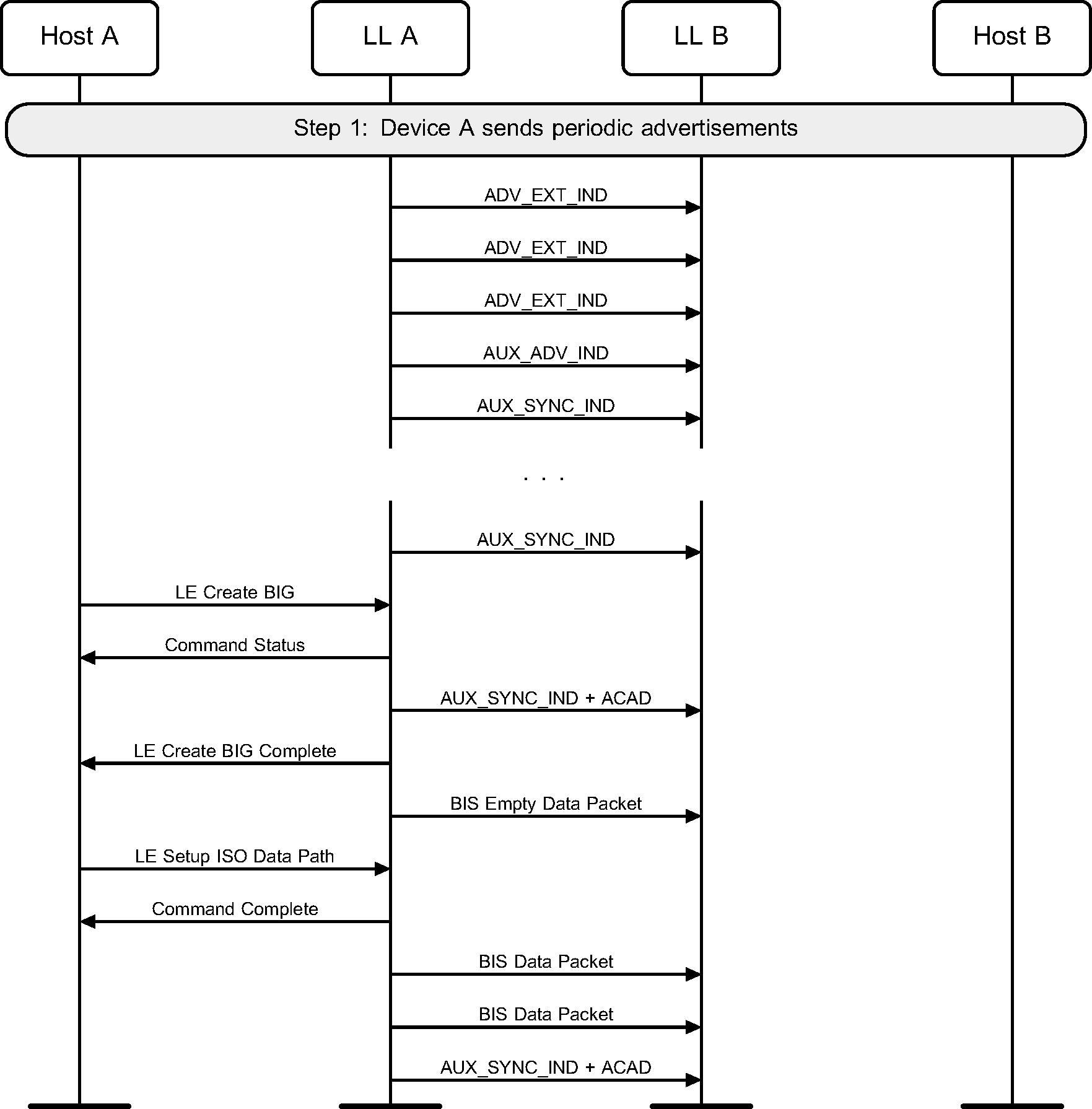
3.8.1. Create a Broadcast Isochronous Group
A device enters the Isochronous Broadcasting State and enables the periodic advertising associated with the BIG. The device then creates the BIG and sends isochronous data using the isochronous data paths (see Figure 3.9).
3.8.2. Terminate a Broadcast Isochronous Group
A device terminates a BIG (see Figure 3.10).

3.9. Periodic advertising with responses (PAwR)
A device may enter the Advertising state by enabling PAwR in a set. The device should configure the advertising set parameters before doing this (see Figure 3.11).
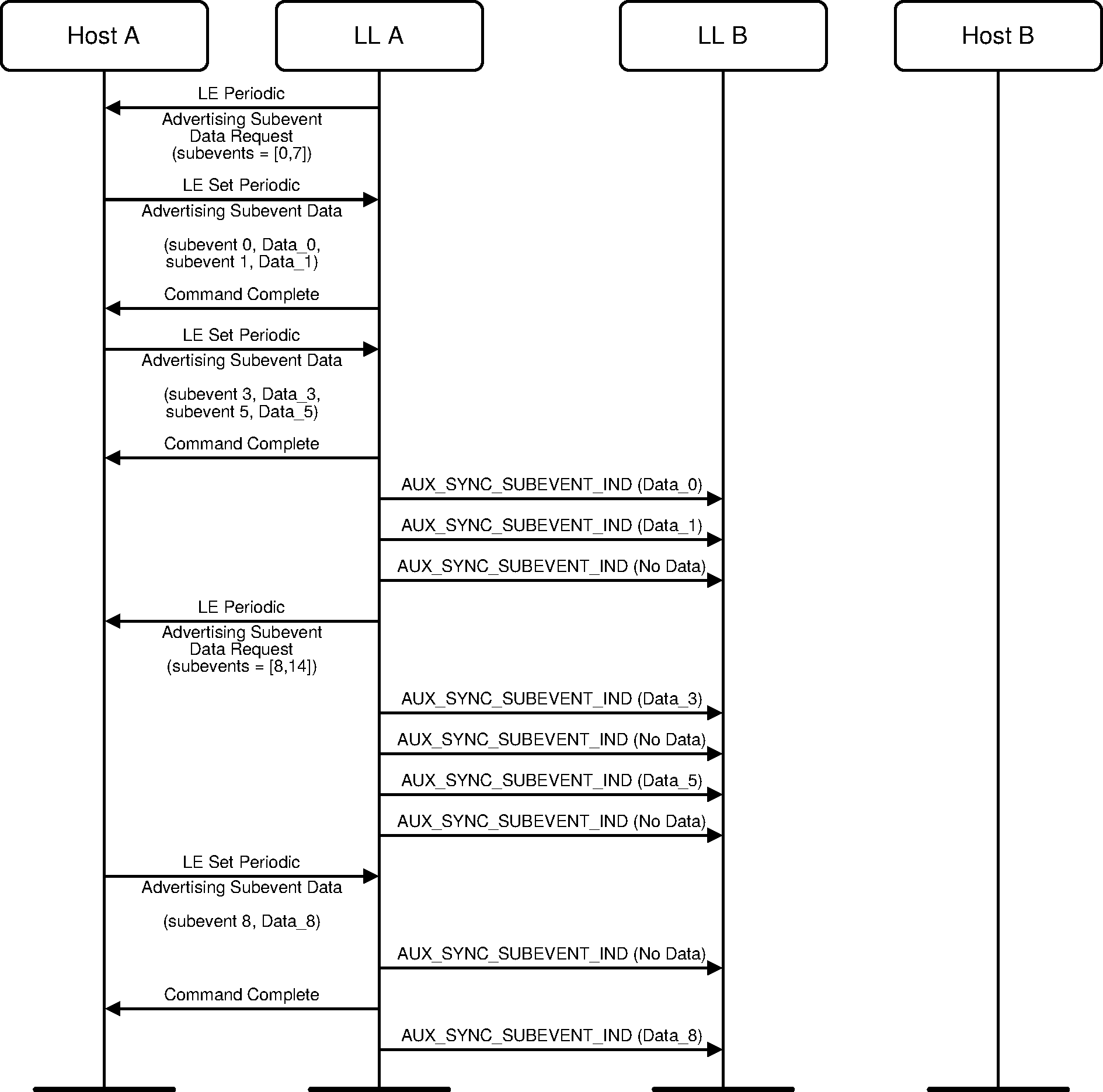
3.10. Transmitting PAwR subevents
A Controller may request data to be sent in one or more subevents of a PAwR advertising set. The Host can send this data to the Controller ahead of when the subevents are scheduled.
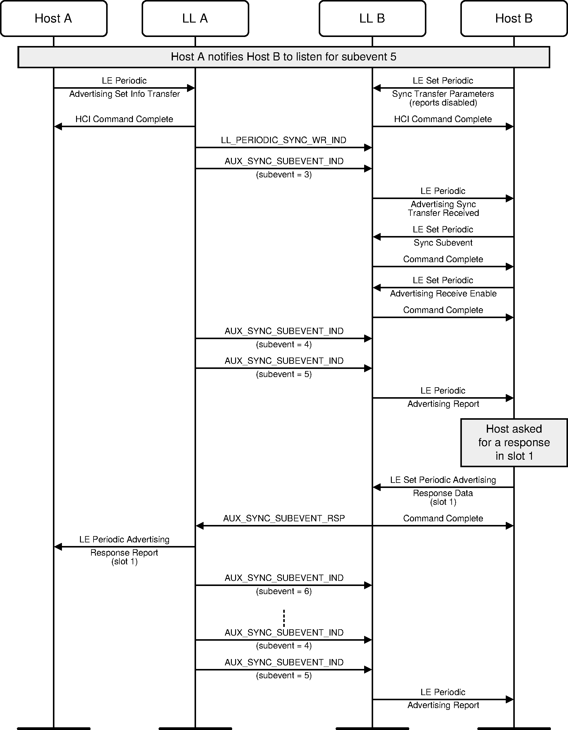
3.11. Using a response slot in PAwR
A device can send a response to a PAwR advertisement packet. The timing of the response is determined by the Host using information from the advertisement packet. The Host can send a response by indicating the response slot and data to be sent in that response slot.
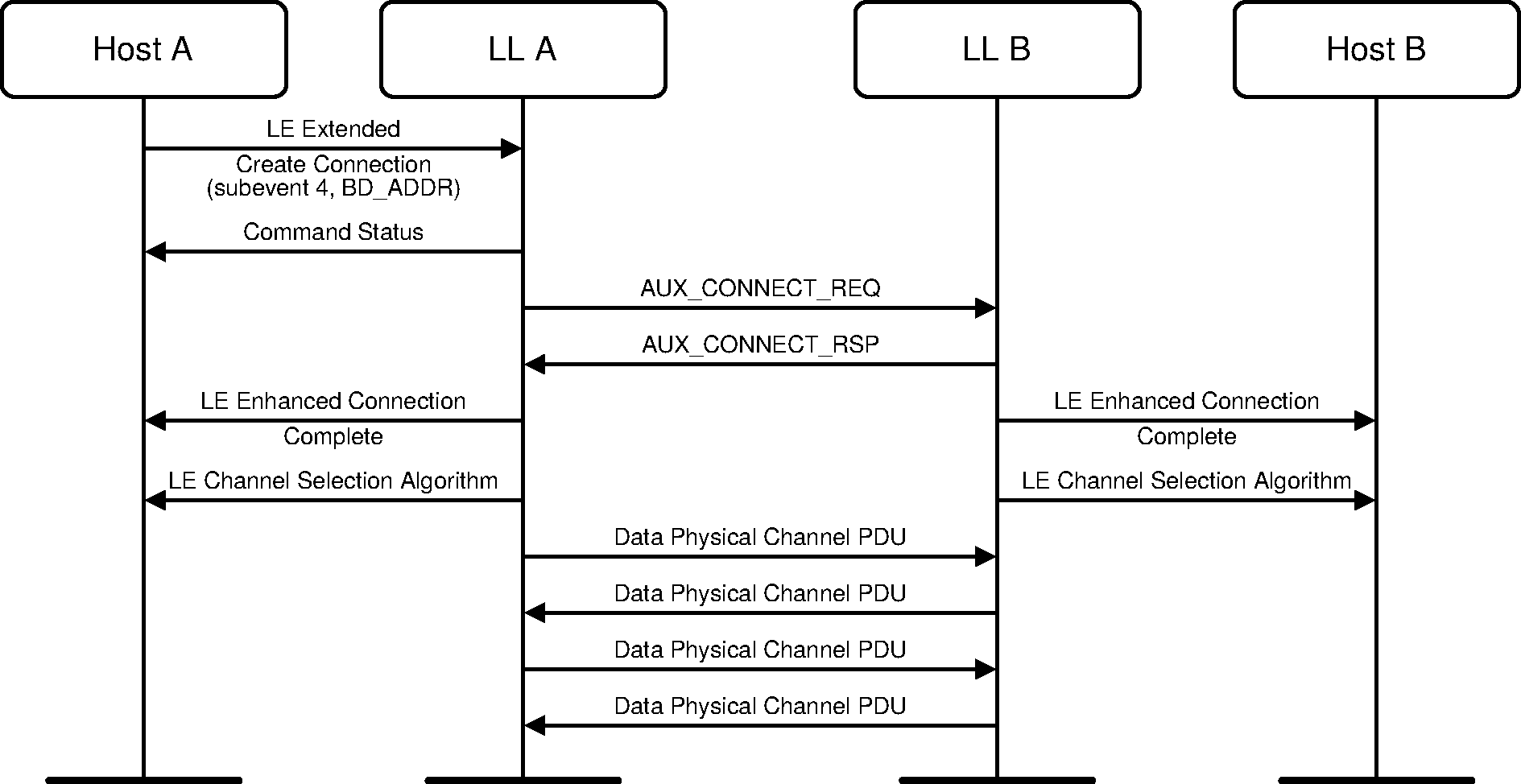
3.12. Connecting from PAwR
A device may initiate a connection with a synchronized device by using the LE Extended Create Connection command which indicates the subevent and BD_ADDR of the peer device. This initiates a connection by sending an AUX_CONNECT_REQ PDU in that subevent.
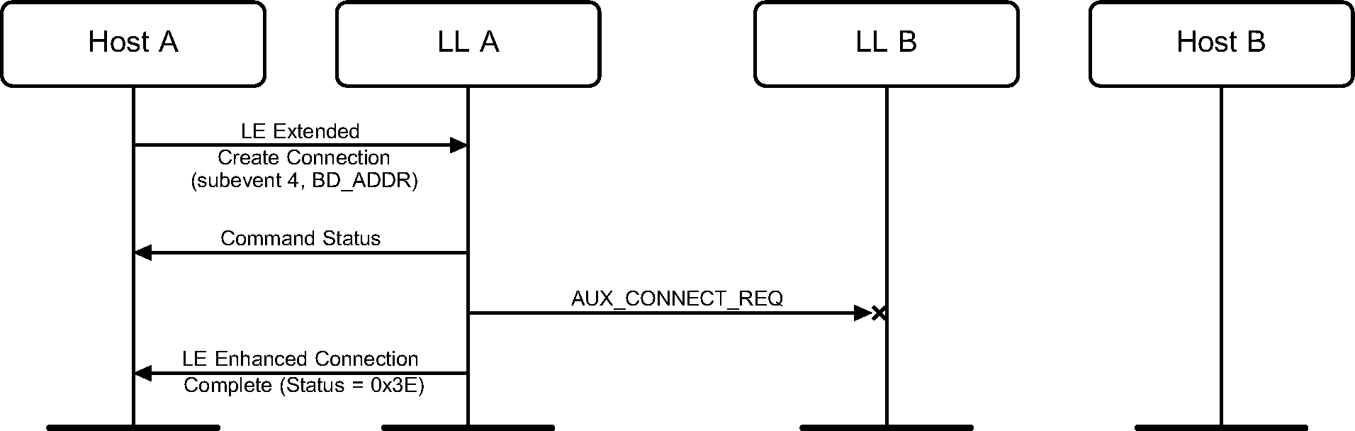
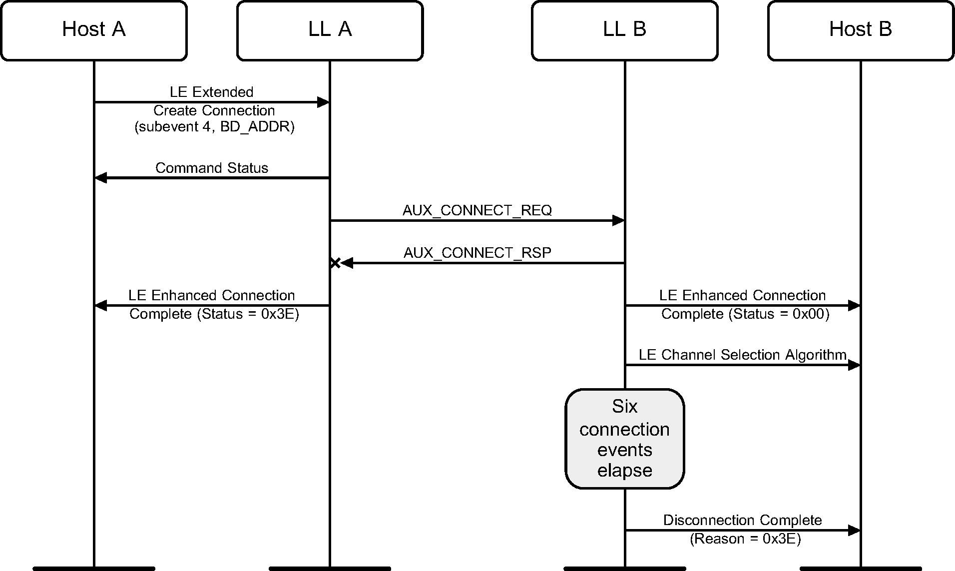
3.13. Failed Connection Attempts From PAWR
A synchronized device can miss an AUX_CONNECT_REQ PDU sent by the periodic advertiser.
The periodic advertiser can miss an AUX_CONNECT_RSP PDU sent by a synchronized device.
4. Scanning state
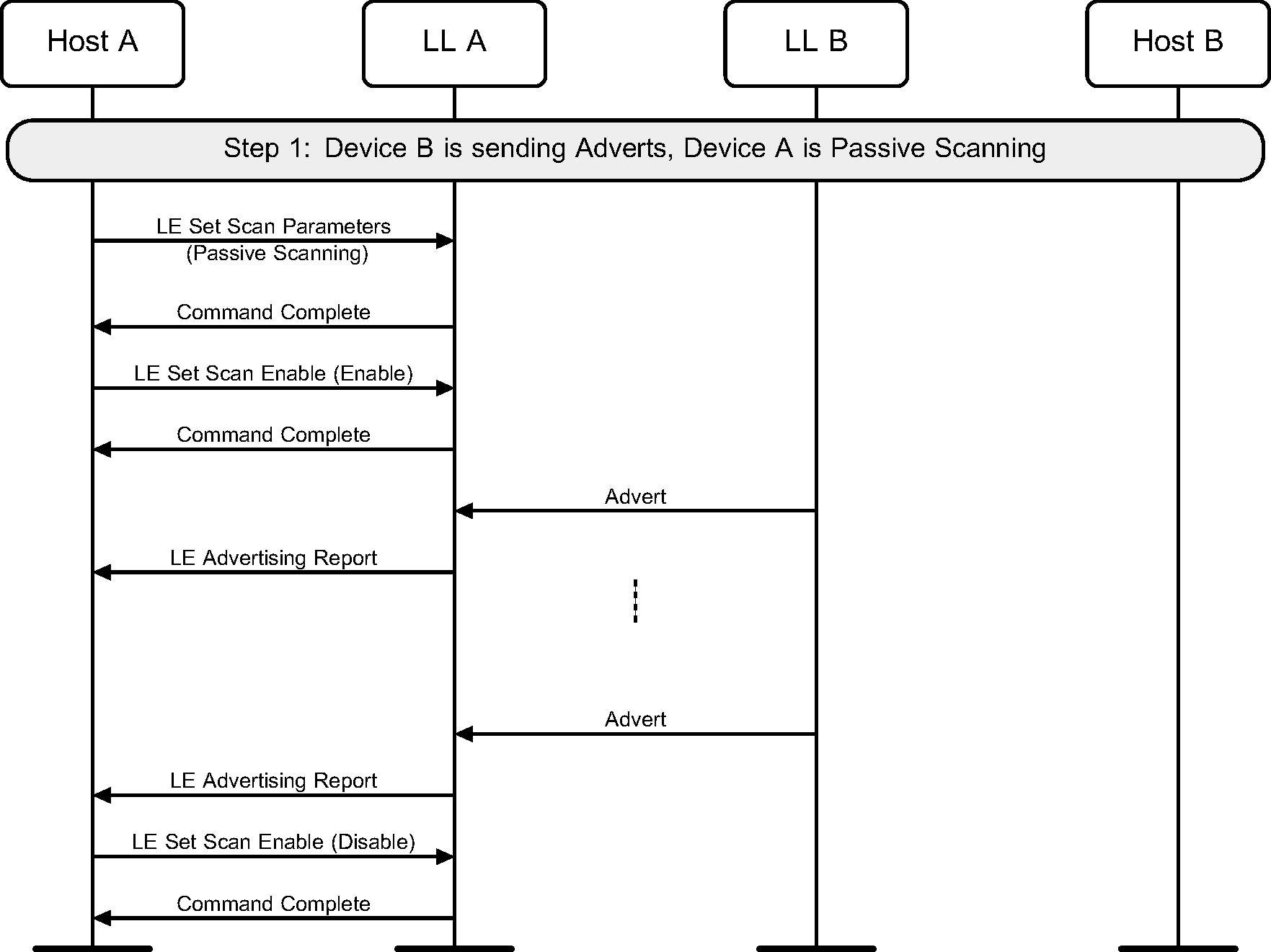
4.1. Passive scanning
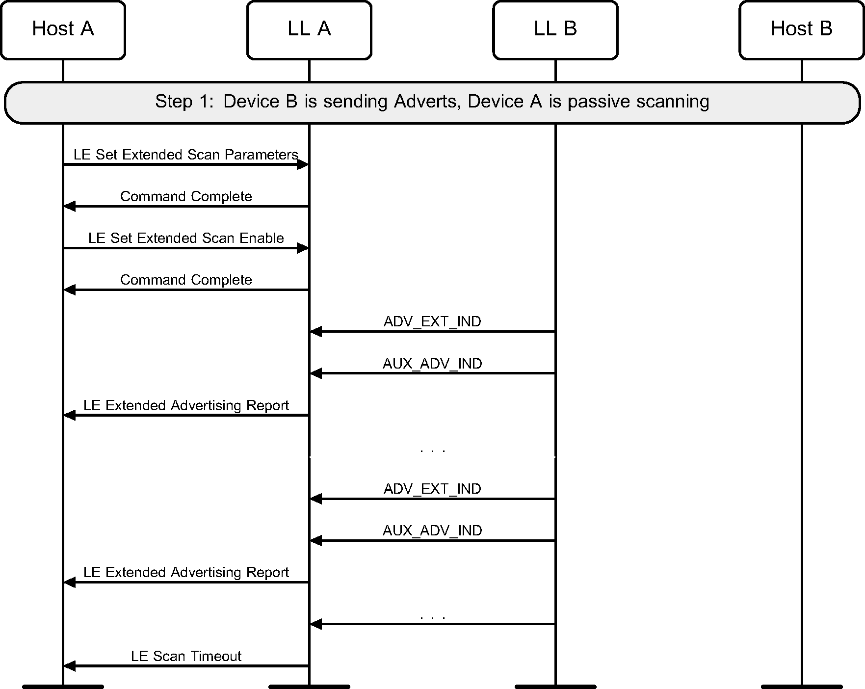
A device can use passive scanning to find advertising devices in the area. This would receive advertising packets from peer devices and report these to the Host (see Figure 4.1).
4.2. Active scanning
A device may use active scanning to obtain more information about devices that may be useful to populate a user interface. Active scanning involves more Link Layer advertising messages (see Figure 4.2).

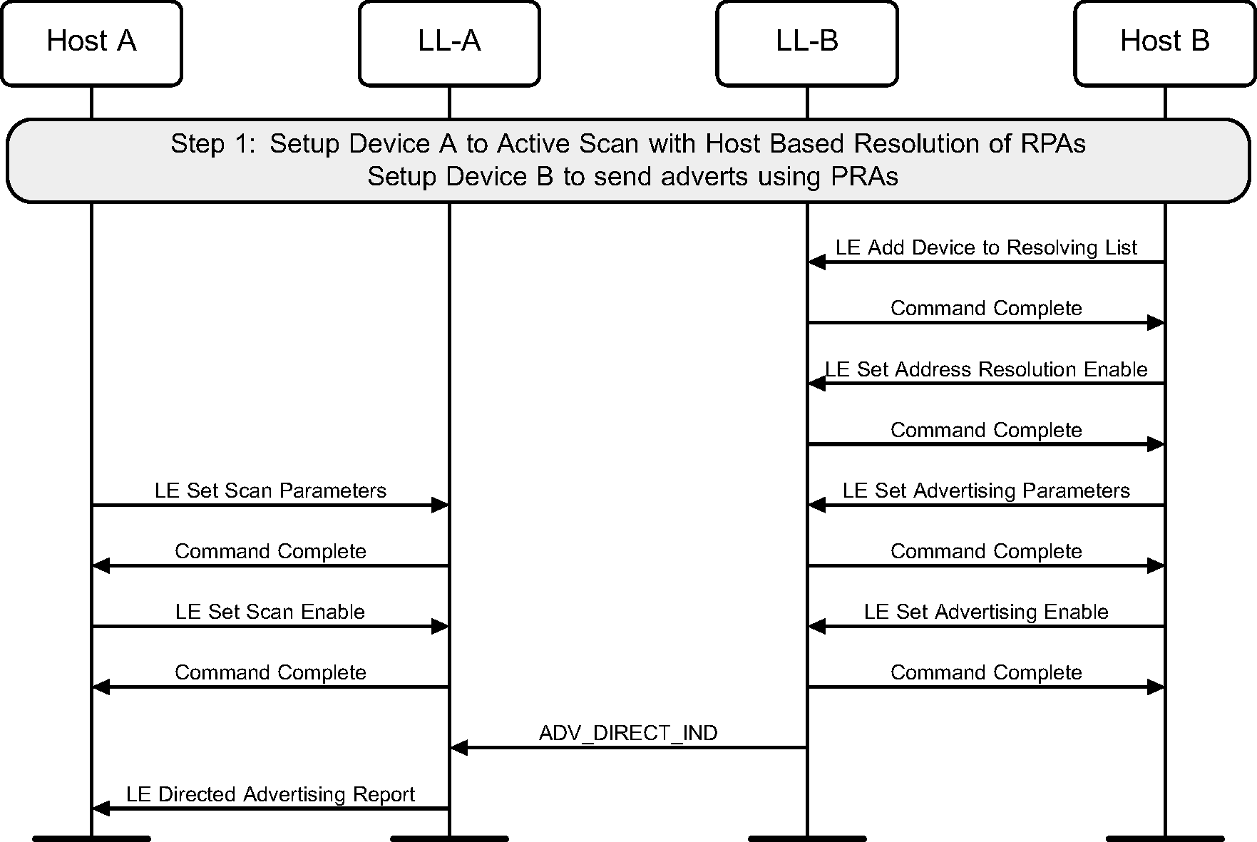
4.3. Passive scanning for directed advertisements with Privacy
If a device does not support Privacy in the Controller, it may choose to forward LE Directed Advertising Report events from devices supporting Privacy without requiring filtering through the Controller Resolving List.
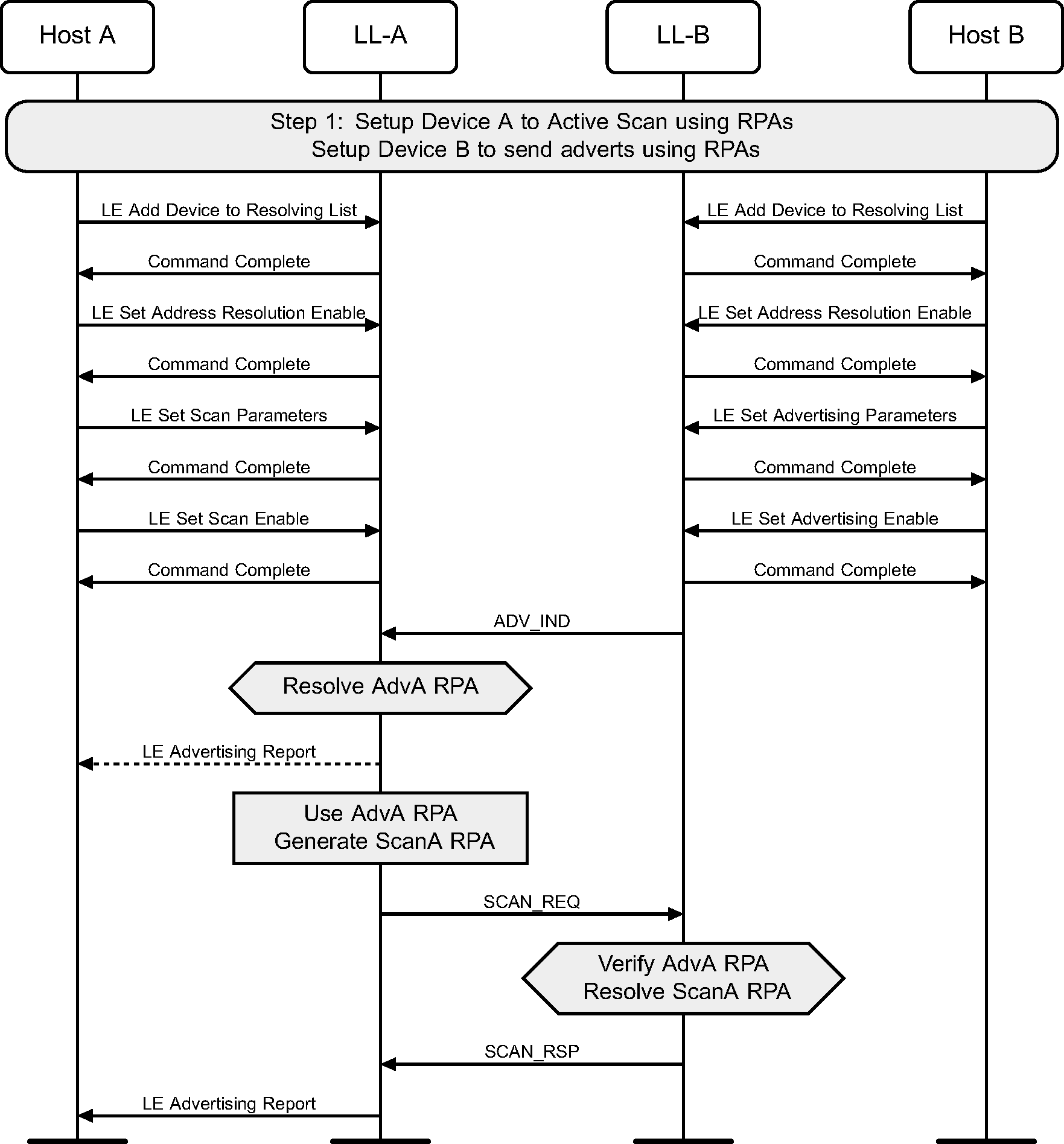
4.4. Active scanning with Privacy
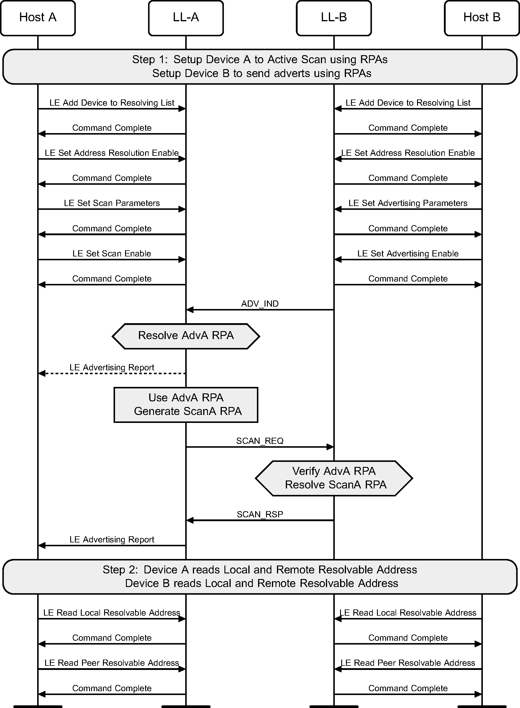
A device may use active scanning to obtain more information about devices that may be useful to populate a user interface. Privacy may be used during active scanning to make it more difficult to track either device during active scanning (see Figure 4.4).
4.5. Active scanning with Privacy and Controller based resolvable private address generation
A Controller will periodically update the resolvable private addresses used on both devices if the devices use active scanning and advertising with Privacy. A Host may at anytime retrieve the read from the Controller the current addresses being used (see Figure 4.5).
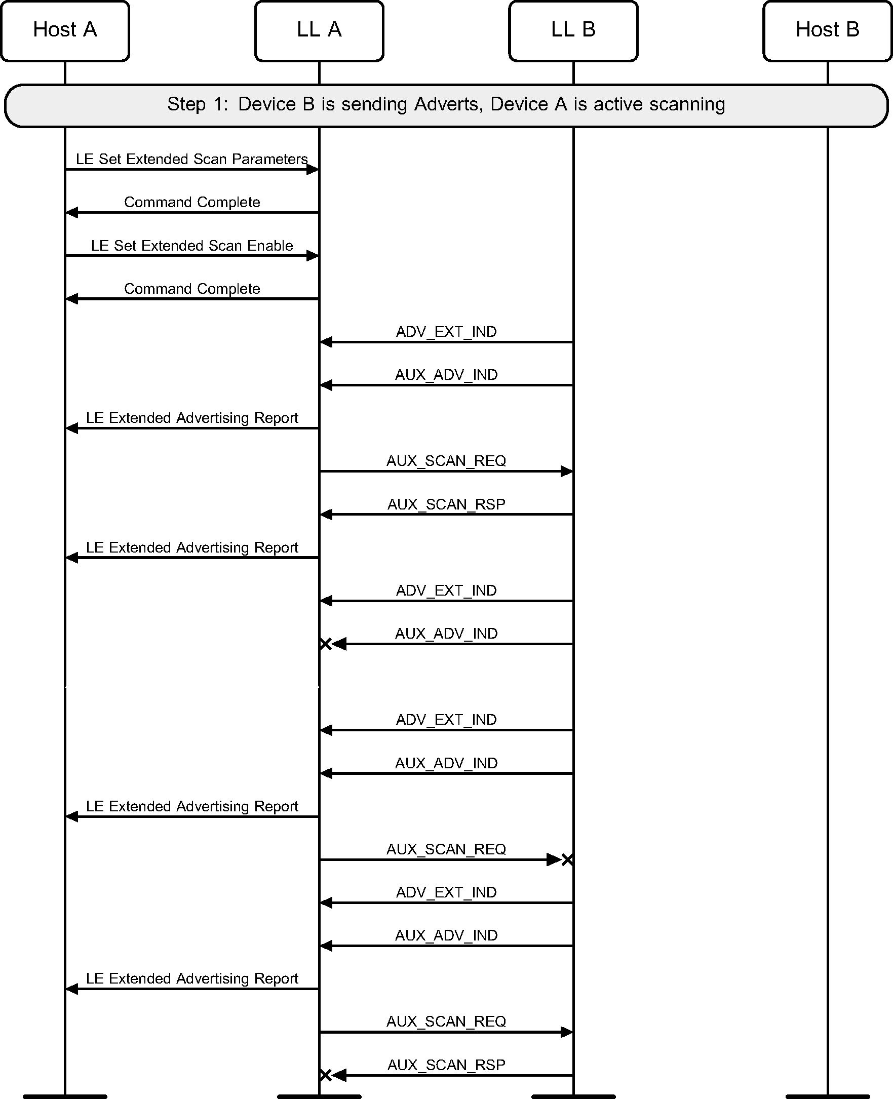
4.6. Active scanning on the secondary advertising Physical channel
A device may use active scanning on the secondary advertising physical channel in order to obtain more information about devices that may be useful to populate a user interface (see Figure 4.6).
4.7. Scan timeout
A device may scan for a limited duration of time (see Figure 4.7).
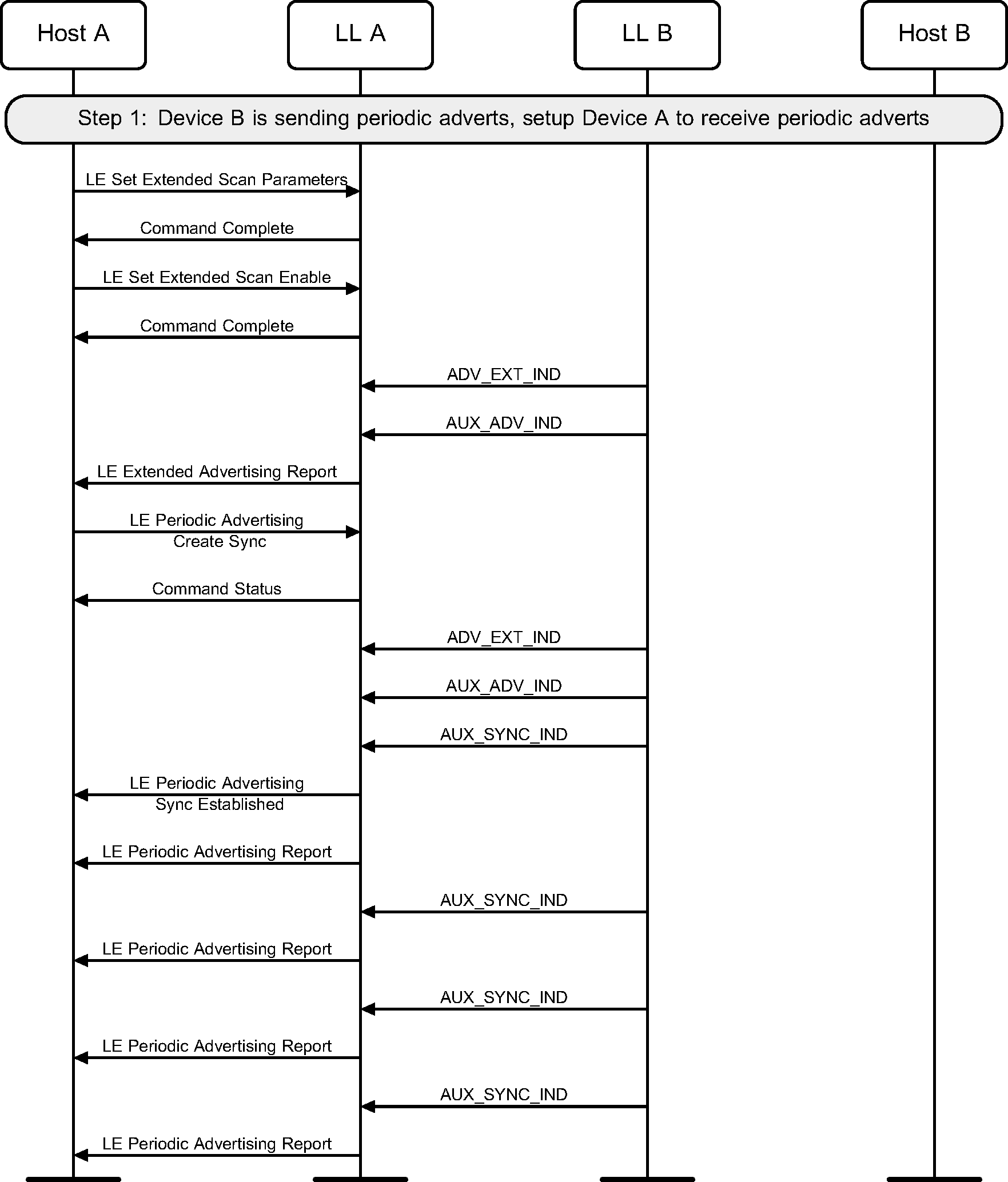
4.8. Scanning for periodic advertisements
A device may establish synchronization with a periodic advertiser and report periodic advertising packets to the Host (see Figure 4.8).
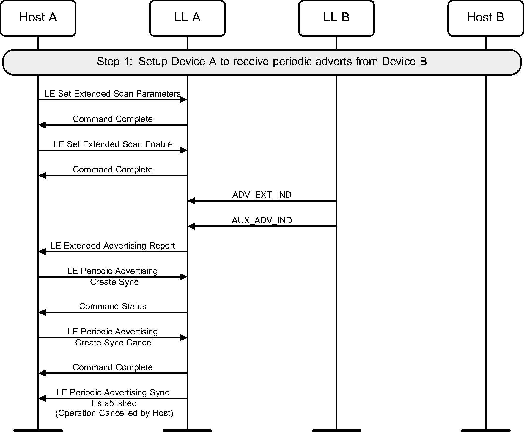
4.9. Cancel scanning for periodic advertisements
A device may cancel a pending request to establish synchronization with a periodic advertiser. This example shows an unsuccessful synchronization, followed by cancellation of the synchronization (see Figure 4.9).
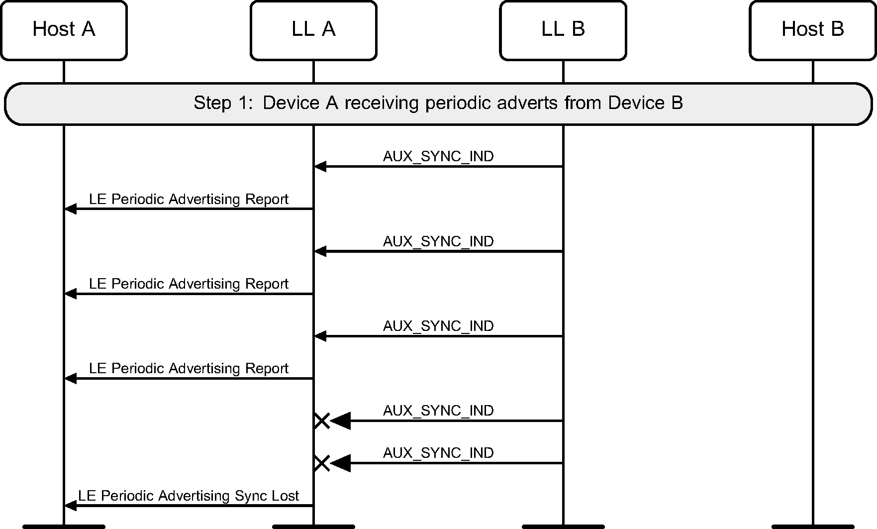
4.10. Periodic advertising synchronization timeout
A device may lose synchronization with a periodic advertiser (see Figure 4.10).
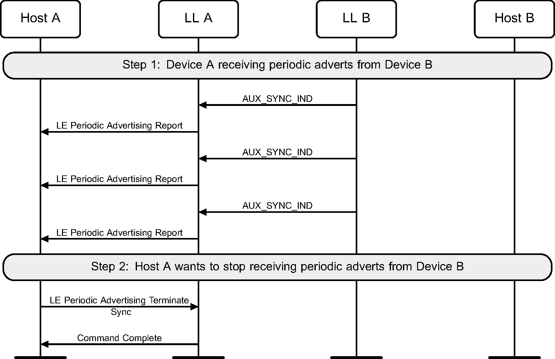
4.11. Terminate reception of periodic advertising
Once synchronized with a periodic advertiser, the Host can terminate the synchronization (see Figure 4.11).
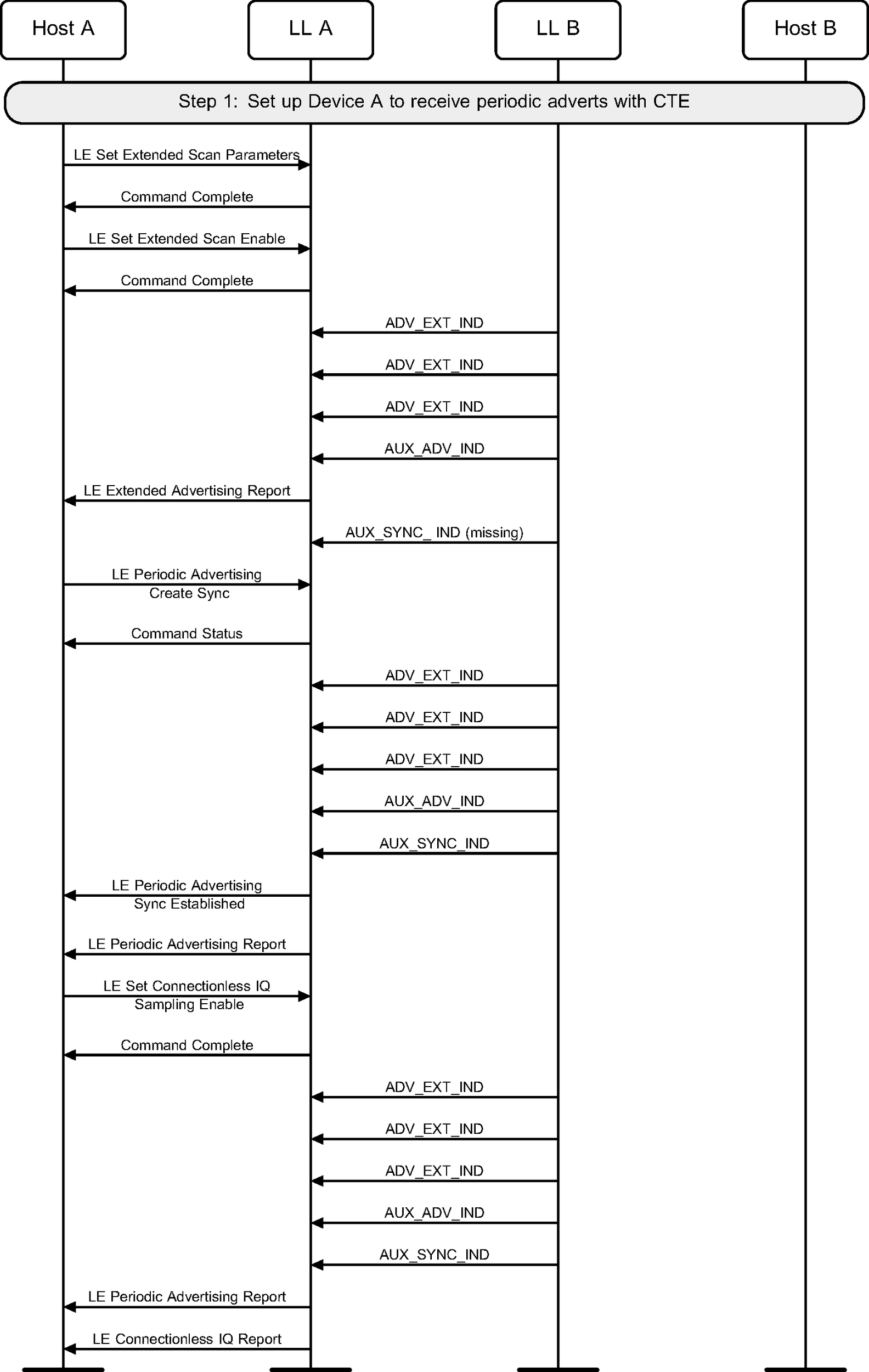
4.12. Connectionless Constant Tone Extension reception
A device may receive periodic advertising packets containing a Constant Tone Extension and send IQ samples to the Host (see Figure 4.12).
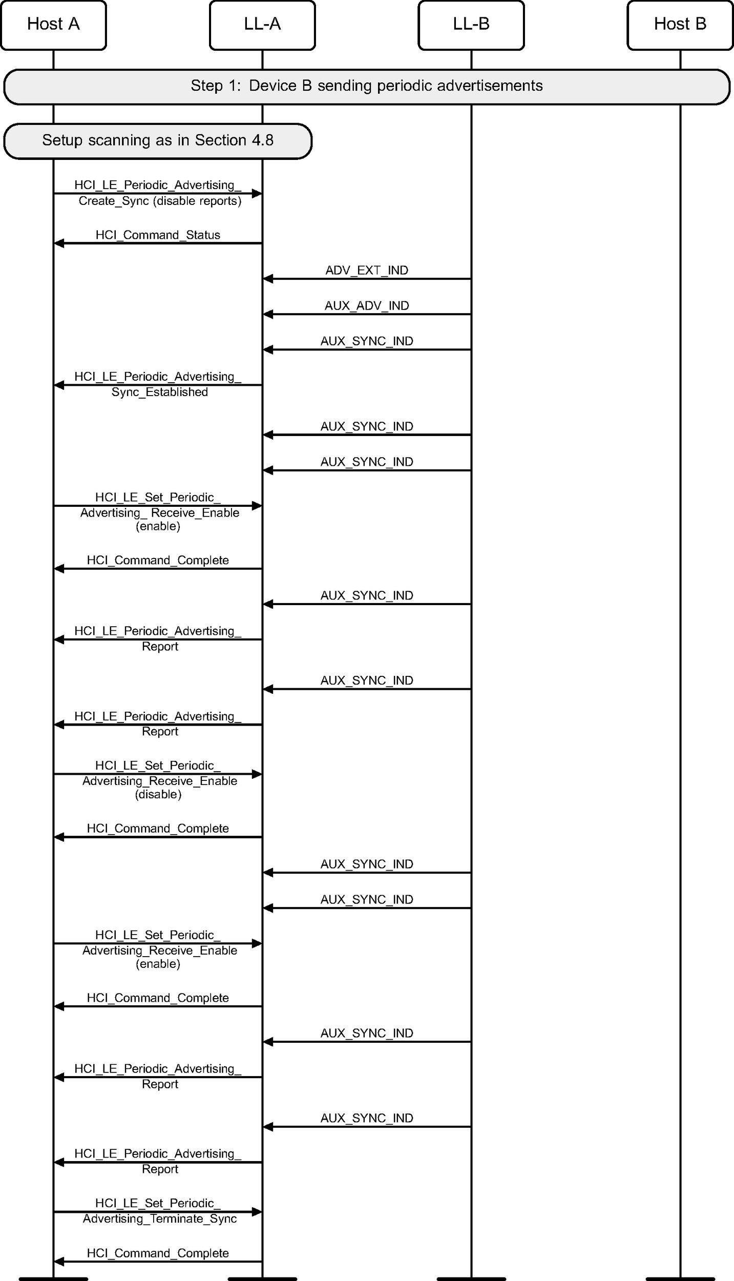
4.13. Synchronization with separate enable of reports
A device may enable or disable reports after establishing synchronization with a periodic advertising train.
5. Initiating state
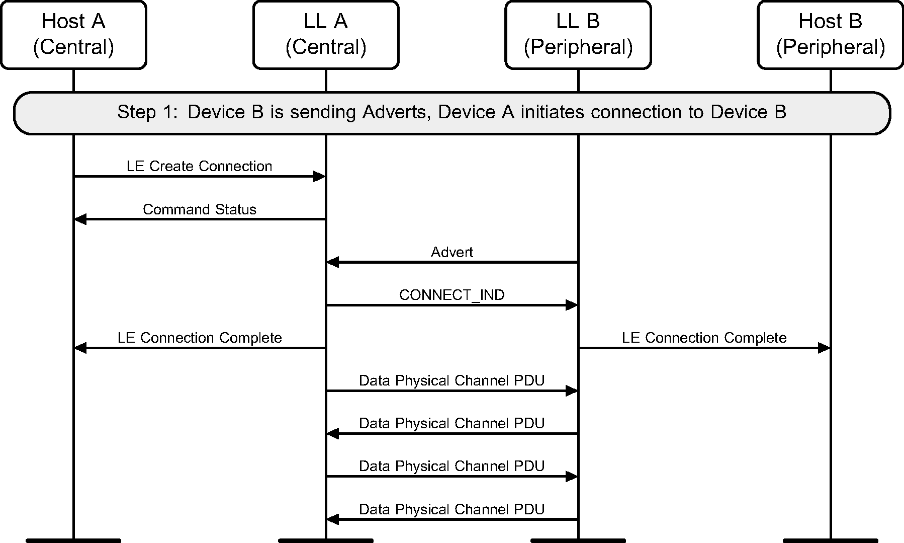
5.1. Initiating a connection
A device can initiate a connection to an advertiser. This example shows a successful initiation, resulting in both devices able to send application data (see Figure 5.1).
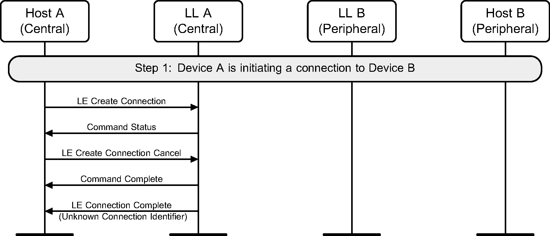
5.2. Canceling an initiation
A device can cancel a pending connection creation. This example shows an unsuccessful initiation, followed by a cancellation of the initiation (see Figure 5.2).
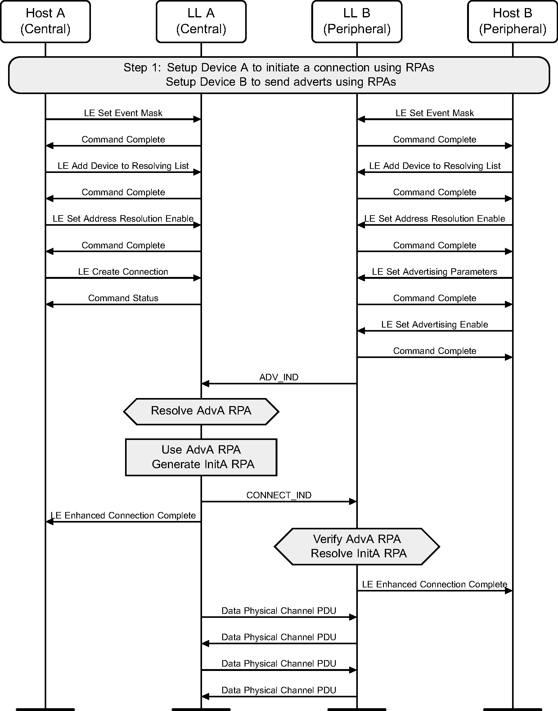
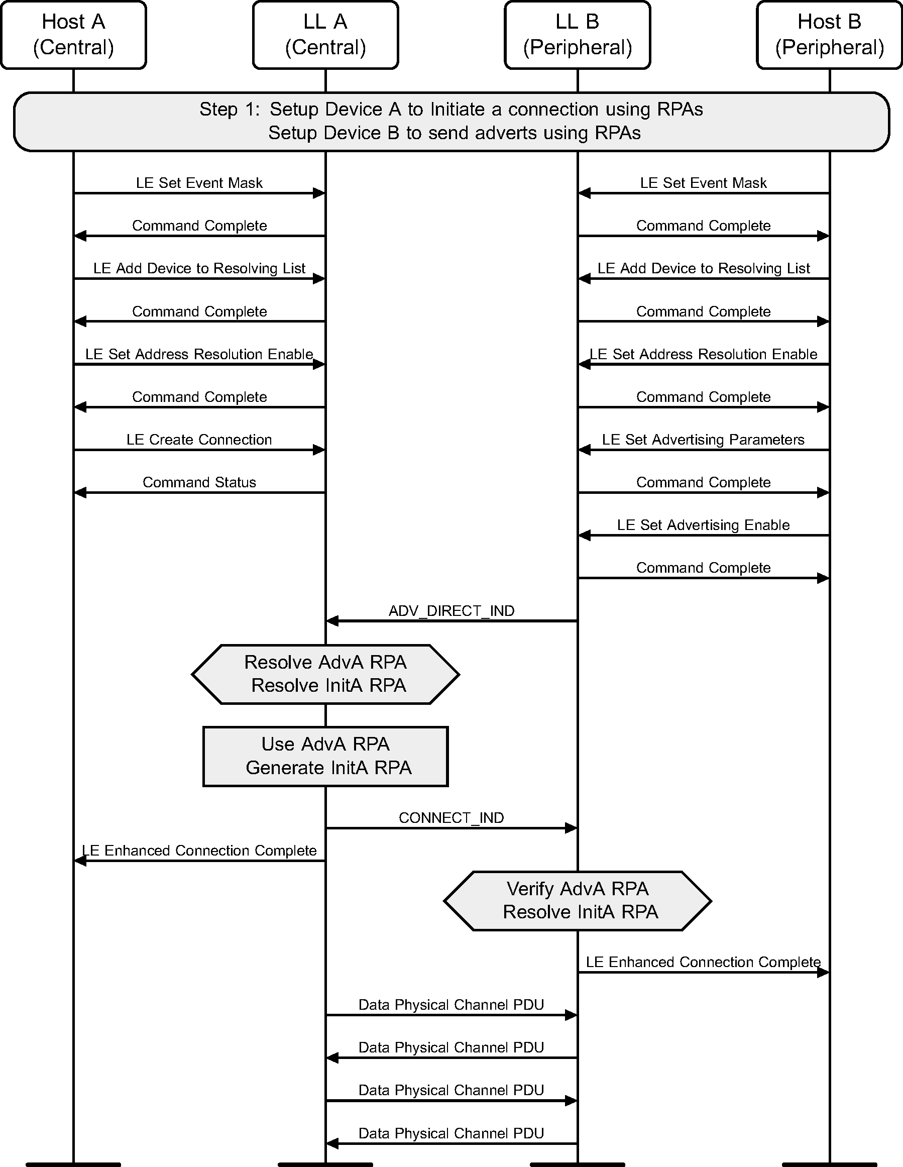
5.3. Initiating a connection using undirected advertising with Privacy
A device can initiate a connection to an advertiser. Privacy may be used during connection initiation to make it more difficult to track either device during connection setup. The example shows a successful initiation, resulting in both devices able to send application data (see Figure 5.3).
5.4. Initiating a connection using directed advertising with Privacy
A device can initiate a connection to an advertiser who is using Directed Advertising. Privacy may be used during connection initiation to make it more difficult to track either device during connection setup as well as target a single initiator. The example shows a successful initiation, resulting in both devices able to send application data (see Figure 5.4).
5.5. Initiating a connection that fails to establish
This example shows an initiation that fails to establish because Device B (the advertiser) fails to respond to the Data Physical Channel PDUs sent by Device A.
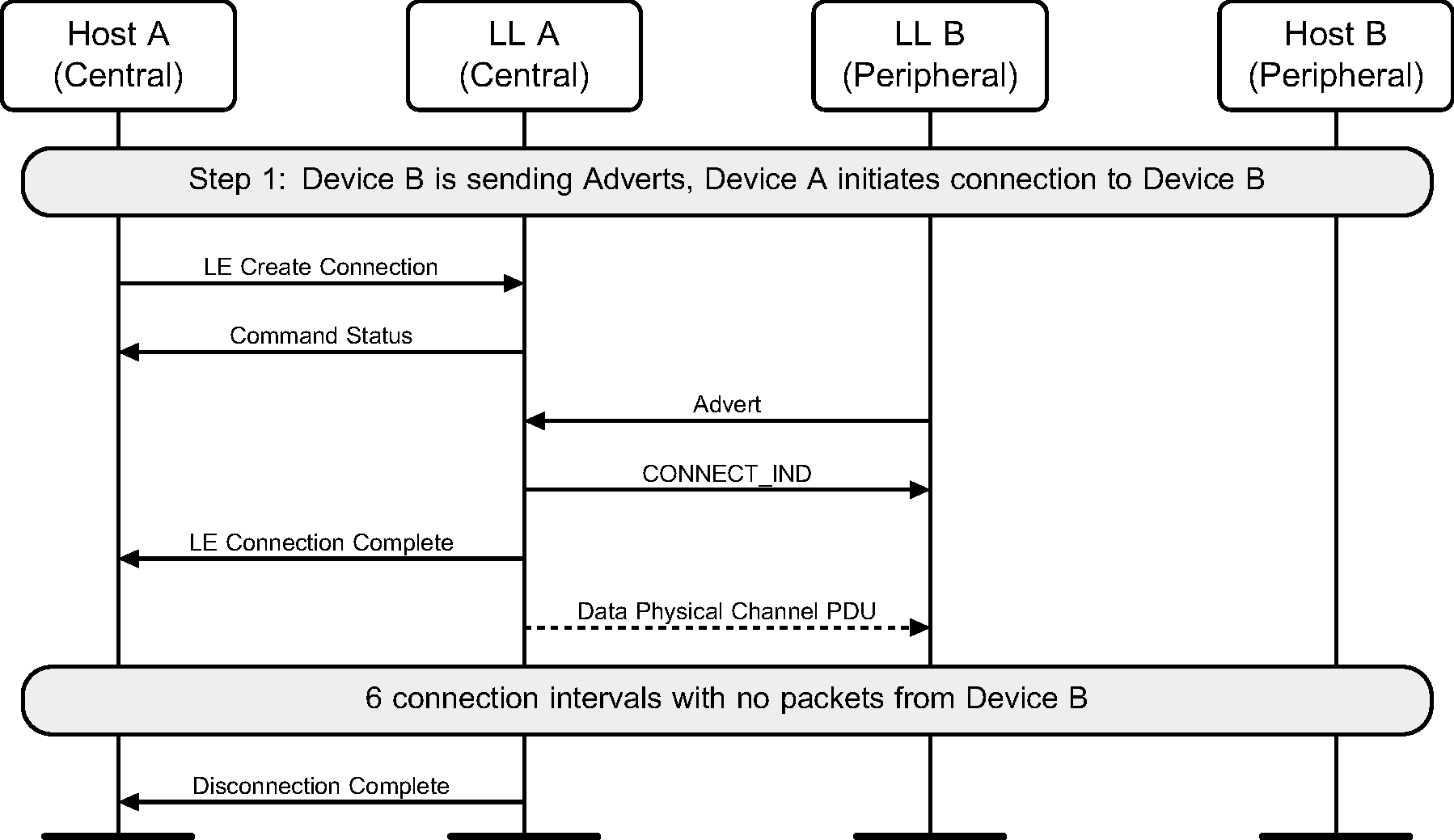
Device A is not required to send Data Channel PDUs in the 6 connection intervals before establishment fails. However, if it does not do so, Device B is unable to respond.
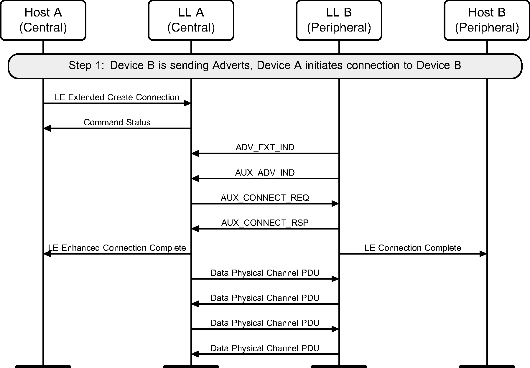
5.6. Initiating a connection on the secondary advertising physical channel
A device can initiate a connection to an advertiser on the secondary channel. This example shows a successful initiation, resulting in both devices able to send application data (see Figure 5.6).
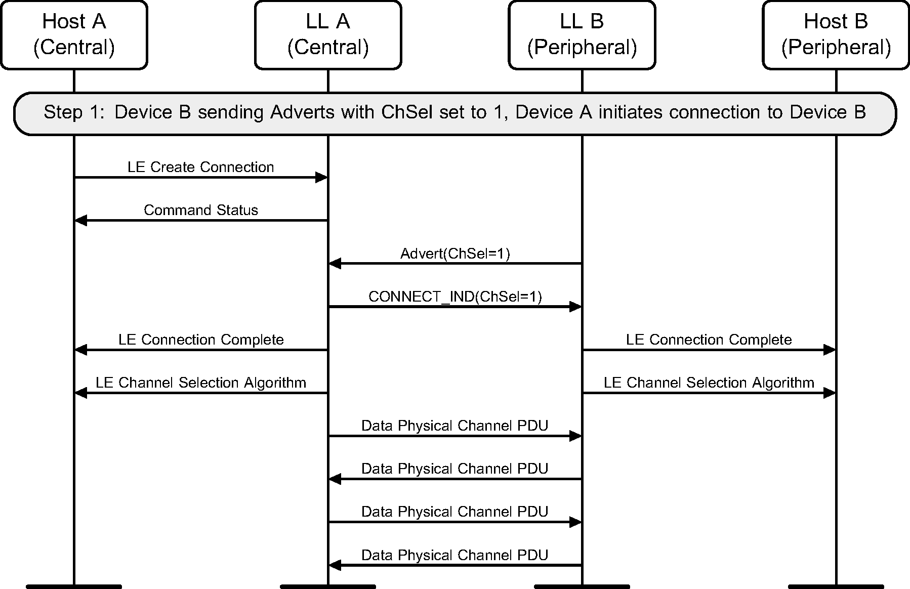
5.7. Initiating a Channel Selection algorithm #2 connection
Where a device supports the Channel Selection Algorithm #2 feature, it can initiate a connection which will use Channel Selection Algorithm #2 to an advertiser who has the ChSel field of the advertising physical channel PDU set to 1. The example shows a successful initiation, resulting in the connection using Channel Selection Algorithm #2.
6. Connection state
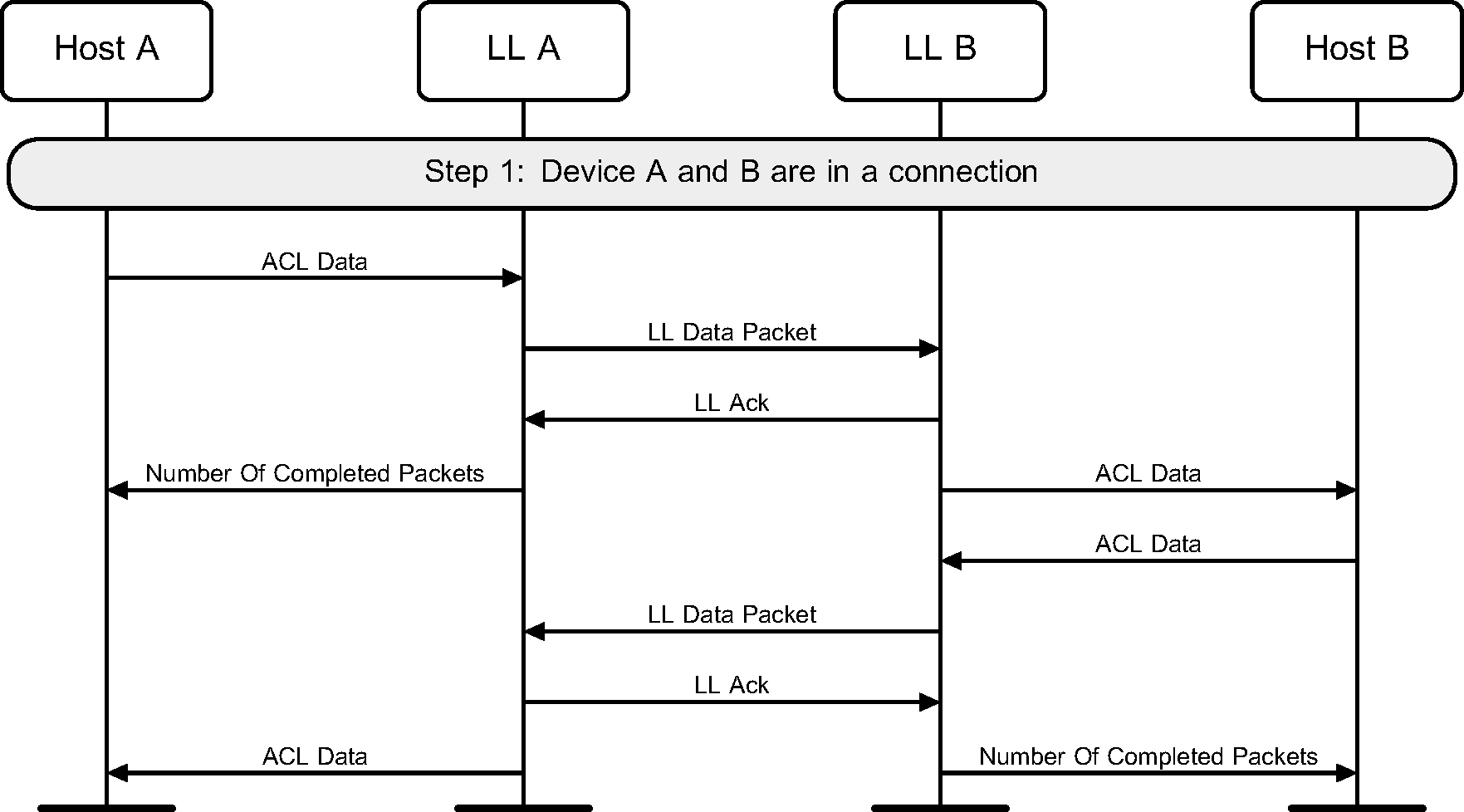
6.1. Sending data
Once two devices are in a connection, either device can send data. This example shows both devices sending data, for example when the Attribute Protocol does a read request and a read response is returned (see Figure 6.1).
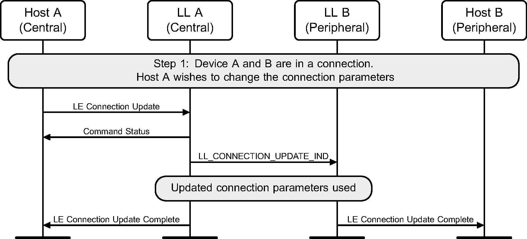
6.2. Connection update
The Central of the connection may request a connection update using a Link Layer control procedure (see Figure 6.2).
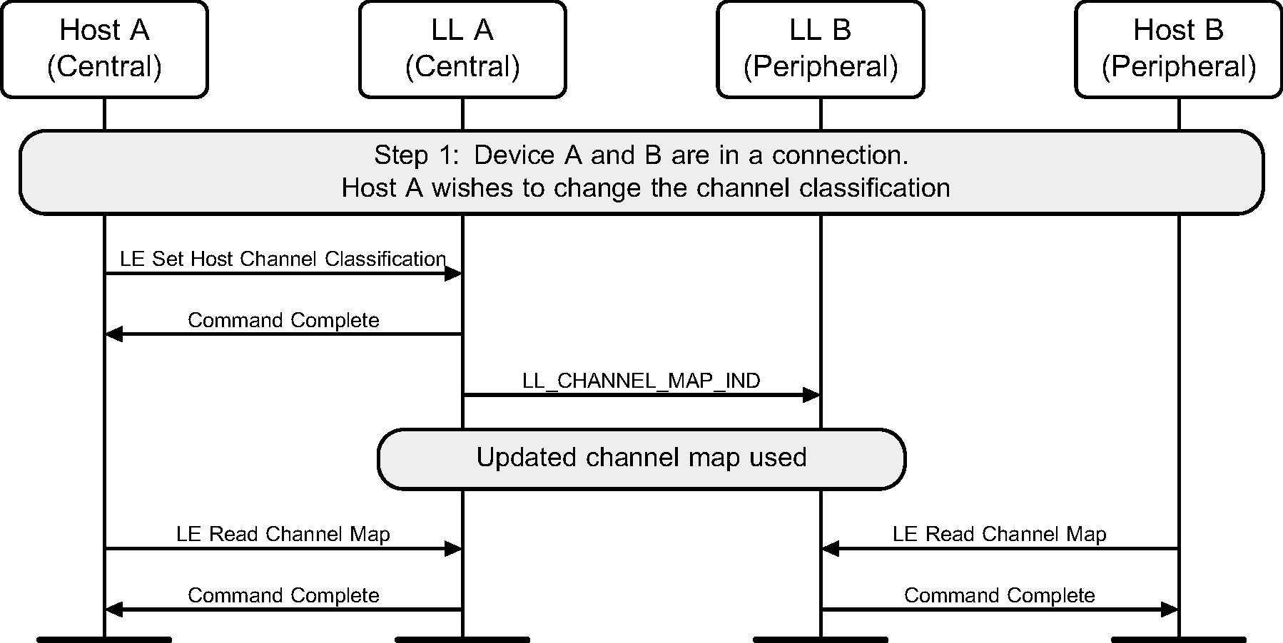
6.3. Channel map update
The Controller of the Central may receive some channel classification data from the Host and then perform the Channel Update Link Layer Control procedure (see Figure 6.3).
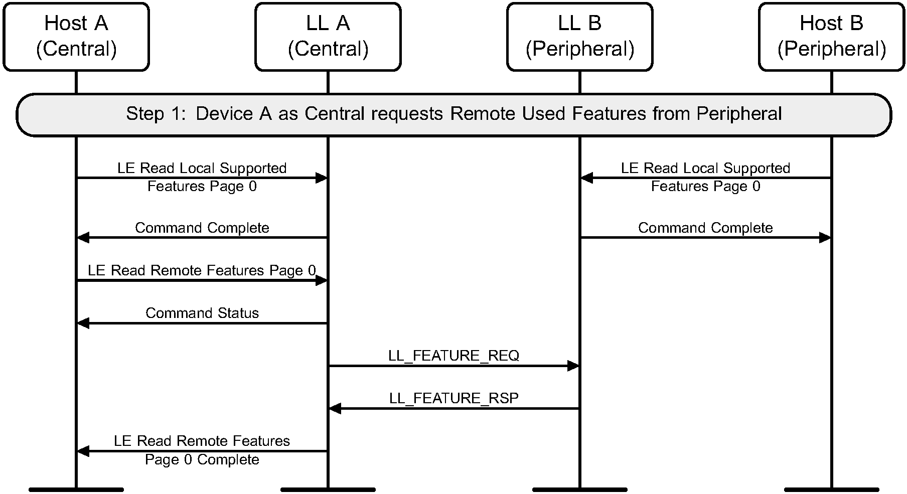
6.4. Features exchange
Both the Central and Peripheral can discover the set of features available on the remote device. To achieve this, the Feature Exchange Link Layer Control procedure is used (see Figure 6.4 and Figure 6.5).

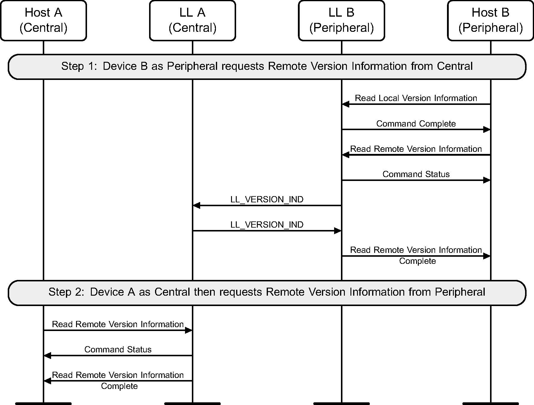
6.5. Version exchange
Either device may perform a Version Exchange procedure (see Figure 6.6 and Figure 6.7).

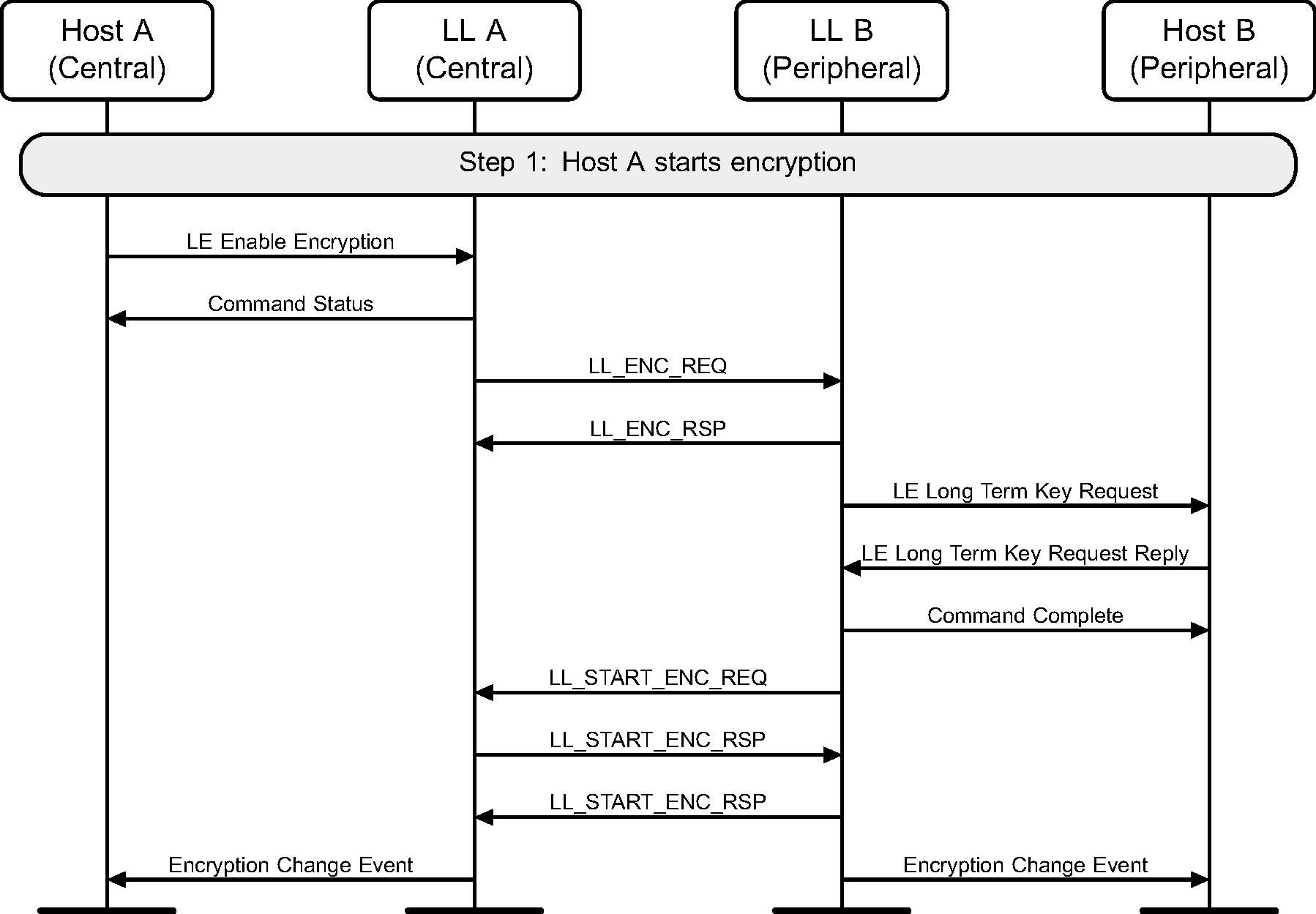
6.6. Start encryption
If encryption has not been started on a connection, it may be started by the Central (see Figure 6.8).
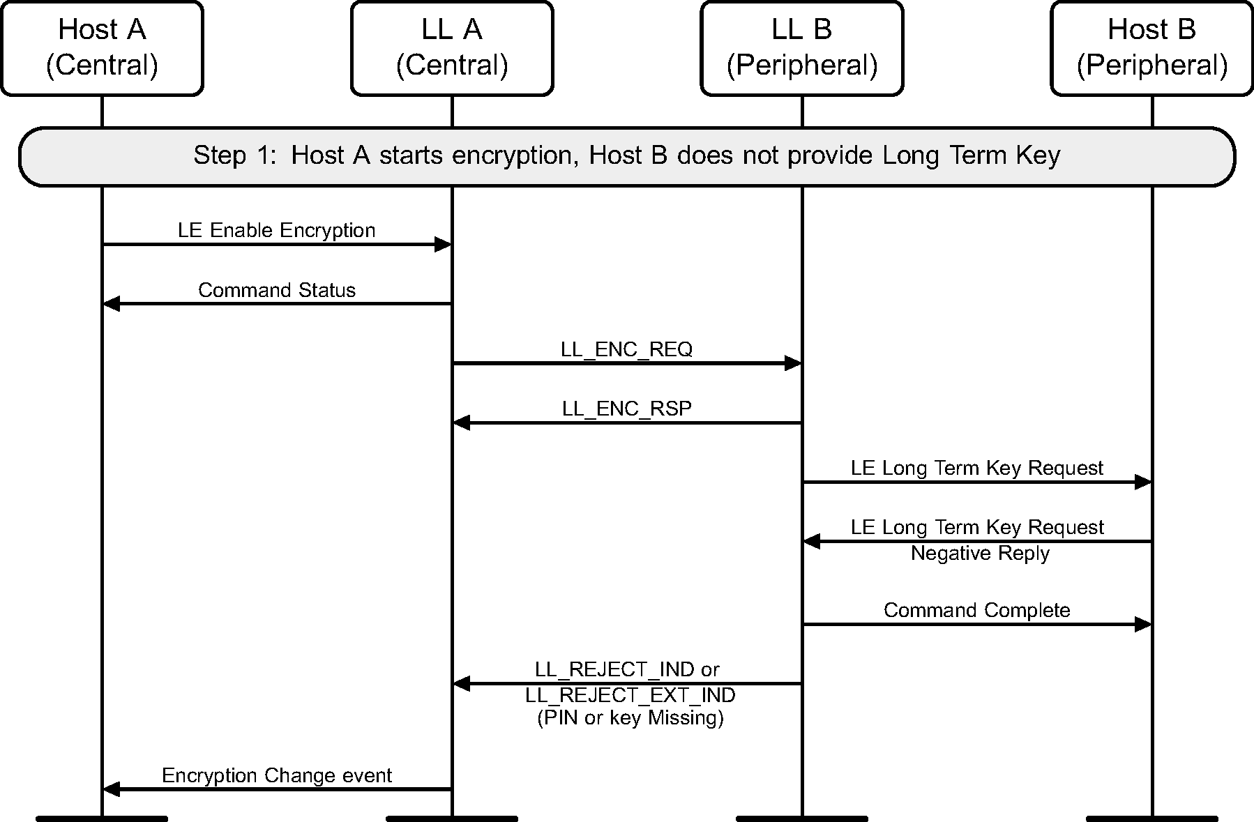
6.7. Start encryption without long-term key
If encryption has not been started on a connection, it may be started by the Central. Figure 6.9 shows the failure case of the Peripheral not having the long term key for the Central.
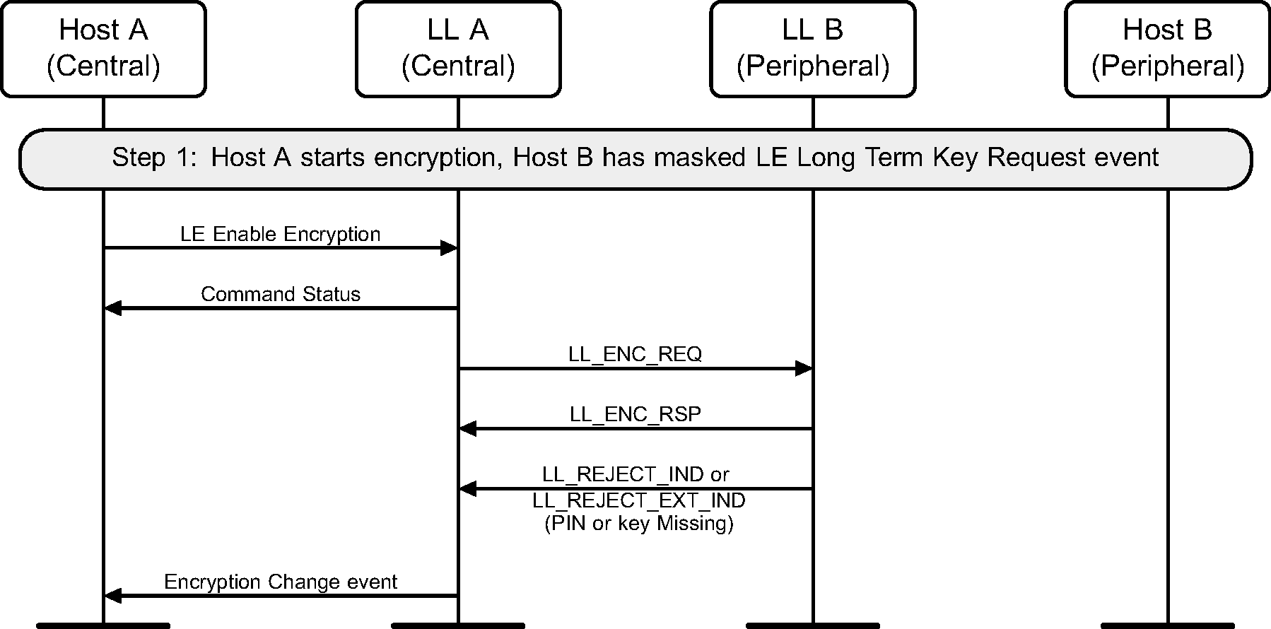
6.8. Start encryption with event masked
If encryption has not been started on a connection, it may be started by the Central. Figure 6.10 shows the failure case when the Peripheral has masked out the HCI_LE_Long_Term_Key_Request event.
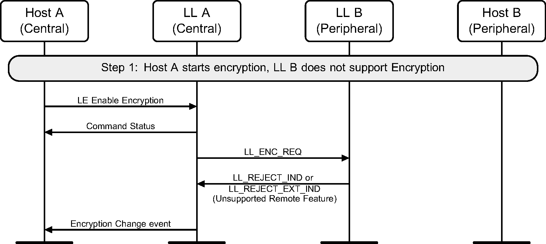
6.9. Start encryption without Peripheral supporting encryption
If encryption has not been started on a connection, it may be started by the Central. Figure 6.11 shows the failure case of the Peripheral that does not support the encryption feature.
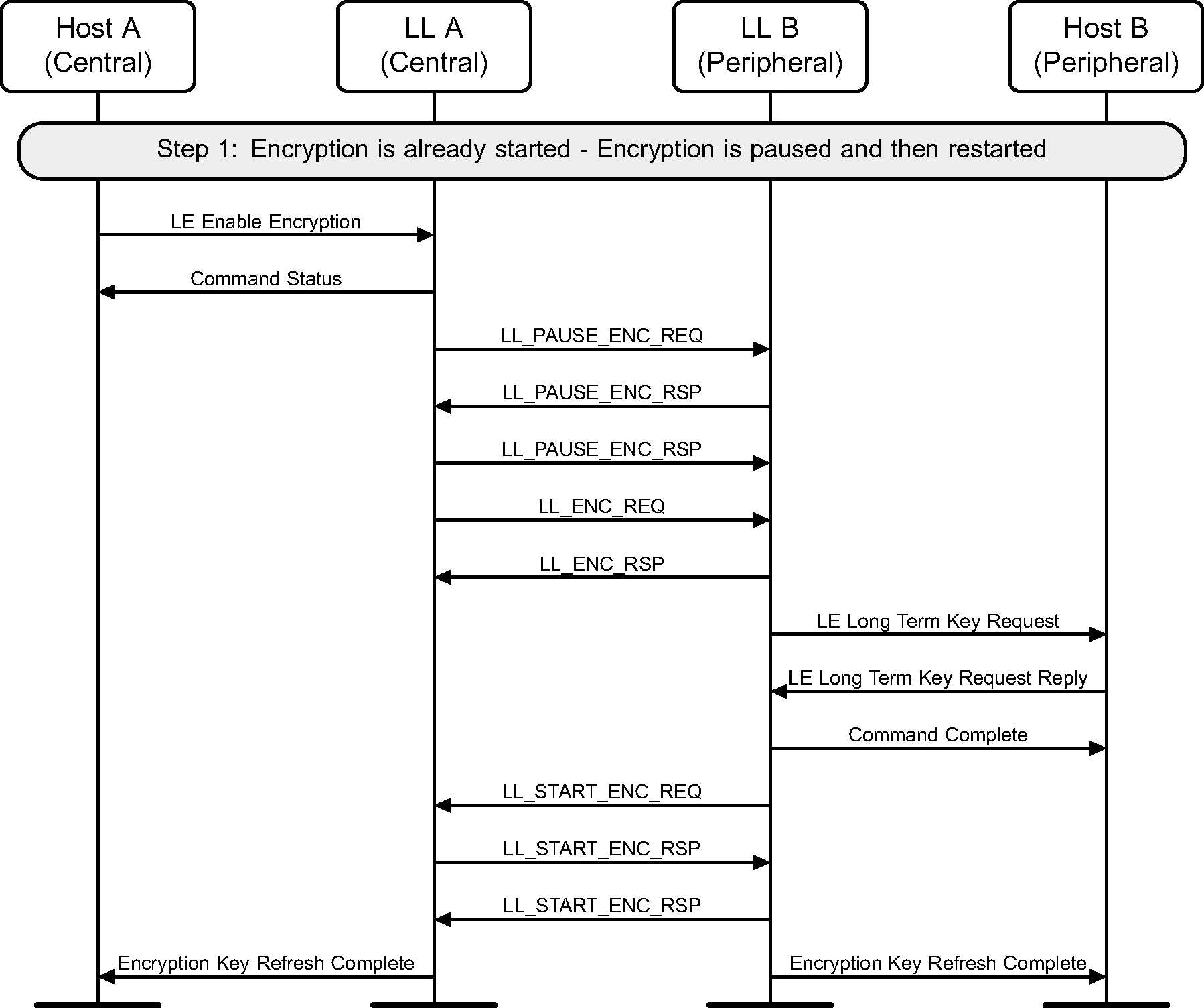
6.10. Restart encryption
If encryption has already been started on a connection, it may be restarted by the Central. This may be required to use a stronger encryption as negotiated by the Security Manager Protocol (see Figure 6.12).
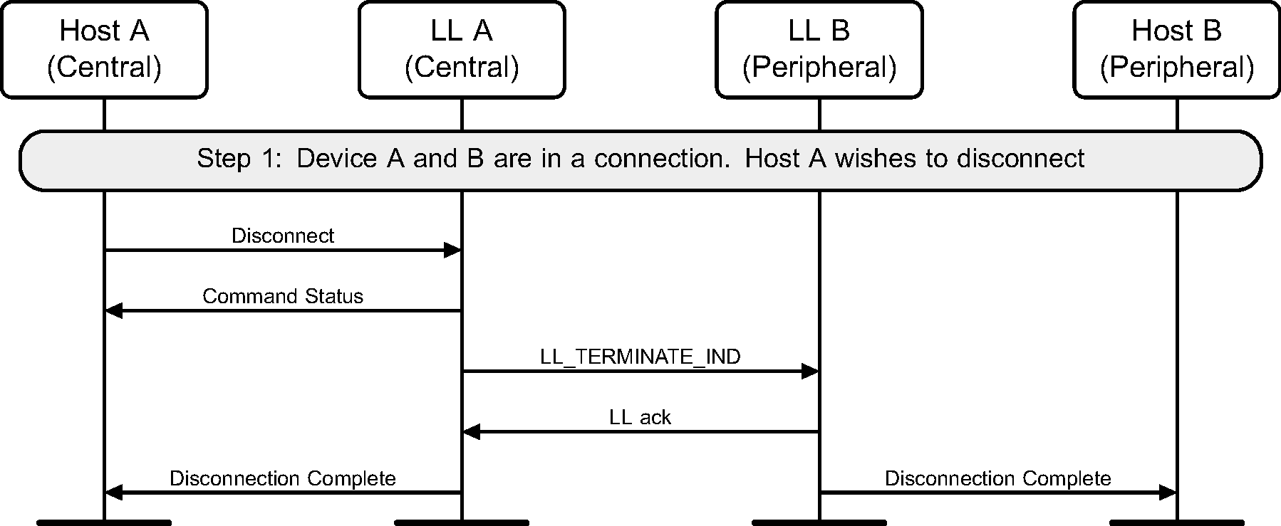
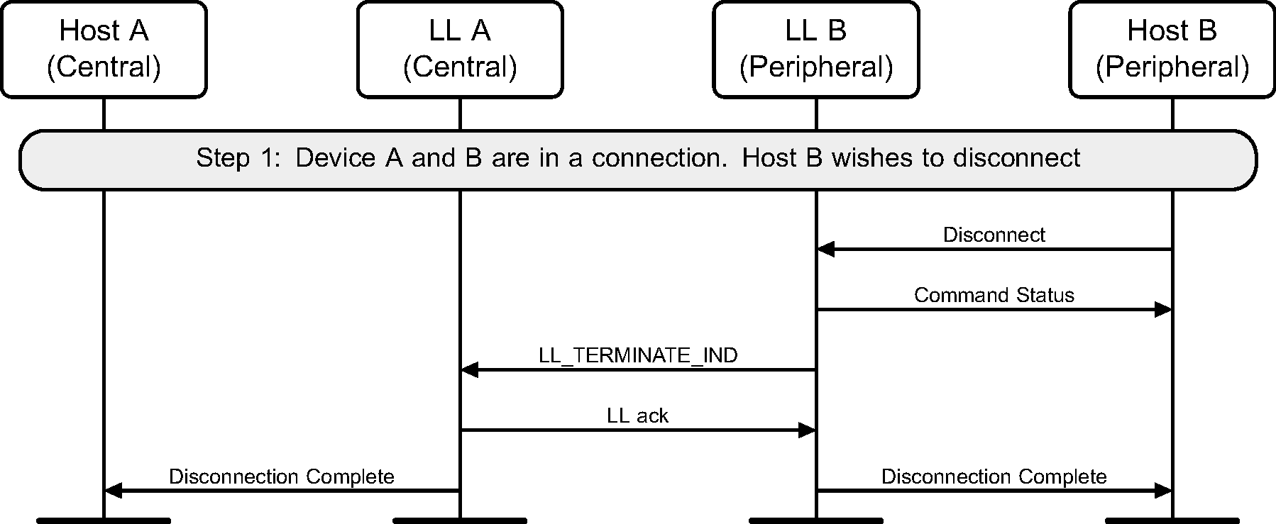
6.11. Disconnect
Once a connection has no need to be kept active, the Host can disconnect it. This can be done by either device (see Figure 6.13 and Figure 6.14).
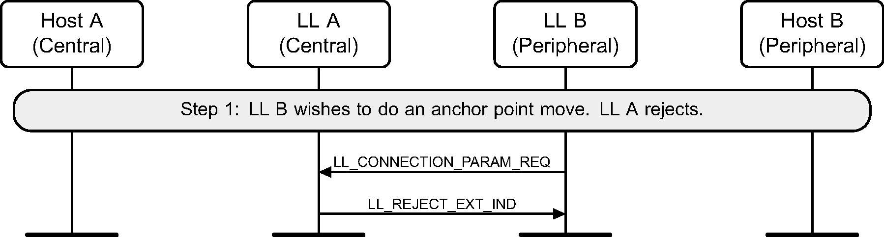
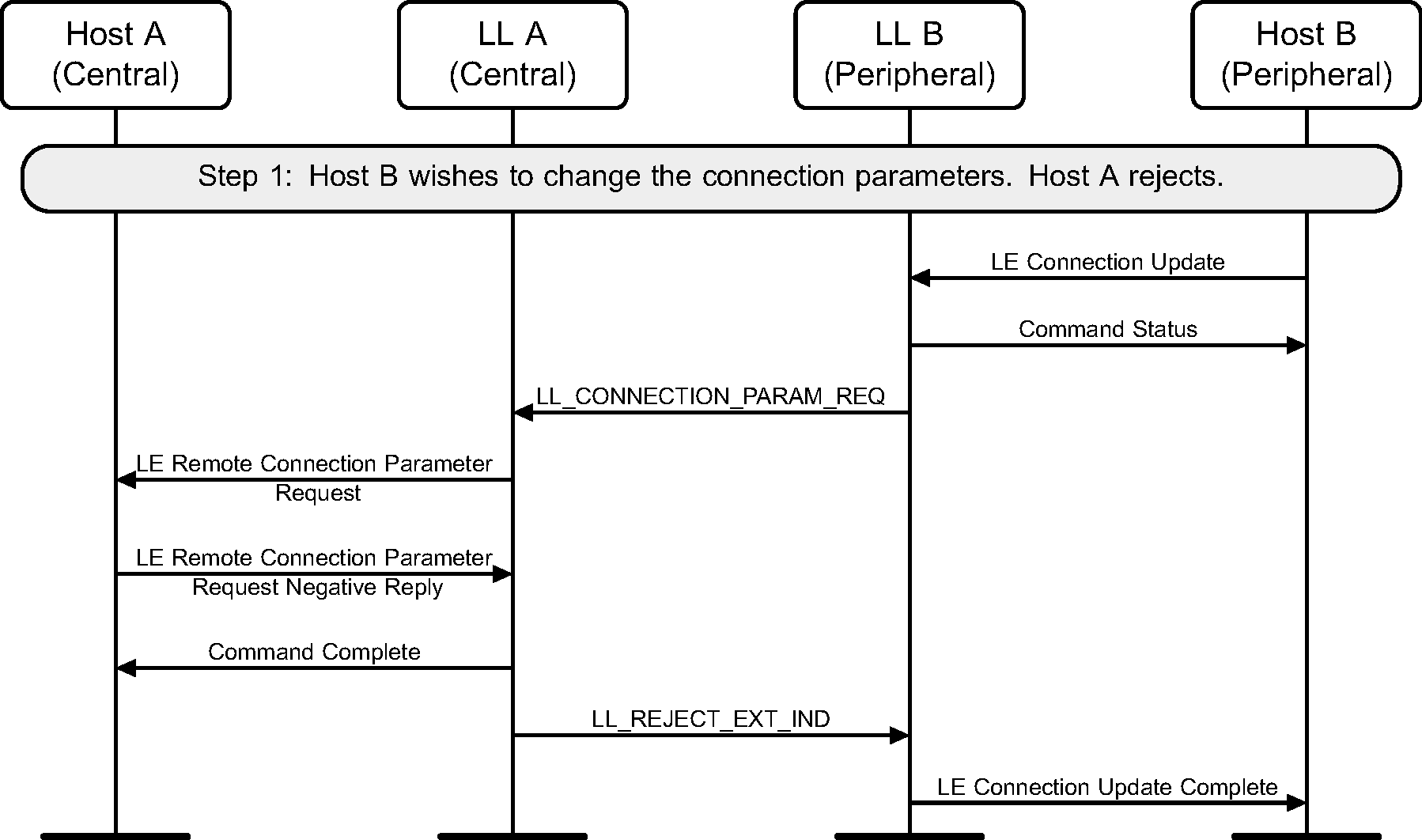
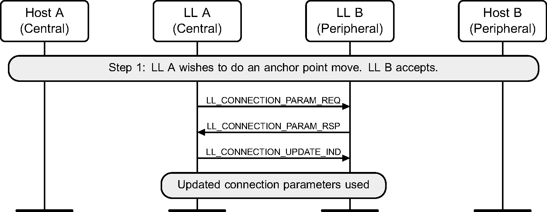
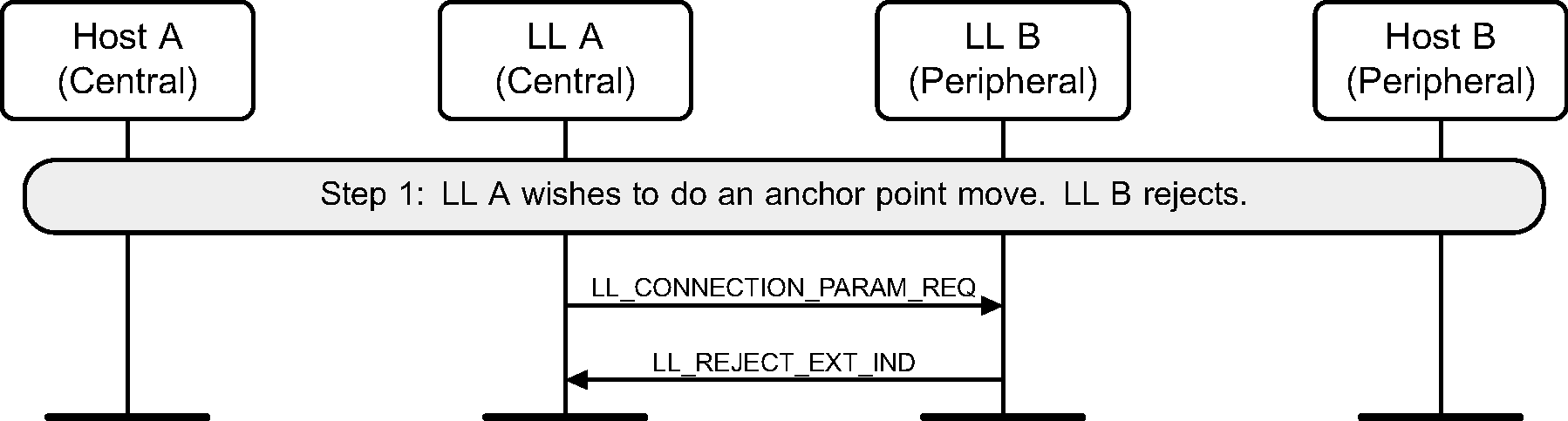
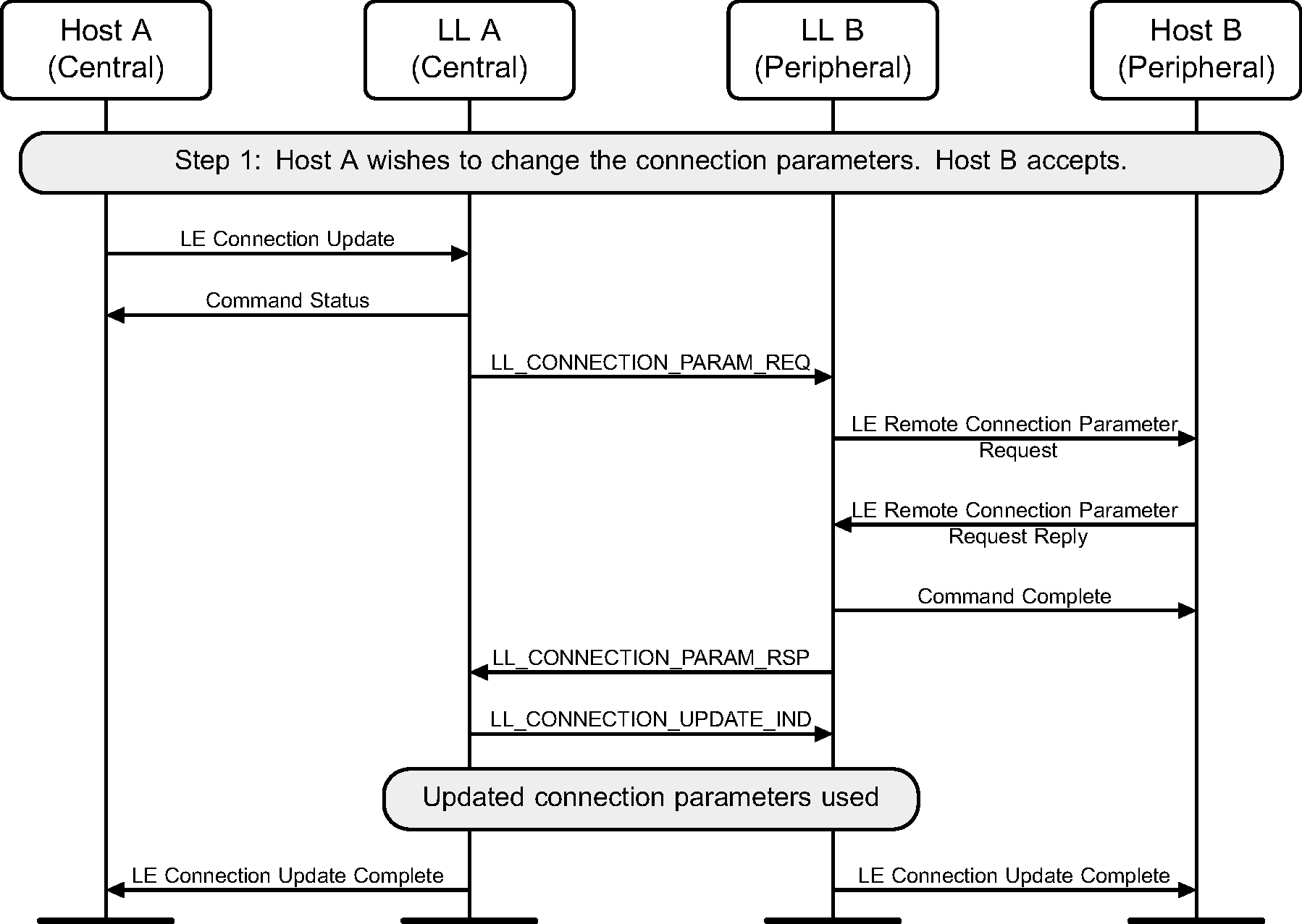
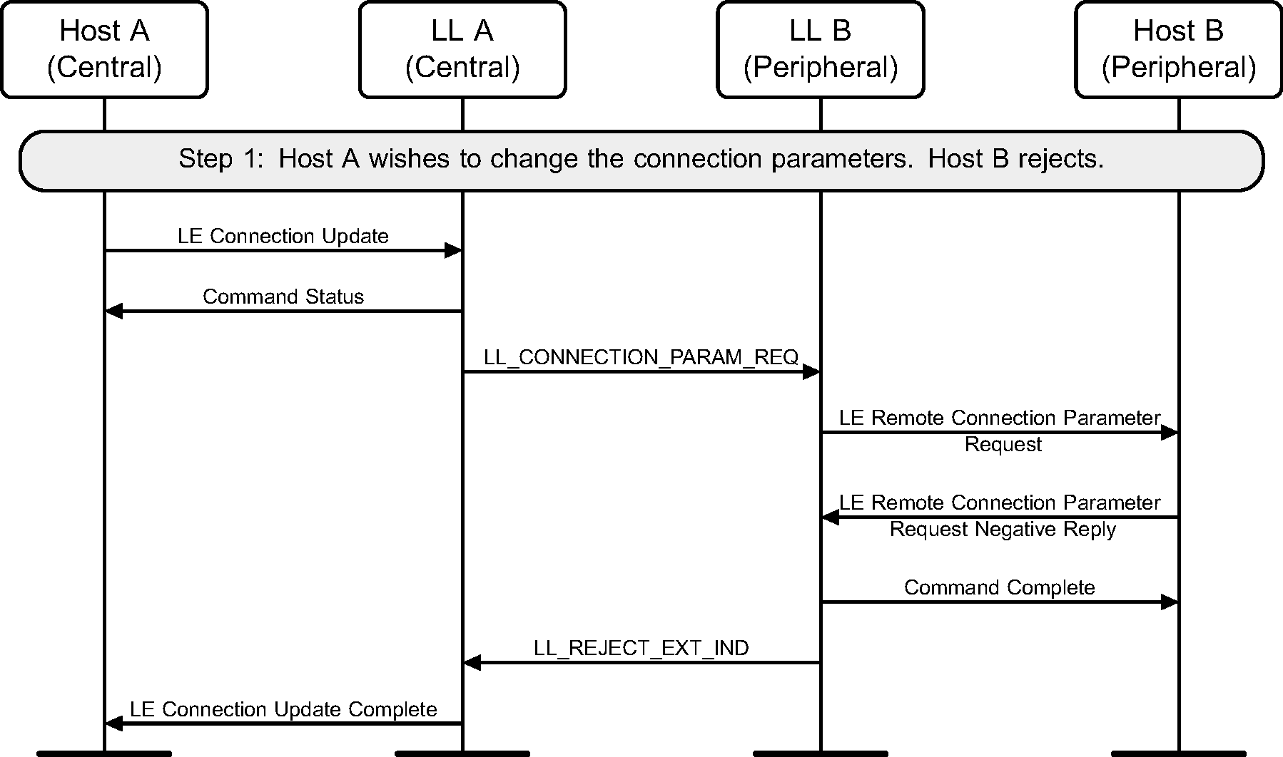
6.12. Connection parameters request
The Central or the Peripheral of the connection may request change in connection parameters using a Link Layer control procedure (see Figure 6.15 to Figure 6.22).


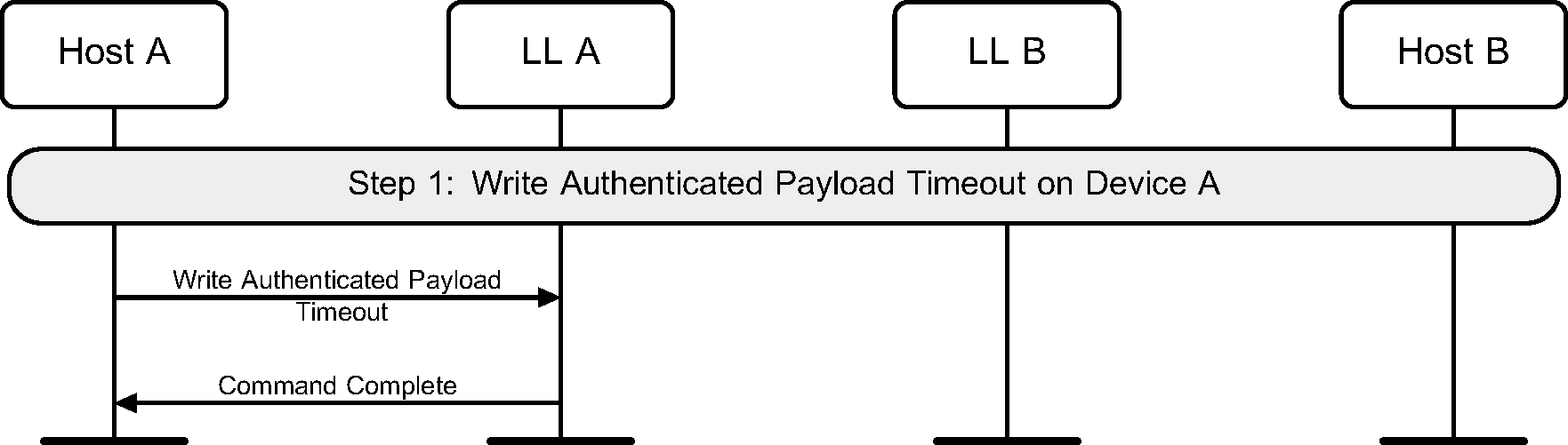
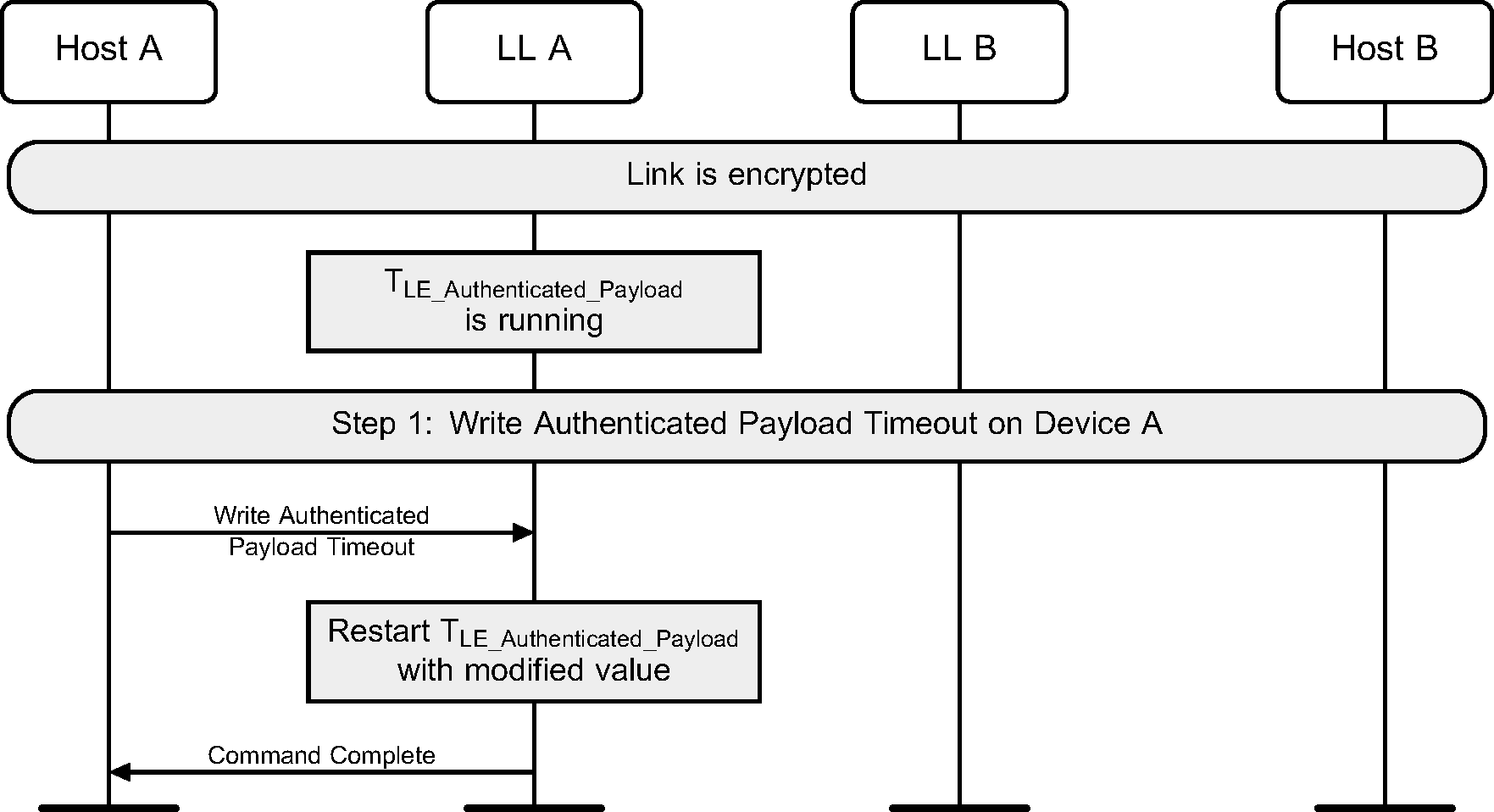
6.13. LE Ping
A Host may use the HCI_Write_Authenticated_Payload_Timeout command to change the maximum interval between packets containing a valid MIC that the Link Layer will enforce when encryption is used.
Either Link Layer can authenticate the remote device using the LE Ping procedure even if the remote device does not support the LE Ping feature. This procedure can also be used for soliciting a packet from the remote device containing a valid MIC. LL A may be a Central or a Peripheral.
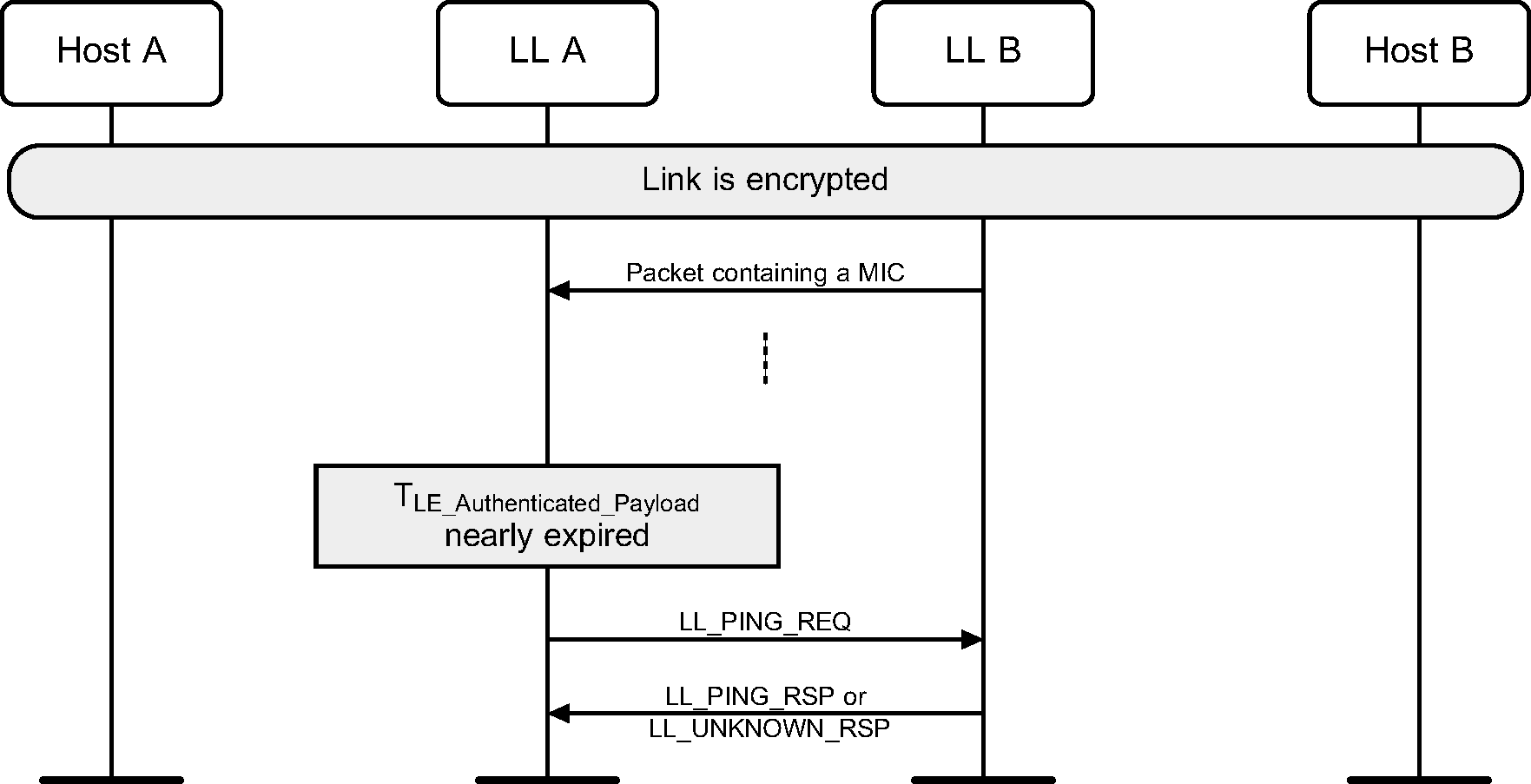
When a packet with a valid MIC has not been received within the LE Authenticated Payload Timeout, the Host is notified that the timer has expired.
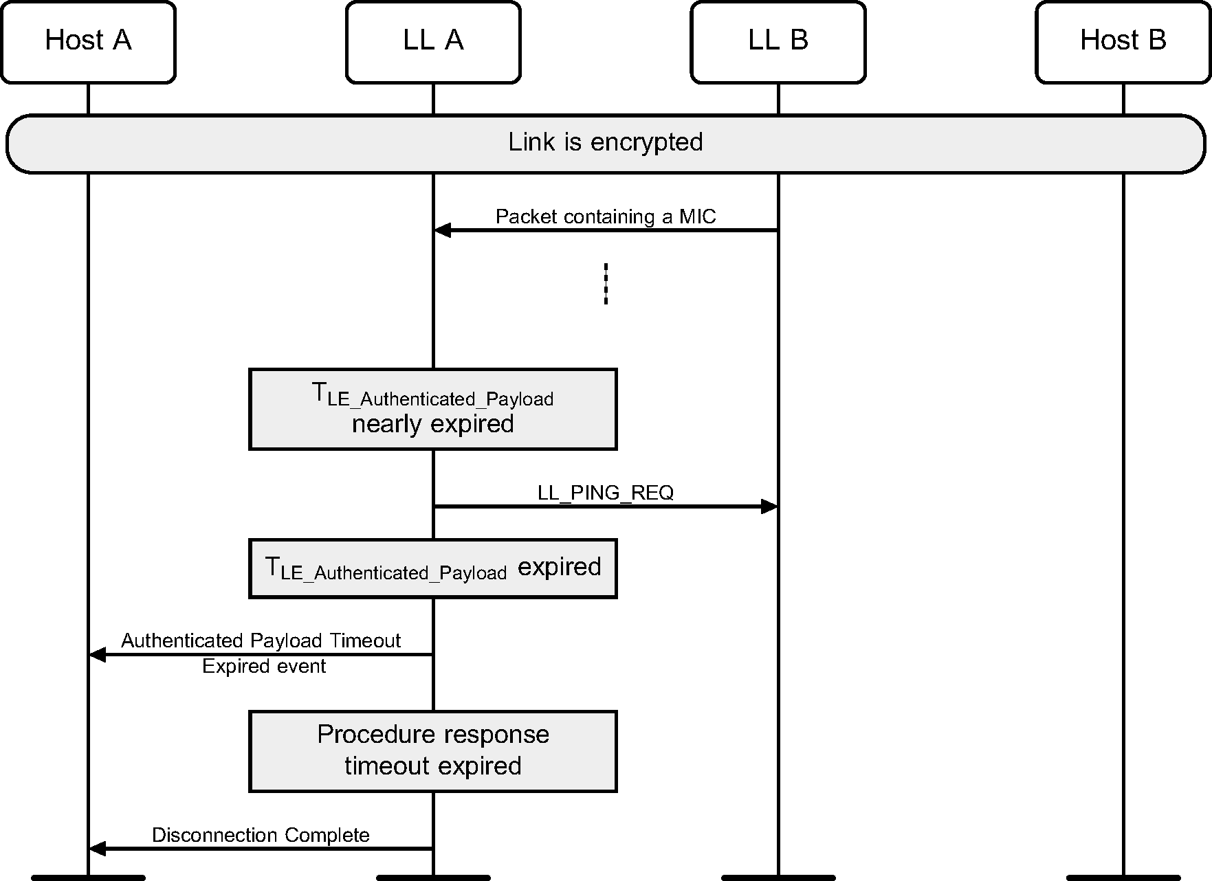
The TLE_Authenticated_Payload Timer gets reset when the Host sets the Authenticated Payload Timeout.
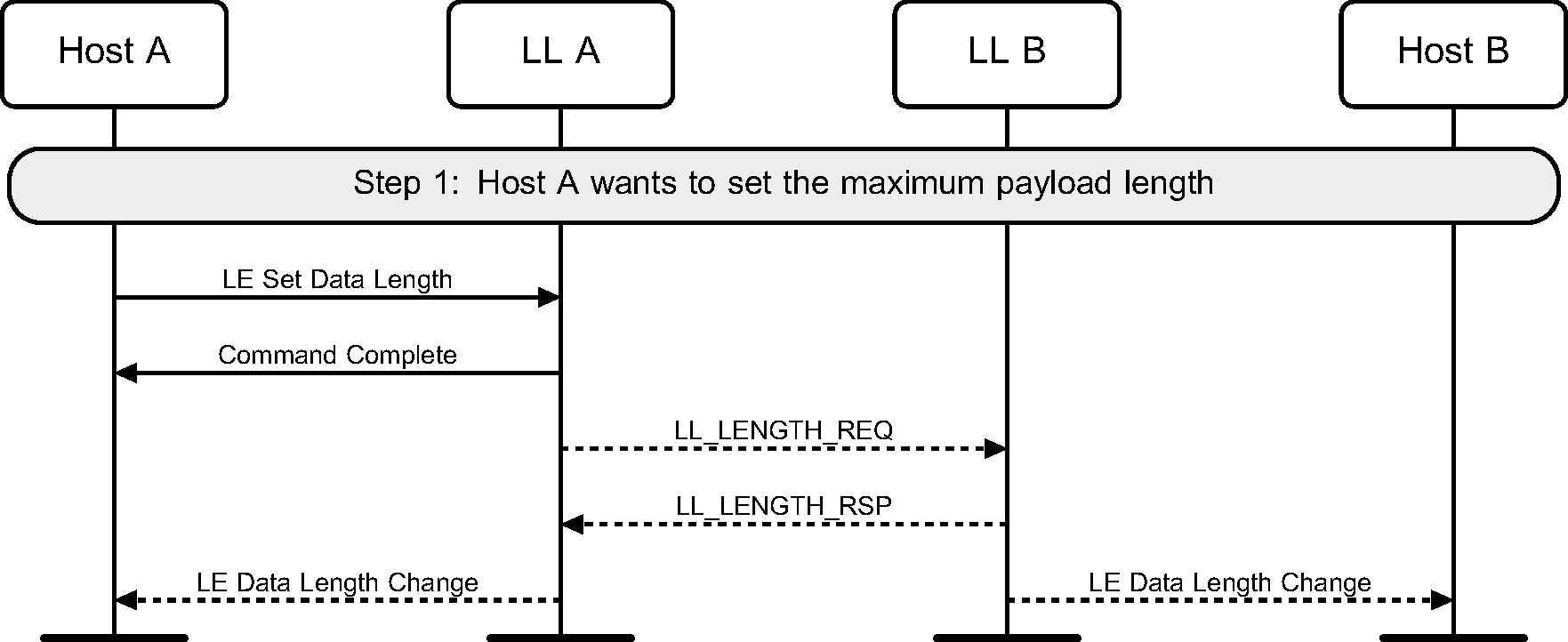
6.14. Data length update
Once a connection has been created, the Host may suggest maximum transmission packet size and maximum packet transmission time to be used for the connection. This may be done on either the Central or the Peripheral.
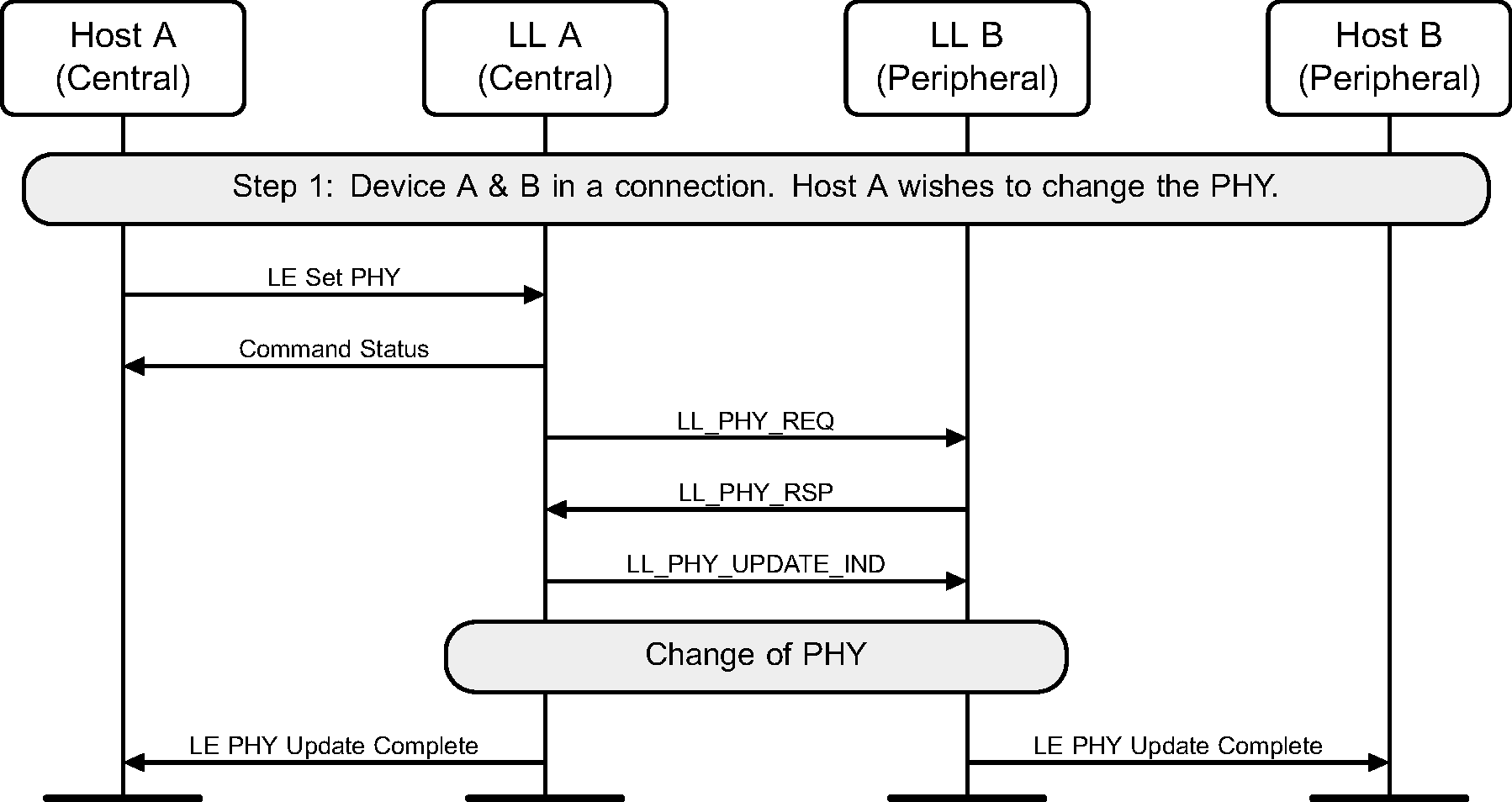
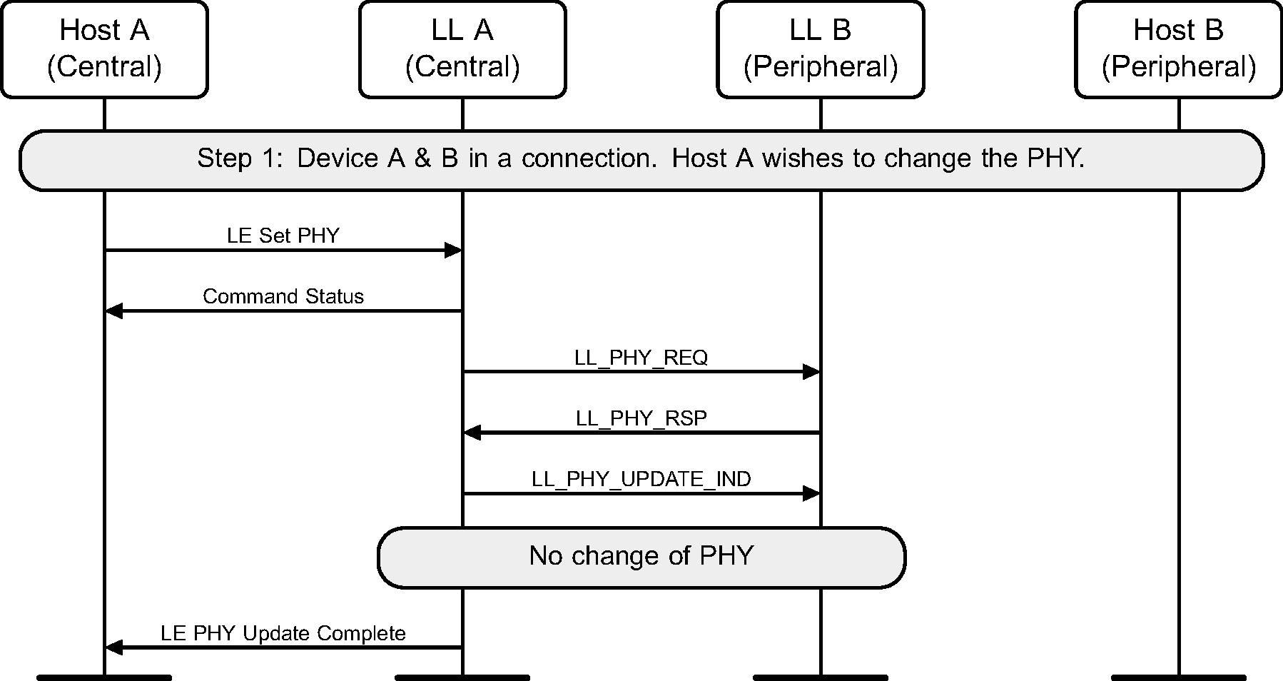
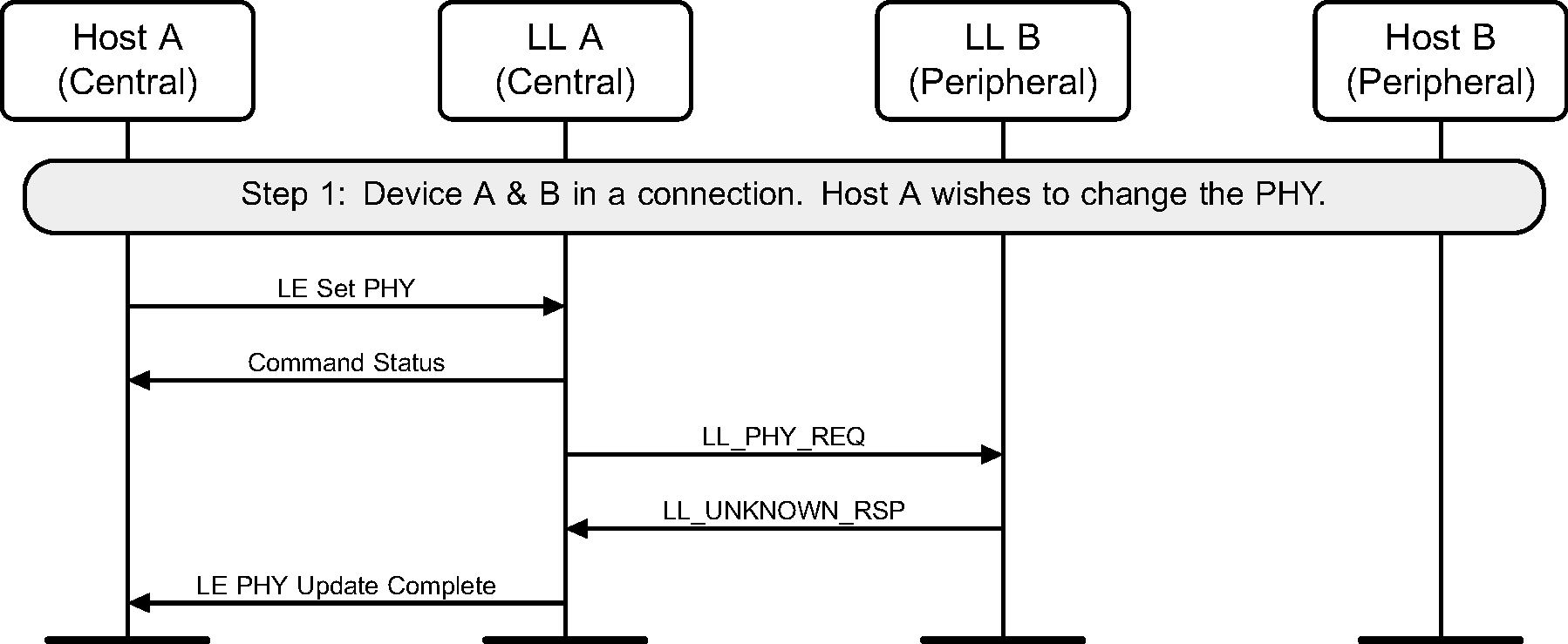
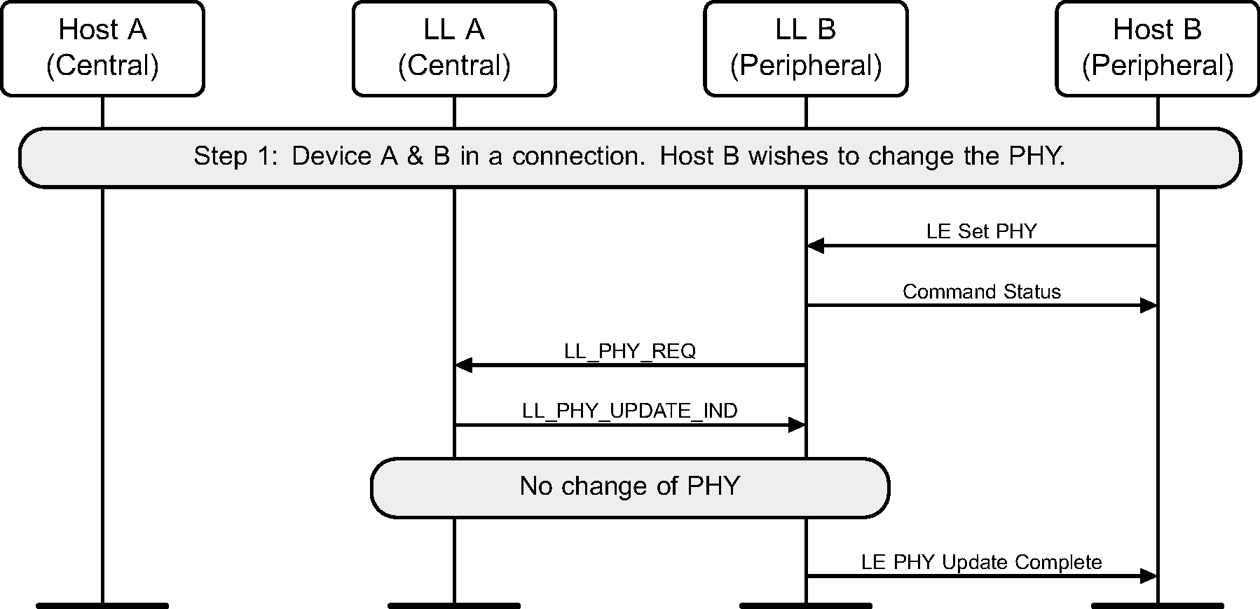
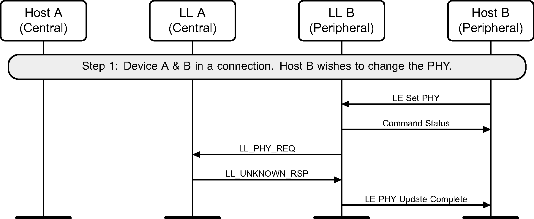
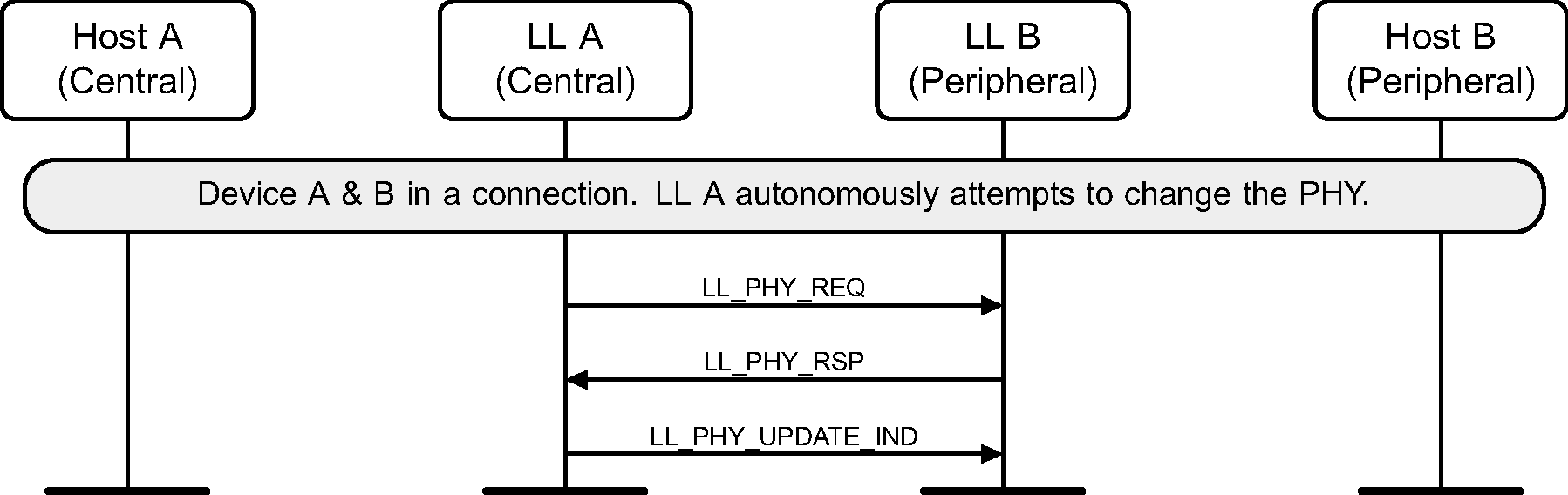
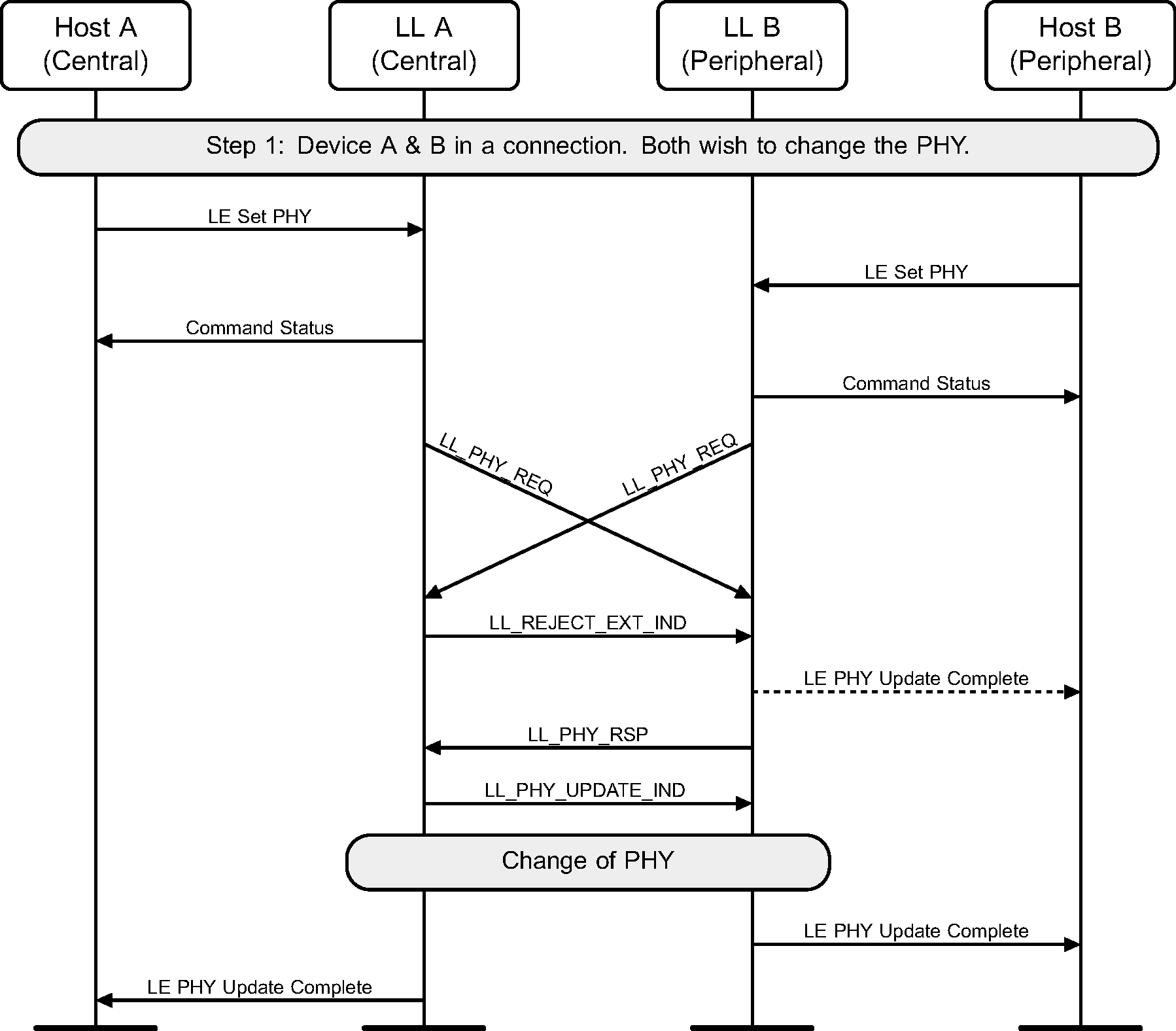
6.15. PHY update
The Central or Peripheral of the connection may request a change in the PHY using a Link Layer control procedure (see Figure 6.28 to Figure 6.36).
The sequence of events shown in Figure 6.30 and Figure 6.33 can only happen before feature exchange and can only happen once per connection, because a Link Layer must not use a procedure that it knows the peer does not support as required by [Vol 6] Part B, Section 4.6.


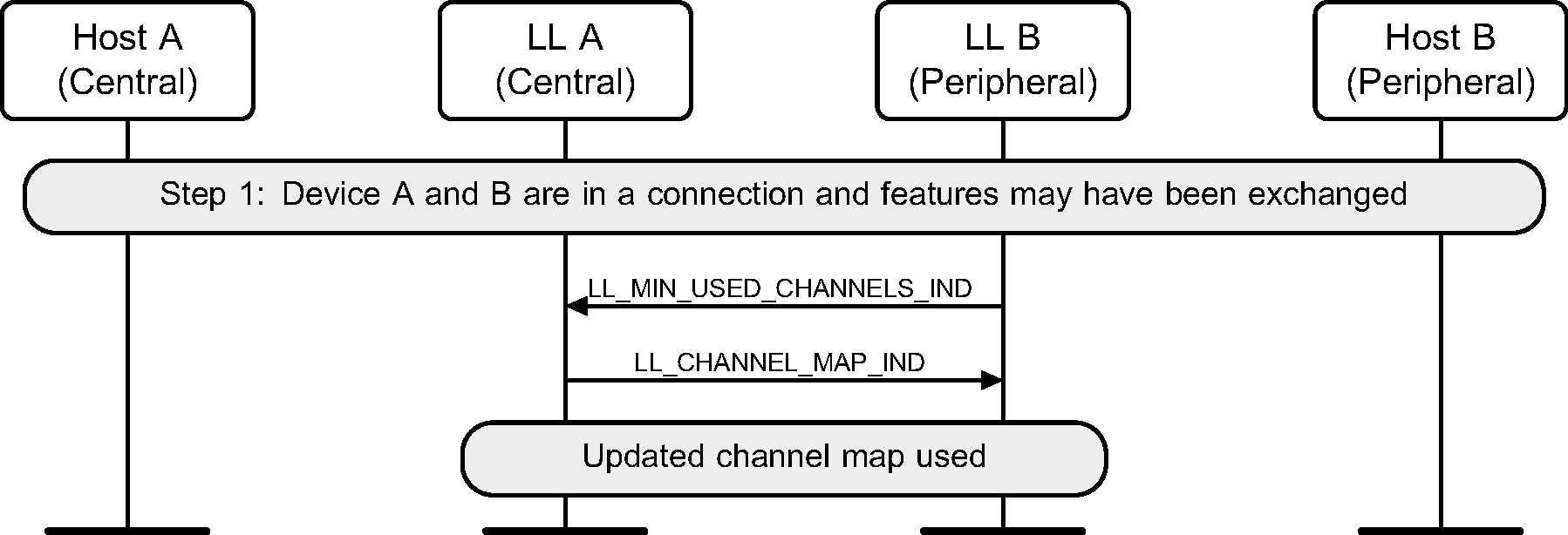
6.16. Minimum number of used channels request
Where a Peripheral supports the Minimum Number of Used Channels procedure, it can request that a certain minimum number of channels be used on the indicated PHY. The example shows a successful request, resulting in a channel map update with the requested minimum number of channels used for the connection.
6.17. LL procedure collision
The Link Layers of both the Central and Peripheral may initiate the same LL procedure at the same time.

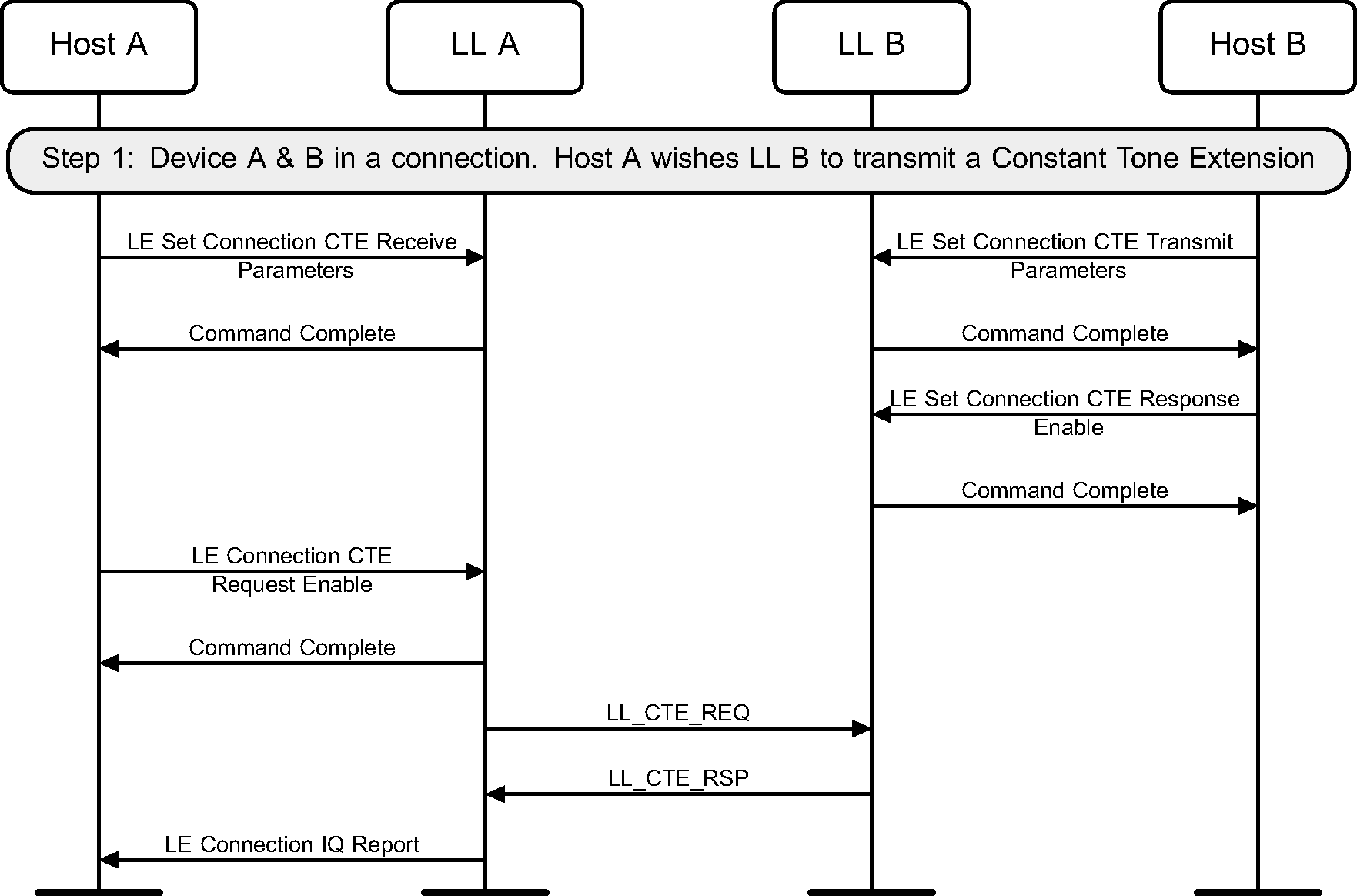
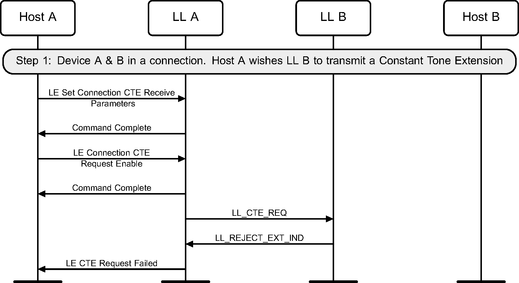
6.18. Constant Tone Extension Request
The Central or Peripheral of the connection may request the remote device to send an LL_CTE_RSP PDU with a Constant Tone Extension (see Figure 6.39 to Figure 6.41).
The sequence of events shown in figure 6.40 can only happen before feature exchange and can only happen once per connection, because a Link Layer must not use a procedure that it knows the peer does not support as required by [Vol 6] Part B, Section 4.6.

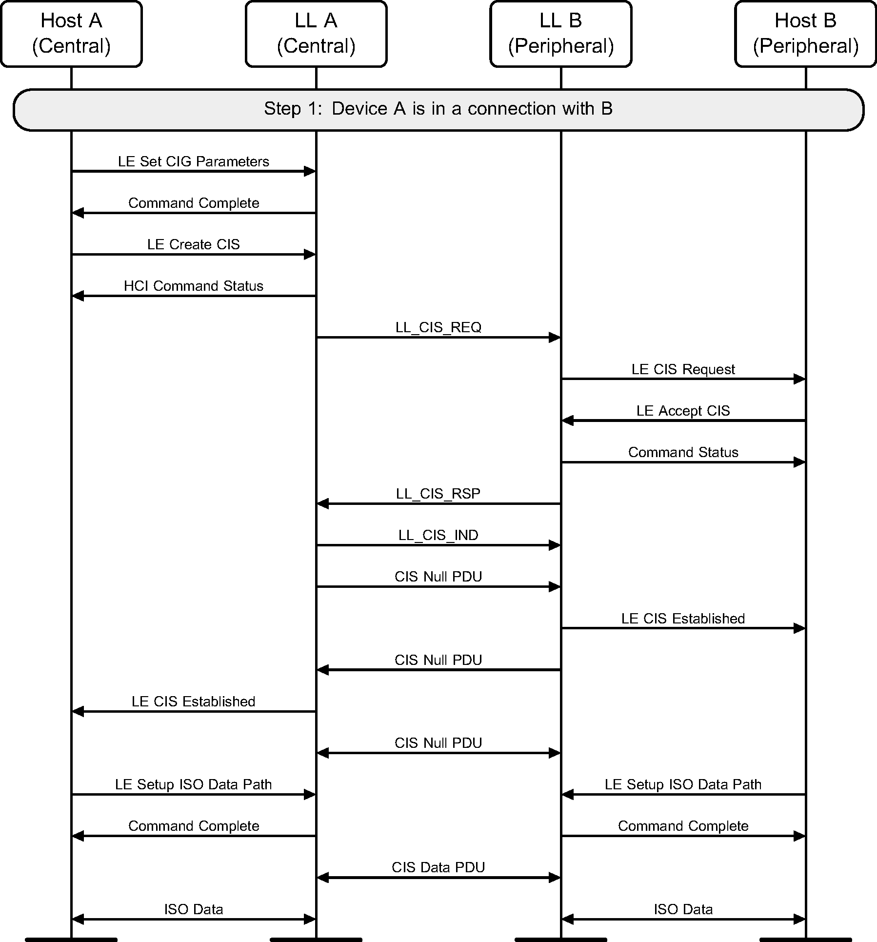
6.19. Connected Isochronous Group Setup
A Central sets up a CIG with parameters for one or more CISes, then establishes a CIS with a Peripheral (see Figure 6.42).
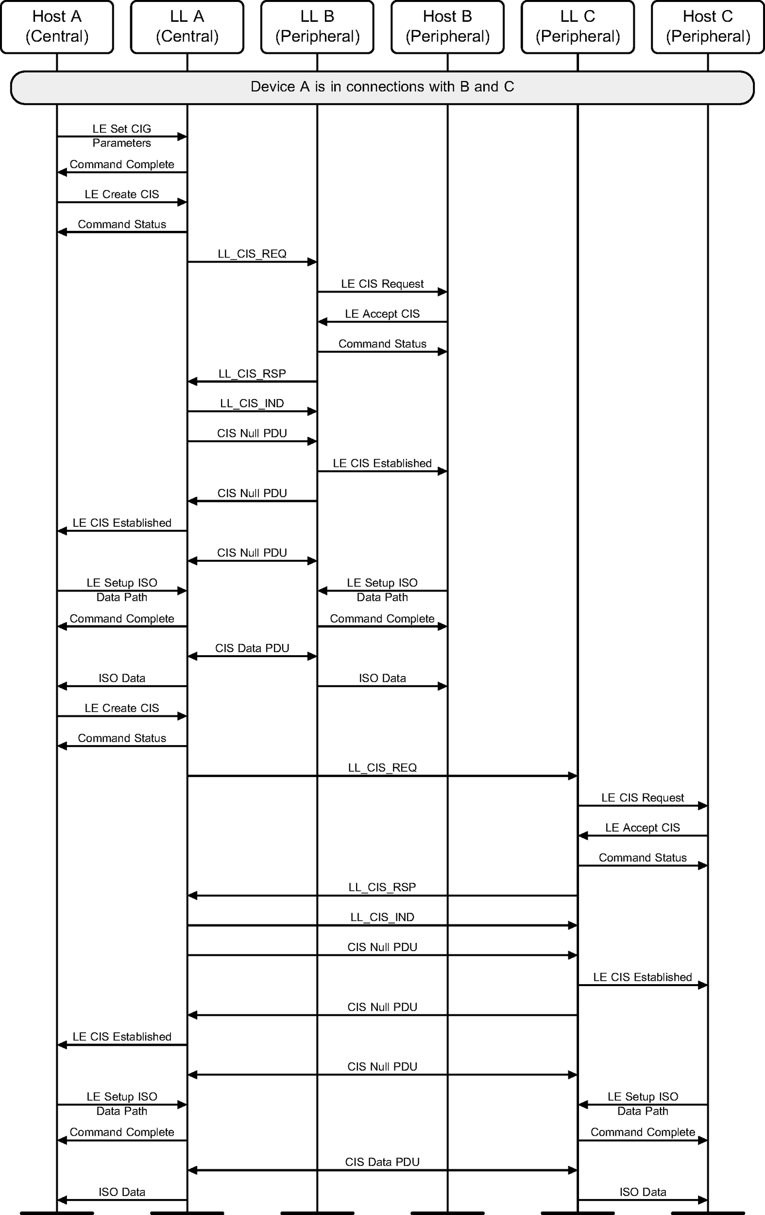
A Central sets up CIG parameters and establishes a CIS with two Peripherals (see Figure 6.43).
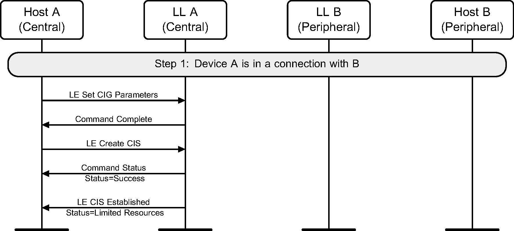
6.20. Host Rejects Connected Isochronous Stream
The Peripheral’s Host rejects the request to establish a CIS with the Central (see Figure 6.44).
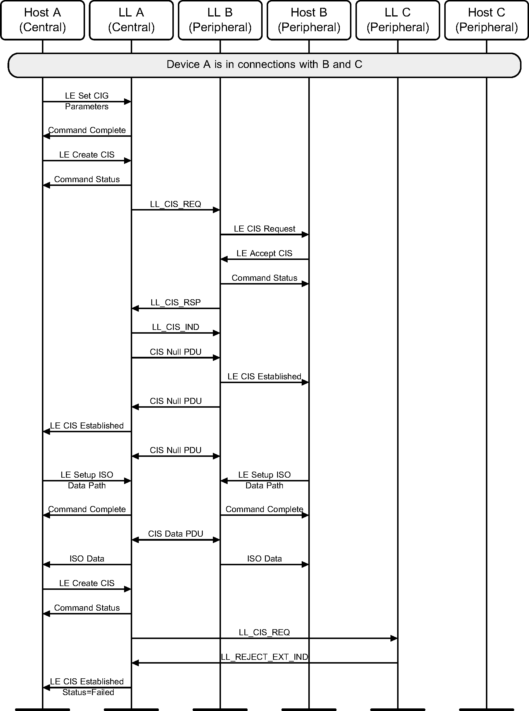
While setting up CISes with two Peripherals, the Host of one of the Peripherals rejects the request to establish a CIS with the Central (see Figure 6.45).
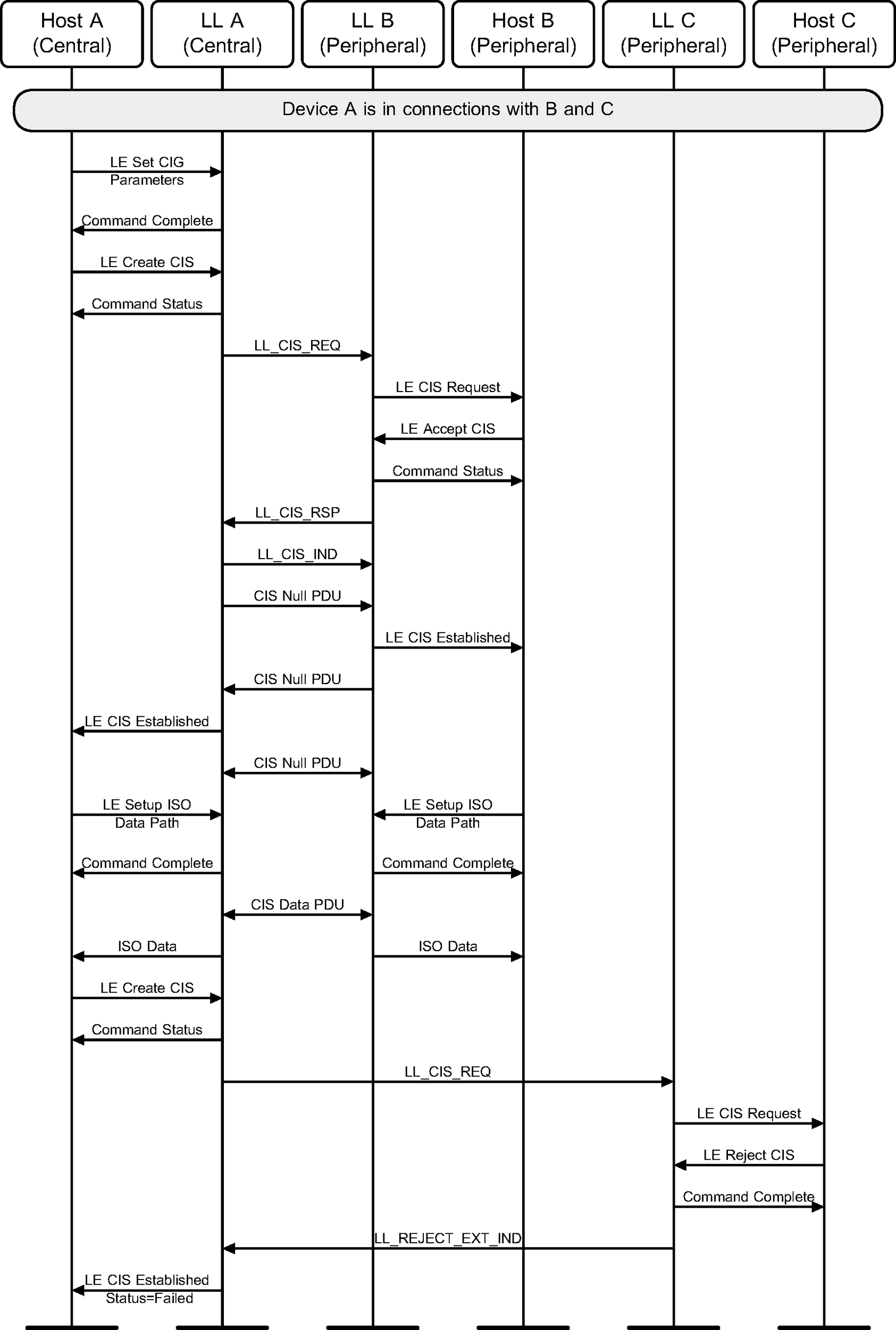
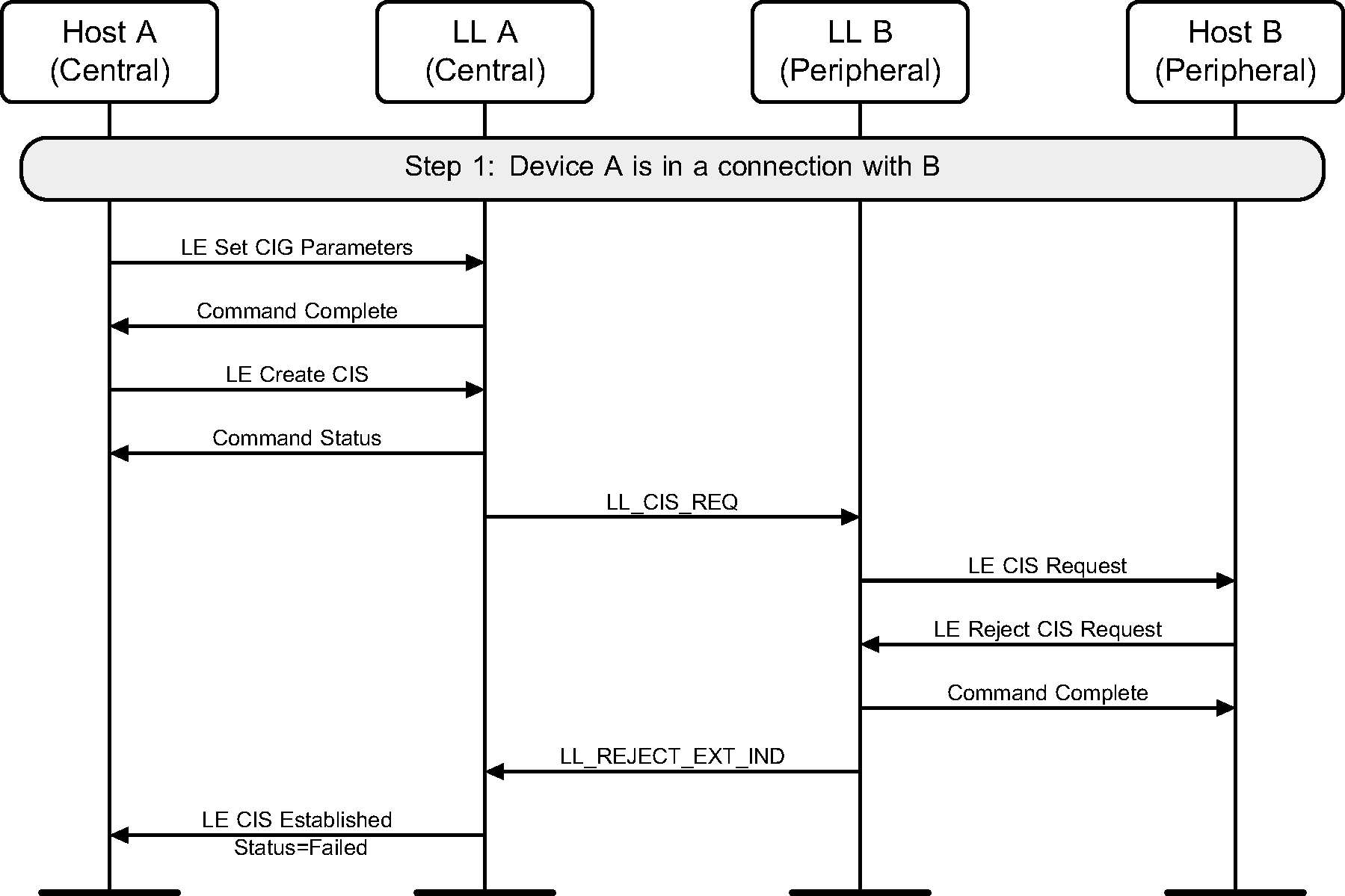
6.21. Link Layer Rejects Connected Isochronous Stream
The Link Layer of the Peripheral rejects the request to establish a CIS with a Central (see Figure 6.46).
While setting up CISes with two Peripherals, the Link Layer of one of the Peripherals rejects the request to establish a CIS with the Central (see Figure 6.47).
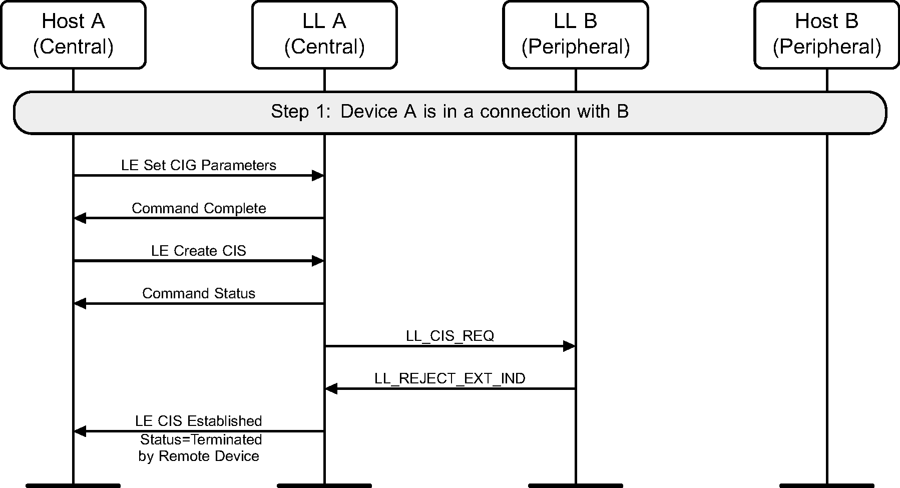
6.22. Link Layer Rejects Connected Isochronous Stream
The Link Layer of the Central rejects the request to create a CIS (see Figure 6.48).
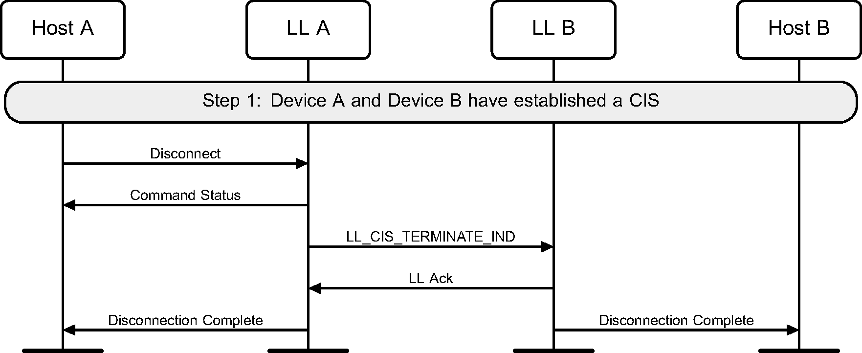
6.23. Host A Terminates Connected Isochronous Stream
The Host of the Central terminates a Connected Isochronous Stream (see Figure 6.49). Either A or B can be the Central.
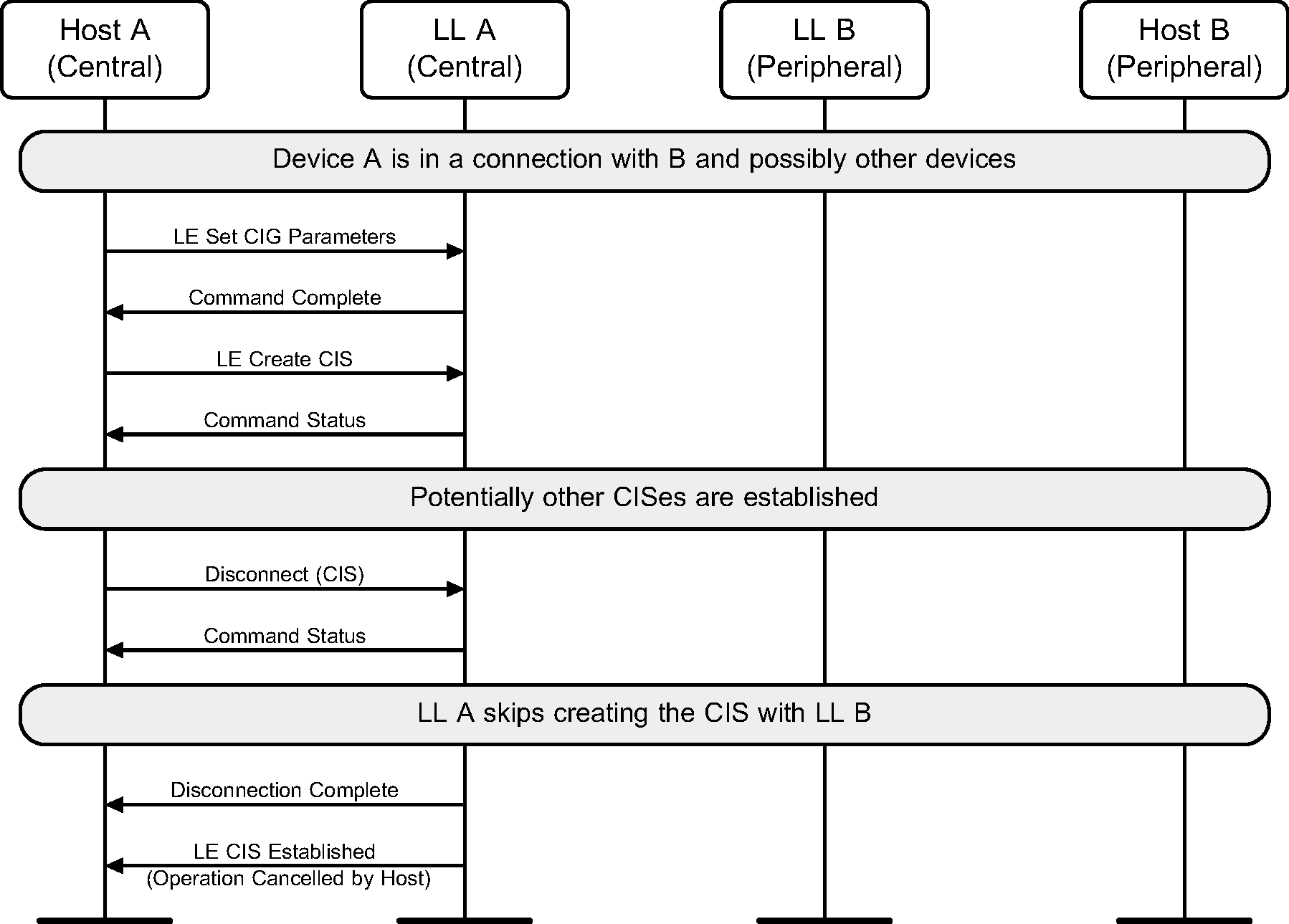
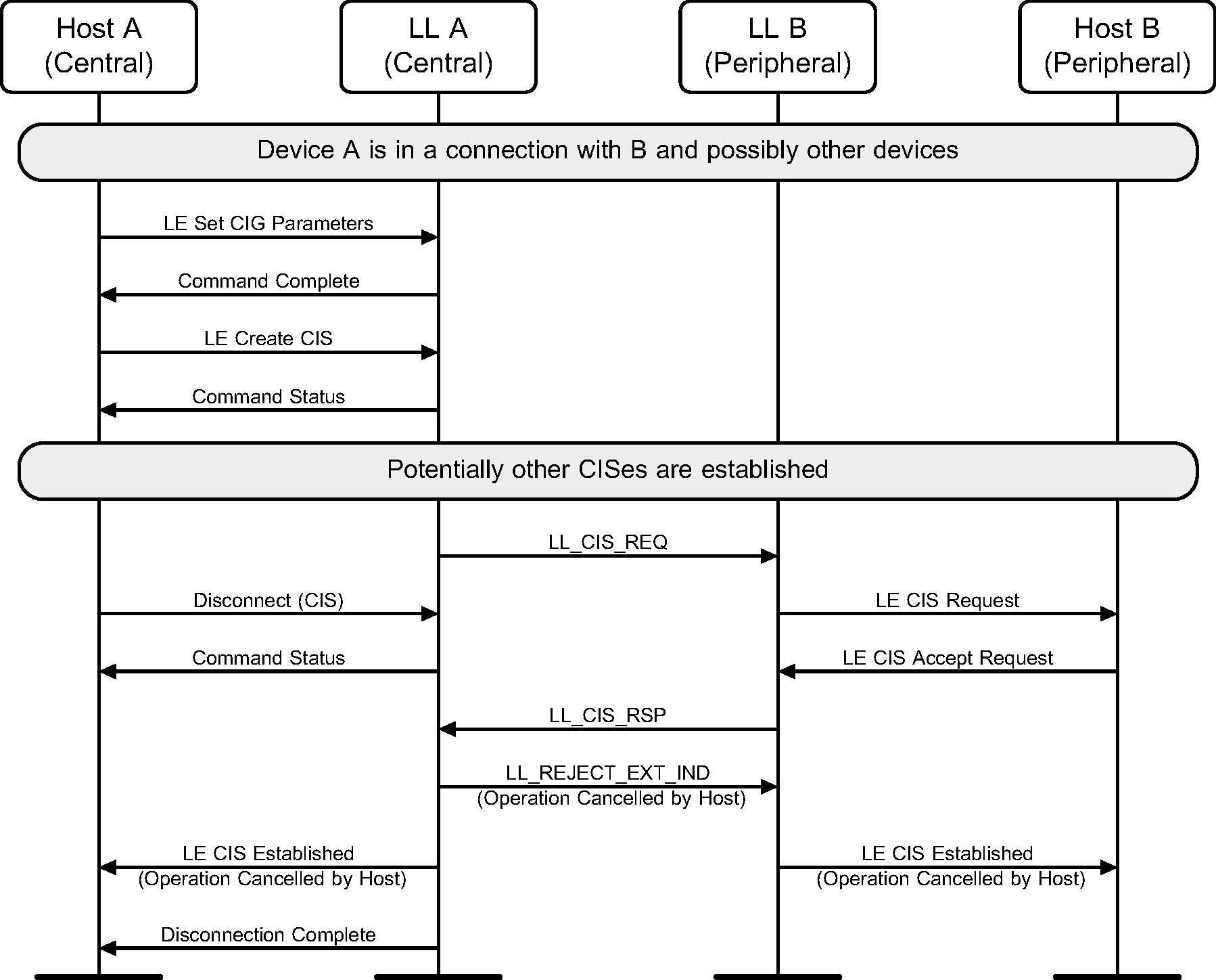
The Host of device A, which is the Central, terminates a Connected Isochronous Stream either before the Link Layer starts creating that CIS (see Figure 6.50) or during the creation process (see Figure 6.51).
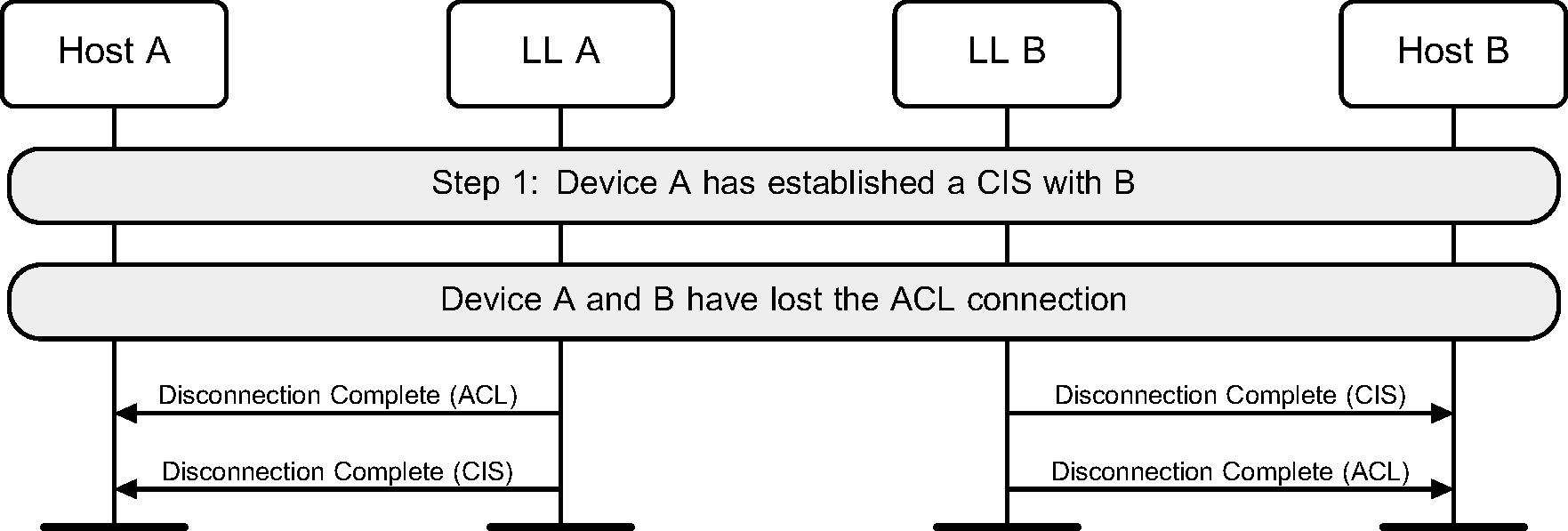
6.24. ACL disconnected
The disconnection of the ACL causes the disconnections of CISes (see Figure 6.52).
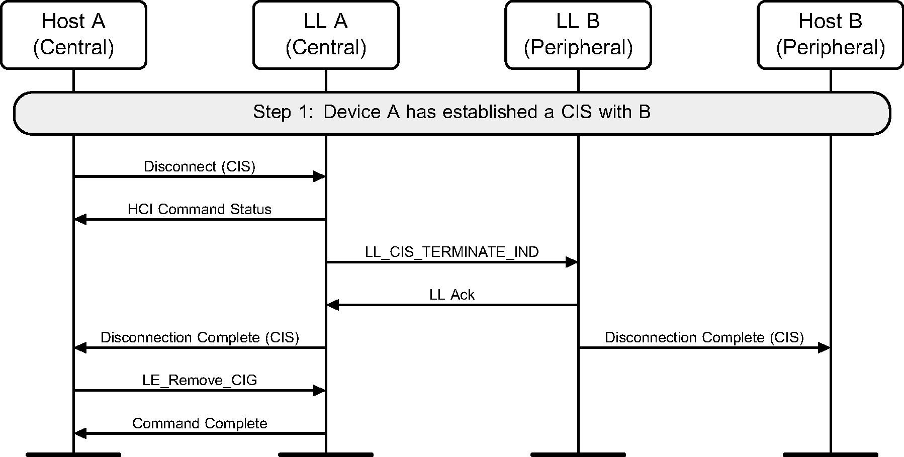
6.25. Host A Removes Connected Isochronous Group
A Host of the Central terminates the CIS and removes the CIG from the Link Layer (see Figure 6.53).
The Host of the Central terminates both the CISes in the CIG and removes the CIG from the Controller (see Figure 6.54).

6.26. Request Sleep Clock Accuracy
Either device can initiate a Sleep Clock Accuracy Update procedure to query the sleep clock accuracy of the peer device (see Figure 6.55).

6.27. Power Control
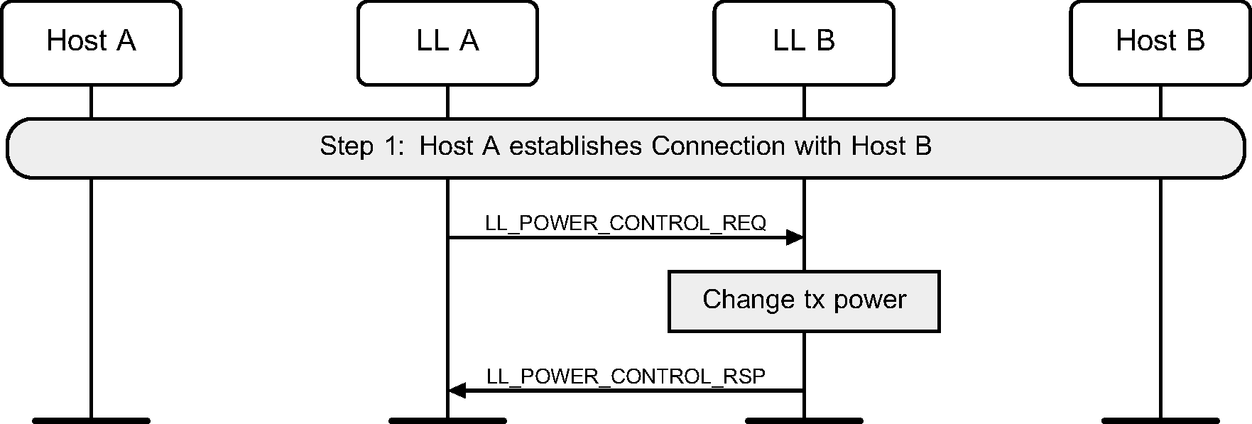
Either device can initiate a Power Control Request procedure to request the peer device to adjust its transmit power level (see Figure 6.56).
Either device can use the Power Control Request procedure to query the Acceptable Power Reduction (APR) value from the peer device and adjust its transmit power based on the response (see Figure 6.57).
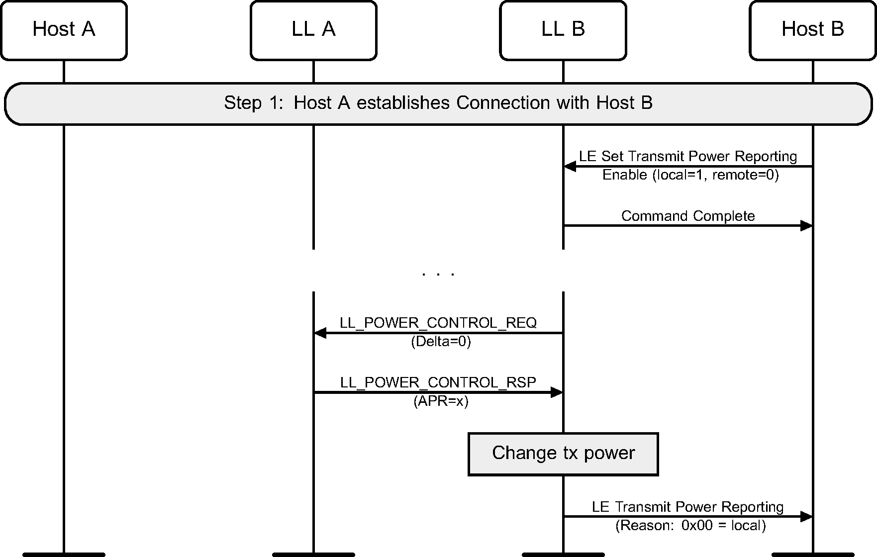
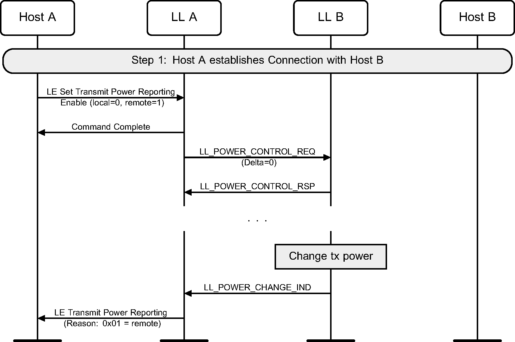
When the Host issues a command to enable reporting of remote power level changes, the Controller may initiate a Power Control Request procedure to request the remote device to start power level management (see [Vol 6] Part B, Section 4.5.15). When the remote Controller changes its transmit power level, it sends an indication to the peer device (see Figure 6.58). If reporting of remote transmit power level changes is enabled, the Controller sends an LE Transmit Power Reporting event to the Host.
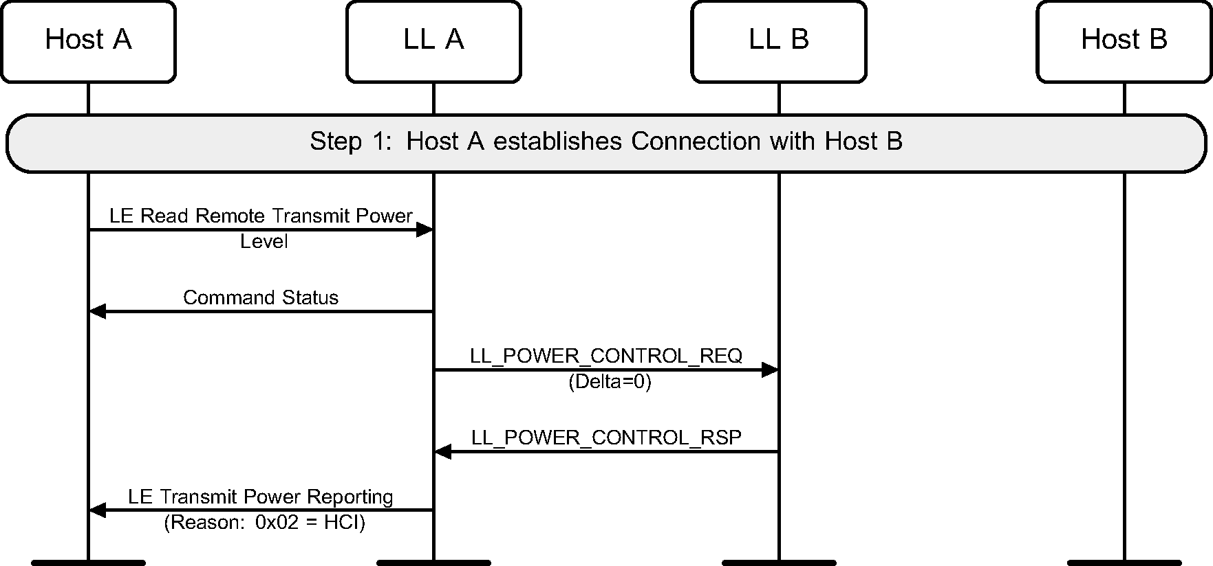
When a Host issues a command to read the transmit power level of a remote device, the Controller can initiate an LL Power Control Request procedure to query the transmit power level of the remote device (see Figure 6.59).
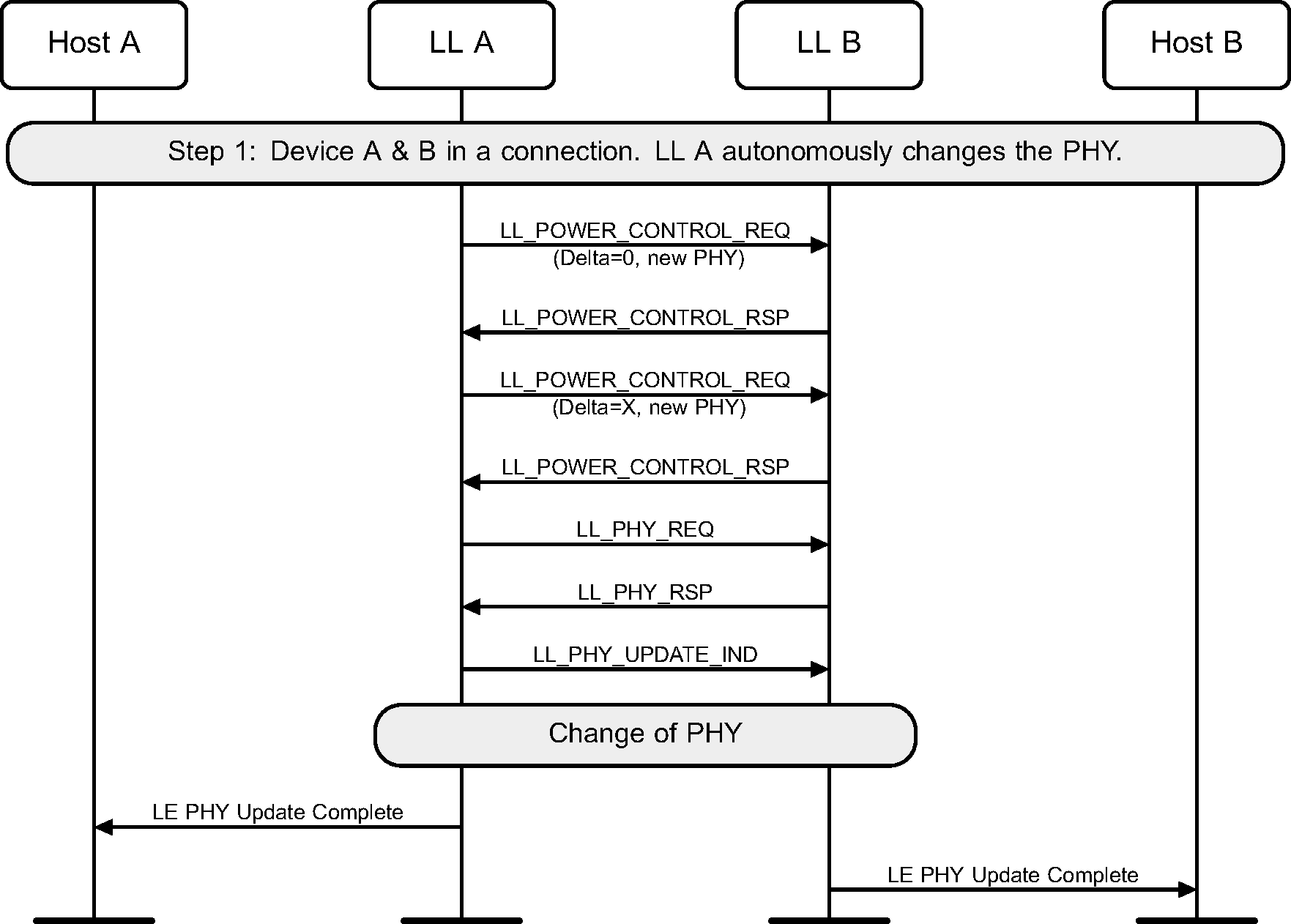
Before a PHY Update procedure is performed, the Link Layer may request a preferred transmit power level for the new PHY to be used by the remote device (see Figure 6.60).
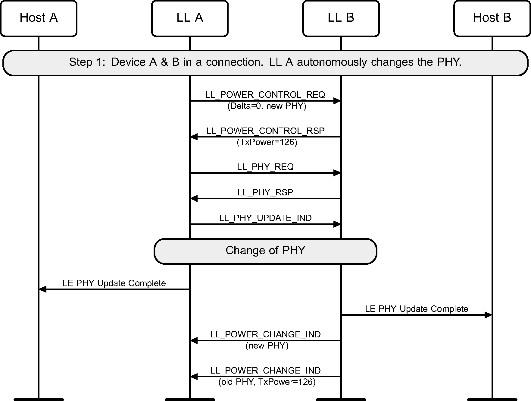
An implementation may choose to manage transmit power levels only on active PHYs and could reject a request for preferred transmit power level on the new PHY before a PHY Update procedure is performed (see Figure 6.61).
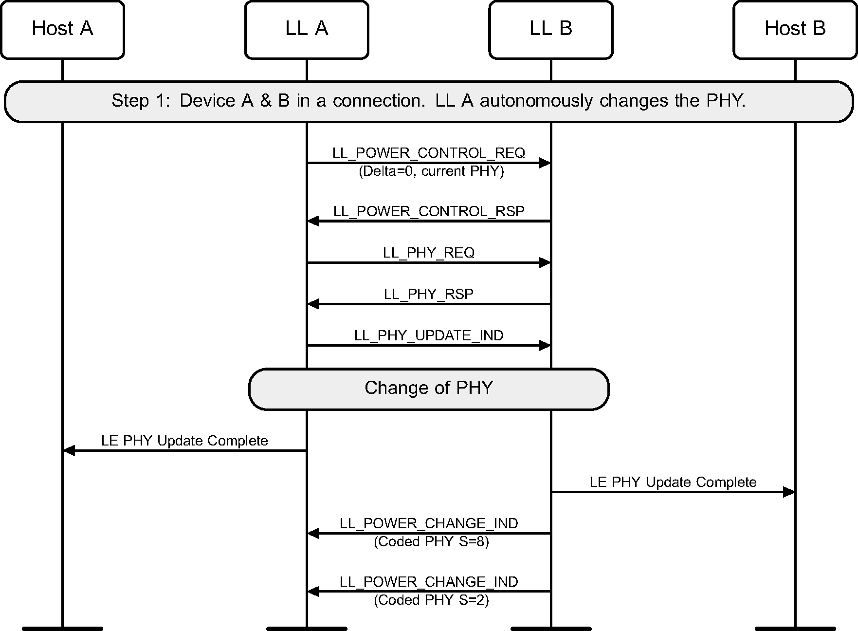
When a PHY Update procedure is performed to switch to the LE Coded PHY, where the local and remote devices can use both S=8 and S=2 coding, the Controller treats them as separate PHYs for the purpose of Power Control (see Figure 6.62).
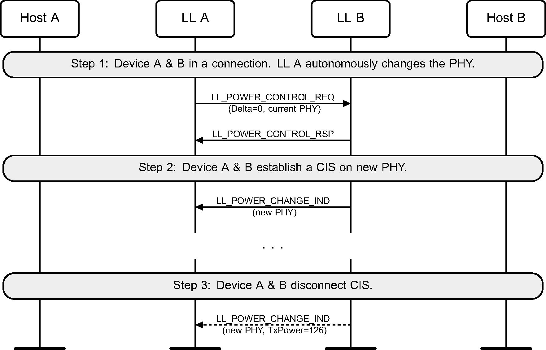
When an associated CIS is established on a PHY different from the one used by ACL, the Power Change Indication procedure may be used to indicate the transmit power level used on the new PHY. When the associated CIS is disconnected, the implementations may choose to stop managing the PHY used on the CIS (see Figure 6.63).
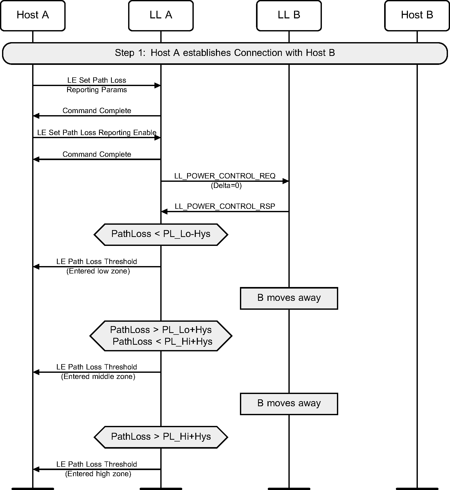
When a Host enables path loss monitoring, the Controller may initiate the Power Control Request procedure to query the remote transmit power level. As the remote device moves around, the Controller monitors the path loss on the connection and sends events to the Host as appropriate (see Figure 6.64).
6.28. Data path setup for a music stream over a CIS
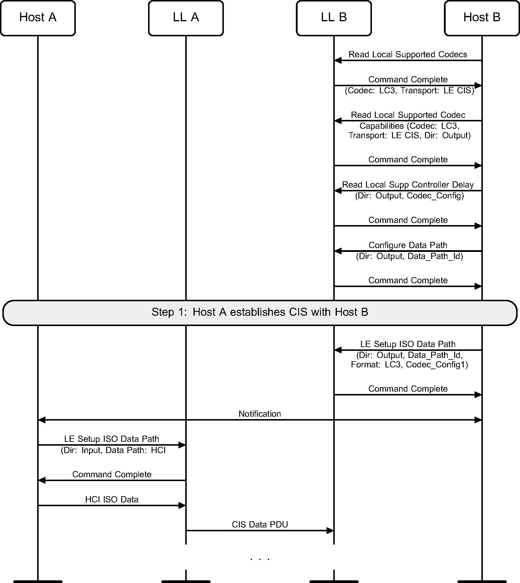
Figure 6.65 shows an example of unidirectional music streaming from Host A to Host B. Host A does LC3 codec processing in the Host and sends data over HCI to the Controller, which transmits the PDUs over the air without further processing. Host B configures an output data path to the speaker(s) and enables LC3 codec processing in the Controller.
Note
Note: The notifications between the Hosts are specified by the relevant profile(s).
Note
Note: The audio data may be mono or stereo. In the latter case, how the data sent to the output data path is split into the separate audio signals is outside the scope of this specification.
6.29. Data path setup for bi-directional voice over a CIS
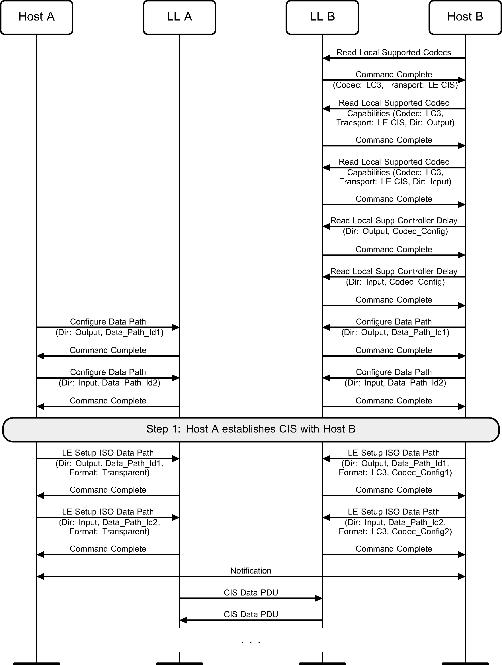
Figure 6.66 shows an example of a bidirectional voice call between Host A and Host B. Device A contains proprietary audio interface hardware with an embedded LC3 codec. Hence the Host sets up the ISO data path with Coding_Format set to transparent mode. Device B supports LC3 codec processing in the Controller and hence Host B sets up the ISO data path with Coding_Format set to LC3 along with the codec configuration data defined by the relevant profile(s).
Note
Note: The notifications between the Hosts are specified by the relevant profile(s).
6.30. [This section is no longer used]
The contents of this section are now in Section 8.5.
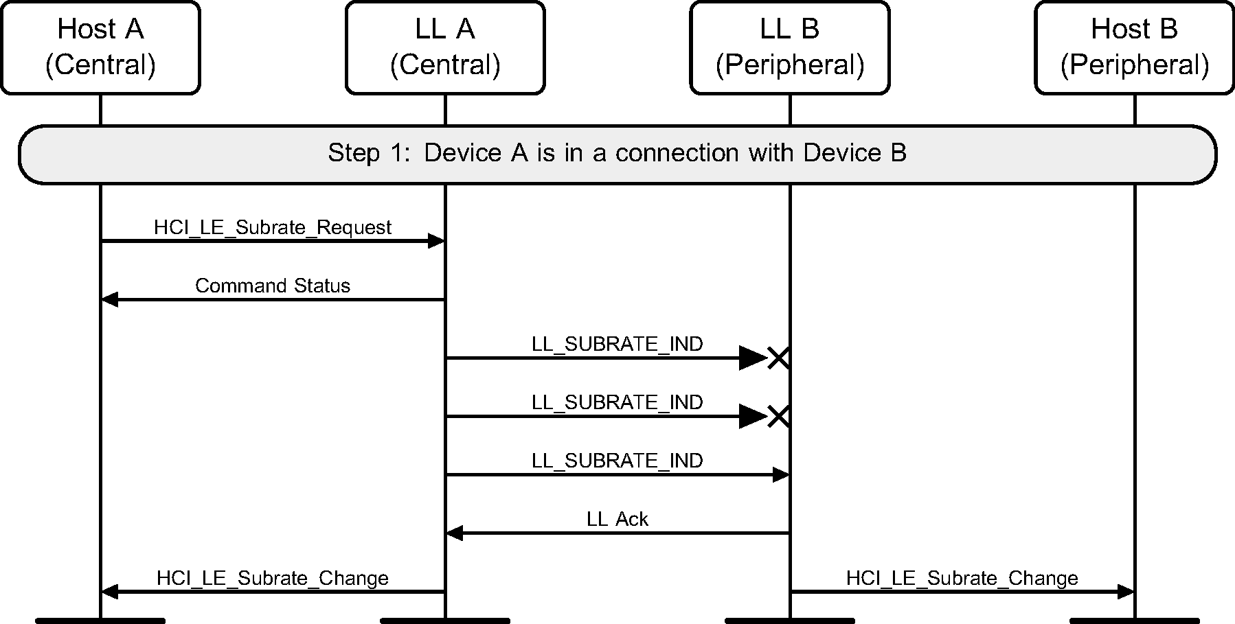
6.31. Modifying the subrate of a connection
A Central A in a connection with a Peripheral B modifies the subrating of the connection. The first two PDUs are not received by device B (see Figure 6.67).
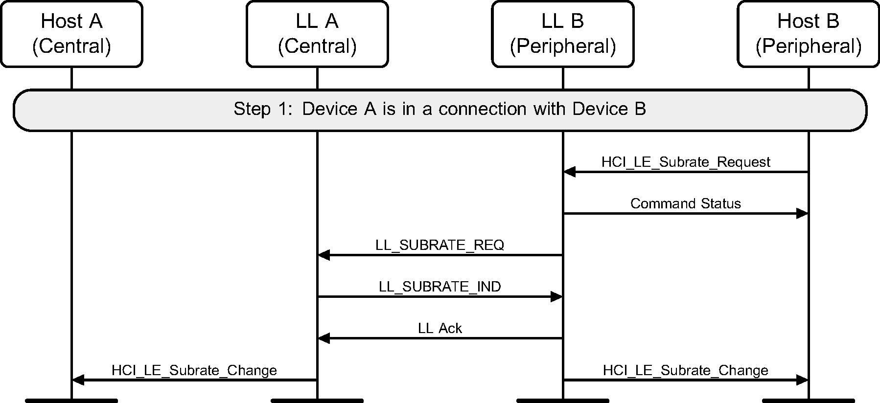
Peripheral B requests a new subrating for its connection with device A and makes the change (see Figure 6.68).
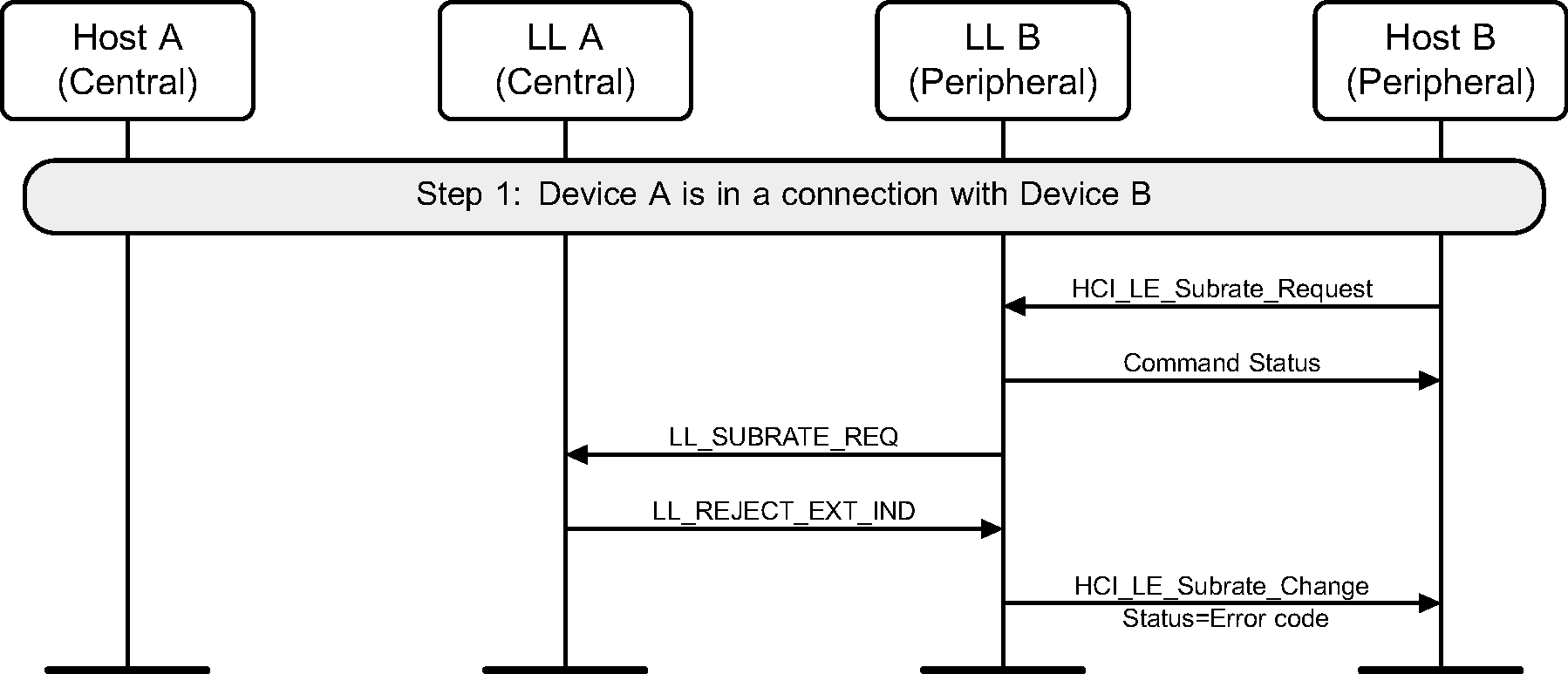
Peripheral B requests a new Subrating for its connection with device A but device A rejects the change (see Figure 6.69).
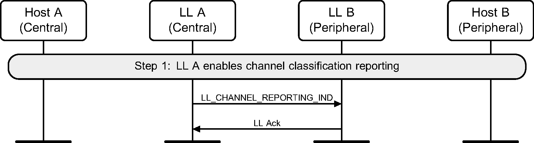
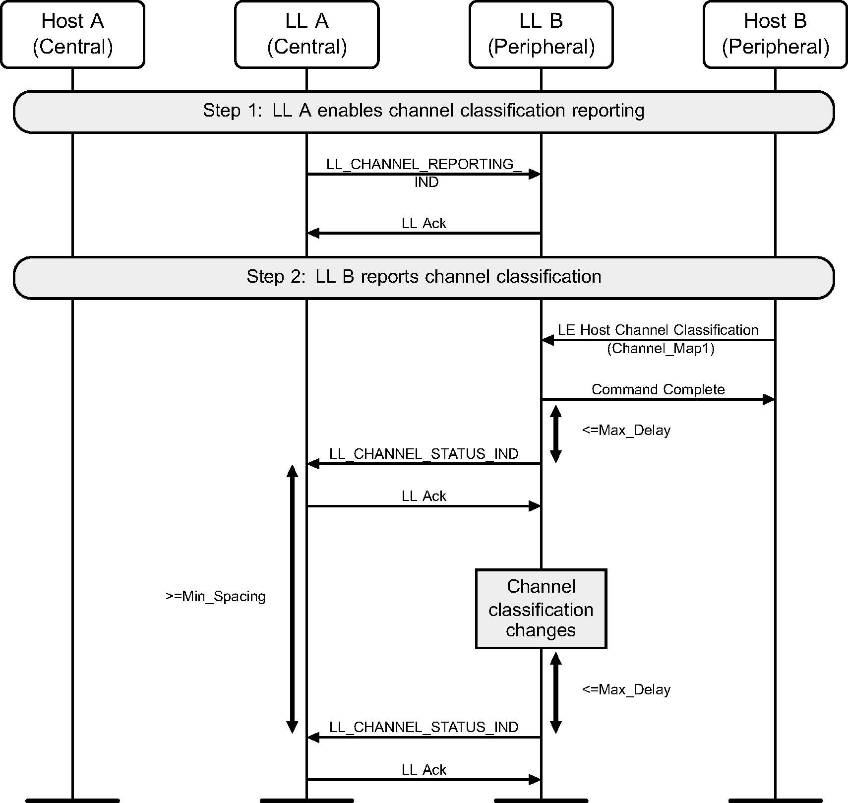
6.32. Channel Classification Enable
The Central can enable reporting of channel classification information on the Peripheral.
6.33. Channel Classification Reporting
The reporting is enabled, the Peripheral can provide channel classification information to the Central.
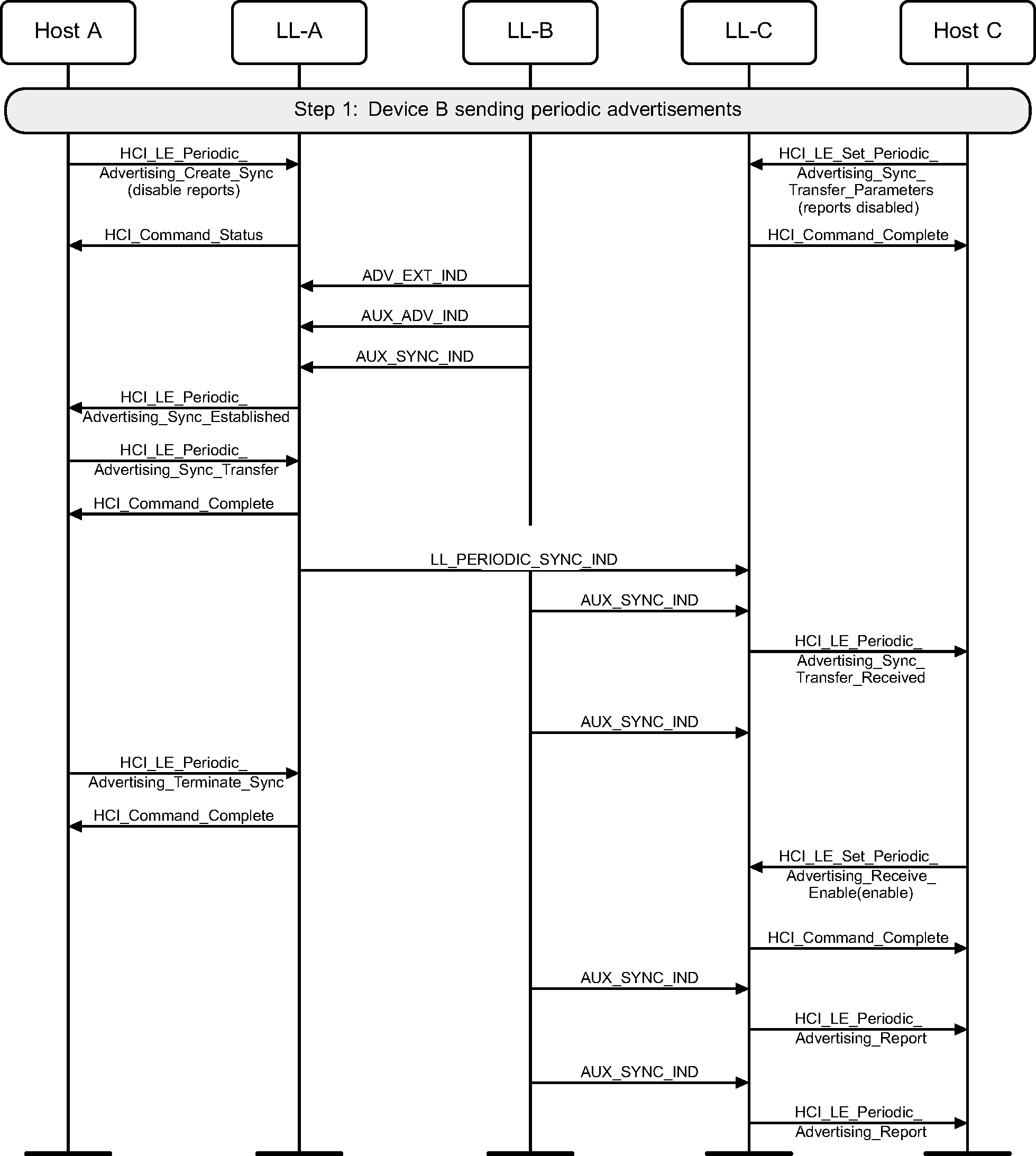
7. Periodic advertising sync transfer
In the following examples, device B is carrying out periodic advertising. Either device A or device B is in a connection with device C and transfers periodic advertising synchronization information about the periodic advertising train to device C.
7.1. Transfer by scanner, reports initially disabled
The scanning device (A) transfers periodic advertising synchronization information to device C, which starts listening to the periodic advertising train but only sends reports to the Host when explicitly requested.
 |
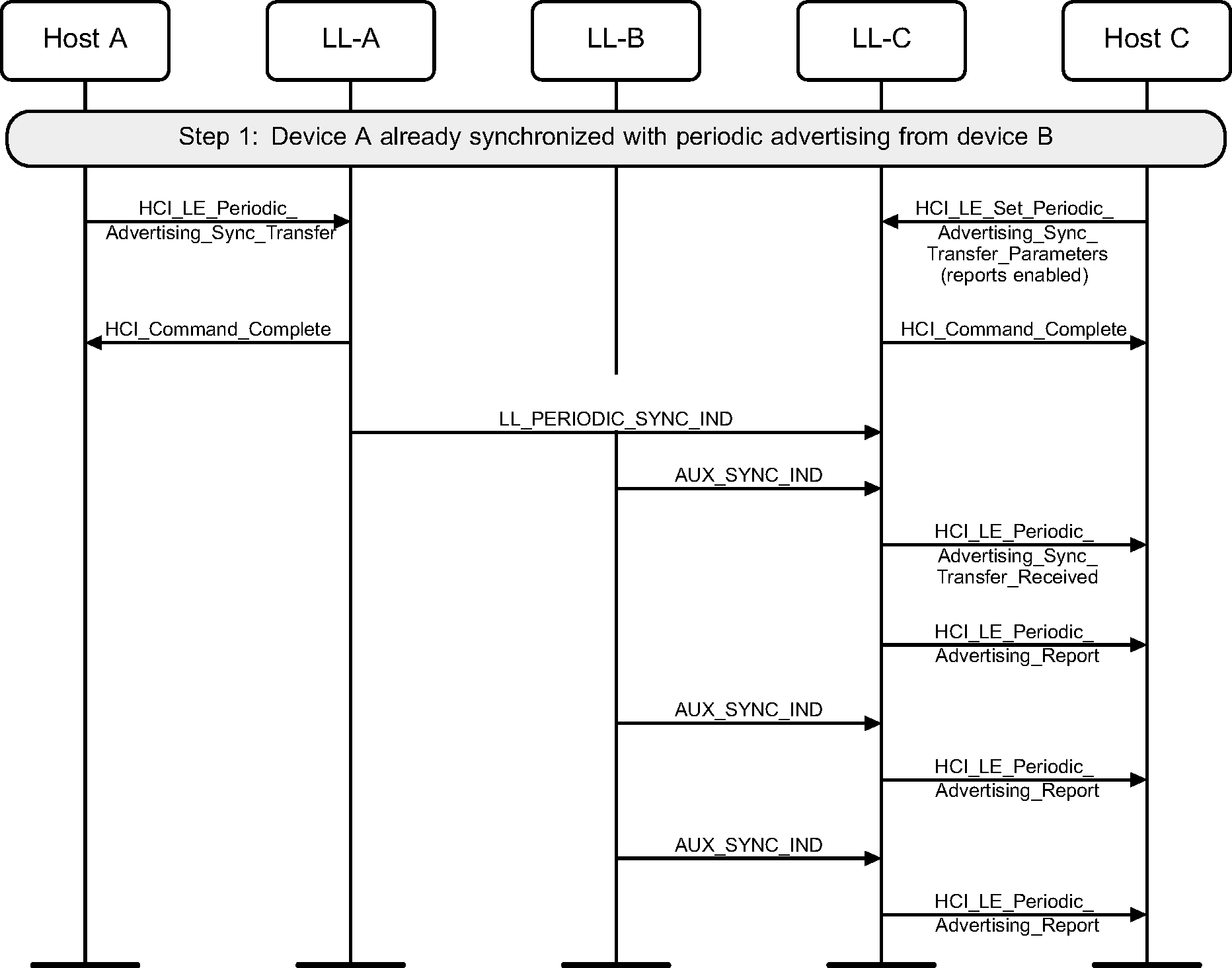
7.2. Transfer by scanner, reports initially enabled
The scanning device (A) transfers periodic advertising synchronization information to device C, which starts listening to the periodic advertising train and immediately sends reports to the Host.
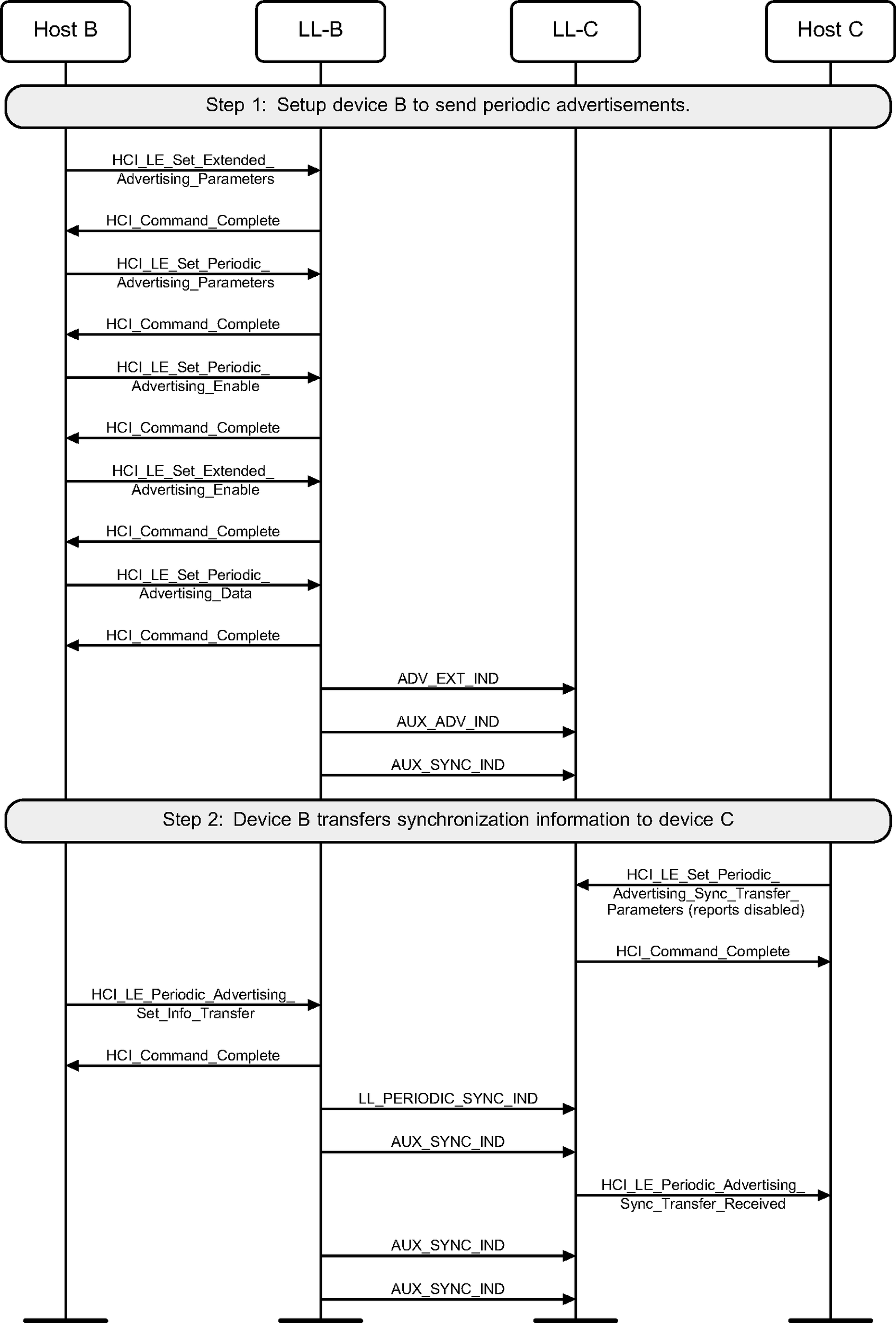
7.3. Transfer by the advertiser
The advertiser (B) directly transfers periodic advertising synchronization information about its periodic advertising to device C. In this example reports to Host C are disabled.
8. Synchronization state
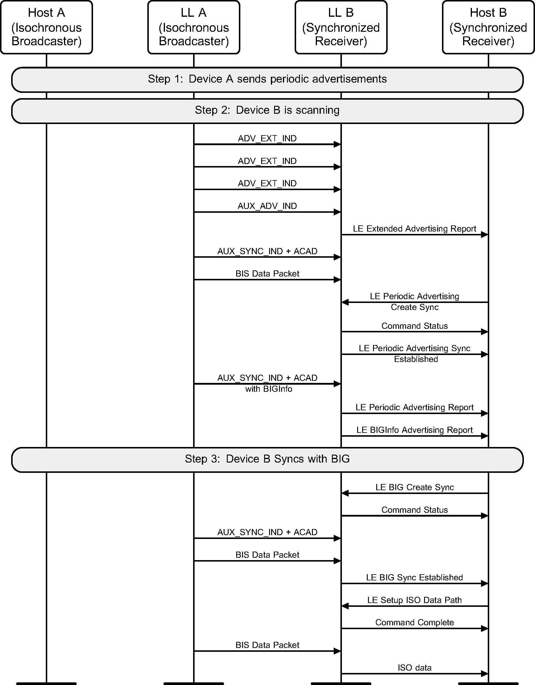
8.1. Synchronizing with a Broadcast Isochronous Group
A device enters the Synchronization state, receives the synchronization information from the periodic advertising train that is associated with the BIG, and synchronizes to a BIS (see Figure 8.1).
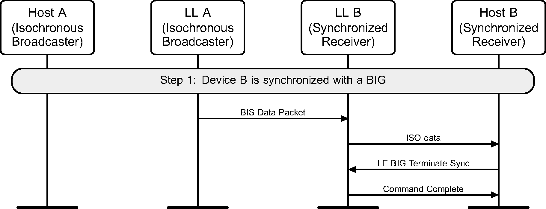
8.2. Terminate Synchronization with a BIG
A device terminates synchronization with a BIG (see Figure 8.2).
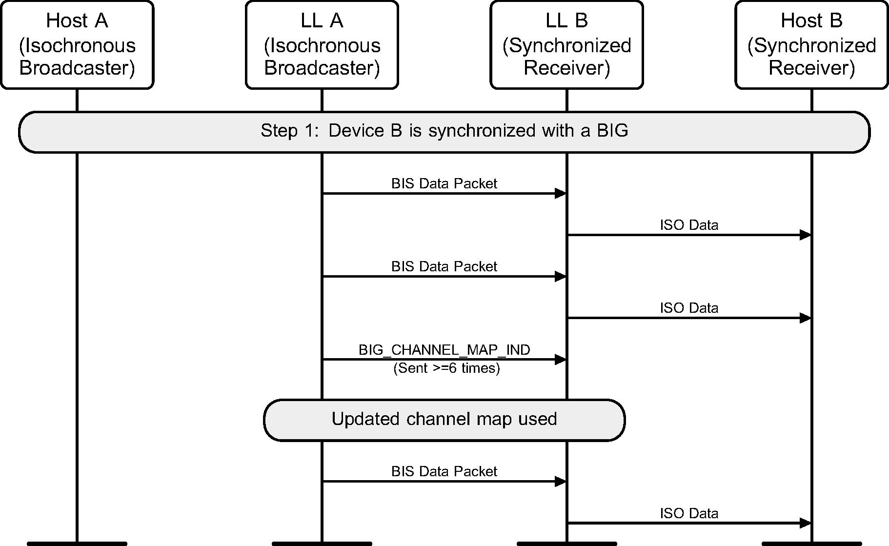
8.3. New Channel Map for Broadcast Isochronous Group
A device receives a channel map update for a BIG (see Figure 8.3).
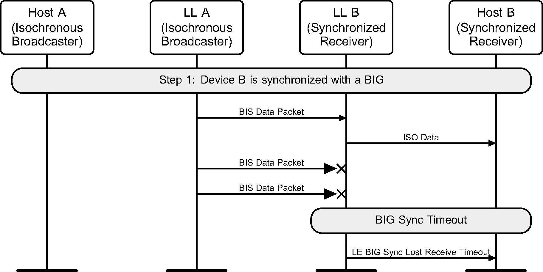
8.4. Lost Synchronization with a Broadcast Isochronous Group
A device loses synchronization with a BIG (see Figure 8.4).
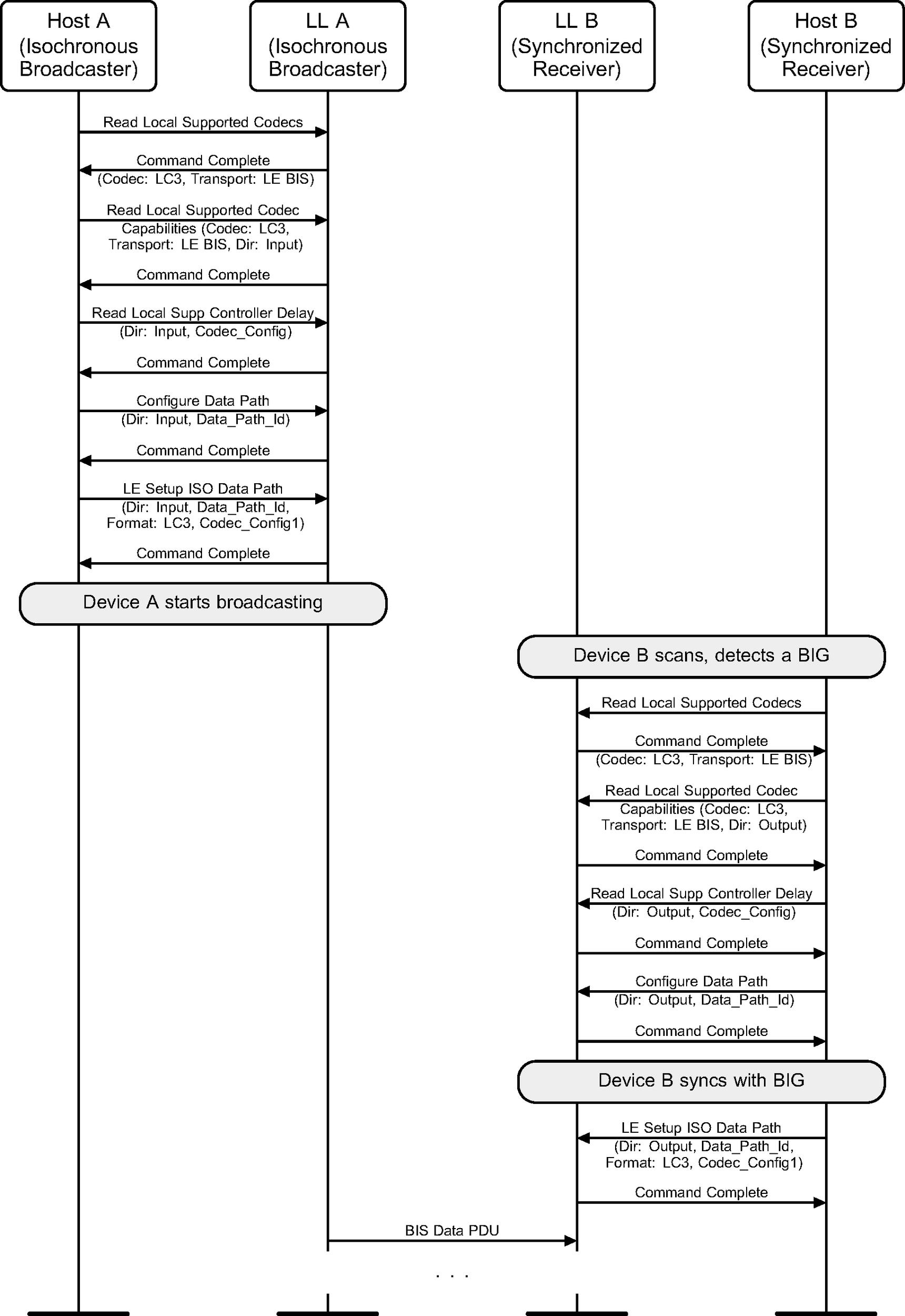
8.5. Data path setup for a BIS
Figure 8.5 shows an example of an isochronous broadcast stream from the Broadcaster A. Host A sets up the ISO data path with codec processing in the Controller to create the PDUs transmitted over the BIS. Device B becomes a Synchronized Receiver for the BIS and sets up the ISO data path to do codec processing in the Controller on the received data PDUs.