Part A. MWS Coexistence Logical Signaling Specification
vAtlanta r00
This Part specifies the Mobile Wireless Standards (MWS) coexistence logical interface between the Controller and an MWS device.
1. Introduction
This Part of the specification describes the MWS Coexistence Logical Signaling. A Bluetooth Controller may incorporate a real-time transport interface to transport the logical signals defined in this section between the Bluetooth Controller and an MWS device.
Figure 1.1 depicts the signaling and messaging architecture.
 |
MWS Coexistence logical signaling is designed to enable a standard interface to allow an MWS device and a Bluetooth Controller to exchange information and support cooperative coexistence.
MWS Coexistence logical signaling defines a set of signals between the collocated Bluetooth Controller and MWS device. Those signals carry time critical, real-time information such as the start point of an MWS frame. The coexistence logical signaling architecture also includes a transparent data messaging mechanism to enable passing of information between the MWS device and Bluetooth Controller when such information cannot tolerate the long latency (tens of milliseconds) of the signaling path via the Bluetooth Host.
2. Logical interface
2.1. Coexistence signals
Table 2.1 defines the logical signals. These logical signals assist in time alignment, protecting the MWS device and the Bluetooth Controller from mutual interference, thus maximizing the usability of the Bluetooth radio.
Name | Direction | Description |
|---|---|---|
FRAME_SYNC | MWS → Bluetooth | See Section 2.1.1 |
MWS_RX | MWS → Bluetooth | See Section 2.1.2 |
BLUETOOTH_RX_PRI | Bluetooth → MWS | See Section 2.1.3 |
BLUETOOTH_TX_ON | Bluetooth → MWS | See Section 2.1.4 |
MWS_PATTERN | MWS → Bluetooth | See Section 2.1.5 |
MWS_TX | MWS → Bluetooth | See Section 2.1.6 |
802_RX_PRI | Bluetooth → MWS | See Section 2.1.7 |
802_TX_ON | Bluetooth → MWS | See Section 2.1.8 |
MWS_INACTIVITY_DURATION | MWS → Bluetooth | See Section 2.1.9 |
MWS_SCAN_FREQUENCY | MWS → Bluetooth | See Section 2.1.10 |
The first 8 of these (FRAME_SYNC, MWS_RX, BLUETOOTH_RX_PRI, BLUETOOTH_TX_ON, MWS_PATTERN, MWS_TX, 802_RX_PRI, and 802_TX_ON) are also referred to as the "real-time coexistence signals".
Many of the signals have associated parameters, which are configured by the Bluetooth Host using HCI commands. There is no requirement for signals that are used internally to be connected to an external interface, although testing requires external control of the FRAME_SYNC signal. For example, a combo-device that integrates a Bluetooth Controller and an MWS radio together does not need to bring out the coexistence signals.
Section 2.2 provides recommended values for the defined offset and jitter parameters.
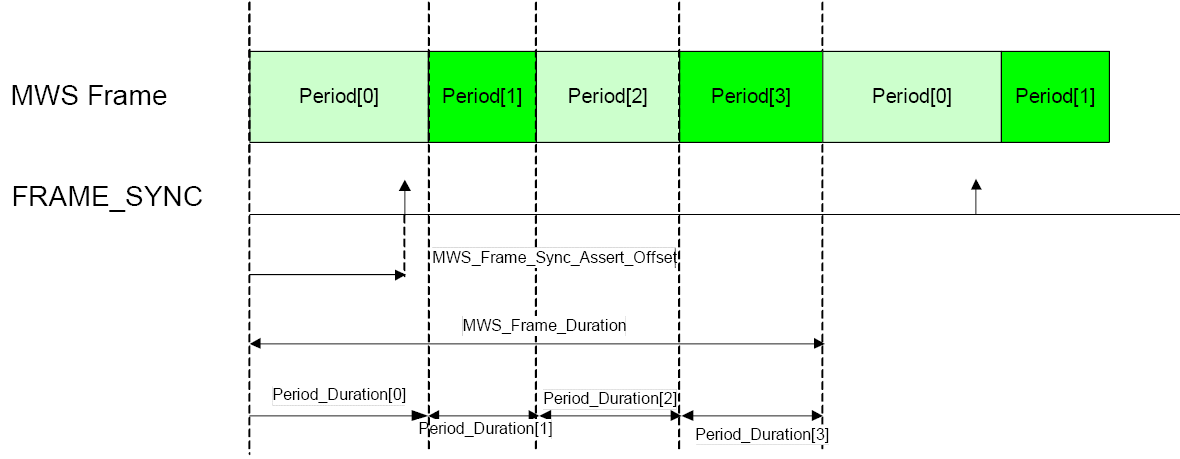
2.1.1. FRAME_SYNC
The FRAME_SYNC signal is sent by the MWS device to indicate the time of the beginning of MWS frames according to the MWS network timing. It provides the anchor point for the Bluetooth Controller to properly align Bluetooth transmission and reception activity with the MWS network frame structure. The time when FRAME_SYNC is sent over the transport, adjusted for MWS_Frame_Sync_Assert_Offset, indicates the start time of the first Period_Duration parameter in the HCI_Set_External_Frame_Configuration command.
The MWS device will inform the Bluetooth Controller about changes to the layout and timing of the MWS frame by issuing new HCI_Set_External_Frame_Configuration commands.
2.1.2. MWS_RX
The MWS_RX signal is sent by the MWS device to indicate that an MWS reception is occurring and to request that the Bluetooth Controller cease ongoing transmission and not start a new transmission. The Bluetooth Controller can occasionally disregard the MWS_RX signal for critical transmissions.
The MWS RX signal should be de-asserted at the time an MWS device stops actively receiving. If there are multiple distinct periods of reception within an MWS downlink duration, the signal may stay asserted until the last period has finished receiving.
2.1.3. BLUETOOTH_RX_PRI
The BLUETOOTH_RX_PRI signal is used by the Bluetooth Controller to request that the MWS device cease its transmission and/or refrain from starting a transmission because the Bluetooth Controller is expecting a high priority reception.
The signal should be used minimally by the Bluetooth system so as not to adversely affect the MWS system. There is no guarantee that the MWS device will honor the signal and not transmit or abort an ongoing transmission.
2.1.4. BLUETOOTH_TX_ON
The BLUETOOTH_TX_ON signal is sent by the Bluetooth Controller to indicate that it is actively transmitting.
2.1.5. MWS_PATTERN
The MWS_PATTERN signal is sent by the MWS device to inform the Bluetooth Controller which MWS_PATTERN is in use.
Up to three different MWS_PATTERNs can be selected: 0, 1, and 2. The MWS device may indicate that the MWS_PATTERN has not changed by setting it to 3. The definitions of the patterns are communicated to the Bluetooth Controller using the HCI_Set_MWS_PATTERN_Configuration command. If the pattern is not currently configured, the behaviour is equivalent to setting a pattern that allows unrestricted activity by the Bluetooth Controller.
At the start of each MWS Frame, as defined by the FRAME_SYNC signal plus the MWS_Frame_Sync_Assert_Offset, the most recent MWS_PATTERN value takes effect as follows.
If it is 3, the current pattern continues in use.
If it is the index of the current pattern, then that pattern is restarted.
Otherwise the indicated pattern is started.
2.1.6. MWS_TX
The MWS_TX signal is sent by the MWS device to indicate its transmission state.
The signal should be asserted at the beginning of an MWS transmission and de-asserted at the end of a transmission. If there are multiple transmission periods during an uplink frame, the signal may stay asserted until the end of the last transmission period.
2.1.7. 802_TX_ON
Bluetooth technology and 802.11 may be collocated and share an interface to coordinate access to the 2.4 GHz ISM band.
The 802_TX_ON is used by the 802.11 device to indicate the state of the 802.11 transmission.
Interference generated by 802.11 to the MWS device will not necessarily be distinguishable from interference created by Bluetooth transmissions.
This signal allows the MWS device to distinguish the interference generated by 802.11 transmissions from the interference generated by the Bluetooth transmissions. The MWS device can use that information to optimize its channel access.
2.1.8. 802_RX_PRI
This signal requests that the MWS device stop or refrain from any transmission because the WLAN device collocated with the Bluetooth Controller is expecting a high priority reception.
The signal should be used minimally by the 802.11 system so as not to adversely affect the MWS system. There is no guarantee that the MWS device will honor the signal and not transmit or abort an ongoing transmission.
2.1.9. MWS_INACTIVITY_DURATION
The MWS_INACTIVITY_DURATION signal provides the time duration until the MWS device is active again. Subsequent MWS_INACTIVITY_DURATION signals override previously sent time durations.
MWS_INACTIVITY_DURATION may be set to zero (i.e. cancel), infinite, or a positive finite duration. The transport layer defines the value for infinite duration and the set of finite durations available.
2.1.10. MWS_SCAN_FREQUENCY
The MWS_SCAN_FREQUENCY signal provides an index to a table of RF frequencies during MWS scan operation.
The MWS device signals MWS_SCAN_FREQUENCY if it starts an inter-frequency scan.
Setting MWS_SCAN_FREQUENCY to a non-zero value indicates the start of the MWS scan period. Setting MWS_SCAN_FREQUENCY to zero indicates the end of the scan period.
The Bluetooth Controller should avoid any transmissions that can interfere with the scan while a scan is active. The Bluetooth Controller can occasionally disregard the signal for critical transmissions.
2.2. Tolerances for offsets and jitter
This section lists the recommended tolerances for the signal assertion and de-assertion offsets and jitter for those signals.
Note
Note: The transmitting side should use a value within the range and the receiving side should accept any value within the range and may accept other values.
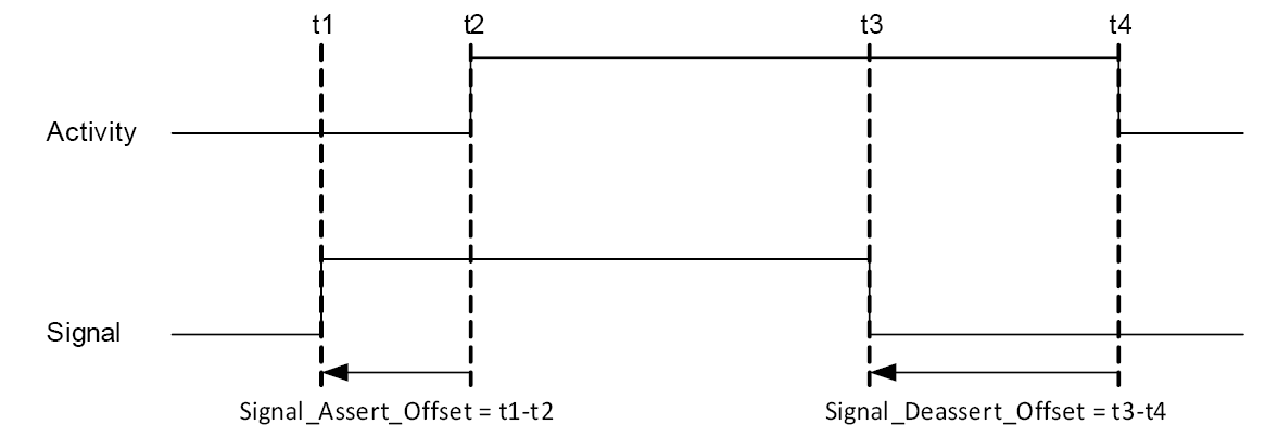
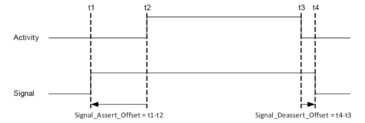
An offset is a static advance notification or delay between the real physical event and the time when the corresponding signal is issued.
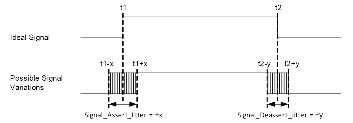
Jitter is variation in the timing of each signal from ideal timing.
Signals that are turned on and off around a period of time have specified values for both assertion and de-assertion offsets and jitter. Signals that represent a single event at a single instant in time have only assertion offset and jitter timing specified.
All jitter values are given as an unsigned value representing the maximum allowable jitter in positive and negative directions. De-assertion and MWS_Frame_Sync_Assert_Offset may be negative (i.e., signal is asserted before the event) or positive (i.e., signal is asserted after the event). All other assertion signals should be negative (i.e., signal is issued before the event).
Parameter | Earliest | Latest |
|---|---|---|
MWS_Frame_Sync_Assert_Offset | -MWS_Frame_Duration | +MWS_Frame_Duration |
MWS_Rx_Assert_Offset | -2 ms | -20 µs |
MWS_Rx_Deassert_Offset | -2 ms | 0 |
MWS_Tx_Assert_Offset | -2 ms | 0 |
MWS_Tx_Deassert_Offset | -2 ms | 0 |
MWS_Pattern_Assert_Offset | 0 | +MWS_Frame_Duration |
MWS_Inactivity_Duration_Assert_Offset | 0 | +MWS_Frame_Duration |
MWS_Scan_Frequency_Assert_Offset | -2 ms | -20 µs |
Bluetooth_Rx_Priority_Assert_Offset | -1 ms | 0 |
Bluetooth_Rx_Priority_Deassert_Offset | -1 ms | 0 |
802_Rx_Priority_Assert_Offset | -1 ms | 0 |
802_Rx_Priority_Deassert_Offset | -1 ms | 0 |
Bluetooth_Tx_On_Assert_Offset | -100 µs | 0 |
Bluetooth_Tx_On_Deassert_Offset | 0 | 100 µs |
802_Tx_On_Assert_Offset | -100 µs | 0 |
802_Tx_On_Deassert_Offset | 0 | 100 µs |
MWS_Priority_Assert_Offset_Request | -1 ms | -200 µs |
Parameter | Maximum |
|---|---|
MWS_Frame_Sync_Assert_Jitter | 3 µs |
MWS_Rx_Assert_Jitter | 5 µs |
MWS_Rx_Deassert_Jitter | 5 µs |
MWS_Tx_Assert_Jitter | 5 µs |
MWS_Tx_Deassert_Jitter | 5 µs |
MWS_Pattern_Assert_Jitter | 5 µs |
MWS_Inactivity_Duration_Assert_Jitter | 5 µs |
MWS_Scan_Frequency_Assert_Jitter | 5 µs |
Bluetooth_Rx_Priority_Assert_Jitter | 5 µs |
Bluetooth_Rx_Priority_Deassert_Jitter | 5 µs |
802_Rx_Priority_Assert_Jitter | 5 µs |
802_Rx_Priority_Deassert_Jitter | 5 µs |
Bluetooth_Tx_On_Assert_Jitter | 5 µs |
Bluetooth_Tx_On_Deassert_Jitter | 5 µs |
802_Tx_On_Assert_Jitter | 5 µs |
802_Tx_On_Deassert_Jitter | 5 µs |