Part H. Security Manager Specification
vAtlanta r00
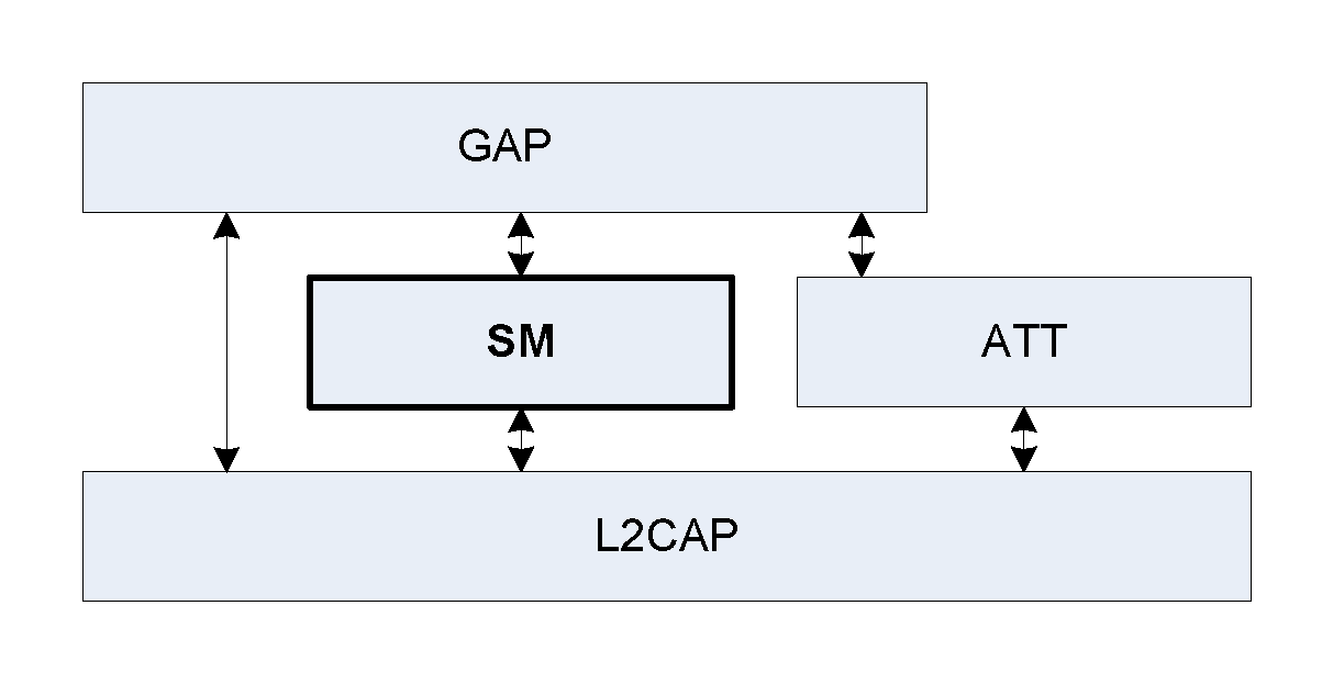
The Security Manager (SM) defines the protocol and behavior to manage pairing, authentication, and encryption between LE-only or BR/EDR/LE devices.
1. Introduction
1.1. Scope
The Security Manager defines methods of pairing and key distribution, a protocol for those methods and a security toolbox to be used by those methods and other parts of an LE-only or BR/EDR/LE device.
The document describes Central and Peripheral roles in terms of protocol and requirements; these have the same meaning and are mapped to the LE device roles described in [Vol 1] Part A, Section 1.2 or BR/EDR device roles (see [Vol 1] Part A, Section 1.1).
1.2. Conventions
1.2.1. Bit and byte ordering conventions
When multiple bit fields are contained in a single octet and represented in a drawing in this Part, the least significant (low-order) bits are shown toward the left and most significant (high-order) bits toward the right.
Multiple-octet fields are drawn with the least significant octets toward the left and the most significant octets toward the right. Multiple-octet fields shall be transmitted with the least significant octet first.
Multiple-octet values written in hexadecimal notation have the most significant octet towards the left and the least significant octet towards the right, for example if ‘12’ is the most significant octet and ‘34’ is the least significant octet it would be written as 0x1234.
1.2.2. Random numbers
In [Vol 3] Part H, the term "random number" includes pseudo-random numbers. Random number generators should conform to the requirements of [Vol 2] Part H, Section 2.
2. Security Manager
2.1. Introduction
The Security Manager (SM) uses a key distribution approach to perform identity and encryption functionalities in radio communication. This means that each device generates and controls the keys it distributes and no other device affects the generation of these keys. The strength of a key is as strong as the algorithms implemented inside the distributing device.
The security architecture is designed such that memory and processing requirements for a responding device are lower than the memory and processing requirement for an initiating device.
Pairing is performed to establish keys which can then be used to encrypt a link. A transport specific key distribution is then performed to share the keys which can be used to encrypt a link in future reconnections, verify signed data and random address resolution.
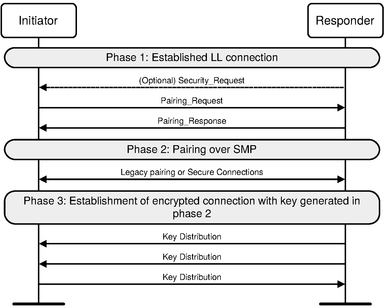
Pairing is a three-phase process. The first two phases are always used and may be followed by an optional transport specific key distribution phase (see Figure 2.1):
Phase 1: Pairing Feature Exchange
Phase 2 (LE legacy pairing): Short Term Key (STK) Generation
Phase 2 (LE Secure Connections): Long Term Key (LTK) Generation
Phase 3: Transport Specific Key Distribution
The devices shall first exchange authentication requirements and IO capabilities in the Pairing Feature Exchange to determine which of the following methods shall be used in Phase 2:
Just Works
Numeric Comparison (Only for LE Secure Connections)
Passkey Entry
Out Of Band (OOB)
Authentication requirements retrieved from the Pairing Feature Exchange also determine whether LE Secure Connections or LE legacy pairing is used.
Optionally, Phase 3 may then be performed to distribute transport specific keys, for example the Identity Resolving Key (IRK) value and Identity Address information. Phase 1 and Phase 3 are identical regardless of the method used in Phase 2.
Phase 3 shall only be performed on a link which is encrypted using:
The STK generated in Phase 2 when using LE legacy pairing or
The LTK generated in Phase 2 when using LE Secure Connections or
The shared Link Key generated using BR/EDR pairing (see Section 2.3.5.7).
Phase 1 and Phase 2 may be performed on a link which is either encrypted or not encrypted.
2.2. Cryptographic toolbox
In order to support random addressing, pairing and other operations SM provides a toolbox of cryptographic functions. The following cryptographic functions are defined:
ah is used to create a 24-bit hash used in random address creation and resolution.
The following cryptographic functions are defined to support the LE legacy pairing process:
c1 is used to generate confirm values used during the pairing process.
s1 is used to generate the STK during the pairing process.
The following cryptographic functions are defined to support the LE Secure Connections pairing process:
f4 is used to generate confirm values during the pairing process.
f5 is used to generate the LTK and the MacKey during the pairing process.
f6 is used to generate the check values during authentication stage 2 in the pairing process.
g2 is used to generate the 6-digit numeric comparison values during authentication stage 1 in the pairing process.
h6 is used to generate the LE LTK from a BR/EDR link key derived from Secure Connections and is used to generate the BR/EDR link key from an LE LTK derived from Secure Connections.
h7 is used to generate intermediate keys while generating the LE LTK from a BR/EDR link key derived from Secure Connections and the BR/EDR link key from an LE LTK derived from Secure Connections.
The building block for the cryptographic functions ah, c1 and s1 is the security function e.
The building block for the cryptographic functions f4, f5, f6, g2, h6, and h7 is the security function AES-CMAC.
Inside the f4, f5, f6, g2, h6, and h7 functions when a multi-octet integer parameter is used as input to AES-CMAC the most significant octet of the integer shall be the first octet of the stream and the least significant octet of the integer shall be the last octet of the stream. The output of AES-CMAC inside these functions is a multi-octet integer where the first octet is MSB and the last octet is LSB of this integer.
2.2.1. Security function e
Security function e generates 128-bit encryptedData from a 128-bit key and 128-bit plaintextData using the AES-128-bit block cypher as defined in FIPS-197[1]:
encryptedData = e(key, plaintextData)
The most significant octet of key corresponds to key[0], the most significant octet of plaintextData corresponds to in[0] and the most significant octet of encryptedData corresponds to out[0] using the notation specified in FIPS-197[1].
Note
Note: The security function e can be implemented in a Host or be implemented using the HCI_LE_Encrypt command (see [Vol 4] Part E, Section 7.8.22).
2.2.2. Random address hash function ah
The random address hash function ah is used to generate a hash value that is used in resolvable private addresses, see [Vol 3] Part C, Section 10.8.2.
The following are inputs to the random address hash function ah:
k is 128 bits r is 24 bits padding is 104 bits
r is concatenated with padding to generate r' which is used as the 128-bit input parameter plaintextData to security function e:
r’ = padding || r
The least significant octet of r becomes the least significant octet of r’ and the most significant octet of padding becomes the most significant octet of r’.
For example, if the 24-bit value r is 0x423456 then r’ is 0x00000000000000000000000000423456.
The output of the random address function ah is:
ah(k, r) = e(k, r’) mod 224
The output of the security function e is then truncated to 24 bits by taking the least significant 24 bits of the output of e as the result of ah.
2.2.3. Confirm value generation function c1 for LE legacy pairing
During the LE legacy pairing process confirm values are exchanged. This confirm value generation function c1 is used to generate the confirm values.
The following are inputs to the confirm value generation function c1:
k is 128 bits r is 128 bits pres is 56 bits preq is 56 bits iat is 1 bit ia is 48 bits rat is 1 bit ra is 48 bits padding is 32 zero bits
iat is concatenated with 7 zero bits to create iat’ which is 8 bits in length. iat is the least significant bit of iat’.
rat is concatenated with 7 zero bits to create rat’ which is 8 bits in length. rat is the least significant bit of rat’.
pres, preq, rat’ and iat’ are concatenated to generate p1 which is XORed with r and used as 128-bit input parameter plaintextData to security function e:
p1 = pres || preq || rat’ || iat’
The octet of iat’ becomes the least significant octet of p1 and the most significant octet of pres becomes the most significant octet of p1.
For example, if the 8-bit iat’ is 0x01, the 8-bit rat’ is 0x00, the 56-bit preq is 0x07071000000101 and the 56 bit pres is 0x05000800000302 then p1 is 0x05000800000302070710000001010001.
ra is concatenated with ia and padding to generate p2 which is XORed with the result of the security function e using p1 as the input parameter plaintextData and is then used as the 128-bit input parameter plaintextData to security function e:
p2 = padding || ia || ra
The least significant octet of ra becomes the least significant octet of p2 and the most significant octet of padding becomes the most significant octet of p2.
For example, if 48-bit ia is 0xA1A2A3A4A5A6 and the 48-bit ra is 0xB1B2B3B4B5B6 then p2 is 0x00000000A1A2A3A4A5A6B1B2B3B4B5B6.
The output of the confirm value generation function c1 is:
c1 (k, r, preq, pres, iat, rat, ia, ra) = e(k, e(k, r XOR p1) XOR p2)
The 128-bit output of the security function e is used as the result of confirm value generation function c1.
For example, if the 128-bit k is 0x00000000000000000000000000000000, the 128-bit value r is 0x5783D52156AD6F0E6388274EC6702EE0, the 128-bit value p1 is 0x05000800000302070710000001010001 and the 128-bit value p2 is 0x00000000A1A2A3A4A5A6B1B2B3B4B5B6 then the 128-bit output from the c1 function is 0x1E1E3FEF878988EAD2A74DC5BEF13B86.
2.2.4. Key generation function s1 for LE legacy pairing
The key generation function s1 is used to generate the STK during the LE legacy pairing process.
The following are inputs to the key generation function s1:
k is 128 bits r1 is 128 bits r2 is 128 bits
The most significant 64-bits of r1 are discarded to generate r1’ and the most significant 64-bits of r2 are discarded to generate r2’.
For example if the 128-bit value r1 is 0x000F0E0D0C0B0A091122334455667788 then r1’ is 0x1122334455667788. If the 128-bit value r2 is 0x010203040506070899AABBCCDDEEFF00 then r2’ is 0x99AABBCCDDEEFF00.
r1’ is concatenated with r2’ to generate r’ which is used as the 128-bit input parameter plaintextData to security function e:
r’ = r1’ || r2’
The least significant octet of r2’ becomes the least significant octet of r’ and the most significant octet of r1’ becomes the most significant octet of r’.
For example, if the 64-bit value r1’ is 0x1122334455667788 and r2’ is 0x99AABBCCDDEEFF00 then r’ is 0x112233445566778899AABBCCDDEEFF00.
The output of the key generation function s1 is:
s1(k, r1, r2) = e(k, r’)
The 128-bit output of the security function e is used as the result of key generation function s1.
For example if the 128-bit value k is
0x00000000000000000000000000000000
and the 128-bit value r' is
0x112233445566778899AABBCCDDEEFF00
then the output from the key generation function s1 is
0x9a1fe1f0e8b0f49b5b4216ae796da062.
2.2.5. Function AES-CMAC
RFC-4493[2] defines the Cipher-based Message Authentication Code (CMAC) that uses AES-128 as the block cipher function, also known as AES-CMAC.
The inputs to AES-CMAC are:
m is the variable length data to be authenticated k is the 128-bit key
The 128-bit message authentication code (MAC) is generated as follows:[3]
MAC = AES-CMACk(m)
A device can implement AES functions in the Host or can use the HCI_LE_Encrypt command (see [Vol 4] Part E, Section 7.8.22) in order to use the AES function in the Controller.
2.2.6. LE Secure Connections confirm value generation function f4
During the LE Secure Connections pairing process, confirm values are exchanged. These confirm values are computed using the confirm value generation function f4.
This confirm value generation function makes use of the MAC function AES-CMACX, with a 128-bit key X.
The inputs to function f4 are:
U is 256 bits V is 256 bits X is 128 bits Z is 8 bits
Z is zero (i.e. 8 bits of zeros) for Numeric Comparison and OOB protocol. In the Passkey Entry protocol, the most significant bit of Z is set equal to one and the least significant bit is made up from one bit of the passkey e.g. if the passkey bit is 1, then Z = 0x81 and if the passkey bit is 0, then Z = 0x80.
U, V and Z are concatenated and used as input m to the function AES-CMAC and X is used as the key k.
The inputs to f4 are different depending on different association models:
Numeric Comparison/ Just Works | Out-Of-Band | Passkey Entry |
|---|---|---|
Ca = f4(PKax, PKbx, Na, 0) Cb = f4(PKbx, PKax, Nb, 0) | Ca = f4(PKax, PKax, ra, 0) Cb = f4(PKbx, PKbx, rb, 0) | Cai = f4(PKax, PKbx, Nai, rai) Cbi = f4(PKbx, PKax, Nbi, rbi) |
PKax denotes the x-coordinate of the public key PKa of A.
Similarly, PKbx denotes the x-coordinate of the public key PKb of B.
Nai is the nonce value of ith round. For each round Nai value is a new 128-bit number. Similarly, rai is a one bit value of the passkey expanded to 8 bits (either 0x80 or 0x81).
Na and Nb are nonces from Devices A and B. ra and rb are random values generated by devices A and B.
The output of the confirm value generation function f4 is as follows:
f4(U, V, X, Z) = AES-CMACX (U || V || Z)
The least significant octet of Z becomes the least significant octet of the AES-CMAC input message m and the most significant octet of U becomes the most significant octet of the AES-CMAC input message m.
2.2.7. LE Secure Connections key generation function f5
The LE Secure Connections key generation function f5 is used to generate derived keying material in order to create the LTK and keys for the commitment function f6 during the LE Secure Connections pairing process.
The definition of this key generation function makes use of the MAC function AES-CMACT with a 128-bit key T.
The inputs to function f5 are:
W is 256 bits N1 is 128 bits N2 is 128 bits A1 is 56 bits A2 is 56 bits
The key (T) is computed as follows:
T = AES-CMACSALT (W)
SALT is the 128-bit value:
0x6C888391_AAF5A538_60370BDB_5A6083BE
Counter, keyID, N1, N2, A1, A2, and Length are concatenated and used as input m to the function AES-CMAC and T is used as the key k.
Counter is one octet. Length is two octets.
The string “btle” is mapped into a keyID using ASCII as 0x62746C65.
The output of the key generation function f5 is as follows:
f5(W, N1, N2, A1, A2) = AES-CMACT (Counter = 0 || keyID || N1 || N2
|| A1 || A2 || Length = 256) || AES-CMACT (Counter = 1 || keyID || N1
|| N2 || A1 || A2 || Length = 256)
The least significant octet of Length becomes the least significant octet of the AES-CMAC input message m and the most significant octet of Counter becomes the most significant octet of the AES-CMAC input message m.
The LTK and MacKey are calculated as:
MacKey || LTK = f5(DHKey, Nc, Np, BD_ADDR_C, BD_ADDR_P)
DHKey is the shared secret Diffie-Hellman key generated during LE Secure Connections pairing phase 2.
Nc is whichever of N1 and N2 was generated by the Central and sent to the Peripheral; Np is the other.
BD_ADDR_C is the device address of the Central and BD_ADDR_P is the device address of the Peripheral. The device addresses are the values used during connection setup. The least significant bit in the most significant octet in both BD_ADDR_C and BD_ADDR_P is set to 1 if the address is a random address and set to 0 if the address is a public address. The 7 most significant bits of the most significant octet in both BD_ADDR_C and BD_ADDR_P are set to 0.
The LTK is the least significant 128 bits (Counter = 1) of f5. The MacKey (see Section 2.2.8) is the most significant 128 bits (Counter = 0) of f5.
A device can implement Diffie-Hellman key generation in the Host or can use the HCI_LE_Generate_DHKey command (see [Vol 4] Part E, Section 7.8.37) to generate the key in the Controller.
Note
Note: When using the HCI_LE_Generate_DHKey command, the device can only pair one remote device at a time.
2.2.8. LE Secure Connections check value generation function f6
The LE Secure Connections check value generation function f6 is used to generate check values during authentication stage 2 of the LE Secure Connections pairing process.
The definition of the f6 function makes use of the MAC function AES-CMACW with a 128-bit key W.
The inputs to function f6 are:
W is 128 bits N1 is 128 bits N2 is 128 bits R is 128 bits IOcap is 24 bits A1 is 56 bits A2 is 56 bits
N1, N2, R, IOcap, A1 and A2 are concatenated and used as input m to the function AES-CMAC and W is used as the key k.
The inputs to f6 are different depending on different association models:
Numeric Comparison/ Just Works | Out-Of-Band | Passkey Entry |
|---|---|---|
Ea = f6(MacKey, Na, Nb, 0, IOcapA, A, B) Eb = f6(MacKey, Nb, Na, 0, IOcapB, B, A) | Ea = f6(MacKey, Na, Nb, rb, IOcapA, A, B) Eb = f6(MacKey, Nb, Na, ra, IOcapB, B, A) | Ea = f6(MacKey, Na20, Nb20, rb, IOcapA, A, B) Eb = f6(MacKey, Nb20, Na20, ra, IOcapB, B, A) |
MacKey is the 128-bit MSBs of the output of f5.
Na is the random number sent by the Central to the Peripheral and Nb is the random number sent by the Peripheral to the Central.
IOcapA is the capabilities of the Central and IOcapB is the capabilities of the Peripheral. IOcapA and IOcapB are both three octets with the most significant octet as the AuthReq parameter, the middle octet as the OOB data flag and the least significant octet as the IO capability parameter. The AuthReq, OOB data flag and IO capability parameters are present in the Pairing Request and Pairing Response SMP packets.
In Passkey Entry, ra and rb are 6-digit passkey values expressed as a 128-bit integer. For instance, if the 6-digit value of ra is 131313 then
ra = 0x 00 00 00 00 00 00 00 00 00 00 00 00 00 02 00 f1
A is the device address of the Central and B is the device address of the Peripheral. The least significant bit in the most significant octet in both A and B is set to 1 if the address is a random address and set to 0 if the address is a public address. The 7 most significant bits of the most significant octet in both A and B are set to 0.
The output of the check value generation function f6 is as follows:
f6(W, N1, N2, R, IOcap, A1, A2) = AES-CMACW (N1 || N2 || R || IOcap || A1 || A2)
The least significant octet of A2 becomes the least significant octet of the AES-CMAC input message m and the most significant octet of N1 becomes the most significant octet of the AES-CMAC input message m.
2.2.9. LE Secure Connections numeric comparison value generation function g2
The LE Secure Connections numeric comparison value generation function g2 is used to generate the numeric comparison values during authentication stage 1 of the LE Secure Connections pairing process.
The definition of g2 makes use of the MAC function AES-CMACX with 128-bit key X.
The inputs to function g2 are:
U is 256 bits V is 256 bits X is 128 bits Y is 128 bits
U, V, and Y are concatenated and used as input m to the function AES-CMAC and X is used as the key k.
The output of the numeric comparison value generation function g2 is as follows:
g2(U, V, X, Y) = AES-CMACX(U || V || Y) mod 232
The least significant octet of Y becomes the least significant octet of the AES-CMAC input message m and the most significant octet of U becomes the most significant octet of the AES-CMAC input message m.
The numeric verification value is taken as the six least significant digits of the 32-bit integer g2(PKax, PKbx, Na, Nb) where PKax denotes the x-coordinate of the public key PKa of A and PKbx denotes the x-coordinate of the public key PKb of B. Na and Nb are nonces from devices A and B. The value is then converted to decimal numeric value. The checksum used for numeric comparison is the least significant six digits.
Compare Value = g2 (U, V, X, Y) mod 106
For example, if output = 0x 01 2e b7 2a then decimal value = 19838762 and the checksum used for numeric comparison is 838762.
2.2.10. Link key conversion function h6
The function h6 is used to convert keys of a given size from one key type to another key type with equivalent strength.
The definition of the h6 function makes use of the hashing function AES-CMACW with 128-bit key W.
The inputs to function h6 are:
W is 128 bits keyID is 32 bits
keyID is used as input m to the hashing function AES-CMAC and the most significant 128-bits of W are used as the key k (2.2.5).
The output of h6 is as follows:
h6(W, keyID) = AES-CMACW(keyID)
2.2.11. Link key conversion function h7
The function h7 is used to convert keys of a given size from one key type to another key type with equivalent strength.
The definition of the h7 function makes use of the hashing function AES-CMACSALT with 128-bit key SALT.
The inputs to function h7 are:
SALT is 128 bits W is 128 bits
W is used as input m to the hashing function AES-CMAC and SALT is used as the key k (2.2.5).
The output of h7 is as follows:
h7(SALT, W) = AES-CMACSALT(W)
2.3. Pairing methods
When pairing is started, the Pairing Feature Exchange shall be initiated by the initiating device. If the responding device does not support pairing or pairing cannot be performed then the responding device shall respond using the Pairing Failed message with the error code “Pairing Not Supported” otherwise it responds with a Pairing Response message.
The Pairing Feature Exchange is used to exchange IO capabilities, OOB authentication data availability, authentication requirements, key size requirements and which transport specific keys to distribute. The IO capabilities, OOB authentication data availability and authentication requirements are used to determine the key generation method used in Phase 2.
All of the LE legacy pairing methods use and generate 2 keys:
Temporary Key (TK): a 128-bit temporary key used in the pairing process which is used to generate STK (see Section 2.3.5.5).
Short Term Key (STK): a 128-bit temporary key used to encrypt a connection following pairing.
The LE Secure Connections pairing methods use and generate 1 key:
Long Term Key (LTK): a 128-bit key used to encrypt the connection following pairing and subsequent connections.
Authentication requirements are set by GAP, (see [Vol 3] Part C, Section 10.3). The authentication requirements include the type of bonding and man-in-the-middle protection (MITM) requirements.
The initiating device indicates to the responding device which transport specific keys it would like to send to the responding device and which keys it would like the responding device to send to the initiator. The responding device replies with the keys that the initiating device shall send and the keys that the responding device shall send. The keys that can be distributed are defined in Section 2.4.3. If the device receives a command with invalid parameters, it shall respond with Pairing Failed command with the error code “Invalid Parameters.”
2.3.1. Security Properties
Security Properties provided by SM are classified into the following categories:
LE Secure Connections pairing
Authenticated MITM protection
Unauthenticated no MITM protection
No security requirements
LE Secure Connections pairing utilizes the P-256 elliptic curve (see [Vol 2] Part H, Section 7.6).
In LE legacy pairing, Authenticated man-in-the-middle (MITM) protection is obtained by using the passkey entry pairing method or may be obtained using the out of band pairing method. In LE Secure Connections pairing, Authenticated man-in-the-middle (MITM) protection is obtained by using the passkey entry pairing method or the numeric comparison method or may be obtained using the out of band pairing method. To ensure that Authenticated MITM Protection is generated, the selected Authentication Requirements option must have MITM protection specified.
Unauthenticated no MITM Protection does not have protection against MITM attacks.
For LE Legacy Pairing, none of the pairing methods provide protection against a passive eavesdropper during the pairing process as predictable or easily established values for TK are used. If the pairing information is distributed without an eavesdropper being present then all the pairing methods provide confidentiality.
An initiating device shall maintain a record of the Security Properties for the distributed keys in a security database.
A responding device may maintain a record of the distributed key sizes and Security Properties for the distributed keys in a security database. Depending upon the key generation method and negotiated key size a responding device may have to shorten the key length (see Section 2.3.4) so that the initiator and responder are using identical keys.
Security Properties of the key generated in phase 2 under which the keys are distributed shall be stored in the security database.
2.3.2. IO capabilities
Input and output capabilities of a device are combined to generate its IO capabilities. The input capabilities are described in Table 2.3. The output capabilities are described in Table 2.4.
Capability | Description |
|---|---|
No input | Device does not have the ability to indicate ‘yes’ or ‘no’ |
Yes / No | Device has at least two buttons that can be easily mapped to 'yes' and 'no' or the device has a mechanism whereby the user can indicate either 'yes' or 'no' (see note below). |
Keyboard | Device has a numeric keyboard that can input the numbers '0' to '9' and a confirmation. Device also has at least two buttons that can be easily mapped to 'yes' and 'no' or the device has a mechanism whereby the user can indicate either 'yes' or 'no' (see note below). |
Note
Note: 'yes' could be indicated by pressing a button within a certain time limit otherwise 'no' would be assumed.
Capability | Description |
|---|---|
No output | Device does not have the ability to display or communicate a 6 digit decimal number |
Numeric output | Device has the ability to display or communicate a 6 digit decimal number |
The individual input and output capabilities are mapped to a single IO capability for that device which is used in the pairing feature exchange. The mapping is described in Table 2.5.
Local output capacity | |||||||||||||||||||||||||||||||||||||||||||||||||
|---|---|---|---|---|---|---|---|---|---|---|---|---|---|---|---|---|---|---|---|---|---|---|---|---|---|---|---|---|---|---|---|---|---|---|---|---|---|---|---|---|---|---|---|---|---|---|---|---|---|
No output | Numeric output | ||||||||||||||||||||||||||||||||||||||||||||||||
Local input capacity | No input | NoInputNoOutput | DisplayOnly | ||||||||||||||||||||||||||||||||||||||||||||||
Yes/No | NoInputNoOutput[1] | DisplayYesNo | |||||||||||||||||||||||||||||||||||||||||||||||
Keyboard | KeyboardOnly | KeyboardDisplay | |||||||||||||||||||||||||||||||||||||||||||||||
[1] None of the pairing algorithms can use Yes/No input and no output, therefore NoInputNoOutput is used as the resulting IO capability. | |||||||||||||||||||||||||||||||||||||||||||||||||
2.3.3. OOB authentication data
An out of band mechanism may be used to communicate information which is used during the pairing process. The information shall be a sequence of AD structures (see [Vol 3] Part C, Section 11).
The OOB data flag shall be set if a device has the peer device's out of band authentication data. A device uses the peer device's out of band authentication data to authenticate the peer device. In LE legacy pairing, the out of band method is used if both the devices have the other device's out of band authentication data available. In LE Secure Connections pairing, the out of band method is used if at least one device has the peer device's out of band authentication data available.
2.3.4. Encryption key size
Each device shall have maximum and minimum encryption key length parameters which defines the maximum and minimum size of the encryption key allowed in octets. The maximum and minimum encryption key length parameters shall be between 7 octets (56 bits) and 16 octets (128 bits), in 1 octet (8 bit) steps. This is defined by a profile or device application.
The shorter of the initiating and responding devices’ maximum encryption key length parameters shall be used as the encryption key size.
Both the initiating and responding devices shall check that the resultant encryption key size is not shorter than the minimum key size parameter for that device and if it is, the device shall send the Pairing Failed command with error code “Encryption Key Size”.
The encryption key size may be stored so it can be checked by any service that has minimum encryption key length requirements.
If a key has an encryption key size that is shorter than 16 octets (128 bits), it shall be created by masking the appropriate number of most significant octets of the generated key to provide a resulting key that has the agreed encryption key size. The key shall be masked after generation and, if required, after the key is used to derive a BR/EDR link key. The key shall be masked before the key is distributed, used for encryption, or stored.
For example, if a 128-bit encryption key is
0x12345678_9ABCDEF0_12345678_9ABCDEF0
and it is reduced to 7 octets (56 bits), then the resulting key is
0x00000000_00000000_00345678_9ABCDEF0.
2.3.5. Pairing algorithms
The information exchanged in Phase 1 is used to select which key generation method is used in Phase 2.
When LE legacy pairing is used, the pairing is performed by each device generating a Temporary Key (TK). The method to generate TK depends upon the pairing method chosen using the algorithm described in Section 2.3.5.1. If Just Works is used then TK shall be generated as defined in Section 2.3.5.2. If Passkey Entry is used then TK shall be generated as defined in Section 2.3.5.3. If Out Of Band is used then TK shall be generated as defined in Section 2.3.5.4. The TK value shall be used in the authentication mechanism defined in Section 2.3.5.5 to generate the STK and encrypt the link.
2.3.5.1. Selecting key generation method
If both devices have not set the MITM option in the Authentication Requirements Flags, then the IO capabilities shall be ignored and the Just Works association model shall be used.
In LE legacy pairing, if both devices have Out of Band authentication data, then the Authentication Requirements Flags shall be ignored when selecting the pairing method and the Out of Band pairing method shall be used. Otherwise, the IO capabilities of the device shall be used to determine the pairing method as defined in Table 2.8.
In LE Secure Connections pairing, if one or both devices have out of band authentication data, then the Authentication Requirements Flags shall be ignored when selecting the pairing method and the Out of Band pairing method shall be used. Otherwise, the IO capabilities of the device shall be used to determine the pairing method as defined in Table 2.8.
Table 2.6 defines the STK generation method when at least one of the devices does not support LE Secure Connections.
Initiator | ||||||
|---|---|---|---|---|---|---|
OOB Set | OOB Not Set | |||||
MITM Set | MITM Not Set | MITM Set | MITM Not Set | |||
Responder | OOB Set | MITM Set | Use OOB | Use OOB | Use IO Capabilities | Use IO Capabilities |
MITM Not Set | Use OOB | Use OOB | Use IO Capabilities | Use Just Works | ||
OOB Not Set | MITM Set | Use IO Capabilities | Use IO Capabilities | Use IO Capabilities | Use IO Capabilities | |
MITM Not Set | Use IO Capabilities | Use Just Works | Use IO Capabilities | Use Just Works | ||
Table 2.7 defines the LTK generation method when both devices support LE Secure Connections.
Initiator | ||||||
|---|---|---|---|---|---|---|
OOB Set | OOB Not Set | |||||
MITM Set | MITM Not Set | MITM Set | MITM Not Set | |||
Responder | OOB Set | MITM Set | Use OOB | Use OOB | Use OOB | Use OOB |
MITM Not Set | Use OOB | Use OOB | Use OOB | Use OOB | ||
OOB Not Set | MITM Set | Use OOB | Use OOB | Use IO Capabilities | Use IO Capabilities | |
MITM Not Set | Use OOB | Use OOB | Use IO Capabilities | Use Just Works | ||
Initiator | |||||
|---|---|---|---|---|---|
Responder | DisplayOnly | Display YesNo | Keyboard Only | NoInput NoOutput | Keyboard Display |
Display Only | Just Works Unauthenticated | Just Works Unauthenticated | Passkey Entry: responder displays, initiator inputs Authenticated | Just Works Unauthenticated | Passkey Entry: responder displays, initiator inputs Authenticated |
Display YesNo | Just Works Unauthenticated | Just Works (For LE Legacy Pairing) Unauthenticated | Passkey Entry: responder displays, initiator inputs Authenticated | Just Works Unauthenticated | Passkey Entry (For LE Legacy Pairing): responder displays, initiator inputs Authenticated |
Numeric Comparison (For LE Secure Connections) Authenticated | Numeric Comparison (For LE Secure Connections) Authenticated | ||||
Keyboard Only | Passkey Entry: initiator displays, responder inputs Authenticated | Passkey Entry: initiator displays, responder inputs Authenticated | Passkey Entry: initiator and responder input Authenticated | Just Works Unauthenticated | Passkey Entry: initiator displays, responder inputs Authenticated |
NoInput NoOutput | Just Works Unauthenticated | Just Works Unauthenticated | Just Works Unauthenticated | Just Works Unauthenticated | Just Works Unauthenticated |
Keyboard Display | Passkey Entry: initiator displays, responder inputs Authenticated | Passkey Entry (For LE Legacy Pairing): initiator displays, responder inputs Authenticated | Passkey Entry: responder displays, initiator inputs Authenticated | Just Works Unauthenticated | Passkey Entry (For LE Legacy Pairing): initiator displays, responder inputs Authenticated |
Numeric Comparison (For LE Secure Connections) Authenticated | Numeric Comparison (For LE Secure Connections) Authenticated | ||||
The generated key will either be an Authenticated or Unauthenticated key. If the out of band authentication method is used and the Out of Band mechanism is known to be secure from eavesdropping the key is assumed to be Authenticated; however, the exact strength depends upon the method used to transfer the out of band information. If the Out of Band method is used and the Out of Band mechanism is not secure from eavesdropping or the level of eavesdropping protection is unknown, the key shall be Unauthenticated. The mapping of IO capabilities to an authenticated or unauthenticated key is described in Table 2.8.
In LE legacy pairing, if the initiating device has Out of Band data and the responding device does not have Out of Band data then the responding device may send the Pairing Failed command with the error code “OOB Not Available” instead of the Pairing Response command.
If the key generation method does not result in a key that provides sufficient Security Properties (see Section 2.3.1) then the device shall send the Pairing Failed command with the error code “Authentication Requirements”.
2.3.5.2. LE legacy pairing - Just Works
The Just Works STK generation method provides no protection against eavesdroppers or man in the middle attacks during the pairing process. If the attacker is not present during the pairing process then confidentiality can be established by using encryption on a future connection.
Both devices set the TK value used in the authentication mechanism defined in Section 2.3.5.5 to zero.
2.3.5.3. LE legacy pairing - Passkey Entry
The Passkey Entry STK generation method uses 6 numeric digits passed out of band by the user between the devices. A 6 digit numeric randomly generated passkey achieves approximately 20 bits of entropy.
If the IO capabilities of a device are DisplayOnly or if Table 2.8 defines that the device displays the passkey, then that device shall display a randomly generated passkey value between 000,000 and 999,999. The display shall ensure that all 6 digits are displayed – including zeros. The other device shall allow the user to input a value between 000,000 and 999,999.
If the IO capabilities of both devices are KeyboardOnly then the user generates a random 6-digit passkey value and enters it into both devices. Both devices shall allow the user to input a value between 000,000 and 999,999.
The passkey should be generated randomly during each pairing procedure and not be reused from a previous procedure. Static passkeys should not be used since they can compromise the security of the link.
If entry of passkey in UI fails to occur or is cancelled then the device shall send Pairing Failed command with reason code “Passkey Entry Failed”.
For example, if the user entered passkey is ‘019655’ then TK shall be 0x00000000000000000000000000004CC7.
The passkey Entry method does not provide protection against active “man-in-the-middle” (MITM) attacks.
The Passkey Entry STK generation method provides very limited protection against eavesdroppers during the pairing process because of the limited range of possible TK values which STK is dependent upon. If the attacker is not present during the pairing process then confidentiality and authentication can be established by using encryption on a future connection.
The TK value shall then be used in the authentication mechanism defined in Section 2.3.5.5.
2.3.5.4. Out of band
An out of band mechanism may be used to communicate information to help with device discovery, for example device address, and the 128-bit TK value used in the pairing process. The TK value shall be a 128-bit random number using the requirements for random generation defined in [Vol 2] Part H, Section 2.
If the OOB communication is resistant to MITM attacks, then this association method is also resistant to MITM attacks. Also, in the Out of Band method, the size of authentication parameter (TK) need not be restricted by what the user can comfortably read or type. For that reason, the Out of Band method can be more secure than using the Passkey Entry or Just Works methods. However, both devices need to have matching OOB interfaces.
MITM protection is only provided if an active man-in-the-middle chance of a successful attack has a probability of 0.000001 or less in succeeding.
2.3.5.5. LE legacy pairing phase 2
The initiating device generates a 128-bit random number (LP_RAND_I).
The initiating device calculates the 128-bit confirm value (LP_CONFIRM_I) using the confirm value generation function c1 (see Section 2.2.3) with the input parameter k set to TK, the input parameter r set to LP_RAND_I, the input parameter preq set to Pairing Request command as exchanged with the peer device (i.e. without any modifications), the input parameter pres set to the Pairing Response command as exchanged with the peer device (i.e. without any modifications), the input parameter iat set to the initiating device address type, ia set to the initiating device address, rat set to the responding device address type and ra set to the responding device address:
LP_CONFIRM_I = c1(TK, LP_RAND_I, Pairing Request command, Pairing Response command, initiating device address type, initiating device address, responding device address type, responding device address)
Initiating and responding device addresses used for confirmation generation shall be device addresses used during connection setup, see [Vol 3] Part C, Section 9.3
The responding device generates a 128-bit random number (LP_RAND_R).
The responding device calculates the 128-bit confirm value (LP_CONFIRM_R) using the confirm value generation function c1 (see Section 2.2.3) with the input parameter k set to TK, the input parameter r set to LP_RAND_R, the input parameter preq set to Pairing Request command, the input parameter pres set to the Pairing Response command, the input parameter iat set to the initiating device address type, ia set to the initiating device address, rat set to the responding device address type and ra set to the responding device address:
LP_CONFIRM_R = c1(TK, LP_RAND_R, Pairing Request command, Pairing Response command, initiating device address type, initiating device address, responding device address type, responding device address)
The initiating device transmits LP_CONFIRM_I to the responding device. When the responding device receives LP_CONFIRM_I it transmits LP_CONFIRM_R to the initiating device. When the initiating device receives LP_CONFIRM_R it transmits LP_RAND_I to the responding device.
The responding device verifies the LP_CONFIRM_I value by repeating the calculation the initiating device performed, using the LP_RAND_I value received.
If the responding device’s calculated LP_CONFIRM_I value does not match the received LP_CONFIRM_I value from the initiating device then the pairing process shall be aborted and the responding device shall send the Pairing Failed command with reason code “Confirm Value Failed”.
If the responding device’s calculated LP_CONFIRM_I value matches the received LP_CONFIRM_I value from the initiating device the responding device transmits LP_RAND_R to the initiating device.
The initiating device verifies the received LP_CONFIRM_R value by repeating the calculation the responding device performed, using the LP_RAND_R value received.
If the initiating devices calculated LP_CONFIRM_R value does not match the received LP_CONFIRM_R value from the responding device then the pairing process shall be aborted and the initiating device shall send the Pairing Failed command with the reason code “Confirm Value Failed”.
If the initiating device’s calculated LP_CONFIRM_R value matches the received LP_CONFIRM_R value from the responding device the initiating device then calculates STK and tells the Controller to enable encryption.
STK is generated using the key generation function s1 defined in Section 2.2.4 with the input parameter k set to TK, the input parameter r1 set to LP_RAND_R, and the input parameter r2 set to LP_RAND_I:
STK = s1(TK, LP_RAND_R, LP_RAND_I)
If the encryption key size is shorter than 128 bits then the STK shall be masked to the correct key size as described in Section 2.3.4.
The initiator shall use the generated STK to either enable encryption on the link or if encryption has already been enabled, perform the encryption pause procedure (see Section 2.4.4.1).
2.3.5.6. LE Secure Connections pairing phase 2
The Long Term Key is generated in LE Secure Connections pairing phase 2.
2.3.5.6.1. Public key exchange
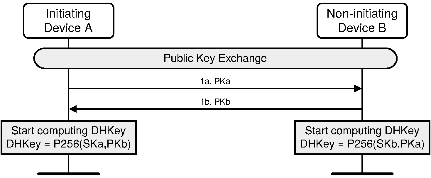
Initially, each device generates its own Elliptic Curve Diffie-Hellman (ECDH) public-private key pair (phase 1). The public-private key pair contains a private (secret) key, and a public key. The private keys of devices A and B are denoted as SKa and SKb respectively. The public keys of devices A and B are denoted as PKa and PKb respectively. See Section 2.3.6 for recommendations on how frequently this key pair should be changed.
Pairing is initiated by the initiating device sending its public key to the receiving device (phase 1a). The responding device replies with its own public key (phase 1b). If the two public keys have the same X coordinate and neither is the debug key, each device should fail the pairing process. These public keys are not regarded as secret although they may identify the devices.
A device shall validate that any public key received from any BD_ADDR is on the correct curve (P-256).
A valid public key Q = (XQ, YQ) is one where XQ and YQ are both in the range 0 to p - 1 and satisfy the equation (YQ)2 = (XQ)3 + aXQ + b (mod p) in the relevant curve's finite field. See [Vol 2] Part H, Section 7.6 for the values of a, b, and p.
A device can validate a public key by directly checking the curve equation, by implementing elliptic curve point addition and doubling using formulas that are valid only on the correct curve, or by other means.
A device that detects an invalid public key from the peer at any point during the LE Secure Connections pairing process shall not use the resulting LTK, if any.
After the public keys have been exchanged, the device can then start computing the Diffie-Hellman Key.
When the Security Manager is placed in a Debug mode it shall use the following Diffie-Hellman private / public key pair:
Private key: | 3f49f6d4 a3c55f38 74c9b3e3 d2103f50 4aff607b eb40b799 5899b8a6 cd3c1abd |
Public key (X): | 20b003d2 f297be2c 5e2c83a7 e9f9a5b9 eff49111 acf4fddb cc030148 0e359de6 |
Public key (Y): | dc809c49 652aeb6d 63329abf 5a52155c 766345c2 8fed3024 741c8ed0 1589d28b |
If a device receives this debug public key and it is in a mode in which it cannot accept the debug key then it may send the Pairing Failed command with the reason set to "Invalid Parameters".
Note
Note: Only one side (initiator or responder) needs to set Secure Connections debug mode in order for debug equipment to be able to determine the LTK and, therefore, be able to monitor the encrypted connection.
2.3.5.6.2. Authentication stage 1 – Just Works or Numeric Comparison
The Numeric Comparison association model will be used during pairing if the MITM bit is set to 1 in the Authentication Requirements in the Pairing Request PDU and/or Pairing Response PDU and both devices have IO capabilities set to either DisplayYesNo or KeyboardDisplay.
The sequence diagram of Authentication stage 1 for the Just Works or Numeric Comparison protocol from the cryptographic point of view is shown in Figure 2.3.
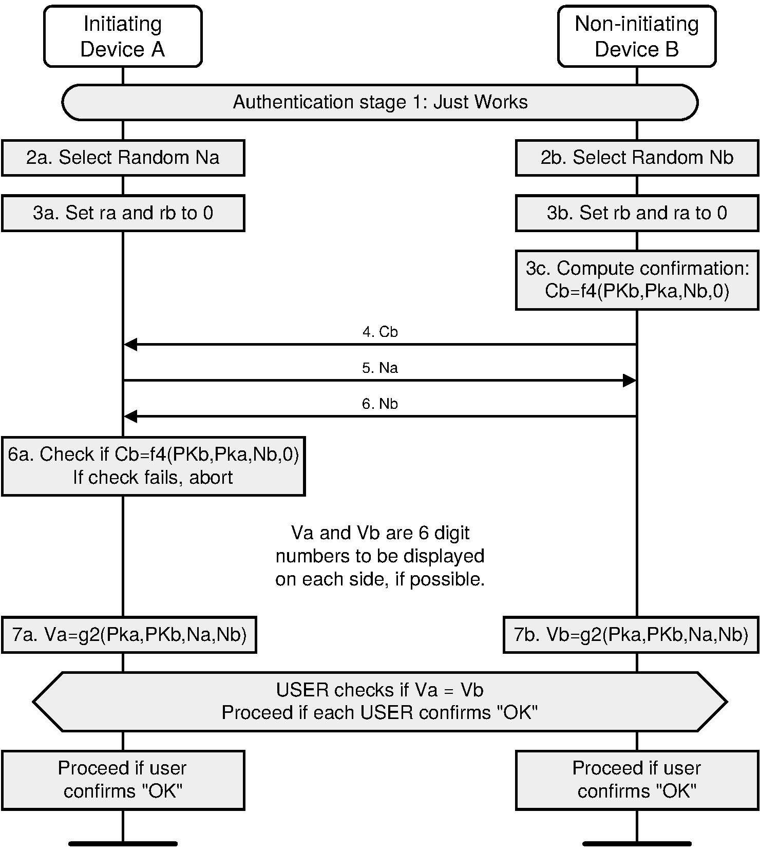
After the public keys have been exchanged, each device selects a random 128-bit nonce (step 2). This value is used to mitigate replay attacks and shall be freshly generated with each instantiation of the pairing protocol. This value should be generated directly from a physical source of randomness or with a good pseudo-random generator seeded with a random value from a physical source.
Following this the responding device then computes a commitment to the two public keys that have been exchanged and its own nonce value (step 3c). This commitment is computed as a one-way function of these values and is transmitted to the initiating device (step 4). The commitment prevents an attacker from changing these values at a later time.
The initiating and responding devices then exchange their respective nonce values (steps 5 and 6) and the initiating device confirms the commitment (step 6a). A failure at this point indicates the presence of an attacker or other transmission error and causes the protocol to abort. The protocol may be repeated with or without the generation of new public-private key pairs, but new nonces shall be generated if the protocol is repeated.
When Just Works is used, the commitment checks (steps 7a and 7b) are not performed and the user is not shown the 6-digit values.
When Numeric Comparison is used, assuming that the commitment check succeeds, the two devices each compute 6-digit confirmation values that are displayed to the user on their respective devices (steps 7a, 7b, and 8). The user is expected to check that these 6-digit values match and to confirm if there is a match. If there is no match, the protocol aborts and, as before, new nonces shall be generated if the protocol is to be repeated.
An active MITM must inject its own key material into this process to have any effect other than denial-of-service. A simple MITM attack will result in the two 6-digit display values being different with probability 0.999999. A more sophisticated attack may attempt to engineer the display values to match, but this is thwarted by the commitment sequence. If the attacker first exchanges nonces with the responding device, it must commit to the nonce that it will use with the initiating device before it sees the nonce from the initiating device. If the attacker first exchanges nonces with the initiating device, it must send a nonce to the responding device before seeing the nonce from the responding device. In each case, the attacker must commit to at least the second of its nonces before knowing the second nonce from the legitimate devices. It therefore cannot choose its own nonces in such a way as to cause the display values to match.
2.3.5.6.3. Authentication stage 1 – Passkey Entry
The Passkey Entry protocol is used when SMP IO capability exchange sequence indicates that Passkey Entry shall be used.
The sequence diagram for Authentication stage 1 for Passkey Entry from the cryptographic point of view is shown in Figure 2.4.
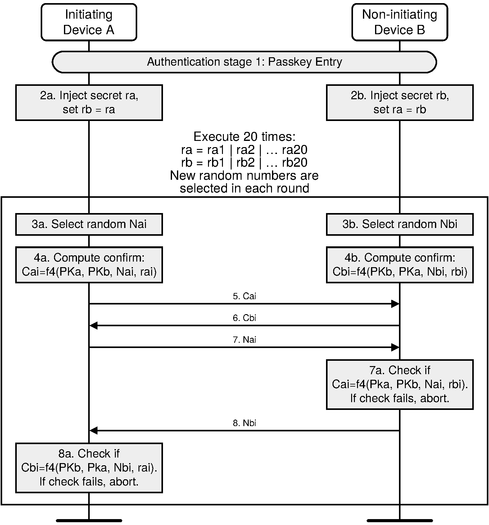
The user inputs an identical Passkey into both devices. Alternately, the Passkey may be generated and displayed on one device, and the user then inputs it into the other (step 2). This short shared key will be the basis of the mutual authentication of the devices. The Passkey should be generated randomly during each pairing procedure and not be reused from a previous procedure. Static Passkeys should not be used since they can compromise the security of the link.
Steps 3 to 8 are repeated 20 times since a 6-digit Passkey is 20 bits (999999=0xF423F). If the device allows a shorter passkey to be entered, it shall be prefixed with zeros (e.g. “1234” is equivalent to “001234”).
In Steps 3 to 8, each side commits to each bit of the Passkey, using a long nonce (128 bits), and sending the hash of the nonce, the bit of the Passkey, and both public keys to the other party. The parties then take turns revealing their commitments until the entire Passkey has been mutually disclosed. The first party to reveal a commitment for a given bit of the Passkey effectively reveals that bit of the Passkey in the process, but the other party then has to reveal the corresponding commitment to show the same bit value for that bit of the Passkey, or else the first party will then abort the protocol, after which no more bits of the Passkey are revealed.
This "gradual disclosure" prevents leakage of more than 1 bit of un-guessed Passkey information in the case of a MITM attack. A MITM attacker with only partial knowledge of the Passkey will only receive one incorrectly-guessed bit of the Passkey before the protocol fails. Hence, a MITM attacker who engages first one side, then the other will only gain an advantage of at most two bits over a simple brute-force guesser, making the probability of success 0.000004 instead of 0.000001.
The long nonce is included in the commitment hash to make it difficult to brute force even after the protocol has failed. The public Diffie-Hellman values are included to tie the Passkey protocol to the original ECDH key exchange, to prevent a MITM from substituting the attacker's public key on both sides of the ECDH exchange in standard MITM fashion.
At the end of this stage, Na is set to Na20 and Nb is set to Nb20 for use in Authentication stage 2.
2.3.5.6.4. Authentication stage 1 – Out of Band
The Out-of-Band protocol is used when authentication information has been received by at least one of the devices and indicated in the OOB data flag parameter included in the SMP Pairing Request and SMP Pairing Response PDU. The mode in which the discovery of the peer device is first done in-band and then followed by the transmission of authentication parameters through OOB interface is not supported. The sequence diagram for Authentication stage 1 for Out of Band from the cryptographic point of view is shown in Figure 2.5.
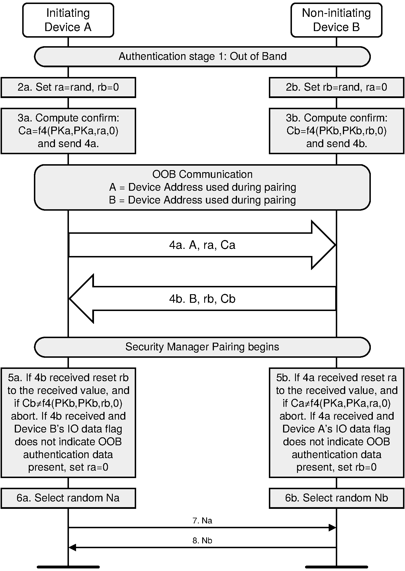
Principle of operation. If both devices can transmit and/or receive data over an out-of-band channel, then mutual authentication will be based on the commitments of the public keys (Ca and Cb) exchanged OOB in Authentication stage 1. If OOB communication is possible only in one direction, then authentication of the device receiving the OOB communication will be based on that device knowing a random number r sent via OOB. In this case, r must be secret: r can be created afresh every time, or access to the device sending r must be restricted. If r is not sent by a device, it is assumed to be 0 by the device receiving the OOB information in step 4a or 4b.
Roles of A and B. The OOB Authentication stage 1 protocol is symmetric with respect to the roles of A and B. It does not require that device A always will initiate pairing and it automatically resolves asymmetry in the OOB communication.
Order of steps. The public key exchange must happen before the verification step 5. In the diagram the in-band public key exchange between the devices (step 1) is done before the OOB communication (step 4). But when the pairing is initiated by an OOB interface, public key exchange will happen after the OOB communication (step 1 will be between steps 4 and 5).
Values of ra and rb: Since the direction of the peer's OOB interface cannot be verified before the OOB communication takes place, a device should always generate and if possible transmit through its OOB interface a random number r to the peer. Each device applies the following rules locally to set the values of its own r and the value of the peer's r:
Initially, r of the device is set to a random number and r of the peer is set to 0 (step 2).
If a device has received OOB, it sets the peer's r value to what was sent by the peer (Step 5).
If the remote device's OOB data flag sent in the SMP Pairing Request or SMP Pairing Response is set to “OOB Authentication data not present”, it sets its own r value to 0 (Step 5)
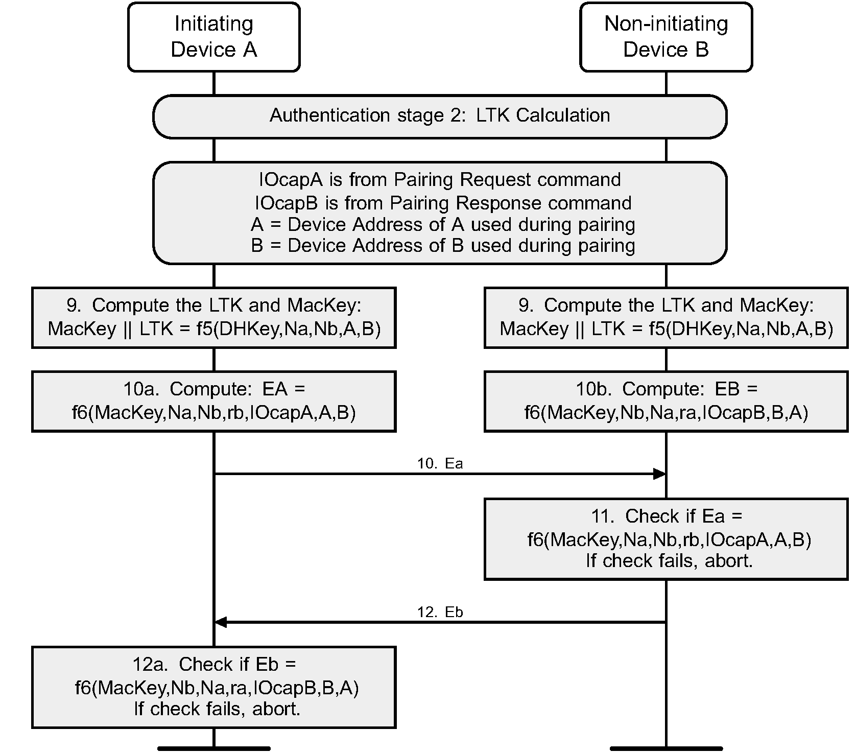
2.3.5.6.5. Authentication stage 2 and long term key calculation
The second stage of authentication then confirms that both devices have successfully completed the exchange. This stage is identical in all three protocols and is shown in Figure 2.6.
Each device computes the MacKey and the LTK using the previously exchanged values and the newly derived shared key (step 9). Each device then computes a new key confirmation value that includes the previously exchanged values and the newly derived MacKey (step 10a and 10b). The initiating device then transmits its key confirmation value, which is checked by the responding device (step 11). If this check fails, it indicates that the initiating device has not confirmed the pairing, and the protocol shall be aborted. The responding device then transmits its key confirmation value, which is checked by the initiating device (step 12). A failure indicates that the responding device has not confirmed the pairing and the protocol should abort.
2.3.5.7. Cross-transport key derivation
When a pair of BR/EDR/LE devices support Secure Connections on a transport, the devices may optionally generate a key of identical strength for the other transport. There are two sequences:
If Secure Connections pairing occurs on the LE transport, the procedures in Section 2.4.2.4 may be used.
If Secure connections pairing occurs on the BR/EDR transport, the procedures in Section 2.4.2.5 may be used.
2.3.6. Repeated attempts
When a pairing procedure fails a waiting interval shall pass before the verifier will initiate a new Pairing Request command or Security Request command to the same claimant, or before it will respond to a Pairing Request command or Security Request command initiated by a device claiming the same identity as the failed device. For each subsequent failure, the waiting interval shall be increased exponentially. That is, after each failure, the waiting interval before a new attempt can be made, could be for example, twice as long as the waiting interval prior to the previous attempt[4]. The waiting interval should be limited to a maximum.
The maximum waiting interval depends on the implementation. The waiting time shall exponentially decrease to a minimum when no new failed attempts are made during a certain time period. This procedure restricts the rate at which an intruder can repeat the pairing procedure with different keys.
To protect a device's private key, a device should implement a method to prevent an attacker from retrieving useful information about the device's private key. For this purpose, a device should change its private key after every pairing (successful or failed). Otherwise, it should change its private key whenever S + 3F > 8, where S is the number of successful pairings and F the number of failed attempts since the key was last changed.
2.4. Security in Bluetooth Low Energy
Security shall be initiated by the Security Manager in the device in the Central role. The device in the Peripheral role shall be the responding device. The Peripheral may request the Central to initiate pairing or other security procedures, see Section 2.4.6.
The Peripheral in the key distribution phase gives keys to the Central so a reconnection can be encrypted, its random addresses can be resolved, or the Central can verify signed data from the Peripheral.
The Central may also provide keys to the Peripheral so a reconnection can be encrypted if the roles are reversed, the Central’s random addresses can be resolved, or the Peripheral can verify signed data from the Central.
2.4.1. Definition of keys and values
LE security uses the following keys and values for encryption, signing, and random addressing:
Identity Resolving Key (IRK) is a 128-bit key used to generate and resolve random addresses.
Connection Signature Resolving Key (CSRK) is a 128-bit key used to sign data and verify signatures on the receiving device.
Long Term Key (LTK) is a 128-bit key used to generate the contributory session key for an encrypted connection. Link Layer encryption is described in [Vol 6] Part B, Section 5.1.3.
Encrypted Diversifier (EDIV) is a 16-bit stored value used to identify the LTK distributed during LE legacy pairing. A new EDIV is generated each time a unique LTK is distributed.
Random Number (Rand) is a 64-bit stored valued used to identify the LTK distributed during LE legacy pairing. A new Rand is generated each time a unique LTK is distributed.
2.4.2. Generation of distributed keys
Any method of generation of keys that are being distributed that results in the keys having 128 bits of entropy can be used, as the generation method is not visible outside the Peripheral (see Appendix B). The keys shall not be generated only from information that is distributed to the Central or only from information that is visible outside of the Peripheral.
2.4.2.1. Generation of IRK
The Identity Resolving Key (IRK) is used for resolvable private address construction (see [Vol 3] Part C, Section 10.8.2). A Central that has received IRK from a Peripheral can resolve that Peripheral’s random device addresses. A Peripheral that has received IRK from a Central can resolve that Central’s random device addresses. The privacy concept only protects against devices that are not part of the set to which the IRK has been given.
IRK can be assigned, or randomly generated by the device during manufacturing, or some other method could be used. If IRK is randomly generated then the requirements for random generation defined in [Vol 2] Part H, Section 2 shall be used.
The encryption key size does not apply to IRK; therefore, its size does not need to be shortened before distribution.
2.4.2.2. Generation of CSRK
The Connection Signature Resolving Key (CSRK) is used to sign data in a connection. A device that has received CSRK can verify signatures generated by the distributing device. The signature only protects against devices that are not part of the set to which CSRK has been given.
CSRK can be assigned or randomly generated by the device during manufacturing, or some other method could be used. If CSRK is randomly generated then the requirements for random generation defined in [Vol 2] Part H, Section 2 shall be used.
The encryption key size does not apply to CSRK, therefore its size does not need to be shortened before distribution.
2.4.2.3. LE legacy pairing - generation of LTK, EDIV and Rand
Devices which support encryption in the Link Layer Connection state in the Peripheral Role shall be capable of generating LTK, EDIV, and Rand.
The EDIV and Rand are used by the Peripheral to establish a previously shared LTK in order to start an encrypted connection with a previously paired Central.
The generated LTK size shall not be longer than the negotiated encryption key size, so its size may need to be shortened (see Section 2.3.4).
New values of LTK, EDIV, and Rand shall be generated each time they are distributed.
The Peripheral may store the mapping between EDIV, Rand and LTK in a security database so the correct LTK value is used when the Central requests encryption. Depending upon the LTK generation method additional information may be stored, for example the size of the distributed LTK.
The Central may also distribute EDIV, Rand, and LTK to the Peripheral which can be used to encrypt a reconnection if the device roles are reversed in a future connection.
2.4.2.4. Derivation of BR/EDR link key from LE LTK
The LTK from the LE physical transport can be converted to the BR/EDR link key for the BR/EDR transport as follows, using intermediate link key (ILK) as an intermediate value:
If at least one device sets CT2 = 0 then
ILK = h6(LTK, “tmp1”)
BR/EDR link key = h6(ILK, “lebr”)
If both devices set CT2 = 1 then
ILK = h7(SALT, LTK)
BR/EDR link key = h6(ILK, “lebr”)
The string “lebr” is mapped into a keyID using ASCII as 0x6C656272.
    The string “tmp1” is mapped into a keyID using ASCII as 0x746D7031
    and into a SALT as 0x00000000_00000000_00000000_746D7031.
    Note: If the LTK has an encryption key size that is shorter
    than 16 octets (128 bits), the BR/EDR link key is derived before
    the LTK gets masked.
2.4.2.5. Derivation of LE LTK from BR/EDR link key
The BR/EDR Link Key from the BR/EDR physical transport can be converted to the LTK for the LE transport as follows, using intermediate long term key (ILTK) as an intermediate value:
If at least one device sets CT2 = 0 then
ILTK = h6(Link Key, “tmp2”)
LTK = h6(ILTK, “brle”)
If both devices set CT2 = 1 then
ILTK = h7(SALT, Link Key)
LTK = h6(ILTK, “brle”)
The string “brle” is mapped into a keyID using ASCII as 0x62726C65.
        The string “tmp2” is mapped into a keyID using ASCII as 0x746D7032
        and into a SALT as 0x00000000_00000000_00000000_746D7032.
2.4.3. Distribution of keys
Key distribution for LE Legacy Pairing and LE Secure Connections is described in the following sections.
2.4.3.1. LE legacy pairing key distribution
The Peripheral may distribute to the Central the following keys:
LTK, EDIV, and Rand
IRK
CSRK
The Central may distribute to the Peripheral the following keys:
LTK, EDIV, and Rand
IRK
CSRK
The security properties of the distributed keys shall be set to the security properties of the STK that was used to distribute them. For example if STK has Unauthenticated no MITM Protection security properties then the distributed keys shall have Unauthenticated no MITM Protection security properties.
The link shall be encrypted or re-encrypted using STK generated in Phase 2 (see Section 2.4.4.1) before any keys are distributed.
Note
Note: The distributed EDIV and Rand values are transmitted in clear text by the Central to the Peripheral during encrypted session setup.
The BD_ADDR that is received in the Identity Address Information command shall only be considered valid once a reconnection has occurred using the BD_ADDR and LTK distributed during that pairing. Once this is successful the BD_ADDR and the distributed keys shall be associated with that device in the security database.
A device may request encrypted session setup to use the LTK, EDIV, and Rand values distributed by the Peripheral when the key distribution phase has completed; however, this does not provide any additional security benefit. If an attacker has established the distributed LTK value then performing encrypted session setup to use the distributed values does not provide any protection against that attacker.
2.4.3.2. LE Secure Connections key distribution
The Central and Peripheral may distribute the following keys:
IRK
CSRK
The security properties of the distributed keys shall be set to the security properties of the LTK that was used to distribute them. For example if LTK has Unauthenticated no MITM Protection security properties then the distributed keys shall have Unauthenticated no MITM Protection security properties.
The link shall be encrypted or re-encrypted using LTK generated in Phase 2 (see Section 2.4.4.1) before any keys are distributed.
The BD_ADDR that is received in the Identity Address Information command shall only be considered valid once a reconnection has occurred using the BD_ADDR and LTK generated during that pairing. Once this is successful the BD_ADDR and the distributed keys shall be associated with that device in the security database.
2.4.4. Encrypted session setup
During the encrypted session setup the Central sends a 16-bit Encrypted Diversifier value, EDIV, and a 64-bit Random Number, Rand, distributed by the Peripheral during pairing, to the Peripheral. The Central’s Host provides the Link Layer with the Long Term Key to use when setting up the encrypted session. The Peripheral’s Host receives the EDIV and Rand values and provides a Long Term Key to the Peripheral’s Link Layer to use when setting up the encrypted link.
When both devices support LE Secure Connections, the EDIV and Rand are set to zero.
2.4.4.1. Encryption setup using STK
To distribute LTK and other keys in pairing Phase 3 an encrypted session needs to be established (see Section 2.3.5.5).
The encrypted session is setup using STK generated in Phase 2 (see Section Section 2.3.5.5) as the Long Term Key provided to the Link Layer, (see [Vol 6] Part B, Section 5.1.3.1) EDIV, and Rand values shall be set to zero.
If the link is already encrypted then the encryption pause procedure is performed using STK generated in Phase 2 as the Long Term Key provided to the Link Layer (see [Vol 6] Part B, Section 5.1.3.2). EDIV and Rand values shall be set to zero.
2.4.4.2. Encryption setup using LTK
The Central must have the security information (LTK, EDIV, and Rand) distributed by the Peripheral in LE legacy pairing or the LTK generated in LE Secure Connections to setup an encrypted session.
The Central initiates the encrypted session using the security information; see [Vol 6] Part B, Section 5.1.3.1. If the link is already encrypted the encryption pause procedure is performed using the security information; see [Vol 6] Part B, Section 5.1.3.2.
In LE legacy pairing, the EDIV and Rand values are used to establish LTK which is used as the Long Term Key on the Peripheral. If LTK cannot be established from EDIV and Rand values then the Peripheral shall reject the request to encrypt the link and may optionally disconnect the link.
The LTK size shall not be longer than the negotiated encryption key size, so its size may need to be shortened (see Section 2.3.4).
When the security information is stored, subsequent encryption setups may fail if the remote device has deleted the security information. Table 2.9 defines what shall be done depending on the type of the security properties and whether or not bonding was performed when subsequent encryption setup fails.
Security Properties | Devices Bonded | Action to take when enabling encryption fails |
|---|---|---|
Unauthenticated, no MITM protection | No | Depends on security policy of the device:
Option 1 is recommended. |
Unauthenticated, no MITM protection | Yes | Notify user of security failure |
Authenticated MITM protection | No | Depends on security policy of the device:
Option 2 is recommended. |
Authenticated MITM protection | Yes | Notify user of security failure |
2.4.5. Signing algorithm
An LE device can send signed data without having to establish an encrypted session with a peer device. Data shall be signed using CSRK. A device performing signature verification must have received CSRK from the signing device. The sending device will use its CSRK to sign the transmitted data.
The following are inputs to the signing algorithm:
m is variable length k is 128 bits SignCounter is 32 bits
Signing shall be performed using the algorithm defined in the NIST Special Publication 800-38B [1] using AES-128 as the block cipher. NIST SP 800-38B defines the message authentication code (MAC) generation function:
MAC = CMAC(K, M, Tlen)
The bit length of the MAC (Tlen) shall be 64 bits. The key used for signature generation (k) shall be set to CSRK.
The message to be signed (M) by the CMAC function is the concatenation of the variable length message to be signed (m) and 4 octet string representing the 32-bit counter value (SignCounter) least significant octet first.
M = m || SignCounter
For example, if data to be signed is the 7 octet sequence ‘3456789ABCDEF1’ and SignCounter is set to 67653874 (0x040850F2) then M is the octet sequence ‘3456789ABCDEF1F2500804’. Examples of CMAC generation using AES-128 as the block cipher are included in NIST Special Publication 800-38B Appendix D.
The SignCounter shall be initialized to zero when CSRK is generated and incremented for every message that is signed with a given CSRK.
Note
Note: If a device generates 100,000 signed events a day, a 32-bit counter will wrap after approximately 117 years.
The 64-bit result of the CMAC function is used as the result of the signing algorithm.
To verify a signature a device computes the MAC of a received message and SignCounter and compares it with the received MAC. If the MAC does not match then the signature verification has failed. If the MACs match then the signature verification has succeeded.
The device performing verification should store the last verified SignCounter in the security database and compare it with a received SignCounter to prevent replay attacks. If the received SignCounter is greater than the stored value then the message has not been seen by the local device before and the security database can be updated.
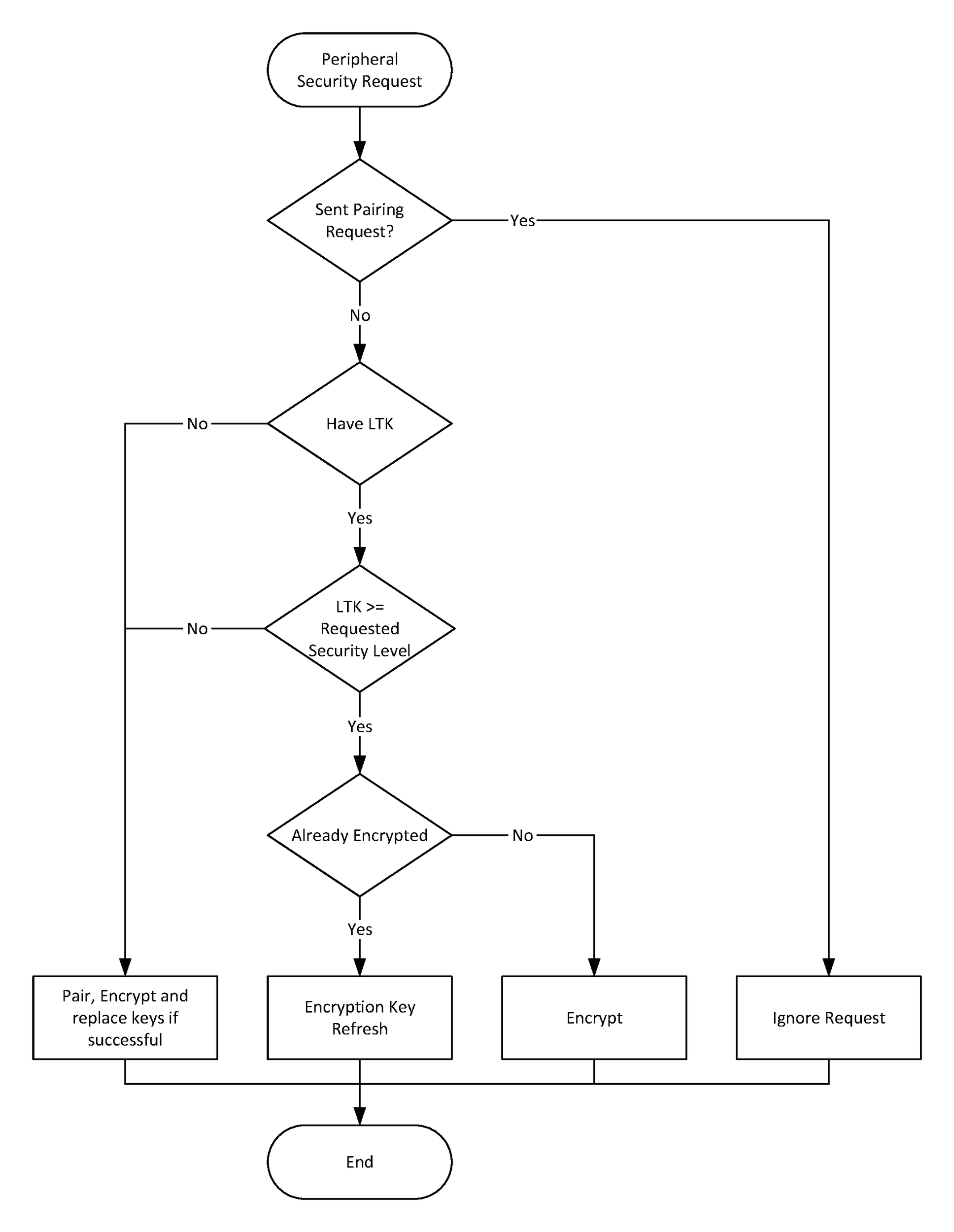
2.4.6. Peripheral Security Request
The Peripheral may request security by transmitting a Security Request command to the Central. When a Central receives a Security Request command it may encrypt the link, initiate the pairing procedure, or reject the request.
The Peripheral shall not send the Security Request command if the pairing procedure is in progress, or if the encryption procedure is in progress.
The Security Request command includes the required security properties. A security property of MITM protection required shall only be set if the Peripheral’s IO capabilities would allow the Passkey Entry association model to be used or out of band authentication data is available.
The Central shall ignore the Peripheral’s Security Request if the Central has sent a Pairing Request without receiving a Pairing Response from the Peripheral or if the Central has initiated encryption mode setup.
If pairing or encryption mode is not supported or cannot be initiated at the time when the Peripheral’s Security Request command is received, then the Central shall respond with a Pairing Failed command with the reason set to “Pairing Not Supported.”
After receiving a Security Request, the Central shall first check whether it has the required security information to enable encryption; see Section 2.4.4.2. If this information is missing or does not meet the security properties requested by the Peripheral, then the Central shall initiate the pairing procedure. If the pairing procedure is successful, the Central’s security database is updated with the keys and security properties are distributed during the pairing procedure.
If the Central has the required security information to enable encryption and it meets the security properties request by the Peripheral, it shall perform encryption setup using LTK, see Section 2.4.4.2.
Figure 2.7 shows a summary of the actions and decisions that a Central shall take when receiving a Security Request.
The Peripheral shall check that any Pairing Request command received from the Central after sending a Security Request command contains Authentication Requirements that meet the requested security properties.
If the Peripheral requests a security property that is not Just Works and receives an encryption procedure request after sending a Security Request command then it shall check that any existing Security Information is of sufficient security properties.
3. Security Manager Protocol
3.1. Introduction
The Security Manager Protocol (SMP) is used for pairing and transport specific key distribution.
3.2. Security Manager Channel over L2CAP
All SMP commands are sent over the Security Manager Channel which is an L2CAP fixed channel (see [Vol 3] Part A, Section 2.1). The configuration parameters for the Security Manager Channel when LE Secure Connections is not supported shall be as shown below in Table 3.1.
Parameter | Value |
|---|---|
MTU | 23 |
Flush Timeout | 0xFFFF (Infinite) |
QoS | Best Effort |
Mode | Basic Mode |
The configuration parameters for the Security Manager Channel when LE Secure Connections is supported shall be as shown below in Table 3.2.
Parameter | Value |
|---|---|
MTU | 65 |
Flush Timeout | 0xFFFF (Infinite) |
QoS | Best Effort |
Mode | Basic Mode |
3.3. Command format
The general format for all SMP commands is shown in Figure 3.1.
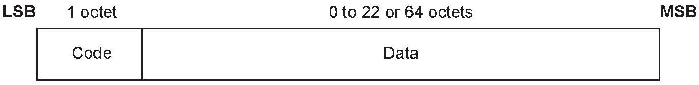
The following are the fields shown:
Code (1 octet)
The Code field is one octet long and identifies the type of command. Table 3.3 lists the codes defined by this document. If a packet is received with a Code that is reserved for future use it shall be ignored.
Code
Description
Logical Link Supported
0x01
Pairing Request
LE-U, ACL-U
0x02
Pairing Response
LE-U, ACL-U
0x03
Pairing Confirm
LE-U
0x04
Pairing Random
LE-U
0x05
Pairing Failed
LE-U, ACL-U
0x06
Encryption Information
LE-U
0x07
Central Identification
LE-U
0x08
Identity Information
LE-U, ACL-U
0x09
Identity Address Information
LE-U, ACL-U
0x0A
Signing Information
LE-U, ACL-U
0x0B
Security Request
LE-U
0x0C
Pairing Public Key
LE-U
0x0D
Pairing DHKey Check
LE-U
0x0E
Pairing Keypress Notification
LE-U
All other values
Reserved for future use
Table 3.3: SMP command codesData (0 or more octets)
The Data field is variable in length. The Code field determines the format of the Data field.
If a device does not support pairing then it shall respond with a Pairing Failed command with the reason set to “Pairing Not Supported” (see Section 3.5.5) when any command is received. If pairing is supported then all commands shall be supported.
3.4. SMP timeout
To protect the Security Manager protocol from stalling, a Security Manager Timer is used. Upon transmission of the Security Request command or reception of the Security Request command, the Security Manager Timer shall be reset and restarted. Upon transmission of the Pairing Request command or reception of the Pairing Request command, the Security Manager Timer shall be reset and started.
The Security Manager Timer shall be reset when an L2CAP SMP command is queued for transmission. The Security Manager Timer should be reset upon reception of a Keypress Notification (if the timer is not reset on receipt of a Keypress Notification, the Security Manager can time out before the peer's Security Manager because there is no response to a Keypress Notification).
When a Pairing process completes (whether successfully or not), the Security Manager Timer shall be stopped.
If the Security Manager Timer reaches 30 seconds, the procedure shall be considered to have failed, and the local higher layer shall be notified. No further SMP commands shall be sent over the L2CAP Security Manager Channel. A new Pairing process shall only be performed when a new physical link has been established.
3.5. Pairing methods
The SMP commands defined in this section are used to perform Pairing Feature Exchange and key generation (see Section 2.1).
3.5.1. Pairing Request
The initiator starts the Pairing Feature Exchange by sending a Pairing Request command to the responding device. The Pairing Request command is defined in Figure 3.2.
The rules for handing a collision between a pairing procedure on the LE transport and a pairing procedure on the BR/EDR transport are defined in [Vol 3] Part C, Section 14.2.
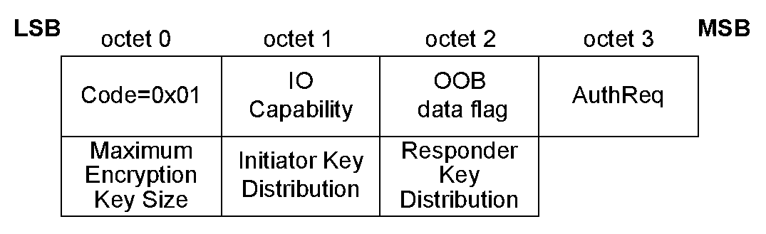
The following data fields are used:
IO Capability (1 octet)
Table 3.4 defines the values which are used when exchanging IO capabilities (see Section 2.3.2).
Value | Description |
|---|---|
0x00 | DisplayOnly |
0x01 | DisplayYesNo |
0x02 | KeyboardOnly |
0x03 | NoInputNoOutput |
0x04 | KeyboardDisplay |
0x05 to 0xFF | Reserved for future use |
OOB data flag (1 octet)
Table 3.5 defines the values which are used when indicating whether OOB authentication data is available (see Section 2.3.3).
Value | Description |
|---|---|
0x00 | OOB Authentication data not present |
0x01 | OOB Authentication data from remote device present |
0x02 to 0xFF | Reserved for future use |
AuthReq (1 octet)
The AuthReq field is a bit field that indicates the requested security properties (see Section 2.3.1) for the STK and LTK and GAP bonding information (see [Vol 3] Part C, Section 9.4).
Figure 3.3 defines the authentication requirements bit field.
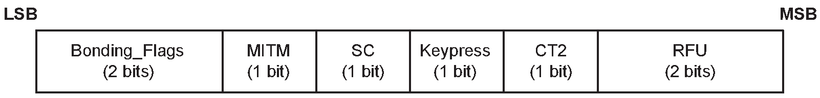
The Bonding_Flags field is a 2-bit field that indicates the type of bonding being requested by the initiating device as defined in Table 3.6.
Bonding_Flags b1b0 | Bonding Type |
|---|---|
00 | No Bonding |
01 | Bonding |
10 | Reserved for future use |
11 | Reserved for future use |
The MITM field is a 1-bit flag that is set to one if the device is requesting MITM protection, otherwise it shall be set to 0. A device sets the MITM flag to one to request an Authenticated security property for the STK when using LE legacy pairing and the LTK when using LE Secure Connections.
The SC field is a 1 bit flag. If LE Secure Connections pairing is supported by the device, then the SC field shall be set to 1, otherwise it shall be set to 0. If both devices support LE Secure Connections pairing, then LE Secure Connections pairing shall be used, otherwise LE Legacy pairing shall be used.
The keypress field is a 1-bit flag that is used only in the Passkey Entry protocol and shall be ignored in other protocols. When both sides set that field to one, Keypress notifications shall be generated and sent using SMP Pairing Keypress Notification PDUs.
The CT2 field is a 1-bit flag that shall be set to 1 upon transmission to indicate support for the h7 function. See sections 2.4.2.4 and 2.4.2.5.
Maximum Encryption Key Size (1 octet)
This value defines the maximum encryption key size in octets that the device can support. The maximum key size shall be in the range 7 to 16 octets.
Initiator Key Distribution / Generation (1 octet)
The Initiator Key Distribution / Generation field indicates which keys the initiator is requesting to distribute / generate or use during the Transport Specific Key Distribution phase (see Section 2.4.3). The Initiator Key Distribution / Generation field format and usage is defined in Section 3.6.1.
Responder Key Distribution / Generation (1 octet)
The Responder Key Distribution / Generation field indicates which keys the initiator is requesting the responder to distribute / generate or use during the Transport Specific Key Distribution phase (see Section 2.4.3). The Responder Key Distribution / Generation field format and usage is defined in Section 3.6.1.
If Secure Connections pairing has been initiated over BR/EDR, the following fields of the SM Pairing Request PDU are reserved for future use:
the IO Capability field,
the OOB data flag field, and
all bits in the Auth Req field except the CT2 bit.
3.5.2. Pairing Response
This command is used by the responding device to complete the Pairing Feature Exchange after it has received a Pairing Request command from the initiating device, if the responding device allows pairing. The Pairing Response command is defined in Figure 3.4.
The rules for handing a collision between a pairing procedure on the LE transport and a pairing procedure on the BR/EDR transport are defined in [Vol 3] Part C, Section 14.2.
If a Pairing Request is received over the BR/EDR transport when either cross-transport key derivation/generation is not supported or the BR/EDR transport is not encrypted using a Link Key generated using P256, a Pairing Failed shall be sent with the error code Cross-Transport Key Derivation/Generation Not Allowed (0x0E).

The following data fields are used:
IO Capability (1 octet)
Table 3.4 defines the values which are used when exchanging IO capabilities (see Section 2.3.2).
OOB data flag (1 octet)
Table 3.5 defines the values which are used when indicating whether OOB authentication data is available (see Section 2.3.3).
AuthReq (1 octet)
The AuthReq field is a bit field that indicates the requested security properties (see Section 2.3.1) for the STK or LTK and GAP bonding information (see [Vol 3] Part C, Section 9.4).
Figure 3.3 defines the authentication requirements bit field.
The Bonding_Flags field is a 2-bit field that indicates the type of bonding being requested by the responding device as defined in Table 3.6.
The MITM field is a 1-bit flag that is set to one if the device is requesting MITM protection, otherwise it shall be set to 0. A device sets the MITM flag to one to request an Authenticated security property for the STK when using LE legacy pairing and the LTK when using LE Secure Connections.
The SC field is a 1 bit flag. If LE Secure Connections pairing is supported by the device, then the SC field shall be set to 1, otherwise it shall be set to 0. If both devices support LE Secure Connections pairing, then LE Secure Connections pairing shall be used, otherwise LE Legacy pairing shall be used.
The keypress field is a 1-bit flag that is used only in the Passkey Entry protocol and shall be ignored in other protocols. When both sides set that field to one, Keypress notifications shall be generated and sent using SMP Pairing Keypress Notification PDUs.
The CT2 field is a 1-bit flag that shall be set to 1 upon transmission to indicate support for the h7 function. See Sections 2.4.2.4 and 2.4.2.5.
Maximum Encryption Key Size (1 octet)
This value defines the maximum encryption key size in octets that the device can support. The maximum key size shall be in the range 7 to 16 octets.
Initiator Key Distribution (1 octet)
The Initiator Key Distribution field defines which keys the initiator shall distribute and use during the Transport Specific Key Distribution phase (see Section 2.4.3). The Initiator Key Distribution field format and usage are defined in Section 3.6.1.
Responder Key Distribution (1 octet)
The Responder Key Distribution field defines which keys the responder shall distribute and use during the Transport Specific Key Distribution phase (see Section 2.4.3). The Responder Key Distribution field format and usage are defined in Section 3.6.1.
If Secure Connections pairing has been initiated over BR/EDR, the following fields of the SM Pairing Response PDU are reserved for future use:
the IO Capability field,
the OOB data flag field, and
all bits in the Auth Req field except the CT2 bit.
3.5.3. Pairing Confirm
This is used following a successful Pairing Feature Exchange to start STK Generation for LE legacy pairing and LTK Generation for LE Secure Connections pairing. The Pairing Confirm command is defined in Figure 3.5.
This command is used by both devices to send the confirm value to the peer device, see Section 2.3.5.5 for LE legacy pairing and Section 2.3.5.6 for LE Secure Connections pairing.
The initiating device starts key generation by sending the Pairing Confirm command to the responding device. If the initiating device wants to abort pairing it can transmit a Pairing Failed command instead.
The responding device sends the Pairing Confirm command after it has received a Pairing Confirm command from the initiating device.
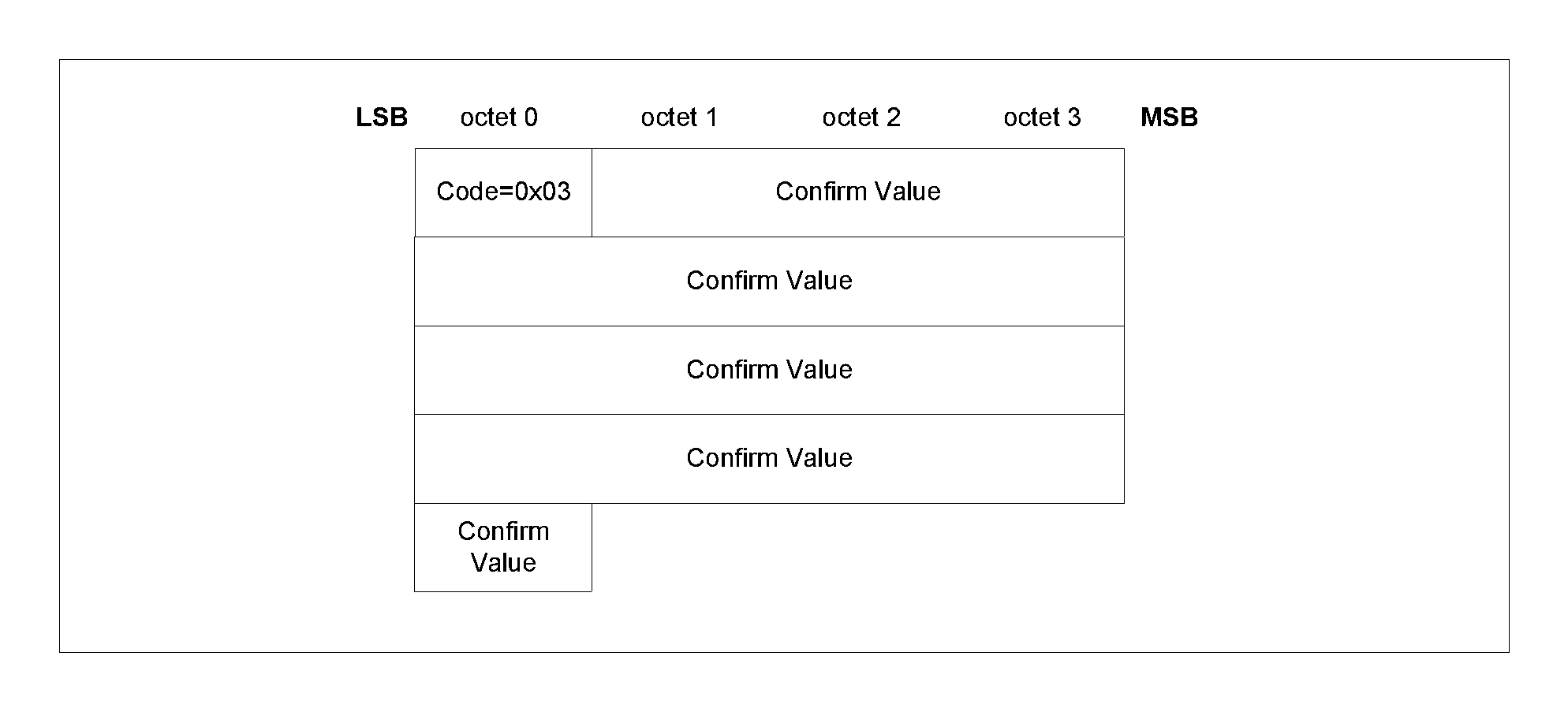
The following data field is used:
Confirm value (16 octets)
In LE legacy pairing, the initiating device sends LP_CONFIRM_I and the responding device sends LP_CONFIRM_R as defined in Section 2.3.5.5. In LE Secure Connections, Ca and Cb are defined in Section 2.2.6.
3.5.4. Pairing Random
This command is used by the initiating and responding device to send the random number used to calculate the Confirm value sent in the Pairing Confirm command. The Pairing Random command is defined in Figure 3.6.
The initiating device sends a Pairing Random command after it has received a Pairing Confirm command from the responding device.
In LE legacy pairing, the responding device shall send a Pairing Random command after it has received a Pairing Random command from the initiating device if the Confirm value calculated on the responding device matches the Confirm value received from the initiating device. If the calculated Confirm value does not match then the responding device shall respond with the Pairing Failed command.
In LE Secure Connections, the responding device shall send a Pairing Random command after it has received a Pairing Random command from the initiating device. If the calculated Confirm value does not match then the responding device shall respond with the Pairing Failed command.
The initiating device shall encrypt the link using the generated key (STK in LE legacy pairing or LTK in LE Secure Connections) if the Confirm value calculated on the initiating device matches the Confirm value received from the responding device. The successful encryption or re-encryption of the link is the signal to the responding device that key generation has completed successfully. If the calculated Confirm value does not match then the initiating device shall respond with the Pairing Failed command.
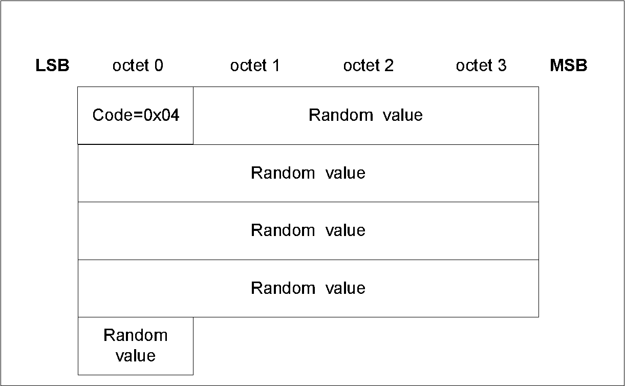
The following are the data fields:
Random value (16 octets)
In LE legacy pairing, the initiating device sends LP_RAND_I and the responding device sends LP_RAND_R as defined in Section 2.3.5.5. In LE Secure Connections, the initiating device sends Na and the responding device sends Nb.
3.5.5. Pairing Failed
This is used when there has been a failure during pairing and reports that the pairing procedure has been stopped and no further communication for the current pairing procedure is to occur. The Pairing Failed command is defined in Figure 3.7.
Any subsequent pairing procedure shall restart from the Pairing Feature Exchange phase.
This command may be sent at any time during the pairing process by either device in response to a message from the remote device.
During LE Secure Connections pairing, this command should be sent if the remote device's public key is invalid (see Section 2.3.5.6.1). The Reason field should be set to "DHKey Check Failed".
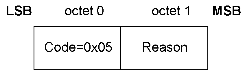
The following data field is used:
Reason (1 octets)
The Reason field indicates why the pairing failed. The reason codes are defined in Table 3.7.
Value | Name | Description |
|---|---|---|
0x01 | Passkey Entry Failed | The user input of passkey failed, for example, the user cancelled the operation |
0x02 | OOB Not Available | The OOB data is not available |
0x03 | Authentication Requirements | The pairing procedure cannot be performed as authentication requirements cannot be met due to IO capabilities of one or both devices |
0x04 | Confirm Value Failed | The confirm value does not match the calculated compare value |
0x05 | Pairing Not Supported | Pairing is not supported by the device |
0x06 | Encryption Key Size | The resultant encryption key size is not long enough for the security requirements of this device |
0x07 | Command Not Supported | The SMP command received is not supported on this device |
0x08 | Unspecified Reason | Pairing failed due to an unspecified reason |
0x09 | Repeated Attempts | Pairing or authentication procedure is disallowed because too little time has elapsed since last pairing request or security request |
0x0A | Invalid Parameters | The Invalid Parameters error code indicates that the command length is invalid or that a parameter is outside of the specified range. |
0x0B | DHKey Check Failed | Indicates to the remote device that the DHKey Check value received doesn’t match the one calculated by the local device. |
0x0C | Numeric Comparison Failed | Indicates that the confirm values in the numeric comparison protocol do not match. |
0x0D | BR/EDR pairing in progress | Indicates that the pairing over the LE transport failed due to a Pairing Request sent over the BR/EDR transport in progress. |
0x0E | Cross-transport Key Derivation/Generation not allowed | Indicates that the BR/EDR Link Key generated on the BR/EDR transport cannot be used to derive and distribute keys for the LE transport or the LE LTK generated on the LE transport cannot be used to derive a key for the BR/EDR transport. |
0x0F | Key Rejected | Indicates that the device chose not to accept a distributed key. |
All other values | Reserved for future use |
3.5.6. Pairing Public Key
This message is used to transfer the device’s local public key (X and Y co-ordinates) to the remote device. This message is used by both the initiator and responder. This PDU is only used for Secure Connections. Its format is specified in Figure 3.8.
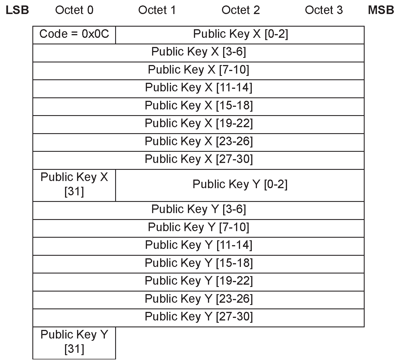
3.5.7. Pairing DHKey Check
This message is used to transmit the 128-bit DHKey Check values (Ea/Eb) generated using f6. These are confirmation values generated using the DHKey. This message is used by both initiator and responder. This PDU is only used for LE Secure Connections. Its format is specified in Figure 3.9.
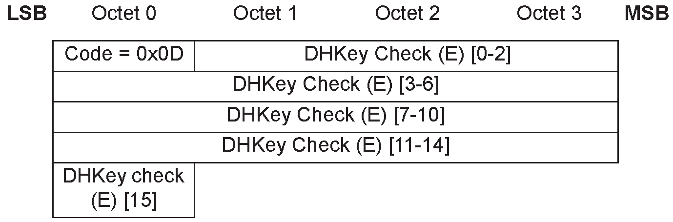
3.5.8. Keypress Notification
This message is used during the Passkey Entry protocol by a device with KeyboardOnly IO capabilities to inform the remote device when keys have been entered or erased. Its format is specified in Figure 3.10.
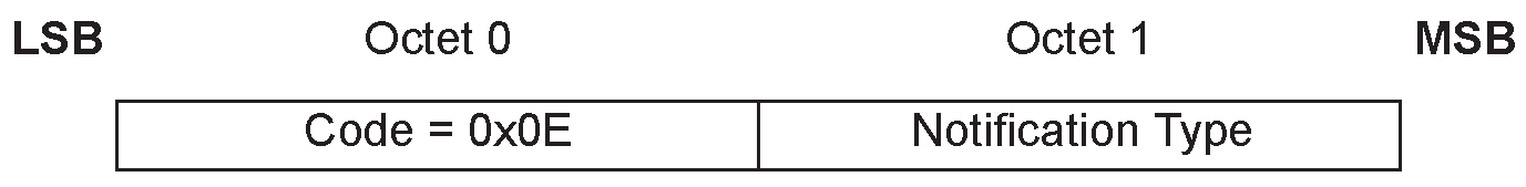
Notification Type can take one of the following values:
Value | Parameter Description |
|---|---|
0 | Passkey entry started |
1 | Passkey digit entered |
2 | Passkey digit erased |
3 | Passkey cleared |
4 | Passkey entry completed |
5 to 255 | Reserved for future use |
3.6. Security in Bluetooth Low Energy
3.6.1. Key distribution and generation
Bluetooth Low Energy devices can distribute keys from the Peripheral to the Central and from the Central to the Peripheral. When using LE legacy pairing, the following keys may be distributed from the Peripheral to the Central:
LTK using Encryption Information command
EDIV and Rand using Central Identification command
IRK using Identity Information command
Public device or static random address using Identity Address Information command
CSRK using Signing Information command
When using LE Secure Connections, the following keys may be distributed from the Peripheral to the Central:
IRK using Identity Information command
Public device or static random address using Identity Address Information command
CSRK using Signing Information command
When using LE legacy pairing, the Central may distribute to the Peripheral the following key:
LTK using Encryption Information command
EDIV and Rand using Central Identification command
IRK using Identity Information command
Public device or static random address using Identity Address Information command
CSRK using Signing Information command
When using LE Secure Connections, the Central may distribute to the Peripheral the following key:
IRK using Identity Information command
Public device or static random address using Identity Address Information command
CSRK using Signing Information command
The keys which are to be distributed in the Transport Specific Key Distribution phase are indicated in the Key Distribution field of the Pairing Request and Pairing Response commands see Section 3.5.1 and Section 3.5.2.
The format of the Initiator Key Distribution / Generation field and Responder Key Distribution / Generation field in the Pairing Request and Pairing Response commands for LE is defined in Figure 3.11.
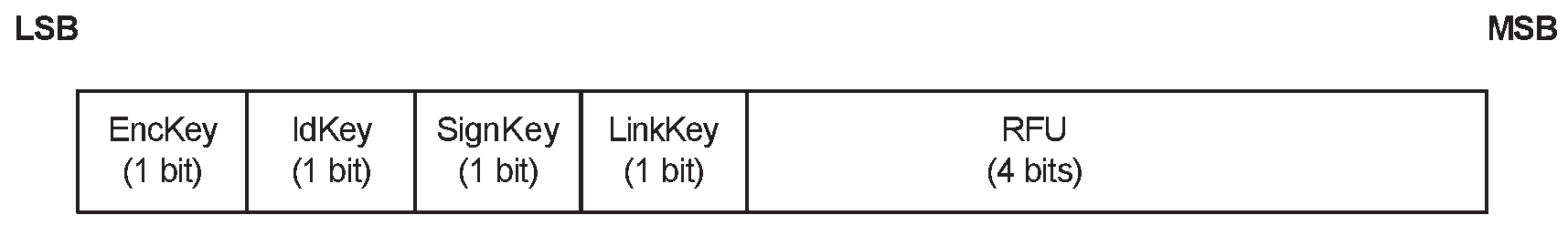
The Key Distribution / Generation field has the following flags:
In LE legacy pairing, EncKey is a 1-bit field that is set to one to indicate that the device shall distribute LTK using the Encryption Information command followed by EDIV and Rand using the Central Identification command.
In LE Secure Connections pairing, when SMP is running on the LE transport, then the EncKey field shall be ignored. EDIV and Rand shall be set to zero and shall not be distributed.
When SMP is running on the BR/EDR transport, the EncKey field is set to one to indicate that the device would like to derive the LTK from the BR/EDR Link Key. When EncKey is set to 1 by both devices in the initiator and responder Key Distribution / Generation fields, the procedures for calculating the LTK from the BR/EDR Link Key shall be used.
IdKey is a 1-bit field that is set to one to indicate that the device shall distribute IRK using the Identity Information command followed by its public device or static random address using Identity Address Information.
SignKey is a 1-bit field that is set to one to indicate that the device shall distribute CSRK using the Signing Information command.
LinkKey is a 1-bit field. When SMP is running on the LE transport, the LinkKey field is set to one to indicate that the device would like to derive the Link Key from the LTK. When LinkKey is set to 1 by both devices in the initiator and responder Key Distribution / Generation fields, the procedures for calculating the BR/EDR link key from the LTK shall be used. Devices not supporting LE Secure Connections shall set this bit to zero and ignore it on reception. When SMP is running on the BR/EDR transport, the LinkKey field is reserved for future use.
The Initiator Key Distribution / Generation field in the Pairing Request command is used by the Central to request which keys are distributed or generated by the initiator to the responder. The Responder Key Distribution / Generation field in the Pairing Request command is used by the Central to request which keys are distributed or generated by the responder to the initiator. The Initiator Key Distribution / Generation field in the Pairing Response command from the Peripheral defines the keys that shall be distributed or generated by the initiator to the responder. The Responder Key Distribution / Generation field in the Pairing Response command from the Peripheral defines the keys that shall be distributed or generated by the responder to the initiator. The Peripheral shall not set to one any flag in the Initiator Key Distribution / Generation or Responder Key Distribution / Generation field of the Pairing Response command that the Central has set to zero in the Initiator Key Distribution / Generation and Responder Key Distribution / Generation fields of the Pairing Request command.
When using LE legacy pairing, the keys shall be distributed in the following order:
LTK by the Peripheral
EDIV and Rand by the Peripheral
IRK by the Peripheral
BD_ADDR by the Peripheral
CSRK by the Peripheral
LTK by the Central
EDIV and Rand by the Central
IRK by the Central
BD_ADDR by the Central
CSRK by the Central
When using LE Secure Connections, the keys shall be distributed in the following order:
IRK by the Peripheral
BD_ADDR by the Peripheral
CSRK by the Peripheral
IRK by the Central
BD_ADDR by the Central
CSRK by the Central
If a key is not being distributed then the command to distribute that key shall not be sent.
Note
Note: If a key is not distributed, then the capabilities that use this key will not be available. For example, if an LTK is not distributed from the Peripheral to the Central, then the Central cannot encrypt a future link with that Peripheral, therefore pairing would have to be performed again.
Note
Note: The initiator should determine the keys needed based on the capabilities that are required by higher layer specifications. For example, if the initiator determines that encryption is required in a future link with that Peripheral, then the initiator must request that Peripheral's LTK is distributed by setting the EncKey bit to one in the Responder Key Distribution / Generation field of the Pairing Request command.
A device may reject a distributed key by sending the Pairing Failed command with the reason set to "Key Rejected".
If EncKey, IdKey, and SignKey are set to zero in the Initiator Key Distribution / Generation and Responder Key Distribution / Generation fields, then no keys shall be distributed or generated and the link will be encrypted using the generated STK when using LE legacy pairing and LTK when using LE Secure Connections pairing.
Key distribution is complete in the device sending the final key when it receives the Baseband acknowledgment for that key and is complete in the receiving device when it receives the final key being distributed.
3.6.2. Encryption Information
Encryption Information is used in the LE legacy pairing Transport Specific Key Distribution to distribute LTK that is used when encrypting future connections. The Encryption Information command is defined in Figure 3.12.
The Encryption Information command shall only be sent when the link has been encrypted or re-encrypted using the generated STK.
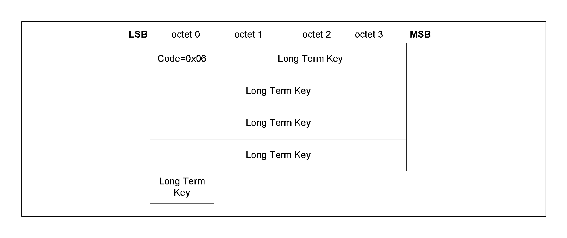
The following is the data field:
Long Term Key (16 octets)
The generated LTK value being distributed, see Section 2.4.2.3.
3.6.3. Central Identification
Central Identification is used in the LE legacy pairing Transport Specific Key Distribution phase to distribute EDIV and Rand which are used when encrypting future connections. The Central Identification command is defined in Figure 3.13.
The Central Identification command shall only be sent when the link has been encrypted or re-encrypted using the generated STK.
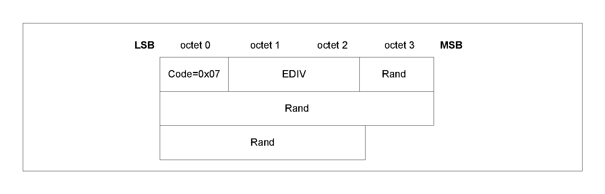
The following data fields are used:
EDIV (2 octets)
The EDIV value being distributed (see Section 2.4.2.3).
Rand (8 octets)
64-bit Rand value being distributed (see Section 2.4.2.3).
3.6.4. Identity Information
Identity Information is used in the Transport Specific Key Distribution phase to distribute the IRK. The Identity Information command is defined in Figure 3.14.
The Identity Information command shall only be sent when the link has been encrypted or re-encrypted using the generated key.
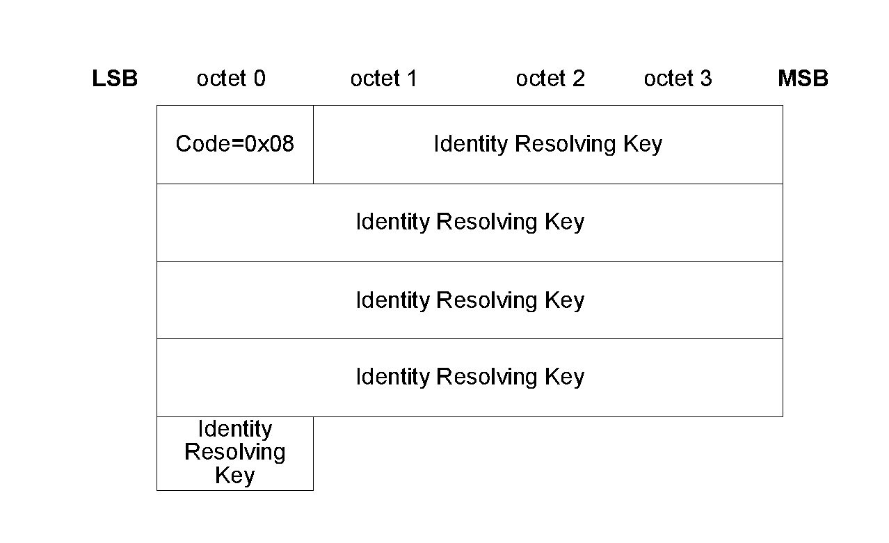
The following are the data fields:
Identity Resolving Key (16 octets)
128-bit IRK value being distributed (see Section 2.4.2.1).
Note
Note: An all zero Identity Resolving Key data field indicates that a device does not have a valid resolvable private address.
3.6.5. Identity Address Information
Identity Address Information is used in the Transport Specific Key Distribution phase to distribute its public device address or static random address. The Identity Address Information command is defined in Figure 3.15.
The Identity Address Information command shall only be sent when the link has been encrypted or re-encrypted using the generated key.

The data fields are:
AddrType (1 octet)
If BD_ADDR is a public device address, then AddrType shall be set to 0x00. If BD_ADDR is a static random device address then AddrType shall be set to 0x01.
BD_ADDR (6 octets)
This field is set to the distributing device’s public device address or static random address.
3.6.6. Signing Information
Signing Information is used in the Transport Specific Key Distribution to distribute the CSRK which a device uses to sign data. The Signing Information command is defined in Figure 3.16.
The Signing Information command shall only be sent when the link has been encrypted or re-encrypted using the generated key.
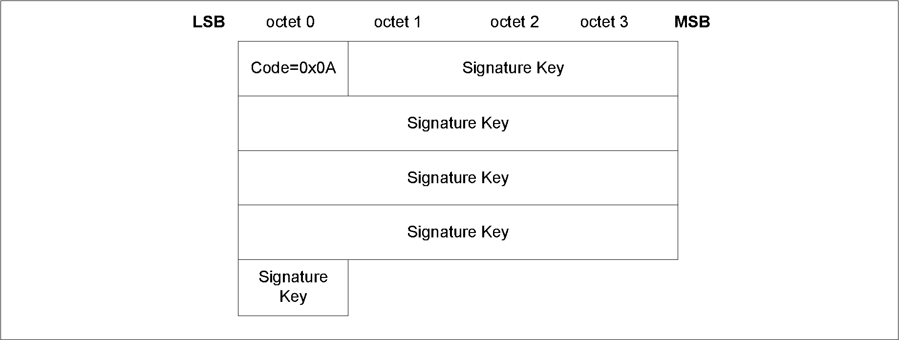
The following data field is used:
Signature Key (16 octets)
128-bit CSRK that is being distributed; see Section 2.4.2.2.
3.6.7. Security Request
The Security Request command is used by the Peripheral to request that the Central initiates security with the requested security properties, see Section 2.4.6. The Security Request command is defined in Figure 3.17.

The following data field is used:
AuthReq (1 octet)
The AuthReq field is a bit field that indicates the requested security properties (see Section 2.3.1) for the STK or LTK and GAP bonding information (see [Vol 3] Part C, Section 9.4).
Figure 3.3 defines the authentication requirements bit field.
The Bonding_Flags field is a 2-bit field that indicates the type of bonding being requested by the responding device as defined in Table 3.6.
The MITM field is a 1-bit flag that is set to one if the device is requesting MITM protection, otherwise it shall be set to 0. A device sets the MITM flag to one to request an Authenticated security property for the STK when using LE legacy pairing and the LTK when using LE Secure Connections.
The SC field is a 1 bit flag. If LE Secure Connections pairing is supported by the device, then the SC field shall be set to 1, otherwise it shall be set to 0. If both devices support LE Secure Connections pairing, then LE Secure Connections pairing shall be used, otherwise LE Legacy pairing shall be used.
The keypress field is a 1-bit flag that is used only in the Passkey Entry protocol and shall be ignored in other protocols. When both sides set that field to one, Keypress notifications shall be generated and sent using SMP Pairing Keypress Notification PDUs.
4. References
[1] NIST Special Publication 800-38B: http://dx.doi.org/10.6028/NIST.SP.800-38B
Appendix A. EDIV and Rand Generation
EDIV and Rand are used by the responding device to identify an initiator and recover LTK. This section provides an example of how the distributed EDIV value is a masked version of the real value (DIV) which is used to recover LTK. Other methods can be used that provide equal or higher levels of confidentially for DIV.
A.1. EDIV masking
The masking process uses a Diversifier Hiding Key (DHK) which is a 128-bit key that is never distributed.
DHK can be assigned, randomly generated by the device during manufacturing, part of a key hierarchy (see Appendix B, Section B.2.3) or some other method could be used, that results in DHK having 128 bits of entropy. If DHK is randomly generated then the requirements for random generation defined in [Vol 2] Part H, Section 2 shall be used.
If DHK is changed then DIV values cannot be recovered from previously distributed EDIV values.
Section A.1.1 defines a cryptographic function that is used by the responding device when generating EDIV and recovering DIV.
Section A.1.2 describes how a responding device generates an EDIV value to be distributed to an initiating device and Section A.1.3 describes how the responding device recovers DIV from a distributed EDIV value.
A.1.1. DIV mask generation function dm
DIV is masked before distribution and unmasked during the encryption session setup using the output of the DIV mask generation function dm.
The following are inputs to the DIV mask generation function dm:
k is 128 bits r is 64 bits padding is 64 bits
r is concatenated with padding to generate r’ which is used as the 128-bit input parameter plaintextData to security function e:
r’ = padding || r
The least significant octet of r becomes the least significant octet of r’ and the most significant octet of padding becomes the most significant octet of r’.
For example, if the 64-bit value r is 0x123456789ABCDEF0 then r’ is 0x0000000000000000123456789ABCDEF0.
The output of the DIV mask generation function dm is
dm(k, r) = e(k, r’) mod 216
The output of the security function e is then truncated to 16 bits by taking the least significant 16 bits of the output of e as the result of dm.
A.1.2. EDIV generation
The responding device generates a 64-bit random value, Rand. The Rand value is used to generate 16-bit Y using the DIV mask generation function dm with the input parameter k set to DHK and the input parameter r set to Rand.
Y = dm(DHK, Rand)
The responding device then masks the DIV value to be distributed by bitwise XORing it with Y to generate EDIV.
EDIV = Y xor DIV
EDIV and Rand are distributed to an initiating device during the transport specific key distribution phase using the Central Identification command.
A.1.3. DIV recovery
When the responding device receives a request to encrypt a session it calculates Y using the DIV mask generation function dm with the input parameter k set to DHK and the input parameter r set to Rand. The Y value is bitwise XORed with EDIV from the initiator to recover DIV.
DIV = Y xor EDIV
The recovered DIV value can then used to recover LTK which is used to enable encryption on the link.
Appendix B. Key Management
The security provided by different methods can vary and care should be taken to ensure that a chosen method is suitable for a device’s requirements.
Section B.1 uses a database for managing the keys. Section B.2 uses a key hierarchy to manage the keys.
B.1. Database lookup
The LTK which is distributed is a 128-bit random number which is stored in a database, using EDIV as an index. There is no direct relationship between LTK and EDIV.
The requirements for random generation defined in [Vol 2] Part H, Section 2 shall be used when generating LTK. This method provides an LTK with 128 bits of entropy.
CSRK, IRK, and other keys shall also be stored in the database. There is no relationship between the keys stored in the database or distributed LTKs, EDIVs, or Rands.
If the example EDIV and Rand generation method described in Section A.1 is used then the database shall be used to store DHK. DIV should be used as the index to recover LTK.
B.2. Key hierarchy
A key hierarchy can be used to generate the keys.
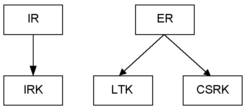
Figure B.1 is an example key hierarchy where LTK and CSRK are generated from a common ER key, and IRK is generated from a common IR key.
ER is a 128-bit key generated for each LE device that supports encrypted connections. It is used to generate LTK using EDIV; see Section B.2.2.
IR is a 128-bit key generated for each LE device that supports encrypted connections, uses random addresses or signing data. IR is used to generate IRK and CSRK, see Section B.2.3. It can also be used to generate DHK; see ???.
New LTK, EDIV, Rand, and CSRK values shall be generated each time they are distributed. If ER is changed then any previously distributed LTK or CSRK keys will no longer be valid.
The distributed IRK shall be the same for all devices it is distributed to. If IR is changed then any previously distributed IRK keys will no longer be valid.
The distributing device only needs to store IR and ER. LTK, IRK, and CSRK can be regenerated when they are required. This reduces the storage requirements on the distributing device.
Section B.2.1 defines an example of the key diversifying function which can be used to generate LTK, IRK, CSRK, and other keys. Other implementations of this function can be used depending upon the exact security requirements of the device.
The NIST Special Publication 800-108 (http://csrc.nist.gov/publications/PubsSPs.html) defines key derivation functions which could be used instead of the example diversifying function d1.
B.2.1. Diversifying function d1
Diversified keys are generated with function d1. The diversifying function d1 makes use of the security function e.
The following are inputs to diversifying function d1:
k is 128 bits d is 16 bits r is 16 bits padding is 96 bits
d is concatenated with r and padding to generate d’, which is used as the 128-bit input parameter plaintextData to security function e:
d’ = padding || r || d
The least significant octet of d becomes the least significant octet of d’ and the most significant octet of padding becomes the most significant octet of d’.
For example, if the 16-bit value d is 0x1234 and the 16-bit value r is 0xABCD, then d’ is 0x000000000000000000000000ABCD1234.
The output diversifying function d1 is:
d1(k, d, r) = e(k, d’)
The 128-bit output of the security function e is used as the result of diversifying function d1.
B.2.2. Generating keys from ER
ER is used to generate LTK and CSRK. ER can be assigned, randomly generated by the device during manufacturing or some other method could be used, that results in ER having 128 bits of entropy. If ER is randomly generated then the requirements for random generation defined in [Vol 2] Part H, Section 2 shall be used.
The EDIV and Rand generation method described in ??? shall be used. LTK is the result of the diversifying function d1 with the ER as the input parameter k, the DIV as the input parameter d, and the value 0 as the input parameter r; see Section B.2.1.
LTK = d1(ER, DIV, 0)
LTK can be recovered from ER and DIV by repeating the calculation when LTK is required.
CSRK is the result of the diversifying function d1 with the ER as the input parameter k, the DIV as the input parameter d, and the value 1 as the input parameter r; see Section B.2.1.
CSRK = d1(ER, DIV, 1)
CSRK can be recovered from ER and DIV by repeating the calculation when CSRK is required.
This method provides an LTK and CSRK with limited amount of entropy because LTK and CSRK are directly related to EDIV and may be less secure than other generation methods.
To reduce the probability of the same LTK or CSRK value being generated, the DIV values must be unique for each CSRK, LTK, EDIV, and Rand set that is distributed.
A method for preventing a malicious device from repeatedly pairing and collecting CSRK, LTK and DIV information, which could be used in a known plain text attack in ER, should be implemented.
Note
Note: The generation of LTK using ER is only applicable when doing LE Legacy Pairing. The generation of CSRK using ER is applicable both when doing LE Legacy Pairing and LE Secure Connections Pairing.
B.2.3. Generating keys from IR
IR can be used to generate IRK and other required keys. IR can be assigned, randomly generated by the device during manufacturing or some other method could be used, that results in IR having 128 bits of entropy. If IR is randomly generated then the requirements for random generation defined in Section A.1 shall be used.
IRK is the result of the diversifying function d1 with IR as the input parameter k and the value 1 as the input parameter d and the value 0 as the input parameter r; see Section B.2.1.
IRK = d1(IR, 1, 0)
If the example EDIV and Rand generation method described in EDIV and Rand Generation, Section A.1 is used then DHK can be the result of diversifying function d1 with IR as the input parameter k and the value 3 as the input parameter d and the value 0 as the input parameter r.
DHK = d1(IR, 3, 0)
Other keys can be generated by using different values for k as the input to the diversifying function d1. If the value of k is reused for a given IR then the resulting key will be the same.
Note
Note: The generation of DHK using IR is only applicable when doing LE Legacy Pairing. The generation of IRK using IR is applicable both when doing LE Legacy Pairing and LE Secure Connections Pairing.
Appendix C. Message sequence charts
This appendix illustrates only the most common scenarios; it does not cover all possible alternatives. Furthermore, the message sequence charts do not consider errors over the air interface or Host interface. If any of these charts differ with text elsewhere in this Part, then that text overrides these charts.
A flow diagram of pairing is shown in Figure C.1. The process has 4 steps. Step 2 has a number of different options.
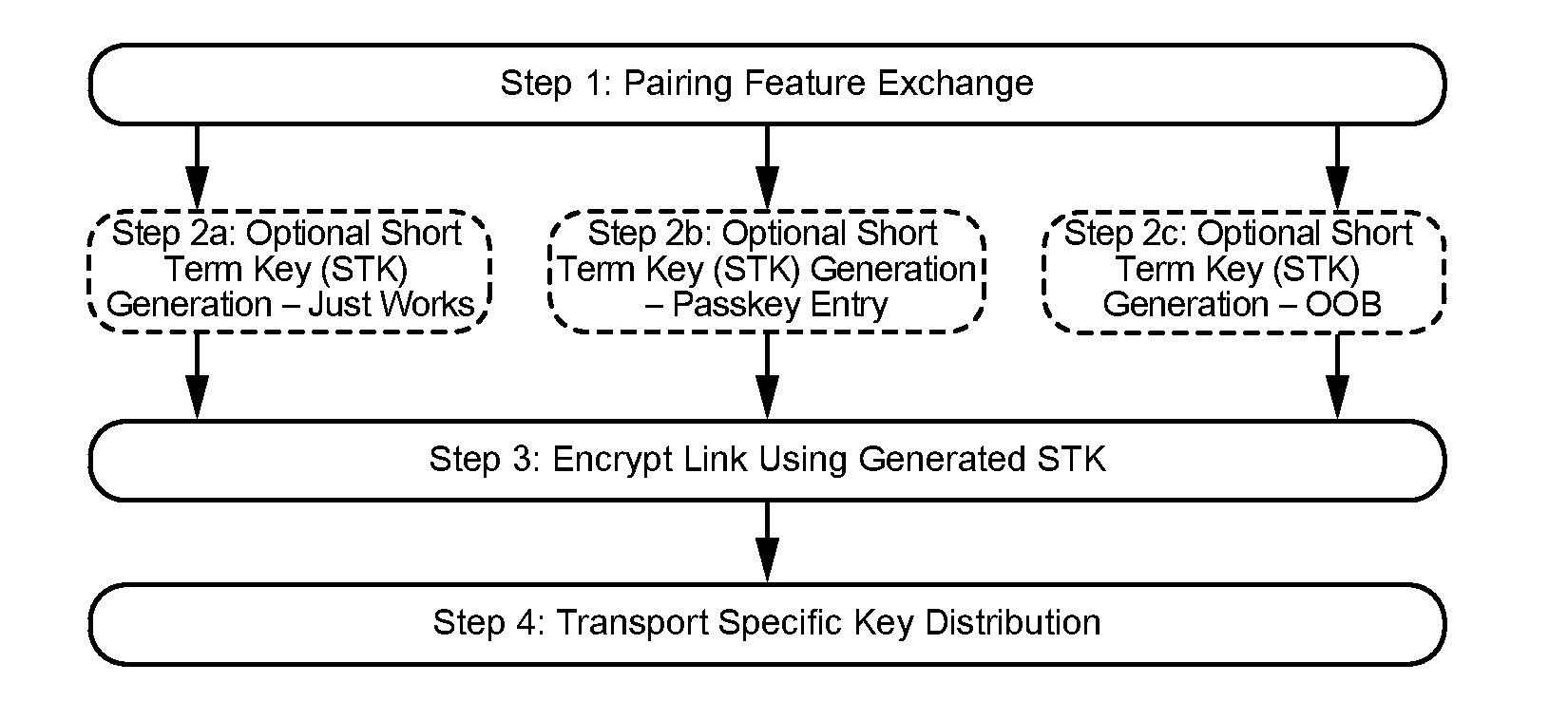
Note
Note: In all the MSCs, the Central is also the Initiating Device and the Peripheral is also the Responding (non-Initiating) Device.
C.1. Phase 1: Pairing feature exchange
The Central initiates the pairing procedure using Pairing Request command as shown in Figure C.2.
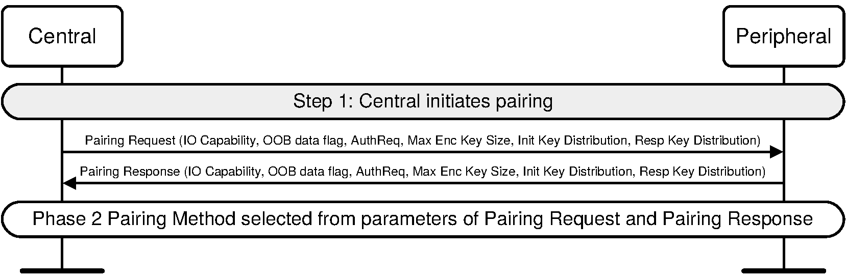
C.1.1. Peripheral security request – Central requests pairing
The Peripheral may request the Central initiates security procedures. Figure C.3 shows an example where the Peripheral requests security and the Central initiates pairing in response.
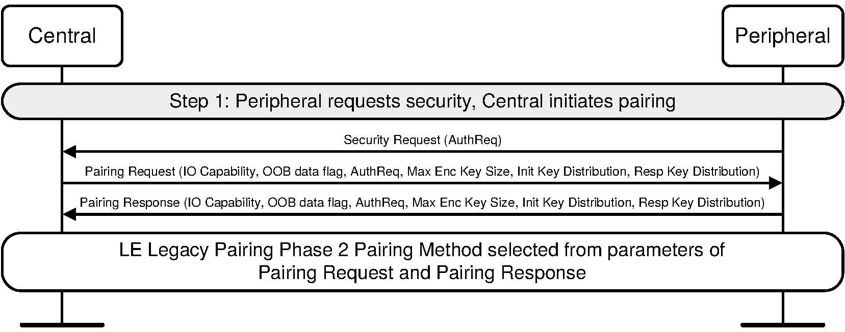
C.2. Phase 2: Authenticating and encrypting
After Pairing Feature Exchange has completed a pairing method is selected one of the possible short term key generation sequences are used. This can be Just Works, Passkey Entry or Out of Band pairing method.
C.2.1. LE legacy pairing
The following sub-sections include message sequence charts for LE legacy pairing.
C.2.1.1. Legacy Phase 2: Short Term Key generation – Just Works
After Pairing Feature Exchange has completed a pairing method is selected. Figure C.4 shows the Just Works pairing method.
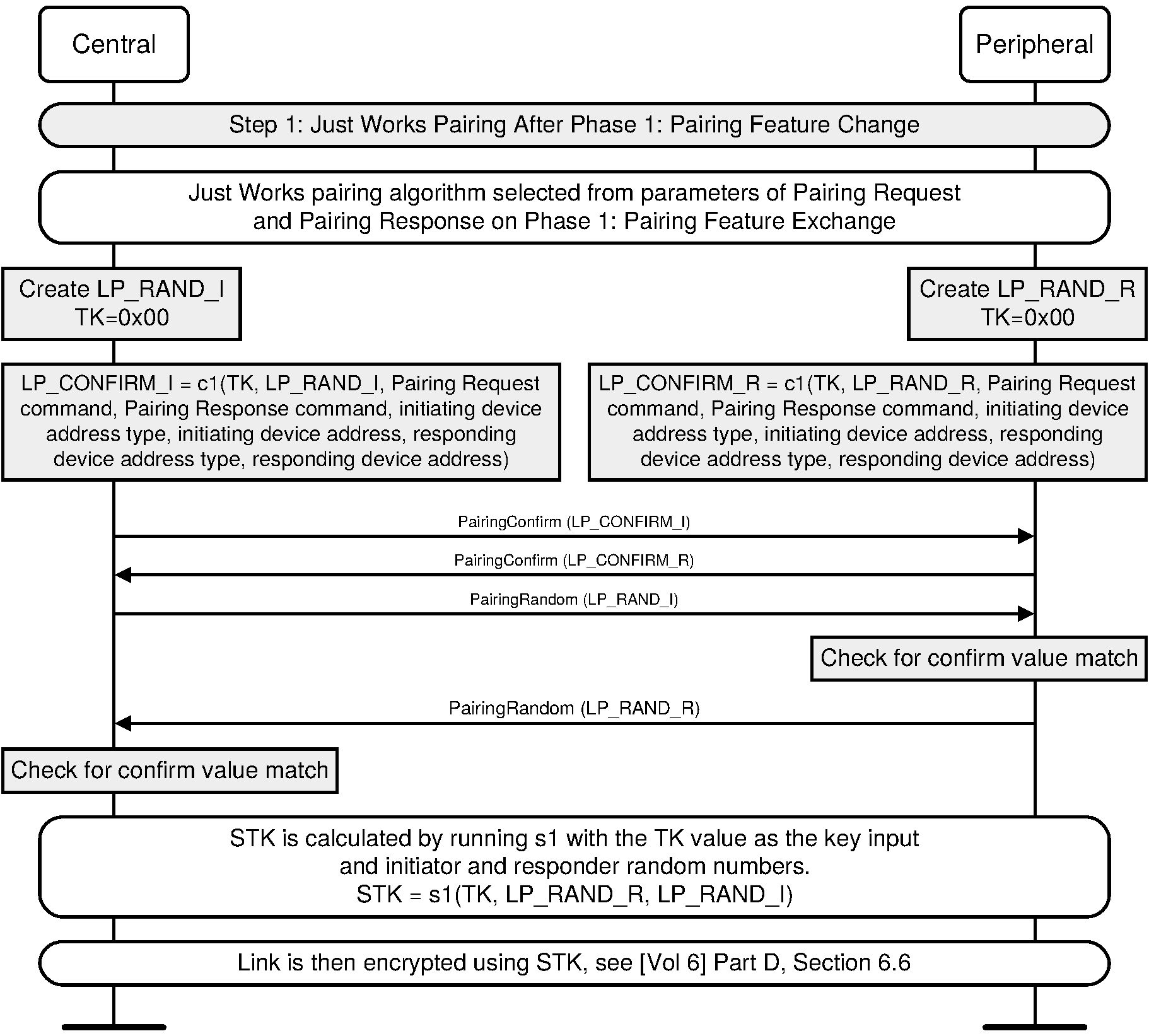
C.2.1.2. Legacy Phase 2: Short Term Key generation – Passkey Entry
After Pairing Feature Exchange has completed, a pairing method is selected. Figure C.5 shows the Passkey Entry pairing method.
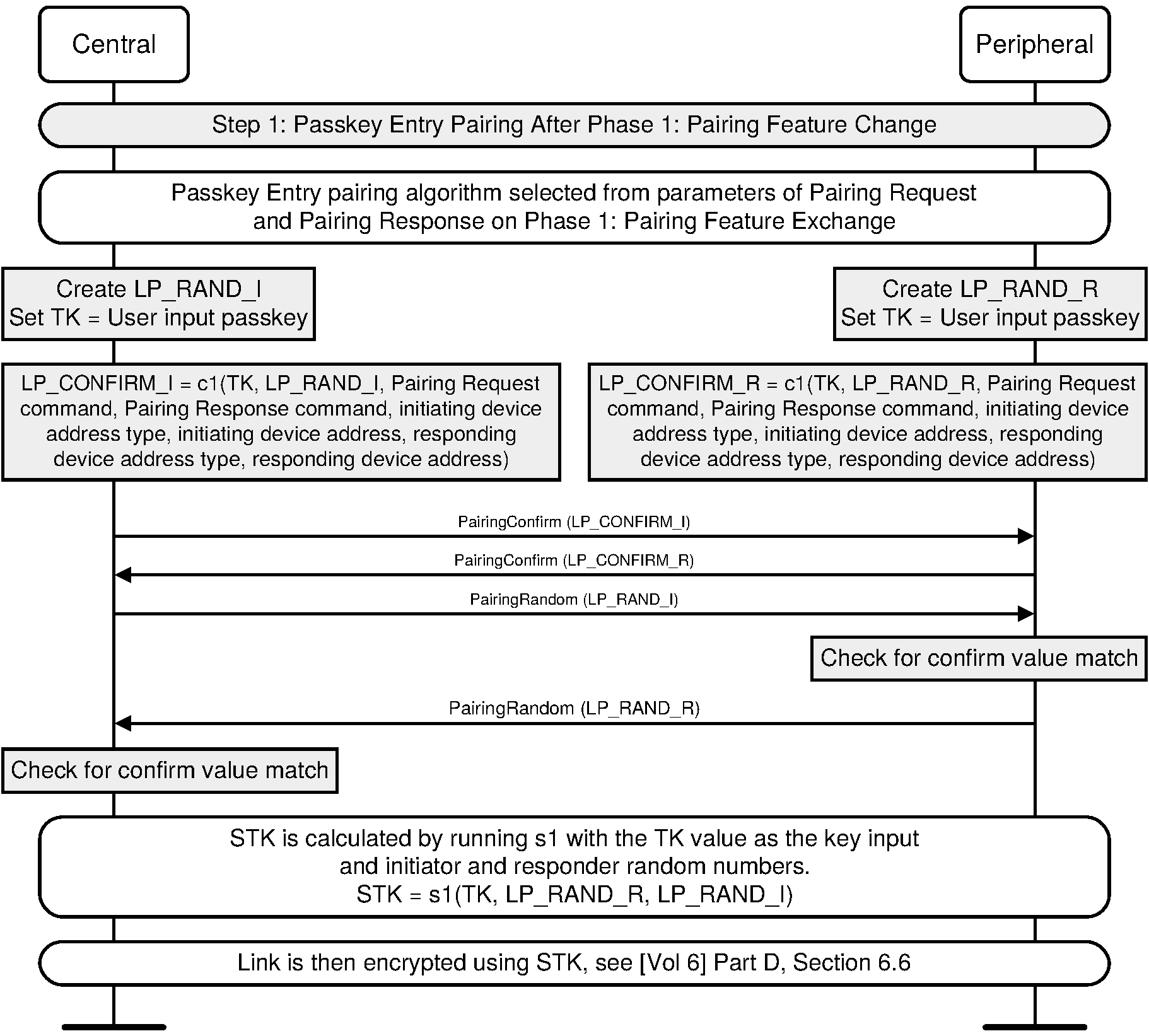
C.2.1.3. Legacy Phase 2: Short Term Key generation – Out of Band
After Pairing Feature Exchange has completed, a pairing method is selected. Figure C.6 shows the Out of Band pairing method.
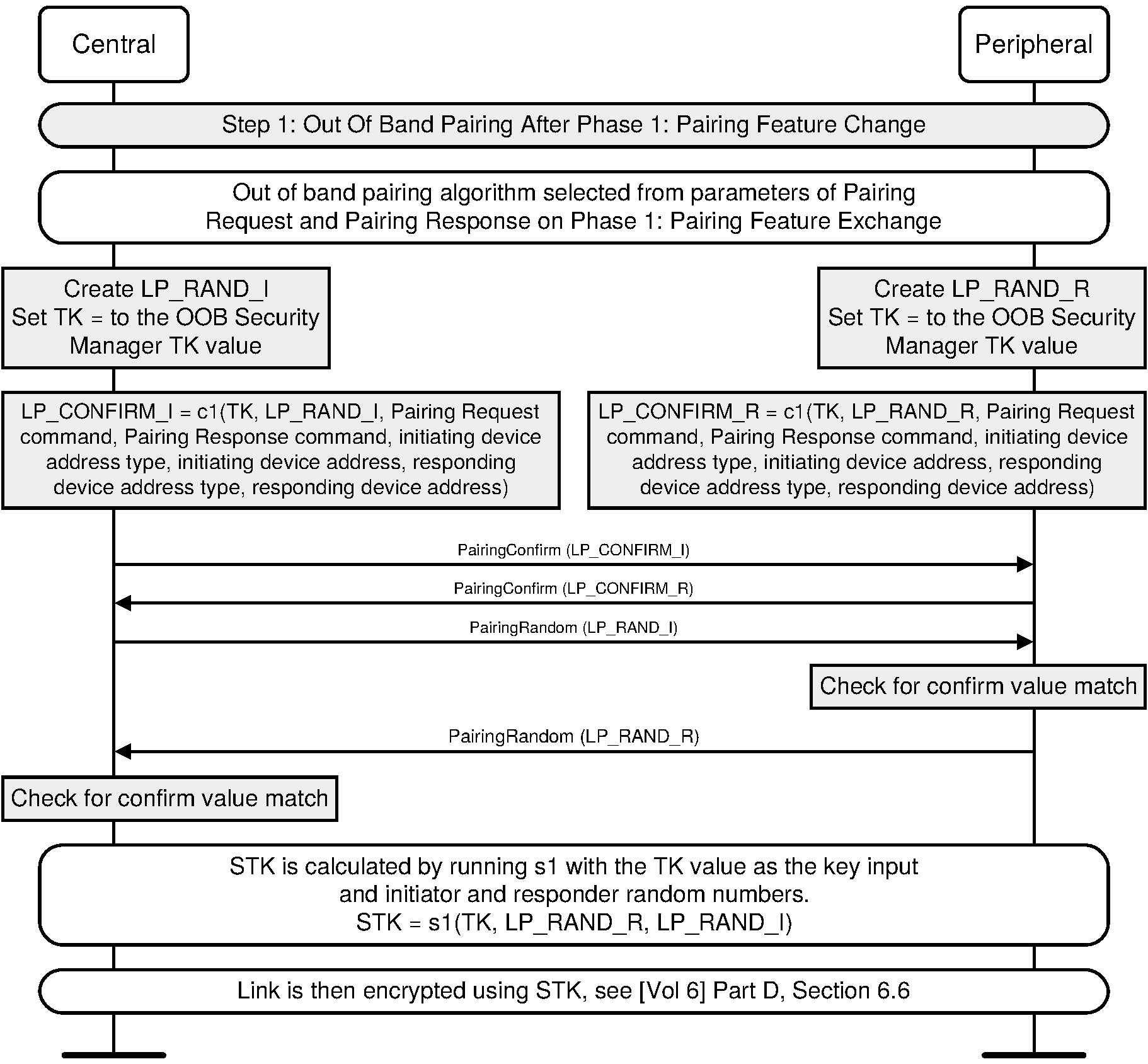
C.2.2. LE Secure Connections
The following sub-sections include message sequence charts for LE Secure Connections.
C.2.2.1. Public key exchange
In Step 1a and 1b, the two devices exchange public keys. The Central sends its public key to the Peripheral followed by Peripheral sending its public key to the Central.
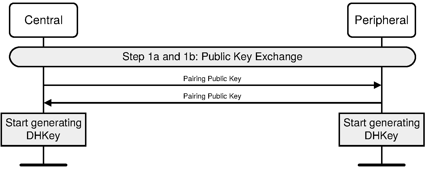
C.2.2.2. Authentication stage 1
The following sub-sections include message sequence charts for the success and failure cases in each association model.
C.2.2.2.1. Successful Numeric Comparison (or Just Works)
The numeric comparison step will be done when both devices have output capabilities, or if one of the devices has no input or output capabilities. If both devices have output capabilities, this step requires the displaying of a user confirmation value. This value should be displayed until the end of step 2. If one or both devices do not have output capabilities, the same protocol is used but the Hosts will skip the step asking for the user confirmation.
Note
Note: The sequence for Just Works is identical to that of Numeric Comparison with the exception that the Host will not show the numbers to the user.
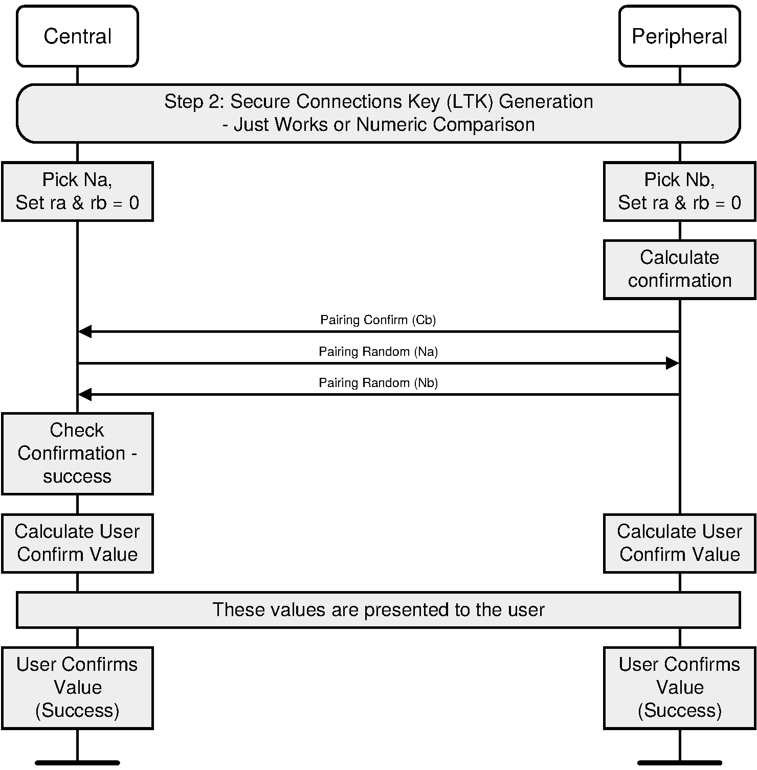
C.2.2.2.2. Numeric Comparison – Confirm Check failure on the Initiator side
If the Confirm value calculated by the Initiator is not equal to the Commitment value received from the Responder, the Initiator will abort Pairing process by sending Pairing Failed with reason “Confirm Value Failed”.
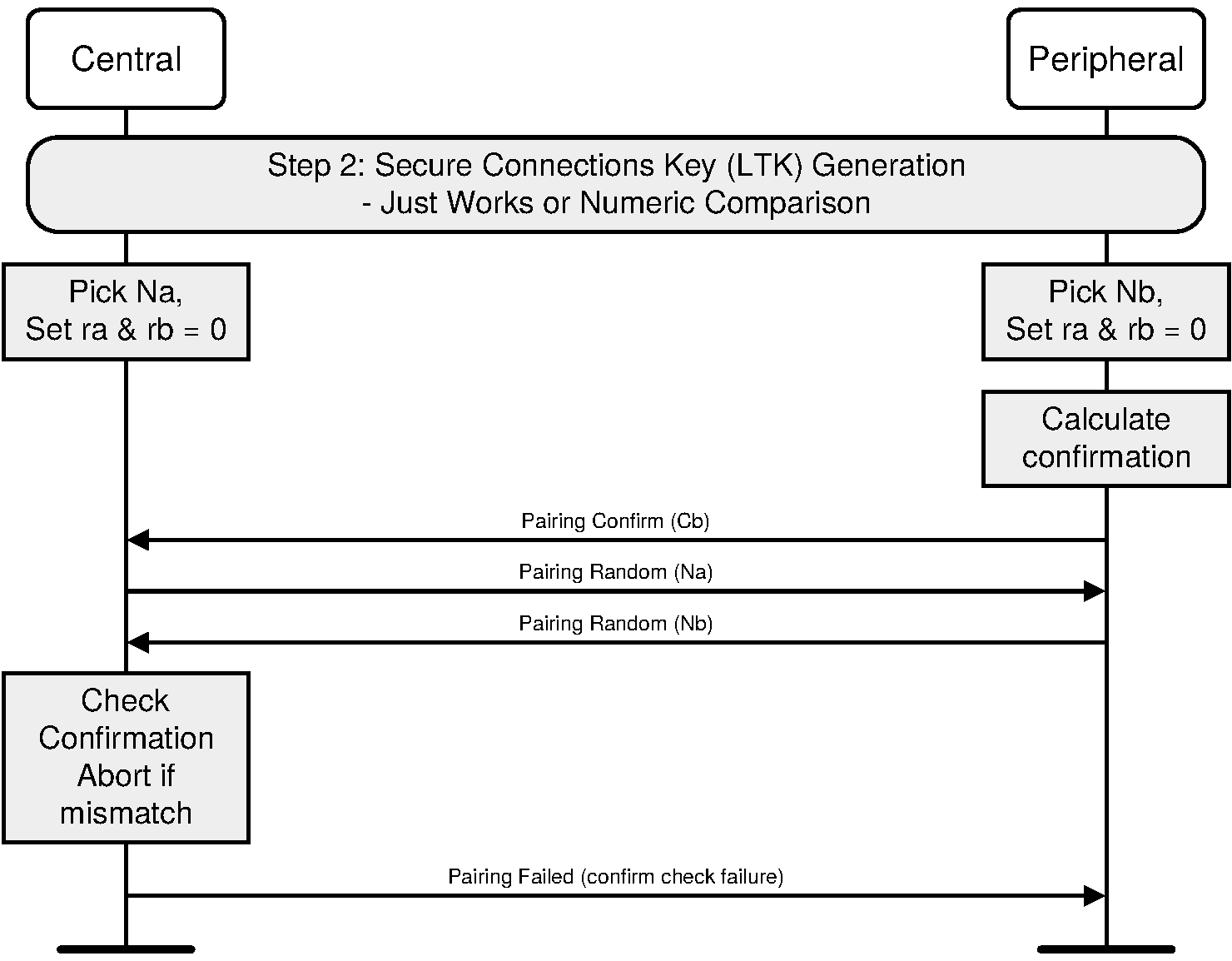
C.2.2.2.3. Numeric Comparison failure on the Initiator side
If the numeric comparison fails on the initiating side due to the user indicating that the confirmation values do not match, Pairing is terminated.
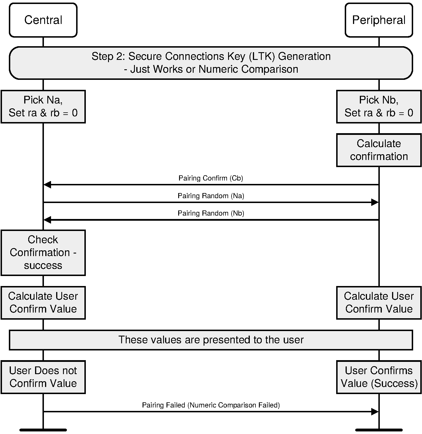
C.2.2.2.4. Numeric Comparison failure on the Responding side
If the numeric comparison fails on the responding side due to the user indicating that the confirmation values do not match, Pairing is terminated.
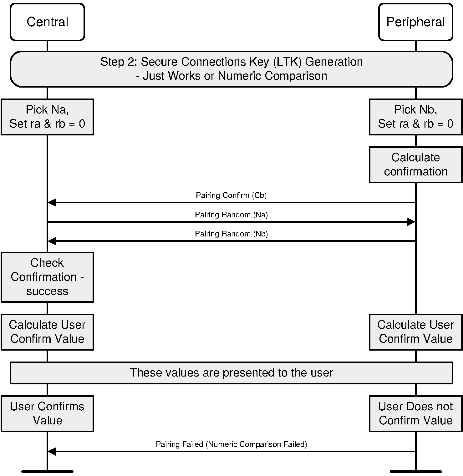
C.2.2.2.5. Successful Passkey Entry
The Passkey Entry step is used in two cases: when one device has numeric input only and the other device has either a display or numeric input capability. In this step, one device display a number to be entered by the other device or the user enters a number on both devices. Key press notification messages are shown during the user input phase.
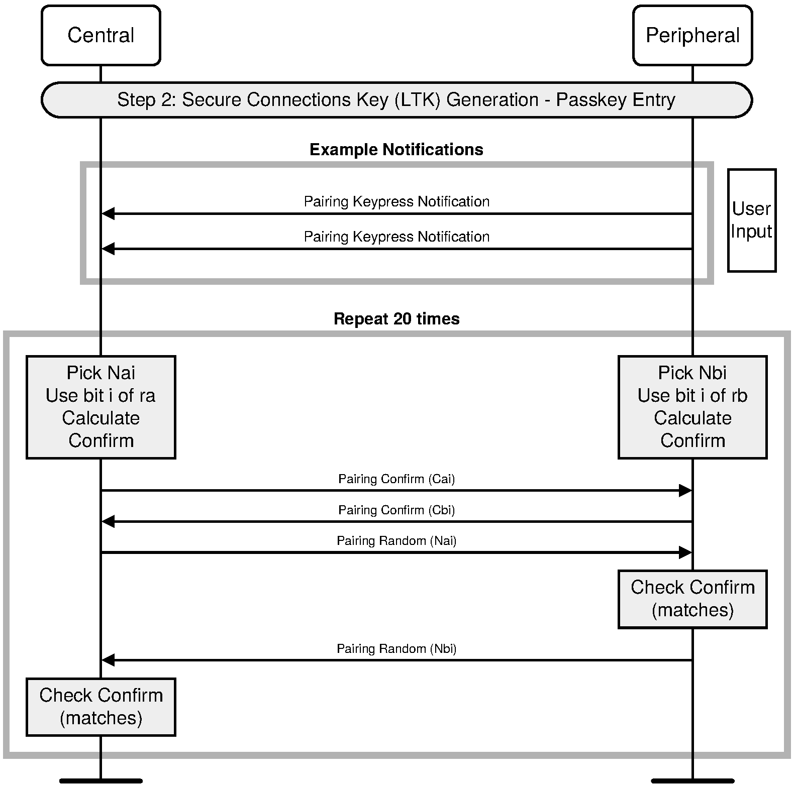
Note
Note: Passkey Entry may prolong pairing experience because of the time required to execute 20 repetitions over SMP.
C.2.2.2.6. Passkey Entry – Confirm Check failure on the Responder side
If during one of the 20 repetitions, the Confirm calculated by the Responder is not equal to the one received from the Initiator, the Responder will abort the Pairing process by sending Pairing Failed with reason “Confirm Value Failed.”
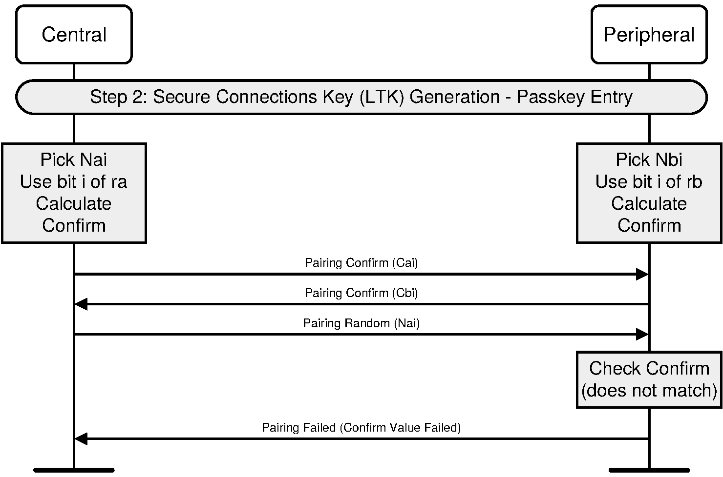
C.2.2.2.7. Passkey Entry – Confirm Check failure on the Initiator side
If during one of the 20 repetitions, the Confirm calculated by the Initiator is not equal to the one received from the Responder, the Initiator will abort the Pairing process by sending Pairing Failed with reason “Confirm Value Failed”.
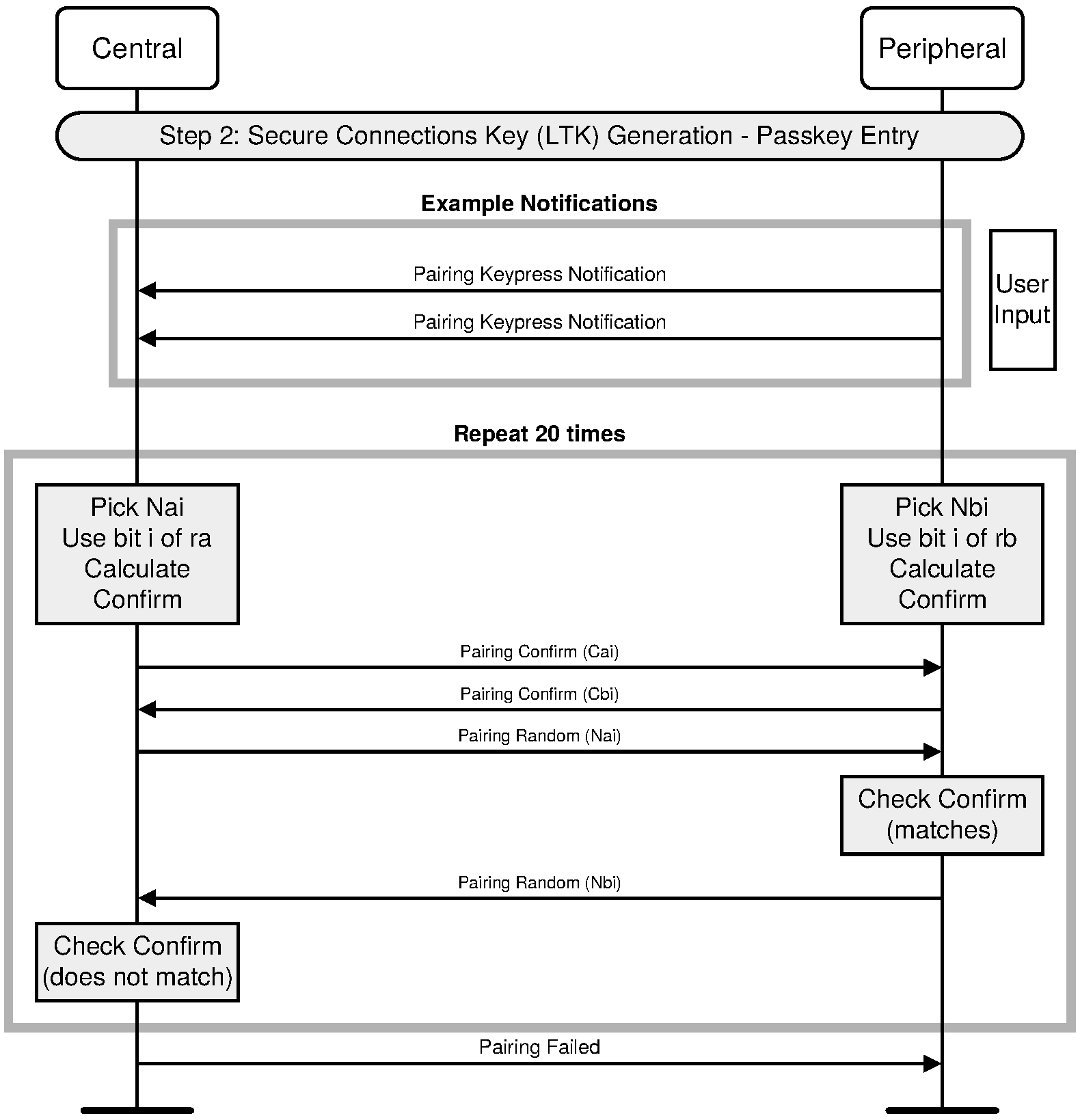
C.2.2.2.8. Passkey Entry failure on the Responding side
If the passkey entry fails on the responding side, Pairing is terminated.
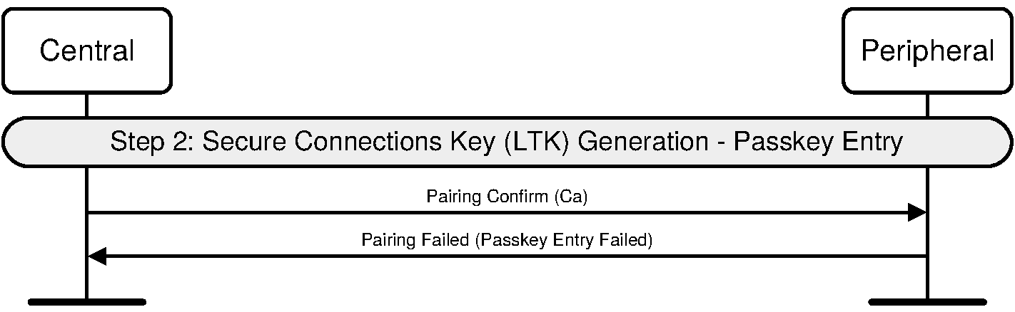
C.2.2.2.9. Passkey Entry Failure on the Initiator Side
If the passkey entry fails on the initiating side, Pairing is terminated.
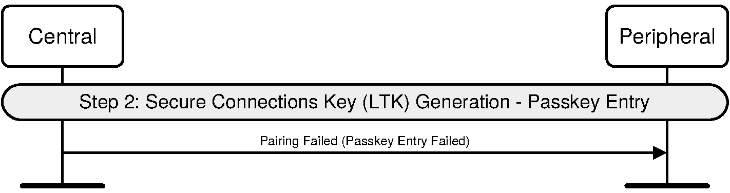
C.2.2.2.10. Successful Out of Band
The OOB authentication will only be done when at least one device has some OOB information to use. This step requires no user interaction.

C.2.2.2.11. Out of Band – Confirm Check failure on the Responder side
If the Confirm value received from OOB is not equal to the calculated Confirm value, the Responder will abort the Pairing process by sending Pairing Failed with reason “Confirm Value Failed”.
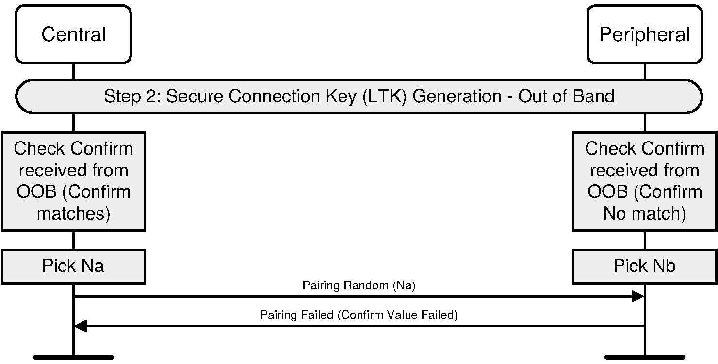
C.2.2.2.12. Out of Band - Confirm Check failure on the Initiating side
If the Confirm value received from OOB is not equal to the calculated Confirm value, the Initiator will abort the Pairing process by sending Pairing Failed with reason "Confirm Value Failed".
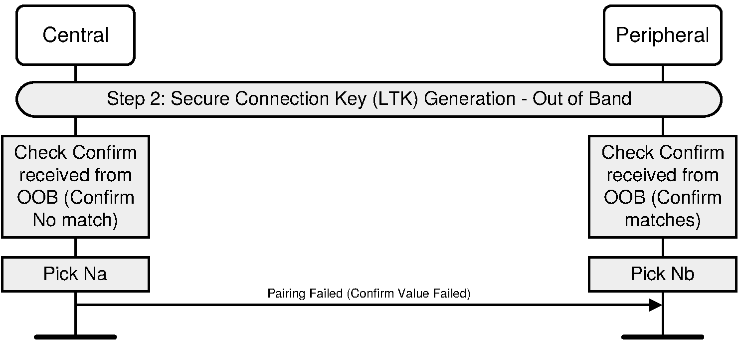
C.2.2.2.13. Out of Band Failure on the Initiator side (OOB information not available)
If the initiating side does not have the responder's OOB information, Pairing is terminated.
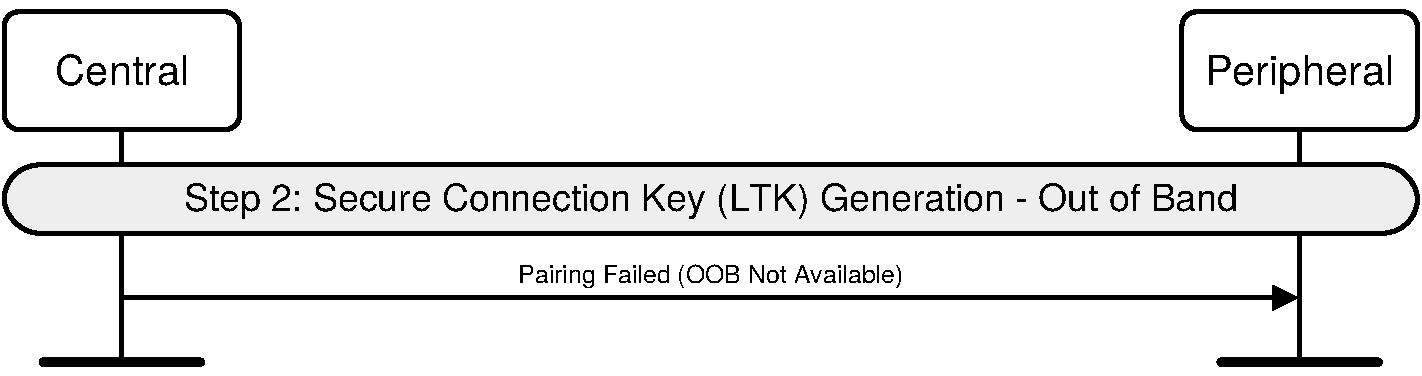
C.2.2.2.14. Out of Band Failure on the Responding side (OOB information not available)
If the responding side does not have the initiator's OOB information, Pairing is terminated.
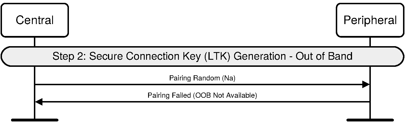
C.2.2.3. Long Term Key calculation
Once the DHKey generation is complete, the Long Term Key (LTK) is calculated from the DHKey.
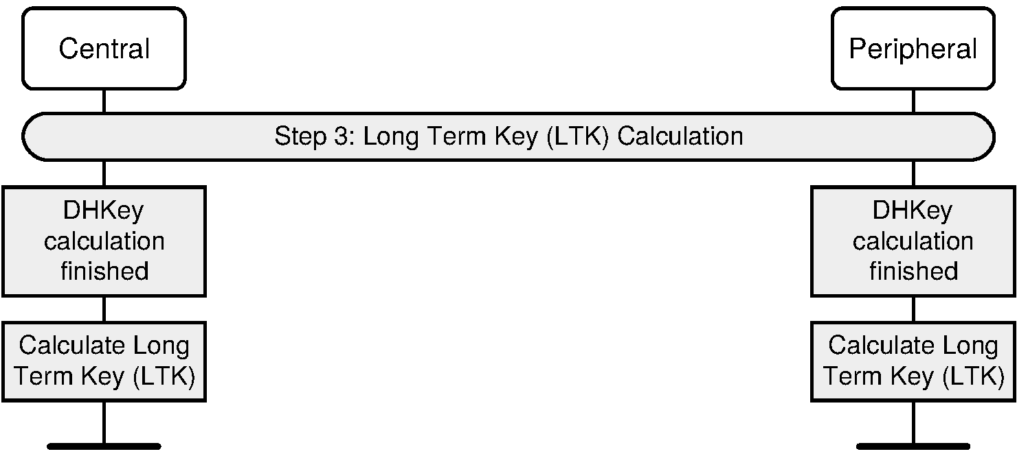
C.2.2.4. Authentication stage 2 (DHKey checks)
Once the LTK calculation and authentication stage 1 have completed, the DHKey value generated is checked by exchanging DHKey Check values generated using the DHKey. If this succeeds, then both devices would have finished displaying information to the user about the process, and therefore the Host can stop displaying this information.
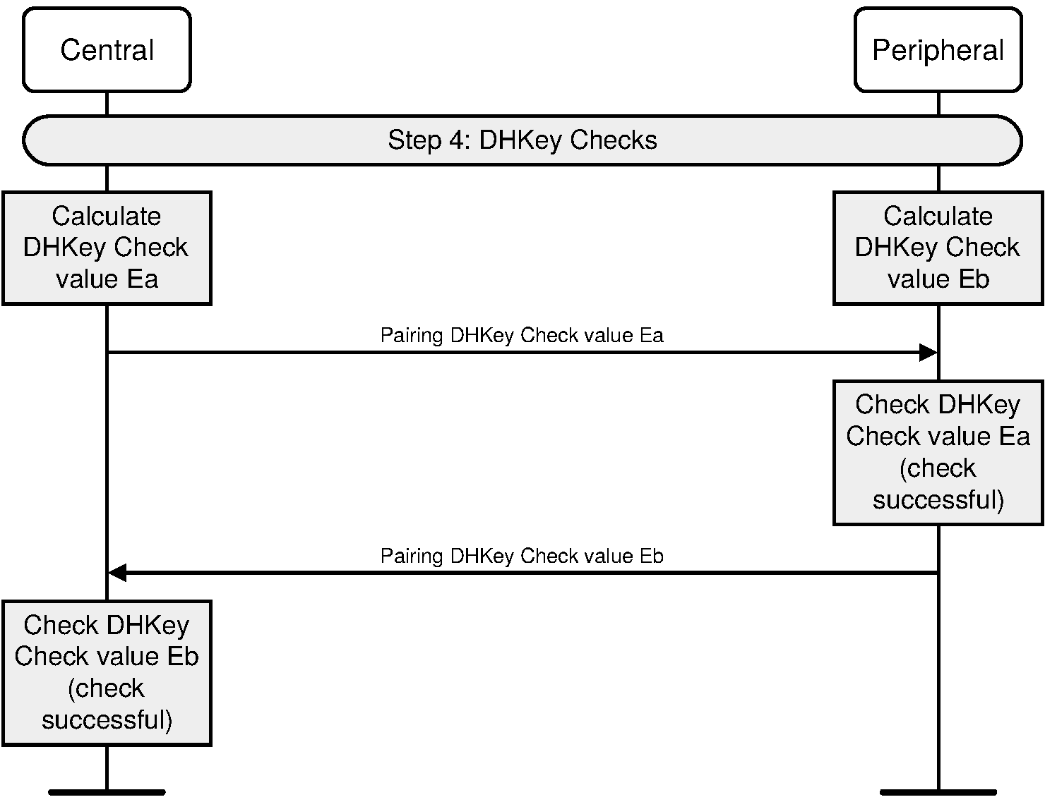
C.3. Phase 3: Transport specific key distribution
After short term key generation and the link has been encrypted, transport specific keys are distributed. Figure C.24 shows an example of all keys and values being distributed by Central and Peripheral.
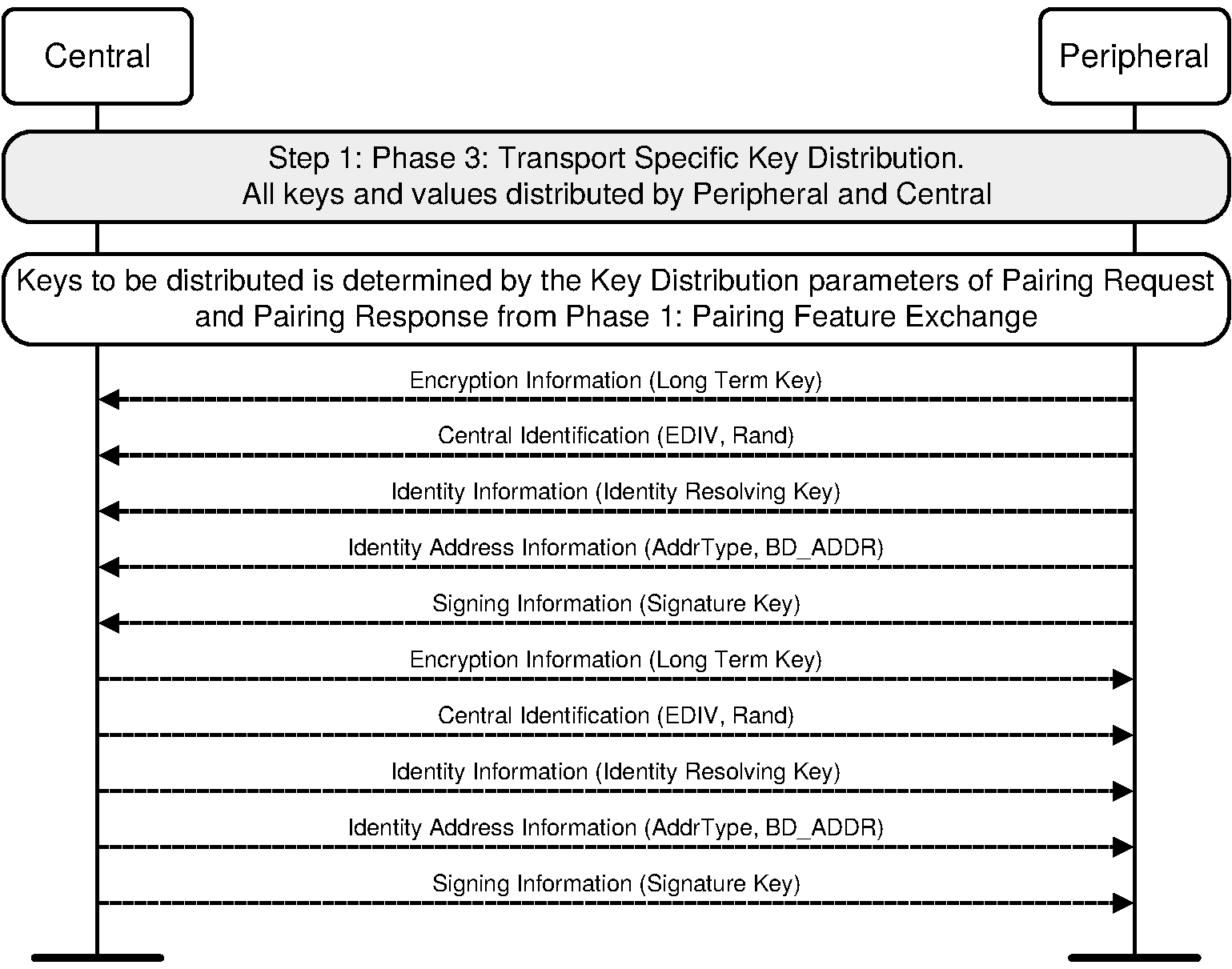
C.4. Security re-established using previously distributed LTK
Devices may re-establish security using a previously distributed LTK. The Central always initiates the encryption procedures, and therefore there are two possible sequences: Central initiated and Peripheral requested.
C.4.1. Central initiated security - Central initiated Link Layer encryption
The Central initiates encryption procedures. There is no SM signaling to enable this; the Central initiates Link Layer encryption only. See [Vol 6] Part D, Section 6.6.
C.4.2. Peripheral security request - Central initiated Link Layer encryption
The Peripheral may request the Central initiates security procedures. Figure C.25 shows an example where the Peripheral requests security and the Central initiates Link Layer encryption.
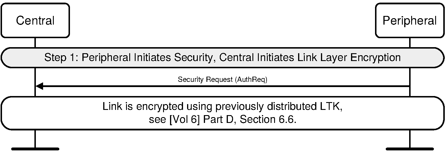
C.5. Failure conditions
The following sequences show possible failure conditions and their associated signaling.
C.5.1. Pairing not supported by Peripheral
If the Peripheral does not support pairing or pairing cannot be performed the Peripheral can reject the request from the Central. Figure C.26 shows the Peripheral rejecting a Pairing Request command from the Central.
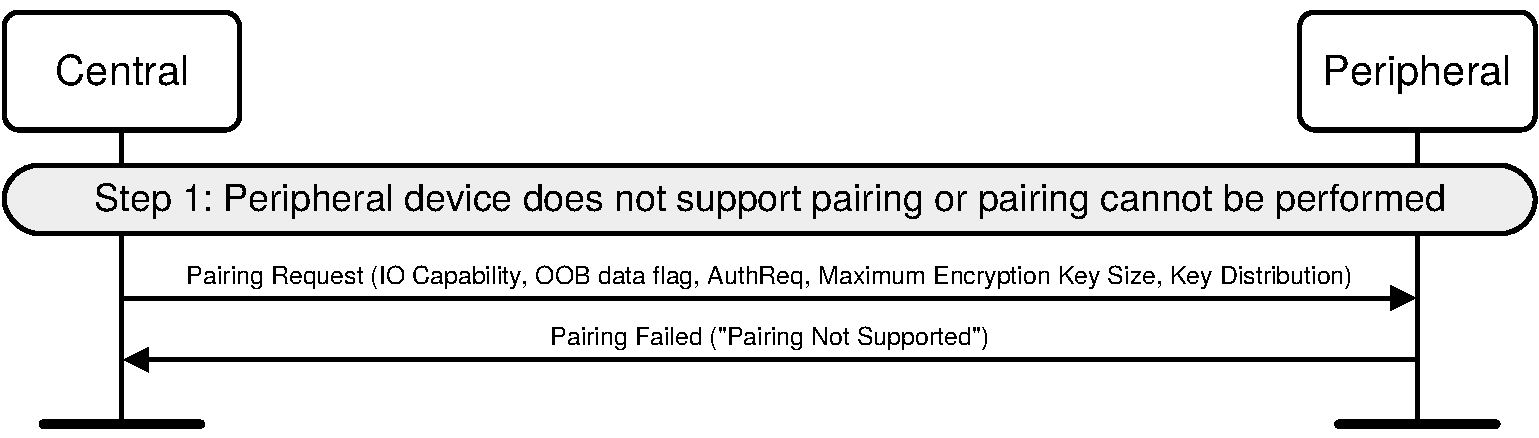
C.5.2. Central rejects pairing because of key size
During Pairing Feature Exchange the size of the Encryption Key is negotiated. Figure C.27 shows an example where the Central terminates the pairing procedure because the resulting key size is not acceptable.
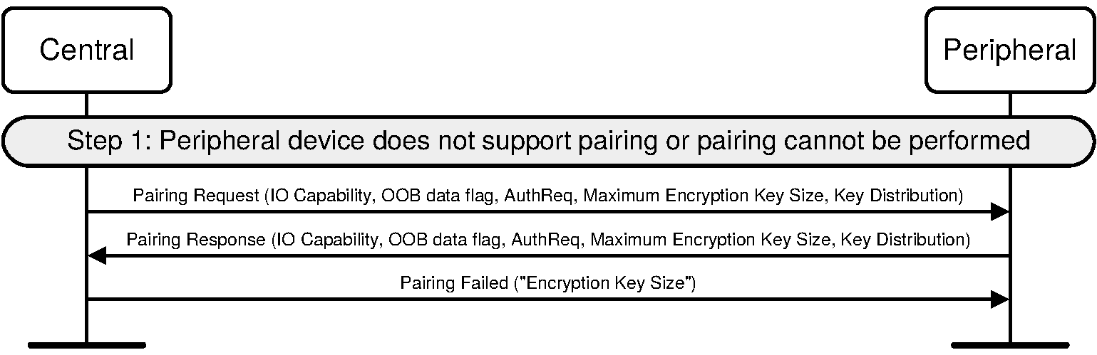
C.5.3. Peripheral rejects pairing because of key size
During Pairing Feature Exchange the size of the Encryption Key is negotiated. Figure C.28 shows an example where the Peripheral terminates the pairing procedure because the resulting key size is not acceptable.
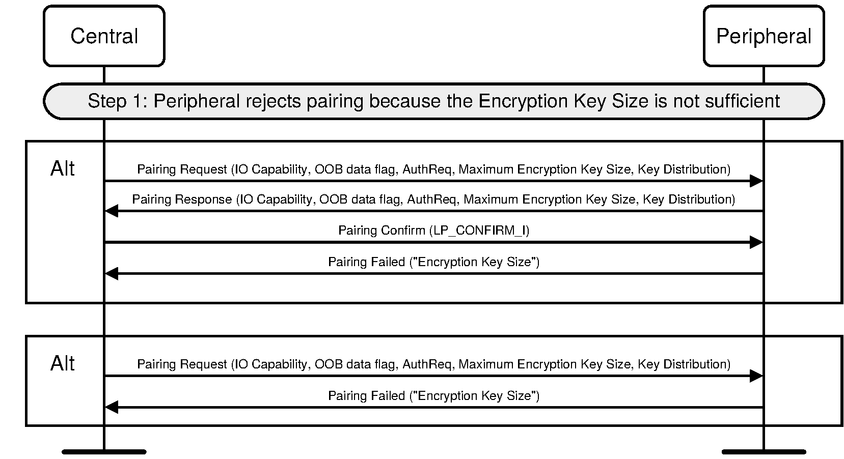
C.5.4. Passkey Entry failure on Central
During Passkey Entry pairing the user enters a passkey on both devices. Figure C.29 shows an example where the passkey entry fails on the Central.
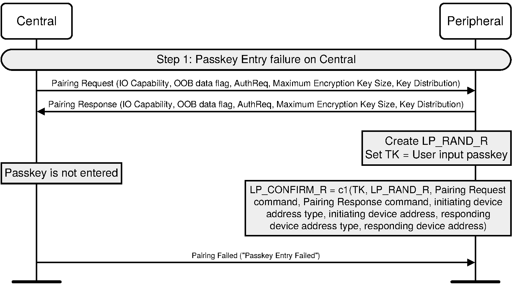
C.5.5. Passkey Entry failure on Peripheral
During Passkey Entry pairing the user enters a passkey on both devices. Figure C.30 shows an example where the passkey entry fails on the Peripheral.
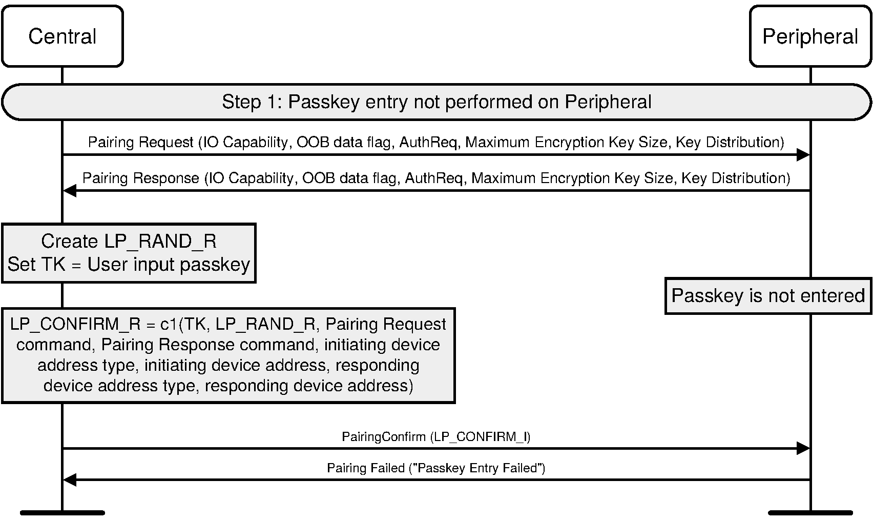
C.5.6. Peripheral rejects Central’s confirm value
During Passkey Entry pairing the user enters a passkey on both devices. Figure C.31 shows an example where a different passkey is entered on both devices. This sequence could also occur if any of the inputs to c1 (Passkey, LP_RAND_I, LP_RAND_R, Pairing Request command, Pairing Response command, address types or addresses) are incorrect or altered.
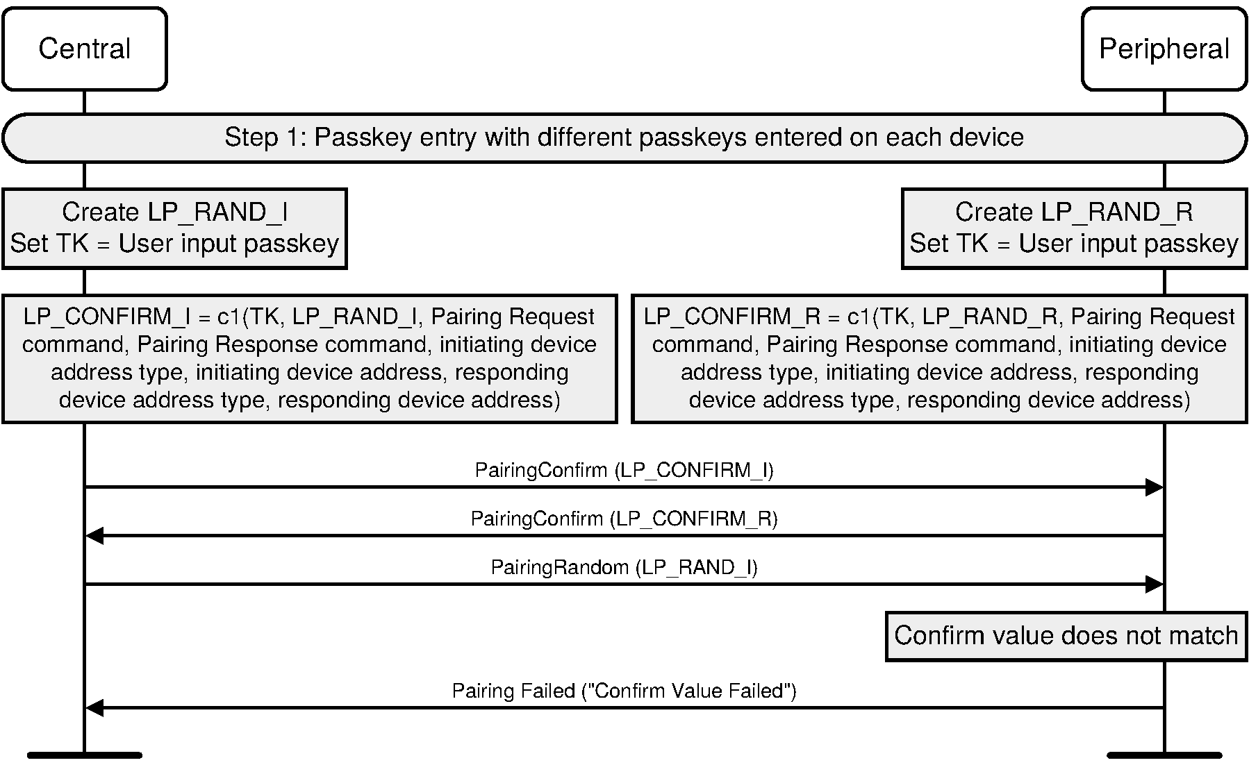
C.5.7. Central rejects Peripheral’s confirm value
During all the pairing methods the Central and Peripheral send random numbers and confirm values. Figure C.32 shows an example where the Central rejects pairing because it cannot verify the confirm value from the Peripheral because any of the inputs to c1 (Passkey, LP_RAND_I, LP_RAND_R, Pairing Request command, Pairing Response command, address types or addresses) are incorrect or altered.
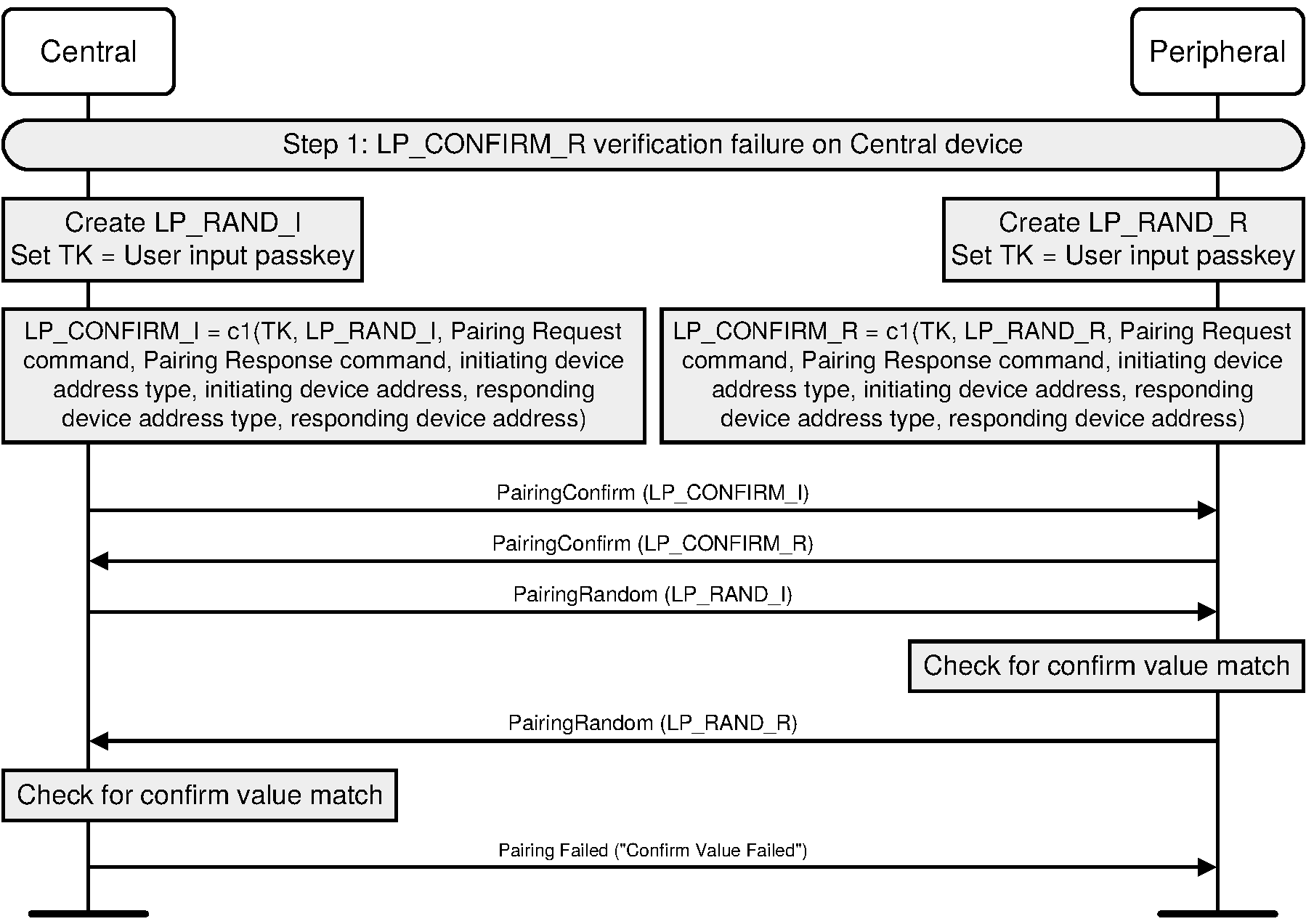
Appendix D. Sample data
In each data set in this section, the bytes are ordered from most significant on the left to least significant on the right. ‘M’ represents the message byte array for which the AES CMAC is calculated.
D.1. AES-CMAC RFC4493 test vectors
The following test vectors are referenced from RFC4493.
K | 2b7e1516 28aed2a6 abf71588 09cf4f3c |
Subkey Generation | |
AES_128(key,0) | 7df76b0c 1ab899b3 3e42f047 b91b546f |
K1 | fbeed618 35713366 7c85e08f 7236a8de |
K2 | f7ddac30 6ae266cc f90bc11e e46d513b |
D.1.1. Example 1: Len = 0
M | <empty string> |
AES_CMAC | bb1d6929 e9593728 7fa37d12 9b756746 |
D.1.2. Example 2: Len = 16
M | 6bc1bee2 2e409f96 e93d7e11 7393172a |
AES_CMAC | 070a16b4 6b4d4144 f79bdd9d d04a287c |
D.1.3. Example 3: Len = 40
M0 | 6bc1bee2 2e409f96 e93d7e11 7393172a |
M1 | ae2d8a57 1e03ac9c 9eb76fac 45af8e51 |
M2 | 30c81c46 a35ce411 |
AES_CMAC | dfa66747 de9ae630 30ca3261 1497c827 |
D.1.4. Example 4: Len = 64
M0 | 6bc1bee2 2e409f96 e93d7e11 7393172a |
M1 | ae2d8a57 1e03ac9c 9eb76fac 45af8e51 |
M2 | 30c81c46 a35ce411 e5fbc119 1a0a52ef |
M3 | f69f2445 df4f9b17 ad2b417b e66c3710 |
AES_CMAC | 51f0bebf 7e3b9d92 fc497417 79363cfe |
D.2. f4 LE SC confirm value generation function
U | 20b003d2 f297be2c 5e2c83a7 e9f9a5b9 |
eff49111 acf4fddb cc030148 0e359de6 | |
V | 55188b3d 32f6bb9a 900afcfb eed4e72a |
59cb9ac2 f19d7cfb 6b4fdd49 f47fc5fd | |
X | d5cb8454 d177733e ffffb2ec 712baeab |
Z | 0x00 |
M0 | 20b003d2 f297be2c 5e2c83a7 e9f9a5b9 |
M1 | eff49111 acf4fddb cc030148 0e359de6 |
M2 | 55188b3d 32f6bb9a 900afcfb eed4e72a |
M3 | 59cb9ac2 f19d7cfb 6b4fdd49 f47fc5fd |
00 | |
AES_CMAC | f2c916f1 07a9bd1c f1eda1be a974872d |
D.3. f5 LE SC key generation function
DHKey(W) | ec0234a3 57c8ad05 341010a6 0a397d9b |
99796b13 b4f866f1 868d34f3 73bfa698 | |
T | 3c128f20 de883288 97624bdb 8dac6989 |
keyID | 62746c65 |
N1 | d5cb8454 d177733e ffffb2ec 712baeab |
N2 | a6e8e7cc 25a75f6e 216583f7 ff3dc4cf |
A1 | 00561237 37bfce |
A2 | 00a71370 2dcfc1 |
Length | 0100 |
(LTK) | |
M0 | 0162746c 65d5cb84 54d17773 3effffb2 |
M1 | ec712bae aba6e8e7 cc25a75f 6e216583 |
M2 | f7ff3dc4 cf005612 3737bfce 00a71370 |
M3 | 2dcfc101 00 |
AES_CMAC | 69867911 69d7cd23 980522b5 94750a38 |
(MacKey) | |
M0 | 0062746c 65d5cb84 54d17773 3effffb2 |
M1 | ec712bae aba6e8e7 cc25a75f 6e216583 |
M2 | f7ff3dc4 cf005612 3737bfce 00a71370 |
M3 | 2dcfc101 00 |
AES_CMAC | 2965f176 a1084a02 fd3f6a20 ce636e20 |
D.4. f6 LE SC check value generation function
N1 | d5cb8454 d177733e ffffb2ec 712baeab |
N2 | a6e8e7cc 25a75f6e 216583f7 ff3dc4cf |
MacKey | 2965f176 a1084a02 fd3f6a20 ce636e20 |
R | 12a3343b b453bb54 08da42d2 0c2d0fc8 |
IOcap | 010102 |
A1 | 00561237 37bfce |
A2 | 00a71370 2dcfc1 |
M0 | d5cb8454 d177733e ffffb2ec 712baeab |
M1 | a6e8e7cc 25a75f6e 216583f7 ff3dc4cf |
M2 | 12a3343b b453bb54 08da42d2 0c2d0fc8 |
M3 | 01010200 56123737 bfce00a7 13702dcf |
M4 | c1 |
AES_CMAC | e3c47398 9cd0e8c5 d26c0b09 da958f61 |
D.5. g2 LE SC numeric comparison generation function
U | 20b003d2 f297be2c 5e2c83a7 e9f9a5b9 |
eff49111 acf4fddb cc030148 0e359de6 | |
V | 55188b3d 32f6bb9a 900afcfb eed4e72a |
59cb9ac2 f19d7cfb 6b4fdd49 f47fc5fd | |
X | d5cb8454 d177733e ffffb2ec 712baeab |
Y | a6e8e7cc 25a75f6e 216583f7 ff3dc4cf |
M0 | 20b003d2 f297be2c 5e2c83a7 e9f9a5b9 |
M1 | eff49111 acf4fddb cc030148 0e359de6 |
M2 | 55188b3d 32f6bb9a 900afcfb eed4e72a |
M3 | 59cb9ac2 f19d7cfb 6b4fdd49 f47fc5fd |
M4 | a6e8e7cc 25a75f6e 216583f7 ff3dc4cf |
AES_CMAC | 1536d18d e3d20df9 9b7044c1 2f9ed5ba |
g2 | 2f9ed5ba |
D.6. h6 LE SC link key conversion function
Key | ec0234a3 57c8ad05 341010a6 0a397d9b |
keyID | 6c656272 |
M | 6c656272 |
AES_CMAC | 2d9ae102 e76dc91c e8d3a9e2 80b16399 |
D.7. ah random address hash functions
IRK | ec0234a3 57c8ad05 341010a6 0a397d9b |
prand | 00000000 00000000 00000000 00708194 |
M | 00000000 00000000 00000000 00708194 |
AES_128 | 159d5fb7 2ebe2311 a48c1bdc c40dfbaa |
ah | 0dfbaa |
D.8. h7 LE SC link key conversion function
Key | ec0234a3 57c8ad05 341010a6 0a397d9b |
SALT | 00000000 00000000 00000000 746D7031 |
AES_CMAC | fb173597 c6a3c0ec d2998c2a 75a57011 |
D.9. LTK to link key conversion using CT2=1
LTK | 368df9bc e3264b58 bd066c33 334fbf64 |
Link Key | 287ad379 dca40253 0a39f1f4 3047b835 |
D.10. LTK to link key conversion using CT2=0
LTK | 368df9bc e3264b58 bd066c33 334fbf64 |
Link Key | bc1ca4ef 633fc1bd 0d8230af ee388fb0 |
D.11. Link key to LTK conversion using CT2=1
Link Key | 05040302 01000908 07060504 03020100 |
LTK | e85e09eb 5eccb3e2 69418a13 3211bc79 |
D.12. Link key to LTK conversion using CT2=0
Link Key | 05040302 01000908 07060504 03020100 |
LTK | a813fb72 f1a3dfa1 8a2c9a43 f10d0a30 |
[1] NIST Publication FIPS-197 (http://csrc.nist.gov/publications/fips/fips197/fips-197.pdf))
[3] RFC4493 uses the notation MAC = AES-CMAC(k,m) where k is the key. This is functionally the same as the notation used in this specification MAC = AES-CMACk(m)
[4] Another appropriate integer value larger than 1 may be used.