Part F. Message Sequence Charts
vAtlanta r00
Examples of interactions between Host Controller Interface commands and events and Link Manager Protocol Data Units are represented in the form of message sequence charts. These charts show typical interactions and do not indicate all possible protocol behavior.
1. Introduction
This Part shows typical interactions between Host Controller Interface (HCI) commands and events and Link Manager (LM) Protocol Data Units (PDU) on the BR/EDR Controller. It provides message sequence charts (MSCs) for a range of common Link Manager procedures and the associated Host commands.
This Part illustrates only the most useful scenarios, it does not cover all possible alternatives. Furthermore, the message sequence charts do not consider errors over the air interface or Host interface. In all message sequence charts it is assumed that all events are not masked, so the Controller will not filter out any events.
The sequence of messages in these message sequence charts is for illustrative purposes. The messages may be sent in a different order where allowed by the Link Manager or HCI. If any of these charts differ with text in the Baseband, Link Manager, or HCI Parts, the text in those Parts overrides these charts.
1.1. Notation
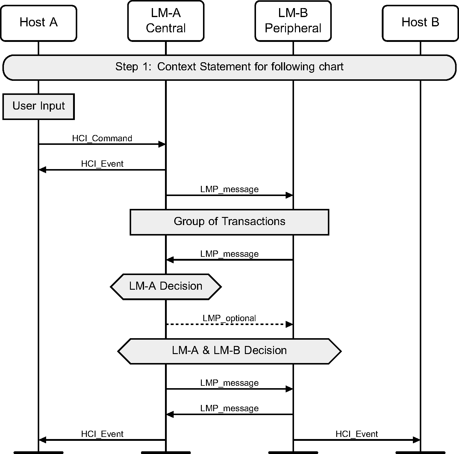
The notation used in the message sequence charts (MSCs) consists of ovals, elongated hexagons, boxes, lines, and arrows. The vertical lines terminated on the top by a shadow box and at the bottom by solid oval indicate a protocol entity that resides in a device. MSCs describe interactions between these entities and states those entities may be in.
The following symbols represent interactions and states:
Oval | Defines the context for the message sequence chart. |
Hexagon | Indicates a condition needed to start the transactions below this hexagon. The location and width of the Hexagon indicates which entity or entities make this decision. |
Box | Replaces a group of transactions. May indicate a user action, or a procedure in the Baseband. |
Dashed Box | Optional group of transactions. |
Solid Arrow | Represents a message, signal or transaction. Can be used to show LMP and HCI traffic. Some Baseband packet traffic is also shown. These are prefixed by BB followed by either the type of packet, or an indication that there is an ACK signal in a packet. |
Dashed Arrow | Represents an optional message, signal or transaction. Can be used to show LMP and HCI traffic. |
1.2. Flow of control
Some message sequences are split into several charts. In these charts, numbers indicate normal or required ordering and letters represent alternative paths. For example, Step 4 is after Step 3, and Step 5a could be executed instead of Step 5b.
1.3. Example MSC
The protocol entities represented in the example shown in Figure 1.1 illustrate the interactions of two devices named A and B. Each device includes a Host and a LM entity in this example. Other MSCs in this Part may show the interactions of more than two devices.
1.4. Forward compatibility
Many of the message sequences in this Part use HCI commands or events that have enhanced or extended variants that were added to the specification later than the relevant sequence. Such variants can be related commands or events with different names (e.g., HCI_Flush and HCI_Enhanced_Flush commands) or commands or events with multiple versions (e.g., HCI_Encryption_Change event). In some instances (for example, see [Vol 4] Part E, Section 3.1.1), a Host is required to use the new variant rather than the one shown in the MSC. Even when this is not a requirement, Host implementers may prefer to use the newer variants.
In these circumstances, the MSCs have not been rewritten to use newer features but have been left unchanged. In general, the new commands and events will directly replace the old ones, but this is not always the case and readers should not assume it.
2. Services without connection request
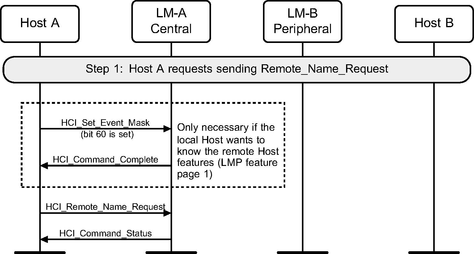
2.1. Remote Name Request
The service Remote Name Request is used to find out the name of the remote device without requiring an explicit ACL connection.
Step 1: The Host sends an HCI_Set_Event_Mask with the bit of Remote Host Supported Features Notification event (bit 60) set and an HCI_Remote_Name_Request command expecting that its local device will automatically try to connect to the remote device. (See Figure 2.1.)
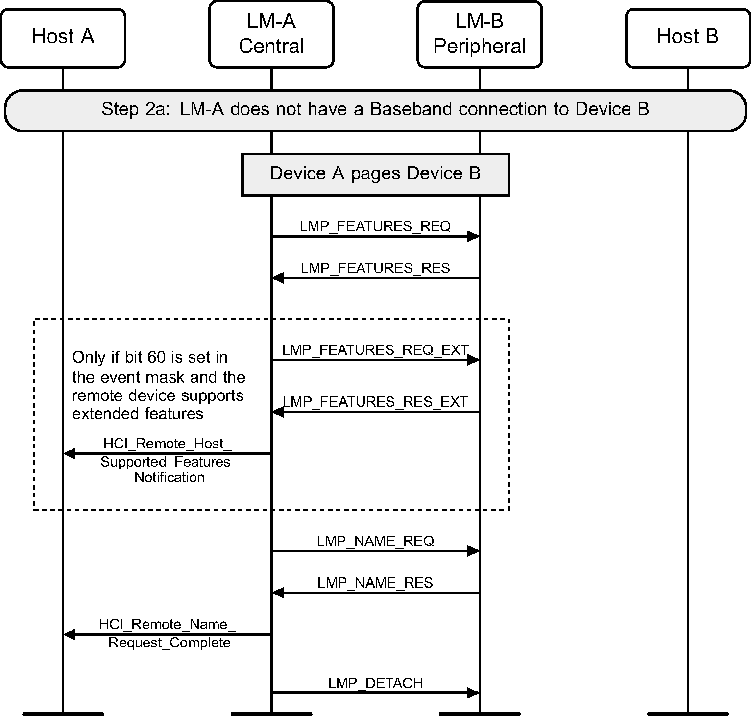
Step 2a: If an ACL connection does not exist device A pages device B. After the Baseband Paging procedure, the local device attempts to get the remote device's extended features, send an HCI_Remote_Host_Supported_Features_Notification event, get the remote name, disconnect, and return the name of the remote device to the Host. (See Figure 2.2.)
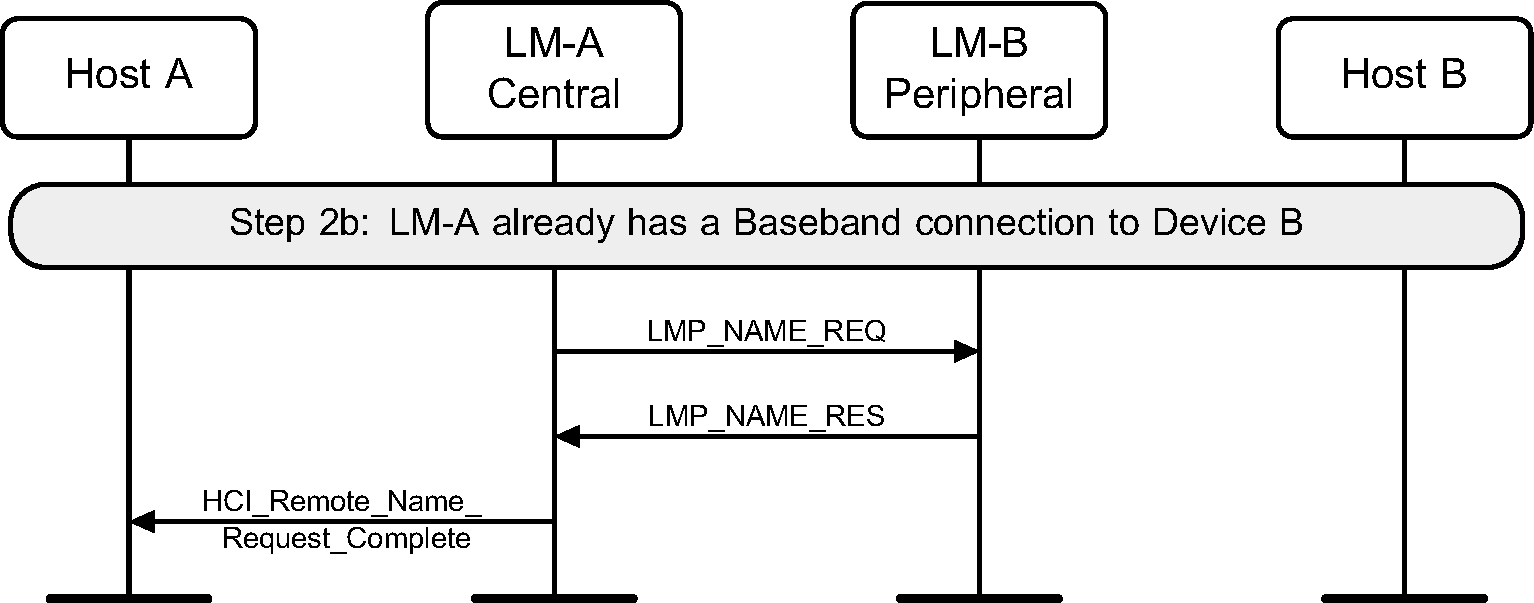
Step 2b: If an ACL connection exists when the request is made, then the Remote Name Request procedure will be executed like an optional service. No Paging and no ACL disconnect is done. (See Figure 2.3.)
2.2. One-time inquiry
Inquiry is used to detect and collect nearby devices.
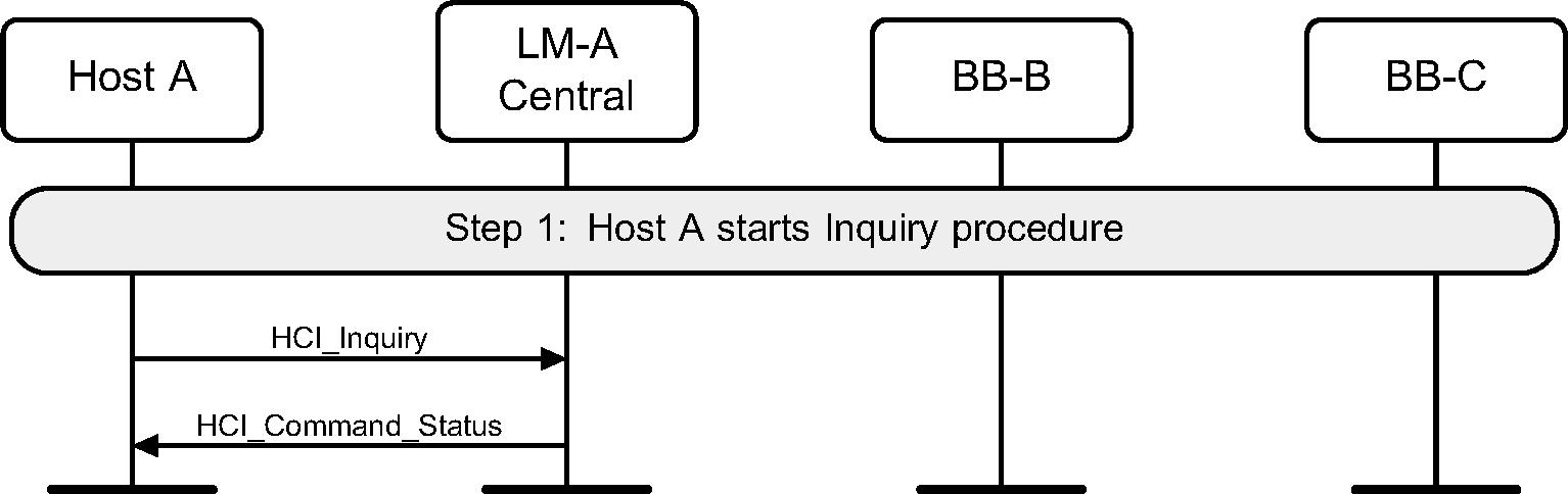
Step 1: The Host sends an HCI_Inquiry command. (See Figure 2.4.)
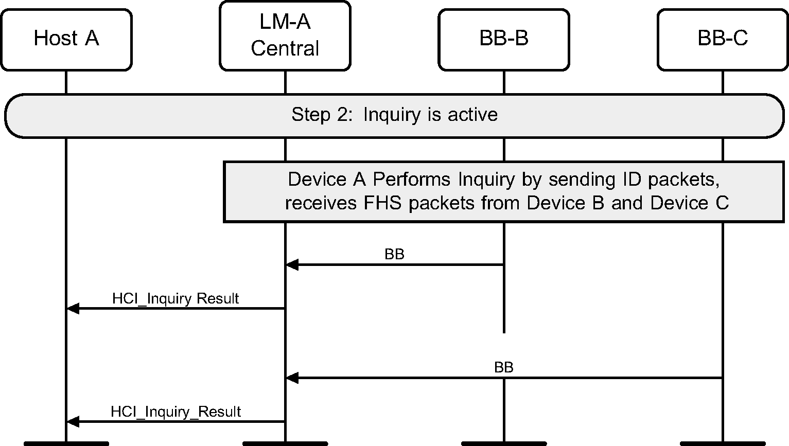
Step 2: The Controller will start the Baseband Inquiry procedure with the specified Inquiry Access Code and Inquiry Length. When inquiry responses are received, the Controller extracts the required information and returns the information related to the found devices using one or more HCI_Inquiry_Result events to the Host. (See Figure 2.5.)
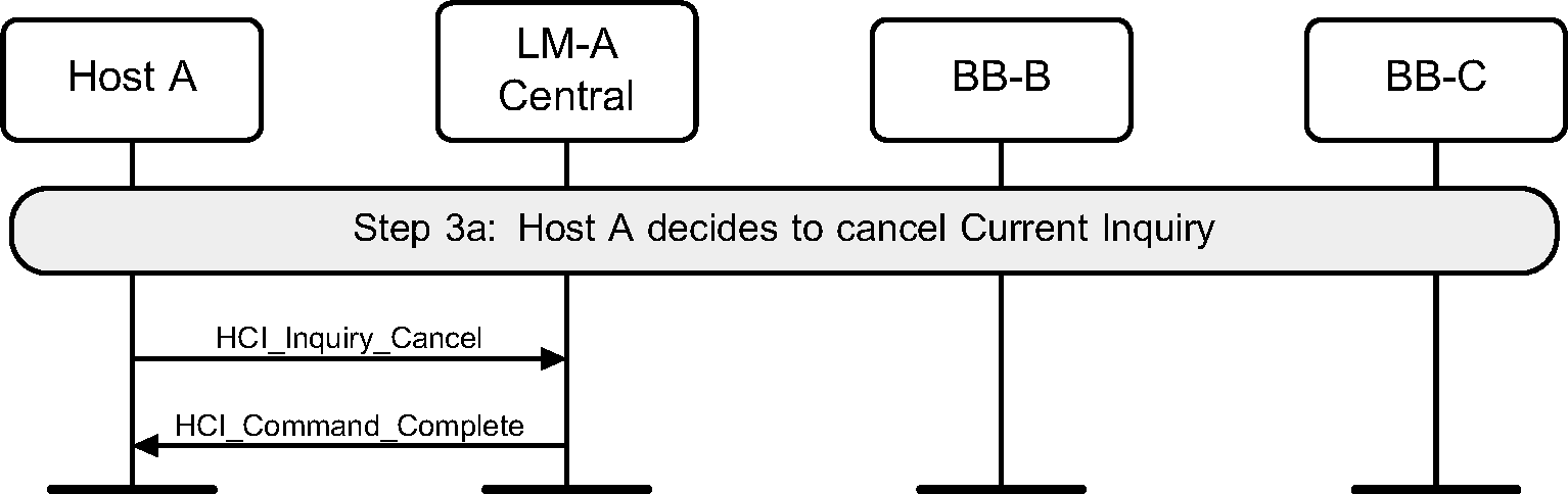
Step 3a: If the Host wishes to terminate an Inquiry, the HCI_Inquiry_Cancel command is used to immediately stop the inquiry procedure. (See Figure 2.6.)
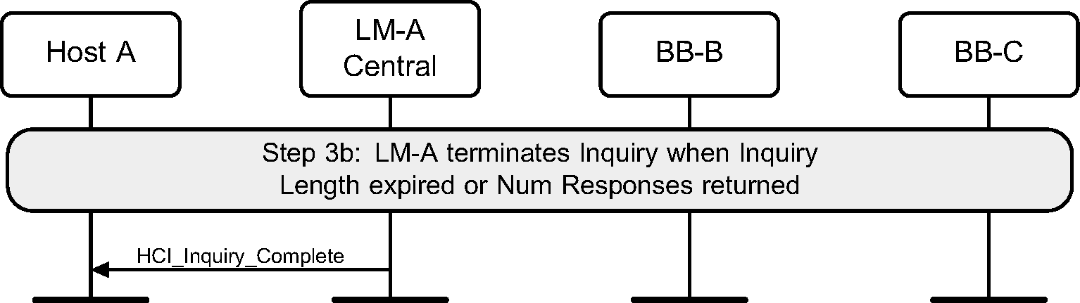
Step 3b: If the Inquiry procedure is completed due to the number of results obtained, or the Inquiry Length has expired, an HCI_Inquiry_Complete event is returned to the Host. (See Figure 2.7.)
2.3. Periodic inquiry
Periodic inquiry is used when the inquiry procedure is to be repeated periodically.
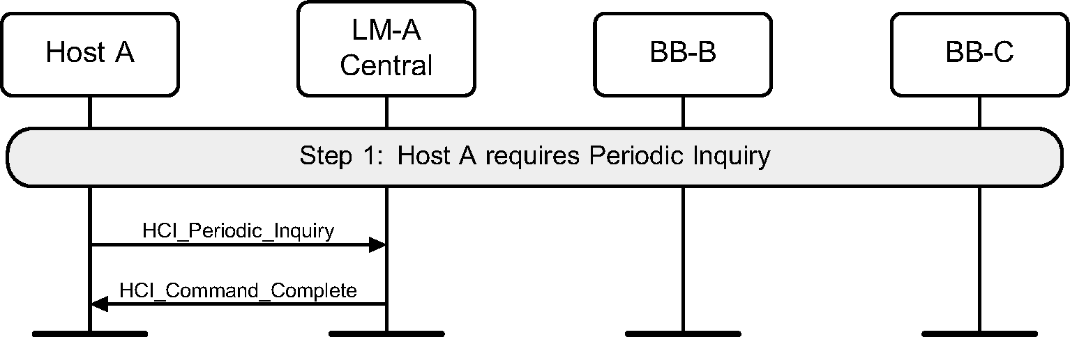
Step 1: The Hosts sends an HCI_Periodic_Inquiry_Mode command. (See Figure 2.8.)
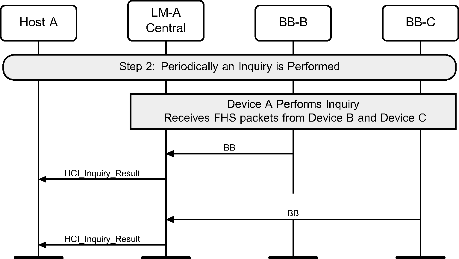
Step 2: The Controller will start a periodic Inquiry. In the inquiry cycle, one or several HCI_Inquiry_Result events will be returned. (See Figure 2.9.)
Step 3: An HCI_Inquiry_Complete event will be returned to the Host when the current periodic inquiry has finished. (See Figure 2.10.)

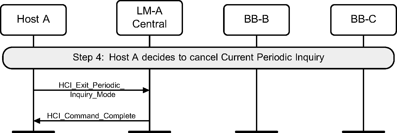
Step 4: The periodic Inquiry can be stopped using the HCI_Exit_Periodic_Inquiry_Mode command. (See Figure 2.11.)
3. ACL connection establishment and detachment
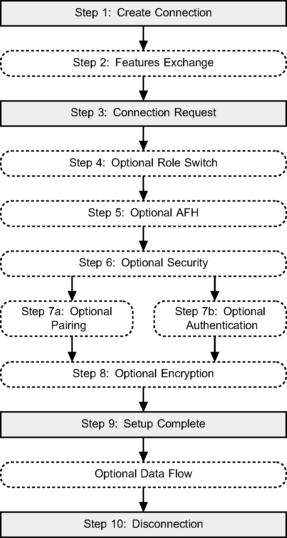
A flow diagram of the establishment and detachment of a connection between two devices is shown in Figure 3.1. The process is illustrated in 9 distinct steps. A number of these steps may be optionally performed, such as authentication and encryption. Some steps are required, such as the Connection Request and Setup Complete steps. The steps in the overview diagram directly relate to the steps in the following message sequence charts.
3.1. Connection setup
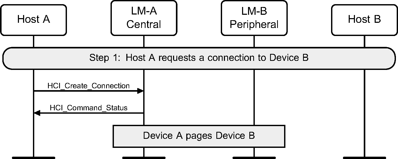
Step 1: The Host sends an HCI_Create_Connection command to the Controller. The Controller then performs a Baseband Paging procedure with the specified BD_ADDR. (See Figure 3.2.)
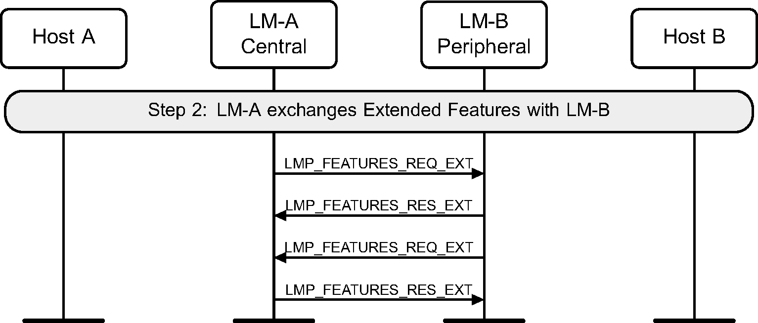
Step 2: Optionally, the LM may decide to exchange features.
(See Figure 3.3.)
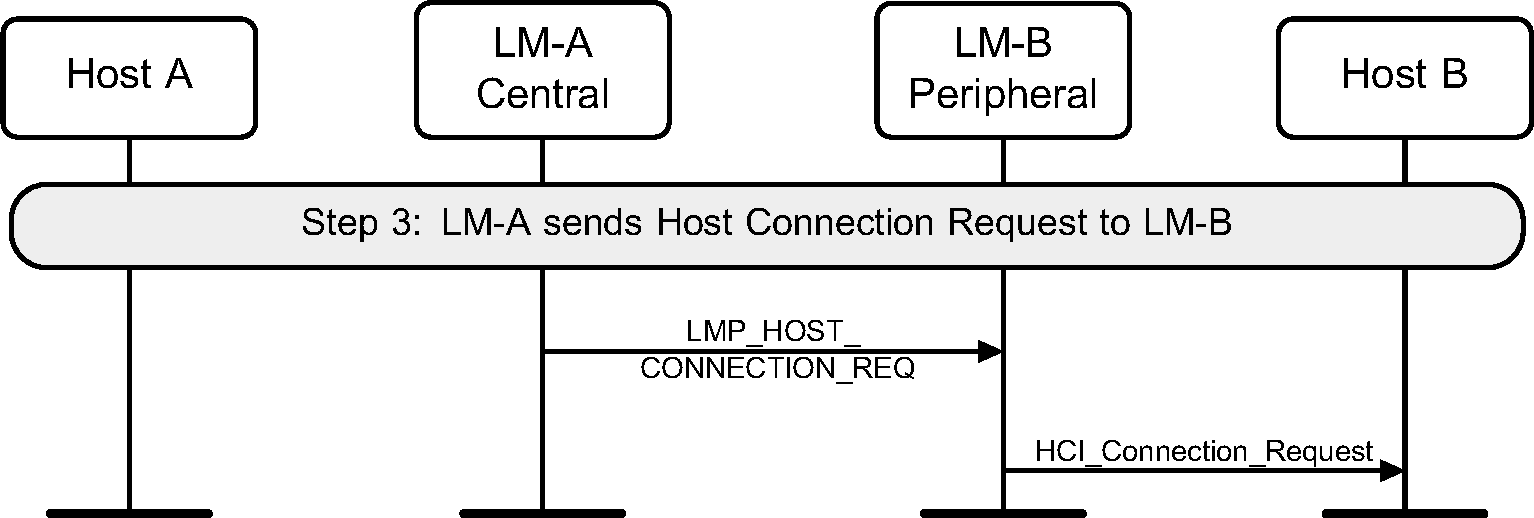
Step 3: The LM on the Central will request an LMP_HOST_CONNECTION_REQ PDU. The LM on the Peripheral will then confirm that a connection is OK, and if so, what role is preferred. (See Figure 3.4)
Step 4a: The remote Host rejects this connection, and the link is terminated. (See Figure 3.5.)

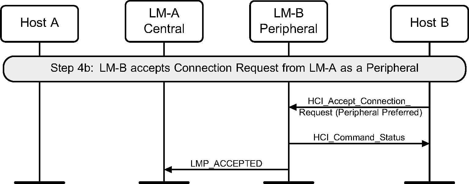
Step 4b: The remote Host accepts this connection. (See Figure 3.6.)
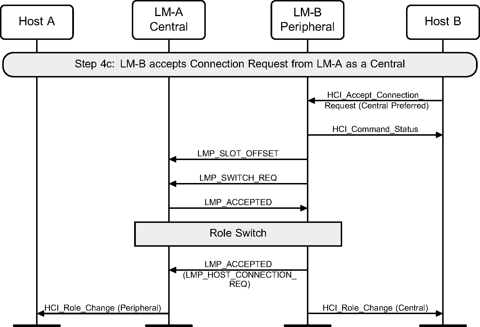
Step 4c: The remote Host accepts this connection but with the preference of being a Central. This will cause a role switch to occur before the LMP_ACCEPTED for the LMP_HOST_CONNECTION_REQ PDU is sent. (See Figure 3.7.)
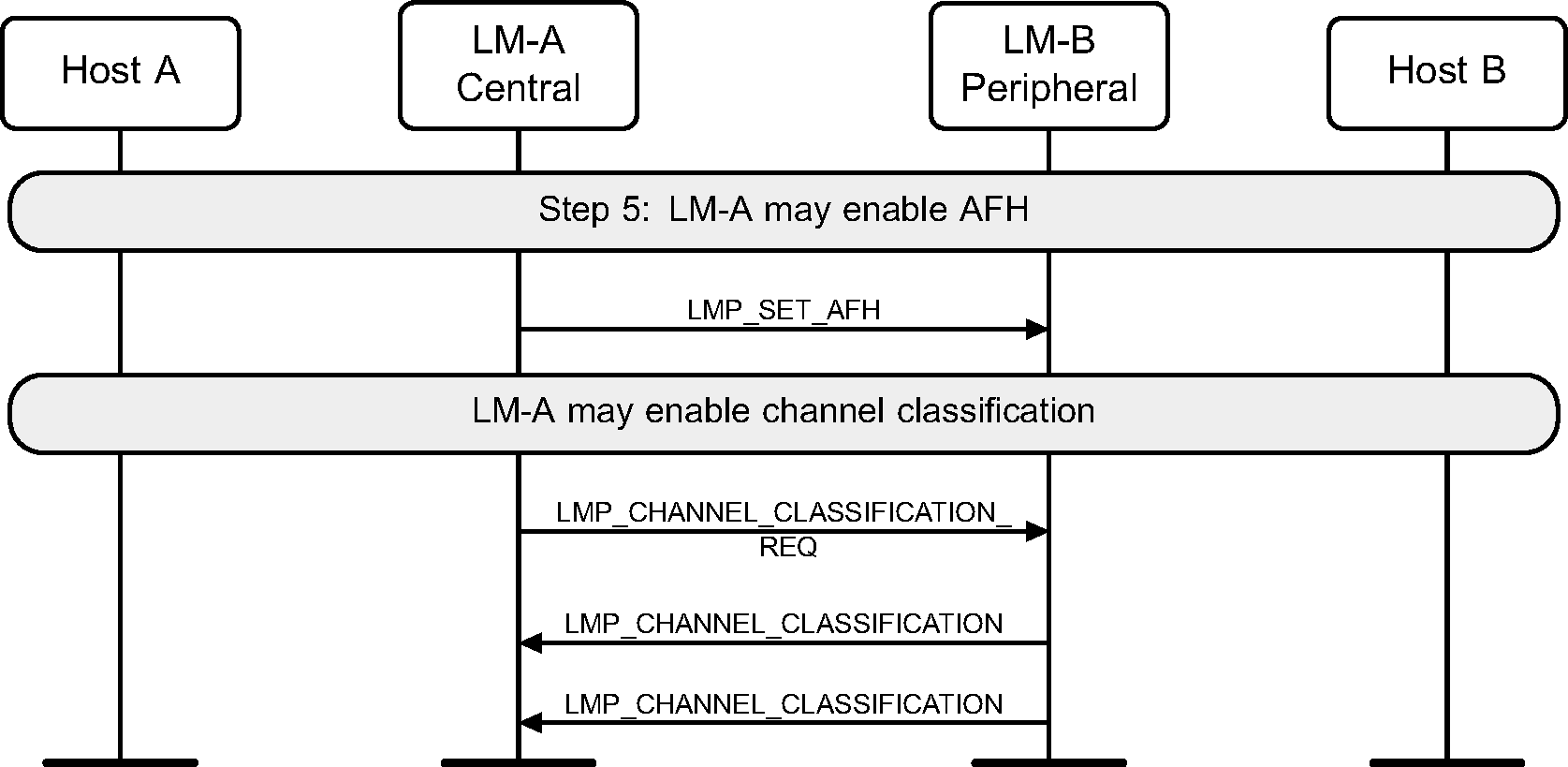
Step 5: After the features have been exchanged and AFH support is determined to be available, the Central may at any time send an LMP_SET_AFH and LMP_CHANNEL_CLASSIFICATION_REQ PDU. (See Figure 3.8.)
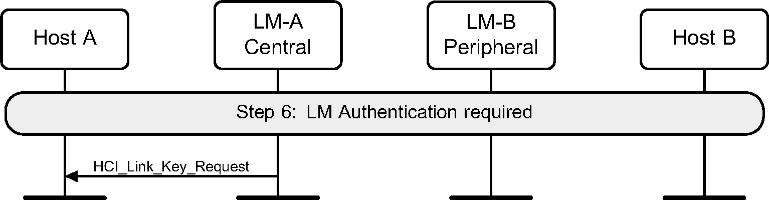
Step 6: The LM will request if authentication is required. It does this by requesting the Link Key for this connection from the Host. (See Figure 3.9.)
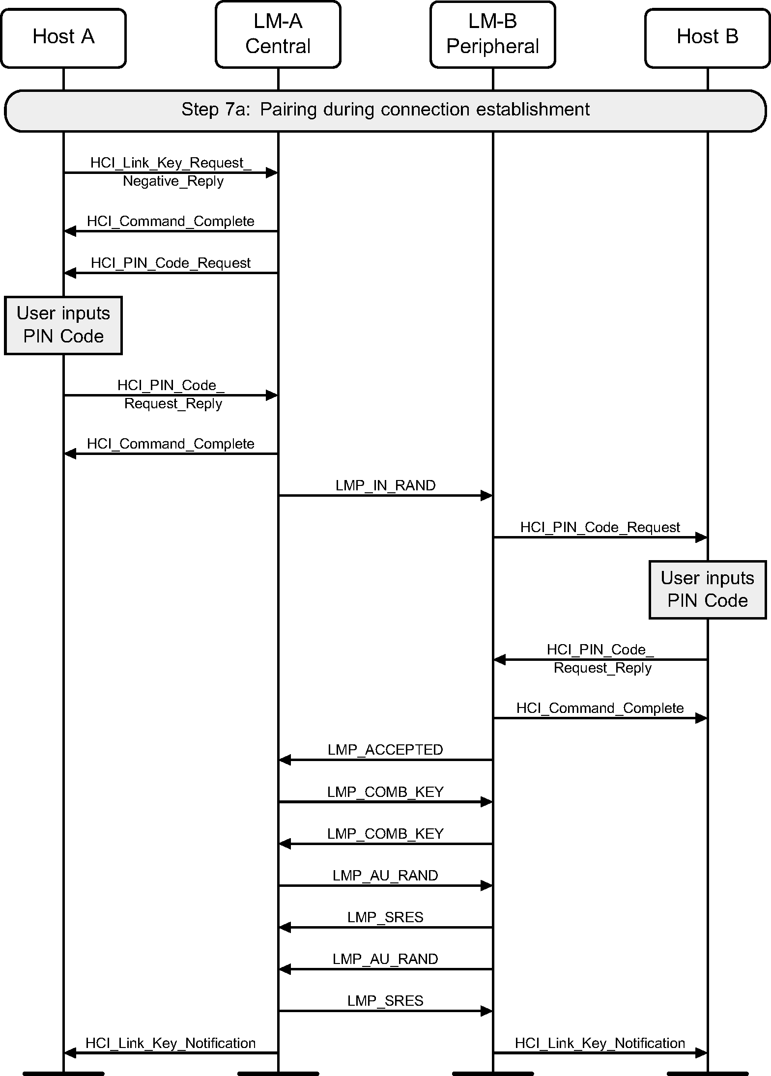
Step 7a: If authentication is required by the higher layers and the devices to be connected do not have a common link key, a pairing procedure will be used. The LM will have requested a link key from the Host for this connection. If there is a negative reply, then a PIN code will be requested. This PIN code will be requested on both sides of the connection, and authentication performed based on this PIN code. The last step is for the new link key for this connection to be passed to the Host so that it may store it for future connections. (See Figure 3.10.)
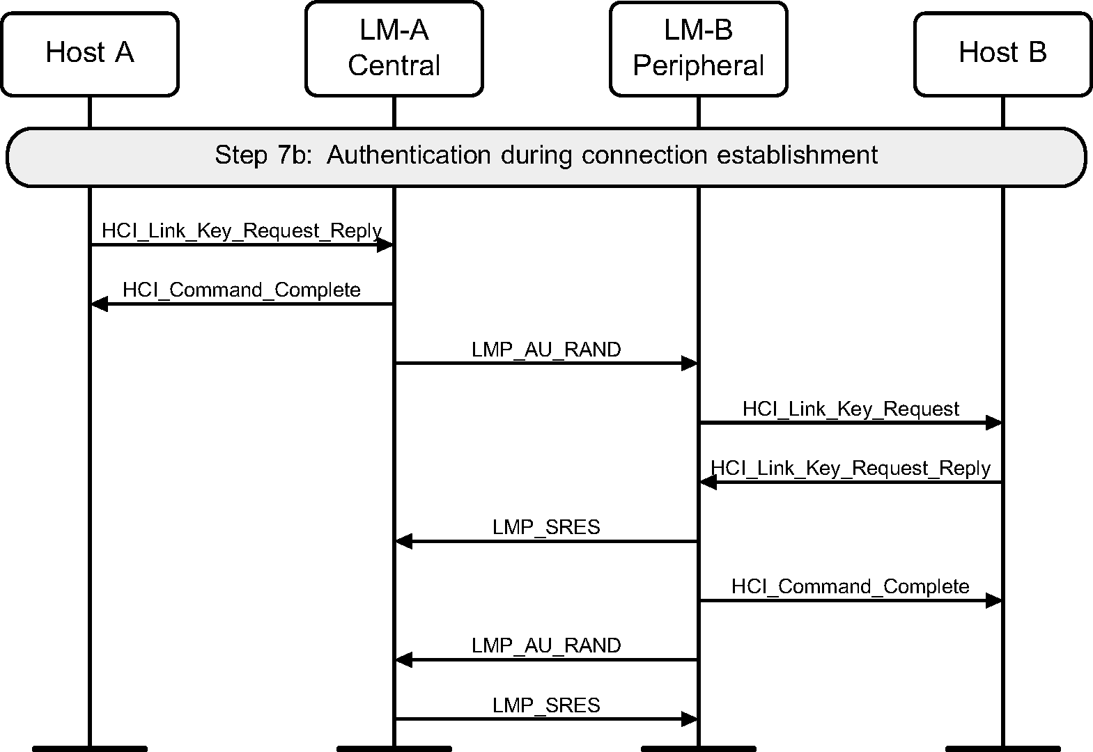
Step 7b: If a common link key exists between the devices, then pairing is not needed. The LM will have asked for a link key from the Host for this connection. If this is a positive reply, then the link key is used for authentication. If the configuration parameter Authentication_Enable is set, then the authentication procedure is executed. This MSC only shows the case when Authentication_Enable is set on both sides. (See Figure 3.11.)
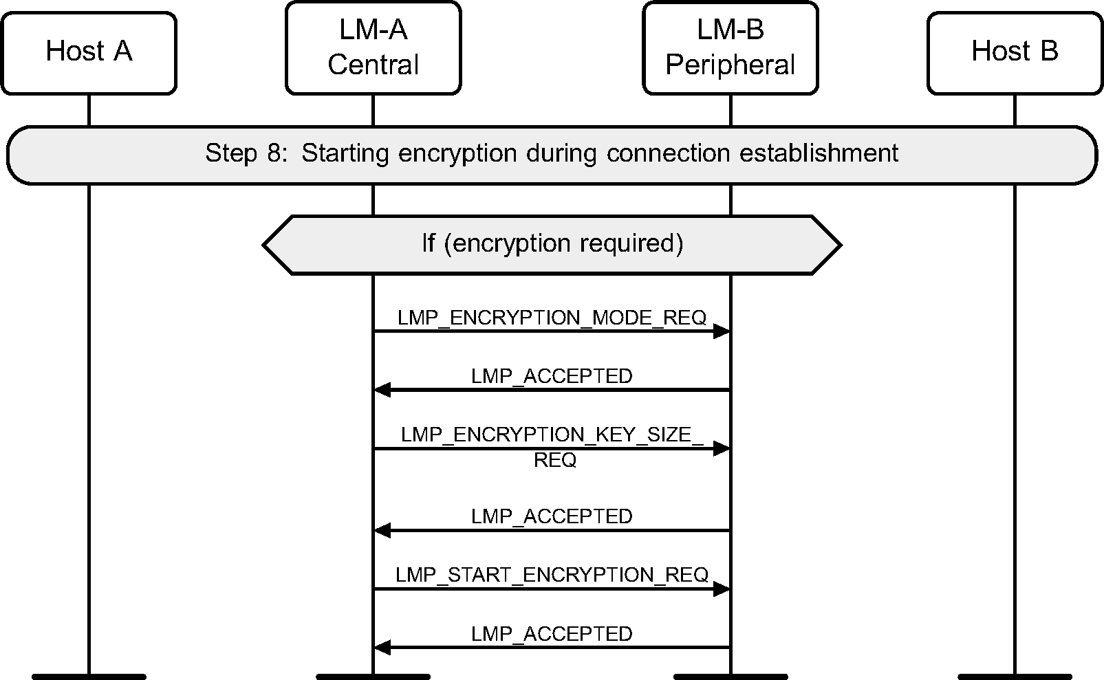
Step 8: Once the pairing or authentication procedure is successful, the encryption procedure may be started. This MSC only shows the set up of an encrypted point-to-point connection. (See Figure 3.12.)
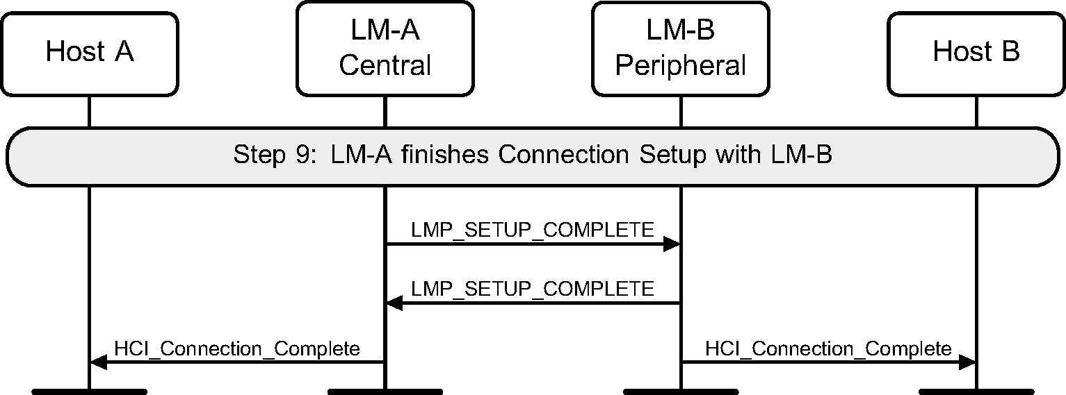
Step 9: The LMs indicate that the connection is setup by sending LMP_SETUP_COMPLETE PDU. This will cause the Host to be notified of the new Connection_Handle, and this connection may be used to send higher layer data such as L2CAP information. (See Figure 3.13.)
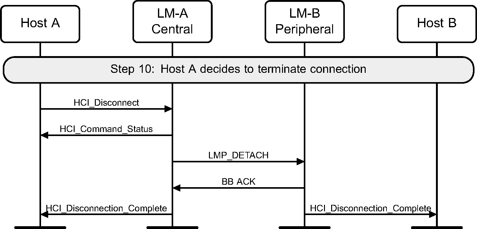
Step 10: Once the connection is no longer needed, either device may terminate the connection using the HCI_Disconnect command and LMP_DETACH message PDU. The disconnection procedure is one-sided and does not need an explicit acknowledgment from the remote LM. The use of ARQ Acknowledgment from the Baseband indicates that the remote LM has received the LMP_DETACH PDU. (See Figure 3.14.)
4. Optional activities after ACL connection establishment
4.1. Authentication requested
Step 1: Authentication can be explicitly executed at any time after a connection has been established. If no Link Key is available then the Link Key is required from the Host. (See Figure 4.1.)
Note
Note: If the Controller or LM and the Host do not have the Link Key, the devices will need to pair using a procedure such as that in Section 3.1 Step 7a or that in Section 4.2.
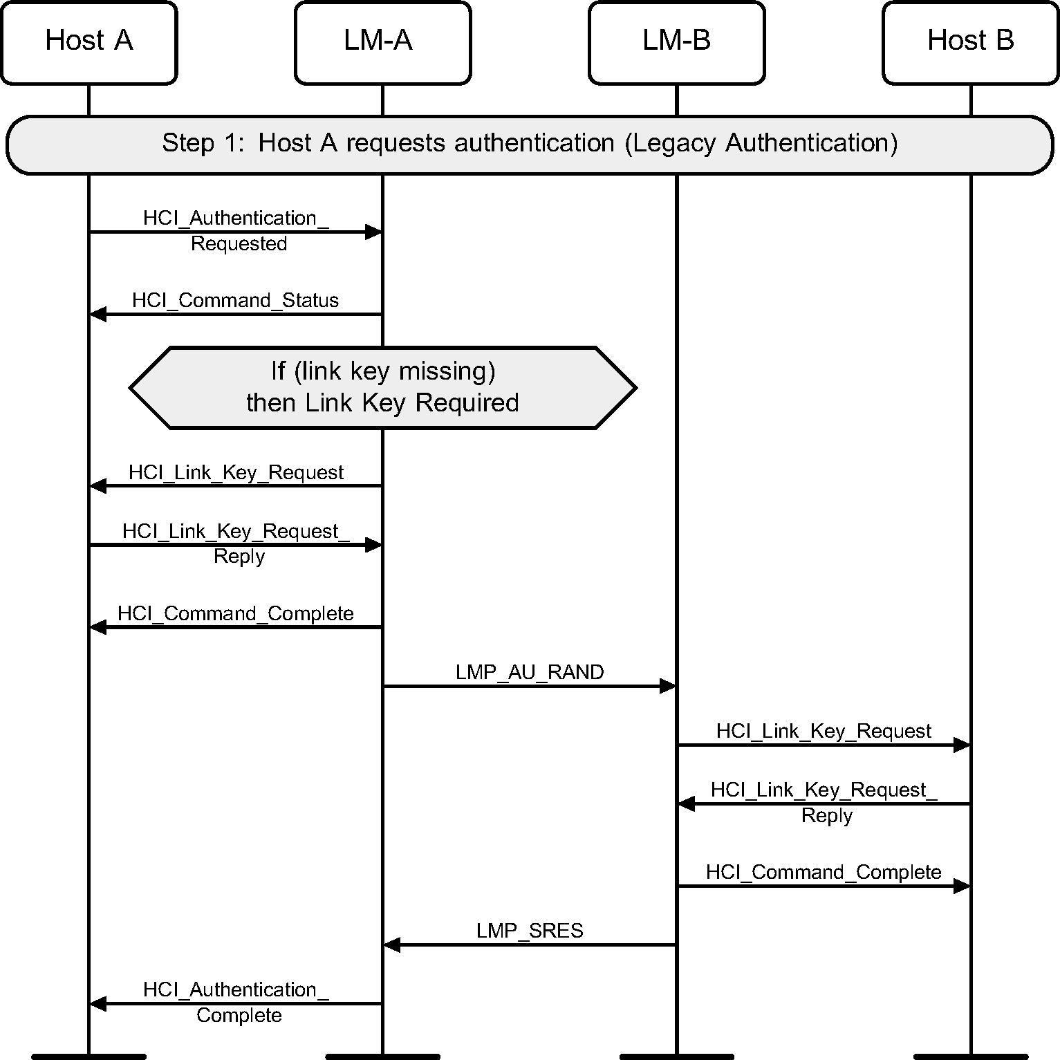
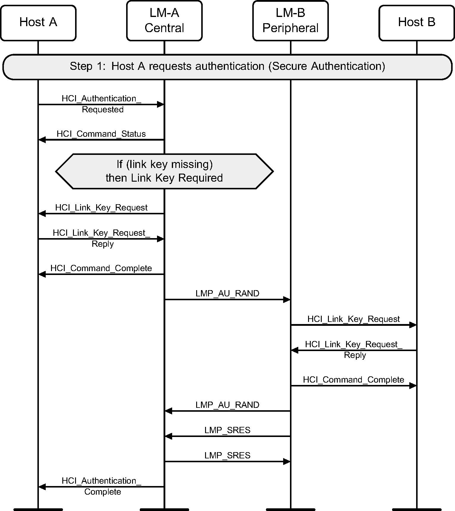
When both devices support Secure Connections, Secure Authentication is used.
4.2. Secure Simple Pairing message sequence charts
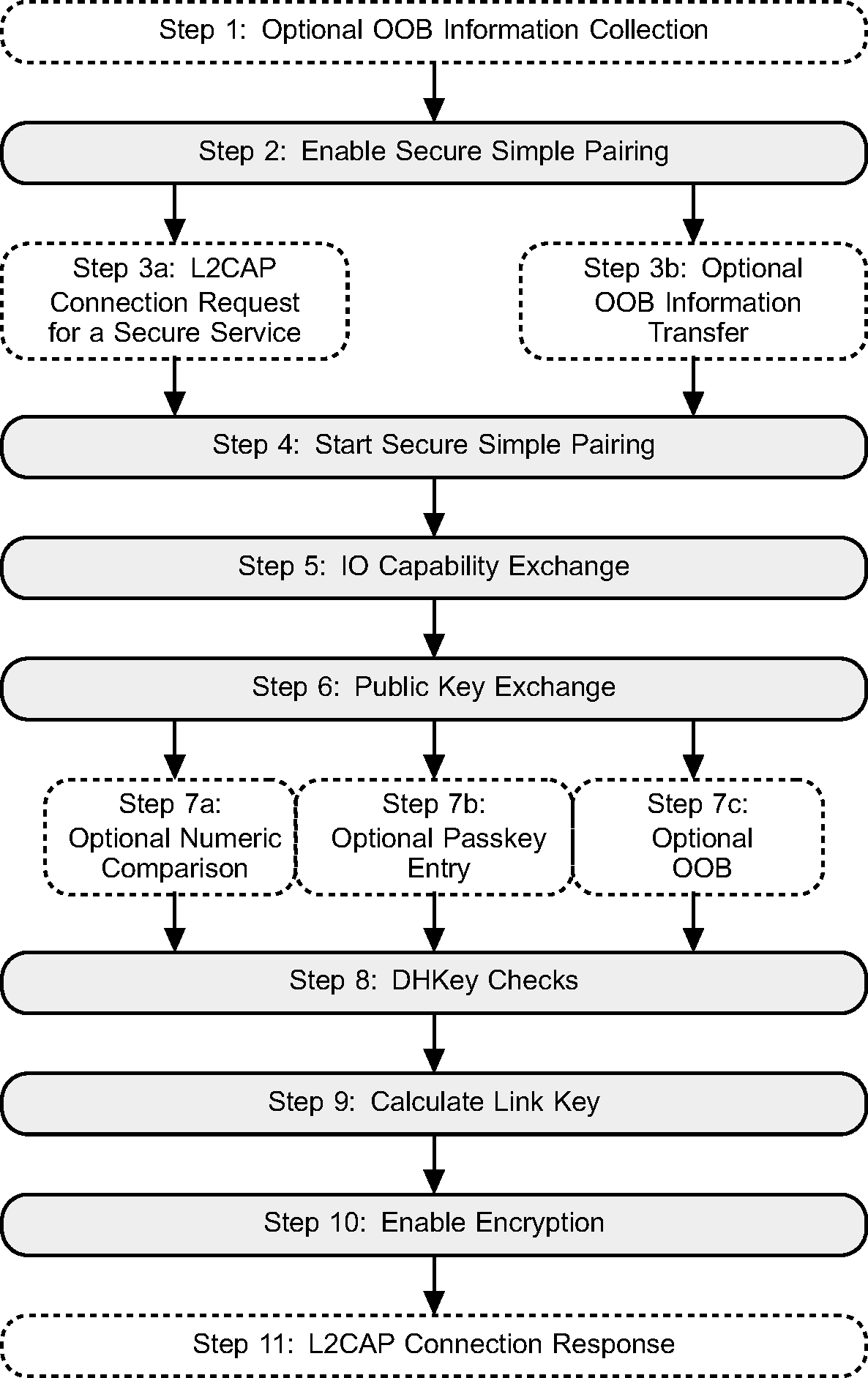
A flow diagram of Secure Simple Pairing between two devices is shown in Figure 4.3. The process is illustrated in 11 distinct steps. A number of these steps have a number of different options.
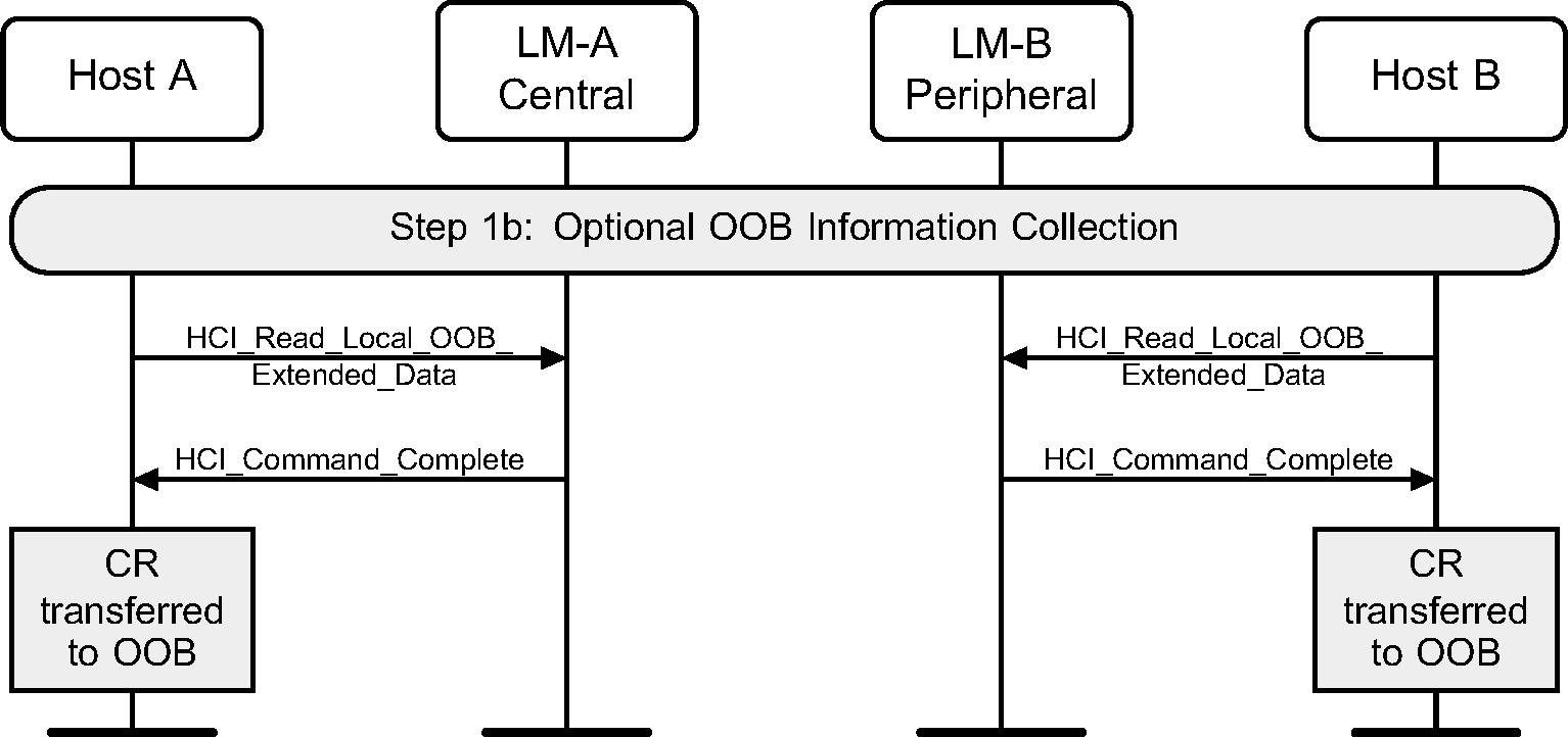
4.2.1. Optional OOB information collection
If a device supports OOB information exchange, then the Host should request the C and R values from the Controller that need to be sent by OOB. It is then assumed that the Host transfers this information to the OOB system. This could occur a long time before, for example at the factory for a passive tag.
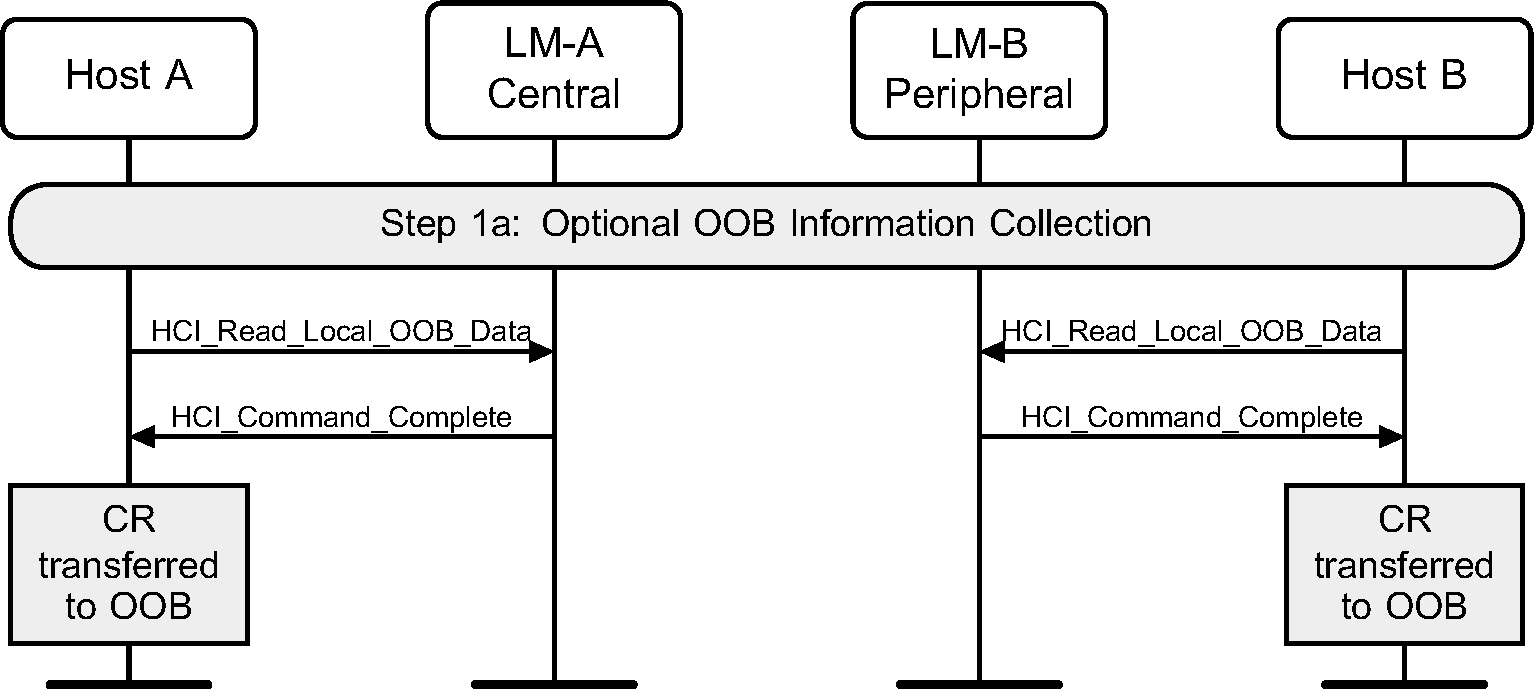
When the Controller and Host support Secure Connections, the HCI_Read_Local_OOB_Extended_Data command is used instead of HCI_Read_Local_OOB_Data.
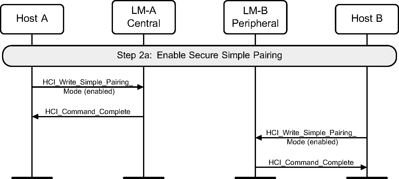
4.2.2. Enable Secure Simple Pairing and secure connections
To enable Secure Simple Pairing, a device must use the HCI_Write_Simple_Pairing_Mode command. This should be done before any other connections that may use Secure Simple Pairing are created.
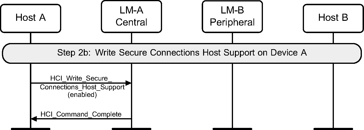
To configure the Controller to use Secure Connections HCI commands and events, a device must use the HCI_Write_Secure_Connections_Host_Support command. This should be done before any connections are created.
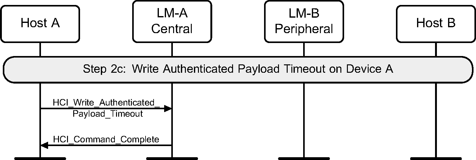
To configure the Controller to enforce a maximum interval between packets containing a MIC (when AES-CCM encryption is used), a device must use the HCI_Write_Authenticated_Payload_Timeout command.
4.2.3. Connection establishment
Secure Simple Pairing, once it is enabled, is triggered by one of two possible actions. It could be triggered by an L2CAP connection request to a service that requires security, or it could be triggered by an OOB transfer of information.
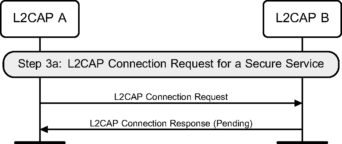
4.2.4. L2CAP connection request for a secure service
Once a connection has been established between two devices, if a device requests an L2CAP connection to a service that requires authentication and encryption, then the device will start Secure Simple Pairing.
 |
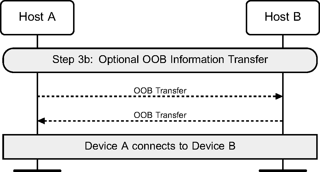
4.2.5. Optional OOB information transfer
Even if a Bluetooth connection has not been established between two devices, an OOB transfer can occur that transfers the Bluetooth Device Address of the device, and other OOB information for authentication. If an OOB transfer occurs, then the Host can start Secure Simple Pairing.
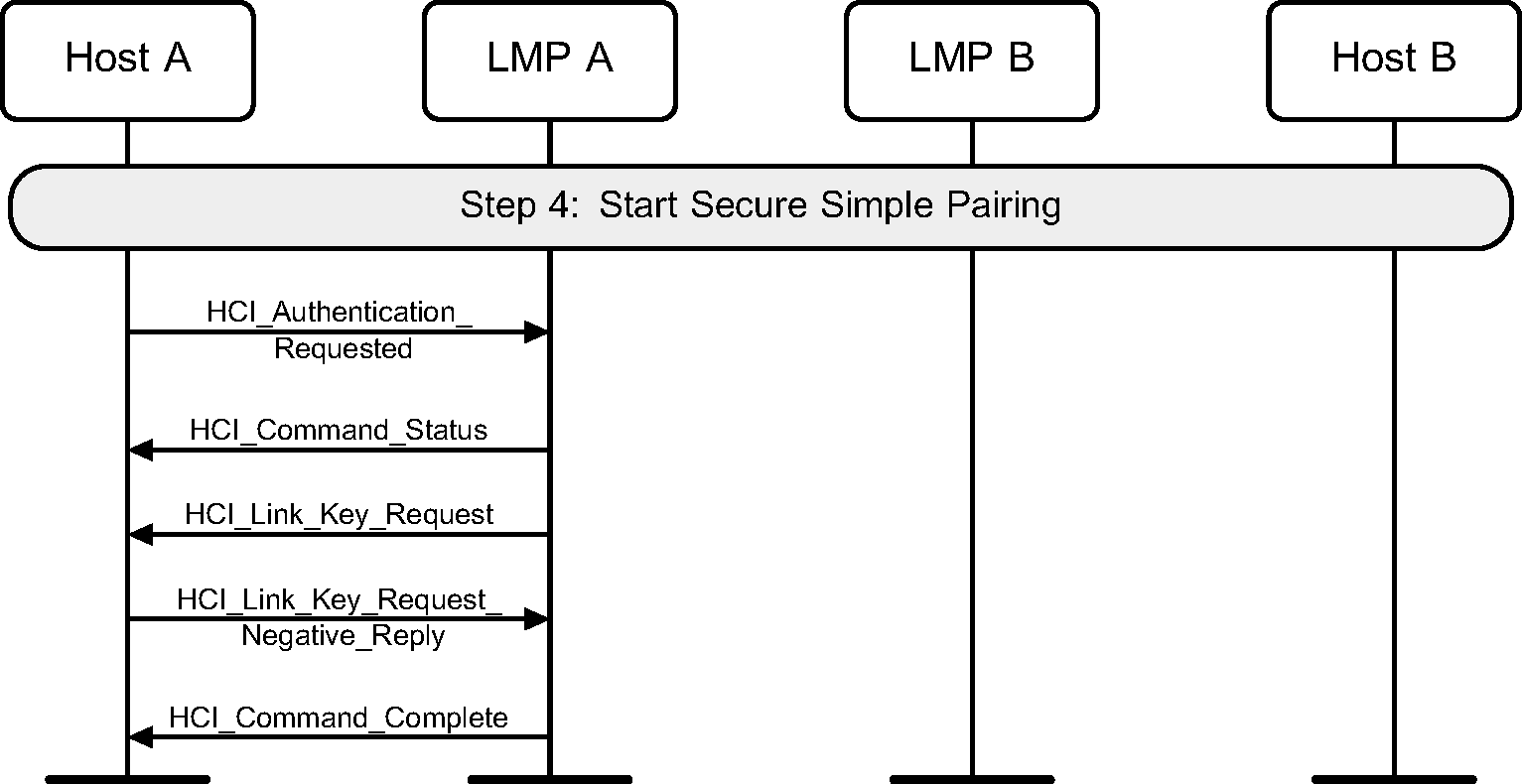
4.2.6. Start Secure Simple Pairing
Once the Host has determined that Secure Simple Pairing should start, it issues an HCI_Authentication_Requested command to the Controller. This will cause the Controller to generate a request for a link key. If the Host has a link key for this connection, then pairing is not required, and the link key can be used immediately once it has been authenticated. Secure Simple Pairing will only be used if an HCI_Link_Key_Request_Negative_Reply command is sent from the Host to the Controller on the initiating side.
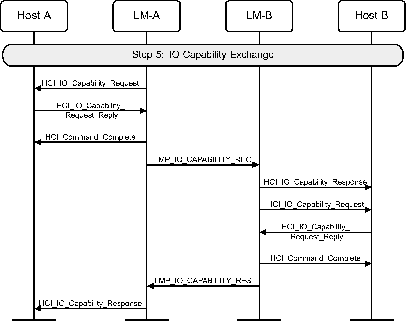
4.2.7. IO capability exchange
To be able to determine the correct authentication algorithm to use, the input / output capabilities of the two devices are exchanged.
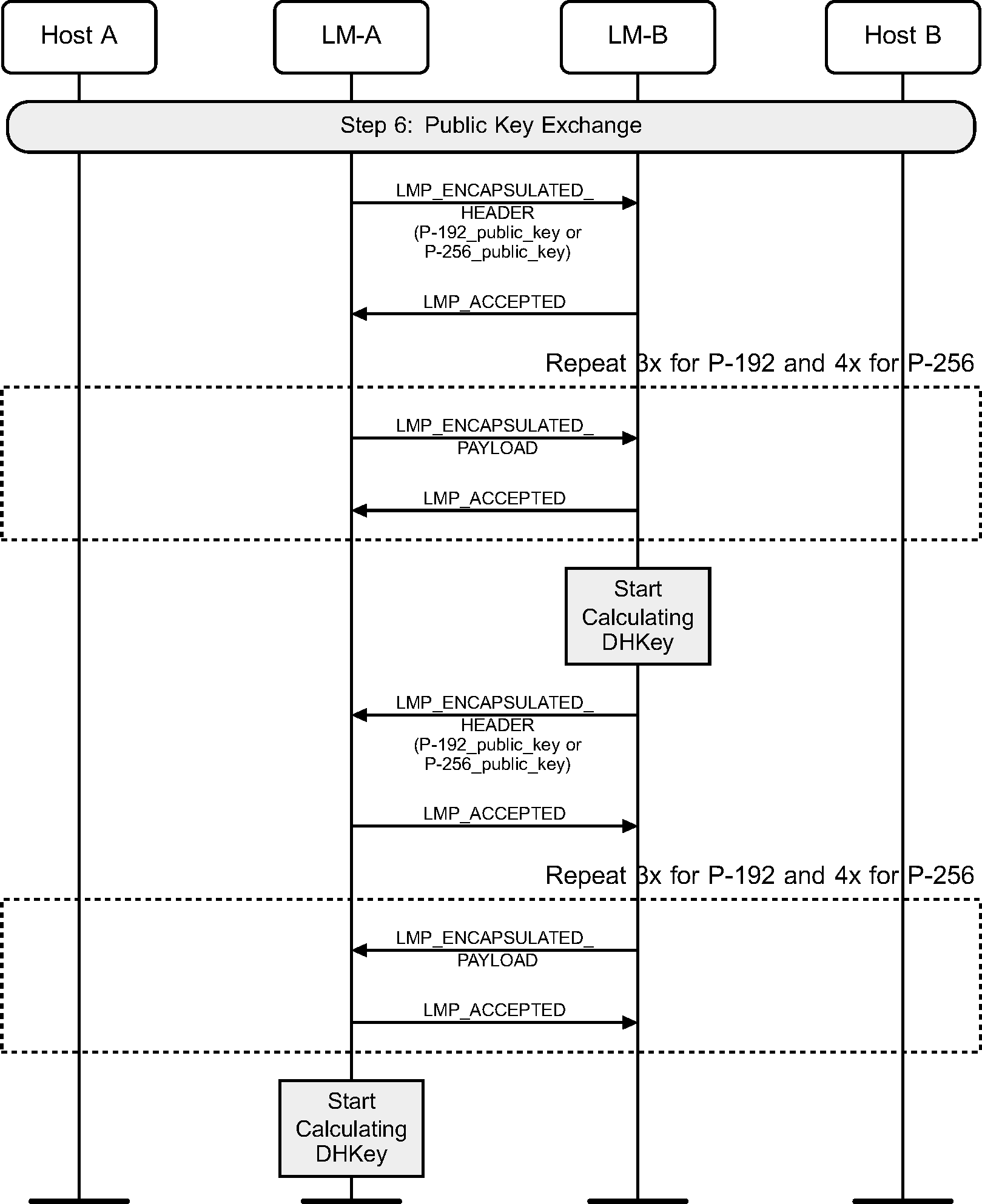
4.2.8. Public key exchange
Next the public keys are exchanged between the two devices. Once a device has received the public key of the peer device, it can start to calculate the Diffie Hellman Key (DHKey). This may take a long time, and should be started early, so that user interaction can hide the calculation time. The DHKey is not required until step 8.
4.2.9. Authentication
A device can be authenticated by using one of three algorithms. The choice of algorithm is determined by the combination of the IO capabilities of the two devices.
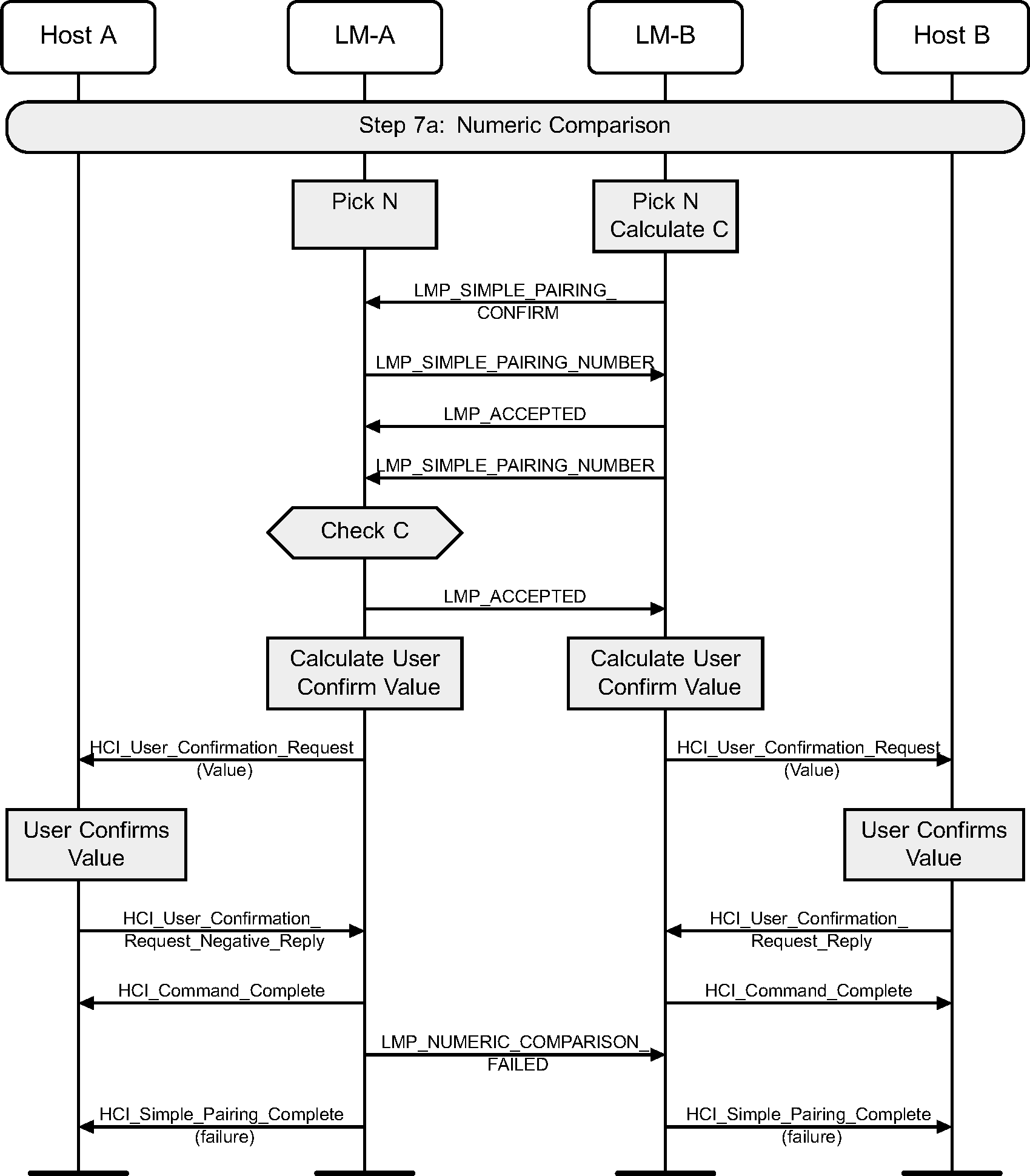
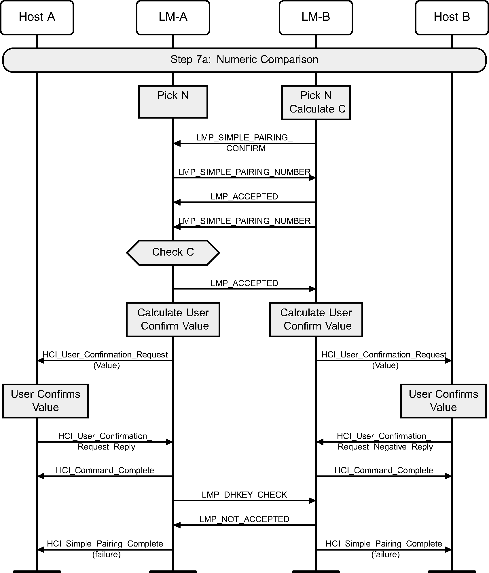
4.2.10. Numeric Comparison
The numeric comparison step will be done when both devices have output capabilities, or if one of the devices has no input or output capabilities. If both devices have output capabilities, this step requires the displaying of a user confirmation value. This value should be displayed until the end of step 8. If one or both devices do not have output capabilities, the same protocol is used but the Hosts will skip the step asking for the user confirmation. The sequence for Just Works is identical to that of Numeric Comparison with the exception that the Host will not show the numbers to the user.

4.2.11. Numeric Comparison failure on initiating side
If the numeric comparison fails on the initiating side due to the user indicating that the confirmation values do not match, Secure Simple Pairing is terminated.
4.2.12. Numeric Comparison failure on responding side
If the numeric comparison fails on the responding side due to the user indicating that the confirmation values do not match, Secure Simple Pairing is terminated.
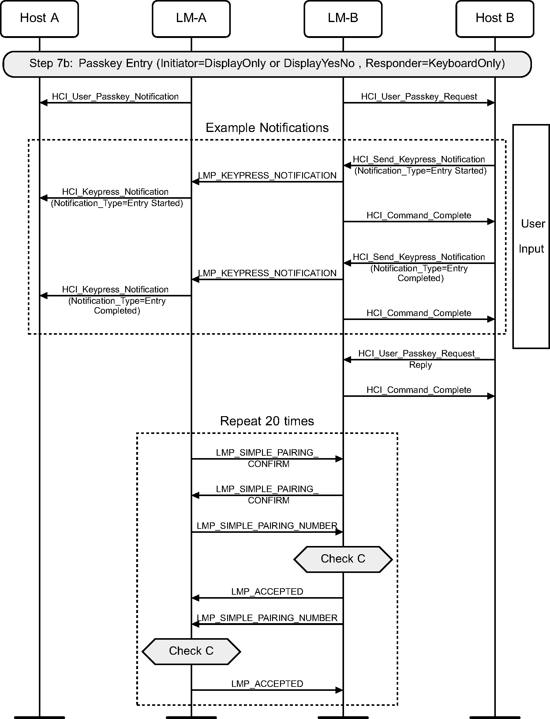
4.2.13. Passkey Entry
The Passkey Entry step is used in two cases: when one device has numeric input only and the other device has either a display or numeric input capability or when both devices only have numeric input capability. In this step, one device display a number to be entered by the other device or the user enters a number on both devices. This number should be displayed until the end of step 8. Key press notification messages are shown during the user input phase.
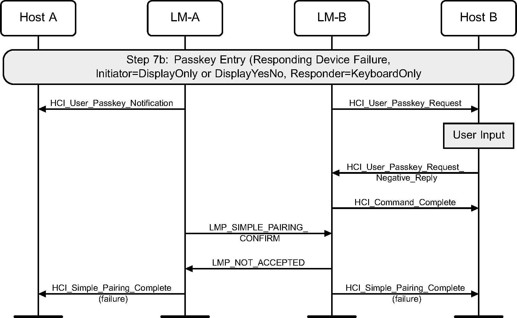
4.2.14. Passkey Entry failure on responding side
If the Passkey Entry fails on the responding side, Secure Simple Pairing is terminated.
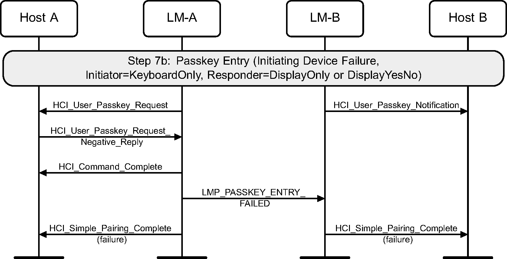
4.2.15. Passkey Entry failure on initiator side
If the Passkey Entry fails on the initiating side, Secure Simple Pairing is terminated. This is only possible if the initiating LM side sends an HCI_User_Passkey_Request event.
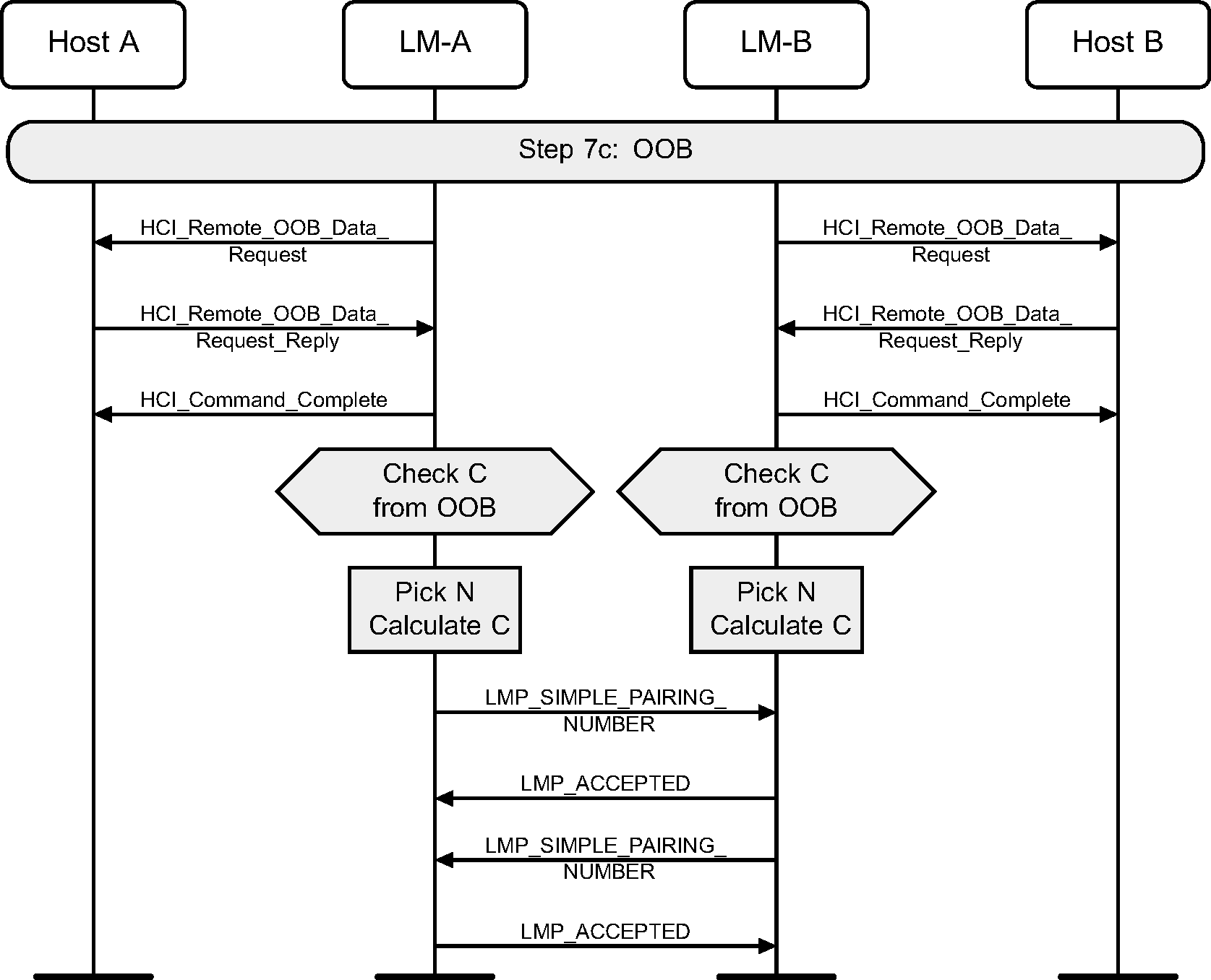
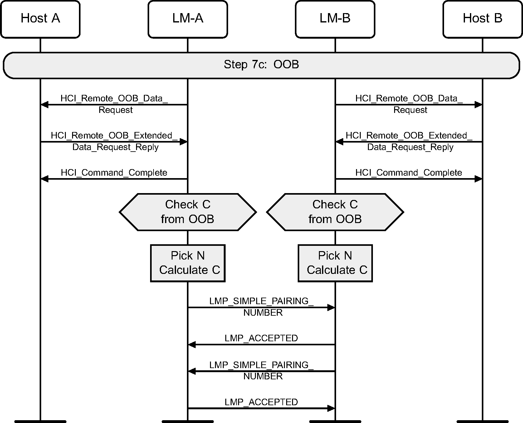
4.2.16. Out of Band
The OOB authentication will only be done when both devices have some OOB information to use. This step requires no user interaction.
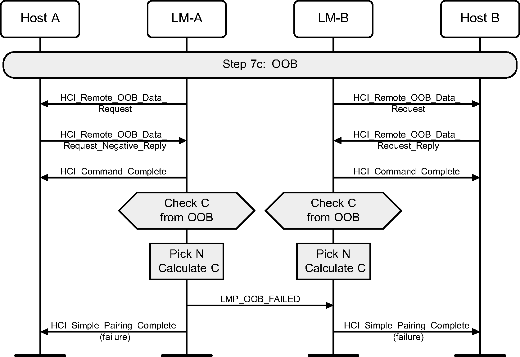
4.2.17. OOB failure on initiator side
If the initiating side does not have OOB information, Secure Simple Pairing is terminated.
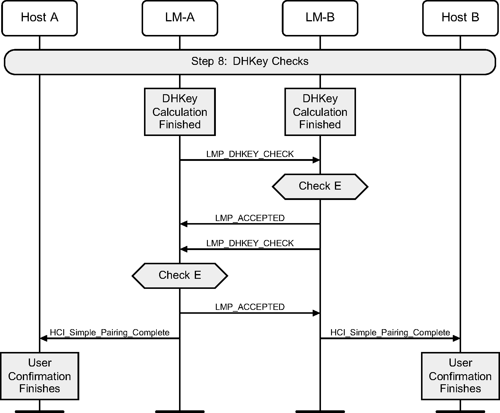
4.2.18. DHKey checks
Once the devices have been authenticated, and the DHKey calculation has completed, the DHKey value generated is checked. If this succeeds, then both devices would have finished displaying information to the user about the process, and therefore a message is sent from the Controller to the Host to notify it to stop displaying this information.
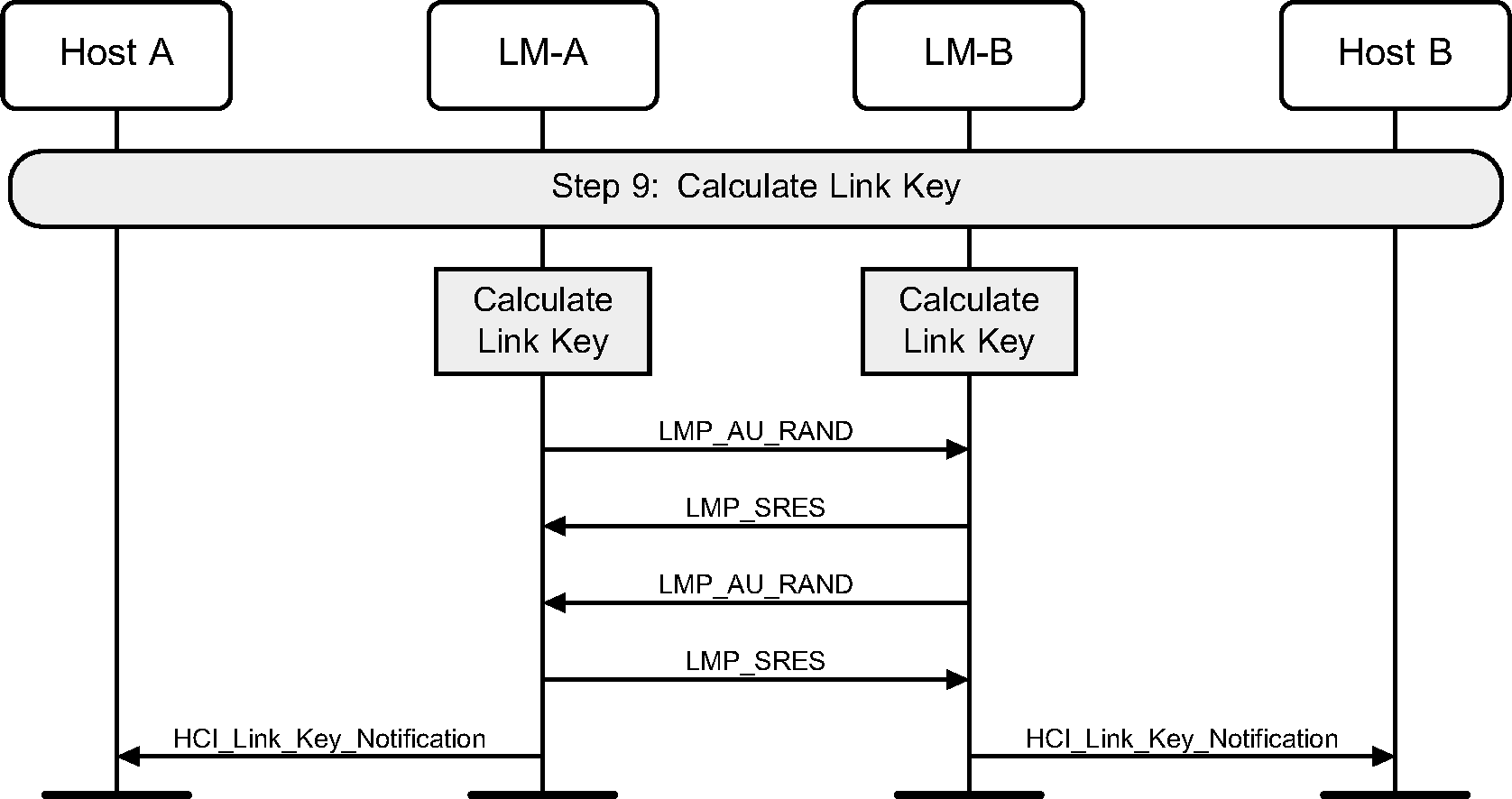
4.2.19. Calculate link key
Once Secure Simple Pairing is complete, the link key can be calculated from the DHKey, and this should be used as input to a standard mutual authentication. Once this is complete, an HCI_Link_Key_Notification event will be generated.
4.2.20. Enable encryption
Once the link key has been notified to the Host, the HCI_Authentication_Requested command will complete with an HCI_Authentication_Complete event. The Host can then turn on encryption using the standard methods.
4.2.21. L2CAP connection response
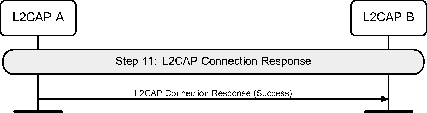
If this Secure Simple Pairing was triggered by an L2CAP Connection Request, then only after all of the above steps have completed can the L2CAP Connection Response message be sent.
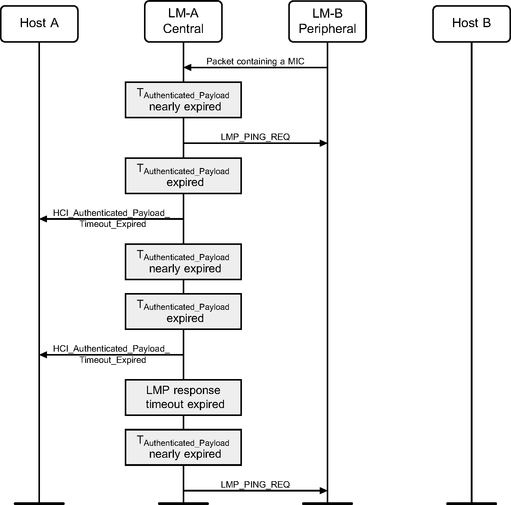
4.2.22. LMP ping
When the Authenticated Payload Timeout has nearly expired, the Link Manager will force the remote device to send a packet containing a MIC by sending the LMP_PING_REQ PDU.

When a packet with a MIC has not been received within the Authenticated Payload Timeout, the Host is notified that the timer has expired.
4.3. Link Supervision Timeout Changed event
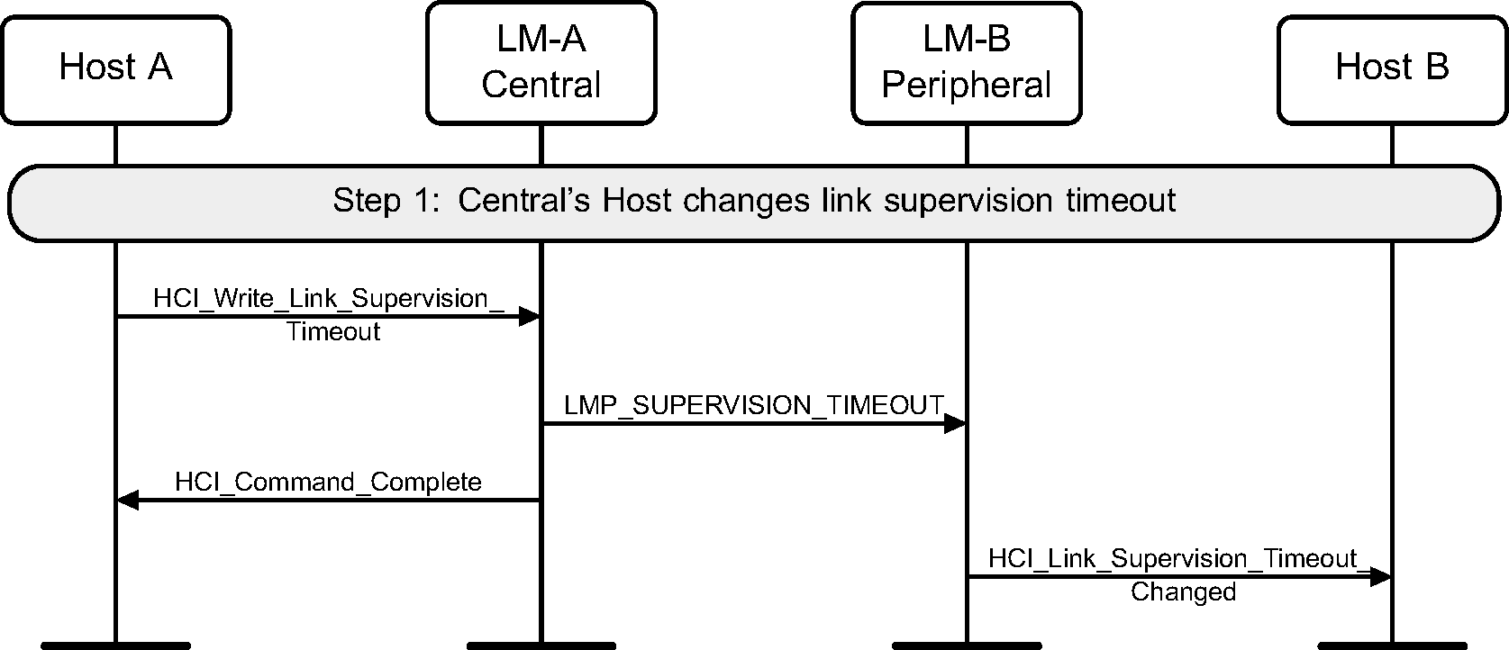
When enabled by the Host, the Peripheral generates an HCI_Link_Supervision_Timeout_Changed event after the LMP_SUPERVISION_TIMEOUT PDU is received.
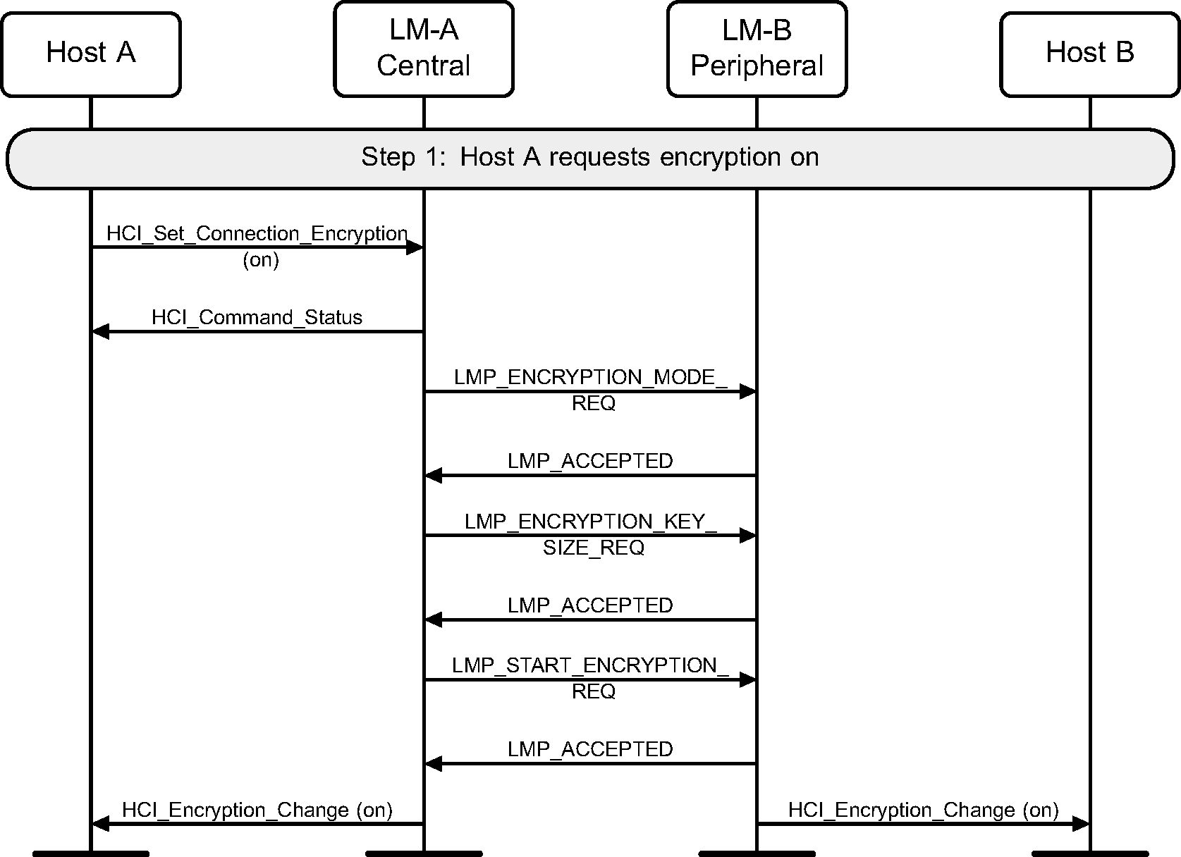
4.4. Set Connection Encryption
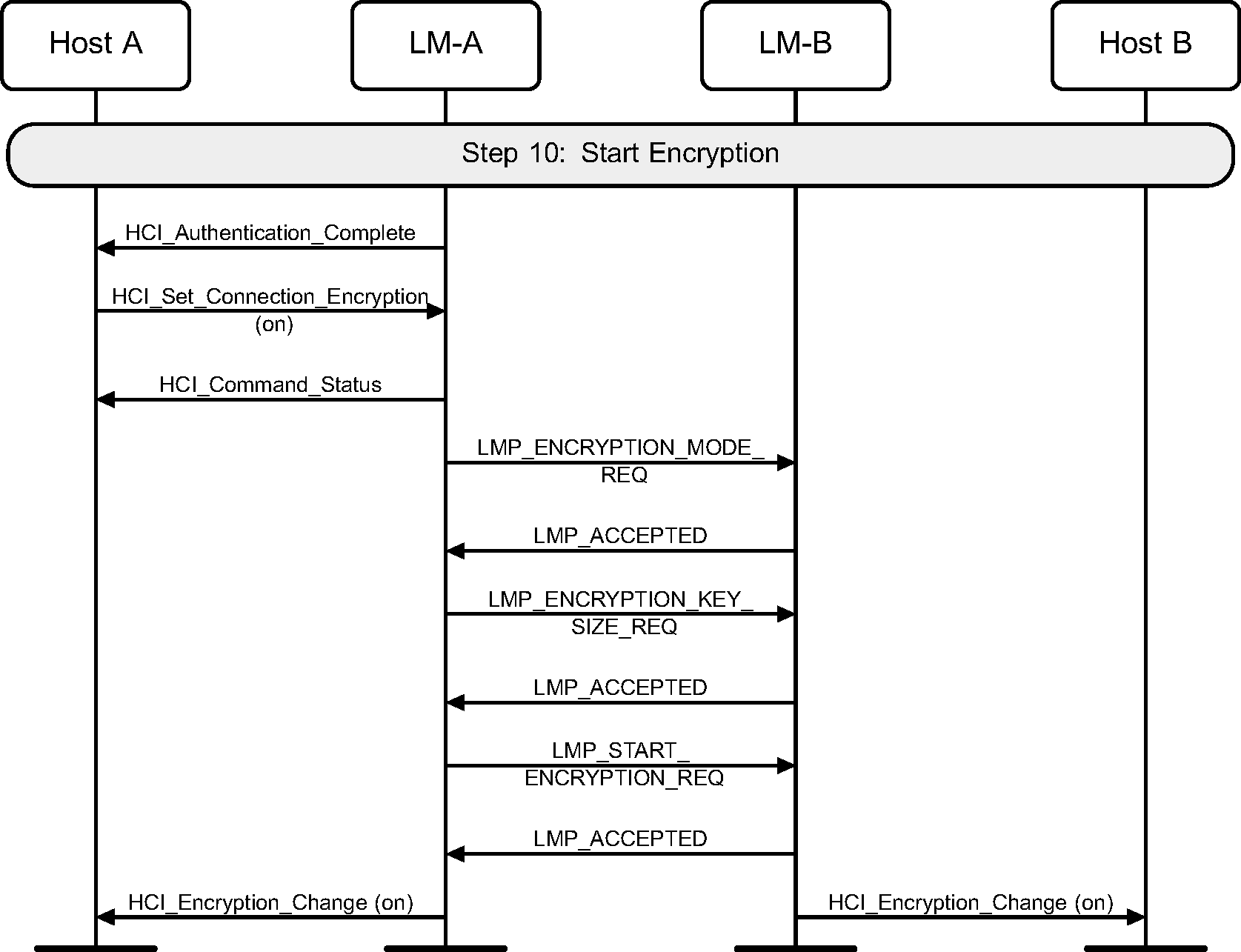
Step 1: The Host may at any time turn on encryption using the HCI_Set_Connection_Encryption command. This command can be originated from either the Central or Peripheral sides. Only the Central side is shown in Figure 4.30. If this command is sent from a Peripheral, the only difference is that the LMP_ENCRYPTION_MODE_REQ PDU will be sent from the Peripheral. The LMP_ENCRYPTION_KEY_SIZE_REQ and LMP_START_ENCRYPTION_REQ PDUs will always be requested from the Central. (See Figure 4.30.)
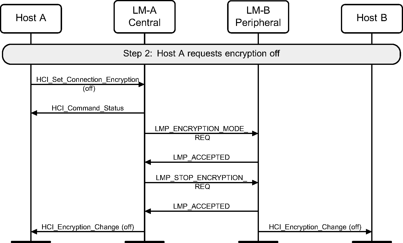
Step 2: To terminate the use of encryption, the HCI_Set_Connection_Encryption command is used. (See Figure 4.31.)
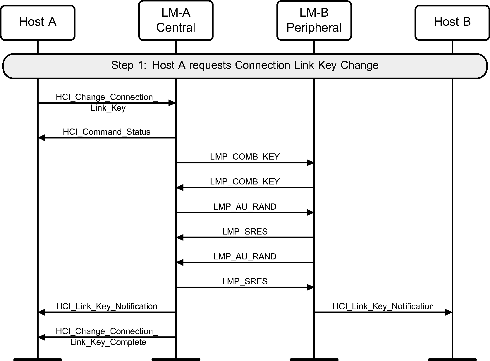
4.5. Change connection link key
Step 1: The Central’s Host (Host A) may change the connection link key using the HCI_Change_Connection_Link_Key command. A new link key will be generated and the Hosts will be notified of this new link key. (See Figure 4.32.)
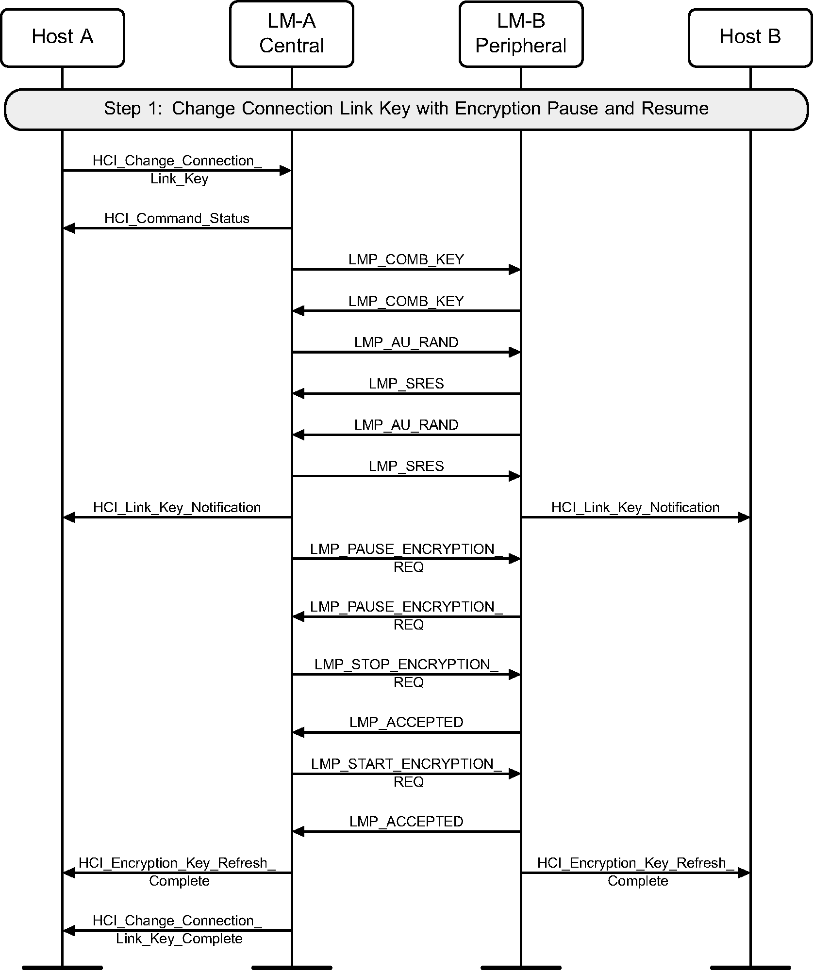
4.6. Change connection link key with encryption pause and resume
Step 1: The Central’s Host (Host A) may change the connection link key using the HCI_Change_Connection_Link_Key command. A new link key will be generated and the Hosts will be notified of this new link key. Encryption will then be paused and resumed, immediately using this new link key to generate a new encryption key. (See Figure 4.33.)
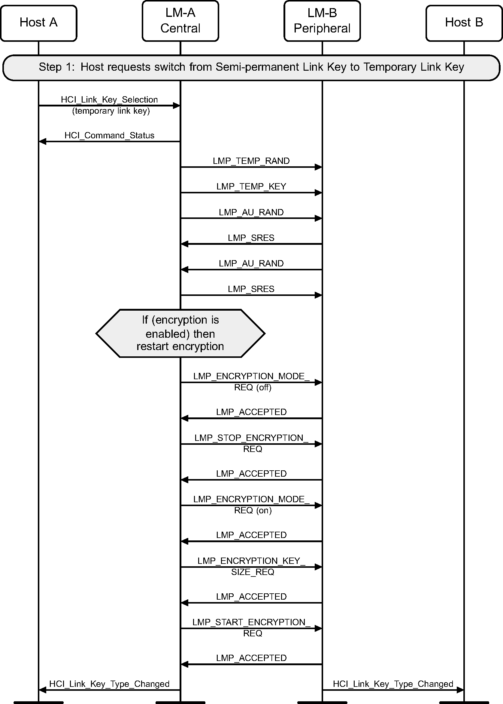
4.7. Temporary Link Key
Step 1: The Host changes to a Temporary Link Key from a Semi-permanent Link Key using the HCI_Link_Key_Selection command when at least one device does not support Encryption Pause and Resume. (See Figure 4.34.)
Step 2: The Host changes to a Semi-permanent Link Key from a Temporary Link Key using the HCI_Link_Key_Selection command. (See Figure 4.35.)

4.8. Read remote supported features
Using the HCI_Read_Remote_Supported_Features command the supported LMP Features of a remote device can be read. (See Figure 4.36.)
If the remote supported features have been obtained previously then the Controller may return them without sending any LMP PDUs.
Step 1: The Host requests the supported features of a remote device.

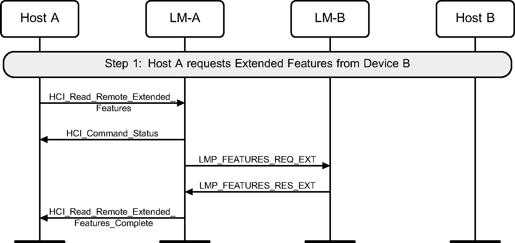
4.9. Read remote extended features
Using the HCI_Read_Remote_Extended_Features command the extended LMP features of a remote device can be read. (See Figure 4.37.)
If the remote extended features have been obtained previously then the Controller may return them without sending any LMP PDUs.
Step 1: The Host requests the extended features of a remote device.
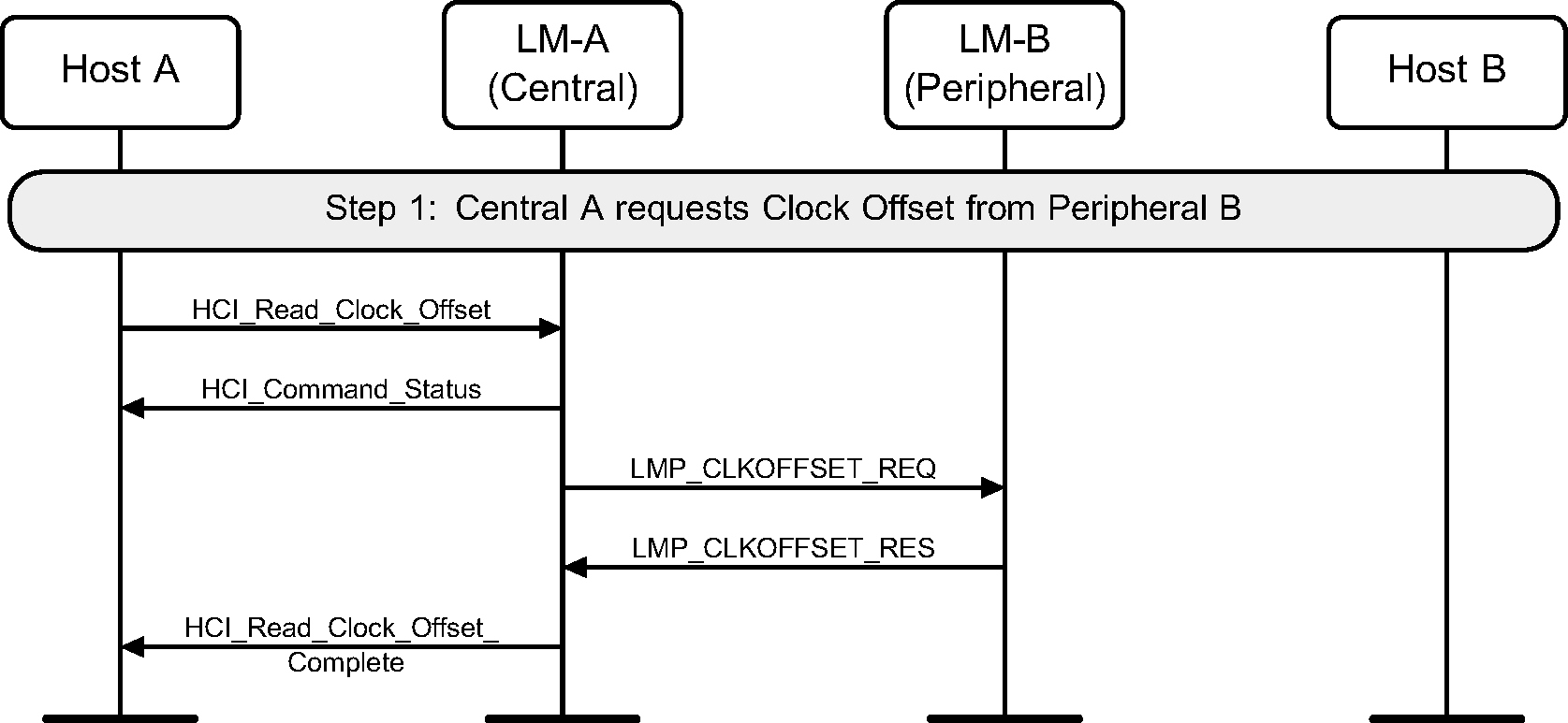
4.10. Read clock offset
Using the HCI_Read_Clock_Offset command the device acting as the Central can read the Clock Offset of a Peripheral (see Figure 4.38). The Clock Offset can be used to speed up the paging procedure in a later connection attempt.
Step 1: The Host requests the clock offset of a remote device.
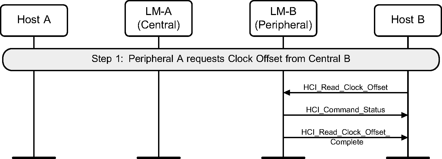
If the command is requested from the Peripheral, the Controller will directly return an HCI_Command_Status event and an HCI_Read_Clock_Offset_Complete event without sending any LMP PDUs (see Figure 4.39).
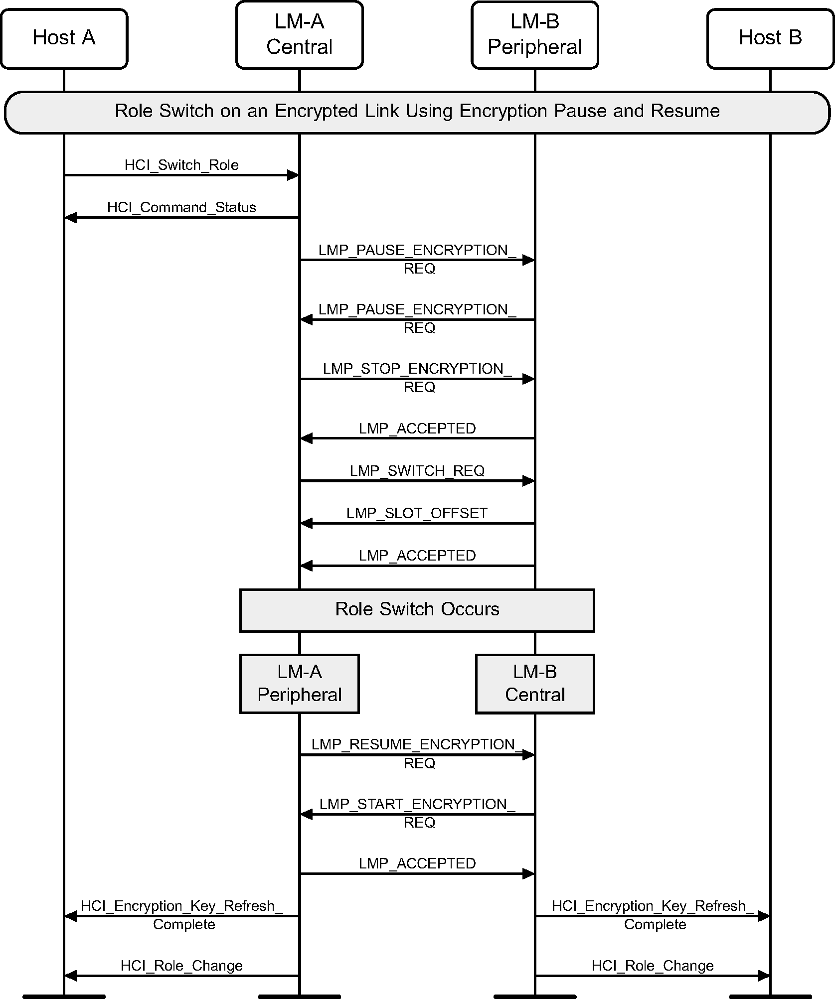
4.11. Role switch on an encrypted link using encryption pause and resume
The HCI_Switch_Role command can be used to explicitly switch the current Central / Peripheral role of the local device with the specified device. The Central’s Host (A) requests a role switch with a Peripheral. This will first pause encryption, and then send the switch request, and the Peripheral will respond with the slot offset and accepted. The role switch is performed by doing the TDD switch and piconet switch. Encryption is resumed, and finally an HCI_Role_Change event is sent on both sides. (See Figure 4.40.)
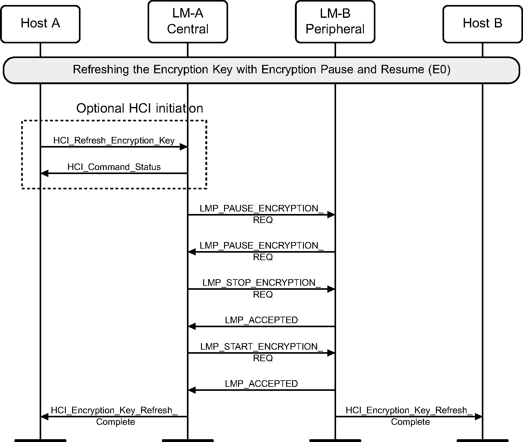
4.12. Refreshing encryption keys
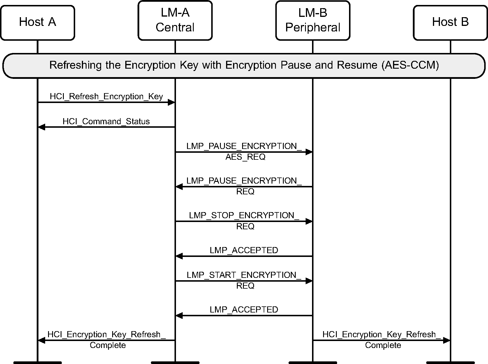
The HCI_Refresh_Encryption_Key command may be used by the Central's Host to explicitly pause and resuming encryption to refresh the encryption key. After encryption is resumed an HCI_Encryption_Key_Refresh_Complete event is sent on both sides. (See Figure 4.41).
When both devices support Secure Connections, the encryption key refresh sequence is performed as follows.
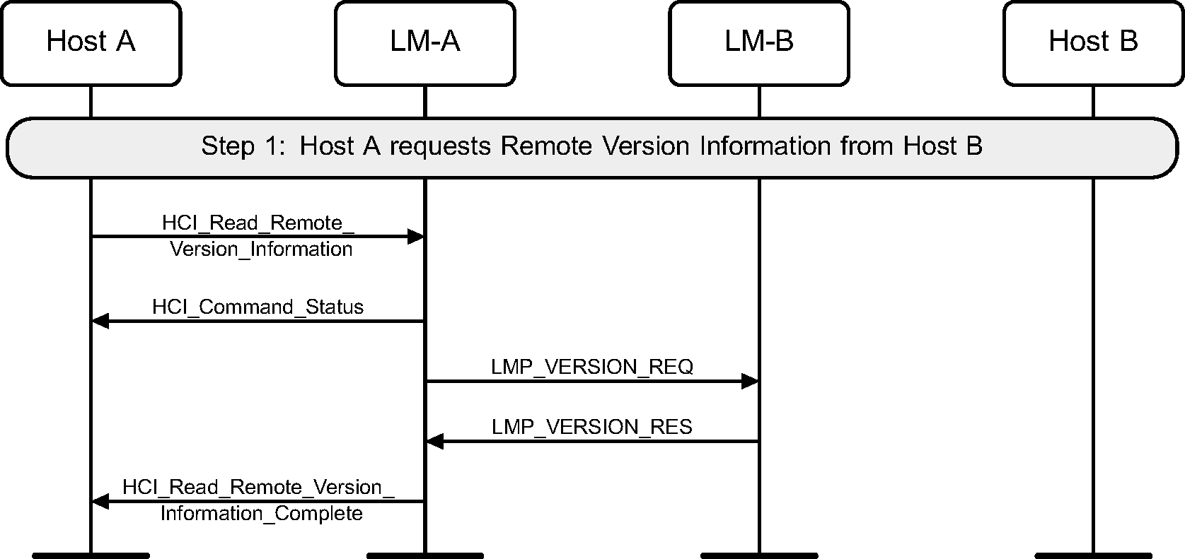
4.13. Read remote version information
Using the HCI_Read_Remote_Version_Information command the version information of a remote device can be read. (See Figure 4.43.)
If the remote version information has been obtained previously then the Controller may return them without sending any LMP PDUs.
Step 1: The Host requests the version information of a remote device.
4.14. QoS setup
Using the HCI_Flow_Specification command the Quality of Service (QoS) and Flow Specification requirements of a connection can be notified to a Controller. The Controller may then change the quality of service parameters with a remote device. (See Figure 4.44.)
Step 1: The Host sends QoS parameters to a remote device.

4.15. Switch role
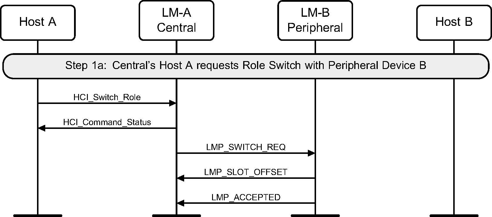
The HCI_Switch_Role command can be used to explicitly switch the current Central / Peripheral role of the local device with the specified device.
Step 1a: The Central’s Host (A) requests a role switch with a Peripheral. This will send the switch request, and the Peripheral will respond with the slot offset and accepted. (See Figure 4.45.)
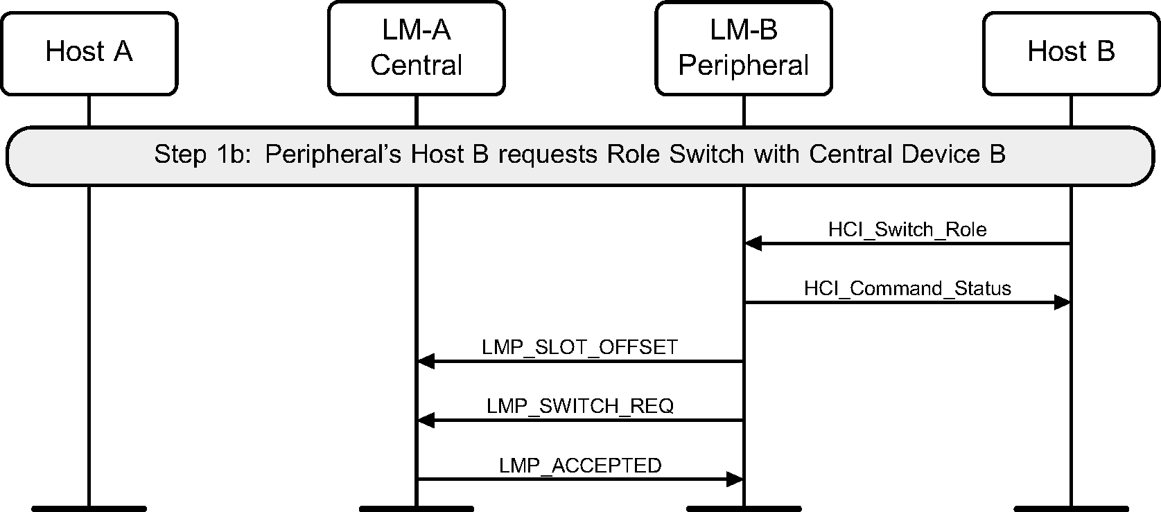
Step 1b: The Peripheral’s Host (B) requests a role switch with a Central. This will send the slot offset and the switch request, and the Central will respond with a LMP_ACCEPTED PDU. (See Figure 4.46.)
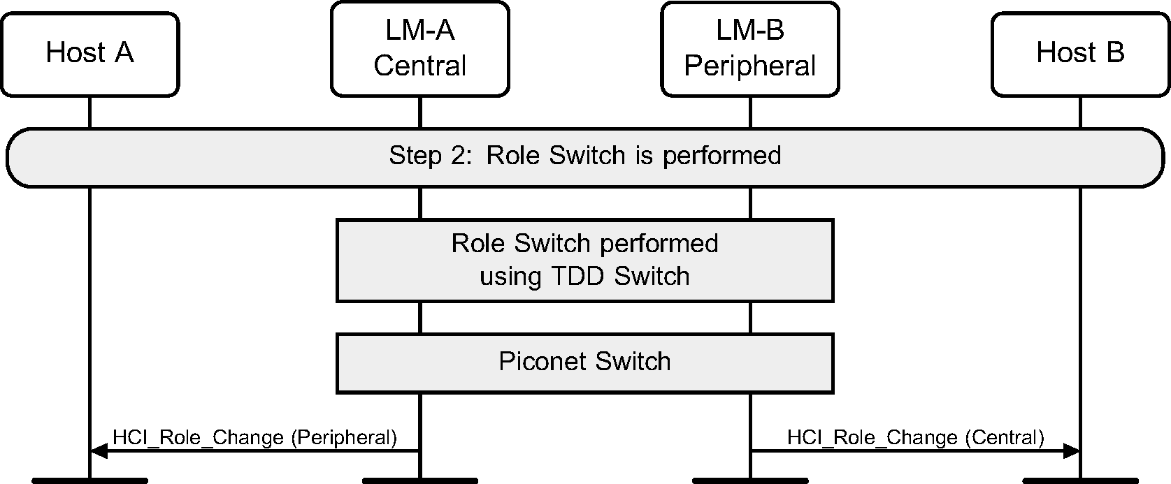
Step 2: The role switch is performed by doing the TDD switch and piconet switch. Finally an HCI_Role_Change event is sent on both sides. (See Figure 4.47.)
4.16. [This section is no longer used]
4.17. [This section is no longer used]
4.18. Slot availability mask
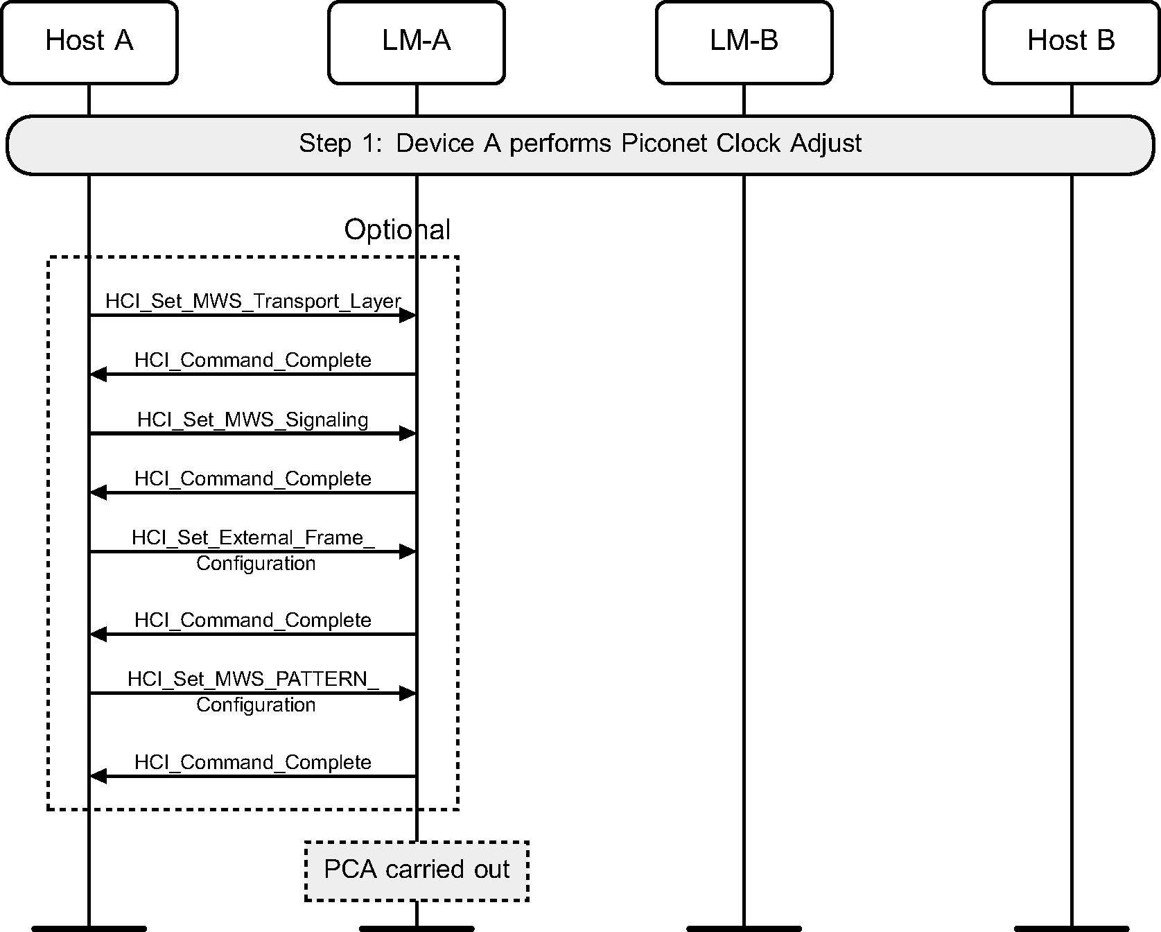
Step 1: The setup of SAM may be triggered by the Link Manager for MWS coexistence or topology management purposes. SAM setup may be triggered by HCI commands as shown in Figure 4.48 or by the real-time signals (e.g. MWS_PATTERN_Index, FRAME_SYNC, etc.) from the Coexistence Logical Interface (see [Vol 7] Part A ).
Piconet Clock Adjustment may be performed to create more available slot pairs per MWS frame.
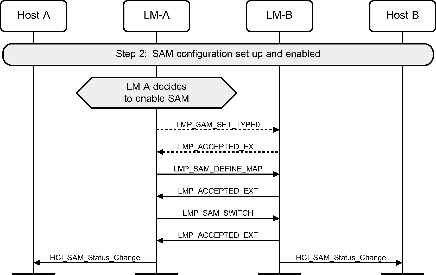
Step 2: The Link Manager on device A sends the SAM configuration to device B and then selects a SAM map (see Figure 4.49).
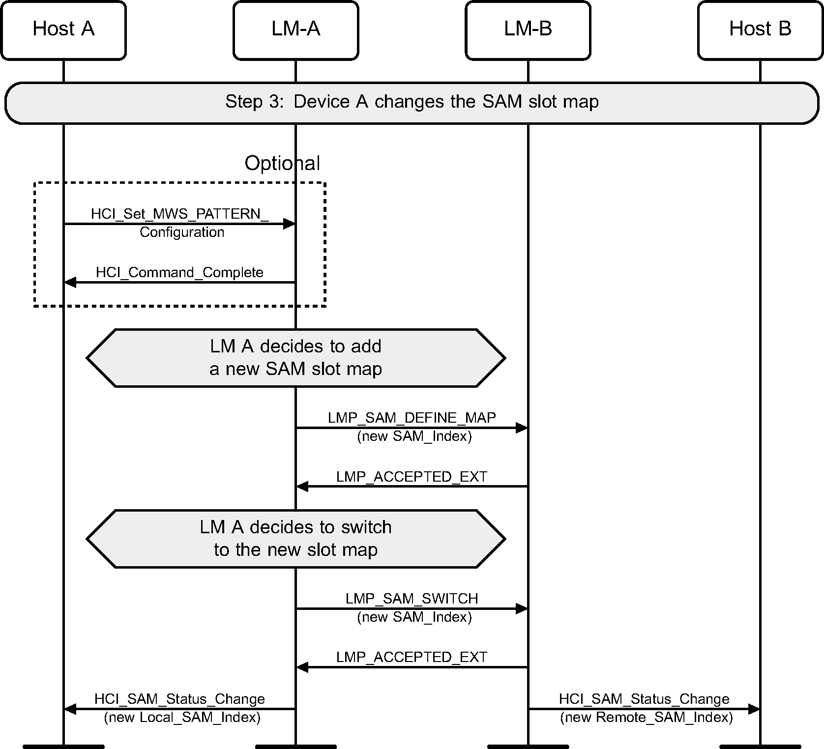
Step 3: Device A receives a new configuration (possibly over HCI), sends it to device B, and switches to using it (see Figure 4.50).
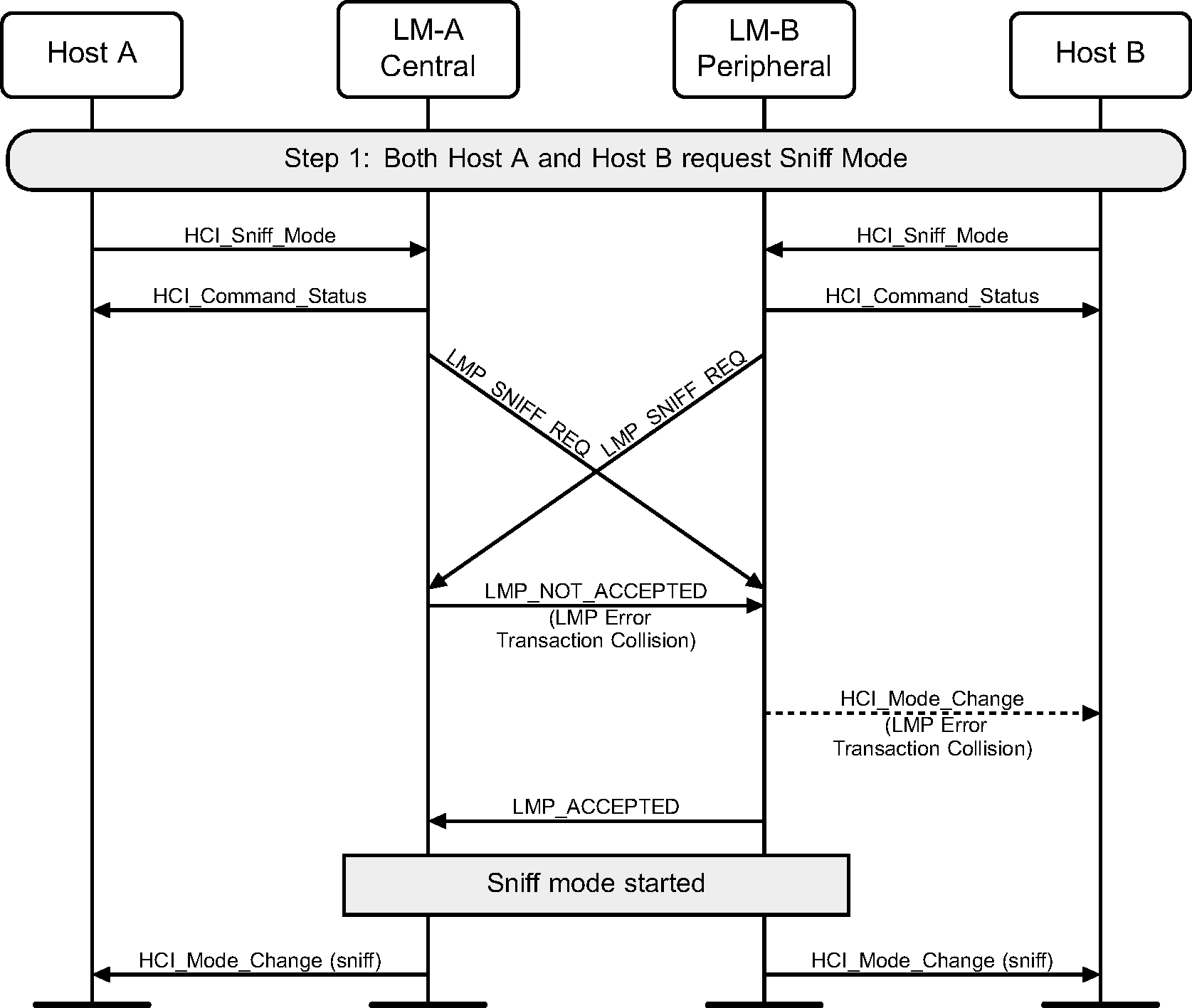
4.19. LMP transaction collision
The Link Managers of both the Central and Peripheral may initiate the same LMP transaction at the same time.
5. Synchronous connection establishment and detachment
5.1. Synchronous connection setup
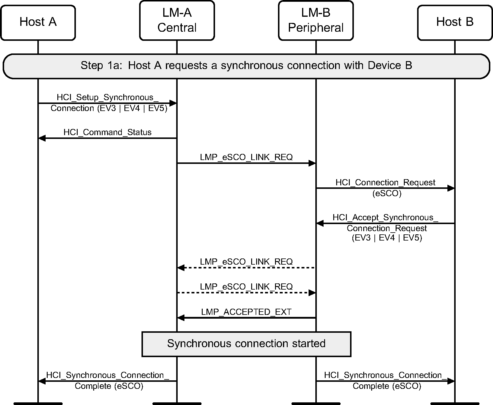
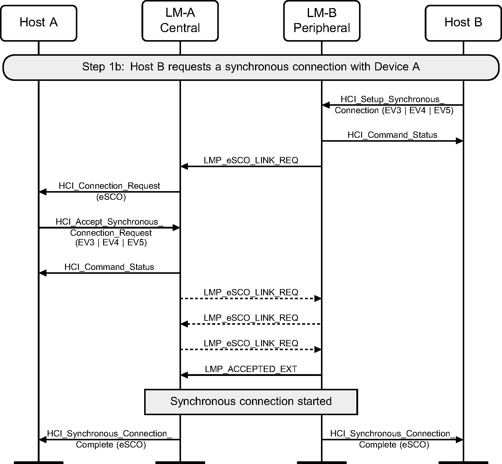
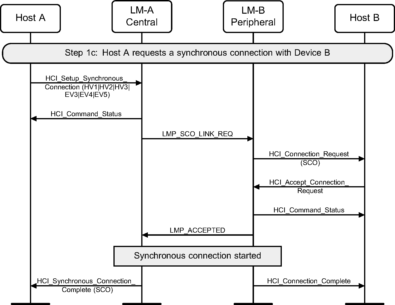
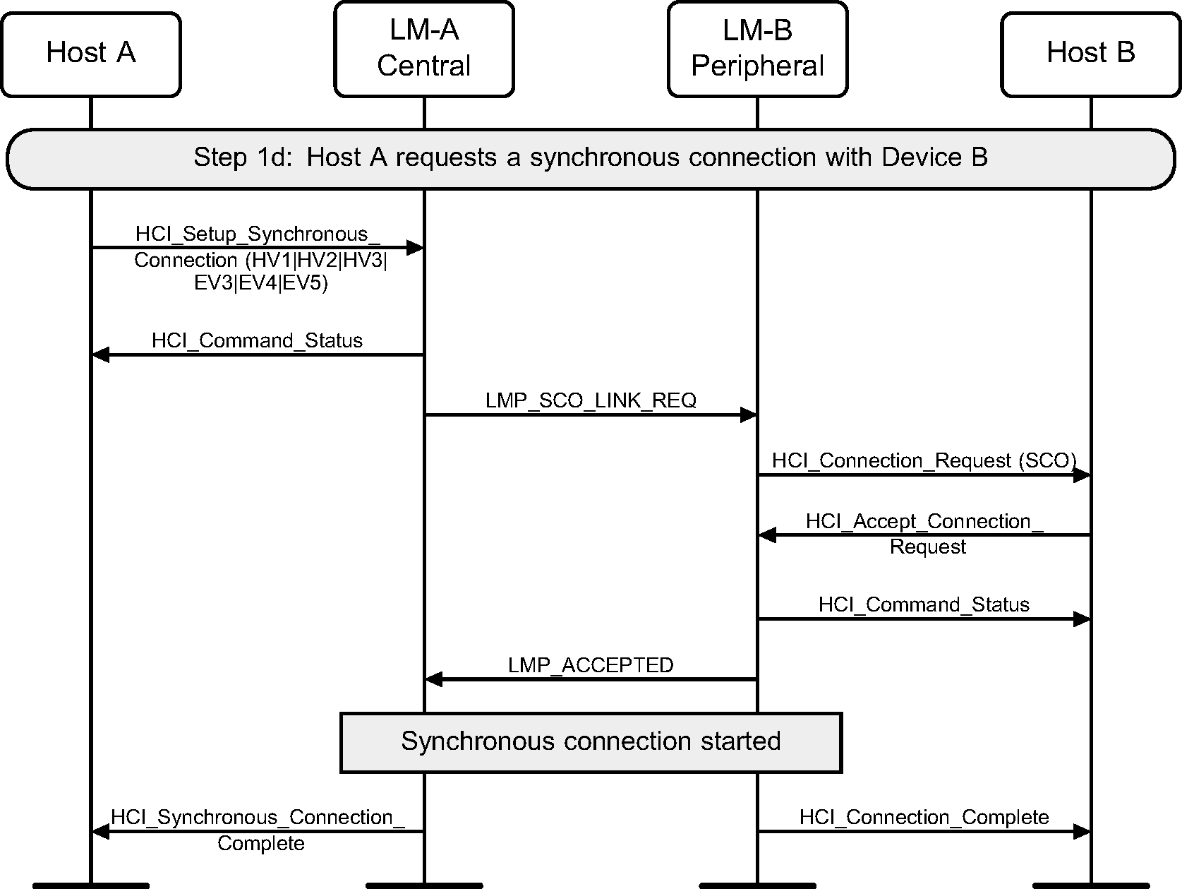
Using the HCI_Setup_Synchronous_Connection command, a Host can add a synchronous logical channel to the link. A synchronous logical link can be provided by creating a SCO or an eSCO logical transport.
Note
Note: An ACL connection must be established before a synchronous connection can be created.
Step 1a: Central requests a synchronous connection with a device. (See Figure 5.1.)
Step 1b: Peripheral requests a synchronous connection with a device. (See Figure 5.2.)
Step 1c: Central requests a SCO connection with a device. (See Figure 5.3.)
Step 1d: Central requests a SCO connection with a device. (See Figure 5.4.)
Step 1e: Host device requests a SCO connection with a device. (See Figure 5.5.)

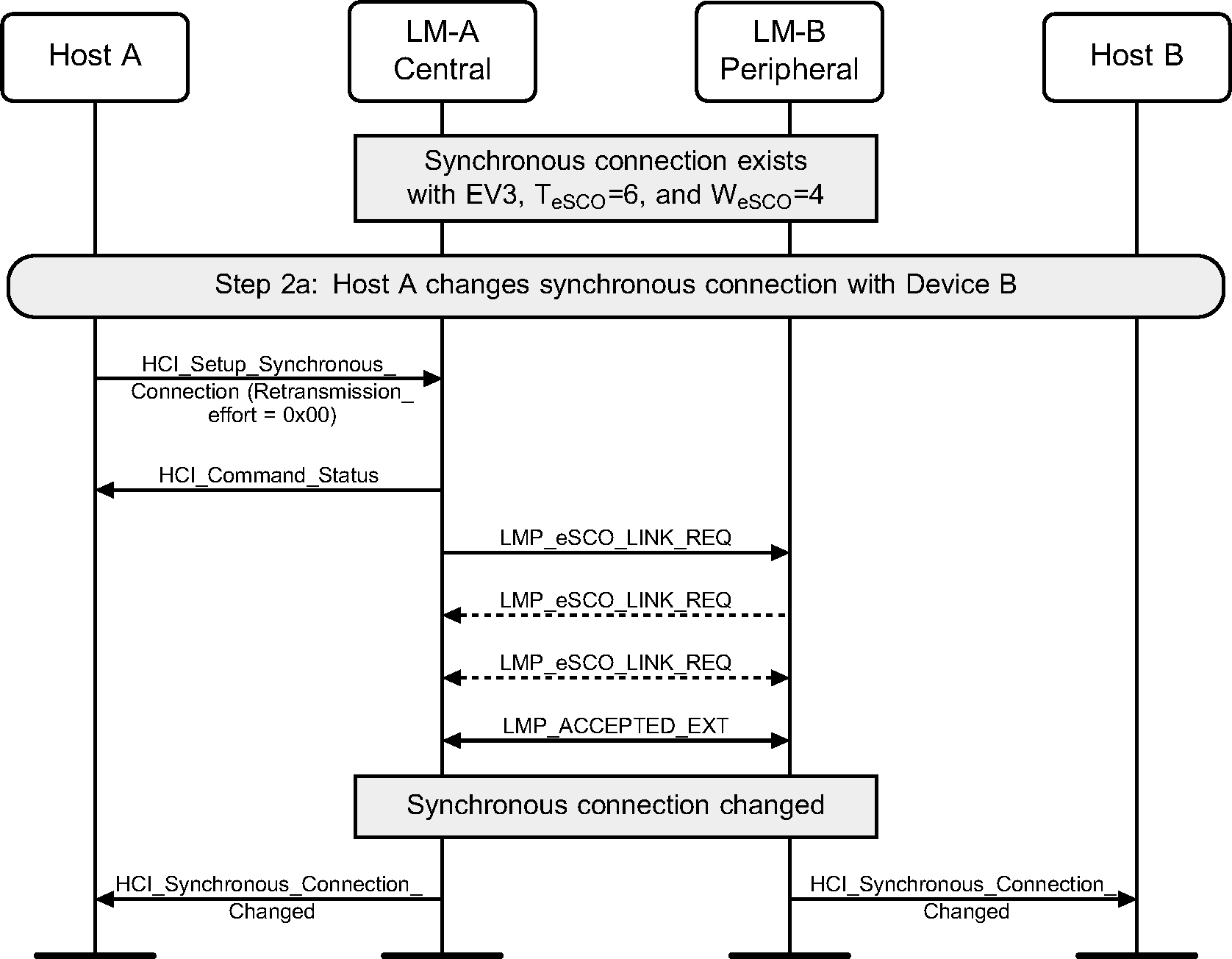
Step 2a: Central renegotiates eSCO connection (see Figure 5.6.)
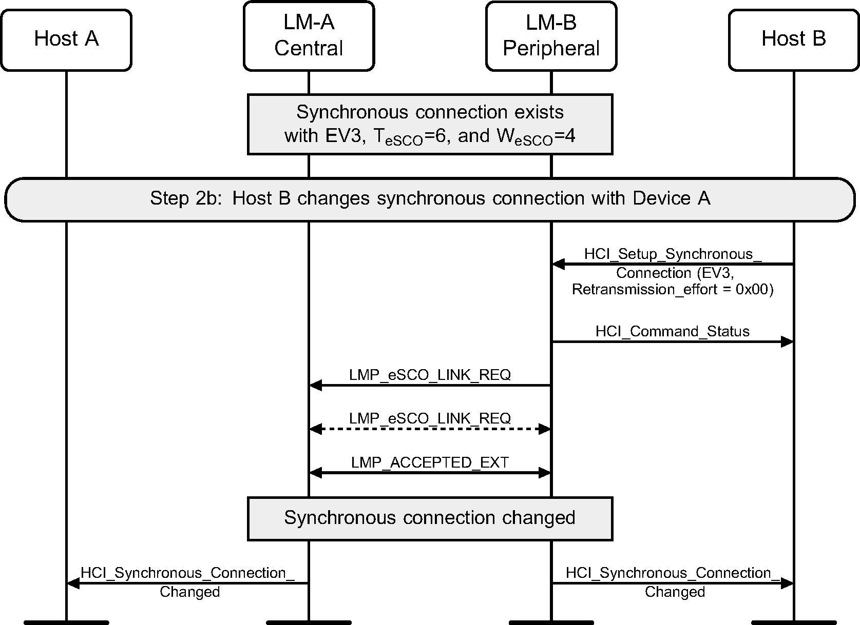
Step 2b: Peripheral renegotiates eSCO connection (see Figure 5.7.)
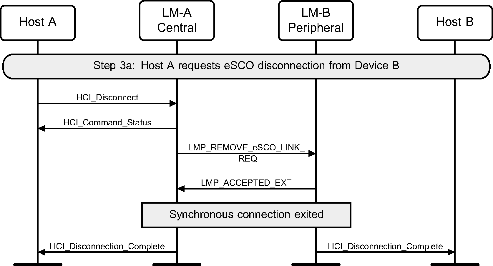
Step 3a: eSCO disconnection. (See Figure 5.8.)
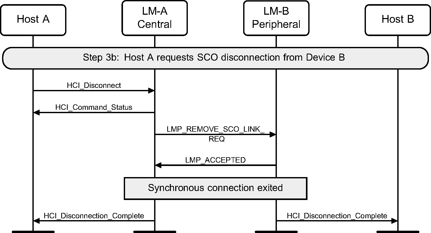
Step 3b: SCO disconnection. (See Figure 5.9.)
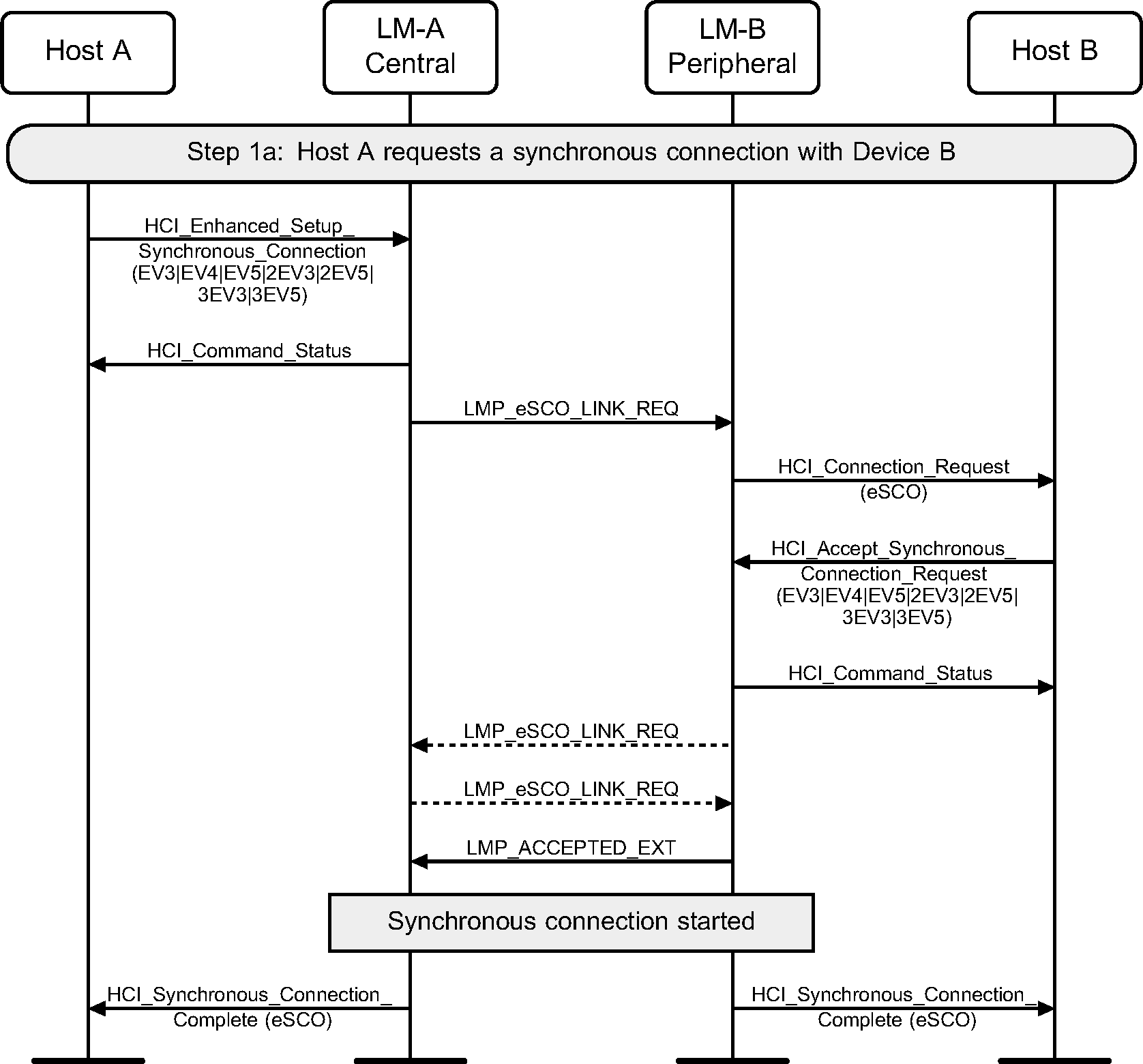
5.2. Synchronous connection setup with enhanced synchronous commands
Using the HCI_Enhanced_Setup_Synchronous_Connection command, a Host can add a synchronous logical channel to the link. A synchronous logical link can be provided by creating a SCO or an eSCO logical transport.
Note
Note: An ACL connection must be established before a synchronous connection can be created.
Step 1a: Central requests a synchronous connection with a Peripheral.
Step 1b: Peripheral requests a synchronous connection with a Central.

Step 1c : Central requests a SCO connection with a Peripheral.
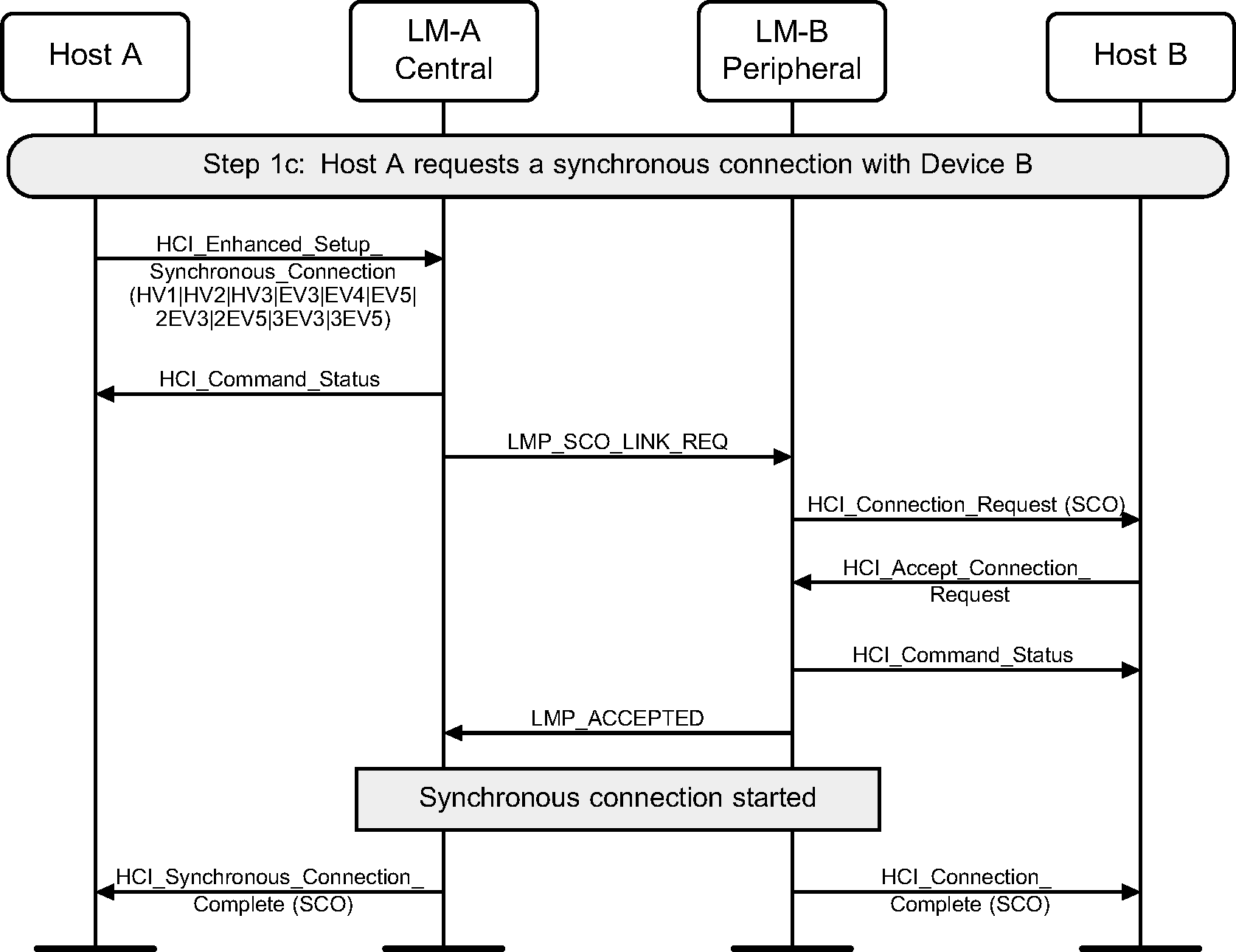
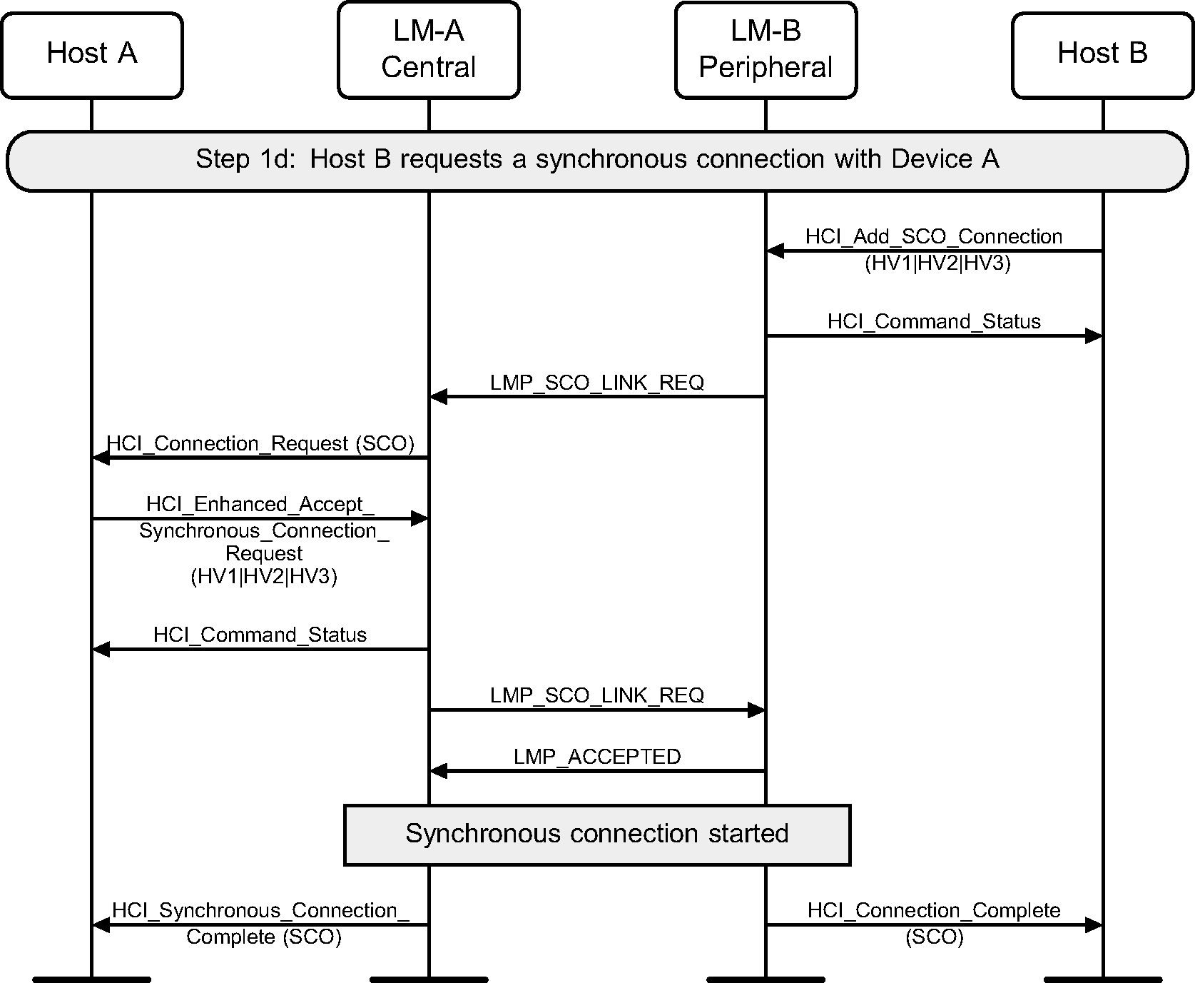
Step 1d : Peripheral requests a SCO connection with a Central.
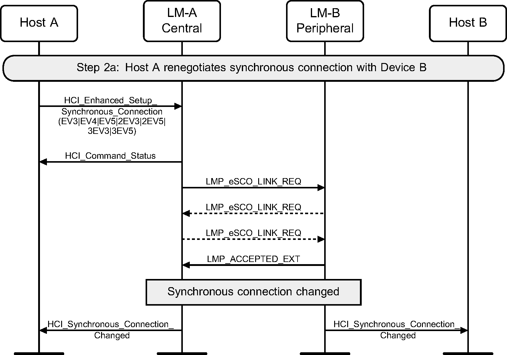
Step 2a: Central renegotiates eSCO connection.
Step 2b: Peripheral renegotiates eSCO connection.

6. Sniff and Hold modes
Entry into Sniff mode or Hold mode requires an established ACL connection.
6.1. Sniff mode
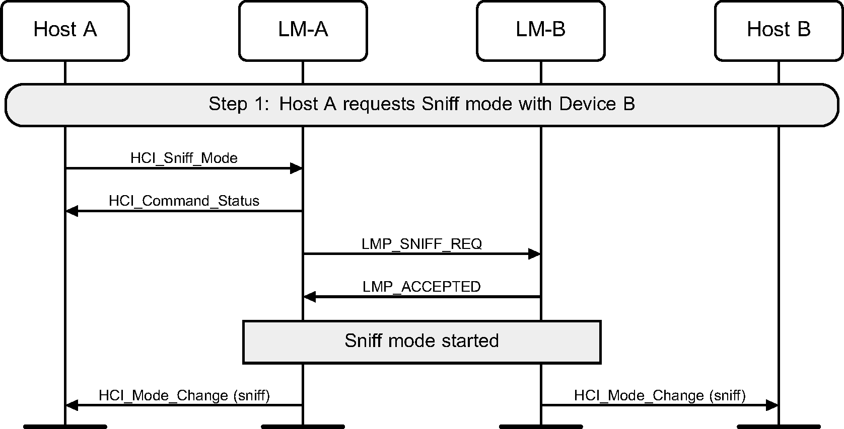
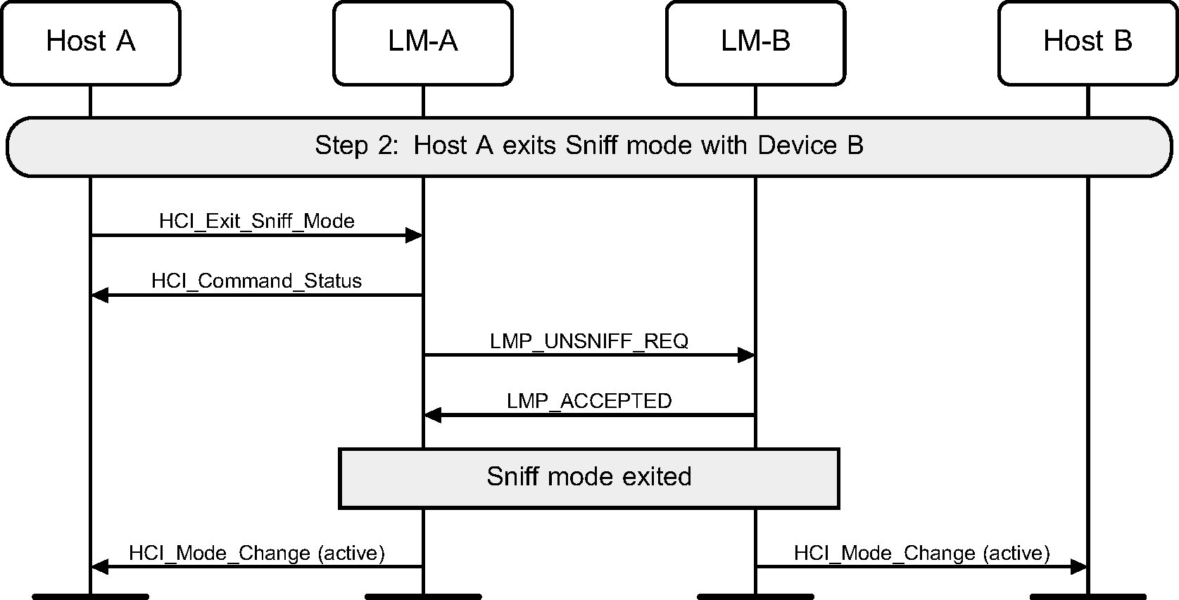
The HCI_Sniff_Mode command is used to enter Sniff mode. The HCI_Exit_Sniff_Mode command is used to exit Sniff mode.
Step 1: Host requests to enter Sniff mode. Multiple LMP_SNIFF_REQ PDUs may be sent as the parameters for Sniff mode are negotiated. (See Figure 6.1.)
Step 2: Host requests to exit Sniff mode. (See Figure 6.2.)
6.2. Hold mode
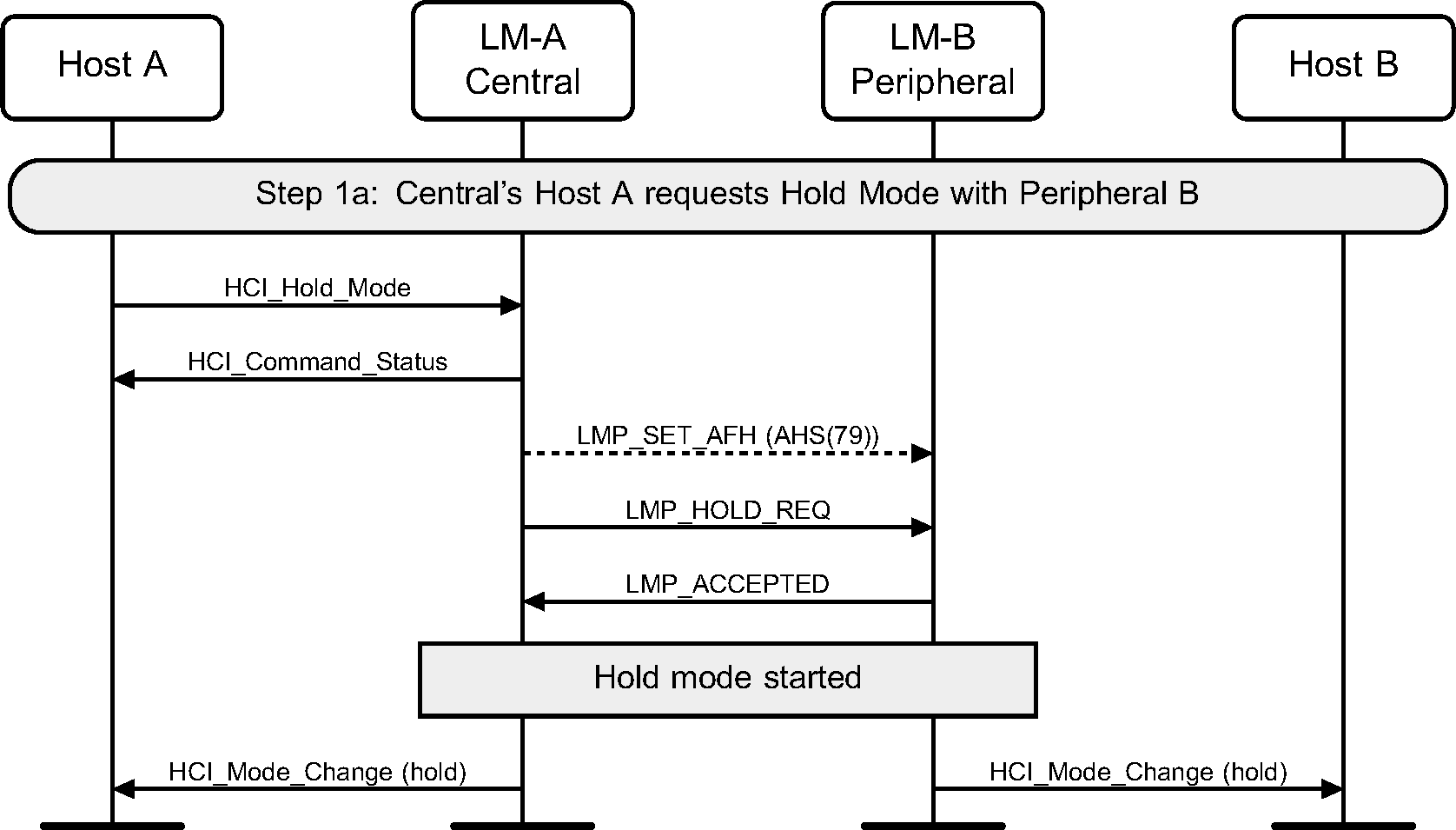
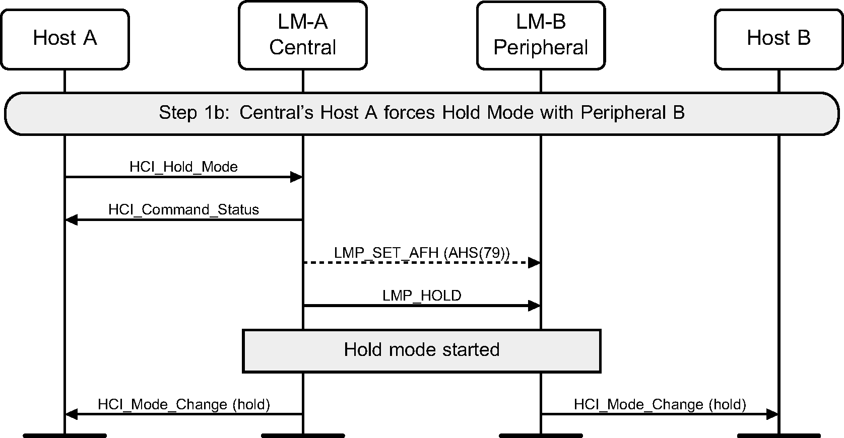
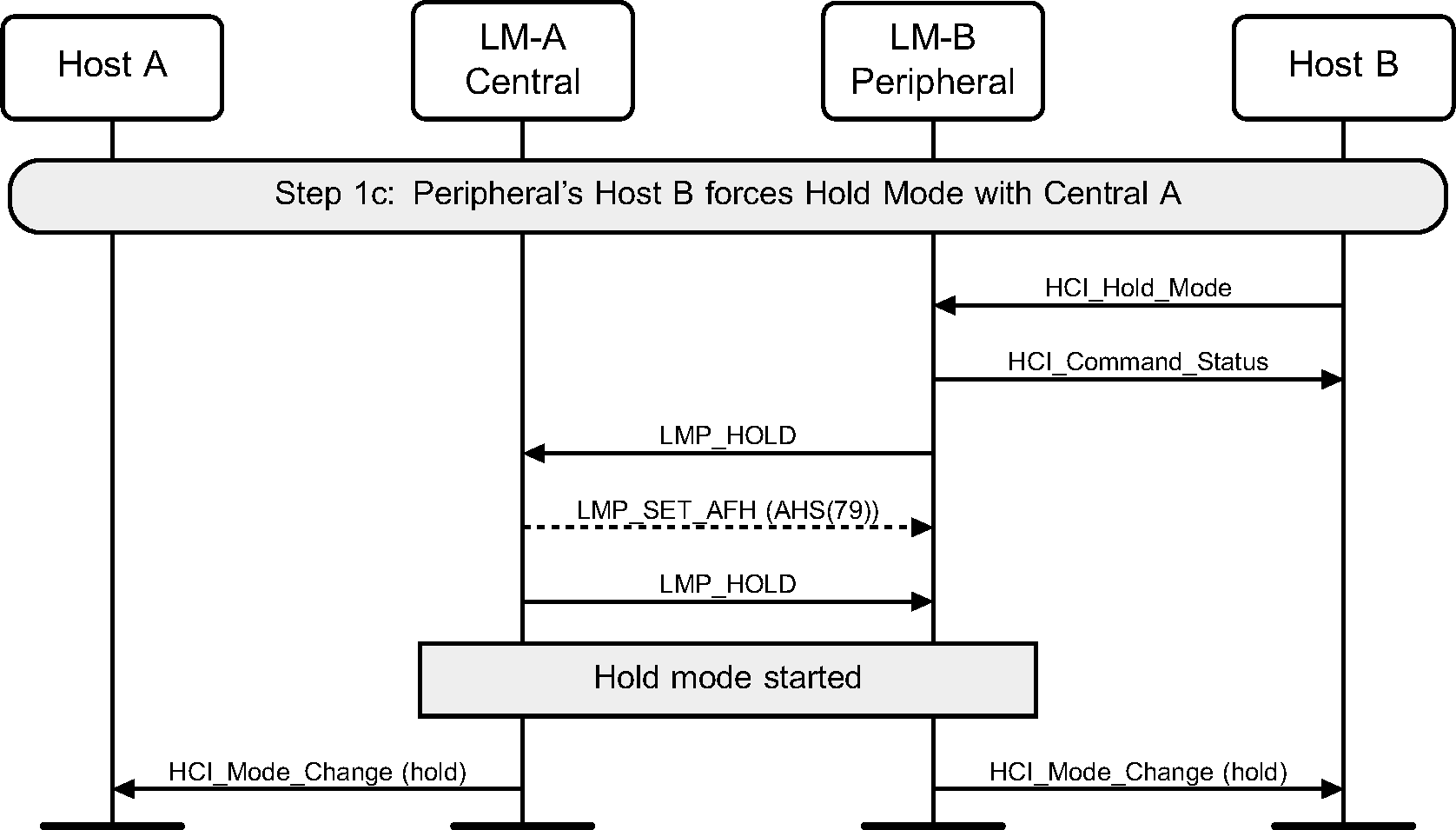
The HCI_Hold_Mode command can be used to place a device into Hold mode. The Controller may do this by either negotiating the Hold mode parameters or forcing Hold mode. Hold mode will automatically end after the negotiated length of time.
Step 1a: A Host requests Hold mode. (See Figure 6.3.)
Step 1b: A Host may force Hold mode. (See Figure 6.4.)
Step 1c: A Peripheral requests Hold mode. (See Figure 6.5.)
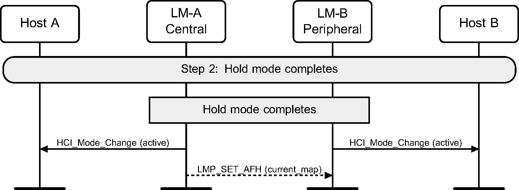
Step 2: When Hold mode completes the Hosts are notified using the HCI_Mode_Change event. (See Figure 6.6.)
6.3. [This section is no longer used]
7. Buffer management, flow control
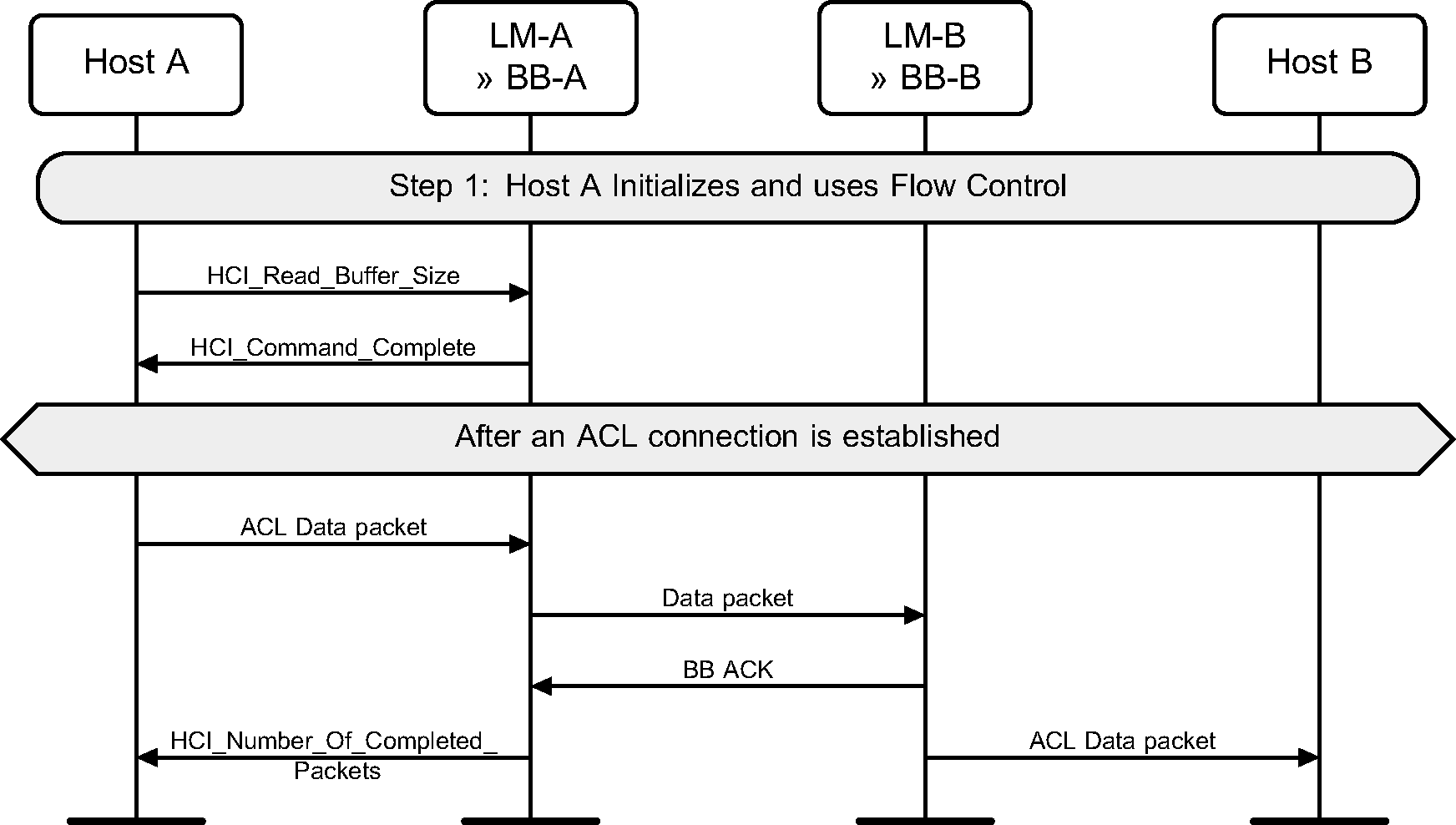
Buffer management is very important for resource limited devices. This can be achieved on the Host Controller interface using the HCI_Read_Buffer_Size command, and the HCI_Number_Of_Completed_Packets event, and the HCI_Set_Controller_To_Host_Flow_Control, HCI_Host_Buffer_Size and HCI_Host_Number_Of_Completed_Packets commands.
Step 1: During initialization, the Host reads the buffer sizes available in the Controller. When an HCI Data packet has been transferred to the remote device, and a Baseband acknowledgment has been received for this data, then an HCI_Number_Of_Completed_Packets event will be generated. (See Figure 7.1.)
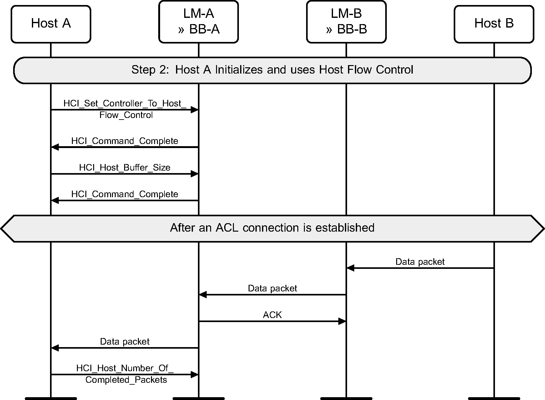
Step 2: During initialization, the Host notifies the Controller that Host flow control shall be used, and then the Host buffer sizes available. When a data packet has been received from a remote device, an HCI Data packet is sent to the Host from the Controller, and the Host shall acknowledge its receipt by sending HCI_Host_Number_Of_Completed_Packets command. (See Figure 7.2.)
8. Loopback mode
The loopback modes are used for testing of a device only.
8.1. Local Loopback mode
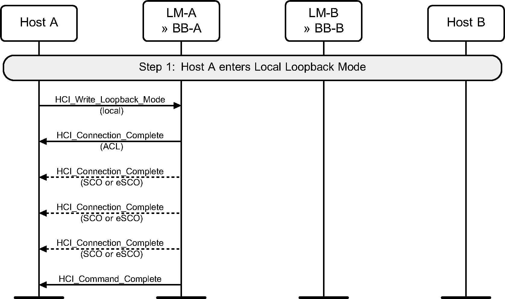
The Local Loopback mode is used to loopback received HCI commands, and HCI ACL Data and HCI Synchronous Data packets sent from the Host to the Controller.
Step 1: The Host enters Local Loopback mode. Four HCI_Connection_Complete events are generated and then an HCI_Command_Complete event. (See Figure 8.1.)
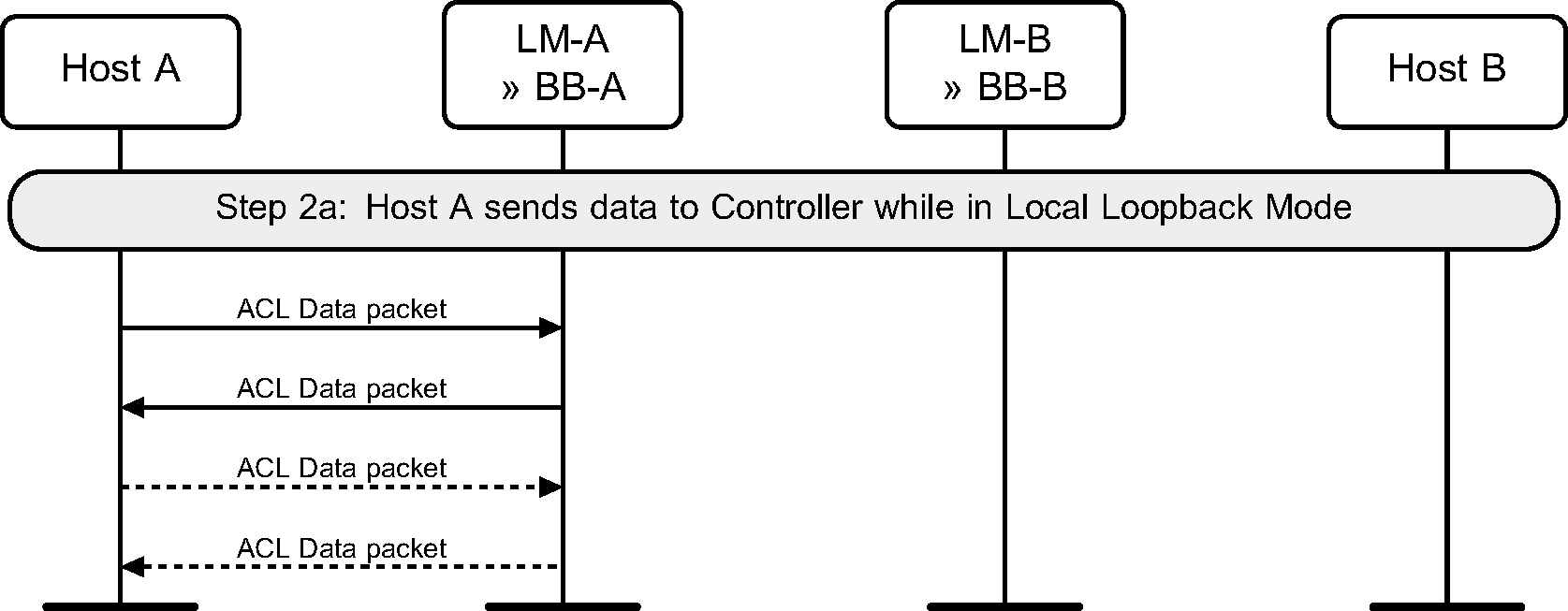
Step 2a: The Host sending HCI Data packet will receive the exact same data back in HCI Data packets from the Controller. (See Figure 8.2.)
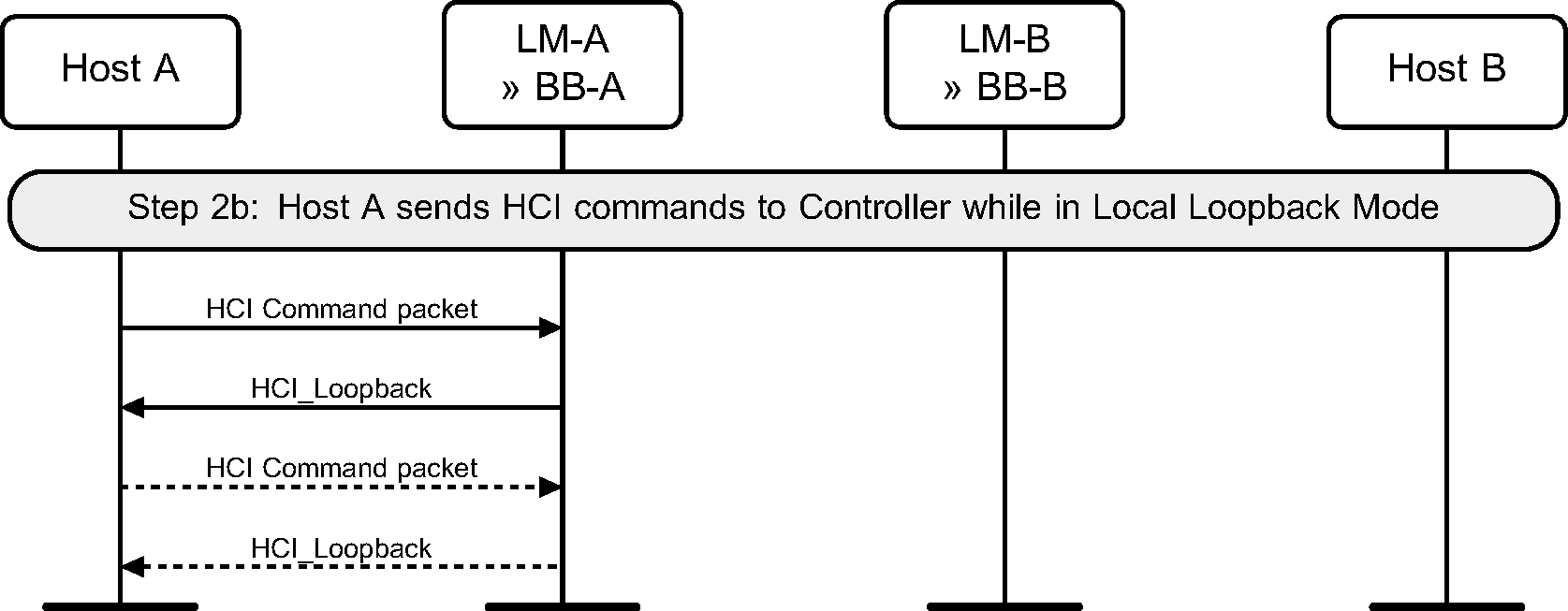
Step 2b: The Host sending most HCI Command packets to the Controller will receive an HCI_Loopback_Command event with the contents of the HCI Command packet in the payload. (See Figure 8.3.)
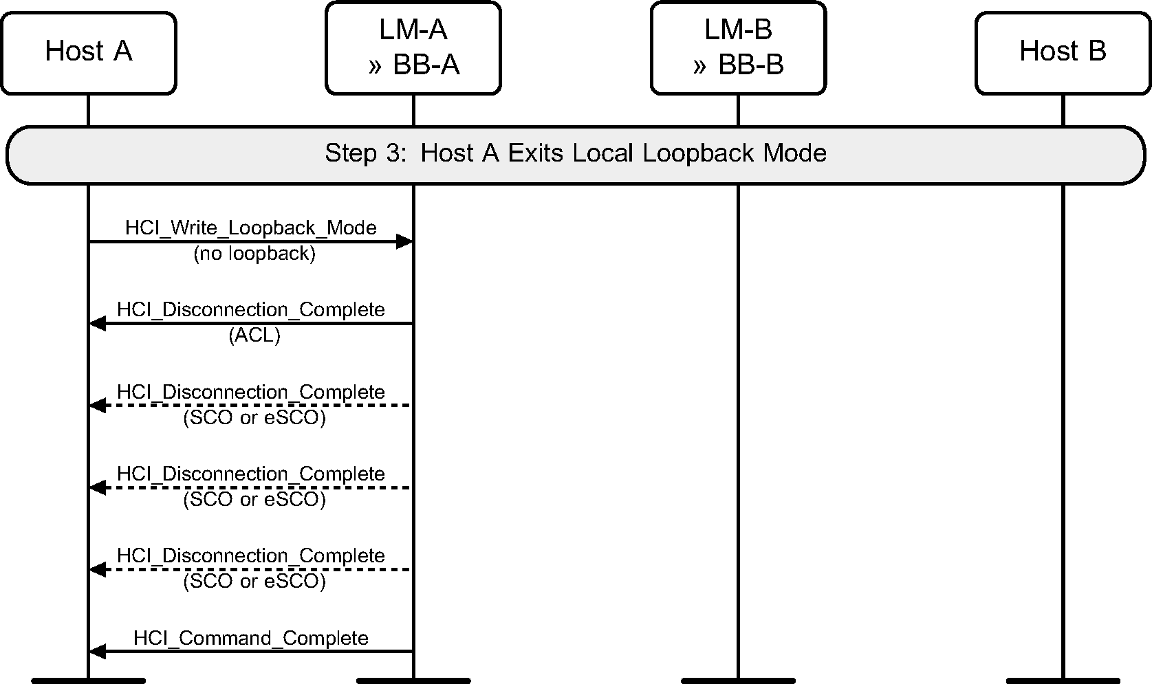
Step 3: The Host exits Local Loopback mode. Multiple HCI_Disconnection_Complete events are generated before the HCI_Command_Complete event. (See Figure 8.4.)
8.2. Remote Loopback mode
The Remote Loopback mode is used to loopback data to a remote device over the air.
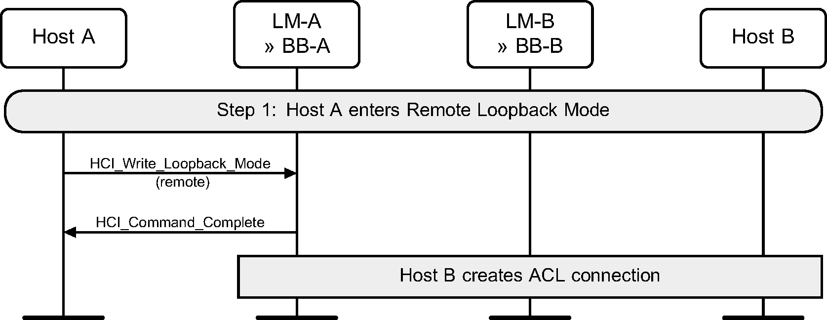
Step 1: The local device first enables remote loopback. The remote Host then sets up a connection to the local device. (See Figure 8.5.)
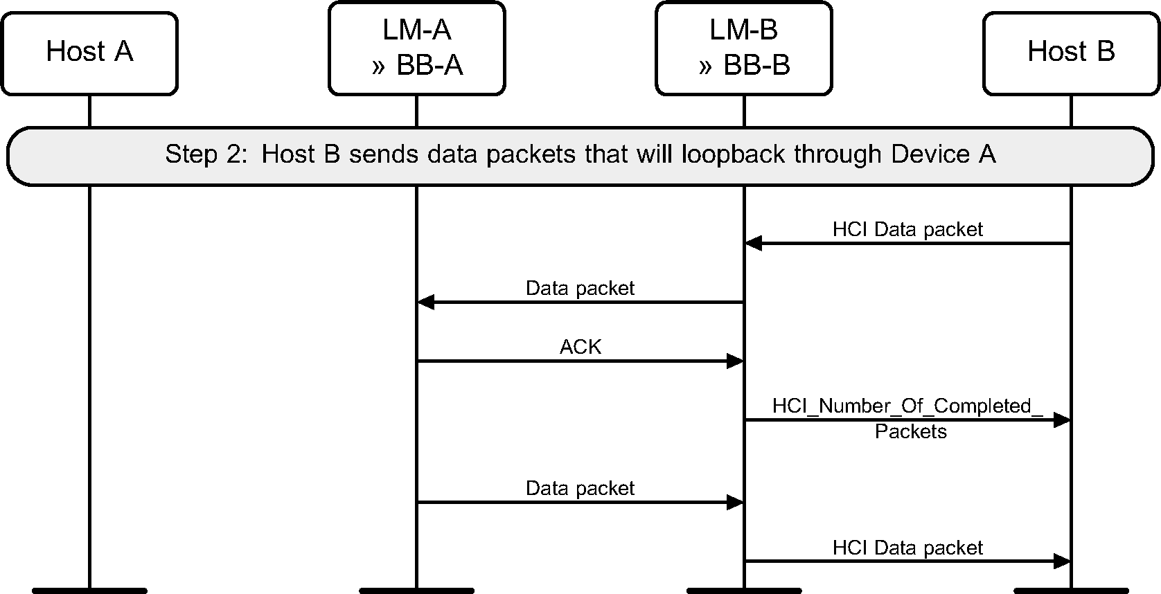
Step 2: Any data received from the remote Host will be looped back in the Controller of the local device. (See Figure 8.6.)
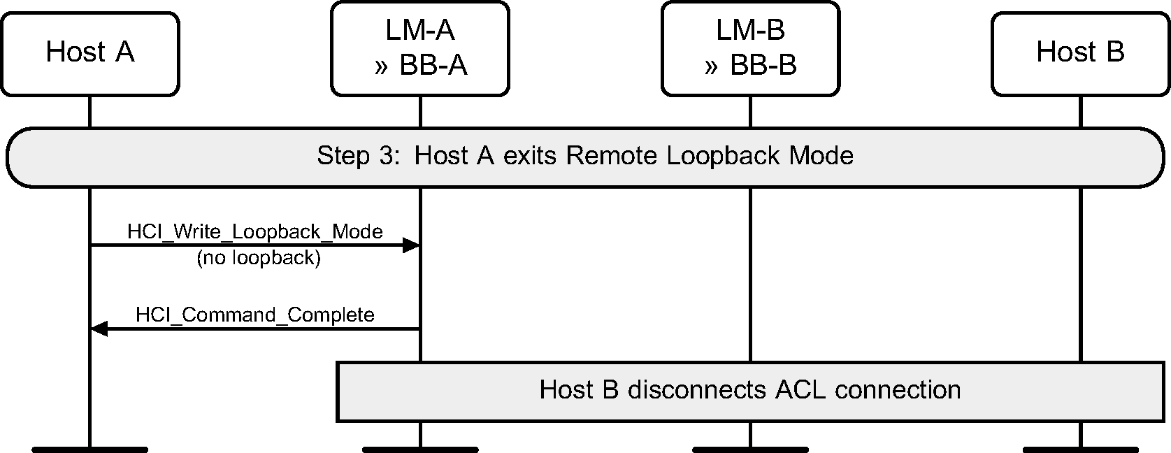
Step 3: The local Host exits Remote Loopback mode. Any connections can then be disconnected by the remote device. (See Figure 8.7.)
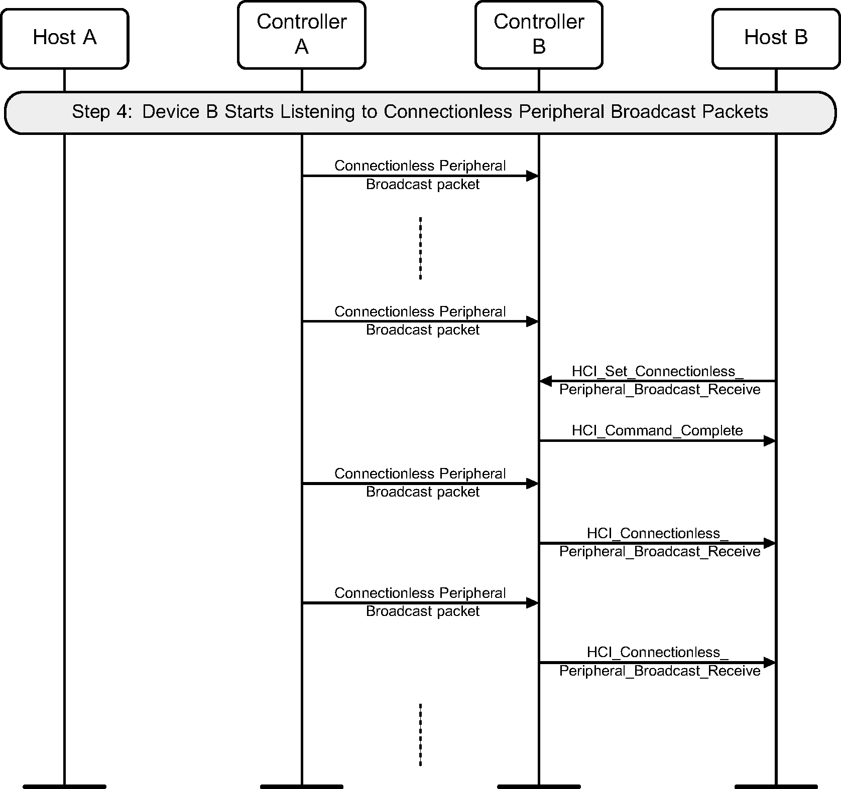
9. Connectionless Peripheral Broadcast services
Figure 9.1 illustrates the Truncated Page procedure.
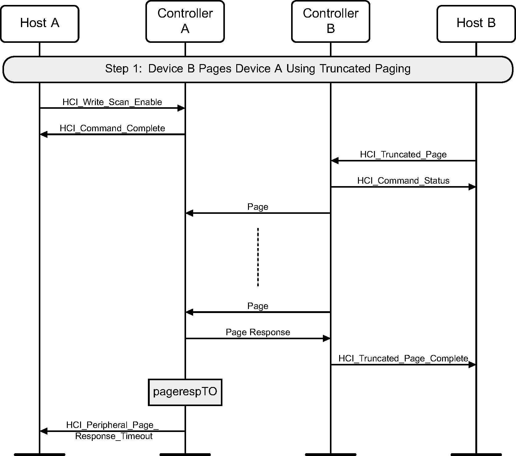
Figure 9.2 illustrates how Device A starts transmitting Connectionless Peripheral Broadcast packets to Device B.

Figure 9.3 shows the Synchronization Train feature. Device A is the Connectionless Peripheral Broadcast Transmitter. Device B is the Connectionless Peripheral Broadcast Receiver.
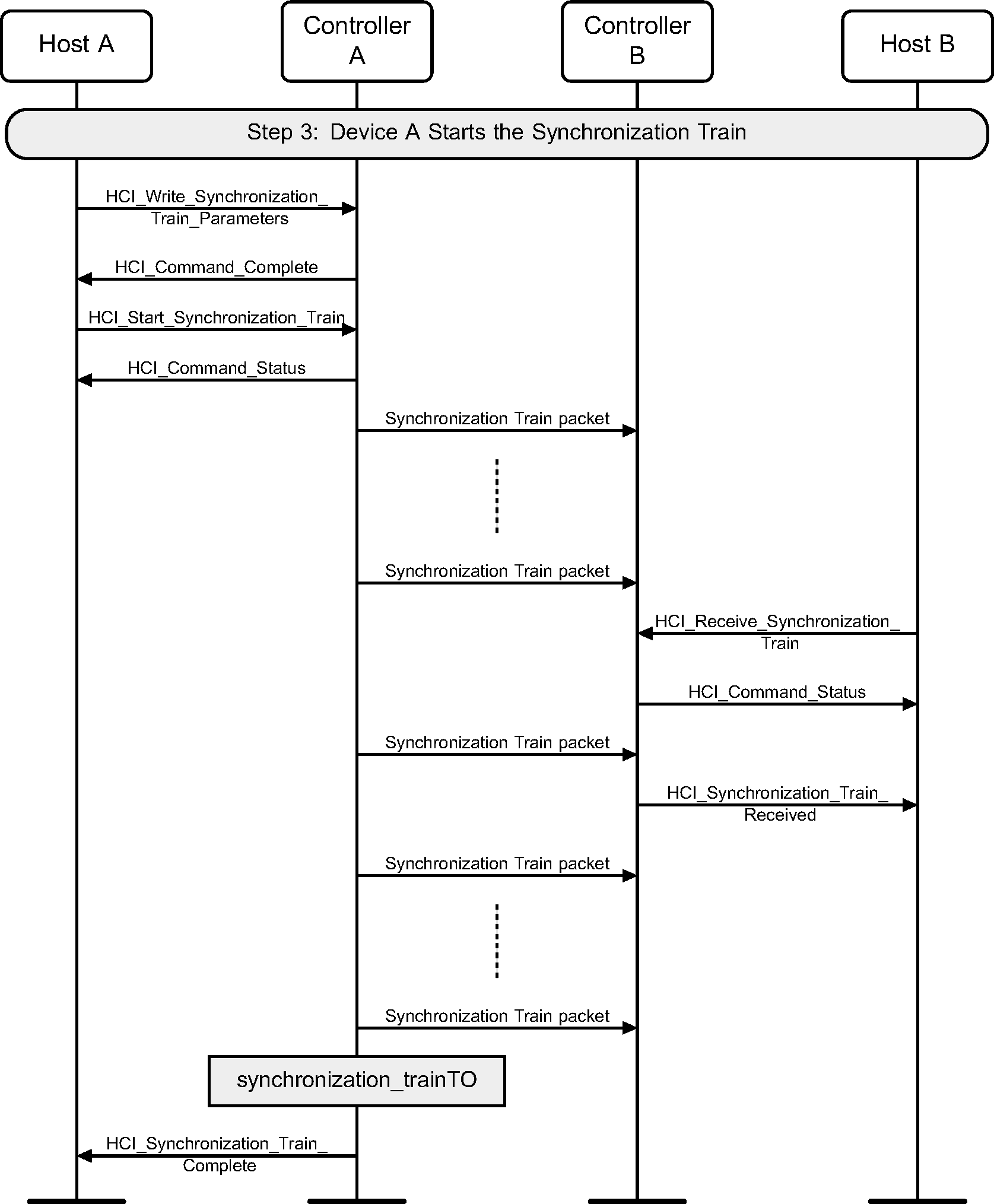
Figure 9.4 illustrates how Device B starts receiving Connectionless Peripheral Broadcast packets from Device A.