Part F. Direct Test Mode
vAtlanta r00
This Part describes the Direct Test Mode for RFPHY testing of Bluetooth Low Energy devices.
1. Introduction
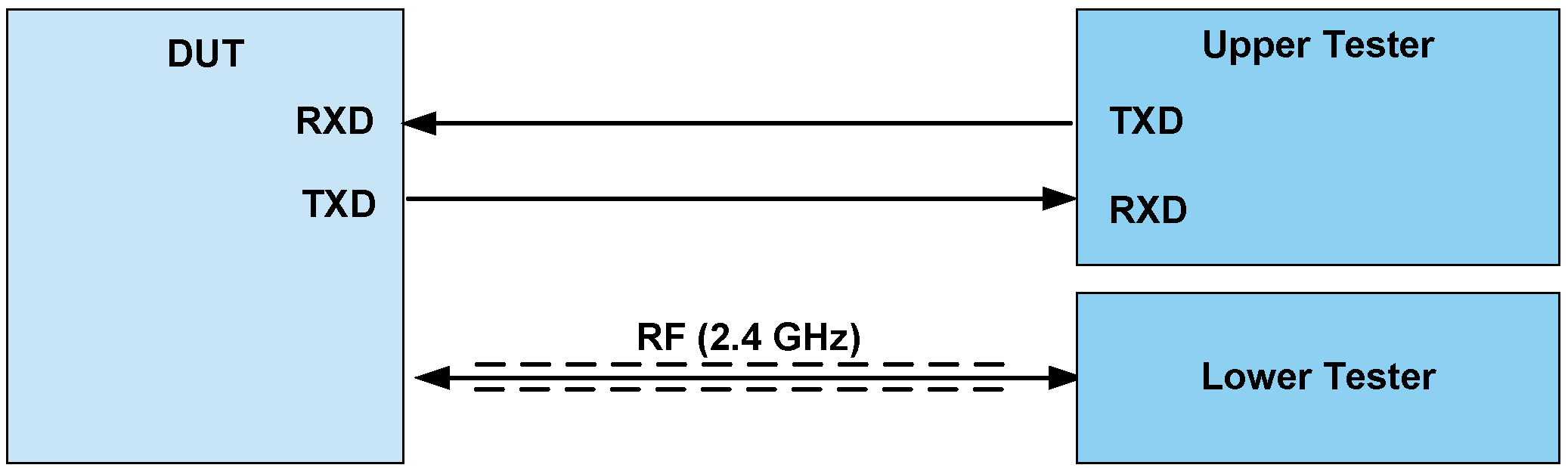
Direct Test Mode is used to control the Device Under Test (DUT) and provides a report back to the Tester.
Direct Test Mode shall be set up using one of two alternate methods:
Each DUT shall implement one of the two Direct Test Mode methods in order to test the Low Energy PHY layer. Figure 1.1 illustrates the alternatives for Direct Test Mode setup.

Figure 1.2 illustrates the Bluetooth LE Direct Test Mode setup principle using a 2-wire UART interface.
2. Low Energy test scenarios
2.1. Test sequences
These sequences are used as routines and used to control an LE DUT with an accessible HCI or a 2-wire UART interface for RF testing.
The following mapping shall be performed from the RF testing commands to HCI commands and events or 2-wire UART commands and events:
RF Test command / event | HCI command / event | 2-wire UART command / event |
|---|---|---|
LE_Transmitter_Test command | HCI_LE_Transmitter_Test command | LE_Transmitter_Test command |
LE_Receiver_Test command | HCI_LE_Receiver_Test command | LE_Receiver_Test command |
LE_Test_End command | HCI_LE_Test_End command | LE_Test_End command |
LE_Status event | HCI_Command_Complete event | LE_Test_Status event |
LE_Packet_Report event | HCI_Command_Complete event | LE_Packet_Report event |
The HCI commands and events used in Direct Test Mode are defined in [Vol 4] Part E, Section 7.8.
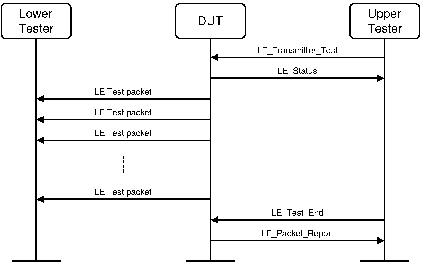
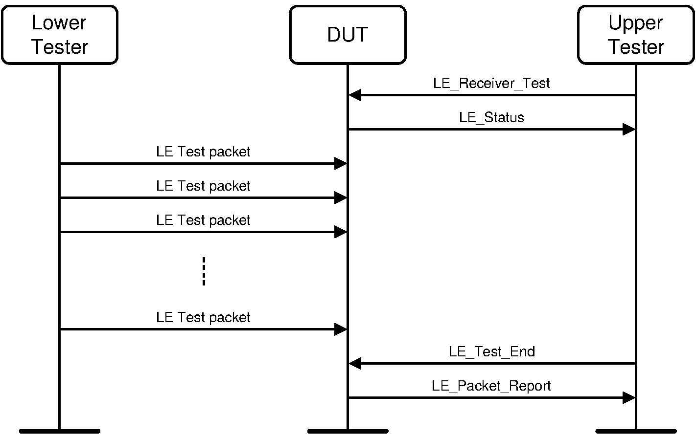
2.2. Message sequence charts
Transmitter Test
Receiver Test
3. UART Test Interface
3.1. UART Interface characteristics
The UART interface characteristics shall be set to use the following parameters:
Baud rate: One of the following shall be supported by the DUT:
1200, 2400, 9600, 14400, 19200, 38400, 57600, 115200
Number of data bits: 8
No parity
1 stop bit
No flow control (RTS or CTS)
3.2. UART functional description
The Upper Tester shall always initiate any a test scenario using the UART interface. The DUT shall respond to the commands from the Upper Tester.
The Upper Tester sends test commands to the DUT. The DUT shall respond with a test status event or packet report event.
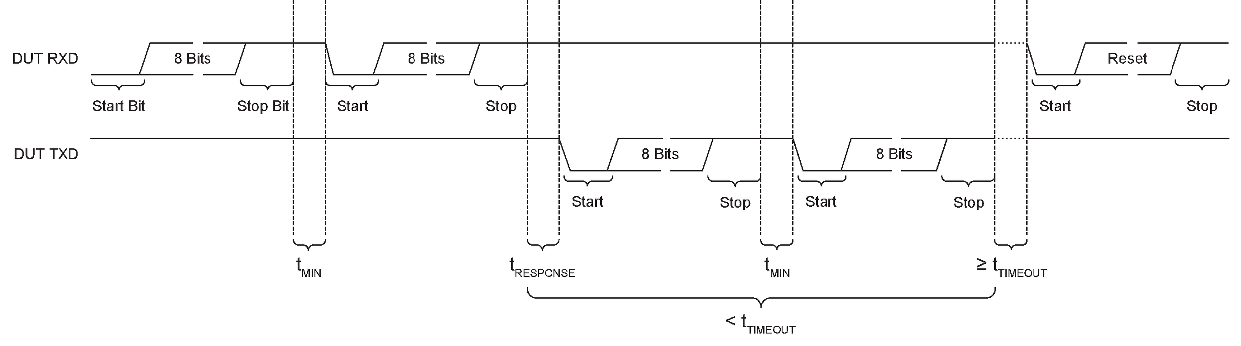
The Upper Tester shall not transmit further commands before it receives a response from the DUT. If the Upper Tester does not receive a response from the DUT within the time tTIMEOUT, the Upper Tester shall transmit a reset command (i.e., a test setup command with the control argument set to 0x00) to the DUT and display an appropriate error message. For the reset command, tRESPONSE and tTIMEOUT do not apply.
On reception of a reset command, the DUT shall reset all parameters to their default state.
Definitions
All commands and events consist of 16 bits (2 bytes).
The most significant bit is bit number 15.
The least significant bit is bit number 0.
The most significant byte is from bit 15 to 8.
The least significant byte is from bit 7 to 0.
Commands and events are sent most significant byte (MSB) first, followed by the least significant byte (LSB).
3.3. Commands and events
3.3.1. Command and event behavior
Table 3.1 outlines the set of commands which can be received by the DUT and the corresponding response events that can be transmitted by the DUT.
Command (DUT RXD) | Event (DUT TXD) |
|---|---|
LE_Test_Setup | LE_Test_Status SUCCESS LE_Test_Status FAIL |
LE_Receiver_Test | LE_Test_Status SUCCESS LE_Test_Status FAIL |
LE_Transmitter_Test | LE_Test_Status SUCCESS LE_Test_Status FAIL |
LE_Test_End | LE_Packet_Report LE_Test_Status FAIL |
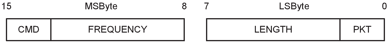
3.3.2. Commands
Command packet formats are shown in Figure 3.1 and Figure 3.2.

Note
Note: Some cases of the Test Setup and Test End commands have four parameter values, differing only in the bottom 2 bits, specified for the same action. In these cases the specific value chosen does not affect the behavior of the command.
CMD (command): | Size: 2 bits |
Value b1b0 | Parameter Description | |
|---|---|---|
00 | LE_Test_Setup command | |
01 | LE_Receiver_Test command | |
10 | LE_Transmitter_Test command | |
11 | LE_Test_End command | |
Test Setup command: | Size: 14 bits |
Control (6 bits) | Parameter (8 bits) | Description |
|---|---|---|
0x00 | 0x00 to 0x03 | RESET; the upper 2 bits of the data length for any LE_Transmitter_Test or LE_Receiver_Test commands following are set to 00, the PHY is set to LE 1M, the receiver assumes the transmitter has a standard modulation index, and no Constant Tone Extension is present. |
Any other value | Reserved for future use | |
0x01 | 0x00 to 0x0F | Set the upper 2 bits of the data length for any LE_Transmitter_Test or LE_Receiver_Test commands following to bits 2 and 3 of the parameter (to enable a length greater than 0x3F to be used) |
Any other value | Reserved for future use | |
0x02 | 0x04 to 0x07 | PHY set to LE 1M |
0x08 to 0x0B | PHY set to LE 2M | |
0x0C to 0x0F | PHY set to LE Coded; transmitter is to use S=8 data coding | |
0x10 to 0x13 | PHY set to LE Coded; transmitter is to use S=2 data coding | |
Any other value | Reserved for future use | |
0x03 | 0x00 to 0x03 | Receiver assumes transmitter has a standard modulation index |
0x04 to 0x07 | Receiver assumes transmitter has a stable modulation index | |
Any other value | Reserved for future use | |
0x04 | 0x00 to 0x03 | Read the test case supported features. The LE_Test_Status event will return the state of the test case supported features as detailed in the LE_Test_Status event ( Section 3.4.1). |
Any other value | Reserved for future use | |
0x05 | 0x00 to 0x03 | Read supportedMaxTxOctets (see [Vol 6] Part B, Section 4.5.10) |
0x04 to 0x07 | Read supportedMaxTxTime (see [Vol 6] Part B, Section 4.5.10) | |
0x08 to 0x0B | Read supportedMaxRxOctets (see [Vol 6] Part B, Section 4.5.10) | |
0x0C to 0x0F | Read supportedMaxRxTime (see [Vol 6] Part B, Section 4.5.10) | |
0x10 | Read maximum length of Constant Tone Extension supported | |
Any other value | Reserved for future use | |
0x06 | 0x00 | No Constant Tone Extension |
Any other value | CTEInfo (see [Vol 6] Part B, Section 2.5.2) | |
0x07 | 0x01 | Sample Constant Tone Extension with 1 µs slots |
0x02 | Sample Constant Tone Extension with 2 µs slots | |
Any other value | Reserved for future use | |
0x08 | Bits 0 to 6: 0x01 to 0x4B | Number of antennae in the antenna array |
Any other value | Reserved for future use | |
Bit 7: 0 | Antenna switching pattern A: 1, 2, 3, ..., n, 1, 2, 3, ..., n, ... (where n is the number of antennae in the antenna array) | |
1 | Antenna switching pattern B: 1, 2, 3, ..., n, n-1, n-2, ..., 1, ... (where n is the number of antennae in the antenna array) | |
0x09 | -127 to +20 | Set transmitter to the specified or the nearest transmit power level Units: dBm |
0x7E | Set transmitter to minimum transmit power level | |
0x7F | Set transmitter to maximum transmit power level | |
All other values | Reserved for future use |
If an AoD Constant Tone Extension is selected when transmitting, Control 0x08 shall be used before starting the test. If an AoA Constant Tone Extension is selected when receiving, Controls 0x07 and 0x08 shall be used before starting the test.
Control 0x07 does not affect receiving AoD Constant Tone Extensions or any transmissions. Control 0x08 does not affect transmitting AoA Constant Tone Extensions or receiving AoD Constant Tone Extensions.
In the receiver test, the CTEInfo field specified using Control 0x06 indicates the expected type and length of the Constant Tone Extension. If either the length or type of the Constant Tone Extension in a received LE Test packet does not match the expected value, then the DUT shall discard that packet.
LE_Test_End command: | Size: 14 bits |
Control (6 bits) | Parameter (8 bits) | Description |
|---|---|---|
0x00 | 0x00 to 0x03 | LE_Test_End command |
0x00 | Any other value | Reserved for future use |
0x01 to 0x3F | Any value | Reserved for future use |
LE_Transmitter_Test and LE_Receiver_Test commands:
Frequency: | Size: 6 bits |
Value | Parameter Description |
|---|---|
0x00 to 0x27 | The frequency to be used; a value of N represents a frequency of (2N+2402) MHz (the available range is therefore even values from 2402 MHz to 2480 MHz) |
0x28 to 0x3F | Reserved for future use |
Length: | Size: 6 bits |
Value | Parameter Description |
|---|---|
0x00 to 0x3F | The lower 6 bits of the packet length in bytes of payload data in each packet (the top two bits are set by the LE_Test_Setup command) |
PKT (Packet Type): | Size: 2 bits |
Value b1b0 | Parameter Description |
|---|---|
00 | PRBS9 Packet Payload |
01 | 11110000 Packet Payload |
10 | 10101010 Packet Payload |
11 | On the LE Uncoded PHYs: Vendor Specific On the LE Coded PHY: 11111111 |
3.4. Events
There are two types of events sent by the DUT:
LE_Test_Status event
LE_Packet_Report event
The event packet format is shown in Figure 3.3. This packet format is used for both LE_Test_Status events and LE_Packet_Report events.

EV (event): | Size: 1 bit |
Value | Parameter Description |
|---|---|
0 | LE_Test_Status event |
1 | LE_Packet_Report event |
3.4.1. LE_Test_Status event
The LE_Test_Status event packet format is as shown in Figure 3.4.

ST (status): | Size: 1 bit |
Value | Parameter Description |
|---|---|
0 | Success |
1 | Error |
Response: [1] | Size: 14 bits | ||||||||||||||||||||||||||||||||||||||||||||||||
[1] If the event has a status of "Error" or was generated in response to a command other than LE_Test_Setup, then this field is Reserved for future use. | |||||||||||||||||||||||||||||||||||||||||||||||||
LE_Test_Setup command control parameter | Value bits 1 to 14[2] | Description | |||||||||||||||||||||||||||||||||||||||||||||||
|---|---|---|---|---|---|---|---|---|---|---|---|---|---|---|---|---|---|---|---|---|---|---|---|---|---|---|---|---|---|---|---|---|---|---|---|---|---|---|---|---|---|---|---|---|---|---|---|---|---|
0x04 | Bit 1 | LE Data Packet Length Extension feature supported | |||||||||||||||||||||||||||||||||||||||||||||||
Bit 2 | LE 2M PHY supported | ||||||||||||||||||||||||||||||||||||||||||||||||
Bit 3 | Transmitter has a Stable Modulation Index | ||||||||||||||||||||||||||||||||||||||||||||||||
Bit 4 | LE Coded PHY supported | ||||||||||||||||||||||||||||||||||||||||||||||||
Bit 5 | Constant Tone Extension supported | ||||||||||||||||||||||||||||||||||||||||||||||||
Bit 6 | Antenna switching supported | ||||||||||||||||||||||||||||||||||||||||||||||||
Bit 7 | 1 µs switching supported for AoD transmission | ||||||||||||||||||||||||||||||||||||||||||||||||
Bit 8 | 1 µs sampling supported for AoD reception | ||||||||||||||||||||||||||||||||||||||||||||||||
Bit 9 | 1 µs switching and sampling supported for AoA reception | ||||||||||||||||||||||||||||||||||||||||||||||||
Bits 10 to 14 | Reserved for future use | ||||||||||||||||||||||||||||||||||||||||||||||||
0x05 | Bits 1 to 14 | One of the following values (depending on the parameter in the original query):
Range:
All values outside the range are reserved for future use. | |||||||||||||||||||||||||||||||||||||||||||||||
0x09 | Bits 1 to 8 | Actual transmit power level set by the transmitter Range: -127 to +20 Units: dBm | |||||||||||||||||||||||||||||||||||||||||||||||
Bit 9 | Set to 1 if the transmitter is at minimum transmit power level | ||||||||||||||||||||||||||||||||||||||||||||||||
Bit 10 | Set to 1 if the transmitter is at maximum transmit power level | ||||||||||||||||||||||||||||||||||||||||||||||||
Bits 11 to 14 | Reserved for future use | ||||||||||||||||||||||||||||||||||||||||||||||||
All other values | Reserved for future use | ||||||||||||||||||||||||||||||||||||||||||||||||
[2] This field is described as having bits 1 to 14 rather than 0 to 13 to avoid confusion. | |||||||||||||||||||||||||||||||||||||||||||||||||
3.4.2. LE_Packet_Report event
The LE_Packet_Report event packet format is shown in Figure 3.5. The Packet Count parameter indicates the number of received LE Test packets. The Packet Count in the LE_Packet_Report event ending a transmitter test shall be 0.
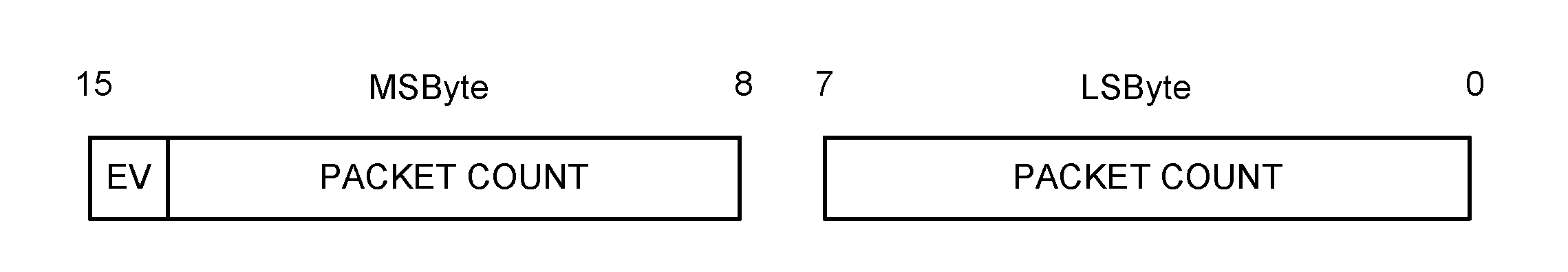
PACKET COUNT: | Size: 15 bits |
Value | Parameter Description |
|---|---|
N | N is the number of packets received Range = 0 to 32767. |
Note
Note: The DUT is not responsible for any overflow conditions of the packet count. That responsibility belongs with the RFPHY Tester or other auxiliary equipment.
3.5. Timing - command and event
The timing requirements are as shown in Table 3.2.
Symbol | Parameter | Min. | Max. | Unit |
|---|---|---|---|---|
bERR | Baud rate accuracy | ±5 | % | |
tMIN | The time between the first and second byte of the command or event (end of stop bit to start of start bit) | 0 | 5 | ms |
tRESPONSE | The time from a DUT receiving a command (end of stop bit) until the DUT responds (start of start bit) | 0 | 50 | ms |
tTURNAROUND | The time from when the tester receives a response (end of stop bit) until the tester sends another command (start of start bit) | 5 | - | ms |
tTIMEOUT | The time from when a tester sends a command (end of stop bit) until the tester times out (not having received end of the stop bit in the response) | 51 | 100 | ms |
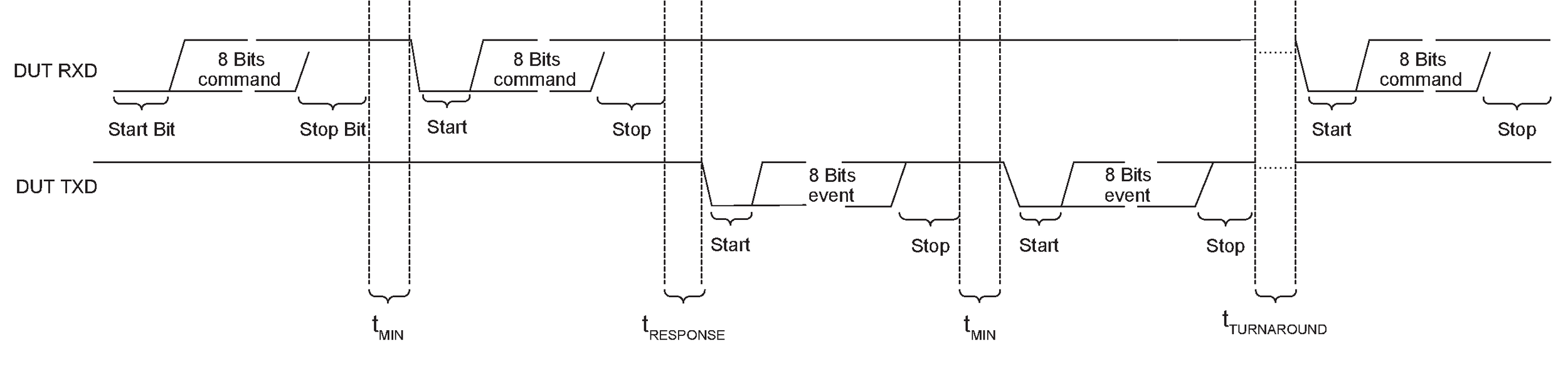
The commands and events shall be transmitted with two 8-bit bytes with a maximum time between the 2 transmissions. A timeout is required for no response or an invalid response from the DUT.
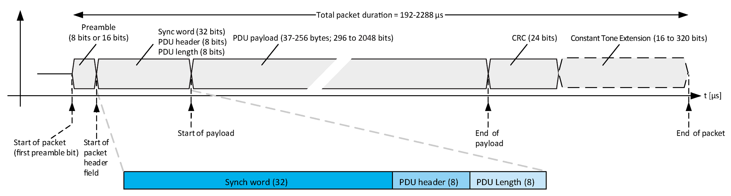
4. LE Test packet definition
4.1. LE Test packets format
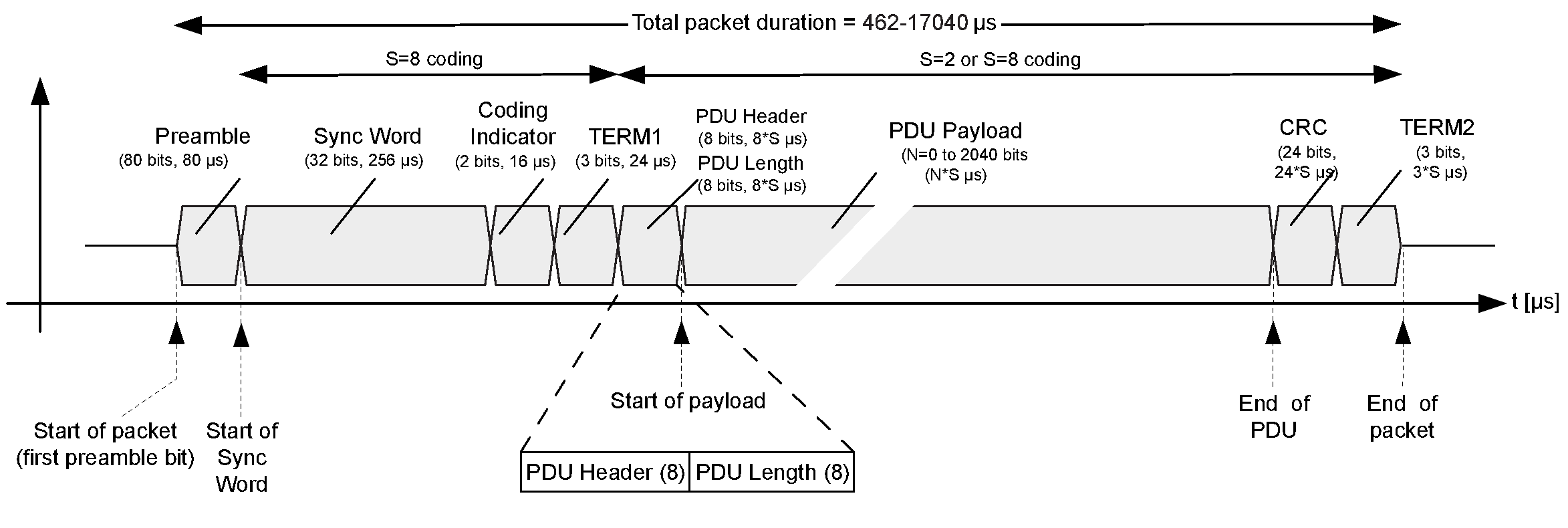
The LE Test packet format for the LE Uncoded PHYs shall be as shown in Figure 4.1. The LE Test packet format for the LE Coded PHY shall be as shown in Figure 4.2. LE test packets are required for LE RFPHY conformance testing using Direct Test Mode. Except as modified by this section, the LE Test packet formats shall be identical to the formats specified in [Vol 6] Part B, Section 2.1 and [Vol 6] Part B, Section 2.2.
Depending on the test, the packet payload content may vary
4.1.1. Whitening
LE test packets shall not use whitening.
4.1.2. Preamble and synchronization word
LE test packets shall have ‘10010100100000100110111010001110’ (in transmission order) as the synchronization word. The preamble for all LE test packets is thus ‘10101010’ (in transmission order) when the device under test is configured for the LE 1M PHY, ‘1010101010101010’ (in transmission order) if the device under test is configured for the LE 2M PHY, and the preamble described in [Vol 6] Part B, Section 2.2.1 if the device under test is configured for the LE Coded PHY.
4.1.3. CRC
The CRC shift register shall be preset with 0x555555 for every LE test packet.
4.1.4. LE Test packet PDU
The LE test packet PDU consists of an 8-bit header, an 8-bit length field, an optional 8-bit CTEInfo field, and a variable size payload. Its structure is as shown in Figure 4.3 and Figure 4.4.
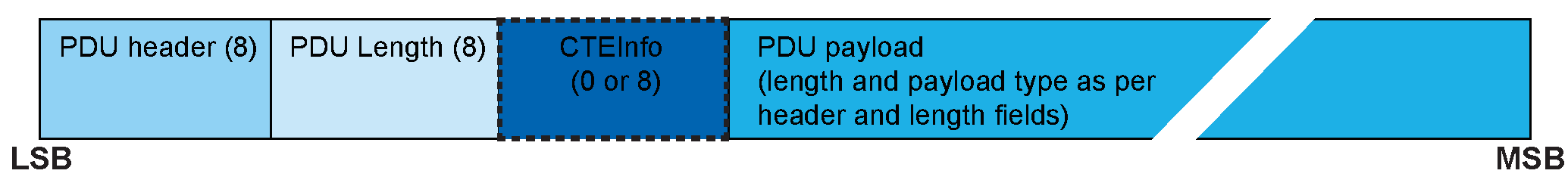

The first four bits of the PDU header field indicate the payload content type as defined in Table 4.1. The CTEInfo Present (CP) field of the PDU header indicates whether the CTEInfo field is present and therefore whether the test packet has a Constant Tone Extension. If the CP field is 0, then no CTEInfo field is present and there is no Constant Tone Extension in the test packet. If the CP field is 1, then the CTEInfo field is present and the test packet includes a Constant Tone Extension. The CTEInfo field is defined in [Vol 6] Part B, Section 2.5.2. The length field expresses the Payload length in bytes.
Note
Note: On the LE Coded PHY, this section defines the PDU contents before coding.
Payload type b3b2b1b0 | Payload description |
|---|---|
0b0000 | PRBS9 sequence ‘11111111100000111101...’ (in transmission order) as described in Section 4.1.5 |
0b0001 | Repeated ‘11110000’ (in transmission order) sequence as described in Section 4.1.5 |
0b0010 | Repeated ‘10101010’ (in transmission order) sequence as described in Section 4.1.5 |
0b0011 | PRBS15 sequence as described in Section 4.1.5 |
0b0100 | Repeated ‘11111111’ (in transmission order) sequence |
0b0101 | Repeated ‘00000000’ (in transmission order) sequence |
0b0110 | Repeated ‘00001111’ (in transmission order) sequence |
0b0111 | Repeated ‘01010101’ (in transmission order) sequence |
Example: For LE test packets with 0x0F payload contents (‘11110000’ in transmission order) and with an LE test packet payload length of 37 bytes (296 bits), the LE test packet header and length type field will be ‘1000000010100100’ in transmission order.
4.1.5. LE Test packet payload description
The LE test packet payload content alternatives required for the Bluetooth Low Energy RFPHY conformance tests are:
PRBS9:
A 9-bit pseudorandom binary sequence used for wanted signal payload content. The PRBS9 sequence repeats itself after the (29 -1 = 511) bit. The PRBS9 sequence may be generated in a nine stage shift register whose 5th and 9th stage outputs are XORed (see Figure 4.5) and the result is fed back to the input of the first stage. The sequence begins with the first ONE of 9 consecutive ONEs (i.e. the shift register is initialized with nine ONEs).
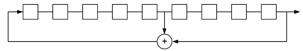
The same pseudorandom sequence of bits shall be used for each transmission (i.e. the packet is repeated).
PRBS15:
A 15-bit pseudorandom binary sequence that is used for the interfering signal and can optionally be used for wanted signal payload content. The PRBS15 sequence repeats itself after the (215 -1 = 32767) bit. The PRBS15 sequence may be generated in a fifteen stage shift register whose 14th and 15th stage outputs are XORed (see Figure 4.6) and the result is fed back to the input of the first stage. The sequence begins with the first ONE of 15 consecutive ONEs (i.e., the shift register is initialized with fifteen ONEs).
This PRBS15 definition is consistent with ITU T-REC-01 150-199605-I. SERIES O: SPECIFICATIONS OF MEASURING EQUIPMENT - Equipment for the measurement of digital and analogue/digital parameters.
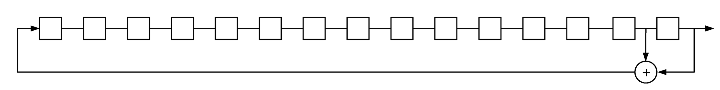
The same pseudorandom sequence of bits shall be used for each transmission (i.e. the packet is repeated).
10101010:
Repeated sequence of alternating 1’s and 0’s, starting at the first payload bit and ending at the start of the first bit in the CRC. This pattern is used to verify the frequency deviation and the Gaussian filtering properties of the transmitter modulator.
11110000:
Repeated sequence of alternating 0’s and 1’s in groups of four (i.e. 1111000011110000...), starting at the first payload bit and ending at the start of the first bit in the CRC. This pattern is used to verify the frequency deviation and the Gaussian filtering properties of the transmitter modulator.
4.1.6. LE Test packet interval
While in LE direct TX mode, LE test packets shall be transmitted from the EUT with a packet interval I(L) as defined below; see the top half of Figure 4.7 for reference.
While in LE direct RX mode, the nominal packet interval of the LE test packets transmitted from the tester is I(L), but the tester packet interval may be extended to a maximum of T(L) upon change of the dirty transmitter parameter settings and during verification of the EUT PER reporting functionality. See the bottom half of Figure 4.7 for reference.
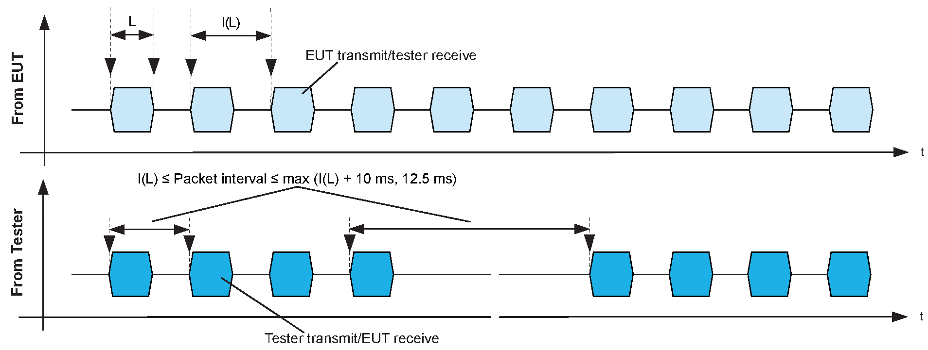
For an LE Test packet length of L µs, I(L) = * 625 µs and T(L) = max (I(L) + 10 ms, 12.5 ms).
4.1.7. Constant Tone Extension
The Constant Tone Extension is an optional field that consists of a constantly modulated series of unwhitened 1s. It is 16 to 160 bits when operating at 1 Msym/s modulation or 32 to 320 bits when operating at 2 Msym/s modulation. The Constant Tone Extension is not included in CRC or MIC calculations. The Constant Tone Extension shall only be present on the LE Uncoded PHYs.
If Direct Test Mode is being used over HCI and a Constant Tone Extension is present in a received packet, the Controller may generate events containing IQ samples of the Constant Tone Extension (see [Vol 4] Part E, Section 7.7.65.21).