Part G. Isochronous Adaptation Layer
vAtlanta r00
This Part describes the Isochronous Adaptation Layer (ISOAL) which supports segmentation and reassembly, and fragmentation and recombination of packets to and from a higher layer.
1. Introduction
The Isochronous Adaptation Layer (ISOAL) provides segmentation, fragmentation, reassembly and recombination services for conversion of SDUs from the upper layer to PDUs of the Link Layer and vice versa. The ISOAL accepts or generates SDUs, each with a length up to the maximum length (Max_SDU), at a rate that is supported by the Controller. SDUs are transferred to and from the upper layer using either HCI ISO Data packets or over an implementation-specific transport.
Note
Note: SDUs in the ISOAL has no relation to SDUs in the L2CAP layer.
1.1. Terminology
The following terms are used in the ISOAL:
Term | Description |
|---|---|
Upper layer | The upper layer generates and or receives isochronous data packets known as SDUs. The interface between the upper layer and ISOAL may be the HCI or a proprietary interface. |
SDU (Service Data Unit) | An SDU is a packet containing isochronous data that is generated or received by the upper layer. |
PDU (Protocol Data Unit) | A PDU is a data packet that is transmitted or received in a Connected or Broadcast Isochronous Stream. |
Fragment | A part of an SDU, resulting from the fragmentation operation. |
Segment | A part of an SDU, resulting from the segmentation operation. |
Isochronous interval | The time between two consecutive BIS or CIS events (designated ISO_Interval in the Link Layer). |
Unframed PDU | A PDU that contains a fragment. |
Framed PDU | A PDU that contains one or more segments. |
SDU interval | The nominal time between two consecutive SDUs that are sent or received by the upper layer. |
Max_SDU | Maximum size of an SDU. |
Synchronization Reference | A time reference of an SDU that allows synchronization of isochronous data in multiple devices. |
Time_Stamp | Time stamp (32-bit value in microseconds) of a packet. |
Time_Offset | Time offset (24-bit value in microseconds) of a packet. |
ISO Data PDU | Either a CIS Data PDU or a BIS Data PDU. |
2. ISOAL features
Figure 2.1 shows the architectural diagram of the ISOAL. The multiplexer in Figure 2.1 shows the route of SDUs to either unframed PDU or framed PDU path.
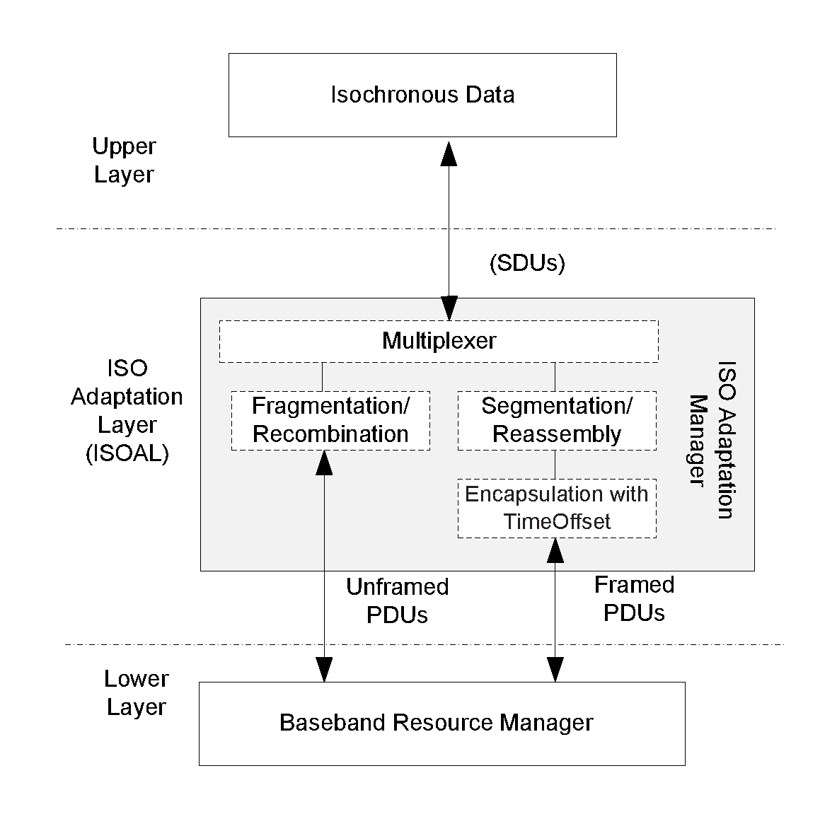
Fragmentation and recombination
The fragmentation process splits an SDU into one or more fragments which are carried by one or more unframed PDUs (see Section 4) in a Connected or Broadcast Isochronous Stream. A fragment shall contain only isochronous data. An SDU with a length less than or equal to the Max_PDU shall be sent in a single unframed PDU. An SDU with a length greater than the Max_PDU shall be sent in multiple fragments in multiple unframed PDUs. The fragmentation process shall use the minimum number of unframed PDUs to transmit the SDU. The recombination process generates an SDU from one or more fragments received in unframed PDUs.
Segmentation and reassembly
The segmentation process splits an SDU into one or more segments which are carried by one or more framed PDUs (see Figure 2.1) in a Connected or Broadcast Isochronous Stream. A segment shall contain a Segmentation Header (see Section 3) and may contain Time_Offset and isochronous data. The reassembly process combines data from one or more segments received in framed PDUs and generates one or more SDUs.
Encapsulation and Time_Offset
In the encapsulation process Segmentation Headers and a Time_Offset parameter are added before the first segment of each new SDU allowing timing reconstruction at the peer device (see Section 3.)
Unframed PDUs shall only be used when the ISO_Interval is equal to or an integer multiple of the SDU_Interval and a constant time offset alignment is maintained between the SDU generation and the timing in the isochronous transport. This requires the upper layer to synchronize generation of its data to the effective transport timing. When the Host requests the use of framed PDUs, the Controller shall use framed PDUs.
Framed PDUs are not restricted by the limitations of unframed PDUs and can support any valid combinations of SDU_Interval and ISO_Interval.
SDU_Interval shall be a value, in microseconds, between 0x0000FF and 0x0FFFFF.
SDUs sent to the upper layer by the ISOAL shall be given a sequence number which is initialized to 0 when the CIS or BIS is created. SDUs received by the ISOAL from the upper layer shall be given a sequence number which is initialized to 0 when the CIS or BIS is created. The upper layer may synchronize its sequence number with the sequence number in the ISOAL once the Datapath is configured and the link is established.
The sequence number shall be incremented for each SDU_Interval, whether or not an SDU was received from the upper layer or included in reports sent to the upper layer.
The sequence number shall be 16 bits and shall be included in the Packet_Sequence_Number parameter in HCI ISO Data Packets.
2.1. Unframed PDU
An unframed PDU is an ISO Data PDU; it shall contain payload from the SDU without additional headers in the payload. An unframed PDU shall only contain payload from a single SDU.
There are two types of unframed PDUs. An unframed PDU containing an end fragment or a complete SDU, and an unframed PDU containing a start or a continuation fragment. Unframed PDUs are identified by the LLID field as described below:
LLID in the header of the ISO Data PDU shall be set to 0b00 in the following conditions:
When the payload of the ISO Data PDU contains the end fragment of an SDU.
When the payload of the ISO Data PDU contains a complete SDU.
LLID in the header of the ISO Data PDU shall be set to 0b01 in the following conditions:
When the payload of the ISO Data PDU contains a start or a continuation fragment of an SDU.
When the ISO Data PDU is used as padding. This is required when the fragments do not add up to the configured number of PDUs specified by the BN parameter per BIS or CIS event.
In the receiving device the payload from a PDU with LLID = 0b00 shall append the payload from PDUs with LLID = 0b01 to derive the length of the payload of the SDU. The SDU can contain some invalid or missing data due to missing or invalid PDUs. All SDUs shall be sent to the upper layer including the indication of validity of data. A report shall be sent to the upper layer if the SDU is completely missing.
Each fragment shall be sent in a new unframed PDU. Multiple fragments shall not be sent in a single PDU.
BN, Max_PDU and ISO_Interval parameters of the Connected or Broadcast Isochronous Stream shall be set such that the bandwidth of the data transmitted by the Link Layer shall be greater than or equal to the bandwidth of data from the upper layer.
BN shall be an integer multiple of ISO_Interval ÷ SDU_Interval and shall be at least × (ISO_Interval ÷ SDU_Interval).
Each SDU shall generate BN ÷ (ISO_Interval ÷ SDU_Interval) fragments. All these fragments shall be sent to the Link Layer before any fragments of the next SDU. If an SDU generates less than this number of fragments, empty payloads shall be used to make up the number. Empty payloads shall be PDUs with LLID 0b01 with zero length payload, e.g., when BN=4 and only 3 PDUs are generated from the SDU, an additional padding PDU needs to be added.
When an SDU contains zero length data, the corresponding PDU shall be of zero length and the LLID field shall be set to 0b00.
2.2. Framed PDU
A framed PDU is an ISO Data PDU where the payload field is made up of segments or is empty. Each segment is encapsulated by a Segmentation Header and, for each first segment of a new SDU, a Time_Offset field is included to allow for reconstruction of the original SDU timing.
Framed PDUs shall be used when the requirements for using unframed PDUs are not met. Framed PDUs support the aggregation of data from multiple SDUs into a single PDU. The maximum allowed drift (MaxDrift) on the average timing of SDU delivery shall not exceed 100 ppm from the configured value of SDU_Interval.
BN, Max_PDU and ISO_Interval parameters of the Connected or Broadcast Isochronous Stream shall be set such that the bandwidth of the data transmitted by the Link Layer shall be greater than or equal to the bandwidth of data from the upper layer plus the amount of space needed for the headers (including an allowance for MaxDrift). This requirement is met if:
BN × (Max_PDU − 2) ≥ × 5 +
where F = (1 + MaxDrift) × ISO_Interval ÷ SDU_Interval
The requirement can be met without the inequality being satisfied.
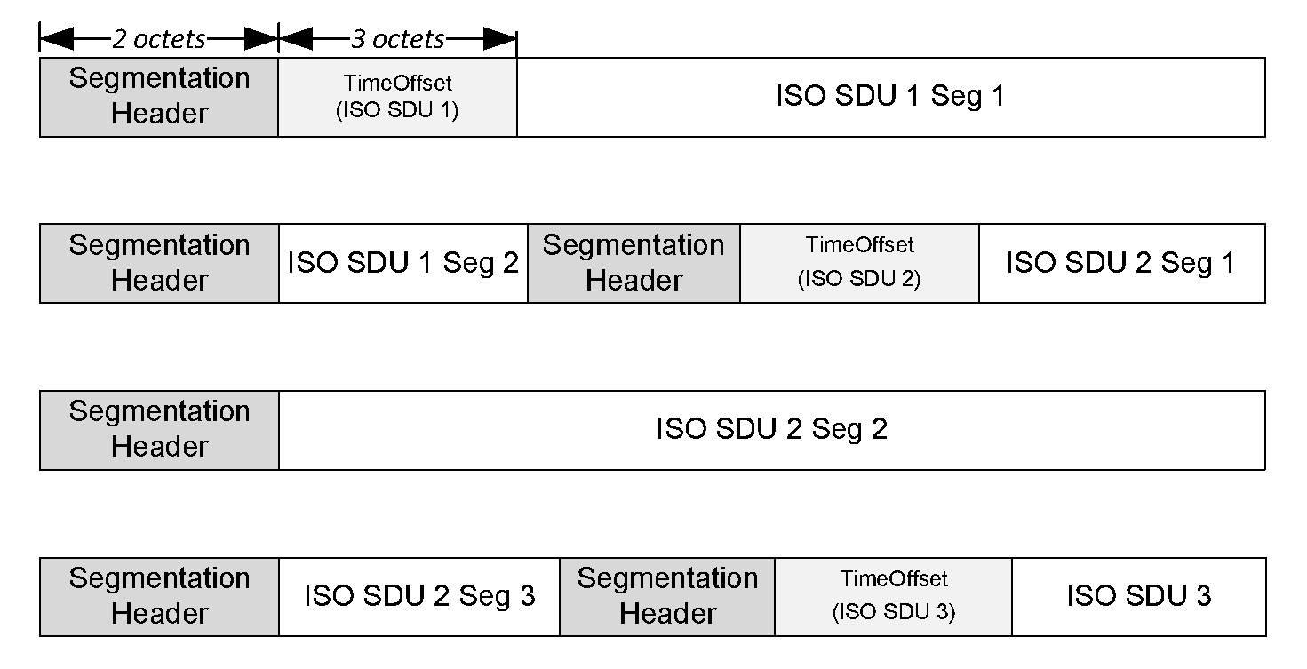
Figure 2.2 shows how multiple segments from multiple SDUs may fit in multiple ISO Data PDUs. Each row in the figure shows the payload field of one PDU. The number and length of segments in the payload shall be limited such that the length of the ISO Data PDU does not exceed the Max_PDU set for the Connected or Broadcast Isochronous Stream.
 |
The format of a Segmentation Header is shown in Figure 2.3.
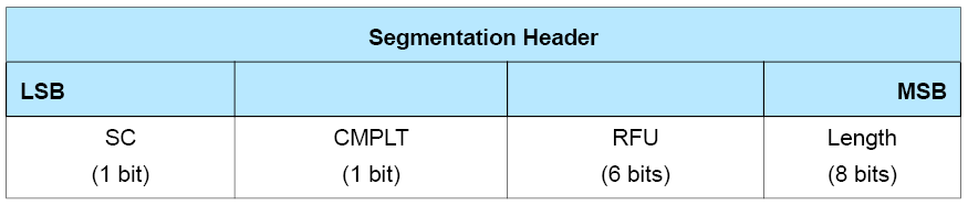
The fields in the Header is shown in Table 2.1.
Field Name | Description |
|---|---|
SC | The Start or Continuation (SC) field indicates that the data following the Segmentation Header is the start of a new SDU or the continuation of a previous SDU. |
CMPLT | The Completion (CMPLT) field indicates that the segment following the Segmentation Header in the PDU is the end segment of an SDU. |
Length | The length field indicates the size, in octets, of the segment that follows the Segmentation Header in this PDU and, when present, includes the Time_Offset parameter. |
Each framed PDU starts with a Segmentation Header that contains a SC, CMPLT and a Length field. Depending on the SC field, an additional Time_Offset parameter is included between the Segmentation Header and the start of SDU data to indicate the relative timing difference between the SDU and CIG reference point or BIG anchor point timing.
A framed PDU with non-zero length shall contain one or more segments. A framed PDU with zero length can be used as a padding PDU; such a PDU does not have a Segmentation Header. Padding is required when the data does not add up to the configured number of PDUs that are specified by the BN parameter per BIS or CIS event.
The Segmentation Header includes the SC and the CMPLT fields with the following requirements:
When SC is set to 0, it indicates the start of a new SDU and that the data that follows the header is part of a new SDU. If SC is set to 1, it indicates a continuation of an SDU that was partially transmitted in a previous isochronous PDU.
When SC is set to 0, the Segmentation Header shall be followed by a Time_Offset field, otherwise the Time_Offset is omitted and the header is directly followed by a segment of an SDU.
When CMPLT is set to 0, not all data of the SDU has been included in the current PDU. One or more additional framed PDUs are required to complete the SDU transfer. When CMPLT is set to 1, all remaining data of the SDU is included in the segment and the SDU may be transferred to the higher layer.
CMPLT is independent of the value of SC.
The Segmentation Header shall contain a Length field. The Length field indicates the number of octets of the SDU data segment following the Segmentation Header including the length of Time_Offset when present (see Section 3).
Data from a single SDU shall not be split over multiple segments in a single PDU. Additional Segmentation Headers and data from other SDUs may be added depending on available remaining octets in that PDU. When an SDU has zero length, the SDU shall be included with a Segmentation Header with SC set to 0, CMPLT set to 1, and the length field set to the length of the Time_Offset. Such an empty SDU shall contain a correct Time_Offset, to allow the higher layer of the device that receives the empty SDU to maintain synchronization.
Because an isochronous transport is not a reliable transport, Segmentation Headers shall integrally be contained in a single PDU. When insufficient octets remain in a framed isochronous PDU to contain the Segmentation Header and the Time_Offset field, no new Segmentation Header can be added, as shown in Table 2.2. When only 5 octets remain, a new Segmentation Header, including the start of the next SDU, may be included but is not recommended.
SC Start/continuation | COMPLT Completion | Time_Offset Added | Description |
|---|---|---|---|
0 | 0 | Yes | The start of a new SDU, where not all SDU data is included in the current PDU, and additional PDUs are required to complete the SDU. |
0 | 1 | Yes | The start of a new SDU that contains the full SDU data in the current PDU. |
1 | 0 | No | The continuation of a previous SDU. The SDU payload is appended to the previous data and additional PDUs are required to complete the SDU. |
1 | 1 | No | The continuation of a previous SDU. Frame data is appended to previously received SDU data and completes in the current PDU. |
A start of a new SDU with SC = 0 shall only be used when the previous frame has completed. A continuation of an SDU with SC = 1 shall only be used if the previous transmitted Segmentation Header had the completion flag set to 0.
When one or more ISO Data PDUs are not received, the receiving device may discard all SDUs affected by the missing PDUs. Any partially received SDU may also be discarded. A report shall be sent to the upper layer for each discarded SDU.
3. Time_Stamp and Time_Offset
Framed PDUs include a Time_Offset field to allow the reconstruction of the original SDU timing. When using HCI ISO Data packets, a Time_Stamp field may be included. This section defines the usage of these parameters. Every Time_Stamp and Time_Offset shall be derived from a free running reference clock that is not affected by adjustments to synchronize with other devices (e.g. a Peripheral synchronizing to a received packet from the Central (See [Vol 6] Part B, Section 4.5.7, or an adjustment done as part of the PCA feature see [Vol 2] Part B, Section 8.6.10).
3.1. Time_Offset in framed PDUs
At the transmitter, the Time_Offset is measured from the reference time of the SDU at the source to the CIG Reference point or BIG anchor point of the corresponding CIG or BIG event of the isochronous payload containing the first Segmentation Header of that SDU. This computation excludes any potential retransmissions or missed subevents, resulting in the time of transmission under perfect link conditions. The Time_Offset shall be a positive value.
The reference time of the SDU is determined based on the local timing in the Controller based on either a time stamp of that SDU (e.g., provided via the Time_Stamp parameter in the HCI ISO Data packet) or another mechanism used by the implementation tracking the SDU timing to the transport timing.
For details on the computation of the SDU synchronization reference and transport latency for all options of framed and unframed PDU in CIS and BIS, see Section 3.2.
At the receiver, the CIS reference anchor point is computed excluding any retransmissions or missed subevents, resulting in the time of transmission under perfect link conditions. Similar calculations can be performed for BIG.
Any potential delays in effective transmission shall be excluded in the calculation of Time_Offset.
When BN is greater than 1, all PDUs belonging to the same CIS or BIG event use the same reference anchor point.
For example, in a CIS with BN=2 and FT = 10, payload number 720 can have its first transmission potentially in CIS event 360 and its last potential transmission in CIS event 369. Even when the transfer effectively takes place in CIS event 365, the CIS reference anchor point for this payload is the anchor point of CIS event 360.
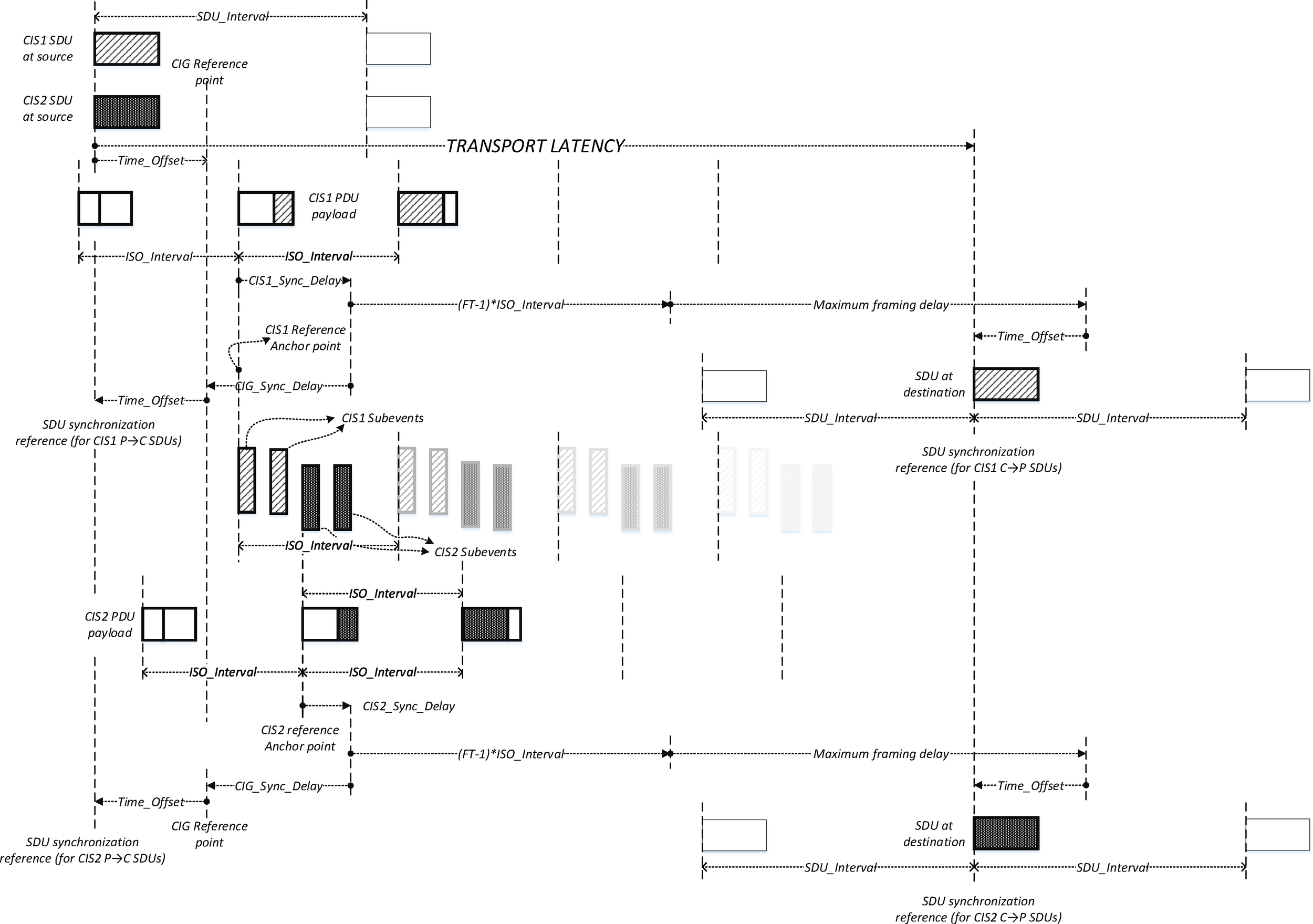
The Controller transmitting an SDU may use any of the following methods to determine the value of the SDU reference time, indicated in Figure 3.1, to define the Time_Offset for that SDU:
A captured timestamp of the SDU
A timestamp provided by the higher layer
A computed timestamp based on a sequence counter provided by the higher layer
Any other method of determining Time_Offset
3.2. SDU synchronization reference
This section describes the method of managing the SDU synchronization reference in framed and unframed PDUs.
3.2.1. SDU synchronization reference using framed PDUs
Using framed PDUs introduces additional delay in transferring SDUs. This additional delay shall be included when computing the SDU synchronization reference.
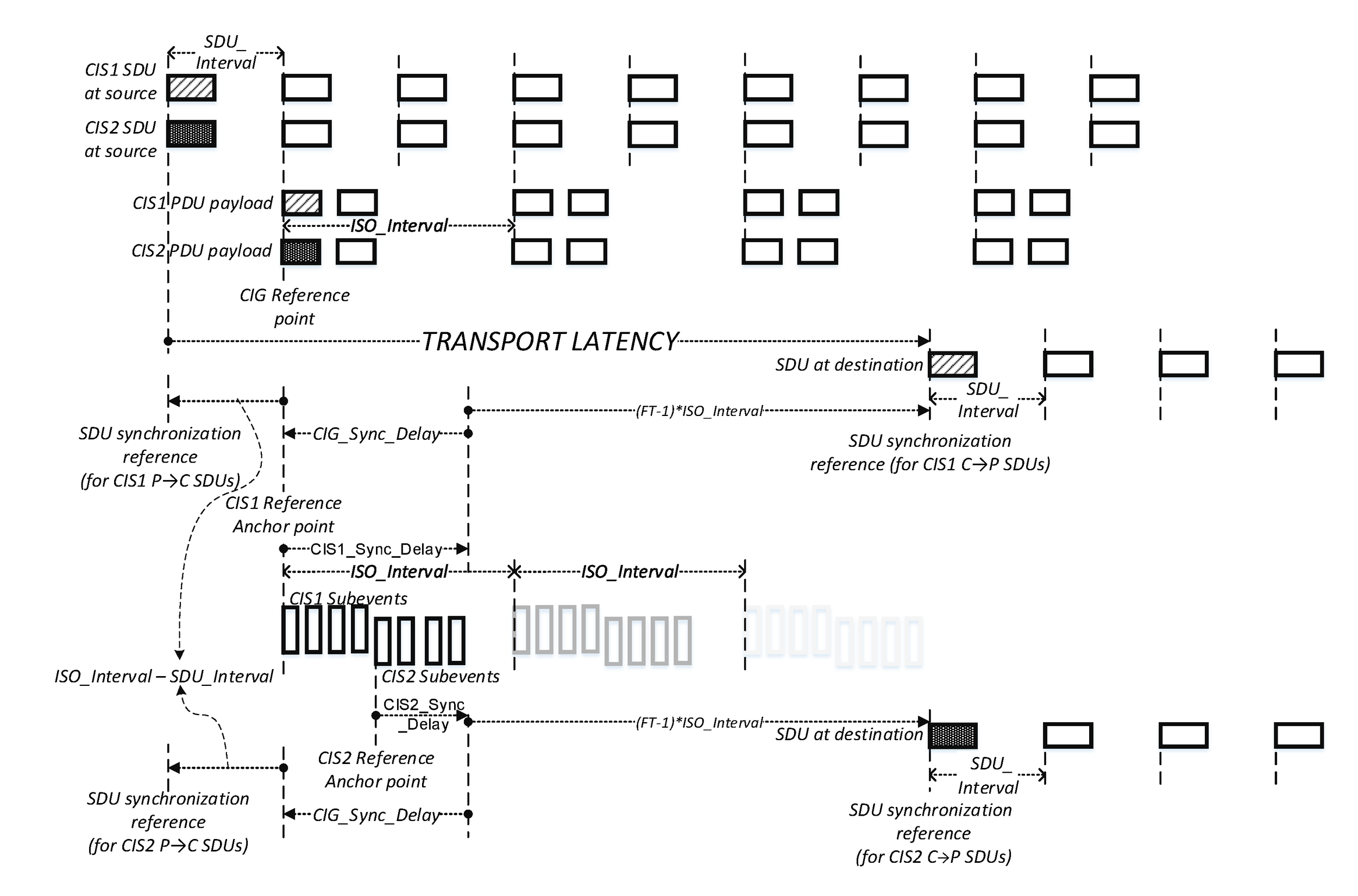
When using framed PDUs, the additional delay caused by the segmentation in a system where SDU creation is not synchronized to the transport timing equals one SDU interval plus one Isochronous interval.
The transport latency is the duration between the CIG reference point (or BIG anchor point for BIG) of the first possible CIG event (or BIG event) containing the payload to the CIG synchronization point (or BIG synchronization point) of the last possible CIG event (or BIG event) containing the payload, plus the segmentation delay (shown as maximum segmentation delay in Figure 3.1 for CIG). Transport latency is measured from the reference time of the SDU to its SDU_Synchronization_Reference and does not include any implementation specific processing times or internal transport delays (e.g., delays over the HCI transport or PDU processing times).
The transport latency for a CIG is the actual latency of transmitting payloads of all CISes in the CIG, and calculates as:
Transport_Latency_C_To_P = CIG_Sync_Delay + (FT_C_To_P) × ISO_Interval + SDU_Interval_C_To_P Transport_Latency_P_To_C = CIG_Sync_Delay + (FT_P_To_C) × ISO_Interval + SDU_Interval_P_To_C
The transport latency for a BIG is the actual latency of transmitting payloads of all BISes in the BIG, and calculates as:
Transport_Latency_BIG = BIG_Sync_Delay + PTO × (NSE ÷ BN – IRC) * ISO_Interval + ISO_Interval + SDU_Interval
The calculated transport latencies shall be less than or equal to those set by the Host.
Each SDU is given a synchronization reference based on the Reference Anchor point.
The CIS reference anchor point is computed excluding any retransmissions or missed subevents and shall be set to the anchor point of the CIS event in which the first PDU containing the SDU could have been transferred.
The BIG reference anchor point is the anchor point of the BIG event that the PDU is associated with (see [Vol 6] Part B, Section 4.4.6.6).
For the Central to Peripheral direction or from the Isochronous Broadcaster to Synchronized Receiver direction, the SDU synchronization point represents the absolute time where the data from a CIG or BIG should be available, and can be used to synchronize between multiple devices.
For SDUs sent from the Central to the Peripheral in CIS using framed PDUs the SDU_Synchronization_Reference shall be calculated as follows:
SDU_Synchronization_Reference = CIS Reference Anchor point + CIS_Sync_Delay + SDU_Interval_C_To_P + FT_C_To_P × ISO_Interval – Time_Offset
For the Peripheral to Central direction, the SDU synchronization point represents the absolute reference time of the origin of an SDU and can be used to synchronize data coming from multiple sources. This point is at the start of the CIG reference point. It could be earlier for framed PDUs.
For SDUs sent from the Peripheral to the Central in CIS using framed PDUs, the SDU_Synchronization_Reference shall be set to the following value: synchronization reference SDU = CIS reference anchor point + CIS_Sync_Delay – CIG_Sync_Delay – Time_Offset
For SDUs received in BIS using framed PDUs, the SDU_Synchronization_Reference shall be set to BIG reference anchor point + BIG_Sync_Delay + SDU_Interval + ISO_Interval – Time_Offset.
For example, when the SDU interval is 10.6 ms and the isochronous interval is 10 ms an additional 20.6 ms is added due to segmentation.
This example clarifies the usage of Time_Offset in the Central to Peripheral direction of CIS: at the source an SDU has a reference time X at the Controller clock. The start of the CIS event of the first potential transmission of the PDU that can contain the first part of that SDU is 6.123 ms later in time. The Time_Offset for the initial segment for that SDU will contain the value 6123 decimal or 0x0017EB. During the exchange over the isochronous transport, the PDU was not transmitted at the first possible opportunity, rather the PDU was received by the peer in the pth subevent n events later due to actual conditions of physical transport and potential Controller behavior such as scheduling conflicts at a subevent with starting time Y. Time Y is captured at the clock of the receiving device.
The receiving device computes the CIS reference anchor point time Y1 as follows:
Y1 = Y - (p-1) × Sub_Interval - n × ISO_Interval
The SDU synchronization reference for the SDU known as Y2 in µs is computed as:
Y2 = Y1 + CIS_Sync_Delay + SDU_Interval_C_To_P + (FT_C_To_P × ISO_Interval) - 6123
The SDU may be exchanged over multiple PDUs, but the synchronization reference point shall only be computed based on the PDU timing of the PDU containing the first Segmentation Header of the applicable SDU.
3.2.2. SDU synchronization reference using unframed PDUs
Using unframed PDUs does not introduce additional delay when the SDU interval equals the isochronous interval. When the Isochronous interval is larger than the SDU interval, multiple SDUs are received per BIS or CIS event which increases the delay. This additional delay shall be included when computing the SDU_Synchronization_Reference.
The transport latency is the duration between the CIG reference point (or BIG anchor point for BIG) of the first possible CIG event (or BIG event) containing the payload to the CIG synchronization point (or BIG synchronization point) of the last possible CIG event (or BIG event) containing the payload, plus the additional delay when grouping multiple SDUs in a single ISO_Interval (as shown in Figure 3.2 for CIG). Transport latency is measured from the reference time of the SDU to its SDU_Synchronization_Reference and does not include any implementation specific processing times or internal transport delays (e.g., delays over the HCI transport or PDU processing times).
The Transport_Latency for a CIG is the actual latency of transmitting payloads of all CISes in the CIG, and calculates as:
Transport_Latency_C_To_P = CIG_Sync_Delay + (FT_C_To_P - 1) × ISO_Interval + ((ISO_Interval ÷ SDU_Interval_C_To_P) - 1) × SDU_Interval_C_To_P Transport_Latency_P_To_C = CIG_Sync_Delay + (FT_P_To_C - 1) × ISO_Interval + ((ISO_Interval ÷ SDU_Interval_P_To_C) - 1) × SDU_Interval_P_To_C
These calculations can be simplified as follows:
Transport_Latency_C_To_P = CIG_Sync_Delay + FT_C_To_P × ISO_Interval - SDU_Interval_C_To_P Transport_Latency_P_To_C = CIG_Sync_Delay + FT_P_To_C × ISO_Interval - SDU_Interval_P_To_C
The Transport_Latency for a BIG is the actual latency of transmitting payloads of all BISes in the BIG, and calculates as:
Transport_Latency = BIG_Sync_Delay + PTO × (NSE ÷ BN – IRC) × ISO_Interval + ((ISO_Interval ÷ SDU_Interval)-1) × SDU_Interval
This calculation can be simplified as follows:
Transport_Latency = BIG_Sync_Delay + (PTO × (NSE ÷ BN - IRC) + 1) × ISO_Interval - SDU_Interval
For example, when the SDU interval is 10 ms and the Isochronous interval is 20 ms an additional 10 ms is added due to combination of 2 SDUs in one BIS or CIS event.
Each SDU is given a synchronization reference point based on the reference anchor point.
The CIS reference anchor point is computed excluding any retransmissions or missed subevents and shall be set to the start of the CIS event in which the first PDU containing the SDU could have been transferred.
The BIG reference anchor point is the anchor point of the BIG event that the PDU is associated with (see [Vol 6] Part B, Section 4.4.6.6).
For the Central to Peripheral direction or from the Isochronous Broadcaster to Synchronized Receiver direction, the SDU synchronization point represents the absolute time where the data from a CIG or BIG should be available, and can be used to synchronize between multiple devices.
For SDUs sent from the Central to the Peripheral in CIS using unframed PDUs the synchronization reference for the first SDU received in a burst of PDUs shall be set to the following value: SDU_Synchronization_Reference = CIS reference anchor point + CIS_Sync_Delay + (FT_C_To_P - 1) × ISO_Interval
For the Peripheral to Central direction, the SDU synchronization point represents the absolute reference time of the origin of an SDU and can be used to synchronize data coming from multiple sources. This point is at the start of the CIG reference point.
For SDUs sent from the Peripheral to the Central in CIS using unframed PDUs, the SDU synchronization reference for the first SDU received in a burst of PDUs shall be set to the following value: SDU_Synchronization_Reference = CIS reference anchor point + CIS_Sync_Delay - CIG_Sync_Delay - ((ISO_Interval ÷ SDU_Interval)-1) × SDU_Interval
For SDUs received in BIS using unframed PDUs, the SDU_Synchronization_Reference shall be set to BIG reference anchor point + BIG_Sync_Delay.
All PDUs belonging to a burst as defined by the configuration of BN have the same reference anchor point. When multiple SDUs have the same reference anchor point, the first SDU uses the reference anchor point timing. Each subsequent SDU increases the SDU synchronization reference timing with one SDU interval.
3.3. Time Stamp for SDU
When the Time_Stamp field is included in an HCI ISO Data packet from the Controller to the Host, the value of Time_Stamp is set to the synchronization reference for the SDU, as defined in Section 3.2, and is based on the CIS or BIG reference anchor point of the Controller’s clock. The Controller should include a Time_Stamp.
The Host may determine the CIG reference point or BIG anchor point for the last transmitted SDU from the TX_Time_Stamp and Time_Offset return parameters of the HCI_LE_Read_ISO_TX_Sync command, as shown in Figure 3.1. It may then use this information when providing the Time_Stamp in future HCI ISO Data packets. For each HCI ISO Data packet where the Host can provide a valid Time_Stamp value, it should include a Time_Stamp in those HCI ISO Data packets that it sends.
When an HCI ISO Data packet sent by the Host does not contain a Time_Stamp or the Time_Stamp value is not based on the Controller's clock, the Controller should determine the CIS or BIS event to be used to transmit the SDU contained in that packet based on the time of arrival of that packet.
In each direction, in a given packet, the Time_Stamp provided (if any) shall be one that applies to the SDU corresponding to the Packet_Sequence_Number.
When using the Time_Stamp or another suitable method for synchronization, both the higher layer and Controller should implement a mechanism to compensate potential clock drift and jitter. These mechanisms should include long term drift compensation and tolerances on the synchronization method used.
The Controller or the higher layer sending or receiving an SDU may use any of the following methods to transfer the synchronization reference of the SDU to the higher layer:
Timestamps at the Controller’s clock
Any other signaling method suitable to the higher layer
4. SDU Recombination and Reassembly
The ISOAL shall reconstruct SDUs from the received framed PDUs and pass all correct SDUs to the upper layer.
As an isochronous transport is not a reliable transport, errors can occur in the transfer of PDUs. Upon packet loss or erroneous reception, multiple SDUs can be affected. The number of affected SDUs will be (new synchronization reference – last valid SDU synchronization reference) / SDU_Interval, rounded to the nearest integer, unless clock drift in this period is greater than SDU_Interval.
Each SDU shall be reported to the upper layer. SDUs that are completely missing shall be reported as "lost data". The following SDUs shall either be discarded and reported as “lost data” or be reported as “data with possible errors”:
SDUs with violations in the Segmentation Headers of framed PDUs
SDUs with a length exceeding Max_SDU. In this case, the length of the SDU reported to the upper layer shall not exceed the Max_SDU length. The SDU shall be truncated to Max_SDU octets.
SDUs with missing isochronous data due to loss of PDUs.
SDUs with unreliable isochronous data due to CRC errors in PDUs.