Part C. Link Manager Protocol Specification
vAtlanta r00
This Part describes the Link Manager protocol (LMP) which is used for link set-up and control. The signals are interpreted and filtered out by the Link Manager on the receiving side and are not propagated to higher layers.
1. Introduction
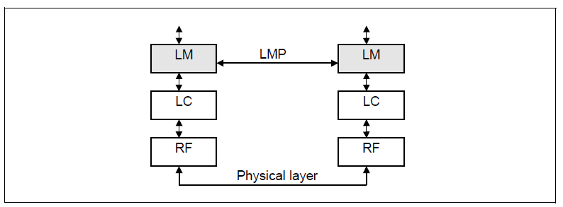
The Link Manager Protocol (LMP) is used to control and negotiate all aspects of the operation of the Bluetooth connection between two devices. This includes the set-up and control of logical transports and logical links, and for control of physical links.
The Link Manager Protocol is used to communicate between the Link Managers (LM) on the two devices. All LMP messages shall apply solely to the physical link and associated logical links and logical transports between the sending and receiving devices.
The protocol is made up of a series of messages which shall be transferred over the ACL-C or APB-C logical link between two devices. LMP messages shall be interpreted and acted-upon by the LM and shall not be directly propagated to higher protocol layers.
2. General rules
2.1. Message transport
LMP messages shall be exchanged over the ACL-C logical link that is carried on the default ACL logical transport ([Vol 2] Part B, Section 4.4) or over the APB-C logical link that is carried on the APB logical transport ([Vol 2] Part B, Section 4.6). LMP messages shall be carried on the default ACL logical transport unless specified otherwise in Sections 4 and 5. The ACL-C and APB-C logical links are distinguished from the ACL-U and APB-U logical links (which carry L2CAP and user data) by the Logical Link Identifier (LLID) field carried in the payload header of variable-length packets ([Vol 2] Part B, Section 6.6.2).
The control logical links have a higher priority than other traffic - see [Vol 2] Part B, Section 5.6.
The error detection and correction capabilities of the Baseband ACL logical transport are generally sufficient for the requirements of the LMP. Therefore LMP messages do not contain any additional error detection information beyond what can be realized by means of sanity checks performed on the contents of LMP messages. Any such checks and protections to overcome undetected errors in LMP messages is an implementation matter.
2.2. Synchronization
This section explains why many of the LMP message sequences are defined as they are. It does not create any requirements.
LMP messages are carried on the ACL-C and APB-C logical links, which do not guarantee a time to deliver or acknowledge packets. LMP procedures take account of this when synchronizing state changes in the two devices. For example, criteria are defined that specify when a logical transport address (LT_ADDR) may be re-used after it becomes available due to a device leaving the piconet. Other LMP procedures, such as hold or role switch include the Bluetooth clock as a parameter in order to define a fixed synchronization point. The transitions into and out of Sniff mode are protected with a transition mode.
The LC normally attempts to communicate with each Peripheral no less often than every Tpoll slots (see Section 4.1.8) based on the Tpoll for that Peripheral.

Figure 2.1 illustrates the fundamental problem. It shows the transmission of a packet from the Central to the Peripheral in conditions of heavy interference for illustrative purposes. It is obvious that neither side can determine the value of either Tdeliver or Tack. It is therefore not possible to use simple messages to identify uniquely the instant at which a state change occurs in the other device.
2.3. Packet format
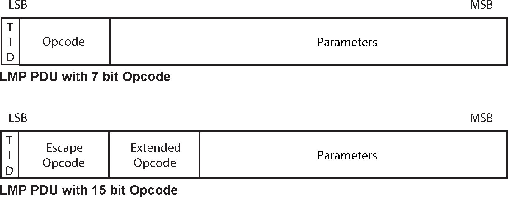
Each PDU is assigned either a 7 or a 15 bit opcode used to uniquely identify different types of PDUs, see Table 5.1. The first 7 bits of the opcode and a transaction ID are located in the first byte of the payload body. If the initial 7 bits of the opcode have one of the special escape values 124 to 127 then an additional byte of opcode is located in the second byte of the payload and the combination uniquely identifies the PDU.
The FLOW bit in the packet header is always 1 and shall be ignored on reception.
If the PDU contains one or more parameters these are placed in the payload starting immediately after the opcode, i.e. at byte 2 if the PDU has a 7 bit opcode or byte 3 if the PDU has a 15 bit opcode. The number of bytes used depends on the length of the parameters. The representation of each parameter is determined by its type as specified in [Vol 1] Part E, Section 2.9.
LMP messages shall be transmitted using DM1 packets, however if an HV1 SCO link is in use and the length of the payload is no greater than 9 bytes then DV packets may be used.
2.4. Transactions
The LMP operates in terms of transactions. A transaction is a connected set of message exchanges which achieve a particular purpose. All PDUs which form part of the same transaction shall have the same value for the transaction ID which is stored as part of the first byte of the opcode (see Section 2.3).
The transaction ID is in the least significant bit. It shall be 0 if the PDU forms part of a transaction that was initiated by the Central and 1 if the transaction was initiated by the Peripheral.
Each sequence described in Section 4 shall be defined as a transaction. For pairing, see Section 4.2.2, and encryption, see Section 4.2.5, all sequences belonging to each section shall be counted as one transaction and shall use the same transaction ID. For connection establishment, see Section 4.1.1, LMP_HOST_CONNECTION_REQ and the response with LMP_ACCEPTED or LMP_NOT_ACCEPTED shall form one transaction and have the transaction ID of 0. LMP_SETUP_COMPLETE is a stand-alone PDU, which forms a transaction by itself.
For error handling, see Section 2.5, the PDU to be rejected and LMP_NOT_ACCEPTED or LMP_NOT_ACCEPTED_EXT shall form a single transaction.
2.4.1. LMP response timeout
The time between receiving a Baseband packet carrying an LMP PDU and sending a Baseband packet carrying a valid response PDU, according to the procedure rules in Section 4, shall be less than the LMP Response Timeout. The value of this timeout is 30 seconds. The LMP Response Timeout is applied not only to sequences described in Section 4, but also to the series of the sequences defined as the transactions in Section 4. It shall also be applied to the series of LMP transactions that take place during a period when traffic on the ACL-U logical link is disabled for the duration of the series of LMP transactions, for example during the enabling of encryption.
The LMP Response Timeout shall restart each time an LMP PDU which requires a reply is queued for transmission by the Baseband.
LMP messages sent on the APB-C logical link have special rules and are not subject to the LMP Response Timeout.
2.5. Error handling
If the LM receives a PDU with an unknown opcode (e.g. one added in a higher version of the specification), it shall respond with LMP_NOT_ACCEPTED or LMP_NOT_ACCEPTED_EXT with the Error_Code Unknown LMP PDU (0x19). The Opcode parameter shall be the unrecognized opcode.
If the LM receives a PDU which contains valid parameters followed by extra data, it shall either ignore the extra data or shall respond with LMP_NOT_ACCEPTED or LMP_NOT_ACCEPTED_EXT with the Error_Code Invalid LMP Parameters (0x1E).
If the LM receives a PDU which is too short to hold all the parameters, it shall either continue with implementation-specific values for the missing or damaged parameters or shall respond with LMP_NOT_ACCEPTED or LMP_NOT_ACCEPTED_EXT with the Error_Code Invalid LMP Parameters (0x1E).
If the LM receives a PDU with the correct length but with invalid parameters, it shall respond with LMP_NOT_ACCEPTED or LMP_NOT_ACCEPTED_EXT with the Error_Code Invalid LMP Parameters (0x1E).
If the maximum response time (see Section 2.4.1) is exceeded or if a link loss is detected (see [Vol 2] Part B, Section 3.1), the party that waits for the response shall conclude that the procedure has terminated unsuccessfully.
Erroneous LMP messages can be caused by errors on the channel or systematic errors at the transmit side. To detect the latter case, the LM should monitor the number of erroneous messages and disconnect if it exceeds a threshold, which is implementation-dependent.
When the LM receives a PDU that is not allowed, and the PDU normally expects a PDU reply, for example LMP_HOST_CONNECTION_REQ, the LM shall return PDU LMP_NOT_ACCEPTED or LMP_NOT_ACCEPTED_EXT with the Error_Code LMP PDU Not Allowed (0x24). If the PDU normally doesn’t expect a reply, for example LMP_SRES or LMP_TEMP_KEY, the PDU shall be ignored.
If the LM recognizes the PDU as optional but unsupported then it shall reply with LMP_NOT_ACCEPTED or LMP_NOT_ACCEPTED_EXT with the Error_Code Unsupported LMP Feature (0x1A) if the PDU would normally generate a reply; otherwise it shall ignore the PDU and no reply is generated.
2.5.1. Transaction collision resolution
Since LMP PDUs are not interpreted in real time, collision situations can occur where both LMs initiate the same procedure and both cannot be completed. In this situation, the Central shall reject the Peripheral-initiated procedure by sending LMP_NOT_ACCEPTED or LMP_NOT_ACCEPTED_EXT with the Error_Code LMP Error Transaction Collision / LL Procedure Collision (0x23). The Central-initiated procedure shall then be completed.
Collision situations can also occur where both LMs initiate different procedures and both cannot be completed. In this situation, the Central shall reject the Peripheral-initiated procedure by sending LMP_NOT_ACCEPTED or LMP_NOT_ACCEPTED_EXT with the Error_Code Different Transaction Collision (0x2A). The Central-initiated procedure shall then be completed.
2.6. Procedure rules
Each procedure is described and depicted with a sequence diagram. The symbols in Figure 2.3 are used in the sequence diagrams:
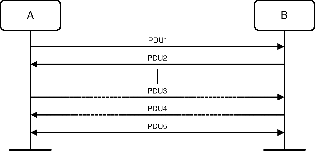
PDU1 is a PDU sent from A to B. PDU2 is a PDU sent from B to A. PDU3 is a PDU that is optionally sent from A to B. PDU4 is a PDU that is optionally sent from B to A. PDU5 is a PDU sent from either A or B. A vertical line indicates that more PDUs can optionally be sent.
2.7. General response messages
The PDUs LMP_ACCEPTED, LMP_ACCEPTED_EXT, LMP_NOT_ACCEPTED and LMP_NOT_ACCEPTED_EXT are used as response messages to other PDUs in a number of different procedures. LMP_ACCEPTED or LMP_ACCEPTED_EXT includes the opcode of the message which is accepted. LMP_NOT_ACCEPTED or LMP_NOT_ACCEPTED_EXT includes the opcode of the message which is not accepted and the error code why it is not accepted.
LMP_ACCEPTED_EXT and LMP_NOT_ACCEPTED_EXT shall be used when the opcode is 15 bits in length. LMP_ACCEPTED and LMP_NOT_ACCEPTED shall be used when the opcode is 7 bits in length.
M/O | PDU | Contents |
|---|---|---|
M | LMP_ACCEPTED | Opcode |
M | LMP_NOT_ACCEPTED | Opcode Error_Code |
O | LMP_ACCEPTED_EXT | Escape_Opcode Extended_Opcode |
O | LMP_NOT_ACCEPTED_EXT | Escape_Opcode Extended_Opcode Error_Code |
2.8. LMP message constraints
The following principles are used in the design of LMP.
No LMP message exceeds the maximum payload length of a single DM1 packet i.e. 17 bytes in length ([Vol 2] Part B, Section 6.5.4.1).
All LMP messages are of fixed length.
The LMP version number is not used to indicate the presence or absence of functionality.
3. Device features
3.1. General description
Each PDU is either Mandatory or Optional as defined by the M/O field in the tables of Section 4. An M in this field shall indicate that support for the PDU is mandatory. An O in this field shall indicate that support for the PDU is optional and it shall be followed by the number(s) of the feature(s) involved in brackets.
Some features have associated LMP feature bits. Support of these features may be required by the qualification process but the LM still considers them to be optional since it must interoperate with devices which do not support them.
The LM does not need to be able to transmit a PDU which is optional. Support of optional PDUs is indicated by a device's features mask. The features mask can be read (see Section 4.3.4). An LM shall not send or be sent any PDU which is incompatible with the features signaled in its or its peer's features mask, as detailed in Section 3.2.
The set of features supported by the LM shall not change while the Controller has a connection to another device. A peer device may cache the device's feature mask or extended feature mask, or the LM may cache a peer's feature mask or extended feature mask, during a connection.
3.2. Feature definitions
Feature | Definition |
|---|---|
3-slot Enhanced Data Rate ACL packets | This feature indicates whether the device supports the transmission and reception of three-slot Enhanced Data Rate packets on the ACL-U logical link. |
3-slot Enhanced Data Rate eSCO packets | This feature indicates whether the device supports the transmission and reception of 3-slot Enhanced Data Rate packets for the transport of traffic on the eSCO logical transport. |
3 slot packets | This feature indicates whether the device supports the transmission and reception of both DM3 and DH3 packets for the transport of traffic on the ACL-U logical link. |
5-slot Enhanced Data Rate ACL packets | This feature indicates whether the device supports the transmission and reception of 5-slot Enhanced Data Rate packets for the transport of traffic on the ACL-U logical link. |
5 slot packets | This feature indicates whether the device supports the transmission and reception of both DM5 and DH5 packets for the transport of traffic on the ACL-U logical link. |
AFH capable Central | This indicates whether the device is able to support the Adaptive Frequency Hopping mechanism as a Central as defined in [Vol 2] Part B, Section 2.3 using the LMP sequences defined in Section 4.1.4. |
AFH capable Peripheral | This feature indicates whether the device is able to support the Adaptive Frequency Hopping mechanism as a Peripheral as defined in [Vol 2] Part B, Section 2.3 using the LMP sequences defined in Section 4.1.4. |
AFH classification Central | This feature indicate whether the device is able to support the AFH classification mechanism as a Central as defined in [Vol 2] Part B, Section 8.6.8 using the LMP sequences defined in Section 4.1.5. |
AFH classification Peripheral | This feature indicates whether the device is able to support the AFH classification mechanism as a Peripheral as defined in [Vol 2] Part B, Section 8.6.8 using the LMP sequences defined in Section 4.1.5. |
A-law log synchronous data | This feature indicates whether the device is capable of supporting A-law Log format data as defined in [Vol 2] Part B, Section 9.1 on the SCO and eSCO logical transports. |
BR/EDR Not Supported | This feature indicates whether the device does not support BR/EDR. |
Broadcast encryption | This feature indicates whether the device is capable of supporting broadcast encryption as defined in [Vol 2] Part H, Section 4.2 and also the sequences defined in Section 4.2.6 and Section 4.2.4. |
Channel Quality Driven Data Rate | This feature indicates whether the LM is capable of recommending a packet type (or types) depending on the channel quality using the LMP sequences defined in Section 4.1.7. |
Coarse Clock Adjustment | This feature indicates whether the device is able to support coarse clock adjustments using the LMP sequences as defined in Section 4.1.14. |
Connectionless Peripheral Broadcast - Receiver Operation | This feature indicates whether the device supports Connectionless Peripheral Broadcast as Receiver. |
Connectionless Peripheral Broadcast - Transmitter Operation | This feature indicates whether the device supports Connectionless Peripheral Broadcast as Transmitter. |
CVSD synchronous data | This feature indicates whether the device is capable of supporting CVSD format data as defined in [Vol 2] Part B, Section 9.2 on the SCO and eSCO logical transports. |
Encapsulated PDU | This feature indicates whether the device is capable of supporting the Encapsulated PDU mechanism as defined in Section 4.1.12.1. |
Encryption | This feature indicates whether the device supports the encryption of packet contents using the sequence defined in Section 4.2.5. |
Enhanced Data Rate ACL 2 Mb/s mode | This feature indicates whether the device supports the transmission and reception of 2-DH1 packets for the transport of traffic on the ACL-U logical link. |
Enhanced Data Rate ACL 3 Mb/s mode | This feature indicates whether the device supports the transmission and reception of 3-DH1 packets for the transport of traffic on the ACL-U logical link. |
Enhanced Data Rate eSCO 2 Mb/s mode | This feature indicates whether the device supports the transmission and reception of 2-EV3 packets for the transport of traffic on the eSCO logical transport. |
Enhanced Data Rate eSCO 3 Mb/s mode | This feature indicates whether the device supports the transmission and reception of 3-EV3 packets for the transport of traffic on the eSCO logical transport. |
Enhanced power control | This feature indicates whether the device is able to support enhanced power control using the LMP sequences as defined in Section 4.1.3.1. |
Erroneous Data Reporting | This feature indicates whether the device is able to support the Packet_Status_Flag and the HCI commands HCI_Write_Default_Erroneous_Data_Reporting and HCI_Read_Default_Erroneous_Data_Reporting. |
EV4 packets | This feature indicates whether the device is capable of supporting the EV4 packet type defined in [Vol 2] Part B, Section 6.5.3.2 on the eSCO logical transport. |
EV5 packets | This feature indicates whether the device is capable of supporting the EV5 packet type defined in [Vol 2] Part B, Section 6.5.3.3 on the eSCO logical transport. |
Extended features | This feature indicates whether the device is able to support the extended features mask using the LMP sequences defined in Section 4.3.4. |
Extended Inquiry Response | This feature indicates whether the device supports extended inquiry response as defined in [Vol 2] Part B, Section 8.4.3. |
Extended SCO link | This feature indicates whether the device is able to support the eSCO logical transport as defined in [Vol 2] Part B, Section 5.5 and the EV3 packet defined in [Vol 2] Part B, Section 6.5.3.1 using the LMP sequences defined in Section 4.6.2. |
Flow control lag | This is defined as the total amount of ACL-U data that can be sent following the receipt of a valid payload header with the payload header flow bit set to 0 and is in units of 256 bytes. See further in [Vol 2] Part B, Section 6.6.2. |
Generalized interlaced scan | This feature indicates whether the device is able to support the generalized interlaced scan mechanism described in [Vol 2] Part B, Section 8.3.1 and Section 8.4.1. The presence of this feature has only local meaning and does not imply support for any additional LMP PDUs or sequences. |
Hold mode | This feature indicates whether the device is able to support Hold mode as defined in [Vol 2] Part B, Section 8.8 using the LMP sequences defined in Section 4.5.1. |
HV2 packets | This feature indicates whether the device is capable of supporting the HV2 packet type as defined in [Vol 2] Part B, Section 6.5.2.2 on the SCO logical transport. |
HV3 packets | This feature indicates whether the device is capable of supporting the HV3 packet type as defined in [Vol 2] Part B, Section 6.5.2.3 on the SCO logical transport. |
Inquiry Response Notification event | This feature bit indicates whether the device supports sending the HCI_Inquiry_Response_Notification event to the Host. |
Interlaced inquiry scan | This feature indicates whether the device is capable of supporting the interlaced inquiry scan mechanism as defined in [Vol 2] Part B, Section 8.4.1. The presence of this feature has only local meaning and does not imply support for any additional LMP PDUs or sequences. |
Interlaced page scan | This feature indicates whether the device is capable of supporting the interlaced page scan mechanism as defined in [Vol 2] Part B, Section 8.3.1. The presence of this feature has only local meaning and does not imply support for any additional LMP PDUs or sequences. |
LE Supported (Controller) | This feature indicates whether the Controller supports LE. The local Host uses this feature bit to determine whether the Controller supports LE. A remote device does not use this feature bit. |
LE Supported (Host) | This feature indicates that the Host supports LE. The local Host sets this feature bit to indicate to a remote device that the local device is capable of supporting LE. A remote Host uses this feature bit to determine whether an LE connection to the peer device is possible. |
Link Supervision Timeout Changed event | This feature bit indicates whether the device supports the sending the HCI_Link_Supervision_Timeout_Changed event to the Host. |
μ-law log synchronous data | This feature indicates whether the device is capable of supporting µ-law Log format data as defined in [Vol 2] Part B, Section 9.1 on the SCO and eSCO logical transports. |
Non-flushable Packet Boundary Flag | This feature indicates that the device supports the capability to correctly handle HCI ACL Data packets with a Packet_Boundary_Flag value of 00 (Non-Automatically-Flushable packet). |
Paging parameter negotiation | This feature indicates whether the LM is capable of supporting the signaling of changes in the paging scheme as defined in Section 4.1.9. |
Pause Encryption | When this feature bit is enabled on both sides, then the encryption pause and resume sequences shall be used. If either side does not support the Pause Encryption feature bit, then the encryption pause and resume sequences shall not be used. |
Ping | This feature indicates whether the device supports the transmission and reception of ping messages. |
Power control | This feature indicates whether the device is capable of adjusting its transmission power. This feature indicates the ability to receive the LMP_INCR_POWER and LMP_DECR_POWER PDUs and transmit the LMP_MAX_POWER and LMP_MIN_POWER PDUs, using the sequences defined in Section 4.1.3. These sequences may be used even if the remote device does not support the power control feature, as long as it supports the Power control requests feature. |
Power control requests | This feature indicates whether the device is capable of determining if the transmit power level of the other device should be adjusted and will send the LMP_INCR_POWER and LMP_DECR_POWER PDUs to request the adjustments. It indicates the ability to receive the LMP_MAX_POWER and LMP_MIN_POWER PDUs, using the sequences in Section 4.1.3. These sequences may be used even if the remote device does not support the RSSI feature, as long as it supports the power control feature. |
Role switch | This feature indicates whether the device supports the exchange of Central and Peripheral roles as defined by [Vol 2] Part B, Section 8.6.5 using the sequence defined in Section 4.4.2. |
RSSI with inquiry results | This feature indicates whether the device is capable of reporting the RSSI with inquiry results as defined in [Vol 2] Part B, Section 8.4.2. The presence of this feature has only local meaning and does not imply support for any additional LMP PDUs or sequences. |
SCO link | This feature shall indicate whether the device is able to support the SCO logical transport as defined in [Vol 2] Part B, Section 4.3, the HV1 packet defined in [Vol 2] Part B, Section 6.5.2.1 and receiving the DV packet defined in [Vol 2] Part B, Section 6.5.2.4 using the LMP sequence in Section 4.6.1. |
Secure Connections (Controller Support) | This feature indicates whether the Controller is able to support AES-CCM, the P-256 Elliptic Curve for Secure Simple Pairing, and enhanced authentication using the LMP sequences as defined in Section 4.2.7. |
Secure Connections (Host Support) | This feature indicates whether the Host is capable of supporting Secure Connections. If HCI is supported, this bit shall be set if the HCI_Write_Secure_Connections_Host_Support command has been issued by the Host. When HCI is not supported, this bit may be set using a vendor specific mechanism. |
Secure Simple Pairing (Controller Support) | This feature indicates whether the Link Manager is capable of supporting Secure Simple Pairing as defined in Section 4.2.7. |
Secure Simple Pairing (Host Support) | This feature indicates whether the Host is capable of supporting Secure Simple Pairing as defined in Section 4.2.7. If HCI is supported, this bit shall be set if the HCI_Write_Simple_Pairing_Mode command has been issued to enable the Secure Simple Pairing feature. When HCI is not supported, this bit may be set using a vendor specific mechanism. |
Simultaneous LE and BR/EDR to Same Device Capable (Controller) | This feature indicates that the Controller supports simultaneous LE and BR/EDR links to the same remote device. The local Host uses this feature bit to determine whether the Controller is capable of supporting simultaneous LE and BR/EDR connections to a remote device. A remote device does not use this feature bit. |
Slot Availability Mask | This feature indicates whether the device is able to support Slot Availability Mask using the LMP sequences as defined in Section 4.1.15. |
Slot offset | This feature indicates whether the LM supports the transfer of the slot offset using the sequence defined in Section 4.4.1. |
Sniff mode | This feature indicates whether the device is able to support Sniff mode as defined in [Vol 2] Part B, Section 8.7 using the LMP sequences defined in Section 4.5.3. |
Sniff subrating | This feature indicates whether the device is able to support sniff subrating as defined in [Vol 2] Part B, Section 8.7.2 using the LMP sequences as defined in Section 4.5.3.3. |
Synchronization Scan | This feature indicates whether the device supports Synchronization Scan as Peripheral. |
Synchronization Train | This feature indicates whether the device supports Synchronization Train as Central. |
Timing accuracy | This feature indicates whether the LM supports requests for timing accuracy using the sequence defined in Section 4.3.1. |
Train nudging | This feature indicates whether the device is able to support the train nudging mechanism described in [Vol 2] Part B, Section 8.3.2 and Section 8.4.2. The presence of this feature has only local meaning and does not imply support for any additional LMP PDUs or sequences. |
Transparent synchronous data | This feature indicates whether the device is capable of supporting transparent synchronous data as defined in [Vol 2] Part B, Section 6.4.3 on the SCO and eSCO logical transports. |
Variable Inquiry TX Power Level | This feature indicates whether the device is capable of setting the TX power level for Inquiry. |
3.3. Feature mask definition
The features are represented as a bit mask when they are transferred in LMP messages. For each feature a single bit is specified which shall be set to 1 if the feature is supported and set to 0 otherwise. The single exception is the flow control lag which is coded as a 3 bit field with the least significant bit in byte 2 bit 4 and the most significant bit in byte 2 bit 6. All unassigned feature bits are reserved for future use.
No. | Supported feature | Byte | Bit |
|---|---|---|---|
0 | 3 slot packets | 0 | 0 |
1 | 5 slot packets | 0 | 1 |
2 | Encryption | 0 | 2 |
3 | Slot offset | 0 | 3 |
4 | Timing accuracy | 0 | 4 |
5 | Role switch | 0 | 5 |
6 | Hold mode | 0 | 6 |
7 | Sniff mode | 0 | 7 |
8 | Previously used | 1 | 0 |
9 | Power control requests | 1 | 1 |
10 | Channel quality driven data rate (CQDDR) | 1 | 2 |
11 | SCO link | 1 | 3 |
12 | HV2 packets | 1 | 4 |
13 | HV3 packets | 1 | 5 |
14 | μ-law log synchronous data | 1 | 6 |
15 | A-law log synchronous data | 1 | 7 |
16 | CVSD synchronous data | 2 | 0 |
17 | Paging parameter negotiation | 2 | 1 |
18 | Power control | 2 | 2 |
19 | Transparent synchronous data | 2 | 3 |
20 | Flow control lag (least significant bit) | 2 | 4 |
21 | Flow control lag (middle bit) | 2 | 5 |
22 | Flow control lag (most significant bit) | 2 | 6 |
23 | Broadcast Encryption | 2 | 7 |
24 | Reserved for future use | 3 | 0 |
25 | Enhanced Data Rate ACL 2 Mb/s mode | 3 | 1 |
26 | Enhanced Data Rate ACL 3 Mb/s mode | 3 | 2 |
27 | Enhanced inquiry scan (see note) | 3 | 3 |
28 | Interlaced inquiry scan | 3 | 4 |
29 | Interlaced page scan | 3 | 5 |
30 | RSSI with inquiry results | 3 | 6 |
31 | Extended SCO link (EV3 packets) | 3 | 7 |
32 | EV4 packets | 4 | 0 |
33 | EV5 packets | 4 | 1 |
34 | Reserved for future use | 4 | 2 |
35 | AFH capable Peripheral | 4 | 3 |
36 | AFH classification Peripheral | 4 | 4 |
37 | BR/EDR Not Supported | 4 | 5 |
38 | LE Supported (Controller) | 4 | 6 |
39 | 3-slot Enhanced Data Rate ACL packets | 4 | 7 |
40 | 5-slot Enhanced Data Rate ACL packets | 5 | 0 |
41 | Sniff subrating | 5 | 1 |
42 | Pause encryption | 5 | 2 |
43 | AFH capable Central | 5 | 3 |
44 | AFH classification Central | 5 | 4 |
45 | Enhanced Data Rate eSCO 2 Mb/s mode | 5 | 5 |
46 | Enhanced Data Rate eSCO 3 Mb/s mode | 5 | 6 |
47 | 3-slot Enhanced Data Rate eSCO packets | 5 | 7 |
48 | Extended Inquiry Response | 6 | 0 |
49 | Simultaneous LE and BR/EDR to Same Device Capable (Controller) | 6 | 1 |
50 | Reserved for future use | 6 | 2 |
51 | Secure Simple Pairing (Controller Support) | 6 | 3 |
52 | Encapsulated PDU | 6 | 4 |
53 | Erroneous Data Reporting | 6 | 5 |
54 | Non-flushable Packet Boundary Flag | 6 | 6 |
55 | Reserved for future use | 6 | 7 |
56 | HCI_Link_Supervision_Timeout_Changed event | 7 | 0 |
57 | Variable Inquiry TX Power Level | 7 | 1 |
58 | Enhanced Power Control | 7 | 2 |
59 | Reserved for future use | 7 | 3 |
60 | Reserved for future use | 7 | 4 |
61 | Reserved for future use | 7 | 5 |
62 | Reserved for future use | 7 | 6 |
63 | Extended features | 7 | 7 |
No. | Supported Feature | Byte | Bit |
|---|---|---|---|
64 | Secure Simple Pairing (Host Support) | 0 | 0 |
65 | LE Supported (Host) | 0 | 1 |
66 | Previously used | 0 | 2 |
67 | Secure Connections (Host Support) | 0 | 3 |
No. | Supported Feature | Byte | Bit |
|---|---|---|---|
128 | Connectionless Peripheral Broadcast – Transmitter Operation | 0 | 0 |
129 | Connectionless Peripheral Broadcast – Receiver Operation | 0 | 1 |
130 | Synchronization Train | 0 | 2 |
131 | Synchronization Scan | 0 | 3 |
132 | HCI_Inquiry_Response_Notification event | 0 | 4 |
133 | Generalized interlaced scan | 0 | 5 |
134 | Coarse Clock Adjustment | 0 | 6 |
135 | Reserved for future use | 0 | 7 |
136 | Secure Connections (Controller Support) | 1 | 0 |
137 | Ping | 1 | 1 |
138 | Slot Availability Mask | 1 | 2 |
139 | Train nudging | 1 | 3 |
Note
Note: Feature bit 27 (“Enhanced Inquiry Scan”) is no longer used in the specification. Devices may set this bit but are not required to.
3.4. Link Manager interoperability policy
Link managers of any version shall interpret using the lowest common subset of functionality by reading the LMP features mask (defined in Table 3.2).
An optional LMP PDU shall only be sent to a device if the corresponding feature bit is set in its feature mask. The exception to this are certain PDUs (see Section 4.1.1) which can be sent before the features mask is requested.
Note
Note: A higher version device with a restricted feature set is indistinguishable from a lower version device with the same features.
3.5. Feature requirements
Note
Note: In the tables in this section, numbers in parentheses before feature names are the corresponding feature bit numbers (see Section 3.3).
Any device supporting any feature with a feature bit number greater than or equal to 64 shall support Extended features and shall set feature bit 63.
3.5.1. Devices supporting BR/EDR
This section applies to devices supporting BR/EDR.
The features listed in Table 3.5 are mandatory in this version of the specification (see Section 3.1) and these feature bits shall be set.
Feature |
|---|
(2) Encryption |
(51) Secure Simple Pairing (Controller Support) |
(52) Encapsulated PDU |
The features listed in Table 3.6 are forbidden in this version of the specification and these feature bits shall not be set.
Feature |
|---|
(37) BR/EDR Not Supported |
For each row of Table 3.7, either every feature named in that row shall be supported or none of the features named in that row shall be supported.
Features | |
|---|---|
(7) Sniff mode | (41) Sniff subrating |
For each row of Table 3.8, not more than one feature in that row shall be supported.
Features | |
|---|---|
(23) Broadcast encryption | (134) Coarse clock adjustment |
For each row of Table 3.9, if the feature named in the first column is supported then the feature named in the second column shall be supported.
Feature | Required feature |
|---|---|
(5) Role switch | (3) Slot offset |
(12) HV2 packets | (11) SCO link |
(13) HV3 packets | (11) SCO link |
(14) µ-law log synchronous data | (11) SCO link or (31) Extended SCO link (EV3 packets) |
(15) A-law log synchronous data | (11) SCO link or (31) Extended SCO link (EV3 packets) |
(16) CVSD log synchronous data | (11) SCO link or (31) Extended SCO link (EV3 packets) |
(19) Transparent synchronous data | (11) SCO link or (31) Extended SCO link (EV3 packets) |
(26) Enhanced Data Rate ACL 3 Mb/s mode | (25) Enhanced Data Rate ACL 2 Mb/s mode |
(32) EV4 packets | (31) Extended SCO link (EV3 packets) |
(33) EV5 packets | (31) Extended SCO link (EV3 packets) |
(36) AFH classification Peripheral | (35) AFH capable Peripheral |
(39) 3-slot Enhanced Data Rate ACL packets | (25) Enhanced Data Rate ACL 2 Mb/s mode |
(40) 5-slot Enhanced Data Rate ACL packets | (25) Enhanced Data Rate ACL 2 Mb/s mode |
(44) AFH classification Central | (43) AFH capable Central |
(45) Enhanced Data Rate eSCO 2 Mb/s mode | (31) Extended SCO link (EV3 packets) |
(46) Enhanced Data Rate eSCO 3 Mb/s mode | (45) Enhanced Data Rate eSCO 2 Mb/s mode |
(47) 3-slot Enhanced Data Rate eSCO packets | (45) Enhanced Data Rate eSCO 2 Mb/s mode |
(48) Extended inquiry response | (30) RSSI with inquiry results |
(49) Simultaneous LE and BR/EDR to Same Device Capable (Controller) | (38) LE Supported (Controller) |
(53) Erroneous data reporting | (11) SCO link or (31) Extended SCO link (EV3 packets) |
(58) Enhanced power control | (9) Power control requests and (18) Power control |
(65) LE Supported (Host) | (38) LE Supported (Controller) |
(67) Secure Connections (Host Support) | (64) Secure Simple Pairing (Host Support) and (136) Secure Connections (Controller Support) |
(128) Connectionless Peripheral Broadcast – Transmitter Operation | (130) Synchronization Train |
(129) Connectionless Peripheral Broadcast – Receiver Operation | (131) Synchronization Scan |
(133) Generalized interlaced scan | (28) Interlaced inquiry scan or (29) Interlaced page scan |
(134) Coarse clock adjustment | (35) AFH capable Peripheral and (43) AFH capable Central and (130) Synchronization Train and (131) Synchronization Scan |
(136) Secure Connections (Controller Support) | (42) Pause encryption and (137) Ping |
3.5.2. Devices not supporting BR/EDR
This section applies to devices not supporting BR/EDR.
The features listed in Table 3.10 are mandatory (so those feature bits shall be set).
Feature |
|---|
(37) BR/EDR Not Supported |
(38) LE Supported (Controller) |
The features listed in Table 3.11 are optional and the feature bits may be set.
Feature |
|---|
(63) Extended features |
(65) LE Supported (Host) |
No other feature shall be supported and no other feature bit shall be set.
4. Procedure rules
4.1. Connection control
4.1.1. Connection establishment
After the paging procedure, LMP procedures for clock offset request, LMP version, supported features, name request and detach may then be initiated.
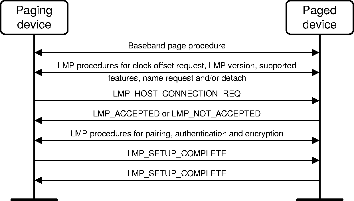
When the paging device wishes to create a connection involving layers above LM, it sends an LMP_HOST_CONNECTION_REQ PDU. When the other side receives this message, the Host is informed about the incoming connection. The remote device can accept or reject the connection request by sending an LMP_ACCEPTED PDU or an LMP_NOT_ACCEPTED PDU. Alternatively, if the Peripheral needs a role switch, see Section 4.4.2, it sends an LMP_SLOT_OFFSET PDU and LMP_SWITCH_REQ PDU after it has received an LMP_HOST_CONNECTION_REQ PDU. If the role switch fails the LM shall continue with the creation of the connection unless this cannot be supported due to limited resources in which case the connection shall be terminated with an LMP_DETACH PDU with Error_Code Remote Device Terminated Connection due to Low Resources (0x14). When the role switch has been successfully completed, the old Peripheral will reply with an LMP_ACCEPTED PDU or an LMP_NOT_ACCEPTED PDU to the LMP_HOST_CONNECTION_REQ PDU (with the transaction ID set to 0).
If the paging device receives an LMP_NOT_ACCEPTED PDU in response to LMP_HOST_CONNECTION_REQ it shall immediately disconnect the link using the mechanism described in Section 4.1.2.
If the LMP_HOST_CONNECTION_REQ PDU is accepted, LMP security procedures (pairing, authentication and encryption) may be invoked. When a device is not going to initiate any more security procedures during connection establishment it sends an LMP_SETUP_COMPLETE PDU. When both devices have sent LMP_SETUP_COMPLETE PDUs the traffic can be transferred on the BR/EDR ACL logical transport.
M/O | PDU | Contents |
|---|---|---|
M | LMP_HOST_CONNECTION_REQ | none |
M | LMP_SETUP_COMPLETE | none |
4.1.2. Detach
The connection between two Bluetooth devices may be detached anytime by the Central or the Peripheral. An Error_Code parameter is included in the message to inform the other party of why the connection is detached.
M/O | PDU | Contents |
|---|---|---|
M | LMP_DETACH | Error_Code |
The initiating LM shall pause traffic on the ACL-U logical link (see [Vol 2] Part B, Section 5.3.1). The initiating LM then queues the LMP_DETACH for transmission and it shall start a timer for 6*Tpoll slots where Tpoll is the poll interval for the connection. If the initiating LM receives the Baseband acknowledgment before the timer expires it starts a timer for 3*Tpoll slots. When this timer expires, and if the initiating LM is the Central, the LT_ADDR(s) may be re-used immediately. If the initial timer expires then the initiating LM drops the link and starts a timer for Tlinksupervisiontimeout slots after which the LT_ADDR(s) may be re-used if the initiating LM is the Central.
When the receiving LM receives the LMP_DETACH, it shall start a timer for 6*Tpoll slots if it is the Central and 3*Tpoll if it is the Peripheral. On timer expiration, the link shall be detached and, if the receiving LM is the Central, the LT_ADDR(s) may be re-used immediately. If the receiver never receives the LMP_DETACH then a link supervision timeout will occur, the link will be detached, and the LT_ADDR may be re-used immediately.
If at any time during this or any other LMP sequence the Link supervision timeout expires then the link shall be terminated immediately and the LT_ADDR(S) may be re-used immediately.
If the connection is in Hold mode, the initiating LM shall wait for Hold mode to end before initiating the procedure defined above. If the connection is in Sniff mode, the initiating LM shall perform the procedure to exit Sniff mode before initiating the procedure defined above. If the procedure to exit Sniff mode does not complete within the LMP response timeout (30 seconds) the procedure defined above shall be initiated anyway.
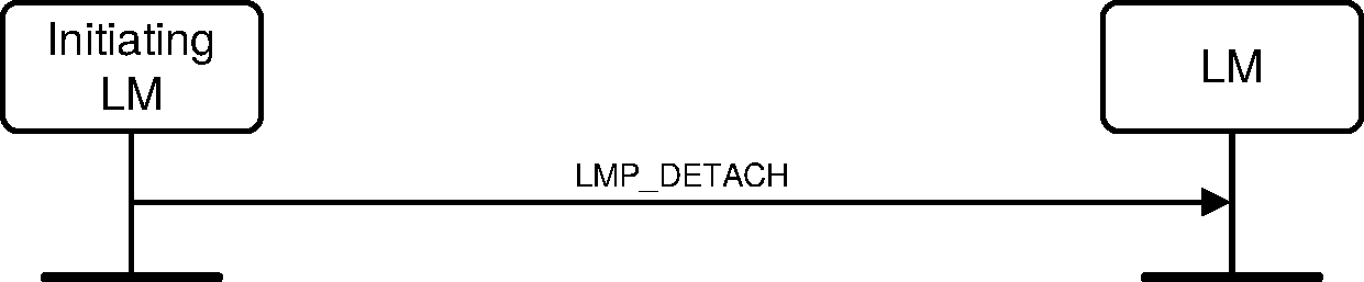
Sequence 1: Connection closed by sending LMP_DETACH
If there are any SCO or eSCO connections open on the same physical link, sending or receiving the LMP_DETACH PDU implicitly removes them and the initiating LM should not send separate PDUs for this purpose when detaching.
4.1.3. Power control
If the received signal characteristics differ too much from the preferred value of a Bluetooth device, it may request an increase or a decrease of the other device’s transmit power level. A device's transmit power level is a property of the physical link, and affects all logical transports carried over the physical link. Power control requests carried over the default ACL-C logical link shall only affect the physical link associated with the requesting device’s default ACL-C logical link; they shall not affect the power level used on the physical links to other Peripherals.
Two power control mechanisms are specified: legacy power control (see Table 4.3) and enhanced power control (see Table 4.4 and Section 4.1.3.1).
M/O | PDU | Contents |
|---|---|---|
O(9) | LMP_INCR_POWER_REQ | Reserved |
O(9) | LMP_DECR_POWER_REQ | Reserved |
O(18) | LMP_MAX_POWER | none |
O(18) | LMP_MIN_POWER | none |
M/O | PDU | Contents |
|---|---|---|
O(58) | LMP_POWER_CONTROL_REQ | Power_Adj_Req |
O(58) | LMP_POWER_CONTROL_RES | Power_Adj_Rsp |
The power adjustment requests may be made at any time using the legacy power control mechanism following a successful Baseband Paging procedure and before the link manager supported features responses have been processed. After the Link Manager supported features responses have been processed, if both devices support enhanced power control (see Section 4.1.3.1) then only enhanced power control shall be used. Otherwise, if either device supports only the legacy power control mechanism then only legacy power control shall be used.
If a device does not support power control requests this is indicated in the supported features list and thus no power control requests shall be sent after the supported features response has been processed. Prior to this time, a power control adjustment might be sent and if the recipient does not support power control it is allowed to send LMP_MAX_POWER in response to LMP_INCR_POWER_REQ and LMP_MIN_POWER in response to LMP_DECR_POWER_REQ. Another possibility is to send LMP_NOT_ACCEPTED with the Error_Code Unsupported LMP Feature (0x1A).
Upon receipt of an LMP_INCR_POWER_REQ PDU or LMP_DECR_POWER_REQ PDU the output power shall be increased or decreased one step. See [Vol 2] Part A, Section 3 for the definition of the step size.
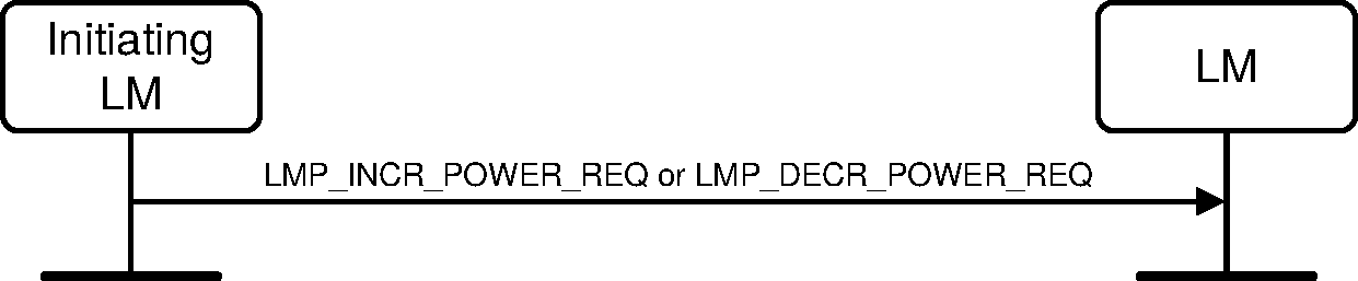
Sequence 2: A device requests a change of the other device’s TX power
If the receiver of LMP_INCR_POWER_REQ is at maximum power LMP_MAX_POWER shall be returned. The device shall only request an increase again after having requested a decrease at least once. If the receiver of LMP_DECR_POWER_REQ is at minimum power then LMP_MIN_POWER shall be returned and the device shall only request a decrease after having requested an increase at least once.

Sequence 3: The TX power cannot be increased

Sequence 4: The TX power cannot be decreased
One byte in LMP_INCR/DECR_POWER_REQ is reserved for future use.
4.1.3.1. Enhanced power control
Enhanced power control shall only be used when both devices support the enhanced power control LMP feature. Legacy power control shall not be used when both devices support the enhanced power control LMP feature.
4.1.3.1.1. Sending enhanced power control requests
To adjust the remote device's output power, a device shall send the LMP_POWER_CONTROL_REQ PDU with the Power_Adj_Req parameter.
The Power_Adj_Req parameter may be set to: one step up, one step down, or all the way to the max power level. The remote device shall respond with an LMP_POWER_CONTROL_RES PDU. The responder shall transmit the LMP_POWER_CONTROL_RES PDU at the new power level. Upon reception of the LMP_POWER_CONTROL_RES PDU, the initiating device should restart any processes used to determine whether additional power level changes are required.
If the receiver of the LMP_POWER_CONTROL_REQ PDU has indicated that the output power levels for all of the supported modulation modes are at maximum the requesting device shall only request an increase again after having requested a decrease at least once. If the receiver of the LMP_POWER_CONTROL_REQ PDU has indicated that the output power levels for all of the supported modulation modes are at minimum the requesting device shall only request a decrease after having requested an increase at least once.
A new LMP_POWER_CONTROL_REQ PDU shall not be sent until an LMP_POWER_CONTROL_RES PDU has been received.
4.1.3.1.2. Responding to enhanced power control requests
When a device receives an LMP_POWER_CONTROL_REQ PDU with the Power_Adj_Req parameter set to "increment one step," all supported modulations that are not at the maximum level shall be increased one step.
When a device receives an LMP_POWER_CONTROL_REQ PDU with the Power_Adj_Req parameter set to "decrement one step", all supported modulations that are not at the minimum level shall be decreased one step.
Implementations shall not violate the relative power level between modulations (see [Vol 2] Part A, Section 3).
When a device receives an LMP_POWER_CONTROL_REQ PDU with the Power_Adj_Req parameter set to "increment power to maximum value", each supported modulation mode shall be set to its maximum power level.
Note
Note: See [Vol 2] Part A, Section 3 for requirements on the relative power levels of different modulation modes.
The responding LM shall send the LMP_POWER_CONTROL_RES PDU to indicate the status for every modulation. The Power_Adj_Rsp parameter has three 2-bit fields indicating the status for each modulation mode: GFSK, π/4-DQPSK and 8DPSK. Each 2-bit field shall be set to one of the following values: not supported, changed one step, max power, or min power. The changed one step value shall only be used when the power level for that modulation mode has not reached the minimum or maximum level.
The not supported value shall be used for each unsupported modulation type.
The responder shall transmit the LMP_POWER_CONTROL_RES PDU at the new transmit power level and shall not change its power level until requested by the remote device by a subsequent LMP_POWER_CONTROL_REQ PDU.
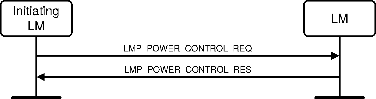
Sequence 5: A device responds to a power control request
4.1.4. Adaptive frequency hopping
AFH is used to improve the performance of physical links in the presence of interference as well as reducing the interference caused by physical links on other devices in the ISM band. AFH shall only be used during Connection state.
M/O | PDU | Contents |
|---|---|---|
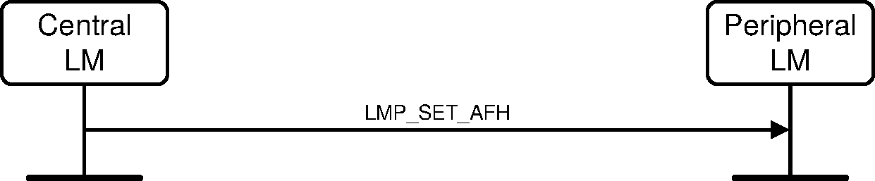
O(35) Rx O(43) Tx | LMP_SET_AFH | AFH_Instant, AFH_Mode, AFH_Channel_Map |
The LMP_SET_AFH PDU contains three parameters: AFH_Instant, AFH_Mode, and AFH_Channel_Map. The parameter, AFH_Instant, specifies the instant at which the hopset switch shall become effective. This is specified as a Bluetooth Clock value of the Central’s clock, that is available to both devices. The AFH instant is chosen by the Central and shall be an even value at least 6*Tpoll or 96 slots (whichever is greater) in the future. The AFH_Instant shall be within 12 hours of the current clock value. The parameter AFH_Mode, specifies whether AFH shall be enabled or disabled. The parameter AFH_Channel_Map, specifies the set of channels that shall be used if AFH is enabled.
When the LMP_SET_AFH PDU is received the AFH instant shall be compared with the current Bluetooth clock value. If it is in the past then the AFH_Instant has passed and the Peripheral shall immediately configure the hop selection kernel (see [Vol 2] Part B, Section 2.6.3) with the new AFH_Mode and AFH_Channel_Map specified in the LMP_SET_AFH PDU. If it is in the future then a timer shall be started to expire at the AFH instant. When this timer expires it shall configure the hop selection kernel with the new AFH_Mode and AFH_Channel_Map.
The Central shall not send a new LMP_SET_AFH PDU to a Peripheral until it has received the Baseband acknowledgment for any previous LMP_SET_AFH addressed to that Peripheral and the instant has passed.
Role switch while AFH is enabled shall follow the procedures define by [Vol 2] Part B, Section 8.6.5.
4.1.4.1. Central enables AFH
Prior to enabling AFH the Central LM shall pause traffic on the ACL-U logical link (see [Vol 2] Part B, Section 5.3.1). The Central shall then enable AFH on a physical link by sending the LMP_SET_AFH PDU with AFH_Mode set to enabled, the AFH_Channel_Map parameter containing the set of used and unused channels, and an AFH_instant. The LM shall not calculate the AFH instant until after traffic on the ACL-U logical link has been stopped. The Central considers the physical link to be enabled once the Baseband acknowledgment has been received and the AFH_Instant has passed. Once the Baseband acknowledgment has been received the Central shall restart transmission on the ACL-U logical link.

Sequence 6: Central enables AFH
4.1.4.2. Central disables AFH
Prior to disabling AFH the Central LM shall pause traffic on the ACL-U logical link ([Vol 2] Part B, Section 5.3.1). The Central shall then disable AFH operation on a physical link by sending the LMP_SET_AFH PDU with AFH_mode set to disabled and an AFH_Instant. The AFH_Channel_Map parameter is not valid when AFH_Mode is disabled. The LM shall not calculate the AFH instant until after traffic on the ACL-U logical link has been stopped. The Central considers the physical link to have entered AFH-disabled operation once the Baseband acknowledgment has been received and the AFH_Instant has passed. Once the Baseband acknowledgment has been received the Central shall restart transmission on the ACL-U logical link.
Sequence 7: Central disables AFH
4.1.4.3. Central updates AFH
A Central shall update the AFH parameters on a physical link by sending the LMP_SET_AFH PDU with AFH_Mode set to enabled, an AFH_Instant and a new AFH_Channel_Map. The Central shall consider the Peripheral to have the updated AFH parameters once the Baseband acknowledgment has been received and the AFH_Instant has passed.

Sequence 8: Central updates AFH
4.1.4.4. AFH operation in Hold and Sniff modes
A Peripheral in Hold mode or Sniff mode shall retain the AFH_Mode and AFH_Channel_Map it was using prior to entering those modes. A Central may change the AFH_Mode while a Peripheral is in Sniff mode.
A Central that receives a request from an AFH-enabled Peripheral to enter Hold mode or Sniff mode and decides to operate the Peripheral using a different hop sequence shall respond with an LMP_SET_AFH PDU specifying the new hop sequence.
The Central continues with the LMP signaling, for Hold or Sniff initiation, once the Baseband acknowledgment for the LMP_SET_AFH PDU has been received. Optionally, the Central may delay the continuation of this LMP signaling until after the instant. An AFH capable Peripheral shall support both of these cases.
A Central that receives a request from an AFH-enabled Peripheral to enter Hold mode or Sniff mode and decides not to change the Peripheral's hop sequence shall respond exactly as it would do without AFH. In this case, AFH operation has no effect on the LMP signaling.
4.1.5. Channel classification
A Central may request channel classification information from a Peripheral that is AFH-enabled.
A Peripheral that supports the AFH_classification_Peripheral feature shall perform channel classification and reporting according to its AFH_reporting_mode. The Central shall control the AFH_reporting_mode using the LMP_CHANNEL_CLASSIFICATION_REQ PDU. The Peripheral shall report its channel classification using the LMP_CHANNEL_CLASSIFICATION PDU.
The Peripheral shall report pairs of channels as good, bad or unknown. See Table 5.2 for the detailed format of the AFH_Channel_Classification parameter. When one channel in the nth channel pair is good and the other channel is unknown the nth channel pair shall be reported as good. When one channel in the nth channel pair is bad and the other is unknown the nth channel pair shall be reported as bad. It is implementation dependent what to report when one channel in a channel pair is good and the other is bad.
M/O | PDU | Contents |
|---|---|---|
O(36) Rx O(44) Tx | LMP_CHANNEL_CLASSIFICATION_REQ | AFH_Reporting_Mode, AFH_Min_Interval, AFH_Max_Interval |
O(36) Tx O(44) Rx | LMP_CHANNEL_CLASSIFICATION | AFH_Channel_Classification |
The LMP_CHANNEL_CLASSIFICATION_REQ PDU contains three parameters: AFH_Reporting_Mode, AFH_Min_Interval, and AFH_Max_Interval. In the disabled state, the Peripheral shall not generate any channel classification reports. The parameter AFH_min_interval, defines the minimum amount of time from the last LMP_CHANNEL_CLASSIFICATION command that was sent before the next LMP_CHANNEL_CLASSIFICATION PDU may be sent. The parameter AFH_max_interval, defines the maximum amount of time between the change in the channel classification being detected by a Peripheral and its generation of an LMP_CHANNEL_CLASSIFICATION PDU. The AFH_max_interval shall be equal to or larger than AFH_min_interval.
The AFH_reporting_mode parameter shall determine if the Peripheral is in the enabled or disabled state. The default state, prior to receipt of any LMP_CHANNEL_CLASSIFICATION_REQ PDUs, shall be disabled.
AFH_reporting_mode is implicitly set to the disabled state when any of the following occur:
Establishment of a connection at the Baseband level
Role switch
Entry to Hold mode operation
AFH_reporting_mode is implicitly restored to its former value when any of the following occur:
Exit from Hold mode
Failure of role switch
4.1.5.1. Channel classification reporting enabling and disabling
A Central enables Peripheral channel classification reporting by sending the LMP_CHANNEL_CLASSIFICATION_REQ PDU with the AFH_reporting_mode parameter set to enabled.
When a Peripheral has had classification reporting enabled by the Central it shall send the LMP_CHANNEL_CLASSIFICATION PDU according to the information in the latest LMP_CHANNEL_CLASSIFICATION_REQ PDU. The LMP_CHANNEL_CLASSIFICATION PDU shall not be sent if there has been no change in the Peripheral’s channel classification.
A Central disables Peripheral channel classification reporting by sending the LMP_CHANNEL_CLASSIFICATION_REQ PDU with the AFH_reporting_mode parameter set to disabled.
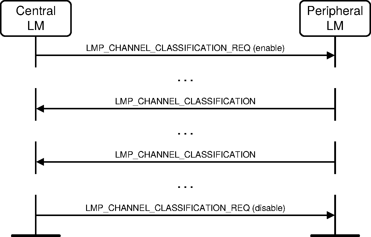
Sequence 9: Channel classification reporting
4.1.6. Link supervision
Each physical link has a timer that is used for link supervision. This timer is used to detect physical link loss caused by devices moving out of range, or being blocked by interference, a device’s power-down, or other similar failure cases. Link supervision is specified in [Vol 2] Part B, Section 3.1.
M/O | PDU | Contents |
|---|---|---|
M | LMP_SUPERVISION_TIMEOUT | Supervision_Timeout |
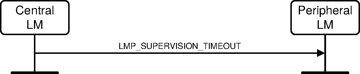
Sequence 10: Setting the link supervision timeout
4.1.7. Channel quality driven data rate change (CQDDR)
The data throughput for a given packet type depends on the quality of the RF channel. Quality measurements in the receiver of one device can be used to dynamically control the packet type transmitted from the remote device for optimization of the data throughput. Device A sends the LMP_AUTO_RATE PDU once to notify device B to enable this feature. Once enabled, device B may request packet type(s) that A should transmit by sending the LMP_PREFERRED_RATE PDU. This PDU has a parameter which determines the preferred error coding (with or without 2/3 FEC) and optionally the preferred size in slots of the packets. Device A is not required to change to the packet type specified by this parameter. Device A shall not send a packet that is larger than max slots (see Section 4.1.10) even if the preferred size is greater than this value.
The Data_Rate parameter includes the preferred rate for Basic Rate and Enhanced Data Rate modes. When operating in Basic Rate mode, the device shall use bits 0 to 2 to determine the preferred data rate. When operating in Enhanced Data Rate mode, the device shall use bits 3 to 6 to determine the preferred data rate. For devices that support Enhanced Data Rate, the preferred rates for both Basic Rate and Enhanced Data Rate modes shall be valid at all times.
These PDUs may be sent at any time after connection setup is completed.
M/O | PDU | Contents |
|---|---|---|
O(10) | LMP_AUTO_RATE | none |
O(10) | LMP_PREFERRED_RATE | Data_Rate |
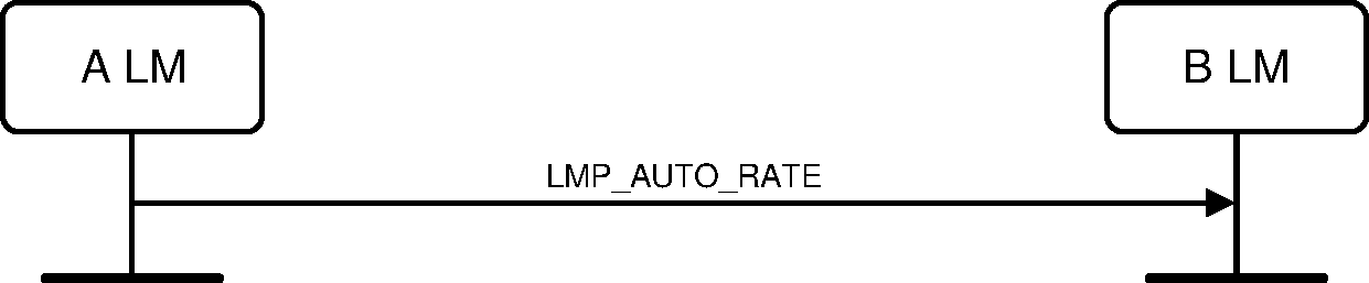
Sequence 11: A notifies B to enable CQDDR
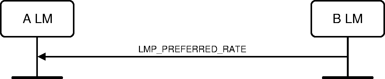
Sequence 12: B sends A a preferred packet type
4.1.8. Quality of service (QoS)
The LM provides QoS capabilities. A poll interval, Tpoll , that is defined as the maximum time between transmissions from the Central to a particular Peripheral on the ACL logical transport, is used to support bandwidth allocation and latency control - see [Vol 2] Part B, Section 8.6.1 for details. The poll interval shall be met in the Active and Sniff modes except when there are collisions with page, page scan, inquiry and inquiry scan, during time critical LMP sequences in the current piconet and any other piconets in which the Bluetooth device is a member, and during critical Baseband sequences (such as the page response, initial Connection state until the first POLL, and role switch). These PDUs may be sent at any time after connection setup is completed.
Central and Peripheral negotiate the number of repetitions for broadcast packets (NBC ), see [Vol 2] Part B, Section 7.6.5.
M/O | PDU | Contents |
|---|---|---|
M | LMP_QUALITY_OF_SERVICE | Poll_Interval NBC |
M | LMP_QUALITY_OF_SERVICE_REQ | Poll_Interval NBC |
4.1.8.1. Central notifies Peripheral of the quality of service
The Central notifies the Peripheral of the new poll interval and NBC by sending the LMP_QUALITY_OF_SERVICE PDU. The Peripheral cannot reject the notification.
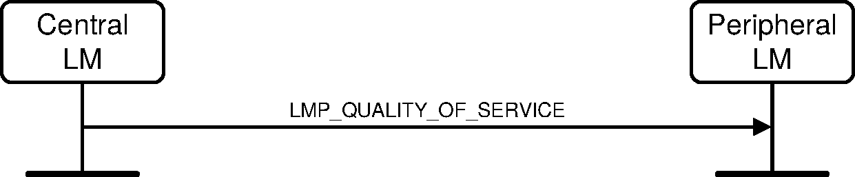
Sequence 13: Central notifies Peripheral of quality of service
4.1.8.2. Device requests new quality of service
Either the Central or the Peripheral may request a new poll interval and NBC by sending an LMP_QUALITY_OF_SERVICE_REQ PDU. The parameter NBC is meaningful only when it is sent by a Central to a Peripheral. For transmission of LMP_QUALITY_OF_SERVICE_REQ PDUs from a Peripheral, this parameter shall be ignored by the Central. The request can be accepted or rejected. This allows the Central and Peripheral to dynamically negotiate the quality of service as needed.
The selected poll interval by the Peripheral shall be less than or equal to the specified Access Latency for the outgoing traffic of the ACL link (see L2CAP Definition: Quality of Service (QoS) option [Vol 3] Part A, Section 5.3).
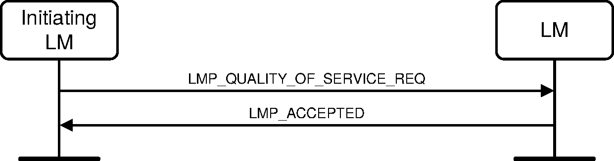
Sequence 14: Device accepts new quality of service

Sequence 15: Device rejects new quality of service
4.1.9. Paging scheme parameters
LMP provides a means to negotiate the paging scheme parameters that are used the next time a device is paged.
M/O | PDU | Contents |
|---|---|---|
O(17) | LMP_PAGE_MODE_REQ | Paging_Scheme Paging_Scheme_Settings |
O(17) | LMP_PAGE_SCAN_MODE_REQ | Paging_Scheme Paging_Scheme_Settings |
4.1.9.1. Page mode
This procedure is initiated from device A and negotiates the paging scheme used when device A pages device B. Device A proposes a paging scheme including the parameters for this scheme and device B can accept or reject. On rejection the old setting shall not be changed. A request to switch to a reserved paging scheme shall be rejected.
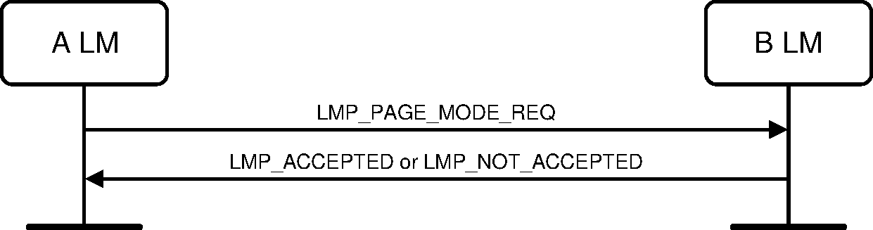
Sequence 16: Negotiation for Page mode
4.1.9.2. Page Scan mode
This procedure is initiated from device A and negotiates the paging scheme and paging scheme settings used when device B pages device A. Device A proposes a paging scheme and paging scheme settings and device B may accept or reject. On reject the old setting is not changed. A request specifying the mandatory scheme shall be accepted. A request specifying a non-mandatory scheme shall be rejected. This procedure should be used when device A changes its paging scheme settings. A Peripheral should also send this message to the Central after connection establishment, to inform the Central of the Peripheral's current paging scheme and paging scheme settings.
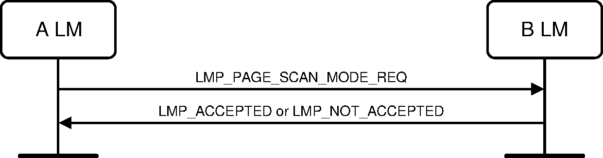
Sequence 17: Negotiation for Page Scan mode
4.1.10. Control of multi-slot packets
The number of consecutive slots used by a device on an ACL-U logical link can be limited. It does not affect traffic on the eSCO links where the packet sizes are defined as part of link setup. A device allows the remote device to use a maximum number of slots by sending the PDU LMP_MAX_SLOT providing a Max_Slots parameter. Each device can request to use a maximal number of slots by sending the PDU LMP_MAX_SLOT_REQ providing a Max_Slots parameter. After a new connection (as a result of page or page scan), or after a role switch, the value shall be 1 slot. These PDUs can be sent at any time after connection setup is completed.
M/O | PDU | Contents |
|---|---|---|
M | LMP_MAX_SLOT | Max_Slots |
M | LMP_MAX_SLOT_REQ | Max_Slots |
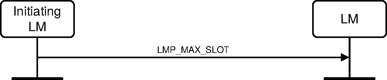
Sequence 18: Device allows Remote Device to use a maximum number of slots
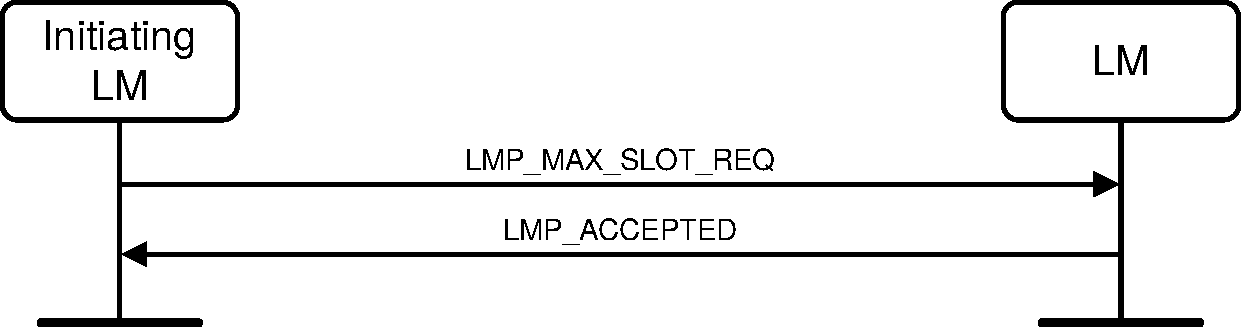
Sequence 19: Device requests a maximum number of slots. Remote Device accepts.

Sequence 20: Device requests a maximum number of slots. Remote Device rejects
4.1.11. Enhanced Data Rate
A device may change the packet type table, ptt, to select which if any of the packets and optional modulation modes are to be used on an ACL logical transport.
Either the Central or the Peripheral may request a new packet type table and therefore the packets and modulation mode to be used on this ACL link. After a new Baseband connection, as a result of page or page scan, the default value for ptt shall be 0.
The change of the modulation mode for an ACL logical transport shall not affect the packet and packet types used for an associated SCO logical transport on the same LT_ADDR.
Note
Note: Enhanced Data Rate eSCO links are negotiated using the LMP eSCO link_req as described in Section 4.6.2.
Before changing the packet type table, the initiator shall finalize the transmission of the current ACL packet with ACL-U information and shall stop ACL-U transmissions. It shall then send the LMP_PACKET_TYPE_TABLE_REQ PDU.
If the receiver rejects the change, then it shall respond with an LMP_NOT_ACCEPTED_EXT PDU.
If the receiver accepts the change, then it shall finalize the transmission of the current ACL packet with ACL-U information and shall stop ACL-U transmissions, it shall change to the new packet type table and shall respond with an LMP_ACCEPTED_EXT PDU. When it receives the Baseband acknowledgment for the LMP_ACCEPTED_EXT PDU it shall restart ACL-U transmissions.
When the initiator receives an LMP_NOT_ACCEPTED_EXT PDU the initiator shall restart ACL-U transmissions.
When the initiator receives an LMP_ACCEPTED_EXT PDU it shall change the packet type table and restart ACL-U transmissions.
M/O | PDU | Contents |
|---|---|---|
O(25) | LMP_PACKET_TYPE_TABLE_REQ | Packet_Type_Table |
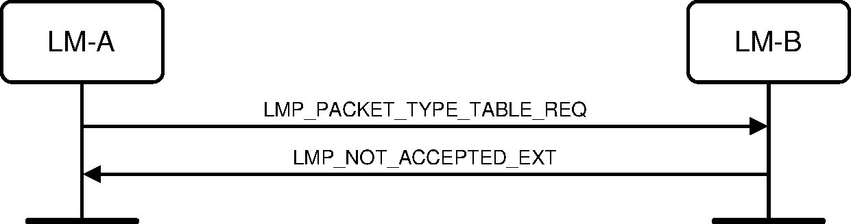
Sequence 21: Packet type table change is rejected
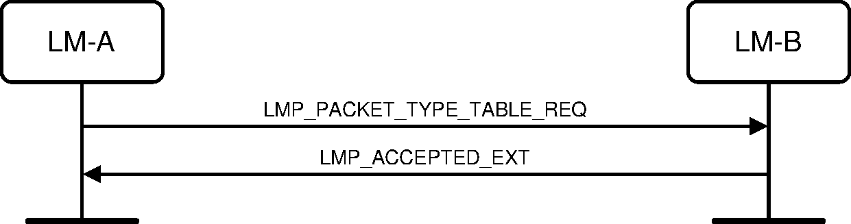
Sequence 22: Packet type table change is accepted
4.1.12. Encapsulated LMP PDUs
Some transactions require sending LMP payload data that is longer than 16 octets. To enable a link manager to send a large PDU, an encapsulated LMP PDU is defined. An encapsulated LMP PDU is composed of a minimum of two LMP messages, a header PDU and one or more payload PDUs.
M/O | PDU | Contents |
|---|---|---|
O(52) | LMP_ENCAPSULATED_HEADER | Encap_Major_Type Encap_Minor_Type Encap_Payload_Length |
O(52) | LMP_ENCAPSULATED_PAYLOAD | Encap_Data |
4.1.12.1. Sending an encapsulated PDU
The LMP_ENCAPSULATED_HEADER PDU shall be sent by the initiating device when it needs to send an encapsulated PDU. This PDU shall be either accepted or rejected using the LMP_ACCEPTED or LMP_NOT_ACCEPTED PDUs. If the major and minor types are not supported the PDU shall be rejected with Error_Code Unsupported LMP Parameter Value (0x20). If the LMP_ENCAPSULATED_HEADER PDU is accepted, then one or more LMP_ENCAPSULATED_PAYLOAD PDUs will be sent with the encapsulated data sent in sequence, 16 octets at a time, or if this is last packet, the correct number of octets and then zero padded.
Each LMP_ENCAPSULATED_PAYLOAD PDU shall be accepted or rejected. If the LMP_ENCAPSULATED_HEADER PDU is rejected, then the opcode in the LMP_NOT_ACCEPTED PDU shall be the opcode for the LMP_ENCAPSULATED_HEADER and not the Encap_Major_Type or Encap_Minor_Type. If the LMP_ENCAPSULATED_PAYLOAD PDU is rejected, then the opcode in the LMP_NOT_ACCEPTED PDU shall be the opcode for the LMP_ENCAPSULATED_PAYLOAD.
A responding device may reject the final LMP_ENCAPSULATED_PAYLOAD PDU after accepting the LMP_ENCAPSULATED_HEADER PDU. This is so that the link manager can still reject an encapsulated message after all the data has been received.
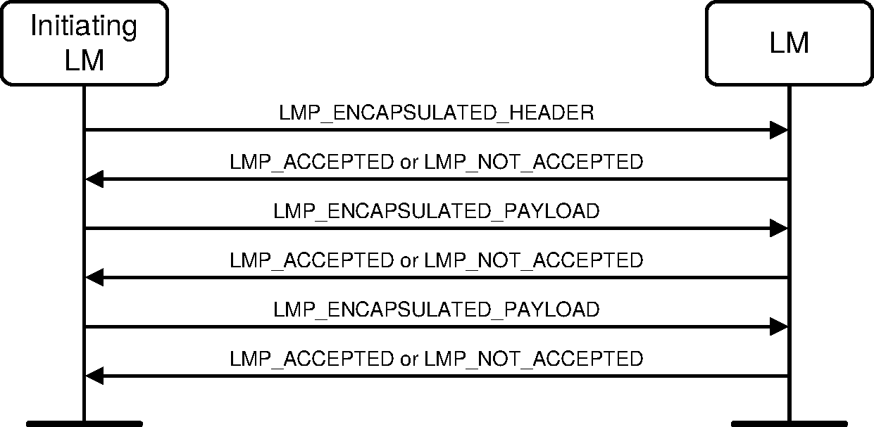
Sequence 23: Sending an encapsulated PDU
Between sending an LMP_ENCAPSULATED_HEADER PDU and an LMP_ENCAPSULATED_PAYLOAD PDU, or between each of the LMP_ENCAPSULATED_PAYLOAD PDUs, either device shall be able to send the following LMP PDUs without causing a "different transaction collision" error.
LMP_CHANNEL_CLASSIFICATION
LMP_DECR_POWER_REQ
LMP_DETACH
LMP_INCR_POWER_REQ
LMP_MAX_POWER
LMP_MAX_SLOT
LMP_MIN_POWER
LMP_PREFERRED_RATE
LMP_SET_AFH
4.1.13. Ping
When both devices support the Ping feature, a Link Manager may verify the presence of the remote Link Manager by using the LMP ping mechanism. The LMP ping mechanism may also be used to verify message integrity on the ACL logical transport by forcing the remote device to send an ACL packet that contains a MIC.
Note
Note: Since the LMP_PING_RES PDU contains a MIC and will update the packet counter, the sender of the LMP_PING_REQ PDU can verify that packets with earlier packet counter values have not been deliberately suppressed by an attacker.
M/O | PDU | Contents |
|---|---|---|
O(137) | LMP_PING_REQ | none |
O(137) | LMP_PING_RES | none |
The initiating link manager sends the LMP_PING_REQ PDU. The responding link manager responds with the LMP_PING_RES PDU. The initiating link manager may be a Central or Peripheral.

Sequence 24: Ping PDUs
The Link Manager shall send an LMP_PING_REQ PDU when the remote device has not sent a packet containing a payload protected by a MIC within an authenticated payload timeout set by the Host (see [Vol 4] Part E, Section 7.3.94). The Link Manager should send an LMP_PING_REQ PDU in advance enough of the expiration of the authenticated payload timeout to allow the remote device reasonable time to respond with an LMP_PING_RES PDU before the timeout expires.
4.1.14. Piconet clock adjustment
The Central may adjust the piconet clock (e.g. to align with an external time base) by initiating the Coarse Clock Adjustment or Clock Dragging procedures. A Peripheral may request that the Central adjust the piconet clock.
M/O | PDU | Contents |
|---|---|---|
O(134) | LMP_CLK_ADJ | Clk_Adj_ID Clk_Adj_Instant Clk_Adj_Offset Clk_Adj_Slots Clk_Adj_Mode Clk_Adj_Clk |
O(134) | LMP_CLK_ADJ_ACK | Clk_Adj_ID |
O(134) | LMP_CLK_ADJ_REQ | Clk_Adj_Offset Clk_Adj_Slots Clk_Adj_Period |
Piconet clock adjustment requests may be made at any time after the Link Manager supported features responses have been processed.
The Central is free to reject any request for an adjustment; an implementation may, for instance, accept coarse clock adjustment requests from one Peripheral but reject all requests from any other Peripheral.
4.1.14.1. Central coarse adjustment of piconet clock
The coarse clock adjustment procedure shall only be used if all connected Peripherals declare support for the Coarse Clock Adjustment feature.
For all devices that may use Coarse Clock Adjustment Recovery Mode (see [Vol 2] Part B, Section 8.6.10.2), the RF channel indices used for the Synchronization Train (see [Vol 2] Part B, Section 2.6.4.8) shall be marked as unused in the AFH_Channel_Map for all logical links.
The Central may use the Clk_Adj_Period parameter from one or more Peripherals, in addition to other scheduling considerations, to select an optimal value of Clk_Adj_Slots.
The Central selects the parameters of the coarse clock adjustment. Some parameters shall remain the same for every LMP_CLK_ADJ PDU associated with a given adjustment. These are the number of slots (Clk_Adj_Slots) between 0 and 255, an offset within a slot (Clk_Adj_Offset) between –624 µs and 624 µs, a coarse clock adjustment instant (Clk_Adj_Instant), which is specified in the old time domain before the instant, and an identifier for the instant (Clk_Adj_ID). The Clk_Adj_Instant shall be at least 12 slots in the future and no more than 12 hours away. The Clk_Adj_ID shall be different for any two adjacent adjustments and for any two adjustments whose instants are closer together in time than the longest Link Supervision Timeout period for any Peripheral. Each LMP_CLK_ADJ PDU also contains the value of CLK when it is transmitted (Clk_Adj_Clk) and a flag Clk_Adj_Mode, which shall be set to Before Instant if the LMP_CLK_ADJ PDU is sent before the instant or to After Instant if the LMP_CLK_ADJ PDU is sent on or after the instant.
To initiate the coarse adjustment, the Central starts broadcasting the LMP_CLK_ADJ PDU using the APB-C logical link and, unless all Peripherals have acknowledged, it should broadcast the LMP_CLK_ADJ PDU at least 6 times before the adjustment instant. The Central shall continue to broadcast the LMP_CLK_ADJ PDU until all Peripherals have acknowledged the adjustment with an LMP_CLK_ADJ_ACK PDU or the Central has left Coarse Clock Adjustment Recovery Mode.
The Central shall not initiate a coarse clock adjustment if there are any transactions outstanding that involve LMP PDUs containing an instant or timing control flags including, but not limited to: role switch, adaptive frequency hopping, SCO, eSCO, sniff, sniff subrating, hold, and encryption pause and resume.
The Central shall not initiate another sequence containing an instant or timing control flags before an outstanding clock adjustment instant has been reached, while waiting for CLK_adj_dragTO to expire (see [Vol 2] Part B, Appendix B), or while in Coarse Clock Adjustment Recovery Mode (see [Vol 2] Part B, Section 8.6.10.2); however the latter may be terminated by the Central in order to initiate the request. If a request to initiate such a sequence is received before an outstanding clock adjustment instant is reached or CLK_adj_dragTO has been cancelled or has expired, the request shall be rejected with the Error_Code Different Transaction Collision (0x2A).
A Peripheral shall discard and not acknowledge an LMP_CLK_ADJ PDU with a value of Clk_Adj_ID that is the same as that in the most recently received LMP_CLK_ADJ PDU, if any, and any LMP_CLK_ADJ PDU with any parameters outside the valid range (see Section 5.2).
On receipt of an LMP_CLK_ADJ PDU that passes these checks, the Peripheral shall reply with an LMP_CLK_ADJ_ACK PDU (on the ACL-C logical link) containing the same value of Clk_Adj_ID as in the LMP_CLK_ADJ PDU and shall change the value of peripheral_clock_offset, if not already performed, as described in [Vol 2] Part B, Section 8.6.10.1, either at the adjustment instant or, if that has passed, immediately.

Sequence 25: Central initiates a coarse clock adjustment
4.1.14.2. Peripheral request for coarse adjustment of piconet clock
The Peripheral may request a coarse adjustment of the piconet clock by sending the LMP_CLK_ADJ_REQ PDU to the Central. The LMP_CLK_ADJ_REQ PDU contains three parameters: Clk_Adj_Offset, Clk_Adj_Slots, and Clk_Adj_Period. The parameters Clk_Adj_Offset and Clk_Adj_Slots have the same meaning as in the LMP_CLK_ADJ PDU and Clk_Adj_Slots or Clk_Adj_Offset shall be non-zero. If non-zero, the parameter Clk_Adj_Period is an indication to the Central that the request is for any of a set of possible adjustments, all of which are equally acceptable to the Peripheral. These adjustments are those where the number of slots is equal to Clk_Adj_Slots + N * Clk_Adj_Period, where N is zero or a positive integer, and the offset within a slot equals Clk_Adj_Offset. For example, if Clk_Adj_Slots is 18 and Clk_Adj_Period is 48, then the acceptable adjustments are 18, 66, 114, 162, and 210 slots. A value of zero for Clk_Adj_Period indicates that an adjustment of any number of slots is equally acceptable to the Peripheral (that is, the Central may ignore the value of Clk_Adj_Slots). A request for a coarse adjustment shall also update the Central’s local record of Clk_Adj_Period for the Peripheral.
The Peripheral may indicate its preferred Clk_Adj_Period to the Central without requesting a clock adjustment. In this case it shall set Clk_Adj_Slots and Clk_Adj_Offset to zero. Upon receiving an LMP_CLK_ADJ_REQ PDU with Clk_Adj_Slots and Clk_Adj_Offset set to zero, the Central shall respond with LMP_ACCEPTED PDU and update its local record of Clk_Adj_Period for the Peripheral, but shall not initialize any clock adjustment. The Central is not required to honor a Peripheral’s preferred Clk_Adj_Period when making coarse clock adjustments.
The Central may accept the coarse clock adjustment request from the Peripheral by sending an LMP_ACCEPTED_EXT PDU. This indicates that the Central intends to carry out a coarse clock adjustment with the requested value of Clk_Adj_Offset; however, the value of Clk_Adj_Slots may be different to that requested and might not follow the Clk_Adj_Period parameter.
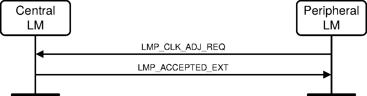
Sequence 26: Central accepts Peripheral request for a coarse clock adjustment
The Central may reject the coarse clock adjustment request from the Peripheral by sending an LMP_NOT_ACCEPTED_EXT PDU with the Error_Code Command Disallowed (0x0C) (see [Vol 1] Part F, Section 2.12). The Central's decision not to follow the Clk_Adj_Slots or Clk_Adj_Period parameters does not constitute a rejection.
The Central may implement the coarse clock adjustment request from the Peripheral by carrying out clock dragging (see [Vol 2] Part B, Section 8.6.10.3) to achieve the requested clock adjustment. If so, it shall send an LMP_NOT_ACCEPTED_EXT PDU with the Error_Code Coarse Clock Adjustment Rejected but Will Try to Adjust Using Clock Dragging (0x40) (see [Vol 1] Part F, Section 2.61).
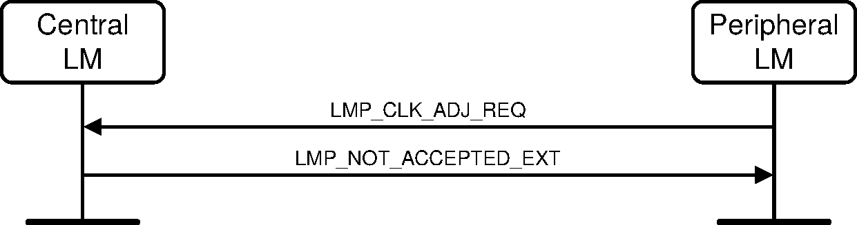
Sequence 27: Central rejects a Peripheral request for coarse clock adjustment
4.1.15. Slot Availability Mask
SAM LMP sequences may be initiated at any time after Link Manager supported features responses have been processed.
Either the Central or the Peripheral may initiate the LMP_SAM_SET_TYPE0 PDU to configure the SAM type 0 submap of the local device. The initiation may be triggered by the HCI command HCI_Set_External_Frame_Configuration for MWS coexistence.
Either the Central or the Peripheral may initiate the LMP_SAM_DEFINE_MAP PDU to define a new or modify an existing local SAM slot map. The initiation may be triggered by the HCI command HCI_Set_MWS_PATTERN_Configuration for MWS coexistence. If a type 0 submap is used with the LMP_SAM_DEFINE_MAP PDU, the Controller shall first execute the SAM set type 0 LMP sequence to configure the SAM type 0 submap, then the SAM define map LMP sequence itself.
Either the Central or the Peripheral may initiate the LMP_SAM_SWITCH PDU to switch to a local SAM slot map that has been defined by previous SAM set type 0 and SAM define map LMP sequences. This may be triggered by the real-time signals (e.g. MWS_PATTERN_Index, FRAME_SYNC, etc.) from the Coexistence Logical Interface (see [Vol 7] Part A), which contain information for the SAM_Index to be activated and the SAM anchor point for MWS coexistence. Piconet Clock Adjustment may be performed to create more available slot pairs per MWS frame before initiating the SAM switch LMP sequence.
These SAM LMP sequences will be described in detail in the following subsections.
M/O | PDU | Contents |
|---|---|---|
O(138) | LMP_SAM_SET_TYPE0 | Update_Mode SAM_Type0_Submap |
O(138) | LMP_SAM_DEFINE_MAP | SAM_Index TSAM_SM NSAM_SM SAM_Submaps |
O(138) | LMP_SAM_SWITCH | SAM_Index Timing_Control_Flags DSAM SAM_Instant |
The LMP_SAM_SET_TYPE0 PDU contains the following SAM parameters from the sender:
Update_Mode: When Update_Mode is set to 0, the existing slot maps containing the type 0 submap are invalidated and the corresponding SAM_Index shall not be used until the map with that index has been redefined in a subsequent SAM define map LMP sequence. When Update_Mode is set to 1, the new type 0 submap shall take effect immediately. When Update_Mode is set to 2, the new type 0 submap shall take effect at the start of the next sub-interval.
SAM_Type0_Submap: This parameter specifies the types of each slot in the type 0 submap. The length of this parameter corresponds to 56 slots but, when it is used in a map, only the first TSAM_SM entries are significant.
Different maps can have different values of TSAM_SM.
The LMP_SAM_DEFINE_MAP PDU contains the following parameters from the sender:
SAM_Index: Index of the SAM slot map this PDU applies to. If the same SAM_Index has been previously defined, then the previous map parameters associated with the map shall be discarded and replaced by the parameters contained in this PDU.
TSAM_SM: Length of each SAM submap in slots. It shall be an even integer in the range 2 to 56.
NSAM_SM: The number of SAM submaps in the SAM slot map.
SAM_Submaps: This parameter specifies the types of the SAM submaps, using 2 bits for each submap. The length of this parameter corresponds to 48 submaps, but only the first NSAM_SM entries are significant.
The LMP_SAM_SWITCH PDU contains the following parameters from the sender:
SAM_Index: Index of the SAM slot map. It shall either be the index of a valid map, in which case SAM should be enabled and that map selected, or shall be 0xFF, which indicates that SAM should be disabled (meaning that, for SAM purposes, all slots are available for both transmission and reception). Disabling SAM does not invalidate a SAM slot map or the type 0 submap.
Timing_Control_Flags: This parameter is used to avoid clock wrap-around during the sequence, using one of the two initialization rules. Only bit1 of the Timing_Control_Flags parameter is valid.
DSAM: SAM offset that is used to compute the SAM anchor point. Only even values are valid.
SAM_Instant: Bits 27:1 of the Central's clock value when the SAM slot map is to be activated. This is used to indicate the first anchor point of the slot map. The new SAM slot map may be activated at SAM_Instant even if the Baseband acknowledgment is not received.
4.1.15.1. SAM type 0 submap configuration
Either the Central or the Peripheral may initiate the SAM type 0 submap configuration sequence by sending an LMP_SAM_SET_TYPE0 PDU to the responder. Both devices shall save the SAM parameters contained in this PDU. Update_Mode shall not be set to 0 if the active SAM slot map contains a type 0 submap. If the responder can accept the parameters, it shall send an LMP_ACCEPTED_EXT PDU. If the Update_Mode parameter is set to 0 and the active SAM slot map contains a type 0 submap, it shall send an LMP_NOT_ACCEPTED PDU with the Error_Code Invalid LMP Parameters (0x1E).
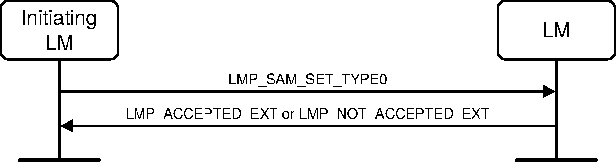
Sequence 28: SAM type 0 submap configuration sequence
4.1.15.2. SAM slot map define
Either the Central or the Peripheral may initiate the SAM slot map define sequence by sending an LMP_SAM_DEFINE_MAP PDU. If NSAM_SM is set to zero, the map shall be deleted. The SAM_Index parameter shall not be 0xFF or that of the currently selected map. The slot map may only contain a type 0 submap if the LMP_SAM_SET_TYPE0 sequence has already been used to define the type 0 submap. If the responder can accept the parameters, it shall send an LMP_ACCEPTED_EXT PDU. If a SAM type 0 submap is used in an LMP_SAM_DEFINE_MAP PDU without successfully completing the LMP_SAM_SET_TYPE0 sequence in advance, it shall send an LMP_NOT_ACCEPTED PDU with the Error_Code Type0 Submap Not Defined (0x41).
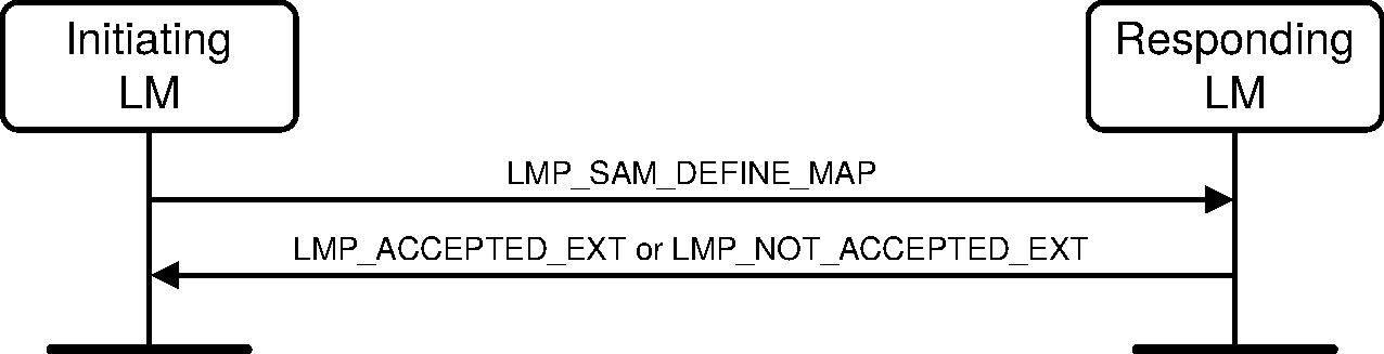
Sequence 29: SAM slot map define sequence
4.1.15.3. SAM switch sequence
Either the Central or the Peripheral may initiate the SAM switch sequence by sending an LMP_SAM_SWITCH PDU to the responder. There are two initialization procedures to prevent problems caused by clock wrap-around; see [Vol 2] Part B, Section 8.6.11.1 for details. The SAM_Index shall refer to a SAM slot map that is currently valid (the special value 0xFF is always valid). If the responder can accept the parameters, it shall send an LMP_ACCEPTED_EXT PDU. If the SAM_Index is invalid (e.g., the associated SAM_Index configuration has not yet been defined with LMP_SAM_DEFINE_MAP_SEQUENCE), it shall send an LMP_NOT_ACCEPTED PDU with the Error_Code Invalid LMP Parameters (0x1E).
Each Controller shall notify its Host of a successful SAM switch sequence specifying a different SAM_Index to that currently selected (it may, but need not, notify the Host if the sequence specifies the current map). The currently selected map remains in effect if the change is not accepted.
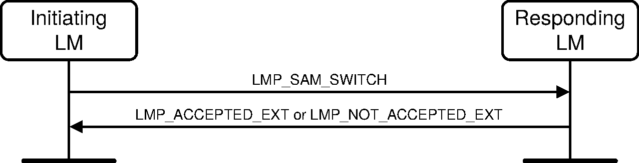
Sequence 30: SAM switch sequence
4.1.15.4. SAM change during the transmission of a multi-slot packet
SAM slot map changes do not affect the transmission of a multi-slot packet that spans the change instant. In the case of a Central-to-Peripheral packet, the new map can mean that the Peripheral may choose not to reply to the packet.
4.1.15.5. SAM and role switching
The Central and Peripheral shall disable SAM at the role switch instant. If the role switch fails, both devices shall resume using the SAM parameters prior to the role switch instant
SAM mode may be reconfigured and re-enabled after the successful completion of a role switch using the new piconet clock.
4.1.15.6. SAM and Sniff mode
If sniff negotiation is requested when SAM is already enabled, the device should align sniff with SAM by choosing the sniff anchor point to be an available Central-to-Peripheral slot and the sniff period to be an integer multiple of TSAM. If such alignment is not possible, the sniff configuration shall take precedence, even if this requires a device to transmit or receive on a slot marked as unavailable by SAM. The SAM slot maps shall be reinstated when devices exit Sniff mode.
Note
Note: Even though Sniff mode overrides the SAM slot maps, a device still might not be able to transmit or receive because of scatternet commitments, a coexistence clash, or some other reason.
4.2. Security
4.2.1. Authentication
Two authentication procedures are defined: legacy and secure authentication. Legacy authentication shall be performed when at least one device does not support both the Secure Connections (Controller Support) and Secure Connections (Host Support) features and the local device allows legacy authentication to be used. Secure authentication shall be performed when both devices support the Secure Connections (Controller Support) and Secure Connections (Host Support) features.
The legacy authentication procedure is based on a challenge-response scheme as described in [Vol 2] Part H, Section 3.2.2. The verifier sends an LMP_AU_RAND PDU that contains a random number (the challenge) to the claimant. The claimant calculates a response, that is a function of this challenge, the claimant’s BD_ADDR and a secret key. The response is sent back to the verifier, which checks if the response was correct or not. The response shall be calculated as described in [Vol 2] Part H, Section 6.1. A successful calculation of the authentication response requires that two devices share a secret key. This key is created as described in Section 4.2.2. Both the Central and the Peripheral can be verifiers. The sequences for legacy authentication are described in Section 4.2.1.1 and Section 4.2.1.2.
The secure authentication procedure is a challenge-response scheme as described in [Vol 2] Part H, Section 5. The verifier sends an LMP_AU_RAND PDU that contains a random number (the challenge) to the claimant. The claimant responds with another LMP_AU_RAND PDU also containing a random number. Both Link Managers calculate the Device Authentication Key using the h4 function (see [Vol 2] Part H, Section 7.7.7) and then calculate the SRES_C, SRES_P and ACO values using the h5 function (see [Vol 2] Part H, Section 7.7.8). The Peripheral (regardless of whether it was the verifier or claimant) sends its response (SRES_P) to the Central. The Central sends its response (SRES_C) to the Peripheral. A successful calculation of the authentication response requires that two devices share a secret key. The sequences for secure authentication are described in Section 4.2.1.2 and Section 4.2.1.4.
M/O | PDU | Contents |
|---|---|---|
M | LMP_AU_RAND | Random_Number |
M | LMP_SRES | Authentication_Rsp |
4.2.1.1. Claimant has link key (legacy authentication)
If the claimant has a link key associated with the verifier, it shall calculate the response and sends it to the verifier with LMP_SRES. The verifier checks the response. If the response is not correct, the verifier can end the connection by sending an LMP_DETACH PDU with the Error_Code Authentication Failure (0x05), see Section 4.1.2.
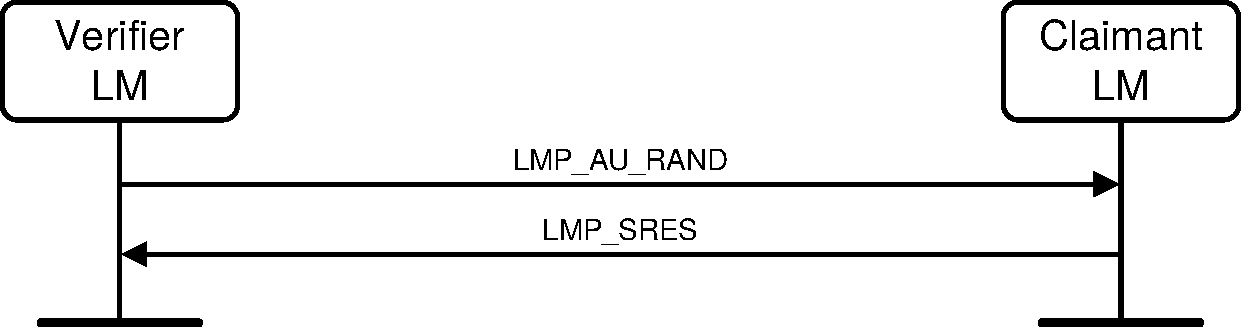
Sequence 31: Authentication. Claimant has link key.
Upon reception of an LMP_AU_RAND, an LM shall reply with LMP_SRES before initiating its own authentication.
Note
Note: There can be conflicting actions from the Central and the Peripheral which could lead to the two devices having different Authenticated Ciphering Offsets (ACOs, see [Vol 2] Part H, Section 6.1) when they calculate the encryption key. The following procedures assure that this cannot occur:
procedure in Section 2.5.1 (Transaction Collision Resolution) when the Central and Peripheral simultaneously initiate an authentication.
procedure in Section 4.2.5.1 when encryption parameters are being negotiated.
4.2.1.2. Claimant has no link key (legacy authentication and secure authentication)
If the claimant does not have a link key associated with the verifier it shall send an LMP_NOT_ACCEPTED PDU with the Error_Code PIN or Key Missing (0x06) after receiving an LMP_AU_RAND PDU ([Vol 1] Part F, Section 2.6).
Note
Note: This sequence is identical for legacy authentication and secure authentication.
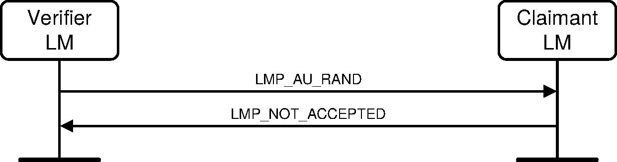
Sequence 32: Authentication fails. Claimant has no link key.
4.2.1.3. Repeated attempts
The scheme described in [Vol 2] Part H, Section 5.1 shall be applied when an authentication fails.
4.2.1.4. Responder has link key (secure authentication)
Both the Central and Peripheral LM act as verifier and claimant. The initiator is the device that sends the LMP_AU_RAND PDU first.
The initiator sends an LMP_AU_RAND PDU to the responder. If the responder has a link key associated with the initiator, it shall respond with an LMP_AU_RAND PDU. The initiator and responder shall calculate the response. The Peripheral responds first with an LMP_SRES PDU containing SRES_P. The Central shall then respond with an LMP_SRES PDU containing SRES_C. The Central shall verify that the SRES_P sent by the Peripheral matches the SRES_P calculated by the Central. The Peripheral shall verify that the SRES_C sent by the Central matches the SRES_C calculated by the Peripheral. If the response is not correct, then either device can end the connection by sending an LMP_DETACH PDU with the Error_Code Authentication Failure (0x05) (see Section 4.1.2).
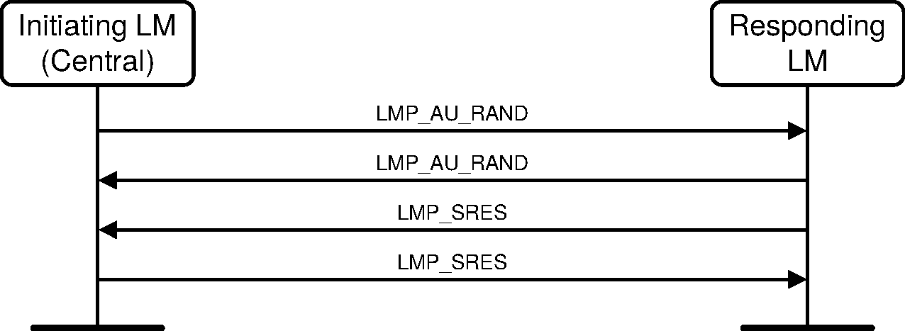
Sequence 33: Secure authentication. Responder has link key. Initiator is Central.
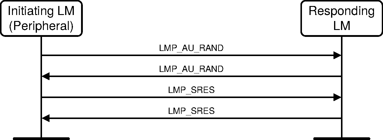
Sequence 34: Secure authentication. Responder has link key. Initiator is Peripheral.
In the case where the Central and Peripheral both initiate the secure authentication sequence, the Central shall reject the Peripheral’s LMP_AU_RAND PDU with an LMP_NOT_ACCEPTED PDU with the Error_Code LMP Error Transaction Collision / LL Procedure Collision (0x23). The Peripheral shall send another LMP_AU_RAND PDU with transaction ID set to 0 (Central).
Note
Note: Secure Authentication is a mutual authentication.
4.2.2. Pairing
When two devices do not have a common link key an initialization key (Kinit) shall be created using either the pairing or Secure Simple Pairing procedures. When pairing is used, Kinit shall be created based on a PIN, and a random number and a BD_ADDR. Kinit shall be created as specified in [Vol 2] Part H, Section 6.3. When both devices have calculated Kinit the link key shall be created, and a mutual authentication is performed. The pairing procedure starts with a device sending an LMP_IN_RAND PDU; this device is referred to as the "initiating LM" or "initiator" in Section 4.2.2.1 - Section 4.2.2.5. The other device is referred to as the "responding LM" or "responder". The PDUs used in the pairing procedure are:
M/O | PDU | Contents |
|---|---|---|
M | LMP_IN_RAND | Random_Number |
M | LMP_AU_RAND | Random_Number |
M | LMP_SRES | Authentication_Rsp |
M | LMP_COMB_KEY | Random_Number |
M | LMP_UNIT_KEY | Key |
The Link Manager shall not send an LMP_UNIT_KEY PDU.
All sequences described in Section 4.2.2, including the mutual authentication after the link key has been created, shall form a single transaction. The transaction ID from the first LMP_IN_RAND shall be used for all subsequent sequences.
4.2.2.1. Responder accepts pairing and has a variable PIN
If the responder accepts the pairing and has a variable PIN, then it shall reply with an LMP_ACCEPTED PDU. Both devices shall then calculate Kinit based on the BD_ADDR of the responder and the procedure continues with creation of the link key; see Section 4.2.2.4.

Sequence 35: Pairing accepted. Responder has a variable PIN. Initiator has a variable or fixed PIN.
4.2.2.2. Responder accepts pairing and has a fixed PIN
If the responder accepts the pairing and has a fixed PIN, then it shall generate a new random number and send it back in an LMP_IN_RAND PDU. If the initiator has a variable PIN, then it shall accept the LMP_IN_RAND PDU and shall respond with an LMP_ACCEPTED PDU. Both sides shall then calculate Kinit based on the last IN_RAND and the BD_ADDR of the initiator. The procedure continues with creation of the link key; see Section 4.2.2.4.
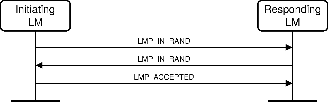
Sequence 36: Responder has a fixed PIN and initiator has a variable PIN
If the responder has a fixed PIN and the initiator also has a fixed PIN, then the second LMP_IN_RAND shall be rejected by the initiator sending an LMP_NOT_ACCEPTED PDU with the Error_Code Pairing not Allowed (0x18).

Sequence 37: Both devices have a fixed PIN
4.2.2.3. Responder rejects pairing
If the responder rejects pairing (e.g., because the user has disabled pairing on the device) it shall send an LMP_NOT_ACCEPTED PDU with the Error_Code Pairing not Allowed (0x18) after receiving an LMP_IN_RAND PDU.
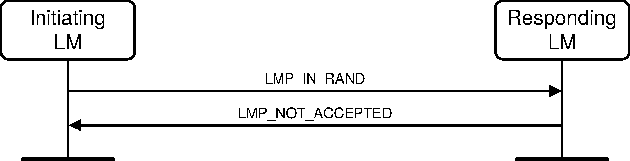
Sequence 38: Responder rejects pairing
4.2.2.4. Creation of the link key
When Kinit is calculated in both devices the link key shall be created. This link key will be used in the authentication between the two devices for all subsequent connections until it is changed; see Section 4.2.3 and Section 4.2.4. The link key created in the pairing procedure will be a combination key; both devices send an LMP_COMB_KEY PDU and the link key shall be calculated as described in [Vol 2] Part H, Section 3.2.
The content of the LMP_COMB_KEY PDU is LK_RAND bitwise XORed with Kinit. Any device configured to use a combination key shall store the link key.
When the new link key has been created mutual authentication shall be performed to confirm that the same link key has been created in both devices. After mutual authentication, if encryption is enabled, the initiating device shall pause and immediately resume encryption to produce a new encryption key.
Note: This will cause a new encryption key to be generated from the ACO created during the mutual authentication process and, when E0 encryption is used, the random number sent in the LMP_START_ENCRYPTION_REQ PDU which occurs in response to the resumption of encryption.

Sequence 39: Creation of the link key
If, in sequence 39, either device sends an LMP_UNIT_KEY PDU, the other device shall respond with an LMP_NOT_ACCEPTED PDU with the Error_Code set to Pairing with Unit Key Not Supported (0x29).
4.2.2.5. Repeated attempts
When the authentication after creation of the link key fails because of an incorrect Authentication_Rsp, the scheme described in [Vol 2] Part H, Section 5.1 shall be applied.
4.2.3. Change link key
The link key can be changed. The contents of the LMP_COMB_KEY PDU is protected by a bitwise XOR with the current link key.
M/O | PDU | Contents |
|---|---|---|
M | LMP_COMB_KEY | Random_Number |
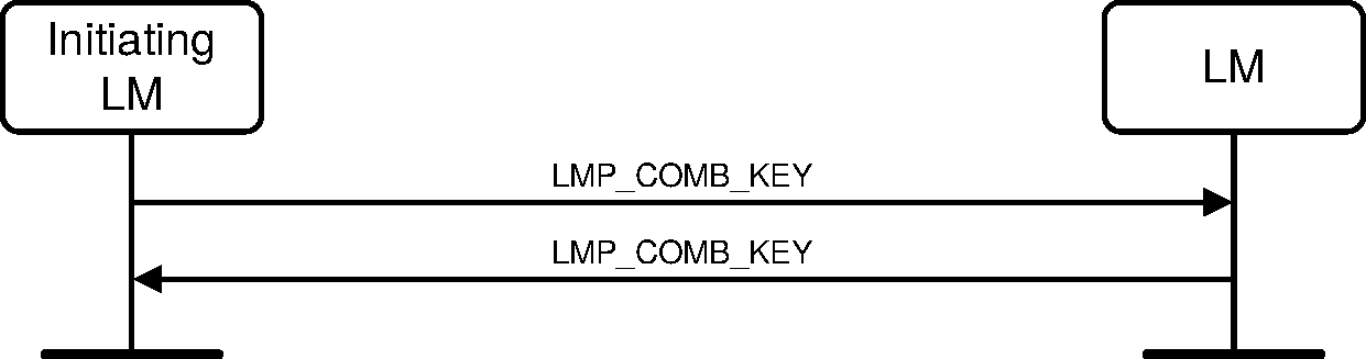
Sequence 40: Successful change of the link key
The new link key shall be stored and the old link key shall be discarded. The new link key shall be used as link key for all the following connections between the two devices until the link key is changed again. The new link key also becomes the current link key. It will remain the current link key until the link key is changed again, or until a temporary link key is created, see Section 4.2.4.
When the new link key has been created, mutual or secure authentication shall be performed to confirm that the same link key has been created in both devices.
If both devices support the Secure Connections (Controller Support) and Secure Connections (Host Support) features, the device that initiated the change link key shall initiate the Secure Authentication procedure. Otherwise, the first authentication in the mutual authentication is performed with the device that initiated the change link key as verifier. When finalized an authentication in the reverse direction is performed.
After mutual or secure authentication, if encryption is enabled, the initiating device shall pause and immediately resume encryption to produce a new encryption key.
Note
Note: This will cause a new encryption key to be generated from the ACO created during the mutual authentication process, and when E0 encryption is used, the random number sent in the LMP_START_ENCRYPTION_REQ PDU which occurs in response to the resumption of encryption.
4.2.4. Change current link key type
The current link key can be a semi-permanent link key or a temporary link key. It may be changed temporarily, but the change shall only be valid for the current connection, see [Vol 2] Part H, Section 3.1. Changing to a temporary link key is necessary if the piconet is to support encrypted broadcast. The current link key shall not be changed before the connection establishment procedure has completed.
M/O | PDU | Contents |
|---|---|---|
O(23) | LMP_TEMP_RAND | Random_Number |
O(23) | LMP_TEMP_KEY | Key |
O(23) | LMP_USE_SEMI_PERMANENT_KEY | none |
4.2.4.1. Change to a temporary link key
The Central starts by creating the temporary link key K_temp as specified in [Vol 2] Part H (EQ 4). Then the Central shall generate a random number, RAND, and shall send it to the Peripheral in an LMP_TEMP_RAND PDU. Both sides then calculate an overlay denoted OVL as OVL= E22 (current link key, RAND, 16). The Central shall then send K_temp protected by XORing with OVL to the Peripheral in an LMP_TEMP_KEY PDU. The Peripheral calculates K_temp, based on OVL, that becomes the current link key. It shall be the current link key until the devices fall back to the semi-permanent link key, see Section 4.2.4.2.
Note
Note: The terminology in this section is the same as used in [Vol 2] Part H, Section 3.2.8.

Sequence 41: Change to a temporary link key
All sequences described in Section 4.2.4.1, including the mutual authentication after K_temp has been created, shall form a single transaction. The transaction ID shall be set to 0.
When the devices have changed to the temporary key, a mutual authentication shall be made to confirm that the same link key has been created in both devices. The first authentication in the mutual authentication shall be performed with the Central as verifier. When finalized an authentication in the reverse direction is performed.
Should the mutual authentication fail at either side, the LM of the verifier should start the detach procedure. This will allow the procedure to succeed even though one of the devices may be erroneous.
4.2.4.2. Semi-permanent link key becomes current link key
After the current link key has been changed to K_temp, this change can be undone and the semi-permanent link key becomes the current link key again. If encryption is used on the link, the procedure to go back to the semi-permanent link key shall be immediately followed by the Central stopping encryption using the procedure described in Section 4.2.5.4. Encryption may be restarted by the Central according to the procedures in Section 4.2.5.1 subsection 3. This is to assure that encryption with encryption parameters known by other devices in the piconet is not used when the semi-permanent link key is the current link key.
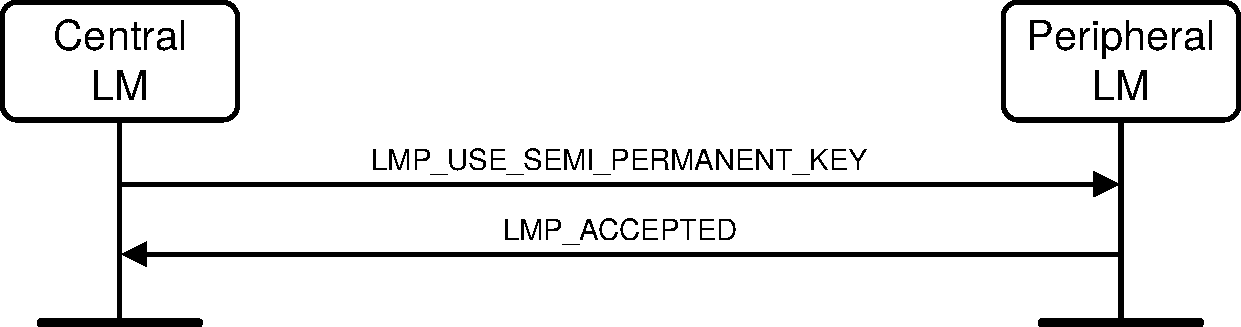
Sequence 42: Link key changed to the semi-permanent link key
4.2.5. Encryption
If at least one authentication has been performed encryption may be used. Two encryption mechanisms are defined: E0 encryption (legacy) and AES-CCM encryption. If both devices support the Secure Connections (Controller Support) and Secure Connections (Host Support) features, then AES-CCM shall be used when encryption is enabled. If at least one device does not support both the Secure Connections (Controller Support) and Secure Connections (Host Support) features, then E0 shall be used when encryption is enabled.
In order for the Central to use the same encryption parameters for all Peripherals in the piconet where E0 encryption would be used it shall issue a temporary key, K_temp. The Central shall make this key the current link key for all Peripherals in the piconet where E0 encryption would be used before encryption is started, see Section 4.2.4. This is required if broadcast packets are to be encrypted.
Note
Note: Packets encrypted with broadcast encryption can not be received by Peripherals that have AES-CCM encryption enabled. When the local Controller supports Secure Connections and there are not any Peripherals in the piconet that do not support Secure Connections, broadcast packets will not be encrypted and may be received by Peripherals that support Secure Connections.
M/O | PDU | Contents |
|---|---|---|
O (2) | LMP_ENCRYPTION_MODE_REQ | Encryption_Mode |
O (2) | LMP_ENCRYPTION_KEY_SIZE_REQ | Key_Size |
O (2) | LMP_START_ENCRYPTION_REQ | Random_Number |
O (2) | LMP_STOP_ENCRYPTION_REQ | none |
O (42) | LMP_PAUSE_ENCRYPTION_REQ | none |
O (42) | LMP_RESUME_ENCRYPTION_REQ | none |
O (136) | LMP_PAUSE_ENCRYPTION_AES_REQ | Random_Number |
All sequences described in Section 4.2.5 shall form a single transaction. The transaction ID from the LMP_ENCRYPTION_MODE_REQ PDU shall be used for all start encryption and stop encryption sequences.
Where the specification requires a device to resume encryption as part of one procedure and then pause it as part of a following procedure, the device may omit both the resume and the subsequent pause.
4.2.5.1. Encryption mode
The Central and the Peripheral must agree upon whether to use encryption (Encryption_Mode=1 in LMP_ENCRYPTION_MODE_REQ) or not (Encryption_Mode=0). If the semi-permanent key is used, encryption shall only apply to point-to-point packets. If the temporary link key is used, encryption shall apply to both point-to-point packets and broadcast packets. If Central and Peripheral agree on the encryption mode, the Central continues to give more detailed information about the encryption.
If a device receives an LMP_ENCRYPTION_MODE_REQ with an Encryption_Mode value of 2 then the device should treat it as if the Encryption_Mode value was 1.
If both devices support both the Secure Connections (Controller Support) and Secure Connections (Host Support) features, setting the Encryption_Mode to 0 shall not be allowed. If a device receives an LMP_ENCRYPTION_MODE_REQ PDU with Encryption_Mode set to 0, it shall respond with an LMP_NOT_ACCEPTED PDU with Error_Code Encryption Mode Not Allowed (0x25).
The initiating LM shall pause traffic on the ACL-U logical link (see [Vol 2] Part B, Section 5.3.1). The initiating device shall then send the LMP_ENCRYPTION_MODE_REQ PDU. If the responding device accepts the change in encryption mode then it shall complete the transmission of the current packet on the ACL logical transport and shall then suspend transmission on the ACL-U logical link. The responding device shall then send the LMP_ACCEPTED PDU.
ACL-U logical link traffic shall only be resumed after the attempt to encrypt or decrypt the logical transport is completed, i.e. at the end of Sequence 43 (on failure), 44, 46, or 47.
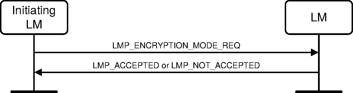
Sequence 43: Negotiation for encryption mode
After a device has sent an LMP_ENCRYPTION_MODE_REQ PDU it shall not send an LMP_AU_RAND PDU before encryption is started. After a device has received an LMP_ENCRYPTION_MODE_REQ PDU and sent an LMP_ACCEPTED PDU it shall not send an LMP_AU_RAND PDU before encryption is started. If an LMP_AU_RAND PDU is sent violating these rules, the claimant shall respond with an LMP_NOT_ACCEPTED PDU with the Error_Code LMP PDU Not Allowed (0x24). This assures that devices will not have different ACOs when they calculate the encryption key. If the encryption mode is not accepted or the encryption key size negotiation results in disagreement the devices may send an LMP_AU_RAND PDU again.
4.2.5.2. Encryption key size
Note
Note: This section uses the same terms as in [Vol 2] Part H, Section 4.1.
The Central sends an LMP_ENCRYPTION_KEY_SIZE_REQ PDU including the suggested key size L_sug_c, that shall initially be equal to L_max_c. If L_min_p ≤ L_sug_c ≤ L_max_p, the Peripheral shall respond with an LMP_ACCEPTED PDU and L_sug_c shall be used as the key size.
If L_sug_c > L_max_p, the Peripheral shall send back an LMP_ENCRYPTION_KEY_SIZE_REQ PDU including the Peripheral’s suggested key size L_sug_p set to L_max_p. If L_sug_c < L_min_p, the Peripheral shall send back an LMP_NOT_ACCEPTED PDU with the Error_Code Unsupported LMP Parameter Value (0x20) and the devices shall not communicate using encryption.
If the Peripheral sends back an LMP_ENCRYPTION_KEY_SIZE_REQ PDU, then the Central performs the corresponding test on the Peripheral’s suggestion. This procedure is repeated until a key size agreement is reached or it becomes clear that no such agreement can be reached. If an agreement is reached a device sends an LMP_ACCEPTED PDU and the key size in the last LMP_ENCRYPTION_KEY_SIZE_REQ PDU shall be used.
If a key size is agreed, encryption is then started; see Section 4.2.5.3. If an agreement is not reached a device sends an LMP_NOT_ACCEPTED PDU with the Error_Code Unsupported LMP Parameter Value (0x20) and the devices shall not communicate using encryption.
L_max_c and L_max_p shall be set to at least 7 octets. L_min_c and L_min_p should be set to at least 7 octets. The values of L_max_c, L_min_c, L_max_p, and L_min_p shall not change during an ACL connection between the Central and the Peripheral.
Note
Note: If the Host of either the Central or the Peripheral uses services that require security mode 4 (see [Vol 3] Part C, Section 5.2.2.8), a key size longer than the key size negotiated by the two Link Managers can be enforced.

Sequence 44: Encryption key size negotiation successful
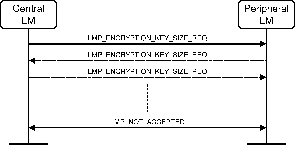
Sequence 45: Encryption key size negotiation failed
4.2.5.3. Start encryption
To start encryption, the Central issues the random number EN_RAND and calculates the encryption key. See [Vol 2] Part H, Section 3.2.5. The random number shall be the same for all Peripherals in the piconet when broadcast encryption is used. The Central then sends an LMP_START_ENCRYPTION_REQ PDU, that includes EN_RAND.
The Peripheral shall calculate the encryption key when this message is received and shall acknowledge with an LMP_ACCEPTED PDU. For E0, the encryption key shall be calculated using the E3 algorithm (see [Vol 2] Part H, Section 6.4). For AES-CCM, the encryption key shall be calculated using the h3 algorithm (see [Vol 2] Part H, Section 7.7.6).
Note
Note: For AES-CCM, the EN_RAND is not used when creating the encryption key.
If encryption has been paused, then this sequence shall not be used.

Sequence 46: Start encryption
Starting encryption shall be performed in three steps:
Central is configured to transmit unencrypted packets and to receive encrypted packets.
Peripheral is configured to transmit and receive encrypted packets.
Central is configured to transmit and receive encrypted packets.
Between step 1 and step 2, Central-to-Peripheral transmission is possible. This is when an LMP_START_ENCRYPTION_REQ PDU is transmitted. Step 2 is triggered when the Peripheral receives this message. Between step 2 and step 3, Peripheral-to-Central transmission is possible. This is when an LMP_ACCEPTED PDU is transmitted. Step 3 is triggered when the Central receives this message.
4.2.5.4. Stop encryption
To stop encryption a device shall send an LMP_ENCRYPTION_MODE_REQ PDU with the parameter Encryption_Mode equal to 0 (no encryption). The other device responds with an LMP_ACCEPTED PDU or an LMP_NOT_ACCEPTED PDU (the procedure is described in Sequence 43 in Section 4.2.5.1). If accepted, encryption shall be stopped by the Central sending an LMP_STOP_ENCRYPTION_REQ PDU and the Peripheral shall respond with an LMP_ACCEPTED PDU according to Sequence 47.
If encryption has been paused, then this sequence shall not be used.

Sequence 47: Stop encryption
Stopping encryption shall be performed in three steps, similar to the procedure for starting encryption.
Central is configured to transmit encrypted packets and to receive unencrypted packets.
Peripheral is configured to transmit and receive unencrypted packets.
Central is configured to transmit and receive unencrypted packets.
Between step 1 and step 2 Central to Peripheral transmission is possible. This is when an LMP_STOP_ENCRYPTION_REQ PDU is transmitted. Step 2 is triggered when the Peripheral receives this message. Between step 2 and step 3 Peripheral to Central transmission is possible. This is when an LMP_ACCEPTED PDU is transmitted. Step 3 is triggered when the Central receives this message.
4.2.5.5. Pause encryption
For E0 encryption:
To pause encryption without disabling encryption, a device shall finalize the transmission of the current ACL-U data packet and then send an LMP_PAUSE_ENCRYPTION_REQ PDU (with the transaction ID set to the role of the device at the time the LMP_PAUSE_ENCRYPTION_REQ PDU is sent).
For AES-CCM encryption:
To pause encryption without disabling encryption, a device shall finalize the transmission of the current ACL-U data packet and then send an LMP_PAUSE_ENCRYPTION_AES_REQ PDU (with the transaction ID set to the role of the device at the time the LMP_PAUSE_ENCRYPTION_AES_REQ PDU is sent). The LMP_PAUSE_ENCRYPTION_AES_REQ PDU includes a random number EN_RAND.
If the responding device is a Central, then the Central shall finalize the transmission of the current ACL-U data packet and then respond with an LMP_STOP_ENCRYPTION_REQ PDU to the Peripheral.
If the responding device is a Peripheral, then the Peripheral shall finalize the transmission of the current ACL-U data packet and then respond with an LMP_PAUSE_ENCRYPTION_REQ PDU. The Central shall respond to the LMP_PAUSE_ENCRYPTION_REQ PDU with an LMP_STOP_ENCRYPTION_REQ PDU to the Peripheral.
When the Peripheral receives the LMP_STOP_ENCRYPTION_REQ PDU it shall respond with an LMP_ACCEPTED PDU.

Sequence 48: Central-initiated pausing of encryption (E0)
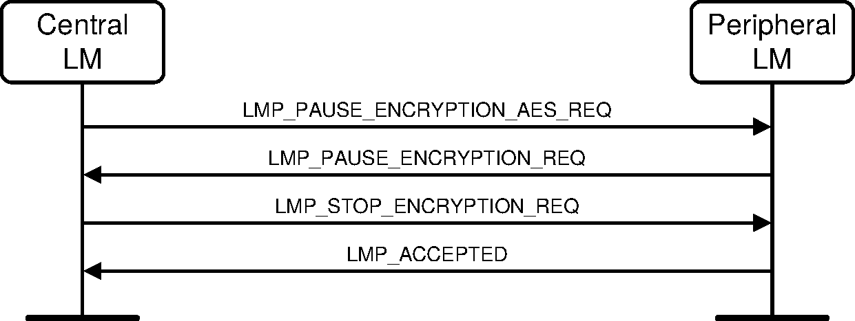
Sequence 49: Central-initiated pausing of encryption (AES-CCM)
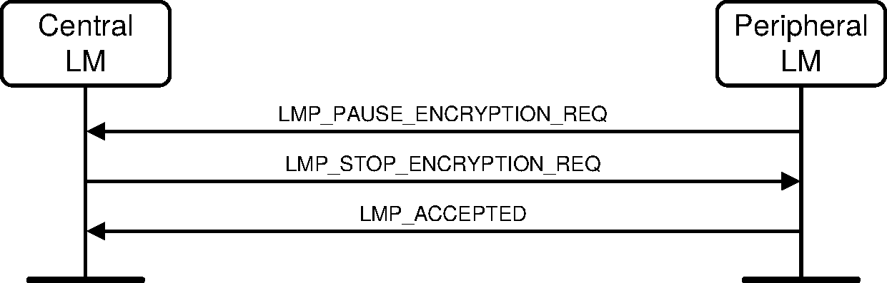
Sequence 50: Peripheral-initiated pausing of encryption (E0)

Sequence 51: Peripheral-initiated pausing of encryption (AES-CCM)
For E0 encryption:
The LMP_PAUSE_ENCRYPTION_REQ PDU and LMP_STOP_ENCRYPTION_REQ PDU shall only be rejected when a transaction collision needs to be resolved.
For AES-CCM encryption:
The LMP_PAUSE_ENCRYPTION_AES_REQ PDU and LMP_STOP_ENCRYPTION_REQ PDU shall only be rejected when a transaction collision needs to be resolved.
Pausing encryption shall be performed in three steps, similar to the procedure for stopping encryption.
Central is configured to transmit encrypted packets and to receive unencrypted packets.
Peripheral is configured to transmit and receive unencrypted packets.
Central is configured to transmit and receive unencrypted packets.
Between step 1 and step 2 Central-to-Peripheral transmission is possible. This is when the LMP_STOP_ENCRYPTION_REQ PDU is transmitted from the Central to the Peripheral. Step 2 is triggered when the Peripheral receives this message. Between step 2 and step 3 Peripheral-to-Central transmission is possible. This is when an LMP_ACCEPTED PDU is transmitted. Step 3 is triggered when the Central receives this message.
Note
Note: A device can only restart ACL-U data traffic by resuming encryption using the procedures in Section 4.2.5.6.
4.2.5.6. Resume encryption
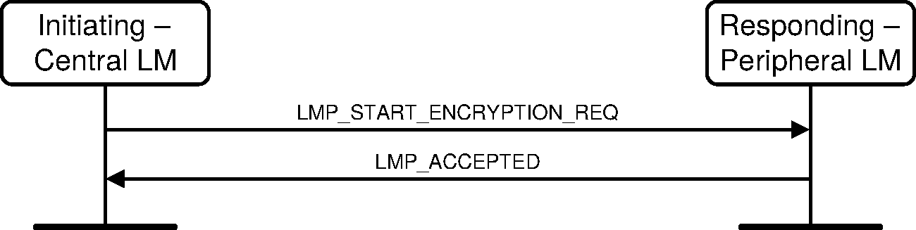
Sequence 52: Initiating Central LM resumes encryption
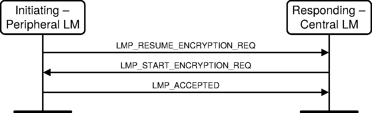
Sequence 53: Initiating Peripheral LM resumes encryption
For E0 encryption:
If the responding device is a Peripheral, then the Peripheral shall calculate the encryption key and respond with an LMP_ACCEPTED PDU.
If the responding device is a Central, then the Central shall respond with an LMP_START_ENCRYPTION_REQ PDU. The Peripheral, upon receiving the LMP_START_ENCRYPTION_REQ PDU from the Central, shall calculate the encryption key and respond with an LMP_ACCEPTED PDU.
For AES-CCM encryption:
If the resume encryption was the result of a Change Connection Link Key procedure, the LMs shall calculate a new encryption key using the h3 algorithm (see [Vol 2] Part H, Section 7.7.6).
If the responding device is a Peripheral, then the Peripheral shall respond with an LMP_ACCEPTED PDU.
If the responding device is a Central, then the Central shall respond with an LMP_START_ENCRYPTION_REQ PDU. The Peripheral, upon receiving the LMP_START_ENCRYPTION_REQ PDU from the Central, shall respond with an LMP_ACCEPTED PDU.
Note
Note: When AES-CCM is used, the EN_RAND value in the LMP_START_ENCRYPTION_REQ PDU is not used.
The LMP_RESUME_ENCRYPTION_REQ PDU and the LMP_START_ENCRYPTION_REQ PDU shall not be rejected.
Resuming encryption shall be performed in three steps, similar to the procedure for starting encryption:
Central is configured to transmit unencrypted packets and to receive encrypted packets.
Peripheral is configured to transmit and receive encrypted packets.
Central is configured to transmit and receive encrypted packets.
Between step 1 and step 2, Central-to-Peripheral transmission is possible. This is when the LMP_START_ENCRYPTION_REQ PDU is transmitted from the Central. Step 2 is triggered when the Peripheral receives this message. Between step 2 and step 3, Peripheral-to-Central transmission is possible. This is when an LMP_ACCEPTED PDU is transmitted. Step 3 is triggered when the Central receives this message.
Note
Note: For a Peripheral-initiated resumption of encryption, step 1 is not started when the Central has received the LMP_RESUME_ENCRYPTION_REQ PDU from the Peripheral, but when the Central sends the LMP_START_ENCRYPTION_REQ PDU.
Once encryption has been resumed, the device shall restart ACL-U traffic.
4.2.5.7. Change encryption key or random number
If the encryption key or encryption random number need to be changed, or if the current link key needs to be changed according to the procedures in Section 4.2.3 and Section 4.2.4, encryption shall be paused and resumed after completion, using the procedures in Section 4.2.5.5 and Section 4.2.5.6, for the new parameters to be valid. If the Pause Encryption feature is not supported by both devices, encryption shall be stopped and re-started after completion, using the procedures in Section 4.2.5.3 and Section 4.2.5.4, for the new parameters to be valid.
4.2.5.8. Encryption key refresh
When E0 encryption is used, the Link Manager shall refresh the encryption key within 228 ticks of the Bluetooth clock from the previous start or resume of encryption. When AES-CCM encryption is used, the Link Manager shall refresh the encryption key before either the PayloadCounter or dayCounter roll over (at least 238 ticks of the Bluetooth clock from the previous start of encryption). To refresh the encryption key, the Link Manager shall Pause encryption using the procedure in Section 4.2.5.5 and immediately Resume encryption using the procedure in Section 4.2.5.6.
If the encryption key has not been refreshed before the rollover event, the link shall be terminated immediately.
4.2.6. Request supported encryption key size
It is possible for the Central to request a Peripheral's supported encryption key sizes.
M/O | PDU | Contents |
|---|---|---|
O(23) | LMP_ENCRYPTION_KEY_SIZE_MASK_REQ | none |
O(23) | LMP_ENCRYPTION_KEY_SIZE_MASK_RES | Key_Size_Mask |
The Central shall send an LMP_ENCRYPTION_KEY_MASK_REQ PDU to the Peripheral to obtain the Peripheral’s supported encryption key sizes.
The Peripheral shall return a bit mask indicating all broadcast encryption key sizes supported. The least significant bit shall indicate support for a key size of 1, the next most significant bit shall indicate support for a key size of 2 and so on up to a key size of 16. In all cases a bit set to 1 shall indicate support for a key size; a bit set to 0 shall indicate that the key size is not supported.
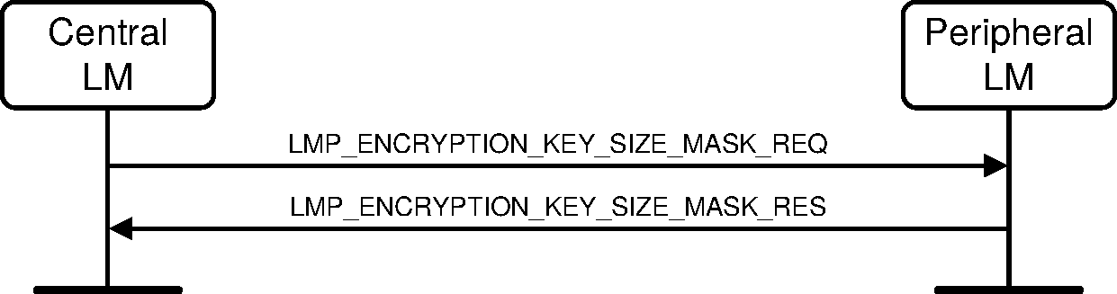
Sequence 54: Request for supported encryption key sizes
4.2.7. Secure Simple Pairing
There are four stages defined in the Secure Simple Pairing LM process:
IO capabilities exchange
Public key exchange
Authentication stage 1
Authentication stage 2
The devices shall first exchange the IO capabilities to determine the proper algorithm to be used. Three algorithms have been specified: Numeric comparison, Passkey entry, Out of band.
In following sections, the device requesting the IO capabilities is referred to as the "Initiating LM" or "Initiator". The other device is referred to as the "LM" or "Responder". This designation remains throughout the entire Secure Simple Pairing procedure.
M/O | PDU | Contents |
|---|---|---|
O(51) | LMP_IO_CAPABILITY_REQ | IO_Capabilities, OOB_Auth_Data, Authentication_Requirements |
O(51) | LMP_IO_CAPABILITY_RES | IO_Capabilities, OOB_Auth_Data, Authentication_Requirements |
O(51) | LMP_SIMPLE_PAIRING_CONFIRM | Commitment_Value |
O(51) | LMP_SIMPLE_PAIRING_NUMBER | Nonce_Value |
O(51) | LMP_DHKEY_CHECK | Confirmation_Value |
O(51) | LMP_NUMERIC_COMPARISON_FAILED | none |
O(51) | LMP_OOB_FAILED | none |
O(51) | LMP_KEYPRESS_NOTIFICATION | Notification_Type |
O(51) | LMP_PASSKEY_ENTRY_FAILED | none |
4.2.7.1. IO capability exchange
The Link Managers shall use the local and remote IO capabilities to determine which association model shall be used.
If Simple_Pairing_Mode is set to enabled, the Initiator shall request the IO capabilities from the Host. The initiator shall send an LMP_IO_CAPABILITY_REQ PDU to the Responder. If Simple_Pairing_Mode is set to enabled on the responding device, it shall reply with an LMP_IO_CAPABILITY_RES PDU containing its IO capabilities description.
The OOB_Auth_Data parameter shall be set as shown in Table 4.24.
Remote Device | Does not have OOB Data | No OOB Data Received | No OOB Data Received | ||||||||||||||||||||||||||||||||||||||||||||||
Does not support Secure Connections. P-192 OOB Data Available | OOB Data Received | OOB Data Received | |||||||||||||||||||||||||||||||||||||||||||||||
Supports Secure Connections | Only P-192 OOB Data Available | OOB Data Received | No OOB Data Received | ||||||||||||||||||||||||||||||||||||||||||||||
P-192 OOB Data and P-256 OOB Data Available | OOB Data Received [1] | OOB Data Received | |||||||||||||||||||||||||||||||||||||||||||||||
Only P-256 OOB Data Available | No OOB Data Received [1] | OOB Data Received | |||||||||||||||||||||||||||||||||||||||||||||||
[1] A device that does not support Secure Connections cannot generate P-256 OOB data. | |||||||||||||||||||||||||||||||||||||||||||||||||
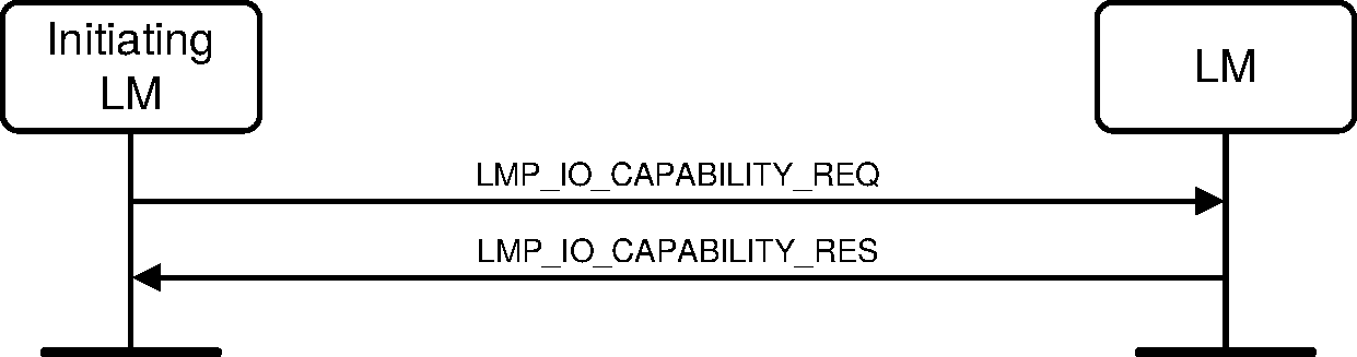
Sequence 55: IO capability exchange
4.2.7.1.1. IO capability exchange transaction collision and resolution
If both Link Managers attempt to become the initiator of the IO capability exchange, the Central’s Link Manager shall send an LMP_NOT_ACCEPTED_EXT PDU with Error_Code LMP Error Transaction Collision / LL Procedure Collision (0x23). The Peripheral’s Link Manager shall respond with the LMP_IO_CAPABILITY_RES PDU.
The Central’s LM shall remain the initiating LM for the remainder of the Secure Simple Pairing sequences.
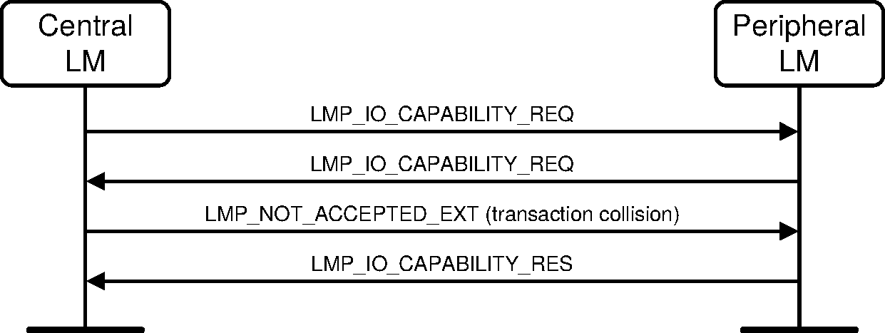
Sequence 56: IO capability exchange with transaction collision (Central transmitting LMP_IO_CAPABILITY_REQ first) and resolution
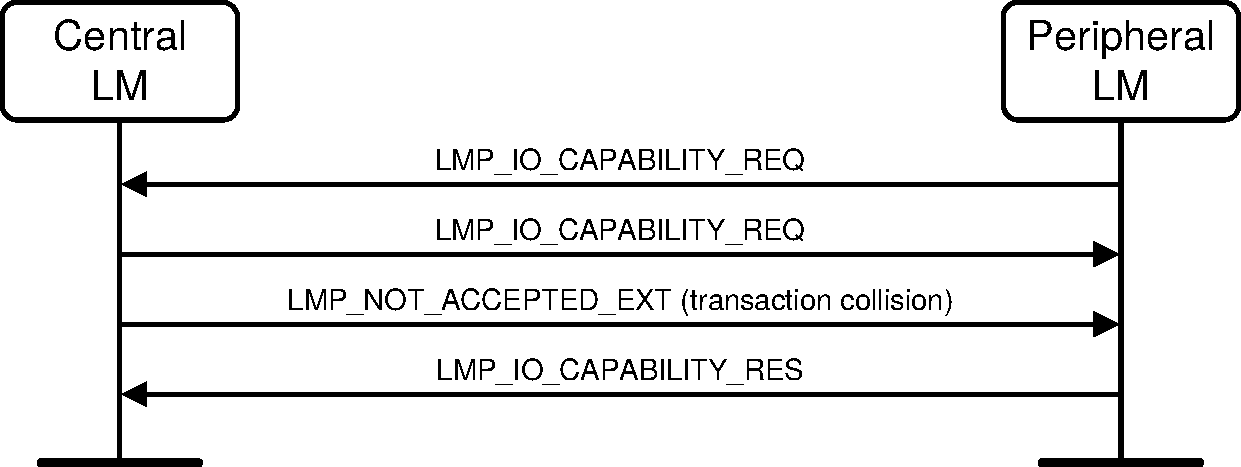
Sequence 57: IO capability exchange with transaction collision (Peripheral transmitting LMP_IO_CAPABILITY_REQ first) and resolution
4.2.7.2. Public key exchange
Once the IO capabilities are exchanged, public keys shall be exchanged between the two devices.
Since the public key size is longer than the payload body length of a DM1 packet, the exchange shall be done using the LMP_ENCAPSULATED_HEADER and LMP_ENCAPSULATED_PAYLOAD PDUs as defined in Section 4.1.12.
When at least one device does not support Secure Connections, the P-192 curve shall be used for calculating the public and private keys. When both devices support Secure Connections, the P-256 curve shall be used for calculating the public and private keys.
The Initiator shall first send its public key, and the Responder shall reply with its public key.
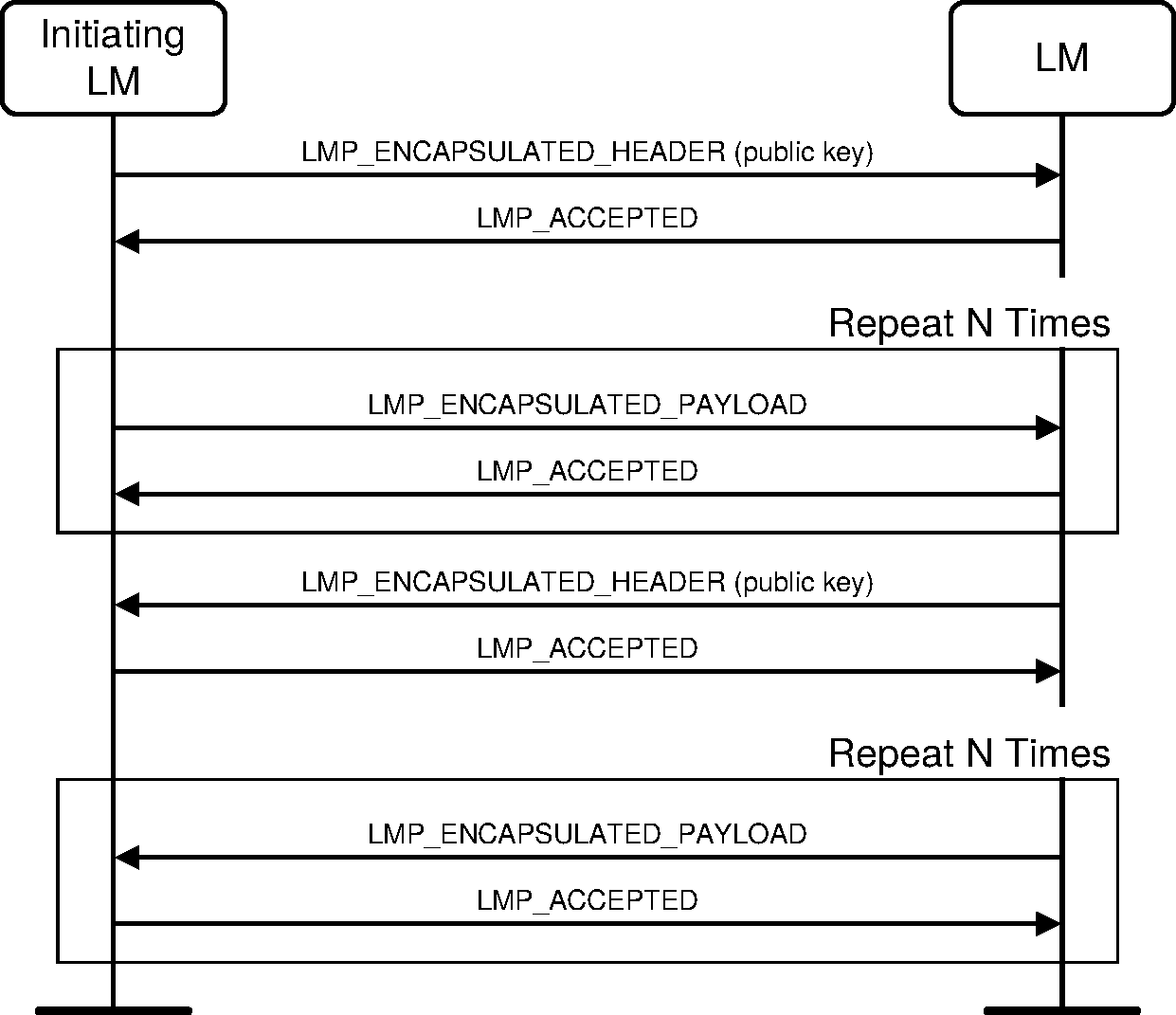
Sequence 58: Public key exchange
A public key shall be considered as received when the last LMP_ENCAPSULATED_PAYLOAD has been received and the associated LMP_ACCEPTED PDU has been sent.
The device can then start computing its Diffie Hellman Key.
4.2.7.3. Authentication stage 1
One of the following procedures shall be used in Authentication stage 1:
If one or both devices have the OOB_Auth_Data parameter set to Received, the Out-of-Band procedure shall be used.
If both devices have the Authentication_Requirements parameter set to one of the man-in-the middle (MITM) Protection Not Required options, the Numeric Comparison procedure shall be used.
If one or both devices have the Authentication_Requirements parameter set to one of the MITM Protection Required options, the Passkey Entry procedure shall be used if the either the local or remote IO Capability is set to KeyboardOnly and the other IO capability is not set to NoInputNoOutput. Otherwise, the Numeric Comparison authentication procedure shall be used.
4.2.7.3.1. Authentication stage 1: Numeric Comparison
Once public keys have been exchanged, both devices shall generate a random number.
The Responder shall compute its commitment as defined in [Vol 2] Part H, Section 7.7.1, and shall send this value to the Initiator by using LMP_SIMPLE_PAIRING_CONFIRM PDU. The Initiator shall then send an LMP_SIMPLE_PAIRING_NUMBER PDU with its generated random number. The Responder shall acknowledge by sending an LMP_ACCEPTED PDU.
The Responder shall then send an LMP_SIMPLE_PAIRING_NUMBER containing its own generated random number. Upon reception, the Initiator shall calculate the commitment as defined in [Vol 2] Part H, Section 7.7.1 and compare it to the one received previously with the LMP_SIMPLE_PAIRING_CONFIRM PDU. If both values are equal, the Initiator shall respond with an LMP_ACCEPTED PDU.

Sequence 59: Numeric Comparison Authentication: Commitment check success
4.2.7.3.1.1. Commitment check failure
If the calculated commitment by the Initiator is not equal to the received commitment, the Initiator shall abort the Secure Simple Pairing process by sending an LMP_NOT_ACCEPTED PDU with reason "Authentication Failure."
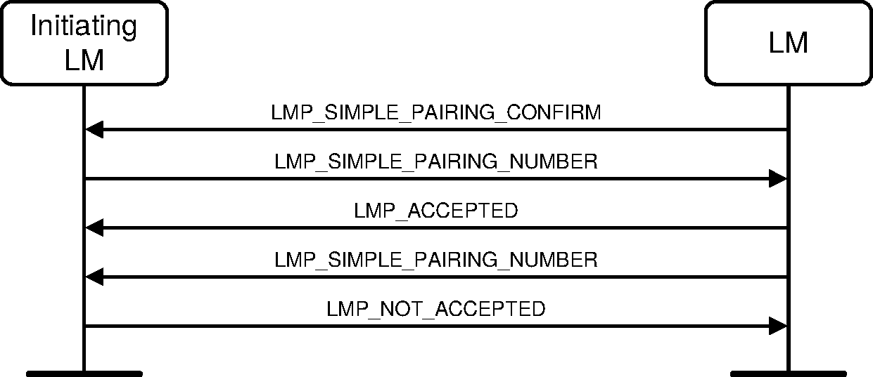
Sequence 60: Numeric Comparison authentication: Commitment check failure
4.2.7.3.1.2. Numeric Comparison failure on Initiator side
If the user on the initiating side indicates that the confirm values do not match (as indicated by the HCI_User_Confirmation_Request_Negative_Reply command) the initiating LM shall send an LMP_NUMERIC_COMPARISON_FAILURE PDU.
The Secure Simple Pairing process shall then be aborted. The Link Managers shall not disconnect the connection.
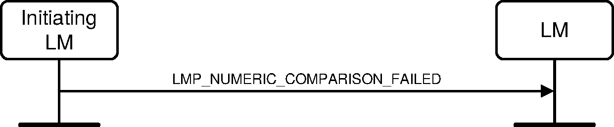
Sequence 61: Authentication stage 1: Numeric Comparison failure on Initiator side
4.2.7.3.1.3. Numeric Comparison failure on Responder side
If the user on the responding side indicates that the confirm values do not match (as indicated by the HCI_User_Confirmation_Request_Negative_Reply command) the responding LM shall send an LMP_NOT_ACCEPTED PDU in response to the LMP_DKHEY_CHECK PDU.
The Secure Simple Pairing process shall then be aborted. The Link Managers shall not disconnect the connection.
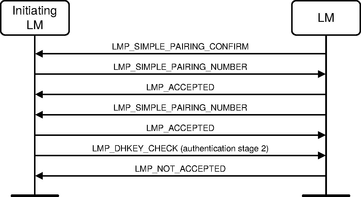
Sequence 62: Authentication stage 1: Numeric Comparison failure on Responder side
4.2.7.3.2. Authentication stage 1: Passkey Entry Authentication
The initiating LM shall start the following procedure after receiving the Passkey Reply from the Host. This procedure shall be repeated 20 times:
The Initiator and the Responder shall generate a new random number.
The Initiator and the Responder shall calculate the local commitment value using the exchanged public keys, the local random number, and the passkey from the local Host, according to [Vol 2] Part H, Section 7.7.1.
The Initiator shall send an LMP_SIMPLE_PAIRING_CONFIRM PDU with the commitment it calculated in step 2.
The Responder shall respond with an LMP_SIMPLE_PAIRING_CONFIRM PDU with the commitment it calculated in step 2.
The Initiator shall then send an LMP_SIMPLE_PAIRING_NUMBER PDU with the random number it generated in step 1.
The Responder shall then calculate commitment from the exchanged public keys, the random number it received and the passkey from the local Host, according to [Vol 2] Part H, Section 7.7.1. If the calculated commitment and the received commitment are equal, the Responder shall reply with an LMP_ACCEPTED PDU.
The Responder shall then send an LMP_SIMPLE_PAIRING_NUMBER PDU with the random value it generated in step 1.
The Initiator shall calculate the commitment using the exchanged public keys, the random number it received, and the passkey from the local Host, according to [Vol 2] Part H, Section 7.7.1. If the calculated commitment is equal to the received commitment, the Initiator shall reply with an LMP_ACCEPTED PDU.
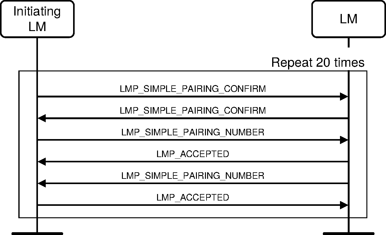
Sequence 63: Authentication passkey entry
When this procedure has successfully passed 20 times, the Secure Simple Pairing process continues with the Authentication step 2 as described in Section 4.2.7.4.
4.2.7.3.2.1. Commitment check failure on the Responder side
If during one of the 20 repetitions, the commitment calculated by the Responder is not equal to the one received from the Initiator (step 6), the Responder shall abort the Secure Simple Pairing process by sending an LMP_NOT_ACCEPTED PDU with reason "Authentication Failure."
Secure Simple Pairing procedures shall then be aborted. The Link Managers shall not disconnect the connection.
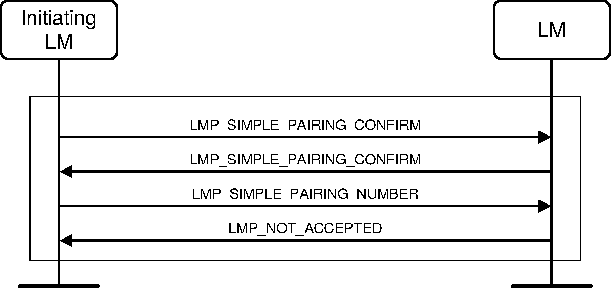
Sequence 64: Authentication passkey entry: Commitment check failure on the Responder side
4.2.7.3.2.2. Commitment check failure on the Initiator side
If during one of the 20 repetitions, the commitment calculated by the Initiator is not equal to the one received from the Responder (step 8), the Initiator shall abort the Secure Simple Pairing process by sending an LMP_NOT_ACCEPTED PDU with reason "Authentication Failure".
Secure Simple Pairing procedures shall then be aborted. The Link Managers shall not disconnect the connection.
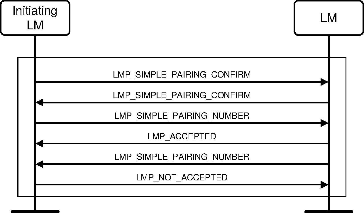
Sequence 65: Authentication passkey entry: Commitment check failure on the Initiator side
4.2.7.3.2.3. Passkey Entry failure on Initiator side
If the initiating side indicates that the passkey was not entered or canceled (as indicated by the HCI_User_Passkey_Request_Negative_Reply command) the initiating LM shall send an LMP_PASSKEY_ENTRY_FAILED PDU.
Secure Simple Pairing process shall then be aborted. The Link Managers shall not disconnect the connection.
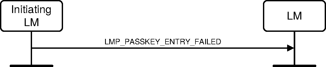
Sequence 66: Authentication stage 1: Passkey Entry failure on Initiator side
4.2.7.3.3. Passkey Entry failure on Responding side
If the responding side indicates that the passkey was not entered or canceled (as indicated by the HCI_User_Passkey_Request_Negative_Reply command), the responding LM shall send an LMP_NOT_ACCEPTED PDU in response to the LMP_SIMPLE_PAIRING_CONFIG PDU.
The Secure Simple Pairing process shall then be aborted. The Link Managers shall not disconnect the connection.
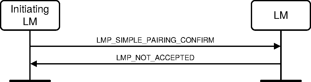
Sequence 67: Authentication stage 1: Passkey Entry failure on Responding side
4.2.7.3.4. Keypress notifications
A Controller that allows the Host to change its IO capabilities shall send notifications on key presses to the remote side using the LMP_KEYPRESS_NOTIFICATION PDU when the Host sets the IO capabilities to KeyboardOnly IO and when Secure Simple Pairing is supported on the Host and Controller.
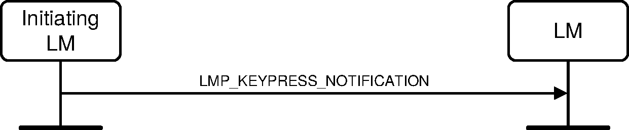
Sequence 68: Keypress notifications
4.2.7.3.5. Authentication stage 1: OOB
Upon reception of the OOB information (as defined in [Vol 2] Part H, Section 7.2.2) from the Host, the devices shall compare the received commitment from its Host, with the one calculated using the secret number received from the Host and the public key received from the remote device. If the local Host has not set the OOB Authentication Data Present, the LM shall set the remote secret number to zero and base the subsequent calculations on this value.
If the commitment check on the initiator is valid, the Initiator shall then generate a random number (nonce) and send it to the Responder using an LMP_SIMPLE_PAIRING_NUMBER PDU. If the commitment succeeds, the Responder shall acknowledge by sending an LMP_ACCEPTED PDU otherwise it shall send an LMP_NOT_ACCEPTED PDU. The Responder shall then generate a random number (nonce) and send it to the Initiator using an LMP_SIMPLE_PAIRING_NUMBER PDU. If the commitment succeeds, the Initiator shall acknowledge by sending an LMP_ACCEPTED PDU otherwise it shall send an LMP_NOT_ACCEPTED PDU.
If the commitment values don't match in the Initiator, the procedure in Section 4.2.7.3.5.2 shall apply.
If the commitment values don't match in the Responder, the procedure in Section 4.2.7.3.5.1 shall apply.
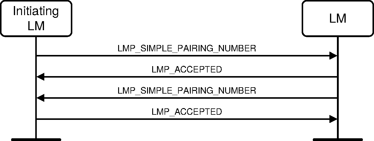
Sequence 69: Authentication OOB: Only one device is OOB-r capable
When these operations have been passed successfully, Secure Simple Pairing procedures continue with Authentication step 2 as described in Section 4.2.7.4.
4.2.7.3.5.1. Commitment check failure on the Responder side
If the commitment received OOB from the Host is not equal to the calculated commitment, the Responder shall send an LMP_NOT_ACCEPTED PDU with reason "Authentication Failure" in response to the LMP_SIMPLE_PAIRING_NUMBER PDU.
Secure Simple Pairing process shall then be aborted. The Link Managers shall not disconnect the connection.
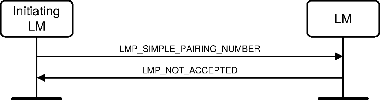
Sequence 70: Authentication stage 1 OOB: Commitment check failure on the Responder side
4.2.7.3.5.2. Commitment check failure on the Initiator side
If the commitment received OOB from the Host is not equal to the calculated commitment, the Initiator shall send an LMP_NOT_ACCEPTED PDU with reason "Authentication Failure" in response to the LMP_SIMPLE_PAIRING_NUMBER PDU.
Secure Simple Pairing process shall then be aborted. The Link Managers shall not disconnect the connection.
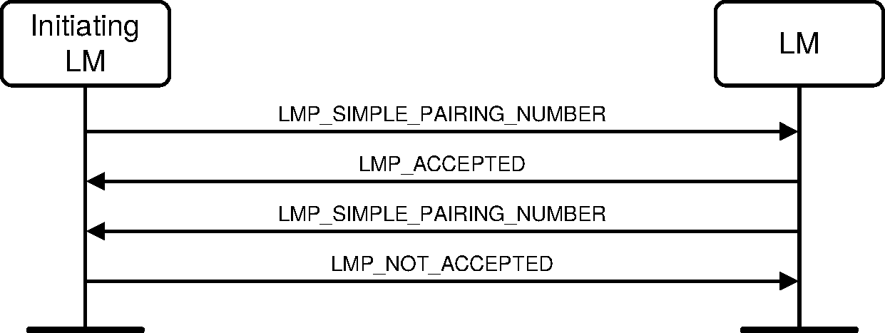
Sequence 71: Authentication stage 1 OOB: Commitment check failure on the Initiator side
4.2.7.3.6. Out-of-band information not available on the Initiator side
If the Host on the initiating side does not have out-of-band information the Initiator shall send an LMP_OOB_FAILED PDU.
The Secure Simple Pairing process shall then be aborted. The Link Managers shall not disconnect the connection.
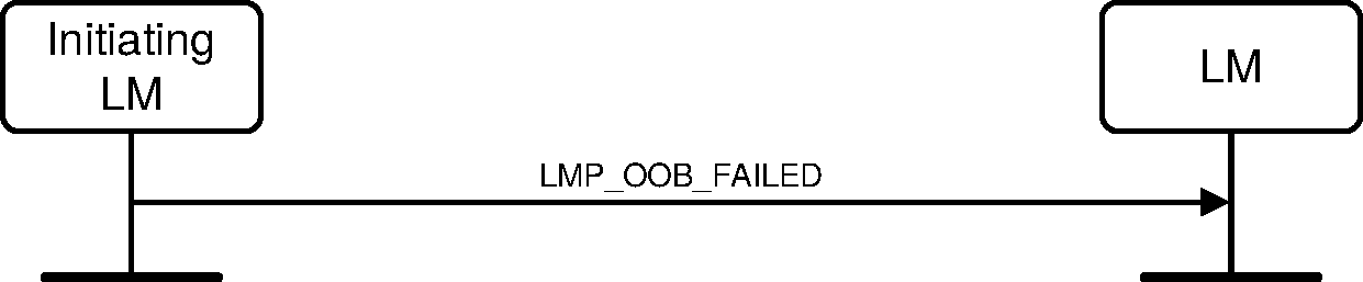
Sequence 72: Authentication stage 1 OOB: OOB information not available on the Initiator side
4.2.7.4. Authentication stage 2: DHKey check
At this stage, both devices compute new confirmation values based on Diffie-Hellman key and previously exchanged information according to [Vol 2] Part H, Section 7.7.4.
The Initiator shall send an LMP_DHKEY_CHECK PDU to the Responder. If the Initiator has determined that the received public key is invalid (see [Vol 2] Part H, Section 7.6), the PDU should include a value that is different from the computed confirmation value (for example, substituting a randomly generated number). Otherwise, the PDU shall include the computed confirmation value.
Upon reception, if the received value is not equal to the one calculated according to [Vol 2] Part H, Section 7.7.4, then the Responder shall follow the procedure in Section 4.2.7.4.1. If the values match, the Responder should follow the procedure in Section 4.2.7.4.1 if the received public key is invalid (see [Vol 2] Part H, Section 7.6). Otherwise it shall reply with an LMP_ACCEPTED PDU.
The Responder shall then send an LMP_DHKEY_CHECK PDU, including the confirmation value it has computed, to the Initiator. Upon reception, if the received value is not equal to the one calculated according to [Vol 2] Part H, Section 7.7.4, then the Initiator shall follow the procedure in Section 4.2.7.4.1. If the values match, the Initiator should follow the procedure in Section 4.2.7.4.1 if the received public key is invalid (see [Vol 2] Part H, Section 7.6). Otherwise it shall reply with an LMP_ACCEPTED PDU.
At this point, both devices shall compute the link key according to [Vol 2] Part H, Section 7.7.3.
If at least one device does not support both the Secure Connections (Controller Support) and the Secure Connections (Host Support) features, the Initiator shall then start standard mutual authentication as described in Section 4.2.1.1
If both devices support both the Secure Connections (Controller Support) and the Secure Connections (Host Support) features, the Initiator shall then start secure authentication as described in Section 4.2.1.4.
After secure authentication, if encryption is enabled, the initiating device shall pause and immediately resume encryption to produce a new encryption key.
Note
Note: This will cause a new encryption key to be generated using the h3 function including the ACO created during the secure authentication process.
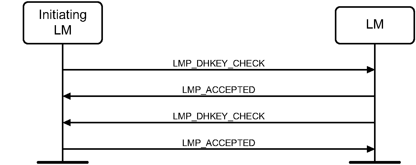
Sequence 73: DHKey check
A device that detects an invalid public key (see [Vol 2] Part H, Section 7.6) from the peer at any point during the Secure Simple Pairing process shall fail the pairing process and therefore not create a link key.
4.2.7.4.1. Check failure
If either Link Manager receives a public key that is invalid (see [Vol 2] Part H, Section 7.6), it should send an LMP_NOT_ACCEPTED PDU with reason "Authentication Failure". If either Link Manager receives a confirmation value via LMP that is not equal to the one it has calculated according to [Vol 2] Part H, Section 7.7.4, it shall send an LMP_NOT_ACCEPTED PDU with reason "Authentication Failure".
The Secure Simple Pairing procedures shall then be aborted. The Link Managers shall not disconnect the connection.
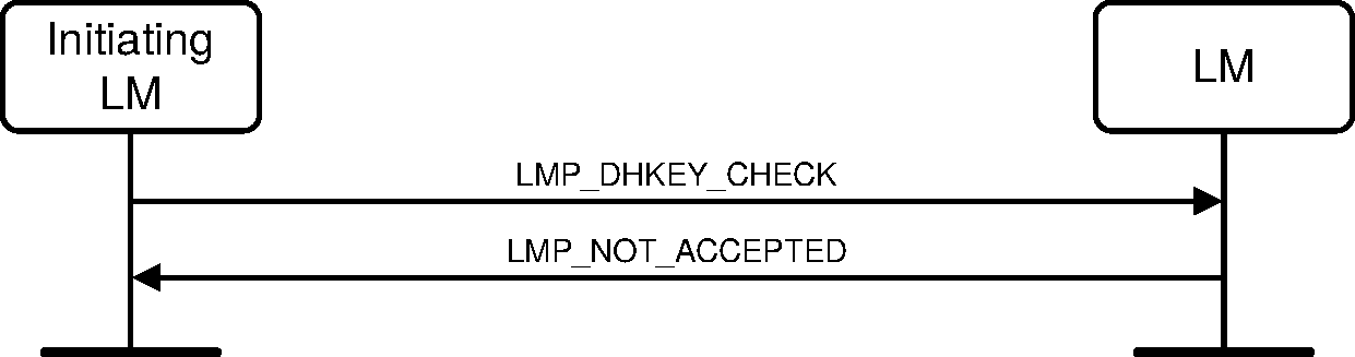
Sequence 74: DHKey check: Check failure on the Responder side
Sequence 75: DHKey check: Check failure on the Initiator side
4.2.7.4.1.1. [This section is no longer used]
4.3. Informational requests
4.3.1. Timing accuracy
LMP supports requests for the timing accuracy. This information can be used to minimize the scan window during piconet physical channel re-synchronization (see [Vol 2] Part B, Section 2.2.5.2). The timing accuracy parameters returned are the long term drift measured in ppm and the long term jitter measured in µs of the worst case clock used. These parameters are fixed for a certain device and shall be identical when requested several times. Reported time accuracy shall not include changes caused by performing Piconet Clock Adjustment. If timing accuracy information has not been received from the remote device, the worst-case values (drift = 250 ppm and jitter = 10 µs) shall be used.
M/O | PDU | Contents |
|---|---|---|
O(4) | LMP_TIMING_ACCURACY_REQ | none |
O(4) | LMP_TIMING_ACCURACY_RES | Drift Jitter |

Sequence 76: The requested device supports timing accuracy information
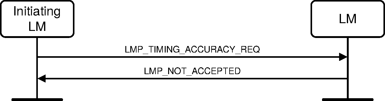
Sequence 77: The requested device does not support timing accuracy information
4.3.2. Clock offset
The clock offset can be used to speed up the paging time the next time the same device is paged. The Central can request the clock offset at anytime following a successful Baseband Paging procedure (i.e., before, during or after connection setup). The clock offset shall be defined by the following equation:
(CLKN16-2 Peripheral - CLKN16-2 Central) mod 215.
M/O | PDU | Contents |
|---|---|---|
M | LMP_CLKOFFSET_REQ | none |
M | LMP_CLKOFFSET_RES | Clock_Offset |
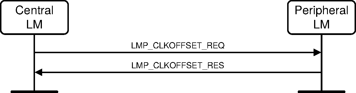
Sequence 78: Clock offset requested
4.3.3. LMP version
LMP supports requests for the version of the LM protocol. The LMP_VERSION_REQ and LMP_VERSION_RES PDUs contain three parameters: Version, Company_Identifier and Subversion. Version specifies the version of the Bluetooth LMP specification that the device supports. All companies that create a unique implementation of the LM shall have their own Company_Identifier. The same company is also responsible for the administration and maintenance of the Subversion. It is recommended that each company has a unique Subversion for each RF/BB/LM implementation. For a given Version and Company_Identifier, the values of the Subversion shall increase each time a new implementation is released. For both Company_Identifier and Subversion the value 0xFFFF means that no valid number applies. There is no ability to negotiate the version of the LMP. The sequence below is only used to exchange the parameters. LMP version can be requested at anytime following a successful Baseband Paging procedure.
Note
Note: A given value for Version does not indicate that the device supports all the features in the corresponding version of the specification; the relevant feature bits (see Section 4.3.4) should be checked instead.
Note
Note: A larger value for Version does not necessarily indicate a higher version of the specification.
M/O | PDU | Contents |
|---|---|---|
M | LMP_VERSION_REQ | Version Company_Identifier Subversion |
M | LMP_VERSION_RES | Version Company_Identifier Subversion |

Sequence 79: Request for LMP version
4.3.4. Supported features
The supported features may be requested at anytime following a successful Baseband Paging procedure by sending the LMP_FEATURES_REQ PDU. Upon reception of an LMP_FEATURES_REQ PDU, the receiving device shall return an LMP_FEATURES_RES PDU.
The extended features mask provides support for more than 64 features. Support for the extended features mask is indicated by the presence of the appropriate bit in the LMP features mask. The LMP_FEATURES_REQ_EXT and LMP_FEATURES_RES_EXT PDUs operate in precisely the same way as the LMP_FEATURES_REQ and LMP_FEATURES_RES PDUs except that they allow the various pages of the extended features mask to be requested. The LMP_FEATURES_REQ_EXT may be sent at any time following the exchange of the LMP_FEATURES_REQ and LMP_FEATURES_RSP PDUs.
The LMP_FEATURES_REQ_EXT PDU contains a Features_Page parameter that specifies which page is requested and the contents of that page for the requesting device. Pages are numbered from 0 to 255 with page 0 corresponding to the normal features mask. Each page consists of 64 bits. If a device does not support any page number it shall return an Extended_Features parameter with every bit set to 0. It also contains the maximum features page number containing any non-zero bit for this device. The recipient of an LMP_FEATURES_REQ_EXT PDU shall respond with an LMP_FEATURES_RES_EXT PDU containing the same page number and the appropriate features page along with its own maximum features page number.
If the extended features request is not supported then all bits in all extended features pages for that device shall be assumed to be zero.

Sequence 80: Request for supported features
M/O | PDU | Contents |
|---|---|---|
M | LMP_FEATURES_REQ | Features |
M | LMP_FEATURES_RES | Features |
O(63) | LMP_FEATURES_REQ_EXT | Features_Page Max_Supported_Page Extended_Features |
O(63) | LMP_FEATURES_RES_EXT | Features_Page Max_Supported_Page Extended_Features |
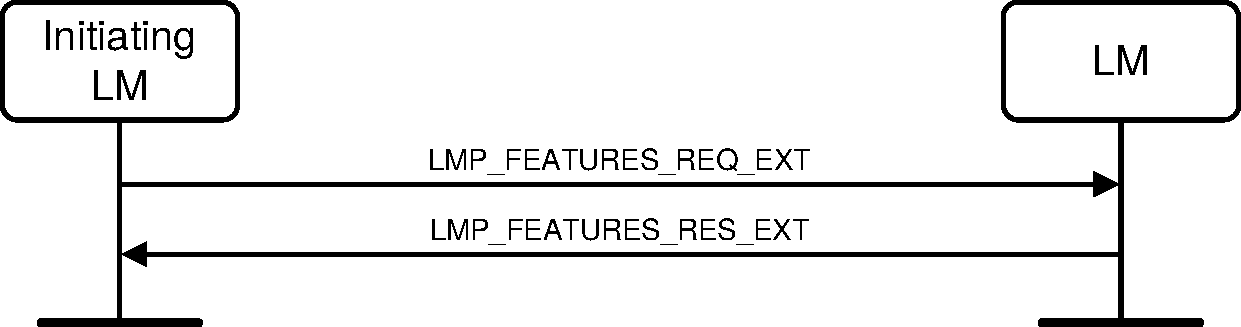
Sequence 81: Request for extended features
4.3.5. Name request
LMP supports name request to another device. The name is a user-friendly name associated with the device and consists of a maximum of 248 bytes coded according to the UTF-8 standard (more specifically, the type utf8{248z} defined in [Vol 1] Part E, Section 2.9.3). The name is fragmented over one or more DM1 packets. When an LMP_NAME_REQ PDU is sent, a Name_Offset indicates which fragment is expected. The corresponding LMP_NAME_RES PDU carries the same Name_Offset, the Name_Length indicating the total number of bytes in the name of the device and the Name_Fragment, where:
Name_Fragment(N) = name(N + Name_Offset), if (N + Name_Offset) < Name_Length
Name_Fragment(N) = 0,otherwise.
Here 0 ≤ N ≤ 13. In the first sent LMP_NAME_REQ PDU, Name_Offset=0. Sequence 82 is then repeated until the initiator has collected all fragments of the name. The name request may be made at any time following a successful Baseband Paging procedure.
M/O | PDU | Contents |
|---|---|---|
M | LMP_NAME_REQ | Name_Offset |
M | LMP_NAME_RES | Name_Offset Name_Length Name_Fragment |

Sequence 82: Request for device name
4.4. Role switch
4.4.1. Slot offset
With LMP_SLOT_OFFSET the information about the difference between the slot boundaries in different piconets is transmitted. The LMP_SLOT_OFFSET PDU may be sent anytime after the Baseband Paging procedure has completed if the ACL logical transport is in Active mode and a synchronous logical transport is not being negotiated by the LM. This PDU carries the parameters Slot_Offset and BD_ADDR. The Slot_Offset shall be the time in microseconds from the start of a Central transmission in the current piconet to the start of the next following Central transmission in the piconet where the BD_ADDR device (normally the Peripheral) is Central at the time that the request is interpreted by the BD_ADDR device.
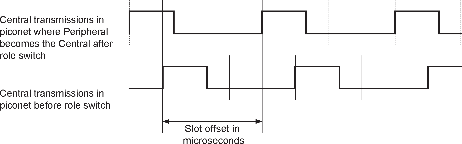
See Section 4.4.2 for the use of LMP_SLOT_OFFSET in the context of the role switch. In the case of role switch the BD_ADDR is that of the Peripheral.
M/O | PDU | Contents |
|---|---|---|
O(3) | LMP_SLOT_OFFSET | Slot_Offset BD_ADDR |
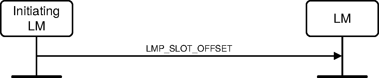
Sequence 83: Slot offset information is sent
4.4.2. Role switch
Since the paging device always becomes the Central of the piconet, a role switch is sometimes needed; see [Vol 2] Part B, Section 8.6.5. A role switch may be performed as part of connection establishment (see Section 4.1.1) or any time after connection establishment has completed.
The LMP_SWITCH_REQ shall be sent only if the ACL logical transport is in Active mode, encryption is stopped or paused, and all synchronous logical transports on the same physical link are disabled. LMP_SWITCH_REQ shall not be initiated or accepted while a synchronous logical transport is being negotiated by the LM.
M/O | PDU | Contents |
|---|---|---|
O(5) | LMP_SWITCH_REQ | Switch_Instant |
O(5) | LMP_SLOT_OFFSET | Slot_Offset BD_ADDR |
Role switch is performed by an initiating device and a responding device.
First, the initiating LM shall pause traffic on the ACL-U logical link (see [Vol 2] Part B, Section 5.3.1). Next, if the Encryption_Mode is set to "encryption" then it shall initiate either the pause encryption sequence (see Section 4.2.5.5.) if both devices support pausing encryption or the stop encryption sequence (see Section 4.2.5.4) otherwise. If it is the Peripheral, it shall next send an LMP_SLOT_OFFSET PDU. Finally, it shall send an LMP_SWITCH_REQ PDU.
If the responding device accepts the role switch, then first it shall pause traffic on the ACL-U logical link if it is not already paused. If it is the Peripheral, it shall next send an LMP_SLOT_OFFSET PDU. Finally, it shall send an LMP_ACCEPTED PDU. The two devices shall then perform the Baseband Role Switch procedure. If it rejects the role switch, it shall send an LMP_NOT_ACCEPTED PDU.
When the role switch has been completed at the Baseband level (successfully or not), or has been rejected, then:
If the initiating device had paused encryption, it shall initiate the resume encryption sequence (see Section 4.2.5.6). When AES-CCM encryption is used, the LMs shall calculate a new encryption key using the h3 algorithm (see [Vol 2] Part H, Section 7.7.6) with the BD_ADDRs for the new Central and Peripheral prior to resuming encryption.
If the initiating device had stopped encryption, it shall initiate the start encryption sequence (see Section 4.2.5.3).
Both devices shall then re-enable transmission on the ACL-U logical link.
The transaction ID for the role switch PDUs in the sequence (LMP_SLOT_OFFSET and LMP_SWITCH_REQ along with the associated LMP_ACCEPTED or LMP_NOT_ACCEPTED) shall be set to 0 when the initiating device is the Central and 1 when it is the Peripheral.
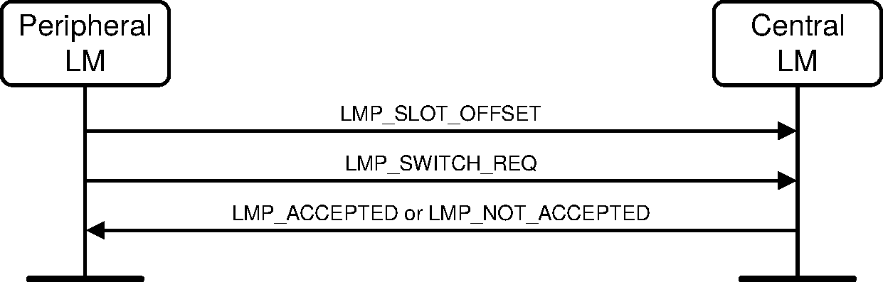
Sequence 84: Role switch (Peripheral initiated)
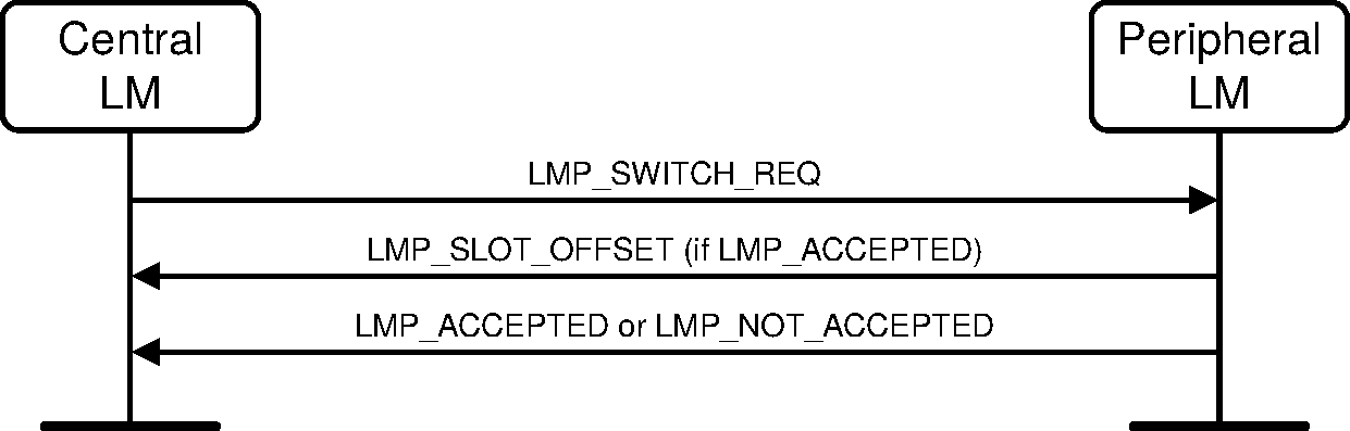
Sequence 85: Role switch (Central initiated)
The LMP_SWITCH_REQ PDU contains a parameter, Switch_Instant, which specifies the instant at which the TDD switch is performed. This is specified as a Bluetooth clock value of the Central's clock, that is available to both devices. This instant is chosen by the sender of the message and shall be at least 2*Tpoll or 32 (whichever is greater) slots in the future. The switch instant shall be within 12 hours of the current clock value to avoid clock wrap.
The sender of the LMP_SWITCH_REQ PDU selects the switch instant and queues the LMP_SWITCH_REQ PDU to LC for transmission and starts a timer to expire at the switch instant. When the timer expires it initiates the mode switch. In the case of a Central initiated switch if the LMP_SLOT_OFFSET PDU has not been received by the switch instant the role switch is carried out without an estimate of the Peripheral's slot offset. If an LMP_NOT_ACCEPTED PDU is received before the timer expires then the timer is stopped and the role switch shall not be initiated.
When the LMP_SWITCH_REQ is received the switch instant is compared with the Central's current clock value. If it is in the past then the instant has been passed and an LMP_NOT_ACCEPTED PDU with the Error_Code Instant Passed (0x28) shall be returned. If it is in the future then an LMP_ACCEPTED PDU shall be returned, assuming the role switch is accepted, and a timer is started to expire at the switch instant. When this timer expires the role switch shall be initiated.
After a successful role switch the supervision timeout and poll interval (Tpoll) shall be set to their default values. The authentication state and the ACO shall remain unchanged. Adaptive Frequency Hopping shall follow the procedures described in [Vol 2] Part B, Section 8.6.5. The default value for Max_Slots shall be used.
A role switch, whether successful or failed, does not affect the state of the Link Manager and of the ACL-C and ACL-U logical links except where explicitly stated.
4.5. Modes of operation
4.5.1. Hold mode
The ACL logical transport of a connection between two Bluetooth devices can be placed in Hold mode for a specified hold time. See [Vol 2] Part B, Section 8.8 for details.
M/O | PDU | Contents |
|---|---|---|
O(6) | LMP_HOLD | Hold_Time, Hold_Instant |
O(6) | LMP_HOLD_REQ | Hold_Time, Hold_Instant |
The LMP_HOLD and LMP_HOLD_REQ PDUs both contain a parameter, Hold_Instant, that specifies the instant at which the hold becomes effective. This is specified as a Bluetooth clock value of the Central's clock, that is available to both devices. The hold instant is chosen by the sender of the message and should be at least 6*Tpoll slots in the future. The hold instant shall be within 12 hours of the current clock value to avoid clock wrap.
4.5.1.1. Central forces Hold mode
The Central may force Hold mode if there has previously been a request for Hold mode that has been accepted by the Peripheral. The hold time included in the PDU when the Central forces Hold mode shall not be longer than any hold time the Peripheral has previously accepted when there was a request for Hold mode.
The Central LM shall first pause traffic on the ACL-U logical link (see [Vol 2] Part B, Section 5.3.1). It shall select the hold instant and queue the LMP_HOLD PDU to its LC for transmission. It shall then start a timer to wait until the hold instant occurs. When this timer expires then the connection shall enter Hold mode. If the Baseband acknowledgment for the LMP_HOLD PDU is not received then the Central may enter Hold mode, but it shall not use its low accuracy clock during the hold.
When the Peripheral LM receives an LMP_HOLD PDU it compares the hold instant with the Central's current clock value. If it is in the future then it starts a timer to expire at this instant and enters Hold mode when it expires.
When the Central LM exits from Hold mode it re-enables transmission on the ACL-U logical link.
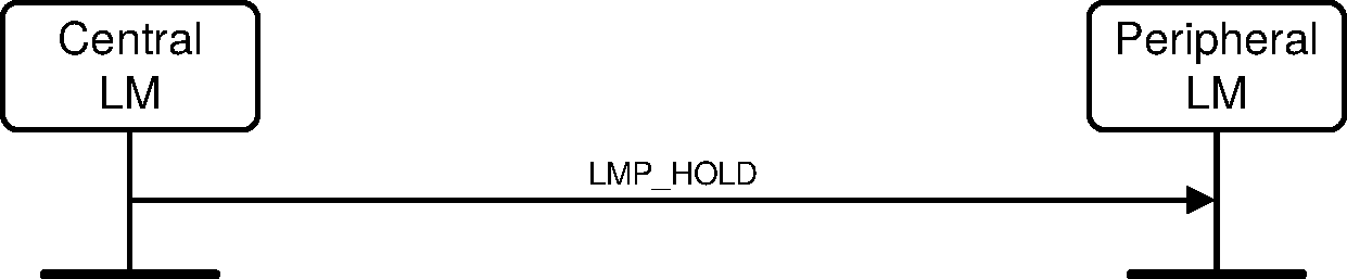
Sequence 86: Central forces Peripheral into Hold mode
4.5.1.2. Peripheral forces Hold mode
The Peripheral may force Hold mode if there has previously been a request for Hold mode that has been accepted by the Central. The hold time included in the PDU when the Peripheral forces Hold mode shall not be longer than any hold time the Central has previously accepted when there was a request for Hold mode.
The Peripheral LM shall first complete the transmission of the current packet on the ACL logical transport and then shall suspend transmission on the ACL-U logical link. It shall select the hold instant and queue the LMP_HOLD PDU to its LC for transmission. It shall then wait for an LMP_HOLD PDU from the Central acting according to the procedure described in Section 4.5.1.1.
When the Central LM receives an LMP_HOLD PDU it shall pause traffic on the ACL-U logical link (see [Vol 2] Part B, Section 5.3.1). It shall then inspect the hold instant. If this is less than 6*Tpoll slots in the future it shall modify the instant so that it is at least 6*Tpoll slots in the future. It shall then send an LMP_HOLD PDU using the mechanism described in Section 4.5.1.1.
When the Central and Peripheral LMs exit from Hold mode they shall re-enable transmission on the ACL-U logical link.
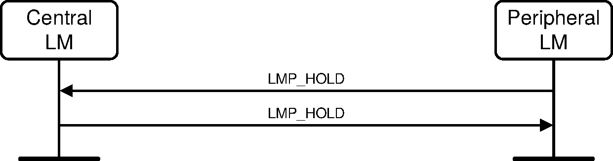
Sequence 87: Peripheral forces Central into Hold mode
4.5.1.3. Central or Peripheral requests Hold mode
The Central or the Peripheral may request to enter Hold mode. Upon receipt of the request, the same request with modified parameters may be returned or the negotiation may be terminated. If an agreement is seen an LMP_ACCEPTED PDU terminates the negotiation and the ACL link is placed in Hold mode. If no agreement is seen, an LMP_NOT_ACCEPTED PDU with the Error_Code Unsupported LMP Parameter Value (0x20) terminates the negotiation and Hold mode is not entered.
The initiating LM shall pause traffic on the ACL-U logical link (see [Vol 2] Part B, Section 5.3.1). On receiving an LMP_HOLD_REQ PDU the receiving LM shall complete the transmission of the current packet on the ACL logical transport and then shall suspend transmission on the ACL-U logical link.
The LM sending the LMP_HOLD_REQ PDU selects the hold instant, that shall be at least 9*Tpoll slots in the future. If this is a response to a previous LMP_HOLD_REQ PDU and the contained hold instant is at least 9*Tpoll slots in the future then this shall be used. The LMP_HOLD_REQ PDU shall then be queued to its LC for transmission and a timer shall be started to expire at this instant and the connection enters Hold mode when it expires unless an LMP_NOT_ACCEPTED or LMP_HOLD_REQ PDU is received by its LM before that point. If the LM receiving LMP_HOLD_REQ PDU agrees to enter Hold mode it shall return an LMP_ACCEPTED PDU and shall start a timer to expire at the hold instant. When this timer expires it enters Hold mode.
When each LM exits from Hold mode it shall re-enable transmission on the ACL-U logical link.
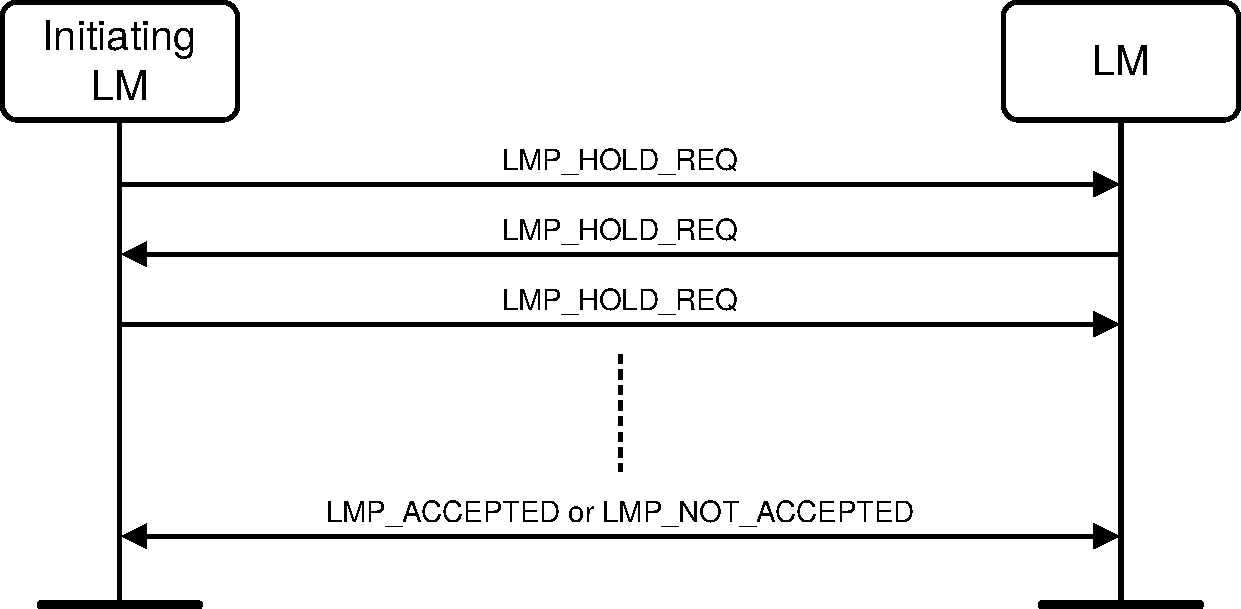
Sequence 88: Negotiation for Hold mode
4.5.2. [This section is no longer used]
4.5.3. Sniff mode
To enter Sniff mode, Central and Peripheral negotiate a sniff interval TSniff and a sniff offset, DSniff, that specifies the timing of the sniff slots. The offset determines the time of the first sniff slot; after that the sniff slots follow periodically with the sniff interval TSniff. To avoid clock wrap-around during the initialization, one of two options is chosen for the calculation of the first sniff slot. A timing control flag in the sniff request message indicates this. Only bit 1 of the timing control flag is valid.
When the ACL logical transport is in Sniff mode the Central shall only start a transmission in the sniff slots. Two parameters control the listening activity in the Peripheral: the Sniff_Attempt and the Sniff_Timeout. The Sniff_Attempt parameter determines for how many slots the Peripheral shall listen when the Peripheral is not treating this as a scatternet link, beginning at the sniff slot, even if it does not receive a packet with its own LT_ADDR. The Sniff_Timeout parameter determines for how many additional slots the Peripheral shall listen when the Peripheral is not treating this as a scatternet link if it continues to receive only packets with its own LT_ADDR. It is not possible to modify the sniff parameters while the device is in Sniff mode.
4.5.3.1. Central or Peripheral requests Sniff mode
Either the Central or the Peripheral may request entry to Sniff mode. The process is initiated by sending an LMP_SNIFF_REQ PDU containing a set of parameters. The receiving LM shall then decide whether to reject the attempt by sending an LMP_NOT_ACCEPTED PDU, to suggest different parameters by replying with an LMP_SNIFF_REQ PDU or to accept the request.
M/O | PDU | Contents |
|---|---|---|
O(7) | LMP_SNIFF_REQ | Timing_Control_Flags DSniff TSniff Sniff_Attempt Sniff_Timeout |
O(7) | LMP_UNSNIFF_REQ | - |
O(41) | LMP_SNIFF_SUBRATING_REQ | Max_Sniff_Subrate Min_Sniff_Mode_Timeout Sniff_Subrating_Instant |
O(41) | LMP_SNIFF_SUBRATING_RES | Max_Sniff_Subrate Min_Sniff_Mode_Timeout Sniff_Subrating_Instant |
Before the first time that the Central sends LMP_SNIFF_REQ in a transaction it shall enter Sniff Transition mode. If the Central receives or sends an LMP_NOT_ACCEPTED PDU it shall exit from Sniff Transition mode.
If the Central receives an LMP_SNIFF_REQ PDU it shall enter Sniff Transition mode (if not already in it) and then determine whether to accept the request. The Central may reply with an LMP_NOT_ACCEPTED PDU or, if it can enter Sniff mode but requires a different set of parameters, it shall respond with an LMP_SNIFF_REQ PDU containing the new parameters. If the Central decides that the parameters are acceptable then it shall send an LMP_ACCEPTED PDU; when it receives the Baseband acknowledgment for this PDU it shall exit Sniff Transition mode and enter Sniff mode.
If the Central receives an LMP_ACCEPTED PDU the Central shall exit from Sniff Transition mode and enter Sniff mode.
If the Peripheral receives an LMP_SNIFF_REQ PDU it shall determine whether to accept the request. The Peripheral may reply with an LMP_NOT_ACCEPTED PDU to reject the request or, if it can enter Sniff mode but requires a different set of parameters, it shall respond with an LMP_SNIFF_REQ PDU containing the new parameters. If the Peripheral decides that the parameters are acceptable then it shall send an LMP_ACCEPTED PDU and enter Sniff mode. If the Peripheral receives an LMP_NOT_ACCEPTED PDU it shall terminate the attempt to enter Sniff mode.
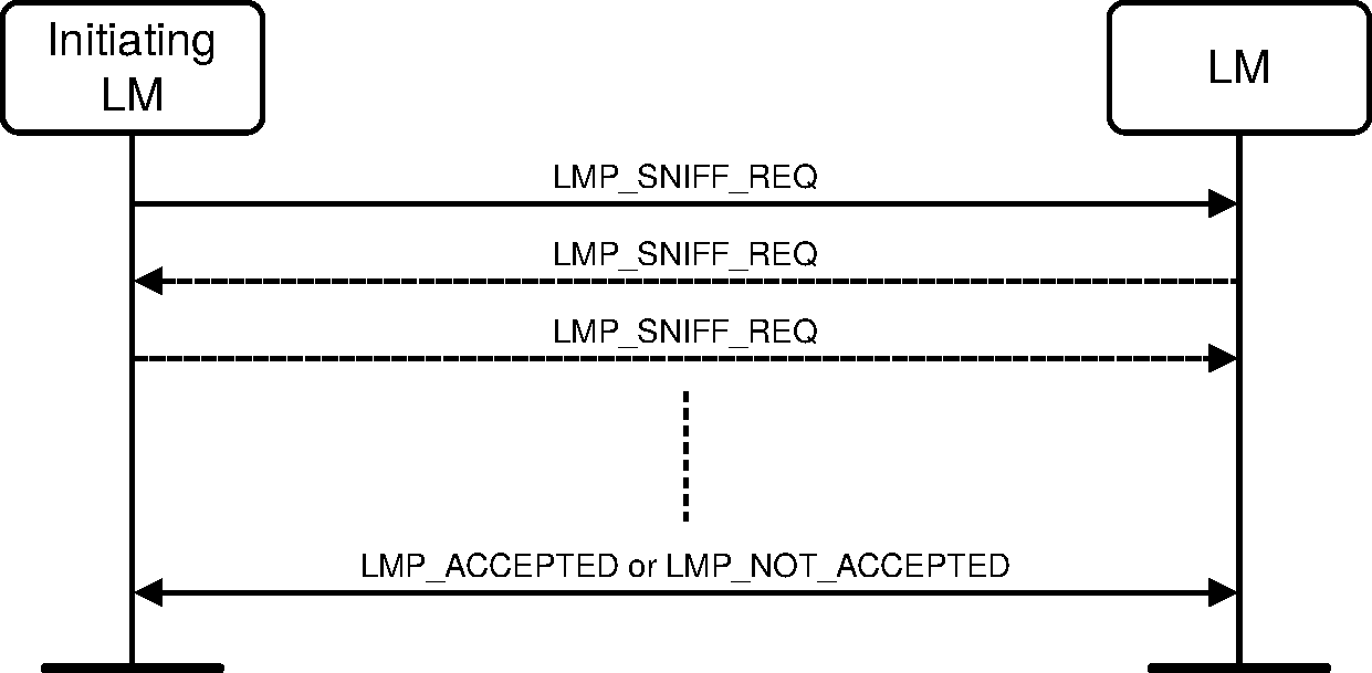
Sequence 89: Negotiation for Sniff mode
4.5.3.2. Moving a Peripheral from Sniff mode to Active mode
Sniff mode may be exited by either the Central or the Peripheral sending an LMP_UNSNIFF_REQ PDU. The requested device shall reply with an LMP_ACCEPTED PDU.
If the Central requests an exit from Sniff mode it shall enter Sniff Transition mode and then send an LMP_UNSNIFF_REQ PDU. When the Peripheral receives the LMP_UNSNIFF_REQ it shall exit from Sniff mode and reply with an LMP_ACCEPTED PDU. When the Central receives the LMP_ACCEPTED PDU it shall exit from Sniff Transition mode and enter Active mode.
If the Peripheral requests an exit from Sniff mode it shall send an LMP_UNSNIFF_REQ PDU. When the Central receives the LMP_UNSNIFF_REQ PDU it shall enter Sniff Transition mode and then send an LMP_ACCEPTED PDU. When the Peripheral receives the LMP_ACCEPTED PDU it shall exit from Sniff mode and enter Active mode. When the Central receives the Baseband acknowledgment for the LMP_ACCEPTED PDU it shall leave Sniff Transition mode and enter Active mode.

Sequence 90: Peripheral moved from Sniff mode to Active mode
4.5.3.3. Sniff subrating
Once Sniff mode has been started, sniff subrating may be initiated by either Link Manager.
The LMP_SNIFF_SUBRATING_REQ and LMP_SNIFF_SUBRATING_RES PDUs specify parameters that the peer and initiating device shall use respectively for sniff subrating.
The Sniff_Subrating_Instant value shall be used to calculate the first sniff subrating anchor point. The Sniff_Subrating_Instant value shall be a maximum of 216 time slots (40.9 seconds) from the Central's current clock and shall be a sniff anchor point. The Sniff_Subrating_Instant value should indicate a clock value in the future with respect to the clock value when the LMP message is first sent.
If the LMP_SNIFF_SUBRATING_REQ PDU is sent by the Central, the Sniff_Subrating_Instant value shall be used. The Peripheral shall reply with an LMP_SNIFF_SUBRATING_RES PDU using the same Sniff_Subrating_Instant value given by the Central.
When the LMP_SNIFF_SUBRATING_REQ PDU is sent by the Peripheral, the Sniff_Subrating_Instant value shall be ignored. The Central shall reply with an LMP_SNIFF_SUBRATING_RES PDU with the Sniff_Subrating_Instant value that shall be used for sniff subrating.
The initiating device shall not transition to the new sniff subrating parameters until the sniff subrating instant has passed and the LMP_SNIFF_SUBRATING_RES PDU has been received. The non-initiating device shall remain in Sniff mode and shall not transition to the new sniff subrating parameters until after the sniff subrating instant has passed and the Baseband acknowledgment of the LMP_SNIFF_SUBRATING_RES PDU has been received.

Sequence 91: LM accepts sniff subrating request
A device shall not send a new LMP_SNIFF_SUBRATING_REQ PDU until the previous sniff subrating transaction has completed and the sniff subrating instant has passed.
The maximum clock interval between two sniff subrating anchor points shall be less than the link supervision timeout. If the link supervision timeout needs to be updated to a shorter value than the clock interval between two sniff subrating anchor points, the Central shall disable sniff subrating, shall send the LMP_SUPERVISION_TIMEOUT PDU with the new supervision timeout value, and shall start using the new supervision timeout value after receiving a Baseband acknowledgment for the LMP_SUPERVISION_TIMEOUT PDU. Upon reception of the LMP_SUPERVISION_TIMEOUT PDU the Peripheral shall disable sniff subrating and shall start using the new supervision timeout value.
The Central shall initiate sniff subrating with the Max_Sniff_Subrate parameter less than the new supervision timeout. The Peripheral shall respond with the LMP_SNIFF_SUBRATING_RES PDU with the Max_Sniff_Subrate parameter less than the new supervision timeout.
4.6. Logical transports
When a connection is first established between two devices the connection consists of the ACL logical transport (carrying the ACL-C logical link for LMP messages and the ACL-U logical link for L2CAP data) and the APB logical transport carrying the APB-C logical links for LMP messages and the APB-U logical link for L2CAP data. One or more synchronous logical transports (SCO or eSCO) may then be added. A new logical transport shall not be created if it would cause all slots to be allocated to reserved slots on secondary LT_ADDRs.
4.6.1. SCO logical transport
The SCO logical transport reserves slots separated by the SCO interval, Tsco. The first slot reserved for the SCO logical transport is defined by Tsco and the SCO offset, Dsco. See [Vol 2] Part B, Section 8.6.2 for details. A device shall initiate a request for HV2 or HV3 packet type only if the other device supports that type. A device shall initiate CVSD, μ-law or A-law coding or uncoded (transparent) data only if the other device supports the corresponding feature. To avoid problems with a wrap-around of the clock during initialization of the SCO logical transport, the Timing_Control_Flags parameter is used to indicate how the first SCO slot shall be calculated. Only bit1 of the Timing_Control_Flags parameter is valid. The SCO link is distinguished from all other SCO links by a SCO handle. The SCO handle zero shall not be used.
The Link Manager shall not initiate a SCO connection, and shall reject any request for a SCO connection, while AES-CCM encryption is in use.
Note
Note: The Peripheral interprets the initialization flag in the Timing_Control_Flags in terms of the Central’s Bluetooth clock. See [Vol 2] Part B, Section 8.6.2.
M/O | PDU | Contents |
|---|---|---|
O(11) | LMP_SCO_LINK_REQ | SCO_Handle Timing_Control_Flags Dsco Tsco SCO_Packet Air_Mode |
O(11) | LMP_REMOVE_SCO_LINK_REQ | SCO_Handle Error_Code |
4.6.1.1. Central initiates a SCO link
When establishing a SCO link the Central sends a request, a LMP_SCO_LINK_REQ PDU, with parameters that specify the timing, packet type and coding that will be used on the SCO link. Each of the SCO packet types supports three different voice coding formats on the air-interface: µ-law log PCM, A-law log PCM and CVSD. The air coding by log PCM or CVSD may be deactivated to achieve a transparent synchronous data link at 64 kb/s.
The slots used for the SCO links are determined by three parameters controlled by the Central: Tsco, Dsco and a flag indicating how the first SCO slot is calculated. After the first slot, the SCO slots follow periodically at an interval of Tsco.
If the Peripheral does not accept the SCO link, but can operate with a different set of SCO parameters, it can indicate what it does not accept in the Error_Code parameter of an LMP_NOT_ACCEPTED PDU. The Central may then issue a new request with modified parameters.
The SCO handle in the message shall be different from existing SCO link(s).
If the SCO packet type is HV1 the LMP_ACCEPTED shall be sent using the DM1 packet.
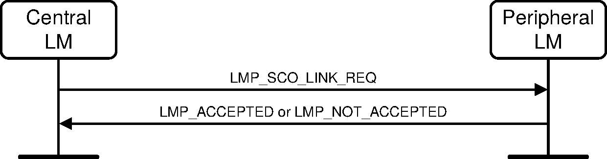
Sequence 92: Central requests a SCO link
4.6.1.2. Peripheral initiates a SCO link
The Peripheral may initiate the establishment of a SCO link. The Peripheral sends an LMP_SCO_LINK_REQ PDU with the SCO handle set to zero; the Timing_Control_Flags parameter shall be ignored by the Central, while the DSCO parameter should be set to 0. If the Central is not capable of establishing a SCO link, it replies with an LMP_NOT_ACCEPTED PDU. Otherwise it sends back an LMP_SCO_LINK_REQ PDU. This message includes the assigned SCO handle, Dsco and the timing control flags. The Central should try to use the same parameters as in the Peripheral request; if the Central cannot meet that request, it is allowed to use other values. The Peripheral shall then reply with LMP_ACCEPTED or LMP_NOT_ACCEPTED PDU.
If the SCO packet type is HV1 the LMP_ACCEPTED shall be sent using the DM1 packet.
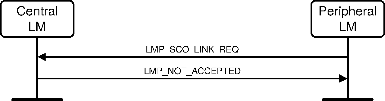
Sequence 93: Central rejects Peripheral’s request for a SCO link
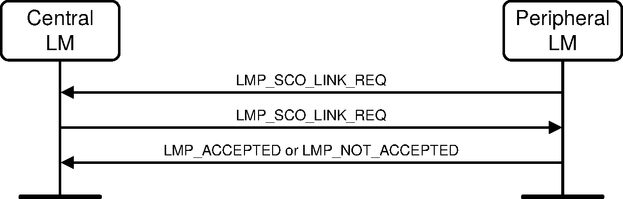
Sequence 94: Central accepts Peripheral’s request for a SCO link
4.6.1.3. Central requests change of SCO parameters
The Central sends an LMP_SCO_LINK_REQ PDU, where the SCO_Handle is the handle of the SCO link the Central wishes to change parameters for. If the Peripheral accepts the new parameters, it replies with an LMP_ACCEPTED PDU and the SCO link will change to the new parameters. If the Peripheral does not accept the new parameters, it shall reply with an LMP_NOT_ACCEPTED PDU and the SCO link is left unchanged. When the Peripheral replies with an LMP_NOT_ACCEPTED PDU it shall indicate in the Error_Code parameter what it does not accept. The Central may then try to change the SCO link again with modified parameters. The sequence is the same as in Section 4.6.1.1.
4.6.1.4. Peripheral requests change of SCO parameters
The Peripheral sends an LMP_SCO_LINK_REQ PDU, where the SCO_Handle is the handle of the SCO link to be changed. The parameters Timing_Control_Flags and Dsco are not valid in this PDU. If the Central does not accept the new parameters it shall reply with an LMP_NOT_ACCEPTED PDU and the SCO link is left unchanged. If the Central accepts the new parameters it shall reply with an LMP_SCO_LINK_REQ PDU containing the same parameters as in the Peripheral request. When receiving this message the Peripheral replies with an LMP_NOT_ACCEPTED PDU if it does not accept the new parameters. The SCO link is then left unchanged. If the Peripheral accepts the new parameters it replies with an LMP_ACCEPTED PDU and the SCO link will change to the new parameters. The sequence is the same as in Section 4.6.1.2.
4.6.1.5. Remove a SCO link
The Central or Peripheral may remove the SCO link by sending a request including the SCO handle of the SCO link to be removed and an Error_Code indicating why the SCO link is removed. The receiving side shall respond with an LMP_ACCEPTED PDU.
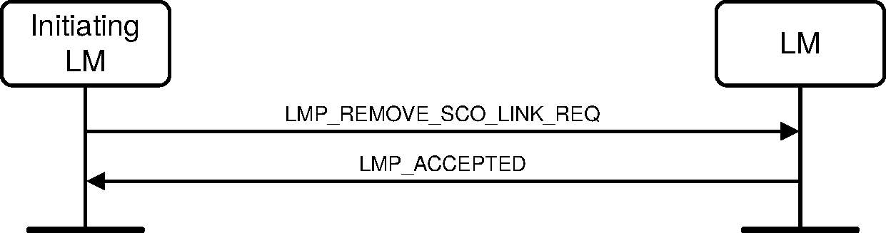
Sequence 95: SCO link removed
4.6.2. eSCO logical transport
After an ACL link has been established, one or more extended SCO (eSCO) links can be set up to the remote device. The eSCO links are similar to SCO links using timing control flags, an interval TeSCO and an offset DeSCO. Only bit1 of the Timing_Control_Flags parameter is valid. As opposed to SCO links, eSCO links have a configurable data rate that may be asymmetric, and can be set up to provide limited retransmissions of lost or damaged packets inside a retransmission window of size WeSCO. The DeSCO shall be based on CLK.
Note
Note: The Peripheral interprets the initialization flag in the Timing_Control_Flags in terms of the Central’s Bluetooth clock. See [Vol 2] Part B, Section 8.6.2.
The parameters DeSCO, TeSCO, WeSCO, eSCO_Packet_Type C→P, eSCO_Packet_Type P→C, Packet_Length C→P, Packet_Length P→C are henceforth referred to as the negotiable parameters.
M/O | PDU | Contents |
|---|---|---|
O(31) | LMP_eSCO_LINK_REQ | eSCO_Handle eSCO_LT_ADDR Timing_Control_Flags DeSCO TeSCO WeSCO eSCO_Packet_Type C→P eSCO_Packet_Type P→C Packet_Length C→P Packet_Length P→C Air_Mode Negotiation_State |
O(31) | LMP_REMOVE_eSCO_LINK_REQ | eSCO_Handle Error_Code |
4.6.2.1. Central initiates an eSCO link
When establishing an eSCO link the Central sends an LMP_eSCO_LINK_REQ PDU specifying all parameters. The Peripheral may accept this with an LMP_ACCEPTED_EXT PDU, reject it with an LMP_NOT_ACCEPTED_EXT PDU, or respond with its own LMP_eSCO_LINK_REQ specifying alternatives for some or all parameters. The Peripheral shall not negotiate the eSCO_Handle or eSCO_LT_ADDR parameters. The negotiation of parameters continues until the Central or Peripheral either accepts the latest parameters with an LMP_ACCEPTED_EXT PDU, or terminates the negotiation with an LMP_NOT_ACCEPTED_EXT PDU. The negotiation shall use the procedures defined in Section 4.6.2.5.
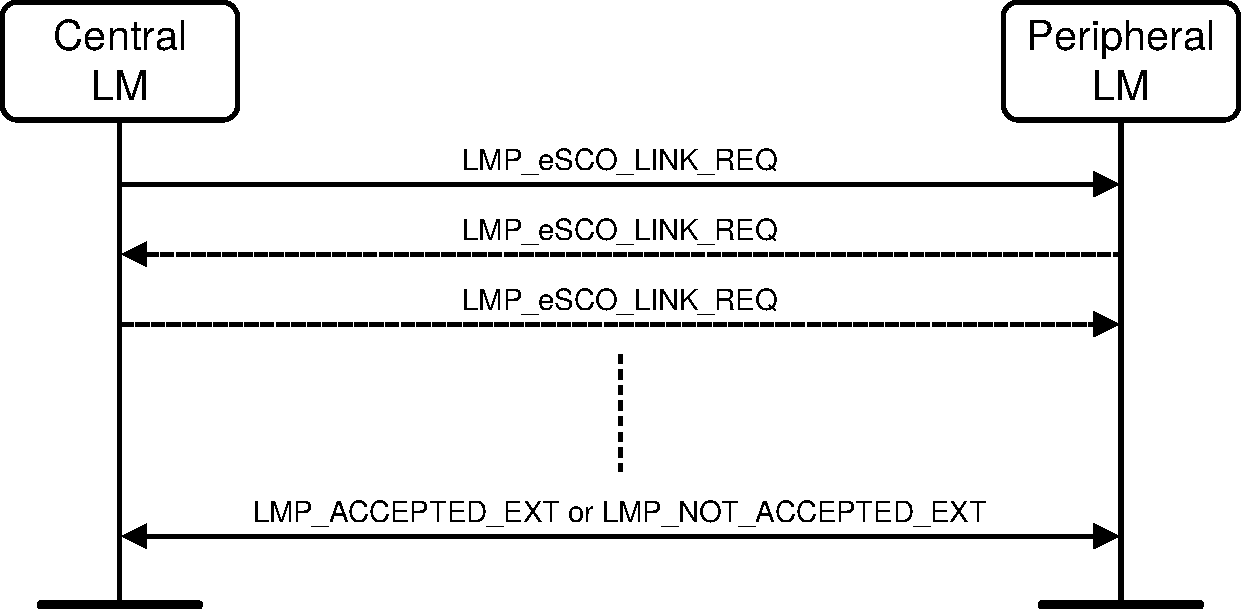
Sequence 96: Central requests an eSCO link
4.6.2.2. Peripheral initiates an eSCO link
When attempting to establish an eSCO link the Peripheral shall send an LMP_eSCO_LINK_REQ PDU specifying all parameters except eSCO_LT_ADDR, which is reserved for future use, and eSCO_Handle, which shall be set to zero. The Central may respond to this with an LMP_eSCO_LINK_REQ PDU, filling in these missing parameters, and potentially changing the other requested parameters. The Peripheral can accept this with an LMP_ACCEPTED_EXT PDU, or respond with a further LMP_eSCO_LINK_REQ PDU specifying alternatives for some or all of the parameters. The negotiation of parameters continues until the Central or Peripheral either accepts the latest parameters with an LMP_ACCEPTED_EXT PDU, or terminates the negotiation with an LMP_NOT_ACCEPTED_EXT PDU.
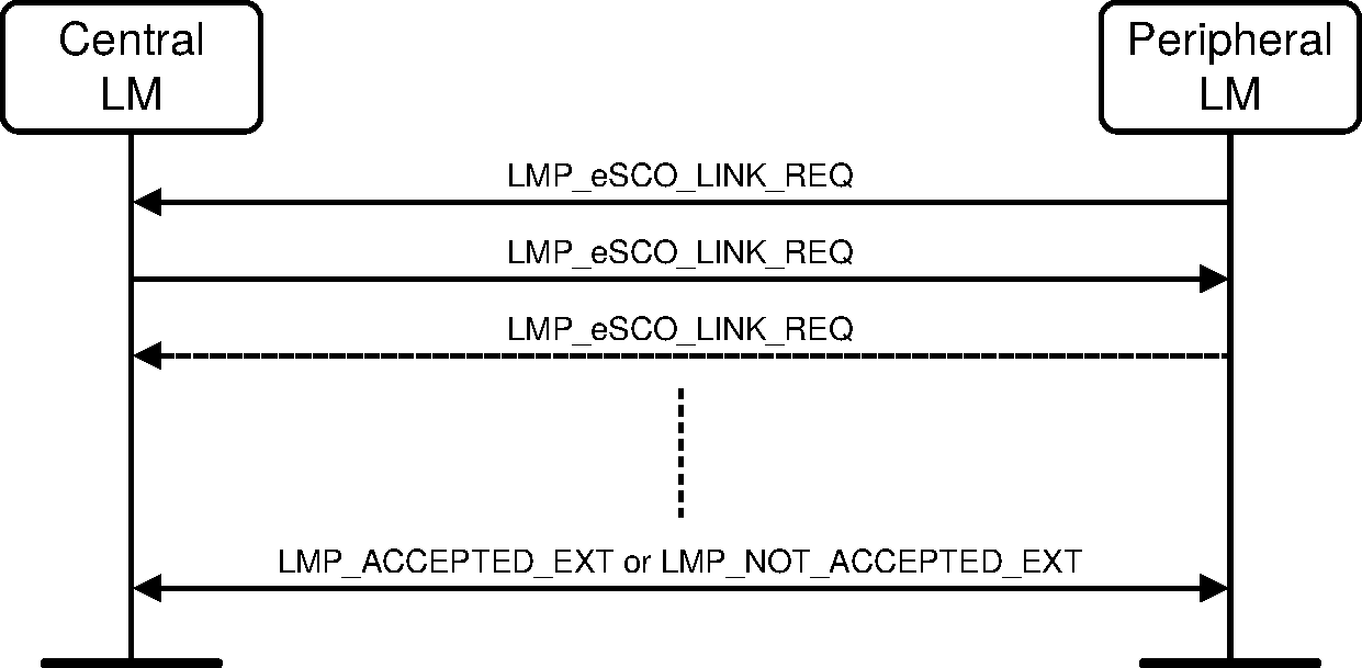
Sequence 97: Peripheral requests an eSCO link
The Central may reject the request immediately with an LMP_NOT_ACCEPTED_EXT PDU. The negotiation shall use the procedures defined in Section 4.6.2.5.
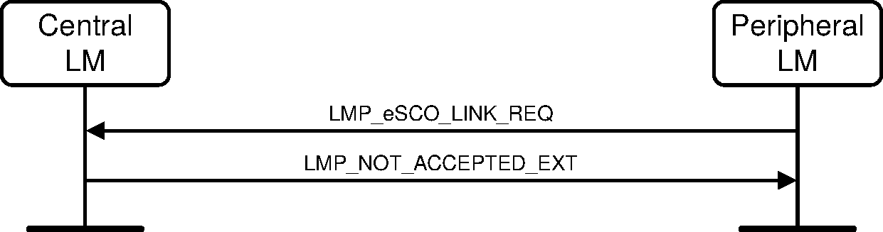
Sequence 98: Central rejects Peripheral’s request for an eSCO link
4.6.2.3. Central or Peripheral requests change of eSCO parameters
The Central or Peripheral may request a renegotiation of the eSCO parameters. The Central or Peripheral shall send an LMP_eSCO_LINK_REQ PDU with the eSCO handle of the eSCO link the device wishes to renegotiate. The remote device may accept the changed parameters immediately with LMP_ACCEPTED_EXT PDU, or the negotiation may be continued with further LMP_eSCO_LINK_REQ PDUs until the Central or Peripheral accepts the latest parameters with an LMP_ACCEPTED_EXT PDU or terminates the negotiation with an LMP_NOT_ACCEPTED_EXT PDU. In the case of termination with an LMP_NOT_ACCEPTED_EXT PDU, the eSCO link continues on the previously negotiated parameters.
The sequence is the same as in Section 4.6.2.2.
During re-negotiation, the eSCO LT_ADDR and eSCO handle shall not be re-negotiated and shall be set to the originally negotiated values. The negotiation shall use the procedures defined in Section 4.6.2.5.
4.6.2.4. Remove an eSCO link
Either the Central or Peripheral may remove the eSCO link by sending a request including the eSCO handle of the eSCO link to be removed and an Error_Code indicating why the eSCO link is removed. The receiving side shall respond with an LMP_ACCEPTED_EXT PDU. The Peripheral shall shut down its eSCO logical transport before sending its PDU (LMP_REMOVE_eSCO_LINK_REQ for Peripheral initiated removal, LMP_ACCEPTED_EXT for Central initiated). The Central shall not reassign the eSCO LT_ADDR until the end of the removal procedure. If, for some reason, such as the Peripheral being out of range, the procedure cannot be completed, the Central shall not reassign the eSCO LT_ADDR until the primary LT_ADDR is available for reuse (supervision timeout).
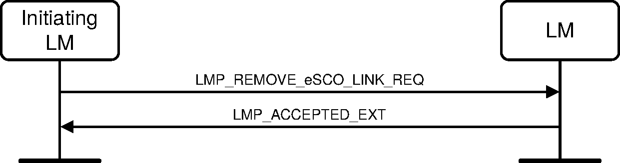
Sequence 99: eSCO link removed
4.6.2.5. Rules for the LMP negotiation and renegotiation
Rule 1: the Negotiation_State shall be set to 0 by the initiating LM. After the initial LMP_eSCO_LINK_REQ is sent the Negotiation_State shall not be set to 0.
Rule 2: if the bandwidth (defined as 1600 times the packet length in bytes divided by TeSCO in slots) for either RX or TX or the Air_Mode cannot be accepted the device shall send LMP_NOT_ACCEPTED_EXT with the appropriate Error_Code.
Rule 3: Bandwidth and Air_Mode are not negotiable and shall not be changed for the duration of the negotiation. Once one side has rejected the negotiation (with LMP_NOT_ACCEPTED_EXT) a new negotiation may be started with different bandwidth and Air_Mode parameters.
Rule 4: if the parameters will cause a latency violation (TeSCO + WeSCO + reserved synchronous slots > allowed local latency) the device should propose new parameters that shall not cause a reserved slot violation or latency violation for the device that is sending the parameters. In this case the Negotiation_State shall be set to 3. Otherwise the device shall send LMP_NOT_ACCEPTED_EXT.
Rule 5: once a device has received an LMP_eSCO_LINK_REQ with the Negotiation_State set to 3 (latency violation), the device shall not propose any combination of packet type, TeSCO, and WeSCO that will give an equal or larger latency than the combination that caused the latency violation for the other device.
Rule 6: if the parameters cause both a reserved slot violation and a latency violation or if the parameters are not supported and a latency violation occurs, then the device shall set the Negotiation_State to 3 (latency violation).
Rule 7: if the parameters will cause a reserved slot violation the device should propose new parameters that shall not cause a reserved slot violation. In this case the Negotiation_State shall be set to 2. Otherwise the device shall send LMP_NOT_ACCEPTED_EXT.
Rule 8: If the requested parameters are not supported the device should propose a setting that is supported, and set the Negotiation_State to 4. If it is not possible to find such a parameter set, the device shall send LMP_NOT_ACCEPTED_EXT.
Rule 9: when proposing new parameters for reasons other than a latency violation, reserved slot violation, or configuration not supported, the Negotiation_State shall be set to 1.
4.6.2.6. Negotiation state definitions
Reserved Slot Violation: a reserved slot violation is when the receiving LM cannot setup the requested eSCO logical transport because the eSCO reserved slots would overlap with other regularly scheduled slots (e.g. other synchronous reserved slots or sniff anchor points).
Latency Violation: a latency violation is when the receiving LM cannot setup the requested eSCO logical transport because the latency (WeSCO+TeSCO + reserved synchronous slots) is greater than the maximum allowed latency.
Configuration not supported: The combination of parameters requested is not inside the supported range for the device.
4.7. Test mode
LMP has PDUs to support different test modes used for certification and compliance testing of the Bluetooth radio and Baseband. See Definition: Test methodology [Vol 3] Part D, Section 1 for a detailed description of these test modes.
4.7.1. Activation and deactivation of Test mode
The activation may be carried out locally (via a HW or SW interface), or using the air interface.
For activation over the air interface, entering the test mode shall be locally enabled for security and type approval reasons. The implementation of this local enabling is not subject to standardization.
The tester sends an LMP command that shall force the DUT to enter test mode. The DUT shall terminate all normal operation before entering the test mode.
The DUT shall return an LMP_ACCEPTED PDU on reception of an activation command. An LMP_NOT_ACCEPTED PDU shall be returned if the DUT is not locally enabled.
If the activation is performed locally using a HW or SW interface, the DUT shall terminate all normal operation before entering the test mode.
Until a connection to the tester exists, the device shall perform page scan and inquiry scan. Extended scan activity is recommended.
The test mode is activated by sending an LMP_TEST_ACTIVATE PDU to the device under test (DUT). The DUT is always the Peripheral. The LM shall be able to receive this message at any time. If entering test mode is locally enabled in the DUT it shall respond with an LMP_ACCEPTED PDU and test mode is entered. Otherwise the DUT responds with an LMP_NOT_ACCEPTED PDU and the DUT remains in normal operation. The Error_Code in the LMP_NOT_ACCEPTED PDU shall be LMP PDU Not Allowed (0x24).

Sequence 100: Activation of test mode successful
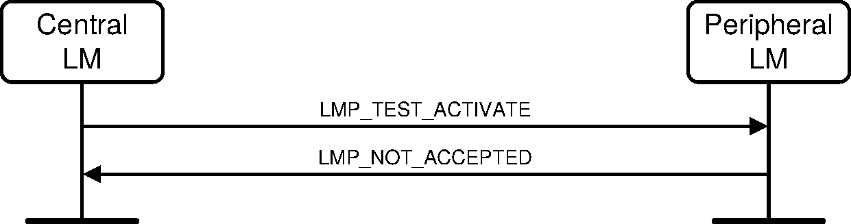
Sequence 101: Activation of Test mode fails. Peripheral is not allowed to enter Test mode.
The test mode can be deactivated in two ways. Sending an LMP_TEST_CONTROL PDU with Test_Scenario set to "exit test mode" exits the test mode and the Peripheral returns to normal operation still connected to the Central. Sending an LMP_DETACH PDU to the DUT ends the test mode and the connection.
4.7.2. Control of Test mode
Control and configuration is performed using special LMP commands (see Section 4.7.3). These commands shall be rejected if the Bluetooth device is not in test mode. In this case, an LMP_NOT_ACCEPTED shall be returned. The DUT shall return an LMP_ACCEPTED on reception of a control command when in test mode.
A Bluetooth device in test mode shall ignore all LMP commands not related to control of the test mode. LMP commands dealing with power control and the request for LMP features (LMP_FEATURES_REQ), and adaptive frequency hopping (LMP_SET_AFH, LMP_CHANNEL_CLASSIFICATION_REQ and LMP_CHANNEL_CLASSIFICATION) are allowed in test mode; the normal procedures are also used to test the adaptive power control.
The DUT shall leave the test mode when an LMP_DETACH command is received or an LMP_TEST_CONTROL command is received with Test_Scenario set to 'exit test mode'.
When the DUT has entered test mode, the LMP_TEST_CONTROL PDU can be sent to the DUT to start a specific test. This PDU is acknowledged with an LMP_ACCEPTED PDU. If a device that is not in test mode receives an LMP_TEST_CONTROL PDU it responds with an LMP_NOT_ACCEPTED PDU, where the Error_Code shall be LMP PDU Not Allowed (0x24).
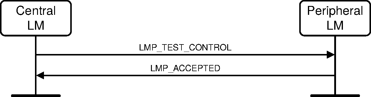
Sequence 102: Control of Test mode successful

Sequence 103: Control of Test mode rejected since Peripheral is not in Test mode
4.7.3. Summary of Test mode PDUs
Table 4.36 lists all LMP messages used for test mode. To ensure that the contents of the LMP_TEST_CONTROL PDU are suitably whitened (important when sent in transmitter mode), all parameters listed in Table 4.37 are XORed with 0x55 before being sent.
LMP PDU | PDU number | Possible Direction | Contents | Position in Payload |
|---|---|---|---|---|
LMP_TEST_ACTIVATE | 56 | C → P | none | |
LMP_TEST_CONTROL | 57 | C → P | Test_Scenario Hopping_Mode Tx_Frequency Rx_Frequency Power_Mode Poll_Period Packet_Type Test_Data_Length | 2 3 4 5 6 7 8 9-10 |
LMP_DETACH | 7 | C → P | none | |
LMP_ACCEPTED | 3 | C ← P | none | |
LMP_NOT_ACCEPTED | 4 | C ← P | none |
Name | Length (bytes) | Type | Detailed |
|---|---|---|---|
Test_Scenario | 1 | uint8 | 0 Pause Test Mode 1 Transmitter test – 0 pattern 2 Transmitter test – 1 pattern 3 Transmitter test – 1010 pattern 4 Pseudorandom bit sequence 5 Closed Loop Back – ACL packets 6 Closed Loop Back – Synchronous packets 7 ACL packets without whitening 8 Synchronous packets without whitening 9 Transmitter test – 1111 0000 pattern 10–254 Reserved for future use 255 Exit Test Mode The value is XORed with 0x55. |
Hopping_Mode | 1 | uint8 | 0 RX/TX on single frequency 1 Normal hopping 2–255 Reserved for future use The value is XORed with 0x55. |
Tx_Frequency | 1 | uint8 | f = [2402 + k] MHz The value is XORed with 0x55. |
Rx_Frequency | 1 | uint8 | f = [2402 + k] MHz The value is XORed with 0x55. |
Power_Mode | 1 | uint8 | 0 fixed TX output power 1 adaptive power control The value is XORed with 0x55. |
Poll_Period | 1 | uint8 | Unit: 1.25 ms The value is XORed with 0x55. |
Packet_Type | 1 | uint8 | Bits 3-0 numbering as in packet header, see [Vol 2] Part B, Section 6.4.2 Bits 7-4 0: ACL/SCO 1: eSCO 2: Enhanced Data Rate ACL 3: Enhanced Data Rate eSCO 4-15: Reserved for future use The value is XORed with 0x55. |
Test_Data_Length | 2 | uint16 | This is equal to the length of user data in [Vol 2] Part B, Section 6.5, in bytes, excluding the payload header and CRC if present in the relevant type of packet. The value is XORed with 0x5555. |
The control PDU is used for both transmitter and loop back tests. The following restrictions apply for the parameter settings:
Parameter | Restrictions Transmitter Test | Restrictions Loopback Test |
|---|---|---|
Tx_Frequency | 0 ≤ k ≤ 78 | 0 ≤ k ≤ 78 |
Rx_Frequency | same as Tx_Frequency | 0 ≤ k ≤ 78 |
Poll_Period | none | not applicable (set to 0) |
Test_Data_Length | Depends on packet type. See [Vol 2] Part B, Table 6.8 and [Vol 2] Part B, Table 6.9 | For ACL and SCO packets: not applicable (set to 0) For eSCO packets: |
5. Summary
5.1. PDU summary
Where the "Possible direction" column in Table 5.1 shows "B", the PDU is sent on the APB-C logical link. All other PDUs are sent on the ACL-C logical link and only in the direction(s) indicated.
LMP PDU | Length (bytes) | Opcode | Packet type | Possible direction | Contents | Position in payload |
|---|---|---|---|---|---|---|
LMP_ACCEPTED | 2 | 3 | DM1/DV | C ↔ P | Opcode | 2 |
LMP_ACCEPTED_EXT | 4 | 127/01 | DM1 | C ↔ P | Escape_Opcode | 3 |
Extended_Opcode | 4 | |||||
LMP_AU_RAND | 17 | 11 | DM1 | C ↔ P | Random_Number | 2–17 |
LMP_AUTO_RATE | 1 | 35 | DM1/DV | C ↔ P | none | |
LMP_CHANNEL_CLASSIFICATION | 12 | 127/17 | DM1 | C ← P | AFH_Channel_Classification | 3–12 |
LMP_CHANNEL_CLASSIFICATION_REQ | 7 | 127/16 | DM1 | C → P | AFH_Reporting_Mode | 3 |
AFH_Min_Interval | 4–5 | |||||
AFH_Max_Interval | 6–7 | |||||
LMP_CLK_ADJ | 15 | 127/5 | DM1 | B | Clk_Adj_ID | 3 |
Clk_Adj_Instant | 4–7 | |||||
Clk_Adj_Offset | 8–9 | |||||
Clk_Adj_Slots | 10 | |||||
Clk_Adj_Mode | 11 | |||||
Clk_Adj_Clk | 12–15 | |||||
LMP_CLK_ADJ_ACK | 3 | 127/6 | DM1 | C ← P | Clk_Adj_ID | 3 |
LMP_CLK_ADJ_REQ | 6 | 127/7 | DM1 | C ← P | Clk_Adj_Offset | 3–4 |
Clk_Adj_Slots | 5 | |||||
Clk_Adj_Period | 6 | |||||
LMP_CLKOFFSET_REQ | 1 | 5 | DM1/DV | C → P | none | |
LMP_CLKOFFSET_RES | 3 | 6 | DM1/DV | C ← P | Clock_Offset | 2–3 |
LMP_COMB_KEY | 17 | 9 | DM1 | C ↔ P | Random_Number | 2–17 |
LMP_DECR_POWER_REQ | 2 | 32 | DM1/DV | C ↔ P | Reserved | 2 |
LMP_DETACH | 2 | 7 | DM1/DV | C ↔ P | Error_Code | 2 |
LMP_DHKEY_CHECK | 17 | 65 | DM1 | C ↔ P | Confirmation_Value | 2–17 |
LMP_ENCAPSULATED_HEADER | 4 | 61 | DM1 | C ↔ P | Encap_Major_Type | 2 |
Encap_Minor_Type | 3 | |||||
Encap_Payload_Length | 4 | |||||
LMP_ENCAPSULATED_PAYLOAD | 17 | 62 | DM1 | C ↔ P | Encap_Data | 2–17 |
LMP_ENCRYPTION_KEY_SIZE_MASK_REQ | 1 | 58 | DM1 | C → P | none | |
LMP_ENCRYPTION_KEY_SIZE_MASK_RES | 3 | 59 | DM1 | C ← P | Key_Size_Mask | 2–3 |
LMP_ENCRYPTION_KEY_SIZE_REQ | 2 | 16 | DM1/DV | C ↔ P | Key_Size | 2 |
LMP_ENCRYPTION_MODE_REQ | 2 | 15 | DM1/DV | C ↔ P | Encryption_Mode | 2 |
LMP_eSCO_LINK_REQ (see Note 1) | 16 | 127/12 | DM1 | C ↔ P | eSCO_Handle | 3 |
eSCO_LT_ADDR | 4 | |||||
Timing_Control_Flags | 5 | |||||
DeSCO | 6 | |||||
TeSCO | 7 | |||||
WeSCO | 8 | |||||
eSCO_Packet_Type C→P | 9 | |||||
eSCO_Packet_Type P→C | 10 | |||||
Packet_Length C→P | 11–12 | |||||
Packet_Length P→C | 13–14 | |||||
Air_Mode | 15 | |||||
Negotiation_State | 16 | |||||
LMP_FEATURES_REQ | 9 | 39 | DM1/DV | C ↔ P | Features | 2–9 |
LMP_FEATURES_REQ_EXT | 12 | 127/03 | DM1 | C ↔ P | Features_Page | 3 |
Max_Supported_Page | 4 | |||||
Extended_Features | 5–12 | |||||
LMP_FEATURES_RES | 9 | 40 | DM1/DV | C ↔ P | Features | 2–9 |
LMP_FEATURES_RES_EXT | 12 | 127/04 | DM1 | C ↔ P | Features_Page | 3 |
Max_Supported_Page | 4 | |||||
Extended_Features | 5–12 | |||||
LMP_HOLD | 7 | 20 | DM1/DV | C ↔ P | Hold_Time | 2–3 |
Hold_Instant | 4–7 | |||||
LMP_HOLD_REQ | 7 | 21 | DM1/DV | C ↔ P | Hold_Time | 2–3 |
Hold_Instant | 4–7 | |||||
LMP_HOST_CONNECTION_REQ | 1 | 51 | DM1/DV | C ↔ P | none | |
LMP_IN_RAND | 17 | 8 | DM1 | C ↔ P | Random_Number | 2–17 |
LMP_INCR_POWER_REQ | 2 | 31 | DM1/DV | C ↔ P | Reserved | 2 |
LMP_IO_CAPABILITY_REQ | 5 | 127/25 | DM1 | C ↔ P | IO_Capabilities | 3 |
OOB_Auth_Data | 4 | |||||
Authentication_Requirements | 5 | |||||
LMP_IO_CAPABILITY_RES | 5 | 127/26 | DM1 | C ↔ P | IO_Capabilities | 3 |
OOB_Auth_Data | 4 | |||||
Authentication_Requirements | 5 | |||||
LMP_KEYPRESS_NOTIFICATION | 3 | 127/30 | DM1 | C ↔ P | Notification_Type | 2 |
LMP_MAX_POWER | 1 | 33 | DM1/DV | C ↔ P | none | |
LMP_MAX_SLOT | 2 | 45 | DM1/DV | C ↔ P | Max_Slots | 2 |
LMP_MAX_SLOT_REQ | 2 | 46 | DM1/DV | C ↔ P | Max_Slots | 2 |
LMP_MIN_POWER | 1 | 34 | DM1/DV | C ↔ P | none | |
LMP_NAME_REQ | 2 | 1 | DM1/DV | C ↔ P | Name_Offset | 2 |
LMP_NAME_RES | 17 | 2 | DM1 | C ↔ P | Name_Offset | 2 |
Name_Length | 3 | |||||
Name_Fragment | 4–17 | |||||
LMP_NOT_ACCEPTED | 3 | 4 | DM1/DV | C ↔ P | Opcode | 2 |
Error_Code | 3 | |||||
LMP_NOT_ACCEPTED_EXT | 5 | 127/02 | DM1 | C ↔ P | Escape_Opcode | 3 |
Extended_Opcode | 4 | |||||
Error_Code | 5 | |||||
LMP_NUMERIC_COMPARISON_FAILED | 2 | 127/27 | DM1 | C ↔ P | none | |
LMP_OOB_FAILED | 2 | 127/29 | DM1 | C ↔ P | none | |
LMP_PACKET_TYPE_TABLE_REQ | 3 | 127/11 | DM1 | C ↔ P | Packet_Type_Table | 3 |
LMP_PAGE_MODE_REQ | 3 | 53 | DM1/DV | C ↔ P | Paging_Scheme | 2 |
Paging_Scheme_Settings | 3 | |||||
LMP_PAGE_SCAN_MODE_REQ | 3 | 54 | DM1/DV | C ↔ P | Paging_Scheme | 2 |
Paging_Scheme_Settings | 3 | |||||
LMP_PASSKEY_FAILED | 2 | 127/28 | DM1 | C ↔ P | none | |
LMP_PAUSE_ENCRYPTION_AES_REQ | 17 | 66 | DM1 | C ↔ P | Random_Number | 2–17 |
LMP_PAUSE_ENCRYPTION_REQ | 2 | 127/23 | DM1 | C ↔ P | none | |
LMP_PING_REQ | 2 | 127/33 | DM1 | C ↔ P | none | |
LMP_PING_RES | 2 | 127/34 | DM1 | C ↔ P | none | |
LMP_POWER_CONTROL_REQ | 3 | 127/31 | DM1/DV | C ↔ P | Power_Adj_Req | 3 |
LMP_POWER_CONTROL_RES | 3 | 127/32 | DM1/DV | C ↔ P | Power_Adj_Rsp | 3 |
LMP_PREFERRED_RATE | 2 | 36 | DM1/DV | C ↔ P | Data_Rate | 2 |
LMP_QUALITY_OF_SERVICE | 4 | 41 | DM1/DV | C → P | Poll_Interval | 2–3 |
NBC | 4 | |||||
LMP_QUALITY_OF_SERVICE_REQ | 4 | 42 | DM1/DV | C ↔ P | Poll_Interval | 2–3 |
NBC | 4 | |||||
LMP_REMOVE_eSCO_LINK_REQ (see Note 1) | 4 | 127/13 | DM1 | C ↔ P | eSCO_Handle | 3 |
Error_Code | 4 | |||||
LMP_REMOVE_SCO_LINK_REQ | 3 | 44 | DM1/DV | C ↔ P | SCO_Handle | 2 |
Error_Code | 3 | |||||
LMP_RESUME_ENCRYPTION_REQ | 2 | 127/24 | DM1 | C ← P | none | |
LMP_SAM_DEFINE_MAP | 17 | 127/36 | DM1 | C ↔ P | SAM_Index | 3 |
TSAM_SM | 4 | |||||
NSAM_SM | 5 | |||||
SAM_Submaps | 6–17 | |||||
LMP_SAM_SET_TYPE0 | 17 | 127/35 | DM1 | C ↔ P | Update_Mode | 3 |
SAM_Type0_Submap | 4–17 | |||||
LMP_SAM_SWITCH | 9 | 127/37 | DM1 | C ↔ P | SAM_Index | 3 |
Timing_Control_Flags | 4 | |||||
DSAM | 5 | |||||
SAM_Instant | 6–9 | |||||
LMP_SCO_LINK_REQ | 7 | 43 | DM1/DV | C ↔ P | SCO_Handle | 2 |
Timing_Control_Flags | 3 | |||||
Dsco | 4 | |||||
Tsco | 5 | |||||
SCO_Packet | 6 | |||||
Air_Mode | 7 | |||||
LMP_SET_AFH | 16 | 60 | DM1 | C → P | AFH_Instant | 2–5 |
AFH_Mode | 6 | |||||
AFH_Channel_Map | 7–16 | |||||
LMP_SETUP_COMPLETE | 1 | 49 | DM1 | C ↔ P | none | |
LMP_SIMPLE_PAIRING_CONFIRM | 17 | 63 | DM1 | C ↔ P | Commitment_Value | 2–17 |
LMP_SIMPLE_PAIRING_NUMBER | 17 | 64 | DM1 | C ↔ P | Nonce_Value | 2–17 |
LMP_SLOT_OFFSET | 9 | 52 | DM1/DV | C ↔ P | Slot_Offset | 2–3 |
BD_ADDR | 4–9 | |||||
LMP_SNIFF_REQ | 10 | 23 | DM1 | C ↔ P | Timing_Control_Flags | 2 |
DSniff | 3–4 | |||||
TSniff | 5–6 | |||||
Timing_Control_Flags | 7–8 | |||||
Sniff_Timeout | 9–10 | |||||
LMP_SNIFF_SUBRATING_REQ | 9 | 127/21 | DM1 | C ↔ P | Max_Sniff_Subrate | 3 |
Min_Sniff_Mode_Timeout | 4–5 | |||||
Sniff_Subrating_Instant | 6–9 | |||||
LMP_SNIFF_SUBRATING_RES | 9 | 127/22 | DM1 | C ↔ P | Max_Sniff_Subrate | 3 |
Min_Sniff_Mode_Timeout | 4–5 | |||||
Sniff_Subrating_Instant | 6–9 | |||||
LMP_SRES | 5 | 12 | DM1/DV | C ↔ P | Authentication_Rsp | 2–5 |
LMP_START_ENCRYPTION_REQ | 17 | 17 | DM1 | C → P | Random_Number | 2–17 |
LMP_STOP_ENCRYPTION_REQ | 1 | 18 | DM1/DV | C → P | none | |
LMP_SUPERVISION_TIMEOUT | 3 | 55 | DM1/DV | C → P | Supervision_Timeout | 2–3 |
LMP_SWITCH_REQ | 5 | 19 | DM1 | C ↔ P | Switch_Instant | 2–5 |
LMP_TEMP_KEY | 17 | 14 | DM1 | C → P | Key | 2–17 |
LMP_TEMP_RAND | 17 | 13 | DM1 | C → P | Random_Number | 2–17 |
LMP_TEST_ACTIVATE | 1 | 56 | DM1/DV | C → P | none | |
LMP_TEST_CONTROL | 10 | 57 | DM1 | C → P | Test_Scenario | 2 |
Hopping_Mode | 3 | |||||
Tx_Frequency | 4 | |||||
Rx_Frequency | 5 | |||||
Power_Mode | 6 | |||||
Poll_Period | 7 | |||||
Packet_Type | 8 | |||||
Test_Data_Length | 9–10 | |||||
LMP_TIMING_ACCURACY_REQ | 1 | 47 | DM1/DV | C ↔ P | none | |
LMP_TIMING_ACCURACY_RES | 3 | 48 | DM1/DV | C ↔ P | Drift | 2 |
Jitter | 3 | |||||
LMP_UNIT_KEY | 17 | 10 | DM1 | C ↔ P | Key | 2–17 |
LMP_UNSNIFF_REQ | 1 | 24 | DM1/DV | C ↔ P | none | |
LMP_USE_SEMI_PERMANENT_KEY | 1 | 50 | DM1/DV | C → P | none | |
LMP_VERSION_REQ | 6 | 37 | DM1/DV | C ↔ P | Version | 2 |
Company_Identifier | 3–4 | |||||
Subversion | 5–6 | |||||
LMP_VERSION_RES | 6 | 38 | DM1/DV | C ↔ P | Version | 2 |
Company_Identifier | 3–4 | |||||
Subversion | 5–6 |
Note 1. Parameters coincide with their namesakes in LMP_SCO_LINK_REQ and LMP_REMOVE_SCO_LINK_REQ apart from the following:
eSCO_LT_ADDR - the eSCO connection will be active on an additional LT_ADDR that needs to be defined. The Central is not allowed to re-assign an active eSCO link to a different LT_ADDR.
DeSCO, TeSCO - as per LMP_SCO_LINK_REQ but with a greater flexibility in values (e.g. no longer fixed with respect to HV1, HV2, and HV3 packet choice).
WeSCO - the eSCO retransmission window size (in slots)
packet type and packet length may be prescribed differently in Central-to- Peripheral or Peripheral-to-Central directions for asynchronous eSCO links
packet length (in bytes) - eSCO packet types no longer have fixed length
negotiation state – this is used to better enable the negotiation of the negotiable parameters: DeSCO, TeSCO, WeSCO, eSCO_Packet_Type C→P, eSCO_Packet_Type P→C, Packet_Length C→P, Packet_Length P→C. When responding to an eSCO link request with a new suggestion for these parameters, this flag may be set to 1 to indicate that the last received negotiable parameters are possible, but the new parameters specified in the response eSCO link request would be preferable, to 2 to indicate that the last received negotiable parameters are not possible as they cause a reserved slot violation or to 3 to indicate that the last received negotiable parameters would cause a latency violation. The flag is set to zero in the initiating LMP_eSCO_LINK_REQ.
Note
Note: The following opcodes were previously used: 22, 25 to 30. All other opcodes not listed in Table 5.1 are reserved for future use.
5.2. Parameter definitions
Where no mandatory range is given, the mandatory range consists of all valid values that are not reserved for future use.
Name | Length (bytes) | Type | Unit | Detailed |
|---|---|---|---|---|
Access_Scheme | 1 | uint4 | 0: polling technique 1-15: reserved for future use | |
AFH_Channel_Classification | 10 | uint2 [40] | The nth (numbering from 0) element defines the classification of channels 2n and 2n+1, other than the 39th element which just contains the classification of channel 78. The value of each element indicates: 0 = unknown 1 = good 2 = reserved for future use 3 = bad | |
AFH_Channel_Map | 10 | uint1 [80] | If AFH_Mode is not 1 (enabled), the contents of this parameter are reserved for future use. Otherwise: The nth (numbering from 0) element (in the range 0 to 78) contains the value for channel n. Element 79 is reserved for future use. The value of each element indicates: 0: channel n is unused 1: channel n is used | |
AFH_Instant | 4 | uint32 | slots | Bits 27:1 of the Central's clock value at the time of switching hop sequences. Only even values are valid. |
AFH_Max_Interval | 2 | uint16 | slots | Range is 0x0640 to 0xBB80 slots (1 to 30 s) Only even values are valid |
AFH_Min_Interval | 2 | uint16 | slots | Range is 0x0640 to 0xBB80 slots (1 to 30 s) Only even values are valid |
AFH_Mode | 1 | uint8 | 0: disabled 1: enabled 2-255: reserved for future use | |
AFH_Reporting_Mode | 1 | uint8 | 0: disabled 1: enabled 2-255: reserved for future use | |
Air_Mode | 1 | uint8 | 0: µ-law log 1: A-law log 2: CVSD 3: transparent data 4-255: reserved for future use | |
Authentication_Rsp | 4 | multiple bytes | ||
Authentication_Requirements | 1 | uint8 | 0x00: MITM Protection Not Required – No Bonding 0x01: MITM Protection Required – No Bonding 0x02: MITM Protection Not Required – Dedicated Bonding 0x03: MITM Protection Required – Dedicated Bonding 0x04: MITM Protection Not Required – General Bonding 0x05: MITM Protection Required – General Bonding 0x06 to 0xFF: reserved for future use | |
BD_ADDR | 6 | multiple bytes | BD_ADDR of the sending device | |
Clk_Adj_Clk | 4 | uint32 | slot pairs | CLK[27:2] for the moment that the PDU is transmitted. |
Clk_Adj_ID | 1 | uint8 | Clk_Adj_ID is chosen by the Central as a handle to identify a Coarse Clock Adjustment event. | |
Clk_Adj_Instant | 4 | uint32 | slots | CLKold[27:1] at the time of the coarse clock adjustment, based on the value of time_base_offset before the adjustment is made. Only even values are valid. |
Clk_Adj_Mode | 1 | uint8 | 0: Before Instant 1: After Instant 2-255: reserved for future use | |
Clk_Adj_Offset | 2 | sint16 | µs | The offset between the old and new slot boundaries. Valid range is ‒624 to +624. |
Clk_Adj_Period | 1 | uint8 | slots | Indicates to the Central that adding an integer multiple of this value to Clk_Adj_Slots gives an equally acceptable adjustment. The value of Clk_Adj_Period shall be zero or an even number greater than Clk_Adj_Slots. Only even values are valid. |
Clk_Adj_Slots | 1 | uint8 | slots | The difference between the clocks at the adjustment instant (i.e. CLKnew[27:1] - CLKold[27:1]). |
Clock_Offset | 2 | uint15 | 1.25 ms | (CLKN16-2 Peripheral - CLKN16-2 Central) mod 215 |
Commitment_Value | 16 | uint128 | ||
Company_Identifier | 2 | uint16 | see Assigned Numbers | |
Confirmation_Value | 16 | uint128 | ||
Data_Rate | 1 | uint8 | When in Basic Rate mode: bit0 = 0: use FEC bit0 = 1: do not use FEC bit1-2=0: No packet-size preference available bit1-2=1: use 1-slot packets bit1-2=2: use 3-slot packets bit1-2=3: use 5-slot packets When in Enhanced Data Rate mode: bit3-4=0: use DM1 packets bit3-4=1: use 2 Mb/s packets bit3-4=2: use 3 Mb/s packets bit3-4=3: reserved for future use bit5-6=0: No packet-size preference available bit5-6=1: use 1-slot packets bit5-6=2: use 3-slot packets bit5-6=3: use 5-slot packets bit7: reserved for future use | |
DeSCO | 1 | uint8 | slots | Only even values less than TeSCO are valid |
Drift | 1 | uint8 | ppm | |
DSAM | 1 | uint8 | slots | Only even values less than TSAM are valid |
DSCO | 1 | uint8 | slots | Only even values less than TSCO are valid |
DSniff | 2 | uint16 | slots | Only even values less than TSniff are valid |
Encap_Data | 16 | Multiple bytes | MSBs zero padded when data is less than 16 bytes. Little-endian format | |
Encap_Major_Type | 1 | uint8 | See Table 5.4 | |
Encap_Minor_Type | 1 | uint8 | See Table 5.4 | |
Encap_Payload_Length | 1 | uint8 | See Table 5.4 | |
Encryption_Mode | 1 | uint8 | 0: no encryption 1: encryption 2: previously used 3-255: reserved for future use | |
Error_Code | 1 | uint8 | See [Vol 1] Part F | |
Escape_Opcode | 1 | uint8 | Identifies which Escape_Opcode is being acknowledged: range 124-127 | |
eSCO_Handle | 1 | uint8 | ||
eSCO_LT_ADDR | 1 | uint3 | Logical transport address for the eSCO logical transport. Valid range is 1-7. | |
eSCO_Packet_Type | 1 | uint8 | 0x00 (C → P): POLL 0x00 (P → C): NULL 0x07: EV3 0x0C: EV4 0x0D: EV5 0x26: 2-EV3 0x2C: 2-EV5 0x37: 3-EV3 0x3D: 3-EV5 Other values are reserved for future use | |
Extended_Features | 8 | uint1 [64] | The nth (numbering from 0) element represents feature number 64P + n in Tables 3.2 onwards, where P is the relevant features page number. | |
Extended_Opcode | 1 | uint8 | Which Extended_Opcode is being acknowledged | |
Features | 8 | uint1 [64] | The nth (numbering from 0) element represents feature number n in Table 3.2 | |
Features_Page | 1 | uint8 | Identifies which page of extended features is being requested. 0 means standard features 1-255 other feature pages | |
Hold_Instant | 4 | uint32 | slots | Bits 27:1 of the Central's clock value. Only even values are valid |
Hold_Time | 2 | uint16 | slots | Only even values less than or equal to (supervisionTO * 0.999) are valid. Mandatory range 0x0014 to 0x8000. |
IO_Capabilities | 1 | uint8 | 0: Display only 1: Display YesNo 2: KeyboardOnly 3: NoInputNoOutput 4-255: reserved for future use | |
Jitter | 1 | uint8 | µs | |
Key | 16 | multiple bytes | ||
Key_Size | 1 | uint8 | byte | |
Key_Size_Mask | 2 | uint1 [16] | Supported broadcast encryption key sizes: first element is support for length 1, and so on. The bit shall be one if the key size is supported. | |
LT_ADDR | 1 | uint4 | ||
Max_Slots | 1 | uint8 | slots | |
Max_Sniff_Subrate | 1 | uint8 | subrate | Valid range: 1-255 |
Max_Supported_Page | 1 | uint8 | Highest page of extended features which contains a non-zero bit for the originating device. Range 0-255 | |
Min_Sniff_Mode_Timeout | 2 | uint16 | slots | Only even values are valid |
Name_Fragment | 14 | utf8s{14z} | UTF-8 characters. | |
Name_Length | 1 | uint8 | bytes | |
Name_Offset | 1 | uint8 | bytes | |
NBC | 1 | uint8 | Minimum number of times that an APB broadcast packet should be sent. | |
Negotiation_State | 1 | uint8 | 0: Initiate negotiation 1: the latest received set of negotiable parameters were possible but these parameters are preferred. 2: the latest received set of negotiable parameters would cause a reserved slot violation. 3: the latest received set of negotiable parameters would cause a latency violation. 4: the latest received set of negotiable parameters are not supported. Other values are reserved for future use | |
Nonce_Value | 16 | Multiple bytes | Little-endian Format | |
Notification_Type | 1 | uint8 | 0=passkey entry started 1=passkey digit entered 2=passkey digit erased 3=passkey cleared 4=passkey entry completed 5-255: reserved for future use | |
NPoll | 1 | uint8 | ||
NSAM_SM | 1 | uint8 | submaps | Number of submaps in the SAM slot map; range 0 to 48 |
OOB_Auth_Data | 1 | uint8 | 0: No OOB Authentication Data received 1: OOB Authentication Data received 2-255: reserved for future use | |
Opcode | 1 | uint8 | ||
Packet_Length | 2 | uint16 | bytes | Length of the eSCO payload 0 for POLL/NULL 1-30 for EV3 1-120 for EV4 1-180 for EV5 1-60 for 2-EV3 1-360 for 2-EV5 1-90 for 3-EV3 1-540 for 3-EV5 Other values are invalid |
Packet_Type_Table | 1 | uint8 | 0: 1 Mb/s only 1: 2/3 Mb/s 2-255: reserved for future use | |
Paging_Scheme | 1 | uint8 | 0: mandatory scheme 1-255: reserved for future use | |
Paging_Scheme_Settings | 1 | uint8 | For mandatory scheme: 0: R0 1: R1 2: R2 3-255: reserved for future use | |
Poll_Interval | 2 | uint16 | slots | Only even values are valid. Mandatory range 0x0006 to 0x1000. |
Power_Adj_Req | 1 | uint8 | 0: decrement power one step 1: increment power one step 2: increase to maximum power 3-255: reserved for future use | |
Power_Adj_Rsp | 1 | uint2 [4] | element 0: GFSK element 1: π/4-DQPSK element 2: 8DPSK element 3: reserved for future use Each 2-bit value is defined as follows 0: not supported 1: changed one step, (not min or max) 2: max power 3: min power | |
Random_Number | 16 | multiple bytes | ||
Reserved | 1 | uint8 | Reserved for future use | |
SAM_Index | 1 | uint8 | Index of the SAM slot map. Mandatory values 0, 1, 2, and 0xFF. | |
SAM_Instant | 4 | uint32 | slots | CLK[27:1] at the instant the SAM slot map is to be activated. Only even values are valid. |
SAM_Submaps | 12 | uint2 [48] | This parameter contains 48 2-bit fields. Only the first NSAM_SM fields are significant; the remainder are reserved for future use. The nth (numbering from 0) such field defines the submap type of the nth submap in the map. The meanings of the possible values are: 0 = Each slot is individually available or unavailable as configured. Slots may have different availabilities for transmission and reception 1 = All slots are available for transmission and reception 2 = All slots are unavailable for transmission and reception 3 = reserved for future use | |
SAM_Type0_Submap | 14 | uint2 [56] | This parameter contains 56 2-bit fields. The nth (numbering from 0) such field defines the slot type of the nth slot. The meanings of the possible values are: 0 = The slot is not available for either transmission or reception 1 = The slot is available for transmission but not reception 2 = The slot is available for reception but not transmission 3 = The slot is available for both transmission and reception | |
SCO_Handle | 1 | uint8 | ||
SCO_Packet | 1 | uint8 | 0: HV1 1: HV2 2: HV3 3-255: reserved for future use | |
Slot_Offset | 2 | uint16 | µs | Valid range is 0 to 1249 |
Sniff_Attempt | 2 | uint16 | received slots | Number of receive slots. Mandatory range 1 to Tsniff /2 |
Sniff_Subrating_Instant | 4 | uint32 | slots | Bits 27:1 of the Central's clock value Only even values are valid |
Sniff_Timeout | 2 | uint16 | received slots | Number of receive slots. Mandatory range 0 to 0x0028. |
Subversion | 2 | uint16 | Defined by each company | |
Supervision_Timeout | 2 | uint16 | slots | Mandatory values 0 and 0x0190 to 0xFFFF. 0 means an infinite timeout |
Switch_Instant | 4 | uint32 | slots | Bits 27:1 of the Central's clock value Only even values are valid |
TeSCO | 1 | uint8 | slots | Valid range is 4 – 254 slots Only even values are valid |
Timing_Control_Flags | 1 | uint8 | bit0 = 0: no timing change bit0 = 1: timing change bit1 = 0: use initialization 1 bit1 = 1: use initialization 2 bit2 = 0: access window bit2 = 1: no access window bit3-7: reserved for future use | |
TSAM_SM | 1 | uint8 | slots | Length of each SAM submap. Range 2 to 56. Only even values are valid |
Tsco | 1 | uint8 | slots | Only even values are valid. Mandatory values 2 and 6. |
TSniff | 2 | uint16 | slots | Only even values less than or equal to (supervisionTO * 0.999) are valid. Mandatory values: valid values in the range 0x0006 to 0x0540. |
Update_Mode | 1 | uint8 | 0: Existing SAM slot maps containing any type 0 submaps are invalidated 1: The defined type 0 submap takes effect immediately 2:The defined type 0 submap takes effect at the start of the next sub-interval All other values are reserved for future use. | |
Version | 1 | uint8 | See Assigned Numbers | |
W eSCO | 1 | uint8 | slots | Number of slots in the retransmission window Valid range is 0 – 254 slots Only even values are valid |
If a parameter is described as "only even values are valid" and a device receives an LMP PDU with an odd value for this parameter field, the PDU should be rejected with an error code of Invalid LMP Parameters (0x1E).
Where a parameter is described as bits N:M of some other value V, the parameter value in the PDU shall be V shifted right by M bits. Where the space available for the parameter is greater than that needed (N-M+1 bits), the parameter value still occupies the entire space and the remaining bits shall be zero.
For example, if a 16 bit parameter is equal to 0xDEAD and bits 10:6 are stored in a uint8, the resulting parameter will be 0x1A.
The mandatory values for eSCO parameters are shown in Table 5.3.
Single Slot Packets | 3-Slot Packets | |
|---|---|---|
Packet type and TeSCO | EV3: 6 2-EV3: 6-12 (even) 3-EV3: 6-18 (even) | EV4: 16 EV5: 16 2-EV5: 16 3-EV5: 16 |
WeSCO | 0, 2, and 4 | 0 and 6 |
Packet_Length (in each direction) | 10* TeSCO /2 | 10* TeSCO /2 |
Air_Mode | At least one of A-law, µ-law, CVSD, transparent | transparent |
5.3. LMP encapsulated
Name | Major Type | Minor Type | Payload Length | Detailed |
|---|---|---|---|---|
P-192 Public Key | 1 | 1 | 48 | X, Y format Bytes 23-0: X co-ordinate Bytes 47-24: Y co-ordinate Little-endian Format |
P-256 Public Key | 1 | 2 | 64 | X, Y format Bytes 31-0: X co-ordinate Bytes 63-32: Y co-ordinate Little-endian Format |
All other combinations of major and minor type are reserved for future use.
5.4. Default values
Devices shall use these values before anything else has been negotiated:
Parameter | Value |
|---|---|
AFH_Mode | disabled |
AFH_Reporting_Mode | disabled |
Drift | 250 |
Jitter | 10 |
Max_Slots | 1 |
Poll_Interval | 40 |
Appendix A. Changes to parameter names
Previous versions of this specification used different names for some of the parameters listed in Section 5.2. Table A.1 shows the previous and current names where a name has been changed; Table A.2 shows those names that have not changed.
Previous name | Current name |
|---|---|
access scheme | Access_Scheme |
AFH_channel_classification | AFH_Channel_Classification |
AFH_channel_map | AFH_Channel_Map |
AFH_instant | AFH_Instant |
AFH_max_interval | AFH_Max_Interval |
AFH_min_interval | AFH_Min_Interval |
AFH_mode | AFH_Mode |
AFH_reporting_mode | AFH_Reporting_Mode |
air mode | Air_Mode |
authentication response | Authentication_Rsp |
clk_adj_clk | Clk_Adj_Clk |
clk_adj_id | Clk_Adj_ID |
clk_adj_instant | Clk_Adj_Instant |
clk_adj_mode | Clk_Adj_Mode |
clk_adj_period | Clk_Adj_Period |
clk_adj_slots | Clk_Adj_Slots |
clk_adj_us | Clk_Adj_Offset |
clock offset | Clock_Offset |
Commitment value | Commitment_Value |
CompId | Company_Identifier |
Confirmation value | Confirmation_Value |
data rate | Data_Rate |
drift | Drift |
Dsniff | DSniff |
encapsulated data | Encap_Data |
encapsulated major type | Encap_Major_Type |
encapsulated minor type | Encap_Minor_Type |
encapsulated payload length | Encap_Payload_Length |
encryption mode | Encryption_Mode |
error code | Error_Code |
escape op code | Escape_Opcode |
eSCO handle | eSCO_Handle |
eSCO LT_ADDR | eSCO_LT_ADDR |
eSCO packet type | eSCO_Packet_Type |
extended features | Extended_Features |
extended op code | Extended_Opcode |
features | Features |
features page | Features_Page |
for future use | Reserved |
hold instant | Hold_Instant |
hold time | Hold_Time |
hopping mode | Hopping_Mode |
jitter | Jitter |
key | Key |
key size | Key_Size |
key size mask | Key_Size_Mask |
length of test data | Test_Data_Length |
max slots | Max_Slots |
max supported page | Max_Supported_Page |
max_sniff_subrate | Max_Sniff_Subrate |
min_sniff_mode_timeout | Min_Sniff_Mode_Timeout |
name fragment | Name_Fragment |
name length | Name_Length |
name offset | Name_Offset |
negotiation state | Negotiation_State |
Nonce Value | Nonce_Value |
Notification Type | Notification_Type |
Npoll | NPoll |
NSAM-SM | NSAM_SM |
OOB Authentication Data | OOB_Auth_Data |
op code | Opcode |
packet length | Packet_Length |
packet type | Packet_Type |
packet type table | Packet_Type_Table |
paging scheme | Paging_Scheme |
paging scheme settings | Paging_Scheme_Settings |
poll interval | Poll_Interval |
poll period | Poll_Period |
power_adjustment_request | Power_Adj_Req |
power_adjustment_response | Power_Adj_Rsp |
power control mode | Power_Mode |
random number | Random_Number |
RX frequency | RX_Frequency |
SAM_Type0-Submap | SAM_Type0_Submap |
SCO handle | SCO_Handle |
SCO packet | SCO_Packet |
slot offset | Slot_Offset |
sniff attempt | Sniff_Attempt |
sniff timeout | Sniff_Timeout |
sniff_subrating_instant | Sniff_Subrating_Instant |
SubVersNr | Subversion |
supervision timeout | Supervision_Timeout |
switch instant | Switch_Instant |
test scenario | Test_Scenario |
timing control flags | Timing_Control_Flags |
TSAM-SM | TSAM_SM |
Tsniff | TSniff |
TX frequency | TX_Frequency |
Update Mode | Update_Mode |
VersNr | Version |
Parameter name |
|---|
Authentication_Requirements |
BD_ADDR |
DeSCO |
DSAM |
DSCO |
IO_Capabilities |
LT_ADDR |
NBC |
SAM_Index |
SAM_Instant |
SAM_Submaps |
TeSCO |
TSCO |
WeSCO |
[1] Note the diagram shows the limiting case where the Central transmits the message at intervals of Tpoll. In the case of heavy interference improved performance is gained by transmitting more often.