Part C. Wireless Coexistence Interface 2 (WCI-2) Transport Specification
vAtlanta r00
This Part specifies the MWS Wireless Coexistence Interface 2 (WCI-2) Transport Interface between the Bluetooth Controller and an MWS device.
1. Introduction
This Part of the specification describes the MWS Wireless Coexistence Interface 2 (WCI-2) Transport Interface for a Bluetooth Controller.
Note
Note: The physical layers for WCI-2 and WCI-1 (see [Vol 7] Part B) differ but the transport layers are identical.
2. Physical layer
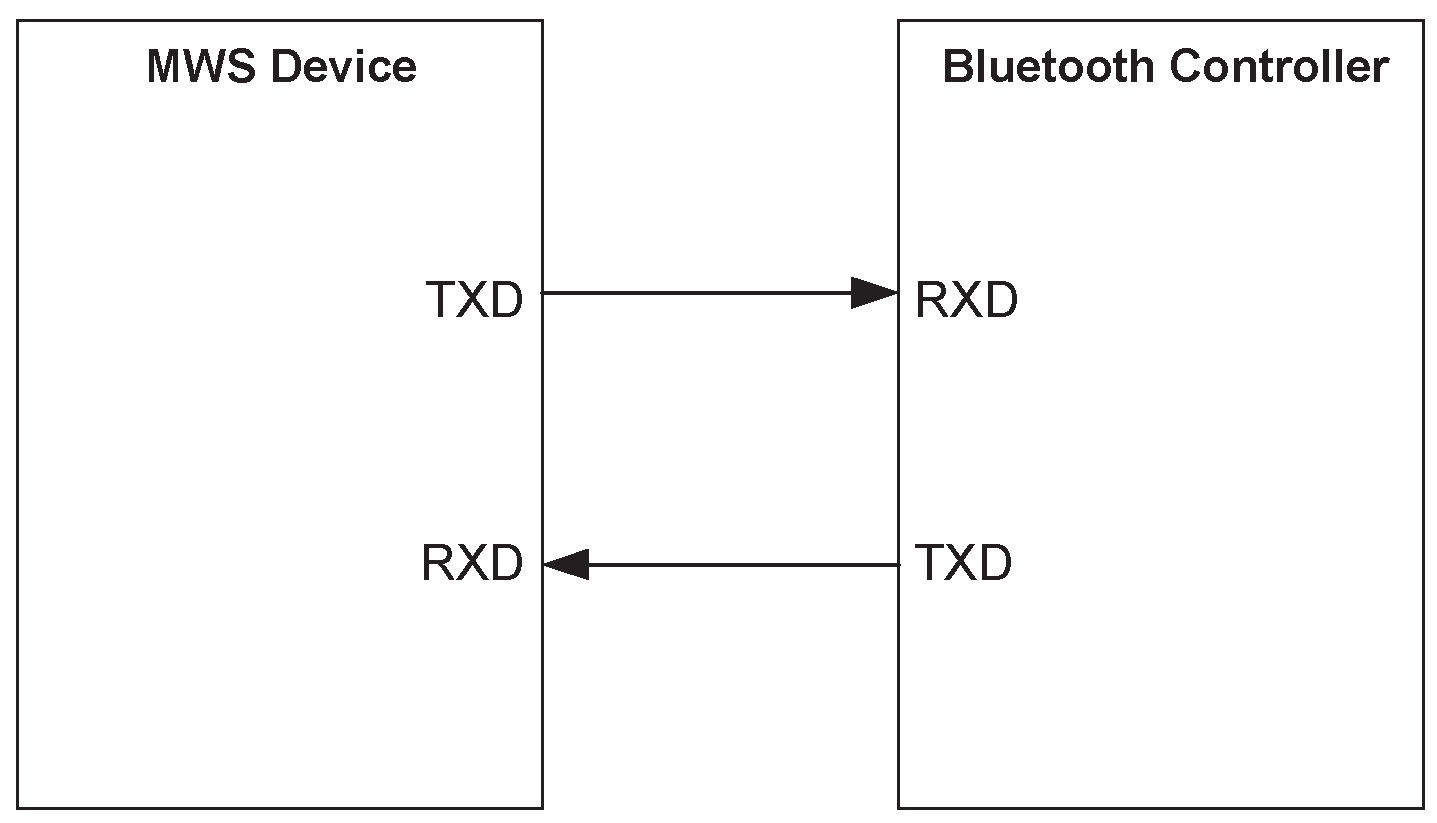
The WCI-2 Transport is based on a standard full duplex UART carrying logical signals framed as UART characters. Only the TXD and RXD UART signals are used. The interface supports multiple logical channels.
The messaging is based on a standard UART format.

The UART signals shall be connected in a null-modem fashion; i.e. the local TXD shall be connected to the remote RXD and vice versa.
3. Transport layer
The transport layer defines the mapping of the logical signals (see [Vol 7] Part A) onto the physical transport channel.
The 8 bit UART character is divided into two portions with three bits for the message type indicator and five bits for the message body. The bit with index 0 is the LSB and shall be transmitted first.
b0 | b1 | b2 | b3 | b4 | b5 | b6 | b7 |
|---|---|---|---|---|---|---|---|
Type[0] | Type[1] | Type[2] | MSG[0] | MSG[1] | MSG[2] | MSG[3] | MSG[4] |
3.1. Message types
This section describes the message formats for the logical coexistence signals. The message types are listed in Table 3.2.
Message Type Indicator | Direction | Message Type |
|---|---|---|
0 | MWS ↔ Bluetooth | Real-time Signal message |
1 | MWS ↔ Bluetooth | Transport Control message |
2 | MWS ↔ Bluetooth | Transparent Data message |
3 | MWS → Bluetooth Bluetooth → MWS | MWS Inactivity Duration message RFU |
4 | MWS → Bluetooth Bluetooth → MWS | MWS Scan Frequency message RFU |
5 | MWS → Bluetooth Bluetooth → MWS | RFU RFU |
6 | Vendor-specific | |
7 | Vendor-specific | |
The logical coexistence signals are listed in Table 3.3.
Logical Signal Name | Description |
|---|---|
FRAME_SYNC | |
MWS_RX | |
BLUETOOTH_RX_PRI | |
BLUETOOTH_TX_ON | |
MWS_PATTERN | |
MWS_TX | |
802_TX_ON | |
802_RX_PRI | |
MWS_INACTIVITY_DURATION | |
MWS_SCAN_FREQUENCY |
3.1.1. Real-time Signal message (Type 0)
The Real-time Signal message is used to transport the real-time coexistence signals (see [Vol 7] Part A) over the WCI-2 transport.
The Real-time Signal message conveys all the real-time coexistence signals in one message. The time reference point for the Real-time Signal message is the end of MSG[4] (i.e. the transition to the Stop bit).
Two Real-time Signal messages are defined, one from the Bluetooth Controller to the MWS device and another from the MWS device to the Bluetooth Controller.
MSG[0] | MSG[1] | MSG[2] | MSG[3] | MSG[4] |
|---|---|---|---|---|
FRAME_SYNC | MWS_RX | MWS_TX | MWS_PATTERN[0] | MWS_PATTERN [1] |
MSG[0] | MSG[1] | MSG[2] | MSG[3] | MSG[4] |
|---|---|---|---|---|
BLUETOOTH_RX_PRI | BLUETOOTH_TX_ON | 802_RX_PRI | 802_TX_ON | RFU |
3.1.2. Transport Control message (Type 1)
The Transport Control message can request state information from the MWS device’s coexistence interface.
MSG[0] | MSG[1] | MSG[2] | MSG[3] | MSG[4] |
|---|---|---|---|---|
RESEND_REAL_TIME | RFU | RFU | RFU | RFU |
Signal Name | Description |
|---|---|
RESEND_REAL_TIME | This bit is set if a device wants to get a status update of the real-time coexistence signals. The signal is usually used after wake-up from sleep of the transport interface. If the receiving device’s transport interface is awake it shall send a Real-time message with the current status of the real-time coexistence signals within 4 UART character periods. If the signal is not received within 4 UART character periods the device is considered asleep. |
3.1.3. Transparent Data message (Type 2)
The Transparent Data message can be used to exchange non-time critical messages between the MWS device and the Bluetooth Controller. The interface does not guarantee the delivery of a message. Protocol and content of the message are vendor specific.
Each octet to be transmitted is split into two 4-bit parts, called "nibbles". The least significant nibble consists of bits 0 to 3 of the octet and shall be transmitted first. The most significant nibble consists of bits 4 to 7 of the octet and shall be transmitted after the least significant nibble.
A least significant nibble shall be discarded if the next nibble is a least significant nibble. A most significant nibble shall only be accepted if the preceding nibble was a least significant nibble.
MSG[0] | MSG[1] | MSG[2] | MSG[3] | MSG[4] |
|---|---|---|---|---|
NIBBLE_POSITION | DATA[0]/ DATA[4] | DATA[1]/ DATA[5] | DATA[2]/ DATA[6] | DATA[3]/ DATA[7] |
Signal Name | Description |
|---|---|
NIBBLE_POSITION | 0 – Least Significant Nibble 1 – Most Significant Nibble |
DATA[n]; n=0 .. 7 | Data bits of the message octet |
3.1.4. MWS Inactivity Duration message (Type 3)
The MWS Inactivity Duration message is used to send the MWS_INACTIVITY_DURATION signal from the MWS device to the Bluetooth Controller.
The message is sent at the beginning of the MWS inactivity period.
MSG[0] | MSG[1] | MSG[2] | MSG[3] | MSG[4] |
|---|---|---|---|---|
DURATION[0] | DURATION[1] | DURATION[2] | DURATION[3] | DURATION[4] |
The MWS Inactivity Duration is encoded in 5 bits. DURATION is unsigned.
When DURATION = 0, MWS_INACTIVITY_DURATION is cancelled.
When DURATION = 31, MWS_INACTIVITY_DURATION is infinite.
Otherwise, MWS_INACTIVITY_DURATION is given by the formula:
MWS_INACTIVITY_DURATION = DURATION * 5 ms
3.1.5. MWS Scan Frequency message (Type 4)
The MWS Scan Frequency message is used to send the MWS_SCAN_FREQUENCY signal from the MWS device to the Bluetooth Controller.
MSG[0] | MSG[1] | MSG[2] | MSG[3] | MSG[4] |
|---|---|---|---|---|
FREQ[0] | FREQ[1] | FREQ[2] | FREQ[3] | FREQ[4] |
The MWS Scan Frequency index is encoded in 5 bits. FREQ is unsigned.