Part C. Secure Digital (SD) Transport Layer
vAtlanta r00
This Part describes the SD transport layer (between the Host and Controller). HCI command, event and data packets flow through this layer, but the layer does not decode them. The Bluetooth SD transport layer is defined in a document owned and maintained by the Secure Digital Association. Information regarding that document is described herein.
1. Introduction
This document discusses the requirements of the Secure Digital (SD) interface for Bluetooth hardware. Readers should be familiar with SD, SD design issues, and the overall Bluetooth architecture. The reader should also be familiar with the Bluetooth Host Controller interface.
The SD Bluetooth Protocol is documented in the SDIO Card Type-A Specification for Bluetooth, which is owned and maintained by the Secure Digital Association (SDA). The full specification is available to members of the SDA that have signed all appropriate SD NDA and license requirements. The SDA also makes a Non-NDA version available, the Simplified Version of: SDIO Card Type-A Specification for Bluetooth. There are no changes to the SDA document to comply with the requirements of the Bluetooth SIG.
2. Goals
2.1. Hardware goals
The Bluetooth SD transport interface specification is designed to take advantage of both the SD Physical Transport bus and the packet orientation of the Bluetooth HCI protocol. Thus, all data is transferred in blocks as packets. Since the block size used on the SD bus may be smaller than the HCI packet, a segmentation and recombination protocol is defined.
SDIO [2] provides different data rate options, including different bit path widths and clock rates. Systems using SDIO should choose options that provide sufficient bandwidth to support the needs of the Controller, both for device control (HCI commands and events) and for data (ACL, SCO).
The specification supports an SDIO-connected Controller.
2.2. Software goals
The Bluetooth SD transport interface specification is designed for non-embedded solutions. It is assumed that the Host software does not necessarily have a priori knowledge of the SD Bluetooth device.
The interface is not designed for embedded applications where much of the information passed via the interface is known in advance.
The SDA also defines a Bluetooth interface for embedded applications where the Controller contains protocol layers above HCI (RFComm, SDP etc.). This specification is called SDIO Card Type-B Specification for Bluetooth. Information about this specification can be obtained from the SDA:
2.3. Configuration goals
The SDIO Card Specification [2] defines SDIO Standard Function Codes in Table 6-4:
- 0x2
This function supports the SDIO Type-A for Bluetooth standard interface
- 0x3
This function supports the SDIO Type-B for Bluetooth standard interface
The SDIO Card Type-A Specification for Bluetooth [3] specifies how to implement a Controller. Table 2.1 defines Service ID codes to route HCI messages (codes 0x01 to 0x05).
SDIO Type-A service ID | Controller |
|---|---|
0x00 | reserved for future use |
0x01 | HCI Command packet |
0x02 | ACL data |
0x03 | SCO data |
0x04 | HCI Event packet |
0x05 | HCI ISO Data packet |
All other values | Reserved as per [3] |
2.4. Configuration for multiple Controllers
An SDIO device may contain one or more Controllers as defined in [3]. These Controller functions shall conform to the requirements of [2] section 6.12.
3. Physical interface documents
This specification references the SD SDIO Card Type-A Specification for Bluetooth. This SDA document defines the Bluetooth HCI for all SD devices that support an HCI level interface. Any SD Bluetooth device claiming compliance with the SD Bluetooth Transport must support this interface and additionally adhere to its device type specification, which is set by the Secure Digital Association. The SDIO Card Type-A Specification for Bluetooth document is based on the SDIO Card Specification, which in turn is based on the SD Memory Card Specification: Part 1 Physical Layer Specification. All of these documents are copyrighted by the SDA and are available ONLY to SDA member companies that have signed the appropriate NDA documents with the SDA. As an introduction to the SD Bluetooth Type A specification, the SDA has created ‘Simplified’ versions of each of these documents. The simplified versions do not contain enough information to fully implement a device, however they do contain enough information to convey the structure and intent of the specifications.
Applicable SDA Documents available to members of the SDA:
SD Memory Card Specification: Part 1 Physical Layer Specification SDIO Card Specification SDIO Card Type-A Specification for Bluetooth.
Applicable Simplified SDA Documents available to non-members and members of the SDA:
Simplified Version of: SD Memory Card Specification: Part 1 Physical Layer Specification Simplified Version of: SDIO Card Specification: Simplified Version of: SDIO Card Type-A Specification for Bluetooth
More information on the Secure Digital Association and the SD specifications can be found at the SDA web site at https://www.sdcard.org.
4. Communication
4.1. Overview
Figure 4.1 below is a diagram of the communication interface between a Bluetooth SD device and the Bluetooth Host protocol stack. Modifications to this diagram might be needed for operating systems that do not support a miniport model:

Appendix A. Acronyms and Abbreviations
Acronym | Description |
|---|---|
HCI | Host Controller interface |
NDA | Non-Disclosure Agreement |
OS | Operating System |
SD | Secure Digital |
SDA | Secure Digital Association |
SDIO | Secure Digital Input/Output |
SDP | Service Discovery protocol |
SIG | Special Interest Group |
Appendix B. Related Documents
A) Applicable SDA Documents available to members of the SDA:
[1] A.1) SD Memory Card Specification: Part 1 Physical Layer Specification
[2] A.2) SDIO Card Specification
[3] A.3) SDIO Card Type-A Specification for Bluetooth
[4] A.4) SDIO Card Type-B Specification for Bluetooth
[5] A.5) SDIO Card Physical Test Specification
[6] A.5) SDIO Host Physical Test Specification
[7] A.6) SD Bluetooth Type A Test Specification
These documents are available to members of the SDA in the “Members Only” section of the SDA web site (https://members.sdcard.org/members). See https://www.sdcard.org/join/index.html for information on joining the SDA.
B) Applicable Simplified SDA Documents available to non-members and members of the SDA:
- B.1)
Simplified Version of: SD Memory Card Specification: Part 1 Physical Layer Specification https://www.sdcard.org/downloads/pls/
- B.2)
Simplified Version of: SDIO Card Specification https://www.sdcard.org/downloads/pls/
- B.3)
Simplified Version of: SDIO Card Type-A Specification for Bluetooth https://www.sdcard.org/downloads/pls/
Appendix C. Tests
The SDA has defined formal test procedures for SDIO Type A Bluetooth cards (Controller) and Hosts. It is expected that both Controllers and Hosts will comply with all test requirements set forth by the SDA in accordance with the rules of the SDA. The Bluetooth SIG does not require any formal testing to comply with SIG requirements. The test document names are listed in Appendix B.
C.1. Test suite structure
There are two types of tests defined for the HCI SD Transport Layer:
Functional Tests
Protocol Tests
Tests of both types are defined for both the Host and Controller.
The purpose of the functional tests is to verify that the SD Bluetooth Type A Specification, SDIO Standard and SD Physical Standard have been implemented according to the specifications. These tests and the test environment for these tests are defined in documents provided by the SDA.
The purpose of the protocol tests are to verify that the Bluetooth Controller SD implementation or the Host implementation are according to the SD Bluetooth Type A specification.
The test environment for the protocol tests consists of the tester and the Device Under Test (DUT) as illustrated in Figure C.1 below.
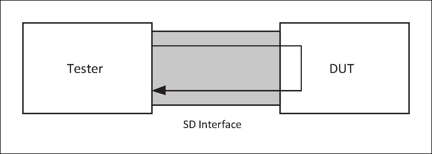
The tester is typically a PC with an SD interface. The DUT is placed into local loopback mode and standard HCI commands are used to drive the tests. The test results are verified in the tester.