Part D. Three-wire UART Transport Layer
vAtlanta r00
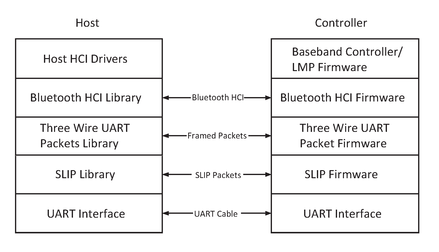
This Part describes the Three-Wire UART transport layer (between the Host and Controller). HCI command, event, and data packets flow through this layer, but the layer does not decode them.
1. General
The HCI Three-Wire UART Transport Layer makes it possible to use the Bluetooth HCI over a serial interface between two UARTs. The HCI Three-Wire UART Transport Layer assumes that the UART communication may have bit errors, overrun errors or burst errors. See also Part A, UART Transport Layer.
2. Overview
The HCI Three-Wire UART Transport Layer is a connection based protocol that transports HCI commands, events, ACL and Synchronous packets between the Host and the Controller. Packet construction is in done in two steps. First, it adds a packet header onto the front of every HCI packet which describes the payload. Second, it frames the packets using a SLIP protocol. Finally, it sends this packet over the UART interface.
The SLIP layer converts an unreliable octet stream into an unreliable packet stream. The SLIP layer places start and end octets around the packet. It then changes all occurrences of the frame start or end octet in the packet to an escaped version.
The packet header describes the contents of the packet, and if this packet needs to be reliably transferred, a way of identifying the packet uniquely, allowing for retransmission of erroneous packets.
3. Slip layer
The SLIP layer places packet framing octets around each packet being transmitted over the Three-Wire UART Transport Layer. This delimits the packets and allows packet boundaries to be detected if the receiver loses synchronization. The SLIP layer is based upon the RFC 1055 Standard [1].
3.1. Encoding a packet
The SLIP layer performs octet stuffing on the octets entering the layer so that specific octet codes which may occur in the original data do not occur in the resultant stream.
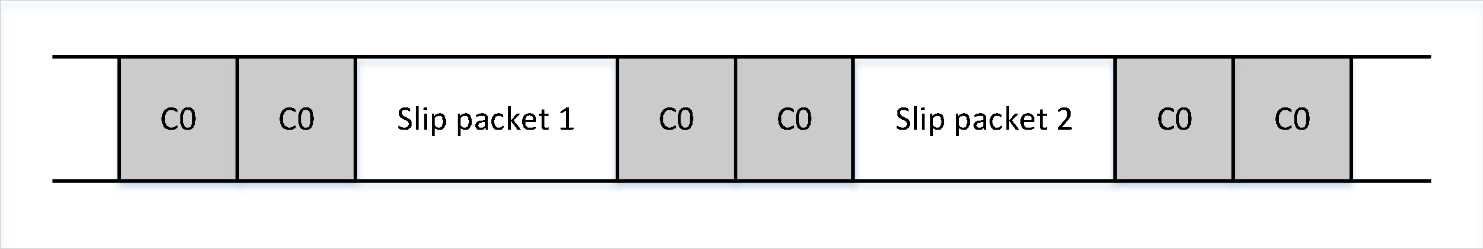
The SLIP layer places octet 0xC0 at the start and end of every packet it transmits. Any occurrence of 0xC0 in the original packet is changed to the sequence 0xDB 0xDC before being transmitted. Any occurrence of 0xDB in the original packet is changed to the sequence 0xDB 0xDD before being transmitted. These sequences, 0xDB 0xDC and 0xDB 0xDD are SLIP escape sequences. All SLIP escape sequences start with 0xDB. All SLIP escape sequences are listed in Table 3.1.
3.2. Decoding a packet
When decoding a SLIP stream, a device will first be in an unknown state, not knowing if it is at the start of a packet or in the middle of a packet. The device shall therefore discard all octets until it finds a 0xC0. If the 0xC0 is followed immediately by a second 0xC0, then the device will discard the first 0xC0 as it was presumably the end of the last packet, and the second 0xC0 was the start of the next packet. The device shall then be in the decoding packet state. It can then decode the octets directly changing any SLIP escape sequences back into their unencoded form. When the device decodes the 0xC0 at the end of the packet, it will calculate the length of the SLIP packet, and pass the packet data into the packet decoder. The device will then seek the next packet. If the device does not receive an 0xC0 for the start of the next packet, then all octets up to and including the next 0xC0 will be discarded.
SLIP Escape Sequence | Unencoded form | Notes |
|---|---|---|
0xDB 0xDC | 0xC0 | |
0xDB 0xDD | 0xDB | |
0xDB 0xDE | 0x11 | Only valid when OOF Software Flow Control is enabled |
0xDB 0xDF | 0x13 | Only valid when OOF Software Flow Control is enabled |
4. Packet header
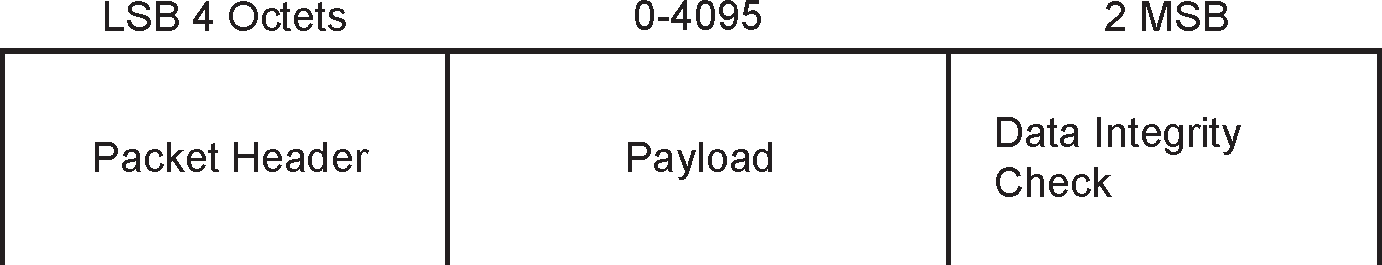
Every packet that is sent over the Three-Wire UART Transport Layer has a packet header. It also has an optional Data Integrity Check at the end of the payload. The Transport Layer does not support packet segmentation and reassembly. Each transport packet will contain at most one higher layer packet.
A packet consists of a Packet Header of 4 octets, a Payload of 0 to 4095 octets, and an optional Data Integrity Check of 2 octets. See Figure 4.1.
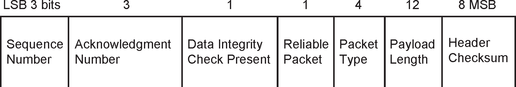
The packet header consists of a Sequence Number of 3 bits, an Acknowledge Number of 3 bits, a Data Integrity Check Present bit, a Reliable Packet bit, a Packet Type of 4 bits, a Payload Length of 12 bits and an 8 bit Header Checksum. See Figure 4.2.
4.1. Sequence Number
For unreliable packets this field shall be set to 0 on transmit and ignored on receive.
Each new reliable packet shall be assigned a sequence number which is equal to the sequence number of the previous reliable packet plus one mod eight. A packet shall use the same sequence number each time it is retransmitted.
4.2. Acknowledge Number
The acknowledge number shall be set to the sequence number of the next reliable packet this device expects to receive. See Section 6.4.
4.3. Data Integrity Check Present
If a 16 bit CCITT-CRC Data Integrity Check is appended to the end of the payload, this bit shall be set to 1.
4.4. Reliable Packet
If this bit it set to 1, then this packet is reliable. This means that the sequence number field is valid, and the receiving end shall acknowledge its receipt. If this bit is set to 0, then this packet is unreliable.
4.5. Packet Type
There are five kinds of HCI packets that can be sent via the Three-Wire UART Transport Layer; these are HCI Command packet, HCI Event packet, HCI ACL Data packet, HCI Synchronous Data packet, and HCI ISO Data packet (see [Vol 4] Part E, Section 5.4). HCI Command packets can be sent only to the Controller, HCI Event packets can be sent only from the Controller, and HCI ACL/Synchronous/ISO Data packets can be sent both to and from the Controller.
HCI packet coding does not provide the ability to differentiate the five HCI packet types. Therefore, the Packet Type field is used to distinguish the different packets. The acceptable values for this Packet Type field are given in Table 4.1.
HCI Packet Type | Packet Type |
|---|---|
Acknowledgment packets | 0 |
HCI Command packet | 1 |
HCI ACL Data packet | 2 |
HCI Synchronous Data packet | 3 |
HCI Event packet | 4 |
HCI ISO Data packet | 5 |
Vendor Specific | 14 |
Link Control packet | 15 |
Reserved for future use | All other values |
HCI Command packets, HCI ACL Data packets, HCI Event packets, and HCI ISO Data packets are always sent as reliable packets. HCI Synchronous Data packets are sent as unreliable packets unless HCI Synchronous Flow Control is enabled, in which case they are sent as reliable packets.
In addition to the five HCI packet types, other packet types are defined. One packet type is defined for pure Acknowledgment packets, and one additional packet type is to support link control. One packet type is made available to vendors for their own use. All other Three-Wire UART Packet Types are reserved for future use.
4.6. Payload Length
The payload length is the number of octets in the payload data. This does not include the length of the packet header, or the length of the optional data integrity check.
4.7. Packet Header Checksum
The packet header checksum validates the contents of the packet header against corruption. This is calculated by setting the Packet Header Checksum to a value such that the two's-complement sum mod 256 of the four octets of the Packet Header including the Packet Header Checksum is 0xFF.
5. Data Integrity Check
The Data Integrity Check field is optional. It can be used to ensure that the packet is valid. The Data Integrity Check field is appended onto the end of the packet. Each octet of the Packet Header and Packet Payload is used to compute the Data Integrity Check.
5.1. 16-bit CCITT-CRC
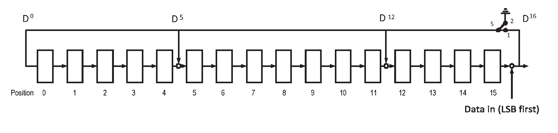
The CRC is defined using the CRC-CCITT generator polynomial
g(D) = D16 + D12 + D5 + 1
(see Figure 5.1)
The CRC shift register is filled with 1s before calculating the CRC for each packet. Octets are fed through the CRC generator least significant bit first.
The most significant parity octet is transmitted first (where the CRC shift register is viewed as shifting from the least significant bit towards the most significant bit). Therefore, the transmission order of the parity octets within the CRC shift register is as follows:
x[8] (first), x[9],..., x[15], x[0], x[1],..., x[7] (last)
where x[15] corresponds to the highest power CRC coefficient and x[0] corresponds to the lowest power coefficient.
The switch S shall be set in position 1 while the data is shifted in. After the last bit has entered the LFSR, the switch shall be set in position 2, and the registers contents shall be read out for transmission.
6. Reliable packets
To allow the reliable transmission of packets through the transport, a method needs to be defined to recover from packet errors. The Host or Controller can detect a number of different errors in the packet.
6.1. Header Checksum error
The header of the packet is protected by a Packet Header Checksum. If the two's-complement sum mod 256 of the four octets of the header is not 0xFF, then the packet has an unrecoverable error and all information contained in the packet shall be discarded.
6.2. Slip Payload Length error
The length of the SLIP packet shall be checked against the Packet Payload Length. If the Data Integrity Check Present bit is set to 1, then the SLIP packet length should be 6 + Packet Payload Length. If the Data Integrity Check Present bit is set to 0, then the SLIP packet length should be 4 + Packet Payload Length. If this check fails, then all information contained in the packet shall be discarded. The SLIP packet length is the length of the data received from the SLIP layer after the SLIP framing, and SLIP escape codes have been processed.
6.3. Data Integrity Check error
The packet may have a Data Integrity Check at the end of the payload. This is controlled by the Data Integrity Check Present bit in the header. If this is set to 1, then the Data Integrity Check at the end of the payload is checked. If this is different from the value expected, then the packet shall be discarded. If the link is configured to not use data integrity checks, and a packet is received with the Data Integrity Check Present bit set to 1, then the packet shall be discarded.
6.4. Out Of Sequence Packet error
Each device keeps track of the sequence number it expects to receive next. This will be one more than the sequence number of the last successfully received reliable packet, mod eight. If a reliable packet is received which has the expected sequence number, then this packet shall be accepted.
If a reliable packet is received which does not have the expected sequence number, then the packet shall be discarded.
6.5. Acknowledgment
Whenever a reliable packet is received, an acknowledgment shall be generated.
If a packet is available to be sent, the Acknowledgment Number of that packet shall be updated to the latest expected sequence number.
If a requirement to send an acknowledgment value is pending, but there are no other packets available to be sent, the device may send a pure Acknowledgment packet. This is an Unreliable packet, with the Packet Type set to 0, Payload Length set to 0, and the Sequence Number set to 0.
The maximum number of reliable packets that can be sent without acknowledgment defines the sliding window size of the link. This is configured during link establishment. See Sections 8.6, 8.7 and 8.8.
6.6. Resending packets
A Reliable packet shall be resent until it is acknowledged. Devices should refrain from resending packets too quickly to avoid saturating the link with retransmits. See Section 12.1.2.
6.7. Example reliable packet flow
Figure 6.1 shows the transmission of reliable packets between two devices. Device A sends a packet with a Sequence Number of 6, and an Acknowledgment Number of 3. Device B receives this packet correctly, so needs to generate an acknowledgment. Device B then sends a packet with Sequence Number 3 with its Acknowledgment Number set to the next expected packet Sequence Number from Device A of 7.
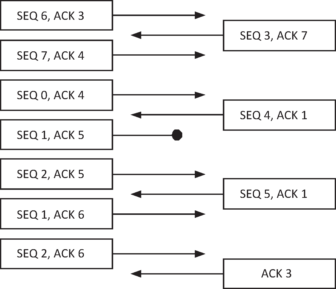
Device A receives a packet with Sequence Number 3 and an Acknowledgment Number of 7. Device A was expecting this sequence number so needs to generate an acknowledgment. The Acknowledgment Number of 7 is one greater than the last Sequence Number that was sent, meaning that this packet was received correctly (see Section 6.6).
Device A sends two packets, Sequence Numbers 7 and 0. Both packets have the Acknowledgment Number of 4, the next sequence number it expects from Device B. Device B receives the first correctly, and increments its next expected sequence number to 0. It then receives the second packet correctly, and increments the next expected sequence number to 1.
Device B sends a packet with Sequence Number 4, and the Acknowledgment Number of 1. This will acknowledge both of the previous two packets sent by Device A.
Device A now sends two more packets, Sequence Numbers 1 and 2. Unfortunately, the first packet is corrupted. Device B receives the first packet, and discovers the error, so discards this packet (see Section 6.1, Section 6.2 or Section 6.3). It generates an acknowledgment of this erroneously received reliable packet. Device B then receives the second packet. This is received out of sequence, as it is currently expecting Sequence Number 1, but has received Sequence Number 2 (see Section 6.4). Again, it generates an acknowledgment.
Device B sends another packet with Sequence Number 5. It is still expecting a packet with Sequence Number 1 next, so the Acknowledgment Number is set to 1. Device A receives this, and accepts this packet.
Device A has not had either of its last two packets acknowledged, so it resends them (see Section 6.6) and updates the Acknowledgment Number of the original packets that were sent (see Section 6.5). The Sequence Numbers of these packets stay the same (see Section 4.1).
Device B receives these packets correctly, and schedules the sending of an acknowledgment. Because Device B doesn’t have any data packets that need to be sent, it sends a pure Acknowledgment packet (see Section 6.5).
7. Unreliable packets
To allow the transmission of unreliable packets through the transport, the following method shall be used.
7.1. Unreliable packet header
An unreliable packet header always has the Reliable Packet bit set to 0. The sequence number shall be set to 0. The Data Integrity Check Present, Acknowledgment Number, Packet Type, Payload Length and Packet Header Checksum shall all be set the same as a Reliable packet.
7.2. Unreliable packet error
If a packet that is marked as unreliable and the packet has an error, then the packet shall be discarded.
8. Link Establishment
Before any packets except Link Control packets can be sent, the Link Establishment procedure shall be performed. This ensures that the sequence numbers are initialized correctly and that the two sides are using the same baud rate, allows detection of peer reset, and allows the device to be configured.
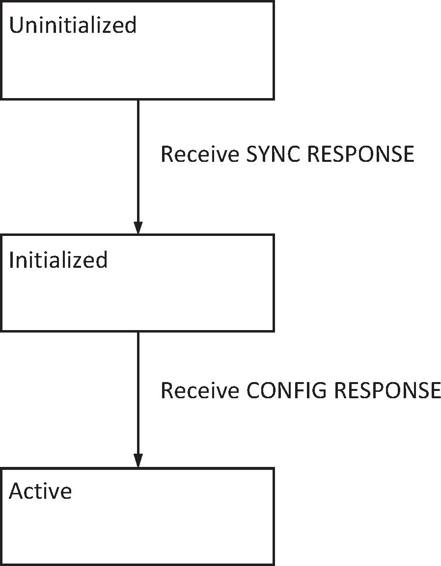
Link Establishment is defined by a state machine with three states: Uninitialized, Initialized and Active. When the transport is first started, the link is in the Uninitialized State. There are four messages that are defined: SYNC, SYNC RESPONSE, CONFIG and CONFIG RESPONSE. All four link establishment messages shall be sent with the Data Integrity Present flag set to 0.
8.1. Uninitialized state
In the Uninitialized State a device periodically[1] sends SYNC messages. If a SYNC message is received, the device shall respond with a SYNC RESPONSE message. If a SYNC RESPONSE message is received, the device shall move to the Initialized State. In the Uninitialized State only SYNC and SYNC RESPONSE messages are valid, all other messages that are received shall be discarded. If an invalid packet is received, the device shall respond with a SYNC message. The device shall not send any acknowledgment packets in the Uninitialized State[2].
In the Uninitialized State the Controller may wait until it receives a SYNC message before sending its first SYNC message. This allows the Host to control when the Controller starts to send data.
The SYNC message can be used for automatic baud rate detection. It is assumed that the Controller shall stay on a single baud rate, while the Host could hunt for the baud rate. Upon receipt of a SYNC RESPONSE message, the Host can assume that the correct baud rate has been detected.
8.2. Initialized state
In the Initialized State a device periodically sends CONFIG messages. If a SYNC message is received, the device shall respond with a SYNC RESPONSE message. If a CONFIG message is received, the device shall respond with a CONFIG RESPONSE message. If a CONFIG RESPONSE message is received, the device will move to the Active State. All other messages that are received shall be ignored.
8.3. Active state
In the Active State, a device can transfer higher layer packets through the transport. If a CONFIG message is received, the device shall respond with a CONFIG RESPONSE message. If a CONFIG RESONSE message is received, the device shall discard this message.
If a SYNC message is received while in the Active State, it is assumed that the peer device has reset. The local device should therefore perform a full reset of the upper stack, and start Link Establishment again at the Uninitialized State.
Upon entering the Active State, the first packet sent shall have its SEQ and ACK numbers set to zero.
8.4. Sync message
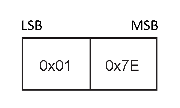
The SYNC message is an unreliable message sent with the Packet Type of 15 and a Payload Length of 2.
The payload is composed of the octet pattern 0x01 0x7E[3].
 |
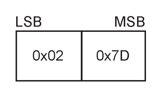
8.5. Sync Response message
The SYNC RESPONSE message is an unreliable message sent with the Packet Type of 15 and a Payload Length of 2. The payload is composed of the octet pattern 0x02 0x7D.
 |
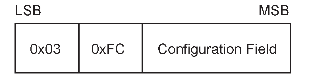
8.6. Config message
The CONFIG message is an unreliable message sent with the Packet Type of 15 and a Payload Length of 2 plus the size of the Configuration Field. The payload is composed of the octet pattern 0x03 0xFC and the Configuration Field.
 |
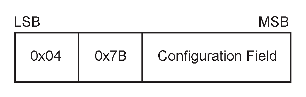
8.7. Config Response message
The CONFIG RESPONSE message is an unreliable message sent with the Packet Type of 15 and a Payload Length of 2 plus the size of the Configuration Field. The payload is composed of the octet pattern 0x04 0x7B and the Configuration Field.
 |
8.8. Configuration Field
The Configuration Field contains the Version Number, Sliding Window Size, the Data Integrity Check Type, and if Out Of Frame (OOF) Software Flow Control is allowed. The format of this field is specified in Figure 8.6.
The Configuration Field in a CONFIG message sent by the Host determines what the Host can transmit and accept. The Configuration Field in a CONFIG RESPONSE message sent by the Controller determines what the Host and Controller shall transmit and can expect to receive.
The Controller sends CONFIG messages without a Configuration Field. The Host sends CONFIG RESPONSE messages without a Configuration Field.

To allow for future extension of the Configuration Field, the size of the message determines the number of significant Configuration Octets in the payload. Future versions of the specification may use extra octets. Any bits that are not included in the message shall be set to 0. Any bits that are not defined are reserved for future use.
A device shall not change the values if sends in the Configuration Field during Link Establishment.
8.8.1. Configuration messages
The CONFIG – CONFIG RESPONSE message sequence configures the link in both directions. Until a CONFIG RESPONSE message is received only unreliable Link Establishment messages may be sent. Once CONFIG RESPONSE message has been received all other packet types may be sent, and received messages passed up to the Host.
The CONFIG and CONFIG RESPONSE messages contain a set of options for both devices on the link. The Host sends a CONFIG message with the set of options that the Host would like to use. The Controller responds with a CONFIG RESPONSE message with the set of options that the Host and the Controller will use. This means that the Controller is in full control of the set of options that will be used for all messages sent by both the Host and Controller.
8.8.2. Sliding window size
This is the maximum number of reliable packets a sender of the CONFIG message can send without requiring an acknowledgment. The value of this field shall be in the range one to seven. The value in the CONFIG RESPONSE message shall be less than or equal to the value in the CONFIG message. For example, the Host may suggest a window size of five in its CONFIG message and the Controller may respond with a value of three in its CONFIG RESPONSE message, but not six or seven. Both devices will then use a maximum sliding window size of three.
8.8.3. Level of Data Integrity Check
The CONFIG message contains a bit field describing the types of Data Integrity Checks the sender is prepared to transmit. The peer will select the one it is prepared to use and send its choice in the CONFIG RESPONSE message.
If data integrity checks are not required, then the Data Integrity Check Present bit shall be set to 0 by the Host and Controller.
Level of Data Integrity | Parameter Description for CONFIG Message |
|---|---|
0 | No Data Integrity Check is supported. |
1 | 16 bit CCITT-CRC may be used. |
Level of Data Integrity | Parameter Description for CONFIG RESPONSE Message |
|---|---|
0 | No Data Integrity Check is used. |
1 | 16 bit CCITT-CRC may be used. |
8.8.4. Out of Frame Software Flow Control
By default, the transport uses no flow control except that mandated by the HCI Functional Specification and the flow control achieved by not acknowledging reliable Host messages. If Software Flow Control is to be used, this needs to be negotiated.
The CONFIG message specifies whether the sender of the CONFIG message is prepared to receive Out of Frame Software Flow Control messages. The CONFIG RESPONSE message specifies whether the peer can send Out of Frame Software Flow Control messages. The CONFIG RESPONSE message may have the field set to 1 only if the CONFIG message had it set to 1. (See Section 10.1)
8.8.5. Version Number
The Version Number of this protocol shall determine which facilities are available to be used.
The CONFIG message specifies the Version Number supported by the Host. The CONFIG RESPONSE message specifies the Version Number that shall be used by the Host and Controller when sent by the Controller. The value in the CONFIG RESPONSE message shall be less than or equal to the value in the CONFIG message. The Version Numbers are enumerated in Table 8.3. This specification defines version 1.0 (Version Number = 0).
Version Number | Parameter Description for CONFIG and CONFIG RESPONSE Message |
|---|---|
0 | Version 1.0 of this Protocol |
All other values | Reserved for future use |
9. Low power
After a device is in the Active State, either side of the transport link may wish to enter a low power state. Because recovery from a loss of synchronization is possible, it is allowable to stop listening for incoming packets at any time.
To make the system more responsive after a device has entered a low power state, a system of messages is employed to allow either side to notify the other that they are entering a low power state and to wake a device from that state. These messages are sent as Link Control packets. It is optional for a device to support the Sleep message. The Wakeup and Woken messages are mandatory.
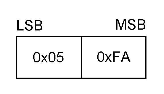
9.1. Wakeup message
The Wakeup message shall be the first message sent whenever the device believes that the other side is asleep. The device shall then repeatedly send the Wakeup message until the Woken message is received. There shall be at least a one character gap between the sending of each Wakeup message to allow the UART to resynchronize. The Wakeup message is an unreliable message sent with a Packet Type of 15, and a Payload Length of 2. The payload is composed of the octet pattern 0x05 0xFA. The Wakeup message shall be used after a device has sent a Sleep message. It is mandatory to respond to the Wakeup message.
 |
9.2. Woken message
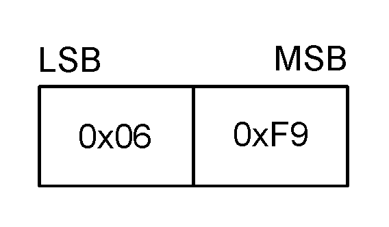
The Woken message shall be sent whenever a Wakeup message is received even if the receiver is currently not asleep. Upon receiving a Woken message, a device can determine that the other device is not in a low power state and can send and receive data. The Woken message is an unreliable message sent with a Packet Type of 15, and a Payload Length of 2. The payload is composed of the octet pattern 0x06 0xF9.
 |
9.3. Sleep message
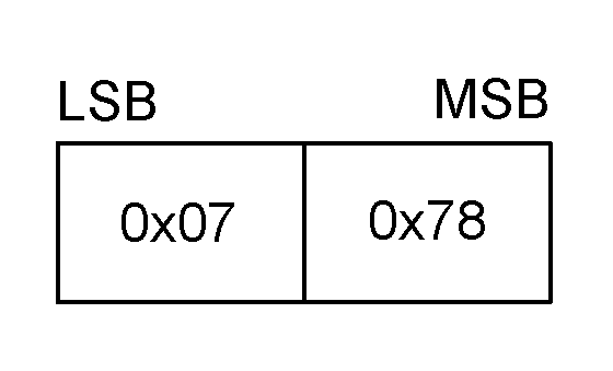
A Sleep message can be sent at any time after Link Establishment has finished. It notifies the other side that this device is going into a low power state, and that it may also go to sleep. If a device sends a Sleep message it shall use the Wakeup / Woken message sequence before sending any data. If a device receives a Sleep message, then it should use the Wakeup / Woken message sequence before sending any data. The Sleep message is an unreliable message sent with a Packet Type of 15, and a Payload Length of 2. The payload is composed of the octet pattern 0x07 0x78.
The sending of this message is optional. The receiver of this message need not go to sleep, but cooperating devices may be able to schedule sleeping more effectively with this message.
 |
10. Out of Frame Control
It is possible to embed information in the SLIP data stream after a SLIP ESCAPE character that can allow for Software Flow Control. This feature is optional and may be negotiated in the Link Establishment configuration messages.
10.1. Software Flow Control
If Software Flow Control is enabled, then the standard XON / XOFF (0x11 and 0x13) characters will control the flow of data over the transport. To allow the XON / XOFF characters to be sent in the payload, they shall be escaped as follows: 0x11 shall be changed to 0xDB 0xDE, 0x13 shall be changed to 0xDB DF. This means that the XON / XOFF characters in the data stream are used only by software flow control.
If Software Flow Control is disabled, then the SLIP escape sequences 0xDB 0xDE and 0xDB 0xDF are undefined. In this case, the original octets of 0x11 and 0x13 shall not be changed. Flow control should always be provided by the tunneled protocols, e.g. HCI Flow Control. Flow control is still available using the standard Sequence Number / Acknowledge Number. This can be done by not acknowledging packets until traffic can resume.
11. Hardware configuration
The HCI Three-Wire UART Transport uses the following configurations.
11.1. Wires
There are three wires used by the HCI Three-Wire UART Transport. These are Transmit, Receive, and Ground.
11.1.1. Transmit & receive
The transmit line from one device shall be connected to the receive line of the other device.
11.1.2. Ground
A common ground reference shall be used.
11.2. Hardware flow
Hardware flow control may be used. The signaling shall be the same as a standard RS232 flow control lines. If used, the signals shall be connected in a null-modem fashion; for example, the local RTS shall be connected to the remote CTS and vice versa.
11.2.1. RTS & CTS
Request to Send indicates to the remote side that the local device is able to accept more data.
Clear to Send indicates if the remote side is able to receive data.
12. Recommended parameters
12.1. Timing parameters
Because this transport protocol can be used with a wide variety of baud rates, it is not possible to specify a single timing value. However, it is possible to specify the time based on the baud rate in use. If Tmax is defined as the maximum time in seconds it will take to transmit the largest packet over this transport, Tmax can be expressed as:
Tmax = maximum size of a packet in bits / baud rate
The maximum size of a packet in bits is either the number of bits in a 4095 octet packet (32,760) or less if required in an embedded system or as determined by the Host or Controller[4]. Thus, at a baud rate of 921,600 and the maximum packet size of 4095 octets, Tmax is: (4095*10) / 921,600 = 44.434 ms.
12.1.1. Acknowledgment of packets
It is not necessary to acknowledge every packet with a pure acknowledgment packet if there is a data packet that will be sent soon. The recommended maximum time before starting to send an acknowledgment is 2 * Tmax.
12.1.2. Resending reliable packets
A reliable packet shall be resent until it is acknowledged. The recommended time between starting to send the same packet is 3 * Tmax.
13. References
[1] IETF RFC 1055: A nonstandard for transmission of IP datagrams over serial lines: SLIP – http://www.ietf.org/rfc/rfc1055.txt
[2] ITU Recommendation V.24: List of definitions for interchange circuits between data terminal equipment (DTE) and data circuit-terminating equipment (DCE) – http://www.itu.int/rec/recommendation.asp
[3] ITU Recommendation V.28: Electrical characteristics for unbalanced double-current interchange circuits – http://www.itu.int/rec/recommendation.asp
[1] During link establishment, various messages are sent periodically. It is suggested to send 4 messages per second.
[2] Any packet that was erroneous would normally be acknowledged, as the recipient does not know if the packet was a reliable packet or not. The recipient cannot do this in the Uninitialized State, as it is possible to receive corrupt data while in the Uninitialized state.
[3] The second octet for all Link Control packets equals the least significant 7 bits of the first octet, inverted, with the most significant bit set to ensure even parity.
[4] This can be determined using the HCI_Read_Buffer_Size command.