Part B. USB Transport Layer
vAtlanta r00
This Part describes the USB transport layer (between a Host and the Controller). HCI commands flow through this layer, but the layer does not decode the commands.
1. Overview
This document discusses the requirements of the Universal Serial Bus (USB) interface for Bluetooth hardware. Readers should be familiar with USB, USB design issues, Advanced Configuration Power Interface (ACPI), the overall Bluetooth architecture, and the basics of the radio interface.
The reader should also be familiar with the Bluetooth Host Controller interface.
Referring to Figure 1.1, notice that this document discusses the implementation details of the two-way arrow labeled “USB Function.”
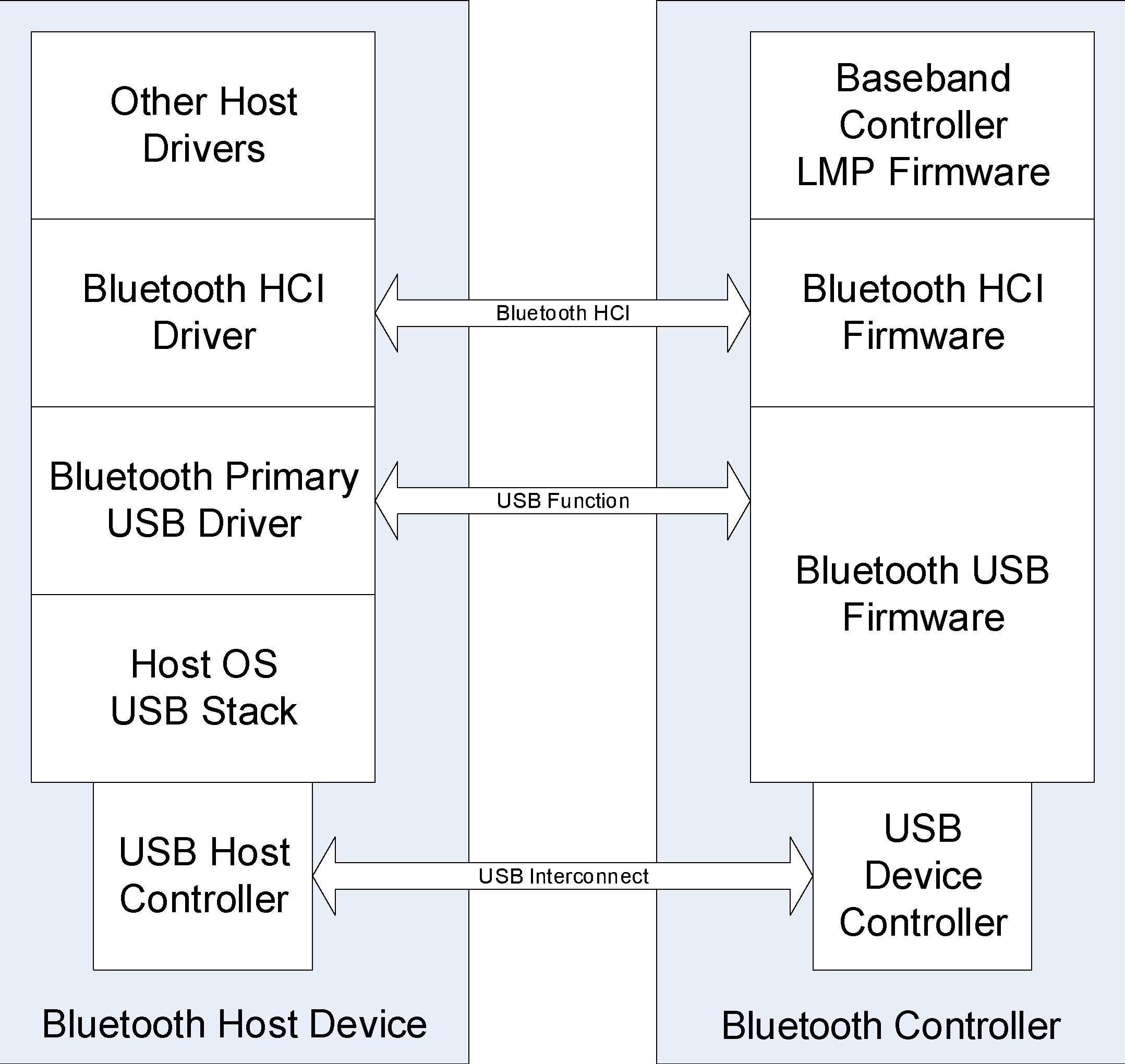
The USB hardware can be embodied in one of several ways:
As a USB dongle (e.g. cabled USB)
As a USB module integrated into the product and connected internally via a cable or connector
Integrated onto the motherboard of a notebook PC or other device and connected via circuit board traces with standard USB, Inter-Chip USB or High Speed Inter-Chip USB
Integrated as a subsystem on a single-chip System-on-Chip (SoC) design connected on-chip as part of a compound device.
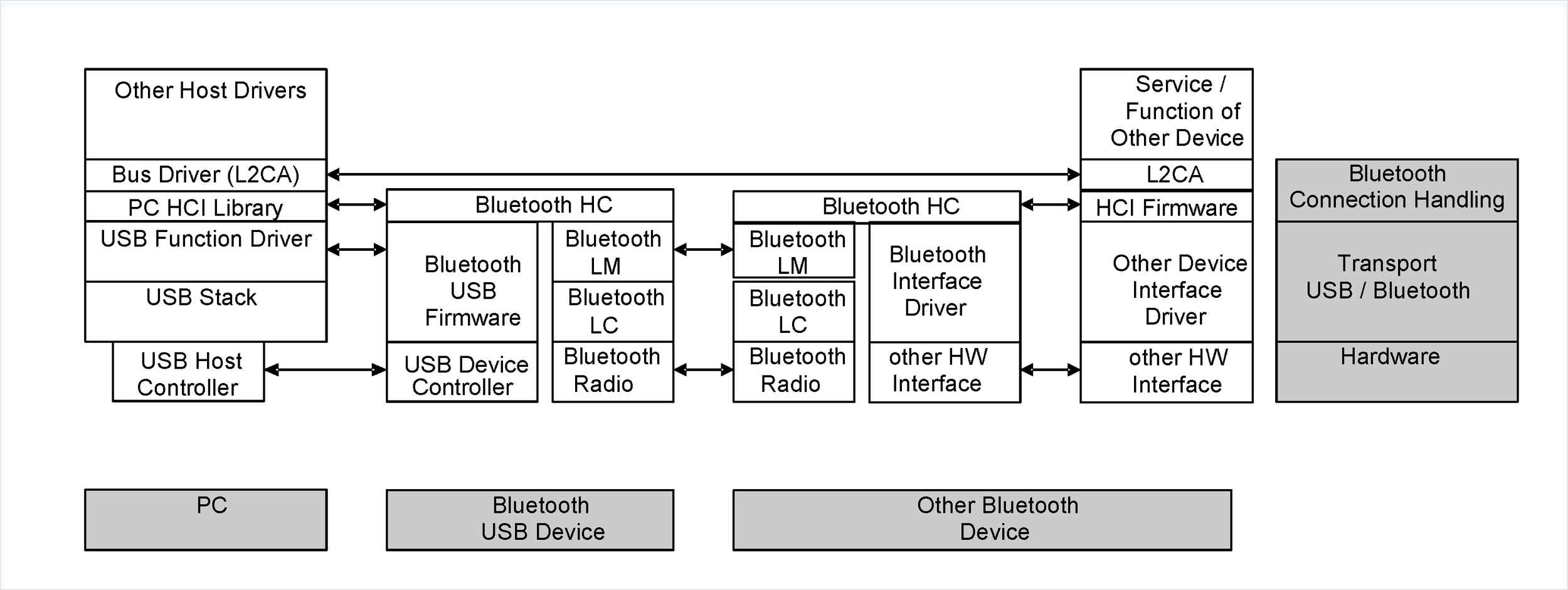
Finally, for an overview of the connection that is established between two Bluetooth devices, reference Figure 1.2.
2. USB endpoint expectations
This section outlines specific USB endpoints that are required in order to function properly with the Host. This section assumes a basic familiarity with USB. The endpoint numbers (labeled ‘Suggested Endpoint Address’ below) may be dynamically recognized upon driver initialization – this depends on the implementation.
2.1. Descriptor overview
The Universal Serial Bus is intended for high data rates. USB defines several physical layers, ranging from 1.5 Mb/s to several Gb/s of bus bandwidth. A Bluetooth USB device should provide a USB transport with sufficient bus bandwidth to support the Bluetooth radio transports included in the device.
2.1.1. Controller descriptors
The Controller configuration consists of two interfaces. The first interface has no alternate settings and contains the bulk and interrupt endpoints. The second interface provides scalable isochronous bandwidth. The recommended configuration for the second interface has four alternate settings that provide different bandwidth. The default interface is empty so that the device is capable of scaling down to zero isochronous bandwidth.
An HCI packet consisting of an HCI header and HCI data shall be contained in one USB Transfer. A USB transfer is defined by the USB specification as one or more USB transactions that contain the data from one IO request. For example, an ACL data packet containing 256 bytes (both HCI header and HCI data) would be sent over the bulk endpoint in one IO request. That IO request will require four 64-byte full speed USB Transactions or a single 256-byte High-speed USB Transaction, and forms a Transfer. If the Maximum Packet Size for the endpoint on which the transfer is sent is 64 bytes, then that IO request will require four 64-byte USB transactions.
The endpoints are spread across two interfaces so that when adjusting isochronous bandwidth consumption (via select interface calls), any pending bulk and/or interrupt transactions do not have to be terminated or resubmitted.
Table 2.1 and the following example calculations illustrate recommended endpoint descriptor parameter values and how they are derived. The maximum packet sizes for control endpoints, interrupt endpoints and bulk endpoints may be any value allowed by the relevant USB core specifications. The maximum packet size for isochronous endpoints must be large enough to accommodate the maximum average traffic; they may be set to accommodate the largest HCI transfer, subject to the capabilities of the Controller. In Table 2.1, the service interval is assumed to be 1 millisecond, for USB Full Speed (FS) frames.
Examples:
For a single 8 kHz audio channel with of 64 kb/s CVSD audio the Host may break HCI data into one USB transfers for each USB frame (e.g. 1 ms); in that case, the max packet size must be at least 11 = 3 octet HCI header + 8 octets of data. To reduce HCI header overhead, a common strategy (see Table 2.2) is to consolidate 3 ms of data into a 27 octet HCI packet of 24 octets of data + 3 octets of HCI header. These HCI packets can be exchanged as a single USB transfer on 3 ms intervals; this requires a max packet size of 27/3 = 9 octets per 1 millisecond USB Full Speed Frame.
For two 8 kHz audio channels of 64 kb/s CVSD audio the Host may double the payload size of each HCI packet, which would be 3 octets HCI header + 48 octets of data = 51 octets. Posting these at 3 ms intervals requires 51/3 = 17 octets of maximum packet size.
For one 16 kHz audio channel the HCI packets need to be large enough to accommodate single octet (128 kb/s) or 2-octet (256 kb/s) encoding. On 3 ms intervals, these would have to be (48+3)/3 = 17 octets or (96+3)/3 = 33 octets respectively.
For one mSBC[1] compressed wideband audio channel the HCI packets will be 3 octets of HCI header + 60 octets of data. If the Controller can support a maximum packet size of 63 (or 64) octets, an entire mSBC frame may be exchanged in one USB transaction. If the maximum packet size is smaller than 63 octets, additional latency will be introduced. The USB Host Controller will reserve bandwidth that will only be used when the Bluetooth Host or Controller has data to transfer.
For combinations of audio channels, if the max packet size can accommodate the largest HCI packets, there is also sufficient bandwidth for the audio channels that have smaller HCI packets. See example 4 above.
Table 2.1 outlines a recommended configuration for a USB Full Speed device.
Interface Number | Alternate Setting | Suggested Endpoint Address | Endpoint Type | Suggested Max Packet Size | USB Polling Interval/HCI Packet Interval |
|---|---|---|---|---|---|
HCI commands | |||||
HCI events | |||||
ACL Data | |||||
0 | 0 | 0x02 | Bulk (OUT) | 32/64 | variable |
No active voice channels (for USB compliance) | |||||
1 | 0 | 0x03 | Isoch (OUT) | 0 | none |
One 8 kHz voice channel with 8-bit encoding | |||||
1 | 1 | 0x03 | Isoch (OUT) | 9 | 1 ms/3 ms |
Two 8 kHz voice channels with 8-bit encoding or one 8 kHz voice channel with 16-bit encoding | |||||
1 | 2 | 0x03 | Isoch (OUT) | 17 | 1 ms/3 ms |
Three 8 kHz voice channels with 8-bit encoding | |||||
1 | 3 | 0x03 | Isoch (OUT) | 25 | 1 ms/3 ms |
Two 8 kHz voice channels with 16-bit encoding or one 16 kHz voice channel with 16-bit encoding | |||||
1 | 4 | 0x03 | Isoch (OUT) | 33 | 1 ms/3 ms |
Three 8 kHz voice channels with 16-bit encoding or one 8 kHz voice channel with 16-bit encoding and one 16 kHz voice channel with 16-bit encoding | |||||
1 | 5 | 0x03 | Isoch (OUT) | 49 | 1 ms/3 ms |
One mSBC voice channel | |||||
1 | 6 | 0x03 | Isoch (OUT) | 63 | 1 ms/7.5 ms |
The following two examples are used to demonstrate the flow of data given the described endpoints. Table 2.2 shows one voice channel and Table 2.3 shows two voice channels. In both examples, the duration of the voice data is 3 ms per IO request and the encoding is 8 bits.
Time (ms) | USB data (header refers to HCI header) (Receive & Send from the Host) | Queued data (read / write) | Time (ms) | Air data | Amount Received/ Sent (ms) |
|---|---|---|---|---|---|
0 | Receive 0 bytes Send 9 bytes (3 header, 6 data) | 0 / 6 | 0 | Send 0 | 0 / 0 |
10 / 6 | 0.625 | Receive 10 | 1.25 / 0 | ||
1 | Receive 0 bytes Send 9 bytes (9 bytes HCI data) | 10 / 15 | 1.25 | Send 0 | 1.25 / 0 |
20 / 15 | 1.875 | Receive 10 | 2.50 / 0 | ||
2 | Receive 0 bytes Send 9 bytes (9 bytes HCI data) | 20 / 24 | 2.50 | Send 0 | 2.50 / 0 |
30 / 24 | 3.125 | Receive 10 | 3.75 / 0 | ||
3 | Receive 9 bytes (3 header, 6 data) Send 9 bytes (3 header, 6 data) | 24 / 20 | 3.75 | Send 10 | 3.75 / 1.25 |
4 | Receive 9 bytes (9 bytes data) Send 9 bytes (9 bytes HCI data) | 25 / 29 | 4.375 | Receive 10 | 5.0 / 1.25 |
5 | Receive 9 bytes (9 bytes data) Send 9 bytes (9 bytes HCI data) | 16 / 28 | 5.0 | Send 10 | 5.0 / 2.50 |
26 / 28 | 5.625 | Receive 10 | 6.25 / 2.50 | ||
6 | Receive 9 bytes (3 header, 6 data) Send 9 bytes (3 header, 6 data) | 20 / 24 | 6.25 | Send 10 | 6.25 / 3.75 |
30 / 24 | 6.875 | Receive 10 | 7.5 / 3.75 | ||
7 | Receive 9 bytes (9 bytes data) Send 9 bytes (9 bytes HCI data) | 21 / 23 | 7.5 | Send 10 | 7.5 / 5.0 |
8 | Receive 9 bytes (9 bytes data) Send 9 bytes (9 bytes HCI data) | 22 / 32 | 8.125 | Receive 10 | 8.75 / 5.0 |
22 / 22 | 8.75 | Send 10 | 8.75 / 6.25 | ||
9 | Receive 9 bytes (3 header, 6 data) Send 9 bytes (3 header, 6 data) | 26 / 28 | 9.375 | Receive 10 | 10.0 / 6.25 |
10 | Receive 9 bytes (9 bytes data) Send 9 bytes (9 bytes HCI data) | 17 / 27 | 10 | Send 10 | 10.0 / 7.5 |
27 / 27 | 10.625 | Receive 10 | 11.25 / 7.5 | ||
11 | Receive 9 bytes (9 bytes data) Send 9 bytes (9 bytes HCI data) | 18 / 26 | 11.25 | Send 10 | 11.25 / 8.75 |
Convergence is expected because the radio is sending out an average of eight bytes of voice data every millisecond and USB is sending eight bytes of voice data every millisecond.
Time (ms | USB data (header refers to HCI header) (Receive & Send from the Host) | Queued data (read / write) | Time (ms) | Air data | Amount Received / Sent (ms) |
|---|---|---|---|---|---|
0 | Receive 0 bytes for Channel #1 Send 17 bytes (3 header, 14 data) for Channel #1 | C1- 0/14 C2- 0/0 | 0 | Send 0 for C1 | C1- 0/0 C2- 0/0 |
C1- 20/14 C2- 0/0 | 0.625 | Receive 20 for C1 | C1- 2.5/0 C2- 0/0 | ||
1 | Receive 0 bytes for Channel #1 Send 17 bytes (17 bytes HCI data) for Channel #1 | C1- 20/31 C2- 0/0 | 1.25 | Send 0 for C2 | C1- 2.5/0 C2- 0/0 |
C1- 20/31 C2- 20/0 | 1.875 | Receive 20 for C2 | C1- 2.5/0 C2- 2.5/0 | ||
2 | Receive 0 bytes for Channel #1 Send 17 bytes (17 bytes HCI data) for Channel #1 | C1- 20/28 C2- 20/0 | 2.50 | Send 20 for C1 | C1- 2.5/2.5 C2- 2.5/0 |
C1- 40/28 C2- 0/0 | 3.125 | Receive 20 for C1 | C1- 5.0/2.5 C2- 2.5/0 | ||
3 | Receive 0 bytes for Channel #2 Send 17 bytes (3 header, 14 data) for Channel #2 | C1- 40/28 C2- 20/14 | 3.75 | Send 0 for C2 | C1- 5.0/2.5 C2- 2.5/0 |
4 | Receive 0 bytes for Channel #2 Send 17 bytes (17 bytes HCI data) for Channel #2 | C1- 40/28 C2- 40/31 | 4.375 | Receive 20 for C2 | C1- 5.0/2.5 C2- 5.0/0 |
5 | Receive 0 bytes for Channel #2 Send 17 bytes (17 bytes HCI data) for Channel #2 | C1- 40/8 C2- 40/48 | 5.0 | Send 20 for C1 | C1- 5.0/5.0 C2- 5.0/0 |
C1- 60/8 C2- 40/48 | 5.625 | Receive 20 for C1 | C1- 7.5/5.0 C2- 5.0/0 | ||
6 | Receive 17 bytes (3 header, 14 data) for Channel #1 Send 17 bytes (3 header, 14 data) for Channel #1 | C1- 46/22 C2- 40/28 | 6.25 | Send 20 for C2 | C1- 7.5/5.0 C2- 5.0/2.5 |
C1- 46/22 C2- 60/28 | 6.875 | Receive 20 for C2 | C1- 7.5/5.0 C2- 7.5/2.5 | ||
7 | Receive 17 bytes (17 bytes data) for Channel #1 Send 17 bytes (17 bytes HCI data) for Channel #1 | C1- 29/19 C2- 60/28 | 7.5 | Send 20 for C1 | C1- 7.5/7.5 C2- 7.5/2.5 |
8 | Receive 17 bytes (17 bytes data) for Channel #1 Send 17 bytes (17 bytes HCI data) for Channel #1 | C1- 32/36 C2- 60/28 | 8.125 | Receive 20 for C1 | C1- 10/7.5 C2- 7.5/2.5 |
C1- 32/36 C2- 60/8 | 8.75 | Send 20 for C2 | C1- 10/7.5 C2- 7.5/5.0 | ||
9 | Receive 17 bytes (3 header, 14 data) for Channel #2 Send 17 bytes (3 header, 14 data) for Channel #2 | C1- 32/36 C2- 54/22 | 9.375 | Receive 20 for C2 | C1- 10/7.5 C2- 10/5.0 |
10 | Receive 17 bytes (17 bytes data) for Channel #2 Send 17 bytes (17 bytes HCI data) for Channel #2 | C1- 32/16 C2- 37/39 | 10 | Send 20 for C1 | C1- 10/10 C2- 10/5.0 |
C1- 52/16 C2- 37/39 | 10.625 | Receive 20 for C1 | C1- 12.5/10 C2- 10/5.0 | ||
11 | Receive 17 bytes (17 bytes data) for Channel #2 Send 17 bytes (17 bytes HCI data) for Channel #2 | C1- 52/16 C2- 20/36 | 11.25 | Send 20 for C2 | C1- 12.5/10 C2- 10/7.5 |
2.1.2. [This section is no longer used]
2.2. Control endpoint expectations
Endpoint 0 is used to configure and control the USB device. Endpoint 0 will also be used to allow the Host to send HCI-specific commands to the Controller. HCI command packets should be sent with the following parameters:
bmRequestType = 0x20 (Host-to-device class request, device as target) bRequest = 0x00 wValue = 0x00 wIndex = 0x00
Some Host devices on the market set bRequest to 0xE0. Hence, for historical reasons, if the Bluetooth Controller firmware receives a class request over this endpoint, it should treat the packet as an HCI command packet regardless of the value of bRequest, wValue and wIndex.
All HCI Control packets delivered to Endpoint 0 are addressed in the Setup Data structure (See 9.3 of [1]). This structure contains fields which determine the destination within the device. The bmRequestType can be used to select the Device or the Interface. If Interface is selected, the wIndex parameter shall select the Index for the targeted Bluetooth Controller.
2.2.1. Single function Controller
For a single function Controller, the Host should address HCI command packets to the Device. HCI command packets should be sent with the following parameters:
bmRequestType = 0x20 (Host-to-device class request, device as target) bRequest = 0x00 wValue = 0x00 wIndex = 0x00
Note
Note: For historical reasons, if the Controller firmware receives a packet over this endpoint, it should treat the packet as an HCI command packet regardless of the value of bRequest, wValue and wIndex. Some Host devices set bRequest to 0xE0.
2.2.2. Controller function in a composite device
For a Controller included in a composite (multi-function) device, the Host should address HCI control packets to the Interface of the Controller. HCI command packets should be sent with the following parameters:
bmRequestType = 0x21 (Host-to-Interface class request, interface as target) bRequest = 0x00 wValue = 0x00 wIndex = the actual Interface number within the composite device
If the Host system driver addresses USB requests containing HCI command packets to the Device (see Section 2.2.1) instead of to the Interface, the device implementation shall recognize these HCI command packets and correctly route them to the Controller function. This allows correct operation of the Controller function and avoids malfunctions in other functions contained in the composite device.
2.2.3. [This section is no longer used]
2.3. Bulk endpoints expectations
Data integrity is a critical aspect for ACL data. This, in combination with bandwidth requirements, is the reason for using a bulk endpoint. Multiple 64-byte packets can be shipped per USB Frame (1 millisecond, full speed) or 512-byte packets per USB Microframe (125 microseconds, high-speed), across the bus.
Suggested bulk max packet size is 64 bytes for full-speed, or 512 bytes for high speed.
Bulk has the ability to detect errors and correct them. In order to avoid starvation, a flow control model similar to the shared endpoint model is recommended for the Controller.
2.4. Interrupt endpoint expectations
An interrupt endpoint is used to deliver events in a predictable and timely manner. Event packets can be sent across USB with a known latency.
The interrupt endpoint should have an interval of 1 ms (full speed). For a Controller using USB high-speed the interrupt interval may have an interval of 125 microseconds.
The USB software and firmware requires no intimate knowledge of the events passed to the Controller.
2.5. Isochronous endpoints expectations
These isochronous endpoints transfer synchronous data to and from the Controller of the radio.
Time is the critical aspect for this type of data. The USB firmware should transfer the contents of the data to the Controllers' synchronous FIFOs. If the FIFOs are full, the data should be overwritten with new data.
These endpoints have a one (1) ms interval, as required by Chapter 9 of the USB Specification, Versions 1.0 and 1.1.
The radio is capable of three (3) 64 kb/s voice channels (and can receive the data coded in different ways – 16-bit linear audio coding is the method that requires the most data). A suggested max packet size for this endpoint would be at least 64 bytes. (It is recommended that max packet sizes be on power of 2 boundaries for optimum throughput.) However, if it is not necessary to support three voice channels with 16-bit coding, 32 bytes could also be considered an acceptable max packet size.
3. Class code
A class code will be used that is specific to all USB Bluetooth devices. This will allow the proper driver stack to load, regardless of which vendor built the device.
3.1. Bluetooth codes
The values shown in Table 3.1 shall be used in the Device Descriptor for Bluetooth Controller devices with USB HCI transport.
Code | Label | Value | Description |
|---|---|---|---|
Class | bDeviceClass | 0xE0 | Wireless Controller |
Subclass | bDeviceSubClass | 0x01 | RF Controller |
Protocol | bDeviceProtocol | 0x01 | Bluetooth Controller |
These values should also be used in the interface descriptors for the interfaces described in Section 2.1 that apply to the Controller.
The bDeviceProtocol value 0x04 is previously used.
3.1.1. [This section is no longer used]
3.1.2. [This section is no longer used]
3.1.3. [This section is no longer used]
3.1.4. [This section is no longer used]
4. Device firmware upgrade
Firmware upgrade capability is not a required feature. If implemented, the firmware upgrade should be compliant with the “Universal Serial Bus Device Class Specification for Device Firmware Upgrade” (version 1.1 or later) available on the USB Forum web site at http://www.usb.org.
5. Limitations
5.1. Power specific limitations
Some USB Host Controllers in portable devices will not receive power while the system is in a sleep mode. For example, many PCs do not supply power to the USB port in system power states S3 or S4, as defined in ACPI. Hence, USB wake-up can only occur when the system is in S1 or S2. Furthermore, all connections and state information of the USB Bluetooth Controller will be lost in the system sleep state if power is lost necessitating re-initialization when the device returns to the active state.
Some USB Host Controllers further continually snoop memory when a device is attached to see if there is any work that needs to be done. The snoop is typically performed every 1 ms for USB full-speed devices. This prevents the processor from dropping into a low power state known as C3. Because the processor is not able to enter the C3 state, significant power consumption may occur. This is a major concern for battery-powered Hosts such notebook computers. Some Host Controllers are capable of scheduling polling of USB devices at short intervals while snooping the Host's memory much less frequently. Systems with such Host Controllers may be able to greatly increase the percentage of time spent in the C3 state even if Bluetooth connections are maintained.
A feature called Link Power Management is also recommended for implementation by Bluetooth devices. It is described in an ECN (Engineering Change Notice) from the USB Implementers' Forum.
5.2. Other limitations
Data corruption may occur across isochronous endpoints. Endpoints one and two may suffer from data corruption.
USB provides 16-CRC on all data transfers. The USB has a bit error rate of 10-13.
Note
Note: When a dongle is removed from the system, the radio will lose power (assuming this is a bus-powered device), which means that devices will lose connection.
6. Bluetooth Composite Device implementation
A USB Composite contains multiple independent functions. This section describes how to implement Bluetooth functions within a USB Composite device. This may require the use of Interface Association Descriptors (IAD) to aggregate multiple Interfaces. This also requires the Host to address USB requests to the specific Interface (see [1]).
6.1. Configurations
Bluetooth Controller functions may be included in a USB composite device:
Controller in a multi-radio device
Controller in a device also containing non-radio functions (e.g. memory)
6.2. Using USB Interface Association Descriptors for a Controller function
A Controller ([Vol 1] Part A, Section 2) shall contain at least two interfaces:
HCI events and ACL data (3 endpoints)
HCI SCO data (2 endpoints, multiple alternate settings)
and may also contain
Device Firmware Upgrade (see [2])
When used in a USB Composite device, a Controller function shall use an IAD descriptor to associate the provided interfaces. The following is an example IAD for a Controller function without Device Firmware Upgrade:
It would be contained within a Configuration Descriptor set.
It would be followed by two Interface Descriptors and associated Endpoint Descriptors.
Offset | Field | Size | Value | Description |
|---|---|---|---|---|
0 | bLength | 1 | 0x08 | Size of this descriptor in octets |
1 | bDescriptorType | 1 | 0x0B | INTERFACE ASSOCIATION DESCRIPTOR |
2 | bFirstInterface | 1 | number | Interface number of the first interface associated with this device |
3 | bInterfaceCount | 1 | 0x02 | Number of contiguous interfaces associated with the function |
4 | bFunctionClass | 1 | 0xE0 | Wireless Controller |
5 | bFunctionSubClass | 1 | 0x01 | RF Controller |
6 | bFunctionProtocol | 1 | 0x01 | Bluetooth Controller |
7 | iFunction | 1 | Index | Pointer to a name string for this function, if any is provide |
6.3. [This section is no longer used]
7. References
[1] Universal Serial Bus specification revision 2.0: http://www.usb.org/developers/docs/usb20_docs/
[2] Universal Serial Bus Device Class specification for Device Firmware Upgrade version 1.1: https://usb.org/sites/default/files/DFU_1.1.pdf