Part B. Link Layer Specification
vAtlanta r00
This Part describes the Bluetooth Low Energy Link Layer.
1. General description
1.1. Link Layer states
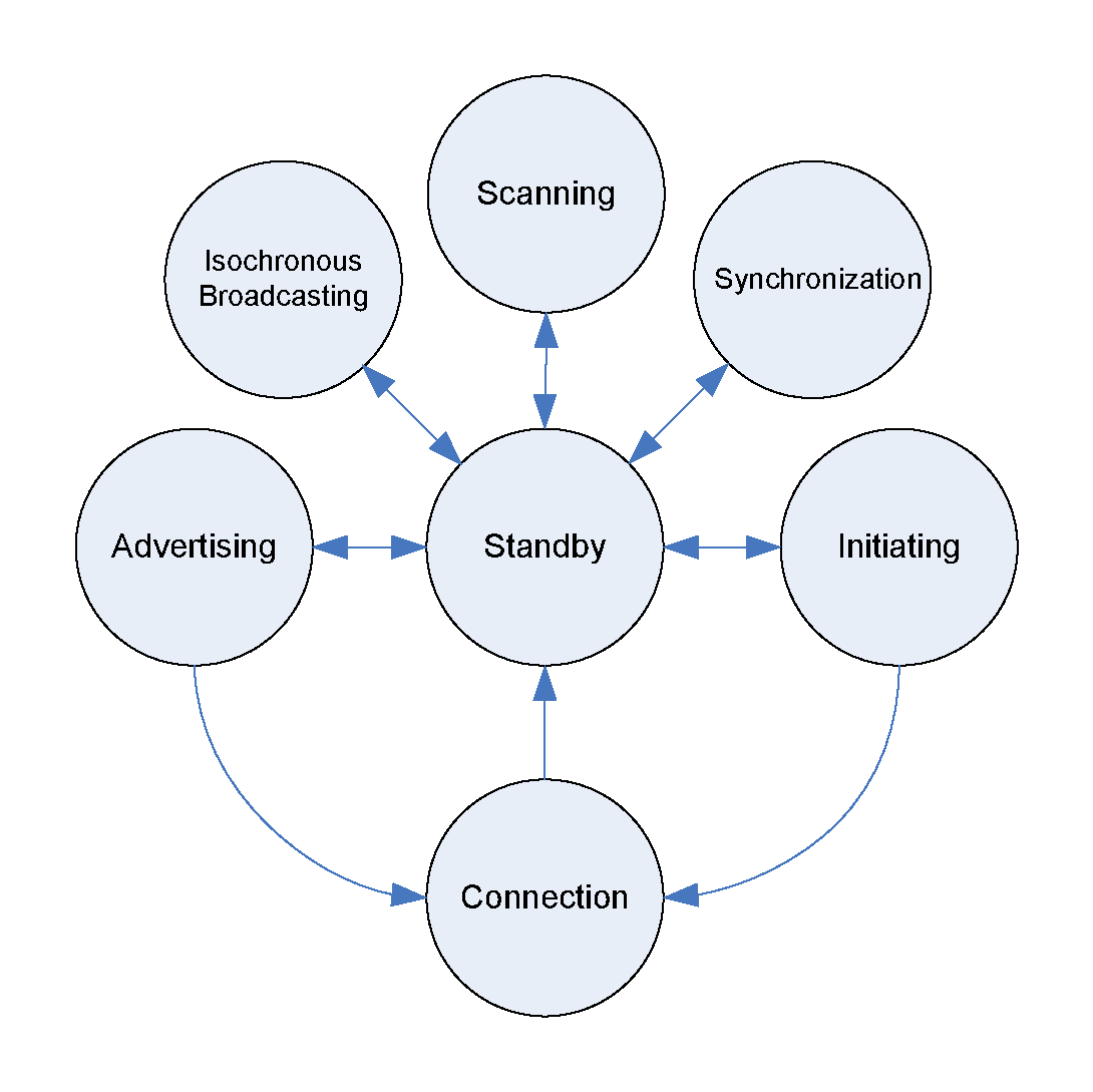
The operation of the Link Layer can be described in terms of a state machine with the following states:
Standby State
Advertising State
Scanning State
Initiating State
Connection State
Synchronization State
Isochronous Broadcasting State
The Link Layer state machine allows only one state to be active at a time. The Link Layer shall have at least one Link Layer state machine that supports one of Advertising state or Scanning state. The Link Layer may have multiple instances of the Link Layer state machine.
The Link Layer in the Standby state does not transmit or receive any packets. The Standby state can be entered from any other state.
The Link Layer in the Advertising state will be transmitting advertising physical channel packets and possibly listening to and responding to responses triggered by these advertising physical channel packets. A device in the Advertising state is known as an advertiser. The Advertising state can be entered from the Standby state.
The Link Layer in the Scanning state will be listening for advertising physical channel packets from devices that are advertising. A device in the Scanning state is known as a scanner. The Scanning state can be entered from the Standby state.
The Link Layer in the Initiating state will be listening for advertising physical channel packets from a specific device(s) and responding to these packets to initiate a connection with another device. A device in the Initiating state is known as an initiator. The Initiating state can be entered from the Standby state.
The Connection state can be entered either from the Initiating state or the Advertising state. A device in the Connection state is known as being in a connection.
Within the Connection state, two roles are defined:
Central Role
Peripheral Role
When entered from the Initiating state, the Connection state shall be in the Central Role. When entered from the Advertising state, the Connection state shall be in the Peripheral Role.
The Link Layer in the Central Role will communicate with a device in the Peripheral Role and defines the timings of transmissions.
The Link Layer in the Peripheral Role will communicate with a single device in the Central Role.
The Link Layer in the Synchronization State will be listening for periodic physical channel packets forming a specific periodic advertising train, coming from a specified device that is transmitting periodic advertising. The Synchronization State can be entered from the Standby State. While in this State, the Host may direct the Link Layer to listen for isochronous data packets coming from a specified device that is transmitting a Broadcast Isochronous Group (BIG). A device that is in the Synchronization State and is receiving isochronous data packets is referred as a Synchronized Receiver.
The Link Layer in the Isochronous Broadcasting State will transmit isochronous data packets on an isochronous physical channel. The Isochronous Broadcasting State can be entered from the Standby State. A device that is in the Isochronous Broadcasting State is referred as an Isochronous Broadcaster.
1.1.1. Permitted state and role combinations
The Link Layer may optionally support multiple state machines. If it does support multiple state machines, then any combination of states and roles may be supported. In particular, the Link Layer may be in the Connection State multiple times with any mix of Central Role and Peripheral Role. However, any two devices shall not have more than one connection between them.
Note: A device supporting scanning for periodic advertising (see Section 4.4.3.4) must support at least two state machines.
A Link Layer implementation is not required to support all the possible state combinations that are allowed by the specification. However, if it supports a state or state combination given in the "combination A" column of Table 1.1, it shall also support the corresponding state or state combination in the "combination B" column.
Combination A | Combination B |
|---|---|
Initiating plus any combination C of other states | Connection (Central role) plus the same combination C |
Connection (Central role) plus Initiating plus any combination C of other states | Connection (Central role) to more than one device in the Peripheral role plus the same combination C |
A connectable Advertising state plus any combination C of other states | Connection (Peripheral role) plus the same combination C |
Connection (Peripheral role) plus a connectable Advertising state plus any combination C of other states | Connection (Peripheral role) to more than one device in the Central role plus the same combination C |
In each case, the combination of other states C may be empty. In the last two rows, "other states" includes other connectable Advertising states.
1.1.2. Devices supporting only some states
Devices supporting only some Link Layer states or only one of the two roles within the Connection state are not required to support features (including supporting particular PDUs, procedures, data lengths, or HCI commands or particular features of an HCI command) that are only used by a state or mode that the device does not support.
1.2. Bit ordering
The bit ordering when defining fields within the packet or Protocol Data Unit (PDU) in the Link Layer specification follows the little-endian format. The following rules apply:
The Least Significant Bit (LSB) corresponds to b0
The LSB is the first bit sent over the air
In illustrations, the LSB is shown on the left side
Furthermore, data fields defined in the Link Layer, such as the PDU header fields, shall be transmitted with the LSB first. For instance, a 3-bit parameter X=3 is sent as:
Over the air, 1 is sent first, 1 is sent next, and 0 is sent last. This is shown as 110 in the specification.
Binary field values specified in the specification that follow the format 0b10101010 (e.g., the advertising physical channel Access Address in Section 2.1.2) are written with the MSB to the left.
Multi-octet fields, with the exception of the Cyclic Redundancy Check (CRC) and the Message Integrity Check (MIC), shall be transmitted with the least significant octet first. Each octet within multi-octet fields, with the exception of the CRC (see Section 3.1.1), shall be transmitted in LSB first order. For example, the 48-bit addresses in the advertising physical channel PDUs shall be transmitted with the least significant octet first, followed by the remainder of the five octets in increasing order.
Multi-octet field values specified in the specification (e.g. the CRC initial value in Section 2.3.3.1) are written with the most significant octet to the left; for example in 0x112233445566, the octet 0x11 is the most significant octet.
Where a packet or PDU is shown in a figure as containing more than one field, the fields shall be transmitted in the order shown in the figure, leftmost first.
1.3. Device address
Devices are identified using a device address and an address type; the address type indicates either a public device address or a random device address. A public device address and a random device address are both 48 bits in length.
A device shall use at least one type of device address and may use both. The device may be addressed by any device address that it uses.
A device's Identity Address is a Public Device Address or Random Static Device Address that it uses in packets it transmits. If a device is using Resolvable Private Addresses, it shall also have an Identity Address.
Whenever two device addresses are compared, the comparison shall include the device address type (i.e. if the two addresses have different types, they are different even if the two 48-bit addresses are the same).
1.3.1. Public device address
The public device address shall be created in accordance with [Vol 2] Part B, Section 1.2, with the exception that the restriction on LAP values does not apply unless the public device address will also be used as a BD_ADDR for a BR/EDR Controller.
1.3.2. Random device address
The random device address may be of either of the following:
Static address
Private address.
The specific sub-type is indicated by the two most significant bits of the random device address as shown in Table 1.2.
Address [47:46] | Sub-Type |
|---|---|
0b00 | Non-resolvable private address |
0b01 | Resolvable private address |
0b10 | Reserved for future use |
0b11 | Static device address |
The term random device address refers to both static and private address types.
The transmission of a random device address is optional. A device shall accept the reception of a random device address from a remote device.
1.3.2.1. Static device address
A static address is a 48-bit randomly generated address and shall meet the following requirements:
At least one bit of the random part of the address shall be 0
At least one bit of the random part of the address shall be 1
The format of a static address is shown in Figure 1.2.
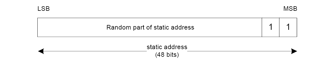
A device may choose to initialize its static address to a new value after each power cycle. A device shall not change its static address value once initialized until the device is power cycled.
Note
Note: If the static address of a device is changed, then the address stored in peer devices will not be valid and the ability to reconnect using the old address will be lost.
1.3.2.2. Private device address generation
The private address may be of either of the following two sub-types:
Non-resolvable private address
Resolvable private address
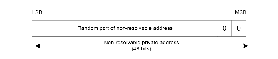
To generate a non-resolvable address, the device shall generate a 48-bit address with the following requirements:
At least one bit of the random part of the address shall be 1
At least one bit of the random part of the address shall be 0
The address shall not be equal to the public address
The format of a non-resolvable private address is shown in Figure 1.3.
To generate a resolvable private address, the device must have either the Local Identity Resolving Key (IRK) or the Peer Identity Resolving Key (IRK). The resolvable private address shall be generated with the IRK and a randomly generated 24-bit number. The random number is known as prand and shall meet the following requirements:
At least one bit of the random part of prand shall be 0
At least one bit of the random part of prand shall be 1
The format of the resolvable private address is shown in Figure 1.4.

The hash is generated using the random address function ah defined in [Vol 3] Part H, Section 2.2.2 with the input parameter k set to the device’s IRK and the input parameter r set to prand.
The prand and hash are concatenated to generate the random address (randomAddress) in the following manner:
The least significant octet of hash becomes the least significant octet of randomAddress and the most significant octet of prand becomes the most significant octet of randomAddress.
1.3.2.3. Private device address resolution
A resolvable private address may be resolved if the corresponding device’s IRK is available using this procedure. If a resolvable private address is resolved, the device can associate this address with the peer device.
The resolvable private address (RPA) is divided into a 24-bit random part (prand) and a 24-bit hash part (hash). The least significant octet of the RPA becomes the least significant octet of hash and the most significant octet of RPA becomes the most significant octet of prand. A localHash value is then generated using the random address hash function ah defined in [Vol 3] Part H, Section 2.2.2 with the input parameter k set to IRK of the known device and the input parameter r set to the prand value extracted from the RPA.
The localHash value is then compared with the hash value extracted from RPA. If the localHash value matches the extracted hash value, then the identity of the peer device has been resolved.
If a device has more than one stored IRK, the device repeats the above procedure for each stored IRK to determine if the received resolvable private address is associated with a stored IRK, until either address resolution is successful for one of the IRKs or all have been tried.
Note
Note: A device that cannot resolve a private address within T_IFS may respond on the reception of the next event.
A non-resolvable private address cannot be resolved.
1.4. Physical channel
As specified in [Vol 6] Part A, Section 2, 40 RF channels are defined in the 2.4 GHz ISM band. These RF channels are divided into 3 RF channels known as the "primary advertising channels", used for initial advertising and all legacy advertising activities, and 37 RF channels known as the "general-purpose channels", used for the majority of communications. Each of these RF channels is allocated a unique channel index (see Section 1.4.1).
These two groups of RF channels are used in four LE physical channels: advertising, periodic, isochronous, and data. The advertising physical channel uses both groups for discovering devices, initiating a connection, and broadcasting data; within this, the primary advertising channels form the primary advertising physical channel and the general-purpose channels form the secondary advertising physical channel. The remaining physical channels only use the general-purpose channels.
Two devices that wish to communicate use a shared physical channel. To achieve this, their transceivers must be tuned to the same RF channel at the same time.
Given that the number of RF channels is limited, and that many Bluetooth devices may be operating independently within the same spatial and temporal area, there is a strong likelihood of two independent Bluetooth devices having their transceivers tuned to the same RF channel, resulting in a physical channel collision. To mitigate the unwanted effects of this collision, each transmission on a physical channel starts with an Access Address that is used as a correlation code by devices tuned to the physical channel. This Access Address is a property of the physical channel. The Access Address is present at the start of every transmitted packet.
The Link Layer uses one physical channel at a given time.
Whenever the Link Layer is synchronized to the timing, frequency, and Access Address of a physical channel, it is said to be 'connected' on the data physical channel or ‘synchronized’ to the periodic physical channel or isochronous physical channel (whether or not it is actively involved in communications over the channel).
1.4.1. Physical channel indices
Table 1.3 shows the mapping from RF Channel to Physical Channel Index and RF Channel group. A ‘●’ in Table 1.3 indicates the RF channel and index are part of the specified channel group; a blank cell indicates that they are not part of that group.
RF Channel (Center Frequency) | Physical Channel Index | RF Channel Group | |
|---|---|---|---|
Primary Advertising | General purpose | ||
2402 MHz | 37 | ● | |
2404 MHz | 0 | ● | |
2406 MHz | 1 | ● | |
... | ... | ... | ... |
2424 MHz | 10 | ● | |
2426 MHz | 38 | ● | |
2428 MHz | 11 | ● | |
2430 MHz | 12 | ● | |
... | ... | ... | ... |
2478 MHz | 36 | ● | |
2480 MHz | 39 | ● | |
2. Air interface packets
LE devices shall use the packets as defined in the following sections. There are two basic formats: one for the LE Uncoded PHYs, described in Section 2.1, and one for the LE Coded PHY, described in Section 2.2.
2.1. Packet format for the LE Uncoded PHYs
The following packet format is defined for the LE Uncoded PHYs (LE 1M and LE 2M) and is used for packets on all physical channels.
This packet format is shown in Figure 2.1. Each packet consists of four mandatory fields and one optional field. The mandatory fields are Preamble, Access Address, PDU, and CRC. The optional field is Constant Tone Extension.
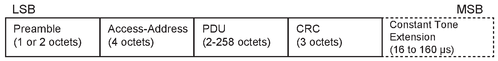
The preamble is 1 octet when transmitting or receiving on the LE 1M PHY and 2 octets when transmitting or receiving on the LE 2M PHY. The Access Address is 4 octets. The PDU range is from 2 to 258 octets. The CRC is 3 octets.
The Preamble is transmitted first, followed by the Access Address, PDU, CRC, and Constant Tone Extension (if present) in that order. The entire packet is transmitted at the same symbol rate (either 1 Msym/s or 2 Msym/s modulation).
Packets (not including the Constant Tone Extension) take between 44 and 2128 µs to transmit.
When the Constant Tone Extension is present, the Constant Tone Extension duration is between 16 and 160 µs, as shown in Figure 2.1.
2.1.1. Preamble
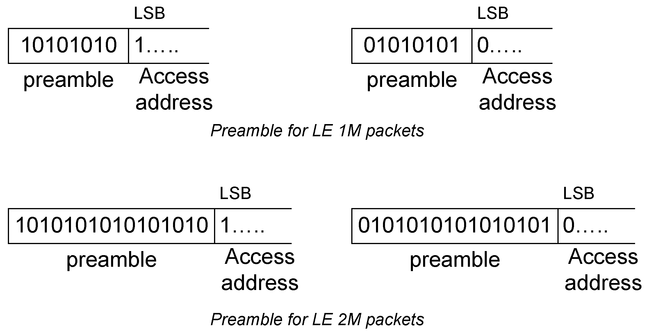
All Link Layer packets have a preamble which is used in the receiver to perform frequency synchronization, symbol timing estimation, and Automatic Gain Control (AGC) training. The preamble is a fixed sequence of alternating 0 and 1 bits. For packets transmitted on the LE 1M PHY, the preamble is 8 bits; for packets transmitted on the LE 2M PHY, the preamble is 16 bits. The first bit of the preamble (in transmission order) shall be the same as the LSB of the Access Address. The preamble is shown in Figure 2.2.
2.1.2. Access Address
All AUX_SYNC_IND, AUX_CHAIN_IND, AUX_SYNC_SUBEVENT_IND, AUX_CONNECT_REQ, and AUX_CONNECT_RSP PDUs sent on a periodic advertising train shall use the Access Address (AA) value set in the SyncInfo field (see Section 2.3.4.6) contained in the AUX_ADV_IND PDU that describes the train. All AUX_SYNC_SUBEVENT_RSP PDUs sent on a periodic advertising with responses train shall use the Access Address value set in the Periodic Advertising Response Timing Information (see Section 1.24 of [1]) contained in the AUX_ADV_IND PDU that describes the train. For a given periodic advertising with responses train, the AA value of the AUX_SYNC_SUBEVENT_RSP PDUs shall be different from the AA value of the AUX_SYNC_SUBEVENT_IND PDUs.
The Access Address for all other advertising physical channel packets shall be 0b10001110_10001001_10111110_11010110 (0x8E89BED6).
It is intended that each Link Layer connection between any two devices, each BIS, and each periodic advertising train has a different Access Address.
The Link Layer in the Initiating state shall generate a new Access Address for each initiating PDU it sends (see Section 2.3.3.1). The Link Layer in the Advertising state shall generate a new Access Address each time that it enables a periodic advertising train and, for periodic advertising with responses, a second Access Address for the responses. The first address is sent in the SyncInfo field (see Section 2.3.4.6) of PDUs referring to that periodic advertising train and the second in the Periodic Advertising Response Timing Information (see Section 1.24 of [1]) for the train.
The Link Layer in the Central Role in the Connected State shall generate a new Access Address for each Connected Isochronous Stream (CIS) it creates. The address is sent in the Link Layer Control PDU that is used to create the CIS (see Section 2.4.2.31).
The Access Address shall be a 32-bit value. Each time it needs a new Access Address (except for a Broadcast Isochronous Stream (BIS)), the Link Layer shall generate a new random value.
Each Access Address shall meet the following requirements:
It shall not be the Access Address for any existing ACL connection or CIS on this device.
It shall not be the Access Address for any enabled periodic advertising train.
It shall not be the Access Address for any existing BIS on this device.
It shall not be the Access Address for any existing BIG Control logical link on this device.
If it is the Access Address for a new CIS, it shall differ by more than one bit from any other Access Address being used on the same device.
It shall have no more than six consecutive zeros or ones.
It shall not be the advertising physical channel packets’ Access Address.
It shall not be a sequence that differs from the advertising physical channel packets’ Access Address by only one bit.
It shall not have all four octets equal.
It shall have no more than 24 transitions.
It shall have a minimum of two transitions in the most significant six bits.
The Link Layer in the Isochronous Broadcasting State shall generate a new Seed Access Address (SAA) for each BIG. The Access Addresses for the constituent BIS(es) are derived from the SAA. The SAA shall be a random number that meets the following requirements:
SAA19 = SAA15 SAA22 = SAA16 ≠ SAA15 SAA25 = 0 SAA23 = 1
For any pair of BIGs transmitted by the same device, the SAA15-0 values shall differ in at least two bits.
The Access Address for each BIS and for the BIG Control logical link (see Section 4.4.6.7) in a BIG shall be derived from the SAA for that BIG.
For each BIS logical transport, the Access Address shall be equal to the SAA bit-wise XORed with a diversifier word (DW) for that logical transport derived from a Diversifier (D) as follows:
D = ((35 * n) + 42) mod 128 where n is the BIS number, or 0 for the BIG Control logical link
For example, if n=1, D=77=0b01001101 and DW = 0xFD060000.
The seed for the random number generator shall be from a physical source of entropy and should have at least 20 bits of entropy.
If the random number and, in the case of an SAA, the derived Access Addresses for the BIS and the BIG Control logical link do not meet the above requirements, new random numbers shall be generated until the requirements are met.
On an implementation that also supports the LE Coded PHY (see Section 2.2), the Access Address shall also meet the following requirements:
It shall have at least three ones in the least significant 8 bits.
It shall have no more than eleven transitions in the least significant 16 bits.
2.1.3. PDU
The preamble and Access Address are followed by a PDU. When a packet is transmitted on either the primary or secondary advertising physical channel or the periodic physical channel, the PDU shall be the Advertising Physical Channel PDU as defined in Section 2.3. When a packet is transmitted on the data physical channel, the PDU shall be the Data Physical Channel PDU as defined in Section 2.4. When a packet is transmitted on the isochronous physical channel, the PDU shall be one of the Isochronous Physical Channel PDUs as defined in Section 2.6.
2.1.4. CRC
The PDU is followed by a 24-bit CRC. It shall be calculated over the PDU. The CRC polynomial is defined in Section 3.1.1.
2.1.5. Constant Tone Extension
The CRC is followed by an optional Constant Tone Extension, which consists of a constantly modulated series of unwhitened 1s. The Constant Tone Extension is not included in CRC or MIC calculations. The Constant Tone Extension field shall not be present in a packet sent on the isochronous physical channel. The Constant Tone Extension is discussed further in Section 2.5.
2.2. Packet format for the LE Coded PHY
The following packet format is defined for the LE Coded PHY and is used for packets on all physical channels. This packet format is shown in Figure 2.3.
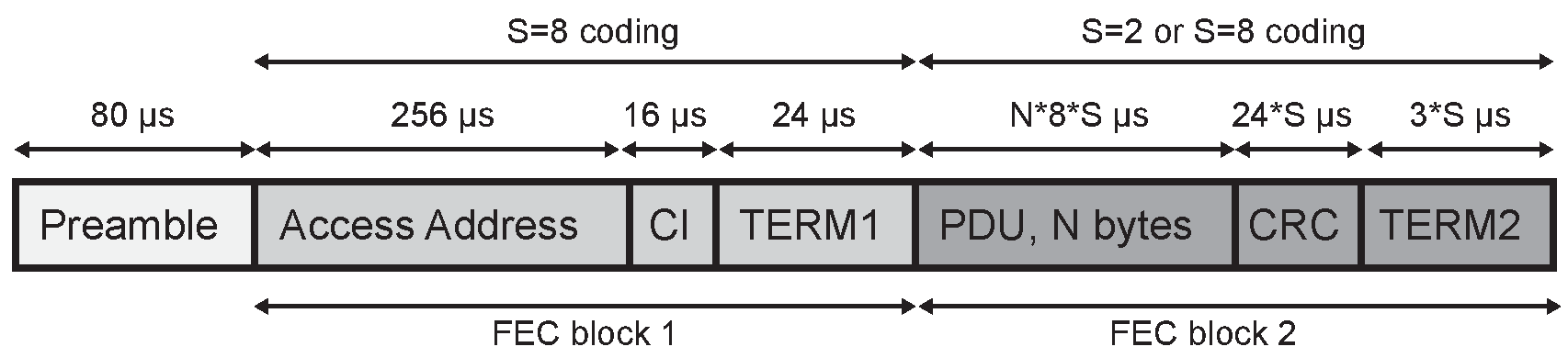
Each packet consists of the Preamble, FEC block 1, and FEC block 2.
The Preamble is not coded.
The FEC block 1 consists of three fields: Access Address, Coding Indicator (CI), and TERM1. These shall use the S=8 coding scheme as defined in Section 3.3.1.
The CI determines which coding scheme is used for FEC block 2.
The FEC block 2 consists of three fields: PDU, CRC, and TERM2. These shall use either the S=2 or S=8 coding scheme as defined in Section 3.3, depending on the value of the CI.
The entire packet is transmitted with 1 Msym/s modulation.
Table 2.1 captures the size and duration of the data packet fields.
Fields | |||||||
|---|---|---|---|---|---|---|---|
Preamble | Access Address | CI | TERM1 | PDU | CRC | TERM2 | |
Number of Bits | Uncoded | 32 | 2 | 3 | 16 – 2056 | 24 | 3 |
Duration when using S=8 coding (µs) | 80 | 256 | 16 | 24 | 128 – 16448 | 192 | 24 |
Duration when using S=2 coding (µs) | 80 | 256 | 16 | 24 | 32 – 4112 | 48 | 6 |
Packets take between 462 and 17040 µs to transmit.
Note
Note: There is no Constant Tone Extension on the LE Coded PHY.
2.2.1. Preamble
The Preamble is 80 symbols in length and consists of 10 repetitions of the symbol pattern '00111100' (in transmission order).
2.2.2. Access Address
The Access Address is specified in Section 2.1.2.
2.2.3. Coding Indicator
The Coding Indicator (CI) consists of two bits as defined in Table 2.2.
CI | Meaning |
|---|---|
0b00 | FEC Block 2 coded using S=8 |
0b01 | FEC Block 2 coded using S=2 |
All other values | Reserved for future use |
2.2.4. PDU
When a packet is transmitted on either the primary or secondary advertising physical channel or the periodic physical channel, the PDU shall be the Advertising Physical Channel PDU as defined in Section 2.3. When a packet is transmitted on the data physical channel, the PDU shall be the Data Physical Channel PDU as defined in Section 2.4. When a packet is transmitted on the isochronous physical channel, the PDU shall be one of the Isochronous Physical Channel PDUs as defined in Section 2.6.
2.2.5. CRC
The CRC is 24 bits in length and the value is calculated over all the PDU bits. The CRC generator polynomial is defined in Section 3.1.1.
2.2.6. TERM1 and TERM2
There is a terminator at the end of each FEC block referred to as TERM1 and TERM2. Each terminator is 3 bits long and forms the termination sequence defined in Section 3.3.1.
2.3. Advertising physical channel PDU
Note
Note: Despite the name, the advertising physical channel PDU is also used on the periodic physical channel.
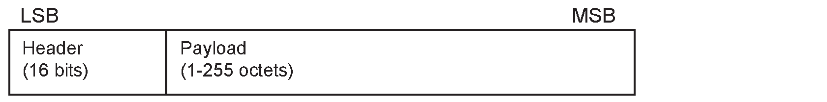
The advertising physical channel PDU has a 16-bit header and a variable size payload. Its format is as shown in Figure 2.4. The 16-bit Header field of the advertising physical channel PDU is as shown in Figure 2.5.
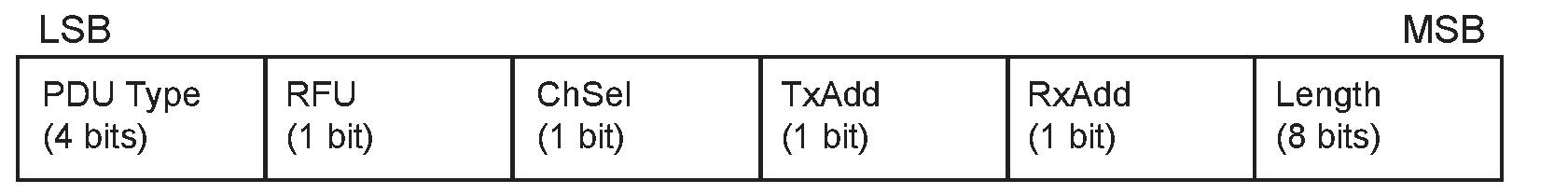
The PDU Type field of the advertising physical channel PDU that is contained in the header indicates the PDU type as defined in Table 2.3, which also shows which channel and which PHYs the packet may appear on. A ‘●’ in Table 2.3 indicates that the PDU may appear on that PHY; a blank cell indicates that the PDU shall not appear on that PHY.
PDU Type | PDU Name | Physical Channel | Permitted PHYs | ||
|---|---|---|---|---|---|
LE 1M | LE 2M | LE Coded | |||
0b0000 | ADV_IND | Primary Advertising | ● | ||
0b0001 | ADV_DIRECT_IND | Primary Advertising | ● | ||
0b0010 | ADV_NONCONN_IND | Primary Advertising | ● | ||
0b0011 | SCAN_REQ | Primary Advertising | ● | ||
AUX_SCAN_REQ | Secondary Advertising | ● | ● | ● | |
0b0100 | SCAN_RSP | Primary Advertising | ● | ||
0b0101 | CONNECT_IND | Primary Advertising | ● | ||
AUX_CONNECT_REQ | Secondary Advertising | ● | ● | ● | |
0b0110 | ADV_SCAN_IND | Primary Advertising | ● | ||
0b0111 | ADV_EXT_IND | Primary Advertising | ● | ● | |
AUX_ADV_IND | Secondary Advertising | ● | ● | ● | |
AUX_SCAN_RSP | Secondary Advertising | ● | ● | ● | |
AUX_SYNC_IND | Periodic | ● | ● | ● | |
AUX_CHAIN_IND | Secondary Advertising and Periodic | ● | ● | ● | |
AUX_SYNC_SUBEVENT_IND | Periodic | ● | ● | ● | |
AUX_SYNC_SUBEVENT_RSP | Periodic | ● | ● | ● | |
0b1000 | AUX_CONNECT_RSP | Secondary Advertising | ● | ● | ● |
All other values | Reserved for future use | ||||
The ChSel, TxAdd and RxAdd fields of the advertising physical channel PDU that are contained in the header contain information specific to the PDU type defined for each advertising physical channel PDU separately. If the ChSel, TxAdd or RxAdd fields are not defined as used in a given PDU then they shall be considered reserved for future use.
The Length field of the advertising physical channel PDU header indicates the length of the payload in octets. The valid range of the Length field shall be 1 to 255 octets.
The Payload fields in the advertising physical channel PDUs are specific to the PDU Type and are defined in Section 2.3.1 to Section 2.3.4. The PDU Types marked as Reserved for Future Use shall not be sent and shall be ignored upon receipt.
Within advertising physical channel PDUs, advertising data or scan response data from the Host may be included in the Payload in some PDU Types. The format of this data is defined in [Vol 3] Part C, Section 11.
Some advertising physical channel PDUs contain an AuxPtr field (see Section 2.3.4.5) which points to a packet containing another advertising physical channel PDU. In this case, the second packet and PDU are the auxiliary packet and auxiliary PDU of the original PDU, which in turn is the superior packet and superior PDU of the second one.
Note
Note: A PDU can only have one auxiliary PDU but more than one superior PDU.
Given a packet, its subordinate set consists of its auxiliary packet, if any, and the subordinate set of the auxiliary packet. A packet without an AuxPtr field has an empty subordinate set.
2.3.1. Advertising PDUs
The following advertising physical channel PDU Types are called advertising PDUs:
ADV_IND
ADV_DIRECT_IND
ADV_NONCONN_IND
ADV_SCAN_IND
ADV_EXT_IND
AUX_ADV_IND
AUX_SYNC_IND
AUX_CHAIN_IND
AUX_SYNC_SUBEVENT_IND
AUX_SYNC_SUBEVENT_RSP
These PDUs are sent by the Link Layer in the Advertising state and received by a Link Layer in the Scanning state or Initiating state. The ADV_IND, ADV_DIRECT_IND, ADV_NONCONN_IND, and ADV_SCAN_IND PDUs are called “legacy advertising PDUs”. The ADV_EXT_IND, AUX_ADV_IND, AUX_SYNC_IND, AUX_CHAIN_IND, AUX_SYNC_SUBEVENT_IND, and AUX_SYNC_SUBEVENT_RSP PDUs are called “extended advertising PDUs”. Advertising events using legacy advertising PDUs are called “legacy advertising events”.
2.3.1.1. ADV_IND
The Payload field of the ADV_IND PDU is shown in Figure 2.6. The PDU shall be used in connectable and scannable undirected advertising events. The TxAdd in the advertising physical channel PDU header indicates whether the advertiser’s address in the AdvA field is public (TxAdd = 0) or random (TxAdd = 1). The ChSel field in the advertising physical channel PDU header shall be set to 1 if the advertiser supports the LE Channel Selection Algorithm #2 feature (see Section 4.5.8.3).
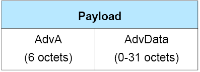
The Payload consists of AdvA and AdvData fields. The AdvA field shall contain the advertiser’s public or random device address as indicated by TxAdd. The AdvData field, if not empty, shall contain Advertising Data from the advertiser’s Host.
2.3.1.2. ADV_DIRECT_IND
The Payload field of the ADV_DIRECT_IND PDU is shown in Figure 2.7. The PDU shall only be used in connectable directed advertising events. The TxAdd in the advertising physical channel PDU header indicates whether the advertiser’s address in the AdvA field is public (TxAdd = 0) or random (TxAdd = 1). The RxAdd in the advertising physical channel PDU header indicates whether the target’s address in the TargetA field is public (RxAdd = 0) or random (RxAdd = 1). The ChSel field in the advertising physical channel PDU header shall be set to 1 if the advertiser supports the LE Channel Selection Algorithm #2 feature (see Section 4.5.8.3).
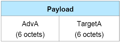
The Payload consists of AdvA and TargetA fields. The AdvA field shall contain the advertiser’s public or random device address as indicated by TxAdd. The TargetA field is the address of the device to which this PDU is addressed. The TargetA field shall contain the target’s public or random device address as indicated by RxAdd.
Note
Note: This packet does not contain any Host data.
2.3.1.3. ADV_NONCONN_IND
The Payload field of the ADV_NONCONN_IND PDU is shown in Figure 2.8. The PDU shall only be used in non-connectable and non-scannable undirected advertising events. The TxAdd in the advertising physical channel PDU header indicates whether the advertiser’s address in the AdvA field is public (TxAdd = 0) or random (TxAdd = 1).
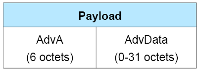
The Payload consists of AdvA and AdvData fields. The AdvA field shall contain the advertiser’s public or random device address as indicated by TxAdd. The AdvData field, if not empty, shall contain Advertising Data from the advertiser’s Host.
2.3.1.4. ADV_SCAN_IND
The Payload field of the ADV_SCAN_IND PDU is shown in Figure 2.9. The PDU shall only be used in scannable undirected advertising events. The TxAdd in the advertising physical channel PDU header indicates whether the advertiser’s address in the AdvA field is public (TxAdd = 0) or random (TxAdd = 1).
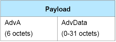
The Payload consists of AdvA and AdvData fields. The AdvA field shall contain the advertiser’s public or random device address as indicated by TxAdd. The AdvData field, if not empty, shall contain Advertising Data from the advertiser’s Host.
2.3.1.5. ADV_EXT_IND
The ADV_EXT_IND PDU uses the Common Extended Advertising Payload Format described in Section 2.3.4. The PDU may be used in the advertising events indicated by the AdvMode field value. An advertising event using an ADV_EXT_IND PDU is directed if, and only if, either the TargetA field is present or the AuxPtr field is present and points to a PDU where the TargetA field is present.
The Common Extended Advertising Payload Format fields permitted in the ADV_EXT_IND PDU are shown in Table 2.4.
Common Extended Advertising Payload Format fields | ||||||||||
|---|---|---|---|---|---|---|---|---|---|---|
Event Type | Adv Mode | AdvA | TargetA | CTE Info | ADI | Aux Ptr | Sync Info | Tx Power | ACAD | Adv Data |
Non-Connectable and Non-Scannable Undirected without auxiliary packet | 0b00 | M | X | X | X | X | X | O | X | X |
Non-Connectable and Non-Scannable Undirected with auxiliary packet | 0b00 | C.1 | X | X | M | M | X | C.1 | X | X |
Non-Connectable and Non-Scannable Directed without auxiliary packet | 0b00 | M | M | X | X | X | X | O | X | X |
Non-Connectable and Non-Scannable Directed with auxiliary packet | 0b00 | C.1 | C.1 | X | M | M | X | C.1 | X | X |
Connectable Undirected | 0b01 | X | X | X | M | M | X | C.1 | X | X |
Connectable Directed | 0b01 | X | X | X | M | M | X | C.1 | X | X |
Scannable Undirected | 0b10 | X | X | X | M | M | X | C.1 | X | X |
Scannable Directed | 0b10 | X | X | X | M | M | X | C.1 | X | X |
RFU | 0b11 | |||||||||
- C.1
This field is optional on the LE 1M PHY and reserved for future use on the LE Coded PHY.
For the non-connectable and non-scannable directed and non-connectable and non-scannable undirected event types without ACAD or AdvData, the Controller can choose whether or not to use an auxiliary packet. See Sections 4.4.2.6 and 4.4.2.9.
Fields reserved for future use shall not be present when the packet is sent and shall be ignored when received.
Any auxiliary packet shall be an AUX_ADV_IND packet.
2.3.1.6. AUX_ADV_IND
The AUX_ADV_IND PDU uses the Common Extended Advertising Payload Format described in Section 2.3.4. The PDU may be used in the advertising events indicated by the AdvMode field value.
The AdvMode field indicates the type of advertising event the AUX_ADV_IND packet is being used for and shall have the same value as the field in the superior PDU of this PDU.
The Common Extended Advertising Payload Format fields permitted in the AUX_ADV_IND PDU are shown in Table 2.5.
The PHY used for the AUX_ADV_IND shall be specified in the AuxPtr field of the superior PDU. The PHY specified in any AuxPtr field in an AUX_ADV_IND PDU shall be the same as the PHY the PDU was sent on.
The ADI field shall have the same value as the field in the superior PDU of this PDU.
Note
Note: The ADI field can be used to detect collisions.
Any auxiliary PDU shall be an AUX_CHAIN_IND PDU.
The SyncInfo field, when present, shall point to an AUX_SYNC_IND PDU.
Common Extended Advertising Payload Format fields | ||||||||||
|---|---|---|---|---|---|---|---|---|---|---|
Adv Mode | Event Type | AdvA | TargetA | CTE Info | ADI | Aux Ptr | Sync Info | Tx Power | ACAD | Adv Data |
0b00 | Non-Connectable and Non-Scannable Undirected | C.1 | X | X | M | O | O | O | O | O |
0b00 | Non-Connectable and Non-Scannable Directed | C.1 | C.2 | X | M | O | O | O | O | O |
0b01 | Connectable Undirected | M | X | X | M | X | X | O | O | O |
0b01 | Connectable Directed | M | M | X | M | X | X | O | O | O |
0b10 | Scannable Undirected | M | X | X | M | X | X | O | O | X |
0b10 | Scannable Directed | M | M | X | M | X | X | O | O | X |
0b11 | RFU | |||||||||
- C.1
This field is optional if the corresponding field in the ADV_EXT_IND PDU is not present, otherwise it is reserved for future use.
- C.2
This field is mandatory if the corresponding field in the ADV_EXT_IND PDU is not present, otherwise it is reserved for future use.
2.3.1.7. AUX_SYNC_IND
The AUX_SYNC_IND PDU uses the Common Extended Advertising Payload Format described in Section 2.3.4. The PDU is used in periodic advertising.
The AdvMode field shall be set to 0b00.
The Common Extended Advertising Payload Format fields permitted in the AUX_SYNC_IND PDU are shown in Table 2.6.
The PHY used for the AUX_SYNC_IND PDU shall be that specified in Section 4.4.2.12.
Any auxiliary PDU shall be an AUX_CHAIN_IND PDU.
The Advertising SID subfield of the ADI field shall have the same value as that in the superior PDU of this PDU.
Common Extended Advertising Payload Format fields | ||||||||||
|---|---|---|---|---|---|---|---|---|---|---|
Adv Mode | Event Type | AdvA | TargetA | CTE Info | ADI | Aux Ptr | Sync Info | Tx Power | ACAD | Adv Data |
0b00 | Non-Connectable and Non-Scannable Undirected or Directed | X | X | O | O | O | X | O | O | O |
0b01 to 0b11 | RFU | |||||||||
2.3.1.8. AUX_CHAIN_IND
The AUX_CHAIN_IND PDU uses the Common Extended Advertising Payload Format described in Section 2.3.4. The PDU is used to hold additional AdvData. Its superior PDU is an AUX_ADV_IND, AUX_SYNC_IND, AUX_SCAN_RSP or another AUX_CHAIN_IND PDU.
The AdvMode field shall be set to 0b00.
The Common Extended Advertising Payload Format fields permitted in the AUX_CHAIN_IND PDU are shown in Table 2.7.
The PHY used for the AUX_CHAIN_IND PDU shall be the same as the PHY used for its superior PDU.
The ADI field, when present, shall have the same value as the field in the superior PDU.
Note
Note: The ADI field can be used to detect collisions.
Any auxiliary PDU shall be another AUX_CHAIN_IND PDU.
Common Extended Advertising Payload Format fields | ||||||||||
|---|---|---|---|---|---|---|---|---|---|---|
Adv Mode | Event Type | AdvA | TargetA | CTE Info | ADI | Aux Ptr | Sync Info | Tx Power | ACAD | Adv Data |
0b00 | Chained data | X | X | C.2 | C.1 | O | X | O | X | O |
0b01 to 0b11 | RFU | |||||||||
- C.1
This field is mandatory if the corresponding field in the superior PDU of this PDU is present, otherwise it is reserved for future use.
- C.2
This field is optional if the corresponding field in the superior PDU of this PDU is present, otherwise it is reserved for future use.
2.3.1.9. AUX_SYNC_SUBEVENT_IND
The AUX_SYNC_SUBEVENT_IND PDU uses the Common Extended Advertising Payload Format described in Section 2.3.4. This PDU is used in PAwR.
The AdvMode field shall be set to 0x00.
The Common Extended Advertising Payload Format fields permitted in the AUX_SYNC_SUBEVENT_IND PDU are shown in Table 2.8.
The PHY used for the AUX_SYNC_SUBEVENT_IND shall be that specified in Section 4.4.2.12.
The Advertising SID subfield of the ADI field shall have the same value as that in the superior PDU of this PDU.
Common Extended Advertising Payload Format fields | ||||||||||
|---|---|---|---|---|---|---|---|---|---|---|
Adv Mode | Event Type | AdvA | TargetA | CTE Info | ADI | Aux Ptr | Sync Info | Tx Power | ACAD | Adv Data |
0b00 | Subevent Indication | X | X | O | O | X | X | O | O | O |
0b01 to 0b11 | RFU | |||||||||
2.3.1.10. AUX_SYNC_SUBEVENT_RSP
The AUX_SYNC_SUBEVENT_RSP PDU uses the Common Extended Advertising Payload Format described in Section 2.3.4. This PDU is used in PAwR.
The AdvMode field shall be set to 0x00.
The Common Extended Advertising Payload Format fields permitted in the AUX_SYNC_SUBEVENT_RSP PDU are shown in Table 2.9.
The PHY used for the AUX_SYNC_SUBEVENT_RSP shall be that specified in Section 4.4.2.12.
Common Extended Advertising Payload Format fields | ||||||||||
|---|---|---|---|---|---|---|---|---|---|---|
Adv Mode | Event Type | AdvA | TargetA | CTE Info | ADI | Aux Ptr | Sync Info | Tx Power | ACAD | Adv Data |
0b00 | Subevent Response | O | X | O | X | X | X | O | O | O |
0b01 to 0b11 | RFU | |||||||||
2.3.2. Scanning PDUs
The following advertising physical channel PDU types are called scanning PDUs.
SCAN_REQ
SCAN_RSP
AUX_SCAN_REQ
AUX_SCAN_RSP
The SCAN_REQ and AUX_SCAN_REQ PDUs are called scan request PDUs. The SCAN_RSP and AUX_SCAN_RSP PDUs are called scan response PDUs.
Where these PDUs are used to reply to a scannable advertisement, the PHY used for them shall be the same as the PHY used for the PDU that they reply to.
2.3.2.1. SCAN_REQ and AUX_SCAN_REQ
The Payload field of the SCAN_REQ and AUX_SCAN_REQ PDUs is shown in Figure 2.10. The TxAdd in the advertising physical channel PDU header indicates whether the scanner’s address in the ScanA field is public (TxAdd = 0) or random (TxAdd = 1). The RxAdd in the advertising physical channel PDU header indicates whether the advertiser’s address in the AdvA field is public (RxAdd = 0) or random (RxAdd = 1).
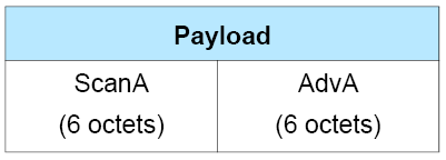
The Payload consists of ScanA and AdvA fields. The ScanA field shall contain the scanner’s public or random device address as indicated by TxAdd. The AdvA field is the address of the device to which this PDU is addressed. The AdvA field shall contain the advertiser’s public or random device address as indicated by RxAdd.
Note
Note: These PDUs do not contain any Host Data.
2.3.2.2. SCAN_RSP
The Payload field of the SCAN_RSP PDU is shown in Figure 2.11. The TxAdd in the advertising physical channel PDU header indicates whether the advertiser’s address in the AdvA field is public (TxAdd = 0) or random (TxAdd = 1). The Length field indicates the size of the payload (AdvA and ScanRspData) in octets.
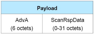
The Payload consists of AdvA and ScanRspData fields. The AdvA field shall contain the advertiser’s public or random device address as indicated by TxAdd. The ScanRspData field may contain any data from the advertiser’s Host.
2.3.2.3. AUX_SCAN_RSP
The AUX_SCAN_RSP PDU uses the Common Extended Advertising Payload Format described in Section 2.3.4.
The AdvMode field shall be set to 0b00.
The Common Extended Advertising Payload Format fields permitted in the AUX_SCAN_RSP PDU are shown in Table 2.10.
The ADI field, if present, shall have the same value as the field in the AUX_ADV_IND PDU that the scanner responded to.
Note
Note: The ADI field can be used to detect collisions.
Any auxiliary PDU shall be an AUX_CHAIN_IND PDU.
Common Extended Advertising Payload Format fields | ||||||||||
|---|---|---|---|---|---|---|---|---|---|---|
Adv Mode | Event Type | AdvA | TargetA | CTE Info | ADI | Aux Ptr | Sync Info | Tx Power | ACAD | Adv Data |
0b00 | Scan response | M | X | X | O | O | X | O | O | M |
0b01 to 0b11 | RFU | |||||||||
2.3.3. Initiating PDUs
The following advertising physical channel PDU Types are called initiating PDUs:
CONNECT_IND
AUX_CONNECT_REQ
AUX_CONNECT_RSP
The CONNECT_IND and the AUX_CONNECT_REQ PDUs are sent by the Link Layer in the Initiating state and received by the Link Layer in the Advertising state. The AUX_CONNECT_RSP PDU is sent by the Link Layer in the Advertising state and received by the Link Layer in the Initiating state.
The PHY used for these PDUs shall be the same as the PHY used for the PDU that they reply to.
2.3.3.1. CONNECT_IND and AUX_CONNECT_REQ
The Payload field of the CONNECT_IND and AUX_CONNECT_REQ PDUs is shown in Figure 2.12. TxAdd in the advertising physical channel PDU header indicates whether the address in the InitA field is public (TxAdd = 0) or random (TxAdd = 1). The RxAdd in the advertising physical channel PDU header indicates whether the address in the AdvA field is public (RxAdd = 0) or random (RxAdd = 1).
The ChSel field in the CONNECT_IND PDU header shall be set to 1 if both the initiator and advertiser support the LE Channel Selection Algorithm #2 feature (see Section 4.5.8.3). If the initiator supports the LE Channel Selection Algorithm #2 feature but the advertiser does not, the initiator may set the ChSel field to 0 or 1. The ChSel field in the CONNECT_IND PDU header shall be set to 0 if the initiator does not support the LE Channel Algorithm #2 feature. The ChSel field in the AUX_CONNECT_REQ PDU header is reserved for future use.
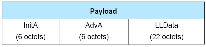
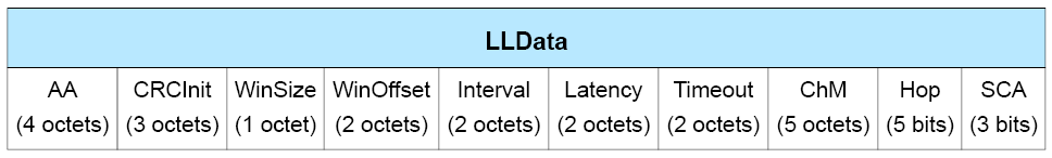
The format of the LLData field is shown in Figure 2.13.
The Payload consists of InitA, AdvA, and LLData fields. The InitA field shall contain the Initiator’s public or random device address as indicated by TxAdd. The AdvA field shall contain the advertiser’s public or random device address as indicated by RxAdd.
The LLData consists of 10 fields:
The AA field shall contain the ACL connection’s Access Address determined by the Link Layer following the rules specified in Section 2.1.2.
The CRCInit field shall contain the initialization value for the CRC calculation for the ACL connection, as defined in Section 3.1.1. It shall be a random value, generated by the Link Layer. The seed for the random number generator shall be from a physical source of entropy and should have at least 20 bits of entropy.
The WinSize field shall be set to indicate the transmitWindowSize value, as defined in Section 4.5.3 in the following manner:
transmitWindowSize = WinSize * 1.25 ms.
The WinOffset field shall be set to indicate the transmitWindowOffset value, as defined in Section 4.5.3 in the following manner:
transmitWindowOffset = WinOffset * 1.25 ms.
The Interval field shall be set to indicate the connInterval as defined in Section 4.5.1 in the following manner:
connInterval = Interval * 1.25 ms.
The Latency field shall be set to indicate the connPeripheralLatency value, as defined in Section 4.5.1 in the following manner:
connPeripheralLatency = Latency.
The Timeout field shall be set to indicate the connSupervisionTimeout value, as defined in Section 4.5.2, in the following manner:
connSupervisionTimeout = Timeout * 10 ms.
The ChM field shall contain the channel map indicating Used and Unused data channels. Every channel is represented with a bit positioned as per the data channel index as defined in Section 1.4.1. The LSB represents data channel index 0 and the bit in position 36 represents data channel index 36. A bit value of 0 indicates that the channel is Unused. A bit value of 1 indicates that the channel is Used. The bits in positions 37, 38 and 39 are reserved for future use.
Note
Note: When mapping from RF channels to data channel index, care should be taken to remember that there is a gap where advertising channel index 38 is placed.
The Hop field shall be set to indicate the hopIncrement used in the data channel selection algorithm as defined in Section 4.5.8.2. It shall have a random value in the range 5 to 16.
The SCA field shall be set to indicate the centralSCA used to determine the Central's worst case sleep clock accuracy as defined in Section 4.2.2. The value of the SCA field shall be set as defined in Table 2.11.
SCA | centralSCA or peripheralSCA |
|---|---|
0 | 251 ppm to 500 ppm |
1 | 151 ppm to 250 ppm |
2 | 101 ppm to 150 ppm |
3 | 76 ppm to 100 ppm |
4 | 51 ppm to 75 ppm |
5 | 31 ppm to 50 ppm |
6 | 21 ppm to 30 ppm |
7 | 0 ppm to 20 ppm |
2.3.3.2. AUX_CONNECT_RSP
The AUX_CONNECT_RSP PDU uses the Common Extended Advertising Payload Format described in Section 2.3.4.
The AdvMode field shall be set to 0b00.
The Common Extended Advertising Payload Format fields permitted in the AUX_CONNECT_RSP PDU are shown in Table 2.12.
Common Extended Advertising Payload Format fields | ||||||||||
|---|---|---|---|---|---|---|---|---|---|---|
Adv Mode | Event Type | AdvA | TargetA | CTE Info | ADI | Aux Ptr | Sync Info | Tx Power | ACAD | Adv Data |
0b00 | Connection response | M | M | X | X | X | X | X | X | X |
0b01 to 0b11 | RFU | |||||||||
2.3.4. Common Extended Advertising Payload Format
The following extended Advertising Physical Channel PDUs share the same Advertising Physical Channel PDU payload format, referred to in the specification as the “Common Extended Advertising Payload Format”:
ADV_EXT_IND
AUX_ADV_IND
AUX_SCAN_RSP
AUX_SYNC_IND
AUX_CHAIN_IND
AUX_CONNECT_RSP
AUX_SYNC_SUBEVENT_IND
AUX_SYNC_SUBEVENT_RSP
The common extended advertising payload format is shown in Figure 2.14.
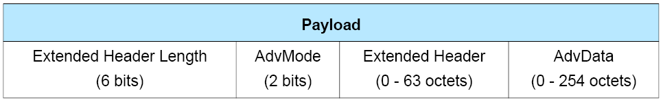
The Extended Header Length is a value between 0 and 63 and indicates the size of the variable length Extended Header field.
The AdvMode field indicates the mode of the advertisement. The value of the AdvMode field shall be set as defined in Table 2.13.
Value | Mode | |
|---|---|---|
0b00 | Non-connectable | Non-scannable |
0b01 | Connectable | Non-scannable |
0b10 | Non-connectable | Scannable |
0b11 | Reserved for future use | |
AdvData, if present, shall contain advertising data from the advertiser’s Host. The maximum size of AdvData depends on the size of the Extended Header. The size of the AdvData can be calculated by subtracting the length of the Extended Header plus one octet from the Length specified in the Advertising physical channel PDU Header.
The Extended Header field is a variable length header that is present if, and only if, the Extended Header Length field is non-zero. The format of the Extended Header is shown in Figure 2.15.
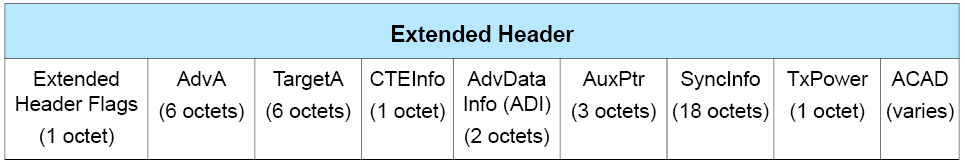
The Extended Header Flags bit field definitions are shown in Table 2.14.
Bit | Extended Header |
|---|---|
0 | AdvA |
1 | TargetA |
2 | CTEInfo |
3 | AdvDataInfo (ADI) |
4 | AuxPtr |
5 | SyncInfo |
6 | TxPower |
7 | Reserved for future use |
If a flag bit is set to 1, the corresponding Extended Header field is present; otherwise, the corresponding Extended Header field is not present. The Extended Header fields that are present are always in the same order as the flags in the Extended Header flags (i.e., the AdvA field is first if present, then the TargetA field if present, etc.).
Whether an Extended Header flag and corresponding Extended Header field is mandatory, optional, or reserved for future use is dependent on the Advertising Physical Channel PDU in which the extended header is used.
2.3.4.1. AdvA field
When present, the AdvA field is six octets with the format shown in Figure 2.16.

The Advertising Address field contains the advertiser’s device address. If the AdvA field is present, TxAdd in the advertising physical channel PDU header indicates whether this address is public (TxAdd = 0) or random (TxAdd = 1).
2.3.4.2. TargetA field
When present, the TargetA field is six octets with the format shown in Figure 2.17.

The Target Address field contains the scanner’s or initiator’s device address to which the advertisement is directed. If the TargetA field is present, RxAdd in the advertising physical channel PDU header indicates whether this address is public (RxAdd = 0) or random (RxAdd = 1).
2.3.4.3. CTEInfo field
The presence of the CTEInfo field indicates that the packet includes a Constant Tone Extension. The CTEInfo field is defined in Section 2.5.2.
2.3.4.4. AdvDataInfo field
When present, the AdvDataInfo (ADI) field is two octets with the format shown in Figure 2.18.
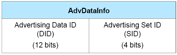
The Advertising Set ID (SID) is set by the advertiser to distinguish between different advertising sets transmitted by this device.
The Advertising Data ID (DID) is set by the advertiser to indicate to the scanner whether it can assume that the data contents in the AdvData are a duplicate of the previous AdvData sent in an earlier packet.
2.3.4.5. AuxPtr field
When present, the AuxPtr field is three octets with the format shown in Figure 2.19.
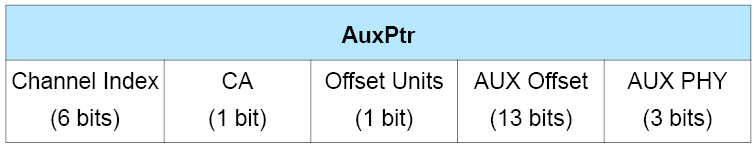
The presence of the AuxPtr field indicates that some or all of the advertisement data is in a subsequent auxiliary packet. The contents of the AuxPtr field describe this packet.
The Channel Index field contains the general-purpose channel index (see Section 1.4.1) used to transmit the auxiliary packet.
The Offset Units field indicates the units used by the Aux Offset Field. The value of the Offset Units field shall be set as defined in Table 2.15.
Value | Units |
|---|---|
0 | 30 µs |
1 | 300 µs |
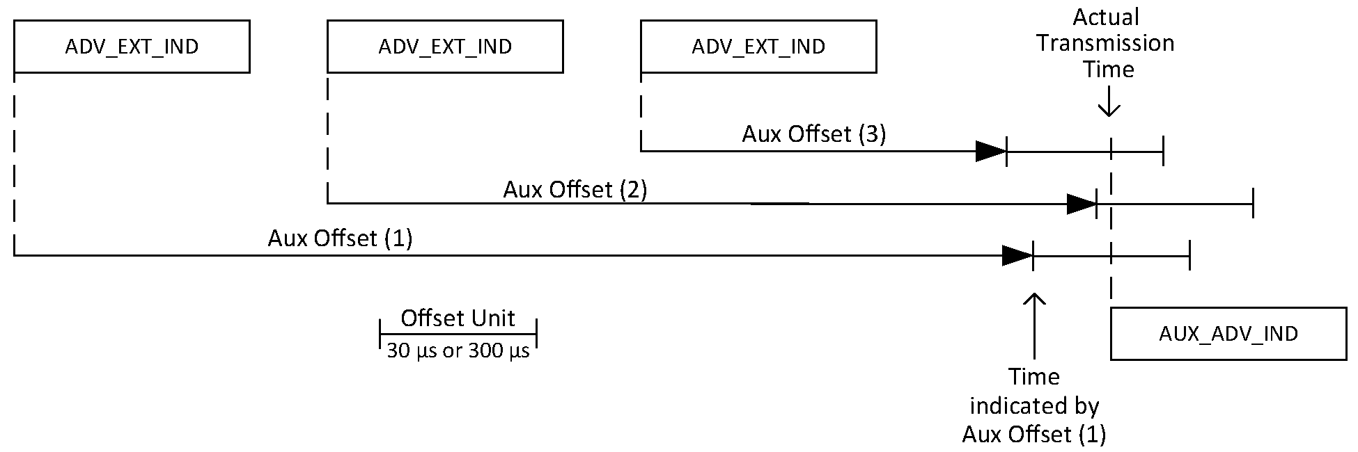
The Aux Offset field contains the time from a reference point to the approximate start of the auxiliary packet, where the reference point is the start of the packet containing the AuxPtr field. The value of the AUX Offset field is in the unit of time indicated by the Offset Units field; the offset is determined by multiplying the value by the unit. The Aux Offset shall be at least the length of the packet plus T_MAFS (see Section 4.1.2). The Offset Units field shall be set to 0 if the Aux Offset is less than 245,700 µs.The auxiliary packet shall not start any earlier than the Aux Offset after the reference point and shall start no later than the Aux Offset plus one Offset Unit after the reference point. This allows the Link Layer to round the Aux Offset to the Offset Unit.
The Aux PHY field indicates the PHY used to transmit the auxiliary packet. The value of the Aux PHY field shall be set as defined in Table 2.16.
Value | PHY used |
|---|---|
0b000 | LE 1M |
0b001 | LE 2M |
0b010 | LE Coded |
0b011 – 0b111 | Reserved for future use |
The CA field contains the clock accuracy of the advertiser that will be used between the packet containing this data and the auxiliary packet. The value of the CA field shall be set as defined in Table 2.17.
CA Value | Advertiser’s Clock Accuracy |
|---|---|
0 | 51 ppm to 500 ppm |
1 | 0 ppm to 50 ppm |
An AuxPtr field with an Aux Offset of zero is permitted and indicates that no auxiliary packet will be transmitted but the Host advertising data in the current PDU is incomplete (see Section 2.3.4.9); it shall be treated as equivalent to one referring to an AUX_CHAIN_IND PDU that is never received. The remaining fields shall contain valid values.
2.3.4.6. SyncInfo field
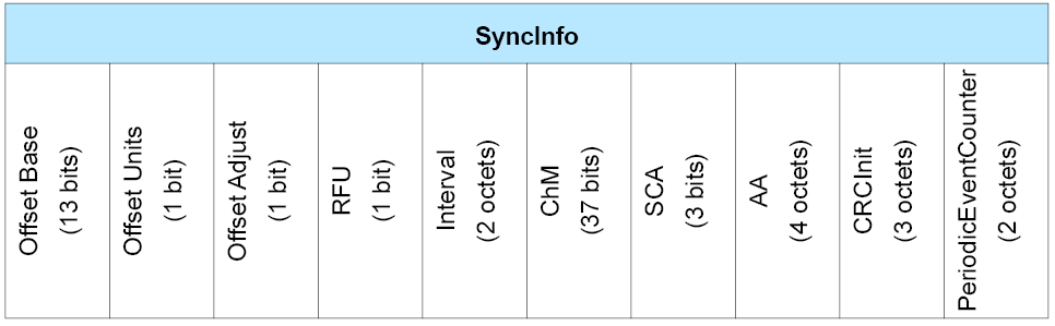
When present, the SyncInfo field is 18 octets with the format shown in Figure 2.21.
The presence of the SyncInfo field indicates the presence of a periodic advertising train (using AUX_SYNC_IND PDUs or AUX_SYNC_SUBEVENT_IND PDUs). The contents of the SyncInfo field describe this periodic advertising train.
The Offset Units field indicates the units used by the Offset Base field. The value of the Offset Units field shall be set as defined in Table 2.18.
Value | Units |
|---|---|
0 | 30 µs |
1 | 300 µs |
The SyncInfo field can appear in an advertising PDU or in an LL_PERIODIC_SYNC_IND PDU or LL_PERIODIC_SYNC_WR_IND PDU (see Section 2.4.2.27 and Section 2.4.2.40).
The syncPacketWindowOffset value is the time from a reference point to the start of the AUX_SYNC_IND or the AUX_SYNC_SUBEVENT_IND of subevent 0 packet that this SyncInfo field describes. If the SyncInfo appears in an advertising PDU, the reference point is the start of the packet containing it. If it appears in an LL_PERIODIC_SYNC_IND PDU or an LL_PERIODIC_SYNC_WR_IND PDU, the reference point is specified by that PDU. The value of syncPacketWindowOffset is determined by multiplying the value of the Offset Base field by the unit of time indicated by the Offset Units field and then, if the Offset Adjust field is set to 1, adding 2.4576 seconds. The Offset Units field shall be set to 0 if syncPacketWindowOffset is less than 245,700 µs. The Offset Adjust field shall be set to 0 if the Offset Units field is set to 0 or if the SyncInfo field appears within an advertising PDU. As illustrated in Figure 2.22, the packet containing the AUX_SYNC_IND PDU or AUX_SYNC_SUBEVENT_IND PDU shall not start any earlier than syncPacketWindowOffset after the reference point and shall start no later than syncPacketWindowOffset plus one Offset unit after the reference point. This allows the Link Layer to round syncPacketWindowOffset to the Offset Unit.
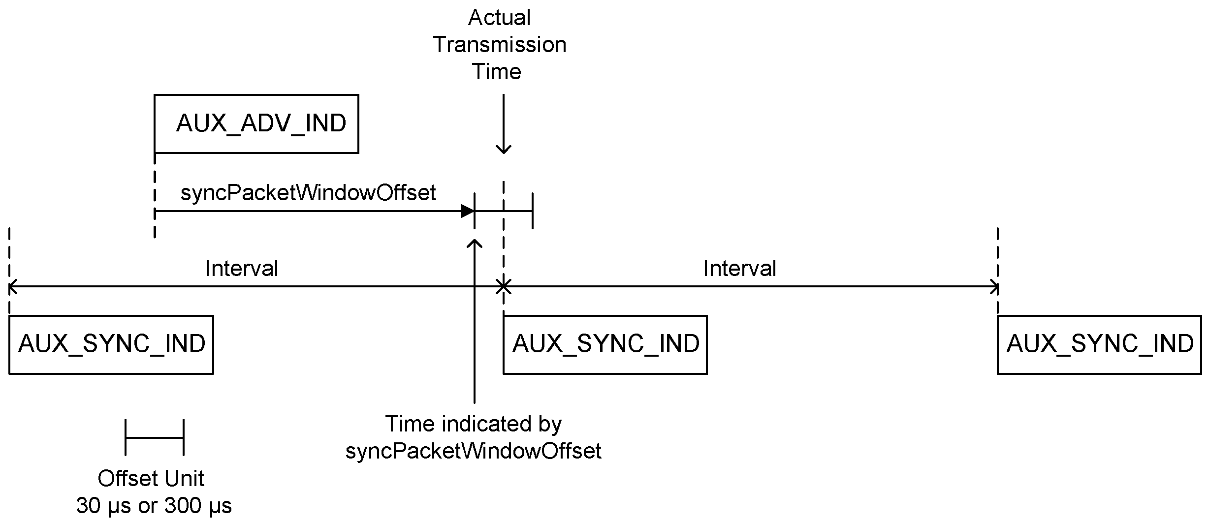
A value of 0 for syncPacketWindowOffset indicates that the time to the next AUX_SYNC_IND or AUX_SYNC_SUBEVENT_IND packet is greater than can be represented.
The Interval field contains the time in 1.25 ms units from the start of one packet of the periodic advertising train to the start of the next packet. The value shall not be less than 6 (7.5 ms).
The ChM field contains the channel map indicating Used and Unused RF channels on the periodic physical channel. Every channel is represented with a bit positioned as per the channel index as defined in Section 1.4.1. The LSB represents channel index 0 and the bit in position 36 represents channel index 36. A bit value of 0 indicates that the channel is Unused. A bit value of 1 indicates that the channel is Used.
The AA, CRCInit, and SCA fields have the same meaning as the corresponding fields in the CONNECT_IND PDU (see Section 2.3.3.1).
The PeriodicEventCounter field contains the value of paEventCounter (see Section 4.4.2.1) that applies to the AUX_SYNC_IND or AUX_SYNC_SUBEVENT_IND packet that this SyncInfo field describes.
2.3.4.7. TxPower field
When present, the TxPower is one octet with the format shown in Figure 2.23.

The Tx Power Level field is the same value defined for the Tx Power Advertising Data type defined in Section 1.5 of [1].
If the Host instructs the Controller to include the TxPower field in an advertisement, then it shall be included in the AUX_ADV_IND PDU if the extended advertising event contains one and in all the ADV_EXT_IND PDUs otherwise. Any AUX_CHAIN_IND PDUs should not contain a TxPower field. If the Host instructs the Controller to include the TxPower field in a periodic advertisement, then it shall be included in the AUX_SYNC_IND, AUX_SYNC_SUBEVENT_IND, or AUX_SYNC_SUBEVENT_RSP PDUs but not in any AUX_CHAIN_IND PDUs.
2.3.4.8. ACAD field
The remainder of the extended header forms the Additional Controller Advertising Data (ACAD) field. The length of this field is the Extended Header length minus the sum of the size of the extended header flags (1 octet) and those fields indicated by the flags as present. ACAD cannot be fragmented across multiple advertising physical channel PDUs; it shall always fit inside a single advertising physical channel PDU.
The ACAD field, if present, shall hold data from the advertiser’s Controller or intended to be used by the recipient’s Controller. It uses the format described in [Vol 3] Part C, Section 11.
The ACAD type formats and meanings are defined in Section 1 of [1]. The ACAD type identifier values are defined in Assigned Numbers.
2.3.4.9. Host Advertising Data
The portion of the PDU after the extended header forms the AdvData field. The length of this field is specified in Section 2.3.4.
The AdvData field, if present, shall hold data from the advertiser’s Host in the format described in [Vol 3] Part C, Section 11. If the Host does not provide any data, the AdvData field shall be omitted but, for all other purposes in this Part, this shall be treated as if the Host had provided data.
The Controller may support fragmentation of Host Advertising Data. The total amount of Host Advertising Data before fragmentation shall not exceed 1650 octets. When the Link Layer fragments the Host advertising data, the number of fragments and the size of each fragment are chosen by the Controller. The Controller should minimize the number of fragments to ensure more reliability in delivering the entire Host advertising data. The Host may indicate a preference whether the Controller should fragment the Host advertising data, but the Controller may ignore the preference. If the amount of advertising or scan response data to be sent in an extended advertising or scanning PDU plus the Extended Header Length, AdvMode, and Extended Header exceed the maximum Advertising Physical Channel PDU payload (255 octets), the Link Layer shall fragment the Host advertising data.
The Link Layer shall place the multiple fragments in the AdvData field of different PDUs. When Host advertising data is fragmented the first fragment shall be placed in the AUX_ADV_IND, AUX_SYNC_IND or AUX_SCAN_RSP PDU while subsequent fragments shall be placed in AUX_CHAIN_IND PDUs. Each AUX_CHAIN_IND PDU is the auxiliary PDU of the PDU containing the previous fragment; AUX_CHAIN_IND PDUs not containing AdvData shall not have an auxiliary PDU containing AdvData.
If the Link Layer has fragmented the Host advertising data but is subsequently unable to transmit all the fragments, the last fragment that it is able to transmit should contain an AuxPtr field with an Aux Offset of zero so that scanners are aware that the data has been truncated.
2.4. Data Physical Channel PDU
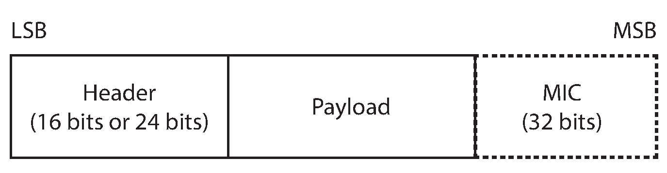
The Data Physical Channel PDU has a 16 or 24 bit header, a variable size payload, and may include a Message Integrity Check (MIC) field.
The Data Physical Channel PDU is as shown in Figure 2.24.
The Header field of the Data Physical Channel PDU is as shown in Figure 2.25.
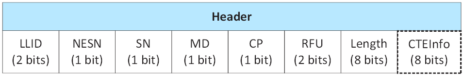
The 16 or 24 bit Header field consists of 6 or 7 fields that are specified in Table 2.19.
The MIC field shall not be included in an un-encrypted ACL connection, or in an encrypted ACL connection with a Data Channel PDU with a zero length Payload.
The MIC field shall be included in an encrypted ACL connection, with a Data Channel PDU with a non-zero length Payload and shall be calculated as specified in [Vol 6] Part E, Section 1.
The payload format depends on the LLID field of the Header. If the LLID field is 0b01 or 0b10, the Data Physical Channel PDU Payload contains an LL Data PDU as defined in Section 2.4.1. If the LLID field is 0b11 then the Data Physical Channel PDU Payload contains an LL Control PDU as defined in Section 2.4.2.
The NESN bit of the Header is defined in Section 4.5.9.
The SN bit of the Header is defined in Section 4.5.9.
The MD bit of the Header is defined in Section 4.5.6.
The CTEInfo Present (CP) field of the Header indicates whether the Data Physical Channel PDU Header has a CTEInfo field and therefore whether the data physical channel packet has a Constant Tone Extension. If the CP field is 0, then no CTEInfo field is present in the Data Channel PDU Header and there is no Constant Tone Extension in the data physical channel packet. If the CP field is 1, then the CTEInfo field in the Data Physical Channel PDU Header is present and the data physical channel packet includes a Constant Tone Extension.
The Length field of the Header indicates the length of the Payload and MIC if included. The length field has the range 0 to 255 octets. The Payload shall be less than or equal to 251 octets in length. The MIC is 4 octets in length.
The CTEInfo field of the Header is present if indicated in the CP field. The CTEInfo field is defined in Section 2.5.2. The CTEInfo field can be present in the header of any Data Physical Channel PDU. However, the Link Layer shall not transmit a Data Physical Channel PDU containing a CTEInfo field unless it has determined that the peer device supports the Receiving Constant Tone Extensions feature (see Section 4.6.22).
Note
Note: A Controller that transmits a PDU containing a CTEInfo field will not necessarily be able to receive one and vice-versa.
In this version of the specification, the only way to request a remote device to send a packet containing the CTEInfo field is via the Constant Tone Extension Request procedure.
Field name | Description |
|---|---|
LLID | The LLID indicates whether the packet is an LL Data PDU or an LL Control PDU. 0b00 = Reserved for future use 0b01 = LL Data PDU: Continuation fragment of an L2CAP message, or an Empty PDU. 0b10 = LL Data PDU: Start of an L2CAP message or a complete L2CAP message with no fragmentation. 0b11 = LL Control PDU |
NESN | Next Expected Sequence Number |
SN | Sequence Number |
MD | More Data |
CP | CTEInfo Present |
Length | The Length field indicates the size, in octets, of the Payload and MIC, if included. |
CTEInfo | The CTEInfo field indicates the type and length of the Constant Tone Extension. |
2.4.1. LL Data PDU
An LL Data PDU is a Data Channel PDU that is used to send L2CAP data. The LLID field in the Header shall be set to either 0b01 or 0b10.
An LL Data PDU with the LLID field in the Header set to 0b01, and the Length field set to 0b00000000, is known as an Empty PDU. The Central’s Link Layer may send an Empty PDU to the Peripheral to allow the Peripheral to respond with any Data Physical Channel PDU, including an Empty PDU.
An LL Data PDU with the LLID field in the Header set to 0b10 shall not have the Length field set to 0 and should not have it set to less than 4.
Note
Note: If the Link Layer receives an HCI ACL Data Packet with Data_Total_Length equal to 0b00000000 and Packet_Boundary_Flag set to 0b00 (i.e., a start fragment), then the Link Layer cannot simply transmit the fragment over the air but, as this section requires, must instead combine it with one or more of the following continuation fragments to form a PDU with LLID set to 0b10 and non-zero length.
2.4.2. LL Control PDU
An LL Control PDU is a Data Physical Channel PDU that is used to control the Link Layer connection.
The Payload field of the LL Control PDU is shown in Figure 2.26.

An LL Control PDU shall not have the Length field set to 0b00000000.
The Payload consists of Opcode and CtrData fields.
The Opcode field identifies different types of LL Control PDU, as defined in Table 2.20.
The CtrData field in the LL Control PDU is specified by the Opcode field and is defined in the following subsections. For a given Opcode the length of the CtrData field is fixed.
Where the description of a field within the CtrData field gives a range of valid values or other restrictions on a value (e.g. that field X is less than field Y), all other values shall be reserved for future use. The range may be directly specified in the relevant subsection for the LL Control PDU or indirectly, possibly in a section referenced by that subsection (e.g. the range of the WinSize field in Section 2.4.2.1 is derived from the range of the transmitWindowSize value specified in Section 4.5.3).
If no range is specified for a field, then all values for that field are valid.
Except where explicitly stated otherwise, all fields within the CtrData field in an LL Control PDU that hold an integer shall be interpreted as unsigned.
Opcode | LL Control PDU Name |
|---|---|
0x00 | LL_CONNECTION_UPDATE_IND |
0x01 | LL_CHANNEL_MAP_IND |
0x02 | LL_TERMINATE_IND |
0x03 | LL_ENC_REQ |
0x04 | LL_ENC_RSP |
0x05 | LL_START_ENC_REQ |
0x06 | LL_START_ENC_RSP |
0x07 | LL_UNKNOWN_RSP |
0x08 | LL_FEATURE_REQ |
0x09 | LL_FEATURE_RSP |
0x0A | LL_PAUSE_ENC_REQ |
0x0B | LL_PAUSE_ENC_RSP |
0x0C | LL_VERSION_IND |
0x0D | LL_REJECT_IND |
0x0E | LL_PERIPHERAL_FEATURE_REQ |
0x0F | LL_CONNECTION_PARAM_REQ |
0x10 | LL_CONNECTION_PARAM_RSP |
0x11 | LL_REJECT_EXT_IND |
0x12 | LL_PING_REQ |
0x13 | LL_PING_RSP |
0x14 | LL_LENGTH_REQ |
0x15 | LL_LENGTH_RSP |
0x16 | LL_PHY_REQ |
0x17 | LL_PHY_RSP |
0x18 | LL_PHY_UPDATE_IND |
0x19 | LL_MIN_USED_CHANNELS_IND |
0x1A | LL_CTE_REQ |
0x1B | LL_CTE_RSP |
0x1C | LL_PERIODIC_SYNC_IND |
0x1D | LL_CLOCK_ACCURACY_REQ |
0x1E | LL_CLOCK_ACCURACY_RSP |
0x1F | LL_CIS_REQ |
0x20 | LL_CIS_RSP |
0x21 | LL_CIS_IND |
0x22 | LL_CIS_TERMINATE_IND |
0x23 | LL_POWER_CONTROL_REQ |
0x24 | LL_POWER_CONTROL_RSP |
0x25 | LL_POWER_CHANGE_IND |
0x26 | LL_SUBRATE_REQ |
0x27 | LL_SUBRATE_IND |
0x28 | LL_CHANNEL_REPORTING_IND |
0x29 | LL_CHANNEL_STATUS_IND |
0x2A | LL_PERIODIC_SYNC_WR_IND |
0xF0 to 0xFB | Reserved for future use (used for specification development purposes) |
All other values | Reserved for future use |
If an LL Control PDU is received that is not supported or reserved for future use, the Link Layer shall respond with an LL_UNKNOWN_RSP PDU. The UnknownType field of the LL_UNKNOWN_RSP PDU shall be set to the value of the Opcode in the received PDU.
If an LL Control PDU is received with the wrong length or with invalid CtrData fields, the Link Layer may continue with the relevant Link Layer procedure with an implementation-specific interpretation of the data (e.g., if the PDU is too long it can ignore the extra data; if a field is out of range it can use the nearest permitted value). If it does not continue the procedure, it shall respond with an LL_UNKNOWN_RSP PDU or, if the relevant procedure allows it, an LL_REJECT_IND or LL_REJECT_EXT_IND PDU. The UnknownType field of the LL_UNKNOWN_RSP PDU or the RejectOpcode field of the LL_REJECT_EXT_IND PDU shall be set to the value of the Opcode in the received PDU.
2.4.2.1. LL_CONNECTION_UPDATE_IND
The format of the CtrData field is as shown in Figure 2.27.
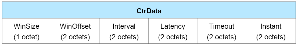
The LL_CONNECTION_UPDATE_IND CtrData consists of six fields:
The WinSize field shall be set to indicate the transmitWindowSize value, as defined in Section 4.5.3 in the following manner:
transmitWindowSize = WinSize * 1.25 ms.
The WinOffset field shall be set to indicate the transmitWindowOffset value, as defined in Section 4.5.3, in the following manner:
transmitWindowOffset = WinOffset * 1.25 ms.
The Interval field shall be set to indicate the connInterval value, as defined in Section 4.5.1, in the following manner:
connInterval = Interval * 1.25 ms.
The Latency field shall be set to indicate the connPeripheralLatency value, as defined by Section 4.5.1, in the following manner:
connPeripheralLatency = Latency.
The Timeout field shall be set to indicate the connSupervisionTimeout value, as defined by Section 4.5.2, in the following manner:
connSupervisionTimeout = Timeout * 10 ms.
The Instant field shall be set to indicate the instant described in Section 5.1.1.
2.4.2.2. LL_CHANNEL_MAP_IND
The format of the CtrData field is shown in Figure 2.28.
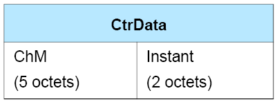
The LL_CHANNEL_MAP_IND CtrData consists of two fields:
The ChM field shall contain the channel map indicating Used and Unused data channels. Every channel is represented with a bit positioned as per the data channel index defined by Section 1.4.1. The format of this field is identical to the ChM field in the CONNECT_IND PDU (see Section 2.3.3.1).
The Instant field shall be set to indicate the instant described in Section 5.1.2.
2.4.2.3. LL_TERMINATE_IND
The format of the CtrData field is shown in Figure 2.29.

The LL_TERMINATE_IND CtrData consists of one field:
The ErrorCode field shall be set to inform the remote device why the connection is about to be terminated. See [Vol 1] Part F, Controller Error Codes for details.
2.4.2.4. LL_ENC_REQ
The format of the CtrData field is shown in Figure 2.30.
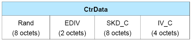
The LL_ENC_REQ CtrData consists of four fields:
The Rand field shall contain a random number that is provided by the Host and used with EDIV (see [Vol 3] Part H, Section 2.4.4).
The EDIV field shall contain the encrypted diversifier.
The SKD_C field shall contain the Central’s portion of the session key diversifier.
The IV_C field shall contain the Central’s portion of the initialization vector.
2.4.2.5. LL_ENC_RSP
The format of the CtrData field is shown in Figure 2.31.

The LL_ENC_RSP CtrData consists of two fields.
The SKD_P field shall contain the Peripheral’s portion of the session key diversifier.
The IV_P field shall contain the Peripheral’s portion of the initialization vector.
2.4.2.6. LL_START_ENC_REQ
The LL_START_ENC_REQ PDU does not have a CtrData field.
2.4.2.7. LL_START_ENC_RSP
The LL_START_ENC_RSP PDU does not have a CtrData field.
2.4.2.8. LL_UNKNOWN_RSP
The format of the CtrData field is shown in Figure 2.32.

The LL_UNKNOWN_RSP CtrData consists of one field:
UnknownType shall contain the Opcode field value of the received LL Control PDU.
2.4.2.9. LL_FEATURE_REQ
The format of the CtrData field is shown in Figure 2.33.

The LL_FEATURE_REQ CtrData consists of one field:
FeatureSet shall contain the set of features supported by the Central’s Link Layer as specified in Section 4.6.
2.4.2.10. LL_FEATURE_RSP
The format of the CtrData field is shown in Figure 2.34.

The LL_FEATURE_RSP CtrData consists of one field:
FeatureSet[0] shall contain a set of features supported by the Link Layers of both the Central and Peripheral.
FeatureSet[1-7] shall contain a set of features supported by the Link Layer that transmits this PDU.
See Section 4.6 for the list of features.
2.4.2.11. LL_PAUSE_ENC_REQ
The LL_PAUSE_ENC_REQ packet does not have a CtrData field.
2.4.2.12. LL_PAUSE_ENC_RSP
The LL_PAUSE_ENC_RSP packet does not have a CtrData field.
2.4.2.13. LL_VERSION_IND
The format of the CtrData field is shown in Figure 2.35.
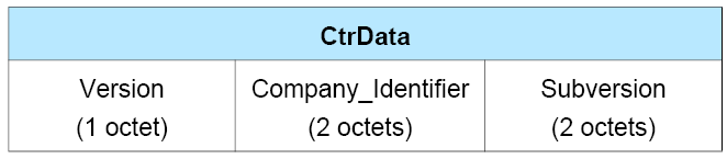
The LL_VERSION_IND CtrData consists of three fields:
Version field shall contain the version of the Bluetooth Link Layer specification supported by the Controller (see Assigned Numbers).
Company_Identifier field shall contain the company identifier of the manufacturer of the Bluetooth Controller (see Assigned Numbers).
Subversion field shall contain a unique value for each implementation or revision of an implementation of the Bluetooth Controller.
Note
Note: A given value of Version does not indicate that the device supports all the features in the corresponding version of the specification; the relevant feature bits (see Section 4.6) should be checked instead.
Note
Note: A larger value for Version does not necessarily indicate a higher version of the specification.
2.4.2.14. LL_REJECT_IND
The format of the CtrData field is shown in Figure 2.36.

ErrorCode shall contain the reason a request was rejected; see [Vol 1] Part F, Controller Error Codes.
2.4.2.15. LL_PERIPHERAL_FEATURE_REQ
The format of the CtrData field is shown in Figure 2.37.

The LL_PERIPHERAL_FEATURE_REQ CtrData consists of one field:
FeatureSet shall contain the set of features supported by the Peripheral’s Link Layer as specified in Section 4.6.
2.4.2.16. LL_CONNECTION_PARAM_REQ
The format of the CtrData field is shown in Figure 2.38.
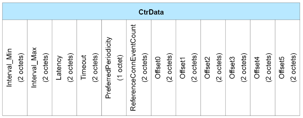
The LL_CONNECTION_PARAM_REQ CtrData consists of 12 fields:
The Interval_Min field shall be set to indicate the minimum value of connInterval, as defined in Section 4.5.1, in the following manner:
connInterval = Interval_Min * 1.25 ms.
The Interval_Max field shall be set to indicate the maximum value of connInterval, as defined in Section 4.5.1, in the following manner:
connInterval = Interval_Max * 1.25 ms. The value shall not be less than the value of Interval_Min.
The Latency field shall be set to indicate the connPeripheralLatency value, as defined by Section 4.5.1, in the following manner:
connPeripheralLatency = Latency.
The Timeout field shall be set to indicate the connSupervisionTimeout value, as defined by Section 4.5.2, in the following manner:
connSupervisionTimeout = Timeout * 10 ms.
The PreferredPeriodicity field shall be set to indicate a value the connInterval is preferred to be a multiple of. PreferredPeriodicity is in units of 1.25 ms. E.g. if the PreferredPeriodicity is set to 100, it implies that connInterval is preferred to be any multiple of 125 ms. A value of zero means no preference. The PreferredPeriodicity shall be less than or equal to Interval_Max.
The ReferenceConnEventCount field shall be set to indicate the value of the connEventCounter relative to which all the valid Offset0 to Offset5 fields have been calculated.
Note: The ReferenceConnEventCount field is independent of the Instant field in the LL_CONNECTION_UPDATE_IND PDU.
The Offset0, Offset1, Offset2, Offset3, Offset4, and Offset5 fields shall be set to indicate the possible values of the position of the anchor points of the LE connection with the updated connection parameters relative to the ReferenceConnEventCount. The Offset0 to Offset5 fields are in units of 1.25 ms and are in decreasing order of preference; that is, Offset0 is the most preferred value, followed by Offset1, and so on. Offset0 to Offset5 shall be less than Interval_Max. A value of 0xFFFF means not valid. Valid Offset0 to Offset5 fields shall contain unique values. Valid fields shall always be before invalid fields.
2.4.2.17. LL_CONNECTION_PARAM_RSP
The format of the LL_CONNECTION_PARAM_RSP PDU is identical to the format of the LL_CONNECTION_PARAM_REQ PDU (see Section 2.4.2.16).
2.4.2.18. LL_REJECT_EXT_IND
The format of the CtrData field is shown in Figure 2.39.
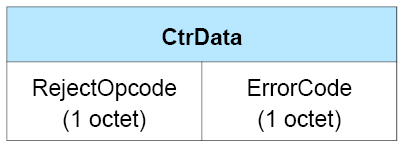
The LL_REJECT_EXT_IND CtrData consists of two fields:
RejectOpcode shall contain the Opcode field value of the LL Control PDU being rejected.
ErrorCode shall contain the reason the LL Control PDU was being rejected. See [Vol 1] Part F, Controller Error Codes for a list of error codes and descriptions.
This PDU shall be issued only when the remote Link Layer supports the Extended Reject Indication Link Layer feature ( Section 4.6). Otherwise, the LL_REJECT_IND PDU ( Section 2.4.2.14) shall be issued instead.
2.4.2.19. LL_PING_REQ
The LL_PING_REQ PDU does not have a CtrData field.
2.4.2.20. LL_PING_RSP
The LL_PING_RSP PDU does not have a CtrData field.
2.4.2.21. LL_LENGTH_REQ and LL_LENGTH_RSP
The format of the CtrData field for both the LL_LENGTH_REQ and LL_LENGTH_RSP PDUs is shown in Figure 2.40.
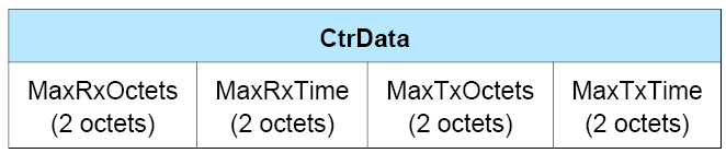
The LL_LENGTH_REQ and LL_LENGTH_RSP CtrData consists of four fields:
MaxRxOctets shall be set to the sender’s connMaxRxOctets value, as defined in Section 4.5.10. The MaxRxOctets field shall have a value not less than 27 octets.
MaxRxTime shall be set to the sender’s connMaxRxTime value, as defined in Section 4.5.10. The MaxRxTime field shall have a value not less than 328 μs.
MaxTxOctets shall be set to the sender’s connMaxTxOctets value, as defined in Section 4.5.10. The MaxTxOctets field shall have a value not less than 27 octets.
MaxTxTime shall be set to the sender’s connMaxTxTime value, as defined in Section 4.5.10. The MaxTxTime field shall have a value not less than 328 μs.
2.4.2.22. LL_PHY_REQ and LL_PHY_RSP
The format of the CtrData field for both the LL_PHY_REQ and LL_PHY_RSP PDUs is shown in Figure 2.41.
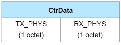
The LL_PHY_REQ and LL_PHY_RSP CtrData consists of two fields:
TX_PHYS shall be set to indicate the transmitter PHYs that the sender prefers to use.
RX_PHYS shall be set to indicate the receiver PHYs that the sender prefers to use.
These fields each consist of 8 bits; at least one bit in each field shall be set to 1. The bits that are set indicate which PHY or PHYs the sender prefers to use.
Bit number | Meaning |
|---|---|
0 | LE 1M PHY |
1 | LE 2M PHY |
2 | LE Coded PHY |
3–7 | Reserved for future use |
2.4.2.23. LL_PHY_UPDATE_IND
The format of the CtrData field is shown in Figure 2.42.
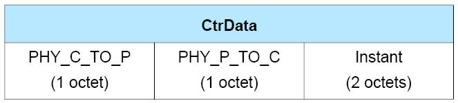
The LL_PHY_UPDATE_IND CtrData consists of three fields:
PHY_C_TO_P shall be set to indicate the PHY that shall be used for packets sent from the Central to the Peripheral. PHY_P_TO_C shall be set to indicate the PHY that shall be used for packets sent from the Peripheral to the Central. These fields each consist of 8 bits. If a PHY is changing, the bit corresponding to the new PHY (as specified in Table 2.21) shall be set to 1 and the remaining bits to 0; if a PHY is remaining unchanged, then the corresponding field shall be set to the value 0.
Instant shall be set to indicate the instant described in Section 5.1.10.
If both the PHY_C_TO_P and PHY_P_TO_C fields are zero then there is no Instant and the Instant field is reserved for future use.
2.4.2.24. LL_MIN_USED_CHANNELS_IND
The format of the CtrData field is as shown in Figure 2.43.
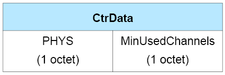
The LL_MIN_USED_CHANNELS_IND consists of two fields:
The PHYS field shall be set to the PHY(s) for which the Peripheral has a minimum number of used channels requirement. The PHYS field consists of 8 bits as specified in Table 2.21. At least one bit in the field shall be set to 1.
The MinUsedChannels field contains the minimum number of channels to be used on the specified PHY. The MinUsedChannels field shall have a value in the range 2 to 37.
2.4.2.25. LL_CTE_REQ
The format of the CtrData field is shown in Figure 2.44.
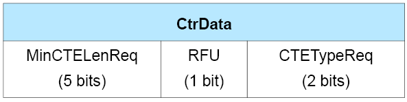
The LL_CTE_REQ PDU CtrData consists of two fields:
MinCTELenReq shall contain the minimum length of the Constant Tone Extension (see Section 2.5.1) requested from the remote device, in 8 µs units. The value of the field shall be in the range 2 to 20.
CTETypeReq shall contain the type of the Constant Tone Extension requested from the remote device as specified in Table 2.22.
Value | Meaning |
|---|---|
0 | AoA Constant Tone Extension |
1 | AoD Constant Tone Extension with 1 µs slots |
2 | AoD Constant Tone Extension with 2 µs slots |
3 | Reserved for future use |
2.4.2.26. LL_CTE_RSP
The LL_CTE_RSP PDU does not have a CtrData field.
2.4.2.27. LL_PERIODIC_SYNC_IND
The format of the CtrData field is shown in Figure 2.45.
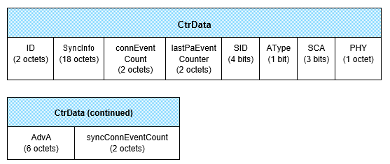
The LL_PERIODIC_SYNC_IND PDU CtrData consists of ten fields:
ID shall be set to an identifier provided by the Host. This is for use by higher-level protocols and its value is not specified or used by this specification.
SyncInfo has the meaning and format specified in Section 2.3.4.6, except that the reference point for syncPacketWindowOffset is the anchor point of the nearest connection event with the counter value specified in the connEventCount field and a zero offset does not have a special meaning.
connEventCount shall be set to a connection event counter value that meets the requirement currEvent - 2 14 < connEventCount < currEvent + 214 (mod 65536), where currEvent is the counter value for the connection event when the LL_PERIODIC_SYNC_IND PDU is being transmitted (or retransmitted).
lastPaEventCounter shall be set to the paEventCounter applying to the AUX_SYNC_IND PDU used to determine the contents of the SyncInfo; the device sending this PDU shall have actually transmitted or received the AUX_SYNC_IND PDU. The lastPaEventCounter field and the PeriodicEventCounter field of the SyncInfo shall be equal, shall have a difference of 1 (mod 65536), or shall represent times not more than 5 seconds apart.
SID shall be set to the Advertising SID subfield of the advertising set pointing to the periodic advertising.
AType shall be 0 if the AdvA field holds a public address and 1 if it holds a random address.
SCA shall be set to indicate the sleep clock accuracy of the device sending this PDU. The value shall be represented in the same way as in the CONNECT_IND PDU (see Section 2.3.3.1).
PHY shall be set to indicate the PHY used by the periodic advertising. The bit corresponding to the PHY (as specified in Table 2.21) shall be set to 1 and the remaining bits to 0.
If the advertiser's address in the advertising set pointing to the periodic advertising is a resolvable private address, AdvA shall be set to any resolvable private address that was generated using the same IRK. Otherwise, AdvA shall be set to the advertiser's address in the advertising set.
syncConnEventCount shall be set to the connection event counter for the connection event that the sending device used in determining the contents of this PDU. This shall be a connection event where the sending device received a packet from the device it will send the LL_PERIODIC_SYNC_IND PDU to and, if the sending device is the Peripheral on the piconet containing those two devices, it used the received packet to synchronize its anchor point (see Section 4.5.7).
Note: This implies that the connection must be established before this PDU can be transmitted.
2.4.2.28. LL_CLOCK_ACCURACY_REQ and LL_CLOCK_ACCURACY_RSP
The format of the CtrData field is shown in Figure 2.46.
 |
The SCA field shall indicate the current centralSCA (if the PDU is sent by the Central) or peripheralSCA (if the PDU is sent by the Peripheral) used to determine the worst case sleep clock accuracy of the sending device as defined in Section 4.2.2. The format of this field is identical to the SCA field in the CONNECT_IND PDU (see Section 2.3.3.1).
2.4.2.29. LL_CIS_REQ
The format of the CtrData field is shown in Figure 2.47.
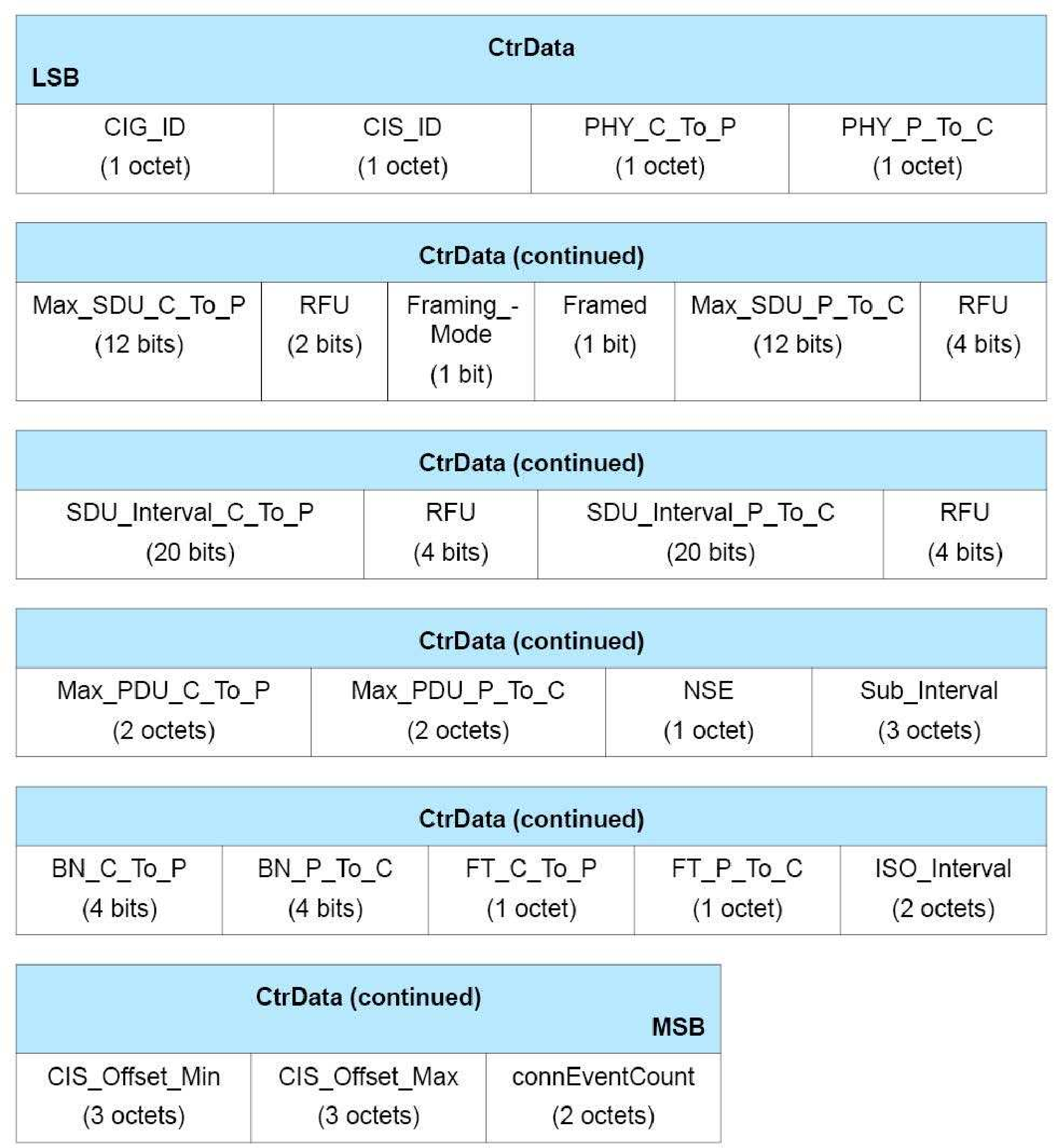
The LL_CIS_REQ CtrData consists of the following fields:
CIG_ID shall be set to the CIG identifier as defined in Section 4.5.14.
CIS_ID shall be set to the CIS identifier as defined in Section 4.5.13.1
PHY_C_To_P shall be set to indicate the PHY that shall be used from the Central to the Peripheral, as defined in Table 2.21. Exactly 1 bit shall be set.
PHY_P_To_C shall be set to indicate the PHY that shall be used from the Peripheral to the Central, as defined in Table 2.21. Exactly 1 bit shall be set.
Max_SDU_C_To_P shall be set to the maximum size of an SDU, in octets, from the Central’s Host.
Framed shall be set to 0 for unframed Data PDUs and 1 for framed Data PDUs.
Max_SDU_P_To_C shall be set to the maximum size of an SDU, in octets, from the Peripheral’s Host.
SDU_Interval_C_To_P shall be set to the time, in microseconds, between two consecutive SDUs from the Central’s Host.
SDU_Interval_P_To_C shall be set to the time, in microseconds, between two consecutive SDUs from the Peripheral’s Host.
Max_PDU_C_To_P shall be set to the maximum payload size, in octets, from the Central to the Peripheral. The value shall be between 0 and 251 octets. This field shall be set to 0 if and only if BN_C_To_P is set to 0.
Max_PDU_P_To_C shall be set to the maximum payload size, in octets, from the Peripheral to the Central. The value shall be between 0 and 251 octets. This field shall be set to 0 if and only if BN_P_To_C is set to 0.
NSE shall be set to the maximum number of subevents in each CIS event. The value shall be between 1 and 31.
Sub_Interval shall be set to the time, in microseconds, between the start of a subevent and the start of the next subevent for that CIS in the same CIS event. The value shall be set to 0 if the NSE field is set to 1; otherwise the value shall be at least 400 µs and shall be less than ISO_Interval.
BN_C_To_P shall be set to the BN parameter value used from the Central to Peripheral, as defined in Section 4.5.13.2. The value shall be between 0 and 15.
BN_P_To_C shall be set to the BN parameter value used from the Peripheral to Central, as defined in Section 4.5.13.2. The value shall be between 0 and 15.
FT_C_To_P shall be set to the FT parameter value used from the Central to the Peripheral, as defined in Section 4.5.13.2. The value shall be between 1 and 255.
FT_P_To_C shall be set to the FT parameter value used from the Peripheral to the Central, as defined in Section 4.5.13.2. The value shall be between 1 and 255.
ISO_Interval shall be set to the time between two consecutive CIS anchor points in units of 1.25 ms. The value shall be between 4 and 3200 (i.e. 5 ms to 4 s).
CIS_Offset_Min shall be set to the proposed minimum time, in microseconds, between the ACL anchor point of the connection event with the connection event counter equal to connEventCount and the first CIS anchor point. The value shall be at least 500 µs.
CIS_Offset_Max shall be set to the proposed maximum time, in microseconds, between the ACL anchor point of the connection event with the connection event counter equal to connEventCount and the first CIS anchor point. The value shall be greater than or equal to CIS_Offset_Min and less than connInterval. CIS_Offset_Max should be less than (connInterval – ((NSE – 1) × Sub_Interval + MPT_C + T_IFS + MPT_P + T_MSS)), where MPT_C and MPT_P are defined in Section 4.5.13.1. For the first CIS in a CIG it should be less than (connInterval – (CIG_Sync_Delay + T_MSS)).
connEventCount shall be set to a connection event counter value that meets the requirement currEvent – 214 < connEventCount < currEvent + 214 (mod 65536), where currEvent is the counter value for the connection event where the PDU containing this field is being transmitted or retransmitted. connEventCount should be set to a value greater than currEvent of the event in which the LL_CIS_REQ PDU is first transmitted.
2.4.2.30. LL_CIS_RSP
The format of the CtrData field is shown in Figure 2.48.
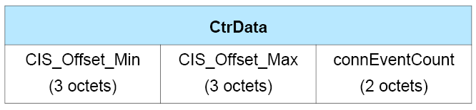
The LL_CIS_RSP CtrData field consists of three fields which have the same meaning as the corresponding fields in the LL_CIS_REQ PDU.
2.4.2.31. LL_CIS_IND
The format of the CtrData field is shown in Figure 2.49.
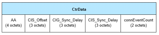
The LL_CIS_IND PDU CtrData consists of the following fields:
AA shall be set to the Access Address of the CIS, generated by the Link Layer following the rules specified in Section 2.1.2.
CIS_Offset shall be set to the time, in microseconds, from the ACL anchor point of the connection event that is referenced by connEventCount to the first CIS anchor point.
CIG_Sync_Delay shall be set to the value of CIG_Sync_Delay, as defined in Section 4.5.14.1, in microseconds.
CIS_Sync_Delay shall be set to the value of CIS_Sync_Delay, as defined in Section 4.5.14.1, in microseconds.
connEventCount shall be set to a connection event counter value that meets the requirement currEvent – 214 < connEventCount < currEvent + 214 (mod 65536), where currEvent is the ACL connection event counter value for the connection event where the LL_CIS_IND PDU is being transmitted. connEventCount should be set to a value greater than currEvent of the event in which the LL_CIS_IND PDU is first transmitted.
2.4.2.32. LL_CIS_TERMINATE_IND
The format of the CtrData field is shown in Figure 2.50.
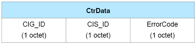
The LL_CIS_TERMINATE_IND PDU CtrData consists of three fields:
CIG_ID shall be set to the identifier of the CIG containing the CIS being terminated.
CIS_ID shall be set to the identifier of the CIS being terminated.
ErrorCode shall be set to inform the peer why the CIS is about to be terminated (see [Vol 1] Part F, Controller Error Codes for a list of error codes and descriptions).
2.4.2.33. LL_POWER_CONTROL_REQ
The format of the CtrData field is shown in Figure 2.51.
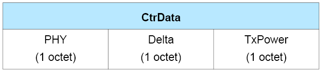
The LL_POWER_CONTROL_REQ CtrData consists of three fields:
PHY shall be set to indicate the PHY for which the request is being made. The bit corresponding to the PHY (as specified in Table 2.23) shall be set to 1 and the remaining bits to 0.
Bit number
Meaning
0
LE 1M PHY
1
LE 2M PHY
2
LE Coded PHY with S=8 data coding
3
LE Coded PHY with S=2 data coding
All other bits
Reserved for future use
Table 2.23: PHY field bit meaningsDelta shall be set to the requested change in the recipient's transmit power level, in dB, for the PHY indicated. The value is a signed integer: a positive value indicates a request to increase the transmit power level, a negative value indicates a request to decrease it, and zero indicates that no change is being requested. A value of 0x7F indicates a request to increase to the maximum power level.
TxPower shall be set to the sender's transmit power level for the PHY indicated. The value is in dBm, represented as a signed integer. When set to 127, it indicates that the value is unavailable. It shall not be set to 126.
2.4.2.34. LL_POWER_CONTROL_RSP
The format of the CtrData field is shown in Figure 2.52.
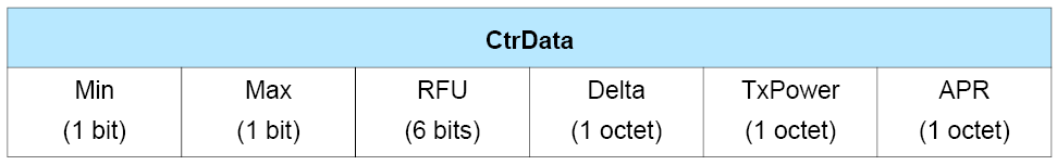
The LL_POWER_CONTROL_RSP CtrData consists of five fields:
Min shall be set if the sender is currently at the minimum supported power level.
Max shall be set if the sender is currently at the maximum supported power level.
Note: if Min and Max are both set then the sender has a single fixed transmit power level.
Delta shall be set to the actual change in the sender's transmit power level, in dB, that the sender has made for the PHY requested. The value is a signed integer, with a positive value indicating a power increase, and a negative value indicating a power decrease. Zero indicates that there was no change.
TxPower shall be set to the sender's transmit power level for the PHY requested. The value is in dBm, represented as a signed integer. When set to 127, it indicates that the value is unavailable. When set to 126, it indicates that the sender is not currently managing power for the requested PHY; in this case all other fields shall be ignored.
APR (Acceptable Power Reduction) shall be set to the maximum decrease in output power level of the peer device in dB, for the PHY requested, that is acceptable to the device sending this PDU. When set to 0xFF, it indicates that the sender is unable to determine a value.
2.4.2.35. LL_POWER_CHANGE_IND
The format of the CtrData field is shown in Figure 2.53.
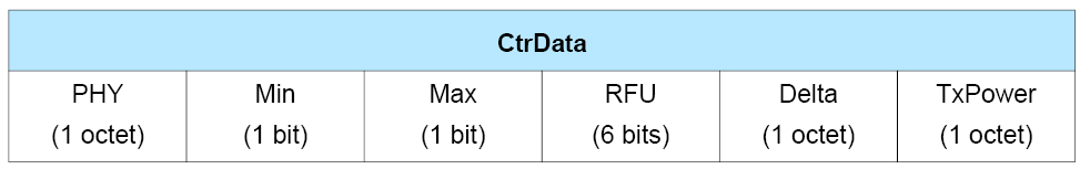
The LL_POWER_CHANGE_IND CtrData consists of five fields:
PHY shall be set to indicate the PHY(s) for which the power level has changed, using the values listed in Table 2.23. The PHY field may have more than one bit set if the other fields have the same values for the PHYs being reported.
Min shall be set if the sender is currently at the minimum supported power level.
Max shall be set if the sender is currently at the maximum supported power level.
Note: if Min and Max are both set then the sender has a single fixed transmit power level.
Delta shall be set to the change in the sender's transmit power level, if any, for the PHY(s) indicated. The value is a signed integer in dB, with a positive value indicating a power increase, and a negative value indicating a power decrease. Zero indicates that there was no change.
TxPower shall be set to the sender's transmit power level for the PHY(s) indicated. The value is in dBm, represented as a signed integer. When set to 127, it indicates that the value is unavailable. When set to 126, it indicates that the sender has stopped managing power for the indicated PHY(s); in this case all other fields shall be ignored.
2.4.2.36. LL_SUBRATE_REQ PDU
The format of the CtrData field is shown in Figure 2.54.
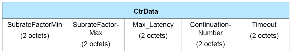
The LL_SUBRATE_REQ CtrData consists of five fields:
The SubrateFactorMin field shall be set to the minimum requested connSubrateFactor, as defined in Section 4.5.1.
The SubrateFactorMax field shall be set to the maximum requested connSubrateFactor, as defined in Section 4.5.1.
The Max_Latency field shall be set to the maximum requested connPeripheralLatency, as defined in Section 4.5.1, in subrated events. The same maximum shall apply irrespective of the subrating factor actually chosen. The value of SubrateFactorMax × (Max_Latency + 1) shall be less than or equal to than 500.
The ContinuationNumber field shall be set to the minimum requested connContinuationNumber, as defined in Section 4.5.1.
The Timeout field shall be set to indicate the requested connSupervisionTimeout value, as defined in Section 4.5.2, in the following manner:
connSupervisionTimeout = Timeout × 10 ms.
2.4.2.37. LL_SUBRATE_IND PDU
The format of the CtrData field is shown in Figure 2.55.
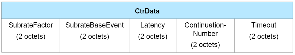
The LL_SUBRATE_IND CtrData consists of five fields:
The SubrateFactor field shall be set to the new connSubrateFactor, as defined in Section 4.5.1, to be used on the connection.
The SubrateBaseEvent field shall be set to the new connSubrateBaseEvent, as defined in Section 4.5.1, to be used on the connection.
The Latency field shall be set to the new connPeripheralLatency in subrated events, as defined in Section 4.5.1, to be used on the connection.
The ContinuationNumber field shall be set to the new connContinuationNumber, as defined in Section 4.5.1, to be used on the connection.
The Timeout field shall be set to indicate the new connSupervisionTimeout value, as defined in Section 4.5.2, in the following manner:
connSupervisionTimeout = Timeout × 10 ms.
2.4.2.38. LL_CHANNEL_REPORTING_IND
The format of the CtrData field is shown in Figure 2.56.
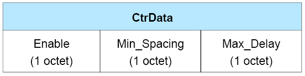
The LL_CHANNEL_REPORTING_IND CtrData consists of three fields:
Enable shall be set to indicate whether channel classification reporting needs to be enabled or disabled as specified in Table 2.24.
Value
Meaning
0x00
Disable channel classification reporting
0x01
Enable channel classification reporting
All other values
Reserved for future use
Table 2.24: Enable field valuesMin_Spacing shall be set to indicate, in units of 200 ms, the minimum amount of time from the last LL_CHANNEL_STATUS_IND PDU that was sent before the next LL_CHANNEL_STATUS_IND PDU may be sent. The value shall be between 5 (1 second) and 150 (30 seconds).
Max_Delay shall be set to indicate, in units of 200 ms, the maximum amount of time between the change in the channel classification being detected by a Peripheral and its generation of an LL_CHANNEL_STATUS_IND PDU. The value shall be between 5 (1 second) and 150 (30 seconds). Max_Delay shall be greater than or equal to Min_Spacing.
2.4.2.39. LL_CHANNEL_STATUS_IND
The format of the CtrData field is shown in Figure 2.57.

The LL_CHANNEL_STATUS_IND CtrData consists of one field:
Channel_Classification has the type uint2[37]. The nth (numbering from 0) element defines the classification of data channel index n. The value of each element indicates:
0 = unknown
1 = good
2 = reserved for future use
3 = bad
2.4.2.40. LL_PERIODIC_SYNC_WR_IND
The format of the CtrData field is shown in Figure 2.58.
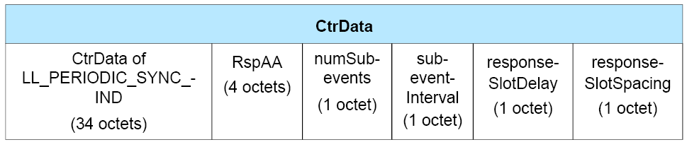
The LL_PERIODIC_SYNC_WR_IND PDU CtrData consists of five fields:
The CtrData of LL_PERIODIC_SYNC_IND field has the meaning and format specified in Section 2.4.2.27.
The RspAA field shall be set to the Access Address to be used by the device when it transmits a response packet to the periodic advertiser.
The numSubevents field shall be set to the number of subevents.
The subeventInterval field shall be set to the time in 1.25 ms units from the start of one subevent to the start of the next subevent.
The responseSlotDelay field shall be set to the time in 1.25 ms units from the start of one subevent to the first response slot.
responseSlotSpacing shall be set to the time in 0.125 ms units from the start of one response slot to the start of the next response slot.
2.5. Constant Tone Extension and IQ sampling
2.5.1. Constant Tone Extension structure and types
The Constant Tone Extension has a variable length; it shall be at least 16 µs and not greater than 160 µs. The contents are a constantly modulated series of 1s and no whitening shall be applied to them.
The first 4 µs of the Constant Tone Extension are termed the guard period and the next 8 µs are termed the reference period. After the reference period, the Constant Tone Extension consists of a sequence of alternating switch slots and sample slots, each either 1 µs or 2 µs long as specified by the Host. The 2-µs-long switch and sample slots are mandatory to support; the 1-µs-long switch and sample slots are optional to support. However, if a device supports 1-µs-long switch and sample slots, it shall support them on all supported PHYs that allow Constant Tone Extensions. The structure of the Constant Tone Extension is shown in Figure 2.59.
The Constant Tone Extension can be one of two types: AoA or AoD.
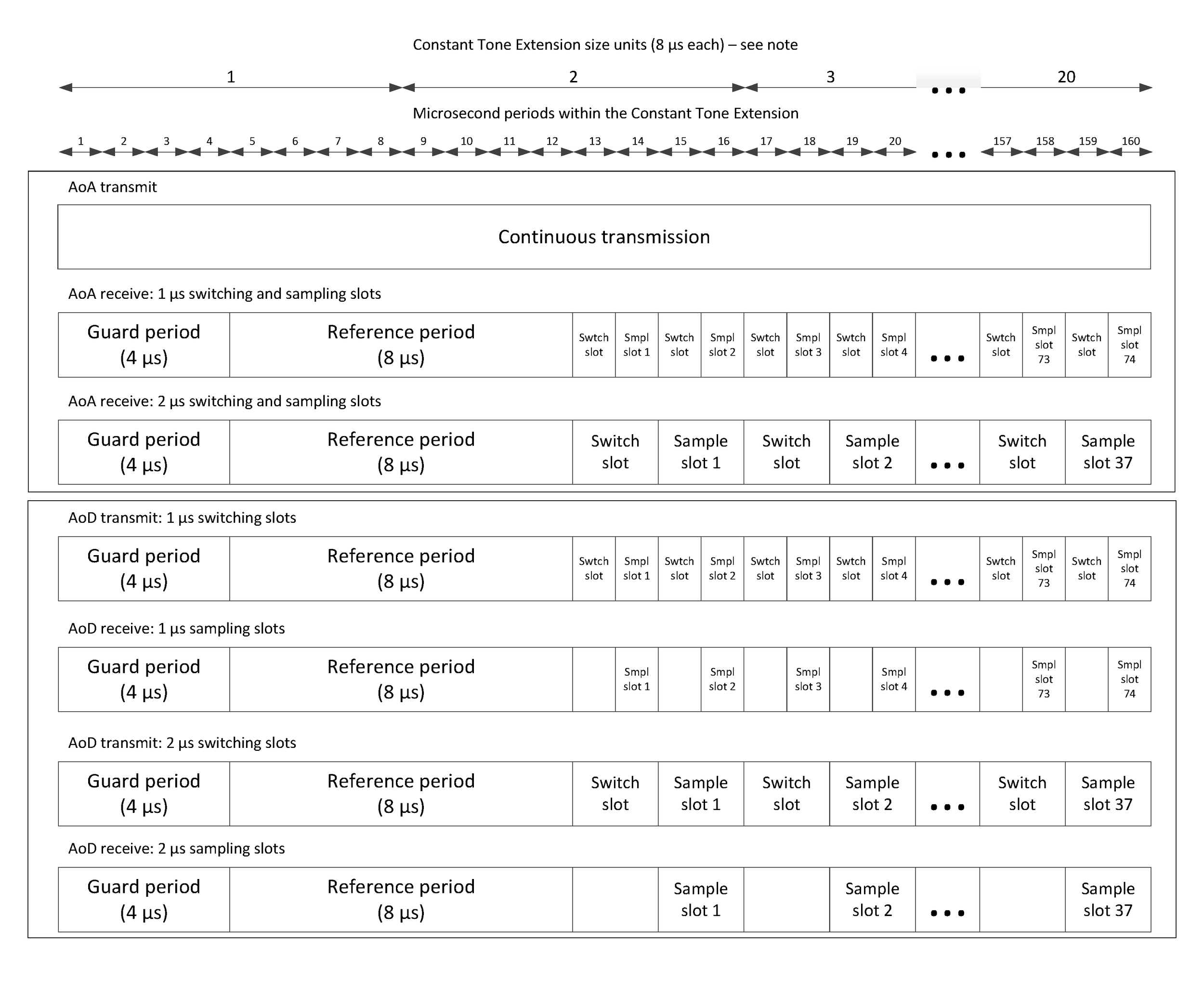
Note
Note: See Section 2.4.2.25 for examples of the use of these units.
2.5.2. CTEInfo field
When present, the CTEInfo field is one octet with the format shown in Figure 2.60.
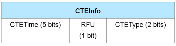
The presence of the CTEInfo field indicates that the packet includes a Constant Tone Extension.
The CTETime field defines the length of the Constant Tone Extension in 8 µs units. The value of the CTETime field shall be between 2 and 20; all other values are reserved for future use.
The CTEType field defines the type of the Constant Tone Extension and the duration of the switching slots. The value of the field is specified in Table 2.25 and the various possible formats are specified in Section 2.5.1.
CTEType value | Description |
|---|---|
0 | AoA Constant Tone Extension |
1 | AoD Constant Tone Extension with 1 µs slots |
2 | AoD Constant Tone Extension with 2 µs slots |
3 | Reserved for future use |
2.5.3. Transmitting Constant Tone Extensions
When transmitting a packet that contains an AoA Constant Tone Extension, the transmitter shall not switch antennae. When transmitting a packet that contains an AoD Constant Tone Extension, the transmitter shall perform antenna switching at the rate and according to the switching pattern configured by the Host (see [Vol 6] Part A, Section 5).
A device that supports transmitting Constant Tone Extensions shall be able to transmit a Constant Tone Extension that is at least 16 µs long.
2.5.4. IQ sampling
When requested by the Host, the receiver shall perform IQ sampling when receiving a valid packet that contains a Constant Tone Extension and may perform IQ sampling when receiving a packet that contains a Constant Tone Extension but an incorrect CRC. The remainder of this section shall apply whenever the receiver performs IQ sampling on a packet.
When receiving a packet that contains an AoD Constant Tone Extension, the receiver does not need to switch antennae. When receiving a packet that contains an AoA Constant Tone Extension, the receiver shall perform antenna switching at the rate and according to the switching pattern configured by the Host (see [Vol 6] Part A, Section 5). In both cases, the receiver shall take an IQ sample each microsecond during the reference period and an IQ sample each sample slot (thus there will be 8 reference IQ samples, 1 to 37 IQ samples with 2 µs slots, and 2 to 74 IQ samples with 1 µs slots, meaning 9 to 82 samples in total). The Controller shall report the IQ samples to the Host. The receiver shall sample the entire Constant Tone Extension, irrespective of length, unless this conflicts with other activities.
Note
Note: In order to obtain good quality data for angle estimation, IQ samples should be taken at the same point within each IQ Sampling Window; this starts 0.125 µs after the beginning and ends 0.125 µs before the end of each microsecond period (see Figure 2.61). If 2 µs sample slots are used, the sampling should be done during the latter microsecond (see Figure 2.62).
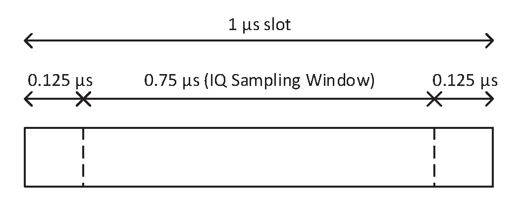
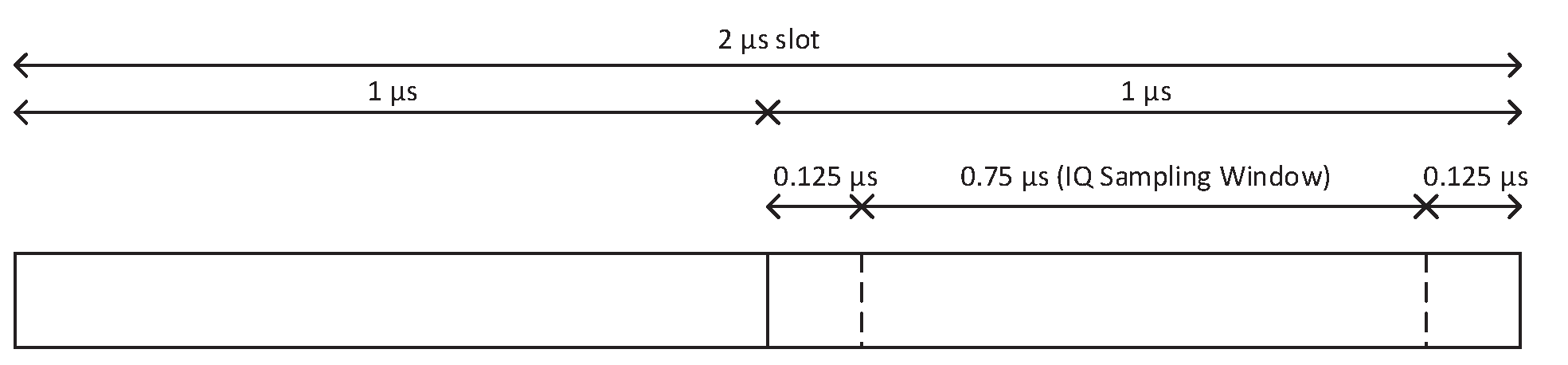
A Controller that supports IQ Sampling shall be able to measure the RSSI of received packets on any antenna used for receiving the body of the packet (in both cases excluding any Constant Tone Extension) and be able to receive and sample a Constant Tone Extension of any valid length.
If the Controller has insufficient resources to perform sampling on all Constant Tone Extensions it receives, it may stop sampling after it has reported at least one set of IQ samples to the Host. If the Controller stops sampling, it shall report this to the Host and should resume sampling at the start of the next periodic advertising event or connection event. If the required resources are not yet available, then the Controller may, but should not, report this to the Host again.
2.6. Isochronous Physical Channel PDU
The Isochronous Physical Channel PDU has a 16-bit header, a variable size payload, and may include a Message Integrity Check (MIC) field.
The Isochronous Physical Channel PDU is shown in Figure 2.63.
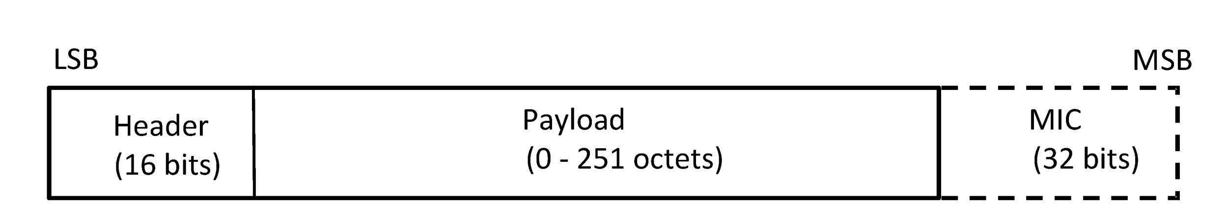
The format of the Header field and the payload depends on the type of the Isochronous Physical Channel PDU that is being used. When used on a CIS, an Isochronous Physical Channel PDU shall be a Connected Isochronous PDU as defined in Section 2.6.1. When used on a BIS, it shall be a Broadcast Isochronous PDU as defined in Section 2.6.2.
The MIC field shall be included in all PDUs that contain a non-zero length Payload that are sent on an encrypted CIS or BIS. The MIC shall be calculated as specified in [Vol 6] Part E, Section 1. The MIC is a 4-octet field. The MIC field shall not be included in any PDU that is sent on an unencrypted CIS or BIS or that has a zero-length payload.
2.6.1. Connected Isochronous PDU
A Connected Isochronous PDU (CIS PDU) shall be either a CIS Data PDU or a CIS Null PDU. A CIS Data PDU is used to carry isochronous data. A CIS Null PDU is used when there is no data to be sent.
The Header field of the Connected Isochronous PDU is shown in Figure 2.64.
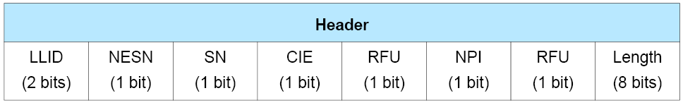
The 16-bit Header field consists of the fields that are shown in Table 2.26.
The LLID field is RFU in a CIS Null PDU.
The Next Expected Sequence Number (NESN) field shall be set as defined in Section 4.5.9.
The Sequence Number (SN) field shall be set as defined in Section 4.5.9 in a CIS Data PDU. This field is RFU in a CIS Null PDU.
The Close Isochronous Event (CIE) field shall be set as defined in Section 4.5.13.4.
The Null PDU Indicator (NPI) field shall be set for every CIS Null PDU.
The Length field shall be set to 0 for a CIS Null PDU.
Field Name | Description |
|---|---|
LLID | The LLID field indicates the type of content of the payload field of the CIS Data PDU. 0b00 = Unframed CIS Data PDU; end fragment of an SDU or a complete SDU. 0b01 = Unframed CIS Data PDU; start or continuation fragment of an SDU. 0b10 = Framed CIS Data PDU; one or more SDU segments. 0b11 = Reserved for future use. |
NESN | Next Expected Sequence Number |
SN | Sequence Number |
CIE | Close Isochronous Event |
NPI | The Null PDU Indicator (NPI) indicates whether the packet is a CIS Data PDU or a CIS Null PDU. |
Length | The Length field indicates the size, in octets, of the Payload and MIC, if included. |
See [Vol 6] Part G, Section 1 for more details about fragmentation and segmentation of SDUs.
2.6.2. Broadcast Isochronous PDU
A Broadcast Isochronous PDU (BIS PDU) shall be either a BIS Data PDU or BIG Control PDU. A BIS Data PDU is used to carry isochronous data. A BIG Control PDU is used to send control information for a BIG.
The Header field of the Broadcast Isochronous PDU is shown in Figure 2.65.
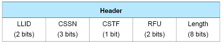
The 16-bit header consists of the fields that are specified in Table 2.27.
The Control Subevent Sequence Number (CSSN) field shall be set as defined in Section 4.4.6.7.
The Control Subevent Transmission Flag (CSTF) field shall be set as defined in Section 4.4.6.7.
Field Name | Description |
|---|---|
LLID | The LLID field indicates the type of content of the payload field of the PDU. 0b00 = Unframed BIS Data PDU; end fragment of an SDU or a complete SDU. 0b01 = Unframed BIS Data PDU; start or continuation fragment of an SDU. 0b10 = Framed BIS Data PDU; one or more SDU segments. 0b11 = BIG Control PDU. |
CSSN | Control Subevent Sequence Number |
CSTF | Control Subevent Transmission Flag |
Length | The Length field indicates the size, in octets, of the Payload and MIC, if included. |
See [Vol 6] Part G, Section 1 for more details about fragmentation and segmentation of SDUs.
2.6.3. BIG Control PDU
A BIG Control PDU shall be used to send control information in a BIG (see Section 4.4.6.7).
The format of the Payload field in a BIG Control PDU is shown in Figure 2.66.
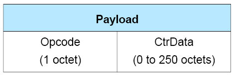
A BIG Control PDU shall not have the Length field (see Section 2.6.2) set to 0b00000000.
The Opcode field identifies different types of BIG Control PDUs, as defined in Table 2.28.
The CtrData field in the BIG Control PDU is specified by the Opcode field and is defined in the following subsections. For a given Opcode the length of the CtrData field is fixed.
Where the description of a field within the CtrData field gives a range of valid values or other restrictions on a value (e.g. that field X is less than field Y), all other values shall be reserved for future use. The range may be directly specified in the relevant subsection for the BIG Control PDU or indirectly, possibly in a section referenced by that subsection.
Except where explicitly stated otherwise, all fields within the CtrData field in a BIG Control PDU that hold an integer shall be interpreted as unsigned.
Opcode | BIG Control PDU Name |
|---|---|
0x00 | BIG_CHANNEL_MAP_IND |
0x01 | BIG_TERMINATE_IND |
0xF8 to 0xFB | Reserved for future use (used for specification development purposes) |
All other values | Reserved for future use |
If a BIG Control PDU is received that is not supported or is reserved for future use, the Link Layer shall ignore it.
If a BIG Control PDU is received with the wrong length or with invalid CtrData fields, the Link Layer may continue with the relevant BIG Control procedure with an implementation-specific interpretation of the data (e.g., if the PDU is too long, it can ignore the extra data; if a field is out of range, it can use the nearest permitted value). If it does not continue the procedure, it shall ignore the PDU.
2.6.3.1. BIG_CHANNEL_MAP_IND
The format of the CtrData field is shown in Figure 2.67.
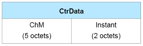
The BIG_CHANNEL_MAP_IND CtrData consists of two fields:
The ChM field shall be set to the channel map indicating Used and Unused data channels. Every channel is represented with a bit positioned as per the channel index defined by Section 1.4.1. The format of this field is identical to the ChM field in the CONNECT_IND PDU (see Section 2.3.3.1).
The Instant field shall be set to the value of bigEventCounter15-0 (see Section 4.4.6.3) when the channel map takes effect.
2.6.3.2. BIG_TERMINATE_IND
The format of the CtrData field is shown in Figure 2.68.
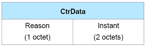
The BIG_TERMINATE_IND CtrData consists of two fields:
The Reason field shall be set to inform the Synchronized Receiver(s) why the BIG is about to be terminated. See [Vol 1] Part F, Controller Error Codes for a list of error codes and descriptions.
The Instant field shall be set to the value of bigEventCounter15-0 (see Section 4.4.6.3) when the BIG will be terminated.
3. Bit stream processing
Bluetooth devices shall use the bit stream processing schemes as defined in the following sections.
Figure 3.1 shows the bit stream processing for PDUs on the LE Uncoded PHYs.
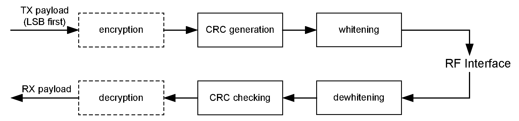
Figure 3.2 shows the bit stream processing for PDUs on the LE Coded PHYs.
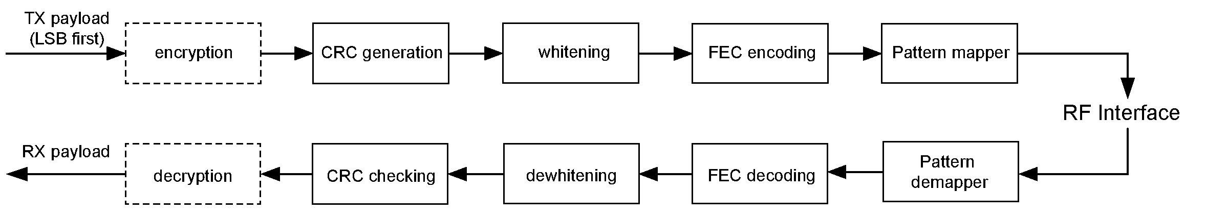
3.1. Error checking
At packet reception, the Access Address shall be checked first. If the Access Address is incorrect, the packet shall be rejected, otherwise the packet shall be considered received. If the CRC is incorrect, the packet shall be rejected, otherwise the packet shall be considered successfully received and therefore valid. A packet shall only be processed if the packet is considered valid, except that the receiver may carry out IQ sampling (see Section 2.5.4) even if the CRC is incorrect. A packet with an incorrect CRC may cause a connection event to continue, as specified in Section 4.5.1.
3.1.1. CRC generation
The CRC shall be calculated on the PDU of all Link Layer packets. If the PDU is encrypted, then the CRC shall be calculated after encryption of the PDU has been performed.
The CRC polynomial is a 24-bit CRC and all bits in the PDU shall be processed in transmitted order starting from the least significant bit. The polynomial has the form of x24 + x10 + x9 + x6 + x4 + x3 + x + 1. For every Data Physical Channel PDU and Connected Isochronous PDU, the shift register shall be preset with the CRC initialization value set for the ACL connection and communicated in the CONNECT_IND or AUX_CONNECT_REQ PDU. For every PDU sent on a periodic advertising train (including AUX_CONNECT_REQ and AUX_CONNECT_RSP PDUs), the shift register shall be preset with the CRCInit value set in the SyncInfo field (see Section 2.3.4.6) that describes the periodic advertising train. For all other Advertising Physical Channel PDUs, the shift register shall be preset with 0x555555. For every Broadcast Isochronous PDU, the shift register shall be preset with the BaseCRCInit value from the BIGInfo data (see Section 4.4.6.11) in the most significant 2 octets and the BIS_Number for the specific BIS in the least significant octet. For BIG Control PDUs, the least significant octet shall be 0.
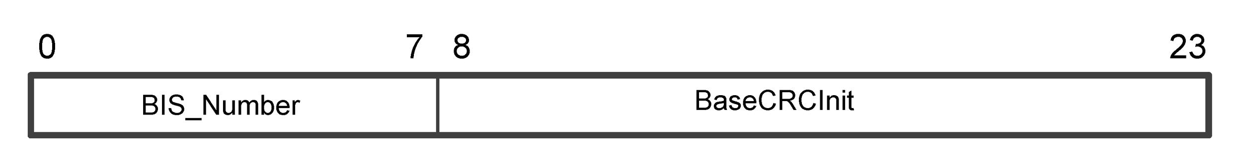
Position 0 shall be set as the least significant bit and position 23 shall be set as the most significant bit of the initialization value. The CRC is transmitted most significant bit first, i.e. from position 23 to position 0 (see Section 1.2).
Figure 3.4 shows an example linear feedback shift register (LFSR) to generate the CRC.
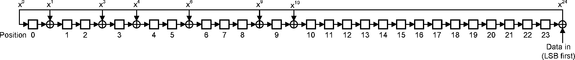
3.2. Data whitening
Data whitening is used to avoid long sequences of zeros or ones, e.g., 0b0000000 or 0b1111111, in the data bit stream. Whitening shall be applied on the PDU and CRC of all Link Layer packets and is performed after the CRC generation in the transmitter. No other parts of the packets are whitened. De-whitening is performed before the CRC checking in the receiver (see Figure 3.1).
The whitener and de-whitener are defined the same way, using a 7-bit linear feedback shift register with the polynomial x7 + x4 + 1. Before whitening or de-whitening, the shift register is initialized with a sequence that is derived from the physical channel index in which the packet is transmitted in the following manner:
Position 0 is set to one.
Positions 1 to 6 are set to the channel index of the channel used when transmitting or receiving, from the most significant bit in position 1 to the least significant bit in position 6.
For example, if the channel index = 23 (0x17), the positions would be set as follows:
Position 0 = 1 Position 1 = 0 Position 2 = 1 Position 3 = 0 Position 4 = 1 Position 5 = 1 Position 6 = 1
Figure 3.5 shows an example linear feedback shift register (LFSR) to generate data whitening.
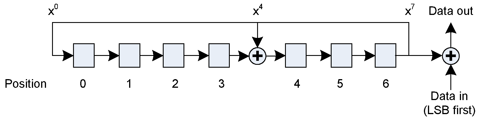
3.3. Coding
Coding only applies to the LE Coded PHY.
Coding consists of two processes. Data is first coded by the Forward Error Correction (FEC) convolutional encoder as defined in Section 3.3.1 and then spread by the pattern mapper as defined in Section 3.3.2.
3.3.1. Forward Error Correction encoder
The convolutional FEC encoder uses a non-systematic, non-recursive rate ½ code with constraint length K=4. The generator polynomials are:
G0(x) = 1 + x + x2 + x 3
G1(x) = 1 + x2 + x3
The bit coming from generator polynomial G0 (a0) is transmitted first; the bit coming from generator polynomial G1 (a1) is transmitted second.
The initial state of the convolutional FEC encoder is set to all zeros. An input sequence of three consecutive zeros always brings the convolutional FEC encoder back to its original state. This sequence is known as the termination sequence.
Figure 3.6 illustrates operation of the convolutional FEC encoder. Squares represent bit storage operations and circles represent XOR.
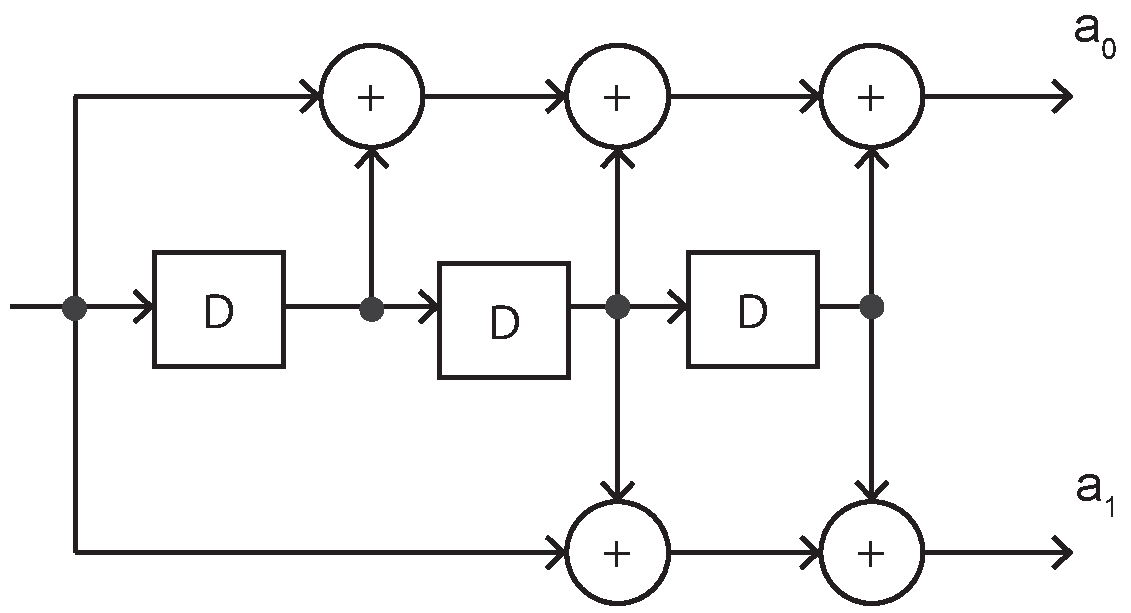
3.3.2. Pattern mapper
The pattern mapper converts each bit from the convolutional FEC encoder into P symbols, where the value of P depends on the coding scheme in use, according to Table 3.1 (the output sequences are in transmission order):
Input bit from the convolutional FEC encoder | Output sequence when P=1 (used by S=2) | Output sequence when P=4 (used by S=8) |
|---|---|---|
0 | 0 | 0011 |
1 | 1 | 1100 |
4. Air Interface protocol
The air interface protocol consists of the multiple access scheme, device discovery and Link Layer connection methods.
4.1. Frame Space
4.1.1. Inter Frame Space
The time interval between two consecutive packets on the same channel index is called the Inter Frame Space. It is defined as the time from the end of the last bit of the previous packet to the start of the first bit of the subsequent packet. The Inter Frame Space is designated “T_IFS” and shall be 150 µs.
4.1.2. Minimum AUX Frame Space
The minimum time interval between a packet containing an AuxPtr and the auxiliary packet it indicates is called the Minimum AUX Frame Space. It is defined as the minimum time from the end of the last bit of the packet containing the AuxPtr to the start of the auxiliary packet. The Minimum AUX Frame Space is designated “T_MAFS” and shall be 300 µs.
Figure 4.1 illustrates an example where the Minimum AUX Frame Space applies.
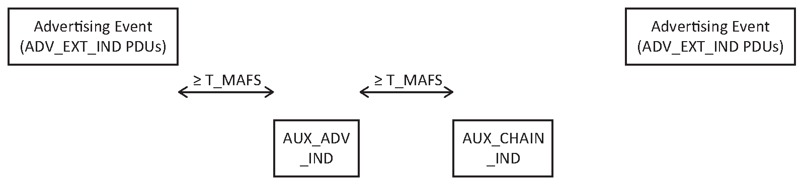
4.1.3. Minimum Subevent Space
The minimum time interval between the end of the last bit of the last packet in one subevent and the start of the first bit of the first packet in the next subevent is called the Minimum Subevent Space.
The Minimum Subevent Space is designated ‘T_MSS’ and shall be 150 µs.
Figure 4.2 illustrates an example where the Minimum Subevent Space applies in a CIS.
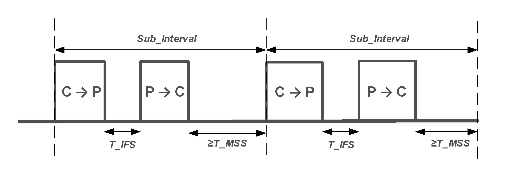
Figure 4.3 illustrates an example where the Minimum Subevent Space applies in a BIS.
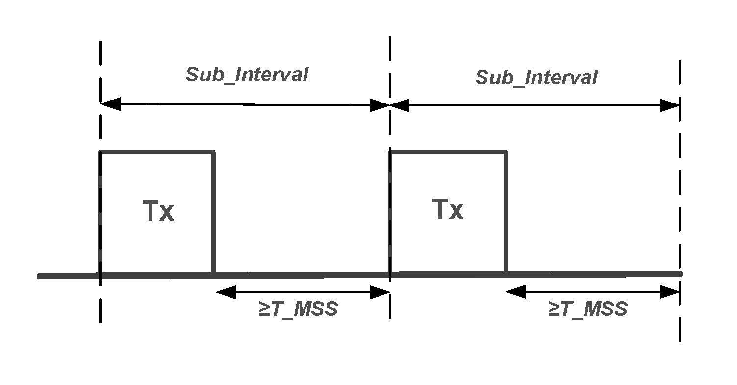 |
4.2. Timing requirements
The Link Layer shall use one of two possible clock accuracies: in the circumstances described in Section 4.2.1 it shall use the active clock accuracy; otherwise it shall use the sleep clock accuracy.
The clock accuracies specified in this section apply to the time between two specific events and only apply to devices when they transmit a packet. The clock used to time packet reception may have any accuracy but the receiving device will need to allow for this. For example, if the receiving device clock has an accuracy of 2000 ppm and a maximum jitter of 45 µs, then, for an event 1 second after the last event where timings were synchronized, the device will need to start listening at least 2045 µs earlier and continue listening until at least 2045 µs later than it would otherwise have done.
An implementation may use either a single clock or several clocks. For example, one implementation could use a single clock with variable accuracy whereas a different implementation could use one clock that only runs during periods where an event timed using active clock accuracy is pending and another clock with lower accuracy that runs at all times.
4.2.1. Active clock accuracy
The average timing of packet transmission during a connection, BIG, or CIG event, during active scanning, during a periodic advertising with responses subevent, and when requesting a connection is determined using the active clock accuracy, with a drift less than or equal to ±50 ppm. All instantaneous timings shall not deviate more than 2 µs from the average timing.
Note
Note: This means that the start of a packet is transmitted 150±2 µs after the end of the previous packet.
More specifically, these requirements apply to the intervals between:
adjacent packets in the same connection event
packets in the same BIG or CIG event, even if they are in different BISes or CISes or in different subevents
an advertising packet and a packet containing a SCAN_REQ, AUX_SCAN_REQ, CONNECT_IND, or AUX_CONNECT_REQ PDU
a packet containing a SCAN_REQ and the response packet containing a SCAN_RSP PDU
a packet containing an AUX_SCAN_REQ PDU and the response packet containing an AUX_SCAN_RSP PDU
a packet containing an AUX_CONNECT_REQ PDU and the response packet containing an AUX_CONNECT_RSP PDU
packets in the same periodic advertising with responses subevent.
4.2.2. Sleep clock accuracy
The average timing of all other activities is determined using the sleep clock accuracy, with a drift less than or equal to ±500 ppm. All instantaneous timings shall not deviate more than 16 µs from the average timing. The worst-case drift and instantaneous deviation of the active clock shall be less than or equal to those of the sleep clock.
In the specification, the Central's current sleep clock accuracy is referred to as centralSCA and the Peripheral's current sleep clock accuracy as peripheralSCA.
On a connection a device shall not use a sleep clock accuracy that is worse than the worst case indicated in the SCA field of the most recently sent LL_CLOCK_ACCURACY_REQ or LL_CLOCK_ACCURACY_RSP PDU. If the Link Layer has not initiated or responded to the Sleep Clock Accuracy Update procedure (see Section 5.1.14) in the current connection, the Central shall use a sleep clock accuracy that is better than or equal to the worst case indicated in the SCA field of the CONNECT_IND or AUX_CONNECT_REQ PDU used to create the connection and the Peripheral shall use a sleep clock accuracy of ±500 ppm or better.
Note
Note: These requirements therefore apply to the time between ACL anchor points (see Section 4.5.7), between CIS anchor points (see Section 4.5.14.1), and between BIG anchor points (see Section 4.4.6.4), as well as to the advertising and periodic advertising intervals and the advDelay value (see Section 4.4.2.2), all intervals between packets in the same extended advertising event or periodic advertising event, and all offsets specified by the AuxPtr and SyncInfo fields of advertising PDUs.
Note
Note: This means that a 2 s connection interval with a 500 ppm Central sleep clock accuracy will require a window widening either side of the anchor point of 1 ms plus 16 µs plus any allowance for the accuracy of the clock actually used by the Peripheral during the connection interval.
4.2.3. Range delay
Where two devices are more than a few meters apart the time taken for a signal to propagate between them will be significant compared with the Active Clock Accuracy defined in Section 4.2.1. When a device is listening for a packet that might be up to D meters away, it should listen for an extra 2D * 4 ns after the nominal latest time (e.g. T_IFS + 2 µs) that the packet would have been transmitted.
(1/c ~= 3.3 * refractive index ns/m, so 4 ns gives a conservative allowance.)
Figure 4.4 shows the range delays relative to a Central packet transmission.
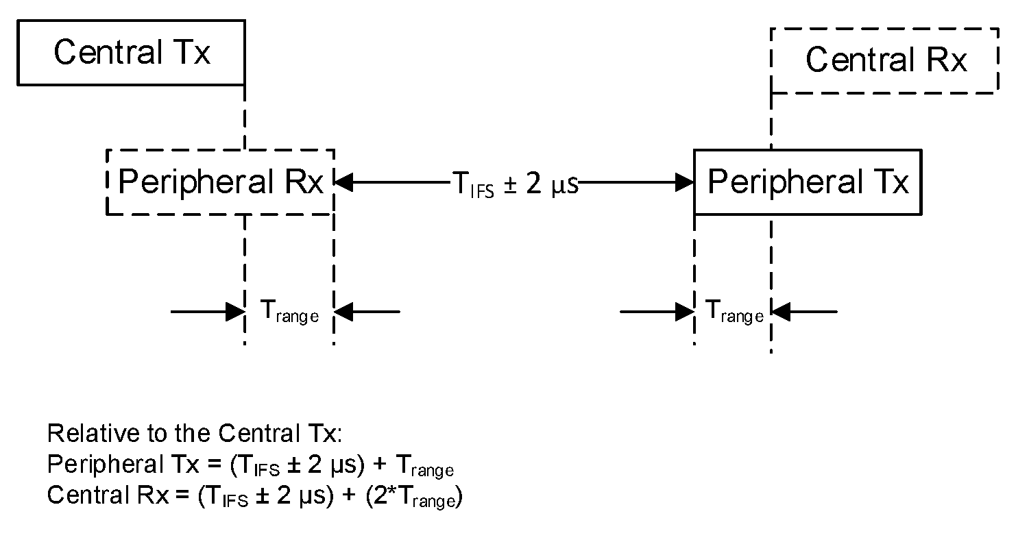
4.2.4. Window widening
In various circumstances a Link Layer is expecting to receive a packet within a certain window (extending from receiveWindowStart to receiveWindowEnd) or at a certain time (in which case receiveWindowStart and receiveWindowEnd are both that time) but, because of active clock accuracies (see Section 4.2.1) and sleep clock accuracies (see Section 4.2.2), there is uncertainty as to the exact timing of that window at the sending Link Layer. The recipient shall therefore adjust its listening time to allow for this uncertainty.
The increase in listening time is called the window widening. Assuming the clock inaccuracies are purely given in parts per million (ppm), it is calculated as follows:
transmitterAllowance = (txCA / 10000000) * (receiveWindowEnd - timeOfLastSync) + J µs
where J shall be 2 when the active clock applies and 16 when the sleep clock applies and the other parameters are specified in Table 4.1.
Note
Note: txCA is the clock accuracy of the transmitting Link Layer and timeOfLastSync is the most recent time that the receiving Link Layer was able to synchronize its clock to that of the transmitting Link Layer.
Activity | txCA | timeOfLastSync | receiveWindowStart | receiveWindowEnd |
|---|---|---|---|---|
Receiving any auxiliary packet | CA field of the relevant AuxPtr field | Start of the packet containing that field | AUX Offset from the start of that packet | One Offset Unit after receiveWindowStart |
Advertiser performing connection setup - Peripheral role | SCA field of the relevant CONNECT_IND or AUX_CONNECT_REQ PDU. | Start of the packet containing that PDU. | Start of the transmit window (see Section 4.5.3) | End of the transmit window |
Peripheral performing connection parameter update | Current centralSCA (see Section 4.5.7) | Last ACL or CIS anchor point where a packet was received from the Central | Start of the transmit window (see Section 5.1.1 and Section 5.1.7) | End of the transmit window |
Peripheral receiving the next connection event | Current centralSCA (see Section 4.5.7) | Last ACL or CIS anchor point where a packet was received from the Central | Time of the scheduled connection event anchor point | |
Adjacent packets in the same connection event or CIS subevent | 50 | End of the previous packet | T_IFS after timeOfLastSync | |
Synchronization state - synchronizing | SCA field of the relevant SyncInfo field | Start of the packet containing that field | syncPacketWindowOffset from the start of that packet | One Offset Unit after receiveWindowStart |
Synchronization state - synchronized | txCA used while synchronizing | Start of the last packet received containing an AUX_SYNC_IND PDU | Time of the scheduled periodic advertising event | |
Synchronization state - listening subevent | txCA used while synchronizing | Start of the last packet received containing an AUX_SYNC_SUBEVENT_IND or AUX_CONNECT_REQ PDU | Time of the scheduled periodic advertising subevent | |
Periodic Advertising state - listening to response slot | 50 | Start of the last packet transmitted containing an AUX_SYNC_SUBEVENT_IND PDU | Time of the scheduled subevent response slot | |
Peripheral receiving the next CIS event | Current centralSCA (see Section 4.5.7) | Last ACL anchor point or the start of a CIS subevent where a packet was received from the Central | Time of the scheduled CIS subevent | |
Reception of a BIS Data PDU in the first BIS event | SCA from SyncInfo | Start of the last packet received on the associated periodic advertising train | Offset in BIGInfo from the start of that packet plus any BIS_Spacing applied | One offset Unit after ReceiveWindowStart |
Reception of the next BIS event | txCA used while synchronizing | Start of the last packet received in any BIS event on the same BIG | Time of the scheduled BIS subevent | |
Reception of subsequent sub-events | 50 | Start of the last subevent where a packet was received | Time of the start of the scheduled subevent | |
The rows relating to a Peripheral receiving a CIS event or a device receiving a BIS event only apply until a packet has been received in the event from the correct sender, regardless of a CRC match, and the timing re-synchronized. Once this has happened, the row "Reception of subsequent sub-events" applies for the rest of the event.
If the recipient has more accurate information about the transmitting Link Layer's clock, it may select a smaller value for transmitterAllowance.
windowWidening = transmitterAllowance + receiverAllowance
where receiverAllowance is the allowance made by the receiver for its own clock accuracy.
If the recipient listens for a packet, it shall listen starting at windowWidening before receiveWindowStart and until windowWidening after receiveWindowEnd.
The windowWidening in an ACL connection shall be smaller than ((connInterval ÷ 2) - T_IFS μs). If the windowWidening reaches ((connInterval ÷ 2) - T_IFS μs) in magnitude, the connection should be considered lost (see Section 4.5.12).
If the windowWidening for a CIS or BIS with NSE < 3 reaches ((ISO_Interval ÷ 2) - T_IFS) μs in magnitude, the Link Layer should terminate the CIS (see Section 5.1.16) or stop synchronization with the BIG.
If the windowWidening for a CIS or BIS with NSE ≥ 3 reaches Sub_Interval in magnitude, the Link Layer should terminate the CIS or stop synchronization with the BIG. The value of Sub_Interval should be chosen to ensure that this limit is not reached within 2 × ISO_Interval. For example, if txCA equals 150 ppm and receiverAllowance equals transmitterAllowance, the parameters should be chosen so that Sub_Interval ÷ ISO_Interval > 0.0006.
4.3. Link Layer device filtering
The Link Layer may perform device filtering based on the device address of the peer device. Link Layer device filtering is used by the Link Layer to minimize the number of devices to which it responds.
A Link Layer shall support Link Layer device filtering unless it only supports the Advertising state and only supports non-connectable and non-scannable advertising.
The filter policies for the Advertising state, Scanning state, Initiating state, and Periodic Sync Establishment are independent of each other. When the Link Layer is in the Advertising state, the advertising filter policy shall be used. When the Link Layer is in the Scanning state, the scanning filter policy shall be used. When the Link Layer is in the Initiating state, the initiator filter policy shall be used. When the Link Layer is performing Periodic Sync Establishment, the periodic sync establishment filter policy shall be used. If the Link Layer does not support the Advertising state, Scanning state, Initiating state, or Periodic Sync Establishment, the corresponding filter policy is not required to be supported.
4.3.1. Filter Accept List
The set of devices that the Link Layer uses for device filtering is called the Filter Accept List.
A Filter Accept List contains a set of records used for Link Layer device filtering. A Filter Accept List record contains both the device address and the device address type (public or random). There is also a special device address type "anonymous"; an entry with this type matches all advertisements sent with no address. All Link Layers supporting Link Layer device filtering shall support a Filter Accept List capable of storing at least one record.
On reset, the Filter Accept List shall be empty.
The Filter Accept List is configured by the Host and is used by the Link Layer to filter advertisers, scanners, or initiators, but not periodic sync establishment. This allows the Host to configure the Link Layer to act on a request without awakening the Host.
All the device filter policies shall use the same Filter Accept List.
4.3.2. Advertising filter policy
The advertising filter policy determines how the advertiser’s Link Layer processes scan and/or connection requests.
When the Link Layer is using non-connectable and non-scannable directed advertising events, scannable directed advertising events, and connectable directed advertising events the advertising filter policy shall be ignored. Otherwise the Link Layer shall use one of the following advertising filter policy modes which are configured by the Host:
The Link Layer shall process scan and connection requests from all devices (i.e. the Filter Accept List is not in use). This is the default on reset.
The Link Layer shall process connection requests from all devices and shall only process scan requests from devices that are in the Filter Accept List.
The Link Layer shall process scan requests from all devices and shall only process connection requests from devices that are in the Filter Accept List.
The Link Layer shall process scan and connection requests only from devices in the Filter Accept List.
Only one advertising filter policy mode per advertising set shall be supported at a time.
4.3.3. Scanning filter policy
The scanning filter policy determines how the scanner’s Link Layer processes advertising and scan response PDUs. The Link Layer shall use one of the following scanning filter policies as selected by the Host. Only one scanning filter policy shall be supported at a time.
There is a choice of two primary filter policies:
Unfiltered: The Link Layer shall process all advertising and scan response PDUs (i.e., the Filter Accept List is not used). This is the default on reset.
Filtered: The Link Layer shall process advertising and scan response PDUs only from devices in the Filter Accept List.
In the basic scanning filter policy mode, a directed advertising PDU accepted by the primary filter policy shall nevertheless be ignored unless either:
the TargetA field is identical to the scanner's device address, or
the TargetA field is a resolvable private address, address resolution is enabled, and the address is resolved successfully.
Note
Note: The scanning filter policy does not affect initiation or periodic sync establishment even though they involve scanning for advertising PDUs.
4.3.3.1. Extended scanning filter policies
If the Link Layer supports the extended scanning filter policies, then extended mode shall also be supported. This is identical to basic mode except that a directed advertising PDU accepted by the primary filter policy shall nevertheless be ignored unless either:
the TargetA field is identical to the scanner's device address, or
the TargetA field is a resolvable private address.
4.3.4. Initiator filter policy
The initiator filter policy determines how an initiator’s Link Layer processes advertising PDUs. The Link Layer shall use one of the following initiator filter policy modes which are configured by the Host:
The Link Layer shall ignore the Filter Accept List and process connectable advertising PDUs from a specific single device specified by the Host.
The Link Layer shall process connectable advertising PDUs from all devices in the Filter Accept List.
If the Link Layer receives a connectable directed advertising PDU from an advertiser that is not contained in the Filter Accept List or the single address specified by the Host, the connectable directed advertising PDU shall be ignored.
Only one initiator filter policy mode shall be supported at a time.
4.3.5. Periodic sync establishment filter policy
The periodic sync establishment filter policy determines how a scanner's Link Layer processes advertising PDUs when attempting to synchronize to a periodic advertising train. The Link Layer shall use one of the following periodic sync establishment filter policy modes which are configured by the Host:
The Link Layer shall ignore the Periodic Advertiser List and process advertising PDUs from a specific single device specified by the Host.
The Link Layer shall process advertising PDUs from all devices in the Periodic Advertiser List.
If the Link Layer receives an advertising PDU which contains a SyncInfo field from an advertiser that is not contained in the Periodic Advertiser List or the single address specified by the Host, or if the advertising has an Advertising SID which is not the one specified in the list entry or by the Host, the SyncInfo field shall be ignored.
Only one periodic sync establishment filter policy mode shall be supported at a time.
Synchronization to periodic advertising takes place at the same time as scanning, but the filter policies for the two activities are independent. The periodic sync establishment filter policy, and not the scanning filter policy, shall determine which advertising PDUs are used to synchronize to a periodic advertising train (successful synchronization is then reported to the Host). If a received PDU only matches one of the two policies, it shall only be processed for the purpose that uses that policy and not for the other.
The Link Layer shall ignore the Periodic Advertiser List when synchronizing to a periodic advertising train where it received the synchronization information using the Periodic Advertising Sync Transfer procedure (see Section 5.1.13).
4.4. Non-connected states
The Host may specify which coding to use when transmitting packets on the LE Coded PHY. If it does not, then the Controller determines the coding of each packet. The coding is indicated by the CI as defined in Section 2.2.3 and may be different in each direction and in adjacent packets in a given direction.
4.4.1. Standby state
The Standby state is the default state in the Link Layer. The Link Layer shall not send or receive packets in the Standby state. The Link Layer may leave the Standby state to enter the Advertising state, Scanning state, Initiator state, Synchronization state, or Isochronous Broadcasting state.
4.4.2. Advertising state
The Link Layer shall enter the Advertising state when directed by the Host. When placed in the Advertising state, the Link Layer shall send advertising PDUs (see Section 2.3.1) in advertising events, periodic advertising events, or both.
Each advertising event is composed of one or more advertising PDUs sent on used primary advertising channel indices. The advertising event shall be closed after one advertising PDU has been sent on each of the used primary advertising channel indices (see Section 4.4.2.1). Some advertising PDUs in an advertising event may be omitted, causing the advertising event to begin late or close early, or the entire advertising event may be omitted to accommodate other functionality.
The time between two consecutive advertising events is defined in Section 4.4.2.2.
An advertising event can be one of the following types:
a connectable and scannable undirected event
a connectable undirected event
a connectable directed event
a non-connectable and non-scannable undirected event
a non-connectable and non-scannable directed event
a scannable undirected event
a scannable directed event
At most one advertising PDU shall be sent on each used primary advertising channel index in an advertising event. Unless specified otherwise, the primary advertising channel indices may be utilized in any order. The order may be different in different events.
The advertising event type determines the allowable response PDUs. Table 4.2 specifies the allowable responses for each advertising event.
Connectable and scannable undirected, connectable undirected, and connectable directed events are collectively referred to as connectable events; the remaining events (non-connectable and non-scannable undirected, non-connectable and non-scannable directed, scannable undirected, and scannable directed) are collectively referred to as non-connectable events. Connectable and scannable undirected, scannable undirected, and scannable directed events are collectively referred to as scannable events; the remaining events (non-connectable and non-scannable undirected, non-connectable and non-scannable directed, connectable undirected, and connectable directed) are collectively referred to as non-scannable events.
Allowable response PDUs | |||||||||||||||||||||||||||||||||||||||||||||||||
|---|---|---|---|---|---|---|---|---|---|---|---|---|---|---|---|---|---|---|---|---|---|---|---|---|---|---|---|---|---|---|---|---|---|---|---|---|---|---|---|---|---|---|---|---|---|---|---|---|---|
Advertising Event Type | Type of PDU being responded to | SCAN_REQ[1] | CONNECT_IND[1] | AUX_SCAN_REQ | AUX_CONNECT_REQ | ||||||||||||||||||||||||||||||||||||||||||||
Connectable and Scannable Undirected event | ADV_IND | YES | YES | NO | NO | ||||||||||||||||||||||||||||||||||||||||||||
Connectable Undirected event | ADV_EXT_IND | NO | NO | NO | NO | ||||||||||||||||||||||||||||||||||||||||||||
AUX_ADV_IND | NO | NO | NO | YES | |||||||||||||||||||||||||||||||||||||||||||||
Connectable Directed event | ADV_DIRECT_IND | NO | YES[2] | NO | NO | ||||||||||||||||||||||||||||||||||||||||||||
ADV_EXT_IND | NO | NO | NO | NO | |||||||||||||||||||||||||||||||||||||||||||||
AUX_ADV_IND | NO | NO | NO | YES[2] | |||||||||||||||||||||||||||||||||||||||||||||
Non-Connectable and Non-Scannable Undirected event | ADV_NONCONN_IND | NO | NO | NO | NO | ||||||||||||||||||||||||||||||||||||||||||||
ADV_EXT_IND | NO | NO | NO | NO | |||||||||||||||||||||||||||||||||||||||||||||
AUX_ADV_IND | NO | NO | NO | NO | |||||||||||||||||||||||||||||||||||||||||||||
Non-Connectable and Non-Scannable Directed event | ADV_EXT_IND | NO | NO | NO | NO | ||||||||||||||||||||||||||||||||||||||||||||
AUX_ADV_IND | NO | NO | NO | NO | |||||||||||||||||||||||||||||||||||||||||||||
Scannable Undirected event | ADV_SCAN_IND | YES | NO | NO | NO | ||||||||||||||||||||||||||||||||||||||||||||
ADV_EXT_IND | NO | NO | NO | NO | |||||||||||||||||||||||||||||||||||||||||||||
AUX_ADV_IND | NO | NO | YES | NO | |||||||||||||||||||||||||||||||||||||||||||||
Scannable Directed event | ADV_EXT_IND | NO | NO | NO | NO | ||||||||||||||||||||||||||||||||||||||||||||
AUX_ADV_IND | NO | NO | YES[3] | NO | |||||||||||||||||||||||||||||||||||||||||||||
[1] Not permitted on the LE Coded PHY. [2] Initiators other than the correctly addressed initiator shall not respond. [3] Scanners other than the correctly addressed scanner shall not respond. | |||||||||||||||||||||||||||||||||||||||||||||||||
If the advertiser receives a PDU for the advertising event that is not explicitly allowed it shall be ignored. If no PDU is received or the received PDU was ignored, the advertiser shall either send an advertising PDU on the next used primary advertising channel index or close the advertising event.
The Controller shall not use two different types of PDU on the primary advertising physical channel in the same advertising event.
4.4.2.1. Advertising channel index selection
Advertising events use three predefined primary advertising physical channels. Primary advertising channel indices are either used or unused.
For AUX_ADV_IND and AUX_CHAIN_IND PDUs, the secondary advertising channel index used in the Channel Index subfield of the AuxPtr field is implementation specific. It is recommended that sufficient channel diversity is used to avoid collisions.
Each periodic advertising train shall have a 16-bit event counter (paEventCounter). The initial value of this counter is implementation specific. The counter shall be incremented by one for each Periodic Advertising Interval (see Section 4.4.2.3), whether or not the AUX_SYNC_IND PDU is actually transmitted; the paEventCounter shall wrap from 0xFFFF to 0x0000. AUX_SYNC_IND PDUs shall use the Channel Selection Algorithm #2 (see Section 4.5.8.3) with this event counter.
When periodic advertising subevents are used, the train has a 7-bit value (paSubEventCounter). The paSubEventCounter is set to 0 at the start of each periodic advertising event and incremented by one for each subevent. AUX_SYNC_SUBEVENT_IND PDUs shall use the Channel Selection Algorithm #2 with the paEventCounter and paSubEventCounter.
The response slots shall use the same channel as the AUX_SYNC_SUBEVENT_IND packet.
The Link Layer shall use the primary and secondary advertising channel indices as specified by the Host, and the used primary and secondary advertising channel indices shall take effect when the Advertising state is entered. The Link Layer need not use all the secondary channels that the Host has marked as "unknown".
4.4.2.2. Advertising events
Advertising events are defined as one or more advertising PDUs sent on the primary advertising physical channel. At most one PDU shall be sent on each used advertising channel index; usually a PDU is sent on all the used advertising indices in each advertising event. The advertising event can be closed early after a CONNECT_IND is received or when a SCAN_RSP is sent.
Advertising packets sent on the secondary advertising physical channel are not part of the advertising event. Advertising events that use the ADV_EXT_IND PDU may also be part of an extended advertising event. All ADV_EXT_IND PDUs containing an AuxPtr field in the same advertising event shall point to the same AUX_ADV_IND packet.
4.4.2.2.1. Advertising interval
For all undirected advertising events or connectable directed advertising events used in a low duty cycle mode, the time between the start of two consecutive advertising events (T_advEvent) for the same advertising set (see Section 4.4.2.10) is computed as follows for each advertising event:
T_advEvent = advInterval + advDelay
The advertising interval (advInterval) shall be an integer multiple of 0.625 ms in the range 20 ms to 10,485.759375 s.
The advDelay is a (pseudo-)random value with a range 0 ms to 10 ms generated by the Link Layer for each advertising event.
As illustrated in Figure 4.5, the advertising events are perturbed in time using the advDelay.
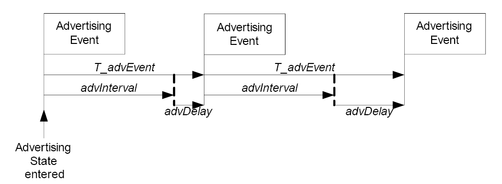
4.4.2.2.2. Extended advertising event
An extended advertising event begins at the start of an advertising event and consists of the PDUs in that advertising event plus their subordinate sets. The extended advertising event ends with the last such PDU.
Multiple extended advertising events may overlap with each other. This can occur when ADV_EXT_IND PDUs containing an AuxPtr field in multiple advertising events point to the same AUX_ADV_IND packet, or when a different advertising event is interposed between the ADV_EXT_IND PDUs and the AUX_ADV_IND PDU.
T_advEvent, advInterval and advDelay have the same meaning as in Section 4.4.2.2.1.
Figure 4.6 illustrates an example of overlapping extended advertising events.
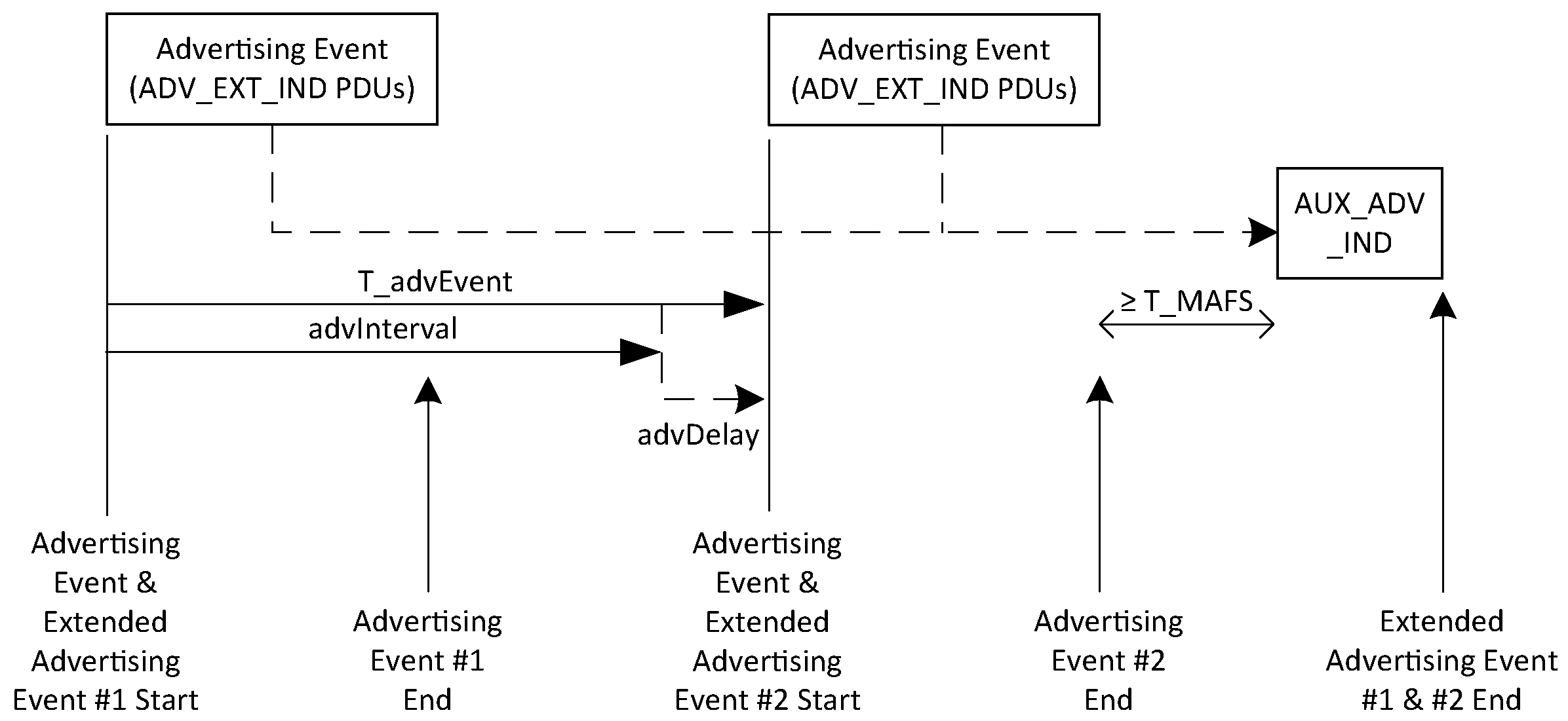
An auxiliary advertising segment starts with the first AUX_ADV_IND PDU in an extended advertising event and ends at the end of the extended advertising event (an auxiliary advertising segment can belong to more than one extended advertising event). Two auxiliary advertising segments for the same advertising set shall not overlap each other.
Figure 4.7 illustrates an example of auxiliary advertising segments belonging to multiple extended advertising events.
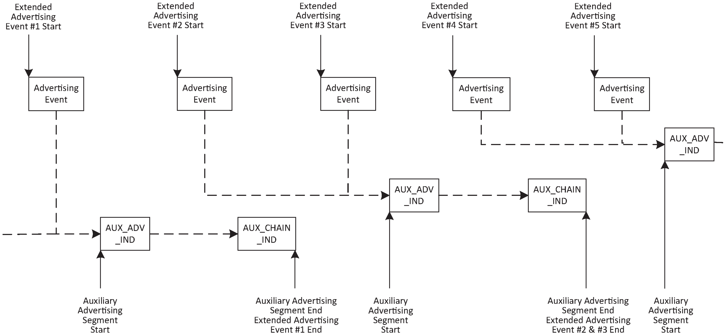
An advertiser should not space PDUs within the auxiliary advertising segment so that two of them would be within the same receive window. If an advertiser transmits a PDU with an AuxPtr field containing an offset of T milliseconds, then it should not start to transmit any other packet on the same RF channel as the auxiliary packet within 2.5*T microseconds of the start of the auxiliary packet of the original PDU.
4.4.2.2.3. Periodic advertising events
The Periodic Advertising Interval is the interval between the start of two scheduled AUX_SYNC_IND PDUs from the same advertising set (even if the PDUs are not transmitted for some reason). The Periodic Advertising Interval shall be an integer multiple of 1.25 ms in the range 7.5 ms to 81.91875 s.
A periodic advertising event consists of an AUX_SYNC_IND PDU and its subordinate set.
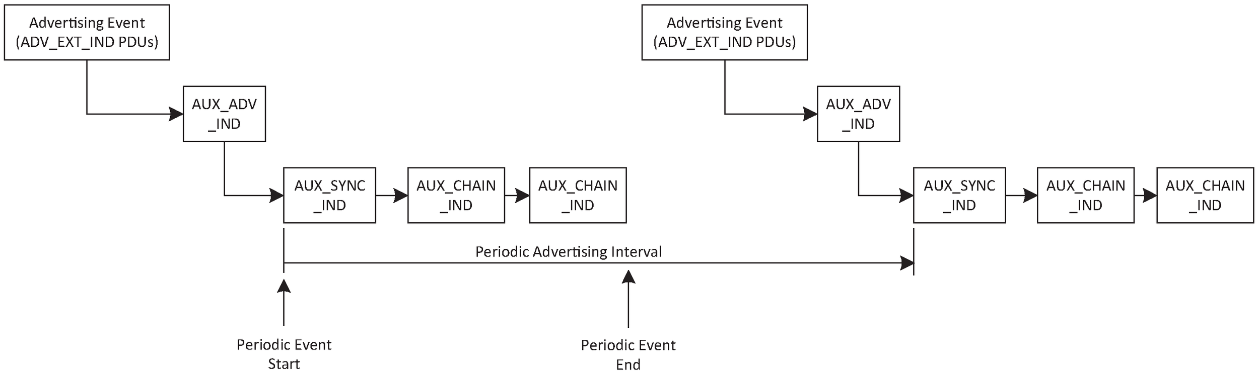
Two periodic advertising events for the same periodic advertising train shall not overlap each other. The periodic advertising interval shall not change while the periodic advertising is enabled.
4.4.2.2.4. Periodic advertising with responses events
A periodic advertising with responses event (PAwR event) consists of one or more subevents. Each subevent consists of an AUX_SYNC_SUBEVENT_IND PDU and one or more AUX_SYNC_SUBEVENT_RSP PDUs (see Figure 4.10).
The duration of the AUX_SYNC_SUBEVENT_IND PDU and the AUX_SYNC_SUBEVENT_RSP PDU shall be smaller than the time available. The gap between the end of one AUX_SYNC_SUBEVENT_IND or AUX_SYNC_SUBEVENT_RSP packet and the start of the next AUX_SYNC_SUBEVENT_IND or AUX_SYNC_SUBEVENT_RSP packet shall be at least T_IFS. The AUX_SYNC_SUBEVENT_RSP PDU shall be sent in response to the AUX_SYNC_SUBEVENT_IND PDU in a response slot and subevent provided by the Host. The data in the AUX_SYNC_SUBEVENT_RSP PDU shall contain the response to the data received in the AUX_SYNC_SUBEVENT_IND PDU. The Controller shall send the response no later than the Periodic Advertising Interval after the start of the received AUX_SYNC_SUBEVENT_IND PDU.
The Periodic Advertising Interval is the interval between the start of two scheduled AUX_SYNC_SUBEVENT_IND PDUs with the same subevent number from the same advertising set (even if the PDUs are not transmitted for some reason). The Periodic Advertising Interval shall be an integer multiple of 1.25 ms in the range 7.5 ms to 81.91875 s.
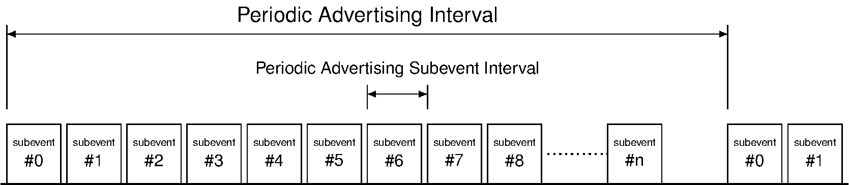
The Periodic Advertising Subevent Interval is the interval between the start of two scheduled adjacent AUX_SYNC_SUBEVENT_IND PDUs in the same PAwR event. The Periodic Advertising Subevent Interval shall be an integer multiple of 1.25 ms in the range 7.5 ms to 318.75 ms. The subevent ends Periodic Advertising Subevent Interval after the start of the subevent. Up to 128 subevents can be used in a Periodic Advertising Interval. The subevent(s) to synchronize to is provided by the Host. If the Host has not provided the subevent(s), the Controller may synchronize with any subevent.
One or more response slots are defined when a device that is synchronized with this periodic advertising train may transmit a response packet. A synchronized device may only transmit a response packet in at most one response slot per subevent. Different synchronized devices may transmit response packets in different response slots in the same subevent. The Periodic Advertising Response Slot Delay is the interval between the start of an AUX_SYNC_SUBEVENT_IND PDU and the first response slot. The Periodic Advertising Response Slot Delay shall be an integer multiple of 1.25 ms in the range 1.25 ms to 317.5 ms. The Periodic Advertising Response Slot Spacing is the interval between the start of two adjacent response slots in a given subevent. The Periodic Advertising Response Slot Spacing shall be an integer multiple of 0.125 ms in the range 0.25 ms to 31.875 ms.
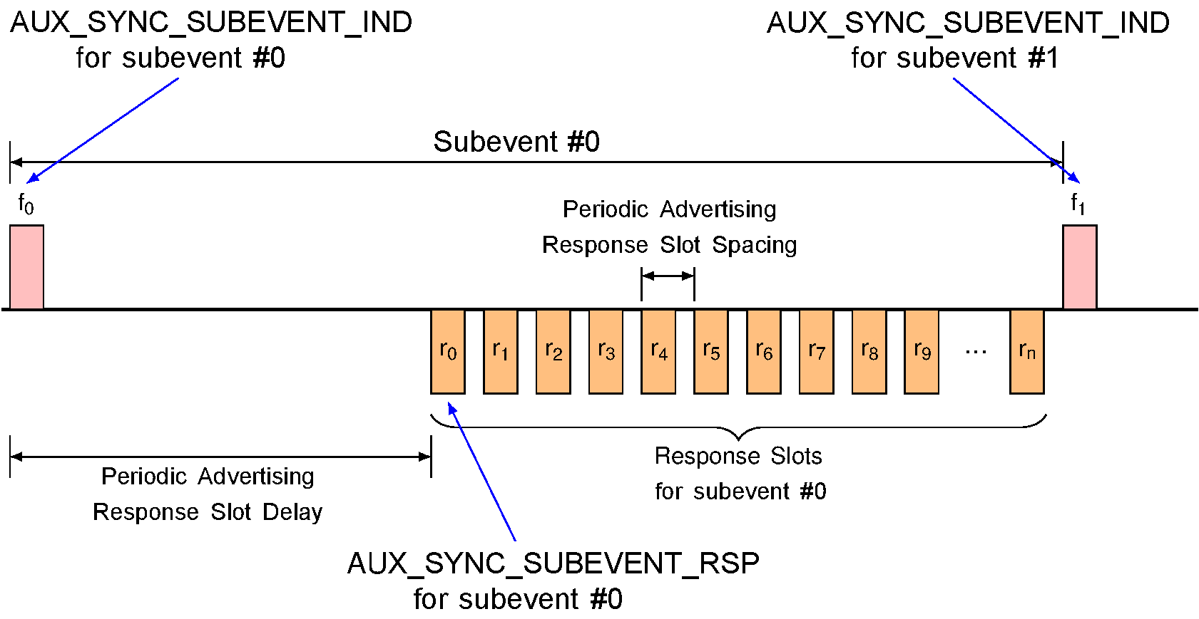
Two periodic advertising events for the same PAwR train shall not overlap each other. Two PAwR subevents shall not overlap each other. The Periodic Advertising Interval, Periodic Advertising Subevent Interval, Periodic Advertising Response Slot Delay, and Periodic Advertising Response Slot Interval shall not change while PAwR is enabled for that advertising set.
4.4.2.3. Connectable and scannable undirected event type
When the connectable and scannable undirected advertising event type is used, advertising indications (ADV_IND PDUs) are sent by the Link Layer.
The connectable and scannable undirected advertising event type allows a scanner or initiator to respond with either a scan request or connect request. A scanner may send a scan request (SCAN_REQ PDU) to request additional information about the advertiser. An initiator may send a connect request (CONNECT_IND PDU) to request the Link Layer to enter the Connection state.
The Link Layer shall listen on the same primary advertising channel index for requests from scanners or initiators.
If the advertiser receives a SCAN_REQ PDU that contains its device address from a scanner allowed by the advertising filter policy, it shall reply with a SCAN_RSP PDU on the same primary advertising channel index. After the SCAN_RSP PDU is sent, or if the advertising filter policy did not allow processing the SCAN_REQ PDU, the advertiser shall either move to the next used primary advertising channel index to send another ADV_IND PDU, or close the advertising event.
If the advertiser receives a CONNECT_IND PDU that contains its device address, from an initiator allowed by the advertising filter policy, the Link Layer shall exit the Advertising state and transition to the Connection state in the Peripheral Role as defined in Section 4.5.5. If the advertising filter policy did not allow processing the received CONNECT_IND PDU, the advertiser shall either move to the next used primary advertising channel index to send another ADV_IND PDU, or close the advertising event.
The time between the beginning of two consecutive ADV_IND PDUs within an advertising event shall be less than or equal to 10 ms. The advertising event shall be closed within the advertising interval.
An illustration of an advertising event using all the primary advertising channel indices and in which no SCAN_REQ or CONNECT_IND PDUs are received is shown in Figure 4.11.
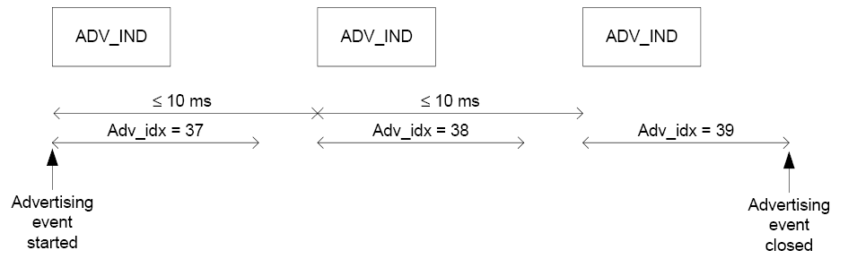
Two illustrations of advertising events using all the primary advertising channel indices during which a SCAN_REQ PDU is received and a SCAN_RSP PDU is sent are shown in Figure 4.12 and in Figure 4.13.
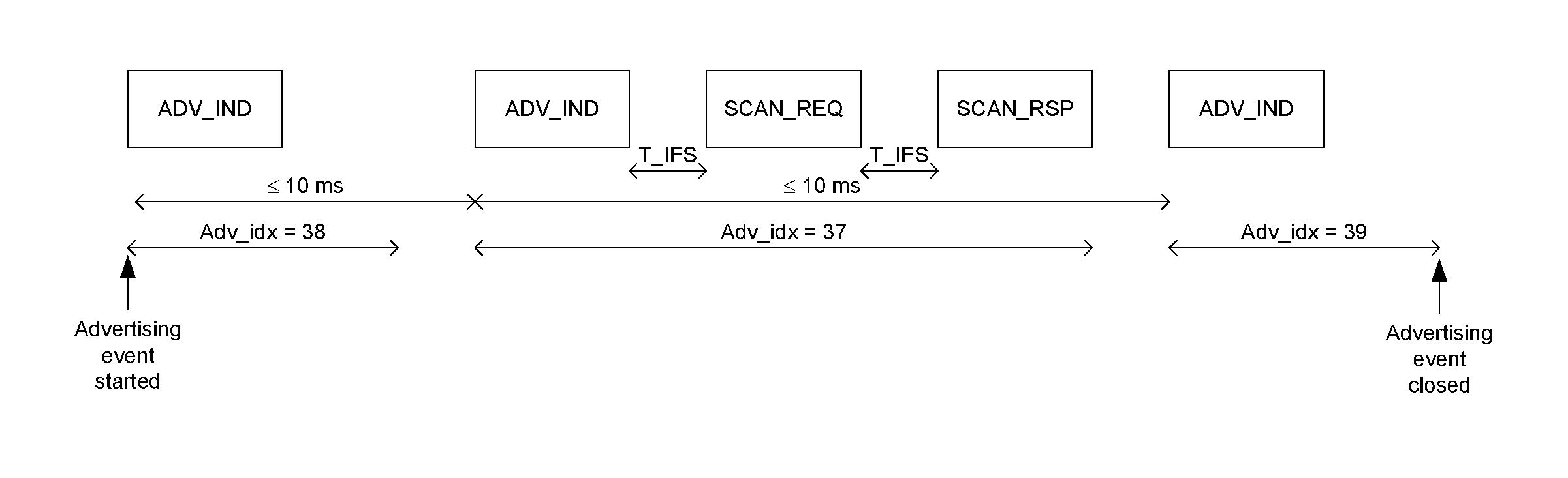
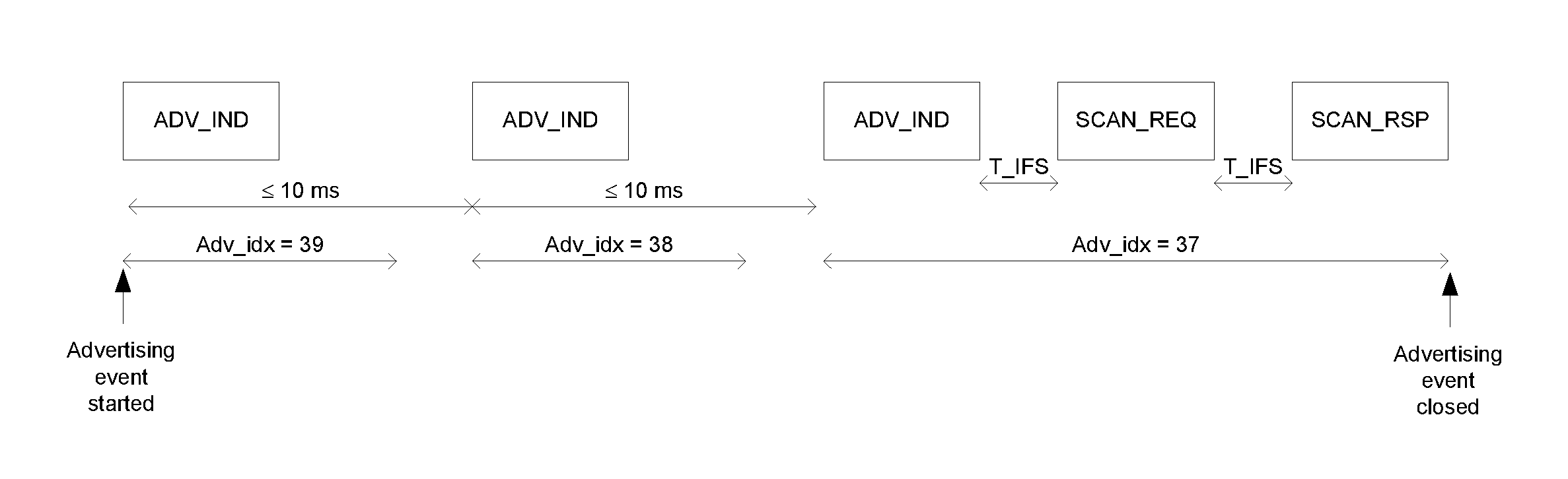
Figure 4.14 illustrates an advertising event during which a CONNECT_IND PDU is received on the second primary advertising channel index.
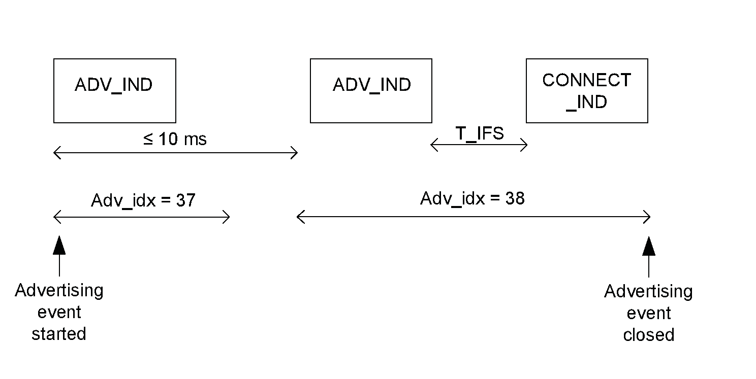
If the Controller supports LL Privacy, then the requirements in Section 6.2.1 shall also be followed.
4.4.2.4. Connectable directed event type
When the connectable directed advertising event type is used, directed advertising indications are sent by the Link Layer.
The connectable directed advertising event type allows an initiator to respond so that both the advertiser and initiator will enter the Connection state.
The connectable directed advertising event type may use either the ADV_DIRECT_IND PDU (see Sections 4.4.2.4.1 to 4.4.2.4.3) or the ADV_EXT_IND PDU (see Section 4.4.2.4.4).
If the Controller supports LL Privacy, then the requirements in Section 6.2.2 shall also be followed.
4.4.2.4.1. Connectable directed event type using ADV_DIRECT_IND
The connectable directed advertising event type using ADV_DIRECT_IND allows an initiator to respond with a connect request on the primary advertising physical channel to establish an ACL connection.
The ADV_DIRECT_IND PDU contains both the initiator’s device address and the advertiser’s device address. Only the addressed initiator may initiate an ACL connection with the advertiser by sending a CONNECT_IND PDU to the advertiser.
After every ADV_DIRECT_IND PDU sent by the advertiser, the advertiser shall listen for CONNECT_IND PDUs on the same primary advertising channel index. Any SCAN_REQ PDUs received shall be ignored.
If the advertiser receives a CONNECT_IND PDU that contains its device address and the initiator device address is contained in the ADV_DIRECT_IND PDU, the Link Layer shall exit the Advertising state and transition to the Connection state in the Peripheral Role as defined in Section 4.5.5.
Otherwise, the advertiser shall either move to the next used primary advertising channel index to send another ADV_DIRECT_IND PDU, or close the Advertising event.
Connectable directed advertising may be either used in a low duty cycle or high duty cycle mode; these are described in the next two sections. Low duty cycle connectable directed advertising is designed for cases where reconnection with a specific device is required, but time is not of the essence or it is not known if the Central is in range or not. High duty cycle connectable directed advertising is designed for cases in which fast ACL connection setup is essential (for example, a reconnection).
Note: High duty cycle connectable directed advertising is a power and bandwidth intensive advertising scheme that should only be used when fast connection setup is required.
4.4.2.4.2. Low duty cycle connectable directed advertising
In low duty cycle connectable directed advertising, the time between the start of two consecutive ADV_DIRECT_IND PDUs within an advertising event shall be less than or equal to 10 ms. The advertising event shall be closed within the advertising interval.
An illustration of an advertising event using all primary advertising channel indices and in which no CONNECT_IND PDUs are received is shown in Figure 4.15.
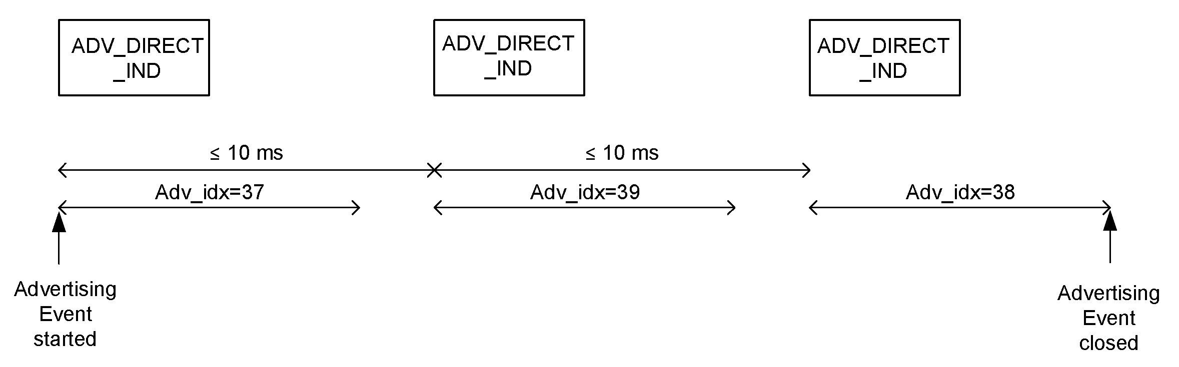
Figure 4.16 illustrates an advertising event using ADV_DIRECT_IND advertising PDUs during which a CONNECT_IND PDU is received on the second primary advertising channel index.
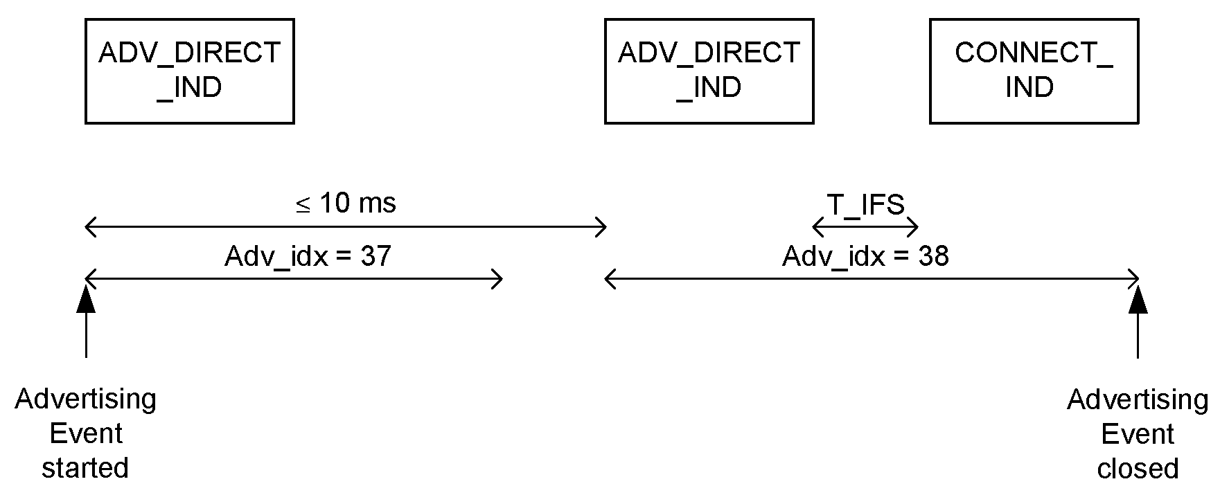
4.4.2.4.3. High duty cycle connectable directed advertising
In high duty cycle connectable directed advertising mode, the time between the start of two consecutive ADV_DIRECT_IND PDUs sent on the same advertising channel index shall be less than or equal to 3.75 ms.
The Link Layer shall exit the Advertising state no later than 1.28 s after the Advertising state was entered.
The Link Layer shall start each advertising event with the lowest used primary advertising channel index and move sequentially through the other used primary advertising indices.
A sequence of five ADV_DIRECT_IND PDUs in two Advertising events without CONNECT_IND PDUs is shown in Figure 4.17 for the case in which all the primary advertising physical channels are used.
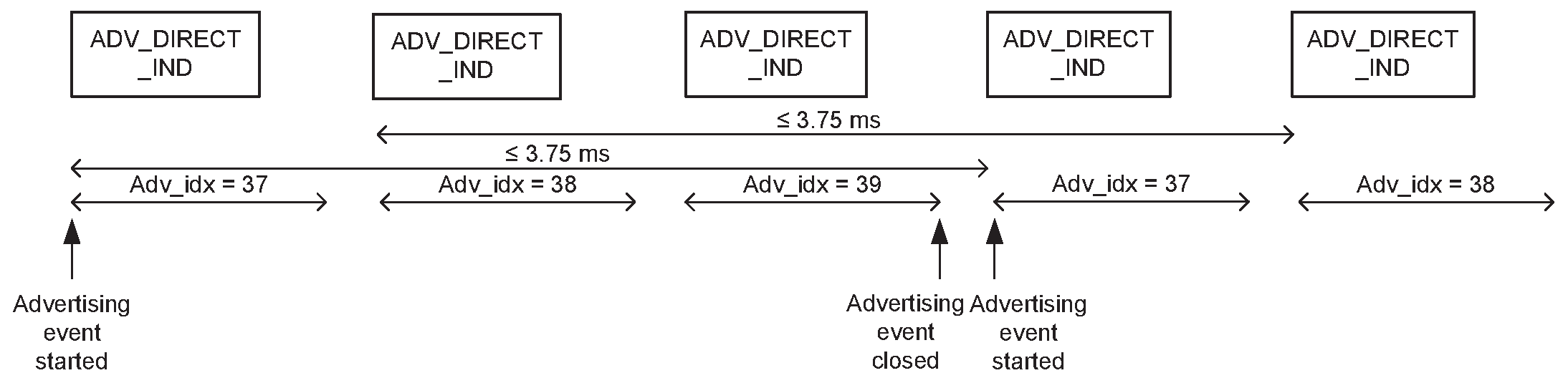
4.4.2.4.4. Connectable directed event type using ADV_EXT_IND
The connectable directed advertising event type using ADV_EXT_IND allows an initiator to respond with a connect request on the secondary advertising physical channel to establish an ACL connection.
After every AUX_ADV_IND PDU related to this event it sends, the advertiser shall listen for AUX_CONNECT_REQ PDUs on the same secondary advertising channel index. Any AUX_SCAN_REQ PDUs received shall be ignored.
If the advertiser receives an AUX_CONNECT_REQ PDU that contains its device address and the initiator’s device address was contained in the AUX_ADV_IND PDU, then the advertiser shall reply with an AUX_CONNECT_RSP PDU on the same secondary advertising channel index. If the advertiser’s Link Layer does not support LL Privacy, then it shall use those addresses in the AUX_CONNECT_RSP PDU. After the AUX_CONNECT_RSP PDU is sent the Link Layer shall exit the Advertising state and transition to the Connection state in the Peripheral Role as defined in Section 4.5.5. Any AUX_SCAN_REQ PDUs received on the secondary advertising physical channel shall be ignored.
The time between the start of two consecutive connectable directed ADV_EXT_IND PDUs within an advertising event shall be less than or equal to 10 ms. The advertising event shall be closed within the advertising interval.
The channel index on the secondary channel, SAdv_idx, is contained in the AuxPtr field of the ADV_EXT_IND PDU.
Figure 4.18 shows an advertising event in which no AUX_CONNECT_REQ PDU is received.
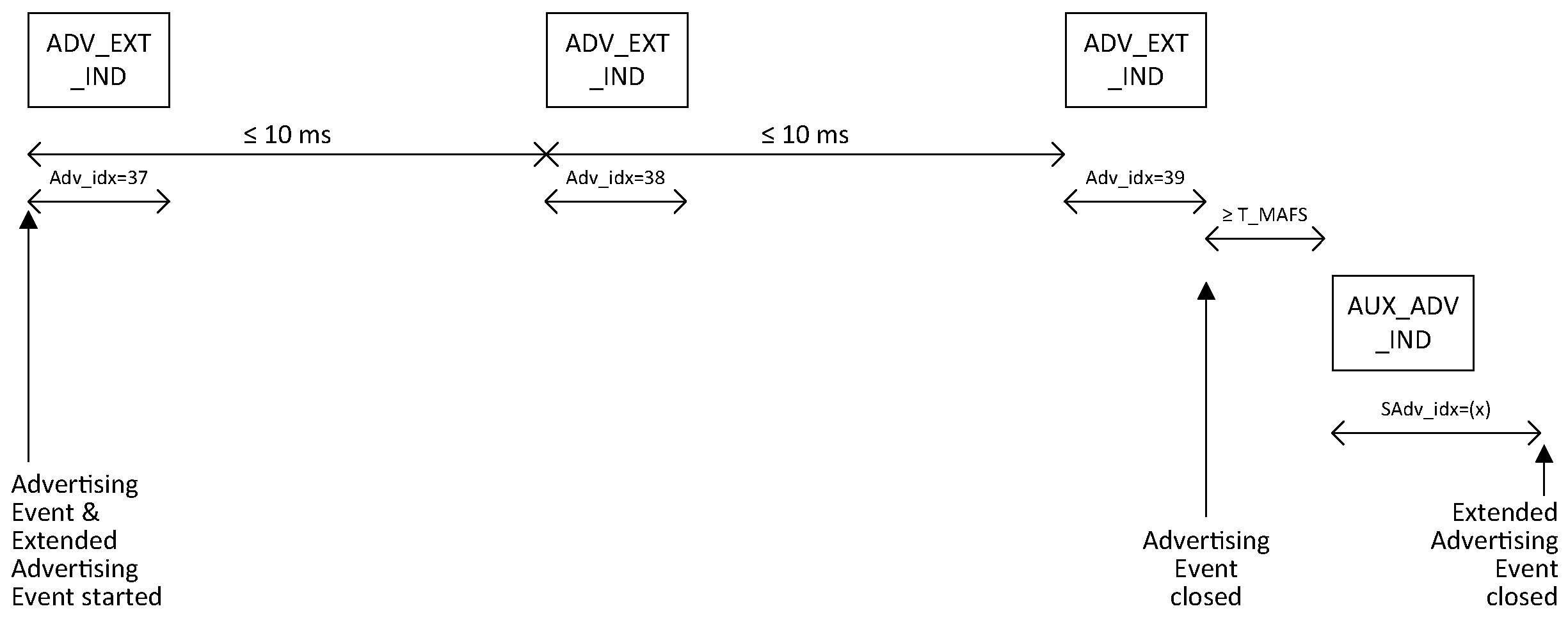
Figure 4.19 illustrates an advertising event using connectable directed ADV_EXT_IND advertising PDUs during which an AUX_CONNECT_REQ PDU is received on the second secondary advertising channel index.
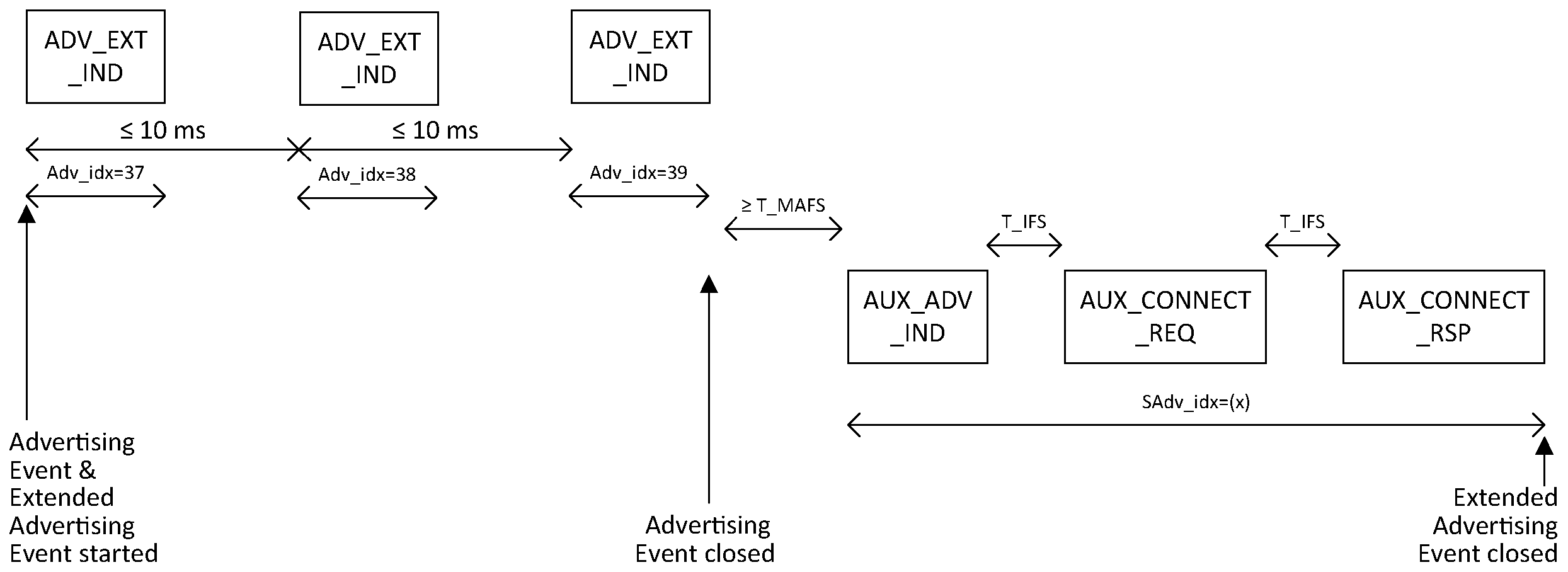
4.4.2.5. Scannable undirected event type
When the scannable undirected advertising event type is used, scannable undirected advertising indications (ADV_SCAN_IND or scannable undirected ADV_EXT_IND PDUs) are sent by the Link Layer.
If the Controller supports LL Privacy, then the requirements in Section 6.2.3 shall also be followed.
4.4.2.5.1. Scannable undirected event type using ADV_SCAN_IND
The scannable undirected event type allows a scanner to respond with a scan request (SCAN_REQ PDU) to request additional information about the advertiser.
The Link Layer shall listen on the same primary advertising channel index for requests from scanners. Any CONNECT_IND PDUs received shall be ignored.
If the advertiser receives a SCAN_REQ PDU that contains its device address from a scanner allowed by the advertising filter policy it shall reply with a SCAN_RSP PDU on the same advertising channel index. After the SCAN_RSP PDU is sent or if the advertising filter policy did not allow processing the SCAN_REQ PDU the advertiser shall either move to the next used primary advertising channel index to send another ADV_SCAN_IND PDU, or close the advertising event.
The time between the beginning of two consecutive ADV_SCAN_IND PDUs within an advertising event shall be less than or equal to 10 ms. The advertising event shall be closed within the advertising interval.
The structure of an advertising event in which no SCAN_REQ PDU was received is shown in Figure 4.20 for the case in which all the primary advertising physical channels are used.
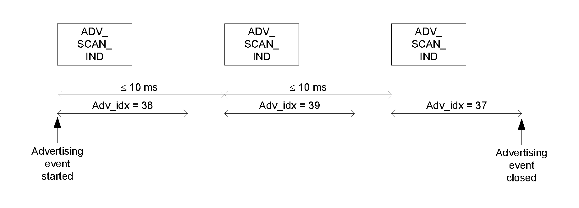
Two example advertising events during which a SCAN_REQ PDU is received and a SCAN_RSP PDU is sent are shown in Figure 4.21 and in Figure 4.22 for the case in which all the primary advertising physical channels are used.
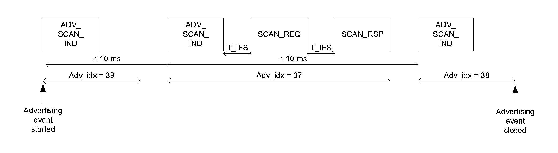
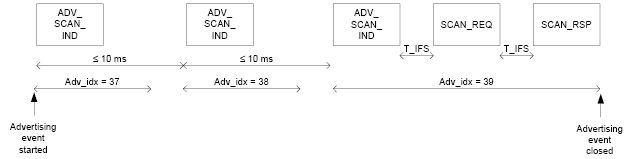 |
4.4.2.5.2. Scannable undirected event type using ADV_EXT_IND
The scannable undirected event type using the ADV_EXT_IND PDU allows any scanner to respond with a scan request to receive scan response data on the secondary advertising physical channel.
A scanner may send a scan request using the AUX_SCAN_REQ PDU on the same secondary advertising channel index as the received AUX_ADV_IND PDU pointed to by the ADV_EXT_IND PDU.
After every AUX_ADV_IND PDU sent by the advertiser, the advertiser shall listen for AUX_SCAN_REQ PDUs on the same secondary advertising channel index from scanners. Any AUX_CONNECT_REQ PDUs received shall be ignored.
If the advertiser receives an AUX_SCAN_REQ PDU that contains its device address from a scanner allowed by the advertising filter policy, it shall reply with an AUX_SCAN_RSP PDU on the same secondary advertising channel index prior to the start of the next advertising event. After the AUX_SCAN_RSP PDU is sent, or if the advertising filter policy prohibits processing the AUX_SCAN_REQ PDU, the advertising event shall be closed. Any AUX_CONNECT_REQ PDUs on the secondary advertising physical channel shall be ignored.
The time between the beginning of two consecutive ADV_EXT_IND PDUs within an advertising event shall be less than or equal to 10 ms. The advertising event shall be closed within the advertising interval.
Figure 4.23 shows an advertising event in which no AUX_SCAN_REQ PDU is received.
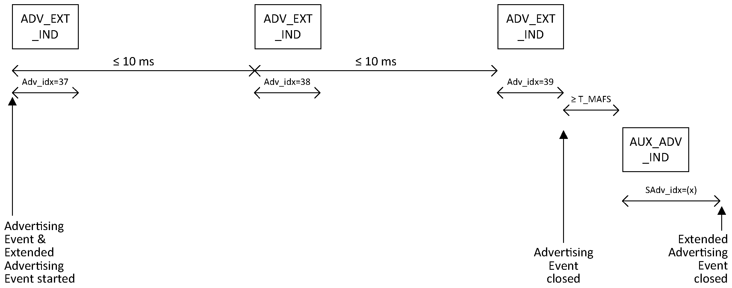
An example advertising event during which an AUX_SCAN_REQ PDU is received and an AUX_SCAN_RSP PDU is sent on the secondary advertising physical channel is shown in Figure 4.24.
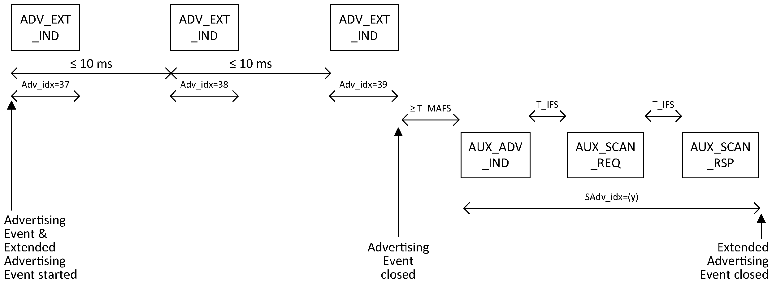
4.4.2.6. Non-connectable and non-scannable undirected event type
When the non-connectable and non-scannable undirected advertising event type is used, non-connectable and non-scannable undirected advertising indications (ADV_NONCONN_IND or non-connectable and non-scannable undirected ADV_EXT_IND PDUs, the latter either with or without an auxiliary AUX_ADV_IND PDU) are sent by the Link Layer.
The non-connectable and non-scannable undirected event type allows a scanner to receive information from the advertiser. This information is contained either in the ADV_NONCONN_IND PDU or in an AUX_ADV_IND PDU pointed to by the AuxPtr field of the ADV_EXT_IND PDU.
The advertiser shall either move to the next used primary advertising channel index or close the advertising event after each ADV_NONCONN_IND or ADV_EXT_IND PDU that is sent. The Link Layer does not listen, and therefore cannot receive any requests from scanners or initiators.
The time between the beginning of two consecutive ADV_NONCONN_IND or ADV_EXT_IND PDUs within an advertising event shall be less than or equal to 10 ms. The advertising event shall be closed within the advertising interval.
When using an ADV_EXT_IND PDU with an AUX_ADV_IND PDU, the Controller shall decide which PDU contains the AdvA field and should make this choice based on overall efficient use of the medium.
An illustration of a non-connectable and non-scannable undirected advertising event is shown in Figure 4.25 for the case in which all the primary advertising physical channels are used.
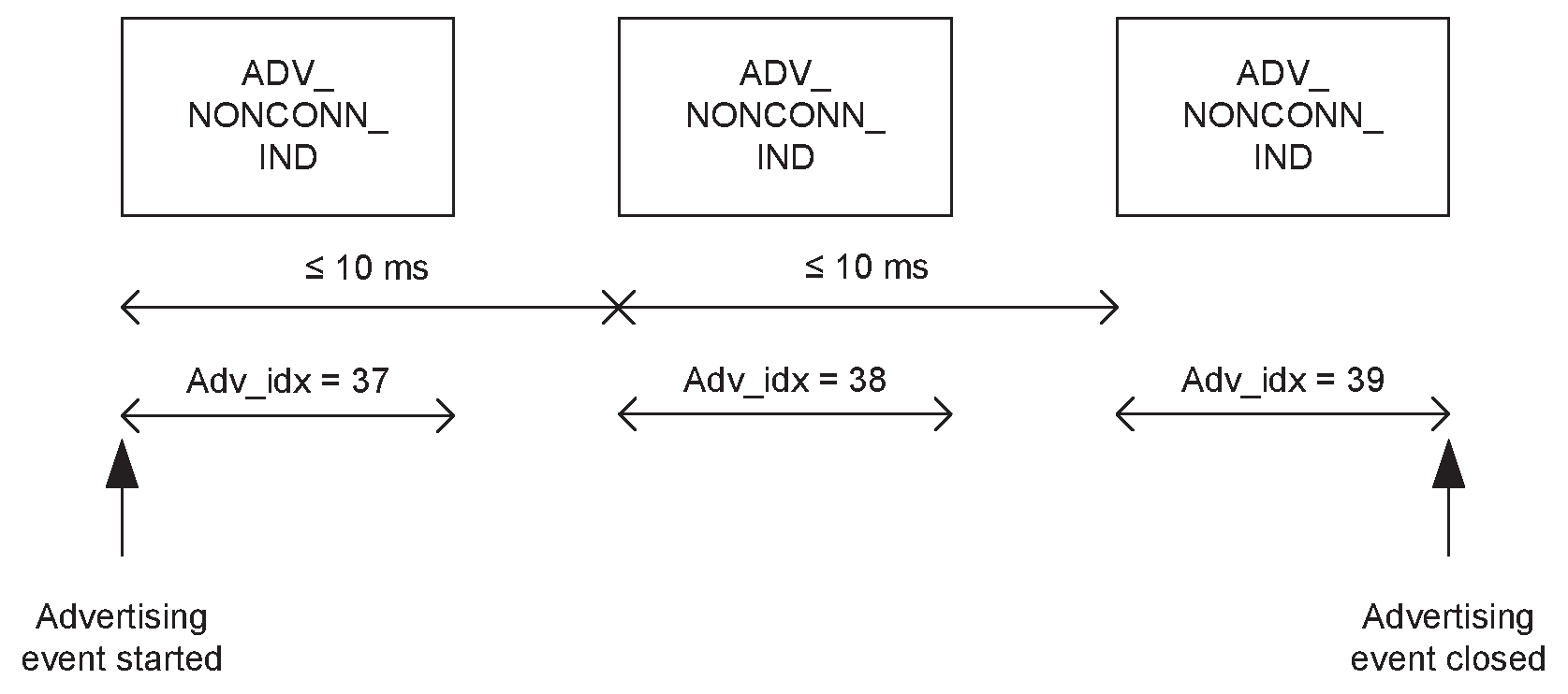
Figure 4.26 shows an example of a non-connectable and non-scannable undirected ADV_EXT_IND PDU.
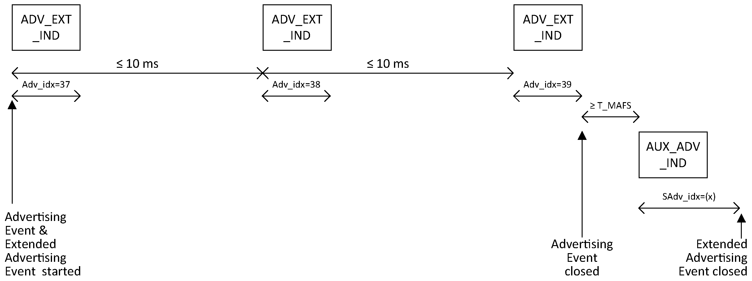
Figure 4.27 shows an example of a non-connectable and non-scannable undirected ADV_EXT_IND PDU where the Host advertising data is fragmented using the AUX_CHAIN_IND PDU.
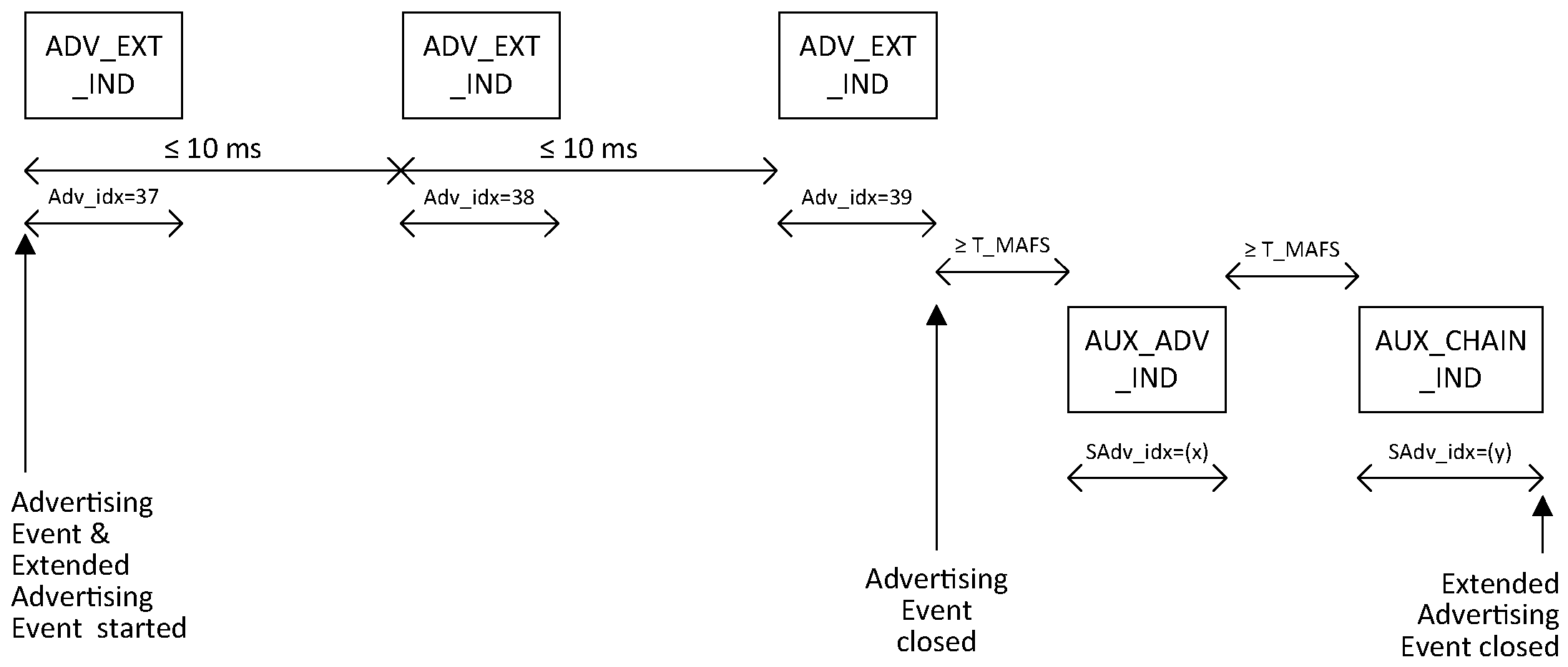
If the Controller supports LL Privacy, then the requirements in Section 6.2.3 shall also be followed.
4.4.2.7. Connectable undirected event type
The connectable undirected advertising event type using the ADV_EXT_IND PDU allows an initiator to respond with a connect request to establish an ACL connection on the secondary advertising physical channel.
An initiator may send a connect request using the AUX_CONNECT_REQ PDU on the same secondary advertising physical channel as the AUX_ADV_IND PDU to request the Link Layer to enter the Connection state.
After every AUX_ADV_IND PDU sent related to this event by the advertiser, the advertiser shall listen for AUX_CONNECT_REQ PDUs on the same secondary advertising channel index. Any AUX_SCAN_REQ PDUs received shall be ignored.
If the advertiser receives an AUX_CONNECT_REQ PDU that contains its device address from an initiator allowed by the advertising filter policy it shall reply with an AUX_CONNECT_RSP PDU on the same secondary advertising channel index. After the AUX_CONNECT_RSP PDU is sent the Link Layer shall exit the Advertising state and transition to the Connection state in the Peripheral Role as defined in Section 4.5.5.
The time between the beginning of two consecutive ADV_EXT_IND PDUs within an advertising event shall be less than or equal to 10 ms. The advertising event shall be closed within the advertising interval.
Figure 4.28 shows an advertising event in which no AUX_CONNECT_REQ PDU is received.
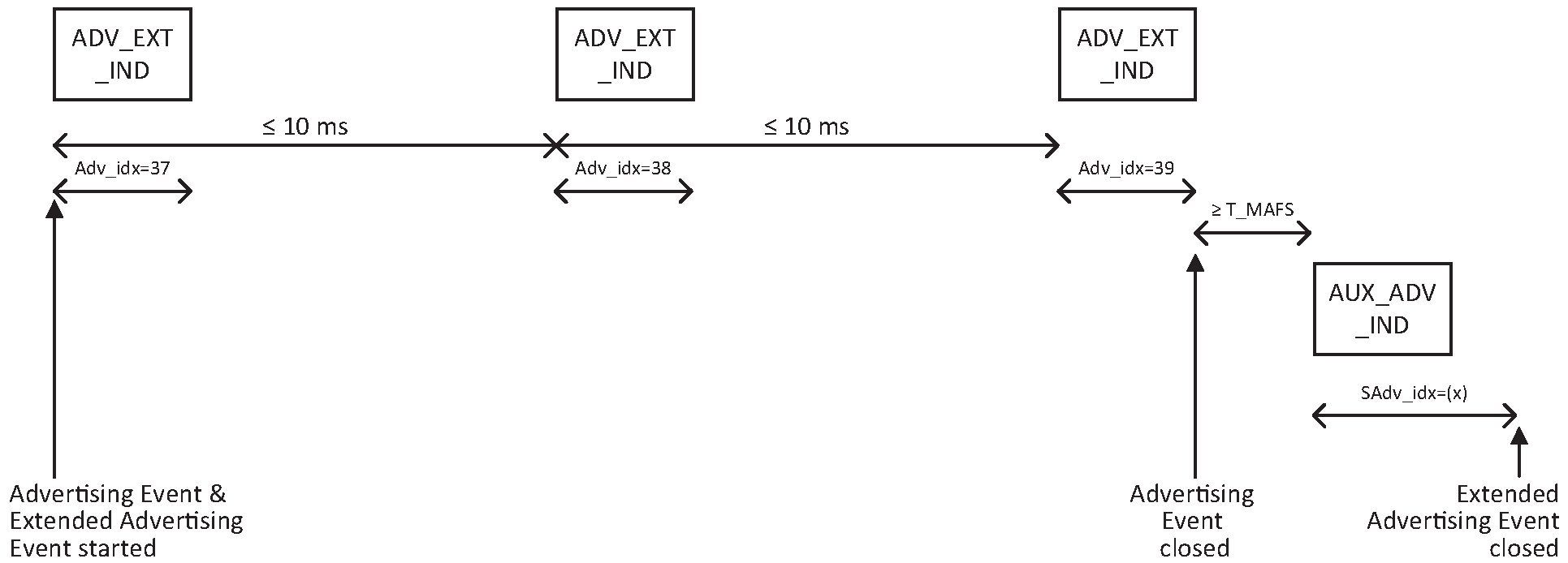
Figure 4.29 illustrates an advertising event during which an AUX_CONNECT_REQ PDU is received and an AUX_CONNECT_RSP PDU is sent on the secondary advertising channel index.
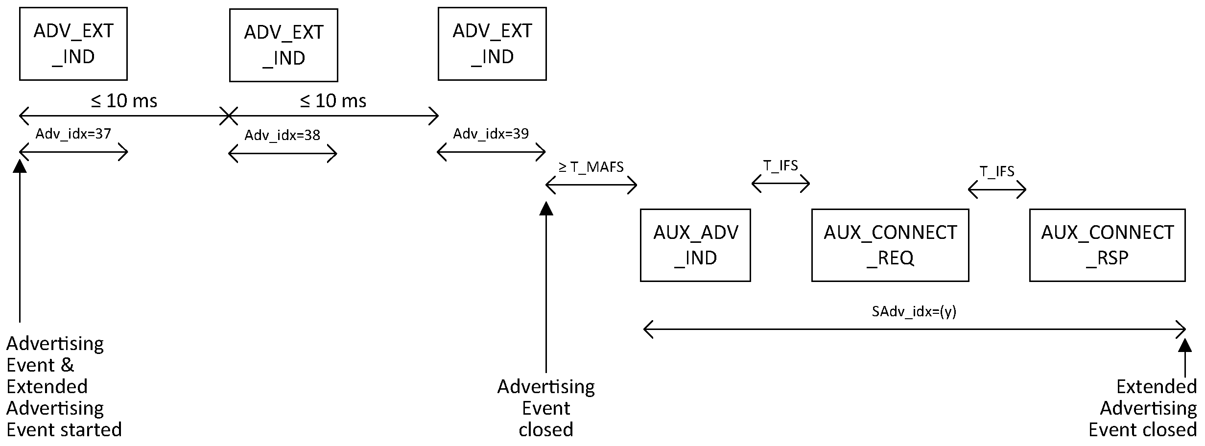
If the Controller supports LL Privacy, then the requirements in Section 6.2.4 shall also be followed.
4.4.2.8. Scannable directed event type
The scannable directed advertising event type using the ADV_EXT_IND PDU allows a specific scanner to respond with a scan request to receive scan response data on the secondary advertising physical channel.
After every AUX_ADV_IND PDU sent, the advertiser shall listen for an AUX_SCAN_REQ PDU on the same secondary advertising channel index from the targeted scanner.
If the advertiser receives an AUX_SCAN_REQ PDU that contains its device address and the scanner’s device address is contained in the AUX_ADV_IND PDU, it shall reply with an AUX_SCAN_RSP PDU on the same secondary advertising channel index prior to the next advertising event. The AUX_SCAN_RSP PDU shall contain the scan response data. AUX_SCAN_REQ PDUs from any other scanner or any AUX_CONNECT_REQ PDUs received shall be ignored.
The time between the beginning of two consecutive ADV_EXT_IND PDUs within an advertising event shall be less than or equal to 10 ms. The advertising event shall be closed within the advertising interval.
See Section 4.4.2.5.2 for a description on how the AUX_SCAN_REQ packet is used in conjunction with the AUX_SCAN_RSP packets on the secondary advertising physical channel.
If the Controller supports LL Privacy, then the requirements in Section 6.2.5 shall also be followed.
4.4.2.9. Non-connectable and non-scannable directed event type
The non-connectable and non-scannable directed advertising event type using the ADV_EXT_IND PDU (either with or without an auxiliary AUX_ADV_IND PDU) allows an advertiser to send non-connectable and non-scannable directed ADV_EXT_IND PDUs on the primary advertising physical channel with any advertising data sent on the secondary advertising physical channel targeted for a specific scanner.
Note
Note: The Host cannot specify which PDU contains the AdvA or TargetA field; the Controller should make this choice based on overall efficient use of the medium.
The Link Layer does not listen, and therefore cannot receive any requests from scanners or initiators.
If the Controller supports LL Privacy, then the requirements in Section 6.2.5 shall also be followed.
4.4.2.10. Advertising Sets
The advertiser’s Host may instruct the Link Layer to interleave advertising events. Advertising data belonging together is called an advertising set. The Link Layer may support multiple advertising sets, with each set having different advertising parameters such as advertising PDU type, advertising interval, and PHY.
When advertising with the ADV_EXT_IND, AUX_ADV_IND, or AUX_SYNC_IND PDUs, the advertising set is identified by the Advertising SID subfield of the ADI field. The Link Layer shall set the Advertising SID subfield as directed by the Host.
The scanner may filter advertisements based on the Advertising SID.
The advertising events for each advertising set are considered a separate instance of the Advertising State and each have their own Advertising Interval (see Section 4.4.2.2.1).
Figure 4.30 illustrates an example of advertising using multiple advertising sets.
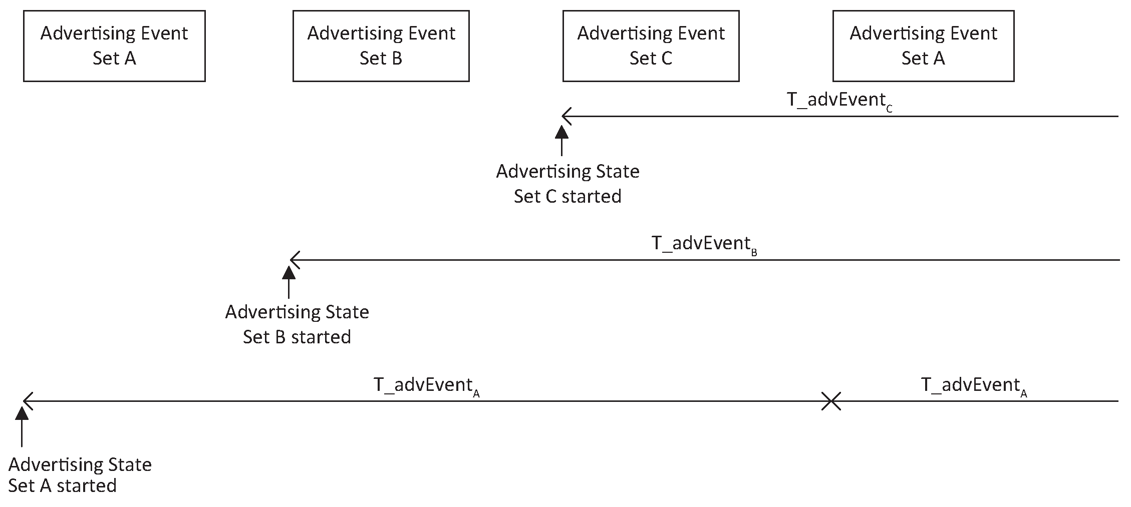
On reset, all advertising sets are destroyed.
When an advertising set is created that includes advertising data, the Controller shall reserve sufficient resources to allow the set to contain at least 31 octets of advertising data. The Controller may release or reuse any unused portion of those resources at any time after the Host first specifies advertising data for that set or creates another advertising set.
When an advertising set is created that is scannable, the Controller shall reserve sufficient resources to allow the set to contain at least 31 octets of scan response data. The Controller may release or reuse those resources if the set is made non-scannable and may release or reuse any unused portion of those resources at any time after the Host first specifies scan response data for that set or creates another advertising set.
4.4.2.11. Using AdvDataInfo (ADI)
The AdvDataInfo (ADI) field is used to identify advertising sets and duplicate AdvData in the AUX_ADV_IND, AUX_SYNC_IND, and AUX_SCAN_RSP PDUs. For scannable advertising events using the ADV_EXT_IND PDU, AdvData is not permitted in the AUX_ADV_IND PDU so the ADI only refers to the AdvData contained in the AUX_SCAN_RSP PDU.
The Advertising DID for a given advertising set or periodic advertising train shall be initialized with a randomly chosen value. The advertising set and any associated periodic advertising shall have separate Advertising DIDs. Whenever the Host provides new advertising data, periodic advertising data, or scan response data for a given advertising set (whether it is the same as the previous data or not), the Advertising DID shall be updated. The new value shall be a randomly chosen value that is not the same as the most recently used value.
Note
Note: Choosing Advertising DID field values randomly reduces the possibility of PDUs from different advertisers containing the same ADI field value.
Note
Note: The Advertising DID is not required to change when a SyncInfo field is added to or removed from an advertising set. However, if it does not change, then scanners may fail to synchronize to periodic advertising because entries in the Advertising DID cache (see Section 4.4.3) mean they ignore the advertisements containing the SyncInfo field. Therefore, advertisers should update the Advertising DID when a periodic advertising train is enabled. Alternatively, the Host should enable periodic advertising before enabling advertising.
4.4.2.12. Periodic advertising
When advertising data is required to be sent regularly at a fixed interval, periodic advertising is used. Two forms of periodic advertising are defined: periodic advertising without responses and periodic advertising with responses.
Periodic advertising without responses consists of advertisements sent at a fixed interval with the advertisement data changing from time to time. The AUX_SYNC_IND and AUX_CHAIN_IND PDUs making up such a sequence of advertisements form a periodic advertising train.
Note
Note: No AUX_SYNC_SUBEVENT_IND and AUX_SYNC_SUBEVENT_RSP PDUs are sent on a periodic advertising without responses train
Periodic Advertising with Responses (PAwR) consists of advertisements sent at a fixed interval with the advertisement data changing frequently, with responses being sent in response. The AUX_SYNC_SUBEVENT_IND and AUX_SYNC_SUBEVENT_RSP PDUs making up such a sequence of advertisements form a PAwR train.
Note
Note: No AUX_SYNC_IND and AUX_CHAIN_IND PDUs are sent on a PAwR train.
The advertising set containing the Periodic Advertising is identified by the AdvDataInfo field of ADV_EXT_IND PDUs that point to AUX_ADV_IND PDUs containing the SyncInfo field. The AUX_SYNC_IND PDUs, the AUX_SYNC_SUBEVENT_IND PDUs, and the PDUs that point to them shall always be sent on the same PHY. The PHY used, the Access Address, and the CRCInit value of the AUX_SYNC_IND PDUs and the AUX_SYNC_SUBEVENT_IND PDUs for a periodic advertising train shall not change while that train is enabled. Advertising pointing to a periodic advertising train shall not be anonymous. Each time that a periodic advertising train is enabled, the Controller shall transmit at least one AUX_ADV_IND PDU pointing to the first AUX_SYNC_IND or AUX_SYNC_SUBEVENT_IND PDU of that train; after this, there is no requirement whether or when to transmit advertising PDUs pointing to the train. If the Periodic Advertising is with responses, then the ACAD field of the AUX_ADV_IND PDUs shall contain Periodic Advertising Response Timing Information (see Section 1.24 of [1]).
Note
Note: The SyncInfo field is only allowed in non-scannable and non-connectable advertisements.
4.4.2.12.1. Trains without responses
When periodic advertising without responses takes place, the advertiser shall send AUX_SYNC_IND PDUs at regular intervals (the periodic advertising interval - see Section 4.4.2.2.3), which are described in the SyncInfo field of AUX_ADV_IND PDUs.
The Host may send periodic advertising data to the Link Layer. This advertising data is placed by the Link Layer in the periodic AUX_SYNC_IND PDUs and their subordinate sets. The Link Layer shall repeat the last advertising data sent by the Host until it receives new advertising data. The AUX_SYNC_IND PDUs are continuously sent out until the Host directs the Link Layer to terminate the periodic advertising train. When including the ADI field is enabled by the Host and where the periodic advertising data is not changed for every periodic advertising event, the Controller should include the ADI field in the AUX_SYNC_IND PDU.
Packets in a periodic advertising train may include a Constant Tone Extension. The Host may enable this before the periodic advertising train starts or may enable or disable inclusion of the Constant Tone Extension while the periodic advertising is in progress.
When an advertising set is first configured for periodic advertising, the Controller shall either reserve sufficient resources to allow the set to contain at least 31 octets of advertising data or else shall not allow periodic advertising on that advertising set. The Controller may release or reuse any unused portion of those resources at any time after the Host first specifies periodic advertising data for that set or creates another advertising set.
Figure 4.31 illustrates an example of periodic advertising.
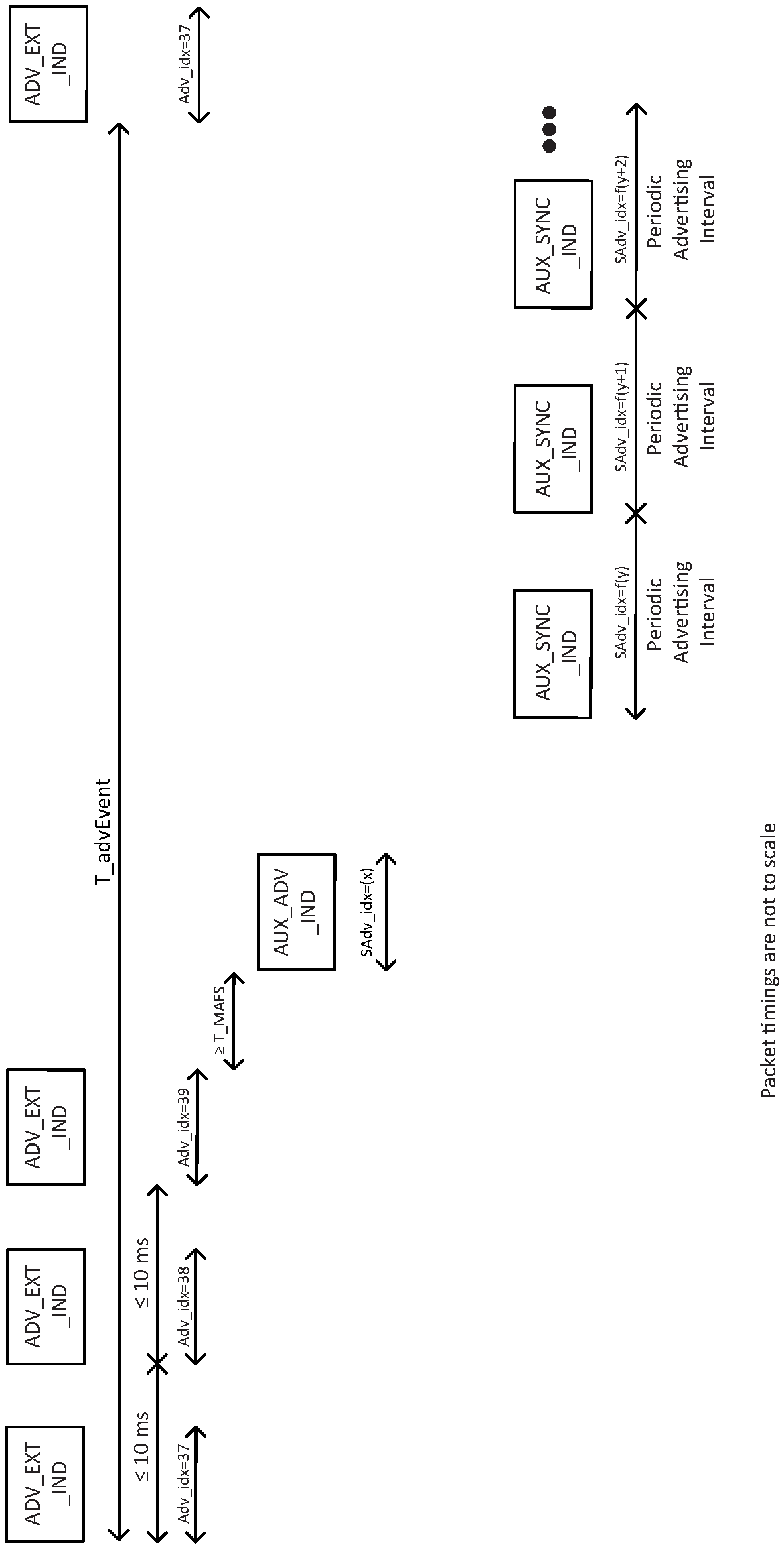
4.4.2.12.2. Trains with responses
When PAwR takes place, the advertiser shall send AUX_SYNC_SUBEVENT_IND PDUs at regular intervals defined by the periodic advertising interval and the periodic advertising subevent interval (see Section 4.4.2.2.4). The PHY used and the CRCInit value of the AUX_SYNC_SUBEVENT_IND and AUX_SYNC_SUBEVENT_RSP PDUs for a periodic advertising train shall not change while that train is enabled. The Access Address value of the AUX_SYNC_SUBEVENT_IND shall not change while that train is enabled. The Access Address value of the AUX_SYNC_SUBEVENT_RSP shall be set by each synchronized device to the RspAA.
The Host may send periodic advertising data to the Link Layer. This advertising data is placed by the Link Layer in the periodic AUX_SYNC_SUBEVENT_IND PDUs. The Link Layer shall send the advertising data sent by the Host once and then immediately discard the advertising data. The AUX_SYNC_SUBEVENT_IND PDUs should be continuously sent out until the Host directs the Link Layer to terminate the periodic advertising train. If the Host has not provided any data to the Link Layer, then an AUX_SYNC_SUBEVENT_IND_PDU should still be sent with an empty payload.
When instructed by the Host, the Link Layer shall transmit an AUX_CONNECT_REQ PDU instead of an AUX_SYNC_SUBEVENT_IND PDU, with the InitA field set to the address of the advertiser and the AdvA field set to the address of the synchronized device. After sending the AUX_CONNECT_REQ PDU, the periodic advertiser shall wait for the synchronized device to send an AUX_CONNECT_RSP PDU T_IFS from the end of the AUX_CONNECT_REQ PDU on the same secondary advertising channel index. If an AUX_CONNECT_RSP PDU is received from the synchronized device, the Link Layer of the periodic advertiser shall start a new state machine that immediately transitions to the Connection state in the Central role as defined in Section 4.5.4; the existing state machine shall remain in the Advertising state. If an AUX_CONNECT_RSP PDU is not received from the synchronized device, then the request to connect to the synchronized device is discarded.
If the synchronized device receives an AUX_CONNECT_REQ PDU from the periodic advertiser that contains its device address, then the synchronized device shall reply with an AUX_CONNECT_RSP PDU on the same secondary advertising channel index with the AdvA field set to the address of the synchronized device and the TargetA field set to the address of the advertiser. After the AUX_CONNECT_RSP PDU is sent, the Link Layer shall start a new state machine that immediately transitions to the Connection state in the Peripheral role as defined in Section 4.5.5; the existing state machine shall remain in the Synchronization state.
4.4.3. Scanning state
The Link Layer shall enter the Scanning state when directed by the Host. When scanning, the Link Layer shall listen on the primary advertising physical channel for the types of PDU and on the PHYs that have been indicated by the Host. There are two types of scanning, determined by the Host: passive and active.
There are no strict timing or advertising channel index selection rules for scanning.
During scanning, the Link Layer should listen on a primary advertising channel index for the duration of the scan window, scanWindow. The scan interval, scanInterval, is defined as the interval between the start of two consecutive scan windows.
The Link Layer should listen for the complete scanWindow every scanInterval as directed by the Host unless there is a scheduling conflict. In each scan window, the Link Layer should scan on a different primary advertising channel index than the one used in the previous scan window. The Link Layer shall use all the primary advertising channel indices.
The scanWindow and scanInterval parameters shall be less than 40.96 s. The scanWindow shall be less than or equal to the scanInterval. If the scanWindow and the scanInterval parameters are set to the same value by the Host, the Link Layer should scan continuously.
The scanning filter policy shall apply when receiving an advertising PDU or scan response PDU when scanning.
On receiving a PDU with the AuxPtr field present, the scanner should also listen for the auxiliary PDU it points to (provided that it supports the PHY specified in the AuxPtr field) and should then attempt to receive the entire subordinate set of the PDU. While doing so, it shall perform the window widening specified in Section 4.2.4. If it does not support the specified PHY or the value is reserved for future use, it shall not listen for the auxiliary PDU and shall behave as if it listened for it but failed to receive it.
When a scanner receives ADV_EXT_IND PDUs that contain an AuxPtr field, it may either always listen for the auxiliary packet or may sometimes skip listening. In the latter case, the following requirements shall apply.
For each Advertising SID value received:
The Controller shall keep a cache of one or more recent Advertising DID values used by each advertising device (for this purpose, all anonymous advertising is treated as being from a single device different to all real devices) and shall update them whenever a PDU containing an ADI field is received. The Controller may delete any cache entry at any time. The Controller should delete the cache entry relating to an ADV_EXT_IND PDU if it fails to receive that PDU's entire subordinate set.
The Controller may only skip listening for the auxiliary packet if the cache has an entry specifying the Advertising DID value in the ADI field being used by a device; if the ADV_EXT_IND PDU contains an AdvA field, the entry shall be for that device. Otherwise, the Controller shall not skip listening for the auxiliary packet.
Irrespective of the cache contents, the Controller should sometimes listen for the AUX_ADV_IND PDU in case another advertiser has started using the same Advertising DID value or the existing advertiser has made a significant change to the extended header (e.g., included the SyncInfo field).
If the Controller supports LL Privacy, then the requirements in Section 6.3 shall also be followed.
4.4.3.1. Passive scanning
When in passive scanning, the Link Layer will only receive packets; it shall not send any packets.
4.4.3.2. Active scanning
In active scanning, the Link Layer shall listen for advertising PDUs and, depending on the advertising PDU type, it may request an advertiser to send additional information.
After entering the Scanning State, if the Link Layer receives a scannable PDU (i.e. an ADV_IND, ADV_SCAN_IND, or scannable AUX_ADV_IND PDU) from an advertiser allowed by the scanning filter policy, it shall respond with a scan request PDU and then listen for the scan response PDU. It shall continue to respond to the same advertiser until it has successfully received the scan response PDU. It may then either respond to or ignore subsequent scannable PDUs from the same advertiser. It should ignore them if either they are legacy PDUs or if the Advertising DID field has not changed since the last advertisement from the same advertiser with the same Advertising SID field; it should not ignore them otherwise.
The Link Layer shall only send a SCAN_REQ PDU to an advertiser from which an ADV_IND PDU or ADV_SCAN_IND PDU is received. The Link Layer shall only send an AUX_SCAN_REQ PDU to an advertiser from which a scannable AUX_ADV_IND is received. The Link Layer shall ignore a scannable AUX_ADV_IND PDU if the TargetA field is present and it does not match the Link Layer’s device address.
The scanner shall run a backoff procedure to minimize collisions of scan request PDUs from multiple scanners. An example of such a procedure is given in the following paragraphs.
The backoff procedure uses two parameters, backoffCount and upperLimit, to restrict the number of scan request PDUs sent when collisions occur on scan response PDUs. Upon entering the Scanning State, the upperLimit and backoffCount are set to one.
On every received ADV_IND, ADV_SCAN_IND, or scannable AUX_ADV_IND PDU that is allowed by the scanning filter policy and for which a scan request PDU is to be sent, the backoffCount is decremented by one until it reaches the value of zero. The scan request PDU is only sent when backoffCount becomes zero.
After sending a scan request PDU the Link Layer listens for a scan response PDU from that advertiser. If the scan response PDU was not received from that advertiser, it is considered a failure; otherwise it is considered a success. On every two consecutive failures, the upperLimit is doubled until it reaches the value of 256. On every two consecutive successes, the upperLimit is halved until it reaches the value of one. After success or failure of receiving the scan response PDU, the Link Layer sets backoffCount to a new (pseudo-)random integer between one and upperLimit.
If a device uses a different backoff algorithm it shall share the medium responsibly.
Two illustrations of advertising events using all the advertising channel indices during which a SCAN_REQ PDU is received and a SCAN_RSP PDU is sent are shown in Figure 4.12 and in Figure 4.13.
4.4.3.3. Advertising sets
The ADV_EXT_IND PDU may contain an ADI field. When the ADI field is present, it can be used to identify advertisement data that belong to the same set. This is specified in the Advertising SID subfield in the ADI. The Advertising SID is set by the Host of the advertiser.
4.4.3.4. Scanning for periodic advertisements
When instructed by the Host, the scanner shall look for periodic advertising synchronization information located in the SyncInfo field and, for PAwR, the ACAD field of AUX_ADV_IND PDUs. If the syncPacketWindowOffset value of the SyncInfo is zero, the periodic advertising synchronization information is incomplete and the scanner should listen for a subsequent advertisement to be able to obtain the complete information. When it has received the complete information it shall start a new state machine that immediately transitions to the Synchronization State; the existing state machine shall remain in the Scanning State.
The Host may instruct the Controller not to synchronize to periodic advertising trains with certain types of Constant Tone Extensions or without a Constant Tone Extension. If the Controller receives an AUX_SYNC_IND or AUX_SYNC_SUBEVENT_IND with such a Constant Tone Extension while synchronizing, the synchronization attempt has failed and shall cease. Once synchronized, the presence or type of Constant Tone Extension shall not affect synchronization.
4.4.3.5. Advertising reports
The Link Layer shall send an advertising report to the Host for each advertising PDU on the primary advertising physical channel that is accepted by the scanning filter policy (see Section 4.3.3) and for each scan response PDU from an advertiser that is accepted by the scanning filter policy, except where stated otherwise in this section. The Controller shall send the report even if it does not respond to the advertiser.
If the Controller receives an ADV_EXT_IND PDU with an AuxPtr field, it shall delay the report until after the corresponding AUX_ADV_IND PDU has been received and the report shall combine the information in the PDUs; if the Controller does not listen for or does not receive the AUX_ADV_IND PDU, no report shall be generated. The advertising report shall contain at least the advertiser's device address and all of the advertising data or scan response data (including any data in any subordinate AUX_CHAIN_IND PDUs that were received) if present.
Note
Note: The Controller may use more than one HCI event to send the report, for example, if the total data does not fit within a single event.
Note
Note: The requirements above and those in Section 4.6.12 mean that the Controller must be able to store and report to the Host at least 251 octets of data from a single advertisement or scan response (irrespective of the number of PDUs used to transmit the data) if the Controller supports LE extended advertising and 31 octets otherwise.
The Host may request that duplicate advertising reports are filtered and so not sent.
Where a received ADV_EXT_IND PDU contains an ADI field, a duplicate advertising report is an advertising report for the same device address where the previous report that contained an ADI value with the same Advertising SID also had the same Advertising DID. For this purpose, all anonymous advertising is treated as being from a single device different to all non-anonymous devices.
Where the ADV_EXT_IND PDU does not contain an ADI field or a legacy PDU was received, a duplicate advertising report is an advertising report for the same device address while the Link Layer stays in the Scanning state.
In either case the actual data may change; advertising data or scan response data is not considered significant when determining duplicate advertising reports. However, if not all the subordinate set of an advertisement or scan response was received (i.e., an incomplete report), a subsequent report that contains more of the data should not be treated as a duplicate of the incomplete report.
4.4.4. Initiating state
The Link Layer shall enter the Initiating state when directed by the Host. When initiating, the Link Layer shall listen on the primary advertising physical channel.
There are no strict timing or advertising channel index selection rules for initiators.
During initiating, the Link Layer listens on a primary advertising channel index for the duration of the scan window, scanWindow. The scan interval, scanInterval, is defined as the interval between the start of two consecutive scan windows.
The Link Layer should listen for the complete scanWindow every scanInterval as directed by the Host unless there is a scheduling conflict. In each scan window, the Link Layer should listen on a different primary advertising channel index. The Link Layer shall use all the primary advertising channel indices.
The scanWindow and scanInterval parameters shall be less than or equal to 40.96 s. The scanWindow shall be less than or equal to the scanInterval. If the scanWindow and the scanInterval parameters are set to the same value by the Host, the Link Layer should listen continuously.
Connection indications or requests in response to a connectable advertisement shall be sent on either the primary or secondary advertising physical channel depending on which advertising PDU contains an AdvA field. The following sub-sections describe the two procedures.
If the Controller supports LL Privacy, then the requirements in Section 6.4 shall also be followed.
4.4.4.1. Connect requests on the primary advertising physical channel
If an ADV_IND PDU is received that is allowed by the initiator filter policy, the initiator shall send a CONNECT_IND PDU to the advertiser. If an ADV_DIRECT_IND PDU containing the initiator's Link Layer device address and allowed by the initiator filter policy is received, the initiator shall send a CONNECT_IND PDU to the advertiser; otherwise it shall be ignored.
After sending the CONNECT_IND PDU, the Link Layer shall exit the Initiating State, and shall transition to the Connection State in the Central Role as defined in Section 4.5.4.
4.4.4.2. Connect requests on the secondary advertising physical channel
If a connectable ADV_EXT_IND PDU is received, the initiator shall listen for the connectable AUX_ADV_IND on the secondary advertising physical channel; while doing so, it shall perform the window widening specified in Section 4.2.4. If a connectable undirected AUX_ADV_IND PDU, or a connectable directed AUX_ADV_IND PDU containing the initiator's Link Layer device address, is received and is allowed by the initiator filter policy, the initiator shall send an AUX_CONNECT_REQ PDU to the advertiser; otherwise, it shall be ignored.
After sending the AUX_CONNECT_REQ PDU, the initiator shall wait for the advertiser to send an AUX_CONNECT_RSP PDU. Once an AUX_CONNECT_RSP PDU is received, the Link Layer shall exit the Initiating State and shall transition to the Connection State in the Central Role as defined in Section 4.5.4. If the initiator does not receive an AUX_CONNECT_RSP PDU from the advertiser, it shall use the back-off algorithm described for SCAN_REQ in Section 4.4.3.2 before responding to the next connectable AUX_ADV_IND PDU.
4.4.5. Synchronization state
In the Synchronization state, the Link Layer listens to regular broadcasts from another device. There are two types of such broadcasts: periodic advertising trains and broadcast isochronous streams.
Synchronization state has two sub-states: synchronizing and synchronized. The Link Layer shall enter the Synchronization state in the synchronizing sub-state when directed by the Host, provided that it is in possession of the necessary information to locate the regular broadcasts. Once it has successfully received a PDU from the broadcast, it transitions to the synchronized sub-state and is then said to be synchronized to the broadcast; until then, it is said to be synchronizing.
Once synchronized, if it fails to receive any PDUs forming the broadcast for a period specified by the Host, it shall transition to the Standby state and notify the Host.
4.4.5.1. Periodic advertising trains
To receive periodic advertising trains the Link Layer must obtain periodic advertising synchronization information. This information may be obtained from the SyncInfo field of an AUX_ADV_IND PDU (see Section 4.4.3.4) or from an LL_PERIODIC_SYNC_IND or an LL_PERIODIC_SYNC_WR_IND PDU sent by a connected device.
While in this state, the Link Layer shall listen on the secondary advertising channel indices specified in Section 4.4.2.1 for the AUX_SYNC_IND or AUX_SYNC_SUBEVENT_IND PDUs forming the periodic advertising train specified in the synchronization information. In the synchronizing sub-state, if the Controller does not receive any of these AUX_SYNC_IND or AUX_SYNC_SUBEVENT_IND PDUs within 6 periodic advertising events, starting with the first periodic advertising event it listened for, it shall notify the Host and transition to the Standby State.
A device shall not attempt to synchronize to a periodic advertising train with the same address, address type, and Advertising SID as one that it is already synchronized to. A device should not attempt to synchronize to a periodic advertising train with the same Access Address as one that it is already synchronized to.
The Link Layer shall perform the window widening specified in Section 4.2.4 while listening. If the windowWidening reaches ((periodicInterval/2) - T_IFS µs) in magnitude, the Controller should notify the Host and transition to the Standby State.
4.4.5.1.1. Trains without responses
If requested by the Host, the Link Layer shall report the advertising data received in the periodic advertisements to the Host. The Host may specify that not all such data is reported or that duplicate periodic advertising reports are filtered and so not sent to the Host. A duplicate periodic advertising report is a report for the same periodic advertising train where the previous report for that train that contained an ADI field had the same Advertising SID and DID. The Link Layer need not listen to AUX_SYNC_IND or AUX_CHAIN_IND PDUs where it will not be reporting the data or samples from Constant Tone Extensions to the Host, other than as necessary to maintain synchronization with the advertiser's clock or to receive any channel map updates.
4.4.5.1.2. Trains with responses
If requested by the Host, the Link Layer shall report the advertising data received in the periodic advertisements to the Host. The Host may specify that not all such data is reported. The Link Layer need not listen to an AUX_SYNC_SUBEVENT_IND PDU where it would not be reporting the data to the Host, other than as necessary to maintain synchronization with the advertiser's clock or to receive any channel map updates.
A synchronized device may transmit an AUX_SYNC_SUBEVENT_RSP PDU when instructed to by its Host. The response slot to use is determined by the Host.
4.4.5.2. Broadcast Isochronous Streams
To receive broadcast isochronous streams, the Link Layer must obtain the BIGInfo describing the streams (see Section 4.4.6.11). This information may be obtained from the ACAD of periodic advertising. If the PHY field of the BIGInfo specifies a PHY that the Link Layer does not support or is reserved for future use, the Link Layer shall ignore the BIGInfo, shall not report the BIGInfo to the Host, and shall not enter the Synchronization state for the BIG specified in the BIGinfo.
While in this state, the Link Layer shall listen on the isochronous channel indices specified in Section 4.4.6.8 for BIS Data PDUs forming the BIG specified in the BIGInfo. In the synchronizing sub-state, if the Link Layer does not receive a BIS Data PDU within 6 BIG events, starting with the first BIG event it listened for, it shall notify the Host and transition to the Standby state.
Once in the synchronized sub-state, the Link Layer shall listen for the Isochronous Broadcaster at least once within any 6 consecutive BIS events.
A device shall not attempt to synchronize to a BIG with the same associated periodic advertising train as a BIG that it is already synchronized to.
A device that has synchronized to a BIG is called a Synchronized Receiver. A Synchronized Receiver may, but it is not required to, remain synchronized to the periodic advertising train.
If requested by the Host, the Link Layer shall report the isochronous data received in the BIS Data PDUs forming the BIG to the Host. The Host may specify that only the data from specific BISes within the BIG are reported. The Link Layer shall listen to and act on the contents of new BIG Control PDUs.
The Link Layer need not listen to Broadcast Isochronous PDUs that are retransmissions of PDUs already successfully received, or to BIS Data PDUs where it will not be reporting the data to the Host, other than as necessary to maintain synchronization with the Isochronous Broadcaster’s clock.
The Link Layer shall perform the window widening specified in Section 4.2.4 while listening.
The Link Layer shall stop listening to the BIG no later than when the bisPayloadCounter equals 239 – 1.
4.4.6. Isochronous Broadcasting state
The Link Layer shall enter the Isochronous Broadcasting state when directed by the Host, provided that it is able to schedule the BIG the Host is requesting to be transmitted. While in this state the Link Layer shall transmit BIS PDUs as described in the following subsections.
When the Link Layer enters the Isochronous Broadcasting state, it shall notify the Host.
In this state, the Host may disable and subsequently re-enable the periodic advertising train associated with the BIG.
Each instance of the Link Layer state machine in the Isochronous Broadcasting state shall transmit a BIG made up of one or more BISes. Each BIS carries a separate isochronous data flow. There shall be at most 31 BISes in a BIG.
Note
Note: The Isochronous Broadcasting state is per BIG (i.e. every new BIG instantiates a new Link Layer state machine).
4.4.6.1. Broadcast Isochronous Stream (BIS)
A BIS is a logical transport that enables a device to transfer isochronous data. The isochronous data can be either framed or unframed.
A BIS supports variable size packets and the transmission of one or more packets in each BIS event, allowing a range of data rates to be supported. The data traffic is unidirectional from the broadcasting device; hence there is no acknowledgment protocol and broadcast isochronous traffic is inherently unreliable. To improve the reliability of packet delivery, the BIS supports multiple retransmissions.
4.4.6.2. Broadcast Isochronous Group (BIG)
A BIG consists of either two or more BISes that have the same ISO_Interval and are expected to have a time relationship at the application layer, or of a single BIS. The maximum number of BISes in a BIG shall be 31. A BIG also contains control subevents (see Section 4.4.6.7).
4.4.6.3. BIG parameters
Each BIG is defined by the following parameters:
Num_BIS is the number of BISes in the BIG. The BISes in a BIG are each assigned a different BIS_Number from 1 to Num_BIS.
ISO_Interval is the time between two adjacent BIG anchor points, in units of 1.25 ms. The value shall be between 4 and 3200 (i.e. 5 ms to 4 s).
BIS_Spacing is the time between the start of corresponding subevents in adjacent BISes in the BIG and also the time between the start of the first subevent of the last BIS and the control subevent, if present.
Sub_Interval is the time between the start of two consecutive subevents of each BIS.
Max_PDU is the maximum number of data octets (excluding the MIC, if any) that can be carried in each BIS Data PDU in the BIG. The value shall be between 1 and 251 octets.
Max_SDU is the maximum size of an SDU on this BIG (see [Vol 6] Part G, Section 1). The value shall be between 1 and 4095 octets.
MPT shall equal the time taken to transmit a packet containing a BIS Data PDU with a payload of Max_PDU octets on the PHY being used for the BIS; on the LE Coded PHY, the S=8 coding shall be assumed.
BN, PTO, and IRC control which data is transmitted in each BIG event. The value of BN shall be between 1 and 7. The value of PTO shall be between 0 and 15. The value of IRC shall be between 1 and 15.
NSE is the number of subevents per BIS in each BIG event. The value shall be between 1 and 31 and shall be an integer multiple of BN.
Framed indicates whether the BIG carries framed or unframed data.
Encrypted indicates whether the BIG is encrypted or not.
These parameters shall not change during the lifetime of the BIG. They are discussed further in subsections 4.4.6.4 to 4.4.6.11.The mandatory range for each parameter is the entire range of valid values except for the following parameters, where only the listed values are mandatory:
Num_BIS: 1
BN: 1
NSE: all supported values of BN
PTO: 0
IRC: all supported values of GC (see Section 4.4.6.6)
Each BIG shall have a 39-bit counter bigEventCounter associated with it. This shall be set to 0 for the first BIG event of a BIG and be incremented by 1 for each BIG event, whether or not the Isochronous Broadcaster transmits any Broadcast Isochronous PDUs during the event.
Each BIS shall have a 39-bit counter bisPayloadCounter associated with it, described further in Section 4.4.6.5. The Link Layers of an Isochronous Broadcaster and a Synchronized Receiver shall terminate the BIG no later than when the bisPayloadCounter equals 239 – 1.
Note: At the start of any BIG event, all the BISes in a BIG will have the same value for bisPayloadCounter and, in addition, bigEventCounter * BN = bisPayloadCounter.
4.4.6.4. BIG event
A BIG event consists of one or more BIS PDUs. The Link Layer shall transmit BIS PDUs only in BIG events. The Link Layer shall transmit only BIS PDUs as part of a BIG event.
Each BIG event is divided into Num_BIS separate BIS events and a control subevent if present. Each BIS event is divided into NSE subevents.
Each BIS event starts at a moment called the BIS anchor point and ends after its last subevent. Each BIG event starts at a moment called the BIG anchor point and ends after the control subevent, if there is one, and otherwise at the end of the last constituent BIS event. The BIG anchor points shall be spaced regularly, ISO_Interval apart. The BIS anchor points for BIS n of a BIG shall be (n – 1) × BIS_Spacing after the BIG anchor points and so are also spaced regularly, ISO_Interval apart. The subevents of each BIS shall be Sub_Interval apart. The Isochronous Broadcaster shall close each BIG event at least T_IFS before the BIG anchor point of the next BIG event. Figure 4.32 shows a BIS event with subevents.
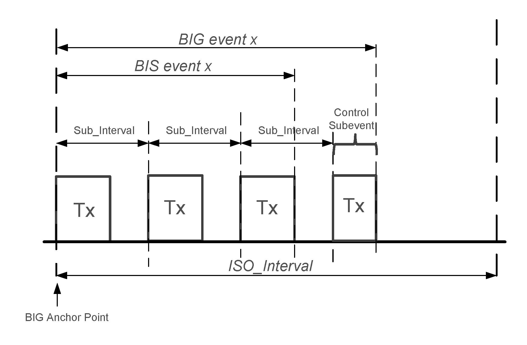 |
The BISes in a BIG shall be arranged either sequential or interleaved by setting the values of the Sub_Interval and BIS_Spacing parameters appropriately. If they are sequential, BIS_Spacing shall be greater than or equal to NSE × Sub_Interval and so all the subevents of a BIS event occur together. If they are interleaved, Sub_Interval shall be greater than or equal to Num_BIS × BIS_Spacing and so the first subevents of all BISes are adjacent, followed by the second subevents of all BISes, and so on. In each case, the minimum value for BIS_Spacing should be used. Figure 4.33 shows each arrangement for a BIG where Num_BIS = 2 and NSE = 2.
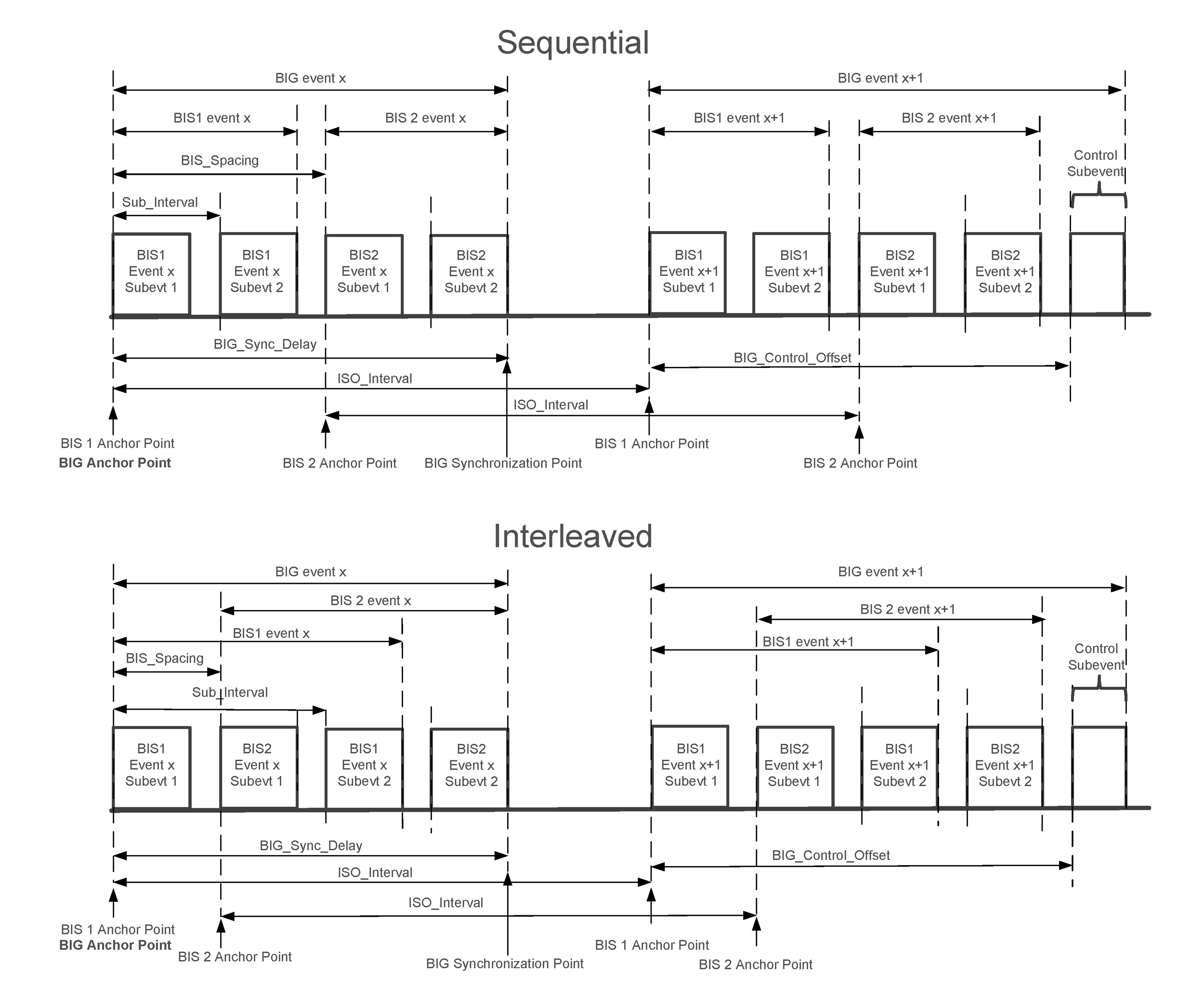
The maximum possible length for the data portion of a BIG event (thus excluding any control subevent) is denoted as BIG_Sync_Delay. The value of BIG_Sync_Delay shall equal the time from the anchor point to the BIG Synchronization point, which is the instant at the end of a packet containing a payload of Max_PDU octets transmitted in the last subevent, as shown in Figure 4.33. Therefore, the BIG_Sync_Delay equals (Num_BIS – 1) × BIS_Spacing + (NSE – 1) × Sub_Interval + MPT.
4.4.6.5. Broadcast Isochronous Data
A BIS carries a single stream of isochronous data provided for broadcast. The data may be divided into payloads of at most Max_PDU octets, each of which is transmitted in a single BIS Data PDU; the payloads need not all be the same size and can be zero length. The BISes in a BIG carry separate but associated streams of data.
The Framed parameter of a BIG shall indicate whether all the constituent BISes are framed or unframed. Framed BIGs shall only use framed BIS Data PDUs to carry data; unframed BIGs shall only use unframed BIS Data PDUs to carry data.
Both BIS_Spacing and Sub_Interval shall be at least T_MSS + MPT.
For each BIS, the payloads shall be numbered in the order provided, starting at zero. This number shall be used as the value of bisPayloadCounter for the PDU containing that payload. If the source of the data fails to provide BN payloads for a BIS event, bisPayloadCounter shall continue to increment as if it had provided the missing payloads and the Link Layer should transmit empty PDUs.
4.4.6.6. BIS subevents
A BIS subevent is an opportunity for an Isochronous Broadcaster to transmit a Broadcast Isochronous BIS PDU and a Synchronized Receiver to receive it. The Link Layer should transmit one BIS Data PDU at the start of each subevent of the isochronous broadcasting event unless, for example, it has scheduling conflicts, but shall transmit at least one BIS PDU within any 6 consecutive BIS events on a given BIS. Where it does not transmit a PDU, the Link Layer shall behave for all other purposes (e.g. the timing of packets and the choice of payload) as if it had done so.
Each BIS subevent ends at the end of the transmitted PDU or, if the Link Layer does not transmit a PDU, the subevent is MPT in duration.
For each BIS event the source of the data shall supply a burst of data consisting of BN (“Burst Number”) payloads, each of which in turn shall hold either a single fragment or one or more SDU segments. This burst is associated with the corresponding BIS event but may be transmitted in earlier events as well. Each PDU containing a given payload shall have the same LLID value but can have different CSSN and CSTF values (see Section 4.4.6.7).
Note
Note: The burst associated with a BIS event consists of payloads with bisPayloadCounter between bigEventCounter × BN and (bigEventCounter + 1) × BN – 1.
The subevents of each BIS event are partitioned into groups of BN subevents each. Therefore, there are Group Count (GC) groups, where GC = NSE ÷ BN.
IRC ("Immediate Repetition Count") specifies the number of groups that carry the data associated with the current BIS event; the remaining groups carry data associated with the future BIS events specified by PTO ("Pre-Transmission Offset"). IRC shall be greater than zero and not greater than GC. If IRC = GC then PTO shall be ignored. Otherwise PTO shall be greater than zero.
The groups of subevents are numbered using g from 0 to GC – 1 in order.
If g < IRC, then group g shall contain the data associated with the current BIS event.
If g ≥ IRC, then group g shall contain the data associated with the future BIS event that is PTO × (g - IRC + 1) BIS events after the current BIS event.
The payloads in each burst shall always be transmitted in the same order.
Note
Note: Setting GC to a value greater than 1 provides redundant transmissions to compensate for the lack of acknowledgments when broadcasting, while setting IRC to a value less than GC (called pre-transmission) provides a greater time diversity among the redundant copies of the data.
For example, Figure 4.34, Figure 4.35, and Figure 4.36 show the allocation of payloads to subevents for three different BISes.
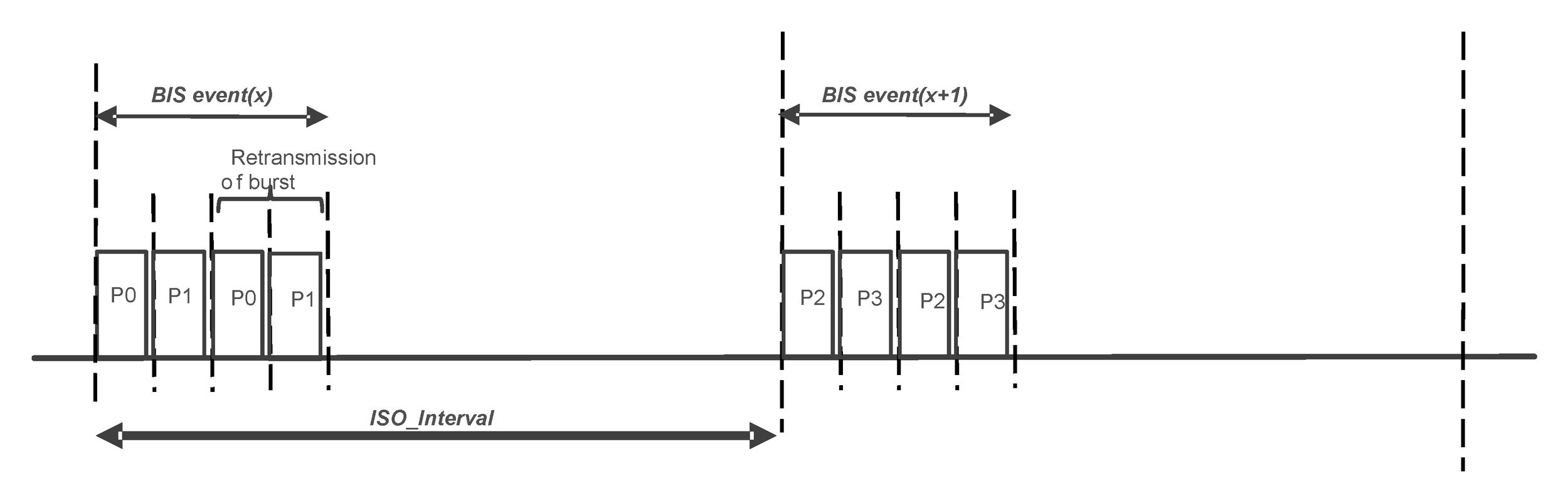
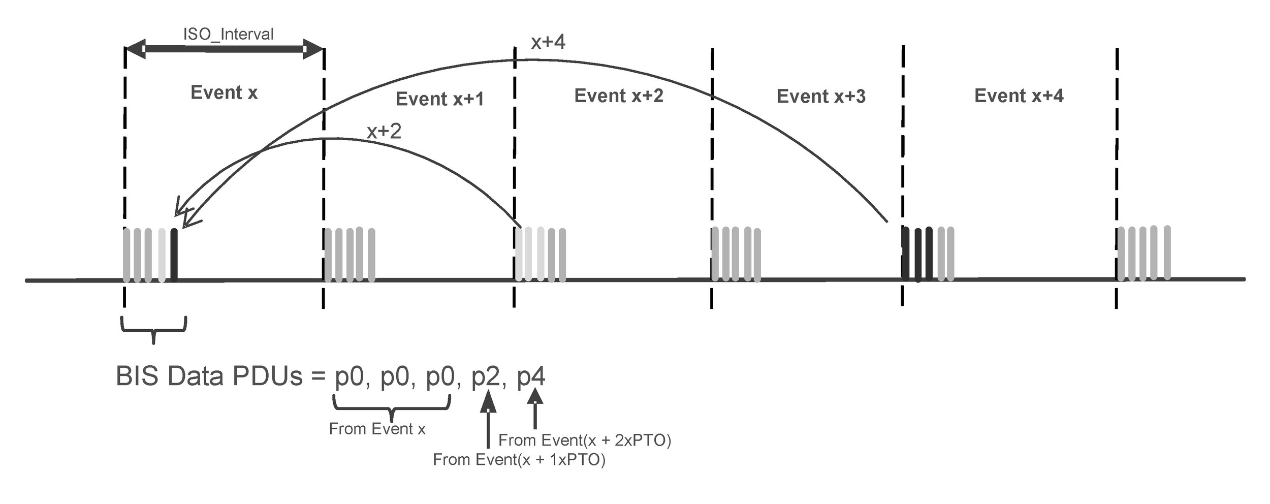
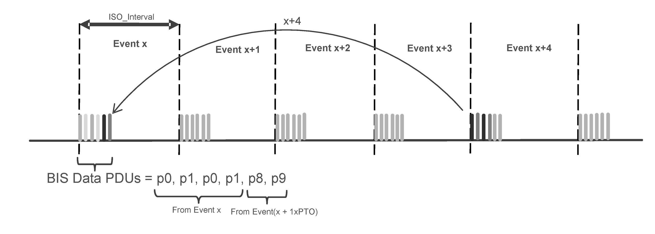
4.4.6.7. Control subevents
Each BIG event may contain a control subevent. If so, the Link Layer shall transmit a single BIG Control PDU at the start of the control subevent to send control information about the BIG (see Section 5.6). The Link Layer shall not transmit a BIG Control PDU at any other time.
The time from the BIG anchor point to the start of the control subevent, designated BIG_Control_Offset, shall be:
BIG_Control_Offset = Num_BIS * BIS_Spacing for sequential arrangement BIG_Control_Offset = NSE * Sub_Interval for interleaved arrangement
Note
Note: See Section 4.4.6.4 for sequential and interleaved arrangements of the BISes in a BIG.
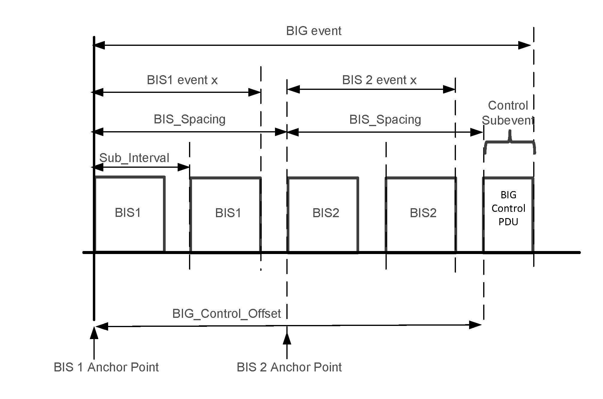
If the Link Layer schedules a BIG Control PDU to be transmitted in a BIG event, it shall set the CSTF bit to 1 in the header of every BIS Data PDU sent in that same BIG event; otherwise it shall set the bit to 0. It shall set the CSTF bit to 0 in the header of all BIG Control PDUs.
The value of the CSSN of every BIS PDU in a BIG event shall be the same. The Link Layer shall increment CSSN by 1 (with 7 wrapping to 0) at the start of a BIG event that contains the first transmission of a new BIG Control PDU and shall leave the CSSN unchanged otherwise (i.e. when a BIG Control PDU is being retransmitted or is not scheduled to be transmitted).
Note
Note: A Synchronized Receiver may use the CSSN to determine that a BIG Control PDU is a retransmission of one that it has already received.
4.4.6.8. Channel indices
Each packet containing a BIS PDU shall be transmitted on the channel index specified by Channel Selection Algorithm #2 (see Section 4.5.8.3). The subevent number se_n shall be set to the values 1 to NSE, in order, for the subevents on a given BIS – the same values shall be used for all the BISes in a BIG – and to 1 for the control subevent.
The channel map used in the BIG shall be included in the BIGInfo. When the channel map changes, it shall be transmitted in the BIG Control logical link using the BIG Channel Map Update procedure (see Section 5.6.1).
4.4.6.9. Associated periodic advertising train
Every BIG shall have an associated periodic advertising train. A periodic advertising train shall not be associated with more than one BIG at the same time. The train and BIG may be enabled and disabled independently. The ACAD field of the AUX_SYNC_IND PDU in the periodic advertising train is used to carry the BIGInfo of a BIG. The BIGInfo shall not be transmitted when the BIG is disabled. Whenever the BIG and associated train are both active, the BIGInfo shall be transmitted in the periodic advertising train whenever the ACAD of the AUX_SYNC_IND PDU has sufficient space for carrying it.
The ACAD can be used for other information as well, such as a change in channel map. Even if it is not possible to fit both in the same PDU, the Link Layer will still need to schedule transmissions of each information so as to meet any relevant requirements.
The transmission of the AUX_SYNC_IND PDU of the associated periodic advertising train should not be scheduled within a BIG event.
4.4.6.10. Encryption
The Link Layer of an Isochronous Broadcaster or Synchronized Receiver shall support unencrypted BIGs.
A BIG may be encrypted, in which case all BIS PDUs (except those with an empty payload) of all BISes in that BIG shall be encrypted. The Link Layer shall determine if a BIG is encrypted by examining the length of the BIGInfo (see Section 4.4.6.11). The rest of this section only applies to encrypted BISes.
The following parameters shall be used in the process of encrypting or decrypting all Broadcast Isochronous PDUs in BIGs:
Broadcast_Code – a 16-octet parameter provided by the Host.The Broadcast_Code applies to all the BISes in a single BIG and different BIGs broadcast by the same device may use different Broadcast_Codes.
GIV – a 64-bit parameter generated by the Controller.
GSKD – a 128-bit parameter generated by the Controller.
For each encrypted BIG, the Controller of an Isochronous Broadcaster shall generate a new GIV and GSKD using the requirements for random number generation as defined in [Vol 3] Part H, Section 2 and shall transmit them in the BIGInfo. Each Broadcast Isochronous PDU in the encrypted BIG shall be encrypted using the CCM algorithm (see [Vol 6] Part E, Section 2).
4.4.6.11. BIGInfo
The length of the BIGInfo is 33 octets for an unencrypted BIG and 57 octets for an encrypted BIG. The format of the BIGInfo is shown in Figure 4.38.
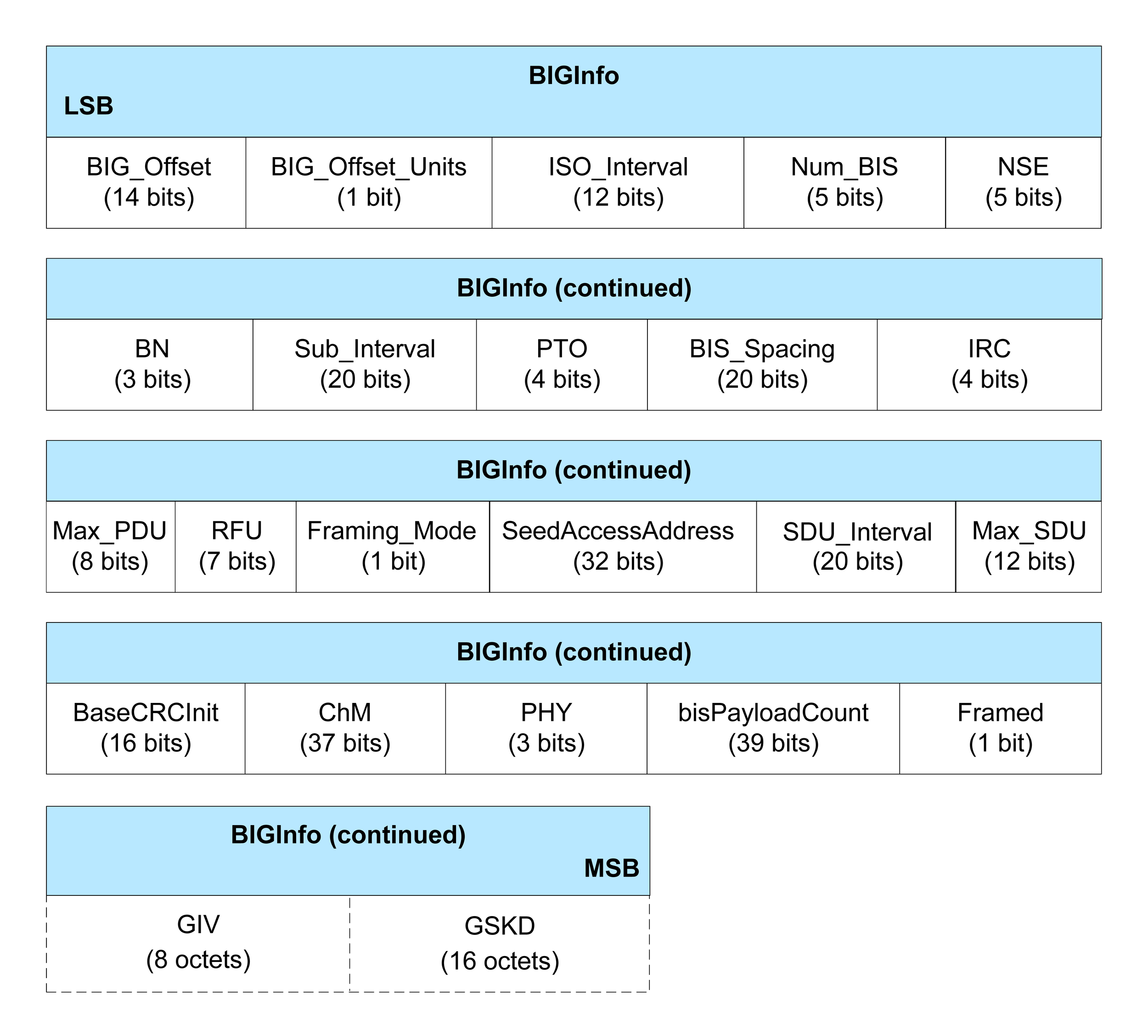
The BIG_Offset field contains the time from the start of the packet containing the BIGInfo to the BIG anchor point that this BIGInfo describes. The value of the BIG_Offset field is in the unit of time indicated by the BIG_Offset_Units bit; the actual time offset is determined by multiplying the value of BIG_Offset by the unit. The offset shall be greater than 600 μs.
If the BIG_Offset_Units bit is set then the unit is 300 µs; otherwise it is 30 µs. The BIG_Offset_Units bit shall not be set if the offset is less than 491,460 µs.
The BIG anchor point shall be no earlier than the offset and no later than the offset plus one unit after the start of the relevant packet, as shown in Figure 4.39.
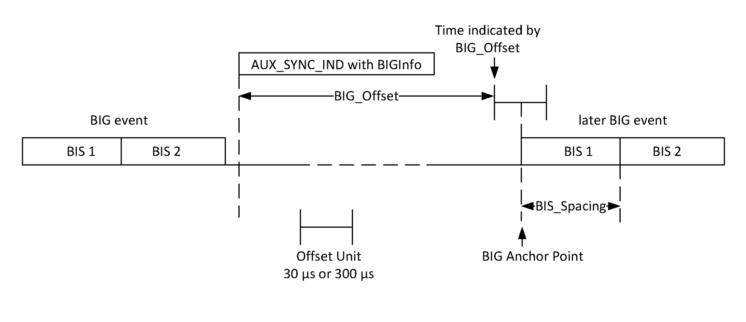
The ISO_Interval, NSE, BN, Sub_Interval, PTO, BIS_Spacing, and IRC fields shall contain the values described in Section 4.4.6.3. Sub_Interval and BIS_Spacing shall be in units of microseconds.
The Num_BIS field shall contain the number of BISes in the BIG.
The Max_PDU field shall contain the value described in Section 4.4.6.3.
The SeedAccessAddress field shall contain the Seed Access Address for the BIG (see Section 2.1.2).
The SDU_Interval field shall contain the interval described in [Vol 6] Part G, Section 2.
The Max_SDU field shall contain the value specified in Section 4.4.6.3.
The BaseCRCInit field shall contain the value described in Section 3.1.1.
The ChM field shall have the same meaning as the corresponding field in the CONNECT_IND PDU (see Section 2.3.3.1).
The PHY field shall be set to indicate the PHY used by the BIG. The values for the PHYs are specified in Table 4.3.
Value | Meaning |
|---|---|
0 | LE 1M PHY |
1 | LE 2M PHY |
2 | LE Coded PHY |
All other values | Reserved for future use |
The bisPayloadCount field shall contain the value specified in Section 4.4.6.5. The value shall be for the first subevent of the BIG event referred to by the BIG_Offset field
The Framing bit shall be set if the BIG carries framed data.
The GIV and GSKD fields shall contain the values described in Section 4.4.6.10 if the BIG is encrypted.
4.5. Connection state
The Link Layer enters the Connection state when an initiator sends a CONNECT_IND PDU on the primary advertising physical channel to an advertiser, an advertiser receives a CONNECT_IND PDU on the primary advertising physical channel from an initiator, an advertiser sends an AUX_CONNECT_RSP PDU on the secondary advertising physical channel to an initiator, or an initiator receives an AUX_CONNECT_RSP PDU on the secondary advertising physical channel from an advertiser.
After entering the Connection State, the connection is considered to be created. The connection is not considered to be established at this point. A connection is only considered to be established once a data physical channel packet has been received (regardless of a valid CRC match) from the peer device. The only difference between a connection that is created and a connection that is established is the Link Layer connection supervision timeout value that is used (see Section 4.5.2).
If the connection is first created using the CONNECT_IND PDU on the primary advertising physical channel, it shall use the LE 1M PHY in both directions. If the connection is first created on the secondary channel using the AUX_CONNECT_REQ and AUX_CONNECT_RSP PDUs, it shall use the same PHY in both directions as was used for the AUX_CONNECT_REQ and AUX_CONNECT_RSP PDU. Either PHY may be changed subsequently using the PHY Update procedure ( Section 5.1.10). When the LE Coded PHY is in use, the coding of each packet is determined by the transmitting Controller. The coding is indicated by the CI as defined in Section 2.2.3 and may be different in each direction and in adjacent packets in a given direction.
When two devices are in a connection, the two devices act in different roles. A Link Layer in the Central Role is called a Central. A Link Layer in the Peripheral Role is called a Peripheral. The Central controls the timing of a connection event. A connection event is a point of synchronization between the Central and the Peripheral. There shall be only one connection, whether or not established, between two LE device addresses. An initiator shall not send a connection request to an advertiser it is already connected to. A periodic advertiser shall not send a connection request to a synchronized device that it is already connected to.
If an advertiser receives a connection request from an initiator it is already connected to, then it shall ignore that request. If a synchronized device receives a connection request from a periodic advertiser it is already connected to, then it shall ignore that request.
If the initiator sent a CONNECT_IND PDU in response to an ADV_IND or ADV_DIRECT_IND PDU and either or both devices’ PDU had the ChSel field set to 0, then Channel Selection Algorithm #1 (see Section 4.5.8.2) shall be used on the connection. Otherwise, Channel Selection Algorithm #2 (see Section 4.5.8.3) shall be used.
The Central, when directed by the Host, may create a Connected Isochronous Stream (CIS) with the peer device using the Connected Isochronous Stream Creation procedure (see Section 5.1.15). The CIS shall be associated with the ACL used to create it with the same device being Central on both connections. The Link Layer may create multiple CISes with the same Peripheral.
Note
Note: A Peripheral cannot initiate a request to create a CIS at the Link Layer level but it can do so at a higher layer.
When the ACL connection between the Central and Peripheral is terminated, all associated CISes shall be terminated at the same time.
4.5.1. Connection events
The Link Layer in the Connection state shall only transmit Data Physical Channel PDUs (see Section 2.4) in connection events. The Central and Peripheral shall determine the data channel index for each connection event as defined in Section 4.5.8. The same data channel index shall be used for all packets in the connection event. Each connection event normally contains at least one packet sent by the Central. The Central can, however, completely fail to transmit in a connection event due to scheduling conflicts or the effect of the subrate factor (see below), but shall transmit at least one Data Channel PDU within each supervision timeout period (see Section 4.5.2).
During a connection event, the Central and Peripheral alternate sending and receiving packets. The connection event is considered open while both devices continue to send packets. The Peripheral shall always send a packet if it receives a packet from the Central regardless of a valid CRC match, except after multiple consecutive invalid CRC matches as specified in Section 4.5.6. The Central may send a packet if it receives a packet from the Peripheral regardless of a valid CRC match, except after multiple consecutive invalid CRC matches as specified in Section 4.5.6. When determining the end of the received packet, the Length and CP fields of the Header, and the CTETime field of the CTEInfo field (if present), are assumed to be correct even if the CRC match was invalid; however, if the receiving device can determine the correct Length and CTETime in some other way, it may use those values instead of those in the Header.
The connection event can be closed by either device, as defined in Section 4.5.6.
Both the Central and the Peripheral shall have a 16-bit connection event counter (connEventCounter), containing the value connEventCount, for each ACL connection. Each counter shall be set to zero on the first connection event and shall be incremented by one for each new connection event; the connEventCounter shall wrap from 0xFFFF to 0x0000. This counter is used to synchronize Link Layer control procedures.
Both devices shall increment connEventCounter for all connection events, even if the Peripheral is not listening to the Central in those events or the Central did not transmit during the event (e.g., because of subrating or Peripheral latency).
The timing of connection events is determined by the following parameters: connection interval (connInterval), subrate base event (connSubrateBaseEvent), subrate factor (connSubrateFactor), continuation number (connContinuationNumber), and Peripheral latency (connPeripheralLatency).
The start of a connection event is called an anchor point. If the Central transmits in a connection event, it shall start to transmit a Data Physical Channel PDU to the Peripheral at the anchor point. The start of connection events are spaced regularly with an interval of connInterval and shall not overlap. The Central shall ensure that a connection event closes at least T_IFS before the anchor point of the next connection event. The Peripheral should listen for the packet sent by its Central at the anchor point.
The connInterval shall be a multiple of 1.25 ms in the range 7.5 ms to 4.0 s. The connInterval is set by the Initiator’s Link Layer in the CONNECT_IND or AUX_CONNECT_REQ PDU from the range given by the Host and can be changed using the Connection Update procedure (see Section 5.1.1) or Connection Parameters Request procedure (see Section 5.1.7).
The subrate factor allows the Central and Peripheral to use a reduced number of connection events. The Central shall only transmit on subrated connection events, the events specified in Section 5.1.1, and, if the continuation number is non-zero, continuation events.
A subrated connection event is a connection event where (connEventCount - connSubrateBaseEvent) is an integer multiple of connSubrateFactor; connSubrateBaseEvent is a connEventCount that is used to determine the phase of the subrated events. The connection event where connEventCount equals connSubrateBaseEvent will always be a subrated connection event. Adding an integer multiple of connSubrateFactor to connSubrateBaseEvent (including a negative multiple) results in a connEventCount value that will also always be a subrated connection event. For example, if connSubrateFactor equals 100, then connSubrateBaseEvent values of 42, 6942, and 65442 are equivalent. In each case, connection event number 24242 is a subrated event because 24242 - 42 = 24200, 24242 - 6942 = 17300, and 24242 - 65442 = -41200 are all integer multiples of 100.
A continuation event is a connection event where, in at least one of the previous connContinuationNumber connection events (ignoring any before the last subrated connection event), at least one packet was transmitted or validly received containing a Link Layer PDU with a non-zero Length field. Continuation events are determined by activity in a subrated connection event and any subsequent continuation events. Some connection events between two consecutive subrated connection events might not be continuation events.
The value of connSubrateFactor shall be in the range 1 to 500 and shall be set to 1 for a new connection. A Controller shall either support only a connSubrateFactor of 1 (in which case the value of connSubrateBaseEvent will not be used) or shall support all valid subrate factors. The value of connContinuationNumber shall be in the range 0 to connSubrateFactor - 1 and shall be set to zero for a new connection. A Controller shall support all valid continuation numbers.
Figure 4.40 and Figure 4.41 show how the subrate base event affects which events are subrated connection events.
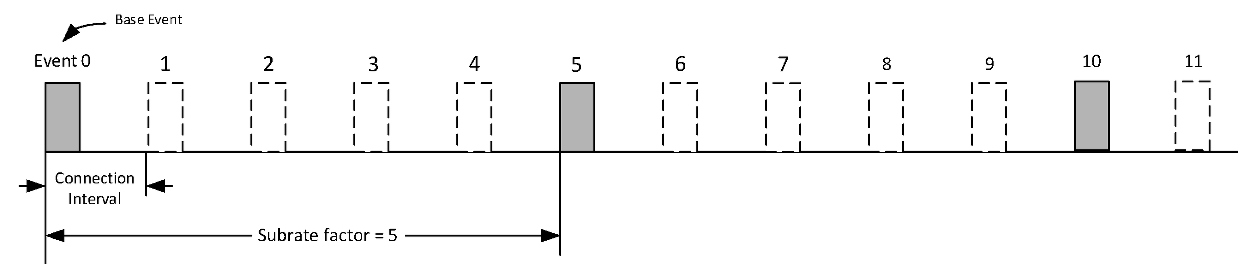
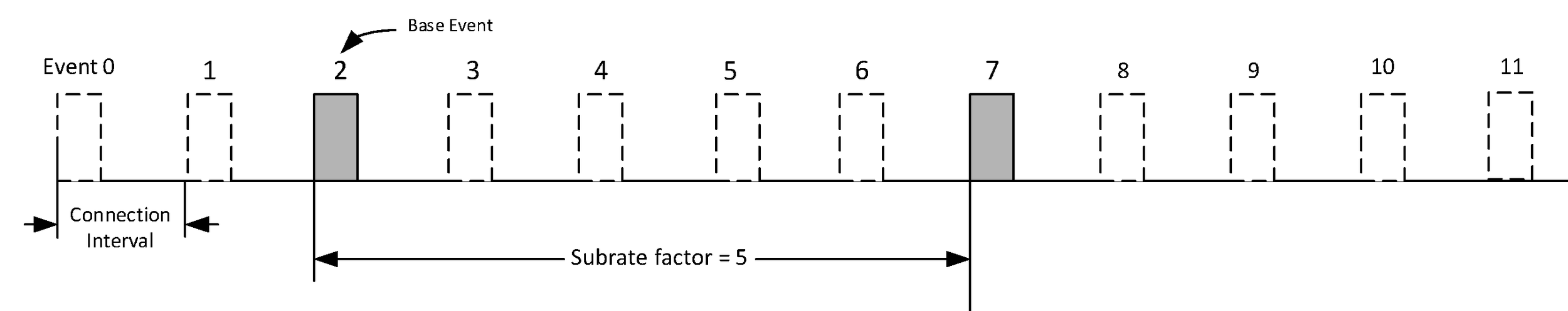
Peripheral latency also allows a Peripheral to use a reduced number of connection events. The connPeripheralLatency parameter defines the number of consecutive subrated connection events that the Peripheral is not required to listen for the Central. For example, if connSubrateFactor is 3, connContinuationNumber is 0, and connPeripheralLatency is 6, then a Peripheral implementation can choose to only listen to every 21st connection event (i.e., every 7th subrated connection event).
connPeripheralLatency shall be an integer such that connSubrateFactor × (connPeripheralLatency + 1) is less than or equal to 500 and connInterval × connSubrateFactor × (connPeripheralLatency + 1) is less than half connSupervisionTimeout. When connPeripheralLatency is set to zero the Peripheral should listen at the anchor point of every subrated connection event and continuation event. Irrespective of Peripheral latency, if the Peripheral receives a valid packet from the Central at a subrated connection event, it shall listen at the anchor point of every continuation event before the next subrated connection event. If the Peripheral does not receive a valid packet from the Central after applying Peripheral latency, it should listen at each of the subrated anchor points and not apply Peripheral latency until it receives a packet from the Central. Irrespective of the value of connPeripheralLatency or any scheduling conflicts, the Peripheral shall listen for the Central at least once within each connection supervision timeout duration (see Section 4.5.2).
Figure 4.42 to Figure 4.44 show how the connection events are used for various values of connSubrateFactor, connPeripheralLatency, and connContinuationNumber. In the figures, S indicates the subrated events, C indicates continuation events, and L indicates subrated events where Peripheral latency is applied. In Figure 4.43, the data is being transmitted by the Peripheral, not the Central.
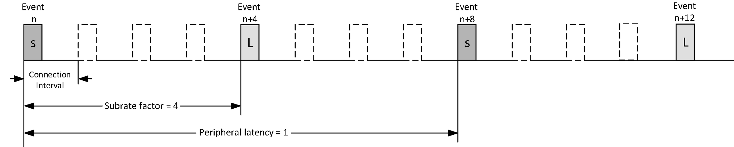

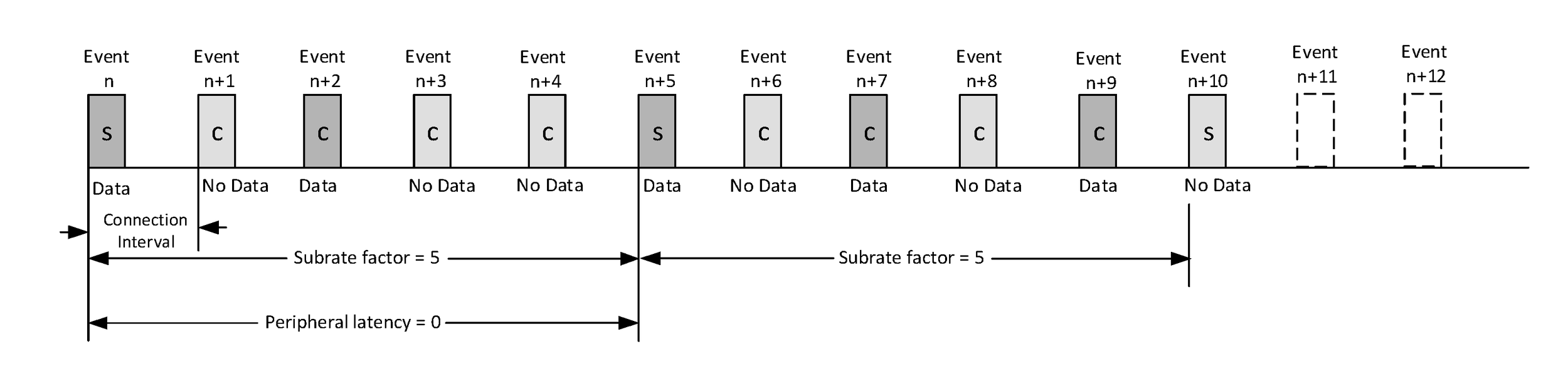
If the Connection Subrating feature is supported then, when connEventCounter wraps, the Link Layer shall set the value of connSubrateBaseEvent to (connSubrateBaseEvent + K × connSubrateFactor - 65536), where K is any integer that will cause the new value to be in the range 0 to 65535, so that the subrated connection events will remain equally spaced.
4.5.2. Supervision timeout
A connection can break down due to various reasons such as a device moving out of range, encountering severe interference or a power failure condition. Since this may happen without any prior warning, it is important for both the Central and the Peripheral to monitor the status of the connection.
To be able to detect link loss in an ACL connection, both the Central and the Peripheral shall use an ACL connection supervision timer, TLLconnSupervision. Upon reception of a valid packet on the ACL, the timer shall be reset. To be able to detect link loss in a CIS, both the Central and the Peripheral shall use a CIS supervision timer, TCISSupervision. Upon reception of a valid packet on the CIS, the timer TCISSupervision shall be reset.
If the ACL connection supervision timer reaches 6 * connInterval before the connection is established (see Section 4.5), the ACL connection may, but should not, be considered lost. If the ACL connection is not established after 6 connection events, it shall be considered lost. This enables fast termination of ACL connections that fail to establish.
Depending on the connection interval and whether a CONNECT_IND or AUX_CONNECT_REQ PDU was used, this timer can expire after 4, 5, or 6 connection events.
Because a packet with a CRC error is sufficient to establish the connection, the connection can become established without the timer TLLconnSupervision being reset.
When establishing a CIS, the Central shall start the CIS supervision timer at the start of the next CIS event after receiving the acknowledgment for the LL_CIS_IND. If the CIS supervision timer reaches 6 * ISO_Interval before the CIS is established, the CIS shall be considered lost.
When establishing a CIS, the Peripheral shall start the CIS supervision timer at the start of the next CIS event after receiving the LL_CIS_IND. If the CIS supervision timer reaches 6 * ISO_Interval before the CIS is established, the CIS shall be considered lost.
Connection supervision timeout (connSupervisionTimeout) is a parameter that defines the maximum time between two received Data Channel PDUs or Connected Isochronous PDUs before the connection is considered lost. The connSupervisionTimeout shall be a multiple of 10 ms in the range 100 ms to 32.0 s and it shall be larger than
(1 + connPeripheralLatency) × connSubrateFactor × connInterval × 2. |
If, at any time in Connection State outside a connection event after the connection has been established, the timer TLLconnSupervision reaches the connSupervisionTimeout value, the connection shall be considered lost (see Section 4.5.12).
If, at any time in Connection State outside a CIS event after the CIS has been established, the timer TCISSupervision reaches the connSupervisionTimeout value, the CIS shall be considered lost.
In either case, the Controller may send the notification of the loss earlier provided that the most recent event has closed and the timer will reach the connSupervisionTimeout value before the next ACL or CIS anchor point.
In either case the Controller may, but should not, consider the connection lost at any time within an event after the timer reaches connSupervisionTimeout.
The supervision timeout can be changed using the Connection Update procedure (see Section 5.1.1) or the Connection Parameters Request procedure (see Section 5.1.7). If either of these procedures are used, the new value shall be greater than twice the ISO_Interval of any associated CIS.
Each supervision timeout period starts with the event following the reception of a valid packet and ends with the last event before the timer reaches the connSupervisionTimeout value.
4.5.3. Connection event transmit window
To allow the Central to efficiently schedule connection events for multiple connections or other activities it may be involved in, the Central has the flexibility to schedule the first connection event anchor point at a time of its choosing. The CONNECT_IND and AUX_CONNECT_REQ PDUs include parameters to determine when the Central sends its first packet in the Connection State to set the anchor point and when the Peripheral listens.
The CONNECT_IND and AUX_CONNECT_REQ PDUs include three parameters used to determine the transmit window. The transmit window starts at transmitWindowDelay + transmitWindowOffset after the end of the packet containing the CONNECT_IND PDU or AUX_CONNECT_REQ PDU, and the transmitWindowSize parameter shall define the size of the transmit window. The connInterval is used in the calculation of the maximum offset and size of the transmit window. The transmitWindowOffset and transmitWindowSize parameters are determined by the Link Layer.
The transmitWindowOffset shall be a multiple of 1.25 ms in the range 0 ms to connInterval. The transmitWindowSize shall be a multiple of 1.25 ms in the range 1.25 ms to the lesser of 10 ms and (connInterval - 1.25 ms).
Therefore the start of the first packet will be no earlier than transmitWindowDelay + transmitWindowOffset and no later than transmitWindowDelay + transmitWindowOffset + transmitWindowSize after the end of the packet containing the CONNECT_IND PDU or AUX_CONNECT_REQ PDU.
The value of transmitWindowDelay shall be 1.25 ms when a CONNECT_IND PDU is used, 2.5 ms when an AUX_CONNECT_REQ PDU is used on an LE Uncoded PHY, and 3.75 ms when an AUX_CONNECT_REQ PDU is used on the LE Coded PHY.
4.5.4. Connection setup – Central Role
After the initiator sends a CONNECT_IND PDU on the primary advertising physical channel or receives an AUX_CONNECT_RSP PDU on the secondary advertising physical channel, the Link Layer is in the Connection state in the Central Role. The Central shall reset the Link Layer connection supervision timer TLLconnSupervision . The Link Layer shall notify the Host that the connection has been created. The first connection event shall use the data channel index specified in Section 4.5.8.
The Central shall start to send the first packet within the transmit window as defined in Section 4.5.3. The Central’s first packet can extend beyond the transmit window.
The first packet sent in the Connection State by the Central determines the anchor point for the first connection event, and therefore the timings of all future connection events in this connection.
The second connection event anchor point shall be connInterval after the first connection event anchor point. All the normal connection event transmission rules specified in Section 4.5.1 shall apply.
Two examples of the LL connection setup procedure timing from the Central’s perspective are shown in Figure 4.45 and in Figure 4.46.
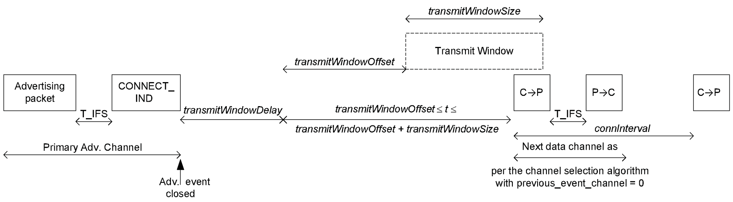
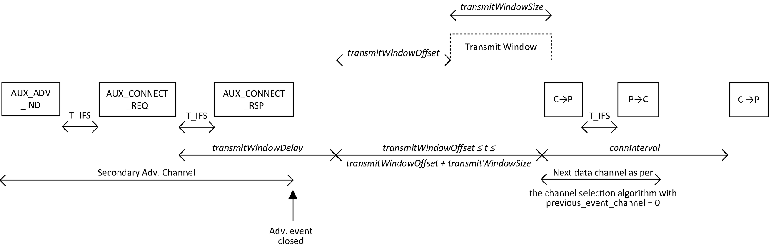
4.5.5. Connection setup – Peripheral Role
After the advertiser receives a CONNECT_IND PDU on the primary advertising physical channel or sends an AUX_CONNECT_RSP PDU on the secondary advertising physical channel, the Link Layer is in the Connection state in the Peripheral Role. The Peripheral shall reset the Link Layer connection supervision timer TLLconnSupervision . The Link Layer shall notify the Host that the connection has been created. The first connection event shall use the data channel index specified in Section 4.5.8.
The Peripheral shall start to listen for the first packet within the transmit window as defined in Section 4.5.3; while doing so, it shall perform the window widening specified in Section 4.2.4. The Central’s first packet can extend beyond the transmit window, and therefore the Peripheral must take this into account.
The first packet received, regardless of a valid CRC match (i.e., only the access address needs to match), in the Connection State by the Peripheral determines the anchor point for the first connection event, and therefore the timings of all future connection events in this connection.
If a packet is not received in a transmit window, the Peripheral shall attempt to receive a packet in a subsequent transmit window. A subsequent transmit window shall start connInterval after the start of the previous transmit window, with the same transmitWindowSize. The data channel index shall be the next data channel index as specified in Section 4.5.8. The connEventCount shall also be incremented by one.
Two examples of the procedure from the Peripheral’s perspective are shown in Figure 4.47 and in Figure 4.48. In these examples the Peripheral fails to receive any part of the first packet (i.e., connEventCount = 0) from the Central and acquires anchor point timing from the second packet (i.e., connEventCount = 1).
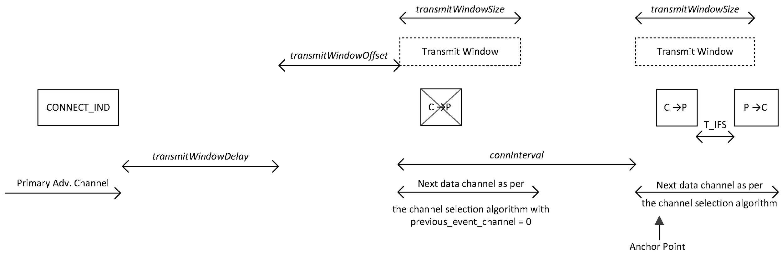
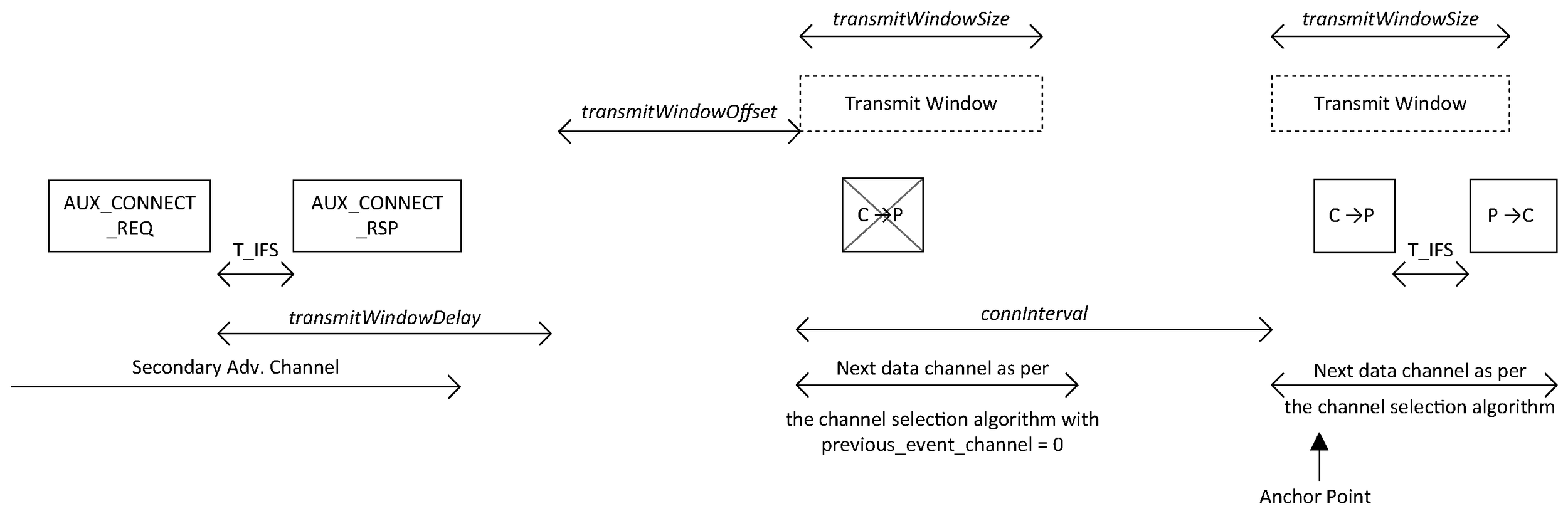
The Peripheral shall be active in every connection event until it receives a packet from the Central with the NESN set to one. From then on it may use Peripheral latency as defined in Section 4.5.1.
4.5.6. Closing connection events
The MD bit of the Header of the Data Physical Channel PDU is used to indicate that the device has more data to send. If neither device has set the MD bit in their packets, the packet from the Peripheral closes the connection event. If either or both of the devices have set the MD bit, the Central may continue the connection event by sending another packet, and the Peripheral should listen after sending its packet.
Failure to receive a packet, or two consecutive packets received with an invalid CRC match within a connection event shall close the event.
MD bit usage is summarized in Table 4.4.
Central | |||
|---|---|---|---|
MD = 0 | MD = 1 | ||
Peripheral | MD = 0 | Central shall not send another packet, closing the connection event. Peripheral does not need to listen after sending its packet. | Central may continue the connection event. Peripheral should listen after sending its packet. |
MD = 1 | Central may continue the connection event. Peripheral should listen after sending its packet. | Central may continue the connection event. Peripheral should listen after sending its packet. | |
4.5.7. Sleep clock accuracy
Because of sleep clock accuracies (see Section 4.2.2), there is uncertainty in the Peripheral of the exact timing of the Central’s anchor point. Therefore the Peripheral shall re-synchronize to the Central’s anchor point at each connection event where it listens for the Central. If the Peripheral receives a packet from the Central at the anchor point, regardless of a CRC match, the Peripheral shall update its timing of the anchor point.
If it listens for a packet, the Peripheral shall perform the window widening described in Section 4.2.4 at each anchor point and during the Connection Update procedure (see Section 5.1.1) and Connection Parameters Request procedure (see Section 5.1.7). In doing so, and in the absence of more accurate information about the Central's clock, the Peripheral shall use the Central’s sleep clock accuracy (centralSCA) from the most recent CONNECT_IND, AUX_CONNECT_REQ, LL_CLOCK_ACCURACY_REQ, or LL_CLOCK_ACCURACY_RSP PDU on the connection.
4.5.8. General-purpose channel group index selection
4.5.8.1. Channel classification
The Link Layer can classify the general-purpose channels as being unknown, bad, or good. These classifications are determined individually by the Link Layer based on local information (e.g., from active or passive channel assessment methods or from the Host). Information received from other devices (e.g., via an LL_CHANNEL_MAP_IND) shall not be included in the channel classification. The Host may provide channel classification information to the Link Layer. The Link Layer may use the information provided by the Host.
The three possible channel classifications are defined in Table 4.5.
Classification | Definition |
|---|---|
unknown | A channel shall be classified as unknown if the channel assessment measurements are insufficient to reliably classify the channel. |
bad | A channel may be classified as bad, for example, when it is marked as bad in the most recent HCI_LE_Set_Host_Channel_Classification command or when the assessment of failure rate or interference with other systems exceeds some threshold. |
good | A channel shall be classified as good if it is neither unknown nor bad. |
The Central’s, periodic advertiser’s, and isochronous broadcaster’s Link Layer shall classify the RF channels in the general-purpose group into used channels (used for transmitting data) and unused channels (not used for transmitting data). This is called the channel map. The minimum number of used channels shall be 2.
A Central shall determine a channel map for the connection based on any combination of the following information:
Channel classification from local measurements (e.g., active or passive channel assessment in the Controller or input from other collocated technologies)
Channel classification information from the Host
Channel classification reports received from the Peripheral in LL_CHANNEL_STATUS_IND PDUs (see Section 2.4.2.39)
The algorithm used by the Central to combine these information sources and generate the channel map is not defined in the specification and is vendor-specific.
For a connection, the Peripheral shall receive the channel map from the Central in the CONNECT_IND PDU or the AUX_CONNECT_REQ PDU. If the Central changes the channel map it shall notify the Peripheral as specified in Section 5.1.2. If the periodic advertiser changes the channel map then it shall notify any scanning devices using the Channel Map Update Indication (see Section 1.20 of [1]). On periodic advertising with responses, the advertiser shall transmit the Channel Map Update Indication data type in each subevent. If the isochronous broadcaster changes the channel map it shall notify any Synchronized Receivers as specified in Section 5.6.1.
4.5.8.2. Channel Selection algorithm #1
Channel Selection Algorithm #1 only supports channel selection for connection events.
Channel Selection Algorithm #1 consists of two stages: calculation of the unmapped channel index followed by mapping this index to a data channel index from the set of used channels.
The unmappedChannel and lastUnmappedChannel are the unmapped channel indices of two consecutive connection events. The unmappedChannel is the unmapped channel index for the current connection event. The lastUnmappedChannel is the unmapped channel index of the previous connection event. The lastUnmappedChannel shall be 0 for the first connection event of a connection.
At the start of a connection event, unmappedChannel shall be calculated using the following basic algorithm:
unmappedChannel = (lastUnmappedChannel + hopIncrement) mod 37
When a connection event closes, the lastUnmappedChannel shall be set to the value of the unmappedChannel.
If the unmappedChannel is a used channel according to the channel map, Channel Selection Algorithm #1 shall use the unmappedChannel as the data channel index for the connection event.
If the unmappedChannel is an unused channel according to the channel map, the unmappedChannel shall be re-mapped to one of the used channels in the channel map using the following algorithm:
remappingIndex = unmappedChannel mod numUsedChannels
where numUsedChannels is the number of used channels in the channel map.
A remapping table is built that contains all the used channels in ascending order, indexed from zero. The remappingIndex is then used to select the data channel index for the connection event from the remapping table.
The complete procedure is as shown in Figure 4.49.
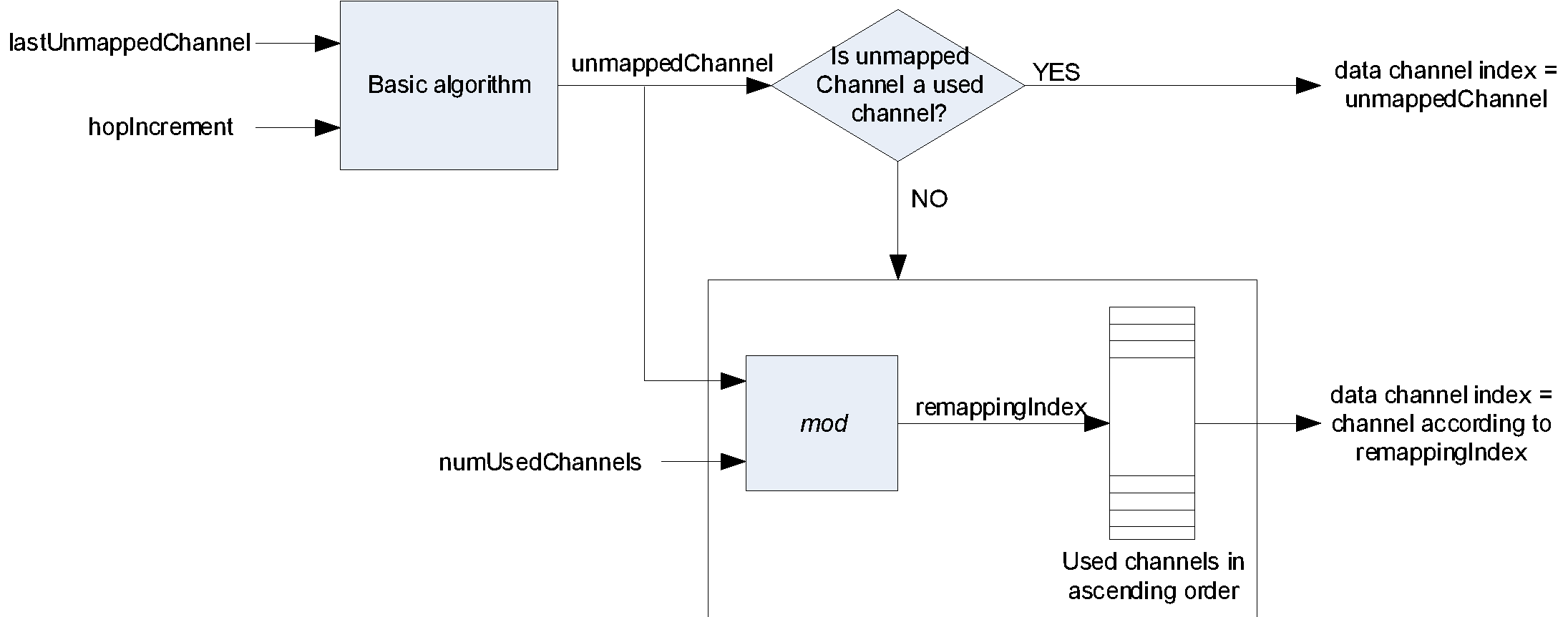
4.5.8.3. Channel Selection algorithm #2
4.5.8.3.1. Overview
Channel Selection Algorithm #2 supports channel selection for connection events and for periodic advertising events and also supports subevent channel selection (see Section 4.5.8.3.5).
For each event, which can be a connection event, an isochronous event (which can be a BIS or CIS event), or a periodic advertising packet, the algorithm described here generates an event channel index (which is a general purpose channel index, as appropriate). If the event contains subevents, it also generates channel indices for each subevent.
Note
Note: In a given event, Channel Selection Algorithm #2 results in two consecutive subevents using different channel indices.
A block diagram of the overall algorithm is shown in Figure 4.50. The upper part generates event channel indices and the lower part subevent channel indices; where there are no subevents, only the upper part is required. The first subevent of an isochronous event shall use the channel index from the event mapping; all subsequent subevent(s) in that event shall use the channel index from the subevent mapping.
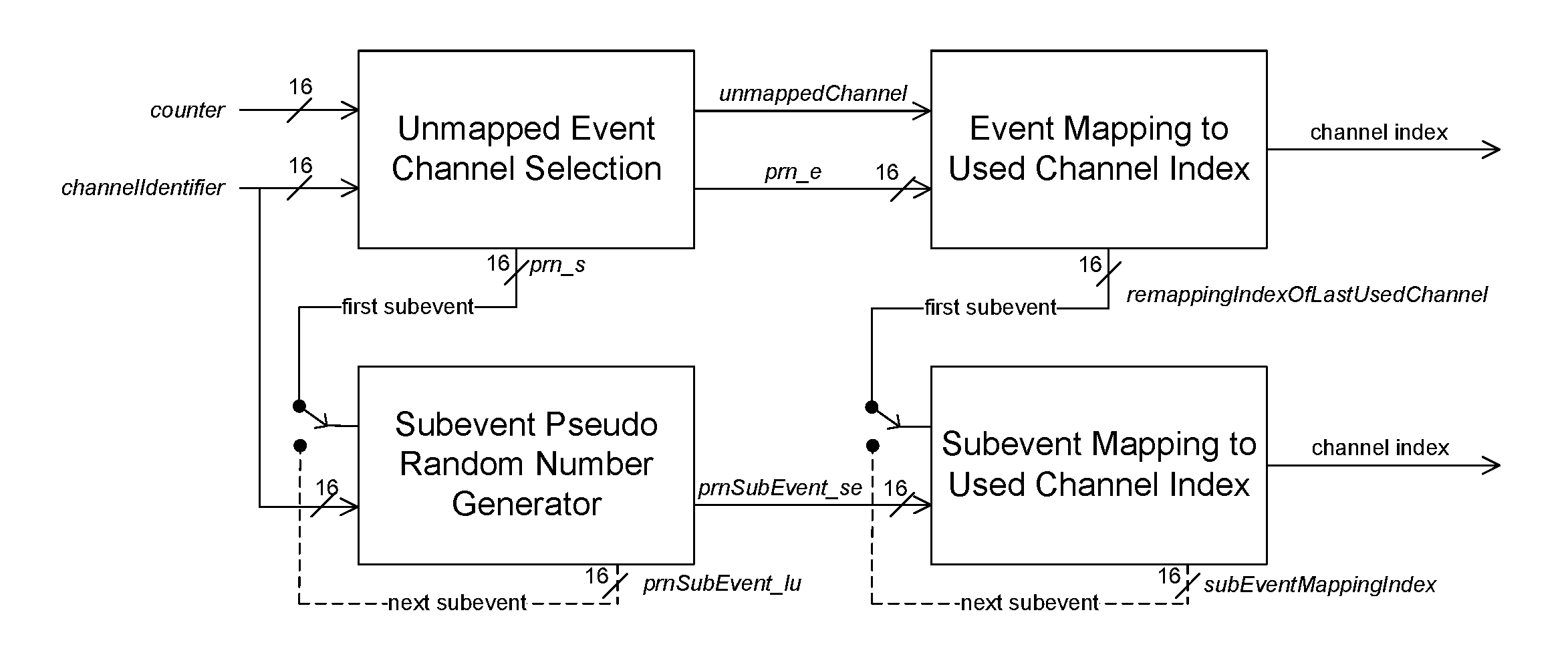
4.5.8.3.2. Inputs and basic components
The algorithm makes use of the following inputs and basic components:
The 6-bit input N is the number of channels classified as Used channels.
The 16-bit input channelIdentifier is fixed for any given connection or periodic advertising train; it is calculated from the Access Address by:
channelIdentifier = (Access Address31-16) XOR (Access Address15-0)
The 16-bit input counter changes for each event. For ACL connections it is the connection event counter connEventCounter defined in Section 4.5.1. For periodic advertising it is the event counter paEventCounter defined in Section 4.4.2.1. For PAwR, it is the XOR of the two event counters paEventCounter and paSubEventCounter defined in Section 4.4.2.1. For isochronous logical transports, it is bits 0 to 15 of the event counter bigEventCounter defined in Section 4.4.6.3 or cisEventCounter defined in Section 4.5.13.1.
For isochronous events, the input se_n is defined in Section 4.4.6.8 for BIS events and Section 4.5.13.6 for CIS events.
The “XOR” operation always refers to a 16-bit bit-wise XOR.
The symbol is used to represent the floor function (the greatest integer less than or equal to the argument).
The permutation operation consists of separately bit-reversing the lower 8 input bits and upper 8 input bits, as illustrated in Figure 4.51.
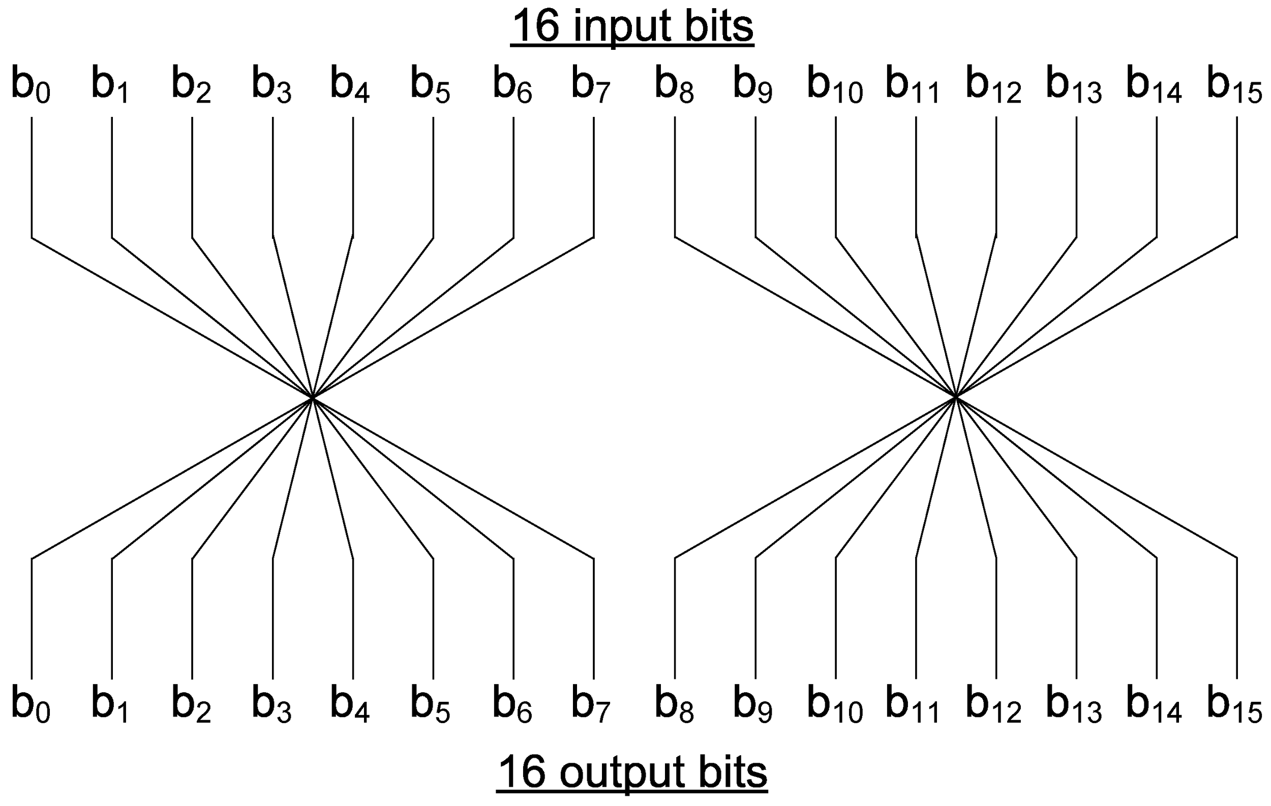 |
The Multiply, Add, and Modulo (MAM) block performs a multiplication operation, an addition operation, and a mod operation, as illustrated in Figure 4.52.
 |
The output of the MAM operation, given inputs a and b, is:
output = (17 × a + b) mod 216 |
A remapping table is built that contains all the used channels in ascending order, indexed from zero.
4.5.8.3.3. Unmapped event channel selection
The unmapped event channel selection process consists of two stages. First, the two unsigned pseudo-random numbers prn_e and prn_s are generated (prn_s is only used for subevent channel selection), after which the unmapped channel index unmappedChannel is derived from prn_e.
The first stage shall be as shown in Figure 4.53.
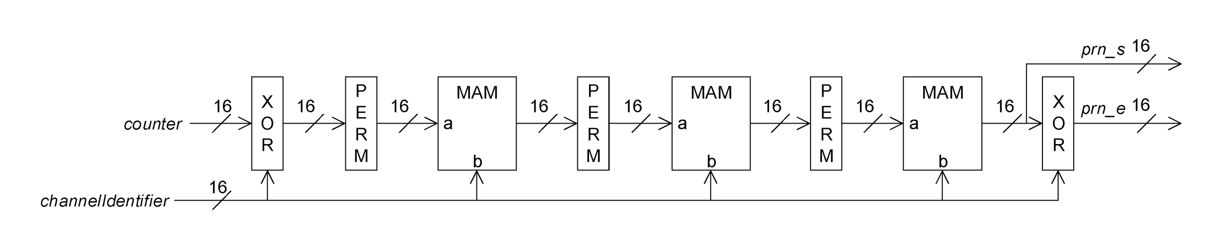
unmappedChannel is then calculated as prn_e mod 37. A block diagram of the overall process is shown in Figure 4.54.
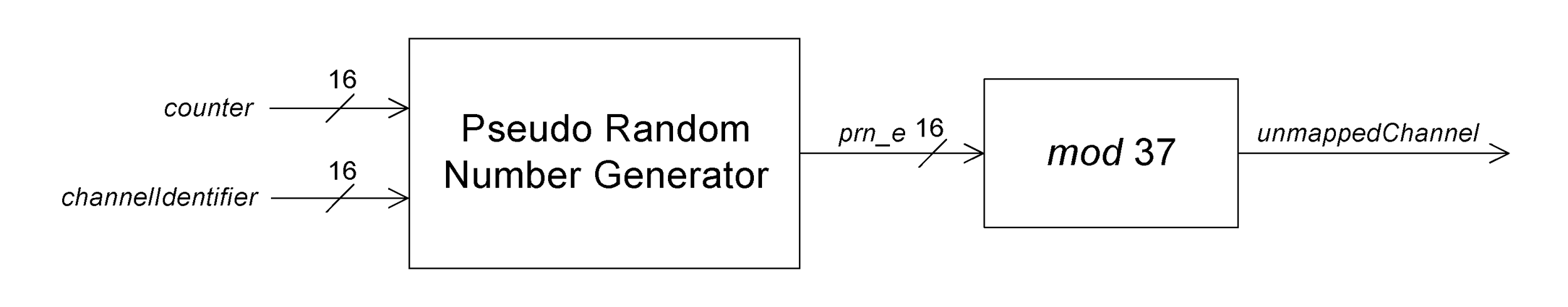
4.5.8.3.4. Event mapping to used channel index
If unmappedChannel is the channel index of a used channel according to the channel map, it is used as the channel index for the event. If unmappedChannel is the index of an unused channel according to the channel map, then the channel index for the event is calculated from prn_e and N (the number of used channels) by first calculating the value remappingIndex as:
and then using remappingIndex as an index into the remapping table to obtain the channel index for the event.
In either case, the value remappingIndexOfLastUsedChannel is the index in the remapping table of the channel index for the event. This value is only used for subevent channel selection.
The overall process is illustrated in Figure 4.55.
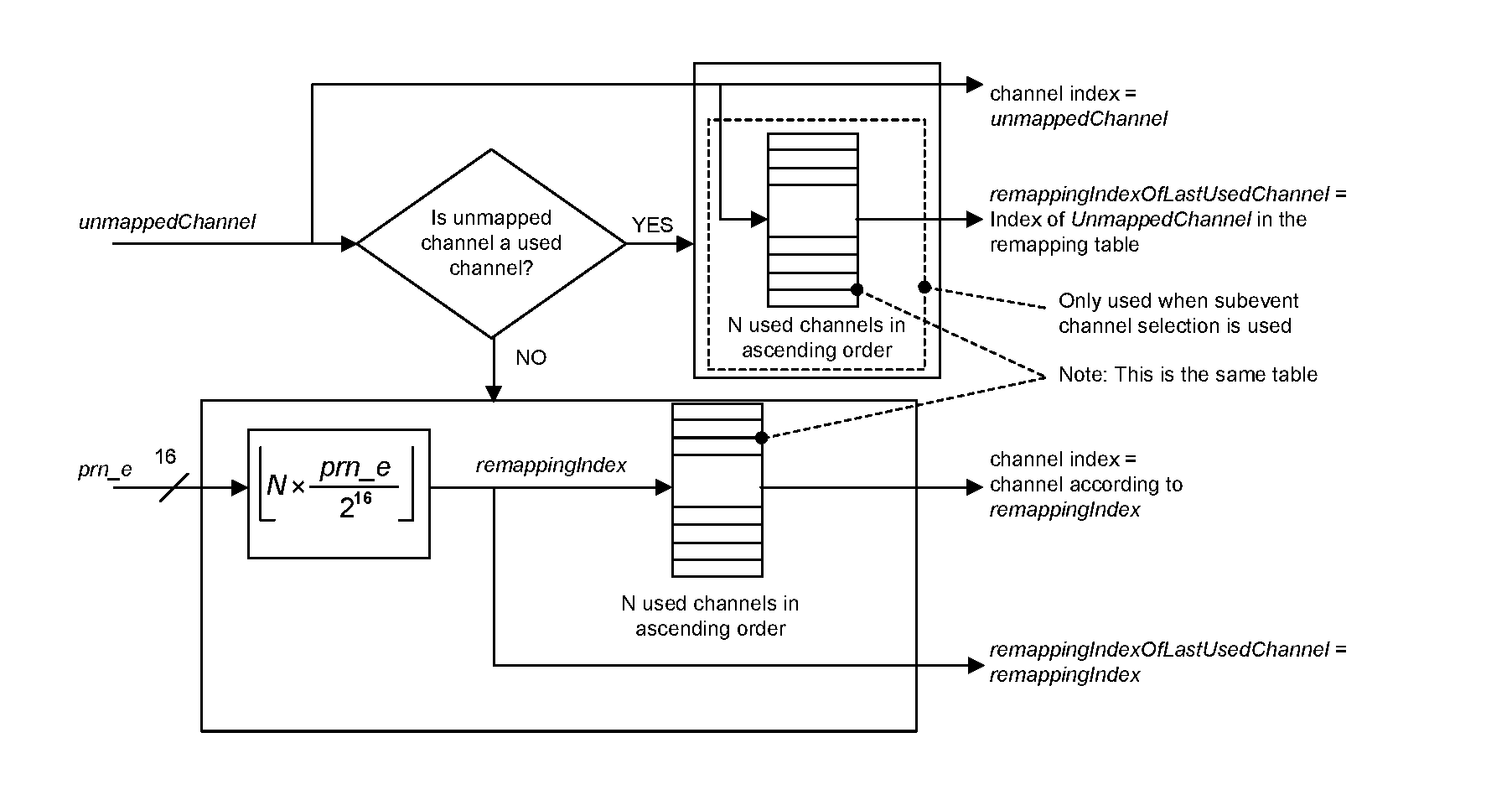
4.5.8.3.5. Subevent pseudo-random number generation
Subevent pseudo-random number generation involves generating two more pseudo-random numbers prnSubEvent_se and prnSubEvent_lu for each subevent. The process shall be as shown in Figure 4.56.
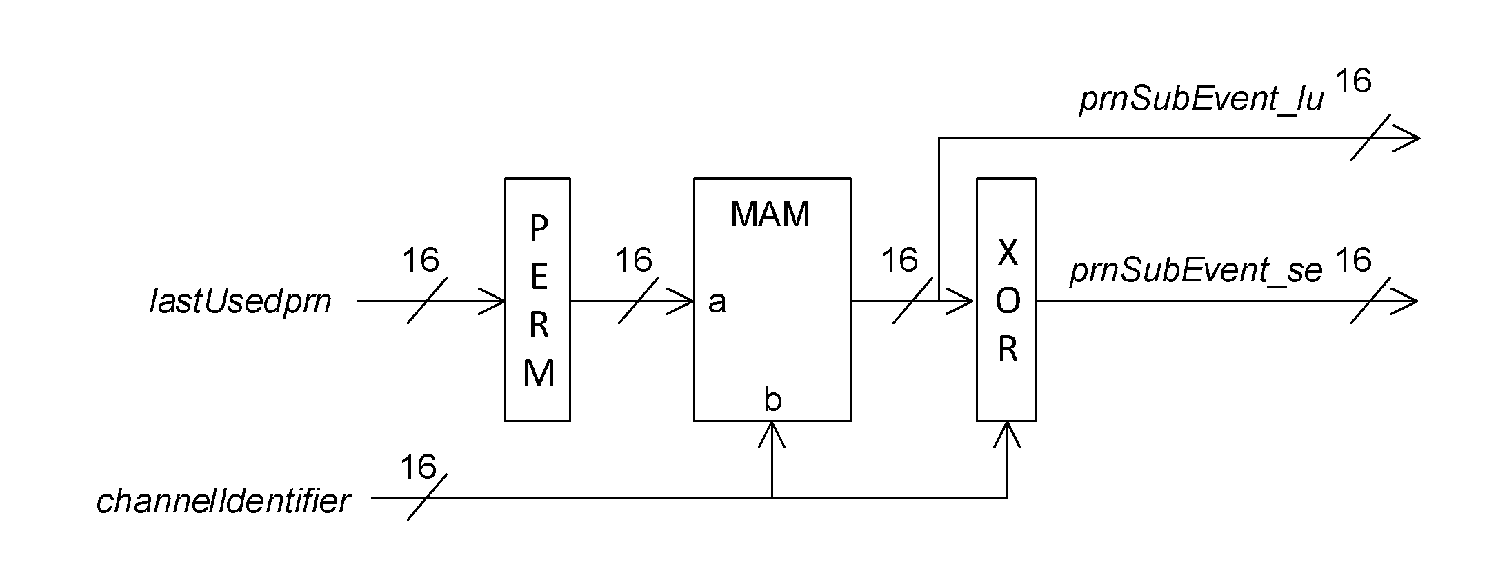
Where:
4.5.8.3.6. Subevent mapping to used channel index
The channel index for a subevent is determined in two stages: calculating the subevent index subEventIndex and then indexing into the remapping table. The value subEventIndex is calculated as:
where indexOfLastUsedChannel is:
and d is calculated as:
where d is the minimum distance between the channel indices used in consecutive subevents.
The value of subEventIndex is then used as an index into the remapping table. The overall process is illustrated in Figure 4.57.
 |
4.5.9. Acknowledgment and flow control
The Link Layer acknowledgment and flow control scheme shall be used in all ACL connections and CISes. Unless specified otherwise, the unqualified use of “PDU” in this section means either a Data Physical Channel PDU or a CIS Data PDU.
For each connection the Link Layer has two parameters, transmitSeqNum and nextExpectedSeqNum, each one bit in size. The transmitSeqNum parameter is used to identify packets sent by the Link Layer. The nextExpectedSeqNum parameter is used by the Link Layer to either acknowledge the last PDU sent by the peer, or to request the peer to resend the last PDU sent.
The transmitSeqNum and nextExpectedSeqNum parameters for an ACL or CIS shall be set to zero upon entering the Connection State or when the CIS is created.
If the last Data Physical Channel PDU was sent on the LE Coded PHY, the coding scheme (see Section 2.2.3) used when resending may be the same as or different from that used in the last Data Physical Channel PDU. If the instant of a PHY Update procedure (see Section 5.1.10) occurs while a Data Physical Channel PDU is waiting to be resent, the new PHY shall be used when resending.
A new PDU is a PDU sent for the first time by the Link Layer. A last PDU is a PDU that is resent by the Link Layer. When resending a Data Physical Channel PDU, the LLID, SN, and CP fields, the CTEInfo field (if present), and the payload of the sent Data Physical Channel PDU shall be equal to those of the last Data Physical Channel PDU sent by the Link Layer. When resending a CIS Data PDU, the LLID, SN, NPI fields, and the payload of the sent CIS Data PDU shall be equal to those of the last CIS Data PDU sent by the Link Layer.
For each new PDU that is sent, the SN bit of the Header shall be set to transmitSeqNum. If a PDU is resent, then the SN bit shall not be changed.
Upon reception of a PDU, the SN bit shall be compared to nextExpectedSeqNum. If the bits are different, then this is a resent PDU, and nextExpectedSeqNum shall not be changed. If the bits are the same, then this is a new PDU, and nextExpectedSeqNum may be incremented by one (see Section 4.5.9.1).
When a PDU is sent, the NESN bit of the Header shall be set to nextExpectedSeqNum.
Upon receiving a PDU (including a CIS Null PDU), if the NESN bit of that PDU is the same as transmitSeqNum, then the last sent PDU has not been acknowledged and shall be resent except as specified below. If the NESN bit of the PDU is different from transmitSeqNum, then the last sent PDU has been acknowledged, transmitSeqNum shall be incremented by one, and a new PDU may be sent.
The above process is illustrated in Figure 4.58 (tSqNo means transmitSeqNum and nExSqNo means nextExpectedSeqNum).
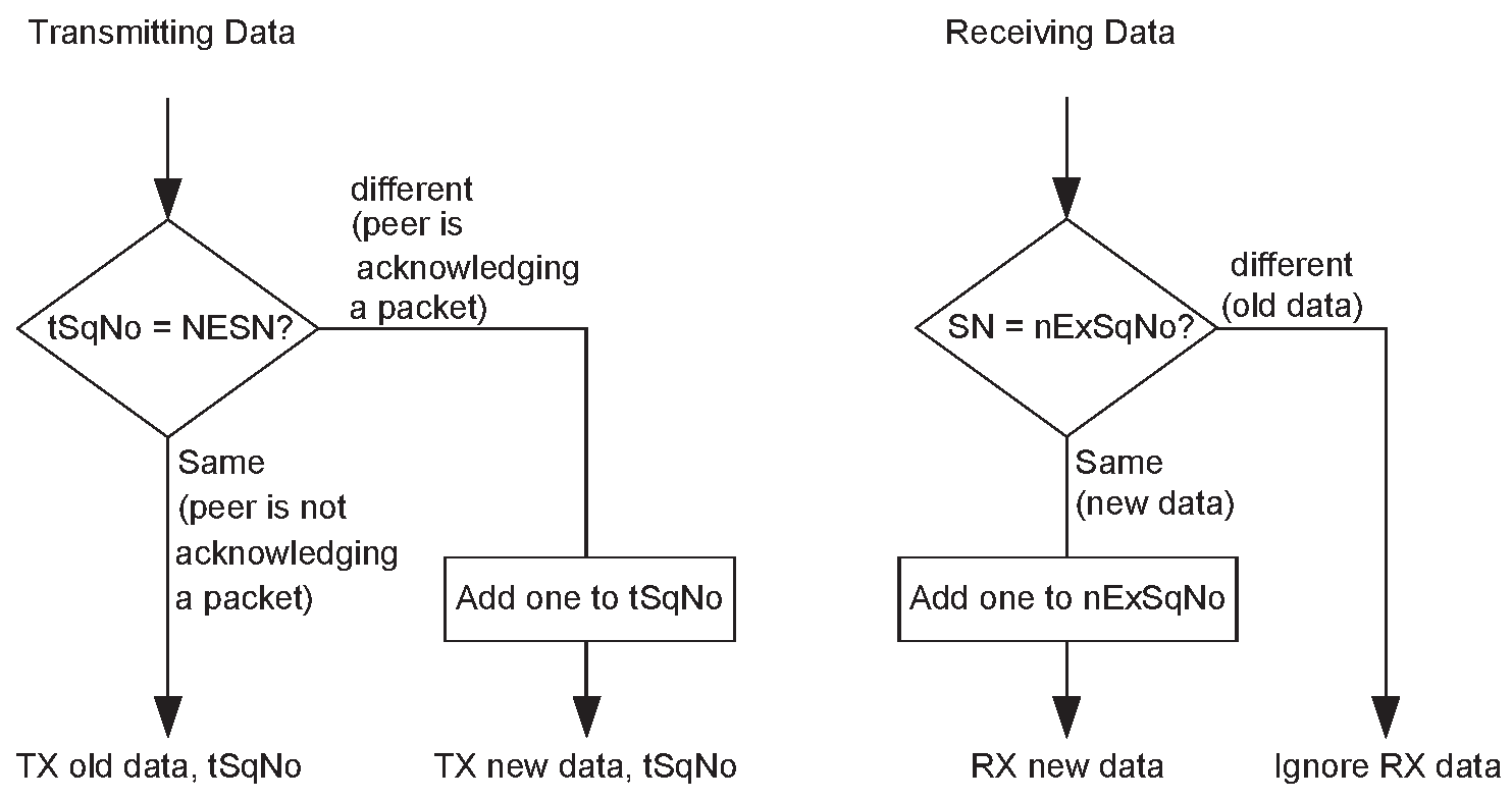
If a PDU is received with an invalid CRC match, nextExpectedSeqNum shall not be changed except as specified below; this means that the PDU will not be acknowledged, causing the peer to resend the PDU. Since the received PDU has been rejected, the nextExpectedSeqNum from the peer device cannot be trusted, and therefore the last sent PDU from this device was not acknowledged and, as this section requires, must be retransmitted; transmitSeqNum shall not be changed.
The SN, NESN and MD bits shall be used from every received Data Physical Channel PDU which has passed the CRC check. The SN, NESN, CIE and NPI bits shall be used from every received CIS Data PDU that has passed the CRC check. The NESN, CIE and NPI bits shall be used from every received CIS Null PDU that has passed the CRC check. The PDU payload shall be ignored on every received PDU that has the same SN value as the previously received PDU.
When the transmitting Link Layer either does not send a CIS Data PDU for a given payload number or sends one but does not receive an acknowledgment for that PDU by the time the flush point occurs (see Section 4.5.13.5), the transmitSeqNum shall be incremented by one and the PDU shall not be retransmitted after the flush point.
When the Link Layer expecting to receive a CIS Data PDU either does not receive that PDU or fails to acknowledge the PDU by the time the flush point occurs, the nextExpectedSeqNum shall be incremented by one and the Link Layer shall not expect the PDU to be retransmitted after the flush point.
The increments to transmitSeqNum and nextExpectedSeqNum shall not happen before the end of the CIS subevent that marks the flush point of the PDU in question.
These rules mean that both devices act, for the purposes of this section, as if, for every payload number, a CIS Data PDU was received and acknowledged at the flush point of that payload number if not before. For example, this means that two consecutive transmitted or successfully received CIS Data PDUs can have the same sequence number but different contents because the intermediate PDU was not transmitted. For any CIS Data PDU, transmitSeqNum will equal cisPayloadCounter0.
4.5.9.1. Flow control
A Link Layer may fail to update nextExpectedSeqNum for reasons, including, but not limited to, lack of receive buffer space. This will cause the peer to resend the Data Physical Channel PDU at a later time, thus enabling flow control.
4.5.10. Data PDU length management
The Controller shall maintain the following global parameters.
Note
Note: All parameters with "Octets" in the name represent the length of the Payload field of an LL Data PDU. All parameters with "Time" in the name represent the time taken to transmit a packet in microseconds.
connInitialMaxTxOctets - the value of connMaxTxOctets that the Controller will use for a new connection.
connInitialMaxTxTime - a value that the Controller will use to determine the value of connMaxTxTime that it will use for a new connection.
connInitialMaxTxTimeUncoded - the value of connMaxTxTime that the Controller will use for a new connection on an LE Uncoded PHY. The value of connInitialMaxTxTimeUncoded shall be the greater of 328 and the value of connInitialMaxTxTime.
connInitialMaxTxTimeCoded - the value of connMaxTxTime that the Controller will use for a new connection on the LE Coded PHY. The value of connInitialMaxTxTimeCoded shall be the greater of 2704 and the value of connInitialMaxTxTime.
supportedMaxTxOctets - the maximum value of connMaxTxOctets that the Controller supports.
supportedMaxTxTime - the maximum value of connMaxTxTime that the Controller supports.
supportedMaxRxOctets - the maximum value of connMaxRxOctets that the Controller supports.
supportedMaxRxTime - the maximum value of connMaxRxTime that the Controller supports.
Note
Note: 2704 µs is derived from the duration of a packet with a 27 octet payload when sent on the LE Coded PHY using S=8 coding.
The Controller shall maintain the following parameters for each connection:
connMaxTxOctets - the maximum number of octets in the Payload that the local device will send to the remote device.
connMaxRxOctets - the maximum number of octets in the Payload that the local device is able to receive from the remote device.
connRemoteMaxTxOctets - the maximum number of octets in the Payload that the remote device will send to the local device.
connRemoteMaxRxOctets - the maximum number of octets in the Payload that the remote device is able to receive from the local device.
connMaxTxTime - the maximum number of microseconds that the local device will take to transmit a packet to the remote device.
connMaxRxTime - the maximum number of microseconds that the local device can take to receive a packet from the remote device.
connRemoteMaxTxTime - the maximum number of microseconds that the remote device will take to transmit a packet to the local device.
connRemoteMaxRxTime - the maximum number of microseconds that the remote device can take to receive a packet from the local device.
The values of the above parameters (both global and per-connection) shall each be within the range given in Table 4.6:
LE Data Packet Length Extension feature supported | LE Coded PHY feature supported | CTEs supported on Data Physical Channel PDUs | Parameters with names containing "Octets" | Parameters with names containing "Time" | ||
|---|---|---|---|---|---|---|
Minimum | Maximum | Minimum | Maximum | |||
No | No | No | 27 | 27 | 328 | 328 |
Yes | No | No | 27 | 251 | 328 | 2120 |
No | No | Yes | 27 | 27 | 328 | 336 |
Yes | No | Yes | 27 | 251 | 328 | 2128 |
No | Yes | Don’t care | 27 | 27 | 328 | 2704 |
Yes | Yes | Don’t care | 27 | 251 | 328 | 17040 |
The following values are derived from the parameters maintained by the Controller:
connEffectiveMaxTxOctets - the lesser of connMaxTxOctets and connRemoteMaxRxOctets.
connEffectiveMaxRxOctets - the lesser of connMaxRxOctets and connRemoteMaxTxOctets.
connEffectiveMaxTxTimeUncoded - the lesser of connMaxTxTime and connRemoteMaxRxTime.
connIntervalRequired - the value (2*T_IFS) + min (connEffectiveMaxRxTime, ((connEffectiveMaxRxOctets * 64) + 976)).
connIntervalCodedMin - connIntervalRequired + 2704.
Note: 976 µs and 2704 µs are the durations of packets with a zero octet and 27 octet payload when sent on the LE Coded PHY using S=8 coding.
connIntervalPortionAvailable - the current connInterval for the connection minus connIntervalRequired.
connEffectiveMaxTxTimeAvailable - the lesser of connEffectiveMaxTxTimeUncoded and connIntervalPortionAvailable.
connEffectiveMaxTxTimeCoded - the greater of 2704 and connEffectiveMaxTxTimeAvailable.
connEffectiveMaxTxTime - equal to connEffectiveMaxTxTimeUncoded while the connection is on an LE Uncoded PHY and equal to connEffectiveMaxTxTimeCoded while the connection is on the LE Coded PHY.
connEffectiveMaxRxTimeUncoded - the lesser of connMaxRxTime and connRemoteMaxTxTime.
connEffectiveMaxRxTimeCoded - the greater of 2704 and connEffectiveMaxRxTimeUncoded.
connEffectiveMaxRxTime - equal to connEffectiveMaxRxTimeUncoded while the connection is on an LE Uncoded PHY and equal to connEffectiveMaxRxTimeCoded while the connection is on the LE Coded PHY.
Note
Note: Corresponding octet and time parameters do not have to be mutually consistent. For example, it is permissible for a time parameter to be 2120 µs even though, on some PHYs, the maximum possible time is less.
The Controller shall not change the values of supportedMaxTxOctets, supportedMaxTxTime, supportedMaxRxOctets, and supportedMaxRxTime.
For a new connection:
connMaxTxOctets shall be set to connInitialMaxTxOctets and connMaxRxOctets shall be chosen by the Controller. If either value is not 27 then the Controller should initiate the Data Length Update procedure ( Section 5.1.9) at the earliest practical opportunity.
connRemoteMaxTxOctets and connRemoteMaxRxOctets shall be 27.
For a new connection on an LE Uncoded PHY:
connMaxTxTime shall be set to connInitialMaxTxTimeUncoded and connMaxRxTime shall be chosen by the Controller. If either value is not 328, then the Controller should initiate the Data Length Update procedure ( Section 5.1.9) at the earliest practical opportunity.
connRemoteMaxTxTime and connRemoteMaxRxTime shall be 328.
For a new connection on the LE Coded PHY:
connMaxTxTime shall be set to connInitialMaxTxTimeCoded and connMaxRxTime shall be chosen by the Controller. If either value is not 2704, then the Controller should initiate the Data Length Update procedure ( Section 5.1.9) at the earliest practical opportunity.
connRemoteMaxTxTime and connRemoteMaxRxTime shall be 2704.
The Controller may change the values of connMaxTxOctets, connMaxRxOctets, connMaxTxTime, and connMaxRxTime at any time after entering the Connection State. Whenever it does so, it shall communicate these values to the peer device using the Data Length Update procedure. The values shall not exceed the values of supportedMaxTxOctets, supportedMaxTxTime, supportedMaxRxOctets, and supportedMaxRxTime respectively.
The values of connMaxTxOctets, connMaxRxOctets, connMaxTxTime, and connMaxRxTime can be used to represent limitations in the implementation; for example, connMaxRxOctets can be set to the size of the receiver's data buffer or connMaxTxTime can be set so that the transmitter frequency will not have enough time to drift outside permitted limits. Their values are only restricted by Table 4.6 and there is no requirement to change them because, for example, the current value is greater than the largest possible value on a new PHY.
The Controller shall not transmit packets containing LL Data PDUs that have a maximum Payload length greater than connEffectiveMaxTxOctets or that take more than connEffectiveMaxTxTime microseconds to transmit (excluding any Constant Tone Extension) except during the period where the values of either connEffectiveMaxTxOctets or connEffectiveMaxTxTime are being modified. During that period, the Controller may still have LL Data PDUs queued for transmission that conformed to the old parameters but violate the new ones. These PDUs remain valid; only PDUs queued after the Data Length Update procedure is completed are required to conform to the changed parameters. However, a Controller should ensure that it has no LL Data PDUs queued for transmission when it transmits an LL_LENGTH_REQ or LL_LENGTH_RSP PDU.
Note
Note: These requirements do not apply to LL Control PDUs (see Section 4.5.11).
If the Controller decreases the value of connMaxRxOctets or connMaxRxTime, it shall not apply the new values until a Data Length Update procedure ( Section 5.1.9) that sends the new value has completed.
The Controller shall notify its Host if any of the parameters connEffectiveMaxTxOctets, connEffectiveMaxRxOctets, connEffectiveMaxTxTime, or connEffectiveMaxRxTime have changed.
Note
Note: These parameters can change as part of a Data Length Update procedure ( Section 5.1.9), a PHY Update procedure ( Section 5.1.10), a Connection Update procedure ( Section 5.1.1), or a Connection Parameters Request procedure ( Section 5.1.7).
4.5.11. Control PDU length management
The Link Layer shall not transmit a packet containing an LL Control PDU with a CtrData field longer than 26 octets until it has successfully completed a Feature Exchange procedure (see Section 5.1.4) on the same connection.
If the Link Layer in the Central role supports receiving LL Control PDUs with a CtrData field longer than 26 octets, it should initiate the Feature Exchange procedure on each connection.
Note
Note: As specified in Section 4.6, once the feature exchange has completed, the Link Layer must not use a procedure that the peer did not mark as supported. Therefore the Link Layer will never transmit an LL Control PDU with a CtrData field longer than 26 octets to a device that does not support it.
4.5.12. Connection termination and loss
An ACL or CIS connection can be terminated by either Link Layer using the ACL Termination procedure (see Section 5.1.6) or the CIS termination procedure (see Section 5.1.16) respectively. A connection can also be considered lost for various reasons. The Host shall be notified when the termination procedure completes, irrespective of whether the Central or Peripheral initiated it.
If an ACL connection is considered lost, the Link Layer shall not send or receive any further packets on the Data Physical Channel for the ACL connection or on the Isochronous Physical Channel for any associated CIS. The Link Layer shall exit the Connection State, shall transition to the Standby State, and shall notify the Host of the loss of the ACL and of any associated CIS.
If a CIS is considered lost, the Link Layer shall not send or receive any further packets on the Isochronous Physical Channel and shall notify the Host of the loss of the CIS. The associated ACL connection shall not be affected, except that the Link Layer shall not send any further PDUs related to that CIS on the ACL connection.
4.5.13. Connected Isochronous Stream (CIS)
A CIS is a logical transport that enables connected devices to transfer isochronous data in either direction. The data may be fixed or variable size and may be framed or unframed. The isochronous data can be transferred either in an LE-S or LE-F logical link using the CIS logical transport. Each CIS shall be associated with an ACL.
A CIS supports variable size packets and transmission of one or more packets in each CIS event, allowing a range of data rates to be supported. Data traffic is unidirectional or bidirectional between the devices. There is an acknowledgment protocol to improve the reliability of packet delivery in a CIS.
4.5.13.1. CIS parameters
Each CIS shall have an identifier, denoted as CIS_ID, that is assigned by the Host. The CIS_ID shall be sent to the Peripheral’s Host via the two Link Layers as part of creation of the CIS, but is not otherwise used by the Link Layer.
Each CIS is defined by the following parameters:
ISO_Interval is the time between the CIS anchor points of adjacent CIS events.
Sub_Interval is the time between start of two consecutive subevents of a CIS.
SE_Length is the time that needs to be reserved for a subevent.
Max_PDU is the maximum number of data octets that can be carried in each CIS Data PDU; the value may be different in each direction.
Max_SDU is the maximum size of an SDU on this CIS (see [Vol 6] Part G, Section 1); the value may be different in each direction.
MPT_C and MPT_P shall equal the time taken by the Central and Peripheral respectively to transmit a packet containing a CIS PDU with a payload of Max_PDU octets (for that direction) on the PHY being used for the CIS; on the LE Coded PHY, the S=8 coding shall be assumed. These values should include the MIC if it is possible that the CIS will be encrypted.
NSE is the maximum number of subevents in each CIS event.
BN and FT control which data is transmitted in each CIS event; the values may be different in each direction.
Framed indicates whether the CIS carries framed or unframed data; the value shall be the same in both directions.
These parameters shall not change during the lifetime of the CIS. They are discussed further in the following subsections. The mandatory range for each parameter is the entire range of valid values except for the following, where only the listed values are mandatory:
BN: 0 and 1
NSE: all supported values of BN except 0
FT: 1
Note
Note: The encryption status of a CIS follows the encryption status of the associated ACL.
Both the Central and Peripheral shall have a 39-bit counter cisEventCounter. It shall be set to 0 for the first CIS event of a CIS and incremented by 1 for each CIS event whether or not the Central transmits any Connected Isochronous PDUs during the event.
Each CIS shall have a 39-bit cisPayloadCounter associated with it, described further in Section 4.5.13.3. The Link Layer of the Central and Peripheral shall terminate the CIS no later than when cisPayloadCounter equals 239 – 1.
4.5.13.2. CIS events and subevents
A CIS event is an opportunity for the Central and Peripheral to exchange CIS PDUs; CIS events occur at regular intervals. Each CIS event in turn contains NSE subevents. Each subevent can be used to transmit a CIS PDU from the Central to the Peripheral followed by a response from the Peripheral to the Central. As described in Section 4.5.13.4, not all subevents are always used in an event.
Each CIS event starts at a moment called the CIS anchor point and ends when closed as specified in Section 4.5.13.4. The CIS anchor points shall be spaced regularly, ISO_Interval apart.
The first subevent of a CIS event starts at the CIS anchor point. The start of two consecutive subevents of a CIS shall be Sub_Interval apart. A subevent ends at the end of the Peripheral’s packet, if any, and at the end of the Central’s packet if not.
Each CIS event normally contains at least one CIS PDU sent by the Central. The Central can, however, completely fail to transmit in a CIS event due to scheduling conflicts but shall transmit at least one CIS PDU within each CIS supervision timeout.
The length of a particular CIS event is at most NSE × (Sub_Interval − 1) + MPT_C + T_IFS + MPT_P.
The Link Layer shall transmit CIS PDUs only in CIS events. The Link Layer shall transmit only CIS PDUs as part of a CIS event.
Figure 4.59 shows a CIS with two subevents.
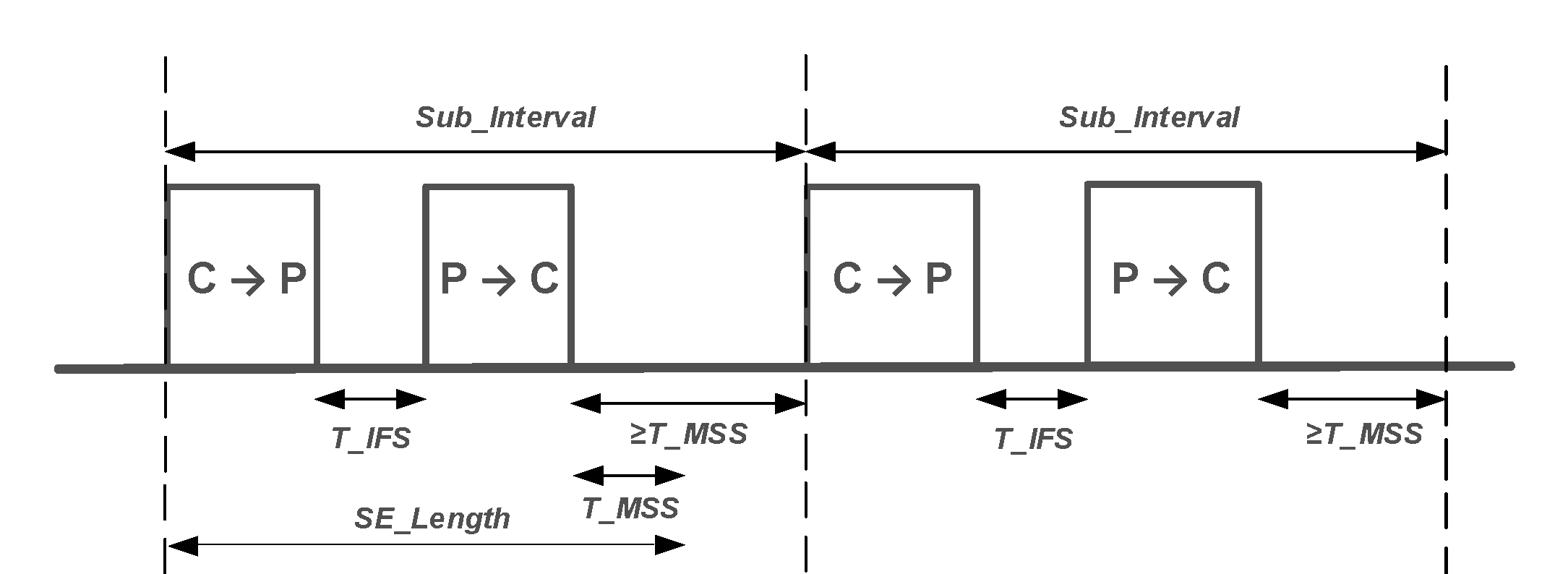
Figure 4.60 shows an example of a CIS event where not all the subevents are used.
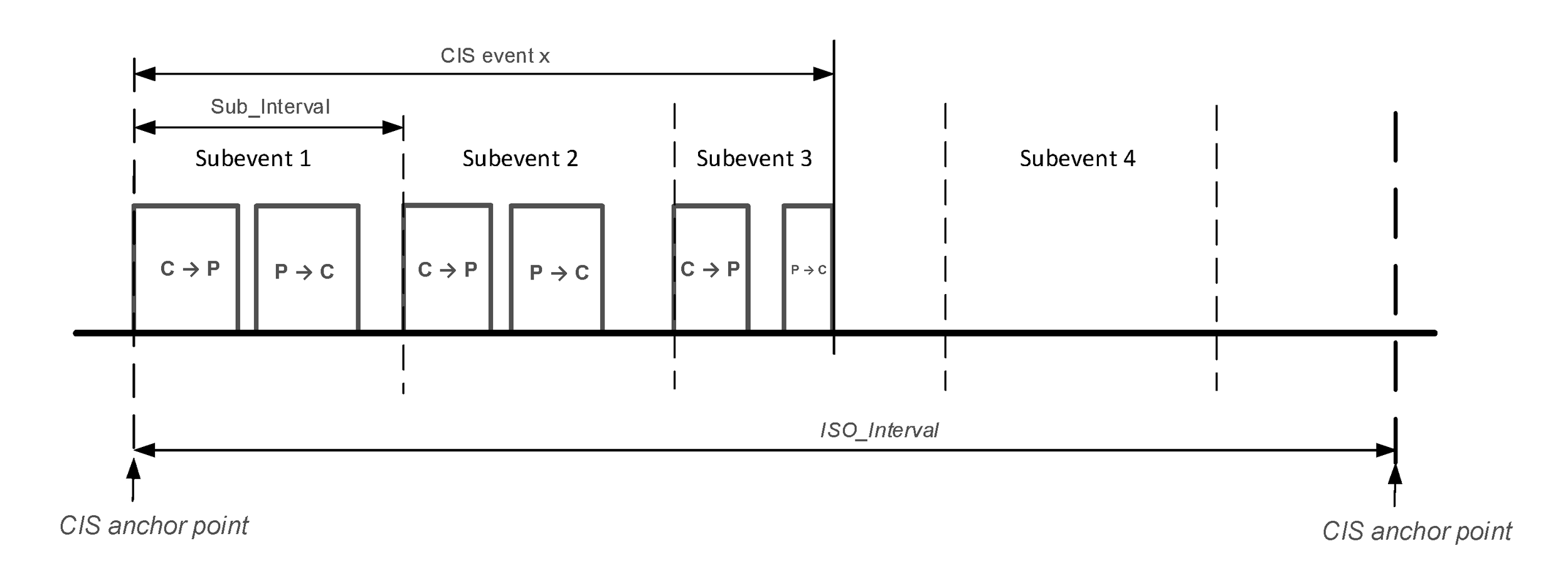
The Central should transmit a packet at the start of each subevent until the event is closed. If the Peripheral receives a packet from the Central, regardless of whether the CRC is valid, it may transmit a response T_IFS after the end of the Central’s packet. The Peripheral shall not transmit if it does not receive a packet from the Central in the same subevent. Where either device does not transmit during a subevent, the Link Layer shall behave for all other purposes (e.g. the timing of packets and the choice of payload) as if it had done so.
ISO_Interval shall be a multiple of 1.25 ms in the range of 5 ms to 4 s, shall be at least NSE × Sub_Interval, and shall be less than half the connSupervisionTimeout for the associated ACL.
SE_Length shall be MPT_C + T_IFS + MPT_P + T_MSS.
Sub_Interval shall be greater than or equal to SE_Length (also see Section 4.5.14.2).
BN shall be in the range 0 to 15. For a bidirectional link the value shall be non-zero for both directions. For a unidirectional link it shall be non-zero in the direction that data is being sent and zero in the other direction.
NSE shall be in the range max (BN_C_To_P, BN_P_To_C) to 31.
4.5.13.3. Connected Isochronous Data
A CIS carries a single stream of isochronous data in each direction or in a single direction. The data is divided into payloads of at most Max_PDU octets, each of which is transmitted as the payload of a single CIS Data PDU; the payloads need not all be the same size and can be zero length.
Note
Note: Max_PDU is the size of the data and excludes the MIC in the CIS Data PDU, if any. Therefore, it has a value in the range 0 to 251.
The Framed parameter of a CIS shall indicate whether the CIS is framed or unframed. Framed CISes shall only use framed CIS Data PDUs to carry data; unframed CISes shall only use unframed CIS Data PDUs to carry data.
For each CIS event the source of the data shall supply, via ISOAL, a burst of data consisting of up to BN payloads, each of which in turn shall hold either a single fragment or one or more SDU segments, or shall be empty. This burst is associated with the corresponding CIS event but the payloads may be transmitted in later events as well; they shall not be transmitted in earlier events. These payloads shall be numbered in order (though not necessarily consecutively); this number shall be used as the value of cisPayloadCounter for the PDU containing that payload. The burst of payloads associated with the CIS event where cisEventCounter has the value E shall consist of payloads with cisPayloadCounter between E × BN and (E + 1) × BN - 1.
CIS Null PDUs do not have a payload and so do not have a cisPayloadCounter.
The payloads shall be transmitted in the order provided. The Link Layer shall continue to retransmit each CIS Data PDU until either it is acknowledged or the data within it has reached its flush point. The Link Layer shall not transmit the CIS Data PDU with cisPayloadCounter N until either payload number N-1 has reached its flush point or the CIS Data PDU with cisPayloadCounter N-1 (if any) has been acknowledged (therefore if payload number N-1 is not provided, payload number N will be delayed until that flush point; the source of the data can provide an empty payload to avoid or reduce this delay). The Link Layer shall not transmit a payload after its flush point. If the source of the data fails to provide a payload in time for a CIS subevent, then the Link Layer shall transmit a CIS Null PDU instead.
Note
Note: It is not specified how the payload numbers assigned by ISOAL are communicated to the Link Layer or how the receiving Link Layer communicates the payload numbers to ISOAL.
Note
Note: If BN is zero, then no payloads are provided and therefore the Link Layer will only transmit CIS Null PDUs.
4.5.13.4. Closing CIS events
The Link Layer shall close a CIS event at the end of its last subevent.
The Central or Peripheral may close a CIS event early by using the Close Isochronous Event (CIE) bit. A device that sends a CIS PDU with the CIE bit set to 1 shall not transmit in the remaining subevents in the current CIS event.
Note
Note: Link Layer implementations will normally end a CIS event early when all the scheduled payloads in both directions have been transmitted and acknowledged.
4.5.13.5. Flush Timeout and Flush Points
The Flush Timeout (FT) parameter is the maximum number of CIS events that may be used to transmit (and retransmit) a given payload. FT shall be between 1 and 255. Each payload number shall have a flush point: a point in time at which the corresponding payload and associated CIS Data PDU, if any, shall be discarded by the Link Layer. The flush point of a payload number occurs immediately after U subevents in the CIS event with cisEventCounter equal to (E + FT – 1), where:
E = floor (cisPayloadCounter ÷ BN)
U = NSE – floor (NSE ÷ BN) × (BN – 1 – cisPayloadCounter mod BN)
Figure 4.61 and Figure 4.62 show examples of data transmissions and payloads reaching their flush points. In these figures, "ACK" and "NAK" have the meaning given in Figure 4.58.
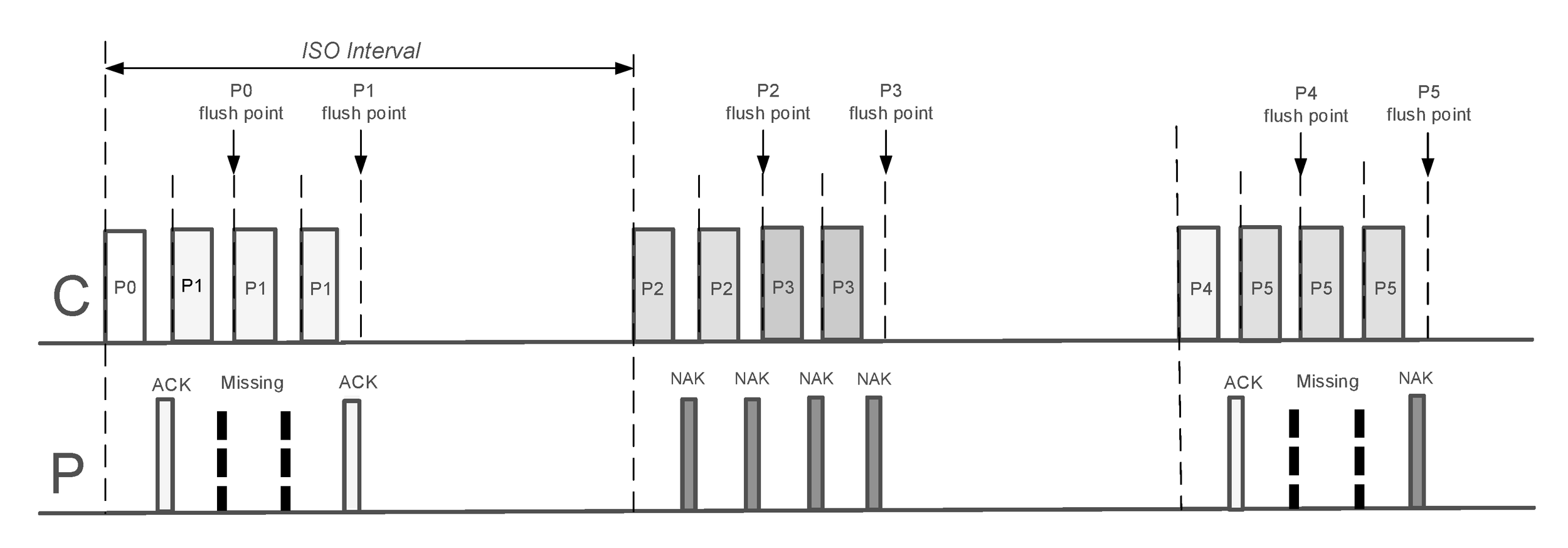
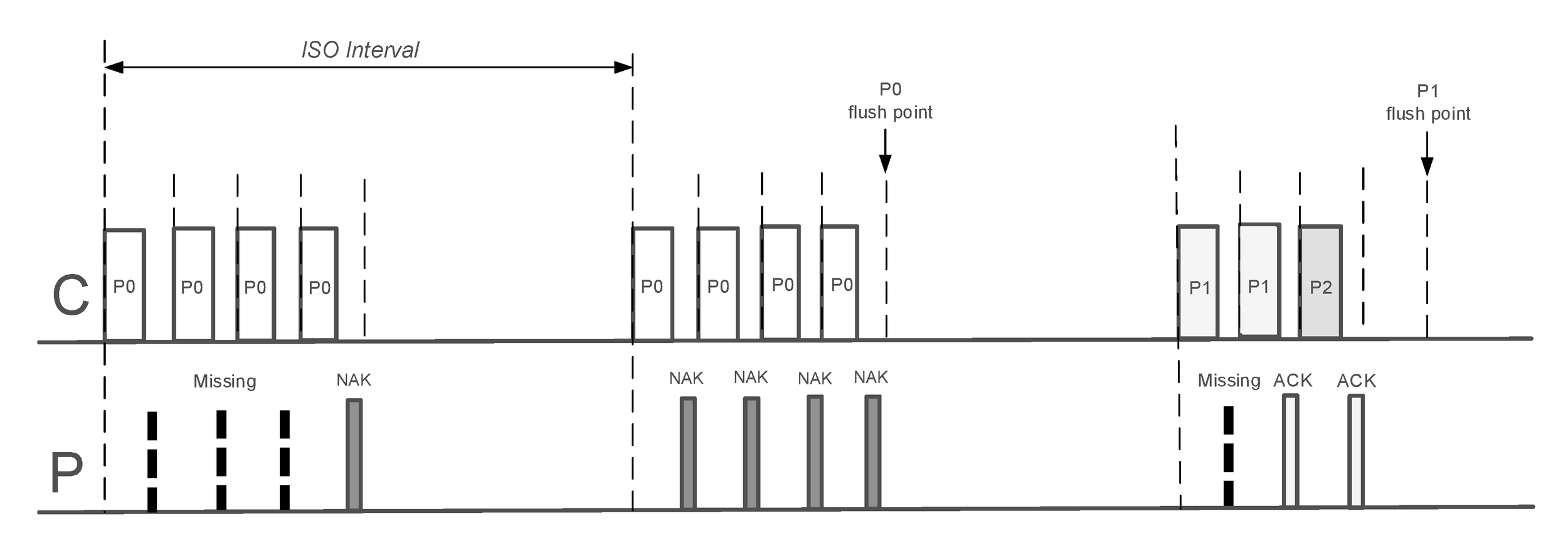
4.5.13.6. Channel indices
Each packet containing a CIS PDU shall be transmitted on the channel index specified by Channel Selection Algorithm #2 (see 4.5.8.3). The subevent number se_n shall be set to the values 1 to NSE, in order, for the subevents of each CIS event. The Peripheral shall transmit on the same channel index as the Central. The channel map used by the CIS shall be the same as the channel map of the associated ACL.
4.5.13.7. CIS Encryption
If an ACL is not encrypted, any associated CIS shall not be encrypted. If an ACL is encrypted, all associated CISes shall be encrypted, in which case all CIS Data PDUs (except those with an empty payload) on those CISes shall be encrypted using the same session key as that used by the associated ACL.
4.5.14. Connected Isochronous Group (CIG)
A CIG consists of either two or more CISes that have the same ISO_Interval and are expected to have a time relationship at the application layer, or of a single CIS. The maximum number of CISes in a CIG shall be 31. An implementation in the Central role is not required to support CIGs with more than 1 CIS.
The Central’s Host assigns an identifier to each CIG, denoted by the parameter CIG_ID. The CIG_ID shall be sent to the Peripheral’s Host via the two Link Layers as part of creation of each CIS in the CIG but is not otherwise used by the Link Layer.
All CISes in a CIG shall have the same Central but may have different Peripherals.
All CISes in a CIG shall have the same value of FT applying from the Central to the Peripheral and the same value of FT applying from the Peripheral to the Central (these two values may be different).
All CISes in a CIG shall have different CIS_IDs, but if a CIS is terminated or considered lost its configuration remains stored within the CIG so that another CIS may then be created in the same CIG with the same CIS_ID and configuration. The configuration is deleted when the CIG is removed.
The Link Layer may use different parameters for a CIS each time that it is created provided that the parameters meet the configuration provided by the Host.
On the Central, a CIG represents a data structure within the Link Layer and does not involve any connection separate from the CISes that make it up. On the Peripheral(s), it represents those CISes with the same CIG_ID.
4.5.14.1. CIG event
A CIG event consists of the corresponding CIS events of the CISes currently making up that CIG. Each CIG event starts at the anchor point of the earliest (in transmission order) CIS of the CIG and ends at the end of the last subevent of the latest CIS of the same CIG event. Two CIG events on the same CIG shall not overlap (that is, the last CIS event of a given CIG event shall end before the first CIS anchor point of the next CIG event).
The Central’s Link Layer shall provide timing parameters (CIS_Sync_Delay and CIG_Sync_Delay) to the Peripherals’ Link Layers which enable synchronization of isochronous data at the application layer.
Each CIG event shall have a CIG reference point and a CIG synchronization point; these shall be CIG_Sync_Delay apart. Each CIG event shall start no earlier than the CIG reference point and shall end no later than the CIG Synchronization point. For a given CIS, the CIS anchor point shall be a fixed offset (which may be zero) after the CIG reference point; therefore CIG reference points are spaced ISO_Interval apart and CIG synchronization points are also spaced ISO_Interval apart. For each CIS, CIS_Sync_Delay shall equal the time from the CIS anchor point to the CIG synchronization point.
Figure 4.63 shows the various elements of a CIG event.
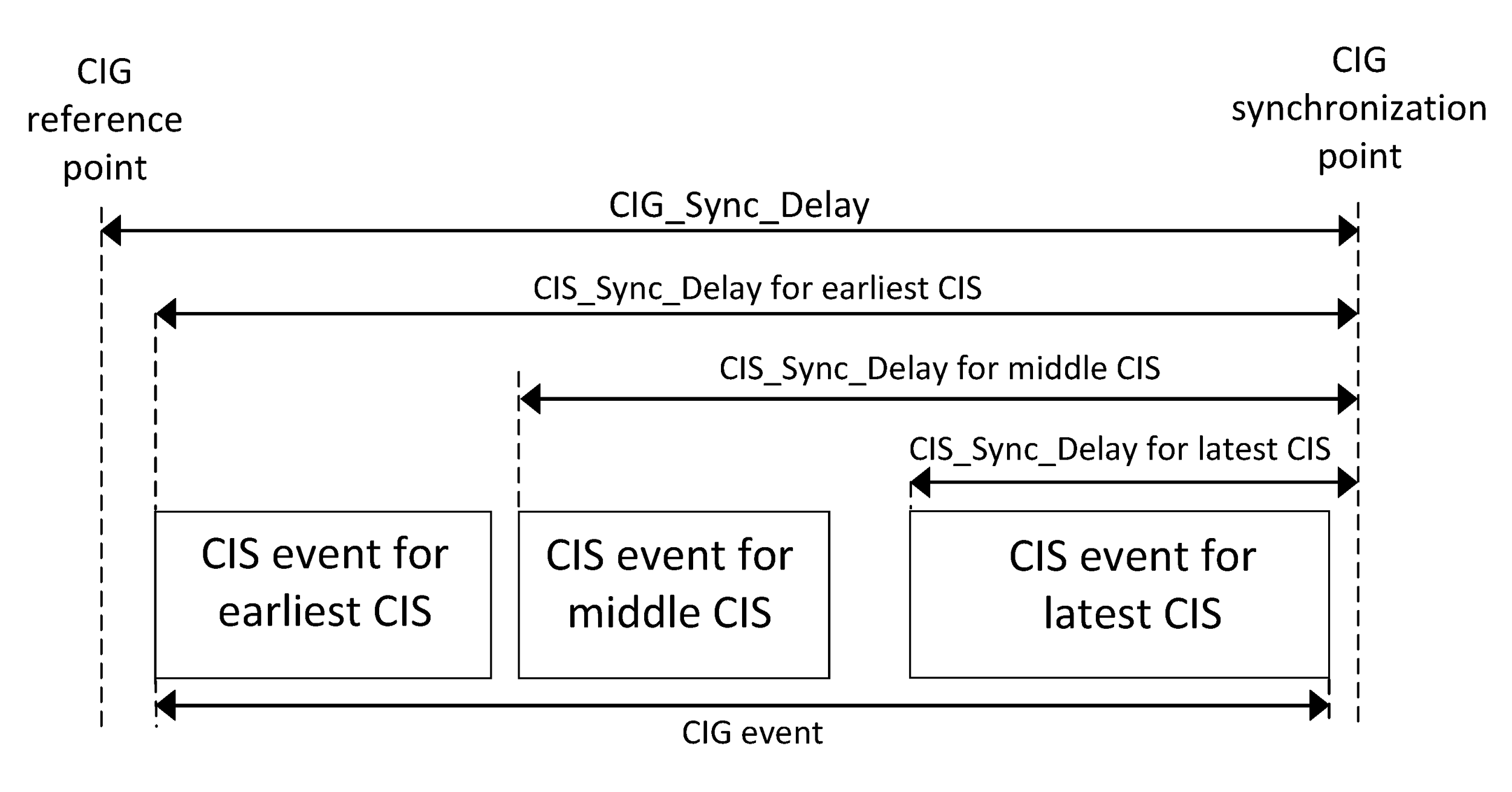
Note
Note: CIG_Sync_Delay will be no less than the maximum possible time for a CIG event; i.e. the time from the CIG reference point to the end of the Peripheral’s packet in the last subevent when both Central and Peripheral transmit packets containing Max_PDU octets. It will have the same value for all CISes in the same CIG. CIS_Sync_Delay for each CIS will equal CIG_Sync_Delay minus the offset from the CIG reference point to the CIS anchor point. The actual maximum possible time for a CIG event cannot be determined until all the CISes in the CIG have been created. Therefore the value that the Central sends is an upper bound.
Note
Note: The maximum possible time for a CIS event equals (NSE – 1) × Sub_Interval + MPT_C + T_IFS + MPT_P for that CIS.
Note
Note: The CIS events making up a CIG event need not have the same values of cisEventCounter, but the difference between the counters will be the same for the lifetime of the CIG.
4.5.14.2. Arrangement of multiple CISes
The CISes in a CIG shall be arranged either sequentially or interleaved by setting the values of the Sub_Interval and the spacing between the CIS anchor points appropriately.
If they are sequential, the CIS events of the different CISes do not overlap and so all the subevents of a CIS event occur together. For each adjacent pair of CISes, the interval between their CIS anchor points shall be at least NSE × Sub_Interval, using the values for the lower numbered CIS.
If they are interleaved, all the first subevents of the CISes are adjacent, followed by the second subevents, and so on. For each CIS, its value of Sub_Interval shall be at least the sum of the values of SE_Length for all the CISes in the CIG. For each adjacent pair of CISes, the interval between their CIS anchor points shall be at least SE_Length of the lower numbered CIS.
Figure 4.64 shows each arrangement for a CIG with two CISes and NSE = 2.
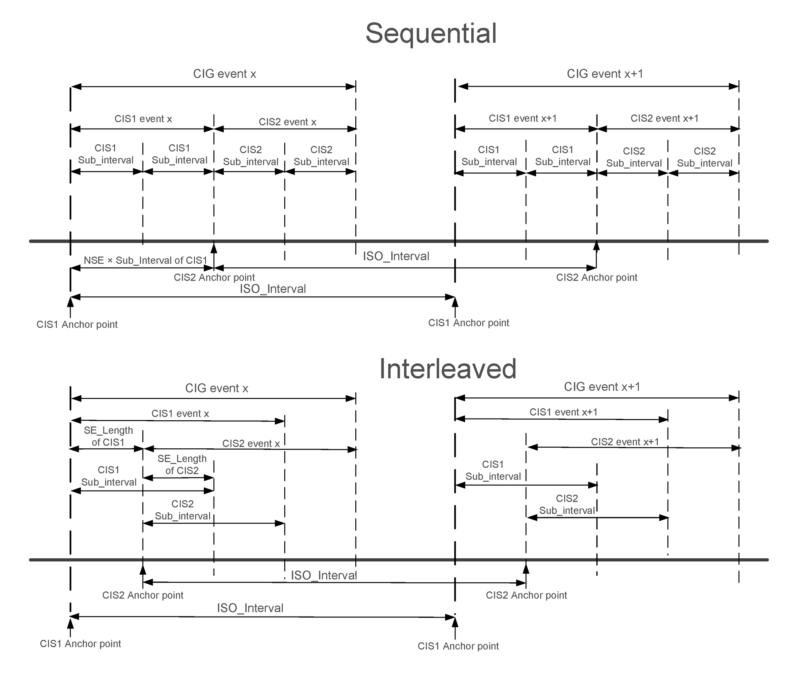
4.5.14.3. States of a CIG
On the Central, a CIG has three states: configurable, active, and inactive. When the Host creates the CIG, it shall be in the configurable state. When the Host creates a CIS in the CIG, if the CIG is not already in the active state, then the Controller shall change the state of the CIG to active. When all CISes in a CIG are terminated or considered lost, the Controller shall change the state of the CIG to inactive. If the Host sends an explicit request to remove the CIG and the CIG is not in the active state, then the Controller shall remove the CIG.
The Host configures the CIG by notifying the Link Layer of the individual configurations of CIS(es) to be stored within the CIG. The Link Layer shall only change the configuration when requested by the Host and while the CIG is in the configurable state.
If the Link Layer is unable to schedule a CIG of the requested configuration, it shall notify the Host and not create any of the CISes in the CIG.
Note
Note: The Controller can use the configuration information to determine whether it is able to schedule all the CISes in the CIG without conflict with each other or other activities. If it is unable to do so, it can notify the Host when requested to create the first CIS. Once it has successfully created a schedule, subsequent CISes can then be created without any risk of conflict. Figure 4.65 illustrates the states of a CIG and the CIS configurations stored within it.
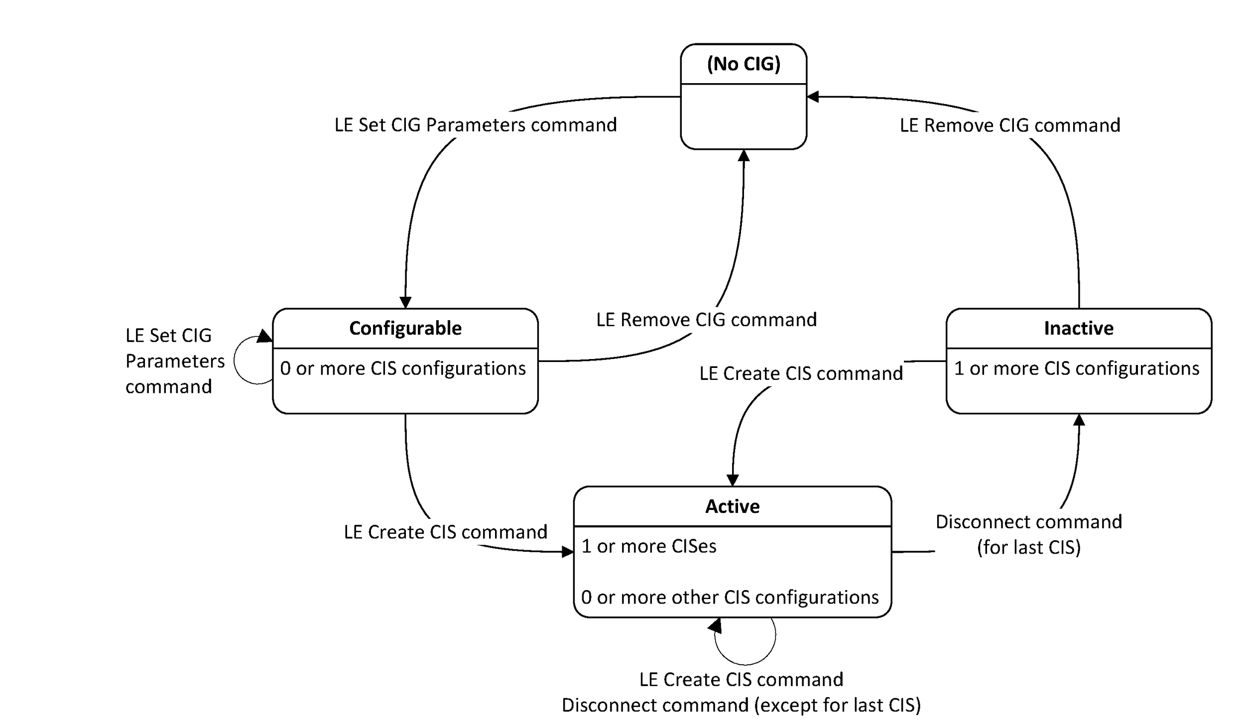
4.5.15. Power level management
A Link Layer that supports power control shall manage power levels on all active PHYs for a given peer and may manage power levels for some or all non-active PHYs that it supports. An active PHY for a peer is the current PHY for the ACL connection to that peer or a PHY for an associated CIS. This implies that, when a CIS is created on a new PHY or the ACL connection changes to a new PHY, the Link Layer must start managing that PHY if it doesn't already do so.
When a device is managing the power level for a PHY, it shall store the power level for that PHY and shall transmit all packets to the peer on that PHY using that power level. The device shall change the power level when requested by the peer and may change it autonomously.
If a device starts to manage the power level for a PHY (e.g. because it has become an active PHY) then the implementation shall choose an initial power level.
Where a PHY has more than one power level, then the different power levels shall be treated as separate PHYs for the purpose of this section, the Power Control Request procedure (see Section 5.1.17), and the Power Change Indication procedure (see Section 5.1.18). In the case of the LE Coded PHY, the two power levels are "packets transmitted with an S=8 payload" and "packets transmitted with an S=2 payload"; the power level shall not change during a packet. Nevertheless, both shall be active or inactive at the same time.
4.5.16. Path loss monitoring
The Host may request the Controller to perform path loss monitoring on an ACL connection. There shall be two path loss zones, called the Low and Middle zones, and optionally a third High zone. The Controller shall notify the Host whenever the path loss changes from one zone to another. The path loss is defined as the difference between the remote transmit power level and the average local RSSI measurement for the connection; how measurements are averaged is not specified. The path loss shall be deemed to have entered a new zone when it becomes greater than or equal to the upwards boundary when moving to a higher zone or becomes less than or equal to the downwards boundary when moving to a lower zone, as shown in Figure 4.66, and, in each case, has spent at least the minimum time specified in the new zone if one is specified. For each pair of zones, the upwards boundary shall be greater than or equal to the downwards boundary and should not be equal so as to provide some hysteresis.
The zone boundaries in each direction and, optionally, the minimum time to spend in a new zone are specified by the Host.
The Controller may notify the Host when the path loss becomes unavailable. If so, it shall notify the Host when the path loss becomes available again as if it had just changed zones.
Two consecutive reports shall not indicate entering the same zone.
Notes:
Path loss can be measured by making use of the Power Control Request procedure or the Power Change Indication procedure to obtain the remote transmit power level, and by making local RSSI measurements.
Path loss is often correlated with distance from the peer device and, therefore, moving to a higher zone might indicate that the peer has moved further away.
A Controller may use path loss measurements from associated physical links, such as CISes, when determining path loss threshold events on the ACL connection.
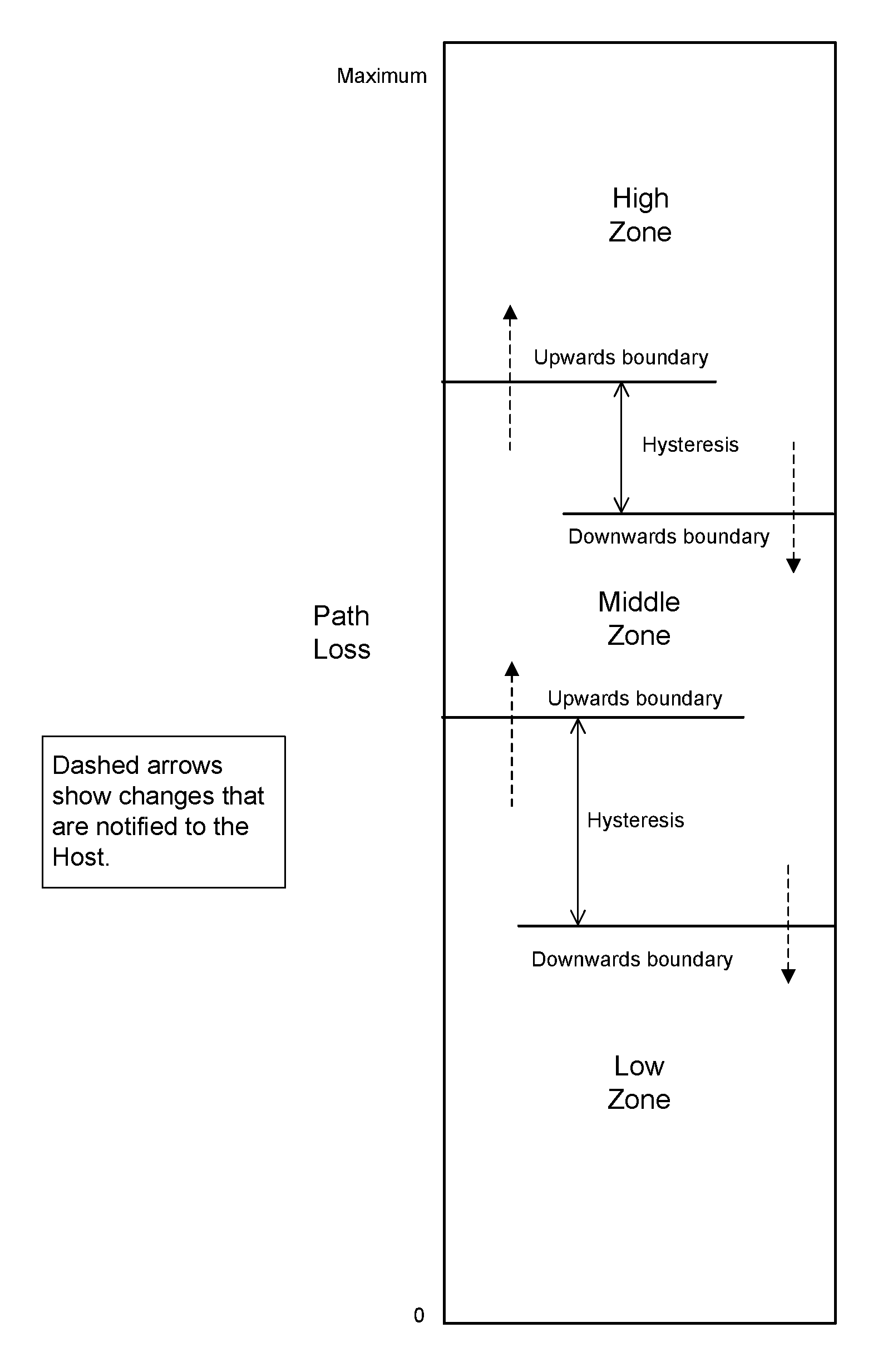
4.5.17. ACL data Host transport
For each logical link, the Controller shall transmit data over the air in the same order that it is received from the Host. The boundaries between packets over the air for a specific L2CAP PDU may be different from the boundaries in the data provided by the Host. Each new L2CAP PDU shall start a new packet over the air. (See [Vol 3] Part A, Section 7.2.1 for related requirements in L2CAP.)
For each logical link, the Controller shall transmit the data received over the air to the Host (whether over HCI or otherwise) in the same order that it was received. The boundaries in the data sent to the Host for a specific L2CAP PDU may be different from the boundaries between packets received over the air. The Controller shall retain boundaries between L2CAP PDUs. Data from different logical links may be interleaved. (See [Vol 3] Part A, Section 7.2.2 for related requirements in L2CAP.)
4.6. Feature support
The set of features supported by a Link Layer is represented by a bit mask called FeatureSet. The value of FeatureSet shall not change while the Controller has a connection to another device. A peer device may cache information about features that the device supports. The Link Layer may cache information about features that a peer supports during a connection.
Within FeatureSet, a bit set to 0 indicates that the Link Layer feature is not supported in this Controller; a bit set to 1 indicates that the Link Layer feature is supported in this Controller.
Except where explicitly stated elsewhere in this specification, if the peer Link Layer has indicated either during a feature exchange procedure or by responding with an LL_UNKNOWN_RSP PDU that it does not support a procedure, then the Link Layer shall not use that procedure. A Link Layer shall not transmit a PDU listed in the following subsections unless it supports at least one of the features that requires support for that PDU.
Unless explicitly stated otherwise, when a Link Layer supports a feature it shall support it on all PHYs that the Controller supports.
The bit positions for each Link Layer feature shall be as shown in Table 4.7, which also shows various properties of the feature bits. In the "Send to Peer" column:
"Y" indicates that the bit shall be set correctly when sent to the peer.
"O" indicates that the bit shall either be zero or set correctly when sent to the peer. The peer device shall ignore the value of this bit.
"N" indicates that the bit shall be set to zero when sent to the peer.
When sent to the Host, the bit shall always be set correctly. If a bit is shown as Host Controlled, the value may be set by the Host and shall default to zero.
If a bit does not have "Y" for "Send to Peer", it shall not be used to determine whether a peer device supports any associated procedure.
Bit position | Link Layer Feature | Send to Peer | Host Controlled |
|---|---|---|---|
0 | LE Encryption | Y | N |
1 | Connection Parameters Request procedure | Y | N |
2 | Extended Reject Indication | Y | N |
3 | Peripheral-initiated Features Exchange | Y | N |
4 | LE Ping | O | N |
5 | LE Data Packet Length Extension | Y | N |
6 | LL Privacy | O | N |
7 | Extended Scanning Filter Policies | O | N |
8 | LE 2M PHY | Y | N |
9 | Stable Modulation Index - Transmitter | Y | N |
10 | Stable Modulation Index - Receiver | Y | N |
11 | LE Coded PHY | Y | N |
12 | LE Extended Advertising | O | N |
13 | LE Periodic Advertising | O | N |
14 | Channel Selection Algorithm #2 | Y | N |
15 | LE Power Class 1 (see [Vol 6] Part A, Section 3) | Y | N |
16 | Minimum Number of Used Channels procedure | Y | N |
17 | Connection CTE Request | Y | N |
18 | Connection CTE Response | Y | N |
19 | Connectionless CTE Transmitter | O | N |
20 | Connectionless CTE Receiver | O | N |
21 | Antenna Switching During CTE Transmission (AoD) | O | N |
22 | Antenna Switching During CTE Reception (AoA) | O | N |
23 | Receiving Constant Tone Extensions | Y | N |
24 | Periodic Advertising Sync Transfer - Sender | Y | N |
25 | Periodic Advertising Sync Transfer - Recipient | Y | N |
26 | Sleep Clock Accuracy Updates | Y | N |
27 | Remote Public Key Validation | N | N |
28 | Connected Isochronous Stream – Central | Y | N |
29 | Connected Isochronous Stream – Peripheral | Y | N |
30 | Isochronous Broadcaster | Y | N |
31 | Synchronized Receiver | Y | N |
32 | Connected Isochronous Stream (Host Support) | Y | Y |
33 | LE Power Control Request | Y | N |
34 | LE Power Control Request | Y | N |
35 | LE Path Loss Monitoring | Y | N |
36 | Periodic Advertising ADI support | O | N |
37 | Connection Subrating | Y | N |
38 | Connection Subrating (Host Support) | Y | Y |
39 | Channel Classification | Y | N |
40 | Advertising Coding Selection | Y | N |
41 | Advertising Coding Selection (Host Support) | Y | Y |
43 | Periodic Advertising with Responses - Advertiser | Y | N |
44 | Periodic Advertising with Responses - Scanner | Y | N |
56 to 62 | Reserved for future use (used for specification development purposes) | ||
All other bits | Reserved for future use |
Bits 33 and 34 shall always have the same value.
4.6.1. LE Encryption
A Controller that supports LE Encryption shall support encryption on all logical transports that it supports and the following sections of this document:
LL_ENC_REQ ( Section 2.4.2.4)
LL_ENC_RSP ( Section 2.4.2.5)
LL_START_ENC_REQ ( Section 2.4.2.6)
LL_START_ENC_RSP ( Section 2.4.2.7)
LL_PAUSE_ENC_REQ ( Section 2.4.2.11)
LL_PAUSE_ENC_RSP ( Section 2.4.2.12)
Encryption Start procedure ( Section 5.1.3.1)
Encryption Pause procedure ( Section 5.1.3.2)
4.6.2. Connection Parameters Request procedure
A Controller that supports Connection Parameters Request procedure shall support the Extended Reject Indication feature and the following sections of this document:
LL_CONNECTION_PARAM_REQ ( Section 2.4.2.16)
LL_CONNECTION_PARAM_RSP ( Section 2.4.2.17)
Connection Parameters Request procedure ( Section 5.1.7)
4.6.3. Extended Reject Indication
A Controller that supports Extended Reject Indication shall support the following sections of this document:
LL_REJECT_EXT_IND ( Section 2.4.2.18)
4.6.4. Peripheral-initiated Features Exchange
A Controller that supports Peripheral-initiated Features Exchange shall support the following sections of this document:
LL_PERIPHERAL_FEATURE_REQ ( Section 2.4.2.15)
Receiving LL_FEATURE_RSP (see Section 2.4.2.10)
4.6.5. LE Ping
A Controller that supports LE Ping shall support the following sections of this document:
LL_PING_REQ ( Section 2.4.2.19)
LL_PING_RSP ( Section 2.4.2.20)
LE Ping procedure ( Section 5.1.8)
LE Authenticated Payload Timeout ( Section 5.4)
4.6.6. LE Data Packet Length Extension
A Controller that supports LE Data Packet Length Extension shall support the following sections of this document:
LL_LENGTH_REQ and LL_LENGTH_RSP ( Section 2.4.2.21)
Data Length Update procedure ( Section 5.1.9)
4.6.7. LL Privacy
A Controller that supports LL Privacy shall support the following sections of this document:
Resolving List ( Section 4.7)
LL Privacy ( Section 6)
4.6.8. Extended Scanning Filter Policies
A Controller that supports Extended Scanning Filter Policies shall support the following sections of this document:
Extended Scanning Filter Policies ( Section 4.3.3.1)
4.6.9. Multiple PHYs
A Controller that supports any PHY other than LE 1M PHY shall support the Extended Reject Indication feature and the following sections of this document:
Transmission and reception using the supported modulation schemes ([Vol 6] Part A, Section 1)
Longer preamble when supporting the LE 2M PHY (see Section 2.2.1)
LL_PHY_REQ ( Section 2.4.2.22)
LL_PHY_RSP ( Section 2.4.2.22)
LL_PHY_UPDATE_IND ( Section 2.4.2.23)
PHY Update procedure ( Section 5.1.10)
and, when supporting the LE Coded PHY:
Packet format for the LE Coded PHY ( Section 2.2)
Coding ( Section 3.3)
4.6.9.1. Symmetric and asymmetric connections
A Controller shall support connections using the same PHY in each direction (“symmetric connections”) and may support connections using different PHYs in each direction (“asymmetric connections”).
If a Controller cannot support asymmetric connections then:
Any LL_PHY_REQ, LL_PHY_RSP, or LL_CIS_REQ PDUs sent shall indicate that it wants a symmetric connection.
Any LL_PHY_UPDATE_IND PDU sent shall not specify an asymmetric connection.
4.6.10. Stable Modulation Index - Transmitter
A Controller that supports Stable Modulation Index - Transmitter shall support the following section of this document:
Stable Modulation Index ([Vol 6] Part A, Section 3.1.1)
4.6.11. Stable Modulation Index - Receiver
A Controller that supports Stable Modulation Index - Receiver shall support the following section of this document:
Stable Modulation Index ([Vol 6] Part A, Section 4.7)
4.6.12. LE Extended Advertising
A Controller that supports LE Extended Advertising shall support reception of an Advertising Physical Channel PDU payload of 255 octets and support the following sections of this document:
ADV_EXT_IND ( Section 2.3.1.5)
AUX_ADV_IND ( Section 2.3.1.6)
AUX_CHAIN_IND ( Section 2.3.1.8)
AUX_SCAN_REQ (see Section 2.3.2.1)
AUX_SCAN_RSP ( Section 2.3.2.3)
AUX_CONNECT_REQ (see Section 2.3.3.1)
AUX_CONNECT_RSP ( Section 2.3.3.2)
Common Extended Advertising Payload Format ( Section 2.3.4)
Connectable Directed event type using ADV_EXT_IND ( Section 4.4.2.4.4)
Scannable Undirected event type using ADV_EXT_IND ( Section 4.4.2.5.2)
Connectable Undirected event type ( Section 4.4.2.7)
Scannable Directed event type ( Section 4.4.2.8)
Non-Connectable and Non-Scannable Directed event type ( Section 4.4.2.9)
Advertising Sets ( Section 4.4.2.10)
Using AdvDataInfo (ADI) ( Section 4.4.2.11)
Advertising Sets ( Section 4.4.3.3)
Connect Requests on the Secondary Advertising Physical Channel ( Section 4.4.4.2)
A Controller that supports connections shall also support the Channel Selection Algorithm #2 feature.
4.6.13. LE Periodic Advertising
A Controller that supports LE Periodic Advertising shall support the LE Extended Advertising feature, Channel Selection Algorithm #2 feature, and the following sections of this document:
AUX_SYNC_IND ( Section 2.3.1.7)
Periodic Advertising ( Section 4.4.2.12)
A Controller that supports Scanning state shall also support the following sections of this document:
Scanning for periodic advertisements ( Section 4.4.3.4)
Synchronization state ( Section 4.4.5) for periodic advertising trains
4.6.14. Channel Selection Algorithm #2
A Controller that supports Channel Selection Algorithm #2 shall support the following sections of this document:
ChSel bit set to 1 (see Sections 2.3, 2.3.1.1, 2.3.1.2, and 2.3.3.1)
Channel Selection Algorithm #2 ( Section 4.5.8.3).
4.6.15. Minimum Number of Used Channels procedure
A Controller that supports the Minimum Number of Used Channels procedure shall support the following sections of this document:
LL_MIN_USED_CHANNELS_IND ( Section 2.4.2.24)
Minimum Number Of Used Channels procedure ( Section 5.1.11)
4.6.16. Connection CTE Request
A Controller that supports Connection CTE Request shall support the Receiving Constant Tone Extensions feature, the Extended Reject Indication feature, and the following sections of this document on all supported PHYs that allow Constant Tone Extensions:
LL_CTE_REQ ( Section 2.4.2.25)
LL_CTE_RSP ( Section 2.4.2.26)
Constant Tone Extension Request procedure ( Section 5.1.12) - as initiator
4.6.17. Connection CTE Response
A Controller that supports Connection CTE Response shall support the Extended Reject Indication feature and the following sections of this document on all supported PHYs that allow Constant Tone Extensions:
LL_CTE_REQ ( Section 2.4.2.25)
LL_CTE_RSP ( Section 2.4.2.26)
Transmitting Constant Tone Extensions ( Section 2.5.3)
Constant Tone Extension Request procedure ( Section 5.1.12) - as responder
4.6.18. Connectionless CTE Transmitter
A Controller that supports Connectionless CTE Transmitter shall support the LE Periodic Advertising feature in Advertising state and the following section of this document on all supported PHYs that allow Constant Tone Extensions:
Transmitting Constant Tone Extensions ( Section 2.5.3)
4.6.19. Connectionless CTE Receiver
A Controller that supports Connectionless CTE Receiver shall support the LE Periodic Advertising feature in Synchronization state and the following sections of this document on all supported PHYs that allow Constant Tone Extensions:
Receiving Advertising Physical Channel PDUs containing a CTEInfo field in the Extended Header (see Section 2.3.4)
IQ Sampling ( Section 2.5.4)
4.6.20. Antenna Switching During CTE Transmission (AoD)
A Controller that supports Antenna Switching During CTE Transmission (AoD) shall support the following sections of this document on all supported PHYs that allow Constant Tone Extensions:
Transmitting Constant Tone Extensions ( Section 2.5.3)
Antenna Switching ([Vol 6] Part A, Section 5)
4.6.21. Antenna Switching During CTE Reception (AoA)
A Controller that supports Antenna Switching During CTE Reception (AoA) shall support the Receiving Constant Tone Extensions feature and the following section of this document on all supported PHYs that allow Constant Tone Extensions:
Antenna Switching ([Vol 6] Part A, Section 5)
4.6.22. Receiving Constant Tone Extensions
A Controller that supports Receiving Constant Tone Extensions shall support the following sections of this document on all supported PHYs that allow Constant Tone Extensions:
Receiving Data Channel PDUs with the CP bit set to 1 and containing a CTEInfo field (see Section 2.4)
IQ Sampling ( Section 2.5.4)
4.6.23. Periodic Advertising Sync Transfer - Sender
A Controller that supports Periodic Advertising Sync Transfer - Sender shall support the LE Periodic Advertising feature and the following sections of this document:
LL_PERIODIC_SYNC_IND ( Section 2.4.2.27)
Periodic Advertising Sync Transfer procedure ( Section 5.1.13) - as initiator
4.6.24. Periodic Advertising Sync Transfer - Recipient
A Controller that supports Periodic Advertising Sync Transfer - Recipient shall support the LE Periodic Advertising feature and the following sections of this document:
LL_PERIODIC_SYNC_IND ( Section 2.4.2.27)
Periodic Advertising Sync Transfer procedure ( Section 5.1.13) - as recipient
4.6.25. Sleep Clock Accuracy Updates
A Controller that supports Sleep Clock Accuracy Updates shall support the following sections of this document:
LL_CLOCK_ACCURACY_REQ and LL_CLOCK_ACCURACY_RSP ( Section 2.4.2.28)
Sleep Clock Accuracy Update procedure ( Section 5.1.14)
4.6.26. Remote Public Key Validation
A Controller that supports Remote Public Key Validation shall validate the remote public key (see [Vol 3] Part H, Section 2.3.5.6.1) sent by the Host in the HCI_LE_Generate_DHKey command (see [Vol 4] Part E, Section 7.8.37).
4.6.27. Connected Isochronous Stream - Central and Connected Isochronous Stream - Peripheral
A Controller that supports the Connected Isochronous Stream - Central feature or the Connected Isochronous Stream - Peripheral feature shall support the Channel Selection Algorithm #2 feature, the Sleep Clock Accuracy Updates feature, the Extended Reject Indication feature, and the following sections of this document:
LL_CIS_REQ ( Section 2.4.2.29)
LL_CIS_RSP ( Section 2.4.2.30)
LL_CIS_IND ( Section 2.4.2.31)
LL_CIS_TERMINATE_IND ( Section 2.4.2.32)
Connected Isochronous PDU ( Section 2.6.1)
Connected Isochronous Stream ( Section 4.5.13)
Connected Isochronous Group ( Section 4.5.14)
Connected Isochronous Stream Creation procedure ( Section 5.1.15)
Connected Isochronous Stream Termination procedure ( Section 5.1.16)
ISO Transmit Test Mode ( Section 7.1)
ISO Receive Test Mode ( Section 7.2)
Isochronous Adaptation Layer (ISOAL) ([Vol 6] Part G)
4.6.28. Isochronous Broadcaster
A Controller that supports the Isochronous Broadcaster feature shall support the LE Periodic Advertising feature and the following sections of this document:
Broadcast Isochronous PDU ( Section 2.6.2)
BIG Control PDU ( Section 2.6.3)
Isochronous Broadcasting State ( Section 4.4.6)
BIG control procedures ( Section 5.6)
ISO Transmit Test Mode ( Section 7.1)
Isochronous Adaptation Layer (ISOAL) ([Vol 6] Part G)
4.6.29. Synchronized Receiver
A Controller that supports the Synchronized Receiver feature shall support the LE Periodic Advertising feature and the following sections of this document:
Broadcast Isochronous PDU ( Section 2.6.2)
BIG Control PDU ( Section 2.6.3)
Synchronization state (see Section 4.4.5)
BIG control procedures ( Section 5.6)
ISO Receive Test Mode ( Section 7.2)
Isochronous Adaptation Layer (ISOAL) ([Vol 6] Part G)
4.6.30. [This section is no longer used]
4.6.31. LE Power Control Request
A Controller that supports LE Power Control Request shall support the Extended Reject Indication feature and the following sections of this document:
LL_POWER_CONTROL_REQ ( Section 2.4.2.33)
LL_POWER_CONTROL_RSP ( Section 2.4.2.34)
LL_POWER_CHANGE_IND ( Section 2.4.2.35)
Power level management ( Section 4.5.15)
Power Control Request procedure ( Section 5.1.17)
Power Change Indication procedure ( Section 5.1.18)
4.6.32. LE Path Loss Monitoring
A Controller that supports LE Path Loss Monitoring shall support the following sections of this document:
LE Path Loss Monitoring ( Section 4.5.16)
4.6.33. Host-set feature bits
The Controller shall only set these bits on request from the Host. The Controller shall reject a request to set a bit if the conditions in this section are not met.
4.6.33.1. Connected Isochronous Stream (Host Support)
This feature bit indicates that the Host supports creating CISes.
The Controller shall only set this feature bit if it supports the Connected Isochronous Stream - Central or Connected Isochronous Stream - Peripheral feature.
4.6.33.2. Connection Subrating (Host Support)
This feature bit indicates that the Host supports Connection Subrating.
The Controller shall only set this feature bit if it supports the LE Connection Subrating feature.
4.6.33.3. Advertising Coding Selection (Host Support)
This feature bit indicates that the Host supports Advertising Coding Selection.
The Controller shall only set this feature bit if it supports the Advertising Coding Selection feature.
4.6.34. Periodic Advertising ADI Support
A Controller that supports the Periodic Advertising ADI Support feature shall support the LE Periodic Advertising feature and the ability to transmit and interpret the ADI field in the AUX_SYNC_IND PDU as described in the following sections of this document:
AUX_SYNC_IND PDU ( Section 2.3.1.7)
Periodic Advertising ( Section 4.4.2.12)
Periodic Advertising Trains ( Section 4.4.5.1)
A Controller that does not support the Periodic Advertising ADI Support feature shall not transmit or interpret the ADI field in the AUX_SYNC_IND PDU.
4.6.35. Connection Subrating
A Controller that supports the Connection Subrating feature shall support all valid values for connSubrateFactor (see Section 4.5.1) and the following sections of this document:
LL_SUBRATE_REQ ( Section 2.4.2.36)
LL_SUBRATE_IND ( Section 2.4.2.37)
Connection Subrate Update procedure ( Section 5.1.19)
Connection Subrate Request procedure ( Section 5.1.20)
A Controller that does not support the Connection Subrating feature shall only support a connSubrateFactor of 1.
4.6.36. Channel Classification
A Controller that supports the Channel Classification feature shall support the following sections of this document:
LL_CHANNEL_REPORTING_IND ( Section 2.4.2.38)
LL_CHANNEL_STATUS_IND ( Section 2.4.2.39)
Channel Classification Enable procedure ( Section 5.1.21)
Channel Classification Reporting procedure ( Section 5.1.22)
4.6.37. Advertising Coding Selection
A Controller that supports Advertising Coding Selection shall support the LE Extended Advertising and LE Coded PHY features and the following section of this document:
Host selection of the coding scheme used in advertising (see Section 4.4)
and, if the Controller supports HCI:
advertising reports specifying the coding scheme used (see [Vol 4] Part E, Section 7.7.65.13).
4.6.38. Periodic Advertising with Responses - Advertiser
A Controller that supports Periodic Advertising with Responses - Advertiser shall support the Periodic Advertising Sync Transfer - Sender feature and the following sections of this document:
AUX_SYNC_SUBEVENT_IND ( Section 2.3.1.9)
AUX_SYNC_SUBEVENT_RSP ( Section 2.3.1.10)
LL_PERIODIC_SYNC_WR_IND ( Section 2.4.2.40)
Trains with responses ( Section 4.4.2.12.2)
4.6.39. Periodic Advertising with Responses - Scanner
A Controller that supports Periodic Advertising with Responses - Scanner shall support the Periodic Advertising Sync Transfer - Recipient feature and the following sections of this document:
AUX_SYNC_SUBEVENT_IND ( Section 2.3.1.9)
AUX_SYNC_SUBEVENT_RSP ( Section 2.3.1.10)
LL_PERIODIC_SYNC_WR_IND ( Section 2.4.2.40)
Scanning for periodic advertisements ( Section 4.4.3.4)
Trains with responses ( Section 4.4.5.1.2)
4.7. Resolving List
All Link Layers supporting Link Layer privacy (see Section 6) shall contain a set of records for local and peer IRK value pairs. These values are known as the Local IRK and the Peer IRK. The Resolving List IRK pairs shall be associated with a public or static device address known as the Identity Address. The Identity Address may be in the Filter Accept List. All Link Layers supporting Link Layer privacy shall support a Resolving List capable of storing at least one Resolving List Record.
On reset, the Resolving List shall be empty.
The Resolving List is configured by the Host and is used by the Link Layer to resolve Resolvable Private Addresses used by advertisers, scanners or initiators. This allows the Host to configure the Link Layer to act on a request without awakening the Host.
The Filter Accept List and filter policies set by the Host are applied to the associated Identity Address once the Resolvable Private Address has been resolved.
If the Host, when populating the resolving list, sets a peer IRK to all zeros, then the peer address used within an advertising physical channel PDU shall use the peer’s Identity Address, which is provided by the Host.
The Host specifies the privacy mode to be used with each peer identity on the resolving list. If it specifies that device privacy mode is to be used, then the Controller shall accept both the peer's device Identity Address and a resolvable private address generated by the peer device using its distributed IRK. Otherwise, network privacy mode is used: the Controller shall only accept resolvable private addresses generated by the peer device using its distributed IRK. If the Host has added the peer device to the resolving list with an all-zero peer IRK, the Controller shall only accept the peer's Identity Address, as defined in Section 6.5.
If the Host, when populating the resolving list, sets a local IRK to all zeros, then any local address used within an advertising physical channel PDU shall use the local Identity Address, which is provided by the Host.
If the Link Layer is using the Resolving List and the peer device has been resolved, the Address returned to the Host is the peer device’s Identity Address.
If the Link Layer is using the Resolving List and the peer device has been resolved but the encryption fails then the current Resolvable Private Address(es) shall be immediately discarded and new Resolvable Private Address(es) shall be generated.
Note
Note: Encryption may fail when the address was resolved successfully using an incorrect IRK and, therefore, encryption keys on both sides did not match.
When the Controller address resolution is enabled, both peer and local RPAs received by the Link Layer shall be resolved using the same Resolving List Record.
Note
Note: The Controller may generate Resolvable Private Addresses even when address resolution is disabled.
5. Link Layer control
The Link Layer Control protocol (LLCP) is used to control and negotiate aspects of the operation of a connection between two Link Layers. This includes procedures for control of the connection, starting and pausing encryption and other link procedures.
Procedures have specific timeout rules as defined in Section 5.2. The ACL Termination procedure may be initiated at any time, even if any other Link Layer control procedure is currently active. For all other Link Layer control procedures, only one Link Layer control procedure shall be initiated in the Link Layer at a time per connection per device. A new Link Layer control procedure shall not be initiated until any previous Link Layer control procedure initiated by the same device on the same connection has completed. However, except where forbidden elsewhere in this section, a Link Layer may initiate an LL control procedure while responding to a procedure initiated by its peer device.
Except where stated otherwise in this section, there are no restrictions on the order that Link Layer control procedures are carried out except that no procedure shall be started until after entering the Connection state.
The prioritization of LL Control PDUs and LL Data PDUs is implementation specific. For example, a Host cannot assume that pending data will be sent when a termination of the link is requested without waiting for those data PDUs to be completed and indicated to the Host.
If the remote device does not support a procedure, the Link Layer will normally receive an LL_UNKNOWN_RSP with the UnknownType field set to the opcode of the initiating PDU. In this case, the procedure is terminated when the LL_UNKNOWN_RSP PDU is received.
5.1. Link Layer ACL control procedures
Except for any wording describing the behavior of a Link Layer that does not support a feature, the requirements in each subsection below only apply if the Link Layer supports the relevant feature (see Section 4.6).
5.1.1. Connection Update procedure
The Central or Peripheral may update the Link Layer parameters for a connection (connInterval, connPeripheralLatency, and connSupervisionTimeout) by applying the following rules.
If both the Central and Peripheral support the Connection Parameters Request procedure (see Section 5.1.7) then either device shall use that procedure. However, if the Peripheral rejects the proposed connection parameters, the Central may update them using the Connection Update procedure.
If the Central, the Peripheral, or both do not support the Connection Parameters Request procedure, then the Central shall send an LL_CONNECTION_UPDATE_IND PDU (the Peripheral shall not send this PDU) while the Peripheral shall use the L2CAP LE Signaling channel (see [Vol 3] Part A, Section 4.20 and Section 4.21).
If a device supports the Connection Parameters Request procedure but does not know whether its peer does (because neither device has previously attempted that procedure or performed a Feature Exchange procedure), then it shall initiate the Connection Parameters Request procedure and, if the peer responds with an LL_UNKNOWN_RSP PDU, by then using the method described in the previous paragraph.
The Link Layer of the Central shall determine the connInterval from the interval range given by the Host (connIntervalmin and connIntervalmax). However, if the current PHY is the LE Coded PHY and the Controller supports the LE Data Packet Length Extension feature, then the new connection interval shall be at least connIntervalCodedMin µs.
The Link Layer shall indicate to the Host the selected interval value.
Section 5.5 shall apply to the LL_CONNECTION_UPDATE_IND PDU. The Central should transmit on the connection event where connEventCount equals Instant and the connection event before that event, irrespective of subrating. When the Peripheral receives such a PDU with the instant in the future, it shall listen to the connection event where connEventCount equals Instant and the connection event before that event, even if subrating or Peripheral latency means it would not normally do so.
The connection interval used before the instant is known as connIntervalOLD. The connection interval contained in the LL_CONNECTION_UPDATE_IND PDU and used at the instant and after, is known as connIntervalNEW.
The connection Peripheral latency used before the instant is known as connPeripheralLatencyOLD. The connection Peripheral latency contained in the LL_CONNECTION_UPDATE_IND PDU and used at the instant and after, is known as connPeripheralLatencyNEW.
The connection supervision timeout used before the instant is known as connSupervisionTimeoutOLD. The connection supervision timeout contained in the LL_CONNECTION_UPDATE_IND PDU and used at the instant and after, is known as connSupervisionTimeoutNEW. The connection supervision timer shall be reset at the instant.
If the connection interval is changed, the subrate factor shall be set to 1 and the continuation number shall be set to 0 at the instant.
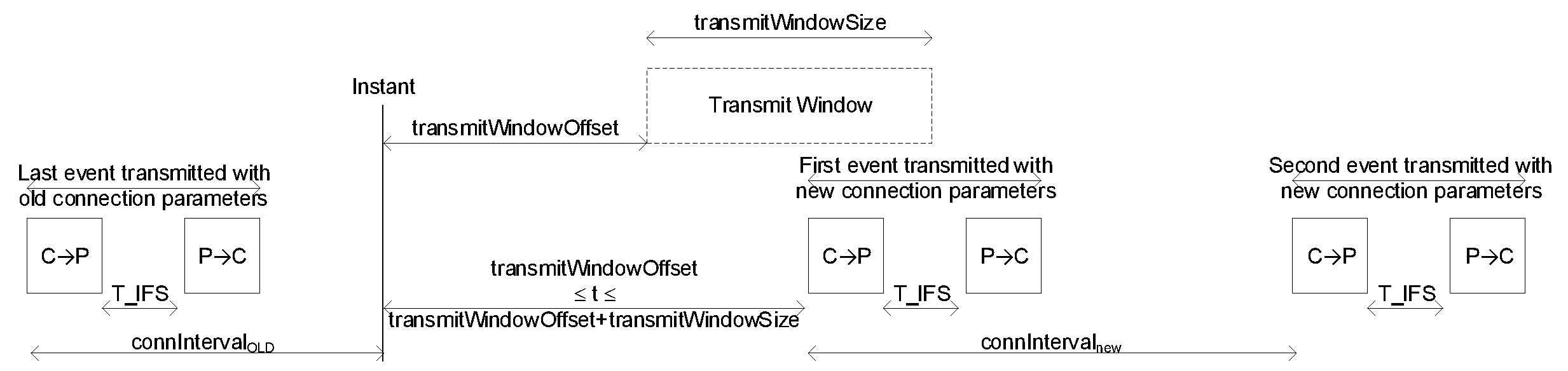
For example, the interval between the preceding connection event before the instant and the instant will be connIntervalOLD. The interval between the connection event after the instant and the following connection event will be connIntervalNEW.
The Central may adjust the anchor point when deciding the timing of the first packet transmitted with new connection parameters. A transmit window is used, as defined in Section 4.5.3. The transmit window starts at connIntervalOLD + transmitWindowOffset after the anchor point of the connection event before the instant. The transmitWindowOffset shall be a multiple of 1.25 ms in the range 0 ms to connIntervalNEW.The transmitWindowSize shall be a multiple of 1.25 ms in the range 1.25 ms to the lesser of 10 ms and (connIntervalNEW - 1.25 ms).
Note
Note: If the Peripheral first receives the LL_CONNECTION_UPDATE_IND PDU on the instant, it can immediately use that packet as the new anchor point and does not apply the transmitWindowOffset and transmitWindowSize.
The Central shall start to send the first packet within the transmit window as defined in Section 4.5.3. The Central’s first packet may extend beyond the transmit window.
The first packet sent after the instant by the Central determines the new anchor point for the connection events, and therefore the timings of all future connection events in this connection.
The instant occurs after connIntervalOLD and before transmitWindowOffset. All the normal connection event transmission rules specified in Section 4.5.1 shall apply.
At the start of the transmit window, the Link Layer shall reset TLLconnSupervision.
If the Link Layer of the Central transmits an LL_CONNECTION_UPDATE_IND PDU autonomously, for example without being requested to by the Host, the Latency and Timeout parameters shall not be changed and shall remain the same as in the last LL_CONNECTION_UPDATE_IND, CONNECT_IND, or AUX_CONNECT_REQ PDU. Any of the other parameters (transmitWindowSize, transmitWindowOffset, connInterval, Instant) may be changed within the restrictions given above.
Note
Note: Autonomous updates can be used to change the anchor points to allow the Central to change the scheduling of the connection due to other activities.
The Link Layer shall notify its Host if any of the three connection parameters have changed. If no connection parameters are changed, the Host would not be notified; this is called an anchor point move.
The procedure is complete when the instant has passed, and the new connection event parameters have been applied.
5.1.2. Channel Map Update procedure
The Central may update the Link Layer parameter for channel map (channelMap) by sending an LL_CHANNEL_MAP_IND PDU. The Peripheral shall not send this PDU. The Central’s Controller may update the channel map without being requested to by the Host.
Section 5.5 shall apply to the LL_CHANNEL_MAP_IND PDU.
The channel map used before the instant is known as channelMapOLD. The channel map contained in the LL_CHANNEL_MAP_IND PDU and used at the instant and after, is known as channelMapNEW.
When connEventCount is equal to the Instant field, the channelMapNEW shall be the current channelMap. The lastUnmappedChannel shall not be reset. If the unmappedChannel is an unused channel, then the channelMapNEW will be used when remapping. The only parameter that changes is the channelMap.
For example:
At connection set-up:
initial channelMapOLD: 0x1FFFFFFFFF (i.e., all channels enabled)
initial hopIncrement: 10 (decimal)
An LL_CHANNEL_MAP_IND PDU with the following parameters is then issued:
Instant: 100 (decimal). Assume that no connection event count wrap-around occurred since the start of the connection.
channelMapNEW: 0x1FFFFFF7FF (i.e. all channels enabled except channel 11)
Channels used:
connEventCount 99 --> data channel index 1 (channelMapOLD)
connEventCount 100 --> data channel index 12 (remapped from 11) (channelMapNEW)
connEventCount 101 --> data channel index 21 (channelMapNEW)
The procedure is complete when the instant has passed and the new channel map has been applied to the ACL. If the ACL has any associated CISes, the new channel map shall be used on each CIS starting with the next CIS event after the instant.
5.1.3. Encryption procedure
The Link Layer of the Central or Peripheral, upon request from the Host, may enable the encryption of packets using the encryption start procedure.
Once the connection is encrypted, the Link Layer may change the encryption key by using the encryption pause procedure, which encapsulates the encryption start procedure.
The Link Layer shall not initiate the encryption start procedure or pause procedure while there is an established CIS associated with the ACL.
5.1.3.1. Encryption Start procedure
To enable encryption, two parameters have to be exchanged, IV and SKD. Both are composed of two parts, a Central part and a Peripheral part, and exchanged in LL_ENC_REQ and LL_ENC_RSP PDUs. After these are exchanged, and the Peripheral's Host has notified its Link Layer of the Long Term Key to be used on this connection, encryption is started using a three way handshake, using LL_START_ENC_REQ and LL_START_ENC_RSP PDUs.
To start encryption, the Link Layer of the Central shall generate the Central’s part of the initialization vector (IV_C) and the Central’s part of the session key diversifier (SKD_C). IV_C shall be a 32 bit random number generated by the Link Layer of the Central. SKD_C shall be a 64 bit random number generated by the Link Layer of the Central. Both IV_C and SKD_C shall be generated using the requirements for random number generation defined in [Vol 2] Part H, Section 2.
Before transmitting the LL_ENC_REQ PDU, the Link Layer of the Central shall finalize the sending of the current Data Physical Channel PDU and may finalize the sending of additional Data Physical Channel PDUs queued in the Controller. After these Data Physical Channel PDUs are acknowledged, until this procedure is complete or specifies otherwise, the Link Layer of the Central shall only send Empty PDUs, LL_TERMINATE_IND PDUs, and PDUs required by this procedure.
The Link Layer of the Central shall then send an LL_ENC_REQ PDU; the Rand and EDIV fields are provided by the Host. After the Central receives the LL_ENC_RSP PDU in response, only PDUs required by this procedure are expected.
If encryption is not supported by the Link Layer of the Peripheral, the Link Layer of the Peripheral shall send an LL_REJECT_IND or LL_REJECT_EXT_IND PDU with the ErrorCode set to Unsupported Remote Feature (0x1A). The Link Layer of the Central receiving the LL_REJECT_IND or LL_REJECT_EXT_IND PDU shall notify the Host. The Link Layer of the Central may now send LL Data PDUs and LL Control PDUs; these packets will not be encrypted. This procedure is complete in the Central when the Central receives the LL_REJECT_IND or LL_REJECT_EXT_IND PDU from the Peripheral. The Central should acknowledge this PDU using an Empty PDU. The procedure is complete in the Peripheral when it sends the LL_REJECT_IND or LL_REJECT_EXT_IND PDU to the Central.
Otherwise, when the Link Layer of the Peripheral receives an LL_ENC_REQ PDU it shall generate the Peripheral’s part of the initialization vector (IV_P) and the Peripheral’s part of the session key diversifier (SKD_P). IV_P shall be a 32 bit random number generated by the Link Layer of the Peripheral. SKD_P shall be a 64 bit random number generated by the Link Layer of the Peripheral. Both IV_P and SKD_P shall be generated using the requirements for random number generation defined in [Vol 2] Part H, Section 2.
The Link Layer of the Peripheral shall finalize the sending of the current Data Physical Channel PDU and may finalize the sending of additional Data Physical Channel PDUs queued in the Controller. After these Data Physical Channel PDUs are acknowledged, until this procedure is complete or specifies otherwise, the Link Layer of the Peripheral shall only send Empty PDUs, LL_TERMINATE_IND PDUs, and PDUs required by this procedure.
If any of the Data Physical Channel PDUs sent by the Peripheral is an LL Control PDU, the Link Layers shall resume any outstanding procedure(s) after the Encryption Start procedure has completed.
The Link Layer of the Peripheral shall then send an LL_ENC_RSP PDU. The Link Layer of the Peripheral shall then notify the Host with the Rand and EDIV fields. After having sent the LL_ENC_RSP PDU, the Link Layer of the Peripheral can receive an LL_UNKNOWN_RSP PDU corresponding to an LL Control PDU sent by the Peripheral. The Peripheral should not disconnect the link in this case.
Each Link Layer shall combine the initialization vector parts and session key diversifier parts in the following manner:
SKD = SKD_P || SKD_C IV = IV_P || IV_C
The SKD_C is concatenated with the SKD_P. The least significant octet of SKD_C becomes the least significant octet of SKD. The most significant octet of SKD_P becomes the most significant octet of SKD.
The IV_C is concatenated with the IV_P. The least significant octet of IV_C becomes the least significant octet of IV. The most significant octet of IV_P becomes the most significant octet of IV.
The Long Term Key is always provided by the Host to the Link Layer in the Central and may be provided by the Host to the Link Layer in the Peripheral. One of the following three actions shall occur:
If this procedure is being performed after a Pause Encryption procedure, and the Peripheral's Host does not provide a Long Term Key, the Peripheral shall perform the ACL Termination procedure with the error code PIN or Key Missing (0x06).
If the Peripheral's Host does not provide a Long Term Key, either because the event to the Host was masked out or if the Host indicates that a key is not available, the Peripheral shall either send an LL_REJECT_IND with the ErrorCode set to PIN or Key Missing (0x06) or an LL_REJECT_EXT_IND PDU with the RejectOpcode set to "LL_ENC_REQ" and the ErrorCode set to PIN or Key Missing (0x06). Upon receiving an LL_REJECT_IND or LL_REJECT_EXT_IND PDU, the Central's Link Layer shall notify its Host. Both Link Layers may now send LL Data PDUs and LL Control PDUs; these packets will not be encrypted. This procedure is complete in the Central when the Central receives the LL_REJECT_IND or LL_REJECT_EXT_IND PDU from the Peripheral. The procedure is completed in the Peripheral when the acknowledgment has been received for the LL_REJECT_IND or LL_REJECT_EXT_IND PDU from the Central.
If the Peripheral's Host does provide a Long Term Key, both Link Layers shall calculate the session key using the encryption engine with LTK as the key and SKD as the plain text input. The session key shall be set to the output of the encryption engine.
After the Peripheral's Link Layer has calculated the session key, it shall send an LL_START_ENC_REQ PDU. This packet shall be sent unencrypted and the Link Layer shall be set up to receive an encrypted packet in response.
When the Link Layer of the Central receives an LL_START_ENC_REQ PDU it shall send an LL_START_ENC_RSP PDU. This PDU shall be sent encrypted and the Link Layer shall be set up to receive an encrypted packet in response.
When the Link Layer of the Peripheral receives an LL_START_ENC_RSP PDU it shall transmit an LL_START_ENC_RSP PDU. This packet shall be sent encrypted.
When the Link Layer of the Central receives the LL_START_ENC_RSP PDU, the connection is encrypted. The Link Layer may now send LL Data PDUs and LL Control PDUs; these PDUs will be encrypted.
The Link Layers shall notify the Hosts that the connection is encrypted.
The procedure is complete in the Central when the Central receives the LL_START_ENC_RSP PDU from the Peripheral. The procedure is complete in the Peripheral when the Peripheral receives the LL_START_ENC_RSP PDU from the Central.
If, at any time during the encryption start procedure after the Peripheral has received the LL_ENC_REQ PDU or the Central has received the LL_ENC_RSP PDU, the Link Layer of the Central or the Peripheral receives an unexpected Data Physical Channel PDU from the peer Link Layer, it shall immediately exit the Connection state, and shall transition to the Standby state. The Host shall be notified that the link has been disconnected with the error code Connection Terminated Due to MIC Failure (0x3D).
5.1.3.2. Encryption Pause procedure
To enable a new encryption key to be used without disconnecting the link, encryption is disabled and then enabled again. During the pause, data PDUs shall not be sent unencrypted to protect the data.
The Link Layer of the Central shall finalize the sending of the current Data Physical Channel PDU and may finalize the sending of additional Data Physical Channel PDUs queued in the Controller. After these Data Physical Channel PDUs are acknowledged, until this procedure is complete, the Link Layer of the Central shall only send Empty PDUs, LL_TERMINATE_IND PDUs, and PDUs required by this procedure.
The Link Layer of the Central shall then send an LL_PAUSE_ENC_REQ PDU. After the Central receives the LL_PAUSE_ENC_RSP PDU in response, only PDUs required by this procedure are expected.
When the Link Layer of the Peripheral receives an LL_PAUSE_ENC_REQ PDU it shall finalize the sending of the current Data Physical Channel PDU and may finalize the sending of additional Data Physical Channel PDUs queued in the Controller. After these Data Physical Channel PDUs are acknowledged, until this procedure is complete, the Link Layer of the Peripheral shall only send Empty PDUs, LL_TERMINATE_IND PDUs, and PDUs required by this procedure.
If any of the Data Physical Channel PDUs sent by the Peripheral is an LL Control PDU, the Link Layers shall resume any outstanding procedure(s) after the Encryption Start procedure has completed.
The Link Layer of the Peripheral shall then send an LL_PAUSE_ENC_RSP PDU. This packet shall be sent encrypted and Link Layer shall be set up to receive an unencrypted packet in response.
When the Link Layer of the Central receives an LL_PAUSE_ENC_RSP PDU it shall be set up to send and receive unencrypted. It shall then send an LL_PAUSE_ENC_RSP PDU to the Peripheral unencrypted.
When the Link Layer of the Peripheral receives an LL_PAUSE_ENC_RSP PDU it shall be set up to also send unencrypted.
The two Link Layers shall then carry out the steps of the encryption start procedure to re-enable encryption using a new session key. The encryption pause procedure is complete when this encapsulated encryption start procedure is complete.
If, at any time during the encryption pause procedure after the Peripheral has received the LL_PAUSE_ENC_REQ PDU or the Central has received the LL_PAUSE_ENC_RSP PDU, the Link Layer of the Central or the Peripheral receives an unexpected Data Physical Channel PDU from the peer Link Layer, it shall immediately exit the Connection state, and shall transition to the Standby state. The Host shall be notified that the link has been disconnected with the error code Connection Terminated Due to MIC Failure (0x3D).
5.1.4. Feature Exchange procedure
The Central or Peripheral may initiate the Feature Exchange procedure to exchange the Link Layer parameter for the current supported feature set (FeatureSet).
The FeatureSet information may be cached either during a connection or between connections. A Link Layer should not request this information on every connection if the information has been cached for this device. Cached information for a device from a previous connection is not authoritative and, therefore, an implementation must be able to accept the LL_UNKNOWN_RSP PDU if use of a feature is attempted that is not currently supported or used by the peer (see Section 2.4.2).
The FeatureSet_C parameter is the feature capabilities of the Link Layer of the Central with certain bits masked as specified in Section 4.6.
The FeatureSet_P parameter is the feature capabilities of the Link Layer of the Peripheral with certain bits masked as specified in Section 4.6.
The FeatureSet_USED parameter is one octet long and is the logical AND of the least significant octets of FeatureSet_C and FeatureSet_P.
5.1.4.1. Central-initiated Feature Exchange procedure
The Link Layer of the Central initiates this procedure by sending an LL_FEATURE_REQ PDU to the Peripheral. This may be done on request from the Host or autonomously. When the Link Layer of the Peripheral receives this, it shall respond by sending an LL_FEATURE_RSP PDU.
When the Link Layer of the Central sends an LL_FEATURE_REQ PDU, the FeatureSet field shall be set to FeatureSet_C.
When the Link Layer of the Peripheral sends an LL_FEATURE_RSP PDU, octet 0 of the FeatureSet field shall be set to FeatureSet_USED and the remaining octets shall be set to the corresponding octets of FeatureSet_P.
The procedure is complete when the Central receives the LL_FEATURE_RSP PDU from the Peripheral.
5.1.4.2. Peripheral-initiated Feature Exchange procedure
The Link Layer of the Peripheral initiates this procedure by sending an LL_PERIPHERAL_FEATURE_REQ PDU to the Central. This may be done on request from the Host or autonomously. When the Link Layer of the Central receives this, it shall respond by sending an LL_FEATURE_RSP PDU.
When the Link Layer of the Peripheral sends an LL_PERIPHERAL_FEATURE_REQ PDU, the FeatureSet field shall be set to FeatureSet_P.
When the Link Layer of the Central sends an LL_FEATURE_RSP PDU, octet 0 of the FeatureSet field shall be set to FeatureSet_USED and the remaining octets shall be set to the corresponding octets of FeatureSet_C.
If the LL_PERIPHERAL_FEATURE_REQ PDU was issued as a result of a Host-initiated read remote features procedure (see [Vol 4] Part E, Section 7.8.21) and the Central does not support this procedure, then the Host shall be notified that the read remote features procedure has completed with the ErrorCode set to Unsupported Remote Feature (0x1A).
The procedure is complete when the Peripheral receives the LL_FEATURE_RSP PDU from the Central.
5.1.5. Version Exchange procedure
The Central or Peripheral may initiate the Version Exchange procedure to exchange the Link Layer parameters for version information (companyID, subVerNum, linkLayerVer, as defined in Section 2.4.2.13) by sending an LL_VERSION_IND PDU. This procedure should be used when requested by the Host. This procedure may be initiated autonomously by the Link Layer.
The Link Layer shall only queue for transmission a maximum of one LL_VERSION_IND PDU during a connection.
If the Link Layer receives an LL_VERSION_IND PDU and has not already sent an LL_VERSION_IND then the Link Layer shall send an LL_VERSION_IND PDU to the peer device.
If the Link Layer receives an LL_VERSION_IND PDU and has already sent an LL_VERSION_IND PDU then the Link Layer shall not send another LL_VERSION_IND PDU to the peer device.
The procedure has completed when an LL_VERSION_IND PDU has been received from the peer device.
5.1.6. ACL Termination procedure
This procedure is used for voluntary termination of an ACL connection while in the Connection state. Voluntary termination occurs when the Host requests the Link Layer to terminate the connection. Either the Link Layer of the Central or Peripheral may initiate this procedure by sending an LL_TERMINATE_IND PDU. The ACL Termination procedure is not used in the event of the loss of the connection, for example after link supervision timeout or after a procedure timeout.
The Link Layer shall start a timer, Tterminate, when the LL_TERMINATE_IND PDU has been queued for transmission. The initiating Link Layer shall send LL_TERMINATE_IND PDUs until an acknowledgment is received or until the timer, Tterminate, expires, after which it shall exit the Connection State and transition to the Standby State. The initial value for Tterminate shall be set to the value of the connSupervisionTimeout.
When the Link Layer receives an LL_TERMINATE_IND PDU it shall send the acknowledgment, exit the Connection State and shall transition to the Standby State.
As soon as the Link Layer has received or queued for transmission an LL_TERMINATE_IND PDU all associated CISes shall be considered lost (see Section 4.5.12). The Link Layer shall not send separate LL_CIS_TERMINATE_IND PDUs when the Host requests termination.
The procedure has completed when the acknowledgment has been received or the timer, Tterminate, expires.
5.1.7. Connection Parameters Request procedure
The Central or Peripheral may initiate a Connection Parameters Request procedure to request the remote device to have the Link Layer parameters for the connection (connInterval, connPeripheralLatency and connSupervisionTimeout) updated any time after entering the Connection State. A device shall not initiate this procedure while a Connection Subrate Update procedure is in progress.
5.1.7.1. Issuing an LL_CONNECTION_PARAM_REQ PDU
The Connection Parameters Request procedure is initiated by issuing an LL_CONNECTION_PARAM_REQ PDU. The procedure may be initiated as a result of a Host initiated connection update procedure (see [Vol 4] Part E, Section 7.8.18) or autonomously by the Link Layer (that is, without being requested by the Host).
If the LL_CONNECTION_PARAM_REQ PDU was issued by the Link Layer of the Peripheral as a result of a Host initiated connection update procedure and the Central does not support this procedure, then the Host shall be notified that the connection update procedure has completed with the ErrorCode set to Unsupported Remote Feature (0x1A).
If the Link Layer initiates this procedure as a result of a Host initiated connection update procedure, then the Link Layer:
Should set the Interval_Min, Interval_Max, Timeout, and Latency fields to the values received from the Host.
Note: The Link Layer may modify the values of these fields, for example, because the values received from the Host would prevent the Link Layer from meeting commitments in another piconet.
May indicate the preferred periodicity by setting the PreferredPeriodicity field to a value other than zero, as described in Section 2.4.2.16.
May set the Offset0 to Offset5 fields to a value other than 0xFFFF as described in Section 2.4.2.16. If all of the Offset0 to Offset5 fields have been set to 0xFFFF, then the Link Layer has no preference about the offset to be used. If one or more of the Offset0 to Offset5 fields have been set to a value other than 0xFFFF, then:
The ReferenceConnEventCount field shall be set to indicate that at least one of the Offset0 to Offset5 fields is valid. If the ReferenceConnEventCount field is set, then it shall always be set to the connEventCount of a connection event that is less than 32767 connection events in the future from the first transmission of the PDU.
Note: Retransmissions of the PDU can result in the ReferenceConnEventCount to be up to 32767 events in the past when the PDU is successfully received by the remote device. See Section 5.1.7.3.2 for examples on how to set the ReferenceConnEventCount field.
If Interval_Min is not equal to Interval_Max then the PerferredPeriodicity field shall be set to a value other than zero. If Interval_Min is equal to Interval_Max then the PreferredPeriodicity field may be set to any value and shall be ignored by the recipient.
If the Link Layer initiates this procedure autonomously, then the Latency field shall be set to the current value of connPeripheralLatency and the Timeout field (in milliseconds) shall be set to the current value of connSupervisionTimeout. Any of the other fields (Interval_Min, Interval_Max, PreferredPeriodicity, ReferenceConnEventCount and Offset0 to Offset5) may be changed within the restrictions given above.
The Link Layer shall ensure that the parameters in the LL_CONNECTION_PARAM_REQ shall not cause supervision timeout. That is, the Link Layer shall ensure that the Timeout (in milliseconds) is greater than 2* Interval_Max * (Latency + 1).
5.1.7.2. Responding to LL_CONNECTION_PARAM_REQ and LL_CONNECTION_PARAM_RSP PDUs
Upon receiving an LL_CONNECTION_PARAM_REQ PDU:
The Peripheral shall respond with either an LL_CONNECTION_PARAM_RSP PDU or an LL_REJECT_EXT_IND PDU.
The Central shall respond with either an LL_CONNECTION_UPDATE_IND PDU or an LL_REJECT_EXT_IND PDU.
Upon receiving an LL_CONNECTION_PARAM_RSP PDU, the Central shall respond with either an LL_CONNECTION_UPDATE_IND PDU or an LL_REJECT_EXT_IND PDU.
The Central shall not send the LL_CONNECTION_PARAM_RSP PDU. The Peripheral shall send an LL_CONNECTION_PARAM_RSP PDU only in response to an LL_CONNECTION_PARAM_REQ PDU.
If the received LL_CONNECTION_PARAM_REQ PDU contains parameters that are not acceptable to the Link Layer, then the Link Layer of the device shall respond to the LL_CONNECTION_PARAM_REQ PDU with one of the following:
An LL_CONNECTION_PARAM_RSP PDU (if the Link Layer is the Peripheral of the connection) or an LL_CONNECTION_UPDATE_IND PDU (if the Link Layer is the Central of the connection), in each case containing alternative parameters.
An LL_REJECT_EXT_IND PDU with the ErrorCode set to Unsupported LL Parameter Value (0x20).
If the received LL_CONNECTION_PARAM_REQ PDU contains any fields that are out of valid range, then the Link Layer shall reject the LL_CONNECTION_PARAM_REQ PDU by issuing an LL_REJECT_EXT_IND PDU with the ErrorCode set to Invalid LL Parameters (0x1E).
If an LL_REJECT_EXT_IND PDU is sent during the Connection Parameters Request procedure, then the procedure is complete on a device when it receives the LL_REJECT_EXT_IND PDU, and is complete on the device that issued the LL_REJECT_EXT_IND PDU when it receives the acknowledgment for the LL_REJECT_EXT_IND PDU.
If the received LL_CONNECTION_PARAM_REQ PDU requests only a change in the anchor points of the LE connection, then the Link Layer shall not indicate this request to its Host.
If the received LL_CONNECTION_PARAM_REQ PDU requests a change to one or more of connInterval, connPeripheralLatency, and connSupervisionTimeout and if the values selected by the Link Layer are, respectively, within the range of the connInterval, the value of connPeripheralLatency and the value of connSupervisionTimeout provided by the local Host, then the Link Layer may choose to not indicate this request to its Host and proceed as if the Host has accepted the remote device’s request. Otherwise, if the event to the Host is not masked, then the Link Layer shall first indicate this request to its Host.
If the local Host has not provided the range of connInterval, the value of connPeripheralLatency and the value of connSupervisionTimeout to the Link Layer of the Peripheral, then the Link Layer of the Peripheral may indicate the received request to its Host if the event to the Host is not masked.
If the request is being indicated to the Host and the event to the Host is masked, then the Link Layer shall issue an LL_REJECT_EXT_IND PDU with the ErrorCode set to Unsupported Remote Feature (0x1A).
Note
Note: The device could have issued the LL_REJECT_EXT_IND PDU temporarily, and thus the initiating device may retry.
Note
Note: If the request is not being indicated to the Host, then the event mask is ignored.
If the Host is indicated of the request, it shall either accept or reject this request. If the Host rejects this request, then the device shall issue an LL_REJECT_EXT_IND PDU with the ErrorCode set to Unacceptable Connection Parameters (0x3B).
If the Host accepts this request or if the request was not indicated to the Host, then:
The Peripheral shall respond to an LL_CONNECTION_PARAM_REQ PDU with an LL_CONNECTION_PARAM_RSP PDU. The rules for filling in various fields of the LL_CONNECTION_PARAM_RSP PDU are the same as those for filling in various fields of the LL_CONNECTION_PARAM_REQ PDU, as described in Section 5.1.7.1. The rules for handling a received LL_CONNECTION_PARAM_RSP PDU on the Link Layer of the Central are identical to the rules for handling a received LL_CONNECTION_PARAM_REQ PDU that are described earlier in this section.
The Central shall respond to an LL_CONNECTION_PARAM_REQ PDU or an LL_CONNECTION_PARAM_RSP PDU with an LL_CONNECTION_UPDATE_IND PDU. The Central should try to choose a value of Interval that is a multiple of PreferredPeriodicity if the Peripheral has set the PreferredPeriodicity field of the LL_CONNECTION_PARAM_REQ or LL_CONNECTION_PARAM_RSP PDU. However, if the current PHY is the LE Coded PHY and the Controller supports the LE Data Packet Length Extension feature, then the new connection interval shall be at least connIntervalCodedMin μs.The Central should try to pick the values of WinOffset and WinSize such that the timing of the new connection events matches one of the Offset0 to Offset5 fields of the LL_CONNECTION_PARAM_REQ PDU or the LL_CONNECTION_PARAM_RSP PDU sent by the Peripheral. The Instant field of the LL_CONNECTION_UPDATE_IND PDU is set as described in Section 5.1.1.
Once the Central issues the LL_CONNECTION_UPDATE_IND PDU, the connection parameters get updated as described in Section 5.1.1.
If the connection interval is changed, the subrate factor shall be set to 1 and the continuation number shall be set to 0 at the instant of the procedure.
The procedure is complete when the instant has passed and the new connection event parameters have been applied.
5.1.7.3. Examples
5.1.7.3.1. Peripheral initiated anchor point move
The following example shows the Link Layer of the Peripheral requesting a change in the anchor points of the LE connection by 3.75 ms.
The Link Layer of the Peripheral issues an LL_CONNECTION_PARAM_REQ PDU with the following parameters:
Interval_Min: connInterval
Interval_Max: connInterval
Latency: connPeripheralLatency
Timeout: connSupervisionTimeout
PreferredPeriodicity: 0
ReferenceConnEventCount: <any value that is less than 32767 connection events in the future>
Offset0: 0x0003
Offset1: 0xFFFF
Offset2: 0xFFFF
Offset3: 0xFFFF
Offset4: 0xFFFF
Offset5: 0xFFFF
If the Link Layer of the Central accepts the Peripheral’s request, then it could respond with an LL_CONNECTION_UPDATE_IND PDU that contains any one of the following set of parameters. In all the sets, Interval is set to connInterval, Latency is set to connPeripheralLatency, Timeout is set to connSupervisionTimeout and Instant is set to any value that is less than 32767 connection events in the future.
Option 1: the first packet sent after the instant by the Central is inside the Transmit Window and 3.75 ms from the beginning of the Transmit Window.
3 ≤ WinSize ≤ 8
WinOffset: 0
Option 2: the first packet sent after the instant by the Central is inside the Transmit Window and 2.5 ms from the beginning of the Transmit Window.
2 ≤ WinSize ≤ 8
WinOffset: 1
Option 3: the first packet sent after the instant by the Central is inside the Transmit Window and 1.25 ms from the beginning of the Transmit Window.
1 ≤ WinSize ≤ 8
WinOffset: 2
Option 4: the first packet sent after the instant by the Central is inside the Transmit Window and 0 ms from the beginning of the Transmit Window.
1 ≤ WinSize ≤ 8
WinOffset: 3
5.1.7.3.2. ReferenceConnEventCount
Figure 5.2 and Figure 5.3 show examples of how the ReferenceConnEventCount and the Offset0 to Offset5 fields of the LL_CONNECTION_PARAM_REQ and the LL_CONNECTION_PARAM_RSP PDU can be utilized to indicate the possible position of the anchor points of the connection with the new connection parameters relative to the anchor points of the connection with the old connection parameters. This figure only shows Offset0 (and not Offset1 to Offset5) for simplicity. The figure also shows the Instant where the updated connection parameters are applied. The actual Instant occurs connIntervalOLD after the last connection event transmitted with the old connection parameters whereas the Instant field in the LL_CONNECTION_UPDATE_IND PDU is set to the connEventCount of the connection event transmitted with the old connection parameters.
The ReferenceConnEventCount is set to the connEventCount of the connection event on the old connection parameters such that the start of the very next connection event on the new connection parameters is Offset0 (in milliseconds) away from the start of the ReferenceConnEventCount connection event.
Figure 5.2 shows the case where the Instant is before the ReferenceConnEventCount. Figure 5.3 shows the case where the Instant is after the ReferenceConnEventCount. Imaginary connection events transmitted with the old connection parameters have been shown beyond the Instant and imaginary connection events transmitted with the new connection parameters have been shown before the Instant.
In Figure 5.2 and Figure 5.3, the time interval, Δt, between the Instant and the start of the first connection event transmitted with the new connection parameters can be calculated using the following equation:
Δt = (connIntervalNEW - ((Instant - ReferenceConnEventCount) * connIntervalOLD) mod connIntervalNEW + offset0) mod connIntervalNEW
Note
Note: The case where the ReferenceConnEventCount and Instant are on different sides of the eventCount wraparound point is not shown in the equations above.
Based on the calculated Δt, the WinOffset and WinSize fields in the LL_CONNECTION_UPDATE_IND PDU could be set accordingly. See Section 5.1.7.3.3 for an example.
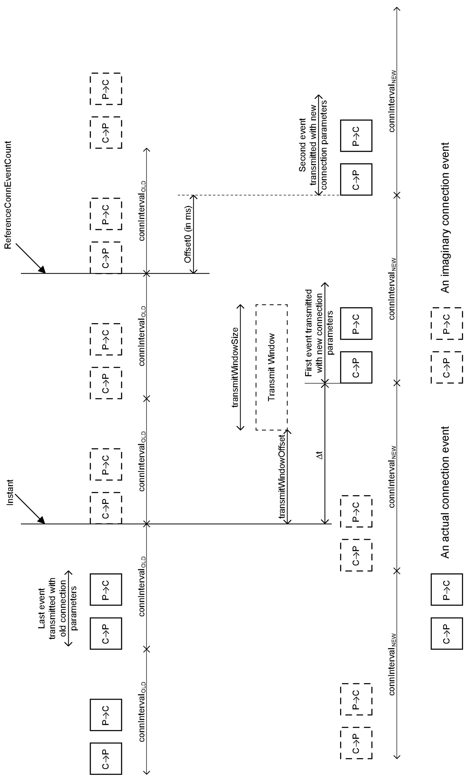
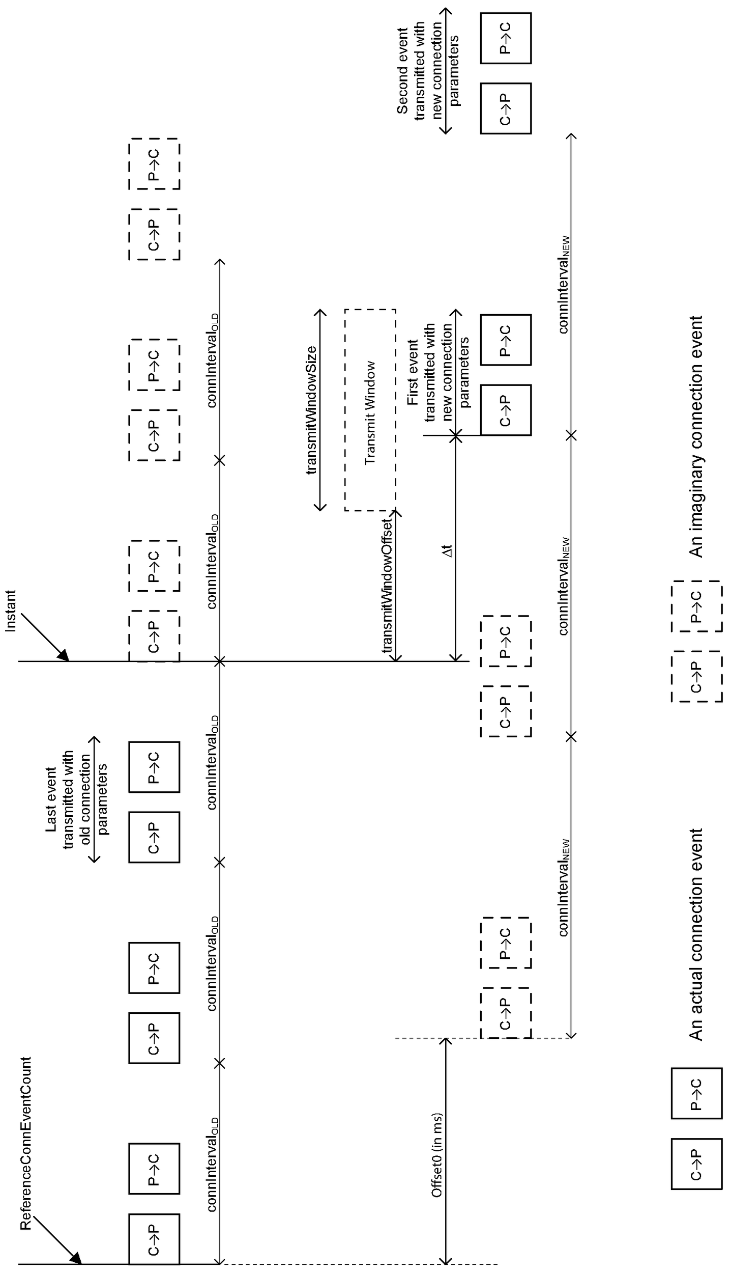
5.1.7.3.3. Peripheral initiated interval and anchor point move
The following example shows the Link Layer of the Peripheral requesting a change in both the connection interval (by indicating a PreferredPeriodicity such that PreferredPeriodicity and connIntervalOLD are not integer multiples of one another) and a change in anchor points of the LE connection by 3.75 ms with respect to the ReferenceConnEventCount.
In this example, connIntervalOLD is 0x0C (15 ms). The Link Layer of the Peripheral issues an LL_CONNECTION_PARAM_REQ PDU with the following parameters:
Interval_Min: 0x16
Interval_Max: 0x20
Latency: connPeripheralLatency
Timeout: connSupervisionTimeout
PreferredPeriodicity: 0x0A
ReferenceConnEventCount: 0x1F00
Offset0: 0x0003
Offset1: 0xFFFF
Offset2: 0xFFFF
Offset3: 0xFFFF
Offset4: 0xFFFF
Offset5: 0xFFFF
If the Link Layer of the Central accepts the Peripheral’s request, then it could respond with an LL_CONNECTION_UPDATE_IND PDU that contains any one of the following set of parameters. In all the sets, the new connection interval connIntervalNEW is set to 0x1E (37.5 ms), Latency is set to connPeripheralLatency, Timeout is set to connSupervisionTimeout and Instant is set to 0x1F06.
Δt, as described in Section 5.1.7.3.2 is calculated as 21 (26.25 ms).
The WinSize and WinOffset fields in the LL_CONNECTION_UPDATE_IND PDU can contain any of the following example set of parameters:
Option 1: the first packet sent after the instant by the Central is inside the Transmit Window and 3.75 ms from the beginning of the Transmit Window.
3 ≤ WinSize ≤ 8
WinOffset: 18
Option 2: the first packet sent after the instant by the Central is inside the Transmit Window and 2.5 ms from the beginning of the Transmit Window.
2 ≤ WinSize ≤ 8
WinOffset: 19
Option 3: the first packet sent after the instant by the Central is inside the Transmit Window and 1.25 ms from the beginning of the Transmit Window.
1 ≤ WinSize ≤ 8
WinOffset: 20
Option 4: the first packet sent after the instant by the Central is inside the Transmit Window and 0 ms from the beginning of the Transmit Window.
1 ≤ WinSize ≤ 8
WinOffset: 21
5.1.7.4. Packet transmit time restrictions
This section only applies if the current PHY is the LE Coded PHY and the Controller supports the LE Data Packet Length Extension feature.
After having sent or received an LL_CONNECTION_UPDATE_IND PDU that decreases the connection interval, and until the instant has been reached, the Link Layer shall not transmit a packet that would take longer than connEffectiveMaxTxTime microseconds (see Section 4.5.10) to transmit, calculated using the connection interval that will apply after the instant.
After a Peripheral sends an LL_CONNECTION_PARAM_REQ or LL_CONNECTION_PARAM_RSP PDU where Interval_Min indicates an interval less than the current connection interval, and until it receives an LL_CONNECTION_UPDATE_IND, LL_UNKNOWN_RSP, or LL_REJECT_EXT_IND PDU in response, its Link Layer shall not transmit a packet that would take longer than connEffectiveMaxTxTime microseconds to transmit, calculated using a connection interval corresponding to the Interval_Min value in the transmitted PDU.
If the value of connEffectiveMaxTxTime changes during the procedure, the above requirements apply to the value at the moment the LL Data PDU is queued for transmission.
Note
Note: The requirements of this section are in addition to, and do not override, those in Section 4.5.10.
Note
Note: If a Link Layer has any LL Data PDUs queued for transmission at the start of the procedure or queues any during the procedure, it may need to re-fragment those PDUs in order to meet these requirements.
5.1.8. LE Ping procedure
The Link Layer may use the LE Ping procedure, when supported, to verify the presence of the remote Link Layer, or to verify message integrity on the LE ACL logical transport, by forcing the remote device to send an LE ACL packet that contains a valid MIC.
This procedure may be used even if it is not supported by the peer’s Link Layer.
Either the Central or the Peripheral Link Layer may initiate this procedure at any time after entering the Connection state by sending an LL_PING_REQ PDU. The responding Link Layer responds with the LL_PING_RSP PDU.
The Link Layer supporting this feature shall send an LL_PING_REQ PDU when the remote device has not sent a packet containing a payload protected by a MIC within the authenticated payload timeout set by the Host ([Vol 4] Part E, Section 7.3.94). The Link Layer should send an LL_PING_REQ PDU in advance enough of the expiration of the authenticated payload timeout to allow the remote device reasonable time to respond with an LL_PING_RSP PDU before the timeout expires.
The procedure is completed when an LL_PING_RSP is received.
5.1.9. Data Length Update procedure
A Controller uses the Data Length Update procedure to transmit the latest values of the current maximum Receive LL Data PDU Payload length and PDU Time (connMaxRxOctets and connMaxRxTime) and the current maximum Transmit LL Data PDU Payload length and PDU Time (connMaxTxOctets and connMaxTxTime) to the peer device.
Both the Central and Peripheral may initiate this procedure by sending an LL_LENGTH_REQ PDU. This procedure shall be initiated by the Link Layer whenever any of these parameters change, whether requested by the Host or autonomously by the Link Layer. However, if this procedure has already been initiated by the remote Controller and the local Controller has not yet responded, it shall use the response to communicate the changes instead of initiating a new procedure.
If the Link Layer receives an LL_LENGTH_REQ, or an LL_LENGTH_RSP PDU that was a response to an LL_LENGTH_REQ PDU, then it shall update its connRemoteMaxTxOctets, connRemoteMaxRxOctets, connRemoteMaxTxTime, and connRemoteMaxRxTime parameters for the connection with the values in the PDU. It shall immediately start using the updated values for all new LL Data PDUs queued for transmission (including any response as specified in the next paragraph). The lengths of any LL Data PDUs that have already been queued for transmission or transmitted at least once shall not be changed.
Note
Note: Because Link Layer PDUs are not required to be processed in real time, it is possible for the local Controller to have queued but not yet transmitted an LL_LENGTH_REQ PDU when it receives an LL_LENGTH_REQ PDU from the peer device. In this situation each device responds as normal; the resulting collision is harmless.
Upon receiving an LL_LENGTH_REQ PDU, the Link Layer shall respond with an LL_LENGTH_RSP PDU containing its own connMaxTxOctets, connMaxRxOctets, connMaxTxTime, and connMaxRxTime values for the connection (which it may have updated based on the values received, for example so as to allow the remote device to transmit longer packets).
If the peer device does not support the LE Coded PHY feature, then the MaxRxTime and MaxTxTime fields in the LL_LENGTH_REQ and LL_LENGTH_RSP PDUs shall be set to a value less than or equal to 2128 microseconds.
The procedure is completed when the initiating Controller receives an LL_LENGTH_RSP PDU.
5.1.10. PHY Update procedure
The Central or Peripheral may use the PHY Update procedure, when supported, to change the transmit or receive PHYs, or both, of an ACL connection; it does not affect the transmit or receive PHY of any associated Connected Isochronous Streams. The procedure may be initiated either on a request by the Host or autonomously by the Link Layer. Link Layer PHY preferences may change during a connection or between connections and, therefore, they should not be cached by the peer device.
When this procedure is initiated by the Central, it sends an LL_PHY_REQ PDU. The Peripheral responds with an LL_PHY_RSP PDU. The Central then responds to this with an LL_PHY_UPDATE_IND PDU.
When this procedure is initiated by the Peripheral, it sends an LL_PHY_REQ PDU. The Central responds with an LL_PHY_UPDATE_IND PDU.
The TX_PHYS and RX_PHYS fields of the LL_PHY_REQ and LL_PHY_RSP PDUs shall be used to indicate the PHYs that the sending Link Layer prefers to use. These shall represent PHYs that the sending Link Layer supports. If the sender wants a symmetric connection (one where the two PHYs are the same) it should make both fields the same, only specifying a single PHY.
The PHY_C_TO_P and PHY_P_TO_C fields of the LL_PHY_UPDATE_IND PDU shall indicate the PHYs that shall be used after the instant.
If the Central initiated the procedure, it shall determine the PHY to use in each direction based on the contents of the LL_PHY_REQ and LL_PHY_RSP PDUs using the following rules:
the PHY_C_TO_P field of the LL_PHY_UPDATE_IND PDU shall be determined from the Central's TX_PHYS field and the Peripheral's RX_PHYS field;
the PHY_P_TO_C field of the LL_PHY_UPDATE_IND PDU shall be determined from the Central's RX_PHYS field and the Peripheral's TX_PHYS field.
In each of those cases the following rules apply:
if, for at least one PHY, the corresponding bit is set to 1 in both the TX_PHYS and RX_PHYS fields, the Central shall select any one of those PHYs for that direction;
if there is no PHY for which the corresponding bit is set to 1 in both the TX_PHYS and RX_PHYS fields, the Central shall not change the PHY for that direction.
If the Peripheral initiated the procedure, the Central shall determine the PHY to use in each direction based on the contents of the LL_PHY_REQ PDU sent by the Peripheral using the following rules:
the PHY_C_TO_P field of the LL_PHY_UPDATE_IND PDU shall be determined from the RX_PHYS field of the Peripheral’s PDU;
the PHY_P_TO_C field of the LL_PHY_UPDATE_IND PDU shall be determined from the TX_PHYS field of the Peripheral’s PDU.
In each of those cases the following rules apply:
if, for at least one PHY, the PHY is one that the Central prefers to use and the corresponding bit is set to 1 in the relevant field of the Peripheral’s PDU, the Central shall select any one of those PHYs for that direction;
if there is no PHY which the Central prefers to use and for which the corresponding bit is set to 1 in the relevant field of the Peripheral’s PDU, the Central shall not change the PHY for that direction.
The remainder of this section shall apply irrespective of which device initiated the procedure.
Irrespective of the above rules, the Central may leave both directions unchanged. If the Peripheral specified a single PHY in both the TX_PHYS and RX_PHYS fields and both fields are the same, the Central shall either select the PHY specified by the Peripheral for both directions or shall leave both directions unchanged.
If either PHY will change, Section 5.5 shall apply to the LL_PHY_UPDATE_IND PDU. Both devices shall use the new PHYs starting at the instant.
The procedure has completed when:
an LL_REJECT_EXT_IND PDU has been sent or received;
an LL_PHY_UPDATE_IND PDU indicating that neither PHY will change has been sent or received; or
the Central sends an LL_PHY_UPDATE_IND PDU indicating that at least one PHY will change and the instant has been reached. In this case, the procedure response timeout shall be stopped on the Central when it sends that PDU and on the Peripheral when it receives that PDU.
If the Peripheral receives an LL_PHY_UPDATE_IND where either PHY field specifies a PHY that the Peripheral does not support, has a bit set that is reserved for future use, or has more than one bit set, the Peripheral shall not change the PHY in that direction.
The Controller shall notify the Host of the PHYs now in effect when the PHY Update procedure completes if either it has resulted in a change of one or both PHYs or if the procedure was initiated by a request from the Host. Otherwise, it shall not notify the Host that the procedure took place.
The Link Layer can reject a proposed change to either PHY (by not setting the corresponding bit in its response) because, for example, a PHY with a lower bit rate could not be scheduled among other activities or because the requested PHY does not support Constant Tone Extensions. Such a rejection could, however, result in link loss if the change was requested to improve reliability.
5.1.10.1. Packet transmit restrictions
For each row of Table 5.1, on the Link Layer(s) in the role(s) listed in the first column and during the period starting with the event described in the second column and ending with the event described in the third column, the Link Layer shall not transmit either of:
any packet that would take longer than connEffectiveMaxTxTime microseconds (see Section 4.5.10) to transmit on any relevant PHY
any packet with a Constant Tone Extension if any relevant PHY does not allow Constant Tone Extensions
where a “relevant PHY” is a PHY described in the fourth column.
Role(s) | Starting event | Ending event | Relevant PHY(s) |
|---|---|---|---|
Either | the Link Layer sends or receives an LL_PHY_UPDATE_IND PDU that changes either PHY | the instant | the PHY that will apply after the instant |
Peripheral | the Link Layer sends an LL_PHY_REQ PDU | the Link Layer receives an LL_PHY_UPDATE_IND, LL_UNKNOWN_RSP, or LL_REJECT_EXT_IND PDU in response | any PHY that appears in the TX_PHYS field of that LL_PHY_REQ PDU |
Peripheral | the Link Layer sends an LL_PHY_RSP PDU | the Link Layer receives the LL_PHY_UPDATE_IND PDU in response | any PHY that appears in both the TX_PHYS field of the Peripheral’s LL_PHY_RSP PDU and the RX_PHYS field of the Central's LL_PHY_REQ PDU |
If the value of connEffectiveMaxTxTime changes during the procedure (for example, if the Data Length Update procedure is performed before the Instant is reached), the above requirements apply to the value at the moment the LL Data PDU is queued for transmission.
Note
Note: The requirements of this section are in addition to, and do not override, those in Section 4.5.10.
If a Link Layer has any LL Data PDUs queued for transmission at the start of the procedure or queues any during the procedure, it might need to re-fragment those PDUs in order to obey the requirements in this section. This can be necessary if, for example, the transmit PHY changes from the LE 2M PHY to the LE 1M PHY and the value of connEffectiveMaxTxTime does not increase enough to compensate for the lower bit rate.If a Link Layer has any packets with a Constant Tone Extension queued for transmission at the start of the procedure or queues any during the procedure, it might need to delay them, cancel them, or (if the packets contain an LL_CTE_RSP PDU) replace them by LL_REJECT_EXT_IND PDUs in order to obey the requirements in this section.
5.1.11. Minimum Number Of Used Channels procedure
A Peripheral's Controller may use the Minimum Number Of Used Channels procedure to request that the peer device uses a minimum number of channels on a given PHY.
The Peripheral initiates this procedure by sending an LL_MIN_USED_CHANNELS_IND PDU. The Central shall not send this PDU.
If the Link Layer receives an LL_MIN_USED_CHANNELS_IND PDU, it should ensure that, whenever the Peripheral-to-Central PHY is one of those specified, the connection uses at least the number of channels given in the MinUsedChannels field of the PDU.
The procedure has completed when the Link Layer acknowledgment of the LL_MIN_USED_CHANNELS_IND PDU is sent or received.
If the channel map does not include the minimum number of channels the Peripheral requires for regulatory compliance, the Peripheral must take steps to remain regulatory compliant, which can include disconnecting the link or reducing the output power.
5.1.12. Constant Tone Extension Request procedure
The Central or Peripheral may use the Constant Tone Extension Request procedure, when supported, to request the remote Link Layer to send a packet containing an LL_CTE_RSP PDU and a Constant Tone Extension (see Section 2.5.3).
Either the Central or the Peripheral Link Layer initiates this procedure by sending an LL_CTE_REQ PDU.
If:
Constant Tone Extension responses are enabled;
the current transmitter PHY is one that allows Constant Tone Extensions;
Section 5.1.10.1 would not prohibit the response from being transmitted;
the length of Constant Tone Extension requested in the LL_CTE_REQ PDU is not greater than the maximum length the responding device supports; and
the responding device is currently configured to respond with the type of Constant Tone Extension requested in the LL_CTE_REQ PDU;
then the remote Link Layer shall respond with an LL_CTE_RSP PDU that includes a Constant Tone Extension of the requested type and whose length is greater than or equal to that requested. Otherwise the remote Link Layer shall respond with an LL_REJECT_EXT_IND PDU. If Constant Tone Extension responses are disabled or the Link Layer is not currently configured to respond with the type and length of the requested Constant Tone Extension, the ErrorCode shall be set to Unsupported LMP Parameter Value/Unsupported LL Parameter Value (0x20). If Constant Tone Extensions are not allowed on the current transmitter PHY, the ErrorCode shall be set to Invalid LMP Parameters/Invalid LL Parameters (0x1E). If Section 5.1.10.1 would prohibit the response from being transmitted, the ErrorCode shall be set to Different Transaction Collision (0x2A).
IQ sampling (see [Vol 6] Part B, Section 2.5.4) shall be performed while receiving the Constant Tone Extension of the LL_CTE_RSP PDU and the sampling results shall be reported to the Host.
The procedure is completed when either an LL_CTE_RSP PDU has been sent or received or an LL_REJECT_EXT_IND PDU is sent or received with the RejectOpcode set to LL_CTE_REQ.
5.1.13. Periodic Advertising Sync Transfer procedure
A Controller may use the Periodic Advertising Sync Transfer procedure to transfer, to a connected peer device, the synchronization information necessary to synchronize to a periodic advertising train (see Section 4.4.3.4).
Either the Central or the Peripheral Link Layer initiates this procedure by sending an LL_PERIODIC_SYNC_IND PDU or an LL_PERIODIC_SYNC_WR_IND PDU. The PDU used is determined by the type of the periodic advertising used. For PAwR, the LL_PERIODIC_SYNC_WR_IND PDU shall be used, otherwise the LL_PERIODIC_SYNC_IND PDU shall be used. If the LL_PERIODIC_SYNC_WR_IND PDU is used, then the RspAA shall be set to an Access Address value as specified in Section 2.1.2.
If the Host has enabled receipt of transfers and the Link Layer receives an LL_PERIODIC_SYNC_IND PDU or an LL_PERIODIC_SYNC_WR_IND PDU that describes a periodic advertising train that the Link Layer is neither already synchronized with nor in the process of synchronizing with, the Link Layer shall synchronize with the described periodic advertising train and then notify the Host; it shall also notify the Host if synchronization fails. However, if the PHY field of the LL_PERIODIC_SYNC_IND PDU or the LL_PERIODIC_SYNC_WR_IND PDU has no bits or more than one bit set, or the bit set corresponds to a PHY that the recipient does not support or is reserved for future use, the recipient shall ignore the PDU.
The procedure has completed when an LL_PERIODIC_SYNC_IND PDU or an LL_PERIODIC_SYNC_WR_IND PDU has been sent or received.
5.1.13.1. Timing considerations
This section explains the issues in handling the relative drifts of three separate device clocks and does not create any requirements. This section does not apply when devices A and B are the same because there is then no clock drift between the two.
In general there are three devices involved in the Periodic Advertising Sync Transfer procedure: the periodic advertiser A, the initiating device B, and the receiving device C. Each of these can have a different sleep clock accuracy. Therefore device C needs to carry out various steps to determine the timing and required receive window for synchronizing to the periodic advertising.
In the following formulae and in Figure 5.4:
PEa is the value of paEventCounter stored in the SyncInfo within the LL_PERIODIC_SYNC_IND PDU.
PEb is the value of paEventCounter for a recent AUX_SYNC_IND PDU that device B has received; this value is stored in the lastPaEventCounter field of the LL_PERIODIC_SYNC_IND PDU.
PEc is the value of paEventCounter for the AUX_SYNC_IND PDU that device C is attempting to receive.
Note
Note: PEc can be before, after, or the same as PEa.
PAI is the periodic advertising interval as represented by the Interval field of the SyncInfo within the LL_PERIODIC_SYNC_IND PDU.
CEs is the value of connEventCounter for the connection event when devices B and C synchronized their anchor points and that device B used to determine the contents of the LL_PERIODIC_SYNC_IND PDU; this value is stored in the syncConnEventCount field of the PDU.
CEt is the value of connEventCounter for the connection event when the LL_PERIODIC_SYNC_IND PDU was (re)transmitted by device B and received by device C.
CEref is the value of connEventCount in the LL_PERIODIC_SYNC_IND PDU.
CEc is a connection event before the AUX_SYNC_IND PDU that device C is attempting to receive.
CI is the connection interval for the connection between devices B and C.
Offset is the value represented by the syncPacketWindowOffset value within the LL_PERIODIC_SYNC_IND PDU.
Target is the time from the anchor point of connection event CEc to the AUX_SYNC_IND PDU that device C is attempting to receive.
CAa, CAb, and CAc are the clock accuracies of devices A, B, and C respectively. CAa is stored in the SCA field of the SyncInfo within the LL_PERIODIC_SYNC_IND PDU and CAb is stored in the SCA field of the LL_PERIODIC_SYNC_IND PDU.
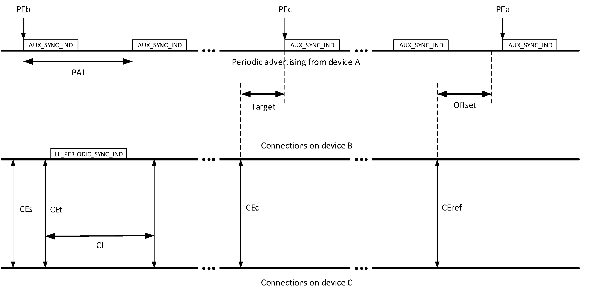
If all three devices had a perfectly accurate clock, then:
Tnominal ≤ Target < Tnominal + U
where:
Tnominal = (CEref – CEc) × CI + Offset – (PEa – PEc) × PAI U = 30 µs or 300 µs depending on the value of the Offset Units field of the SyncInfo
Because of clock drift and jitter, this becomes:
Tnominal – D – 16 µs ≤ Target < Tnominal + U + D + 16 µs
where:
D = (Da + Db) x (1 + CAa + CAb + CAc)
Da represents the drift of the periodic advertising and Db the drift of B's clock between CEs and PEb:
Da = |PEc – PEb| × PAI × (CAa + CAc) Db = |CEt – CEs| × CI × (CAb + CAc)
D should be rounded to the next whole microsecond above.
These values are derived from the assumption that device B will have calculated Offset without making any allowance for drift in its own clock. So if PEb occurred at time TPEb and CEs at time TCEs, both according to its own clock, device B will have chosen values for PEa and CEref and then calculated:
Offset = (TPEb + (PEa – PEb) × PAI) – (TCEs + (CEref – CEs) × CI)
When device C calculates Tnominal, it again does so without allowing for drift. So, by substituting the above expression for Offset in that for Tnominal above, we find that:
- =
(CEref – CEc) × CI + (TPEb + (PEa – PEb) × PAI) – (TCEs + (CEref – CEs) × CI) – (PEa – PEc) × PAI
- =
TPEb + (PEa – PEb) × PAI – (PEa – PEc) × PAI – TCEs – (CEref – CEs) × CI + (CEref – CEc) × CI
- =
TPEb + (PEc – PEb) × PAI – TCEs – (CEc – CEs) × CI
- =
(PEc – PEb) × PAI + (TPEb – TCEs) – (CEc – CEs) × CI
Each of these three terms is based on a different clock:
The first term depends on PAI, which is measured using device A's clock. However, since device C is calculating Tnominal, device C’s clock must be allowed for as well. The drift in this term is represented by Da.
The expression (TPEb – TCEs) is the change in B's clock between the two events and so is measured using that clock; again, it is necessary to allow for device C’s clock as well. The drift in this term is represented by Db; the term in parentheses in the expression for Db is an upper bound for the difference.
The last term is on device C's clock and therefore does not require any adjustment.
The second factor in the formula for D allows for second-order effects: if the relevant periodic events are 12 seconds apart, a 500 ppm drift will result in a 20 × 0.00052 = 3 µs residual error in the required window.
If device C allows for clock drift when making these calculations, it may be able to reduce the window it uses accordingly. If device B allows for clock drift (e.g. by measuring the drift in the periodic advertising timing), the actual drift will be less than that calculated above but device C will not be aware of this. A more detailed analysis based on the exact techniques used in the implementation may allow device C to compute a narrower window.
5.1.14. Sleep Clock Accuracy Update procedure
The Link Layer of the Central or Peripheral may inform its peer of a change to its sleep clock accuracy (centralSCA or peripheralSCA – see Section 4.2.2), or may query the peer’s sleep clock accuracy, by sending an LL_CLOCK_ACCURACY_REQ PDU. The procedure may be initiated either on a request by the Host or autonomously by the Link Layer. A device should not initiate this procedure more than once per second.
Where the Link Layer will specify a more accurate clock than that currently in use, it shall switch to that clock before initiating or responding to this procedure.
When the Link Layer receives an LL_CLOCK_ACCURACY_REQ PDU, it shall send an LL_CLOCK_ACCURACY_RSP PDU in reply. The sleep clock accuracy specified in the reply shall not be less than the value in use when the request was received on the Link Layer sending that reply.
Note
Note: The Link Layer can delay its response in order to make any necessary internal adjustments to the accuracy change, but not for so long as to trigger a timeout. If the responding device wants to change to a less accurate clock, then, as this section requires, it must do so by initiating this procedure separately.
The procedure is complete when the LL_CLOCK_ACCURACY_RSP is sent or received. Where the initiating Link Layer has specified a less accurate clock than that currently in use, it shall not switch to that clock until it has received the LL_CLOCK_ACCURACY_RSP PDU in reply. If it receives an LL_UNKNOWN_RSP PDU, it shall maintain at least the accuracy specified in the CONNECT_IND or AUX_CONNECT_REQ PDU that created the connection.
5.1.15. Connected Isochronous Stream Creation procedure
The Central Link Layer may use the Connected Isochronous Stream Creation procedure to create a CIS between a Central and a Peripheral. The Central Link Layer initiates this procedure by sending an LL_CIS_REQ PDU. The Peripheral Link Layer shall not initiate this procedure. The Central’s Link Layer shall only create a CIS when requested by the Host, only using a CIS_ID that the Host has already stored a configuration for in this CIG, and not using a CIS_ID that corresponds to an existing CIS in the CIG (see Section 4.5.14.3). The Central shall not initiate this procedure if the Connected Isochronous Stream (Host Support) feature bit is not set in its Controller.
When the Peripheral’s Link Layer receives the LL_CIS_REQ PDU, it shall either reject the proposed CIS immediately or notify the Host. In the latter case, the Host requests the Link Layer to either accept or reject the proposed CIS. If the Connected Isochronous Stream (Host Support) feature bit is not set in the local Link Layer, then the Peripheral shall reject the proposed CIS with the error code Unsupported Remote Feature (0x1A). If either PHY field of the LL_CIS_REQ PDU has no bits or more than one bit set, or if the bit set corresponds to a PHY that the recipient does not support or is reserved for future use, the Peripheral shall reject the proposed CIS. If the Peripheral rejects the proposed CIS, it shall send an LL_REJECT_EXT_IND PDU with the appropriate reason code. If it accepts the CIS, it shall send an LL_CIS_RSP PDU.
When the Central’s Link Layer receives an LL_CIS_RSP PDU, it shall either create the CIS by replying with an LL_CIS_IND PDU or shall cancel it by replying with an LL_REJECT_EXT_IND PDU with the appropriate reason code. The Central shall not cancel the CIS if the proposed timings are within those specified in the LL_CIS_REQ PDU unless the Host requested that the CIS be terminated.
When the Central sends and the Peripheral receives the LL_CIS_IND PDU, both devices shall stop the procedure response timeout timer, create the CIS, and start transmitting and receiving CIS PDUs. The first anchor point of the CIS, with cisEventCounter equal to zero, shall be at the moment specified in the LL_CIS_IND PDU. The CIS is considered established by each Link Layer when that Link Layer has received a CIS PDU from the peer that is part of the CIS.
The Central’s Link Layer shall calculate CIG_Sync_Delay and CIS_Sync_Delay for each CIS and send them to the Peripheral in the LL_CIS_IND PDU.
If either Link Layer sends or receives an LL_REJECT_EXT_IND PDU, it shall terminate the procedure immediately and not create the CIS. The CIS configuration nevertheless remains stored within the CIG and the corresponding CIS can be created later. The procedure is completed on each Link Layer when the CIS is established or when an LL_REJECT_EXT_IND PDU has been sent or received. Each Link Layer shall notify its Host when the procedure is completed.
The values of the CIS_Offset_Min, CIS_Offset_Max, and connEventCount fields of the LL_CIS_REQ and LL_CIS_RSP PDUs each specify a window for the CIS anchor point. The window specified by the LL_CIS_RSP PDU shall lie entirely within a window equivalent to that specified by the LL_CIS_REQ PDU. The first CIS anchor point shall lie within a window equivalent to that specified by the LL_CIS_RSP PDU. For this purpose, two windows are equivalent if they have the same width and the difference between their start times is an integer multiple of ISO_Interval for the CIS. The edges of each window are part of the window so, for example, the two windows can be identical.
Section 5.5 shall apply to the LL_CIS_IND PDU as if the connEventCount field was an Instant.
The Link Layer should schedule the CIS so that the CIS events do not overlap with the connection events on the associated ACL.
5.1.16. Connected Isochronous Stream Termination procedure
The Central or Peripheral may use this procedure for voluntary termination of a CIS while in the Connection state. Voluntary termination occurs when the Host requests the Link Layer to terminate the connection. The Link Layer initiates this procedure by sending an LL_CIS_TERMINATE_IND PDU.
The Link Layer shall not transmit or receive on the CIS after it has received or queued for transmission the LL_CIS_TERMINATE_IND PDU.
The procedure has completed when the Link Layer acknowledgment has been sent or received.
Note
Note: Terminating a CIS does not affect the associated ACL.
5.1.17. Power Control Request procedure
The Link Layer of the Central or Peripheral may use the Power Control Request procedure, when supported, to request a remote Controller to adjust its transmit power level on a specified PHY by a given amount. Power Control requests carried over an LE-ACL logical link only affect the power level used on that link and any associated physical link(s) such as isochronous physical links; they do not affect the power level used on the physical links to other connected and unconnected devices.
The Link Layer initiates this procedure by sending an LL_POWER_CONTROL_REQ PDU.
The Link Layer can query the current transmit power level and acceptable power reduction of the remote Controller by sending an LL_POWER_CONTROL_REQ PDU with Delta set to zero.
The responding Link Layer shall make the requested change to its transmit power level unless that would take it above the maximum or below the minimum supported power levels or unless it is not currently managing power levels on the requested PHY. If the requested change would take it above the maximum, it shall change the power level to the maximum supported. Otherwise, if it is unable to make exactly the requested change, it shall change the power level to the lowest available level greater than the requested level. In any case, it shall then reply with an LL_POWER_CONTROL_RSP PDU whose contents indicate the actual change made, if any, or that it is not managing the power level for the requested PHY (by setting the power level to 126).
Note
Note: A request to make a small decrease in the power level can result in the power level not changing.
Note
Note: A request with delta equal to zero on a PHY that is not an active PHY can indicate that the sender is about to make that PHY an active PHY.
If the Link Layer has sent an LL_POWER_CONTROL_REQ PDU and not yet received a response, or has an LL_POWER_CONTROL_REQ PDU queued for transmission, and then receives an LL_POWER_CONTROL_REQ PDU from the same peer device, it shall set the APR field to 0xFF in its response to that PDU. A responding Link Layer may also set the APR field to 0xFF when it is not managing the power level of the requested PHY, if it does not have a valid value to report, or if it does not support this field. Otherwise the responding Link Layer shall set the APR field as described in Section 5.1.17.1.
The new power level for the PHY shall take effect before the response is sent.
Note
Note: The Link Layer may request the remote Link Layer to change the preferred transmit power level for a different PHY, for example before initiating a PHY Update procedure or creating an associated CIS on a PHY different from the one used for the ACL. To do this, it may query the remote Link Layer for the transmit power level that it would use for that PHY and then request a change to the transmit power level.
If the PHY in the LL_POWER_CONTROL_REQ PDU is not supported by the remote Link Layer in its transmit direction or the PHY field contains no set bits, more than one set bit, or a bit set that is reserved for future use, the remote Link Layer shall respond with an LL_REJECT_EXT_IND PDU with the ErrorCode set to Unsupported LMP Parameter Value/Unsupported LL Parameter Value (0x20).
If the TxPower in the LL_POWER_CONTROL_REQ PDU is set to 126, the remote Link Layer shall respond with an LL_REJECT_EXT_IND_PDU with the ErrorCode set to Invalid LL Parameters (0x1E).
The procedure has completed when either an LL_POWER_CONTROL_RSP PDU has been sent or received or an LL_REJECT_EXT_IND PDU has been sent or received with the RejectOpcode field set to LL_POWER_CONTROL_REQ.
5.1.17.1. Acceptable power reduction
A radio receiver may have a “golden range” of RSSI that it prefers the incoming signal to remain within. A device with such a receiver can use the Power Control Request procedure to bring the current RSSI (RSSIcurr) of the incoming signal to a preferred value within its golden range. Nevertheless, it may still be able to receive the signal at a level that is equal to or above a minimum acceptable RSSI (RSSImin) that is lower than the current RSSI. A device can use the Power Control Request procedure to check whether its peer can accept such a reduction in power and, if so, adjust its transmit power based on the response.
When a device sends an LL_POWER_CONTROL_RSP PDU, it should set the APR field to the value given by the following equation:
When a device reports an APR value to the peer device other than zero or 0xFF, it should wait at least two connection intervals to see if the peer device has made use of it to change its local transmit power before initiating a new Power Control Request procedure to request a remote transmit power level change. A device can determine if the peer device has changed its transmit power by sending an LL_POWER_CONTROL_REQ PDU with Delta set to zero, by looking for changes in the RSSI of incoming packets, or by the receipt of an LL_POWER_CHANGE_IND PDU.
When a device receives an APR value from the peer device other than 0xFF, the time period for which that value is considered to remain valid is implementation-specific; for example, the Link Layer can examine changes in received RSSI and remote transmit power level since the APR value was received. When a device receives an APR value other than 0xFF from the peer device, it shall not reduce its power level more than the value specified. When the device receives an APR value of 0xFF, it may choose to ignore any previous APR values.
5.1.18. Power Change Indication procedure
The Link Layer uses the Power Change Indication procedure, when supported, to notify the remote Link Layer of transmit power changes.
After the peer has sent at least one LL_POWER_CONTROL_REQ PDU, a Link Layer shall send an autonomous notification consisting of an LL_POWER_CHANGE_IND PDU each time that any of the following happens:
It changes the power level autonomously on any PHY that it is managing power levels for.
It changes the maximum power level on its current transmit PHY to the current power level.
It starts managing the power level for a PHY.
It stops managing the power level for a PHY.
A Link Layer shall not send the LL_POWER_CHANGE_IND PDU in any other circumstance. If two or more of the above situations occur for the same PHY at the same time or within a connection interval, it may combine the reports into a single LL_POWER_CHANGE_IND PDU. A Link Layer should not perform autonomous power level updates more than once per second to avoid sending too many LL_POWER_CHANGE_IND PDUs to the remote device.
If the notification is for the current ACL PHY, it shall be sent at the power level specified in the notification.
The procedure has completed when the LL_POWER_CHANGE_IND PDU has been sent or received.
The recipient shall ignore all bits of the PHY field of the LL_POWER_CHANGE_IND PDU that correspond to PHYs that it does not support or are reserved for future use. If the PHY field has no bits set or if every bit set corresponds to a PHY that the recipient does not support or is reserved for future use, the recipient shall ignore the PDU.
5.1.19. Connection Subrate Update procedure
The Central's Link Layer may update the subrate parameters (connSubrateBaseEvent, connSubrateFactor, and connContinuationNumber), connPeripheralLatency, and connSupervisionTimeout of a connection by sending an LL_SUBRATE_IND PDU. The Peripheral shall not send this PDU. The Central shall only initiate this procedure when requested by the Host, when requested by the Peripheral via the Connection Subrate Request procedure, or as recommended in Section 5.5. The Central shall not initiate this procedure while a Connection Parameters Request procedure is in progress. The Central shall not initiate this procedure until it has performed a Feature Exchange procedure (see Section 5.1.4) to determine that the Connection Subrating (Host Support) bit is set in the Peripheral's FeatureSet.
After the Central transmits this PDU for the first time during a Connection Subrate Update procedure, it shall enter subrate transition mode. The Central leaves subrate transition mode when it receives the Link Layer acknowledgment for the PDU and then uses the new subrate base event, subrate factor, continuation number, Peripheral latency, and supervision timeout.
During subrate transition mode, the Central shall retransmit the PDU on all connection events which are subrated connection events based on the old subrate base event and subrate factor or are subrated connection events based on the new subrate base event and subrate factor (ignoring Peripheral latency). It shall continue to use the old supervision timeout. If the new continuation number is non-zero then the Central may also transmit on other connection events. The Central's Link Layer may take the Peripheral's opportunities for reception into account when determining which connection events it chooses to transmit on while in subrate transition mode.
When the Peripheral receives this PDU it shall immediately switch to the new subrate base event, subrate factor, continuation number, Peripheral latency, and supervision timeout.
For example, as shown in Figure 5.5, if the old subrate base event is 32, the old subrate factor is 5, the new subrate base event is 38, the new subrate factor is 3, and the Central transmitted the LL_SUBRATE_IND PDU on connection event 42, then the old parameters will result in the devices using connection events 37, 42, 47, 52, 57 etc. while the new parameters will result in the devices using connection events 44, 47, 50, 53, 56, etc. Therefore, while it is in subrate transition mode, the Central will use connection events 42, 44, 47, 50, 52, 53, 56, 57, and so on until it receives the acknowledgment.
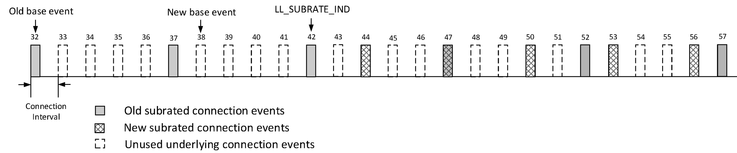
The Central shall set the value of SubrateBaseEvent ("S") in the PDU so that S15-14 = E15-14, where E is the value of connEventCount for the connection event when the PDU is first queued for transmission. If the Peripheral receives an LL_SUBRATE_IND PDU with S15-14 = 0b11 in a connection event with connEventCounter15-14 = 0b00 then, immediately after updating the parameters, it shall change connSubrateBaseEvent as described in Section 4.5.1 as if the value of connEventCount had just wrapped.
The requirement on the value of S15-14 means the Peripheral can determine whether the Central intended to send the PDU before or after connEventCount wrapped. For example, consider the situation where the current connSubrateFactor is 10 and the current connSubrateBaseEvent is 12002. As the point of wrap approaches, these parameters mean that the connection events used are 65522, 65532, 6, 16, 26, etc. If the LL_SUBRATE_IND PDU contained those values for these two parameters then, if the PDU was queued, sent, and received on event 65532, it indicated that the same connection events are to be used; on the other hand, if the PDU was queued, sent, and received on event 6, then it implies a change of phase so that connection events 12, 22, 32, etc. are to be used instead. Since internal queues and retransmissions can mean that a packet queued for event 65532 could be received in event 6, the Peripheral needs to be able to distinguish these two cases, which it does by making the test described.
The procedure is completed when the Link Layer acknowledgment for the LL_SUBRATE_IND PDU has been sent or received.
The Peripheral shall accept an LL_SUBRATE_IND PDU. However, if the Peripheral's Host would prefer a different subrate factor it may, after this procedure has completed, initiate the Connection Subrate Request procedure or the Connection Parameters Request procedure to change the connection parameters.
5.1.20. Connection Subrate Request procedure
The Peripheral's Link Layer may request the Central to update the subrate factor, Peripheral latency, continuation number, and supervision timeout by sending an LL_SUBRATE_REQ PDU. The Central shall not send this PDU. The Peripheral shall only initiate this procedure when requested by the Host.
When the Central receives this PDU it shall either initiate the Connection Subrate Update procedure or shall respond with an LL_REJECT_EXT_IND PDU to reject the request. If the Central's Host has not set the Connection Subrating (Host Support) bit in the FeatureSet, the Central's Link Layer shall reject the request. If the Central's Host has provided acceptable subrate parameters for requests from the Peripheral, then the Central's Link Layer shall initiate the Connection Subrate Update procedure if and only if all of the following are true ("acceptable" indicates values provided by the Host, see [Vol 4] Part E, Section 7.8.124; "requested" indicates values in the LL_SUBRATE_REQ PDU):
Max_Latencyrequested ≤ Max_Latencyacceptable,
Timeoutrequested ≤ Supervision_Timeoutacceptable,
SubrateFactorMaxrequested ≥ Subrate_Minacceptable,
SubrateFactorMinrequested ≤ Subrate_Maxacceptable,
(connIntervalcurrent × SubrateFactorMinrequested × (Max_Latencyrequested + 1))×2 < Timeoutrequested
If the Central accepts the Peripheral’s request, then:
the new connSubrateFactor shall be between Subrate_Minacceptable and Subrate_Maxacceptable and shall also be between SubrateFactorMinrequested and SubrateFactorMaxrequested,
the new connContinuationNumber shall equal min(max(Continuation_Numberacceptable, ContinuationNumberrequested), (new connSubrateFactor) - 1),
the new connPeripheralLatency shall be less than or equal to min(Max_Latencyrequested, Max_Latencyacceptable),
the new connSupervisionTimeout shall equal min(Timeoutrequested, Supervision_Timeoutacceptable).
The procedure has completed when the resulting Connection Subrate Update procedure has completed or an LL_REJECT_EXT_IND PDU has been sent or received.
5.1.21. Channel Classification Enable procedure
A Controller uses the Channel Classification Enable procedure to enable or disable reporting of channel classification information on the peer device. Until the Central initiates this procedure, reporting shall be disabled.
The Central can initiate this procedure at any time after entering the Connection state by sending an LL_CHANNEL_REPORTING_IND PDU. The Peripheral shall not send this PDU.
When a Peripheral that supports the Channel Classification feature receives this PDU, it shall enable or disable reporting of channel classification information to the Central as specified in the PDU. When reporting is enabled, the Peripheral should send channel classification information by initiating the Channel Classification Reporting procedure (see Section 5.1.22). When reporting is disabled, the Peripheral shall not send channel classification information.
The procedure has completed when the Link Layer acknowledgment of the LL_CHANNEL_REPORTING_IND PDU is sent or received.
5.1.22. Channel Classification Reporting procedure
A Controller uses the Channel Classification Reporting procedure to report channel classification information to the peer device.
The Peripheral may initiate this procedure by sending an LL_CHANNEL_STATUS_IND PDU after channel classification reporting has been enabled by the Central. The Central shall not send this PDU.
If channel classification information has not changed since the last time the Peripheral reported the information to the Central, then the Peripheral shall not initiate this procedure. Otherwise, the Peripheral shall initiate this procedure within, or in the first subrated connection event after, the maximum reporting delay from determining that a change in channel classification has occurred or from channel classification reporting being enabled, whichever is later. Two consecutive channel classification reports shall be spaced apart by a duration that is greater than or equal to the minimum reporting spacing.
The procedure has completed when the Link Layer acknowledgment of the LL_CHANNEL_STATUS_IND PDU is sent or received.
5.2. Procedure response timeout
This section specifies procedure timeout rules that shall be applied to all the Link Layer control procedures specified in Section 5.1, except for the Connection Update and Channel Map Update procedures for which there are no timeout rules.
To be able to detect a non-responsive Link Layer Control procedure, both the Central and the Peripheral shall use a procedure response timeout timer, TPRT . Upon the initiation of a procedure, the procedure response timeout timer shall be reset and started.
Each LL Control PDU that is queued for transmission resets the procedure response timeout timer.
When the procedure completes, the procedure response timeout timer shall be stopped.
If the procedure response timeout timer reaches 40 seconds, the ACL connection is considered lost (see Section 4.5.12). The Link Layer exits the Connection state and shall transition to the Standby state. The Host shall be notified of the loss of connection.
5.3. Procedure collisions
Since LL Control PDUs are not interpreted in real time, collisions can occur where the Link Layer of the Central and the Link Layer of the Peripheral initiate incompatible procedures. Two procedures are incompatible if they both involve an instant. In this situation, the rules in this section shall be followed:
A device shall not initiate a procedure after responding to a PDU that had initiated an incompatible procedure until that procedure is complete.
If device initiates a procedure A and, while that procedure is not complete, receives a PDU from its peer that initiates an incompatible procedure B, then:
If the peer has already sent at least one PDU as part of procedure A, the device should immediately exit the Connection State and transition to the Standby State.
Otherwise, if the device is the Central, it shall reject the PDU received from the Peripheral by issuing an LL_REJECT_EXT_IND (if supported by both devices) or LL_REJECT_IND (otherwise) PDU. It shall then proceed with procedure A.
Otherwise (the device is the Peripheral) it shall proceed to handle the Central-initiated procedure B and take no further action in the Peripheral-initiated procedure A except processing the rejection from the Central.
The Host shall be notified that the link has been disconnected with, or the rejection PDU shall use (as appropriate):
the error code LMP Error Transaction Collision / LL Procedure Collision (0x23) if procedures A and B are the same procedure;
the error code LMP Error Transaction Collision / LL Procedure Collision (0x23) if procedure A is the Connection Update procedure and procedure B is the Connection Parameters Request procedure;
the error code Different Transaction Collision (0x2A) otherwise.
5.4. LE Authenticated Payload Timeout
LE Authenticated Payload Timeout (authenticatedPayloadTO) is a parameter that defines the maximum amount of time in milliseconds allowed between receiving packets containing a valid MIC. The Host can change the value of authenticatedPayloadTO using the HCI_Write_Authenticated_Payload_Timeout command ([Vol 4] Part E, Section 7.3.94). The default value for authenticatedPayloadTO is 30 seconds.
When the connection is encrypted, a device supporting LE Ping feature shall start the LE Authenticated Payload timer TLE_Authenticated_Payload to monitor the time since the last reception of a packet containing a valid MIC from the remote device. Each device shall reset the timer TLE_Authenticated_Payload upon reception of a packet with a valid MIC. The timer shall not be reset upon the reception of a resent packet.
If at any time in the CONNECTION state the timer TLE_Authenticated_Payload reaches the authenticatedPayloadTO value, the Host shall be notified using the HCI_Authenticated_Payload_Timeout_Expired event ([Vol 4] Part E, Section 7.7.75). The TLE_Authenticated_Payload Timer restarts after it is expired.
The timer TLE_Authenticated_Payload shall continue to run during encryption pause procedure.
Whenever the Host sets the authenticatedPayloadTO while the timer TLE_Authenticated_Payload is running, the timer shall be reset.
5.5. Procedures with Instants
Where a procedure involves a PDU with an Instant field, then the following rules shall apply.
The Instant field shall be used to indicate the connEventCount or bigEventCounter when the relevant change shall be applied; this is known as the instant for the procedure. The Central should allow a minimum of 6 connection events when it intends to transmit and that the Peripheral will be listening for before the instant occurs, considering that the Peripheral may only be listening once every connSubrateFactor × (connPeripheralLatency + 1) events. The event shall be the next one with the specified value of connEventCount or of bigEventCounter15-0.
Note
Note: Comparisons of the connEventCount or bigEventCounter and the Instant field are performed using mod 65536 math (only values from 0 to 65535 are allowed).
When performing a Link Layer procedure that has an instant, the Central's Link Layer may (particularly for large values of the subrate factor) use the Connection Subrate Update procedure to set the subrate factor to 1 and the Peripheral latency to 0 before performing the procedure and then use it again to restore the previous values afterwards. If the Link Layer does so, it should not notify the Host of these changes. However, the Link Layer shall not restore the settings autonomously after a Connection Update procedure that changed the connection interval and shall not restore connPeripheralLatency or connSupervisionTimeout after a Connection Update procedure that did not change the connection interval.
5.5.1. ACL control procedures
When a Peripheral receives such a PDU where (Instant – connEventCount) mod 65536 is less than 32767 and Instant is not equal to connEventCount, the Peripheral shall listen to all the connection events until it has confirmation that the Central has received its acknowledgment of the PDU or connEventCount equals Instant.
When a Peripheral receives such a PDU where (Instant – connEventCount) mod 65536 is greater than or equal to 32767 (because the instant is in the past), it shall take the following actions:
If the PDU is an LL_CONNECTION_UPDATE_IND, the Link Layer of the Peripheral shall consider the connection to be lost.
Otherwise, the Link Layer of the Peripheral may consider the connection to be lost.
If the connection is considered to be lost, the Link Layer of the Peripheral shall exit the Connection state and transition to the Standby state, and shall notify the Host using the error code Instant Passed (0x28).
5.5.2. BIG control procedures
The Isochronous Broadcaster shall set the instant at least 6 BIG events after the first BIG event where the BIG Control PDU is transmitted.
When a Synchronized Receiver receives such a PDU where (Instant – bigEventCounter) mod 65536 is greater than or equal to 32767 (because the instant is in the past), the Link Layer may stop synchronization with the BIG.
5.6. BIG control procedures
BIG control procedures are used to send control information concerning a BIG from the Isochronous Broadcaster to the Synchronized Receivers.
Each BIG Control procedure involves transmitting a single BIG Control PDU during the control subevent of BIG events. Each such PDU shall be transmitted in six consecutive BIG events and may be transmitted in other BIG events (not necessarily consecutive) after these six; the procedure ends when the BIG Control PDU has been retransmitted for the last time. Only one BIG control procedure shall be in progress at a time for a given BIG.
5.6.1. BIG Channel Map Update procedure
The BIG Channel Map Update procedure is used to send a new channel map for all BISes in a BIG.
When instructed by the Host or autonomously, the Link Layer of an Isochronous Broadcaster shall initiate this procedure by transmitting a BIG_CHANNEL_MAP_IND PDU.
The Link Layer of the Isochronous Broadcaster shall not initiate a subsequent instance of this procedure until the instant has passed.
The Link Layer of both Isochronous Broadcaster and Synchronized Receiver shall use the new channel map starting with the BIG event identified by the instant. The Link Layer shall update the ChM field in the BIGInfo and send the updated BIGInfo in the associated periodic advertising train (if enabled) at the nearest future periodic advertising event to the instant.
5.6.2. BIG Termination procedure
The BIG Termination procedure is used to notify all Synchronized Receivers of a BIG that the transmission of that BIG is about to be terminated.
When instructed by the Host, the Link Layer shall initiate this procedure by transmitting a BIG_TERMINATE_IND PDU. The Link Layer shall stop transmitting BIG events at the instant and shall return to the Standby state. If the Link Layer is still transmitting the associated BIGInfo, it shall stop doing so no later than the instant.
The Link Layer shall terminate the BIG no later than when the bisPayloadCounter equals 239 – 1.
When the Link Layer receives a BIG_TERMINATE_IND PDU, it shall stop synchronization with the BIG and, unless it is still synchronized to the periodic advertising train, shall return to the Standby state.
6. Privacy
The Link Layer provides Privacy by using Private Addresses (see Section 1.3.2).
If a device is using Resolvable Private Addresses Section 1.3.2.2, it shall also have an Identity Address that is either a Public or Random Static address type.
6.1. Resolvable Private address generation interval
A resolvable private address shall be generated using the Resolvable Private Address Generation (see Section 1.3.2.2).
The Link Layer shall set a timer determined by the Host. A new resolvable private address shall be generated when the timer expires. If the Link Layer is reset, a new resolvable private address shall be generated and the timer started with any value in the allowed range.
Note
Note: If the resolvable private address is generated frequently, connection establishment times may be affected. It is recommended to set the timer to 15 minutes.
If requested by the Host, the Controller shall generate a new resolvable private address each time the advertising data or scan response data changes.
6.2. Privacy in the Advertising state
Privacy in the advertising state determines how the Link Layer processes Resolvable Private Addresses for advertising events.
The requirements in the following sub-sections apply in addition to those in Section 4.4.2 and Section 4.7.
6.2.1. Connectable and scannable undirected event type
The Link Layer may use resolvable private addresses or non-resolvable private addresses for the advertiser’s device address (AdvA field) when entering the Advertising State and using connectable and scannable undirected events.
The AdvA field of the connectable and scannable undirected advertising event PDU is generated using the resolving list’s Local IRK value and the Resolvable Private Address Generation procedure (see Section 1.3.2.2). If the Host has not provided any Resolving List IRK pairs for the peer to the Link Layer, then the AdvA field shall use a Host-provided address.
When an advertiser receives a connection request that contains a resolvable private address for the initiator’s address (InitA field) and address resolution is enabled, the Link Layer shall resolve the private address (see Section 1.3.2.3). The advertising filter policy (see Section 4.3.2) shall then determine if the advertiser establishes a connection.
When an advertiser receives a connection request that contains a device Identity Address for the initiator's address field (InitA field), and if that device is in the Resolving List with a non-zero peer IRK for which the Host has specified device privacy mode, then the advertising filter policy (see Section 4.3.2) shall determine if the advertiser establishes a connection.
When an advertiser receives a scan request that contains a resolvable private address for the scanner’s device address (ScanA field) and address resolution is enabled, the Link Layer shall resolve the private address (see Section 1.3.2.3). The advertising filter policy (see Section 4.3.2) shall then determine if the advertiser processes the scan request.
When an advertiser receives a scan request that contains a device Identity Address for the scanner's device address (ScanA field), and if that device is in the Resolving List with a non-zero peer IRK for which the Host has specified device privacy mode, then the advertising filter policy (see Section 4.3.2) shall determine if the advertiser processes the scan request.
When an advertiser receives a scan or connection request that contains a non-resolvable private address, the advertising filter policy (see Section 4.3.2) shall determine if the advertiser processes the scan or connection request.
If the advertiser processes the scan request, the advertiser’s device address (AdvA field) in the SCAN_RSP PDU shall be the same as the advertiser’s device address (AdvA field) in the SCAN_REQ PDU to which it is responding.
6.2.2. Connectable directed event type
The Link Layer shall use resolvable private addresses for the advertiser’s device address (AdvA field). If an IRK is available in the Link Layer Resolving List for the peer device, then the target’s device address (TargetA field) shall use a resolvable private address. If an IRK is not available in the Link Layer Resolving List or the IRK is set to zero for the peer device, then the target’s device address (TargetA field) shall use the Identity Address when entering the Advertising State and using connectable directed events.
The AdvA field of the connectable directed advertising event PDU is generated using the resolving list’s Local IRK value and the Resolvable Private Address Generation procedure (see Section 1.3.2.2).
The TargetA field of the connectable directed advertising event PDU is generated using the Peer IRK value and the Resolvable Private Address Generation procedure (see Section 1.3.2.2). The TargetA field uses the public or static device address of the peer device if no peer IRK is available.
When an advertiser receives a connection request that contains a resolvable private address for the initiator’s address (InitA field) and address resolution is enabled, the Link Layer shall resolve the private address (see Section 1.3.2.3).
When an advertiser receives a connection request that contains a device Identity Address for the initiator's address field (InitA field), and if that device is in the Resolving List with a non-zero peer IRK for which the Host has specified device privacy mode, then the advertiser shall establish a connection. When responding with an AUX_CONNECT_RSP, the Link Layer should not set the TargetA field to the same value as the InitA field in the received PDU.
6.2.3. Non-connectable and non-scannable undirected and scannable undirected event types
The Link Layer may use resolvable private addresses or non-resolvable private addresses for the advertiser’s device address (AdvA field) when entering the Advertising State and using the following event types:
non-connectable and non-scannable undirected event
scannable undirected event
The AdvA field of the non-connectable and non-scannable undirected advertising event PDU and scannable undirected event PDU are generated using the resolving list’s Local IRK value and the Resolvable Private Address Generation procedure or Non-Resolvable Private Address Generation procedure (see Section 1.3.2.2).
When an advertiser receives a scan request that contains a resolvable private address for the scanner’s device address (ScanA field) and address resolution is enabled, the Link Layer shall resolve the private address (see Section 1.3.2.3). The advertising filter policy (see Section 4.3.2) shall then determine if the advertiser processes the scan request.
When an advertiser receives a scan request that contains a device Identity Address for the scanner's device address (ScanA field), and if that device is in the Resolving List with a non-zero peer IRK for which the Host has specified device privacy mode, then the advertising filter policy (see Section 4.3.2) shall determine if the advertiser processes the scan request.
When an advertiser receives a scan request that contains a non-resolvable private address, the advertising filter policy (see Section 4.3.2) shall determine if the advertiser processes the scan request.
If the advertiser processes the scan request, the advertiser’s device address (AdvA field) in the scan response PDU shall be the same as the advertiser’s device address (AdvA field) in the scan request PDU to which it is responding.
6.2.4. Connectable undirected event type
The Link Layer may use resolvable private addresses or non-resolvable private addresses for the advertiser’s device address (AdvA field) when entering the Advertising State and using connectable undirected events.
The AdvA field of the connectable undirected advertising event PDU is generated using the resolving list’s Local IRK value and the Resolvable Private Address Generation procedure (see Section 1.3.2.2). If the Host has not provided any Resolving List IRK pairs for the peer to the Link Layer, then the AdvA field shall use a Host-provided address.
When an advertiser receives a connection request that contains a resolvable private address for the initiator’s address (InitA field) and address resolution is enabled, the Link Layer shall resolve the private address (see Section 1.3.2.3). The advertising filter policy (see Section 4.3.2) shall then determine if the advertiser establishes a connection. The Link Layer should not set the TargetA field to the same value as the InitA field in the received PDU.
The advertising filter policy (see Section 4.3.2) shall determine if the advertiser processes the connect request if an advertiser receives a connect request that contains a non-resolvable private address.
6.2.5. Non-connectable and non-scannable directed and scannable directed event types
The Link Layer may use resolvable private addresses or non-resolvable private addresses for the advertiser’s device address (AdvA field) when entering the Advertising State and using the following event types:
non-connectable and non-scannable directed event
scannable directed event
If an IRK is available in the Link Layer Resolving List for the peer device, then the target’s device address (TargetA field) shall use a resolvable private address. If an IRK is not available in the Link Layer Resolving List or the IRK is set to zero for the peer device, then the target’s device address (TargetA field) shall use the Identity Address when entering the Advertising State and using non-connectable and non-scannable directed and scannable directed events.
The AdvA field of the non-connectable and non-scannable directed advertising event PDU and scannable directed event PDU is generated using the resolving list’s Local IRK value and the Resolvable Private Address Generation procedure or Non-Resolvable Private Address Generation procedure (see Section 1.3.2.2).
The TargetA field of the scannable directed advertising event PDU is generated using the Peer IRK value and the Resolvable Private Address Generation procedure (see Section 1.3.2.2). The TargetA field uses the public or static device address of the peer device if no peer IRK is available.
When an advertiser receives a scan request that contains a resolvable private address for the scanner’s device address (ScanA field) and address resolution is enabled, the Link Layer shall resolve the private address (see Section 1.3.2.3).
If the advertiser processes the scan request, the advertiser’s device address (AdvA field) in the AUX_SCAN_RSP PDU shall be the same as the advertiser’s device address (AdvA field) in the AUX_SCAN_REQ PDU to which it is responding.
6.3. Privacy in the Scanning state
The requirements in this section apply in addition to those in Section 4.4.3 and Section 4.7.
The Link Layer may use resolvable private addresses or non-resolvable private addresses for the scanner’s device address (ScanA field) when entering the Scanning State.
The ScanA field of the scanning PDU is generated using the Resolving List’s Local IRK value and the Resolvable Private Address Generation procedure (see Section 1.3.2.2), or the address is provided by the Host.
The advertiser’s device address (AdvA field) in the scan request PDU shall be the same as the advertiser’s device address (AdvA field) received in the advertising PDU to which the scanner is responding.
When a scanner receives an advertising packet that contains a resolvable private address for the advertiser’s device address (AdvA field) and address resolution is enabled, the Link Layer shall resolve the private address (see Section 1.3.2.3). The scanning filter policy (see Section 4.3.3) shall then determine if the scanner responds with a scan request.
When a scanner receives an advertising packet that contains a device Identity Address for the advertiser's device address (AdvA field), and if that device is in the Resolving List with a non-zero peer IRK for which the Host has specified device privacy mode, then the scanning filter policy (see Section 4.3.3) shall determine if the scanner responds with a scan request. The Link Layer should not set the ScanA field to the same value as the TargetA field in the received advertising PDU.
When a scanner receives a directed scannable advertising packet that contains a resolvable private address for the target’s address (TargetA field) and address resolution is enabled, the Link Layer shall resolve the private address using the Local IRK values (see Section 1.3.2.3). If the Link Layer is unable to resolve the address, the scanning filter policy shall determine if the Host is notified about this advertisement.
A scanner that has been instructed by the Host to use Resolvable Private Addresses (e.g., using the HCI_LE_Set_Scan_Parameters command; see [Vol 4] Part E, Section 7.8.10) shall not respond to directed scannable advertising events that contain public or static addresses for the target’s address (TargetA field).
When a scanner receives an advertising packet that contains a non-resolvable private address, the scanning filter policy (see Section 4.3.3) shall determine if the scanner processes the advertising packet.
6.4. Privacy in the Initiating state
The requirements in this section apply in addition to those in Section 4.4.4 and Section 4.7.
The Link Layer may use resolvable private addresses, the public address, or an address provided by the Host for the initiator’s device address (InitA field) when in the Initiating state.
When an initiator receives a connectable advertising event that contains a resolvable private address for the advertiser’s address (AdvA field) and address resolution is enabled, the Link Layer shall resolve the private address using the resolving list’s Peer IRK values (see Section 1.3.2.3). The initiator filter policy (see Section 4.3.4) shall determine if the initiator establishes a connection.
The advertiser’s device address (AdvA field) in the initiating PDU shall be the same as the advertiser’s device address (AdvA field) received in the advertising event PDU to which the initiator is responding.
When an initiator receives a directed connectable advertising event that contains a resolvable private address for the target’s address (TargetA field) and address resolution is enabled, the Link Layer shall resolve the private address using the resolving list’s Local IRK values (see Section 1.3.2.3). An initiator that has been instructed by the Host to use Resolvable Private Addresses (e.g., using the HCI_LE_Create_Connection command; see [Vol 4] Part E, Section 7.8.12) shall not respond to directed connectable advertising events that contain Public or Static addresses for the target’s address (TargetA field).
When an initiator receives a connectable advertising event that contains a device Identity Address for the advertiser's device address (AdvA field), and if that device is in the Resolving List with a non-zero peer IRK for which the Host has specified device privacy mode, then the initiator filter policy (see Section 4.3.4) shall determine if the initiator establishes a connection.
The Link Layer shall use resolvable private addresses for the initiator’s device address (InitA field) when initiating connection establishment with an associated device that exists in the Resolving List. The initiator’s device address (InitA field) in the initiating PDU is generated using the Resolving List Local IRK and the Resolvable Private Address Generation procedure (see Section 1.3.2.2). The Link Layer should not set the InitA field to the same value as the TargetA field in the received advertising PDU.
The Link Layer shall use the public address or the Host-provided address for the initiator’s device address (InitA field) when initiating connection establishment with a device that is not in the Resolving List.
6.5. Privacy of the device
A device wanting to maintain its privacy shall not use its Identity Address in any advertising PDU. The Host may command the Controller to advertise, scan, or initiate a connection using a Resolvable Private Address when the resolving list is enabled. If the local IRK in the resolving list associated with the peer Identity Address is all zeros, the Controller will use the Identity Address. If the peer IRK in the resolving list associated with the peer Identity Address is all zeros, the Controller will accept the Identity Address. If the Host has instructed the Controller to use device privacy mode with a peer Identity Address, the Controller will accept the peer’s Identity Address. This implies that the device's network privacy is violated. To maintain a device’s network privacy, the Host should only populate entries in the Controller’s resolving list with non-zero IRKs and not instruct the Controller to use device privacy mode.
6.6. Privacy in the Synchronization State
6.6.1. Periodic advertising trains
The requirements in this section apply when the Link Layer is directed by the Host to receive a periodic advertising train using the SyncInfo field of an AUX_ADV_IND PDU. The requirements in this section apply in addition to those in Section 4.4.5.1 and Section 4.7.
When a scanner receives an advertising packet that contains a resolvable private address for the advertiser's device address (AdvA field) and address resolution is enabled, the Link Layer shall resolve the private address (see Section 1.3.2.3). The scanner's periodic sync establishment filter policy (see Section 4.3.5) shall determine if the scanner processes the advertising packet.
7. ISO Test Mode
This section contains information on testing a CIS or BIS in the Controller without the protocols and profiles in the Host that use the CIS Central, CIS Peripheral, Isochronous Broadcaster, and Synchronized Receiver role features of this specification. The command that enters ISO Test mode takes the connection handle of a CIS or BIS as a parameter.
7.1. ISO Transmit test mode
When instructed by the Host, the Link Layer shall generate and transmit the payloads in SDUs as follows:
When Payload_Type = 0b00 (zero size SDU), the length of every SDU shall be set to zero.
When Payload_Type = 0b01 (variable size SDU), every SDU shall contain the value of the 4-octet SDU counter of the SDU padded with vendor-specific data as shown in Figure 7.1. The size of the SDU can be different in every SDU_Interval by an algorithm chosen by the transmitting device. The range shall be between 4 and Max_SDU.
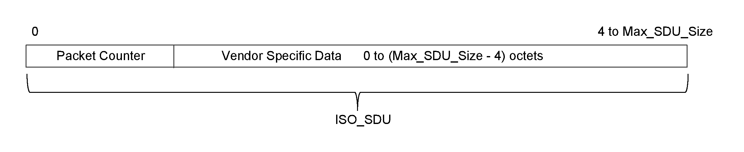 Figure 7.1: Payload_Type = 1 (variable size payloads)
When Payload_Type = 0b10 (maximum size SDU), every SDU shall contain the value of the 4-octet SDU counter of the SDU padded with vendor-specific data, as shown in Figure 7.2. The length of every SDU shall be equal to the value of the Max_SDU.
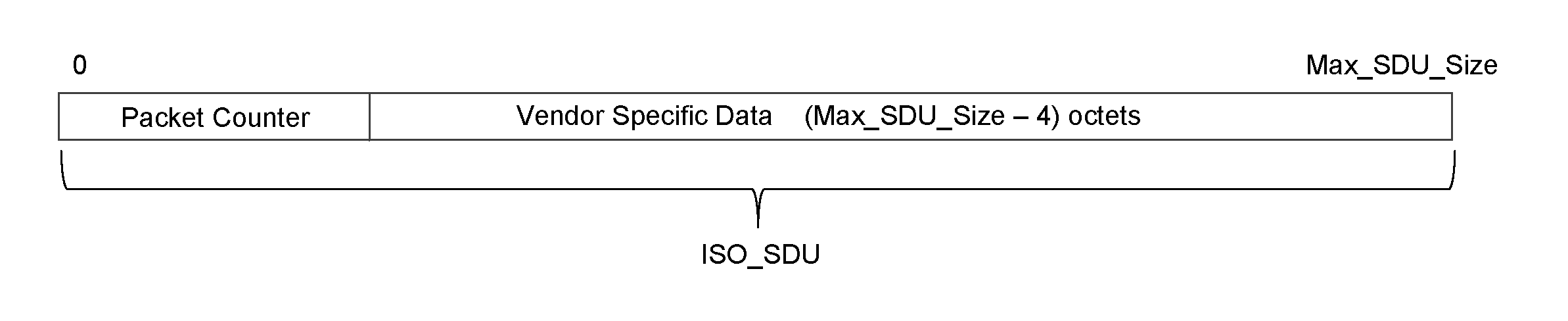 Figure 7.2: Payload_Type = 2 (maximum size payloads)
The ISO Transmit Test mode may be used in combination with the ISO Receive Test mode for a CIS configured for data flow from the Central to Peripheral and/or Peripheral to Central.
Note
Note: For Payload_Type = 0b01 and 0b10, the minimum SDU size must be configured to be at least 4 octets, as described above in numbered paragraphs 2 and 3.
The SDU counter depends on the configuration (Max_SDU, SDU_Interval, or Max_PDU), of the logical link in the direction ISO Transmit Test mode is applied.
When using unframed PDUs, the SDU counter shall be equal to the payload counter (i.e. the value of bisPayloadCounter in a BIS or of cisPayloadCounter in a CIS) of the first PDU containing the first fragment from the SDU divided by n when the Max_SDU would have been used, where n = (BN×SDU_Interval)÷ISO_Interval.
Note: For n=1 this results in the SDU counter being identical to the payload counter. The SDU counter is independent of the actual length of the SDUs when using variable length SDUs.
When using framed PDUs the SDU counter cannot be derived from the payload counter of the PDU. It shall be initialized to 0 for the first test SDU transmitted and incremented by 1 for each additional SDU.
When instructed by the Host, the Link Layer shall stop generating test SDUs, exit the ISO Transmit Test mode, and notify the Host.
7.2. ISO Receive test mode
When instructed by the Host, the Link Layer shall initialize three 32-bit counters (Missed_SDU_Count, Received_SDU_Count, and Failed_SDU_Count) to zero and then increment these counters based on the received or missed test SDUs. Any vendor-specific data included in the SDU shall be ignored for the purpose of updating these counters.
When using framed PDUs the expected value of the SDU counter shall be initialized with the value of the SDU counter of the first valid received SDU. A valid SDU is one where all the PDUs composing the SDU are valid.
The counters shall be incremented as follows:
The Received_SDU_Count shall be incremented by one for every valid received test ISO Data SDU containing a size in the expected range and an SDU counter that matches the expected value as defined in Section 7.1. This includes empty SDUs when configured to zero size SDU.
The Missed_SDU_Count shall be incremented by one for each SDU that is made up of one or more invalid or missing PDUs.
The Failed_SDU_Count shall be incremented by one for each valid received test SDU where the size or SDU counter does not match the expected size or value as defined in Section 7.1.
Because the transmitter and receiver do not enter test mode simultaneously, it is not possible to determine whether the first test SDU received was the first one sent. As a consequence, at the moment the first valid test SDU is received (indicated by either Received_SDU_Count or Failed_SDU_Count being incremented), the value of Missed_SDU_Count is unpredictable. Once a valid test SDU has been received, any further changes in Missed_SDU_Count will be correct.
When instructed by the Host, the Link Layer shall exit the ISO Receive Test mode and notify the Host.
8. References
[1] Core Specification Supplement, Part A, Data Types Specification