Part C. Generic Access Profile
vAtlanta r00
This profile defines the generic procedures related to discovery of Bluetooth devices (idle mode procedures) and link management aspects of connecting to Bluetooth devices (connecting mode procedures). It also defines procedures related to use of different security levels. In addition, this profile includes common format requirements for parameters accessible on the user interface level.
1. Foreword
Interoperability between devices from different manufacturers is provided for a specific service and use case, if the devices conform to a Bluetooth SIG- defined profile specification. A profile defines a selection of messages and procedures (generally termed capabilities) from the Bluetooth SIG specifications and gives a description of the air interface for specified service(s) and use case(s).
All defined features are process-mandatory. This means that, if a feature is used, it is used in a specified manner. Whether the provision of a feature is mandatory or optional is stated separately for both sides of the Bluetooth air interface.
1.1. Scope
The purpose of the Generic Access Profile is:
To introduce definitions, recommendations and common requirements related to modes and access procedures that are to be used by transport and application profiles.
To describe how devices are to behave in standby and connecting states in order to avoid situations where links and channels cannot be established between Bluetooth devices or that prevent multi-profile operation. Special focus is put on discovery, link establishment and security procedures.
To state requirements on user interface aspects, mainly coding schemes and names of procedures and parameters, that are needed to provide a satisfactory user experience.
This profile defines three device types based on the supported Core Configurations as defined in [Vol 0] Part B, Section 3.1. The device types are shown in Table 1.1:
Device Type | Description |
|---|---|
BR/EDR | Devices that support the “Basic Rate” Core Configuration (see [Vol 0] Part B, Section 4.1) |
LE only | Devices that support the “Low Energy” Core Configuration (see [Vol 0] Part B, Section 4.4) |
BR/EDR/LE | Devices that support the “Basic Rate and Low Energy Combined” Core Configuration (see [Vol 0] Part B, Section 4.5) |
The terms physical transport, physical link and physical channel as defined in [Vol 1] Part A, Section 3 are used in the specification.
1.2. Symbols and conventions
1.2.1. [This section is no longer used]
1.2.2. Signaling diagram conventions
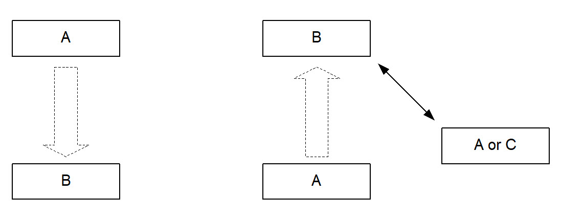
The arrows shown in Figure 1.1 are used in diagrams describing procedures:
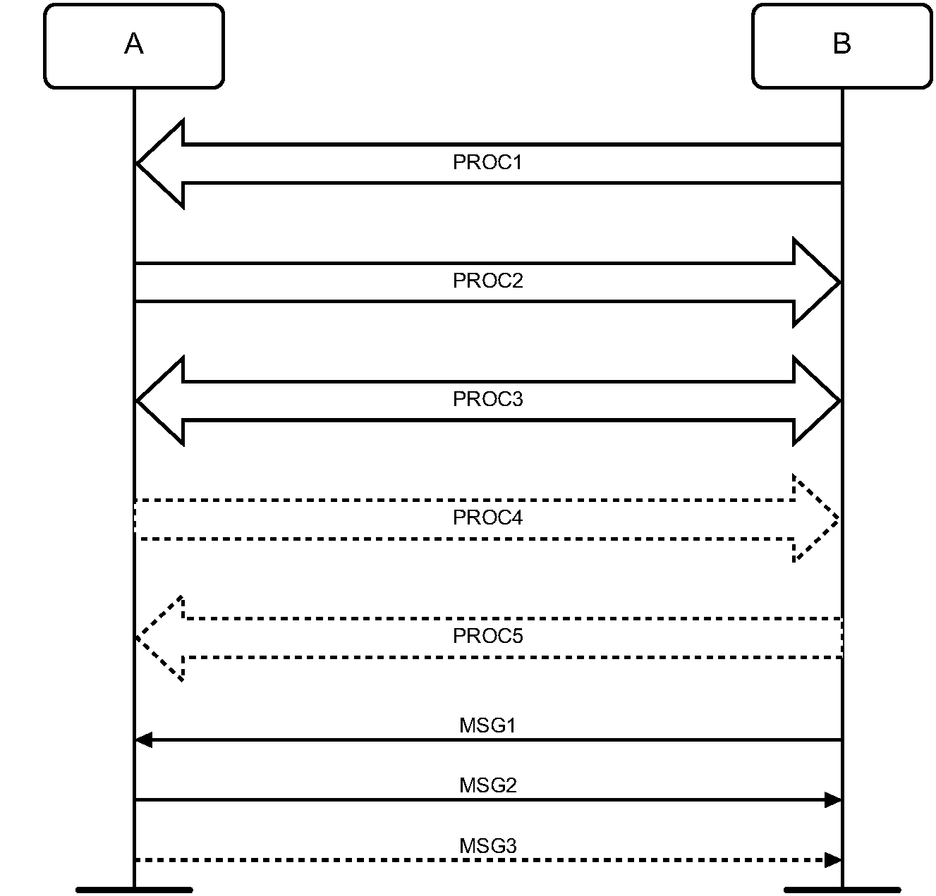
In Figure 1.1, the following cases are shown: PROC1 is a sub-procedure initiated by B. PROC2 is a sub-procedure initiated by A. PROC3 is a sub-procedure where the initiating side is undefined (may be both A or B). Dashed arrows denote optional steps. PROC4 indicates an optional sub-procedure initiated by A, and PROC5 indicates an optional sub-procedure initiated by B.
MSG1 is a message sent from B to A. MSG2 is a message sent from A to B. MSG3 indicates an optional message from A to B.
1.2.3. Notation for timers and counters
Timers are introduced specific to this profile. To distinguish them from timers used in the Bluetooth protocol specifications and other profiles, these timers are named in the following format: ’TGAP(nnn)’.
1.2.4. Notation for UUIDs
The use of « » (e.g. «Device Name») indicates a Bluetooth SIG-defined UUID.
2. Profile overview
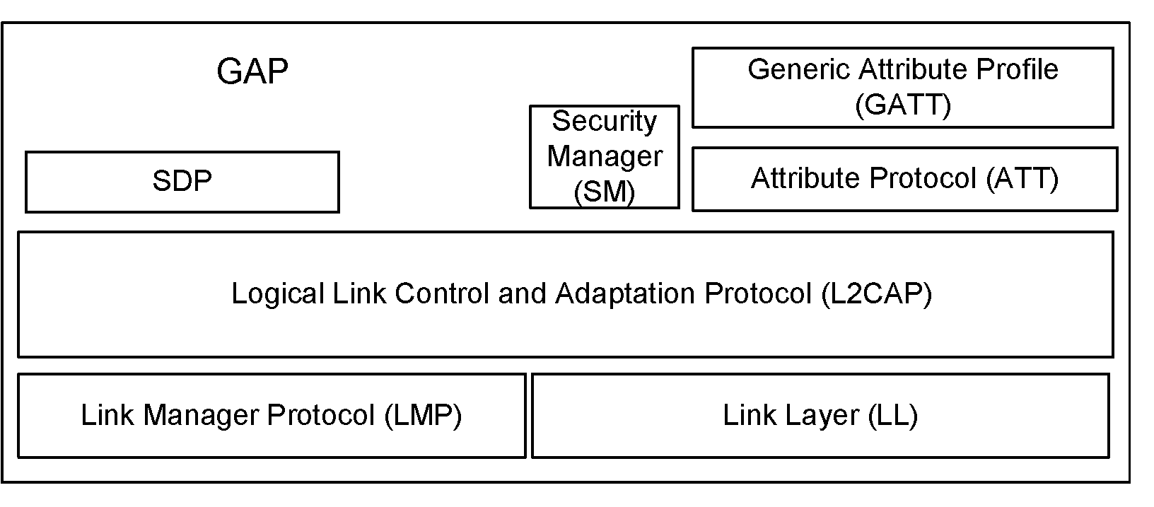
2.1. Profile stack
The purpose of this profile is to describe:
Profile roles
Discoverability modes and procedures
Connection modes and procedures
Security modes and procedures
2.2. Profile roles
2.2.1. Roles when operating over BR/EDR Physical Transport
In GAP, for describing the Bluetooth communication that occurs between two devices in the BR/EDR GAP role, the generic notation of the A-party (the paging device in case of link establishment, or initiator in case of another procedure on an established link) and the B-party (paged device or acceptor) is used. The A-party is the one that, for a given procedure, initiates device discovery, initiates the establishment of a physical link or initiates a transaction on an existing link.
This profile handles the procedures between two devices related to discovery and connecting (link and connection establishment) for the case where none of the two devices has any link established as well as the case where (at least) one device has a link established (possibly to a third device) before starting the described procedure.
The initiator and the acceptor generally operate the generic procedures according to this profile or another profile referring to this profile. If the acceptor operates according to several profiles simultaneously, this profile describes generic mechanisms for how to handle this.
2.2.2. Roles when operating over an LE physical transport
There are four GAP roles defined for devices operating over an LE physical transport:
Broadcaster
Observer
Peripheral
Central
The GAP roles "Central" and "Peripheral" are related to, but not the same as, the Link Layer roles with the same names and therefore can have different requirements. If a connection is established successfully, the device with one of these GAP roles will also have the corresponding Link Layer role. However, the device can be in the GAP role without a connection being established.
Table 2.1 defines requirements for physical layer and Link Layer functionalities for each GAP role when operating over an LE physical transport.
Broadcaster | Observer | Peripheral | Central | ||
|---|---|---|---|---|---|
Physical layer functionality: | |||||
| M | O | M | M | |
| O | M | M | M | |
Link Layer functionality: | |||||
States: | |||||
| M | M | M | M | |
| M | E | M | E | |
| E | M | E | M | |
| E | E | E | M | |
| E | O | E | E | |
| O | E | E | E | |
| Peripheral role | E | E | M | E |
Central role | E | E | E | M | |
Advertising event types: | |||||
| E | E | M | E | |
| E | E | O | E | |
| E | E | O | E | |
| M | E | O | E | |
| O | E | O | E | |
| O | E | O | E | |
| O | E | O | E | |
Scanning type: | |||||
| E | M | E | O | |
| E | O | E | C.1 | |
Link Layer control procedures: | |||||
| E | E | M | M | |
| E | E | M | M | |
| E | E | O | O | |
| E | E | M | M | |
| E | E | C.2 | C.2 | |
| E | E | O | O | |
| E | E | M | M | |
| E | E | M | M | |
| E | E | O | O | |
| E | E | O | O | |
| E | E | O | O | |
| E | E | O | O | |
| E | E | O | O | |
| E | E | O | O | |
| E | E | O | O | |
Broadcast control procedures: | |||||
| O | O | E | E | |
| O | O | E | E | |
| |||||
2.2.2.1. Broadcaster role
A device operating in the Broadcaster role is a device that sends advertising events or periodic advertising events as described in [Vol 6] Part B, Section 4.4.2, and may also send Broadcast Isochronous Stream (BIS) events as described in [Vol 6] Part B, Section 4.4.6. A device operating in the Broadcaster role is referred to as a Broadcaster and shall have a transmitter and may have a receiver.
2.2.2.2. Observer role
A device operating in the Observer role is a device that receives advertising events or periodic advertising events as described in [Vol 6] Part B, Section 4.4.3, and may also receive BIS events as described in [Vol 6] Part B, Section 4.4.6. A device operating in the Observer role is referred to as an Observer and shall have a receiver and may have a transmitter.
2.2.2.3. Peripheral role
Any device that accepts the establishment of an LE active physical link using any of the connection establishment procedures as defined in Section 9 is referred to as being in the Peripheral role. A device operating in the Peripheral role will be in the Peripheral role in the Link Layer Connection state as described in [Vol 6] Part B, Section 4.5. A device operating in the Peripheral role is referred to as a Peripheral. A Peripheral shall have both a transmitter and a receiver.
2.2.2.4. Central role
A device that supports the Central role initiates the establishment of an LE active physical link. A device operating in the Central role will be in the Central role in the Link Layer Connection state as described in [Vol 6] Part B, Section 4.5. A device operating in the Central role is referred to as a Central. A Central shall have both a transmitter and a receiver.
2.2.2.5. Concurrent operation in multiple GAP roles
A device may operate in multiple GAP roles concurrently if supported by the Controller. The Host should read the supported Link Layer states and state combinations from the Controller before any procedures or modes are used.
2.3. User requirements and scenarios
The Bluetooth user should, where expected, be able to connect a Bluetooth device to any other Bluetooth device. Even if the two connected devices don’t share any common application, it should be possible for the user to find this out using basic Bluetooth capabilities. When the two devices do share the same application but are from different manufacturers, the ability to connect them should not be blocked just because manufacturers choose to call basic Bluetooth capabilities by different names on the user interface level or implement basic procedures to be executed in different orders.
2.4. Profile fundamentals
This profile states the requirements on names, values and coding schemes used for names of parameters and procedures experienced on the user interface level.
This profile defines modes of operation that are not service- or profile-specific, but that are generic and can be used by profiles referring to this profile, and by devices implementing multiple profiles.
This profile defines the general procedures that can be used for discovering identities, names and basic capabilities of other Bluetooth devices that are in a mode where they can be discovered. Only procedures where no channel or connection establishment is used are specified.
This profile defines the general procedure for how to create bonds (i.e., dedicated exchange of link keys) between Bluetooth devices.
This profile describes the general procedures that can be used for establishing connections to other Bluetooth devices that are in a mode that allows them to accept connections and service requests.
2.5. Conformance
Bluetooth devices shall conform to this profile to allow basic interoperability.
Bluetooth devices that conform to another Bluetooth profile may use adaptations of the generic procedures as specified by that other profile. They shall, however, be compatible with devices compliant to this profile at least on the level of the supported generic procedures.
3. User interface aspects
3.1. The user interface level
In the context of the specification, the user interface level refers to places (such as displays, dialog boxes, manuals, packaging, advertising, etc.) where users of Bluetooth devices encounters names, values and numerical representation of Bluetooth terminology and parameters.
This profile specifies the generic terms that should be used on the user interface level.
3.2. Representation of Bluetooth parameters
3.2.1. Bluetooth Device Address (BD_ADDR)
3.2.1.1. Definition
A BD_ADDR is the address used by a Bluetooth device as defined in Section 15.1. It is received from a remote device during the device discovery procedure.
3.2.1.2. Term on user interface level
When the Bluetooth address is referred to on the UI level, the term ‘Bluetooth Device Address’ should be used.
3.2.1.3. Representation
On the Baseband level the BD_ADDR is represented as 48 bits (see [Vol 2] Part B, Section 1.2). On the Link Layer the public and random device address are represented as 48-bit addresses.
On the UI level the Bluetooth address shall be represented as 12 hexadecimal characters, possibly divided into sub-parts separated by ‘:’ (e.g., ‘000C3E3A4B69’ or ‘00:0C:3E:3A:4B:69’). On the UI level any number shall have the MSB -> LSB (from left to right) ‘natural’ ordering.
3.2.2. Bluetooth Device Name (the user-friendly name)
3.2.2.1. Definition
The Bluetooth Device Name is the user-friendly name that a Bluetooth device exposes to remote devices. For a device supporting the BR/EDR device type, the name is a character string returned in the LMP_NAME_RES in response to an LMP_NAME_REQ. For a device supporting the LE-only device type, the name is a character string held in the Device Name characteristic as defined in Section 12.1.
3.2.2.1.1. Bluetooth Device Name in a device with BR/EDR/LE device type
A BR/EDR/LE device type shall have a single Bluetooth Device Name which shall be identical irrespective of the physical channel used to perform the name discovery procedure.
For the BR/EDR physical channel the name is received in the LMP_NAME_RES. For the LE physical channel the name can be read from the Device Name characteristic as defined in Section 12.1.
Note
Note: The Device Name Characteristic of the local device can be read by a remote device using ATT over BR/EDR if the local device supports ATT over BR/EDR.
3.2.2.2. Term on user interface level
When the Bluetooth Device Name is referred to on the UI level, the term ‘Bluetooth Device Name’ should be used.
3.2.2.3. Representation
The Bluetooth Device Name can be up to 248 bytes (see [Vol 2] Part C, Section 4.3.5). It shall be encoded according to UTF-8 (therefore the name entered on the UI level may be restricted to as few as 62 characters if codepoints outside the range U+0000 to U+007F are used).
A device cannot expect that a general remote device is able to handle more than the first 40 characters of the Bluetooth Device Name. If a remote device has limited display capabilities, it may use only the first 20 characters.
3.2.3. Bluetooth Passkey (Bluetooth PIN)
3.2.3.1. Definition
The Bluetooth Passkey may be used to authenticate two Bluetooth devices with each other during the creation of a mutual link key via the pairing procedure. The passkey may be used in the pairing procedures to generate the initial link key.
The PIN may be entered on the UI level but may also be stored in the device; e.g., in the case of a device without sufficient MMI for entering and displaying digits.
3.2.3.2. Terms at user interface level
When the Bluetooth PIN is referred to on the UI level, the term ‘Bluetooth Passkey’ should be used.
3.2.3.3. Representation
There are a number of different representations of the Bluetooth Passkey. At a high level there are two distinct representations: one used with the Secure Simple Pairing and Security Manager, and another used with legacy pairing (where it is generally referred to as the Bluetooth PIN).
For Secure Simple Pairing and Security Manager, the Bluetooth Passkey is a 6-digit numerical value. It is represented as integer value in the range 0x00000000 – 0x000F423F (000000 to 999999). The numeric value may be used as the input to the Authentication stage 1 for Secure Simple Pairing Passkey Entry (see [Vol 2] Part H, Section 7.2.3), or as the TK value in the Security Manager for the process defined in [Vol 3] Part H, Section 2.3.5.
For legacy pairing (see Section B.2), the Bluetooth PIN has different representations on different levels. PINBB is used on the Baseband level, and PINUI is used on the user interface level. PINBB is the PIN used in [Vol 2] Part H, Section 3.2.1 for calculating the initialization key during the Pairing procedure.
PINUI is the character representation of the PIN that is entered on the UI level. The transformation from PINUI to PINBB shall be according to UTF-8. PINBB may be 128 bits (16 bytes).
PIN codes may be up to 16 characters. In order to take advantage of the full level of security all PINs should be 16 characters long. Variable PINs should be composed of alphanumeric characters chosen from within the Unicode range U+0000 to U+007F. If the PIN contains any decimal digits these shall be encoded using the Unicode Basic Latin characters (i.e., U+0030 to U+0039) (Note 1).
For compatibility with devices with numeric keypads, fixed PINs shall be composed of only decimal digits, and variable PINs should be composed of only decimal digits.
If a device supports entry of characters outside the Unicode range U+0000 to U+007F, other Unicode code points may be used (Note 2), except the Halfwidth and Fullwidth Forms (i.e., U+FF00 to U+FFEF) shall not be used (Note 3).
Examples:
User-entered code | Corresponding PINBB[0..length-1] (value as a sequence of octets in hexadecimal notation) |
|---|---|
’0196554200906493’ | length = 16, value = 0x30 0x31 0x39 0x36 0x35 0x35 0x34 0x32 0x30 0x30 0x39 0x30 0x36 0x34 0x39 0x33 |
’Børnelitteratur’ | length = 16, value = 0x42 0xC3 0xB8 0x72 0x6E 0x65 0x6C 0x69 0x74 0x74 0x65 0x72 0x61 0x74 0x75 0x72 |
Note
Note 1: This is to prevent interoperability problems since there are decimal digits at other code points (e.g., the Fullwidth digits at code points U+FF10 to U+FF19).
Note
Note 2: Unicode characters outside the Basic Latin range (U+0000 to U+007F) encode to multiple bytes; therefore, when characters outside the Basic Latin range are used the maximum number of characters in the PINUI will be less than 16. The second example illustrates a case where a 15 character string encodes to 16 bytes because the character ø is outside the Basic Latin range and encodes to two bytes (0xC3 0xB8).
Note
Note 3: This is to prevent interoperability problems since the Halfwidth and Fullwidth forms contain alternative variants of ASCII, Katakana, Hangul, punctuation and symbols. All of the characters in the Halfwidth and Fullwidth forms have other related Unicode characters; for example, U+3150 (Hangul Letter AE) can be used instead of U+FFC3 (Halfwidth Hangul Letter AE).
3.2.4. Class of Device
3.2.4.1. Definition
Class of Device is a parameter received during the device discovery procedure on the BR/EDR physical transport, indicating the type of device. The Class of Device parameter is only used on BR/EDR and BR/EDR/LE devices using the BR/EDR physical transport.
3.2.4.2. Term on user interface level
The information within the Class of Device parameter should be referred to as ‘Bluetooth Device Class’ (i.e., the major and minor device class fields) and ‘Bluetooth Service Type’ (i.e., the service class field). The terms for the defined Bluetooth Device Classes and Bluetooth Service Types are defined in [3].
When using a mix of information found in the Bluetooth Device Class and the Bluetooth Service Type, the term ‘Bluetooth Device Type’ should be used.
3.2.4.3. Representation
The Class of Device is a bit field and is defined in [3]. The UI-level representation of the information in the Class of Device is implementation specific.
3.2.4.4. Usage
Some devices provide more than one service and a given service may be provided by different device types. Therefore, the device type does not have a one-to-one relationship with services supported. The major and minor device class field should not be used to determine whether a device supports any specific service(s). It may be used as an indication of devices that are most likely to support desired services before service discovery requests are made, and it may be used to guide the user when selecting among several devices that support the same service.
3.2.5. Appearance characteristic
3.2.5.1. Definition
The Appearance characteristic contains a 16-bit number that can be mapped to an icon or string that describes the physical representation of the device during the device discovery procedure. It is a characteristic of the GAP service located on the device’s GATT Server. See Section 12.2.
3.2.5.2. Usage at user interface level
The Appearance characteristic value should be mapped to an icon or string or something similar that conveys to the user a visual description of the device. This allows the user to determine which device is being discovered purely by visual appearance. If a string is displayed, this string should be translated into the language selected by the user for the device.
3.2.5.3. Representation
The Appearance characteristic value shall be set to one of the 16-bit numbers assigned by the Bluetooth SIG and defined in Section 1.12 of [4]. The UI-level representation of the Appearance characteristic value is implementation specific.
3.2.6. Broadcast Code
3.2.6.1. Definition
The Broadcast_Code parameter is used to support an encrypted BIG. It is used in the process of encrypting the data in the transmission of an encrypted BIG and in the process of decrypting the data in the reception of a BIS within that BIG.
3.2.6.2. Terms at user interface level
When the Broadcast_Code parameter is referred to on the UI level, the term ‘Bluetooth Privacy Code’ should be used.
3.2.6.3. Representation
The Broadcast_Code parameter has different representations on different levels.
On the UI level, the Broadcast Code parameter shall be represented as a string of at least 4 octets that meets the requirements in Section 3.2.3.3 for a PINUI (e.g., it is not more than 16 octets when represented in UTF-8). 16 octets should be used for higher level of security.
On all levels other than UI, the Broadcast Code parameter shall be represented as a 128-bit value. The transformation from string to number shall be by representing the string in UTF-8, placing the resulting bytes in 8-bit fields of the value starting at the least significant bit, and then padding with zeros in the most significant bits if necessary. For example, the string “Børne House” is represented as the value 0x00000000_6573756F_4820656E_72B8C342.
3.3. Pairing
Pairing over a BR/EDR physical link is defined on LMP level (LMP pairing, see Section B.2). Pairing over an LE physical link is defined by the Security Manager specification ([Vol 3] Part H, Section 2.3). Either the user initiates the bonding procedure and enters the passkey with the explicit purpose of creating a bond (and maybe also a secure relationship) between two Bluetooth devices, or the user is requested to enter the passkey during the establishment procedure since the devices did not share a common link key beforehand. In the first case, the user is said to perform “bonding (with entering of passkey)” and in the second case the user is said to “authenticate using the passkey.”
4. Modes – BR/EDR physical transport
Group | Ref. | Mode | Support |
|---|---|---|---|
Discoverability modes: | Non-discoverable | C.1 | |
Discoverable | O | ||
Limited discoverable | C.3 | ||
General discoverable | C.3 | ||
Connectability modes: | Non-connectable | O | |
Connectable | M | ||
Bondable modes: | Non-bondable | C.4 | |
Bondable | C.2 | ||
Synchronizability modes: | Non-synchronizable | M | |
Synchronizable | C.5 | ||
| |||
| |||
| |||
| |||
| |||
4.1. Discoverability modes
With respect to inquiry, a Bluetooth device shall be either in non-discoverable mode or in a discoverable mode. (The device shall be in one, and only one, discoverability mode at a time.) The two discoverable modes defined here are called limited discoverable mode and general discoverable mode. Inquiry is defined in [Vol 2] Part B, Section 8.4.
When a Bluetooth device is in non-discoverable mode it does not respond to inquiry.
A Bluetooth device is said to be made discoverable, or set into a discoverable mode, when it is in limited discoverable mode or in general discoverable mode. Even when a Bluetooth device is made discoverable, it may be unable to respond to inquiry due to other Baseband activity (for example, reserved synchronous slots should have priority over response packets, so that synchronous links may prevent a response from being returned). A Bluetooth device that does not respond to inquiry is called a silent device.
After being made discoverable, the Bluetooth device shall be discoverable for at least TGAP(103).
The speed of discovery is dependent on the configuration of the inquiry scan interval and inquiry scan type of the Bluetooth device. The Host is able to configure these parameters based on trade-offs between power consumption, bandwidth and the desired speed of discovery.
4.1.1. Non-discoverable mode
4.1.1.1. Definition
When a Bluetooth device is in non-discoverable mode, it shall never enter the INQUIRY_SCAN state.
4.1.1.2. Term on UI-level
Bluetooth device is ‘non-discoverable’ or in ’non-discoverable mode’.
4.1.2. Limited Discoverable mode
4.1.2.1. Definition
The limited discoverable mode should be used by devices that need to be discoverable only for a limited period of time, during temporary conditions, or for a specific event.
There are two common reasons to use limited discoverable mode:
Limited discoverable mode can be used to allow remote devices using the general inquiry procedure to prioritize or otherwise identify devices in limited discoverable mode when presenting discovered devices to the end user because, typically, the user is interacting with them.
Limited discoverable mode can also be used to allow remote devices using the limited inquiry procedure to filter out devices using the general discoverable mode.
A Bluetooth device should not be in limited discoverable mode for more than TGAP(104). The scanning for the limited inquiry access code can be done either in parallel or in sequence with the scanning of the general inquiry access code. When in limited discoverable mode, one of the following options shall be used.
Parallel scanning
When a Bluetooth device is in limited discoverable mode and when discovery speed is more important than power consumption or bandwidth, it is recommended that the Bluetooth device enter the INQUIRY_SCAN state at least every TGAP(105) and that Interlaced Inquiry scan is used.
If, however, power consumption or bandwidth is important, but not critical, it is recommended that the Bluetooth device enter the INQUIRY_SCAN state at least every TGAP(102) and Interlaced Inquiry scan is used.
When power consumption or bandwidth is critical it is recommended that the Bluetooth device enter the INQUIRY_SCAN state at least every TGAP(102) and Non-interlaced Inquiry scan is used.
In all cases the Bluetooth device shall enter the INQUIRY_SCAN state at least once in TGAP(102) and scan for the GIAC and the LIAC for at least TGAP(101).
When either a SCO or eSCO link is in operation, it is recommended to use interlaced scan to significantly decrease the discoverability time.
Sequential scanning
When a Bluetooth device is in limited discoverable mode, it shall enter the INQUIRY_SCAN state at least once in TGAP(102) and scan for the GIAC for at least TGAP(101) and enter the INQUIRY_SCAN state more often than once in TGAP(102) and scan for the LIAC for at least TGAP(101).
If an inquiry message is received when in limited discoverable mode, the entry into the INQUIRY_RESPONSE state takes precedence over the next entries into INQUIRY_SCAN state until the inquiry response is completed.
4.1.2.2. Conditions
When a device is in limited discoverable mode it shall set bit number 13 in the Major Service Class part of the Class of Device/Service field [3].
4.1.2.3. Term on UI-level
Bluetooth device is ‘discoverable’ or in ‘discoverable mode’.
4.1.3. General Discoverable mode
4.1.3.1. Definition
The general discoverable mode shall be used by devices that need to be
discoverable continuously or for no specific condition.
Devices in the general discoverable mode will not be discovered by devices performing the limited inquiry procedure. General discoverable mode should not be used if it is known that the device performing discovery will be using the limited inquiry procedure (see Section 6.1).
4.1.3.2. Conditions
When a Bluetooth device is in general discoverable mode and when discovery speed is more important than power consumption or bandwidth, it is recommended that the Bluetooth device enter the INQUIRY_SCAN state at least every TGAP(105) and that Interlaced Inquiry scan is used.
If, however, power consumption or bandwidth is important, but not critical, it is recommended that the Bluetooth device enter the INQUIRY_SCAN state at least every TGAP(102) and Interlaced Inquiry scan is used.
When power consumption or bandwidth is critical it is recommended that the Bluetooth device enter the INQUIRY_SCAN state at least every TGAP(102) and Non-interlaced Inquiry scan is used.
In all cases the Bluetooth device shall enter the INQUIRY_SCAN state at least once in TGAP(102) and scan for the GIAC for at least TGAP(101).
When either a SCO or eSCO link is in operation, it is recommended to use interlaced scan to significantly decrease the discoverability time.
A device in general discoverable mode shall not respond to a LIAC inquiry.
4.1.3.3. Term on UI-level
Bluetooth device is ‘discoverable’ or in ‘discoverable mode’.
4.2. Connectability modes
With respect to paging, a Bluetooth device shall be either in non-connectable mode or connectable mode. Paging is defined in [Vol 2] Part B, Section 8.3.
When a Bluetooth device is in non-connectable mode it does not respond to paging. When a Bluetooth device is in connectable mode it responds to paging.
The speed of connections is dependent on the configuration of the page scan interval and page scan type of the Bluetooth device. The Host is able to configure these parameters based on trade-offs between power consumption, bandwidth and the desired speed of connection.
4.2.1. Non-connectable mode
4.2.1.1. Definition
When a Bluetooth device is in non-connectable mode it shall never enter the PAGE_SCAN state.
4.2.1.2. Term on UI-level
Bluetooth device is ‘non-connectable’ or in ‘non-connectable mode’.
4.2.2. Connectable mode
4.2.2.1. Definition
When a Bluetooth device is in connectable mode it shall periodically enter the PAGE_SCAN state. The device performs page scan using the Bluetooth Device Address, BD_ADDR. Connection speed is a trade-off between power consumption / available bandwidth and speed. The Bluetooth Host is able to make these trade-offs using the Page Scan interval, Page Scan window, and Interlaced Scan parameters.
R0 page scanning should be used when connection speeds are critically important and when the paging device has a very good estimate of the Bluetooth clock. Under these conditions it is possible for paging to complete within two times the page scan window. Because the page scan interval is equal to the page scan window it is not possible for any other traffic to go over the Bluetooth link when using R0 page scanning. In R0 page scanning it is not possible to use interlaced scan. R0 page scanning is the highest power consumption mode of operation.
When connection times are critical but the other device either does not have an estimate of the Bluetooth clock or when the estimate is possibly out of date, it is better to use R1 page scanning with a very short page scan interval, TGAP(106), and Interlaced scan. This configuration is also useful to achieve nearly the same connection speeds as R0 page scanning but using less power and leaving bandwidth available for other connections. Under these circumstances it is possible for paging to complete within TGAP(106). In this case the Bluetooth device shall page scan for at least TGAP(101).
When connection times are important but not critical enough to sacrifice significant bandwidth and/or power consumption it is recommended to use either TGAP(107) or TGAP(108) for the scanning interval. Using Interlaced scan will reduce the connection time by half but may use twice the power consumption. Under these circumstances it is possible for paging to complete within one or two times the page scanning interval depending on whether Interlaced Scan is used. In this case the Bluetooth device shall page scan for at least TGAP(101).
In all cases the Bluetooth device shall enter the PAGE_SCAN state at least once in TGAP(102) and scan for at least TGAP(101).
The page scan interval, page scan window size, and scan type for the six scenarios are described in Table 4.2:
Scenario | Page Scan Interval | Page Scan Window | Scan Type |
|---|---|---|---|
R0 (1.28 s) | TGAP(107) | TGAP(107) | Normal scan |
Fast R1 (100 ms) | TGAP(106) | TGAP(101) | Interlaced scan |
Medium R1 (1.28 s) | TGAP(107) | TGAP(101) | Interlaced scan |
Slow R1 (1.28 s) | TGAP(107) | TGAP(101) | Normal scan |
Fast R2 (2.56 s) | TGAP(108) | TGAP(101) | Interlaced scan |
Slow R2 (2.56 s) | TGAP(108) | TGAP(101) | Normal scan |
When either a SCO or eSCO link is in operation, it is recommended to use interlaced scan to significantly decrease the connection time.
4.2.2.2. Term on UI-level
Bluetooth device is ‘connectable’ or in ‘connectable mode’.
4.3. Bondable modes
With respect to bonding, a Bluetooth device shall be either in non-bondable mode or in bondable mode. In bondable mode the Bluetooth device accepts bonding initiated by the remote device, and in non-bondable mode it does not.
4.3.1. Non-bondable mode
4.3.1.1. Definition
When a Bluetooth device is in non-bondable mode it shall not accept a pairing request that results in bonding. Devices in non-bondable mode may accept connections that do not request or require bonding.
A device in non-bondable mode shall respond to a received LMP_IN_RAND with LMP_NOT_ACCEPTED with the reason pairing not allowed.
When both devices support Secure Simple Pairing and the local device is in non-bondable mode, the local Host shall respond to an IO capability request where the Authentication_Requirements parameter requests dedicated bonding or general bonding with a negative response.
4.3.1.2. Term on UI-level
Bluetooth device is ‘non-bondable’ or in ‘non-bondable mode’ or “does not accept bonding”.
4.3.2. Bondable mode
4.3.2.1. Definition
When a Bluetooth device is in bondable mode, and Secure Simple Pairing is not supported by either the local or remote device, the local device shall respond to a received LMP_IN_RAND with LMP_ACCEPTED (or with LMP_IN_RAND if it has a fixed PIN).
When both devices support Secure Simple Pairing, the local Host shall respond to a user confirmation request with a positive response.
4.3.2.2. Term on UI-level
Bluetooth device is ‘bondable’ or in ‘bondable mode’ or “accepts bonding”.
4.4. Synchronizability modes
A Bluetooth device shall be either in non-synchronizable mode or synchronizable mode. The synchronization train procedure is defined in [Vol 2] Part B, Section 2.7.2.
When a Bluetooth device is in synchronizable mode, it transmits timing and frequency information for its active Connectionless Peripheral Broadcast packets. When a Bluetooth device is non-synchronizable, timing and frequency information is not transmitted.
The Host is able to configure the Synchronization Train interval based on trade-offs between bandwidth, potential interference to other devices, power consumption, and the desired time for a Peripheral to receive a synchronization train packet.
4.4.1. Non-synchronizable mode
4.4.1.1. Definition
When a Bluetooth device is in non-synchronizable mode it shall never enter the Synchronization Train substate.
4.4.1.2. Term on UI-level
Bluetooth device is ‘non-synchronizable’ or in ‘non-synchronizable mode’.
4.4.2. Synchronizable mode
4.4.2.1. Definition
When a Bluetooth device is in synchronizable mode, it shall enter the Synchronization Train substate using a synchronization train interval of TGAP(Sync_Train_Interval).
After being made synchronizable, the Bluetooth device shall be synchronizable for at least TGAP(Sync_Train_Duration).
4.4.2.2. Term on UI-level
Bluetooth device is 'synchronizable' or in 'synchronizable mode'.
5. Security aspects – BR/EDR physical transport
Procedure | Ref. | Support |
|---|---|---|
Authentication | M | |
Security mode 1 | E | |
Security mode 2 | C.1 | |
Security mode 3 | E | |
Security mode 4 | M | |
| ||
5.1. Authentication
5.1.1. Purpose
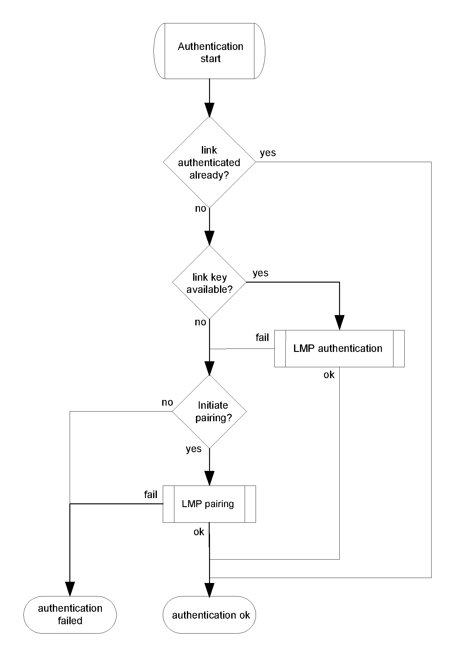
The generic authentication procedure describes how the LMP-authentication and LMP-pairing procedures are used when authentication is initiated by one Bluetooth device towards another, depending on if a link key exists or not and if pairing is allowed or not.
5.1.2. Term on UI level
‘Bluetooth authentication’.
5.1.3. Procedure
Figure 5.1 defines the generic authentication procedure.
5.1.4. Conditions
The local device shall initiate authentication after link establishment. The remote device may initiate security during or after link establishment.
5.2. Security modes
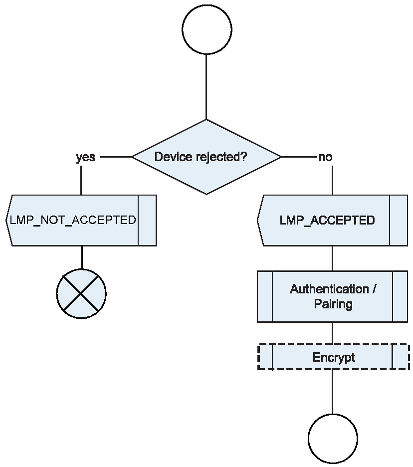
The flow chart in Figure 5.2, including the steps in Figure 5.3, Figure 5.4, and Figure 5.5, specifies the overall channel establishment procedures. The following subsections give more details of these procedures.
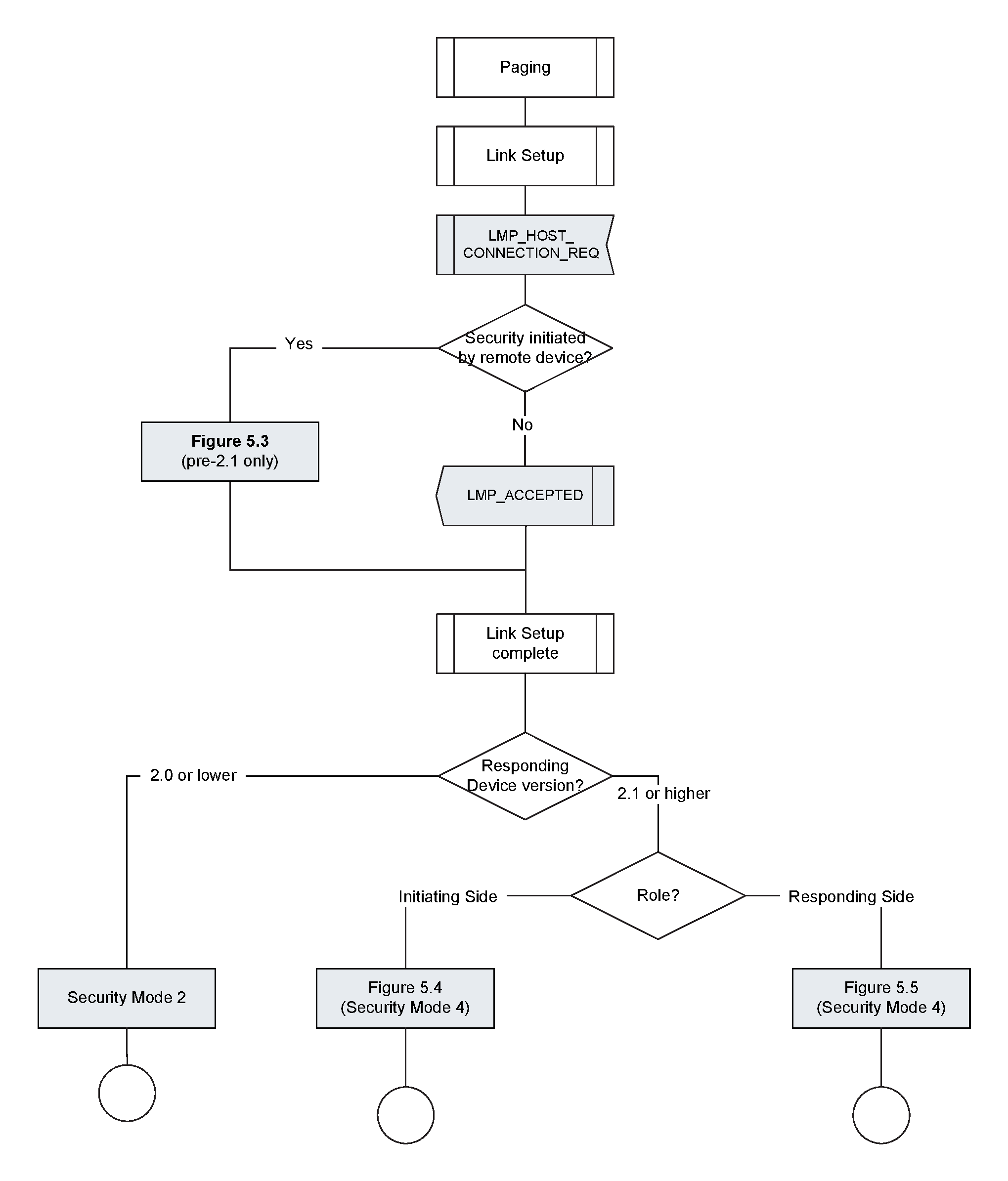
A device may support two security modes simultaneously: security mode 2 for backwards compatibility with remote devices that do not support Secure Simple Pairing and security mode 4 for devices that support Secure Simple Pairing.
5.2.1. Legacy security modes
Legacy security modes apply to those devices with a Controller or a Host that does not support SSP.
5.2.1.1. Security mode 1 (non-secure)
When a remote Bluetooth device is in security mode 1 it will never initiate any security procedure (i.e., it will never send LMP_AU_RAND, LMP_IN_RAND or LMP_ENCRYPTION_MODE_REQ).
5.2.1.2. Security mode 2 (service level enforced security)
When a remote Bluetooth device is in security mode 2 it will not initiate any security procedure before a channel establishment request (L2CAP_CONNECTION_REQ) has been received or a channel establishment procedure has been initiated by itself. Whether a security procedure is initiated or not depends on the security requirements of the requested channel or service.
A Bluetooth device in security mode 2 should classify the security requirements of its services using at least the following attributes:
Authorization required
Authentication required
Encryption required
Note
Note: Security mode 1 can be considered (at least from a remote device point of view) as a special case of security mode 2 where no service has registered any security requirements.
5.2.1.3. Security mode 3 (link level enforced security)
When a remote Bluetooth device is in security mode 3 it will initiate security procedures before it sends LMP_SETUP_COMPLETE.
A Bluetooth device in security mode 3 may reject the Host connection request (respond with LMP_NOT_ACCEPTED to the LMP_HOST_CONNECTION_REQ) based on settings in the Host (e.g., only communication with pre-paired devices allowed).
5.2.2. Security mode 4 (service level enforced security)
A Bluetooth device in security mode 4 shall classify the security requirements of its services using at least the following attributes (in order of decreasing security):
Authenticated link key required
Unauthenticated link key required
Security optional; limited to specific services (see Section 5.2.2.8).
An authenticated link key is a link key where either the numeric comparison, out-of-band, or passkey entry Secure Simple Pairing association models were used. An authenticated link key has protection against man-in-the-middle (MITM) attacks. To ensure that an authenticated link key is created during the Secure Simple Pairing procedure, the Authentication_Requirements parameter should be set to one of the MITM Protection Required options. An unauthenticated link key is a link key where the just works Secure Simple Pairing association model was used. An unauthenticated link key does not have protection against MITM attacks.
When both devices support Secure Simple Pairing, GAP shall require at least an unauthenticated link key and enabling encryption for all connections except those allowed to have security level 0 (see Section 5.2.2.8). A profile or protocol may define services that require more security (e.g., an authenticated link key) or no security (although unencrypted connections are only allowed when connecting to a service allowed to have security level 0). To allow an unauthenticated link key to be created during the Secure Simple Pairing procedure, the Authentication_Requirements parameter may be set to one of the MITM Protection Not Required options.
When the device is in Bondable Mode, it shall enable Secure Simple Pairing mode prior to entering Connectable Mode or establishing a link.
A Bluetooth device in security mode 4 shall respond to authentication requests during link establishment when the remote device is in security mode 3 for backwards compatibility reasons.
A Bluetooth device in security mode 4 enforces its security requirements before it attempts to access services offered by a remote device and before it grants access to services it offers to remote devices. Service access may occur via L2CAP channels or via channels established by protocols above L2CAP such as RFCOMM.
For services transmitting unicast data over the connectionless L2CAP channel, the transmitting device shall enforce its security requirements prior to sending data. There is no mechanism for a device receiving data via the L2CAP connectionless channel to prevent unencrypted data from being received. Hence, Section 5.2.2.1 addresses unicast connectionless data transmission together with devices initiating connection-oriented channels while Section 5.2.2.2 covers only devices responding to requests for connection-oriented channel establishment but does not cover unicast connectionless data reception.
A device may be in a Secure Connections Only mode. When in Secure Connections Only mode, all services (except those allowed to have Security Mode 4, Level 0) available on the BR/EDR physical transport require Security Mode 4, Level 4. The device shall reject both new outgoing and incoming service level connections when the service requires Security Mode 4, Level 4 and either the physical transport does not support Secure Connections or unauthenticated pairing is being requested.
A device operating with a physical transport operating in Secure Connections Only mode may disconnect the ACL connection using error code 0x05 (Authentication Failure) when the physical transport that does not support Secure Connections, tries to access a service that requires Security Mode 4, Level 4.
Note
Note: A device may operate several physical transports simultaneously - in this case all physical transports are required to enable Security Connections Only Mode simultaneously.
5.2.2.1. Security for access to remote service (initiating side)
When the responding device does not support Secure Simple Pairing, it may disconnect the link while the initiating device is requesting the PIN to be entered by the user. This may occur due to the lack of an L2CAP channel being present for longer than an implementation-specific amount of time (e.g., a few seconds). When this occurs, the initiating device shall allow the user to complete entering the PIN and shall then re-page the remote device and restart the pairing procedure (see [Vol 2] Part C, Section 4.2.2) using the PIN entered.
5.2.2.1.1. Pairing required for access to remote service
When a Bluetooth device in security mode 4 initiates access to a remote service via a connection-oriented L2CAP channel, the service requires security, and a sufficient link-key is not available, the local device shall perform pairing procedures and enable encryption before sending a channel establishment request (an L2CAP connection request or a higher-layer channel establishment request such as that of RFCOMM).
When a Bluetooth device in security mode 4 transmits data to a remote service via the unicast connectionless L2CAP channel and a sufficient link-key is not available, the local device shall perform pairing procedures and enable encryption before transmitting unicast data on the connectionless L2CAP channel.
See Section 5.2.2.8 for details on determining whether or not a link key is sufficient.
If pairing does not succeed, the local device shall not send a channel establishment request. The local device may re-try pairing up to three (3) times. If pairing fails three consecutive times, the local device shall disconnect the ACL link with error code 0x05 - Authentication Failure.
If the link key generated is not at least as good as the expected or required type, the local device shall fail the establishment and may disconnect the ACL link with error code 0x05 - Authentication Failure.
5.2.2.1.2. Authentication required for access to remote service
When a Bluetooth device in security mode 4 initiates access to a remote service via a connection-oriented L2CAP channel and a sufficient link key is available for the remote device, it shall authenticate the remote device and enable encryption before sending a channel establishment request (an L2CAP connection request or a higher layer-channel establishment request such as that of RFCOMM).
When a Bluetooth device in security mode 4 transmits unicast data to a remote service via the connectionless L2CAP channel and security is required for the application and a sufficient link-key is available then the local device shall authenticate the remote device and enable encryption before transmitting unicast data on the L2CAP connectionless channel.
See Section 5.2.2.8 for details on determining whether or not a link key is sufficient.
If authentication is required by the service but does not succeed, or if a sufficient link-key is not available, then the local device shall not enable encryption. If encryption is not enabled or if enabling encryption does not result in the correct encryption type (i.e. AES-CCM or E0), the local device shall not send a channel establishment request and shall not send any unicast data via the L2CAP connectionless channel for that application. The Host may then notify the user and offer to perform pairing.
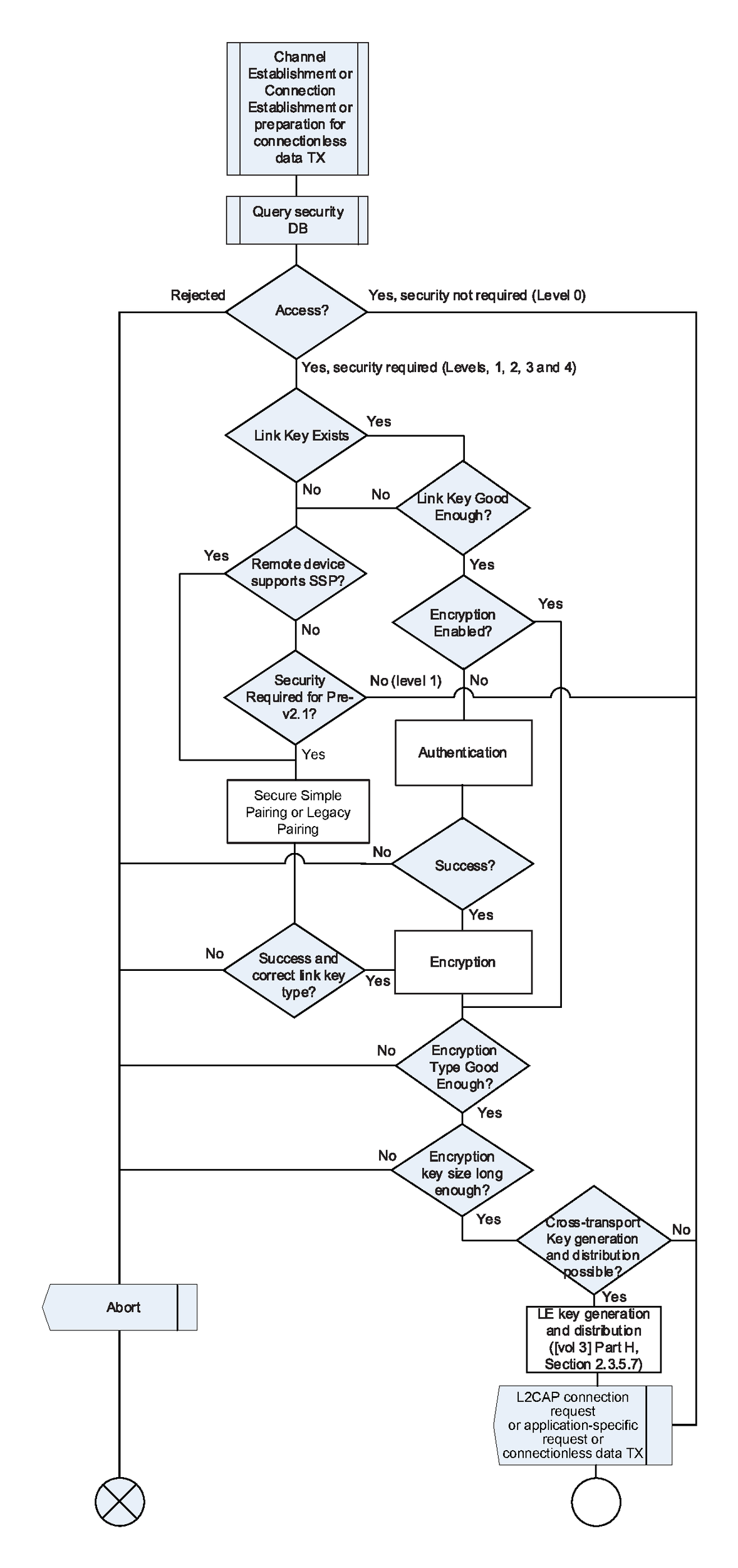
5.2.2.1.3. Cross-transport key generation and distribution
After encryption is enabled and both devices support cross-transport key generation, the Central of the BR/EDR transport may perform LE key generation and distribution ([Vol 3] Part H, Section 2.3.5.7).
If a role switch gets performed after enabling encryption but before the LE keys can be generated and distributed, the new Central may perform LE key generation and distribution once the role switch has completed.
5.2.2.2. Security for access to local service by remote device (responding side)
When a remote device attempts to access a service offered by a Bluetooth device that is in security mode 4 and the service requires security, a sufficient link key exists, and authentication has not been performed, the local device shall authenticate the remote device and enable encryption after the channel establishment request is received but before a channel establishment confirmation (L2CAP connection response with result code of 0x0000 or a higher-level channel establishment confirmation such as that of RFCOMM) is sent.
When L2CAP is the channel establishment protocol being used for the requested service, an L2CAP connection response signaling packet shall be sent by the responding device containing a pending result code following receipt of an L2CAP connection request and prior to initiating security procedures which can result in prompting the local user for input (e.g., pairing using a PIN or Secure Simple Pairing using either the Passkey entry or Numerical Comparison association models). This will stop the L2CAP RTX timer on the remote device (which may be as short as 1 second) and will invoke the ERTX timer on the remote device, which is a minimum duration of 60 seconds.
See [Vol 3] Part A, Section 6.2 for additional information on L2CAP RTX and ERTX timers. See also [Vol 3] Part A, Section 4.3 and [Vol 3] Part A, Section 4.26 for additional information on the L2CAP connection response signaling packets and the defined result codes.
Higher layer channel establishment protocols should be designed to restrict timeouts to be 30 seconds or longer to allow for user input, or provide mechanisms to dynamically extend timeouts when user input may be required.
If authentication or pairing fails when a remote device is attempting to access a local service, the local device shall send a negative response to the channel establishment request (L2CAP connection request or application-specific channel establishment request) indicating a security issue if possible. If the channel establishment protocol is L2CAP, then the result code in the L2CAP connection response shall be set to indicate that the connection was refused due to security reasons. If an L2CAP_CONNECTION_RSP is being sent, then the result code shall be set to 0x0003 (connection refused - security block). If an L2CAP_CREDIT_BASED_CONNECTION_RSP is being sent, then the result code shall be set to 0x0005 (All connections refused - insufficient authentication), 0x0006 (All connections refused - insufficient authorization), 0x0007 (All connections refused - encryption key size too short), or 0x0008 (All connections refused - insufficient encryption).
If the remote device has indicated support for Secure Simple Pairing, a channel establishment request is received for a service other than SDP, and encryption has not yet been enabled, then the local device shall disconnect the ACL link with error code 0x05 - Authentication Failure.
5.2.2.2.1. Pairing required for access to local service by remote device
When a remote device attempts to access a service offered by a Bluetooth device that is in security mode 4 and pairing is required due to the link key being absent or insufficient, the local device shall perform pairing procedures and enable encryption after the channel establishment request is received and before a channel establishment confirmation (L2CAP connection response with result code of 0x0000 or a higher-level channel establishment response such as that of RFCOMM) is sent.
See Section 5.2.2.6 for details on determining whether or not a link key is sufficient.
If pairing does not succeed, then the local device shall not send a channel establishment confirmation. The local device may retry pairing up to three (3) times. If pairing fails three consecutive times, then the local device shall disconnect the ACL link with error code 0x05 - Authentication Failure.
If the link-key generated is not at least as good as the expected or required type or if enabling encryption does not result in the correct encryption type (i.e. AES-CCM or E0), then the local device shall fail the channel establishment and may disconnect the ACL link with error code 0x05 - Authentication Failure.
5.2.2.2.2. Authentication required for access to local service by remote device
See Section 5.2.2.6 for details on determining whether or not a link key is sufficient.
If authentication does not succeed, then the local device shall not send a channel establishment confirmation. The Host may at this point notify the user and offer to perform pairing.
A Bluetooth device in security mode 4 shall respond to authentication and pairing requests during link establishment when the remote device is in security mode 3 for backwards compatibility reasons. However, authentication of the remote device shall be performed after the receipt of the channel establishment request is received, and before the channel establishment response is sent.
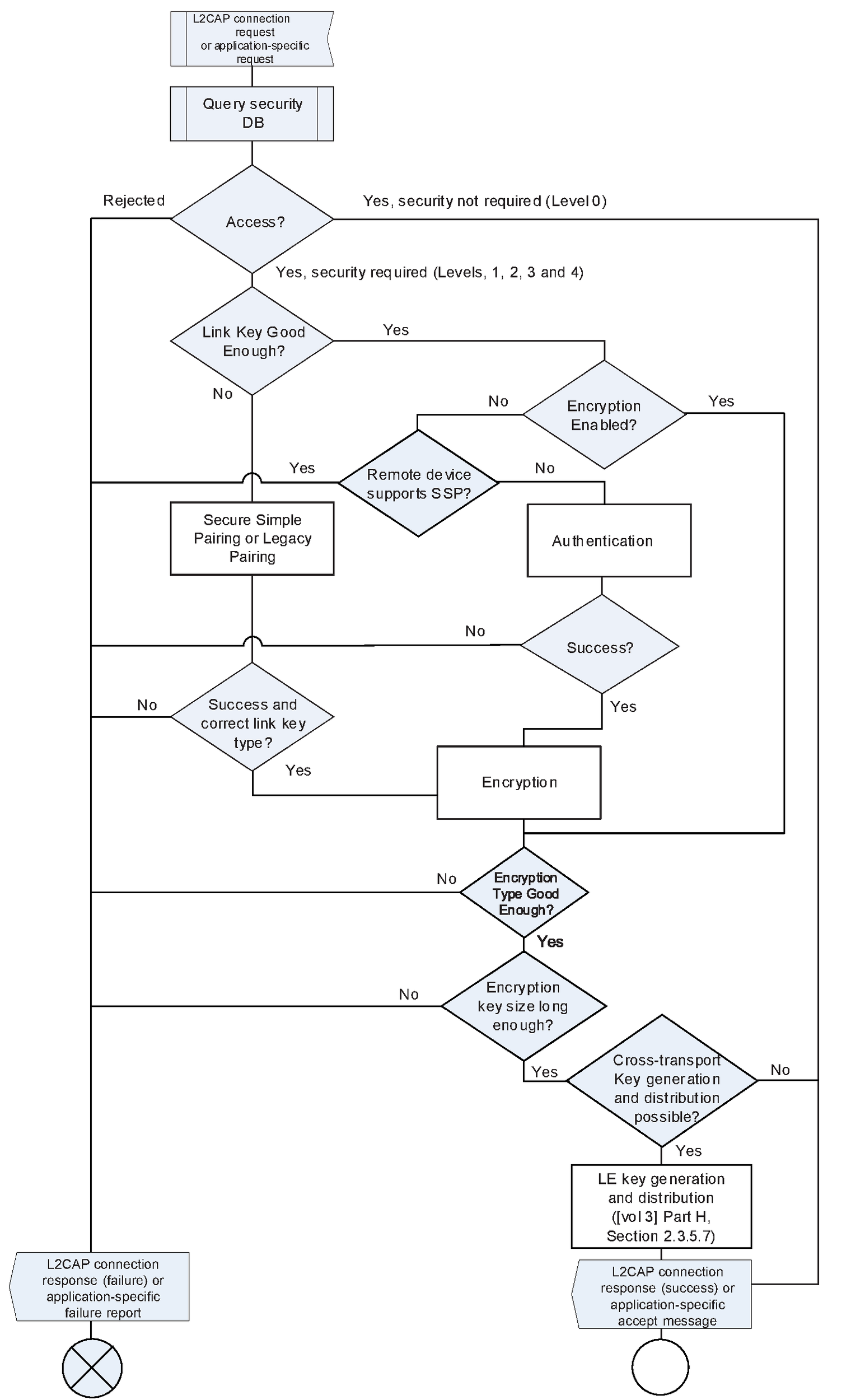
5.2.2.2.3. Cross-transport key generation and distribution
After encryption is enabled and both devices support cross-transport key generation, the Central of the BR/EDR transport may perform LE key generation and distribution ([Vol 3] Part H, Section 2.3.5.7).
If a role switch gets performed after enabling encryption but before the LE keys can be generated and distributed, the new Central may perform LE key generation and distribution once the role switch has completed.
5.2.2.3. Secure Simple Pairing after authentication failure
When both devices support Secure Simple Pairing all non-SDP connections are encrypted regardless of whether security was required or whether the devices are bonded or not. The initial connection between the two devices will result in a link key through Secure Simple Pairing. Depending on whether or not bonding was performed and the security policy of the initiating device, the link key may be stored. When the link key is stored, subsequent connections to the same device will use authentication but this may fail if the remote device has deleted the link key. Table 5.2 defines what shall be done depending on the type of the link key and whether bonding was performed or not.
Link Key Type | Devices Bonded? | Action to take when Authentication Fails |
|---|---|---|
Combination | No | Depends on security policy of the device:
Option 2 is recommended. |
Combination | Yes | Notify user of security failure |
Unauthenticated | No | Depends on security policy of the device:
Option 1 is recommended. |
Unauthenticated | Yes | Notify user of security failure |
Authenticated | No | Depends on security policy of the device:
Option 2 is recommended. |
Authenticated | Yes | Notify user of security failure |
Non-bonded authenticated or unauthenticated link keys may be considered disposable by either device and may be deleted at any time.
5.2.2.4. IO capabilities
Once a connection is established, if the Host determines that security is necessary and both devices support Secure Simple Pairing, the devices perform an IO capability exchange. The purpose of the IO capability exchange is to determine the authentication algorithm used in the Authentication stage 1 phase of Secure Simple Pairing.
The input and output capabilities are described in Table 5.3:
Capability | Description |
|---|---|
No input | Device does not have the ability to indicate 'yes' or 'no' |
Yes / No | Device has at least two buttons that are mapped easily to 'yes' and 'no' or the device has a mechanism whereby the user can indicate either 'yes' or 'no' (see note below). |
Keyboard | Device has a numeric keyboard that can input the numbers '0' to '9' and a confirmation. Device also has two buttons that can be easily mapped to 'yes' and 'no' or the device has a mechanism whereby the user can indicate either 'yes' or 'no' (see Note below). |
Note
Note: 'yes' could be indicated by pressing a button within a certain time limit otherwise 'no' would be assumed.
Capability | Description |
|---|---|
No output | Device does not have the ability to display or communicate a 6 digit decimal number |
Numeric output | Device has the ability to display or communicate a 6 digit decimal number |
5.2.2.5. Mapping of input / output capabilities to IO capability
The individual input and output capabilities are mapped to a single IO capability which is later used to determine which authentication algorithm will be used.
Local Input Capability | No input | NoInputNoOutput | DisplayOnly |
Yes / No | NoInputNoOutput | DisplayYesNo | |
Keyboard | KeyboardOnly | DisplayYesNo |
When a device has OOB authentication information from the remote device, it will indicate it in the LMP_IO_CAPABILITY_RES PDU. When either device has OOB information, the OOB association model will be used.
The Host may allow the Link Manager to ignore the IO capabilities and use the Numeric Comparison protocol with automatic accept by setting the Authentication_Requirements parameter to one of the MITM Protection Not Required options.
5.2.2.6. IO and OOB capability mapping to authentication stage 1 method
Determining which association model to use in Authentication stage 1 is performed in three steps. First, the devices look at the OOB Authentication Data Present parameter received in the remote IO capabilities. If either device has received OOB authentication data then the OOB association model is used. The event of receiving the OOB information is indicated by a device to its peer in the IO Capability Exchange step of Secure Simple Pairing.
Device B | Has not received remote OOB authentication data | Use the IO capability mapping table | Use OOB association with ra = 0 rb from OOB |
Has received remote OOB authentication data | Use OOB association with ra from OOB rb = 0 | Use OOB association with ra from OOB rb from OOB |
Second, if neither device has received OOB authentication data and if both devices have set the Authentication_Requirements parameter to one of the MITM Protection Not Required options, authentication stage 1 shall function as if both devices set their IO capabilities to DisplayOnly (e.g., Numeric comparison with automatic confirmation on both devices).
Finally, if neither device has received OOB authentication data and if one or both devices have set the Authentication_Requirements parameter to one of the MITM Protection Required options, the IO and OOB capabilities are mapped to the authentication stage 1 method as defined in Table 5.7. A Host that has set the Authentication_Requirements parameter to one of the MITM Protection Required options shall verify that the resulting Link Key is an Authenticated Combination Key (see [Vol 4] Part E, Section 7.7.24). Table 5.7 also lists whether the combination key results in an authenticated or unauthenticated link key.
Device B (Responder) | DisplayOnly | Numeric Comparison with automatic confirmation on both devices. | Numeric Comparison with automatic confirmation on device B only. | Passkey Entry: Responder Display, Initiator Input. | Numeric Comparison with automatic confirmation on both devices. |
Unauthenticated | Unauthenticated | Authenticated | Unauthenticated | ||
DisplayYesNo | Numeric Comparison with automatic confirmation on device A only. | Numeric Comparison: Both Display, Both Confirm. | Passkey Entry: Responder Display, Initiator Input. | Numeric Comparison with automatic confirmation on device A only and Yes/No confirmation whether to pair on device B. Device B does not show the confirmation value. | |
Unauthenticated | Authenticated | Authenticated | Unauthenticated | ||
Keyboard Only | Passkey Entry: Initiator Display, Responder Input. | Passkey Entry: Initiator Display, Responder Input. | Passkey Entry: Initiator and Responder Input. | Numeric Comparison with automatic confirmation on both devices. | |
Authenticated | Authenticated | Authenticated | Unauthenticated | ||
NoInputNoOutput | Numeric Comparison with automatic confirmation on both devices. | Numeric Comparison with automatic confirmation on device B only and Yes/No confirmation on whether to pair on device A. Device A does not show the confirmation value. | Numeric Comparison with automatic confirmation on both devices. | Numeric Comparison with automatic confirmation on both devices. | |
Unauthenticated | Unauthenticated | Unauthenticated | Unauthenticated |
Note
Note: The "DisplayOnly" IO capability only provides unidirectional authentication.
5.2.2.7. Out of Band (OOB)
An out of band mechanism may also be used to communicate discovery information as well as other information related to the pairing process.
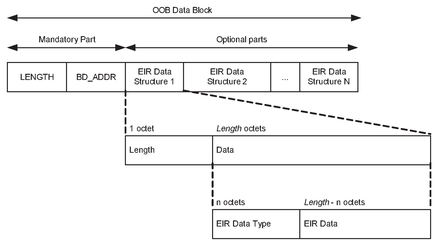
The contents of the OOB data block are:
Mandatory contents:
Length (2 bytes)
BD_ADDR (6 bytes)
Optional contents:
Class of Device (3 bytes)
Secure Simple Pairing Hash C (16 bytes)
Secure Simple Pairing Randomizer R (16 bytes)
Local name (variable length)
Other information
The length field includes all bytes in the OOB data block including the length field itself. The BD_ADDR will be a fixed field in the beginning of the OOB data block. Following the BD_ADDR will be zero or more EIR tag fields containing optional contents. The EIR tag format will be used for the optional contents. See Figure 5.6.
If Secure Simple Pairing fails when one or both devices have OOB Authentication Data present, both devices shall discard the OOB Authentication Data and the device that originally initiated authentication shall re-initiate authentication. Although the user may get involved in authentication as defined by the IO capabilities of the two devices, falling back to the in-band association model will prevent deadlock conditions when one or both devices has stale OOB Authentication Data.
There is a MIME type defined for use with the OOB data format. The MIME type can be found from the following link: http://www.iana.org/assignments/media-types/application/vnd.bluetooth.ep.oob
5.2.2.8. Security database
A Bluetooth device in security mode 4 shall classify and enforce the security requirements of its services using the following levels attributes (in order of decreasing security) for use when pairing with remote devices supporting Secure Simple Pairing:
Level 4, for services with the following attributes:
Authentication of the remote device required
MITM protection required
128-bit equivalent strength for link and encryption keys required using FIPS approved algorithms (E0 not allowed, SAFER+ not allowed, and P-192 not allowed; encryption key not shortened)
User interaction acceptable
Level 3, for services with the following attributes:
Authentication of the remote device required
MITM protection required
Encryption required
At least 56-bit equivalent strength for encryption key should be used
User interaction acceptable
Level 2, for services with the following attributes:
Authentication of the remote device required
MITM protection not required
Encryption required
At least 56-bit equivalent strength for encryption key should be used
Level 1, for services with the following attributes:
Authentication of the remote device required when encryption is enabled
MITM protection not required
At least 56-bit equivalent strength for encryption key when encryption is enabled should be used
Minimal user interaction desired
Level 0: Service requires the following:
Authentication of the remote device not required
MITM protection not required
No encryption required
No user interaction required
Security Mode 4 Level 0 shall only be used for:
L2CAP fixed signaling channels with CIDs 0x0001, 0x0003, and 0x003F
SDP
broadcast data sent on the connectionless L2CAP channel (CID 0x0002)
services with the combinations of Service Class UUIDs and L2CAP traffic types listed in Section 1 of [5].
The security level required for each service offered should be stored in a security database that is accessed to determine the type of link key and the encryption key size that is required for access to the respective service. The security level required for service data transmitted on an L2CAP connection-oriented channel may differ from the security level required for service data transmitted on another L2CAP connection-oriented channel or on the connectionless L2CAP channel. Table 5.8 shows the type of link key required for each security level for both remote devices that support Secure Simple Pairing and for those that do not.
Security Level Required for Service | Link Key type required for remote devices that support SSP | Link Key type required for remote devices that do not support SSP | Comments | ||||||||||||||||||||||||||||||||||||||||||||||
|---|---|---|---|---|---|---|---|---|---|---|---|---|---|---|---|---|---|---|---|---|---|---|---|---|---|---|---|---|---|---|---|---|---|---|---|---|---|---|---|---|---|---|---|---|---|---|---|---|---|
Level 4
| Authenticated (P-256 based Secure Simple Pairing and Secure Authentication) | NA | Highest Security Only possible when both devices support Secure Connections | ||||||||||||||||||||||||||||||||||||||||||||||
Level 3
| Authenticated | Combination (16 digit PIN recommended) | High Security | ||||||||||||||||||||||||||||||||||||||||||||||
Level 2
| Unauthenticated | Combination | Medium Security | ||||||||||||||||||||||||||||||||||||||||||||||
Level 1
| Unauthenticated | None | Low Security | ||||||||||||||||||||||||||||||||||||||||||||||
Level 0
| None | None | Permitted only for SDP and service data sent via either L2CAP fixed signaling channels or the L2CAP connectionless channel to PSMs that correspond to service class UUIDs which are allowed to utilize Level 0. | ||||||||||||||||||||||||||||||||||||||||||||||
[1] Though encryption is not necessary for the service for Level 1, the specification mandates the use of encryption for all services other than SDP when the remote device supports SSP. | |||||||||||||||||||||||||||||||||||||||||||||||||
An authenticated link key is a link key where either the numeric comparison, out-of-band, or passkey entry Secure Simple Pairing association models were used. An authenticated link key has protection against MITM attacks. To ensure that an authenticated link key is created during the Secure Simple Pairing procedure, the Authentication_Requirements parameter should be set to one of the MITM Protection Required options.
An unauthenticated link key is a link key where the “Just Works” Secure Simple Pairing association model was used (see [Vol 1] Part A, Section 5.2.4). An unauthenticated link key does not have protection against MITM attacks. To allow an unauthenticated link key to be created during the Secure Simple Pairing procedure, the Authentication_Requirements parameter may be set to one of the MITM Protection Not Required options.
When both devices support Secure Simple Pairing and at least one device does not support Secure Connections, the strength of the link key is 96 effective bits. When both devices support Secure Connections, the strength of the link key is 128 effective bits. Secure Connections does not change the protection against MITM attacks.
A combination link key is a link key where BR/EDR Legacy Pairing was used to generate the link-key (see [Vol 2] Part C, Section 4.2.2.4).
When both devices support Secure Simple Pairing, GAP shall require at least an unauthenticated link key and enable encryption for service traffic sent or received via connection-oriented L2CAP channels. A profile or protocol may define services that require more security (for example, an authenticated link key) or no security in the case of SDP or service traffic sent via the L2CAP connectionless channel for services that do not require security.
When the device is in Bondable Mode, it shall enable Secure Simple Pairing mode prior to entering Connectable Mode or establishing a link.
A Bluetooth device in security mode 4 shall respond to authentication and pairing requests during link establishment when the remote device is in security mode 3 for backwards compatibility reasons. See Section 5.2.1.3 for more information.
The remote Controller's and remote Host's support for Secure Simple Pairing shall be determined by the Link Manager Secure Simple Pairing (Host Support) feature bit.
A previously generated link key is considered “sufficient” if the link key type is of the type required for the service, or of a higher strength. Authenticated link keys are considered higher strength than Unauthenticated or Combination keys. Unauthenticated link keys are considered higher strength than Combination keys.
A device shall enforce an encryption key with at least 128-bit equivalent strength for all services that require Security Mode 4, Level 4. For all other services that require encryption, a device should enforce an encryption key with at least 56-bit equivalent strength, irrespective of whether the remote device supports Secure Simple Pairing.
After encryption has been enabled, the Host should check the encryption key size using either the HCI_Read_Encryption_Key_Size command (see [Vol 4] Part E, Section 7.5.7) or a vendor-specific method.
6. Idle mode procedures – BR/EDR physical transport
The requirements for devices initiating the inquiry and discovery procedures (device A) are specified in Table 6.1. The requirements on the behavior of the responding device (device B) are specified in Table 4.1.
Procedure | Ref. | Support |
|---|---|---|
General inquiry | C.1 | |
Limited inquiry | C.1 | |
Name discovery | O | |
Device discovery | O | |
Bonding | O | |
Note: Support for LMP-pairing is mandatory (see [Vol 2] Part C, Section 4.2.2). | ||
6.1. General Inquiry
6.1.1. Purpose
The purpose of the general inquiry procedure is to provide the initiator with the Bluetooth Device Address, clock, Class of Device, and extended inquiry response information of devices in either general discoverable mode or limited discoverable mode.
The general inquiry procedure should be used for general purpose discovery, i.e. to discover all discoverable devices regardless of whether they are in general discoverable mode or limited discoverable mode. A device which discovers devices using the general inquiry procedure and presents them to users in some fashion should distinguish devices in the limited discoverable mode from those in the general discoverable mode, e.g., by sorting them to the top of a list of discovered devices or highlighting them in some way.
Note
Note: The rationale for distinguishing the devices in limited discoverable mode to the end user is that devices typically enter limited discoverable mode only after explicit action by the end user, indicating that the user’s immediate goal is to discover and interact with that specific device.
6.1.2. Term on UI level
‘Bluetooth Device Inquiry’.
6.1.3. Description
Figure 6.1 specifies the procedure.
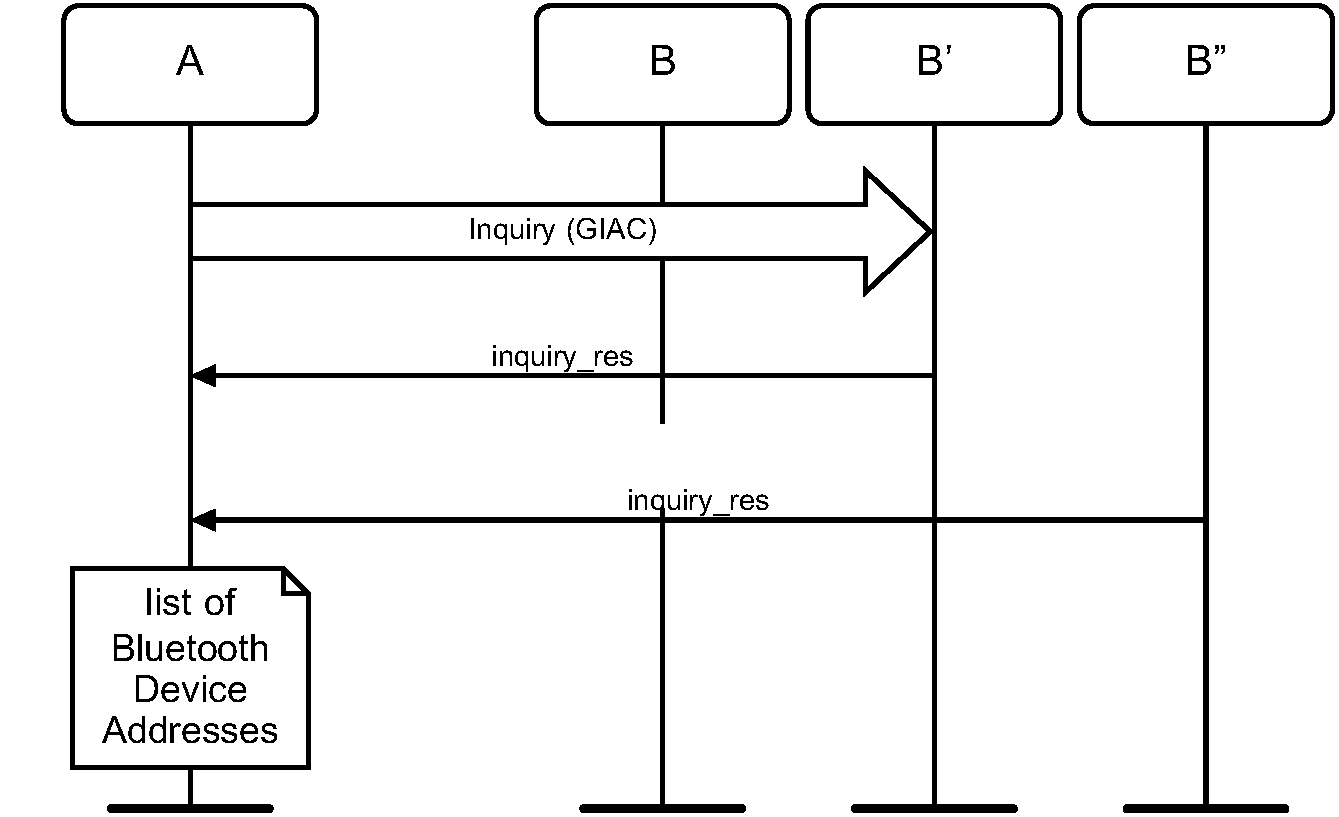
6.1.4. Conditions
When general inquiry is initiated by a Bluetooth device, the INQUIRY state shall last TGAP(100) or longer, unless the inquirer collects enough responses and determines to abort the INQUIRY state earlier. The Bluetooth device shall perform inquiry using the GIAC.
In order for Device A to receive inquiry responses, the remote devices in range have to be made discoverable (limited or general).
6.2. Limited Inquiry
6.2.1. Purpose
The purpose of the limited inquiry procedure is to provide the initiator with the Bluetooth Device Address, clock, Class of Device, and extended inquiry response information of limited discoverable devices. The latter devices are devices that are in range with regard to the initiator, and set to scan for inquiry messages with the Limited Inquiry Access Code.
The limited inquiry procedure should only be used when it is known that the devices to be discovered are using limited discoverable mode. The general inquiry procedure (see Section 6.1) should be used for general purpose discovery when it is desired to discover all devices regardless of whether they are using limited discoverable mode or general discoverable mode.
6.2.2. Term on UI level
’Bluetooth Device Inquiry’.
6.2.3. Description
Figure 6.2 specifies the procedure.
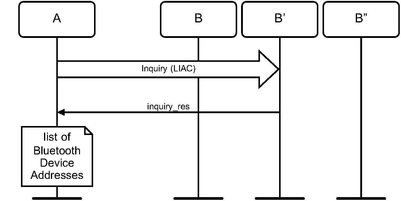
6.2.4. Conditions
When limited inquiry is initiated by a Bluetooth device, the INQUIRY state shall last TGAP(100) or longer, unless the inquirer collects enough responses and determines to abort the INQUIRY state earlier. The Bluetooth device shall perform inquiry using the LIAC.
In order for Device A to receive inquiry responses, the remote devices in range has to be made limited discoverable.
6.3. Name Discovery
6.3.1. Purpose
The purpose of name discovery is to provide the initiator with the Bluetooth Device Name of connectable devices (i.e., devices in range that will respond to paging).
6.3.2. Term on UI level
’Bluetooth Device Name Discovery’
6.3.3. Description
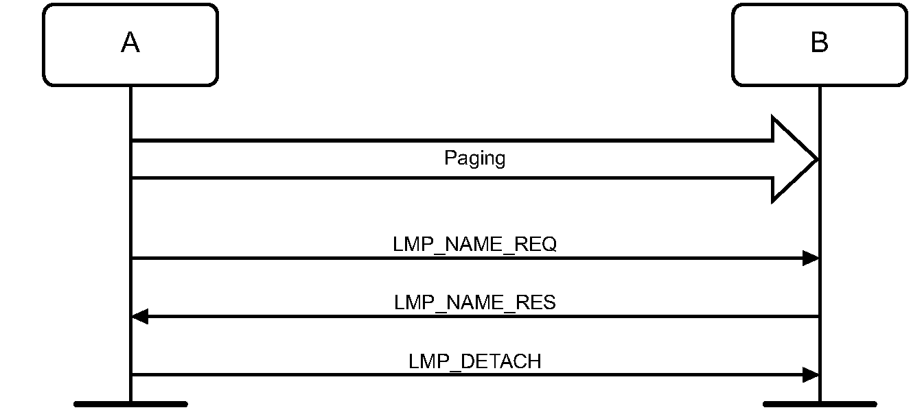
6.3.3.1. Name Request
Name request is the procedure for retrieving the Bluetooth Device Name from a connectable Bluetooth device. It is not necessary to perform the full link establishment procedure (see Section 7.1) in order to just to get the name of another device. Figure 6.3 specifies the procedure.
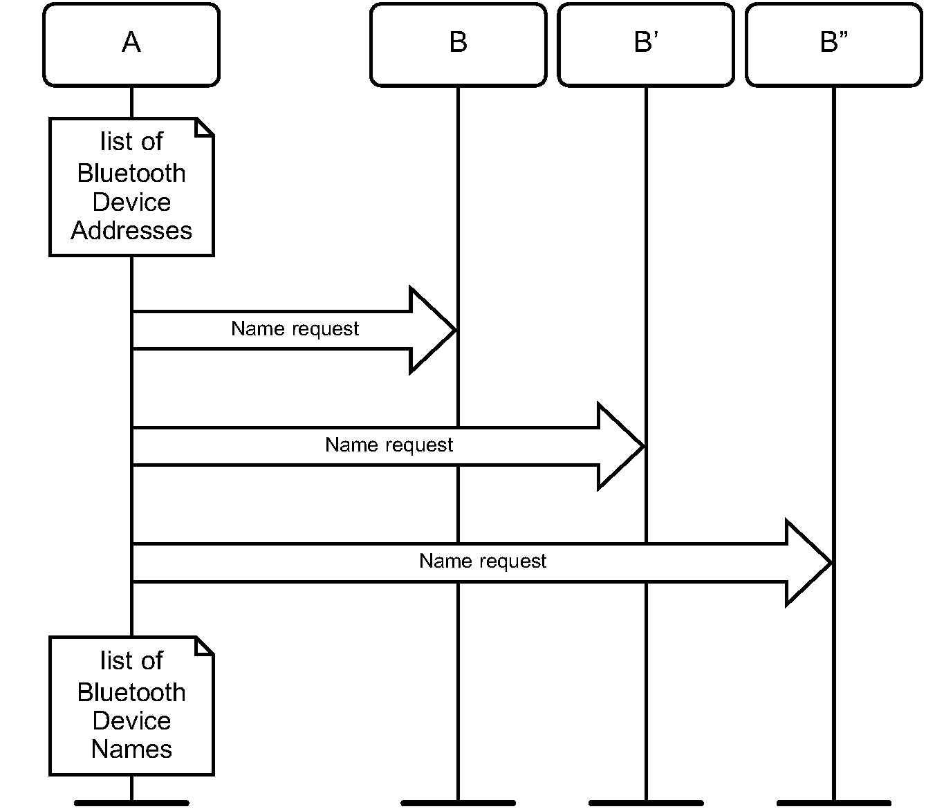
6.3.3.2. Name Discovery
Name discovery is the procedure for retrieving the Bluetooth Device Name from connectable Bluetooth devices by performing name request towards known devices (i.e., Bluetooth devices for which the Bluetooth Device Addresses are available). Figure 6.4 specifies the procedure.
6.3.4. Conditions
In the name request procedure, the initiator will use the Device Access Code of the remote device as retrieved immediately beforehand – normally through an inquiry procedure.
6.4. Device Discovery
This section only applies to a device of the BR/EDR and BR/EDR/LE device type.
6.4.1. Purpose
The purpose of device discovery is to provide the initiator with the Bluetooth Device Address, clock, Class of Device, Bluetooth Device Name, and extended inquiry response information of discoverable devices.
6.4.2. Term on UI level
’Bluetooth Device Discovery’
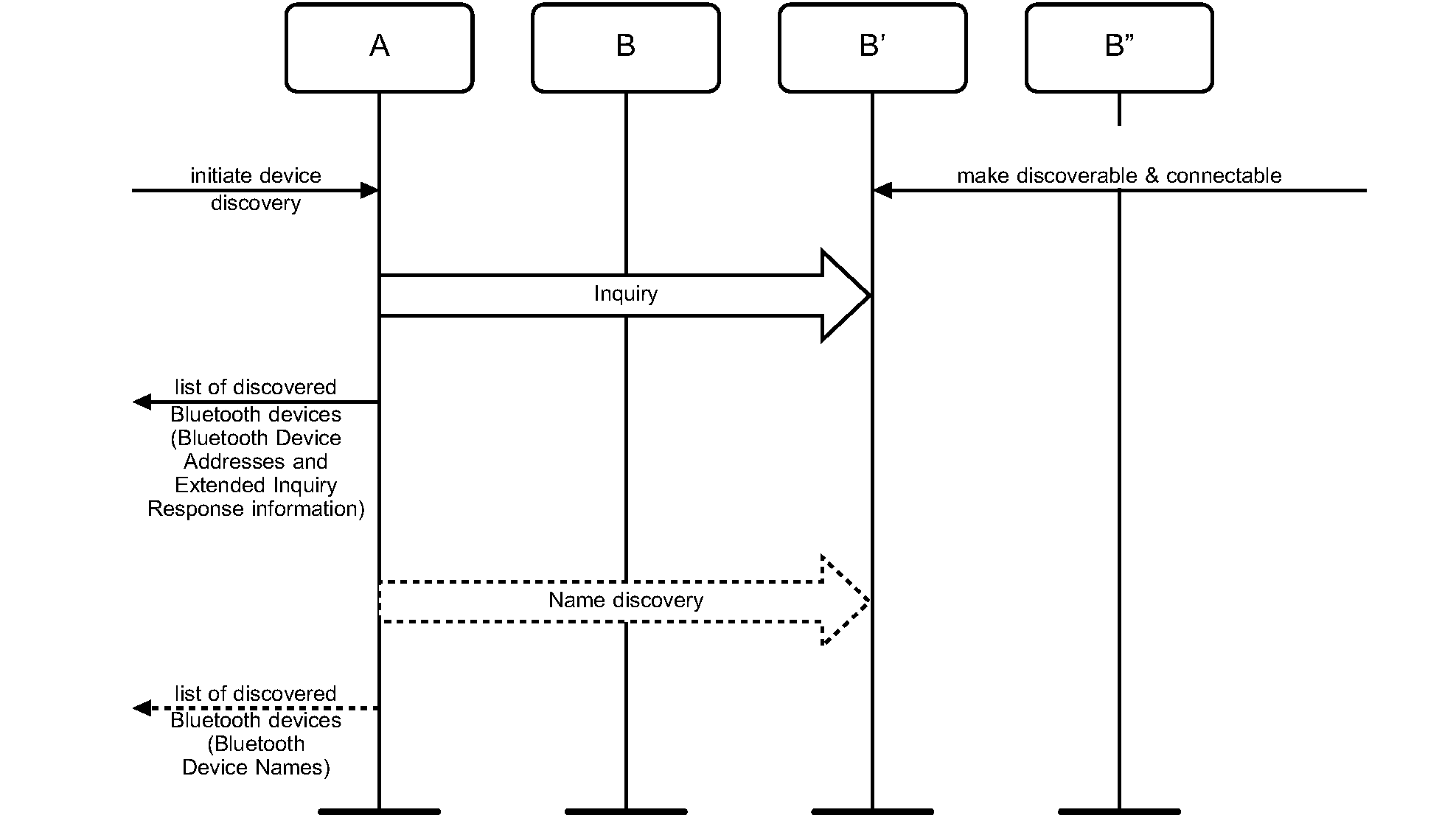
6.4.3. Description
During the Device Discovery procedure, first an inquiry (either general or limited) is performed, and then name discovery is done towards some or all of the devices that responded to the inquiry. If the initiator of the device discovery receives a complete local name or a shortened local name that is considered long enough, via an extended inquiry response from a remote device, the initiator should not do a separate name discovery for that device.
6.4.4. Conditions
Conditions for both inquiry (general or limited) and name discovery must be fulfilled (i.e., devices discovered during device discovery must be both discoverable and connectable).
6.5. Bonding
6.5.1. Purpose
The purpose of bonding is to create a relation between two Bluetooth devices based on a common link key (a bond). The link key is created and exchanged (pairing) during the bonding procedure and is expected to be stored by both Bluetooth devices, to be used for future authentication. In addition to pairing, the bonding procedure can involve higher-layer initialization procedures.
6.5.2. Term on UI level
’Bluetooth Bonding’
6.5.3. Description
Two forms of bonding are described in the following sections: General Bonding and Dedicated Bonding.
6.5.3.1. General Bonding
General Bonding refers to the process of performing bonding during connection setup or channel establishment procedures as a precursor to accessing a service. Figure 6.6 specifies General Bonding.
When the devices that are performing General Bonding both support Secure Simple Pairing, the Authentication_Requirements parameter should be set to MITM Protection Not Required – General Bonding unless the security policy of an available local service requires MITM Protection in which case the Authentication_Requirements parameter shall be set to MITM Protection Required – General Bonding. 'No bonding' is used when the device is performing a Secure Simple Pairing procedure, but does not intend to retain the link key after the physical link is disconnected.
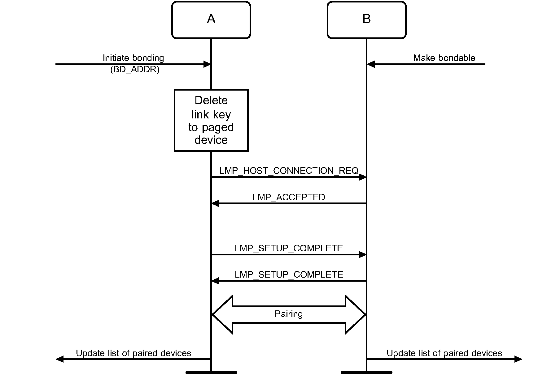
6.5.3.2. Dedicated Bonding
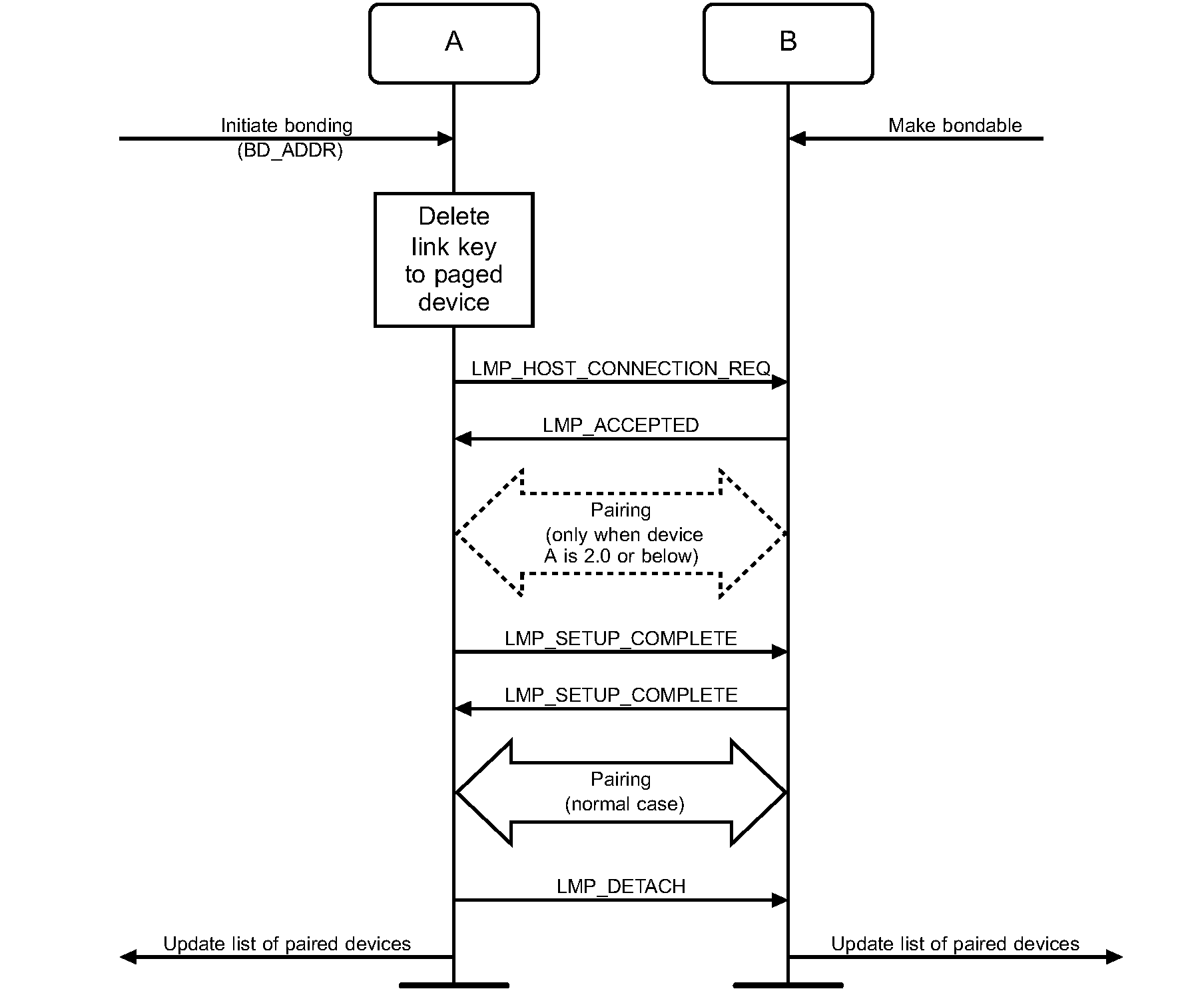
Dedicated Bonding refers to a procedure wherein one device connects to another only for the purpose of pairing without accessing a particular service. Figure 6.7 specifies Dedicated Bonding. The main difference with dedicated bonding, as compared to a pairing done during link or channel establishment, is that for bonding it is the paging device (A) that initiates the authentication.
When the devices that are performing Dedicated Bonding both support Secure Simple Pairing, the Authentication_Requirements parameter should be set to MITM Protection Not Required – Dedicated Bonding unless the security policy of an available local service requires MITM Protection in which case the Authentication Required parameter shall be set to MITM Protection Required – Dedicated Bonding. 'No bonding' is used when the device is performing a Secure Simple Pairing procedure, but does not intend to retain the link key after the physical link is disconnected.
As an exception to the normal process, device B shall also accept pairing before the exchange of LMP_SETUP_COMPLETE PDUs (this can only happen if device A conforms to a lower version of the specification).
6.5.4. Conditions
Before bonding can be initiated, the initiating device (A) must know the Device Access Code of the device to pair with. This is normally done by first performing device discovery. A Bluetooth Device that can initiate bonding (A) should use limited inquiry, and a Bluetooth Device that accepts bonding (B) should support the limited discoverable mode.
Bonding is in principle the same as link establishment with the conditions:
The paged device (B) shall be set into bondable mode. The paging device (A) is assumed to allow pairing since it has initiated the bonding procedure.
The paging device (the initiator of the bonding procedure, A) shall initiate authentication.
Before initiating the authentication part of the bonding procedure, the paging device should delete any link key corresponding to a previous bonding with the paged device.
7. Establishment procedures – BR/EDR physical transport
Procedure | Ref. | Support in A | Support in B |
|---|---|---|---|
Link Establishment | M | M | |
Channel Establishment | O | M | |
Connection Establishment | O | O | |
Synchronization Establishment | O | O |
The establishment procedures defined here do not include any discovery part. Before establishment procedures are initiated, the information provided during device discovery (in the FHS packet or the extended inquiry response packet of the inquiry response or in the response to a name request or in the synchronization train packet) must be available in the initiating device.
This information is:
The Bluetooth Device Address (BD_ADDR) from which the Device Access Code is generated
The system clock of the remote device
Additional information provided during device discovery that may be useful for making the decision to initiate an establishment procedure is:
The Class of Device
The Device name
The supported Service Classes.
7.1. Link Establishment
7.1.1. Purpose
The purpose of the Link Establishment procedure is to establish a logical transport (of ACL type) between two Bluetooth devices using procedures from the Baseband Specification and Link Manager Protocol.
7.1.2. Term on UI level
‘Bluetooth link establishment’
7.1.3. Description
In this sub-section, the paging device (A) is in security mode 3. During link establishment, the paging device cannot distinguish if the paged device (B) is in security mode 1, 2 or 4.
7.1.3.1. B in security mode 1, 2, or 4
Figure 7.1 specifies the procedure.
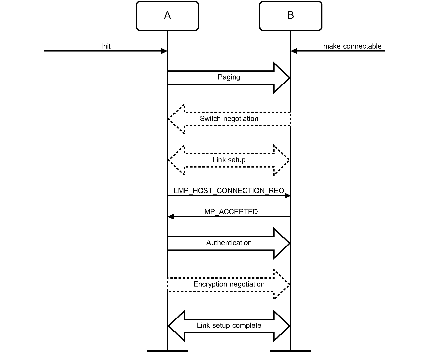
7.1.3.2. B in security mode 3
Figure 7.2 specifies the procedure.
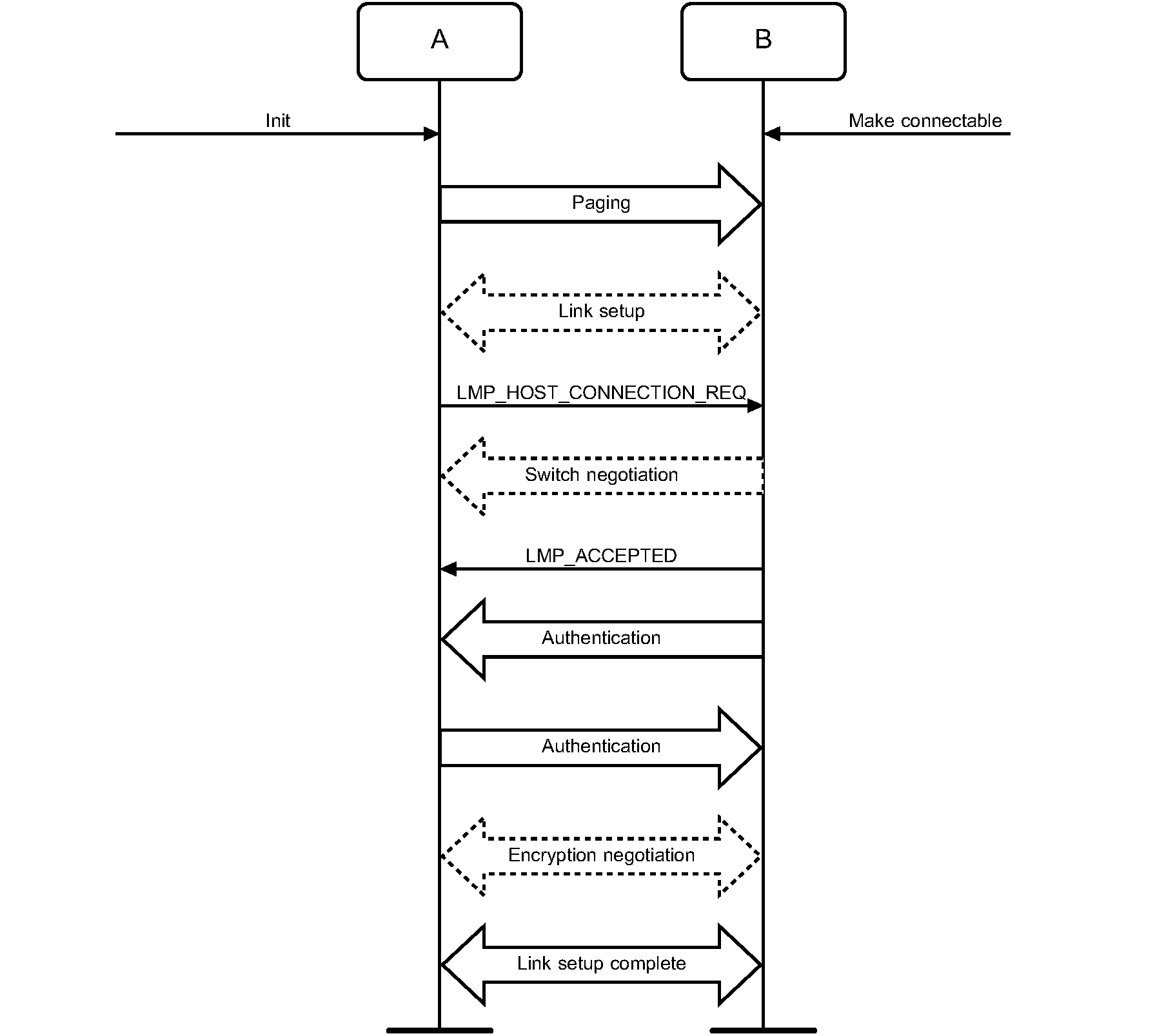
7.1.4. Conditions
The paging procedure shall be according to [Vol 2] Part B, Section 8.3 and the paging device should use the Device Access Code and page mode received through a previous inquiry. When paging is completed, a physical link between the two Bluetooth devices is established.
If role switching is needed it should be done as early as possible after the physical link is established. If the paging device does not accept the switch, the paged device has to consider whether to keep the physical link or not.
Both devices may perform link setup (using LMP procedures that require no interaction with the Host on the remote side). Optional LMP features can be used after having confirmed (using LMP_FEATURES_REQ) that the other device supports the feature.
When the paging device needs to go beyond the link setup phase, it issues a request to be connected to the Host of the remote device. If the paged device is in security mode 3, this is the trigger for initiating authentication.
The paging device shall send LMP_HOST_CONNECTION_REQ during link establishment (i.e., before channel establishment) and may initiate authentication only after having sent LMP_HOST_CONNECTION_REQ.
After an authentication has been performed, any of the devices can initiate encryption.
Further link configuration may take place after the LMP_HOST_CONNECTION_REQ. When both devices are satisfied, they send LMP_SETUP_COMPLETE.
Link establishment is completed when both devices have sent LMP_SETUP_COMPLETE.
7.2. Channel Establishment
7.2.1. Purpose
The purpose of the Channel Establishment procedure is to establish a Bluetooth channel (L2CAP channel) between two Bluetooth devices as described in [Vol 3] Part A, Section 4.2.
7.2.2. Term on UI level
’Bluetooth channel establishment’
7.2.3. Description
In this sub-section, the initiator (A) is in security mode 3. During channel establishment, the initiator cannot distinguish if the acceptor (B) is in security mode 1 or 3.
7.2.3.1. B in security mode 2 or 4
Figure 7.3 specifies the procedure.
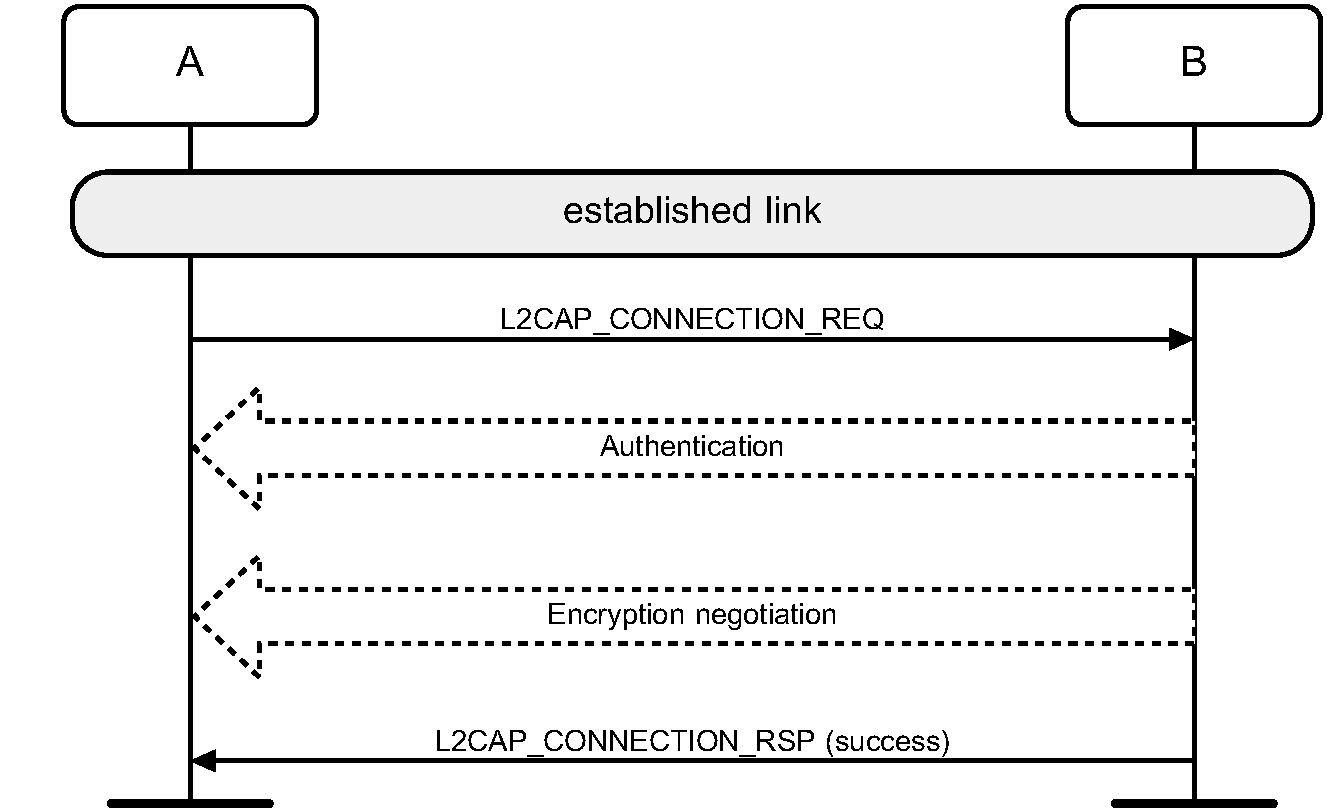
7.2.3.2. B in security mode 1 or 3
Figure 7.4 specifies the procedure.
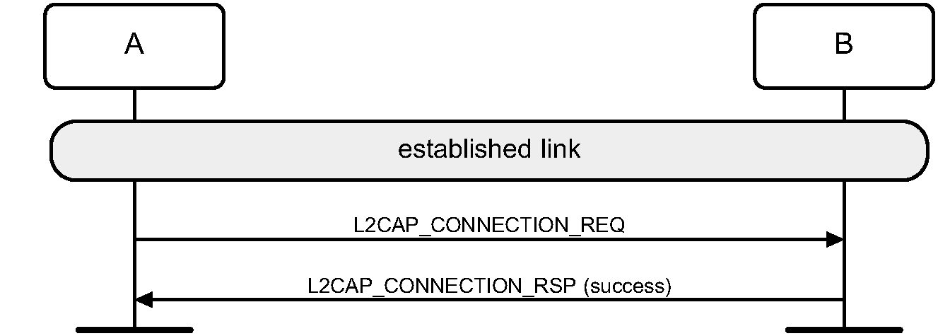
7.2.4. Conditions
Channel establishment starts after link establishment is completed when the initiator sends a channel establishment request (L2CAP_CONNECTION_REQ).
Depending on security mode, security procedures may take place after the channel establishment has been initiated.
Channel establishment is completed when the acceptor responds to the channel establishment request (with a positive L2CAP_CONNECTION_RSP).
7.3. Connection Establishment
7.3.1. Purpose
The purpose of the Connection Establishment procedure is to establish a connection between applications on two Bluetooth devices.
7.3.2. Term on UI level
’Bluetooth connection establishment’
7.3.3. Description
In this sub-section, the initiator (A) is in security mode 3. During connection establishment, the initiator cannot distinguish if the acceptor (B) is in security mode 1 or 3. The connection establishment request and accept messages are defined by the application protocol.
7.3.3.1. B in security mode 2 or 4
Figure 7.5 specifies the procedure.
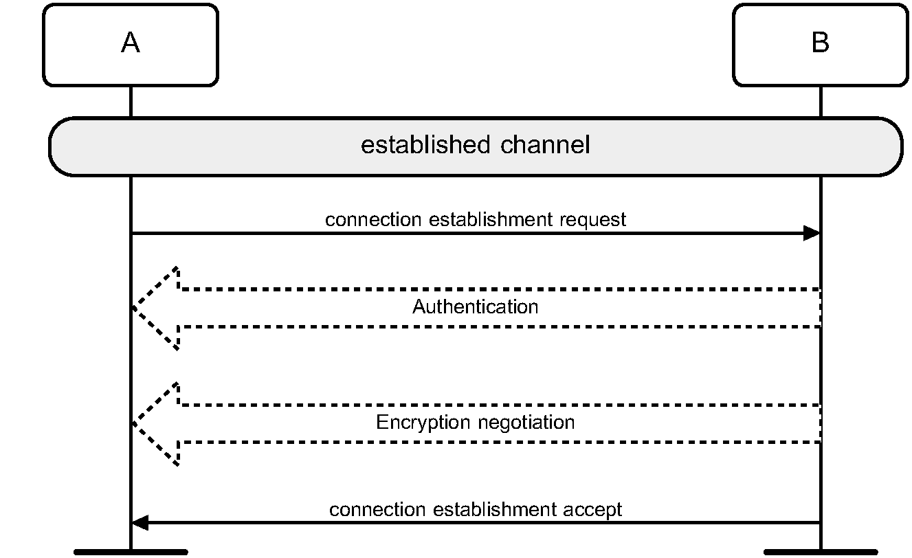
7.3.3.2. B in security mode 1 or 3
Figure 7.6 specifies the procedure.
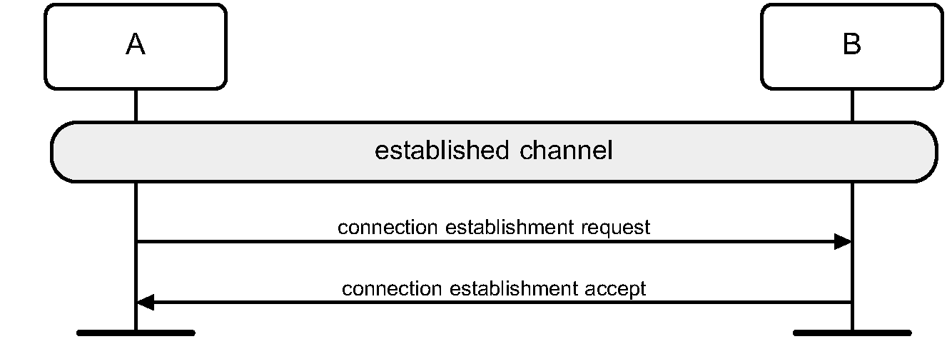
7.3.4. Conditions
Connection establishment starts after channel establishment is completed, when the initiator sends a connection establishment request. This request may be a TCS SETUP message [2] in the case of a Bluetooth telephony application Cordless Telephony Profile, or initialization of RFCOMM and establishment of DLC [1] in the case of a serial port-based application Serial Port Profile (although neither TCS or RFCOMM use the term ‘connection’ for this).
Connection establishment is completed when the acceptor accepts the connection establishment request.
7.4. Establishment of additional connection
When a Bluetooth device has established one connection with another Bluetooth device, it may be available for establishment of:
A second connection on the same channel, and/or
A second channel on the same logical link, and/or
A second physical link.
If the new establishment procedure is to be towards the same device, the security part of the establishment depends on the security modes used. If the new establishment procedure is to be towards a new remote device, the device should behave according to Active modes independent of the fact that it already has another physical link established (unless allowed co-incident radio and Baseband events have to be handled).
7.5. Synchronization Establishment
7.5.1. Purpose
The purpose of the Synchronization Establishment procedure is for a device to receive synchronization train packets using the procedures in [Vol 2] Part B, Section 2.7.3
7.5.2. Term on UI Level
’Bluetooth synchronization establishment’
7.5.3. Description
In Figure 7.7 the receiving device (B) is attempting to receive synchronization train packets from device (A).
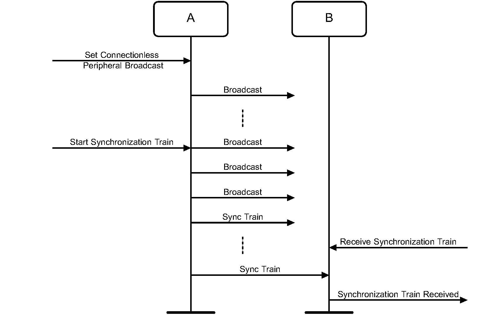
7.5.4. Conditions
After receiving a synchronization train packet, the receiving device can listen to and receive profile data sent via Connectionless Peripheral Broadcast by device A.
Devices A and B may go through a separate Link Establishment procedure any time they desire to establish an ACL logical transport between each other. They may also use Connectionless Peripheral Broadcast procedures with an ACL logical transport already established.
The receiving device shall enter the Synchronization Scan substate using a scan interval of TGAP(Sync_Scan_Interval) and a scan window of TGAP(Sync_Scan_Window).
8. Extended inquiry response data format
The extended inquiry response data format is shown in Figure 8.1. The data is 240 octets and consists of a significant part and a non-significant part. The significant part contains a sequence of data structures. Each data structure shall have a length field of one octet, which contains the Length value, and a data field of Length octets. The first n octets of the data field contain the extended inquiry response (EIR) data type. The content of the remaining Length - n octets in the data field depends on the value of the EIR data type and is called the EIR data. The non-significant part extends the extended inquiry response to 240 octets and shall contain all-zero octets.
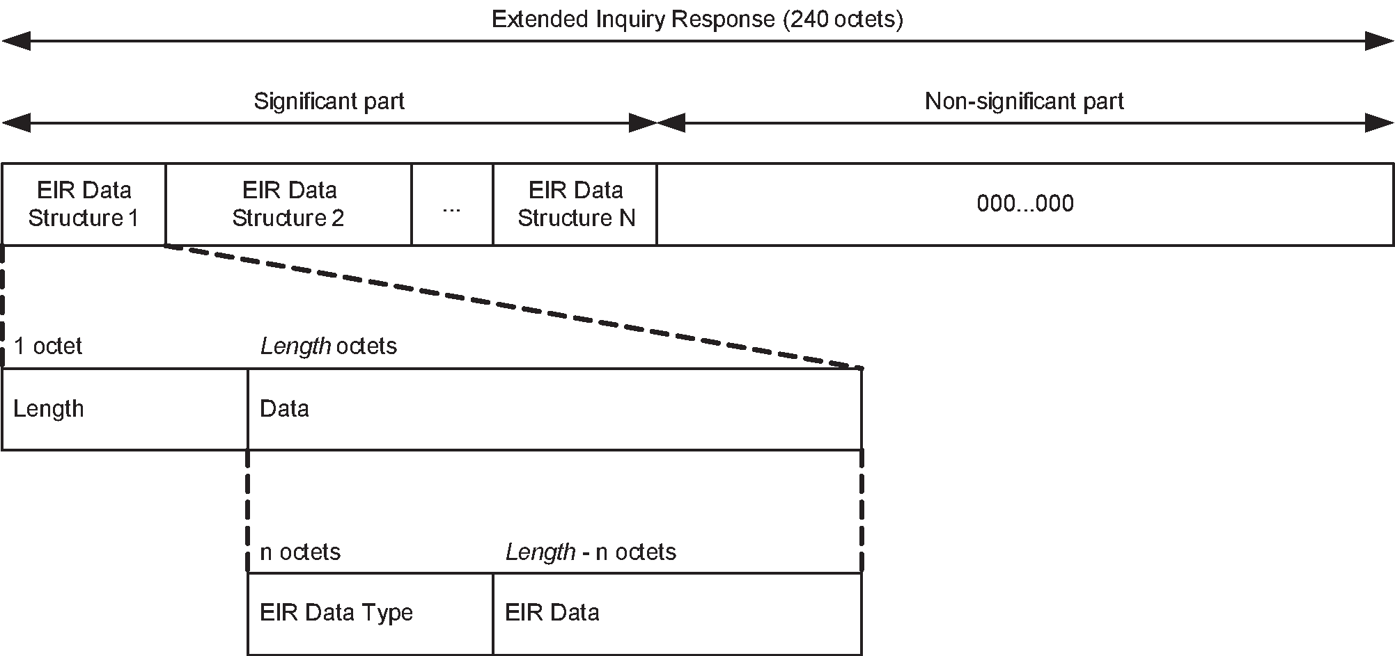
The extended inquiry response data formats and meanings are defined in Section 1 of [4].The extended inquiry response data type values are defined in Assigned Numbers.
If the length field is set to zero, then the data field has zero octets. This shall only occur to allow an early termination of the tagged data.
To reduce interference, the Host should try to minimize the amount of EIR data such that the Baseband can use a 1-slot or 3-slot EIR packet. This is advantageous because it reduces interference and maximizes the probability that the EIR packet will be received. If applications on a Host provide more than 240 bytes of extended inquiry response data, it is up to the Host to limit it to 240 octets.
The EIR data shall be sent during the inquiry response state. In selecting the packet type to be used, FEC (DM1 or DM3) should be considered to maximize the range.
The Host shall include the device name in the EIR data according to the following rules:
If the device does not have a device name (i.e., 0 octet) and
If there is no other data to be sent in the EIR packet, the Host shall send a name tag with zero length and the type field set to indicate that this is the complete name (i.e., total of 2 octets with length = 1).
If there is other important data to be sent in the EIR packet and a zero octet name tag will not fit, the Host may avoid sending the name tag.
If the device has a device name (greater than 0 octet) and
If it is too long be included in the EIR packet (given the choice of packet type and any other data that is being sent), the Host may send a shortened version of the name (even 0 octet) and shall mark the name as 'shortened' to inform the receiver that a remote name request is required obtain the full name if the name is needed.
If there are no other data to be sent in the EIR packet (given the choice of packet type selected), the Host shall maximize the length of the device name to be sent, this may be complete or shortened name (e.g., if DM1 packet is chosen and device name characters equates to greater than 15 octets, then Host sends first few characters that equates to 15 octets or less with shortened flag).
Note
Note: It is not necessary to understand each and every EIR data type. If the Host does not understand a given EIR data type value it should just skip over Length octets and look for the next EIR data structure.
9. Operational modes and procedures – LE physical transport
Several different modes and procedures may be performed simultaneously over an LE physical transport. The following modes and procedures are defined for use over an LE physical transport:
Broadcast mode and Observation procedure
Discovery modes and procedures
Connection modes and procedures
Bonding modes and procedures
Periodic advertising modes and procedure
Isochronous broadcast modes and procedures
Each of the above modes and procedures are independent from each other but are closely related since a combination of the modes and procedures are necessary for most devices to communicate with each other. Both the modes and procedures may be entered or executed respectively as a result of direct user action or autonomously by a device.
The Host shall configure the Controller with its local Link Layer feature information as defined in [Vol 6] Part B, Section 4.6 before performing any of the above modes and procedures.
The types of advertising used in these modes and procedures for each of the associated GAP roles are defined in Section 2.2.2 Table 2.1.
9.1. Broadcast mode and Observation procedure
The Broadcast mode and Observation procedure allow two devices to communicate in a unidirectional connectionless manner using the advertising events. The requirements for a device operating in a specific GAP role to support the Broadcast mode and Observation procedure are defined in Table 9.1.
Broadcast Mode and Observation procedure | Ref. | Peripheral | Central | Broadcaster | Observer |
|---|---|---|---|---|---|
Broadcast mode | E | E | M | E | |
Observation procedure | E | E | E | M |
9.1.1. Broadcast mode
9.1.1.1. Definition
The Broadcast mode provides a method for a device to send connectionless data in advertising events.
9.1.1.2. Conditions
A device in the Broadcast mode shall send data using non-connectable advertising events.
A device in the Broadcast mode may send non-connectable and non-scannable undirected or non-connectable and non-scannable directed advertising events anonymously by excluding the Broadcaster's address.
The advertising data shall be formatted using the Advertising Data (AD) type format as defined in Section 1.3 of [4]. A device in the Broadcast mode shall not set the ‘LE General Discoverable Mode’ flag or the ‘LE Limited Discoverable Mode’ flag in the Flags AD Type as defined in Section 1.3 of [4].
Note
Note: All data sent by a device in the Broadcast mode is considered unreliable since there is no acknowledgment from any device that may have received the data.
The device may configure and enable multiple independent advertising sets. Each advertising set may have an independent advertising filter policy.
9.1.2. Observation procedure
9.1.2.1. Definition
The Observation procedure provides a method for a device to receive connectionless data from a device that is sending advertising events.
9.1.2.2. Conditions
A device performing the Observation procedure may use passive scanning or active scanning to receive advertising events.
A device performing the Observation procedure may use active scanning to also receive scan response data sent by any device in the Broadcast mode that advertises using scannable advertising events.
When a device performing the Observation procedure receives a resolvable private address in the advertising event, the device may resolve the private address by using the resolvable private address resolution procedure as defined in Section 10.8.2.3.
Note
Note: In use cases where a device in the Broadcast mode sends dynamic data, the receiving device should disable duplicate filtering capability in the Controller so that the Host receives all advertising packets received by the Controller.
9.2. Discovery modes and procedures
All devices shall be in either non-discoverable mode or one of the discoverable modes. A device in the discoverable mode shall be in either the general discoverable mode or the limited discoverable mode. A device in the non-discoverable mode is not discoverable. Devices operating in either the general discoverable mode or the limited discoverable mode can be found by the discovering device. A device that is discovering other devices performs either the limited discovery procedure as defined in Section 9.2.5 or the general discovery procedure as defined in Section 9.2.6.
Some devices may only scan for advertising events using legacy advertising PDUs. It is therefore recommended that devices using advertising events with the extended advertising PDUs also use an advertising set with advertising events that use legacy advertising PDUs.
If the device is in one of the discoverable modes, and if multiple advertising sets are used with the same Identity Address or the same IRK, then those advertising sets shall also share the same advertising filter policy.
9.2.1. Requirements
Discovery modes and procedures | Ref. | Peripheral | Central | Broadcaster | Observer |
|---|---|---|---|---|---|
Non-Discoverable mode | M | E | E | E | |
Limited Discoverable mode | O | E | E | E | |
General Discoverable mode | C.1 | E | E | E | |
Limited Discovery procedure | E | O | E | E | |
General Discovery procedure | E | M | E | E | |
Name Discovery procedure | O | O | E | E | |
C.1: Optional if limited discoverable mode is supported, otherwise mandatory. | |||||
9.2.2. Non-discoverable mode
9.2.2.1. Description
A device configured in non-discoverable mode will not be discovered by any device that is performing either the general discovery procedure or the limited discovery procedure.
9.2.2.2. Conditions
A device in the non-discoverable mode may send advertising events. If the device sends advertising events, it shall not set the ‘LE General Discoverable Mode’ flag or ‘LE Limited Discoverable Mode’ flag in the Flags AD type (see Section 1.3 of [4]).
If the device sends advertising events, then it is recommended that the Host configures the Controller as follows:
The Host should set the advertising filter policy for all advertising sets to either ‘process scan and connection requests only from devices in the Filter Accept List’ or ‘process scan and connection requests from all devices’.
The Host should set the advertising intervals as defined in Section 9.3.11.
9.2.3. Limited Discoverable mode
9.2.3.1. Description
Devices configured in the limited discoverable mode are discoverable for a limited period of time by other devices performing the limited or general device discovery procedure. Devices typically enter the limited discoverable mode when a user performs a specific action.
There are two common reasons to use limited discoverable mode:
Limited discoverable mode can be used to allow remote devices using the general discovery procedure to prioritize or otherwise identify devices in limited discoverable mode when presenting discovered devices to the end user because, typically, the user is interacting with them.
Limited discoverable mode can also be used to allow remote devices using the limited discovery procedure to filter out devices using the general discoverable mode.
9.2.3.2. Conditions
A device in the limited discoverable mode shall send advertising event types with the advertising data including the Flags AD type as defined in Section 1.3 of [4] with all the following flags set as described:
The LE Limited Discoverable Mode flag set to one.
The LE General Discoverable Mode flag set to zero.
For a device of the LE-only device type with all the following flags set as described:
The ‘BR/EDR Not Supported’ flag to set one.
The ‘Simultaneous LE and BR/EDR to Same Device Capable (Controller)’ flag set to zero.
The advertising data should also include the following AD types to enable a faster connectivity experience:
Devices shall remain in the limited discoverable mode no longer than TGAP(lim_adv_timeout).
While a device is in limited discoverable mode the Host configures the Controller as follows:
The Host shall set the advertising filter policy for all advertising sets that share the same Identity Address or the same IRK to ‘process scan and connection requests from all devices’.
The Host should set the advertising intervals as defined in Section 9.3.11.
The device shall remain in limited discoverable mode until a connection is established or the Host terminates the mode.
Note
Note: The choice of advertising interval is a trade-off between power consumption and device discovery time.
The device may configure and enable multiple independent advertising sets.
9.2.4. General Discoverable mode
9.2.4.1. Description
Devices configured in the general discoverable mode are discoverable for an indefinite period of time by devices performing the general discovery procedure. Devices typically enter general discoverable mode autonomously.
Devices in the general discoverable mode will not be discovered by devices performing the limited discovery procedure. General discoverable mode should not be used if it is known that the device performing discovery will be using the limited discovery procedure (see Section 9.2.5).
9.2.4.2. Conditions
A device in general discoverable mode shall send advertising events with the advertising data including the Flags AD data type as defined in Section 1.3 of [4] with all the following flags set as described:
The LE Limited Discoverable Mode flag set to zero.
The LE General Discoverable Mode flag set to one.
For a device of the LE-only device type with all the following flags set as described:
The ‘BR/EDR Not Supported’ flag set to one.
The ‘Simultaneous LE and BR/EDR to Same Device Capable (Controller)’ flag set to zero.
The advertising data should also include the following AD types to enable a faster connectivity experience:
While a device is in general discoverable mode the Host configures the Controller as follows:
The Host shall set the advertising filter policy for all advertising sets that share the same Identity Address or the same IRK to ‘process scan and connection requests from all devices’.
The Host should set the advertising intervals as defined in Section 9.3.11.
The device shall remain in general discoverable mode until a connection is established or the Host terminates the mode.
Note
Note: Host data used in legacy advertising events that change frequently should be placed in the advertising data and static data should be placed in the scan response data.
Note
Note: The choice of advertising interval is a trade-off between power consumption and device discovery time.
9.2.5. Limited Discovery procedure
9.2.5.1. Description
A device performing the limited discovery procedure receives the device address, advertising data and scan response data from devices in the limited discoverable mode only.
The limited discovery procedure should only be used when it is known that the devices to be discovered are using limited discoverable mode. The general discovery procedure (see Section 9.2.6) should be used for general purpose discovery when it is desired to discover all devices regardless of whether they are using limited discoverable mode or general discoverable mode.
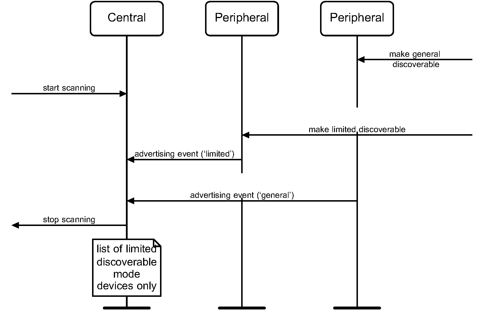
9.2.5.2. Conditions
It is recommended that the device scan on all the PHYs it supports.
When a Host performs the limited discovery procedure, the Host configures the Controller as follows:
The Host shall set the scanning filter policy to an unfiltered scanning policy (see [Vol 6] Part B, Section 4.3.3).
The Host should set the scan interval and scan window as defined in Section 9.3.11.
The Host should configure the Controller to use active scanning.
The Host shall begin scanning for advertising packets and should continue for a minimum of TGAP(lim_disc_scan_min) when scanning on the LE 1M PHY and TGAP(lim_disc_scan_min_coded) when scanning on the LE Coded PHY, unless the Host ends the limited discovery procedure.
The Host shall check for the Flags AD type in the advertising data. If the Flags AD type is present and the LE Limited Discoverable Flag is set to one then the Host shall consider the device as a discovered device, otherwise the advertising data shall be ignored. The Flag AD type is defined in Section 1.3 of [4]. The advertising data of the discovered device may contain data with other AD types, e.g. Service UUIDs AD type, TX Power Level AD type, Local Name AD type, Peripheral Connection Interval Range AD type. The Host may use the data in performing any of the connection establishment procedures.
The Host shall ignore the 'Simultaneous LE and BR/EDR to Same Device Capable (Controller)' bit in the Flags AD type.
9.2.6. General Discovery procedure
9.2.6.1. Description
A device performing the general discovery procedure receives the device address, advertising data and scan response data from devices in the limited discoverable mode or the general discoverable mode.
The general discovery procedure should be used for general purpose discovery, i.e. to discover all discoverable devices regardless of whether they are in general discoverable mode or limited discoverable mode. A device which discovers devices using the general discovery procedure and presents them to users in some fashion should distinguish devices in the limited discoverable mode from those in the general discoverable mode, e.g., by sorting them to the top of a list of discovered devices or highlighting them in some way.
Note
Note: The rationale for distinguishing the devices in limited discoverable mode to the end user is that devices typically enter limited discoverable mode only after explicit action by the end user, indicating that the user’s immediate goal is to discover and interact with that specific device.
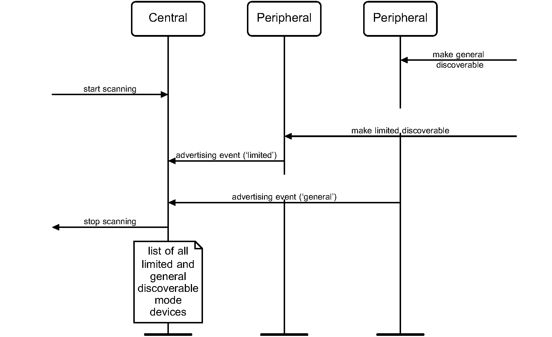
9.2.6.2. Conditions
It is recommended that the device scan on all the PHYs it supports.
When a Host performs the general discovery procedure, the Host configures the Controller as follows:
The Host shall set the scanning filter policy to an unfiltered scanning policy (see [Vol 6] Part B, Section 4.3.3).
The Host should set the scan interval and scan window as defined in Section 9.3.11.
The Host should configure the Controller to use active scanning.
The Host shall begin scanning for advertising packets and should continue for a minimum of TGAP(gen_disc_scan_min) when scanning on the LE 1M PHY and TGAP(gen_disc_scan_min_coded) when scanning on the LE Coded PHY. The procedure may be terminated early by the Host.
The Host shall check for the Flags AD type in the advertising data. If the Flags AD type (see Section 1.3 of [4]) is present and either the LE General Discoverable Mode flag is set to one or the LE Limited Discoverable Mode flag is set to one then the Host shall consider the device as a discovered device, otherwise the advertising data shall be ignored. The advertising data of the discovered device may contain data with other AD types, e.g. Service UUIDs AD type, TX Power Level AD type, Local Name AD type, Peripheral Connection Interval Range AD type. The Host may use the data in performing any of the connection establishment procedures as defined in Section 9.3.
The Host shall ignore the 'Simultaneous LE and BR/EDR to Same Device Capable (Controller)' bit in the Flags AD type.
9.2.7. Name Discovery procedure
9.2.7.1. Description
The name discovery procedure is used to obtain the Bluetooth Device Name of a remote connectable device.
9.2.7.2. Conditions
If the complete device name is not acquired while performing either the limited discovery procedure or the general discovery procedure, then the name discovery procedure may be performed.
The name discovery procedure shall be performed as follows:
The Host shall establish a connection using one of the connection establishment procedures as defined in Section 9.3.
The Host shall read the device name characteristic using the GATT procedure Read Using Characteristic UUID [Vol 3] Part G, Section 4.8.2
The connection may be terminated after the GATT procedure has completed.
9.3. Connection modes and procedures
The connection modes and procedures allow a device to establish a connection to another device.
When devices are connected, the parameters of the connection can be updated with the Connection Parameter Update procedure. The connected device may terminate the connection using the Terminate Connection procedure. The requirements for a device to support the connection modes and procedures are defined in Table 9.3. These requirements refer to the specific role a device is operating in. Devices supporting multiple roles shall support the specified modes and procedures for a given role while operating in that role.
9.3.1. Requirements
Connection Modes and Procedures | Ref. | Peripheral | Central | Broadcaster | Observer |
|---|---|---|---|---|---|
Non-connectable mode | M | E | M | M | |
Directed connectable mode | O | E | E | E | |
Undirected connectable mode | M | E | E | E | |
Auto connection establishment procedure | E | O | E | E | |
General connection establishment procedure | E | O | E | E | |
Selective connection establishment procedure | E | O | E | E | |
Direct connection establishment procedure | E | M | E | E | |
Connection parameter update procedure | O | M | E | E | |
Terminate connection procedure | M | M | E | E | |
Connected Isochronous Stream Central Establishment procedure | E | C.1 | E | E | |
Connected Isochronous Stream Peripheral Establishment procedure | C.1 | E | E | E | |
Connected Isochronous Stream Terminate procedure | C.1 | C.1 | E | E | |
Connection Subrate procedure | C.2 | C.2 | E | E |
- C.1:
Mandatory if Connected Isochronous Streams are supported, otherwise excluded.
- C.2:
Mandatory if the Connection Subrating feature is supported, otherwise excluded.
9.3.2. Non-connectable mode
9.3.2.1. Description
A device in the non-connectable mode shall not allow a connection to be established.
9.3.2.2. Conditions
A Peripheral in the non-connectable mode may send non-connectable advertising events. In this case it is recommended that the Host configures the Controller as follows:
The Host should set the advertising filter policy to either ‘process scan and connection requests only from devices in the Filter Accept List’ or ‘process scan and connection requests from all devices’.
The Host should set the advertising intervals as defined in Section 9.3.11.
The device may configure and enable multiple independent advertising sets. Each advertising set may have an independent advertising filter policy.
9.3.3. Directed Connectable mode
9.3.3.1. Description
A device in the directed connectable mode shall accept a connection request from a known peer device performing the auto connection establishment procedure or the general connection establishment procedure.
9.3.3.2. Conditions
A Peripheral shall send connectable directed advertising events.
The device may configure and enable multiple independent advertising sets. Each advertising set may have an independent advertising filter policy.
9.3.4. Undirected Connectable mode
9.3.4.1. Description
A device in the undirected connectable mode shall accept a connection request from a device performing the auto connection establishment procedure or the general connection establishment procedure.
9.3.4.2. Conditions
A Peripheral should follow the guidelines defined in Section 9.3.11. A Peripheral shall send either connectable and scannable undirected advertising events or connectable undirected advertising events.
The device may configure and enable multiple independent advertising sets. Each advertising set may have an independent advertising filter policy.
9.3.5. Auto Connection Establishment procedure
9.3.5.1. Description
The auto connection establishment procedure allows the Host to configure the Controller to autonomously establish a connection with one or more devices in the directed connectable mode or the undirected connectable mode. This procedure uses the Filter Accept List in the initiator to store the addresses of the devices that can be connected to. The Controller autonomously establishes a connection with a device with the device address that matches the address stored in the Filter Accept List.
9.3.5.2. Conditions
Figure 9.3 shows the flow chart for a device performing the auto connection establishment procedure.
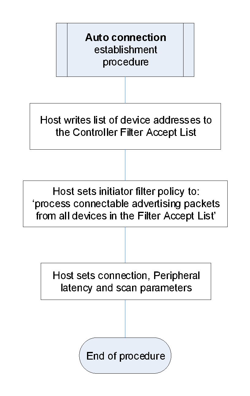
When a Host performs the auto connection establishment procedure, the Host configures the Controller as follows:
The Host shall write the list of device addresses that are to be auto connected to into the Filter Accept List.
The Host shall set the initiator filter policy to ‘process connectable advertising packets from all devices in the Filter Accept List’.
The Host should set the scan interval and scan window as defined in Section 9.3.11.
The Host should set connection parameters as defined in Section 9.3.12.
This procedure is terminated when a connection is established or when the Host terminates the procedure.
9.3.6. General Connection Establishment procedure
9.3.6.1. Description
The general connection establishment procedure allows the Host to establish a connection with a set of known peer devices in the directed connectable mode or the undirected connectable mode.
9.3.6.2. Conditions
Figure 9.4 shows the flow chart for a device performing the general connection establishment procedure.
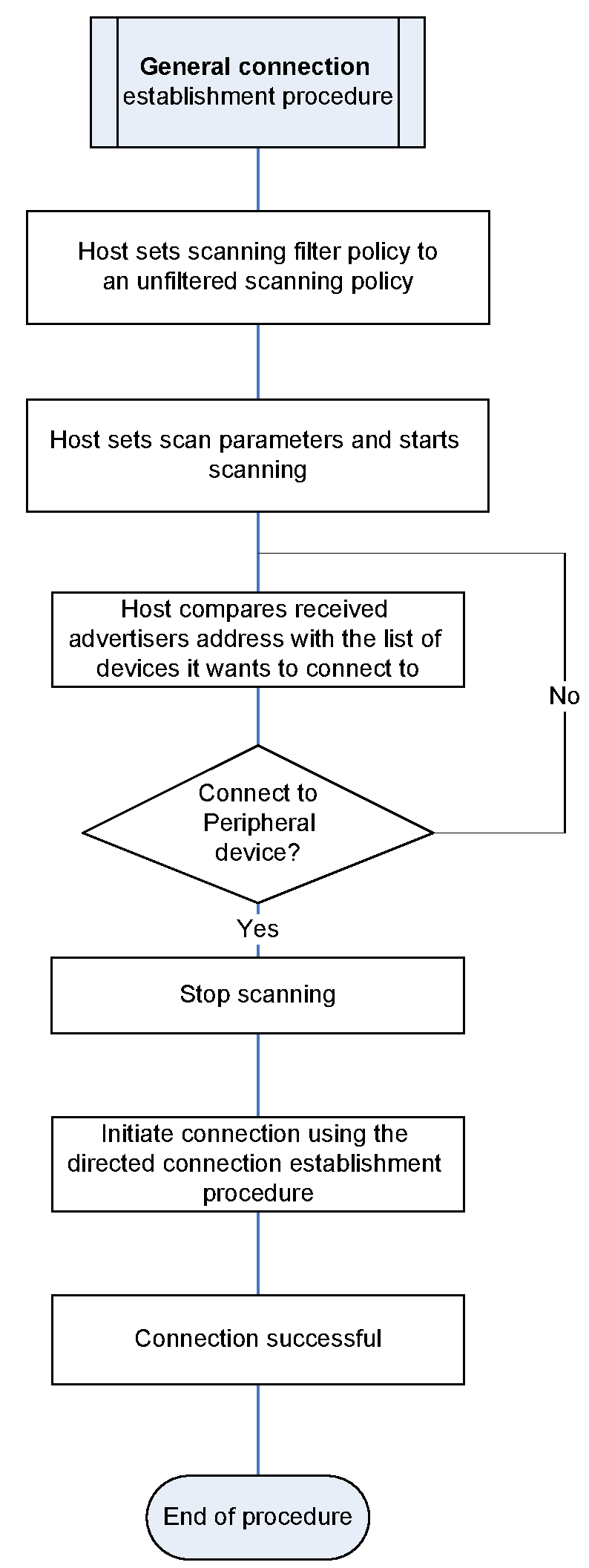
When a Host performs the general connection establishment procedure, the Host configures the Controller as follows:
The Host shall set the scanning filter policy to an unfiltered scanning policy (see [Vol 6] Part B, Section 4.3.3).
The Host should set the scan interval as defined in Section 9.3.11.
The Host should set the scan window as defined in Section 9.3.11.
The Host shall start active scanning or passive scanning.
The Host should set connection parameters as defined in Section 9.3.12.
When the Host discovers a device to which the Host may attempt to connect, the Host shall stop the scanning, and initiate a connection using the direct connection establishment procedure.
This procedure is terminated when a connection is established or when the Host terminates the procedure.
9.3.7. Selective Connection Establishment procedure
9.3.7.1. Description
The selective connection establishment procedure allows the Host to establish a connection, using the Host selected connection configuration parameters, with any device whose address is stored in the Filter Accept List.
9.3.7.2. Conditions
Figure 9.5 shows the flow chart for a device performing the selective connection establishment procedure.
When a Host performs the selective connection establishment procedure, the Host configures the Controller as follows:
The Host shall write the list of device addresses that are to be selectively connected into the Filter Accept List.
The Host shall set the scanning filter policy to a filtered scanning policy (see [Vol 6] Part B, Section 4.3.3).
The Host should set the scan interval as defined in Section 9.3.11.
The Host should set the scan window as defined in Section 9.3.11.
The Host shall start active scanning or passive scanning.
When the Host discovers one of the peer devices it is connecting to, the Host shall stop scanning, and initiate a connection using the direct connection establishment procedure with the connection configuration parameters for that peer device.
This procedure is terminated when a connection is established or when the Host terminates the procedure.
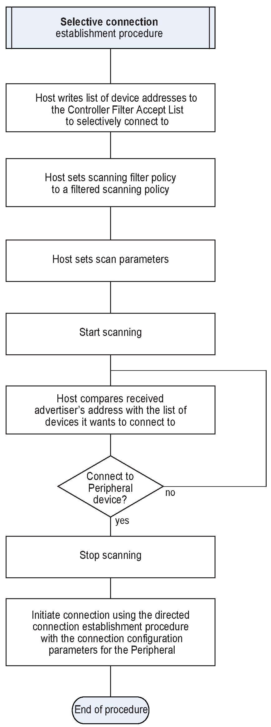
9.3.8. Direct Connection Establishment procedure
9.3.8.1. Description
The direct connection establishment procedure allows the Host to establish a connection with the Host selected connection configuration parameters with a single peer device.
9.3.8.2. Conditions
Figure 9.6 shows the flow chart for a device performing the direct connection establishment procedure.
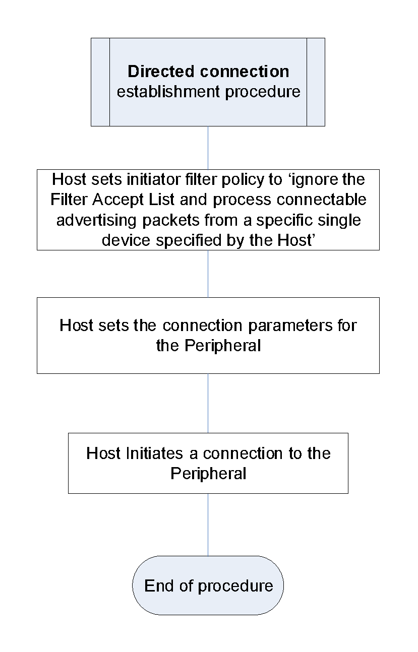
When a Host performs the direct connection establishment procedure, the Host configures the Controller as follows:
The Host shall set the initiator filter policy to ‘ignore the Filter Accept List and process connectable advertising packets from a specific single device specified by the Host’.
The Host shall set the peer address to the device address of the specific single device.
The Host should set connection parameters as defined in Section 9.3.12.
The Host shall initiate a connection.
This procedure is terminated when a connection is established or when the Host terminates the procedure.
9.3.9. Connection Parameter Update procedure
9.3.9.1. Description
The connection parameter update procedure allows a Peripheral or Central to update the parameters of an established ACL connection.
9.3.9.2. Conditions
A Central initiating the connection parameter update procedure shall use the Link Layer Connection Update procedure defined in [Vol 6] Part B, Section 5.1.1 with the required connection parameters if either the Central or the Peripheral does not support the Connection Parameters Request Link Layer Control procedure.
If both the Central and Peripheral support the Connection Parameters Request Link Layer control procedure, then the Central or Peripheral initiating the connection parameter update procedure shall use the Connection Parameters Request Link Layer Control procedure defined in [Vol 6] Part B, Section 5.1.7 with the required connection parameters.
If either the Central or the Peripheral does not support the Connection Parameters Request Link Layer Control procedure, then the Peripheral initiating the connection parameter update procedure shall use the L2CAP_CONNECTION_PARAMETER_UPDATE_REQ command defined in [Vol 3] Part A, Section 4.20 with the required connection parameters. The Peripheral shall not send an L2CAP_CONNECTION_PARAMETER_UPDATE_REQ command within TGAP(conn_param_timeout) of an L2CAP_CONNECTION_PARAMETER_UPDATE_RSP being received. When the Central accepts the Peripheral initiated Connection Parameter Update, the Central should initiate the Link Layer Connection Update procedure defined in [Vol 6] Part B, Section 5.1.1 with the required connection parameters within TGAP(conn_param_timeout).
If the requested or updated connection parameters are unacceptable to the Central or Peripheral then it may disconnect the connection with the error code 0x3B (Unacceptable Connection Parameters). Devices should be tolerant of connection parameters given to them by the remote device.
9.3.10. Terminate Connection procedure
9.3.10.1. Description
The Terminate Connection procedure allows a Host to terminate the connection with a peer device.
9.3.10.2. Conditions
The Host should first terminate any associated CIS(es) prior to terminating the ACL.
The Host initiating the terminate connection procedure shall use the Link Layer ACL Termination procedure defined in [Vol 6] Part B, Section 5.1.6.
9.3.11. Connection Establishment Timing parameters
9.3.11.1. Description
The connection establishment timing parameters are used during initial connection establishment between a Central and a Peripheral.
A Central should use one of the GAP connection establishment procedures to initiate a connection to a Peripheral in a connectable mode. The procedures and modes that may use these timing parameters are defined in Section 9.3.4 to Section 9.3.8.
9.3.11.2. Conditions
A Central starting a user-initiated GAP connection establishment procedure should use the recommended scan interval TGAP(scan_fast_interval) and scan window TGAP(scan_fast_window) for TGAP(scan_fast_period) when scanning on the LE 1M PHY and should use scan interval TGAP(scan_fast_interval_coded) and scan window TGAP(scan_fast_window_coded) for TGAP(scan_fast_period) when scanning on the LE Coded PHY.
A Central that is background scanning (i.e. as part of a GAP connection establishment procedure that is not user-initiated) should use the recommended scan interval TGAP(scan_slow_interval1) and scan window TGAP(scan_slow_window1) when scanning on the LE 1M PHY and should use scan interval TGAP(scan_slow_interval1_coded) and scan window TGAP(scan_slow_window1_coded) when scanning on the LE Coded PHY. Alternatively the Central may use TGAP(scan_slow_interval2) and scan window TGAP(scan_slow_window2) when scanning on the LE 1M PHY and should use TGAP(scan_slow_interval2_coded) and scan window TGAP(scan_slow_window2_coded) when scanning on the LE Coded PHY.
A Peripheral entering any of the following GAP Modes should use the recommended advertising interval TGAP(adv_fast_interval1) for TGAP(adv_fast_period) when advertising on the LE 1M PHY and should use TGAP(adv_fast_interval1_coded) for TGAP(adv_fast_period) when advertising on the LE Coded PHY:
Undirected Connectable Mode
Limited Discoverable Mode and sending connectable undirected advertising events
General Discoverable Mode and sending connectable undirected advertising events
Directed Connectable Mode and sending low duty cycle connectable directed advertising events
A Peripheral when entering any of the following GAP Modes and sending non-connectable advertising events should use the recommended advertising interval TGAP(adv_fast_interval2) for TGAP(adv_fast_period) when advertising on the LE 1M PHY and should use TGAP(adv_fast_interval2_coded) for TGAP(adv_fast_period) when advertising on the LE Coded PHY:
Non-Discoverable Mode
Non-Connectable Mode
Limited Discoverable Mode
General Discoverable Mode
A Peripheral that is background advertising in any GAP Mode other than GAP Directed Connectable Mode with high duty cycle connectable directed advertising events should use the recommended advertising interval TGAP (adv_slow_interval) when advertising on the LE 1M PHY and should use TGAP (adv_slow_interval_coded) when advertising on the LE Coded PHY.
Note
Note: When advertising interval values of less than 100 ms are used for non-connectable or scannable undirected advertising in environments where the advertiser can interfere with other devices, it is recommended that steps be taken to minimize the interference. For example, the advertising might be alternately enabled for only a few seconds and disabled for several minutes.
9.3.12. Connection interval timing parameters
9.3.12.1. Description
The connection interval timing parameters are used within a connection. Initial connection interval is used to ensure procedures such as bonding, encryption setup and service discovery are completed quickly. The connection interval should be changed to the value in the Peripheral Preferred Connection Parameters characteristic after initiating procedures are complete.
9.3.12.2. Conditions
The Central should either read the Peripheral Preferred Connection Parameters characteristic (see Section 12.3) or retrieve the parameters from advertising data (see Section 12.3).
The connection interval should be set to TGAP(initial_conn_interval) when establishing a connection on the LE 1M PHY and to TGAP(initial_conn_interval_coded) when establishing a connection on the LE Coded PHY and connPeripheralLatency should be set to zero. These parameters should be used until the Central has no further pending actions to perform or until the Peripheral performs a Connection Parameter Update procedure (see Section 9.3.9).
After the Central has no further pending actions to perform and the Peripheral has not initiated any other actions within TGAP(conn_pause_central), then the Central should invoke the Connection Parameter Update procedure (see Section 9.3.9) and change the connection interval to that specified in the Peripheral Preferred Connection Parameters characteristic.
If the Central has not read the Peripheral Preferred Connection Parameters characteristic, then the Central may choose the connection parameters to be used.
After the Peripheral has no further pending actions to perform and the Central has not initiated any other actions within TGAP(conn_pause_central), then the Peripheral may perform a Connection Parameter Update procedure (see Section 9.3.9). The Peripheral should not perform a Connection Parameter Update procedure within TGAP(conn_pause_peripheral) after establishing a connection.
At any time a key refresh or encryption setup procedure is required and the current connection interval is greater than TGAP(initial_conn_interval) when connected on the LE 1M PHY or LE 2M PHY or greater than TGAP(initial_conn_interval_coded) when connected on the LE Coded PHY, the key refresh or encryption setup procedure should be preceded with a Connection Parameter Update procedure (see Section 9.3.9). The connection interval should be set to TGAP(initial_conn_interval) when connected on the LE 1M PHY or the LE 2M PHY and TGAP(initial_conn_interval_coded) when connected on the LE Coded PHY, connSubrateFactor should be set to 1, and connPeripheralLatency should be set to zero. This fast connection interval should be maintained until the key refresh or encryption setup procedure is complete. It should then switch to the value in the Peripheral Preferred Connection Parameters characteristic.
9.3.13. Connected Isochronous Stream Central Establishment procedure
9.3.13.1. Description
The Connected Isochronous Stream Central Establishment procedure allows the Host of a Central to establish a CIS with a Peripheral using the Host selected parameters.
9.3.13.2. Conditions
When two devices are connected, a Central may establish one or more CISes with a Peripheral. A CIS is established by the Central using the Connected Isochronous Stream Creation procedure (see [Vol 6] Part B, Section 5.1.15). The Central and or Peripheral may send isochronous data over the established CIS.
9.3.14. Connected Isochronous Stream Peripheral Establishment procedure
9.3.14.1. Description
The Connected Isochronous Stream Peripheral Establishment procedure allows the Host of the Peripheral to accept or reject the request from a Central to establish a CIS.
9.3.14.2. Conditions
When two devices are connected, the Peripheral may receive a request from the Central to establish a CIS. Once the request is received, the Host in the Peripheral shall either accept or reject the request. If it accepts the request, the CIS can be established using the Connected Isochronous Stream Creation procedure defined in [Vol 6] Part B, Section 5.1.15.
9.3.15. Connected Isochronous Stream Terminate procedure
9.3.15.1. Description
The Connected Isochronous Stream Terminate procedure allows a Host to terminate a CIS with a peer device. The CIS shall also be terminated when the ACL between the Central and Peripheral is terminated, using the Terminate Connection procedure ( Section 9.3.10).
9.3.15.2. Conditions
The Host initiating the Connected Isochronous Stream Terminate procedure shall use the Connected Isochronous Stream Termination control procedure defined in [Vol 6] Part B, Section 5.1.16.
9.3.16. Connection Subrate procedure
9.3.16.1. Description
The Connection Subrate procedure allows a Peripheral or Central to modify the connection subrating and other connection parameters of an established ACL connection.
9.3.16.2. Conditions
The Central initiating this procedure shall use the Link Layer Connection Subrate Update procedure defined in [Vol 6] Part B, Section 5.1.19 and the Peripheral initiating this procedure shall use the Connection Subrate Request procedure defined in [Vol 6] Part B, Section 5.1.20.
If the requested subrate connection parameters are unacceptable to the Central then it may reject them. If the updated subrate connection parameters are unacceptable to the Peripheral it cannot reject them but may follow up by using the Connection Parameter Request procedure (see [Vol 6] Part B, Section 5.1.7) or the Connection Subrate Request procedure (see [Vol 6] Part B, Section 5.1.20) to change them. Devices should be tolerant of the connection parameters requested by the peer device.
9.4. Bonding modes and procedures
Bonding allows two connected devices to exchange and store security and identity information to create a trusted relationship. The security and identity information as defined in [Vol 3] Part H, Section 2.4.1 is also known as the bonding information. When the devices store the bonding information, it is known as the phrases ‘devices have bonded’ or ‘a bond is created’.
There are two modes for bonding, non-bondable mode and bondable mode. Bonding may only occur between two devices in bondable mode. The requirements for a device to support the bonding modes and procedure are defined in Table 9.4.
9.4.1. Requirements
Bonding | Ref. | Peripheral | Central | Broadcaster | Observer |
|---|---|---|---|---|---|
Non-Bondable mode | M | M | E | E | |
Bondable mode | O | O | E | E | |
Bonding procedure | C.1 | C.1 | E | E | |
| |||||
9.4.2. Non-bondable mode
9.4.2.1. Description
A device in the non-bondable mode does not allow a bond to be created with a peer device.
9.4.2.2. Conditions
If a device does not support pairing as defined in the Security Manager section then it is considered to be in non-bondable mode.
If Security Manager pairing is supported, the Host shall set the Bonding_Flags to ‘No Bonding’ as defined in [Vol 3] Part H, Section 3.5.1 and bonding information shall not be exchanged or stored.
9.4.3. Bondable mode
9.4.3.1. Description
A device in the bondable mode allows a bond to be created with a peer device in the bondable mode.
9.4.3.2. Conditions
The Host shall set the Bonding_Flags to ‘Bonding’ during the pairing procedure.
9.4.4. Bonding procedure
9.4.4.1. Description
The bonding procedure may be performed when a non-bonded device tries to access a service that requires bonding. The bonding procedure may be performed for the purpose of creating a bond between two devices.
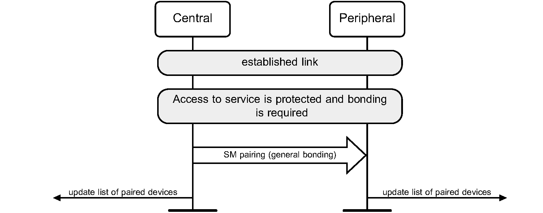
9.4.4.2. Conditions
The Host of the Central initiates the pairing process as defined in [Vol 3] Part C, Section 2.1 with the Bonding_Flags set to Bonding as defined in [Vol 3] Part H, Section 3.5.1. If the peer device is in the bondable mode, the devices shall exchange and store the bonding information in the security database.
If a device supports the generation of resolvable private addresses as defined in Section 10.8.2.2 and generates a resolvable private address for its local address, it shall send Identity Information with SMP, including a valid IRK. If a device does not generate a resolvable private address for its own address and the Host sends Identity Information with SMP, the Host shall send an all-zero IRK. If a device supports resolving resolvable private addresses as defined in Section 10.8.2.3, it shall request the peer device to send its Identity Information with SMP. The Host can abort the pairing procedure if the authentication requirements are not sufficient to distribute the IRK.
9.5. Periodic advertising modes and procedure
The periodic advertising modes and procedure allow two or more devices to communicate in a connectionless manner using extended advertising events and periodic advertising events. These modes and procedures can also make use of existing connections. The requirements for a device operating in a specific GAP role to support these modes and procedures are defined in Table 9.5.
Mode and Procedures | Ref. | Broadcaster | Observer | Peripheral | Central |
|---|---|---|---|---|---|
Periodic Advertising Synchronizability mode | O | E | E | E | |
Periodic Advertising mode | C.1 | E | E | E | |
Periodic Advertising Synchronization Establishment procedure | E | O | O | O | |
Periodic Advertising Synchronization Transfer procedure | E | E | C.2 | C.2 | |
Periodic Advertising Connection procedure | O | O | E | E | |
| |||||
| |||||
9.5.1. Periodic Advertising Synchronizability mode
9.5.1.1. Definition
The periodic advertising synchronizability mode provides a method for a device to send synchronization information about a periodic advertising train (with or without responses) using advertisements.
9.5.1.2. Conditions
A device in the periodic advertising synchronizability mode shall send synchronization information for a periodic advertising train (with or without responses) in non-connectable and non-scannable extended advertising events. The advertising interval used is unrelated to the interval between the periodic advertising events.
A device shall not be in periodic advertising synchronizability mode unless it is also in periodic advertising mode. It may leave, and possibly re-enter, periodic advertising synchronizability mode while remaining in periodic advertising mode.
9.5.2. Periodic Advertising mode
9.5.2.1. Definition
On periodic advertising trains without responses, the periodic advertising mode provides a method for a device to send advertising data at periodic and deterministic intervals. On periodic advertising trains with responses, a device may send advertising data in one or more subevents to synchronized devices who may also send data back to the device.
9.5.2.2. Conditions
A device in the periodic advertising mode shall send periodic advertising events at the interval and using the frequency hopping sequence specified in the periodic advertising synchronization information. On periodic advertising trains with responses, the interval may be divided into subevents. During a subevent, a synchronized device may send data back to the device in response slots.
A device entering periodic advertising mode shall also enter periodic advertising synchronizability mode for at least long enough to complete one extended advertising event (see [Vol 6] Part B, Section 4.4.2.12).
9.5.3. Periodic Advertising Synchronization Establishment procedure
9.5.3.1. Definition
The periodic advertising synchronization establishment procedure provides a method for a device to receive periodic advertising synchronization information and to synchronize to a periodic advertising train.
9.5.3.2. Conditions
A device performing the periodic advertising synchronization establishment procedure shall scan for non-connectable and non-scannable advertising events containing synchronization information about a periodic advertising train or shall accept periodic advertising synchronization information over an existing connection by taking part in the Link Layer Periodic Advertising Sync Transfer procedure defined in [Vol 6] Part B, Section 5.1.13. When a device receives synchronization information for a periodic advertising train, it may listen for periodic advertising events at the intervals and using the frequency hopping sequence specified in the periodic advertising synchronization information. If a device receives synchronization information about periodic advertising with responses, it may listen to one or more subevents in the interval and may send data to the periodic advertiser.
9.5.4. Periodic Advertising Synchronization Transfer procedure
9.5.4.1. Definition
The periodic advertising synchronization transfer procedure provides a method for a device to send synchronization information about a periodic advertising train over an existing connection.
9.5.4.2. Conditions
A device performing the periodic advertising synchronization transfer procedure shall initiate the Link Layer Periodic Advertising Sync Transfer procedure defined in [Vol 6] Part B, Section 5.1.13.
9.5.5. Periodic Advertising Connection procedure
9.5.5.1. Definition
The periodic advertising connection procedure provides a method for a periodic advertiser to initiate a Link Layer connection with a synchronized device.
9.5.5.2. Conditions
A device performing the periodic advertising connection procedure shall initiate the Link Layer connection procedure using periodic advertising trains with responses (see [Vol 6] Part B, Section 4.4.2.12.2).
9.6. Isochronous Broadcast modes and procedures
The Isochronous Broadcast modes and procedures allow two or more devices to communicate in a unidirectional, connectionless manner by using extended advertising events, periodic advertising events, and BIG and BIS events. The requirements for a device that operates in a specific GAP role to support these modes and procedures are defined in Table 9.6.
Modes and Procedures | Ref. | Peripheral | Central | Broadcaster | Observer |
|---|---|---|---|---|---|
Broadcast Isochronous Synchronizability mode | E | E | C.1 | E | |
Broadcast Isochronous Broadcasting mode | E | E | O | E | |
Broadcast Isochronous Synchronization Establishment procedure | E | E | E | O | |
Broadcast Isochronous Channel Map Update procedure | E | E | C.1 | C.2 | |
Broadcast Isochronous Terminate procedure | E | E | C.1 | C.2 |
- C.1:
Mandatory if Broadcast Isochronous Broadcasting mode is supported, otherwise excluded.
- C.2:
Mandatory if Broadcast Isochronous Synchronization Establishment procedure is supported, otherwise excluded.
9.6.1. Broadcast Isochronous Synchronizability mode
9.6.1.1. Definition
The Broadcast Isochronous Synchronizability mode provides a method for a device to transmit the synchronization information of a BIG.
9.6.1.2. Conditions
A device shall also be in the Broadcast Isochronous Broadcasting mode while it is in the Broadcast Isochronous Synchronizability mode. A device in the Broadcast Isochronous Synchronizability mode shall send the BIGInfo in the ACAD field which is located in the AUX_SYNC_IND PDU of periodic advertisement ([Vol 6] Part B, Section 2.3.4.8).
9.6.2. Broadcast Isochronous Broadcasting mode
9.6.2.1. Definition
The Broadcast Isochronous Broadcasting mode provides a method for a device in the Broadcaster role to send encrypted or unencrypted Broadcast Isochronous PDUs in subevents of BISes of a BIG ([Vol 6] Part B, Section 4.4.6).
9.6.2.2. Conditions
A device in the Broadcast Isochronous Broadcasting mode shall send isochronous PDUs in subevents of BISes of a BIG ([Vol 6] Part B, Section 4.4.6).
9.6.3. Broadcast Isochronous Synchronization Establishment procedure
9.6.3.1. Definition
The Broadcast Isochronous Synchronization Establishment procedure provides a way for a device to synchronize to a BIS.
9.6.3.2. Conditions
A device that performs the Broadcast Isochronous Synchronization Establishment procedure shall first perform the Periodic Advertising Synchronization Establishment procedure ( Section 9.5.3) and receive the synchronization information. The synchronization information is used to synchronize to the required BIS in the BIG ([Vol 6] Part B, Section 4.4.6).
9.6.4. Broadcast Isochronous Channel Map Update procedure
9.6.4.1. Definition
The Broadcast Isochronous Channel Map Update procedure allows a Broadcaster to use and transmit a new channel map of a BIG, or an Observer to receive and use a new channel map for a BIG.
9.6.4.2. Conditions
In this procedure, the Broadcaster sends the channel map command in the BIG events ([Vol 6] Part B, Section 4.4.6.4). When an Observer receives a channel map message, it uses the new channel when receiving data from the BIG.
9.6.5. Broadcast Isochronous Terminate procedure
9.6.5.1. Definition
The Broadcast Isochronous Terminate procedure allows a Host of a Broadcaster to terminate a BIG, or the Host of an Observer to terminate synchronization with a BIG.
9.6.5.2. Conditions
The Host initiating the Broadcast Isochronous Stream Terminate procedure shall use the Broadcast Isochronous Stream Termination control procedure defined in [Vol 6] Part B, Section 5.6.2.
10. Security aspects – LE physical transport
This section defines the modes and procedures that relate to the security of either an ACL connection or broadcast. The modes and procedures that relate to the security of a CIS shall be the same as that used in its associated ACL. The following modes and procedures are defined:
LE security mode 1
LE security mode 2
LE security mode 3
Authentication procedure
Authorization procedure
Connection data signing procedure
Authenticate signed data procedure
Encrypted Advertising Data procedure
Requirements for a device to support the LE security modes and procedures is shown in Table 10.1.
10.1. Requirements
Security Modes and Procedures | Ref. | Broadcaster | Observer | Peripheral | Central |
|---|---|---|---|---|---|
LE Security mode 1 | E | E | O | O | |
LE Security mode 2 | E | E | O | O | |
LE Security mode 3 | O | O | E | E | |
Authentication procedure | E | E | O | O | |
Authorization procedure | E | E | O | O | |
Connection data signing procedure | E | E | O | O | |
Authenticate signed data procedure | E | E | O | O | |
Encrypted Advertising Data procedure | O | O | O | O |
10.2. LE security modes
The security requirements of a device, a service or a service request are expressed in terms of a security mode and security level. Each service or service request may have its own security requirement. The device may also have a security requirement. A physical connection between two devices shall operate in only one security mode.
There are three LE security modes, LE security mode 1, LE security mode 2, and LE security mode 3.
10.2.1. LE security mode 1
LE security mode 1 has the following security levels:
No security (No authentication and no encryption)
Unauthenticated pairing with encryption
Authenticated pairing with encryption
Authenticated LE Secure Connections pairing with encryption using a 128-bit strength encryption key.
For certain services that require LE security mode 1, levels 2 or 3, a device may enforce the use of LE Secure Connections pairing before those services can be used.
A connection operating in LE security mode 1 level 2 shall also satisfy the security requirements for LE security mode 1 level 1.
A connection operating in LE security mode 1 level 3 shall also satisfy the security requirements for LE security mode 1 level 2 or LE security mode 1 level 1.
A connection operating in LE security mode 1 level 3 shall also satisfy the security requirements for LE security mode 2.
A connection operating in LE security mode 1 level 4 shall also satisfy the security requirements for LE security mode 1 level 3 or LE security mode 1 level 2 or LE security mode 1 level 1.
A connection operating in LE security mode 1 level 4 shall also satisfy the security requirements for LE security mode 2.
10.2.2. LE security mode 2
LE security mode 2 has two security levels:
Unauthenticated pairing with data signing
Authenticated pairing with data signing
LE security mode 2 shall only be used for connection based data signing.
Data signing as defined in Section 10.4 shall not be used when a connection is operating in LE security mode 1 level 2, LE security mode 1 level 3, or LE security mode 1 level 4.
10.2.3. Mixed security modes requirements
If there are requirements for both LE security mode 1 and LE security mode 2 level 2 for a given physical link then LE security mode 1 level 3 shall be used.
If there are requirements for both LE security mode 1 level 3 and LE security mode 2 for a given physical link then LE security mode 1 level 3 shall be used.
If there are requirements for both LE security mode 1 level 2 and LE security mode 2 level 1 for a given physical link then LE security mode 1 level 2 shall be used.
If there are requirements for both LE security mode 1 level 4 and any other security mode or level for a given physical link then LE security mode 1 level 4 shall be used.
10.2.4. Secure Connections Only mode
A device may be in a Secure Connections Only mode. When in Secure Connections Only mode only security mode 1 level 4 shall be used except for services that only require security mode 1 level 1.
The device shall only accept new outgoing and incoming service level connections for services that require Security Mode 1, Level 4 when the remote device supports LE Secure Connections and authenticated pairing is used.
10.2.5. LE security mode 3
LE security mode 3 has three security levels:
No security (no authentication and no encryption)
Use of unauthenticated Broadcast_Code
Use of authenticated Broadcast_Code
LE security mode 3 shall be used to broadcast a Broadcast Isochronous Group (BIG) in an Isochronous Broadcaster or receive a BIS in a Synchronized Receiver.
A device operating in security mode 3 level 1 shall require that the isochronous data is unencrypted.
A device that operates in LE security mode 3 level 2 shall require a Broadcast_Code to encrypt the data that is transmitted in a BIS. A device that operates in this mode shall also satisfy the security requirements for LE security mode 3 level 1.
A device that operates in LE security mode 3 level 3 shall require a Broadcast_Code to encrypt the data that is transmitted in a BIS. A device that operates in this mode shall also satisfy the security requirements for LE security mode 3 level 2 and LE security mode 3 level 1. If the device has not received a Broadcast_Code using an authenticated method when the service requires Level 3 security, the device should indicate an appropriate error to the user (e.g., Insufficient Security for Broadcast_Code).
10.3. Authentication procedure
The authentication procedure describes how the required security is established when a device initiates a service request to a remote device and when a device receives a service request from a remote device. The authentication procedure covers LE security mode 1. The authentication procedure shall only be initiated after a connection has been established.
LE security mode 2 pertains to the use of data signing and is covered in Section 10.4.
Authentication in LE security mode 1 is achieved by enabling encryption as defined in Section 10.6. The security of the encryption is impacted by the type of pairing performed. There are two types of pairing: authenticated pairing or unauthenticated pairing. Authenticated pairing involves performing the pairing procedure defined in [Vol 3] Part H, Section 2.1 with the authentication set to ‘MITM protection’. Unauthenticated pairing involves performing the pairing procedure with authentication set to ‘No MITM protection’.
Note: In this section, the terms “authenticated pairing” and “unauthenticated pairing” refer to the security method used to perform pairing and are not related to the authentication of previously bonded devices during a reconnection.
Section 10.3.1 specifies the authentication procedure when a device responds to a service request. Section 10.3.2 specifies the authentication procedure when a device initiates a service request.
10.3.1. Responding to a service request
In this section the local device is the device responding to a service request made by a remote device. In the L2CAP protocol the local device responds with a connection response to a remote device making a connection request. In GATT, the local device is the GATT Server and the remote device is the GATT Client.
When a local device receives a service request from a remote device, it shall respond with an error code if the service request is denied. The error code is dependent on whether the current connection is encrypted or not and on the type of pairing that was performed to create the LTK or STK to be used.
When a local device receives a service request from a remote device it shall behave according to the following rules:
The local device’s security database specifies the security settings required to accept a service request. If no encryption and no data signing are required, the service request shall be accepted. If encryption is required the local device shall send an error code as defined in Table 10.2. If no encryption is required, but data signing is required, then the local device behavior is as defined in Section 10.4.
If neither an LTK nor an STK is available, the service request shall be rejected with the error code “Insufficient Authentication”.
Note: When the link is not encrypted, the error code “Insufficient Authentication” does not indicate that MITM protection is required.
If an LTK or an STK is available and encryption is required (LE security mode 1) but encryption is not enabled, the service request shall be rejected with the error code “Insufficient Encryption”. If the encryption is enabled with a key size that is too short then the service request shall be rejected with the error code “Encryption Key Size Too Short.”
If an authenticated pairing is required but only an unauthenticated pairing has occurred and the link is currently encrypted, the service request shall be rejected with the error code “Insufficient Authentication.”
Note
Note: When unauthenticated pairing has occurred and the link is currently encrypted, the error code “Insufficient Authentication” indicates that MITM protection is required.
If LE Secure Connections pairing is required but LE legacy pairing has occurred and the link is currently encrypted, the service request shall be rejected with the error code “Insufficient Authentication”.
The local device will respond with the minimum security level required for access to its services. If the local device has no security requirement it should default to the minimum security level that the local device is capable of as defined in pairing phase 1, (see [Vol 3] Part H, Section 2.1).
A local device shall not require an authenticated pairing (MITM) if the local device does not support the required IO capabilities or OOB data[1].
The local device responds to a service request from a remote device are summarized in Table 10.2.
Link Encryption State | Local Device’s Access Requirement for Service | Local Device Pairing Status | |||
|---|---|---|---|---|---|
No LTK No STK | Unauthenticated LTK (with or without LE Secure Connections) or Unauthenticated STK | Authenticated LTK without LE Secure Connections or Authenticated STK | Authenticated LTK with Secure Connections | ||
Unencrypted | None | Request succeeds | Request succeeds | Request succeeds | Request succeeds |
Encryption, No MITM Protection | Error Resp.: Insufficient Authentication | Error Resp.: Insufficient Encryption | Error Resp.: Insufficient Encryption | Error Resp.: Insufficient Encryption | |
Encryption, MITM Protection | Error Resp.: Insufficient Authentication | Error Resp.: Insufficient Encryption | Error Resp.: Insufficient Encryption | Error Resp.: Insufficient Encryption | |
Encryption, MITM Protec- tion, Secure Connections | Error Resp.: Insufficient Authentication | Error Resp.: Insufficient Encryption | Error Resp.: Insufficient Encryption | Error Resp.: Insufficient Encryption | |
Encrypted | None | N/A (Not possible to be encrypted without LTK) | Request succeeds | Request succeeds | Request succeeds |
Encryption, No MITM Protection | Request succeeds | Request succeeds | Request succeeds | ||
Encryption, MITM Protection | Error Resp.: Insufficient Authentication | Request succeeds | Request succeeds | ||
Encryption, MITM Protection, Secure Connections | Error Resp.: Insufficient Authentication | Error Resp.: Insufficient Authentication | Request succeeds | ||
Figure 10.1 shows how a server handles a service request.
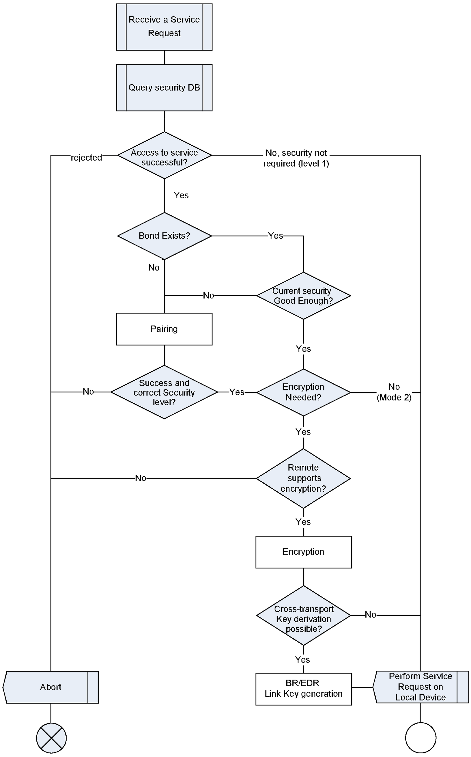
10.3.1.1. Handling of GATT indications and notifications
A client “requests” a server to send indications and notifications by appropriately configuring the server via a Client Characteristic Configuration Descriptor. Since the configuration is persistent across a disconnection and reconnection, security requirements shall be checked against the configuration upon a reconnection before sending indications or notifications. When a server reconnects to a client to send an indication or notification for which security is required, the server shall initiate or request encryption with the client prior to sending an indication or notification. If the client does not have an LTK, indicating that the client has lost the bond, enabling encryption will fail.
10.3.1.2. Cross-transport key generation
After encryption is enabled, the correct security level has been achieved, and both devices support cross-transport key generation, the both devices may perform BR/EDR link key derivation.
Note
Note: If the LTK has an encryption key size that is shorter than 16 octets (128 bits), the BR/EDR link key is derived before the LTK gets masked.
10.3.2. Initiating a service request
In this section the local device is the device initiating a service request to a remote device. In the L2CAP protocol the local device sends the connection request and the remote device sends the connection response. In GATT, the local device is the GATT Client and the remote device is the GATT Server.
When a local device initiates a service request to a remote device it shall behave according to the following rules:
The local device’s security database specifies the security required to initiate a service request. If no encryption is required by the local device then the service request may proceed without encryption or pairing.
If an LTK is not available but encryption is required, the pairing procedure shall be initiated with the local device’s required authentication settings. If the pairing procedure fails then the service request shall be aborted.
Note
Note: When encryption is not enabled, the error code “Insufficient Authentication” does not indicate to the local device that MITM protection is required.
Note
Note: If the local device is a Peripheral then it may send a Peripheral Initiated Security Request as defined in [Vol 3] Part H, Section 2.4.6.
If pairing has occurred but the encryption key size is insufficient the pairing procedure shall be executed with the required encryption key size. If the pairing procedure fails then the service request shall be aborted.
If an LTK is available and encryption is required (LE security mode 1) then encryption shall be enabled before the service request proceeds as defined in Section 10.6. Once encryption is enabled the service request shall proceed. If encryption fails, then either the bond no longer exists on the remote device or the wrong device has been connected. If the local device does not abandon the service request, it shall trigger a user interaction to confirm the remote device and then re-bond, perform service discovery, and reconfigure the remote device (reconfiguring the remote device can involve actions such as re-enabling indications and notifications on the relevant characteristics). If the local device had previously determined that the remote device did not have the «Service Changed» characteristic, or if the local device determines by reading the «Database Hash» characteristic that the database has not changed, then service discovery may be skipped.
If an authenticated pairing is required but only an unauthenticated pairing has occurred and the link is currently encrypted, the pairing procedure should be executed with the required authentication settings. If the pairing procedure fails, or an authenticated pairing cannot be performed with the IO capabilities of the local device and remote device, then the service request shall be aborted.
When a bond has been created between two devices, any reconnection should result in the local device enabling or requesting encryption with the remote device before initiating any service request.
If a local device does not enable encryption before initiating a service request and relies on the error codes to determine the security requirements, the local device shall not request pairing with MITM protection in response to receiving an “Insufficient Authentication” error code from the remote device while the link is unencrypted. The local device shall only set the MITM protection required flag if the local device itself requires MITM protection.
If encryption is not enabled at the time of the service request, the error code “Insufficient Authentication” is received, and the local device currently has an LTK, then the encryption procedure should be started (see Section 10.6). If this fails (likely indicating that the remote device has lost the bond and no longer has the LTK) or the local device does not have the correct LTK, then it should re-pair. If it re-pairs, it shall trigger a user interaction to confirm the remote device before starting the pairing procedure. IO capabilities are exchanged in pairing phase 1, (see [Vol 3] Part H, Section 2.1) and the security level shall be determined by the devices’ IO capabilities and MITM requirements.
If encryption is not enabled at the time of the service request, the error code “Insufficient Encryption” is received, and the local device currently has an LTK, then the encryption procedure shall be started (see Section 10.6). If starting encryption fails (likely indicating that the remote device has lost the bond and no longer has the LTK) or the local device does not have the correct LTK, then it should re-pair. If it re-pairs, it shall trigger a user interaction to confirm the remote device before starting the pairing procedure.
If LE Secure Connections authenticated pairing is required but the remote device does not support LE Secure Connections, then the service request shall be aborted.
Figure 10.2 shows how a client issues a service request.
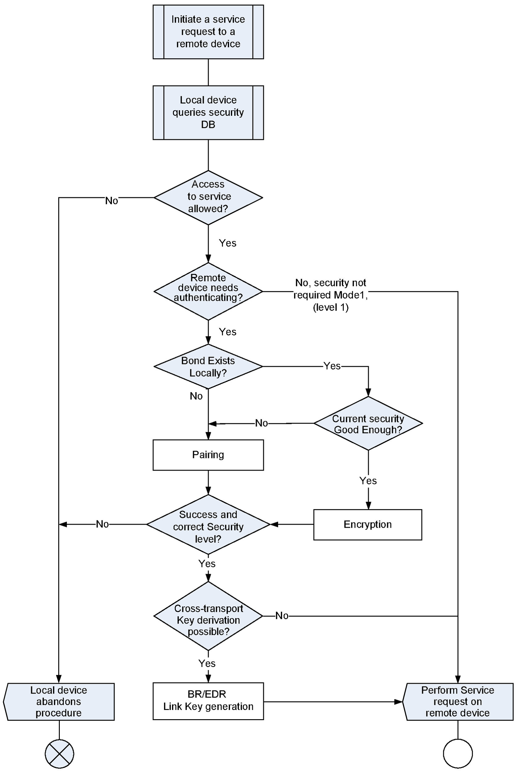
10.3.2.1. Cross-transport key generation
After encryption is enabled, the correct security level has been achieved, and both devices support cross-transport key generation, the both devices may perform BR/EDR link key derivation.
Note
Note: If the LTK has an encryption key size that is shorter than 16 octets (128 bits), the BR/EDR link key is derived before the LTK gets masked.
10.3.2.2. Handling of GATT indications and notifications
A client requests a server to send indications and notifications by appropriately configuring the server via a Client Characteristic Configuration Descriptor. Since the configuration is persistent across a disconnection and reconnection, the client shall check the security requirements against the configuration upon a reconnection before processing any indications or notifications from the server. Any notifications received before the security requirements are met shall be ignored. Any indications received before the security requirements are met shall be confirmed and then discarded. When a client reconnects to a server and expects to receive indications or notifications for which security is required, the client shall enable encryption with the server. If the server does not have an LTK, indicating that the server has lost the bond, enabling encryption will fail.
10.4. Data signing
The data signing is used for transferring authenticated data between two devices in an unencrypted connection. The data signing method is used by services that require fast connection set up and fast data transfer.
If a service request specifies LE security mode 2, the connection data signing procedure shall be used.
10.4.1. Connection Data Signing procedure
A device shall generate a new Connection Signature Resolving Key CSRK for each set of peer device(s) to which it sends signed data in connections. CSRK is defined in [Vol 3] Part H, Section 2.4.2.2.
The data shall be formatted using the Signing Algorithm as defined in [Vol 3] Part H, Section 2.4.5 where m is the Data PDU to be signed, k is the CSRK and the SignCounter is the counter value. A Signature is composed of the counter value and the Message Authentication Code (MAC) generated by the Signing Algorithm. The counter value shall be incremented by one for each new Data PDU sent.
The format of signed data is shown in Figure 10.3.
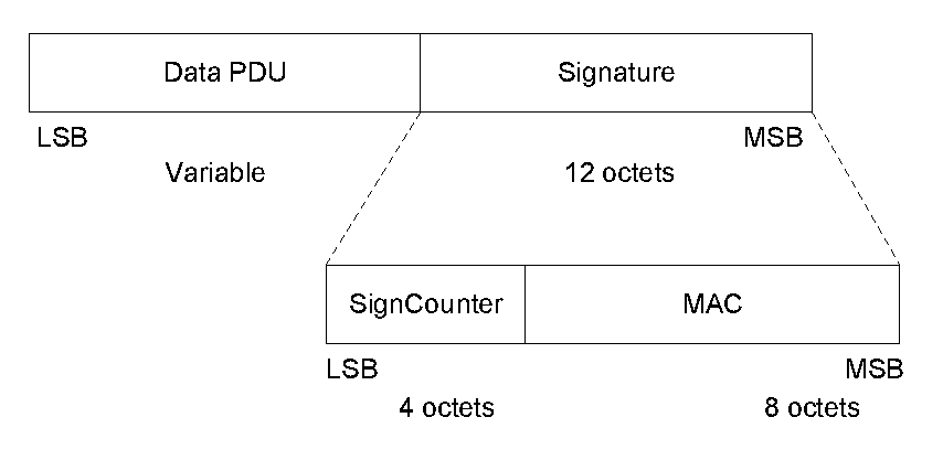 |
10.4.2. Authenticate Signed Data procedure
If encryption is not required and CSRK is available (LE security mode 2) then the data signing procedure shall be used when making a service request involving a write operation.
Note
Note: The existence of the bond on the server can be determined by successfully enabling encryption with the server using the encryption procedure defined in Section 10.6. A higher layer profile may allow a client to not perform the authentication procedure. Alternatively, a higher layer protocol may signal the client that the signature check has failed due to a lost bond, and the client may then take action to notify the user or attempt to pair again to reestablish the bond.
A device receiving signed data shall authenticate it by performing the Signing Algorithm. The signed data shall be authenticated by performing the Signing Algorithm where m is the Data PDU to be authenticated, k is the stored CSRK and the SignCounter is the received counter value. If the MAC computed by the Signing Algorithm does not match the received MAC, the verification fails and the Host shall ignore the received Data PDU.
Since the server does not respond to a Signed Write command, the higher layer application is not necessarily notified of the ignored request. Hence, it is recommended that the server disconnect the link in case the client is a malicious device attempting to mount a security attack.
If the server has no stored CSRK upon receiving a signed write command, it shall ignore the received Data PDU. Since the server does not respond to a Signed Write command, the higher layer application is not necessarily notified of the ignored request. Although the disconnection may be an adequate indication to the user that the devices need to be paired, it is recommended that implementers consider providing an explanatory indication to the user that the devices need to be paired to establish a CSRK.
If the server receives a request from a client for a write operation that requires a response (i.e. other than a Signed Write command or Write command), and encryption is not enabled, then the server shall respond with the error code “Insufficient Authentication”.
If the link is encrypted and the server receives a request from a client for which the server requires data signing but does not require encryption, then the server shall complete the request if it is otherwise valid as the encrypted state of the link is considered to satisfy the signing requirement.
As required by Section 10.2.2, for a given link, signed data is not used at the same time as encryption. Therefore, if the client wishes to test that the server is still bonded, and thus enables encryption, further data transfer must occur without signing, assuming the server does not disconnect the link as recommended above.
If a higher layer determines the bond no longer exists on the server, the client shall trigger a user interaction to confirm the remote device and then re-bond, perform service discovery, and reconfigure the server. If the client had previously determined that the server did not have the «Service Changed» characteristic, or the client determines by reading the «Database Hash» characteristic that the database has not changed, then service discovery may be skipped.
The receiving device shall protect against a replay attack by comparing the received SignCounter with previously received SignCounter from the same peer device. If the SignCounter was previously used then the receiving device shall ignore the Data PDU.
10.5. Authorization procedure
A service may require authorization before allowing access. Authorization is a confirmation by the user to continue with the procedure. Authentication does not necessarily provide authorization. Authorization may be granted by user confirmation after successful authentication.
10.6. Encryption procedure
A Central may encrypt a connection using the Encryption Session Setup as defined in [Vol 3] Part H, Section 2.4.4 to provide integrity and confidentiality.
A Peripheral may encrypt a connection using the Peripheral Initiated Security Request as defined in [Vol 3] Part H, Section 2.4.6 to provide integrity and confidentiality.
If the encryption procedure fails and either the Central or Peripheral used a Resolvable Private Address for the connection establishment, then the current Resolvable Private Address(es) shall be immediately discarded and new Resolvable Private Address(es) shall be generated.
10.7. Privacy feature
The privacy feature provides a level of privacy which makes it more difficult for an attacker to track a device over a period of time. The requirements for a device to support the privacy feature are defined in Table 10.3.
Privacy Requirements | Ref. | Broadcaster | Observer | Peripheral | Central |
|---|---|---|---|---|---|
Privacy feature | O | O | O | O | |
Non-resolvable private address generation procedure | C.2 | C.4 | O | O | |
Resolvable private address generation procedure | C.3 | C.5 | C.1 | C.1 | |
Resolvable private address resolution procedure | E | O | C.1 | C.1 | |
Bondable Mode | E | E | C.1 | C.1 | |
Bonding procedure | E | E | C.1 | C.1 | |
| |||||
Two modes of privacy exist:
Device Privacy Mode: When a device is in device privacy mode, it is only concerned about its own privacy. It should accept advertising packets from peer devices that contain their Identity Addresses as well as their private address, even if the peer device has distributed its IRK.
Network Privacy Mode. When a device is in network privacy mode, it shall not accept advertising packets containing the Identity Address of peer devices that have distributed their IRK.
Note
Note: If the Resolvable Private Address Only characteristic is not present in the GAP service of the remote device then it may use its Identity Address over the air.
A device may use different modes for different peers.
If a device, i.e. Host and Controller, claims support for the privacy feature, the requirements in this section shall be met.
A device may support either just Host-based privacy or both Host-based and Controller-based privacy. When a device supports Controller-based privacy, the Host configures the Controller to perform some of the privacy functionality
If a device supports Controller-based privacy, the requirements in the following paragraphs shall be met.
The Host may maintain a resolving list by adding and removing device identities. A device identity consists of the peer’s Identity Address and a local and peer’s IRK pair. The local or peer’s IRK shall be an all-zero key if not applicable for the particular device identity.
If a peer device provides an all-zero Identity Address during pairing, the Host shall choose a unique identifier to substitute the peer’s device Identity Address. The Host shall ensure that all identities provided to the Controller are unique.
When address resolution is enabled in the Controller, all references to peer devices that are included in the resolving list from Host to the Controller shall be done using the peer’s device Identity Address. Likewise, all incoming events from the Controller to the Host will use the peer’s device identity, if the peer’s device address has been resolved.
If the Host wants to be in device privacy mode, it shall so instruct the Controller for each peer in the resolving list.
10.7.1. Privacy feature in a Peripheral
The privacy-enabled Peripheral shall use a resolvable private address as the advertiser's device address when in connectable mode.
A Peripheral shall use non-resolvable or resolvable private addresses when in non-connectable mode as defined in Section 9.3.2.
If a privacy-enabled Peripheral, that has a stored bond, receives a resolvable private address, the Host may resolve the resolvable private address by performing the ‘resolvable private address resolution procedure’ as defined in Section 10.8.2.3. If the resolution is successful, the Host may accept the connection. If the resolution procedure fails, then the Host shall either accept the connection from the new, unresolved device, disconnect with the error code "Authentication failure", or perform the pairing procedure, or perform the authentication procedure as defined in Section 10.3. Accepting the connection from the new, unresolved device, can result in exposing the device name or unique data to the Central.
The device should not send the device name or unique data in the advertising data that can be used to recognize the device.
10.7.1.1. Privacy feature in a Peripheral with Controller-based privacy
A privacy-enabled Peripheral shall use either the undirected connectable mode as defined in Section 9.3.4 or directed connectable mode as defined in Section 9.3.3. The directed connectable mode shall only be used if the peer device supports Address Resolution in the Controller.
The Host shall enable resolvable private address generation by enabling it in the Controller and populating the resolving list.
By default, network privacy mode is used when private addresses are resolved and generated by the Controller.
If the advertising data or the scan response data change regularly then those changes should be synchronized with any changes in private addresses (both local and remote). For this purpose, the Host should either instruct the Controller to synchronize address changes with those data changes or, if the Controller does not support that feature, generate private addresses as described in Section 10.7.1.2 instead of offloading private address generation to the Controller.
10.7.1.2. Privacy feature in a Peripheral with Host-based privacy
A privacy-enabled Peripheral should use the undirected connectable mode as defined in Section 9.3.2, to create a connection.
The Host shall generate a resolvable private address using the ‘resolvable private address generation procedure’ as defined in Section 10.8.2.2 or non-resolvable private address procedure as defined in Section 10.8.2.1. The Host shall set a timer equal to TGAP(private_addr_int). The Host shall generate a new resolvable private address or non-resolvable private address when the timer TGAP(private_addr_int) expires.
Note
Note: TGAP(private_addr_int) timer need not be run if a Peripheral is not advertising.
10.7.2. Privacy feature in a Central
The privacy-enabled Central shall use a resolvable private address as the initiator's device address.
During active scanning, a privacy enabled Central shall use a non-resolvable or resolvable private address.
If, a privacy-enabled Central, that has a stored bond, receives a resolvable private address, the Host may resolve the resolvable private address by performing the "resolvable private address resolution procedure" as defined in Section 10.8.2.3.
10.7.2.1. Privacy feature in a Central with Controller-based privacy
A privacy-enabled Central with Address Resolution enabled in the Controller can use any of the connection establishment procedures defined in Section 9.3.
By default, network privacy mode is used when private addresses are resolved and generated by the Controller.
10.7.2.2. Privacy feature in a Central with Host-based privacy
A privacy-enabled Central should use the general connection establishment procedure defined in Section 9.3.6 to create a connection.
The Host shall generate a resolvable private address using the ‘resolvable private address generation procedure’ as defined in Section 10.8.2.2 or non-resolvable private address procedure as defined in Section 10.8.2.1. The Host shall set a timer equal to TGAP(private_addr_int). The Host shall generate a new resolvable private address or non-resolvable private address when the timer TGAP(private_addr_int) expires.
Note
Note: TGAP(private_addr_int) timer need not be run if a Central is not scanning or connected.
10.7.3. Privacy feature in a Broadcaster
A privacy-enabled Broadcaster shall use the Broadcast mode defined in Section 9.1.1. The Broadcaster shall use either a resolvable private address or non-resolvable private address.
If Address Resolution is not supported or disabled in the Controller, the following applies to the Host: The Host shall generate a resolvable private address using the ‘resolvable private address generation procedure’ as defined in Section 10.8.2.2 or non-resolvable private address procedure as defined in Section 10.8.2.1. The Host shall set a timer to TGAP(private_addr_int). The Host shall generate a new resolvable private address or non-resolvable private address when the timer TGAP(private_addr_int) expires.
Note
Note: TGAP(private_addr_int) timer need not be run if a Broadcaster is not advertising.
The device should not send the device name or unique data in the advertising data which can be used to recognize the device.
10.7.4. Privacy feature in an Observer
A privacy-enabled Observer shall use the Observation procedure defined in Section 9.1.2. During active scanning, a privacy enabled Observer shall use either a resolvable private address or non-resolvable private address.
If Address Resolution is not supported or disabled in the Controller, the following applies to the Host: The Host shall generate a resolvable private address using the ‘resolvable private address generation procedure’ as defined in Section 10.8.2.2 or non-resolvable private address procedure as defined in Section 10.8.2.1. The Host shall set a timer equal to TGAP(private_addr_int). The Host shall generate a new resolvable private address or non-resolvable private address when the timer TGAP(private_addr_int) expires. The value of TGAP(private_addr_int) shall not be greater than 1 hour.
Note
Note: TGAP(private_addr_int) timer need not be run if an Observer is not scanning.
10.8. Random Device address
For the purposes of this profile, the random device address may be of either of the following two sub-types:
Static address
Private address.
The term random device address refers to both static and private address types.
The transmission of a random device address is optional. A device shall accept the reception of a random device address from a remote device.
The private address may be of either of the following two sub-types:
Non-resolvable private address
Resolvable private address
A bonded device shall process a resolvable private address as defined in Section 10.8.2.3 or by establishing a connection and then performing the authentication procedure as defined in Section 10.3. A device that generates a resolvable private address for its local address shall always request to distribute its IRK value as defined in [Vol 3] Part H, Section 3.6.4 if both sides are bondable, unless keys have been pre-distributed.
After a device has distributed its IRK, it should use resolvable private addresses when establishing a connection with a peer device to which the IRK has been distributed.
10.8.1. Static address
The Host can generate a static address using the procedure described in [Vol 6] Part B, Section 1.3.2.1.
10.8.2. Private address
The private address may be of either of the following two sub-types:
Non-resolvable private address
Resolvable private address
10.8.2.1. Non-Resolvable Private Address Generation procedure
The Host can generate a non resolvable private address using the procedure described in [Vol 6] Part B, Section 1.3.2.2.
10.8.2.2. Resolvable Private Address Generation procedure
The Host can generate a resolvable private address where the Host has its IRK using the procedure described in [Vol 6] Part B, Section 1.3.2.2.
10.8.2.3. Resolvable Private Address Resolution procedure
The Host can resolve a resolvable private address where the Host has the peer device’s IRK or the local device's IRK, using the procedure described in [Vol 6] Part B, Section 1.3.2.3.
10.9. Encrypted Broadcast Isochronous Group
A device with a service that requires using an unauthenticated encrypted BIG shall set its security to LE security mode 3 level 2. A device with a service that requires using an authenticated encrypted BIG shall set its security to LE security mode 3 level 3.
When a user initiates a service that includes broadcasting an encrypted BIG, the Host shall provide the Broadcast_Code associated with the encrypted BIG to the Controller.
When a user initiates a service that requires the reception of an encrypted BIS, the device should use the Broadcast_Code for that encrypted BIS. If the device does not have the Broadcast_Code or cannot obtain the Broadcast_Code, it should indicate an appropriate error (e.g., Code Unavailable) to the user.
10.10. Encrypted Advertising Data procedure
A Broadcaster may encrypt advertising data using an Encrypted Data data type. The data is encrypted using key material that is known by both devices as defined in Section 1.23.3 of [7].
The key material is exposed using the Encrypted Data Key Material characteristic on the Broadcaster.
The scanning device shall read the Encrypted Data Key Material characteristic on an advertising device to obtain the key material for a device if it wants to interpret the encrypted advertising data being sent.
11. Advertising and Scan Response data format
The format of Advertising, Periodic Advertising, and Scan Response data is shown in Figure 11.1. The data consists of a significant part and a non-significant part. The significant part contains a sequence of AD structures. Each AD structure shall have a Length field of one octet, which contains the Length value and shall not be zero, and a Data field of Length octets. The first octet of the Data field shall contain the AD type field. The content of the remaining Length - 1 octets in the Data field depends on the value of the AD type field and is called the AD data. The non-significant part shall only be present when necessary to fill a fixed-length field and shall contain all-zero octets.
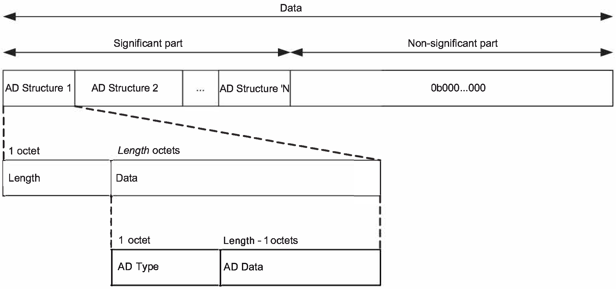
Only the significant part of the data should be sent over the air.
The data is sent in advertising or periodic advertising events. Host Advertising data is placed in the AdvData field of ADV_IND, ADV_NONCONN_IND, ADV_SCAN_IND, AUX_ADV_IND, and AUX_CHAIN_IND PDUs. Additional Controller Advertising Data is placed in the ACAD field of AUX_ADV_IND, AUX_SYNC_IND, and AUX_SCAN_RSP PDUs. Periodic Advertising data is placed in the AdvData field of AUX_SYNC_IND, AUX_SYNC_SUBEVENT_IND, AUX_SYNC_SUBEVENT_RSP, and AUX_CHAIN_IND PDUs. Scan Response data is sent in the ScanRspData field of SCAN_RSP PDUs or the AdvData field of AUX_SCAN_RSP PDUs. If the complete data cannot fit in the AdvData field of an AUX_ADV_IND, AUX_SYNC_IND, or AUX_SCAN_RSP PDU, AUX_CHAIN_IND PDUs are used to send the remaining fragments of the data. In this case, an AD Structure may be fragmented over two or more PDUs.
The AD type data formats and meanings are defined in Section 1 of [4]. The AD type identifier values are defined in Assigned Numbers.
12. GAP service and characteristics for GATT Server
The GATT Server shall contain the GAP service as defined in the GAP Service Requirements in Table 12.1. A device shall have only one instance of the GAP service in the GATT Server. The GAP service is a GATT based service with the service UUID as «GAP Service» defined in Assigned Numbers.
GAP Service | C.1 | E | E | M | M |
| |||||
The characteristics requirements for the GAP service in each of the GAP roles are shown in Table 12.2.
Characteristics | Ref. | BR/EDR GAP Role | LE Broadcaster | LE Observer | LE Peripheral | LE Central |
|---|---|---|---|---|---|---|
Device Name | C.1 | E | E | M | M | |
Appearance | C.1 | E | E | M | M | |
Peripheral Preferred Connection Parameters | O | E | E | O | E | |
Central Address Resolution | O | E | E | C.3 | C.2 | |
Resolvable Private Address Only | O | E | E | C.3 | C.3 | |
Encrypted Data Key Material | O | E | E | O | E | |
LE GATT Security Levels | E | E | E | O | O | |
| ||||||
A device that supports multiple GAP roles contains all the characteristics to meet the requirements for the supported roles. The device shall continue to expose the characteristics when the device is operating in the role in which the characteristics are not valid.
12.1. Device Name characteristic
The Device Name characteristic shall contain the name of the device as an UTF-8 string as defined in Section 3.2.2. When the device is discoverable, the Device Name characteristic value shall be readable without authentication or authorization. When the device is not discoverable, the Device Name Characteristic should not be readable without authentication or authorization. The Device Name characteristic value may be writable. If writable, authentication and authorization may be defined by a higher layer specification or be implementation specific.
Attribute Handle | Attribute Type | Attribute Value | Attribute Permissions |
|---|---|---|---|
0xMMMM | 0x2A00 – UUID for «Device Name» | Device Name | Readable without authentication or authorization when discoverable. Optionally writable, authentication and authorization may be defined by a higher layer specification or be implementation specific. |
The Device Name characteristic value shall be 0 to 248 octets in length.
A device shall have only one instance of the Device Name characteristic.
12.2. Appearance characteristic
The Appearance characteristic defines the representation of the external appearance of the device. This enables the discovering device to represent the device to the user using an icon, or a string, or similar. The Appearance characteristic value shall be readable without authentication or authorization. The Appearance characteristic value may be writable. If writable, authentication and authorization may be defined by a higher layer specification or be implementation specific.
Attribute Handle | Attribute Type | Attribute Value | Attribute Permissions |
|---|---|---|---|
0xMMMM | 0x2A01 – UUID for «Appearance» | Appearance | Readable without authentication or authorization. Optionally writable, authentication and authorization may be defined by a higher layer specification or be implementation specific. |
The Appearance characteristic value shall be the enumerated value as defined in Assigned Numbers. The Appearance characteristic value shall be 2 octets in length. A device shall have only one instance of the Appearance characteristic.
12.3. Peripheral Preferred Connection Parameters characteristic
The Peripheral Preferred Connection Parameters (PPCP) characteristic contains the preferred connection parameters of the Peripheral.
The Peripheral Preferred Connection Parameters characteristic value shall be readable. Authentication and authorization may be defined by a higher layer specification or be implementation specific.
The Peripheral Preferred Connection Parameters characteristic value shall not be writable.
Attribute Handle | Attribute Type | Attribute Value | Attribute Permissions |
|---|---|---|---|
0xMMMM | 0x2A04 – UUID for «Peripheral Preferred Connection Parameters» | Peripheral Preferred Connection Parameters | Readable, authentication and authorization may be defined by a higher layer specification or be implementation specific Not writable |
The Peripheral Preferred Connection Parameters characteristic value shall be 8 octets in length. A device shall have only one instance of the Peripheral Preferred Connection Parameters characteristic. The format of the value is specified in Table 12.6.
Name | Size (Octet) |
|---|---|
Interval_Min | 2 |
Interval_Max | 2 |
Latency | 2 |
Timeout | 2 |
Each field shall have the same meaning and requirements as the field of the LL_CONNECTION_PARAM_REQ PDU (see [Vol 6] Part B, Section 2.4.2.16) with the same name, or shall contain the value 0xFFFF which indicates that no specific value is requested.
12.4. Central Address Resolution characteristic
The Peripheral should check if the peer device supports address resolution by reading the Central Address Resolution characteristic before using directed advertisement where the target address is set to a Resolvable Private Address (RPA).
The Central Address Resolution characteristic defines whether the device supports privacy with address resolution. See Table 12.7.
Attribute Handle | Attribute Type | Attribute Value | Attribute Permissions |
|---|---|---|---|
0xMMMM | 0x2AA6 - UUID of «Central Address Resolution» | Central Address Resolution Support | Readable without authentication or authorization. Not writable. |
The Central Address Resolution characteristic value shall be 1 octet in length:
0 = address resolution is not supported in this device 1 = address resolution is supported in this device
All other values are reserved for future use.
A device shall have only one instance of the Central Address Resolution characteristic. If the Central Address Resolution characteristic is not present, then it shall be assumed that Central Address Resolution is not supported.
12.5. Resolvable Private Address Only characteristic
The device should check if the peer will only use Resolvable Private Addresses (RPAs) after bonding by reading the Resolvable Private Address Only characteristic, in order to determine if it will satisfy its privacy mode as defined in Section 10.7.
The Resolvable Private Address Only characteristic defines whether the device will only use Resolvable Private Addresses (RPAs) as local addresses. See Table 12.8.
Attribute Handle | Attribute Type | Attribute Value | Attribute Permissions |
|---|---|---|---|
0xMMMM | 0x2AC9 - UUID of «Resolvable Private Address Only» | Resolvable Private Address Only | Readable without authentication or authorization. Not writable. |
The Resolvable Private Address Only characteristic value shall be 1 octet in length:
0 = only Resolvable Private Addresses will be used as local addresses after bonding
All other values are reserved for future use.
A device shall have only one instance of the Resolvable Private Address Only characteristic. If the Resolvable Private Address Only characteristic is not present, then it cannot be assumed that only Resolvable Private Addresses will be used over the air.
12.6. Encrypted Data Key Material
The Encrypted Data Key Material characteristic allows advertising data associated with the GAP service to be decrypted and authenticated using the key material. The Encrypted Data Key characteristic value shall not be writable. The Encrypted Data Key Material characteristic shall only be readable when authenticated and authorized. When read, the key material is stored on the local device. The key material may be discarded at any time on a local device.
The Encrypted Data Key Material characteristic may support indications. When authenticated and authorized, if the Encrypted Data Key characteristic value changes and the client has configured the characteristic for indications, then the characteristic shall be indicated by the server to the client.
The Encrypted Data Key Material characteristic can be used by other services to allow those services to expose separate key material for encrypted advertising data used by those services.
Attribute Handle | Attribute Type | Attribute Value | Attribute Permissions |
|---|---|---|---|
0xMMMM | 0x2B88 - UUID for «Encrypted Data Key Material» | Key Material | Readable when authenticated and authorized. Indicatable when authenticated and authorized. Not writable. |
The Key Material is composed of a 128-bit value that is used as the session key and a 64-bit value that is used as the IV for encrypting and authenticating the Encrypted Data as defined in Section 1.23.3 of [4], as shown in Table 12.10. The server should update the Key Material periodically.
Field | Size (octets) | Description |
|---|---|---|
Session Key | 16 | The shared session key. |
IV | 8 | The initialization vector. |
12.7. LE GATT Security Levels Characteristic
This section specifies the LE GATT Security Levels characteristic.
The LE GATT Security Levels characteristic shall contain the highest security requirements of the GATT server when operating on a LE connection. The value of the LE GATT Security Levels characteristic shall be static during a connection.
The format of the LE GATT Security Levels characteristic is given in Table 12.11.
Attribute Handle | Attribute Type | Attribute Value | Attribute Permissions |
|---|---|---|---|
0xMMMM | 0x2BF5 - UUID for «LE GATT Security Levels» | Sequence of one or more Security Level Requirements | Read Only, No Encryption required, No Authentication, No Authorization |
The Attribute Value is a sequence of Security Level Requirements, each with the type uint8[2]. Each Security Level Requirement consists of a Security Mode field followed by a Security Level field. The Security Mode and Security Level shall be expressed as the same number as used in their definitions; e.g., mode 1 is represented as 0x01 and level 4 is represented as 0x04.
Meeting any one of the security requirements provided for a given mode shall be sufficient for the GATT server to allow the GATT client to use all the GATT procedures permitted by the characteristic properties for all characteristics on the server operating in that mode. If any one of the security requirements specified in the LE GATT Security Levels characteristic is met, no GATT procedure will fail for a security-related reason (such as insufficient authentication). For example, the attribute value 0x01 0x04 for the LE GATT Security Levels characteristic means that the GATT server requires level 4 when operating in security mode 1 on a LE connection.
Note
Note: The Security Level value is not a minimum; specifying (say) level 2 for a mode does not mean that level 3, level 4, or even level 87 would suffice instead. However, in many cases a given security level satisfies the security requirements of other levels as well. For example, LE security mode 1 levels 3 and 4, by definition, both satisfy the requirements for mode 1 level 2 and so could be used with a GATT server that requires mode 1 level 2.
The security modes and levels for LE are defined in Section 10.
A device shall have at most one instance of a LE GATT Security Levels characteristic.
13. BR/EDR/LE operation
This section describes the requirements for devices that support the BR/EDR/LE device type. The device may support any LE GAP roles allowed by the Controller over the LE physical channel.
A BR/EDR/LE device type that supports the Broadcaster role shall meet the requirements for the Broadcaster role as defined in Section 9.
A BR/EDR/LE device type that supports the Observer role shall meet the requirements for the Observer role as defined in Section 9.
A BR/EDR/LE device type that supports the Peripheral role shall meet the requirements for the Peripheral role as defined in Section 9.
A BR/EDR/LE device type that supports the Central role shall meet the requirements for the Central role as defined in Section 9.
13.1. Modes, procedures, and security aspects
All modes, procedures and security aspects shall follow the requirements as specified for the physical transport over which they operate. Sections 4, 5, 6 and 7 specify the requirements for the modes, procedures and security aspects for operations performed over the BR/EDR physical transport. Sections 9 and 9.6 specify the requirements for the modes, procedures and security aspects performed over the LE physical transport. It is optional to support both physical transports simultaneously to the same remote device.
13.1.1. Discoverable mode requirements
A device shall expose the capabilities of both physical transports for both Limited and General Discoverable Mode using the advertisement Flag AD Type as follows:
The ‘BR/EDR Not Supported’ bit in the Flags AD type shall be set to 0 as defined in Section 1.3 of [4].
The 'Simultaneous LE and BR/EDR to Same Device Capable (Controller)' bit in the Flags AD type shall be set to 0.
The ‘LE Supported (Controller)’ and ‘LE Supported (Host)’ bits in the LMP features shall be set as defined in [Vol 2] Part C, Section 3.2.
13.2. Bonding for BR/EDR/LE device type
The requirements for a device supporting BR/EDR/LE device type are shown in Table 13.2.
If the remote device supports the BR/EDR physical transport, the bonding procedures for the BR/EDR physical transport as defined in Section 6.5 shall be used.
If the remote device supports the LE physical transport, the bonding procedures for the LE physical transport as defined in Section 9.4.4 shall be used.
13.3. Relationship between physical transports
To determine if both the BR/EDR physical transport and the LE physical transport are established to the same peer device, the device shall use either the public address used on the LE advertising physical channel or the public address from the BD_ADDR field contained in the SMP Identity Address Information packet ([Vol 3] Part H, Section 3.6.5) if it has been received.
14. BR/EDR/LE security aspects
The requirements for a device supporting BR/EDR/LE device type are shown in Table 14.1.
Security aspects | Ref. | Peripheral | Central |
|---|---|---|---|
Security aspects | M | M |
If the remote device supports the BR/EDR physical transport the security procedures for the BR/EDR physical transport as defined in Section 5 shall be used.
If the remote device supports the LE physical transport the security procedures for the LE physical transport as defined in Section 9.6 shall be used.
If the LE transport in a BR/EDR/LE device supports Secure Connections, the security procedures in Section 14.1 may also be used.
14.1. Cross-transport key derivation
If both the local and remote devices support Secure Connections over the BR/EDR and LE transports, devices may optionally generate keys of identical strength and the same MITM protection for both transports as part of a single pairing procedure (see [Vol 3] Part H, Section 2.3.5.7).
If both the local and remote devices support Secure Connections over the LE transport but not over the BR/EDR transport, then the devices may optionally generate the BR/EDR keys of identical strength and the same MITM protection as the LE keys as part of the LE pairing procedure (see [Vol 3] Part H, Section 2.3.5.7).
If an LE LTK already exists and the BR/EDR link key is weaker in either strength or MITM protection, then neither device shall generate an LE LTK using cross-transport key derivation from a BR/EDR link key. If either device receives a request to generate an LE LTK using cross-transport key derivation, it shall respond with a Pairing Failed message with reason "Cross-transport Key Derivation/Generation not allowed".
If the BR/EDR link key has been generated by a Controller that does not perform remote public key validation (see [Vol 2] Part H, Section 7.6), then neither device should generate an LE LTK using cross-transport key derivation from a BR/EDR link key. If either device receives a request to generate an LE LTK using cross-transport key derivation, it should respond with a Pairing Failed message with reason "Cross-transport Key Derivation/Generation not allowed".
If a BR/EDR link key already exists and the LE LTK is weaker in either strength or MITM protection, then neither device shall generate a BR/EDR link key using cross-transport key derivation from the LE LTK. If both devices request cross-transport key derivation during pairing, then each device shall either silently skip deriving the BR/EDR link key or stop the pairing procedure by sending a Pairing Failed message with reason "Cross-transport Key Derivation/Generation not allowed".
Note
Note: The Host can use the HCI_Read_Local_Simple_Pairing_Options command (see [Vol 4] Part E, Section 7.4.9) or vendor-specific methods to determine whether the Controller performs remote public key validation.
If the LE LTK has been generated using the HCI_LE_Generate_DHKey command (see [Vol 4] Part E, Section 7.8.37) by a Controller that does not perform remote public key validation (see [Vol 3] Part H, Section 2.3.5.6.1), then the BR/EDR link key should not be generated from such an LE LTK using cross-transport key derivation.
Note
Note: The Host can use the Remote Public Key Validation feature bit (see [Vol 6] Part B, Section 4.6) or vendor-specific methods to determine whether the HCI_LE_Generate_DHKey command performs the remote public key validation.
14.2. Collision handling
If pairing has been initiated by the local device on the BR/EDR transport, and a pairing request is received from the same remote device on the LE transport, the LE pairing shall be rejected with SMP error code BR/EDR Pairing in Progress (0x0D) if both sides support LE Secure Connections.
If a BR/EDR/LE device supports LE Secure Connections, then it shall initiate pairing on only one transport at a time to the same remote device.
14.3. Secure Connections Only Mode
If a BR/EDR/LE device is in Secure Connections Only Mode, then this mode applies to both transports and the requirements in both Section 5.2.2 and Section 10.2.4 shall apply.
15. Bluetooth Device requirements
15.1. Bluetooth Device address
All Bluetooth devices shall have a Bluetooth Device Address (BD_ADDR) that uniquely identifies the device to another Bluetooth device. The specific Bluetooth Device Address requirements depend on the type of Bluetooth device.
15.1.1. Bluetooth Device Address types
15.1.1.1. Public Bluetooth address
A Bluetooth public address used as the BD_ADDR for the BR/EDR physical channel is defined in [Vol 2] Part B, Section 1.2. A Bluetooth public address used as the BD_ADDR for the LE physical channel is defined in [Vol 6] Part B, Section 1.3.
15.1.1.2. Random Bluetooth address
A random device address used as the BD_ADDR on the LE physical channel is defined in Section 10.8.
15.2. GATT Profile requirements
The requirements for supporting a GATT Client or GATT Server are specified in Table 15.1.
GATT Client | O | E | E | O | O |
GATT Server | C.1 | E | E | M | M |
| |||||
15.3. SDP requirements
The requirements for supporting an SDP Client or SDP Server are specified in Table 15.2. There shall be no more than one active SDP Server per device.
SDP Client | C.1 | E |
SDP Server | C.2 | E |
| ||
15.4. SDP service record requirement
A BR/EDR or BR/EDR/LE device that supports a GATT Server accessible over the BR/EDR physical transport and that supports only one of ATT or EATT shall publish the SDP record shown below in Table 15.3; if both ATT and EATT are supported, the device shall publish the SDP record shown below in Table 15.4. The GAP Service Start Handle shall be set to the attribute handle of the «GAP Service» service declaration. The GAP Service End Handle shall be set to the attribute handle of the last attribute within the «GAP Service» service definition group.
Item | Type | Value | Meaning | ||
|---|---|---|---|---|---|
Attribute ID | uint16 | 0x0001 | ServiceClassIDList | ||
Attribute Value | Data element sequence (1 item) | ||||
Service Class | UUID | «GAP Service» | |||
Attribute ID | uint16 | 0x0004 | ProtocolDescriptorList | ||
Attribute Value | Data element sequence (2 items) | ||||
Protocol Descriptor | Data element sequence (2 items) | ||||
Protocol | UUID | «L2CAP» | |||
Parameter 0 | uint16 | 0x001F or 0x0027 | PSM = ATT or PSM = EATT | ||
Protocol Descriptor | Data element sequence (3 items) | ||||
Protocol | UUID | «ATT» | |||
Parameter 0 | uint16 | 0xHHHH | GAP service start handle | ||
Parameter 1 | uint16 | 0xHHHH | GAP service end handle | ||
Attribute ID | uint16 | 0x0005 | BrowseGroupList | ||
Attribute Value | Data element sequence (1 item) | ||||
Group | UUID | «PublicBrowseRoot» | |||
Item | Type | Value | Meaning | |||
|---|---|---|---|---|---|---|
Attribute ID | uint16 | 0x0001 | ServiceClassIDList | |||
Attribute Value | Data element sequence (1 item) | |||||
Service class | UUID | «GAP Service» | ||||
Attribute ID | uint16 | 0x0004 | ProtocolDescriptorList | |||
Attribute Value | Data element sequence (2 items) | |||||
Protocol Descriptor | Data element sequence (2 items) | |||||
Protocol | UUID | «L2CAP» | ||||
Parameter 0 | uint16 | 0x001F | PSM = ATT | |||
Protocol Descriptor | Data element sequence (3 items) | |||||
Protocol | UUID | «ATT» | ||||
Parameter 0 | uint16 | 0xHHHH | GAP service start handle | |||
Parameter 1 | uint16 | 0xHHHH | GAP service end handle | |||
Attribute ID | uint16 | 0x000D | AdditionalProtocolDescriptorList | |||
Attribute Value | Data element sequence (1 item) | |||||
Protocol Descriptor List | Data element sequence (2 items) | |||||
Protocol Descriptor | Data element sequence (2 items) | |||||
Protocol | UUID | «L2CAP» | ||||
Parameter 0 | uint16 | 0x0027 | PSM = EATT | |||
Protocol Descriptor | Data element sequence (3 items) | |||||
Protocol | UUID | «ATT» | ||||
Parameter 0 | uint16 | 0xHHHH | GAP service start handle | |||
Parameter 1 | uint16 | 0xHHHH | GAP service end handle | |||
Attribute ID | uint16 | 0x0005 | BrowseGroupList | |||
Attribute Value | Data element sequence (1 item) | |||||
Group | UUID | «PublicBrowseRoot» | ||||
If a BR/EDR or BR/EDR/LE device supports a GATT-based service on the BR/EDR transport, the service shall exist in the SDP Server and the GATT Server.
16. Definitions
In the following, terms written with capital letters refer to states.
Most definitions in this section are BR/EDR specific.
16.1. General definitions
Mode: A set of directives that defines how a device will respond to certain events.
Idle: As seen from a remote device, a Bluetooth device is idle, or is in idle mode, when there is no link established between them.
Bond: A relation between two Bluetooth devices defined by creating, exchanging and storing a common link key. The bond is created through the bonding or LMP-pairing procedures.
16.2. Connection-related definitions
Physical channel: A synchronized Bluetooth Baseband-compliant RF hopping sequence.
Piconet: A set of Bluetooth devices sharing the same physical channel defined by the Central's parameters (clock and BD_ADDR).
Physical link: A Baseband-level connection[2] between two devices established using paging. A physical link comprises a sequence of transmission slots on a physical channel alternating between Central and Peripheral transmission slots.
ACL link: An asynchronous (packet-switched) connection[2] between two devices created on LMP level. Traffic on an ACL link uses ACL packets to be transmitted.
SCO link: A synchronous (circuit-switched) connection[2] for reserved bandwidth communications; e.g. voice between two devices, created on the LMP level by reserving slots periodically on a physical channel. Traffic on a SCO link uses SCO packets to be transmitted. SCO links can be established only after an ACL link has first been established.
Link: Shorthand for an ACL link.
PAGE: A Baseband state where a device transmits page trains, and processes any eventual responses to the page trains.
PAGE_SCAN: A Baseband state where a device listens for page trains.
Page: The transmission by a device of page trains containing the Device Access Code of the device to which the physical link is requested.
Page scan: The listening by a device for page trains containing its own Device Access Code.
Channel: A logical connection on L2CAP level between two devices serving a single application or higher layer protocol.
Connection: A connection between two peer applications or higher layer protocols mapped onto a channel.
Connecting: A phase in the communication between devices when a connection between them is being established. (Connecting phase follows after the link establishment phase is completed.)
Connect (to service): The establishment of a connection to a service. If not already done, this includes establishment of a physical link, link and channel as well.
16.3. Device-related definitions
Discoverable device: A Bluetooth device in range that will respond to an inquiry (normally in addition to responding to page).
Silent device: A Bluetooth device appears as silent to a remote device if it does not respond to inquiries made by the remote device. A device may be silent due to being non-discoverable or due to baseband congestion while being discoverable.
Connectable device: Bluetooth device in range that will respond to a page.
Trusted device: A paired device that is explicitly marked as trusted.
Paired device: A Bluetooth device with which a link key has been exchanged (either before connection establishment was requested or during connecting phase).
Pre-paired device: A Bluetooth device with which a link key was exchanged, and the link key is stored, before link establishment.
Un-paired device: A Bluetooth device for which there was no exchanged link key available before connection establishment was requested.
Known device: A Bluetooth device for which at least the BD_ADDR is stored.
Un-known device: Bluetooth device for which no information (BD_ADDR, link key or other) is stored.
Authenticated device: A Bluetooth device whose identity has been verified during the lifetime of the current link, based on the authentication procedure.
16.4. Procedure-related definitions
Paging: A procedure for establishing a physical link of ACL type on Baseband level, consisting of a page action of the initiator and a page scan action of the responding device.
Link establishment: A procedure for establishing a link on LMP level. A link is established when both devices have agreed that LMP setup is completed.
Channel establishment: A procedure for establishing a channel on L2CAP level.
Connection establishment: A procedure for creating a connection mapped onto a channel.
Creation of a trusted relationship: A procedure where the remote device is marked as a trusted device. This includes storing a common link key for future authentication and pairing (if the link key is not available).
Creation of a secure connection: A procedure of establishing a connection, including authentication and encryption.
Device discovery: A procedure for retrieving the Bluetooth Device Address, clock, and Class of Device from discoverable devices.
Name discovery: A procedure for retrieving the user-friendly name (the Bluetooth Device Name) of a connectable device.
Service discovery: Procedures for querying and browsing for services offered by or through another Bluetooth device.
16.5. Security-related definitions
Authentication: A generic procedure based on LMP-authentication if a link key exists or on LMP-pairing if no link key exists.
LMP-authentication: An LMP level procedure for verifying the identity of a remote device. The procedure is based on a challenge-response mechanism using a random number, a secret key and the BD_ADDR of the non-initiating device. The secret key used can be a previously exchanged link key.
Authorization: A procedure where a user of a Bluetooth device grants a specific (remote) Bluetooth device access to a specific service. Authorization implies that the identity of the remote device can be verified through authentication.
Authorize: The act of granting a specific Bluetooth device access to a specific service. It may be based upon user confirmation, or given the existence of a trusted relationship.
LMP-pairing: A procedure that authenticates two devices, based on a PIN, and subsequently creates a common link key that can be used as a basis for a trusted relationship or a (single) secure connection. The procedure consists of the steps: creation of an initialization key (based on a random number and a PIN), creation and exchange of a common link key and LMP-authentication based on the common link key.
Bonding: A dedicated procedure for performing the first authentication, where a common link key is created and stored for future use.
Trusting: The marking of a paired device as trusted. Trust marking can be done by the user, or automatically by the device (e.g. when in bondable mode) after a successful pairing.
17. References
[1] RFCOMM
[2] Telephony Control Specification
[3] Assigned Numbers Specification: https://www.bluetooth.com/specifications/assigned-numbers
[4] Core Specification Supplement, Part A, Data Types Specification
[5] Core Specification Supplement, Part C, Services Permitted to use Security Mode 4 Level 0
Appendix A. Timers and Constants
The following timers are required by this profile.
Timer name | Value | Description | Requirement or Recommendation |
|---|---|---|---|
TGAP(100) | 10.24 s | Time span that a Bluetooth device performs device discovery | Recommended value |
TGAP(101) | 10.625 ms | A discoverable Bluetooth device enters INQUIRY_SCAN for at least TGAP(101) every TGAP(102) | Required value |
TGAP(102) | 2.56 s | Maximum time between repeated INQUIRY_SCAN enterings when power consumption or bandwidth is more important than discovery speed | Recommended value |
TGAP(103) | 30.72 s | Minimum time span that a device is in discoverable mode | Required value |
TGAP(104) | 1 min | Maximum time span that a device is in limited discoverable mode | Recommended value |
TGAP(105) | 100 ms | Maximum time between INQUIRY_SCAN enterings when discovery speed is more important than power consumption or bandwidth | Recommended value |
TGAP(106) | 100 ms | Maximum time between PAGE_SCAN enterings when connection speed is more important than power consumption or bandwidth | Recommended value |
TGAP(107) | 1.28 s | Maximum time between PAGE_SCAN enterings (R1 page scan) when power consumption or bandwidth is more important than connection speed | Recommended value |
TGAP(108) | 2.56 s | Maximum time between PAGE_SCAN enterings (R2 page scan) when power consumption or bandwidth is more important than connection speed | Recommended value |
TGAP(adv_fast_interval1_coded) | 90 ms to 180 ms | Minimum to maximum advertising interval in the following GAP Modes on the LE Coded PHY when user initiated:
| Recommended value |
TGAP(adv_fast_interval1) | 30 ms to 60 ms | Minimum to maximum advertising interval in the following GAP Modes on the LE 1M PHY when user initiated:
| Recommended value |
TGAP(adv_fast_interval2_coded) | 300 ms to 450 ms | Minimum to maximum advertising interval in the following GAP Modes on the LE Coded PHY when user initiated and sending non-connectable advertising events:
| Recommended value |
TGAP(adv_fast_interval2) | 100 ms to 150 ms | Minimum to maximum advertising interval in the following GAP Modes on the LE 1M PHY when user initiated and sending non-connectable advertising events:
| Recommended value |
TGAP(adv_fast_period) | 30 s | Minimum time to perform advertising when user initiated | Recommended value |
TGAP(adv_slow_interval_coded) | 3 s to 3.6 s | Minimum to maximum advertisement interval in any discoverable or connectable mode when background advertising on the LE Coded PHY | Recommended value |
TGAP(adv_slow_interval) | 1 s to 1.2 s | Minimum to maximum advertisement interval in any discoverable or connectable mode when background advertising on the LE 1M PHY | Recommended value |
TGAP(conn_param_timeout) | 30 s | Connection parameter update notification timer when performing the connection parameter update procedure | Recommended value |
TGAP(conn_pause_central) | 1 s | Central idle timer | Recommended value |
TGAP(conn_pause_peripheral) | 5 s | Minimum time upon connection establishment before the Peripheral starts a connection update procedure | Recommended value |
TGAP(gen_disc_scan_min_coded) | 30.72 s | Minimum time to perform scanning when performing the general discovery procedure on the LE Coded PHY | Recommended value |
TGAP(gen_disc_scan_min) | 10.24 s | Minimum time to perform scanning when performing the general discovery procedure on the LE 1M PHY | Recommended value |
TGAP(initial_conn_interval_coded) | 90 ms to 150 ms | Minimum to maximum connection interval upon any connection establishment on the LE Coded PHY | Recommended value |
TGAP(initial_conn_interval) | 30 ms to 50 ms | Minimum to maximum connection interval upon any connection establishment on the LE 1M PHY | Recommended value |
TGAP(lim_adv_timeout) | 180 s | Maximum time to remain advertising when in the limited discoverable mode | Required value |
TGAP(lim_disc_scan_int_coded) | 33.75 ms | Scan interval used in the limited discovery procedure on the LE Coded PHY | Recommended value |
TGAP(lim_disc_scan_int) | 11.25 ms | Scan interval used in the limited discovery procedure on the LE 1M PHY | Recommended value |
TGAP(lim_disc_scan_min_coded) | 30.72 s | Minimum time to perform scanning when performing the limited discovery procedure on the LE Coded PHY | Recommended value |
TGAP(lim_disc_scan_min) | 10.24 s | Minimum time to perform scanning when performing the limited discovery procedure on the LE 1M PHY | Recommended value |
TGAP(private_addr_int) | 15 min | Maximum time interval between private address change | Recommended value |
TGAP (scan_fast_interval_coded | 90 ms to 180 ms | Scan interval in any discovery or connection establishment procedure when user initiated on the LE Coded PHY | Recommended value |
TGAP(scan_fast_interval) | 30 ms to 60 ms | Scan interval in any discovery or connection establishment procedure when user initiated on the LE 1M PHY | Recommended value |
TGAP(scan_fast_period) | 30.72 s | Minimum time to perform scanning when user initiated | Recommended value |
TGAP(scan_fast_window_coded) | 90 ms | Scan window in any discovery or connection establishment procedure when user initiated on the LE Coded PHY | Recommended value |
TGAP(scan_fast_window) | 30 ms | Scan window in any discovery or connection establishment procedure when user initiated on the LE 1M PHY | Recommended value |
TGAP(scan_slow_interval1_coded) | 3.84 s | Scan interval in any discovery or connection establishment procedure when background scanning on the LE Coded PHY | Recommended value |
TGAP(scan_slow_interval1) | 1.28 s | Scan interval in any discovery or connection establishment procedure when background scanning on the LE 1M PHY | Recommended value |
TGAP(scan_slow_interval2_coded) | 7.68 s | Scan interval in any discovery or connection establishment procedure when background scanning on the LE Coded PHY | Recommended value |
TGAP(scan_slow_interval2) | 2.56 s | Scan interval in any discovery or connection establishment procedure when background scanning on the LE 1M PHY | Recommended value |
TGAP(scan_slow_window1_coded) | 33.75 ms | Scan window in any discovery or connection establishment procedure when background scanning on the LE Coded PHY | Recommended value |
TGAP(scan_slow_window1) | 11.25 ms | Scan window in any discovery or connection establishment procedure when background scanning on the LE 1M PHY | Recommended value |
TGAP(scan_slow_window2_coded) | 67.5 ms | Scan window in any discovery or connection establishment procedure when background scanning on the LE Coded PHY | Recommended value |
TGAP(scan_slow_window2) | 22.5 ms | Scan window in any discovery or connection establishment procedure when background scanning on the LE 1M PHY | Recommended value |
TGAP(Sync_Scan_Interval) | 320 ms | Interval between the start of adjacent synchronization scan windows | Recommended value |
TGAP(Sync_Scan_Window) | 91.25 ms | Duration of Synchronization scan window | Recommended value |
TGAP(Sync_Train_Duration) | 30.72 s | Duration of synchronizability mode | Required value |
TGAP(Sync_Train_Interval) | 80 ms | Interval between Synchronization Train events | Recommended value |
Appendix B. Information Flows of Related Procedures
B.1. LMP – authentication
The specification of authentication on link level is found in [2].
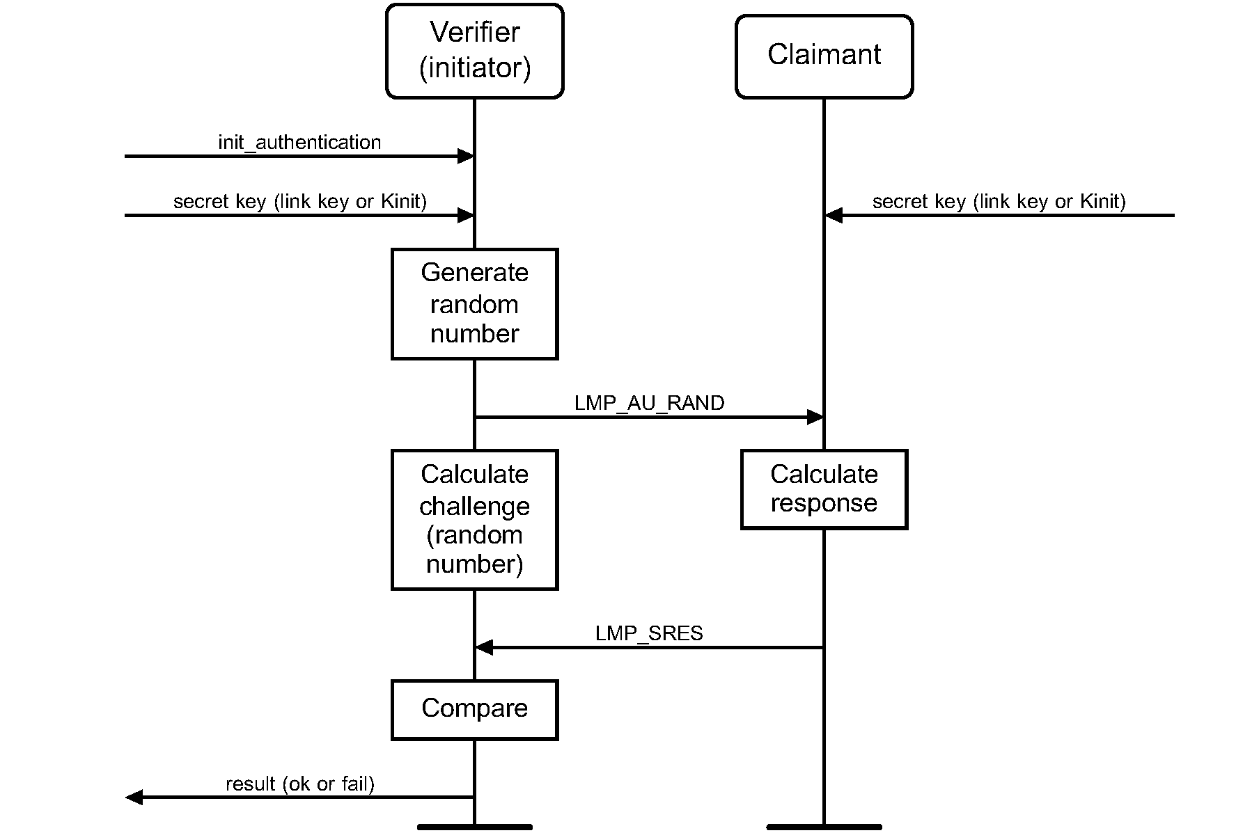
The secret key used here is an already exchanged link key.
B.2. LMP – pairing
The specification of pairing on link level is found in [2].
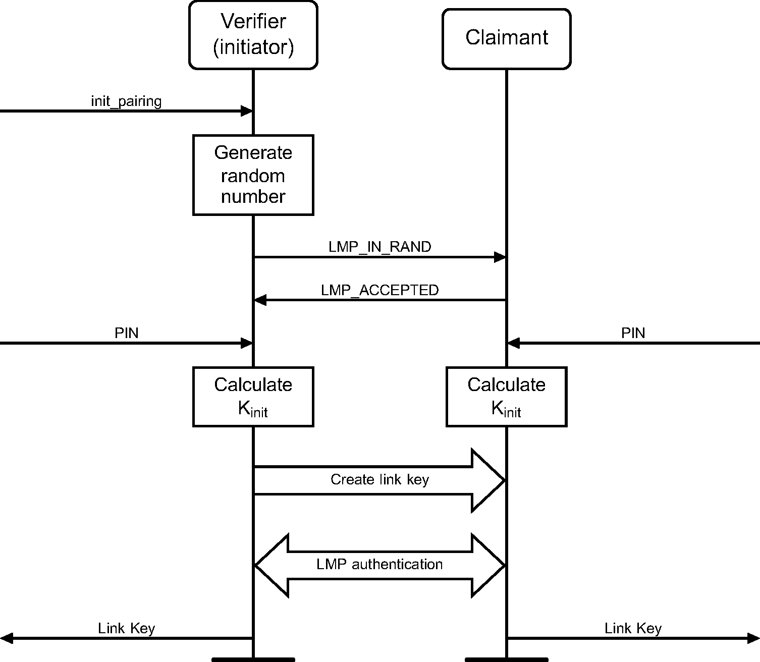
The PIN used here is PINBB.
The create link key procedure is described in [Vol 2] Part C, Section 4.2.2.4 and [Vol 2] Part H, Section 3.2. If the link key is based on a combination key, a mutual authentication takes place irrespective of the current security mode.
B.3. Service Discovery
The Service Discovery Protocol [5] specifies what PDUs are used over-the-air to inquire about services and service attributes. The procedures for discovery of supported services and capabilities using the Service Discovery Protocol are described in higher layer specifications. This is just an example.
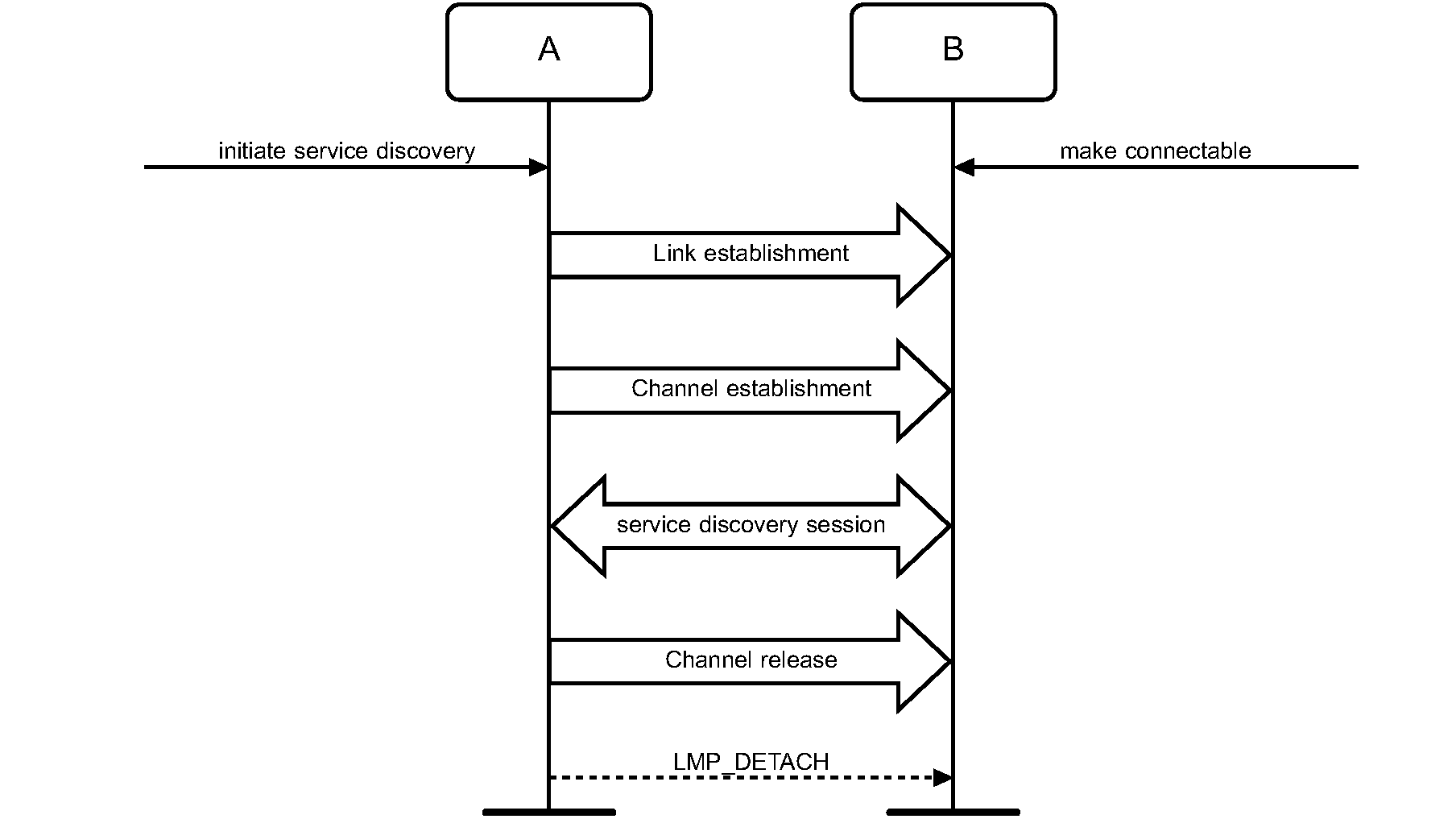
B.4. Generating a resolvable private address
Generating a resolvable private address is described in Section 10.8.2.2.
B.5. Resolving a resolvable private address
Resolving a resolvable private address is described in Section 10.8.2.3.
[1] If an OOB mechanism is used, the level of MITM protection is dependent upon the properties of the OOB communications channel. See [Vol 3] Part H, Section 2.3.5.1 for more information
[2] The term ’connection’ used here is not identical to the definition below. It is used in the absence of a more concise term.