Part D. Test Support
vAtlanta r00
1. Test methodology
This section describes the test modes for hardware and low-level functionality tests of Bluetooth devices.
The BR/EDR Test mode supports testing of the Bluetooth transmitter and receiver including transmitter tests (packets with constant bit patterns) and loopback tests. It is intended mainly for certification/compliance testing of the radio and Baseband and may also be used for regulatory approval or in-production and after-sales testing.
1.1. BR/EDR test scenarios
A device in BR/EDR Test mode shall not support normal operation. For security reasons the BR/EDR Test mode is designed such that it offers no benefit to the user. Therefore, no data output or acceptance on a HW or SW interface shall be allowed.
1.1.1. Test setup
The setup consists of a device under test (DUT) and a tester. Optionally, additional measurement equipment may be used.
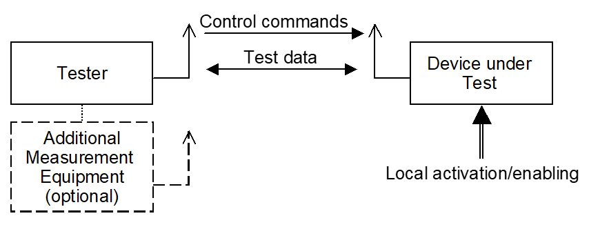
Tester and DUT form a piconet where the tester acts as Central and has full control over the test procedure. The DUT acts as Peripheral.
The control is done via the air interface using LMP commands (see [Vol 2] Part C, Section 4.7.3). Hardware interfaces to the DUT may exist, but are not subject to standardization.
The test mode is a special state of the Bluetooth model. For security and type approval reasons, a Bluetooth device in test mode shall not support normal operation. When the DUT leaves the test mode it enters the standby state. After power-off the Bluetooth device shall return to the standby state.
1.1.2. Transmitter test
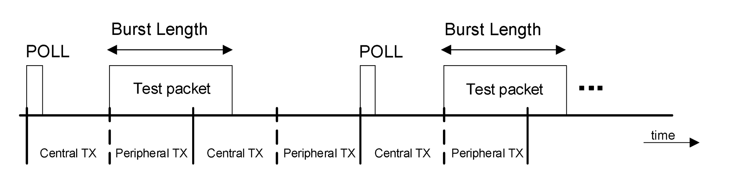
The Bluetooth device transmits a constant bit pattern. This pattern is transmitted periodically with packets aligned to the Peripheral TX timing of the piconet formed by tester and DUT. The same test packet is repeated for each transmission.
The transmitter test is started when the Central sends the first POLL packet. In non-hopping mode the agreed frequency is used for this POLL packet.
The tester (Central) transmits control or POLL packets in the Central-to-Peripheral transmission slots. The DUT (Peripheral) shall transmit packets in the following Peripheral-to-Central transmission slot. The tester’s polling interval is fixed and defined by the LMP_TEST_CONTROL PDU. The device under test may transmit its burst according to the normal timing even if no packet from the tester was received. In this case, the ARQN bit is shall be set to NAK.
The burst length may exceed the length of a one slot packet. In this case the tester may take the next free Central TX slot for polling. The timing is illustrated in Figure 1.2.
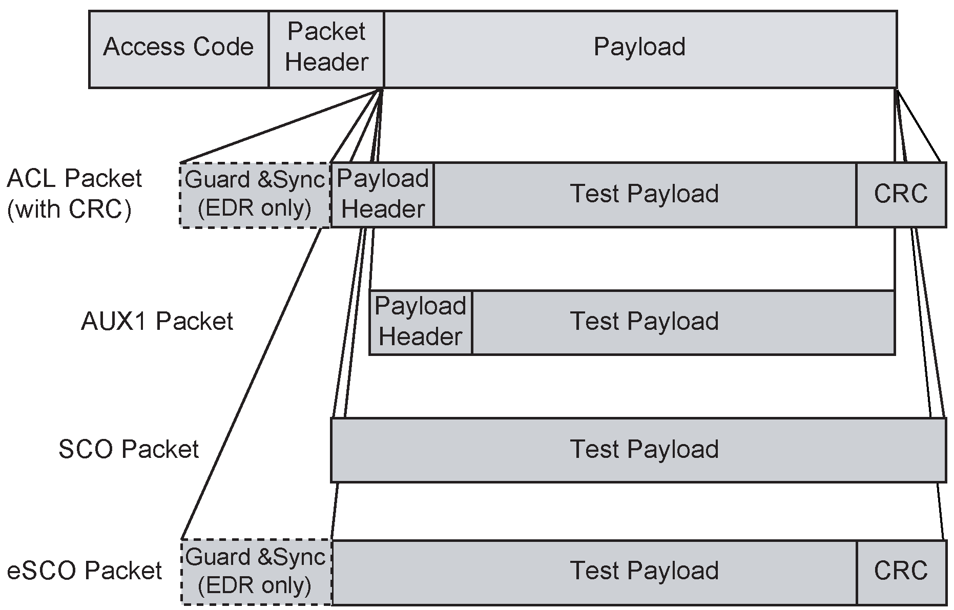
1.1.2.1. Packet format
The test packet is a normal Bluetooth packet, see Figure 1.3. For the payload itself see below.
During configuration the tester defines:
the packet type to be used
payload length
For the payload length, the restrictions from the Baseband specification shall apply (see [Vol 2] Part B, Section 6.5). In case of ACL, SCO and eSCO packets the payload structure defined in the Baseband specification is preserved as well, see Figure 1.3.
For the transmitter test mode, only packets without FEC should be used; i.e. HV3, EV3, EV5, DH1, DH3, DH5, 2-EV3, 2-EV5, 3-EV3, 3-EV5, 2-DH1, 2-DH3, 2-DH5, 3-DH1, 3-DH3, 3-DH5 and AUX1 packets.
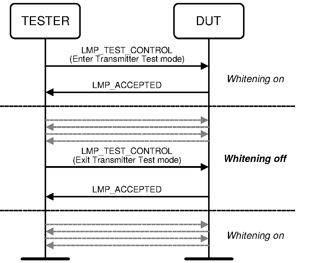
In transmitter test mode, the packets exchanged between the tester and the DUT shall not be scrambled with the whitening sequence. Whitening shall be turned off when the DUT has accepted to enter the transmitter test mode, and shall be turned on when the DUT has accepted to exit the transmitter test mode, see Figure 1.4. Implementations shall ensure that retransmissions of the LMP_ACCEPTED messages use the same whitening status as used in the original LMP_ACCEPTED.
1.1.2.2. Pseudorandom sequence
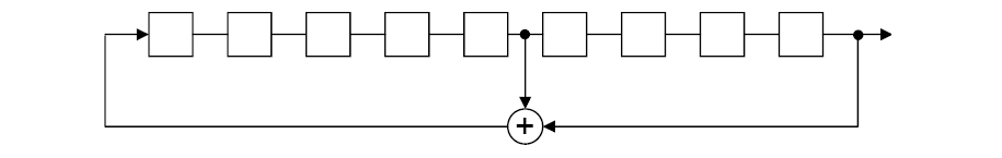
The same pseudorandom sequence of bits shall be used for each transmission (i.e. the packet is repeated). A PRBS9 sequence is used, see [1] and [2].
The properties of this sequence are as follows (see [2]). The sequence may be generated in a nine-stage shift register whose 5th and 9th stage outputs are XORed (see Figure 1.5), and the result is fed back to the input of the first stage. The sequence begins with the first ONE of 9 consecutive ONEs; i.e. the shift register is initialized with nine ones.
Number of shift register stages: 9
Length of pseudo-random sequence: 29-1 = 511 bits
Longest sequence of zeros: 8 (non-inverted signal)
1.1.2.3. Control of transmit parameters
The following parameters can be set to configure the transmitter test:
Bit pattern:
Frequency selection:
Single frequency
Normal hopping
TX frequency
(2402 + k) MHz for channel k
Default poll period in TDD frames (n * 1.25 ms)
Packet Type
Length of test payload
1.1.2.4. Power control
When the legacy power control mechanism is tested the DUT shall start transmitting at the maximum power and shall reduce/increase its power by one step on every LMP_INCR_POWER_REQ or LMP_DECR_POWER_REQ PDU received. When the enhanced power control mechanism is tested a DUT shall start transmitting at the maximum power and shall reduce/increase its power by one step or go to the maximum power level when a LMP_POWER_CONTROL_REQ PDU is received.
1.1.2.5. Switch between different frequency settings
A change in the frequency selection becomes effective when the LMP procedure is completed:
When the tester receives the LMP_ACCEPTED it shall then transmit POLL packets containing the ACK for at least 8 slots (4 transmissions). When these transmissions have been completed the tester shall change to the new frequency hop and whitening settings.
After sending LMP_ACCEPTED the DUT shall wait for the LC level ACK for the LMP_ACCEPTED. When this is received it shall change to the new frequency hop and whitening settings.
There will be an implementation defined delay after sending the LMP_ACCEPTED before the TX or loopback test starts. Testers shall be able to cope with this.
Note
Note: Loss of the LMP_ACCEPTED PDU will eventually lead to a loss of frequency synchronization that cannot be recovered. Similar problems occur in normal operation, when the hopping pattern changes.
1.1.2.6. Adaptive Frequency Hopping
Adaptive Frequency Hopping (AFH) shall only be used when the Hopping Mode is set to 79 channels (e.g. Hopping Mode = 1) in the LMP_TEST_CONTROL PDU. If AFH is used, the normal LMP commands and procedures shall be used. When AFH is enabled prior to entering test mode it shall continue to be used with the same parameters if Hopping Mode = 1 until the AFH parameters are changed by the LMP_SET_AFH PDU.
The channel classification reporting state shall be retained upon entering or exiting Test Mode. The DUT shall change the channel classification reporting state in Test Mode based on control messages from the tester (LMP_CHANNEL_CLASSIFICATION_REQ) and from the Host (HCI_Write_AFH_Channel_Assessment_Mode).
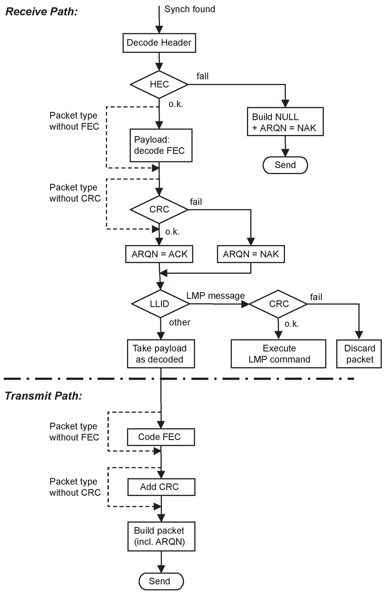
1.1.3. LoopBack test
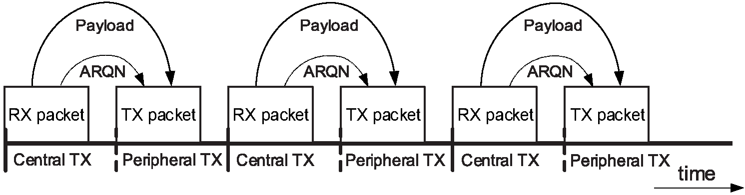
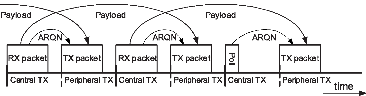
In loopback, the device under test receives normal Baseband packets containing payload Accepted from the tester. The received packets shall be decoded in the DUT, and the payload shall be sent back using the same packet type. The return packet shall be sent back in either the Peripheral-to-Central transmission slot directly following the transmission of the tester, or it is delayed and sent back in the Peripheral-to-Central transmission slot after the next transmission of the tester (see Figure 1.7 to Figure 1.9).
There is no signaling to determine or control the mode. The device behavior shall be fixed or adjusted by other means, and shall not change randomly.
The tester can select whether whitening is on or off. This setting holds for both uplink and downlink. For switching the whitening status, the same rules as in Section 1.1.2 ( Figure 1.4) shall apply.
The following rules apply (for illustration see Figure 1.6):
If the synch word was not detected, the DUT shall not reply.
If the header error check (HEC) fails, the DUT shall either reply with a NULL packet with the ARQN bit set to NAK or send nothing.
If the packet contains an LMP message relating to the control of the test mode this command shall be executed and the packet shall not be returned, though ACK or NAK shall be returned as per the usual procedure. Other LMP commands shall be ignored and no packet returned.
The payload FEC is decoded and the payload shall be encoded again for transmission. This allows testing of the FEC handling. If the pure bit error rate shall be determined the tester chooses a packet type without FEC.
The CRC shall be evaluated. In the case of a failure, ARQN=NAK shall be returned. The payload shall be returned as received.
A new CRC for the return packet shall be calculated for the returned payload regardless of whether the CRC was valid or not.
If the CRC fails for a packet with a CRC and a payload header, the number of bytes as indicated in the (possibly erroneous) payload header shall be looped back.
The timing for normal and delayed loopback is illustrated in Figure 1.7 to Figure 1.9:

The whitening is performed in the same way as it is used in normal Active mode.
The following parameters can be set to configure the loop back test:
Packet Class[2] ACL packets
SCO packets
eSCO packets
ACL packets without whitening
SCO packets without whitening
eSCO packets without whitening
Frequency Selection
Single frequency (independent for RX and TX)
Normal hopping
Power level: (To be used according radio specification requirements)
power control or fixed TX power
The switch of the frequency setting is done exactly as for the transmitter test (see Section 1.1.2.5).
1.1.4. Pause test
Pause test is used by testers to put the device under test into Pause Test mode from either the loopback or transmitter test modes.
When an LMP_TEST_CONTROL PDU that specifies Pause Test is received the DUT shall stop the current test and enter Pause Test mode. In the case of a transmitter test this means that no more packets shall be transmitted. While in Pause Test mode the DUT shall respond normally to POLL packets (i.e. responds with a NULL packet). The DUT shall also respond normally to all the LMP packets that are allowed in test mode.
When the test scenario is set to Pause Test all the other fields in the LMP_TEST_CONTROL PDU shall be ignored. There shall be no change in hopping scheme or whitening as a result of a request to pause test.
1.2. [This section is no longer used]
1.3. References
[1] CCITT Recommendation O.153 (1992), Basic parameters for the measurement of error performance at bit rates below the primary rate.
[2] ITU-T Recommendation O.150 (1996), General requirements for instrumentation for performance measurements on digital transmission equipment.