Part A. UART Transport Layer
vAtlanta r00
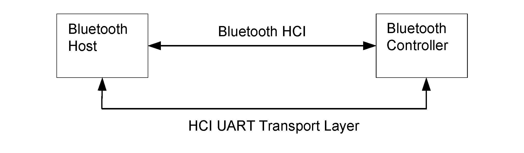
This Part describes the UART transport layer (between the Host and the Controller). HCI command, event, and data packets flow through this layer, but the layer does not decode them.
1. General
The objective of this HCI UART Transport Layer is to make it possible to use the Bluetooth HCI over a serial interface between two UARTs on the same PCB. The HCI UART Transport Layer assumes that the UART communication is free from line errors.
See [Vol 4] Part D for an alternative UART transport layer for use in the presence of line errors.
2. Protocol
There are five kinds of HCI packets that can be sent via the UART Transport Layer; i.e. HCI Command packet, HCI Event packet, HCI ACL Data packet, HCI Synchronous Data packet, and HCI ISO Data packet (see [Vol 4] Part E, Section 5.4). HCI Command packets can only be sent to the Bluetooth Controller, HCI Event packets can only be sent from the Bluetooth Controller, and HCI ACL/Synchronous/ISO Data Packets can be sent both to and from the Bluetooth Controller.
HCI does not provide the ability to differentiate the five HCI packet types. Therefore, if the HCI packets are sent via a common physical interface, an HCI packet indicator has to be added according to Table 2.1 below.
HCI packet type | HCI packet indicator |
|---|---|
HCI Command packet | 0x01 |
HCI ACL Data packet | 0x02 |
HCI Synchronous Data packet | 0x03 |
HCI Event packet | 0x04 |
HCI ISO Data packet | 0x05 |
The HCI packet indicator shall be sent immediately before the HCI packet. All five kinds of HCI packets have a length field, which is used to determine how many bytes are expected for the HCI packet. When an entire HCI packet has been received, the next HCI packet indicator is expected for the next HCI packet. Over the UART Transport Layer, only HCI packet indicators followed by HCI packets are allowed.
3. RS232 settings
The HCI UART Transport Layer uses the following settings for RS232:
Baud rate: | manufacturer-specific |
|---|---|
Number of data bits: | 8 |
Parity bit: | no parity |
Stop bit: | 1 stop bit |
Flow control: | RTS/CTS |
Flow-off response time: | manufacturer specific |
Flow control with RTS/CTS is used to prevent temporary UART buffer overrun. It should not be used for flow control of HCI, since HCI has its own flow control mechanisms for HCI commands, HCI events and HCI data.
If CTS is 1, then the Host/Controller is allowed to send.
If CTS is 0, then the Host/Controller is not allowed to send.
The flow-off response time defines the maximum time from setting RTS to 0 until the byte flow actually stops.
The RS232 signals should be connected in a null-modem fashion; i.e. the local TXD should be connected to the remote RXD and the local RTS should be connected to the remote CTS and vice versa.
4. Error recovery
If the Host or the Controller lose synchronization in the communication over RS232, then a reset is needed. A loss of synchronization means that an incorrect HCI packet indicator has been detected, or that the length field in an HCI packet is out of range.
If the UART synchronization is lost in the communication from Host to Controller, then the Controller shall send an HCI_Hardware_Error event to tell the Host about the synchronization error. The Controller will then expect to receive an HCI_Reset command from the Host in order to perform a reset. The Controller will also use the HCI_Reset command in the byte stream from Host to Controller to re-synchronize.
If the UART synchronization is lost in the communication from Controller to Host, then the Host shall send the HCI_Reset command in order to reset the Controller. The Host shall then re-synchronize by looking for the HCI_Command_Complete event for the HCI_Reset command in the byte stream from Controller to Host.