Part A. Logical Link Control and Adaptation Protocol Specification
vAtlanta r00
The Bluetooth Logical Link Control and Adaptation Protocol (L2CAP) supports higher level protocol multiplexing, packet segmentation and reassembly, and the conveying of quality of service information. The protocol state machine, packet format, and composition are described in this Part of the specification.
1. Introduction
This section of the Bluetooth Specification defines the Logical Link Control and Adaptation Layer Protocol, referred to as L2CAP. L2CAP provides connection-oriented and connectionless data services to upper layer protocols with protocol multiplexing capability and segmentation and reassembly operation. L2CAP permits higher level protocols and applications to transmit and receive upper layer data packets (L2CAP Service Data Units, SDU) up to 64 kilobytes in length. L2CAP also permits per-channel flow control and retransmission.
The L2CAP layer provides logical channels, named L2CAP channels, which are multiplexed over one or more logical links.
1.1. L2CAP features
The functional requirements for L2CAP include protocol/channel multiplexing, segmentation and reassembly (SAR), per-channel flow control, and error control. L2CAP sits above a lower layer composed of one of the following:
BR/EDR Controller
BR/EDR/LE Controller (supporting BR/EDR and LE)
LE Controller (supporting LE only)
L2CAP interfaces with upper layer protocols.
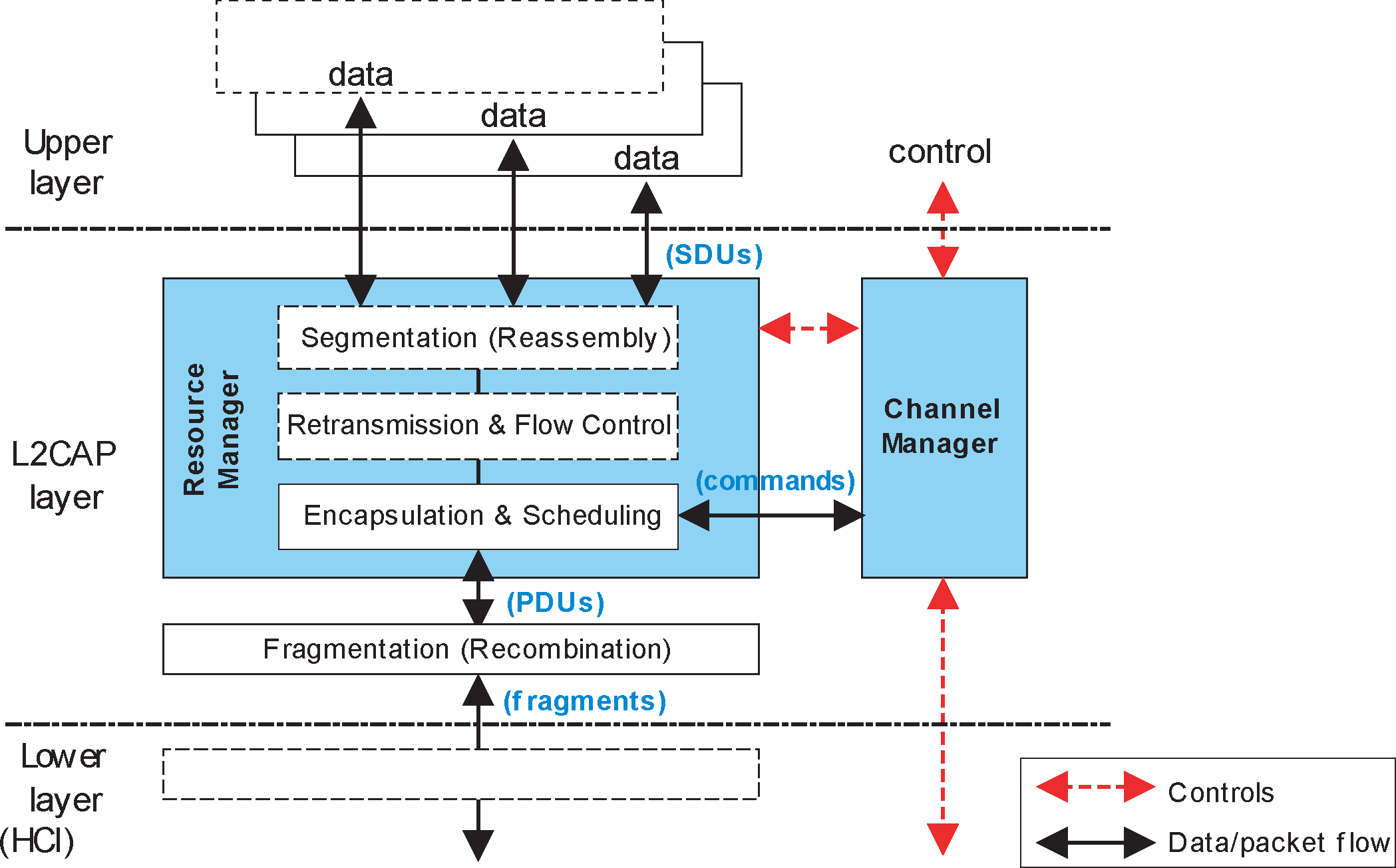
Figure 1.1 breaks down L2CAP into its architectural components. The Channel Manager provides the control plane functionality and is responsible for all internal signaling, L2CAP peer-to-peer signaling and signaling with higher and lower layers. It performs the state machine functionality described in Section 6 and uses message formats described in Section 4, and Section 5. The Retransmission and Flow Control block provides per-channel flow control and error recovery using packet retransmission. The Resource Manager is responsible for providing a frame relay service to the Channel Manager, the Retransmission and Flow Control block and those application data streams that do not require Retransmission and Flow Control services. It is responsible for coordinating the transmission and reception of packets related to multiple L2CAP channels over the facilities offered at the lower layer interface.
Protocol/channel multiplexing
L2CAP supports multiplexing over individual Controllers. An L2CAP channel shall operate over one Controller. An L2CAP channel cannot move between Controllers.
During channel setup, protocol multiplexing capability is used to route the connection to the correct upper layer protocol.
For data transfer, logical channel multiplexing is needed to distinguish between multiple upper layer entities. There may be more than one upper layer entity using the same protocol.
Segmentation and reassembly
With the frame relay service offered by the Resource Manager, the length of transport frames is controlled by the individual applications running over L2CAP. Many multiplexed applications are better served if L2CAP has control over the PDU length. This provides the following benefits:
Segmentation will allow the interleaving of application data units in order to satisfy latency requirements.
Memory and buffer management is easier when L2CAP controls the packet size.
Error correction by retransmission can be made more efficient.
The amount of data that is destroyed when an L2CAP PDU is corrupted or lost can be made smaller than the application's data unit.
The application is decoupled from the segmentation required to map the application packets into the lower layer packets.
Flow control per L2CAP channel
Controllers provide error and flow control for data going over the air and HCI flow control exists for data going over an HCI transport. When several data streams run over the same Controller using separate L2CAP channels, each channel requires individual flow control. A window based flow control scheme is provided.
Error control and retransmissions
Some applications require a residual error rate much smaller than some Controllers can deliver. L2CAP provides error checks and retransmissions of L2CAP PDUs. The error checking in L2CAP protects against errors due to Controllers falsely accepting packets that contain errors but pass Controller-based integrity checks. L2CAP error checking and retransmission also protect against loss of packets due to flushing by the Controller. The error control works in conjunction with flow control in the sense that the flow control mechanism will throttle retransmissions as well as first transmissions.
Support for Streaming
Streaming applications such as audio set up an L2CAP channel with an agreed-upon data rate and do not want flow control mechanisms, including those in the Controller, to alter the flow of data. A flush timeout is used to keep data flowing on the transmit side. Streaming mode is used to stop HCI and Controller based flow control from being applied on the receiving side.
Fragmentation and Recombination
Some Controllers may have limited transmission capabilities and may require fragment sizes different from those created by L2CAP segmentation. Therefore layers below L2CAP may further fragment and recombine L2CAP PDUs to create fragments which fit each layer’s capabilities. During transmission of an L2CAP PDU, many different levels of fragmentation and recombination may occur in both peer devices.
The HCI driver or Controller may fragment L2CAP PDUs to honor packet size constraints of a Host Controller Interface transport scheme. This results in HCI ACL Data packet payloads carrying start and continuation fragments of the L2CAP PDU. Similarly the Controller may fragment L2CAP PDUs to map them into Controller packets. This may result in Controller packet payloads carrying start and continuation fragments of the L2CAP PDU.
Each layer of the protocol stack may pass on different sized fragments of L2CAP PDUs, and the size of fragments created by a layer may be different in each peer device. However the PDU is fragmented within the stack, the receiving L2CAP entity still recombines the fragments to obtain the original L2CAP PDU.
Quality of Service
The L2CAP connection establishment process allows the exchange of information regarding the quality of service (QoS) expected between two Bluetooth devices. Each L2CAP implementation monitors the resources used by the protocol and ensures that QoS contracts are honored.
For a BR/EDR or BR/EDR/LE Controller, L2CAP may support both isochronous (Guaranteed) and asynchronous (Best Effort) data flows over the same ACL logical link by marking packets as automatically-flushable or non-automatically-flushable by setting the appropriate value for the Packet_Boundary_Flag in the HCI ACL Data packet (see [Vol 4] Part E, Section 5.4.2). Automatically-flushable L2CAP packets are flushed according to the automatic flush timeout set for the ACL logical link on which the L2CAP channels are mapped (see [Vol 4] Part E, Section 6.19). Non-automatically-flushable L2CAP packets are not affected by the automatic flush timeout and will not be flushed. All L2CAP packets can be flushed by using the HCI_Flush command (see [Vol 4] Part E, Section 7.3.4).
Note
Note: The terms "Guaranteed" and "Best Effort" are used as a shorthand to indicate that the implementation will or will not attempt to provide some level of quality of service. They do not make any statement as to what actual quality is provided; in particular, "Guaranteed" does not mean that successful delivery of data is guaranteed. Similarly, a "guarantee" is a set of resources (such as bandwidth and buffer space) allocated to a "Guaranteed" connection and does not mean that a specific data rate and latency will be provided under all possible circumstances.
1.2. Assumptions
The protocol is designed based on the following assumptions:
Controllers provide orderly delivery of data packets, although there might be individual packet corruption and duplicates. For devices with a BR/EDR or BR/EDR/LE Controller, no more than one ACL-U logical link exists between any two devices. For devices with a BR/EDR/LE or LE Controller, no more than one LE-U logical link exists between any two devices.
Controllers always provide the impression of full-duplex communication channels. This does not imply that all L2CAP communications are bi-directional. Unidirectional traffic does not require duplex channels.
The L2CAP layer provides a channel with a degree of reliability based on the mechanisms available in Controllers and with additional packet segmentation, error detection, and retransmission that can be enabled in the enhanced L2CAP layer. Some Controllers perform data integrity checks and resend data until it has been successfully acknowledged or a timeout occurs. Other Controllers will resend data up to a certain number of times whereupon the data is flushed. Because acknowledgments may be lost, timeouts may occur even after the data has been successfully sent.
Note
Note: The use of Baseband Broadcast packets in a BR/EDR or BR/EDR/LE Controller is unreliable and all broadcasts start the first segment of an L2CAP packet with the same sequence bit.
Controllers provide error and flow control for data going over the air and HCI flow control exists for data going over an HCI transport but some applications will want better error control than some Controllers provide. The Flow and Error Control block provides four modes. Enhanced Retransmission mode and Retransmission Mode offer segmentation, flow control and L2CAP PDU retransmissions. Flow control mode offers just the segmentation and flow control functions. Streaming mode offers segmentation and receiver side packet flushing.
1.3. Scope
The following features are outside the scope of L2CAP’s responsibilities:
L2CAP does not transport synchronous data designated for SCO or eSCO logical transports.
L2CAP does not support a reliable broadcast channel. See Section 3.2.
1.4. Terminology
The following formal definitions apply:
Term | Description |
|---|---|
Upper layer | The system layer above the L2CAP layer, which exchanges data with L2CAP in the form of SDUs. The upper layer may be represented by an application or higher protocol entity known as the Service Level Protocol. The interface of the L2CAP layer with the upper layer is not specified. |
Lower layer | The system layer below the L2CAP layer, which exchanges data with the L2CAP layer in the form of PDUs, or fragments of PDUs. The lower layer is mainly represented within the Controller, however a Host Controller interface (HCI) may be involved, such that an HCI Host driver could also be seen as the lower layer. Except for the HCI functional specification (in case HCI is involved) the interface between L2CAP and the lower layer is not specified. |
L2CAP channel | The logical connection between two endpoints in peer devices, characterized by their Channel Identifiers (CID), which is multiplexed over one Controller based logical link. |
SDU, or L2CAP SDU | Service Data Unit: a packet of data that L2CAP exchanges with the upper layer and transports transparently over an L2CAP channel using the procedures specified here. The term SDU is associated with data originating from upper layer entities only, i.e. does not include any protocol information generated by L2CAP procedures. |
Segment, or SDU segment | A part of an SDU, as resulting from the Segmentation procedure. An SDU may be split into one or more segments. Note: This term is relevant only to Enhanced Retransmission mode, Streaming mode, Retransmission Mode and Flow Control Mode, not to the Basic L2CAP Mode. |
Segmentation | A procedure used in the L2CAP Retransmission and Flow Control Modes, resulting in an SDU being split into one or more smaller units, called Segments, as appropriate for the transport over an L2CAP channel. Note: This term is relevant only to the Enhanced Retransmission mode, Streaming mode, Retransmission Mode and Flow Control Mode, not to the Basic L2CAP Mode. |
Reassembly | The reverse procedure corresponding to Segmentation, resulting in an SDU being re-established from the segments received over an L2CAP channel, for use by the upper layer. The interface between the L2CAP and the upper layer is not specified; therefore, reassembly may actually occur within an upper layer entity although it is conceptually part of the L2CAP layer. Note: This term is relevant only to Enhanced Retransmission mode, Streaming mode, Retransmission Mode and Flow Control Mode, not to the Basic L2CAP Mode. |
PDU, or L2CAP PDU | Protocol Data Unit: a packet of data containing L2CAP protocol information fields, control information, and/or upper layer information data. A PDU is always started by a Basic L2CAP header. Types of PDUs are: B-frames, I-frames, S-frames, C-frames, G-frames, and K-frames. |
Basic L2CAP header | Minimum L2CAP protocol information that is present in the beginning of each PDU: a PDU length field and a field containing the Channel Identifier (CID). |
Basic information frame (B‑frame) | A B-frame is a PDU used in the Basic L2CAP mode for L2CAP data packets. It contains a complete SDU as its payload, encapsulated by a Basic L2CAP header. |
Information frame (I‑frame) | An I-frame is a PDU used in Enhanced Retransmission Mode, Streaming mode, Retransmission mode, and Flow Control Mode. It contains an SDU segment and additional protocol information, encapsulated by a Basic L2CAP header |
Supervisory frame (S‑frame) | An S-frame is a PDU used in Enhanced Retransmission Mode, Retransmission Mode, and Flow Control Mode. It contains protocol information only, encapsulated by a Basic L2CAP header, and no SDU data. |
Control frame (C‑frame) | A C-frame is a PDU that contains L2CAP signaling messages exchanged between the peer L2CAP entities. C-frames are exclusively used on the L2CAP signaling channels. |
Group frame (G‑frame) | A G-frame is a PDU exclusively used on the Connectionless L2CAP channel. It is encapsulated by a Basic L2CAP header and contains the PSM followed by the completed SDU. G-frames may be used to broadcast data to active Peripherals via Active Peripheral Broadcast or to send unicast data to a single remote device. |
Credit-based frame (K‑frame) | A K-frame is a PDU used in LE Credit Based Flow Control Mode and Enhanced Credit Based Flow Control Mode. It contains an SDU segment and additional protocol information, encapsulated by a Basic L2CAP header. |
Fragment | A part of a PDU, as resulting from a fragmentation operation. Fragments are used only in the delivery of data to and from the lower layer. They are not used for peer-to-peer transportation. A fragment may be a Start or Continuation Fragment with respect to the L2CAP PDU. A fragment does not contain any protocol information beyond the PDU; the distinction of start and continuation fragments is transported by lower layer protocol provisions. Note: Start Fragments always either begin with the first octet of the Basic L2CAP header of a PDU or they have a length of zero (see [Vol 2] Part B, Section 6.6.2). |
Fragmentation | A procedure used to split L2CAP PDUs to smaller parts, named fragments, appropriate for delivery to the lower layer transport. Although described within the L2CAP layer, fragmentation may actually occur in an HCI Host driver, and/or in a Controller, to accommodate the L2CAP PDU transport to HCI ACL Data packet or Controller packet sizes. Fragmentation of PDUs may be applied in all L2CAP modes. |
Recombination | The reverse procedure corresponding to fragmentation, resulting in an L2CAP PDU re-established from fragments. In the receive path, full or partial recombination operations may occur in the Controller and/or the Host, and the location of recombination does not necessarily correspond to where fragmentations occurs on the transmit side. |
Maximum PDU payload Size (MPS) | The maximum size of an SDU, in octets, that the upper layer entity is capable of accepting. |
Payload Size | The amount of SDU data in a single PDU, in octets; equivalently, the number of octets in the Information Payload field of a PDU. |
Maximum PDU payload Size (MPS) | The maximum payload size in octets that the L2CAP layer entity is capable of accepting. In the absence of segmentation, or in the Basic L2CAP Mode, the Maximum Transmission Unit is the same as the Maximum PDU payload Size and the two configuration parameters shall be set to the same value. |
Signaling MTU (MTUsig) | The maximum size of command information that the L2CAP layer entity is capable of accepting. The MTUsig, refers to the signaling channel only and corresponds to the maximum size of a C-frame, excluding the Basic L2CAP header. The MTUsig value of a peer is discovered when a C-frame that is too large is rejected by the peer. |
Connectionless MTU (MTUcnl) | The maximum size of the connection packet information that the L2CAP layer entity is capable of accepting. The MTUcnl refers to the connectionless channel only and corresponds to the maximum G-frame, excluding the Basic L2CAP header and the PSM which immediately follows it. The MTUcnl of a peer can be discovered by sending an L2CAP_INFORMATION_REQ packet. |
MaxTransmit | In Enhanced Retransmission mode and Retransmission mode, MaxTransmit controls the number of transmissions of a PDU that L2CAP is allowed to try before assuming that the PDU (and the link) is lost. The minimum value is 1 (only 1 transmission permitted). In Enhanced Retransmission mode a value 0 means infinite transmissions. Note: Setting MaxTransmit to 1 prohibits PDU retransmissions. Failure of a single PDU will cause the link to drop. By comparison, in Flow Control mode, failure of a single PDU will not necessarily cause the link to drop. |
2. General operation
L2CAP is based around the concept of ’channels’. Each one of the endpoints of an L2CAP channel is referred to by a channel identifier (CID).
2.1. Channel identifiers
A channel identifier (CID) is the local name representing a logical channel endpoint on the device. The scope of CIDs is related to the logical link as shown in Figure 2.1. The null identifier (0x0000) shall never be used as a destination endpoint. Identifiers from 0x0001 to 0x003F are reserved for specific L2CAP functions. These channels are referred to as fixed channels. At a minimum, the L2CAP Signaling channel (fixed channel 0x0001) or the L2CAP LE Signaling channel (fixed channel 0x0005) shall be supported. If fixed channel 0x0005 is supported, then fixed channels 0x0004 and 0x0006 shall be supported (see Table 2.3). Other fixed channels may be supported. The L2CAP_INFORMATION_REQ / L2CAP_INFORMATION_RSP mechanism (described in Section 4.10 and Section 4.11) shall be used to determine which fixed channels a remote device supports over the ACL-U logical link. Each fixed channel has the same CID at each end of the logical link carrying the channel.
The characteristics of each fixed channel are defined on a per channel basis. Fixed channel characteristics include configuration parameters (e.g., reliability, MTU size, QoS), security, and the ability to change parameters using the L2CAP configuration mechanism. Table 2.1 lists the defined fixed channels, provides a reference to where the associated channel characteristics are defined and specifies the logical link over which the channel may operate. Fixed channels are available as soon as the ACL-U or LE-U logical link is set up. All initialization that is normally performed when a channel is created shall be performed for each of the supported fixed channels when the ACL-U or LE-U logical link is set up. Fixed channels shall only run over ACL-U, APB-U, or LE-U logical links.
Implementations are free to manage the remaining CIDs in a manner best suited for that particular implementation, with the provision that two simultaneously active L2CAP channels on the same logical link (i.e., to the same peer device using the same transport) shall not share the same CID. A different CID name space exists for each ACL-U, APB-U, and LE-U logical link. Table 2.1 to Table 2.3 summarize the definition and partitioning of the CID name space for each type of logical link.
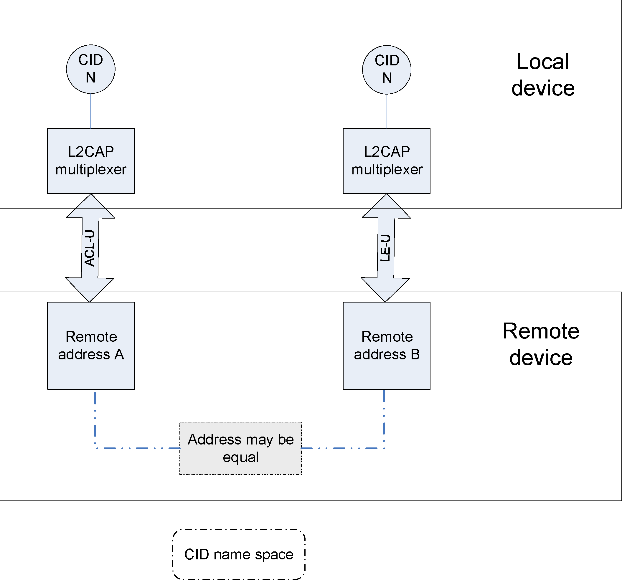
Assignment of dynamically allocated CIDs is relative to a particular logical link and a device can assign CIDs independently from other devices. Thus, even if the same CID value has been assigned to (remote) channel endpoints by several remote devices connected to a single local device, the local device can still uniquely associate each remote CID with a different device. Further, even if the same CID value has been assigned to (remote) channel endpoints by the same remote device, these can be distinguished because they will be bound to a different logical link.
The CID name space for ACL-U logical links is as follows:
CID | Description | Channel Characteristics |
|---|---|---|
0x0000 | Null identifier | Not allowed |
0x0001 | L2CAP Signaling channel | See Section 4 |
0x0002 | Connectionless channel | See Section 7.6 |
0x0003 | Previously used | Not applicable |
0x0007 | BR/EDR Security Manager | See [Vol 3] Part H |
0x003F | Previously used | Not applicable |
0x0040 to 0xFFFF | Dynamically allocated | Communicated using L2CAP configuration mechanism (see Section 7.1) or the L2CAP credit based create connection mechanism (see Section 4.25) |
All other values | Reserved for future use | Not applicable |
The CID name space for APB-U logical links is as follows:
CID | Description | Channel Characteristics |
|---|---|---|
0x0000 | Null identifier | Not allowed |
0x0002 | Connectionless channel | See Section 7.6 |
All other values | Reserved for future use | Not applicable |
The CID name space for LE-U logical links is as follows:
CID | Description | Channel Characteristics |
|---|---|---|
0x0000 | Null identifier | Not Allowed |
0x0004 | Attribute Protocol | See [Vol 3] Part F |
0x0005 | L2CAP LE Signaling channel | See Section 4 |
0x0006 | Security Manager protocol | See [Vol 3] Part H |
0x0020 to 0x003E | ||
0x0040 to 0x007F | Dynamically allocated | Communicated using the L2CAP LE credit based create connection mechanism (see Section 4.22) or the L2CAP credit based create connection mechanism (see Section 4.25) |
All other values | Reserved for future use | Not applicable |
2.2. Operation between devices
Figure 2.2 illustrates the use of CIDs in a communication between corresponding peer L2CAP entities in separate devices. The connection-oriented data channels represent a connection between two devices, where a CID, combined with the logical link, identifies each endpoint of the channel. When used for broadcast transmissions, the connectionless channel restricts data flow to a single direction. The connectionless channel may be used to transmit data to all active Peripherals, using Active Peripheral Broadcast. When used for unicast transmissions the connectionless channel may be used in either direction between a Central and a Peripheral.
There are also a number of CIDs reserved for special purposes. The L2CAP signaling channels are examples of reserved channels. Fixed channel 0x0001 is used to create and establish connection-oriented data channels and to negotiate changes in the characteristics of connection-oriented channels and to discover characteristics of the connectionless channel operating over the ACL-U logical link.
The L2CAP Signaling channel (0x0001) and all supported fixed channels are available immediately when the ACL-U logical link is established between two devices. Another CID (0x0002) is reserved for all incoming and outgoing connectionless data traffic, whether broadcast or unicast. Connectionless data traffic may flow immediately once the ACL-U logical link is established between two devices and once the transmitting device has determined that the remote device supports connectionless traffic.
The L2CAP LE Signaling channel (0x0005) and all supported fixed channels are available immediately when the LE-U logical link is established between two devices.

Table 2.4 describes the various channel types and their source and destination identifiers. A dynamically allocated CID is allocated to identify, along with the logical link, the local endpoint and shall be in the range 0x0040 to 0xFFFF for ACL-U, 0x0040 to 0x007F for LE-U. Section 6 describes the state machine associated with each connection-oriented channel with a dynamically allocated CID. Section 3.1 and Section 3.3 describe the packet format associated with connection-oriented channels. Section 3.2 describes the packet format associated with the connectionless channel.
Channel Type | Local CID (sending) | Remote CID (receiving) |
|---|---|---|
Connection-oriented | Dynamically allocated and fixed | Dynamically allocated and fixed |
Connectionless data | 0x0002 (fixed) | 0x0002 (fixed) |
L2CAP Signaling | 0x0001 and 0x0005 (fixed) | 0x0001 and 0x0005 (fixed) |
2.3. Operation between layers
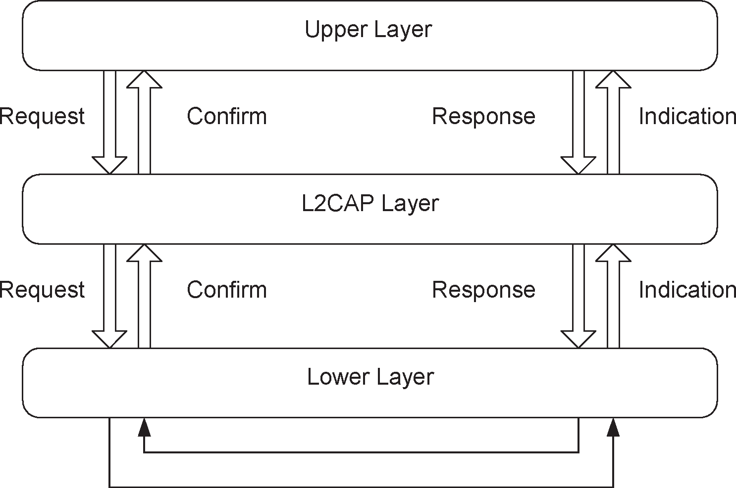
L2CAP implementations should follow the general architecture described below. L2CAP implementations transfer data between upper layer protocols and the lower layer protocol. This document lists a number of services that should be exported by any L2CAP implementation. Each implementation shall also support a set of signaling commands for use between L2CAP implementations. L2CAP implementations should also be prepared to accept certain types of events from lower layers and generate events to upper layers. How these events are passed between layers is implementation specific.
2.4. Modes of operation
L2CAP channels may operate in one of several different modes as selected for each L2CAP channel.
The modes are:
Basic L2CAP Mode (BR/EDR and some LE fixed channels only)
Flow Control Mode (BR/EDR only)
Retransmission Mode (BR/EDR only)
Enhanced Retransmission Mode (BR/EDR only)
Streaming Mode (BR/EDR only)
LE Credit Based Flow Control Mode (LE only)
Enhanced Credit Based Flow Control Mode (BR/EDR and LE)
The modes are enabled using the configuration procedure described in Section 7.1. The Basic L2CAP Mode shall be the default mode, which is used when no other mode is agreed. Enhanced Retransmission mode shall be used for ACL-U logical links operating as described in Section 7.10. Enhanced Retransmission mode should be enabled for reliable channels created over ACL-U logical links not operating as described in Section 7.10. Streaming mode shall be used for ACL-U logical links operating as described in Section 7.10. Streaming mode should be enabled for streaming applications created over ACL-U logical links not operating as described in Section 7.10. Enhanced Retransmission mode, Enhanced Credit Based Flow Control mode, or Streaming mode should be enabled when supported by both L2CAP entities. Flow Control Mode and Retransmission mode shall only be enabled when communicating with L2CAP entities that do not support Enhanced Retransmission mode, Enhanced Credit Based Flow Control mode, or Streaming mode.
In Flow Control mode, Retransmission mode, and Enhanced Retransmission mode, PDUs exchanged with a peer entity are numbered and acknowledged. The sequence numbers in the PDUs are used to control buffering, and a TxWindow size is used to limit the required buffer space and/or provide a method for flow control.
In Flow Control Mode no retransmissions take place, but missing PDUs are detected and can be reported as lost.
In Retransmission Mode a timer is used to ensure that all PDUs are delivered to the peer, by retransmitting PDUs as needed. A go-back-n repeat mechanism is used to simplify the protocol and limit the buffering requirements.
Enhanced Retransmission mode is similar to Retransmission mode. It adds the ability to set a POLL bit to solicit a response from a remote L2CAP entity, adds the SREJ S-frame to improve the efficiency of error recovery and adds an RNR S-frame to replace the R-bit for reporting a local busy condition.
Streaming mode is for real-time isochronous traffic. PDUs are numbered but are not acknowledged. A finite flush timeout is set on the sending side to flush packets that are not sent in a timely manner. On the receiving side if the receive buffers are full when a new PDU is received then a previously received PDU is overwritten by the newly received PDU. Missing PDUs can be detected and reported as lost. TxWindow size is not used in Streaming mode.
LE Credit Based Flow Control Mode is used for LE L2CAP connection-oriented channels for flow control using a credit based scheme for L2CAP data (i.e. not signaling packets).
Enhanced Credit Based Flow Control Mode is used for L2CAP connection-oriented channels on both LE and BR/EDR for flow control using a credit-based scheme for L2CAP data (i.e. not signaling packets). A BR/EDR/LE device that implements Enhanced Credit Based Flow Control Mode may support it on BR/EDR only, on LE only, or on both.
Enhanced Retransmission Mode should be used instead of Enhanced Credit Based Flow Control Mode for data being transmitted over BR/EDR.
Care should be taken in selecting the parameters used for Enhanced Retransmission mode and Streaming mode when they are used beneath legacy profile implementations to ensure that performance is not negatively impacted relative to the performance achieved when using the same profile with Basic mode on an ACL-U logical link. It may be preferable to configure Basic mode to minimize the risk of negative performance impacts.
2.5. Mapping channels to logical links
L2CAP maps channels to Controller logical links, which in turn run over Controller physical links. All logical links going between a local Controller and remote Controller run over a single physical link. There is one ACL-U logical link per BR/EDR physical link and one LE-U logical link per LE physical link.
All Best Effort and Guaranteed channels going over a BR/EDR physical link between two devices shall be mapped to a single ACL-U logical link. All channels going over an LE physical link between two devices shall be treated as best effort and mapped to a single LE-U logical link.
When a Guaranteed channel is created, a corresponding Guaranteed logical link shall be created to carry the channel traffic. Creation of a Guaranteed logical link involves admission control. Admission control is verifying that the guarantee can be achieved without compromising existing guarantees. For a BR/EDR Controller, admission control (creation of a Guaranteed logical link) shall be performed by the L2CAP layer.
3. Data packet format
L2CAP is packet-based but follows a communication model based on channels. A channel represents a data flow between L2CAP entities in remote devices. Channels may be connection-oriented or connectionless. All channels other than the L2CAP connectionless channel (CID 0x0002) and the two L2CAP signaling channels (CIDs 0x0001 and 0x0005) are connection-oriented. All L2CAP layer packet fields shall use little-endian byte order with the exception of the information payload field. The endianness of higher layer protocols encapsulated within L2CAP information payload is protocol-specific.
If a PDU is received on a CID that is not assigned or is reserved for future use on the logical link type, the recipient shall ignore that PDU.
In all L2CAP PDUs, the PDU Length field indicates the size of the entire L2CAP PDU in octets, excluding the 4 octets of the Basic L2CAP header. Therefore a PDU cannot be more than 65539 octets long.
In PDUs that contain an Information Payload field, the number of octets in that field (the payload size) shall not be greater than the peer device's MPS for the channel.
3.1. Connection-oriented channels in Basic L2CAP mode
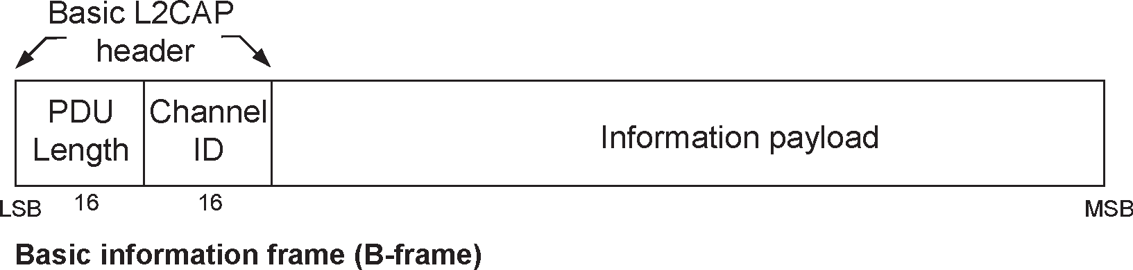
Figure 3.1 illustrates the format of the L2CAP PDU used on connection-oriented channels. In basic L2CAP mode, the L2CAP PDU on a connection-oriented channel is also referred to as a "B-frame".
The fields shown are:
PDU Length: 2 octets (16 bits)
For B-frames, the PDU Length equals the payload size and can be up to 65535 octets. The PDU Length field is used for recombination and serves as a simple integrity check of the recombined L2CAP packet on the receiving end.
Channel ID: 2 octets
The channel ID (CID) identifies the destination channel endpoint of the packet.
Information payload: 0 to 65535 octets
This contains the payload received from the upper layer protocol (outgoing packet), or delivered to the upper layer protocol (incoming packet). The payload size shall not be greater than the peer device's MTU for the channel. The MTU for channels with dynamically allocated CIDs is determined during channel configuration (see Section 5.1). The minimum supported MTU values for the signaling PDUs are shown in Table 4.1.
3.2. Connectionless data channel in Basic L2CAP mode
Figure 3.2 illustrates the L2CAP PDU format within a connectionless data channel. Here, the L2CAP PDU is also referred to as a "G-frame".
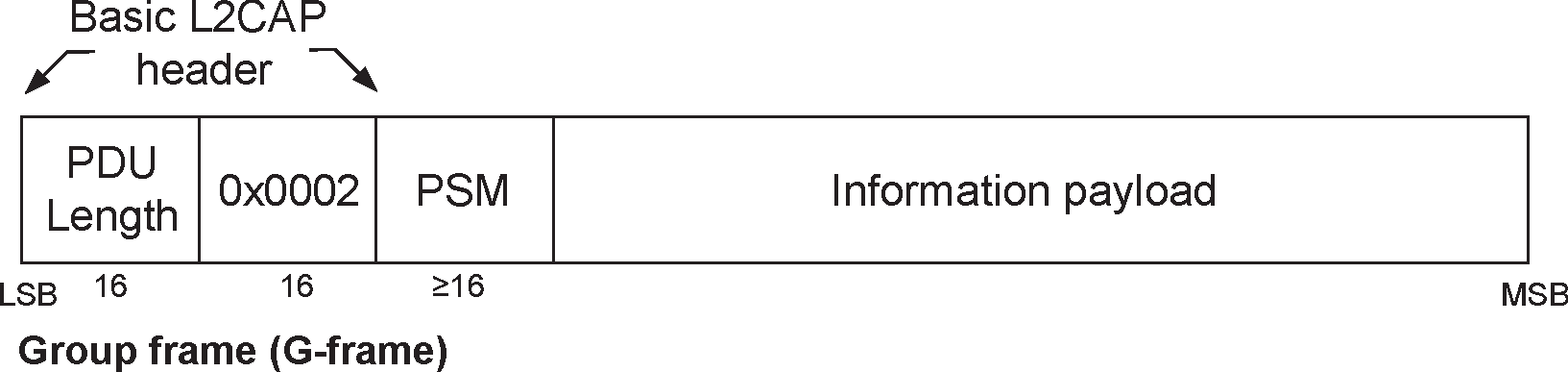
The fields shown are:
PDU Length: 2 octets
For G-frames, the PDU Length equals the payload size plus the number of octets in the PSM.
Channel ID: 2 octets
Channel ID (0x0002) reserved for connectionless traffic.
Protocol/Service Multiplexer (PSM): 2 octets (minimum)
For information on the PSM field see Section 4.2.
Information payload: 0 to 65533 octets
This parameter contains the payload information to be distributed to all Peripherals in the piconet for broadcast connectionless traffic, or to a specific remote device for data sent via the L2CAP connectionless channel. The payload size shall not be greater than the peer device's MTU for the channel. Implementations shall support a connectionless MTU (MTUcnl) of 48 octets on the connectionless channel. Devices may also explicitly change to a larger or smaller connectionless MTU (MTUcnl).
Note
Note: The maximum size of the Information payload field decreases accordingly if the PSM field is extended beyond the two octet minimum.
3.3. Connection-oriented channel in Retransmission/Flow Control/Streaming modes
To support flow control, retransmissions, and streaming, L2CAP PDU types with protocol elements in addition to the Basic L2CAP header are defined. The information frames (I-frames) are used for information transfer between L2CAP entities. The supervisory frames (S-frames) are used to acknowledge I-frames and request retransmission of I-frames. Figure 3.3 illustrates these frames.
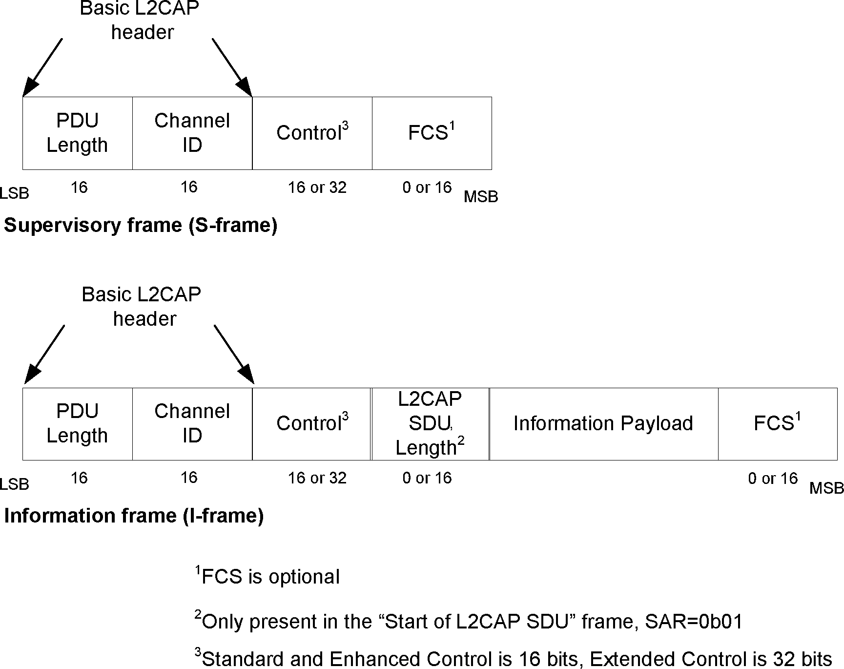
3.3.1. L2CAP header fields
PDU Length: 2 octets
For I-frames and S-frames, the PDU Length equals the sum of the octet lengths of the Control, L2CAP SDU Length (when present), Information Payload, and frame check sequence (FCS) (when present) fields. The PDU Length field of an S-frame therefore equals 2, 4, or 6.
The maximum number of Information octets (the payload size) in one I-frame is based on which fields are present and the type of the Control Field. The maximum number of Information octets in an I-frame with a Standard Control field is as follows:
L2CAP SDU Length present and FCS present
65529 octets
L2CAP SDU Length present and FCS not present
65531 octets
L2CAP SDU Length not present and FCS present
65531 octets
L2CAP SDU Length not present and FCS not present
65533 octets
The maximum number of Information octets in an I-frame with an Extended Control field is as follows:
L2CAP SDU Length present and FCS present
65527 octets
L2CAP SDU Length present and FCS not present
65529 octets
L2CAP SDU Length not present and FCS present
65529 octets
L2CAP SDU Length not present and FCS not present
65531 octets
Channel ID: 2 octets
This field contains the Channel Identification (CID).
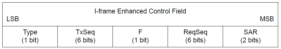
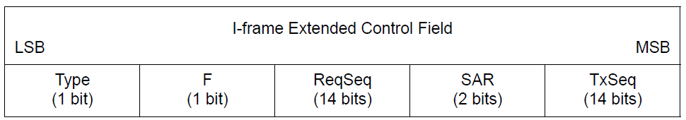
3.3.2. Control field
The Control Field identifies whether the frame is an S-frame or I-frame and contains various information about the frame. There are three different Control Field formats: the Standard Control Field, the Enhanced Control Field, and the Extended Control Field. Which format is used is determined by the mode and is not indicated within the frame. The Standard Control Field shall be used for Retransmission mode and Flow Control mode. The Enhanced and Extended Control Fields shall be used for Enhanced Retransmission mode and Streaming mode. The Enhanced Control Fields shall be used until the first successful use of the Extended Window Size option (see Section 5.7) and Extended Control Fields thereafter. The Control Field will contain sequence numbers where applicable. Its coding is shown in Figure 3.4 to Figure 3.9. There are two different frame types, Information frame types and Supervisory frame types. Information and Supervisory frames types are distinguished by the least significant bit in the Control Field.
Information frame format (I-frame)
The I-frames are used to transfer information between L2CAP entities. Each I-frame has a TxSeq(Send sequence number), ReqSeq(Receive sequence number) which can acknowledge additional I-frames received by the data Link Layer entity. Each I-frame with a Standard Control field has a retransmission bit (R bit) that affects whether I-frames are retransmitted. Each I-frame with an Enhanced Control Field or an Extended Control Field has an F-bit that is used in Poll/Final bit functions.
The SAR field in the I-frame is used for segmentation and reassembly control. The L2CAP SDU Length field specifies the length of an SDU, including the aggregate length across all segments if segmented.
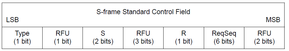
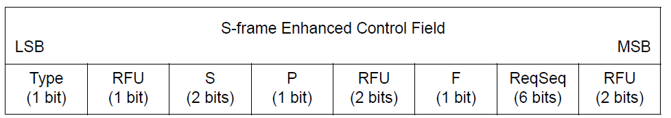
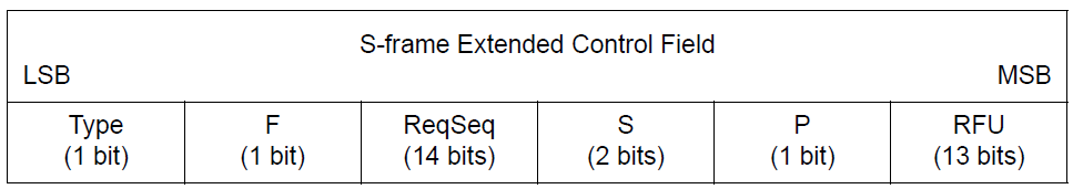
Supervisory frame format (S-frame)
S-frames are used to acknowledge I-frames and request retransmission of I-frames. Each S-frame has an ReqSeq sequence number which may acknowledge additional I-frames received by the data Link Layer entity. Each S-frame with a Standard Control Field has a retransmission bit (R bit) that affects whether I-frames are retransmitted. Each S-frame with an Enhanced Control field or an Extended Control Field has a Poll bit (P-bit) and a Final bit (F-bit) and does not have an R-bit.
Defined types of S-frames are RR (Receiver Ready), REJ (Reject), RNR (Receiver Not Ready) and SREJ (Selective Reject).
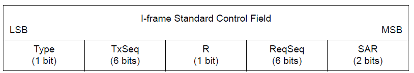
Type
The type bit shall be 0 for an I-frame and 1 for an S-frame.
Send Sequence Number - TxSeq
The send sequence number is used to number each I-frame, to enable sequencing and retransmission.
Receive Sequence Number - ReqSeq
The receive sequence number is used by the receiver side to acknowledge I-frames, and in the REJ and SREJ frames to request the retransmission of an I-frame with a specific send sequence number.
Retransmission Disable Bit - R
The Retransmission Disable bit is used to implement Flow Control. The receiver sets the bit when its internal receive buffer is full, this happens when one or more I-frames have been received but the SDU reassembly function has not yet pulled all the frames received. When the sender receives a frame with the Retransmission Disable bit set it shall disable the RetransmissionTimer, this causes the sender to stop retransmitting I-frames.
R=0: Normal operation. Sender uses the RetransmissionTimer to control retransmission of I-frames. Sender does not use the MonitorTimer.
R=1: Receiver side requests sender to postpone retransmission of I-frames. Sender monitors signaling with the MonitorTimer. Sender does not use the RetransmissionTimer.
The functions of ReqSeq and R are independent.
Segmentation and Reassembly - SAR
The SAR bits define whether an L2CAP SDU is segmented. For segmented SDUs, the SAR bits also define which part of an SDU is in this I-frame, thus allowing one L2CAP SDU to span several I-frames.
An I-frame with SAR=”Start of L2CAP SDU” also contains an L2CAP SDU Length field, specifying the number of information octets in the total L2CAP SDU. The encoding of the SAR bits is shown in Table 3.1.
0b00
Unsegmented L2CAP SDU
0b01
Start of L2CAP SDU
0b10
End of L2CAP SDU
0b11
Continuation of L2CAP SDU
Table 3.1: SAR control element formatSupervisory function - S
The S-bits mark the type of S-frame. There are four types defined: RR (Receiver Ready), REJ (Reject), RNR (Receiver Not Ready) and SREJ (Selective Reject). The encoding is shown in Table 3.2.
0b00
RR - Receiver Ready
0b01
REJ - Reject
0b10
RNR - Receiver Not Ready
0b11
SREJ - Select Reject
Table 3.2: S control element format: type of S-framePoll - P
The P-bit is set to 1 to solicit a response from the receiver. The receiver shall respond immediately with a frame with the F-bit set to 1.
Final - F
The F-bit is set to 1 in response to an S-frame with the P bit set to 1.
3.3.3. L2CAP SDU Length field (2 octets)
When an SDU spans more than one I-frame, the first I-frame in the sequence shall be identified by SAR=0b01=”Start of L2CAP SDU”. The L2CAP SDU Length field shall specify the total number of octets in the SDU and shall not be greater than the peer device's MTU for the channel. The L2CAP SDU Length field shall be present in I-frames with SAR=0b01 (Start of L2CAP SDU) and shall not be used in any other I-frames. When the SDU is unsegmented (SAR=0b00), the L2CAP SDU Length field is not needed and shall not be present.
3.3.4. Information Payload field
The information payload field consists of an integer number of octets. The maximum number of octets in this field is the same as the negotiated value of the MPS configuration parameter. The maximum number of octets in this field also depends on which other fields are present (see Section 3.3.1). If SAR=0b00 (Unsegmented L2CAP SDU) then the payload size shall not be greater than the peer device's MTU for the channel.
3.3.5. Frame Check Sequence (2 octets)
The Frame Check Sequence (FCS) is 2 octets. This field is mandatory in Retransmission and Flow Control modes. Whether it is present or absent in Enhanced Retransmission and Streaming modes is configurable (see Section 5.5).
The FCS is constructed using the generator polynomial g(D) = D16 + D15 + D2 + 1 (see Figure 3.10). The 16 bit LFSR is initially loaded with the value 0x0000, as depicted in Figure 3.11. The switch S is set in position 1 while data is shifted in, LSB first for each octet. After the last bit has entered the LFSR, the switch is set in position 2, and the register contents are transmitted from right to left (i.e. starting with position 15, then position 14, etc.). The FCS covers the Basic L2CAP header, Control, L2CAP SDU Length, and Information Payload fields, if present, as shown in Figure 3.3.
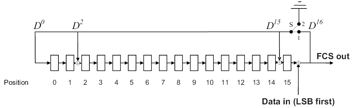

Examples of FCS calculation, g(D) = D16 + D15 + D2 + 1:
I Frame
PDU Length = 14 Channel ID = 0x0040 Control = 0x0002 (SAR=0b00, ReqSeq=0b000000, R=0, TxSeq=0b000001) Information Payload = 00 01 02 03 04 05 06 07 08 09 (10 octets, hexadecimal notation) ==> FCS = 0x6138 ==> Data to Send = 0E 00 40 00 02 00 00 01 02 03 04 05 06 07 08 09 38 61 (hexadecimal notation)
RR Frame
PDU Length = 4 Channel ID = 0x0040 Control = 0x0101 (ReqSeq=0b000001, R=0, S=0b00) ==> FCS = 0x14D4 ==> Data to Send = 04 00 40 00 01 01 D4 14 (hexadecimal notation)
3.3.6. Invalid Frame Detection (Retransmission and Flow Control modes)
For Retransmission mode and Flow Control mode, a received PDU shall be regarded as invalid if one of the following conditions occurs:
Contains an unknown CID.
Contains an FCS error.
I-frame with a payload size greater than the maximum PDU payload size (MPS).
I-frame that has fewer than 8 octets (i.e., PDU Length less than 4).
I-frame with SAR=0b01 (Start of L2CAP SDU) that has fewer than 10 octets (i.e., PDU Length less than 6).
I-frame with SAR bits that do not correspond to a normal sequence of either unsegmented or start, continuation, end for the given CID.
S-frame where the PDU Length field is not equal to 4.
These error conditions may be used for error reporting.
3.3.7. Invalid Frame Detection algorithm
For Enhanced Retransmission mode and Streaming mode the following algorithm shall be used for received PDUs. It may be used for Retransmission mode and Flow Control mode:
Check the CID. If the PDU contains an unknown CID then it shall be ignored.
Check the FCS. If the PDU contains an FCS error then it shall be ignored. If the channel is configured to use "No FCS" then the PDU is considered to have a good FCS (no FCS error).
Check the following conditions. If one of the conditions occurs the channel shall be closed or in the case of fixed channels the ACL shall be disconnected.
I-frame with a payload size greater than the maximum PDU payload size (MPS).
I-frame that has fewer than the required number of octets. If the channel is configured to use a Standard or Enhanced Control Field then the required number of octets is 6 if "No FCS" is configured; otherwise, it is 8. If the channel is configured to use the Extended Control Field then the required number of octets is 8 if "No FCS" is configured; otherwise, it is 10.
S-frame where the PDU Length field is invalid. If the channel is configured to use a Standard or Enhanced Control Field then the PDU Length field shall be 2 if "No FCS" is configured; otherwise, the PDU Length field shall be 4. If the channel is configured to use the Extended Control Field then the PDU Length field shall be 4 if "No FCS" is configured; otherwise, the PDU Length field shall be 6.
Check the SAR bits. The SAR check is performed after the frame has been successfully received in the correct sequence. The PDU is invalid if one of the following conditions occurs:
I-frame with SAR=0b01 (Start of L2CAP SDU) that has fewer than the required number of octets. If the channel is configured to use a Standard or Enhanced Control field then the required number of octets is 8 if "No FCS" is configured; otherwise, the required number of octets is 10. If the channel is configured to use an Extended Control field then the required number of octets is 10 if "No FCS" is configured; otherwise, the required number of octets is 12.
I-frame with SAR bits that do not correspond to a normal sequence of either unsegmented or start, continuation, end for the given CID.
I-frame with SAR= 0b01 (Start of L2CAP SDU) where the value in the L2CAP SDU Length field exceeds the configured MTU.
If the I-frame has been received in the correct sequence and is invalid as described in 4 then the channel shall be closed or in the case of fixed channels the ACL shall be disconnected. For Streaming mode and Flow Control mode if one or more I-frames are missing from a sequence of I-frames using SAR bits of start, continuation and end then received I-frames in the sequence may be ignored. For Flow Control mode and Streaming mode I-frames received out of sequence with SAR bits of unsegmented may be accepted.
If the algorithm is used for Retransmission mode or Flow control mode then it shall be used instead of Invalid Frame detection described in Section 3.3.6.
These error conditions may be used for error reporting.
3.4. Connection-oriented channels in LE Credit Based Flow Control mode and Enhanced Credit Based Flow Control mode
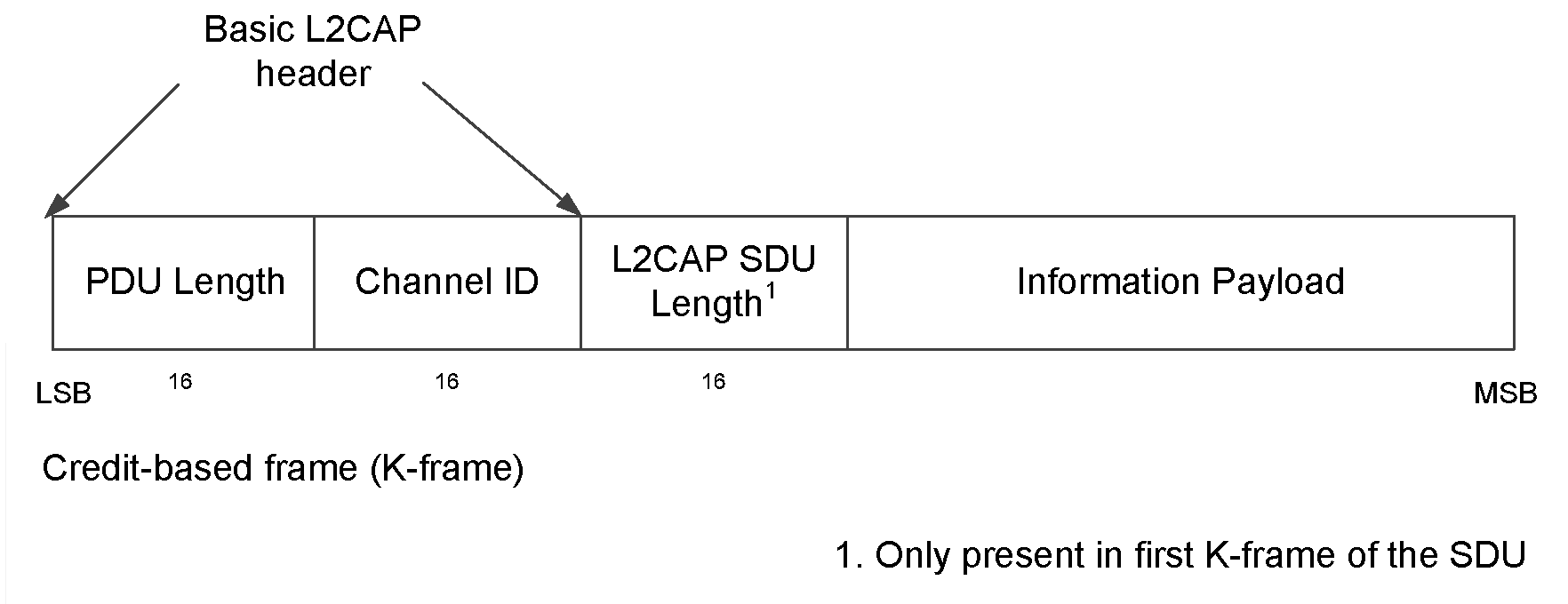
To support LE Credit Based Flow Control Mode and Enhanced Credit Based Flow Control Mode, an L2CAP PDU type with protocol elements in addition to the Basic L2CAP header is defined. In LE Credit Based Flow Control Mode and Enhanced Credit Based Flow Control Mode, the L2CAP PDU on a connection-oriented channel is a Credit-based frame (K-frame) as illustrated in Figure 3.12.
3.4.1. L2CAP Header fields
PDU Length: 2 octets
For K-frames, the PDU Length field equals the payload size plus the octet length of the L2CAP SDU Length (when present).
Channel ID: 2 octets
The channel ID (CID) identifies the destination channel endpoint of the packet.
3.4.2. L2CAP SDU Length field (2 octets)
The first K-frame of the SDU shall contain the L2CAP SDU Length field that shall specify the total number of octets in the SDU. The value shall not be greater than the peer device's MTU for the channel. All subsequent K-frames that are part of the same SDU shall not contain the L2CAP SDU Length field.
3.4.3. Information Payload field
The information payload field consists of an integer number of octets.
The number of octets contained in the first K-frame information payload of the SDU is equal to the PDU Length minus 2 octets. All subsequent K-frames of the same SDU contain the number of octets in the information payload equal to the PDU Length.
If the SDU length field value exceeds the receiver's MTU, the receiver shall disconnect the channel. If the payload size of any K-frame exceeds the receiver's MPS, the receiver shall disconnect the channel. If the sum of the payload sizes for the K-frames exceeds the specified SDU length, the receiver shall disconnect the channel.
4. Signaling packet formats
This section describes the signaling commands passed between two L2CAP entities on peer devices. All signaling commands are sent over a signaling channel. The signaling channel for managing channels over ACL-U logical links shall use CID 0x0001 and the signaling channel for managing channels over LE-U logical links shall use CID 0x0005. Signaling channels are available as soon as the lower layer logical transport is set up and L2CAP traffic is enabled. Figure 4.1 illustrates the general format of L2CAP PDUs containing signaling commands (C-frames). Multiple commands may be sent in a single C-frame over fixed channel CID 0x0001 while only one command per C-frame shall be sent over fixed channel CID 0x0005. Commands take the form of Requests, Responses, and Indications. All L2CAP implementations shall support the reception of C-frames with a payload size that does not exceed the signaling MTU. The minimum supported payload size for the C-frame (MTUsig) is defined in Table 4.1. L2CAP implementations should not use C-frames that exceed the MTUsig of the peer device. If a device receives a C-frame that exceeds its MTUsig then it shall send an L2CAP_COMMAND_REJECT_RSP packet containing the supported MTUsig. Implementations shall be able to handle the reception of multiple commands in an L2CAP packet sent over fixed channel CID 0x0001.
Note
Note: The name of a signalling packet has a suffix indicating its type: _REQ for requests, _RSP for responses, and _IND for indications.
A signaling packet that is not correctly formed is invalid behavior (see [Vol 1] Part E, Section 2.7). Examples of signaling packets that are not correctly formed include:
The packet is less than 4 octets long.
The Data Length field is not correct for the type of packet, such as an L2CAP_CONNECTION_REQ packet with a Data Length other than 4 or an L2CAP_INFORMATION_RSP with InfoType = 0x0003, Result = 0x0000, and Data Length not equal to 12.
The PDU Length of the C-frame does not equal the sum of the sizes of the contained packets.
The Reason or Status field has an unknown value.
A C-frame on fixed channel 0x0005 contains more than one signaling packet.
Logical Link | Minimum Supported Payload Size for the C-frame (MTUsig) |
|---|---|
ACL-U not supporting Extended Flow Specification | 48 octets |
ACL-U supporting the Extended Flow Specification feature | 672 octets |
LE-U | 23 octets |
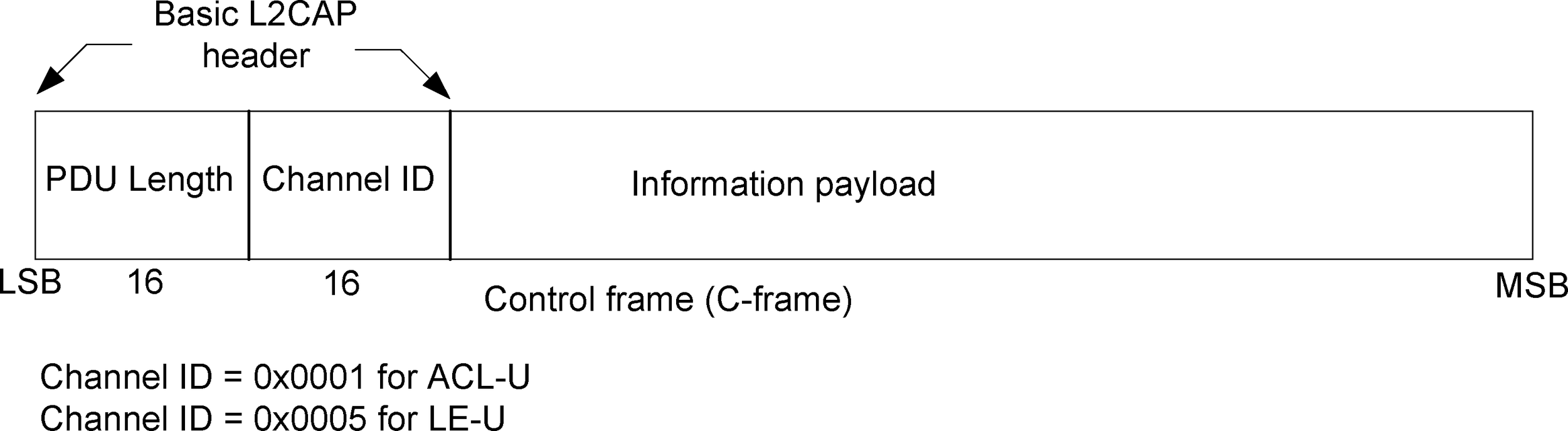
For C-frames, the PDU Length equals the payload size.
Figure 4.2 displays the general format of all signaling commands.
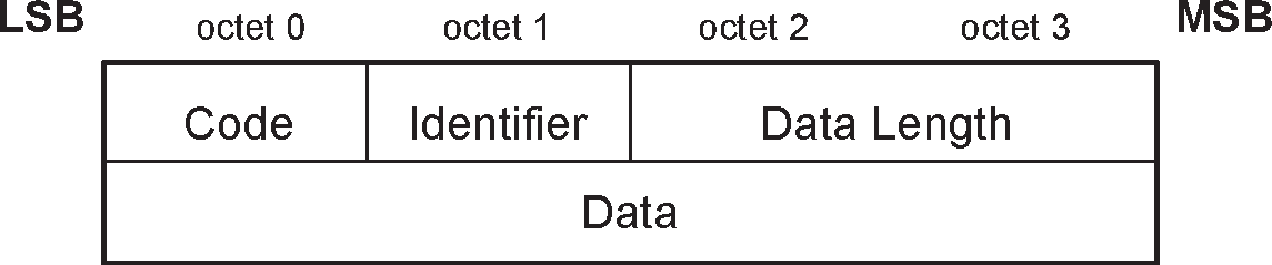
The fields shown are:
Code (1 octet)
The Code field is one octet long and identifies the type of command. When a packet is received with a Code field that is unknown or disallowed on the signaling channel it is received on, an L2CAP_COMMAND_REJECT_RSP packet (defined in Section 4.1) is sent in response.
Table 4.2 lists the codes defined by this document. All codes are specified with the most significant bit in the left-most position.
Code | Description | CIDs on which Code is Allowed |
|---|---|---|
0x01 | L2CAP_COMMAND_REJECT_RSP | 0x0001 and 0x0005 |
0x02 | L2CAP_CONNECTION_REQ | 0x0001 |
0x03 | L2CAP_CONNECTION_RSP | 0x0001 |
0x04 | L2CAP_CONFIGURATION_REQ | 0x0001 |
0x05 | L2CAP_CONFIGURATION_RSP | 0x0001 |
0x06 | L2CAP_DISCONNECTION_REQ | 0x0001 and 0x0005 |
0x07 | L2CAP_DISCONNECTION_RSP | 0x0001 and 0x0005 |
0x08 | L2CAP_ECHO_REQ | 0x0001 |
0x09 | L2CAP_ECHO_RSP | 0x0001 |
0x0A | L2CAP_INFORMATION_REQ | 0x0001 |
0x0B | L2CAP_INFORMATION_RSP | 0x0001 |
0x0C to 0x11 | Previously used | None |
0x12 | L2CAP_CONNECTION_PARAMETER_UPDATE_REQ | 0x0005 |
0x13 | L2CAP_CONNECTION_PARAMETER_UPDATE_RSP | 0x0005 |
0x14 | L2CAP_LE_CREDIT_BASED_CONNECTION_REQ | 0x0005 |
0x15 | L2CAP_LE_CREDIT_BASED_CONNECTION_RSP | 0x0005 |
0x16 | L2CAP_FLOW_CONTROL_CREDIT_IND | 0x0001 and 0x0005 |
0x17 | L2CAP_CREDIT_BASED_CONNECTION_REQ | 0x0001 and 0x0005 |
0x18 | L2CAP_CREDIT_BASED_CONNECTION_RSP | 0x0001 and 0x0005 |
0x19 | L2CAP_CREDIT_BASED_RECONFIGURE_REQ | 0x0001 and 0x0005 |
0x1A | L2CAP_CREDIT_BASED_RECONFIGURE_RSP | 0x0001 and 0x0005 |
Other | Reserved for future use | Any |
Identifier (1 octet)
The Identifier field is one octet long and matches responses with requests. The requesting device sets this field and the responding device uses the same value in its response. Within each signaling channel a different Identifier shall be used for each successive command. Following the original transmission of an Identifier in a command, the Identifier may be recycled if all other Identifiers have subsequently been used.
RTX and ERTX timers are used to determine when the remote end point is not responding to signaling requests. On the expiration of a RTX or ERTX timer, the same identifier shall be used if a duplicate Request is re-sent as stated in Section 6.2.
A device receiving a duplicate request on a particular signaling channel should reply with a duplicate response on the same signaling channel. A command response with an invalid identifier is silently discarded. Signaling identifier 0x00 is an invalid identifier and shall never be used in any command.
Data Length (2 octets)
The Data Length field is two octets long and indicates the size in octets of the data field of the command only, i.e., it does not cover the Code, Identifier, and Data Length fields.
Data (0 or more octets)
The Data field is variable in length. The Code field determines the format of the Data field. The Data Length field specifies the length of the Data field.
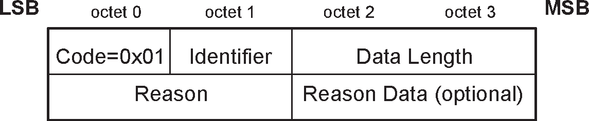
4.1. L2CAP_COMMAND_REJECT_RSP (code 0x01)
An L2CAP_COMMAND_REJECT_RSP packet shall be sent in response to a command packet with an unknown command code or when sending the corresponding response is inappropriate. Figure 4.3 defines the format of the packet. The identifier shall match the identifier of the command packet being rejected. Implementations shall always send these packets in response to unidentified signaling packets. L2CAP_COMMAND_REJECT_RSP packets should not be sent in response to an identified Response packet.
When multiple commands are included in an L2CAP packet and the packet exceeds the signaling MTU (MTUsig) of the receiver, a single L2CAP_COMMAND_REJECT_RSP packet shall be sent in response. The identifier shall match the first Request command in the L2CAP packet. If only Responses are recognized, the packet shall be silently discarded.
The data fields are:
Reason (2 octets)
The Reason field describes why the Request packet was rejected, and is set to one of the Reason codes in Table 4.3.
Reason value
Description
0x0000
Command not understood
0x0001
Signaling MTU exceeded
0x0002
Invalid CID in request
Other
Reserved for future use
Table 4.3: Reason code descriptionsReason Data (0 or more octets)
The length and content of the Reason Data field depends on the Reason code. If the Reason code is 0x0000, “Command not understood”, no Reason Data field is used. If the Reason code is 0x0001, “Signaling MTU Exceeded”, the 2-octet Reason Data field represents the maximum signaling MTU the sender of this packet can accept.
If a command refers to an invalid channel then the Reason code 0x0002 will be returned. Typically a channel is invalid because it does not exist. The Reason Data field shall be 4 octets containing the local (first) and remote (second) channel endpoints (relative to the sender of the L2CAP_COMMAND_REJECT_RSP packet) of the disputed channel. The remote endpoint is the source CID from the rejected command. The local endpoint is the destination CID from the rejected command. If the rejected command contains only one of the channel endpoints, the other one shall be replaced by the null CID 0x0000.
Reason value
Reason Data length
Reason Data value
0x0000
0 octets
0x0001
2 octets
Actual MTUsig
0x0002
4 octets
Requested CIDs
Table 4.4: Reason data values
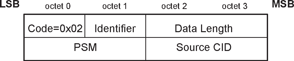
4.2. L2CAP_CONNECTION_REQ (code 0x02)
L2CAP_CONNECTION_REQ packets are sent to create an L2CAP channel between two devices. The L2CAP channel shall be established before configuration begins. Figure 4.4 defines the format of the packet.
The data fields are:
Protocol/Service Multiplexer - PSM (2 octets (minimum))
The PSM field is at least two octets in length. All PSM values shall have the least significant bit of the most significant octet equal to 0 and the least significant bit of all other octets equal to 1.
Note
Note: This means that all PSMs are odd numbers and that the end of a PSM can be easily found by searching for the first even octet.
PSM values are separated into two ranges. Valid values in the first range are assigned by the Bluetooth SIG and indicate protocols. The second range of values are dynamically allocated and used in conjunction with the Service Discovery protocol (SDP). The dynamically assigned values may be used to support multiple implementations of a particular protocol.
PSM values in the first range are defined in Assigned Numbers.
Range
Type
Server Usage
Client Usage
0x0001 to 0x0EFF
(Note [1])
Fixed, SIG assigned
PSM is fixed for all implementations.
PSM may be obtained via SDP or may be assumed for a fixed service. Protocol used is indicated by the PSM.
>0x1000
Dynamic
PSM may be fixed for a given implementation or may be assigned at the time the service is registered in SDP.
PSM shall be obtained via SDP upon every reconnection. PSM for one direction will typically be different from the other direction.
[1] Since PSMs are odd and the least significant bit of the most significant byte is zero, the following ranges do not contain valid PSMs: 0x0100-0x01FF, 0x0300-0x03FF, 0x0500-0x05FF, 0x0700-0x07FF, 0x0900-0x09FF, 0x0B00-0x0BFF, 0x0D00-0x0DFF. All even values are also not valid as PSMs.
Table 4.5: PSM ranges and usageSource CID - SCID (2 octets)
The source CID is two octets in length and represents a channel endpoint on the device sending the request. Once the channel has been configured, data packets flowing to the sender of the request shall be sent to this CID. Thus, the Source CID represents the channel endpoint on the device sending the request and receiving the response. The value of the Source CID shall be from the dynamically allocated range as defined in Table 2.1 and shall not be already allocated to a different channel on the same logical link on the device sending the request.
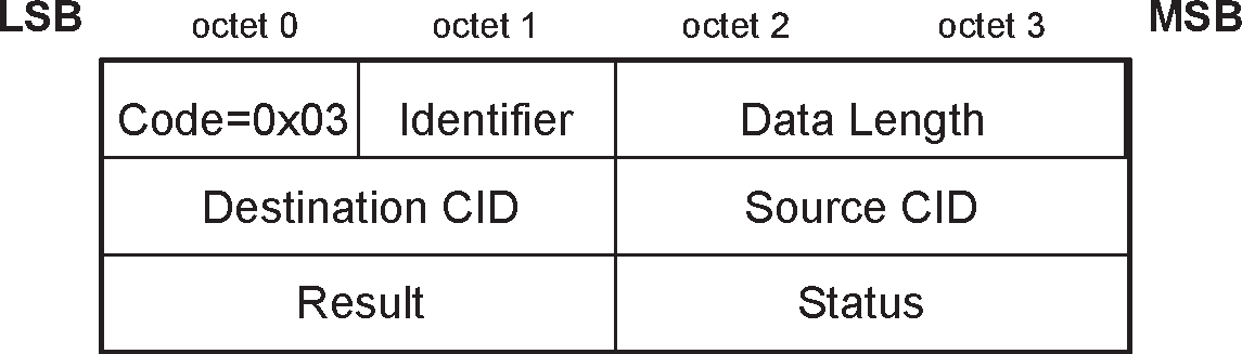
4.3. L2CAP_CONNECTION_RSP (code 0x03)
When a device receives an L2CAP_CONNECTION_REQ packet, it shall send an L2CAP_CONNECTION_RSP packet. Figure 4.5 defines the format of the packet.
Note
Note: Implementations conforming to a version of the specification lower than version 4.2 may respond with an L2CAP_COMMAND_REJECT_RSP (Reason 0x0002 – Invalid CID In Request) packet under conditions now covered by result codes of 0x0006 and 0x0007.
If the device sends an L2CAP_CONNECTION_RSP packet with result code "pending", then it shall subsequently send another L2CAP_CONNECTION_RSP (see also [Vol 3] Part C, Section 5.2.2.2).
The data fields are:
Destination Channel Identifier - DCID (2 octets)
This field contains the channel endpoint on the device sending this Response packet. Thus, the Destination CID represents the channel endpoint on the device receiving the request and sending the response. The value of the Destination CID shall be from the dynamically allocated range as defined in Table 2.1 and shall not be already allocated to a different channel on the same logical link on the device sending the response.
Source Channel Identifier - SCID (2 octets)
This field contains the channel endpoint on the device receiving this Response packet. This is copied from the SCID field of the L2CAP_CONNECTION_REQ packet.
Result (2 octets)
The result field indicates the outcome of the connection request. The result value of 0x0000 indicates success while a non-zero value indicates the connection request failed or is pending. A logical channel is established on the receipt of a successful result unless the DCID field is outside of the dynamically allocated range (see Table 2.1) or is already allocated on the device sending the response. Table 4.6 defines values for this field. If the result field does not indicate the connection was successful, the DCID and SCID fields may be invalid and shall be ignored.
Value
Description
0x0000
Connection successful.
0x0001
Connection pending
0x0002
Connection refused – PSM not supported.
0x0003
Connection refused – security block.
0x0004
Connection refused – no resources available.
0x0006
Connection refused – invalid Source CID
0x0007
Connection refused – Source CID already allocated
Other
Reserved for future use.
Table 4.6: Result values for the L2CAP_CONNECTION_RSP packetStatus (2 octets)
Only defined for Result = Pending. Indicates the status of the connection. The status is set to one of the values shown in Table 4.7.
Value
Description
0x0000
No further information available
0x0001
Authentication pending
0x0002
Authorization pending
Other
Reserved for future use
Table 4.7: Status values for the L2CAP_CONNECTION_RSP packet
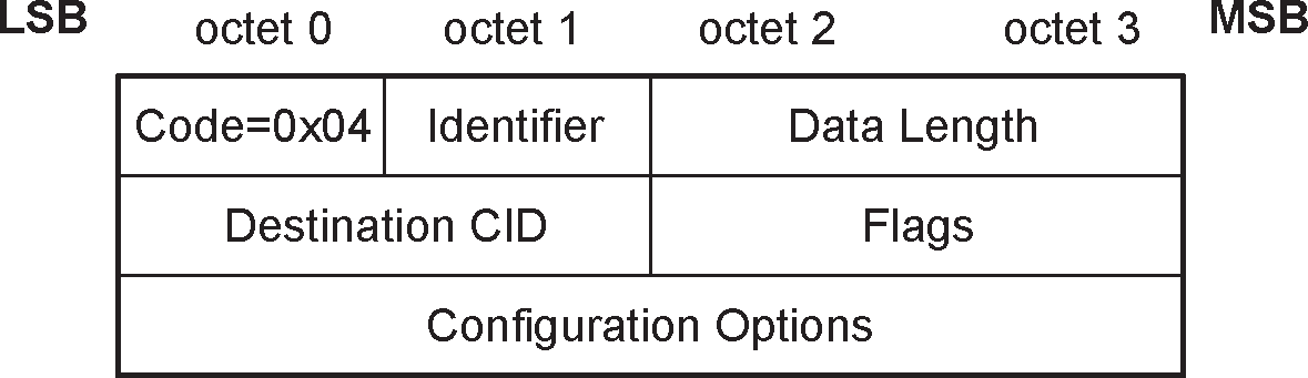
4.4. L2CAP_CONFIGURATION_REQ (code 0x04)
L2CAP_CONFIGURATION_REQ packets are sent to establish an initial logical link transmission contract between two L2CAP entities and also to re-negotiate this contract whenever appropriate. The contract consists of a set of configuration parameter options defined in Section 5. All parameter options have default values and can have previously agreed values which are values that were accepted in a previous configuration process or in a previous step in the current configuration process. The only parameters that should be included in the L2CAP_CONFIGURATION_REQ packet are those that require different values than the default or previously agreed values.
If no parameters need to be negotiated or specified then no options shall be inserted and the continuation flag (C) shall be set to zero. Any missing configuration parameters are assumed to have their most recently explicitly or implicitly accepted values. Even if all default values are acceptable, an L2CAP_CONFIGURATION_REQ packet with no options shall be sent. Implicitly accepted values are default values for the configuration parameters that have not been explicitly negotiated for the specific channel under configuration.
See Section 7.1 for details of the configuration procedure.
Figure 4.6 defines the format of the packet.
The data fields are:
Destination CID - DCID (2 octets)
This field contains the channel endpoint on the device receiving this Request packet.
Flags (2 octets)
Figure 4.7 shows the two-octet Flags field. Note the most significant bit is shown on the left.
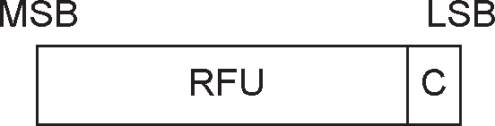 Figure 4.7: L2CAP_CONFIGURATION_REQ Flags field format
Only one flag is defined, the Continuation flag (C).
When both L2CAP entities support the Extended Flow Specification option, the Continuation flag shall not be used and shall be set to zero in all L2CAP_CONFIGURATION_REQ and L2CAP_CONFIGURATION_RSP packets.
When all configuration options cannot fit into an L2CAP_CONFIGURATION_REQ packet with a payload size that does not exceed the receiver's MTUsig, the options shall be passed in multiple L2CAP_CONFIGURATION_REQ packets. If all options fit into the receiver's MTUsig, then they shall be sent in a single L2CAP_CONFIGURATION_REQ packet with the continuation flag set to zero. Each L2CAP_CONFIGURATION_REQ packet shall only contain complete options - partially formed options shall not be sent in a packet. Each L2CAP_CONFIGURATION_REQ packet shall be tagged with a different Identifier and shall be matched with an L2CAP_CONFIGURATION_RSP packet with the same Identifier.
When used in the L2CAP_CONFIGURATION_REQ packet, the continuation flag indicates the responder should expect to receive multiple request packets. The responder shall reply to each L2CAP_CONFIGURATION_REQ packet. The responder may reply to each L2CAP_CONFIGURATION_REQ packet with an L2CAP_CONFIGURATION_RSP packet containing the same option(s) present in the Request (except for those error conditions more appropriate for an L2CAP_COMMAND_REJECT_RSP packet), or the responder may reply with a "Success" L2CAP_CONFIGURATION_RSP packet containing no options, delaying those options until the full Request has been received. The L2CAP_CONFIGURATION_REQ packet with the continuation flag cleared shall be treated as the L2CAP_CONFIGURATION_REQ event in the channel state machine.
When used in the L2CAP_CONFIGURATION_RSP packet, the continuation flag shall be set to one if the flag is set to one in the Request. If the continuation flag is set to one in the Response when the matching Request has the flag set to zero, it indicates the responder has additional options to send to the requestor. In this situation, the requestor shall send null-option L2CAP_CONFIGURATION_REQ packets (with continuation flag set to zero) to the responder until the responder replies with an L2CAP_CONFIGURATION_RSP packet where the continuation flag is set to zero. The L2CAP_CONFIGURATION_RSP packet with the continuation flag set to zero shall be treated as the L2CAP_CONFIGURATION_RSP event in the channel state machine.
The result of the configuration transaction is success if all the individual result values are success, and is failure otherwise.
Other flags are reserved for future use.
Configuration Options
A list of the parameters and their values to be negotiated shall be provided in the Configuration Options field. These are defined in Section 5; in addition, as described in that section, an implementation shall be prepared to receive any number of unknown options. An L2CAP_CONFIGURATION_REQ packet may contain no options (referred to as an empty or null configuration request) and can be used to request a response. For an empty configuration request the Data Length field is set to 0x0004.
4.5. L2CAP_CONFIGURATION_RSP (code 0x05)
L2CAP_CONFIGURATION_RSP packets shall be sent in reply to L2CAP_CONFIGURATION_REQ packets except when the error condition is covered by an L2CAP_COMMAND_REJECT_RSP packet response. Each configuration parameter value (if any is present) in an L2CAP_CONFIGURATION_RSP packet reflects an ‘adjustment’ to a configuration parameter value that has been sent (or, in case of default values, implied) in the corresponding L2CAP_CONFIGURATION_REQ packet. For example, if an L2CAP_CONFIGURATION_REQ packet relates to traffic flowing from device A to device B, the sender of the L2CAP_CONFIGURATION_RSP packet may adjust this value for the same traffic flowing from device A to device B, but the response cannot adjust the value in the reverse direction.
The options sent in the L2CAP_CONFIGURATION_RSP packet depend on the value in the Result field. Figure 4.8 defines the format of the packet. See also Section 7.1 for details of the configuration process, including use of the result code "pending".
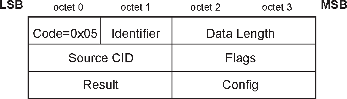
The data fields are:
Source CID - SCID (2 octets)
This field contains the channel endpoint on the device receiving this Response packet. The device receiving the L2CAP_CONFIGURATION_RSP packet shall check that the Identifier field matches the same field in the corresponding L2CAP_CONFIGURATION_REQ packet and the SCID matches its local CID paired with the original DCID.
Flags (2 octets)
Figure 4.9 displays the two-octet Flags field. Note the most significant bit is shown on the left.
Figure 4.9: L2CAP_CONFIGURATION_RSP Flags field formatOnly one flag is defined, the Continuation flag (C).
When both L2CAP entities support the Extended Flow Specification option, the Continuation flag shall not be used and shall be set to zero in all L2CAP_CONFIGURATION_REQ and L2CAP_CONFIGURATION_RSP packets.
More L2CAP_CONFIGURATION_RSP packets will follow when C is set to one. This flag indicates that the parameters included in the response are a partial subset of parameters being sent by the device sending the L2CAP_CONFIGURATION_RSP packet.
The other flag bits are reserved for future use.
Result (2 octets)
The Result field indicates whether or not the Request was acceptable. See Table 4.8 for possible result codes.
Result
Description
0x0000
Success
0x0001
Failure – unacceptable parameters
0x0002
Failure – rejected (no reason provided)
0x0003
Failure – unknown options
0x0004
Pending
0x0005
Failure - flow spec rejected
Other
Reserved for future use
Table 4.8: L2CAP_CONFIGURATION_RSP result codesConfiguration options
This field contains the list of parameters being configured. These are defined in Section 5. On a successful result (Result=0x0000) and pending result (Result=0x0004), these parameters contain the return values for any wild card parameter values (see Section 5.3) and “adjustments” to non-negotiated configuration parameter values contained in the request. A response with a successful result is also referred to as a positive response.
On an unacceptable parameters failure (Result=0x0001) the rejected parameters shall be sent in the response with the values that would have been accepted if sent in the original request. Any missing configuration parameters in the L2CAP_CONFIGURATION_REQ packet are assumed to have their default value or previously agreed value and they too shall be included in the L2CAP_CONFIGURATION_RSP packet if they need to be changed. A response with an unacceptable parameters failure is also referred to as a negative response.
On an unknown option failure (Result=0x0003), the option(s) that contain an option type field that is not understood by the recipient of the L2CAP_CONFIGURATION_REQ packet shall be included in the L2CAP_CONFIGURATION_RSP packet unless they are hints. Hints are those options in the L2CAP_CONFIGURATION_REQ packet that are skipped if not understood (see Section 5). Hints shall not be included in the L2CAP_CONFIGURATION_RSP packet and shall not be the sole cause for rejecting the L2CAP_CONFIGURATION_REQ packet.
On a flow spec rejected failure (Result=0x0005), an Extended Flow Spec option may be included to reflect the QoS level that would be acceptable (see Section 7.1.3).
The decision on the amount of time (or messages) spent arbitrating the channel parameters before terminating the negotiation is implementation specific.
4.6. L2CAP_DISCONNECTION_REQ (code 0x06)
Terminating an L2CAP channel requires that an L2CAP_DISCONNECTION_REQ packet be sent and acknowledged by an L2CAP_DISCONNECTION_RSP packet. Figure 4.10 defines the format of the packet. The receiver shall not initiate a disconnection if the source or destination CIDs do not match.
Once an L2CAP_DISCONNECTION_REQ packet is issued, all incoming data in transit on this L2CAP channel shall be discarded and any new additional outgoing data shall be discarded. Once an L2CAP_DISCONNECTION_REQ packet for a channel has been received, all data queued to be sent out on that channel shall be discarded.

The data fields are:
Destination CID - DCID (2 octets)
This field specifies the endpoint of the channel to be disconnected on the device receiving this request.
Source CID - SCID (2 octets)
This field specifies the endpoint of the channel to be disconnected on the device sending this request.
The SCID and DCID are relative to the sender of this request and shall match those of the channel to be disconnected. If the DCID is not recognized by the receiver of this message, an L2CAP_COMMAND_REJECT_RSP packet with ‘invalid CID’ result code shall be sent in response. If the receiver finds a DCID match but the SCID fails to find the same match, the request should be silently discarded.
4.7. L2CAP_DISCONNECTION_RSP (code 0x07)
L2CAP_DISCONNECTION_RSP packets shall be sent in response to each valid L2CAP_DISCONNECTION_REQ packet. Figure 4.11 defines the format of the packet.
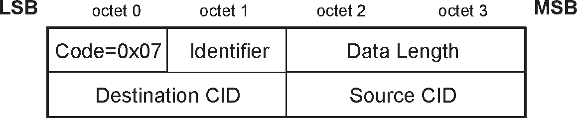
The data fields are:
Destination CID - DCID (2 octets)
This field identifies the channel endpoint on the device sending the L2CAP_DISCONNECTION_RSP packet.
Source CID - SCID (2 octets)
This field identifies the channel endpoint on the device receiving the L2CAP_DISCONNECTION_RSP packet.
The DCID and the SCID (which are relative to the sender of the L2CAP_DISCONNECTION_REQ packet), and the Identifier fields shall match those of the corresponding L2CAP_DISCONNECTION_REQ packet. If the CIDs do not match, the L2CAP_DISCONNECTION_RSP packet should be silently discarded at the receiver.
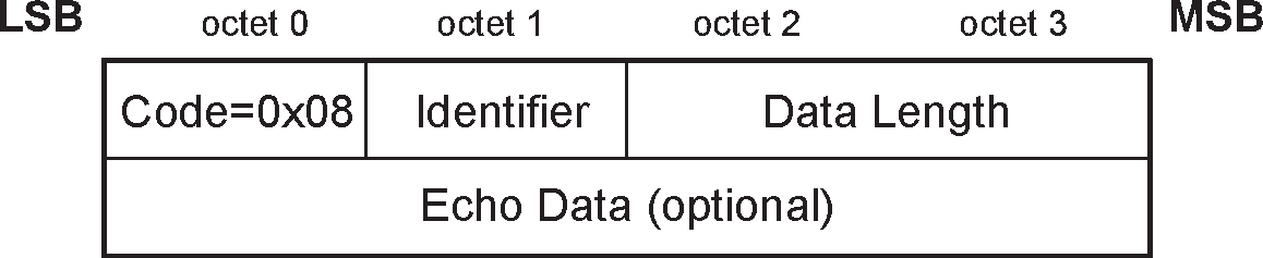
4.8. L2CAP_ECHO_REQ (code 0x08)
L2CAP_ECHO_REQ packets are used to request a response from a remote L2CAP entity. Figure 4.12 defines the format of the packet. These requests may be used for testing the link or for passing vendor specific information using the optional data field. L2CAP entities shall respond to a valid L2CAP_ECHO_REQ packet with an L2CAP_ECHO_RSP packet. The Echo Data field is optional and implementation specific. L2CAP entities should ignore the contents of this field if present.
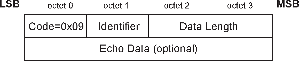
4.9. L2CAP_ECHO_RSP (code 0x09)
An L2CAP_ECHO_RSP packet shall be sent upon receiving a valid L2CAP_ECHO_REQ packet. Figure 4.13 defines the format of the packet. The identifier in the L2CAP_ECHO_RSP packet shall match the identifier sent in the L2CAP_ECHO_REQ packet. The Echo Data field is optional and implementation specific. It may contain the contents of the Echo Data field in the L2CAP_ECHO_REQ packet, different data, or no data at all. L2CAP entities should ignore the contents of this field if present.
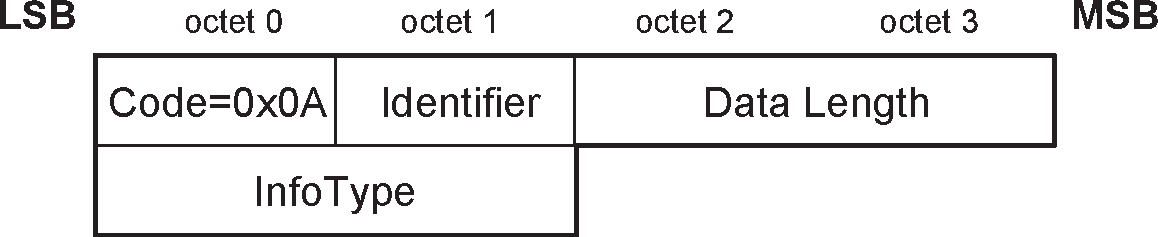
4.10. L2CAP_INFORMATION_REQ (code 0x0A)
L2CAP_INFORMATION_REQ packets are used to request implementation specific information from a remote L2CAP entity. Figure 4.14 defines the format of the packet. L2CAP implementations shall respond to a valid L2CAP_INFORMATION_REQ packet with an L2CAP_INFORMATION_RSP packet. It is optional to send L2CAP_INFORMATION_REQ packets.
An L2CAP implementation shall only use optional features or attribute ranges for which the remote L2CAP entity has indicated support through an L2CAP_INFORMATION_RSP packet. Until an L2CAP_INFORMATION_RSP packet which indicates support for optional features or ranges has been received only mandatory features and ranges shall be used.
The data field is:
InfoType (2 octets)
The InfoType defines the type of implementation specific information being requested. See Section 4.11 for details on the type of information requested.
Value
Description
0x0001
Connectionless MTU
0x0002
Extended features supported
0x0003
Fixed channels supported over BR/EDR
Other
Reserved for future use
Table 4.9: InfoType definitions
L2CAP entities shall not send an L2CAP_INFORMATION_REQ packet with InfoType 0x0003 over fixed channel CID 0x0001 until first verifying that the Fixed Channels bit is set in the Extended feature mask of the remote device. Support for fixed channels is mandatory for devices with BR/EDR/LE or LE Controllers. L2CAP_INFORMATION_REQ and L2CAP_INFORMATION_RSP packets shall not be used over fixed channel CID 0x0005.
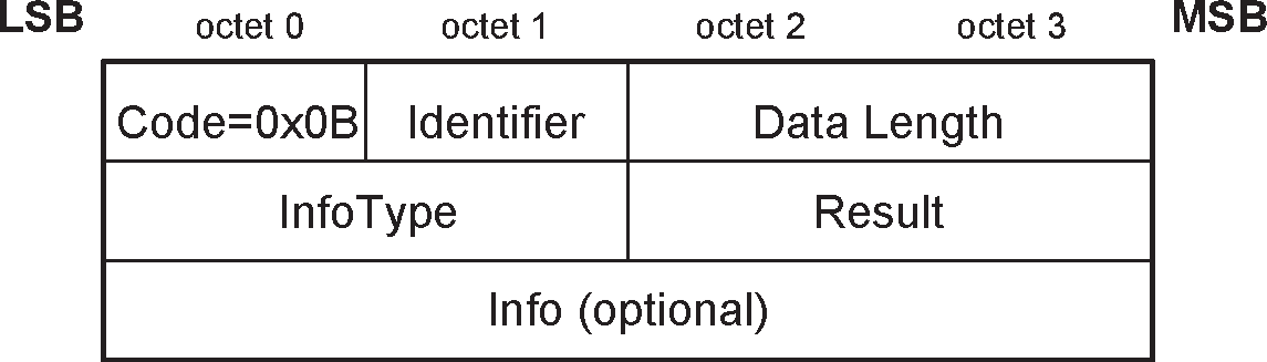
4.11. L2CAP_INFORMATION_RSP (code 0x0B)
An L2CAP_INFORMATION_RSP packet shall be sent upon receiving a valid L2CAP_INFORMATION_REQ packet. Figure 4.15 defines the format of the packet. The identifier in the L2CAP_INFORMATION_RSP packet shall match the identifier sent in the L2CAP_INFORMATION_REQ packet. The Info field shall contain the value associated with the InfoType field sent in the L2CAP_INFORMATION_REQ packet, or shall be empty if the InfoType is not supported.
The data fields are:
InfoType (2 octets)
The InfoType defines the type of implementation specific information that was requested. This value shall be copied from the InfoType field in the L2CAP_INFORMATION_REQ packet.
Result (2 octets)
The Result contains information about the success of the request. If result is "Success," the data field contains the information as specified in Table 4.11. If result is "Not supported," no data shall be returned.
Value
Description
0x0000
Success
0x0001
Not supported
Other
Reserved for future use
Table 4.10: Result values for the L2CAP_INFORMATION_RSP packetInfo (0 or more octets)
The contents of the Info field depends on the InfoType.
For InfoType = 0x0001, the field contains the remote entity’s 2-octet acceptable connectionless MTU. The default value is defined in Section 3.2.
For InfoType = 0x0002, the Info field contains the 4 octet L2CAP extended feature mask. The feature mask refers to the extended features that the L2CAP entity sending the L2CAP_INFORMATION_RSP packet supports. The feature bits contained in the L2CAP feature mask are specified in Section 4.12.
For InfoType = 0x0003, the Info field contains an 8 octet bit map that indicates which Fixed L2CAP Channels (i.e., the L2CAP channels that use a CID from 0x0000 to 0x003F) are supported over BR/EDR. A list of available fixed channels is provided in Table 2.1 in Section 2.1. A detailed description of this Info field is given in Section 4.13.
Note
Note: Implementations conforming to a version lower than 1.2, receiving an L2CAP_INFORMATION_REQ packet with InfoType = 0x0002 for an L2CAP feature discovery, return an L2CAP_INFORMATION_RSP packet with result code "Not supported." Implementations conforming to versions 1.2, 2.0 + EDR, or 2.1 + EDR that have an all zero extended features mask may return an L2CAP_INFORMATION_RSP packet with result code "Not supported."
InfoType
Info
Info length
(octets)
0x0001
Connectionless MTU
2
0x0002
Extended feature mask
4
0x0003
Fixed channels supported over BR/EDR
8
Table 4.11: L2CAP_INFORMATION_RSP Info fields
4.12. Extended Feature Mask
The features are represented as a bit mask in the L2CAP_INFORMATION_RSP packet’s Info field (see Section 4.11). For each feature a single bit is specified which shall be set to 1 if the feature is supported and set to 0 otherwise. All unknown or unassigned feature bits are reserved for future use.
The feature mask shown in Table 4.12 consists of 4 octets (numbered octet 0 to 3), with bit numbers 0 to 7 each.
No. | Supported feature | Octet | Bit | ||||||||||||||||||||||||||||||||||||||||||||||
|---|---|---|---|---|---|---|---|---|---|---|---|---|---|---|---|---|---|---|---|---|---|---|---|---|---|---|---|---|---|---|---|---|---|---|---|---|---|---|---|---|---|---|---|---|---|---|---|---|---|
0 | Flow control mode | 0 | 0 | ||||||||||||||||||||||||||||||||||||||||||||||
1 | Retransmission mode | 0 | 1 | ||||||||||||||||||||||||||||||||||||||||||||||
2 | Bi-directional QoS [1] | 0 | 2 | ||||||||||||||||||||||||||||||||||||||||||||||
3 | Enhanced Retransmission Mode | 0 | 3 | ||||||||||||||||||||||||||||||||||||||||||||||
4 | Streaming Mode | 0 | 4 | ||||||||||||||||||||||||||||||||||||||||||||||
5 | FCS Option | 0 | 5 | ||||||||||||||||||||||||||||||||||||||||||||||
6 | Extended Flow Specification for BR/EDR | 0 | 6 | ||||||||||||||||||||||||||||||||||||||||||||||
7 | Fixed Channels supported over BR/EDR | 0 | 7 | ||||||||||||||||||||||||||||||||||||||||||||||
8 | Extended Window Size | 1 | 0 | ||||||||||||||||||||||||||||||||||||||||||||||
9 | Unicast Connectionless Data Reception | 1 | 1 | ||||||||||||||||||||||||||||||||||||||||||||||
10 | Enhanced Credit Based Flow Control Mode over BR/EDR | 1 | 2 | ||||||||||||||||||||||||||||||||||||||||||||||
31 | Reserved for feature mask extension | 3 | 7 | ||||||||||||||||||||||||||||||||||||||||||||||
All others | Reserved for future use | All others | |||||||||||||||||||||||||||||||||||||||||||||||
[1] Peer side supports upper layer control of the Link Manager's Bi-directional QoS, see Section 5.3 for more details. | |||||||||||||||||||||||||||||||||||||||||||||||||
4.13. Fixed Channels Supported over BR/EDR
Each fixed channel supported over BR/EDR is represented by a single bit in an 8 octet bit mask. The bit associated with a channel shall be set to 1 if the L2CAP entity supports that channel. The L2CAP Signaling channel is mandatory and therefore the bit associated with that channel shall be set to 1. Table 4.13 shows the format of the bit mask.
CID | Fixed Channel | Value | Octet | Bit |
|---|---|---|---|---|
0x0000 | Null identifier | Shall be set to 0 | 0 | 0 |
0x0001 | L2CAP Signaling channel | Shall be set to 1 | 0 | 1 |
0x0002 | Connectionless reception | 0 – if not supported 1 – if supported | 0 | 2 |
0x0003 | Previously used | 0 | 3 | |
0x0004 to 0x0006 | Reserved for future use | 0 | 4-6 | |
0x0007 | BR/EDR Security Manager | 0 – if not supported 1 – if supported | 0 | 7 |
0x0008 to 0x003E | Reserved for future use | 1-6 7 | 0-7 0-6 | |
0x003F | Previously used | 7 | 7 | |
Other | Reserved for future use | Other | ||
An L2CAP entity shall not transmit on any fixed channel (with the exception of the L2CAP Signaling channel) until it has received a Fixed Channels Supported InfoType from the peer L2CAP entity indicating support for that channel, or has received a valid packet from the remote device on that fixed channel. All packets received on a non-supported fixed channel shall be ignored.
4.14. [This section is no longer used]
4.15. [This section is no longer used]
4.16. [This section is no longer used]
4.17. [This section is no longer used]
4.18. [This section is no longer used]
4.19. [This section is no longer used]
4.20. L2CAP_CONNECTION_PARAMETER_UPDATE_REQ (code 0x12)
This command shall only be sent from the Peripheral to the Central and only if one or more of the Peripheral’s Controller, the Central’s Controller, the Peripheral’s Host and the Central’s Host do not support the Connection Parameters Request Link Layer Control procedure ([Vol 6] Part B, Section 5.1.7). If a Peripheral’s Host receives an L2CAP_CONNECTION_PARAMETER_UPDATE_REQ packet it shall respond with an L2CAP_COMMAND_REJECT_RSP packet with reason 0x0000 (Command not understood). Figure 4.16 defines the format of the packet.
The L2CAP_CONNECTION_PARAMETER_UPDATE_REQ packet allows the Peripheral’s Host to request a set of new connection parameters. When the Central’s Host receives an L2CAP_CONNECTION_PARAMETER_UPDATE_REQ packet, depending on the parameters of other connections, the Central’s Host may accept the requested parameters and deliver the requested parameters to its Controller or reject the request. In devices supporting HCI, the Central’s Host delivers the requested parameters to its Controller using the HCI_LE_Connection_Update command (see [Vol 4] Part E, Section 7.8.18). If the Central’s Host accepts the requested parameters it shall send the L2CAP_CONNECTION_PARAMETER_UPDATE_RSP packet with result 0x0000 (Parameters accepted) otherwise it shall set the result to 0x0001 (request rejected).
The Peripheral’s Host will receive an indication from the Peripheral’s Controller when the connection parameters have been updated. In devices supporting HCI, this notification will be in the form of an HCI_LE_Connection_Update_Complete event (see [Vol 4] Part E, Section 7.7.65.3). If the Central’s Controller rejects the updated connection parameters no indication from the Peripheral’s Controller will be sent to the Peripheral’s Host.
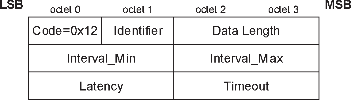
The data fields shall have the same meanings and requirements as the fields of the LL_CONNECTION_PARAM_REQ PDU (see [Vol 6] Part B, Section 2.4.2.16) with the same names.
4.21. L2CAP_CONNECTION_PARAMETER_UPDATE_RSP (code 0x13)
This response shall only be sent from the Central to the Peripheral.
The L2CAP_CONNECTION_PARAMETER_UPDATE_RSP packet shall be sent by the Central’s Host when it receives an L2CAP_CONNECTION_PARAMETER_UPDATE_REQ packet. Figure 4.17 defines the format of the packet. If the Central’s Host accepts the request it shall send the connection parameter update to its Controller.
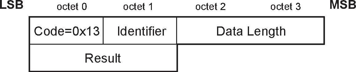
The data field is:
Result (2 octets)
The result field indicates the response to the request. The result value of 0x0000 indicates that the Central’s Host has accepted the connection parameters while 0x0001 indicates that the Central’s Host has rejected the connection parameters.
Result
Description
0x0000
Connection Parameters accepted
0x0001
Connection Parameters rejected
Other
Reserved for future use
Table 4.14: Result values for the L2CAP_CONNECTION_PARAMETER_UPDATE_RSP packet
4.22. L2CAP_LE_CREDIT_BASED_CONNECTION_REQ (code 0x14)
L2CAP_LE_CREDIT_BASED_CONNECTION_REQ packets are sent to create and configure an L2CAP channel between two devices using LE Credit Based Flow Control mode. Figure 4.18 defines the format of the packet.
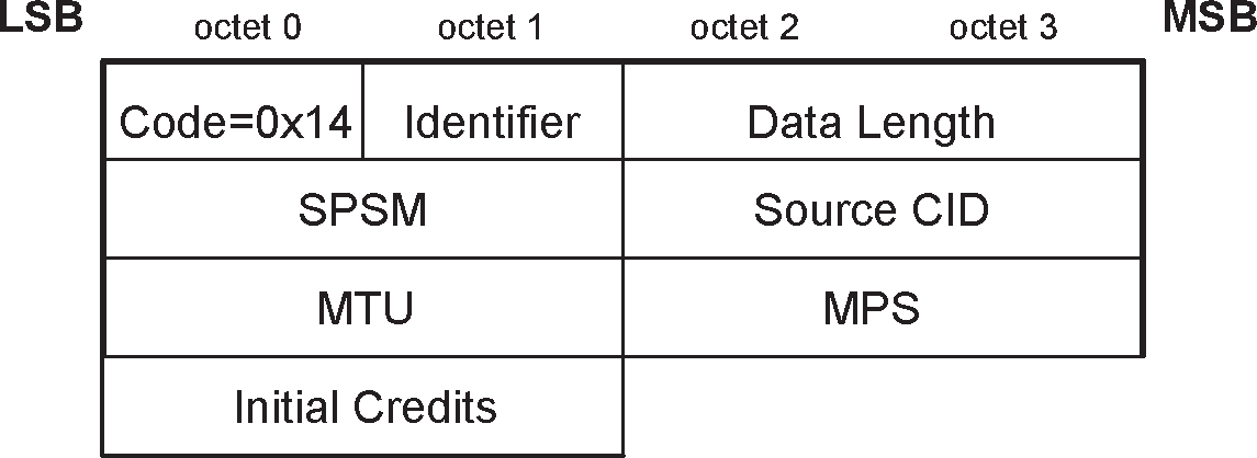
The data fields are:
Simplified Protocol/Service Multiplexer – SPSM[1](2 octets)
The SPSM field is two octets in length. SPSM values are separated into two ranges. Values in the first range are assigned by the Bluetooth SIG and indicate protocols. Values in the second range are dynamically allocated and used in conjunction with services defined in the GATT Server. The dynamically assigned values may be used to support multiple implementations of a particular protocol.
Note
Note: Unlike a normal PSM (see Section 4.2), the length of an SPSM is not variable and each octet may be either odd or even.
SPSM values are defined in Table 4.15.
Range
Type
Server Usage
Client Usage
0x0001 to 0x007F
Fixed, SIG
assigned
SPSM is fixed for all implementations
SPSM may be assumed for fixed service. Protocol used is indicated by the SPSM as defined in Assigned Numbers.
0x0080 to 0x00FF
Dynamic
SPSM may be fixed for a given implementation or may be assigned at the time the service is registered in GATT
SPSM shall be obtained from the service in GATT upon every reconnection. SPSM for one direction will typically be different from the other direction.
Other
RFU
Not applicable
Not applicable
Table 4.15: L2CAP_LE_CREDIT_BASED_CONNECTION_REQ SPSM rangesSource CID – SCID (2 octets)
The source CID is two octets in length and represents a channel endpoint on the device sending the request. Once the channel has been created, data packets flowing to the sender of the request shall be sent to this CID. Thus, the Source CID represents the channel endpoint on the device sending the request and receiving the response. The value of the Source CID shall be from the dynamically allocated range as defined in Table 2.3 and shall not be already allocated to a different channel on the same logical link on the device sending the request.
Maximum Transmission Unit – MTU (2 octets)
The MTU field specifies the maximum SDU size (in octets) that the L2CAP layer entity sending the L2CAP_LE_CREDIT_BASED_CONNECTION_REQ packet can receive on this channel. L2CAP implementations shall support a minimum MTU size of 23 octets.
Maximum PDU Payload Size – MPS (2 octets)
The MPS field specifies the maximum PDU payload size (in octets) that the L2CAP layer entity sending the L2CAP_LE_CREDIT_BASED_CONNECTION_REQ packet is capable of receiving on this channel. L2CAP implementations shall support a minimum MPS of 23 octets and may support an MPS up to 65533 octets.
Initial Credits – (2 octets)
The initial credit value indicates the number of K-frames that the peer device can send to the L2CAP layer entity sending the L2CAP_LE_CREDIT_BASED_CONNECTION_REQ packet. The initial credit value shall be in the range 0 to 65535.
4.23. L2CAP_LE_CREDIT_BASED_CONNECTION_RSP (code 0x15)
When a device receives an L2CAP_LE_CREDIT_BASED_CONNECTION_REQ packet, it shall send an L2CAP_LE_CREDIT_BASED_CONNECTION_RSP packet. Figure 4.19 defines the format of the packet.
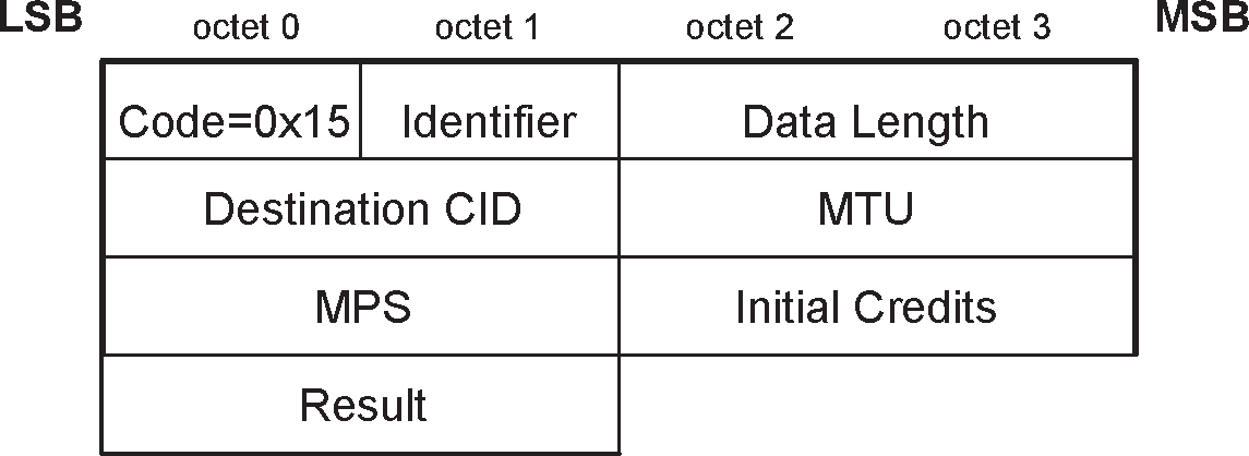
The data fields are:
Destination CID – DCID (2 octets)
The destination CID is two octets in length and represents a channel endpoint on the device sending the response. Once the channel has been created, data packets flowing to the sender of the response shall be sent to this CID. Thus, the destination CID represents the channel endpoint on the device receiving the request and sending the response. The value of the Destination CID shall be from the dynamically allocated range as defined in Table 2.3 and shall not be already allocated to a different channel on the same logical link on the device sending the response.
Maximum Transmission Unit – MTU (2 octets)
The MTU field specifies the maximum SDU size (in octets) that the L2CAP layer entity sending the L2CAP_LE_CREDIT_BASED_CONNECTION_RSP packet can receive on this channel. L2CAP implementations shall support a minimum MTU size of 23 octets.
Maximum PDU Payload Size – MPS (2 octets)
The MPS field specifies the maximum PDU payload size (in octets) that the L2CAP layer entity sending the L2CAP_LE_CREDIT_BASED_CONNECTION_RSP packet is capable of receiving on this channel. L2CAP implementations shall support a minimum MPS of 23 octets and may support an MPS up to 65533 octets.
Initial Credits – (2 octets)
The initial credit value indicates the number of K‑frames that the peer device can send to the L2CAP layer entity sending the L2CAP_LE_CREDIT_BASED_CONNECTION_RSP packet. The initial credit value shall be in the range 0 to 65535.
Result – (2 octets)
The result field indicates the outcome of the connection request. A result value of 0x0000 indicates success while a non-zero value indicates the connection request was refused. A logical channel is established on the receipt of a successful result. Table 4.16 defines values for this field. The DCID, MTU, MPS and Initial Credits fields shall be ignored when the result field indicates the connection was refused.
Value
Description
0x0000
Connection successful
0x0002
Connection refused – SPSM not supported
0x0004
Connection refused – no resources available
0x0005
Connection refused – insufficient authentication
0x0006
Connection refused – insufficient authorization
0x0007
Connection refused – encryption key size too short[a]
0x0008
Connection refused – insufficient encryption
0x0009
Connection refused – invalid Source CID
0x000A
Connection refused – Source CID already allocated
0x000B
Connection refused – unacceptable parameters
Other
Reserved for future use
[a] This was previously "Connection refused - insufficient encryption key size".
Table 4.16: Result values for the L2CAP_LE_CREDIT_BASED_CONNECTION_RSP packet
4.24. L2CAP_FLOW_CONTROL_CREDIT_IND (code 0x16)
A device shall send an L2CAP_FLOW_CONTROL_CREDIT_IND packet when it is capable of receiving additional K-frames (for example after it has processed one or more K-frames) in LE Credit Based Flow Control mode and Enhanced Credit Based Flow Control mode. Figure 4.20 defines the format of the packet.
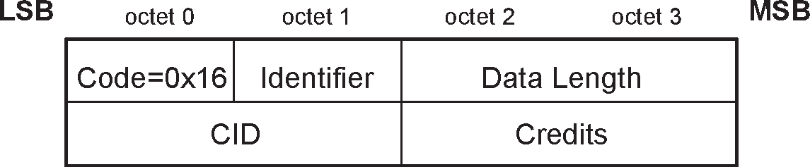
The data fields are:
CID – (2 octets)
The CID is two octets in length and represents the source channel endpoint of the device sending the L2CAP_FLOW_CONTROL_CREDIT_IND packet. For example, a received L2CAP_FLOW_CONTROL_CREDIT_IND packet with a given CID (0x0042) would provide credits for the receiving device’s destination CID (0x0042).
Credits – (2 octets)
The credit value field represents number of credits the receiving device can increment, corresponding to the number of K-frames that can be sent to the peer device sending the L2CAP_FLOW_CONTROL_CREDIT_IND packet. The credit value field shall be a number between 1 and 65535.
4.25. L2CAP_CREDIT_BASED_CONNECTION_REQ (code 0x17)
L2CAP_CREDIT_BASED_CONNECTION_REQ packets are sent to create and configure up to five L2CAP channels between two devices. Figure 4.21 defines the format of the packet.
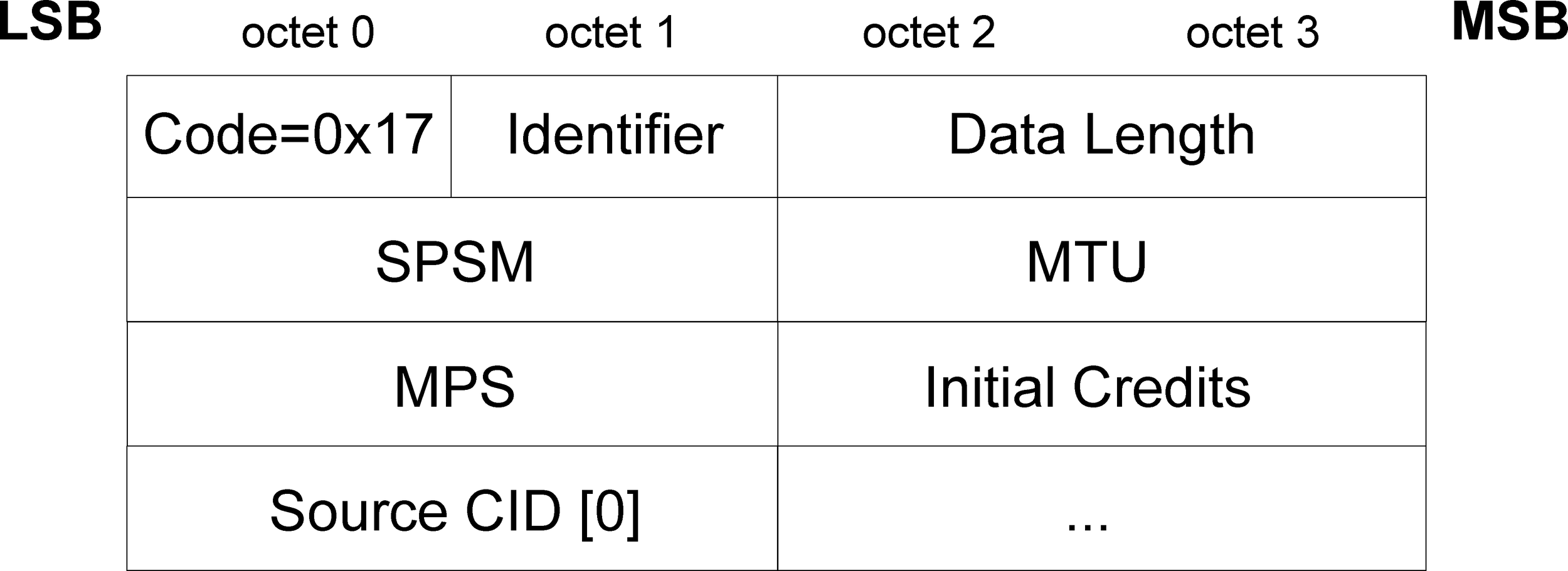 |
The data fields are:
Simplified Protocol/Service Multiplexer – SPSM (2 octets)
The SPSM is defined in Section 4.22.
Maximum Transmission Unit – MTU (2 octets)
The MTU field specifies the maximum SDU size (in octets) that the L2CAP layer entity sending the L2CAP_CREDIT_BASED_CONNECTION_REQ packet can receive on each of the Source CID channels. L2CAP implementations shall support a minimum MTU size of 64 octets for these channels.
Maximum PDU Payload Size – MPS (2 octets)
The MPS field specifies the maximum PDU payload size (in octets) that the L2CAP layer entity sending the L2CAP_CREDIT_BASED_CONNECTION_REQ packet is capable of receiving on each of the Source CID channels. L2CAP implementations shall support a minimum MPS of 64 octets and may support an MPS up to 65533 octets for these channels.
Initial Credits – (2 octets)
The Initial Credit field value indicates the number of K-frames that the peer device can send to the L2CAP layer entity sending the L2CAP_CREDIT_BASED_CONNECTION_REQ packet on each of the Source CID channels. The initial credit value shall be in the range of 1 to 65535.
Source CID – (2 to 10 octets)
The Source CID is an array of up to 5 two-octet values and represents the channel endpoints on the device sending the request. Once a channel has been created, data packets flowing to the sender of the request shall be sent to these CIDs. Each entry in the array shall be non-zero and represents a request for a channel. The value of each Source CID shall be from the dynamically allocated range as defined in Table 2.1 or Table 2.3 (depending on the transport in use) and shall not be already allocated to a different channel on the same logical link on the device sending the request.
4.26. L2CAP_CREDIT_BASED_CONNECTION_RSP (code 0x18)
When a device receives an L2CAP_CREDIT_BASED_CONNECTION_REQ packet, it shall send an L2CAP_CREDIT_BASED_CONNECTION_RSP packet. If the device sends an L2CAP_CREDIT_BASED_CONNECTION_RSP packet with a result code "pending", then it shall subsequently send another L2CAP_CREDIT_BASED_CONNECTION_RSP (see also [Vol 3] Part C, Section 5.2.2.2). Figure 4.22 defines the format of the packet.
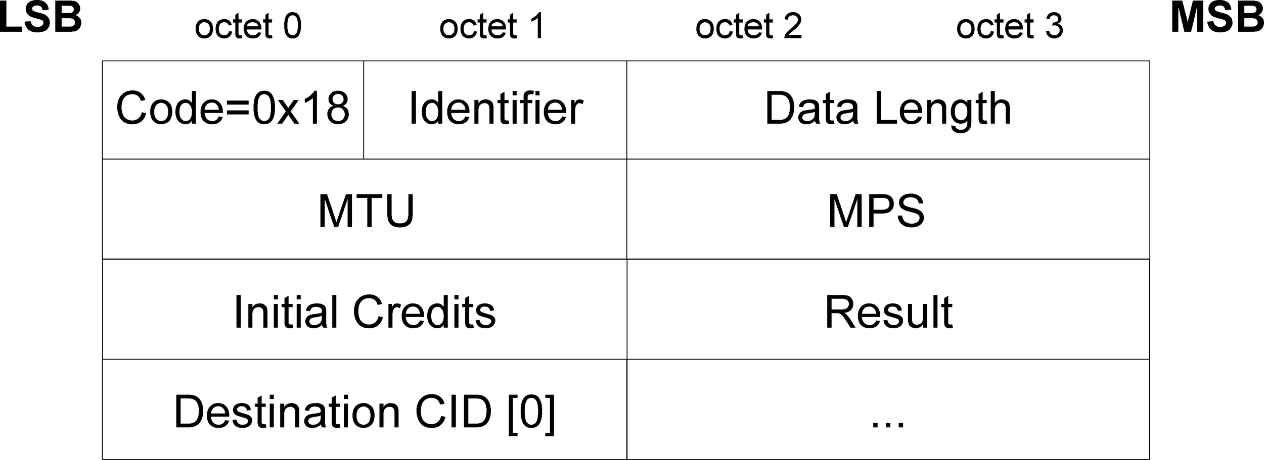 |
The data fields are:
Maximum Transmission Unit – MTU (2 octets)
The MTU field specifies the maximum SDU size (in octets) that the L2CAP layer entity sending the L2CAP_CREDIT_BASED_CONNECTION_RSP packet can receive on each of the Destination CID channels. L2CAP implementations shall support a minimum MTU size of 64 octets.
Maximum PDU Payload Size – MPS (2 octets)
The MPS field specifies the maximum PDU payload size (in octets) that the L2CAP layer entity sending the L2CAP_CREDIT_BASED_CONNECTION_RSP packet is capable of receiving on each of the Destination CID channels. L2CAP implementations shall support a minimum MPS of 64 octets and may support an MPS up to 65533 octets.
Initial Credits – (2 octets)
The Initial Credit field value indicates the number of K-frames that the peer device can send to the L2CAP layer entity sending the L2CAP_CREDIT_BASED_CONNECTION_RSP packet on each of the Destination CID channels. The initial credit value shall be in the range of 1 to 65535.
Result – (2 octets)
The Result field indicates the outcome of the connection request. Table 4.17 defines values for this field. The Destination CID, MTU, MPS and Initial Credits fields shall be ignored when the Result field indicates that all connections were refused or all connections are pending.
Value
Description
0x0000
All connections successful
0x0002
All connections refused – SPSM not supported
0x0004
Some connections refused – insufficient resources available
0x0005
All connections refused – insufficient authentication
0x0006
All connections refused – insufficient authorization
0x0007
All connections refused – encryption key size too short[1]
0x0008
All connections refused – insufficient encryption
0x0009
Some connections refused – invalid Source CID
0x000A
Some connections refused – Source CID already allocated
0x000B
All connections refused – unacceptable parameters
0x000C
All connections refused – invalid parameters
0x000D
All connections pending – no further information available
0x000E
All connections pending – authentication pending
0x000F
All connections pending – authorization pending
Other
Reserved for future use
[1] This was previously "All connections refused - insufficient encryption key size".
Table 4.17: Result values for the L2CAP_CREDIT_BASED_CONNECTION_RSP packetDestination CID – (2 to 10 octets)
The Destination CID is an array of up to 5 two-octet values and represents the channel endpoints on the device sending the L2CAP_CREDIT_BASED_CONNECTION_RSP packet. The value of the Destination CID shall be from the dynamically allocated range as defined in Table 2.1 or Table 2.3 (depending on the transport in use) and shall not be already allocated to a different channel on the same logical link on the device sending the response. Once a channel has been created, data packets flowing to the sender of the response shall be sent to these CIDs. The order of the Destination CIDs shall correspond to the order of the Source IDs in the corresponding L2CAP_CREDIT_BASED_CONNECTION_REQ packet. If a Destination CID is non-zero, the channel was established. If a Destination CID is 0x0000, the channel was not established. If a device receives an L2CAP_CREDIT_BASED_CONNECTION_RSP packet with an already-assigned Destination CID, then both the original channel and the new channel shall not be used.
4.27. L2CAP_CREDIT_BASED_RECONFIGURE_REQ (code 0x19)
A device shall send an L2CAP_CREDIT_BASED_RECONFIGURE_REQ packet when its receive MTU or MPS values have changed compared to when the channel was created or last reconfigured. Figure 4.23 defines the format of the packet.
Note
Note: The current MTU and MPS values of the channels may be different before this packet is sent.
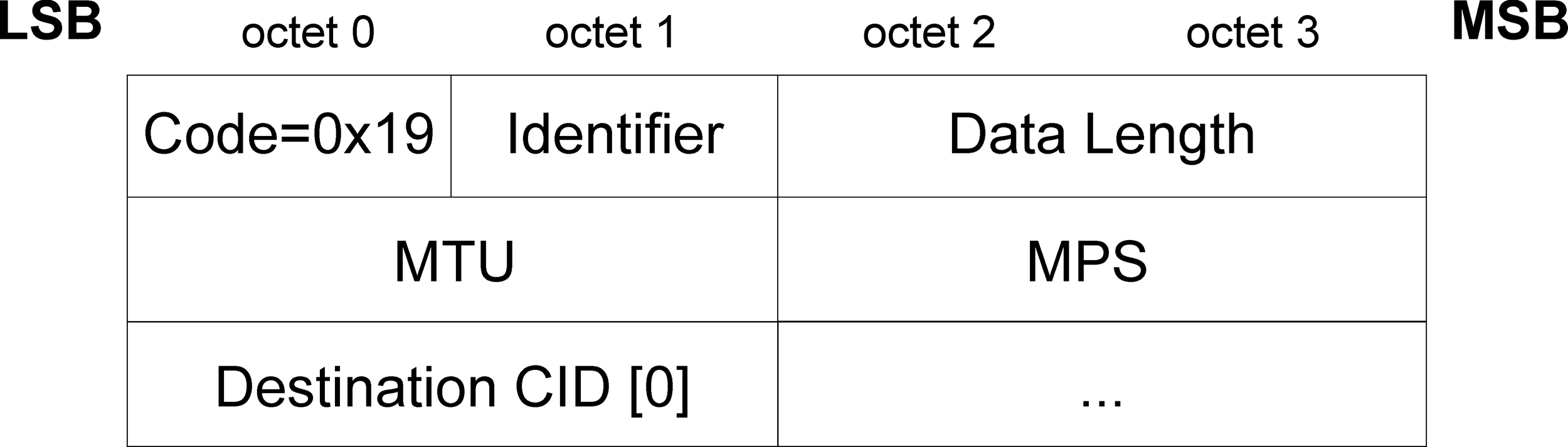 |
The data fields are:
Maximum Transmission Unit – MTU (2 octets)
The MTU field specifies the maximum SDU size (in octets) that the L2CAP layer entity sending the L2CAP_CREDIT_BASED_RECONFIGURE_REQ packet can receive on each of the Destination CID channels. The MTU field shall be greater than or equal to the greatest current MTU size of these channels.
Maximum PDU Payload Size – MPS (2 octets)
The MPS field specifies the maximum PDU payload size (in octets) that the L2CAP layer entity sending the L2CAP_CREDIT_BASED_RECONFIGURE_REQ packet is capable of receiving on each of the Destination CID channels. If more than one channel is being configured, the MPS field shall be greater than or equal to the current MPS size of each of these channels. If only one channel is being configured, the MPS field may be less than the current MPS of that channel.
Destination CID – (2 to 10 octets)
The Destination CID is an array of up to 5 two-octet values which shall be non-zero and represent the channel endpoints on the device sending the L2CAP_CREDIT_BASED_RECONFIGURE_REQ packet.
4.28. L2CAP_CREDIT_BASED_RECONFIGURE_RSP (code 0x1A)
When a device receives an L2CAP_CREDIT_BASED_RECONFIGURE_REQ packet, it shall send an L2CAP_CREDIT_BASED_RECONFIGURE_RSP packet. Figure 4.24 defines the format of the packet.
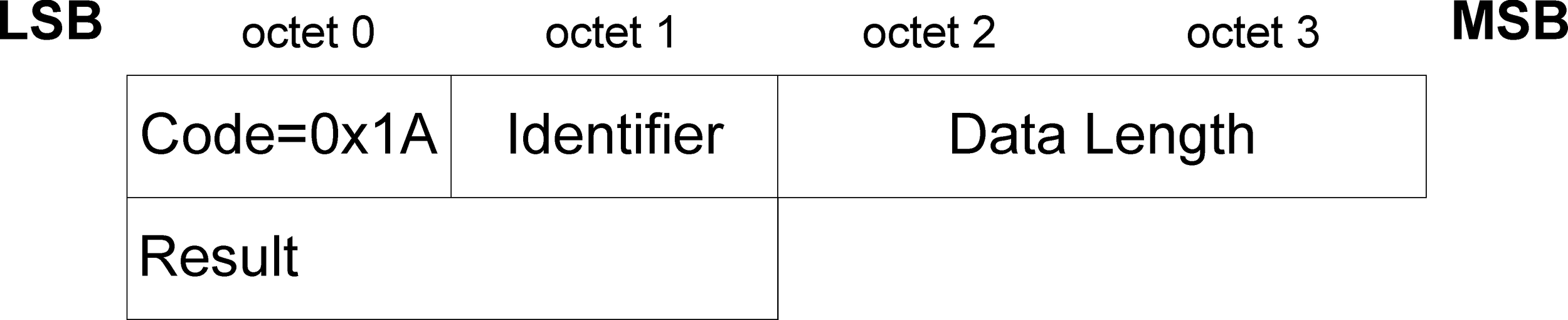 |
The data fields are:
Result (2 octets)
The Result field contains information about the success of the request.
Value | Description |
|---|---|
0x0000 | Reconfiguration successful |
0x0001 | Reconfiguration failed - reduction in size of MTU not allowed |
0x0002 | Reconfiguration failed - reduction in size of MPS not allowed for more than one channel at a time |
0x0003 | Reconfiguration failed - one or more Destination CIDs invalid |
0x0004 | Reconfiguration failed - other unacceptable parameters |
All other values | Reserved for future use |
5. Configuration parameter options
Options are a mechanism to extend the configuration parameters. Options shall be transmitted as information elements containing an option type, an option length, and one or more option data fields. Figure 5.1 illustrates the format of an option.

The configuration option fields are:
Option Type (1 octet)
The Option Type field defines the parameters being configured. If the option is not recognized (e.g. because the option is defined in a higher version of the specification than the version the implementation conforms to) then:
If the most significant bit of the type is 0 (i.e. types 0x00 to 0x7F), the recipient shall refuse the entire configuration request.
If the most significant bit of the type is 1 (i.e. types 0x80 to 0xFF), the recipient shall ignore the option and continue processing with the next option (if any).
Option Length (1 octet)
The Option Length field defines the number of octets in the option data. Thus an option type without option data has a length of 0.
Option data
The contents of this field are dependent on the option type.
5.1. Maximum Transmission Unit (MTU)
This option specifies the maximum SDU size the sender of this option is capable of accepting for a channel. The Option Type is 0x01, and the Option Length is 2 octets, carrying the two-octet MTU size value as the only information element (see Figure 5.2).
MTU is not a negotiated value, it is an informational parameter that each device can specify independently. It indicates to the remote device that the local device can receive, in this channel, an MTU larger than the minimum required. All L2CAP implementations shall support a minimum MTU of 48 octets over the ACL-U logical link and 23 octets over the LE-U logical link; however, some protocols and profiles explicitly require support for a larger MTU. The minimum MTU for a channel is the larger of the L2CAP minimum 48 octet MTU and any MTU explicitly required by the protocols and profiles using that channel.
Note
Note: The MTU is only affected by the profile directly using the channel. For example, if a service discovery transaction is initiated by a non service discovery profile, that profile does not affect the MTU of the L2CAP channel used for service discovery.
The following rules shall be used when responding to an L2CAP_CONFIGURATION_REQ packet specifying the MTU for a channel:
A request specifying any MTU greater than or equal to the minimum MTU for the channel shall be accepted.
A request specifying an MTU smaller than the minimum MTU for the channel may be rejected.
The signaling described in Section 4.5 may be used to reject an MTU smaller than the minimum MTU for a channel. The "failure-unacceptable parameters" result sent to reject the MTU shall include the proposed value of MTU that the remote device intends to transmit. It is implementation specific whether the local device continues the configuration process or disconnects the channel.
If the remote device sends a positive L2CAP_CONFIGURATION_RSP packet it should include the actual MTU to be used on this channel for traffic flowing into the local device. Following the above rules, the actual MTU cannot be less than 48 bytes.This is the minimum of the MTU in the L2CAP_CONFIGURATION_REQ packet and the outgoing MTU capability of the device sending the L2CAP_CONFIGURATION_RSP packet. The new agreed value (the default value in a future re-configuration) is the value specified in the response.
Note
Note: For backwards compatibility reception of the MTU option in a negative L2CAP_CONFIGURATION_RSP packet where the MTU option is not in error should be interpreted in the same way as it is in a positive L2CAP_CONFIGURATION_RSP packet (e.g. the case where another configuration option value is unacceptable but the negative L2CAP_CONFIGURATION_RSP packet contains the MTU option in addition to the unacceptable option).
The MTU to be used on this channel for the traffic flowing in the opposite direction will be established when the remote device sends its own L2CAP_CONFIGURATION_REQ packet as explained in Section 4.4.
If the configured mode is Enhanced Retransmission mode or Streaming mode then MTU shall not be reconfigured to a smaller size.

The option data field is:
Maximum Transmission Unit - MTU (2 octets)
The MTU field is the maximum SDU size, in octets, that the originator of the Request can accept for this channel. The MTU is asymmetric and the sender of the Request shall specify the MTU it can receive on this channel if it differs from the default value. L2CAP implementations shall support a minimum MTU size of 48 octets. The default value is 672 octets.
5.2. Flush Timeout option
This option is used to inform the recipient of the Flush Timeout the sender is going to use. This option shall not be used if the Extended Flow Specification is used. The Flush Timeout is defined in the BR/EDR Baseband specification [Vol 2] Part B, Section 3.3. The Option Type is 0x02 and the Option Length is 2 octets (see Figure 5.3). The Flush Timeout option is negotiable.
If the remote device returns a negative response to this option and the local device cannot honor the proposed value, then it shall either continue the configuration process by sending a new request with the original value, or disconnect the channel. The flush timeout applies to all channels on the same ACL logical transport but may be overridden on a packet by packet basis by marking individual L2CAP packets as non-automatically-flushable via the Packet_Boundary_Flag in the HCI ACL Data packet (see Section 1.1).

The option data field is:
Flush Timeout
This value is the Flush Timeout in milliseconds. This is an asymmetric value and the sender of the Request shall specify its flush timeout value if it differs from the default value of 0xFFFF.
Possible values are:
0x0001 - no retransmissions at the Baseband level should be performed since the minimum polling interval is 1.25 ms.
0x0002 to 0xFFFE - Flush Timeout used by the Baseband.
0xFFFF - an infinite amount of retransmissions. This is also referred to as a ’reliable channel’. In this case, the Baseband shall continue retransmissions until physical link loss is declared by link manager timeouts.
5.3. Quality of Service (QoS) option
This option specifies a flow specification similar to RFC 1363[2]. Although the RFC flow specification addresses only the transmit characteristics, the Bluetooth QoS interface can handle the two directions (Tx and Rx) in the negotiation as described below.
If no QoS configuration parameter is negotiated the link shall assume the default parameters. The Option Type is 0x03. This option shall not be used if the Extended Flow Specification option is used. The QoS option is negotiable. Figure 5.4 specifies the format of this option.
In an L2CAP_CONFIGURATION_REQ packet, this option describes the outgoing traffic flow from the device sending the request. In a positive L2CAP_CONFIGURATION_RSP packet, this option describes the incoming traffic flow agreement to the device sending the response. In a negative L2CAP_CONFIGURATION_RSP packet, this option describes the preferred incoming traffic flow to the device sending the response.
L2CAP implementations are only required to support ’Best Effort’ service, support for any other service type is optional. Best Effort does not require any guarantees. If no QoS option is placed in the request, Best Effort shall be assumed. If any QoS guarantees are required then a QoS configuration request shall be sent.
The remote device’s L2CAP_CONFIGURATION_RSP packet contains information that depends on the value of the result field (see Section 4.5). If the request was for Guaranteed Service, the response shall include specific values for any wild card parameters (see Token Rate and Token Bucket Size descriptions) contained in the request. If the result is “Failure – unacceptable parameters”, the response shall include a list of outgoing flow specification parameters and parameter values that would make a new L2CAP_CONNECTION_REQ packet from the local device acceptable by the remote device. Both explicitly referenced in an L2CAP_CONFIGURATION_REQ packet or implied configuration parameters can be included in an L2CAP_CONFIGURATION_RSP packet. Recall that any missing configuration parameters from an L2CAP_CONFIGURATION_REQ packet are assumed to have their most recently accepted values.
If an L2CAP_CONFIGURATION_REQ packet contains any QoS option parameters set to “do not care” then the L2CAP_CONFIGURATION_RSP packet shall set the same parameters to “do not care”. This rule applies for both Best Effort and Guaranteed Service.
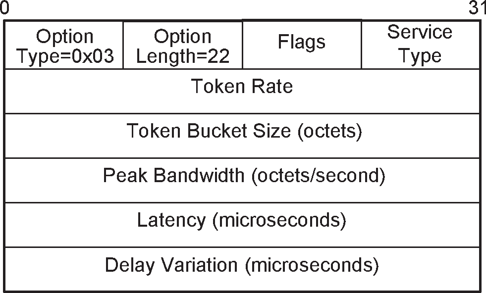
The option data fields are:
Flags (1 octet)
Reserved for future use.
Service Type (1 octet)
This field indicates the level of service required. Table 5.1 defines the different services available. The default value is ‘Best effort’.
If ‘Best effort’ is selected, the remaining parameters should be treated as optional by the remote device. The remote device may choose to ignore the fields, try to satisfy the parameters but provide no response (QoS option omitted in the Response message), or respond with the settings it will try to meet.
If ‘No traffic’ is selected, the remainder of the fields shall be ignored because there is no data being sent across the channel in the outgoing direction.
Value
Description
0x00
No traffic
0x01
Best effort (Default)
0x02
Guaranteed
Other
Reserved for future use
Table 5.1: Service type definitionsToken Rate (4 octets)
The value of this field represents the average data rate with which the application transmits data. The application may send data at this rate continuously. On a short time scale the application may send data in excess of the average data rate, dependent on the specified Token Bucket Size and Peak Bandwidth (see below). The Token Bucket Size and Peak Bandwidth allow the application to transmit data in a 'bursty' fashion.
The Token Rate signaled between two L2CAP peers is the data transmitted by the application and shall exclude the L2CAP protocol overhead. The Token Rate signaled over the interface between L2CAP and the Link Manager shall include the L2CAP protocol overhead. Furthermore the Token Rate value signaled over this interface may also include the aggregation of multiple L2CAP channels onto the same ACL logical transport.
The Token Rate is the rate with which traffic credits are provided. Credits can be accumulated up to the Token Bucket Size. Traffic credits are consumed when data is transmitted by the application. When traffic is transmitted, and there are insufficient credits available, the traffic is non-conformant. The Quality of Service guarantees are only provided for conformant traffic. For non-conformant traffic there may be insufficient resources such as bandwidth and buffer space. Furthermore non-conformant traffic may violate the QoS guarantees of other traffic flows.
The Token Rate is specified in octets per second. The value 0x00000000 indicates no token rate is specified. This is the default value and means “do not care”. When the Guaranteed service is selected, the default value shall not be used. The value 0xFFFFFFFF is a wild card matching the maximum token rate available. The meaning of this value depends on the service type. For best effort, the value is a hint that the application wants as much bandwidth as possible. For Guaranteed service the value represents the maximum bandwidth available at the time of the request.
Token Bucket Size (4 octets)
The Token Bucket Size specifies a limit on the 'burstiness' with which the application may transmit data. The application may offer a burst of data equal to the Token Bucket Size instantaneously, limited by the Peak Bandwidth (see below). The Token Bucket Size is specified in octets.
The Token Bucket Size signaled between two L2CAP peers is the data transmitted by the application and shall exclude the L2CAP protocol overhead. The Token Bucket Size signaled over the interface between L2CAP and Link Manager shall include the L2CAP protocol overhead. Furthermore the Token Bucket Size value over this interface may include the aggregation of multiple L2CAP channels onto the same ACL logical transport.
The value of 0x00000000 means that no token bucket is needed; this is the default value. When the Guaranteed service is selected, the default value shall not be used. The value 0xFFFFFFFF is a wild card matching the maximum token bucket available. The meaning of this value depends on the service type. For best effort, the value indicates the application wants a bucket as big as possible. For Guaranteed service the value represents the maximum L2CAP SDU size.
The Token Bucket Size is a property of the traffic carried over the L2CAP channel. The Maximum Transmission Unit (MTU) is a property of an L2CAP implementation. For the Guaranteed service the Token Bucket Size shall be smaller or equal to the MTU.
Peak Bandwidth (4 octets)
The value of this field, expressed in octets per second, limits how fast packets from applications may be sent back-to-back. Some systems can take advantage of this information, resulting in more efficient resource allocation.
The Peak Bandwidth signaled between two L2CAP peers specifies the data transmitted by the application and shall exclude the L2CAP protocol overhead. The Peak Bandwidth signaled over the interface between L2CAP and Link Manager shall include the L2CAP protocol overhead. Furthermore the Peak Bandwidth value over this interface may include the aggregation of multiple L2CAP channels onto the same ACL logical transport.
The value of 0x00000000 means "don't care." This states that the device has no preference on incoming maximum bandwidth, and is the default value. When the Guaranteed service is selected, the default value shall not be used.
Access Latency (4 octets)
The value of this field is the maximum acceptable delay of an L2CAP packet to the air-interface. The precise interpretation of this number depends on over which interface this flow parameter is signaled. When signaled between two L2CAP peers, the Access Latency is the maximum acceptable delay between the instant when the L2CAP SDU is received from the upper layer and the start of the L2CAP SDU transmission over the air. When signaled over the interface between L2CAP and the Link Manager, it is the maximum delay between the instant the first fragment of an L2CAP PDU is stored in the Controller buffer and the initial transmission of the L2CAP packet on the air.
Thus the Access Latency value may be different when signaled between L2CAP and the Link Manager to account for any queuing delay at the L2CAP transmit side. Furthermore the Access Latency value may include the aggregation of multiple L2CAP channels onto the same ACL logical transport.
The Access Latency is expressed in microseconds. The value 0xFFFFFFFF means “do not care” and is the default value. When the Guaranteed service is selected, the default value shall not be used.
Delay Variation (4 octets)
The value of this field is the difference, in microseconds, between the maximum and minimum possible delay of an L2CAP SDU between two L2CAP peers. The Delay Variation is a purely informational parameter. The value 0xFFFFFFFF means “do not care” and is the default value.
5.4. Retransmission and Flow Control option
This option specifies whether retransmission and flow control is used. If the feature is used both incoming and outgoing parameters are specified by this option. The Retransmission and Flow Control option contains both negotiable parameters and non-negotiable parameters. The mode parameter controls both incoming and outgoing data flow (i.e. both directions have to agree) and is negotiable. The other parameters control incoming data flow and are non-negotiable. Figure 5.5 specifies the format of this option.
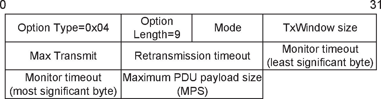
The option data fields are:
Mode (1 octet)
The field contains the requested mode of the link. Possible values are shown in Table 5.2.
Value
Description
0x00
L2CAP Basic Mode
0x01
Retransmission mode
0x02
Flow control mode
0x03
Enhanced Retransmission mode
0x04
Streaming mode
Other
Reserved for future use
Table 5.2: Mode definitionsThe Basic L2CAP mode is the default. If Basic L2CAP mode is requested then all other parameters shall be ignored.
Enhanced Retransmission mode should be enabled if a reliable channel has been requested. Enhanced Retransmission mode shall only be sent to an L2CAP entity that has previously advertised support for the mode in its Extended Feature Mask (see Section 4.12).
Streaming mode should be enabled if a finite L2CAP Flush Timeout is set on an L2CAP connection. Streaming mode shall only be sent to a device that has previously advertised support for the mode in the Extended Feature Mask (see Section 4.12).
Flow Control mode and Retransmission mode shall only be used for backwards compatibility with L2CAP entities that do not support Enhanced Retransmission mode or Streaming mode.
TxWindow size (1 octet)
This field specifies the size of the transmission window for Flow Control mode, Retransmission mode, and Enhanced Retransmission mode. The range is 1 to 32 for Flow Control mode and Retransmission mode. The range is 1 to 63 for Enhanced Retransmission mode.
In Retransmission mode and Flow Control mode this parameter should be negotiated to reflect the buffer sizes allocated for the connection on both sides. In general, the Tx Window size should be made as large as possible to maximize channel utilization. Tx Window size also controls the delay on flow control action. The transmitting device can send as many PDUs fit within the window.
In Enhanced Retransmission mode this value indicates the maximum number of I-frames that the sender of the option can receive without acknowledging some of the received frames. It is not negotiated. It is an informational parameter that each L2CAP entity can specify separately. In general, the TxWindow size should be made as large as possible to maximize channel utilization. The transmitting L2CAP entity can send as many PDUs as will fit within the receiving L2CAP entity's TxWindow. TxWindow size values in an L2CAP_CONFIGURATION_RSP packet indicate the maximum number of packets the sender can send before it requires an acknowledgment. In other words it represents the number of unacknowledged packets the send can hold. The value sent in an L2CAP_CONFIGURATION_RSP packet shall be less than or equal to the TxWindow size sent in the L2CAP_CONFIGURATION_REQ packet. The receiver of this option in the L2CAP_CONFIGURATION_RSP packet may use this value as part of its acknowledgment algorithm.
In Streaming mode this value is reserved for future use.
MaxTransmit (1 octet)
This field controls the number of transmissions of a single I-frame that L2CAP is allowed to try in Retransmission mode and Enhanced Retransmission mode. The minimum value is 1 (one transmission is permitted).
MaxTransmit controls the number of retransmissions that L2CAP is allowed to try in Retransmission mode and Enhanced Retransmission mode before accepting that a packet and the channel is lost. When a packet is lost after being transmitted MaxTransmit times the channel shall be disconnected by sending a Disconnect request (see Section 4.6). In Enhanced Retransmission mode MaxTransmit controls the number of retransmissions for I-frames and S-frames with P-bit set to 1. The sender of the option in an L2CAP_CONFIGURATION_REQ packet specifies the value that shall be used by the receiver of the option. MaxTransmit values in an L2CAP_CONFIGURATION_RSP packet shall be ignored. Lower values might be appropriate for services requiring low latency. Higher values will be suitable for a link requiring robust operation. A value of 1 means that no retransmissions will be made but also means that the channel will be disconnected as soon as a packet is lost. MaxTransmit shall not be set to zero in Retransmission mode. In Enhanced Retransmission mode a value of zero for MaxTransmit means infinite retransmissions.
In Streaming mode this value is reserved for future use.
Retransmission timeout (2 octets)
This is the value in milliseconds of the retransmission timeout (this value is used to initialize the RetransmissionTimer).
The purpose of this timer in retransmission mode is to activate a retransmission in some exceptional cases. In such cases, any delay requirements on the channel may be broken, so the value of the timer should be set high enough to avoid unnecessary retransmissions due to delayed acknowledgments. Suitable values could be 100’s of milliseconds and up.
The purpose of this timer in flow control mode is to supervise I-frame transmissions. If an acknowledgment for an I-frame is not received within the time specified by the RetransmissionTimer value, either because the I-frame has been lost or the acknowledgment has been lost, the timeout will cause the transmitting side to continue transmissions. Suitable values are implementation dependent.
The purpose of this timer in Enhanced Retransmission mode is to detect lost I-frames and initiate appropriate error recovery. The value used for the Retransmission timeout is specified in Section 8.6.2. The value sent in an L2CAP_CONFIGURATION_REQ packet is also specified in Section 8.6.2. A value for the Retransmission timeout shall be sent in a positive L2CAP_CONFIGURATION_RSP packet and indicates the value that will be used by the sender of the L2CAP_CONFIGURATION_RSP packet.
In Streaming mode this value is reserved for future use.
Monitor timeout (2 octets)
In Retransmission mode this is the value in milliseconds of the interval at which S-frames should be transmitted on the return channel when no frames are received on the forward channel. (this value is used to initialize the MonitorTimer, see below).
This timer ensures that lost acknowledgments are retransmitted. Its main use is to recover Retransmission Disable Bit changes in lost frames when no data is being sent. The timer shall be started immediately upon transitioning to the open state. It shall remain active as long as the connection is in the open state and the retransmission timer is not active. Upon expiration of the Monitor timer an S-frame shall be sent and the timer shall be restarted. If the monitor timer is already active when an S-frame is sent, the timer shall be restarted. An idle connection will have periodic monitor traffic sent in both directions. The value for this timeout should also be set to 100’s of milliseconds or higher.
In Enhanced Retransmission mode the Monitor timeout is used to detect lost S-frames with P-bit set to 1. If the timeout occurs before a response with the F-bit set to 1 is received the S-frame is resent. The value used for the Monitor timeout is specified in Section 8.6.3. The value sent in an L2CAP_CONFIGURATION_REQ packet is also specified in Section 8.6.2. A value for the Monitor timeout shall be sent in a positive L2CAP_CONFIGURATION_RSP packet and indicates the value that will be used by the sender of the L2CAP_CONFIGURATION_RSP packet.
In Streaming mode this value is reserved for future use.
Maximum PDU payload Size - MPS (2 octets)
The maximum payload size that the L2CAP layer entity sending the option in an L2CAP_CONFIGURATION_REQ packet is capable of accepting, i.e. the MPS corresponds to the maximum PDU payload size. Each device specifies the value separately. An MPS value sent in a positive L2CAP_CONFIGURATION_RSP packet is the actual MPS the receiver of the L2CAP_CONFIGURATION_REQ packet will use on this channel for traffic flowing into the local device. An MPS value sent in a positive L2CAP_CONFIGURATION_RSP packet shall be equal to or smaller than the value sent in the L2CAP_CONFIGURATION_REQ packet.
When using Retransmission mode and Flow Control mode the settings are configured separately for the two directions of an L2CAP connection. For example, in operating with an L2CAP entity implementing a lower version of the specification, an L2CAP connection can be configured as Flow Control mode in one direction and Retransmission mode in the other direction. If Basic L2CAP mode is configured in one direction and Retransmission mode or Flow control mode is configured in the other direction on the same L2CAP channel then the channel shall not be used.
Note
Note: This asymmetric configuration only occurs during configuration.
When using Enhanced Retransmission mode or Streaming mode, both directions of the L2CAP connection shall be configured to the same mode. A precedence algorithm shall be used by both devices so a mode conflict can be resolved in a quick and deterministic manner.
There are two operating states:
A device has a preferred mode but is willing to use another mode (known as "state 1"), and
A device requires a specific mode (known as "state 2"). This includes cases where channels are created over ACL-U logical links operating as described in Section 7.10.
In state 1, Basic L2CAP mode has the highest precedence and shall take precedence over Enhanced Retransmission mode and Streaming mode. Enhanced Retransmission mode has the second highest precedence and shall take precedence over all other modes except Basic L2CAP mode. Streaming mode shall have the next level of precedence after Enhanced Retransmission mode.
In state 2, a layer above L2CAP requires Enhanced Retransmission mode or Streaming mode. In this case, the required mode takes precedence over all other modes.
A device does not know in which state the remote device is operating so the state 1 precedence algorithm assumes that the remote device may be a state 2 device. If the mode proposed by the remote device has a higher precedence (according to the state 1 precedence) then the algorithm will operate such that creation of a channel using the remote device's mode has higher priority than disconnecting the channel.
The algorithm for state 1 devices is divided into two parts. Part one covers the case where the remote device proposes a mode with a higher precedence than the state 1 local device. Part two covers the case where the remote device proposes a mode with a lower precedence than the state 1 local device. Part one of the algorithm is as follows:
When the remote device receives the L2CAP_CONFIGURATION_REQ packet from the local device it will either reject the local device's L2CAP_CONFIGURATION_REQ packet by sending a negative L2CAP_CONFIGURATION_RSP packet or disconnect the channel. The negative L2CAP_CONFIGURATION_RSP packet will contain the remote device's desired mode.
Upon receipt of the negative L2CAP_CONFIGURATION_RSP packet the local device shall either send a second L2CAP_CONFIGURATION_REQ packet proposing the mode contained in the remote device's negative L2CAP_CONFIGURATION_RSP packet or disconnect the channel.
When the local device receives the L2CAP_CONFIGURATION_REQ packet from the remote device it shall send a positive L2CAP_CONFIGURATION_RSP packet or disconnect the channel.
If the mode in the remote Device's negative L2CAP_CONFIGURATION_RSP packet does not match the mode in the remote device's L2CAP_CONFIGURATION_REQ packet then the local device shall disconnect the channel.
Part two of the algorithm is as follows:
When the local device receives the L2CAP_CONFIGURATION_REQ packet from the remote device it shall reject the L2CAP_CONFIGURATION_REQ packet by sending a negative L2CAP_CONFIGURATION_RSP packet proposing its desired mode. The local device's desired mode shall be the same mode it sent in its L2CAP_CONFIGURATION_REQ packet. Upon receiving the negative L2CAP_CONFIGURATION_RSP packet the remote device will either send a second L2CAP_CONFIGURATION_REQ packet or disconnect the channel.
If the local device receives a second L2CAP_CONFIGURATION_REQ packet from the remote device that does not contain the desired mode then the local device shall disconnect the channel.
If the local device receives a negative L2CAP_CONFIGURATION_RSP packet then it shall disconnect the channel.
An example of the algorithm for state 1 devices is as follows:
The remote device proposes Basic L2CAP mode in an L2CAP_CONFIGURATION_REQ packet and the local device proposes Enhanced Retransmission mode or Streaming mode. The remote device rejects the local device's L2CAP_CONFIGURATION_REQ packet by sending a negative L2CAP_CONFIGURATION_RSP packet proposing Basic mode. The local device will send a second L2CAP_CONFIGURATION_REQ packet proposing Basic L2CAP mode or disconnect the channel. If the local device sends a second L2CAP_CONFIGURATION_REQ packet that does not propose Basic L2CAP mode then the remote device will disconnect the channel. If the local device rejects the remote device's L2CAP_CONFIGURATION_REQ packet then the remote device will disconnect the channel.
The algorithm for state 2 devices is as follows:
If the local device proposes a mode in an L2CAP_CONFIGURATION_REQ packet and the remote device proposes a different mode or rejects the local device's L2CAP_CONFIGURATION_REQ packet then the local device shall disconnect the channel.
For Enhanced Retransmission mode and Streaming mode the Retransmission timeout and Monitor Timeout parameters of the Retransmission and Flow Control option parameters may be changed but all other parameters shall not be changed in a subsequent reconfiguration after the channel has reached the OPEN state.
5.5. Frame Check Sequence (FCS) option
This option is used to specify the type of Frame Check Sequence (FCS) that will be included on S/I-frames that are sent. It is non-negotiable. The FCS option shall only be used when the mode is configured to, or in an L2CAP_CONFIGURATION_REQ packet that contains an option configuring it to, Enhanced Retransmission mode or Streaming mode. This option shall only be used if the peer L2CAP entity has indicated support for the FCS Option in the Extended Features Mask (see Section 4.12).
Figure 5.6 specifies the format of this option. The Option Type is 0x05. "No FCS" shall only be used if both L2CAP entities send the FCS Option with value 0x00 (No FCS) in an L2CAP_CONFIGURATION_REQ packet. If one L2CAP entity sends the FCS Option with "No FCS" in an L2CAP_CONFIGURATION_REQ packet and the other L2CAP sends the FCS Option with a value other than "No FCS" then the default shall be used. If one or both L2CAP entities do not send the FCS option in an L2CAP_CONFIGURATION_REQ packet then the default shall be used.

The FCS types are shown in Table 5.3
Value | Description |
|---|---|
0x00 | No FCS |
0x01 | 16-bit FCS defined in section 3.3.5 (default) |
Other | Reserved for future use |
Value of 0x00 is set when the sender wishes to omit the FCS from S/I-frames.
5.6. Extended Flow Specification option
This option specifies a flow specification for requesting a desired Quality of Service (QoS) on a channel. It is non-negotiable. Extended Flow Specification may be supported on channels created over ACL-U logical links (see Section 7.10). If both devices show support for Extended Flow Specification for BR/EDR in the Extended Feature mask (see Table 4.12) then all channels created between the two devices shall use an Extended Flow Specification. The Quality of Service option and Flush Timeout option shall not be used if the Extended Flow Specification is used.
The parameters in the Extended Flow Specification option specify the traffic stream in the outgoing direction (transmitted traffic). The Option Type is 0x06. Figure 5.7 specifies the format of this option.
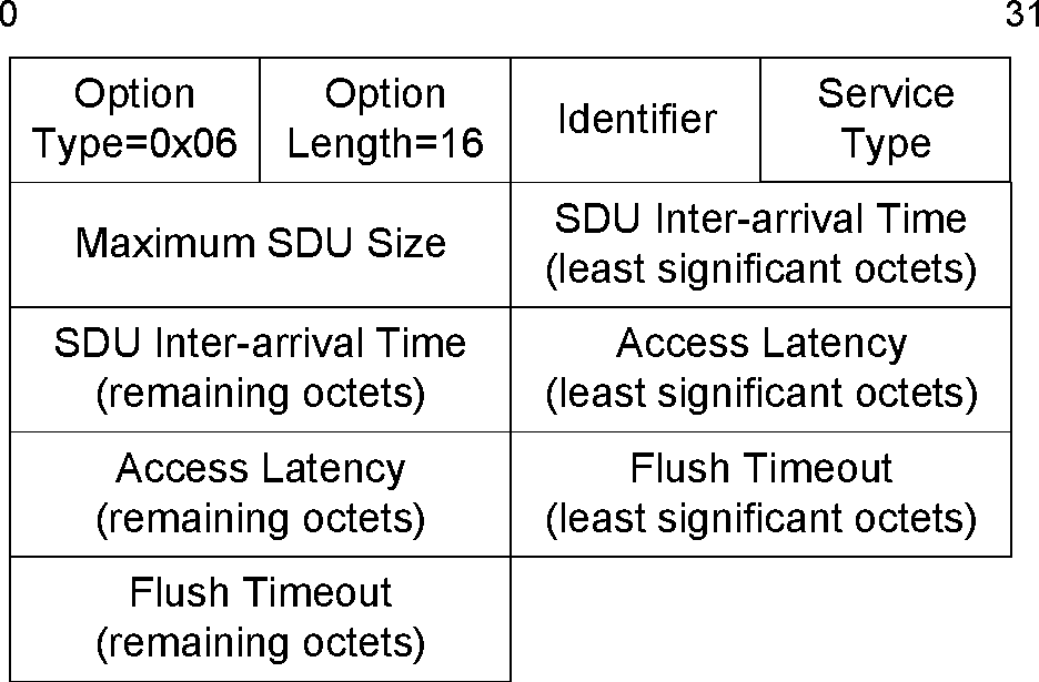
If no Extended Flow Specification is provided by the upper layer, an Extended Flow Specification with following default values shall be used:
Qos Parameter | Default Value |
|---|---|
Identifier | 0x01 |
Service Type | Best Effort |
Maximum SDU size | 0xFFFF |
SDU Inter-arrival Time | 0xFFFFFFFF |
Access Latency | 0xFFFFFFFF |
Flush Timeout | 0xFFFFFFFF |
For a Best Effort channel no latency, air-time or bandwidth guarantees shall be assumed.
The parameters of the Extended Flow Specification are shown in Table 5.5:
QoS parameter | Parameter Size in Octets | Unit |
|---|---|---|
Identifier | 1 | na |
Service Type | 1 | na |
Maximum SDU Size | 2 | octets |
SDU Inter-arrival Time | 4 | microseconds |
Access Latency | 4 | microseconds |
Flush Timeout | 4 | microseconds |
Identifier (1 octet)
This field provides a unique identifier for the flow specification. This identifier is used by some Controllers in the process of setting up the QoS request. Each active flow specification sent by a device to configure an L2CAP channel shall have a unique Identifier. An Identifier can be reused when the L2CAP channel associated with the flow spec is disconnected. The Identifier shall be unique within the scope of a physical link. Extended Flow Specifications for channels on different physical links may have the same Identifier. The Identifier for an Extended Flow Specification with Service Type Best Effort shall be 0x01.
Since the Identifier for an Extended Flow Specification with Service Type Best Effort is fixed to 0x01 it is possible to generate a Best Effort Extended Flow Specification for the remote device without performing the Lockstep Configuration process. (The Lockstep Configuration process is described in Section 7.1.3).
Service Type (1 octet)
This field indicates the level of service required. Table 5.6 defines the different Service Types values. The default value is 'Best effort'. If 'Best effort' is selected then Access Latency and Flush Timeout shall both be set to 0xFFFFFFFF. Maximum SDU size and SDU Inter-arrival Time are used to indicate the maximum data rate that the application can deliver to L2CAP for transmission. The remote device should respond with lower settings indicating the maximum rate at which it can receive data (for example, maximum rate data it can write to a mass storage device, etc.). Values of 0xFFFF for Maximum SDU size and 0xFFFFFFFF for SDU Inter-arrival time are used when the actual values are not known. If Maximum SDU size is set to 0xFFFF then SDU Inter-arrival time shall be set to 0xFFFFFFFF, if SDU Inter-arrival time is set to 0xFFFFFFFF then Maximum SDU size shall be set to 0xFFFF. This tells the Controller to allocate as much bandwidth as possible.
If “Guaranteed” is selected the QoS parameters can be used to identify different types of Guaranteed traffic.
Guaranteed bandwidth traffic is traffic with a minimum data rate but no particular latency requested. Latency will be related to the link supervision timeout. For this type of traffic Access Latency is set to 0xFFFFFFFF.
Guaranteed Latency traffic is traffic with only latency requirements. For this type of traffic SDU Inter-arrival time is set to 0xFFFFFFFF. HID interrupt channel and AVRCP are examples of this type of traffic.
Both Guaranteed Latency and Bandwidth traffic has both a latency and bandwidth requirement. An example is Audio/Video streaming.
If 'No Traffic' is selected the remainder of the fields shall be ignored because there is no data being sent across the channel in the outgoing direction.
Value | Description |
|---|---|
0x00 | No Traffic |
0x01 | Best effort (Default) |
0x02 | Guaranteed |
Other | Reserved for future use |
A channel shall not be configured as “Best Effort” in one direction and “Guaranteed” in the other direction. If a channel is configured in this way it shall be disconnected. A channel may be configured as “No Traffic” in one direction and “Best Effort” in the other direction. The “No Traffic” refers to the application traffic not the Enhanced Retransmission mode supervisory traffic. A channel configured in this way is considered to have a service type of Best Effort. A channel may be configured as “No Traffic” in one direction and “Guaranteed” in the other direction. A channel configure in this way is considered to have a service type of Guaranteed.
Once configured the service type of a channel shall not be changed during reconfiguration.
Maximum SDU Size (2 octets)
The Maximum SDU Size parameter specifies the maximum size of the SDUs transmitted by the application. If the Service Type is “Guaranteed” then traffic submitted to L2CAP with a larger size is considered non-conformant. QoS guarantees are only provided for conformant traffic.
SDU Inter-arrival time (4 octets)
The SDU Inter-arrival time parameter specifies the time between consecutive SDUs generated by the application. For streaming traffic, SDU Inter-arrival time should be set to the average time between SDUs. For variable rate traffic and best effort traffic, SDU Inter-arrival time should be set to the minimum time between SDUs. If the Service Type is “Guaranteed” then traffic submitted to L2CAP with a smaller interval, is considered non-conformant. QoS guarantees are only provided for conformant traffic.
Access Latency (4 octets)
The Access Latency parameter specifies the maximum delay between consecutive transmission opportunities on the air-interface for the connection. Access latency is based on the time base of the Controller, which is not necessarily synchronous to the time base being used by the Host or the application.
For streaming traffic (such as in A2DP), the Access Latency should be set to indicate the time budgeted for transmission of the data over the air, and would normally be roughly equal to the Flush Timeout minus the duration of streaming data which can be stored in the receive side application buffers.
For non-streaming, bursty traffic (such as in HID and AVRCP), the Access Latency parameter value sent in the L2CAP_CONFIGURATION_REQ packet should be set to the desired latency, minus any HCI transport delays and any other stack delays that may be expected on the device and on target Host systems. The remote device receiving the L2CAP_CONFIGURATION_REQ packet may send an Access Latency parameter value in the L2CAP_CONFIGURATION_RSP packet which is equal to or lower than the value it received. The remote device may send a lower value to account for other traffic it may be carrying, or overhead activities it may be carrying out.
If HCI is used then the Host should take into account the latency of the HCI transport when determining the value for the Access Latency. For example if the application requires an Access Latency of 20 ms and the HCI transport has a latency of 5 ms then the value for Access Latency should be 15 ms.
Flush Timeout (4 Octets)
The Flush Timeout defines a maximum period after which all segments of the SDU are flushed from L2CAP and the Controller. A Flush Timeout value of 0xFFFFFFFF indicates that data will not be discarded by the transmitting side, even if the link becomes congested, and thus in this case data is treated as reliable and is never flushed.
The device receiving the L2CAP_CONFIGURATION_REQ packet with Flush Timeout set to 0xFFFFFFFF should not modify this parameter. The Flush Timeout for a “Best Effort” channel shall be set to 0xFFFFFFFF.
However, if the Traffic Type is “Guaranteed” and the transmit side buffer is limited, then the Flush Timeout parameter given in the L2CAP_CONFIGURATION_REQ packet may be set to a value corresponding to the duration of streaming data which the transmit buffer can hold before it must begin discarding data. The side receiving the L2CAP_CONFIGURATION_REQ packet may then set the Flush Timeout parameter in the L2CAP_CONFIGURATION_RSP packet to a lower value if the receive side buffer is smaller than the transmit side buffer.
Note
Note: The total available buffer space is typically a combination of application buffers, any buffers maintained by the L2CAP implementation, and HCI buffers provided by the Controller.
The Flush Timeout should normally be set to a value which is larger than the Access Latency, and which also accounts for buffers maintained by the application on the receive side such as de-jitter buffers used in audio and video streaming applications. In general, the Flush Timeout value should be selected to ensure that the Flush Timeout expires when the application buffers are about to be exhausted.
Flush Timeout may be set to 0x00000000 to indicate that no retransmissions are to occur. Data may be flushed immediately after transmission in this case. This behavior is useful in applications such as gaming where the tolerable latency is on the order of a few milliseconds, and hence the information contained in a packet will become stale very rapidly. In such applications, it is preferable to send “fresher” data if the last SDU submitted for transmission was not transmitted as a result of interference.
5.7. Extended Window Size option
This option is used to negotiate the maximum extended window size. The Option Type is 0x07 and the option is non-negotiable. Figure 5.8 specifies the format of this option.

The allowable values for the Maximum Extended Window Size are:
Value | Description |
|---|---|
0x0000 | Invalid value for Enhanced Retransmission mode Valid for Streaming mode |
0x0001 to 0x3FFF | Valid maximum window size (frames) for Enhanced Retransmission mode. Invalid for Streaming mode |
Other | Reserved for future use |
This option shall only be sent if the peer L2CAP entity has indicated support for the Extended Window size feature in the Extended Features Mask (see Section 4.12).
This option shall be ignored if the channel is configured to use Basic L2CAP Mode (see Section 5.4).
For Enhanced Retransmission mode, this option has the same directional semantics as the Retransmission and Flow Control option (see Section 5.4). The sender of an L2CAP_CONFIGURATION_REQ packet containing this option is suggesting the maximum window size (possibly based on its own internal L2CAP receive buffer resources) that the peer L2CAP entity should use when sending data.
For Streaming mode, this option is used to enable use of the Extended Control Field and if sent, shall have a value of 0.
If this option is successfully configured then the Maximum Window Size negotiated using the Retransmission and Flow Control option (see Section 5.4) shall be ignored.
If this option is successfully configured in either direction then both L2CAP entities shall use the Extended Control Fields in all S/I-frames (see Section 3.3.2).
If the option is only configured in one direction then the maximum window size for the opposite direction shall be taken from the maximum window size value in the existing Retransmission and Flow Control option. In this configuration both L2CAP entities shall use the extended control fields in all S/I-frames.
6. State machine
The state machine does not necessarily represent all possible scenarios.
6.1. General rules for the state machine
It is implementation specific, and outside the scope of the specification, how the transmissions are triggered.
“Ignore” means that the signal can be silently discarded.
The following states have been defined to clarify the protocol; the actual number of states and naming in a given implementation is outside the scope of the specification:
CLOSED – channel not connected.
WAIT_CONNECT – a connection request has been received, but only a connection response with indication “pending” can be sent.
WAIT_CONNECT_RSP – a connection request has been sent, pending a positive connect response.
CONFIG – the different options are being negotiated for both sides; this state comprises a number of substates, see Section 6.1.3
OPEN – user data transfer state.
WAIT_DISCONNECT – a disconnect request has been sent, pending a disconnect response.
In the following state tables and descriptions, the L2CAP_Data message corresponds to one of the PDU formats used on connection-oriented data channels as described in Section 3, including PDUs containing B-frames, I-frames, or S-frames.
Some state transitions and actions are triggered only by internal events effecting one of the L2CAP entity implementations, not by preceding L2CAP signaling messages. It is implementation-specific and out of the scope of the specification, how these internal events are realized; just for the clarity of specifying the state machine, the following abstract internal events are used in the state event tables, as far as needed:
OpenChannel_Req – a local L2CAP entity is requested to set up a new connection-oriented channel.
OpenChannel_Rsp – a local L2CAP entity is requested to finally accept or refuse a pending connection request.
ConfigureChannel_Req – a local L2CAP entity is requested to initiate an outgoing configuration request.
CloseChannel_Req – a local L2CAP entity is requested to close a channel.
SendData_Req – a local L2CAP entity is requested to transmit an SDU.
ReconfigureChannel_Req – a local L2CAP entity is requested to reconfigure the parameters of a connection-oriented channel.
ControllerLogicalLinkInd – a Controller indicates the acceptance or rejection of a logical link request with an Extended Flow Specification.
There is a single state machine for each L2CAP connection-oriented channel that is active. A state machine is created for each new L2CAP_ConnectReq received. The state machine always starts in the CLOSED state.
To simplify the state event tables, the RTX and ERTX timers, as well as the handling of request retransmissions are described in Section 6.2 and not included in the state tables.
L2CAP messages not bound to a specific data channel and thus not impacting a channel state (e.g. L2CAP_InformationReq, L2CAP_EchoReq) are not covered in this section.
The following states and transitions are illustrated in Figure 6.1.
6.1.1. CLOSED state
Event | Condition | Action | Next State |
|---|---|---|---|
OpenChannel_req | - | Send L2CAP_ConnectReq | WAIT_CONNECT_RSP |
L2CAP_ConnectReq | Normal, connection is possible | Send L2CAP_ConnectRsp (success) | CONFIG (substate WAIT_CONFIG) |
L2CAP_ConnectReq | Need to indicate pending | Send L2CAP_ConnectRsp (pending) | WAIT_CONNECT |
L2CAP_ConnectReq | No resource, not approved, etc. | Send L2CAP_ConnectRsp (refused) | CLOSED |
L2CAP_ConnectRsp | - | Ignore | CLOSED |
L2CAP_ConfigReq | - | Send L2CAP_CommandReject (with reason Invalid CID) | CLOSED |
L2CAP_ConfigRsp | - | Ignore | CLOSED |
L2CAP_DisconnectReq | - | Send L2CAP_DisconnectRsp | CLOSED |
L2CAP_DisconnectRsp | - | Ignore | CLOSED |
L2CAP_Data | - | Ignore | CLOSED |
Note
Notes. The L2CAP_ConnectReq message is not mentioned in any of the other states apart from the CLOSED state, as it triggers the establishment of a new channel, thus the branch into a new instance of the state machine.
6.1.2. WAIT_CONNECT_RSP state
Event | Condition | Action | Next State |
|---|---|---|---|
L2CAP_ConnectRsp | Success indicated in result | Send L2CAP_ConfigReq | CONFIG (substate WAIT_CONFIG) |
L2CAP_ConnectRsp | Result pending | - | WAIT_CONNECT_RSP |
L2CAP_ConnectRsp | Remote side refuses connection | - | CLOSED |
L2CAP_ConfigReq | - | Send L2CAP_CommandReject (with reason Invalid CID) | WAIT_CONNECT_RSP |
L2CAP_ConfigRsp | - | Ignore | WAIT_CONNECT_RSP |
L2CAP_DisconnectRsp | - | Ignore | WAIT_CONNECT_RSP |
L2CAP_Data | - | Ignore | WAIT_CONNECT_RSP |
Note
Notes. An L2CAP_DisconnectReq message is not included here, since the Source and Destination CIDs are not available yet to relate it correctly to the state machine of a specific channel.
6.1.3. WAIT_CONNECT state
Event | Condition | Action | Next State |
|---|---|---|---|
OpenChannel_Rsp | Pending connection request is finally acceptable | Send L2CAP_Connect_Rsp (success) | CONFIG (substate WAIT_CONFIG) |
OpenChannel_Rsp | Pending connection request is finally refused | Send L2CAP_Connect_Rsp (refused) | CLOSED |
L2CAP_ConnectRsp | - | Ignore | WAIT_CONNECT |
L2CAP_ConfigRsp | - | Ignore | WAIT_CONNECT |
L2CAP_DisconnectRsp | - | Ignore | WAIT_CONNECT |
L2CAP_Data | - | Ignore | WAIT_CONNECT |
Note
Notes. An L2CAP_DisconnectReq or L2CAP_ConfigReq message is not included here, since the Source and Destination CIDs are not available yet to relate it correctly to the state machine of a specific channel.
6.1.4. CONFIG state
Two configuration processes exist as described in Section 7.1. The configuration processes are the Standard process and the Lockstep process.
In the Standard and Lockstep configuration processes both L2CAP entities initiate a configuration request during the configuration process. This means that each device adopts an initiator role for the outgoing configuration request, and an acceptor role for the incoming configuration request. Configurations in both directions may occur sequentially, but can also occur in parallel.
In the Lockstep configuration process both L2CAP entities send L2CAP_CONFIGURATION_REQ packets and receive L2CAP_CONFIGURATION_RSP packets with a pending result code before submitting the flow specifications to their local Controllers. A final L2CAP_CONFIGURATION_RSP packet is sent by each L2CAP entity indicating the response from its local Controller.
The following substates are distinguished within the CONFIG state:
WAIT_CONFIG – a device has sent or received a connection response, but has neither initiated a configuration request yet, nor received a configuration request with acceptable parameters.
WAIT_SEND_CONFIG – for the initiator path, a configuration request has not yet been initiated, while for the response path, a request with acceptable options has been received.
WAIT_CONFIG_REQ_RSP – for the initiator path, a request has been sent but a positive response has not yet been received, and for the acceptor path, a request with acceptable options has not yet been received.
WAIT_CONFIG_RSP – the acceptor path is complete after having responded to acceptable options, but for the initiator path, a positive response on the recent request has not yet been received.
WAIT_CONFIG_REQ – the initiator path is complete after having received a positive response, but for the acceptor path, a request with acceptable options has not yet been received.
WAIT_IND_FINAL_RSP – for both the initiator and acceptor, the Extended Flow Specification has been sent to the local Controller but neither a response from Controller nor the final configuration response has yet been received.
WAIT_FINAL_RSP – the device received an indication from the Controller accepting the Extended Flow Specification and has sent a positive response. It is waiting for the remote device to send a configuration response.
WAIT_CONTROL_IND – the device has received a positive response and is waiting for its Controller to accept or reject the Extended Flow Specification.
According to Section 6.1.1 and Section 6.1.2, the CONFIG state is entered via WAIT_CONFIG substate from either the CLOSED state, the WAIT_CONNECT state, or the WAIT_CONNECT_RSP state. The CONFIG state is left for the OPEN state if both the initiator and acceptor paths complete successfully.
For better overview, separate tables are given: Table 6.4 shows the success transitions; therein, transitions on one of the minimum paths (no previous non-success transitions) are shaded. Table 6.5 shows the non-success transitions within the configuration process, and Table 6.6 shows further transition cause by events not belonging to the configuration process itself. The following configuration states and transitions are illustrated in Figure 6.2.
Previous state | Event | Condition | Action | Next State |
|---|---|---|---|---|
WAIT_CONFIG | ConfigureChannel_ Req | Standard process | Send L2CAP_ConfigReq | WAIT_CONFIG_REQ_RSP |
WAIT_CONFIG | ConfigureChannel_ Req | Lockstep process | Send L2CAP_Config Req (Ext Flow Spec plus other options) | WAIT_CONFIG_REQ_RSP |
WAIT_CONFIG | L2CAP_ConfigReq | Options acceptable Standard process | Send L2CAP_ConfigRsp (success) | WAIT_SEND_CONFIG |
WAIT_CONFIG | L2CAP_ConfigReq | Options acceptable Lockstep process | Send L2CAP_ConfigRsp (pending) | WAIT_SEND_CONFIG |
WAIT_CONFIG_REQ_RSP | L2CAP_ConfigReq | Options acceptable | Send L2CAP_ConfigRsp (success) | WAIT_CONFIG_RSP |
WAIT_CONFIG_REQ_RSP | L2CAP_ConfigRsp | Remote side accepts options | (continue waiting for configuration request) | WAIT_CONFIG_REQ |
WAIT_CONFIG_REQ | L2CAP_ConfigReq | Options acceptable Standard process | Send L2CAP_ConfigRsp (success) | OPEN |
WAIT_CONFIG_REQ | L2CAP_ConfigReq | Options acceptable Lockstep process | Send L2CAP_ConfigRsp (pending) | WAIT_IND_FINAL_RSP |
WAIT_SEND_CONFIG | ConfigureChannel_ Req | none | Send L2CAP_ConfigReq | WAIT_CONFIG_RSP |
WAIT_CONFIG_RSP | L2CAP_ConfigRsp | Remote side accepts options Standard process | none | OPEN |
WAIT_CONFIG_RSP | L2CAP_ConfigRsp | Remote side accepts option Lockstep proc | none | WAIT_IND_FINAL_RSP |
WAIT_IND_FINAL_RSP | ControllerLogical LinkInd | Reject | Send L2CAP_ConfigRsp (fail) | WAIT_CONFIG |
WAIT_IND_FINAL_RSP | ControllerLogical LinkInd | Accept | Send L2CAP_ConfigRsp (success) | WAIT_FINAL_RSP |
WAIT_IND_FINAL_RSP | L2CAP_ConfigRsp | Remote side fail | none | WAIT_CONFIG |
WAIT_IND_FINAL_RSP | L2CAP_ConfigRsp | Remote side success | none | WAIT_CONTROL_IND |
WAIT_FINAL_RSP | L2CAP_ConfigRsp | Remote side fail | none | WAIT_CONFIG |
WAIT_FINAL_RSP | L2CAP_ConfigRsp | Remote side success | none | OPEN |
WAIT_CONTROL_IND | ControllerLogical LinkInd | Reject | Send L2CAP_ConfigRsp (fail) | WAIT_CONFIG |
WAIT_CONTROL_IND | ControllerLogical LinkInd | Accept | Send L2CAP_ConfigRsp (success) | OPEN |
Previous state | Event | Condition | Action | Next State |
|---|---|---|---|---|
WAIT_CONFIG | L2CAP_ConfigReq | Options not acceptable | Send L2CAP_ConfigRsp (fail) | WAIT_CONFIG |
WAIT_CONFIG | L2CAP_ConfigRsp | none | Ignore | WAIT_CONFIG |
WAIT_SEND_CONFIG | L2CAP_ConfigRsp | none | Ignore | WAIT_SEND_CONFIG |
WAIT_CONFIG_REQ_RSP | L2CAP_ConfigReq | Options not acceptable | Send L2CAP_ConfigRsp (fail) | WAIT_CONFIG_REQ_RSP |
WAIT_CONFIG_REQ_RSP | L2CAP_ConfigRsp | Remote side rejects options | Send L2CAP_ConfigReq (new options) | WAIT_CONFIG_REQ_RSP |
WAIT_CONFIG_REQ | L2CAP_ConfigReq | Options not acceptable | Send L2CAP_ConfigRsp (fail) | WAIT_CONFIG_REQ |
WAIT_CONFIG_REQ | L2CAP_ConfigRsp | none | Ignore | WAIT_CONFIG_REQ |
WAIT_CONFIG_RSP | L2CAP_ConfigRsp | Remote side rejects options | Send L2CAP_ConfigReq (new options) | WAIT_CONFIG_RSP |
Previous state | Event | Condition | Action | Next State |
|---|---|---|---|---|
CONFIG (any substate) | CloseChannel_Req | Any internal reason to stop | Send L2CAP_DisconnectReq | WAIT_DISCONNECT |
CONFIG (any substate) | L2CAP_DisconnectReq | none | Send L2CAP_DisconnectRsp | CLOSED |
CONFIG (any substate) | L2CAP_DisconnectRsp | none | Ignore | CONFIG (remain in substate) |
CONFIG (any substate) | L2CAP_Data | none | Process the PDU | CONFIG (remain in substate) |
Note
Notes:
Receiving data PDUs (L2CAP_Data) in CONFIG state should be relevant only in case of a transition to a reconfiguration procedure (from OPEN state). Discarding the received data is allowed only in Retransmission Mode and Enhanced Retransmission Mode. Discarding an S-frame is allowed but not recommended. If a S-frame is discarded, the monitor timer will cause a new S-frame to be sent after a time out.
Indicating a failure in a configuration response does not necessarily imply a failure of the overall configuration procedure; instead, based on the information received in the negative response, a modified configuration request may be triggered.
6.1.5. OPEN state
Event | Condition | Action | Next State |
|---|---|---|---|
SendData_req | none | Send L2CAP_Data packet according to configured mode | OPEN |
ReconfigureChannel_Req | none | Complete outgoing SDU Send L2CAP_ConfigReq | CONFIG (substate WAIT_CONFIG_REQ_RSP) |
CloseChannel_Req | none | Send L2CAP_DisconnectReq | WAIT_DISCONNECT |
L2CAP_ConnectRsp | none | Ignore | OPEN |
L2CAP_ConfigReq | Incoming config options acceptable | Complete outgoing SDU Send L2CAP_ConfigRsp (ok) | CONFIG (substate WAIT_SEND_CONFIG) |
L2CAP_ConfigReq | Incoming config options not acceptable | Complete outgoing SDU Send L2CAP_ConfigRsp (fail) | OPEN |
L2CAP_DisconnectReq | none | Send L2CAP_DisconnectRsp | CLOSED |
L2CAP_DisconnectRsp | none | Ignore | OPEN |
L2CAP_Data | none | Process the PDU | OPEN |
The outgoing SDU shall be completed from the view of the remote entity. Therefore all PDUs forming the SDU shall have been reliably transmitted by the local entity and acknowledged by the remote entity, before entering the configuration state.
6.1.6. WAIT_DISCONNECT state
Event | Condition | Action | Next State |
|---|---|---|---|
L2CAP_ConnectRsp | none | Ignore | WAIT_DISCONNECT |
L2CAP_ConfigReq | none | Send L2CAP_CommandReject with reason Invalid CID | WAIT_DISCONNECT |
L2CAP_ConfigRsp | none | Ignore | WAIT_DISCONNECT |
L2CAP_DisconnectReq | none | Send L2CAP_DisconnectRsp | CLOSED |
L2CAP_DisconnectRsp | none | none | CLOSED |
L2CAP_Data | none | Ignore | WAIT_DISCONNECT |
6.1.7. [This section is no longer used]
6.1.8. [This section is no longer used]
6.1.9. [This section is no longer used]
6.1.10. [This section is no longer used]
6.1.11. [This section is no longer used]
6.1.12. [This section is no longer used]
6.2. Timers events
6.2.1. RTX
The Response Timeout eXpired (RTX) timer is used to terminate the channel when the remote endpoint is unresponsive to signaling requests. This timer is started when a signaling request (see Section 7) is sent to the remote device. This timer is disabled when the response is received. If the initial timer expires, a duplicate Request message may be sent or the channel identified in the request may be disconnected. If a duplicate Request message is sent, the RTX timeout value shall be reset to a new value at least double the previous value. When retransmitting the Request message, the context of the same state shall be assumed as with the original transmission. If a Request message is received that is identified as a duplicate (retransmission), it shall be processed in the context of the same state which applied when the original Request message was received.
Implementations have the responsibility to decide on the maximum number of Request retransmissions performed at the L2CAP level before terminating the channel identified by the Requests. The exception is fixed channel CIDs since they can never be terminated. On the LE transport, the Peripheral's Host may disconnect the link on the expiry of the RTX timer. The decision should be based on the flush timeout of the signaling link. The longer the flush timeout, the more retransmissions may be performed at the physical layer and the reliability of the channel improves, requiring fewer retransmissions at the L2CAP level.
For example, if the flush timeout is infinite, no retransmissions should be performed at the L2CAP level. When terminating the channel, it is not necessary to send an L2CAP_DISCONNECTION_REQ and enter WAIT_DISCONNECT state. Channels can be transitioned directly to the CLOSED state.
The value of this timer is implementation-dependent but the minimum initial value is 1 second and the maximum initial value is 60 seconds. One RTX timer shall exist for each outstanding signaling request, including each L2CAP_ECHO_REQ. The timer disappears on the final expiration, when the response is received, or the physical link is lost. The maximum elapsed time between the initial start of this timer and the initiation of channel termination (if no response is received) is 60 seconds.
6.2.2. ERTX
The Extended Response Timeout eXpired (ERTX) timer is used in place of the RTX timer when it is suspected the remote endpoint is performing additional processing of a request signal. This timer is started when the remote endpoint responds that a request is pending, e.g., when an L2CAP_CONNECTION_RSP event with a “connect pending” result (0x0001) is received. This timer is disabled when the formal response is received or the physical link is lost. If the initial timer expires, a duplicate Request may be sent or the channel may be disconnected.
If a duplicate Request is sent, the particular ERTX timer disappears, replaced by a new RTX timer and the whole timing procedure restarts as described previously for the RTX timer.
The value of this timer is implementation-dependent but the minimum initial value is 60 seconds and the maximum initial value is 300 seconds. Similar to RTX, there shall be at least one ERTX timer for each outstanding request that received a Pending response. There should be at most one (RTX or ERTX) associated with each outstanding request. The maximum elapsed time between the initial start of this timer and the initiation of channel termination (if no response is received) is 300 seconds. When terminating the channel, it is not necessary to send an L2CAP_DISCONNECTION_REQ and enter WAIT_DISCONNECT state. Channels should be transitioned directly to the CLOSED state.

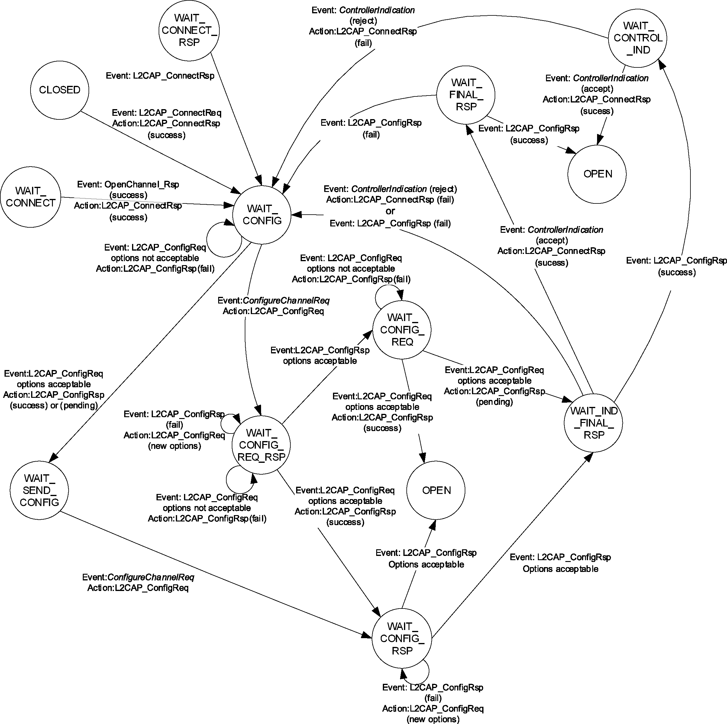
7. General procedures
This section describes the general operation of L2CAP, including the configuration process, the handling and the processing of user data for transportation over the air interface. This section also describes the operation of L2CAP features including the delivery of erroneous packets, the flushing of expired data and operation in connectionless mode, operation collision resolution, aggregation of best effort flow specifications, and prioritizing data over HCI.
Procedures for the flow control and retransmission modes are described in Section 8.
7.1. Configuration process
Configuration consists of two processes, the Standard process and the Lockstep process. The Lockstep process shall be used if both L2CAP entities support the Extended Flow Specification option otherwise the Standard process shall be used.
For both processes, configuring the channel parameters shall be done independently for both directions. Both configurations may be done in parallel.
Each configuration parameter is one-directional. The configuration parameters describe the non default parameters the device sending an L2CAP_CONFIGURATION_REQ packet will accept. The configuration request cannot request a change in the parameters the device receiving the request will accept.
If a device needs to establish the value of a configuration parameter the remote device will accept, then it must wait for an L2CAP_CONFIGURATION_REQ packet containing that configuration parameter to be sent from the remote device.
The Lockstep process is used when the channel parameters include an Extended Flow Specification option. The Lockstep process can be divided into two phases. In the first phase, each L2CAP entity shall receive an Extended Flow Specification option along with all non-default parameters from its peer L2CAP entity and then present the pair of Extended Flow specifications (local and remote) to its local Controller. In the second phase, each L2CAP entity shall report the result from its local Controller to the peer L2CAP entity. The Lockstep process is described in Section 7.1.3. The Standard process is described in Section 7.1.4.
Both the Lockstep and Standard processes can be abstracted into the initial Request configuration path and a Response configuration path, followed by the reverse direction phase. Reconfiguration follows a similar two-phase process by requiring configuration in both directions.
During a reconfiguration session, all data traffic on the channel should be suspended pending the outcome of the configuration. If an L2CAP entity receives an L2CAP_CONFIGURATION_REQ packet while it is waiting for a response it shall not block sending the L2CAP_CONFIGURATION_RSP packet, otherwise the configuration process may deadlock.
7.1.1. Request Path
The Request Path can configure the following:
requester’s incoming MTU
requester’s outgoing flush timeout
requester’s outgoing QoS
requester’s incoming and outgoing flow and error control information
requester's incoming and outgoing Frame Check Sequence option
requester's outgoing QoS using Extended Flow Specification option
requester's incoming Extended Window size option plus incoming and outgoing frame format.
Table 7.1 defines the configuration options that may be placed in an L2CAP_CONFIGURATION_REQ packet.
Parameter | Description | ||||||||||||||||||||||||||||||||||||||||||||||||
|---|---|---|---|---|---|---|---|---|---|---|---|---|---|---|---|---|---|---|---|---|---|---|---|---|---|---|---|---|---|---|---|---|---|---|---|---|---|---|---|---|---|---|---|---|---|---|---|---|---|
MTU | Incoming MTU information | ||||||||||||||||||||||||||||||||||||||||||||||||
FlushTO | Outgoing flush timeout[a] | ||||||||||||||||||||||||||||||||||||||||||||||||
QoS | Outgoing QoS information[a] | ||||||||||||||||||||||||||||||||||||||||||||||||
RFCMode | Incoming and outgoing Retransmission and Flow Control Mode | ||||||||||||||||||||||||||||||||||||||||||||||||
FCS | Incoming and outgoing Frame Check Sequence | ||||||||||||||||||||||||||||||||||||||||||||||||
ExtFlowSpec | Outgoing QoS information[a] | ||||||||||||||||||||||||||||||||||||||||||||||||
ExtWindow | Incoming Extended Window size plus incoming and outgoing frame format | ||||||||||||||||||||||||||||||||||||||||||||||||
[a] FlushTO, QoS and ExtFlowSpec are considered QoS information. ExtFlowSpec is used instead of FlushTO and QoS when both devices support ExtFlowSpec. | |||||||||||||||||||||||||||||||||||||||||||||||||
The state machine for the configuration process is described in Section 6.
7.1.2. Response Path
The Response Path can configure the following:
responder’s outgoing MTU, that is the remote side’s incoming MTU
remote side’s flush timeout
responder’s incoming QoS Flow Specification (remote side’s outgoing QoS Flow Specification)
responder’s incoming and outgoing Flow and Error Control information
responder's incoming QoS Extended Flow Specification (remote side's outgoing QoS Flow Specification)
responder's outgoing Extended Window size.
For the Standard process, if a request-oriented parameter is not present in the Request message (reverts to last agreed value), the remote side may negotiate for a non-default value by including the proposed value in a negative Response message. Table 7.2 defines the configuration options that may be placed in an L2CAP_CONFIGURATION_RSP packet.
Parameter | Description | ||||||||||||||||||||||||||||||||||||||||||||||||
|---|---|---|---|---|---|---|---|---|---|---|---|---|---|---|---|---|---|---|---|---|---|---|---|---|---|---|---|---|---|---|---|---|---|---|---|---|---|---|---|---|---|---|---|---|---|---|---|---|---|
MTU | Outgoing MTU information | ||||||||||||||||||||||||||||||||||||||||||||||||
FlushTO | Incoming flush timeout[a] | ||||||||||||||||||||||||||||||||||||||||||||||||
QoS | Incoming QoS information[a] | ||||||||||||||||||||||||||||||||||||||||||||||||
RFCMode | Incoming and outgoing Retransmission and Flow Control Mode | ||||||||||||||||||||||||||||||||||||||||||||||||
ExtFlowSpec | Incoming QoS information[a] | ||||||||||||||||||||||||||||||||||||||||||||||||
ExtWindow | Outgoing Extended Window size | ||||||||||||||||||||||||||||||||||||||||||||||||
[a] FlushTO, QoS and ExtFlowSpec are considered QoS information. ExtFlowSpec is used instead of FlushTO and QoS when both devices support ExtFLowSpec | |||||||||||||||||||||||||||||||||||||||||||||||||
7.1.3. Lockstep Configuration process
L2CAP_CONFIGURATION_REQ packets are sent to establish or change the channel parameters including the QoS contract between two L2CAP entities. An Extended Flow Specification option along with any non-default parameters shall be sent in an L2CAP_CONFIGURATION_REQ packet following the sending or receipt of a Connect Response which accepts an L2CAP Connect Request for the channel being configured. Unlike the Standard process, negotiation involving the sending of multiple L2CAP_CONFIGURATION_REQ packets shall not be performed. In other words, only one L2CAP_CONFIGURATION_REQ packet shall be sent by each L2CAP entity during the Lockstep configuration process. The Lockstep process shall only be used during channel reconfiguration when an Extended Flow Specification option is present in the L2CAP_CONFIGURATION_REQ packet used for reconfiguration.
The Extended Flow Specification shall only be sent for channels created on the ACL-U logical link if both the local and remote L2CAP entities have indicated support for the Extended Flow Specification for BR/EDR in their Extended Features masks. The Extended Features mask shall be obtained via the L2CAP_INFORMATION_REQ/L2CAP_INFORMATION_RSP signaling mechanism (InfoType = 0x0002) prior to the issuance of the L2CAP_CONFIGURATION_REQ packet. If an L2CAP_CONFIGURATION_REQ packet is sent containing the Extended Flow Specification option then the Quality of Service option and Flush Timeout option shall not be included.
L2CAP_CONFIGURATION_RSP packets shall be sent in reply to L2CAP_CONFIGURATION_REQ packets except when the error condition is covered by an L2CAP_COMMAND_REJECT_RSP response. Although the L2CAP Configuration signaling mechanism allows for the use of wildcards, wildcard values are not supported in the Extended Flow Specification since each parameter represents a property of the traffic in one direction only, and no negotiation is intended to be performed at the L2CAP Configuration level.
The recipient of an L2CAP_CONFIGURATION_REQ packet shall perform all necessary checks with the Controller to validate that the requested QoS can be granted. In the case of a BR/EDR or BR/EDR/LE Controller the L2CAP layer performs the Controller checks. If HCI is used then the L2CAP entity should check that the requested QoS can be achieved over the HCI transport. In order to perform these checks, the recipient needs to have the QoS parameters for both directions. In order for each side to determine when to perform relevant Controller checks, each side will reply with a result “Pending” (0x0004). If no parameters are sent in the L2CAP_CONFIGURATION_RSP packet with result “Pending” then the parameters sent in the L2CAP_CONFIGURATION_REQ packet have been accepted without change. This Lockstep procedure results in both L2CAP entities performing the following:
Receiving an L2CAP_CONFIGURATION_REQ packet containing the Extended Flow Specification option along with all non-default parameters
Sending an L2CAP_CONFIGURATION_RSP packet with any modifications to the Extended Flow Specification option and allowed modifications to non-default parameters (result “Pending”)
Sending an L2CAP_CONFIGURATION_REQ packet containing the Extended Flow Specification option along with all non-default parameters
Receiving an L2CAP_CONFIGURATION_RSP packet containing any modifications to the Extended Flow Specification option and allowed modifications to non-default parameters (result “Pending”).
The ERTX timer is used when an L2CAP_CONFIGURATION_RSP packet is received with result “Pending” (see Section 6.2.2).
If an L2CAP_CONFIGURATION_RSP packet with result “success” is received before an L2CAP_CONFIGURATION_RSP packet with result “pending” is received the recipient shall disconnect the channel. This is a violation of the Lockstep configuration process.
If a device sends an Extended Flow Specification option in an L2CAP_CONFIGURATION_REQ packet with service type “Best Effort” and receives an L2CAP_CONFIGURATION_REQ packet with service type “Guaranteed,” the channel shall be disconnected. If a device sends an Extended Flow Specification in an L2CAP_CONFIGURATION_REQ packet with type “Guaranteed” and receives an L2CAP_CONFIGURATION_REQ packet with service type “Best Effort,” the channel shall be disconnected.
If the service type is “Best Effort” then values for certain parameters may be sent in an L2CAP_CONFIGURATION_RSP packet with result “Pending” to indicate the maximum bandwidth the sender of the L2CAP_CONFIGURATION_RSP packet is capable to receive. The values sent in an L2CAP_CONFIGURATION_RSP packet with result “Pending” and service type Best Effort shall be in accordance with Table 7.3.
Parameter | Changes permitted by responder |
|---|---|
Maximum SDU Size | May decrease only |
SDU Inter-arrival Time | May increase only |
Access Latency | None |
Flush Timeout | None |
After the L2CAP_CONFIGURATION_RSP packet is received with result “Pending,” L2CAP may issue the necessary checks with the Controller.
If the Controller cannot support the Extended Flow Specifications with service type “Guaranteed,” then the recipient of the L2CAP_CONFIGURATION_REQ packet shall send an L2CAP_CONFIGURATION_RSP packet indicating a result code of “Failure - flow spec rejected” (0x0005). If the Controller indicates that it can support the Extended Flow Specifications, then the recipient of the L2CAP_CONFIGURATION_REQ packet shall send an L2CAP_CONFIGURATION_RSP packet with result code of “Success” (0x0000) with no parameters.
If the Result of the L2CAP_CONFIGURATION_RSP packet is Failure (0x0005) for service type “Guaranteed” then an Extended Flow Specification option may be sent in the L2CAP_CONFIGURATION_RSP packet. The Extended Flow Specification parameters sent in the L2CAP_CONFIGURATION_RSP packet may be changed to reflect a QoS level that would be acceptable, but shall only be changed in accordance with Table 7.4.
Parameter | Changes permitted by responder |
|---|---|
Maximum SDU Size | None |
SDU Inter-arrival Time | None |
Access Latency | May decrease only |
Flush Timeout | May decrease only (unless set to 0xFFFFFFFF, in which case no change is permitted) |
If an L2CAP_CONFIGURATION_RSP packet is received containing the Extended Flow Specification option with the same values sent earlier, the upper layer shall be notified of the error.
7.1.4. Standard Configuration process
For the Standard process the following general procedure shall be used for each direction:
Local device informs the remote device of the parameters that the local device will accept using an L2CAP_CONFIGURATION_REQ packet.
Remote device responds, agreeing or disagreeing with these values, including the default ones, using an L2CAP_CONFIGURATION_RSP packet.
The local and remote devices repeat steps (1) and (2) until agreement on all parameters is reached.
The decision on the amount of time (or messages) spent configuring the channel parameters before terminating the configuration is left to the implementation, but it shall not last more than 120 seconds.
There are two types of configuration parameters: negotiable and non-negotiable.
Negotiable parameters are those that a remote side receiving an L2CAP_CONFIGURATION_REQ packet can disagree with by sending an L2CAP_CONFIGURATION_RSP packet with the Unacceptable Parameters (0x0001) result code, proposing new values that can be accepted. Non-negotiable parameters are only informational and the recipient of an L2CAP_CONFIGURATION_REQ packet cannot disagree with them but can provide adjustments to the values in a positive L2CAP_CONFIGURATION_RSP packet. Section 5 identifies each parameter as negotiable or non-negotiable.
Note
Note: MTU is non-negotiable but can be rejected if a value lower than the mandated minimum is proposed (See Section 5.1).
The following rules shall be used for parameter negotiation in the Request Path:
An L2CAP entity shall send at least one L2CAP_CONFIGURATION_REQ packet as part of initial configuration or reconfiguration. If all default or previously agreed values are acceptable, an L2CAP_CONFIGURATION_REQ packet with no options shall be sent.
When an L2CAP entity receives a positive L2CAP_CONFIGURATION_RSP packet from the remote device it shall consider all configuration parameters explicitly contained in the L2CAP_CONFIGURATION_REQ packet along with the default and previously agreed values not explicitly contained in the L2CAP_CONFIGURATION_REQ packet as accepted by the remote device.
When an L2CAP entity receives a negative L2CAP_CONFIGURATION_RSP packet and sends a new L2CAP_CONFIGURATION_REQ packet it shall include all the options it sent in the previous L2CAP_CONFIGURATION_REQ packet with the same values except the negotiable options that were explicitly rejected in the negative L2CAP_CONFIGURATION_RSP packet which will have new values.
Note
Note: The resending of all the options provides backwards compatibility with remote implementations that don’t assume rule 4 when responding.
Negotiable options not included in a negative L2CAP_CONFIGURATION_RSP packet are considered accepted by the remote device.
Note
Note: For backwards compatibility if non-negotiable options are included in a negative L2CAP_CONFIGURATION_RSP packet, they should be processed as if the response was positive.
The following rules shall be used for parameter negotiation in the Response Path:
A positive L2CAP_CONFIGURATION_RSP packet accepts the values of all configuration parameters explicitly contained in the received L2CAP_CONFIGURATION_REQ packet and the default and previously agreed values not explicitly provided.
An L2CAP Entity shall send a negative L2CAP_CONFIGURATION_RSP packet to reject negotiable parameter values that are unacceptable, be it values explicitly provided in the received L2CAP_CONFIGURATION_REQ packet or previously agreed or default values. The rejected parameters sent in a negative L2CAP_CONFIGURATION_RSP packet shall have values that are acceptable to the L2CAP entity sending the negative L2CAP_CONFIGURATION_RSP packet.
All negotiable options being rejected shall be rejected in the same negative L2CAP_CONFIGURATION_RSP packet.
The only options allowed in a negative L2CAP_CONFIGURATION_RSP packet are the negotiable options being rejected. No wildcards or adjustments to non-negotiable options shall be in a negative L2CAP_CONFIGURATION_RSP packet.
Negotiable options not included in the negative L2CAP_CONFIGURATION_RSP packet are considered accepted.
7.2. Fragmentation and recombination
Fragmentation is the breaking down of PDUs into smaller pieces for delivery from L2CAP to the lower layer. Recombination is the process of reassembling a PDU from fragments delivered up from the lower layer. Fragmentation and Recombination may be applied to any L2CAP PDUs.
7.2.1. Fragmentation of L2CAP PDUs
An L2CAP implementation may fragment any L2CAP PDU for delivery to the lower layers, whether directly to the Controller or over HCI. All fragments associated with a specific L2CAP PDU shall be sent to the Controller, in the same order as their contents occur in the PDU, before any other fragment associated with the same logical link. Fragments associated with different logical links may be interleaved. (See [Vol 2] Part B, Section 5.3 and [Vol 6] Part B, Section 4.5.17 for related requirements on the Controller.)
For example, in the BR/EDR Controller the two LLID bits defined in the first octet of Baseband payload (also called the frame header) are used to signal the start and continuation of L2CAP PDUs. LLID shall be 0b10 for the first segment in an L2CAP PDU and 0b01 for a continuation segment. An illustration of fragmentation for a BR/EDR Controller is shown in Figure 7.1. An example of how fragmentation might be used in a device with HCI is shown in Figure 7.2.
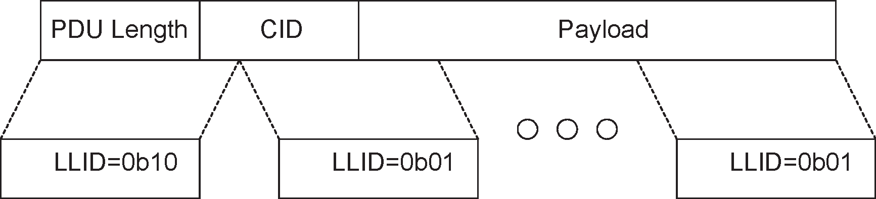
Note
Note: The BR/EDR Link Controller is able to impose a different fragmentation on the PDU by using “start” and “continuation” indications as fragments are translated into Baseband packets. Thus, both L2CAP and the BR/EDR Link Controller use the same mechanism to control the size of fragments.
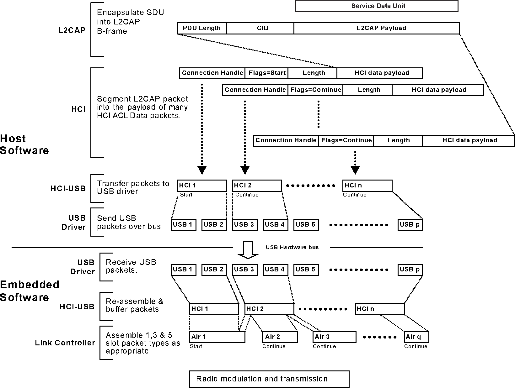
7.2.2. Recombination of L2CAP PDUs
The Controller will provide fragments of L2CAP PDUs to the L2CAP implementation. It is the responsibility of L2CAP to reassemble PDUs and SDUs and to check the length field of the SDUs. The L2CAP layer shall reassemble the fragments it receives from the Controller into complete PDUs, which may then further be combined into SDUs. (See [Vol 2] Part B, Section 5.3 and [Vol 6] Part B, Section 4.5.17 for related requirements on the Controller.)
An L2CAP implementation shall use the PDU Length field in the header of L2CAP PDUs, see Section 3, as a consistency check and shall discard any L2CAP PDUs that fail to match the PDU Length field. If channel reliability is not needed, packets with invalid lengths may be silently discarded. For reliable channels using Basic mode, an L2CAP implementation shall indicate to the upper layer that the channel has become unreliable. Reliable channels are defined by having an infinite flush timeout value as specified in Section 5.2. For higher data integrity L2CAP should be operated in the Enhanced Retransmission Mode.
7.3. Encapsulation of SDUs
All SDUs are encapsulated into one or more L2CAP PDUs.
In Basic L2CAP mode, an SDU shall be encapsulated with a minimum of L2CAP protocol elements, resulting in a type of L2CAP PDU called a Basic Information Frame (B-frame).
Segmentation and Reassembly operations are only used in Enhanced Retransmission mode, Streaming mode, Retransmission mode, and Flow Control mode. SDUs may be segmented into a number of smaller packets called SDU segments. Each segment shall be encapsulated with L2CAP protocol elements resulting in an L2CAP PDU called an Information Frame (I-frame).
The maximum size of an SDU segment shall be given by the Maximum PDU Payload Size (MPS). The MPS parameter may be exported using an implementation specific interface to the upper layer.
The specification does not describe a service interface with the upper layer, nor does it assume any specific buffer management scheme of a Host implementation. Consequently, a reassembly buffer may be part of the upper layer entity. It is assumed that SDU boundaries are preserved between peer upper layer entities.
7.3.1. Segmentation of L2CAP SDUs
In Flow Control, Streaming, or Retransmission modes, incoming SDUs may be broken down into segments, which shall then be individually encapsulated with L2CAP protocol elements (header and checksum fields) to form I-frames. I-frames are subject to flow control and may be subject to retransmission procedures. The header carries a 2 bit SAR field that is used to identify whether the I-frame is a 'start', 'end' or 'continuation' packet or whether it carries a complete, unsegmented SDU. Figure 7.3 illustrates segmentation and fragmentation.
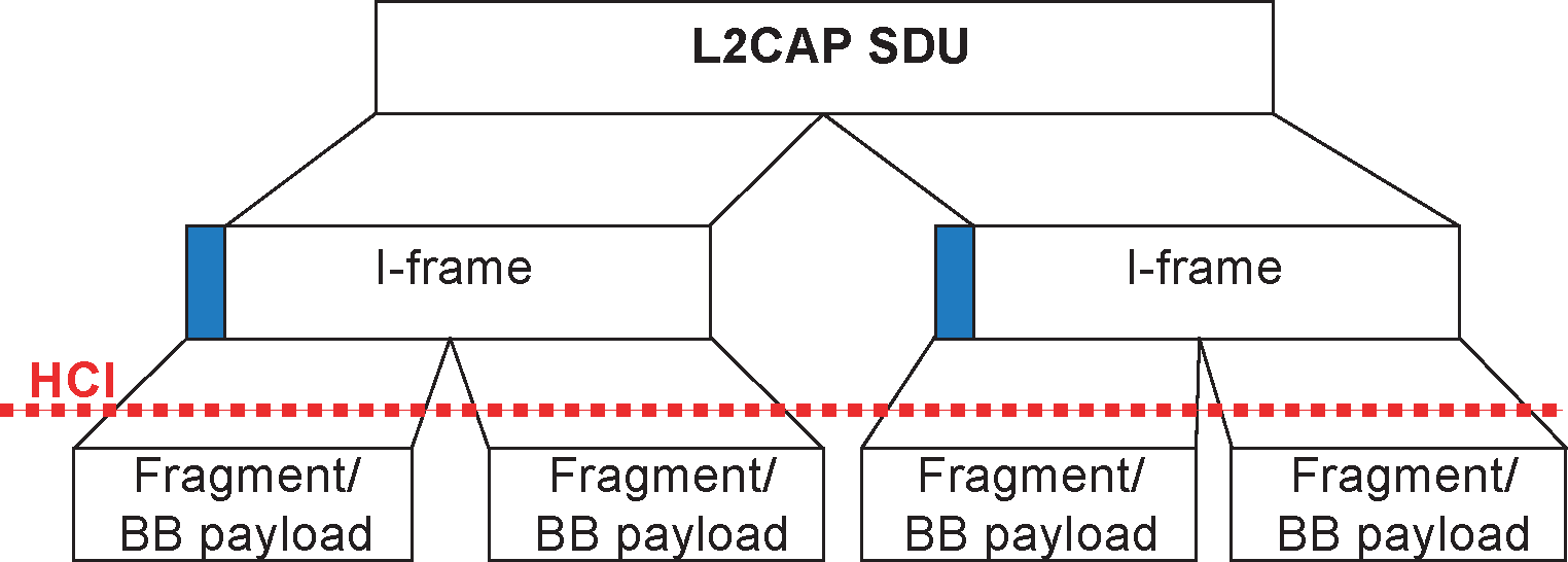
7.3.2. Reassembly of L2CAP SDUs
The receiving side uses the SAR field of incoming 'I-frames' for the reassembly process. The L2CAP SDU Length field, present in the “start of SDU” I-frame, is an extra integrity check, and together with the sequence numbers may be used to indicate lost L2CAP SDUs to the application. Figure 7.3 illustrates segmentation and fragmentation.
7.3.3. Segmentation and fragmentation
Figure 7.4 illustrates the use of segmentation and fragmentation operations to transmit a single SDU. While SDUs and L2CAP PDUs are transported in peer-to-peer fashion, the fragment size used by the Fragmentation and Recombination routines is implementation specific and may be different in the sender and the receiver. The over-the-air sequence of packet fragments as created by the sender is common to both devices.
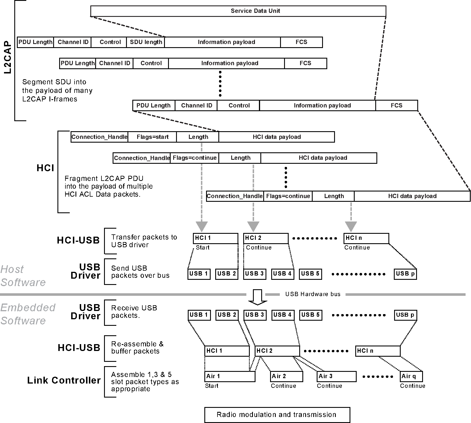
7.4. Delivery of erroneous L2CAP SDUs
Some applications may require corrupted or incomplete L2CAP SDUs to be delivered to the upper layer. If delivery of erroneous L2CAP SDUs is enabled, the receiving side will pass information to the upper layer on which parts of the L2CAP SDU (i.e., which L2CAP frames) have been lost, failed the error check, or passed the error check. If delivery of erroneous L2CAP SDUs is disabled, the receiver shall discard any L2CAP SDU segment with any missing frames or any frames failing the error checks. L2CAP SDUs whose SDU Length field (if provided) does not equal the sum of the segment payload sizes shall also be discarded.
7.5. Operation with flushing On ACL-U logical links
In the L2CAP configuration using either the Flush Timeout option or the Extended Flow Specification option, the Flush timeout may be set separately per L2CAP channel, but in the BR/EDR Baseband, the flush mechanisms operate per ACL logical transport.
When there is more than one L2CAP channel mapped to the same ACL logical transport, the automatic flush timeout does not discriminate between L2CAP channels. The automatic flush timeout also applies to unicast data sent via the L2CAP connectionless channel. The exception is packets marked as non-automatically-flushable via the Packet_Boundary_Flag in the HCI ACL Data packet (see Section 1.1). The automatic flush timeout flushes a specific automatically-flushable L2CAP PDU. The HCI_Flush command flushes all outstanding L2CAP PDUs for the ACL logical transport including L2CAP PDUs marked as non-automatically-flushable. Therefore, care has to be taken when using the Automatic Flush Timeout and the HCI_Flush command. The HCI_Enhanced_Flush command should be used instead.
All packets associated with a reliable connection shall be marked as non-automatically-flushable (if it is mapped to an ACL logical transport with a finite automatic flush timeout) or L2CAP Enhanced Retransmission mode or Retransmission mode shall be used. In Enhanced Retransmission mode or Retransmission mode, loss of flushed L2CAP PDUs on the channel is detected by the L2CAP ARQ mechanism and they are retransmitted. L2CAP Enhanced Retransmission mode or Retransmission mode can be used for other purposes such as the need for a residual error rate that is much smaller than the Baseband can deliver. In this situation L2CAP Enhanced Retransmission mode or Retransmission mode and the Non-Flushable Packet Boundary Flag feature can be used at the same time.
If it is desired to send unicast data via the L2CAP connectionless channel which is not subject to automatic flushing, then the data should be marked as non-automatically flushable if it is mapped to an ACL logical transport with a finite automatic flush timeout. Unicast data sent via the L2CAP connectionless channel may be marked flushable.
There is only one automatic flush timeout setting per ACL logical transport. Therefore, all time bounded L2CAP channels on an ACL logical transport with an automatic flush timeout setting should configure the same flush timeout value at the L2CAP level. The flush timeout setting for the ACL logical transport also applies to unicast data sent via the L2CAP connectionless channel which are marked flushable.
If Automatic Flush Timeout is used, then it should be taken into account that it only flushes one L2CAP PDU. If one PDU has timed out and needs flushing, then other automatically-flushable packets on the same logical transport are also likely to need flushing. Therefore, flushing can be handled by the HCI_Enhanced_Flush command so that all outstanding automatically-flushable L2CAP PDUs are flushed.
When both reliable and isochronous data is to be sent over the same ACL logical transport, an infinite Automatic Flush Timeout can be used. In this case the isochronous data is flushed using the HCI_Enhanced_Flush command with Packet_Type set to “Automatically-Flushable Only,” thus preserving the reliable data.
7.6. Connectionless data channel
In addition to connection-oriented channels, L2CAP also provides a connectionless channel. Data sent on the connectionless channel shall only be sent over the BR/EDR radio. The connectionless channel allows broadcast transmissions from the Central to all members of the piconet or unicast transmissions from either a Central or Peripheral to a single remote device. Data sent through the connectionless channel is sent in a best-effort manner. The connectionless channel provided by L2CAP has no quality of service.
While L2CAP itself does not provide retransmission for data sent via the connectionless channel, the Baseband does provide an ARQ scheme for unicast data (see [Vol 2] Part B, Section 7.6). If a higher degree of reliability is desired for unicast data sent via the connectionless L2CAP channel than is provided by the Baseband ARQ scheme then an ARQ scheme should be implemented at a higher layer.
No acknowledgment is provided by the Baseband for broadcast transmissions and hence broadcast transmissions sent via the connectionless L2CAP channel are unreliable and hence might or might not reach each member of the piconet.
The receiving L2CAP entity may silently discard data received via the connectionless L2CAP channel if the data packet is addressed to a PSM and no application is registered to receive data on that PSM.
L2CAP does not provide flow control for either connection-oriented L2CAP channels operating in Basic mode or for traffic on the connectionless L2CAP channel. Hence if data received by L2CAP is not accepted by the target applications in a timely manner, congestion can occur in a receiving L2CAP implementation. For connection-oriented channels, the receiving L2CAP entity may elect to close a channel if the target application for that channel does not accept the data in a timely manner. Since this option is not available for unicast data received via the connectionless L2CAP channel, the receiving L2CAP entity may instead elect to de-register the application receiving the data or to disconnect the underlying physical link. An application shall be notified if it is de-registered. If the underlying physical link is disconnected then all applications utilizing that physical link shall be notified.
Unicast data shall only be sent via the connectionless L2CAP channel to a remote device if the remote device indicates support for Unicast Connectionless Data Reception in the L2CAP Extended Features Mask.[4]
The L2CAP Extended Features Mask should be retrieved using the L2CAP_INFORMATION_REQ packet to determine if Unicast Connectionless Data Reception is supported. Optionally, support for Unicast Connectionless Data Reception can be inferred from information obtained via a SDP or EIR. For example, if a service is found via SDP or EIR that is known to mandate the support of UCD, then it may be assumed that the device indicating support for the service supports Unicast Connectionless Data Reception.
Unicast data sent via the L2CAP connectionless channel are subject to automatic flushing and hence the packet boundary flags should be set appropriately if the Controller supports the Packet Boundary Flag feature. See Section 7.5 for further details. Since the receiving L2CAP entity has no mechanism to enable it to know whether received packets were originally marked as flushable or non-flushable on the transmitting device, the receiving L2CAP entity should treat all unicast packets received via the connectionless L2CAP packet as non-flushable.
If encryption is required for a given profile, then the profile or application shall ensure that authentication is performed and encryption is enabled prior to sending any unicast data on the connectionless L2CAP channel by utilizing Security Mode 4 as defined in GAP ([Vol 3] Part C, Section 5.2.2). There is no mechanism provided in the specification to prevent reception of unencrypted data on the connectionless L2CAP channel. An application which requires received data to be encrypted should ignore any unencrypted data it may receive over the connectionless channel.
Broadcast transmissions to the connectionless channel are sent with the broadcast LT_ADDR and hence may be received by any of the Peripherals in the piconet. If it is desirable to restrict the reception of the transmitted data to only a subset of the Peripherals in the piconet, then higher level encryption may be used to support private communication.
The Central will not receive transmissions broadcast on the connectionless channel. Therefore, higher layer protocols must loopback any broadcast data traffic being sent to the Central if required.
The connectionless data channel shall not be used with Enhanced Retransmission mode, Retransmission Mode or Flow Control Mode.
7.7. Operation collision resolution
When two devices request the same operation by sending a request packet with the same code, a collision can occur. Some operations require collision resolution. The description of each operation in Section 4 will indicate if collision resolution is required. Both devices must know which request will be rejected. The following algorithm shall be used by both devices to determine which request to reject.
Set i=0 (representing the least significant octet of the BD_ADDR).
Compare the octet[i] of the BD_ADDR of both devices. If the octets are not equal go to step 4.
Increment i by 1. Go to step 2.
The device with the larger BD_ADDR octet shall reject the request from the other device.
7.8. [This section is no longer used]
7.9. Prioritizing data over HCI
In order for Guaranteed channels to meet their guarantees, L2CAP should prioritize traffic over the HCI transport in devices that support HCI. Packets for Guaranteed channels should receive higher priority than packets for Best Effort channels.
7.10. Supporting Extended Flow Specification for BR/EDR and BR/EDR/LE Controllers
If both the local L2CAP entity and the remote L2CAP entity indicate support for Extended Flow Specification for BR/EDR in the Extended Feature Mask then all channels created between the two devices shall send an Extended Flow Specification option and shall use the Lockstep configuration procedure. In addition all channels shall use Enhanced Retransmission mode or Streaming mode. If one or both L2CAP entities do not indicate support for Extended Flow Specification for BR/EDR in the Extended Feature Mask then the Lockstep configuration procedure shall not be used and the Extended Flow Specification option shall not be sent for channels created over the ACL-U logical link between the two devices.
The L2CAP entity shall perform admission control for Guaranteed channels during the Lockstep configuration procedure (see Section 7.1.3). Admission control is performed to determine if the requested Guaranteed QoS can be achieved by the BR/EDR or BR/EDR/LE Controller over an ACL-U logical link without compromising existing Guaranteed channels running on the Controller. If HCI is used then the L2CAP entity shall also verify that the QoS can be achieved over the HCI transport.
In performing admission control the L2CAP layer shall reject a Guaranteed QoS request that causes at least one of the following rules to be violated.
The total guaranteed data rate in both directions shall not exceed two times the highest Symmetric Max of an ACL-U logical link over the BR/EDR or BR/EDR/LE Controller (see [Vol 2] Part B, Section 6.7). For example for a Basic Rate Controller the highest Symmetric Max Rate is 433.9 kb/s (DH5) from [Vol 2] Part B, Table 6.8. Two times that value is 867.8 kb/s.
The total guaranteed data rate in any one direction shall not exceed the highest Asymmetric Max Rate of an ACL-U logical link (see [Vol 2] Part B, Section 6.7). For example the highest Asymmetric Max Rate for Basic Rate is 723.2 kb/s (DH5 packet) from [Vol 2] Part B, Table 6.8.
The data rate of a Guaranteed channel is calculated by dividing the Maximum SDU size in an Extended Flow Specification by the SDU Inter-arrival time. Total guaranteed data rate in both directions is calculated by taking the sum of the data rates in both directions for all existing Guaranteed channels plus the data rate in both directions of the requested Guaranteed channel (i.e. data rates from the both outgoing and incoming Extended Flow Specifications). Total guaranteed data rate for one direction is calculated by taking the sum of the data rates in one direction for all existing Guaranteed channels plus the data rate in the same direction of the requested Guaranteed channel.
An L2CAP entity should use additional information for admission control that may result in a Guaranteed QoS request being rejected even if none of the rules are violated. This allows the L2CAP entity to account for things such as CQDDR, SCO/eSCO channels, LMP traffic, page scanning, etc.
In order to meet the access latency and/or data rate required by a Guaranteed channel, the L2CAP entity should:
Prioritize traffic over the HCI transport in devices that support HCI.
Give conformant packets for Guaranteed channels higher priority than packets for Best Effort channels. Packets for Best Effort channels should have higher priority than non-conformant packets for Guaranteed channels. (See Section 5.6 for a discussion of non-conformant and conformant traffic).
Utilize the SAR feature to restrict the PDU sizes of Best Effort SDUs so that they do not prevent the Controller from sending the SDUs of the Guaranteed channel within the time periods required by its Extended Flow Specification.
When a channel is reconfigured the Lockstep configuration process is only used when an Extended Flow Specification option is present in the L2CAP_CONFIGURATION_REQ packet as described in Section 7.1.3.
7.11. Enhanced Credit-Based Flow Control Reconfiguration
In Enhanced Credit Based Flow Control Mode, each individual channel has its own MTU and MPS; both of these values can be reconfigured independently.
To perform reconfiguration, a device shall send an L2CAP_CREDIT_BASED_RECONFIGURE_REQ packet to the peer device with the new proposed MTU and MPS values and a set of channels to be reconfigured. The request shall not decrease the MTU of any channel and shall not decrease the MPS of a channel if more than one channel is specified.
When an L2CAP_CREDIT_BASED_RECONFIGURE_REQ packet is received and all the parameters are valid, the recipient shall complete sending all existing PDUs that require an MPS larger than the new MPS value for the channel in the L2CAP_CREDIT_BASED_RECONFIGURE_REQ packet and then send the L2CAP_CREDIT_BASED_RECONFIGURE_RSP packet, with a zero Result field, to the peer device.
After the L2CAP_CREDIT_BASED_RECONFIGURE_RSP packet is sent, the MTU and MPS values of the channels included in the L2CAP_CREDIT_BASED_RECONFIGURE_REQ packet shall be set to the MTU and MPS fields from that packet, and new SDUs shall be sent using the new MTU and MPS values.
When an L2CAP_CREDIT_BASED_RECONFIGURE_REQ packet is received with invalid parameters, the recipient shall send an L2CAP_CREDIT_BASED_RECONFIGURE_RSP PDU with a non-zero Result field and not change any MTU and MPS values.
8. Procedures for Flow Control and Retransmission
When Enhanced Retransmission mode, Streaming mode, Flow Control mode, or Retransmission mode is used, the procedures defined in this section shall be used, including the numbering of information frames, the handling of SDU segmentation and reassembly, and the detection and notification of frames with errors. Retransmission mode and Enhanced Retransmission mode also allow the sender to resend frames with errors on request from the receiver.
8.1. Information retrieval
Before attempting to configure Enhanced Retransmission mode, Streaming mode, Flow Control mode, or Retransmission mode on a channel, support for the suggested mode shall be verified by performing an information retrieval for the “Extended features supported” information type (0x0002). If the information retrieval is not successful or the “Extended features mask” bit is not set for the wanted mode, the mode shall not be suggested in a configuration request.
8.2. Function of PDU Types for Flow Control and Retransmission
Two frame formats are defined for Enhanced Retransmission mode, Streaming Mode, Flow Control Mode, and Retransmission mode (see Section 3.3). The I-frame is used to transport user information instead of the B-frame. The S-frame is used for supervision.
8.2.1. Information frame (I-frame)
I-frames are sequentially numbered frames containing information fields. I-frames also include some of the functionality of RR frames (see below).
8.2.2. Supervisory frame (S-frame)
The S-frame is used to control the transmission of I-frames. For Retransmission mode and Flow Control mode, the S-frame has two formats: Receiver Ready (RR) and Reject (REJ). A description of how S-frames are used in Enhanced Retransmission mode is given in Section 8.6.1. S-frames are not used in Streaming mode. The following description of S-frames only applies to Retransmission mode and Flow Control mode.
8.2.2.1. Receiver Ready (RR)
The receiver ready (RR) S-frame is used to:
Acknowledge I-frames numbered up to and including ReqSeq - 1.
Enable or disable retransmission of I-frames by updating the receiver with the current status of the Retransmission Disable Bit.
The RR frame has no information field.
8.2.2.2. Reject (REJ)
The reject (REJ) S-frame is used to request retransmission of all I-frames starting with the I-frame with TxSeq equal to ReqSeq specified in the REJ. The value of ReqSeq in the REJ frame acknowledges I-frames numbered up to and including ReqSeq - 1. I-frames that have not been transmitted, shall be transmitted following the retransmitted I-frames.
When a REJ is transmitted, it triggers a REJ Exception condition. A second REJ frame shall not be transmitted until the REJ Exception condition is cleared. The receipt of an I-frame with a TxSeq equal to the ReqSeq of the REJ frame clears the REJ Exception. The REJ Exception condition only applies to traffic in one direction.
Note
Note: This means that only valid I-frames can be rejected.
8.3. Variables and sequence numbers
The sending peer uses the following variables and sequence numbers:
TxSeq – the send sequence number used to sequentially number each new I-frame transmitted.
NextTxSeq – the sequence number to be used in the next new I-frame transmitted.
ExpectedAckSeq – the sequence number of the next I-frame expected to be acknowledged by the receiving peer.
The receiving peer uses the following variables and sequence numbers:
ReqSeq – The sequence number sent in an acknowledgment frame to request transmission of I-frame with TxSeq = ReqSeq and acknowledge receipt of I-frames up to and including (ReqSeq-1).
ExpectedTxSeq – the value of TxSeq expected in the next I-frame.
BufferSeq – When segmented I-frames are buffered this is used to delay acknowledgment of received I-frame so that new I-frame transmissions do not cause buffer overflow.
All variables have the range 0 to 63. Arithmetic operations on state variables (NextTXSeq, ExpectedTxSeq, ExpectedAckSeq, BufferSeq) and sequence numbers (TxSeq, ReqSeq) contained in this document shall be taken mod 64.
8.3.1. Sending peer
8.3.1.1. Send sequence number TxSeq
I-frames contain TxSeq, the send sequence number of the I-frame. When an I-frame is first transmitted, TxSeq is set to the value of the send state variable NextTXSeq. TxSeq is not changed if the I-frame is retransmitted.
8.3.1.2. Send state variable NextTXSeq
The CID sent in the information frame is the destination CID and identifies the remote endpoint of the channel. A send state variable NextTxSeq shall be maintained for each remote endpoint. NextTxSeq is the sequence number of the next in-sequence I-frame to be transmitted to that remote endpoint. When the link is created NextTXSeq shall be initialized to 0.
The value of NextTxSeq shall be incremented by 1 after each in-sequence I-frame transmission, and shall not exceed ExpectedAckSeq by more than the maximum number of outstanding I-frames (TxWindow). The value of TxWindow shall be in the range 1 to 32 for Retransmission mode and Flow Control mode. The value of TxWindow shall be in the range 1 to 63 for Enhanced Retransmission mode.
8.3.1.3. Acknowledge state variable ExpectedAckSeq
The CID sent in the information frame is the destination CID and identifies the remote endpoint of the channel. An acknowledge state variable ExpectedAckSeq shall be maintained for each remote endpoint. ExpectedAckSeq is the sequence number of the next in-sequence I-frame that the remote receiving peer is expected to acknowledge. (ExpectedAckSeq – 1 equals the TxSeq of the last acknowledged I-frame). When the link is created ExpectedAckSeq shall be initialized to 0.
Note
Note: If the next acknowledgment acknowledges a single I-frame then its ReqSeq will be expectedAckSeq + 1.
If a valid ReqSeq is received from the peer then ExpectedAckSeq is set to ReqSeq. A valid ReqSeq value is one that is in the range ExpectedAckSeq ≤ ReqSeq ≤ NextTxSeq.
Note
Note: The comparison with NextTXSeq must be ≤ in order to handle the situations where there are no outstanding I-frames.
These inequalities shall be interpreted in the following way: ReqSeq is valid, if and only if (ReqSeq-ExpectedAckSeq) mod 64 ≤ (NextTXSeq-ExpectedAckSeq) mod 64. Furthermore, from the description of NextTXSeq, it can be seen that (NextTXSeq-ExpectedAckSeq) mod 64 ≤ TxWindow.
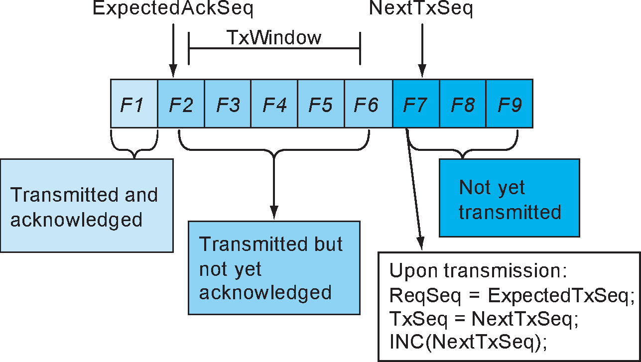
Figure 8.1 shows TxWindow=5, and three frames awaiting transmission. The frame with number F7 may be transmitted when the frame with F2 is acknowledged. When the frame with F7 is transmitted, TxSeq is set to the value of NextTXSeq. After TxSeq has been set, NextTxSeq is incremented.
The sending peer expects to receive valid ReqSeq values, which are in the range ExpectedAckSeq to NextTxSeq. Upon receipt of a ReqSeq value equal to the current NextTxSeq all outstanding I-frames have been acknowledged by the receiver.
8.3.2. Receiving peer
8.3.2.1. Receive sequence number ReqSeq
All I-frames and S-frames contain ReqSeq, the send sequence number (TxSeq) that the receiving peer requests in the next I-frame.
When an I-frame or an S-frame is transmitted, the value of ReqSeq shall be set to the current value of the receive state variable ExpectedTxSeq or the buffer state variable BufferSeq. The value of ReqSeq shall indicate that the data Link Layer entity transmitting the ReqSeq has correctly received all I-frames numbered up to and including ReqSeq – 1.
Note
Note: The option to set ReqSeq to BufferSeq instead of ExpectedTxSeq allows the receiver to impose flow control for buffer management or other purposes. In this situation, if BufferSeq<>ExpectedTxSeq, the receiver should also set the retransmission disable bit to 1 to prevent unnecessary retransmissions.
8.3.2.2. Receive state variable ExpectedTxSeq
Each channel shall have a receive state variable (ExpectedTxSeq). The receive state variable is the sequence number (TxSeq) of the next in-sequence I-frame expected.
The value of the receive state variable shall be the last in-sequence, valid I-frame received.
8.3.2.3. Buffer state variable BufferSeq
Each channel may have an associated BufferSeq. BufferSeq is used to delay acknowledgment of frames until they have been pulled by the upper layers, thus preventing buffer overflow. BufferSeq and ExpectedTxSeq are equal when there is no extra segmentation performed and frames are pushed to the upper layer immediately on reception. When buffer space is scarce, for example when frames reside in the buffer for a period, the receiver may choose to set ReqSeq to BufferSeq instead of ExpectedTxSeq, incrementing BufferSeq as buffer space is released. The windowing mechanism will ensure that transmission is halted when ExpectedTxSeq - BufferSeq is equal to TxWindow.
Note
Note: Owing to the variable size of I-frames, updates of BufferSeq may be based on changes in available buffer space instead of delivery of I-frame contents.
I-frames shall have sequence numbers in the range ExpectedTxSeq ≤ TxSeq < (BufferSeq + TxWindow).
On receipt of an I-frame with TxSeq equal to ExpectedTxSeq, ExpectedTxSeq shall be incremented by 1 regardless of how many I-frames with TxSeq greater than ExpectedTxSeq were previously received.
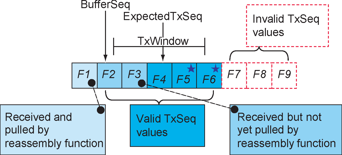
Figure 8.2 shows TxWindow=5. F1 is successfully received and pulled by the upper layer. BufferSeq shows that F2 is the next I-frame to be pulled, and ExpectedTxSeq points to the next I-frame expected from the peer. An I-frame with TxSeq equal to 5 has been received thus triggering an SREJ or REJ exception. The star indicates I-frames received but discarded owing to the SREJ or REJ exception. They will be resent as part of the error recovery procedure.
In Figure 8.2 there are several I-frames in a buffer awaiting the SDU reassembly function to pull them and the TxWindow is full. The receiver would usually disable retransmission in Retransmission mode or Flow Control mode by setting the Retransmission Disable Bit to 1 and send an RR back to the sending side. This tells the transmitting peer that there is no point in performing retransmissions. Both sides will send S-frames to make sure the peer entity knows the current value of the Retransmission Disable Bit.
8.4. Retransmission mode
8.4.1. Transmitting frames
A new I-frame shall only be transmitted when the TxWindow is not full. No I-frames shall be transmitted if the last RetransmissionDisableBit (R) received is set to one.
A previously transmitted I-frame may be retransmitted as a result of an error recovery procedure, even if the TxWindow is full. When an I-frame is retransmitted it shall always be sent with the same TxSeq value used in its initial transmission.
The state of the RetransmissionDisableBit (R) is stored and used along with the state of the RetransmissionTimer to decide the actions when transmitting I-frames. The RetransmissionTimer is running whenever I-frames have been sent but not acknowledged.
8.4.1.1. Last received R was set to zero
If the last R received was set to zero, then I-frames may be transmitted. If there are any I-frames which have been sent and not acknowledged then they shall be retransmitted when the RetransmissionTimer elapses. If the retransmission timer has not elapsed then a retransmission shall not be sent and only new I-frames may be sent.
If unacknowledged I-frames have been sent and the RetransmissionTimer has elapsed then an unacknowledged I-frame shall be retransmitted. The RetransmissionTimer shall be restarted.
If unacknowledged I-frames have been sent, the Retransmission timer has not elapsed then a new I-frame shall be sent if one is waiting and no timer action shall be taken.
If no unacknowledged I-frames have been sent, and a new I-frame is waiting, then the new I-frame shall be sent, the RetransmissionTimer shall be started and if the Monitor Timer is running, it shall be stopped.
If no unacknowledged I-frames have been sent and no new I-frames are waiting to be transmitted, and the RetransmissionTimer is running, then the retransmission timer shall be stopped and the monitor timer shall be started.
Table 8.1 summarizes actions when the RetransmissionTimer is in use and R=0.
Unacknowledged I‑frames sent = Retransmission Timer is running | Retransmission Timer has elapsed | New I‑frames are waiting | Transmit Action | Timer Action |
|---|---|---|---|---|
True | True | True or False | Retransmit un-acknowledged I‑frame | Restart Retransmission Timer |
True | False | True | Transmit new I‑frame | No timer action |
True | False | False | No transmit action | No Timer action |
False | False | True | Transmit new I‑frame | Restart Retransmission Timer |
False | False | False | No Transmit action | If MonitorTimer is not running then restart MonitorTimer |
If the RetransmissionTimer is not in use, no unacknowledged I-frames have been sent and no new I-frames are waiting to be transmitted
If the MonitorTimer is running and has not elapsed then no transmit action shall be taken and no timer action shall be taken.
If the MonitorTimer has elapsed then an S-frame shall be sent and the MonitorTimer shall be restarted.
If any I-frames become available for transmission then the MonitorTimer shall be stopped, the RetransmissionTimer shall be started and the rules for when the RetransmissionTimer is in use shall be applied.
When an I-frame is sent ReqSeq shall be set to ExpectedTxSeq, TxSeq shall be set to NextTxSeq and NextTxSeq shall be incremented by one.
8.4.1.2. Last received R was set to one
If the last R received was set to one, then I-frames shall not be transmitted. The only frames which may be sent are S-frames. An S-frame shall be sent according to the rules below:
If the MonitorTimer is running and has not elapsed then no transmit action shall be taken and no timer action shall be taken.
If the MonitorTimer has elapsed then an S-frame shall be sent and the MonitorTimer shall be restarted.
8.4.2. Receiving I-frames
Upon receipt of a valid I-frame with TxSeq equal to ExpectedTxSeq, the frame shall be accepted for the SDU reassembly function. ExpectedTxSeq is used by the reassembly function.
The first valid I-frame received after an REJ was sent, with a TxSeq of the received I-frame equal to ReqSeq of the REJ, shall clear the REJ Exception condition.
The ReqSeq shall be processed according to Section 8.4.6.
If a valid I-frame with TxSeq ≠ ExpectedTxSeq is received then an exception condition shall be triggered which is handled according to Section 8.4.7.
8.4.3. I-frames pulled by the SDU reassembly function
When the L2CAP layer has removed one or more I-frames from the buffer, BufferSeq may be incremented in accordance with the amount of buffer space released. If BufferSeq is incremented, an acknowledgment shall be sent to the peer entity.
Note
Note: Since the primary purpose of BufferSeq is to prevent buffer overflow, an implementation may choose to set BufferSeq in accordance with how many new incoming I-frames could be stored rather than how many have been removed.
The acknowledgment may either be an RR or an I-frame. The acknowledgment shall be sent to the peer L2CAP entity with ReqSeq equal to BufferSeq. When there are no I-frames buffered for pulling ExpectedTxSeq is equal to BufferSeq.
If the MonitorTimer is active then it shall be restarted to indicate that a signal has been sent to the peer L2CAP entity.
8.4.4. Sending and receiving acknowledgments
Either the MonitorTimer or the RetransmissionTimer shall be active while in Retransmission Mode. Both timers shall not be active concurrently.
8.4.4.1. Sending acknowledgments
Whenever an L2CAP entity transmits an I-frame or an S-frame, ReqSeq shall be set to ExpectedTxSeq or BufferSeq.
8.4.4.2. Receiving acknowledgments
On receipt of a valid S-frame or I-frame, the ReqSeq contained in the frame shall acknowledge previously transmitted I-frames. ReqSeq acknowledges I-frames with a TxSeq up to and including ReqSeq – 1.
The following rules shall be applied:
If the RetransmissionDisableBit changed value from 0 to 1 (stop retransmissions) then the receiving entity shall
If the RetransmissionTimer is running then stop it and start the MonitorTimer.
Store the state of the RetransmissionDisableBit received.
If the RetransmissionDisableBit changed value from 1 to 0 (start retransmissions) then the receiving entity shall
Store the state of the RetransmissionDisableBit received.
If there are any I-frames that have been sent but not acknowledged, then stop the MonitorTimer and start the RetransmissionTimer.
Any buffered I-frames shall be transmitted according to Section 8.4.1.
If any unacknowledged I-frames were acknowledged by the ReqSeq contained in the frame, and the RetransmissionDisableBit equals 1 (retransmissions stopped), then the receiving entity shall
Follow the rules in Section 8.4.1.
If any unacknowledged I-frames were acknowledged by the ReqSeq contained in the frame and the RetransmissionDisableBit equals 0 (retransmissions started) then the receiving entity shall
If the RetransmissionTimer is running, then stop it.
If any unacknowledged I-frames have been sent then the RetransmissionTimer shall be restarted.
Follow the rules in Section 8.4.1.
If the RetransmissionTimer is not running and the MonitorTimer is not running, then start the MonitorTimer.
On receipt of a valid S-frame or I-frame the ReqSeq contained in the frame shall acknowledge previously transmitted I-frames. ExpectedAckSeq shall be set to ReqSeq to indicate that the I-frames with TxSeq up to and including (ReqSeq - 1) have been acknowledged.
8.4.5. Receiving REJ frames
Upon receipt of a valid REJ frame, where ReqSeq identifies an I-frame not yet acknowledged, the ReqSeq acknowledges I-frames with TxSeq up to and including ReqSeq - 1. Therefore the REJ acknowledges all I-frames before the I-frame it is rejecting.
ExpectedAckSeq shall be set equal to ReqSeq to mark I-frames up to and including ReqSeq - 1 as received.
NextTXSeq shall be set to ReqSeq to cause transmissions of I-frames to resume from the point where TxSeq equals ReqSeq.
If ReqSeq equals ExpectedAckSeq then the REJ frame shall be ignored.
8.4.6. Waiting acknowledgments
A counter, TransmitCounter, counts the number of times an L2CAP PDU has been transmitted. This shall be set to 1 after the first transmission. If the RetransmissionTimer expires the following actions shall be taken:
If the TransmitCounter is less than MaxTransmit then:
Increment the TransmitCounter.
Retransmit the last unacknowledged I-frame, according to Section 8.4.1.
If the TransmitCounter is equal to MaxTransmit this channel to the peer entity shall be assumed lost. The channel shall move to the CLOSED state and appropriate action shall be taken to report this to the upper layers.
8.4.7. Exception conditions
Exception conditions may occur as the result of physical layer errors or L2CAP procedural errors. The error recovery procedures which are available following the detection of an exception condition at the L2CAP layer in Retransmission Mode are defined in this section.
8.4.7.1. TxSeq sequence error
A TxSeq sequence error exception condition occurs in the receiver when a valid I-frame is received which contains a TxSeq value which is not equal to the expected value, thus TxSeq is not equal to ExpectedTxSeq.
The TxSeq sequence error may be due to three different causes:
Duplicated I-frame
The duplicated I-frame is identified by a TxSeq in the range BufferSeq to ExpectedTxSeq – 1 (BufferSeq ≤TxSeq<ExpectedTxSeq). The ReqSeq and RetransmissionDisableBit shall be processed according to Section 8.4.4. The Information field shall be discarded since it has already been received.
Out-of-sequence I-frame
The out-of-sequence I-frame is identified by a TxSeq within the valid range. The ReqSeq and RetransmissionDisableBit shall be processed according to Section 8.4.4.
A REJ exception is triggered, and an REJ frame with ReqSeq equal to ExpectedTxSeq shall be sent to initiate recovery. The received I-frame shall be discarded.
Invalid TxSeq
An invalid TxSeq value is a value that does not meet either of the above conditions. An I-frame with an invalid TxSeq is likely to have errors in the control field and shall be silently discarded.
8.4.7.2. ReqSeq sequence error
An ReqSeq sequence error exception condition occurs in the transmitter when a valid S-frame or I-frame is received which contains an invalid ReqSeq value. An invalid ReqSeq is one that is not in the range ExpectedAckSeq ≤ ReqSeq ≤ NextTxSeq.
The L2CAP entity shall close the channel as a consequence of an ReqSeq Sequence error.
8.4.7.3. Timer recovery error
If an L2CAP entity fails to receive an acknowledgment for the last I-frame sent, then it will not detect an out-of-sequence exception condition and therefore will not transmit an REJ frame.
The L2CAP entity that transmitted an unacknowledged I-frame shall, on the expiry of the RetransmissionTimer, take appropriate recovery action as defined in Section 8.4.6.
8.4.7.4. Invalid frame
Any frame received which is invalid (as defined in Section 3.3.6) shall be discarded, and no action shall be taken as a result of that frame.
8.5. Flow Control mode
When a link is configured to work in flow control mode, the flow control operation is similar to the procedures in retransmission mode, but all operations dealing with CRC errors in received packets are not used. Therefore
REJ frames shall not be used in Flow Control Mode.
The RetransmissionDisableBit shall always be set to zero in the transmitter, and shall be ignored in the receiver.
The behavior of flow control mode is specified in this section.
Assuming that the TxWindow size is equal to the buffer space available in the receiver (counted in number of I-frames), in flow control mode the number of unacknowledged frames in the transmitter window is always less than or equal to the number of frames for which space is available in the receiver.
Note
Note: A missing frame still occupies a place in the window.
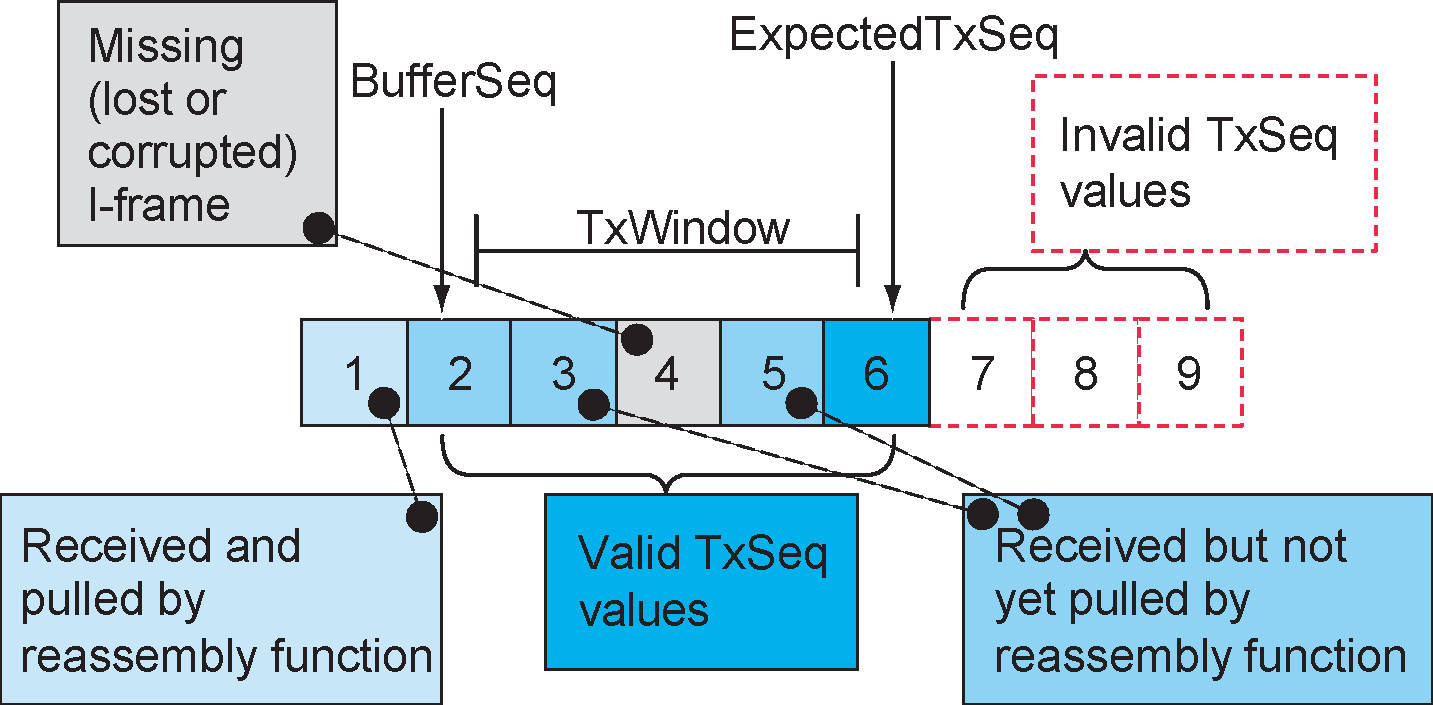
8.5.1. Transmitting I-frames
A new I-frame shall only be transmitted when the TxWindow is not full.
Upon transmission of the I-frame the following actions shall be performed:
If no unacknowledged I-frames have been sent then the MonitorTimer shall be stopped and the RetransmissionTimer shall be started.
If any I-frames have been sent and not acknowledged then the RetransmissionTimer remains active and no timer operation is performed.
The control field parameter ReqSeq shall be set to ExpectedTxSeq, TxSeq shall be set to NextTXSeq and NextTXSeq shall be incremented by one.
8.5.2. Receiving I-frames
Upon receipt of a valid I-frame with TxSeq equal to ExpectedTxSeq, the frame shall be made available to the reassembly function. ExpectedTxSeq shall be incremented by one. An acknowledgment shall not be sent until the SDU reassembly function has pulled the I-frame.
Upon receipt of a valid I-frame with an out-of-sequence TxSeq (see Section 8.5.6) all frames with a sequence number less than TxSeq shall be assumed lost and marked as missing. The missing I-frames are in the range from ExpectedTxSeq (the frame that the device was expecting to receive) up to TxSeq-1, (the frame that the device actually received). ExpectedTxSeq shall be set to TxSeq +1. The received I-frame shall be made available for pulling by the reassembly function. The acknowledgment shall not occur until the SDU reassembly function has pulled the I-frame. The ReqSeq shall be processed according to Section 8.5.4.
8.5.3. I-frames pulled by the SDU reassembly function
When the L2CAP layer has removed one or more I-frames from the buffer, BufferSeq may be incremented in accordance with the amount of buffer space released. If BufferSeq is incremented, an acknowledgment shall be sent to the peer entity. If the MonitorTimer is active then it shall be restarted to indicate that a signal has been sent to the peer L2CAP entity.
Note
Note: Since the primary purpose of BufferSeq is to prevent buffer overflow, an implementation may choose to set BufferSeq in accordance with how many new incoming I-frames could be stored rather than how many have been removed.
The acknowledgment may be an RR or an I-frame. The acknowledgment shall be sent to the peer L2CAP entity with ReqSeq equal to BufferSeq. When there is no I-frame buffered for pulling, ExpectedTxSeq is equal to BufferSeq.
8.5.4. Sending and receiving acknowledgments
One of the timers MonitorTimer or RetransmissionTimer shall always be active while in Flow Control mode. Both timers shall never be active concurrently.
8.5.4.1. Sending acknowledgments
Whenever a data Link Layer entity transmits an I-frame or a S-frame, ReqSeq shall be set to ExpectedTxSeq or BufferSeq.
8.5.4.2. Receiving acknowledgments
On receipt of a valid S-frame or I-frame the ReqSeq contained in the frame shall be used to acknowledge previously transmitted I-frames. ReqSeq acknowledges I-frames with a TxSeq up to and including ReqSeq – 1.
If any outstanding I-frames were acknowledged then
Stop the RetransmissionTimer
If there are still unacknowledged I-frames then restart the RetransmissionTimer, otherwise start the MonitorTimer.
Transmit any I-frames awaiting transmission according to Section 8.5.1.
ExpectedAckSeq shall be set to ReqSeq to indicate that the I-frames with TxSeq up to and including ExpectedAckSeq have been acknowledged.
8.5.5. Waiting acknowledgments
If the RetransmissionTimer expires the following actions shall be taken:
The I-frame supervised by the RetransmissionTimer shall be considered lost, and ExpectedAckSeq shall be incremented by one.
If I-frames are waiting to be sent
the RetransmissionTimer is restarted.
I-frames awaiting transmission are transmitted according to Section 8.5.1.
If there are no I-frames waiting to be sent
If there are still unacknowledged I-frames the RetransmissionTimer is restarted, otherwise the MonitorTimer is started.
8.5.6. Exception conditions
Exception conditions may occur as the result of physical layer errors or L2CAP procedural errors. The error recovery procedures which are available following the detection of an exception condition at the L2CAP layer in flow control only mode are defined in this section.
8.5.6.1. TxSeq sequence error
A TxSeq sequence error exception condition occurs in the receiver when a valid I-frame is received which contains a TxSeq value which is not equal to the expected value, thus TxSeq is not equal to ExpectedTxSeq.
The TxSeq sequence error may be due to three different causes:
Duplicated I-frame
The duplicated I-frame is identified by a TxSeq in the range BufferSeq to ExpectedTxSeq – 1. The ReqSeq shall be processed according to Section 8.5.4. The Information field shall be discarded since it has already been received.
Out-of-sequence I-frame
The out-of-sequence I-frame is identified by a TxSeq such that ExpectedTxSeq < TxSeq < (BufferSeq + TxWindow). The ReqSeq shall be processed according to Section 8.5.4.
The missing I-frame(s) are considered lost and ExpectedTXSeq is set equal to TxSeq+1 as specified in Section 8.5.2. The missing I-frame(s) are reported as lost to the SDU reassembly function.
Invalid TxSeq
An invalid TxSeq value is a value that does not meet either of the above conditions and TxSeq is not equal to ExpectedTxSeq. An I-frame with an invalid TxSeq is likely to have errors in the control field and shall be silently discarded.
8.5.6.2. ReqSeq sequence error
An ReqSeq sequence error exception condition occurs in the transmitter when a valid S-frame or I-frame is received which contains an invalid ReqSeq value. An invalid ReqSeq is one that is not in the range ExpectedAckSeq ≤ ReqSeq ≤ NextTXSeq.
The L2CAP entity shall close the channel as a consequence of an ReqSeq Sequence error.
An L2CAP entity that fails to receive an acknowledgment for an I-frame shall, on the expiry of the RetransmissionTimer, take appropriate recovery action as defined in Section 8.5.5.
8.5.6.3. Invalid frame
Any frame received that is invalid (as defined in Section 3.3.6) shall be discarded, and no action shall be taken as a result of that frame, unless the receiving L2CAP entity is configured to deliver erroneous frames to the layer above L2CAP. In that case, the data contained in invalid frames may also be added to the receive buffer and made available for pulling from the SDU reassembly function.
8.6. Enhanced Retransmission mode
Enhanced Retransmission mode operates as an HDLC balanced data link operational mode. Either L2CAP entity may send frames at any time without receiving explicit permission from the other L2CAP entity. A transmission may contain single or multiple frames and shall be used for I-frame transfer and/or to indicate status change.
8.6.1. Function of PDU types
Enhanced Retransmission mode uses I-frames to transfer upper layer information and S-frames for supervision. There are four S-frames defined: Receiver Ready (RR), Reject (REJ), Receiver Not Ready (RNR), and Selective Reject (SREJ). All frames formats in Enhanced Retransmission mode shall use the Enhanced Control Field.
8.6.1.1. Receiver Ready (RR)
The RR frame shall be used by an L2CAP entity to
Indicate that it is ready to receive I-frames
Acknowledge previously received I-frames numbered up to and including ReqSeq - 1.
An RR with P-bit set to 1 (P=1) is used to indicate the clearance of any busy condition that was initiated by an earlier transmission of an RNR frame by the same L2CAP entity.
8.6.1.2. Reject (REJ)
The REJ frame shall be used by an L2CAP entity to request retransmission of I-frames starting with the frame numbered ReqSeq. I-frames numbered ReqSeq - 1 and below shall be considered acknowledged. Additional I-frames awaiting initial transmission may be transmitted following the retransmitted I-frame(s) up to the TxWindow size of the receiver.
At most only one REJ exception from a given L2CAP entity to another L2CAP entity shall be established at any given time. A REJ frame shall not be transmitted until an earlier REJ exception condition or all earlier SREJ exception conditions have been cleared. The REJ exception condition shall be cleared upon the receipt of an I-frame with TxSeq equal to the ReqSeq of the REJ frame.
Two L2CAP entities may be in REJ exception conditions with each other at the same time.
8.6.1.3. Receiver Not Ready (RNR)
The RNR frame shall be used by an L2CAP entity to indicate a busy condition (i.e. temporary inability to receive I-frames). I-frames numbered up to and including ReqSeq - 1 shall be considered acknowledged. The I-frame numbered ReqSeq and any subsequent I-frames sent shall not be considered acknowledged. The acceptance status of these I-frames shall be indicated in subsequent transfers.
8.6.1.4. Selective Reject (SREJ)
The SREJ frame shall be used by an L2CAP entity to request retransmission of one I-frame. The ReqSeq shall indicate the TxSeq of the earliest I-frame to be retransmitted (not yet reported by a SREJ). If the P-bit is set to 1 then I-frames numbered up to and including ReqSeq -1 shall be considered acknowledged. If the P-bit is set to 0 then the ReqSeq field in the SREJ shall not indicate acknowledgment of I-frames.
Each SREJ exception condition shall be cleared upon receipt of an I-frame with TxSeq equal to the ReqSeq sent in the SREJ frame.
An L2CAP entity may transmit one or more SREJ frames with the P=0 before one or more earlier SREJ exception conditions initiated with SREJ(P=0) have been cleared. An L2CAP entity shall not transmit more than one SREJ with P=1 before all earlier SREJ exception conditions have been cleared. A SREJ frame shall not be transmitted if an earlier REJ exception condition has not been cleared. Likewise a REJ frame shall not be transmitted if one or more SREJ exception conditions have not been cleared. Only one I-frame shall be retransmitted in response to receiving a SREJ frame with P=0. Additional I-frames awaiting initial transmission may be transmitted following the retransmission of the specific I-frame requested by SREJ with P=1.
8.6.1.5. Functions of the Poll (P) and Final (F) bits
P-bit set to 1 shall be used to solicit a response frame with the F-bit set to 1 from the remote L2CAP entity at the earliest respond opportunity. At most only one frame with a P=1 shall be outstanding in a given direction at a given time. Before an L2CAP entity issues another frame with P=1, it shall have received a response frame from the remote L2CAP entity with F=1. If no valid frame is received with F=1 within Monitor timeout period, the frame with P=1 may be retransmitted.
The Final bit shall be used to indicate the frame as a response to a soliciting poll (S‑frame with P=1). The frame with F=1 shall not be retransmitted. The Monitor-timeout is not used to monitor lost frames with F=1. Additional frames with F=0 may be transmitted following the frame with F=1.
S-frames shall not be transmitted with both the F-bit and the P-bit set to 1 at the same time.
8.6.2. Rules for timers
Timers are started upon transmission of a packet. Timers should be started when the corresponding packet leaves the Controller (transmitted or flushed). If the timer is not started when the packet leaves the Controller then it shall be started when the packet is delivered to the Controller. The specific rules for BR/EDR and BR/EDR/LE Controllers are described in the following sections.
8.6.2.1. Timer rules for ACL-U logical links
If a flush timeout does not exist on the ACL-U logical link for the channel using Enhanced Retransmission mode then the value for the Retransmission timeout shall be at least two seconds and the value for the Monitor timeout shall be at least 12 seconds.
If a flush timeout exists on the link for Enhanced Retransmission mode then the value for the Retransmission timeout shall be three times the value of flush timeout, subject to a minimum of 1 second and maximum of 2 seconds.
If a flush timeout exists on the link for Enhanced Retransmission mode and both sides of the link are configured to the same flush timeout value then the monitor timeout shall be set to a value at least as large as the Retransmission timeout otherwise the value of the Monitor timeout shall be six times the value of flush timeout, subject to a minimum of the retransmission timeout value and a maximum of 12 seconds.
If an L2CAP entity knows that a specific packet has been flushed instead of transmitted then it may execute proper error recovery procedures immediately.
When configuring a channel over an ACL-U logical link the values sent in an L2CAP_CONFIGURATION_REQ packet for Retransmission timeout and Monitor timeout shall be 0.
Note
Note: If the link has a flush timeout and the Non-Flushable Packet Boundary Flag feature is used to mark the Enhanced Retransmission mode packets as non-flushable then the link does not have a flush timeout with regards to Enhanced Retransmission mode.
8.6.2.2. [This section is no longer used]
8.6.2.3. [This section is no longer used]
8.6.3. General rules for the state machine
Enhanced Retransmission mode is specified using a pair of state machines, a Transmitter state machine and a Receiver state machine. The following rules apply to the state machine pair.
The state machine pair specifies the behavior of the protocol. Designers and implementers may choose any design / implementation technique they wish, but it shall behave in a manner identical to the external behavior of the specified state machines.
There is a single state machine pair for each active L2CAP channel configured to use Enhanced Retransmission mode.
Variables are used to limit the number of states by maintaining the state of particular conditions. The variables are defined in Section 8.6.5.2.
For some combinations of event and condition, the state tables provide an action that involves alternatives or alternative groups of actions. The alternatives are mutually exclusive; selection of an alternate is done based upon (i) local status, (ii) a layer management action, or (iii) an implementation decision. There is no relationship between the order of the alternatives between events, nor is it implied that the same alternative must be selected every time the event occurs.
The state tables use timers. Any Start Timer action restarts the specified timer from its initial value, even if the timer is already running. When the timer reaches 0 the appropriate timer expired event is set and the timer stops. The Stop Timer action stops a timer if it is running.
Events not recognized in a particular state are assumed to remain pending until any masking flag is modified or a transition is made to a state where they can be recognized.
Some state transitions and actions are triggered by internal events (e.g. requests from the upper layer). It is implementation specific how these internal events are realized. They are used for clarity in specifying the state machine. All events including Internal events are described in Section 8.6.5.3.
The state machines specify the exact frames to be sent by transmitters but are relaxed on what receivers are allowed to accept as valid. For example there are cases where the transmitter is required to send a frame with P=1. The correct response is a frame with F=1 but in some cases the receiver is allowed to accept a frame with F=0 in addition to F=1.
8.6.4. State diagram
The state diagram in Figure 8.4 shows the states and the main transitions. Not all events are shown on the state diagram.
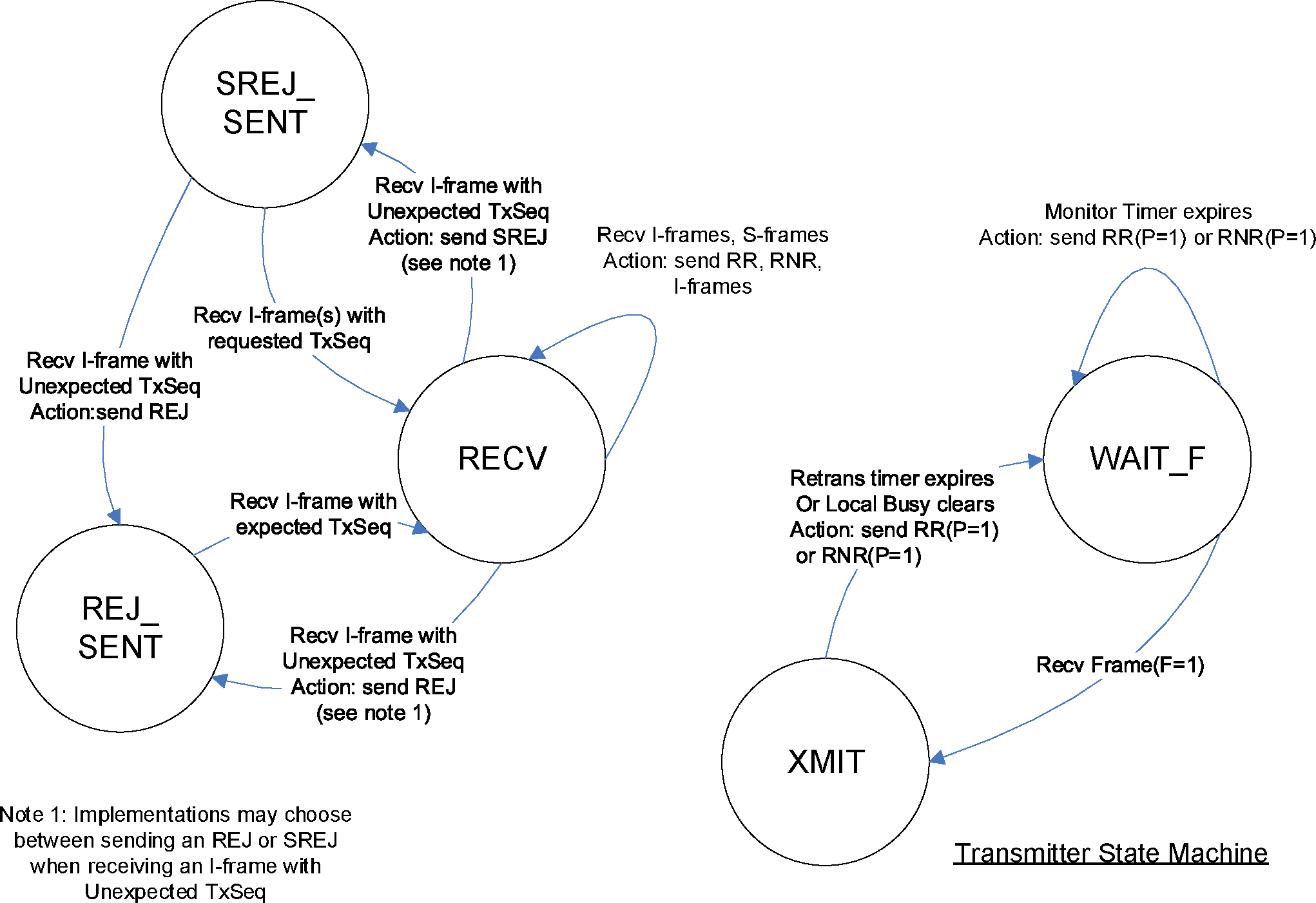
8.6.5. States tables
8.6.5.1. State machines
Enhanced Retransmission mode is described as a pair of state machine. The Receiver state machine handles all received frames while the Transmitter State machine handles all asynchronous events including requests from the upper layer and the expiration of timers.
The Receiver state machine “calls” the Transmitter state machine using the PassToTx action. This shows up in the Transmitter state machine as an event. When the Transmitter state machine is called it runs to completion before returning to the Receiver state machine. Running to completion means that all actions are executed and the Transmitter state is changed to the new state.
The Receiver and Transmitter state machine share variables and timers.
8.6.5.2. States
The following states have been defined to specify the protocol; the actual number of states and naming in a given implementation is outside the scope of the specification:
RECV—This is the main state of the Receiver state machine.
REJ_SENT—The L2CAP entity has sent a REJ frame to cause the remote L2CAP entity to resend I-frame(s). The L2CAP entity is waiting for the I-frame with a TxSeq that matches the ReqSeq sent in the REJ. Whether to send a REJ versus a SREJ is implementation dependent.
SREJ_SENT—The L2CAP entity has sent one or more SREJ frames to cause the remote L2CAP entity to resend missing I-frame(s). The local L2CAP entity is waiting for all requested I-frames to be received. If additional missing I-frames are detected while in SREJ_SENT then additional SREJ frames or a REJ frame can be sent to request those I-frames. Whether to send a SREJ versus a REJ is implementation dependent.
XMIT—This is the main state of the Transmitter state machine.
WAIT_F—Local busy has been cleared or the Retransmission timer has expired and an S-frame with P=1 has been sent. The local L2CAP entity is waiting for a frame with F=1. New I-frames cannot be sent while in the WAIT_F state to prevent the situation where retransmission of I-frames could result in the channel being disconnected.
8.6.5.3. Variables and timers
Variables are used to limit the number of states and help clarify the state chart tables. Variables can be set to values, evaluated in conditions and compared in conditional statements. They are also used in the action descriptions. Below is a list of the operators, connectives and statements that can be used with variables.
Operator, connective or statement | Description |
|---|---|
:= | Assignment operator. Used to set a variable to a value |
= | Relational operator "equal" |
> | Relational operator "greater than" |
< | Relational operator "less than" |
≥ | Relational operator "greater than or equal" |
≤ | Relational operator "less than or equal" |
+ | Arithmetic operator "plus" |
and | logical connective "and." It returns TRUE if both operands are TRUE otherwise it returns FALSE. |
or | logical connective "or." It returns TRUE if either of its operands are TRUE otherwise it returns FALSE. |
if (expression) then { statement } | Conditional Statement. If expression is TRUE then the statement is executed otherwise the statement is not executed. The statement is composed of one or more actions. All the actions in the statement are indented under the if ... then clause and contained within braces “{ }”. |
if (expression) then { statement1 } else { statement2 } | Conditional Statement. If expression is TRUE then statement1 is executed otherwise statement2 is executed. A statement is composed of one or more actions. All the actions in the statement1 are indented under the if ... then clause and contained within braces “{ }”. All the actions of statement2 are indented under the else clause and contained within braces “{ }”. |
Enhanced Retransmission mode uses the following variables and sequence numbers described in Section 8.3:
TxSeq
NextTxSeq
ExpectedAckSeq
ReqSeq
ExpectedTxSeq
BufferSeq
In addition to the variables above the following variables and timers are used:
RemoteBusy—when set to TRUE RemoteBusy indicates that the local L2CAP entity has received an RNR from the remote L2CAP entity and considers the remote L2CAP entity as busy. When the remote device is busy it will likely discard I-frames sent to it. The RemoteBusy flag is set to FALSE when the local L2CAP Entity receives an RR, REJ or SREJ. When set to FALSE the local L2CAP entity considers the remote L2CAP entity able to accept I-frames. When the channel is created RemoteBusy shall be set to FALSE.
LocalBusy—when set to TRUE, LocalBusy indicates the local L2CAP entity is busy and will discard received I-frames. When set to FALSE the local L2CAP entity is not busy and is able to receive I-frames. When the channel is created LocalBusy shall be set to FALSE.
UnackedFrames—holds the number of unacknowledged I-frames. When the channel is created UnackedFrames shall be set to 0.
UnackedList—holds the unacknowledged I-frames so they can be retransmitted if necessary. I-frames in the list are accessed via their TxSeq number. For example UnackedList[5] accesses the I-frame with TxSeq 5.
PendingFrames—holds the number of pending I-frames. I-frames passed to L2CAP from the upper layer may be unable to be sent immediately because the remote L2CAP entity's TxWindow is full, is in a busy condition or the local L2CAP is in the incorrect state. When I-frames cannot be sent they are stored in a queue until conditions allow them to be sent. When the channel is created PendingFrames shall be set to 0.
SrejList—is a list of TxSeq values for I-frames that are missing and need to be retransmitted using SREJ. A SREJ has already been sent for each TxSeq on the list. When SrejList is empty it equals 0 (i.e. SrejList = 0). If SrejList is not empty it is greater than 0 (i.e. SrejList > 0).
RetryCount—holds the number of times an S-frame operation is retried. If an operation is tried MaxTransmit times without success the channel shall be closed.
RetryIframes[ ]—holds a retry counter for each I-frame that is sent within the receiving device's TxWindow. Each time an I-frame is retransmitted the corresponding counter within RetryIframes is incremented. When an attempt to retransmit the I-frame is made and the counter is equal to MaxTransmit then the channel shall be closed.
RNRsent—when set to TRUE it means that the local L2CAP entity has sent an RNR frame. It is used to determine if the L2CAP entity needs to send an RR to the remote L2CAP entity to clear the busy condition. When the channel is created RNRsent shall be set to FALSE.
RejActioned—is used to prohibit a frame with F=1 from causing I-frames already retransmitted in response to a REJ from being retransmitted again. RejActioned is set to TRUE if a received REJ is actioned when a frame sent with P=1 is unanswered. When the channel is created RejActioned shall be set to FALSE.
SrejActioned—is used in conjunction with SrejSaveReqSeq to prohibit a frame with F=1 from causing an I-frame already retransmitted in response to a SREJ from being retransmitted again. SrejActioned is set to TRUE if a received SREJ is actioned when a frame sent with P=1 is unanswered. When the channel is created SrejActioned shall be set to FALSE.
SrejSaveReqSeq—is used to save the ReqSeq of a SREJ frame that causes SrejActioned to be set to TRUE.
SendRej—when set to TRUE it indicates that the local L2CAP entity has determined that a REJ should be sent in the SREJ_SENT state while processing received I-frames. The sending of new SREJ frames is stopped. When the channel is created SendRej shall be set to FALSE.
BufferSeqSrej—is used while in the SREJ_SENT state to keep track of the value to which BufferSeq will be set upon exit of the SREJ_SENT state.
FramesSent—is used to keep track of the number I-frames sent by the Send-Data and Retransmit-I-frames actions.
MaxTxWin—contains the maximum window size plus 1. It is used in TxWindow mod operations as the divisor and in state table conditions. This value shall be set to 16384 (0x4000) if the Extended Window Size option is used; otherwise it shall be set to 64.
RetransTimer—The Retransmission Timer is used to detect lost I-frames. When the channel is created the RetransTimer shall be off.
MonitorTimer—The Monitor Timer is used to detect lost S-frames. When the channel is created the MonitorTimer shall be off.
8.6.5.4. Events
Data-Request—The upper layer has requested that an SDU be sent. The SDU may need to be broken into multiple I-frames by L2CAP based on the MPS of the remote device and/or the maximum PDU allowed by the HCI or QoS requirements of the system.
Local-Busy-Detected—A local busy condition occurs when the local L2CAP entity is temporarily unable to receive, or unable to continue to receive, I-frames due to internal constraints. For example, the upper layer has not pulled received I-frames and the local L2CAP entity needs to send an acknowledgment to the remote L2CAP entity. The method for handling the detection of local busy is implementation specific. An implementation may wait to send an RNR to see if the busy condition will clear before the remote L2CAP entity's Retransmission timer expires. If the busy condition clears then frames can be acknowledged with an RR or I-frame. If the busy condition does not clear before the remote L2CAP entity's Retransmission timer expires then an RNR shall be sent in response to the RR or RNR poll sent by the remote L2CAP entity. Optionally an implementation may send an RNR as soon as the local busy condition is detected.
Local-Busy-Clear—The local busy condition clears when L2CAP has buffer space to receive more I-frames (i.e. SDU Reassembly function and/or upper layer has pulled I-frames) and if necessary the upper layer has cleared the busy condition.
Recv ReqSeqAndFbit—This is an event generated by the Receiver state machine. It contains the ReqSeq and F-bit value of a received frame. The value of the F-bit can be checked in a condition.
Recv Fbit—This is an event generated by the Receiver state machine. It contains the F-bit value of a received frame. The value of the F-bit can be checked in a condition.
RetransTimer-Expires—The Retransmission Timer has counted to down to 0 and stopped.
MonitorTimer-Expires—The Monitor Timer has counted down to 0 and stopped.
Recv I-frame—Receive an I-frame with any value for the F-bit.
Recv RR, REJ, RNR, SREJ (P=x) or (F=x)—Receive a specific S-frame (RR, REJ, etc.) with a specific value for the P and/or F bit. The F-bit and the P-bit shall not both be set to 1 in a transmitted S-frame so received S-frames with both P and F set to 1 should be ignored. If the P and/or F bit value is not specified in the event then either value is accepted.
Recv RRorRNR—Receive an RR or RNR with any value for the P-bit and F-bit.
Recv REJorSREJ—Receive an REJ or SREJ with any value for the P-bit and F-bit.
Recv frame—This is catch-all for all frames that are not explicitly declared as events in the state table.
8.6.5.5. Conditions
RemoteBusy = TRUE or FALSE—TRUE indicates the remote L2CAP entity is in a busy condition and FALSE indicates the remote L2CAP entity is not busy.
LocalBusy = TRUE or FALSE—TRUE indicates the local L2CAP entity is in a busy condition and FALSE indicates the local L2CAP entity is not busy.
RemWindow-Not-Full—The number of unacknowledged I-frames sent by L2CAP has not yet reached the TxWindow size of the remote L2CAP entity.
RemWindow-Full—The number of unacknowledged I-frames sent by the L2CAP entity has reached the TxWindow size of the remote L2CAP entity. No more I-frames shall be sent until one or more I-frames have been acknowledged.
RNRsent = TRUE or FALSE—TRUE indicates an RNR has been sent while a local busy condition exists. It is set to FALSE when the local busy condition clears.
F = 0 or 1—the F-bit of a received frame is checked. The F-bit of the received frame is available as part of the Recv ReqSeqAndFbit and Recv Fbit events.
RetryIframes[i] < or ≥ MaxTransmit—Compare the appropriate counter in RetryIframes after processing the ReqSeq in the receive frame to determine if it has reached MaxTransmit or not.
RetryCount < or ≥ MaxTransmit—Compare RetryCount to determine if it has reached MaxTransmit or not.
With-Expected-TxSeq—The TxSeq of a received I-frame is equal to ExpectedTxSeq.
With-Valid-ReqSeq—The ReqSeq of the received frame is in the range ExpectedAckSeq ≤ ReqSeq < NextTxSeq.
With-Valid-ReqSeq-Retrans—The ReqSeq of the received frame is in the range ExpectedAckSeq ≤ ReqSeq < NextTxSeq.
With-Valid-F-bit —The F-bit of a received frame is valid if it is 0 or if it is 1 and a frame sent with P=1 by the local L2CAP entity is unanswered (i.e. the local L2CAP entity send a frame with P=1 and has not yet received a frame with F=1 until receiving this one). If the Transmitter state machine is in the WAIT_F state then a frame sent with P=1 is unanswered.
With-unexpected-TxSeq—The TxSeq of the received I-frame is within the TxWindow of the L2CAP entity receiving the I-frame but has a TxSeq “greater” than ExpectedTxSeq where “greater” means later in sequence than ExpectedTxSeq.
With-duplicate-TxSeq—The TxSeq of the received I-frame is within the TxWindow of the L2CAP entity receiving the I-frame but has a TxSeq “less” than ExpectedTxSeq where “less” means earlier in the sequence than ExpectedTxSeq. In other words this is a frame that has already been received.
With-Invalid-TxSeq—The TxSeq of the received I-frame is not within the TxWindow of the L2CAP entity receiving the frame.
With-Invalid-ReqSeq—The ReqSeq of the received frame is not in the range ExpectedAckSeq ≤ ReqSeq < NextTxSeq.
With-Invalid-ReqSeq-Retrans—The ReqSeq of the received frame is not in the range ExpectedAckSeq ≤ ReqSeq < NextTxSeq.
Not-With-Expected-TxSeq—The TxSeq of the received I-frame is within the TxWindow of the L2CAP entity receiving the frame but is not equal to ExpectedTxSeq. It is either unexpected or a duplicate.
With-Expected-TxSeq-Srej—The TxSeq of the received I-frame is equal to the TxSeq at the head of SrejList.
SendRej = TRUE or FALSE—TRUE indicates that a REJ will be sent after all frames requested using SREJ have been received.
SrejList = or > 1—Determine if the number of items in SrejList is equal to or greater than 1.
With-Unexpected-TxSeq-Srej—The TxSeq of the received I-frame is equal to one of the values stored in SrejList but is not the TxSeq at the head. This indicates that one or more I-frames requested using SREJ are missing either because the SREJ was lost or the requested I-frame(s) were lost. Either way the SREJ frames must be resent to retrieve the missing I-frames.
With-duplicate-TxSeq-Srej—The TxSeq of the received I-frame is equal to a TxSeq of one of the saved I-frames indicating it is a duplicate.
8.6.5.6. Actions
Send-Data—This action is executed as a result of a Data-Request event. The number of I-frames sent without being acknowledged shall not exceed the TxWindow size of the receiving L2CAP entity (UnackedFrames is less than or equal to the remote L2CAP entity's TxWindow). Any I-frames that cannot be sent because they would exceed the TxWindow size are queued for later transmission. For each I-frame the following actions shall be carried out:
Send I-frame with TxSeq set to NextTxSeq and ReqSeq set to BufferSeq. |
UnackedList[NextTxSeq] := I-frame |
UnackedFrames := UnackedFrames + 1 |
FramesSent := FramesSent + 1 |
RetryIframes[NextTxSeq] := 1 |
NextTxSeq := (NextTxSeq + 1) mod MaxTxWin |
Start-RetransTimer |
Pend-Data—This action is executed as a result of a Data-Request when it is not possible to send I-frames because the window is full, the remote L2CAP entity is in a busy condition or the local L2CAP entity is not in a state where I-frames can be sent (e.g. WAIT_F). The I-frame(s) are queued for later transmission.
Process-ReqSeq—the ReqSeq contained in the received frame shall acknowledge previously transmitted I-frames. ExpectedAckSeq shall be set to ReqSeq to indicate that the I-frames with TxSeq up to and including (ReqSeq—1) have been acknowledged. The acknowledged I-frames shall be removed from UnackedList, the retry counters for each acknowledged frame shall be set to 0 and the number of acknowledged frames shall be subtracted from UnackedFrames so that UnackedFrames shall contain the number of the remaining unacknowledged I-frames. Pending I-frames are now available to be transmitted by the Send-Ack action. If UnackedFrames equals 0 then Stop-RetransTimer.
Send RR, RNR (P=x) or (F=x)—Send the specified S-frame with the specified value for the P-bit or F-bit. If a value for the P-bit or F-bit is not specified the value shall be 0. For example Send RR(P=1) means send an RR with the P-bit set to 1 and the F-bit set to 0. The ReqSeq field shall be set to BufferSeq. If an RNR is sent, RNRsent shall be set to TRUE.
Send REJ (P =x) or (F=x)—Send a REJ with the specified value for the P-bit or F-bit. The ReqSeq field shall be set to ExpectedTxSeq. If a value for the P-bit or F-bit is not specified the value shall be 0, which acknowledges previously received I-frames up to ExpectedTxSeq—1 and may allow the remote L2CAP entity to transmit new I-frames. If the local L2CAP entity is not in a position to acknowledge the previously received I-frames it may use SREJ(P=0) or RNR. It may also wait to send the REJ until it is able to acknowledge the I-frames.
Send RRorRNR (P=x) or (F=1)—Send an RR or RNR with the specified value for the P-bit or F-bit based on the value of LocalBusy. If a value for the P-bit or F-bit is not specified the value shall be 0. An RNR shall be sent if LocalBusy equals TRUE. If LocalBusy equals FALSE then an RR shall be sent.
Send IorRRorRNR(F=1)—Send I-frames, an RR or an RNR with the F-bit set to 1. The following algorithm shall be used:
FramesSent:=0 | ||
if LocalBusy = TRUE then { | ||
Send RNR(F=1) | ||
} | ||
if RemoteBusy = TRUE and UnackedFrames > 0 then { | ||
Start-RetransTimer | ||
} | ||
RemoteBusy := FALSE | ||
Send-Pending-I-frames | ||
if LocalBusy = FALSE and FramesSent = 0 then { | ||
Send RR(F=1) | ||
} | ||
The SendIorRRorRNR(F=1) sends frames by invoking other actions. During the execution of SendIorRRorRNR multiple actions may be invoked. The first action invoked shall send the first or only frame with the F-bit set to 1. All other frames sent shall have the F-bit set to 0.
Send SREJ—Send one or more SREJ frames with P=0. For each missing I-frame starting with ExpectedTxSeq up to but not including the TxSeq of the received I-frame, an SREJ frame is sent with ReqSeq set to the TxSeq of the missing frame. The TxSeq is inserted into the tail of SrejList. For example if ExpectedTxSeq is 3 and the received I-frame has a TxSeq of 5 there are two missing I-frames. An SREJ with ReqSeq 3 is sent followed by an SREJ with ReqSeq 4. TxSeq 3 is inserted first into SrejList followed by TxSeq 4. After all SREJ frames have been sent ExpectedTxSeq shall be set to (the TxSeq of the received I-frame + 1) mod MaxTxWin.
Send SREJ(SrejList)—Send one or more SREJ frames with P=0. An I-frame was received that matches one of the TxSeq values in the SrejList but does not match the head of SrejList. This means I-frames requested via SREJ are still missing. For each TxSeq value starting with the head of SrejList and going backwards (i.e., from the head towards the tail) through the SrejList up to but not including the TxSeq of the received frame, an SREJ frame is sent with ReqSeq set to the TxSeq from SrejList. The TxSeq is removed from SrejList and reinserted into the tail of SrejList. Finally, remove the TxSeq of the received frame from the head of the list.
Send SREJ(SrejList-tail)(F=1)—Send a SREJ frame with F=1 and ReqSeq equal to the TxSeq at the tail of SrejList.
Start-RetransTimer—If the Monitor timer is not running then start the Retransmission Timer from its initial value (see Retransmission timeout in Section 5.4). If the Retransmission timer is already running it is restarted from its initial value. If the Monitor timer is running then the Retransmission timer is not started.
Start-MonitorTimer—Start the Monitor Timer from its initial value (see Monitor timeout in Section 5.4). If the timer is already running it is restarted from its initial value.
PassToTx—Pass the ReqSeq and F-bit value of a received frame to the Transmitter state machine. This will show up as a Recv ReqSeqAndFbit event in the Transmitter state machine.
PassToTxFbit—Pass the F-bit value of a received frame to the Transmitter state machine. This will show up as a Recv Fbit event in the Transmitter state machine.
Data-Indication—A received I-frame is passed to the SDU reassembly function. For the purpose of the state machine this operation is completed immediately so the Send_Ack action should be executed as one of the next actions. In some cases the SDU reassembly function cannot accept the I-frame so the I-frame will be stored within the L2CAP Entity consuming a portion of its TxWindow. When the I-frame is pulled by the SDU reassembly function the Send_Ack action should be executed. Before the Send_Ack action is executed BufferSeq is advanced as follows:
BufferSeq := (BufferSeq + 1) mod MaxTxWin |
Increment-ExpectedTxSeq—ExpectedTxSeq is incremented as follows:
ExpectedTxSeq := (ExpectedTxSeq + 1) mod MaxTxWin |
Stop-RetransTimer—the Retransmission timer is stopped.
Stop-MonitorTimer —the Monitor timer is stopped.
Send-Ack (F=x)—an acknowledgment with the specified value for the F-bit may be sent. This action may occur in an action block with other actions that also send frames. If a frame has already been sent then it is not necessary to send additional frames.
If the value for the F-bit is not specified it shall be set to 0. If the value specified is P then the F-bit shall be set equal to the value of the P-bit of the received frame being acknowledged. If more than one frame is sent in the acknowledgment only the first frame shall have an F-bit set to 1. An acknowledgment is an RR, RNR, or pending I-frame(s) (I-frames that have not been transmitted yet). If pending I-frames are available and are allowed to be sent then as many as allowed should be sent as an acknowledgment. Sending an RR or RNR as an acknowledgment for each received I-frame is not required. An implementation may wait to send an RR or RNR until a specific number of I-frames have been received, after a certain period of time has elapsed or some other algorithm. To keep data flowing it is recommended that an acknowledgment be sent before the TxWindow is full. It should also be noted that the maximum size of a remote L2CAP entity's unacknowledged I-frame list may be smaller than the local L2CAP entity's TxWindow. Therefore the local L2CAP entity should not expect the remote L2CAP entity to send enough frames to fill its TxWindow and should acknowledge I-frames accordingly.
The following algorithm shall be used when sending an acknowledgment.
if LocalBusy == TRUE then { | ||
Send_RNR(F=x) | ||
} | ||
else if (RemoteBusy == FALSE) and Pending I-frames Exist and RemWindow-Not-Full then { | ||
Send-Pending-I-frames (F=x) | ||
} | ||
else { | ||
Send_RR (F=x) | ||
} | ||
InitSrej—Initialize the variables used for processing SREJ as follows:
Clear SrejList - (remove all values) |
SendRej := FALSE |
BufferSeqSrej := BufferSeq |
SaveIframeSrej—Save the received I-frame. Missing I-frame(s) will be retransmitted in response to SREJ frames. Implementations may want to save the I-frame in its proper sequence order by leaving room for the missing I-frames.
StoreOrIgnore—If the local L2CAP entity has room to store the received I-frame then it may store it otherwise it shall discard it. If the received I-frame is stored, ExpectedTxSeq is advanced as follows:
ExpectedTxSeq := (ExpectedTxSeq + 1) mod MaxTxWin |
PbitOutstanding—If the Transmitter state machine of the local L2CAP entity is in the WAIT_F state then return TRUE otherwise return FALSE.
Retransmit-I-frames—All the unacknowledged I-frames starting with the I-frame with TxSeq equal to the ReqSeq field of the received S-frame (REJ or RR) is retransmitted. If the P-bit of the received S-frame is 1 then the F-bit of the first I-frame sent shall be 1. If the P-bit of the received S-frame is 0 then the F-bit of the first I-frame sent shall be 0. The F-bit of all other unacknowledged I-frames sent shall be 0. The retry counter in RetryIframes[ ] for each retransmitted I-frame is incremented by 1. If a retry counter in RetryIframes[ ] is equal to MaxTransmit then the channel shall be closed. FramesSent shall be incremented by 1 for each frame sent. If the RetransTimer is not already running then perform the Start-RetransTimer action.
Retransmit-Requested-I-frame—The unacknowledged I-frame with TxSeq equal to the ReqSeq field of the received S-frame (SREJ) is retransmitted. If the P-bit of the received S-frame is 1 then the F-bit of the retransmitted I-frame shall be 1. If the P-bit of the received S-frame is 0 then the F-bit of the retransmitted I-frame shall be 0. The retry counter in RetryIframes[ ] corresponding to the retransmitted I-frame is incremented by 1. If the RetransTimer is not already running then perform the Start-RetransTimer action.
Send-Pending-I-frames (F=x)—If PbitOutstanding equals FALSE then send all pending I-frames that can be sent without exceeding the receiver's TxWindow using the Send-Data action. If a value for the F-bit is specified then the F-bit of the first I-frame sent shall be set to the specified value and the F-bit of all other I-frames sent shall be set to 0. If no value for the F-bit is specified then all I-frames sent shall have the F-bit set to 0. Pending I-frames are I-frames that have been given to the L2CAP entity by the upper layer but have not yet been transmitted. If one or more I-frames are sent and the RetransTimer is not already running then perform the Start-RetransTimer action.
Close Channel—Close the L2CAP channel as described in Section 4.6.
Ignore—Silently discard the event.
CloseChannelOrIgnore—Either close the L2CAP channel as described in Section 4.6 (in which case the next state is ignored) or silently discard the event.
PopSrejList—Remove and discard the TxSeq from the head of SrejList.
Data-IndicationSrej—If the received I-frame fills a gap in a sequence of saved I-frames then all the saved I-frames in the sequence are passed to the SDU reassembly function. For the purpose of the state machine this operation is completed immediately. For example if the TxSeq of saved I-frames before receiving an I-frame is 2, 3, 5, 6, 9 and the received I-frame has a TxSeq of 4 then it fills the gap between 3 and 5 so the sequence 2, 3, 4, 5, 6 can be passed to the SDU reassembly function. When the I-frames are actually removed from the L2CAP entity receive buffers either by being processed immediately or when pulled by the SDU reassembly function, BufferSeqSrej is advanced as follows:
BufferSeqSrej := (BufferSeqSrej + 1) mod MaxTxWin |
8.6.5.7. XMIT state table
Event | Condition | Action | Next State |
|---|---|---|---|
Data-Request | RemoteBusy = FALSE and RemWindow-Not-Full | Send-Data | XMIT |
Data-Request | RemoteBusy = TRUE or RemWindow-Full | Pend-Data | XMIT |
Local-Busy-Detected | none | LocalBusy := TRUE Optionally Send RNR | XMIT |
Local-Busy-Clear | RNRsent = TRUE | LocalBusy := FALSE RNRsent := FALSE Send RR(P=1) RetryCount := 1 Stop-RetransTimer Start-MonitorTimer | WAIT_F |
Local-Busy-Clear | RNRsent = FALSE | LocalBusy := FALSE RNRsent := FALSE | XMIT |
Recv ReqSeqAndFbit | none | Process-ReqSeq | XMIT |
Recv Fbit | none | none | XMIT |
RetransTimer-Expires | none | Send RRorRNR(P=1) RetryCount := 1 Start-MonitorTimer | WAIT_F |
8.6.5.8. WAIT_F state table
Event | Condition | Action | Next State |
|---|---|---|---|
Data-Request | none | Pend-Data | WAIT_F |
Recv ReqSeqAndFbit | F = 1 | Process-ReqSeq Stop-MonitorTimer If UnackedFrames > 0 then { Start-RetransTimer } | XMIT |
Recv ReqSeqAndFbit | F = 0 | Process-ReqSeq | WAIT_F |
Recv Fbit | F = 1 | Stop-MonitorTimer If UnackedFrames > 0 then { Start-RetransTimer } | XMIT |
Recv Fbit | F = 0 | none | WAIT_F |
MonitorTimer-Expires | RetryCount < MaxTransmit | RetryCount := RetryCount+1 Send RRorRNR(P=1) Start-MonitorTimer | WAIT_F |
MonitorTimer-Expires | RetryCount ≥ MaxTransmit | Close Channel | none |
8.6.5.9. RECV state table
Event | Condition | Action | Next State |
|---|---|---|---|
Recv I-frame (F=0) | With-Expected-TxSeq and With-Valid-ReqSeq and With-Valid-F-bit and LocalBusy = FALSE | Increment-ExpectedTxSeq PassToTx Data-Indication Send-Ack(F=0) | RECV |
Recv I-frame (F=1) | With-Expected-TxSeq and With-Valid-ReqSeq and With-Valid-F-bit and LocalBusy = FALSE | Increment-ExpectedTxSeq PassToTx Data-Indication If RejActioned = FALSE then { Retransmit-I-frames Send-Pending-I-frames } else { RejActioned := FALSE } Send-Ack(F=0) | RECV |
Recv I-frame | With-duplicate-TxSeq and With-Valid-ReqSeq and With-Valid-F-bit and LocalBusy = FALSE | PassToTx | RECV |
Recv I-frame | With-unexpected-TxSeq and With-Valid-ReqSeq and With-Valid-F-bit and LocalBusy = FALSE Alternative 1 | PassToTx SendREJ | REJ_SENT |
Recv I-frame | With-unexpected-TxSeq and With-Valid-ReqSeq and With-Valid-F-bit and LocalBusy = FALSE Alternative 2 | PassToTx InitSrej SaveIframeSrej SendSREJ | SREJ_SENT |
Recv I-frame | With-Expected-TxSeq and With-Valid-ReqSeq and With-Valid-F-bit and LocalBusy = TRUE | PassToTx StoreOrIgnore | RECV |
Recv I-frame | With-Valid-ReqSeq and Not-With_Expected_TxSeq and With-Valid-F-bit and LocalBusy = TRUE | PassToTx | RECV |
Recv RNR (P=0) | With-Valid-ReqSeq and With-Valid-F-bit | RemoteBusy := TRUE PassToTx Stop-RetransTimer | RECV |
Recv RNR (P=1) | With-Valid-ReqSeq and With-Valid-F-bit | RemoteBusy := TRUE PassToTx Stop-RetransTimer Send RRorRNR (F=1) | RECV |
Recv RR(P=0)(F=0) | With-Valid-ReqSeq and With-Valid-F-bit | PassToTx If RemoteBusy = TRUE and UnackedFrames > 0 then { Start-RetransTimer } RemoteBusy := FALSE Send-Pending-I-frames | RECV |
Recv RR(F=1) | With-Valid-ReqSeq and With-Valid-F-bit | RemoteBusy := FALSE PassToTx If RejActioned = FALSE then { Retransmit-I-frames } else { RejActioned := FALSE } Send-Pending-I-frames | RECV |
Recv RR(P=1) | With-Valid-ReqSeq and With-Valid-F-bit | PassToTx Send IorRRorRNR(F=1) | RECV |
Recv REJ (F=0) | With-Valid-ReqSeq-Retrans and RetryIframes[i] < MaxTransmit and With-Valid-F-bit | RemoteBusy := FALSE PassToTx Retransmit-I-frames Send-Pending-I-frames If PbitOutstanding then { RejActioned := TRUE } | RECV |
Recv REJ (F=1) | With-Valid-ReqSeq-Retrans and RetryIframes[i] < MaxTransmit and With-Valid-F-bit | RemoteBusy := FALSE PassToTx If RejActioned = FALSE then { Retransmit-I-frames } else { RejActioned :=FALSE } Send-Pending-I-frames ] | RECV |
Recv SREJ (P=0) (F=0) | With-Valid-ReqSeq-Retrans and RetryIframes[i] < MaxTransmit and With-Valid-F-bit | RemoteBusy := FALSE PassToTxFbit Retransmit-Requested-I-frame If PbitOutstanding then { SrejActioned := TRUE SrejSaveReqSeq = ReqSeq } | RECV |
Recv SREJ (P=0) (F=1) | With-Valid-ReqSeq-Retrans and RetryIframes[i] < MaxTransmit and With-Valid-F-bit | RemoteBusy := FALSE PassToTxFbit If SrejActioned = TRUE and SrejSaveReqSeq = ReqSeq then { SrejActioned := FALSE } else { Retransmit-Requested-I-frame } | RECV |
Recv SREJ(P=1) | With-Valid-ReqSeq-Retrans and RetryIframes[i] < MaxTransmit and With-Valid-F-bit | RemoteBusy := FALSE PassToTx Retransmit-Requested-I-frame Send-Pending-I-frames If PbitOutstanding then { SrejActioned = TRUE SrejSaveReqSeq := ReqSeq } | RECV |
Recv REJ | With-Valid-ReqSeq-Retrans and RetryIframes[i] ≥ MaxTransmit | Close Channel | none |
RECV SREJ | With-Valid-ReqSeq-Retrans and RetryIframes[i] >= MaxTransmit | Close Channel | none |
Recv I-frame | (With-Invalid-TxSeq and TxWindow >(MaxTxWin/2) or With-Invalid-ReqSeq | Close Channel | none |
Recv I-frame | With-Invalid-TxSeq and TxWindow ≤ (MaxTxWin/2) | CloseChannelOrIgnore | RECV |
Recv RRorRNR | With-Invalid-ReqSeq | Close Channel | none |
Recv REJorSREJ | With-Invalid-ReqSeq-Retrans | Close Channel | none |
Recv frame | none | Ignore | RECV |
8.6.5.10. REJ_SENT state table
Event | Condition | Action | Next State |
|---|---|---|---|
Recv I-frame (F=0) | With-Expected-TxSeq and With-Valid-ReqSeq and With-Valid-F-bit | Increment-ExpectedTxSeq PassToTx Data-Indication Send-Ack (F=0) | RECV |
Recv I-frame (F=1) | With-Expected-TxSeq and With-Valid-ReqSeq and With-Valid-F-bit | Increment-ExpectedTxSeq PassToTx Data-Indication If RejActioned = FALSE then { Retransmit I-frames Send-Pending-I-frames } else { RejActioned := FALSE } Send-Ack (F=0) | RECV |
Recv I-frame | With-Unexpected-TxSeq and With-Valid-ReqSeq and With-Valid-F-bit | PassToTx | REJ_SENT |
Recv RR (F=1) | With-Valid-ReqSeq and With-Valid-F-bit | RemoteBusy := FALSE PassToTx If RejActioned = FALSE then { Retransmit-I-frames } else { RejActioned := FALSE } Send-Pending-I-frames | REJ_SENT |
Recv RR (P=0)(F=0) | With-Valid-ReqSeq and With-Valid-F-bit | PassToTx If RemoteBusy = TRUE and UnackedFrames > 0 then { Start-RetransTimer } RemoteBusy := FALSE Send-Ack (F=0) | REJ_SENT |
Recv RR (P=1) | With-Valid-ReqSeq and With-Valid-F-bit | PassToTx If RemoteBusy = TRUE and UnackedFrames > 0 then { Start-RetransTimer } RemoteBusy := FALSE Send RR (F=1) | REJ_SENT |
Recv RNR (P=1) | With-Valid-ReqSeq and With-Valid-F-bit | RemoteBusy := TRUE PassToTx Send RR (F=1) | REJ_SENT |
Recv RNR (P=0) | With-Valid-ReqSeq and With-Valid-F-bit | RemoteBusy := TRUE PassToTx Send RR (F=0) | REJ_SENT |
Recv REJ (F=0) | With-Valid-ReqSeq -Retrans and RetryIframes[i] < MaxTransmit and With-Valid-F-bit | RemoteBusy := FALSE PassToTx Retransmit-I-frames Send-Pending-I-frames If PbitOutstanding then { RejActioned := TRUE } | REJ_SENT |
Recv REJ (F=1) | With-Valid-ReqSeq -Retrans and RetryIframes[i] < MaxTransmit and With-Valid-F-bit | RemoteBusy := FALSE PassToTx If RejActioned = FALSE then { Retransmit-I-frames } else { RejActioned := FALSE } Send-Pending-I-frames | REJ_SENT |
Recv SREJ (P=0) (F=0) | With-Valid-ReqSeq-Retrans and RetryIframes[i] < MaxTransmit and With-Valid-F-bit | RemoteBusy := FALSE PassToTxFbit Retransmit-Requested-I-frame If PbitOutstanding then { SrejActioned := TRUE SrejSaveReqSeq := ReqSeq } | REJ_SENT |
Recv SREJ (P=0) (F=1) | With-Valid-ReqSeq-Retrans and RetryIframes[i] < MaxTransmit and With-Valid-F-bit | RemoteBusy := FALSE PassToTxFbit If SrejActioned = TRUE and SrejSaveReqSeq = ReqSeq then { SrejActioned := FALSE } else { Retransmit-Requested-I-frame } | REJ_SENT |
Recv SREJ (P=1) | With-Valid-ReqSeq-Retrans and RetryIframes[i] < MaxTransmit and With-Valid-F-bit | RemoteBusy := FALSE PassToTx Retransmit-Requested-I-frames Send-Pending-I-frames If PbitOutstanding then { SrejActioned := TRUE SrejSaveReqSeq := ReqSeq } | REJ_SENT |
Recv REJ | With-Valid-ReqSeq-Retrans and RetryIframes[i] ≥ MaxTransmit | Close Channel | none |
Recv SREJ (P=0) | With-Valid-ReqSeq-Retrans and RetryIframes[i] ≥ MaxTransmit | Close Channel | none |
RECV SREJ (P=1) | With-Valid-ReqSeq-Retrans and RetryIframes[i] ≥ MaxTransmit | Close Channel | none |
Recv I-frame | (With-Invalid-TxSeq and TxWindow > (MaxTxWin/2)) or With-Invalid-ReqSeq | Close Channel | none |
Recv RRorRNR | With-Invalid-ReqSeq | Close Channel | none |
RecvREJorSREJ | With-Invalid-ReqSeq-Retrans | Close Channel | none |
Recv I-frame | With-Invalid-TxSeq and TxWindow ≤ (MaxTxWin/2) and With-Valid-ReqSeq | CloseChannelOrIgnore | REJ_SENT |
Recv frame | none | Ignore | REJ_SENT |
8.6.5.11. SREJ_SENT state table
Event | Condition | Action | Next State |
|---|---|---|---|
Recv I-frame | With-Expected-TxSeq-Srej and With-Valid-ReqSeq and With-Valid-F-bit and SendRej = FALSE and SrejList = 1 | SaveIframeSrej PopSrejList PassToTx Data-IndicatioSrej BufferSeq := BufferSeqSrej Send-Ack (F=0) | RECV |
Recv I-frame | With-Expected-TxSeq-Srej and With-Valid-ReqSeq and With-Valid-F-bit and SendRej = TRUE and SrejList = 1 | SaveIframeSrej PopSrejList PassToTx Data-IndicationSrej BufferSeq := BufferSeqSrej Send REJ | REJ_SENT |
Recv I-frame | With-Expected-TxSeq-Srej and With-Valid-ReqSeq and With-Valid-F-bit and SrejList > 1 | SaveIframeSrej PopSrejList PassToTx Data-IndicationSrej | SREJ_SENT |
Recv I-frame | With-Expected-TxSeq and With-Valid-ReqSeq and With-Valid-F-bit | SaveIframeSrej Increment-ExpectedTxSeq PassToTx | SREJ_SENT |
Recv I-frame | With-Unexpected-TxSeq and With-Valid-ReqSeq and With-Valid-F-bit and SendRej = FALSE | SaveIframeSrej PassToTx Send SREJ | SREJ_SENT |
PassToTx SendRej := TRUE | SREJ_SENT | ||
Recv I-frame | With-Unexpected-TxSeq and With-Valid-ReqSeq and With-Valid-F-bit and SendRej = TRUE | PassToTx | SREJ_SENT |
Recv I-frame | With-Unexpected-TxSeq-Srej and With-Valid-ReqSeq and With-Valid-F-bit | SaveIframeSrej PassToTx Send SREJ(SrejList) | SREJ_SENT |
Recv I-frame | With-duplicate-TxSeq-Srej and With-Valid-ReqSeq and With-Valid-F-bit | PassToTx | SREJ_SENT |
Recv RR(F=1) | With-Valid-ReqSeq and With-Valid-F-bit | RemoteBusy := FALSE PassToTx If RejActioned = FALSE then { Retransmit-I-frames } else { RejActioned := FALSE } Send-Pending-I-frames | SREJ_SENT |
Recv RR(P=1) | With-Valid-ReqSeq and With-Valid-F-bit | PassToTx If RemoteBusy = TRUE and UnackedFrames > 0 then { Start-RetransTimer } RemoteBusy := FALSE Send SREJ(SrejList-tail)(F=1) | SREJ_SENT |
Recv RR(P=0)(F=0) | With-Valid-ReqSeq and With-Valid-F-bit | PassToTx If RemoteBusy = TRUE and UnackedFrames > 0 then { Start-RetransTimer } RemoteBusy := FALSE Send-Ack(F=0) | SREJ_SENT |
Recv RNR(P=1) | With-Valid-ReqSeq and With-Valid-F-bit | RemoteBusy := TRUE PassToTx Send SREJ(SrejList-tail)(F=1) | SREJ_SENT |
Recv RNR(P=0) | With-Valid-ReqSeq and With-Valid-F-bit | RemoteBusy := TRUE PassToTx Send RR(F=0) | SREJ_SENT |
Recv REJ (F=0) | With-Valid-ReqSeq-Retrans and RetryIframes[i] < MaxTransmit and With-Valid-F-bit | RemoteBusy := FALSE PassToTx Retransmit-I-frames Send-Pending-I-frames If PbitOutstanding then { RejActioned := TRUE } | SREJ_SENT |
Recv REJ (F=1) | With-Valid-ReqSeq-Retrans and RetryIframes[i] < MaxTransmit and With-Valid-F-bit | RemoteBusy := FALSE PassToTx If RejActioned = FALSE then { Retransmit-I-frames } else { RejActioned := FALSE } Send-Pending-I-frames | SREJ_SENT |
Recv SREJ(P=0) (F=0) | With-Valid-ReqSeq-Retrans and RetryIframes[i] < MaxTransmit and With-Valid-F-bit | RemoteBusy := FALSE PassToTxFbit Retransmit-Requested-I-frame If PbitOutstanding then { SrejActioned := TRUE SrejSaveReqSeq = ReqSeq } | SREJ_SENT |
Recv SREJ(P=0) (F=1) | With-Valid-ReqSeq-Retrans and RetryIframes[i] < MaxTransmit and With-Valid-F-bit | RemoteBusy := FALSE PassToTxFbit If SrejActioned = TRUE and SrejSaveReqSeq = ReqSeq then { SrejActioned := FALSE } else { Retransmit-Requested-I-frame } | SREJ_SENT |
Recv SREJ(P=1) | With-Valid-ReqSeq-Retrans and RetryIframes[i] < MaxTransmit and With-Valid-F-bit | RemoteBusy := FALSE PassToTx Retransmit-Requested-I-frame Send-Pending-I-frames If PbitOutstanding then { SrejActioned := TRUE SrejSaveReqSeq = ReqSeq } | SREJ_SENT |
Recv REJ | With-Valid-ReqSeq-Retrans and RetryIframes[i] ≥ MaxTransmit | Close Channel | none |
Recv SREJ(P=0) | With-Valid-ReqSeqRetrans and RetryIframes[i] ≥ MaxTransmit | Close Channel | none |
Recv SREJ(P=1) | With-Valid-ReqSeqRetrans and RetryIframes[i] ≥ MaxTransmit | Close Channel | none |
Recv I-frame | (With-Invalid-TxSeq and TxWindow > (MaxTxWin/2) or With-Invalid-ReqSeq | Close Channel | none |
Recv RRorRNR | With-Invalid-ReqSeq | Close Channel | none |
Recv REJorSREJ | With-Invalid-ReqSeq-Retrans | Close Channel | none |
Recv I-frame | With-Invalid-TxSeq and TxWindow ≤ (MaxTxWin/2) | CloseChannelOrIgnore | SREJ_SENT |
Recv frame | none | Ignore | SREJ_SENT |
8.7. Streaming mode
When a link is configured to work in Streaming Mode, the frame format for outgoing data is the same as for Enhanced Retransmission mode but frames are not acknowledged. Therefore
RR, REJ, RNR and SREJ frames shall not be used in Streaming Mode.
The F-bit shall always be set to zero in the transmitter, and shall be ignored in the receiver.
the MonitorTimer and RetransmissionTimer shall not be used in Streaming mode.
A channel configured to work in Streaming mode shall be configured with a finite value for the Flush Timeout on the transmitter.
8.7.1. Transmitting I-frames
When transmitting a new I-frame the control field parameter ReqSeq shall be set to 0, TxSeq shall be set to NextTXSeq and NextTXSeq shall be incremented by one.
8.7.2. Receiving I-frames
Upon receipt of a valid I-frame with TxSeq equal to ExpectedTxSeq, the frame shall be made available to the reassembly function. ExpectedTxSeq shall be incremented by one.
Upon receipt of a valid I-frame with an out-of-sequence TxSeq (see Section 8.7.3.1) all frames with a sequence number less than TxSeq shall be assumed lost and marked as missing. The missing I-frames are in the range from ExpectedTxSeq (the frame that the device was expecting to receive) up to and including TxSeq - 1. ExpectedTxSeq shall be set to TxSeq +1. The received I-frame shall be made available for pulling by the reassembly function. The ReqSeq shall be ignored.
Note
Note: It is possible for a complete window size of I-frames to be missing and thus, no missing I-frames are detected. For example, when a window size of 63 is used this situation occurs when 63 I-frames in a row are missing. If the ability to not detect missing I-frames will cause problems for an application, it is recommended that the Extended Window Size option be used.
If there is no buffer space for the received I-frame an existing I-frame (i.e. the oldest) shall be discarded (flushed) freeing up buffer space for the new I-frame. The discarded I-frame shall be marked as missing.
8.7.3. Exception conditions
Exception conditions may occur as the result of physical layer errors or L2CAP procedural errors. The error recovery procedures which are available following the detection of an exception condition at the L2CAP layer in Streaming mode are defined in this section.
8.7.3.1. TxSeq sequence error
A TxSeq sequence error exception condition occurs in the receiver when a valid I-frame is received which contains a TxSeq value which is not equal to the expected value, thus TxSeq is not equal to ExpectedTxSeq.
The out-of-sequence I-frame is identified by a TxSeq that is greater than ExpectedTxSeq (TxSeq > ExpectedTXSeq). The ReqSeq shall be ignored. The missing I-frame(s) are considered lost and ExpectedTXSeq is set equal to TxSeq+1 as specified in Section 8.7.2. The missing I-frame(s) are reported as lost to the SDU reassembly function.
9. [This section is no longer used]
10. Procedures for Credit Based Flow Control
There are two credit-based flow control modes: LE Credit Based Flow Control Mode and Enhanced Credit Based Flow Control Mode.
10.1. LE Credit Based Flow Control mode
LE Credit Based Flow Control Mode is used for LE L2CAP connection-oriented channels with flow control using a credit based scheme for L2CAP data (i.e. not signaling packets).
The number of credits (K-frames) that can be received by a device on an L2CAP channel is determined during connection establishment. K-frames shall only be sent on an L2CAP channel if the device has a credit count greater than zero for that L2CAP channel. For each K-frame sent the device decreases the credit count for that L2CAP channel by one. The peer device may return credits for an L2CAP channel at any time by sending an L2CAP_FLOW_CONTROL_CREDIT_IND packet. When a credit packet is received by a device it shall increment the credit count for that L2CAP channel by the value of the Credits field in this packet. The number of credits returned for an L2CAP channel may exceed the initial credits provided in the L2CAP_LE_CREDIT_BASED_CONNECTION_REQ or L2CAP_LE_CREDIT_BASED_CONNECTION_RSP packet. The device sending the L2CAP_FLOW_CONTROL_CREDIT_IND packet shall ensure that the number of credits returned for an L2CAP channel does not cause the credit count to exceed 65535. The device receiving the credit packet shall disconnect the L2CAP channel if the credit count exceeds 65535. The device shall also disconnect the L2CAP channel if it receives a K-frame on an L2CAP channel from the peer device that has a credit count of zero. If a device receives an L2CAP_FLOW_CONTROL_CREDIT_IND packet with credit value set to zero, the packet shall be ignored. A device shall not send credit values of zero in L2CAP_FLOW_CONTROL_CREDIT_IND packets.
If an L2CAP_LE_CREDIT_BASED_CONNECTION_REQ packet is received and there is insufficient authentication between the two devices, the connection shall be rejected with a result value of “Connection refused - insufficient authentication”. If an L2CAP_LE_CREDIT_BASED_CONNECTION_REQ packet is received and there is insufficient authorization between the two devices, the connection shall be rejected with a result value of “Connection refused - insufficient authorization”. If an L2CAP_LE_CREDIT_BASED_CONNECTION_REQ packet is received and the encryption key size is too short, the connection shall be rejected with a result value of “Connection refused – insufficient encryption key size”.
Note
Note: When encryption is not enabled, the result value “Connection refused – insufficient authentication” does not indicate that MITM protection is required.
10.2. Enhanced Credit Based Flow Control Mode
Enhanced Credit Based Flow Control Mode is used for L2CAP connection-oriented channels on LE and BR/EDR with flow control using a credit-based scheme for L2CAP data (i.e. not signaling packets). The ACL logical transport shall have an infinite Automatic Flush Timeout.
The number of credits (K-frames) that can be received by a device on an L2CAP channel is determined during connection establishment. K-frames shall only be sent on an L2CAP channel if the device has a credit count greater than zero for that L2CAP channel. For each K-frame sent, the sending device shall decrease the credit count for that L2CAP channel by one. The peer device may return credits for an L2CAP channel at any time by sending an L2CAP_FLOW_CONTROL_CREDIT_IND packet. When a credit packet is received by a device, it shall increment the credit count for that L2CAP channel by the value of the Credits field in this packet. The number of credits returned for an L2CAP channel may exceed the initial credits provided in the L2CAP_CREDIT_BASED_CONNECTION_REQ or L2CAP_CREDIT_BASED_CONNECTION_RSP packet. The device sending the L2CAP_FLOW_CONTROL_CREDIT_IND packet shall ensure that the number of credits returned for an L2CAP channel does not cause the credit count to exceed 65535. The device receiving the credit packet shall disconnect the L2CAP channel if the credit count exceeds 65535. The device shall also disconnect the L2CAP channel if it receives a K-frame on an L2CAP channel from the peer device that has a credit count of zero. If a device receives an L2CAP_FLOW_CONTROL_CREDIT_IND packet with credit value set to zero, the packet shall be ignored. A device shall not send credit values of zero in L2CAP_FLOW_CONTROL_CREDIT_IND packets.
This paragraph applies if an L2CAP_CREDIT_BASED_CONNECTION_REQ packet is received on the LE transport. If there is insufficient authentication between the two devices, the connection shall be rejected with a result value of “All connections refused - insufficient authentication”. If there is insufficient authorization between the two devices, the connection shall be rejected with a result value of “All connections refused - insufficient authorization”. If the encryption key size is too short, the connection shall be rejected with a result value of “All connections refused - insufficient encryption key size”.
Note
Note: When encryption is not enabled, the result value “All connections refused - insufficient authentication” does not indicate that MITM protection is required.
See [Vol 3] Part C, Section 5.2.2 for the requirements for responding to a received L2CAP_CREDIT_BASED_CONNECTION_REQ packet.
Appendix A. Configuration MSCs
The examples in this appendix describe a sample of the multiple possible configuration scenarios that might occur.
Figure A.1 illustrates the basic configuration process. In this example, the devices exchange MTU information. All other values are assumed to be default.
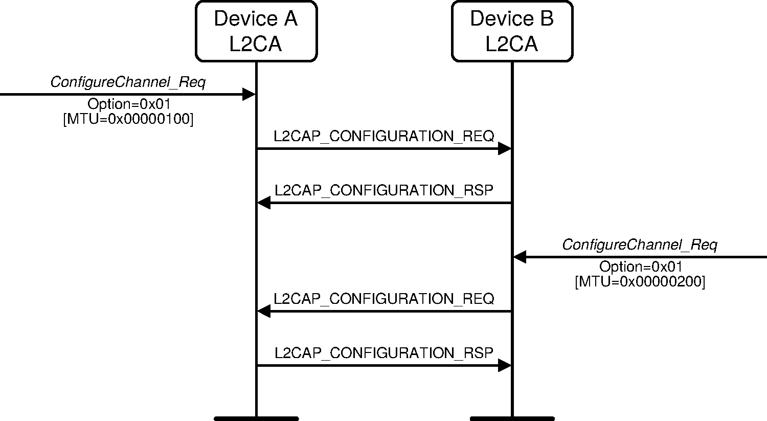
Figure A.2 illustrates how two devices interoperate even though one device supports more options than the other does. Device A is an upgraded version. It uses a hypothetically defined option type 0x20 for link-level security. Device B rejects the command using the L2CAP_CONFIGURATION_RSP packet with result ‘unknown parameter’ informing Device A that option 0x20 is not understood. Device A then resends the request omitting option 0x20. Device B notices that it does not need to such a large MTU and accepts the request but includes in the response the MTU option informing Device A that Device B will not send an L2CAP packet with a payload larger than 0x80 octets over this channel. On receipt of the response, Device A could reduce the buffer allocated to hold incoming traffic.
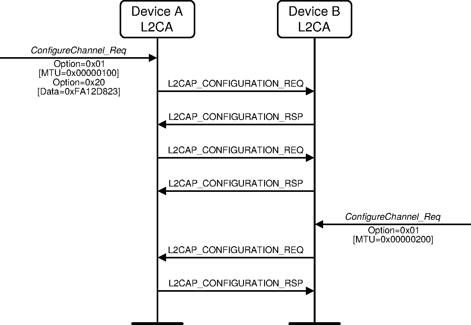
Figure A.3 illustrates an unsuccessful configuration request. There are two problems described by this example. The first problem is that the configuration request is placed in an L2CAP packet that cannot be accepted by the remote device, due to its size. The remote device informs the sender of this problem using the L2CAP_COMMAND_REJECT_RSP message. Device A then resends the configuration options using two smaller L2CAP_ConfigReq messages.
The second problem is an attempt to configure a channel with an invalid CID. For example device B may have no open connection on that CID (0x01234567 in this example case).
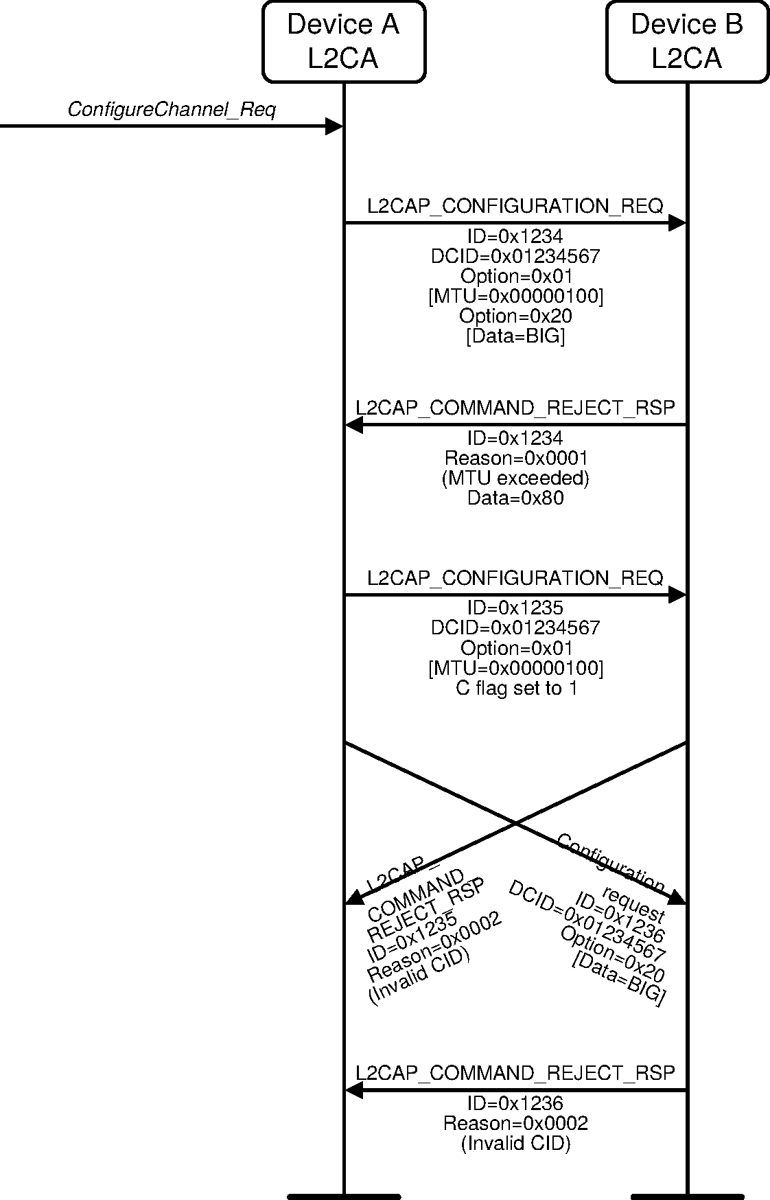
Appendix B. Changes to signaling packet names
Previous versions of this specification used different names for the signalling packets defined in Section 4. Table B.1 shows the previous and current names of these packets.
Previous name | Current name |
|---|---|
Command reject | L2CAP_COMMAND_REJECT_RSP |
Configuration request | L2CAP_CONFIGURATION_REQ |
Configuration response | L2CAP_CONFIGURATION_RSP |
Connection Parameter Update request | L2CAP_CONNECTION_PARAMETER_UPDATE_REQ |
Connection Parameter Update response | L2CAP_CONNECTION_PARAMETER_UPDATE_RSP |
Connection request | L2CAP_CONNECTION_REQ |
Connection response | L2CAP_CONNECTION_RSP |
Disconnection request | L2CAP_DISCONNECTION_REQ |
Disconnection response | L2CAP_DISCONNECTION_RSP |
Echo request | L2CAP_ECHO_REQ |
Echo response | L2CAP_ECHO_RSP |
Information request | L2CAP_INFORMATION_REQ |
Information response | L2CAP_INFORMATION_RSP |
LE Credit Based Connection request | L2CAP_LE_CREDIT_BASED_CONNECTION_REQ |
LE Credit Based Connection response | L2CAP_LE_CREDIT_BASED_CONNECTION_RSP |
LE Flow Control Credit | L2CAP_FLOW_CONTROL_CREDIT_IND |
[1] This was called LE_PSM in versions 4.1 to 5.1.
[2] Internet Engineering Task Force, “A Proposed Flow Specification”, RFC 1363, September 1992.
[3] For simplicity, the stripping of any additional HCI and USB specific information fields prior to the creation of the Baseband packets (Air_1, Air_2, etc.) is not shown in the figure.
[4] The Unicast Connectionless Data Reception bit in the L2CAP Extended Features Mask does not in any way indicate support or lack of support for reception of broadcast data on the connectionless L2CAP channel even though both broadcast data and unicast data are sent and received using the same CID (0x0002). For historical reasons, there is no bit to indicate support for sending or receiving of broadcast data on the connectionless L2CAP channel.