Part A. Architecture
vAtlanta r00
1. General description
Bluetooth wireless technology is a short-range communications system intended to replace the cable(s) connecting portable and/or fixed electronic devices. The key features of Bluetooth wireless technology are robustness, low power consumption, and low cost. Many features of the specification are optional, allowing product differentiation.
There are two forms of Bluetooth wireless technology systems: Basic Rate (BR) and Low Energy (LE). Both systems include device discovery, connection establishment and connection mechanisms. The Basic Rate system includes an optional Enhanced Data Rate (EDR) extension. The Basic Rate system offers synchronous and asynchronous connections with data rates of 721.2 kb/s for Basic Rate and 2.1 Mb/s for Enhanced Data Rate. The LE system includes features designed to enable products that require lower current consumption, lower complexity and lower cost than BR/EDR. The LE system is also designed for use cases and applications with lower data rates and has lower duty cycles. The LE system includes an optional 2 Mb/s physical layer data rate and also offers isochronous data transfer in a connection-oriented and connectionless mechanism that uses the isochronous transports. Depending on the use case or application, one system including any optional parts may be more optimal than the other.
Devices implementing both systems can communicate with other devices implementing both systems as well as devices implementing either system. Some profiles and use cases will be supported by only one of the systems. Therefore, devices implementing both systems have the ability to support the most use cases.
The Bluetooth core system consists of a Host and one or more Controllers. A Host is a logical entity defined as all of the layers below the non-core profiles and above the Host Controller interface (HCI). A Controller is a logical entity defined as all of the layers below HCI. An implementation of the Host and Controller may contain the respective parts of the HCI.
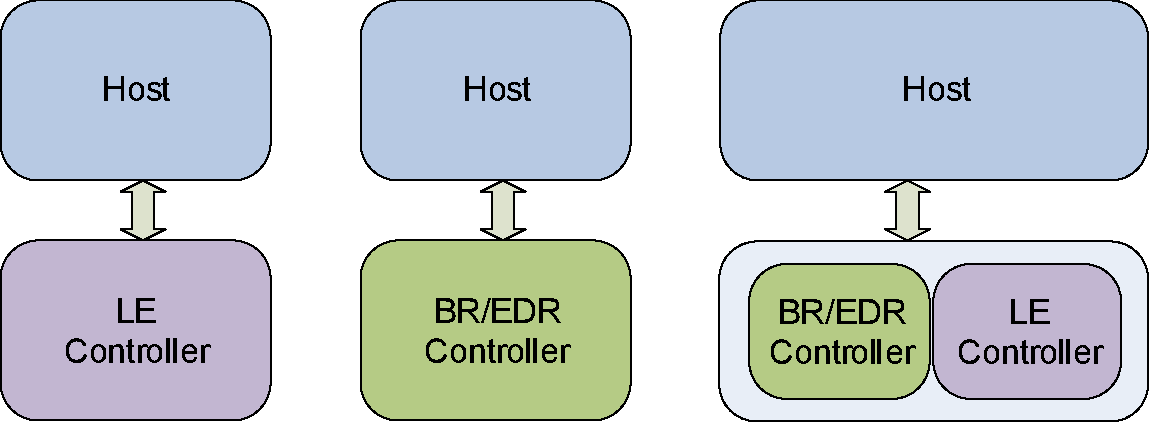
An implementation of the Bluetooth Core has only one Controller which may be one of the following configurations:
a BR/EDR Controller including the Radio, Baseband, Link Manager and optionally HCI.
an LE Controller including the LE PHY, Link Layer and optionally HCI.
a combined BR/EDR Controller portion and LE Controller portion (as identified in the previous two bullets) into a single Controller.
This Part of the specification provides an overview of the Bluetooth system architecture, communication topologies, and data transport features. The text in this Part of the specification should be treated as informational and used as a background and for context-setting.
1.1. Overview of BR/EDR operation
The Basic Rate / Enhanced Data Rate (BR/EDR) radio (physical layer or PHY) operates in the unlicensed ISM band at 2.4 GHz. The system employs a frequency hopping transceiver to combat interference and fading and provides many FHSS carriers. Basic Rate radio operation uses a shaped, binary frequency modulation to minimize transceiver complexity. The symbol rate is 1 megasymbol per second (Msym/s) supporting the bit rate of 1 megabit per second (Mb/s) or, with Enhanced Data Rate, a gross air bit rate of 2 Mb/s or 3 Mb/s. These modes are known as Basic Rate and Enhanced Data Rate respectively.
During typical operation a physical radio channel is shared by a group of devices that are synchronized to a common clock and frequency hopping pattern. One device provides the synchronization reference and is known as the Central. All other devices synchronized to a Central’s clock and frequency hopping pattern are known as Peripherals. A group of devices synchronized in this fashion form a piconet. This is the fundamental form of communication in the Bluetooth BR/EDR wireless technology.
Devices in a piconet use a specific frequency hopping pattern, which is algorithmically determined by certain fields in the Bluetooth address and clock of the Central. The basic hopping pattern is a pseudo-random ordering of the 79 frequencies, separated by 1 MHz, in the ISM band. The hopping pattern can be adapted – on a per-Peripheral basis – to exclude a portion of the frequencies that are used by interfering devices. The adaptive hopping technique improves Bluetooth co-existence with static (non-hopping) ISM systems when they are co-located.
The physical channel is sub-divided into time units known as slots. Data is transmitted between Bluetooth devices in packets that are positioned in these slots. When circumstances permit, a number of consecutive slots may be allocated to a single packet. Frequency hopping may take place between the transmission or reception of packets. Bluetooth technology provides the effect of full duplex transmission through the use of a Time-Division Duplex (TDD) scheme.
Above the physical channel there is a layering of links and channels and associated control protocols. The hierarchy of channels and links from the physical channel upwards is physical channel, physical link, logical transport, logical link and L2CAP channel. These are discussed in more detail in Section 3.3 to Section 3.6 but are introduced here to aid the understanding of the remainder of this section.
Typically within a physical channel, a physical link is formed between a Central and one or more Peripherals. Exceptions to this include Inquiry scan and Page scan physical channels, which have no associated physical link. The physical link provides bidirectional packet transport between the Central and Peripherals, except in the case of a Connectionless Peripheral Broadcast physical link. In that case, the physical link provides a unidirectional packet transport from the Central to a potentially unlimited number of Peripherals. Since a physical channel could include multiple Peripherals, there are restrictions on which devices may form a physical link. There is a physical link between each Peripheral and the Central. Physical links are not formed directly between the Peripherals in a piconet.
The physical link is used as a transport for one or more logical links that support unicast synchronous, asynchronous and isochronous traffic, and broadcast traffic. Traffic on logical links is multiplexed onto the physical link by occupying slots assigned by a scheduling function in the resource manager.
A control protocol for the baseband and physical layers is carried over logical links in addition to user data. This is the Link Manager protocol (LMP). Devices that are active in a piconet have a default asynchronous connection-oriented logical transport that is used to transport the LMP protocol signaling. For historical reasons this is known as the ACL logical transport. With the exception of Connectionless Peripheral Broadcast devices, the primary ACL logical transport is the one that is created whenever a device joins a piconet. Connectionless Peripheral Broadcast devices may join the piconet purely to listen to Connectionless Peripheral Broadcast packets. In that case, a Connectionless Peripheral Broadcast logical transport is created (also called a CPB logical transport) and no ACL logical transport is required. For all devices, additional logical transports may be created to transport synchronous data streams when required.
The Link Manager function uses LMP to control the operation of devices in the piconet and provide services to manage the lower architectural layers (radio and baseband). The LMP protocol is carried on the primary ACL and Active Peripheral Broadcast logical transports.
Above the baseband the L2CAP layer provides a channel-based abstraction to applications and services. It carries out segmentation and reassembly of application data and multiplexing and de-multiplexing of multiple channels over a shared logical link. L2CAP has a protocol control channel that is carried over the default ACL logical transport. Application data submitted to the L2CAP protocol may be carried on any logical link that supports the L2CAP protocol.
1.2. Overview of Bluetooth Low Energy operation
Like the BR/EDR radio, the LE radio operates in the unlicensed 2.4 GHz ISM band. The LE system employs a frequency hopping transceiver to combat interference and fading and provides many FHSS carriers. LE radio operation uses a shaped, binary frequency modulation to minimize transceiver complexity. LE uses terminology that differs from BR/EDR to describe supported PHYs with regards to differences in modulation, coding that may be applied, and the resulting data rates. The mandatory symbol rate is 1 megasymbol per second (Msym/s), where 1 symbol represents 1 bit therefore supporting a bit rate of 1 megabit per second (Mb/s), which is referred to as the LE 1M PHY. The 1 Msym/s symbol rate may optionally support error correction coding, which is referred to as the LE Coded PHY. This may use either of two coding schemes: S=2, where 2 symbols represent 1 bit therefore supporting a bit rate of 500 kb/s, and S=8, where 8 symbols represent 1 bit therefore supporting a bit rate of 125 kb/s. An optional symbol rate of 2 Msym/s may be supported, with a bit rate of 2 Mb/s, which is referred to as the LE 2M PHY. The 2 Msym/s symbol rate supports uncoded data only. LE 1M and LE 2M are collectively referred to as the LE Uncoded PHYs. Section 3.2.2 describes this terminology in more detail.
LE employs two multiple access schemes: Frequency division multiple access (FDMA) and time division multiple access (TDMA). Forty (40) physical channels, separated by 2 MHz, are used in the FDMA scheme. Three (3) are used as primary advertising channels and 37 are used as general purpose channels (including as secondary advertising channels). A TDMA based polling scheme is used in which one device transmits a packet at a predetermined time and a corresponding device responds with a packet after a predetermined interval.
The physical channel is sub-divided into time units known as events. Data is transmitted between LE devices in packets that are positioned in these events. The following types of events exist: Advertising, Extended Advertising, Periodic Advertising, Connection, and Isochronous events (which are partitioned into BIS, BIG, CIS, and CIG events).
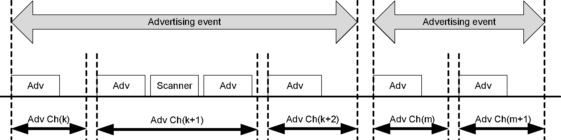
Devices that transmit advertising packets on the advertising PHY channels are referred to as advertisers. Devices that receive advertising packets on the advertising physical channels without the intention to connect to the advertising device are referred to as scanners. Transmissions on the advertising PHY channels occur in advertising events. At the start of each advertising event, the advertiser sends an advertising packet corresponding to the advertising event type. Depending on the type of advertising packet, the scanner may make a request to the advertiser on the same advertising PHY channel which may be followed by a response from the advertiser on the same advertising PHY channel. The advertising PHY channel changes on the next advertising packet sent by the advertiser in the same advertising event. The advertiser may end the advertising event at any time during the event. Each advertising packet in an advertising event uses a different advertising PHY channel. Each advertising event may use a different order for the advertising PHY channels.
LE devices may fulfill the entire communication in the case of unidirectional or broadcast communication between two or more devices using advertising events. LE devices may also use advertising events to establish bi-directional connections with another device and to establish asynchronous or isochronous periodic broadcasts. Asynchronous periodic broadcasts may allow the advertiser to receive responses from one or more devices. These additional activities make use of the general purpose channels in various ways.
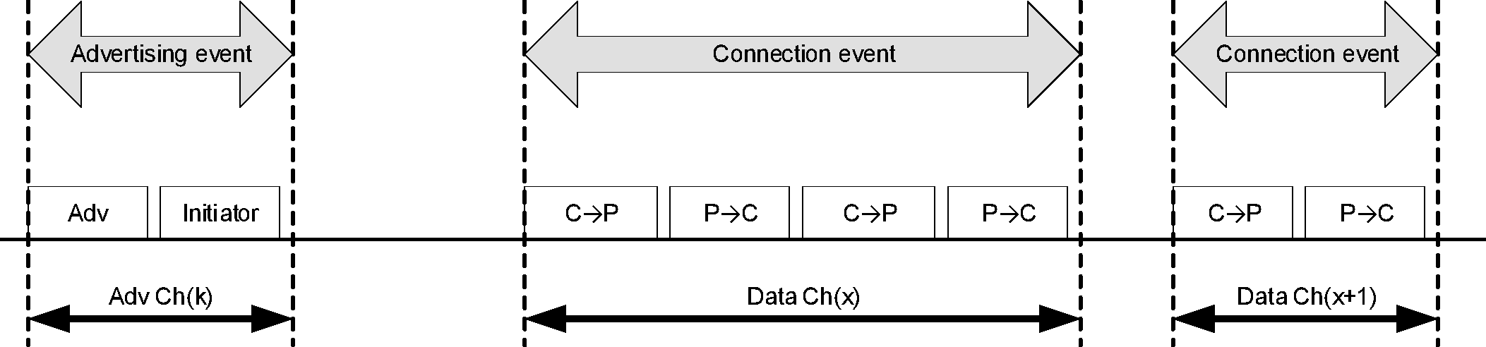
Devices that need to form an ACL connection to another device listen for connectable advertising packets. Such devices are referred to as initiators. If the advertiser is using a connectable advertising event, an initiator may make a connection request using the same advertising PHY channel on which it received the connectable advertising packet. The advertising event is ended and connection events begin if the advertiser receives and accepts the request for a connection be initiated. Once a connection is established, the initiator becomes the Central in what is referred to as a piconet and the advertising device becomes the Peripheral. Connection events are used to send data packets between the Central and Peripherals. In connection events, channel hopping occurs at the start of each connection event. Within a connection event, the Central and Peripheral alternate sending data packets using the same data PHY channel. The Central initiates the beginning of each connection event and can end each connection event at any time.
Devices in a piconet use a specific frequency hopping pattern, which is algorithmically determined by a field contained in the connection request sent by an initiating device. The hopping pattern used in LE is a pseudo-random ordering of the 37 frequencies in the ISM band. The hopping pattern can be adapted to exclude a portion of the frequencies that are used by interfering devices. The adaptive hopping technique improves Bluetooth co-existence with static (non-hopping) ISM systems when these are co-located and have access to information about the local radio environment, or detected by other means. A Peripheral can classify frequencies as good and bad and provide that information to the Central. The Central can take this information into consideration while adapting the hopping pattern.
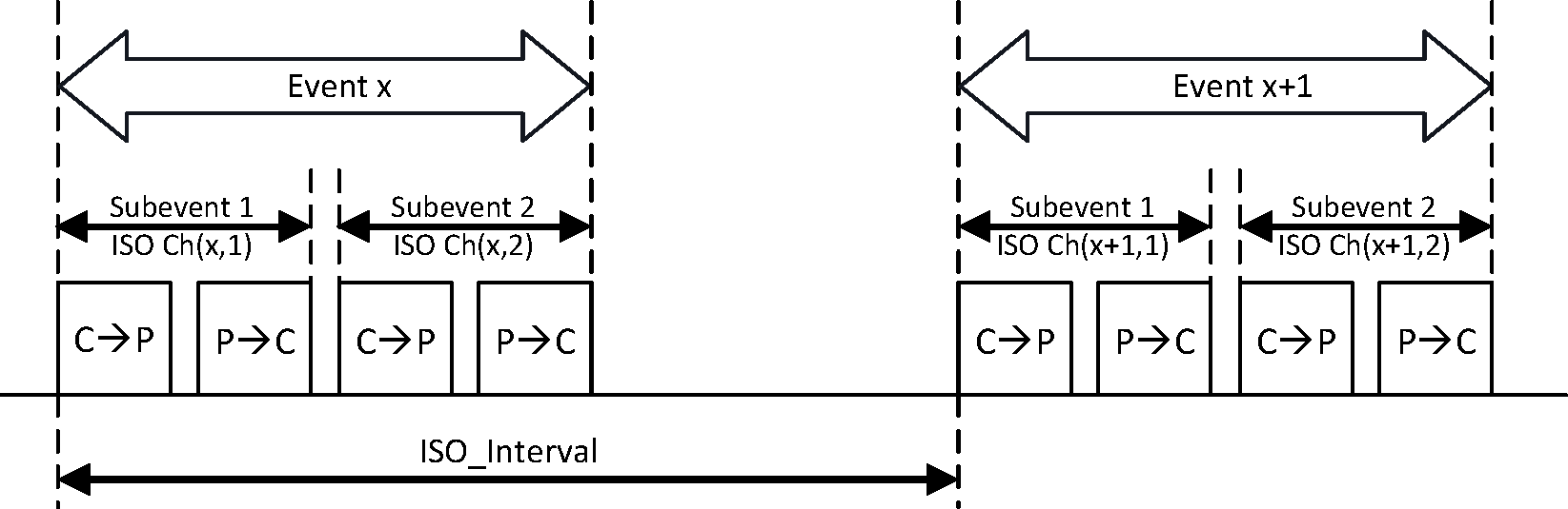
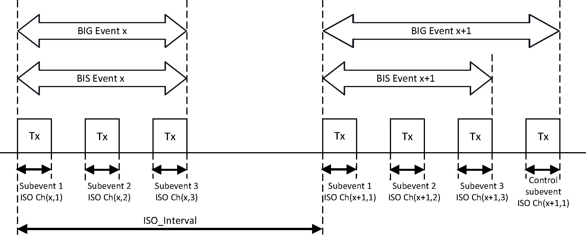
Using an ACL connection, a Central can establish one or more isochronous connections that use the isochronous physical channel. An isochronous connection is used to transfer isochronous data between the Central and a Peripheral by using a logical transport, which is referred to as a Connected Isochronous Stream (CIS). A CIS consists of CIS events that occur at regular intervals (designated ISO_Interval). Every CIS event consists of one or more subevents. In each subevent, the Central transmits once and the Peripheral responds. If the Central and Peripheral have completed transferring the scheduled isochronous data in a CIS event, all remaining subevents in that event will have no radio transmissions and the event is closed. Each subevent uses a PHY channel which is determined by using the channel selection algorithm. The PHY channel that is used for a subevent is marked as ISO Ch(eventcount, subeventcount), as shown in Figure 1.4.
A device can use an isochronous physical channel to broadcast isochronous data by using isochronous connectionless logical transports. An isochronous connectionless logical transport is referred to as a Broadcast Isochronous Stream (BIS). A BIS consists of BIS events that occur at regular intervals (designated ISO_Interval). Every BIS event consists of one or more subevents. In every subevent, a broadcasting device transmits an isochronous data packet. Each subevent uses a PHY channel that is determined using the channel selection algorithm.
A device can transmit several BISes with synchronized timing; this is referred to as a Broadcast Isochronous Group (BIG). The various BIS events together form a BIG event. The device can also use the isochronous physical channel to broadcast control information in a Control subevent, which is transmitted at the end of all subevents for a BIG, as shown in Figure 1.5.
A device that transmits BIG events also transmits periodic advertisement events that contain synchronization information of the BIG. A device that is scanning can synchronize to those periodic advertising events and receive the synchronization information. Using this synchronization information, the device can synchronize to one or more BISes in the BIG and receive the isochronous data. Figure 1.5 shows two BIG events: one with and one without a Control subevent. Each subevent uses a PHY channel marked as ISO Ch(eventcount, subeventcount), as shown in Figure 1.5.
Above the physical channel there are concepts of links, channels and associated control protocols. The hierarchy is physical channel, physical link, logical transport, logical link, and L2CAP channel. These are discussed in more detail in Section 3.3 to Section 3.6 but are introduced here to aid the understanding of the remainder of this section.
Within a physical channel, a physical link is formed between devices. The active physical link provides bidirectional packet transport between the Central and Peripherals. Centrals may have physical links to more than one Peripheral at a time and Peripherals may have physical links to more than one Central at a time. A device may be Central and Peripheral in different piconets at the same time. Role changes between a Central and Peripheral are not supported. The advertising and periodic physical links provide a unidirectional packet transport from the advertiser to a potentially unlimited number of scanners or initiators.
The physical link is used as a transport for one or more logical links that support asynchronous traffic. Traffic on logical links is multiplexed onto the physical link assigned by a scheduling function in the resource manager.
A control protocol for the link and physical layers is carried over logical links in addition to user data. This is the Link Layer protocol (LL). Devices that are active in a piconet have a default LE asynchronous connection logical transport (LE ACL) that is used to transport the LL protocol signaling. The default LE ACL is the one that is created whenever a piconet is created.
The Link Layer function uses the LL protocol to control the operation of devices in the piconet and provide services to manage the lower architectural layers (PHY and LL).
Overall, a piconet consists of one ACL logical transport over the active physical link plus zero or more CIS logical transports over the isochronous physical link(s).
Just as in BR/EDR, above the Link Layer the L2CAP layer provides a channel-based abstraction to applications and services. It carries out fragmentation and de-fragmentation of application data and multiplexing and de-multiplexing of multiple channels over a shared logical link. L2CAP has a protocol control channel that is carried over the primary ACL logical transport.
In addition to L2CAP, LE provides two additional protocol layers that reside on top of L2CAP. The Security Manager protocol (SMP) uses a fixed L2CAP channel to implement the security functions between devices. The other is the Attribute Protocol (ATT) that provides a method to communicate small amounts of data over a fixed L2CAP channel. The Attribute Protocol is also used by devices to determine the services and capabilities of other devices. The Attribute Protocol may also be used over BR/EDR.
The LE radio provides a means for detecting the relative direction of another LE radio by using the Angle of Arrival (AoA) or Angle of Departure (AoD) method.
1.3. [This section is no longer used]
1.4. Nomenclature
Where the following terms appear in the specification they have the meaning given in Table 1.1.
Active Peripheral Broadcast (APB) | The logical transport that is used to transport L2CAP user traffic and some kinds of LMP traffic to all active devices in the piconet over the BR/EDR Controller. See Section 3.5.4.4 |
Ad Hoc Network | A network typically created in a spontaneous manner. An ad hoc network requires no formal infrastructure and is limited in temporal and spatial extent. |
Advertiser | A Bluetooth Low Energy device that broadcasts advertising packets during advertising events on advertising channels |
Advertising event | A series of between one and three advertising packets on different advertising physical channels sent by an advertiser. |
Advertising Packet | A packet containing an advertising PDU. See [Vol 6] Part B, Section 2.3.1 |
Angle of Arrival (AoA) | Angle of Arrival is the relative direction at which a propagating RF wave that was transmitted by a single antenna is incident on an antenna array. |
Angle of Departure (AoD) | Angle of Departure is the relative direction from which a propagating RF wave that was transmitted using an antenna array is incident on another antenna. |
BD_ADDR | The Bluetooth Device Address, BD_ADDR, is used to identify a Bluetooth device. |
Bluetooth | Bluetooth is a wireless communication link, operating in the unlicensed ISM band at 2.4 GHz using a frequency hopping transceiver. It allows real-time AV and data communications between Bluetooth Hosts. The link protocol is based on time slots. |
Bluetooth Baseband | The part of the Bluetooth system that specifies or implements the medium access and physical layer procedures to support the exchange of real-time voice, data information streams, and ad hoc networking between Bluetooth Devices. |
Bluetooth Clock | A 28 bit clock internal to a BR/EDR Controller sub-system that ticks every 312.5 µs. The value of this clock defines the slot numbering and timing in the various physical channels. |
Bluetooth Controller | A generic term referring to a Controller. |
Bluetooth Device | A device that is capable of short-range wireless communications using the Bluetooth system. |
Bluetooth Device Address | A 48 bit address used to identify each Bluetooth device. |
BR/EDR | Bluetooth basic rate (BR) and enhanced data rate (EDR). |
BR/EDR Controller | A term referring to the Bluetooth Radio, Baseband, Link Manager, and HCI layers. |
BR/EDR Piconet Physical Channel | A Channel that is divided into time slots in which each slot is related to an RF hop frequency. Consecutive hops normally correspond to different RF hop frequencies and occur at a standard hop rate of 1600 hops per second. These consecutive hops follow a pseudo-random hopping sequence, hopping through a 79 RF channel set, or optionally fewer channels when Adaptive Frequency Hopping (AFH) is in use. |
BR/EDR/LE | Bluetooth basic rate (BR), enhanced data rate (EDR) and low energy (LE). |
C-plane | Control plane |
Channel | Either a physical channel or an L2CAP channel, depending on the context. |
Connect (to service) | The establishment of a connection to a service. If not already done, this also includes establishment of a physical link, logical transport, logical link and L2CAP channel. |
Connectable device | A BR/EDR device in range that periodically listens on its page scan physical channel and will respond to a page on that channel. An LE device that is advertising using a connectable advertising event. |
Connected devices | Two BR/EDR devices and with a physical link between them. |
Connecting | A phase in the communication between devices when a connection between the devices is being established. (Connecting phase follows after the link establishment phase is completed.) |
Connection | A connection between two peer applications or higher layer protocols mapped onto an L2CAP channel. |
Connection establishment | A procedure for creating a connection mapped onto a channel. |
Connection event | A series of one or more pairs of interleaving data packets sent between a Central and a Peripheral on the same physical channel. |
Connectionless Peripheral Broadcast (CPB) | A feature that enables a Central to broadcast information to an unlimited number of Peripherals. |
Connectionless Peripheral Broadcast Receiver | A Bluetooth device that receives broadcast information from a Connectionless Peripheral Broadcast Transmitter. The device is a Peripheral of the piconet. |
Connectionless Peripheral Broadcast Transmitter | A Bluetooth device that sends Connectionless Peripheral Broadcast messages for reception by one or more Connectionless Peripheral Broadcast receivers. The device is the Central of the piconet. |
Controller | A collective term referring to all of the layers below HCI. |
Coverage area | The area where two Bluetooth devices can exchange messages with acceptable quality and performance. |
Creation of a secure connection | A procedure of establishing a connection, including authentication and encryption. |
Creation of a trusted relationship | A procedure where the remote device is marked as a trusted device. This includes storing a common link key for future authentication, or pairing, when a link key is not available. |
Device discovery | A procedure for retrieving the Bluetooth Device Address, clock, and Class of Device from discoverable devices. |
Discoverable device | A BR/EDR device in range that periodically listens on an inquiry scan physical channel and will respond to an inquiry on that channel. An LE device in range that is advertising with a connectable or scannable advertising event with a discoverable flag set in the advertising data. This device is in the discoverable mode. |
Discoverable Mode | A Bluetooth device that is performing inquiry scans in BR/EDR or advertising with a discoverable or connectable advertising event with a discoverable flag set in LE. |
Discovery procedure | A Bluetooth device that is carrying out the inquiry procedure in BR/EDR or scanning for advertisers using a discoverable or connectable advertising event with a discoverable flag set in LE. |
HCI | The Host Controller interface (HCI) provides a command interface to the baseband Controller and link manager and access to hardware status and control registers. This interface provides a uniform method of accessing the Bluetooth baseband capabilities. |
Host | A logical entity defined as all of the layers below the non-core profiles and above the Host Controller interface (HCI); i.e., the layers specified in Volume 3. A Bluetooth Host attached to a Bluetooth Controller may communicate with other Bluetooth Hosts attached to their Controllers as well. |
Initiator | A Bluetooth Low Energy device that listens on advertising physical channels for connectable advertising events to form connections. |
Inquiring device | A BR/EDR device that is carrying out the inquiry procedure. This device is performing the discovery procedure. |
Inquiry | A procedure where a Bluetooth device transmits inquiry messages and listens for responses in order to discover the other Bluetooth devices that are within the coverage area. |
Inquiry scan | A procedure where a Bluetooth device listens for inquiry messages received on its inquiry scan physical channel. |
Interoperability | The ability of two or more devices to exchange information and to use the information that has been exchanged. |
Isochronous data | Information in a stream where each information entity in the stream is bound by a time relationship to previous and successive entities. |
Known device | A Bluetooth device for which at least the BD_ADDR is stored. |
L2CAP | Logical Link Control and Adaptation Protocol |
L2CAP Channel | A logical connection on L2CAP level between two devices serving a single application or higher layer protocol. |
L2CAP Channel establishment | A procedure for establishing a logical connection on L2CAP level. |
LE | Bluetooth Low Energy |
Link | Shorthand for a logical link. |
Link establishment | A procedure for establishing the default ACL link and hierarchy of links and channels between devices. |
Link key | A secret key that is known by two devices and is used to authenticate the link. |
LMP authentication | An LMP level procedure for verifying the identity of a remote device. |
LMP pairing | A procedure that authenticates two devices and creates a common link key that can be used as a basis for a trusted relationship or a (single) secure connection. |
Logical link | The lowest architectural level used to offer independent data transport services to clients of the Bluetooth system. |
Logical transport | Shared acknowledgment protocol and link identifiers between different logical links. |
Name discovery | A procedure for retrieving the user-friendly name (the Bluetooth Device Name) of a connectable device. |
Packet | Format of aggregated bits that are transmitted on a physical channel. |
Page | The initial phase of the connection procedure where a device transmits a train of page messages until a response is received from the target device or a time-out occurs. |
Page scan | A procedure where a device listens for page messages received on its page scan physical channel. |
Paging device | A Bluetooth device that is carrying out the page procedure. |
Paired device | A Bluetooth device for which a link key has been created (either before connection establishment was requested or during connecting phase). |
Passkey | A 6-digit number used to authenticate connections when Secure Simple Pairing is used. |
Periodic advertising synchronization information | The control information describing a periodic advertisement that a Bluetooth Low Energy device uses to synchronize to the advertisement it describes. |
Physical Channel | Characterized by synchronized occupancy of a sequence of RF carriers by one or more devices. A number of physical channel types exist with characteristics defined for their different purposes. |
Physical link | A Baseband or Link Layer level connection between two devices. |
Physical Transport | PHY packet transmission and/or reception on an RF channel using one or more modulation schemes. |
Piconet | A collection of devices (up to eight devices in BR/EDR, exactly two devices in LE) occupying a shared physical channel where one of the devices is the Piconet Central and the remaining devices are connected to it. |
Piconet Central | The BR/EDR device in a piconet whose Bluetooth Clock and Bluetooth Device Address are used to define the piconet physical channel characteristics. The LE device in a piconet which initiates the creation of the piconet, chooses the Access Address that identifies the piconet, and transmits first in each connection event. |
Piconet Peripheral | Any BR/EDR device in a piconet that is not the Piconet Central, but is connected to the Piconet Central. The LE device in a piconet which is not the Central but communicates with it. |
PIN | A user-friendly number that can be used to authenticate connections to a device before pairing has taken place. |
Profile Broadcast Data (PBD) | A logical link that carries data from a Connectionless Peripheral Broadcast Transmitter to one or more Connectionless Peripheral Broadcast Receivers. |
Resolving List | A list of records used to generate and resolve Resolvable Private Addresses. Each record contains a local Identity Resolving Key, a peer Identity Resolving Key, and a peer Identity Address. |
Scanner | A Bluetooth Low Energy device that listens for advertising events on the advertising physical channels. |
Scatternet | Two or more piconets that have one or more devices in common. |
Service discovery | Procedures for querying and browsing for services offered by or through another Bluetooth device. |
Service Layer Protocol | A protocol that uses an L2CAP channel for transporting PDUs. |
Silent device | A Bluetooth enabled device appears as silent to a remote device if it does not respond to inquiries made by the remote device. |
Synchronization Scan Physical Channel | A physical channel that enables a Peripheral to receive synchronization train packets from a Central. |
Synchronization Train | A series of packets transmitted on a set of fixed frequencies that deliver sufficient information for a receiving device to start receiving corresponding Connectionless Peripheral Broadcast packets or to recover the current piconet clock after missing a Coarse Clock Adjust. |
Tick | (BR/EDR) the time between changes of the value of the Bluetooth Clock: 312.5 µs. |
U-plane | User plane |
Unknown device | A Bluetooth device for which no information (Bluetooth Device Address, link key or other) is stored. |
2. Core system architecture
The Bluetooth Core system consists of a Host and a Controller. A minimal implementation of the Bluetooth BR/EDR core system covers the four lowest layers and associated protocols defined by the Bluetooth specification as well as one common service layer protocol; the Service Discovery Protocol (SDP) and the overall profile requirements are specified in the Generic Access Profile (GAP). A minimal implementation of a Bluetooth LE only core system covers the four lowest layers and associated protocols defined by the Bluetooth specification as well as two common service layer protocols; the Security Manager (SM) and Attribute Protocol (ATT) and the overall profile requirements are specified in the Generic Attribute Profile (GATT) and Generic Access Profile (GAP). Implementations combining Bluetooth BR/EDR and LE include both of the minimal implementations described above.
A complete Bluetooth application requires a number of additional service and higher layer protocols that are defined in the Bluetooth specification, but are not described here. The core system architecture is shown in Figure 2.1.
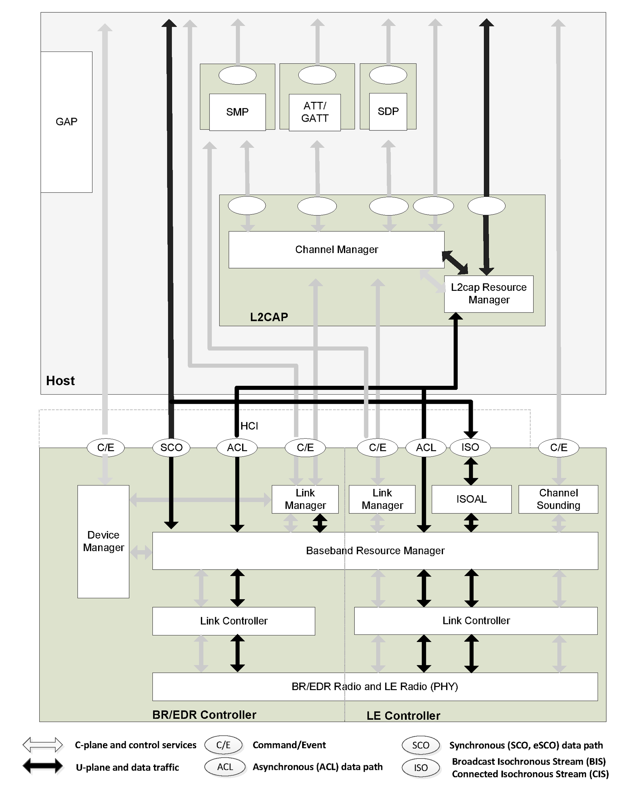 |
Figure 2.1 shows the Core blocks, each with its associated communication protocol. Link Manager, Link Controller and BR/EDR Radio blocks comprise a BR/EDR Controller. Link Manager, Link Controller and LE Radio blocks comprise an LE Controller. L2CAP, SDP and GAP blocks comprise a BR/EDR Host. L2CAP, SMP, Attribute Protocol, GAP and Generic Attribute Profile (GATT) blocks comprise an LE Host. A BR/EDR/LE Host combines the set of blocks from each respective Host. This is a common implementation involving a standard physical communication interface between the Controller and the Host. Although this interface is optional the architecture is designed to allow for its existence and characteristics. The Bluetooth specification enables interoperability between independent Bluetooth systems by defining the protocol messages exchanged between equivalent layers, and also interoperability between independent Bluetooth Controllers and Bluetooth Hosts by defining a common interface between Bluetooth Controllers and Bluetooth Hosts.
A number of functional blocks and the path of services and data between them are shown. The functional blocks shown in the diagram provide a set of conceptual entities that are used when describing the requirements of the specification; in general the Bluetooth specification does not define the details of implementations except where this is required for interoperability. Thus the functional blocks in Figure 2.1 are shown in order to aid description of the system behavior. An implementation may be different from the system shown in Figure 2.1.
Standard interactions are defined for all inter-device operation, where Bluetooth devices exchange protocol signaling according to the Bluetooth specification. The Bluetooth core system protocols are the Radio (PHY) protocol, Link Control (LC) and Link Manager (LM) protocol or Link Layer (LL) protocol, and Logical Link Control and Adaptation protocol (L2CAP), all of which are fully defined in subsequent parts of the Bluetooth specification. In addition, the Service Discovery protocol (SDP) and the Attribute Protocol (ATT) are service layer protocols that may be required by some Bluetooth applications.
The Bluetooth core system offers services through a number of service access points that are shown in the diagram as ellipses. These services consist of the basic primitives that control the Bluetooth core system. The services can be split into three types. There are device control services that modify the behavior and modes of a Bluetooth device, transport control services that create, modify and release traffic bearers (channels and links), and data services that are used to submit data for transmission over traffic bearers. It is common to consider the first two as belonging to the C-plane and the last as belonging to the U-plane.
A service interface to the Bluetooth Controller is defined such that the Controller may be considered a standard part. In this configuration the Bluetooth Controller operates the lowest four layers. The Bluetooth Host operates the L2CAP layer and other higher layers. The standard interface is called the Host Controller interface (HCI) and its service access points are represented by the ellipses on the upper edge of the Bluetooth Controller in Figure 2.1. Implementation of this standard service interface is optional.
As the Bluetooth architecture is defined with the possibility of separate Host and Controller(s) communicating through one or more HCI transports, a number of general assumptions are made. Bluetooth Controllers are assumed to have limited data buffering capabilities in comparison with the Host. Therefore the L2CAP layer is expected to carry out some simple resource management when submitting L2CAP PDUs to the Controller for transport to a peer device. This includes segmentation of L2CAP SDUs into more manageable PDUs and then the fragmentation of PDUs into start and continuation packets of a size suitable for the Controller buffers, and management of the use of Controller buffers to ensure availability for channels with Quality of Service (QoS) commitments.
The BR/EDR Baseband and LE Link Layer provide the basic acknowledgment/repeat request (ARQ) protocol in Bluetooth. The L2CAP layer can optionally provide a further error detection and retransmission to the L2CAP PDUs. This feature is recommended for applications with requirements for a low probability of undetected errors in the user data. A further optional feature of L2CAP is a window-based flow control that can be used to manage buffer allocation in the receiving device. Both of these optional features augment the QoS performance in certain scenarios. Not all of the L2CAP capabilities are available when using the LE system.
Although these assumptions are not always required for embedded Bluetooth implementations that combine all layers in a single system, the general architectural and QoS models are defined with these assumptions in mind, in effect a lowest common denominator.
Automated conformance testing of implementations of the Bluetooth core system is required. This is achieved by allowing the tester to control the implementation through the PHY interface, test interfaces such as Direct Test Mode (DTM), and test commands and events over HCI which are only required for conformance testing.
The tester exchanges messages with the Implementation Under Test (IUT) through the PHY interface to ensure the correct responses to requests from remote devices. The tester controls the IUT through HCI, DTM, or test commands to cause the IUT to originate exchanges through the PHY interface so that these can also be verified as conformant.
2.1. Core architectural blocks
This section describes the function and responsibility of each of the blocks shown in Figure 2.1. An implementation is not required to follow the architecture described above, though every implementation is still required to conform to the protocol specifications, behaviors, and other requirements specified in subsequent parts of the Bluetooth specification.
2.1.1. Host architectural blocks
2.1.1.1. Channel manager
The channel manager is responsible for creating, managing and closing L2CAP channels for the transport of service protocols and application data streams. The channel manager uses the L2CAP protocol to interact with a channel manager on a remote (peer) device to create these L2CAP channels and connect their endpoints to the appropriate entities. The channel manager interacts with its local link manager to create new logical links (if necessary) and to configure these links to provide the required quality of service for the type of data being transported.
2.1.1.2. L2CAP resource manager
The L2CAP resource manager block is responsible for managing the ordering of submission of PDU fragments to the baseband and some relative scheduling between channels to ensure that L2CAP channels with QoS commitments are not denied access to the physical channel due to Controller resource exhaustion. This is required because the architectural model does not assume that a Controller has limitless buffering, or that the HCI is a pipe of infinite bandwidth.
L2CAP Resource Managers may also carry out traffic conformance policing to check that applications are submitting L2CAP SDUs within the bounds of their negotiated QoS settings. The general Bluetooth data transport model assumes well-behaved applications, and does not define how an implementation is expected to deal with this problem.
2.1.1.3. Security Manager Protocol
The Security Manager Protocol (SMP) is the peer-to-peer protocol used to generate encryption keys and identity keys. The protocol operates over a dedicated fixed L2CAP channel. The SMP block also manages storage of the encryption keys and identity keys and is responsible for generating random addresses and resolving random addresses to known device identities. The SMP block interfaces directly with the Controller to provide stored keys used for encryption and authentication during the encryption or pairing procedures.
This block is only used in LE systems. Similar functionality in the BR/EDR system is contained in the Link Manager block in the Controller. SMP functionality is in the Host on LE systems to reduce the implementation cost of the LE only Controllers.
2.1.1.4. Attribute Protocol
The Attribute Protocol (ATT) block implements the peer-to-peer protocol between an ATT Server and an ATT Client. The ATT Client communicates with an ATT Server on a remote device over a dedicated fixed L2CAP channel. The ATT Client sends commands, requests, and confirmations to the ATT Server. The ATT Server sends responses, notifications and indications to the client. These ATT Client commands and requests provide a means to read and write values of attributes on a peer device with an ATT Server.
2.1.1.5. [This section is no longer used]
2.1.1.6. Generic Attribute Profile
The Generic Attribute Profile (GATT) block represents the functionality of the ATT Server and, optionally, the ATT Client. The profile describes the hierarchy of services, characteristics and attributes used in the ATT Server. The block provides interfaces for discovering, reading, writing and indicating of service characteristics and attributes. GATT is used on LE devices for LE profile service discovery.
2.1.1.7. Generic Access Profile
The Generic Access Profile (GAP) block represents the base functionality common to all Bluetooth devices such as modes and access procedures used by the transports, protocols and application profiles. GAP services include device discovery, connection modes, security, authentication, association models and service discovery.
2.1.2. BR/EDR/LE Controller architectural blocks
In implementations where the BR/EDR and LE systems are combined, the architectural blocks may be shared between systems or each system may have their own instantiation of the block.
2.1.2.1. Device manager
The device manager is the functional block in the baseband that controls the general behavior of the Bluetooth device. It is responsible for all operations of the Bluetooth system that are not directly related to data transport, such as inquiring for the presence of nearby Bluetooth devices, connecting to Bluetooth devices, or making the local Bluetooth device discoverable or connectable by other devices.
The device manager requests access to the transport medium from the baseband resource Controller in order to carry out its functions.
The device manager also controls local device behavior implied by a number of the HCI commands, such as managing the device local name, any stored link keys, and other functionality.
2.1.2.2. Link manager
The link manager is responsible for the creation, modification and release of logical links (and, if required, their associated logical transports), as well as the update of parameters related to physical links between devices. The link manager achieves this by communicating with the link manager in remote Bluetooth devices using the Link Manager Protocol (LMP) in BR/EDR and the Link Layer Protocol (LL) in LE.
The LM or LL protocol allows the creation of new logical links and logical transports between devices when required, as well as the general control of link and transport attributes such as the enabling of encryption on the logical transport, the adapting of transmit power on the physical link, or the adjustment of QoS settings in BR/EDR for a logical link.
2.1.2.3. Baseband resource manager
The baseband resource manager is responsible for all access to the radio medium. It has two main functions. At its heart is a scheduler that grants time on the physical channels to all of the entities that have negotiated an access contract. The other main function is to negotiate access contracts with these entities. An access contract is effectively a commitment to deliver a certain QoS that is required in order to provide a user application with an expected performance.
The access contract and scheduling function must take account of any behavior that requires use of the Controller. This includes (for example) the normal exchange of data between connected devices over logical links, and logical transports, as well as the use of the radio medium to carry out inquiries, make connections, be discoverable or connectable, or to take readings from unused carriers during the use of adaptive frequency hopping mode.
In some cases in BR/EDR systems the scheduling of a logical link results in changing a logical link to a different physical channel from the one that was previously used. This may be (for example) due to involvement in scatternet, a periodic inquiry function, or page scanning. When the physical channels are not time slot aligned, then the resource manager also accounts for the realignment time between slots on the original physical channel and slots on the new physical channel. In some cases the slots will be naturally aligned due to the same device clock being used as a reference for both physical channels.
2.1.2.4. Link Controller
The Link Controller is responsible for the encoding and decoding of Bluetooth packets from the data payload and parameters related to the physical channel, logical transport and logical link.
The Link Controller carries out the link control protocol signaling in BR/EDR and Link Layer protocol in LE (in close conjunction with the scheduling function of the resource manager), which is used to communicate flow control and acknowledgment and retransmission request signals. The interpretation of these signals is a characteristic of the logical transport associated with the baseband packet. Interpretation and control of the link control signaling is normally associated with the resource manager’s scheduler.
2.1.2.5. PHY
The PHY block is responsible for transmitting and receiving packets of information on the physical channel. A control path between the baseband and the PHY block allows the baseband block to control the timing and frequency carrier of the PHY block. The PHY block transforms a stream of data to and from the physical channel and the baseband into required formats.
2.1.2.6. Isochronous Adaptation Layer
The Isochronous Adaptation Layer (ISOAL) enables the upper layer to send or receive isochronous data to or from the Link Layer in a flexible way such that the size and interval of data packets in the upper layer can be different from the size and interval of data packets in the Link Layer. The ISOAL uses fragmentation/recombination or segmentation/reassembly operations to convert upper layer data units into lower layer data units (or the other way around).
2.1.3. [This section is no longer used]
3. Data transport architecture
The Bluetooth data transport system follows a layered architecture. This description of the Bluetooth system describes the Bluetooth core transport layers up to and including L2CAP channels. All Bluetooth operational modes follow the same generic transport architecture, which is shown in Figure 3.1.
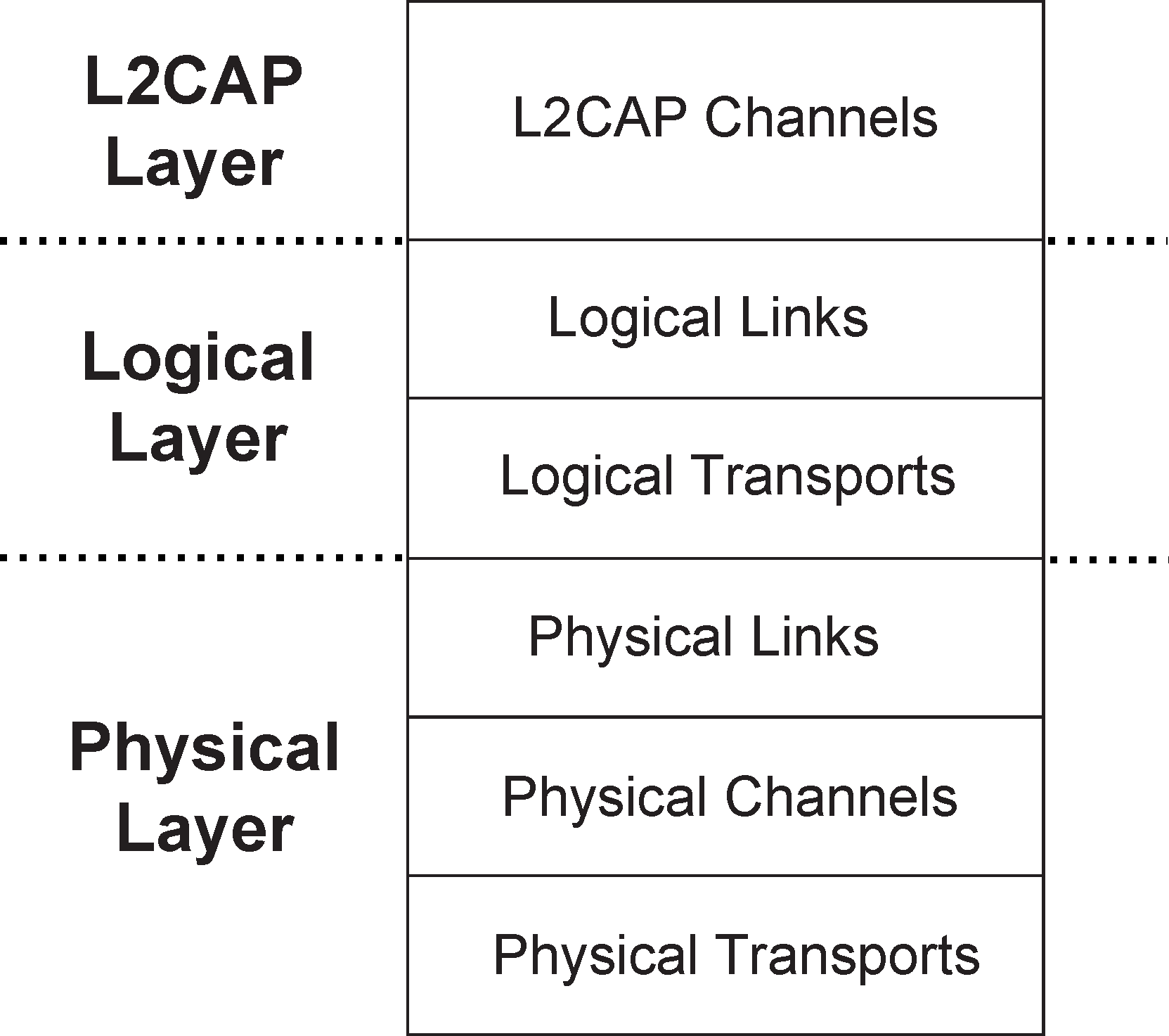
For efficiency and legacy reasons, the Bluetooth transport architecture includes a sub-division of the logical layer, distinguishing between logical links and logical transports. This sub-division provides a general (and commonly understood) concept of a logical link that provides an independent transport between two or more devices. The logical transport sub-layer is required to describe the inter-dependence between some of the logical link types (mainly for reasons of legacy behavior).
The ACL, SCO, and eSCO connections are considered as logical transports but often behave as separate physical links. However, they are not as independent as might be desired, due to their shared use of resources such as the LT_ADDR and acknowledgment/repeat request (ARQ) scheme. Hence the architecture is incapable of representing these logical transports with a single transport layer. The additional logical transport layer goes some way towards describing this behavior.
3.1. Core traffic bearers
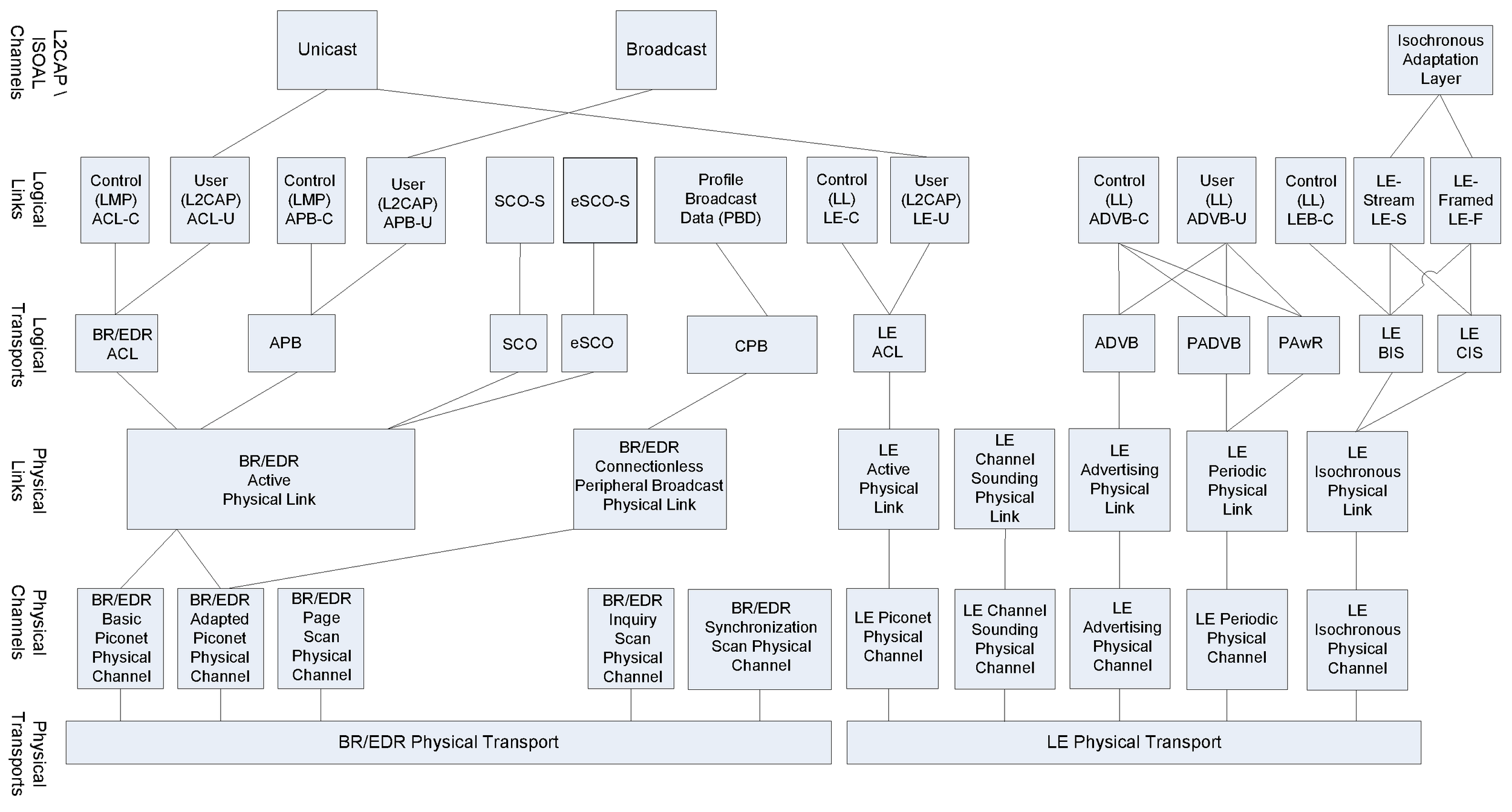
The Bluetooth core system provides a number of standard traffic bearers for the transport of service protocol and application data. These are shown in Figure 3.2 below (for ease of representation this is shown with higher layers to the left and lower layers to the right).
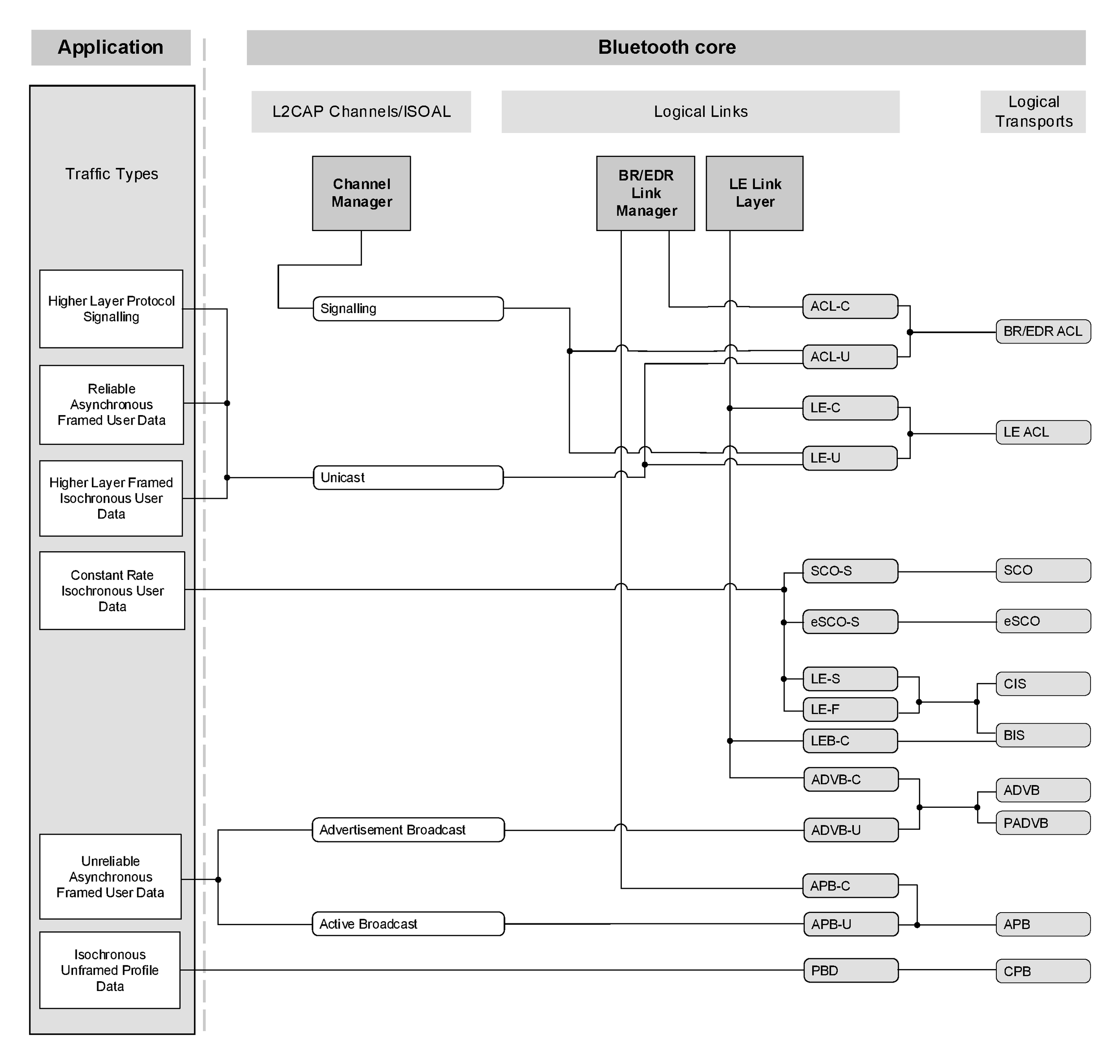
The core traffic bearers that are available to applications are shown in Figure 3.2 as the shaded rounded rectangles. The architectural layers that are defined to provide these services are described in Section 2. A number of data traffic types are shown on the left of the diagram linked to the traffic bearers that are typically suitable for transporting that type of data traffic.
The logical links are named using the names of the associated logical transport and a suffix that indicates the type of data that is transported. (C for control links carrying LMP or LL messages, U for L2CAP links carrying user data (L2CAP PDUs) and S for stream links carrying unformatted synchronous or isochronous data.) It is common for the suffix to be removed from the logical link without introducing ambiguity, thus a reference to the default ACL logical transport can be resolved to mean the ACL-C logical link in cases where the LMP protocol is being discussed, the LE-C logical link in cases where LL protocol is being discussed, or the ACL-U or LE-U logical links when the L2CAP layer is being discussed.
The mapping of application traffic types to Bluetooth core traffic bearers in Figure 3.2 is based on matching the traffic characteristics with the bearer characteristics. It is recommended to use these mappings as they provide the most natural and efficient method of transporting the data with its given characteristics.
However, an application (or an implementation of the Bluetooth core system) may choose to use a different traffic bearer, or a different mapping to achieve a similar result. For example, in a BR/EDR piconet with only one Peripheral, the Central may choose to transport L2CAP broadcasts over the ACL-U logical link rather than over the APB-U logical link. This will probably be more efficient in terms of bandwidth (if the physical channel quality is not too degraded). Use of alternative transport paths to those in Figure 3.2 is only acceptable if the characteristics of the application traffic type are preserved.
Figure 3.2 shows a number of application traffic types. These are used to classify the types of data that may be submitted to the Bluetooth core system. The original data traffic type can be different from the type that is submitted to the Bluetooth core system if an intervening process modifies it. For example, video data is generated at a constant rate but an intermediate coding process may alter this to variable rate, e.g. by MPEG4 encoding. For the purposes of the Bluetooth core system, only the characteristic of the submitted data is of interest.
3.1.1. Framed data traffic
The L2CAP layer services provide a frame-oriented transport for asynchronous and isochronous user data. The application submits data to this service in variable-sized frames (up to a negotiated maximum for the channel) and these frames are delivered in the same form to the corresponding application on the remote device. There is no requirement for the application to insert additional framing information into the data, although it may do so if this is required (such framing is invisible to the Bluetooth core system).
Connection-oriented L2CAP channels may be created for transport of unicast (point-to-point) data between two Bluetooth devices. Connection-oriented channels provide a context within which specific properties may be applied to data transported on the channel. For example, quality of service parameters or flow and error control modes may be applied. Connection-oriented L2CAP channels are created using the L2CAP connection procedure.
A connectionless BR/EDR L2CAP channel exists for broadcasting data or for transport of unicast data. In the case of piconet topologies the Central is always the source of broadcast data and the Peripheral(s) are the recipients. Broadcast traffic on the connectionless L2CAP channel is uni-directional. Unicast data sent on the connectionless L2CAP channels may be uni-directional or bi-directional. Unicast data sent on the L2CAP connectionless channel provides an alternate mechanism to send data with the same level of reliability as an L2CAP connection-oriented channel operating in Basic mode but without the additional latency incurred by opening an L2CAP connection-oriented channel. LE L2CAP connectionless channels are not supported.
BR/EDR L2CAP channels have an associated QoS setting that defines constraints on the delivery of the frames of data. These QoS settings may be used to indicate (for example) that the data is isochronous, and therefore has a limited lifetime after which it becomes invalid, or that the data should be delivered within a given time period, or that the data is reliable and should be delivered without error, however long this takes.
Some L2CAP channels are fixed channels created when the ACL-U and/or LE-U logical links are established. These fixed channels have fixed channel identifiers and fixed configurations and do not permit negotiation of the configuration after they are created. These fixed channels are used for BR/EDR and LE L2CAP signaling (ACL-U or LE-U), connectionless channel (ACL-U and APB-U), Security Manager Protocol (LE-U), and Attribute Protocol (ACL-U or LE-U).
The L2CAP channel manager is responsible for arranging to transport the L2CAP channel data frames on an appropriate baseband logical link, possibly multiplexing this onto the baseband logical link with other L2CAP channels with similar characteristics.
3.1.2. Unframed data traffic
If the application does not require delivery of data in frames, possibly because it includes in-stream framing, or because the data is a pure stream, then it may avoid the use of L2CAP channels and make direct use of a baseband logical link.
The Bluetooth core system supports the direct transport of application data that is isochronous and of a constant rate (either bit-rate, or frame-rate for pre-framed data), using a SCO-S or eSCO-S logical link. These logical links reserve physical channel bandwidth and provide a constant rate transport locked to the piconet clock. Data is transported in fixed size packets at fixed intervals with both of these parameters negotiated during channel establishment. eSCO links provide a greater choice of bit-rates and also provide greater reliability by using limited retransmission in case of error. Enhanced Data Rate operation is supported for eSCO, but not for SCO logical transports. SCO and eSCO logical transports do not support multiplexed logical links or any further layering within the Bluetooth core. An application may choose to layer a number of streams within the submitted SCO/eSCO stream, provided that the submitted stream is, or has the appearance of being, a constant rate stream.
The Bluetooth core system also supports the direct transport of application data using a Profile Broadcast Data (PBD) logical link. This logical link is similar to SCO-S and eSCO-S since it reserves physical channel bandwidth, provides a constant rate transport locked to the piconet clock, and transports data at fixed intervals. It does not support multiplexed logical links or any further layering within the Bluetooth core but, unlike SCO-S and eSCO-S, it supports broadcasting data from a single transmitter to many receivers.
The application chooses the most appropriate type of logical link from those available at the baseband, and creates and configures it to transport the data stream, and releases it when completed. (The application will normally also use a framed L2CAP unicast channel to transport its C-plane information to the peer application on the remote device.)
If the application data is isochronous and of a variable rate, then this may only be carried by the L2CAP unicast channel, and hence will be treated as framed data.
Unframed data traffic is not supported in the LE system.
3.1.3. Reliability of traffic bearers
A link or channel is characterized as reliable if the receiver is capable of detecting errors in received packets and requesting retransmission until the errors are removed. This is known as an Automatic Repeat reQuest (ARQ) scheme. Due to the error detection systems used, some residual undetected errors may still remain in the received data. The rate at which these occur depends on the details of the error detection system.
A link or channel is characterized as unreliable if the receiver is not capable of detecting errors in received packets or if it can detect errors but cannot request retransmission. In the latter case (such as with most broadcast links), the packets passed on by the receiver to higher layers may be without error but there is no guarantee that all the packets that were sent are received. Uses for unreliable links are normally dependent on techniques to improve the redundancy of the transmission, such as the use of Forward Error Connection or the repetition of data from the higher layers while the data is valid, in order to increase the probability that the receiver is able to receive at least one of the copies successfully.
3.1.3.1. BR/EDR reliability
Bluetooth is a wireless communications system. In poor RF environments, this system should be considered inherently unreliable. To counteract this the system provides levels of protection at each layer. The baseband packet header uses forward error correcting (FEC) coding to allow error correction by the receiver and a header error check (HEC) to detect errors remaining after correction. Certain Baseband packet types include FEC for the payload. Furthermore, some Baseband packet types include a cyclic redundancy error check (CRC).
On ACL logical transports the results of the error detection algorithm are used to drive a simple ARQ protocol. This provides an enhanced reliability by re-transmitting packets that do not pass the receiver’s error checking algorithm. It is possible to modify this scheme to support latency-sensitive packets by discarding an unsuccessfully transmitted packet at the transmitter if the packet’s useful life has expired. eSCO links use a modified version of this scheme to improve reliability by allowing a limited number of retransmissions.
The resulting reliability gained by this ARQ scheme is only as dependable as the ability of the HEC and CRC codes to detect errors. In most cases this is sufficient, however it has been shown that for the longer packet types the probability of an undetected error is too high to support typical applications, especially those with a large amount of data being transferred.
The L2CAP layer provides an additional level of error control that is designed to detect the occasional errors not detected by the baseband and request retransmission of the affected data. This provides the level of reliability required by typical Bluetooth applications. The resulting rate of residual errors is comparable to the rate in other communication systems.
The transmitter may remove packets from the transmit queue such that the receiver does not receive all the packets in the sequence. If this happens detection of the missing packets is delegated to the L2CAP layer.
Stream links have a reliability characteristic somewhere between a reliable and an unreliable link, depending on the current operating conditions.
3.1.3.2. LE reliability
Like BR/EDR, in poor RF environments, the LE system should be considered inherently unreliable. To counteract this, the system provides levels of protection at each layer. The LL packet uses a 24-bit cyclic redundancy error check (CRC) to cover the contents of the packet payload. If the CRC verification fails on the packet payload, the packet is not acknowledged by the receiver and the packet gets retransmitted by the sender.
Because of the longer CRC and the shorter typical message compared with BR/EDR, it is not necessary for the L2CAP layer to provide a separate error detection and retransmission mechanism.
3.1.3.3. [This section is no longer used]
3.2. Transport architecture entities
The Bluetooth transport architecture entities are shown in Figure 3.3 and are described from the lowest layer upwards in the subsequent sections.
 |
The BR/EDR Physical Transport encapsulates the BR/EDR Physical Channels. Transfers using the BR/EDR Physical Transport use the BR/EDR Generic Packet Structure. The LE Physical Transport encapsulates the LE Physical Channels. Transfers using the LE Physical Transport use the LE Generic Packet Structure.
3.2.1. BR/EDR generic packet structure
The generic packet structure nearly reflects the architectural layers found in the Bluetooth BR/EDR system. The BR/EDR packet structure is designed for optimal use in normal operation. It is shown in Figure 3.4.
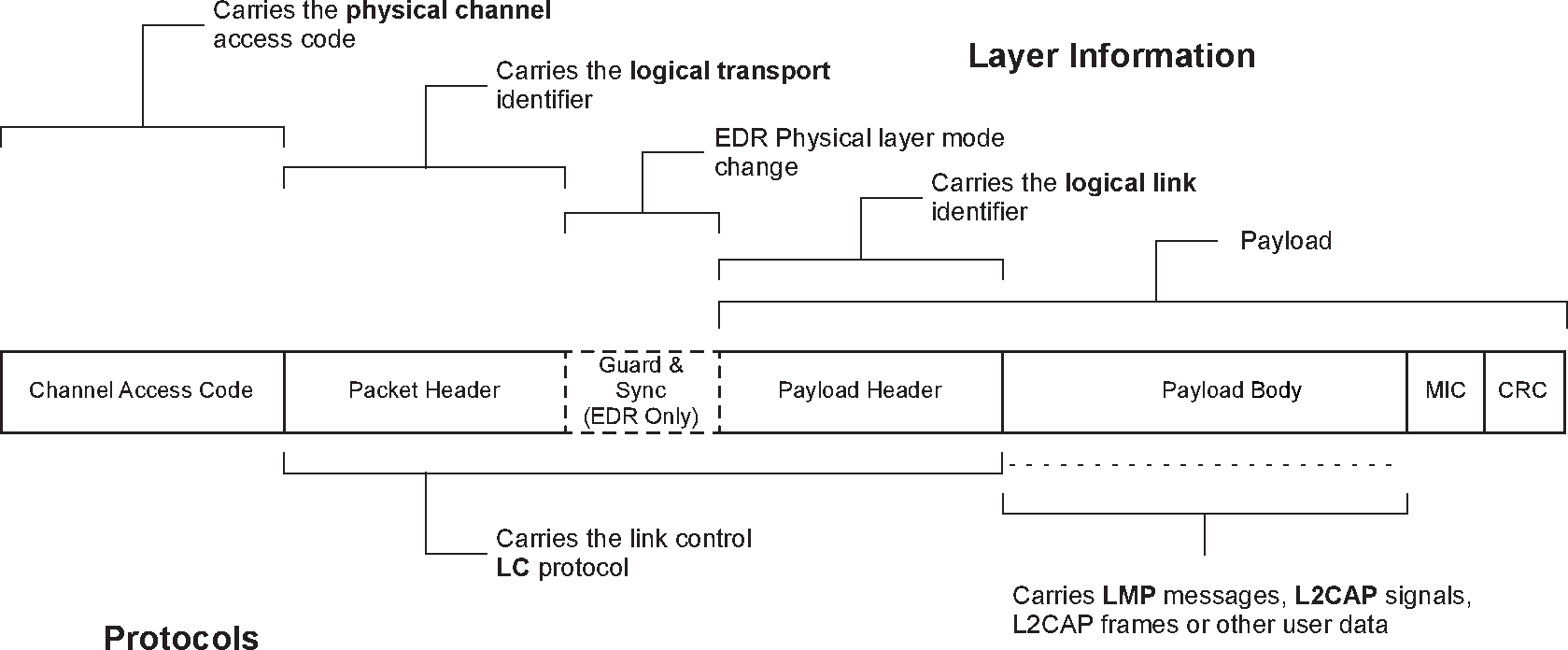 |
Packets normally only include the fields that are necessary to represent the layers required by the transaction. Thus a simple inquiry request over an inquiry scan physical channel does not create or require a logical link or higher layer and therefore consists only of the channel access code (associated with the physical channel).
All packets include the channel access code. This is used to identify communications on a particular physical channel, and to exclude or ignore packets on a different physical channel that happens to be using the same RF carrier in physical proximity.
There is no direct field within the BR/EDR packet structure that represents or contains information relating to physical links. This information is implied by the combination of the logical transport address (LT_ADDR) carried in the packet header and the channel access code (CAC).
Most BR/EDR packets include a packet header. The packet header is always present in packets transmitted on physical channels that support physical links, logical transports and logical links. The packet header carries the LT_ADDR, which is used by each receiving device to determine if the packet is addressed to the device and is used to route the packet internally.
The BR/EDR packet header also carries part of the link control (LC) protocol that is operated per logical transport (except for ACL and SCO transports that operate a shared LC protocol carried on either logical transport).
The Enhanced Data Rate (EDR) packets have a guard time and synchronization sequence before the payload. This is a field used for physical layer change of modulation scheme.
The payload header is present in all packets on logical transports that support multiple logical links. The payload header includes a logical link identifier field used for routing the payload, and a field indicating the length of the payload body. Some packet types also include a CRC at the end of the packet payload that is used to detect most errors in received packets. When AES-CCM encryption is enabled, ACL packets include a Message Integrity Check (MIC) just prior to the CRC.
EDR packets have a trailer after the CRC.
The packet payload body is used to transport the user data. The interpretation of this data is dependent on the logical transport and logical link identifiers. For ACL logical transports Link Manager protocol (LMP) messages and L2CAP signals are transported in the packet payload body, along with general user data from applications.
For SCO, eSCO, and CPB logical transports the payload body contains the user data for the logical link.
3.2.2. LE generic packet structure
LE radio operation is based on three PHYs and makes use of two modulation schemes. Table 3.1 summarizes the properties of each of the LE PHYs. Each packet transmitted uses a single PHY. Each PHY uses a single modulation scheme. Two of the PHYs are uncoded - that is, each bit maps directly to a single radio symbol in the packet - while the third PHY is error correction coded. There are two coding schemes: S=8 and S=2, where S is the number of symbols per bit.
PHY | Modulation scheme | Coding scheme | Data rate | |
|---|---|---|---|---|
Access Header | Payload | |||
LE 1M | 1 Msym/s modulation | Uncoded | Uncoded | 1 Mb/s |
LE 2M | 2 Msym/s modulation | Uncoded | Uncoded | 2 Mb/s |
LE Coded | 1 Msym/s modulation | S=8 | S=8 | 125 kb/s |
S=2 | 500 kb/s | |||
The "Access Header" referred to in Table 3.1 includes all the bits in the packet format associated with the particular PHY prior to the start of the PDU Header but not including the preamble. The preamble is excluded as this is uncoded for all PHYs.
The "Payload" referred to in Table 3.1 includes all the bits in the packet format from the PDU Header to the end of the packet.
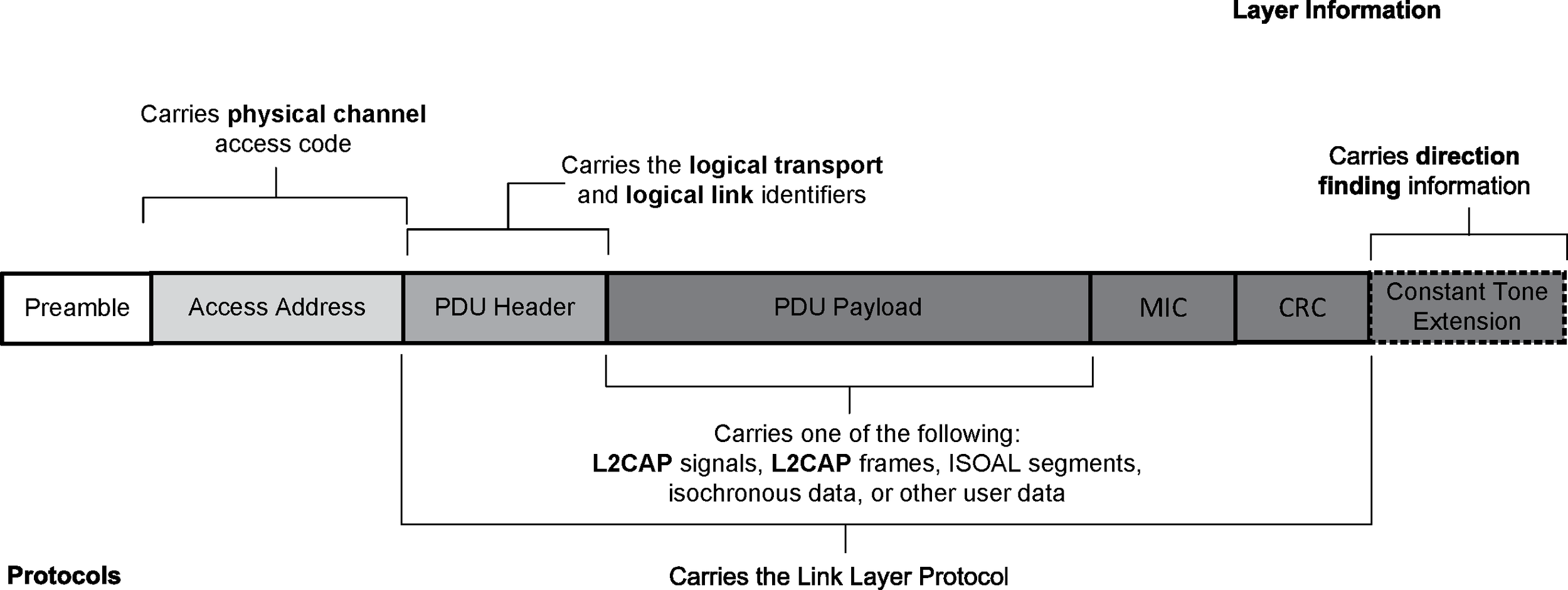
The general structure of the Link Layer Air Interface packet closely reflects the architectural layers found in the LE system. The packet structure for the LE Uncoded PHYs is designed for optimal use in normal operation and is shown in Figure 3.5.
The packet structure for the LE Coded PHY is designed for optimal use in extended range operation and is shown in Figure 3.6.
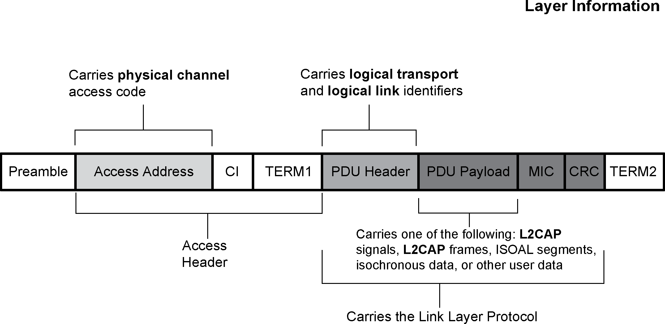
When using the LE Coded PHY, it is recommended to carefully consider the impact of radio-on time for power consumption and duty cycle for scheduling and coexistence over the air. The LE Coded PHY with S=8 coding (125 kb/s) represents the worst case, when considering radio-on time and duty cycle, where each packet sent over the air will be approximately 8 times larger than LE 1M.
Table 3.2 illustrates the on-air time of advertising events with different sizes of AdvData. The first is using connectable and scannable undirected advertising events where the AdvData is sent on the primary advertising physical channel. The second is using events where the AdvData is offloaded to the secondary advertising physical channel. The usage of the primary and secondary advertising physical channels is described in Section 3.3.2.2. Numbers in parentheses are hypothetical and show cases that are not valid in a compliant implementation.
AdvData [Bytes] | Connectable Undirected Advertising event [µs] | Connectable Undirected Advertising event Using Offloading [µs] | ||
|---|---|---|---|---|
LE 1M | LE Coded S=8 | LE 1M | LE Coded S=8 | |
0 | 384 | (3,312) | 568 | 4,864 |
15 | 744 | (6,192) | 688 | 5,824 |
31 | 1,128 | (9,264) | 816 | 6,848 |
100 | (2,784) | (22,512) | 1,368 | 11,264 |
245 | (6,264) | (50,352) | 2,528 | 20,544 |
Note
Note: The events without offloading were calculated using three ADV_IND PDUs, while the events with offloading used three ADV_EXT_IND PDUs containing only the AuxPtr and ADI fields plus one AUX_ADV_IND PDU with the AdvA and ADI fields present and holding the AdvData.
Table 3.3 illustrates, for a range of payload sizes, the difference in Link Layer Data Physical Channel PDU packet durations for connections over the LE 1M PHY and LE Coded PHY with S=8 coding. Connection duty cycle for a specific implementation may be easily calculated from this information.
Payload [bytes] | LL Data Physical Channel PDU [µs] | |
|---|---|---|
LE 1M | LE Coded S=8 | |
0 | 80 | 720 |
15 | 200 | 1,680 |
31 | 328 | 2,704 |
100 | 880 | 7,120 |
255 | 2,120 | 17,040 |
The physical link identifier is not contained in the Link Layer Air Interface packet. The physical channel identifiers are either fixed, are determined at connection setup, or are determined at periodic advertising setup. All LE packets include the Access Address. This is used to identify communications on a physical channel, and to exclude or ignore packets on different physical channels that are using the same PHY channels in physical proximity. The Access Address determines whether the packet is directed to the advertising physical channel (and thus an advertising physical link) used for non-periodic advertising, the periodic physical channel used for periodic advertising, or to a piconet physical channel (and thus an active physical link to a device). The LE advertising physical channel used for non-periodic advertising uses a fixed Access Address. The LE periodic physical channel used for periodic advertising and LE piconet physical channels use a randomly generated 32-bit value as their Access Address. This provides a high number of periodic advertising trains and a high number of active devices that can be addressed in an LE periodic advertisement or an LE piconet.
All LE packets include a PDU header. The PDU header determines the type of advertisement broadcast or logical link carried over the physical channel.
For advertising physical channel PDUs, the PDU header contains the type of advertisement payload, the device address type for addresses contained in the advertisement, and the advertising physical channel PDU payload length. Most advertising physical channel PDU payloads contain the advertiser's address and advertising data. One advertising physical channel PDU payload only contains the advertiser's device address and the initiator's device address in which the advertisement is directed. Advertising physical channel PDUs with scan requests payloads contain the scanner's device address and the advertiser's device address. Advertising physical channel PDUs with scan responses contain advertiser's device address and the scan response data. Advertising physical channel PDUs with connection request payloads contain the initiator's device address, advertiser's device address and connection setup parameters.
For Data Physical Channel PDUs, the PDU header contains the Logical Link Identifier (LLID), the Next Expected Sequence Number (NESN), Sequence Number (SN), More Data (MD), CTEInfo Present (CP), payload length, and may contain CTEInfo. For Data Physical Channel PDUs that contain control commands, the Data Channel PDU payload contains a command opcode and control data that is specific to the command. There is an optional Message Integrity Check (MIC) value that is used to authenticate the data PDU. For Data Physical Channel PDUs that are data, the Data Physical Channel PDU payload contains L2CAP data.
An Isochronous Physical Channel PDU can be either a Connected Isochronous or Broadcast Isochronous PDU. A Connected Isochronous PDU contains a header and may contain an isochronous payload. The header field contains the Logical Link Identifier (LLID), Sequence Number (SN), Next Expected Sequence Number (NESN), Close Isochronous Event (CIE), Null PDU Indicator (NPI), and the payload length. A Connected Isochronous PDU may also contain a Message Integrity Check (MIC) field.
A Broadcast Isochronous PDU contains a header and either isochronous or control data. The header field contains the Logical Link Identifier (LLID), the Control Subevent Sequence Number (CSSN), the Control Subevent Transmission Flag (CSTF), and the payload length. The Broadcast Isochronous PDU may also contain a Message Integrity Check (MIC) field.
Both advertising physical channel packets and data physical channel packets can contain a Constant Tone Extension, which can be used for determining the relative direction of a received radio signal.
3.3. Physical channels
A number of types of physical channel are defined. All Bluetooth physical channels are characterized by a set of PHY frequencies combined with temporal parameters and restricted by spatial considerations. For the basic and adapted piconet physical channels frequency hopping is used to change frequency periodically to reduce the effects of interference and for regulatory reasons.
The Bluetooth BR/EDR system and LE system differ slightly in the way they use physical channels.
3.3.1. BR/EDR physical channels
In the BR/EDR core system, peer devices use a shared physical channel for communication. To achieve this their transceivers need to be tuned to the same PHY frequency at the same time, and they need to be within a nominal range of each other.
Given that the number of RF carriers is limited and that many Bluetooth devices may be operating independently within the same spatial and temporal area there is a strong likelihood of two independent Bluetooth devices having their transceivers tuned to the same RF carrier, resulting in a physical channel collision. To mitigate the unwanted effects of this collision each transmission on a physical channel starts with an access code that is used as a correlation code by devices tuned to the physical channel. This channel access code is a property of the physical channel. The access code is present at the start of every transmitted packet.
Several BR/EDR physical channels are defined. Each is optimized and used for a different purpose. Two of these physical channels (the basic piconet channel and adapted piconet channel) are used for communication between connected devices and are associated with a specific piconet. Other BR/EDR physical channels are used for discovering (the inquiry scan channel) and connecting (the page scan channel) Bluetooth devices. The synchronization scan physical channel is used by devices to obtain timing and frequency information about the Connectionless Peripheral Broadcast physical link or to recover the current piconet clock.
A Bluetooth device can only use one BR/EDR physical channel at any given time. In order to support multiple concurrent operations the device uses time-division multiplexing between the channels. In this way a Bluetooth device can appear to operate simultaneously in several piconets, as well as being discoverable and connectable.
Whenever a Bluetooth device is synchronized to the timing, frequency and access code of a physical channel it is said to be ‘connected’ to this channel (whether or not it is actively involved in communications over the channel). The Bluetooth specification assumes that a device is only capable of connecting to one physical channel at any time. Advanced devices may be capable of connecting simultaneously to more than one physical channel, but the specification does not assume that this is possible.
3.3.1.1. Basic piconet channel
3.3.1.1.1. Overview
The basic piconet channel is used for communication between connected devices during normal operation.
3.3.1.1.2. Characteristics
The basic piconet channel is characterized by a pseudo-random sequence hopping through the PHY channels. The hopping sequence is unique for the piconet and is determined by the Bluetooth Device Address of the Central. The phase in the hopping sequence is determined by the Bluetooth clock of the Central. All Bluetooth devices participating in the piconet are time- and hop-synchronized to the channel.
The channel is divided into time slots where each slot corresponds to an PHY hop frequency. Consecutive hops correspond to different PHY hop frequencies. The time slots are numbered according to the Bluetooth clock of the piconet Central. Packets are transmitted by Bluetooth devices participating in the piconet aligned to start at a slot boundary. Each packet starts with the channel access code, which is derived from the Bluetooth Device Address of the piconet Central.
On the basic piconet channel the Central controls access to the channel. The Central starts its transmission in even-numbered time slots only. Packets transmitted by the Central are aligned with the slot start and define the piconet timing. Packets transmitted by the Central may occupy up to five time slots depending on the packet type.
Each Central transmission is a packet carrying information on one of the logical transports. Peripherals may transmit on the physical channel in response. The characteristics of the response are defined by the logical transport that is addressed.
For example, on the asynchronous connection-oriented logical transport (ACL), the addressed Peripheral responds by transmitting a packet containing information for the same logical transport that is nominally aligned with the next (odd-numbered) slot start. Such a packet may occupy up to five time slots, depending on the packet type. On a broadcast logical transport no Peripherals are allowed to respond.
3.3.1.1.3. Topology
A basic piconet channel may be shared by any number of Bluetooth devices, limited only by the resources available on the piconet Central. Only one device is the piconet Central, all others being piconet Peripherals. All communication is between the Central and Peripherals. There is no direct communication between Peripherals on the piconet channel.
There is, however, a limitation on the number of logical transports that can be supported within a piconet. This means that although there is no theoretical limit to the number of Bluetooth devices that share a channel there is a limit to the number of these devices that can be actively involved in exchanging data with the Central.
3.3.1.1.4. Supported layers
The basic piconet channel supports a number of physical links, logical transports, logical links and L2CAP channels used for general purpose communications.
3.3.1.2. Adapted piconet channel
3.3.1.2.1. Overview
The adapted piconet channel differs from the basic piconet channel in two ways. First, the frequency on which a Peripheral transmits is the same as the frequency used by its Central in the preceding transmission. In other words the frequency is not recomputed between Central and subsequent Peripheral packets. Second, the adapted piconet channel may be based on fewer than the full 79 frequencies. A number of frequencies may be excluded from the hopping pattern by being marked as “unused”. The remainder of the 79 frequencies are included. The two sequences are the same except that whenever the basic pseudo-random hopping sequence selects an unused frequency, it is replaced with an alternative chosen from the used set. The set of frequencies used may vary between different physical links on the same adapted piconet channel.
Because the adapted piconet channel uses the same timing and access code as the basic piconet channel, physical links on the two channels are often coincident. This provides a deliberate benefit as it allows Peripherals in either the basic piconet channel or the adapted piconet channel to adjust their synchronization to the Central.
The topology and supported layers of the adapted piconet physical channel are identical to the basic piconet physical channel with one exception: on the adapted piconet physical channel, it is possible for a single Central to transmit data to an unlimited number of Peripherals using a single CPB logical transport. In this case, however, data is only transferred from Central to Peripheral and not from Peripheral to Central.
3.3.1.3. Inquiry scan channel
3.3.1.3.1. Overview
In order for a device to be discovered, an inquiry scan channel is used. A discoverable device listens for inquiry requests on its inquiry scan channel and then sends a response to that request. In order for a device to discover other devices, it iterates (hops) through all possible inquiry scan channel frequencies in a pseudo-random fashion, sending an inquiry request on each frequency and listening for any response.
3.3.1.3.2. Characteristics
Inquiry scan channels follow a slower hopping pattern and use an access code to distinguish between occasional occupancy of the same radio frequency by two co-located devices using different physical channels.
The access code used on the inquiry scan channel is taken from a reserved set of inquiry access codes that are shared by all Bluetooth devices. One access code is used for general inquiries, and a number of additional access codes are reserved for limited inquiries. Each device has access to a number of different inquiry scan channels. As all of these channels share an identical hopping pattern, a device may concurrently occupy more than one inquiry scan channel if it is capable of concurrently correlating more than one access code.
A device using one of its inquiry scan channels remains passive on that channel until it receives an inquiry message on this channel from another Bluetooth device. This is identified by the appropriate inquiry access code. The inquiry scanning device will then follow the inquiry response procedure to return a response to the inquiring device.
In order for a device to discover other Bluetooth devices it uses the inquiry scan channel to send inquiry requests. As it has no prior knowledge of the devices to discover, it cannot know the exact characteristics of the inquiry scan channel.
The device takes advantage of the fact that inquiry scan channels have a reduced number of hop frequencies and a slower rate of hopping. The inquiring device transmits inquiry requests on each of the inquiry scan hop frequencies and listens for an inquiry response. Transmissions are done at a faster rate, allowing the inquiring device to cover all inquiry scan frequencies in a reasonably short time period.
3.3.1.3.3. Topology
Inquiring and discoverable devices use a simple exchange of packets to fulfill the inquiring function. The topology formed during this transaction is a simple and transient point-to-point connection.
3.3.1.3.4. Supported layers
During the exchange of packets between an inquiring and discoverable device it may be considered that a temporary physical link exists between these devices. However, the concept is quite irrelevant as it has no physical representation but is only implied by the brief transaction between the devices. No further architectural layers are considered to be supported.
3.3.1.4. Page scan channel
3.3.1.4.1. Overview
A connectable device (one that is prepared to accept connections) does so using a page scan channel. A connectable device listens for a page request on its page scan channel and, once received, enters into a sequence of exchanges with this device. In order for a device to connect to another device, it iterates (hops) through all page scan channel frequencies in a pseudo-random fashion, sending a page request on each frequency and listening for a response.
3.3.1.4.2. Characteristics
The page scan channel uses an access code derived from the scanning device’s Bluetooth Device Address to identify communications on the channel. The page scan channel uses a slower hopping rate than the hop rate of the basic and adapted piconet channels. The hop selection algorithm uses the Bluetooth device clock of the scanning device as an input.
A device using its page scan channel remains passive until it receives a page request from another Bluetooth device. This is identified by the page scan channel access code. The two devices will then follow the page procedure to form a connection. Following a successful conclusion of the page procedure both devices switch to the basic piconet channel that is characterized by having the paging device as Central.
In order for a device to connect to another Bluetooth device it uses the page scan channel of the target device in order to send page requests. If the paging device does not know the phase of the target device’s page scan channel it therefore does not know the current hop frequency of the target device. The paging device transmits page requests on each of the page scan hop frequencies and listens for a page response. This is done at a faster hop rate, allowing the paging device to cover all page scan frequencies in a reasonably short time period.
The paging device may have some knowledge of the target device’s Bluetooth clock (indicated during a previous inquiry transaction between the two devices, or as a result of a previous involvement in a piconet with the device), in this case it is able to predict the phase of the target device’s page scan channel. It may use this information to optimize the synchronization of the paging and page scanning process and speed up the formation of the connection.
3.3.1.4.3. Topology
Paging and connectable devices use a simple exchange of packets to fulfill the paging function. The topology formed during this transaction is a simple and transient point-to-point connection.
3.3.1.4.4. Supported layers
During the exchange of packets between a paging and connectable device it may be considered that a temporary physical link exists between these devices. However, the concept is quite irrelevant as it has no physical representation but is only implied by the brief transaction between the devices. No further architectural layers are considered to be supported.
3.3.1.5. Synchronization scan channel
3.3.1.5.1. Overview
In order to receive packets sent on the CPB logical transport, a device must first obtain information about the timing and frequency channels of those packets. If a device misses a Coarse Clock Adjustment notification, it needs to recover the current piconet clock. The synchronization scan channel is provided for these purposes. A scanning device listens for synchronization train packets on the synchronization scan channel. Once a synchronization train packet is received, the device may stop listening for synchronization train packets because it has the timing and frequency information necessary to start receiving packets sent on the CPB logical transport or to recover the piconet clock.
3.3.1.5.2. Characteristics
The synchronization scan channel uses an access code derived from the Bluetooth Device Address of the synchronization train transmitter to identify synchronization train packets on the channel. Once a synchronization train packet is received, the scanning BR/EDR Controller may start receiving packets sent on the CPB logical transport, depending on the needs of the Host and any applicable profile(s).
3.3.1.5.3. Topology
The topology formed during this scan is transient and point-to-multipoint. There can be an unlimited number of scanning devices simultaneously receiving synchronization train packets from the same synchronization train transmitter.
3.3.1.5.4. Supported layers
There is a one-way flow of packets from the synchronization train transmitting device to the scanning device(s). This may be considered a temporary physical link that exists only until the scanning device receives the required information. No further architectural layers are considered to be supported.
3.3.2. LE physical channels
In the LE core system, two Bluetooth devices use a shared physical channel for communication. To achieve this, their transceivers need to be tuned to the same PHY frequency at the same time, and they need to be within a nominal range of each other.
Given that the number of PHY channels is limited, and many Bluetooth devices can be operating independently within the same spatial and temporal area, there is a strong likelihood of two pairs of independent Bluetooth devices having their transceivers tuned to the same PHY channel, resulting in a collision. Unlike BR/EDR, where an access code is used to identify the piconet, LE uses a randomly generated Access Address to identify a physical channel between devices. In the event that two devices happen to share the same PHY channel in the same area, the targeted device Access Address is used as a correlator to determine to which device the communication is directed.
Four LE physical channels are defined. Each is optimized and used for a different purpose. The LE piconet physical channel is used for communication between connected devices and is associated with a specific piconet. The LE advertising physical channel is used for broadcasting advertisements to LE devices. These advertisements can be used to discover, connect, or send user data to scanner or initiator devices. The periodic physical channel is used to send user data to scanner devices in periodic advertisements at a specified interval. The LE isochronous physical channel is used to transfer isochronous data between LE devices in an LE piconet or to transfer isochronous data between unconnected LE devices.
An LE device can only use one of these LE physical channels at any given time. In order to support multiple concurrent operations the device uses time-division multiplexing between the channels. In this way a Bluetooth device can appear to support connected devices while simultaneously sending advertising broadcasts.
Whenever an LE device is synchronized to the timing and frequency of the physical channel it is said to be connected or synchronized to this channel (whether or not it is actively involved in communications over the channel). The Bluetooth specification assumes that a device is only capable of connecting to one physical channel at a time. Advanced devices may be capable of connecting or synchronizing simultaneously to more than one physical channel, but the specification does not make this assumption.
Packets on both the LE piconet physical channel and the LE advertisement broadcast channel can contain a Constant Tone Extension that can be used for the purpose of direction finding.
3.3.2.1. LE piconet physical channel
3.3.2.1.1. Overview
The LE piconet physical channel is used for communication between connected LE devices during normal operation.
3.3.2.1.2. Characteristics
The LE piconet physical channel is characterized by the access address, a pseudo-random sequence of PHY channels, and three additional parameters provided by the Central. The first is the channel map that indicates the set of PHY channels used in the piconet. The second is a pseudo random number used as an index into the complete set of PHY channels. The third is the timing of the first data packet sent by the Central after the connection request.
The channel is divided into connection events where each connection event corresponds to a PHY hop channel. Consecutive connection events correspond to different PHY hop channels. The first packet sent by the Central after the connection establishment sets an anchor point for the timing of all future connection events. In a connection event the Central transmits packets to a Peripheral in the piconet and the Peripheral may respond with a packet of its own.
On the LE piconet physical channel the Central controls access to the channel. The Central starts its transmission in a connection event that occurs at regular intervals. Packets transmitted by the Central are aligned with the connection event start and define the piconet timing.
Each Central transmission contains a packet carrying information on one of the logical transports. The Peripheral can transmit on the physical channel in response.
The LE piconet physical channel is similar to the BR/EDR adapted piconet channel in that the set of PHY channels used can be modified to avoid interference. The set of used channels in the channel map is established by the Central during connection setup. While in a connection the Central can change the channel map when necessary to avoid new interferers. The Peripheral can provide channel classification information to the Central.
There are 37 LE piconet channels. The Central can reduce this number through the channel map indicating the used channels. When the hopping pattern hits an unused channel the unused channel is replaced with an alternate from the set of used channels. The LE Piconet physical channel can use any LE PHY.
3.3.2.1.3. Topology
An LE piconet physical channel is shared by exactly two LE devices.
An LE device may belong to one or more piconets at a time, that is, an LE device may be a Peripheral in zero or more piconets and may also be a Central in zero or more piconets.
Only one LE piconet physical channel can exist between two LE device identities or non-resolvable private addresses.
3.3.2.1.4. Supported layers
The LE piconet physical channel supports L2CAP channels used for general purpose communications.
3.3.2.2. Advertising physical channels
3.3.2.2.1. Overview
An LE advertising physical channel is used to set up connections between two devices or to communicate broadcast information between unconnected devices.
3.3.2.2.2. Characteristics
There are two LE advertising physical channels: the primary advertising physical channel and the secondary advertising physical channel.
The primary advertising physical channel is a set of three fixed PHY channels spread evenly across the LE frequency spectrum. The number of primary advertising PHY channels can be reduced by the advertising device in order to reduce interference. The primary advertising physical channel can use either the LE 1M or LE Coded PHY.
The primary advertising physical channel is divided into advertising events where each advertising event can hop on all primary advertising PHY channels. The advertising events occur at regular intervals which are slightly modified with a random delay to aid in interference avoidance.
On the primary advertising physical channel the advertising device controls access to the physical channel. The advertising device starts its transmission in an advertising event and transmits advertising packets on one or more of the primary advertising PHY channels. Each advertising packet is sent on a different advertising PHY channel at a fixed interval. Seven types of advertising events can be used, with each advertising event type having different sized advertising packets. The PDU payloads of these advertising packets can vary in length from 6 to 37 octets.
Some advertising events sent by the advertising device permit the listening device to concurrently send scan requests or connection requests packets on the same advertising PHY channel in which the advertising packet was received. The advertising device can send a scan response packet again on the same advertising PHY channel within the same advertising event. The payload of the scan response packet can vary in length from 6 to 37 octets.
The secondary advertising physical channel is a set of 37 fixed PHY channels spread across the LE frequency spectrum. These are the same fixed LE PHY channels used by the data physical channel. The secondary advertising physical channel uses the same channel indices as the data physical channel. The payload of advertising packets used on the secondary advertising physical channel can vary in length from 0 to 255 octets. Advertising packets on the secondary advertising physical channel are not part of the advertising event but are part of the extended advertising event. These extended advertising events begin at the same time as the advertising event on the primary advertising physical channel and conclude with the last packet on the secondary advertising physical channel.
The secondary advertising physical channel is used to offload data that would otherwise be transmitted on the primary advertising physical channel. Advertising packets on the secondary advertising physical channel ("auxiliary packets") are scheduled by the advertiser when sufficient over-the-air time is available. The advertising packet on the primary advertising physical channel contains the PHY channel and the offset to the start time of the auxiliary packet.
The secondary advertising physical channel can use any LE PHY. All advertising packets on the secondary advertising physical channel in the same extended advertising event use the same PHY, which is specified in the advertising packet on the primary advertising physical channel.
3.3.2.2.3. Topology
An LE advertising physical channel can be shared by any number of LE devices. Any number of LE devices can transmit advertising packets while sharing the advertising physical channel. Any number of scanning devices can listen on the advertising physical channel. An advertising device can advertise and be connected on an LE piconet physical channel simultaneously. Scanning devices may also be connected to one or more LE piconet physical channels simultaneously.
3.3.2.3. Periodic physical channel
3.3.2.3.1. Overview
An LE periodic physical channel is used to set up a periodic broadcast between unconnected devices.
3.3.2.3.2. Characteristics
The periodic physical channel is characterized by a pseudo-random sequence of PHY channels and additional parameters provided by the advertiser. These are the channel map that indicates the set of PHY channels used in the periodic broadcast, the event counter used to determine the channel hopping sequence, the offset indicating the timing of the first periodic broadcast packet, and the interval between successive periodic broadcasts.
The channel is divided into periodic advertising events where the start of a periodic advertising event corresponds to a PHY hop channel. The start of consecutive periodic advertising events corresponds to different PHY hop channels. The first packet sent by the advertiser after the broadcast is established sets an anchor point for the timing of all future periodic advertising events.
On the periodic physical channel, the advertising device controls access to the physical channel. The advertiser starts its transmission in a periodic advertising event that occurs at regular intervals. Packets transmitted by the advertiser are aligned with the periodic advertising event and specified broadcast timing. Additional packets may also be transmitted between the periodic advertising events. The payload of packets sent by the advertiser may vary in length from 0 octets to 255 octets.
Each advertiser transmission contains a packet carrying information on the PADVB logical transports. Scanners cannot transmit on the physical channel.
There are 37 PHY channels. The advertiser can reduce this number through the channel map indicating the used channels. When the hopping pattern hits an unused channel, the unused channel is replaced with an alternate from the set of used channels. The periodic physical channel can use any PHY. All periodic advertising events use the same PHY used by the advertiser in the packet describing the characteristics of the periodic physical channel.
3.3.2.3.3. Topology
An LE periodic physical channel can be shared by any number of LE devices. Any number of LE devices can transmit periodic advertising packets while sharing the same periodic physical PHY channels. Any number of scanning devices can listen on the periodic physical channel. An advertising device can advertise and be synchronized on an LE periodic physical channel simultaneously. Scanning devices may also be synchronized to one or more LE periodic physical channels simultaneously.
3.3.2.4. LE Isochronous physical channel
The LE isochronous physical channel can be created to transfer isochronous data between LE devices.
3.3.2.4.1. Overview
The LE isochronous physical channel is used to transfer isochronous data between connected or unconnected LE devices.
3.3.2.4.2. Characteristics
The LE isochronous physical channel is characterized by a pseudo-random sequence of PHY channels and by three additional parameters that are provided by a Central or a connectionless broadcaster. The first parameter is the channel map that indicates the set of PHY channels. The second parameter is a pseudo random number that is used as an index into the complete set of PHY channels. The third parameter is the timing of the first data packet. The timing of the first packet of a CIS is provided in the Link Layer message that is sent in the associated ACL connection by the Central during the CIS establishment phase. The timing of the first packet of a BIS is referenced from a periodic advertising event associated with the BIS.
The LE isochronous physical channel is used to transfer isochronous data in isochronous events that occur at regular intervals. Each isochronous event is divided into one or more subevents. Each subevent uses a PHY channel that is selected by the channel selection algorithm.
In any subevent in an isochronous connection, the Central transmits a packet to the Peripheral and the Peripheral may respond with a packet of its own. The Central controls the access to the LE isochronous physical channel. In every CIS event, the Central starts its transmission at the start of the first subevent. Packets that are transmitted by the Central are time aligned with the start of every subevent.
A Broadcasting Isochronous transmitter transmits isochronous data packets and control packets. Any device that is synchronized to the BIS can receive these packets. The broadcasting device controls access to the LE isochronous physical channel. Within BIS events, the broadcasting device starts its transmission in the first subevent. Packets that are transmitted by the broadcasting device are aligned with the start of every subevent.
There are 37 PHY channels. The Central or the isochronous stream transmitter can reduce this number through the channel map that indicates the used channels. When the channel selection algorithm selects an unused channel, the unused channel is replaced with an alternate from the set of used channels. For CISes, the LE isochronous physical channel uses the set of PHY channels that are enabled on the LE piconet physical channel. The LE isochronous physical channel can use any LE PHY.
3.3.2.4.3. Topology
The LE isochronous physical channel in a CIS can be used for one-to-one communication between the devices that are in the LE piconet. The Central may establish one or more CISes with the Peripheral in the LE piconet; that is, the LE isochronous physical channel can carry one or more CIS logical transports between a given Central and Peripheral. The LE isochronous physical channel and all the CISes it carries are terminated when the associated LE piconet physical channel is terminated. If a Central has established piconets with more than one Peripheral, it can establish LE isochronous physical channels with more than one of these Peripherals at the same time.
The LE isochronous physical channel can be used for one-to-many communication topologies of unconnected LE devices. Each LE isochronous physical channel can carry one or more BIS logical transports.
3.3.3. [This section is no longer used]
3.4. Physical links
A physical link represents a baseband connection between Bluetooth devices. A physical link is always associated with exactly one physical channel (although a physical channel may support more than one physical link). Within the Bluetooth system a physical link is a virtual concept that has no direct representation within the structure of a transmitted packet.
In BR/EDR the access code packet field, together with the clock and address of the Central Bluetooth device, is used to identify a physical channel. In LE, the access address and channel map, including hopIncrement in the case of Channel Selection Algorithm #1 or an event counter in the case of Channel Selection Algorithm #2, are used to identify a physical channel. For BR/EDR and LE, there is no subsequent part of the packet that directly identifies the physical link. Instead, the physical link may be identified by association with the logical transport, as each logical transport is only received on one physical link.
Some physical link types have properties that may be modified. An example of this is the transmit power for the link. Other physical link types have no modifiable properties. In the case of BR/EDR physical links with modifiable properties the LM protocol is used to adapt these properties. In the case of LE physical links with modifiable properties the LL protocol is used to adapt these properties. As the LM protocol (BR/EDR) or LL protocol (LE) is supported at a higher layer (by a logical link) the appropriate physical link is identified by implication from the logical link that transports the LM or LL signaling.
In the situation where a transmission is broadcast over a number of different physical links, then the transmission parameters are selected to be suitable for all of the physical links.
3.4.1. BR/EDR links supported by the basic and adapted piconet physical channels
The basic piconet physical channel supports a physical link which may only be active. The adapted piconet physical channel may support several physical links, including active and Connectionless Peripheral Broadcast. An active physical link is a point-to-point link between the Central and a Peripheral. A Connectionless Peripheral Broadcast physical link is a point-to-multipoint link between the Transmitter (Central) and zero or more Receivers (Peripherals). At least one physical link on the piconet physical channel is always present when a Peripheral is synchronized in the piconet.
3.4.1.1. Active physical link
The physical link between a Central and a Peripheral is active if a default ACL logical transport exists between the devices. Active physical links have no direct identification of their own, but are identified by association with the default ACL logical transport ID with which there is a one-to-one correspondence.
An active physical link has the associated property of radio transmit power in each direction. Transmissions from Peripherals are always directed over the active physical link to the Central, and use the transmit power that is a property of this link in the Peripheral to Central direction. Transmissions from the Central may be directed over a single active physical link (to a specific Peripheral) or over a number of physical links (to a group of Peripherals in the piconet). In the case of point-to-point transmissions the Central uses the appropriate transmit power for the physical link in question. (In the case of point-to-multipoint transmissions the Central uses a transmit power appropriate for the set of devices addressed.)
Active physical links may be placed into Hold or Sniff mode. The effect of these modes is to modify the periods when the physical link is active and may carry traffic. Logical transports that have defined scheduling characteristics are not affected by these modes and continue according to their pre-defined scheduling behavior. The default ACL logical transport and other links with undefined scheduling characteristics are subject to the mode of the active physical link.
3.4.1.2. [This section is no longer used]
3.4.1.3. Connectionless Peripheral Broadcast physical link
A Connectionless Peripheral Broadcast physical link is present on a Receiver (Peripheral) when it is synchronized in the piconet where a CPB logical transport exists. On a Transmitter (Central), a Connectionless Peripheral Broadcast physical link is present when a CPB logical transport exists whether or not any Receivers are synchronized. The Connectionless Peripheral Broadcast physical link is a point-to-multipoint unidirectional link between a Transmitter and zero or more Receivers.
Connectionless Peripheral Broadcast physical links do not support power control because there is no feedback from Receivers to the Transmitter. Traffic is always directed from a single Transmitter to zero or more Receivers.
Connectionless Peripheral Broadcast packets are sent at regular intervals. The BR/EDR Controller selects an interval within a range requested by the Host.
3.4.2. BR/EDR links supported by the scanning physical channels
In the case of inquiry scan and page scan channels, the physical link exists for a relatively short time and cannot be controlled or modified in any way. These types of physical links are not further elaborated.
3.4.3. LE links supported by the LE physical channels
The LE piconet physical channels support an LE active physical link. The physical link is a point-to-point link between the Central and a Peripheral. It is always present when the Peripheral is in a connection with the Central.
The LE advertising physical channels support an LE advertising physical link. The physical link is a broadcast between the advertiser device and one or more scanner or initiator devices. It is always present when the advertiser is broadcasting advertisement events.
The LE periodic physical channels support an LE periodic physical link. The physical link is a broadcast between the advertiser device and one or more scanner devices. It is always present when the advertiser is broadcasting periodic advertising events.
The LE isochronous physical channels support LE isochronous physical links. An LE isochronous physical link can be a point-to-point link between a Central and a Peripheral or a connectionless link between a broadcast isochronous transmitter and multiple receiving devices.
3.4.3.1. Active physical link
The physical link between a Central and a Peripheral is active if a default LE ACL logical transport exists between the devices. Active physical links are each associated with a separate piconet physical channel, which in turn is identified by the randomly generated Access Address used in the Link Layer packet. Each Access Address has a one-to-one relationship with the Central and the Peripheral of the active physical link.
An active physical link has the associated property of radio transmit power in each direction, which may be different in each direction. A device uses the appropriate transmit power for the physical link in question.
3.4.3.2. Advertising physical link
An advertising physical link between an advertising device and an initiating device for the purposes of forming a connection (active physical link) can exist for a relatively short period of time. These advertising physical links cannot be controlled or modified in any way and these types of physical links are not further elaborated.
An advertising physical link between an advertising device and a scanning device used for periodic broadcasting of user data can exist for longer periods of time. There is no identification information about the physical link within the protocol. The relationship between the advertising and scanning device is established through the use of the Bluetooth Device Address.
3.4.3.3. Periodic physical link
A periodic physical link between an advertising device and one or more scanning devices normally exists for a prolonged period of time. Periodic physical links are each associated with a separate periodic physical channel, which in turn is identified by the randomly generated Access Address used in the Link Layer packet. Each Access Address has a one-to-one relationship with the advertiser of the periodic physical link.
3.4.3.4. Isochronous physical links
The isochronous physical link uses an isochronous physical channel and carries CIS and BIS logical transports.
Isochronous physical links carrying CIS(es) use the appropriate transmit power level for the physical link in question. Devices use power control on the associated ACL-C logical link to adapt the transmit power level for the physical link.
Isochronous physical links carrying BIS(es) do not support power control because there is no feedback from Observers to the Broadcaster. Traffic is always directed from a single Broadcaster to zero or more Observers.
3.4.4. [This section is no longer used]
3.5. Logical links and logical transports
A variety of logical links are available to support different application data transport requirements. Each logical link is associated with a logical transport, which has a number of characteristics. These characteristics include flow control, acknowledgment/repeat mechanisms, sequence numbering and scheduling behavior. Logical transports are able to carry different types of logical links (depending on the type of the logical transport). In the case of some of the Bluetooth logical links these are multiplexed onto the same logical transport. Logical transports may be carried by active physical links on either the basic or the adapted piconet physical channel.
Logical transport identification and real-time (link control) signaling are carried in the packet header, and for some logical links identification is carried in the payload header. Control signaling that does not require single slot response times is carried out using the LMP protocol.
Table 3.4 lists all of the logical transport types, the supported logical link types, which type of physical links and physical channels can support them, and a brief description of the purpose of the logical transport.
Logical transport | Links supported | Supported by | Bearer | Overview |
|---|---|---|---|---|
Asynchronous Connection-Oriented (ACL) | Control (LMP) ACL‑C User (L2CAP) ACL‑U | BR/EDR active physical link, BR/EDR basic or adapted piconet physical channel | BR/EDR | Reliable or time-bounded, bi-directional, point-to-point |
Synchronous Connection-Oriented (SCO) | Stream (unframed) SCO-S | BR/EDR active physical link, BR/EDR basic or adapted piconet physical channel | BR/EDR | Bi-directional, symmetric, point-to-point, AV channels. Used for 64 kb/s constant rate data. |
Extended Synchronous Connection-Oriented (eSCO) | Stream (unframed) eSCO-S | BR/EDR active physical link, BR/EDR basic or adapted piconet physical channel | BR/EDR | Bi-directional, symmetric or asymmetric, point-to-point, general regular data, limited retransmission. Used for constant rate data synchronized to the Central’s clock. |
Active Peripheral Broadcast (APB) | Control (LMP) APB‑C User (L2CAP) APB‑U | BR/EDR active physical link, basic or adapted physical channel | BR/EDR | Unreliable, uni-directional broadcast to any devices synchronized with the physical channel. Used for broadcast L2CAP groups and certain LMP messages. |
Connectionless Peripheral Broadcast (CPB) | Profile Broadcast Data (PBD) | Connectionless Peripheral Broadcast physical link, BR/EDR adapted piconet physical channel | BR/EDR | Unreliable, unidirectional, point-to-multipoint, periodic transmissions to zero or more devices. |
LE asynchronous connection (LE ACL | Control (LL) LE‑C, User (L2CAP) LE‑U | LE active physical link, LE piconet physical channel | LE | Reliable, bi-directional, point-to-point. |
LE Advertising Broadcast (ADVB) | Control (LL) ADVB‑C, User (LL) ADVB‑U | LE advertising physical link, LE advertising physical channel | LE | Unreliable, uni-directional broadcast to all devices in a given area or directed to one recipient. Used to carry data and Link Layer signaling between unconnected devices. |
LE Periodic Advertising Broadcast (PADVB) | Control (LL) ADVB‑C, User (LL) ADVB‑U | LE periodic physical link, LE periodic physical channel | LE | Unreliable, periodic, unidirectional broadcast to all devices in a given area. |
Connected Isochronous Stream | Low Energy Stream (LE‑S) and Low Energy Framed data (LE‑F) | LE isochronous physical link | LE | Unidirectional or bidirectional transport in a point-to-point connection for transferring isochronous data. |
Broadcast Isochronous Stream | Low Energy Stream (LE‑S), Low Energy Framed data (LE‑F) and Low Energy Broadcast Control (LEB‑C) | LE isochronous physical link | LE | Unidirectional transport for broadcasting data in a point to multipoint configuration and unidirectional transport for controlling the broadcast data. |
The classification of each link type follows from a selection procedure within three categories.
3.5.1. Casting
The first category is that of casting. This may be either unicast or broadcast.
Unicast links exist between exactly two endpoints. Traffic may be sent in either direction on unicast links.
Broadcast links exist between one source device and zero or more receiver devices. Traffic is unidirectional, i e., only sent from the source devices to the receiver devices. Broadcast links are connectionless, meaning there is no procedure to create these links, and data may be sent over them at any time. Broadcast links are unreliable, and there is no guarantee that the data will be received.
3.5.2. Scheduling and acknowledgment scheme
The second category relates to the scheduling and acknowledgment scheme of the link, and implies the type of traffic that is supported by the link. These are synchronous, isochronous or asynchronous. There are no specific isochronous links defined, though the default ACL link can be configured to operate in this fashion.
Synchronous links provide a method of associating the transported data with the Bluetooth piconet clock. This is achieved by reserving regular slots on the physical channel, and transmitting fixed size packets at these regular intervals. Such links are suitable for constant rate isochronous data.
Asynchronous links provide a method for transporting data that has no time-based characteristics. The data is normally expected to be retransmitted until successfully received, and each data entity can be processed at any time after receipt, without reference to the time of receipt of any previous or successive entity in the stream (providing the ordering of data entities is preserved).
Isochronous links provide a method for transporting data that has time-based characteristics. The data may be retransmitted until received or expired. The data rate on the link need not be constant (this being the main difference from synchronous links).
3.5.3. Class of data
The final category is related to the class of data that is carried by the link. This is either control data or user data. The user data category is sub-divided into L2CAP data, stream data, and periodic broadcast data.
Control links are only used for transporting LMP or Link Layer messages between two Controllers. These links are invisible above the baseband layer or Link Layer and cannot be directly instantiated, configured, or released by applications, other than by the use of the services, such as connection and disconnection, that have this effect implicitly. Control links are always multiplexed with an equivalent L2CAP data link onto a logical transport. For example, ACL-C and ACL-U are multiplexed onto an ACL logical transport, whereas ADVB-C and ADVB-U are multiplexed onto ADVB and PADVB logical transports. Subject to the rules defining the acknowledgment scheme, the control link traffic normally takes priority over the L2CAP link traffic.
L2CAP links are used to transport L2CAP PDUs, which may carry the L2CAP signaling channel or framed user data submitted to user-instantiated L2CAP channels. L2CAP frames submitted to the baseband may be larger than the available Baseband packets. A link control protocol embedded within the LLID field preserves the frame-start and frame-continuation semantics when the frame is transmitted in a number of fragments to the receiver. Normally, L2CAP links give reliable delivery of data priority over timely delivery.
Stream links are used to transport user data when timely delivery of the latest data has priority over reliability. Lost data may be replaced by padding at the receiver. On BR/EDR, these links (SCO and eSCO) have a fixed bandwidth and are always bidirectional between two devices; on LE, they have a variable bandwidth with a specified maximum and may be either bidirectional between two devices (CIS) or unidirectional broadcast (BIS).
Periodic broadcast data is transmitted at regular intervals, possibly with jitter, by a device. It has no acknowledgment mechanism. The same data is transmitted until it is explicitly changed. This is sent on the PBD logical link on BR/EDR and on the ADVB-U logical link on LE.
3.5.4. Logical transports
3.5.4.1. BR/EDR asynchronous connection-oriented (ACL)
The asynchronous connection-oriented (ACL) logical transport is used to carry LMP and L2CAP control signaling and best effort asynchronous user data. The ACL logical transport uses a 1-bit ARQN/SEQN scheme to provide simple channel reliability. Every active Peripheral within a piconet has one ACL logical transport to the piconet Central, known as the default ACL.
The default ACL is created between the Central and the Peripheral when a device joins a piconet (connects to the basic piconet physical channel). This default ACL is assigned a logical transport address (LT_ADDR) by the piconet Central. This LT_ADDR is also used to identify the active physical link when required (or as a piconet active member identifier, effectively for the same purpose).
The LT_ADDR for the default ACL is reused for synchronous connection-oriented logical transports between the same Central and Peripheral. Thus the LT_ADDR is not sufficient on its own to identify the default ACL. However the packet types used on the ACL are different from those used on the synchronous connection-oriented logical transport. Therefore, the ACL logical transport can be identified by the LT_ADDR field in the packet header in combination with the packet type field.
The default ACL may be used for isochronous data transport by configuring it to automatically flush packets after the packets have expired. Asynchronous traffic can be sent over an ACL logical transport configured for isochronous traffic by marking the asynchronous packets as non-automatically-flushable. This allows both isochronous and asynchronous traffic to be transferred at the same time to a single device.
If the default ACL is removed from the active physical link then all other logical transports that exist between the Central and the Peripheral are also removed. In the case of unexpected loss of synchronization to the piconet physical channel the physical link and all logical transports and logical links cease to exist at the time that this synchronization loss is detected.
3.5.4.2. BR/EDR synchronous connection-oriented (SCO)
The synchronous connection-oriented (SCO) logical transport is a symmetric, point-to-point transport between the Central and a specific Peripheral. The SCO logical transport reserves slots on the physical channel and can therefore be considered as a circuit-switched connection between the Central and the Peripheral. SCO logical transports carry 64 kb/s of information synchronized with the piconet clock. Typically this information is an encoded voice stream. Three different SCO configurations exist, offering a balance between robustness, delay and bandwidth consumption.
Each SCO-S logical link is supported by a single SCO logical transport, which is assigned the same LT_ADDR as the default ACL logical transport between the devices. Therefore the LT_ADDR field is not sufficient to identify the destination of a received packet. Because the SCO links use reserved slots, a device uses a combination of the LT_ADDR, the slot numbers (a property of the physical channel) and the packet type to identify transmissions on the SCO link.
Although slots are reserved for the SCO, it is permissible to use a reserved slot for traffic from another channel that has a higher priority. This may be required as a result of QoS commitments, or to send LMP signaling on the default ACL when the physical channel bandwidth is fully occupied by SCOs. As SCOs carry different packet types to ACLs, the packet type is used to identify SCO traffic (in addition to the slot number and LT_ADDR).
There are no further architectural layers defined by the specification that are transported over a SCO link. A number of standard formats are defined for the 64 kb/s stream that is transported, or an unformatted stream is allowed where the application is responsible for interpreting the encoding of the stream.
3.5.4.3. BR/EDR extended synchronous connection-oriented (eSCO)
The extended synchronous connection-oriented (eSCO) logical transport is a symmetric or asymmetric, point-to-point transport between the Central and a specific Peripheral. The eSCO reserves slots on the physical channel and can therefore be considered as a circuit-switched connection between the Central and the Peripheral. eSCO links offer a number of extensions over the standard SCO links, in that they support a more flexible combination of packet types and selectable data contents in the packets and selectable slot periods, allowing a range of synchronous bit rates to be supported.
eSCO links also can offer limited retransmission of packets (unlike SCO links where there is no retransmission). If these retransmissions are required they take place in the slots that follow the reserved slots, otherwise the slots may be used for other traffic.
Each eSCO-S logical link is supported by a single eSCO logical transport, identified by a LT_ADDR that is unique within the piconet for the duration of the eSCO. eSCO-S links are created using LM signaling and follow scheduling rules similar to SCO-S links.
There are no further architectural layers defined by the specification that are transported over an eSCO-S link. Instead applications may use the data stream for whatever purpose they require, subject to the transport characteristics of the stream being suitable for the data being transported.
3.5.4.4. BR/EDR active Peripheral broadcast (APB)
The active Peripheral broadcast logical transport is used to transport LMP control signaling and connectionless L2CAP user traffic to all devices in the piconet that are currently connected to the physical channel that is used by the APB. There is no acknowledgment protocol and the traffic is uni-directional from the piconet Central to the Peripherals. The APB channel may be used for L2CAP group traffic (a legacy of the 1.1 specification), and is never used for L2CAP connection-oriented channels or L2CAP control signaling.
The APB logical transport is inherently unreliable because of the lack of acknowledgment. To improve the reliability, each packet is transmitted a number of times. An identical sequence number is used to assist with filtering retransmissions at the Peripheral.
The APB logical transport is identified by a reserved LT_ADDR.
An APB is implicitly created whenever a piconet exists, and there is always one APB associated with each of the active physical links (whether operating over the basic or adapted piconet physical channel) that exist within the piconet. Because the basic and adapted piconet physical channels, and different channel maps on the adapted piconet physical channel, are mostly coincident, a Peripheral cannot always distinguish which of the APB channels is being used to transmit the packets. This adds to the general unreliability of the APB channel. (Although it is, perhaps, no more unreliable than general missed packets.)
A Central may decide to use only one of its two possible APBs (when it has both a basic and adapted piconet physical channel), or only one of the channel maps in use on the adapted piconet physical channel (when it has more than one map), as with sufficient retransmissions or careful selection of which slots to transmit on it is possible to address all Peripherals.
The APB channel is never used to carry L2CAP control signals.
3.5.4.5. [This section is no longer used]
3.5.4.6. LE asynchronous connection (LE ACL)
The LE asynchronous connection (LE ACL) logical transport is used to carry LL and L2CAP control signaling and best effort asynchronous user data. The LE ACL logical transport uses a 1-bit NESN/SN scheme to provide simple channel reliability. Every active Peripheral has one LE ACL logical transport to the piconet Central, known as the default LE ACL.
The default LE ACL is automatically created between the Central and the Peripheral when the piconet connecting them is created. This default LE ACL is assigned an Access Address by the piconet Central. This Access Address is also used to identify the active physical link and active piconet physical channel when required.
If the default LE ACL is removed from the LE active physical link then all other LE logical transports that exist between the Central and the Peripheral are also removed. In the case of unexpected loss of synchronization to the LE piconet physical channel the LE physical link and all LE logical transports and LE logical links cease to exist at the time that this synchronization loss is detected.
3.5.4.7. LE advertising broadcast (ADVB)
The LE advertising broadcast logical transport is used to transport broadcast control and user data to all scanning devices in a given area. There is no acknowledgment protocol and the traffic is predominately unidirectional from the advertising device. A scanning device can send requests over the logical transport to get additional broadcast user data, or to form an LE ACL logical transport connection. The LE Advertising Broadcast logical transport data is carried only over the LE advertising broadcast link.
The ADVB logical transport is inherently unreliable because of the lack of acknowledgment. To improve the reliability, each packet is transmitted a number of times over the LE advertising broadcast link.
An ADVB is created whenever an advertising device begins advertising. The ADVB logical transport is identified by the advertiser's Bluetooth Device Address and advertising set.
3.5.4.8. Connectionless Peripheral Broadcast (CPB)
The CPB logical transport is used to transport profile broadcast data to all devices connected to the Connectionless Peripheral Broadcast logical transport. There is no acknowledgment scheme and the traffic is unidirectional from a Transmitter to zero or more Receivers. To improve reliability, profile broadcast data may be transmitted multiple times.
The CPB logical transport is created on the transmitter whenever the Connectionless Peripheral Broadcast is started. The CPB logical transport is created on the receiver whenever Connectionless Peripheral Broadcast reception is configured. The CPB logical transport is identified by a unique LT_ADDR within the piconet that is reserved specifically for that purpose by the Connectionless Peripheral Broadcast Transmitter.
3.5.4.9. LE periodic advertising
3.5.4.9.1. LE periodic advertising broadcast (PADVB)
The LE periodic advertising broadcast logical transport is used to transport periodic broadcast control and user data to all scanning devices in a given area. The data may be constant for several periods or may change frequently. There is no acknowledgment protocol and the traffic is unidirectional from the advertising device. The LE Periodic Advertising Broadcast logical transport data is carried only over the LE periodic physical link.
The PADVB logical transport is inherently unreliable because of the lack of acknowledgment. To improve the reliability, the period between transmissions can be shorter than the interval between changes to the data so that each packet can be transmitted a number of times over the LE periodic physical link.
A PADVB is created whenever an advertising device begins periodic advertising. The PADVB logical transport is identified by the advertiser's Bluetooth Device Address, timing, and advertising set.
3.5.4.9.2. Periodic advertising with responses (PAwR)
The LE periodic advertising with responses logical transport is used to transport periodic broadcast control and user data to all scanning devices in a given area. These broadcasts are grouped into subevents, allowing a subset of the devices to be synchronized with each subevent. Each subevent can then contain information that is directed to the subset of devices synchronized to that subevent. This allows the broadcasting device to send data to many devices and the synchronized devices to only have to listen very infrequently for information directed to them. The data may be constant for several periods or may change frequently. The PAwR logical transport data is carried only over the LE periodic physical link.
The PAwR logical transport also includes response slots. The devices that have been directly addressed by the advertising device use response slots to send back responses. A higher layer specification determines the set of devices that can respond and when they respond. The PAwR logical transport is inherently unreliable, but the ability to use response slots allows higher layer acknowledgments to be used to provide reliability.
A PAwR logical transport is created whenever an advertising device begins periodic advertising configured to use subevents and responses. The PAwR logical transport is identified by the advertiser's Bluetooth Device Address, timing, and advertising set.
3.5.4.10. Connected Isochronous Stream (CIS)
The CIS is a data-symmetric or data-asymmetric, point-to-point logical transport between the Central and a specific Peripheral. A CIS reserves transmission/reception (Tx/Rx) periods, known as subevents, on the isochronous physical channel and can be considered as a circuit switched connection between the Central and the Peripheral. The CIS supports a variable flushing period for payloads, variable size data contents in the packets, and a variable number of subevents, allowing a range of isochronous data rates, latencies, and re-transmissions to be supported. A CIS can be configured to retransmit packets by providing more subevents than required for transmitting the data. If retransmissions are required, they take place in the subevents (of the current or subsequent events) that follow.
Each LE-S or LE-F logical link is supported by a single CIS that is identified by a unique access address for the lifetime of the CIS. The LE-S or LE F links are created by using Link Layer procedures. The higher layer may use the data stream for whatever purpose it requires, as long as the transport characteristics of the stream are suitable for the data that is being transported. All isochronous connections are terminated when the associated LE piconet physical channel is terminated.
3.5.4.11. Connected Isochronous Group (CIG)
Each CIS is part of a CIG. A CIG may have one or more CISes, all with the same Central but possibly different Peripherals. Multiple CISes in a CIG have a common timing reference based on the Central timing and are synchronized in time. The common timing reference of multiple CISes helps devices to synchronize their input or output data. For example, when the left and right channels of an audio stereo stream, which are received by separate devices, need to be rendered at the same time. Multiple CISes in a CIG can be scheduled sequentially or in an interleaved arrangement.
3.5.4.12. Broadcast Isochronous Stream (BIS)
The BIS logical transport is used to transport one or more isochronous data streams to all devices for a BIS within range. The data may be fixed or variable size, framed or unframed. A BIS has one or more subevents for transmitting isochronous data packets. A BIS supports transmission of multiple new isochronous data packets in every BIS event. There is no acknowledgment protocol and the traffic is unidirectional from the broadcasting device. The BIS logical transport is inherently unreliable because of the lack of acknowledgment. To improve the reliability of delivery, the isochronous data packets can be unconditionally re-transmitted by increasing the number of subevents in every event. The reliability of delivery can also be improved by transmitting packets in intervals earlier than the intervals they are associated with; this is called "pre-transmission". A BIS supports LE-S or LE-F logical links. A BIS is identified by a unique access address and the timing information. The access address and the timing information is transmitted in the packet that is sent using the associated Periodic Advertising Broadcast (PADVB) logical transport. A scanning device that supports the Synchronized Receiver role feature may receive isochronous data from a BIS after synchronizing to the BIS by using the timing information from the periodic advertising train.
3.5.4.13. Broadcast Isochronous Group (BIG)
Each BIS is part of a BIG. A BIG may have one or more BISes. Multiple BISes in a BIG have a common timing reference based on the broadcaster and are synchronized in time. For example, when the left and right channels of an audio stereo stream, which are received by separate devices, need to be rendered at the same time. Multiple BISes in a BIG can be scheduled sequentially or in an interleaved arrangement. A BIG also supports a Low Energy Broadcast Control (LEB-C) logical link.
3.5.5. Logical links
Some logical transports are capable of supporting different logical links, either concurrently multiplexed, or one of the choice.
3.5.5.1. BR/EDR logical links
Within BR/EDR logical transports, the logical link is identified by the logical link identifier (LLID) bits in the payload header of Baseband packets that carry a data payload. The logical links distinguish between a limited set of core protocols that are able to transmit and receive data on the logical transports. Not all of the logical transports are able to carry all of the logical links (the supported mapping is shown in Figure 3.2). In particular the BR/EDR SCO and eSCO logical transports are only able to carry constant data rate streams, and these are uniquely identified by the LT_ADDR. Such logical transports only use packets that do not contain a payload header, as their length is known in advance, and no LLID is necessary.
3.5.5.1.1. ACL control logical links (ACL‑C and APB‑C)
The ACL Control Logical Links (ACL-C and APB-C) are used to carry BR/EDR LMP signaling between devices in the piconet. The ACL-C control link is only carried on the default ACL logical transport while the APB-C control link is only carried on the APB logical transport. Each control link is always given priority over the corresponding data link carried on the same logical transport.
3.5.5.1.2. User asynchronous/isochronous logical links (ACL-U and APB-U)
The user asynchronous/isochronous logical links (ACL-U and APB-U) are used to carry all asynchronous and isochronous framed user data. The ACL-U link is only carried on the default ACL logical transport while the APB-U link is only carried on the APB logical transport. Packets on the ACL-U and APB-U link are identified by one of two reserved LLID values. One value is used to indicate that the Baseband packet contains the start of an L2CAP frame and the other indicates a continuation of a previous frame. This ensures correct synchronization of the L2CAP reassembler following flushed packets. The use of this technique removes the need for a more complex L2CAP header in every Baseband packet (the header is only required in the L2CAP start packets) because each L2CAP frame is completely transmitted before the next one starts. (An exception to this rule being the ability to flush a partially transmitted L2CAP frame in favor of another L2CAP frame.)
3.5.5.1.3. User synchronous/extended synchronous logical links (SCO‑S/eSCO‑S)
Synchronous (SCO-S) and extended synchronous (eSCO-S) logical links are used to support isochronous data delivered in a stream without framing. These links are associated with a single logical transport, where data is delivered in constant sized units at a constant rate. There is no LLID within the packets on these transports, as only a single logical link can be supported, and the packet length and scheduling period are pre-defined and remain fixed during the lifetime of the link.
Variable rate isochronous data cannot be carried by the SCO-S or eSCO-S logical links. In this case the data must be carried on ACL-U or APB-U logical links, which use packets with a payload header.
3.5.5.1.4. Profile Broadcast Data (PBD) logical link
The PBD logical link is used to broadcast isochronous unframed data to multiple receivers and resides on the CPB logical transport.
3.5.5.2. LE logical links
Within LE logical transports, the logical link is identified by the logical link identifier (LLID) bits in the payload header of Baseband packets that carry a data payload. The logical links distinguish between a limited set of core protocols that are able to transmit and receive data on the logical transports. Not all of the logical transports are able to carry all of the logical links (the supported mapping is shown in Figure 3.2).
3.5.5.2.1. Control logical link (LE-C)
The LE ACL Control Logical Link (LE-C) is used to carry LE LL signaling between the two devices in the piconet. The control link is only carried on the default LE ACL logical transport.
3.5.5.2.2. User asynchronous logical link (LE-U)
The user asynchronous logical link (LE-U) is used to carry all asynchronous and framed user data. The LE-U link is carried on the LE logical transport. Packets on the LE-U link are identified by one of two reserved LLID values. One value is used to indicate that the Baseband packet contains the start of an L2CAP frame and the other indicates a continuation of a previous frame or empty PDU. This ensures correct synchronization of the L2CAP re-assembler. The use of this technique removes the need for a more complex L2CAP header in every Baseband packet because each L2CAP frame is completely transmitted before the next one starts.
3.5.5.2.3. Advertising Broadcast Control logical link (ADVB-C)
The LE Advertising Broadcast Control Logical Link (ADVB-C) is used to carry LE LL signaling between unconnected devices in a given area. This signaling is the control commands for gathering additional broadcast user data (scan requests) or connection requests. The control link is carried on the LE Advertising Broadcast and LE Periodic Advertising Broadcast logical transports.
3.5.5.2.4. Advertising Broadcast User Data logical link (ADVB-U)
The LE Advertising Broadcast User Data Logical Link (ADVB-U) is used to carry LE Advertising Broadcast and LE Periodic Advertising Broadcast user data used between devices without the need for a connection or LE-U between the devices. The user data link is carried on the LE Advertising Broadcast logical transport for LE Advertising Broadcast user data and the LE Periodic Advertising Broadcast logical transport for LE Periodic Advertising Broadcast user data.
3.5.5.2.5. Low Energy Stream (LE-S)
An LE-S is a logical link that is used to carry the unframed isochronous data packets of an isochronous data stream in a CIS or a BIS logical transport.
3.5.5.2.6. Low Energy Framed (LE-F)
An LE-F is a logical link that is used to carry the framed isochronous data packets of an isochronous data stream in a CIS or a BIS logical transport.
3.5.5.2.7. Low Energy Broadcast Control (LEB-C)
An LEB-C is a logical link that uses the BIS logical transport to carry the control information for all the BISes in a BIG.
3.5.5.3. [This section is no longer used]
3.6. L2CAP channels
L2CAP provides a multiplexing role allowing many different applications to share an ACL-U, APB-U, or LE-U logical link. Applications and service protocols interface with L2CAP using a channel-oriented interface to create connections to equivalent entities on other devices.
L2CAP channel endpoints are identified to their clients by a Channel Identifier (CID). This is assigned by L2CAP, and each L2CAP channel endpoint on any device has a different CID.
L2CAP channels may be configured to provide an appropriate Quality of Service (QoS) to the application. L2CAP maps the channel onto the ACL-U, APB-U, or LE-U logical link.
L2CAP supports channels that are connection-oriented and others that are group-oriented. Group-oriented channels may be mapped onto the APB-U logical link, or implemented as iterated transmission to each member in turn over an ACL-U logical link.
Apart from the creation, configuration and dismantling of channels, the main role of L2CAP is to multiplex service data units (SDUs) from the channel clients onto the ACL-U, APB-U, or LE-U logical link, and to carry out a simple level of scheduling, selecting SDUs according to relative priority.
L2CAP can provide per channel flow control with the peer L2CAP layer (except on the APB-U logical link). This option is selected by the application when the channel is established. L2CAP can also provide enhanced error detection and retransmission to (a) reduce the probability of undetected errors being passed to the application and (b) recover from loss of portions of the user data when the Baseband performs a flush on the ACL-U logical link.
In the case where an HCI is present, the L2CAP is also required to segment L2CAP SDUs into fragments that will fit into the baseband buffers, and also to operate a token based flow control procedure over the HCI, submitting fragments to the baseband only when allowed to do so. This may affect the scheduling algorithm.
3.7. Isochronous Adaptation Layer (ISOAL)
The ISOAL provides a mechanism such that the timing used to generate or receive isochronous data in the upper layer can be independent of the timing used in the CIS or BIS logical transport used to carry the isochronous data. For example, audio codec data can be generated at a 10 ms interval while the value of ISO_Interval for the CIS can be 11.25 ms. The ISOAL converts upper layer isochronous data units to lower layer isochronous data packets (or the other way around). For more information, see [Vol 6] Part G.
3.8. Power control
The power control feature provides a mechanism to request a remote device to adjust its transmit power level based on local signal quality information. The feature is supported on BR/EDR active physical links (see Section 3.4.1.1) and on LE active physical links (see Section 3.4.3.1).
3.8.1. Power control in BR/EDR
In BR/EDR, two power control mechanisms (legacy and enhanced power control) are available. Both mechanisms support requesting an incremental change in transmit power level. The enhanced power control mechanism also allows requesting a change to maximum transmit power level. The requested change is applied on all supported modulations at once since the modulation can change dynamically between packets.
3.8.2. Power control in LE
In LE, a device can request a remote device to make a specified change in the remote device's power level on a given PHY. This allows a faster transition to the desired power level compared to incremental changes. A responding device can also return a value to indicate an acceptable reduction in the power level that allows the requesting device to further reduce its transmit power level to the minimum level possible and hence conserve energy. The local and remote devices can also share their current transmit power levels during this exchange to enable devices to calculate the link path loss between them. Devices are also allowed to do autonomous local transmit power level changes and indicate the change to the remote device.
In LE, an ACL connection can have associated connections like CIS(es). The power control for all the PHYs used on the ACL and associated connections is managed over the ACL connection. The Host can use the connection handle of the ACL connection to retrieve information for all PHYs used on the ACL and associated connections.
4. Communication topology and operation
4.1. Piconet topology
4.1.1. BR/EDR topology
Any time a link is created using the BR/EDR Controller it is within the context of a piconet. Each link connects two devices, called the “Central” and “Peripheral”. A piconet consists of a single Central, known as the Central of the piconet, and all the Peripherals linked to it, known as the Peripherals in the piconet.
Connected BR/EDR devices communicate on the same physical channel by synchronizing with a common clock and hopping sequence. The common (piconet) clock is identical to the Bluetooth clock of the Central of the piconet and the hopping sequence is derived from the Central’s clock and the Central’s Bluetooth Device Address (different hopping sequences may be used for different Peripherals).
The terms Central and Peripheral are only used when describing these roles in a piconet.
A number of independent piconets may exist in close proximity. Each piconet has a different physical channel (that is a different Central and an independent timing and hopping sequence).
A Bluetooth device may participate concurrently in two or more piconets. It does this on a time-division multiplexing basis. A Bluetooth device can never be a Central of more than one piconet. (Since in BR/EDR the piconet is defined by synchronization to the Central’s Bluetooth clock it is impossible to be the Central of two or more piconets.) A Bluetooth device may be a Peripheral in many independent piconets.
A Bluetooth device that is a member of two or more piconets is said to be involved in a scatternet. Involvement in a scatternet does not necessarily imply any network routing capability or function in the Bluetooth device. The Bluetooth core protocols do not, and are not intended to offer such functionality, which is the responsibility of higher level protocols and is outside the scope of the specification.

In Figure 4.1 an example topology is shown that demonstrates a number of the architectural features described below. Device A is a Central in a piconet (represented by the shaded area, and known as piconet A) with devices B, C, D and E as Peripherals. Three other piconets are shown: a) one piconet with device F as Central (known as piconet F) and devices E, G and H as Peripherals, b) one piconet with device D as Central (known as piconet D) and device J as Peripheral, and c) one piconet with device M as Central (known as piconet M) and device E as a Peripheral and many devices N as Peripherals.
In piconet A there are two physical channels. Devices B and C are using the basic piconet physical channel (represented by the blue enclosure) as they do not support adaptive frequency hopping. Devices D and E are capable of supporting adaptive frequency hopping, and are using the adapted piconet physical channel (represented by the red enclosure). Device A is capable of adaptive frequency hopping, and operates in a TDM basis on both physical channels according to which Peripheral is being addressed.
Piconet D and piconet F are both using only a basic piconet physical channel (represented by the cyan and magenta enclosures respectively). In the case of piconet D this is because device J does not support the adaptive hopping mode. Although device D supports adaptive hopping it cannot use it in this piconet. In piconet F device F does not support adaptive hopping, and therefore it cannot be used in this piconet.
Piconet M (represented by the orange enclosure) uses a Connectionless Peripheral Broadcast physical link over the adaptive piconet physical channel to send Profile Broadcast Data from the transmitter device M to many Receiver devices including E and N.
Device K is shown in the same locality as the other devices. It is not currently a member of a piconet, but has services that it offers to other Bluetooth devices. It is currently listening on its inquiry scan physical channel (represented by the green enclosure), awaiting an inquiry request from another device.
Device L is shown in the same locality as the other devices. It is not currently a member of a piconet, but is currently listening on its synchronization scan physical channel (represented by the brown enclosure), awaiting a synchronization train from another device.
4.1.2. LE topology
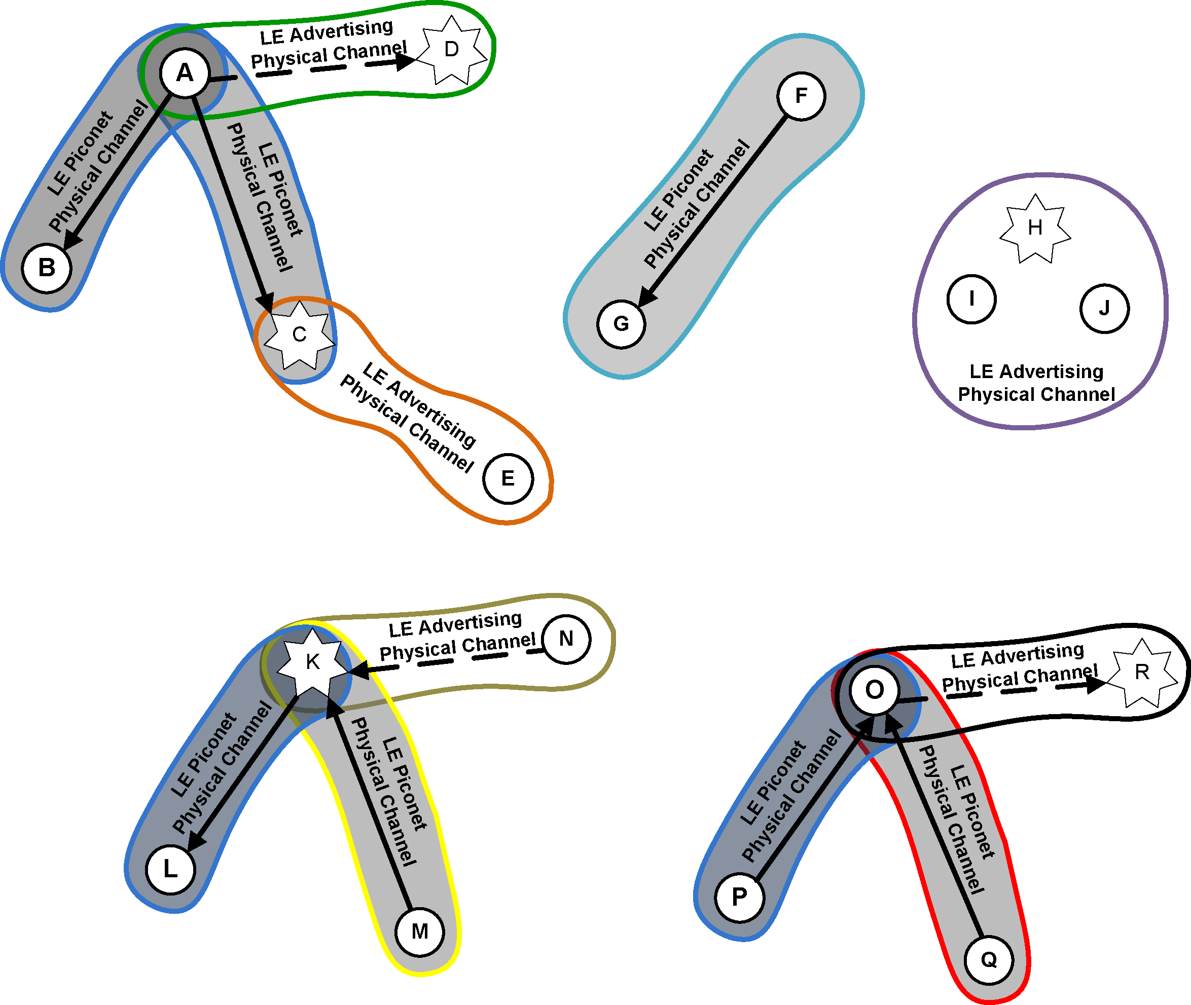
In Figure 4.2 an example topology is shown that demonstrates a number of the LE architectural features described below. Device A is a Central in two piconets (represented by the shaded areas) with devices B and C as the respective Peripherals. Unlike BR/EDR Peripherals, LE Peripherals do not share a single piconet or a common physical channel with the Central. Each Peripheral communicates on a separate physical channel with the Central. One other piconet is shown with device F as Central and device G as a Peripheral. Device K is in a scatternet. Device K is Central of one piconet with device L as the Peripheral and is Peripheral of a second piconet with device M as the Central. Device O is also in a scatternet. Device O is the Peripheral of two piconets, one with device P as the Central and the other with device Q as the Central. In the figure, solid arrows point from Central to Peripheral; dashed arrows, indicating a connection initiation, point from initiator to advertiser using a connectable advertising event; devices that are advertising are indicated using stars.
There are five other groups of devices shown:
Device D is an advertiser and device A is also an initiator.
Device E is a scanner and device C is also an advertiser.
Device H is an advertiser and devices I and J are scanners.
Device K is also an advertiser and device N is an initiator.
Device R is an advertiser and device O is also an initiator.
Devices A and B are using one LE piconet physical channel (represented by the blue enclosure and a dark gray background). Devices A and C are using another LE piconet physical channel (represented by the blue enclosure and a lighter gray background). Device D is advertising using a connectable advertising event on the advertising physical channel (represented by the green enclosure) and device A is an initiator. Device A can form a connection with device D, creating a new piconet. Device C is also advertising on the advertising physical channel (represented by the orange enclosure) using any type of advertising events that are being captured by device E as a scanner. Devices C and D may be using different advertising PHY channels or different timings to avoid collisions.
Devices F and G are using a piconet and an LE piconet physical channel (represented by the aqua enclosure). Device F is the Central and device G is the Peripheral.
Devices H, I and J are using the LE advertising physical channel (represented by the purple enclosure). Device H is an advertiser and devices I and J are scanners.
In the scatternet involving device K, devices K and L are using one piconet and LE piconet physical channel. Devices K and M are using another piconet and LE piconet physical channel. Device K is also advertising using a connectable advertising event on the advertising physical channel and device N is an initiator. Device N can form a connection with device K resulting in device K being Peripheral of two devices and Central of one device at the same time.
In the scatternet involving device O, devices O and P are using one piconet and LE piconet physical channel. Devices O and Q are using another piconet and LE piconet physical channel. Device R is advertising using a connectable advertising event on the advertising physical channel and device O is an initiator. Device O can form a connection with device R resulting in device O being Peripheral of two devices and Central of one device at the same time.
4.2. Operational procedures and modes
The typical operational mode of a Bluetooth device is to be connected to other Bluetooth devices (in a piconet) and exchanging data with those Bluetooth devices. As Bluetooth is an ad-hoc wireless communications technology, there are a number of operational procedures that enable piconets to be formed so that the subsequent communications can take place. Procedures and modes are applied at different layers in the architecture and therefore a device may be engaged in a number of these procedures and modes concurrently.
4.2.1. BR/EDR procedures
4.2.1.1. Inquiry (discovering) procedure
Bluetooth devices use the inquiry procedure to discover nearby devices, or to be discovered by devices in their locality.
The inquiry procedure is asymmetrical. A Bluetooth device that tries to find other nearby devices is known as an inquiring device and actively sends inquiry requests. Bluetooth devices that are available to be found are known as discoverable devices and listen for these inquiry requests and send responses. The inquiry procedure uses a special physical channel for the inquiry requests and responses.
Both inquiring and discoverable devices may already be connected to other Bluetooth devices in a piconet. Any time spent inquiring or occupying the inquiry scan physical channel needs to be balanced with the demands of the QoS commitments on existing logical transports.
The inquiry procedure does not make use of any of the architectural layers above the physical channel, although a transient physical link may be considered to be present during the exchange of inquiry and inquiry response information.
4.2.1.1.1. Extended Inquiry response
An Extended Inquiry Response can be used to provide miscellaneous information during the inquiry response procedure. Data types are defined for such things as local name and supported services, information that otherwise would have to be obtained by establishing a connection. A device that receives a local name and a list of supported services in an extended inquiry response does not have to connect to do a remote name request and an SDP service search, thereby shortening the time to useful information. It is recommended that a device includes all supported services and a significant portion of its local name, if that name is too long to be sent in its entirety, in the extended inquiry response.
Extended inquiry response data can be transmitted encrypted or unencrypted. Unencrypted data can be interpreted by any device. Encrypted data can be received by any device but can only be decrypted and authenticated by devices that have previously shared the session key used to encrypt the data.
The extended inquiry response procedure is backwards compatible with the standard inquiry response procedure.
4.2.1.2. Paging (connecting) procedure
The procedure for forming connections is asymmetrical and requires that one Bluetooth device carries out the page (connection) procedure while the other Bluetooth device is connectable (page scanning). The procedure is targeted, so that the page procedure is only responded to by one specified Bluetooth device.
The connectable device uses a special physical channel to listen for connection request packets from the paging (connecting) device. This physical channel has attributes that are specific to the connectable device, hence only a paging device with knowledge of the connectable device is able to communicate on this channel.
Both paging and connectable devices may already be connected to other Bluetooth devices. Any time spent paging or occupying the page scan physical channel needs to be balanced with the demands of the QoS commitments on existing logical transports.
4.2.1.3. Connected mode
After a successful connection procedure over the BR/EDR Controller, there is a piconet physical channel to which both devices are connected, there is a physical link between the devices, and there are default ACL-C, ACL-U, APB-C, and APB-U logical links. Two of these links (ACL-C and APB-C) transport the LMP control protocol and are invisible to the layers above the Link Manager. The ACL-U link transports the L2CAP signaling protocol and any multiplexed L2CAP best-effort channels. The APB-U link transports L2CAP channels that are broadcast to all Peripherals on the piconet. It is common to refer to a default ACL logical transport, which can be resolved by context, but typically refers to the default ACL-U logical link.
When in the connected mode it is possible to create and release additional logical links and to change the modes of the physical and logical links while remaining connected to the piconet physical channel. It is also possible for the device to carry out inquiry, paging or scanning procedures or to be connected to other piconets without needing to disconnect from the original piconet physical channel. These actions are done using the Link Manager, which exchanges Link Manager protocol messages with the remote Bluetooth device.
During the time that a Peripheral is actively connected to a piconet there is always a default ACL logical transport between the Peripheral and the Central. The only method of deleting the default ACL logical transport is to detach the device from the piconet physical channel, at which time the entire hierarchy of L2CAP channels, logical links, and logical transports between the devices is deleted.
4.2.1.4. Hold mode
Hold mode is not a general device mode, but applies to unreserved slots on the physical link. When in this mode, the physical link is only active during slots that are reserved for the operation of the synchronous link types SCO and eSCO. All asynchronous links are inactive. Hold modes operate once for each invocation and are then exited when complete, returning to the previous mode.
4.2.1.5. Sniff mode
Sniff mode is not a general device mode, but applies to the default ACL logical transports. When in this mode the availability of these logical transports is modified by defining a duty cycle consisting of periods of presence and absence. Devices that have their default ACL logical transports in Sniff mode may use the absent periods to engage in activity on another physical channel, or to enter reduced power mode. Sniff mode only affects the default ACL logical transports (i.e. their shared ACL logical transport), and does not apply to any additional SCO or eSCO logical transports that may be active. The periods of presence and absence of the physical link on the piconet physical channel is derived as a union of all logical transports that are built on the physical link.
Sniff subrating provides a mechanism for further reducing the active duty cycle, thereby enhancing the power-saving capability of Sniff mode, by allowing a Host to specify maximum transmit and receive latencies. This allows the basebands to optimize the low power performance without having to exit and re-enter Sniff mode using Link Manager commands.
Broadcast logical transports have no defined expectations for presence or absence. A Central should aim to schedule broadcasts to coincide with periods of physical link presence within the piconet physical channel, but this is not always possible or practical. Repetition of broadcasts is defined to improve the possibilities for reaching multiple Peripherals without overlapping presence periods. However, broadcast logical transports cannot be considered to be reliable.
4.2.1.6. [This section is no longer used]
4.2.1.7. Role switch procedure
The role switch procedure is a method for swapping the roles of two devices connected in a piconet. The procedure involves moving from the physical channel that is defined by the original Central to the physical channel that is defined by the new Central. In the process of swapping from one physical channel to the next, the hierarchy of physical links and logical transports over the BR/EDR Controller are removed and rebuilt, with the exception of the APB logical transport that is implied by the topology and is not preserved. After the role switch, the original piconet physical channel may cease to exist or may be continued if the original Central had other Peripherals that are still connected to the channel.
The procedure only moves the default ACL logical links and supporting layers to the new physical channel. Any additional logical transports are not copied by this procedure, and if required this must be carried out by higher layers. The LT_ADDRs of any affected transports will be reassigned on the new physical channel and, therefore, may change.
If there are any QoS commitments on the original logical transports, then these are not preserved after a role switch. These must be renegotiated after the role switch has completed.
4.2.1.8. Enhanced Data Rate
Enhanced Data Rate is a method of extending the capacity and types of Bluetooth packets for the purposes of increasing the maximum throughput, providing better support for multiple connections, and lowering power consumption, while the remainder of the architecture is unchanged.
Enhanced Data Rate may be selected as a mode that operates independently on each logical transport. Once enabled, the packet type bits in the packet header are interpreted differently from their meaning in Basic Rate mode. This different interpretation is clarified in conjunction with the logical transport address field in the header. The result of this interpretation allows the packet payload header and payload to be received and demodulated according to the packet type. Enhanced Data Rate can be enabled only for the ACL and eSCO logical transports and cannot be enabled for the SCO and broadcast logical transports.
4.2.1.9. Connectionless Peripheral Broadcast mode
Connectionless Peripheral Broadcast mode allows a piconet Central to transmit profile broadcast data to any number of connected Peripherals using the BR/EDR adapted piconet physical channel. To enter this mode, the Central reserves a specific logical transport address for the CPB logical transport and starts broadcasting data using the Connectionless Peripheral Broadcast physical link and the synchronization train procedure. A single Profile Broadcast Data logical link is defined, which carries profile broadcast data using the Connectionless Peripheral Broadcast logical transport. The profile broadcast data is unframed and bypasses L2CAP.
To receive the Connectionless Peripheral Broadcast packets, a device must connect with the Connectionless Peripheral Broadcast Transmitter which has already established a CPB logical transport. To connect, a device follows the Synchronization Scan procedure to obtain the time schedule of the physical link and then starts receiving the Connectionless Peripheral Broadcast packets. Once connected, Connectionless Peripheral Broadcast receivers can receive profile broadcast data on the dedicated CPB logical transport and PBD logical link.
4.2.2. LE procedures
4.2.2.1. Device filtering procedure
The device filtering procedure is a method for Controllers to reduce the number of devices requiring communication responses. Since it is not required to respond to requests from every device, it reduces the number of transmissions an LE Controller is required to make which reduces power consumption. It also reduces the communication the Controller would be required to make with the Host. This results in additional power savings since the Host does not have to be involved.
An advertising or scanning device may employ device filtering to restrict the devices from which it receives advertising packets, scan requests or connection requests. In LE, some advertising packets received by a scanning device require that the scanning device send a request to the advertising device. This advertisement can be ignored if device filtering is used and the advertising device is being filtered. A similar situation occurs with connection requests. Connection requests must be responded to by advertisers unless a device filter is used to limit the devices to which the advertiser is required to respond. Advertisers can also use device filters to limit the devices in which it will accept a scan request or connection request.
This device filtering is accomplished through the use of a “Filter Accept List” located in the LL block of the Controller. A Filter Accept List enumerates the remote devices that are allowed to communicate with the local device. When a Filter Accept List is in effect, transmissions from devices that are not in the Filter Accept List will be ignored by the LL. Since device filtering occurs in the LL it can have a significant impact on power consumption by filtering (or ignoring) advertising packets, scan requests or connection requests from being sent to the higher layers for handling.
The use of device filtering during certain procedures needs to be evaluated carefully to ensure devices are not unintentionally ignored, which may cause interoperability problems when attempting to establish connections or receive advertising broadcasts.
4.2.2.2. Advertising procedure
An advertiser uses the advertising procedure to perform unidirectional broadcasts to devices in the area. The unidirectional broadcast occurs without a connection between the advertising device and the listening devices. The advertising procedure can be used to establish connections with nearby initiating devices or used to provide periodic broadcast of user data to scanning devices listening on the advertising physical channel. The advertising procedure uses the primary advertising physical channel for all advertising broadcasts. However, the data may be offloaded on to the secondary advertising physical channel in one or more auxiliary packets to reduce both the occupancy of the primary advertising physical channel and the total on-air time and also to allow the data to be longer than the maximum that will fit into a single packet.
Advertising data can be transmitted encrypted or unencrypted. Unencrypted data can be interpreted by any scanning device. Encrypted data can be received by any scanning device but can only be decrypted and authenticated by devices that have previously obtained the session key used to encrypt the data.
An LE device connected in an LE piconet may also advertise using any type of advertising event. Time spent advertising while connected needs to be balanced with the connection requirements needed to maintain the already established connection(s).
Advertising devices may receive scan requests from listening devices in order to get additional user data from the advertising device. Scan responses are sent by the advertising device to the device making the scan request.
An advertising device may receive connection requests from initiator devices. If the advertising device was using a connectable advertising event and the initiating device is not being filtered by the device filtering procedure, the advertising device ceases advertising and enters the connected mode. The device can begin advertising again after it is in the connected mode.
When advertising on the LE Uncoded PHYs, scan requests and scan responses can take place on the same PHY channel as the original advertisement or can be offloaded to the secondary advertising physical channel. In some cases when advertising on the LE Uncoded PHYs, connection request and connection responses are offloaded to the secondary advertising physical channel. When advertising on the LE Coded PHY, scan requests, scan responses, connection requests, and connection responses are always offloaded. As with advertising data, offloading is carried out by having the initial advertisement on the primary advertising physical channel point to an auxiliary packet on the secondary advertising physical channel. Scan requests and scan responses, connection requests, and connection responses are made on the same PHY and same physical channel as the auxiliary packet.
4.2.2.3. Scanning procedure
A scanning device uses the scanning procedure to listen for unidirectional broadcasts of user data from advertising devices using the advertising physical channel. A scanning device can request additional user data from an advertising device by making a scan request. The advertising device responds to these requests with additional user data sent to the scanning device over the advertising physical channel.
The scanning procedure can be used while connected to other LE devices. Time spent scanning while connected needs to be balanced with the connection requirements needed to maintain the already established connection with the other LE device in each piconet.
If the broadcasts are connectable advertising events and the scanning device is in the initiator mode, it can initiate a connection by sending a connection request on the primary advertising physical channel or secondary advertising physical channel to the advertising device. Once the connection request is sent on the primary advertising physical channel, the scanning device ceases the initiator mode scanning for additional broadcasts and enters the connected mode. When the connection request is sent on the secondary advertising physical channel, the scanning device leaves the initiator mode, ceasing scanning for additional broadcasts, and enters the connected mode when it receives the connection response. The device can use the scanning procedure after it enters the connected mode, allowing it to be the Central in more than one piconet at a time.
4.2.2.4. Discovering procedure
Bluetooth devices use the advertising procedure and scanning procedure to discover nearby devices, or to be discovered by devices in a given area.
The discovery procedure is asymmetrical. A Bluetooth device that tries to find other nearby devices is known as a discovering device and listens for devices advertising scannable advertising events. Bluetooth devices that are available to be found are known as discoverable devices and actively broadcast scannable advertising events over the advertising broadcast physical channel.
Both discovering and discoverable devices may already be connected to other Bluetooth devices. Any time spent inquiring or occupying the advertising broadcast physical channel needs to be balanced with the connection requirements needed to maintain the already established connection with these other LE devices.
Using device filtering by the scanning device can prevent the scanning device from discovering all the devices in a given area.
4.2.2.5. Connecting procedure
The procedure for forming connections is asymmetrical and requires that one Bluetooth device carries out the advertising procedure while the other Bluetooth device carries out the scanning procedure. The advertising procedure can be targeted, so that only one device will respond to the advertising. The scanning device can also target an advertising device by first discovering that the advertising device is present in a connectable manner, and in the given area, and then scanning only connectable advertising events from that device using the device filter. After receiving connectable advertising events from the targeted advertising device, it can initiate a connection by sending the connection request to the targeted advertising device over the primary advertising physical channel or secondary advertising physical channel.
Time spent scanning while connected needs to be balanced with the connection requirements needed to maintain the already established connection with other LE devices.
4.2.2.6. Connected mode
After a successful connection procedure, the devices are physically connected to each other within a piconet. This means that there is a piconet physical channel to which they are both connected, there is a physical link between the devices, and there are default LE-C and LE-U logical links. When in the connected mode it is possible to change the properties of the physical and logical links while remaining connected to the piconet physical channel, such as changing the adaptive frequency hopping sequence or changing the maximum length of data packets. It is also possible for the device to carry out advertising, scanning or discovery procedures without needing to disconnect from the original piconet physical channel.
Additional logical links are created using the Link Manager that exchanges LL Protocol messages with the remote Bluetooth device to negotiate the creation and settings for these links. One of these links (LE-C) transports the LL control protocol and is invisible to the layers above the Link Manager. The other link (LE-U) transports the L2CAP signaling protocol and any multiplexed L2CAP best-effort channels. It is common to refer to a default LE ACL logical transport, which can be resolved by context, but typically refers to the default LE-U logical link.
These two logical links share a logical transport.
During the time that a Peripheral is actively connected to a piconet there is always a default LE ACL logical transport between the Peripheral and the Central. The method of deleting the default LE ACL logical transport is to detach the device from the piconet physical channel, at which time the entire hierarchy of L2CAP channels, logical links, and logical transports between the devices is deleted.
4.2.2.6.1. Connection Subrating
Connection subrating is a means of quickly modifying the effective connection interval of an existing LE ACL connection. It is accomplished by the Central and Peripheral skipping most of the underlying connection events; for example, if the subrating factor is set to 7 then only every 7th connection event is used.
When connection subrating is applied to an existing connection, the active duty cycle may be quickly reduced, saving power, but the original connection interval can be quickly restored for improved throughput when needed. Subrated connections rely on an underlying connection interval which is understood by both Central and Peripheral and, in so doing, allow reliable and immediate reductions and changes to the connection interval without waiting for connection updates which rely on an instant several connection events in the future. Devices that have subrated their default LE ACL logical transports may use the absent periods to engage in activity on another logical transport, or to enter reduced power mode. An LE subrated connection interval only affects the specified LE ACL logical transport and does not apply to any associated LE CIS logical transports that may be active.
4.2.2.7. Periodic advertising procedure
An advertiser uses the periodic advertising procedure to perform unidirectional periodic broadcasts to devices in the area. The unidirectional broadcast occurs without a connection between the advertising device and the listening devices. The periodic advertising procedure can be used to synchronize with nearby devices to provide deterministic periodic broadcast of user data to scanning devices listening on the advertising physical channel. The advertising procedure uses the primary and secondary advertising physical channel to broadcast control information about the periodic advertising, referred to as the periodic advertising synchronization information. The advertiser can also pass the periodic advertising synchronization information to another connected device over the LE-C logical link.
An LE device synchronized with other LE devices on the periodic physical channel uses the periodic advertising event. Time spent periodic advertising while connected or synchronized with other LE devices needs to be balanced with the connection and synchronization requirements needed to maintain the already established connection(s) or synchronizations.
4.2.2.8. Periodic advertising synchronization procedure
The procedure for synchronizing to periodic advertising consists of two parts: obtaining the periodic advertising synchronization information and then listening for the periodic advertisements. The first part may be done using either of two methods.
The first method requires that one Bluetooth device carries out the advertising procedure while the other Bluetooth device carries out the scanning procedure. The scanning device can target an advertising device by first discovering that the advertising device is present and broadcasting periodic advertisements in the given area. The scanning device then needs to receive the advertising events containing the periodic advertising synchronization information from the targeted advertising device.
The second method requires that a device that already has the periodic advertising synchronization information passes it to another connected device over the LE-C logical link.
Once the receiving device has obtained the periodic advertising synchronization information, the second part of the procedure is for it to listen directly for those periodic advertising events; the receiving device is synchronized when it has successfully received one such event.
Synchronizing devices may already be advertising, scanning, or be connected to other Bluetooth devices in a piconet or synchronized to other periodic advertisements. Any time spent synchronizing to periodic advertising needs to be balanced with the requirements needed to maintain already established connections or synchronizations.
4.2.2.9. Periodic advertising synchronized mode
After a successful periodic advertising synchronization procedure, the devices are physically synchronized to each other. This means that there is a periodic physical channel to which they are both synchronized, there is a periodic physical link between the devices, and there is an ADVB-U and an ADVB-C logical link. It is also possible for the device to carry out advertising, scanning, or discovery procedures without needing to disconnect from the LE periodic physical channel.
A Link Layer that is listening to periodic advertising may report the data in the periodic advertisements to the Host. When it is not reporting the data to the Host, the Link Layer does not need to listen to as many events to maintain synchronization, thereby potentially providing more time for other procedures or reducing power consumption.
4.2.3. [This section is no longer used]
5. Security overview
5.1. Security architecture
The Bluetooth security model includes five distinct security features: pairing, bonding, device authentication, encryption and message integrity.
Pairing: the process for creating one or more shared secret keys
Bonding: the act of storing the keys created during pairing for use in subsequent connections in order to form a trusted device pair
Device authentication: verification that the two devices have the same keys
Encryption: message confidentiality
Message integrity: protects against message forgeries
The Bluetooth Core security architecture has evolved over time and therefore there are several security mechanisms.
BR/EDR Legacy Pairing utilizes the E21 or E22 algorithms based on SAFER+. Device authentication is based on the E1 algorithm, which is also based on SAFER+. Encryption utilizes the E0 algorithm derived from the Massey-Rueppel algorithm. There is no provision for cryptographic message integrity. While the CRC provides some integrity protection, it is not considered to provide cryptographic integrity as it can be easily forged.
Secure Simple Pairing utilizes FIPS-approved algorithms (SHA-256, HMAC-SHA-256 and the P-192 elliptic curve) and four association models: Just Works, Numeric Comparison, Passkey Entry and Out-Of-Band (see Section 5.2). Device authentication and encryption are the same as BR/EDR Legacy Pairing.
LE Legacy Pairing uses AES-CCM encryption and four association models similar to, though not the same as, those in Secure Simple Pairing. It also provides signed data and a privacy feature.
Secure Connections on the BR/EDR physical transport upgrades Secure Simple Pairing to utilize the P-256 elliptic curve and device authentication to use FIPS-approved algorithms (HMAC-SHA-256 and AES-CTR). Secure Connections also adds message integrity (AES-CCM).
Secure Connections on the LE physical transport upgrades LE Legacy Pairing to utilize FIPS-approved algorithms (AES-CMAC and P-256 elliptic curve) and adapts the Numeric Comparison association model of Secure Simple Pairing to be used on the Bluetooth LE physical transport. It also includes provisions for a key generated using Secure Connections on either physical transport to preclude the need for the user to pair a second time on the other physical transport.
The security key hierarchy for BR/EDR is shown in Figure 5.1. The key hierarchy is different depending on whether a physical link is using Secure Connections or legacy security procedures and algorithms.
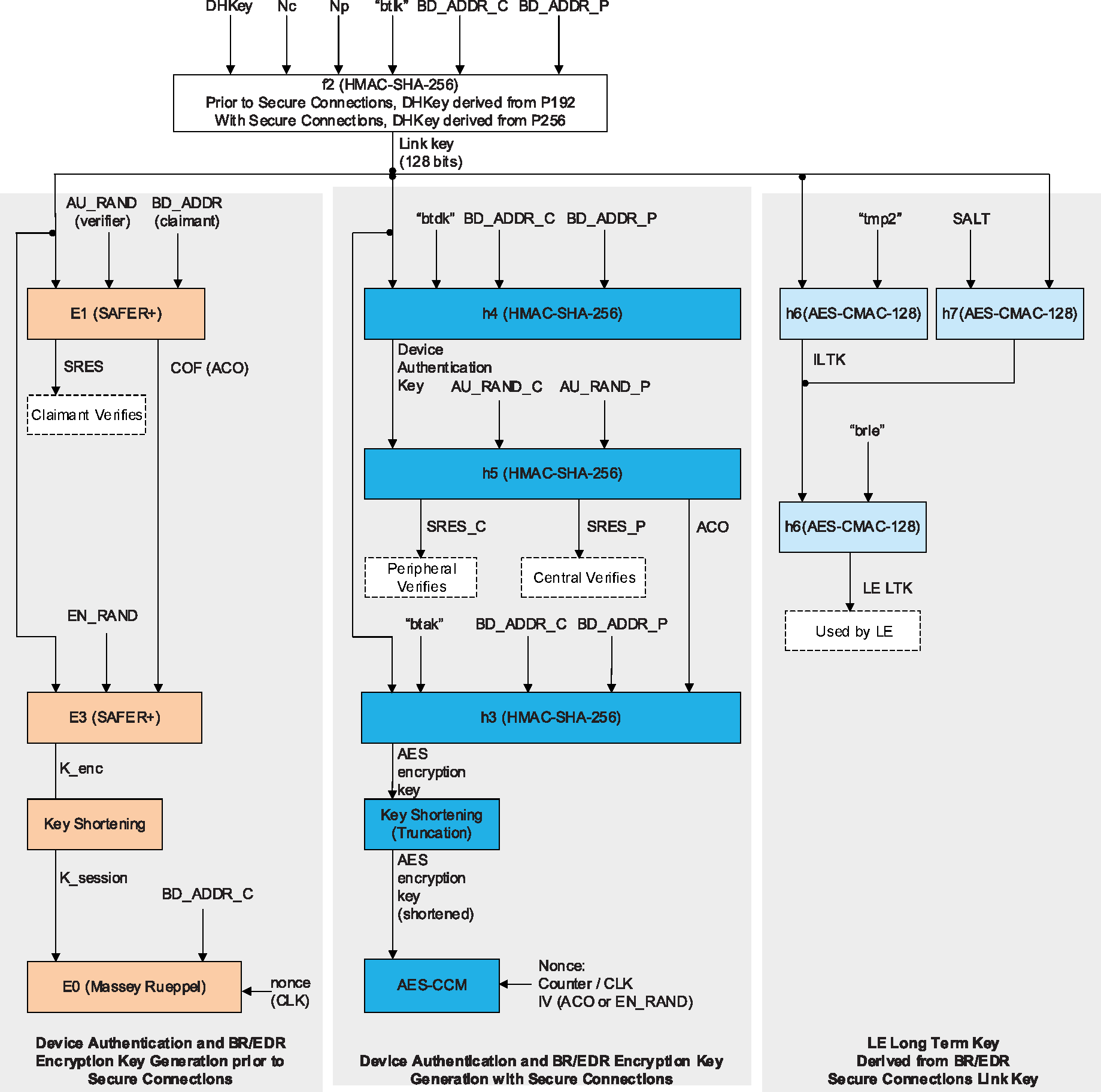
The security key hierarchy for LE is shown in Figure 5.2. The key hierarchy is different depending on whether a physical link is using LE Secure Connections or LE legacy pairing procedures and algorithms.
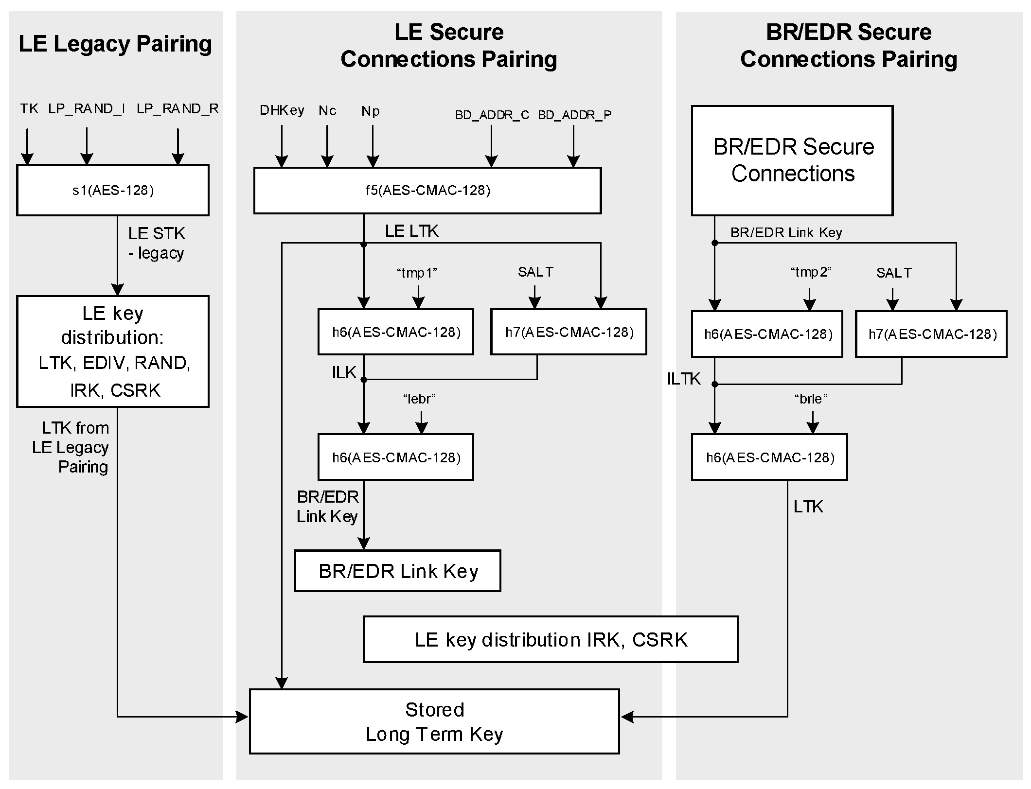
The 5.2 version of the Core Specification adds a new LE security mode that enables transmission and reception of encrypted isochronous data over the Broadcast Isochronous Stream (BIS) logical transport.
5.2. BR/EDR Secure Simple Pairing
The primary goal of Secure Simple Pairing is to simplify the pairing procedure for the user. Secondary goals are to maintain or improve the security in Bluetooth wireless technology. Since high levels of security and ease-of-use are often at opposite ends of the spectrum in many technologies and products, much care has been taken to maximize security while minimizing complexity from the end user's point of view.
5.2.1. Security goals
Secure Simple Pairing has two security goals: protection against passive eavesdropping and protection against man-in-the-middle (MITM) attacks (active eavesdropping). It is a goal of Secure Simple Pairing to exceed the maximum security level provided by the use of a 16 character, alphanumeric, case-sensitive PIN with BR/EDR Legacy Pairing, which often used a 4-digit PIN or a fixed PIN of commonly known values significantly limiting the security on the link.
5.2.2. Passive eavesdropping protection
A strong link key coupled with a strong encryption algorithm is necessary to give the user protection against passive eavesdropping. The strength of the link key is based on the amount of entropy (or randomness) in its generation process which would not be known by an attacker. Using legacy pairing, the only source of entropy is the PIN which, in many use cases, is typically four digits either selected by the user or fixed for a given product. Therefore, if the pairing procedure and one authentication exchange is recorded one can run an exhaustive search to find the PIN in a very short amount of time on commonly available computing hardware. With Secure Simple Pairing, the recording attack becomes much harder as the attacker must have solved a hard problem in public key cryptography in order to derive the link key from the recorded information. This protection is independent of the length of the passkey or other numeric values that the user must handle. Secure Simple Pairing gives the same resistance against the recording and passive eavesdropping attacks even when the user is not required to do anything.
Secure Simple Pairing uses Elliptic Curve Diffie Hellman (ECDH) public key cryptography as a means to thwart passive eavesdropping attacks. ECDH provides a very high degree of strength against passive eavesdropping attacks but it may be subject to MITM attacks, which however, are much harder to perform in practice than the passive eavesdropping attack (see Section 5.2.3).
Using BR/EDR Legacy Pairing with a 16 numeric digit PIN achieves about 53 bits of entropy whereas a 16 character, alphanumeric, case sensitive PIN yields about 95 bits of entropy when the entire 62 character set is used ([0, ... 9, 'A', ... 'Z', 'a', ... 'z']). For devices that do not support the Secure Connections feature, Secure Simple Pairing has approximately 96 bits of entropy using the FIPS approved P-192 elliptic curve which is at least as good as the entropy in BR/EDR Legacy Pairing using a 16 character, alphanumeric, case sensitive PIN. For devices that do support the Secure Connections feature, Secure Simple Pairing has approximately 128 bits of entropy using the FIPS-approved P-256 elliptic curve.
5.2.3. Man-in-the-middle protection
A man-in-the-middle (MITM) attack occurs when a user wants to connect two devices but instead of connecting directly with each other they unknowingly connect to a third (attacking) device that plays the role of the device they are attempting to pair with. The third device then relays information between the two devices giving the illusion that they are directly connected. The attacking device may even eavesdrop on communication between the two devices (known as active eavesdropping) and is able to insert and modify information on the connection. In this type of attack, all of the information exchanged between the two devices are compromised and the attacker may inject commands and information into each of the devices thus potentially damaging the function of the devices. Devices falling victim to the attack are capable of communicating only when the attacker is present. If the attacker is not active or out range, the two victim devices will not be able to communicate directly with each other and the user will notice it.
To prevent MITM attacks, Secure Simple Pairing offers two user assisted numeric methods: numerical comparison or passkey entry. If Secure Simple Pairing would use 16 decimal digit numbers, then the usability would be the same as using legacy pairing with 16 decimal digit PIN. The chance for a MITM to succeed inserting its own link keys in this case is a 1 in 1016 = 253 pairing instances, which is an unnecessarily low probability.
Secure Simple Pairing protects the user from MITM attacks with a goal of offering a 1 in 1,000,000 chance that a MITM could mount a successful attack. The strength of the MITM protections was selected to minimize the user impact by using a six digit number for numerical comparison and Passkey entry. This level of MITM protection was selected since, in most cases, users can be alerted to the potential presence of a MITM attacker when the connection process fails as a result of a failed MITM attack. While most users feel that provided that they have not compromised their passkey, a 4-digit key is sufficient for authentication (i.e. bank card PIN codes), the use of six digits allows Secure Simple Pairing to be FIPS compliant and this was deemed to have little perceivable usability impact.
5.2.4. Association models
Secure Simple Pairing uses four association models referred to as Numeric Comparison, Just Works, Out Of Band, and Passkey Entry. Each of these association models are described in more detail in the following sections.
The association model used is deterministic based on the I/O capabilities of the two devices.
5.2.4.1. Numeric Comparison
The Numeric Comparison association model is designed for scenarios where both devices are capable of displaying a six digit number and both are capable of having the user enter "yes" or "no". A good example of this model is the cell phone / PC scenario.
The user is shown a six digit number (from "000000" to "999999") on both displays and then asked whether the numbers are the same on both devices. If "yes" is entered on both devices, the pairing is successful.
The numeric comparison serves two purposes. First, since many devices do not have unique names, it provides confirmation to the user that the correct devices are connected with each other. Second, the numeric comparison provides protection against MITM attacks (see Section 5.2.3).
There is a significant difference from a cryptographic point of view between Numeric Comparison and the PIN entry model used by BR/EDR Legacy Pairing. In the Numeric Comparison association model, the six digit number is an artifact of the security algorithm and not an input to it, as is the case in the PIN entry model. Knowing the displayed number is of no benefit in decrypting the encoded data exchanged between the two devices.
5.2.4.2. Just Works
The Just Works association model is primarily designed for scenarios where at least one of the devices does not have a display capable of displaying a six digit number nor does it have a keyboard capable of entering six decimal digits. A good example of this model is the cell phone/mono headset scenario where most headsets do not have a display.
The Just Works association model uses the Numeric Comparison protocol but the user is never shown a number and the application may simply ask the user to accept the connection (exact implementation is up to the manufacturer).
The Just Works association model provides the same protection as the Numeric Comparison association model against passive eavesdropping but offers no protection against the MITM attack.
When compared against today's experience of a headset with a fixed PIN, the security level of the Just Works association model is considerably higher since a high degree of protection against passive eavesdropping is realized.
5.2.4.3. Out of Band
The Out of Band (OOB) association model is primarily designed for scenarios where an Out of Band mechanism is used to both discover the devices as well as to exchange or transfer cryptographic numbers used in the pairing process. In order to be effective from a security point of view, the Out of Band channel should provide different properties in terms of security compared to the Bluetooth radio channel. The Out of Band channel should be resistant to MITM attacks. If it is not, security may be compromised during authentication.
The user's experience differs a bit depending on the Out of Band mechanism. As an example, with a Near Field Communication (NFC) solution, the user(s) will initially touch the two devices together, and is given the option to pair the first device with the other device. If "yes" is entered, the pairing is successful. This is a single touch experience where the exchanged information is used in both devices. The information exchanged includes discovery information (such as the Bluetooth Device Address) as well as cryptographic information. One of the devices will use a Bluetooth Device Address to establish a connection with the other device. The rest of the exchanged information is used during authentication.
The OOB mechanism may be implemented as either read only or read/write. If one side is read only, a one-way authentication is performed. If both sides are read/write, a two-way authentication is performed.
The OOB protocol is selected only when the pairing process has been activated by previous OOB exchange of information and one (or both) of the device(s) gives OOB as the IO capabilities. The protocol uses the information which has been exchanged and simply asks the user to confirm connection.
The OOB association model supports any OOB mechanism where cryptographic information and the Bluetooth Device Address can be exchanged. The OOB association model does not support a solution where the user has activated a Bluetooth connection and would like to use OOB for authentication only.
5.2.4.4. Passkey Entry
The Passkey Entry association model is primarily designed for the scenario where one device has input capability but does not have the capability to display six digits and the other device has output capabilities. A good example of this model is the PC and keyboard scenario.
The user is shown a six digit number (from "000000" to "999999") on the device with a display, and is then asked to enter the number on the other device. If the value entered on the second device is correct, the pairing is successful.
There is a significant difference from a cryptographic point of view between Passkey Entry and the PIN entry model used by BR/EDR Legacy Pairing. In the Passkey Entry association model, the six digit number is independent of the security algorithm and not an input to it, as is the case in the PIN entry model. Knowing the entered number is of no benefit in decrypting the encoded data exchanged between the two devices.
5.2.4.5. Association model overview
The following diagram shows Secure Simple Pairing from the point of view of the technology used for discovery and then the different association possibilities.
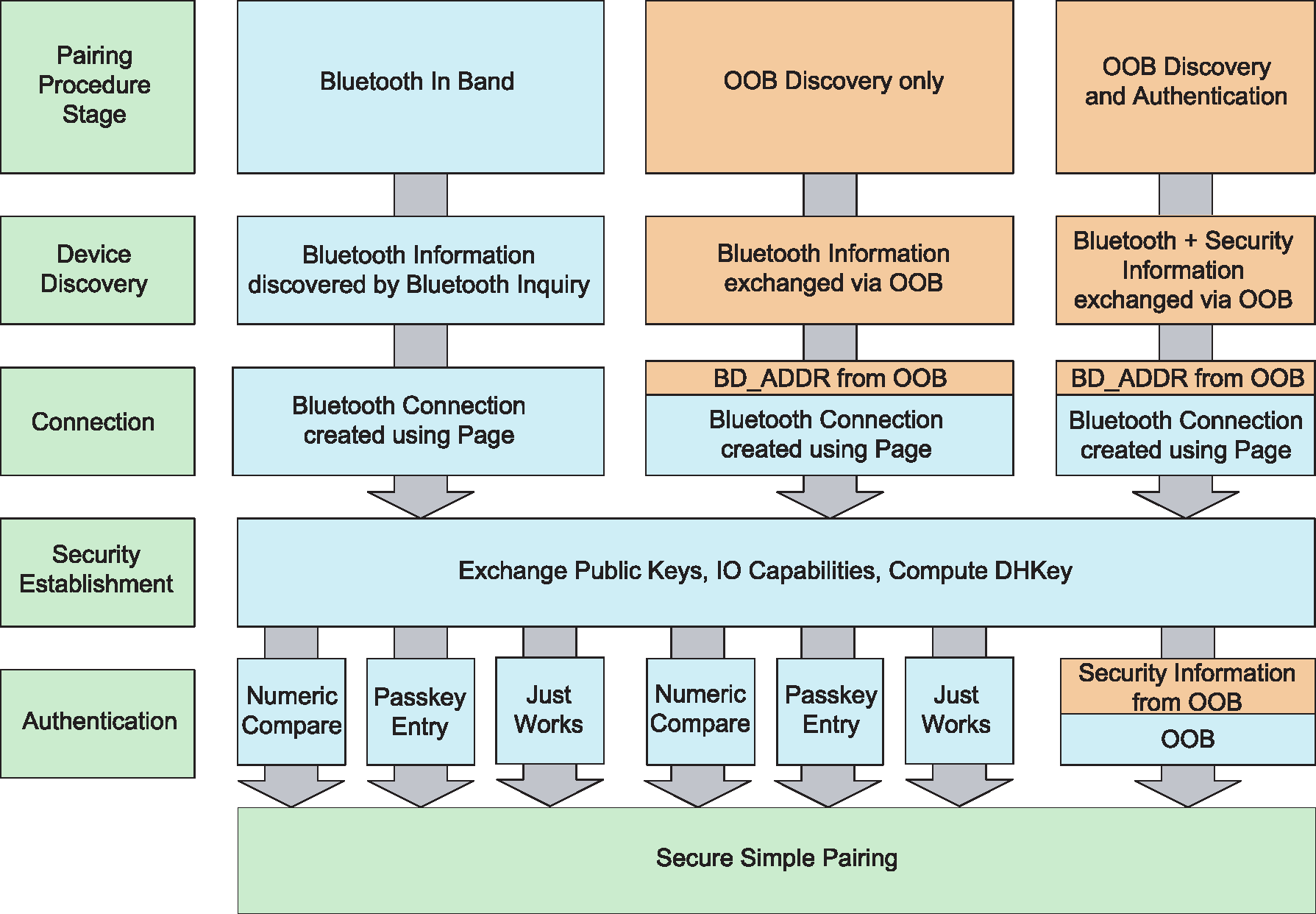
5.3. Secure Connections Only mode
When a device requires that only FIPS-approved algorithms are used on the BR/EDR or LE physical transport, it should enter Secure Connections Only Mode. Secure Connections Only Mode is sometimes called a "FIPS Mode". This mode should be used when it is more important for a device to have high security than it is for it to maintain backwards compatibility with devices that do not support Secure Connections. The Host will enforce that the P-256 elliptic curve is used during pairing and that, on the BR/EDR physical transport, the secure authentication sequences are used and AES-CCM is used for encryption.
If a BR/EDR/LE device is configured in Secure Connections Only Mode, then both the BR/EDR and the LE transports will be in Secure Connections Only Mode.
5.4. LE security
LE Legacy Pairing has some differences in security aspects compared to BR/EDR security features such as Secure Simple Pairing. The association models are similar to BR/EDR Secure Simple Pairing from the user perspective and have the same names but have differences in the quality of the protection provided.
5.4.1. Association models
Bluetooth LE uses four association models referred to as Just Works, Numeric Comparison, Out of Band and Passkey Entry. LE legacy pairing does not have an equivalent of Numeric Comparison.
In LE legacy pairing, each of these association models is similar to BR/EDR Secure Simple Pairing with the following exceptions.
Just Works and Passkey Entry do not provide any passive eavesdropping protection. This is because Secure Simple Pairing uses Elliptic Curve Diffie-Hellman and LE legacy pairing does not.
In LE Secure Connections pairing, the four association models are functionally equivalent to BR/EDR Secure Connections.
The use of each association model is based on the I/O capabilities of the devices.
5.4.2. Key generation
Key generation in Bluetooth LE is performed by the Host on each LE device independent of any other LE device. By performing key generation in the Host, the key generation algorithms can be upgraded without the need to change the Controller.
Note
Note: Key generation in BR/EDR is performed in the Controller.
Bluetooth LE uses multiple keys, each for a specific purpose, as follows:
Confidentiality of data and device authentication
Authentication of unencrypted data
Device Identity
In LE, the key used to provide confidentiality and authentication is generated by combining contributions from each device during pairing.
5.4.3. Encryption
Encryption in Bluetooth LE uses AES-CCM cryptography. Like BR/EDR, in LE encryption is performed in the Controller.
5.4.4. Signed Data
Bluetooth LE supports the ability to send authenticated data over an unencrypted ATT bearer between two devices with a trusted relationship. This is accomplished by signing the data with a Connection Signature Resolving Key (CSRK). The sending device places a signature after the Data PDU. The receiving device verifies the signature and if the signature is verified the Data PDU is assumed to come from the trusted source. The signature is composed of a Message Authentication Code generated by the signing algorithm and a counter. The counter is used to protect against a replay attack and is incremented on each signed Data PDU sent.
5.4.5. Privacy feature
Bluetooth LE supports a feature that reduces the ability to track a LE device over a period of time by changing the Bluetooth Device Address on a frequent basis.
In order for a device using the privacy feature to reconnect to known devices, the device address, referred to as the private address, must be resolvable by the other device. The private address is generated using the device’s identity resolving key (IRK) exchanged during the bonding procedure.
The term “resolution” means a process used by a device to calculate the device Identity Address from the received private address and the IRK, while the state “resolved” is the successful result of a resolution.
There are two variants of the privacy feature. In the first variant, private addresses are resolved and generated by the Host. In the second variant, private addresses are resolved and generated by the Controller without involving the Host after the Host provides the Controller device identity information. In addition, the second variant may involve the Host when the resolving list in the Controller cannot store all the device identity resolving keys necessary for bonded devices.
There are two modes of privacy: device privacy mode and network privacy mode. A device in device privacy mode is only concerned about the privacy of the device and will accept advertising packets from peer devices that contain their Identity Address as well as ones that contain a private address, even if the peer device has distributed its IRK in the past. In network privacy mode, a device will only accept advertising packets from peer devices that contain private addresses. By default, network privacy mode is used when private addresses are resolved and generated by the Controller.
The Host maintains a resolving list by adding and removing device identities. The Host may provide the Controller with a complete resolving list or a subset of the resolving list. A device identity consists of the peer’s Identity Address and a local and peer’s IRK pair.
When the Controller performs address resolution and the Host needs to refer to a peer device that is included in the resolving list, it uses the peer’s device Identity Address. Likewise, all incoming events from the Controller to the Host will use the peer’s device identity, provided that the peer’s device address has been resolved. If the Controller cannot resolve the peer’s device Identity Address in an advertisement, it may pass the event to the Host for resolution in the Host.
Device filtering becomes possible when address resolution is performed in the Controller because the peer’s device Identity Address can be resolved prior to checking whether it is in the Filter Accept List.
Figure 5.4 shows a logical representation of the relationship between the Controller resolving list and the Controller Filter Accept List. Actual implementations of the resolving list and Filter Accept List are not required to follow this model. The resolving list may be independent of the Filter Accept List.
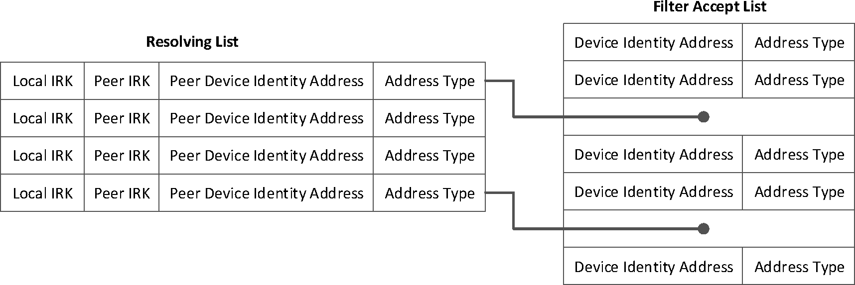
Note
Note: Not all devices in the Filter Accept List are device Identity Addresses.
5.4.6. Encrypted Advertising Data
The privacy feature described in Section 5.4.5 allows the Bluetooth Device Address to be changed periodically while still allowing the fingerprinting of devices based on the contents of their advertising data. It is possible to encrypt advertising data by encapsulating the normal advertising data within an Encrypted Data data type using a pre-shared session key and a nonce. Because the encrypted advertising data nonce is changed whenever the private address is changed, the encrypted data before and after the change is also different. This approach prevents the tracking of devices based solely on the private address and advertising data.
The encrypted advertising data pre-shared session key is communicated only to peer devices that are authorized to receive such information. Only devices that have the key material can decrypt and authenticate messages and track the advertising device.
5.5. [This section is no longer used]
5.6. Key generation between BR/EDR and LE physical transports
When two BR/EDR/LE devices support Secure Connections over both transports, keys for both transports may be generated during a single pairing procedure. The ability to convert keys from one transport to the other prevents the need to pair twice, thus enabling a better user experience.
The link key for BR/EDR generated during Phase 4 of Secure Simple Pairing on the BR/EDR physical transport may be converted to a Long Term Key (LTK) for use on the LE transport. Similarly, an LTK generated during Phase 2 of pairing on the LE physical transport may be converted to the BR/EDR Link Key for use on the BR/EDR physical transport.
6. Bluetooth application architecture
6.1. Bluetooth profiles
Application interoperability in the Bluetooth system is accomplished by Bluetooth profiles. Bluetooth profiles define the required functions and features of each layer in the Bluetooth system from the PHY to L2CAP and any other protocols outside of this specification. The profile defines the vertical interactions between the layers as well as the peer-to-peer interactions of specific layers between devices.

In addition, application behaviors and data formats are also defined by the profile. When two devices comply with all the requirements of a Bluetooth profile, interoperability of an application is enabled.
All profiles describe service discovery requirements necessary for devices to connect, find available application services and connection information necessary for making application level connections.
6.2. Generic Access Profile
The Bluetooth system defines a base profile which all Bluetooth devices implement. This profile is the Generic Access Profile (GAP), which defines the basic requirements of a Bluetooth device. For instance, for BR/EDR, it defines a Bluetooth device to include the Radio, Baseband, Link Manager, L2CAP, and the Service Discovery protocol functionality; for LE, it defines the Physical Layer, Link Layer, L2CAP, Security Manager, Attribute Protocol and Generic Attribute Profile. This ties all the various layers together to form the basic requirements for a Bluetooth device. It also describes the behaviors and methods for device discovery, connection establishment, security, authentication, association models and service discovery.
In BR/EDR, GAP defines a single role with functionality that may be present in each device. This functionality includes how devices discovery each other, establish connections and describes security association models used for authentication. In BR/EDR this functionality may be present in both devices. It may be necessary for a device to implement both the initiating and accepting functionality if the device wants to discover or establish connections with all devices. A device may only include either the initiating or the accepting functionality but it requires the remote device to support the complimentary functionality to discovery or establish connections with the device. For BR/EDR, the Controller is required to support all the functionality, however the Host may limit this functionality based on the other profiles or use cases supported by the device.
In LE, GAP defines four specific roles: Broadcaster, Observer, Peripheral, and Central. A device may support multiple LE GAP roles provided that the underlying Controller supports those roles or role combinations. Each role specifies the requirements for the underlying Controller. This allows for Controllers to be optimized for specific use cases.
The Broadcaster role is optimized for transmitter only applications. Devices supporting the Broadcaster role use advertising to broadcast data. The Broadcaster role does not support connections. The Observer role is optimized for receiver only applications. Devices supporting the Observer role are the complementary device for a Broadcaster and receives broadcast data contained in advertisements. The Observer role does not support connections. The Peripheral role is optimized for devices that support a single connection and are less complex than Centrals; it uses the Link Layer Peripheral role within the connection. The Central role supports multiple connections and is the initiator for all connections with devices in the Peripheral role; it uses the Link Layer Central role within the connection. Devices supporting the Central role generally support more complex functions compared to the other LE GAP roles.
6.3. Profile hierarchy
Since all Bluetooth devices are required to implement GAP, any additional profiles implemented by a Bluetooth device become supersets of GAP. Depending on the complexity of an application or the ability to reuse common requirements of functionality of the Bluetooth system between many applications, additional generic profiles can be created that depend on GAP or other generic profiles, as well as enabling other profiles. A top level profile that describes application interoperability is called an Application Profile.
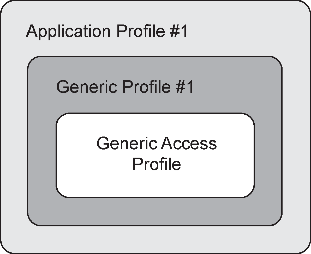 |
Application profiles contain by reference GAP and any other generic profile that describes a set of common requirements of the Bluetooth system.
6.4. Generic Attribute Architecture
6.4.1. Attribute Protocol
To allow devices to read and write small data values held on a server, an Attribute Protocol (ATT) is defined. Each stored value, typically only a few octets, is known as an attribute. This protocol allows each attribute to be self-identifying using UUIDs to identify the type of data. These UUIDs can be well-known assigned numbers defined in the Assigned Numbers document and associated specifications, or a vendor assigned 128-bit UUID.
Attribute Protocol messages are sent over L2CAP channels, known as the ATT bearers.
Attribute Protocol defines two roles: Client and Server. A device can be both an ATT Client and an ATT Server at the same time. Attribute Protocol messages on a single ATT bearer allow a single transaction in each direction to be outstanding at a time. When a response to a message is received, the next transaction can be initiated. When multiple ATT bearers are created, each ATT bearer has a separate transaction model and therefore multiple ATT transactions can be outstanding at the same time, one per bearer. This can be used to allow multiple higher layer specifications to send messages concurrently.
The ATT Server stores the attributes and accepts Attribute Protocol requests, commands and confirmations from the ATT Client. The ATT Server sends responses to requests and, when configured by a higher layer, sends indications and notifications asynchronously to the ATT Client when specified events occur on the ATT Server.
6.4.2. Generic Attribute Profile
Generic Attribute Profile (GATT) is built on top of the Attribute Protocol (ATT) and establishes common operations and a framework for the data transported and stored by the Attribute Protocol. GATT defines two roles: Server and Client. A GATT Client or Server is an ATT Client or Server respectively that conforms to the requirements in GATT. The GATT roles are not necessarily tied to specific GAP roles but may be specified by higher layer profiles. GATT and ATT are not transport specific and can be used in both BR/EDR and LE. However, GATT and ATT are mandatory to implement in LE since it is used for discovering services.
GATT also specifies the format of data contained on the GATT Server. Attributes, as transported by the Attribute Protocol, are formatted as Services and Characteristics. Services may contain a collection of characteristics. Characteristics contain a single value and any number of descriptors describing the characteristic value.
With the defined structure of services, characteristics and characteristic descriptors a GATT Client that is not specific to a profile can still traverse the GATT Server and display characteristic values to the user. The characteristic descriptors can be used to display descriptions of the characteristic values that may make the value understandable by the user.
6.5. GATT-Based Profile hierarchy
The GATT Profile specifies the structure in which profile data is exchanged. This structure defines basic elements such as services and characteristics, used in a profile.
The top level of the hierarchy is a profile. A profile is composed of one or more services necessary to fulfill a use case. A service is composed of characteristics or references to other services. Each characteristic contains a value and may contain optional information about the value. The service and characteristic and the components of the characteristic (i.e., value and descriptors) contain the profile data and are all stored in Attributes on the server.
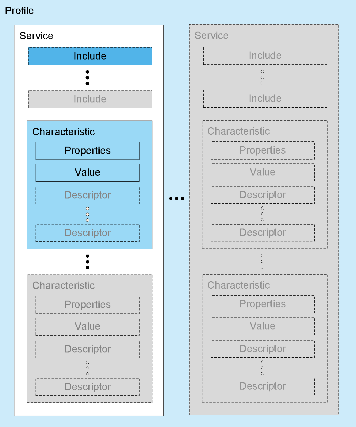
6.5.1. Service
A service is a collection of data and associated behaviors to accomplish a particular function or feature of a device or portions of a device. A service may include other primary or secondary services and/or a set of characteristics that make up the service.
There are two types of services: primary and secondary. A primary service is a service that provides functionality of a device that can be used on its own. A secondary service is a service that provides additional functionality of a device in association with a primary service and is included from at least one primary service on the device.
To maintain backward compatibility with earlier clients, later revisions of a service definition can only add new included services or optional characteristics. Later revisions of a service definition are also forbidden from changing behaviors from previous revision of the service definition.
Services may be used in one or more profiles to fulfill a particular use case.
6.5.2. Included services
An included service is a method to incorporate another service definition on the server as part of the service including it. When a service includes another service, the entire included service becomes part of the new service including any nested included services and characteristics. The included service still exists as an independent service. There are no limits to the depth of nesting.
6.5.3. Characteristic
A characteristic is a value used in a service along with properties and configuration information about how the value is accessed and information about how the value is displayed or represented. A characteristic definition contains a characteristic declaration, characteristic properties, and a value. It may also contain descriptors that describe the value or permit configuration of the server with respect to the characteristic value.
6.6. Mesh-based model hierarchy
The Mesh Profile[1] specifies the structure within which data is exchanged by devices in a mesh network. This structure defines basic building blocks such as models and properties.
The top level of the hierarchy is a model, which is either a client model or a server model. A client model can send messages to a server model and the server model can use other messages to respond to the client model. Models enable devices to send standardized messages, using standardized data formats, to other devices that they have had no previous relationship with.
6.6.1. Model
A model is a collection of properties, states, messages, and associated behaviors that accomplishes a particular device function. A model defines and exposes states along with any associated behavior. It also defines the messages that are used to communicate between models within devices in a mesh network. Messages are defined globally and are not model-specific. Models are immutable meaning that features cannot be added to or removed from a model definition. Therefore, the only way to add features to a model is by defining a new model that extends an existing model by defining new states, messages, and behaviors. These new states and behaviors are linked to the existing model using state binding. This ensures backwards and forwards compatibility by allowing newer devices to access the newer features of the extended model, and older devices to access the base features of an existing model.
6.6.2. Properties
A property adds context to a defined characteristic. When sending data into a mesh network, it is very useful to label data with the meaning, or context, of that data. This allows a device that receives a property to interpret that data without having to negotiate the context beforehand. For example, a temperature characteristic can be given a context about how or when that temperature was measured such as “outside temperature”, “indoor temperature”, or “oil temperature”.
Properties are defined globally and are not model-specific.
7. Coexistence and collocation
Bluetooth devices operate in the unlicensed 2.4 GHz Industrial, Scientific and Medical (ISM) band. Many other technologies utilize the ISM band, including wireless LAN, cordless phones, and microwave ovens. The ISM band is also close enough to other frequency bands that Bluetooth devices may be an interferer of or a victim of other technologies.
Radios may be collocated or non-collocated. The term "collocated" is a loose one - in this specification, collocated radios are assumed to be in the same product (a Multi-Radio Terminal or MRT) and may have mechanisms to coordinate their activity in order to mitigate interference.
Determining the amount of expected isolation between radios is important for choosing an appropriate coexistence mechanism. With sufficient isolation, frequency division duplexing (FDD) techniques are the most efficient. With insufficient isolation or a shared antenna, time division duplexing (TDD) techniques need to be used. In many cases, a combination of FDD and TDD techniques are required to achieve acceptable levels of performance.
This specification supports a variety of features that help mitigate interference to other devices and to minimize interference from other devices. Broadly, the types of solutions fall into the following categories:
Type | Description |
|---|---|
Frequency division | Simultaneous use of multiple radios enabled by filters and/or isolation |
Time division | One radio may transmit or receive at a time through scheduling or prioritization |
Time alignment | Activities of the collocated radios are aligned in the time domain to optimize performances by avoiding conflicting activities. E.g. Transmissions of multiple radios may occur simultaneously, multiple receptions may occur simultaneously, but it is not possible to transmit and receive simultaneously |
Hybrid frequency and time division | Use of frequency division, time alignment, and time division techniques depending on the relative frequencies in use by the radios, filters and isolation |
7.1. Core features supporting coexistence and collocation
There are features in the specification to specifically target the reduction of interference from collocated or non-collocated devices.
Feature | Version Introduced | Description |
|---|---|---|
Adaptive Frequency Hopping | 1.2 | Allows devices to reduce the number of channels used in a piconet in order to avoid interferers |
HCI Set Host Channel Classification | 1.2 | Allows a Host to inform the local Bluetooth Controller of the channels that are occupied by a collocated technology |
Enhanced SCO (eSCO) | 1.2 | Added retransmissions to SCO for the purpose of combating interference |
MWS Coexistence Signaling | CSA3 | Provides a standardized interface between collocated radios for communicating information necessary to enable some coexistence techniques |
Piconet Clock Adjust | 4.1 | Allows a Bluetooth device to align the piconet clock with an external technology, e.g. Long Term Evolution (LTE) |
Train Nudging | 4.1 | Provides a mechanism to improve the success rate of page and inquiry when the slots to receive the respective responses are periodically not available |
Generalized Interlaced Scanning | 4.1 | Provides a mechanism to improve the success rate of page scan and inquiry scan when some slots are periodically not available for scanning |
Slot Availability Mask | 5.0 | Provides a mechanism for two Bluetooth devices to indicate to each other the availability of their time slots |
7.2. Adaptive Frequency Hopping
Adaptive Frequency Hopping (AFH) allows Bluetooth devices to improve their immunity to interference from and avoid causing interference to other devices in the 2.4 GHz ISM band. The basic principle is that Bluetooth channels are classified into two categories, used and unused, where used channels are part of the hopping sequence and unused channels are replaced in the hopping sequence by used channels in a pseudo-random way. This classification mechanism allows for the Bluetooth device to use either all or fewer than the 79 channels available. The minimum number of channels allowed by the Bluetooth specification is 20.
The specification defines the aspects of AFH necessary to ensure interoperability, including the hopping kernel, Baseband behavior, Link Manager Protocol (LMP) commands, and Host Controller interface (HCI) commands and events required to change and configure hopping sequences. The Bluetooth Specification also defines a mechanism that allows for a Peripheral to report channel classification information to the Central.
Adaptive Frequency Hopping utilizes metrics obtained through many sources. These metrics are analyzed and then the resulting Channel_Map is used by the adaptive frequency hopping kernel. The metrics may come from over-the-air measurements, data supplied by the Host (via the HCI_Set_AFH_Host_Channel_Classification command), or reports by the Peripheral or from other hardware coexistence interfaces.
While AFH is a critical element in coexistence, it is not enough in some circumstances.
7.3. Coexistence between Bluetooth Devices and Wireless LAN Devices
Coexistence between Bluetooth and Wireless LAN has traditionally been a combination of Adaptive Frequency Hopping (AFH) and proprietary techniques to prioritize traffic between the two protocols. The specification does not specify signaling between the Bluetooth Controller and a Wireless LAN device.
7.4. Mobile Wireless Standards (MWS) coexistence
Significant interference can be present between the Bluetooth radio and a collocated MWS radio operating in frequency bands adjacent to the 2.4 GHz ISM band. This interference can prevent one radio from receiving while the other radio is transmitting.
The “Filter recommendations for Coexistence with LTE and WiMAX” whitepaper[2] describes filter specifications that, in some cases, can reduce collocated interference to an acceptable level. The specification includes complementary solutions to traditional filtering including features for Bluetooth Controllers and Hosts as well as signaling and messaging mechanisms between collocated MWS and Bluetooth radios. Figure 7.1 illustrates the general architecture model for these mechanisms. This architecture assumes separate antennas with limited isolation.
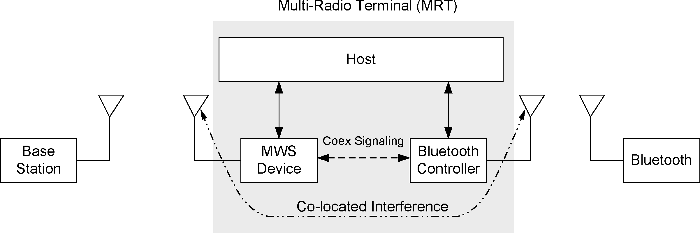
Two types of solutions have been considered. In the first solution, both Bluetooth transmissions (TX) and receptions (RX) are constrained by collocated MWS activities. Solutions of this type are called Pure TDM (Time Division Multiplexed) Mode. In the second solution, only Bluetooth receptions are affected by collocated MWS transmissions and Bluetooth transmissions do not impact the operation of the collocated MWS. Solutions of this type are called Hybrid Mode and are achieved, for example, by using steep roll-off Band Select Filters (BSFs) for the ISM band in the Bluetooth transceiver. Hybrid Mode applies where the Bluetooth transmission’s effect on MWS is sufficiently reduced via filtering that the Bluetooth device can transmit during the MWS downlink time. This requires a frequency guard band between the Bluetooth and MWS operational frequency ranges as well as constraints on both the Bluetooth BSF and the MWS BSF. The requirement for a time domain solution still remains, but only to protect Bluetooth reception.
These solutions are facilitated by an MWS coexistence signaling mechanism (see [Vol 7] Part A) and multiple transport layers (see [Vol 7] Part B and [Vol 7] Part C).
MWS technologies operate in licensed bands and use centralized scheduling to support Wide Area Network services. An MWS radio synchronizes both time and frequency with a network Base Station. The Base Station determines which MWS radio will transmit or receive and when. MWS radios have no control over when to transmit or receive. When Bluetooth transmissions interfere with MWS receptions in the MRT, the MWS radio can be rendered unusable if the Bluetooth radio transmits freely. Figure 7.2 shows how Bluetooth activity can interfere with every MWS reception opportunity and similarly how MWS transmissions can interfere with Bluetooth reception. In the example shown in Figure 7.2 the Bluetooth device in the MRT is operating as the Central of a piconet. Blocks marked with a “C” are single slot Central transmissions and those marked with a “P” are single slot Peripheral transmissions. The times at which reception by the MWS device may be corrupted by Bluetooth transmissions are marked with a red shade.
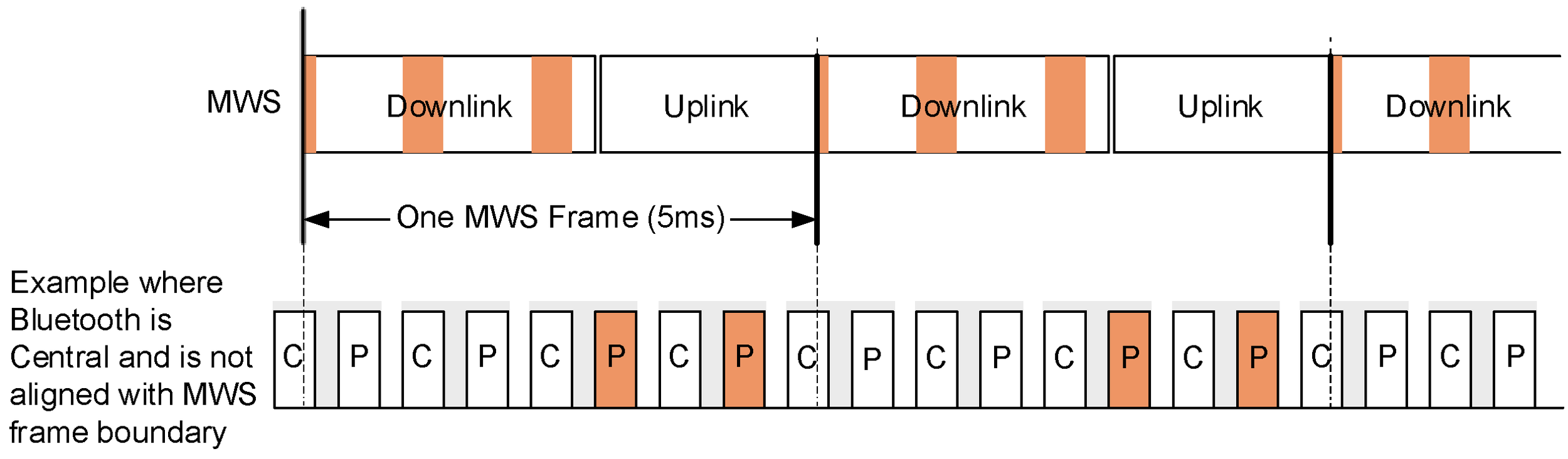
Even with the best relative timing relationship (when the Bluetooth slot boundary is aligned with the MWS frame boundary), the Bluetooth radio in the MRT suffers reduced transmission and reception opportunities due to time multiplexing with the collocated MWS radio. The Bluetooth radio only gets one transmission/reception opportunity every MWS frame, as shown in Figure 7.3.
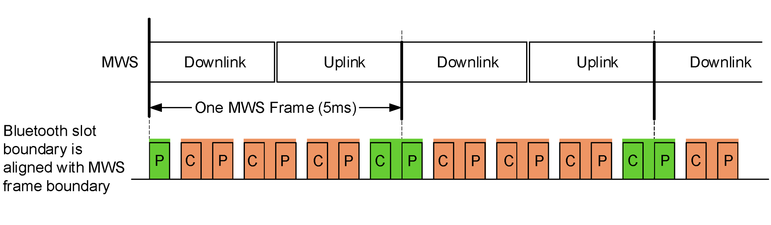
Consequently, three out of four (for 5 ms MWS frames) or seven out of eight (for 10 ms MWS frames) slot pairs of Bluetooth can be punctured by MWS activities. Furthermore, since Bluetooth inquiry and paging use a sequence of 16 channels at a time, when the Bluetooth radio in the MRT is performing inquiry or paging the channel sequence will repeat every 5 ms resulting in the same channels being repeatedly punctured by the collocated MWS activities, see Figure 7.4. As a result, there is a high probability that the remote scanning device will not be able to receive the page or inquiry IDs within the current timeout.
When the inquiry or paging channel sequence gets repeatedly punctured, Train Nudging can be used to add an additional offset to the clock bits in order to shift the channel sequence.
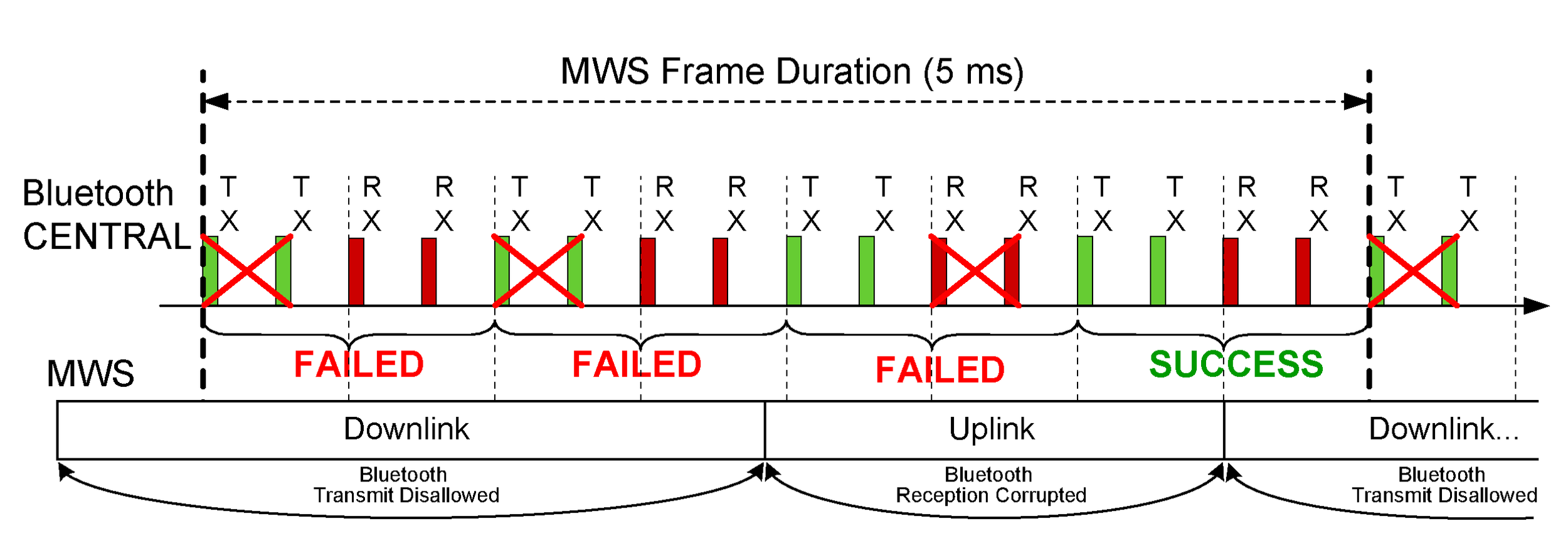
As MWS transmissions interfere with Bluetooth receptions in the MRT, up to 50% of the transmitted IDs from the remote inquiry/page device will not be received by the Bluetooth radio in the MRT performing scanning, as shown in Figure 7.5.
Based on the pattern of slots that are not available for scanning, Generalized Interlaced Scanning can be used to tune the phase of the second scan during a back-to-back scan.
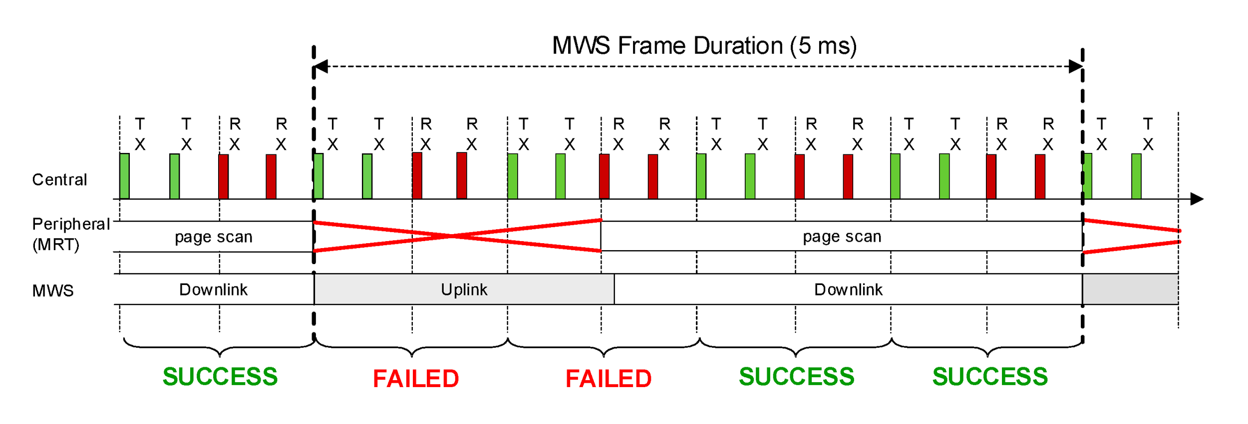
7.5. Synchronizing Bluetooth with an external timing source
This section provides an example to illustrate the synchronization of the Bluetooth CLK with an MWS system so that the Bluetooth slots line up with the Downlink and Uplink times of the MWS system. The external frame in this example is LTE TDD Frame Configuration #1 and special subframe configuration #1; however the same mechanisms can be used for any external TDD/TDMA protocol. The example shows a time span of 10 ms.
[Vol 7] Part A defines the timing of the MWS frame as a fixed offset from the FRAME_SYNC signal in the coexistence signaling. This is shown in Figure 7.6 as FS. FS can be defined by the Host as any specific offset within the MWS frame. For a piconet Central, the most useful position for FS is the boundary between the uplink and the following downlink. This is because the Central needs to transmit in a Central slot during the uplink and then receive in the following Peripheral slot during the downlink. Putting FS at this boundary allows the Central to easily align its Bluetooth clock to put it between these slots. The situation is reversed in a Peripheral: FS is most useful on the boundary between the downlink and the following uplink.
The HCI command HCI_Set_External_Frame_Configuration ([Vol 4] Part E, Section 7.3.81) is used to describe the MWS frame timing. This knowledge, together with FS, allows the Bluetooth Controller to align the Bluetooth clock with the MWS frame timing so as to minimize the effect of mutual interference. This is illustrated in Figure 7.6. The red ovals show slot pairs where both MWS and Bluetooth transmit and receive simultaneously and so do not interfere with each other. The MWS frame structure includes a downlink portion (“D”), an uplink portion (“U”), and a special portion (“S”) that includes a downlink and uplink portion separated by a guard period (“GP”).
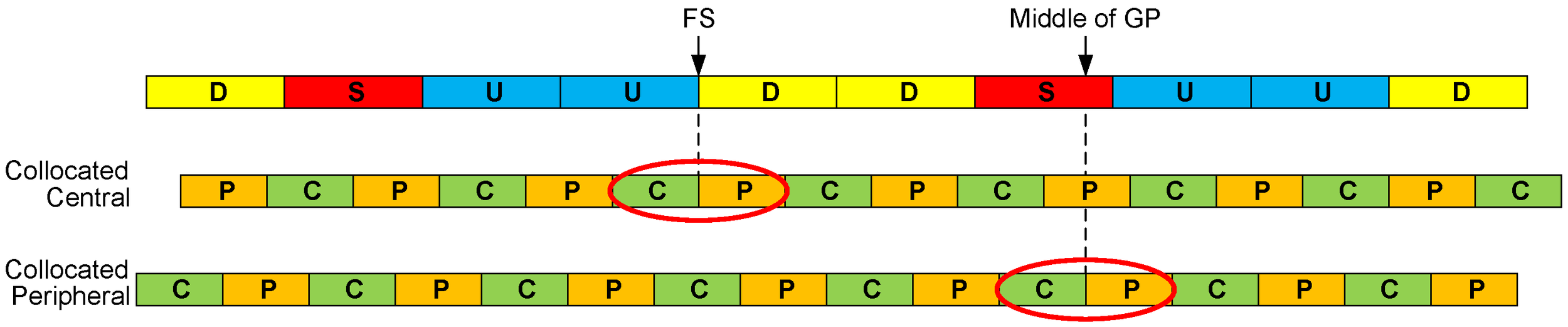
Note
Note: In LTE, if the implementation does not have access to the exact LTE timing it can assume that the downlink-to-uplink boundary is the middle of the GP in a special LTE subframe.
7.6. Piconet clock adjustment
As discussed in the previous section, aligning the MWS and Bluetooth clocks correctly greatly improves throughput on both technologies. The Central has two mechanisms at its disposal to mitigate misalignments.
Coarse Clock Adjustments can be used to move the Bluetooth CLK using the LMP_CLK_ADJ PDU. The clk_adj_us parameter is used to align the slots with the MWS alignment point indicated by the FRAME_SYNC signal. The clk_adj_slots parameter can be used to move the CLK several slots forward in time. This can be useful to align e.g. eSCO. Coarse Clock Adjustment is expected to be used only rarely, for instance at MWS connection or when the MWS frame timing changes due to roaming. Coarse Clock Adjustment can only be used when all Peripherals in the piconet support it.
The other option for the Central is to use Clock Dragging. This is a method of slowly adjusting the phase of the clock backward or forward by making the slots a few µs shorter or longer, respectively, until the desired CLK phase has been achieved. It should be noted that this is a very slow rate of adjustment, as it is designed to allow a legacy device to track the change, and therefore the requirements of [Vol 2] Part B, Section 1.1 mean that Clock Dragging must not be done at a faster rate than the maximum natural drift between devices. For this reason its main use is to facilitate small corrections over time if a misalignment with the MWS system is detected. If any device is connected that does not support Coarse Clock Adjustment, slowly moving the Peripheral using Clock Dragging is the only option.
It is recommended to let the collocated device be the Central, when possible, as it can react much faster to correct misalignments. If a Peripheral is the collocated device, doing a role switch to make it Central may be worth considering. Alternatively a Peripheral can send a Piconet Clock Adjustment Request LMP packet to the Central. The Central then has the option to perform a Coarse Clock Adjustment, Clock Dragging, or to reject the request.
7.7. Slot Availability Mask (SAM)
Slot Availability Mask (SAM) allows two Bluetooth devices to indicate to each other time slots that are available for transmission and reception. The SAM slot map specifies the availability or otherwise of Bluetooth slots. A slot could be unavailable because of external conditions (e.g., MWS coexistence) or internal conditions (e.g., scatternet commitments). SAM does not impose new mandatory rules for the scheduling of BR/EDR time slots. Instead, it merely provides information which allows Controllers to refine their scheduling of Bluetooth slots to improve performance.
SAM slot maps are calculated by the Controller itself based on its scheduling requirements. There are no HCI commands defined specifically for SAM, merely LMP sequences that enable devices to exchange maps and indicate the map in use. The HCI commands HCI_Set_External_Frame_Configuration (see [Vol 4] Part E, Section 7.3.81) and HCI_Set_MWS_PATTERN_Configuration (see [Vol 4] Part E, Section 7.3.85) and real-time signals (e.g., MWS_PATTERN_Index or FRAME_SYNC) provided by the Coexistence Logical Interface (see [Vol 7] Part A) contain information concerning the appropriate SAM_Index and SAM anchor point to use for MWS coexistence; these may therefore trigger these LMP sequences.
A Controller may choose to perform a Piconet Clock Adjustment before initiating an LMP_SAM_SWITCH sequence so as to increase the number of slot pairs available per MWS frame.
8. Direction finding using Bluetooth Low Energy
An LE device can make its direction available for a peer device by transmitting direction finding enabled packets. Using direction information from several transmitters and profile-level information giving their locations, an LE radio can calculate its own position.
This feature is supported over the LE Uncoded PHYs, but not over the LE Coded PHY.
8.1. Angle of arrival (AoA) method
An LE device can make its direction available to a peer device by transmitting direction finding enabled packets using a single antenna.
The peer device, consisting of an RF switch and antenna array, switches antennae while receiving part of those packets and captures IQ samples. The IQ samples can be used to calculate the phase difference in the radio signal received using different elements of the antenna array, which in turn can be used to estimate the angle of arrival (AoA).
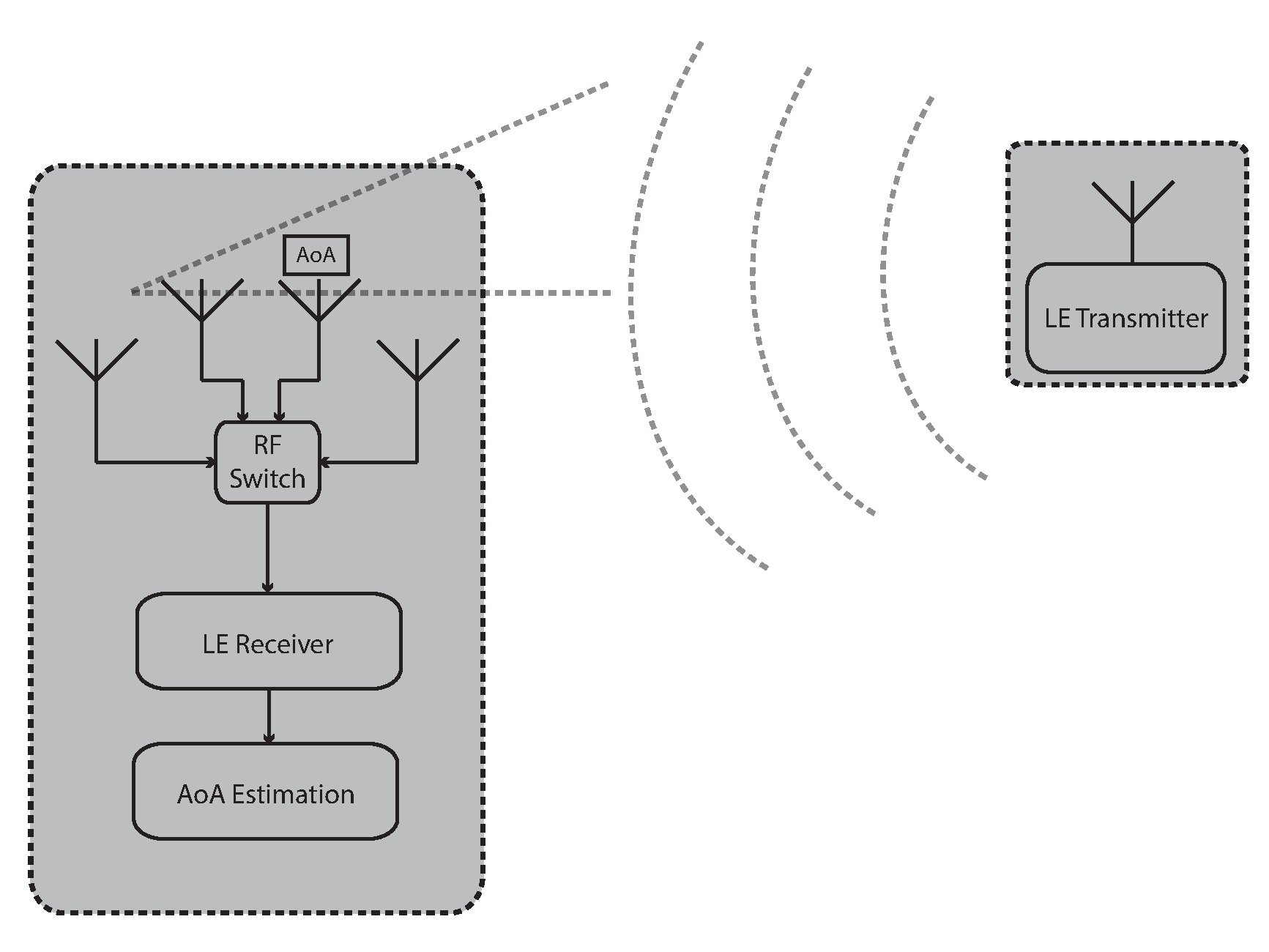 |
Consider a receiver device with an antenna array consisting of two antennae, separated by distance d. The transmitter device uses a single antenna to transmit a signal. As shown in Figure 8.2, a perpendicular line can be drawn from an incoming signal wave front extending to the furthest antenna (antenna 2) at the point of intersection to the closest antenna (antenna 1). The adjacent side of that right triangle represents the path difference relative to the angle of incidence of that wave front between both antennae. The phase difference, ψ, in the signal arriving at the two antennae is then
ψ = (2πd cos(θ))/λ
where λ is the wavelength of the signal and θ is the angle of arrival (measured from a line connecting the two antennae in the receiver), and so
θ = arccos((ψλ)/(2πd))
Note
Note: The distance d is profile-level information that is used by the receiving device to calculate the angle of arrival.
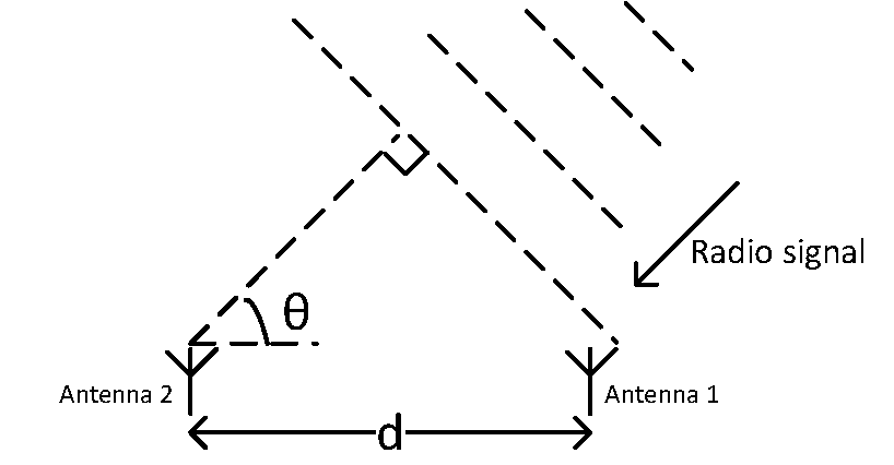 |
8.2. Angle of departure (AoD) method
A device consisting of an RF switch and antenna array can make its angle of departure (AoD) detectable by transmitting direction finding enabled packets, switching antennae during transmission.
The peer device receives those packets using a single antenna and captures IQ samples during part of those packets. Determination of the direction is based on the different propagation delays of the LE radio signal between the transmitting elements of the antenna array and a receiving single antenna. The propagation delays are detectable with IQ measurements. Any receiving LE radio with a single antenna that supports the AoD feature can capture IQ samples and, with the aid of profile-level information specifying the antenna layout of the transmitter, calculate the angle of incidence of the incoming radio signal.

Consider a transmitter device with an antenna array consisting of two antennae, separated by distance d. The receiver device uses a single antenna to receive the signals. The phase difference, ψ, in the signal from antenna 1 and the signal from antenna 2 arriving at the receiver is then
ψ = (2πd cos(θ))/λ
where λ is the wavelength of the signal and θ is the angle of departure (measured from a line connecting the two antennae in the transmitter), and so
θ = arccos((ψλ)/(2πd))
Note
Note: The distance d is profile-level information that a transmitting device exchanges with the receiving device in order for the receiving device to calculate the angle of departure.
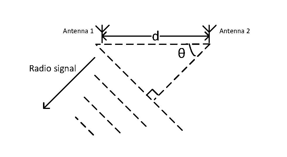 |