Bluetooth® Core 7.0 feature overview
| Version: | 1.0 |
| Publication date: | 3 November 2026 |
| Author: | Gongyu Lu |
1. Introduction
Bluetooth® Core 7.0 introduces a range of enhancements that extend the capabilities of Bluetooth® LE across data throughput, isochronous transport, security, and implementation support. These enhancements address evolving requirements for higher throughput, more flexible transport behavior, new security models, and improved visibility for development and interoperability testing. Together, they build upon the existing Bluetooth architecture while introducing new capabilities that allow Bluetooth devices to adapt to increasingly demanding applications and operating environments.
This paper provides a technical overview of the key features introduced in Bluetooth® Core 7.0. It examines Bluetooth® High Data Throughput (HDT), Bluetooth® LE Isochronous Parameter Update (IPU), Bluetooth® Encryption Key Schedule (EKS), Bluetooth® Transient Application Key (TAK), and Bluetooth® Encryption Product Debugging (EPD). For each feature, the paper describes the underlying motivation, architectural concepts, and principal protocol mechanisms, providing a foundation for understanding how these changes extend and evolve Bluetooth technology.
Note: This is a marketing document and is not intended to replace or overrule the Bluetooth® Core Specification in any way. Each feature enhancement is described in a dedicated section, beginning with relevant background information. This is intended to assist readers who may be unfamiliar with certain aspects of Bluetooth® LE. However, the background sections are not fully comprehensive. Readers who encounter unfamiliar terminology or concepts are encouraged to download and read the Bluetooth® LE primer.
2. At a glance
2.1 Bluetooth® High Data Throughput
Bluetooth® High Data Throughput (HDT) introduces a new Bluetooth LE physical layer that increases the maximum Bluetooth bit rate to 7.5 Mbps while improving wireless efficiency and robustness. Through a combination of higher-order modulation, convolutional forward error correction, synchronization enhancements, adaptive rate selection, and enhanced packet architectures, HDT enables Bluetooth devices to transfer larger amounts of data more efficiently and reliably. The feature provides a scalable foundation for future higher data rate Bluetooth applications, including high-resolution and lossless audio streaming, while maintaining backwards compatibility with the existing Bluetooth LE architecture.
2.2 Bluetooth® LE Isochronous Parameter Update
Bluetooth® LE Isochronous Parameter Update (IPU) introduces a standardized mechanism that allows the parameters of an active Connected Isochronous Stream (CIS) to be updated after the stream has been established. Rather than removing and recreating a Connected Isochronous Group (CIG) when bandwidth, latency, transport, or scheduling requirements change, IPU enables devices to transition between alternative stream configurations while maintaining the existing connection. This capability improves flexibility for Bluetooth LE Audio and other isochronous applications, reduces service interruption, and enables Bluetooth® devices to dynamically adapt transport characteristics to changing application requirements.
2.3 Bluetooth® Encryption Key Schedule
Bluetooth® Encryption Key Schedule (EKS) introduces a new framework for establishing and managing encryption keys used by Bluetooth® LE connections. Rather than deriving encryption material directly from a Long-Term Key (LTK), EKS combines ECDH-based key establishment with a CMAC-based key derivation hierarchy to generate session-specific encryption material. This architecture enables devices to refresh encryption keys, maintain separate security contexts for different transport types, and support enhanced Message Integrity Code (MIC) protection. EKS serves as the security foundation for Bluetooth® High Data Throughput (HDT) while remaining defined as an independent Bluetooth feature that can also support additional Bluetooth use cases.
2.4 Bluetooth® Transient Application Key
Bluetooth® Transient Application Key (TAK) introduces a new approach to securing Bluetooth® LE connections by enabling encryption without relying on pairing or bonding. In this model, authentication and key establishment are handled by a higher-layer application, which establishes a shared 128-bit security-strength secret and provides it to the Bluetooth Host. The TAK is then used to establish Link Layer encryption, allowing devices to create secure connections without forming a long-term trust relationship. The Host discards the TAK after initiating the Encryption Start Procedure, while the higher-layer application determines how its copy of the key is managed.
2.5 Bluetooth® Encryption Product Debugging
Bluetooth® Encryption Product Debugging (EPD) introduces a standardized mechanism that allows a Bluetooth® Host to receive the active encryption credentials used by an encrypted connection. By giving authorized debugging tools visibility into the credentials generated and maintained by the Controller, EPD helps preserve protocol analysis and interoperability debugging as Bluetooth encryption evolves beyond traditional long-term key–based operation.
3. Bluetooth® High Data Throughput (HDT)
Bluetooth® High Data Throughput (HDT) introduces a new Bluetooth® LE physical layer that increases the maximum Bluetooth bit rate to 7.5 Mbps while improving wireless efficiency and robustness. Through a combination of higher-order modulation, convolutional forward error correction, synchronization enhancements, adaptive rate selection, and enhanced packet architectures, HDT enables Bluetooth devices to transfer larger amounts of data more efficiently and reliably. The feature provides a scalable foundation for future higher data rate Bluetooth applications, including high-resolution and lossless audio streaming, while maintaining integration with the existing Bluetooth® LE architecture.
3.1 Background
3.1.1 Evolution of Bluetooth® LE Throughput
Bluetooth LE has evolved through the introduction of new physical layers designed to address different performance objectives. Following the original LE 1M PHY, Bluetooth technology introduced LE 2M to increase throughput and LE Coded to improve range and robustness in challenging radio environments. These enhancements expanded the versatility of Bluetooth® LE across a wide range of applications while preserving interoperability and power efficiency.
However, while Bluetooth LE has continued to evolve, the maximum supported bit rate has remained limited to 2 Mbps. As Bluetooth devices increasingly exchange larger amounts of data and support more demanding applications, the need for higher throughput continues to grow.
3.1.2 Limitations of existing Bluetooth® LE PHYs
Increasing throughput beyond 2 Mbps presents a more fundamental challenge. Bluetooth LE operates within the constraints of the globally available 2.4 GHz ISM band, where spectrum availability, regulatory requirements, implementation complexity, and power efficiency must all be carefully balanced.
The existing Bluetooth LE physical layers are based on Gaussian Frequency Shift Keying (GFSK), a modulation scheme that has contributed significantly to the success of Bluetooth technology through its simplicity, robustness, and low implementation complexity. However, these same characteristics limit the extent to which throughput can be increased using traditional approaches.
3.2 Technical overview
3.2.1 HDT architecture
Bluetooth® High Data Throughput (HDT) addresses these limitations through the introduction of a new Bluetooth® LE physical layer optimized for significantly higher spectral efficiency while remaining fully integrated within the Bluetooth® LE architecture. Rather than introducing a separate wireless technology, HDT builds upon the existing Bluetooth® LE framework and extends it with new capabilities designed to support substantially higher throughput.
At the physical layer, HDT introduces new modulation and coding techniques that enable significantly higher data rates within the existing Bluetooth channel structure. To support these capabilities, HDT also introduces enhancements to packet formats, Link Layer procedures, security mechanisms, and Host Controller Interface (HCI) functionality. Together, these enhancements allow Bluetooth devices to transfer more data with greater efficiency while maintaining the interoperability and reliability expected of Bluetooth technology.
Figure 3.2.1 illustrates the Bluetooth LE protocol stack and highlights the major protocol layers enhanced to support HDT. While HDT introduces significant new functionality, it remains fully integrated within the Bluetooth LE architecture and continues to operate within the same 2.4 GHz ISM spectrum as existing Bluetooth LE devices.
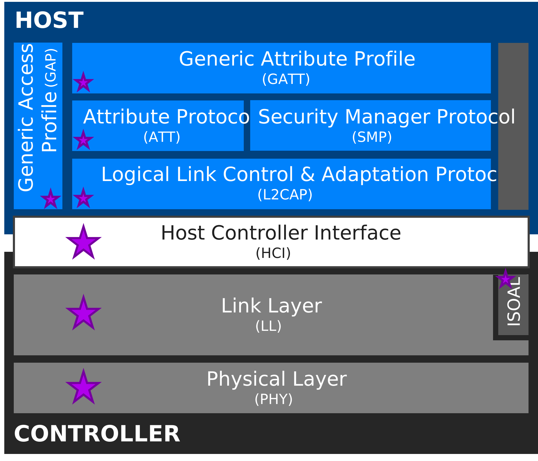
The sections that follow examine each of these architectural enhancements in greater detail, beginning with the HDT PHY and continuing through the packet architecture, Link Layer enhancements, and security framework that collectively enable high-throughput Bluetooth communication.
3.2.2 HDT PHY
The HDT PHY is the foundation of Bluetooth® High Data Throughput and enables significantly higher bit rates than existing Bluetooth® LE PHYs. This is achieved through enhancements to modulation, coding, and synchronization mechanisms that collectively improve spectral efficiency while maintaining reliable wireless communication.
3.2.2.1 Modulation, coding, and HDT rates
Traditional Bluetooth® LE PHYs are based on Gaussian Frequency Shift Keying (GFSK), where each symbol represents a single bit of information. While this approach provides excellent robustness and implementation simplicity, it limits the amount of information that can be transmitted within a given channel bandwidth. HDT addresses this limitation through the introduction of higher-order coherent modulation schemes and Forward Error Correction (FEC), enabling significantly improved spectral efficiency.
The HDT PHY employs a common convolutional FEC framework across all operating modes. Different HDT rates are achieved through a combination of modulation efficiency and coding efficiency. Following FEC encoding, puncturing may be used to selectively remove coded bits, increasing the effective code rate and allowing different tradeoffs between throughput and robustness.
The LE HDT PHY operates at a fixed symbol rate of 2 Msym/s (symbol period = 0.5 μs). The effective bit rate depends on three factors:
- Symbol rate
- Bits per symbol
- Effective code rate
Conceptually, the effective bit rate can be expressed as:
Effective bit rate = symbol rate × bits per symbol × effective code rate
The modulation scheme determines how many bits are represented by each transmitted symbol, while the effective code rate reflects the proportion of transmitted bits that carry user data after FEC encoding and puncturing are applied. Higher-order modulation schemes increase spectral efficiency by conveying more bits per symbol, while higher code rates reduce coding overhead and increase the proportion of useful data. Together, these mechanisms allow HDT to support multiple operating rates while maintaining a common PHY architecture, as summarized in Table 3.2.2.1.
| HDT rate | Effective bit rate | Modulation scheme | Bits per symbol | Effective code rate | Availability |
|---|---|---|---|---|---|
| HDT2 | 2 Mb/s | π/4 QPSK | 2 | 1/2 | Mandatory |
| HDT3 | 3 Mb/s | π/4 QPSK | 2 | 3/4 | Mandatory |
| HDT4 | 4 Mb/s | 8PSK | 3 | 2/3 | Mandatory |
| HDT6 | 6 Mb/s | 16QAM | 4 | 3/4 | Optional |
| HDT7.5 | 7.5 Mb/s | 16QAM | 4 | 15/16 | Optional* |
*Supporting HDT7.5 requires support for HDT6.
For example, HDT2 combines a 2 Msym/s symbol rate, π/4 QPSK modulation (2 bits per symbol), and a 1/2 effective code rate to achieve a 2 Mb/s effective bit rate. Similarly, HDT7.5 combines 16QAM modulation (4 bits per symbol) with a 15/16 effective code rate to achieve an effective bit rate of 7.5 Mb/s. This flexible combination of modulation efficiency and coding efficiency allows HDT devices to balance throughput and robustness according to operating requirements and channel conditions.
The mandatory HDT2, HDT3, and HDT4 rates establish a common interoperability baseline for HDT-capable devices. Higher-rate modes further increase throughput using 16QAM modulation and reduced coding overhead, enabling Bluetooth technology to support bit rates of up to 7.5 Mb/s.
3.2.2.2 Synchronization and robustness
Higher-order modulation schemes generally require more accurate synchronization and channel estimation than traditional GFSK-based communication. To maintain reliable operation at higher bit rates, HDT introduces several PHY-level mechanisms that support packet acquisition, channel estimation, receiver tracking, and periodic re-synchronization throughout the reception process. Table 3.2.2.2 summarizes the key synchronization and robustness mechanisms introduced by HDT.
| Mechanism | Summary |
|---|---|
| Short Training Sequence (STS) | • Enables rapid initial packet detection, coarse timing alignment, and AGC settling • Appears in the preamble, at the very start of every HDT packet and repeats multiple consecutive times • Establishes a reliable entry point into the packet |
| Long Training Sequence (LTS) | • Enables fine timing alignment, frequency offset estimation/correction, and initial channel estimation • Appears also in the preamble of HDT packets, after STS, and repeats several consecutive times • Prepares receiver for coherent demodulation |
| Guard Interval (GI) | • Time buffer to absorb transient effects due to switching between training sequences, symbol streams, and modulation or coding boundaries • Appears explicitly in the preamble, between STS and LTS, and implicitly throughout the packet via terminating symbols • Allows receiver filters and timing loops to settle before fine LTS synchronization and ensures clean transitions between symbol streams |
| Terminating Symbols | • Create explicit boundaries between symbol streams and absorb transient effects at symbol stream transitions • Appear at end of every independently processed symbol stream in a packet (e.g., after Control Header, after PDU Header zone, after each PHY Interval in packet format 1, etc.) • Allow FEC decoder to flush state and reset before the next segment/stream begins • Especially important for packet format 1 to help limit error propagation, enable partial packet recovery, and reduce cost of retransmissions when errors are localized to a single PHY interval |
| PHY Intervals | • Allow breaking long payloads into smaller and easier to manage decoding units • Appear in the Payload Zone of packet format 1 (PF1) HDT packets only • Enable adaptive modulation and dynamic rate selection |
| PHY Interval Training Sequence (PITS) | • Enable mid-packet retraining to refresh phase and channel estimation for robust reception of payloads segmented into multiple PHY intervals • Appears in the Payload Zone of packet format 1 (PF1) HDT packets only • Important for long payloads transmitted at high bit rates where channel conditions may vary over the packet duration; continuous channel tracking improves resilience to fading, phase drift, and multi-path |
Together, these mechanisms provide a layered synchronization framework. STS and LTS support initial packet acquisition and channel estimation, while PHY Intervals and PITS enable periodic channel tracking and synchronization refresh during longer high-throughput transmissions. Terminating Symbols support reliable packet completion and receiver state transitions.
The integration of these mechanisms allows HDT to maintain reliable communication under changing radio conditions while supporting significantly higher throughput than previous Bluetooth® LE PHYs.
3.2.3 HDT packet
The HDT PHY provides the foundation for significantly higher data throughput. But achieving reliable and efficient operation at these bit rates also requires corresponding enhancements to the Bluetooth packet architecture. Bluetooth® High Data Throughput (HDT) introduces a new packet framework designed to support adaptive bit rates, large payload transmission, selective retransmission, and improved robustness under varying radio conditions. Unlike legacy Bluetooth® LE packets, HDT packets introduce additional structural layers that allow control information, protocol metadata, and payload data to be processed independently while enabling advanced throughput and reliability features.
3.2.3.1 HDT packet structure
As illustrated in Figure 3.2.3.1, the HDT packet structure consists of four primary zones: a Preamble, a Control Header, an optional PDU Header Zone, and an optional Payload Zone. The Preamble and Control Header are present in all HDT packet formats, while the PDU Header Zone and Payload Zone are present depending on the packet format being used.

At a high level, each zone serves a distinct purpose:
Preamble
Provides packet detection, synchronization, timing acquisition, frequency-offset correction, and channel estimation functions required for reliable HDT reception. These functions are described in greater detail in Section 3.2.2.
Control Header
Carries essential information needed to identify the packet and determine how subsequent packet contents should be processed. Separating this information from high-rate payload data enables reliable packet interpretation before payload demodulation begins.
PDU Header Zone
Carries protocol-level metadata used to interpret and manage payload data. This metadata supports capabilities such as payload aggregation, acknowledgement processing, selective retransmission, link-quality feedback, flow control, and future protocol extensibility.
Payload Zone
Carries user data organized within one or more blocks. Packet Format 0 contains only a single block. In Packet Format 1, payloads may be segmented into logical blocks to support efficient error recovery and selective retransmission.
3.2.3.2 HDT packet formats
To support a broad range of Bluetooth applications and traffic patterns, HDT defines three packet formats. Each format is optimized for a different balance of throughput, robustness, and protocol overhead.
Short Format
The Short Format is a minimal packet structure used when no payload data is transmitted. It is primarily intended for acknowledgement, synchronization, and control signaling, minimizing airtime consumption and protocol overhead. The structure of the Short Format packet is shown in Figure 3.2.3.2a.

Packet Format 0 (PF0)
Packet Format 0 is optimized for transmitting a single payload block with minimal overhead. It is well suited for small and moderate data transfers where payload segmentation and advanced retransmission mechanisms are not required. The structure of Packet Format 0 is shown in Figure 3.2.3.2b.

Packet Format 1 (PF1)
Packet Format 1 is the most capable HDT packet format and is designed for maximum throughput and large payload transmission. In addition to supporting substantially larger data transfers, PF1 introduces payload aggregation, block-based transmission, selective retransmission, enhanced header protection, and PHY-level robustness mechanisms. The structure of Packet Format 1 is shown in Figure 3.2.3.2c.
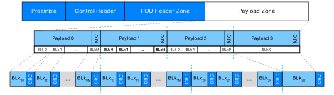
Table 3.2.3.2 provides a comparison and summary of the three packet formats.
| Short | PF0 | PF1 | |
|---|---|---|---|
| Max payload | N/A | 494 octets | 8175 octets |
| Useful for | Higher throughput | Highest throughput, efficiency and/or robustness | |
| Key advantages | • Reduces airtime if there is no payload data to TX, and when only consecutive whole payloads need to be acknowledged | • Simpler to implement • Lower overhead • Single payload block with MIC | • Up to four payloads in a packet • Division of payloads into blocks • Selective (block) acknowledgement • Payload blocks can spread over multiple packets • PHY intervals, phase tracking using PITS |
3.2.3.3 Payload aggregation and reliability
One of the key innovations introduced by Packet Format 1 (PF1) is its ability to efficiently transport large amounts of data while maintaining robust wireless performance. To achieve this, PF1 introduces payload aggregation, block-based transmission, selective retransmission, and enhanced error protection mechanisms. Collectively, these capabilities enable HDT to significantly improve throughput while minimizing the impact of packet loss and changing radio conditions. Figure 3.2.3.3 illustrates the PDU components that support these capabilities within an HDT packet.
While Packet Format 0 carries a single payload block, Packet Format 1 can aggregate up to four independent payloads within a single packet transmission. This capability reduces protocol overhead and improves channel utilization by allowing multiple payloads to be transmitted together.
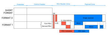
To further improve efficiency, PF1 introduces a block-based payload model. Rather than treating an entire payload as a single transmission unit, each payload may be divided into between one and sixteen logical blocks. These blocks can be independently described, transmitted, and tracked, allowing large payloads to be managed more efficiently.
Block-based transmission enables selective retransmission. Additional packet metadata allows the transmitter and receiver to determine which payload blocks have been successfully received and which require retransmission. When transmission errors occur, only the affected blocks need to be resent, while correctly received blocks can be preserved. This approach significantly reduces retransmission overhead compared to retransmitting an entire payload.
PF1 also enhances reliability through additional protection mechanisms. Each transmitted block includes independent integrity checking, allowing individual blocks to be verified without requiring validation of the entire payload. In addition, Packet Format 1 includes dedicated protection for protocol metadata through the Header Error Check for the PDU Header Zone (HEC-P), helping ensure reliable interpretation of payload management information.
The packet architecture also supports advanced link management capabilities through optional protocol metadata. Link quality information, including metrics such as signal strength, signal-to-noise ratio (SNR), and preferred transmission rate recommendations, can be exchanged to provide greater visibility into current channel conditions. The architecture additionally supports flow-control signaling, enabling devices to dynamically manage payload transmission behavior when buffering or processing resources become constrained.
Finally, PF1 is designed to operate together with PHY-level mechanisms such as PHY Intervals and PHY Interval Training Sequences (PITS), described in Section 3.2.2. These mechanisms enable periodic receiver re-synchronization during long transmissions and help maintain robust communication under fading, phase drift, and other time-varying channel conditions.
By combining payload aggregation, logical blocks, selective retransmission, enhanced metadata protection, and PHY-level robustness mechanisms, Packet Format 1 provides the foundation for efficient and reliable high-throughput Bluetooth communication.
3.2.4 Bluetooth® HDT Link Layer
While the HDT PHY and packet architecture provide the foundation for substantially higher throughput, achieving reliable operation at these bit rates also requires corresponding enhancements to the Bluetooth® LE Link Layer. Rather than introducing separate protocol architecture, HDT extends the existing Bluetooth® LE Link Layer with new procedures, capabilities, and control mechanisms that allow high-throughput communication to operate within the established Bluetooth® LE framework.
Together, these enhancements support HDT capability negotiation, PHY management, payload transport, rate adaptation, security, reliability, and isochronous communication. The Link Layer provides the operational framework that transforms the throughput potential of the HDT PHY into practical improvements in efficiency, robustness, and application performance.
Table 3.2.4 summarizes the primary Link Layer capability areas introduced for HDT support.
| Capability | Description |
|---|---|
| HDT initiation and PHY management | Enables HDT activation, capability negotiation, and transitions between GFSK and HDT operation |
| HDT data length management and scheduling | Supports larger payloads while preserving Bluetooth® LE timing and scheduling requirements |
| HDT link quality | Provides dynamic link-quality reporting and adaptation capabilities |
| HDT and isochronous channels | Extends CIS and BIS transport support for HDT operation |
| HDT security and encryption | Integrates EKS, longer MICs, and coordinated key management |
| HDT reliability and flow control | Enables block-level reliability mechanisms and enhanced flow control |
The following sections provide a high-level overview of the principal Link Layer capabilities enabled by these procedures.
3.2.4.1 Bluetooth® HDT initiation and PHY management
Bluetooth® HDT is initiated and managed through Link Layer procedures operating over Bluetooth® LE connections. Once HDT capabilities have been established between devices, HDT operation may be used for ACL connections, Connected Isochronous Streams (CIS), and Broadcast Isochronous Streams (BIS). The HDT PHY is not used for advertising and must always be activated through dedicated Link Layer procedures.
The process begins with the HDT Configuration Exchange procedure, which uses the new LL_HDT_CONFIG_REQ and LL_HDT_CONFIG_RSP control PDUs. Through this procedure, devices exchange HDT-specific capabilities and operating parameters, including supported HDT rates, payload-window capabilities, security-related parameters, and other information required to establish HDT operation.
Rather than negotiating a single operating rate, devices establish a range of supported HDT rates. During operation, the Controller may dynamically select any rate within the negotiated range according to current channel conditions, implementation policy, and application requirements. This adaptive-rate model allows throughput and robustness to be balanced without requiring additional connection reconfiguration.
Once capabilities have been exchanged, devices may transition between GFSK PHYs and the HDT PHY using the PHY Update and Encryption Refresh procedure, which extends the existing LL_PHY_REQ, LL_PHY_RSP, and LL_PHY_UPDATE_IND control PDUs. This enables HDT-capable devices to dynamically enter, modify, or leave HDT operation while maintaining an active Bluetooth® LE connection.
Transitioning from a GFSK PHY to HDT operation also requires the establishment of HDT-specific physical channel addressing information. During this process, devices exchange Physical Channel Address (PCA) information that uniquely identifies HDT traffic on the physical channel. PCA supports packet filtering, synchronization, and reception of HDT transmissions while remaining coordinated with the existing Bluetooth® LE connection architecture.
During normal operation, both directions of a connection use either GFSK PHYs or the HDT PHY. However, HDT rates may be selected independently in each direction, allowing throughput to adapt dynamically to changing channel conditions and application requirements. If HDT operation is unavailable or no longer desirable, communication may continue using conventional Bluetooth LE PHYs.
3.2.4.2 Bluetooth® HDT data-length management and scheduling
Bluetooth HDT introduces enhanced data-length management capabilities to support payloads that are substantially larger than those used in traditional Bluetooth® LE operation while preserving the timing characteristics required for Bluetooth connections and isochronous streams.
To achieve this, the Link Layer maintains separate transmission-length and timing parameters for HDT and GFSK operation. This allows each PHY family to operate according to its respective payload and airtime constraints while supporting seamless transitions between HDT and legacy Bluetooth LE modes.
HDT also introduces payload-window management capabilities that allow multiple payloads to be aggregated within a single HDT transmission. Through HDT configuration procedures, devices exchange payload-window capabilities that define how payload data may be grouped and transported. These capabilities work together with the payload aggregation and block-based transmission mechanisms described in Section 3.2.3 to improve channel utilization and transmission efficiency.
Because HDT packets may carry significantly larger amounts of data than conventional Bluetooth LE packets, additional scheduling constraints are introduced to bound packet airtime and preserve coexistence with ACL connections, CISs, BISs, and other concurrent Bluetooth activities. These scheduling mechanisms ensure that higher throughput can be achieved without compromising predictable Bluetooth LE timing behavior.
The enhanced Data Length Update procedure, using LL_LENGTH_REQ [v2] and LL_LENGTH_RSP [v2], allows devices to communicate maximum transmit and receive payload lengths together with associated timing parameters. By maintaining PHY-specific limits, HDT enables Controllers to maximize throughput while preserving compatibility with connection-event scheduling, isochronous operation, and multi-link activity.
3.2.4.3 Bluetooth® HDT link quality
HDT introduces an optional Link Quality Feedback (LQF) capability that allows devices to exchange real-time information about channel conditions during operation. When enabled, link-quality information can be reported continuously between devices, providing Controllers with additional visibility into current radio conditions.
These reports may include signal-quality measurements as well as preferred operating-rate recommendations, enabling Controllers to make more informed adaptation decisions. Depending on implementation policy and measured channel conditions, Controllers may adjust HDT operating rates, modify transmission behavior, or transition between HDT and GFSK operation.
The HDT Link Quality Enable procedure uses the new LL_HDT_LQF_REPORTING_IND control PDU to enable or disable Link Quality Feedback reporting. LQF may be configured independently for ACL and CIS transports, allowing different traffic types to benefit from channel-quality awareness when appropriate.
By providing direct visibility into current channel conditions, LQF supports more efficient use of adaptive-rate operation and helps maximize the performance benefits of HDT under a wide range of wireless environments.
3.2.4.4 Bluetooth® HDT reliability and flow control
HDT introduces enhanced reliability mechanisms designed to efficiently support large-payload transfers. Building upon the block-based payload architecture of Packet Format 1 (PF1), HDT supplements traditional Bluetooth® LE acknowledgement behavior with block-level recovery mechanisms.
Conventional Bluetooth LE sequence numbering and acknowledgement procedures continue to provide packet ordering and cumulative acknowledgement. HDT extends this model through selective acknowledgement of payload blocks. This significantly reduces retransmission overhead when transporting large amounts of data.
HDT also introduces enhanced flow-control capabilities. Through information carried in HDT packet headers, a receiving device may temporarily pause the transmission of new payload data when additional buffering or processing resources are required. Retransmission activity may continue during this period, allowing reliability procedures to proceed while preventing receiver overload.
Once resources become available, normal payload transmission resumes without requiring higher-layer intervention or connection reconfiguration. Together, these mechanisms improve efficiency, maintain reliability, and help HDT sustain high throughput under demanding operating conditions.
3.2.4.5 Representative Bluetooth® HDT Link Layer procedures and control messages
The Link Layer capabilities described above are implemented through a collection of new and enhanced procedures and control messages. Table 3.2.4.5 summarizes representative Link Layer procedures and the associated LL Control PDUs used to establish, manage, secure, and optimize HDT operation.
| Procedure | Key Functions | Representative LL Control PDUs |
|---|---|---|
| HDT Configuration Exchange | Payload windows, rate capabilities, ACL/CIS HDT parameters | LL_HDT_CONFIG_REQ / LL_HDT_CONFIG_RSP |
| HDT Link Quality Enable | ACL/CIS feedback reporting | LL_HDT_LQF_REPORTING_IND |
| Encryption Start with Key Schedule | EKS establishment | LL_ENC_ECDH_REQ / LL_ENC_ECDH_RSP |
| Data-length update | PHY-specific payload and airtime limits | LL_LENGTH_REQ [v2] / LL_LENGTH_RSP [v2] |
| PHY update and encryption refresh | PHY transitions, PCA assignment, MIC update, key refresh | LL_PHY_REQ [v2], LL_PHY_RSP [v2], LL_PHY_UPDATE_IND [v2] |
| Connected Isochronous Stream creation | HDT-enabled CIS establishment | LL_CIS_REQ [v2], LL_CIS_IND [v2] |
Together, these procedures provide the signaling framework required to activate, manage, secure, and optimize HDT operation while preserving compatibility with the existing Bluetooth LE Link Layer architecture. They also illustrate how HDT extends established Bluetooth LE procedures rather than replacing them, allowing higher throughput to be integrated into the Bluetooth ecosystem while maintaining architectural consistency and interoperability.
3.2.5 Bluetooth® HDT HCI layer
The Host Controller Interface (HCI) provides the primary control and status interface between the Host and Controller. To support HDT operation, Bluetooth® LE introduces new HCI commands and events while extending several existing mechanisms. These enhancements allow Hosts to discover HDT capabilities, configure operating preferences, monitor PHY transitions, manage security features, and control HDT-enabled isochronous transports.
Consistent with Bluetooth architecture, most HDT-specific functionality remains within the Controller. Timing-critical functions such as PHY transitions, rate adaptation, retransmission handling, and packet scheduling continue to be performed autonomously by the Controller, while the HCI exposes the information and controls required for policy configuration, diagnostics, and application awareness. This preserves the traditional separation between Host decision-making and Controller execution while allowing applications to benefit from HDT capabilities.
The HCI enhancements required for HDT can be grouped into six categories: capability discovery and configuration, PHY management, throughput management, security management, isochronous transport management, and testing and diagnostics. Table 3.2.5 summarizes the primary HCI capability areas associated with HDT support.
| Capability | Description |
|---|---|
| Capability discovery and configuration | Discover HDT capabilities and configure operating preferences |
| PHY selection and transition coordination | Request and monitor HDT PHY operation |
| Data-length and throughput management | Configure payload limits and throughput-related parameters |
| Security and encryption management | Manage EKS-related features and monitor encryption state |
| Isochronous transport management | Configure and monitor HDT-enabled CIS and BIS transports |
| Testing and diagnostics | Support validation, debugging, and link-quality analysis |
The following sections provide a high-level overview of the principal HCI capabilities introduced for HDT support.
3.2.5.1 Capability discovery and configuration
Before Bluetooth® HDT can be used, the Host must determine the capabilities supported by the local and remote Controller and configure the operating preferences that should be applied to future connections. HDT-capable Controllers expose information related to supported PHY modes, HDT rate capabilities, maximum payload sizes, timing constraints, and HDT-related security features. This information allows applications to determine whether HDT operation is appropriate for a particular use case and to establish suitable operating policies.
The HCI also allows the Host to establish default HDT operating preferences. These preferences may include preferred HDT rates, supported packet formats, payload-window capabilities, and security-related parameters. Representative interfaces include the LE Set HDT Default Parameters command together with enhanced capability-reporting procedures such as LE Read Maximum Data Length.
Rather than directly controlling packet-level operation, the Host expresses preferred operating behavior while leaving real-time decisions to the Controller. For example, Hosts may indicate preferred HDT rate ranges for ACL and isochronous transports or express a preference for a specific packet format. During actual operation, the Controller remains responsible for rate adaptation, packet scheduling, and other time-critical decisions. This approach provides flexibility while avoiding unnecessary Host involvement in Link Layer execution.
3.2.5.2 PHY selection and transition coordination
PHY selection and PHY transitions represent one of the most visible aspects of Bluetooth® HDT operation at the HCI layer. Hosts may indicate support for, or preference toward, operation on the HDT PHY through existing PHY-selection mechanisms. Such requests communicate desired operating behavior, while the Controller remains responsible for determining whether HDT operation can be successfully established.
When a PHY transition occurs, whether entering or leaving HDT operation, the Controller reports the outcome through HCI events. These notifications allow Hosts to monitor active PHY selection, adjust application behavior, and manage throughput-related expectations without requiring detailed awareness of Link Layer execution. Representative interfaces include the LE Set PHY command and the enhanced LE PHY Update Complete event, which provide visibility into the resulting operating mode following a PHY transition.
Because HDT rate selection remains under Controller control, HCI reporting focuses on the outcome of PHY selection and operation rather than the packet-by-packet decisions performed by the Link Layer. This preserves the traditional separation between Host policy and Controller execution.
3.2.5.3 Data-length and throughput management
The larger payloads and higher throughput enabled by Bluetooth® HDT require corresponding enhancements to HCI-level configuration and monitoring capabilities. Hosts may configure payload-related operating parameters and query Controller capabilities to optimize throughput while remaining within implementation coexistence and timing constraints.
In addition to traditional payload-length information, HDT capability reporting exposes payload window capabilities, maximum receive-packet capacities, and other throughput-related operating parameters. These capabilities provide greater visibility into the throughput potential of a Controller and help applications make informed buffering, scheduling, and resource-allocation decisions for high-bandwidth data transfers.
HDT continues to separate policy decisions from Link Layer execution. The Host may configure preferred operating limits and monitor negotiated capabilities, while the Controller remains responsible for packet aggregation, payload segmentation, retransmission management, and scheduling decisions during active operation. This approach allows applications to benefit from larger payloads and higher throughput without introducing additional protocol complexity at the Host level.
Changes to negotiated payload capabilities may be reported through the enhanced LE Data Length Change event, allowing the Host to remain aware of the effective operating limits of active connections. Together with LE Set Data Length and LE Read Maximum Data Length, these interfaces provide the primary HCI framework for throughput management in HDT-enabled systems.
3.2.5.4 Security and encryption management
The Bluetooth® HDT security enhancements described in Section 3.2.6 are exposed through a set of HCI controls and status mechanisms that allow Hosts to configure and monitor Encryption Key Schedule (EKS)-related functionality while maintaining compatibility with the existing Bluetooth® LE security architecture.
Representative interfaces include the LE Read Encryption Key Schedule Debug Mode and LE Write Encryption Key Schedule Debug Mode commands. These commands are primarily intended for development, testing, and interoperability validation environments, and apply to subsequent connections rather than modifying the security state of active encrypted sessions.
Additional HCI enhancements provide visibility into MIC-length selection, EKS usage, and encryption-refresh procedures. Commands such as LE Enable Encryption [v2] and Refresh Encryption Key [v2], together with events including Encryption Change [v3] and Encryption Key Refresh Complete [v2], allow Hosts to monitor security-related state transitions associated with HDT operation.
These interfaces ensure that applications remain informed of security status and configuration changes without requiring direct involvement in the underlying Link Layer security procedures. As with other HDT capabilities, the Controller continues to manage timing-sensitive security operations while the Host maintains visibility into their outcome and operational state.
3.2.5.5 Isochronous transport management
Bluetooth® HDT extends Bluetooth LE isochronous communications and therefore requires corresponding HCI support for Connected Isochronous Groups (CIGs), Connected Isochronous Streams (CISs), and Broadcast Isochronous Streams (BISs). The associated HCI interfaces allow Hosts to configure HDT-enabled transports while preserving the established Bluetooth LE isochronous management model.
These interfaces support HDT-specific operating preferences, including HDT rates, packet-format selection, payload capabilities, and MIC-length configuration. Through these mechanisms, applications can align transport behavior with throughput, latency, reliability, and security requirements while maintaining compatibility with existing Bluetooth LE procedures. Representative configuration interfaces include LE Set CIG Parameters [v2] and LE Create BIG [v2].
Once transport establishment procedures have been completed, the Controller reports the resulting operating characteristics through enhanced status events. Interfaces such as LE CIS Established [v3] and LE Create BIG Complete [v2] provide visibility into HDT-enabled transport creation and allow Hosts to verify configuration outcomes and adjust application behavior accordingly.
By extending existing isochronous management mechanisms rather than introducing an entirely new control model, HDT enables applications to take advantage of significantly higher throughput while preserving the operational framework already familiar to Bluetooth developers.
3.2.5.6 Testing and diagnostics
In addition to operational controls, Bluetooth® HDT introduces HCI functionality intended to support validation, performance measurement, interoperability analysis, and implementation debugging. These capabilities provide visibility into HDT-specific operating characteristics and simplify the evaluation of Controller performance under different radio conditions and traffic patterns.
Testing and diagnostic interfaces allow Controllers to be configured with HDT-specific test parameters and provide reporting mechanisms for collected measurements, including information associated with HDT link quality and PHY operation. Such capabilities support product development, certification testing, performance characterization, and interoperability verification across implementations.
Representative interfaces associated with this capability include the LE Set HDT Parameters Test command and the LE Test Report HDT Link Quality event. Together, these mechanisms provide developers and test engineers with access to information needed to evaluate and optimize HDT implementations.
3.2.5.7 Representative Bluetooth® HDT HCI commands and events
The HCI enhancements described above are realized through a combination of new and extended commands and events. Table 3.2.5.7 summarizes representative interfaces associated with each HDT capability area and illustrates how Hosts interact with HDT-enabled Controllers.
| Capability | Representative commands and events |
|---|---|
| Capability discovery and configuration | LE Set HDT Default Parameters, LE Read Maximum Data Length |
| PHY selection and transition coordination | LE Set PHY, LE PHY Update Complete |
| Data-length and throughput management | LE Set Data Length, LE Data Length Change |
| Security and encryption management | LE Enable Encryption [v2], Refresh Encryption Key [v2], Encryption Change [v3], Encryption Key Refresh Complete [v2], LE Read/Write Encryption Key Schedule Debug Mode |
| Isochronous transport management | LE Set CIG Parameters [v2], LE Create BIG [v2], LE CIS Established [v3], LE Create BIG Complete [v2] |
| Testing and diagnostics | LE Set HDT Parameters Test, LE Test Report HDT Link Quality Event |
Together, these commands and events provide the primary management interface between the Host and Controller for HDT operation. They enable applications to discover Controller capabilities, configure operating preferences, monitor system status, and manage HDT-enabled transports while preserving the established architectural separation between Host policy and Controller execution.
3.2.6 Bluetooth® HDT security
Bluetooth HDT builds on the existing Bluetooth® LE security architecture while introducing several enhancements designed to support high-throughput communication. These enhancements strengthen key management, improve integrity protection, and more closely coordinate security procedures with PHY operation.
Rather than defining a separate security architecture, HDT extends established Bluetooth LE security mechanisms through the introduction of the Encryption Key Schedule (EKS), support for longer Message Integrity Check (MIC) lengths, and coordinated security procedures with PHY operation. Together, these enhancements provide the security capabilities required by HDT while building on mechanisms that can also be leveraged by other Bluetooth features and use cases.
3.2.6.1 Enhanced message integrity protection
Traditional Bluetooth® LE communication uses a 32-bit Message Integrity Check (MIC). HDT additionally supports 64-bit and 128-bit MIC lengths, providing stronger protection against packet modification, forgery, and transmission errors when transferring larger amounts of data.
3.2.6.2 Security-aware PHY transitions
Bluetooth® HDT more closely integrates security management with PHY operation through the PHY Update and Encryption Refresh procedure. Rather than treating PHY transitions and encryption updates as independent activities, this procedure allows devices to coordinate PHY changes with related security updates when required.
This coordinated approach enables devices to transition between GFSK and HDT operation while maintaining secure communication and minimizing operational disruption. By synchronizing PHY and security state management, devices can adapt to changing operating requirements without requiring connection re-establishment or interruption of higher-layer services.
Changes in MIC length require a corresponding key refresh to ensure that security state remains aligned with the selected protection level. At the same time, key-refresh operations may occur independently of PHY transitions, providing flexibility while maintaining strong security protection.
The procedure is supported through enhanced versions of LL_PHY_REQ, LL_PHY_RSP, and LL_PHY_UPDATE_IND, which provide the signaling required to coordinate PHY operation and security state management.
3.2.6.3 Security architecture compatibility
By extending rather than replacing existing Bluetooth® LE security mechanisms, Bluetooth® HDT allows manufacturers to adopt enhanced security features while preserving interoperability with the broader Bluetooth ecosystem. This approach simplifies adoption and enables products to benefit from HDT capabilities without requiring a fundamentally different security model.
3.3 Summary
Bluetooth® High Data Throughput (HDT) extends Bluetooth® LE with a new high-efficiency physical layer capable of supporting bit rates of up to 7.5 Mb/s while remaining fully integrated within the existing Bluetooth architecture. Through enhancements to the PHY, packet architecture, Link Layer, HCI, and security framework, HDT enables significantly higher throughput while preserving the interoperability, efficiency, and deployment flexibility of Bluetooth LE.
Together, these enhancements establish a scalable foundation for future Bluetooth applications that require substantially greater data capacity, including next-generation audio systems, wearable devices, industrial solutions, and other emerging use cases. HDT demonstrates how Bluetooth LE can continue to evolve to meet growing bandwidth demands while maintaining compatibility with the existing Bluetooth ecosystem.
4. Bluetooth® LE Isochronous Parameter Update (IPU)
4.1 Background
4.1.1 Static CIS configurations and limitations
Bluetooth® LE Audio introduced Connected Isochronous Streams (CISs) as the transport mechanism for time-sensitive applications. During CIS establishment, transport parameters such as PHY selection, ISO_Interval, Burst Number (BN), Flush Timeout (FT), Maximum SDU size (Max_SDU), and transport latency are negotiated between devices and remain fixed for the lifetime of the stream. This model simplifies scheduling and provides predictable timing behavior for isochronous communication.
In real-world deployments, however, operating conditions often change while a stream is active. Radio quality may fluctuate because of interference, mobility, or changing environments, and applications may transition between operating modes with different latency, reliability, throughput, or power requirements. As a result, transport behavior cannot always be efficiently optimized using a single static CIS configuration.
Prior to Bluetooth® LE Isochronous Parameter Update (IPU), adapting to these changing requirements typically required terminating the existing CIS and establishing a new stream with updated parameters. Although functionally effective, this approach may introduce service interruption, require additional system reconfiguration, and complicate seamless transitions between operating modes.
4.1.2 Introducing runtime adaptation
Bluetooth® LE Isochronous Parameter Update (IPU) addresses these limitations by enabling transport parameters to be updated while a CIS remains active. Rather than treating CIS configuration as a one-time setup decision, IPU allows devices to transition between alternative operating configurations throughout the lifetime of a stream.
This capability enables Bluetooth® systems to adapt transport behavior to changing radio conditions, application requirements, and operating modes without requiring stream re-establishment. By supporting coordinated runtime configuration transitions, IPU improves flexibility while preserving the continuity and synchronization characteristics required by isochronous applications.
The following sections describe the design concepts, configuration architecture, and runtime mechanisms that enable this new transport adaptation model.
4.2 Bluetooth® IPU design concept
4.2.1 From static streams to runtime configuration management
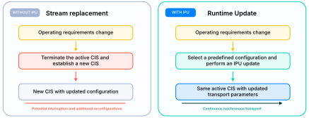
Traditionally, the transport parameters of a Connected Isochronous Stream (CIS) remain fixed after the stream has been established. When operating requirements change significantly, adapting the transport may therefore require terminating the active CIS and establishing a new CIS with different parameters. Although this approach provides the required transport characteristics, it may introduce service interruption and additional system reconfiguration.
IPU introduces an alternative model in which the transport parameters of an active CIS can be updated without replacing the stream. When radio conditions, application requirements, or system policies change, devices can select an appropriate predefined configuration and perform a coordinated update while the CIS remains active. This separates transport adaptation from stream establishment and allows devices to respond to changing requirements without re-establishing the stream.
Figure 4.2.1 compares stream re-establishment with the runtime update model enabled by IPU.
4.2.2 A configuration-centric adaptation model
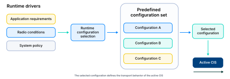
Bluetooth® IPU supports runtime adaptation through a set of predefined CIG configurations. Each configuration represents a defined operating point for the CISs within the CIG and contains the transport parameters required for that operating point. An implementation may provision multiple configurations to address different application requirements, radio conditions, or system policies.
During operation, one of these configurations is selected to define the transport behavior of the active CISs. When conditions change, a different configuration may be selected and applied through the IPU procedure. The configurations therefore represent available transport operating points, while the active CIS remains the persistent transport to which the selected configuration is applied.
Figure 4.2.2 illustrates the relationship between runtime drivers, predefined configurations, the selected configuration, and the active CIS.
4.2.3 Designing multiple operating points
The configurations provisioned for a CIG may be designed to address different transport objectives. For example, one configuration may prioritize throughput, another may reduce transport latency, and another may provide greater robustness under challenging radio conditions. The appropriate configuration set depends on the operating modes and adaptation requirements supported by the product.
Rather than defining a separate update procedure for every parameter or use case, IPU provides a common mechanism for transitioning between these predefined operating points. The parameters that differ between configurations determine the transport aspects affected by an update, while the IPU procedure coordinates when and how the selected configuration becomes active.
The following sections describe how these configurations are identified and organized, how update responsibilities are divided between the Host and Controller, and how different parameter changes affect CIS operation.
4.3 Bluetooth® IPU architecture & key concepts
4.3.1 Why multiple configurations exist
Modern Bluetooth® devices often operate under conditions that require different transport characteristics. Changes in radio quality, application behavior, power constraints, or latency requirements may each favor a different transport operating point.
Rather than modifying individual transport parameters whenever conditions change, IPU organizes transport behavior into a collection of predefined configurations. Each configuration represents a complete operating point that can be selected and applied to an active Connected Isochronous Stream (CIS).
This approach simplifies runtime adaptation by treating updates as transitions between predefined configurations rather than independent modifications of individual transport parameters.
Table 4.3.1 provides examples of operating requirements that may call for different transport configurations, illustrating why a single static CIS configuration may not be optimal under all operating conditions.
| Operating requirement | Example transport objective |
|---|---|
| Music playback | Higher throughput and audio quality |
| Voice communication | Lower transport latency |
| RF degradation recovery | Increased reliability |
| Power-constrained operation | Reduced radio activity |
4.3.2 Organizing runtime configurations
Supporting multiple operating configurations introduces a need for configuration management. IPU organizes configurations using a hierarchical model that groups related operating points together. Each configuration is identified by a Config_ID, while configurations can also be organized using Config_Group_ID and Transport Latency Group (TL_Group) identifiers.
At the highest level, configurations are associated with a Connected Isochronous Group (CIG). Within a CIG, configurations may be organized into TL_Groups according to their transport-latency characteristics. Within a TL_Group, Config_Groups provide a way to associate configurations that support related transport operating points. Individual configurations within a Config_Group are identified by their Config_ID.
This organization allows a device to maintain multiple predefined operating points while providing a structured mechanism for selecting configurations during runtime adaptation. Configurations created by the Host and configurations created autonomously by the Controller can be managed within this framework.
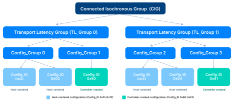
As shown in Figure 4.3.2, IPU introduces a layered organization model in which latency-related grouping is separated from individual transport configurations. Rather than viewing configurations as unrelated parameter sets, it is often useful to view them as members of a larger configuration space that defines the potential operating modes of a CIG.
4.3.3 Why transport latency groups matter
Transport latency is an important characteristic of isochronous transport because changes in transport latency can affect buffering behavior, presentation timing, and application-level processing requirements.
IPU therefore organizes configurations using Transport Latency Groups (TL_Groups). Configurations within the same TL_Group share the same transport-latency characteristics, while configurations associated with different TL_Groups represent different transport-latency models.
This organization is important during runtime transitions because the handling of payloads across an update depends, in part, on whether the transition remains within the same TL_Group or crosses a TL_Group boundary.
4.3.4 Host and controller responsibilities
Not all configuration transitions have the same scope or impact. Some updates influence only Link Layer operation, while others may affect transport latency, buffering assumptions, or application-level behavior.
IPU reflects this distinction by separating responsibilities between the Host and the Controller.
The Host is responsible for application-level adaptation decisions, including selecting or requesting a transport configuration based on application requirements, operating mode, quality objectives, or system policies. The Controller is responsible for executing the corresponding update procedure and coordinating the transport transition.
The separation allows IPU to support both application-driven and Controller-driven adaptation. For example, the Host may initiate a configuration change when an application changes operating mode, while the Controller may autonomously adapt transport parameters in response to changing radio conditions or other Link Layer conditions.
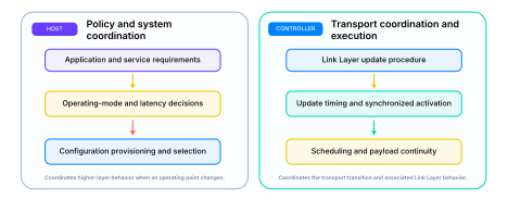
As shown in Figure 4.3.4, the Host decides why and when a transport transition should occur, while the Controller is responsible for coordinating and executing the transition.
4.3.5 Adaptation dimensions
One of the defining characteristics of Bluetooth® IPU is that runtime adaptation is not limited to a single transport parameter. Different configurations may change different aspects of CIS behavior, including radio performance, transmission cadence, reliability, latency, and event scheduling.
From an architectural perspective, these changes can be understood across a small set of adaptation dimensions.
| Adaptation objective | Example parameters |
|---|---|
| PHY / Link adaptation | PHY, transmission rate, retransmission parameters |
| Bitrate adaptation | Max_SDU |
| Scheduling flexibility | Anchor Point, ISO_Interval |
| Latency adaptation | Transport Latency, TL_Group |
| Operating-mode adaptation | Configuration changes associated with different application requirements |
As shown in Table 4.3.5, IPU configurations can support adaptation across multiple transport objectives. A configuration change may affect one or more parameters simultaneously, depending on the operating point being selected. This provides a common framework for adapting radio behavior, bitrate, scheduling, latency, and application operating modes.
Although the specification defines numerous update scenarios, most of them can be understood as variations across these adaptation dimensions. This perspective provides a useful framework for understanding how different parameter changes influence CIS operation without examining every possible update combination individually.
The following sections describe how IPU coordinates transitions across these dimensions while preserving synchronization and maintaining payload continuity.
4.4 Configuration lifecycle and runtime coordination
4.4.1 Configuration lifecycle
One of the key concepts introduced by Bluetooth® IPU is the separation of configuration definition from configuration activation. Rather than being created only when a CIS is established, configurations can be defined, provisioned, and maintained independently of the active transport.
Each provisioned configuration represents a complete transport operating point for a Connected Isochronous Group (CIG). A configuration may define PHY selections, ISO timing characteristics, scheduling behavior, retransmission parameters, transport-latency characteristics, and related synchronization information. Configurations are identified by unique Config_ID values and can be provisioned before a CIS is established.
To support both Host-managed and Controller-managed configuration provisioning, Config_ID values are partitioned into separate allocation ranges. Configuration definition is separate from the runtime update procedure. Configurations can be defined and provisioned in advance so that, when an operating-point change is required, the update procedure can activate an existing configuration rather than define a new configuration as part of the transition. Config_ID values from 0x01 to 0x7F are assigned by the Host, while values from 0x80 to 0xFF may be assigned autonomously by the Controller. This separation prevents conflicts while enabling both application-driven and controller-driven adaptation models.
Once provisioned, a configuration becomes available for runtime selection and may later be activated when operating requirements change. Because configuration definition is decoupled from stream creation, multiple configurations can coexist within a CIG and remain available throughout the lifetime of the stream.
This separation between configuration management and stream establishment is a fundamental architectural characteristic of IPU. Unlike earlier CIS implementations, where transport parameters effectively became fixed once stream establishment completed, IPU enables transport behavior to evolve by selecting among predefined operating points.
As a result, transport adaptation becomes a process of configuration selection and activation rather than configuration creation, allowing CIS to adjust to changing requirements without re-establishment.
4.4.2 Coordinated runtime configuration updates
Although configuration changes ultimately affect individual CIS transport parameters, update execution is coordinated at the CIG level. This allows multiple CISs belonging to the same CIG to transition coherently and maintain synchronization throughout the update process.
Runtime adaptation begins when a device determines that a different transport operating point is better suited for current operating conditions. The motivation for a configuration change may originate from application operating-mode transitions, changes in radio conditions, latency requirements, reliability objectives, or system-level adaptation policies.
Identifying a target configuration does not immediately modify the active CIS. Before the new configuration can become effective, both devices must coordinate the transition through the Bluetooth® IPU update procedure.
This coordination ensures that the participating devices agree on the target configuration and its associated transport characteristics before the update is activated. By separating configuration selection from activation, IPU allows adaptation decisions to be made independently of the timing constraints required for a safe transport transition.
In the most common deployment model, the Central selects a target configuration and initiates a CIS update procedure. IPU also supports Peripheral-originated update requests, allowing a peripheral to indicate that a different transport operating point may be desirable while preserving the Central’s role in making the final update decision.
Regardless of the initiator, updates follow the same coordination model and ultimately activate at a synchronized update boundary. Throughout this process, the CIS remains established and available for continued operation. This allows transport behavior to evolve without requiring stream termination and re-establishment whenever operating requirements change.
4.4.3 Instant-based activation and synchronization
A configuration update does not take effect immediately when it is requested. Instead, the new configuration becomes active at a predefined activation point known as an Instant.
The Instant provides a common synchronization boundary that allows both devices to transition to the updated configuration simultaneously. Without coordinated activation, one device could begin operating with updated transport parameters before the other device is prepared to do so, potentially resulting in scheduling inconsistencies, payload misalignment, or temporary loss of synchronization.
For this reason, the update procedure first establishes agreement on the target configuration and its activation timing before the transition is applied. Both devices continue operating with the current configuration until the agreed Instant is reached, at which point the selected configuration becomes active.
The same Instant-based approach is also used when updates affect CIS timing placement through Anchor Offset adjustments. In these scenarios, the update modifies not only transport characteristics but also the timing position of future CIS events. By scheduling the change at a predefined Instant, both Controllers maintain a consistent view of the post-update event timeline.
Anchor Point adjustments may also be applied without changing the active Config_ID. In these cases, the update modifies the placement of future CIS events while leaving the underlying transport configuration unchanged. This allows scheduling optimization and timing realignment to occur independently of any transport-parameter transition.
By coupling configuration activation to a common CIS event boundary, Bluetooth® IPU ensures that both Controllers transition to the new timing model in a deterministic manner, regardless of the transport parameters being updated. Whether the change affects throughput, retransmission behavior, transport latency, or future event positioning, the same synchronization principle applies.
Although reaching the Instant completes the configuration activation process, additional mechanisms are required to preserve payload continuity and timing consistency across the transition. These mechanisms become particularly important when the updated configuration affects transport timing, latency characteristics, scheduling behavior, or payload delivery.
4.5 Maintaining continuity during configuration transitions
4.5.1 Runtime transition and continuity
Activating a new configuration at the Instant does not necessarily mean that all transport activity associated with the previous configuration has completed. Depending on the parameters being updated, payloads associated with the previous configuration may remain in flight after the Update Instant.
Bluetooth® IPU therefore provides mechanisms for coordinating payload processing across the configuration transition. Transition Payloads and Flush Points allow the Controller to maintain synchronization and determine when transport state associated with the previous configuration can be retired. Activating a new configuration is only one step in an IPU update.
4.5.2 Managing payloads during the transition
A CIS update can occur while payloads associated with the previous configuration are still being processed. Bluetooth® IPU defines Transition Payloads and Post-Transition Payloads to manage payload processing across the Update Instant.
Transition Payloads are associated with the CIS reference anchor point before the Update Instant. Their handling depends on the characteristics of the update and whether the update changes the Transport Latency Group or reduces the maximum packet payload size.
When the update changes the TL_Group_ID or reduces Max_Packet_Payload, Transition Payloads are flushed at the Update Instant. This ensures that payloads associated with the previous transport configuration do not continue to use a transport model that is no longer applicable after the transition.
For other update scenarios, the Flush Point is determined according to the applicable CIS update rules. This allows Transition Payloads to continue to be processed across the Update Instant while maintaining SDU synchronization.
Post-Transition Payloads use the Update Instant as their CIS reference anchor point. Their handling is particularly relevant when the ISO_Interval is reduced, because payloads associated with the new configuration may need to be scheduled using the updated event timing.
Together, these mechanisms allow IPU to transition between configurations while maintaining synchronization and appropriately managing payloads associated with both sides of the Update Instant.
4.6 Protocol extensions
4.6.1 Host Controller Interface extensions
Although Bluetooth® IPU introduces significant new runtime capabilities, the resulting protocol changes are relatively compact. Most of the added functionality is concentrated in a small set of HCI commands and events that support configuration management and runtime updates.
At the Host Controller Interface level, new commands allow Hosts to define CIG configurations, remove previously defined configurations, initiate configuration updates, and participate in update decisions. Corresponding HCI events allow Controllers to report update completion and communicate update requests originating from the Peripheral side.
The major HCI additions introduced by IPU are summarized in Table 4.6.1.
| Mechanism | Purpose |
|---|---|
| LE Add CIG Configuration | Define an additional runtime configuration |
| LE Remove CIG Configuration | Remove a previously defined configuration |
| LE Update CIG | Initiate a configuration transition |
| LE Update CIG Peripheral Request Reply | Respond to a Peripheral-originated update request |
| LE CIS Update Event | Notify the Host of update completion |
| LE Update CIG Peripheral Request Event | Notify the Host of a Peripheral update request |
Together, these commands and events allow the Host to manage multiple transport operating points throughout the lifetime of a CIG rather than only during stream establishment.
4.6.2 Link Layer extensions
At the Link Layer, Bluetooth® IPU introduces new control procedures that support configuration definition, configuration removal, Central-initiated updates, and Peripheral-initiated update requests. These procedures provide the signaling framework required to coordinate transport adaptation while an active CIS remains established.
The major Link Layer additions introduced by IPU are summarized in Table 4.6.2.
| Mechanism | Purpose |
|---|---|
| LL_CIG_CONFIG_REQ / RSP | Create configuration definitions |
| LL_CIG_CONFIG_REMOVE_IND | Remove configuration definitions |
| LL_CIS_UPDATE_REQ / RSP | Execute configuration updates |
| LL_CIS_PERIPHERAL_UPDATE_REQ | Request an update from the Peripheral side |
These procedures extend the CIS lifecycle beyond creation and termination by allowing configuration state to evolve during operation. Combined with the activation and continuity mechanisms described in previous sections, they form the protocol foundation for runtime transport adaptation.
Although updates are applied to CIS transport behavior, update execution is coordinated at the CIG level to ensure that multiple CISs belonging to the same CIG remain synchronized throughout the transition.
4.7 Representative update scenarios
The preceding sections described how Bluetooth® IPU enables runtime transport adaptation through configuration provisioning, coordinated activation, and continuity management. This section illustrates how these capabilities can be applied across different layers of a system.
The examples are intentionally selected to represent three common adaptation triggers:
- changes in radio conditions
- changes in transport requirements
- changes in application behavior
Together, they demonstrate how a CIS can evolve during operation without requiring stream re-establishment.
4.7.1 Dynamic RF adaptation
One of the primary motivations for Bluetooth® IPU is the ability to adapt transport characteristics in response to changing radio conditions.
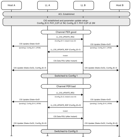
Figure 4.7.1 illustrates an example in which multiple configurations are provisioned within the same CIG. One configuration may prioritize transport efficiency under favorable radio conditions, while another may provide greater robustness when packet loss begins to increase.
During operation, the Controller monitors radio-quality indicators such as Packet Error Rate (PER) and determines when a different operating point is desirable. Once a target Config_ID has been identified, the Host initiates a transition using the LE Update CIG command. The Controllers then coordinate the update through the CIS Update procedure and activate the new configuration at the agreed Instant.
When channel conditions later deteriorate, the same procedure can be used to transition back to a more resilient configuration. From the application perspective, the audio stream remains active throughout the process. Only the underlying transport configuration changes.
This example illustrates how IPU can adapt the transport configuration to changing radio conditions while the CIS remains active.
The same adaptation framework applies to LE 1M, LE 2M, and LE Coded PHYs, as well as newer transport technologies such as LE High Data Throughput (HDT). For example, configurations can be defined for different sets of HDT rates, allowing each configuration to use an appropriate Sub Interval. A lower-rate configuration could support HDT2, HDT3, and HDT4, while a higher-rate configuration could support HDT6 and HDT7.5. Separating these operating points can provide greater flexibility in scheduling retransmission opportunities within the available airtime.
This allows IPU to provide a common configuration and update framework as new transport capabilities are introduced.
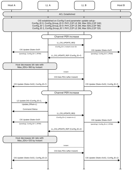
4.7.2 Adaptive Bit Rate
Bluetooth® IPU can also support adaptive Bit Rate by allowing multiple configurations with different Maximum SDU sizes (Max_SDU) to be provisioned for the same CIS. Since Max_SDU directly influences the amount of application data transported during each SDU interval, different configurations can represent different bitrate operating points.
For example, a device may define several configurations that correspond to different audio quality levels. Under favorable link conditions, a configuration with a larger Max_SDU may be selected to support higher bitrate audio transport. When link conditions become less favorable, the system may transition to a configuration with a smaller Max_SDU, reducing the transport bitrate while maintaining the active CIS.
Figure 4.7.2 illustrates an example in which multiple configurations with different Max_SDU values are provisioned in advance. As operating conditions change, IPU enables the active CIS to transition between these configurations, allowing bitrate adaptation without requiring stream re-establishment.
This approach allows audio quality and transport capacity to adapt dynamically while preserving service continuity and maintaining an active CIS connection throughout the transition.
4.7.3 Audio mode transitions
While the previous examples are driven primarily by transport conditions, some updates originate from changes in application behavior.
LE Audio devices frequently operate in multiple application modes. Music playback, voice communication, hearing-access applications, and interactive audio services can prioritize different transport characteristics, including latency, bitrate, and reliability.
Bluetooth® IPU allows configurations optimized for these different operating modes to be provisioned in advance and activated while the CIS remains active. For example, a device may transition from a music-oriented configuration to a voice-oriented configuration when a voice call is initiated. The Host identifies the configuration appropriate for the new operating mode and initiates the update through the Host Controller Interface. The Controllers then coordinate the transition through the CIS Update procedure and activate the new configuration at the agreed Instant.
The same approach can be used for the reverse transition when the call ends, and music playback resumes. Because the required configurations can be defined in advance, the transition can change the transport characteristics without requiring CIS re-establishment.
4.7.4 Coexistence and scheduling flexibility
Bluetooth® IPU can also provide scheduling flexibility to support coexistence with other wireless traffic and synchronization with other Bluetooth® isochronous streams.
For example, an IPU update can adjust the Anchor Point of a CIS to change the timing relationship between the CIS and a Broadcast Isochronous Stream (BIS), such as an Auracast® stream. This can allow the CIS timing to be aligned more effectively with other isochronous activity.
IPU can also change the ISO_Interval to create larger gaps between CIS events. These gaps can provide additional airtime for other wireless traffic, including larger Wi-Fi packets, improving coexistence between Bluetooth® and other radio technologies.
These scheduling changes can be applied through the same coordinated update mechanism used for other IPU configuration changes, allowing timing behavior to evolve while the CIS remains active.
4.8 Summary
Bluetooth® LE Isochronous Parameter Update (IPU) extends Connected Isochronous Streams beyond a fixed transport model and introduces the ability to evolve transport behavior while a CIS remains active.
Rather than treating transport parameters as a one-time result of stream establishment, IPU introduces a configuration-centric framework in which multiple operating points can be provisioned, selected, and activated throughout the lifetime of a CIG.
Runtime updates are coordinated through Instant-based activation, allowing both devices to transition to a new configuration at a common synchronization boundary. Additional continuity mechanisms, including Transition Payload handling and Flush Point coordination, preserve payload processing while transport state evolves.
To support these capabilities, IPU introduces a compact set of Host Controller Interface and Link Layer extensions that enable configuration management, runtime adaptation, and coordinated update execution.
Together, these mechanisms transform transport adaptation from a stream-establishment operation into a runtime capability. IPU can support adaptation to changing radio conditions, adaptive bitrate, application-mode transitions, and scheduling or coexistence requirements while maintaining an active CIS. By providing a common mechanism for defining and activating alternative configurations, IPU enables transport behavior to evolve without requiring stream re-establishment.
5. Bluetooth® Encryption Key Schedule (EKS)
5.1 Background
5.1.1 Evolution of Bluetooth® LE encryption
Bluetooth® LE traditionally establishes encrypted connections using the Encryption Start with Diversifiers procedure. In this model, devices exchange initialization vectors and session key diversifiers before deriving the session key used by Bluetooth Link Layer encryption. This approach has provided a secure and interoperable foundation for Bluetooth LE communications across a wide range of applications.
As Bluetooth technology evolves toward higher-performance transports and more advanced security architectures, additional flexibility is required for establishing, managing, and refreshing encryption material. In particular, there is increasing demand for stronger cryptographic separation between transports, support for evolving encryption contexts, and more flexible key lifecycle management.
To address these requirements, Bluetooth introduces the Encryption Key Schedule (EKS), a new framework that combines ECDH-based key establishment with hierarchical key derivation and integrated key refresh capabilities.
5.1.2 Why a new key management framework was needed
Traditional Bluetooth® LE encryption derives session keys directly from a Long Term Key (LTK) together with exchanged session parameters. While effective, this model provides limited flexibility for managing encryption material after a connection has been established.
Bluetooth® EKS introduces a different approach. Rather than deriving encryption material directly from a single key source, EKS establishes a cryptographic foundation built from multiple inputs and subsequently derives the session encryption material through a structured hierarchy. This separation between key establishment, transport-specific key derivation, and subsequent key updates provides a more flexible lifecycle for Bluetooth LE encryption material.
5.2 Technical overview
Bluetooth® Encryption Key Schedule establishes a structured lifecycle for Bluetooth® LE encryption material. It first establishes the cryptographic foundation for a connection, then uses a hierarchical derivation framework to create transport-specific encryption material. Because the establishment of the cryptographic foundation is separated from the generation of Session Keys, the same architecture can also support alternative operating modes and subsequent key updates, including opportunistic encryption and in-connection key refresh.
5.2.1 Establishing the cryptographic foundation
The first stage of Bluetooth® EKS establishes the cryptographic foundation used by subsequent key derivation procedures.
Traditional Bluetooth® LE encryption uses the Encryption Start with Diversifiers procedure. During this process, the Central and Peripheral exchange Session Key Diversifier (SKD) and Initialization Vector (IV) values through the LL_ENC_REQ and LL_ENC_RSP PDUs. The exchanged values are combined with a Long Term Key (LTK) to generate the Session Key used by Link Layer encryption.
EKS introduces a different approach. Instead of exchanging SKD and IV values, devices exchange ECDH public keys, random values, and encryption-related parameters using the LL_ENC_ECDH_REQ and LL_ENC_ECDH_RSP PDUs. These messages contain:
- ECDH public keys (PubKey_C and PubKey_P)
- Random values (Rand_C and Rand_P)
- Encryption flags (Flags_C and Flags_P)
- Public key type information
- MIC-related operating preferences
Using the exchanged public keys, both devices independently calculate the same ECDH shared secret using the Bluetooth P-256 elliptic curve.
As shown in Figure 5.2.1, the Encryption Start with Key Schedule procedure establishes more than an encrypted connection. In addition to generating an ECDH shared secret, the procedure exchanges the control information that will later become part of the EKS derivation process. This exchanged data is subsequently incorporated into the EKS key hierarchy.
The ECDH shared secret is not used directly as a Session Key. Instead, the procedure establishes the cryptographic inputs and negotiation context required to initialize the EKS key hierarchy. Once the necessary encryption material has been derived, the devices complete the existing three-way encryption handshake using LL_START_ENC_REQ and LL_START_ENC_RSP.
The ECDH shared secret and connection context established through the procedure shown in Figure 5.2.1 therefore become inputs to the CMAC-based key hierarchy described in the following section.
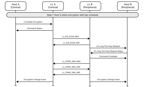
5.2.2 Building the Bluetooth® EKS key hierarchy
Once the cryptographic foundation has been established, EKS uses a CMAC-based key derivation framework to transform the information exchanged during the Encryption Start with Key Schedule procedure into the encryption material used by Bluetooth® LE Link Layer encryption. Figure 5.2.2 illustrates the key hierarchy used to perform this transformation.
As shown in Figure 5.2.2, EKS derives and manages encryption material through a structured hierarchy rather than generating a Session Key directly from a Long Term Key. The labels such as k2, ee12, kv12, and k3 represent CMAC-based derivation functions that are applied at different stages of this hierarchy. Rectangles in the figure represent cryptographic functions, rounded boxes represent cryptographic values, and shaded boxes represent events in the EKS lifecycle.
Detailed definitions of the functions and tags shown in Figure 5.2.2 can be found in the Bluetooth® Core Specification, Volume 6, Part E, Section 4. This overview therefore focuses on the purpose of the hierarchy and the role of the resulting cryptographic material rather than the mathematical operation of each derivation function.
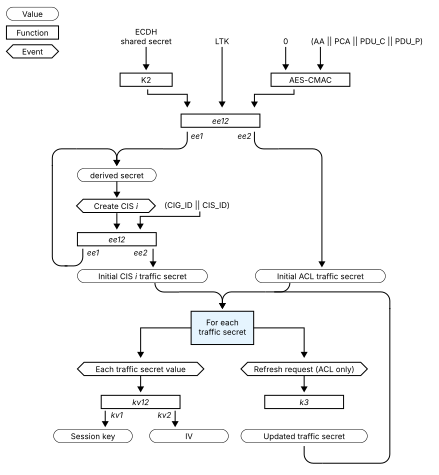
Bluetooth® Core Specification, Volume 6, Part E, Section 4, Figure 4.1.
To initialize the hierarchy, EKS combines several cryptographic inputs associated with the Encryption Start with Key Schedule procedure:
- ECDH Shared Secret: Calculated independently by both devices from the public keys exchanged in LL_ENC_ECDH_REQ and LL_ENC_ECDH_RSP
- Long Term Key: Provided by the Host when an existing Bluetooth security relationship is available
- AA: The Access Address of the ACL connection
- HPA: The HDT Packet Address of the ACL connection when one exists, or the single-octet value 0x00 otherwise
- PDU_C: The CtrData field of the LL_ENC_ECDH_REQ PDU transmitted by the Central
- PDU_P: The CtrData field of the LL_ENC_ECDH_RSP PDU transmitted by the Peripheral
Together, AA, HPA, PDU_C, and PDU_P provide connection-specific context for the derivation process. PDU_C and PDU_P incorporate the encryption flags, random values, public-key types, and public keys exchanged during encryption setup. The Bluetooth® Core Specification also defines the octet ordering used when PDU_C and PDU_P are supplied to the AES-CMAC calculation, ensuring that both Controllers construct identical derivation inputs.
By combining the ECDH shared secret, the applicable LTK, and connection-specific context, EKS binds the resulting encryption material to the ACL connection and EKS negotiation. EKS therefore does more than transform an ECDH result into a Session Key. It combines fresh ECDH-derived material, an existing Bluetooth credential when available, and the context of the current connection within a structured derivation process.
The first intermediate value produced by this process is the Derived Secret, which forms the evolving root of the EKS hierarchy. The Derived Secret is used to create one or more Traffic Secrets, and each Traffic Secret is subsequently used to generate the Session Key and Initialization Vector required by AES-CCM encryption.
This layered structure separates the connection-level cryptographic foundation from the encryption material used by individual transports. As described in the following section, it allows EKS to create independent encryption contexts for the ACL connection and its associated CIS transports, while also providing the basis for later key refresh operations.
5.2.3 Managing ACL and CIS encryption material
The layered structure introduced in Figure 5.2.2 allows Bluetooth® EKS to manage encryption material independently for different transport types while maintaining a common cryptographic foundation. Rather than generating a single Session Key for all traffic associated with a connection, EKS uses Traffic Secrets to create transport-specific encryption contexts.
When ACL encryption is established, EKS generates an ACL Traffic Secret from the Derived Secret associated with the connection. This ACL Traffic Secret is then used to derive the Session Key and Initialization Vector (IV) used by AES-CCM to protect traffic on the encrypted ACL connection. The Derived Secret and Traffic Secret remain internal to the Controller and are not exposed outside the EKS framework.
When a new Connected Isochronous Stream (CIS) is created, EKS extends the hierarchy by generating additional cryptographic material for the new transport. Using the current Derived Secret together with the applicable CIG_ID and CIS_ID values, both devices generate a new Derived Secret and an initial CIS Traffic Secret associated with that stream. The CIS Session Key and Initialization Vector are then derived from the CIS Traffic Secret.
Figure 5.2.2 should therefore be viewed as a branching hierarchy rather than a single linear chain. The ACL connection maintains its own ACL Traffic Secret and corresponding Session Key material, while each associated CIS maintains an independent CIS Traffic Secret and Session Key. Creation of a new CIS also advances the Derived Secret used by the hierarchy.
This transport-specific branching is one of the primary reasons EKS introduces the Derived Secret and Traffic Secret layers. By maintaining separate Traffic Secrets for ACL and CIS transports, EKS provides cryptographic separation between communication streams while preserving a common connection-level trust foundation. Multiple transport contexts can therefore coexist without sharing the same Session Keys, even though they originate from the same EKS hierarchy.
5.2.4 Opportunistic encryption
The transport-specific encryption contexts described in the previous section are created and managed through the Bluetooth® EKS hierarchy regardless of how the cryptographic foundation is established. In the most common case, EKS is initialized using a Long Term Key (LTK) provided by the Host. However, the same architecture can also operate when no previously established Bluetooth security relationship exists. This operating mode is known as opportunistic encryption.
Opportunistic encryption allows two devices to establish encrypted communication without requiring prior pairing or bonding. Instead of relying on a bonded Long Term Key, the devices use the ECDH shared secret established during the Encryption Start with Key Schedule procedure together with a fixed all-zero LTK value defined by the Bluetooth® Core Specification.
The Central requests opportunistic encryption through the corresponding flag in LL_ENC_ECDH_REQ. The Peripheral accepts this mode only when the Opportunistic Encryption Host Support feature is available. Otherwise, the Peripheral rejects the request with the Encryption Mode Not Acceptable error.
Unlike traditional EKS operation, which uses an LTK supplied by the Host, opportunistic encryption uses an all-zero LTK value. Apart from this difference, the same establishment, derivation, and key-management procedures are used to create and maintain the encryption material for the connection.
By allowing encrypted communication without requiring prior pairing or bonding, opportunistic encryption expands the range of scenarios in which Bluetooth® LE encryption can be applied. However, because no previously established Bluetooth trust relationship is available, opportunistic encryption does not provide man-in-the-middle protection. The Bluetooth® Core Specification describes its confidentiality and integrity properties as equivalent to devices paired using the LE Secure Connections Just Works association model.
5.2.5 Updating encryption material
The transport-specific encryption contexts described in the previous sections are built upon the Traffic Secrets maintained by the EKS hierarchy. Because the ACL and CIS Session Keys described in the previous section are derived from Traffic Secrets rather than directly from the original cryptographic foundation, Bluetooth® EKS can evolve encryption material throughout the lifetime of a connection without necessarily rebuilding the entire hierarchy.
EKS supports two approaches for updating encryption material: restarting encryption and refreshing encryption.
Restarting encryption
In some situations, encryption must be re-established using a new encryption context. To support this capability, Bluetooth® LE uses the Encryption Pause procedure.
During the Encryption Pause procedure, encryption is temporarily suspended, and an encapsulated Encryption Start procedure is executed before encryption is re-enabled. Data PDUs are not transmitted unencrypted during the pause.
If EKS was originally used to establish the connection, the same Encryption Start with Key Schedule procedure is used during restart. This process effectively repeats the key-establishment phase described in Section 5.2.1, establishing a new cryptographic foundation and rebuilding the EKS hierarchy before generating new Session Key material. The existing connection is preserved throughout the procedure. Opportunistic encryption is not permitted during an encapsulated restart procedure.
Refreshing encryption
EKS also supports refreshing encryption material without rebuilding the entire encryption context.
Unlike restarting encryption, refresh operations occur entirely within the existing EKS hierarchy. Rather than repeating the ECDH exchange and reconstructing the cryptographic foundation, both devices update the existing ACL Traffic Secret and derive a new Session Key and Initialization Vector from the updated value. The original ECDH shared secret, Derived Secret, and connection-specific context remain unchanged.
Refreshing the ACL Session Key does not reset the packet counter or payload number. If a payload was transmitted before the key change and must be retransmitted afterward, the payload is re-encrypted, and its MIC is recalculated using the new Session Key.
Although both restart and refresh ultimately produce new Session Key material, they operate at different levels of the EKS hierarchy. Restarting encryption rebuilds the encryption context through a new Encryption Start procedure, whereas refreshing encryption evolves the existing encryption context by advancing the ACL Traffic Secret and deriving new Session Keys from that updated value. In practice, refresh operations allow new Session Key material to be introduced without repeating the ECDH exchange that originally established the connection.
This distinction illustrates one of the primary benefits of introducing Traffic Secrets into the EKS architecture: encryption material can evolve independently of the original key-establishment process.
5.2.6 MIC selection and HDT operation
In addition to establishing and managing encryption keys, the Encryption Start with Key Schedule procedure also determines how integrity protection is applied to the connection.
The encryption flags exchanged during the Encryption Start with Key Schedule procedure determine the Message Integrity Code (MIC) behavior of the connection.
Connections operating on a GFSK PHY use a 32-bit MIC. For LE HDT PHY operation, a 64-bit MIC is used when both the Central and Peripheral indicate that a 64-bit MIC is allowed. Otherwise, a 128-bit MIC is used.
The MIC length is therefore selected as part of the EKS encryption setup rather than being independently chosen after encryption begins. The selected MIC behavior becomes part of the connection context incorporated into the Bluetooth® EKS hierarchy.
The MIC length used on the LE HDT PHY may subsequently be modified through the PHY Update and Encryption Refresh procedure, allowing a change in PHY characteristics and associated integrity-protection parameters to be coordinated within the EKS framework.
Although EKS was originally introduced alongside Bluetooth® HDT, it is defined as an independent Controller feature. HDT should therefore be viewed as one application of the EKS framework rather than the sole reason for its existence.
The capabilities described throughout this section, including hierarchical key derivation, transport-specific Traffic Secrets, opportunistic encryption, encryption restart, and key refresh, establish a reusable security foundation that can support Bluetooth technologies beyond HDT.
5.2.7 Comparison with encryption using diversifiers
After examining how Bluetooth® EKS establishes, derives, and manages encryption material, it is useful to compare the architecture with the traditional Encryption Start with Diversifiers procedure. Both approaches ultimately use the LL_START_ENC_REQ and LL_START_ENC_RSP handshake to transition the connection to encrypted operation. The principal differences lie in the information exchanged before that handshake and in how the resulting encryption material is derived and subsequently managed.
Table 5.2.7 summarizes the primary architectural differences between the traditional Encryption Start with Diversifiers procedure and the EKS framework.
| Aspect | Encryption with Diversifiers | EKS |
|---|---|---|
| Cryptographic Foundation | LTK + SKD/IV | ECDH Shared Secret + LTK + Connection Context |
| Key Structure | Session Key | Derived Secret → Traffic Secret → Session Key |
| Transport Separation | Not defined | Separate ACL and CIS Traffic Secrets |
| Key Update | Restart encryption | Restart or refresh encryption |
| Opportunistic Encryption | Not supported | Supported |
5.3 Summary
Bluetooth® Encryption Key Schedule introduces a hierarchical framework for establishing and managing Bluetooth® LE encryption material. It combines an ECDH shared secret, the applicable Long Term Key, and connection-specific context to derive independent encryption material for ACL and CIS transports.
EKS also supports opportunistic encryption, encryption restart, in-connection key refresh, and enhanced MIC operation. Together, these capabilities provide the security foundation required by HDT while allowing EKS to remain an independent and reusable Bluetooth feature.
6. Bluetooth® Transient Application Key (TAK)
6.1 Background
6.1.1 Evolution of the Bluetooth security architecture
Bluetooth has long provided mechanisms for establishing trust and protecting communications between devices. These mechanisms are built around several core security functions:
- Pairing, which establishes shared secret keys between devices
- Bonding, which stores those keys for future use
- Device authentication, which verifies possession of shared key material
- Encryption, which protects the confidentiality of data in transit
- Message integrity, which protects against unauthorized modification of data
Over time, the Bluetooth security architecture has evolved from legacy BR/EDR mechanisms to more advanced approaches such as LE Secure Connections. While the underlying cryptography has improved significantly, the operational model has remained largely unchanged.
In most cases, Bluetooth security assumes that devices establish trust through pairing and then retain that trust relationship through bonding. As a result, security state persists across multiple connections and interactions.
This model works well for devices that communicate repeatedly over time, such as smartphones, wearables, headphones, and input devices. However, it assumes that trust relationships are long-lived and worth maintaining.
6.1.2 Limitations of stateful pairing in transient interactions
As Bluetooth® LE expands into new application areas, an increasing number of interactions are becoming short-lived and transactional rather than persistent. Bluetooth is now frequently used in scenarios such as digital keys, access control systems, ticketing, credential-based access, shared infrastructure, and temporary device provisioning, where devices may interact only once or for a limited period before the relationship ends.
In these situations, the traditional pairing-based security model can introduce unnecessary complexity. Pairing and bonding are designed to establish and maintain a long-term trust relationship between devices, allowing keys and security to be reused across future connections. However, when interaction is temporary, maintaining persistent security may provide little benefit.
This can lead to several challenges. Short-lived interactions may still create long-term bonding information, consuming limited storage resources on devices. In addition, trust may already have been established through mechanisms outside the Bluetooth stack, such as cloud-based identity services, digital credentials, certificates, or other application-specific authentication systems. Performing pairing solely to obtain an encryption key can therefore duplicate authentication processes that have already taken place.
These trends reflect a broader shift in system design. Modern applications increasingly separate identity management from transport technologies, allowing authentication and trust decisions to be handled at the application level while communication technologies focus on protecting the data being exchanged.
To support this model, Bluetooth introduces a non-paired security architecture that enables Link Layer encryption without requiring pairing or bonding. In this approach, authentication and key establishment are performed by a higher-layer application, while Bluetooth continues to provide standardized transport protection for data exchanged over the wireless link.
Rather than replacing the existing pairing-based model, this approach extends the Bluetooth security architecture to support transient, session-based interactions where maintaining a long-term trust relationship is neither necessary nor desirable.
6.2 Technical overview
6.2.1 What is a Transient Application Key (TAK)
A Transient Application Key (TAK) is a 128-bit secret provided by a higher-layer application and used to establish Link Layer encryption for a Bluetooth® LE connection. Functionally, it serves the same purpose as a Long-Term Key (LTK) during the encryption procedure but differs fundamentally in how it is generated and managed.
Traditional Bluetooth® LE security derives encryption keys through pairing procedures managed by the Security Manager Protocol (SMP). In contrast, a TAK is generated through an authentication and key establishment process defined by a higher-layer application or specification. The Bluetooth Security Manager is not involved in the creation of the key.
As a result, trust establishment is separated from transport protection. Authentication is performed by the higher-layer application, while Bluetooth provides standardized Link Layer encryption once a shared key has been established.
The lifecycle of a TAK is intentionally transient. The TAK is provided to the Bluetooth Host for use during the Encryption Start Procedure and is discarded by the Host after the procedure is initiated. No bonding relationship is created, and no long-term Bluetooth security state is retained.
6.2.2 Non-paired security architecture
Bluetooth® TAK introduces a new security architecture for Bluetooth® LE known as the non-paired security model. Unlike traditional Bluetooth security, which relies on pairing and bonding to establish trust, this model allows encrypted connections to be established without using the Security Manager.
Under this architecture, a higher-layer application authenticates the peer device and establishes a shared secret. The resulting TAK is then provided to the Bluetooth Host and used to initiate Link Layer encryption. The remainder of the Bluetooth protocol stack, including GAP, ATT, L2CAP, and the Controller, continues to operate normally.
As shown in Figure 6.2.2, the application responsible for authentication operates outside the Bluetooth Security Manager. Rather than participating in Bluetooth pairing procedures, the application establishes trust directly and supplies a Transient Application Key to the Host. The Bluetooth stack then uses this key to establish and maintain Link Layer encryption for the duration of the connection.
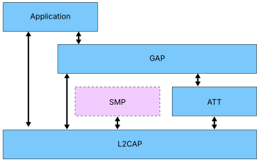
The key architectural distinction is that the Security Manager Protocol (SMP) is not involved in TAK-secured connections. Pairing, key generation, and bonding are bypassed, allowing trust establishment to be delegated to a higher-layer application while Bluetooth continues to provide Link Layer confidentiality and integrity protection. Devices operating under this model are therefore encrypted but not paired or bonded.
The result is an architecture in which connections can be encrypted without creating a persistent trust relationship. Authentication and key establishment are handled outside the Bluetooth security framework, while the existing Bluetooth® LE encryption mechanisms remain unchanged.
While the non-paired security model defines how TAK integrates into the Bluetooth® LE architecture, support for this model is formalized through the introduction of a new Bluetooth® LE security mode. The following section describes how Security Mode 4 extends the existing Bluetooth® LE security framework.
6.2.3 LE Security Modes and the introduction of Mode 4
Bluetooth® LE defines multiple security modes to address different communication requirements. Prior to the introduction of Bluetooth® TAK, Bluetooth LE supported Security Mode 1 for securing point-to-point LE connections and Security Mode 3 for securing encrypted broadcast communications. Together, these modes provided mechanisms for protecting both connection-oriented and broadcast-based communication scenarios.
The introduction of the non-paired security model extends this framework with a new security mode: LE Security Mode 4. Unlike the existing security modes, which rely on Bluetooth-managed security procedures such as pairing or broadcast key distribution, Security Mode 4 enables encrypted connections using a Transient Application Key supplied by a higher-layer application.
| Security Mode | Security Levels | Description |
|---|---|---|
| Mode 1 | Level 1 | No authentication and no encryption |
| Level 2 | Unauthenticated pairing with encryption | |
| Level 3 | Authenticated pairing with encryption | |
| Level 4 | Authenticated LE Secure Connections pairing with encryption using a 128-bit strength encryption key | |
| Mode 3 | Level 1 | No security |
| Level 2 | Use of unauthenticated Broadcast_Code | |
| Level 3 | Use of authenticated Broadcast_Code | |
| Mode 4 (new) | Level 2 | Encrypted transient connection using a Transient Application Key (TAK) |
As shown in Table 6.2.3, Security Mode 1 remains the primary mechanism for securing point-to-point LE connections. Security is established through Bluetooth pairing procedures managed by the Security Manager Protocol (SMP), with higher security levels providing stronger authentication and encryption requirements. Most Bluetooth® LE devices today operate using Security Mode 1.
Security Mode 3 addresses a different category of communication by securing Broadcast Isochronous Streams (BIS). Rather than deriving encryption keys through pairing, Mode 3 uses a Broadcast_Code to control access to encrypted broadcast content. The security level determines whether the Broadcast_Code is distributed through an authenticated or unauthenticated mechanism.
The addition of Security Mode 4 introduces a fundamentally different approach to Bluetooth® LE security. While Security Mode 1 establishes trust through Bluetooth pairing procedures and maintains that trust through bonding, Mode 4 assumes that authentication and key establishment are performed externally by a higher-layer specification. Bluetooth then uses the resulting Transient Application Key to establish Link Layer encryption without creating a bond or retaining long-term security state. This makes Mode 4 particularly well suited to transient interactions where secure communication is required, but a persistent trust relationship is unnecessary.
In summary, Security Mode 4 is intended for use only after the participating devices have been authenticated by a higher-layer specification capable of establishing a shared 128-bit security-strength secret.
6.2.4 Establishing a TAK-secured connection
Once a device operating under Security Mode 4 has obtained a Transient Application Key (TAK) from a higher-layer application, the key can be used to establish an encrypted Bluetooth® LE connection. Unlike traditional Bluetooth security procedures, authentication and key establishment occur outside the Bluetooth stack. Bluetooth is responsible only for applying Link Layer encryption using the provided key.
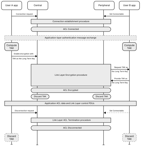
Figure 6.2.4 illustrates the separation between higher-layer authentication and Bluetooth Link Layer protection. Unlike pairing-based security, trust is established outside the Bluetooth stack, and a shared secret is derived before the Bluetooth® LE Encryption Start Procedure is initiated. As shown in the figure, a TAK-secured connection is established through the following sequence of operations:
Step 1: Connection establishment
The participating devices first establish a standard Bluetooth® LE ACL connection. At this stage, the connection has not yet been encrypted.
Step 2: Higher-layer authentication
A higher-layer application authenticates the peer device using procedures defined by its own specification. Depending on the application, the authentication process may be performed in-band or through an out-of-band mechanism. This authentication process is independent of the Bluetooth Security Manager and occurs outside the Bluetooth security framework.
Step 3: TAK derivation and provisioning
Following successful authentication, both devices derive or obtain a shared 128-bit security-strength secret. This secret becomes the Transient Application Key (TAK) and is provided to the Bluetooth Host for use during encryption setup. Functionally, the TAK serves the same purpose as a Long Term Key (LTK) during the encryption procedure.
Step 4: Encryption Start Procedure
The Host initiates the standard Bluetooth® LE Encryption Start Procedure using the TAK. During this process, the TAK is supplied to the Link Layer as the encryption key, while the EDIV and Rand values are set to zero because the key was not generated through Bluetooth pairing procedures. The Controller then establishes an encrypted session using the existing Bluetooth® LE encryption framework.
Step 5: TAK disposal
After initiating the Encryption Start Procedure, the Host discards the TAK. The Controller uses the TAK to establish the encryption context and does not retain the TAK after the encryption context has been established. The higher-layer application may retain or discard its copy of the key according to its own security policy. No bonding information is created, and no long-term Bluetooth security state is stored.
6.2.5 Runtime behavior and session management
Once a TAK-secured connection has been established, its runtime behavior differs from that of a traditional pairing-based connection. The key distinction is that devices operating under Security Mode 4 do not rely on pairing, bonding, or the Security Manager Protocol (SMP) to maintain security state. Instead, the connection operates using a security policy defined by the higher-layer application together with the Transient Application Key established during authentication.
When determining how a connection should be secured, the device considers the bonding status of the peer device and the requirements of the higher-layer application. If the peer device is already bonded, the connection uses the existing pairing-based security model and the bonded Long-Term Key (LTK). A TAK is not used for a bonded connection. If the peer device is not bonded and the higher-layer application is configured to use the non-paired security model, the connection operates under Security Mode 4.
Unlike Security Mode 1, devices operating under Security Mode 4 do not initiate Bluetooth pairing procedures to satisfy security requirements. If encryption is required and a valid TAK is available, the Host enables Link Layer encryption using the TAK before access to the requested service is granted. If a TAK is not available, the service request is aborted rather than falling back to pairing.
Similarly, a connection operating under Security Mode 4 does not use pairing to establish security. If encryption is required, a valid TAK must be available to establish Link Layer encryption. Pairing is not used as an alternative mechanism for establishing security on a connection operating under Security Mode 4.
Service access decisions are based on both the current state of the connection and the policy defined by the higher-layer specification. When a service requires encryption, the connection must be encrypted before access is granted. When authentication requirements exist, a TAK-secured connection is accepted only when those requirements are satisfied according to the higher-layer policy responsible for establishing trust.
The runtime behavior of Security Mode 4 differs fundamentally from Security Mode 1 and can be summarized as shown in Table 6.2.5.
| Scenario | Security Mode 4 Behavior |
|---|---|
| No encryption required | Service request proceeds normally |
| Encryption required and TAK available | Link Layer encryption is enabled using the TAK |
| Encryption required but no TAK available | Service request is aborted |
| Authentication required | Decision governed by higher-layer policy |
| Pairing request received | Request rejected |
| Security upgrade through pairing | Not permitted |
As a result, Security Mode 4 operates as a distinct security model rather than a variation of pairing-based security. Trust is established externally by the higher-layer application, while Bluetooth is responsible only for enforcing Link Layer protection throughout the lifetime of the connection.
6.2.6 GATT considerations in TAK-secured connections
The session-oriented nature of TAK affects application behavior at the GATT layer. Because devices operating under Security Mode 4 do not create bonds, the Bluetooth stack does not preserve service-level state between connections. Each TAK-secured connection is therefore treated as an independent session.
This behavior is particularly visible in the handling of Client Characteristic Configuration (CCC) settings. In Security Mode 4, CCC configurations are considered transient and are discarded when the connection ends. Applications that require notifications or indications must therefore reconfigure the corresponding CCC values each time a new TAK-secured connection is established.
Security Mode 4 also requires the use of the LE GATT Security Levels characteristic to communicate the security requirements of the GATT server. This characteristic allows the GATT server to indicate the security level required for access to its services and attributes when operating with a TAK-secured connection.
As a result, TAK-based security introduces a fully session-oriented operating model in which both security state and associated service configuration exist only for the lifetime of a connection. When the connection terminates, both the TAK and any session-specific service state are discarded.
6.2.7 Security considerations
A TAK is used to establish and maintain Link Layer encryption for a Bluetooth® LE connection. Once encryption is established, the connection benefits from the confidentiality and integrity protections provided by the Bluetooth® LE encryption framework.
The higher-layer specification using TAK is responsible for establishing the trust relationship and determining how the TAK is generated, obtained, and provided to the Bluetooth Host. This includes the authentication and security procedures required to protect the key establishment process.
As a result, a higher-layer specification using TAK is responsible for:
- Authenticating the peer device
- Deriving or obtaining the shared secret used as the TAK
- Providing protection against man-in-the-middle attacks
- Defining the policy that governs when and how a TAK is supplied to the Bluetooth Host
A key implication of the TAK architecture is that authentication and protection against man-in-the-middle attacks are provided by the higher-layer specification rather than by Bluetooth pairing procedures. The security properties of a TAK-secured connection therefore depend on the authentication and key-establishment procedures used by the higher-layer specification.
This separation allows higher-layer specifications to define authentication, and trust mechanisms appropriate to their application while using standardized Bluetooth® Link Layer encryption to protect data exchanged over the connection.
6.3 Summary
Bluetooth® Transient Application Key introduces a new non-paired security model that enables encrypted Bluetooth® LE connections without requiring pairing or bonding. Authentication and key establishment are performed by a higher-layer application, while Bluetooth provides Link Layer confidentiality and integrity protection using the resulting key.
To support this capability, Bluetooth® LE introduces Security Mode 4, extending the existing security framework with a new option designed specifically for transient interactions. Unlike traditional pairing-based security, Mode 4 does not create persistent trust relationships or retain long-term security state.
By separating trust establishment from transport protection, TAK extends the Bluetooth security architecture to support secure, session-based communication without requiring persistent trust relationships. Rather than replacing existing pairing-based security models, TAK complements them by providing an alternative approach for applications that establish trust outside the Bluetooth stack.
The introduction of both the Transient Application Key and Security Mode 4 therefore represents an important evolution of the Bluetooth® LE security architecture, enabling secure, encrypted, session-based interactions without requiring pairing, bonding, or persistent trust relationships.
7. Bluetooth® Encryption Product Debugging (EPD)
7.1 Background
Encryption plays a critical role in protecting user data and communications. At the same time, it creates challenges for protocol analysis because captured traffic cannot be fully decoded without access to the credentials protecting the connection. Bluetooth® Encryption Product Debugging (EPD) addresses this challenge by providing a standardized way for authorized debugging tools to access the active encryption information needed to analyze encrypted Bluetooth traffic.
Historically, encrypted Bluetooth traffic could often be analyzed using visibility into long-term security credentials established during pairing, such as the Long-Term Key (LTK). In many deployments, access to these credentials provided sufficient information for protocol analyzers and debugging tools to reconstruct the encryption state of a connection and support interoperability testing, product validation, and troubleshooting activities.
As Bluetooth encryption continues to evolve, however, active encryption credentials are increasingly generated and maintained within the Controller. In Host Controller Interface (HCI)-based architectures, these credentials may remain inaccessible to the Host and external debugging tools, making encrypted traffic more difficult to analyze and troubleshoot. This is particularly relevant with Encryption Key Schedule (EKS), where the encryption state protecting a connection is derived and maintained within the Controller. Without standardized access to the active encryption credentials, a Host developer may require proprietary mechanisms to obtain Controller keys to decrypt captured air traffic. EPD addresses this challenge by providing a standardized mechanism for the Host to obtain the active encryption state, enabling test setups to capture both air traffic and HCI traffic and supporting automated decoding, debugging, and interoperability testing.
To address this challenge, Bluetooth® Encryption Product Debugging (EPD) introduces a standardized mechanism that allows the Controller to report active encryption credentials to the local Host for debugging purposes. By providing visibility into the encryption state currently protecting a connection, EPD helps preserve protocol analysis and interoperability debugging capabilities without changing how Bluetooth encryption operates.
7.2 Technical overview
7.2.1 Visibility into active encryption state
Bluetooth® EPD provides visibility into the encryption information actively protecting an encrypted Bluetooth® connection. Rather than exposing pairing records, bonding databases, or other historical security information, EPD focuses on the encryption state currently maintained by the Controller and used to protect traffic exchange between connected devices.
Figure 7.2.1 illustrates how encryption visibility evolves from traditional Bluetooth® LE encryption to Encryption Key Schedule (EKS)-based encryption.
In traditional LE encryption, debugging often begins with visibility into the Long-Term Key (LTK). Because the active encryption state can generally be reconstructed from the LTK together with information exchanged during encryption establishment, protocol analyzers are typically able to derive the session key and decrypt captured traffic.
With EKS, however, the process becomes more complex. As shown in Figure 7.2.1, EKS introduces an internal key hierarchy in which ECDH-derived shared secrets, together with other cryptographic inputs, are used to derive traffic secrets that subsequently generate the session key and initialization vector (IV) protecting the connection. Under these conditions, visibility into long-term credentials alone may no longer provide sufficient information to determine the active encryption state currently protecting user traffic.
EPD addresses this challenge by providing visibility into the active encryption state rather than the long-term credentials used during pairing or bonding. Instead of reporting the LTK, EPD reports the session key and IV associated with the encrypted connection, allowing debugging tools to remain synchronized with the encryption context actively maintained by the Controller.
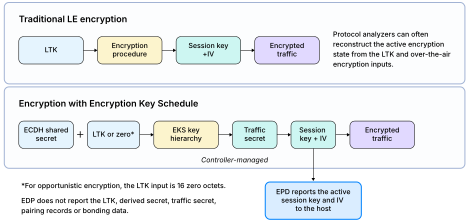
7.2.2 EKS-based encryption modes
To better understand the active encryption state shown in Figure 7.2.1, it is useful to briefly examine how encryption credentials are established when the Encryption Key Schedule (EKS) framework is used.
When both devices support EKS, encryption is established using the Encryption Start with Key Schedule procedure. Unlike traditional LE encryption, EKS introduces controller-managed key derivation procedures that use ECDH-generated shared secrets and additional cryptographic inputs to establish the encryption state protecting a connection. These procedures ultimately generate the session key and IV used to encrypt traffic.
EKS supports two deployment models.
- EKS with Long-Term Key (LTK)
In this mode, a Host-provided LTK participates in the derivation process together with ECDH-generated shared secrets and other encryption inputs exchanged during encryption establishment. The resulting traffic secret is subsequently used to derive the session key and IV protecting the connection.
- Opportunistic Encryption
In this mode, encryption is established through the EKS framework without relying on a previously distributed LTK. The specification defines the LTK input as a zero-valued key, while the session key and IV are derived from the ECDH exchange and associated EKS procedures.
Regardless of how encryption is established, both deployment models ultimately create an active encryption state within the Controller represented by the session key and IV protecting the connection. These are the values reported by EPD and made available to debugging tools through the Host Controller Interface (HCI).
7.2.3 Bluetooth® EPD reporting mechanism
To provide standardized access to the active encryption state, EPD introduces a lightweight Host Controller Interface (HCI) reporting framework. The feature consists of two HCI commands used to manage reporting behavior and one HCI event used to deliver encryption information to the Host.
EPD is intended for use in controlled development, testing, and interoperability environments and should not be enabled during normal product operation.
Table 7.2.3a summarizes the HCI elements introduced by the EPD feature.
| Component | Purpose |
|---|---|
| Read Encryption Key Debug Reporting Mode Command | Reads the current EPD reporting configuration |
| Write Encryption Key Debug Reporting Mode Command | Enables or disables encryption reporting |
| Encryption Key Debug Report Event | Reports encryption information associated with an active connection |
As shown in Table 7.2.3a, the Read and Write Encryption Key Debug Reporting Mode commands allow the Host to query and configure reporting behavior, while the Encryption Key Debug Report event provides the actual encryption information required by debugging tools. Together, these additions create a standardized mechanism for exposing encryption information through HCI without requiring vendor-specific diagnostics.
The Encryption Key Debug Report Event contains information associated with the active encryption state of a connection. As shown in Table 7.2.3b, EPD reports the session key and IV currently associated with an encrypted connection rather than long-term credentials such as the LTK. These values represent the encryption state actively maintained by the Controller and correspond directly to the information used to encrypt and decrypt traffic.
| Parameter | Description |
|---|---|
| Connection Handle | Identifies the encrypted connection |
| Session Key | Encryption key associated with the connection |
| Session Key Length | Length of the session key |
| IV | Initialization vector associated with the connection |
| IV Length | Length of the initialization vector |
7.2.4 Event generation behavior
Bluetooth® EPD follows an event-driven reporting model. Rather than continuously reporting encryption information, the Controller generates an Encryption Key Debug Report Event only when new encryption credentials become active for a connection. This approach ensures that debugging tools receive updated encryption information whenever the active encryption state changes while avoiding unnecessary reporting overhead.
| Trigger event | Encryption Key Debug Report generated |
|---|---|
| HCI_Encryption_Change | Yes |
| HCI_Encryption_Key_Refresh_Complete | Yes |
| HCI_LE_CIS_Established | Yes |
As shown in Table 7.2.4, report generation is tied directly to changes in the encryption state of a connection. When encryption is initially enabled, when an existing session key is refreshed, or when a new encrypted CIS becomes available, the Controller generates an Encryption Key Debug Report containing the encryption information associated with the connection.
This event-driven approach helps ensure that debugging tools remain synchronized with the active encryption state throughout the lifetime of a connection. As encryption credentials evolve over time, additional reports are generated to reflect the updated session key and IV protecting the connection.
Because reports are generated only when the encryption state changes, EPD minimizes implementation overhead while still providing debugging tools with the information required to analyze encrypted Bluetooth® traffic.
7.2.5 Bluetooth® EPD Reporting workflow
While the previous sections describe the information reported by EPD and the conditions under which reporting occurs, the overall interaction between the Host and Controller is best understood through the reporting workflow shown in Figure 7.2.5.
Figure 7.2.5 illustrates a representative EPD reporting sequence. After the Host enables encryption key debug reporting, the Controller generates an Encryption Key Debug Report whenever a new session key is created for an encrypted connection and delivers the associated session key and IV to the Host. This event-driven workflow allows debugging tools to remain synchronized with the active encryption state throughout the lifetime of the connection.
The workflow can be summarized as follows:
- The Host enables EPD reporting using the Write Encryption Key Debug Reporting Mode command
- An encrypted connection is established using standard Bluetooth encryption procedures
- A new session key becomes active for the encrypted connection
- The Controller generates an Encryption Key Debug Report containing the session key and IV associated with the connection
- The Host receives the report and can provide information to protocol analyzers, interoperability test systems, or other debugging tools
Additional reports may be generated whenever subsequent session keys are created, ensuring that debugging tools remain synchronized with changes to the active encryption state. For example, the active encryption state may change for a CIS connection when the PHY changes to or from HDT, or when a voluntary key refresh is triggered. In these cases, EPD provides the updated session key and IV to the Host so that debugging tools can continue to decode encrypted traffic using the current encryption state.
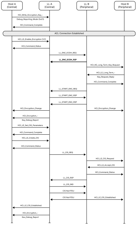
7.3 Summary
Bluetooth® Encryption Product Debugging (EPD) introduces a standardized mechanism for exposing the active encryption state of an encrypted Bluetooth® connection through the Host Controller Interface (HCI). Rather than relying on visibility into long-term credentials such as the Long-Term Key (LTK), EPD provides direct access to the session key and initialization vector (IV) currently protecting the connection.
As Bluetooth encryption evolves through mechanisms such as Encryption Key Schedule (EKS), the credentials protecting user traffic may be established and maintained through controller-managed cryptographic procedures. Under these conditions, visibility into long-term credentials alone may no longer be sufficient for protocol analysis and interoperability debugging. EPD addresses this challenge by providing standardized visibility into the active encryption state maintained by the Controller.
Through two HCI commands and a dedicated reporting event, EPD enables protocol analyzers, interoperability test systems, and debugging tools to remain synchronized with changes to encrypted connections while avoiding vendor-specific logging mechanisms or proprietary debugging interfaces.
By decoupling debugging visibility from the underlying encryption establishment procedure, EPD ensures that encrypted Bluetooth traffic remains observable and debuggable across both traditional LE encryption and EKS-based encryption deployments.
8. Clarifying Bluetooth® Power Classes
Bluetooth® Core 7.0 removes the historical Bluetooth Power Class definitions from the specification. While Power Classes have long been used as informational classifications describing a device’s transmit power capability, Bluetooth qualification and compliance have always been based on the applicable radio requirements defined throughout the Bluetooth® Core Specification. As a result, the removal of Power Class definitions does not affect qualification procedures, interoperability, or device behavior.
Bluetooth® devices have historically been associated with Power Classes that categorize devices according to their maximum transmit power capability. For BR/EDR and LE devices, these classifications are shown in Tables 8a and 8b.
| Power Class | Requirements |
|---|---|
| 1 | 100 mW (20 dBm) ≥ Pmax > 2.5 mW (4 dBm) |
| 2 | 2.5 mW (4 dBm) ≥ Pmax > 1 mW (0 dBm) |
| 3 | 1 mW (0 dBm) ≥ Pmax |
| Power Class | Requirements |
|---|---|
| 1 | 100 mW (+20 dBm) ≥ Pmax > 10 mW (+10 dBm) |
| 1.5 | 10 mW (+10 dBm) ≥ Pmax > 2.5 mW (+4 dBm) |
| 2 | 2.5 mW (+4 dBm) ≥ Pmax > 1 mW (0 dBm) |
| 3 | 1 mW (0 dBm) ≥ Pmax ≥ 0.01 mW (-20 dBm) |
Although widely referenced in product documentation and marketing materials, Power Classes have traditionally served as descriptive classifications rather than compliance requirements. Bluetooth qualification and compliance have always been based on the applicable radio requirements defined by the Bluetooth® Core Specification. For this reason, Bluetooth® Core 7.0 removes the historical Power Class definitions from the specification.
As a result, the removal of Power Class definitions does not affect qualification procedures, interoperability expectations, radio performance requirements, or device behavior. Instead, this change further clarifies the distinction between informational product classifications and normative Bluetooth requirements.
9. Conclusion
Bluetooth® Core 7.0 extends Bluetooth® LE in several key areas, including data throughput, isochronous transport, security, and implementation support. HDT significantly increases data throughput while remaining integrated with the existing Bluetooth® LE architecture; IPU enables active CIS transport to adapt to changing operating requirements without stream re-establishment; and EKS provides a more flexible framework for establishing, separating, and updating encryption material. TAK further expands the Bluetooth security model by enabling secure, session-oriented interactions without pairing or bonding, while EPD provides standardized visibility into active encryption state to support protocol analysis, debugging, and interoperability testing.
Taken together, these enhancements continue the evolution of Bluetooth to support higher performance, greater adaptability, and more flexible security and development models while preserving the foundations of Bluetooth architecture. Bluetooth® Core 7.0 therefore expands the capabilities of Bluetooth while maintaining the interoperability and architectural consistency that underpin the technology.
10. References
| Item | Location |
|---|---|
| Bluetooth® Core Specification v7.0 | https://www.bluetooth.com/specifications/specs/core-specification-v7/ |
