Bluetooth® Core 6.2 feature overview
1. Introduction
Bluetooth® Core Specification v6.2 (Bluetooth® Core 6.2) includes several feature enhancements. This paper provides an overview of each enhancement.
Note: This is a marketing document and is not intended to replace or overrule the Bluetooth® Core Specification in any way. Each feature enhancement is described in a dedicated section, beginning with relevant background information. This is intended to assist readers who may be unfamiliar with certain aspects of Bluetooth® LE. However, the background sections are not fully comprehensive. Readers who encounter unfamiliar terminology or concepts are encouraged to download and read the Bluetooth® LE Primer.
2. At a glance
2.1 Bluetooth® Shorter Connection Intervals
Shorter Connection Intervals (SCI) reduce the minimum connection interval from 7.5 ms to 375 µs, enabling faster device responsiveness for high-performance HID devices, real-time HMI systems, and sensors.
2.2 Bluetooth® Channel Sounding Amplitude-based Attack Resilience
Channel Sounding Amplitude-based Attack Resilience strengthens secure ranging by detecting and mitigating sophisticated RF amplitude attacks, adding protection against relay and spoofing threats in automotive, smart home, and industrial environments.
2.3 Bluetooth® HCI USB LE Isochronous Support
HCI USB LE Isochronous Support standardizes isochronous communication over USB by introducing Bulk Serialization Mode, which unifies Host Controller Interface (HCI) packet transmission and facilitates seamless Bluetooth® LE Audio integration.
2.4 Bluetooth® LE Test Mode Enhancements
LE Test Mode Enhancements enable flexible, secure RF testing with over-the-air (OTA) support by introducing a Unified Test Protocol (UTP) for wireless PHY tests, standardized messaging, and improved test control.
3. Bluetooth® Shorter Connection Intervals
3.1 Background
Bluetooth® LE utilizes a configurable connection interval to strike a balance between latency, throughput, and power consumption for wireless devices. Historically, the minimum interval was 7.5 ms with a 1.25 ms resolution, which is sufficient for many applications but restrictive for latency-sensitive use cases such as AR/VR, gaming, and real-time sensing.
The latest Bluetooth® specification reduces the minimum interval to 375 µs, with 125 µs resolution. This enables sub-millisecond communication cycles, supporting faster data exchange and more responsive user experiences.
This section highlights the motivation behind shorter connection intervals, the specification changes that enable them, and key considerations for developers integrating them into their designs.
3.2 Technical details
3.2.1 Overview
The Shorter Connection Intervals (SCI) enhancement addresses this issue by reducing the minimum supported interval to just 375 µs, with a finer resolution of 125 µs. To support this change, the specification introduces several key updates:
- New Link Layer control PDUs: Used to negotiate the new, shorter connection intervals
- Updated HCI commands and events: Provide the Host with greater control over connection parameters
- Feature exchange mechanism: Allows devices to indicate support for the new capability
- Flushable ACL data support: Prevents the accumulation of outdated data in transmission buffers
To manage connection intervals effectively under the new model, SCI introduces a three-value framework for negotiating and applying timing parameters. These values are:
| Connection value | Description | Usage |
|---|---|---|
| Baseline Connection Interval Values (BCV) | Default connection interval range when SCI is not supported. | 7.5 ms and above, in multiples of 1.25 ms. |
| Rounded Connection Interval Values (RCV) | Mandatory connection interval range when SCI is supported. | 1.25 ms and above, in multiples of 1.25 ms. |
| Extended Connection Interval Values (ECV) | Optional extension range available when SCI is supported. These values are communicated by the Peripheral to the Central through the upper layer. | Enables connection intervals below 1.25 ms, down to 375 µs in 125 µs units. Also supports intervals above 1.25 ms with 125 μs resolution (e.g., 32 ms, which is not possible with BCV). |
3.2.2 Feature support and negotiation
Before initiating shorter interval procedures, devices exchange feature information.
New feature bits:
- Shorter Connection Intervals – Controller support (sent to peer)
- Shorter Connection Intervals – Host support (sent to peer, host-controlled)
- LE Flushable ACL Data (host-controlled, not sent to peer)
Rules:
- If both peers advertise Shorter Interval support, new Link Layer PDUs may be used
- Otherwise, the connection remains limited to Baseline Connection Interval Values (BCV ≥ 7.5 ms, in multiples of 1.25 ms)
- If LE Flushable ACL Data is not set, the Host cannot mark data as flushable, and the Controller must transmit all ACL PDUs
In practice, the flushable ACL data feature complements shorter connection intervals by preventing the accumulation of stale traffic when data rates increase.
3.2.3 New Link Layer control PDUs
Since the legacy LL_CONNECTION_UPDATE_IND PDU is not flexible enough for low-latency applications, two new PDUs were created for connection rate negotiation:
- LL_CONNECTION_RATE_REQ – a request carrying a full proposal of new timing parameters (sent by the Peripheral)
- LL_CONNECTION_RATE_IND – a response confirming and enforcing final parameters at a specific event count Instant (always sent by the Central)
LL_CONNECTION_RATE_REQ – the “proposal”
This PDU is sent by the Peripheral to propose an update. It provides a range of acceptable connection intervals, minimum and maximum subrate factors, a maximum peripheral latency, a required number of continuous active events after data transmission, the supervision timeout, a preferred periodicity, and up to four candidate anchor offsets referenced to a given connection event counter.
The key semantics are:
- Interval_Min / Interval_Max: Define the allowable range for connInterval, expressed in 125 µs units. The Central must choose a value within these bounds.
- SubrateFactorMin / SubrateFactorMax: Define the permissible range for the subrate factor. These values are jointly constrained with latency: SubrateFactorMax × (Max_Latency + 1) ≤ 500.
- Max_latency: Expressed in terms of post-subrate events. Independent of the actual subrate factor chosen.
- ContinuationNumber: The minimum number of subsequent events that must remain active after a data event. This is useful for HID-like traffic.
- Timeout: Supervision timeout, expressed in units of 10 ms.
- PreferredPeriodicity: Indicates that the proposed interval should ideally be a multiple of this value (in 125 µs units). A value of 0 means no preference.
- ReferenceConnEventCount: A reference counter used for evaluating the provided offsets.
- Offset0..Offset3: Up to four candidate anchor offsets (125 µs resolution). Each must be unique and valid. A value of 0xFFFF indicates that the offset is unused.
The Central, upon receiving this PDU, responds either with an LL_CONNECTION_RATE_IND (accepting and finalizing) or rejects the request with an LL_REJECT_EXT_IND.
LL_CONNECTION_RATE_IND – the “confirmation and enforcement”
This PDU is only sent by the Central to confirm the final chosen parameters. The Instant field defines the exact connection event counter at which the new parameters take effect.
Key points include:
- Interval: The selected connInterval, which must fall within the range provided in the LL_CONNECTION_RATE_REQ
- WinOffset (transmitWindowOffset): The offset, relative to the old anchor, of the first event after the switch
- Instant: The event counter defines the switchover point
- SubrateFactor, latency, ContinuationNumber, timeout: The final values applied by the Central
The Peripheral sets the new parameters at the Instant. Both sides must maintain synchronization to ensure a seamless transition.
3.2.4 Connection rate procedures
Connection rate update procedure (Central-driven):
- Initiation: The Central may only initiate this procedure after successful feature exchange and confirm that the peer supports Shorter Connection Intervals (Host support). It may be triggered by a Host command or in response to a Peripheral request. Please refer to Figure 3.2.4a as the flow chart.
- Restrictions: Cannot be started while other procedures (e.g., Connection Parameters Request, Subrate Request, or CS procedures) are ongoing.
- Execution:
- The Central selects a new interval (not below the PHY minimum).
- It sends an LL_CONNECTION_RATE_IND with the chosen parameters.
- The Instant defines the event count for switching. Both devices must transmit and listen during the Instant and the immediately preceding event, regardless of subrate.
- After the Instant, both devices operate with the new interval, latency, subrate, and supervision timeout.
- Transmit window offset: The first packet with the new parameters may be delayed by connIntervalOLD + transmitWindowOffset after the old anchor, allowing adjustment.
- Completion: The procedure is complete once the Instant has passed and new parameters are active, or if either side rejects the PDU. The supervision timer is reset at the new anchor point.

Figure 3.2.4a Central A modifies the connection rate
Connection rate request procedure (Peripheral-driven):
- Initiation: The Peripheral may send an LL_CONNECTION_RATE_REQ to propose changes, provided that both local and peer Controllers advertise Host support. A Host command typically triggers this action. A typical flowchart example is illustrated in Figure 3.2.4b below.
- Restrictions: Same as central case – cannot overlap with parameter or subrate request procedures.
- Execution:
- The Peripheral prepares the request following the rules defined for parameter requests (interval, timeout, offsets) and subrate requests (subrate factor, latency, and continuation)
- The Central either accepts, responding with an LL_CONNECTION_RATE_IND, or rejects with LL_REJECT_EXT_IND
- Rejection causes:
- Controller Busy (0x3A) – due to conflicting ongoing procedures
- Invalid LL Parameters (0x1E) – malformed or out-of-range fields
- Unsupported LL Parameter Value (0x20) – valid but not acceptable
- Unsupported Feature or Value (0x11) – e.g., interval too small to accommodate required PDU length
- Completion: The procedure ends when the Central replies (accept or reject) and, in the case of acceptance, after the subsequent update procedure completes

Figure 3.2.4b: Peripheral B requests a change to the connection rate, Central A accepts
3.2.5 Connection interval ranges and the role in Link Layer procedures
When a Peripheral sends an LL_CONNECTION_RATE_REQ, or when a Central responds with an LL_CONNECTION_RATE_IND, the interval-related fields inside these PDUs are not arbitrary values. They must be chosen from well-defined sets of connection interval values (BCV, RCV, and ECV) that the specification introduces for compatibility and clarity of implementation.
The relevance of the ranges of BCV, RCV, and ECV, as referenced in Section 2.1, becomes clear when interpreting the new LL PDUs:
- In an LL_CONNECTION_RATE_REQ, the Interval_Min and Interval_Max fields must be valid ECV values, thereby expressing the most flexible domain.
- In an LL_CONNECTION_RATE_IND, the chosen Interval must map back to a value acceptable by both sides. If the peer only supports RCV, the Central must constrain its selection accordingly.
This layered approach ensures that SCI can be introduced without breaking interoperability: Controllers that only understand BCV values will still interoperate. Controllers that support the SCI feature must support RCV as the minimum mandatory values for this feature, while advanced devices can exploit the full resolution of ECV. Additionally, ECV values are optional, and the Central device learns about a Peripheral’s support for ECV through the upper layer.
In short, BCV ensures backward compatibility, RCV balances legacy alignment and flexibility, while ECV unlocks the full resolution needed for ultra-low-latency applications.
3.2.6 HCI support for Shorter Connection Intervals
At the Host Controller Interface (HCI), several new primitives are introduced to provide Host-level control and visibility into the SCI feature. These commands and events mirror the new Link Layer procedures, abstracting away the low-level details, such as offset lists and instants.
- HCI_LE_Connection_Rate_Request (Command)
Allows the Host to request a change in connection parameters, which the Controller translates into an LL_CONNECTION_RATE_REQ to the peer (in the case of a Peripheral-initiated connection) or LL_CONNECTION_RATE_INS (in the case of a Central-initiated connection) - HCI_LE_Set_Default_Rate_Parameters (Command)
Enables the Central Host to preconfigure default connection rate parameters for new connections, avoiding the need to reconfigure each connection individually - HCI_LE_Read_Minimum_Supported_Connection_Interval (Command)
Allows the Host to query the minimum interval and resolution supported by the Controller, which is essential for applications that require sub-millisecond performance - LE Connection Rate Change (Event)
Notifies the Host when a rate update has been completed, either successfully (with the applied interval, latency, and supervision timeout) or unsuccessfully (with an error status)
These primitives together give the Host the ability to request, monitor, and configure SCI in a flexible but abstract way, while the detailed negotiation remains within the Controller and Link Layer.
3.2.7 ACL flush mechanism
When connection intervals become shorter, stale data can quickly accumulate in the Controller’s buffers. To prevent outdated traffic from blocking new traffic, it allows the Host to designate certain ACL data as flushable.
To quickly understand the difference between flushable and unflushable ACL data, the following two figures illustrate the distinction.
Flushable ACL Data Case:
In Figure 3.2.7a, the data packets are configured with an ACL Flush Timeout. When a Link Layer delay occurs (e.g., packet 3 is being retransmitted), if the packets in the queue (like packets 4 and 5) remain in the buffer for longer than the set timeout, they are flushed. This behavior prioritizes ensuring the data in the transmission channel is fresh rather than guaranteeing that every single packet is successfully delivered.

Figure 3.2.7a: Example of a Host sending flushable data to the Controller
Unflushable ACL Data Case:
In Figure 3.2.7b, the data packets are not configured with a timeout, or the timeout is set to infinite. When a Link Layer delay occurs, these data packets (like 4 and 5) will remain in the queue. They will only be sent after the old packet (packet 3) is successfully transmitted and acknowledged. This behavior ensures that all data packets will be transmitted, thereby prioritizing data integrity and reliability.

Figure 3.2.7b: Example of a Host sending data that is not flushable to the Controller
Now, let us review the specific steps for flushing ACL data from the Host to the Controller.
- The Host marks the first fragment of an L2CAP PDU as flushable when sending it over HCI. This is indicated through the Packet_Boundary_Flag in the ACL data packet header. Only such PDUs are eligible for flushing.
- The Controller maintains a Flush Timeout for each ACL logical link. This timer starts when the first fragment of a flushable ACL-U packet is stored.
- If the Flush Timeout expires before any fragment of the PDU has been transmitted, the Controller discards all fragments of that PDU, including any continuation fragments that may still arrive. The Baseband queues are also cleared of the remaining segments.
- After flushing, the next ACL-U packet is processed normally. The following transmitted PDU always carries an L2CAP start indication (LLID = 10), allowing the peer to utilize upper-layer methods, such as counters or timestamps, if it needs to detect missing application payloads.
- If any part of the PDU is sent before the timeout, the flush timer is canceled, and the packet is delivered normally.
- By default, the Flush Timeout is infinite, meaning packets are never flushed unless explicitly configured otherwise.
Host control:
- The Host configures the per-link flush timeout using the HCI_Write_Automatic_Flush_Timeout command
- A value of 0x0000 means infinite (no flushing)
- A finite value N corresponds to a timeout of N × 0.625 ms
- On command completion, the Controller generates a standard Command Complete event
This mechanism ensures that new traffic can be delivered promptly, rather than being delayed by outdated packets, which is particularly important for low-latency applications.
3.3 Summary
The SCI feature represents a significant advancement for Bluetooth® LE. By reducing the minimum interval to 375 µs with a fine-grained 125 µs resolution, it enables next-generation applications that demand ultra-low latency, such as high-performance gaming peripherals and immersive VR/AR controllers.
The introduction of new Link Layer PDUs, robust negotiation procedures, and updated HCI commands provides a comprehensive framework for managing high-rate data delivery. The ACL flush mechanism enhances responsiveness by preventing outdated packets from blocking new transmissions.
Together, these innovations ensure that Bluetooth® LE can meet the stringent latency requirements of modern technologies while maintaining full backward compatibility.
4. Bluetooth® Channel Sounding Amplitude-based Attack Resilience
4.1 Background
4.1.1 Bluetooth® Channel Sounding
Bluetooth® Channel Sounding is a secure fine-ranging feature in the Bluetooth® Core Specification, designed to enable secure, precise distance measurements between Bluetooth connected devices. By leveraging the physical properties of radio signals, it significantly improves upon received signal strength indicator (RSSI) methods, providing centimeter-level accuracy. It combines phase-based ranging (PBR) for high-accuracy measurements with round-trip time (RTT) as a security measure against relay attacks. This dual-method approach enhances both the precision and security of distance measurements between Bluetooth® connected devices.
4.1.2 Normalized Attack Detector Metric
To safeguard the integrity of distance measurement, the Bluetooth® Core Specification defines the Normalized Attack Detector Metric (NADM), a sliding scale that indicates the likelihood of an attack, ranging from extremely unlikely to extremely likely. Rather than prescribing a fixed algorithm, the specification offers a flexible framework based on evaluating CS_Sync packets for anomalies, such as unexpected bit transitions or phase changes. Controllers generate NADM values and report them to the host via Host Controller Interface (HCI) events, allowing the user application to perform threat assessment.
4.1.3 Early Commit ranging attacks
An Early Commit attack is a type of ranging attack that manipulates the phase of a signal to deceive the receiver into perceiving an earlier arrival time than the legitimate signal. This attack works by injecting a crafted signal with an adjusted phase. As an example, this could be achieved with a Gaussian mono-pulse added at the start of each symbol. The manipulation causes phase distortion, leading to a shorter calculated distance and enabling a man-in-the-middle (MITM) attack. To detect such attacks, methods like normalized cross-correlation and phase minimum square error are used to compare the received signal’s phase with a reference and identify any anomalous phase jitter.
4.1.4 The evolution of Early Commit ranging attacks
The evolving landscape of security threats necessitated an expansion of the NADM framework. A new class of attacks, exploiting amplitude-based signal manipulation, was identified. Like phase-based attacks, these also aim to cause an Early Commit effect but do so by exploiting amplitude-to-phase conversion in the receiver. This new resilience feature is a direct response to these threats and serves as a critical extension to the existing NADM capabilities, specifically targeting and mitigating amplitude-based attacks on Bluetooth® Channel Sounding RTT packets.
4.2 Technical details
4.2.1 Overview
The core mechanism of an amplitude-based attack is to exploit the non-linear response of a receiver’s frontend. The attacker applies a periodic amplification profile to the legitimate signal, which is precisely synchronized with the symbol timing grid of the communication. This controlled amplitude manipulation introduces a predictable phase distortion in the receiver, effectively shifting the perceived signal timing forward and resulting in an advanced timing measurement.
The latest Bluetooth® Core Specification (Bluetooth® Core 6.2) introduces a Discrete Fourier Transform (DFT) based method for detecting these attacks. This approach was selected because a predictable amplitude attack, being correlated with the symbol period, will manifest as distinct, quantifiable energy peaks in the frequency domain. These peaks appear at or near the 1x and 2x symbol frequencies. By measuring the energy at these specific frequency bins and comparing it to the total signal energy, the DFT metric can reliably detect the attack. This method is more robust than alternative approaches (e.g., a stable-envelope metric) because it specifically targets the attack’s periodic nature, avoiding false positives from random, uncorrelated amplitude variations.
4.2.2 Attack signal definition and parameterized requirements
The amplitude-based attack signal ![]() is constructed by modulating the legitimate signal,
is constructed by modulating the legitimate signal, ![]() , with a repetitive amplification pattern term,
, with a repetitive amplification pattern term, ![]() , that shares the same period as the data packet symbol period,
, that shares the same period as the data packet symbol period, ![]() . The attacker must first estimate the victim’s symbol timing grid. They then apply a periodic gain profile,
. The attacker must first estimate the victim’s symbol timing grid. They then apply a periodic gain profile, ![]() , which is a summation of the repeating term,
, which is a summation of the repeating term, ![]() , to the legitimate signal. A simplified square wave attack model is used for testing and characterization, as shown in Figure 4.2.2. And the attack signal is then given by the equation:
, to the legitimate signal. A simplified square wave attack model is used for testing and characterization, as shown in Figure 4.2.2. And the attack signal is then given by the equation: ![]() =
=![]() ⋅
⋅ ![]() .
.

Figure 4.2.2: Waveforms depicting the relationship of ![]() and
and ![]()
![]() for the square wave with a frequency equal to the legitimate signal’s symbol frequency is defined by the following pseudocode.
for the square wave with a frequency equal to the legitimate signal’s symbol frequency is defined by the following pseudocode.

This model is defined by three key parameters that form a 3D search space for testing. These parameters are systematically explored during testing to identify the most effective attack configurations for a given device and are outlined in the following table:
| Parameter | Definition | Range | Index Range |
|---|---|---|---|
| Po | Time Offset of the start of the attack pattern relative to the symbol start as a fraction of Tsym | 0.03125 to 0.96875 in 0.0625 increments | [1, 16] |
| DC | Duty Cycle of the Amplifier on pulse as a fraction of Tsym | 0.03125 to 0.96875 in 0.0625 increments | [1, 16] |
| Ag | Amplifier Gain scaling factor, where 1.0 represents the original signal. | 2.0, 1.9, 1.8, 1.7, 1.6, 1.5, 1.45, 1.4, 1.35, 1.3, 1.275, 1.25, 1.225, 1.2, 1.175, 1.15, 1.125, 1.1, 1.075, 1.05 | [1, 20] |
In general, the combination of offset (![]() ) and duty cycle (
) and duty cycle (![]() ) determine if the attack will advance the timing, while the amplifier gain (
) determine if the attack will advance the timing, while the amplifier gain (![]() ) controls the magnitude of the timing advancement.
) controls the magnitude of the timing advancement.
4.2.3 Detection mechanism: The DFT metric
The DFT metric is a quantitative measure designed to detect the presence of a periodic amplitude attack by analyzing the signal in the frequency domain. The core principle is that for an attack to be effective, its energy must be sufficiently correlated with the symbol period. This correlation results in distinct energy spikes in the frequency domain at or near the fundamental and harmonic frequencies of the symbol rate.
- What is DFT correlation? DFT, or Discrete Fourier Transform, is a mathematical tool that converts a signal from the time domain (how it changes over time) into the frequency domain (the strength of its various frequency components). In this context, DFT correlation refers to the output of the DFT — a set of coefficients, each representing the intensity and phase of a specific frequency component within the signal. The higher the correlation at a particular frequency, the larger that frequency component is present in the signal.
- How it applies to the attack: Because the amplitude attack is a periodic pattern precisely synchronized with the data packet symbol period, it creates a unique fingerprint in the frequency domain. This fingerprint appears as predictable energy peaks at the symbol frequency (f1=1/Tsym) and its harmonics (f2=2/Tsym)
The DFT metric leverages this principle. It calculates the ratio of the combined energy at these specific attack frequencies (![]() and
and ![]() ) to the energy of the signal’s DC component (zero frequency). The reference formula is:
) to the energy of the signal’s DC component (zero frequency). The reference formula is:
![]()
where:
- φ(f1) and φ(f2) are the DFT correlations at the symbol frequency (f1) and twice the symbol frequency (f2)
- φ(0) is the DFT correlation at the DC component
A higher DFT metric value indicates a greater likelihood of an attack, as it signifies a more pronounced presence of the periodic tones characteristic of an amplitude attack. This metric provides a robust method for reliably identifying amplitude-based manipulations.
4.2.4 Characterization requirements
Before testing the actual detection capability, the Instrument Under Test (IUT) must first undergo characterization to determine its susceptibility to manipulation. This process identifies the specific combinations of ![]() ,
, ![]() , and
, and ![]() that are most effective in influencing the receiver’s behavior. The characterization process involves the following steps:
that are most effective in influencing the receiver’s behavior. The characterization process involves the following steps:
- Initial data collection: A tester device, acting as an initiator, sets an initial Amplifier Gain Ag to a high value. It then systematically performs a procedure for each combination of duty cycle (DC) and time offset (pd) and records the signal’s timing advancement. This process is designed to create a map of attack effectiveness.
- Data smoothing: To mitigate random noise measurements, a spatial filter is applied to the raw data to smooth it out. This step ensures that the identified effective attack points are genuine and not caused by accidental measurement errors.
- Local minima search: The tester device then searches for local minima in the smoothed data. These points represent the parameter combinations where the attack caused the greatest timing advancement. Such points of interest are considered the most aggressive attack configurations and are recorded.
- Incremental gain reduction and effectiveness determination: For each identified point of interest, the tester performs an incremental test. It gradually reduces the amplifier gain (Ag) and at each step, applies a statistical method called a Z-test to determine whether the attack is still effective. The core idea is to compare the average timing advancement of the attack signal to the average of a legitimate signal to determine if the difference is statistically significant (i.e., greater than 10 ns). If the difference is large enough, the attack configuration is deemed effective until the gain is reduced to a point where it no longer causes a significant difference.
The parameters of all points of interest identified during the characterization phase are stored in a key data structure, which serves as the basis for testing the subsequent detection requirements.
4.2.5 Detection requirements
The final phase of the process involves verifying the IUT’s NADM performance through mandatory tests. This section describes how an IUT’s NADM implementation is tested to determine if it can effectively distinguish between legitimate and amplitude-based attack signals.
- Test procedures: The IUT is tested across various PHYs (LE 1M, LE 2M, LE 2M 2BT) and RTT step types (Mode-1, Mode-3), using the most effective attack parameters found during characterization. Each test uses a random sequence of legitimate and attacker-modulated signals sent in random order.
- Performance threshold: The IUT must correctly identify the presence or absence of an attack with a high degree of confidence. It is required that for each test, at least 90 percent of the NADM values reported by the IUT must correctly reflect whether the signal was normal or an attack. Failure to meet this threshold results in a failed test, ensuring that the final certified implementation is robust against these specific threats.
4.2.6 HCI and Link Layer updates for Channel Sounding Amplitude-based Attack Resilience
HCI and Link Layer updates for Channel Sounding Amplitude-based Attack Resilience
To support the new amplitude-based NADM capabilities, the Bluetooth® Host Controller Interface (HCI) and Link Layer (LL) have been updated to enable devices to communicate and respond to these security features.
HCI updates
New parameters have been added to existing HCI commands and events to manage amplitude-based NADM support:
- LE CS Read Remote Supported Capabilities Complete event: Now includes bits indicating whether a remote device supports amplitude-based attack detection for both sounding and random sequences
- LE CS Read Local Supported Capabilities command: Allows a host to query its controller’s amplitude-based NADM capabilities
- LE CS Write Cached Remote Supported Capabilities command: Allows a host to cache a remote device’s capabilities, optimizing the connection process
These updates enable dynamic capability negotiation and awareness between devices.
Link Layer (LL) updates
The LL_CS_CAPABILITIES_REQ/RSP PDUs (Protocol Data Units) have been updated to include a bit indicating support for the amplitude-based NADM feature. This allows devices to coordinate their security capabilities directly at the link layer during Bluetooth® Channel Sounding initialization.
4.3 Summary
The introduction of amplitude-based attack resilience strengthens the security capabilities of Bluetooth® Channel Sounding. By defining a precise attack model, a robust DFT-based detection metric, and a thorough multi-stage testing regimen, the specification ensures that certified devices can reliably detect sophisticated attempts to manipulate distance measurements. Coupled with necessary updates to the HCI and Link Layer protocols, this enhancement provides a comprehensive framework for mitigating this evolving threat. It reflects Bluetooth® technology’s commitment to continuous security improvement, ensuring that its precision ranging technology remains both accurate and trustworthy in the face of new challenges.
5. Bluetooth® HCI USB LE Isochronous Support
5.1 Background
In 2022, Bluetooth® technology added support for isochronous data transports, Connected Isochronous Streams (CIS), and Broadcast Isochronous Streams (BIS). Market demand for USB-based isochronous communication capabilities led the Bluetooth SIG to develop the HCI USB LE Isochronous Support feature.
Traditionally, the HCI USB transport layer defined endpoints for ACL, command, event, and SCO/eSCO traffic. However, no standardized method existed for carrying LE Isochronous traffic over USB. This gap created interoperability challenges, fragmented implementations, and, in some cases, required vendors to define custom USB endpoints or multiplex LE ISO traffic through bulk endpoints in non-standard ways.
To address this, a new operational mode called Bulk Serialization Mode has been introduced. This approach provides a unified, standardized method for transmitting LE Isochronous data streams and is designed for broad compatibility with existing USB controllers, helping to accelerate time-to-market for new products.
5.2 Technical details
5.2.1 Legacy Mode vs. Bulk Serialization Mode
A Bluetooth® controller’s USB transport layer can operate in one of two modes: Legacy Mode and Bulk Serialization Mode. All USB transport layer implementations must support Legacy Mode, while support for Bulk Serialization Mode is optional.
- Legacy Mode: This is the traditional mode where different Host Controller Interface (HCI) packet types are transmitted over dedicated USB endpoints. Specifically, HCI Commands use the control endpoint, HCI Events use the interrupt endpoint, ACL data uses bulk endpoints, and SCO/eSCO data uses isochronous endpoints. A key limitation of this mode is the absence of a standardized mechanism for exchanging data over LE Isochronous Channels.
- Bulk Serialization Mode: This optional mode addresses the limitations of Legacy Mode by consolidating all HCI packets — including HCI ISO Data packets — onto bulk endpoints. This approach maximizes compatibility with a wide range of existing USB controllers while providing essential support for LE Isochronous Channels.
5.2.2 Mode switching and controller behavior
A precise procedure allows the Host to instruct the Controller to switch to the new mode. This mechanism leverages a key concept from the USB specification: the Alternate Setting. A single USB interface can support multiple alternate settings, each representing a distinct operational mode or configuration.
- Indication of support: A Controller that supports Bulk Serialization Mode signals this capability by including an additional alternate setting (alternate setting 1) in the first interface of its USB configuration descriptor. This alternate setting contains only bulk endpoints, distinguishing it from the default Legacy Mode setting (typically alternate setting 0).
- Switching command: The Host instructs the Controller to switch to Bulk Serialization Mode by issuing a standard USB select interface request to activate this specific alternate setting. This allows the Host to dynamically change the interface’s operational mode after the device is connected.
Using an alternate setting for mode switching is considered more dependable than earlier proposals based on USB control transfers, as it reduces compatibility risks with existing controllers.
5.2.3 Packet multiplexing and identification
In Bulk Serialization Mode, all HCI traffic is multiplexed onto the same bulk endpoints, so a mechanism is needed to differentiate between packet types. This is achieved by prefixing each HCI packet with a single-byte HCI packet indicator.
The table below specifies the indicators defined for each HCI packet type:
| HCI Packet Type | HCI Packet Indicator |
| HCI Command packet | 0x01 |
| HCI ACL Data packet | 0x02 |
| HCI Synchronous Data packet | 0x03 |
| HCI Event packet | 0x04 |
| HCI ISO Data packet | 0x05 |
| Reserved for future use | All other values |
This system enables the receiving end to accurately parse the data stream and route each packet to the corresponding handler, allowing for the efficient transmission of multiple HCI data types over a single interface.
5.2.4 Addressing race conditions and enhancing robustness
In addition to enabling Bluetooth® LE Audio, the new mode resolves a persistent race condition in the legacy USB transport layer. In Legacy Mode, different endpoint types are serviced in a specific order within a USB frame, which can result in out-of-order delivery of data and events. For example, a Host might receive a data packet before the event signaling its arrival. This behavior can disrupt critical processes such as connection setup, disconnection, and data encryption, adversely affecting the user experience.
Bulk Serialization Mode effectively eliminates this issue by consolidating all HCI packets into a single bulk endpoint. Because data is transmitted as a single, ordered stream, the robustness of Bluetooth® applications is significantly improved.
5.3 Summary
The Bluetooth® Core Specification update introduces a key enhancement to the USB transport layer through the definition of Bulk Serialization Mode. This new mode offers a standardized, backward-compatible method for transmitting LE Isochronous Streams (such as Bluetooth® LE Audio data) over USB. By consolidating all HCI packet types onto bulk endpoints and using a simple packet indicator, the updated standard resolves race conditions, improves reliability, and ensures a robust communication channel between the Bluetooth® Host and Controller. These improvements lay the foundation for more advanced audio and data applications in modern Bluetooth® devices.
6. Bluetooth® LE Test Mode Enhancements
6.1 Background
6.1.1 PHY test and Direct Test Mode
The Bluetooth® LE specification defines physical layer (PHY) tests to ensure device interoperability and performance criteria are met. These tests, which cover aspects such as transmitter performance, receiver sensitivity, and new features like Bluetooth® Channel Sounding, are essential for conformance and quality assurance. Historically, the primary methodology for controlling and testing an LE device’s radio has been the use of Direct Test Mode (DTM).
DTM operates over a physical transport interface between test device equipment (the Upper Tester) and the Implementation Under Test (IUT). This interface is typically either a Host Controller Interface (HCI) or a 2-wire UART, as shown in Figure 1.1. The tester sends standardized commands and receives corresponding events to control the IUT’s radio for conformance testing. For example, commands such as LE_Transmitter_Test and LE_Receiver_Test are used to place the IUT in a transmit or receive state, while events such as LE_Packet_Report provide feedback on the test results.
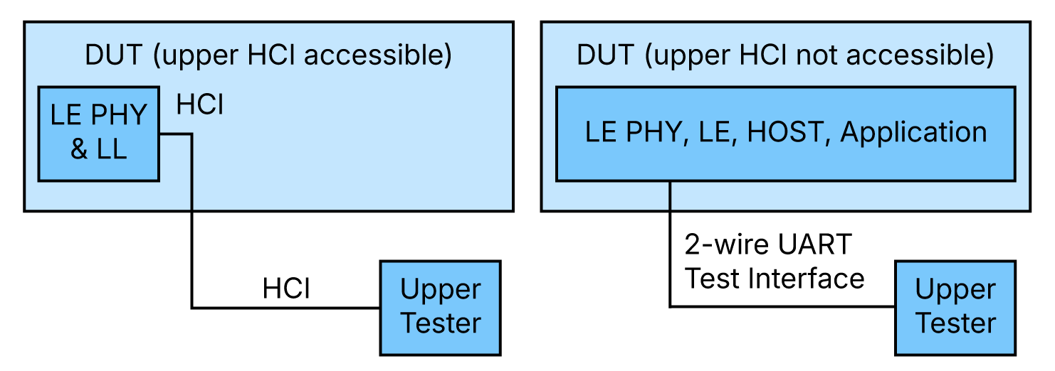
Figure 6.1.1 Setup alternatives for RFPHY Test modes
This methodology works effectively during the design and development phases when a physical I/O port is readily available. However, a significant limitation arises once the Bluetooth® LE solution is integrated into a final product. In this state, the physical control interface often becomes inaccessible, severely restricting the options for post-production or over-the-air (OTA) conformance testing. Furthermore, the presence of a wired connection can sometimes influence the device’s RF characteristics, potentially skewing test results.
6.1.2 The shift to Unified Test Protocol
To address the limitations of DTM, the Bluetooth® Core Specification introduces the Unified Test Protocol (UTP). This new test mode is designed as an equivalent alternative to DTM, with the critical advantage of supporting an OTA transport, thereby eliminating the dependency on a physical control interface. UTP enables RF PHY tests equivalent to those conducted with DTM, ensuring full specification compliance even when a physical I/O port is inaccessible. Additionally, UTP enables the performance of BER receiver measurements, thereby extending beyond basic PER measurements. This provides a better understanding of the receiver’s performance.
6.2 Technical details
6.2.1 UTP architecture and messaging
A typical UTP test scenario follows a defined sequence of messages between the Upper Tester and the IUT. The Upper Tester initiates the process by querying the IUT’s supported UTP features. This may be followed by an optional reset of parameters and the configuration of the IUT for a specific transmitter or receiver test. The test is then started, executed, and subsequently stopped, with the IUT providing detailed reports back to the tester.
All UTP messages follow a standardized Type-Length-Value (TLV) format. The Type field (1 octet) indicates the message type, the Length field (2 octets) specifies the size of the payload, and the Value field (Length octets) contains the actual message payload. This TLV structure provides a flexible and extensible framework for a variety of messages.
All UTP messages are categorized into three main types: Configuration, Control, and Report.
Configuration messages
Configuration messages are sent by the tester to set up the IUT’s test parameters before a test begins. They provide granular control over the test environment, ensuring the IUT is correctly configured for the desired test scenario. A complete list of these messages includes:
- UTP_Set_RF_Channel: Specifies the RF channel on which the test will be conducted
- UTP_Set_Packet_Payload: Sets the type of payload to be used in test packets (e.g., pseudo-random, all 1s, and all 0s)
- UTP_Set_Payload_Length: Sets the length of the test data payload
- UTP_Set_PHY: Configures the PHY (e.g., LE 1M, LE 2M, and LE Coded) to be used for the test
- UTP_Set_Modulation_Index: Sets the modulation index for the transmitter test
- UTP_Set_CTE_Length: Specifies the length of the Constant Tone Extension (CTE) for angle-of-arrival (AoA) or angle-ofdeparture (AoD) testing
- UTP_Set_CTE_Type: Sets the type of CTE to be used (e.g., AoA and AoD)
- UTP_Set_CTE_Slot_Durations: Defines the slot durations for the CTE
- UTP_Set_CTE_Antenna_IDs: Specifies the antenna pattern or IDs to be used for the CTE
- UTP_Set_Packet_Count: Sets the number of test packets to be sent or received
- UTP_Set_Tx_Power_Level: Adjusts the transmit power level of the IUT
- UTP_Set_OTA_Exclusion_Period: Configures the exclusion period for over-the-air tests
- UTP_Set_Vendor_Specific_Data: A vendor-specific message for proprietary configuration
Control messages
Control messages are used to manage the overall test flow, including initiating, terminating, and querying the status of the IUT. They serve as the primary commands for directing the test sequence and can be categorized based on their direction.
- Control messages sent by the Lower or Upper Tester: These messages instruct the IUT to perform specific actions
- UTP_Query_Supported_Features: Requests the IUT to report the UTP features it supports
- UTP_Reset: Resets the IUT to its default test configuration
- UTP_Start_Test: Initiates a previously configured transmitter or receiver test
- UTP_Stop_Test: Terminates the current test and instructs the IUT to report its results
- Control messages sent by the IUT: These messages are sent in response to commands or to indicate the state of a test
- UTP_Accept: Acknowledges a command, indicating it was accepted
- UTP_Reject: Signals that a command was rejected due to an error
- UTP_Reset_Accept: Acknowledges a reset command
- UTP_Test_Ended: Notifies the tester that a test has finished
Report messages
Report messages are sent from the IUT to the tester to provide feedback and test results. They are essential for gathering data and verifying the IUT’s performance against the specification. A complete list of these messages includes:
- UTP_Report_Supported_Features: Sent in response to a query, this message details the UTP features and capabilities of the IUT
- UTP_Report_IQ_Samples: Used for advanced testing, this message provides I and Q sample data from the IUT’s receiver
- UTP_Report_Receiver_Quality_Counters: Provides statistics from a receiver test, such as the number of received packets and other quality metrics
- UTP_Report_Vendor_Specific_Data: A vendor-specific message for reporting proprietary data
6.2.2 UTP transport options and specific commands
UTP’s versatility is highlighted by its ability to operate over three different transport interfaces: 2-wire UART, HCI, and OTA.
UTP 2-wire UART mode
Like DTM, UTP can operate over a 2-wire UART physical transport interface. This enables a seamless transition from DTM to UTP for test setups that already utilize this interface. UTP messages are encapsulated and exchanged over the UART connection between the Upper Tester and the IUT.
UTP HCI mode
When UTP operates over the HCI transport, specific HCI commands and events are used to facilitate testing. A Host can send a UTP message to the Controller using the HCI_LE_UTP_Send command, while the Controller notifies the Host of a received UTP message via the HCI_LE_UTP_Receive event. Additionally, the HCI_LE_Enable_UTP_OTA_Mode command enables the Host to activate OTA UTP mode on the Controller.
UTP OTA mode
Over-the-air (OTA) transport is the most significant enhancement of UTP. In this mode, both control messages and RF PHY test packets are exchanged wirelessly over the 2.4 GHz RF interface. This eliminates the need for a physical test interface, as the tester controls the IUT through the same radio link that is being tested.
A Controller uses the UTP OTA mode procedure to enter the RF PHY test mode. The Central or Peripheral can initiate this procedure at any time after entering the connection state by sending an LL_OTA_UTP_IND PDU. The procedure is considered complete when the Link Layer acknowledgment for this PDU is sent or received. UTP messages are then transported using these LL_OTA_UTP_IND PDUs.
LL_OTA_UTP_IND PDU format
The LL_OTA_UTP_IND PDU has the following format:
- Opcode (1 byte): Identifies the type of UTP message.
- Transaction_ID (1 byte): An identifier used to pair request and response messages.
- UTP_Message (Variable): Carries the actual UTP message, which follows a Type-Length-Value (TLV) structure. This allows the message to contain any UTP message type, such as a Configuration or Control message, providing a high degree of flexibility and extensibility.
Security and encryption requirements
The versatile format of the LL_OTA_UTP_IND PDU allows UTP messages to be efficiently encapsulated and transmitted across different test scenarios.
A crucial security and integrity check is performed for UTP OTA. UTP PDUs shall be processed only if all the following conditions are met:
- The ACL is encrypted
- The OTA UTP mode feature is supported by the Controller
- OTA UTP mode is enabled on the IUT
If the ACL is not encrypted when a UTP PDU is received, the Controller must immediately reject the PDU by sending an LL_REJECT_EXT_IND PDU with the error code Insufficient Security (0x2F). Similarly, if OTA UTP mode is not enabled when a UTP PDU is received, the Controller must reject it by sending an LL_REJECT_EXT_IND PDU with the error code Command Disallowed (0x0C).
This mechanism ensures that the test mode can only be entered under secure and pre-configured conditions.
6.2.3 OTA transmitter test example
In an OTA transmitter test, the Upper Tester instructs the IUT to begin transmitting RF PHY test packets. The IUT continues to transmit these packets on a configured frequency until either a specified packet count is reached, or the Lower Tester sends a command to end the test.
The purpose of this test is to verify the IUT’s transmitter characteristics, such as transmit power, power density spectrum, and modulation accuracy, without a physical connection affecting the measurements. Figure 6.2.3 shows an example of an OTA transmitter test.

Figure 6.2.3: OTA transmitter test example: Lower Tester ends the sequence early, packet count reached
6.2.4 OTA receiver test example
In an OTA receiver test, the Upper Tester initiates the test, and the Lower Tester begins transmitting RF PHY test packets on a configured frequency. The Lower Tester transmits packets over a number of connection intervals required to satisfy the configured packet count.
The IUT listens to these packets and reports on the quality of reception. This test evaluates the IUT’s receiver performance, including sensitivity and blocking characteristics. Figure 6.2.4 shows an example of an OTA receiver test.

Figure 6.2.4: OTA receiver test example
6.3 Summary
The introduction of the Unified Test Protocol represents a significant advancement in Bluetooth® LE RF PHY conformance testing. By providing a comprehensive set of messages and control mechanisms, UTP offers a more flexible and powerful solution than the traditional DTM. Most importantly, its support for OTA transport, combined with well-defined procedures and Link Layer security measures, addresses the long-standing limitation of physical interface dependency.
UTP enables more practical and accurate testing of devices in their final form factor, expanding the scope of conformance testing to scenarios that were previously difficult or impossible to manage.
7. Conclusion
Bluetooth® Core 6.2 introduces new features that enhance device responsiveness, strengthen security, and improve communication and testing capabilities. From significantly reduced connection intervals that enable faster, more responsive interactions to advanced security features that defend against sophisticated RF amplitude attacks, these enhancements address the evolving needs of modern wireless ecosystems. Standardized isochronous communication over USB simplifies Bluetooth® LE Audio integration, while upgraded testing features ensure more flexible, secure, and comprehensive RF validation. Together, these advancements position Bluetooth® technology for continued innovation across a wide range of industries and use cases.
8. References
| Item | Location |
|---|---|
| Bluetooth® Core Specification v6.2 | https://www.bluetooth.com/specifications/specs/core-specification-6-2/ |
| Bluetooth® Channel Sounding technical overview paper | https://www.bluetooth.com/channel-sounding-tech-overview/ |