Bluetooth® High Data Throughput technical overview
| Version: | 1.0 |
| Publication date: | 3 November 2026 |
| Author: | Alfredo Perez |
1. Introduction
Bluetooth® is a versatile, widely adopted wireless technology that enables a broad range of applications and use cases across audio, wearables, human interface devices, smart home, industrial, automotive, and many other market segments. Its success is rooted in fundamental qualities like energy efficiency, interoperability, ease of use, and a continuous evolution of its capabilities and performance. Together, these qualities have allowed Bluetooth technology to scale, to enable and support robust development and product ecosystems, and to earn the trust of companies and consumers worldwide.
Yet, the landscape of wireless applications is also evolving. Systems in which Bluetooth connectivity has long thrived are becoming more sophisticated, generating, processing, and managing far more data. In the audio market, for example, solutions are moving toward higher-fidelity and multi-stream use cases that demand greater data capacity and faster communication to deliver seamless performance and experiences. For Bluetooth, this creates a need to support increasing throughput requirements that extend beyond its existing capabilities. To address this need, the Bluetooth Special Interest Group (SIG) is introducing a major architectural and performance enhancement to Bluetooth LE known as Bluetooth® High Data Throughput (HDT).
Since the introduction of the LE 2M PHY in 2016, the maximum PHY bitrate supported by Bluetooth LE has been 2 Mbps. With Bluetooth® HDT, the performance and capabilities of Bluetooth LE are significantly expanded, increasing the maximum PHY bitrate by nearly a factor of four while also delivering improved capacity, energy efficiency, and reliability. Overall, Bluetooth HDT reduces data transfer times, supports more demanding application workloads, and creates headroom for future innovations, establishing a foundation for the Bluetooth technology roadmap to continue evolving with the needs of modern applications.
This document provides a high-level technical overview of Bluetooth High Data Throughput, aimed at helping readers develop a basic understanding of this major Bluetooth technology milestone.
2. Background
In principle, the primary benefit of increasing throughput in a communication system is straightforward: Higher throughput reduces the time needed to transfer a fixed amount of data between devices or, conversely, allows more data to be exchanged within a given time interval. However, completing transmissions in less time provides other valuable advantages. For example, it implies that the transmitter and receiver in the system are active for shorter periods, which may translate to reduced energy consumption. Also, it helps free up airtime that can be reallocated for additional communication links or for other collocated systems to use via managed coexistence mechanisms.
In practice, increasing the throughput of a communication system involves acting on three fundamental design variables: bandwidth (BW), signal-to-noise ratio (SNR), and spectral efficiency. Shannon’s theorem1 formalizes how BW and SNR influence channel capacity, showing that capacity increases linearly with BW and logarithmically with SNR. However, approaching the capacity predicted by Shannon’s theorem depends on achieving high spectral efficiency. Spectral efficiency is a measure of how many bits per second can be transmitted per Hertz of bandwidth available (bps/Hz). In real systems, spectral efficiency depends on physical layer design choices such as modulation order, coding efficiency, symbol rate, and other implementation factors that influence how effectively bandwidth can be utilized.
Bluetooth technology has been architected around principles prioritizing simplicity, reliability, efficient operation in globally available unlicensed frequency bands, and, in the case of Bluetooth LE, energy efficiency. Because of this, Bluetooth LE radios have been developed with physical layers based on Gaussian Frequency Shift Keying (GFSK), a simple, robust, and low-complexity modulation scheme, and with limited or no forward error correction. The simplicity of GFSK PHYs has served and will continue to serve Bluetooth well, but their spectral efficiency is low and, therefore, they offer limited options for increasing throughput significantly.
Referring again to Shannon’s theorem, one approach to improve the throughput of GFSK PHYs could be to increase their BW, but that is impractical given constraints of the 2.4 GHz ISM band and, more importantly, the architectural and energy-efficiency implications this would entail. Another approach could be to increase their SNR, but this also presents challenges. Transmit power is constrained by regulatory limits, while the room for improving receiver noise performance is marginal. Hence, the more viable option is to tackle spectral efficiency limitations, and this is precisely what Bluetooth® HDT does.
Bluetooth HDT introduces a new PHY that operates with the same channel bandwidth and spacing used by Bluetooth LE. More importantly, however, the PHY incorporates coherent higher-order modulation schemes and forward error correction (FEC) to enable high spectral efficiency. Bluetooth HDT also introduces new packet formats and link layer updates to support adaptive modulation and link adaptation, improving resilience against multipath or fading while helping meet the spectral efficiency targets of the new PHY. Furthermore, Bluetooth HDT defines new HCI commands and events to support the new HDT capabilities and introduces related security enhancements.
The chapters that follow provide a detailed overview of Bluetooth HDT based on its building blocks. The document guides the reader through the main components of Bluetooth HDT in the following order: architecture, Physical Layer (PHY), packets, Link Layer (LL), encryption, Host Controller Interface (HCI), and miscellaneous, which encompasses updates to ISOAL and Host layers of the stack.
3. Bluetooth® HDT architecture
Prior to diving into the technical aspects of Bluetooth HDT, it is useful to have a top-level view of the benefits and value that HDT brings to Bluetooth technology:
- It increases the maximum supported bitrate to 7.5 Mbps
- It delivers significant wireless performance enhancements, not just a throughput increase
- It expands the capacity and capabilities available to support existing Bluetooth applications and use cases
- It enables new, richer use cases like high-resolution and lossless audio
These benefits are realized through architectural innovations and enhancements introduced to the Bluetooth Core Specification. This section provides an overview of the key architectural principles for Bluetooth HDT.
3.1 Overview
The essential architectural goals behind Bluetooth HDT are to increase throughput significantly while maintaining backward compatibility with Bluetooth LE, achieve the performance needed to support higher bitrates efficiently and reliably (e.g., better sensitivity, higher resilience to interference, and robustness against multipath and fading conditions) and accomplish these goals with a manageable level of implementation complexity compared with previous Bluetooth systems.
A simple way to visualize the innovations and enhancements introduced by Bluetooth HDT is by mapping them to the structure of the Bluetooth LE stack. To illustrate this, Figure 3.1 shows a simplified view of the Bluetooth LE stack with the layers undergoing updates to enable HDT marked with a star.
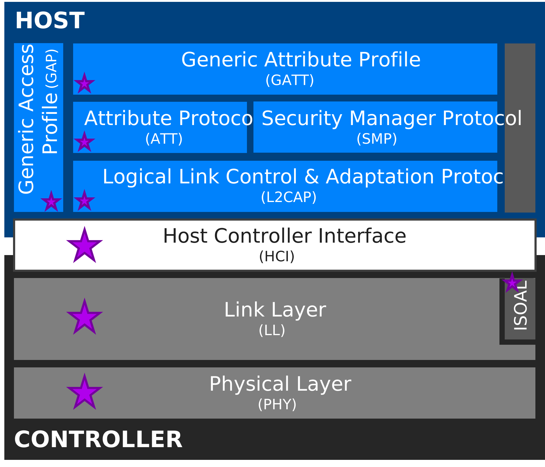
Figure 3.1 – Bluetooth LE stack updates for HDT
Stepping one level lower to obtain a mid-level view, the main innovations and enhancements at each stack layer to enable or support HDT can be summarized as follows:
Physical Layer (PHY)
- A new, non-GFSK PHY based on higher-order coherent modulation schemes and forward error correction with puncturing
- Support for five different bitrates up to 7.5 Mbps
Link Layer (LL)
- A new packet structure
- Three new packet format variants
- A new procedure for HDT Configuration information exchange
- Updated procedures for PHY Update and for CIS Creation information exchange
- HDT encryption and longer MIC sizes
Host Controller Interface (HCI)
- New commands to set parameters, read payloads, enable testing, and more
- New events to report HDT rates, encryption enablement, and more
Small updates to the Isochronous Adaptation Layer (ISOAL) and to the Host layers of the Bluetooth LE stack are also made. Host-layer updates primarily support the verification and enforcement of MIC length requirements, while updates to ISOAL support the transport of larger data payloads enabled by the new PHY.
The final, low-level view with higher technical resolution is covered in the sections that follow in this paper, with the Physical Layer in Section 4, packets in Section 5, Link Layer in Section 6, encryption in Section 7, HCI in Section 8, and miscellaneous (e.g., ISOAL and Host layers) in Section 9.
3.2 Architectural principles
Bluetooth High Data Throughput (HDT) is an extension of Bluetooth LE, not a separate or parallel technology. It introduces new capabilities while preserving the architectural framework used with Bluetooth LE (e.g., same physical channels, logical transports, logical links, etc.).
HDT is backward compatible with existing GFSK-based Bluetooth LE devices, operating in the 2.4 GHz ISM band and using the same channelization. More specifically, a connection is always established using a GFSK PHY, after which devices can optionally switch to the HDT PHY. HDT is designed such that devices can dynamically transition between GFSK PHYs and the HDT PHY within an LE connection, allowing HDT-capable devices to coexist with and fall back to legacy Bluetooth LE operation as needed. It must be noted that the initial version of HDT does not support any form of advertising.
Instead of increasing BW or SNR, HDT achieves higher throughput through increased spectral efficiency. This is realized through the introduction of a new PHY based on higher-order coherent modulation schemes combined with forward error correction and puncturing.
HDT introduces a new packet structure that supports high data rates efficiently, and defines multiple packet formats useful to balance overhead, robustness, and efficiency in different operating scenarios. One packet format in particular (PF1) allows a single HDT packet to carry multiple payloads, potentially from different applications or logical links, and to split payload data into blocks. This flexibility enables aggregation, efficient radio usage, optimized retransmissions, and additional benefits discussed later in this paper.
HDT is designed to enable reliable packet interpretation at high data rates, adaptive modulation, and dynamic, per-packet rate adaptation. The PHY maximizes the probability that control information for a packet can be decoded, even under poor channel conditions, by always modulating it with the most robust method and by managing and processing control information separately from payload data in the packet structure.
To improve resilience against interference, multipath, and fading, HDT incorporates PHY-aware mechanisms within the packet structure. Packets transmitted using the HDT PHY may be divided into PHY Intervals, each bounded by known sequences useful to support channel tracking and phase correction during reception. This approach allows mid-packet receiver resynchronization, enhancing reliability at high data rates while supporting adaptive modulation and dynamic rate selection.
For clarity, the segmentation of data into blocks and PHY Intervals is independent. The key distinction is that blocks are a logical payload-segmentation mechanism, whereas PHY Intervals are a PHY-level transmission segmentation mechanism. In PF1, each payload, including its MIC if encrypted, can be divided into blocks, with each block protected by its own CRC. The resulting Payload Zone can then be divided at the PHY layer into fixed-length symbol streams called PHY Intervals, each of which is followed by a terminating symbol sequence and, except for the final interval, a PHY Interval Training Sequence (PITS). Hence, block boundaries and PHY Interval boundaries serve different purposes and do not represent the same segmentation. Blocks support payload organization, error detection, and selective retransmission, while PHY Intervals support robust over-the-air transmission through manageable decoding intervals and periodic receiver retraining.
HDT also introduces a Physical Channel Address (PCA) mechanism to uniquely identify physical links. This enhancement benefits dense device environments by providing a large address space while preserving the role of the Access Address on GFSK PHYs. The separation of physical channel identification mechanisms ensures that HDT packets can be efficiently filtered and correctly associated with active connections, even in congested RF conditions. A physical channel can have more than one PCA, with each being used on a different PHY.
Finally, security considerations are incorporated into HDT without altering Bluetooth LE’s security model. HDT introduces support for longer Message Integrity Check (MIC) sizes at the Link Layer, enhancing data authentication for longer payloads. Also, it supports the Encryption Key Schedule (EKS) feature, which introduces a new framework for establishing and managing encryption keys in Bluetooth LE. EKS generates session keys and other cryptographic values needed to protect an encrypted connection and enables encryption key refreshing during an active connection. For HDT, EKS facilitates the coordination of encryption key and MIC size changes when transitioning between GFSK and HDT PHYs, without requiring the connection to be disconnected or encryption to be restarted.
Clearly, the introduction of a new PHY to enable HDT means that implementing HDT requires new hardware and, therefore, a new radio. While Bluetooth HDT will be backward compatible with GFSK-based Bluetooth devices, GFSK-only devices will not be able to support the new, higher throughput levels.
4. Bluetooth® HDT Physical Layer (PHY)
The Bluetooth HDT Physical Layer (PHY) defines the radio-level mechanisms that enable higher throughput. It is specified as an optional Bluetooth LE PHY that coexists with the mandatory LE 1M PHY and the optional LE 2M, LE 2M 2BT, and LE Coded PHYs based on GFSK modulation. The HDT PHY operates in the 2.4 GHz ISM band and uses the same channel bandwidth and spacing as GFSK-based PHYs.
This section zooms into three fundamental areas for the HDT PHY: Modulation and bitrates, bitstream processing, and synchronization and robustness.
4.1 Modulation and bitrates
Modulation is the process of mapping information onto a physical carrier signal for communication. In Bluetooth LE PHYs, this mapping has traditionally been performed using Gaussian Frequency Shift Keying (GFSK), where information is conveyed through small shifts in the frequency of the RF carrier signal, encoding one bit of data in every symbol transmitted.
The Bluetooth HDT PHY introduces the use of three coherent modulation schemes that represent data as complex-valued symbols and encode multiple bits per symbol:
- π/4 Quadrature Phase-Shift Keying (π/4 QPSK)
- 8 Phase-Shift Keying (8PSK)
- 16 Quadrature Amplitude Modulation (16QAM)
These modulation schemes convey information through shifts in the phase of the RF carrier or, in the case of 16QAM, through shifts in both the phase and amplitude of the carrier simultaneously. During communication, transmitted symbols are constituted by two signal components referred to as in-phase (I) and quadrature (Q) where, by design, each I/Q signal pair represents a specific symbol value. The collection of all possible I/Q signal pairs for a given modulation scheme, mapped as points on a complex plane, is referred to as a constellation diagram. Figure 4.1 shows the constellation diagrams for π/4 QPSK, 8PSK, and 16QAM.
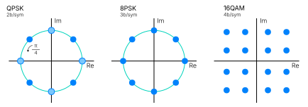
Figure 4.1 – Constellation diagrams for HDT modulation schemes
Coherent modulation implies that the scheme supports frequency and/or phase locking between the transmitting and receiving ends of the communication system, which is beneficial for synchronization and to reduce the probability of errors. With non-coherent schemes, there is no such locking, making the system simpler but generally more susceptible to errors than coherent modulation under comparable conditions. HDT uses coherent modulation.
The HDT PHY combines the new modulation schemes with convolutional forward error correction (FEC) and puncturing. FEC is implemented based on convolutional coding with a ½ coding rate, and puncturing is used to enable higher coding rates. Overall, HDT supports five different bitrates, all operating at a fixed symbol rate of 2 Msym/s. Architecturally, the different bitrates are treated as modes of a single PHY. Table 4.1 gives a summary of relevant characteristics for each of the bitrates.
Table 4.1 – HDT rates
| HDT Rate | PHY bitrate | Modulation scheme | Bits per symbol | Controller implementation |
|---|---|---|---|---|
| HDT2 | 2 Mbps | π/4 QPSK | 2 | Mandatory |
| HDT3 | 3 Mbps | π/4 QPSK | 2 | Mandatory |
| HDT4 | 4 Mbps | 8PSK | 3 | Mandatory |
| HDT6 | 6 Mbps | 16QAM | 4 | Optional |
| HDT7.5 | 7.5 Mbps | 16QAM | 4 | Optional |
Rates up to HDT4 are mandatory while rates above HDT4 are optional. If HDT6 is supported, HDT7.5 is optional. If HDT7.5 is supported, then HDT6 is also mandatory. For each rate, if receive (Rx) is supported, then transmit (Tx) is optional; if Tx is supported, then Rx is mandatory.
For complete details, including symbol coordinate tables, implementation requirements, etc., refer to the relevant sections of the Bluetooth Core Specification 7.0.
4.2 Bitstream processing
The conversion of digital data into symbols to transmit and receive over a wireless communication link involves managing the flow of such data through a well-structured processing model known as the bitstream processing pipeline.
The PHY specification for Bluetooth HDT defines a deterministic bitstream processing pipeline for HDT traffic illustrated by the block diagram in Figure 4.2. It is an extension of the pipeline found in GFSK-based LE PHYs with the additions of interval spacing and puncturing. All processing stages are always followed in the same order, regardless of the chosen PHY rate.
On the transmit side, raw data bits sequentially pass through encryption (if enabled), Cyclic Redundancy Check (CRC) generation, data whitening, interval spacing, Forward Error Correction (FEC) encoding, and puncturing. Resulting bit sequences are then converted to modulated I/Q signals representing symbols to be transmitted over the air. It should be noted that interval spacing is only applicable when HDT packet format 1 (PF1) is used (to divide the payload bitstream and support multiple PHY intervals). The complete packet structure and format definitions are covered in Section 5.
On the receive side, symbols received pass through the corresponding inverse processing stages for the extraction of the data bits sent (except puncturing).

Figure 4.2 – HDT bitstream processing pipeline
All stages in the pipeline are common across HDT bitstream processing, but the PHY applies distinct processing rules for control information versus payload data. Control information is treated separately because the new HDT packet structure defines a Control Header that is separated from the payload-carrying sections. This separation in the packet structure is an architectural decision to support critical PHY-level performance targets as explained next.
A receiver must successfully decode the Control Header to be able to extract the subsequent high-throughput payload in the packets. To maximize the probability that control information can be decoded, even under poor channel conditions, control information is always modulated with π/4 QPSK, the most robust modulation scheme available in HDT. For that, the bitstream process for control data forms its own symbol stream, omitting whitening and using a ½ coding rate for FEC with no puncturing. This helps improve packet interpretation reliability at higher data rates.
By processing control information ahead and separately from the payload, dynamic data rate adaptation on a packet-by-packet basis is also enabled. More specifically, the Control Header of a packet carries details related to packet format, selected data rate, PHY interval configuration, etc., for the payload-carrying sections that follow. When control information is received and decoded ahead, it allows configuring the receiver to the right demodulation and decoding settings to process the payload and, more importantly, to modify them for every packet as needed. It also allows preparing the receiver to support mid-packet receiver resynchronization when transmitted payload data is split into multiple PHY intervals to improve link robustness in fading or time-varying channels.
For reference, Table 4.2 provides a high-level summary of the role and relevant facts to understand about each of the stages in the bitstream processing pipeline.
Table 4.2 – HDT bitstream pipeline stages summary
| Bitstream stage | Summary |
|---|---|
| Encryption | • Ensures data confidentiality by applying cryptographic transformation before further processing • Applied to payload when encryption is active (e.g., PDU Header and Payload Zone in HDT packets) • Follows the HDT encryption framework detailed in Section 7 • Occurs early in the pipeline to maximize security coverage while maintaining compatibility with subsequent error detection and correction stages |
| CRC | • Calculated over payload blocks (after encryption if applied) • Provides error detection for both random and burst errors |
| Whitening | • Randomizes bit patterns and breaks up long sequences of identical bits, ensuring sufficient transitions in a stream for reliable clock recovery • Applied only to payload (e.g., PDU Header and Payload Zone in HDT packets); starts at the first PDU Header bit after the Control Header and ends at the last data bit of the Payload Zone in a packet |
| Interval spacing | • Exclusive to HDT Packet Format 1 • Enables division of Payload Zone into fixed-length transmission intervals • Enables periodic insertion of PHY Interval Training Sequences (PITS) for channel estimation refresh |
| FEC encoding | • Applied to all transmitted data (e.g., Control Header, PDU Header, and Payload Zone in HDT packets) • Uses non-systematic, non-recursive convolutional encoding with ½ coding rate as base (K=6 constraint length) • Provides error-correction capability for both random and short burst errors |
| Puncturing | • Selectively removes specific bits from the FEC-encoded bitstream • Different puncturing patterns combined with single, base 1/2 convolutional encoder produce multiple data rates that can be adaptively changed based on channel conditions • Puncturing patterns for HDT maximize free distance for each target data rate, a parameter that measures robustness of a code rate against noise • PF1 punctures the Payload Zone but not the PDU Header; PF0 punctures both |
For completeness, a summary of puncturing-related parameters for each HDT data rate is included in Table 4.3. Note that HDT3 and HDT6 share the same puncturing pattern and code rate, but they use different modulations.
Table 4.3 – HDT puncturing parameters summary
| HDT Rate | Puncturing pattern (1=retained, 0=omitted) | Puncturing efficiency (Ep) | Effective code rate |
|---|---|---|---|
| HDT2 | [1 1] | 1.0 (2/2) | 1/2 |
| HDT3 | [1 1 0 1 0 1] | 0.667 (4/6) | 3/4 |
| HDT4 | [1 1 0 1] | 0.75 (3/4) | 2/3 |
| HDT6 | [1 1 0 1 0 1] | 0.667 (4/6) | 3/4 |
| HDT7.5 | [1 1 0 1 1 0 1 0 1 0 0 1 0 1 0 1 1 0 1 0 0 1 0 1 0 1 1 0 0 1] | 0.933 (28/30) | 15/16 |
4.3 Synchronization and robustness
The higher-order coherent modulation schemes used for HDT are inherently more sensitive to phase or frequency noise, drift, and channel variations in comparison to GFSK. Because of that, the HDT PHY introduces several mechanisms designed to support accurate synchronization and robust decoding at high data rates, enabling the spectral efficiency gains desired and offering performance reliability in challenging wireless environments presenting channel degradation, fading conditions, or multipath distortion.
Table 4.4 provides a high-level summary of the role and relevant facts to understand about each of these mechanisms, which include training sequences (short and long), guard intervals, terminating symbols, PHY intervals, and PHY interval training sequences (PITS).
Table 4.4 – HDT training and synchronization mechanisms summary
| Mechanism | Summary |
|---|---|
| Short Training Sequence (STS) | • Enables rapid initial packet detection, coarse timing alignment, and AGC settling • Appears in the Preamble, at the very start of every HDT packet and repeats multiple consecutive times • Establishes reliable entry point into the packet |
| Long Training Sequence (LTS) | • Enables fine timing alignment, frequency offset estimation/correction, and initial channel estimation • Appears also in the Preamble of HDT packets, after STS, and repeats several consecutive times • Prepares receiver for coherent demodulation |
| Guard Interval (GI) | • Time buffer to absorb transient effects due to switching between training sequences, symbol streams, and modulation or coding boundaries • Appears explicitly in the Preamble, between STS and LTS, and implicitly throughout the packet via terminating symbols • Allows receiver filters and timing loops to settle before fine LTS synchronization, and ensures clean transitions between symbol streams |
| Terminating Symbols | • Create explicit boundaries between symbol streams and absorb transient effects at symbol stream transitions • Appear at the end of every independently processed symbol stream in a packet (e.g., after Control Header, after PDU Header Zone, after each PHY Interval in packet format 1, etc.) • Allow FEC decoder to flush state and reset before next segment/stream begins • Especially important for packet format 1 to help limit error propagation between independently processed symbol streams |
| PHY Intervals | • Allow breaking long payloads into smaller and easier to manage decoding units • Appear in the Payload Zone of packet format 1 (PF1) HDT packets only • Enable periodic channel tracking and retraining between intervals within long PF1 payloads |
| PHY Interval Training Sequence (PITS) | • Enable mid-packet retraining to refresh phase and channel estimation for robust reception of payloads segmented into multiple PHY intervals • Appear in the Payload Zone of packet format 1 (PF1) HDT packets only |
Together, the synchronization and robustness elements in the HDT PHY provide a layered framework to enable reliable, high-throughput operation. First, initial acquisition is achieved through robust Preamble-based training with STS and LTS. Then, clean transitions and explicit decoding boundaries are established and enforced with the help of guard intervals and terminating symbols. Finally, mid-packet resynchronization is enabled via PHY Intervals and their associated training sequences to adapt to changing channel conditions when working with longer packets and higher data rates. This structured approach ensures resilience to fading, phase drift, and multipath effects, allowing HDT to deliver substantial throughput gains with robustness and efficiency.
5. Bluetooth® HDT Packets
Bluetooth® HDT defines a new packet structure that bridges the PHY-level capabilities introduced in the previous section with the Link Layer intelligence and procedures presented later in Section 6 to deliver higher throughput and robust performance practically and reliably.
This section covers the HDT packet structure and packet formats, reviewing at a high level each of their zones, portions, and/or fields.
5.1 Overview of HDT packet structure
As illustrated in Figure 5.1, the HDT packet structure is composed of four zones: Preamble, Control Header, PDU Header Zone, and Payload Zone. The Preamble and the Control Header are mandatory and must be present in all HDT packet formats. The presence of the PDU header and the Payload Zones depend on the packet format selected.

Figure 5.1 – HDT Packet structure
The depth of the HDT packet structure is such that the PDU header and Payload Zones carry information with four layers of detail. For communication clarity, naming fields related to the highest layer of the packet are referred to as zones, naming fields related to the next lower layer are referred to as portions, and naming fields for the bottom two layers are simply called fields. As an example, one would state that the PDU Header Zone of the HDT packet structure contains a TX portion where the LL Descriptor field is specified and includes the LLID field with the Link Layer ID for each payload. The advantage of using this naming approach will become evident later in this section.
In the big picture, the role and composition of each zone in the HDT packet structure can be summarized as follows.
Preamble
- Allows the receiver to identify the beginning of an incoming packet, to synchronize with the transmitter and correct for timing, frequency, or phase offsets and to perform channel estimation to mitigate amplitude and phase distortion introduced by the wireless channel
- Consists of nine repetitions of the short training sequence (STS), followed by a guard interval (GI), followed by two repetitions of the long training sequence (LTS)
Control Header
- Allows the receiver to associate the incoming packet with the correct physical link, to decode essential control information reliably (with dedicated header error check), and to do this before any payload demodulation or processing occurs
- Consists of seven fields conveying control details including the HDT Packet Address (HPA-A), packet format, rate selection, etc.
PDU Header Zone
- Carries protocol-level metadata needed for the receiver to interpret and manage the payload data that follows in the Payload Zone, including packet type (e.g. transport, link ID, etc.), payload length, etc.
- Consists of five portions: Initial, RX, TX, Extended Header, and Header Error Correct (HEC-P)
Payload Zone
- Carries the payload blocks transmitted (with their Message Integrity Check when encrypted) and the CRCs, organized according to the packet format used
- Details covered in packet format sections
5.2 HDT packet formats
To enable efficiency and flexibility across different communication scenarios, HDT defines three packet formats: short, packet format 0 (PF0), and packet format 1 (PF1).
Short Format
The short packet format is a minimal overhead structure optimal for cases where there is no data to be transmitted. It reduces airtime usage (e.g., always exactly 69 us long) and is useful for synchronization between devices and to exchange acknowledgments. Structurally, the short format consists of only the Preamble and the Control Header as illustrated in Figure 5.2

Figure 5.2 – HDT packet, short format
Packet Format 0 (PF0)
Packet format 0 is a low complexity structure optimal for transmitting an unsegmented payload in a single block. Structurally, PF0 consists of the Preamble, the Control Header, the PDU Header Zone, and the Payload Zone (which may become optional for an empty payload).
The single block in the Payload Zone will include a MIC if encrypted. The Payload Zone also includes a CRC for error detection that is calculated on the sum of the entire PDU header, the payload block, and the MIC. Figure 5.3 illustrates the structure of PF0.

Figure 5.3 – HDT Packet Format 0 (PF0)
Packet Format 1 (PF1)
Packet format 1 is the most capable and robust structure that is optimal for transmitting large amounts of data efficiently and reliably. Structurally, PF1 consists of the Preamble, the Control Header, the PDU Header Zone, and the Payload Zone.
PF1 allows aggregating up to four different payloads in the Payload Zone (e.g. the next four payloads waiting to be transmitted), each with its MIC if encryption is enabled. Each of the payloads can be divided into blocks (1-16), with a CRC calculated for each block. All blocks, except for the last one, are the same size, but the size can be different for each payload. Figure 5.4 illustrates the structure of PF1. Subscripts M, N, and P relate to the number of blocks for payloads 0, 1, and 2 respectively.
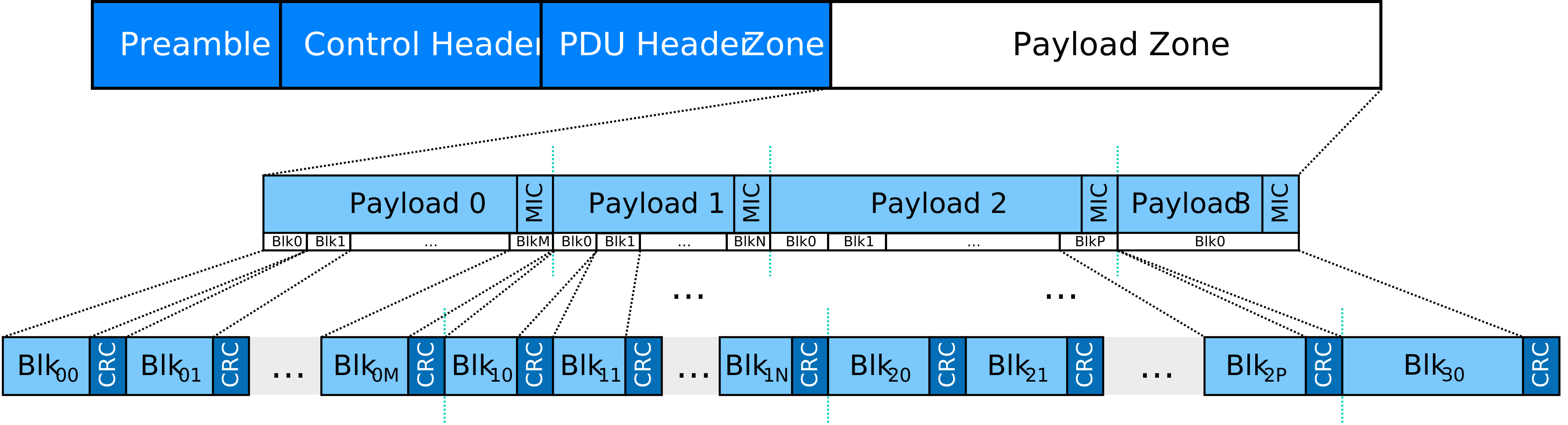
Figure 5.4 – HDT Packet Format 1 (PF1)
A block is a new payload transmission and validation unit in the HDT packet Payload Zone. Instead of treating a payload as one monolithic piece, HDT handles payload data as a sequence of blocks, with each block protected by its own CRC to allow a receiver to validate blocks independently. The fundamental benefit of this concept is the enablement of selective acknowledgment and retransmission while transmitting larger payloads/packets to enable higher throughput. Portions of the packet can be acknowledged when successfully received and, when interference corrupts part of a payload, the HDT PHY only needs to retransmit the missing or corrupted blocks, preserving successfully received blocks.
Block granularity allows supporting multiplexing and sustained throughput, complementing the ability of PF1 to aggregate up to four payloads in a packet. Block sizing for a given payload is specified in the TX portion of the PDU Header Zone.
In general, HDT uses payload numbers and a sliding payload window to manage the transmission, acknowledgment, and retransmission of payloads. In each direction of an ACL or CIS connection, the payload window contains between one and four payloads eligible for transmission or retransmission, beginning with the CurrentPayloadNumber. As payloads at the beginning of the window are acknowledged, CurrentPayloadNumber advances, moving the window forward. ExpectedPayloadNumber identifies the next payload expected from the peer device. SN and NESN carry the three least-significant bits of CurrentPayloadNumber and ExpectedPayloadNumber, respectively, allowing devices to track the state of the payload window. This payload-numbering model applies to both PF0 and PF1. PF0 can transmit or retransmit only the first payload in the window, whereas PF1 can transmit or retransmit selected blocks from payloads within the window.
To summarize, Table 5.1 provides a comparison of the three packet formats.
Table 5.1 – HDT packet formats summary
| Short | PF0 | PF1 | |
|---|---|---|---|
| Max payload | N/A | 494 octets | 8175 octets |
| Useful for | Synchronization, acknowledgments | Higher throughput | Highest throughput, efficiency and/or robustness |
| Key advantages | Reduces airtime if there is no payload data to TX, and when only consecutive whole payloads need to be acknowledged | • Simpler to implement • Lower overhead • Single payload block with MIC | • Up to four payloads in a packet • Division of payloads into blocks • Selective (block) acknowledgment • Payload blocks can spread over multiple packets • PHY Intervals, phase tracking using PITS |
Now, let’s briefly review each of the packet structure zones in more detail
5.3 Preamble
Figure 5.5 illustrates the structure and timing of the Preamble. Refer to Volume 6, Part A, Section 7.4 of the Bluetooth Core Specification for more training sequence and guard interval technical details.

Figure 5.5 – HDT packet Preamble
5.4 Control Header
Figure 5.6 shows the format and fields of the Control Header.

Figure 5.6 – HDT packet Control Header
- HPA-A (HDT Packet Address – Partial): Bits 39:24 of the full 40b HPA. Provides a partial address that allows the receiver to filter incoming packets and identify candidate physical links.
- NESN (Next Expected Sequence Number): Contains the three least-significant bits of ExpectedPayloadNumber and provides cumulative acknowledgment information for payloads received from the peer device. As acknowledged payloads advance through the payload window, NESN reflects the next payload expected from the peer device.
- PFI (Packet Format Indicator): Indicates format used for the packet. Field is dynamic and can change on a per-packet basis.
- 0: Short or Format 0; 1: Format 1
- Short can be inserted at any time
- Can switch from PF0 to PF1 at any time
- Switch from PF1 to PF0 is possible in certain circumstances
- RI (Rate Indicator): Specifies data rate for the PDU Header and Payload Zones. This field is dynamic and can change on a per-packet basis, enabling rapid PHY rate adaptation in response to channel conditions.
- 0b000: Short Format (no data zone)
- 0b001-0b101: rates from 2 Mbps to 7.5 Mbps.
- RFU (Reserved for Future Use)
- PDU Control: Content is dependent on packet format
- Short: Contains MD/CIE (More Data/Close Isochronous Event) for immediate link control, 3 RFU bits, and SNR (Signal-to-Noise Ratio) fields
- Format 0: A 9b value specifying the total length of the combined PDU Header and Payload Zones, excluding the CRC
- Format 1: Contains 6b PDU Header Zone length (excluding the HEC-P portion), 2b PHY INT indicating the number of payload symbols per PHY Interval [00: 128; 01: 256; 10: 384; 11: 512], and one RFU bit
- HEC-C (Header Error Check – Control): A 24b CRC calculated over all preceding Control Header fields and initialized with the full HPA, allowing the receiver to validate the Control Header against the applicable HPA and correctly associate the packet with the corresponding physical link.
5.5 PDU Header Zone
Figure 5.7 shows the format and portions of the PDU Header Zone.
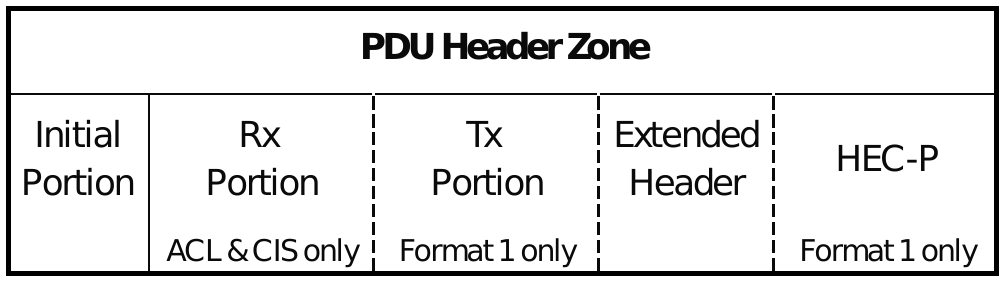
Figure 5.7 – HDT packet PDU Header Zone portions
Initial Portion
The Initial Portion is an 8b field serving as the control map and entry point for the entire PDU Header Zone. It defines the presence of optional portions and carries transport-specific control information. The interpretation of the Initial Portion depends on the transport type, as summarized in Table 5.2.
Table 5.2 – Transport-specific Initial Portion fields
| Bit | ACL | CIS | BIS |
|---|---|---|---|
| 0 | XHP (Extended Header Present) | XHP (Extended Header Present) | XHP (Extended Header Present) |
| 1 | RxPP (Rx Portion Present) | RxPP (Rx Portion Present) | Fixed 0 (No Rx Portion) |
| 2 | MD (More Data): Keeps connection event open for continued transmission | CIE (Close Isochronous Event): Signals early subevent completion | CSTF (Control Subevent Transmission Flag): Indicates BIG Control PDU coming in a later packet; set in Data PDUs |
| 3-5 | SN (Sequence Number): 3 LSBs of CurrentPayloadNumber identifying sender’s current position in the payload window | SN (Same as ACL for Data PDUs) | CSSN (Control Subevent Sequence Number) |
| 6-7 (PF0) | LLID (Logical Link ID) | LLID (Logical Link ID) | LLID (Logical Link ID) |
| 6-7 (PF1) | TxPP (Tx Portion Present) + RFU | TxPP (Tx Portion Present) + RFU | TxPP (Tx Portion Present) + RFU |
Rx Portion
The Rx Portion is present in ACL or CIS packets when selective acknowledgments are required to indicate that data sent by a peer device has been received. Its format and fields are shown in Figure 5.8. Fine-grained feedback can be provided for up to four payloads.
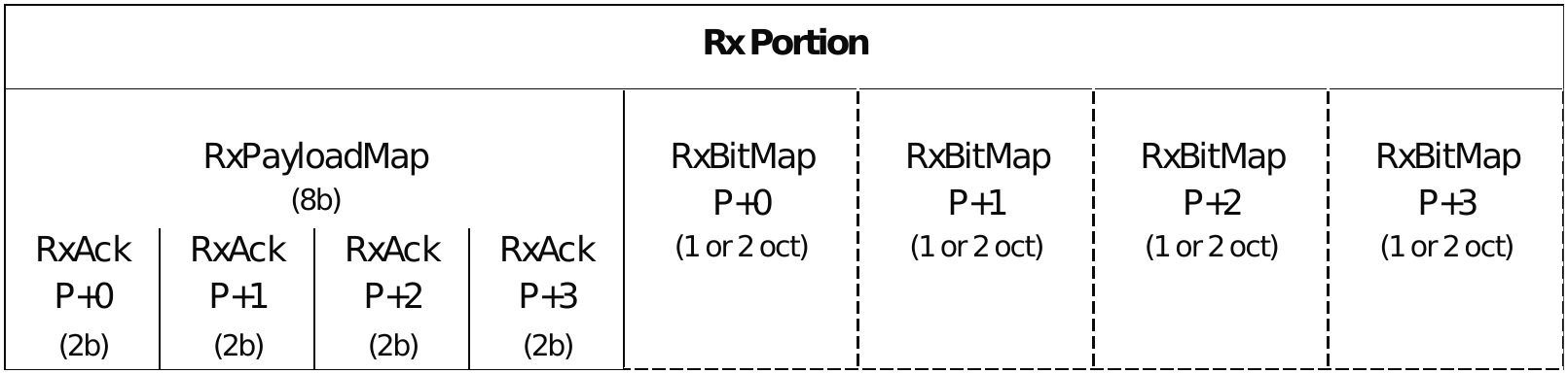
Figure 5.8 – PDU Header Zone, Rx Portion format and fields
- RxPayloadMap: Indicates which of the next four expected payloads (P+0 to P+3) are being acknowledged in this packet
- RxAck P+k (2b per payload): Specifies the acknowledgment granularity for each payload k
- 00: Unacknowledged. Neither the payload nor any specific blocks have been received and validated
- 01: Fully Acknowledged. The entire payload is received correctly (no RxBitmap follows for this payload)
- 10/11: Partially Acknowledged. Specific but not all logical blocks within the payload are acknowledged. An RxBitmap of 1 or 2 octets follows for this payload.
- RxBitmap (8b or 16b): A bitmask where a 1 indicates the corresponding logical block (as defined by the payload’s segmentation) has been successfully received and validated. Its size is determined by the number of blocks in the payload (Nb+1).
- Any unneeded bits are set to 1 so that only 0xFF and 0xFFFF indicate fully received and validated
- For 8b bitmask, the 8 most significant bits are set to 1; an 8b mask can only be used if Nb<8 or if all blocks after number 8 have already been acknowledged
Tx Portion
The Tx Portion is present in Format 1 packets to describe the transmitted content, enabling the receiver to recognize and reconstruct blocks from specific payloads. Its format and fields are shown in Figure 5.9. Fine-grained detail can be provided for up to four payloads.

Figure 5.9 – PDU Header Zone, Tx Portion format and fields
- TxPayloadMap: Indicates which of the next four payloads (P+0 to P+3) in the transmit window have blocks included in this packet
- DscType P+k (2b per payload): Describes the format of the following LL Descriptor for payload k
- 00: Absent (no blocks from this payload)
- 01: 2-octet descriptor
- 10: 5-octet descriptor
- 11: 6-octet descriptor
- LL Descriptor (2, 5, or 6 octets): Contains metadata for a specific payload whose blocks are present
- Payload Length (13b): Total length of the entire payload (including MIC, if present)
- LLID (2b), RFU (1b): Logical Link Identifier and reserved bits
- Nb (4b): Number of Blocks – 1; 0 = 1 block, 15 = 16 blocks. Defines how many blocks the payload is divided into.
- BlockSize (9b): Size of all but the last block in the payload (range 32-511 octets). The last block size is variable and can be anything between 32 and Blocksize+32 octets
- If Nb=0, the single block can be anything from 0 to 510 octets
- TxBlockMap (8b or 16b): A bitmask indicating which specific blocks (as defined by Nb and BlockSize) are included in this packet. A 1 signifies the block is present.
- Unneeded bits are set to 0
Extended Header
The Extended Header is a compact, flag-based structure supporting a variety of optional features without imposing fixed overhead. Its presence is indicated by the XHP (Extended Header Present) bit in the Initial Portion. All fields are optional except flags octet 0. Its format and fields are shown in Figure 5.10.
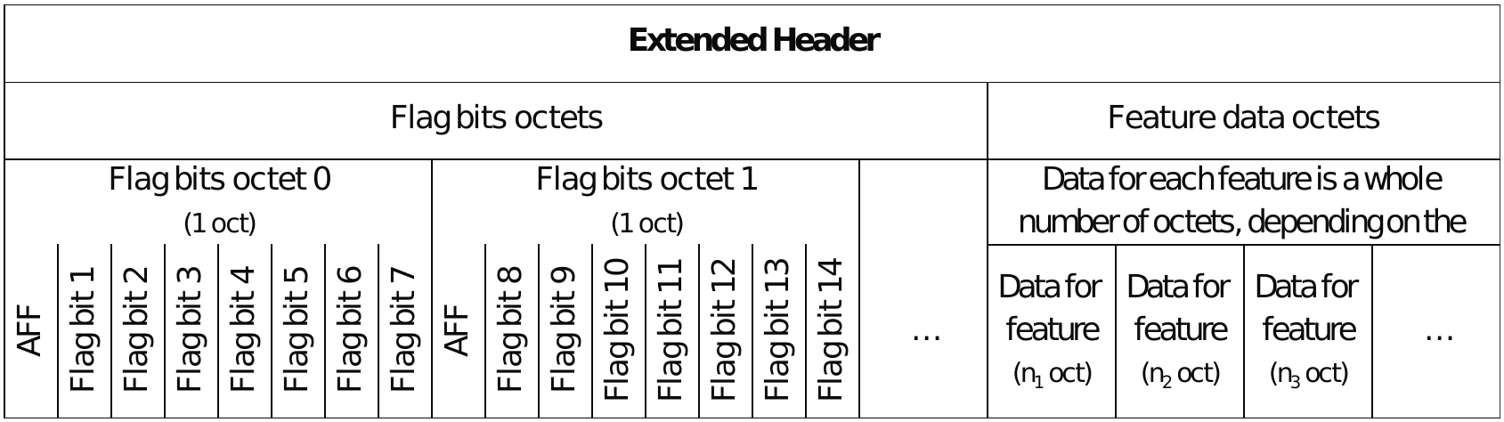
Figure 5.10 – PDU Header Zone, Extended Header portion format and fields
- Flag Bit Encoding: Features are addressed via a 7×O+B scheme, where O is the zero-based flags octet index and B is the bit position (1-7, where bit 0 is reserved for future use). Setting a flag bit to 1 indicates the corresponding feature is present and its data octets are included in the Feature Data region.
- Feature Data Order: Feature data octets are concatenated in the strict numerical order of their feature IDs after all flag octets
The Extended Header supports a curated set of features very important for HDT, each with a specific purpose and strict implementation rules. The features are tailored to logical transport types (ACL, CIS, BIS) and they are summarized in Table 5.3.
Table 5.3 – Extended Header features
| Feat. No. | ACL | Size | CIS | Size | BIS | Size |
|---|---|---|---|---|---|---|
| 1 | Extended Header feature data length | 1 oct | Extended Header feature data length | 1 oct | Extended Header feature data length | 1 oct |
| 2 | Link Quality | 2 oct | Link Quality | 2 oct | — | — |
| 3 | — | — | NPI | 0 oct | — | — |
| 4 | Flow Control | 0 oct | — | — | — | — |
| 5 | NPI | 0 oct | — | — | — | — |
Feature Data Length
- Provides the total length of all subsequent feature data octets within the Extended Header
- Feature is MANDATORY in all Format 0 packets that contain an Extended Header. This requirement is critical because Format 0 packets lack an explicit length field for the PDU Header Zone. The receiver relies on this value to correctly locate the start of the Payload Zone
- It is permitted to include this field in PF1 but it’s not necessary to decode the packet like with PF0 (normally omitted to save airtime)
- A single octet field containing an unsigned integer representing the total number of feature data octets that follow
Link Quality
- Enables adaptive data rate (ADR) control by providing the transmitter with feedback on the quality of the most recently received packet
- Can only be used if the Link Quality Feedback feature is supported by both devices
- A 2 oct field structured as follows:
- RSSI (Bits 0-7): received signal strength indication
- SNR (Bits 8-12): signal-to-noise ratio
- Preferred Rate (Bits 13-15): A 3b code representing the receiver’s recommended PHY data rate (HDT2-HDT7.5) for subsequent transmissions. The value 0 indicates no specific recommendation.
Flow Control
- Two state values: STOP and GO
- Provides immediate, per-packet flow control for ACL connections
- Upon receiving a packet containing this feature, the receiver’s Link Layer must set its local flow control state for the corresponding direction to STOP
- STOP State Implications: While in the STOP state, the transmitter is only permitted to send:
- Blocks from payloads for which at least one block has already been acknowledged (i.e., retransmissions)
- Control PDUs (identified by LLID = 0b11)
- Reverting to GO: The flow control state reverts to GO upon the reception of a subsequent valid packet that does not contain the Stop feature; this implies a short format packet cannot be sent if you want to stay in STOP state
Null PDU Indicator (NPI)
- Explicitly distinguishes a Null PDU (a protocol placeholder with no data intent) from an Empty PDU (a valid data PDU with a zero-length payload).
- This feature is only valid in Format 0 packets that have an empty Payload Zone (length = 0)
- Semantics:
- NPI = 1: The PDU is a Null PDU. It serves as a placeholder (e.g., for timing or acknowledgment purposes) and is not associated with a valid PayloadNumber. It does not advance the data sequence.
- NPI = 0 or feature absent: The PDU is associated with a valid PayloadNumber. It may contain data octets in its payload or can be an Empty PDU.
HEC-P
The HEC-P (Header Error Check – PDU Header) is a 24b CRC covering the entire PDU Header Zone (excluding itself). It is only present in PF1 (omitted in PF0) and it is initialized with the HPA.
5.6 Payload Zone
The structure of the Payload Zone is determined by the packet format chosen which defines how data is to be organized, transmitted, and protected. Table 5.4 compares and summarizes the key Payload Zone differences between Packet Format 0 and Format 1.
Table 5.4 – PF0 and PF1 Payload Zones comparison
| PF0 | PF1 | |
|---|---|---|
| Payload data | Contained and transmitted in a single, contiguous block | Aggregated from up to four payloads, segmented and transmitted in a sequence of multiple blocks |
| Max payloads per packet | 1 | 1 to 4 (identified through TxPayloadMap) |
| Payload capacity (Size) | 0-494 octets +MIC if present | 0-8175 octets + MICs if present |
| CRC protection | Single 32b CRC covering the combined PDU Header Zone and Payload Zone | 32b CRC per block; each block immediately followed by its own CRC. |
| Key consideration | Simplicity; akin to the common PDU model | Higher throughput due to longer packets, with selective block acknowledgment and retransmissions |
| PHY Intervals support | No | Yes |
With PF1, the segmentation into intervals at the PHY layer, with the termination and PITS for increased robustness during communication is mandatory (except for a Payload Zone shorter than an interval).
At the Link Layer level, payloads are segmented into blocks to enable selective acknowledgment and retransmission. The blocks are tracked and referenced by the Link Layer via block maps/bitmaps. At the PHY layer, the Payload Zone is further segmented into fixed-length symbol streams called PHY Intervals by means of the interval spacing stage in the bitstream processing pipeline.
PHY Intervals consist of a fixed number of payload-carrying symbols, followed by a terminating symbol sequence and a PHY Interval Training Sequence (PITS), except after the final interval. The PITS provides a known training pattern that allows the receiver to refresh timing and carrier frequency/phase references mid-packet to manage and mitigate the impact of channel degradation on the longer, aggregated payloads carried by PF1 to maximize throughput.
PHY Interval sizing is configured by the PHY INT field in the Control Header as shown in Table 5.5.
Table 5.5 – Symbols per PHY interval
| PHY INT | Symbols per Interval |
|---|---|
| 0b00 | 128 |
| 0b01 | 256 |
| 0b10 | 384 |
| 0b11 | 512 |
This bitstream for a PHY Interval also includes necessary FEC termination bits and zero-padding (when required). After modulation, the actual symbol count per PHY interval can vary slightly with the data rate, as detailed in Table 5.6.
Also note that the different PHY rates have different bits per symbol. Hence, the data in PHY INT 0b00 is 128 bits (16 octets) at HDT2, 192 bits (24 octets) at HDT3, 256 bits (32 octets) at HDT4, 384 bits (48 octets) at HDT6, and 480 bits (60 octets) at HDT7.5.
Table 5.6 – PHY Interval symbol count per data rate
| PHY INT | HDT2 | HDT3 | HDT4 | HDT6 | HDT7.5 |
|---|---|---|---|---|---|
| 0b00 | 133 | 132 | 131 | 130 | 130 |
| 0b01 | 261 | 260 | 259 | 258 | 258 |
| 0b10 | 389 | 388 | 387 | 386 | 386 |
| 0b11 | 517 | 516 | 515 | 514 | 514 |
For visualization, Figure 5.11 repeats the structure for PF1 illustrating the additional segmentation of the Payload Zone into PHY Intervals.

Figure 5.11 – Segmentation of PF1 Payload Zone into blocks and PHY Intervals
In the context of a PHY layer perspective, Figure 5.12 provides an alternate view of all three HDT packet formats in terms of symbols, also for visualization.
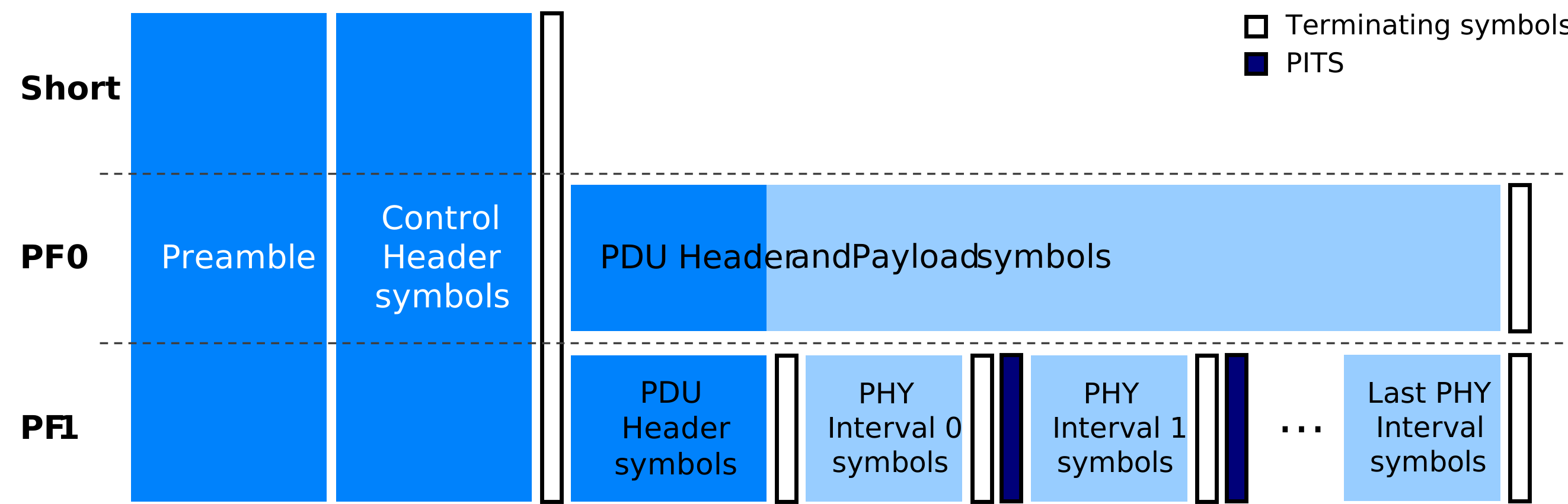
Figure 5.12 – PHY layer perspective of HDT packet formats
Observe that terminating symbols mark the end of symbol streams within HDT packets, where each set of terminating symbols consists of two all-zero-bit symbols, modulated according to the preceding symbol stream’s scheme. For PF0, terminating symbols are inserted after the Control Header and after the combined PDU Header and Payload. For PF1, terminating symbols appear after the Control Header, after the PDU Header, and after each PHY Interval.
6. Bluetooth® HDT Link Layer (LL)
Bluetooth HDT introduces new or updated features, procedures, and control PDUs that expand the capabilities of the Bluetooth LE Link Layer to support the new PHY and packet formats, and to enable the throughput, performance, reliability, and security enhancements targeted with HDT.
At a high level, features define the capabilities that devices may support, while procedures define the coordinated operations devices need to perform to use or manage those capabilities. Control PDUs are the Link Layer messages exchanged between devices to communicate information, parameters, and/or state changes needed to execute the procedures. In this way, features describe what capabilities are available, procedures define how devices coordinate their use, and control PDUs provide the messages used to carry out that coordination.
This section offers an overview of the expanded Link Layer capabilities prompted by Bluetooth HDT, providing a summary of new, upversioned, and updated Link Layer features, procedures, and control PDUs for HDT enablement.
6.1 Overview of new Link Layer capabilities for HDT
HDT Initiation and management
Bluetooth® HDT is initiated and managed through connection-based operations that occur via data physical channels and the ACL transport. However, once an HDT-capable link is established between devices, it can be used to support an ACL connection or connected isochronous streaming.
In the case of isochronous broadcasting, devices must use GFSK-based advertising to find the periodic advertising. Then a BIG containing one or more BISes can be transmitted or received without the need for an ACL connection. The HDT PHY does not currently support any form of advertising.
Overall, HDT operation must always be initiated explicitly through the defined Link Layer procedures. It also requires symmetric PHY usage in both link directions (except for broadcasting), meaning that transmit and receive activities must both use the HDT PHY or both use GFSK PHYs, as applicable. When using the HDT PHY, the data rate can vary independently on a packet-by-packet basis, with no requirement for the same rate to be used in both directions.
The new HDT Configuration Exchange procedure allows devices to communicate and negotiate supported HDT capabilities (e.g., maximum data rate, packet formats, payload sizes, etc.). Then, the execution of the PHY Update procedure using the upversioned LL_PHY_REQ [v2], LL_PHY_RSP [v2], and LL_PHY_UPDATE_IND [v2] control PDUs can switch their communication to the HDT PHY or manage transitions into or out of HDT. When HDT capabilities between devices are incompatible, unsupported, or operational conditions require it, communication can remain on or return to a GFSK PHY, with all PHY state changes reported to the Host through HCI events for visibility and control.
HDT Data length management and scheduling
HDT introduces data length management capabilities allowing the Link Layer to keep separate transmission length and timing parameters for each connection over the HDT and GFSK PHYs. Moreover, updated value range limits for these parameters permit larger packet payloads while also enforcing maximum transmission airtime limits for packets. A Controller can segment large payloads into multiple blocks or adjust the selected data rate when necessary to keep packet transmission times bounded. This ensures that timing and scheduling requirements for Bluetooth LE connection events and for the simultaneous operation of multiple links and/or isochronous streams can be satisfied.
With the Data Length Update procedure, devices can communicate maximum Tx/Rx lengths and timing parameters to use for LL data PDUs. Executing the procedure with the upversioned LL_LENGTH_REQ [v2] and LL_LENGTH_RSP [v2] control PDUs allows specifying the PHY to which the parameters apply.
HDT Link quality
HDT brings an optional Link Quality Feedback (LQF) capability to Bluetooth LE permitting the exchange of real-time information on channel conditions through a dedicated Link Layer procedure. When enabled, link quality metrics are included in transmitted packets and communicated continuously between controllers. This information allows making dynamic decisions for link operation in response to changing radio conditions, such as adapting transmission parameters, selecting a different HDT data rate, or transitioning back to a GFSK PHY when conditions warrant.
Devices can use the new HDT Link Quality Enable procedure along with the new LL_HDT_LQF_REPORTING_IND control PDU to indicate when link quality information should start or stop being included in packets.
HDT and isochronous channels
HDT broadens the isochronous transport capabilities of Bluetooth LE to support connected or broadcast isochronous streams over the new HDT PHY.
Devices can negotiate HDT-specific operating parameters (e.g., HDT PHY, data rates, payload window sizes, etc.) and set up time-bounded isochronous streams capable of delivering large payloads reliably with the HDT PHY and packets using the Connected Isochronous Stream Creation procedure with upversioned LL_CIS_REQ [v2] and LL_CIS_IND [v2] control PDUs. Notably, high throughput, connected isochronous communication is crucial for the enablement of high-quality audio solutions and applications with Bluetooth LE.
For broadcasting, the Isochronous Broadcasting state of the Link Layer’s air interface protocol is updated with broader BIG parameter value ranges for HDT data length management, revised BIGInfo header fields, and block-based acknowledgment support. This allows synchronized receivers to leverage HDT for high-throughput broadcast streams following the existing timing and synchronization requirements defined for periodic advertising and isochronous broadcasting.
HDT Security and encryption
HDT enhances Bluetooth LE security, introducing support for longer Message Integrity Check (MIC) sizes and the new Encryption Key Schedule (EKS) feature for generating and refreshing encryption keys. The Link Layer coordinates the exchange of parameters between devices and manages transitions to HDT operation while keeping communication encrypted.
With the new Encryption Start with Key Schedule procedure, devices can exchange encryption-related parameters and select one of the new MIC size lengths supported with HDT (128b or 64b) for the connection via the LL_ENC_ECDH_REQ and LL_ENC_ECDH_RSP control PDUs. Once long-term and session keys for link encryption are calculated by the devices, encryption is started via the LL_START_ENC_REQ and LL_START_ENC_RSP PDUs. Note that EKS can also be used with GFSK PHYs, in which case the only MIC size applicable is 32b.
In addition, for devices that support the EKS feature, the PHY Update and Encryption Refresh procedure allows implementing a PHY change and an encryption key refresh simultaneously without disconnecting or pausing encryption with the upversioned LL_PHY_REQ [v2], LL_PHY_RSP [v2], and LL_PHY_UPDATE_IND [v2] control PDUs. For clarity, a MIC size change always forces a key refresh, but a key refresh doesn’t force a MIC size change.
Section 7 of this document covers HDT Encryption in more detail.
HDT Reliability and flow control
HDT enables Link Layer mechanisms for a block-based assessment of payloads to detect and manage transmission errors. Existing sequence numbering and acknowledgment mechanisms in Bluetooth LE are still used for cumulative acknowledgment of payloads and to maintain packet ordering, but HDT supplements these with the selective acknowledgment of blocks. The SN, NESN, RxPayloadMap, RxBitmap, Nb, and BlockSize fields in HDT packets are used by the LL to check if a block is acknowledged or not and, subsequently, to determine if retransmission is necessary. This minimizes retransmission overhead by having only affected portions of a large payload resent.
HDT also enhances Link Layer flow control through an immediate flow-off mechanism that allows a receiving device to temporarily pause the transmission of new payloads when additional buffering or processing time is required. Using information carried in an extended packet header, a receiver can signal a peer device to stop transmitting new data while permitting retransmission activities to continue. Once the receiver is ready to accept additional traffic, normal data transmission can resume without requiring connection reconfiguration or other higher-layer intervention.
6.2 Link Layer features for HDT
The Bluetooth LE Link Layer uses the FeatureSet bitmask defined in [Vol 6] Part B, Section 4.6 of the Bluetooth Core Specification to identify capabilities supported by a Controller. For HDT, the FeatureSet introduces a bit identifying support for the fundamental HDT capability along with additional bits identifying support for optional HDT capabilities, including higher HDT rates, Packet Format 1, Link Quality Feedback, and isochronous operation over the HDT PHY.
Listed below are the HDT-related FeatureSet bits introduced to represent support for HDT capabilities:
- 77 – High Data Throughput
- 78 – Receive HDT6 Rate
- 79 – Transmit HDT6 Rate
- 80 – Receive HDT7.5 Rate
- 81 – Transmit HDT7.5 Rate
- 82 – HDT Packet Format 1
- 83 – Link Quality Feedback
- 84 – Isochronous Broadcaster on the LE HDT PHY
- 85 – Synchronized Receiver on the LE HDT PHY
For each FeatureSet bit, the specification defines the requirements a Controller must satisfy to indicate support for the corresponding capability, including, where applicable, related PHY functions, packet formats, procedures, and control PDUs.
Mandatory requirements associated with the High Data Throughput FeatureSet bit are described next. For all remaining FeatureSet bits identifying support for optional HDT capabilities, refer to [Vol 6] Part B, Section 4.6 of the Bluetooth Core Specification for their complete definitions and associated support requirements.
High Data Throughput
A Controller that supports the High Data Throughput capability must also support the LE Encryption with Diversifiers, LE Data Packet Length Extension, Encryption Key Schedule, and Channel Selection Algorithm #2 features, as well as the following HDT functionality:
- LE HDT PHY (see [Vol 6] Part A, Sections 3.6 and 4.1.2)
- HDT symbol stream processing ([Vol 6] Part A, Section 7), excluding:
- PHY Intervals ([Vol 6] Part A, Section 7.2)
- 16QAM symbol mapping ([Vol 6] Part A, Section 7.3.3)
- PITS ([Vol 6] Part A, Section 7.4.5)
- Transmitter RMS EVM levels ([Vol 6] Part A, Appendix C)
- Packet format for the LE HDT PHY ([Vol 6] Part B, Section 2.7), excluding:
- Packet Format 1
- Payload block structure ([Vol 6] Part B, Section 2.7.4)
- Link Quality ([Vol 6] Part B, Section 2.7.2.4.1)
- 32b CRC generation ([Vol 6] Part B, Section 3.1.2)
- Bitstream processing for LE HDT ([Vol 6] Part B, Section 3.4), excluding:
- Interval spacing ([Vol 6] Part B, Section 3.4.2)
- HDT Configuration Exchange procedure ([Vol 6] Part B, Section 5.1.34), excluding:
- Uses that involve Isochronous Broadcasters, Synchronized Receivers, and Broadcast Isochronous Streams, Groups and PDUs on the LE HDT PHY
- LL_LENGTH_REQ [v2] and LL_LENGTH_RSP [v2] PDUs
- LL_HDT_CONFIG_REQ and LL_HDT_CONFIG_RSP PDUs
In addition, a Controller that supports the High Data Throughput capability and the Connected Isochronous Stream (Central or Peripheral) feature must also support:
- LL_CIS_REQ [v2] and LL_CIS_IND [v2]
Refer to ([Vol 6] Part B, Section 4.6.54) for additional details.
6.3 Link Layer procedures for HDT
6.3.1 New procedures
The following procedures are introduced to the Link Layer Control Protocol for ACL links to support HDT capabilities:
- HDT Configuration Exchange procedure
- HDT Link Quality Enable procedure
A summary of their function and the PDUs involved to initiate and complete them is given next. Note that these procedures can only be carried out after entering the Connection state for the ACL link.
HDT Configuration Exchange procedure
Changes the configuration values associated with a connection on the LE HDT PHY. Values exchanged do not affect any existing ACL or CISes on the LE HDT PHY. Values take effect on CISes created subsequently, and on ACL when it switches from a GFSK PHY to the LE HDT PHY. The procedure is initiated by sending the LL_HDT_CONFIG_REQ PDU and completed when the LL_HDT_CONFIG_RSP PDU is received. Each PDU sent relates to the sending device’s configuration only, which makes collisions between procedures initiated on each side harmless.
HDT Link Quality Enable procedure
Asks a remote controller to start or stop sending link quality feedback in each packet transmitted on the specified transports. The procedure is initiated by sending the LL_HDT_LQF_REPORTING_IND PDU and completed when acknowledgement of the LL_HDT_LQF_REPORTING_IND PDU is received. Link quality feedback is disabled with this same procedure.
6.3.2 Updated procedures
The following procedures for ACL control have been modified to enable the support of HDT capabilities:
- Encryption procedures
- Encryption Start with Diversifiers procedure (part1)
- Encryption Start with Key Schedule procedure (part1)
- Encryption Start with Diversifiers and Encryption Start with Key Schedule procedures (part2)
- Encryption Pause procedure
- Data Length Update Procedure
- PHY Update and Encryption Refresh procedure
- Connected Isochronous Stream Creation procedure
- Frame Space Update procedure
A summary of every updated procedure’s function and the PDUs involved to initiate and complete them is given next. Again, notice that these procedures can only be carried out after entering the connection state for the ACL link.
Encryption procedures
Enable encryption and authentication of data PDUs to protect payload confidentiality and integrity. If both the Central and Peripheral support the Encryption Key Schedule (EKS) feature, the Central initiates the Encryption Start with Key Schedule procedure, otherwise it initiates the Encryption Start with Diversifiers procedure. Once the connection is encrypted, the encryption key can be changed by the link layer using the PHY Update and Encryption Refresh procedure if both Central and Peripheral support EKS or via the Encryption Pause procedure otherwise.
Both the Encryption Start with Diversifiers and Encryption Start with Key Schedule procedures have two parts. The first part is different for both whereas the second part is the same for both.
Encryption Start with Diversifiers procedure (part 1)
To enable encryption, the Central and Peripheral generate their portions of the Initialization Vector (IV) and the Session Key Diversifier (SKD) and exchange them through the LL_ENC_REQ and LL_ENC_RSP PDUs. Then each LL combines the IV and SKD parts. The Peripheral host notifies its LL of the Long-Term Key (LTK) to use. Encryption is started via a three-way handshake using the LL_START_ENC_REQ and LL_START_ENC_RSP PDUs.
Encryption Start with Key Schedule procedure (part 1)
To enable encryption, the Central and Peripheral generate their portions of the Public Key (PubKey) and the Random Number (Rand) and exchange them through the LL_ENC_ECDH_REQ and LL_ENC_ECDH_RSP PDUs. If on a GFSK PHY, the connection will use a 32b MIC. If on the HDT PHY, the connection will use a 128b MIC unless Flags are set for a 64b MIC.
Encryption Start with Diversifiers and Encryption Start with Key Schedule procedure (part 2)
Determines the kind of Long-Term Key (LTK) to be used (e.g., all zeros if opportunistic encryption is being used) and its source (e.g., provided by Host to LL) for encryption. In the Central’s case, the host always provides the LTK to the Link Layer. In the Peripheral’s case, it may or may not; if it does, the LL uses it to calculate the session key. Session key calculation is based on [Vol 3] Part H, Section 2.2.1 for Encryption Start with Diversifiers, and on [Vol 6] Part E, Section 4.2.1 for Encryption Start with Key Schedule.
Encryption Pause procedure
Encapsulates both Encryption Start procedures. Hence, the same updates apply.
Data Length Update procedure
Used to transmit to a peer device the latest values of the current Max Rx and Tx payload lengths and times for the LL data PDU (connMaxRxOctets, connMaxRxTime, connMaxTxOctets, and connMaxTxTime). Updated wording to the specification clarifies that if the controller supports more than one set of parameters for the connection, then the procedure may select which set is to be updated. The procedure is initiated by either Central or Peripheral issuing the LL_LENGTH_REQ PDU. The request is responded to with an LL_LENGTH_RSP PDU. The response updates the set of parameters specified in the request PDU.
PHY Update and Encryption Refresh procedure
Used to change the Tx or Rx PHYs (or both) of an ACL connection or to refresh the encryption key and IV if devices support the EKS feature, or both. It does not affect PHYs or key/IVs associated with CISes. A request is initiated using the LL_PHY_REQ PDU. The request is responded with the LL_PHY_RSP PDU. The Central always sends an LL_PHY_UPDATE_IND PDU as the last step.
HDT introduces wording for rules that clarify how to deal with in-transit or queued data before requesting or responding to a PHY update, how to manage the encryption key refresh, invalid behaviors, etc. In addition, HDT introduces [v2] of the PDUs with a Refresh field to require (in the case of LL_PHY_REQ/RSP) or indicate (in the case of LL_PHY_UPDATE_IND) an encryption key refresh request, and a MIC_Length field to indicate the preferred MIC length on the HDT PHY. Note that a 64b MIC length is only selected if both sides require it; one device cannot reduce the security required by its peer.
Connected Isochronous Stream Creation procedure
Used to create a CIS between a Central and a Peripheral. The request is initiated only by a Central using the LL_CIS_REQ PDU. The request is responded to by a Peripheral using the LL_CIS_RSP PDU if accepted, or with the LL_REJECT_EXT_IND PDU and the appropriate reason code if rejected. Upon response, the Central creates the CIS by replying with the LL_CIS_IND PDU or cancels it with the LL_REJECT_EXT_IND PDU. HDT introduces rules clarifying the requirements for creating a CIS on the GFSK or HDT PHYs, and for the usage of PDU versions, symmetric PHYs, and the EKS feature.
6.4 Link Layer control PDUs for HDT
6.4.1 New control PDUs
The following are new control PDUs (for data physical channels) introduced to convey requests, responses, or indications related to the newly defined procedures for HDT support over the air:
- (0x40) LL_ENC_ECDH_REQ
- (0x41) LL_ENC_ECDH_RSP
- (0x42) LL_HDT_CONFIG_REQ
- (0x43) LL_HDT_CONFIG_RSP
- (0x44) LL_HDT_LQF_REPORTING_IND.
The format of their CtrData field and one-line descriptions for every field under the latter are provided next.
LL_ENC_ECDH_REQ

- Flags_C: Central’s encryption flags [bit0: 0=128b MIC, 1=64b MIC; bit1: Opportunistic encryption]
- Rand_C: Random number provided by Central
- KeyType_C: Type of public key used by Central [0=Derived using P-256 elliptic curve]
- PubKey_C: Central’s ECDH public key [Pubkey_C31-0 = X coordinate, Pubkey_C63-32 = Y coordinate]
LL_ENC_ECDH_RSP
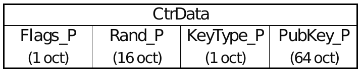
- Flags_P: Peripheral’s encryption flags [bit0: 0=128b MIC, 1=64b MIC]
- Rand_P: Random number provided by Peripheral
- KeyType_P: Type of public key used by Peripheral [0=Derived using P-256 elliptic curve]
- PubKey_P: Peripheral’s ECDH public key [Pubkey_C31-0 = X coordinate, Pubkey_C63-32 = Y coordinate]
LL_HDT_CONFIG_REQ and LL_HDT_CONFIG_RSP

- ACL_RX_Payload_Window_Size: Set to one less than PayloadWindowSize used on the ACL connection, in the RX direction; Default = 0
- Max_CIS_TX_Payload_Window_Size: Set to one less than the maximum payload window size used on the associated CIS, in the TX direction; Default value = 0
- Max_CIS_RX_Payload_Window_Size: Set to one less than the maximum payload window size used on the associated CIS, in the RX direction; Default value = 0
- ACL_RX_Rates: Rates the controller is allowed to receive from a remote controller on the ACL connection [bit0: HDT2; bit1: HDT3; bit2: HDT4; bit3: HDT6; bit4: HDT7.5]
- Max_ACL_RX_Octets_Per_Packet: Max data octets that can be received in a single packet on the ACL connection. Excludes MIC, termination sequences, PITS, etc.
LL_HDT_LQF_REPORTING_IND
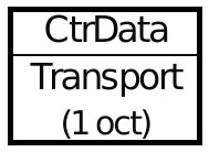
- Transport: Indicates logical transports LQF reporting is enabled or disabled for [bit0: ACL; bit1: CIS]
6.4.2 Updated control PDUs
The following are updated control PDUs (for data physical channels) with modifications or added fields to convey requests, responses, or indications related to the updated Link Layer procedures for HDT support over the air:
- (0x14) LL_LENGTH_REQ
- (0x15) LL_LENGTH_RSP
- (0x16) LL_PHY_REQ
- (0x17) LL_PHY_RSP
- (0x18) LL_PHY_UPDATE_IND
- (0x1F) LL_CIS_REQ
- (0x21) LL_CIS_IND
- (0x23) LL_POWER_CONTROL_REQ.
The format of their CtrData field and one-line descriptions for every field under the latter, either modified or added, are provided next. Note: As a result of the modifications for HDT support, these LL Control PDUs can now have more than one format indicated by [v1] or [v2]. Each field within the CtrData field has the same meaning in all formats that it’s present in.
LL_LENGTH_REQ and LL_LENGTH_RSP

- PHY_S: Indicates which set of PHY parameters the PDU applies to [0=GFSK; 1=HDT]; field is ignored in LL_LENGTH_RSP
LL_PHY_REQ and LL_PHY_RSP

- TX_PHYS: Transmitter PHYs sender prefers to use [bit0: LE_1M; bit1: LE_2M; bit2: LE Coded; bit4: HDT]
- RX_PHYS: Receiver PHYs sender prefers to use [bit0: LE_1M; bit1: LE_2M; bit2: LE Coded; bit4: HDT]
- Refresh: Key refresh [1=required]; Value=0 if not included, or ignored if connection not encrypted or if either device does not support EKS feature
- MIC_Length: [1=Request for 64b MIC for HDT, 0 or not included=128b MIC for HDT]; ignored if connection not encrypted, key not refreshed, or change to GFSK PHY
LL_PHY_UPDATE_IND

- PHY_C_TO_P: PHY for packets sent from Central [bit0: LE_1M; bit1: LE_2M; bit2: LE Coded; bit4: HDT]
- PHY_P_TO_C: PHY for packets sent from Peripheral [bit0: LE_1M; bit1: LE_2M; bit2: LE Coded; bit4: HDT]
- Instant: Specific connection event in the future, referenced by connection event counter value
- Address: Physical Channel Address for the PHY that will be used after the instant on the ACL connection
- Refresh: 1=Encryption key will be refreshed; 0 or not included= Encryption key will not be refreshed or connection is not encrypted
- MIC_Length: [1=Refresh and 64b MIC for HDT, 0 or not included=128b MIC for HDT]; ignored if connection not encrypted, key not refreshed, or change to GFSK PHY
LL_CIS_REQ
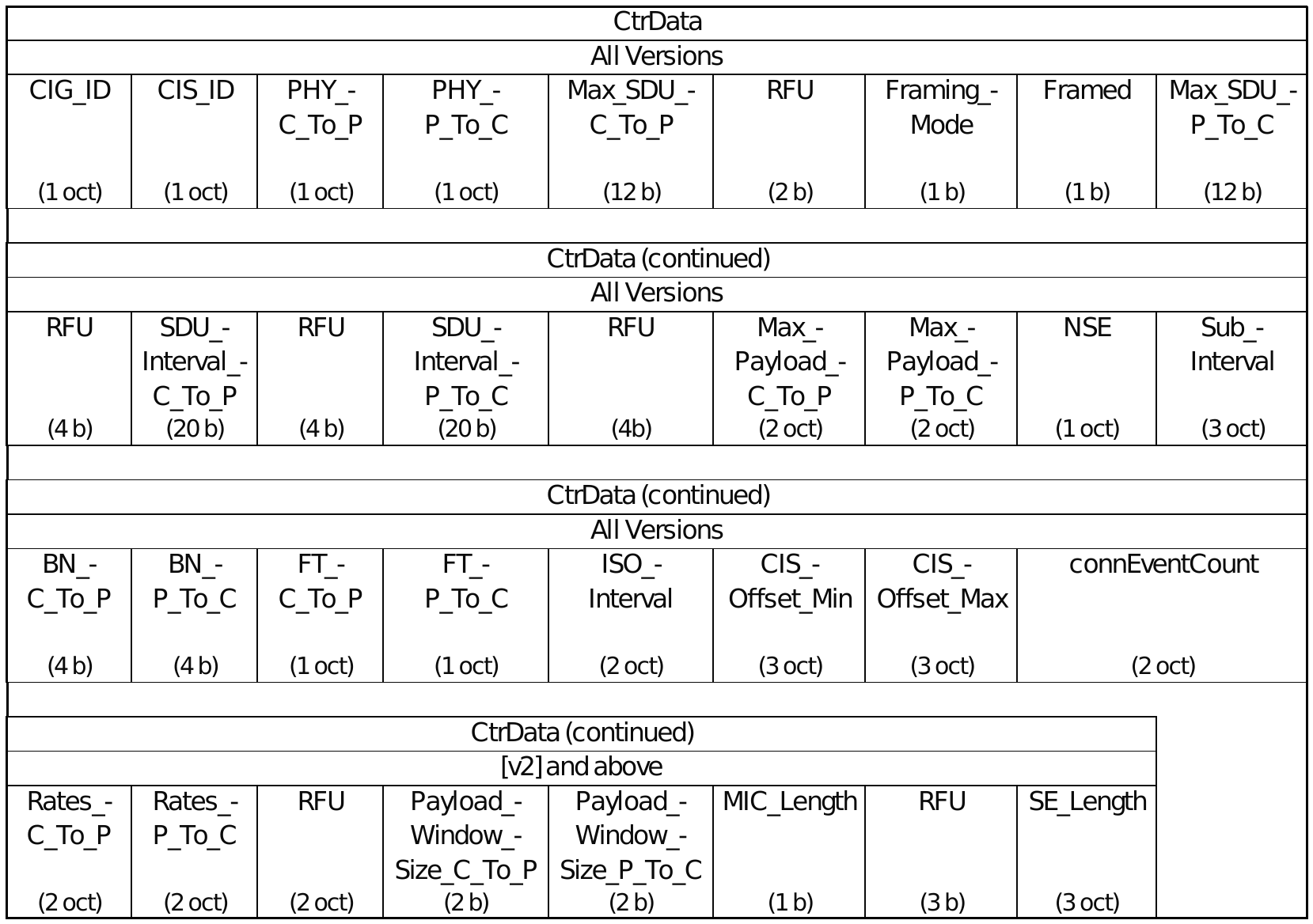
- Max_Payload_C_To_P: Maximum link layer payload size (in bytes) the Central may transmit in a CIS PDU
- Max_Payload_P_To_C: Maximum link layer payload size (in bytes) the Peripheral may transmit in a CIS PDU
- Rates_C_To_P: Rates allowed from Central [bit0: HDT2; bit1: HDT3; bit2: HDT4; bit3: HDT6; bit4: HDT7.5]
- Rates_P_To_C: Rates allowed from Peripheral [bit0: HDT2; bit1: HDT3; bit2: HDT4; bit3: HDT6; bit4: HDT7.5]
- Payload_Window_Size_C_To_P: Number of payloads in the window that Central can track, transmit and retransmit (from 1 to 4)
- Payload_Window_Size_P_To_C: Number of payloads in the window that Peripheral can track, transmit and retransmit (from 1 to 4)
- MIC_Length: If CIS is on HDT PHY and encrypted, 1=64b MIC and 0=128b MIC, else ignored
- SE_Length: Time (in us) that needs to be reserved for the subevent
LL_CIS_IND
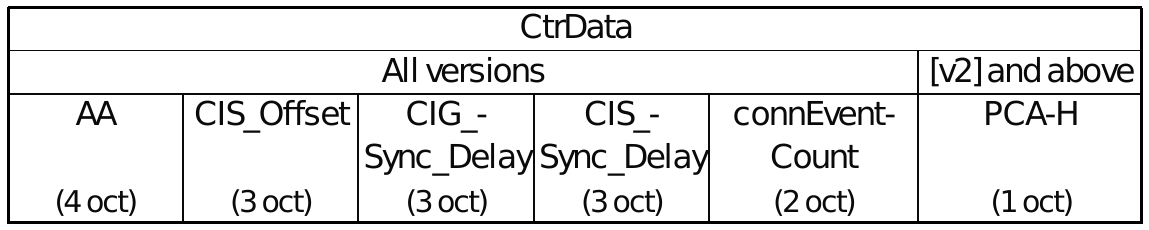
- If CIS on GFSK PHY: AA=Access Address of CIS, or 0 if PCA-H included in PDU
- If CIS of HDT PHY: AA=HPA31-0, and PCA-H must be present and set to HPA39-32
LL_POWER_CONTROL_REQ
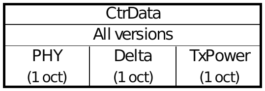
- PHY: PHY for which request being made [bit0: 1M; bit1: 2M; bit2: Coded S=8; bit3: Coded S=2; bit4: HDT]
7. Bluetooth® HDT encryption
HDT enhances the framework for encryption and authentication of Bluetooth LE to enable stronger data protection, preserve compatibility with the existing security model, and allow Bluetooth technology to keep up with industry and regulatory security trends.
This section provides an overview of the encryption-related enhancements spurred by Bluetooth® HDT and a summary of new functions, procedures, and parameters introduced to enable them.
7.1 Overview of HDT encryption enhancements
HDT enhances Bluetooth LE encryption capabilities through the introduction of support for longer Message Integrity Check (MIC) sizes and for the new Encryption Key Schedule (EKS) feature introduced in Bluetooth Core 7.0. However, the overall encryption and authentication process continues to rely on established cryptographic algorithms, with ECDH used for shared-secret establishment, AES-CMAC for key derivation, and AES-CCM for data encryption and integrity protection.
Longer MIC size support
In GFSK-based Bluetooth PHYs, the MIC appended to encrypted packets has a fixed length of 32b (4 octets). With HDT, longer packet payloads demand longer MICs to reduce the probability of undetected data corruption or tampering. Hence, HDT introduces support for MIC sizes of:
- 64b (8 octets)
- 128b (16 octets)
The MIC size is established during the encryption setup phase managed by the Link Layer. If either side prefers 128b, then 128b is selected. The new MIC sizes can only be applied to packets transmitted over the HDT PHY (GFSK-based PHYs continue to use a 32b MIC). The selected MIC size is enforced symmetrically across the connection and bound to the session key in use, in accordance with NIST recommendations.
For HDT packets with Packet Format 1 (PF1), the encrypted payload and MIC are segmented into blocks before transmission (after encryption). Hence, each block can be decrypted as it is received, but the MIC verification can only happen after all blocks are successfully received and reassembled.
Encryption Key Schedule (EKS) support
To operate with HDT, devices must establish a link using a GFSK PHY, discover HDT capabilities supported, select/exchange configuration parameters, and then switch to the HDT PHY via a PHY update and encryption refresh procedure. From an encryption perspective, this involves a MIC size change from 32b to 64b or 128b, which, in turn, requires an encryption key change.
The Encryption Key Schedule (EKS) feature enables the generation, management, and refreshing of encryption keys to support PHY (and MIC size) changes without disconnecting or having to restart the encryption procedure. Using ECDH-derived shared secrets and AES-CMAC-based key derivation functions, EKS allows supporting:
- Opportunistic encryption
- Perfect Forward Secrecy (PFS)
- Seamless PHY transitions with synchronized key and MIC updates
- Per-stream key separation for ACL and CIS transports
With Opportunistic Encryption, devices can establish an encrypted link without a previously shared Life-Time Key (LTK), allowing encrypted communication even when devices have not been paired. This provides similar confidentiality and integrity as when devices are paired using LE Secure Connections with the Just Works method but without authentication or man-in-the-middle (MITM) protection.
With PFS, compromise of a device’s LTK, private key, or a current Session Key does not expose earlier Session Keys. Hence, previous encrypted sessions remain secure. The exposure of a Session Key after an encryption refresh reveals nothing about the previous Session Key before the encryption refresh. Given only a Session Key, any other Session Key or Traffic Secret cannot be derived. Given a Traffic Secret, later Traffic Secrets can be derived but earlier ones cannot.
Per-stream key separation was previously possible but required repeating the Encryption with Diversifiers process entirely. EKS PFS simplifies this process significantly. At present, a CIS session has a limited lifetime because the CIS Session Key cannot be refreshed.
Support for EKS is mandatory for devices that support HDT. When both devices in a connection support EKS, its use is mandatory. If EKS is not supported, Encryption with Diversifiers remains in effect.
New functions, procedures, and parameters
As part of the EKS feature, new cryptographic functions, new cryptographic tag values, and new procedures to derive session keys are introduced. Also, new fields and values are added to the counter mode blocks used by the AES-CCM algorithm to support MIC calculation with the new sizes.
7.2 Key derivation updates
Cryptographic toolbox
The key derivation hierarchy for EKS involves
- A Derived Secret: The base key derived from the ECDH shared secret between devices and used as part of the EKS key hierarchy
- A Traffic Secret: A key obtained from the Derived Secret to generate session keys and IVs
- A Session Key and Initialization Vector (IV): Used by the AES-CCM algorithm for MIC generation, and for encryption and authentication of packets
New cryptographic functions introduced for EKS support are based on the AES-CMAC function (see [Vol 3] Part H, Section 2.2.5 of the Bluetooth Core Specification). They support the entire key derivation hierarchy in conjunction with an LTK and an ECDH shared secret. The CMAC-based key derivation hierarchy enabled with the new functions is illustrated in Figure 7.1.
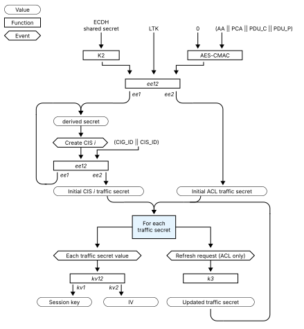
Figure 7.1 – CMAC-based key derivation hierarchy with EKS
A summary of the new cryptographic functions and tags is given in Tables 7.1 and 7.2. Tagged inputs ensure cryptographic separation between keys.
Table 7.1 – Cryptographic toolbox functions
| Function | Description |
|---|---|
| k1 | Derives a new 128-bit key from an existing key and context-specific info using AES-CMAC. Used as a building block for other derivations |
| k2 | Derives the initial “Derived Secret” from the ECDH shared secret. This is the root of the key hierarchy for a connection |
| k3 | Refreshes a Traffic Secret to support session key updates without re-pairing |
| kv1 | Derives the 128-bit Session Key from a Traffic Secret. Used for AES-CCM encryption |
| kv2 | Derives the 64-bit Initialization Vector (IV) from a Traffic Secret. Used in AES-CCM for nonce construction |
| kv12 | Not a function, but notation to indicate that both kv1 and kv2 are always used together to derive the Session Key and IV from a Traffic Secret |
| ee1 | Derives the Derived Secret from a base key (e.g., LTK or ECDH output) and context tags, or from a previously derived secret |
| ee2 | Derives the Traffic Secret from a base key and context |
| ee12 | Not a function, but notation to indicate that both ee1 and ee2 are always used together to derive both the Derived Secret and Traffic Secret |
Table 7.2 – Cryptographic tag values
| Identifier | Value | Derivation | Use |
|---|---|---|---|
| taghs | 0x6465_72697665_64206873 | “derived hs” | k2 |
| tagda | 0x646572_69766564_2041434C | “derived ACL” | Initial derived secret |
| tagdc | 0x646572_69766564_20434953 | “derived CIS” | Subsequent derived secret |
| tagta | 0x747261_66666963_2041434C | “traffic ACL” | ACL traffic secret |
| tagtc | 0x747261_66666963_20434953 | “traffic CIS” | CIS traffic secret |
| tagtr | 0x747261_66666963_20757064 | “traffic upd” | k3 |
| tagsk | 0x6B6579 | “key” | kv1 |
| tagiv | 0x6976 | “iv” | kv2 |
Cryptographic procedures
Start ACL encryption
When initiating encryption on an ACL connection using EKS, devices must first exchange public keys and create an ECDH shared secret using the Encryption Start with Key Schedule procedure. Then they must validate the public key received and calculate initial values for the Derived and Traffic Secrets for the ACL using the ee12 function. Finally, devices must calculate the initial Session Key and IV using the kv12 function.
If the devices are not paired, a zero-valued LTK is used, enabling opportunistic encryption. Opportunistic encryption allows devices to switch from GFSK PHYs to the HDT PHY while maintaining encryption, even if no LTK is available.
CIS traffic secrets
Each time a new Connected Isochronous Stream (CIS) is created, devices generate a new Derived Secret value and the initial Traffic Secret for that CIS using the ee12 function with CIS-specific identifiers (CIG_ID, CIS_ID). This enables per-stream key separation, enhancing security in multi-stream scenarios. Then, devices must calculate the initial Session Key and IV for the CIS using the kv12 function.
At present, each CIS has one Traffic Secret for its lifetime (2^39 packets) because its Session Key cannot be refreshed.
ACL Session key refresh
HDT supports in-connection Session Key refresh without requiring Host intervention. The Traffic Secret is updated by devices using the k3 function, and then a new Session Key and IV are derived via the kv12 function. The refresh preserves both the packet counter and the payload numbering, allowing packet sequencing to continue without disrupting data delivery. This implies that the Session Key must be refreshed within 2^39 packets since the last refresh.
Integration with PHY transitions
In Bluetooth LE, switching PHYs during an encrypted session has typically required pausing and restarting encryption. HDT eliminates this requirement by integrating EKS with PHY transitions:
- When switching from a GFSK PHY with a 32b MIC to the HDT PHY with a 64b or 128b MIC, or vice versa, the Link Layer performs a coordinated key refresh using EKS
- A key refresh on a GFSK PHY can also be coordinated with a change to a different GFSK PHY
- When a PHY transition requires a MIC size change, the new Session Key and MIC size take effect simultaneously with the PHY switch
- A key/MIC change doesn’t happen when transitioning between two GFSK PHYs and does not necessarily need to occur while remaining on the HDT PHY
- This coordination maintains continuous encryption without exposing unprotected data or requiring Host re-authentication
This integration simplifies PHY switching and enhances security by ensuring that MIC size changes are always accompanied by a key change, as required by NIST.
One caveat: If the LL_PHY_REQ/RSP and LL_PHY_UPDATE_IND are sent on the HDT PHY, it is necessary to pause ACL user data (but not control plane data) for part of the procedure.
7.3 Encryption updates
CCM Algorithm
For encryption and authentication, the CCM algorithm requires the payload and additional parameters to be formatted into the CCM nonce, counter-mode blocks, and encryption blocks. The CCM nonce provides uniqueness to each packet, the counter-mode blocks are used to calculate the MIC, and encryption blocks provide the keystream used to encrypt the payload and MIC.
Support for EKS and variable MIC lengths introduces updates to the format and fields of the counter-mode blocks related to differences between GFSK PHY and HDT PHY-based operation and to account for the MIC size to use (32b, 64b, or 128b) established by Link Layer procedures.
8. Bluetooth® HDT Host Controller Interface (HCI)
Bluetooth® HDT introduces new commands and events, and makes updates to existing ones, to expand the capabilities of the Host Controller Interface (HCI) and support higher throughput, improved performance and robustness, and enhanced security.
This section provides a summary of the new, upversioned, and updated HCI commands and events for HDT enablement. It also includes message sequence charts illustrating typical interactions of key HCI commands and events for HDT support with the Bluetooth LE Link Layer.
8.1 Overview of new or updated HCI commands and events
Tables 8.1, 8.2, and 8.3 provide overviews of new, upversioned, and updated HCI commands and events for HDT support, respectively. For clarity, upversioned commands and events introduce new command or return parameters for HDT support, whereas updated commands and events only add new values for HDT enablement and support to already existing command or return parameters. Refer to [Vol 4], Part E, Section 3 of the Bluetooth Core Specification for additional details, including support requirements for each command or event.
Table 8.1 – New HCI commands and events for HDT support
| Command / Event | Description |
|---|---|
| LE Read Encryption Key Schedule Debug Mode command | Used to read the debug mode when using the EKS-based encryption |
| LE Set HDT Default Parameters command | Used by a Host to set the default HDT parameters for the local Controller |
| LE Set HDT Parameters Test command | Used by a Host to set the HDT test parameters for the connection |
| LE Test Report HDT Link Quality event | Reports the link quality information of received HDT PHY test packets |
| LE Write Encryption Key Schedule Debug Mode command | Used by a Host to set the debug mode during EKS-based encryption |
Table 8.2 – Upversioned HCI commands and events for HDT support
| Command / Event | Description |
|---|---|
| Encryption Change event [v3] | Indicates that change in encryption has been completed for the specified Connection_Handle |
| Encryption Key Refresh Complete event [v2] | Indicates Host that encryption key was refreshed on Connection_Handle given any time encryption is paused and then resumed |
| LE CIS Established event [v3] | Indicates that Controller established a CIS |
| LE Create BIG command [v2] | Creates one or more BISes of a BIG |
| LE Create BIG Complete event [v2] | Indicates that Controller completed an attempt to create the BISes requested by the Host |
| LE Create BIG Test command [v2] | Used to create one or more BISes of a BIG for testing purposes |
| LE Data Length Change event [v2] | Used to indicate a change in maximum packet sizes by the Link Layer |
| LE Enable Encryption command [v2] | Used to enable link level encryption |
| LE Read Maximum Data Length command [v2] | Allows the Host to read Controller’s supported MaxTxOctets, MaxTxTime, MaxRxOctets, and MaxRxTime parameters |
| LE Read Suggested Default Data Length command [v2] | Allows Host to read initial MaxTxOctets and MaxTxTime for HDT PHY or new connections on a GFSK PHY suggested to the Controller |
| LE Receiver Test command [v4] | Runs LE receiver test |
| LE Set CIG Parameters command [v2] | Used by a Central’s Host to set parameters for one or more CISes associated with a CIG in the Controller |
| LE Set CIG Parameters Test command [v2] | For testing purposes only. Used by a Central’s Host to set parameters for one or more CISes associated with a CIG in the Controller |
| LE Set Data Length command [v2] | Used to suggest maximum packet sizes to the Controller |
| LE Test End command [v2] | Ends the current receiver or transmitter test |
| LE Transmitter Test command [v5] | Runs the LE transmitter test |
| LE Write Suggested Default Data Length command [v2] | Allows the Host to suggest initial MaxTxOctets and MaxTxTime values for the HDT PHY or new connections on a GFSK PHY |
| Refresh Encryption Key command [v2] | Used by the Host to cause the Controller to refresh the encryption key by pausing and resuming encryption |
Table 8.3 – Updated HCI commands and events for HDT support
| Command / Event | Description |
|---|---|
| LE BIG Sync Established event | Indicates that Controller has completed an attempt to synchronize with the requested BISes |
| LE BIGInfo Advertising Report event | Indicates that Controller has received an Advertising PDU that contained a BIGInfo field |
| LE CS Set Procedure Parameters command | Used by Host to set parameters for the scheduling of one or more CS procedures by local Controller |
| LE Enhanced Read Transmit Power Level command | Used to read current and max transmit power levels of local Controller on the ACL connection |
| LE Frame Space Update Complete event | Used to inform Host of changes to the frame space values |
| LE PHY Update Complete event | Used to inform Host of the current PHY in each direction |
| LE Read PHY command | Used to read current PHY in each direction |
| LE Read Remote Transmit Power Level command | Used to read transmit power level used by remote Controller on the ACL connection |
| LE Set Default PHY command | Used to configure preferred PHYs for new connections for the local device |
| LE Set Event Mask command | Used to control which events are generated by the HCI for the Host |
| LE Set PHY command | Used to request a change of PHY for a Connection_Handle |
| LE Transmit Power Reporting event | Used to report the transmit power level on the ACL connection |
| Set Event Mask Page 2 command | Used to control which events are generated by the HCI for the Host |
8.2 New HCI commands and events
LE Read Encryption Key Schedule Debug Mode command

Returns the debug mode when using the Encryption Key Schedule-based encryption. The command takes effect for all subsequent connections and does not affect any existing connection.
LE Set HDT Default Parameters command

Allows Central or Peripheral Host to specify its default parameters for the HDT PHY to be used for all subsequent connections. It does not affect existing connections.
- Preferred_MIC_Length – Indicates preferred MIC length to be used on all encrypted connections on the LE HDT PHY
- Preferred_Packet_Format – Indicates preferred HDT packet format to be used for data transmission on the LE HDT PHY
- Preferred_ACL_Rates – Indicates preferred rates to use over an ACL connection on the LE HDT PHY
LE Set HDT Parameters Test command

For testing purposes only. It is used by Central or Peripheral Host to set test parameters for the ACL or CIS connection specified by the Connection_Handle when using the HDT PHY. The Host may read the supported HDT payload and packet capabilities for the local Controller using HCI_LE_Read_Maximum_Data_Length
- MIC_Length – Indicates MIC length to use for encryption of the ACL connection specified by the handle
- Packet_Format – Indicates format to use for all transmitted packets with a PDU Header Zone
- Blocks_Per_Payload – Indicates number of blocks per payload to use on the connection when PF1 is used
- TX_Rate – Indicates HDT rate to use when transmitting on the ACL connection (ignored for CIS)
LE Test Report HDT Link Quality event

Generated when the local Controller has link quality results to report from received LE HDT PHY test packets.
- Subevent_Code – Subevent code for event
- Channel_Index – RF channel on which test packets are received
- Report_Status – Specifies whether or not the Controller has more reports to send
- Report_Count – Specifies number of per-packet RSSI[i] & SNR[i] parameter values that are being reported
- RSSI[i] – RSSI value associated with a single test packet in order of reception
- SNR[i] – SNR value associated with a single test packet in order of reception
LE Write Encryption Key Schedule Debug Mode command

Used to configure the Controller to use a predefined ECDH key pair for Encryption Key Schedule-based encryption to enable debug equipment to monitor the encrypted connection. The Command takes effect for all subsequent connections and does not affect any existing connection.
8.3 Upversioned HCI commands and events
Encryption Change event [v3]

Used to indicate the completion of a change in encryption mode. [v3] introduces new event parameters to indicate MIC length for connection, if EKS-based encryption is used, and whether debug key pair is used in the Encryption Start with Key Schedule LL procedure.
Encryption Key Refresh Complete event [v2]

Used to indicate to Host that encryption key was refreshed on the given Connection_Handle. [v2] introduces event parameters MIC_Length, Key_Schedule_Enabled, and Key_Schedule_Debug_Flag for same purposes as Encryption Change [v3] event. If the event is generated by a LE PHY update procedure, the event is sent immediately after the HCI_LE_PHY_Update_Complete event.
LE CIS Established event [v3]

Notifies the Host that a CIS has been successfully established or has failed (e.g., rejected or lost before being established). [v3] introduces the event parameters below, adds new values for PHY event parameters to specify HDT usage, and increases the upper limit for Max_Payload event parameters to 8175 octets.
- Rates_C_To_P – Indicates usage of specific LE Coded or HDT data rate(s) in Central to Peripheral direction
- Rates_P_To_C – Indicates usage of specific LE Coded or HDT data rate(s) in Peripheral to Central direction
- Config_ID – CIG configuration identifier
- TL_Group_ID – Transport latency group identifier associated with Config_ID
- Encryption_Enabled – Indicates if encryption is enabled on the CIS and type (e.g., EKS, Opportunistic)
- MIC_Length – Indicates length of MIC to use for encryption
LE Create BIG command [v2]

Used to create a BIG with one or more BISes. All BISes in a BIG have the same value for all parameters. [v2] introduces the command parameters below, as well as a new Bit Number for the PHY parameter to indicate transmission of packets with the HDT PHY.
- Coded_Rates – Identifies the preferred rate to use over the LE Coded PHY
- HDT_Rates – Indicates the preferred rate(s) to use over the HDT PHY
- HDT_MIC_Length – Indicates the MIC length to be used for encryption over HDT
- HDT_Packet_Format – Indicates the preferred HDT packet format for data transmission when BIS is on HDT PHY
LE Create BIG Complete event [v2]

Indicates that the HCI_LE_Create_BIG or HCI_LE_Create_BIG_Test command has completed and, if successful, that the link layer has entered the Isochronous Broadcasting state. [v2] introduces the event parameters below, adds new value for PHY event parameter to specify HDT usage, and increases the upper limit for Max_Payload size to 8175 octets.
- Rates – Indicates coding or rate(s) used for LE Coded or HDT PHY
- Encryption_Enabled – Indicates if encryption is enabled or not on the BIG
- MIC_Length – Indicates length of MIC to use for encryption
LE Create BIG Test command [v2]

For testing purposes only. Used to create a BIG with one or more BISes. All BISes in a BIG have the same value for all parameters. [v2] introduces the command parameters below, adds a new Bit Number for the PHY parameter to indicate transmission of packets with the HDT PHY, and raises the upper limit for Max_Payload size to 8175 octets.
- Coded_Rates – Identifies preferred rate to use over the LE Coded PHY
- HDT_Rates – Indicates preferred rates to use over the HDT PHY
- HDT_MIC_Length – Indicates the MIC length to be used for encryption over HDT
- HDT_Packet_Format – Indicates preferred packet format for data transmission when BIS is on HDT PHY
- HDT_Blocks_Per_Payload – Indicates number of blocks per payload to use on the connection with PF1
LE Data Length Change event [v2]

Notifies the Host of a change to either the maximum link layer Data PDU Payload length or the maximum transmission time of packets containing LL Data PDUs in either direction. [v2] introduces the PHYS event parameter to indicate the PHYs the event parameters apply to. It also increases the upper limit for Max_TX_Octets and Max_RX_Octets sizes to 8175 octets.
LE Enable Encryption command [v2]

Used to authenticate the given encryption key associated with the remote device and to encrypt the connection after authentication. [v2] introduces HDT_MIC_Length and Encryption_Type command parameters to indicate preferred MIC Length for encryption and EKS or opportunistic encryption type for ACL connection on HDT PHY.
LE Read Maximum Data Length command [v2]

Allows the Host to read the Controller’s maximum supported payload size and packet duration time for transmission and reception of LL Data PDUs. [v2] introduces the PHY command parameter to indicate the PHY for which the parameters are being read, as well as the return parameters below for HDT feature support. It also increases the upper limit for the Supported_Max_TX/RX_Octets value range to 8175 octets.
- Supported_Max_TX_Payload_Window_Size – Maximum supported transmit payload window size by controller
- Supported_Max_RX_Payload_Window_Size – Maximum supported receive payload window size by controller
- Supported_Max_RX_Octets_Per_Packet – Maximum total payload octets that can be received in a single packet
LE Read Suggested Default Data Length command [v2]

Allows the Host to read the suggested default values for LL Data PDU transmission parameters set for the Controller (Suggested_Max_TX_Octets, Suggested_Max_TX_Time). [v2] introduces the command parameter PHYS to indicate the PHY for which the transmission parameters are being read (GFSK or HDT) and also increases the upper limit for the returned Suggested_Max_TX_Octets value range to 8175 octets.
LE Receiver Test command [v4]

Used to start a test where the IUT receives test reference packets at a fixed interval. [v4] introduces the HDT_SNR_Test command parameter to specify if the SNR measurement is to be performed for the HDT PHY. It also adds a new value for PHY to indicate HDT PHY usage.
LE Set CIG Parameters command [v2]
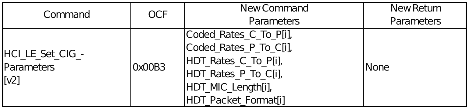
Used by a Central’s Host to create a CIG and to set the parameters of one or more CISes associated with a CIG in the Controller. [v2] introduces the command parameters below for HDT PHY support, as well as new Bit Numbers for PHY_C_To_P[i] and PHY_P_To_C[i] to indicate HDT PHY usage.
- Coded_Rates_C_To_P[i] – Indicates preferred rate to use over the LE Coded PHY from central to peripheral
- Coded_Rates_P_To_C[i] – Indicates preferred rate to use over the LE Coded PHY from peripheral to central
- HDT_Rates_C_To_P[i] – Indicates preferred rates to use over the HDT PHY from central to peripheral
- HDT_Rates_P_To_C[i] – Indicates preferred rates to use over the HDT PHY from peripheral to central
- HDT_MIC_Length[i] – Indicates the MIC length for encryption
- HDT_Packet_Format[i] – Indicates preferred HDT packet format for the controller to use
LE Set CIG Parameters Test command [v2]

For testing purposes only. Used by a Central’s Host to create a CIG and to set the parameters of one or more CISes associated with a CIG in the Controller. [v2] introduces the command parameters below for HDT PHY support, raises the upper limit for Max Payload command parameters to 8175 octets, and defines new Bit Numbers for PHY_C_To_P[i] and PHY_P_To_C[i] to indicate HDT PHY usage.
- Coded_Rates_C_To_P[i] – Identifies preferred rate to use over the LE Coded PHY from central to peripheral
- Coded_Rates_P_To_C[i] – Identifies preferred rate to use over the LE Coded PHY from peripheral to central
- HDT_Rates_C_To_P[i] – Indicates preferred rates to use over the HDT PHY from central to peripheral
- HDT_Rates_P_To_C[i] – Indicates preferred rates to use over the HDT PHY from peripheral to central
- HDT_MIC_Length[i] – Indicates the MIC length to be used for encryption over HDT
- HDT_Packet_Format[i] – Indicates preferred HDT packet format for the controller to use
- HDT_Payload_Window_Size_C_To_P[i] – Indicates size of payload window used by Central to Peripheral
- HDT_Payload_Window_Size_P_To_C[i] – Indicates size of payload window used by Peripheral to Central
LE Set Data Length command [v2]

Allows the Host to suggest the maximum transmission payload size and time to be used for LL Data PDUs on a given connection. [v2] introduces the command parameter PHYS to indicate the PHYs the parameters apply to (GFSK or HDT) and increases the TX_Octets value range upper limit to 8175 octets.
LE Test End command [v2]

Used to stop any test in progress. [v2] introduces the return parameter Num_Blocks to indicate the number of received blocks on the HDT PHY.
LE Transmitter Test command [v5]
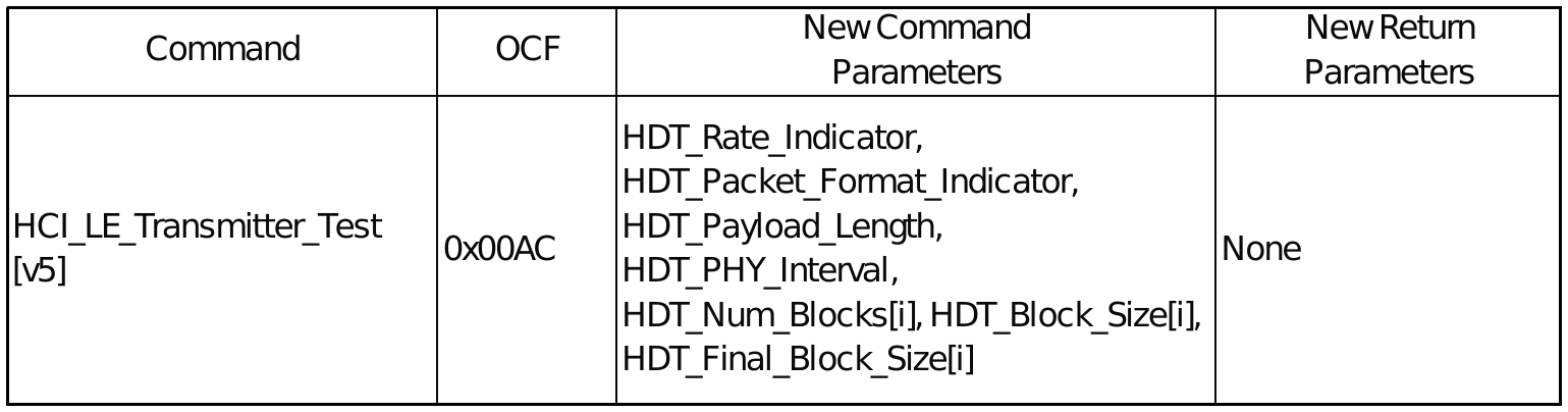
Used to start a test where the IUT generates test reference packets at a fixed interval. [v5] introduces the command parameters below for HDT transmission testing and adds a new value for PHY to indicate HDT PHY usage.
- HDT_Rate_Indicator – Specifies the HDT PHY rate
- HDT_Packet_Format_Indicator – Specifies the HDT packet format
- HDT_Payload_Length – Specifies the length of the payload in packet format 0 (ignored in PF1)
- HDT_PHY_Interval – Specifies the payload symbols per PHY interval
- HDT_Num_Blocks[i] – Specifies the number of blocks (Nb) in the payload (Nb=0 for PF0)
- HDT_Block_Size[i] – Specifies length of each block in the payload excluding the last
- HDT_Final_Block_Size[i] – Specifies the length of the last block to be transmitted
LE Write Suggested Default Data Length command [v2]

Allows the Host to specify/write the suggested default values for LL Data PDU transmission parameters for the Controller (Suggested_Max_TX_Octets, Suggested_Max_TX_Time). [v2] introduces the command parameter PHYS to indicate the PHY for which the transmission parameters are being specified (GFSK or HDT) and increases the upper limit for the Suggested_Max_TX_Octets range of values to 8175 octets.
Refresh Encryption Key command [v2]

Used by the Host to cause the Controller to refresh the encryption key on the ACL connection identified by the Connection_Handle, using the Encryption Refresh procedure. The MIC Length is specified when using the HDT PHY for the connection.
8.4 Updated HCI commands and events
LE BIG Sync Established event
Upper limit for Max_Payload event parameter value range increased to 8175 octets.
LE BIGInfo Advertising Report event
Upper limit for Max_Payload event parameter value range increased to 8175 octets. Also, new PHY event parameter value defined to indicate BIG is transmitted on HDT PHY.
LE CS Set Procedure Parameters command
New PHY command parameter value defined to indicate HDT PHY usage.
LE Enhanced Read Transmit Power Level command
New value for PHY command and return parameters defined to specify HDT PHY association.
LE Frame Space Update Complete event
New bit number for PHYS event parameter defined to indicate HDT PHY usage.
LE PHY Update Complete event
New values for TX_PHY and RX_PHY event parameters defined to indicate use of HDT PHY to transmit and receive.
LE Read PHY command
New values for TX_PHY and RX_PHY return parameters defined to indicate HDT PHY usage.
LE Read Remote Transmit Power Level command
New value for PHY command parameter defined to specify HDT PHY association.
LE Set Default PHY command
New values for TX_PHY and RX_PHY command parameters defined to indicate HDT PHY usage.
LE Set Event Mask command
Four events added to the mask for LE CIS Established [v3], LE Create BIG Complete [v2], LE Data Length Change [v2], and LE Test Report HDT Link Quality.
LE Set PHY command
New bit numbers for TX_PHYs, RX_PHYs, and PHY_Options command parameters defined to indicate HDT PHY usage and preferences.
LE Transmit Power Reporting event
New PHY event parameter value defined to indicate HDT PHY usage.
Set Event Mask Page 2 command
Three events added to the mask for Encryption Change [v3], Encryption Key Refresh Complete [v2], and Encryption Key Debug Report.
8.5 Message sequence charts
The charts that follow show typical interactions of relevant HCI commands and events for HDT support with the Bluetooth LE Link Layer.
Switch from GFSK PHY to HDT PHY
Unencrypted ACL connection
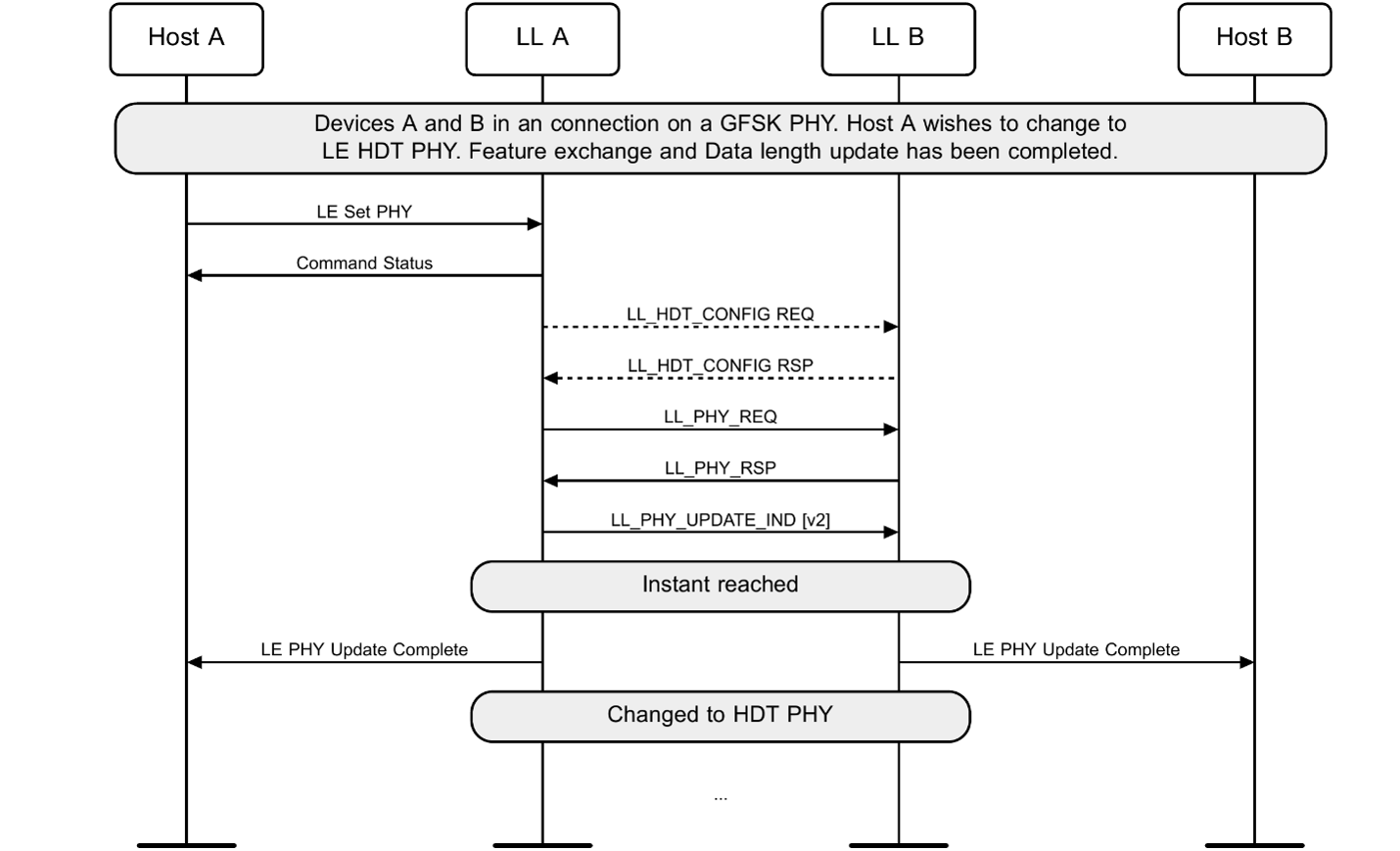
Figure 8.1 – Switch to HDT PHY on an unencrypted ACL connection
Encrypted ACL connection
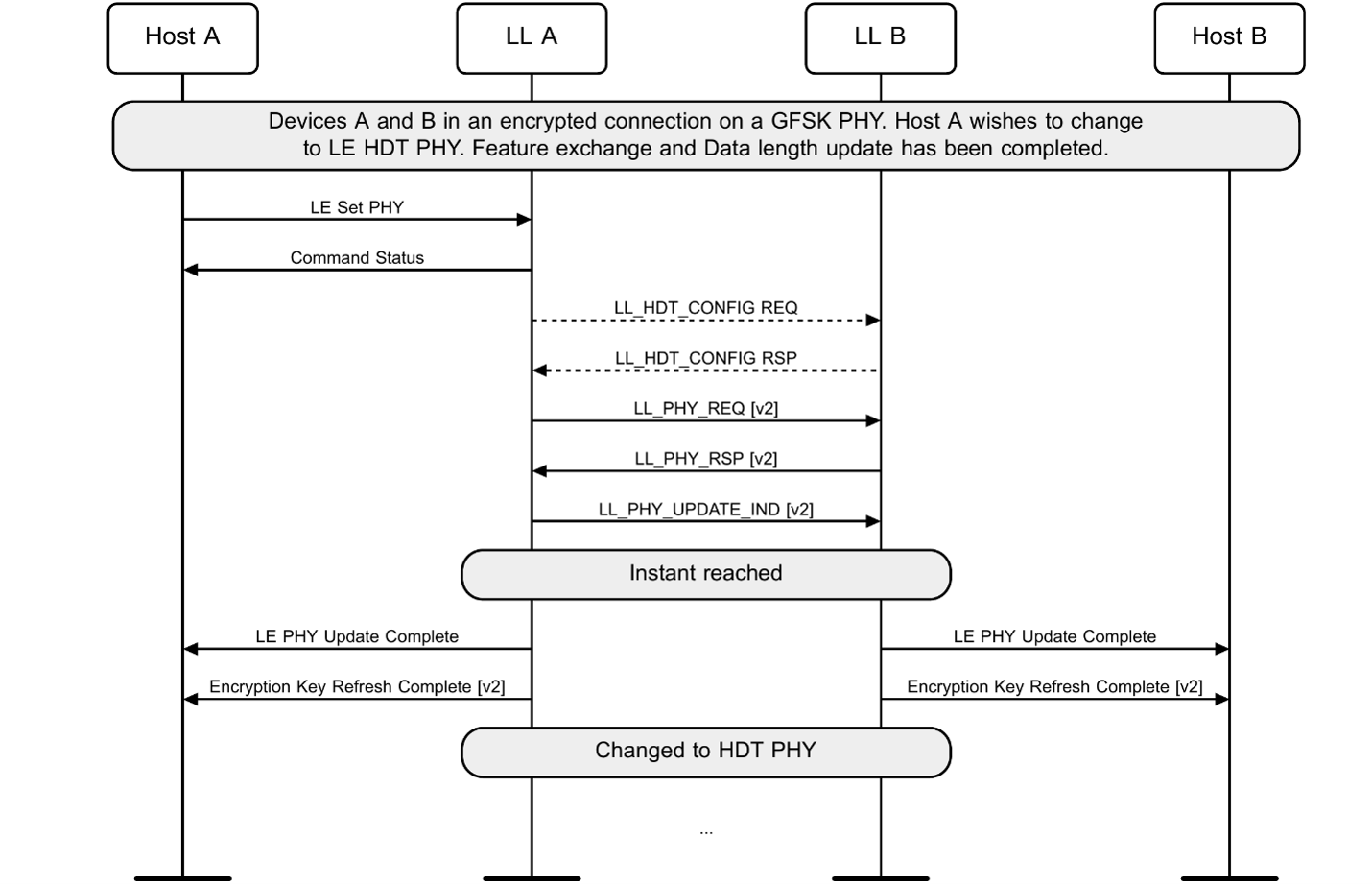
Figure 8.2 – Switch to HDT PHY on an encrypted ACL connection
Switch from HDT PHY to GFSK PHY
Unencrypted ACL connection
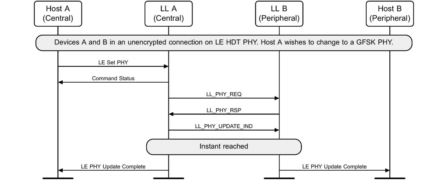
Figure 8.3 – Switch from HDT PHY to GFSK PHY on an unencrypted ACL connection
Encrypted ACL connection
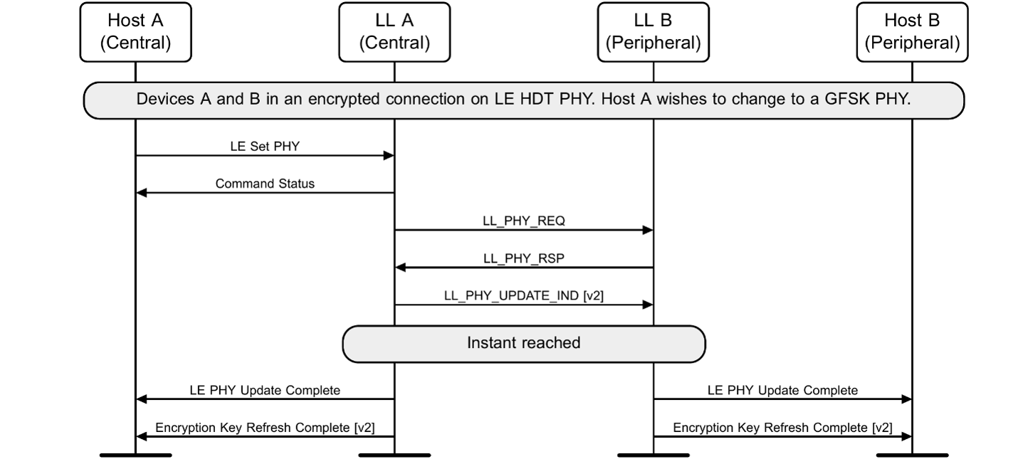
Figure 8.4 – Switch from HDT PHY to GFSK PHY on an encrypted ACL connection
Data Length update
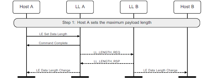
Figure 8.5 – Data length update
[v2] or later of the HCI_LE_Set_Data_Length command, the HCI_LE_Data_Length_Change event, the LL_LENGTH_REQ PDU, and the LL_LENGTH_RSP PDU are used to change the parameters for the HDT PHY.
CIG setup over HDT
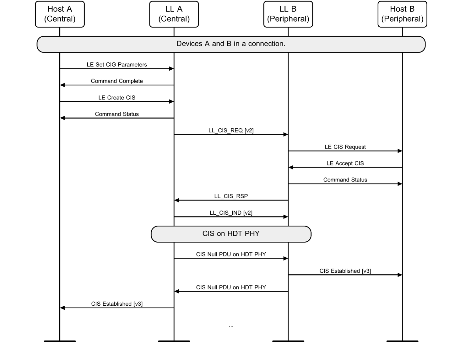
Figure 8.6 – CIG and CIS setup over HDT PHY
Start Encryption with Key Schedule
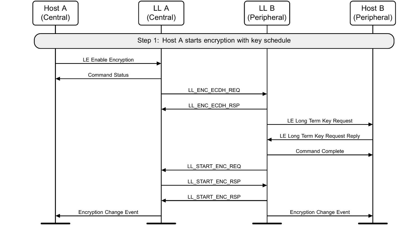
Figure 8.7 – Start encryption with key schedule
Start Opportunistic Encryption with Key Schedule
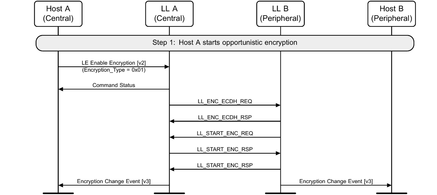
Figure 8.8 – Start opportunistic encryption
Restart Encryption with Key Schedule
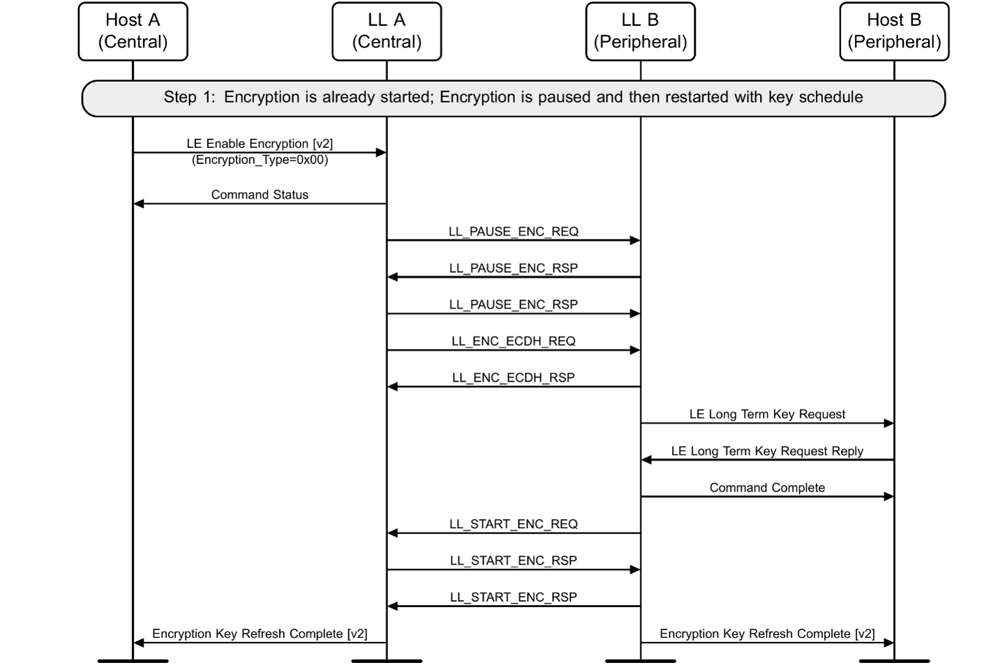
Figure 8.9 – Restart encryption with key schedule
Refresh Encryption with Key Schedule
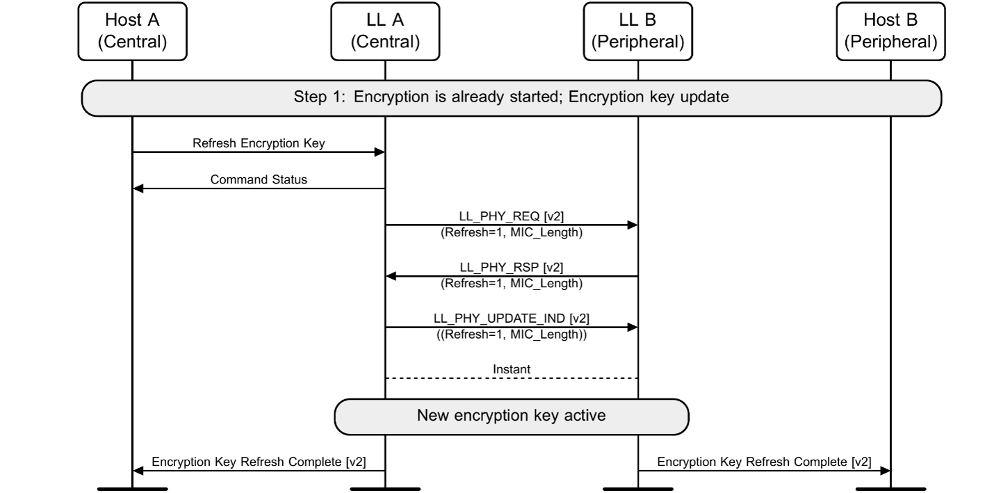
Figure 8.10 – Refresh encryption with key schedule
9. Miscellaneous
Bluetooth® HDT introduces updates to the Host and ISOAL layers of the Bluetooth LE stack. Host layer updates primarily support the verification and enforcement of MIC length requirements, while updates to ISOAL support the transport of larger data payloads enabled by the new HDT PHY.
9.1. Logical Link Control and Adaptation Protocol (L2CAP)
HDT makes MIC length an additional security criterion for the creation of L2CAP data channels with Credit Based Flow Control (CBFC).
CBFC is a mechanism where receiver-granted credits are used to regulate data transmission between devices and manage connection-oriented L2CAP channels. There are two CBFC modes: LE and Enhanced. At a high level, LE CBFC establishes a single L2CAP channel per connection, whereas Enhanced CBFC can establish multiple channels simultaneously. Both modes are enabled through L2CAP procedures that involve the exchange of a credit-based connection request and a corresponding response.
HDT extends the security validation performed while establishing credit-based L2CAP channels, enabling devices to check and enforce MIC length requirements in addition to traditional authentication, authorization, and encryption key size checks. It introduces values for the Result data field of response packets to indicate that a connection request is rejected because the negotiated MIC length is insufficient.
9.2. Generic Access Profile (GAP)
HDT makes small updates to the specification of LE Security Mode 1 and to service authorization procedures, enhancing the way Bluetooth LE devices evaluate and satisfy security requirements to access services through the Generic Access Profile (GAP).
In GAP, security modes define the requirements a Bluetooth LE connection must satisfy for a device to securely access services and attributes. LE Security Mode 1 governs security for LE ACL connections through four security levels using different combinations of authentication and encryption.
HDT extends LE Security Mode 1 by requiring the use of a Long-Term Key (LTK) with 128b equivalent strength for encrypted connections operating on the HDT PHY. Devices are prohibited from transitioning a connection to the HDT PHY, or establishing a CIS that uses the HDT PHY, when the associated LTK fails to meet the required 128b strength.
HDT also updates GAP procedures used to respond to and initiate service requests. When a service requires a level of security that is not satisfied by the current connection, GAP can now evaluate a service request and reject it with the error code MIC Length Too Short if the negotiated MIC length does not meet the service’s requirements.
When a device initiates a service request and the MIC length is insufficient, GAP can trigger a PHY Update and Encryption Refresh procedure to obtain the required MIC length before retrying the request. If the required MIC length cannot be established, the request is rejected.
Refer to Volume 3, Part C of the Core Specification for more details.
9.3. Attribute Protocol (ATT)
HDT makes MIC length an additional security criterion for access to attributes managed by the Attribute Protocol (ATT).
ATT is the protocol used by Bluetooth LE devices to let a client discover, read, write, and otherwise access attributes exposed by a server.
HDT introduces a new error code, MIC Length Too Short, to indicate that an attribute access request is rejected because the negotiated MIC length fails to satisfy the security requirements of the requested attribute. The error code is incorporated into ATT attribute permissions and supported across ATT procedures that access protected attributes, including attribute discovery, read, and write operations.
Updated ATT PDUs to support the new error code are identified in Volume 3, Part F of the Core Specification and listed below for reference.
- ATT_ERROR_RSP
- ATT_FIND_INFORMATION_REQ
- ATT_FIND_BY_TYPE_VALUE_REQ
- ATT_READ_BY_TYPE_REQ
- ATT_READ_REQ
- ATT_READ_BLOB_REQ
- ATT_READ_MULTIPLE_REQ
- ATT_READ_BY_GROUP_TYPE_REQ
- ATT_READ_MULTIPLE_VARIABLE_REQ
- ATT_WRITE_REQ
- ATT_PREPARE_WRITE_REQ
9.4. Generic Attribute Profile (GATT)
HDT makes minor updates to procedures defined in the GATT Profile to read and write characteristic values and descriptors that help recognize and propagate the ATT-level MIC length security checks and the new MIC Length Too Short error condition.
Updated GATT procedures are identified in Volume 3, Part G of the Core Specification and listed below for reference.
- Read Characteristic Value
- Read Long Characteristic Value
- Read Multiple Characteristic Values
- Read Multiple Variable Length Characteristic Values
- Write Characteristic Value
- Write Long Characteristic Value
- Characteristic Value Reliable Writes
- Read Characteristic Descriptor
- Read Long Characteristic Descriptor
- Write Characteristic Descriptor
- Write Long Characteristic Descriptor
9.5. Isochronous Adaptation Layer (ISOAL)
HDT introduces updates to the Isochronous Adaptation Layer (ISOAL) needed to support the transport of larger data payloads enabled by the HDT PHY.
ISOAL is responsible for segmenting and reassembling Service Data Units (SDUs) exchanged over isochronous transports (as used in LE Audio’s CIS and BIS streams).
To accommodate larger SDU segments, HDT updates the format of the ISOAL Framed PDU Segmentation Header by expanding the Length field from 8 bits to 12 bits. The Length field indicates the size, in octets, of the SDU segment carried within a framed PDU. To preserve compatibility with the existing header format, the 12-bit value is divided into separate Length High and Length Low fields within the Segmentation Header.
These changes increase the maximum SDU segment size that can be represented by ISOAL, enabling efficient transport of larger payloads while maintaining compatibility with the existing ISOAL segmentation and reassembly architecture. See Volume 6, Part G of the Bluetooth Core Specification for additional details.
Although these changes are implemented within ISOAL, their impact can extend to higher layers of the Bluetooth stack. By supporting larger SDU segments, ISOAL enables controllers to transport larger isochronous payloads that may ultimately be delivered to the Host through larger ISO data packets. While segmentation and reassembly remain transparent to most Host and application software, the increased payload capacity provided by HDT helps support more demanding isochronous data streams without requiring changes to the underlying ISOAL segmentation and reassembly architecture.
10. Conclusion
Bluetooth® High Data Throughput substantially advances the capabilities and performance of Bluetooth LE, creating the foundation for a new generation of wireless experiences and new opportunities for innovation across the Bluetooth ecosystem.
The new Bluetooth HDT PHY expands the performance envelope of Bluetooth LE, increasing the maximum supported bitrate to 7.5 Mbps through higher spectral efficiency, adaptive data rates, and mechanisms designed to maintain reliable communication under changing channel conditions.
The new Bluetooth HDT packet structure complements the higher-capacity PHY with flexible formats designed to balance efficiency, robustness, and overhead. Separating the Control Header from the payload allows critical packet information to be processed more robustly while supporting dynamic data rates for payload transmission. Larger payloads, payload aggregation, block-based transmission, and selective retransmission further enable HDT to move larger amounts of data efficiently, limiting the impact of transmission errors.
The HDT Link Layer enhancements deliver the intelligence needed to configure and manage HDT operation, coordinate transitions between GFSK and HDT PHYs, respond to changing link conditions, support isochronous communication, and manage the enhanced security capabilities introduced with Bluetooth HDT.
HDT strengthens Bluetooth LE security with longer MIC sizes and support for the Encryption Key Schedule (EKS) feature, enabling stronger protection for larger payloads and coordinated key updates as devices transition between GFSK and HDT operation. EKS also introduces capabilities such as opportunistic encryption, Perfect Forward Secrecy, and more flexible encryption key management.
Updates to the HCI and Host layers integrate HDT controller functionality into the broader Bluetooth LE stack, giving the Host the interfaces needed to set HDT preferences and parameters, monitor HDT operation, and accommodate the larger payloads and enhanced security requirements introduced with the new PHY.
For established Bluetooth applications and use cases, Bluetooth HDT provides capabilities that developers can leverage in new generations of products to achieve faster data transfers, greater capacity, improved efficiency, and more robust wireless performance. At the same time, HDT expands what is possible with Bluetooth LE, providing the additional performance and capacity needed for more sophisticated experiences such as high-resolution and lossless audio and for emerging applications with increasingly demanding data requirements.
Overall, Bluetooth technology has evolved continuously to serve new applications while preserving the interoperability, efficiency, and flexibility that have contributed to its widespread adoption. Bluetooth® High Data Throughput marks an important next step in that evolution, providing the additional performance and capacity needed for Bluetooth LE to continue advancing alongside the applications and experiences that depend on it.
For complete implementation requirements and technical details, refer to the Bluetooth Core Specification 7.0.
1. C. E. Shannon, “A mathematical theory of communication,” Bell System Technical Journal, vol. 27, pp. 379–423 and 623–656, Jul. and Oct. 1948.
