ブルートゥース® ・ネットワーキング入門
1.改訂履歴
| バージョン | 日付 | 著者 | 変更点 |
|---|---|---|---|
| 1.0.0 | 2019年1月19日 | マーティン・ウーリー、BluetoothSIG | 初期バージョン |
| 1.1.0 | 2024年5月16日 | マーティン・ウーリー、BluetoothSIG | Bluetooth Mesh Networking 1.1 および Bluetoothネットワーク照明制御 NLC) の主要機能を追加して更新しました |
2.本稿について
ブルートゥース® 入門書は、製品 開発者などの技術専門家が、正式な技術仕様を参照し、より深く掘り下げる前に、ブルートゥース・メッシュ・ネットワーキング技術について素早く理解するための手助けとして作成されました。
本稿の目的は、正式な仕様書と同じ内容を再現したり、同じ深さまでカバーしたりすることではない。時折、仕様書からの簡単な抜粋が含まれることがあります。本書は、Bluetooth メッシュネットワーキングの重要な概念を紹介・説明し、他のリソースや仕様への道筋を示し、できれば学習曲線の険しさを少しでも和らげることで、方向づけを行うためのものだとお考えください。
3.はじめに
3.1 Bluetooth技術の進化
Bluetooth技術は2000年から存在している。当初は、他のネットワーク機器を介さずに2台のデバイスが無線でデータを交換できるようにするために開発され、ワイヤレスマウスや車載用ハンズフリーキットなどの製品にすぐに採用された。 これらの初代Bluetooth製品に採用された最初のバージョンは、正式にはBluetooth BR(基本レート)と呼ばれ、物理層で毎秒100万ビット[1](Mb/s)で動作します。その後、同じ技術の高速版であるBluetooth BR/EDR が登場しましたBluetooth BR/EDR 拡張データレート(Enhanced Data Rate)Bluetooth BR/EDR 意味しBluetooth BR/EDR ビットレートが2Mb/sに倍増されています。
Bluetooth LE 、ブルートゥース® 4.0[2]Bluetooth LE 登場しました。Bluetooth BR/EDRではなく、並行して存在する新たなバージョンのBluetooth技術であり、次世代製品に最適で、新たな技術的・機能的要件を満たす能力を備えた代替手段として位置づけられました。
Bluetooth LE 、2つのデバイス間のポイント・ツー・ポイント通信以外のトポロジーをサポートしており、1つのデバイスが同時に無制限の数のレシーバーにデータを送信できるブロードキャストモードを備えている。
Bluetooth LE Bluetooth Mesh Networkingの基盤でもあり、何万台ものデバイスのネットワークを構築し、それぞれがネットワーク内の他のデバイスと通信することを可能にする。
3.2 ブルートゥース・メッシュ・ネットワーキング
ブルートゥース・メッシュ・ネットワーキングは、商業ビルの問題や機会に適用できる、安全で拡張性のある標準化された無線通信技術を提供するために開発された。
ネットワーク照明制御 NLC)は、Bluetoothメッシュアプリケーション 主要なアプリケーション であり、物理的に広大な空間における手動および自動の照明制御を可能にします。個々の照明器具または照明器具のグループに対して、単一のネットワーク操作で制御を実行できます。
Bluetoothメッシュネットワークネットワーク照明制御 で実現可能な主な機能は以下の通りです。
- オンとオフの切り替えができる。
- その明るさ(より正確には明度)は、人間の目の光に対する感度の変化を補正する知覚的に均一な尺度に沿って制御することができる。
- 色温度、色相、彩度は変更可能です。
- センサーは、多かれ少なかれ、部屋の測定可能なプロパティ 情報を関連する照明に届けることができ、環境状態 照明が自動的に調整される。ブルートゥース・メッシュ・ネットワーキングでは、センサーと照明の間でメッセージをやり取りするための集中型ルーターは必要ない。
- シーンとして知られる特定の状態 値の任意のコレクションを定義することができ、ライトは1回のリクエストで1つのシーンから別のシーンに切り替えることができる。
- 照明のグループに影響を与えるシーンの変更は、特定の時点で自動的に行われるようにスケジュールすることができます。
- 部屋の使用状況に応じたシーンの自動トリガーや、使用者がいない場合のスタンバイ状態 自動移行が可能。省エネに役立ちます。
- 照明の状態を変更するための事前定義されたスケジュールを設定する機能をサポート。
- メーカーが必要に応じて機器に機能を追加できるようにするベンダーモデルのコンセプトをサポートする。
ネットワークにおける照明の制御は、直接的な無線通信の範囲に制限されない。スイッチやセンサーのようなデバイスは、ビルのはるか遠く、おそらく数十階上にある照明を制御することができる。
セキュリティは当初からブルートゥース・メッシュ・ネットワーキング技術に組み込まれており、以下のような潜在的な問題や脅威に対処している:
- 情報の機密性の保護
- デバイスおよびネットワークのプライバシー保護機能による追跡の防止
- ネットワーク制御メッセージの改ざん防止
- デバイスの動作をネットワークの特定部分のみに制限する
- リプレイ攻撃の防止
- ネットワークへのデバイスの追加が安全なプロセスに従うことを保証する
- 廃棄されたデバイスが後日不正アクセスに悪用されるリスクを一切伴わずに、デバイスをネットワークから安全に削除できることを保証する
- ネットワーク全体のセキュリティを損なうことなく、ネットワーク内の関連機能に対するゲストアクセス権限を付与・取り消す機能を提供します
BluetoothメッシュネットワークとワイヤレスBluetoothネットワーク照明制御 を備えた建物は、様々な利点をネットワーク照明制御 。
- センサーが周囲の明るさや部屋の使用状況などのデータを提供し、自動的に照明レベルを調整できるため、エネルギー効率が向上する。
- スイッチやスマートアプリケーション ユーザーインターフェース(UI)に触れるだけで、プレゼンテーションや大企業の円卓会議など、部屋の現在の用途に最適な照明を再設定できる。
- プロアクティブなメンテナンスは、Bluetooth Mesh Networkingをサポートするデバイスが利用可能な使用状況とデバイスのヘルスデータによって促進されます。
- 建物内の物理的なレイアウトや照明要件の変更は、より容易に実現できる。
- ブルートゥース・メッシュ・ネットワーキング・テクノロジーは、プロトコルスタック 、デバイスの動作、能力、インターフェイスを網羅する一連の標準仕様によって定義されています。つまり、どのメーカーの製品であっても相互運用が可能です。Bluetooth Mesh Networking技術の採用者は、単一のメーカーや小規模で閉鎖的なグループに縛られることはありません。
4. 主な特徴と概念
Bluetooth Mesh Networkingのトポロジーを理解するには、Bluetooth LEの世界では他に類を見ない一連の基本的な機能、技術用語、概念について学ぶ必要があります。このセクションでは、それらの機能、用語、概念の中でも最も基本的なものを探求します。
4.1 Bluetoothの動作モード
Bluetooth LE 、デバイス同士が通信するための複数の異なる方法をBluetooth LE 。これらはブルートゥース® で正式に定義されており、本稿では非公式に動作モードとして言及される。
各種の動作モードは、デバイスによって形成されるトポロジー、可能な通信の方向、およびモードの技術的基盤(接続指向モードか非接続指向モードかなど)を含む、いくつかの点で異なる。
コネクションオリエンテッド通信では、デバイスはまず、送受信タイミングパラメータなど、その後の通信の重要な局面で合意できる情報を交換する。コネクションレス型通信では、このようなことは起こらず、送受信のタイミングも同じように事前合意されません。Bluetooth LE では、コネクション型通信は常に 2 台のデバイス間で行われるのに対し、コネクショ ンレス型通信は、1 台の送信デバイスが複数のレシーバー デバイスと通信する際に、パラメータに関す る事前合意情報の有無に関わらず使用することができます。
トポロジーは、通信機器間に形成されうる関係の冗長性に関係する。3つの異なるトポロジーが認識されている:
- 一対一(1:1)
- 一対多 (1:m)
- 多対多(m:n)
一部の動作モードでは、一方向のみのアプリケーション データ通信が可能であるが、他の動作モードでは双方向通信が可能である。
モードによっては、パケットの送信に正確に規則的なスケジュールを使用する場合もあれば、不規則な場合もある。
現在、7つのオペレーションモードが定義されている。それらは以下の通りである:
- LE 非同期接続指向論理トランスポート(LE ACL)
- LE広告放送(ADVB)
- 定期アドバタイズ (padvb)
- レスポンス付き定期アドバタイズPAwR
- コネクテッド・アイソクロナスストリーム(CIS)
- ブロードキャスト・アイソクロナスストリーム(BIS)
- Channel Sounding (CS)
ブルートゥース® 仕様は、各モードを詳細に定義しています。
表 1 は、比較のために 7 つの動作モードの主な属性をまとめたものである。Channel Sounding (CS)は、2つのデバイス間の距離の安全な計算のみをサポートするように設計された特別なモードであり、アプリケーション データの転送には使用されないことに注意してください。
| 動作モード | 接続指向型または接続非指向型 | トポロジー | 送信スケジュール | アプリケーション の方向 |
| LE ACL | コネクション型 | ポイントツーポイント | レギュラー | 双方向 |
| エーディーブイビー | コネクションレス | 一対多 | イレギュラー | 一方向 |
| PADVB | コネクションレス | 一対多 | レギュラー | 一方向 |
| PAwR | コネクションレス | 一対多 | レギュラー | 双方向 |
| CIS | コネクション型 | ポイントツーポイント | レギュラー | 双方向 |
| ビス | コネクションレス | 一対多 | レギュラー | 一方向 |
| CS | 該当なし | マンツーマン | レギュラー | 該当なし |
表1 - Bluetooth動作モードの属性
Bluetoothメッシュネットワーキング技術は動作モードではありません。これは一連の定義済み手順、標準的なアプリケーション動作、Bluetooth LE 無線ネットワークBluetooth LE 利用可能にするその他の機能を備えたプロトコルです。Bluetooth LE 機能Bluetooth LE 複数の動作モードBluetooth LE 基盤として構築されており、接続レス方式で動作する場合もあれば、接続指向通信を利用する場合もあります。 原則として、Bluetoothメッシュネットワークが形成するトポロジーは多対多です。これは、あらゆるデバイスが他のあらゆるデバイスと通信する可能性があり、アプリケーション 通信が双方向で発生し得るためです。
通信は、動作モードの1つに基づくベアラと呼ばれるメカニズムを使用して、適切な方法でBluetooth LE によって伝送されるメッセージを使用して達成されます。デバイスは、エンド・ツー・エンドの通信範囲が個々のメッシュ・デバイスの無線範囲をはるかに超えて拡張されるように、ネットワーク全体にわたって他のデバイスにメッセージを中継することができます。
4.2 デバイスとノード
メッシュ・ネットワークの一部であるデバイスはノードと呼ばれ、そうでないデバイスは非プロビジョニング・デバイスと呼ばれる。
プロビジョニングされていないデバイスをノードに変換するプロセスをプロビジョニングと呼ぶ。
プロビジョニングとは、プロビジョニングされていないデバイスが一連のセキュ リティキーを所有し、ユニキャスト・アドレス 割り当てられ、プロビジョナー呼ばれるデバイスのデータベースにリストされるようになる手順のことである。プロビジョナー 通常、タブレットやスマートフォンである。
4.3 エレメント
一部のノードは複数の構成要素を持ち、それぞれが独立して制御可能です。Bluetoothメッシュネットワークの用語では、これらの要素を「エレメント」と呼びます。図1はLED製品 を示しており製品 ネットワークに追加すると、個々のLEDライトごとに1つずつ、合計3つのエレメントを持つ単一のノードを形成します。
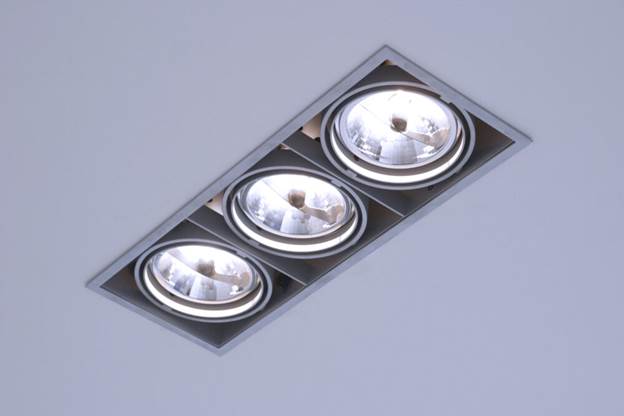
図1 - 3つの要素からなる照明ノード
4.4 メッセージ
ノードが他のノードのステータスを照会したり、何らかの方法で他のノードを制御する必要がある場合、適切なタイプのメッセージを送信します。ノードが他のノードにステータスを報告する必要がある場合は、メッセージを送信します。メッシュ・ネットワークの通信はすべてメッセージ指向で、多くのメッセージ・タイプが定義されており、それぞれに固有のオペコードがあります。
メッセージは大きく2つに分類される:
- 確認されたメッセージは、それを受信したノードからの応答を必要とする。応答には2つの目的がある。それは、関連するメッセージが受信されたことを確認することと、メッセージ受信者に関するデータを元のメッセージ送信者に返すことである。承認済みメッセージ 送信者は、期待された応答を受け取らなかった場合、メッセージを再送することができる。したがって、承認済みメッセージ済みメッセージは冪等でなければならない。これは、あるノードに複数回到着した承認済みメッセージ効果は、それが一度だけ受信された場合と同じであることを意味する。
- 未承認のメッセージには返事は不要です。
ほとんどのBluetoothメッシュネットワーキングシナリオでは、このメッセージングモデルが非常によく拡張できるため、確認なしメッセージを使用します。メッセージのコピーを複数回連続して再送信するようにノードを設定することで、信頼性を高めています。
確認応答を返す必要のあるメッセージは、ターゲットが 1 台のデバイスの場合はうまく機能しますが、複数のデバイスのグループをターゲットにする場合はうまく機能しません。ノードやそのエレメントのコンフィギュレーションに関わるメッセージのほとんどは、確認応答付きメッセージを使用します。
中継と呼ばれるシステムにより、メッセージは直近の無線範囲を超えて伝送される。中継の詳細は4.19節「メッセージ中継」で説明されている。
4.5 住所
メッセージはアドレス、またはアドレスへ送信されなければならない。ブルートゥース・メッシュ・ネットワーキングは3種類のアドレス定義しています。
アドレス、単一のエレメント一意に識別する。ユニキャストアドレスは、プロビジョニングプロセス中にデバイスに割り当てられます。
アドレス アドレス。アドレス 、パブリッシュ 購読と呼ばれるプロセスを通じて、複数のデバイスが同じ送信メッセージを受信することを可能にします。グループアドレスはSIG 定義された固定グループアドレスSIG Fixed Group AddressesSIG 動的に割り当てられるアドレスのいずれかです。 BluetoothSIG グループアドレスは7種類定義されている。これらはall-nodes、all-relays、all-friends、all-proxies、all-directed-forwarding-proxies、all-ipt-nodes、all-ipt-border-routersと命名される。プロキシ、フレンド、リレーの用語については本稿の後半で説明する。
ダイナミック・グループ・アドレスは、設定アプリケーション ユーザーによって確立され、例えば、建物の各部屋に対応するグループ・アドレスを定義するなど、建物の物理的な構成を反映することが期待される。
バーチャルアドレスグループアドレス おり、一つの送信メッセー ジをパブリッシュ 購読複数のデバイスが受信できるようにする。これは、任意のエレメント 関連付けることができる128ビットのUUID値の形をとり、ラベルによく似ている。例えば、仮想アドレスは製造時点で事前に設定することができ、メッシュ・ネットワークに配備された、そのメーカーが製造したすべての会議室プロジェクターのアドレスを簡単に設定できるようにするなどのシナリオに使用できます。
4.6パブリッシュ 購読
メッセージを送信する行為はパブリッシングと呼ばれる。ノードは、処理のために特定のアドレスに送られたメッセージだけを受信するように設定され、これはサブスクライブと呼ばれる。
通常、メッセージはグループアドレスまたはバーチャルアドレスに宛てられる。グループ名とバーチャル・アドレス 名は、エンド・ユーザーにとって容易に理解できる意味を持ち、デバイスを設定する際に簡単かつ直感的に使用できる。
図2では、Switch 1という名前のノードがアドレス Receptionにパブリッシュしていることがわかります。 ノードLight 1、Light 2、Light 3 購読 それぞれアドレス 購読 アドレス アドレスに公開されたメッセージを処理します。つまり、Light 1、Light 2、Light 3はSwitch 1によってオン/オフを切り替えられます。
スイッチ2 アドレス 「Accounts」にメッセージを発行します。ライト3のみアドレス 購読アドレス スイッチ2によって制御される唯一のライトとなります。なお、この例はノードが複数の異なるアドレス宛ての購読 事実も示しています。これは強力かつ柔軟な機能です。
同様に、スイッチ5と スイッチ6の両方が同じ引受 アドレス パブリッシュ いることに注目してほしい。
パブリッシュ通信モデルでグループアドレスとバーチャルアドレスを使用すると、ネットワークに新しいノードを削除、交換、または追加しても、他のノードの再構成が不要になるという利点もあります。経理部門に追加の照明を設置する場合を考えてみよう。新しいデバイスは、プロビジョニング・プロセスを使用してネットワークに追加され、アカウント・ アドレス 購読 ように構成される。このネットワークの変更によって、他のノードが影響を受けることはない。スイッチ 2 は以前と同じようにAccountsへのメッセージをパブリッシュ 続けるが、ライト 3と新しいライトの両方が応答するようになる。

図2 –パブリッシュ 購読
4.7 状態とプロパティ
Bluetoothメッシュネットワーキングでは、以下のような概念で表現されている。 状態値で表されます。
状態 、エレメント そのモデルの1つに含まれる、ある型の値のことである。)状態はまた、関連する振る舞いを持ち、他の文脈では再利用できない。
例として、点灯または消灯する単純なライトを考えてみよう。Bluetoothメッシュネットワーキングでは、Generic OnOffと呼ばれる状態 定義されている。ライトはこの状態 持ち、Onの値はライトの点灯に対応し、ライトを点灯させます。一方、Generic OnOffの 状態 Offの場合、ライトは消灯します。
ジェネリックという言葉の意味については後述する。
プロパティは、エレメントに関連する値を含むという点で状態と似ています。しかし、他の点では状態とは異なります。
Bluetooth LE[3]に慣れ親しんだ読者であれば、特徴を認識し、異なる GATT サービス内のような 異なるコンテキストで再利用可能な、定義された振る舞いのないデータ型であることを思い出すだろう。プロパティ 、Bluetooth Mesh Networking をサポートするデバイスで特徴 解釈するためのコンテキストを提供します。
プロパティに関連するコンテキストの重要性と使用法を理解するために、例えば、現在屋内周囲温度と 現在屋外周囲温度を含む多くの関連プロパティを持つ8ビット温度状態 タイプである特徴 温度8を考えてみましょう。この2つのプロパティにより、センサーはパブリッシュ 読み取り値を、受信側クライアント その温度値が持つコンテキストを判断できるようにし、その真の意味をより理解できるようにします。
4.8 状態と基本演算
メッセージは、メッシュデバイスに対して作用する操作を呼び出すための仕組みです。特定のメッセージタイプは、状態 状態 状態 集合に対する操作を定義します。すべてのメッセージは、Bluetoothメッシュネットワークがサポートする操作の種類を反映した、大きく3つのタイプに分類されます。これら3つのタイプの略称は、GET、SET、STATUSです。
GETメッセージは、1つ以上の要素から与えられた状態 値を要求する。STATUSメッセージはGETに応答して送られ、関連する状態 値を含む。
SET メッセージは与えられた状態値を変更する。確認された SET メッセージは、SET メッセージに対する応答として STATUS メッセージが返されます。
STATUSメッセージは、GETメッセージに応答して送信されたり、SETメッセージに応答して送信されたり、他のメッセージとは無関係に送信されたりする。
メッセージによって参照される特定の状態は、メッセージのオペコードから推測される。一方、プロパティは、16 ビットのプロパティ ID を使って、一般的なプロパティ 関連メッセージの中で明示的に参照されます。
4.9状態
ある状態 別の状態 変化は、状態 遷移と呼ばれる。遷移は瞬間的な場合もあれば、「遷移時間」と呼ばれる一定期間にわたって実行される場合もある。 遷移時間.状態 遷移は、アプリケーション 層の動作やノードの外観に影響を与える可能性が高い。
4.10 束縛状態
状態間には、一方の変化が他方の変化を誘発するような関係が存在することがある。このような関係は状態 バインディングと呼ばれる。一つの状態 他の複数の状態に結合していることもある。
例えば、調光スイッチで制御されるライトを考えてみよう。ライトは2つの状態、ジェネリック・オンオフと ジェネリック・レベルを持ち、それぞれが他方に束縛されている。Generic Levelの値がゼロになるまで(完全に暗くなるまで)ライトの明るさを下げると、Generic OnOffはOn状態 Off状態遷移する。
4.11 モデル
モデルは前述の概念をまとめ、オブジェクト指向ソフトウェア開発におけるクラスや オブジェクトのように、状態 データと関連するメッセージタイプや機能の組み合わせを定義する。
モデルは通常、サーバーモデルか クライアント どちらかである。
- サーバーモデルは、状態、状態 遷移、状態 バインディング、そしてモデルを含むエレメント 送受信するメッセージのコレクションを定義します。また、サポートされるメッセージ、状態 、遷移に関連する振る舞いも定義します。
- クライアント 状態を定義しない。その代わりに、対応するサーバーモデルで定義されたステータスをGET、SET、または取得するために送受信するメッセージを定義します。
モデルは、他のモデルを拡張することによって作成することができる。拡張されていないモデルはルート・モデルと呼ばれる。
モデルは不変であり、振る舞いを追加したり削除したりして変更することはできない。新しいモデル要求を実装するための正しい、そして唯一許されるアプローチは、既存のモデルを拡張することです。
ファウンデーション・モデルとは、メッシュ・ネットワークを構成・管理するために必要なモデルである。その他のモデルは、特定のクラスの製品必要とされるような特定のタイプの機能に関係する。
4.12 ジェネリック
ONとOFFという単純な考え方に代表されるように、多くの異なるタイプのデバイスは、しばしば意味的に等価な状態を持つことが認識されている。照明、扇風機、電源ソケットを考えてみよう。
その結果、Bluetooth Mesh Model仕様では、Generic OnOffや Generic Levelといった一連の再利用可能なジェネリック・ステートが定義されています。
同様に、ジェネリック・ステートを操作する一連のジェネリック・メッセージも定義されている。例えば、Generic OnOff Getや Generic Level Setなどがある。
ジェネリック・ステートとジェネリック・メッセージは、ジェネリック・オンオフ・サーバーのようなジェネリック・サーバー・モデルや、 クライアントようなクライアント 、一般化されたモデルで使用される。
ジェネリックを使用することで、新しいモデルを作成することなく、さまざまな種類のデバイスがBluetooth Mesh Networkingをサポートできるようになります。モデルは他のモデルを拡張することによっても作成できることを忘れないでください。そのため、ジェネリックモデルは、新しいタイプのデバイスのモデルを素早く作成するための基礎となります。
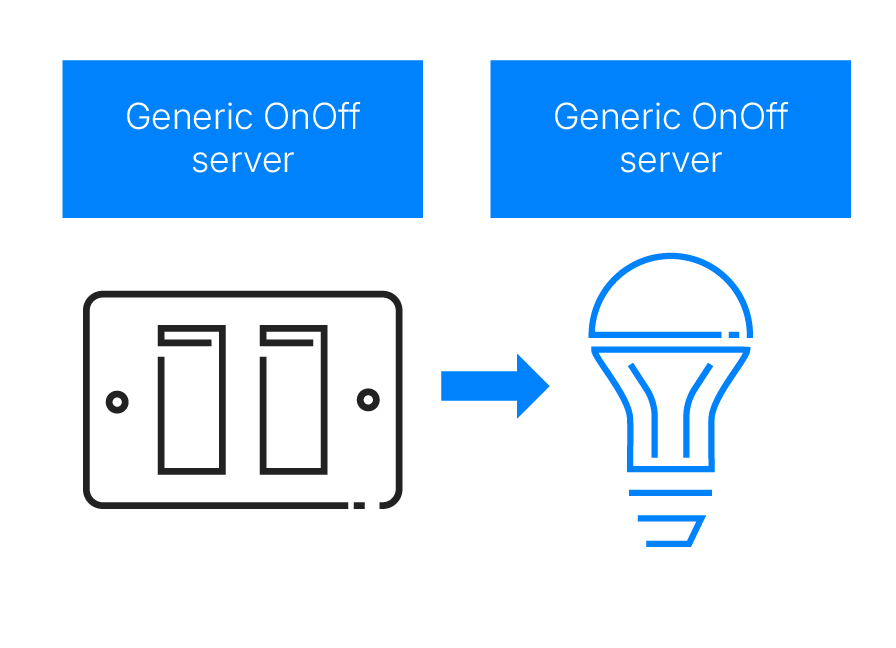
図3 – 汎用モデル
4.13 シーン
シーンは、保存された状態のコレクションであり、特別なタイプのメッセージの受信に応答して、または指定されたスケジュールされた時間に呼び出され、現在の状態にすることができる。シーンは16ビットのシーン番号で識別され、メッシュネットワーク内でユニークです。
シーンは、一連のノードを、1つの協調アクションで、以前に保存された補完的な状態のコレクションに設定することを可能にします。
朝、受付の温度を20℃にし、LEDライトを一定の明るさにし、受付デスクのランプを暖かみのある黄色に設定することを想像してください。このシナリオ例の様々なノードを手動でこれらの状態に設定した後、アプリケーション 使用してシーンとして保存し、適切なシーンに関連するメッシュ・メッセージを送信することで要求に応じて、またはスケジュールされた時間に自動的に、後でシーンを呼び出すことができます。
4.14 ネットワークとサブネット
Bluetoothメッシュネットワークは、アドレス 、ネットワークキー、アプリケーション 、IVインデックスという4つの共通リソースの集合によって定義されます。Bluetoothメッシュネットワークは、一連のサブネットに細分化できます。 TCP/IPなどのプロトコルに基づくネットワークとは異なり、特定のネットワークへの所属はアドレス 一切関係ありません。代わりに、Bluetoothメッシュネットワークサブネット メンバーシップ 主にノードに ネットワークキー (4.15 キー参照)を発行することでエレメント 。エレメント 複数のネットワークキーを発行エレメント 、したがってサブネット メンバー 。サブネットサブネット互いに完全に分離されている場合もあれば、重複したり、サブネット完全に含まれている場合もあります。
サブネットには、以下のような用途がある:
- あるデバイスグループを他の無関係なデバイスから隔離することで、ネットワークにセキュリティを加える。
- サブネット境界を越えてメッセージが流れないようにすることで、電波スペクトラムの利用をより効率的にすることができる。
- ネットワーク管理を容易にします。例えば、ゲストデバイスにはサブネット ネットワークキーを使用して、ネットワークの一部への一時的なアクセス権を付与できます。
図4は、ホテルの各客室に使用されるサブネットを示したものである。
つのサブネット サブネット指定される。ネットワークの恒久的なメンバーになると予想されるデバイスは、サブネットメンバーになる。
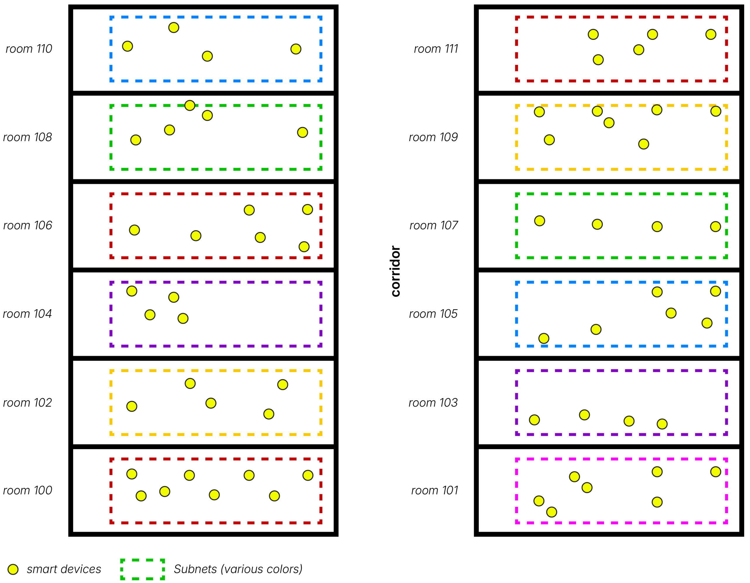
図4 – ホテルの各部屋でデバイスを分離するためにサブネットが使用されている例
4.15 キー
ブルートゥース・メッシュ・プロトコル仕様では、いくつかのタイプのセキュリティキー定義されている。
- 各ノードは一意のデバイスキー(デバイスキー).このキーの値を知っているのは、キーが発行されたデバイスとプロビジョナー です。このキーは、コンフィギュレーション・プロセスを安全に行うために使用されます。
- デバイスには、少なくとも1つの共有ネットワーク鍵(NetKey).この種のキーはネットワークレイヤー通信を保護する。特定のNetKey キーを所有することで、ノードは関連するネットワークまたはサブネット一部となる。 NetKey呼ばれる特別なキーはプライマリ・メッシュ・ネットワークに関係する。
- メッシュネットワークは、少なくとも1つのアプリケーションキー(アプリキー).ネットワークがサポートするアプリケーションの例としては、照明、空調、暖房などがある。アプリキー 、アッパートランスポートレイヤー 通信を保護するために使用され、セキュリティの観点から異なるアプリケーション間のメッセージングを分割する効果がある。
プロビジョニングプロセス(4.16 プロビジョニング参照)において、各ノードにデバイスキー ネットワークキー 。アプリケーション 、および必要に応じてサブネットに対応する追加のネットワークキーは、構成(4.17 構成参照)中にデバイスに発行される。
4.16 プロビジョニング
プロビジョニングとは、デバイスがメッシュ・ネットワークに参加し、ノードとなるプロセスである。このプロセスにはいくつかの段階があり、様々なセキュリティ・キーが生成され、それ自体が安全なプロセスである。
プロビジョニングは通常、スマートフォンやタブレットアプリケーション 行われます。他のアーキテクチャ(例:クラウドベースのプロビジョニング)も可能です。この役割において、プロビジョニングプロセスを駆動するために使用されるデバイスは プロビジョナー と呼ばれ、プロビジョニングされるデバイスはプロビジョニーと呼ばれます。
プロビジョナー 、直接電波の届く範囲にあるデバイスをプロビジョニングできる。リモート・プロビジョニングと呼ばれるオプションの機能 、プロビジョナー距離を問わず、ネットワーク内の任意の場所にあるデバイスのプロビジョニングが可能になる。
4.16.1 直接プロビジョニング
ダイレクト・プロビジョニング・プロセスは、5つのステップを経て進行する。
ステップ1.ビーコン送信
未プロビジョニングデバイスは、未プロビジョニングデバイスビーコンをブロードキャストすることで、プロビジョニングが可能であることを示す。これは Mesh Beaconアドバタイジング・データ(AD)タイプがアドバタイジング・パケットのペイロード・フィールドに含まれることで示されます。
ユーザーは、例えばボタンを押すことによって、このように新しいデバイスの広告を開始する必要があるかもしれない。
ステップ 2.招待
このステップでは、プロビジョナー Invite PDUの形式で、プロビジョナー 招待 送信する。ビーコン送信 Provisionee デバイスは、自分自身に関する情報を Provisioning Capabilities PDU として応答する。
ステップ3. 公開鍵の交換
プロビジョナー および被提供者は、直接または帯域外(OOB)方式で、静的または一時的な公開鍵を交 換する。
サポートされている場合、X.509証明書は公開認証 に使用できます。4.16.3 証明書ベースのプロビジョニングを参照してください。
ステップ4.認証
このステップでは、プロビジョナー およびプロビジョニ ーは、認証のために特定の動作を行う。たとえば、Provisionee は、その能力に適したアクションを使用して、ランダムな 1 桁または複数桁の数値を何らかの形式でユーザーに出力することができる。たとえば、複数桁の数値を表示する。次にユーザーは、新しいデバイスが出力した数字をプロビジョナー 入力し、2つのデバイス間で、乱数を含む暗号交換が行われ、2つのデバイスのそれぞれの認証 他方に対して完了する。同様に、プロビジョナー 、Provisioneeに入力しなければならない値を出力することもできる。デバイスの入出力能力にもよるが、さまざまな認証 方法が可能である。
ステップ5. プロビジョニングデータの配布
認証 成功裏に完了すると、2つのデバイスはそれぞれ、秘密鍵と交換されたピア公開 鍵からセッション鍵を導き出す。セッション・キーは、プロビジョニング・プロセスを完了するために必要なデータのその後の配布を保護するために使用される、セッション・セキュリティキー 、デバイスキー 完了するために必要なネットワークキー 後続の配 布を保護するために使用される。セキュリティキー 知られるネットワークキー NetKey)と、 デバイス・デバイスキー)と呼ばれるデバイス固有のキーが含まれる。決定的に重要なのは、デバイスキー プロビジョナー プロビジョニーによって独立して計算されるため、無線で送信されることはないということである。
プロビジョニングが完了すると、プロビジョニングされたデバイスは、デバイスキー、ネットワークのNetKey、IVインデックス 知られるメッシュ・セキュリティパラメータ 、およびプロビジョナー割り当てられたユニキャスト・アドレス持つ。これは現在ノードとして知られている。
4.16.2 リモートプロビジョニング
プロビジョナー (RPR)を使用すると、プロビジョナー プロビジョニングされていないデバイスは、2つのデバイス間のネットワークを介した通信経路が形成されるのであれば、どのような場所にあってもよい。これは、多くの実世界の状況に対して、より実用的なプロビジョニングのアプローチを提供する。
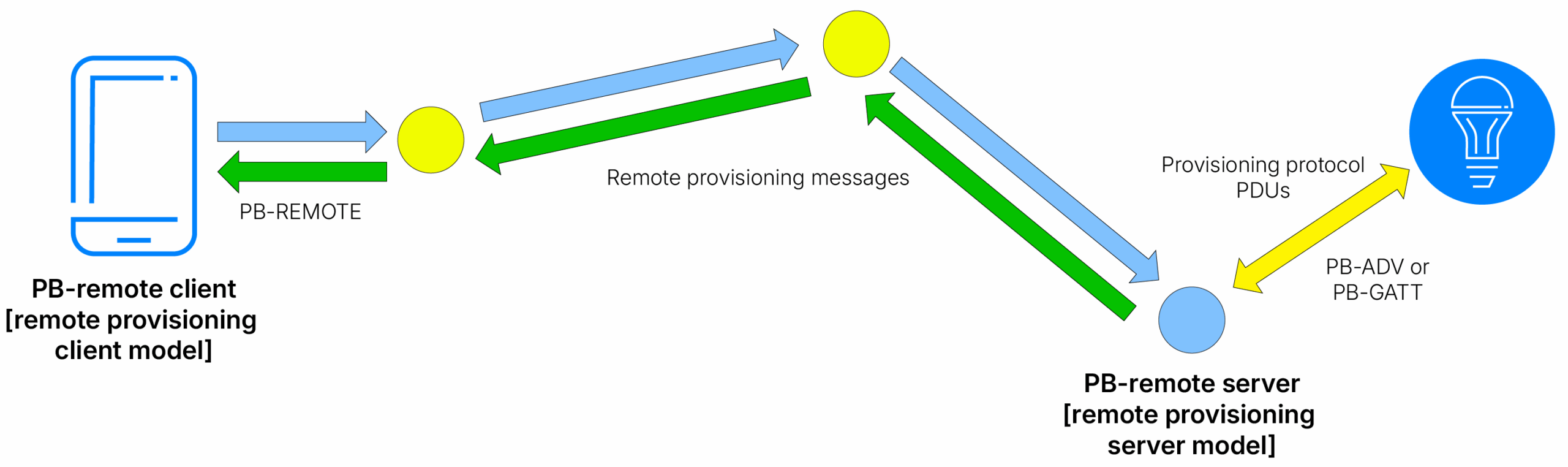
図5 – リモートプロビジョニング
4.16.3 証明書ベースのプロビジョニング
プロビジョニングプロセスには認証 が含まれます。認証 複数の方法で認証 、例えば複数桁の数字を表示する方法などが挙げられます。 一般的に、認証 プロビジョニング対象デバイスがプロビジョニング実施者の視界内にある認証 。これによりLEDの点滅回数を数えることが可能となります。しかし、これは常に現実的とは限りません。特にリモートプロビジョニングを使用している場合、プロビジョニング対象デバイスは建物の反対側など、完全に視界外にある可能性があります。
X.509証明書は標準フォーマットを持つデジタル公開鍵証明書です。Bluetoothメッシュネットワークはプロビジョニング時のX.509証明書の使用をサポートします。X.509証明書を使用してプロビジョニングされたデバイスは視界内にある必要がなく、したがってリモートプロビジョニングに非常に適しています。
4.17 コンフィギュレーション
各ノードは、標準設定サーバ モデル内に実装され、設定クライアント 使用してアクセスされる、標準設定状態のセットをサポートします。コンフィギュレーション状態 データは、ノードの構成と、特定のアプリケーション デバイス・タイプの動作に依存しない機能に関係します(これらは、デバイスに実装された他のモデルによって管理されます)。
構成データ 状態 ページに分かれており、要素やサポートするモデルなど、ノードに関する情報が含まれている。大規模構成データ サーバー・モデルはこの状態 補完し、複雑な構成と多数のコンポーネントを持つデバイスのサポートを提供する。DALI(Digital Addressable Lighting Interface)デバイスは、そのようなデバイスの代表例です。
DALIデバイスは通信バスを中心に構築されており、そこに最大128個のコンポーネント(DALI用語ではバス ユニットと呼ばれる)を簡単に抜き差しすることができる。メッシュネットワークの一部である場合、DALIコンポーネントは、DALIデバイス全体を表す複雑なメッシュノードのエレメント なります。デバイスのファームウェアがバスに接続されたコンポーネントの変更を検出すると、その構成データ 自動的に更新され、プラグアンドプレイ機能を提供することができます。
ノードがサポートする機能(4.18 機能参照)設定サーバ によって示される。ノードが登録したアドレスは状態保存される。ノードがメンバー ネットワークを示すネットワークサブネット は状態 保存され状態 アプリケーション 状態保存される。
一連のコンフィギュレーション・メッセージによって、クライアント 設定サーバ モデルは、設定サーバ モデルの状態に関するGET、SET、STATUS操作をサポートすることができます。
4.18 特徴
すべてのノードはメッシュ・メッセージの送受信が可能ですが、ノードがさらに特別な機能を持つオプション機能がいくつかあります。このようなオプション機能には、リレー機能、プロキシ機能、フレンド機能、低電力機能の4つがあります。サポートされている機能 、ある時点で有効または無効にすることができます。
4.18.1 リレーノード
中継機能 サポートするノードは中継ノードと呼ばれ、受信したメッセージを再送信することができる。中継とは、メッセージが中継されることで機器間を複数ホップしながらメッシュネットワーク全体を横断できる仕組みのことである。
メッシュネットワークPDUには TTL(Time to Live)と呼ばれるフィールドがある。これは整数値をとり、メッセージがネットワークを通過するホップ数を制限するために使用されます。例えばTTL 3に設定すると、メッセージは最大2回中継されます。TTLを0に設定すると、メッセージはまったく中継されず、発信元デバイスから直接宛先 デバイスまで1ホップしか移動しません。TTL 値を1に設定すると、そのメッセージはすでに何度か中継されており、再度中継されるべきではないことを意味する。TTL = 1で送信されたメッセージはデバイスを離れないため、ループバックを経由してノード上のローカル通信にのみ使用できる。
ネットワークと無線スペクトラムを最も効率的に使用するために、Directed Forwardingと呼ばれるオプション機能 使用することができる。ディレクティッド・フォワーディングは、情報提供されたより効率的な方法で中継を使用します。
リレーの仕組みに関する詳細は、4.19 メッセージリレーを参照してください。
4.18.2 低電力ノードとフレンドノード
ノードの種類によっては、電源に限りがあり、できるだけエネルギーを節約する必要があります。このようなタイプのデバイスは、主にメッセージの送信に関係するが、時折メッセージを受信する必要がある。
小さなコイン電池で動く温度センサーを考えてみよう。温度が設定された上下のしきい値を上回ったり下回ったりするたびに、1分間に1回、温度の読み取り値を送信する。温度がこれらのしきい値内にとどまる場合、メッセージは送信されない。これらの動作は簡単に実装でき、消費電力に関する問題は特に発生しない。
しかし、ユーザーはセンサーにメッセージを送り、温度しきい状態 値を変更することもできる。これは比較的稀なイベントであるが、センサーはこれをサポートしなければならない。メッセージを受信する必要性は、デューティサイクルと消費電力に影響を与える。100%の受信(RX)デューティサイクルは、センサーが温度閾値設定メッセージを見逃さないことを保証するが、法外な量の電力を使用する。低いデューティ・サイクルはエネルギーを節約しますが、センサーがコンフィギュレーション・メッセージを見逃すリスクがあります。
この難問に対する答えが、フレンドシップ概念である。
例にある温度センサーのようなノードは、低電力ノード(LPN)として指定され、センサーの構成データ内の機能 がこれを示すように設定される。
LPNは、電力に制約のない(例えば常時AC電源を持つ)別のノードとタンデムで動作する。このデバイスをフレンドノード呼びます。フレンドは LPN 宛のメッセージを保存し、LPN がフレンドノード メッセージの待ち受けをポーリングするた びにメッセージを送信します。LPN は、電力を節約する必要性と、メッセージを受信し処理する必要性のバランスをとるため、 比較的頻繁にフレンドをポーリングすることはありません。ポーリングが行われると、フレンドが保存しているメッセージはすべてLPNに転送され、フレンドノードさらに送信すべきメッセージがあるかどうかを示すMD (More Data) )というフラグが LPNに付きます。
LPNとフレンドノード 関係はフレンドシップ知られています。フレンドシップは、Bluetooth Meshネットワークにおいて、メッセージを受信する必要がある電力制約の大きいノードが効率的に機能するための鍵となります。
4.18.3 プロキシノード
4.18.3.1 プロキシノードについて
ほとんどのスマートフォンやタブレットを含め、Bluetooth LE サポートするデバイスは世界中に膨大な数があります。通常、このようなデバイスは Bluetooth Mesh Networking スタックを搭載していますが、GATT(Generic Attribute Profile)で定義された手順を使用して他のデバイスと接続し、相互作用する機能を持っています。
プロキシノードは GATT サービスを実装し、他のBluetooth LE 機器が Bluetooth Mesh ネットワークにメッセー ジを送受信するために使用できるいくつかの特徴を持ちます。プロキシノード GATT サーバーとして動作し、他のデバイスは GATTクライアントなります。
プロキシプロトコル プロトコルが定義されている。GATTデバイスは、プロキシノード実装するGATT特性内からプロキシプロトコル PDUを読み書きする。プロキシノード は、これらのPDUをメッシュネットワークPDUに変換したり、メッシュネットワークPDU から変換したりする。プロキシプロトコル使用に関して、プロキシサーバー みなされ、他のデバイスはプロクライアントみなされる。
クライアント 、ネットワークの他のメンバー 同様に、最初にプロビジョニングする必要があります。
プロキシノードは、完全なBluetooth Mesh Networkingスタックを持たないBluetooth LE デバイスがメッシュネットワーク内のノードと対話することを可能にします。実際には、完全なオペレーティング・システムと高解像度ディスプレイを持つ強力なデバイスに、ネットワーク内の照明などのデバイスと対話するためのグラフィカル・ユーザー・インターフェース(GUI)をユーザーに提供するアプリケーションを搭載できることを意味します。

図6 - メッシュ経由で通信するスマートフォンプロキシノード
4.18.3.2 プロキシの検出
プロキシノードは2つのモードのいずれかで動作し、スマートフォンなどのプロキシ・アプリケーション ・クライアント 2つの方法のいずれかで検出され、エンゲージすることができる。
4.18.3.2.1 連続広告モード
このモードでは、プロキシノード プロキシ・クライアント 有無に関わらず、広告パケットを一定間隔でブロードキャストする。ブロードキャスト・パケットには、GATTメッシュ・プロキシ・サービスのUUID識別子とその他のサービス・データを含むサービス・データと呼ばれる広告データが含まれる。メッシュプロキシサービスのUUIDが存在することで、広告デバイスがプロキシノードであることが識別される。クライアント 、メッシュプロキシサービスUUIDを含む広告パケットをスキャンすることでプロキシノード 発見し、プロキシノード 接続し、接続を介してプロキシPDUを交換することができる。プロキシノード アドバタイズ ベアラー使用してメッシュネットワークとの間でPDUを中継する。
このアプローチで使用される無差別で多かれ少なかれ永続的な広告は、最適とは言えず、Bluetooth広告チャネルを無駄に使用しています。メッシュ・ネットワーク内の大多数のノードが使用するアドバタイズ ベアラー、これらのチャネルが利用可能であることに依存しています。
4.18.3.2.2 オンデマンド・プライベート・プロキシ・モード
勧誘と呼ばれる技法を含む、より効率的な第二のアプローチが定義されている。これはオンデマンドプライベートGATTプロキシ(On-Demand Private GATT Proxy)と呼ばれ、サポートはオプションである。
このアプローチでは、プロキシサーバー クライアント 存在し、そのサービスを必要としていることを認識するまで、広告は開始されない。
オンデマンドプロキシ機能 サポートするクライアント 、広告によってプロキシノード サービスが必要であることを示す。プロキシが送信する広告パケットには、Solicitation PDUと呼ばれるPDUが含まれる。このPDUには、メッシュプロキシ勧誘サービスのUUIDなどが含まれている。
プロキシサーバー パッシブ・スキャンと呼ばれるスキャンを行う。パッシブスキャンはパケットの送信を伴わないため、無線チャネルに影響を与えない。クライアント、プロキシクライアントSolicitation PDUを受信して認証すると、クライアント 接続できるように広告を開始し、標準的な方法で確立された接続上でプロキシPDUの 交換を開始する。
オンデマンド型プライベートGATTプロキシは、クライアント 広告クライアント にのみ広告をクライアント することで、広告チャネルを効率的に活用します。また、メッシュ型プライベートビーコンを採用することでプライバシー保護を強化しています。詳細は7.7プライバシーを参照してください。
4.19 メッセージの中継
4.19.1 マルチホップによるメッセージ配信
Bluetoothメッシュネットワークは広範囲に及ぶことがあり、建物内の特定区域にあるノードは、他のノードの直接電波到達範囲外となることが頻繁に発生します。 送信元ノードと宛先 距離に関わらず、全ノード間でメッセージベースの通信を可能にするため、Bluetoothメッシュネットワークでは特定のノードによるメッセージの再送信システムを採用しています。これによりメッセージはネットワークを横断してノードからノードへと中継され、最終的に宛先到達します。
一般用語では、メッセージを再送信するプロセスを中継と呼び、これがリレーノード機能である。
中継は2つの異なる方法のいずれかで機能する。ひとつは フラッディング呼ばれる方法で、もうひとつはディレクテッド・フォワーディングと呼ばれる方法だ。
4.19.2 管理されたフラッディング
リレーノード デフォルトで、より単純なフラッディング 使用する。フラッディング 、リレーが受信したメッセージを再送する。
しかし、特定の条件下では、Relayは再送信を行わないため、電波スペクトラムの効率向上に役立ちます。例えば、以下のようなものがあります:
- PDUにはTTLTime to Live)と呼ばれるフィールドがある。送信者はこのフィールドに、メッセージが中継される回数を制限 整数値を設定する。これにより、メッセージがネットワーク上で無意味にリレーされるのを防ぐことができる。
- 受信したメッセージの詳細はリレーによってキャッシュされる。キャッシュはリレーの前にチェックされる。メッセージがキャッシュにあった場合、そのメッセージは以前に受信され、再送されたものとみなされる。
4.19.3 指定転送
有向フォワーディング・アプローチは、フラッディング 洗練されており、無線スペクトラムをより効率的に利用できる。有向転送を使用する場合
- リレーノード 、メッセージがそのノードの宛先到達するために経由できる一連の ノードのメンバー であることを知っている場合にのみ、メッセージを再送する。このノードを経由して宛先 到達できない場合、メッセージは破棄される。こうして無線伝送が削減され、スペクトラムの利用が効率化されるため、ネットワーク内のメッセージングにより多くの容量が残され、衝突が発生する確率が減少します。
- 宛先 配送が可能なノードのシーケンスは、コンフィギュレーション中に手動で作成されるか、さまざまなシステム手順によって自動的に作成・維持される。
セクション6.4 リレーは、指向性転送をさらに掘り下げる。
ダイレクトフォワーディングの詳細な説明については、「Bluetooth Mesh Networking ダイレクトフォワーディング」を参照してください。
4.20 デバイスのファームウェア更新
4.20.1 ファームウェアについて
デバイスの機能を実装しハードウェアを制御する低レベルソフトウェアは、通常ファームウェアと呼ばれる。Bluetoothメッシュネットワーキングをサポートするデバイスは、Bluetoothメッシュネットワーキングプロトコルとデバイスがサポートするモデルを実装するファームウェアを実行する。
一般的に、ファームウェアはその寿命の間に更新する必要がある。Bluetooth Mesh Networking ファームウェアをサポートするデバイスを更新する理由には、以下が含まれる:
- デバイスがサポートするBluetoothメッシュネットワークプロトコルのバージョンをアップグレードする
- 追加のBluetoothメッシュモデルをサポートすることで新機能を追加する
- バグを修正する
4.20.2 実務上の問題点
Bluetoothメッシュネットワーク内のデバイスは、物理的に到達困難な場所(例:天井への設置)に設置されることが多い。実用的な観点から、物理的な有線接続に依存するファームウェア更新手順は問題が生じやすい。更新対象デバイスとの直接通信に依存する無線更新メカニズムでさえ、特に大規模な建物内では最適とは言えない。
ブルートゥース・メッシュ・ネットワーキングは、ネットワーク全体からデバイスのファームウェアを更新することを可能にする一連の手順を定義しており、どのノードに対しても、物理的な場所から更新を開始することができる。
このDevice Firmware Update (DFU) 機能 、次に説明する。
4.20.3 DFU機能
ブルートゥース・メッシュ・ネットワーキング DFU機能 、ファームウェア・アップデート・ファイル(多くの場合、バイナリ・ イメージとして知られている)を、1 回の操作で 1 つまたは複数のターゲット・デバイスのセットに、ネットワークを介してワイヤレスで配布することができます。ファームウェアを最新の状態に保つための便利なツールであり、人、ネットワーク、無線のリソースを効率的に使用する方法で動作します。
4.20.3.1 DFUモデルと役割
ブルートゥース・メッシュ・ネットワーキングのDFU機能 、3組のクライアント サーバーモデルが含まれる。
- BLOB転送モデルは、ノード間でバイナリラージオブジェクト(BLOB)を転送するための一般化されたメカニズムを提供する。ファームウェア・アップデート・ファイルはBLOBの一例です。
- ファームウェア配布モデルは、アップデートされるノードにファームウェア・アップデート・ ファイルを配布する手順をサポートします。ファームウェア配布手順は、BLOB 転送モデルを使用します。
- ファームウェア・アップデート・モデルは、デバイスのファームウェアにアップデートを適用する手順をサポートしています。
多くのDFUの役割が定義されている:
| 役割 | 項目 | モデル |
| ターゲット | ファームウェア・アップデートを受信するノード。ターゲットは、実行中のファームウェアのバージョンと、アップデートを入手できる場所を報告することができる。 | ファームウェア・アップデート・サーバー BLOB転送サーバー |
| イニシエータ | 通常、Bluetooth Meshをサポートし、インターネット接続が可能なデバイス上で動作する。そのようなデバイスの例としては、スマートフォンやゲートウェイ・デバイスがある。定期的に、またはリクエストに応じて、イニシエータ メーカーのウェブサイトをチェックし、新しいファームウェアのリリースを確認する。その後、アップデートファイルをダウンロードし、ディストリビューターノードに送信します。 | ファームウェア配布クライアント クライアント 更新クライアントBLOB転送 |
| ディストリビューター | イニシエータ ファームウェアアップデートファイルを受信し、ターゲットノードに送信してインストールします。イニシエータ 仲介することで、イニシエータ 配信とアップデートの全手順の間、メッシュネットワークの範囲内にいる必要がなくなります。 | ファームウェア配布サーバー ファームウェア更新クライアント BLOB転送クライアント BLOB転送サーバー |
| スタンドアロン型アップデータ | スタンドアローン・アップデーターは、イニシエータ ディストリビューターを組み合わせた役割を 果たし、ファームウェア・アップデートを取得し、中間ディストリビューターを介さずにアップデ ータ・ノードに直接送信します。 | ファームウェア・アップデートクライアントBLOB転送 |
4.20.3.2 ファームウェアの更新手順[4]
4.20.3.2.1 ファームウェアの更新の入手
Mesh DFU モデル仕様では、Firmware Check Over HTTPS手順を定義しています。この手順は、イニシエータ (またはスタンドアロン・アップデータ)により呼び出され、通常、以下のことが行われます:
- アプリケーション ターゲットノードのリストを受け取る
- リスト上の各ターゲットノードに対して
- 現在インストールされているファームウェアに関する情報の取得(バージョン番号や更新プログラムの取得元となる場所のURIなど)
- URIにHTTP GETリクエストを送信し、ファームウェア・アップデートが利用可能であれば、レスポンスでファームウェア記述ファイルをダウンロードする。
ファームウェア記述ファイルは JSON 形式のファイルで、ファームウェア・アップデートが 分割されたファイル数や、アップデートの合計サイズ(バイト)などの情報を提供する。
その後、ファームウェア・アップデート・ファイルをHTTPS プロトコルを使用して取得するため に、「Firmware Retrieval over HTTPS」手順が使用されます。イニシエータ これを行うか、ファームウェア・アップデートの取得をディストリビューターに指示することができます。
この仕様では、ファームウェアのアップデートを、ベンダー固有のアプローチでチェックし、 取得することも可能であることに注意されたい。
4.20.3.2.2 ファームウェアの更新の配布
イニシエータ 、ファームウェア・アップデートとターゲット・ノードの詳細をディストリビュー タに送信するために、BLOB 転送クライアント バックアップされたファームウェア配 布クライアント 使用します。その後、Distributor は、ファームウェア・アップデート・クライアント BLOB 転送クライアント 使用して、各ターゲッ ト・ノードにアップデートを送信します。
4.20.3.2.3 ファームウェアのインストール
ターゲットは、ベンダー固有の手順でアップデートを確認し、インストールする。進捗情報は、ディストリビューターが入手できます。
4.20.3.2.4 DFUのセキュリティ
リモートソースからファームウェアを取得し、それをBluetoothメッシュネットワークのノードにインストールすることには、セキュリティ上のリスクが伴います。リモートソースが信頼できるものであること、およびファームウェアの更新ファイルが改ざんされていないことを確認する手段が必要です。
DFU 仕様では、標準的なファームウェア・チェックおよびファームウェア取得 手順の中で、リモート・サーバーからのダウンロードに安全な HTTPS プロトコルの使用を義務付けています。これにより、ダウンロードは暗号化され、機内で検知されずに改ざんされることはありません。HTTPS はまた、リモートサーバーがその身元を認証できるデジタル証明書を持つことを要求します。
HTTPS を介したファームウェア・チェックと HTTPS を介したファームウェア取得の手順は、主要なセキュリ ティ問題にアドレス する。デバイスが使用するベンダー固有のインストール手順は、さらなるセキュリティ・チェックのための他の機会を提供する。
5. システムアーキテクチャ
5.1 はじめに
このセクションでは、Bluetooth Meshのアーキテクチャ、メッシュ・ネットワーキング・スタックのレイヤー、そしてこの技術を定義する技術仕様について詳しく見ていきます。
5.2 Bluetoothメッシュネットワークの仕様
ブルートゥース・メッシュ・ネットワーキングは仕様の集合体として定義されている。
- Bluetooth Meshプロトコル仕様書は、Bluetooth Meshネットワークのアーキテクチャ、プロトコル、手順、基礎モデル、およびその他の中核となる概念を定義しています。
- Bluetooth Mesh Models仕様では、基礎モデルで定義されている機能を超える機能を提供する追加のモデルが定義されています。
- デバイスのファームウェア・アップデートと BLOB 転送機能にはそれぞれ専用の仕様があり、それぞれのモデルが定義されている。
- プロファイル仕様のコレクションは、特定のクラスの製品をさらに標準化するための追加要件と実装の詳細を定義し、結果として相互運用性を向上させる。
5.3 Bluetoothメッシュネットワークのスタック
図7は、Bluetoothメッシュネットワークのアーキテクチャを、そのレイヤー構成およびブルートゥースコア仕様の一部に対する依存関係という観点から示したものである。スタックは2つある。Bluetoothメッシュネットワークスタックは、Bluetoothメッシュネットワーク内のノード間の通信を可能にする。メッシュプロビジョニングスタックは、デバイスのプロビジョニングを可能にする。
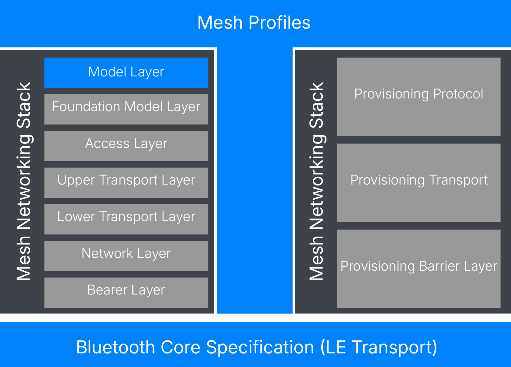
図7 – Bluetoothメッシュネットワークのアーキテクチャ
図 7 に、ブルートゥースコア仕様 (LE Physical Transport)とラベル付けされたコンポーネントがあ ります。これは、Bluetooth Mesh Networking で利用されるBluetooth LE コア機能のセットを表しています。
Bluetooth LE は、コントローラと hostで構成されます。これらは多くの場合、物理的に分離されたコンポーネントであり、何らかの方法(例:UART)で接続され、Host ・インターフェース(HCI)として知られる一連の標準コマンドおよびイベントを使用して通信します。Bluetoothメッシュ・ネットワーキング・スタックの各レイヤーは、すべてhost 内に存在します。 Bluetoothメッシュネットワーキングスタックは、リンクレイヤー 物理層など、コントローラ上で動作するBluetooth LE に依存しています。これらの層Bluetooth LEの基本アーキテクチャに関する詳細については、『Bluetooth LE 』を参照してください。
ここでは、Bluetoothメッシュネットワークのアーキテクチャを、最下層から順に各層ごとに解説していきます。
5.4 ベアラー層
Bluetoothメッシュネットワークのメッセージを伝送するには、基盤となる通信システムが必要です。ベアラー層は、特定の通信システムにおいてメッシュPDUがどのように処理されるかを定義します。一般的なメッセージングに使用される2つの主要なベアラーが定義されており、これらは「アドバタイジング・ベアラー」および GATTベアラーと呼ばれます。
アドバタイズ ベアラー 、Bluetooth LE 広告機能とスキャン機能を活用し、メッシュPDUを送受信します。
GATTベアラー 、アドバタイズ ベアラー サポートしていないデバイスが、プロキシプロトコル知られるプロトコルを使用して、メッシュネットワークのノードと間接的に通信することを可能にします。このプロキシプロトコル 、メッシュプロキシサービスと呼ばれるGATTサービスが含まれ、メッシュプロキシデータインと メッシュプロキシデータアウトという2つのGATT特性があります。
プロキシノード 、Bluetooth Meshプロキシサービスとその機能プロキシノード 。GATTベアラー アドバタイズ ベアラーの両方をサポートしており、これにより、これら2種類のベアラー間でメッセージを変換・中継することが可能になります。
GATTベアラー 、プロキシ機能サポートしていないノードでもサポートされることがある。
5.5ネットワークレイヤー
ネットワークレイヤー 、トランスポート層の PDU をベアラ層で扱えるようにするために、様々なメッセーアドレス ネットワークメッセージフォーマットを定義する。
複数のベアラをサポートすることができ、各ベアラは、同じノードに属するエレメント間の通信に使用されるローカル・インタフェースを含む、複数のネットワーク・インタフェースを持つことができる。
ネットワークレイヤー 、どのネットワークインターフェース(複数可)にメッセー ジを出力するかを決定する。インプットフィルター 、ベアラレイヤから到着したメッセージに適用され、さらに 処理するためにネットワークレイヤー 配送すべきかどうかを決定する。出力メッセージは、ドロップされるかベアラ層に配送されるかを制御するために、アウトプットフィルター 対象となる。
リレー機能とプロキシ機能は、ネットワークレイヤー実装してもよい。
5.6ローワー トランスポート レイヤー
ローワー トランスポート レイヤー アッパートランスポートレイヤー 、ピアデバイス上のローワー トランスポート レイヤー PDUを受け取り、それをローワー トランスポート レイヤー 送信する。必要に応じて、PDUのセグメンテーションと再アセンブリを実行する。単一のトランスポートPDUに収まらない長いパケットの場合、ローワー トランスポート レイヤー セグメンテーションを実行し、PDUを複数のトランスポートPDUに 分割する。もう一方のデバイスの受信ローワー トランスポート レイヤー 、セグメントを1つのアッパートランスポートレイヤー PDUに組み立て直し、これをスタックに渡す。
5.7アッパートランスポートレイヤー
アッパートランスポートレイヤー 、アクセス レイヤー間でやり取りされるアプリケーション 暗号化、復号化、および認証 責任を負う。また、内部的に生成され、異なるピアノードの上位トランスポート レイヤ間で送信されるトランスポート制御メッセージの責任も負う。これには、フレンドシップ、有向転送、ハートビートに関連するメッセージが含まれる。
5.8アクセス レイヤー
アクセス レイヤー 、モデルがどのようにアッパートランスポートレイヤー使用するかを定義する責任を負う。これには以下が含まれる:
- メッセージデータの形式の定義
- アッパートランスポートレイヤーで実行される暗号化および復号化のプロセスを定義し、制御する
- データをスタックの上層へ転送する前に、アッパートランスポートレイヤー から受信したデータが、正しいネットワークおよびモデル向けアッパートランスポートレイヤー 確認する
5.9基本モデル階層
基本モデル階層 、メッシュネットワークの構成と管理に関係するモデルの実装を担当する。
5.10 モデル層
モデル層はモデルの実装、すなわち、1つまたは複数のモデル仕様で定義された動作、メッセージ、状態、および状態 の実装を担当する。
6.メッセージング
このセクションでは、Bluetooth Mesh ネットワークにおけるメッセージングの仕組みについて解説し、第4章「主な機能と概念」で説明した重要な概念をまとめています。
6.1 メッセージの公開と配信
Wi-Fiを使用するネットワークは、アクセスポイントと呼ばれる中央のネットワークノードを中心に構成され、すべてのネットワークトラフィックはアクセスポイントを経由する。ルーターが利用できなくなると、ネットワーク全体が利用できなくなる。
一方、Bluetooth Mesh Networkingでは、電波の届く範囲にいるノードに直接メッセージを送ったり、距離が離れている場合は中継ノードを経由してメッセージを送ったりする。ノードがパブリッシュした場合、メッセージは特定のノードに直接ルーティングされるのではなく、ブロードキャストされます。すべてのノードは、直接無線範囲内にあるノードからのすべてのメッセージを受信します。そのように設定されている場合、ノードはフラッディング または有向転送のいずれかを使用し、受信したメッセージをリレーします。
6.2 マルチパス配信
ブロードキャスト通信と中継を使用することの重要な帰結は、メッセージがネットワークを介して複数の経路を経由して宛先 到着することができることである。これはBluetooth Mesh Networkingが信頼性の高いネットワーク技術であることに貢献している。
6.3 スタックの探索
メッセージの受信は、Bluetooth LE コントローラのリンクレイヤー パケットを受信することから始まる[5]。そして、そのペイロードはHost Bluetooth Mesh Networkingベアラ層に渡され、そこからネットワークレイヤー渡されます。
ネットワークレイヤー 様々なチェックを行い、メッセージをスタックの上位に渡すか、破棄するかを決定する。
加えて、PDUにはネットワークID フィールドがあり、メッセージがどのNetKey 暗号化されたかを高速に判断する方法を提供する。受信側ノードのネットワークレイヤー このネットワークID 認識できない場合は、対応するネットワークレイヤー おらず、 サブネットでないことを示す、これは対応するNetKey おらず、そのサブネット メンバー でないことを示すので、PDUは破棄される。ネットワークメッセージ整合性チェック(MIC)フィールドもある。MICチェックに失敗した場合、メッセージは破棄される。
メッセージは発信者の範囲内にあるすべてのノードによって受信されるが、その多くが、そのノードが属するネットワークやサブネット関係で、そのノードに関係ないことが明らかになると、すぐに破棄される。
同じ原理がスタックの上位のアッパートランスポートレイヤー適用される。しかし、ここでは、メッセージに関連付けられ、PDUの識別子(AID)フィー ルドでアプリケーション されるアプリキー チェックが行われる。このノードがAIDを認識できない場合、PDUはアッパートランスポートレイヤー破棄される。トランスポートメッセージの完全性チェック(TransMIC)が失敗した場合、メッセージは破棄される。
アッパートランスポートレイヤー メッセージをアクセス レイヤー渡す。そこからモデルレイヤーは、受け取ったメッセージのタイプに基づいて適切なモデル関数を呼び出すために使用される。
6.4 中継
リレーの基本的な概念については、4.19節「メッセージのリレー」で説明しました。指向性転送方式は、管理型フラッディング 複雑であり、この節でさらに詳しく説明します。
6.4.1 指定転送
6.4.1.1 マネージドフラッディングとの比較
フラッディング 使用される場合、TTL フィールドで示される最大ホップ数がすでに経過している場合などの限られた状況を除いて、リレー・ノードは受信したすべてのメッセージを再送する。これはシンプルで効果的なメカニズムであるが、無線スペクトラムの使用に関しては最も効率的とは言えない。メッセージは、宛先 ノードがリレーノードある方向に位置しているかどうかに関係なく、ネットワークを全方向に伝搬する。
図8および図9は、Bluetoothメッシュネットワークが導入され、ステージ上の照明を制御するスイッチを備えた大規模な会議場を示しています。すべての機器にメッセージを届けるには、1ホップで中継する必要があります。
スイッチの範囲内に2つのリレーノードがある。ステージ照明スイッチが使用されると、メッセージが送信され、両方のリレーで受信され、再送信されます。このため、メッセージはターゲット照明に向かっても、ターゲット照明から遠ざかっても、ネットワーク内を移動します。
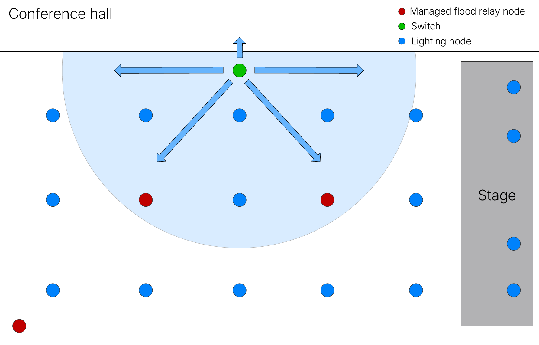
図8 - 点灯/消灯メッセージを放送する照明スイッチ
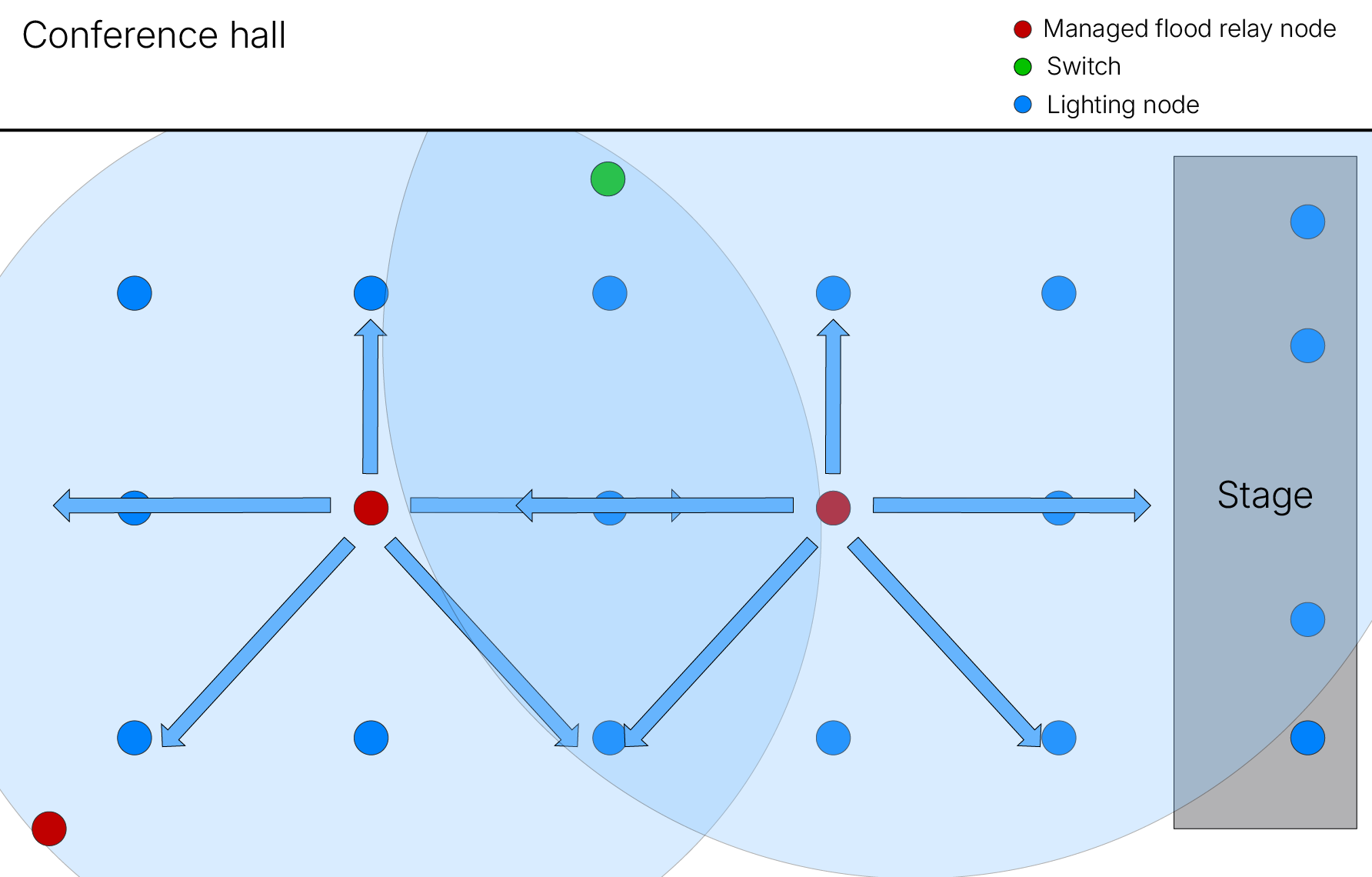
図9-2つのリレーがメッセージを受信し、両方が再送信する
これは最適とは言えません。ステージから最も遠いリレーノード 、スイッチからステージ照明へのオン/オフ制御メッセージの配信に貢献できない。
有向転送が管理型フラッディング 異なる点は、リレーノード 状態 データが、メッセージでアドレス指定された1つ以上のノ ードへのパス上にあることを示す場合にのみ、中継が行われる点であ る。有向転送を使用できるリレーノード 、有向リレーノード呼ばれる。
図10は、会議ホールの照明スイッチとリレー・ノードが使用した場合の有向転送の効果を示しています。照明スイッチからのオン/オフ・メッセージの伝搬は、ステージ上の照明に向かってのみ行われ、ネットワークの他の部分には伝搬されません。
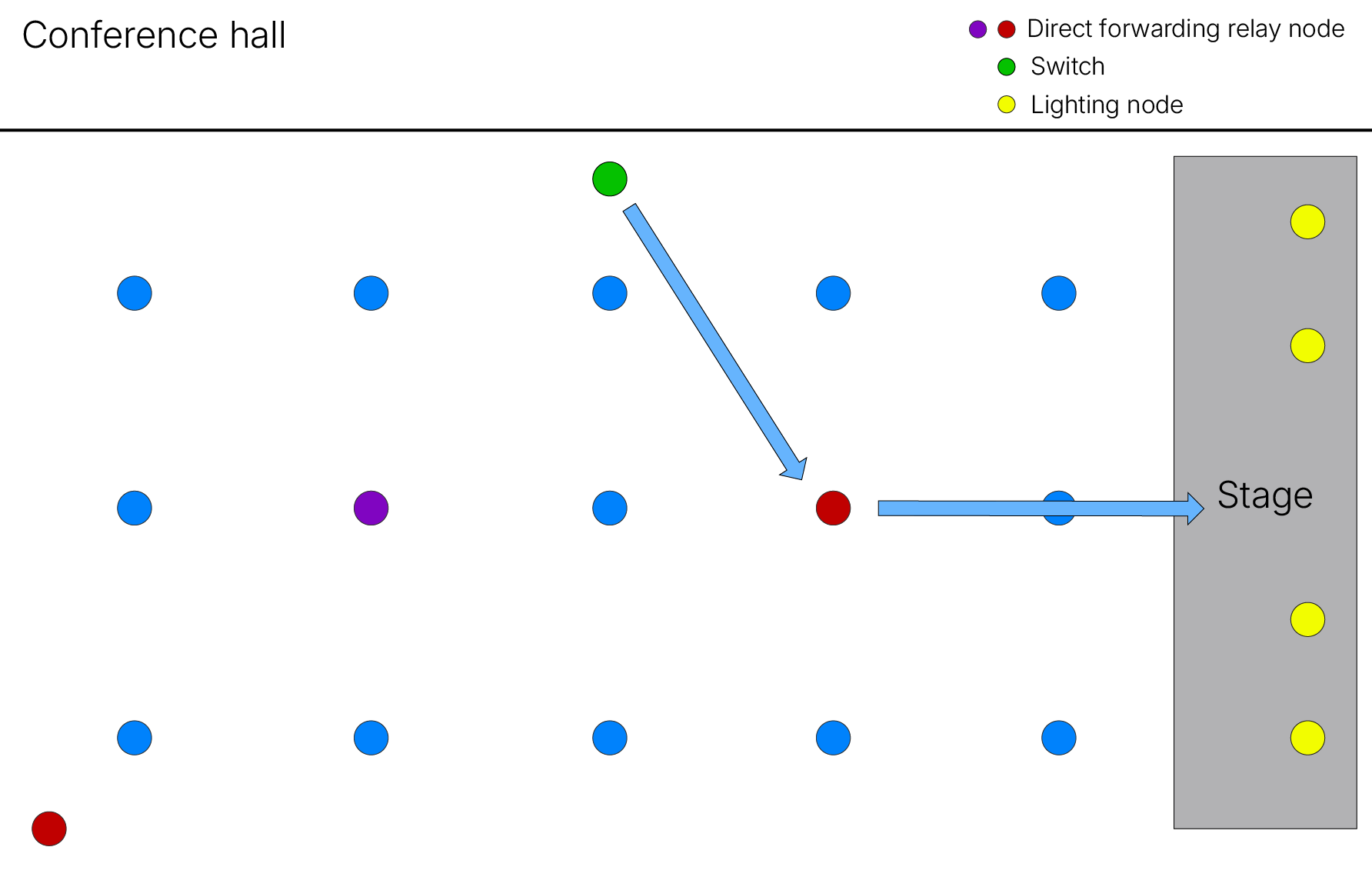
図10 - 有向転送の効果
パスの概念は、有向転送において正式に定義されたものである。
6.4.1.2 経路とレーン
有向転送は、与えられた送信アドレス 特定の宛先 アドレスメッセージを配送することができる有向中継ノードのシーケンスを定義または発見することを含む。このようなノードシーケンスはパスと呼ばれる。
パスの定義では、送信アドレス 常にアドレスであるが、宛先 アドレス グループアドレス、どのようなタイプでもよい。宛先 アドレス 複数のノードに対応する場合、有向転送パスを有向中継ノードのシーケンスの集合として記述する方がより正確である。
Directedリレーノード Forwarding Tableと呼ばれる状態 データ項目は、リレーがサービ スできるパスを示す。これは、ソースアドレスと宛先 アドレスのペアのリストで構成される。メッセージを受信すると、Directed RelayはForwarding Tableを参照し、その中にメッセージの送信元アドレスと宛先 アドレス エントリがあれば、そのメッセージは中継される。そうでない場合、メッセージは破棄される。
特定のターゲットノードに到達するために、メッセージが中継される有向中継ノードのシーケンスが複数存在する可能性がある。これはマルチレーンパスを作成することで利用できる。レーンはDirected Relayノードのシーケンスであり、その点ではパスと同じです。1つの送信元ノードから1つの宛先 ノードへのメッセージ配送に複数の代替ノードシーケンスが利用可能な場合、レーンという用語はシーケンスに使用され、パスという用語はすべてのレーンの集合に使用されます。マルチレーン・パスは冗長性が高いため、Directed Relayノードのシーケンスの1つが何らかの理由で使用できない場合でも、メッセージが配送される可能性が高くなるという利点があります。
6.4.1.3 パスの作成と維持
パスは、Configuration Managerツールを使って手動で作成されるか、一連の自動化された手順の実行によって動的に発見され、確立される。
自動パス作成が使用されている場合、プロセスはいくつかのステージにわたって実行される。パスが必要とされる送信元と宛先 アドレス ペアについては、送信元から宛先メッセー ジを送信できるリレーノード 配列の発見を目標に、ネットワークを探索するために特別なメッセー ジが使用される。この過程で、パスメトリックと呼ばれる測定値が確立され、代替シーケンス間の比較が行われ、最適なものが使用されるように選択される。パスメトリックとは、送信元ノードから所定のリレーシーケンスを経由して宛先 到達するのに要するホップ数を単純にカウントしたものである。より少ないホップで構成されるパスの方が、より多くのホップを必要とするパスよりも優れている。
送信元/宛先アドレス ペアのパスとして機能するノードの最短シーケンスが発見されると、そのシーケンス内のノードは、そのパスの一部であることを示すように、制御メッセージを使用して更新される。
7.セキュリティ
7.1 Bluetoothメッシュネットワークにおけるセキュリティは必須である
Bluetooth LE 、プロファイル設計者が様々なセキュリティの仕組みを利用することを可能にする。 これには、2 つのデバイスのペアリングが機能する様々な方法、広告パケットにおけるプライベートデバイ スアドレスの使用、GATT 特性に付随するセキュリティルールが含まれる。しかし、セキュリティは完全にオプションであり、セキュリティ保護や制約のない完全にオープンなデバイスを持つことも許されます。ブルートゥースSIG 仕様が適用されない場合(例えば、カスタムプロファイルやサービスを扱う場合)、機器の設計者又は製造者は、脅威を分析し、セキュリティ要件を決定し、それらの要件を満たすためにBluetooth LE のセキュリティ機能をどのように使用するかを決定する責任がある。
一方、Bluetoothメッシュ・ネットワーキングでは、セキュリティは必須である。ネットワーク、デバイス、個々のアプリケーションはすべてセキュアであり、セキュリティをオフにしたり低減したりすることはできない。
7.2 セキュリティの基礎
以下の基本的なセキュリティに関する事項は、すべてのBluetooth Meshネットワークに適用されます:
- メッシュ・メッセージはすべて暗号化され、認証される。
- ネットワークセキュリティ、アプリケーション 、およびデバイスセキュリティは、それぞれ個別に扱われます。以下の7.3「関心の分離」および「セキュリティキー」を参照してください。
- セキュリティ・キーは、メッシュ・ネットワークの使用中に、キー更新 手順と ノード・プロビジョニング・プロトコル・インターフェイス手順を使用して変更することができます。
- メッセージの難読化は、ノードの追跡を困難にするプライバシー・メカニズムを提供する。
- Bluetooth Meshのプライベートビーコンは、デバイスの追跡に利用される可能性のある静的な情報がノードから送信されないようにします。
- Bluetoothメッシュネットワークのセキュリティ機能は、リプレイ攻撃からネットワークを保護します。
- デバイスをメッシュ・ネットワークに追加してノードにするプロビジョニング・プロセスは、安全なプロセスであり、X.509デジタル証明書のサポートも含まれている。
- ゴミ箱攻撃を防ぐ方法で、ノードをネットワークから安全に削除することができる[6]。
7.3 関心の分離とセキュリティキー
Bluetoothメッシュネットワークのセキュリティの中核をなすのは、セキュリティキー。これらのキーは、それぞれネットワークの異なる側面を保護します。design セキュリティキー 異なる種類のセキュリティキー を採用していることは、「関心の分離」として知られる重要な原則の一例です。
このことを理解し、その意義を理解するために、リレーノード機能するメッシュライトを考えてみよう。リレーノード機能するメッシュ・ライトは、建物のブルートゥース・メッシュ・ネットワーキングのドアや窓のセキュリティ・システムに関するメッセージを処理する。ライトは、そのようなメッセージのデータにアクセスして処理できる正当な理由はないが、他のノードにリレーする必要がある。
この潜在的な利益相反に対処するため、ブルートゥース・メッシュ・ネットワーキングは、照明、物理的セキュリティ、暖房などの特定のアプリケーションに関連するデータを保護するために使用されるセキュリティ・キーとは異なる、ネットワークレイヤー セキュリティを提供するためのセキュリティ・キーを使用する。
Bluetoothメッシュネットワーク内のすべてのノードは、少なくとも1ネットワークキー NetKey)ネットワークキー 保持しています。この共有キーを保持していることこそが、そのノードをメンバー とする要件です。ネットワーク暗号化キーとプライバシーキーは、NetKey直接導出されます。
NetKey 所有することで、ノードはネットワークレイヤー 復号と認証を行うことができ、中継などのネットワーク機能を実行することができる。ただし、アプリケーション データを復号化することはできない。
特定のアプリケーション データは、正しいアプリケーション キーアプリキー)を所有するノードによってのみ復号化できる。メッシュネットワーク内のノード全体では、多くの異なるアプリキーが存在する可能性がありますが、通常、アプリキー ノードのごくサブセット 、つまり特定のアプリケーション参加できるタイプのノードによってのみ所有されます。例えば、照明と照明スイッチは照明アプリキー アプリキー 持つが、暖房システムのアプリキー 持たない。
AppKeyは、アッパートランスポートレイヤー メッセージを復号化し、認証するために使用するアクセス レイヤー
AppKey は 1 つのNetKey にのみ関連付けられる。この関連付けはキーバインディングと呼ばれ、特定のアプリキー所有によって定義される特定のアプリケーションは特定のネットワーク上でのみ動作可能である。
最後のキータイプはデバイスキーである。これは特殊なタイプのアプリケーション キーである。各ノードは、プロビジョナー いる固有のデバイスキー 持つ。デバイスキー 、コンフィギュレーション・プロセス中の通信を保護するために使用される。
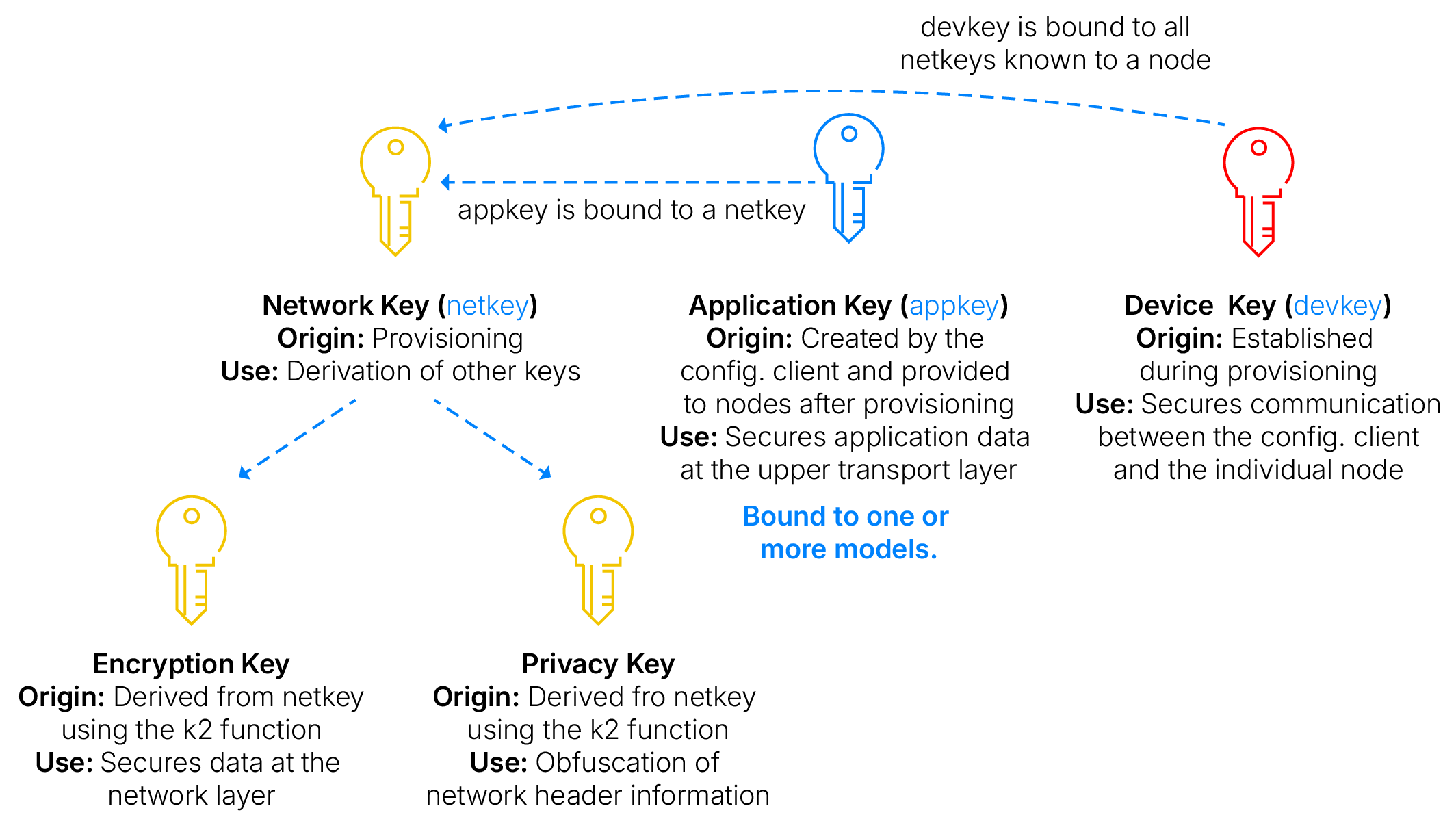
図11 – Bluetooth Meshにおけるセキュリティキー ネットワーク
7.4 サブネットとサブネット
ネットワークはサブネットに細分化できる。サブネット 独自のNetKey持ち、そのNetKeyキーはそのサブネットメンバーであるノードだけが持つ。これは例えば、ホテルの各客室など、物理的に異なるエリアを分離してセキュアにするために使用される。この場合、特定の客室の照明などのデバイスは、同じ客室で同じサブネット上にある他のデバイスによってのみ制御できるようになります。
異なるサブネットにあるデバイス間の通信が必要な場合があります。ホテルの管理スタッフが全客室の全デバイスを一元的にコントロールする必要がある場合もありますが、同時に、ある客室のデバイスを使って別の客室のデバイスをコントロールしたり、ある客室のデバイスからの通信を別の客室のデバイスが傍受して解読したりすることができないようにする必要があります。ブルートゥース・メッシュ・ネットワーキングには、これを可能にするサブネット ブリッジと呼ばれる機能 ある。
サブネット ブリッジ機能 、ネットワークプランナーはエリア分離のためにサブネットを使用するだけでなく、セキュリティを損なうことなく、隣接する異なるサブネット内の特定のデバイス間の通信を選択的に許可することができます。これには、サブネット 機能する1つ以上のノードをセットアップする必要があります。これらのノードは、ブリッジ設定サーバモデルと呼ばれるモデルとその様々な状態だけでなく、ブリッジされる各サブネットのNetKey 所有しています。
サブネット 、サブネット 呼ばれる状態 有効になる。ブリッジングテーブルと呼ばれる更なる状態 、特定のソースアドレス 特定の宛先 アドレス間の通信を可能にするエントリを含む。さらに、ブリッジングテーブルのエントリは、最初のサブネット NetKey 2番目のサブネット NetKey キーを示す。
これは、あるサブネットメッセージを、最初のNetKey暗号化し、サブネット・ブリッジとして動作するノードが復号化し、2番目のサブネットのNetKey再暗号化することを可能にするブリッジ・テーブルの状態 情報である、で暗号化された1つのサブネットからのメッセージを、サブネット ブリッジと して動作するノードが復号し、2番目のサブネット NetKey 再暗号化し、この動作を指定され た送信元と宛先 アドレスメッセージに制限することを可能にするブリッジングテーブル の情報である。
7.5 ノードの削除、キー更新、およびトラッシュカン攻撃
ノードには様々なメッシュ・セキュリティ・キーが含まれている。ノードが故障して廃棄する必要が生じた場合、あるいは所有者がノードを別の所有者に売却することを決めた場合、そのデバイスとその中に含まれる鍵が、ノードの持ち出されたネットワークへの攻撃に使用されないようにすることが重要である。
ネットワークからノードを削除する手順を定義する。アプリケーション 使用してノードを拒否リストに追加し、キー更新 手順と呼ばれるプロセスを開始する。
キー更新 手順により、拒否リストのメンバーを除く、ネットワーク上のすべてのノードに、 新しいネットワーク・キー、アプリケーション キー、および関連する派生データが発行される。言い換えれば、ネットワークとアプリケーション セキュリティの基礎となるセキュリティ鍵のセット全体が置き換え られる。
その結果、ネットワークから削除され、古いNetKey 古いAppKeyのセットを含むノードは、もはやネットワークのメンバー 、脅威とならない。
7.6 リプレイ攻撃
リプレイ攻撃とは、盗聴者が1つまたは複数のメッセージを傍受してキャプチャし、後で再送信する技術で、受信者を騙して攻撃デバイスが許可されていないことを実行させることを目的とする。
7.6.1IVインデックス シーケンス番号
ブルートゥース・メッシュ・ネットワーキングには、リプレイ攻撃に対する保護機能がある。この保護の基礎となるのは、シーケンスナンバー (SEQ)とIVインデックス呼ばれる2つのデータ項目の使用です。エレメントはメッセージをパブリッシュ たびにSEQ値をインクリメントする。最後に有効だったメッセージに含まれていた値以下の SEQ 値を含むエレメント メッセージを受信したノードは、それがリプレイ攻撃に関連する可能性が高いため、そのメッセージを破棄する。
IVインデックスはネットワーク共有リソースで、メッセージ受信時にSEQとソース・アドレス 値と一緒にチェックされる。SEQ、IVインデックス 、およびSRC(送信アドレス)フィールドの組み合わせ値は、エレメント 送信するすべてのメッシュ・メッセージで常に一意である。
ネットワークは一度に1つのIVインデックス 値を使用する。ただし、IVアップデート 手順が進行している間は、手順が完了しネットワーク全体に新しい値が割り当てられるまで、2つの異なる値が使用される。
7.6.2IVアップデート
シーケンス番号は24ビット長である。SEQフィールドのインクリメントを繰り返すうちに、ノードはシーケンスナンバー 供給量を使い果たしてしまうかもしれない。このような事態を避けるために、IVアップデート 呼ばれるネットワーク手順が、このような状況に陥ったノードによって開始される。これにより、古い値をインクリメントして新しいIVインデックス 値が計算され、ネットワーク全体に割り当てられ、影響を受けるノードのエレメントはシーケンスナンバー ゼロにリセットする。
セキュリティ上の理由から、サブネット メンバであるノードだけがIVアップデート 手順を開始することが許可されている。非プライマリサブネットのメンバーであるゲストデバイスだけがIVアップデート開始することはできません。これにより、この重要な共有ネットワークリソースが保護されます。
7.7 プライバシー
NetKey から派生したプライバシーキーは、送信アドレスネットワーク PDU ヘッダー値を難読化するために使用されます。難読化によって、何気ない受動的な盗聴が、デバイスとそれを使用する人々を追跡するために使用できないことが保証されます。また、トラフィック解析に基づく攻撃を困難にします。
キー更新 手順やIVアップデート 手順を含む、Bluetoothメッシュネットワーキング手順の多くは、以下を使用しています。 ビーコン送信を使用して、ネットワーク内の他のデバイスにデータをブロードキャストし、その存在と状態示します。ビーコン送信はBluetoothの広告を活用する技術です。
静的で変化しない情報の送信は、ネットワーク上を移動するデバイスを追跡し、デバイス、デバイスのユーザー、そしておそらくネットワーク全体に関する情報を推測することが可能になるため、セキュリティ・リスクとなる可能性があります。このリスクにアドレス するため、Bluetoothメッシュ・ネットワーキングにはメッシュ・プライベート・ビーコンと呼ばれる機能が搭載されています。
メッシュ・プライベート・ビーコン送信には静的な情報は含まれません。ビーコン・メッセージに含まれるデータを使ってデバイスが追跡される可能性を排除することで、ネットワーク・プライバシーを向上させます。
8.スケーラビリティ
ブルートゥース・メッシュ・ネットワーキングは拡張性が証明されている。現実の世界では、6,000ものノードが商用展開されている。
Bluetoothメッシュネットワークにおいて、アドレス指定可能な要素の理論上の最大数は32,767です。これは、エレメント 識別するためにアドレス エレメント 15ビットエレメント ことに起因します。とはいえ、ネットワークが収容できるノード数という観点からスケーラビリティを考えることは、このテーマを捉える上で特に有益な方法とは言えません。 むしろ、ネットワークが処理できる作業量、言い換えれば、ネットワークが対応可能なネットワーク操作の量と処理速度という観点から考える方が適切です。
スケーラビリティやその他のパフォーマンス指標は、ネットワーク設計者(10.1節「設計者」を参照)がネットワークを設計する際に考慮すべき事項である。ノードの配置や構成は、ネットワークのパフォーマンスや、将来必要となる最大ノード数への拡張の容易さに大きな影響を及ぼす可能性がある。
ワイヤレスネットワークの拡張性は、共有される無線周波数帯域がどれほど効率的に利用されるかなど、さまざまな要因によって制約されがちです。2つのデバイスが同時に同じ無線チャネルで送信を行うと衝突が発生し、これがネットワークの拡張性を制限する要因となり得ます。したがって、衝突によるメッセージ損失を回避またはその発生確率を低減することは、design 、またネットワークプランナーが行うdesign 、極めて重要な戦略となります。
すべてのネットワークが同じとは限らない。ノードの数が比較的少ない小規模なネットワークは、小規模なネットワークのノードが物理的に近くに配置され、ノードが頻繁にメッセージを送信する場合、大規模なネットワークよりもスケーリングが難しくなる可能性があります。つまり、ネットワーク密度やノードの冗長性といった概念が重要なのだ。ネットワークに含まれるノードの絶対数だけではありません。
ブルートゥース・メッシュ・ネットワーキングは、当初からスケーラビリティを念頭に置いて設計されました。PDUは小さく(長さは最大29オクテット)、これによって送信に使用される通信時間が短縮されるため、衝突が発生する確率が低くなります。
通常、メッセージのコピーは3つの異なるチャンネルで送信される。これにより、ネットワーク容量が増加し、衝突によるメッセージ損失の確率が減少する。
有向転送機能 精巧さの有無にかかわらず、中継プロセスはメッセージのための複数の経路を確立し、特に混雑したネットワークでは配送の確率を高める。
確認応答のないメッセージはネットワークトラフィックを削減します。特に、1台のデバイスが単一の操作で他のデバイスのグループを制御しようとするマルチキャストのシナリオでは、その効果が顕著です。これはBluetoothメッシュネットワークにおいて非常に典型的な状況です。
分散型のdesign 思想は、Bluetooth Mesh Networkingがどのように機能するかの重要な側面の基本となっている。これにより、より高いレベルのスケーラビリティがサポートされ、他の類似技術とも差別化される。例えば、センサーは中間の照明コントローラーを必要とせずに照明と直接通信します。
BluetoothSIG のSIG には、Bluetoothメッシュネットワークのスケーラビリティについてより詳しく解説した記事が掲載されています。
9.ネットワーク照明制御 (NLC)
ブルートゥース・メッシュ・ネットワーキングが設計された主な用途のひとつは、大規模ビルにおけるネットワーク化された照明機器の制御である。
ライト(正式には照明器具と呼ばれることもある)は複雑で、独立して制御可能な複数のランプを備え、明るさや色の制御をサポートし、人間が操作するスイッチによる手動制御と、遠隔のワイヤレスセンサーによる環境測定制御の両方が可能である。
ブルートゥース・メッシュ・モデル仕様は、照明などのデバイスがネットワーク内で特定の機能(スイッチのオン/オフなど)を得るために実装する標準化された機能ブロックを定義しています。モデルのモジュール性は、革新的な多機能製品の作成をサポートします。個々のモデルは洗練されていることが多く、その状態 動作を制御するために多数のパラメータが利用可能です。このことが、NLCの技術としてのブルートゥース・メッシュ・ネットワーキングの柔軟性と汎用性をさらに高めている。
Bluetoothメッシュネットワークには、オプションとなる重要な要素がいくつかあります。これには、サポートされるベアラの一覧、デバイスのプロビジョニング方法、サポートされるノード機能(プロキシ、リレー、LPN、フレンドなど)などが含まれます。Bluetoothメッシュネットワーク仕様の異なる部分の間には、しばしば依存関係が存在します。
ブルートゥース・メッシュ・ネットワーキング技術の柔軟な性質は、かなりの利点がある。しかし、これは標準化によって異なるメーカーの製品間の相互運用性を実現するという目標とのバランスを取る必要があります。ある技術が構成可能で可変的であればあるほど、相互運用性を確保することが難しくなる場合があります。このため、一連のBluetooth NLCデバイス・プロファイル仕様は、様々なタイプのデバイスに対する標準的なコンフィギュレーションやその他のアプリケーション 層の要件および推奨事項を定義しています。関連するプロファイルに準拠することで、同じプロファイルを実装する他の製品 相互運用が可能になります。
以下の製品 タイプのNLCプロファイル仕様が定義されている。
- 環境光センサー NLCプロファイル
- ベーシック・ライトネス・コントローラー NLCプロファイル
- ベーシックシーンセレクター NLCプロファイル
- 調光制御 NLCプロファイル
- エネルギーモニターNLCプロフィール
- NLCプロファイル
ブルートゥース・メッシュ・ネットワーキングは、物理層からアプリケーション 層までデバイスの全層を定義することで、ワイヤレス照明制御のための初のフルスタック規格となっている。
10. Bluetoothメッシュネットワークの関係者
主要なステークホルダーとその役割を理解することは、Bluetoothメッシュネットワークがどのように計画、構築、維持、管理されるかを把握する上で役立ちます。本節では、いくつかの標準的な役割を特定し、説明します。
10.1 プランナー
プランナーには広範な責務があり、そのすべてが作成されるネットワークの定義に関係する。これらの責任を3つのサブカテゴリーに分類して考えることは有益である:
- 物理的計画
- 機能計画
- ネットワーク計画
同じ人がすべてのサブカテゴリーを担当することもあれば、スペシャリストに分散させることもある。
物理的計画とは、建物内の機器の物理的配置を定義することである。建築家、インテリアデザイナー、工業デザイナーは、一般的に物理的なプランニングを担当する。
機能計画は、デバイスの機能特性とネットワーク内の他のデバイスとの機能的関係を定義することに関係する。機能計画は物理計画に影響を与えるかもしれない。
ネットワークプランニングは、必要な機能性と信頼性が達成されるように、デバイスの必要な構成を決定することに関係する。例えば、どのデバイスをフレンドノード、低電力ノード、リレーノード、プロキシノードとして機能させるかを決定するのはこの役割です。ネットワークプランナーは物理的なプランニングに影響を与えます。
10.2 インストーラー
インストーラーは、建物内に機器を物理的に設置する。通常、穴を開けたり、はしごに登ったり、ドライバーを使ったり、電力を供給接続中 する。
10.3 コミッショナー
プランナーによって作成されたdesign 、設置業者によってデバイスが物理的に設置された後、この役割はデバイスをプロビジョニングすることによって、新しいBluetooth Meshネットワークの一部にします。プロビジョニング後、コミッショナーは各新規ノードが機能およびネットワークプランニング作業によって指定された機能と構成を持つように設定します。通常、プロビジョニングとコンフィギュレーションは同じツールを使って同時に行われます。
10.4 建物の維持管理業務
ビルメンテナンスの役割は、プランナー、インストーラー、コミッショナーの役割の側面を含むが、新しいネットワークを構築するのではなく、ビル内の既存のネットワークに責任を持つ、もう1つの幅広い役割である。ビルメンテナンス担当が行うタスクの例としては、デバイスの交換(インストール、プロビジョニング、コンフィギュレーションが必要)、問題の診断と解決、不要になったデバイスの安全な廃棄などがある。
10.5 建物の所有者
ビルのオーナーはビルを所有し、ネットワークが要求通りに機能し、安全で、期待される投資収益率(ROI)を実現することを懸念している。
11.結論
本稿では、Bluetooth Mesh Networkingについて、その主な機能、コンセプト、用語を紹介した。これはBluetoothだが、我々が知っているBluetoothではない。新しいトポロジーを使ってデバイスが通信する新しい方法をサポートするBluetooth技術だ。
そして何よりも、この最も広く普及している低消費電力ワイヤレス技術を、まったく新しいユースケースや産業分野に完璧に適合させるのがブルートゥースなのだ。
12. その他のリソース
このセクションでは、様々な観点からBluetooth LE 学習を支援するその他のリソースを掲載する。
| リソース | 項目 | 所在地 |
| ブルートゥース・メッシュ・プロトコル仕様 | この仕様は、Bluetooth Mesh Networking アーキテクチャとそのプロトコルおよび手順を定義する。 | https://www.bluetooth.com/specifications/specs/mesh-protocol/ |
| ブルートゥース・メッシュ・モデル仕様 | 照明やセンサーなどのアプリケーションのための標準化されたモデル一式を定義する。 | https://www.bluetooth.com/specifications/specs/mesh-model-1-1/ |
| ブルートゥースコア仕様 | Bluetooth スタックの全レイヤーと関連するプロトコルおよび手順を定義しています。Bluetooth LE とBluetooth BR/EDR両方をカバーしています。 | https://www.bluetooth.com/specifications/specs/ |
| プロフィールとサービス仕様 | サービス仕様は、1つのGATTサービスを、そのサービスに含まれる特性および記述子とともに定義する。サービスをホストするGATTサーバーデバイスが様々な条件や状態 データ値に応答して示すべき動作は、サービス仕様書に定義される。 プロファイル仕様は、関連デバイスが担う役割を定義し、特に、クライアント 動作と、それが動作すべき接続サーバー上のデータを定義する。 | https://www.bluetooth.com/specifications/specs/ |
| Bluetooth LE | Bluetooth LE では、最下層の物理層から最上層の汎用アクセスプロファイルに至るまで、Bluetooth LE 各層について解説しています。セキュリティなど、スタックの階層型アーキテクチャに関連するトピックについても取り上げています。Bluetooth LE 初めて学ぶBluetooth LE 技術的な観点からこの技術について理解を深めたいBluetooth LE 最適な入門書です。 | https://www.bluetooth.com/bluetooth-resources/the-bluetooth-low-energy-primer/ |
| Bluetooth Meshプロトコル仕様 –機能 | Bluetooth Mesh Protocol仕様では、いくつかの重要な新機能が導入されました。本稿では、変更点を高いレベルで要約し、各新機能のより詳細な情報を提供する論文へのリンクを示します。 | https://www.bluetooth.com/mesh-feature-enhancements-summary/ |
| 学習ガイド –Bluetooth LE 入門 | スマートフォンや周辺機器との接続を重視したソフトウェア開発について学びたい開発者向けの教材。解決策を含む一連のハンズオンプロジェクトが含まれています。 | https://www.bluetooth.com/bluetooth-resources/bluetooth-le-developer-starter-kit/ |
| 学習ガイド – Bluetooth Mesh ネットワークのソフトウェア開発入門 | Bluetooth Mesh NetworkingとマイクロコントローラへのMesh Modelsの実装について学びたい開発者向けの教育リソースです。ソリューション付きの一連のハンズオンプロジェクトが含まれています。 | https://www.bluetooth.com/bluetooth-resources/bluetooth-mesh-developer-study-guide/ |
| 学習ガイド – Bluetooth Mesh Networking プロキシ機能の概要 | Bluetoothメッシュネットワーク内のノードと通信できるスマートフォンなどのデバイス向けGUIアプリケーションの作成方法を学びたい開発者向けの学習リソースです。解決策付きのハンズオンプロジェクトが多数収録されています。 | https://www.bluetooth.com/bluetooth-resources/bluetooth-mesh-proxy-kit/ |
| 論文 – Bluetoothメッシュネットワーク – 開発者向け入門 | ブルートゥース・メッシュ・ネットワーキングの主要なコンセプトと機能について学びたい人のための教材。 | https://www.bluetooth.com/bluetooth-resources/bluetooth-mesh-networking-an-introduction-for-developers/ |
| 論文 – Bluetooth Meshモデル – 技術概要 | ブルートゥース・メッシュ・ネットワーキング製品で使用可能な標準モデルの理解を深めるための教育リソースです。 | https://www.bluetooth.com/bluetooth-resources/bluetooth-mesh-models/ |
| 学習ガイド –Bluetooth LE を理解する | Bluetooth LE Mesh Networkingを除く)におけるセキュリティの全側面を解説した教育用リソース。セキュリティに関する全くの初心者の方にも、経験者の方にも最適です。解決策を含む一連の実践的プロジェクトを含みます。 | https://www.bluetooth.com/bluetooth-resources/le-security-study-guide/ |
| ホワイトペーパー – Bluetoothのセキュリティとプライバシーに関するベストプラクティスガイド | このガイドは、実装者が、特定のアプリケーションにおいて、利用可能な特定のセキュリティとプライバシーの選択肢が他よりも優れている、あるいは劣っている理由や、仕様にどのようなリスクや落とし穴が残されているかをよりよく理解できるようにすることを目的としている。 | https://www.bluetooth.com/bluetooth-resources/bluetooth-security-and-privacy-best-practices-guide/ |
| 記事 - Bluetoothメッシュ・ネットワークにおけるスケーラビリティ | スケーラビリティの問題を検討し、定義を提示し、より大規模なネットワークにおける問題を支配する要因を探るブログ記事。 | https://www.bluetooth.com/blog/mesh-in-large-scale-networks/ |