
-
Version: v1.2
-
Version Date: 2026-04-21
-
Prepared By: Human Interface Device Working Group
Version History
|
Version Number |
Date |
Comments |
|---|---|---|
|
V10r00 |
2011-12-27 |
Adopted by the Bluetooth SIG Board of Directors |
|
v1.1 |
2025-08-05 |
Adopted by the Bluetooth SIG Board of Directors |
|
v1.2 |
2026-04-21 |
Adopted by the Bluetooth SIG Board of Directors. |
Acknowledgments
|
Name |
Company |
|---|---|
|
Krishnan Nair |
CSR |
|
Simon Finch |
CSR |
|
Robin Heydon |
CSR |
|
Joe Decuir |
CSR |
|
Amit Gupta |
CSR |
|
Chris Church |
CSR |
|
Alain Michaud |
Microsoft |
|
Jacques Chassot |
Logitech |
|
David Edwin |
Nordic |
|
Sandeep Kamath |
TI |
|
Karl Torvmark |
TI |
|
Len Ott |
Socket Mobile |
|
Mike Tsai |
Qualcomm Atheros |
|
Rob Hulvey |
Broadcom |
|
HJ Lee |
LG Electronics Inc. |
|
Frank Berntsen |
Nordic Semiconductor ASA |
|
Robert Hulvey |
Meta Platforms, Inc. |
|
Niclas Granqvist |
Logitech International SA |
|
Victor Zhodzishsky |
Infineon Technologies AG |
|
Rasmus Abildgren |
Bose Corporation |
|
Jonathan Tanner |
Qualcomm Technologies International, Ltd |
|
Oren Haggai |
Apple, Inc. |
|
Ben Kim |
Apple, Inc. |
|
Robert D. Hughes |
Intel Corporation |
|
Marcel Holtmann |
Intel Corporation |
|
Yaniv Weizman |
Intel Corporation |
|
Vladislav Tsigan |
Intel Corporation |
|
Jose Miguel Esteve |
Logitech International SA |
|
Frank Gorgenyi |
Microsoft Corporation |
|
Shirin Ebrahimi-Taghizadeh |
Microsoft Corporation |
|
Robert Hulvey |
Hulvey Enterprises LLC |
|
Robert Hulvey |
Meta Platforms, Inc. |
|
Shawn Ding |
Broadcom Corporation |
|
Kim Schulz |
Samsung Electronics Co., Ltd. |
|
Artur Moura Aguiar |
Microsoft Corporation |
Use of this specification is your acknowledgement that you agree to and will comply with the following notices and disclaimers. You are advised to seek appropriate legal, engineering, and other professional advice regarding the use, interpretation, and effect of this specification.
Use of Bluetooth specifications by members of Bluetooth SIG is governed by the membership and other related agreements between Bluetooth SIG and its members, including those agreements posted on Bluetooth SIG’s website located at www.bluetooth.com. Any use of this specification by a member that is not in compliance with the applicable membership and other related agreements is prohibited and, among other things, may result in (i) termination of the applicable agreements and (ii) liability for infringement of the intellectual property rights of Bluetooth SIG and its members. This specification may provide options, because, for example, some products do not implement every portion of the specification. All content within the specification, including notes, appendices, figures, tables, message sequence charts, examples, sample data, and each option identified is intended to be within the bounds of the Scope as defined in the Bluetooth Patent/Copyright License Agreement (“PCLA”). Also, the identification of options for implementing a portion of the specification is intended to provide design flexibility without establishing, for purposes of the PCLA, that any of these options is a “technically reasonable non-infringing alternative.”
Use of this specification by anyone who is not a member of Bluetooth SIG is prohibited and is an infringement of the intellectual property rights of Bluetooth SIG and its members. The furnishing of this specification does not grant any license to any intellectual property of Bluetooth SIG or its members. THIS SPECIFICATION IS PROVIDED “AS IS” AND BLUETOOTH SIG, ITS MEMBERS AND THEIR AFFILIATES MAKE NO REPRESENTATIONS OR WARRANTIES AND DISCLAIM ALL WARRANTIES, EXPRESS OR IMPLIED, INCLUDING ANY WARRANTIES OF MERCHANTABILITY, TITLE, NON-INFRINGEMENT, FITNESS FOR ANY PARTICULAR PURPOSE, OR THAT THE CONTENT OF THIS SPECIFICATION IS FREE OF ERRORS. For the avoidance of doubt, Bluetooth SIG has not made any search or investigation as to third parties that may claim rights in or to any specifications or any intellectual property that may be required to implement any specifications and it disclaims any obligation or duty to do so.
TO THE MAXIMUM EXTENT PERMITTED BY APPLICABLE LAW, BLUETOOTH SIG, ITS MEMBERS AND THEIR AFFILIATES DISCLAIM ALL LIABILITY ARISING OUT OF OR RELATING TO USE OF THIS SPECIFICATION AND ANY INFORMATION CONTAINED IN THIS SPECIFICATION, INCLUDING LOST REVENUE, PROFITS, DATA OR PROGRAMS, OR BUSINESS INTERRUPTION, OR FOR SPECIAL, INDIRECT, CONSEQUENTIAL, INCIDENTAL OR PUNITIVE DAMAGES, HOWEVER CAUSED AND REGARDLESS OF THE THEORY OF LIABILITY, AND EVEN IF BLUETOOTH SIG, ITS MEMBERS OR THEIR AFFILIATES HAVE BEEN ADVISED OF THE POSSIBILITY OF THE DAMAGES.
Products equipped with Bluetooth wireless technology ("Bluetooth Products") and their combination, operation, use, implementation, and distribution may be subject to regulatory controls under the laws and regulations of numerous countries that regulate products that use wireless non-licensed spectrum. Examples include airline regulations, telecommunications regulations, technology transfer controls, and health and safety regulations. You are solely responsible for complying with all applicable laws and regulations and for obtaining any and all required authorizations, permits, or licenses in connection with your use of this specification and development, manufacture, and distribution of Bluetooth Products. Nothing in this specification provides any information or assistance in connection with complying with applicable laws or regulations or obtaining required authorizations, permits, or licenses.
Bluetooth SIG is not required to adopt any specification or portion thereof. If this specification is not the final version adopted by Bluetooth SIG’s Board of Directors, it may not be adopted. Any specification adopted by Bluetooth SIG’s Board of Directors may be withdrawn, replaced, or modified at any time. Bluetooth SIG reserves the right to change or alter final specifications in accordance with its membership and operating agreements.
Copyright © 2011–2026. All copyrights in the Bluetooth Specifications themselves are owned by Apple Inc., Ericsson AB, Intel Corporation, Google LLC, Lenovo (Singapore) Pte. Ltd., Microsoft Corporation, Nokia Corporation, and Toshiba Corporation. The Bluetooth word mark and logos are owned by Bluetooth SIG, Inc. Other third-party brands and names are the property of their respective owners.
1. Introduction
The HID over GATT Profile (HOGP) defines the procedures and features to be used by HID Devices and HID Hosts using Bluetooth® LE. This profile is an adaptation of the USB HID specification [1] to operate over a Bluetooth LE wireless link. For BR/EDR, the Human Interface Device Profile Specification [8] can be used.
The HOGP defines two operation modes: Default Operation mode, which is mandatory, and Hybrid Operation mode, which is optional.
In Default Operation mode, all HID traffic is sent over GATT. The HID Shorter Connection Intervals (SCI) feature uses Shorter Connection Intervals (see Volume 6, Part B of [2]) and LE Flushable ACL data (see Volume 1, Part A, Section 3.5.4.6 of [2]) of HID payloads sent over the LE ACL transport. HID SCI also leverages peripheral latency, subrate factor, and continuation number to achieve low power and wireless robustness simultaneously.
In Hybrid Operation mode, HID traffic that requires higher report rates, flushable transport, or lower latency is sent over LE Isochronous Channels, while HID traffic that does not require higher report rates, flushable transport, or lower latency uses GATT.
1.1. Profile dependencies
This profile requires the Generic Attribute Profile (GATT), the Battery Service, the Device Information Service, and the Scan Parameters Profile.
1.2. Change History
This section summarizes changes at a moderate level of detail and should not be considered representative of every change made.
1.2.1. Changes from v1.0 to v1.1
1.2.1.1. New and updated features
|
Feature Name |
Description |
Location |
|---|---|---|
|
HID ISO |
An option to stream HID Reports over LE Isochronous channels to enable higher report rates, lower latency, and flushing of expired reports. |
Many 5: HID ISO requirements 6: HID ISO Service |
1.2.1.2. Removed features
No features were removed in this version.
1.2.1.3. Errata incorporated into v1.1
|
Section |
Errata |
|---|---|
|
Global |
27652 |
|
1.2: Conformance |
23819 |
|
2.5: Multiple service instances |
24649 |
|
3.1.7: HID Information behavior |
14917 |
|
4: HID Host requirements and behaviors |
24512 |
|
4.1: GATT sub-procedure requirements |
26703 |
|
4.3: Service discovery - Boot Host |
26703 |
|
4.5: Service discovery - Report Host |
26703 |
|
5.1: Report interval and latency |
27651 |
|
5.2: Operation modes |
27651 |
|
5.3: Configuration of LE Isochronous Channels for HID ISO |
27651 |
|
6.4: Declaration |
27651 |
|
6.5.2.1.2: Parameters field |
27651 |
|
7: Security requirements |
14917 |
|
7.1: Device security requirements |
14917, 15795, 15860 |
|
7.2: Host security requirements |
14917, 15795, 18330 |
|
9: References |
22367 |
1.2.2. Changes from v1.1 to v1.2
1.2.2.1. New and updated features
|
Feature Name |
Description |
Location |
|---|---|---|
|
HID Shorter Connection Intervals (SCI) |
The HID SCI feature reduces the latency below 7.5 ms while preserving low power for common HID devices. |
Many |
1.2.2.2. Removed features
No features were removed in this version.
1.2.2.3. Errata incorporated in v1.2
|
Section |
Errata |
|---|---|
|
Global / Several parts |
29019 |
|
Front matter |
28006 |
|
1.4: Requirements in Tables |
28922 |
|
1.4.1: Table requirements for unused cells |
28922 |
|
2.5: Multiple service instances |
28006 |
|
2.6: [This section is no longer used] |
28926 |
|
3: HID Device requirements |
28006 |
|
3.5: HID ISO support |
28142, 28746 |
|
4: HID Host requirements and behaviors |
28555, 28922 |
|
4.1: GATT sub-procedure requirements |
28633, 28922 |
|
4.19: HID ISO support |
28142, 28746 |
|
5.3: Configuration of LE Isochronous Channels for HID ISO |
28006 |
|
5.6.2: Sequence Number handling upon receipt |
28006 |
|
6.5.1.1.2: Supported Report Intervals field |
28386 |
|
6.5.1.1.3: Hybrid Mode ISO Reports field |
28006 |
|
6.5.1.1.3.1: Additional Info sub-field |
28006 |
|
10: References |
28006, 28718, 28926 |
1.3. Language
1.3.1. Language conventions
In the development of a specification, the Bluetooth SIG has established the following conventions for use of the terms “shall”, “mandatory”, “shall not”, “should”, “should not”, “may”, “optional”, “must”, and “can”. In this Bluetooth specification, the terms in Table 1.5 have the specific meanings given in that table, irrespective of other meanings that exist.
|
Term |
Definition |
|---|---|
|
shall or mandatory |
—used to express what is required by the specification and is to be implemented exactly as written without deviation |
|
shall not |
—used to express what is forbidden by the specification |
|
should or may or optional |
— not mandatory. Used to express either:
|
|
should not |
—used to indicate that something is discouraged but not forbidden by the specification |
|
must |
—used to indicate either:
|
|
can |
—used to express a statement of possibility or capability |
Where more than one item is permitted but not required, the choices to include or support those items are independent from one another unless the specification explicitly states otherwise. Each item that is implemented shall be implemented exactly as written without deviation.
1.3.1.1. Implementation alternatives
When specification content indicates that there are multiple alternatives to satisfy specification requirements, if one alternative is explained or illustrated in an example it is not intended to limit other alternatives that the specification requirements permit.
1.3.1.2. Discrepancies
It is the goal of Bluetooth SIG that specifications are clear, unambiguous, and do not contain discrepancies. However, members can report any perceived discrepancy by filing an erratum and can request a test case waiver as appropriate.
1.3.2. Reserved for Future Use
Where a field in a packet, Protocol Data Unit (PDU), or other data structure is described as "Reserved for Future Use" (irrespective of whether in uppercase or lowercase), the device creating the structure shall set its value to zero unless otherwise specified. Any device receiving or interpreting the structure shall ignore that field; in particular, it shall not reject the structure because of the value of the field.
Where a field, parameter, or other variable object can take a range of values, and some values are described as "Reserved for Future Use," a device sending the object shall not set the object to those values. A device receiving an object with such a value should reject it, and any data structure containing it, as being erroneous; however, this does not apply in a context where the object is described as being ignored or it is specified to ignore unrecognized values.
When a field value is a bit field, unassigned bits can be marked as Reserved for Future Use and shall be set to 0. Implementations that receive a message that contains a Reserved for Future Use bit that is set to 1 shall process the message as if that bit was set to 0, except where specified otherwise.
The acronym RFU is equivalent to Reserved for Future Use.
1.3.3. Prohibited
When a field value is an enumeration, unassigned values can be marked as “Prohibited.” These values shall never be used by an implementation, and any message received that includes a Prohibited value shall be ignored and shall not be processed and shall not be responded to.
Where a field, parameter, or other variable object can take a range of values, and some values are described as “Prohibited,” devices shall not set the object to any of those Prohibited values. A device receiving an object with such a value should reject it, and any data structure containing it, as being erroneous.
“Prohibited” is never abbreviated.
1.4. Requirements in Tables
Requirements in this specification are defined as "Mandatory" (M), "Optional" (O), "Excluded" (E), “Not Applicable” (N/A), or "Conditional" (C.#). Conditional statements (C.#) are listed directly below the table in which they appear.
-
"M” for mandatory. See Table 1.5: Language conventions terms and definitions.
-
"O” for optional. See Table 1.5: Language conventions terms and definitions.
-
“E” for excluded. “Excluded” means not permitted in this context; cannot be supported or included for this purpose. The item can still be supported or included if allowed for some other purpose (e.g., a feature can be mandatory for one role and excluded for another; a device that supports both roles must support this feature).
-
“C.#” for conditional. “Conditional” means that an item is required, optional, or prohibited based on whether one or more other items are supported or included (# represents any number). Within the definition of the condition, if those other items mean that “not permitted” applies, it has the same meaning as “E”.
1.4.1. Table requirements for unused cells
An unused cell is a table cell without a value or content, which is indicated with either the word “none” (without quotation marks) or a hyphen (i.e., a “minus” sign).
To use an additional form of notation in this specification’s tables—such as an ellipsis (…) to indicate a gap in a series of values—add an explanation of that notation in the specification’s section on table conventions for requirements and unused cells. If a particular table uses a notation that differs from the initially expressed table conventions for unused cells, explain this additional notation in the introduction of the table to which it applies.
1.5. Conformance
Each capability of this specification shall be supported in the specified manner. This specification may provide options for design flexibility, because, for example, some products do not implement every portion of the specification. For each implementation option that is supported, it shall be supported as specified.
2. Configuration
2.1. Roles
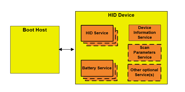
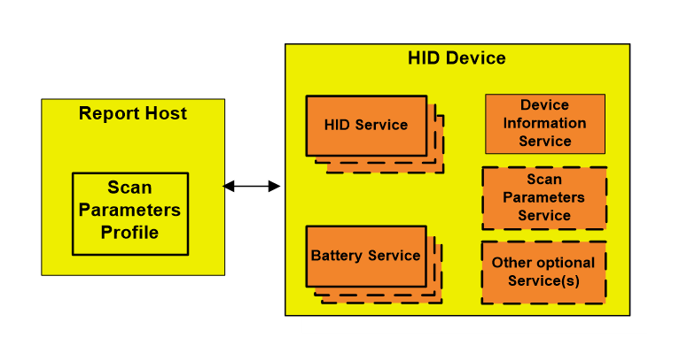
This profile defines three roles: HID Device, Boot Host, and Report Host.
-
The HID Device shall be a GATT server.
-
The Boot Host shall be a GATT client.
-
The Report Host shall be a GATT client.
The term HID Host refers to both host roles: Boot Host, and Report Host. A Report Host is required to support a HID Parser and be able to handle arbitrary formats for data transfers (known as Reports), whereas a Boot Host is not required to support a HID Parser as all data transfers (Reports) for Boot Protocol Mode are of predefined length and format.
2.2. Role and service relationships
Figure 2.1 shows the relationship between services and the profile roles.
 |
Note
Note: Profile roles are represented by yellow boxes and services are represented by orange boxes.
 |
Note
Note: Profile roles are represented by yellow boxes and services are represented by orange boxes.
The Report Host supports the Scan Client role of the Scan Parameters Profile.
The Boot Host shall not support the Scan Client role of the Scan Parameters Profile.
The HID Device has one or more instances of the HID Service, one or more instances of the Battery Service, a single instance of the Device Information Service, and optionally one instance of the Scan Parameters Service as part of the Scan Server role of the Scan Parameters Profile. A HID Device that supports the HID ISO feature has a single instance of the HID ISO Service. The HID Device may optionally have single or multiple instances of other services.
2.3. Concurrency limitations and restrictions
A Boot Host shall not concurrently be a Report Host.
A Report Host shall not concurrently be a Boot Host.
There are no concurrency limitations on either HID Host roles from also being a HID Device.
Devices with HID SCI and devices with HID ISO can be connected in various combinations. A HID Host may be connected to multiple HID devices, each device using the Hybrid Operation mode or the Default Operation mode with or without HID SCI.
2.4. Topology limitations and restrictions
The HID Device shall use the GAP Peripheral role.
The Boot Host shall use the GAP Central role.
The Report Host shall use the GAP Central role.
2.5. Multiple service instances
Multiple service instances shall not be supported for the following services:
-
Device Information Service
-
Scan Parameters Service
-
HID ISO Service
Multiple service instances of the HID Service may be supported to allow implementers to define composite HID Devices whose combined functions require more than 512 octets of data to describe.
-
Multiple service instances of the Battery Service may be supported.
-
Multiple service instances of any service other than HID Service, Device Information Service, or Scan Parameters Service may be supported, but are not considered as a part of this profile.
2.6. [This section is no longer used]
2.7. Inter-layer dependencies
This profile shall operate over an LE transport only. Implementations that support report intervals less than 2 ms shall use the LE 2M PHY for report intervals less than 2 ms.
HID Host implementations and HID Device implementations that support the HID SCI feature depend on both Host support and Controller support for SCI. See Volume 6, Part B of [2].
2.8. Core configuration dependencies
Enabling Bluetooth wireless technology end-to-end in an implementation of this profile requires an implementation of a Core Configuration that supports the LE transport.
2.8.1. Core feature inter-layer dependencies
Table 2.1 details the required Core dependencies for HID Host role and HID Device role.
|
Core Layer Feature |
Specification Role |
|
|---|---|---|
|
HID Host |
HID Device |
|
|
Shorter Connection Intervals Specified since: Core 6.2 Volume 6, Part B, Section 4.6.50 |
C.1 |
C.1 |
|
LE Flushable ACL Data Specified since: Core 6.2 Volume 6, Part B, Section 4.6.51 |
C.2 |
C.2 |
- C.1:
-
Mandatory to support if Shorter Connection Intervals is supported, otherwise optional.
- C.2:
-
Mandatory to support if HID ACL Flush is supported, otherwise optional.
3. HID Device requirements
The HID Device shall have one or more instances of the HID Service, one or more instances of the Battery Service, one instance of the Device Information Service, and optionally the Scan Parameters Service, but only a single instance.
The HID Device may support the functionalities defined by the Scan Server role of the Scan Parameters Profile [6].
Table 3.1 shows service requirements for the HID Device.
|
Service |
Requirement |
|---|---|
|
HID Service |
M |
|
Battery Service |
M |
|
Device Information Service |
M |
|
Scan Parameters Service |
O |
|
HID ISO Service |
C.1 |
- C.1:
-
Mandatory if the HID ISO feature is supported, otherwise excluded.
3.1. HID Service
This sub-section defines additional HID Device requirements beyond those defined in the HID Service [3].
3.1.1. Dependent service requirements
Any non-HID Service that has a characteristic whose value is described within the Report Map characteristic value shall be referenced as an «Include» within the HID Service definition containing that Report Map characteristic.
Any characteristic belonging to an external service whose value is described within the Report Map characteristic shall also contain a Report Reference characteristic descriptor within that external service characteristic definition. Only characteristics supporting the mandatory characteristic properties for the intended Report Type shall be described within the Report Map characteristic.
A HID Service shall not include any external service that is already included within another HID Service definition on the GATT Server. These rules prevent separate HID Services from referencing multiple characteristics of the same UUID having identical Report Reference characteristic descriptors.
3.1.2. Service Type
All services with the «HID Service» UUID shall be instantiated as a «Primary Service» as part of this profile.
3.1.3. Service UUID AD Type
While in a GAP Discoverable Mode for initial connection to a HID Host, the HID Device should include HID Service UUIDs (defined in the Bluetooth Assigned Numbers [7]) in the Service UUID AD type field of the advertising data.
3.1.4. Local Name AD Type
For enhanced user experience, a HID Device should include its Local Name in its Advertising Data or Scan Response Data.
3.1.5. Appearance AD Type
For enhanced user experience, a HID Device should include its Appearance in its Advertising Data or Scan Response Data.
This profile defines additional security requirements in Section 8.1 beyond those defined in the HID Service.
3.1.6. Additional service requirements for HID ISO support
When a HID Device supporting the HID ISO feature has more than one instance of the HID Service [3], all Report IDs shall be unique within each Report Type within the HID Device.
3.1.7. HID Information behavior
A HID Device can set the NormallyConnectable flag to TRUE in the HID Information characteristic to expose that it is connections-initiated by the bonded Report Host. When NormallyConnectable is TRUE, a HID Device bonded to at least one Report Host shall be in the GAP Undirected Connectable Mode whenever it is not connected to any HID Host.
Refer to Appendix A for details on NormallyConnectable behavior.
3.2. Battery Service
This sub-section defines additional HID Device requirements beyond those defined in the Battery Service [4].
3.2.1. Service Type
There shall be at least one instance of a service with the «Battery Service» UUID, instantiated as a «Primary Service». If a Battery Level characteristic value is described within the Report Map characteristic value, then the Battery Service definition in which the Battery Level characteristic exists shall be included, using the include definition, within the HID Service definition containing the Report Map characteristic.
3.2.2. Additional security requirements
This profile defines additional security requirements in Section 8.1 beyond those defined in the Battery Service [4].
3.3. Device Information Service
This sub-section defines additional HID Device requirements beyond those defined in the Device Information Service [5].
3.3.1. Service Type
The Device Information Service shall be instantiated as a «Primary Service» as part of this profile.
3.3.2. Mandatory characteristics
The Device Information Service shall include the PnP ID characteristic for reading the PnP ID fields for the HID Device. This service is defined in the Device Information Service [5].
3.3.3. Additional security requirements
This profile defines additional security requirements in Section 8.1 beyond those defined in the Device Information Service [5].
3.4. Scan Parameters Service
This subsection defines additional HID Device requirements beyond those defined in the Scan Parameters Service [6].
3.4.1. Additional security requirements
This profile defines additional security requirements in Section 8.1 beyond those defined by the Scan Parameters Service [6], if implemented as part of this profile.
3.5. HID ISO support
Section 5 establishes additional requirements for a HID Device that supports the HID ISO feature.
3.6. HID SCI support
Section 7 establishes additional requirements for a HID Device that supports the HID SCI feature. HID SCI capability is exposed in the HID Information characteristic.
3.7. HID SCI Flush of Input Reports
A HID Device may configure a Flush Timeout on LE ACL for Input Reports. Flushing of data is only allowed in the Attribute Protocol with GATT notifications for Input Reports. Flush operation only applies to HID Input Reports. For further information, see Volume 3, Part G, Section 5.2.2 of [2].
4. HID Host requirements and behaviors
The HID Host defines requirements for observing, connecting to, configuring for notification from, reading from, and writing to a HID Device.
This section describes the procedure and characteristic requirements for a HID Host.
|
Procedure |
Section Reference |
Boot Host Requirement |
Report Host Requirement |
|---|---|---|---|
|
Service Discovery |
M |
M |
|
|
M |
M |
|
|
O |
M |
|
|
O |
M |
|
|
E |
C.4 |
|
|
Characteristic Discovery |
O |
M |
|
|
O |
M |
|
|
E |
C.4 |
|
|
O O |
M M |
|
|
Report Map |
E |
M |
|
|
Report |
E |
M |
|
|
Boot Keyboard Input Report |
C.2/C.3 |
E |
|
|
Boot Keyboard Output Report |
C.2/C.3 |
E |
|
|
Boot Mouse Input Report |
C.2 |
E |
|
|
HID Information |
E |
M |
|
|
HID Control Point |
E |
C.1 |
|
|
Protocol Mode |
M |
O |
|
|
Non-HID Service characteristic defined within Report Map |
E |
M |
|
|
LE HID Operation Mode |
E |
C.4 |
|
|
HID SCI Information |
E |
C.5 |
|
|
HID SCI Mode |
E |
C.5 |
|
|
|||
Requirements marked with ‘M’ are mandatory, ‘O’ are optional, and ‘E’ are excluded (not permitted).
4.1. GATT sub-procedure requirements
Requirements in this section represent a minimum set of requirements for a client. Other GATT sub-procedures may be used if supported by both the GATT Client and GATT Server.
Table 4.2 summarizes additional GATT sub-procedure requirements beyond those required by all GATT Clients.
|
GATT Sub-Procedure |
Boot Host Requirement |
Report Host Requirement |
|---|---|---|
|
Discover All Primary Services |
C.1 |
C.1 |
|
Discover Primary Service by Service UUID |
C.1 |
C.1 |
|
Discover All Characteristics of a Service |
O |
C.2 |
|
Discover Characteristics by UUID |
O |
C.2 |
|
Discover All Characteristic Descriptors |
M |
M |
|
Find included Services |
E |
M |
|
Write Without Response |
M |
M |
|
Write Characteristic Value |
M |
M |
|
Single Notifications |
M |
M |
|
Read using Characteristic UUID |
M |
O |
|
Read Characteristic Value |
M |
M |
|
Read Long Characteristic Value |
E |
M |
|
Read Characteristic Descriptors |
M |
M |
|
Write Characteristic Descriptors |
M |
M |
|
||
Requirements marked with ‘M’ are mandatory, ‘O’ are optional, and ‘E’ are excluded (not permitted).
4.2. Scan Parameters Profile support
The Report Host shall support the functionality defined in the Scan Parameters Profile [6].
4.2.1. Additional security requirements
This profile defines additional requirements for the Scan Parameters Profile Scan Client role in Section 8.2.
4.3. Service discovery - Boot Host
The Boot Host shall perform primary service discovery using either the GATT Discover All Primary Services sub-procedure or the GATT Discover Primary Service by Service UUID sub-procedure. Fast connection parameters and procedures for connection establishment are recommended to enhance Service Discovery speeds.
4.3.1. HID Service discovery
The Boot Host shall perform primary service discovery to discover all HID Services.
4.3.2. Device Information Service discovery
The Boot Host may perform primary service discovery to discover the Device Information Service [5].
4.3.3. Battery Service discovery
The Boot Host may perform primary service discovery to discover the Battery Service [4].
4.4. Characteristic discovery – Boot Host
4.4.1. HID Service characteristic discovery
The Boot Host may use either the GATT Discover All Characteristics of a Service sub-procedure or the GATT Discover Characteristics by UUID sub-procedure to discover the following characteristics for each HID Service on the GATT Server, if characteristic discovery is supported:
-
Protocol Mode characteristic (Section 4.4.1.1)
-
Boot Keyboard Input Report characteristic (Section 4.4.1.2)
-
Boot Keyboard Output Report characteristic (Section 4.4.1.3)
-
Boot Mouse Input Report characteristic (Section 4.4.1.4)
If characteristic discovery is not supported, the Boot Host shall use the GATT Read Using Characteristic UUID sub-procedure to read the above HID Service characteristics for Boot Mode operation, replacing normal characteristic discovery.
4.4.1.1. Protocol Mode characteristic
The Boot Host may discover the Protocol Mode characteristic for each HID Service on the GATT Server.
4.4.1.2. Boot Keyboard Input Report characteristic
The Boot Host may discover the Boot Keyboard Input Report characteristic for each HID Service on the GATT Server.
The Boot Host shall discover the associated Client Characteristic Configuration Descriptor of all Boot Keyboard Input Report characteristics using the GATT Discover All Characteristic Descriptors sub‑procedure.
4.4.1.3. Boot Keyboard Output Report characteristic
The Boot Host may discover the Boot Keyboard Output Report characteristic for each HID Service on the GATT Server.
4.4.1.4. Boot Mouse Input Report characteristic
The Boot Host may discover the Boot Mouse Input Report characteristic for each HID Service on the GATT Server.
The Boot Host shall discover the associated Client Characteristic Configuration Descriptor of all Boot Mouse Input Report characteristics using the GATT Discover All Characteristic Descriptors sub‑procedure.
4.4.2. Device Information Service characteristic discovery
The Boot Host may use either the GATT Discover All Characteristics of a Service sub-procedure or the GATT Discover Characteristics by UUID sub-procedure to discover the following characteristic of the Device Information Service, if characteristic discovery is supported:
-
PnP ID characteristic (Section 4.4.2.1)
If characteristic discovery is not supported, then the Boot Host may use the GATT Read Using Characteristic UUID sub-procedure to read the above Device Information Service characteristic, replacing normal characteristic discovery.
4.4.2.1. PnP ID characteristic
The Boot Host may discover the PnP ID characteristic.
4.4.3. Battery Service characteristic discovery
The Boot Host may use either the GATT Discover All Characteristics of a Service sub-procedure or the GATT Discover Characteristics by UUID sub-procedure to discover the following characteristic of the Battery Service, if characteristic discovery is supported:
-
Battery Level characteristic (Section 4.4.3)
If characteristic discovery is not supported, then the Boot Host may use the GATT Read Using Characteristic UUID sub-procedure to read the above Battery Service characteristic, replacing normal characteristic discovery.
4.4.3.1. Battery Level characteristic
The Boot Host may discover the Battery Level characteristic.
4.5. Service discovery – Report Host
The Report Host shall perform primary service discovery using either the GATT Discover All Primary Services sub-procedure or the GATT Discover Primary Service by Service UUID sub-procedure. Fast connection parameters and procedures for connection establishment are recommended to enhance Service Discovery speeds.
If the Report Host supports an ATT_MTU larger than the default ATT_MTU, then the Report Host shall use the GATT Exchange MTU sub-procedure prior to performing service discovery.
4.5.1. HID Service discovery
The Report Host shall perform primary service discovery to discover all HID Services.
4.5.2. Device Information Service discovery
The Report Host shall perform primary service discovery to discover the Device Information Service.
4.5.3. Battery Service discovery
The Report Host may perform primary service discovery to discover all Battery Services.
The Report Host shall perform relationship discovery to find included services to discover all Battery Services with characteristics described within a HID Service Report Map characteristic value.
Note
Note: Multiple instances of the Battery Service can be distinguished using the Characteristic Presentation Format characteristic descriptor of the Battery Level characteristic as defined by the Battery Service [4]. Within this profile, multiple Battery Level characteristics referenced within the Report Map characteristic are distinguished by the Report Reference characteristic descriptor.
4.5.4. HID ISO Service discovery
If the Report Host supports the HID ISO feature, then the Report Host shall perform primary service discovery to discover the HID ISO Service.
4.6. Characteristic discovery – Report Host
As required by GATT, the Report Host must be tolerant of additional optional characteristics of services used with this profile and used outside of this profile.
4.6.1. HID Service characteristic discovery
The Report Host shall use either the GATT Discover All Characteristics of a Service sub-procedure or the GATT Discover Characteristics by UUID sub-procedure to discover the characteristics of all HID services.
The Report Host shall use the GATT Discover All Characteristic Descriptors sub-procedure to discover the characteristic descriptors described in the following sections.
4.6.1.1. Report Map characteristic
The Report Host shall discover all Report Map characteristics.
The Report Host shall discover all External Report Reference characteristic descriptors for each Report Map characteristic.
4.6.1.2. Report characteristics
The Report Host shall discover all Report characteristics.
The Report Host shall discover the associated Client Characteristic Configuration Descriptor of all Report characteristics.
The Report Host shall discover the associated Report Reference characteristic descriptor of all Report characteristics.
4.6.1.3. HID Control Point characteristic
The Report Host shall discover all HID Control Point characteristics, if the Report Host supports Suspend mode, to allow the Report Host to send control commands to HID Devices whenever the Report Host enters a low power Suspend Mode.
4.6.1.4. HID Information characteristic
The Report Host shall discover all HID Information characteristics.
4.6.1.5. Protocol Mode characteristic
The Report Host may discover the Protocol Mode characteristic for each HID Service on the GATT server.
4.6.1.6. HID SCI Information characteristic
A HID Report Host that supports HID SCI shall discover the HID SCI Information characteristic of at least one HID Service on the GATT Server. The HID SCI Information characteristic allows the HID Host to discover the minimum-supported connection intervals of the HID Device.
4.6.1.7. HID SCI Mode characteristic
A HID Report Host that supports HID SCI shall discover the HID SCI Mode characteristic of at least one HID Service on the GATT Server. The HID SCI Mode characteristic allows the HID Host to determine the HID SCI mode being used by the HID Device. The HID SCI Mode characteristic also allows the HID Host to be notified of HID SCI mode changes.
4.6.2. Device Information Service characteristic discovery
The Report Host shall discover characteristics of the Device Information Service.
In order for the Report Host to discover the characteristics of the Device Information Service, it shall use either the GATT Discover All Characteristics of a Service sub-procedure or the GATT Discover Characteristics by UUID sub-procedure.
4.6.2.1. PnP ID characteristic
The Report Host shall discover the PnP ID characteristic.
4.6.3. Battery Service characteristic discovery
The Report Host shall discover the characteristics of all Battery Services.
In order for the Report Host to discover the characteristics of all Battery Services, it shall use either the GATT Discover All Characteristics of a Service sub-procedure or the GATT Discover Characteristics by UUID sub-procedure.
4.6.3.1. Battery Level characteristic
The Report Host shall discover all Battery Level characteristics to find Battery Level characteristics referenced within the External Report Reference characteristic descriptor and their associated Report Reference characteristic descriptors.
4.6.4. HID ISO Service characteristic discovery
4.6.4.1. HID ISO Properties characteristic
The Report Host shall discover the HID ISO Properties characteristic when supporting the HID ISO feature.
4.6.4.2. LE HID Operation Mode characteristic
The Report Host shall discover the LE HID Operation Mode characteristic when supporting the HID ISO feature.
4.7. Report Map behavior
The Report Map characteristic shall return the HID Report Descriptor when read.
The HID Report Descriptor is defined in the USB HID specification [1].
The Report Host shall read all characteristic descriptors of the Report Map characteristic to allow the Report Host to map information within the Report Map characteristic to external service characteristics used to transfer data described by the information between the Report Host and HID Device.
4.8. Report behavior
The Report characteristic is used to transfer HID Service data between the Report Host and the HID Device.
The Report Host shall enable notifications, via the Client Characteristic Configuration descriptor, of the Report characteristic for all instances of the Report characteristic where the Report Type as defined in the Report Reference characteristic descriptor refers to an Input Report.
The Boot Host shall ignore notifications of the Report characteristic.
4.8.1. Translation layer
Note
Note: This profile delivers USB-IF HID data over Bluetooth by means of the Generic Attribute Profile [1]. If an implementation of the Report Host were to utilize a translation layer located between the GATT layer on the Report Host and the USB HID class driver, it would need to conform to the behavior described in this section.
According to Sections 4.5 and 4.6, the Report Host shall perform service discovery, characteristic discovery, and characteristic descriptor discovery in the specified manner.
A Report ID and a Report Type defined within the Report Map characteristic and referenced within Report Reference characteristic descriptors allow the Report Host to route GATT characteristic value data into and out of the USB HID class driver, and allow the Report Host to route USB HID class driver data into and out of GATT characteristic values.
For each separate Report ID and Report Type combination defined within the Report Map characteristic value, there shall be one of the following:
-
A HID Service Report characteristic and Report Reference characteristic descriptor within the Report characteristic definition.
-
An external service characteristic whose UUID is supplied via an External Report Reference characteristic descriptor within the Report Map characteristic definition, and whose characteristic value contains a Report Reference characteristic descriptor within the external service characteristic definition. All External Report Reference characteristic descriptors shall contain unique values within a HID Service definition.
For data transferred from the HID Device to the Report Host, the Report ID is prepended to data received by the Report Host (usually either a notification of a Report characteristic value, or as a read response of a Report characteristic value, for HID Service data) before being passed to a USB HID Class driver.
For data transferred to the HID Device from the Report Host, the Report ID is removed from data received from a USB HID Class driver before being transmitted to the HID Device (usually a write command to a Report characteristic value or as a write request to a Report characteristic value for HID Service data).
4.9. HID Control Point behavior
The HID Control Point characteristic is a control-point characteristic as defined in Volume 3, Part F, Section 3.2.6 of [2]. The HID Control Point characteristic allows the Report Host to signal the HID Device that the Report host is entering or exiting a power saving mode known as Suspend Mode (see [8], §7.4.2).
4.10. HID Information behavior
The HID Information characteristic value contains the bcdHID and bcountryCode fields as defined by the USB HID specification [1].
When a system enters a low-power Suspend Mode, the RemoteWake flag shall be used to determine whether the Report Host includes the HID Device in the set of devices that can wake it up.
If the RemoteWake flag is FALSE, then the HID device does not consider itself remote wakeup-capable, and the Report Host can exclude the HID Device from the set of devices that can wake the Report Host up.
When a Report Host is exiting a low power Suspend Mode, the NormallyConnectable flag shall be used to determine whether the Report Host can connect to the HID Device before any user interaction occurs on the HID device. This may be used to improve the perceived responsiveness of the system.
4.11. Protocol Mode behavior
The Protocol Mode characteristic allows reading and writing of the protocol mode of the HID Service and to set the desired protocol mode.
The Boot Host shall write to the Protocol Mode characteristic for each HID Service on the GATT Server and set the characteristic value to the defined value for Boot Protocol Mode following connection establishment. There are no requirements on a Report Host to use the Protocol Mode characteristic.
4.12. Boot Keyboard Input Report behavior
The Boot Keyboard Input Report characteristic is used to transfer HID Service data representing keyboard keystrokes between a HID Service corresponding to a HID Device operating in Boot Protocol Mode as a keyboard and a Boot Host.
If the Boot Host supports the Boot Keyboard Input Report characteristic, then it shall enable notifications of the Boot Keyboard Input Report characteristic using the Client Characteristic Configuration descriptor.
The Report Host shall ignore notifications of the Boot Keyboard Input Report characteristic.
4.13. Boot Keyboard Output Report behavior
The Boot Keyboard Output Report characteristic is used to transfer HID Service data representing the status of LED’s visible to the user between a HID Service corresponding to a HID Device operating in Boot Protocol Mode as a keyboard and a Boot Host.
4.14. Boot Mouse Input Report behavior
The Boot Mouse Input Report characteristic is used to transfer HID Service data representing pointer coordinates between a HID Service corresponding to a HID Device operating in Boot Protocol Mode as a mouse and a Boot Host.
If the Boot Host supports the Boot Mouse Input Report characteristic, then it shall enable notifications of the Boot Mouse Input Report characteristic using the Client Characteristic Configuration descriptor.
The Report Host shall ignore notifications of the Boot Mouse Input Report characteristic.
4.15. Battery Level behavior
The Battery Level characteristic may either be read by the HID Host or be enabled for notification using the Client Characteristic Configuration Descriptor by the HID Host. The HID Host should minimize the frequency of reads of the Battery Level characteristic value to avoid significant impact on the battery life of the HID Device. The HID Host may use the information returned in a read response or a notification of the Battery Level characteristic value to display the battery level of the HID Device.
4.16. PnP ID behavior
The PnP ID characteristic value shall be read by the Report Host upon initial connection establishment and may be cached afterwards. The PnP ID characteristic value may be read by the Boot Host upon initial connection establishment and may be cached afterwards.
The HID Host can use the information returned in the PnP ID characteristic value to find representative icons or load associated support software.
Note
Note: The Appearance AD type exists and may be common to multiple distinct devices. However, based on the PnP ID characteristic value, icons that are unique to a single manufacturer can be displayed on a per-device basis.
4.17. Information sharing between HID Hosts
The Boot Host and Report Host shall share bonding information and information regarding «Service changed» indications. If a bond is deleted from a Report Host, then the bonding information shall be removed from the Boot Host. If a bond is deleted from a Boot Host, then the bonding information shall be removed from the Report Host.
If a «Service changed» indication is received by the Report Host when connected to the HID Device, then the Report Host shall make the Boot Host aware of the «Service changed» indication and any information contained therein. If a «Service changed» indication is received by the Boot Host when connected to the HID Device, then the Boot Host shall make the Report Host aware of the «Service changed» indication and any information contained therein.
4.18. LE HID Operation Mode behavior
The LE HID Operation Mode characteristic is used to switch the operation mode between Default Operation mode and Hybrid Operation mode at the application layer. For a Report Host that supports the HID ISO feature, the client requirements in Section 5.2 are mandatory.
4.19. HID ISO support
Section 5.3, Section 5.4, Section 5.5, and Section 5.6 establish additional requirements for a HID Host that supports the HID ISO feature.
4.20. HID SCI support
Section 7 establishes additional requirements for a HID Host to be able to support the HID SCI feature.
A HID Host that supports the HID SCI feature shall discover the support for HID SCI in the HID Device by reading the HID Information characteristic.
4.21. HID SCI Flush Output Reports
A HID Host may configure a Flush Timeout on LE ACL for Output Reports. Flush operation only applies to HID Output Reports marked as flushable. For further information, see Volume 3, Part G, Section 5.2.2 of [2].
5. HID ISO requirements
When supporting the HID ISO feature, Input reports and/or Output reports can be configured to be sent over LE Isochronous Channels using a Connected Isochronous Stream (CIS).
One or more reports can be made available for sending over LE Isochronous Channels in Hybrid Operation mode by the Hybrid Mode ISO Reports field of the HID ISO Properties characteristic. One Input Report and/or one Output Report from the available reports can be selected for transmission over LE Isochronous Channels in Hybrid Mode.
5.1. Report interval and latency
The term “report interval” refers to the nominal time difference between the opportunities to transmit reports created at either the HID Device (Input report) or HID Host (Output report).
For HID Reports sent over LE Isochronous channels in Hybrid Operation mode, the SDU interval is the same value as the report interval.
End-to-end latency for an input report is the time from when a human action is performed on the HID Device until the action is detected by an application on the HID Host.
End-to-end latency for an output report is the time from when an application on the HID Host sends a message to an actuator in the HID Device until the effect of the message reaches the user.
Both report interval and end-to-end latency can be important for the user experience.
The report interval is set by the HID Host selecting an SDU interval supported by both the HID Device and HID Host. The HID Host should choose the minimum report interval that is supported by both devices.
The selected SDU interval will limit the minimum end-to-end latency.
The end-to-end delay is also influenced by several other factors, such as sample acquisition, sample processing, buffering in the transmitting device, maximum spacing between transmit opportunities, buffering in the receiving device, and signaling between layers.
Link Layer parameters for the CIS will impact the average latency as well as the latency variance.
For optimal latency performance, when the report rate is less than 5 ms, the implementer will need to consider the detailed Link Layer timing for the CIS and ACL PDUs (see Appendix C.2 for an example). Section 5.3 describes the Link Layer behavior for optimal latency performance.
5.2. Operation modes
The LE HID Operation Mode characteristic is used to switch the operation mode between Default Operation mode and Hybrid Operation mode at the application layer.
When a connection between a HID Device and a HID Host is established, the initial operation mode shall be Default Operation mode, which uses only GATT for sending and receiving reports. In Hybrid Operation mode, the HID Report(s) identified by a command from the HID Host are sent over LE Isochronous Channels while other reports are sent over GATT. The procedures in Section 5.2.1 and Section 5.2.2 are designed to keep the HID Device and the HID Host in the same operation mode at any given time.
Figure 5.1 shows the simplified state diagram of the HID Device and HID Host operation modes.
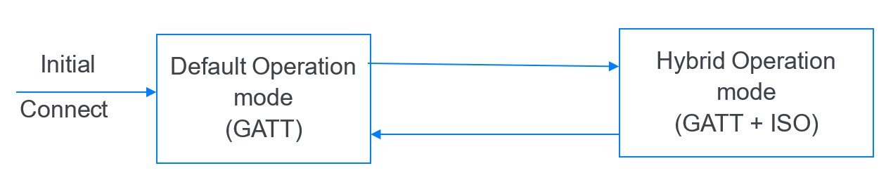
Section 5.2.1 and Section 5.2.2 describe how the HID Host can change the operation mode and how the HID Device may request an operation mode change. The sequence for changing the operation mode is explained in Appendix B.
5.2.1. Host-initiated operation mode change
To change the operation mode to Hybrid Operation mode and to enable certain HID Reports to be sent over LE Isochronous Channels, the HID Host shall write the LE HID Operation Mode characteristic with the Opcode field set to Select Hybrid Operation Mode and the Parameters field set to indicate the report interval to be used, the SDU sizes to be used, and the list of HID Reports (identified by Report Type and Report ID) that shall be sent over LE Isochronous Channels when in Hybrid Operation mode. At most one Input Report and/or one Output Report shall be sent over LE Isochronous Channels in a given Hybrid mode session.
After sending the Select Hybrid Operation Mode Opcode and receiving a successful response, the HID Host shall configure the CIS to be used for HID ISO traffic and initiate the Connected Isochronous Stream Creation procedure. The HID Host shall continue in Default Operation mode (still using GATT) until the LE Connected Isochronous stream is successfully established and then enter Hybrid Operation mode.
After receiving the Select Hybrid Operation Mode Opcode, the HID Device shall continue in Default Operation mode (still using GATT) until the LE Connected Isochronous stream is established and then enter Hybrid Operation mode.
To change the operation mode to Default Operation mode, the HID Host shall write the LE HID Operation Mode characteristic with the Opcode field set to Select Default Operation Mode and the Parameters field empty, change the state to Default Operation mode, and initiate termination of the CIS, in that order.
After receiving the Select Default Operation Mode Opcode, the HID Device shall change the state to Default Operation mode without waiting for termination of the CIS.
If the HID Device detects an error in the command written to the LE HID Operation Mode characteristic, then the HID Device shall respond with one of the error codes defined in Section 6.2.
5.2.2. Device request to change operation mode
If the HID Device has the Device Mode Change Supported bit in the HID ISO Properties characteristic set, then the HID Device may request an operation mode change by indicating the LE HID Operation Mode characteristic with the corresponding Opcode. If the HID Device is requesting to change the operation mode to Hybrid Operation mode, then the Parameters field is set to indicate the desired report interval and the list of HID Reports (identified by Report Type and Report ID) that the HID Device prefers to send over LE Isochronous Channels when in Hybrid Operation mode. After receiving the request, the HID Host should perform the Host-initiated operation mode change as described in Section 5.2.1.
5.3. Configuration of LE Isochronous Channels for HID ISO
The HID Host shall read the HID ISO Properties characteristic on each connection to discover the properties of the HID Device. The HID Host shall configure either an existing or a new Connected Isochronous Group (CIG). The HID Host shall create and configure a single CIS in the CIG to transfer ISO reports in Hybrid Operation mode. The CISes created for HID Devices that are also implementing the HID ISO feature and the CISes for other profiles can be created in the same CIG or in different CIGs. Note that combining CISes in a CIG constrains the link parameters of each CIS ([2] Volume 6, Part B, Section 4.5.14), and will limit which CISes that can be combined into one CIG.
The CIS for HID ISO data shall be configured with the SDU interval (parameters SDU_Interval_P_to_C and SDU_Interval_C_to_P when using HCI) set equal to one of the report intervals supported by the HID Device, as indicated by the Supported Report Intervals field of the HID ISO Properties characteristic.
The maximum SDU size for the Central to Peripheral direction (parameter Max_SDU_C_to_P when using HCI) shall be set to a value greater than or equal to the length of the longest Output Report enabled over ISO plus the overhead of the HID ISO protocol (3 octets). When the HID Host device is not constrained by other use cases, the maximum SDU size for the Central to Peripheral direction should be set to the value of the Max SDU Size for Output Reports field of the HID ISO Properties characteristic. When the maximum SDU size for the Central to Peripheral direction is set to a value less than the value of the Preferred SDU Size for Output Reports field of the HID ISO Properties characteristic, then the HID Device may have to reduce the robustness or reduce the effective report rate.
The maximum SDU size for the Peripheral to Central direction (parameter Max_SDU_P_to_C when using HCI) shall be set to a value greater than or equal to the length of the longest Input Report enabled over ISO plus the overhead of the HID ISO protocol (3 octets). When the HID Host device is not constrained by other use cases, the maximum SDU size for the Peripheral to Central direction should be set to the value of the Max SDU Size for Input Reports field of the HID ISO Properties characteristic. When the maximum SDU size for the Peripheral to Central direction is set to a value less than the value of the Preferred SDU Size for Input Reports field of the HID ISO Properties characteristic, then the HID Device may have to reduce the robustness or reduce the effective report rate.
To minimize latency contribution from the Link Layer protocols, the Controller in the HID Host should be configured to use an ISO subinterval less than or equal to the SDU interval when the SDU interval is less than the ISO interval and to send unframed SDUs.
Note that the HID Host must select a combination of SDU interval and SDU size that allows the Controller to schedule the Central to Peripheral PDU (MPT_C), the Peripheral to Central PDU (MPT_P), and the frame spacing (T_IFS and T_MSS) within one ISO subinterval. See Appendix C.2 for details on Link Layer timing.
To minimize latency contribution from the Bluetooth implementation, the Controller in both the HID Host and the HID Device should send an SDU received from its Host at the first available transmit opportunity (PDU).
To minimize latency contribution from the Bluetooth implementation, the Controller in both the HID Host and the HID Device should send an SDU received from its peer device to its Host as soon as the PDU carrying the SDU is received.
If the Controllers behave differently from what is described in the above two paragraphs, then the latency contribution from the Link Layer can be determined by the Transport Latency calculated by the Link Layer. The behavior described in the two paragraphs above does not affect the Controller’s calculation of Transport Latency as described in [2] Volume 6, Part G, Section 3.2.2. The Transport Latency calculated by the Controller is not used by the application layer for a CIS that carries HID ISO packets. Figure 5.2 shows an adaptation of Figure 3.2 in [2] Volume 6, Part G, Section 3.2.2 to illustrate the behavior described in the above two paragraphs. Figure 5.2 uses black color for semantics copied from [2] with FT=1. Figure 5.2 uses red color for semantics used to describe SDUs and PDUs with the SDU interval identical to the ISO subinterval. Figure 5.2 uses green color for semantics used to describe the optimal behavior for HID ISO.

The Controller must follow the Bluetooth Core Specification requirements for ISOAL packet sequence numbers (see [2] Volume 6, Part G, Section 2), but the packet sequence number is not used for a CIS that carries HID ISO packets.
Note that an implementation of the HID ISO feature must synchronize generation of its data to the effective transport timing (i.e., the Host must send exactly one SDU, which can be empty, to the Controller each SDU interval) when using Unframed PDUs, see [2] Volume 6, Part G, Section 2.
Table 5.1 shows the requirements for report intervals.
|
Report interval |
HID Host support |
HID Device support |
|---|---|---|
|
1 ms |
O |
O |
|
1.25 ms |
O |
O |
|
2 ms |
O |
O |
|
2.5 ms |
O |
O |
|
3 ms |
O |
O |
|
3.75 ms |
O |
O |
|
4 ms |
O |
O |
|
5 ms |
C.1 |
M |
|
7.5 ms |
C.1 |
M |
- C.1:
-
Mandatory to support at least one of 5 ms and 7.5 ms.
Appendix C shows recommended ISO parameters for each report interval setting, and the range of Max_Transport_Latency that can be used to constrain a generic Controller to achieve those settings.
5.4. HID ISO packet structure
Zero or more HID ISO packets may be sent in a single SDU over LE Isochronous Channels. A HID ISO packet can contain either a HID report or a Confirmation. Each HID ISO packet that contains a HID report shall use the format defined in Table 5.2. Each HID ISO packet that contains a Confirmation shall use the format defined in Table 5.3.
|
Field |
Size |
Value |
|---|---|---|
|
Length |
1 octet |
The length of the Report field. The range is 1 to 255. |
|
Sequence Number |
1 octet |
Sequence Number that shall be individually calculated and stored for each report (i.e., for each unique Report ID and HID report type combination) sent over LE Isochronous Channels. See Section 5.6 for details on Sequence Number handling. The range is 0 to 255. |
|
Report ID |
1 octet |
For reports that do not contain a Report ID, this field shall be set to a value of 0. Otherwise, this field shall be set to equal the Report ID from the original report. |
|
Report |
Length octets |
HID Report. If the report contains Report ID, it shall be excluded. |
If the Length field value is set to a value of 0, as shown in Table 5.3, then the packet is a Confirmation to the receipt of a report. The receiving device can use this Confirmation to stop sending reports with the same Sequence Number as the one contained in the Confirmation to save power.
|
Field |
Size |
Value |
|---|---|---|
|
Length |
1 octet |
0 |
|
Sequence Number |
1 octet |
Sequence Number (see Section 5.6) for the report being confirmed. The range is 0 to 255. |
|
Report ID |
1 octet |
Report ID field for the report being confirmed. |
5.5. HID ISO Protocol
The HID ISO Protocol is defined for transporting HID Reports over LE Isochronous Channels. This protocol provides the following capabilities:
-
Redundancy – enables retransmission of the same packet with an optional confirmation to avoid unnecessary retransmission.
-
Multiple reports per SDU – optionally provides the ability to include multiple reports in a single SDU to enable retransmission of packets concurrently with transmitting new packets.
A HID Host that supports the HID ISO feature shall support all the above capabilities.
The HID Device may support some of the above capabilities, and the HID Device shall indicate the support for Repetition (multiple reports per SDU) and Confirmation by setting the corresponding bits in the Additional Info subfield of the Hybrid Mode ISO Reports field of the HID ISO Properties characteristic.
When the HID Host is instructed to enter hybrid mode by a higher layer, the higher layer can include requirements or recommendations for using Repetition or Confirmation. The HID Host should enable Repetition and Confirmation when supported by the HID Device in accordance with the instructions from the higher layer. If there are no recommendations or requirements from the higher layer, then the HID Host should enable Repetitions and Confirmation if supported by the HID Device.
It is up to the implementer of the device transmitting each report to use these features to provide a level of reliability that is adequate for the type of data contained in the report. The following report types are defined to provide guidance on how these features should be used.
ABSOLUTE: The Absolute report type is intended for reports that are more “absolute” in nature. Such reports contain data that represent the current state of an input mechanism, independent of any previous reports to be interpreted by the receiving side. Such reports often remain the same from one transmission to the next. For example, a report containing the status of a momentary push button or the position of a 2-position switch can be interpreted without knowledge of the values of previous reports.
RELATIVE: The Relative report type is intended for reports that are more “relative” in nature. Such reports contain data that are taken together with the values of previous reports to determine or derive another value. For example, the X and Y delta reports for a mouse or other pointing device are summed with previous values to determine the current X and Y coordinates of an on-screen pointer. For such reports, the loss of any single report can have a negative impact on user experience. Because of the nature of Bluetooth transmissions, any single transmission has some probability of being lost because of interference or multipath effects. The frequency hopping mechanism provides frequency diversity; therefore, if a packet is lost on one frequency, then the next transmission will occur on a different frequency on the same link. The existing retransmission (ARQ) schemes used at the Link Layer of Bluetooth LE would introduce too much latency because the receiver must send a negative acknowledgment and the original transmitter must retransmit the lost transmission, as required by Volume 6, Part B, Section 4.5.9 in [2]. To avoid this latency, a simple report repetition scheme is defined.
Some reports can contain both types of data. For example, a mouse report may contain X and Y delta data, which are considered relative, but also buttons, which are absolute. Such reports should be treated as Relative reports.
Reports carrying mouse X and Y delta data should be treated as Relative reports, and repetition should be used when these are carried over the LE Isochronous Channels transport.
5.5.1. Power saving confirmation of reception
When the Confirmation bit in the Additional Info subfield of the Hybrid Mode ISO Reports field of the HID ISO Properties characteristic is set and the HID Host or HID Device receives a HID ISO packet, the receiving device shall send a Confirmation with the Sequence Number and the Report ID values equal to values of the same fields in the received HID ISO packet.
When the Confirmation bit in the Additional Info subfield of the Hybrid Mode ISO Reports field of the HID ISO Properties characteristic is set and the HID Host or HID Device receives a Confirmation, the device receiving the Confirmation may stop sending the HID ISO packet identified by the Sequence Number and Report ID in the Confirmation.
Note that the receiving device can still receive additional duplicates of a report, even if it has sent the Confirmation, because the sending device may not have received the Confirmation, could have buffered multiple copies for sending before receiving the Confirmation, or may have decided not to stop sending the report.
5.6. Sequence Number handling
The Sequence Number is maintained independently for each Report ID that is enabled to use the LE Isochronous Channels transport.
Section 5.6.1 and Section 5.6.2 specify how the Sequence Number field should be generated for transmission and interpreted upon receipt.
5.6.1. Sequence Number generation
Upon the establishment of a CIS connection, the transmitter shall initialize the Sequence Number to a value of 0 for each report with a given Report ID.
Whenever the content of a report changes, the Sequence Number shall be incremented after creating the HID ISO packet. The transmitter also may increment the Sequence Number when the content does not change if the content of the report represents a distinct user action from the report with the previous Sequence Number. For example, a mouse might produce a report containing deltaX = 5 followed by another report containing deltaX = 5. While the content is the same, the two reports together represent a user input that caused a total deltaX change of 10.
When the Repetition bit in the Additional Info subfield of the Hybrid Mode ISO Reports field of the HID ISO Properties characteristic is set, the sending device may include a given Report ID in an SDU with its current Sequence Number along with one or more previous values of that Report ID with previous Sequence Numbers. The reports shall be included in the SDU in order of increasing Sequence Number. The number of reports with the same Report ID in an SDU shall be less than or equal to 8. The limitations for the maximum SDU sizes specified in the HID ISO Properties characteristic can limit the number to less than 8. The maximum SDU sizes are defined by the implementer of the HID Device, considering the air-time available for HID ISO packets at the minimum report rate supported by the HID Device.
Table 5.4 shows an example with three repetitions (“r” is a report with a given Report ID, and the number following “r” represents the Sequence Number).
|
SDU number |
Packet(s) in SDU |
Packet sent to upper layer |
|---|---|---|
|
0 |
r0 |
r0 |
|
1 |
r0, r1 |
r1 |
|
2 |
r0, r1, r2 |
r2 |
|
3 |
r1, r2, r3 |
r3 |
|
4 |
r2, r3, r4 |
r4 |
|
… |
… |
... |
5.6.2. Sequence Number handling upon receipt
Upon receipt of an SDU over the LE Isochronous Channels transport, the receiver shall process the contents of the SDU as described in this section.
The receiving device shall process all packets in the SDU in sequence. The processing of each HID ISO packet is independent from the SDU the packet arrives in. Only the arrival sequence of the HID ISO packets impacts the packet processing.
If the Length field in a packet is set to a value of 0, then the packet is a Confirmation of a packet previously sent from that device. The device that received the Confirmation may stop sending further copies of the packet identified in the report (to save power).
If the Length field in a packet is set to a value greater than 0, then the packet contains a HID Report. In this case, the receiving device shall process the Report ID and Sequence Number fields as follows:
-
If the receiving device has previously received reports with the Report ID in this connection and (previously stored Sequence Number – Sequence Number) mod 256 is less than or equal to 7 (because the Sequence Number is in the past), then the receiving device shall ignore this packet.
-
Otherwise, the receiving device shall deliver the HID Report to a higher layer and store the Sequence Number.
If the Report ID is 0, then the HID Report sent to the higher layer shall be the Report field of the packet.
If the Report ID is not 0, then the HID Report sent to the higher layer shall be the Report field prepended with the Report ID field of the packet.
6. HID ISO Service
The HID ISO Service defines one characteristic to describe the ISO-related properties of the HID Device, and one characteristic to configure the HID ISO behavior and the state changes between the Default Operation mode and Hybrid Operation mode.
6.1. Service dependencies
The HID ISO Service does not depend on any other services.
6.2. Attribute Protocol Application error codes
The HID ISO Service defines the Attribute Protocol Application error codes listed in Table 6.1.
|
Name |
Error Code |
Description |
|---|---|---|
|
Opcode outside range |
0x81 |
Opcode is in the RFU range |
|
Device already in requested state |
0x82 |
The HID host has requested the HID Device to change to the state it is already in |
|
Unsupported feature |
0x83 |
Request contains settings that are not supported according to the Features field of the HID ISO Properties characteristic |
6.3. GATT sub-procedure requirements
Requirements in this section represent a minimum set of requirements for a Server. Other GATT sub-procedures may be used if supported by both the Client and Server.
Table 6.2 summarizes additional GATT sub-procedure requirements beyond those required by all GATT Servers.
|
GATT sub-procedure |
Requirements |
|---|---|
|
Write Characteristic Value |
M |
|
Indications |
C.1 |
- C.1:
-
Mandatory if the Device Mode Change Supported feature is set, otherwise optional.
6.4. Declaration
The HID ISO Service shall be instantiated as a «Primary Service».
Only one instance of the HID ISO Service shall be allowed on a Server.
The service UUID shall be set to «HID ISO Service» as defined in [7].
6.5. Service characteristics
This section defines the characteristic requirements. Where a characteristic can be indicated, a Client Characteristic Configuration descriptor must be included in that characteristic as required by [2].
The characteristics defined in this section are using the conventions described in Section 2 of the GATT Specification Supplement [9].
|
Characteristic Name |
Requirement |
Mandatory Properties |
Optional Properties |
Security Permissions |
|---|---|---|---|---|
|
HID ISO Properties |
M |
Read |
None |
None |
|
LE HID Operation Mode |
M |
Write |
Indication |
None |
6.5.1. HID ISO Properties
The HID ISO Properties characteristic is used to show the device’s HID ISO features, supported report intervals for HID ISO, and mapping of reports that will use the LE Isochronous Channels in the Hybrid Operation mode. The value of the HID ISO Properties shall be static during a connection.
6.5.1.1. Characteristic format
The structure of this characteristic is defined in Table 6.4.
|
Field |
Data Type |
Size |
Description |
|---|---|---|---|
|
Features |
boolean[8] |
1 |
Supported HID ISO features of the HID Device. See Section 6.5.1.1.1. |
|
Supported Report Intervals |
boolean[16] |
2 |
Supported report intervals for the HID Device. See Section 6.5.1.1.2. |
|
Max SDU Size for Input Reports |
uint8 |
1 |
Maximum SDU size the HID Device can use to send ISO data to the HID Host. Maximized robustness with no impact on latency. The sum of the longest Input Report length and the HID ISO protocol header multiplied by the maximum number of repetitions. |
|
Preferred SDU Size for Input Reports |
uint8 |
1 |
Preferred SDU size the HID Device will use to send ISO data to the HID Host. Most use cases experience no or minor performance impact. The sum of the most critical Input Report length and the HID ISO protocol header multiplied by the maximum number of repetitions. |
|
Max SDU Size for Output Reports |
uint8 |
1 |
Maximum SDU size the HID Host can use to send ISO data to the HID Device. Maximized robustness with no impact on latency. The sum of the longest Output Report length and the HID ISO protocol header multiplied by the maximum number of repetitions. |
|
Preferred SDU Size for Output Reports |
uint8 |
1 |
Preferred SDU size the HID Host can use to send ISO data to the HID Device. Most use cases experience no or minor performance impact. The sum of the most critical Output Report length and the HID ISO protocol header multiplied by the maximum number of repetitions. |
|
Hybrid Mode ISO Reports |
struct[1-6] |
2 to 12 |
Array of structs describing each Report Type and Report ID combination that the HID Device may use for transmission over LE Isochronous Channels in the Hybrid Operation mode. See Section 6.5.1.1.3. |
6.5.1.1.1. Features field
The values of the Features field are defined in Table 6.5.
|
Bit |
Description |
|---|---|
|
0 |
Device Mode Change Supported |
|
1 to 7 |
RFU |
6.5.1.1.2. Supported Report Intervals field
The values of the Supported Report Intervals field are defined in Table 6.6.
|
Bit |
Description |
|---|---|
|
0 |
1 ms |
|
1 |
2 ms |
|
2 |
3 ms |
|
3 |
4 ms |
|
4 |
5 ms |
|
5 |
1.25 ms |
|
6 |
2.5 ms |
|
7 |
3.75 ms |
|
8 |
7.5 ms |
|
9 to 15 |
RFU |
6.5.1.1.3. Hybrid Mode ISO Reports field
Each struct in the Hybrid Mode ISO Reports field is defined in Table 6.7.
|
Field |
Data Type |
Size |
Description |
|---|---|---|---|
|
Report ID |
uint8 |
1 |
Report ID for the Input or Output report. |
|
Additional Info |
boolean[8] |
1 |
See Section 6.5.1.1.3.1. |
6.5.1.1.3.1. Additional Info sub-field
The individual bits in the Additional Info sub-field are defined in Table 6.8.
|
Bit |
Description |
|---|---|
|
0 |
Report Type When the value is 0, the report is an Input Report. When the value is 1, the report is an Output Report. |
|
1 |
Confirmation Supported |
|
2 |
Repetition Supported |
|
3 to 7 |
RFU |
6.5.1.2. Characteristic behavior
The HID ISO Properties characteristic returns its associated value when it is read by the HID Host.
6.5.2. LE HID Operation Mode
The LE HID Operation Mode characteristic is used to switch operation modes between Default Operation mode and Hybrid Operation mode.
6.5.2.1. Characteristic format
The structure of this characteristic is defined in Table 6.9.
|
Field |
Data Type |
Size |
Description |
|---|---|---|---|
|
Opcode |
uint8 |
1 |
Select Hybrid Operation Mode or Select Default Operation Mode. See Section 6.5.2.1.1. |
|
Parameters |
struct |
0 to 17 |
Parameters contents depend on the Opcode. See Section 6.5.2.1.1. |
6.5.2.1.1. Opcode field
The values for the Opcode field when initiating a procedure are shown in Table 6.10.
|
Opcode |
Parameters |
Description |
|---|---|---|
|
0x01 |
As defined in Section 6.5.2.1.2. |
Select Hybrid Operation Mode. |
|
0x02 |
None |
Select Default Operation Mode. |
|
All other values |
RFU |
RFU |
6.5.2.1.2. Parameters field
The content of the Parameters field (when Opcode is Select Hybrid Operation Mode) is shown in Table 6.11.
|
Field |
Data Type |
Size |
Description |
|---|---|---|---|
|
CIG ID |
uint8 |
1 |
CIG ID for the CIG created by the HID Host. |
|
CIS ID |
uint8 |
1 |
CIS ID for the CIS created by the HID Host for the HID Reports. |
|
Report Interval |
boolean[16] |
2 |
Report interval selection. Encoded identically to the Supported Report Intervals field of the HID ISO Properties characteristic (see Section 6.5.1.1.2). Only one bit is set to a value of 1; all other bits are set to a value of 0. |
|
Current SDU Size for Input Reports |
uint8 |
1 |
Maximum SDU Size for SDUs from the HID Device to the HID Host for the Hybrid Mode session started by this command. |
|
Current SDU Size for Output Reports |
uint8 |
1 |
Maximum SDU Size for SDUs from the HID Host to the HID Device for the Hybrid Mode session started by this command. |
|
Hybrid Mode ISO Reports Enable |
struct[1-2] |
1 to 2 |
Array of 8-bit structs containing indices into the Hybrid Mode ISO Reports field of the HID ISO Properties characteristic and settings for Confirmation and Repetition flags for the Reports enabled for Hybrid Operation Mode. See Section 6.5.2.1.2.1. |
6.5.2.1.2.1. Hybrid Mode ISO Reports Enable sub-field
The fields of the Hybrid Mode ISO Reports Enable sub-field are defined in Table 6.12.
|
Field |
Data Type |
Size |
Description |
|---|---|---|---|
|
Report Info Index |
uint3 |
3 |
Index into the Hybrid Mode ISO Reports field of the HID ISO Properties characteristic. The Report ID and Report Type to be enabled over ISO in Hybrid Mode. The first array element has index 0. |
|
RFU |
boolean[3] |
1 |
Reserved for future use. |
|
Confirmation Enable |
boolean |
1 |
Enable Confirmation for the Report ID and Report Type referenced by the Report Info Index field. |
|
Repetition Enable |
boolean |
1 |
Enable Repetition for the Report ID and Report Type referenced by the Report Info Index field. |
6.5.2.2. Characteristic behavior
The HID Device behavior when writing or indicating the LE HID Operation Mode characteristic is described in Section 5.2.
7. HID SCI Introduction and Requirements
When supporting the HID SCI feature, the LE ACL connection parameters can be configured for SCI according to the capabilities of the HID Host and HID Device controllers. HID SCI can also be configured for reduced power consumption or for more robust and timely delivery of reports.
Once the HID SCI feature is activated in a connection, the feature then applies to all HID Device Input Reports and Output Reports across all HID Services over LE ACL during the connection.
7.1. Transport parameters and terms
Within this section, the term Transport parameters refers to all the parameters noted in Table 7.1.
|
Terms |
Description |
|---|---|
|
Input Report length Output Report length |
Determines the length and time required for data over the air, excluding overhead using LE ACL. |
|
Transport Interval |
Transport Interval in this specification refers to the connection interval in combination with the following closely related concepts:
See the Bluetooth Core Specification (Volume 6, Part B of [2]) for definitions and use. |
|
Flush Timeout |
See the Bluetooth Core Specification (Volume 6, Part B, Section 4.5.17.1 of [2]). |
Mode, in the context of HID SCI, refers to the ability of a device to adapt transport parameters to different uses and circumstances. Such could be the need to use lower power, default execution, enhanced robustness of the link, or the need for low latency.
7.2. Report Interval and latency
Both Transport Interval and end-to-end latency are important for the user experience. Section 5.1 defines end-to-end latency for Input Report and for Output Report. Such end-to-end latency definitions also apply to HID SCI. The Report Interval and Transport Interval together contribute to the minimum end-to-end latency achievable.
The HID Host must select Transport Interval and other parameters as supported by both HID Host and HID Device through SCI negotiation. The HID Host must choose the most appropriate Transport Interval supported by both HID Host and HID Device, as well as by overall airtime allocation.
LE ACL scheduling can affect the performance of HID SCI.
7.3. Connection life cycle
The following section describes the connection life cycle using the HID SCI feature. The section details how the connection is created as well as reconnection and disconnection after no activity.
7.3.1. Initial connection
Figure 7.1 describes the HID SCI Discovery procedure. After a first-time connection, pair, and bond, the HID Host discovers the HID Service among other services, and continues to discover all the characteristics of the HID service, including those influencing the HID SCI behavior.
The GATT database should be cached for fast reconnection.
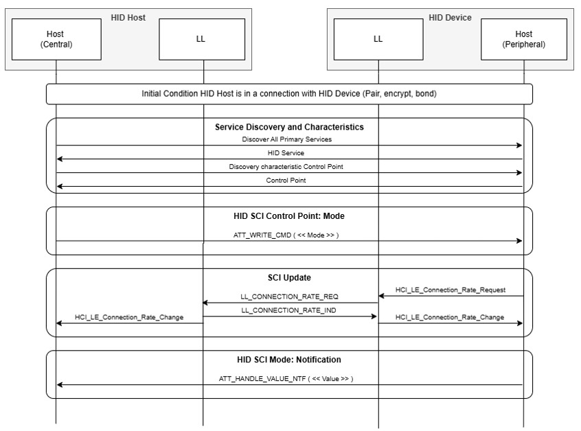
7.3.1.1. Configuring HID SCI and activation
To properly configure and activate HID SCI, the following steps apply:
-
The HID Host and the HID Device shall read the Rounded connInterval Values (RCVs) and Extended connInterval Values (ECVs) supported by the local controller (command HCI_LE_Read_Minimum_Supported_Connection_Interval when using HCI).
-
The HID Host may read the HID Device HID SCI Information characteristic to determine the connection intervals supported by the HID Device for RCVs and ECVs (see Volume 6, Part B, Section 4.5.1 of [2]).
-
The HID Host shall write the default connection parameters to the local controller (command HCI_LE_Set_Default_Rate_Parameters when using HCI).
-
The HID Host shall configure the HID Device by writing the desired mode to the HID Control Point characteristic (see Section 7.4.1).
7.3.2. Additional message sequence charts
This section details a few more message sequence charts for multiple devices and rejection of negotiation.Figure 7.2 shows an example of two devices with the HID Control Point characteristic enabling two different HID SCI modes.
Figure 7.3 shows an example of HID Control Point characteristic usage with rejected changes.
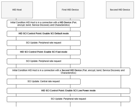
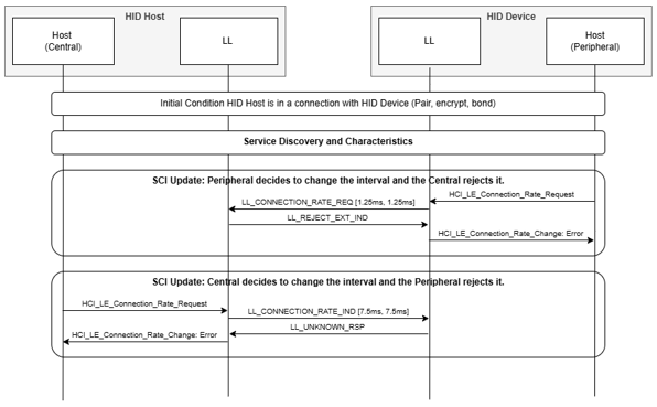
7.3.3. Low power and disconnection
When the HID Device is no longer in use, the HID Device may choose to enter a low-power mode. A HID Host low on power may also ask a HID Device to enter a state of lower power consumption. When the HID Device is not used for an extended amount of time, the HID Device can choose to disconnect from the HID Host.
7.4. Transport Intervals
A connection between a HID Host and a HID Device using SCI can use any Transport Interval that is supported by the Shorter Connection Intervals of [2]. The Bluetooth Core Specification (Volume 6, Part B, Section 4.5.1 of [2]) defines the intervals as RCV and ECV. Table 7.2 shows the Transport Interval requirements for certain intervals that HID Hosts and HID Devices shall support.
|
Transport Interval |
HID Host support |
HID Device support |
|---|---|---|
|
1.25 ms |
O |
M |
|
2.5 ms |
O |
M |
|
5.0 ms |
M |
M |
The HID Host must choose a mode that is appropriate for the device.
7.4.1. Transport parameters for HID SCI modes
The HID Device must determine suitable parameter values for the application. Table 7.3 details the qualitative choice of transport parameter values. In the table, TI refers to the connection interval, RI refers to the HID report interval, and subscripts are used to denote various performance objectives as follows:
-
D refers to Default performance
-
LP refers to Low Power performance
-
R refers to Robust wireless performance
-
LL refers to low latency performance
|
If the Performance Objective is |
Then choose |
Notes |
|---|---|---|
|
Lowest possible latency TILL and RILL |
TILL ≤ 1.25 ms and RILL ≈ TILL |
Select for fast devices that need the lowest possible latency |
|
Robust performance TIR and RIR |
TIR < 7.5 ms and RIR > TIR |
Select for robust wireless performance and lower latency |
|
Default latency TID and RID |
7.5 ms ≤ TID ≤ 15 ms and RID ≈ TID |
TID before the introduction of SCI |
|
Low Power TILP and RILP |
TILP > TID, TILP > 15 ms and RILP > RID |
Select for low power |
Because of the wide range of HID devices and their unique requirements, the recommendations for transport parameter values in this section are meant as guidance rather than as a strict mandate. Which performance objective is chosen in Table 7.3 depends on the use and the system design of the actual HID Device and HID Host. However, the HID Device shall implement some of the modes: Default mode, Fast mode, and Full Range mode. Table 7.4 defines the recommended parameter values applying to both HID Host and HID Device.
|
Parameter |
Mode (HID Control Point characteristic value) |
|||
|---|---|---|---|---|
|
Fast |
Default |
Low Power |
Full Range |
|
|
Connection Interval min |
1.25 ms |
7.5 ms |
7.5 ms |
1.25 ms |
|
Connection Interval max |
5 ms |
15 ms |
15 ms |
15 ms |
|
Peripheral Latency |
0 |
0 |
100 |
0 |
|
Subrate min |
1 |
1 |
1 |
1 |
|
Subrate max |
4 |
4 |
4 |
4 |
|
Continuation Number |
3 |
0 |
0 |
1 |
|
Supervision Timeout |
Greater than or equal to (1 + Peripheral Latency) x Subrate max x Connection Interval max x 2. See the note at the end of this section. |
|||
In the Fast mode, the Connection Interval min value and Connection Interval max value shall be less than 7.5 ms.
In the Full range mode, the Connection Interval min value shall be the same as the Connection Interval min value in the Fast mode.
A HID Host or a HID Device implementing the HID SCI feature shall implement the Default, Fast, and Full Range modes. The HID Host or HID Device may implement the Low Power mode. For details about the HID Control Point characteristic, see Section 3 of [3] and Section 2.11 of [3].
Note
Note: The Supervision Timeout calculated by this formula will allow the HID Host to use any combination of the other parameters without violating the requirement in Core [Vol. 6, Part B, Section 4.5.2 in [2]].
7.5. HID Host and HID Device transport parameters
The HID Host or the HID Device can, at any time, renegotiate or update the transport parameters of HID SCI. Renegotiating or updating HID SCI transport parameters may be needed due to different types of devices connecting and disconnecting.
7.5.1. HID Device-initiated transport parameter updates
The HID Device may negotiate new transport parameters with the HID Host. Negotiating new transport parameters may be needed as the mode of the HID Device changes. The HID Device must initiate the transport parameters update by initiating the Connection Update Request with the HID Host.
7.5.2. HID Host-initiated transport parameter updates
The HID Host must negotiate transport parameters by writing to the HID Control Point characteristic to initiate a new negotiation.
8. Security requirements
This section describes the security considerations for a HID Device and HID Host.
8.1. Device security requirements
The HID Device, which must be a Peripheral as per Section 2.4, shall be in the Bondable mode as defined in [2] Volume 3, Part C, Section 9.4.3.
HID Service characteristics shall require an encrypted link for reading, writing, and notification.
The HID Device should use the Peripheral Security Request, as defined in [2] Volume 3, Part H, Section 2.4.6, procedure to inform the HID Host of its security requirements.
All supported characteristics specified by the Device Information Service, Scan Parameters Service, and Battery Service should be set to the same LE Security Mode and the same Security Level as the characteristics in the HID Service.
8.2. Host security requirements
The HID Host, which must be a Central as per Section 2.4, shall perform the Bonding procedure with the HID Device, as defined in [2] Volume 3, Part C, Section 9.4.4.
The HID Host should encrypt the link as early as possible after reconnection.
The HID Host shall only initiate an encryption key refresh on receipt of a Peripheral Security Request, as defined in [2] Volume 3, Part H, Section 2.4.6, from the HID Device.
9. Acronyms and abbreviations
|
Acronym/Abbreviation |
Meaning |
|---|---|
|
AD |
Advertising Data |
|
BR/EDR |
Basic Rate / Enhanced Data Rate |
|
CIG |
Connected Isochronous Group |
|
CIS |
Connected Isochronous Stream |
|
ECV |
Extended connInterval Value |
|
GAP |
Generic Access Profile |
|
GATT |
Generic Attribute Profile |
|
HID |
Human Interface Device |
|
HOGP |
HID over GATT Profile |
|
ISO |
Isochronous |
|
LE |
Low Energy |
|
LE ACL |
LE Asynchronous Connection-oriented [logical transport] |
|
RCV |
Rounded connInterval Value |
|
SCI |
Shorter Connection Intervals |
|
SM |
Security Manager |
|
UUID |
Universally Unique Identifier |
|
USB |
Universal Serial Bus |
10. References
It is recommended to use the latest version of the Core Specification.
[1] USB Implementers Forum, Inc. (USB-IF), "Device Class Definition for Human Interface Devices (USB HID Specification), Version 1.11", May 2001, https://www.usb.org/document-library/device-class-definition-hid-111
[2] Bluetooth Core Specification, Version 6.2 or later
[3] Human Interface Device Service, Version 1.1 or later
[4] Battery Service, Version 1.1 or later
[5] Device Information Service, Version 1.1 or later
[6] Scan Parameters Profile, Version 1.0 or later
[7] Bluetooth Assigned Numbers, https://www.bluetooth.com/specifications/assigned-numbers/
[8] Human Interface Device Profile, Version 1.1.2 or later
[9] GATT Specification Supplement, https://www.bluetooth.com/specifications/gss/
Appendix A. Connection behavior Normally Connectable
Table A.1 details the Host and Device connection behavior as a function of NormallyConnectable bit of the HID Information characteristic.
|
Normally Connectable |
LE reconnection requirements |
Comments |
|---|---|---|
|
FALSE |
Device:
Host:
|
Most common configuration |
|
TRUE |
Device:
Host:
|
In this case, it is preferred to keep the LE HID connection active always. |
Appendix B. Operation mode switch
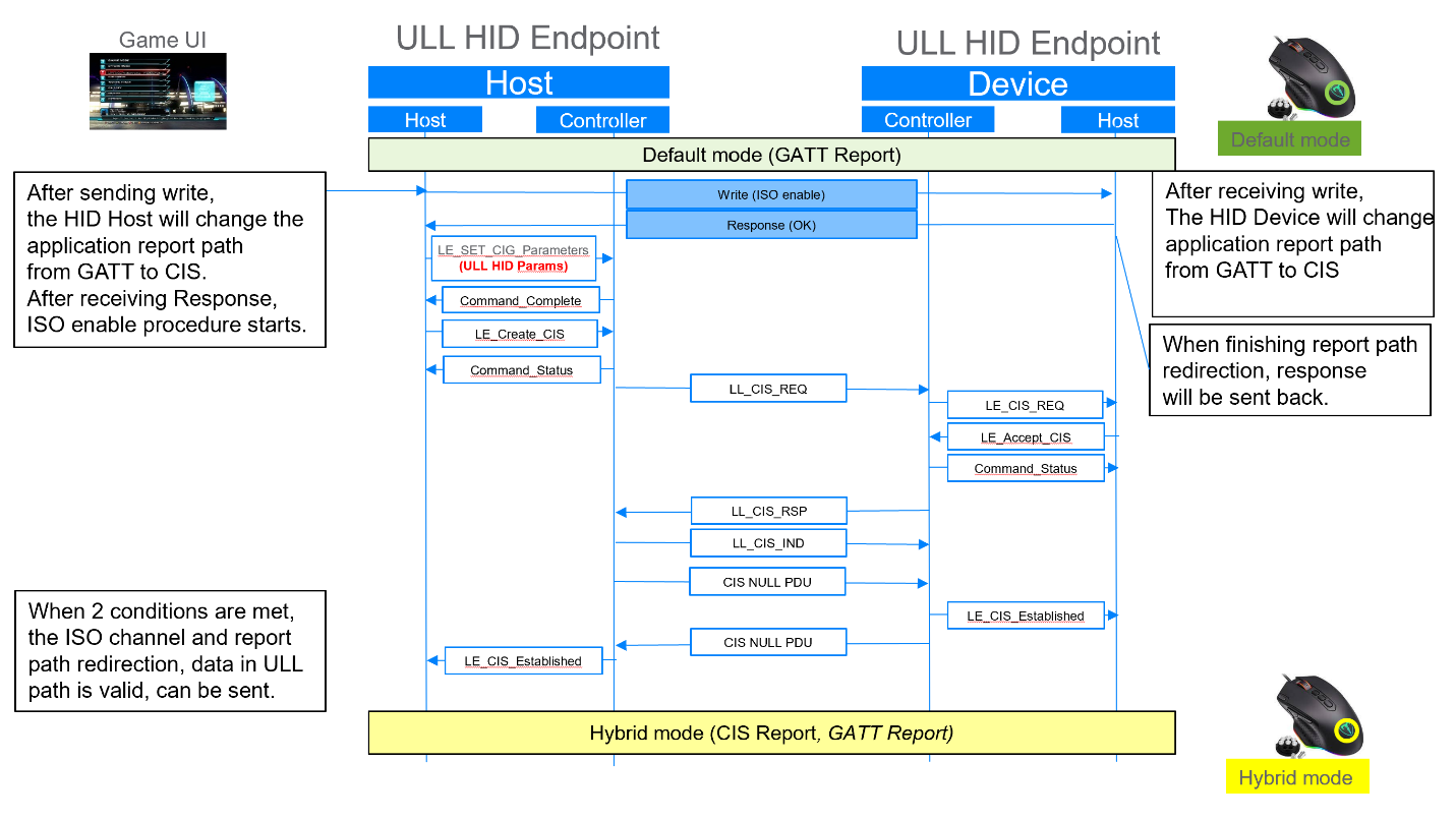 |
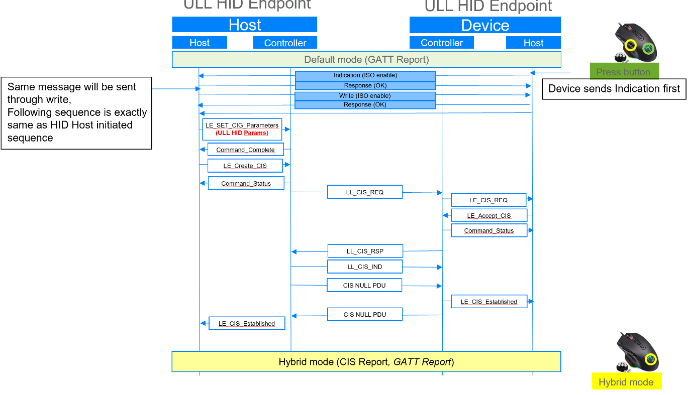 |
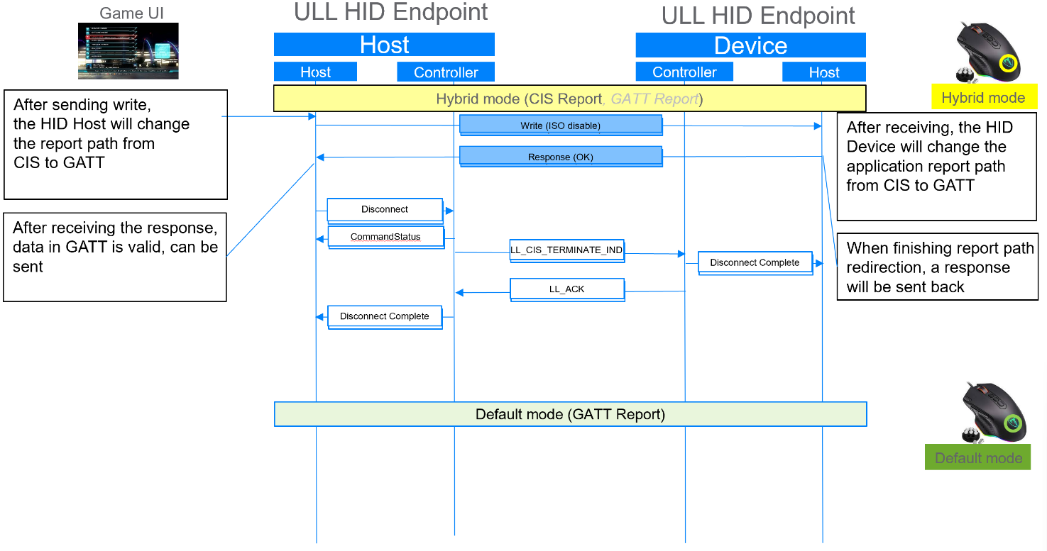 |
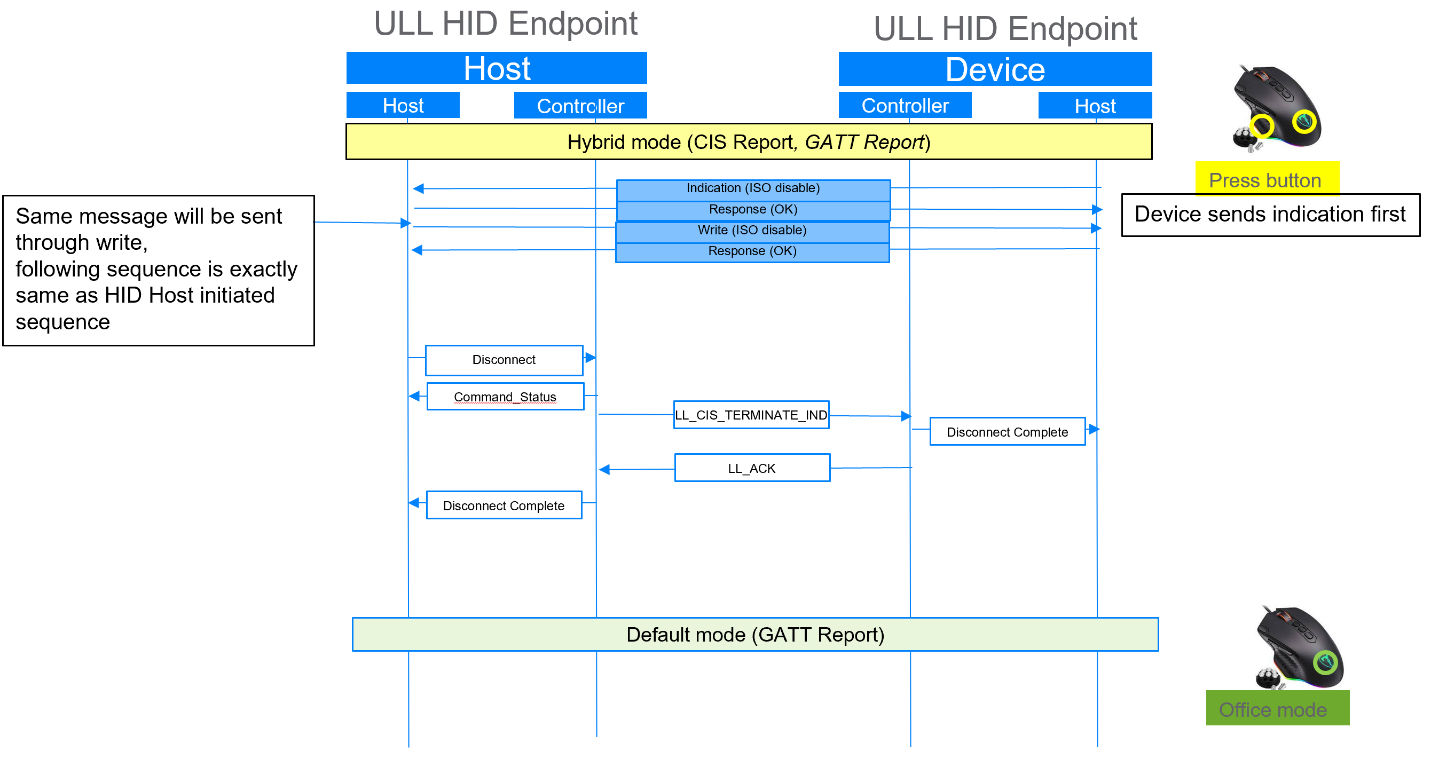 |
Appendix C. Link Layer parameters
C.1. Recommended ISO parameters
Table C.1 shows the recommended ISO parameters and the range of Max_Transport_Latency that can be used to constrain a generic Controller to the ISO_Interval for each report interval setting. The NSE(=BN) and FT=1 are constrained by the selection of SDU interval (i.e., the Controller must select an ISO_Interval that is an integer multiple of the SDU interval for unframed and unfragmented ISO data).
|
Report interval |
ISO_Interval |
NSE (=BN) |
FT |
|---|---|---|---|
|
1 ms |
5 ms |
5 |
1 |
|
10 ms |
10 |
1 |
|
|
15 ms |
15 |
1 |
|
|
1.25 ms |
5 ms |
4 |
1 |
|
7.5 ms |
6 |
1 |
|
|
10 ms |
8 |
1 |
|
|
15 ms |
12 |
1 |
|
|
2 ms |
10 ms |
5 |
1 |
|
20 ms |
10 |
1 |
|
|
2.5 ms |
7.5 ms |
3 |
1 |
|
10 ms |
4 |
1 |
|
|
15 ms |
6 |
1 |
|
|
20 ms |
8 |
1 |
|
|
3 ms |
15 ms |
5 |
1 |
|
3.75 ms |
7.5 ms |
2 |
1 |
|
15 ms |
4 |
1 |
|
|
4 ms |
20 ms |
5 |
1 |
|
5 ms |
5 ms |
1 |
1 |
|
10 ms |
2 |
1 |
|
|
20 ms |
4 |
1 |
|
|
7.5 ms |
7.5 ms |
1 |
1 |
Note that using a Report Interval of 3 ms, 3.75 ms, or 4 ms with a Controller that is not using the configurations and behaviors recommended for minimum latency contribution in Section 5.3 can cause the Controller to select an ISO interval that is greater than or equal to 15 ms or to use framed PDUs. This will result in a significant increase in the latency contribution from Bluetooth Link Layer protocols.
C.2. Example timing of 1 ms report interval
To check the implementation possibility, a timing calculation of having a 1 ms report interval is explained. The GAP Peripheral role here corresponds to the HID Device role, and the GAP Central role corresponds to the HID Host role.
In this example, a 1 ms report interval is equivalent to a 1 ms Sub_Interval in the LE ISO channel.
The HID ISO data traffic is assumed to be from the Peripheral to the Central only. The Central sends the Peripheral a null (empty) packet. The size of a null packet is 11 octets: Preamble (2 octets) + Access Address (4 octets) + Header (2 octets) + CRC (3 octets). The null packet timing is 44 µs at 2M PHY.
Assuming a HID payload for gaming device data, which is 16 octets long, the size of the HID report packet is 31 octets long: Preamble (2 octets) + Access Address (4 octets) + Header (2 octets) + Payload (16 octets) + CRC (3 octets) + MIC (4 octets). The HID report packet timing is 124 µs at 2M PHY.
If the data is ready at the Sub_Interval, then the Peripheral will send the HID report packet with the data to the Central. If the data is not ready at the Sub_Interval, then the Peripheral will send an empty packet to the Central.
For a HID data size of 16 octets, the minimum SE_Length (Sub Event Length, per Volume 6, Part B, Section 4.5.13.1 of [2]) is 468 µs, where T_IFS (Inter Frame Space, per Volume 6, Part B, Section 4.1.1 of [2]) and T_MSS (Minimum Sub Event Space, per Volume 6, Part B, Section 4.1.3 of [2]) are both 150 µs.
This timing is illustrated in Figure C.1. BN (Burst Number) and NSE (Number of Sub Events) are both equal to 5 and FT (Flush Timeout) is equal to 1.
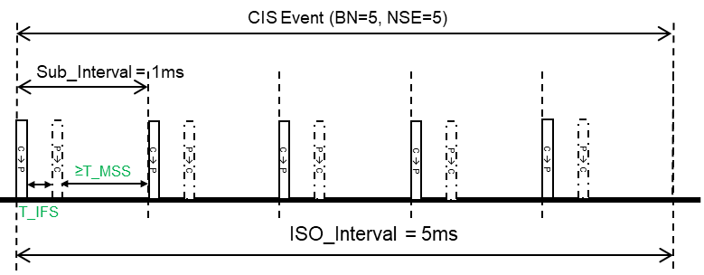 |
ACL packets for the ACL associated with the ISO channel can be scheduled in an empty space after T_MSS of any sub-event. Periodic ACL packet transfer is necessary to maintain ISO connection and can be used to exchange Link Layer control packets and low bandwidth data.
For a HID Data size of 16 octets, the SE_Length of 468 µs leaves 532 µs for the ACL event. The ACL event can be used, for example, for a GATT transaction with the default GATT MTU or a Link Layer control transaction. Figure C.2 shows an ACL event with a 27 octet PDU in the Central to Peripheral direction, and a shorter, 9 octet PDU in the Peripheral to Central direction.
 |
If the sum of the two ACL PDUs exceed 36 octets (the 4 octet MIC for a non-empty PDU is included in this number), then the behavior will be defined by Controller implementation. Some Controllers will drop the following ISO sub-event, with minimal impact to the HID ISO data stream (the probability of the lost ISO event carrying an empty or redundant payload is high). Other Controllers will drop the ACL event. Dropping every ACL event can lead to link loss.
An application can use a 1.25 ms SDU_Interval for an additional 29 octets of data (either ISO or ACL) if more bandwidth needs to be available for ACL traffic or to have longer HID ISO payloads. For example, an application that uses the maximum HID ISO data size (48 octets) can support 33 octets of ACL data when the SDU interval is 1.25 ms.
If the HID ISO payloads are longer or the ACL data can be longer than the default MTU size, then the application may use the Frame Space Update feature to reduce the 150 µs waits between packets.