-
Version: v1.0
-
Version Date: 2024-10-15
-
Prepared By: Automation Working Group
Version History
|
Version Number |
Date |
Comments |
|---|---|---|
|
v1.0 |
2024-10-15 |
Adopted by the Bluetooth SIG Board of Directors. |
Acknowledgments
|
Name |
Company |
|---|---|
|
Victor Zhodzishsky |
Infineon Technologies AG |
|
Benjamin Wieder |
WTO Werkzeug-Einrichtungen GmbH |
|
Matthias Kirn |
WTO Werkzeug-Einrichtungen GmbH |
|
Philipp Sommer |
HAINBUCH GMBH SPANNENDE TECHNIK |
|
Katrin Schindler |
Hoffmann SE |
Use of this specification is your acknowledgement that you agree to and will comply with the following notices and disclaimers. You are advised to seek appropriate legal, engineering, and other professional advice regarding the use, interpretation, and effect of this specification.
Use of Bluetooth specifications by members of Bluetooth SIG is governed by the membership and other related agreements between Bluetooth SIG and its members, including those agreements posted on Bluetooth SIG’s website located at www.bluetooth.com. Any use of this specification by a member that is not in compliance with the applicable membership and other related agreements is prohibited and, among other things, may result in (i) termination of the applicable agreements and (ii) liability for infringement of the intellectual property rights of Bluetooth SIG and its members. This specification may provide options, because, for example, some products do not implement every portion of the specification. All content within the specification, including notes, appendices, figures, tables, message sequence charts, examples, sample data, and each option identified is intended to be within the bounds of the Scope as defined in the Bluetooth Patent/Copyright License Agreement (“PCLA”). Also, the identification of options for implementing a portion of the specification is intended to provide design flexibility without establishing, for purposes of the PCLA, that any of these options is a “technically reasonable non-infringing alternative.”
Use of this specification by anyone who is not a member of Bluetooth SIG is prohibited and is an infringement of the intellectual property rights of Bluetooth SIG and its members. The furnishing of this specification does not grant any license to any intellectual property of Bluetooth SIG or its members. THIS SPECIFICATION IS PROVIDED “AS IS” AND BLUETOOTH SIG, ITS MEMBERS AND THEIR AFFILIATES MAKE NO REPRESENTATIONS OR WARRANTIES AND DISCLAIM ALL WARRANTIES, EXPRESS OR IMPLIED, INCLUDING ANY WARRANTIES OF MERCHANTABILITY, TITLE, NON-INFRINGEMENT, FITNESS FOR ANY PARTICULAR PURPOSE, OR THAT THE CONTENT OF THIS SPECIFICATION IS FREE OF ERRORS. For the avoidance of doubt, Bluetooth SIG has not made any search or investigation as to third parties that may claim rights in or to any specifications or any intellectual property that may be required to implement any specifications and it disclaims any obligation or duty to do so.
TO THE MAXIMUM EXTENT PERMITTED BY APPLICABLE LAW, BLUETOOTH SIG, ITS MEMBERS AND THEIR AFFILIATES DISCLAIM ALL LIABILITY ARISING OUT OF OR RELATING TO USE OF THIS SPECIFICATION AND ANY INFORMATION CONTAINED IN THIS SPECIFICATION, INCLUDING LOST REVENUE, PROFITS, DATA OR PROGRAMS, OR BUSINESS INTERRUPTION, OR FOR SPECIAL, INDIRECT, CONSEQUENTIAL, INCIDENTAL OR PUNITIVE DAMAGES, HOWEVER CAUSED AND REGARDLESS OF THE THEORY OF LIABILITY, AND EVEN IF BLUETOOTH SIG, ITS MEMBERS OR THEIR AFFILIATES HAVE BEEN ADVISED OF THE POSSIBILITY OF THE DAMAGES.
Products equipped with Bluetooth wireless technology ("Bluetooth Products") and their combination, operation, use, implementation, and distribution may be subject to regulatory controls under the laws and regulations of numerous countries that regulate products that use wireless non-licensed spectrum. Examples include airline regulations, telecommunications regulations, technology transfer controls, and health and safety regulations. You are solely responsible for complying with all applicable laws and regulations and for obtaining any and all required authorizations, permits, or licenses in connection with your use of this specification and development, manufacture, and distribution of Bluetooth Products. Nothing in this specification provides any information or assistance in connection with complying with applicable laws or regulations or obtaining required authorizations, permits, or licenses.
Bluetooth SIG is not required to adopt any specification or portion thereof. If this specification is not the final version adopted by Bluetooth SIG’s Board of Directors, it may not be adopted. Any specification adopted by Bluetooth SIG’s Board of Directors may be withdrawn, replaced, or modified at any time. Bluetooth SIG reserves the right to change or alter final specifications in accordance with its membership and operating agreements.
Copyright © 2023–2024. All copyrights in the Bluetooth Specifications themselves are owned by Apple Inc., Ericsson AB, Intel Corporation, Google LLC, Lenovo (Singapore) Pte. Ltd., Microsoft Corporation, Nokia Corporation, and Toshiba Corporation. The Bluetooth word mark and logos are owned by Bluetooth SIG, Inc. Other third-party brands and names are the property of their respective owners.
1. Introduction
The machine tools used in smart machine factories today (e.g., milling centers, turning centers, or combinations of both) are highly automated and offer a variety of services to tool operators, the factory control systems, and maintenance services.
Tool operators and service technicians need to monitor and control the condition of the internal components of these tools and peripheral devices to optimize processes, determine predictive maintenance services, and identify possible defects.
Tool operators and service technicians can control the condition of the internal components of these machine tools, but only if the tool is physically connected by cable to the tool’s computer-based control system.
The Industrial Measurement Device Profile (IMDP) Specification allows peripheral devices like tool holders, clamping chucks, and measurement devices to report their state and other measurements (such as acceleration, force, or temperature) to a Bluetooth-enabled, machine tool control system by using a wireless data connection.
1.1. Language
1.1.1. Language conventions
In the development of a specification, the Bluetooth SIG has established the following conventions for use of the terms “shall”, “shall not”, “should”, “should not”, “may”, “must”, and “can”. In this Bluetooth specification, the terms in Table 1.1 have the specific meanings given in that table, irrespective of other meanings that exist.
|
Term |
Definition |
|---|---|
|
shall |
—used to express what is required by the specification and is to be implemented exactly as written without deviation |
|
shall not |
—used to express what is forbidden by the specification |
|
should |
—used to express what is recommended by the specification without forbidding anything |
|
should not |
—used to indicate that something is discouraged but not forbidden by the specification |
|
may |
—used to indicate something that is permissible within the limits of the specification |
|
must |
—used to indicate either:
|
|
can |
—used to express a statement of possibility or capability |
1.1.1.1. Implementation alternatives
When specification content indicates that there are multiple alternatives to satisfy specification requirements, if one alternative is explained or illustrated in an example it is not intended to limit other alternatives that the specification requirements permit.
1.1.1.2. Discrepancies
It is the goal of Bluetooth SIG that specifications are clear, unambiguous, and do not contain discrepancies. However, members can report any perceived discrepancy by filing an erratum and can request a test case waiver as appropriate.
1.1.2. Reserved for Future Use
Where a field in a packet, Protocol Data Unit (PDU), or other data structure is described as "Reserved for Future Use" (irrespective of whether in uppercase or lowercase), the device creating the structure shall set its value to zero unless otherwise specified. Any device receiving or interpreting the structure shall ignore that field; in particular, it shall not reject the structure because of the value of the field.
Where a field, parameter, or other variable object can take a range of values, and some values are described as "Reserved for Future Use," a device sending the object shall not set the object to those values. A device receiving an object with such a value should reject it, and any data structure containing it, as being erroneous; however, this does not apply in a context where the object is described as being ignored or it is specified to ignore unrecognized values.
When a field value is a bit field, unassigned bits can be marked as Reserved for Future Use and shall be set to 0. Implementations that receive a message that contains a Reserved for Future Use bit that is set to 1 shall process the message as if that bit was set to 0, except where specified otherwise.
The acronym RFU is equivalent to Reserved for Future Use.
1.1.3. Prohibited
When a field value is an enumeration, unassigned values can be marked as “Prohibited.” These values shall never be used by an implementation, and any message received that includes a Prohibited value shall be ignored and shall not be processed and shall not be responded to.
Where a field, parameter, or other variable object can take a range of values, and some values are described as “Prohibited,” devices shall not set the object to any of those Prohibited values. A device receiving an object with such a value should reject it, and any data structure containing it, as being erroneous.
“Prohibited” is never abbreviated.
1.2. Table requirements
Requirements in this specification are defined as "Mandatory" (M), "Optional" (O), "Excluded" (X), “Not Applicable” (N/A), or "Conditional" (C.n). Conditional statements (C.n) are listed directly below the table in which they appear.
1.3. Conformance
Each capability of this specification shall be supported in the specified manner. This specification may provide options for design flexibility, because, for example, some products do not implement every portion of the specification. For each implementation option that is supported, it shall be supported as specified.
1.4. Terminology
Table 1.2 lists all of the terms defined in this document.
|
Term |
Definition |
|---|---|
|
Industrial Measurement Device |
The Industrial Measurement Device (IMD) is a measurement device that is mounted in or near a machine tool and is the target device of this document. |
|
Life Cycle |
The Life Cycle Data characteristic provides values describing the life cycle data defined by the manufacturer. The life cycle is the interval between manufacturing and scrapping a device. |
|
Service Cycle |
The Service Cycle Data characteristic provides values describing the service cycle of the IMD. A service cycle is the interval between two maintenance operations. |
|
Work Cycle |
A work cycle is the process of enclosing a single IMD operation (e.g., drilling one hole into a workpiece). |
|
Yellow Limit |
Manufacturer-defined high Yellow Limit and low Yellow Limit indicate that the IMD is not operating under optimal manufacturer-defined conditions. User-defined high Yellow Limit and low Yellow Limit values indicate that the process is being performed outside of the optimal user-defined conditions. The color coding is inherited by commonly used stack lights (see also [9]). |
|
Red Limit |
Manufacturer-defined high Red Limit and low Red Limit indicate that the IMD is operating under harmful manufacturer-defined conditions. User-defined high Red Limit and low Red Limit values indicate that the process is being performed outside of the user-defined conditions. The color coding is inherited by commonly used stack lights (see also [9]). |
|
Green Zone |
The Green Zone describes the operating area within which, in the context of the specific measured physical property, the IMD is functioning under optimal conditions. The color coding is inherited by commonly used stack lights (see also [9]). |
|
Yellow Zone |
The Yellow Zone (Warning Zone) describes the operating area within which the IMD is not operating under optimal conditions. The color coding is inherited by commonly used stack lights (see also [9]). |
|
Red Zone |
The Red Zone (Error Zone) describes the operating area within which the IMD is operating under harmful conditions. The color coding is inherited by commonly used stack lights (see [9]). |
|
Target Value |
The target value is the measured value defined by the user that should be reached in the measuring process. |
2. Configuration
2.1. Roles
IMDP defines two roles:
-
Industrial Measurement Device (IMD) Server: The device that reports actual and, optionally, historical measurement data to a Collector. The IMD Server shall be a GATT Server.
-
Collector: The device that optionally configures the IMD Server and then receives the data from the IMD Server. The Collector shall be a GATT Client.
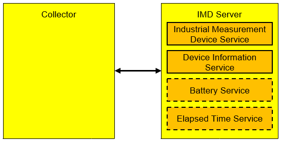
2.2. Role and service relationships
A device acting as a Collector as defined in this specification discovers and uses services from an IMD Server as shown in Figure 2.1.
2.3. Concurrency limitations and restrictions
There are no concurrency limitations or restrictions for the roles imposed by IMDP.
2.4. Topology limitations and restrictions
2.4.1. Topology limitations and restrictions for Low Energy
This section describes topology limitations and restrictions when IMDP is used over Bluetooth Low Energy (LE) transport.
The IMD Server shall implement the Generic Access Profile (GAP) Peripheral role (see Section 5).
The Collector shall implement the GAP Central role (see Section 5).
2.4.2. Topology limitations and restrictions for BR/EDR
There are no topology limitations or restrictions when IMDP is used over the Basic Rate Enhanced Rate (BR/EDR) transport.
2.5. Bluetooth specification release compatibility
This specification is compatible with Bluetooth Core Specification, Version 4.2 or later [1] that includes the Generic Attribute Profile (GATT).
2.6. Transport dependencies
There are no transport restrictions imposed by IMDP.
3. IMD Server role requirements
The IMD Server shall instantiate one and only one instance of the IMD Service (IMDS) [2]. IMDS shall be instantiated as a «Primary Service».
The IMD Server shall instantiate one and only one instance of the Device Information Service (DIS) [3].
A battery-operated IMD Server should instantiate one or more instances of the Battery Service (BAS) [4].
If the IMD Server supports the IMD Historical Data characteristic (see Section 4.4.10), then it should instantiate at most one instance of the Elapsed Time Service (ETS) [5].
Table 3.1 defines the requirements for a device in the IMD Server role.
|
Service |
Support in IMD Server |
Section for Additional Requirements |
|---|---|---|
|
Industrial Measurement Device Service |
M |
|
|
Device Information Service |
M |
|
|
Battery Service |
O |
|
|
Elapsed Time Service |
C.1 |
- C.1:
-
Mandatory if the IMD Server supports the IMD Historical Data characteristic; otherwise Optional.
3.1. Incremental IMD Service requirements
3.1.1. Additional requirements for Low Energy transport
This section describes additional IMD Server role requirements beyond those defined in IMDS [2] when using IMDP over LE transport.
3.1.1.1. Service UUIDs and Service Data AD types
While in a GAP Discoverable Mode for initial connection to a Collector, the IMD Server should include the IMDS UUID in the advertising data (AD): in the Service UUID AD Type field and/or in the Service Data AD Type field.
If present, the Service Data AD Type field shall contain a concatenation of 16-bit unique UUIDs of the IMD Measurement characteristics that are supported by IMDS as defined in the GATT Specification Supplement (GSS) [7]. If the IMD Server supports more than one type of the IMD Measurement characteristics, then the IMD Server may include a partial list of supported UUIDs to reduce the size of the advertising data.
The presence of the IMDS UUID and the UUIDs of the IMD Measurement characteristics enhances the user experience because the Collector may identify an advertising device as an IMD Server with specific functionality before initiating a connection.
The format of the Service Data AD Type is presented in Table 3.2.
|
Field |
Requirement |
Data Type |
Size (in Octets) |
Description |
|---|---|---|---|---|
|
Service UUID |
M |
uint16 |
2 |
The «Industrial Measurement Device Service» UUID |
|
IMD Measurement Characteristic UUID |
M |
uint16[] |
variable |
Array of one or more UUIDs referencing unique IMD Measurement characteristics present in IMDS |
3.1.1.2. Local Name AD Type
For an enhanced user experience, an IMD Server should include the Local Name (containing either the complete or shortened value of the Device Name characteristic) as defined in GAP (see Volume 3, Part C, Section 12.1 in [8]) in its advertising data or scan response data. An IMD Server with the Privacy Feature enabled should not include this field in the advertisement.
3.1.1.3. Writable GAP Device Name characteristic
The IMD Server may support the Write property for the Device Name characteristic to allow a Collector to write a device name to the IMD Server. The IMD Server may require authentication or authorization to write to the Device Name characteristic. The authorization method is implementation-specific.
3.1.1.4. Appearance AD Type
For an enhanced user experience, an IMD Server should include the value of the Appearance characteristic as defined in GAP (see Volume 3, Part C, Section 12.2 in [8]) in its advertising data or scan response data.
3.2. Incremental DIS requirements
Table 3.3 sets requirements for the instance of DIS on an IMD Server in addition to the requirements specified in DIS [3].
|
Characteristic |
Requirement |
Mandatory Properties |
Security Permission |
|---|---|---|---|
|
Manufacturer Name String |
M |
Read |
None |
|
Serial Number String |
M |
Read |
None |
|
Hardware Revision String |
M |
Read |
None |
|
Firmware Revision String |
M |
Read |
None |
3.3. Incremental BAS requirements
The server may support BAS to provide information on the status of its battery or batteries.
For devices with multiple batteries, the IMD Server should instantiate multiple instances of BAS with one instance for the main battery that powers the device (for details, see BAS [4]).
The number of instances of BAS should match the number of batteries present on the IMD Server.
3.4. Incremental ETS requirements
Writing to the Elapsed Time characteristic may require authorized access. The authorization method is implementation-specific.
The IMD Server shall use the same clock to support ETS and to fill time stamps in the IMD Historical Records of IMDS. The Time Stamp value in an IMD Historical Record shall match the Elapsed Time value from the Current Elapsed Time characteristic at the time the IMD Historical Record was created (i.e., the time when the measurement was completed, the time when the work cycle was completed, or the time when the service was completed).
When the Current Elapsed Time characteristic is updated for a reason other than the natural progression of time (the normal way that clock time increases), the IMD Server shall update the time stamps of all IMD Historical Records from the current timeline (i.e., of the IMD Historical Records with the Time Stamp Is From The Current Timeline field set to a value of 1).
-
When only the Time Zone (TZ) / Daylight Saving Time (DST) offset is changed, the IMD Server shall not make any changes to the IMD Historical Records.
-
When the Time Value field is changed, or when a Client is writing a UTC time while the IMD Server is using the Counter, the IMD Server shall follow one of two update policies:
-
The Time Stamp Is From The Current Timeline field shall be set to a value of 0 (False).
-
The Time Value field is adjusted to reflect the update of the Current Elapsed Time characteristic. For example, when the Time Value in the Current Elapsed Time characteristic is increased by one hour, the Time Value of the Record Timestamp filed in the IMD Historical Records shall be increased by one hour as well.
-
The update policy may differ for different IMD Historical Records. An IMD Server may, for example, adjust the time for IMD Historical Records from the last 24 hours and set the Time Stamp Is From The Current Timeline field to a value of 0 for older IMD Historical Records.
4. Collector role requirements
A Collector is a device that may establish connection to an IMD Server and execute as a client for IMDS as defined in [2].
The Collector shall use IMDS.
The Collector should use DIS [3] as well as BAS [4] and ETS [5] if supported by the IMD Server as defined in Table 4.1.
|
Service |
Collector |
|---|---|
|
IMDS |
M |
|
DIS |
O |
|
BAS |
O |
|
ETS |
O |
Table 4.2 specifies the GATT service, characteristics, and descriptors discovery requirements for a Collector.
|
Service / Characteristic / Descriptor |
Support in Collector |
Additional Requirements |
||
|---|---|---|---|---|
|
GATT service discovery for IMDS |
M |
|||
|
GATT service discovery for DIS |
O |
|||
|
GATT service discovery for BAS |
O |
|||
|
GATT service discovery for ETS |
O |
|||
|
IMDS |
||||
|
IMD Measurement characteristic |
M |
|||
|
Measurement Description descriptor |
O |
|||
|
Characteristic User Description descriptor |
O |
|||
|
Manufacturer Limits descriptor |
O |
|||
|
Process Tolerances descriptor |
O |
|||
|
Trigger Settings descriptor |
O |
|||
|
Valid Range descriptor |
O |
|||
|
IMD Status |
O |
|||
|
IMDS Descriptor Value Changed characteristic |
O |
|||
|
First Use Date characteristic |
O |
|||
|
Life Cycle Data characteristic |
O |
|||
|
Work Cycle Data characteristic |
O |
|||
|
Service Cycle Data characteristic |
O |
|||
|
IMD Control characteristic |
O |
|||
|
IMD Historical Data characteristic |
O |
|||
|
Record Access Control Point characteristic |
O |
|||
|
DIS |
||||
|
Manufacturer Name String characteristic |
O |
|||
|
Serial Number String characteristic |
O |
|||
|
Hardware Revision String characteristic |
O |
|||
|
Firmware Revision String characteristic |
O |
|||
|
Other DIS characteristics characteristic |
O |
|||
|
BAS |
||||
|
Battery Level characteristic |
O |
|||
|
Other BAS characteristics |
O |
|||
|
ETS |
||||
|
Current Elapsed Time characteristic |
O |
|||
4.1. GATT sub-procedures for Collector
Requirements in this section represent a minimum set of requirements for a Collector. Other GATT sub-procedures may be used if supported by both the GATT Client and the GATT Server.
Table 4.3 summarizes the GATT sub-procedure requirements.
|
GATT Sub-Procedure |
Requirements |
|---|---|
|
Discover All Primary Services |
C.1 |
|
Discover Primary Services by Service UUID |
C.1 |
|
Discover All Characteristics of a Service |
C.2 |
|
Discover Characteristics by UUID |
C.2 |
|
Discover All Characteristic Descriptors |
M |
|
Read Characteristic Value |
M |
|
Write Characteristic Value |
C.3 |
|
Read Characteristic Descriptors |
M |
|
Write Characteristic Descriptors |
C.4 |
|
Read Long Characteristic Value |
C.5 |
|
Write Long Characteristic Value |
C.6 |
|
Read Long Characteristic Descriptors Value |
C.7 |
|
Write Long Characteristic Descriptors Value |
C.8 |
|
Characteristic Value Notification |
M |
|
Characteristic Value Indication |
M |
- C.1:
-
Mandatory to support at least one of these primary service discovery sub-procedures when using the LE transport. Excluded when using the BR/EDR transport because in this case, the Service Discovery Protocol (SDP) must be used.
- C.2:
-
Mandatory to support at least one of these Characteristic Discovery sub-procedures.
- C.3:
-
Mandatory to support if the Collector supports writing to any of the IMDS characteristics.
- C.4:
-
Mandatory to support if the Collector supports writing to any of the IMDS characteristic descriptors.
- C.5:
-
Mandatory if reading of the Life Cycle Data characteristic is supported; otherwise Optional.
- C.6:
-
Mandatory if writing of the Life Cycle Data characteristic is supported; otherwise Optional.
- C.7:
-
Mandatory if reading of the Characteristic User Description descriptor is supported; otherwise Optional.
- C.8:
-
Mandatory if writing of the Characteristic User Description descriptor is supported; otherwise Optional.
4.2. Service discovery
When using the LE transport and performing primary service discovery, the Collector shall use either the GATT Discover All Primary Services sub-procedure or the GATT Discover Primary Services by Service UUID sub-procedure.
When using the BR/EDR transport, the Collector shall initiate service discovery by retrieving the SDP records of the referenced services, as defined in the Service Discovery Protocol (SDP; see Volume 3, Part B, Section 4.5 in [8]).
The Collector shall discover IMDS [2].
The Collector may discover DIS [3].
The Collector may discover BAS [4] if BAS is exposed by the IMD Server.
The Collector may discover ETS [5] if ETS is exposed by the IMD Server.
The Collector may also discover other services.
4.3. Characteristic and descriptor discovery
The Collector shall perform either the GATT Discover All Characteristics of a Service sub-procedure or the GATT Discover Characteristics by UUID sub-procedure to discover the supported characteristics as listed in Table 4.2.
The Collector shall perform the GATT Discover All Characteristic Descriptors sub-procedure to discover the supported characteristic descriptors as listed in Table 4.2 and the Client Characteristic Configuration descriptors of discovered characteristics that support indications or notifications.
The Collector shall handle additional optional characteristics and descriptors in the service records of services used with IMDP.
The Collector shall discover characteristics and descriptors for use with IMDS (see Section 4.4), DIS (see Section 4.5), BAS (see Section 4.6), and ETS (see Section 4.7).
Where a characteristic used by this profile as listed in Table 4.2 is discovered that can be notified or indicated, the Collector shall also discover the associated Client Characteristic Configuration descriptor.
4.4. IMDS client role requirements
4.4.1. Additional requirements for characteristic and descriptor discovery
The requirements for discovery of IMDS characteristics and descriptors are stated in Table 4.2.
As IMDS may present multiple instances of the IMD Measurement characteristic, the number of IMD Measurement characteristics discovered by the Collector shall match the number of IMD Measurement characteristics present in IMDS.
4.4.2. IMD Measurements
IMDS contains one or more Measurement characteristics. Permitted characteristic types are listed in the Industrial Measurement Device section in the Bluetooth Assigned Numbers [6]. The Collector shall be able to ignore IMD Measurement characteristics with UUIDs not recognized by the Collector.
The Collector shall be able to support the IMD Server exposing multiple IMD Measurement characteristics.
The Collector shall be able to support the IMD Server exposing multiple IMD Measurement characteristics with the same UUID and different values of the Measurement Description descriptors.
The Collector may read the IMD Measurement characteristic value to find out the latest measured value.
As defined in the following subsections, the Collector may read the values of the IMD Measurement characteristic’s associated descriptors to find out more information about the measurements.
The Collector may control the configuration of notifications using the Client Characteristic Configuration descriptor of any IMD Measurement characteristic that supports the notify property. If there is a writable Trigger Settings descriptor associated with the IMD Measurement characteristic, then the Collector may also control the conditions under which the notifications occur by writing trigger settings (see Section 4.4.2.5).
4.4.2.1. Measurement Description descriptor
If present, the Collector may read the Measurement descriptor to obtain additional information about the IMD Measurement characteristic. For example, the Collector may read the value of the Internal Update Interval field to check the maximum age of the measurement (i.e., the measurement provided cannot be older than this value).
If the Collector reads a value with Reserved for Future Use (RFU) bits of the Flags field that are non-zero, then the Collector shall ignore those bits and any additional unassigned octets that may be present in the packet and continue to process the IMD Measurement characteristic in the same way as if all the RFU bits had been zero.
The Collector shall ignore RFU values in the Sampling Function field and the Description field.
4.4.2.2. Characteristic User Description descriptor
If present, the Collector may read the value of the Characteristic User Description descriptor to obtain a human-readable label associated with the measurement.
If the Characteristic User Description descriptor is writable, then the Collector may write a new value associated with a given IMD Measurement characteristic. The value is global and will be accessible by any other Collectors.
As defined in GATT (Volume 3, Part G, Section 3.3.2 in [8]), the Collector may read the Writable Auxiliaries bit of the Characteristic Extended Properties descriptor to find out if the Characteristic User Description descriptor is writable. The descriptor access permissions are implementation-specific.
4.4.2.3. Manufacturer Limits descriptor
If present, the Collector may read the value of the Manufacturer Limits descriptor to obtain the Low Red Limit, the Low Yellow Limit, the High Yellow Limit, and the High Red Limit of the measurement associated with the IMD Measurement characteristic (see Section 1.4).
4.4.2.4. Process Tolerances descriptor
If present, the Collector may read the value of the Process Tolerances descriptor to obtain the user-defined Target Value and process limits associated with the current process.
If the Process Tolerances descriptor is writable, then the Collector may write a new value associated with a given IMD Measurement characteristic. The value is global and will be accessible by any other Collectors. Writing to the Trigger Settings descriptor may require authorization. The authorization method is implementation-specific.
4.4.2.5. Trigger Settings descriptor
If present, the Collector may read the value of the Trigger Settings descriptor to understand the condition(s) upon which the associated IMD Measurement characteristic value will be notified by the IMD Server.
The Collector may write to the descriptor to specify the condition(s) under which the associated IMD Measurement characteristic will be notified by the IMD Server. Writing to the Trigger Settings descriptor may require authorization. The authorization method is implementation-specific.
The Collector may set the Time Condition field of the Trigger Settings descriptor to a non-zero value to enable periodic notifications, or to a zero value to effectively disable periodic notifications of the IMD Measurement characteristic.
The Collector may set the Delta Condition field of the Trigger Settings descriptor to a non-zero value to enable notifications on the value change, or to a zero value to effectively disable notifications on the value change of the IMD Measurement characteristic.
4.4.2.6. Valid Range descriptor
If present, the Collector may read the value of the Valid Range descriptor to obtain the upper and lower bounds (inclusive) of an associated IMD Measurement characteristic.
4.4.3. IMD Status characteristic
To receive notifications when the status of the IMD changes, the Collector shall register using the Client Characteristic Configuration descriptor of the IMD Status characteristic.
4.4.4. IMDS Descriptor Value Changed characteristic
To receive indications when the values of the descriptors of the IMD Measurement characteristic are changed by other Collectors or by any other method, the Collector shall register using the Client Characteristic Configuration descriptor of the IMDS Descriptor Value Changed characteristic. Upon receiving the indication, the Collector should read the descriptors to determine the change that caused indication.
4.4.5. First Use Date characteristic
If supported by the server, and if the characteristic supports writing, the Collector may write to the First Use Date characteristic to set the date when the IMD Server was first used.
The Collector may write zero to the First Use Date characteristic to request the IMD Server to fill the First Use Date characteristic value on the first use. Writing to the First Use Date characteristic may require authorization. The authorization method is implementation-specific.
The Collector may read the First Use Date characteristic to determine the date when the IMD Server was first used.
4.4.6. Life Cycle Data characteristic
If supported by the server, and if the characteristic supports writing, the Collector may write to the Life Cycle Data characteristic to set the manufacturing date, as well as the use time and the use counts of the Red Limit and the Yellow Limit for the IMD Server.
The Collector shall be able to support the case when the IMD Server rejects the write request with the error code set to Value Not Allowed (see Volume 3, Part F, Section 3.4.1.1 in [8]) because the value has already been set.
Writing to the Life Cycle Data characteristic may require authorization. The authorization method is implementation-specific.
The Collector may read the Life Cycle Data characteristic to determine the manufacturing date, the use time and the use count limits for the Yellow and Red Zones, the use time and the use counts while in the Red Zone and in the Yellow Zone, the number of times that the IMD Server executed the work cycle, and the actual time that the IMD Server spent executing the work cycles.
4.4.7. Work Cycle Data characteristic
If supported by the server, and if the characteristic supports writing, then the Collector may write to the Work Cycle Data characteristic to start, stop, or restart the work cycle.
The Collector shall be able to support the case when the IMD Server rejects the write request with the error code set to Value Not Allowed (see Volume 3, Part F, Section 3.4.1.1 in [8]).
The Collector may read the Work Cycle Data characteristic to determine the index of the current work cycle, the time when the work cycle has been started, and the status of the work cycle.
If supported by the server, then the Collector may also register for the IMD Status characteristic notifications via the Client Characteristic Configuration descriptor to be notified when a work cycle is started or completed.
4.4.8. Service Cycle Data characteristic
If supported by the server, then the Collector may write to the Service Cycle Data characteristic to set the next service date, as well as the maximum amount of time that the IMD Server can execute the work cycles and the maximum number of work cycles that the IMD Server can execute until the next service has to be performed.
Writing to the Service Cycle Data characteristic may require authorization. The authorization method is implementation-specific.
The Collector may read the Service Cycle Data characteristic to determine the Service Cycle Data parameters that were written, plus the actual use time in which the IMD Server was executing the work cycles since the last service and the number of work cycles executed since the last service.
4.4.9. IMD Control characteristic
If present, the Collector may use the IMD Control characteristic to request the IMD Server to perform various operations. The type of the operation requested is defined by the Op Code field.
Writing to the IMD Control characteristic may require authorization. The authorization method is implementation-specific.
4.4.9.1. Request to start measurement
The Collector may write a value to the IMD Control characteristic with the Op Code set to 0x00 to request the IMD Server to start measurement. If the IMD Server accepted the command, then the IMD Server will perform the measurement, and if configured, the IMD Server will send a notification when the measurement is completed (see Section 4.4.2).
To start measurement for the IMD Characteristic that does not include the Measurement Description descriptor, or for the IMD Characteristic that includes the Measurement Description descriptor, which does not include the Sampling Function, the Collector shall use the default value for the Sampling function field (0x01 - Instantaneous).
To start measurement for the IMD Characteristic that does not include the Measurement Description descriptor, or for the IMD Characteristic that includes the Measurement Description descriptor, which does not include the Description, the Collector shall use the default value for the Description field (0x00 - Unknown).
4.4.9.2. Request to abort current operation
The Collector may write a value to the IMD Control characteristic with the Op Code set to 0x01 to request the IMD Server to abort the current operation. The Collector shall be able to support the case when the IMD Server does not accept the request.
4.4.10. IMD Historical Records retrieval using RACP
The Record Access Control Point (RACP) characteristic enables Collectors to retrieve sets of IMD Historical Records from the IMD Server. Multiple Collectors may retrieve either the same or different sets of IMD Historical Records.
A Collector may write to the RACP characteristic to request that a certain RACP procedure be executed (see Section 4.4.10.1).
The Collector shall register for the RACP characteristic indications using the Client Characteristic Configuration descriptor before starting any of the RACP procedures.
The Collector shall register for the IMD Historical Data characteristic notifications via the Client Characteristic Configuration descriptor before starting the Combined Report procedure.
4.4.10.1. RACP procedure
A procedure begins when the Collector writes a command to the RACP characteristic with the Op Code set to Report Number of Stored Records, or Combined Report, or Delete Stored Records, or Abort Operation. The procedure ends when the Collector receives an RACP indication with the Op Code set to Response Code, or Number of Stored Records Response, or Combined Report Response.
When the Combined Report procedure is executed (see Section 4.4.10.2.3), the procedure may include one or more IMD Historical Data characteristic notifications between the beginning and the end of the procedure.
The Collector shall not attempt to perform any RACP procedure other than the Abort Operation procedure (see Section 4.4.10.2.5) before the previous procedure has ended.
4.4.10.1.1. RACP procedure timeout
The Collector shall start a 30-second timer when the RACP procedure is started. The timer shall be restarted after every IMD Historical Data characteristic notification is received. The timer shall be stopped when the procedure ends. If the timer expires, then the procedure shall be considered to have failed.
If an RACP procedure times out, then the Collector shall not start a new RACP procedure until a new connection is established with the server.
In the case of a procedure timeout during a Combined Report procedure, the Collector may consider the received records to be valid. However, the Collector shall assume that the records received during a Combined Report procedure that has timed out are an incomplete set of records based on the filter criteria. The Collector may then perform the procedure again when a new link is established, adjusting the filter criteria based on the records received during the failed transfer.
4.4.10.1.2. RACP procedure authorization
Various RACP procedures may require different authorization levels. For example, an IMD Server may require the Delete Stored Records procedure to perform over the authorized link, while allowing an unauthorized Collector to execute the Number of Stored Records procedure. The authorization method is implementation-specific.
4.4.10.2. RACP behavioral description
The Collector may write a command to the RACP characteristic using one of the supported Op Codes in IMDS [2] to request a server to perform a procedure. This command shall include an Operator and an Operand that are valid within the context of that Op Code.
The procedures including Filter Types are described in Sections 4.4.10.2.1 to 4.4.10.2.5.
The Collector shall support the case when the server adds or deletes the IMD Historical Records while an RACP procedure is taking place or between two different RACP procedures. For example, the Collector may perform the Request Number of Stored Records procedure with the Procedure Operator set to All Records to get the total number of records stored by the server.
However, if the Collector then performs a Combined Report procedure with the Procedure Operator set to All Records, the Collector shall support receiving a different number of records from this procedure than the IMD Server reported in the response to the Report Number of Stored Records. This is because the IMD Server might have generated a new IMD Historical Record or might have deleted an IMD Historical Record through user interaction in the time between the Request Number of Stored Records procedure and the Combined Report procedure.
The Collector shall also support the possibility that the IMD Server reports records with sequence numbers not increasing continuously. This can be caused by a catastrophic hardware or software error on the IMD Server but can also be caused by another Collector deleting some IMD Historical Records.
4.4.10.2.1. Filter Types
Certain RACP procedures use a Filter Type that is used to determine the portion of the stored records on the IMD Server to which the procedure applies. The format of the Filter Type and the RACP procedures that have a Filter Type operand are defined in IMDS [2]. The Collector may filter using the Record Type filter, the Record Sequence Number filter, or the Time filter as supported by the IMD Server.
The Collector shall use the Record Type filter set to 0x00 (IMD Service Cycle Data Record) or 0x01 (IMD Work Cycle Data Record) to specify which records the procedure shall apply to.
The Collector shall use the Record Sequence Number filter when a procedure should apply to a specific record or a range of records. The Record Sequence Number used is obtained from the Record Sequence Number field in the IMD Historical Record.
The Collector shall use the Time filter when a procedure should apply to either a specific date and time or a range of dates and times.
The Time filter is provided to allow a mechanism for the Collector to perform RACP procedures with a given date or time, or a range of dates and times. However, because the Record Timestamp value can be corrupted (because of time faults or other problems), the Record Sequence Number filter should be used in most cases. For example, the Collector may use the Report Number of Stored Records procedure to obtain all the records that the IMD Server has collected since the last record received by the Collector. The Collector may do this by using the Record Sequence Number filter with the Record Sequence Number set to the Record Sequence Number of the last IMD Historical Record received by the Collector incremented by one.
4.4.10.2.2. Report Number of Stored Records procedure
To determine the number of stored records on an IMD Server, the Collector shall use the Report Number of Stored Records procedure. To determine the number based on filter criteria, an appropriate Operator and Operand shall be used. Refer to IMDS [2] for Operand requirements when used with a specific Operator.
The Collector shall wait for one of two RACP indications that complete the Report Number of Stored Records procedure:
-
The Number of Stored Records Response indication containing the number of stored records available in the server as per the request.
-
A Response Code indication with the Response Code Value representing an error condition that occurred in processing the request. See Section 3.9.3 in IMDS [2] for general error handling procedures.
The value returned by the Number of Stored Records procedure is intended to be used for the user interface (UI) on the Collector or to enable the Client to acquire an estimate of the number of records the Collector might receive to determine if it has sufficient resources. The Collector should not rely on this value to determine whether new records are available from the IMD Server. The Collector should request new records by filtering with a Record Sequence Number or a Record Timestamp incremented from a previous transfer session.
4.4.10.2.3. Combined Report procedure
To request the transfer of stored records from the IMD Server, the Collector shall use the Combined Report procedure. To receive a selected set of stored records based on filter criteria, an appropriate Operator and Operand shall be used. Refer to IMDS [2] for Operand requirements when used with a specific Operator.
The Collector shall wait for one of two RACP indications that complete the Combined Report procedure:
-
A Combined Report Response indication and the Operand set to the number of records reported.
-
A Response Code indication with the Response Code Value representing an error condition that occurred in processing the request. The error conditions are defined in Section 3.9.2.5 in IMDS [2].
In some circumstances, a received record might be invalid. The Collector should check for invalid records. Examples of checks include the following:
-
Check if the Segmentation Header in the different segments of a multi-message Stored Health Observation contains a first segment, intermediate segments, and a last segment with subsequent Rolling Segment Counter values. If not, then the record is invalid.
-
Check if the Length field of an observation matches the length of the record. If not, then the record is invalid.
If an invalid record is detected, then the Collector may re-request a single record using the RACP with the Operator set to Within Range Of and the Operand set to the Record Sequence Number Filter Type with the minimum value of the range and maximum value of the range both set to the Record Sequence Number value of the invalid record. If the record is retransmitted and is still found to be invalid after a few reattempts as left to the implementation, then the Collector should discard the invalid record.
If the Collector requests multiple records, then the notifications with the IMD Historical Records might be lost. The Collector shall check the Number of Records in the Combined Report Response indication to match the number of records received in the notifications before the Combined Report Response indication. If the value does not match, then the Collector may re-request missing records using RACP with the operator set to Within Range Of and the Operand set to the minimum and maximum value pair of the missing Record Sequence Numbers.
If a condition arises where a Collector cannot process the requested data, then the Collector may request to abort the data transfer as described in Section 4.4.10.2.5.
4.4.10.2.4. Delete Stored Records procedure
To request deletion of stored records within the server, the Collector shall use the Delete Stored Records procedure. To delete a selected set of stored records based on filter criteria, an appropriate Operator and Operand shall be used. Refer to IMDS [2] for Operand requirements when used with a specific Operator.
The Collector shall wait for the Response Code RACP Indication with the Response Code Value set to Success, indicating the successful deletion of records or an error condition. The error conditions are defined in Section 3.9.2.2 in IMDS [2].
4.4.10.2.5. Abort Operation procedure
To abort a procedure initiated by the Collector, the Collector shall use the Abort Operation Op Code.
The Collector shall then wait for the Response Code RACP indication with the Request Op Code in the Operand set to the Abort Operation. The Collector shall continue waiting if the Response Code RACP indication is received with the Request Op Code in the Operand set to a value other than the Abort Operation.
Although servers must stop the data transfer after they have sent the Response Code Value of Success (see Section 3.9.2.2 in [2]), the servers may still have some records queued for transfer. The Collector may process or ignore these additional records but shall support this lag in the termination of the transfer.
4.4.10.3. RACP error handling
The Collector shall be tolerant to receiving a Response Code RACP indication with the Response Code Value representing an error condition that occurred on the IMD Server while processing the request. See IMDS [2] for a detailed explanation of the possible error conditions.
4.5. Device Information Service client role requirements
The Collector may read the characteristics of the IMD Server’s DIS [3] that it supports that are also supported by the IMD Server.
Usage of DIS is implementation-specific. For example, the Collector may display IMD Server information on the UI, or use DIS information to access some vendor-specific functionality.
4.6. Battery Service client role requirements
The Collector may use the characteristics of BAS [4] as supported by the server. These characteristics can be read and may support indications, notifications, or broadcasts.
The Collector may display the battery level information on the UI, it may advise the user to change the IMD Server batteries, or it may charge the batteries depending on the information provided by BAS.
4.7. Elapsed Time Service client role requirements
The Collector may use the Current Elapsed Time characteristic to read and write the server’s time and to receive indications on certain changes of the IMD Server’s time (see ETS [5]). The Collector may also use the server’s current time to filter historic data by using the value as an RACP filter parameter.
An IMD Server may support different types of time stamps at different resolutions that are tick counters, where the zero value may or may not be defined as the start of a specific epoch. An example of an epoch-based time stamp is the Unix epoch used universally by many computers, where the zero value is defined as 1970/01/01 00:00:00.000 UTC. In IMDS, the epoch start is 2000/01/01 00:00:00.000. Flags indicate whether the time is UTC or local and indicate the type of time source that was used to synchronize the time to an external time source.
When the Clock Needs To Be Set flag in the Current Elapsed Time characteristic is set, the Collector should set the server’s time by writing to the Current Elapsed Time characteristic. The Collector can choose to set the time before or after retrieving the IMD Historical Records from IMDS.
When setting the time, the client shall use the same format and flags present in the Current Elapsed Time characteristic read from the server.
When setting the time, a Collector shall support the server returning error codes as defined in ETS [5].
The Collector may use the Time Value from the Current Elapsed Time characteristic to adjust the time stamps in the IMD Historical Records from the current timeline. For example, when the Collector observes a difference of its own clock being 3 minutes ahead of the server’s clock, the client may add 3 minutes to the time stamp of the IMD Historical Records that it received from the server that has the Time Stamp Is From The Current Timeline bit set.
5. Connection establishment procedures
This section describes specific details of the connection establishment and connection termination procedures that may be used by a Collector and an IMD Server in certain scenarios in addition to what is specified in GAP [8].
After a Collector configures an IMD Server, the IMD Server in most cases will remain powered-off between uses and will only advertise and allow a Collector to connect when the IMD Server detects that it is in use (for example, based on the accelerometer input) or when the IMD Server has new measurements. In this scenario, the IMD Server will enter a GAP Connectable Mode and start advertising. The Collector may execute a GAP connection establishment procedure such that the Collector is scanning for the IMD Server using a Filter Accept List. When a connection is established, the IMD Server sends one or more measurement results to the Collector.
The IMD Server may terminate the connection if there is no more data to transfer. The server should support a reasonable time-out before disconnecting to allow a Collector to use any of the other GATT services that the server supports.
6. Security requirements
This section describes the security requirements for each role for the LE transport and the BR/EDR transport.
6.1. IMD Server security requirements for Low Energy
The IMD Server should bond with the Collector.
The characteristics of IMDS should be set to the security mode and level (Security Mode 1, Level 2 or higher for IMDs) required by the application.
6.2. Collector security requirements for Low Energy
The Collector should bond with the IMD Server.
The Collector shall accept any security request from the IMD Server.
6.3. Security requirements for BR/EDR
As required by GAP, Security Mode 4 (service-level enforced security) shall be used for connections established between an IMD Server and a Collector.
The Collector should bond with the server device with the Authentication Requirements parameter set to man-in-the-middle (MITM) Protection required – General Bonding.
7. Additional requirements for BR/EDR
There are no additional requirements beyond those set in the Bluetooth Core Specification [1].
8. Acronyms and abbreviations
|
Acronym/Abbreviation |
Meaning |
|---|---|
|
AD |
advertising data |
|
ATT |
Attribute Protocol |
|
BAS |
Battery Service |
|
BR/EDR |
Basic Rate/Enhanced Data Rate |
|
CNC |
Computerized Numerical Control |
|
DIS |
Device Information Service |
|
DST |
Daylight Saving Time |
|
ETS |
Elapsed Time Service |
|
GAP |
Generic Access Profile |
|
GATT |
Generic Attribute Profile |
|
GSS |
GATT Specification Supplement |
|
IMD |
Industrial Measurement Device |
|
IMDP |
Industrial Measurement Device Profile |
|
IMDS |
Industrial Measurement Device Service |
|
LE |
Low Energy |
|
MITM |
man-in-the-middle |
|
PDU |
Protocol Data Unit |
|
RACP |
Record Access Control Point |
|
RFU |
Reserved for Future Use |
|
SDP |
Service Discovery Protocol |
|
TZ |
Time Zone |
|
UI |
user interface |
|
UTC |
Coordinated Universal Time |
|
UUID |
Universally Unique Identifier |
9. References
[1] Bluetooth Core Specification, Version 4.2 or later
[2] Industrial Measurement Device Service, Version 1.0
[3] Device Information Service, Version 1.1 or later
[4] Battery Service, Version 1.1 or later
[5] Elapsed Time Service, Version 1.0
[6] Bluetooth SIG Assigned Numbers, https://www.bluetooth.com/specifications/assigned-numbers
[7] GATT Specification Supplement, https://www.bluetooth.com/specifications/gss/
[8] Bluetooth Core Specification, Version 5.4 or later
[9] IEC 60073:2002 Basic and safety principles for man-machine interface, marking and identification - Coding principles for indicators and actuators, https://webstore.iec.ch/publication/587