Part F. RFPHY Test Modes
This Part describes the Test modes available for RFPHY testing of Bluetooth Low Energy devices.
1. Introduction
Direct Test Mode and Unified Test Protocol mode (encompassing both the UTP HCI mode and the UTP OTA mode) are used to control the implementation under test (IUT) and provide reports back to the Lower or Upper Tester.
The following Test mode alternatives are available to perform validation on an LE device’s RFPHY layer:
DTM shall operate over a physical transport interface between the Upper Tester and the IUT. The transport used may be either HCI (see Section 2) or 2-wire UART (see Section 3).
UTP mode may operate over a physical transport interface or, if supported, an OTA transport interface between the Lower Tester and the IUT. The transport used may be any of the following:
2-wire UART (see Section 6.2)
HCI (see Section 6.3)
OTA (see Section 6.4)
Figure 1.1 illustrates the alternatives for RFPHY Test modes setup using a physical transport interface.
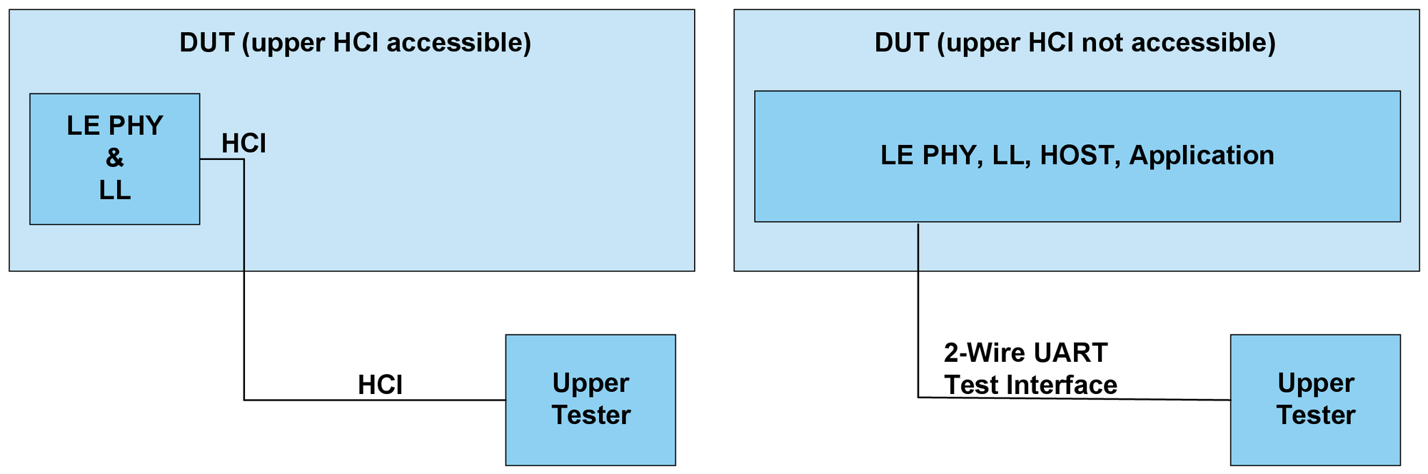
Figure 1.2 illustrates the RFPHY Test modes setup principle using a 2-wire UART interface.

Figure 1.3 illustrates the RFPHY Test mode setup for the OTA transport interface. This setup removes the requirement for the physical test interfaces shown in Figure 1.1 and Figure 1.2.

For LE devices supporting the Channel Sounding feature, DTM shall only be available when an accessible Host Controller Interface is provided, as shown in Figure 1.1 (left). The applicable CS commands and event are defined in Section 2.3.
2. Low Energy test scenarios
2.1. Test sequences
These sequences are used as routines and used to control an LE IUT with an accessible HCI or a 2-wire UART interface for RF testing.
The following mapping shall be performed from the RF testing commands to HCI commands and events or 2-wire UART commands and events, depending on which method is used:
RF Test command / event | HCI command / event | 2-wire UART command / event |
|---|---|---|
LE_Transmitter_Test command | HCI_LE_Transmitter_Test command | LE_Transmitter_Test command |
LE_Receiver_Test command | HCI_LE_Receiver_Test command | LE_Receiver_Test command |
LE_Test_End command | HCI_LE_Test_End command | LE_Test_End command |
LE_Status event | HCI_Command_Complete event | LE_Test_Status event |
LE_Packet_Report event | HCI_Command_Complete event | LE_Packet_Report event |
The HCI commands and events used in Direct Test Mode are defined in [Vol 4] Part E, Section 7.8 and [Vol 4] Part E, Section 7.7.65 respectively.
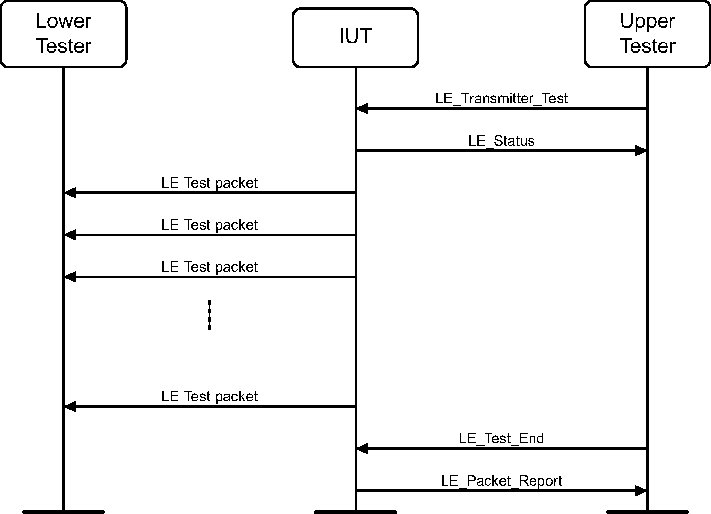
2.2. Message sequence charts
Transmitter Test
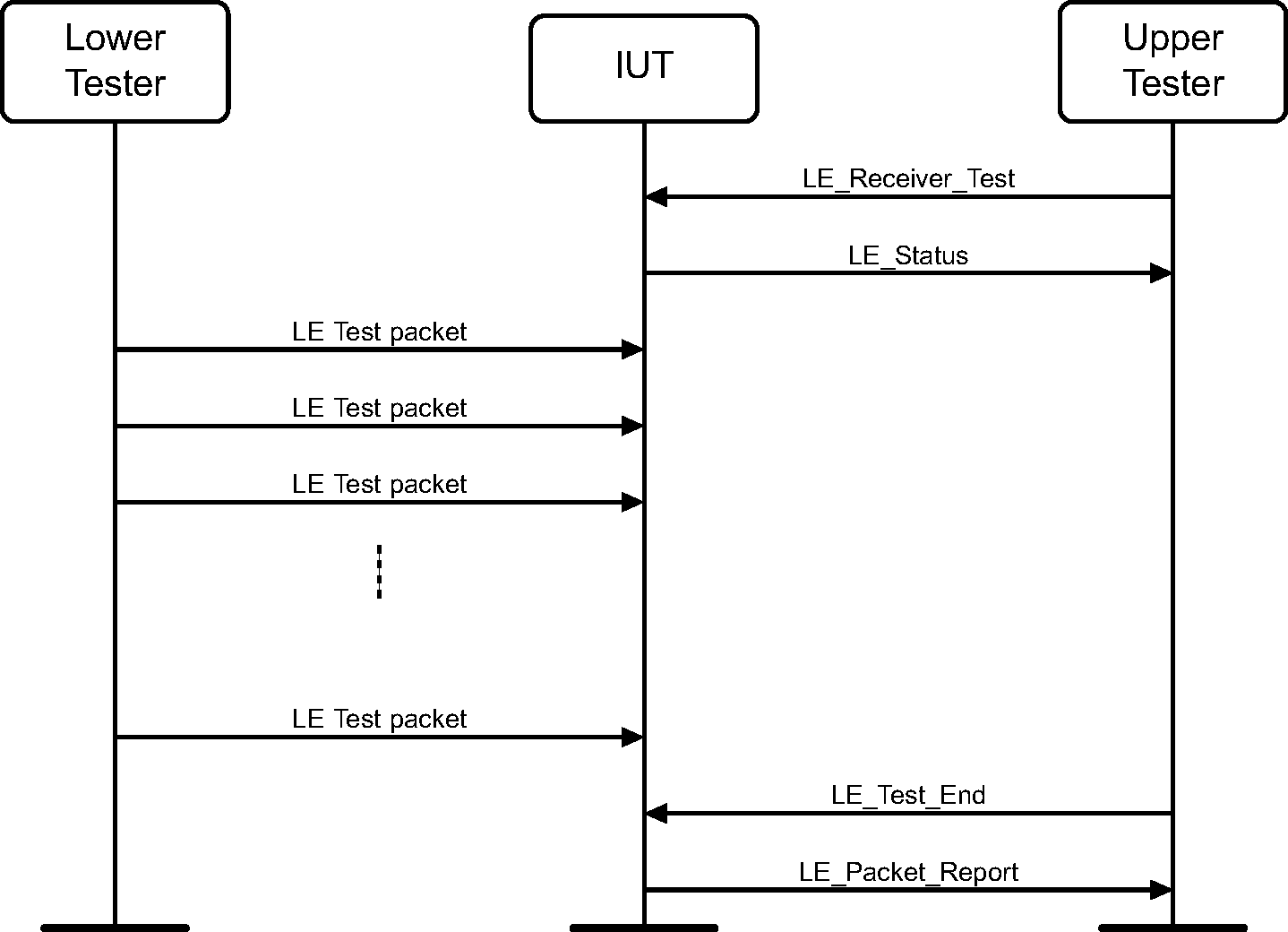
Receiver Test
2.3. Channel Sounding test commands
The relevant HCI commands and events for performing RFPHY Channel Sounding testing are defined in Table 2.2.
HCI command / event | Description |
|---|---|
HCI_LE_CS_Test command | This command is used to begin a CS test where the IUT is placed in the role of either the initiator or reflector. A single CS procedure which consists of one or more CS subevents is scheduled. |
HCI_LE_CS_Subevent_Result event | This event is generated when the local Controller has results to report for a CS subevent within the CS procedure. |
HCI_LE_CS_Subevent_Result_Continue event | This event is generated after the local Controller has completed a new CS subevent measurement and has already sent an HCI_LE_CS_Subevent_Result event for the specified subevent. |
HCI_LE_CS_Test_End command | This command is used to terminate any CS test that is in progress. |
HCI_LE_CS_Test_End_Complete event | This event is generated when the local Controller has stopped an ongoing CS test as a result of the HCI_LE_CS_Test_End command. |
The HCI commands and events used in Direct Test Mode are defined in [Vol 4] Part E, Section 7.8.
2.4. Channel Sounding message sequence charts
Test scenarios for Channel Sounding require the Tester and IUT having interchangeable roles, one side being in the initiator role, and the other in the reflector role. Figure 2.3 shows an MSC with the IUT in the initiator role, with Figure 2.4 the IUT in the reflector role.

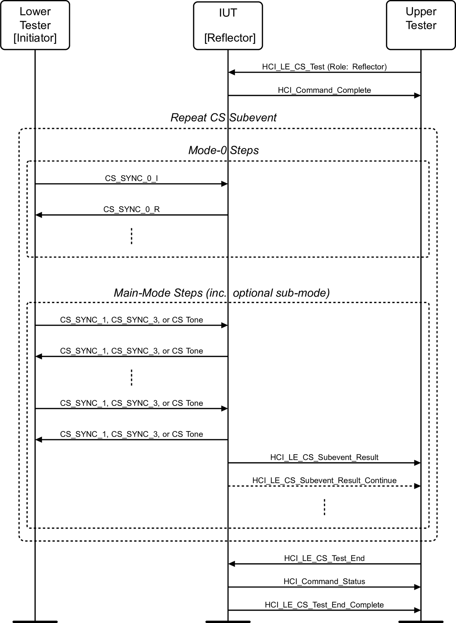
The test procedure below applies to all test scenarios, the IUT can assume either of the Initiator or Reflector roles as described in Figure 2.3, and Figure 2.4.
The Upper Tester sends an HCI_LE_CS_Test command to the IUT with Role configured appropriately to either 0x00 (initiator), or 0x01 (reflector) and receives a successful HCI_Command_Complete event response. All Channel Sounding parameters referred to in this test procedure are derived from the HCI_LE_CS_Test command. The first channel in the Channel parameter list is used as the starting channel for the test. At the beginning of the test, either the IUT or Lower Tester in the reflector role shall listen on this channel until it receives the first mode-0 transmission from the initiator.
The initiator sends the mode-0 CS_SYNC_0_I transmission to the reflector.
The reflector responds with the mode-0 CS_SYNC_0_R transmission to the initiator.
Repeat steps 2 and 3 the number of times specified by the Mode_0_Steps parameter.
The initiator sends the Main-Mode step transmission to the reflector.
The reflector responds with a Main-Mode transmission to the initiator.
Optional Sub_Mode steps specified by Sub_Mode_Type may be exchanged.
Repeat steps 5 to 7 with the parameters configured by the HCI_LE_CS_Test command from step 1 for this Channel Sounding test procedure observing the Subevent_Len, Subevent_Interval, the computed channel map or Channel array override, and so on.
The IUT sends an HCI_LE_CS_Subevent_Result event to the Upper Tester for each CS subevent based on the procedure parameters from step 1. The IUT may also send one or more HCI_LE_CS_Subevent_Result_Continue events for each CS subevent to the Upper Tester.
The Upper Tester sends an HCI_LE_CS_Test_End command to the IUT. The IUT shall respond to the Tester with an HCI_Command_Status event. When the IUT has successfully sent all pending CS subevent results it shall generate an HCI_LE_CS_Test_End_Complete event.
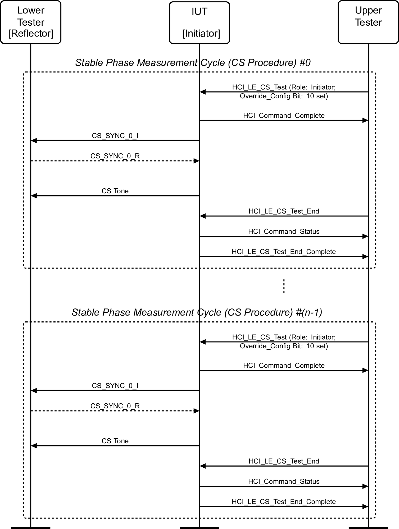
The test scenario for the Stable Phase measurement differs from every other Channel Sounding RFPHY test. The Stable Phase test is enabled via the Override_Config Bit 10 in the HCI_LE_CS_Test command, defined in [Vol 4] Part E, Section 7.8.143. The Tester shall assume the role of the reflector, and IUT the role of initiator.
The Stable Phase measurement period is defined as T_PM_MEAS. T_PM_MEAS is equal to the CS step mode‑2 duration with parameter configuration as defined in [Vol 6] Part A, Section 3.4.
The Stable Phase measurement is performed on CS_Tone transmissions. As CS_Tone transmissions are continuous unmodulated carrier waves the Tester cannot accurately synchronize. Instead, the Tester shall rely up on the preceding mode-0 step transmission (CS_SYNC_0_I) sent from the IUT to provide a satisfactory measurement anchor point. The Tester is not required to respond to the IUT mode‑0 transmission in this test, but the IUT shall still transmit a CS_Tone as if the tester had properly transmitted its portion of the mode‑0 exchange. The IUT is not required to provide a measurement report on the mode‑0 packet (CS_SYNC_0_R) if sent back from the Tester. The measurement period T_PM_MEAS shall begin following a duration T_RD + T_IP2 + T_SY + T_GD + T_FM + T_RD + T_FCS (not including the 1μs exclusion period).
Figure 2.5 shows the Stable Phase measurement MSC. Each Stable Phase measurement cycle uses a single CS procedure containing a single CS subevent. Each CS subevent contains a single mode‑0 step, followed by a single CS_Tone. As such, there is a single measurement period T_PM_MEAS available for obtaining phase measurement samples per CS procedure. The number of measurement cycles may be adjusted dependent upon the number of phase measurement samples required.
3. UART Test Interface
3.1. UART Interface characteristics
The UART interface characteristics shall be set to use the following parameters:
Baud rate: One of the following shall be supported by the IUT:
1200, 2400, 9600, 14400, 19200, 38400, 57600, 115200, 230400, 460800, 500000, 576000, 921600, 1000000, 1152000, 2000000, 3000000, 3500000, 4000000
Number of data bits: 8
No parity
1 stop bit
No flow control (RTS or CTS)
3.2. UART functional description
The Upper Tester shall always initiate any a test scenario using the UART interface. The IUT shall respond to the commands from the Upper Tester.
The Upper Tester sends test commands to the IUT. The IUT shall respond with a test status event or packet report event.
The Upper Tester shall not transmit further commands before it receives a response from the IUT. If the Upper Tester does not receive a response from the IUT within the time tTIMEOUT, the Upper Tester shall transmit a reset command (i.e., a test setup command with the control argument set to 0x00) to the IUT and display an appropriate error message. For the reset command, tRESPONSE and tTIMEOUT do not apply.
On reception of a reset command, the IUT shall reset all parameters to their default state.
Definitions
All commands and events consist of 16 bits (2 bytes).
The most significant bit is bit number 15.
The least significant bit is bit number 0.
The most significant byte is from bit 15 to 8.
The least significant byte is from bit 7 to 0.
Commands and events are sent most significant byte (MSB) first, followed by the least significant byte (LSB).
3.3. Commands and events
3.3.1. Command and event behavior
Table 3.1 outlines the set of commands which can be received by the IUT and the corresponding response events that can be transmitted by the IUT.
Command (IUT RXD) | Event (IUT TXD) |
|---|---|
LE_Test_Setup | LE_Test_Status SUCCESS LE_Test_Status FAIL |
LE_Receiver_Test | LE_Test_Status SUCCESS LE_Test_Status FAIL |
LE_Transmitter_Test | LE_Test_Status SUCCESS LE_Test_Status FAIL |
LE_Test_End | LE_Packet_Report LE_Test_Status FAIL |
3.3.2. Commands
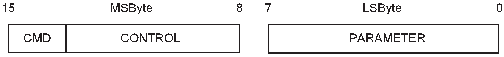
Command packet formats are shown in Figure 3.1 and Figure 3.2.
Note
Note: Some cases of the Test Setup and Test End commands have four parameter values, differing only in the bottom 2 bits, specified for the same action. In these cases the specific value chosen does not affect the behavior of the command.
CMD (command): | Size: 2 bits |
Value b1b0 | Parameter Description | |
|---|---|---|
00 | LE_Test_Setup command | |
01 | LE_Receiver_Test command | |
10 | LE_Transmitter_Test command | |
11 | LE_Test_End command | |
Test Setup command: | Size: 14 bits |
Control (6 bits) | Parameter (8 bits) | Description |
|---|---|---|
0x00 | 0x00 to 0x03 | RESET; the upper 2 bits of the data length for any LE_Transmitter_Test or LE_Receiver_Test commands following are set to 00, the PHY is set to LE 1M, the receiver assumes the transmitter has a standard modulation index, and no Constant Tone Extension is present. |
Any other value | Reserved for future use | |
0x01 | 0x00 to 0x0F | Set the upper 2 bits of the data length for any LE_Transmitter_Test or LE_Receiver_Test commands following to bits 2 and 3 of the parameter (to enable a length greater than 0x3F to be used) |
Any other value | Reserved for future use | |
0x02 | 0x04 to 0x07 | PHY set to LE 1M |
0x08 to 0x0B | PHY set to LE 2M | |
0x0C to 0x0F | PHY set to LE Coded; transmitter is to use S=8 data coding | |
0x10 to 0x13 | PHY set to LE Coded; transmitter is to use S=2 data coding | |
Any other value | Reserved for future use | |
0x03 | 0x00 to 0x03 | Receiver assumes transmitter has a standard modulation index |
0x04 to 0x07 | Receiver assumes transmitter has a stable modulation index | |
Any other value | Reserved for future use | |
0x04 | 0x00 to 0x03 | Read the test case supported features. The LE_Test_Status event will return the state of the test case supported features as detailed in the LE_Test_Status event ( Section 3.4.1). |
Any other value | Reserved for future use | |
0x05 | 0x00 to 0x03 | Read supportedMaxTxOctets (see [Vol 6] Part B, Section 4.5.10) |
0x04 to 0x07 | Read supportedMaxTxTime (see [Vol 6] Part B, Section 4.5.10) | |
0x08 to 0x0B | Read supportedMaxRxOctets (see [Vol 6] Part B, Section 4.5.10) | |
0x0C to 0x0F | Read supportedMaxRxTime (see [Vol 6] Part B, Section 4.5.10) | |
0x10 | Read maximum length of Constant Tone Extension supported | |
Any other value | Reserved for future use | |
0x06 | 0x00 | No Constant Tone Extension |
Any other value | CTEInfo (see [Vol 6] Part B, Section 2.5.2) | |
0x07 | 0x01 | Sample Constant Tone Extension with 1 µs slots |
0x02 | Sample Constant Tone Extension with 2 µs slots | |
Any other value | Reserved for future use | |
0x08 | Bits 0 to 6: 0x01 to 0x4B | Number of antennae in the antenna array |
Any other value | Reserved for future use | |
Bit 7: 0 | Antenna switching pattern A: 1, 2, 3, ..., n, 1, 2, 3, ..., n, ... (where n is the number of antennae in the antenna array) | |
1 | Antenna switching pattern B: 1, 2, 3, ..., n, n-1, n-2, ..., 1, ... (where n is the number of antennae in the antenna array) | |
0x09 | -127 to +20 | Set transmitter to the specified or the nearest transmit power level Units: dBm |
0x7E | Set transmitter to minimum transmit power level | |
0x7F | Set transmitter to maximum transmit power level | |
All other values | Reserved for future use |
If an AoD Constant Tone Extension is selected when transmitting, Control 0x08 shall be used before starting the test. If an AoA Constant Tone Extension is selected when receiving, Controls 0x07 and 0x08 shall be used before starting the test.
Control 0x07 does not affect receiving AoD Constant Tone Extensions or any transmissions. Control 0x08 does not affect transmitting AoA Constant Tone Extensions or receiving AoD Constant Tone Extensions.
In the receiver test, the CTEInfo field specified using Control 0x06 indicates the expected type and length of the Constant Tone Extension. If either the length or type of the Constant Tone Extension in a received LE Test packet does not match the expected value, then the IUT shall discard that packet.
LE_Test_End command: | Size: 14 bits |
Control (6 bits) | Parameter (8 bits) | Description |
|---|---|---|
0x00 | 0x00 to 0x03 | LE_Test_End command |
0x00 | Any other value | Reserved for future use |
0x01 to 0x3F | Any value | Reserved for future use |
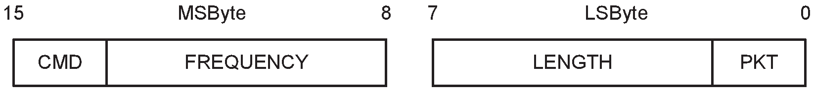
LE_Transmitter_Test and LE_Receiver_Test commands:
Frequency: | Size: 6 bits |
Value | Parameter Description |
|---|---|
0x00 to 0x27 | The frequency to be used; a value of N represents a frequency of (2N+2402) MHz (the available range is therefore even values from 2402 MHz to 2480 MHz) |
0x28 to 0x3F | Reserved for future use |
Length: | Size: 6 bits |
Value | Parameter Description |
|---|---|
0x00 to 0x3F | The lower 6 bits of the packet length in bytes of payload data in each packet (the top two bits are set by the LE_Test_Setup command) |
PKT (Packet Type): | Size: 2 bits |
Value b1b0 | Parameter Description |
|---|---|
00 | PRBS9 Packet Payload |
01 | 11110000 Packet Payload |
10 | 10101010 Packet Payload |
11 | On the LE Uncoded PHYs: Vendor Specific On the LE Coded PHY: 11111111 |
3.4. Events
There are two types of events sent by the IUT:
LE_Test_Status event
LE_Packet_Report event
The event packet format is shown in Figure 3.3. This packet format is used for both LE_Test_Status events and LE_Packet_Report events.
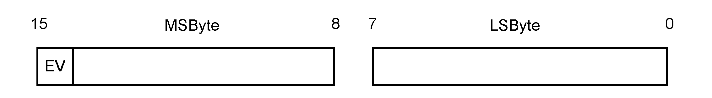
EV (event): | Size: 1 bit |
Value | Parameter Description |
|---|---|
0 | LE_Test_Status event |
1 | LE_Packet_Report event |
3.4.1. LE_Test_Status event
The LE_Test_Status event packet format is as shown in Figure 3.4.

ST (status): | Size: 1 bit |
Value | Parameter Description |
|---|---|
0 | Success |
1 | Error |
Response: [1] | Size: 14 bits | ||||||||||||||||||||||||||||||||||||||||||||||||
[1] If the event has a status of "Error" or was generated in response to a command other than LE_Test_Setup, then this field is Reserved for future use. | |||||||||||||||||||||||||||||||||||||||||||||||||
LE_Test_Setup command control parameter | Value bits 1 to 14[2] | Description | |||||||||||||||||||||||||||||||||||||||||||||||
|---|---|---|---|---|---|---|---|---|---|---|---|---|---|---|---|---|---|---|---|---|---|---|---|---|---|---|---|---|---|---|---|---|---|---|---|---|---|---|---|---|---|---|---|---|---|---|---|---|---|
0x04 | Bit 1 | LE Data Packet Length Extension feature supported | |||||||||||||||||||||||||||||||||||||||||||||||
Bit 2 | LE 2M PHY supported | ||||||||||||||||||||||||||||||||||||||||||||||||
Bit 3 | Transmitter has a Stable Modulation Index | ||||||||||||||||||||||||||||||||||||||||||||||||
Bit 4 | LE Coded PHY supported | ||||||||||||||||||||||||||||||||||||||||||||||||
Bit 5 | Constant Tone Extension supported | ||||||||||||||||||||||||||||||||||||||||||||||||
Bit 6 | Antenna switching supported | ||||||||||||||||||||||||||||||||||||||||||||||||
Bit 7 | 1 µs switching supported for AoD transmission | ||||||||||||||||||||||||||||||||||||||||||||||||
Bit 8 | 1 µs sampling supported for AoD reception | ||||||||||||||||||||||||||||||||||||||||||||||||
Bit 9 | 1 µs switching and sampling supported for AoA reception | ||||||||||||||||||||||||||||||||||||||||||||||||
Bits 10 to 14 | Reserved for future use | ||||||||||||||||||||||||||||||||||||||||||||||||
0x05 | Bits 1 to 14 | One of the following values (depending on the parameter in the original query):
Range:
All values outside the range are reserved for future use. | |||||||||||||||||||||||||||||||||||||||||||||||
0x09 | Bits 1 to 8 | Actual transmit power level set by the transmitter Range: -127 to +20 Units: dBm | |||||||||||||||||||||||||||||||||||||||||||||||
Bit 9 | Set to 1 if the transmitter is at minimum transmit power level | ||||||||||||||||||||||||||||||||||||||||||||||||
Bit 10 | Set to 1 if the transmitter is at maximum transmit power level | ||||||||||||||||||||||||||||||||||||||||||||||||
Bits 11 to 14 | Reserved for future use | ||||||||||||||||||||||||||||||||||||||||||||||||
All other values | Reserved for future use | ||||||||||||||||||||||||||||||||||||||||||||||||
[2] This field is described as having bits 1 to 14 rather than 0 to 13 to avoid confusion. | |||||||||||||||||||||||||||||||||||||||||||||||||
3.4.2. LE_Packet_Report event
The LE_Packet_Report event packet format is shown in Figure 3.5. The Packet Count parameter indicates the number of received LE Test packets. The Packet Count in the LE_Packet_Report event ending a transmitter test shall be 0.
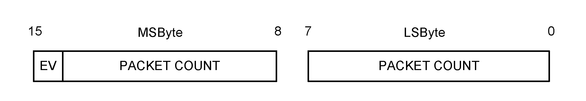
PACKET COUNT: | Size: 15 bits |
Value | Parameter Description |
|---|---|
N | N is the number of packets received Range = 0 to 32767. |
Note
Note: The IUT is not responsible for any overflow conditions of the packet count. That responsibility belongs with the RFPHY Tester or other auxiliary equipment.
3.5. Timing - command and event
The timing requirements are as shown in Table 3.2.
Symbol | Parameter | Min. | Max. | Unit |
|---|---|---|---|---|
bERR | Baud rate accuracy | ±5 | % | |
tMIN | The time between the first and second byte of the command or event (end of stop bit to start of start bit) | 0 | 5 | ms |
tRESPONSE | The time from a IUT receiving a command (end of stop bit) until the IUT responds (start of start bit) | 0 | 50 | ms |
tTURNAROUND | The time from when the tester receives a response (end of stop bit) until the tester sends another command (start of start bit) | 5 | - | ms |
tTIMEOUT | The time from when a tester sends a command (end of stop bit) until the tester times out (not having received end of the stop bit in the response) | 51 | 100 | ms |
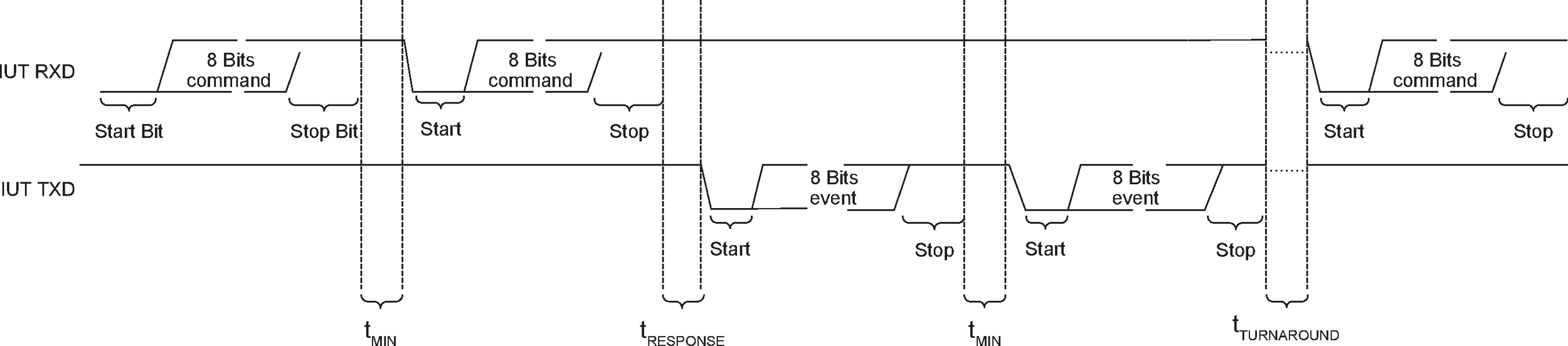
The commands and events shall be transmitted with two 8-bit bytes with a maximum time between the 2 transmissions. A timeout is required for no response or an invalid response from the IUT.

4. LE Test packet definition
4.1. LE Test packets format
The LE Test packet format for the LE Uncoded PHYs shall be as shown in Figure 4.1. The LE Test packet format for the LE Coded PHY shall be as shown in Figure 4.2. LE test packets are required for LE RFPHY conformance testing using Direct Test Mode. Except as modified by this section, the LE Test packet formats shall be identical to the formats specified in [Vol 6] Part B, Section 2.1 and [Vol 6] Part B, Section 2.2.
Depending on the test, the packet payload content may vary


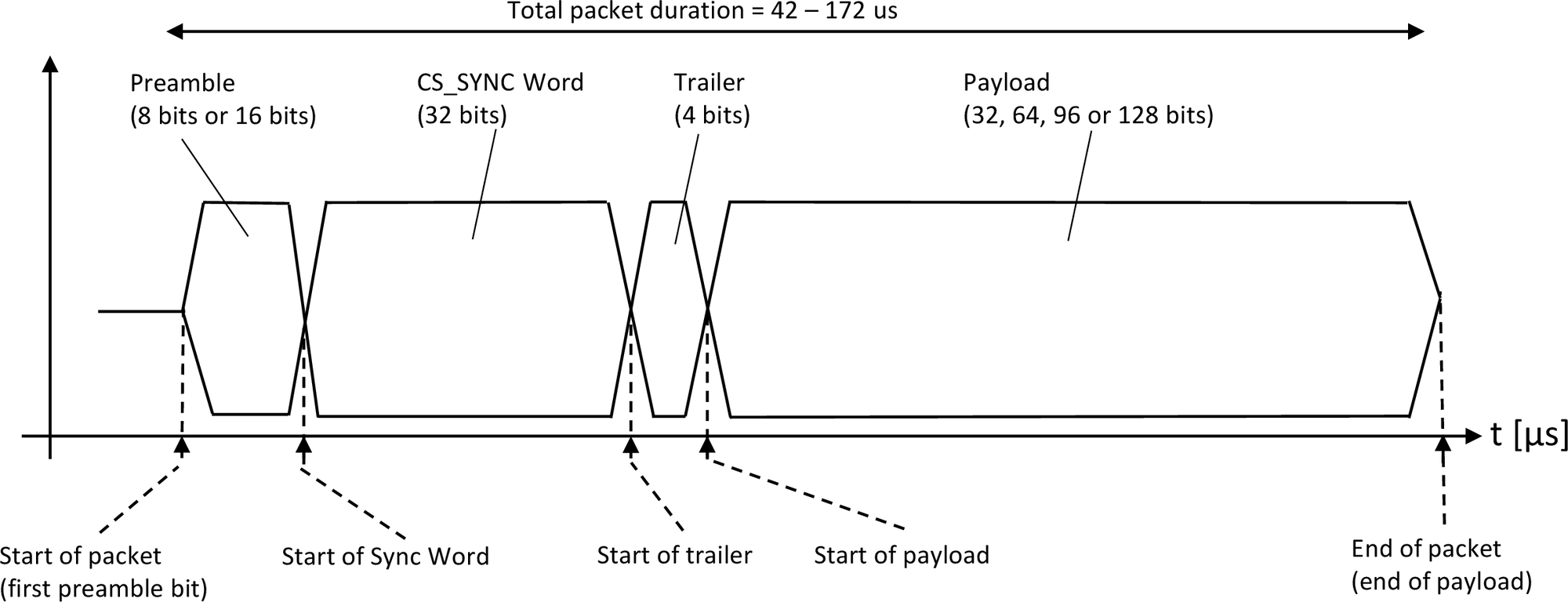
The LE Channel Sounding test packet (CS_SYNC) format shall be as shown in Figure 4.3. Except as modified by this section, the LE CS Test packet format shall be identical to the format specified in [Vol 6] Part H, Section 2.
4.1.1. Whitening
LE test packets and LE CS test packets shall not use whitening.
4.1.2. Preamble and synchronization word
LE test packets shall have ‘10010100100000100110111010001110’ (in transmission order) as the synchronization word. The preamble for all LE test packets is thus ‘10101010’ (in transmission order) when the implementation under test is configured for the LE 1M PHY, ‘1010101010101010’ (in transmission order) if the implementation under test is configured for the LE 2M PHY, and the preamble described in [Vol 6] Part B, Section 2.2.1 if the implementation under test is configured for the LE Coded PHY.
LE CS test packets use Access Addresses (CS_SYNC Words) as defined by the HCI_LE_CS_Test command, [Vol 4] Part E, Section 7.8.
4.1.3. CRC
The CRC shift register shall be preset with 0x555555 for every LE test packet. The CRC portion is not applicable for LE CS test packets.
4.1.4. LE Test packet PDU
The LE test packet PDU consists of an 8-bit header, an 8-bit length field, an optional 8-bit CTEInfo field, and a variable size payload. Its structure is as shown in Figure 4.4 and Figure 4.5.
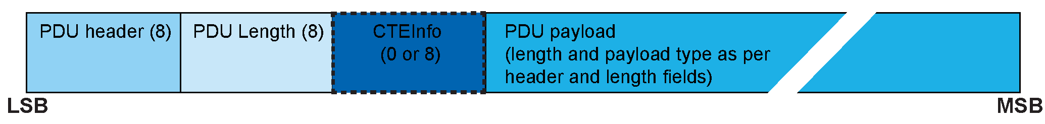
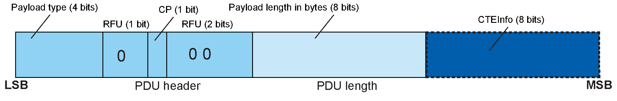
The first four bits of the PDU header field indicate the payload content type as defined in Table 4.1. The CTEInfo Present (CP) field of the PDU header indicates whether the CTEInfo field is present and therefore whether the test packet has a Constant Tone Extension. If the CP field is 0, then no CTEInfo field is present and there is no Constant Tone Extension in the test packet. If the CP field is 1, then the CTEInfo field is present and the test packet includes a Constant Tone Extension. The CTEInfo field is defined in [Vol 6] Part B, Section 2.5.2. The length field expresses the Payload length in bytes.
Note
Note: On the LE Coded PHY, this section defines the PDU contents before coding.
Payload type b3b2b1b0 | Payload description |
|---|---|
0b0000 | PRBS9 sequence ‘11111111100000111101...’ (in transmission order) as described in Section 4.1.5 |
0b0001 | Repeated ‘11110000’ (in transmission order) sequence as described in Section 4.1.5 |
0b0010 | Repeated ‘10101010’ (in transmission order) sequence as described in Section 4.1.5 |
0b0011 | PRBS15 sequence as described in Section 4.1.5 |
0b0100 | Repeated ‘11111111’ (in transmission order) sequence |
0b0101 | Repeated ‘00000000’ (in transmission order) sequence |
0b0110 | Repeated ‘00001111’ (in transmission order) sequence |
0b0111 | Repeated ‘01010101’ (in transmission order) sequence |
Example: For LE test packets with 0x0F payload contents (‘11110000’ in transmission order) and with an LE test packet payload length of 37 bytes (296 bits), the LE test packet header and length type field will be ‘1000000010100100’ in transmission order.
4.1.5. LE Test packet payload description
The LE test packet payload content alternatives required for the Bluetooth Low Energy RFPHY conformance tests are:
PRBS9:
A 9-bit pseudorandom binary sequence used for wanted signal payload content. The PRBS9 sequence repeats itself after the (29 -1 = 511) bit. The PRBS9 sequence may be generated in a nine stage shift register whose 5th and 9th stage outputs are XORed (see Figure 4.6) and the result is fed back to the input of the first stage. The sequence begins with the first ONE of 9 consecutive ONEs (i.e. the shift register is initialized with nine ONEs).

The same pseudorandom sequence of bits shall be used for each transmission (i.e. the packet is repeated).
PRBS15:
A 15-bit pseudorandom binary sequence that is used for the interfering signal and can optionally be used for wanted signal payload content. The PRBS15 sequence repeats itself after the (215 -1 = 32767) bit. The PRBS15 sequence may be generated in a fifteen stage shift register whose 14th and 15th stage outputs are XORed (see Figure 4.7) and the result is fed back to the input of the first stage. The sequence begins with the first ONE of 15 consecutive ONEs (i.e., the shift register is initialized with fifteen ONEs).
This PRBS15 definition is consistent with ITU T-REC-01 150-199605-I. SERIES O: SPECIFICATIONS OF MEASURING EQUIPMENT - Equipment for the measurement of digital and analogue/digital parameters.

The same pseudorandom sequence of bits shall be used for each transmission (i.e. the packet is repeated).
10101010:
Repeated sequence of alternating 1’s and 0’s, starting at the first payload bit and ending at the start of the first bit in the CRC. This pattern is used to verify the frequency deviation and the Gaussian filtering properties of the transmitter modulator.
11110000:
Repeated sequence of alternating 0’s and 1’s in groups of four (i.e. 1111000011110000...), starting at the first payload bit and ending at the start of the first bit in the CRC. This pattern is used to verify the frequency deviation and the Gaussian filtering properties of the transmitter modulator.
4.1.6. LE Test packet interval
While in LE direct TX mode, LE test packets shall be transmitted from the EUT with a packet interval I(L) as defined below; see the top half of Figure 4.8 for reference.
While in LE direct RX mode, the nominal packet interval of the LE test packets transmitted from the tester is I(L), but the tester packet interval may be extended to a maximum of T(L) upon change of the DTX parameter settings and during verification of the EUT PER reporting functionality. See the bottom half of Figure 4.8 for reference.
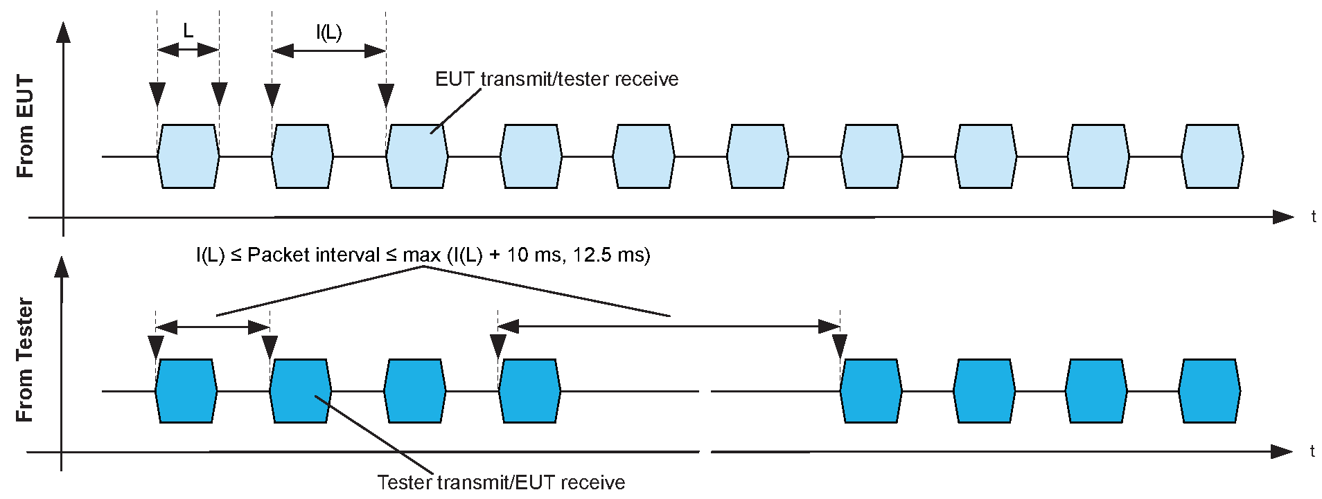
For an LE Test packet length of L µs, I(L) = × 625 µs and T(L) = max (I(L) + 10 ms, 12.5 ms).
4.1.7. Constant Tone Extension
The Constant Tone Extension is an optional field that consists of a constantly modulated series of unwhitened 1s. It is 16 to 160 bits when operating at 1 Msym/s modulation or 32 to 320 bits when operating at 2 Msym/s modulation. The Constant Tone Extension is not included in CRC or MIC calculations. The Constant Tone Extension shall only be present on the LE Uncoded PHYs.
If Direct Test Mode is being used over HCI and a Constant Tone Extension is present in a received packet, the Controller may generate events containing IQ samples of the Constant Tone Extension (see [Vol 4] Part E, Section 7.7.65.21).
4.1.8. LE Channel Sounding Test packet trailer
The CS trailer is a sequence of 4 bits, alternating between 0 and 1 bits. The trailer is 1010 (in transmission order) when the most significant bit of the CS Access Address is a 0, and 0101 when the most significant bit of the CS Access Address is a 1.
4.1.9. LE Channel Sounding Test packet payload
The CS Test packet payload is defined by the HCI_LE_CS_Test command, [Vol 4] Part E, Section 7.8. The payload length shall be either 32, 64, 96, or 128 bits, defined in [Vol 6] Part H, Section 2.5. There are no associated PDU header or PDU length fields for LE CS Test packet.
4.1.10. LE Channel Sounding Test exchanges
In some instances Channel Sounding tests involve exchanges between initiator and reflector devices. In these cases both devices shall operate using active clock accuracy as described in [Vol 6] Part B, Section 4.2.1.
5. Unified Test Protocol
5.1. Introduction
The Unified Test Protocol (UTP) is a set of configuration, control, and reporting messages used to perform the RFPHY transmitter and receiver tests for Bluetooth LE devices. The UTP may be used on any of the RFPHY Test mode transports (see Section 6).
UTP messages are sent between the Lower or Upper Tester and the IUT across a test control interface. There are three types of messages:
UTP configuration messages are used to set test parameters at both the Lower (in the case of OTA), or Upper Tester (in the case of UART) and the IUT. See Table 5.1 for a list of available configuration messages.
UTP control messages are sent by the Lower or Upper Tester to control the test execution and are used by the IUT to accept or reject requests from the Lower or Upper Tester as required. See Table 5.3 and Table 5.4 for a list of available control messages.
UTP report messages are sent by the IUT to report test results to the Lower or Upper Tester. See Table 5.5 for a list of available report messages.
The Lower Tester, Upper Tester, and IUT shall behave as defined by each of the associated roles specified by the test procedure.
Figure 5.1 provides an overview of a typical RFPHY UTP HCI mode scenario showing how transmitter or receiver measurements are performed using UTP.
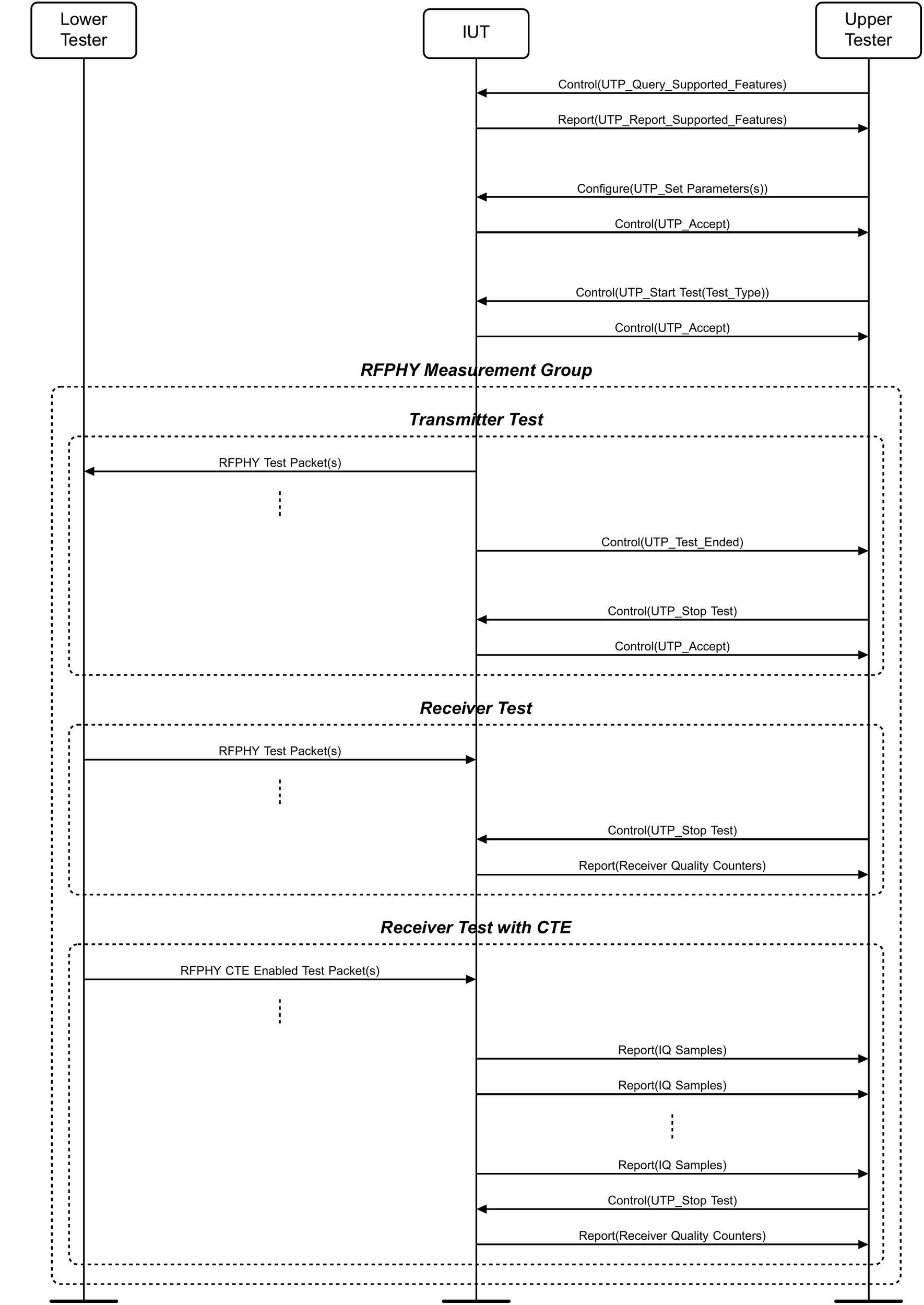
A typical UTP scenario involves the following steps:
The Lower or Upper Tester queries the UTP supported features of the IUT. The IUT reports the queried UTP supported features back to the Lower or Upper Tester.
The Lower or Upper Tester resets the UTP mode parameters configured at the IUT (optional).
The Lower or Upper Tester configures the IUT’s UTP mode parameters as required for the transmitter or receiver test(s) to be performed. The IUT accepts or rejects each message accordingly.
The Lower or Upper Tester initiates the transmitter or receiver test(s) by sending a start test control message to the IUT. The IUT accepts the control message.
The transmitter or receiver test(s) are performed using the configuration(s) made in step 3.
The Lower or Upper Tester ends the test by sending a stop test control message to the IUT. For a transmitter test, the IUT accepts the control message. For a receiver test, the IUT sends a UTP Receiver Quality Counters report message to the Lower or Upper Tester.
Each device shall process UTP messages, and reply if required, in the order received.
All configuration and control messages sent by the Lower or Upper Tester to the IUT shall either be accepted (see Section 5.5.1) or rejected (see Section 5.5.2).
The implementation is transport dependent; see Section 6.
5.2. Message format
Each UTP message shall be composed of a Type-Length-Value (TLV) triplet as shown in Figure 5.2.
The Type field indicates the message type (opcode). The Length field specifies the length of the Value field in octets. When the Length field is set to zero, the Value field is not included. An octet with value 0x00 where the Type field would be indicates padding. The message recipient shall ignore this octet and continue parsing any following octet.
Triplet | ||
|---|---|---|
Type (1 octet) | Length (2 octets) | Value (Length octets) |
Message parameters values other than those specified shall be reserved for future use.
5.3. Configuration messages
UTP configuration messages shall be sent by the Lower or Upper Tester to set the test parameters used by the IUT. Table 5.1 lists the configuration messages.
Opcode | Triplet Type | Controller Support |
|---|---|---|
0x01 | UTP_Set_RF_Channel | M |
0x02 | UTP_Set_Packet_Payload | M |
0x03 | UTP_Set_Payload_Length | M |
0x04 | UTP_Set_PHY | C.1 |
0x05 | UTP_Set_Modulation_Index | C.2 |
0x06 | UTP_Set_CTE_Length | C.3 |
0x07 | UTP_Set_CTE_Type | C.3 |
0x08 | UTP_Set_CTE_Slot_Durations | C.3 |
0x0A | UTP_Set_CTE_Antenna_IDs | C.3 |
0x0B | UTP_Set_Packet_Count | M |
0x0C | UTP_Set_Tx_Power_Level | C.4 |
0x0D | UTP_Set_OTA_Exclusion_Period | C.5 |
0xFF | UTP_Set_Vendor_Specific_Data | O |
| ||
UTP configuration messages apply to both the device’s transmitter and the receiver, unless stated otherwise. The Lower or Upper Tester sends configuration messages to the IUT that are based on the test scenario(s) to be performed.
The Lower or Upper Tester and the IUT shall set the parameters to the default values in Table 5.2 when the UTP transport is initialized or when the UTP_Reset message (see Section 5.4.2) is sent or received.
Parameter | Value |
|---|---|
RF_Channel | 0x00 |
Packet_Payload | 0x02 |
Payload_Length | 0x0025 |
PHY | 0x01 |
Modulation_Index | 0x00 |
CTE_Length | 0x00 |
CTE_Type | any valid value |
CTE_Slot_Durations | any valid value |
CTE_Antenna_IDs | any valid value |
Packet_Count | 0x0A |
Tx_Power_Level | 0x7F |
OTA_Exclusion_Period | 0x03 |
5.3.1. UTP_Set_RF_Channel
Description:
The UTP_Set_RF_Channel message is used to set the RF channel.
Message Parameters:
RF_Channel: | Size: 1 octet |
Value | Parameter Description |
|---|---|
N = 0xXX | Range: N = 0x00 to 0x4E Frequency used to transmit and receive RFPHY test packets Frequency: (N + 2402) MHz Available frequency range: 2402 MHz to 2480 MHz |
5.3.2. UTP_Set_Packet_Payload
Description:
The UTP_Set_Packet_Payload message is used to set the packet payload.
Message Parameters:
Packet_Payload: | Size: 1 octet |
Value | Parameter Description |
|---|---|
0x00 | PRBS9 sequence '11111111100000111101…' (in transmission order) as described in [Vol 6] Part F, Section 4.1.5 |
0x01 | Repeated '11110000' (in transmission order) sequence as described in [Vol 6] Part F, Section 4.1.5 |
0x02 | Repeated '10101010' (in transmission order) sequence as described in [Vol 6] Part F, Section 4.1.5 |
0x03 | PRBS15 sequence as described in [Vol 6] Part F, Section 4.1.5 |
0x04 | Repeated '11111111' (in transmission order) sequence |
0x05 | Repeated '00000000' (in transmission order) sequence |
0x06 | Repeated '00001111' (in transmission order) sequence |
0x07 | Repeated '01010101' (in transmission order) sequence |
5.3.3. UTP_Set_Payload_Length
Description:
The UTP_Set_Payload_Length message is used to set the payload length.
Message Parameters:
Payload_Length: | Size: 2 octets |
Value | Parameter Description |
|---|---|
0xXXXX | Length, in octets, of the payload data in each RFPHY test packet Range: 0x0000 to 0x00FF |
5.3.4. UTP_Set_PHY
Description:
The UTP_Set_PHY message is used to set the PHY for test packets. If OTA mode is being used, the PHY used by the ACL shall not be affected by this message.
Message Parameters:
PHY: | Size: 1 octet |
Value | Parameter Description |
|---|---|
0x01 | LE 1M PHY |
0x02 | LE 2M PHY |
0x03 | LE Coded PHY with S=8 data coding |
0x04 | LE Coded PHY with S=2 data coding |
5.3.5. UTP_Set_Modulation_Index
Description:
The UTP_Set_Modulation_Index message is used to set the assumed modulation index at the receiver.
Message Parameters:
Modulation_Index: | Size: 1 octet |
Value | Parameter Description |
|---|---|
0x00 | Receiver assumes transmitter has a standard modulation index |
0x01 | Receiver assumes transmitter has a stable modulation index |
5.3.6. UTP_Set_CTE_Length
Description:
The UTP_Set_CTE_Length message is used to set the CTE length.
Message Parameters:
CTE_Length: | Size: 1 octet |
Value | Parameter Description |
|---|---|
0x00 | Do not transmit a Constant Tone Extension, or do not expect a Constant Tone Extension in a receiver test |
0x02 to 0x14 | Length of the Constant Tone Extension in 8 μs units |
5.3.7. UTP_Set_CTE_Type
Description:
The UTP_Set_CTE_Type message is used to set the CTE type of the transmitter or the CTE type expected by the receiver.
Message Parameters:
CTE_Type: | Size: 1 octet |
Value | Parameter Description |
|---|---|
0x00 | AoA Constant Tone Extension |
0x01 | AoD Constant Tone Extension with 1 μs slots |
0x02 | AoD Constant Tone Extension with 2 μs slots |
5.3.8. UTP_Set_CTE_Slot_Durations
Description:
The UTP_Set_CTE_Slot_Durations message is used to set the CTE switching and sampling slot size of the receiver.
Message Parameters:
Slot_Durations: | Size: 1 octet |
Value | Parameter Description |
|---|---|
0x00 | Switching and sampling slots are 1 μs each |
0x01 | Switching and sampling slots are 2 μs each |
5.3.9. UTP_Set_CTE_Antenna_IDs
Description:
The UTP_Set_CTE_Antenna_IDs message is used to set the Antenna IDs for transmitter and receiver tests in the IUT and the Lower or Upper Tester.
Message Parameters:
Antenna_IDs[i]: | Size: Length x 1 octet |
Value | Parameter Description |
|---|---|
0xXX | List of Antenna IDs in the pattern |
5.3.10. UTP_Set_Packet_Count
Description:
The UTP_Set_Packet_Count message is used to set the number of packets sent in transmitter tests by the IUT or sent in receiver tests by the Lower Tester.
Message Parameters:
Packet_Count: | Size: 4 octets |
Value | Parameter Description |
|---|---|
0x00000000 | Packets transmitted continuously until explicitly stopped by sending the UTP_Stop_Test message (see Section 5.4.4) |
All other values | Number of test packets to be transmitted during the test |
5.3.11. UTP_Set_Tx_Power_Level
Description:
The UTP_Set_Tx_Power_Level message is used to set the IUT’s transmit power.
Message Parameters:
Tx_Power_Level: | Size: 1 octet |
Value | Parameter Description |
|---|---|
0x80 (min), to 0x14 (max) | Power level to use (signed integer). If this level is not supported, then use the nearest supported level Range: -127 to +20 Units: dBm |
0x7E | Use the minimum transmit power level the IUT supports |
0x7F | Use the maximum transmit power level the IUT supports |
5.3.12. UTP_Set_OTA_Exclusion_Period
Description:
The UTP_Set_OTA_Exclusion_Period message is used to configure the time from each ACL anchor point until test packets may be sent via the OTA transport.
Message Parameters:
OTA_Exclusion_Period: | Size: 1 octet |
Value | Parameter Description |
|---|---|
0x03 to 0xFF | Time after the start of each connection event before the first test packet may be transmitted Unit: 625 µs Range: 0x03 to 0xFF |
5.3.13. UTP_Set_Vendor_Specific_Data
Description:
The UTP_Set_Vendor_Specific_Data message is used to configure parameters at the IUT that are vendor-specific (e.g., calibration data). The first two data octets shall contain a company identifier from Assigned Numbers. The interpretation of any other octets within the data shall be defined by the manufacturer specified by the company identifier.
Message Parameters:
Vendor_Specific_Data: | Size: Length octets |
Value | Parameter Description |
|---|---|
Octets 0 and 1 | Company ID, see Assigned Numbers for Company Identifier |
Octets 2 to Length-1 | Vendor-specific data |
5.4. Control messages sent by the Lower or Upper Tester
UTP control messages shall be sent by the Lower or Upper Tester to control the test execution. Table 5.3 lists the control messages.
Opcode | Triplet Type | Controller Support |
|---|---|---|
0x0E | UTP_Query_Supported_Features | M |
0x0F | UTP_Reset | M |
0x10 | UTP_Start_Test | M |
0x11 | UTP_Stop_Test | M |
0xFE | UTP_Vendor_Specific_Control | O |
5.4.1. UTP_Query_Supported_Features
Description:
The UTP_Query_Supported_Features message is used to obtain the features supported by the IUT (see Section 5.6.1).
5.4.2. UTP_Reset
Description:
The UTP_Reset message is used to reset the default UTP mode values in the IUT. See Table 5.2 for the default parameter values.
Reset_Seq_Number: | Size: 1 octet |
Value | Parameter Description |
|---|---|
0xXX | Sequential reset number used to identify each individual reset message For every consecutive UTP_Reset sent, Reset_Seq_Number shall be incremented by 1 (modulo 256). |
5.4.3. UTP_Start_Test
Description:
The UTP_Start_Test message is used by the Lower or Upper Tester to start a transmitter or receiver test.
If the set of test parameters specified by the default parameters and any previous configuration messages is not valid for testing (e.g., two parameters have inconsistent values), then the Lower or Upper Tester shall reject the UTP_Start_Test message using a UTP_Reject message (see Section 5.5.2) that contains the opcode and error code of the configuration message containing the parameter that caused the error; more than one UTP_Reject message may be sent in the case of inconsistent parameters.
Test_Type: | Size: 1 octet |
Value | Parameter Description |
|---|---|
0x00 | Transmitter test. No transmission of RFPHY test packets shall occur until the IUT has sent a UTP_Accept message (see Section 5.5.1). |
0x01 | Receiver test. No transmission of RFPHY test packets shall occur until the Lower or Upper Tester has received a UTP_Accept message (see Section 5.5.1). |
Reset_Counters: | Size: 1 octet |
Value | Parameter Description |
|---|---|
0x00 | Do not reset counters |
0x01 | Reset counters |
5.4.4. UTP_Stop_Test
Description:
The UTP_Stop_Test message is used to stop a test.
Transmitter test: The Send_Report parameter shall be set to 0x00 (do not send the report). The IUT shall respond with an acknowledgment when it completes transmitting the RFPHY test packets. The IUT may send a UTP_Test_Ended command in advance of responding to the UTP_Stop_Test command.
Receiver test: If the Send_Report parameter is set to 0x00 (do not send the report), then the IUT shall respond with an acknowledgment. If the Send_Report parameter is set to 0x01 (send the report), then the IUT shall respond with the appropriate measurement-dependent report (see Section 5.6.3).
Send_Report: | Size: 1 octet |
Value | Parameter Description |
|---|---|
0x00 | Do not send the report |
0x01 | Send the report (applicable to receiver test only) |
5.4.5. UTP_Vendor_Specific_Control
Description:
The UTP_Vendor_Specific_Control message is used by the Lower or Upper Tester to initiate a vendor-specific operation or process at the IUT. The first two data octets shall contain a company identifier from Assigned Numbers. The interpretation of any other octets within the data shall be defined by the manufacturer specified by the company identifier.
Message Parameters:
Vendor_Specific_Data: | Size: Length octets |
Value | Parameter Description |
|---|---|
Octets 0 and 1 | Company ID, see Assigned Numbers for Company Identifier |
Octets 2 to Length-1 | Vendor-specific data |
5.5. Control messages sent by the IUT
UTP control messages shall be sent by the IUT to respond to requests from the Lower or Upper Tester. Table 5.4 lists the control messages.
Opcode | Triplet Type | Controller Support |
|---|---|---|
0x12 | UTP_Accept | M |
0x13 | UTP_Reject | M |
0x14 | UTP_Reset_Accept | M |
0x15 | UTP_Test_Ended | M |
5.5.1. UTP_Accept
Description:
The UTP_Accept message is used to indicate that the IUT has correctly processed a message. If a message is rejected by the IUT, then a UTP_Reject message shall be sent instead.
Opcode: | Size: 1 octet |
Value | Parameter Description |
|---|---|
0xXX | Opcode of the Lower or Upper Tester’s message |
5.5.2. UTP_Reject
Description:
The UTP_Reject message is used when the IUT rejects a message. Any message that the IUT does not support, including a parameter value that is reserved for future use, shall be rejected and the Controller shall return the error code Unsupported Feature or Parameter Value (0x11).
Opcode: | Size: 1 octet |
Value | Parameter Description |
|---|---|
0xXX | Opcode of the Lower or Upper Tester’s message |
Error_Code: | Size: 1 octet |
Value | Parameter Description |
|---|---|
0xXX | Reason that the received message was rejected. See [Vol 1] Part F, Controller Error Codes for a list of error codes and descriptions |
5.5.3. UTP_Reset_Accept
Description:
The UTP_Reset_Accept message is used to individually accept reset messages (see Section 5.4.2).
Reset_Seq_Number: | Size: 1 octet |
Value | Parameter Description |
|---|---|
0xXX | Sequential reset number used to identify each individual reset message Reset_Seq_Number shall match the value in the UTP_Reset message being accepted |
5.5.4. UTP_Test_Ended
Description:
The UTP_Test_Ended message shall be used for Transmitter tests only. This message is used to notify the Lower or Upper Tester that the last RFPHY test packet has been transmitted. The message may be sent even though the IUT has not received a UTP_Stop Test command. The Lower or Upper Tester shall not acknowledge receipt of the message.
Packet_Count: | Size: 4 octets |
Value | Parameter Description |
|---|---|
0xXXXXXXXX | Number of test packets transmitted during the test |
5.6. Report messages
UTP report messages shall be sent by the IUT to report results back to the Lower or Upper Tester. Table 5.5 lists these report messages.
Opcode | Triplet Type | Controller Support |
|---|---|---|
0x16 | UTP_Report_Supported_Features | M |
0x17 | UTP_Report_IQ_Samples | C.1 |
0x18 | UTP_Report_Receiver_Quality_Counters | M |
0xFD | UTP_Report_Vendor_Specific_Data | O |
| ||
5.6.1. UTP_Report_Supported_Features
Description:
The UTP_Report_Supported_Features message returns the supported features of the IUT.
Message Parameters:
Supported_Features: | Size: Length octets |
Octet | Bit Number | Parameter Description |
|---|---|---|
0 | 0 | Extended Packet Error Rate (PER) measurements (measurements in addition to the number of packets received with valid CRC)
|
1 | Bit Error Rate (BER) measurement |
Until the Lower or Upper Tester receives a UTP_Report_Supported_Features message from the IUT, the Lower or Upper Tester shall assume that the IUT does not support any of these features.
If the message is not long enough to include bits for all the features listed, then the Lower or Upper Tester shall assume that the IUT does not support any features beyond those in the last octet in the message.
5.6.2. UTP_Report_IQ_Samples
Description:
The UTP_Report_IQ_Samples message returns the IQ data from the Constant Tone Extension of a packet received by the IUT to the Lower or Upper Tester. IQ samples shall only be reported for packets that contain a CTE.
Message Parameters:
Status: | Size: 1octet |
Value | Parameter Description |
|---|---|
0x00 | IQ Samples collected |
0x01 to 0xFF | Error in collecting IQ samples. See [Vol 1] Part F, Controller Error Codes for a list of error codes and descriptions |
Channel_Index: | Size: 1 octet |
Value | Parameter Description |
|---|---|
0x00 to 0x27 | The physical channel index on which the packet was received, see [Vol 6] Part B, Section 1.4.1 |
RSSI: | Size: 2 octets |
Value | Parameter Description |
|---|---|
0xXXXX | RSSI of the packet Range: -1270 to +200 Units: 0.1 dBm |
RSSI_Antenna_ID: | Size: 1 octet |
Value | Parameter Description |
|---|---|
0xXX | Antenna ID of the antenna on which the RSSI was measured |
Packet_Status: | Size: 1 octet |
Value | Parameter Description |
|---|---|
0x00 | CRC was correct |
0x01 | CRC was incorrect and the Length and CTETime fields of the packet were used to determine sampling points |
0x02 | CRC was incorrect but the Controller has determined the position and length of the Constant Tone Extension in some other way |
0xFF | Insufficient resources to sample |
Sample_Count: | Size: 1 octet |
Value | Parameter Description |
|---|---|
0x00 | No samples provided (only permitted if Packet_Status is 0xFF) |
0x09 to 0x52 | Total number of sample pairs (there shall be the same number of I samples and Q samples) Note: This number is dependent on the switch and sample slot durations used |
I_Sample[i]: | Size: Sample_Count x 1 octet |
Value | Parameter Description |
|---|---|
0x80 | No valid sample available |
All other values | I sample for the reported PDU (signed integer) The list is in the order of the sampling points within the packet |
Q_Sample[i]: | Size: Sample_Count x 1 octet |
Value | Parameter Description |
|---|---|
0x80 | No valid sample available |
All other values | Q sample for the reported PDU (signed integer) The list is in the order of the sampling points within the packet |
I & Q samples shall be interleaved in the order I[0], Q[0], I[1], Q[1], ..., I[N-1], Q[N-1].
5.6.3. UTP_Report_Receiver_Quality_Counters
Description:
The UTP_Report_Receiver_Quality_Counters message shall return the supported receiver quality parameters (see Section 5.6.1) from the IUT.
Receiver_Quality_Counters_Config is a bit-field that shall indicate which data is being returned in the message.
Receiver_Quality_Counters_Data shall contain the data items specified by Receiver_Quality_Counters_Config, in ascending order of bit number (i.e., the lowest numbered bit set in Receiver_Quality_Counters_Config corresponds to the first item in Receiver_Quality_Counters_Data).
The Lower or Upper Tester shall process the reported receiver quality parameters based on the IUT’s reported supported feature set. Invalid counter values reported for unsupported features shall be ignored by the Lower or Upper Tester.
Message Parameters:
Receiver_Quality_Counters_Config: | Size: 1 octet |
Bit Number | Parameter Description |
|---|---|
0 | Number of correctly received packets (with correct CRC). Counter incremented when the CRC matches the packet contents. Size: 4 octets |
1 | Number of received packets with invalid CRC. Counter incremented when the CRC does not match the packet contents. Size: 4 octets |
2 | Number of received packets with incorrect packet payload. Counter incremented when the packet payload content does not match the Packet_Payload parameter provided by the Lower or Upper Tester (see Section 5.3.2). Size: 4 octets |
3 | Number of received packets with incorrect payload length. Counter incremented when the payload length does not match the Payload_Length parameter provided by the Lower or Upper Tester (see Section Section 5.3.3). Size: 4 octets |
4 | Total number of bit errors in received packets with invalid CRC. Counter is not incremented if either of the Packet_Payload (see Section 5.3.2) or Payload_Length (see Section 5.3.3) parameters do not match those provided by the Lower or Upper Tester. If both these parameters match those provided, then the counter increments for every payload bit received in error. Size: 4 octets |
Receiver_Quality_Counters_Data: | Size: Length-1 octets |
Value | Parameter Description |
|---|---|
Variable | Parameter values for those parameters specified by Receiver_Quality_Counters_Config |
5.6.4. UTP_Report_Vendor_Specific_Data
Description:
The UTP_Report_Vendor_Specific_Data message returns parameters at the IUT that are vendor-specific (e.g., calibration data). The first two data octets shall contain a company identifier from Assigned Numbers. The interpretation of any other octets within the data shall be defined by the manufacturer specified by the company identifier.
Message Parameters:
Vendor_Specific_Data: | Size: Length octets |
Value | Parameter Description |
|---|---|
Octets 0 and 1 | Company ID, see Assigned Numbers for Company Identifier |
Octets 2 to Length-1 | Vendor-specific data |
6. UTP transport
6.1. Introduction
All UTP messages may be concatenated rather than sent individually over any supported transport. UTP messages may be fragmented (e.g., when too large to fit in a single message) and then recombined at the target. The sender decides when to use concatenation or fragmentation.
This section describes how the UTP is carried over the following transports:
2-wire UART (see Section 6.2)
HCI (see Section 6.3)
OTA (see Section 6.4)
6.2. 2-wire UART
The 2-wire protocol is transported over a serial interface between the Upper Tester and the IUT (see Figure 1.2). See Section 3 for details of the UART test interface used to carry the UTP.
6.3. HCI
HCI is transported over a physical interface between the Upper Tester and the IUT's accessible upper HCI interface (see Figure 1.1).
UTP is carried over this HCI transport by the HCI_LE_UTP_Send command (see [Vol 4] Part E, Section 7.8.153) and the HCI_LE_UTP_Receive event (see [Vol 4] Part E, Section 7.7.65.49).
6.4. OTA
6.4.1. Introduction
UTP OTA mode is an alternative method for performing RFPHY testing without the need for a physical UART interface between the Upper Tester and the IUT (see Figure 1.3).
See Section 5.1 for a description of the UTP mode procedure. The test system shall, in addition to the UTP procedure, perform the following steps when using the OTA transport:
UTP OTA mode is enabled at the IUT.
The Lower Tester and IUT shall establish an encrypted ACL connection between them. Either the Lower Tester or the IUT can assume the Central role in the connection.
The ACL connection shall be terminated when the test session is completed.
The IUT shall disable UTP OTA mode when the test session has completed.
The connection shall be maintained between the Lower Tester and the IUT during the entirety of the test session. If the connection is terminated or lost, then the test session shall immediately end.
Throughout the test session, connSubrateFactor and connPeripheralLatency (see [Vol 6] Part B, Section 4.5.1) shall be set to 1 and 0, respectively.
The RFPHY test packets shall be sent on a static configured frequency (see Section 5.3.1) between connection events (see Section 6.4.2). The number of test packets sent during a connection interval is dependent on the configured connection interval, the test packet PHY, and the test packet length.
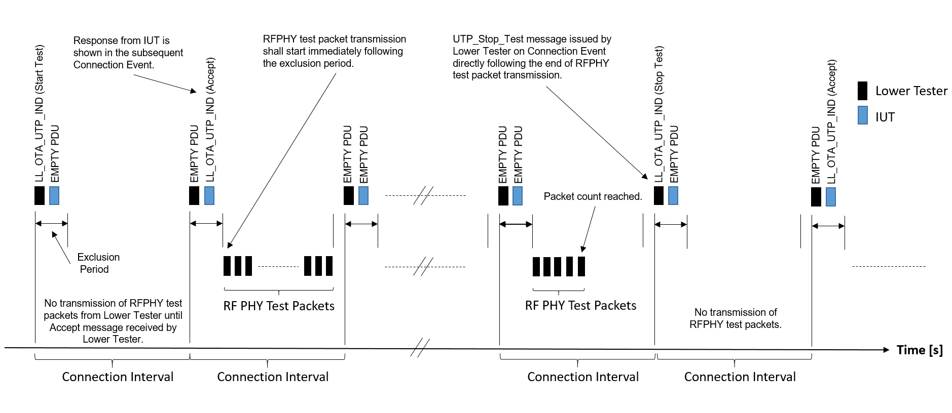
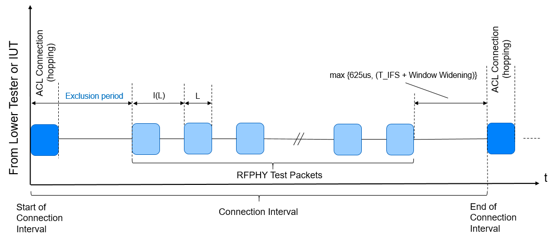
6.4.2. Connection interval requirements
The number of RFPHY test packets that can be sent in a connection interval depends on the PHY, payload length, DTX, interval between test packets, exclusion period, and ACL connection interval. In addition, the last test packet within a connection interval shall end at least max (625 µs, T_IFS + Window Widening) before the next anchor point.
The connection interval period shall be agreed between the Lower or Upper Tester and IUT based on the above parameters and shall be long enough to allow at least one test packet in each connection interval.
The UTP OTA mode timings are shown in Figure 6.1.
The OTA exclusion period is described in Section 5.3.12.
L and I(L) are defined in Section 4.1.6.
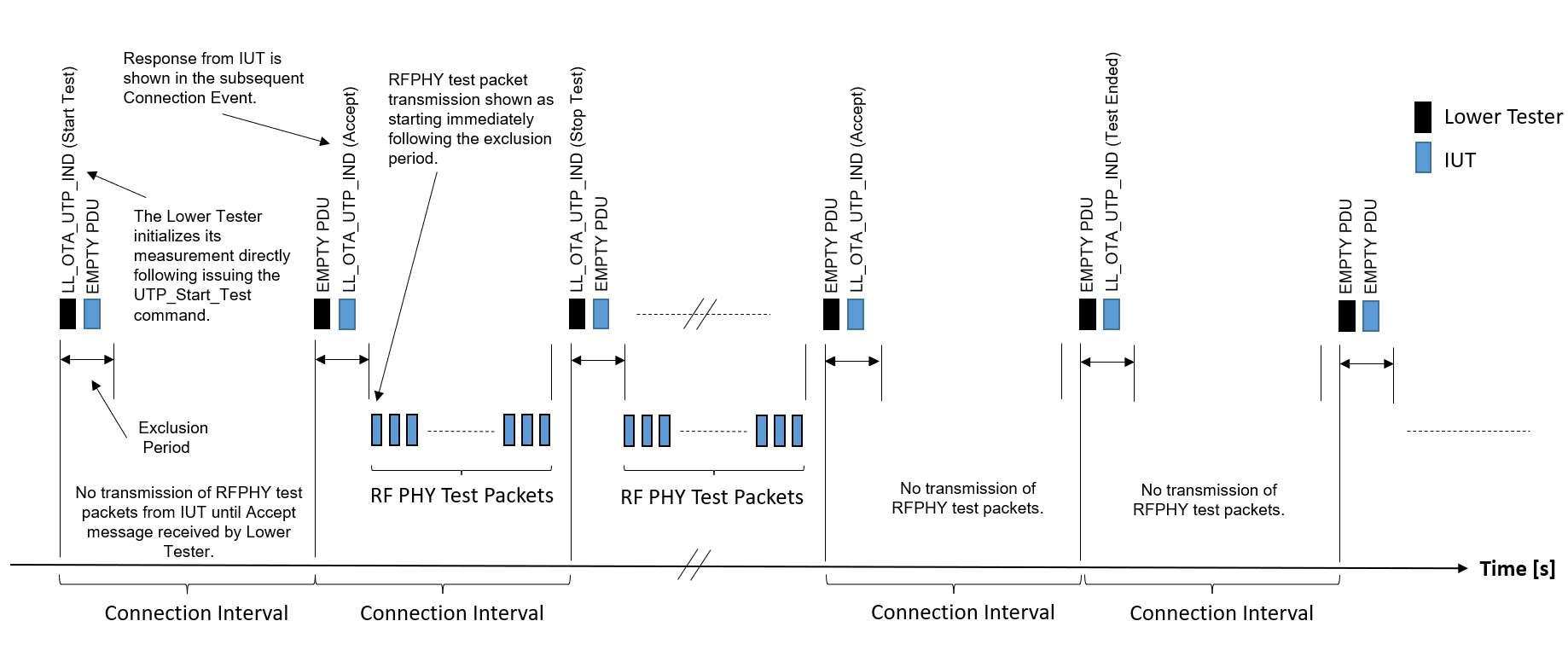
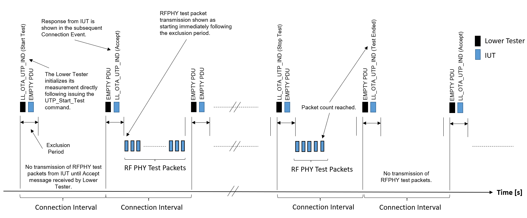
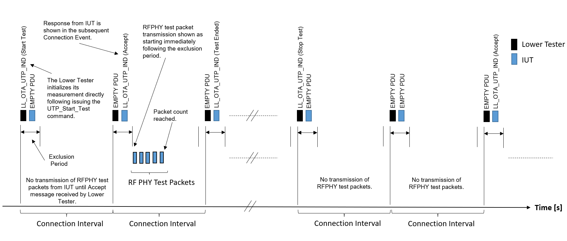
6.4.3. Transmitter test
The Upper Tester may initiate a transmitter test using the UTP_Start_Test message (see Section 5.4.3). The IUT shall transmit RFPHY test packets to the Lower Tester on the configured frequency for the number of connection interval(s) required to satisfy the configured packet count. The IUT shall stop sending RFPHY test packets in the connection interval in which the configured packet count is reached.
Examples of OTA transmitter tests are shown in Figure 6.2, Figure 6.3, and Figure 6.4.
6.4.4. Receiver test
The Upper Tester may initiate a receiver test using the UTP_Start_Test message (see Section 5.4.3). In this test, the Lower Tester shall transmit RFPHY test packets on the configured frequency for the number of connection interval(s) required to satisfy the configured packet count. The Lower Tester shall begin the transmission of RFPHY test packets immediately after the end of an exclusion period and shall not omit any transmissions.
An example of an OTA receiver test is shown in Figure 6.5.