-
Revision: v1.1
-
Revision Date: 2020-08-11
-
Group Prepared By: Discovery of Things Working Group
-
Feedback Email: dot-main@bluetooth.org
Revision History
|
Revision Number |
Date |
Comments |
|---|---|---|
|
v10 |
2015-11-17 |
Adopted by the Bluetooth SIG BoD |
|
v1.1 |
2020-08-11 |
Adopted by the Bluetooth SIG Board of Directors. |
Version History
|
Versions |
Changes |
|---|---|
|
v1.0 to v1.1 |
New section describing the length-type-value (LTV) data and additional characteristics, descriptors, and fields for profiles that use TDS. |
Contributors
|
Name |
Company |
|---|---|
|
Robert D. Hughes |
Intel Corporation |
|
Dominik Sollfrank |
Berner & Mattner |
|
Chris Church |
CSR |
|
Jaeho Lee |
LG Electronics Inc. |
|
Jingu Choi |
LG Electronics Inc. |
|
Masahiko Seki |
Sony |
|
Ash Kapur |
Broadcom Corporation |
|
Smith Kennedy |
HP Inc. |
|
HJ Lee |
LG Electronics Inc. |
|
Siegfried Lehmann |
Apple Inc. |
|
Scott Walsh |
Plantronics Inc. |
|
Robert Hulvey |
Cypress Semiconductor |
|
Minsoo Lee |
LG Electronics Inc. |
|
Norman Geilhardt |
Assystem Germany GmbH |
|
Andre Eisenbach |
Google Inc. |
Use of this specification is your acknowledgement that you agree to and will comply with the following notices and disclaimers. You are advised to seek appropriate legal, engineering, and other professional advice regarding the use, interpretation, and effect of this specification.
Use of Bluetooth specifications by members of Bluetooth SIG is governed by the membership and other related agreements between Bluetooth SIG and its members, including those agreements posted on Bluetooth SIG’s website located at www.bluetooth.com. Any use of this specification by a member that is not in compliance with the applicable membership and other related agreements is prohibited and, among other things, may result in (i) termination of the applicable agreements and (ii) liability for infringement of the intellectual property rights of Bluetooth SIG and its members. This specification may provide options, because, for example, some products do not implement every portion of the specification. Each option identified in the specification is intended to be within the bounds of the Scope as defined in the Bluetooth Patent/Copyright License Agreement (“PCLA”). Also, the identification of options for implementing a portion of the specification is intended to provide design flexibility without establishing, for purposes of the PCLA, that any of these options is a “technically reasonable non-infringing alternative.”
Use of this specification by anyone who is not a member of Bluetooth SIG is prohibited and is an infringement of the intellectual property rights of Bluetooth SIG and its members. The furnishing of this specification does not grant any license to any intellectual property of Bluetooth SIG or its members. THIS SPECIFICATION IS PROVIDED “AS IS” AND BLUETOOTH SIG, ITS MEMBERS AND THEIR AFFILIATES MAKE NO REPRESENTATIONS OR WARRANTIES AND DISCLAIM ALL WARRANTIES, EXPRESS OR IMPLIED, INCLUDING ANY WARRANTIES OF MERCHANTABILITY, TITLE, NON-INFRINGEMENT, FITNESS FOR ANY PARTICULAR PURPOSE, OR THAT THE CONTENT OF THIS SPECIFICATION IS FREE OF ERRORS. For the avoidance of doubt, Bluetooth SIG has not made any search or investigation as to third parties that may claim rights in or to any specifications or any intellectual property that may be required to implement any specifications and it disclaims any obligation or duty to do so.
TO THE MAXIMUM EXTENT PERMITTED BY APPLICABLE LAW, BLUETOOTH SIG, ITS MEMBERS AND THEIR AFFILIATES DISCLAIM ALL LIABILITY ARISING OUT OF OR RELATING TO USE OF THIS SPECIFICATION AND ANY INFORMATION CONTAINED IN THIS SPECIFICATION, INCLUDING LOST REVENUE, PROFITS, DATA OR PROGRAMS, OR BUSINESS INTERRUPTION, OR FOR SPECIAL, INDIRECT, CONSEQUENTIAL, INCIDENTAL OR PUNITIVE DAMAGES, HOWEVER CAUSED AND REGARDLESS OF THE THEORY OF LIABILITY, AND EVEN IF BLUETOOTH SIG, ITS MEMBERS OR THEIR AFFILIATES HAVE BEEN ADVISED OF THE POSSIBILITY OF THE DAMAGES.
Products equipped with Bluetooth wireless technology ("Bluetooth Products") and their combination, operation, use, implementation, and distribution may be subject to regulatory controls under the laws and regulations of numerous countries that regulate products that use wireless non-licensed spectrum. Examples include airline regulations, telecommunications regulations, technology transfer controls, and health and safety regulations. You are solely responsible for complying with all applicable laws and regulations and for obtaining any and all required authorizations, permits, or licenses in connection with your use of this specification and development, manufacture, and distribution of Bluetooth Products. Nothing in this specification provides any information or assistance in connection with complying with applicable laws or regulations or obtaining required authorizations, permits, or licenses.
Bluetooth SIG is not required to adopt any specification or portion thereof. If this specification is not the final version adopted by Bluetooth SIG’s Board of Directors, it may not be adopted. Any specification adopted by Bluetooth SIG’s Board of Directors may be withdrawn, replaced, or modified at any time. Bluetooth SIG reserves the right to change or alter final specifications in accordance with its membership and operating agreements.
Copyright © 2014–2020. All copyrights in the Bluetooth Specifications themselves are owned by Apple Inc., Ericsson AB, Intel Corporation, Lenovo (Singapore) Pte. Ltd., Microsoft Corporation, Nokia Corporation, and Toshiba Corporation. The Bluetooth word mark and logos are owned by Bluetooth SIG, Inc. Other third-party brands and names are the property of their respective owners.
1. Introduction
The Transport Discovery Service (TDS) enables a device using Bluetooth Low Energy (LE) [1] wireless technology to expose services that are available on a transport other than Bluetooth LE. The term ‘transport’ when used in the context of this specification describes a communication technology that can be used for data transfers between a server and client. When used together with a higher-level specification (e.g., a specification which references and makes use of TDS), the information provided by this service can be used to facilitate discovery and utilization of BR/EDR or transports not defined by the Bluetooth SIG such as those defined by the Wi-Fi Alliance® or other organizations. This service is designed such that it can be used by other organizations to describe their own transport and services using their own incremental requirements.
1.1. Conformance
If conformance to this service is claimed, all capabilities indicated as mandatory for this service shall be supported in the specified manner (process-mandatory). This also applies for all optional and conditional capabilities for which support is indicated.
1.2. Service dependencies
This service is not dependent upon any other services.
1.3. Bluetooth Core specification release compatibility
This specification is compatible with Bluetooth Core Specification v4.0 [1] or later.
1.4. GATT sub-procedure requirements
Requirements in this section represent a minimum set of requirements for a GATT server. Other GATT sub-procedures may be used if supported by both client and server.
Table 1.1 summarizes additional GATT sub-procedures required beyond those required by all GATT servers.
|
GATT Sub-Procedure |
Server Requirements |
|---|---|
|
Write Characteristic Value |
C.1 |
|
Indications |
C.1 |
|
Read Characteristic Descriptors |
C.1 |
|
Write Characteristic Descriptors |
C.1 |
- C.1:
-
Mandatory if the server supports the TDS Control Point characteristic; optional otherwise.
1.5. Transport dependencies
Some portions of this specification require features only available when using the Bluetooth LE transport including any requirements related to the use of advertising and scanning.
The term BR/EDR used throughout this document also includes the optional use of Alternate MAC PHY (AMP).
1.6. Application error codes
This service does not define any Attribute Protocol Application error codes.
1.7. Byte transmission order
All characteristics used with this service shall be transmitted with the least significant octet first (LSO) (i.e., little endian). Refer to Section 3.2 for information related to the identification of the LSO.
1.8. Document Terminology
The Bluetooth SIG has adopted portions of the IEEE Standards Style Manual, which dictates use of the words “shall’’, “should”, “may”, and “can” in the development of documentation, as follows:
The word shall is used to indicate mandatory requirements strictly to be followed in order to conform to the standard and from which no deviation is permitted (shall equals is required to).
The use of the word must is deprecated and shall not be used when stating mandatory requirements; must is used only to describe unavoidable situations.
The use of the word will is deprecated and shall not be used when stating mandatory requirements; will is only used in statements of fact.
The word should is used to indicate that among several possibilities one is recommended as particularly suitable, without mentioning or excluding others; or that a certain course of action is preferred but not necessarily required; or that (in the negative form) a certain course of action is deprecated but not prohibited (should equals is recommended that).
The word may is used to indicate a course of action permissible within the limits of the standard (may equals is permitted).
The word can is used for statements of possibility and capability, whether material, physical, or causal (can equals is able to).
The term Reserved for Future Use (RFU) is used to indicate Bluetooth SIG assigned values that are reserved by the Bluetooth SIG and are not otherwise available for use by implementations.
2. Service declaration
The server shall either be a GAP Peripheral or a GAP Broadcaster.
If the server is a GAP Peripheral, the following requirements apply:
-
The Transport Discovery Service shall be instantiated as a Primary Service.
-
Only one instance of the Transport Discovery Service shall be exposed on a device.
-
The service Universally Unique Identifier (UUID) shall be set to «Transport Discovery Service» as defined in [3].
3. Service Advertising Data
This section defines the advertising data requirements for TDS.
3.1. Transport Discovery Data AD Type
This section describes the contents of and requirements for the Transport Discovery Data AD Type that enables a client to determine the role of the device (i.e., whether it is seeking a service (Seeker) or providing a service (Provider) available on a specific transport), the organization and transport associated with the supported service, and other information such as the transport state and other features.
The Transport Discovery Data AD Type shall be present in the Advertising Data (i.e., AD) and may also be present in the Extended Inquiry Response (EIR). EIR and Advertising Packets may be of different sizes and may contain different information within the Transport Discovery Data AD Type.
The definition of the Transport Discovery Data AD Type is shown in Table 3.1.
Refer to Section 3.2 for details regarding byte ordering.
|
Fields |
Data Type |
Size (octets) |
Requirement |
|
|---|---|---|---|---|
|
Transport Discovery Data AD Type Code |
uint8 |
1 |
M |
|
|
Transport Block (1 or more) |
Organization ID |
uint8 |
1 |
M |
|
TDS Flags |
8bit |
1 |
M |
|
|
Transport Data Length |
uint8 |
1 |
M |
|
|
Transport Data |
Variable |
Variable |
O |
|
- M:
-
Mandatory
- O:
-
Optional
Note
Note 1: Typically 0-26 (inclusive of the Flags AD Type); however, larger values may be supported in future updates of the Core Specification.
3.1.1. Transport Discovery Data AD Type Code field
The Transport Discovery Data AD Type Code field shall be included in the Transport Discovery Data AD Type.
This field shall contain the 1-octet Transport Discovery Data AD Type Code value as defined in the Generic Access Profile (GAP) section of the Bluetooth SIG Assigned Numbers [3].
3.1.2. Transport Block
A Transport Block includes the following fields: Organization ID, TDS Flags, Transport Data Length, and Transport Data.
One or more Transport Block(s) may be present in the Transport Discovery Data AD Type.
The value of the fields in this section relate only to the transport which the block describes (i.e., they pertain only to that Transport Block).
The data contained in the Transport Block shall be able to be fully parsed by clients even if size or other restrictions require that full data is in the GATT database.
Refer to Section 3.1.2.5 for details on how this block may be repeated in case there are multiple services (for example, from the same or different transports) that need to be advertised simultaneously in available space.
3.1.2.1. Organization ID field
The Organization ID field shall be included in the Transport Block.
This field shall contain a 1-octet Organization ID value from the Bluetooth SIG Assigned Numbers [3] with the value set to the appropriate organization. Refer to Section 3.1.2.5 for details on how multiple services (related to the same or different Organization IDs) can be advertised in the same packet.
The values of the Organization ID field defined in this version of the specification are shown in Table 3.2. Refer to the Bluetooth SIG Assigned Numbers [3] for a complete list of assigned numbers.
|
Value |
Definition |
|---|---|
|
0x00 |
Reserved for Future Use (RFU) |
|
0x01 |
Bluetooth SIG |
|
0x02–0xFF |
RFU at the time of this writing. Refer to Bluetooth SIG Assigned Numbers [3] for a complete list. |
Organizations requiring the assignment of a value for this field should contact specification.manager@bluetooth.com for guidance on the process for requesting a new assignment.
3.1.2.2. TDS Flags field
The TDS Flags field shall be included in the Transport Block.
This field shall contain a 1-octet value that represents the role of the device and information about its state and supported features.
Bits defined as RFU shall be set to 0.
The values of this field are defined as:
|
Bits |
Definition |
|---|---|
|
0-1 |
Role: 0b00: Not specified 0b01: Seeker Only 0b10: Provider Only 0b11: Both Seeker and Provider |
|
2 |
Transport Data Incomplete: 0: False 1: True |
|
3-4 |
Transport State: 0b00: Off 0b01: On 0b10: Temporarily Unavailable 0b11: RFU |
|
5-7 |
Reserved for future use |
The definition and purpose of the bits listed in Table 3.3 are described in the sections that follow.
3.1.2.2.1. Role
The Role bits indicate whether the Transport Block represents a Provider of a service, a Seeker of a service, a combination of Seeker and Provider, or is unspecified.
The server shall set these bits to an appropriate value for the Transport Block (i.e., whether the role of this specific block is seeking a service, providing a service, acting as a combination of the two, or is unspecified).
3.1.2.2.2. Transport Data Incomplete
The Transport Data Incomplete bit indicates whether the Transport Data field contains complete or incomplete data. If incomplete, then all fields of the Transport Block can be found in the GATT database. The Transport Data Incomplete bit can be used when there is insufficient space in the Advertising Packet for the entire contents or due to other restrictions.
The server shall set the Transport Data Incomplete bit to 1 if the Transport Data is incomplete and when the complete Transport Block can be found in the GATT database. Otherwise, the bit shall be set to 0.
3.1.2.2.3. Transport State
The Transport State bits indicate whether the transport providing access to the advertised service(s) is Off, On, or Temporarily Unavailable. When the bits are set to Off, the transport is not in a state that can accept a connection, however is available to be changed to the On state (e.g., using the TDS Control Point). When set to On, the transport is in a state that can accept a connection. When the bits are set to Temporarily Unavailable, the transport is in a transient state (e.g., if the device is servicing another request) and will change to Off or On as appropriate. When the bits are set to Temporarily Unavailable, a higher-level specification can include a ‘hint’ of the duration and/or cause of unavailability in the Transport Data or via other means.
3.1.2.3. Transport Data Length field
The Transport Data Length field shall be included in the Transport Block.
This field shall contain a 1-octet value that represents the total number of octets in the Transport Data field that follows. This allows a scanning device to determine the length of the variable field that follows, and also allows for extensibility in the future. For example, a Transport Data Length value of 0x10 represents that a 16 octet Transport Data field follows. Similarly, a value of 0x00 represents that the Transport Data field is not present.
|
Value |
Definition |
|---|---|
|
0x00 |
Transport Data field not present (i.e., 0 octets in length) |
|
0x01 – 0xEF |
Number of Octets in Transport Data field |
|
0xF0 – 0xFF |
Reserved for Future Use |
Note
Note 1: Although the contents of the Transport Data will typically be 0-26 octets (inclusive of the Flags AD Type), larger values may be supported in future updates of the Core Specification.
3.1.2.4. Transport Data field
The Transport Data field may be included in the Transport Block.
If used, this field contains organization-specific data and shall be byte-aligned. The value shall fit within the available space in the Advertising Packet. The contents of this field are defined by a higher-level specification.
If multiple service identifiers are listed in the Transport Data field, the advertising device should list these in order of descending priority or preference. For example, if the list represents more than one supported service (corresponding to the Provider role), the order represents preferred support (e.g., a device is capable of transferring data using a faster method as well as a slower legacy method). If the list represents more than one required service (corresponding to the Seeker role), the order represents preferred service order (e.g., a device requires an immediate service, but also another service that is of lower priority).
3.1.2.5. Advertising Using Multiple Transport Blocks
The structure of the Transport Block may be repeated in case there are multiple services (on the same or different transports) to advertise simultaneously. The structure may repeat as long as there is space available. These Transport Blocks may be from the same organization or from different organizations.
Where multiple Transport Blocks are used, the advertising device should list the Transport Blocks in order of descending priority or preference. For example, if the blocks represent more than one supported service, the order represents preferred support (e.g., a printer is capable of printing using a faster technology from one organization, but also a slower technology from another organization). If the blocks represent more than one required service, the order represents preferred service order (e.g., a device requires an immediate service, but also another service that is of lower priority).
The example in Table 3.5 shows the Transport Block structure repeated twice.
|
Fields |
Data Type |
Size (octets) |
|
|---|---|---|---|
|
Transport Discovery Data AD Type Code |
uint8 |
1 |
|
|
Transport Block 1 |
Organization ID |
uint8 |
1 |
|
TDS Flags |
8bit |
1 |
|
|
Transport Data Length |
uint8 |
1 |
|
|
Transport Data |
Variable |
Variable |
|
|
Transport Block 2 |
Organization ID |
uint8 |
1 |
|
TDS Flags |
8bit |
1 |
|
|
Transport Data Length |
uint8 |
1 |
|
|
Transport Data |
Variable |
Variable |
|
Note
Note 1: Typically, 0-23 octets (inclusive of the Flags AD Type) for total length of the Transport Data of Transport Block 1 and Transport Data of Transport Block 2, however larger values may be supported in future updates of the Core Specification.
Where multiple Transport Blocks are present in an instance of the Transport Discovery Data AD Type, the value of the Role bits may be different between Transport Blocks.
3.2. Byte Ordering
Where characteristics and descriptors are comprised of multiple bytes (shown in several tables within this document), the LSO is the topmost field in the tables and the Most Significant Octet (MSO) is the bottommost field in the tables. Refer to Section 1.7 for requirements related to byte transmission order.
4. Service characteristics
This section defines requirements related to GATT characteristics and descriptors for this service. Only one instance of each characteristic in Table 4.1 is permitted within this service.
Where a characteristic can be indicated, a Client Characteristic Configuration descriptor shall be included in that characteristic as required by the Core Specification [1].
|
Characteristic Name |
Requirement |
Mandatory |
Optional |
Security |
|---|---|---|---|---|
|
TDS Control Point |
O |
Write, Indicate |
– |
None |
Notes:
-
Properties not listed as Mandatory or Optional are excluded for this version of the service.
-
Security Permissions of “None” means that this version of the service does not impose any requirement.
-
The characteristics and the characteristic descriptors specified by this service are defined in this specification and in [3].
- O:
-
Optional
4.1. TDS Control Point
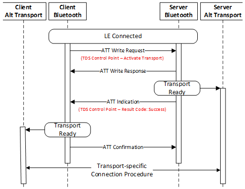
The TDS Control Point characteristic is used to request activation of a transport. Additional Op Codes may be added in the future for other purposes. Figure 4.1 shows an informative example of the flow of a TDS Control Point operation.
In this example, the client writes the Activate Transport Op Code (0x01) to the TDS Control Point. The server sends a Write Response to acknowledge the write to the TDS Control Point. The server sets the desired transport into a connection-ready state. The server sends a TDS Control Point Indication with the Requested Op Code (0x01) followed by the Result Code for ‘Success’ (0x00). The client sets the desired transport into a connection-ready state and responds with the ATT Confirmation. The server and client perform a transport-specific connection procedure.
 |
Only one instance of the TDS Control Point characteristic shall be exposed.
Table 4.2 shows the required structure of the TDS Control Point characteristic:
|
Fields |
Data Type |
Size (octets) |
Requirement |
|---|---|---|---|
|
Op Code |
uint8 |
1 |
M |
|
Organization ID |
uint8 |
1 |
M |
|
Parameter |
Variable |
0 to 18 octets |
O |
Note
Note 1: Parameters larger than 18 octets are permitted if a larger MTU is negotiated.
4.1.1. TDS Control Point procedure requirements
Table 4.3 shows the op code requirements for the TDS Control Point characteristic:
|
Op Code Value |
Procedure |
Requirement |
Organization ID |
Parameter |
|---|---|---|---|---|
|
0x00 |
Reserved for Future Use |
|||
|
0x01 |
Activate Transport |
M |
This field shall contain the relevant 1-octet Organization ID. |
This field shall contain relevant transport-specific data up to 18 octets (see Note 1). |
|
0x02-0xFF |
Reserved for Future Use |
|||
Note
Note 1: Parameters larger than 18 octets are permitted if a larger MTU is negotiated.
Table 4.4 shows the required structure of the TDS Control Point Indication:
|
Fields |
Data Type |
Size (octets) |
Requirement |
|---|---|---|---|
|
Requested Op Code |
uint8 |
1 |
M |
|
Result Code |
uint8 |
1 |
M |
|
Response Parameter |
Variable |
0 to 18 octets |
O |
Note
Note 1: A Response Parameter larger than 18 octets is permitted if a larger MTU is negotiated.
The Response Parameter field, if present, shall contain the relevant 1-octet Organization ID followed by transport-specific data.
The Result Codes that can be sent in a TDS Control Point Indication are defined in Table 4.5:
|
Result Code |
Definition |
Description |
|---|---|---|
|
0x00 |
Success |
Response for successful operation. |
|
0x01 |
Op Code Not Supported |
Response if unsupported or RFU Op Code is received. |
|
0x02 |
Invalid Parameter |
Response if Parameter received does not meet the requirements of the higher-level specification. |
|
0x03 |
Unsupported Organization ID |
Response if unsupported or RFU Organization ID is received. |
|
0x04 |
Operation Failed |
Response if the requested procedure failed for any reason other than those enumerated in this table. |
|
0x05-0xFF |
Reserved For Future Use |
|
A higher-level specification may include additional information within the Parameter of the Response Value. It may include, for example, additional details relating to the reason for a failed operation.
4.1.2. Characteristic behavior
The TDS Control Point is used by a client to control certain behaviors of the server.
A procedure is triggered by writing a value that includes an Op Code specifying the operation and this may be followed by an Organizational ID and Parameter that is valid within the context of that Op Code (see Table 4.3). For the procedure described in the next section, the server shall indicate the TDS Control Point characteristic along with the Requested Op Code and “Success” or other appropriate Result Code contained in the response as listed in Table 4.5.
Refer also to Section 4.1.4 for information on General Error Handling.
4.1.3. Activate Transport procedure
When the Activate Transport Op Code is written to the TDS Control Point and the response is “Success,” the actions to follow are defined by a higher-level specification.
The contents of the organization-specific octets in the parameter for this Op code are defined by a higher‑level specification.
In the event that an error condition occurs, the applicable Error Response shall be sent.
4.1.4. General error handling
Writing an Op Code to the TDS Control Point may result in an ATT Error response or a Control Point Error response as described in the following sections.
4.1.4.1. ATT Error
An ATT Write Request to the TDS Control Point characteristic may be rejected with an Attribute Protocol Error Response under certain conditions as defined in [1]. Reasons for sending an ATT Error Response include, but are not limited to, Insufficient Encryption, Client Characteristic Configuration Descriptor Improperly Configured, Procedure Already in Progress, or Invalid Attribute Value Length. See also Section 1.6 for Attribute Protocol Application Error codes defined by this service.
4.1.4.2. Control Point Error
If the ATT Write Request to the control point characteristic is successful but the requested control point procedure cannot be performed or cannot be completed successfully, an appropriate Result Code from the following sections shall be indicated in the Response Value as described above and in this section.
4.1.4.2.1. Op Code Not Supported
The Op Code Not Supported error response shall be indicated if the Op Code written to the control point is not supported by the server. This includes Op Code values that are reserved for future use.
4.1.4.2.2. Invalid Parameter
The Invalid Parameter error response shall be indicated if the value of the parameter written to the control point does not meet the requirements of the service.
Note that a parameter of an incorrect size, including any parameter sent with an Op Code for which no parameter was actually required, should be trapped by an ATT Error response as described in Section 4.1.4.1 and in this case, it should not generate a control point error response.
4.1.4.2.3. Unsupported Organization ID
The Unsupported Organization ID error response shall be indicated if the value of the Organization ID written to the control point is RFU or otherwise not supported by the server.
4.1.4.2.4. Operation Failed
The Operation Failed error response shall be indicated if a requested control point procedure failed for any reason not otherwise enumerated.
4.1.4.3. Procedure Timeout
In the context of the TDS Control Point characteristic, a control point procedure is started when an ATT Write Request to the TDS Control Point characteristic is successful (i.e., when the server sends the ATT Write Response).
The server may then use an implementation-specific timeout that should be a maximum of 10 seconds. If the timeout expires before the requested control point procedure has been completed, the server may abort the service procedure and indicate the Operation Failed error response, as described in Section 4.1.4.2.4.
A control point procedure is not considered started and not queued in the server when a Write Request to the TDS Control Point characteristic results in an ATT Error response, as described in Section 4.1.4.1.
5. Additional characteristic and descriptor requirements
This section describes the length-type-value (LTV) data and additional characteristics, descriptors, and the fields they contain and may be used by the profiles using TDS.
|
Name |
Requirement |
Mandatory |
Optional |
Security |
|---|---|---|---|---|
|
BR-EDR Handover Data |
O |
Read |
None |
Encryption required |
|
Bluetooth SIG Data |
O |
None |
None |
None |
|
Complete BR-EDR Transport Block Data descriptor |
C.1 |
Read |
None |
None |
- O:
-
Optional
- C.1:
-
Optional if the Bluetooth SIG Data characteristic is supported, otherwise excluded
Security Permissions of “None” means that this version of the service does not impose any requirement.
The characteristics and the characteristic descriptors specified by this service are defined in this specification and in [3].
5.1. BR-EDR Handover Data characteristic
The BR-EDR Handover Data characteristic consists of several fields, such as Bluetooth Device Address (BD_ADDR), to facilitate a quick connection over the BR/EDR transport when required.
5.1.1. Characteristic behavior
When read, the BR-EDR Handover Data characteristic returns data that can be used by a Seeker as part of the BR/EDR Connection Handover procedure. To allow the Provider to manage access to the BD_ADDR field, the Provider may set the Attribute Permissions field of the BR-EDR Handover Data characteristic value declaration to Authorization Required.
5.1.2. Characteristic fields
The structure of the BR-EDR Handover Data characteristic is shown in Table 5.2.
|
Field |
Data Type |
Size |
Units |
|---|---|---|---|
|
BR-EDR Features |
uint8 |
1 octet |
None |
|
BD_ADDR |
uint48 |
6 octets |
None |
|
Class of Device |
uint24 |
3 octets |
None |
5.1.2.1. BR-EDR Features field
This 1-octet field contains supported features that are related to the BR/EDR Connection Handover Profile [4]. See Table 5.3 for the definition.
|
Bit Number |
Definition |
Description |
|---|---|---|
|
0-7 |
Reserved for Future Use |
Reserved for Future Use |
All Reserved for Future Use (RFU) bits in the BR-EDR Features field shall be set to 0.
5.1.2.2. BD_ADDR field
This 6-octet field contains the BD_ADDR of the device. The format of the BD_ADDR is defined in [1].
5.1.2.3. Class of Device field
This 3-octet field contains the Class of Device of the Provider. The format and values are defined in the Bluetooth SIG Assigned Numbers [3].
5.2. Bluetooth SIG Data characteristic
This characteristic does not contain data and is not itself readable; however, it is used to form a hierarchy of descriptors, beneath which shall contain at least one Transport Block.
5.2.1. Complete BR-EDR Transport Block Data descriptor
This characteristic descriptor shall contain the complete Transport Block Data.
This descriptor has the same structure as the Transport Block of the Transport Discovery Data AD Type.
5.2.1.1. Characteristic descriptor behavior
When read, this descriptor returns a value that can be used by a Seeker to access the complete transport data related to the BR/EDR transport.
5.3. LTV data definition
This service defines a set of LTV structures in Table 5.4. Restrictions on usage are shown for the Transport Data field of the Transport Discovery Data (TDD) AD Type and Parameter and Response Parameter fields of the TDS Control Point defined in Section 4.1.1.
|
Type |
LTV Structure |
Transport Data in An Advertising Packet |
TDS Control Point |
|
|---|---|---|---|---|
|
Parameter |
Response Parameter |
|||
|
0x00 |
Reserved for Future Use |
– |
– |
– |
|
0x01 |
16-bit Service UUID List |
Allowed |
Allowed |
Allowed |
|
0x02 |
32-bit Service UUID List |
Allowed |
Allowed |
Allowed |
|
0x03 |
128-bit Service UUID List |
Allowed |
Allowed |
Allowed |
|
0x04 |
Availability Offset |
Allowed |
Not Allowed |
Not Allowed |
|
0x05 |
Seeker Address |
Allowed |
Allowed |
Not Allowed |
|
0x06 |
BD_ADDR |
Allowed |
Not Allowed |
Not Allowed |
|
0x07 |
BR/EDR Local Name |
Allowed |
Not Allowed |
Allowed |
|
0x08 |
BR/EDR Class of Device |
Allowed |
Not Allowed |
Allowed |
|
0x09–0xFE |
Reserved for Future Use |
– |
– |
– |
|
0xFF |
Manufacturer Specific Transport Discovery Data |
Allowed |
Allowed |
Allowed |
Sections 5.3.1 through 5.3.8 describe the defined LTV structures. Implementations will parse the fields in the LTV structures by using the information in the tables to determine precisely where each LTV structure begins and ends. Implementations that cannot parse a particular Type in an LTV structure can skip the LTV structure and move to the beginning of the next LTV structure and continue parsing.
5.3.1. Byte ordering
Where structures (characteristics, descriptors, and LTVs) are comprised of multiple bytes (shown in several tables within this document), the LSO is the topmost field in the tables and the MSO is the bottommost field in the tables.
5.3.2. Service UUID List LTVs
The services listed in this structure use 16-bit UUIDs or 32-bit UUIDs from the Service Discovery table in the Bluetooth SIG Assigned Numbers [3] (specifically found here: https://www.bluetooth.com/specifications/assigned-numbers/service-discovery/), or 128-bit UUIDs.
|
Fields |
Octet Order |
Data Type |
Size |
|---|---|---|---|
|
Length |
N/A |
uint8 |
1 octet |
|
Types = 0x01, 0x02, or 0x03 (see Table 5.4) |
N/A |
uint8 |
1 octet |
|
Value: UUID list |
LSO...MSO |
List of «Service UUIDs» |
2, 4, or 16 octets for each UUID listed |
5.3.3. Availability Offset LTV
When Transport State in the TDS Flags is set to Temporarily Unavailable, the Availability Offset LTV structure allows Providers to give Seekers an estimated time (in units of seconds) until the BR/EDR transport becomes available.
|
Fields |
Octet Order |
Data Type |
Size |
|---|---|---|---|
|
Length |
N/A |
uint8 |
1 octet |
|
Type = 0x04 |
N/A |
uint8 |
1 octet |
|
Value: Availability Offset (in seconds) |
N/A |
uint8 |
1 octet |
5.3.4. Seeker Address LTV
The Seeker Address LTV structure allows Seekers, who send an Activate Alternate Transport request to the Provider’s TDS Control Point characteristic, to notify the Provider about which BD_ADDR to expect within the Frequency Hop Synchronization (FHS) packet, which is used during paging. Note that if the Seeker Address LTV is included in advertising data by a Provider, then the identity of the device could be exposed and tracked.
|
Fields |
Octet Order |
Data Type |
Size |
|---|---|---|---|
|
Length |
N/A |
uint8 |
1 octet |
|
Type = 0x05 |
N/A |
uint8 |
1 octet |
|
Value: Seeker Address |
LSO…MSO |
uint48 |
6 octets |
5.3.5. BD_ADDR LTV
The BD_ADDR LTV allows Providers to expose the BD_ADDR used on the BR/EDR transport to Seekers. Note that if the BD_ADDR LTV is included in advertising data by a Provider, then the identity of the device could be exposed and tracked; alternatively, BD_ADDR in the BR-EDR Handover Data characteristic can be used.
|
Fields |
Octet Order |
Data Type |
Size |
|---|---|---|---|
|
Length |
N/A |
uint8 |
1 octet |
|
Type = 0x06 |
N/A |
uint8 |
1 octet |
|
Value: BD_ADDR |
LSO…MSO |
uint48 |
6 octets |
5.3.6. BR/EDR Local Name
A Provider should include the BR/EDR Local Name (containing either the complete or shortened value of the Device Name characteristic as defined in [1] and [2]). This can be used to assist users in selecting the proper device in case there are multiple devices in range.
|
Fields |
Octet Order |
Data Type |
Size |
|---|---|---|---|
|
Length |
N/A |
uint8 |
1 octet |
|
Type = 0x07 |
N/A |
uint8 |
1 octet |
|
Value: BR/EDR Local Name |
LSO…MSO |
uint8 |
Up to 248 octets (see definition of Local Name in [1]) |
Use of a shortened name is preferred when the BR/EDR Local Name is included in advertising packets.
5.3.7. BR/EDR Class of Device
This 3-octet field contains the BR/EDR Class of Device of the Provider. The format and values are defined in the Bluetooth SIG Assigned Numbers [3].
|
Fields |
Octet Order |
Data Type |
Size |
|---|---|---|---|
|
Length |
N/A |
uint8 |
1 octet |
|
Type = 0x08 |
N/A |
uint8 |
1 octet |
|
Value: BR/EDR Class of Device |
LSO…MSO |
uint24 |
3 octets |
5.3.8. Manufacturer Specific Transport Discovery Data LTV
This Manufacturer Specific Transport Discovery Data LTV structure is used for manufacturer-specific data. The first two octets in the Value field shall contain the Provider Company Identifier code, as defined in the Company Identifiers section of the Bluetooth SIG Assigned Numbers [3]. The interpretation of any other octets within the data shall be defined by the manufacturer that is specified by the company identifier.
|
Fields |
Octet Order |
Data Type |
Size |
|
|---|---|---|---|---|
|
Length |
N/A |
uint8 |
1 octet |
|
|
Type = 0xFF |
N/A |
uint8 |
1 octet |
|
|
Value |
Company Identifier |
LSO…MSO |
uint16 |
2 octets |
|
Manufacturer Specific Transport Discovery Data |
LSO…MSO |
N/A |
variable |
|
6. Service Discovery Protocol interoperability
If this service is exposed over BR/EDR, then it shall expose the following Service Discovery Protocol (SDP) record.
|
Item |
Definition |
Type |
Value |
Status |
|---|---|---|---|---|
|
Service Class ID List |
– |
– |
– |
M |
|
Service Class #0 |
– |
UUID |
«Transport Discovery Service» |
M |
|
Protocol Descriptor List |
– |
– |
– |
M |
|
Protocol #0 |
– |
UUID |
L2CAP |
M |
|
Parameter #0 for Protocol #0 |
PSM |
uint16 |
PSM = ATT |
M |
|
Protocol #1 |
– |
UUID |
ATT |
M |
|
Parameter #0 for Protocol #1 |
GATT Start Handle |
uint16 |
First handle of this service in the GATT database |
M |
|
Parameter #1 for Protocol #1 |
GATT End Handle |
uint16 |
Last handle of this service in the GATT database |
M |
|
BrowseGroupList |
– |
– |
PublicBrowseRoot* |
M |
- M:
-
Mandatory
* PublicBrowseRoot shall be present; however, other browse UUIDs may also be included in the list.
7. Acronyms and abbreviations
|
Acronyms and Abbreviations |
Meaning |
|---|---|
|
AD |
Advertising Data |
|
AMP |
Alternate MAC PHY |
|
BD_ADDR |
Bluetooth Device Address |
|
BR/EDR |
Basic Rate/Enhanced Data Rate |
|
EIR |
Extended Inquiry Response |
|
FHS |
Frequency Hop Synchronization |
|
GAP |
Generic Access Profile |
|
GATT |
Generic Attribute Profile |
|
LE |
Low Energy |
|
LSO |
least significant octet |
|
LTV |
length-type-value |
|
MSO |
most significant octet |
|
MTU |
Maximum Transmission Unit |
|
PDU |
Protocol Data Unit |
|
RFU |
Reserved for Future Use |
|
SDP |
Service Discovery Protocol |
|
TDS |
Transport Discovery Service |
|
UUID |
Universally Unique Identifier |
8. References
Bibliography
[1] Bluetooth Core Specification v4.0 or later
[2] Core Specification Supplement v6 or later
[4] BR/EDR Connection Handover Profile v1.0