-
Revision: v1.0.1
-
Revision Date: 2022-01-18
-
Group Prepared By: Medical Devices Working Group
Revision History
|
Revision Number |
Date |
Comments |
|---|---|---|
|
v1.0 |
2017-Dec-05 |
Adopted by the Bluetooth SIG Board of Directors. |
|
v1.0.1 |
2022-01-18 |
Adopted by the Bluetooth SIG Board of Directors. |
Version History
|
Versions |
Changes |
|---|---|
|
v1.0 to v1.0.1 |
Incorporated errata E14847, E15809, E15852, E16252. |
Acknowledgments
|
Name |
Company |
|---|---|
|
Wolfgang Heck |
F. Hoffmann-La Roche AG |
|
Laurence Richardson |
Qualcomm Technologies International, Ltd. |
|
Craig Carlson |
F. Hoffmann-La Roche AG |
|
Leif-Alexandre Aschehoug |
Nordic Semiconductor ASA |
|
Felix Bootz |
F. Hoffmann-La Roche AG |
Use of this specification is your acknowledgement that you agree to and will comply with the following notices and disclaimers. You are advised to seek appropriate legal, engineering, and other professional advice regarding the use, interpretation, and effect of this specification.
Use of Bluetooth specifications by members of Bluetooth SIG is governed by the membership and other related agreements between Bluetooth SIG and its members, including those agreements posted on Bluetooth SIG’s website located at www.bluetooth.com. Any use of this specification by a member that is not in compliance with the applicable membership and other related agreements is prohibited and, among other things, may result in (i) termination of the applicable agreements and (ii) liability for infringement of the intellectual property rights of Bluetooth SIG and its members. This specification may provide options, because, for example, some products do not implement every portion of the specification. All content within the specification, including notes, appendices, figures, tables, message sequence charts, examples, sample data, and each option identified is intended to be within the bounds of the Scope as defined in the Bluetooth Patent/Copyright License Agreement (“PCLA”). Also, the identification of options for implementing a portion of the specification is intended to provide design flexibility without establishing, for purposes of the PCLA, that any of these options is a “technically reasonable non-infringing alternative.”
Use of this specification by anyone who is not a member of Bluetooth SIG is prohibited and is an infringement of the intellectual property rights of Bluetooth SIG and its members. The furnishing of this specification does not grant any license to any intellectual property of Bluetooth SIG or its members. THIS SPECIFICATION IS PROVIDED “AS IS” AND BLUETOOTH SIG, ITS MEMBERS AND THEIR AFFILIATES MAKE NO REPRESENTATIONS OR WARRANTIES AND DISCLAIM ALL WARRANTIES, EXPRESS OR IMPLIED, INCLUDING ANY WARRANTIES OF MERCHANTABILITY, TITLE, NON-INFRINGEMENT, FITNESS FOR ANY PARTICULAR PURPOSE, OR THAT THE CONTENT OF THIS SPECIFICATION IS FREE OF ERRORS. For the avoidance of doubt, Bluetooth SIG has not made any search or investigation as to third parties that may claim rights in or to any specifications or any intellectual property that may be required to implement any specifications and it disclaims any obligation or duty to do so.
TO THE MAXIMUM EXTENT PERMITTED BY APPLICABLE LAW, BLUETOOTH SIG, ITS MEMBERS AND THEIR AFFILIATES DISCLAIM ALL LIABILITY ARISING OUT OF OR RELATING TO USE OF THIS SPECIFICATION AND ANY INFORMATION CONTAINED IN THIS SPECIFICATION, INCLUDING LOST REVENUE, PROFITS, DATA OR PROGRAMS, OR BUSINESS INTERRUPTION, OR FOR SPECIAL, INDIRECT, CONSEQUENTIAL, INCIDENTAL OR PUNITIVE DAMAGES, HOWEVER CAUSED AND REGARDLESS OF THE THEORY OF LIABILITY, AND EVEN IF BLUETOOTH SIG, ITS MEMBERS OR THEIR AFFILIATES HAVE BEEN ADVISED OF THE POSSIBILITY OF THE DAMAGES.
Products equipped with Bluetooth wireless technology ("Bluetooth Products") and their combination, operation, use, implementation, and distribution may be subject to regulatory controls under the laws and regulations of numerous countries that regulate products that use wireless non-licensed spectrum. Examples include airline regulations, telecommunications regulations, technology transfer controls, and health and safety regulations. You are solely responsible for complying with all applicable laws and regulations and for obtaining any and all required authorizations, permits, or licenses in connection with your use of this specification and development, manufacture, and distribution of Bluetooth Products. Nothing in this specification provides any information or assistance in connection with complying with applicable laws or regulations or obtaining required authorizations, permits, or licenses.
Bluetooth SIG is not required to adopt any specification or portion thereof. If this specification is not the final version adopted by Bluetooth SIG’s Board of Directors, it may not be adopted. Any specification adopted by Bluetooth SIG’s Board of Directors may be withdrawn, replaced, or modified at any time. Bluetooth SIG reserves the right to change or alter final specifications in accordance with its membership and operating agreements.
Copyright © 2015–2022. All copyrights in the Bluetooth Specifications themselves are owned by Apple Inc., Ericsson AB, Intel Corporation, Lenovo (Singapore) Pte. Ltd., Microsoft Corporation, Nokia Corporation, and Toshiba Corporation. The Bluetooth word mark and logos are owned by Bluetooth SIG, Inc. Other third-party brands and names are the property of their respective owners.
1. Introduction
The Reconnection Configuration (RC) Service enables peer devices to request changes of the communication parameters to save energy by enabling devices to be in a “non-connected” mode for a common time. If the communication phases are in the area of minutes or hours the current mechanisms of Bluetooth Low Energy are not sufficient.
This service only handles communication settings.
1.1. Conformance
If conformance to this specification is claimed, all capabilities indicated as mandatory for this specification shall be supported in the specified manner (process-mandatory). This also applies for all optional and conditional capabilities for which support is indicated.
1.2. Language
1.2.1. Language conventions
The Bluetooth SIG has established the following conventions for use of the words shall, must, will, should, may, can, is, and note in the development of specifications:
|
shall |
is required to – used to define requirements. |
|
must |
is a natural consequence of – used only to describe unavoidable situations. |
|
will |
it is true that – only used in statements of fact. |
|
should |
is recommended that – used to indicate that among several possibilities one is recommended as particularly suitable, but not required. |
|
may |
is permitted to – used to allow options. |
|
can |
is able to – used to relate statements in a causal manner. |
|
is |
is defined as – used to further explain elements that are previously required or allowed. |
|
note |
Used to indicate text that is included for informational purposes only and is not required in order to implement the specification. Informative text in a note continues to the end of the paragraph. |
For clarity of the definition of those terms, see Core Specification Volume 1, Part E, Section 1.
Certain terms used in this specification have been updated and are no longer used by Bluetooth SIG. For a list of terms that have been updated and their replacement terms, see the Appropriate Language Mapping Table [3].
1.2.2. Reserved for Future Use
Where a field in a packet, Protocol Data Unit (PDU), or other data structure is described as "Reserved for Future Use" (irrespective of whether in uppercase or lowercase), the device creating the structure shall set its value to zero unless otherwise specified. Any device receiving or interpreting the structure shall ignore that field; in particular, it shall not reject the structure because of the value of the field.
Where a field, parameter, or other variable object can take a range of values, and some values are described as "Reserved for Future Use," a device sending the object shall not set the object to those values. A device receiving an object with such a value should reject it, and any data structure containing it, as being erroneous; however, this does not apply in a context where the object is described as being ignored or it is specified to ignore unrecognized values.
When a field value is a bit field, unassigned bits can be marked as Reserved for Future Use and shall be set to 0. Implementations that receive a message that contains a Reserved for Future Use bit that is set to 1 shall process the message as if that bit was set to 0, except where specified otherwise.
The acronym RFU is equivalent to Reserved for Future Use.
1.2.3. Prohibited
When a field value is an enumeration, unassigned values can be marked as “Prohibited.” These values shall never be used by an implementation, and any message received that includes a Prohibited value shall be ignored and shall not be processed and shall not be responded to.
Where a field, parameter, or other variable object can take a range of values, and some values are described as “Prohibited,” devices shall not set the object to any of those Prohibited values. A device receiving an object with such a value should reject it, and any data structure containing it, as being erroneous.
“Prohibited” is never abbreviated.
1.3. Service dependencies
This service is not dependent upon any other services but is intended to be used together with other services.
1.4. Bluetooth Core Specification release compatibility
This specification is compatible with any Bluetooth Core Specification that includes the Generic Attribute Profile (GATT) portion of the Bluetooth Core Specification. Nevertheless there are some optional features of this service that require a higher version of the Bluetooth Core Specification. These requirements are described in the relevant section of this specification.
1.5. GATT sub-procedure requirements
Requirements in this section represent a minimum set of requirements for a Reconnection Configuration server. Other GATT sub‑procedures may be used if supported by both Reconnection Configuration client and Reconnection Configuration server.
Table 1.1 summarizes additional GATT sub-procedures required beyond those required by all GATT servers.
|
GATT Sub-Procedure |
Requirements |
|---|---|
|
Write |
M |
|
Notifications |
C.1 |
|
Indications |
C.2 |
|
Read Characteristic Descriptors |
M |
|
Write Characteristic Descriptors |
M |
- M:
-
Mandatory
- C.1:
-
Mandatory if Ready for Disconnect is supported, otherwise Optional.
- C.2:
-
Mandatory if Reconnection Configuration Control Point (RCCP) procedures are supported, otherwise Excluded.
1.6. Transport dependencies
Within this version of the specification this service operates over the LE transports only. The specified functionality is mostly dependent on the Link Layer and therefore a different handling is required when using BR/EDR transport.
1.7. Application error codes
This service defines the following Attribute Protocol Application error codes:
|
Name |
Error Code |
Description |
|---|---|---|
|
Missing CRC |
0x80 |
If E2E-CRC is supported and a Write procedure is processed without CRC attached |
|
Invalid CRC |
0x81 |
If E2E-CRC is supported and a Write procedure is processed with invalid CRC value attached |
1.8. Byte transmission order
All characteristics used with this service shall be transmitted with the least significant octet first (i.e., little endian). The least significant octet is identified as described in this document or if not mentioned within this document, in the characteristic definitions in [1].
2. Service
2.1. Declaration
There shall only be one instance of the Reconnection Configuration Service on a device.
The service UUID shall be set to the UUID value assigned to «Reconnection Configuration Service» defined in [1].
2.2. Behavior
The communication parameters influenced by this service are mostly related to the Link Layer. Some changes of the communication parameters will be activated after the requested transport is no longer active in the requesting device.
2.2.1. LE transport
-
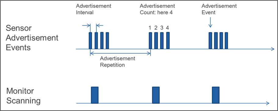
This service introduces the following parameters for the timing of advertisements: the Advertisement Count and the Advertisement Repetition Time.
Via the Reconnection Configuration Control Point, a change of the following connection parameters can be requested and controlled:
-
Connection Interval:
Configuration of the Minimum Connection Interval and Maximum Connection Interval as defined in the Bluetooth Core Specification, limited by device specific min and max values. Also some parameter combinations may not be supported by the device and the peer device may not accept these settings.
-
Peripheral Latency:
Configuration of the Peripheral Latency as defined in the Bluetooth Core Specification, limited by device specific min and max values. Also some parameter combinations may not be supported by the device and the peer device may not accept these settings.
-
Supervision Timeout Multiplier:
Configuration of the Supervision timeout multiplier as defined in the Bluetooth Core Specification, limited by device specific min and max values. Also some parameter combinations may not be supported by the device and the peer device may not accept these settings.
-
Advertisement Interval:
Configuration of the Advertisement Interval as defined in the Bluetooth Core Specification, limited by device specific min and max values. Also some parameter combinations may not be supported by the device.
-
Advertisement Count:
Configuration of the Advertisement Count (definition see above) within the limits of the device. Some parameter combinations may not be supported by the device.
-
Advertisement Repetition Time:
Configuration of the Advertisement Repetition Time (definition see above) within the limits of the device. Some parameter combinations may not be supported by the device.
-
Reconnection Timeout:
When no reconnection can be established to the peer device within the reconnection timeout the settings shall switch back to default behavior. This enables a device to be again in a connectable condition.
-
Stored Settings:
Procedure applying the stored values of the parameters.
-
Enable Disconnect:
Enable the Reconnection Configuration server to disconnect when all procedures have finished without further interaction with the peer device.
For example, glucose meter is requested to send all measurement data. After sending the data the connection should be disconnected. If a measurement is not pending on the glucose meter, the device requests to disconnect from the Collector and might save energy.
-
Supplementary Settings:
There are a few behavior changes that are possible which can be used to influence advertising behavior, Filter Accept List usage and security:
-
LESC:
Enabling devices to switch to Secure Connections Only Mode when peer device is requesting this. If a secure connection is preferred between two devices (e.g. in medical applications), the Reconnection Configuration server is still able to be connected from older Reconnection Configuration clients not supporting LESC. If Reconnection Configuration client supports LESC the Reconnection Configuration server is able to request it.
-
OOB:
OOB pairing can be selected for special use cases. For example, if a CGM server is connected directly to an insulin pump, there might be higher requirements for the authentication in the pairing process.
-
Filter Accept List:
If a Reconnection Configuration server is used with different Reconnection Configuration clients and does not want to waste energy when Connection Requests are received from other scanning Reconnection Configuration clients, the Reconnection Configuration server should use the Filter Accept List. Restricting devices listed in the Filter Accept List is application dependent and requires evaluations for the intended use case to achieve the desired result. The usage of the Filter Accept List is controlled by a timer to enable connectivity to other devices if the devices in the Filter Accept List are not available any more.
-
Advertisement Mode:
Enabling a device to change advertising. The selection allows switching between Connectable undirected advertising, Scannable undirected advertising, Non-connectable undirected, or low duty cycle directed advertising (e.g., when a connection to only one peer device is desired).
-
2.2.2. BR/EDR transport
Within this version of specification, the service operates over LE transport only.
3. Service characteristics
This section defines the characteristic and descriptor requirements.
|
Characteristic Name |
Requirement |
Mandatory Properties |
Optional Properties |
Security Permissions |
|---|---|---|---|---|
|
RC Feature |
M |
Read |
Indicate C.4 |
Optional |
|
RC Settings |
C.1 |
Read, Notify* |
N/A |
Optional |
|
RC Settings Client Characteristic Descriptor |
C.2 |
Read, Write |
N/A |
Optional |
|
RCCP |
C.3 |
Indicate, Write |
N/A |
Optional |
|
RCCP Client Characteristic Descriptor |
C.3 |
Read, Write |
N/A |
Optional |
- M:
-
Mandatory
- C.1:
-
Mandatory if device supports more than one Advertisement Configuration or one or more of the following features: “Ready for Disconnect”, “Upgrade to LESC Only”, “Next Pairing OOB”, “Limited Access”, otherwise Excluded.
- C.2:
-
Mandatory if device supports “Ready for Disconnect” feature, otherwise Optional.
- C.3:
-
Mandatory if device supports more than one Advertisement Configuration or one or more of the following features: “Enable Disconnect”, “Propose Reconnection Timeout”, “Propose Connection Interval”, “Propose Peripheral Latency”, “Propose Supervision Timeout”, “Propose Advertisement Interval”, “Propose Advertisement Count”, “Propose Advertisement Repetition Time”, “Upgrade to LESC Only”, “Next Pairing OOB”, “Use of Filter Accept List”, “Limited Access”, otherwise Excluded.
- C.4:
-
Mandatory if the value of the RC Feature characteristic can change over the lifetime of the device, otherwise Excluded.
* Notify is Mandatory if device supports “Ready for Disconnect” feature, otherwise Optional.
Note
Note: Security Permissions of “Optional” means that this service does not impose any requirements on security; the service can require either security or no security.
3.1. RC Feature
The RC Feature characteristic shall be used to describe the supported features of the Reconnection Configuration server.
Support for this characteristic is mandatory.
The RC Feature characteristic is identified using the UUID «Reconnection Configuration Features», as defined in [1].
Reserved for Future Use (RFU) bits in the RC Feature characteristic value shall be set to 0.
The structure of the RC Feature characteristic is defined in Table 3.2 below:
|
E2E-CRC field |
RC Feature field |
|
|---|---|---|
|
Byte Order |
LSO…MSO |
LSO…MSO |
|
Data type |
uint16 |
uint8 |
|
Size |
2 octets |
3+n* |
|
Units |
N/A |
None |
* If Feature Extension bit(s) is set to “1”, the number of octets increases.
Where LSO = Least Significant Octet and MSO = Most Significant Octet.
3.1.1. Characteristic behavior
When read or indicated, the RC Feature characteristic gives a value that is used by a Reconnection Configuration client to determine the supported features of the Reconnection Configuration server.
When the Client Characteristic Configuration descriptor is configured for indications and the supported features of the Server have changed, the RC Feature characteristic shall be indicated to any bonded Collectors after reconnection.
3.1.1.1. E2E-CRC field
If the device supports E2E-safety (E2E-CRC Supported bit is set in RC Feature), the RC Feature field shall be protected by a CRC calculated over all data but the CRC field itself, see Section 3.4 for details. If the device does not support E2E-safety, this E2E-CRC field shall be set to 0xFFFF.
If E2E-safety is supported and an error occurs, the error codes as defined in Section 1.7 shall be used.
3.1.1.2. RC Feature field
The bits of the RC Feature field shall be static during a connection.
When the Reconnection Configuration server supports a feature, the associated bit of the RC Feature characteristic shall be set to 1 (Feature supported), otherwise, the associated bit shall be set to 0 (Feature not supported). The feature bits are defined in the following table:
|
Bit |
Definition |
|---|---|
|
0 |
E2E-CRC Supported |
|
1 |
Enable Disconnect Supported |
|
2 |
Ready for Disconnect Supported |
|
3 |
Propose Reconnection Timeout Supported |
|
4 |
Propose Connection Interval Supported |
|
5 |
Propose Peripheral Latency Supported |
|
6 |
Propose Supervision Timeout Supported |
|
7 |
Propose Advertisement Interval Supported |
|
8 |
Propose Advertisement Count Supported |
|
9 |
Propose Advertisement Repetition Time Supported |
|
10 |
Advertisement Configuration 1 Supported |
|
11 |
Advertisement Configuration 2 Supported |
|
12 |
Advertisement Configuration 3 Supported |
|
13 |
Advertisement Configuration 4 Supported* |
|
14 |
Upgrade to LESC Only Supported** |
|
15 |
Next Pairing OOB Supported |
|
16 |
Use of Filter Accept List Supported |
|
17 |
Limited Access Supported |
|
18–22 |
RFU |
|
23 |
Feature Extension |
* If Advertisement Configuration 4 is supported, compatibility to Bluetooth Core Specification, v4.1 is Mandatory.
** If Upgrade to LESC Only is supported, compatibility to Bluetooth Core Specification, v4.2 is Mandatory.
Note
Note: If the Feature Extension bit (bit 23) is set, an additional octet is attached (bit 24 .. bit 31), where bit 31 shall be used as Feature Extension bit in the same way. If this bit is set, then another octet is attached (bit 32 .. 39) and so on. This is defined to allow future extension of the characteristic.
3.2. RC Settings
The RC Settings characteristic shall be used to both read and notify supported features on the Reconnection Configuration server.
Support for this characteristic is defined in Table 3.1.
The RC Settings characteristic is identified using the UUID «Reconnection Configuration Settings», as defined in [1].
3.2.1. RC Settings structure
The structure of the characteristic is shown in the following table:
|
Length field |
Settings field |
E2E-CRC (C.1) field |
|
|---|---|---|---|
|
Byte Order |
LSO…MSO |
LSO…MSO |
N/A |
|
Data type |
uint8 |
Variable |
uint16 |
|
Size |
1 octet |
2 octets |
0 or 2 octets |
|
Units |
None |
None |
None |
- C.1:
-
Mandatory if device supports E2E-CRC (bit 0 is set in RC Feature), otherwise Excluded.
The length field represents the size of the RC Settings characteristic. At minimum the size is 3 octets and is enlarged by more octets depending on the size of the Settings field and if the E2E-CRC field is attached. This enables an extension of the characteristic for adding new features.
The following table defines the bits in the Settings field:
|
Octet |
Bit |
Definition |
Description |
|||
|---|---|---|---|---|---|---|
|
0 |
0 |
RFU |
||||
|
0 |
1 |
LESC Only |
When set to 1, the next pairings are done in Security Mode 1, Level 4 |
|||
|
0 |
2 |
Use OOB Pairing |
When set to 1 the next pairings are done with request for OOB |
|||
|
0 |
3 |
RFU |
||||
|
0 |
4 |
Ready for Disconnect |
When set to 1 the Reconnection Configuration server is ready for disconnect. The Reconnection Configuration server shall set this bit if no procedures are running to notify the Reconnection Configuration client that it should disconnect now (e.g., the Upgrade to LESC Only is done). |
|||
|
0 |
5 |
Limited Access |
This bit is used to signal other Reconnection Configuration clients that the Service will be disabled (characteristics are read only) by the Reconnection Configuration client setting this bit. Only this Reconnection Configuration client is able to control the settings (write to characteristics). This bit should be used very carefully to not exclude Reconnection Configuration clients from further reconnections. |
|||
|
0 |
6 |
Access Permitted |
This bit is signaling the Reconnection Configuration client that it can control the settings when Limited Access is set. (This is needed to enable a future Authorization Control Service to be included in a simple way.) If the bit “Limited Access” is not set, this bit shall be ignored. |
|||
|
0 |
7 |
RFU |
||||
|
1 |
0 |
Advertisement Mode 0 |
These two bits describe the configuration of advertising: |
|||
|
Advertisement Configuration |
Bit 1 |
Bit 0 |
Configuration |
|||
|
1 |
0 |
0 |
Connectable undirected advertising (ADV_IND) (default) |
|||
|
2 |
0 |
1 |
Scannable undirected advertising (ADV_SCAN_IND |
|||
|
1 |
1 |
Advertisement Mode 1 |
3 |
1 |
0 |
Non-connectable undirected advertising (ADV_NONCONN_IND) |
|
4 |
1 |
1 |
Connectable low duty cycle directed advertising (ADV_DIRECT_IND, low duty cycle) |
|||
|
1 |
2 |
RFU |
||||
|
1 |
3 |
RFU |
||||
|
1 |
4 |
RFU |
||||
|
1 |
5 |
RFU |
||||
|
1 |
6 |
RFU |
||||
|
1 |
7 |
RFU |
||||
If the device supports E2E-safety (E2E-CRC Supported bit is set in RC Feature), the RC Settings characteristic shall be protected by a CRC calculated over all data but the CRC field itself, see Section 3 for details. If the device does not support E2E-safety, the E2E-CRC field shall be not attached.
3.2.2. RC Settings characteristic behavior for Server notification
When the Reconnection Configuration server is ready for disconnect and the Ready for Disconnect feature is supported, it shall notify the RCS characteristic with the bit Ready for Disconnect set to 1. This enables the Reconnection Configuration client to disconnect immediately or to keep in connection to process other requests.
3.3. Reconnection Configuration Control Point
The Reconnection Configuration Control Point (RCCP) characteristic shall be used to execute a supported procedure on the Reconnection Configuration server. This may include parameters that are valid within the context of that opcode as defined in Table 3.7.
The Reconnection Configuration client should read the RC Feature characteristic to obtain information about the supported features on the Reconnection Configuration server before writing to the Reconnection Configuration Control Point.
Support for this characteristic is defined in Table 3.1.
The Reconnection Configuration Control Point characteristic is identified using the UUID «Reconnection Configuration Control Point», as defined in [1].
The structure of the characteristic is defined below:
|
Opcode (see Table 3.7) |
Operand (value defined per Service) |
E2E-CRC (C.1) |
|
|---|---|---|---|
|
Byte Order |
N/A |
LSO…MSO |
LSO…MSO |
|
Data type |
uint8 |
Variable |
uint16 |
|
Size |
1 octet |
0 to 17 octets |
0 or 2 octets |
|
Units |
None |
None |
N/A |
- C.1:
-
Mandatory if device supports E2E-CRC (bit 0 is set in RC Feature), otherwise Excluded.
Where LSO = Least Significant Octet and MSO = Most Significant Octet.
3.3.1. Reconnection Configuration Control Point procedure requirements
Table 3.7 shows the requirements of the RCCP characteristic in the context of this service:
|
Opcode Value |
Procedure |
Requirement |
Operand |
Applicable Result Codes (see Table 3.10) |
Remark |
|---|---|---|---|---|---|
|
0x00 |
Enable Disconnect |
C.1 |
None |
Opcode Not Supported, Operation Failed, Success |
|
|
0x01 |
Get Actual Communication Parameters |
C.2 |
None |
Opcode Not Supported, Operation Failed |
Normal response to this opcode is Client Parameter Indication |
|
0x02 |
Propose Settings |
C.2 |
See Table 3.8 |
Opcode Not Supported, Communication Parameter out of Range, Invalid Parameter Combination, Operation Failed, Invalid Operand Proposal Accepted, Success, Communication Parameters rejected |
|
|
0x03 |
Activate Stored Settings |
C.2 |
Parameter-Set uint8 |
Success, Opcode Not Supported, Operation Failed, Invalid Operand Proposal Accepted, Communication Parameters rejected |
|
|
0x04 |
Get Max Values |
C.3 |
None |
Opcode Not Supported, Operation Failed |
Normal response to this opcode is Communication Parameter Response |
|
0x05 |
Get Min Values |
C.3 |
None |
Opcode Not Supported, Operation Failed |
Normal response to this opcode is Communication Parameter Response |
|
0x06 |
Get Stored Values |
C.2 |
Parameter-Set uint8 |
Opcode Not Supported, Operation Failed, Invalid Operand |
Normal response to this opcode is Communication Parameter Response |
|
0x07 |
Set Filter Accept List Timer |
C.4 |
uint32 containing time in seconds used for Filter Accept List |
Opcode Not Supported, Operation Failed, Invalid Operand, Success |
|
|
0x08 |
Get Filter Accept List Timer |
C.4 |
None |
Opcode Not Supported, Operation Failed |
Normal response to this opcode is Filter Accept List Timer Response |
|
0x09 |
Set Advertisement Configuration |
C.5 |
uint8 |
Success, Opcode Not Supported, Operation Failed, Invalid Operand |
|
|
0x0A |
Upgrade to LESC Only |
C.6 |
uint8 (0xFF = true, 0x00 = false) |
Success, Opcode Not Supported, Invalid Operand, Operation Failed |
|
|
0x0B |
Switch OOB Pairing |
C.7 |
uint8 (0xFF = true, 0x00 = false) |
Success, Opcode Not Supported, Invalid Operand, Operation Failed |
|
|
0x0C |
Limited Access |
C.8 |
uint8 (0xFF = true, 0x00 = false) |
Success, Opcode Not Supported, Invalid Operand, Operation Failed |
|
|
0x0D |
Reserved for Future Use |
||||
|
0x0E |
Procedure Response |
M |
Request Opcode, Result Code |
N/A |
|
|
0x0F |
Communication Parameter Response |
C.2 |
Request Opcode, parameters as defined in Table 3.8 |
Normal response for the Get Min Values, Get Max Values, Get Stored Values procedures |
|
|
0x10 |
Filter Accept List Timer Response |
C.4 |
uint32 for current settings of Filter Accept List Timer (in seconds), uint32 for min value and uint32 for max value |
N/A |
Normal response for the Get Filter Accept List Timer procedure |
|
0x11 |
Client Parameter Indication |
M |
See Table 3.8 |
This Indication is sent every time the Reconnection Configuration client sets the communication parameters, even when not triggered by a RCCP procedure. |
|
|
0x12–0xFF |
Reserved for Future Use |
None |
N/A |
- C.1:
-
Mandatory if device supports “Enable Disconnect” feature, otherwise Excluded.
- C.2:
-
Mandatory if device supports one or more of the following features: “Propose Reconnection Timeout”, “Propose Connection Interval”, “Propose Peripheral Latency”, “Propose Supervision Timeout”, “Propose Advertisement Interval”, “Propose Advertisement Count”, “Propose Advertisement Repetition Time”, otherwise Excluded.
- C.3:
-
Optional if device supports one or more of the following features: “Propose Reconnection Timeout”, “Propose Connection Interval”, “Propose Peripheral Latency”, “Propose Supervision Timeout”, “Propose Advertisement Interval”, “Propose Advertisement Count”, “Propose Advertisement Repetition Time”, otherwise Excluded.
- C.4:
-
Mandatory if device supports “Use of Filter Accept List” feature, otherwise excluded.
- C.5:
-
Mandatory if device supports more than one Advertisement Configuration, otherwise Excluded.
- C.6:
-
Mandatory if device supports “Upgrade to LESC Only”, otherwise Excluded.
- C.7:
-
Mandatory if device supports “Next pairing OOB”, otherwise Excluded.
- C.8:
-
Mandatory if device supports “Limited Access”, otherwise Excluded.
Table 3.8 shows the operands / responses for the following opcodes:
-
Get Actual Communication Parameters
-
Propose Settings
-
Get Max Values
-
Get Min Values
-
Get Stored Values
-
Communication Parameter Response
-
Client Parameter Indication
|
Reconnection Timeout |
Minimum Connection Interval |
Maximum Connection Interval |
Peripheral Latency |
Supervision Timeout multiplier |
Advertisement Interval |
Advertisement Count |
Advertisement Repetition Time |
|
|---|---|---|---|---|---|---|---|---|
|
Byte Order |
LSO... MSO |
LSO... MSO |
LSO... MSO |
LSO... MSO |
LSO... MSO |
LSO... MSO |
LSO... MSO |
LSO... MSO |
|
Data type |
uint16 |
uint16 |
uint16 |
uint16 |
uint16 |
uint16 |
uint16 |
uint16 |
|
Range |
0 to 20000 |
0x0006 to 0x0C80 multiply by 1.25 ms |
0x0006 to 0x0C80 multiply by 1.25 ms |
0 to 499 |
10 to 3200 multiply by 10 ms |
0x0020 to 0x4000 multiply by 0.625 ms |
1 to 1000 |
0 to 10000 |
|
Unit |
s |
ms |
ms |
N/A |
ms |
ms |
N/A |
s |
|
Size |
2 octets |
2 octets |
2 octets |
2 octet |
2 octets |
2 octets |
2 octets |
2octets |
|
Field-No. |
0 |
1 |
2 |
3 |
4 |
5 |
6 |
7 |
Note
Note: Within the Client Parameter Indication the values for the Minimum Connection Interval and Maximum Connection Interval shall be set to the actual used value of the communication interval.
Table 3.9 shows the setting of the bits in the operand for the Set Advertisement Configuration opcode:
|
bit 7 .. bit 2 |
bit 1 |
bit 0 |
|
|---|---|---|---|
|
Advertisement Configuration 1 |
0 |
0 |
0 |
|
Advertisement Configuration 2 |
0 |
0 |
1 |
|
Advertisement Configuration 3 |
0 |
1 |
0 |
|
Advertisement Configuration 4 |
0 |
1 |
1 |
|
RFU |
X (all other permutations) |
X |
X |
The following Result Codes are associated with the Procedure Response opcode:
|
Result Code Value |
Definition |
Result Parameter |
Description |
|---|---|---|---|
|
0x00 |
Reserved for Future Use |
Reserved for Future Use |
Reserved for Future Use |
|
0x01 |
Success |
None |
Response for successful operation. |
|
0x02 |
Opcode not supported |
None |
Response if unsupported opcode is received. |
|
0x03 |
Invalid Operand |
None |
Response if operand received does not meet the requirements of the service. |
|
0x04 |
Operation failed |
None |
Response if unable to complete a procedure for any reason. |
|
0x05 |
Communication Parameter out of range |
uint8 identifying the parameter fields out of range, see below. |
Response if operand received does not meet the range requirements |
|
0x06 |
Invalid Parameter combination |
uint8 identifying the parameter fields out of range, see below |
Normal response if the combination of parameters received does not meet the requirements of the device |
|
0x07 |
Device Busy |
None |
Normal response if unable to start the disconnect procedure, e.g., if a measurement is pending |
|
0x08 |
Communication Parameters rejected |
None |
Response when Reconnection Configuration client does not accept the request |
|
0x09 |
Proposal Accepted |
None |
Response when the Reconnection Configuration server accepts the parameters of the “Propose Settings” and the “Activate Stored Settings” procedure. It is sent when the Reconnection Configuration server starts the Connection Parameter Update Request. This Indication is always followed by a Client Parameter indication showing the result of the operation. |
|
0x0A–0xFF |
Reserved for Future Use |
None |
N/A |
For Communication Parameter Out of Range or Invalid Parameter Combination, the parameter(s) out of range shall be identified by setting a bit corresponding to Field-No. in Table 3.8.
If the device supports E2E-safety (E2E-CRC Supported bit is set in RC Feature), the Reconnection Configuration Control Point characteristic shall be protected by a CRC calculated over all data but the CRC field itself, see Section 3.4 for details. If the device does not support E2E-safety, the E2E-CRC field shall be not attached.
3.3.2. Reconnection Configuration Control Point characteristic behavior
For this service to operate, profiles or other applications utilizing this service will need to ensure that the Reconnection Configuration client has configured the Reconnection Configuration Control Point (RCCP) characteristic for indications.
The Reconnection Configuration Control Point is used by a Reconnection Configuration client to control certain behaviors of the Reconnection Configuration server. Procedures are triggered by writing to this characteristic value. The value includes an opcode specifying the operation (see Table 3.7) which may be followed by a Parameter that is valid within the context of that opcode.
If the device supports E2E-safety (E2E-CRC Supported bit is set in Reconnection Configuration Features) and an error in the CRC calculation is detected the Reconnection Configuration server shall return an error response with the Attribute Protocol Application error code set to Invalid CRC. If the CRC is not present, the Reconnection Configuration server shall return an error response with the Attribute Protocol Application error code set to Missing CRC. See Section 1.7 for error code definition.
In the context of the Reconnection Configuration Control Point characteristic, a procedure is started when a write to the Reconnection Configuration Control Point characteristic is successfully completed. When a procedure is complete, the Reconnection Configuration server shall indicate the Reconnection Configuration Control Point with the opcode as specified in Table 3.7. A procedure shall be considered to have timed out if a handle/value confirmation is not received from the Reconnection Configuration client within the ATT transaction timeout, defined as 30 seconds in Volume 2 Part F Section 3.3.3 of [2].
3.3.2.1. Enable Disconnect procedure
When the Enable Disconnect opcode is written to the RCCP and the procedure is supported by the Reconnection Configuration server, the Reconnection Configuration server should terminate the active transport with the corresponding client device when there is no more data to be transferred.
The Reconnection Configuration server shall indicate the RCCP with a Procedure Response opcode and Result Code Value in the operand set to Success when the request is accepted. Afterwards the Reconnection Configuration server shall request the termination of the connection from the Reconnection Configuration client.
If the operation results in an error condition, this shall be indicated using the Procedure Response opcode and the appropriate Result Code Value in the operand for the error condition as described in Section 3.3.3.
3.3.2.2. Get Actual Communication Parameters procedure
When the Get Actual Communication Parameters opcode is written to the RCCP and the procedure is supported by the Reconnection Configuration server, the Reconnection Configuration server shall report the current Values of the connection. The response shall be indicated using Client Parameter indication.
The values for the Minimum Connection Interval and Maximum Connection Interval are set to the actual used value of the communication interval.
If the operation results in an error condition, this shall be indicated using the Procedure Response opcode and the appropriate Result Code Value in the operand for the error condition as described in Section 3.3.3.
3.3.2.3. Propose Settings procedure
When the Propose Settings opcode is written to the RCCP and the procedure is supported by the Reconnection Configuration server, the Reconnection Configuration server shall use the parameters in the operand to propose the change to the Reconnection Configuration client. Only the parameters in supported fields shall be handled by the Reconnection Configuration server. The other values shall be ignored.
When only advertising parameters are changed and the Reconnection Configuration server accepts the values, it shall indicate the RCCP with a Procedure Response opcode and Result Code Value in the operand set to Success.
When the new connection parameters were accepted by the Reconnection Configuration server, the Reconnection Configuration server shall request the change of the communication parameters at the Reconnection Configuration client and indicate the RCCP with a Procedure Response opcode and Result Code Value in the operand set to Proposal Accepted.
When the new connection parameters have been applied, the Reconnection Configuration server shall indicate the RCCP with a Client Parameter Indication opcode. The parameters are always defined by the Reconnection Configuration client, the values within Client Parameters might be different from the request.
For parameter not to be changed a wildcard value of 0xFFFF shall be used. The Reconnection Configuration server shall keep this parameter at the current used value.
If the Advertisement Repetition Time is set to 0, the Advertising Count shall be ignored and the advertising shall continue permanent with an advertising interval as defined in the Advertising Interval field.
If the request is declined by the Reconnection Configuration client, the Reconnection Configuration server shall indicate the RCCP with a Procedure Response opcode and Result Code Value in the operand set to Communication Parameters rejected.
If the operation results in an error condition, this shall be indicated using the Procedure Response opcode and the appropriate Result Code Value in the operand for the error condition as described in Section 3.3.3.
If the error condition is Communication Parameter out of Range or Invalid Parameter Combination, the Reconnection Configuration server shall set the bit in the Result Parameter, corresponding to the parameter field(s) causing the error.
If the value of Minimum Connection Interval > Maximum Connection Interval the error condition Communication Parameter out of Range shall be used to indicate the error and both corresponding bits in the parameter field shall be set to 1.
If a Reconnection Timeout expires the Reconnection Configuration server shall change all parameters modified back to the stored values of Parameter-Set 0x00.
If the Reconnection Timer is set to a value of 0, the parameters should only be used in the current connection. The Reconnection Configuration server shall switch back to the stored values of Parameter-Set 0x00 immediately after disconnection.
If the Reconnection Timer is set to a value of 0xFFFE, the functionality of the reconnection timeout is disabled.
The principal flow when Reconnection Configuration client is changing connection parameters is shown in Figure 3.1.
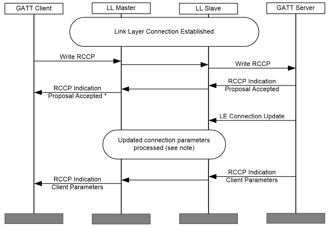 |
Note
Note: Figure 3.1 only illustrates the principle of the connection parameter update, so the mechanism used for updating the connection parameters on Link Layer is not defined here.
* The RCCP procedure is completed with an indication of the RCCP with the result code Proposal Accepted .
3.3.2.4. Activate Stored Settings procedure
When the Activate Stored Settings opcode is written to the RCCP and the procedure is supported by the Reconnection Configuration server, the Reconnection Configuration server shall request the Reconnection Configuration client to use the stored parameters of the selected Parameter-Set.
Parameter-Set 0 is mandatory to be supported. Optionally, the Reconnection Configuration server may support up to 254 more Parameter-sets. If the application is complex it could be an advantage to store a set of parameters that the device is able to work with. This might be a better option for the Reconnection Configuration client than trying different combinations. The optional parameter sets shall be stored in a contiguous way starting from 1.
When only advertising parameters are changed the Reconnection Configuration server shall indicate the RCCP with a Procedure Response opcode and Result Code Value in the operand set to Success.
When the new connection parameters were accepted by the Reconnection Configuration server, the Reconnection Configuration server shall start the connection parameter update as described in the Bluetooth Core Specification, Volume 3, Part C, Section 9.3.9 of [2] or equivalent and indicate the RCCP with a Procedure Response opcode and Result Code Value in the operand set to Request Accepted.
When the stored connection parameters have been applied, the Reconnection Configuration server shall indicate the RCCP with the Client Parameter Indication opcode and the operand set to Client Parameters. The parameters are always defined by the Reconnection Configuration client, the values within Client Parameters might be different from the request.
When the selected parameter set is not supported (e.g., if only 10 sets are stored and the request is for parameter set 11), the RCCP shall be indicated with a Procedure Response opcode and Result Code Value in the operand set to Invalid Operand.
If the operation results in an error condition, this shall be indicated using the Procedure Response opcode and the appropriate Result Code Value in the operand for the error condition as described in Section 3.3.3.
3.3.2.5. Get Max Values procedure
When the Get Max Values opcode is written to the RCCP and the procedure is supported by the Reconnection Configuration server, the Reconnection Configuration server shall report the maximum acceptable Values of the connection parameters by the Reconnection Configuration server. The response shall be indicated using the Communication Parameter Response opcode and the operand set to requesting opcode followed by the maximum values of the connection parameters. Parameters not supported shall be set to 0xFFFF.
If the operation results in an error condition, this shall be indicated using the Procedure Response opcode and the appropriate Result Code Value in the operand for the error condition as described in Section 3.3.3.
3.3.2.6. Get Min Values procedure
When the Get Min Values opcode is written to the RCCP and the procedure is supported by the Reconnection Configuration server, the Reconnection Configuration server shall report the minimum acceptable Values of the connection parameters by the Reconnection Configuration server. The response shall be indicated using the Communication Parameter Response opcode and the operand set to requesting opcode followed by the minimum values of the connection parameters. Parameters not supported shall be set to 0xFFFF.
If the operation results in an error condition, this shall be indicated using the Procedure Response opcode and the appropriate Result Code Value in the operand for the error condition as described in Section 3.3.3.
3.3.2.7. Get Stored Values procedure
When the Get Stored Values opcode is written to the RCCP and the procedure is supported by the Reconnection Configuration server, the Reconnection Configuration server shall report the Values of the connection parameter set defined by the operand. The response shall be indicated using the Communication Parameter Response opcode and the operand set to requesting opcode followed by the values of the stored connection parameter set.
If the value in the operand is out of the supported range, the Reconnection Configuration server shall indicate the Control Point with a Procedure Response opcode and Result Code Value in the operand set to Invalid Operand.
If the operation results in an error condition, this shall be indicated using the Procedure Response opcode and the appropriate Result Code Value in the operand for the error condition as described in Section 3.3.3.
3.3.2.8. Set Filter Accept List Timer procedure
When the Set Filter Accept List Timer opcode is written to the RCCP and the procedure is supported by the Reconnection Configuration server, the Reconnection Configuration server shall set its current Filter Accept List Timer to the value in the operand and indicate the RCCP with a Procedure Response opcode and Result Code Value in the operand set to Success.
When the Filter Accept List timer is running, the Reconnection Configuration server shall only accept connection request of Reconnection Configuration clients in the Filter Accept List. The timer is set to the value of the operand and starts counting down when Reconnection Configuration client disconnects. When a Reconnection Configuration client of the Filter Accept List reconnects again, the timer again is set to the value known from this procedure.
If the Filter Accept List timer is set to a value of 0, the Reconnection Configuration server shall accept any connection request. The functionality of Filter Accept List then is disabled.
If the Filter Accept List Timer is set to a value of 0xFFFFFFFE, the functionality of the Filter Accept List Timer is disabled. The Reconnection Configuration server shall only accept connection requests of Reconnection Configuration clients in the Filter Accept List. This setting should be handled with care, if the Filter Accept List is empty, then no connection to the Reconnection Configuration Server is possible any more.
The input value with which the Filter Accept List timer can be used shall be in a range supported by the device (Filter Accept List timer min value ≤ input value ≤ Filter Accept List timer max value) but can also be set to 0 for disabling Filter Accept List functionality or 0xFFFFFFFE to mandate no timeout.
Example:
Filter Accept List timer min value = 20
Filter Accept List timer max value = 300
A value of 0 or 27 is within the supported range; a value of 17 or 370 is out of the supported range.
If the value in the operand is out of the supported range, the Reconnection Configuration server shall indicate the Control Point with a Procedure Response opcode and Result Code Value in the operand set to Invalid Operand.
If the operation results in another error condition, this shall be indicated using the Procedure Response opcode and the appropriate Result Code Value in the operand for the error condition as described in Section 3.3.3.
3.3.2.9. Get Filter Accept List Timer procedure
When the Get Filter Accept List Timer opcode is written to the RCCP and the procedure is supported by the Reconnection Configuration server, the Reconnection Configuration server shall report the current Value of the Filter Accept List Timer, the minimum and maximum value. The response shall be indicated using the Filter Accept List Timer Response opcode and the operand set to Filter Accept List Timer value.
If the operation results in an error condition, this shall be indicated using the Procedure Response opcode and the appropriate Result Code Value in the operand for the error condition as described in Section 3.3.3.
3.3.2.10. Set Advertisement Configuration procedure
When the Set Advertisement Configuration opcode is written to the RCCP and the procedure is supported by the Reconnection Configuration server, the Reconnection Configuration server shall set the Advertisement Configuration based on the operand as described in Table 3.9.
The Reconnection Configuration server shall use the Advertisement Configuration as defined and shall handle the bits in the RC Settings characteristic accordingly. When using direct advertising and multiple bonds stored in the Reconnection Configuration server, the Reconnection Configuration server may alternate the address from advertisement burst to advertisement burst. How to proceed in this case is left up to the implementation.
When the bond list is cleared, the Reconnection Configuration server should not use directed advertisement any more. How to proceed in this case is left up to the implementation.
When no reconnection can be established to the peer device within the reconnection timeout the Advertisement Configuration shall switch back to default configuration.
If the operation results in an error condition, this shall be indicated using the Procedure Response opcode and the appropriate Result Code Value in the operand for the error condition as described in Section 3.3.3.
3.3.2.11. Upgrade to LESC Only procedure
When the Upgrade to LESC Only opcode is written to the RCCP and the procedure is supported by the Reconnection Configuration server, the Reconnection Configuration server shall set the bit LESC Only in the RC Settings characteristic to 1 when operand is 0xFF (true) or reset bit to 0 when operand is 0x00 (false).
If Upgrade to LESC Only is written to 1, the device shall be in a Secure Connections Only mode. When in Secure Connections Only mode, only Security Mode 1, Level 4 shall be used except for services that only require Security Mode 1, Level 1. The device shall only accept new outgoing and incoming service level connections for services that require Security Mode 1, Level 4 when the remote device supports LE Secure Connections and authenticated pairing is used.
If Upgrade to LESC Only is written to 1, the Reconnection Configuration server shall use LESC for the next Pairings, otherwise it shall use the existing security settings. A timeout should be used to fall back to security level used before if no connection can be established in a time defined by the implementation. When timeout occurs the bit LESC Only shall be reset to 0.
If the operation results in an error condition, this shall be indicated using the Procedure Response opcode and the appropriate Result Code Value in the operand for the error condition as described in Section 3.3.3.
3.3.2.12. Switch OOB Pairing procedure
When the Switch OOB Pairing opcode is written to the RCCP and the procedure is supported by the Reconnection Configuration server, the Reconnection Configuration server shall set the bit Use OOB Pairing in the RC Settings characteristic to 1 when operand is 0xFF (true) or reset bit to 0 when operand is 0x00 (false).
When the bit Use OOB Pairing is written to 1, the Reconnection Configuration server shall use the OOB pairing mechanism for the next Pairing Requests, otherwise it shall keep the actual method.
A timeout should be used to fall back to pairing method used before if no pairing can be established in a time defined by the implementation. When a timeout occurs the bit Use OOB Pairing shall be reset to 0.
If the operation results in an error condition, this shall be indicated using the Procedure Response opcode and the appropriate Result Code Value in the operand for the error condition as described in Section 3.3.3.
3.3.2.13. Limited Access procedure
When the Limited Access opcode is written to the RCCP and the procedure is supported by the Reconnection Configuration server, the Reconnection Configuration server shall set the bit Limited Access in the RC Settings characteristic to 1 when operand is 0xFF (true) or reset bit to 0 when operand is 0x00 (false).
When the bit Limited Access is written to 1, only the Reconnection Configuration client setting this bit is permitted to change settings (the service shall remember this Reconnection Configuration client), any Control Point procedure modifying parameters from other Reconnection Configuration clients shall be rejected with the ATT error code Insufficient Authorization. All other Reconnection Configuration clients stored in the Reconnection Configuration servers database shall not be able to change parameters within this Service. Otherwise each Reconnection Configuration client can manipulate parameters.
When the bit Limited Access is set to 1, the bit Access Permitted of the RC Settings characteristic shall be set to 1 when connected to the Reconnection Configuration client setting the Limited Access bit and this Reconnection Configuration client needs no further authorization. For all other Reconnection Configuration clients this bit shall be set to 0.
If the bond of the Reconnection Configuration client that set the Limited Access bit gets deleted, and the device disconnects, the Reconnection Configuration server should clear the Limited Access bit.
If the operation results in an error condition, this shall be indicated using the Procedure Response opcode and the appropriate Result Code Value in the operand for the error condition as described in Section 3.3.3.
3.3.3. General error handling procedures for Write Requests of the RCCP
Other than error handling procedures that are specific to certain opcodes, the following apply:
If an opcode is written to the Control Point characteristic and the Client Characteristic Configuration descriptor of the Control Point is not configured for indications, the Reconnection Configuration server shall return an error response with the Attribute Protocol Application error code set to Client Characteristic Configuration Descriptor Improperly Configured.
If the opcode that was written to the Control Point characteristic is unsupported by the Reconnection Configuration server, the Reconnection Configuration server shall indicate the Control Point with a Procedure Response opcode and Result Code Value in the operand set to opcode Not Supported.
If the operand that was written to the Control Point characteristic is invalid, the Reconnection Configuration server shall indicate the Control Point with a Procedure Response opcode and Result Code Value in the operand set to Invalid Operand.
If an opcode was written to the Control Point characteristic and a procedure is running on the Reconnection Configuration server and the opcode cannot be processed, the Reconnection Configuration server shall return an error response with the Attribute Protocol Application error code set to Procedure Already In Progress.
3.4. CRC calculation
The CRC is defined using a CRC-CCITT generator polynomial g(D)=D16+D12+D5+1 (i.e., 210041 in octal representation) with a seed of 0xFFFF.
The CRC shift register is filled with 1s before calculating the CRC. Octets are fed through the CRC generator least significant bit first.
The most significant parity octet is transmitted first (where the CRC shift register is viewed as shifting from the least significant bit towards the most significant bit). Therefore, the transmission order of the bits of the parity octets within the CRC shift register is as follows:
x[8], x[9], …, x[15], x[0], x[1], …, x[7] (last)
Where x[15] correspondents to the highest power CRC coefficient and x[0] corresponds to the lowest power coefficient.
The switch shall be set in position 1 while the data is shifted in. After the last bit has entered the Linear Feedback Shift Register (LFSR), the switch (S) shall be set in position 2, and the register contents shall be read out.
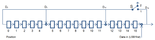 |
The following computation is for a sample with 10 bytes of data:
data[0] = 0x3E
data[1] = 0x01
data[2] = 0x02
data[3] = 0x03
data[4] = 0x04
data[5] = 0x05
data[6] = 0x06
data[7] = 0x07
data[8] = 0x08
data[9] = 0x09
-
CRC = 01 2F
Based on little endianness, the output of the shift register is 0x2F01 (MSB…LSB).
Note
Note: See also Volume 2, Part B, Section 7.1.2 in [2] for more details. For E2E-CRC the Linear Feedback Shift Register is initially loaded with a seed of 0xFFFF instead of the UAP, and the calculation is done in the same way.
4. SDP interoperability
N/A (Within this version of the specification, the service operates over LE transport only.)
5. Acronyms and abbreviations
The following alphabetized list of abbreviations and acronyms are used in this specification. Acronyms and abbreviations used but not defined in this specification (including the table below) have the meanings given to them in the Bluetooth Core Specification.
|
Abbreviation or Acronym |
Meaning |
|---|---|
|
CCITT |
International Telegraph and Telephone Consultative Committee |
|
LESC |
Low Energy Secure Connections |
|
RC |
Reconnection Configuration |
|
RC Settings |
Reconnection Configuration Settings |
|
RCCP |
Reconnection Configuration Control Point |
|
RCS |
Reconnection Configuration Service |
6. References
Bibliography
[1] Characteristic and Descriptor descriptions accessible via the Bluetooth SIG Assigned Numbers
[2] Bluetooth Core Specification, v4.0 or later
[3] Appropriate Language Mapping Table, https://www.bluetooth.com/language-mapping/Appropriate-Language-Mapping-Table