-
Revision: v1.1
-
Revision Date: 2023-09-12
-
Prepared By: Mesh Working Group
Revision History
|
Revision Number |
Date |
Comments |
|---|---|---|
|
v1.0 |
2017-07-13 |
Adopted by the Bluetooth SIG Board of Directors |
|
v1.0.1 |
2019-01-21 |
Adopted by the Bluetooth SIG Board of Directors |
|
v1.1 |
2023-09-12 |
Adopted by the Bluetooth SIG Board of Directors. |
Version History
|
Versions |
Changes |
|---|---|
|
v1.0.0 to v1.0.1 |
Incorporated errata E9701, E9719, E9810, E9959, E9960, E9989, E9990, E10050, E10069, E10199, E10287, E10327, E10333, E10434, E10435, E10436, E10437, E10438, E10439, E10440, E10455, E10474, E10475, E10640, E10655, E10666, E10667, E10678, E10727, E10740, E10801, E10816, E10862, E10867, E10895, E10898, E11305 |
|
v1.0.1 to v1.1 |
Incorporated the Mesh Model Minor Enhancements CR. Incorporated errata E10903, E10950, E10974, E11148, E11149, E11263, E11277, E11278, E11279, E11291, E11343, E11345, E11350, E11361, E11367, E11370, E11372, E11448, E11631, E11664, E11713, E11734, E11759, E11771, E11805, E11881, E11907, E11937, E11942, E11960, E11993, E12090, E12091, E12146, E12256, E12258, E12282, E12328, E12371, E12494, E12572, E12687, E12688, E12835, E12906, E12907, E13011, E13093, E13269, E13288, E13334, E13410, E13487, E13499, E13507, E13509, E13510, E13529, E13541, E13558, E13560, E14733, E14744, E14798, E14822, E14843, E14976, E14978, E15015, E15057, E15125, E15141, E15207, E15209, E15279, E15430, E15439, E15470, E15483, E15484, E15512, E15655, E15665, E15716, E15865, E15886, E15922, E15923, E16106, E16130, E16154, E16223, E16227, E16302, E16349, E16399, E16400, E16472, E16555, E16579, E16640, E16641, E16666, E16762, E16777, E16783, E16818, E16820, E16821, E16844, E16845, E16848, E16872, E16987, E17092, E17156, E17160, E17204, E17207, E17280, E17362, E17370, E17416, E17418, E17537, E17613, E17672, E17677, E17776, E17915, E17953, E18035, E18036, E18037, E18127, E18136, E18160, E19117, E19121, E19249, E20364, E20397, E20433, E20434, E20435, E22651, E22767, E22829, E22980, E22983, E23134, E23160 |
Acknowledgments
|
Name |
Company |
|---|---|
|
Robin Heydon |
Cambridge Silicon Radio |
|
Robin Heydon |
Qualcomm Technologies International, Ltd. |
|
Jonathan Tanner |
Cambridge Silicon Radio |
|
Jonathan Tanner |
Qualcomm Technologies International, Ltd. |
|
Victor Zhodzishsky |
Broadcom Corporation |
|
Wei Shen |
Ericsson AB |
|
Bogdan Alexandru |
NXP Semiconductors N.V., formerly of Freescale Semiconductor, Inc. |
|
Martin Turon |
Google Inc. |
|
Robert D. Hughes |
Intel Corporation |
|
Marcel Holtmann |
Intel Corporation |
|
Simon Slupik |
Silvair, Inc. |
|
Piotr Winiarczyk |
Silvair, Inc. |
|
Danilo Blasi |
STMicroelectronics |
|
Yao Wang |
Barrot Technology Co., Ltd. |
|
Rustam Kovyazin |
Motorola Solutions |
|
Elaine Mar |
California Eastern Laboratories |
|
Gerard Harbers |
Xicato, Inc. |
|
Clive Feather |
Samsung Electronics Co., Ltd. |
|
Omkar Kulkarni |
Nordic Semiconductor ASA |
|
Victor Zhodzishsky |
Cypress Semiconductor Corporation |
|
Hannu Mallat |
Silicon Laboratories |
|
Max Palumbo |
Silicon Laboratories |
|
Max Palumbo |
Katerra Inc. |
|
Luca Zappaterra |
Signify Netherlands B.V. |
|
Laurence Richardson |
Qualcomm Technologies International, Ltd. |
Use of this specification is your acknowledgement that you agree to and will comply with the following notices and disclaimers. You are advised to seek appropriate legal, engineering, and other professional advice regarding the use, interpretation, and effect of this specification.
Use of Bluetooth specifications by members of Bluetooth SIG is governed by the membership and other related agreements between Bluetooth SIG and its members, including those agreements posted on Bluetooth SIG’s website located at www.bluetooth.com. Any use of this specification by a member that is not in compliance with the applicable membership and other related agreements is prohibited and, among other things, may result in (i) termination of the applicable agreements and (ii) liability for infringement of the intellectual property rights of Bluetooth SIG and its members. This specification may provide options, because, for example, some products do not implement every portion of the specification. All content within the specification, including notes, appendices, figures, tables, message sequence charts, examples, sample data, and each option identified is intended to be within the bounds of the Scope as defined in the Bluetooth Patent/Copyright License Agreement (“PCLA”). Also, the identification of options for implementing a portion of the specification is intended to provide design flexibility without establishing, for purposes of the PCLA, that any of these options is a “technically reasonable non-infringing alternative.”
Use of this specification by anyone who is not a member of Bluetooth SIG is prohibited and is an infringement of the intellectual property rights of Bluetooth SIG and its members. The furnishing of this specification does not grant any license to any intellectual property of Bluetooth SIG or its members. THIS SPECIFICATION IS PROVIDED “AS IS” AND BLUETOOTH SIG, ITS MEMBERS AND THEIR AFFILIATES MAKE NO REPRESENTATIONS OR WARRANTIES AND DISCLAIM ALL WARRANTIES, EXPRESS OR IMPLIED, INCLUDING ANY WARRANTIES OF MERCHANTABILITY, TITLE, NON-INFRINGEMENT, FITNESS FOR ANY PARTICULAR PURPOSE, OR THAT THE CONTENT OF THIS SPECIFICATION IS FREE OF ERRORS. For the avoidance of doubt, Bluetooth SIG has not made any search or investigation as to third parties that may claim rights in or to any specifications or any intellectual property that may be required to implement any specifications and it disclaims any obligation or duty to do so.
TO THE MAXIMUM EXTENT PERMITTED BY APPLICABLE LAW, BLUETOOTH SIG, ITS MEMBERS AND THEIR AFFILIATES DISCLAIM ALL LIABILITY ARISING OUT OF OR RELATING TO USE OF THIS SPECIFICATION AND ANY INFORMATION CONTAINED IN THIS SPECIFICATION, INCLUDING LOST REVENUE, PROFITS, DATA OR PROGRAMS, OR BUSINESS INTERRUPTION, OR FOR SPECIAL, INDIRECT, CONSEQUENTIAL, INCIDENTAL OR PUNITIVE DAMAGES, HOWEVER CAUSED AND REGARDLESS OF THE THEORY OF LIABILITY, AND EVEN IF BLUETOOTH SIG, ITS MEMBERS OR THEIR AFFILIATES HAVE BEEN ADVISED OF THE POSSIBILITY OF THE DAMAGES.
Products equipped with Bluetooth wireless technology ("Bluetooth Products") and their combination, operation, use, implementation, and distribution may be subject to regulatory controls under the laws and regulations of numerous countries that regulate products that use wireless non-licensed spectrum. Examples include airline regulations, telecommunications regulations, technology transfer controls, and health and safety regulations. You are solely responsible for complying with all applicable laws and regulations and for obtaining any and all required authorizations, permits, or licenses in connection with your use of this specification and development, manufacture, and distribution of Bluetooth Products. Nothing in this specification provides any information or assistance in connection with complying with applicable laws or regulations or obtaining required authorizations, permits, or licenses.
Bluetooth SIG is not required to adopt any specification or portion thereof. If this specification is not the final version adopted by Bluetooth SIG’s Board of Directors, it may not be adopted. Any specification adopted by Bluetooth SIG’s Board of Directors may be withdrawn, replaced, or modified at any time. Bluetooth SIG reserves the right to change or alter final specifications in accordance with its membership and operating agreements.
Copyright © 2015–2023. All copyrights in the Bluetooth Specifications themselves are owned by Apple Inc., Ericsson AB, Intel Corporation, Lenovo (Singapore) Pte. Ltd., Microsoft Corporation, Nokia Corporation, and Toshiba Corporation. The Bluetooth word mark and logos are owned by Bluetooth SIG, Inc. Other third-party brands and names are the property of their respective owners.
1. Introduction
This Mesh Model specification defines models (along with their required states and messages) that are used to define basic functionality of nodes on a mesh network.
Terms, acronyms, and abbreviations that have a specific meaning in the context of this specification or the Bluetooth environment in general are defined or expanded upon on their first use. Defined terms that are used in this specification are listed in Section 1.6. Mathematical functions that are used in this specification are defined in Appendix B: Mathematical functions.
1.1. Conformance
Each capability of this specification shall be supported in the specified manner. This specification may provide options for design flexibility, because, for example, some products do not implement every portion of the specification. For each implementation option that is supported, it shall be supported as specified.
1.2. Bluetooth specification release compatibility
This specification is compatible with Mesh Protocol v1.1 [1].
1.3. Language
1.3.1. Language conventions
In the development of a specification, the Bluetooth SIG has established the following conventions for use of the terms “shall”, “shall not”, “should”, “should not”, “may”, “must”, and “can”. In this Bluetooth specification, the terms in Table 1.1 have the specific meanings given in that table, irrespective of other meanings that exist.
|
Term |
Definition |
|---|---|
|
shall |
—used to express what is required by the specification and is to be implemented exactly as written without deviation |
|
shall not |
—used to express what is forbidden by the specification |
|
should |
—used to express what is recommended by the specification without forbidding anything |
|
should not |
—used to indicate that something is discouraged but not forbidden by the specification |
|
may |
—used to indicate something that is permissible within the limits of the specification |
|
must |
—used to indicate either:
|
|
can |
—used to express a statement of possibility or capability |
1.3.1.1. Implementation alternatives
When specification content indicates that there are multiple alternatives to satisfy specification requirements, if one alternative is explained or illustrated in an example it is not intended to limit other alternatives that the specification requirements permit.
1.3.1.2. Discrepancies
It is the goal of Bluetooth SIG that specifications are clear, unambiguous, and do not contain discrepancies. However, members can report any perceived discrepancy by filing an erratum and can request a test case waiver as appropriate.
1.3.2. Reserved for Future Use
Where a field in a packet, Protocol Data Unit (PDU), or other data structure is described as "Reserved for Future Use" (irrespective of whether in uppercase or lowercase), the device creating the structure shall set its value to zero unless otherwise specified. Any device receiving or interpreting the structure shall ignore that field; in particular, it shall not reject the structure because of the value of the field.
Where a field, parameter, or other variable object can take a range of values, and some values are described as "Reserved for Future Use," a device sending the object shall not set the object to those values. A device receiving an object with such a value should reject it, and any data structure containing it, as being erroneous; however, this does not apply in a context where the object is described as being ignored or it is specified to ignore unrecognized values.
When a field value is a bit field, unassigned bits can be marked as Reserved for Future Use and shall be set to 0. Implementations that receive a message that contains a Reserved for Future Use bit that is set to 1 shall process the message as if that bit was set to 0, except where specified otherwise.
The acronym RFU is equivalent to Reserved for Future Use.
1.3.3. Prohibited
When a field value is an enumeration, unassigned values can be marked as “Prohibited.” These values shall never be used by an implementation, and any message received that includes a Prohibited value shall be ignored and shall not be processed and shall not be responded to.
Where a field, parameter, or other variable object can take a range of values, and some values are described as “Prohibited,” devices shall not set the object to any of those Prohibited values. A device receiving an object with such a value should reject it, and any data structure containing it, as being erroneous.
“Prohibited” is never abbreviated.
1.4. Architectural concepts
This specification is based on the concepts of states, bindings, messages, elements, addresses, models, and the publish-subscribe paradigm for message exchange that are defined in the Mesh Protocol specification [1].
This specification in addition provides a detailed discussion of state transitions (see Section 1.4.1) and introduces the concept of a device property as it relates to mesh models (see Section 2).
1.4.1. State transitions
A state is a value that represents a condition of an element. An element exposing a state is referred to as a server. For example, the simplest server is a Generic OnOff Server (see Section 3.3.1), which represents that the state is either on or off. An element accessing a state is referred to as a client. For example, the simplest client is a Generic OnOff Client (a binary switch) that is able to control a Generic OnOff Server via messages accepted by the Generic OnOff Server model.
States can be changed as a result of any of the following:
-
A state-changing message that is received and processed by a server
-
An asynchronous event, such as a scheduler action being executed (see Section 5.1.4)
-
A local (non-network) event such as a press of a button located on a networked lamp
A change of state may be instantaneous (e.g., a state reported by a sensor) or may take some time (e.g., a lamp that dims gradually or a motor that moves a physical object). The time that it takes for a state to change from a present state to the target state (the state that the state server is changing to) is called the transition time.
States may support non-instantaneous change using either the Generic Default Transition Time (see Section 3.1.3) or the transition time specified as a field in the state-changing message.
Messages may support a Delay parameter that indicates a delay between receiving a message and executing a behavior for this message, such as starting the state transition. This helps when synchronizing actions of multiple receivers (such as lights) when senders retransmit messages multiple times. Each retransmitted message may indicate a different delay, compensating for the time elapsed since transmitting the first message.
When publishing a message which includes a Delay field, depending on a scenario, there are recommendations on calculating the value for the Delay field:
-
When the message is published as a result of the configured Model Publication state (see Section 4.2.3 in [1]), and when the Publish Retransmit Count (see Section 4.2.3.6 in [1]) multiplied by the retransmission interval (see Section 4.2.3.7 in [1]) is not greater than 1275 milliseconds, then the value of the Delay field for the nth message in sequence, starting from n=1, should be calculated using the formula:
Delay[n] = [Publish Retransmit Count + 1 - n] * (Publish Retransmit Interval Steps + 1) * 50
The messages retransmitted in the series are considered the same published message despite the changing value of the Delay field.
-
When a series of m messages are originated by an application (see Section 3.7.3.1 in [1]) over a Generic Attribute Profile (GATT) bearer configured with a connection interval i, then the value of the Delay field for the nth message in sequence, starting from n=1, should be calculated using the formula:
Delay[n] = [m - n] * i
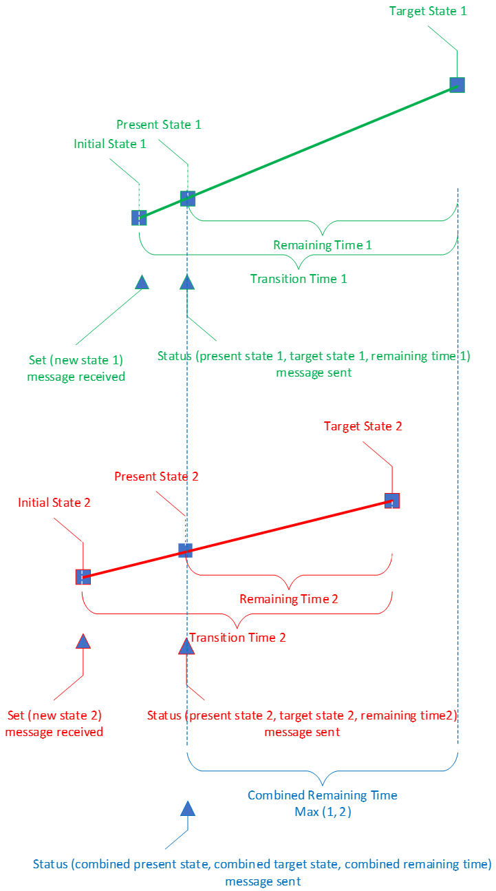
Some states have associated messages that are able to report the state in transition. Whenever a changing state is reported, the message is sent to report the value of the state that is present at the moment. There are also messages reporting both the present value of a state and the target value of the state, along with the remaining time, which is the time it will take from the moment the message is sent by the model to the end of the transition to the target state. This is illustrated in Figure 1.1.
 |
During the transition time, when a new message that results in a new transition involving that state is received and processed, the new target state and the new transition time overwrite the existing target state and transition time for this state.
A model sends a response message after receiving an acknowledged state-change message. The response message contains information about the present state and optionally contains the target state and the remaining time to complete the state change. When sending the response message, the remaining time value in the response message is the time it will take the state to reach the end of the transition.
Note
Note: It is recommended that the state is changed linearly during the transition, when the transition is a result of processing a message directly changing that state. The bound states are changed according to the binding formulas.
States can have multiple dimensions. Such states are known as multidimensional states. For example, the Light HSL state (see Section 6.1.4) is a 3-dimensional state that combines the Light HSL Lightness (see Section 6.1.4.7), Light HSL Hue (see Section 6.1.4.1), and Light HSL Saturation (see Section 6.1.4.4) states.
State transitions in each dimension are independent. For a combined multidimensional state transition, the transition time and the remaining time represent the combined transition and remaining times of individual dimensions. This is illustrated by Figure 1.2.
 |
1.4.1.1. Bound states
When a state is bound to another state, a change in one state results in a change in the other state. Bound states may be from different models, and may be in one or more elements.
For example, a common type of binding is between a ‘Level’ state and an ‘OnOff’ state, such as the Generic Power Level state (see Section 3.1.5) and the Generic OnOff state (see Section 3.1.1): changing the Level to zero changes the bound OnOff state to Off, and changing the Level to a non-zero value changes the bound OnOff state to On. Such binding is a unidirectional binding. Bindings also may be bidirectional such as changing the OnOff state to Off changes the bound Level state to zero, and changing the OnOff state to On changes the bound Level state to its last known non-zero value. The binding rules are defined explicitly in state definitions.
1.4.1.1.1. Subscription Lists on bound states
As defined in the Mesh Protocol specification [1], the Subscription List is a list of group addresses or virtual addresses that are assigned to a model. Each address in the list is considered a subscription filter for messages received. Models that operate on bound states share a single instance of a Subscription List per element.
For example, a Light HSL Server model (see Section 6.4.3.3.1), a Light Lightness Server model (see Section 6.4.1), and a Generic Power OnOff Server model (see Section 3.3.4) on a Light HSL main element share a single instance of a Subscription List. This means that subscribing one of the models (e.g., Light Lightness Server) to a group results in the other models (the Generic Power OnOff Server and the Light HSL Server) also subscribing to the same group.
1.4.1.2. Composite states
Multiple states can be grouped together as a shorthand notation referred to as a composite state. This allows a model to refer to this composite state instead of each of the individual grouped states. For example, the Light Lightness state (see Section 6.1.2) includes the following states:
-
Light Lightness Actual state
-
Light Lightness Last state
-
Light Lightness Default state
A model can refer to changes in the Light Lightness state instead of individually referencing each change to the Light Lightness Actual, Light Lightness Last, and Light Lightness Default states.
1.4.2. Messages
All communication within a mesh network is accomplished by sending messages. Messages operate on states. For each state, there is a defined set of messages that a server supports and that a client may use to request the value of a state or to change a state. A server may also transmit unsolicited messages that carry information about states and/or changing states.
A message is defined as having an opcode and associated parameters. For a description of the opcode and its parameters, see the Mesh Protocol specification [1], Section 3.7.3 Access payload.
1.4.2.1. Transactions
Messages may support transactions. A client can send a series of state-changing messages such as Set, Recall, or Clear within a single transaction. A transaction is considered unique in the context of a Transaction Identifier (if present in a message), a Source Address, a Destination Address, and an instance of a state. Specific behaviors for transactions are included in model behaviors.
If the Transaction Identifier is not present in a message, then the context of the response message can be determined by the value of a field containing a status code and/or the presence of optional and/or conditional fields in the response message.
1.4.3. Publication
Model publication is a method of transmitting an access message (see Section 3.7.4.1 of the Mesh Protocol specification [1]) controlled by states defined in Section 4.2.2 of the Mesh Protocol specification. It is the process of sending a message using the corresponding credentials stored in the Configuration Server model. Publication is an optional feature supported only by models that explicitly state support. Publication is also by default disabled; a Configuration Manager can enable publication by setting the publication credentials of the corresponding model in the Configuration Server Model Publication state. An application may also choose to send any message at any time by selecting the destination address, AppKey, and TTL; this does not require model publication.
Models configured for publication generally publish messages under the following scenarios:
-
A server model with an instance of a state publishes a single status corresponding to this state.
-
A server model with an instance of a composite state, where the included states in the composite state have corresponding status messages, only publishes a single status message indicating the value of the composite state.
For example, the Light Lightness Server includes a Light Lightness composite state that includes the Light Lightness Actual state and the Light Lightness Linear state. When configured for publication, the Light Lightness Server publishes the Light Lightness Status message and does not publish the Light Lightness Linear status message regardless of the state within the composite state that initiated a state transition. Therefore, a Light Lightness Server configured for publication that receives a Light Lightness Linear Set Unacknowledged message will publish a Light Lightness Status message and not a Light Lightness Linear status message.
-
A server model can publish multiple status messages originating from different models if a transition on a bound state spanning multiple models is completed and the additional models are configured for publication.
For example, a Light Lightness Set Unacknowledged message that changes the value of the Light Lightness Actual state from 0 to a non-zero value causes a state transition on the bound Generic OnOff state on the Generic OnOff Server model. The Light Lightness Server will publish the Light Lightness Status message, and the Generic OnOff Server (whose OnOff state is bound to the Light Lightness Actual state of the Light Lightness Server) will also publish the corresponding Generic OnOff Status message if configured for publication.
-
A server model that has publication configured receives an acknowledged message, and the acknowledged message acts upon a state that would result in publication of a status message upon completion of the state transition. The server model will send at least two status messages:
-
One status message is sent using the publication credentials, following the guidelines for model publication.
-
One status message is sent using the corresponding credentials of the acknowledged message that caused the state transition. This message is sent only to the client that originated the acknowledged message.
Additional messages are sent if the state transition that completed was a bound state transition, and additional models in the state binding are also configured for publication.
For example, a Light Lightness Server that receives a Light Lightness Linear Set message sends a Light Lightness Linear Status message (as the response to the acknowledged Set message) using the same credentials that were used for the Light Lightness Linear Set message and starts the transition on the Light Lightness state. When the state transition is complete, the Light Lightness Server publishes a Light Lightness Status message and any additional status messages from bound states that also completed the state transition.
-
-
A server model with publication configured receives a message that acts upon a state, causing a state transition. The message that caused the state transition has a transition time longer than 2 seconds. The server sends the same status message multiple times. The server might publish the first status message within 1 second of the start of the state transition, then publishes a subsequent status message periodically for the duration of the state transition and publishes a final status message when the state transition is complete.
-
A client model configured for publication sends messages chosen by the application.
1.4.4. Relationship between main, base, extending, and corresponding models
Models are grouped together in order to support functionalities (such as dimmable light or occupancy sensing).
Message dispatch from the access layer to the model layer is based on the destination address and the opcode of the message. Given that unicast addresses are assigned to each element on a node, an element cannot have instances of models with overlapping opcodes. Therefore, a functionality may require a set of models that must be located on different elements within a node, as required by the Mesh Protocol specification [1], Section 3.7.3.
For example, a Light CTL Server model extends the Generic Level Server model twice: once to allow control of the lightness level and once to allow control of the color temperature. The Generic Level Server model is instantiated on two elements. Therefore, when the device receives a Generic Level message destined for one of the elements, the device can determine whether the message is to control the lightness or to control the color temperature.
A node supports a functionality by instantiating the main model for that functionality, which may require a set of base, extending, and corresponding models:
-
A main model may require one or more base models. A node can include multiple instances of a main model to implement the same functionality multiple times. A main model may be instantiated on either the primary element or a secondary element of a node.
-
Base models must be instantiated with the extending models and corresponding models for a functionality and must be indicated in the Composition Data of a node, as required in Section 3.8.4 in [1].
A base model might be extended by multiple models if unambiguous message dispatch is preserved by this extension. For example, the Generic Power OnOff Server is a base model of the Light Lightness Server. The Light Lightness Server corresponds with the Light Lightness Setup Server, which extends the Generic Power OnOff Setup Server, which extends the Generic Power OnOff Server. In this case, a single instance of the Generic Power OnOff Server is a base model of both the Light Lightness Server and the Generic Power OnOff Setup Server, because a single instance of the Generic Power OnOff Server can provide unambiguous message dispatch to both extending models. Figure 1.3 illustrates this example.
 |
To aid a Mesh Manager in parsing the node Composition Data:
-
All models are instantiated on elements by using the smallest number of elements to achieve the desired functionality (i.e., by using the smallest possible element index).
-
Corresponding models that cannot be instantiated on the same element as the main model as a result of message dispatch limitations are instantiated on an element with a larger element index.
-
Multiple instances of the same main model do not interleave their corresponding models on subsequent elements. All the corresponding models for the main model are instantiated before the next instance of the main model.
The values of namespace descriptors in the Loc field of Composition Data Page 0 are unrelated to the designation of a model as main or corresponding.
1.4.4.1. Example: Light with built-in controller and separate scene control for lightness and color temperature
This light controller and scene control example illustrates the application of the model relationship principles introduced in Section 1.4.4.
The device is a color temperature-selectable luminaire that has a built-in controller that automatically adjusts the dim level based on ambient light conditions. The device also supports scene-setting of the dim level and controller parameters separately from the color temperature (that is, using a scene to change the color temperature of the luminaire does not change the brightness or the controller parameters).
Figure 1.4 shows the Composition Data for a node implementing this functionality.
 |
The Light Lightness Server model is a base model for both the Light LC Server model (the main model for light controller functionality) and the Light CTL Server model (the main model for tunable white functionality). However, the Light CTL Server model and the Light CTL Temperature Server model (the corresponding model) are stored with different scene servers to meet the device’s functional requirements.
This example illustrates a successful application of the model relationship principles, because:
-
The models are instantiated on the elements in a way that allows unambiguous message dispatch to be performed.
-
The corresponding models of the main models do not interleave with each other.
-
The models are instantiated by using the smallest number of elements to achieve the functionality.
It would be a mistake to move the first scene server from Element 0 to Element 2, and then instantiate a new element and move the second scene server and the Light CTL Temperature Server model to the new element (Element 3). That would be an unsuccessful application of the model relationship principles, because it is not necessary to place the scene server on its own element to achieve the desired functionality (i.e., the scene server can be instantiated on Element 0).
1.4.4.2. Example: Light with two color temperature-selectable outputs
This dual-channel tunable white luminaire example illustrates the application of the model relationship principles introduced in Section 1.4.4.
The device is a driver that has two output channels for color temperature-controllable luminaires.
Figure 1.5 shows the Composition Data for a node implementing this functionality.
 |
This example illustrates a successful application of the model relationship principles, because:
-
The models are instantiated on the elements in a way that allows unambiguous message dispatch to be performed.
-
The corresponding models of the main models do not interleave with each other.
It would be a mistake to place the first instance of the Light CTL Server model on Element 0, the second instance of the Light CTL Server model on Element 1, and then the two instances of the Light CTL Temperature Server model on Element 3 and Element 4. Although this would allow for unambiguous message dispatch, this would be an unsuccessful application of the model relationship principles. These principles do not permit interleaving a new instance of a Light CTL Server model before instantiating the corresponding models of the initial Light CTL Server model.
1.5. Endianness and field ordering
All multiple-octet numeric values shall be little-endian.
Where data structures are made of multiple fields, the fields are listed in the tables from top to bottom, and they appear in the corresponding figures from left to right (i.e., the top row of the table corresponds to the left of the figure). Table 1.2 and Figure 1.6 show an example data structure made up of multiple fields.
|
Field |
Size |
Field Content Description |
|---|---|---|
|
Field 0 |
1 or more |
Start of this field is in Octet 0 (left most octet in corresponding figure) |
|
… |
… |
|
|
Field n |
1 or more |
End of this field is in Octet m |
 |
In order to convert the data structure defined in a table into a series of octets the following procedure is used. The binary number with N unassigned bits is created. The number of bits N in the number is equal to the sum of the number of bits of every field in the table. The least significant bits (LSbs) of the number are set to the value of Field 0 (first row of the table), then the number’s unassigned LSbs are set to the value of Field 1. This procedure is continued for consecutive fields of the table and ends when the most significant bits (MSbs) of the number are set to the value of last field of the table. As a final step the number is transmitted in little-endian format (i.e., least significant octet first).
For example, the field 0 is 4 bits wide and has a value of 0x6, field 1 is 12 bits wide and has a value of 0x987, and field 2 is 16 bits wide and has a value of 0x1234. The value of the binary number is 0x12349876 and shall be transmitted as 0x76, 0x98, 0x34, 0x12.
1.6. Table conventions
This section describes conventions regarding the following:
-
Requirements that are in a table
-
Indicating a cell that has no value or content
1.6.1. Requirements that are in a table
Unless otherwise stated, requirements that are in a table in this specification can be defined as "Mandatory" (M), "Optional" (O), "Excluded" (X), or "Conditional" (C.n). Conditional statements (C.n) are listed directly below the table in which they appear.
1.6.2. Indicating a cell that has no value or content
Where a cell in a table indicates an intended absence of a value or other content, the cell will contain “none” or a hyphen (i.e., a “minus” sign). Examples of this are:
-
In the “condition” column of the description of a finite state machine where a rule is unconditional
-
In the “action” column of the description of a finite state machine where a rule has no action
-
In a “restrictions” column where there are no applicable restrictions
-
In an interface description where there are no parameters of a specific type
An empty cell in a table indicates that there is no useful information that can be placed in that cell. Examples of this are:
-
In a “comments” column when there is no comment to make in a particular row
-
In a column specifying properties when the relevant item is reserved for future use (and therefore does not have any properties)
-
In a “units” column when the relevant item is unitless
1.7. Terminology
Table 1.3 lists all of the defined terms used in this specification.
|
Term |
Definition Location |
|---|---|
|
bidirectional binding |
|
|
device property |
|
|
multidimensional state |
|
|
multisensor |
|
|
present value |
|
|
scene |
|
|
sensor cadence |
|
|
TAI time |
|
|
target value |
|
|
transaction |
|
|
unidirectional binding |
2. Device properties
A device property is a collection of one or more format descriptors that interpret data contained by a server state.
A device property is identified by a 16-bit assigned Property ID (see Section 2.1), which references GATT characteristics, and has a state called the Property Value (see Section 2.2).
2.1. Property ID
The Property ID is an assigned 16-bit number that identifies a device property that is associated with a defined characteristic [5].
2.2. Property Value
The Property Value is the value of the characteristic referenced by a device property. The value is not self-describing.
2.3. Interpretation of Device Property Values
The format of each characteristic referenced by a device property [5] determines how each Raw Value contained in a device property is formatted.
Characteristics referenced by device properties may represent scalar or non-scalar values. Interpretation of scalar values is defined in Section 2.3.1 and interpretation of non-scalar values is defined in Section 2.3.2.
2.3.1. Device property scalar value
For scalar values, the represented value is related to the Device Property Value by the following equation, where the M, d, and b coefficients are defined for each field of the characteristic:
|
R=C×M×10d×2b |
Where:
|
R=represented value |
|
M=multiplier |
|
d=decimal exponent |
|
b=binary exponent |
2.3.1.1. Example decimal exponent
To represent a length in decimeters with a resolution of 1 decimeter within a characteristic value, the following values are used:
|
M=1, d=-1, b=0 |
2.3.1.2. Example binary exponent
To represent a duration in 256ths of a second with a precision of 1/256 of a second within a characteristic value, the following values are used:
|
M=1, d=0, b=-8 |
2.3.1.3. Example multiplier
To represent the horizontal dilution of precision with an accuracy of 1/5 with a precision of 1/5 within a characteristic value, the following values are used:
|
M=2, d=-1, b=0 |
2.3.2. Device property non-scalar value
For non-scalar data, the represented value is the Device Property Value as defined by the characteristic’s Format field.
2.4. Required device properties summary
Table 2.1 lists the device properties that are required by this specification. The device properties are defined in [5].
|
Device Property Name |
|---|
|
Light Control Time Occupancy Delay |
|
Light Control Time Fade On |
|
Light Control Time Run On |
|
Light Control Time Fade |
|
Light Control Time Prolong |
|
Light Control Time Fade Standby Auto |
|
Light Control Time Fade Standby Manual |
|
Light Control Lightness On |
|
Light Control Lightness Prolong |
|
Light Control Lightness Standby |
|
Light Control Ambient LuxLevel On |
|
Light Control Ambient LuxLevel Prolong |
|
Light Control Ambient LuxLevel Standby |
|
Light Control Regulator Kiu |
|
Light Control Regulator Kid |
|
Light Control Regulator Kpu |
|
Light Control Regulator Kpd |
|
Light Control Regulator Accuracy |
|
Motion Sensed |
|
Time Since Motion Sensed |
|
People Count |
|
Presence Detected |
|
Present Ambient Light Level |
3. Generics
This section of the specification defines a number of generic states, messages and models that are explicitly defined to be non-specific in their functionality. For example, many devices can be turned on and off regardless of whether they are a fan, an air conditioning unit, a light, or a power socket. All of those devices would support the Generic OnOff states, messages, and models instead of having separate OnOff states, messages, and models for each type of device.
3.1. Generic states
3.1.1. Generic OnOff
The Generic OnOff state is a Boolean value that represents the state of an element. The values for the Generic OnOff state are defined in Table 3.1. The meaning of the state is determined by the model.
|
Value |
Description |
|---|---|
|
0x00 |
Off |
|
0x01 |
On |
|
0x02–0xFF |
Prohibited |
3.1.1.1. Binary state transitions
Because binary states cannot support transitions, when changing to 0x01 (On), the Generic OnOff state shall change immediately when the transition starts, and when changing to 0x00, the state shall change when the transition finishes.
Figure 3.1 illustrates the behavior for a Generic OnOff state bound to a Generic Power Actual state (see Section 3.1.5.1.2) when changing to 0x01 (On). Figure 3.2 illustrates the behavior for a Generic OnOff state bound to a Generic Power Actual state when changing to 0x00 (Off).
 |
 |
3.1.2. Generic Level
The Generic Level state is a 16-bit signed integer (2’s complement) representing the state of an element. The values are defined in Table 3.2. The meaning of the level is determined by a model.
|
Value |
Description |
|---|---|
|
0x8000–0x7FFF |
The Generic Level state of an element, represented as a 16-bit signed integer (the complement of 2) |
3.1.3. Generic Default Transition Time
The Generic Default Transition Time state determines how long an element shall take to transition from the present state to a new state (see Section 1.4.1.1). The Generic Default Transition Time state uses the Generic Transition Time format defined in Section 3.1.10. The Generic Default Transition Time consists of the Default Transition Step Resolution field and the Default Transition Number of Steps field.
Default values for the Generic Default Transition Step Resolution and the Default Transition Number of Steps are implementation specific and are defined by a device manufacturer.
3.1.3.1. Default Transition Step Resolution
The Default Transition Step Resolution field shall use the Transition Step Resolution format (see Section 3.1.10.1) of the Generic Default Transition Time.
3.1.3.2. Default Transition Number of Steps
The Default Transition Number of Steps field shall use the Transition Number of Steps format (see Section 3.1.10.2) of the Generic Transition Time.
Default Transition Number of Steps shall not be set to a value of 0x3F.
3.1.4. Generic OnPowerUp
The Generic OnPowerUp state is an enumeration representing the behavior of an element when powered up. The values for the state are defined in Table 3.3.
|
Value |
Description |
|---|---|
|
0x00 |
Off. After being powered up, the element is in an off state. |
|
0x01 |
Default. After being powered up, the element is in an On state and uses default state values. |
|
0x02 |
Restore. If a transition was in progress when powered down, the element restores the target state when powered up. Otherwise the element restores the state it was in when powered down. |
|
0x03–0xFF |
Prohibited |
3.1.5. Generic Power Level
The Generic Power Level state is a composite state that includes the following states:
-
Generic Power Actual state (see Section 3.1.5.1)
-
Generic Power Last state (see Section 3.1.5.2)
-
Generic Power Default state (see Section 3.1.5.3)
-
Generic Power Range state (see Section 3.1.5.4)
3.1.5.1. Generic Power Actual
The Generic Power Actual state determines the linear percentage of the maximum power level of an element, representing a range from 0 percent through 100 percent. The value is derived using the following formula:
|
Represented power level [%]=100 [%]×Generic Power Actual÷65535 |
The state is bound to the Generic Level state (see Section 3.1.2) and the Generic OnOff state (see Section 3.1.1). The values for the Generic Power Actual state are defined in Table 3.4.
|
Value |
Description |
|---|---|
|
0x0000–0xFFFF |
Represents the power level relative to the maximum power level |
An element that has the Generic Power Actual set to 0x0000 may continue to power the wireless communications and the microcontroller necessary to change the Generic Power Actual state back to a non-zero value.
Additional regulatory requirements may determine the maximum energy use when the element has the Generic Power Actual state set to 0x0000.
3.1.5.1.1. Binding with the Generic Level state
The Generic Power Actual state is bound to an instance of the Generic Level state (see Section 3.1.2), meaning that whenever the Generic Level state of an element changes, the following binding calculation steps shall be performed in the given order:
-
If the transition is a GL Set transition (see Section 3.3.2.2.2), calculate:
Generic Power Actual=Generic Level+32768
-
If the transition is a GL Delta transaction (see Section 3.3.2.2.3) or a GL Move transition (see Section 3.3.2.2.4) and:
-
if the value of the Generic Power Actual state is non-zero at the beginning of the transition, calculate:
Generic Power Actual=max(Generic Power Range Min, Generic Level+32768)
-
if the value of the Generic Power Actual state is zero at the beginning of the transition, calculate:
Generic Power Actual=Generic Level+32768
-
-
Modify the value of the calculated Generic Power Actual state using the binding defined in Section 3.1.5.1.4, if applicable.
-
Calculate all other bindings and reverse bindings.
A reverse binding is also defined, meaning that whenever the Generic Power Actual state of an element changes, the following calculation shall be performed:
|
Generic Level=Generic Power Actual-32768 |
The Generic Power Actual state shall not wrap around (i.e., from 65535 to 0, or 0 to 65535) when it reaches the maximum or minimum value.
3.1.5.1.2. Binding with the Generic OnOff state
The Generic Power Actual state is bound to an instance of the Generic OnOff state (see Section 3.1.1), meaning that whenever the Generic OnOff state of an element is set, the following calculations shall be performed:
|
Generic Power Actual=0x0000 |
|
when the value of the Generic OnOff state is equal to 0x00, or |
|
Generic Power Actual=Generic Power Last |
|
when the value of the Generic OnOff state is equal to 0x01, when value of the Generic Power Default state is equal to 0x0000, or |
|
Generic Power Actual=Generic Power Default |
|
when the value of the Generic OnOff state is equal to 0x01 and the value of the Generic Power Default state is not equal to 0x0000. |
A reverse binding is also defined, meaning that whenever the Generic Power Actual state of an element changes, the following calculations shall be performed:
|
Generic OnOff=0x00 |
|
when the value of the Generic Power Actual is equal to 0x0000, or |
|
Generic OnOff=0x01 |
|
when the value of the Generic Power Actual is greater than 0x0000. |
3.1.5.1.3. Binding with the Generic OnPowerUp state
The Generic Power Actual state is bound to an instance of the Generic OnPowerUp state (see Section 3.1.4), meaning that during a power-up sequence (when an element is physically powered up), the following calculations shall be performed:
|
Generic Power Actual=0 |
|
when the value of the Generic OnPowerUp state is equal to 0x00, or |
|
Generic Power Actual=Generic Power Default |
|
when the value of the Generic OnPowerUp state is equal to 0x01 and Generic Power Default is not equal to zero, or |
|
Generic Power Actual=Generic Power Last (see Section 3.1.5.2) |
|
when the value of the Generic OnPowerUp state is equal to 0x01 and Generic Power Default equal to zero, or |
|
Generic Power Actual=last known value of the Generic Power Actual state before the node is powered down |
|
when the value of the Generic OnPowerUp state is equal to 0x02. |
3.1.5.1.4. Binding with the Generic Power Range state
The Generic Power Actual state is bound to an instance of the Generic Power Range state (see Section 3.1.5.4), meaning that whenever the Generic Power Actual state of an element changes, the following calculations shall be performed:
|
Generic Power Actual=Generic Power Range Min |
|
when the non-zero values of the Generic Power Actual state are less than the value of the Generic Power Range Min state |
|
Generic Power Actual=Generic Power Range Max |
|
when the non-zero values of the Generic Power Actual state are greater than the value of the Generic Power Range Max state |
3.1.5.2. Generic Power Last
The Generic Power Last state is a 16-bit value representing a percentage ranging from (1/65535) percent to 100 percent. The value is derived using the following formula:
|
Represented power level [%]=100 [%]×Generic Power Last÷65535 |
The purpose of the Generic Power Last state is to store the last known non-zero value of the Generic Power Actual state, which is a result of a completed transactional change of the state. Depending on the value of the Generic OnPowerUp state (see Section 3.1.4), It may also be used as a default value when an element is powered up.
Whenever the Generic Power Actual state is changed to a non-zero value as a result of a non-transactional message or a completed sequence of transactional messages, the value of the Generic Power Last state shall be set to the value of the Generic Power Actual state.
The values for the Generic Power Last state are defined in Table 3.5.
|
Value |
Description |
|---|---|
|
0x0000 |
Prohibited |
|
0x0001–0xFFFF |
Represents the power level relative to the maximum power level |
3.1.5.3. Generic Power Default
The Generic Power Default state is a 16-bit value ranging from 0 through 65535. Values from 0x0001 through 0xFFFF represent the percentage of power level, derived using the following formula:
|
Represented power level [%]=100 [%]×Generic Power Default÷65535 |
Value 0x0000 has a special meaning defined: use the value of the Generic Power Last state as the default value. The purpose of the Generic Power Default state is to determine the power level of an element when the device is powered up and when the Generic OnPowerUp state (see Section 3.1.4) bound to the Generic Power Level state is set to 0x01 (Default).
The values for the Generic Power Default state are defined in Table 3.6.
|
Value |
Description |
|---|---|
|
0x0000 |
Use the Power Last value (see Section 3.1.5.1.1). |
|
0x0001–0xFFFF |
Represents the power level relative to the maximum power level. |
3.1.5.4. Generic Power Range
The Generic Power Range state determines the minimum and maximum power levels of an element relative to the maximum power level an element can output. This is a pair of 16-bit unsigned integers: Generic Power Range Min and Generic Power Range Max.
The Generic Power Range Min state determines the minimum non-zero power level an element can be configured to. The Generic Power Range Max state determines the maximum power level an element can be configured to. The values for the states are defined in Table 3.7.
|
Value |
Description |
|---|---|
|
0x0000 |
Prohibited |
|
0x0001–0xFFFF |
Represents the power level relative to the maximum power level. |
3.1.6. Generic Battery
The Generic Battery state is a set of four values representing the state of a battery: a charge level (Generic Battery Level), remaining time to complete discharging (Generic Battery Time to Discharge), remaining time to complete charging (Generic Battery Time to Charge), and a flags bit field (Generic Battery Flags).
3.1.6.1. Generic Battery Level
The Generic Battery Level state is a value ranging from 0 percent through 100 percent. The values for the state are defined in Table 3.8.
|
Value |
Description |
|---|---|
|
0x00–0x64 |
The percentage of the charge level. 100% represents fully charged. 0% represents fully discharged. |
|
0x65–0xFE |
Prohibited |
|
0xFF |
The percentage of the charge level is unknown. |
3.1.6.2. Generic Battery Time to Discharge
The Generic Battery Time to Discharge state is a 24-bit unsigned value ranging from 0 through 0xFFFFFF. The values for the state are defined in Table 3.9.
|
Value |
Description |
|---|---|
|
0x000000–0xFFFFFE |
The remaining time (in minutes) of the discharging process |
|
0xFFFFFF |
The remaining time of the discharging process is not known. |
3.1.6.3. Generic Battery Time to Charge
The Generic Battery Time to Charge state is a 24-bit unsigned value ranging from 0 through 0xFFFFFF. The values for the state are defined in Table 3.10.
|
Value |
Description |
|---|---|
|
0x000000–0xFFFFFE |
The remaining time (in minutes) of the charging process |
|
0xFFFFFF |
The remaining time of the charging process is not known. |
3.1.6.4. Generic Battery Flags
As defined in Table 3.11, the Generic Battery Flags state is a concatenation of four 2-bit bit fields: Presence, Indicator, Charging, and Serviceability. The values for the state are defined in Table 3.11.
|
Bit |
Definition |
|---|---|
|
0–1 |
Generic Battery Flags Presence |
|
2–3 |
Generic Battery Flags Indicator |
|
4–5 |
Generic Battery Flags Charging |
|
6–7 |
Generic Battery Flags Serviceability |
3.1.6.4.1. Generic Battery Flags Presence
The Generic Battery Flags Presence state bit field indicates presence of a battery. The values for the state are defined in Table 3.12.
|
Value |
Description |
|---|---|
|
0b00 |
The battery is not present. |
|
0b01 |
The battery is present and is removable. |
|
0b10 |
The battery is present and is non-removable |
|
0b11 |
The battery presence is unknown. |
3.1.6.4.2. Generic Battery Flags Indicator
The Generic Battery Flags Indicator state bit field indicates the charge level of a battery. The values for the state are defined in Table 3.13.
|
Value |
Description |
|---|---|
|
0b00 |
The battery charge is Critically Low Level. |
|
0b01 |
The battery charge is Low Level. |
|
0b10 |
The battery charge is Good Level. |
|
0b11 |
The battery charge is unknown. |
The implementation determines what represents a good, low, or critically low battery level.
3.1.6.4.3. Generic Battery Flags Charging
The Generic Battery Flags Charging state bit field indicates whether a battery is charging. The values for the state are defined in Table 3.14.
|
Value |
Description |
|---|---|
|
0b00 |
The battery is not chargeable. |
|
0b01 |
The battery is chargeable and is not charging. |
|
0b10 |
The battery is chargeable and is charging. |
|
0b11 |
The battery charging state is unknown. |
3.1.6.4.4. Generic Battery Flags Serviceability
The Generic Battery Flags Serviceability state bit field indicates the serviceability of a battery. The values for the state are defined in Table 3.15.
|
Value |
Description |
|---|---|
|
0b00 |
Reserved for Future Use |
|
0b01 |
The battery does not require service. |
|
0b10 |
The battery requires service. |
|
0b11 |
The battery serviceability is unknown. |
3.1.7. Generic Location
The Generic Location state defines location information of an element. The state is composed of the fields defined in Table 3.16.
|
Field |
Size (octets) |
Description |
|---|---|---|
|
Global Latitude |
4 |
Global Coordinates (Latitude) |
|
Global Longitude |
4 |
Global Coordinates (Longitude) |
|
Global Altitude |
2 |
Global Altitude |
|
Local North |
2 |
Local Coordinates (North) |
|
Local East |
2 |
Local Coordinates (East) |
|
Local Altitude |
2 |
Local Altitude |
|
Floor Number |
1 |
Floor Number |
|
Uncertainty |
2 |
Uncertainty |
3.1.7.1. Global Latitude
The Global Latitude field describes the global WGS84 North coordinate of the element. The format of the field is a signed integer of size 32 bits encoded as signed magnitude.
Note
Note: The global WGS84 North coordinate and latitude are based on the World Geodetic System 1984 datum (WGS84) [3].
The relationship between Latitude X in the range [-90°, 90°] and the encoded number N is derived using the following formula:
where N is bounded to the range -231+1≤N≤231-1. If N exceeds the bounds, the closest value within the bounds shall be used.
The floor operation shall be performed according to IEEE standards.
Note
Note: The IEEE standards are described in [4].
The value 0x80000000 in the Global Latitude field indicates the Global Latitude is not configured.
3.1.7.2. Global Longitude
The Global Longitude field describes the global WGS84 East coordinate of the element. The format of the field is a signed integer of size 32 bits encoded as signed magnitude.
Note
Note: The global WGS84 East coordinate and longitude are based on the WGS84 datum [3].
Note: The global WGS84 East coordinate and longitude are based on the WGS84 datum [3].
The relationship between Longitude X in the range [-180°, 180°] and the encoded number N is derived using the following formula:
where N is bounded to the range -231+1≤N≤231-1. If N exceeds the bounds, the closest value within the bounds shall be used.
The floor operation shall be performed according to IEEE standards.
Note
Note: The IEEE standards are described in [4].
The value 0x80000000 in the Global Latitude field indicates the Global Longitude is not configured.
3.1.7.3. Global Altitude
The Global Altitude field determines the altitude of the device above the WGS84 datum. It expresses the altitude beyond the WGS84 ellipsoid of the element that exposed its position. This is a 16-bit signed integer in meters.
Note
Note: The WGS84 ellipsoid is described in [3].
The values for the state are defined in Table 3.17.
|
Value |
Meaning |
|---|---|
|
0x7FFF |
Global Altitude is not configured. |
|
0x7FFE |
Global Altitude is greater than or equal to 32766 meters. |
|
0x8000–0x7FFD |
Global Altitude is (field value) from -32768 meters through 32765 meters. |
3.1.7.4. Local North
The Local North field describes the North coordinate of the device using a local coordinate system. It is relative to the north orientation on a predefined map. The format of the field is a signed integer of size 16 bits.
The Local North value is encoded in decimeters and has a range of -32767 decimeters through 32767 decimeters. The value 0x8000 means the Local North information is not configured.
3.1.7.5. Local East
The Local East field describes the East coordinate of the device using a local coordinate system. It is relative to the east orientation of a predefined map. The format of the field is a signed integer of size 16 bits.
The Local East value is encoded decimeters and it ranges from -32767 decimeters through 32767 decimeters. The value 0x8000 means the Local East information is not configured.
3.1.7.6. Local Altitude
The Local Altitude field determines the altitude of the device relative to the Generic Location Global Altitude. This is a 16-bit signed integer in decimeters.
The valid range is from -32768 decimeters through 32765 decimeters.
The values for the state are defined in Table 3.18.
|
Value |
Meaning |
|---|---|
|
0x7FFF |
Local Altitude is not configured. |
|
0x7FFE |
Local Altitude is greater than or equal to 32766 decimeters. |
|
0x8000–0x7FFD |
Local Altitude is (field value) from -32768 decimeters through 32765 decimeters. |
3.1.7.7. Floor Number
The Floor Number field describes the floor number where the element is installed.
The floor number, N, is encoded as X=N+20, where X is the encoded floor number.
Floor number=-20 (X=0) has a special meaning, indicating the floor -20, and also any floor below that.
Floor number=232 (X=252) has a special meaning, indicating the floor 232, and also any floor above that.
The values for the state are defined in Table 3.19.
|
Encoded Value X |
Floor number N |
|---|---|
|
0x00 |
Floor -20 or any floor below -20. |
|
0x01–0xFB |
Floor number N, encoded as X=N+20. |
|
0xFC |
Floor 232 or any floor above 232. |
|
0xFD |
Ground floor. Floor 0. |
|
0xFE |
Ground floor. Floor 1. |
|
0xFF |
Not configured |
Note
Note: The reason for having two definitions of ground floor (0 or 1) is to allow for different conventions applicable in different countries.
The format of the field is an unsigned integer of size 8 bits.
3.1.7.8. Uncertainty
The Uncertainty field is a 16-bit bit field that describes the uncertainty of the location information the element exposes. The field consists of several values. The meaning of each bit is described in Table 3.20.
|
Bits |
Field |
Description |
|---|---|---|
|
0 |
Stationary |
Stationary field indicates whether the device broadcasting the location information has a stationary location or is mobile. |
|
1–7 |
RFU |
Reserved for Future Use |
|
8–11 |
Update Time |
Update Time field indicates the time (t) elapsed since the last update of the device's position. |
|
12–15 |
Precision |
Precision field indicates a location precision. |
The Stationary field indicates whether the device broadcasting the location information has a stationary location or is mobile. The values of the Stationary field are defined Table 3.21.
|
Value |
Description |
|---|---|
|
0 |
Stationary |
|
1 |
Mobile |
The Update Time field indicates the time (t) elapsed since the last update of the device's position, measured in seconds, using the following formula:
|
t=2x-3 |
The field value (x) is a 4-bit value ranging from 0 through 15. The represented Update Time value range is from 0.125 seconds through 4096 seconds.
If the Stationary field is set to the Stationary value, the Update Time field value can be ignored.
The Precision field indicates a location precision with the formula:
|
Precision=2y-3 |
The field value (y) is a 4-bit value ranging from 0 through 15. The represented Precision value range is from 0.125 meters through 4096 meters.
3.1.8. Generic Property states
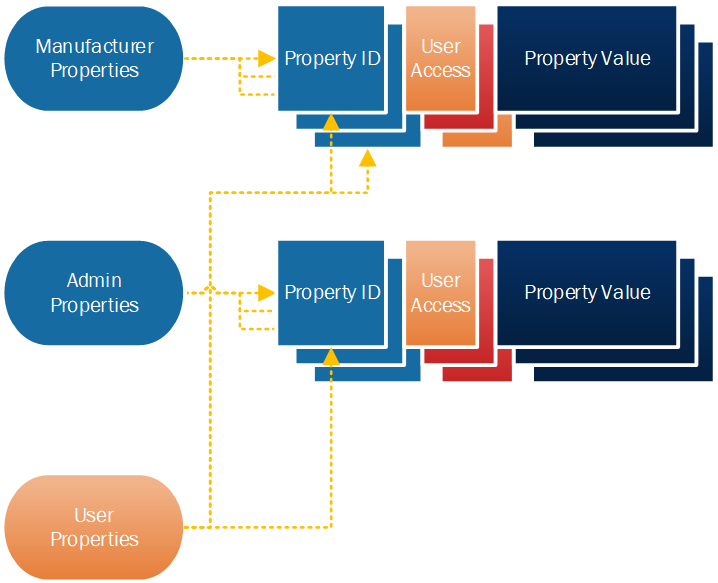
Generic Property states are used to represent any value to be stored by an element. Generic Properties are organized in three categories with respect to access rights: Generic User Properties (see Section 3.1.8.1), Generic Admin Properties (see Section 3.1.8.2), and Generic Manufacturer Properties (see Section 3.1.8.3).
Generic Manufacturer Properties cannot be written, but a client that has access to the Generic Manufacturer Property Server (see Section 3.3.13) may decide if the device properties are accessible by clients via the Generic User Property Server (see Section 3.3.11).
Generic Admin Properties can be read or written, and a client that has access to the Generic Admin Property Server (see Section 3.3.12) may decide whether these device properties are accessible by clients via the Generic User Property Server (see Section 3.3.11) and whether this access is read-only, write-only, or read-write.
Figure 3.3 illustrates the hierarchy of Generic Property states.
 |
3.1.8.1. Generic User Property
Generic User Property is a state representing a device property of an element. Depending on how the device property is defined, this may be a read-only state or a read-write state. The values for the state are defined in Table 3.22.
|
Field |
Size |
Description |
|---|---|---|
|
User Property ID |
2 |
Defined in Section 3.1.8.1.1. |
|
User Access |
1 |
Defined in Section 3.1.8.1.2. |
|
User Property Value |
variable |
Scalar or String value, defined in Section 3.1.8.1.3. |
3.1.8.1.1. User Property ID
The User Property ID field is a 2-octet Assigned Number value referencing a device property (see Section 2).
The values for the field are defined in Table 3.23.
|
Value |
Meaning |
|---|---|
|
0x0000 |
Prohibited |
|
0x0001–0xFFFF |
Identifier of a device property (see Section 2.1) |
3.1.8.1.2. User Access
The User Access field is an enumeration indicating whether the device property can be read or written as a Generic User Property. The values for the field are defined in Table 3.24.
|
Value |
Meaning |
|---|---|
|
0x00 |
Prohibited |
|
0x01 |
The device property can be read. |
|
0x02 |
The device property can be written. |
|
0x03 |
The device property can be read and written. |
|
0x04–0xFF |
Prohibited |
3.1.8.1.3. User Property Value
The User Property Value field is a conditional field. Depending on the format defined by the characteristic that the device property references, the field contains a scalar value, as described in Section 2.3.1, or a string value, as described in Section 2.3.2.
3.1.8.2. Generic Admin Property
Generic Admin Property is a state representing a device property of an element that can be read or written. The values for the state are defined in Table 3.25.
|
Field |
Size |
Description |
|---|---|---|
|
Admin Property ID |
2 |
Defined in Section 3.1.8.2.1. |
|
Admin User Access |
1 |
Defined in Section 3.1.8.2.2. |
|
Admin Property Value |
variable |
Scalar or String value, defined in Section 3.1.8.2.3. |
3.1.8.2.1. Admin Property ID
The Admin Property ID field is a 2-octet Assigned Number value referencing a device property (see Section 2).
The values for the field are defined in Table 3.26.
|
Value |
Meaning |
|---|---|
|
0x0000 |
Prohibited |
|
0x0001–0xFFFF |
Identifier of a device property (see Section 2.1) |
3.1.8.2.2. Admin User Access
The Admin User Access field is an enumeration indicating whether the device property can be read or written as a Generic User Property. The values for the field are defined in Table 3.27.
|
Value |
Meaning |
|---|---|
|
0x00 |
The device property is not a Generic User Property. |
|
0x01 |
The device property is a Generic User Property and can be read. |
|
0x02 |
The device property is a Generic User Property and can be written. |
|
0x03 |
The device property is a Generic User Property and can be read and written. |
|
0x04–0xFF |
Prohibited |
3.1.8.2.3. Admin Property Value
The Admin Property Value field is a conditional field. Depending on the format defined by the characteristic that the device property references, the field contains either a scalar value, as described in Section 2.3.1, or a string value, as described in Section 2.3.2.
3.1.8.3. Generic Manufacturer Property
Generic Manufacturer Property is a state representing a device property of an element that is programmed by a manufacturer and can be read. The values for the state are defined in Table 3.28.
|
Field |
Size |
Description |
|---|---|---|
|
Manufacturer Property ID |
2 |
Defined in Section 3.1.8.3.1. |
|
Manufacturer User Access |
1 |
Defined in Section 3.1.8.3.2. |
|
Manufacturer Property Value |
variable |
Scalar or String value, defined in Section 3.1.8.3.3. |
3.1.8.3.1. Manufacturer Property ID
The Manufacturer Property ID field is a 2-octet Assigned Number value that references a device property (see Section 2).
The values for the field are defined in Table 3.29.
|
Value |
Meaning |
|---|---|
|
0x0000 |
Prohibited |
|
0x0001–0xFFFF |
Identifier of a device property (see Section 2.1) |
3.1.8.3.2. Manufacturer User Access
The Manufacturer User Access field is an enumeration indicating whether or not the device property can be read as a Generic User Property. The values for the field are defined in Table 3.30.
|
Value |
Meaning |
|---|---|
|
0x00 |
The device property is not a Generic User Property. |
|
0x01 |
The device property is a Generic User Property and can be read. |
|
0x02–0xFF |
Prohibited |
3.1.8.3.3. Manufacturer Property Value
The Manufacturer Property Value field is a conditional field. Depending on the format defined by the characteristic that the device property references, the field contains either a scalar value, as described in Section 2.3.1, or a string value, as described in Section 2.3.2.
3.1.9. Generic Client Property
Generic Client Property is a read-only state representing a device property that an element supports. It is used by a client to indicate a device property that the client supports and is capable of consuming. The value for the state is described in Table 3.31.
|
Field |
Size |
Description |
|---|---|---|
|
Client Property ID |
2 |
Defined in Section 3.1.9.1. |
3.1.9.1. Client Property ID
The Client Property ID field is a 2-octet Assigned Number value that references a device property (see Section 2).
The values for the field are defined in Table 3.32.
|
Value |
Meaning |
|---|---|
|
0x0000 |
Prohibited |
|
0x0001–0xFFFF |
Identifier of a device property (see Section 2.1) |
3.1.10. Generic Transition Time
Generic Transition Time is a 1-octet value that consists of two fields: a 2-bit bit field that determines the step resolution and a 6-bit bit field that determines the number of transition steps. The format of this state is defined in Table 3.33 and illustrated in Figure 3.4.
|
Field |
Size (bits) |
Definition |
|---|---|---|
|
Transition Number of Steps |
6 |
The number of steps |
|
Transition Step Resolution |
2 |
The resolution of the Default Transition Number of Steps field |
Figure 3.4 illustrates the Generic Transition Time format.
 |
This format covers a wide range of times that may be required by different applications:
-
For 100-millisecond step resolution, the range is 0 to 6.2 seconds.
-
For 1-second step resolution, the range is 0 to 62 seconds.
-
For 10-second step resolution, the range is 0 to 620 seconds (10.5 minutes).
-
For 10-minute step resolution, the range is 0 to 620 minutes (10.5 hours).
The Generic Transition Time is calculated using the following formula:
|
Generic Transition Time=Transition Step Resolution * Transition Number of Steps |
3.1.10.1. Transition Step Resolution
The Transition Step Resolution field is a 2-bit bit field that determines the resolution of the Generic Transition Time. The field values represent the states defined in Table 3.34.
|
Value |
Description |
|---|---|
|
0b00 |
The Transition Step Resolution is 100 milliseconds |
|
0b01 |
The Transition Step Resolution is 1 second |
|
0b10 |
The Transition Step Resolution is 10 seconds |
|
0b11 |
The Transition Step Resolution is 10 minutes |
3.1.10.2. Transition Number of Steps
The Transition Number of Steps field is a 6-bit value that determines the number of transition steps. The field values represent the states defined in Table 3.35.
|
Value |
Description |
|---|---|
|
0x00 |
The Generic Transition Time is immediate. |
|
0x01–0x3E |
The number of steps. |
|
0x3F |
Interpretation of this value is context specific. |
3.2. Generic messages
Generic messages operate on Generic states (see Section 3.1).
3.2.1. Generic OnOff messages
3.2.1.1. Generic OnOff Get
Generic OnOff Get is an acknowledged message used to get the Generic OnOff state of an element (see Section 3.1.1).
The response to the Generic OnOff Get message is a Generic OnOff Status message.
The structure of the message is defined in Table 3.36.
|
Field |
Size |
Description |
Req. |
|---|---|---|---|
|
Opcode |
2 |
The message opcode |
M |
The Opcode field shall contain the opcode value for the Generic OnOff Get message defined in the Assigned Numbers document [10].
3.2.1.2. Generic OnOff Set
Generic OnOff Set is an acknowledged message used to set the Generic OnOff state of an element (see Section 3.1.1).
The response to the Generic OnOff Set message is a Generic OnOff Status message.
The structure of the message is defined in Table 3.37.
|
Field |
Size |
Description |
Req. |
|---|---|---|---|
|
Opcode |
2 |
The message opcode |
M |
|
OnOff |
1 |
The target value of the Generic OnOff state |
M |
|
TID |
1 |
Transaction Identifier |
M |
|
Transition Time |
1 |
Format as defined in Section 3.2.9. |
O |
|
Delay |
1 |
Message execution delay in 5-millisecond steps |
C.1 |
- C.1:
-
If the Transition Time field is present, the Delay field shall also be present; otherwise these fields shall not be present.
The Opcode field shall contain the opcode value for the Generic OnOff Set message defined in the Assigned Numbers document [10].
The OnOff field identifies the Generic OnOff state of the element (see Section 3.1.1).
The TID field is a transaction identifier indicating whether the message is a new message or a retransmission of a previously sent message, as described in Section 3.4.1.2.2.
If present, the Transition Time field identifies the time that an element will take to transition to the target state from the present state (see Section 1.4.1.1). The Transition Time field shall use the format defined in Section 3.2.9.
If present, the Delay field identifies the message execution delay, representing a time interval between receiving the message by a model and executing the associated model behaviors.
3.2.1.3. Generic OnOff Set Unacknowledged
Generic OnOff Set Unacknowledged is an unacknowledged message used to set the Generic OnOff state of an element (see Section 3.1.1).
The structure of the message is defined in Table 3.38.
|
Field |
Size |
Description |
Req. |
|---|---|---|---|
|
Opcode |
2 |
The message opcode |
M |
|
OnOff |
1 |
The target value of the Generic OnOff state |
M |
|
TID |
1 |
Transaction Identifier |
M |
|
Transition Time |
1 |
Format as defined in Section 3.2.9. |
O |
|
Delay |
1 |
Message execution delay in 5-millisecond steps |
C.1 |
- C.1:
-
If the Transition Time field is present, the Delay field shall also be present; otherwise these fields shall not be present.
The Opcode field shall contain the opcode value for the Generic OnOff Set Unacknowledged message defined in the Assigned Numbers document [10].
The OnOff field identifies the Generic OnOff state of the element (see Section 3.1.1).
The TID field is a transaction identifier indicating whether the message is a new message or a retransmission of a previously sent message, as described in Section 3.4.1.2.2.
If present, the Transition Time field identifies the time that an element will take to transition to the target state from the present state (see Section 1.4.1.1). The Transition Time field shall use the format defined in Section 3.2.9.
If present, the Delay field identifies the message execution delay, representing a time interval between receiving the message by a model and executing the associated model behaviors.
3.2.1.4. Generic OnOff Status
Generic OnOff Status is an unacknowledged message used to report the Generic OnOff state of an element (see Section 3.1.1).
The structure of the message is defined in Table 3.39.
|
Field |
Size |
Description |
Req. |
|---|---|---|---|
|
Opcode |
2 |
The message opcode |
M |
|
Present OnOff |
1 |
The present value of the Generic OnOff state. |
M |
|
Target OnOff |
1 |
The target value of the Generic OnOff state. |
O |
|
Remaining Time |
1 |
Format as defined in Section 3.2.10. |
C.1 |
- C.1:
-
If the Target OnOff field is present, the Remaining Time field shall also be present; otherwise these fields shall not be present.
The Opcode field shall contain the opcode value for the Generic OnOff Status message defined in the Assigned Numbers document [10].
The Present OnOff field identifies the present Generic OnOff state of the element (see Section 3.1.1).
If present, the Target OnOff field identifies the target Generic OnOff state that the element is to reach (see Section 3.1.1).
If present, the Remaining Time field identifies the time it will take the element to complete the transition to the target Generic OnOff state of the node (see Section 1.4.1.1 and 3.1.1).
3.2.2. Generic Level messages
3.2.2.1. Generic Level Get
Generic Level Get is an acknowledged message used to get the Generic Level state of an element (see Section 3.1.2).
The response to the Generic Level Get message is a Generic Level Status message.
The structure of the message is defined in Table 3.40.
|
Field |
Size |
Description |
Req. |
|---|---|---|---|
|
Opcode |
2 |
The message opcode |
M |
The Opcode field shall contain the opcode value for the Generic Level Get message defined in the Assigned Numbers document [10].
3.2.2.2. Generic Level Set
Generic Level Set is an acknowledged message used to set the Generic Level state of an element (see Section 3.1.2) to a new absolute value.
The response to the Generic Level Set message is a Generic Level Status message.
The structure of the message is defined in Table 3.41.
|
Field |
Size |
Description |
Req. |
|---|---|---|---|
|
Opcode |
2 |
The message opcode |
M |
|
Level |
2 |
The target value of the Generic Level state |
M |
|
TID |
1 |
Transaction Identifier |
M |
|
Transition Time |
1 |
Format as defined in Section 3.2.9. |
O |
|
Delay |
1 |
Message execution delay in 5-millisecond steps |
C.1 |
- C.1:
-
If the Transition Time field is present, the Delay field shall also be present; otherwise these fields shall not be present.
The Opcode field shall contain the opcode value for the Generic Level Set message defined in the Assigned Numbers document [10].
The Level field identifies the Generic Level state of the element (see Section 3.1.2).
The TID field is a transaction identifier indicating whether the message is a new message or a retransmission of a previously sent message, as described in Section 3.4.2.2.2.
If present, the Transition Time field identifies the time that an element will take to transition to the target state from the present state (see Section 1.4.1.1). The Transition Time field shall use the format defined in Section 3.2.9.
If present, the Delay field identifies the message execution delay, representing a time interval between receiving the message by a model and executing the associated model behaviors.
3.2.2.3. Generic Level Set Unacknowledged
Generic Level Set Unacknowledged is an unacknowledged message used to set the Generic Level state of an element (see Section 3.1.2) to a new absolute value.
The structure of the message is defined in Table 3.42.
|
Field |
Size |
Description |
Req. |
|---|---|---|---|
|
Opcode |
2 |
The message opcode |
M |
|
Level |
2 |
The target value of the Generic Level state |
M |
|
TID |
1 |
Transaction Identifier |
M |
|
Transition Time |
1 |
Format as defined in Section 3.2.9. |
O |
|
Delay |
1 |
Message execution delay in 5-millisecond steps |
C.1 |
- C.1:
-
If the Transition Time field is present, the Delay field shall also be present; otherwise these fields shall not be present.
The Opcode field shall contain the opcode value for the Generic Level Set Unacknowledged message defined in the Assigned Numbers document [10].
The Level field identifies the Generic Level state of the element (see Section 3.1.2).
The TID field is a transaction identifier indicating whether the message is a new message or a retransmission of a previously sent message, as described in Section 3.4.2.2.2.
If present, the Transition Time field identifies the time that an element will take to transition to the target state from the present state (see Section 1.4.1.1). The Transition Time field shall use the format defined in Section 3.2.9.
If present, the Delay field identifies the message execution delay, representing a time interval between receiving the message by a model and executing the associated model behaviors.
3.2.2.4. Generic Delta Set
Generic Delta Set is an acknowledged message used to set the Generic Level state of an element (see Section 3.1.2) by a relative value. The message is transactional – it supports changing the state by a cumulative value with a sequence of messages that are part of a transaction.
The response to the Generic Delta Set message is a Generic Level Status message.
The structure of the message is defined in Table 3.43.
|
Field |
Size |
Description |
Req. |
|---|---|---|---|
|
Opcode |
2 |
The message opcode |
M |
|
Delta Level |
4 |
The Delta change of the Generic Level state |
M |
|
TID |
1 |
Transaction Identifier |
M |
|
Transition Time |
1 |
Format as defined in Section 3.2.9. |
O |
|
Delay |
1 |
Message execution delay in 5-millisecond steps |
C.1 |
- C.1:
-
If the Transition Time field is present, the Delay field shall also be present; otherwise these fields shall not be present.
The Opcode field shall contain the opcode value for the Generic Delta Set message defined in the Assigned Numbers document [10].
The Delta Level field identifies the increase (when positive) or decrease (if negative) of the Generic Level state of the element (see Section 3.1.2).
The TID field is a transaction identifier and shall be used to logically group a series of Generic Delta Set and Generic Delta Set Unacknowledged messages. When starting a new transaction, TID should be assigned a least recently used value, as described in Section 3.4.2.2.3.
The Transition Time field identifies the time that an element will take to transition to the target state from the present state. The Transition Time field shall use the format defined in Section 3.2.9.
If present, the Delay field identifies the message execution delay, representing a time interval between receiving the message by a model and executing the associated model behaviors.
3.2.2.5. Generic Delta Set Unacknowledged
Generic Delta Set Unacknowledged is an unacknowledged message used to set the Generic Level state of an element (see Section 3.1.2) by a relative value.
The structure of the message is defined in Table 3.44.
|
Field |
Size |
Description |
Req. |
|---|---|---|---|
|
Opcode |
2 |
The message opcode |
M |
|
Delta Level |
4 |
The Delta change of the Generic Level state |
M |
|
TID |
1 |
Transaction Identifier |
M |
|
Transition Time |
1 |
Format as defined in Section 3.2.9. |
O |
|
Delay |
1 |
Message execution delay in 5-millisecond steps |
C.1 |
- C.1:
-
If the Transition Time field is present, the Delay field shall also be present; otherwise these fields shall not be present.
The Opcode field shall contain the opcode value for the Generic Delta Set Unacknowledged message defined in the Assigned Numbers document [10].
The Delta Level field identifies the increase (when positive) or decrease (if negative) of the Generic Level state of the element (see Section 3.1.2).
The TID field is a transaction identifier and shall be used to logically group a series of Generic Delta Set and Generic Delta Set Unacknowledged messages. When starting a new transaction, TID should be assigned a least recently used value, as described in Section 3.4.2.2.3.
If present, the Transition Time field identifies the time an element will take to transition to the target state from the present state. The Transition Time field shall use the format defined in Section 3.2.9.
If present, the Delay field identifies the message execution delay, representing a time interval between receiving the message by a model and executing the associated model behaviors.
3.2.2.6. Generic Move Set
Generic Move Set is an acknowledged message used to start a process of changing the Generic Level state of an element (see Section 3.1.2) with a defined transition speed.
The response to the Generic Move Set message is a Generic Level Status message.
The structure of the message is defined in Table 3.45.
|
Field |
Size |
Description |
Req. |
|---|---|---|---|
|
Opcode |
2 |
The message opcode |
M |
|
Delta Level |
2 |
The Delta Level step to calculate Move speed for the Generic Level state. |
M |
|
TID |
1 |
Transaction Identifier |
M |
|
Transition Time |
1 |
Format as defined in Section 3.2.9. |
O |
|
Delay |
1 |
Message execution delay in 5-millisecond steps. |
C.1 |
- C.1:
-
If the Transition Time field is present, the Delay field shall also be present; otherwise these fields shall not be present.
The Opcode field shall contain the opcode value for the Generic Move Set message defined in the Assigned Numbers document [10].
The Delta Level field shall be used to calculate the speed of the transition of the Generic Level state.
The TID field is a transaction identifier indicating whether the message is a new message or a retransmission of a previously sent message, as described in Section 3.4.2.2.4.
If present, the Transition Time field shall be used to calculate the speed of the transition of the Generic Level state. The Transition Time field shall use the format defined in Section 3.2.9. If the resulting Transition Time is equal to 0 or is undefined, the Generic Move Set command will not initiate any Generic Level state change.
If present, the Delay field identifies the message execution delay, representing a time interval between receiving the message by a model and executing the associated model behaviors.
3.2.2.7. Generic Move Set Unacknowledged
Generic Move Set Unacknowledged is an unacknowledged message used to start a process of changing the Generic Level state of an element (see Section 3.1.2) with a defined transition speed.
The structure of the message is defined in Table 3.46.
|
Field |
Size |
Description |
Req. |
|---|---|---|---|
|
Opcode |
2 |
The message opcode |
M |
|
Delta Level |
2 |
The Delta Level step to calculate Move speed for the Generic Level state |
M |
|
TID |
1 |
Transaction Identifier |
M |
|
Transition Time |
1 |
Format as defined in Section 3.2.9.. |
O |
|
Delay |
1 |
Message execution delay in 5-millisecond steps. |
C.1 |
- C.1:
-
If the Transition Time field is present, the Delay field shall also be present; otherwise these fields shall not be present.
The Opcode field shall contain the opcode value for the Generic Move Set Unacknowledged message defined in the Assigned Numbers document [10].
The Delta Level field shall be used to calculate the speed of the transition of the Generic Level state.
The TID field is a transaction identifier indicating whether the message is a new message or a retransmission of a previously sent message, as described in Section 3.4.2.2.4.
If present, the Transition Time field shall be used to calculate the speed of the transition of the Generic Level state. The Transition Time field shall use the format defined in Section 3.2.9. If the resulting Transition Time is equal to 0 or undefined, the Generic Move Set command will not initiate any Generic Level state change.
If present, the Delay field identifies the message execution delay, representing a time interval between receiving the message by a model and executing the associated model behaviors.
3.2.2.8. Generic Level Status
Generic Level Status is an unacknowledged message used to report the Generic Level state of an element (see Section 3.1.2).
The structure of the message is defined in Table 3.47.
|
Field |
Size |
Description |
Req. |
|---|---|---|---|
|
Opcode |
2 |
The message opcode |
M |
|
Present Level |
2 |
The present value of the Generic Level state. |
M |
|
Target Level |
2 |
The target value of the Generic Level state. |
O |
|
Remaining Time |
1 |
Format as defined in Section 3.2.10. |
C.1 |
- C.1:
-
If the Target Level field is present, the Remaining Time field shall also be present; otherwise these fields shall not be present.
The Opcode field shall contain the opcode value for the Generic Level Status message defined in the Assigned Numbers document [10].
The Present Level field identifies the present Generic Level state of the element (see Section 3.1.2).
If present, the Target Level field identifies the target Generic Level state that the element is to reach (see Section 3.1.2).
If present, the Remaining Time field identifies the time that it will take the element to complete the transition to the target Generic Level state of the element (see Section 3.1.2).
3.2.3. Generic Default Transition Time messages
3.2.3.1. Generic Default Transition Time Get
Generic Default Transition Time Get is an acknowledged message used to get the Generic Default Transition Time state of an element (see Section 3.1.3).
The response to the Generic Default Transition Time Get message is a Generic Default Transition Time Status message.
The structure of the message is defined in Table 3.48.
|
Field |
Size |
Description |
Req. |
|---|---|---|---|
|
Opcode |
2 |
The message opcode |
M |
The Opcode field shall contain the opcode value for the Generic Default Transition Time Get message defined in the Assigned Numbers document [10].
3.2.3.2. Generic Default Transition Time Set
Generic Default Transition Time Set is an acknowledged message used to set the Generic Default Transition Time state of an element (see Section 3.1.3).
The response to the Generic Default Transition Time Set message is a Generic Default Transition Time Status message.
The structure of the message is defined in Table 3.49.
|
Field |
Size |
Description |
Req. |
|---|---|---|---|
|
Opcode |
2 |
The message opcode |
M |
|
Transition Time |
1 |
The value of the Generic Default Transition Time state. |
M |
The Opcode field shall contain the opcode value for the Generic Default Transition Time Set message defined in the Assigned Numbers document [10].
The Transition Time field identifies the Generic Default Transition Time state of the element (see Section 3.1.3).
3.2.3.3. Generic Default Transition Time Set Unacknowledged
Generic Default Transition Time Set Unacknowledged is an unacknowledged message used to set the Generic Default Transition Time state of an element (see Section 3.1.3).
The structure of the message is defined in Table 3.50.
|
Field |
Size |
Description |
Req. |
|---|---|---|---|
|
Opcode |
2 |
The message opcode |
M |
|
Transition Time |
1 |
The value of the Generic Default Transition Time state. |
M |
The Opcode field shall contain the opcode value for the Generic Default Transition Time Set Unacknowledged message defined in the Assigned Numbers document [10].
The Transition Time field identifies the Generic Default Transition Time state of the element (see Section 3.1.3).
3.2.3.4. Generic Default Transition Time Status
Generic Default Transition Time Status is an unacknowledged message used to report the Generic Default Transition Time state of an element (see Section 3.1.3).
The structure of the message is defined in Table 3.51.
|
Field |
Size |
Description |
Req. |
|---|---|---|---|
|
Opcode |
2 |
The message opcode |
M |
|
Transition Time |
1 |
The value of the Generic Default Transition Time state. |
M |
The Opcode field shall contain the opcode value for the Generic Default Transition Time Status message defined in the Assigned Numbers document [10].
The Transition Time field identifies the Generic Default Transition Time state of the element (see Section 3.1.3).
3.2.4. Generic OnPowerUp messages
3.2.4.1. Generic OnPowerUp Get
Generic OnPowerUp Get is an acknowledged message used to get the Generic OnPowerUp state of an element (see Section 3.1.4).
The response to the Generic OnPowerUp Get message is a Generic OnPowerUp Status message.
The structure of the message is defined in Table 3.52.
|
Field |
Size |
Description |
Req. |
|---|---|---|---|
|
Opcode |
2 |
The message opcode |
M |
The Opcode field shall contain the opcode value for the Generic OnPowerUp Get message defined in the Assigned Numbers document [10].
3.2.4.2. Generic OnPowerUp Set
Generic OnPowerUp Set is an acknowledged message used to set the Generic OnPowerUp state of an element (see Section 3.1.4).
The response to the Generic OnPowerUp Set message is a Generic OnPowerUp Status message.
The structure of the message is defined in Table 3.53.
|
Field |
Size |
Description |
Req. |
|---|---|---|---|
|
Opcode |
2 |
The message opcode |
M |
|
OnPowerUp |
1 |
The value of the Generic OnPowerUp state. |
M |
The Opcode field shall contain the opcode value for the Generic OnPowerUp Set message defined in the Assigned Numbers document [10].
The OnPowerUp field identifies the Generic OnPowerUp state of the element (see Section 3.1.4).
3.2.4.3. Generic OnPowerUp Set Unacknowledged
Generic OnPowerUp Set Unacknowledged is an unacknowledged message used to set the Generic OnPowerUp state of an element (see Section 3.1.4).
The structure of the message is defined in Table 3.54.
|
Field |
Size |
Description |
Req. |
|---|---|---|---|
|
Opcode |
2 |
The message opcode |
M |
|
OnPowerUp |
1 |
The value of the Generic OnPowerUp state. |
M |
The Opcode field shall contain the opcode value for the Generic OnPowerUp Set Unacknowledged message defined in the Assigned Numbers document [10].
The OnPowerUp field identifies the Generic OnPowerUp state of the element (see Section 3.1.4).
3.2.4.4. Generic OnPowerUp Status
Generic OnPowerUp Status is an unacknowledged message used to report the Generic OnPowerUp state of an element (see Section 3.1.4).
The structure of the message is defined in Table 3.55.
|
Field |
Size |
Description |
Req. |
|---|---|---|---|
|
Opcode |
2 |
The message opcode |
M |
|
OnPowerUp |
1 |
The value of the Generic OnPowerUp state. |
M |
The Opcode field shall contain the opcode value for the Generic OnPowerUp Status message defined in the Assigned Numbers document [10].
The OnPowerUp field identifies the Generic OnPowerUp state of the element (see Section 3.1.4).
3.2.5. Generic Power Level messages
3.2.5.1. Generic Power Level Get
Generic Power Level Get message is an acknowledged message used to get the Generic Power Actual state of an element (see Section 3.1.5.1).
The response to the Generic Power Level Get message is a Generic Power Level Status message.
The structure of the message is defined in Table 3.56.
|
Field |
Size |
Description |
Req. |
|---|---|---|---|
|
Opcode |
2 |
The message opcode |
M |
The Opcode field shall contain the opcode value for the Generic Power Level Get message defined in the Assigned Numbers document [10].
3.2.5.2. Generic Power Level Set
Generic Power Level Set is an acknowledged message used to set the Generic Power Actual state of an element (see Section 3.1.5.1).
The response to the Generic Power Level Set message is a Generic Power Level Status message.
The structure of the message is defined in Table 3.57.
|
Field |
Size |
Description |
Req. |
|---|---|---|---|
|
Opcode |
2 |
The message opcode |
M |
|
Power |
2 |
The target value of the Generic Power Actual state |
M |
|
TID |
1 |
Transaction Identifier |
M |
|
Transition Time |
1 |
Format as defined in Section 3.2.9. |
O |
|
Delay |
1 |
Message execution delay in 5-millisecond steps |
C.1 |
- C.1:
-
If the Transition Time field is present, the Delay field shall also be present; otherwise these fields shall not be present.
The Opcode field shall contain the opcode value for the Generic Power Level Set message defined in the Assigned Numbers document [10].
The Power field identifies the target Generic Power Actual state of the element, as defined in Section 3.1.5.1.
The TID field is a transaction identifier indicating whether the message is a new message or a retransmission of a previously sent message, as described in Section 3.4.5.2.2.
If present, the Transition Time field identifies the time an element will take to transition to the target state from the present state (see Section 1.4.1.1). The Transition Time field shall use the format defined in Section 3.2.9.
If present, the Delay field identifies the message execution delay, representing a time interval between receiving the message by a model and executing the associated model behaviors.
3.2.5.3. Generic Power Level Set Unacknowledged
Generic Power Level Set Unacknowledged is an unacknowledged message used to set the Generic Power Actual state of an element (see Section 3.1.5.1).
The structure of the message is defined in Table 3.58.
|
Field |
Size |
Description |
Req. |
|---|---|---|---|
|
Opcode |
2 |
The message opcode |
M |
|
Power |
2 |
The target value of the Generic Power Actual state |
M |
|
TID |
1 |
Transaction Identifier |
M |
|
Transition Time |
1 |
Format as defined in Section 3.2.9. |
O |
|
Delay |
1 |
Message execution delay in 5-millisecond steps |
C.1 |
- C.1:
-
If the Transition Time field is present, the Delay field shall also be present; otherwise these fields shall not be present.
The Opcode field shall contain the opcode value for the Generic Power Level Set Unacknowledged message defined in the Assigned Numbers document [10].
The Power field identifies the target Generic Power Actual state of the element, as defined in Section 3.1.5.1.
The TID field is a transaction identifier indicating whether the message is a new message or a retransmission of a previously sent message, as described in Section 3.4.5.2.2.
If present, the Transition Time field identifies the time an element will take to transition to the target state from the present state (see Section 1.4.1.1). The Transition Time field shall use the format defined in Section 3.2.9.
If present, the Delay field identifies the message execution delay, representing a time interval between receiving the message by a model and executing the associated model behaviors.
3.2.5.4. Generic Power Level Status
Generic Power Level Status is an unacknowledged message used to report the Generic Power Actual state of an element (see Section 3.1.5.1).
The structure of the message is defined in Table 3.59.
|
Field |
Size |
Description |
Req. |
|---|---|---|---|
|
Opcode |
2 |
The message opcode |
M |
|
Present Power |
2 |
The present value of the Generic Power Actual state. |
M |
|
Target Power |
2 |
The target value of the Generic Power Actual state. |
O |
|
Remaining Time |
1 |
Format as defined in Section 3.2.10. |
C.1 |
- C.1:
-
If the Target Power field is present, the Remaining Time field shall also be present; otherwise these fields shall not be present.
The Opcode field shall contain the opcode value for the Generic Power Level Status message defined in the Assigned Numbers document [10].
The Present Power field identifies the Generic Power Actual state of the element, as defined in Section 3.1.5.1.
If present, the Target Power field identifies the target Generic Power Actual state that the element is to reach (see Section 3.1.5.1).
If present, the Remaining Time field identifies the time it will take the element to complete the transition to the target Generic Power Actual state of the element (see Section 1.4.1.1 and 3.1.5.1).
3.2.5.5. Generic Power Last Get
Generic Power Last Get is an acknowledged message used to get the Generic Power Last state of an element (see Section 3.1.5.1.1).
The response to a Generic Power Last Get message is a Generic Power Last Status message.
The structure of the message is defined in Table 3.60.
|
Field |
Size |
Description |
Req. |
|---|---|---|---|
|
Opcode |
2 |
The message opcode |
M |
The Opcode field shall contain the opcode value for the Generic Power Last Get message defined in the Assigned Numbers document [10].
3.2.5.6. Generic Power Last Status
Generic Power Last Status is an unacknowledged message used to report the Generic Power Last state of an element (see Section 3.1.5.1.1).
The structure of the message is defined in Table 3.61.
|
Field |
Size |
Description |
Req. |
|---|---|---|---|
|
Opcode |
2 |
The message opcode |
M |
|
Power |
2 |
The value of the Generic Power Last state. |
M |
The Opcode field shall contain the opcode value for the Generic Power Last Status message defined in the Assigned Numbers document [10].
The Power field identifies the Generic Power Last state of the element, as defined in Section 3.1.5.1.1.
3.2.5.7. Generic Power Default Get
Generic Power Default Get is an acknowledged message used to get the Generic Power Default state of an element (see Section 3.1.5.3).
The response to a Generic Power Default Get message is a Generic Power Default Status message.
The structure of the message is defined in Table 3.62.
|
Field |
Size |
Description |
Req. |
|---|---|---|---|
|
Opcode |
2 |
The message opcode |
M |
The Opcode field shall contain the opcode value for the Generic Power Default Get message defined in the Assigned Numbers document [10].
3.2.5.8. Generic Power Default Set
Generic Power Default Set is an acknowledged message used to set the Generic Power Default state of an element (see Section 3.1.5.3).
The response to the Generic Power Default Set message is a Generic Power Default Status message.
The structure of the message is defined in Table 3.63.
|
Field |
Size |
Description |
Req. |
|---|---|---|---|
|
Opcode |
2 |
The message opcode |
M |
|
Power |
2 |
The value of the Generic Power Default state. |
M |
The Opcode field shall contain the opcode value for the Generic Power Default Set message defined in the Assigned Numbers document [10].
The Power field identifies the Generic Power Default state of the element, as defined in Section 3.1.5.3.
3.2.5.9. Generic Power Default Set Unacknowledged
Generic Power Default Set Unacknowledged is an unacknowledged message used to set the Generic Power Default state of an element (see Section 3.1.5.3).
The structure of the message is defined in Table 3.64.
|
Field |
Size |
Description |
Req. |
|---|---|---|---|
|
Opcode |
2 |
The message opcode |
M |
|
Power |
2 |
The value of the Generic Power Default state. |
M |
The Opcode field shall contain the opcode value for the Generic Power Default Set Unacknowledged message defined in the Assigned Numbers document [10].
The Power field identifies the Generic Power Default state of the element, as defined in Section 3.1.5.3.
3.2.5.10. Generic Power Default Status
Generic Power Default Status is an unacknowledged message used to report the Generic Power Default state of an element (see Section 3.1.5.3).
The structure of the message is defined in Table 3.65.
|
Field |
Size |
Description |
Req. |
|---|---|---|---|
|
Opcode |
2 |
The message opcode |
M |
|
Power |
2 |
The value of the Generic Power Default state. |
M |
The Opcode field shall contain the opcode value for the Generic Power Default Status message defined in the Assigned Numbers document [10].
The Power field identifies the Generic Power Default state of the element, as defined in Section 3.1.5.3.
3.2.5.11. Generic Power Range Get
Generic Power Range Get is an acknowledged message used to get the Generic Power Range state of an element (see Section 3.1.5.4).
The response to the Generic Power Range Get message is a Generic Power Range Status message.
The structure of the message is defined in Table 3.66.
|
Field |
Size |
Description |
Req. |
|---|---|---|---|
|
Opcode |
2 |
The message opcode |
M |
The Opcode field shall contain the opcode value for the Generic Power Range Get message defined in the Assigned Numbers document [10].
3.2.5.12. Generic Power Range Set
Generic Power Range Set is an acknowledged message used to set the Generic Power Range state of an element (see Section 3.1.5.4).
The response to the Generic Power Range Set message is a Generic Power Range Status message.
The structure of the message is defined in Table 3.67.
|
Field |
Size |
Description |
Req. |
|---|---|---|---|
|
Opcode |
2 |
The message opcode |
M |
|
Range Min |
2 |
The value of the Generic Power Min field of the Generic Power Range state. |
M |
|
Range Max |
2 |
The value of the Generic Power Range Max field of the Generic Power Range state. |
M |
The Opcode field shall contain the opcode value for the Generic Power Range Set message defined in the Assigned Numbers document [10].
The Range Min field identifies the Generic Power Range Min field of the Generic Power Range state of the element (see Section 3.1.5.4).
The Range Max field identifies the Generic Power Max field of the Generic Power Range state of the element (see Section 3.1.5.4).
The value of the Range Max field shall be greater or equal to the value of the Range Min field.
3.2.5.13. Generic Power Range Set Unacknowledged
Generic Power Range Set Unacknowledged is an unacknowledged message used to set the Generic Power Range state of an element (see Section 3.1.5.4).
The structure of the message is defined in Table 3.68.
|
Field |
Size |
Description |
Req. |
|---|---|---|---|
|
Opcode |
2 |
The message opcode |
M |
|
Range Min |
2 |
The value of the Generic Power Min field of the Generic Power Range state. |
M |
|
Range Max |
2 |
The value of the Generic Power Range Max field of the Generic Power Range state. |
M |
The Opcode field shall contain the opcode value for the Generic Power Range Set Unacknowledged message defined in the Assigned Numbers document [10].
The Range Min field identifies the Generic Power Range Min field of the Generic Power Range state of the element (see Section 3.1.5.4).
The Range Max field identifies the Generic Power Max field of the Generic Power Range state of the element (see Section 3.1.5.4).
The value of the Range Max field shall be greater or equal to the value of the Range Min field.
3.2.5.14. Generic Power Range Status
Generic Power Range Status is an unacknowledged message used to report the Generic Power Range state of an element (see Section 3.1.5.4).
The structure of the message is defined in Table 3.69.
|
Field |
Size |
Description |
Req. |
|---|---|---|---|
|
Opcode |
2 |
The message opcode |
M |
|
Status Code |
1 |
Status Code for the requesting message. |
M |
|
Range Min |
2 |
The value of the Generic Power Range Min field of the Generic Power Range state. |
M |
|
Range Max |
2 |
The value of the Generic Power Range Max field of the Generic Power Range state. |
M |
The Opcode field shall contain the opcode value for the Generic Power Range Status message defined in the Assigned Numbers document [10].
The Status Code field identifies the Status Code for the last operation on the Generic Power Range state. The allowed values for status codes and their meanings are documented in Section 7.2.
The Range Min field identifies the Generic Power Range Min field of the Generic Power Range state of the element (see Section 3.1.5.4).
The Range Max field identifies the Generic Power Range Max field of the Generic Power Range state of the element (see Section 3.1.5.4).
3.2.6. Generic Battery messages
3.2.6.1. Generic Battery Get
Generic Battery Get message is an acknowledged message used to get the Generic Battery state of an element (see Section 3.1.6).
The response to the Generic Battery Get message is a Generic Battery Status message.
The structure of the message is defined in Table 3.70.
|
Field |
Size |
Description |
Req. |
|---|---|---|---|
|
Opcode |
2 |
The message opcode |
M |
The Opcode field shall contain the opcode value for the Generic Battery Get message defined in the Assigned Numbers document [10].
3.2.6.2. Generic Battery Status
Generic Battery Status is an unacknowledged message used to report the Generic Battery state of an element (see Section 3.1.6).
The structure of the message is defined in Table 3.71.
|
Field |
Size |
Description |
Req. |
|---|---|---|---|
|
Opcode |
2 |
The message opcode |
M |
|
Battery Level |
1 |
The value of the Generic Battery Level state. |
M |
|
Time to Discharge |
3 |
The value of the Generic Battery Time to Discharge state. |
M |
|
Time to Charge |
3 |
The value of the Generic Battery Time to Charge state. |
M |
|
Flags |
1 |
The value of the Generic Battery Flags state. |
M |
The Opcode field shall contain the opcode value for the Generic Battery Status message defined in the Assigned Numbers document [10].
The Battery Level field identifies the Generic Battery Level state of the element, as defined in Section 3.1.6.1.
The Time to Discharge field identifies the Generic Battery Time to Discharge state of the element, as defined in Section 3.1.6.2.
The Time to Charge field identifies the Generic Battery Time to Charge state of the element, as defined in Section 3.1.6.3.
The Flags field identifies the Generic Battery Flags state of the element, as defined in Section 3.1.6.4.
3.2.7. Generic Location messages
3.2.7.1. Generic Location Global Get
Generic Location Global Get message is an acknowledged message used to get the selected fields of the Generic Location state of an element (see Section 3.1.7).
The response to the Generic Location Global Get message is a Generic Location Global Status message.
The structure of the message is defined in Table 3.72.
|
Field |
Size |
Description |
Req. |
|---|---|---|---|
|
Opcode |
2 |
The message opcode |
M |
The Opcode field shall contain the opcode value for the Generic Location Global Get message defined in the Assigned Numbers document [10].
3.2.7.2. Generic Location Global Set
Generic Location Global Set is an acknowledged message used to set the selected fields of the Generic Location state of an element (see Section 3.1.7).
The response to the Generic Location Global Set message is a Generic Location Global Status message.
The structure of the message is defined in Table 3.73.
|
Field |
Size |
Description |
Req. |
|---|---|---|---|
|
Opcode |
1 |
The message opcode |
M |
|
Global Latitude |
4 |
Global Coordinates (Latitude) |
M |
|
Global Longitude |
4 |
Global Coordinates (Longitude) |
M |
|
Global Altitude |
2 |
Global Altitude |
M |
The Opcode field shall contain the opcode value for the Generic Location Global Set message defined in the Assigned Numbers document [10].
The Global Latitude field identifies the Generic Location Global Latitude state of the element, as defined in Section 3.1.7.1.
The Global Longitude field identifies the Generic Location Global Longitude state of the element, as defined in Section 3.1.7.2.
The Global Altitude field identifies the Generic Location Global Altitude state of the element, as defined in Section 3.1.7.6.
3.2.7.3. Generic Location Global Set Unacknowledged
Generic Location Global Set Unacknowledged is an unacknowledged message used to set the selected fields of the Generic Location state of an element (see Section 3.1.7).
The structure of the message is defined in Table 3.74.
|
Field |
Size |
Description |
Req. |
|---|---|---|---|
|
Opcode |
1 |
The message opcode |
M |
|
Global Latitude |
4 |
Global Coordinates (Latitude) |
M |
|
Global Longitude |
4 |
Global Coordinates (Longitude) |
M |
|
Global Altitude |
2 |
Global Altitude |
M |
The Opcode field shall contain the opcode value for the Generic Location Global Set Unacknowledged message defined in the Assigned Numbers document [10].
The Global Latitude field identifies the Generic Location Global Latitude state of the element, as defined in Section 3.1.7.1.
The Global Longitude field identifies the Generic Location Global Longitude state of the element, as defined in Section 3.1.7.2.
The Global Altitude field identifies the Generic Location Global Altitude state of the element, as defined in Section 3.1.7.6.
3.2.7.4. Generic Location Global Status
Generic Location Global Status is an unacknowledged message used to report the selected fields of the Generic Location state of an element (see Section 3.1.7).
The structure of the message is defined in Table 3.75.
|
Field |
Size |
Description |
Req. |
|---|---|---|---|
|
Opcode |
1 |
The message opcode |
M |
|
Global Latitude |
4 |
Global Coordinates (Latitude) |
M |
|
Global Longitude |
4 |
Global Coordinates (Longitude) |
M |
|
Global Altitude |
2 |
Global Altitude |
M |
The Opcode field shall contain the opcode value for the Generic Location Global Status message defined in the Assigned Numbers document [10].
The Global Latitude field identifies the Generic Location Global Latitude state of the element, as defined in Section 3.1.7.1.
The Global Longitude field identifies the Generic Location Global Longitude state of the element, as defined in Section 3.1.7.2.
The Global Altitude field identifies the Generic Location Global Altitude state of the element, as defined in Section 3.1.7.6.
3.2.7.5. Generic Location Local Get
Generic Location Local Get message is an acknowledged message used to get the selected fields of the Generic Location state of an element (see Section 3.1.7).
The response to the Generic Location Local Get message is a Generic Location Local Status message.
The structure of the message is defined in Table 3.76.
|
Field |
Size |
Description |
Req. |
|---|---|---|---|
|
Opcode |
2 |
The message opcode |
M |
The Opcode field shall contain the opcode value for the Generic Location Local Get message defined in the Assigned Numbers document [10].
3.2.7.6. Generic Location Local Set
Generic Location Local Set is an acknowledged message used to set the selected fields of the Generic Location state of an element (see Section 3.1.7).
The response to the Generic Location Local Set message is a Generic Location Local Status message.
The structure of the message is defined in Table 3.77.
|
Field |
Size |
Description |
Req. |
|---|---|---|---|
|
Opcode |
2 |
The message opcode |
M |
|
Local North |
2 |
Local Coordinates (North) |
M |
|
Local East |
2 |
Local Coordinates (East) |
M |
|
Local Altitude |
2 |
Local Altitude |
M |
|
Floor Number |
1 |
Floor Number |
M |
|
Uncertainty |
2 |
Uncertainty |
M |
The Opcode field shall contain the opcode value for the Generic Location Local Set message defined in the Assigned Numbers document [10].
The Local North field identifies the Generic Location Local North state of the element, as defined in Section 3.1.7.4.
The Local East field identifies the Generic Location Local East state of the element, as defined in Section 3.1.7.5.
The Local Altitude field identifies the Generic Location Local Altitude state of the element, as defined in Section 3.1.7.6.
The Floor Number field identifies the Generic Location Floor Number state of the element, as defined in Section 3.1.7.7.
The Uncertainty field identifies the Generic Location Uncertainty state of the element, as defined in Section 3.1.7.8.
3.2.7.7. Generic Location Local Set Unacknowledged
Generic Location Local Set Unacknowledged is an unacknowledged message used to set the selected fields of the Generic Location state of an element (see Section 3.1.7).
The structure of the message is defined in Table 3.78.
|
Field |
Size |
Description |
Req. |
|---|---|---|---|
|
Opcode |
2 |
The message opcode |
M |
|
Local North |
2 |
Local Coordinates (North) |
M |
|
Local East |
2 |
Local Coordinates (East) |
M |
|
Local Altitude |
2 |
Local Altitude |
M |
|
Floor Number |
1 |
Floor Number |
M |
|
Uncertainty |
2 |
Uncertainty |
M |
The Opcode field shall contain the opcode value for the Generic Location Local Set Unacknowledged message defined in the Assigned Numbers document [10].
The Local North field identifies the Generic Location Local North state of the element, as defined in Section 3.1.7.4.
The Local East field identifies the Generic Location Local East state of the element, as defined in Section 3.1.7.5.
The Local Altitude field identifies the Generic Location Local Altitude state of the element, as defined in Section 3.1.7.6.
The Floor Number field identifies the Generic Location Floor Number state of the element, as defined in Section 3.1.7.7.
The Uncertainty field identifies the Generic Location Uncertainty state of the element, as defined in Section 3.1.7.8.
3.2.7.8. Generic Location Local Status
Generic Location Local Status is an unacknowledged message used to report the selected fields of the Generic Location state of an element (see Section 3.1.7).
The structure of the message is defined in Table 3.79.
|
Field |
Size |
Description |
Req. |
|---|---|---|---|
|
Opcode |
2 |
The message opcode |
M |
|
Local North |
2 |
Local Coordinates (North) |
M |
|
Local East |
2 |
Local Coordinates (East) |
M |
|
Local Altitude |
2 |
Local Altitude |
M |
|
Floor Number |
1 |
Floor Number |
M |
|
Uncertainty |
2 |
Uncertainty |
M |
The Opcode field shall contain the opcode value for the Generic Location Local Status message defined in the Assigned Numbers document [10].
The Local North field identifies the Generic Location Local North state of the element, as defined in Section 3.1.7.4.
The Local East field identifies the Generic Location Local East state of the element, as defined in Section 3.1.7.5.
The Local Altitude field identifies the Generic Location Local Altitude state of the element, as defined in Section 3.1.7.6.
The Floor Number field identifies the Generic Location Floor Number state of the element, as defined in Section 3.1.7.7.
The Uncertainty field identifies the Generic Location Uncertainty state of the element, as defined in Section 3.1.7.8.
3.2.8. Generic Property messages
3.2.8.1. Generic User Properties Get
Generic User Properties Get is an acknowledged message used to get the list of Generic User Property states of an element (see Section 3.1.8).
The response to the Generic User Properties Get message is a Generic User Properties Status message.
The structure of the message is defined in Table 3.80.
|
Field |
Size |
Description |
Req. |
|---|---|---|---|
|
Opcode |
2 |
The message opcode |
M |
The Opcode field shall contain the opcode value for the Generic User Properties Get message defined in the Assigned Numbers document [10].
3.2.8.2. Generic User Properties Status
Generic User Properties Status is an unacknowledged message used to report a list of the Generic User Properties states of an element (see Section 3.1.8).
The message is sent as a response to the Generic User Properties Get message or may be sent as an unsolicited message.
The structure of the message is defined in Table 3.81.
|
Field |
Size |
Description |
Req. |
|---|---|---|---|
|
Opcode |
1 |
The message opcode |
M |
|
User Property IDs |
2*N |
A sequence of N User Property IDs present within an element, where N is the number of device property IDs included in the message. |
M |
The Opcode field shall contain the opcode value for the Generic User Properties Status message defined in the Assigned Numbers document [10].
The User Property IDs field contains a sequence of all Generic User Property ID states of an element (see Section 3.1.8).
3.2.8.3. Generic User Property Get
Generic User Property Get is an acknowledged message used to get the Generic User Property state of an element (see Section 3.1.8).
The response to the Generic User Property Get message is a Generic User Property Status message.
The structure of the message is defined in Table 3.82.
|
Field |
Size |
Description |
Req. |
|---|---|---|---|
|
Opcode |
2 |
The message opcode |
M |
|
User Property ID |
2 |
Property ID identifying a Generic User Property |
M |
The Opcode field shall contain the opcode value for the Generic User Property Get message defined in the Assigned Numbers document [10].
The User Property ID field identifies a Generic User Property ID state of an element (see Section 3.1.8).
3.2.8.4. Generic User Property Set
Generic User Property Set is an acknowledged message used to set the Generic User Property state of an element (see Section 3.1.8).
The response to the Generic User Property Set message is a Generic User Property Status message.
The structure of the message is defined in Table 3.83.
|
Field |
Size |
Description |
Req. |
|---|---|---|---|
|
Opcode |
1 |
The message opcode |
M |
|
User Property ID |
2 |
Property ID identifying a Generic User Property |
M |
|
User Property Value |
variable |
Raw value for the User Property |
M |
The Opcode field shall contain the opcode value for the Generic User Property Set message defined in the Assigned Numbers document [10].
The User Property ID field identifies a User Property ID state of an element (see Section 3.1.8.1.1).
The User Property Value field identifies a User Property Value state of an element (see Section 3.1.8.1.3).
3.2.8.5. Generic User Property Set Unacknowledged
Generic User Property Set Unacknowledged is an unacknowledged message used to set the Generic User Property state of an element (see Section 3.1.8).
The structure of the message is defined in Table 3.84.
|
Field |
Size |
Description |
Req. |
|---|---|---|---|
|
Opcode |
1 |
The message opcode |
M |
|
User Property ID |
2 |
Property ID identifying a Generic User Property |
M |
|
User Property Value |
variable |
Raw value for the User Property |
M |
The Opcode field shall contain the opcode value for the Generic User Property Set Unacknowledged message defined in the Assigned Numbers document [10].
The User Property ID field identifies a User Property ID state of an element (see Section 3.1.8.1.1).
The User Property Value field identifies a User Property Value state of an element (see Section 3.1.8.1.3).
3.2.8.6. Generic User Property Status
Generic User Property Status is an unacknowledged message used to report the Generic User Property state of an element (see Section 3.1.8).
The message is sent as a response to the Generic User Property Get message and the Generic User Property Set message, or may be sent as an unsolicited message.
The structure of the message is defined in Table 3.85.
|
Field |
Size |
Description |
Req. |
|---|---|---|---|
|
Opcode |
1 |
The message opcode |
M |
|
User Property ID |
2 |
Property ID identifying a Generic User Property. |
M |
|
User Access |
1 |
Enumeration indicating user access |
O |
|
User Property Value |
variable |
Raw value for the User Property |
C.1 |
- C.1:
-
If the User Access field is present, the User Property Value field shall also be present; otherwise this field shall not be present.
The Opcode field shall contain the opcode value for the Generic User Property Status message defined in the Assigned Numbers document [10].
The User Property ID field identifies a User Property ID state of an element (see Section 3.1.8.1.1).
The User Access field identifies a User Access state of an element (see Section 3.1.8.1.2).
The User Property Value field identifies a User Property Value state of an element (see Section 3.1.8.1.3).
3.2.8.7. Generic Admin Properties Get
Generic Admin Properties Get is an acknowledged message used to get the list of Generic Admin Property states of an element (see Section 3.1.8.2).
The response to the Generic Admin Properties Get message is a Generic Admin Properties Status message.
The structure of the message is defined in Table 3.86.
|
Field |
Size |
Description |
Req. |
|---|---|---|---|
|
Opcode |
2 |
The message opcode |
M |
The Opcode field shall contain the opcode value for the Generic Admin Properties Get message defined in the Assigned Numbers document [10].
3.2.8.8. Generic Admin Properties Status
Generic Admin Properties Status is an unacknowledged message used to report a list of the Generic Admin Properties states of an element (see Section 3.1.8.2).
The message is sent as a response to the Generic Admin Properties Get message or may be sent as an unsolicited message.
The structure of the message is defined in Table 3.87.
|
Field |
Size |
Description |
Req. |
|---|---|---|---|
|
Opcode |
1 |
The message opcode |
M |
|
Admin Property IDs |
2*N |
A sequence of N Admin Property IDs present within an element, where N is the number of device property IDs included in the message. |
M |
The Opcode field shall contain the opcode value for the Generic Admin Properties Status message defined in the Assigned Numbers document [10].
The Admin Property IDs field contains a sequence of all Generic Admin Property ID states of an element (see Section 3.1.8.2).
3.2.8.9. Generic Admin Property Get
Generic Admin Property Get is an acknowledged message used to get the Generic Admin Property state of an element (see Section 3.1.8.2).
The response to the Generic Admin Property Get message is a Generic Admin Property Status message.
The structure of the message is defined in Table 3.88.
|
Field |
Size |
Description |
Req. |
|---|---|---|---|
|
Opcode |
2 |
The message opcode |
M |
|
Admin Property ID |
2 |
Property ID identifying a Generic Admin Property. |
M |
The Opcode field shall contain the opcode value for the Generic Admin Property Get message defined in the Assigned Numbers document [10].
The Admin Property ID field identifies an Admin Property ID state of an element (see Section 3.1.8.2.1).
3.2.8.10. Generic Admin Property Set
Generic Admin Property Set is an acknowledged message used to set the Generic Admin Property state of an element (see Section 3.1.8.2).
The response to the Generic Admin Property Set message is a Generic Admin Property Status message.
The structure of the message is defined in Table 3.89.
|
Field |
Size |
Description |
Req. |
|---|---|---|---|
|
Opcode |
1 |
The message opcode |
M |
|
Admin Property ID |
2 |
Property ID identifying a Generic Admin Property. |
M |
|
Admin User Access |
1 |
Enumeration indicating user access. |
M |
|
Admin Property Value |
variable |
Raw value for the Admin Property |
M |
The Opcode field shall contain the opcode value for the Generic Admin Property Set message defined in the Assigned Numbers document [10].
The Admin Property ID field identifies an Admin Property ID state of an element (see Section 3.1.8.2.1).
The Admin User Access field identifies an Admin User Access state of an element (see Section 3.1.8.2.2).
The Admin Property Value field identifies an Admin Property Value state of an element (see Section 3.1.8.2.3).
3.2.8.11. Generic Admin Property Set Unacknowledged
Generic Admin Property Set Unacknowledged is an unacknowledged message used to set the Generic Admin Property state of an element (see Section 3.1.8.2).
The structure of the message is defined in Table 3.90.
|
Field |
Size |
Description |
Req. |
|---|---|---|---|
|
Opcode |
1 |
The message opcode |
M |
|
Admin Property ID |
2 |
Property ID identifying a Generic Admin Property. |
M |
|
Admin User Access |
1 |
Enumeration indicating user access. |
M |
|
Admin Property Value |
variable |
Raw value for the Admin Property. |
M |
The Opcode field shall contain the opcode value for the Generic Admin Property Set Unacknowledged message defined in the Assigned Numbers document [10].
The Admin Property ID field identifies an Admin Property ID state of an element (see Section 3.1.8.2.1).
The Admin User Access field identifies an Admin User Access state of an element (see Section 3.1.8.2.2).
The Admin Property Value field identifies an Admin Property Value state of an element (see Section 3.1.8.2.3).
3.2.8.12. Generic Admin Property Status
Generic Admin Property Status is an unacknowledged message used to report the Generic Admin Property state of an element (see Section 3.1.8.2).
The message is sent as a response to the Generic Admin Property Get message and the Generic Admin Property Set message, or may be sent as an unsolicited message.
The structure of the message is defined in Table 3.91.
|
Field |
Size |
Description |
Req. |
|---|---|---|---|
|
Opcode |
1 |
The message opcode |
M |
|
Admin Property ID |
2 |
Property ID identifying a Generic Admin Property |
M |
|
Admin User Access |
1 |
Enumeration indicating user access |
O |
|
Admin Property Value |
variable |
Raw value for the Admin Property |
C.1 |
- C.1:
-
If the Admin User Access field is present, the Admin Property Value field shall also be present; otherwise this field shall not be present.
The Opcode field shall contain the opcode value for the Generic Admin Property Status message defined in the Assigned Numbers document [10].
The Admin Property ID field identifies an Admin Property ID state of an element (see Section 3.1.8.2.1).
The Admin User Access field identifies an Admin User Access state of an element (see Section 3.1.8.2.2).
The Admin Property Value field identifies an Admin Property Value state of an element (see Section 3.1.8.2.3).
3.2.8.13. Generic Manufacturer Properties Get
Generic Manufacturer Properties Get is an acknowledged message used to get the list of Generic Manufacturer Property states of an element (see Section 3.1.8).
The response to the Generic Manufacturer Properties Get message is a Generic Manufacturer Properties Status message.
The structure of the message is defined in Table 3.92.
|
Field |
Size |
Description |
Req. |
|---|---|---|---|
|
Opcode |
2 |
The message opcode |
M |
The Opcode field shall contain the opcode value for the Generic Manufacturer Properties Get message defined in the Assigned Numbers document [10].
3.2.8.14. Generic Manufacturer Properties Status
Generic Manufacturer Properties Status is an unacknowledged message used to report a list of the Generic Manufacturer Properties states of an element (see Section 3.1.8).
The message is sent as a response to the Generic Manufacturer Properties Get message or may be sent as an unsolicited message.
The structure of the message is defined in Table 3.93.
|
Field |
Size |
Description |
Req. |
|---|---|---|---|
|
Opcode |
1 |
The message opcode |
M |
|
Manufacturer Property IDs |
2*N |
A sequence of N Manufacturer Property IDs present within an element, where N is the number of device property IDs included in the message. |
M |
The Opcode field shall contain the opcode value for the Generic Manufacturer Properties Status message defined in the Assigned Numbers document [10].
The Manufacturer Property IDs field contains a sequence of all Generic Manufacturer Property ID states of an element (see Section 3.1.8).
3.2.8.15. Generic Manufacturer Property Get
Generic Manufacturer Property Get is an acknowledged message used to get the Generic Manufacturer Property state of an element (see Section 3.1.8).
The response to the Generic Manufacturer Property Get message is a Generic Manufacturer Property Status message.
The structure of the message is defined in Table 3.94.
|
Field |
Size |
Description |
Req. |
|---|---|---|---|
|
Opcode |
2 |
The message opcode |
M |
|
Manufacturer Property ID |
2 |
Property ID identifying a Generic Manufacturer Property |
M |
The Opcode field shall contain the opcode value for the Generic Manufacturer Property Get message defined in the Assigned Numbers document [10].
The Manufacturer Property ID field identifies a Manufacturer Property ID state of an element (see Section 3.1.8.3.1).
3.2.8.16. Generic Manufacturer Property Set
Generic Manufacturer Property Set is an acknowledged message used to set the Generic Manufacturer Property User Access state of an element (see Section 3.1.8.3.1).
The response to the Generic Manufacturer Property Set message is a Generic Manufacturer Property Status message.
The structure of the message is defined in Table 3.95.
|
Field |
Size |
Description |
Req. |
|---|---|---|---|
|
Opcode |
1 |
The message opcode |
M |
|
Manufacturer Property ID |
2 |
Property ID identifying a Generic Manufacturer Property |
M |
|
Manufacturer User Access |
1 |
Enumeration indicating user access |
M |
The Opcode field shall contain the opcode value for the Generic Manufacturer Property Set message defined in the Assigned Numbers document [10].
The Manufacturer Property ID field identifies a Manufacturer Property ID state of an element (see Section 3.1.8.3.1).
The Manufacturer User Access field identifies a Manufacturer User Access state of an element (see Section 3.1.8.3.2).
3.2.8.17. Generic Manufacturer Property Set Unacknowledged
The Generic Manufacturer Property Set Unacknowledged is an unacknowledged message used to set the Generic Manufacturer Property User Access state of an element (see Section 3.1.8).
The structure of the message is defined in Table 3.96.
|
Field |
Size |
Description |
Req. |
|---|---|---|---|
|
Opcode |
1 |
The message opcode |
M |
|
Manufacturer Property ID |
2 |
Property ID identifying a Generic Manufacturer Property |
M |
|
Manufacturer User Access |
1 |
Enumeration indicating user access |
M |
The Opcode field shall contain the opcode value for the Generic Manufacturer Property Set Unacknowledged message defined in the Assigned Numbers document [10].
The Manufacturer Property ID field identifies a Manufacturer Property ID state of an element (see Section 3.1.8.3.1).
The Manufacturer User Access field identifies a Manufacturer User Access state of an element (see Section 3.1.8.3.2).
3.2.8.18. Generic Manufacturer Property Status
The Generic Manufacturer Property Status is an unacknowledged message used to report the Generic Manufacturer Property state of an element (see Section 3.1.8).
The message is sent as a response to the Generic Manufacturer Property Get and Generic Manufacturer Property Set messages or may be sent as an unsolicited message.
The structure of the message is defined in Table 3.97.
|
Field |
Size |
Description |
Req. |
|---|---|---|---|
|
Opcode |
1 |
The message opcode |
M |
|
Manufacturer Property ID |
2 |
Property ID identifying a Generic Manufacturer Property |
M |
|
Manufacturer User Access |
1 |
Enumeration indicating user access |
O |
|
Manufacturer Property Value |
variable |
Raw value for the Manufacturer Property |
C.1 |
- C.1:
-
If the Manufacturer User Access field is present, the Manufacturer Property Value field shall also be present; otherwise this field shall not be present.
The Opcode field shall contain the opcode value for the Generic Manufacturer Property Status message defined in the Assigned Numbers document [10].
The Manufacturer Property ID field identifies a Manufacturer Property ID state of an element (see Section 3.1.8.3.1).
The Manufacturer User Access field identifies a Manufacturer User Access state of an element (see Section 3.1.8.3.2).
The Manufacturer Property Value field identifies a Manufacturer Property Value state of an element (see Section 3.1.8.3.3).
3.2.8.19. Generic Client Properties Get
Generic Client Properties Get is an acknowledged message used to get the list of Generic Client Property states of an element (see Section 3.1.9).
The response to the Generic Client Properties Get message is a Generic Client Properties Status message.
The structure of the message is defined in Table 3.98.
|
Field |
Size |
Description |
Req. |
|---|---|---|---|
|
Opcode |
1 |
The message opcode |
M |
|
Client Property ID |
2 |
A starting Client Property ID present within an element |
M |
The Opcode field shall contain the opcode value for the Generic Client Properties Get message defined in the Assigned Numbers document [10].
The Client Property ID field contains the smallest Property ID the client is requesting (see Section 3.1.9).
3.2.8.20. Generic Client Properties Status
The Generic Client Properties Status is an unacknowledged message used to report a list of the Generic Client Properties states of an element (see Section 3.1.9).
The message is sent as a response to the Generic Client Properties Get message or may be sent as an unsolicited message.
The structure of the message is defined in Table 3.99.
|
Field |
Size |
Description |
Req. |
|---|---|---|---|
|
Opcode |
1 |
The message opcode |
M |
|
Client Property IDs |
2*N |
A sequence of N Client Property IDs present within an element, where N is the number of device property IDs included in the message. |
M |
The Opcode field shall contain the opcode value for the Generic Client Properties Status message defined in the Assigned Numbers document [10].
The Client Property IDs field contains a sequence of all Generic Client Property ID states of an element (see Section 3.1.9).
3.2.9. Transition Time field format
The Transition Time field uses the Generic Transition Time format defined in Section 3.1.10. The Transition Time consists of the Transition Step Resolution field and the Transition Number of Steps field.
3.2.9.1. Transition Step Resolution
The Transition Step Resolution field shall use the Transition Step Resolution format (see Section 3.1.10.1) of the Generic Transition Time.
3.2.9.2. Transition Number of Steps
The Transition Number of Steps field shall use the Transition Number of Steps format (see Section 3.1.10.2) of the Generic Transition Time.
When the Transition Number of Steps field is set to a value of 0x3F and Generic Default Transition Time state is supported, the transition time is computed from the Generic Default Transition Time state. When the Transition Number of Steps field is set to a value of 0x3F and the Generic Default Transition Time state is not supported, the computed transition time is immediate.
3.2.9.3. Computation of transition time
When a Transition Time field is included in the message, the transition time shall be computed as follows:
-
If the Transition Time field is present in the message and the Transition Number of Steps field value is not equal to 0x3F, the Transition Time field value shall be used as the transition time.
-
If the Transition Time field is present in the message and the Transition Number of Steps field value is equal to 0x3F and the Generic Default Transition Time state is supported, the Generic Default Transition Time state value shall be used as the transition time.
-
If the Transition Time field is present in the message and the Transition Number of Steps field value is equal to 0x3F and the Generic Default Transition Time state is not supported, the transition time is 0 and the transition shall be instantaneous.
-
If the Transition Time field is not present in the message and the Generic Default Transition Time state is supported, the Generic Default Transition Time state shall be used as the transition time.
-
If the Transition Time field is not present in the message and the Generic Default Transition Time state is not supported, the transition time is 0 and the transition shall be instantaneous.
3.2.10. Remaining Time field format
The Remaining Time field uses the Generic Transition Time format defined in Section 3.1.10. The Remaining Time consists of the Transition Step Resolution field and the Transition Number of Steps field.
3.2.10.1. Transition Step Resolution
The Transition Step Resolution field shall use the Transition Step Resolution format (see Section 3.1.10.1) of the Generic Transition Time.
3.2.10.2. Transition Number of Steps
The Transition Number of Steps field shall use the Transition Number of Steps format (see Section 3.1.10.2) of the Generic Transition Time.
A value of 0x3F (unknown value) is used to indicate a transition time that requires a number of steps higher than 0x3E or that cannot be determined.
3.3. Generic server models
3.3.1. Generic OnOff Server
3.3.1.1. Description
The Generic OnOff Server model is used to support the control and reporting functionality of a node with a generic output that can be turned on or off.
The Generic OnOff Server is a root model and a main model that does not extend any other models.
This model shall support model publication, defined in Section 4.2.2 of the Mesh Protocol specification [1], and model subscription, defined in Section 4.2.3 of the Mesh Protocol specification. When configured for publication, the Generic OnOff Server shall publish Generic OnOff Status messages (see Section 3.3.1.2.3).
The Generic OnOff Server model defines the state instances listed in Table 3.100 and Table 3.101 and the messages listed in Table 3.102, and requires one element: the OnOff Main element. The OnOff Main element contains the Generic OnOff Server main model.
Table 3.100 defines whether the states from the Generic OnOff Server model are stored with a scene.
|
State |
Stored with Scene |
|---|---|
|
Generic OnOff |
Yes |
Table 3.101 illustrates the state bindings between the Generic OnOff Server model states and the states of the models that the Generic OnOff Server extends.
|
State |
Bound State |
|
|---|---|---|
|
Model |
State |
|
|
Generic OnOff |
– |
– |
Table 3.102 lists the Generic OnOff Server model messages.
|
Element |
Model Name |
State |
Message |
Rx |
Tx |
|---|---|---|---|---|---|
|
OnOff Main |
Generic OnOff Server |
Generic OnOff (see Section 3.1.1) |
Generic OnOff Get |
M |
– |
|
Generic OnOff Set |
M |
– |
|||
|
Generic OnOff Set Unacknowledged |
M |
– |
|||
|
Generic OnOff Status |
– |
M |
Table 3.103 illustrates an example structure of elements and states used by the Generic OnOff Server model (including the corresponding and base models).
|
Element Index |
Model Name |
State |
|---|---|---|
|
X |
Generic OnOff Server |
Generic OnOff (see Section 3.1.1) |
3.3.1.2. Generic OnOff state behavior
3.3.1.2.1. Receiving a Generic OnOff Get message
When a Generic OnOff Server receives a Generic OnOff Get message, it shall respond with a Generic OnOff Status message (see Section 3.3.1.2.3).
3.3.1.2.2. Receiving a Generic OnOff Set / Generic OnOff Set Unacknowledged message
When a Generic OnOff Server receives a Generic OnOff Set message or a Generic OnOff Set Unacknowledged message, it shall set the Generic OnOff state to the OnOff field of the message, unless the message has the same value for the SRC, DST, and TID fields as the previous message received within the past 6 seconds.
Both messages may optionally include a Transition Time field that indicates the transition time to the target state. The transition time shall be computed as defined in Section 3.2.9.33.2.9.1.
If the Transition Time field is included, the Delay field is included and indicates a delay in 5-millisecond steps that the server shall wait before executing any state-changing behavior for this message.
If the received message is a Generic OnOff Set message, the Generic OnOff Server shall respond with a Generic OnOff Status message (see Section 3.3.1.2.3).
3.3.1.2.3. Sending a Generic OnOff Status message
A Generic OnOff Server shall send Generic OnOff Status messages in response to a Generic OnOff Get message (see Section 3.2.1.1), in response to a Generic OnOff Set message (see Section 3.2.1.2), or as an unsolicited message at any time.
When sending a Generic OnOff Status message, the Generic OnOff Server shall set the OnOff field to the present Generic OnOff state. If the Generic OnOff Server is in the process of changing the Generic OnOff state or is waiting for a delay to complete, it shall set the Target OnOff field to the target Generic OnOff state and shall set the Remaining Time field to the time it will take to complete the transition; otherwise, the Target OnOff and Remaining Time fields shall be omitted.
It is recommended to transmit a Generic OnOff Status message when the element has been physically turned on or off locally (as opposed to via the mesh network).
3.3.2. Generic Level Server
3.3.2.1. Description
The Generic Level Server model is used to support the control and reporting functionality of a node with a generic output that can be set to a range of levels.
The Generic Level Server is a root model and a main model that does not extend any other models.
This model shall support model publication, defined in Section 4.2.2 of the Mesh Protocol specification [1], and model subscription, defined in Section 4.2.3 of the Mesh Protocol specification. When configured for publication, the Generic Level Server shall publish Generic Level Status messages (see Section 3.3.2.2.5).
The Generic Level Server model defines the state instances listed in Table 3.104 and Table 3.105 and the messages listed in Table 3.106, and requires one element: the Level Main element. The Level Main element contains the Generic Level Server main model.
Table 3.104 defines whether the states from the Generic Level Server model are stored with a scene.
|
State |
Stored with Scene |
|---|---|
|
Generic Level |
Yes |
Table 3.105 illustrates the state bindings between the Generic Level Server model states and the states of the models that the Generic Level Server extends.
|
State |
Bound State |
|
|---|---|---|
|
Model |
State |
|
|
Generic Level |
– |
– |
Table 3.106 lists the Generic Level Server model messages.
|
Element |
Model Name |
State |
Message |
Rx |
Tx |
|---|---|---|---|---|---|
|
Level Main |
Generic Level Server |
Generic Level (see Section 3.1.2) |
Generic Level Get |
M |
– |
|
Generic Level Set |
M |
– |
|||
|
Generic Level Set Unacknowledged |
M |
– |
|||
|
Generic Delta Set |
M |
– |
|||
|
Generic Delta Set Unacknowledged |
M |
– |
|||
|
Generic Move Set |
M |
– |
|||
|
Generic Move Set Unacknowledged |
M |
– |
|||
|
Generic Level Status |
– |
M |
Table 3.107 illustrates an example structure of elements and states used by the Generic Level Server model (including the corresponding and base models).
|
Element Index |
Model Name |
State |
|---|---|---|
|
X |
Generic Level Server |
Generic Level (see Section 3.1.2) |
3.3.2.2. Generic Level state behavior
3.3.2.2.1. Receiving a Generic Level Get message
When a Generic Level Server receives a Generic Level Get message, the Generic Level Server shall respond with a Generic Level Status message (see Section 3.3.2.2.5).
3.3.2.2.2. Receiving Generic Level Set / Generic Level Set Unacknowledged messages
When a Generic Level Server receives a Generic Level Set message or a Generic Level Set Unacknowledged message, it shall set the Generic Level state to the Level field of the message, unless the message has the same values for the SRC, DST, and TID fields as the previous message received within the last 6 seconds. When the Generic Level state is transitioning to a new state, due to processing a Generic Level Set message, processing a Generic Level Set Unacknowledged message, or performing the Scene Recall operation (see Section 5.1.3.1.2), regardless of whether the transition is instantaneous, the transition is named GL Set.
If present, the Transition Time field value shall be used as the time for transition to the target state. The transition time shall be computed as defined in Section 3.2.9.3.
If the Transition Time field is included, the Delay field is included and indicates a delay 5-millisecond steps that the server shall wait before executing any state-changing behavior for this message.
If the target state is equal to the current state, the transition shall not be started and is considered complete.
If the received message is the Generic Level Set message, the Generic Level Server shall respond with a Generic Level Status message (see Section 3.3.2.2.5).
3.3.2.2.3. Receiving Generic Delta Set / Generic Delta Set Unacknowledged messages
The Generic Delta Set message and the Generic Delta Set Unacknowledged message support transactional control. A number of Generic Delta Set and Generic Delta Set Unacknowledged messages with the same transaction identifier set in the TID field may be sent.
Note
Note: The messages within a transaction carry the cumulative values of the Delta Level field. If one or more messages within a transaction are not received (e.g., because of radio collisions), the next received message will make up for the lost messages, carrying cumulative values of the Delta Level field.
A new transaction starts when the TID field value in the received message is different from the TID field value in the previously received message that was using the same source and destination addresses or different from the most recently received message with the same TID field value that was received 6 or more seconds earlier. The transaction is named GL Delta and may contain one or more transitions.
The Generic Level state value at the beginning of the first transition within a transaction is stored as the Initial Generic Level value for the transaction.
A Generic Level Server shall cancel a transaction upon receiving the message with a different source address, or with a different destination address, or with a new TID, or when the Generic Level state has been changed as a result of processing another message, or as a result of binding with other states, or as a result of a local action (as opposed to via the mesh network). When a transaction is canceled, the current transition (if any) is also canceled. Incoming messages within a canceled transaction shall not result in any state changes.
When a Generic Level Server receives a Generic Delta Set message or a Generic Delta Set Unacknowledged message, the Generic Level Server shall calculate a target value by adding the Delta Level field of the message to the Initial Generic Level value. A new transition shall start if the calculated target value or transition time is different from the current transition. If a new transition starts, the current transition is canceled. When the transition within a transaction is canceled or completed, all bindings and reverse bindings are computed, if applicable.
When the Generic Level state is not bound to any state, the overflow/underflow handling is implementation specific. Some Generic Level Servers may stop at their maximum or minimum level, and some may wrap around.
When the Generic Level state is bound to another state, the overflow/underflow handling shall be defined by the wrap-around behavior of the bound state.
If present, the Transition Time field value shall be used as the time for transition to the target state. The transition time shall be computed as defined in Section 3.2.9.3.
If the Transition Time field is included, the Delay field is included and indicates a delay 5-millisecond steps that the server shall wait before executing any state-changing behavior for this message.
If the target state is equal to the current state, the transition shall not be started and is considered complete.
It is recommended to set the value of the Transition Time field to the expected interval after which the next message will be sent. For example, if the messages are sent every 200 milliseconds, the Transition Time should be set to 200 milliseconds.
Upon receiving a Generic Delta Set message, the Generic Level Server shall respond with a Generic Level Status message (see Section 3.3.2.2.5).
3.3.2.2.4. Receiving Generic Move Set / Generic Move Set Unacknowledged messages
When a Generic Level Server receives a Generic Move Set message or a Generic Move Set Unacknowledged message, it shall start a process of changing the Generic Level state with a transition speed that is calculated by dividing the Delta Level by the Transition Time (i.e., it will be changing by a value of the Delta Level in time of the Transition Time), unless the message has the same values for the SRC, DST, and TID fields as the previous message received within the last 6 seconds. When the Generic Level state is transitioning to a new state, due to processing a Generic Move Set message or processing a Generic Move Set Unacknowledged message, regardless of whether the transition is instantaneous, the transition is named GL Move.
When the Generic Level state is not bound to another state, the overflow/underflow handling is implementation specific. Some Generic Level Servers may stop at their maximum or minimum levels, and some may wrap around.
When the Generic Level state is bound to another state, the overflow/underflow handling shall be defined by the wrap-around behavior of the bound state.
When a Generic Level Server receives the message with a value of the Delta Level field equal to 0, it shall stop changing the Generic Level state.
If present, the Transition Time field value shall be used as the time for calculating the transition speed. The transition time shall be computed as defined in Section 3.2.9.3. If the computed transition time equals 0, the Generic Move Set command shall not initiate any Generic Level state change.
If the resulting Transition Time is equal to 0, the Generic Move Set command will not initiate any Generic Level state change.
If the Transition Time field is included, the Delay field is included and indicates a delay 5-millisecond steps that the server shall wait before executing any state-changing behavior for this message.
Upon receiving a Generic Move Set message, the Generic Level Server shall respond with a Generic Level Status message (see Section 3.3.2.2.5). The target Generic Level state is the upper limit of the Generic Level state when the transition speed is positive, or the lower limit of the Generic Level state when the transition speed is negative.
3.3.2.2.5. Sending a Generic Level Status message
A Generic Level Server shall send Generic Level Status messages in response to a Generic Level Get message (see Section 3.2.2), in response to a Generic Level Set message (see Section 3.2.2.2), in response to a Generic Delta Set message (see Section 3.2.2.4), in response to a Generic Move Set message (see Section 3.2.2.6), or as an unsolicited message at any time.
It is recommended to send a Generic Level Status message when the Generic Level state (see Section 3.1.2) has changed as a result of a local action (as opposed to an action initiated via the mesh network), such as the element being turned on or off.
When sending a Generic Level Status message, the Generic Level Server shall set the Present Level field to the present Generic Level state. If the Generic Level Server is in the process of changing the Generic Level state or is waiting for a delay to complete, it shall set the Target Level field to the target Generic Level state and the Remaining Time field to the time it will take to complete the transition. Otherwise, the Target Level and Remaining Time fields shall be omitted.
3.3.3. Generic Default Transition Time Server
3.3.3.1. Description
The Generic Default Transition Time Server model is used to support the control and reporting functionality of a node with an output that transitions to a target state over a period of time.
The Generic Default Transition Time Server is a root model and a main model that does not extend any other models.
This model shall support model subscription, defined in Section 4.2.3 of the Mesh Protocol specification [1].
The Generic Default Transition Time Server model defines the state instances listed in Table 3.108 and Table 3.109 and the messages listed in Table 3.110, and requires one element: the Default Transition Time Main element. The Default Transition Time Main element contains the Generic Default Transition Time Server main model.
Table 3.108 defines whether the states from the Generic Default Transition Time Server model are stored with a scene.
|
State |
Stored with Scene |
|---|---|
|
Generic Default Transition Time |
No |
Table 3.109 illustrates the state bindings between the Generic Default Transition Time Server model states and the states of the models that the Generic Default Transition Time Server extends.
|
State |
Bound State |
|
|---|---|---|
|
Model |
State |
|
|
Generic Default Transition Time |
– |
– |
Table 3.110 lists the Generic Default Transition Time Server model messages.
|
Element |
Model Name |
State |
Message |
Rx |
Tx |
|---|---|---|---|---|---|
|
Default Transition Time Main |
Generic Default Transition Time Server |
Generic Default Transition Time (Section 3.1.3) |
Generic Default Transition Time Get |
M |
– |
|
Generic Default Transition Time Set |
M |
– |
|||
|
Generic Default Transition Time Set Unacknowledged |
M |
– |
|||
|
Generic Default Transition Time Status |
– |
M |
The following method shall be used to determine which Generic Default Transition Time Server model instance to use:
-
If a Generic Default Transition Time Server model is present on the main element of the model, that model instance shall be used.
-
If a Generic Default Transition Time Server model is not present on the main element of the model, then the Generic Default Transition Time Server model instance that is present on the element with the largest address that is smaller than the address of the main element of the node shall be used; if no model instance is present on any element with an address smaller than the address of the main element, then the Generic Default Transition Time Server is not supported.
Table 3.111 illustrates an example structure of elements and states used by the Generic Default Transition Time Server model (including the corresponding and base models).
|
Element Index |
Model Name |
State |
|---|---|---|
|
X |
Generic Default Transition Time Server |
Generic Default Transition Time (Section 3.1.3) |
3.3.3.2. Generic Default Transition Time state behavior
3.3.3.2.1. Receiving a Generic Default Transition Time Get message
When a Generic Default Transition Time Server receives a Generic Default Transition Time Get message, it shall respond with a Generic Default Transition Time Status message (see Section 3.3.3.2.3).
3.3.3.2.2. Receiving Generic Default Transition Time Set / Generic Default Transition Time Set Unacknowledged messages
When a Generic Default Transition Time Server receives a Generic Default Transition Time Set message or a Generic Default Transition Time Set Unacknowledged message, it shall set the Generic Default Transition Time state to the Transition Time field of the message.
If the received message is a Generic Default Transition Time Set message, the Generic Default Transition Time Server shall respond with a Generic Default Transition Time Status message (see Section 3.3.3.2.3).
3.3.3.2.3. Sending a Generic Default Transition Time Status message
A Generic Default Transition Time Server shall send Generic Default Transition Time Status messages in response to a Generic Default Transition Time Get message (see Section 3.2.3.1) or in response to a Generic Default Transition Time Set message (see Section 3.2.3.2).
When sending a Generic Default Transition Time Status message, the Generic Default Transition Time Server shall set the Transition Time field to the Generic Default Transition Time state.
3.3.4. Generic Power OnOff Server
3.3.4.1. Description
The Generic Power OnOff Server model is used to support the control and reporting functionality of a node with a generic output whose power-up behavior can be configured.
The Generic Power OnOff Server is a main model that extends the Generic OnOff Server model. The Generic Power OnOff Server also has the corresponding Generic Power OnOff Setup Server model (see Section 3.3.5) that shall be present on the same element.
The application-layer security on the Generic Power OnOff Server model uses application keys.
This model shall support model publication, defined in Section 4.2.2 of the Mesh Protocol specification [1], and model subscription, defined in Section 4.2.3 of the Mesh Protocol specification. When configured for publication, the Generic Power OnOff Server shall publish Generic OnPowerUp Status messages (see Section 3.3.4.3.2).
The Generic Power OnOff Server model adds the state instances listed in Table 3.112 and Table 3.113 and the messages listed in Table 3.114 to the models that it extends, and requires one element: the Power OnOff Main element. The Power OnOff Main element contains the Generic Power OnOff Server main model and all the models that the main model extends.
Table 3.112 defines whether the states from the Generic Power OnOff Server model are stored with a scene.
|
State |
Stored with Scene |
|---|---|
|
Generic OnPowerUp |
No |
Table 3.113 illustrates the state bindings between the Generic Power OnOff Server model states and the states of the models that the Generic Power OnOff Server extends.
|
State |
Bound State |
|
|---|---|---|
|
Model |
State |
|
|
Generic OnPowerUp |
– |
– |
Table 3.114 lists the Generic Power OnOff Server model messages.
|
Element |
Model Name |
State |
Message |
Rx |
Tx |
|---|---|---|---|---|---|
|
Power OnOff Main |
Generic Power OnOff Server |
Generic OnPowerUp (see Section 3.1.4) |
Generic OnPowerUp Get |
M |
– |
|
Generic OnPowerUp Status |
– |
M |
Table 3.115 illustrates an example structure of elements and states used by the Generic Power OnOff Server model (including the corresponding and base models).
|
Element Index |
Model Name |
State |
|---|---|---|
|
X |
Generic OnOff Server |
Generic OnOff (see Section 3.1.1) |
|
Generic Power OnOff Server |
Generic OnPowerUp (see Section 3.1.4) |
3.3.4.2. PowerUp sequence behavior
A Generic Power OnOff Server shall use the Generic OnPowerUp state to determine the behavior after a node is powered up.
If the value of the Generic OnPowerUp state is 0x00, the Generic OnOff state shall be set to Off.
If the value of the Generic OnPowerUp state is 0x01, the Generic OnOff state shall be set to On. The bound states shall be set to their default values, if defined.
If the value of the Generic OnPowerUp state is 0x02, the bound states shall be restored to the states they were in when powered down. If the bound states were in transition to new target states when a node was powered down, they shall be restored to the target states. If the bound states were in transition with unknown target states (i.e., as a result of receiving a Generic Move message), they shall continue the transition.
If the value of the Generic OnPowerUp state is 0x02 and a transition was in progress when powered down, the element restores the target state when powered up.
If the value of the Generic OnPowerUp state is 0x02 and a transition was not in progress when powered down, the element restores the state it was in when powered down.
Each element shall transition to the determined state using its value of the Generic Default Transition Time state as the transition time. If the Generic Default Transition Time is not defined for the element, it shall transition to the determined state instantaneously.
3.3.4.3. Generic OnPowerUp state behavior
3.3.4.3.1. Receiving a Generic OnPowerUp Get message
When a Generic Power OnOff Server receives a Generic OnPowerUp Get message, it shall respond with a Generic OnPowerUp Status message (see Section 3.3.4.3.2).
3.3.4.3.2. Sending a Generic OnPowerUp Status message
A Generic Power OnOff Server shall send Generic OnPowerUp Status messages in response to a Generic OnPowerUp Get message (see Section 3.2.4.1), in response to a Generic OnPowerUp Set message (see Section 3.2.4.2), or as an unsolicited message at any time.
When sending a Generic OnPowerUp Status message, the Generic Power OnOff Server shall set the OnPowerUp field to the Generic OnPowerUp state.
3.3.5. Generic Power OnOff Setup Server
3.3.5.1. Description
The Generic Power OnOff Setup Server model is used to support the configuration functionality of a node with outputs whose power-up behavior can be configured.
The Generic Power OnOff Setup Server is a main model that extends and corresponds with the Generic Power OnOff Server model (see Section 3.3.4) and extends the Generic Default Transition Time Server model.
The application-layer security on the Generic Power OnOff Setup Server model uses application keys.
This model shall support model subscription, defined in Section 4.2.3 of the Mesh Protocol specification [1].
The Generic Power OnOff Setup Server model adds the messages listed in Table 3.116 to the model it extends, and requires one element: the Power OnOff Setup Main element. The Power OnOff Setup Main element contains the Generic Power OnOff Setup Server main model and all the models that the main model extends.
Table 3.116 lists the Generic Power OnOff Setup Server model messages.
|
Element |
Model Name |
State |
Message |
Rx |
Tx |
|---|---|---|---|---|---|
|
Power OnOff Setup Main |
Generic Power OnOff Setup Server |
Generic OnPowerUp (see Section 3.1.4) |
Generic OnPowerUp Set |
M |
– |
|
Generic OnPowerUp Set Unacknowledged |
M |
– |
Table 3.117 illustrates an example structure of elements and states used by the Generic Power OnOff Setup Server model (including the corresponding and base models).
|
Element Index |
Model Name |
State |
|---|---|---|
|
X |
Generic OnOff Server |
Generic OnOff (see Section 3.1.1) |
|
Generic Default Transition Time Server |
Generic Default Transition Time (Section 3.1.3) |
|
|
Generic Power OnOff Server |
Generic OnPowerUp (see Section 3.1.4) |
|
|
Generic Power OnOff Setup Server |
Generic OnPowerUp (see Section 3.1.4) |
3.3.5.2. Generic OnPowerUp state behavior
3.3.5.2.1. Receiving Generic OnPowerUp Set / Generic OnPowerUp Set Unacknowledged messages
When a Generic Power OnOff Setup Server receives a Generic OnPowerUp Set message or a Generic OnPowerUp Set Unacknowledged message, it shall set the Generic OnPowerUp state to the value of the OnPowerUp field of the message.
If the received message is a Generic OnPowerUp Set message, the Generic Power OnOff Server shall respond with a Generic OnPowerUp Status message (see Section 3.3.4.3.2).
3.3.6. Generic Power Level Server
3.3.6.1. Description
The Generic Power Level Server model is used to support the control and reporting functionality of a node with a configurable output power level.
The Generic Power Level Server is a main model that extends the Generic Power OnOff Server model (see Section 3.3.4) and the Generic Level Server model (see Section 3.3.2). The Generic Power Level Server also has the corresponding Generic Power Level Setup Server model (see Section 3.3.7) that shall be present on the same element.
The application-layer security on the Generic Power Level Server model uses application keys.
This model shall support model publication, defined in Section 4.2.2 of the Mesh Protocol specification [1], and model subscription, defined in Section 4.2.3 of the Mesh Protocol specification. When configured for publication, the Generic Power Level Server shall publish Generic Power Level Status messages (see Section 3.3.6.2.3).
The Generic Power Level Server model adds the state instances listed in Table 3.118 and Table 3.119 and the messages listed in Table 3.120 to the model it extends, and requires one element: the Power Level Main element. The Power Level Main element contains the Generic Power Level Server main model and all the models that the main model extends.
Table 3.118 defines whether the states from the Generic Power Level Server model are stored with a scene.
|
State |
Stored with Scene |
|---|---|
|
Generic Power Actual |
Yes |
|
Generic Level |
Yes |
|
Generic OnOff |
Yes |
|
Generic Power Last |
No |
|
Generic Power Default |
No |
|
Generic Power Range |
No |
|
Generic OnPowerUp |
No |
Table 3.119 illustrates the state bindings between the Generic Power Level Server model states and the states of the models that the Generic Power Level Server extends.
|
State |
Bound State |
|
|---|---|---|
|
Model |
State |
|
|
Generic Power Actual |
Generic Level Server |
Generic Level (see Section 3.1.5.1.1) |
|
Generic OnOff Server |
Generic OnOff (see Section 3.1.5.1.2) |
|
|
Generic PowerOnOff Server |
Generic OnPowerUp (see Section 3.1.5.1.3) |
|
|
Generic Power Level Server |
Generic Power Range (see Section 3.1.5.1.4) |
|
|
Generic Power Last |
– |
– |
|
Generic Power Default |
– |
– |
|
Generic Power Range |
– |
– |
Table 3.120 lists the Generic Power Level Server model messages.
|
Element |
Model Name |
State |
Message |
Rx |
Tx |
|---|---|---|---|---|---|
|
Power Level Main |
Generic Power Level Server |
Generic Power Level (see Section 3.1.5) |
Generic Power Level Get |
M |
– |
|
Generic Power Level Set |
M |
– |
|||
|
Generic Power Level Set Unacknowledged |
M |
– |
|||
|
Generic Power Level Status |
– |
M |
|||
|
Generic Power Last (see Section 3.1.5.2) |
Generic Power Last Get |
M |
– |
||
|
Generic Power Last Status |
– |
M |
|||
|
Generic Power Default (see Section 3.1.5.3) |
Generic Power Default Get |
M |
– |
||
|
Generic Power Default Status |
– |
M |
|||
|
Generic Power Range (see Section 3.1.5.4) |
Generic Power Range Get |
M |
– |
||
|
Generic Power Range Status |
– |
M |
Table 3.121 illustrates an example structure of elements and states used by the Generic Power Level Server model (including the corresponding and base models).
|
Element Index |
Model Name |
State |
|---|---|---|
|
X |
Generic OnOff Server |
Generic OnOff (see Section 3.1.1) |
|
Generic Power OnOff Server |
Generic OnPowerUp (see Section 3.1.4) |
|
|
Generic Level Server |
Generic Level (see Section 3.1.2) |
|
|
Generic Power Level Server |
Generic Power Level (see Section 3.1.5) |
|
|
Generic Power Range (see Section 3.1.5.4) |
3.3.6.2. Generic Power Actual state behavior
3.3.6.2.1. Receiving a Generic Power Level Get message
When a Generic Power Level Server receives a Generic Power Level Get message, it shall respond with a Generic Power Level Status message (see Section 3.3.6.2.3).
3.3.6.2.2. Receiving Generic Power Level Set / Generic Power Level Set Unacknowledged messages
When a Generic Power Level Server receives a Generic Power Level Set message or a Generic Power Level Set Unacknowledged message, it shall set the Generic Power Actual state to the value of the Power field of the message, unless the message has the same values for the SRC, DST, and TID fields as the previous message received within the last 6 seconds.
Both messages may optionally include a Transition Time field, indicating the transition time to the target state. The transition time shall be computed as defined in Section 3.2.9.3.
If the Transition Time field is included, the Delay field is included and indicates a delay 5-millisecond steps that the server shall wait before executing any state-changing behavior for this message.
If the target state is equal to the current state, the transition shall not be started and is considered complete.
If the received message is a Generic Power Level Set message, the Generic Power Level Server shall respond with a Generic Power Level Status message (see Section 3.3.6.2.3).
3.3.6.2.3. Sending a Generic Power Level Status message
A Generic Power Level Server shall send Generic Power Level Status messages in response to a Generic Power Level Get message (see Section 3.2.1.1), in response to a Generic Power Level Set message (see Section 3.2.1.2), or as an unsolicited message at any time.
When sending a Generic Power Level Status message, the Generic Power Level Server shall set the Power field to the Generic Power Actual state. If the Generic Power Level Server is in the process of changing the Generic Power Actual state or is waiting for a delay to complete, it shall set the Target Power field to the target Generic Power Actual state and shall set the Remaining Time field to the time it will take to complete the transition. Otherwise, the Target Power and Remaining Time fields shall be omitted. It is recommended to transmit a Generic Power Level Status message when the element has been physically turned on or off or its Generic Power Actual state (see Section 3.1.5.1) has changed locally (as opposed to via the mesh network).
3.3.6.3. Generic Power Last state behavior
3.3.6.3.1. Receiving a Generic Power Last Get message
When a Generic Power Level Server receives a Generic Power Last Get message, it shall respond with a Generic Power Last Status message (see Section 3.3.6.3.2).
3.3.6.3.2. Sending a Generic Power Last Status message
A Generic Power Level Server shall send Generic Power Last Status messages in response to a Generic Power Last Get message (see Section 3.2.1.1).
When sending a Generic Power Last Status message, the Generic Power Level Server shall set the Power field to the Generic Power Last state.
3.3.6.4. Generic Power Default state behavior
3.3.6.4.1. Receiving a Generic Power Default Get message
When a Generic Power Level Server receives a Generic Power Default Get message, it shall respond with a Generic Power Default Status message (see Section 3.3.6.4.2).
3.3.6.4.2. Sending a Generic Power Default Status message
A Generic Power Level Server shall send Generic Power Default Status messages in response to a Generic Power Default Get message (see Section 3.2.5.7) or in response to a Generic Power Default Set message (see Section 3.2.5.8).
When sending a Generic Power Default Status message, the Generic Power Level Server shall set the Power field to the Generic Power Default state.
3.3.6.5. Generic Power Range state behavior
3.3.6.5.1. Receiving a Generic Power Range Get message
When a Generic Power Level Server receives a Generic Power Range Get message, it shall respond with a Generic Power Range Status message (see Section 3.3.6.5.2).
3.3.6.5.2. Sending a Generic Power Range Status message
A Generic Power Level Server shall send Generic Power Range Status messages in response to a Generic Power Range Get message (see Section 3.2.5.11) or in response to a Generic Power Range Set message (see Section 3.2.5.12).
When sending a Generic Power Range Status message, the Generic Power Server shall set the Range Min field to the Generic Power Range Min state, the Range Max field to the Generic Power Range Max state, and the Status Code field to the status of the last operation on the Generic Power Range state.
3.3.7. Generic Power Level Setup Server
3.3.7.1. Description
The Generic Power Level Setup Server model is used to support the configuration functionality of a node with a configurable output power level.
The Generic Power Level Setup Server is a main model that extends and corresponds with the Generic Power Level Server model (see Section 3.3.6) and extends the Generic Power OnOff Setup Server model (see Section 3.3.5).
The application-layer security on the Generic Power Level Setup Server model uses application keys.
This model shall support model subscription, defined in Section 4.2.3 of the Mesh Protocol specification [1].
The Generic Power Level Setup Server model adds the messages listed in Table 3.122 to the model it extends, and requires one element: the Power Level Setup Main element. The Power Level Setup Main element contains the Generic Power Level Setup Server main model and all the models that the main model extends.
Table 3.122 lists the Generic Power Level Setup Server model messages.
|
Element |
Model Name |
State |
Message |
Rx |
Tx |
|---|---|---|---|---|---|
|
Power Level Setup Main |
Generic Power Level Setup Server |
Generic Power Default (see Section 3.1.5.3) |
Generic Power Default Set |
M |
– |
|
Generic Power Default Set Unacknowledged |
M |
– |
|||
|
Generic Power Range (see Section 3.1.5.4) |
Generic Power Range Set |
M |
– |
||
|
Generic Power Range Set Unacknowledged |
M |
– |
Table 3.123 illustrates an example structure of elements and states used by the Generic Power Level Setup Server model (including corresponding and base models).
|
Element Index |
Model Name |
State |
|---|---|---|
|
X |
Generic OnOff Server |
Generic OnOff (see Section 3.1.1) |
|
Generic Default Transition Time Server |
Generic Default Transition Time (Section 3.1.3) |
|
|
Generic Level Server |
Generic Level (see Section 3.1.2) |
|
|
Generic Power OnOff Server |
Generic OnPowerUp (see Section 3.1.4) |
|
|
Generic Power Level Server |
Generic Power Level (see Section 3.1.5) |
|
|
Generic Power Range (see Section 3.1.5.4) |
||
|
Generic Power Level Setup Server |
Generic Power Default (see Section 3.1.5.3) |
|
|
Generic Power Range (see Section 3.1.5.4) |
3.3.7.2. Generic Power Default state behavior
3.3.7.2.1. Receiving Generic Power Default Set / Generic Power Default Set Unacknowledged messages
When a Generic Power Level Server receives a Generic Power Default Set message or a Generic Power Default Set Unacknowledged message, it shall set the Generic Power Default state to the value in the Power field of the message.
If the received message is a Generic Power Default Set message, the Generic Power Level Server shall respond with a Generic Power Default Status message (see Section 3.3.6.4.2).
3.3.7.3. Generic Power Range state behavior
3.3.7.3.1. Receiving Generic Power Range Set / Generic Power Range Set Unacknowledged messages
When a Generic Power Level Setup Server receives a Generic Power Range Set message (see Section 3.2.5.2) or a Generic Power Range Set Unacknowledged message (see Section 3.2.5.3) with values that can be accepted, it shall set the Generic Power Range state fields to the corresponding fields of the message and shall set the status of the operation to 0x00 (Success).
When a Generic Power Level Setup Server receives a Generic Power Range Set message or a Generic Power Range Set Unacknowledged message with values that cannot be accepted, it shall set the status of the operation to a value representing the reason why the values cannot be accepted, as defined in Table 7.1.
If the Range Min value is greater than the Range Max value, then the message is considered invalid and is ignored. If the Range Min value is smaller than (or equal to) the Range Max value, then the message is valid. However, if the request for the Range Min value or the Range Max value cannot be satisfied, the Server responds with the error code.
If the received message is a Generic Power Range Set message, the Generic Power Level Server shall respond with a Generic Power Range Status message (see Section 3.3.6.5.2).
3.3.8. Generic Battery Server
3.3.8.1. Description
The Generic Battery Server model is used to support the control and reporting functionality of a node that is battery powered and can report its battery state.
The Generic Battery Server is a root model and a main model that does not extend any other models.
This model shall support model publication, defined in Section 4.2.2 of the Mesh Protocol specification [1], and model subscription, defined in Section 4.2.3 of the Mesh Protocol specification. When configured for publication, the Generic Battery Server shall publish Generic Battery Status messages (see Section 3.3.8.2.2).
The Generic Battery Server model defines the state instances listed in Table 3.124 and Table 3.125 and the messages listed in Table 3.126, and requires one element: the Battery Main element. The Battery Main element contains the Generic Battery Server main model.
Table 3.124 defines whether the states from the Generic Battery Server model are stored with a scene.
|
State |
Stored with Scene |
|---|---|
|
Generic Battery |
No |
Table 3.125 illustrates the state bindings between the Generic Battery Server model states and the states of the models that the Generic Battery Server extends.
|
State |
Bound States |
|
|---|---|---|
|
Model |
State |
|
|
Generic Battery |
– |
– |
Table 3.126 lists the Generic Battery Server model messages.
|
Element |
Model Name |
State |
Message |
Rx |
Tx |
|---|---|---|---|---|---|
|
Battery Main |
Generic Battery Server |
Generic Battery (see Section 3.1.6) |
Generic Battery Get |
M |
– |
|
Generic Battery Status |
– |
M |
Table 3.127 illustrates an example structure of elements and states used by the Generic Battery Server model (including the corresponding and base models).
|
Element Index |
Model Name |
State |
|---|---|---|
|
X |
Generic Battery Server |
Generic Battery (see Section 3.1.6) |
3.3.8.2. Generic Battery state behavior
3.3.8.2.1. Receiving a Generic Battery Get message
Upon receiving a Generic Battery Get message, the Generic Battery Server shall respond with a Generic Battery Status message (see Section 3.3.8.2.2).
3.3.8.2.2. Sending a Generic Battery Status message
A Generic Battery Server shall send Generic Battery Status messages (see Section 3.2.6.2) in response to a Generic Battery Get message (see Section 3.2.6.1) or as an unsolicited message at any time.
It is recommended to send a Generic Battery Status message when any of the Generic Battery states (see Section 3.1.6) has changed.
3.3.9. Generic Location Server
3.3.9.1. Description
The Generic Location Server model is used to support the control and reporting functionality of a node that can report its location.
The Generic Location Server is a root model and a main model that does not extend any other models. The Generic Location Server also has the corresponding Generic Location Setup Server model (see Section 3.3.10) that shall be present on the same element.
The application-layer security on the Generic Location Server model uses application keys.
This model shall support model publication, defined in Section 4.2.2 of the Mesh Protocol specification [1], and model subscription, defined in Section 4.2.3 of the Mesh Protocol specification. When configured for publication, the Generic Location Server shall publish Generic Location Global Status messages (see Section 3.3.9.2.3) if the server knows its global location or shall publish Generic Location Local Status messages (see Section 3.3.9.2.6) if the server knows its local location. If configured for periodic publications, and both global and local locations are known, the Generic Location Server shall alternate between publishing its local and global locations in consecutive publish periods.
The Generic Location Server model defines the state instances listed in Table 3.128 and Table 3.129 and the messages listed in Table 3.130, and requires one element: the Location Main element. The Location Main element contains the Generic Location Server main model.
Table 3.128 defines whether the states from the Generic Location Server model are stored with a scene.
|
State |
Stored with Scene |
|---|---|
|
Generic Location |
No |
Table 3.129 illustrates the state bindings between the Generic Location Server model states and the states of the models that the Generic Location Server extends.
|
State |
Bound State |
|
|---|---|---|
|
Model |
State |
|
|
Generic Location |
– |
– |
Table 3.130 lists the Generic Location Server model messages.
|
Element |
Model Name |
State |
Message |
Rx |
Tx |
|---|---|---|---|---|---|
|
Location Main |
Generic Location Server |
Generic Location (see Section 3.1.7) |
Generic Location Global Get |
M |
– |
|
Generic Location Global Status |
– |
M |
|||
|
Generic Location Local Get |
M |
– |
|||
|
Generic Location Local Status |
– |
M |
Table 3.131 illustrates an example structure of elements and states used by the Generic Location Server model (including the corresponding and base models).
|
Element Index |
Model Name |
State |
|---|---|---|
|
Location Main |
Generic Location Server |
Generic Location (see Section 3.1.7) |
3.3.9.2. Generic Location state behavior
3.3.9.2.1. Receiving a Generic Location Global Get message
Upon receiving a Generic Location Global Get message, the Generic Location Server shall respond with a Generic Location Global Status message (see Section 3.3.9.2.3).
3.3.9.2.2. Receiving Generic Location Global Set / Generic Location Global Set Unacknowledged messages
Upon receiving a Generic Location Global Set message or a Generic Location Global Set Unacknowledged message, the Generic Location Server shall set the Generic Location Global Latitude state to the value of the Global Latitude field, the Generic Location Global Longitude state to the value of the Global Longitude field, and the Generic Location Global Altitude state to the value of the Global Altitude field.
If the message is a Generic Location Global Set message, the Generic Location Server shall respond with a Generic Location Global Status message (see Section 3.3.9.2.3).
3.3.9.2.3. Sending a Generic Location Global Status message
When sending a Generic Location Global Status message, the Generic Location Server shall set the Global Latitude field to the value of the Generic Location Global Latitude state, the Global Longitude field to the value of the Generic Location Global Longitude state, and the Global Altitude field to the value of the Generic Location Global Altitude state.
A Generic Location Server shall send Generic Location Status messages in response to a Generic Location Global Get message (see Section 3.2.7.1) or as an unsolicited message at any time.
3.3.9.2.4. Receiving a Generic Location Local Get message
Upon receiving a Generic Location Local Get message, the Generic Location Server shall respond with a Generic Location Local Status message (see Section 3.3.9.2.6).
3.3.9.2.5. Receiving Generic Location Local Set / Generic Location Local Set Unacknowledged messages
Upon receiving a Generic Location Local Set message or a Generic Location Local Set Unacknowledged message, the Generic Location Server shall set the Generic Location Local North state to the value of the Local North field, the Generic Location Local East state to the value of the Local East field, the Generic Location Floor Number state to the value of the Floor Number field, the Generic Location Local Altitude state to the value of the Local Altitude field, and the Generic Location Uncertainty state to the value of the Uncertainty field.
Upon receiving a Generic Location Local Set message, the Generic Location Server shall respond with a Generic Location Local Status message (see Section 3.3.9.2.6).
3.3.9.2.6. Sending a Generic Location Local Status message
When sending a Generic Location Local Status message, the Generic Location Server shall set the Local North field to the value of the Generic Location Local North state, the Local East field to the value of the Generic Location Local East state, the Floor Number field to the value of the Generic Location Floor Number state, the Local Altitude field to the value of the Generic Location Local Altitude field, and the Uncertainty field to the value of the Generic Location Uncertainty state.
A Generic Location Server shall send Generic Location Status messages in response to a Generic Location Local Get message (see Section 3.2.7.5) or as an unsolicited message at any time.
3.3.10. Generic Location Setup Server
3.3.10.1. Description
The Generic Location Setup Server model is used to support the configuration functionality of a node that can report its location.
The Generic Location Setup Server is a main model that extends the Generic Location Server model (see Section 3.3.9).
This model shall support model subscription, defined in Section 4.2.3 of the Mesh Protocol specification [1].
The Generic Location Setup Server model adds the messages listed in Table 3.132 to the model it extends, and requires one element: the Location Setup Main element. The Location Setup Main element contains the Generic Location Setup Server main model and all the models that the main model extends.
Table 3.132 lists the Generic Location Setup Server model messages.
|
Element |
Model Name |
State |
Message |
Rx |
Tx |
|---|---|---|---|---|---|
|
Location Setup Main |
Generic Location Setup Server |
Generic Location (see Section 3.1.7) |
Generic Location Global Set |
M |
– |
|
Generic Location Global Set Unacknowledged |
M |
– |
|||
|
Generic Location Local Set |
M |
– |
|||
|
Generic Location Local Set Unacknowledged |
M |
– |
Table 3.133 illustrates an example structure of elements and states used by the Generic Location Setup Server model (including the corresponding and base models).
|
Element Index |
Model Name |
State |
|---|---|---|
|
X |
Generic Location Server |
Generic Location (see Section 3.1.7) |
|
Generic Location Setup Server |
Generic Location (see Section 3.1.7) |
3.3.10.2. Generic Location state behavior
3.3.10.2.1. Receiving Generic Location Global Set / Generic Location Global Set Unacknowledged messages
Upon receiving a Generic Location Global Set message or a Generic Location Global Set Unacknowledged message, the Generic Location Setup Server shall set the Generic Location Global Latitude state to the value of the Global Latitude field, the Generic Location Global Longitude state to the value of the Global Longitude field, and the Generic Location Global Altitude state to the value of the Global Altitude field.
If the message is a Generic Location Global Set message, the Generic Location Server shall respond with a Generic Location Global Status message (see Section 3.3.9.2.3).
3.3.10.2.2. Receiving Generic Location Local Set / Generic Location Local Set Unacknowledged messages
Upon receiving a Generic Location Local Set message or a Generic Location Local Set Unacknowledged message, the Generic Location Setup Server shall set the Generic Location Local North state to the value of the Local North field, the Generic Location Local East state to the value of the Local East field, the Generic Location Floor Number state to the value of the Floor Number field, the Generic Location Local Altitude state to the value of the Local Altitude field, and the Generic Location Uncertainty state to the value of the Uncertainty field.
If the message is a Generic Location Local Set message, the Generic Location Server shall respond with a Generic Location Local Status message (see Section 3.3.9.2.6).
3.3.11. Generic User Property Server
3.3.11.1. Description
The Generic User Property Server model is used to support the control and reporting functionality of a node with properties that can be read and written with user privileges.
The Generic User Property Server is a root model and a main model that does not extend any other models.
This model shall support model subscription, defined in Section 4.2.3 of the Mesh Protocol specification [1].
The Generic User Property Server model defines the state instances listed in Table 3.134 and Table 3.135 and the messages listed in Table 3.136, and requires one element: the User Property Main element. The User Property Main element contains the Generic User Property Server main model.
Table 3.134 defines whether the states from the Generic User Property Server model are stored with a scene.
|
State |
Stored with Scene |
|---|---|
|
Generic User Property |
No |
Table 3.135 illustrates the state bindings between the Generic User Property Server model states and the states of the models that the Generic User Property Server extends.
|
State |
Bound States |
|
|---|---|---|
|
Model |
State |
|
|
Generic User Property |
– |
– |
Table 3.136 lists the Generic User Property Server model messages.
|
Element |
Model Name |
State |
Message |
Rx |
Tx |
|---|---|---|---|---|---|
|
User Property Main |
Generic User Property Server |
Generic User Property (see Section 3.1.8.1) |
Generic User Properties Get |
M |
– |
|
Generic User Properties Status |
– |
M |
|||
|
Generic User Property Get |
M |
– |
|||
|
Generic User Property Set |
M |
– |
|||
|
Generic User Property Set Unacknowledged |
M |
– |
|||
|
Generic User Property Status |
– |
M |
Table 3.137 illustrates an example structure of elements and states used by the Generic User Property Server model (including the corresponding and base models).
|
Element Index |
Model Name |
State |
|---|---|---|
|
X |
Generic User Property Server |
Generic User Property (see Section 3.1.8.1) |
3.3.11.2. Generic User Property state behavior
3.3.11.2.1. Receiving a Generic User Properties Get message
Upon receiving a Generic User Properties Get message, the Generic User Property Server shall respond with a Generic User Properties Status message (see Section 3.3.11.2.2).
3.3.11.2.2. Sending a Generic User Properties Status message
A Generic User Property Server shall send Generic User Properties Status messages in response to a Generic User Properties Get message (see Section 3.2.8.1), setting the User Property IDs field to the concatenated sequence of all User Property ID states within an element.
3.3.11.2.3. Receiving a Generic User Property Get message
Upon receiving a Generic User Property Get message, the Generic User Property Server shall respond with a Generic User Property Status message (see Section 3.3.11.2.5).
3.3.11.2.4. Receiving Generic User Property Set / Generic User Property Set Unacknowledged messages
Upon receiving a Generic User Property Set message or a Generic User Property Set Unacknowledged message, the Generic User Property Server shall set the User Property Value state to the value of the User Property Value field for a device property identified by the User Property ID, if the value of the User Access state for this device property is 0x02 (can be written) or 0x03 (can be read and written).
If the received message is a Generic User Property Set message, the Generic User Property Server shall respond with a Generic User Property Status message (see Section 3.3.11.2.5).
3.3.11.2.5. Sending a Generic User Property Status message
A Generic User Property Server shall send Generic User Property Status messages in response to a Generic User Property Get message (see Section 3.2.8.3) or in response to a Generic User Property Set message (see Section 3.2.8.4), setting the User Property ID field to the value of the User Property ID state, the User Access field to the value of the User Access state, and the User Property Value field to the value of the User Property Value state for a device property identified by the User Property ID field.
If the message is sent as a response to the Generic User Property Get message or a Generic User Property Set message with a value of the User Property ID field that does not identify any existing User Property, the User Property ID field shall be set to the value of the User Property ID field of the incoming message, and the User Access and User Property Value fields shall be omitted.
If the message is sent as a response to the Generic User Property Get message with a value of the User Property ID field that identifies an existing User Property and the value of the User Access state is 0x02 (can be written), the User Property ID field shall be set to the value of the User Property ID field of the incoming message, the User Access field shall be set to the value of the User Access state field, and the User Property Value field shall be omitted.
If the message is sent as a response to the Generic User Property Set message with a User Property ID field that identifies an existing User Property, and the value of the User Access state is 0x01 (can be read), the User Property ID field shall be set to the value of the User Property ID field of the incoming message, the User Access field shall be set to the value of the User Access state field, and the User Property Value field shall be omitted.
3.3.12. Generic Admin Property Server
3.3.12.1. Description
The Generic Admin Property Server model is used to support the control and reporting functionality of a node with properties that can be read and written with administrator privileges.
The Generic Admin Property Server is a main model that extends the Generic User Property Server model (see Section 3.3.11).
This model shall support model subscription, defined in Section 4.2.3 of the Mesh Protocol specification [1].
The Generic Admin Property Server model adds the state instances listed in Table 3.138 and Table 3.139 and the messages listed in Table 3.140 to the model it extends, and requires one element: the Admin Property Main element. The Admin Property Main element contains the Generic Admin Property Server main model and all the models that the main model extends.
Table 3.138 defines whether the states from the Generic Admin Property Server model are stored with a scene.
|
State |
Stored with Scene |
|---|---|
|
Generic Admin Property |
No |
Table 3.139 illustrates the state bindings between the Generic Admin Property Server model states and the states of the models that the Generic Admin Property Server extends.
|
State |
Bound State |
|
|---|---|---|
|
Model |
State |
|
|
Generic Admin Property |
– |
– |
Table 3.140 lists the Generic Admin Property Server model messages.
|
Element |
Model Name |
State |
Message |
Rx |
Tx |
|---|---|---|---|---|---|
|
Admin Property Main |
Generic Admin Property Server |
Generic Admin Property (see Section 3.1.8.2) |
Generic Admin Properties Get |
M |
– |
|
Generic Admin Properties Status |
– |
M |
|||
|
Generic Admin Property Get |
M |
– |
|||
|
Generic Admin Property Set |
M |
– |
|||
|
Generic Admin Property Set Unacknowledged |
M |
– |
|||
|
Generic Admin Property Status |
– |
M |
Table 3.141 illustrates an example structure of elements and states used by the Generic Admin Property Server model (including the corresponding and base models).
|
Element Index |
Model Name |
State |
|---|---|---|
|
X |
Generic User Property Server |
Generic User Property (see Section 3.1.8.1) |
|
Generic Admin Property Server |
Generic Admin Property (see Section 3.1.8.2) |
3.3.12.2. Generic Admin Property state behavior
3.3.12.2.1. Receiving a Generic Admin Properties Get message
Upon receiving a Generic Admin Properties Get message, the Generic Admin Property Server shall respond with a Generic Admin Properties Status message (see Section 3.3.12.2.2).
3.3.12.2.2. Sending a Generic Admin Properties Status message
A Generic Admin Property Server shall send Generic Admin Properties Status messages in response to a Generic Admin Properties Get message (see Section 3.2.8.7), setting the Admin Property IDs field to the concatenated sequence of all Admin Property ID states within an element.
3.3.12.2.3. Receiving a Generic Admin Property Get message
Upon receiving a Generic Admin Property Get message, the Generic Admin Property Server shall respond with a Generic Admin Property Status message (see Section 3.3.12.2.5).
3.3.12.2.4. Receiving Generic Admin Property Set / Generic Admin Property Set Unacknowledged messages
Upon receiving a Generic Admin Property Set message or a Generic Admin Property Set Unacknowledged message, the Generic Admin Property Server shall set the Admin User Access state to the value of the Admin User Access field, and shall set the Admin Property Value state to the value of the Admin Property Value field for a device property that is identified by the User Property ID.
If the received message is a Generic Admin Property Set message, the Generic Admin Property Server shall respond with a Generic Admin Property Status message (see Section 3.3.12.2.5).
3.3.12.2.5. Sending a Generic Admin Property Status message
A Generic Admin Property Server shall send Generic Admin Property Status messages in response to a Generic Admin Property Get message (see Section 3.2.8.9) or in response to a Generic Admin Property Set message (see Section 3.2.8.10), setting the Admin Property ID field to the value of the Admin Property ID state, the Admin User Access field to the value of the Admin User Access state, and the Admin Property Value field to the value of the Admin Property Value state for a device property identified by the Admin Property ID field.
If the message is sent as a response to the Generic Admin Property Get message or a Generic Admin Property Set message with a value of the Admin Property ID field that does not identify any existing Admin Property, the Admin Property ID field shall be set to the value of the Admin Property ID field of the incoming message, and the Admin User Access field and Admin Property Value field shall be omitted.
3.3.13. Generic Manufacturer Property Server
3.3.13.1. Description
The Generic Manufacturer Property Server model is used to support the control and reporting functionality of a node with properties defined by a manufacturer that can be configured for user or administrator access.
The Generic Manufacturer Property Server is a main model that extends the Generic User Property Server model (see Section 3.3.11).
This model shall support model subscription, defined in Section 4.2.3 of the Mesh Protocol specification [1].
The Generic Manufacturer Property Server model adds the state instances listed in Table 3.142 and Table 3.143 and the messages listed in Table 3.144 to the model it extends, and requires one element: the Manufacturer Property Main element. The Manufacturer Property Main element contains the Generic Manufacturer Property Server main model and all the models that the main model extends.
Table 3.142 defines whether the states from the Generic Manufacturer Property Server model are stored with a scene.
|
State |
Stored with Scene |
|---|---|
|
Generic Manufacturer Property |
No |
Table 3.143 illustrates the state bindings between the Generic Manufacturer Property Server model states and the states of the models that the Generic Manufacturer Property Server extends.
|
State |
Bound State |
|
|---|---|---|
|
Model |
State |
|
|
Generic Manufacturer Property |
– |
– |
Table 3.144 lists the Generic Manufacturer Property Server model messages.
|
Element |
Model Name |
State |
Message |
Rx |
Tx |
|---|---|---|---|---|---|
|
Manufacturer Property Main |
Generic Manufacturer Property Server |
Generic Manufacturer Property (see Section 3.1.8.3) |
Generic Manufacturer Properties Get |
M |
– |
|
Generic Manufacturer Properties Status |
– |
M |
|||
|
Generic Manufacturer Property Get |
M |
– |
|||
|
Generic Manufacturer Property Set |
M |
– |
|||
|
Generic Manufacturer Property Set Unacknowledged |
M |
– |
|||
|
Generic Manufacturer Property Status |
– |
M |
Table 3.145 illustrates an example structure of elements and states used by the Generic Manufacturer Property Server model (including the corresponding and base models).
|
Element Index |
Model Name |
State |
|---|---|---|
|
X |
Generic User Property Server |
Generic User Property (see Section 3.1.8.1) |
|
Generic Manufacturer Property Server |
Generic Manufacturer Property (see Section 3.1.8.3) |
3.3.13.2. Generic Manufacturer Property state behavior
3.3.13.2.1. Receiving a Generic Manufacturer Properties Get message
Upon receiving a Generic Manufacturer Properties Get message, the Generic Manufacturer Property Server shall respond with a Generic Manufacturer Properties Status message (see Section 3.3.13.2.2).
3.3.13.2.2. Sending a Generic Manufacturer Properties Status message
A Generic Manufacturer Property Server shall send Generic Manufacturer Properties Status messages in response to a Generic Manufacturer Properties Get message (see Section 3.2.8.15), setting the Manufacturer Property IDs field to the concatenated sequence of all Manufacturer Property ID states within an element.
3.3.13.2.3. Receiving a Generic Manufacturer Property Get message
Upon receiving a Generic Manufacturer Property Get message, the Generic Manufacturer Property Server shall respond with a Generic Manufacturer Property Status message (see Section 3.3.13.2.5).
3.3.13.2.4. Receiving Generic Manufacturer Property Set / Generic Manufacturer Property Set Unacknowledged messages
Upon receiving a Generic Manufacturer Property Set message or a Generic Manufacturer Property Set Unacknowledged message, the Generic Manufacturer Property Server shall set the Manufacturer User Access state to the value of the Manufacturer User Access field for a device property identified by the User Property ID.
If the received message is a Generic Manufacturer Property Set message, the Generic Manufacturer Property Server shall respond with a Generic Manufacturer Property Status message (see Section 3.3.13.2.5).
3.3.13.2.5. Sending a Generic Manufacturer Property Status message
A Generic Manufacturer Property Server shall send Generic Manufacturer Property Status messages in response to a Generic Manufacturer Property Get message (see Section 3.2.8.15) or in response to a Generic Manufacturer Property Set message (see Section 3.2.8.16), setting the Manufacturer Property ID field to the value of the Manufacturer Property ID state, the Manufacturer User Access field to the value of the Manufacturer User Access state, and the Manufacturer Property Value field to the value of the Manufacturer Property Value state for a property identified by the Manufacturer Property ID field.
If the message is sent as a response to the Generic Manufacturer Property Get message or a Generic Manufacturer Property Set message with a value of the Manufacturer Property ID field that does not identify any existing Manufacturer Property, the Manufacturer Property ID field shall be set to the value of the Manufacturer Property ID field of the incoming message, and the Manufacturer User Access field and Manufacturer Property Value field shall be omitted.
3.3.14. Generic Client Property Server
3.3.14.1. Description
The Generic Client Property Server model is used to indicate the set of properties supported by the Generic Property Client model (see Section 3.4.8).
The Generic Client Property Server is a root model and a main model that does not extend any other models.
This model shall support model subscription, defined in Section 4.2.3 of the Mesh Protocol specification [1].
The Generic Client Property Server model defines the state instances listed in Table 3.146 and Table 3.147 and the messages listed in Table 3.148, and requires one element: the Client Property Main element. The Client Property Main element contains the Generic Client Property Server main model.
Table 3.146 defines whether the states from the Generic Client Property Server model are stored with a scene.
|
State |
Stored with Scene |
|---|---|
|
Generic Client Property |
No |
Table 3.147 illustrates the state bindings between the Generic Client Property Server model states and the states of the models that the Generic Client Property Server extends.
|
State |
Bound State |
|
|---|---|---|
|
Model |
State |
|
|
Generic Client Property |
– |
– |
Table 3.148 lists the Generic Client Property Server model messages.
|
Element |
Model Name |
State |
Message |
Rx |
Tx |
|---|---|---|---|---|---|
|
Client Property Main |
Generic Client Property Server |
Generic Client Property (see Section 3.1.9) |
Generic Client Properties Get |
M |
– |
|
Generic Client Properties Status |
– |
M |
Table 3.149 illustrates an example structure of elements and states used by the Generic Client Property Server model (including the corresponding and base models).
|
Element Index |
Model Name |
State |
|---|---|---|
|
X |
Generic Client Property Server |
Generic Client Property (see Section 3.1.9) |
3.3.14.2. Generic Client Property state behavior
3.3.14.2.1. Receiving a Generic Client Properties Get message
Upon receiving a Generic Client Properties Get message, the Generic Client Property Server shall respond with a Generic Client Properties Status message (see Section 3.3.14.2.2).
3.3.14.2.2. Sending a Generic Client Properties Status message
A Generic Client Property Server shall send Generic Client Properties Status messages in response to a Generic Client Properties Get message (see Section 3.2.8.19), setting the User Property IDs field to the concatenated sequence of Client Property ID states within the element. The sequence shall be in an ascending order of Property ID values and shall start with a smallest Property ID that is greater than or equal to the value of the Generic Client Property field of the Generic Client Properties Get message that it is responding to. The size of the Client Property IDs field is limited by the maximum size of a mesh message defined by the Mesh Protocol specification [1]. If the sequence exceeds the maximum size, only the truncated part of the sequence that fits within the maximum size of a message shall be sent.
3.4. Generic client models
3.4.1. Generic OnOff Client
3.4.1.1. Description
The Generic OnOff Client model is used to support the functionality of a node that can control an output of another node that can be turned on or off.
The Generic OnOff Client is a root model and a main model that does not extend any other models. The Generic OnOff Client model may operate on states defined by the Generic OnOff Server model (see Section 3.3.1) via Generic OnOff messages (see Section 3.2.1).
The application-layer security on the Generic OnOff Client model uses application keys.
This model shall support model publication, defined in Section 4.2.2 of the Mesh Protocol specification [1], and model subscription, defined in Section 4.2.3 of the Mesh Protocol specification.
The Generic OnOff Client model defines the messages listed in Table 3.150, and requires one element: the OnOff Main element. The OnOff Main element contains the Generic OnOff Client main model.
Table 3.150, lists the Generic OnOff Client model messages. At least one message listed in the table shall be supported by this model.
|
Element |
Model Name |
Procedure |
Message |
Rx |
Tx |
|---|---|---|---|---|---|
|
OnOff Main |
Generic OnOff Client |
Generic OnOff |
Generic OnOff Get |
– |
O |
|
Generic OnOff Set |
– |
O |
|||
|
Generic OnOff Set Unacknowledged |
– |
O |
|||
|
Generic OnOff Status |
C.1 |
– |
- C.1:
-
If any of the messages: Generic OnOff Get, Generic OnOff Set are supported, the Generic OnOff Status message shall also be supported; otherwise, support for the Generic OnOff Status message is optional.
Table 3.151 illustrates an example structure of elements and procedures used by the Generic OnOff Client model (including the corresponding and base models).
|
Element Index |
Model Name |
Procedure |
|---|---|---|
|
X |
Generic OnOff Client |
Generic OnOff |
3.4.1.2. Generic OnOff procedure
3.4.1.2.1. Sending a Generic OnOff Get message
To determine the Generic OnOff state of a Generic OnOff Server, a Generic OnOff Client shall send a Generic OnOff Get message. The response is a Generic OnOff Status message (see Section 3.4.1.2.3).
3.4.1.2.2. Sending Generic OnOff Set / Generic OnOff Set Unacknowledged messages
To set the Generic OnOff state of a Generic OnOff Server with acknowledgment, a Generic OnOff Client shall send a Generic OnOff Set message, setting the OnOff field to the required value and the TID field to the least recently used transaction identifier. The response is a Generic OnOff Status message (see Section 3.4.1.2.3).
To set the Generic OnOff state of a Generic OnOff Server without acknowledgment, a Generic OnOff Client shall send a Generic OnOff Set Unacknowledged message, setting the OnOff field to the required value and the TID field to the least recently used value.
Both messages may optionally include a Transition Time field indicating the transition time to the target state. The transition time is computed as defined in Section 3.2.9.3.
If a Transition Time is included, a Delay field shall be included indicating the message execution delay representing the time interval between receiving the message by a Model and executing the associated model behaviors.
To retransmit the message, a Generic OnOff Client shall use the same value for the TID field as in the previously sent message within 6 seconds from sending that message.
The choice to use a Generic OnOff Set or Generic OnOff Set Unacknowledged message is an implementation detail.
An element, typically due to user interaction, may send a Generic OnOff Set message or a Generic OnOff Set Unacknowledged message at any time.
3.4.1.2.3. Receiving a Generic OnOff Status message
Upon receiving a Generic OnOff Status message, a Generic OnOff Client can determine the Generic OnOff state of a Generic OnOff Server, which is indicated by the OnOff field of the message.
If the Generic OnOff Server is in a process of changing the Generic OnOff state, the Generic OnOff Client can determine the target Generic OnOff state that is indicated by the Target OnOff field of the message as well as the remaining transition time that is indicated by the Remaining Time field of the message.
3.4.2. Generic Level Client
3.4.2.1. Description
The Generic Level Client model is used to support the functionality of a node that can control an output of another node that can be set to a range of levels.
The Generic Level Client is a root model and a main model that does not extend any other models. The Generic Level Client model may operate on states defined by the Generic Level Server model (see Section 3.3.2) via Generic Level messages (see Section 3.2.2).
The application-layer security on the Generic Level Client model uses application keys.
This model shall support model publication, defined in Section 4.2.2 of the Mesh Protocol specification [1], and model subscription, defined in Section 4.2.3 of the Mesh Protocol specification.
The Generic Level Client model defines the messages listed in Table 3.152, and requires one element: the Level Main element. The Level Main element contains the Generic Level Client main model.
Table 3.152 lists the Generic Level Client model messages. At least one message listed in the table shall be supported by this model.
|
Element |
Model Name |
Procedure |
Message |
Rx |
Tx |
|---|---|---|---|---|---|
|
Level Main |
Generic Level Client |
Generic Level |
Generic Level Get |
– |
O |
|
Generic Level Set |
– |
O |
|||
|
Generic Level Set Unacknowledged |
– |
O |
|||
|
Generic Delta Set |
– |
O |
|||
|
Generic Delta Set Unacknowledged |
– |
O |
|||
|
Generic Move Set |
– |
O |
|||
|
Generic Move Set Unacknowledged |
– |
O |
|||
|
Generic Level Status |
C.1 |
– |
- C.1:
-
If any of the messages: Generic Level Get, Generic Level Set, Generic Delta Set, Generic Move Set are supported, the Generic Level Status message shall also be supported; otherwise, support for the Generic Level Status message is optional.
Table 3.153 illustrates an example structure of elements and procedures used by the Generic Level Client model (including the corresponding and base models).
|
Element Index |
Model Name |
Procedure |
|---|---|---|
|
X |
Generic Level Client |
Generic Level |
3.4.2.2. Generic Level procedure
3.4.2.2.1. Sending a Generic Level Get message
To determine the Generic Level state of a Generic Level Server, a Generic Level Client shall send a Generic Level Get message. The response is a Generic Level Status message (see Section 3.4.2.2.5).
3.4.2.2.2. Sending Generic Level Set / Generic Level Set Unacknowledged messages
To set the Generic Level state of a Generic Level Server with acknowledgment, a Generic Level Client shall send a Generic Level Set message, setting the Level field to the required value and the TID field to the least recently used value. The response is a Generic Level Status message (see Section 3.4.2.2.5).
To set the Generic Level state of a Generic Level Server without acknowledgment, a Generic Level Client shall send a Generic Level Set Unacknowledged message, setting the Level field to the required value and the TID field to the least recently used value.
Both messages may optionally include a Transition Time field indicating the transition time to the target state. The transition time is computed as defined in Section 3.2.9.3.
If a Transition Time is included, a Delay field shall be included indicating the message execution delay, which represents the time interval between when a model received the message and when the associated model behaviors were executed.
To retransmit the message, a Generic Level Client shall use the same value for the TID field as in the previously sent message, within 6 seconds from sending that message.
The choice to use a Generic Level Set message or Generic Level Set Unacknowledged message is an implementation detail.
An element, typically as a result of user interaction, may send a Generic Level Set message or a Generic Level Set Unacknowledged message at any time.
3.4.2.2.3. Sending Generic Delta Set / Generic Delta Set Unacknowledged messages
To change the Generic Level state of a Generic Level Server by a relative value with acknowledgment, a Generic Level Client shall send a Generic Delta Set message, setting the Delta Level field to the required relative value. The response is a Generic Level Status message (see Section 3.4.2.2.5).
To change the Generic Level state of a Generic Level Server by a relative value without acknowledgment, a Generic Level Client shall send a Generic Delta Set Unacknowledged message, setting the Delta Level field to the required relative value.
Both messages may optionally include a Transition Time field indicating the transition time to the target state. The transition time is computed as defined in Section 3.2.9.3.
If a Transition Time is included, a Delay field shall be included indicating the message execution delay, which represents the time interval between when a model received the message and when the associated model behaviors were executed.
Both messages support transactional control. A number of Generic Delta Set and Generic Delta Set Unacknowledged messages with the same transaction identifier in the TID field may be sent.
Note
Note: The messages within a transaction carry the cumulative values of the Delta Level field. In case one or more messages within a transaction are not received by the Generic Level Server (e.g., as a result of radio collisions), the next received message will make up for the lost messages, carrying cumulative values of the Delta Level field. For example, a first message in a new transaction has the value of Delta Level equal to 20. Upon receiving this message, the server sets the current state as the Initial state for this transaction (see Section 3.3.2.2.3) and increases the value of the Initial state by 20. If the subsequent messages in the same transaction have values of the Delta field equal to 30, 40, and 50 respectively, each message sets the new state to the value relative to the Initial state stored when the transaction has been started. This mechanism is designed to ensure that a correct value will be set upon receiving any message, regardless of how many messages were lost. In this example, the final state is set to the value of the base state increased by 50, even if some messages within this transaction have not been received.
A new transaction is started when the TID field value in the sent message is different from the TID field value in the previously sent message, or when a message with the same TID field value was sent 6 or more seconds earlier.
To retransmit the message, a Generic Level Client shall use the same value for the TID field and the same value for the Delta Level fields as in the message previously sent within 6 seconds from sending that message.
The choice to use a Generic Delta Set message or Generic Delta Set Unacknowledged message is an implementation detail.
An element, typically as a result of user interaction, may send a Generic Delta Set message or a Generic Delta Set Unacknowledged message at any time or may start a transaction by selecting a new TID and sending a Generic Delta Set Unacknowledged message with the selected TID. As additional deltas are required, typically as a result of continuing user interaction, the element may continue to send additional Generic Delta Set Unacknowledged messages with the same TID. When the procedure is complete, typically due to the lack of user interaction, the element may send a Generic Delta Set message or a Generic Delta Set Unacknowledged message with the same TID. The sample message sequence chart (MSC) for this scenario is presented in Section 7.4.2.7.
3.4.2.2.4. Sending Generic Move Set / Generic Move Set Unacknowledged messages
To start changing the Generic Level state of a Generic Level Server with a determined speed with acknowledgment, a Generic Level Client shall send a Generic Move Set message, which sets the Delta Level field to the required relative value and the TID field to the least recently used value. The response is a Generic Level Status message (see Section 3.4.2.2.5).
To start changing the Generic Level state of a Generic Level Server with a determined speed without acknowledgment, a Generic Level Client shall send a Generic Move Set Unacknowledged message, setting the Delta Level field to the required relative value and the TID field to the least recently used value.
Both messages may optionally include a Transition Time field indicating the transition time, which is used to calculate the speed of the transition. The transition time is computed as defined in Section 3.2.9.3. If the computed transition time is equal to 0, the message will not start the Generic Level state transition.
If a Transition Time is included, a Delay field shall be included indicating the message execution delay, which represents the time interval between when a model received the message and when the associated model behaviors were executed.
To stop changing the Generic Level state of a Generic Level Server with acknowledgment, a Generic Level Client shall send a Generic Move Set message, setting the Delta Level field to 0x0000. The response is a Generic Level Status message (see Section 3.4.2.2.5).
To stop changing the Generic Level state of a Generic Level Server without acknowledgment, a Generic Level Client shall send a Generic Move Set Unacknowledged message, setting the Delta Level field to 0x0000.
To retransmit the message, a Generic Level Client shall use the same value for the TID field as in the previously sent message, within 6 seconds from sending that message.
The choice to use a Generic Move Set message or a Generic Move Set Unacknowledged message is an implementation detail.
An element, typically as a result of user interaction, may send a Generic Delta Set message or a Generic Delta Set Unacknowledged message at any time.
3.4.2.2.5. Receiving a Generic Level Status message
Upon receiving a Generic Level Status message, a Generic Level Client can determine the Generic Level state of a Generic Level Server, which is indicated by the Level field of the message.
If the Generic Level Server is in a process of changing the Generic Level state, the Generic Level Client can determine the target Generic Level state that is indicated by the Target Level field of the message as well as the remaining transition time that is indicated by the Remaining Time field of the message.
3.4.3. Generic Default Transition Time Client
3.4.3.1. Description
The Generic Default Transition Time Client model is used to support the functionality of a node that can configure the transition time of an output of another node.
The Generic Default Transition Time Client is a root model and a main model that does not extend any other models.
The application-layer security on the Generic Default Transition Time Client model uses application keys.
This model shall support model publication, defined in Section 4.2.2 of the Mesh Protocol specification [1], and model subscription, defined in Section 4.2.3 of the Mesh Protocol specification.
The Generic Default Transition Time Client model may operate on states defined by the Generic Default Transition Time Server model (Section 3.3.3) via Generic Default Transition Time messages (Section 3.2.3).
The Generic Default Transition Time Client model defines the messages listed in Table 3.154, and requires one element: the Default Transition Time Main element. The Default Transition Time Main element contains the Generic Default Transition Time Client main model.
Table 3.154 lists the Generic Default Transition Time Client model messages. At least one message listed in the table shall be supported by this model.
|
Element |
Model Name |
Procedure |
Message |
Rx |
Tx |
|---|---|---|---|---|---|
|
Default Transition Time Main |
Generic Default Transition Time Client |
Generic Default Transition Time |
Generic Default Transition Time Get |
– |
O |
|
Generic Default Transition Time Set |
– |
O |
|||
|
Generic Default Transition Time Set Unacknowledged |
– |
O |
|||
|
Generic Default Transition Time Status |
C.1 |
– |
- C.1:
-
If any of the messages: Generic Default Transition Time Get, Generic Default Transition Time Set are supported, the Generic Default Transition Time Status message shall also be supported; otherwise support for the Generic Default Transition Time Status message is optional.
Table 3.155 illustrates an example structure of elements and procedures used by the Generic Default Transition Time Client model (including the corresponding and base models).
|
Element Index |
Model Name |
Procedure |
|---|---|---|
|
X |
Generic Default Transition Time Client |
Generic Default Transition Time |
3.4.3.2. Generic Default Transition Time procedure
3.4.3.2.1. Sending a Generic Default Transition Time message
To determine the Generic Default Transition Time state of a Generic Default Transition Time Server, a Generic Default Transition Time Client shall send a Generic Default Transition Time Get message. The response is a Generic Default Transition Time Status message (see Section 3.4.3.2.3).
3.4.3.2.2. Sending Generic Default Transition Time Set / Generic Default Transition Time Unacknowledged messages
To set the Generic Default Transition Time state of a Generic Default Transition Time Server with acknowledgment, a Generic Default Transition Time Client shall send a Generic Default Transition Time Set message, setting the Transition Time field to the required value. The response is a Generic Default Transition Time Status message (see Section 3.4.3.2.3).
To set the Generic Default Transition Time state of a Generic Default Transition Time Server without acknowledgment, a Generic Default Transition Time Client shall send a Generic Default Transition Time Set Unacknowledged message, setting the Transition Time field to the required value.
The choice to use a Generic Default Transition Time Set message or a Generic Default Transition Time Set Unacknowledged message is an implementation detail.
3.4.3.2.3. Receiving a Generic Default Transition Time Status message
Upon receiving a Generic Default Transition Time Status message, a Generic Default Transition Time Client can determine the Generic Default Transition Time state of a Generic Default Transition Time Server.
3.4.4. Generic Power OnOff Client
3.4.4.1. Description
The Generic Power OnOff Client model is used to support the functionality of a node that can configure the power-up behavior of another node.
The Generic Power OnOff Client is a root model and a main model that does not extend any other models. The Generic Power OnOff Client model may operate on states defined by the Generic Power OnOff Server model (see Section 3.3.4) and the Generic Power OnOff Setup Server model (see Section 3.3.5) via Generic Power OnOff messages (see Section 3.2.4).
The application-layer security on the Generic Power OnOff Client model uses application keys.
This model shall support model publication, defined in Section 4.2.2 of the Mesh Protocol specification [1], and model subscription, defined in Section 4.2.3 of the Mesh Protocol specification.
The Generic Power OnOff Client model defines the messages listed in Table 3.156, and requires one element: the Power OnOff Main element. The Power OnOff Main element contains the Generic Power OnOff Client main model.
Table 3.156 lists the Generic Power OnOff Client model messages. At least one message listed in the table shall be supported by this model.
|
Element |
Model Name |
Procedure |
Message |
Rx |
Tx |
|---|---|---|---|---|---|
|
Power OnOff Main |
Generic Power OnOff Client |
Generic |
Generic OnPowerUp Get |
– |
O |
|
Generic OnPowerUp Set |
– |
O |
|||
|
Generic OnPowerUp Set Unacknowledged |
– |
O |
|||
|
Generic OnPowerUp Status |
C.1 |
– |
- C.1:
-
If any of the messages: Generic OnPowerUp Get, Generic OnPowerUp Set are supported, the Generic OnPowerUp Status message shall also be supported; otherwise support for the Generic OnPowerUp Status message is optional.
Table 3.157 illustrates an example structure of elements and procedures used by the Generic Power OnOff Client model (including the corresponding and base models).
|
Element Index |
Model Name |
Procedure |
|---|---|---|
|
X |
Generic Power OnOff Client |
Generic OnPowerUp |
3.4.4.2. Generic OnPowerUp procedure
3.4.4.2.1. Sending a Generic OnPowerUp Get message
To determine the Generic OnPowerUp state of a Generic Power OnOff Server, a Generic OnOff Client shall send a Generic OnPowerUp Get message. The response is a Generic OnPowerUp Status message (see Section 3.4.4.2.3).
3.4.4.2.2. Sending Generic OnPowerUp Set / Generic OnPowerUp Set Unacknowledged messages
To set the Generic OnPowerUp state of a Generic Power OnOff Server with acknowledgment, a Generic OnOff Client shall send a Generic OnPowerUp Set message, setting the OnPowerUp field to the required value. The response is a Generic OnPowerUp Status message (see Section 3.4.4.2.3).
To set the Generic OnPowerUp state of a Generic Power OnOff Server without acknowledgment, a Generic OnOff Client shall send a Generic OnPowerUp Set Unacknowledged message, setting the OnPowerUp field to the required value.
The choice to use a Generic OnPowerUp Set or Generic OnPowerUp Set Unacknowledged message is an implementation detail.
3.4.4.2.3. Receiving a Generic OnPowerUp Status message
Upon receiving a Generic OnPowerUp Status message, a Generic OnOff Client can determine the Generic OnPowerUp state of a Generic Power OnOff Server, which is indicated by the OnPowerUp field of the message.
3.4.5. Generic Power Level Client
3.4.5.1. Description
The Generic Power Level Client model is used to support the functionality of a node that can configure the output power level of another node.
The Generic Power Level Client is a root model and a main model that does not extend any other models. The Generic Power Level Client model may operate on states defined by the Generic Power Level Server model (see Section 3.3.6) and the Generic Power Level Setup Server model (see Section 3.3.7) via Generic Power Level messages (see Section 3.2.5).
The application-layer security on the Generic Power Level Client model uses application keys.
This model shall support model publication, defined in Section 4.2.2 of the Mesh Protocol specification [1], and model subscription, defined in Section 4.2.3 of the Mesh Protocol specification.
The Generic Power Level Client model defines the messages listed in Table 3.158, and requires one element: the Power Level Main element. The Power Level Main element contains the Generic Power Level Client main model.
Table 3.158 lists the Generic Power Level Client model messages. At least one message listed in the table shall be supported by this model.
|
Element |
Model Name |
Procedure |
Message |
Rx |
Tx |
|---|---|---|---|---|---|
|
Power Level Main |
Generic Power Level Client |
Generic Power Actual |
Generic Power Level Get |
– |
O |
|
Generic Power Level Set |
– |
O |
|||
|
Generic Power Level Set Unacknowledged |
– |
O |
|||
|
Generic Power Level Status |
C.1 |
– |
|||
|
Generic Power Last |
Generic Power Last Get |
– |
O |
||
|
Generic Power Last Status |
C.2 |
– |
|||
|
Generic Power Default |
Generic Power Default Get |
– |
O |
||
|
Generic Power Default Set |
– |
O |
|||
|
Generic Power Default Set Unacknowledged |
– |
O |
|||
|
Generic Power Default Status |
C.3 |
– |
|||
|
Generic Power Range |
Generic Power Range Get |
– |
O |
||
|
Generic Power Range Set |
– |
O |
|||
|
Generic Power Range Set Unacknowledged |
– |
O |
|||
|
Generic Power Range Status |
C.4 |
– |
- C.1:
-
If any of the messages: Generic Power Level Get, Generic Power Level Set are supported, the Generic Power Level Status message shall also be supported; otherwise support for the Generic Power Level Status message is optional.
- C.2:
-
If the Generic Power Last Get message is supported, the Generic Power Last Status message shall also be supported; otherwise support for the Generic Power Last Status message is optional.
- C.3:
-
If any of the messages: Generic Power Default Get, Generic Power Default Set are supported, the Generic Power Default Status message shall also be supported; otherwise support for the Generic Power Default Status message is optional.
- C.4:
-
If any of the messages: Generic Power Range Get, Generic Power Range Set are supported, the Generic Power Range Status message shall also be supported; otherwise support for the Generic Power Range Status message is optional.
Table 3.159 illustrates an example structure of elements and procedures used by the Generic Power Level Client model (including the corresponding and base models).
|
Element Index |
Model Name |
Procedure |
|---|---|---|
|
X |
Generic Power Level Client |
Generic Power Actual |
|
Generic Power Last |
||
|
Generic Power Default |
||
|
Generic Power Range |
3.4.5.2. Generic Power Actual procedure
3.4.5.2.1. Sending a Generic Power Level Get message
To determine the Generic Power Actual state of a Generic Power Level Server, a Generic Power Level Client shall send a Generic Power Level Get message. The response is a Generic Power Level Status message (see Section 3.4.5.2.3).
3.4.5.2.2. Sending Generic Power Level Set / Generic Power Level Set Unacknowledged messages
To set the Generic Power Actual state of a Generic Power Level Server with acknowledgment, a Generic Power Level Client shall send a Generic Power Level Set message, setting the Power field to the required value and the TID field to the least recently used value. The response is a Generic Power Level Status message (see Section 3.4.5.2.3).
To set the Generic Power Actual state of a Generic Power Level Server without acknowledgment, a Generic Power Level Client shall send a Generic Power Level Set Unacknowledged message, setting the Power field to the required value and the TID field to the least recently used value.
Both messages may optionally include a Transition Time field indicating the transition time to the target state. The transition time is computed as defined in Section 3.2.9.3.
If a Transition Time is included, a Delay field shall be included indicating the message execution delay, which represents the time interval between when a model received the message and when the associated model behaviors were executed.
To retransmit the message, a Generic Power Level Client shall use the same value for the TID field as in the previously sent message, within 6 seconds from sending that message.
An element, typically as a result of a user interaction, may send a Generic Power Level Set message at any time. The choice to use a Generic Power Level Set message or a Generic Power Level Set Unacknowledged message is an implementation detail.
3.4.5.2.3. Receiving a Generic Power Level Status message
Upon receiving a Generic Power Level Status message, a Generic Power Level Client can determine the Generic Power Actual state of a Generic Power Level Server, which is indicated by the Power field of the message.
If the Generic Power Level Server is in a process of changing the Generic Power Actual state, the Generic Power Level Client can determine the target Generic Power Actual state, which is indicated by the Target Power field of the message, as well as the remaining transition time, which is indicated by the Remaining Time field of the message.
3.4.5.3. Generic Power Last procedure
3.4.5.3.1. Sending a Generic Power Last Get message
To determine the Generic Power Last state of a Generic Power Level Server, a Generic Power Level Client shall send a Generic Power Last Get message. The response is a Generic Power Last Status message (see Section 3.4.5.3.2).
3.4.5.3.2. Receiving a Generic Power Last Status message
Upon receiving a Generic Power Last Status message, a Generic Power Level Client can determine the Generic Power Last state of a Generic Power Level Server, which is indicated by the Power field of the message.
3.4.5.4. Generic Power Default procedure
3.4.5.4.1. Sending a Generic Power Default Get message
To determine the Generic Power Default state of a Generic Power Level Server, a Generic Power Level Client shall send a Generic Power Default Get message. The response is a Generic Power Default Status message (see Section 3.4.5.4.3).
3.4.5.4.2. Sending Generic Power Default Set / Generic Power Default Set Unacknowledged messages
To set the Generic Power Default state of a Generic Power Level Server with acknowledgment, a Generic Power Level Client shall send a Generic Power Default Set message, setting the Power field to the required value. The response is a Generic Power Default Status message (see Section 3.4.5.4.3).
To set the Generic Power Default state of a Generic Power Level Server without acknowledgment, a Generic Power Level Client shall send a Generic Power Default Set Unacknowledged message, setting the Power field to the required value.
The choice to use a Generic Power Default Set message or a Generic Power Default Set Unacknowledged message is an implementation detail.
3.4.5.4.3. Receiving a Generic Power Default Status message
Upon receiving a Generic Power Default Status message, a Generic Power Level Client can determine the Generic Power Default state of a Generic Power Level Server, which is indicated by the Power field of the message.
3.4.5.5. Generic Power Range procedure
3.4.5.5.1. Sending a Generic Power Range Get message
To determine the Generic Power Range state of a Generic Power Level Server, a Generic Power Level Client shall send a Generic Power Range Get message. The response is a Generic Power Range Status message (see Section 3.4.5.5.3).
3.4.5.5.2. Sending Generic Power Range Set / Generic Power Range Set Unacknowledged messages
To set the Generic Power Range state of a Generic Power Level Setup Server with acknowledgment, a Generic Power Level Client shall send a Generic Power Range Set message, setting the Range Min and Range Max fields to the required values. The response is a Generic Power Range Status message (see Section 3.4.5.5.3).
To set the Generic Power Range state of a Generic Power Level Setup Server without acknowledgment, a Generic Power Level Client shall send a Generic Power Range Set Unacknowledged message, setting the Range Min and Range Max fields to the required values.
The choice to use a Generic Power Range Set or a Generic Power Range Set Unacknowledged message is an implementation detail.
An element, typically as a result of user interaction, may send a Generic Power Range Set message or a Generic Power Range Set Unacknowledged message at any time.
3.4.5.5.3. Receiving a Generic Power Range Status message
Upon receiving a Generic Power Range Status message, a Generic Power Level Client can determine the Generic Power Range state of a Generic Power Level Server, which is indicated by the Range Min and the Range Max fields of the message.
3.4.6. Generic Battery Client
3.4.6.1. Description
The Generic Battery Client model is used to support the functionality of a node that can monitor the battery level of another node.
The Generic Battery Client is a root model and a main model that does not extend any other models. The Generic Battery Client model may operate on states defined by the Generic Battery Server model (see Section 3.3.8) via Generic Battery messages (see Section 3.2.6).
The application-layer security on the Generic Battery Client model uses application keys.
This model shall support model publication, defined in Section 4.2.2 of the Mesh Protocol specification [1], and model subscription, defined in Section 4.2.3 of the Mesh Protocol specification.
The Generic Battery Client model defines the messages listed in Table 3.160, and requires one element: the Battery Main element. The Battery Main element contains the Generic Battery Client main model.
Table 3.160 lists the Generic Battery Client model messages. At least one message listed in the table shall be supported by this model.
|
Element |
Model Name |
Procedure |
Message |
Rx |
Tx |
|---|---|---|---|---|---|
|
Battery Main |
Generic Battery Client |
Generic Battery |
Generic Battery Get |
– |
O |
|
Generic Battery Status |
C.1 |
– |
- C.1:
-
If the Generic Battery Get message is supported, the Generic Battery Status message shall also be supported; otherwise support for the Generic Battery Status message is optional.
Table 3.161 illustrates an example structure of elements and procedures used by the Generic Battery Client model (including the corresponding and base models).
|
Element Index |
Model Name |
Procedure |
|---|---|---|
|
X |
Generic Battery Client |
Generic Battery |
3.4.6.2. Generic Battery procedure
3.4.6.2.1. Sending a Generic Battery Get message
To determine the Generic Battery state of a Generic Battery Sever, a Generic Battery Client shall send a Generic Battery Get message. The response is a Generic Battery Status message (see Section 3.4.6.2.2).
3.4.6.2.2. Receiving a Generic Battery Status message
Upon receiving a Generic Battery Status message, a Generic Battery Client can determine the Generic Battery state of a Sensor Server.
3.4.7. Generic Location Client
3.4.7.1. Description
The Generic Location Client model is used to support the functionality of a node that can configure the location metadata of another node and/or read the location of that node.
The Generic Location Client is a root model and a main model that does not extend any other models. The Generic Location Client model may operate on states defined by the Generic Location Server model (see Section 3.3.9) and the Generic Location Setup Server model (see Section 3.3.10) via Generic Location messages (see Section 3.2.7).
The application-layer security on the Generic Location Client model uses application keys.
This model shall support model publication, defined in Section 4.2.2 of the Mesh Protocol specification [1], and model subscription, defined in Section 4.2.3 of the Mesh Protocol specification.
The Generic Location Client model defines the messages listed in Table 3.162, and requires one element: the Location Main element. The Location Main element contains the Generic Location Client main model.
Table 3.162 lists the Generic Location Client model messages. At least one message listed in the table shall be supported by this model.
|
Element |
Model Name |
Procedure |
Message |
Rx |
Tx |
|---|---|---|---|---|---|
|
Location Main |
Generic |
Generic |
Generic Location Global Get |
– |
O |
|
Generic Location Global Set |
– |
O |
|||
|
Generic Location Global Set Unacknowledged |
– |
O |
|||
|
Generic Location Global Status |
C.1 |
– |
|||
|
Generic |
Generic Location Local Get |
– |
O |
||
|
Generic Location Local Set |
– |
O |
|||
|
Generic Location Local Set Unacknowledged |
– |
O |
|||
|
Generic Location Local Status |
C.2 |
– |
- C.1:
-
If any of the messages: Generic Location Global Get, Generic Location Global Set are supported, the Generic Location Global Status message shall also be supported; otherwise support for the Generic Location Global Status message is optional.
- C.2:
-
If any of the messages: Generic Location Local Get, Generic Location Local Set are supported, the Generic Location Local Status message shall also be supported; otherwise support for the Generic Location Local Status message is optional.
Table 3.163 illustrates an example structure of elements and procedures used by the Generic Location Client model (including the corresponding and base models).
|
Element Index |
Model Name |
Procedure |
|---|---|---|
|
X |
Generic Location Client |
Generic Location Global |
|
Generic Location Local |
3.4.7.2. Generic Location Global procedure
3.4.7.2.1. Sending a Generic Location Global Get message
To determine the Global Latitude, Global Longitude, and Global Altitude fields of the Generic Location state of a Generic Location Server, a Generic Location Client shall send a Generic Location Global Get message. The response is a Generic Location Global Status message (see Section 3.4.7.2.3).
3.4.7.2.2. Sending Generic Location Global Set / Generic Location Global Set Unacknowledged messages
To set the Global Latitude, Global Longitude, and Global Altitude fields of the Generic Location state of a Generic Location Server with acknowledgment, a Generic Location Client shall send a Generic Location Global Set message, setting the Global Latitude, Global Longitude, and Global Altitude fields to the required values. The response is a Generic Location Global Status message (see Section 3.4.7.2.3).
To set the Global Latitude, Global Longitude, and Global Altitude fields of the Generic Location state of a Generic Location Server without acknowledgment, a Generic Location Client shall send a Generic Location Global Set Unacknowledged message, setting the Global Latitude, Global Longitude, and Global Altitude fields to the required values.
3.4.7.2.3. Receiving a Generic Location Global Status message
Upon receiving a Generic Location Global Status message, a Generic Location Client can determine the values of the Generic Location Global Latitude, Generic Location Global Longitude, and Generic Location Global Altitude fields of the Generic Location state of a Generic Location Server, which are indicated by the Global Latitude, Global Longitude, and Global Altitude fields of the message.
3.4.7.3. Generic Location Local procedure
3.4.7.3.1. Sending a Generic Location Local Get message
To determine the Local North, Local East, Floor Number, Local Altitude, and Uncertainty fields of the Generic Location state of a Generic Location Server, a Generic Location Client shall send a Generic Location Local Get message. The response is a Generic Location Local Status message (see Section 3.4.7.3.3).
3.4.7.3.2. Sending Generic Location Local Set / Generic Location Local Set Unacknowledged messages
To set the Local North, Local East, Floor Number, Local Altitude, and Uncertainty fields of the Generic Location state of a Generic Location Server with acknowledgment, a Generic Location Client shall send a Generic Location Local Set message, setting the Local North, Local East, Floor Number, Local Altitude, and Uncertainty fields to the required values. The response is a Generic Location Global Status message (see Section 3.4.7.3.3).
To set the Local North, Local East, Floor Number, Local Altitude, and Uncertainty fields of the Generic Location state of a Generic Location Server without acknowledgment, a Generic Location Client shall send a Generic Location Local Set Unacknowledged message, setting the Local North, Local East, Floor Number, Local Altitude, and Uncertainty fields to the required values.
The choice to use a Generic Location Local Set message or a Generic Location Local Set Unacknowledged message is an implementation detail.
3.4.7.3.3. Receiving a Generic Location Global Status message
Upon receiving a Generic Location Global Status message, a Generic Location Client can determine the values of the Local North, Local East, Floor Number, Local Altitude, and Uncertainty fields of the Generic Location state of a Generic Location Server, which are indicated by the Local North, Local East, Floor Number, Local Altitude, and Uncertainty fields of the message.
3.4.8. Generic Property Client
3.4.8.1. Description
The Generic Property Client model is used to support the functionality of a node that can read and write the properties of another node.
An element supporting the Generic Property Client model may include the Generic Client Property Server model (see Section 3.3.14) to indicate the set of properties supported by the Generic Property Client model.
The Generic Property Client is a root model and a main model that does not extend any other models. The Generic Property Client model may operate on states defined by the Generic User Property Server model (see Section 3.3.11), the Generic Admin Property Server model (see Section 3.3.12), the Generic Manufacturer Property Server model (see Section 3.3.13), and the Generic Client Property Server model (see Section 3.3.14) via Generic Property messages (see Section 3.2.8).
The application-layer security on the Generic Property Client model uses application keys.
This model shall support model publication, defined in Section 4.2.2 of the Mesh Protocol specification [1], and model subscription, defined in Section 4.2.3 of the Mesh Protocol specification.
The Generic Property Client model defines the messages listed in Table 3.164, and requires one element: the Property Main element. The Property Main element contains the Generic Property Client main model.
Table 3.164 lists the Generic Property Client model messages. At least one message listed in the table shall be supported by this model.
|
Element |
Model Name |
Procedure |
Message |
Rx |
Tx |
|---|---|---|---|---|---|
|
Property Main |
Generic |
Generic User |
Generic User Properties Get |
– |
O |
|
Generic User Properties Status |
C.1 |
– |
|||
|
Generic User Property Get |
– |
O |
|||
|
Generic User Property Set |
– |
O |
|||
|
Generic User Property Set Unacknowledged |
– |
O |
|||
|
Generic User Property Status |
C.2 |
– |
|||
|
Generic Admin |
Generic Admin Properties Get |
– |
O |
||
|
Generic Admin Properties Status |
C.3 |
– |
|||
|
Generic Admin Property Get |
– |
O |
|||
|
Generic Admin Property Set |
– |
O |
|||
|
Generic Admin Property Set Unacknowledged |
– |
O |
|||
|
Generic Admin Property Status |
C.4 |
– |
|||
|
Generic |
Generic Manufacturer Properties Get |
– |
O |
||
|
Generic Manufacturer Properties Status |
C.5 |
– |
|||
|
Generic Manufacturer Property Get |
– |
O |
|||
|
Generic Manufacturer Property Set |
– |
O |
|||
|
Generic Manufacturer Property Set Unacknowledged |
– |
O |
|||
|
Generic Manufacturer Property Status |
C.6 |
– |
|||
|
Generic Client |
Generic Client Properties Get |
– |
O |
||
|
Generic Client Properties Status |
C.7 |
– |
- C.1:
-
If the Generic User Properties Get message is supported, the Generic User Properties Status message shall also be supported; otherwise support for the Generic User Properties Status message is optional.
- C.2:
-
If any of the messages: Generic User Property Get, Generic User Property Set are supported, the Generic User Property Status message shall also be supported; otherwise support for the Generic User Property Status message is optional.
- C.3:
-
If the Generic Admin Properties Get message is supported, the Generic Admin Properties Status message shall also be supported; otherwise support for the Generic Admin Properties Status message is optional.
- C.4:
-
If any of the messages: Generic Admin Property Get, Generic Admin Property Set are supported, the Generic Admin Property Status message shall also be supported; otherwise support for the Generic Admin Property Status message is optional.
- C.5:
-
If the Generic Manufacturer Properties Get message is supported, the Generic Manufacturer Properties Status message shall also be supported; otherwise support for the Generic Manufacturer Properties Status message is optional.
- C.6:
-
If any of the messages: Generic Manufacturer Property Get, Generic Manufacturer Property Set are supported, the Generic Manufacturer Property Status message shall also be supported; otherwise support for the Generic Manufacturer Property Status message is optional.
- C.7:
-
If the Generic Client Properties Get message is supported, the Generic Client Properties Status message shall also be supported; otherwise support for the Generic Client Properties Status message is optional.
Table 3.165 illustrates an example structure of elements and procedures used by the Generic Property Client model (including the corresponding and base models).
|
Element Index |
Model Name |
Procedure |
|---|---|---|
|
X |
Generic Property Client |
Generic User |
|
Generic Admin |
||
|
Generic Manufacturer |
||
|
Generic Client |
3.4.8.2. Generic User procedure
3.4.8.2.1. Sending a Generic User Properties Get message
To determine the list of Generic User Property states of a Generic User Property Server, a Generic Property Client shall send a Generic User Properties Get message. The response is a Generic User Properties Status message (see Section 3.4.8.2.2).
3.4.8.2.2. Receiving a Generic User Properties Status message
Upon receiving a Generic User Properties Status message, a Generic Property Client can determine the list of Generic User Property states (see Section 3.1.8) of a Generic User Property Server.
3.4.8.2.3. Sending a Generic User Property Get message
To determine the Generic User Property state of a Generic User Property Server, a Generic Property Client shall send a Generic User Property Get message, setting the User Property ID field to the value identifying the device property. The response is a Generic User Property Status message (see Section 3.4.8.2.5).
3.4.8.2.4. Sending Generic User Property Set / Generic User Property Set Unacknowledged messages
To set the Generic User Property state of a Generic User Property Sever with acknowledgment, a Generic Property Client shall send a Generic User Property Set message, setting the User Property ID field to the value identifying the property and the User Property Value field to the required value. The response is a Generic User Property Status message (see Section 3.4.8.2.5).
To set the Generic User Property state of a Generic User Property Setting Sever without acknowledgment, a Generic Property Client shall send a Generic User Property Set Unacknowledged message, setting the User Property ID field to the value identifying the device property and the User Property Value field to the required value.
The choice to use a Generic User Property Set message or a Generic User Property Set Unacknowledged message is an implementation detail.
3.4.8.2.5. Receiving a Generic User Property Status message
Upon receiving a Generic User Property Status message, a Generic Property Client can determine the User Access state (see Section 3.1.8.1.2) and the User Property Value state (see Section 3.1.8.1.3) of a Generic User Property Server, for a device property identified by the User Property ID field.
3.4.8.3. Generic Admin procedure
3.4.8.3.1. Sending a Generic Admin Properties Get message
To determine the list of Generic Admin Property states of a Generic Admin Property Server, a Generic Property Client shall send a Generic Admin Properties Get message. The response is a Generic Admin Properties Status message (see Section 3.4.8.3.2).
3.4.8.3.2. Receiving a Generic Admin Properties Status message
Upon receiving a Generic Admin Properties Status message, a Generic Property Client can determine the list of Generic Admin Property states (see Section 3.1.8.2) of a Generic Admin Property Server.
3.4.8.3.3. Sending a Generic Admin Property Get message
To determine the Generic Admin Property state of a Generic Admin Property Server, a Generic Property Client shall send a Generic Admin Property Get message, setting the Admin Property ID field to the value identifying the device property. The response is a Generic Admin Property Status message (see Section 3.4.8.3.5).
3.4.8.3.4. Sending Generic Admin Property Set / Generic Admin Property Set Unacknowledged messages
To set the Generic Admin Property state of a Generic Admin Property Sever with acknowledgment, a Generic Property Client shall send a Generic Admin Property Set message, setting the Admin Property ID field to the value identifying the device property, and setting the Admin User Access field and the Admin Property Value field to the required values. The response is a Generic Admin Property Status message (see Section 3.4.8.3.5).
To set the Generic Admin Property state of a Generic Admin Property Sever without acknowledgment, a Generic Property Client shall send a Generic Admin Property Set Unacknowledged message, setting the Admin Property ID field to the value identifying the device property and setting the Admin User Access field and the Admin Property Value field to the required values.
The choice to use a Generic Admin Property Set message or a Generic Admin User Property Set Unacknowledged message is an implementation detail.
3.4.8.3.5. Receiving a Generic Admin Property Status message
Upon receiving a Generic Admin Property Status message, a Generic Property Client can determine the Admin User Access state (see Section 3.1.8.2.2) and the Admin Property Value state (see Section 3.1.8.2.3) of a Generic Admin Property Server for a device property identified by the Admin Property ID field.
3.4.8.4. Generic Manufacturer procedure
3.4.8.4.1. Sending a Generic Manufacturer Properties Get message
To determine the list of Generic Manufacturer Property states of a Generic Manufacturer Property Server, a Generic Property Client shall send a Generic Manufacturer Properties Get message. The response is a Generic Manufacturer Properties Status message (see Section 3.4.8.4.2).
3.4.8.4.2. Receiving a Generic Manufacturer Properties Status message
Upon receiving a Generic Manufacturer Properties Status message, a Generic Property Client can determine the list of Generic Manufacturer Property states (see Section 3.1.8.3) of a Generic Manufacturer Property Server.
3.4.8.4.3. Sending a Generic Manufacturer Property Get message
To determine the Generic Manufacturer Property state of a Generic Manufacturer Property Server, a Generic Property Client shall send a Generic Manufacturer Property Get message, setting the Manufacturer Property ID field to the value identifying the device property. The response is a Generic Manufacturer Property Status message (see Section 3.4.8.4.5).
3.4.8.4.4. Sending Generic Manufacturer Property Set / Generic Manufacturer Property Set Unacknowledged messages
To set the Generic Manufacturer Property state of a Generic Manufacturer Property Sever with acknowledgment, a Generic Property Client shall send a Generic Manufacturer Property Set message, setting the Manufacturer Property ID field to the value identifying the device property, and setting the Manufacturer User Access field to the required value. The response is a Generic Manufacturer Property Status message (see Section 3.4.8.4.5).
To set the Generic Manufacturer Property state of a Generic Manufacturer Property Sever without acknowledgment, a Generic Property Client shall send a Generic Manufacturer Property Set Unacknowledged message, setting the Manufacturer Property ID field to the value identifying the device property and setting the Manufacturer User Access field to the required value.
The choice to use a Generic Manufacturer Property Set message or a Generic Manufacturer User Property Set Unacknowledged message is an implementation detail.
3.4.8.4.5. Receiving a Generic Manufacturer Property Status message
Upon receiving a Generic Manufacturer Property Status message, a Generic Property Client can determine the Manufacturer User Access state (see Section 3.1.8.3.2) and the Manufacturer Property Value state (see Section 3.1.8.3.3) of a Generic Manufacturer Property Server for a device property identified by the Manufacturer Property ID field.
3.4.8.5. Generic Client procedure
3.4.8.5.1. Sending a Generic Client Properties Get message
To determine the list of Generic Client Property states of a Generic Client Property Server, a Generic Property Client shall send a Generic Client Properties Get message, setting the Client Property ID field to a required Property ID. The response is a Generic Client Properties Status message (see Section 3.4.8.5.2).
3.4.8.5.2. Receiving a Generic Client Properties Status message
Upon receiving a Generic Client Properties Status message, a Generic Property Client can determine the list of Generic Client Property states (see Section 3.1.9) of a Generic Client Property Server.
3.5. Summary of generic models
Figure 3.5 illustrates the relationships between generic models.
The following types of relations are illustrated: interactions via messages between client models (represented by blue rectangles) and server models (represented by dark blue rectangles), hierarchy of models extending other models, server models serving states (represented by red rounded rectangles), and bindings between states.
 |
4. Sensors
This section of the specification defines a standard way of interfacing with sensors. This allows any device to expose any set of sensors that can be used without having specific states, messages, and models defined for each application area.
4.1. Sensor states
The Sensor state is a composite state that includes four states:
-
Sensor Descriptor state (see Section 4.1.1), which is constant throughout the term of a node on a network
-
Sensor Setting state, which can be configured
-
Sensor Cadence state, which can be configured
-
The measurement value, which may be represented as a single data point, the Sensor Data state (see Section 4.1.4), or as a column of a series of data points, such as a histogram Sensor Series Column state (see Section 4.1.5). The measurement value can change over time.
Multiple instances of the Sensor states may be present within the same model, provided that each instance has a unique value of the Sensor Property ID (see Section 4.1.1.1) to allow the instances to be differentiated. This allows a sensor to collect and send multiple measurements (e.g., a room sensor may send temperature, humidity, and occupancy information in a single message) or to report its readings in more than one way (e.g., a temperature sensor may provide both instantaneous and daily average readings). Such sensors are known as multisensors.
Note
Note: The number of sensors within a multisensor is limited by the size of the message payload for the Sensor Descriptor Status message. A single Sensor Descriptor may be sent using a single Unsegmented Access message. Using segmentation and reassembly (SAR), up to 38 Sensor Descriptor states may be sent.
4.1.1. Sensor Descriptor
The Sensor Descriptor state represents the attributes describing the sensor data. This state does not change throughout the term of a node on the network.
The Sensor Descriptor state is defined in Table 4.1.
|
Field |
Size |
Description |
|---|---|---|
|
Sensor Property ID |
16 |
Defined in Section 4.1.1.1. |
|
Sensor Positive Tolerance |
12 |
Defined in Section 4.1.1.2. |
|
Sensor Negative Tolerance |
12 |
Defined in Section 4.1.1.3. |
|
Sensor Sampling Function |
8 |
Defined in Section 4.1.1.4. |
|
Sensor Measurement Period |
8 |
Defined in Section 4.1.1.5. |
|
Sensor Update Interval |
8 |
Defined in Section 4.1.1.6. |
4.1.1.1. Sensor Property ID
The Sensor Property ID field is a 2-octet value referencing a device property that describes the meaning and the format of data reported by a sensor (see Section 2.1). A measurement reported by a sensor may be represented as a single data point (see Section 4.1.4) or as a column of a series of data points, such as a histogram (see Section 4.1.5). This representation is also determined by the device property.
The values for the field are defined in Table 4.2.
|
Value |
Meaning |
|---|---|
|
0x0000 |
Prohibited |
|
0x0001–0xFFFF |
Identifier of a device property |
4.1.1.2. Sensor Positive Tolerance
The Sensor Positive Tolerance field is a 12-bit value representing the magnitude of a possible positive error associated with the measurements that the sensor is reporting. For cases in which the tolerance information is not available, a special number has been assigned to indicate “Unspecified”.
The values for the state are defined in Table 4.3.
|
Value |
Description |
|---|---|
|
0x000 |
Unspecified |
|
0x001–0xFFF |
The positive tolerance of the sensor. See Note below. |
Note
Note: The magnitude of a possible positive error associated with the reported data (expressed as a percentage) is derived using the following formula:
4.1.1.3. Sensor Negative Tolerance
The Sensor Negative Tolerance field is a 12-bit value representing the magnitude of a possible negative error associated with the measurements that the sensor is reporting. When the tolerance information is not available, a special number is assigned indicating the value is Unspecified.
The values for the state are defined in Table 4.4.
|
Value |
Description |
|---|---|
|
0x000 |
Unspecified |
|
0x001–0xFFF |
The negative tolerance of the sensor. See Note below. |
Note
Note: The magnitude of a possible negative error associated with the reported data (expressed as a percentage) is derived using the following formula:
4.1.1.4. Sensor Sampling Function
This Sensor Sampling Function field specifies the averaging operation or type of sampling function applied to the measured value. For example, this field can identify whether the measurement is an arithmetic mean value or an instantaneous value. The values for this field are enumerated in Table 4.5.
For cases in which the sampling function is not made available, a special number has been assigned to indicate the value is Unspecified. The values for the state are defined in Table 4.5.
|
Value |
Description |
|---|---|
|
0x00 |
Unspecified |
|
0x01 |
Instantaneous |
|
0x02 |
Arithmetic Mean |
|
0x03 |
RMS |
|
0x04 |
Maximum |
|
0x05 |
Minimum |
|
0x06 |
Accumulated. (See note below.) |
|
0x07 |
Count. (See note below.) |
|
0x08–0xFF |
Reserved for Future Use |
Note
Note: The Count sampling function can be used for a discrete variable such as the number of lightning discharges detected by a lightning detector. The Sensor Measurement Period (see Section 4.1.1.5) in this case would state the length of the period over which a counted number of lightning strikes was detected. The Accumulated sampling function is intended to represent a cumulative moving average. The measurement value would be a cumulative moving average value that was continually updated with a frequency indicated by the Sensor Update Interval (see Section 4.1.1.6).
4.1.1.5. Sensor Measurement Period
This Sensor Measurement Period field specifies a uint8 value n that represents the averaging time span, accumulation time, or measurement period in seconds over which the measurement is taken, using the formula:
|
represented value=1.1n-64 |
For example, it can specify the length of the period used to obtain an average reading.
For those cases where a value for the measurement period is not available or is not applicable, a special number has been assigned to indicate Not Applicable. The values for the state are defined in Table 4.6.
|
Value n |
Represented Value |
Description |
|---|---|---|
|
0x00 |
Not Applicable |
Not Applicable |
|
0x01–0xFF |
1.1n-64 |
Time period in seconds |
4.1.1.6. Sensor Update Interval
The measurement reported by a sensor is internally refreshed at the frequency indicated in the Sensor Update Interval field (e.g., a temperature value that is internally updated every 15 minutes). This field specifies a uint8 value n that determines the interval (in seconds) between updates, using the formula:
|
represented value=1.1n-64 |
For those cases where a value for the Sensor Update Interval is not available or is not applicable, a special number has been assigned to indicate Not Applicable. The values for the state are defined in Table 4.7.
|
Value n |
Represented Value |
Description |
|---|---|---|
|
0x00 |
Not Applicable |
Not Applicable |
|
0x01–0xFF |
1.1n-64 |
Update interval in seconds. |
4.1.2. Sensor Setting
The Sensor Setting state controls parameters of a sensor.
For example, an occupancy sensor may have a “motion threshold” setting that controls the sensitivity of the sensor. The threshold may be adjusted to prevent small animals from triggering the sensor.
The state is a list of device properties, as shown in Table 4.8.
|
Field |
Size (octets) |
Description |
|---|---|---|
|
Sensor Property ID |
2 |
Property ID of a sensor |
|
Sensor Setting Property ID |
2 |
Property ID of a setting within a sensor |
|
Sensor Setting Access |
1 |
Read/Write access rights for the setting |
|
Sensor Setting Raw |
variable |
Raw value of a setting within a sensor |
Multiple Sensor Setting states may be present for each sensor. The Sensor Setting Property ID values shall be unique for each Sensor Property ID that identifies a sensor within an element.
4.1.2.1. Sensor Property ID
The Sensor Property ID field identifies the device property of a sensor. It matches the Sensor Property ID field of the Sensor Descriptor state (see Section 4.1.1.1).
The values for the field are defined in Table 4.9.
|
Value |
Meaning |
|---|---|
|
0x0000 |
Prohibited |
|
0x0001–0xFFFF |
Identifier of a device property (see Section 2.1) |
4.1.2.2. Sensor Setting Property ID
The Sensor Setting Property ID field identifies the device property of a setting, including the size, format, and representation of the Sensor Setting Raw field.
The values for the field are defined in Table 4.10.
|
Value |
Meaning |
|---|---|
|
0x0000 |
Prohibited |
|
0x0001–0xFFFF |
Identifier of a device property (see Section 2.1) |
4.1.2.3. Sensor Setting Access
The Sensor Setting Access field is an enumeration indicating whether the device property can be read or written. The values for the field are defined in Table 4.11.
|
Value |
Meaning |
|---|---|
|
0x00 |
Prohibited |
|
0x01 |
The device property can be read. |
|
0x02 |
Prohibited |
|
0x03 |
The device property can be read and written. |
|
0x04–0xFF |
Prohibited |
4.1.2.4. Sensor Setting Raw
The Sensor Setting Raw field has a size and representation defined by the Sensor Setting Property ID and represents a setting of a sensor.
4.1.3. Sensor Cadence
The Sensor Cadence state controls the cadence of sensor reports. It allows a sensor to be configured to send measured values using Sensor Status messages (see Section 4.2.14) at a different cadence for a range of measured values. It also allows a sensor to be configured to send measured values when the value changes up or down by more than a configured delta value.
The value of the Sensor Cadence state shall be set to Unknown when the device is provisioned and should be set to Unknown when Sensor Server publication is disabled.
If the Fast Cadence High value is equal or higher than the Fast Cadence Low value, and the measured value is within the closed interval of [Fast Cadence Low, Fast Cadence High], the Sensor Status messages are published more frequently. The messages shall be published every Publish Period (configured for the model) divided by the Fast Cadence Period Divisor state (see Section 4.1.3.1).
If the Fast Cadence High value is lower than the Fast Cadence Low value, and the measured value is lower than the Fast Cadence High value or is higher than the Fast Cadence Low value, the Sensor Status messages are published more frequently. The messages shall be published every Publish Period (configured for the model) divided by the Fast Cadence Period Divisor state (see Section 4.1.3.1).
Figure 4.1 illustrates how the cadence of sent messages varies based on a measured quantity. If the measured value is within the range defined by the Fast Cadence High and the Fast Cadence Low values, messages are sent more frequently. While measured values exceed the Fast Cadence High value or when they fall below the Fast Cadence Low value, messages are sent less frequently until the measured value is again within the specified range.
 |
If the change exceeds the conditions determined by the Status Trigger Type (see Section 4.1.3.2), Status Trigger Delta Down (see Section 4.1.3.3), and the Status Trigger Delta Up (see Section 4.1.3.4), a Sensor Status message is published and the Status Min Interval state (see Section 4.1.3.5) controls the minimum interval between two consecutive messages.
Figure 4.2 illustrates an example of sending Sensor Status messages triggered by the measured quantity change exceeding the configured Status Trigger Delta Down value in addition to the periodically published messages. The interval between two consecutive messages is no smaller than the value of the Status Min Interval state.
 |
The Sensor Cadence state is defined in Table 4.12.
|
Field |
Size |
Description |
|---|---|---|
|
Sensor Property |
16 |
Defined in Section 4.1.1.1. |
|
Fast Cadence Period Divisor |
7 |
Divisor for the Publish Period (see Mesh Protocol specification [1]). |
|
Status Trigger Type |
1 |
Defines the unit and format of the Status Trigger Delta fields. |
|
Status Trigger Delta Down |
variable |
Delta down value that triggers a status message. |
|
Status Trigger Delta Up |
variable |
Delta up value that triggers a status message. |
|
Status Min Interval |
8 |
Minimum interval between two consecutive Status messages. |
|
Fast Cadence Low |
variable |
Low value for the fast cadence range. |
|
Fast Cadence High |
variable |
High value for the fast cadence range. |
The Sensor Cadence state may be not supported by sensors based on device properties referencing non- scalar characteristics such as histograms or composite characteristics.
4.1.3.1. Fast Cadence Period Divisor
The Fast Cadence Period Divisor field is a 7-bit value that shall control the increased cadence of publishing Sensor Status messages. The value is represented as a 2n divisor of the Publish Period (see Mesh Protocol specification [1]). For example, the value 0x04 would have a divisor of 16, and the value 0x00 would have a divisor of 1 (i.e., the Publish Period would not change).
The valid range for the Fast Cadence Period Divisor state is 0–15 and other values are Prohibited.
4.1.3.2. Status Trigger Type
The Status Trigger Type field shall define the unit and format of the Status Trigger Delta Down and the Status Trigger Delta Up fields.
-
The value of 0b0 means that the format shall be defined by the Format Type of the characteristic that the Sensor Property ID state references (see Section 4.1.1.1).
-
The value of 0b1 means that the unit is «unitless», the format type is 0x06 (uint16), and the value is represented as a percentage change with a resolution of 0.01 percent.
4.1.3.3. Status Trigger Delta Down
The Status Trigger Delta Down field shall control the negative change of a measured quantity that triggers publication of a Sensor Status message. The setting is calculated based on the value of the Status Trigger Type field:
-
If the value of the Status Trigger Type field is 0b0, the setting is calculated as defined by the Sensor Property ID state (see Section 4.1.1.1).
-
If the value of the Status Trigger Type field is 0b1, the setting is calculated using the following formula:
represented value [percentage]=Status Trigger Delta Down / 100
Note
Note: In both of the cases mentioned in this section, setting the Status Trigger Delta Down field value to zero will trigger publication of a Sensor Status message for any measured change.
4.1.3.4. Status Trigger Delta Up
The Status Trigger Delta Up field shall control the positive change of a measured quantity that triggers publication of a Sensor Status message. The setting is calculated based on the value of the Status Trigger Type field:
-
If the value of the Status Trigger Type field is 0b0, the setting is calculated as defined by the Sensor Property ID state (see Section 4.1.1.1).
-
If the value of the Status Trigger Type field is 0b1, the setting is calculated using the following formula:
represented value [percentage]=Status Trigger Delta Up / 100
Note
Note: In both of the cases mentioned above in this Section, setting the Status Trigger Delta Up field value to zero will trigger publication of a Sensor Status message for any measured change.
4.1.3.5. Status Min Interval
The Status Min Interval field is a 1-octet value that controls the minimum interval between publishing two consecutive Sensor Status messages.
The value is represented as 2n milliseconds. For example, the value 0x0A would represent an interval of 1024ms.
The valid range for the Status Min Interval is 0–26 and other values are Prohibited.
4.1.3.6. Fast Cadence Low
The Fast Cadence Low field shall define the lower boundary of a range of measured quantities when the publishing cadence is increased as defined by the Fast Cadence Period Divisor field. The represented value is calculated as defined by the Sensor Property ID state (see Section 4.1.1.1).
Note
Note: The Fast Cadence Low may be set to a value higher than the Fast Cadence High. In such cases, the increased cadence will occur outside the range (Fast Cadence High, Fast Cadence Low).
4.1.3.7. Fast Cadence High
The Fast Cadence High field shall define the upper boundary of a range of measured quantities when the publishing cadence is increased as defined by the Fast Cadence Period Divisor field. The represented value is calculated as defined by the Sensor Property ID state (see Section 4.1.1.1).
Note
Note: The Fast Cadence High may be set to a value lower than the Fast Cadence Low. In such cases, the increased cadence will occur outside the range (Fast Cadence High, Fast Cadence Low).
4.1.4. Sensor Data
The Sensor Data state consists of a Sensor Property ID and Raw Value fields with Raw Value field size and representation defined by the characteristics referenced by the Sensor Property ID (see Section 2.1).
When the Sensor Property refers multiple characteristics or a composite characteristic (i.e., a characteristic that contains other characteristics), the associated Raw Value field is a concatenated sequence of all formats defined by all characteristics.
|
Field |
Size (octets) |
Description |
|---|---|---|
|
Sensor Property ID |
2 |
Property that describes the Sensor Raw Value field |
|
Sensor Raw Value |
variable |
Raw Value field with a size and representation defined by the property indicated by the Sensor Property ID field |
Multiple Sensor Data state instances for different property IDs may be present.
The maximum number of Sensor Data state instances within a multisensor depends on their size. The combined size of the Sensor Data state shall not exceed the message payload size.
4.1.4.1. Sensor Property ID
The Sensor Property ID field identifies the device property of a sensor and describes the meaning and context of the Sensor Raw Value field. It matches the Sensor Property ID field of the Sensor Descriptor state (see Section 4.1.1.1).
4.1.4.2. Sensor Raw Value
The Sensor Raw Value field has a size and representation defined by the Sensor Property ID field and represents the sensor raw value.
If the Sensor Property ID field represents a measured quantity, this field represents the value resulting from the most recent measurement.
4.1.5. Sensor Series Column
Values measured by sensors may be organized as arrays (and represented as a sequence of columns as illustrated by Figure 4.3). Table 4.14 summarizes the Sensor Series Column states. Each Sensor Series Column state can represent a column of a series, a column of a histogram, or a column of a bar chart. The specific representation is decided by the Property ID field.
|
Field |
Size (octets) |
Description |
|---|---|---|
|
Sensor Property ID |
2 |
Property describing the data series of the sensor |
|
Sensor Raw Value A |
variable |
Representing Start field of the property |
|
Sensor Raw Value B |
variable |
Representing Width field of the property |
|
Sensor Raw Value C |
variable |
Representing Value field of the property |
 |
Unless otherwise specified in the Device Properties document [5], for the device properties that have one field or two fields in the Property Value and have a Sensor Update Interval value other than 0x00, the Sensor Series Column represents a single individual measurement taken over the Sensor Measurement Period interval for that device property. In such cases this state does not have Sensor Raw Value B or Raw Value C fields. The Sensor Raw Value A field represents the entire raw value of the one-field or two-field property. A sequence of Sensor Series Columns represents a sequence of measurements taken at every Sensor Update Interval. For such device properties, the format of the Sensor Series Column state is as shown in Table 4.15.
|
Field |
Size (octets) |
Description |
|---|---|---|
|
Sensor Property ID |
2 |
Property describing the data series of the sensor |
|
Sensor Raw Value A |
variable |
Raw value of the first field (see Table 4.16) or both first and second fields (see Table 4.17) representing the sensor measurement. |
For properties that have a single field, Table 4.16 specifies the format of the Sensor Raw Value A field.
|
Field |
Size (octets) |
Description |
|---|---|---|
|
Property Field |
variable |
Contains the raw value of the property field. |
For properties that have two fields, Table 4.17 specifies the format of the Sensor Raw Value A field.
|
Field |
Size (octets) |
Description |
|---|---|---|
|
First Property Field |
variable |
Contains the raw value of the first property field. |
|
Second Property Field |
variable |
Contains the raw value of the second property field. |
4.1.5.1. Sensor Property ID
The Sensor Property ID field identifies the device property of a sensor and describes the meaning and context of both the X and Y axes of the series. It matches the Sensor Property ID field of the Sensor Descriptor state (see Section 4.1.1.1).
The values for the field are defined in Table 4.18.
|
Value |
Meaning |
|---|---|
|
0x0000 |
Prohibited |
|
0x0001–0xFFFF |
Identifier of a device property (see Section 2.1) |
4.1.5.2. Sensor Raw Value A
The Sensor Raw Value A field has a size and representation defined by the Sensor Property ID and represents the left corner of the column on the X axis (Start field of the property) or the raw value representing the sensor measurement.
4.1.5.3. Sensor Raw Value B
The Sensor Raw Value B field has a size and representation defined by the Sensor Property ID and represents the width of the column on the X axis (Width field of the property). The Sensor Raw Value B field is not present if it is not applicable for a certain device property.
4.1.5.4. Sensor Raw Value C
The Sensor Raw Value C field has a size and representation defined by the Sensor Property ID and represents the height of the column on the Y axis (Value field of the property). The Sensor Raw Value C field is not present if it is not applicable for a certain device property.
Note
Note: Values outside the bins defined by a Sensor Property are not included. For example, if the histogram is defined as 3 bins representing “lamp operating hours in a given temperature range” and the bins are [40,60), [60, 80), and [80,100], then any hours outside that [40, 100] range would not be included.
4.1.6. Sensor Series
The Sensor Series is a composite state. It contains multiple instances of the Sensor Series Column state. If the Sensor Series Column state does not exist for a certain property, the Sensor Series state does not exist for that property.
4.2. Sensor messages
4.2.1. Sensor Descriptor Get
Sensor Descriptor Get is an acknowledged message used to get the Sensor Descriptor state of all sensors within an element (see Section 4.1.1).
The response to a Sensor Descriptor Get message is a Sensor Descriptor Status message.
The structure of the message is defined in Table 4.19.
|
Field |
Size |
Description |
Req. |
|---|---|---|---|
|
Opcode |
2 |
The message opcode |
M |
|
Property ID |
2 |
Property ID for the sensor |
O |
The Opcode field shall contain the opcode value for the Sensor Descriptor Get message defined in the Assigned Numbers document [10].
If present, the Property ID field identifies a Sensor Property ID state of a sensor (see Section 4.1.1.1).
4.2.2. Sensor Descriptor Status
The Sensor Descriptor Status is an unacknowledged message used to report a sequence of the Sensor Descriptor states of an element (see Section 4.1.1).
The structure of the message is defined in Table 4.20.
|
Field |
Size |
Description |
Req. |
|---|---|---|---|
|
Opcode |
1 |
The message opcode |
M |
|
Descriptor |
8*N or 2 |
Sequence of 8-octet Sensor Descriptors |
M |
The Opcode field shall contain the opcode value for the Sensor Descriptor Status message defined in the Assigned Numbers document [10].
The message uses a single-octet Opcode to maximize the payload size.
The Descriptor field shall contain a sequence of one or more Sensor Descriptor states, as defined in Section 4.1.1.
When the message is a response to a Sensor Descriptor Get message that identifies a sensor descriptor property that does not exist on the element, the Descriptor field shall contain the requested Property ID value and the other fields of the Sensor Descriptor state shall be omitted.
4.2.3. Sensor Cadence Get
Sensor Cadence Get is an acknowledged message used to get the Sensor Cadence state of a sensor (see Section 4.1.3).
The response to the Sensor Cadence Get message is a Sensor Cadence Status message.
The structure of the message is defined in Table 4.21.
|
Field |
Size |
Description |
Req. |
|---|---|---|---|
|
Opcode |
2 |
The message opcode |
M |
|
Property ID |
2 |
Property ID for the sensor. |
M |
The Opcode field shall contain the opcode value for the Sensor Cadence Get message defined in the Assigned Numbers document [10].
The Property ID field identifies a Sensor Property ID state of an element (see Section 4.1.1.1).
4.2.4. Sensor Cadence Set
Sensor Cadence Set is an acknowledged message used to set the Sensor Cadence state of a sensor (see Section 4.1.3).
The response to the Sensor Cadence Set message is a Sensor Cadence Status message.
The structure of the message is defined in Table 4.22.
|
Field |
Size |
Description |
Req. |
|---|---|---|---|
|
Opcode |
8 |
The message opcode |
M |
|
Property ID |
16 |
Property ID for the sensor. |
M |
|
Fast Cadence Period Divisor |
7 |
Divisor for the Publish Period (see Mesh Protocol specification [1]). |
M |
|
Status Trigger Type |
1 |
Defines the unit and format of the Status Trigger Delta fields. |
M |
|
Status Trigger Delta Down |
variable |
Delta down value that triggers a status message to be published. |
M |
|
Status Trigger Delta Up |
variable |
Delta up value that triggers a status message to be published. |
M |
|
Status Min Interval |
8 |
Minimum interval between two consecutive Status messages. |
M |
|
Fast Cadence Low |
variable |
Low value for the fast cadence range. |
M |
|
Fast Cadence High |
variable |
High value for the fast cadence range. |
M |
The Opcode field shall contain the opcode value for the Sensor Cadence Set message defined in the Assigned Numbers document [10].
The Property ID field identifies a Sensor Property ID state of a sensor (see Section 4.1.1.1).
The Fast Cadence Period Divisor field identifies a Fast Cadence Period Divisor state of a sensor (see Section 4.1.3.1).
The Status Trigger Type field identifies a Status Trigger Type state of a sensor (see Section 4.1.3.2).
The Status Trigger Delta Down field identifies a Status Trigger Delta Down state of a sensor (see Section 4.1.3.3).
The Status Trigger Delta Up field identifies a Status Trigger Delta Up state of a sensor (see Section 4.1.3.4).
The Status Min Interval field identifies a Status Min Interval state of a sensor (see Section 4.1.3.5).
The Fast Cadence Low field identifies a Fast Cadence Low state of a sensor (see Section 4.1.3.6).
The Fast Cadence High field identifies a Fast Cadence High state of a sensor (see Section 4.1.3.7).
4.2.5. Sensor Cadence Set Unacknowledged
Sensor Cadence Set Unacknowledged is an unacknowledged message used to set the Sensor Cadence state of a sensor (see Section 4.1.3).
The structure of the message is defined in Table 4.23.
|
Field |
Size |
Description |
Req. |
|---|---|---|---|
|
Opcode |
8 |
The message opcode |
M |
|
Property ID |
16 |
Property for the sensor. |
M |
|
Fast Cadence Period Divisor |
7 |
Divisor for the Publish Period (see Mesh Protocol specification [1]). |
M |
|
Status Trigger Type |
1 |
Defines the unit and format of the Status Trigger Delta fields. |
M |
|
Status Trigger Delta Down |
variable |
Delta down value that triggers a status message to be published. |
M |
|
Status Trigger Delta Up |
variable |
Delta up value that triggers a status message to be published. |
M |
|
Status Min Interval |
8 |
Minimum interval between two consecutive Status messages. |
M |
|
Fast Cadence Low |
variable |
Low value for the fast cadence range. |
M |
|
Fast Cadence High |
variable |
High value for the fast cadence range. |
M |
The Opcode field shall contain the opcode value for the Sensor Cadence Set Unacknowledged message defined in the Assigned Numbers document [10].
The Property ID field identifies a Sensor Property ID state of a sensor (see Section 4.1.1.1).
The Fast Cadence Period Divisor field identifies a Fast Cadence Period Divisor state of a sensor (see Section 4.1.3.1).
The Status Trigger Type field identifies a Status Trigger Type state of a sensor (see Section 4.1.3.2).
The Status Trigger Delta Down field identifies a Status Trigger Delta Down state of a sensor (see Section 4.1.3.3).
The Status Trigger Delta Up field identifies a Status Trigger Delta Up state of a sensor (see Section 4.1.3.4).
The Status Min Interval field identifies a Status Min Interval state of a sensor (see Section 4.1.3.5).
The Fast Cadence Low field identifies a Fast Cadence Low state of a sensor (see Section 4.1.3.6).
The Fast Cadence High field identifies a Fast Cadence High state of a sensor (see Section 4.1.3.7).
4.2.6. Sensor Cadence Status
The Sensor Cadence Status is an unacknowledged message used to report the Sensor Cadence state of a sensor (see Section 4.1.3).
The structure of the message is defined in Table 4.24.
|
Field |
Size |
Description |
Req. |
|---|---|---|---|
|
Opcode |
8 |
The message opcode |
M |
|
Property ID |
16 |
Property for the sensor. |
M |
|
Fast Cadence Period Divisor |
7 |
Divisor for the Publish Period (see Mesh Protocol specification [1]). |
O |
|
Status Trigger Type |
1 |
Defines the unit and format of the Status Trigger Delta fields. |
C.1 |
|
Status Trigger Delta Down |
variable |
Delta down value that triggers a status message to be published. |
C.1 |
|
Status Trigger Delta Up |
variable |
Delta up value that triggers a status message to be published. |
C.1 |
|
Status Min Interval |
8 |
Minimum interval between two consecutive status messages. |
C.1 |
|
Fast Cadence Low |
variable |
Low value for the fast cadence range. |
C.1 |
|
Fast Cadence High |
variable |
High value for the fast cadence range. |
C.1 |
- C.1:
-
If the Fast Cadence Period Divisor field is present, the Status Trigger Type, Status Trigger Delta Down, Status Trigger Delta Up, Status Min Interval, Fast Cadence Low, and Fast Cadence High fields shall also be present; otherwise these fields shall not be present.
The Opcode field shall contain the opcode value for the Sensor Cadence Status message defined in the Assigned Numbers document [10].
The Property ID field identifies a Sensor Property ID state of a sensor (see Section 4.1.1.1).
If present, the Fast Cadence Period Divisor field identifies a Fast Cadence Period Divisor state of a sensor (see Section 4.1.3.1).
If present, the Status Trigger Type field identifies a Status Trigger Type state of a sensor (see Section 4.1.3.2).
If present, the Status Trigger Delta Down field identifies a Status Trigger Delta Down state of a sensor (see Section 4.1.3.3).
If present, the Status Trigger Delta Up field identifies a Status Trigger Delta Up state of a sensor (see Section 4.1.3.4).
If present, the Status Min Interval field identifies a Status Min Interval state of a sensor (see Section 4.1.3.5).
If present, the Fast Cadence Low field identifies a Fast Cadence Low state of a sensor (see Section 4.1.3.6).
If present, the Fast Cadence High field identifies a Fast Cadence High state of a sensor (see Section 4.1.3.7).
4.2.7. Sensor Settings Get
Sensor Settings Get is an acknowledged message used to get the list of Sensor Setting states of a sensor (see Section 4.1.2).
The response to the Sensor Settings Get message is a Sensor Settings Status message (see Section 4.2.8).
The structure of the message is defined in Table 4.25.
|
Field |
Size |
Description |
Req. |
|---|---|---|---|
|
Opcode |
2 |
The message opcode |
M |
|
Sensor Property ID |
2 |
Property ID identifying a sensor. |
M |
The Opcode field shall contain the opcode value for the Sensor Settings Get message defined in the Assigned Numbers document [10].
The Sensor Property ID field identifies a Sensor Property ID state of a sensor (see Section 4.1.1.1).
4.2.8. Sensor Settings Status
The Sensor Settings Status is an unacknowledged message used to report a list of the Sensor Setting states of a sensor (see Section 4.1.2).
The message is sent as a response to the Sensor Settings Get message or is sent as an unsolicited message.
The structure of the message is defined in Table 4.26.
|
Field |
Size |
Description |
Req. |
|---|---|---|---|
|
Opcode |
1 |
The message opcode |
M |
|
Sensor Property ID |
2 |
Property ID identifying a sensor. |
M |
|
Sensor Setting Property IDs |
2*N |
A sequence of N Sensor Setting Property IDs identifying settings within a sensor, where N is the number of property IDs included in the message. |
O |
The Opcode field shall contain the opcode value for the Sensor Settings Status message defined in the Assigned Numbers document [10].
The Sensor Property ID field identifies a Sensor Property ID state of a sensor (see Section 4.1.1.1).
If present, the Sensor Setting Property IDs field contains a sequence of all Sensor Setting Property ID states of a sensor (see Section 4.1.2).
4.2.9. Sensor Setting Get
Sensor Setting Get is an acknowledged message used to get the Sensor Setting state of a sensor (see Section 4.1.2).
The response to the Sensor Setting Get message is a Sensor Setting Status message.
The structure of the message is defined in Table 4.27.
|
Field |
Size |
Description |
Req. |
|---|---|---|---|
|
Opcode |
2 |
The message opcode |
M |
|
Sensor Property ID |
2 |
Property ID identifying a sensor. |
M |
|
Sensor Setting Property ID |
2 |
Setting Property ID identifying a setting within a sensor. |
M |
The Opcode field shall contain the opcode value for the Sensor Setting Get message defined in the Assigned Numbers document [10].
The Sensor Property ID field identifies a Sensor Property ID state of a sensor (see Section 4.1.1.1).
The Sensor Setting Property ID field identifies a Sensor Setting Property ID state of a sensor (see Section 4.1.2).
4.2.10. Sensor Setting Set
Sensor Setting Set is an acknowledged message used to set the Sensor Setting state of a sensor (see Section 4.1.2).
The response to the Sensor Setting Set message is a Sensor Setting Status message.
The structure of the message is defined in Table 4.28.
|
Field |
Size |
Description |
Req. |
|---|---|---|---|
|
Opcode |
1 |
The message opcode |
|
|
Sensor Property ID |
2 |
Property ID identifying a sensor. |
M |
|
Sensor Setting Property ID |
2 |
Setting ID identifying a setting within a sensor. |
M |
|
Sensor Setting Raw |
variable |
Raw value for the setting. |
M |
The Opcode field shall contain the opcode value for the Sensor Setting Set message defined in the Assigned Numbers document [10].
The Sensor Property ID field identifies a Sensor Property ID state of a sensor (see Section 4.1.2.1).
The Sensor Setting Property ID field identifies a Sensor Setting Property ID state of a sensor (see Section 4.1.2.2).
The Sensor Setting Raw field identifies a Sensor Setting Raw state of a sensor (see Section 4.1.2.4).
4.2.11. Sensor Setting Set Unacknowledged
Sensor Setting Set Unacknowledged is an unacknowledged message used to set the Sensor Setting state of a sensor (see Section 4.1.2).
The structure of the message is defined in Table 4.29.
|
Field |
Size |
Description |
Req. |
|---|---|---|---|
|
Opcode |
1 |
The message opcode |
M |
|
Sensor Property ID |
2 |
Property ID identifying a sensor. |
M |
|
Sensor Setting Property ID |
2 |
Setting ID identifying a setting within a sensor. |
M |
|
Sensor Setting Raw |
variable |
Raw value for the setting. |
M |
The Opcode field shall contain the opcode value for the Sensor Setting Set Unacknowledged message defined in the Assigned Numbers document [10].
The Sensor Property ID field identifies a Sensor Property ID state of a sensor (see Section 4.1.2.1).
The Sensor Setting Property ID field identifies a Sensor Setting Property ID state of a sensor (see Section 4.1.2.2).
The Sensor Setting Raw field identifies a Sensor Setting Raw state of a sensor (see Section 4.1.2).
4.2.12. Sensor Setting Status
Sensor Setting Status is an unacknowledged message used to report the Sensor Setting state of a sensor (see Section 4.1.2).
The message is sent as a response to the Sensor Setting Get and Sensor Setting Set messages or sent as an unsolicited message.
The structure of the message is defined in Table 4.30.
|
Field |
Size |
Description |
Req. |
|---|---|---|---|
|
Opcode |
1 |
The message opcode |
M |
|
Sensor Property ID |
2 |
Property ID identifying a sensor. |
M |
|
Sensor Setting Property ID |
2 |
Setting ID identifying a setting within a sensor. |
M |
|
Sensor Setting Access |
1 |
Read / Write access rights for the setting. |
O |
|
Sensor Setting Raw |
variable |
Raw value for the setting. |
C.1 |
- C.1:
-
If the Sensor Setting Access field is present, the Sensor Setting Raw field shall also be present; otherwise this field shall not be present.
The Opcode field shall contain the opcode value for the Sensor Setting Status message defined in the Assigned Numbers document [10].
The Sensor Property ID field identifies a Sensor Property ID state of a sensor (see Section 4.1.2.1).
The Sensor Setting Property ID field identifies a Sensor Setting Property ID state of a sensor (see Section 4.1.2.2).
If present, the Sensor Setting Access field identifies a Sensor Setting Access state of a sensor (see Section 4.1.2.3).
If present, the Sensor Setting Raw field identifies a Sensor Setting Raw state of a sensor (see Section 4.1.2.4).
4.2.13. Sensor Get
Sensor Get is an acknowledged message used to get the Sensor Data state of a sensor (see Section 4.1.4).
The response to the Sensor Get message is a Sensor Status message.
The structure of the message is defined in Table 4.31.
|
Field |
Size |
Description |
Req. |
|---|---|---|---|
|
Opcode |
2 |
The message opcode |
M |
|
Property ID |
2 |
Property for the sensor. |
O |
The Opcode field shall contain the opcode value for the Sensor Get message defined in the Assigned Numbers document [10].
If present, the Property ID field identifies a Sensor Property ID state of a sensor (see Section 4.1.1.1).
4.2.14. Sensor Status
Sensor Status is an unacknowledged message used to report the Sensor Data state(s) of a sensor (see Section 4.1.4).
The message contains a Sensor Data state(s), defined by the Sensor Descriptor state (see Section 4.1.1).
The structure of the message is defined in Table 4.32.
|
Field |
Size |
Description |
Req. |
|---|---|---|---|
|
Opcode |
1 |
The message opcode |
M |
|
Marshalled Sensor Data |
variable |
The Sensor Data state. |
M |
The Opcode field shall contain the opcode value for the Sensor Status message defined in the Assigned Numbers document [10].
The message shall be sent as a response to the Sensor Get message (see Section 4.2.13) or as an unsolicited message.
The Marshalled Sensor Data field represents the marshalled Sensor Data state(s) (see Section 4.1.4).
Special marshalling is used in order to facilitate forward compatibility and to optimize the payload of the message, as illustrated by the figure below.

Marshalling is based on a type-length-value (TLV) concept. A Marshalled Property ID (MPID) is a concatenation of a 1-bit Format field, a 4-bit or 7-bit Length of the Property Value field, and an 11-bit or 16-bit Property ID.
The format of the Marshalled Sensor Data field is shown in Table 4.33.
|
Field |
Size (octets) |
Description |
|---|---|---|
|
MPID 1 |
2 or 3 |
TLV of the 1st device property of the sensor. |
|
Raw Value 1 |
variable |
Raw Value field with a size and representation defined by the 1st device property. |
|
MPID 2 |
2 or 3 |
TLV of the 2nd device property of a sensor. |
|
Raw Value 2 |
variable |
Raw Value field with a size and representation defined by the 2nd device property. |
|
… |
||
|
MPID n |
2 or 3 |
TLV of the nth device property of the sensor. |
|
Raw Value n |
variable |
Raw Value field with a size and representation defined by the nth device property. |
The TLV units of Marshalled Property IDs shall be present in ascending order in the Marshalled Sensor Data field.
The ascending order provides backward compatibility when new numbers for device properties are assigned. A client may stop parsing the structure on the first device property that it does not recognize.
The Format field is a 1-bit bit field that identifies the format of the Length and Property ID fields, as defined by Table 4.34:
|
Value |
Description |
|---|---|
|
0b0 |
Format A |
|
0b1 |
Format B |
Format A is defined as a 4-bit Length field and an 11-bit Property ID field, as defined in Table 4.35. This format may be used for Property Values that are not longer than 16 octets and for Property IDs less than 0x0800.
|
Field |
Size |
Description |
Req. |
|---|---|---|---|
|
Format |
1 |
Format A tag, 0b0 |
M |
|
Length |
4 |
Length of the Property Value |
M |
|
Property ID |
11 |
Property identifying a sensor |
M |
The Format field is 0b0 and indicates that Format A is used.
The Length field is a 1-based uint4 value (valid range 0x0–0xF, representing range of 1–16).
The Property ID is an 11-bit bit field representing 11 LSb of a Property ID.
Format B is defined as a 7-bit Length field and a 16-bit Property ID field, as described in Table 4.36. This format may be used for Property Values not longer than 127 octets and for any Property IDs.
|
Field |
Size |
Description |
Req. |
|---|---|---|---|
|
Format |
1 |
Format B tag, 0b1 |
M |
|
Length |
7 |
Length of the Property Value |
M |
|
Property ID |
16 |
Property identifying a sensor |
O |
The Format field is 0b1 and indicates Format B is used.
The Length field is a 1-based uint7 value. The range 0x0–0x7E represents the values in the range 1–127. The value 0x7F represents a length of zero.
The Property ID is a 16-bit bit field representing a Property ID.
Property values longer than 127 octets are not supported by the Sensor Status message.
4.2.15. Sensor Column Get
Sensor Column Get is an acknowledged message used to get the Sensor Series Column state of a sensor (see Section 4.1.5).
The response to the Sensor Column Get message is a Sensor Column Status message (see Section 4.2.16).
The structure of the message is defined in Table 4.37.
|
Field |
Size |
Description |
Req. |
|---|---|---|---|
|
Opcode |
2 |
The message opcode |
M |
|
Property ID |
2 |
Property identifying a sensor |
M |
|
Raw Value A |
variable |
Raw value identifying a column |
M |
The Opcode field shall contain the opcode value for the Sensor Column Get message defined in the Assigned Numbers document [10].
The Property ID field identifies a sensor within an element (see Section 4.1.5.1).
For the device properties that have more than two fields in the Property Value, the Raw Value A field identifies a column of a sensor’s series within an element (see Section 4.1.5.2). For the device properties that have one or two fields in the Property Value, the Raw Value A field identifies a 2-octet starting index of the measured value counting backwards from the most recent value (represented as index 0x0000).
4.2.16. Sensor Column Status
Sensor Column Status is an unacknowledged message used to report the Sensor Series Column state of a sensor (see Section 4.1.5).
The structure of the message is defined in Table 4.38.
|
Field |
Size |
Description |
Req. |
|---|---|---|---|
|
Opcode |
1 |
The message opcode |
M |
|
Property ID |
2 |
Property identifying a sensor and the Y axis. |
M |
|
Raw Value A |
variable |
Raw value representing the Sensor Raw Value A field of the Sensor Series Column state. |
O |
|
Raw Value B |
variable |
Raw value representing the Sensor Raw Value B field of the Sensor Series Column state. |
C.1 |
|
Raw Value C |
variable |
Raw value representing the Sensor Raw Value C field of the Sensor Series Column state. |
C.2 |
- C.1:
-
If the Raw Value A field is present, the Raw Value B field may be present; otherwise, this field shall not be present.
- C.2:
-
If the Raw Value B field is present, the Raw Value C field shall also be present; otherwise, this field shall not be present.
The Opcode field shall contain the opcode value for the Sensor Column Status message defined in the Assigned Numbers document [10].
The message shall be sent as a response to the Sensor Column Get message (see Section 4.2.15) or as an unsolicited message.
The Property ID field shall contain the Sensor Property ID state (see Section 4.1.5).
If present, the Raw Value A field shall contain the Sensor Raw Value A field of the Sensor Series Column state (see Section 4.1.5).
If present, the Raw Value B field shall contain the Sensor Raw Value B field of the Sensor Series Column state (see Section 4.1.5).
If present, the Raw Value C field shall contain the Sensor Raw Value C field of the Sensor Series Column state (see Section 4.1.5.4).
4.2.17. Sensor Series Get
Sensor Series Get is an acknowledged message used to get a sequence of the Sensor Series Column states of a sensor (see Section 4.1.5).
The response to the Sensor Series Get message is a Sensor Series Status message (see Section 4.2.18).
The structure of the message is defined in Table 4.39.
|
Field |
Size |
Description |
Req. |
|---|---|---|---|
|
Opcode |
2 |
The message opcode |
M |
|
Property ID |
2 |
Property identifying a sensor. |
M |
|
Raw Value A1 |
variable |
Raw value identifying a starting column. |
O |
|
Raw Value A2 |
variable |
Raw value identifying an ending column. |
C.1 |
- C.1:
-
If the Raw Value A1 field is present, the Raw Value A2 field shall also be present; otherwise, this field shall not be present.
The Opcode field shall contain the opcode value for the Sensor Series Get message defined in the Assigned Numbers document [10].
The Property ID field identifies a sensor within an element (see Section 4.1.5.1).
If present, the Raw Value A1 field identifies a starting column of a sensor’s series within an element (see Section 4.1.5) or identifies a 2-octet starting index of the measured value counting backwards from the most recent value (represented as index 0x0000) for the device properties that have only one or two fields in the Property Value.
If present, the Raw Value A2 field identifies an ending column of a sensor’s series within an element (see Section 4.1.5) or identifies a 2-octet last index of the measured value counting backwards from the most recent value for the device properties that have only one or two fields in the Property Value.
4.2.18. Sensor Series Status
Sensor Series Status is an unacknowledged message used to report a sequence of the Sensor Series Column states of a sensor (see Section 4.1.5).
The structure of the message is defined in Table 4.40.
|
Field |
Size |
Description |
Req. |
|---|---|---|---|
|
Opcode |
1 |
The message opcode |
M |
|
Property ID |
2 |
Property identifying a sensor and the Y axis. |
M |
|
Property Raw Value List |
variable |
List of Property Raw Values. |
O |
The Opcode field shall contain the opcode value for the Sensor Series Status message defined in the Assigned Numbers document [10].
The message shall be sent as a response to the Sensor Series Get message (see Section 4.2.17) or as an unsolicited message.
The Property ID field shall contain the Sensor Property ID state (see Section 4.1.5).
If present, the Property Raw Value List field shall contain one or more entries for the property raw values. The structure of this field is defined in Table 4.41.
|
Field |
Size |
Description |
|---|---|---|
|
Property Raw Value Entry |
variable |
First entry |
|
Property Raw Value Entry |
variable |
Second entry |
|
… |
… |
… |
|
Property Raw Value Entry |
variable |
Last entry |
The structure of the Property Raw Value Entry field is defined in Table 4.42.
|
Field |
Size |
Description |
Req. |
|---|---|---|---|
|
Raw Value A |
variable |
Raw value representing the left corner of the nth column on the X axis. |
M |
|
Raw Value B |
variable |
Raw value representing the width of the nth column. |
O |
|
Raw Value C |
variable |
Raw value representing the height of the nth column on the Y axis. |
C.1 |
- C.1:
-
If the Raw Value B field is present, the Raw Value C field shall also be present; otherwise, this field shall not be present.
The Raw Value A field shall contain the Sensor Raw Value A state (see Section 4.1.5) for that entry in a list.
If present, the Raw Value B field shall contain the Sensor Raw Value B state (see Section 4.1.5) for that entry in a list.
If present, the Raw Value C field shall contain the Sensor Raw Value C state (see Section 4.1.5) for that entry in a list.
Figure 4.5 shows examples of a Sensor Series Status message for a Sensor Property ID having three fields (a), two fields (b), or one field (c).
 |
4.3. Sensor server models
4.3.1. Sensor Server
4.3.1.1. Description
The Sensor Server model is used to support the reporting functionality of a node with a set of sensors whose data is available on the network.
The Sensor Server is a root model and a main model that does not extend any other models. The Sensor Server also has the corresponding Sensor Setup Server model (see Section 4.3.1.3) that shall be present on the same element.
The application-layer security on the Sensor Server model uses application keys.
This model shall support model publication, defined in Section 4.2.2 of the Mesh Protocol specification [1], and model subscription, defined in Section 4.2.3 of the Mesh Protocol specification. When configured for publication, the Sensor Server shall publish Sensor Status messages (see Section 4.3.1.2.4), Sensor Column Status messages (see Section 4.3.1.2.6), or Sensor Series Status messages (see Section 4.3.1.2.8), depending on the format(s) of the data supported by the sensor. As described in Section 4.1.1.1, a device property describes the meaning and the format of data reported by a sensor. The Sensor Server may expose one or more Sensor Descriptor states, each of which exposes the Sensor Property ID. The Sensor Property ID indicates the measurements reported by the sensor that are represented either in a Sensor Data state, which may be sent in a Sensor Status message, or in a Sensor Series Column state, which may be sent in a Sensor Column Status message. In addition, if the Sensor Server supports the Sensor Series Column state, the Sensor Server may send the Sensor Series Status message to send the data for multiple columns in a single message.
If the formats supported by the Sensor Server require publication of more than one type of message (i.e., Sensor Status messages and Sensor Column Status or Sensor Series Status messages), the Sensor Server shall alternate between publishing the different types of message in consecutive publish periods.
The Sensor Cadence state modifies the frequency of Sensor Server publication and the conditions that change the frequency of publication or trigger immediate publication (see Section 4.3.1.2.4).
The Sensor Server model defines the state instances listed in Table 4.43 and Table 4.44 and the messages listed in Table 4.45, and requires one element: the Sensor Main element. The Sensor Main element contains the Sensor Server main model.
Table 4.43 defines whether the states from the Sensor Server model are stored with a scene.
|
State |
Stored with Scene |
|---|---|
|
Sensor Descriptor |
No |
|
Sensor Data |
No |
|
Sensor Series Column |
No |
Table 4.44 illustrates the state bindings between the Sensor Server model states and the states of the models that the Sensor Server extends.
|
State |
Bound State |
|
|---|---|---|
|
Model |
State |
|
|
Sensor Descriptor |
– |
– |
|
Sensor Data |
– |
– |
|
Sensor Series Column |
– |
– |
Table 4.45 lists the Sensor Server model messages.
|
Element |
Model Name |
State |
Message |
Rx |
Tx |
|---|---|---|---|---|---|
|
Sensor Main |
Sensor Server |
Sensor Descriptor (see Section 4.1.1) |
Sensor Descriptor Get |
M |
– |
|
Sensor Descriptor Status |
– |
M |
|||
|
Sensor Data (see Section 4.1.4) |
Sensor Get |
M |
– |
||
|
Sensor Status |
– |
M |
|||
|
Sensor Series Column (see Section 4.1.5) |
Sensor Column Get |
M |
– |
||
|
Sensor Column Status |
– |
M |
|||
|
Sensor Series Get |
M |
– |
|||
|
Sensor Series Status |
– |
M |
Table 4.46 illustrates an example structure of elements and states used by the Sensor Server model (including the corresponding and base models).
|
Element Index |
Model Name |
State |
|---|---|---|
|
X |
Sensor Server |
Sensor Descriptor (see Section 4.1.1) |
|
Sensor Data (see Section 4.1.4) |
||
|
Sensor Series Column (see Section 4.1.5) |
4.3.1.2. Sensor state behavior
4.3.1.2.1. Receiving a Sensor Descriptor Get message
Upon receiving a Sensor Descriptor Get message with the Property ID field present, the Sensor Server shall respond with a Sensor Descriptor Status message (see Section 4.3.1.2.2) containing the Sensor Descriptor states for the sensor identified by the Property ID field.
Upon receiving a Sensor Descriptor Get message with the Property ID field omitted, the Sensor Server shall respond with a Sensor Descriptor Status message (see Section 4.3.1.2.2) containing the Sensor Descriptor states for all sensors within the Sensor Server.
4.3.1.2.2. Sending a Sensor Descriptor Status message
A Sensor Server shall send Sensor Descriptor Status messages in response to a Sensor Descriptor Get message (see Section 4.2.1).
When the message is sent as a response to the Sensor Descriptor Get message with an unknown Property ID field, the Descriptor field shall be omitted.
4.3.1.2.3. Receiving a Sensor Get message
Upon receiving a Sensor Get message, the Sensor Server shall respond with a Sensor Status message (see Section 4.3.1.2.4).
4.3.1.2.4. Sending a Sensor Status message
A Sensor Server shall send a Sensor Status message in response to a Sensor Get message or as an unsolicited message if the device property value to be sent can be represented in a Sensor Status message as described in this section.
4.3.1.2.4.1. Sending a Sensor Status message in response to a Sensor Get message
If the Sending a Sensor Status message is sent as a response to a Sensor Get message, and if the Property ID field of the incoming Sensor Get message is omitted, the Marshalled Sensor Data field shall contain data for all device properties within a sensor; otherwise, the Marshalled Sensor Data field shall contain data for the requested device property only, or the Length field shall represent the value of zero and the Raw Value field shall contain only the Property ID if the requested device property is not recognized by the Sensor Server.
4.3.1.2.4.2. Sending a Sensor Status message due to a state change
This section overrides the requirements for state change publishing stated in Section 3.7.6.1.2 of the Mesh Protocol specification [1].
A change in the raw value of any sensor data represented in the Sensor Data state causes a change in that Sensor Data state as described in Section 4.1.4.
The behavior triggered by a change in the Sensor Data state is not dependent on periodic publishing. The behavior triggered by a change in the Sensor Data state shall depend on whether the Sensor Cadence state has been configured:
-
If the Sensor Cadence state has not been configured, the Sensor Cadence state values shall be ignored, and any change in the Sensor Data state that is greater than an implementation-specific minimum amount shall trigger immediate publication of the Sensor Status message. This implementation-specific threshold should be chosen so that frequent small changes in the raw sensor data do not result in publication of an excessive amount of data.
The Marshalled Sensor Data field of the Sensor Status message shall contain data for the device property relating to the sensor data that triggered publication of the Sensor Status message and may contain data from other device properties within the same element.
-
If the Sensor Cadence state has been configured and the value of the measured quantity satisfies at least one of the following conditions, as specified by the Sensor Cadence state:
-
the measured value is lower than the previously published value decremented by the value of the Status Trigger Delta Down state (see Section 4.1.3.3);
-
the measured value is higher than the previously published value incremented by the value of the Status Trigger Delta Up state (see Section 4.1.3.4);
then a Sensor Status message shall be published with the Marshalled Sensor Data field containing data for the device property that satisfies the relevant condition and may contain data from other device properties within this element.
Once a Sensor Status message has been sent, another Sensor Status message shall not be sent until at least the minimum interval has elapsed between publishing two consecutive Sensor Status messages, as specified by the Status Min Interval field of the Sensor Cadence state.
-
4.3.1.2.4.3. Sending a Sensor Status message due to periodic publication
When the Publish Period is enabled as described in Section 4.2.2.2 of the Mesh Protocol specification [1], Sensor Status messages are sent periodically, even when the Sensor Data state is unchanged. The cadence of publishing unsolicited messages is controlled by the Publish Period state defined in the Mesh Protocol specification [1].
If the Sensor Cadence state has been configured, the cadence of the periodic publication shall be modified as follows:
-
If the Fast Cadence High value (see Section 4.1.3.7) is equal to or higher than the Fast Cadence Low value (see Section 4.1.3.6) and the measured value is within the closed interval of [Fast Cadence Low, Fast Cadence High], the messages shall be published with a Publish Period divided by the value represented by the Fast Cadence Period Divisor state (see Section 4.1.3.1).
-
If the Fast Cadence High value (see Section 4.1.3.7) is lower than the Fast Cadence Low value (see Section 4.1.3.6) and the measured value either is lower than the Fast Cadence High value or higher than the Fast Cadence Low value, the messages shall be published with a Publish Period divided by the value represented by the Fast Cadence Period Divisor state (see Section 4.1.3.1).
When the Sensor Status message is being published at a higher frequency due to satisfying a condition specified by the Sensor Cadence state as described above in this Section, the Marshalled Sensor Data field shall contain data for the device property that satisfies the relevant condition and may contain data from other device properties within this element.
Once a Sensor Status message has been sent, another Sensor Status message shall not be sent until at least the minimum interval has elapsed between publishing two consecutive Sensor Status messages, as specified by the Status Min Interval field of the Sensor Cadence state.
4.3.1.2.4.4. Sending a Sensor Status message as an unsolicited message at other times
Notwithstanding the requirements in sections 4.3.1.2.4, 4.3.1.2.4.1, 4.3.1.2.4.2, and 4.3.1.2.4.3, an application may choose to send an additional Sensor Status message as an unsolicited message at any time as described in Section 1.4.3.
4.3.1.2.5. Receiving a Sensor Column Get message
Upon receiving a Sensor Column Get message, the Sensor Server shall respond with a Sensor Column Status message (see Section 4.3.1.2.6).
4.3.1.2.6. Sending a Sensor Column Status message
A Sensor Server shall send Sensor Column Status messages, setting the Property ID field to the value of the Sensor Property ID state. If the requested Sensor Property ID is recognized by the Sensor Server, the Raw Value A field shall be set to the identified value of the Sensor Raw Value A state. If the requested Sensor Property ID is not recognized by the Sensor Server, the Raw Value A field, the Raw Value B field and the Raw Value C field shall be omitted.
If Sensor Raw Value B and Sensor Raw Value C states are present for the Raw Value A state recognized and defined by the referenced device property, the Raw Value B field shall be set to the value of the Sensor Raw Value B state, and the Raw Value C field shall be set to the value of the Sensor Raw Value C state. If Sensor Raw Value B and Sensor Raw Value C states are not present for the Raw Value A state recognized and defined by the referenced device property, the Raw Value B field and the Raw Value C field shall be omitted.
The message shall be sent in response to a Sensor Column Get message (see Section 4.2.15) or may be sent as an unsolicited message at any time.
4.3.1.2.7. Receiving a Sensor Series Get message
Upon receiving a Sensor Series Get message, the Sensor Server shall respond with a Sensor Series Status message (see Section 4.3.1.2.8).
4.3.1.2.8. Sending a Sensor Series Status message
A Sensor Server shall send Sensor Series Status messages, setting the Property ID field to the value of the requested Property ID state and the Property Raw Value List field to the list of Property Raw Values (see Section 4.2.18).
When the Raw Value A1 and Raw Value A2 fields are present in the incoming message, the Property Raw Value List field shall contain a list of Property Raw Values as follows:
-
If all fields of the Sensor Series Column state are available for a requested property, then the Property Raw Value List field contains entries starting with an entry corresponding to Raw Value A1 in the incoming message and ending with an entry corresponding to Raw Value A2. Each entry shall contain Sensor Raw Value A, Sensor Raw Value B, and Sensor Raw Value C fields of a Sensor Series Column state.
-
If only the Sensor Property ID and Sensor Raw Value A fields of the Sensor Series Column state are available for a requested property, then the Property Raw Value List field contains entries starting with an index corresponding to Raw Value A1 in the incoming message and ending with an index corresponding to Raw Value A2 in the incoming message.
When the Raw Value A1 and Raw Value A2 fields are not present in the incoming message, the Property Raw Value List field shall contain a list of Property Raw Values containing entries as follows:
-
If all fields of the Sensor Series Column state are available for a requested property, then the Property Raw Value List field contains consecutive entries beginning with the starting column. The number of reported columns are limited by the maximum useful access payload size.
-
If only the Sensor Property ID and Sensor Raw Value A fields of the Sensor Series Column state are available for a requested property, then the Property Raw Value List field contains consecutive entries beginning with the most recent column. The number of reported columns are limited by the maximum useful access payload size.
If the requested Property ID is not recognized by the Sensor Server or if there is no Sensor Series Column state for requested Property ID, then the Property Raw Value List field shall be omitted.
4.3.1.3. Metadata
If the Large Composition Data Server model is supported, then the Sensor Server model may support the Sensor Properties metadata [10].
The format of the Sensor Properties metadata is defined in Table 4.47.
|
Field |
Size (octets) |
Description |
|---|---|---|
|
Sensor_Property_IDs |
2*N |
A sequence of N Property IDs identifying sensors implemented by the Sensor Server model instance, where N is the number of Property IDs included in the message. |
The Sensor_Property_IDs field contains a sequence of Property IDs identifying sensors implemented by the Sensor Server model instance.
4.3.2. Sensor Setup Server
4.3.2.1. Description
The Sensor Setup Server model is used to support the configuration functionality of a node with a set of sensors whose data is available on the network.
The Sensor Setup Server is a main model that extends and corresponds with the Sensor Server model (see Section 4.3.1).
The application-layer security on the Sensor Setup Server model uses application keys.
This model shall support model subscription, defined in Section 4.2.3 of the Mesh Protocol specification [1].
The Sensor Setup Server model adds the state instances listed in Table 4.48 and the messages listed in Table 4.49 to the model it extends, and requires one element: the Sensor Setup Main element. The Sensor Setup Main element contains the Sensor Setup Server main model and all the models that the main model extends.
Table 4.48 defines whether the states from the Sensor Setup Server model are stored with a scene.
|
State |
Stored with Scene |
|---|---|
|
Sensor Cadence |
No |
|
Sensor Setting |
No |
Table 4.49 lists the Sensor Setup Server model messages.
|
Element |
Model Name |
State |
Message |
Rx |
Tx |
|---|---|---|---|---|---|
|
Sensor Setup Main |
Sensor Setup Server |
Sensor Cadence (see Section 4.1.3) |
Sensor Cadence Get |
M |
– |
|
Sensor Cadence Set |
M |
– |
|||
|
Sensor Cadence Set Unacknowledged |
M |
– |
|||
|
Sensor Cadence Status |
– |
M |
|||
|
Sensor Setting (see Section 4.1.2) |
Sensor Settings Get |
M |
– |
||
|
Sensor Settings Status |
– |
M |
|||
|
Sensor Setting Get |
M |
– |
|||
|
Sensor Setting Set |
M |
– |
|||
|
Sensor Setting Set Unacknowledged |
M |
– |
|||
|
Sensor Setting Status |
– |
M |
Table 4.50 illustrates an example structure of elements and states used by the Sensor Setup Server model (including the corresponding and base models).
|
Element Index |
Model Name |
State |
|---|---|---|
|
X |
Sensor Server |
Sensor Descriptor (see Section 4.1.1) |
|
Sensor Data (see Section 4.1.4) |
||
|
Sensor Series Column (see Section 4.1.5) |
||
|
Sensor Setup Server |
Sensor Cadence (see Section 4.1.3) |
|
|
Sensor Setting (see Section 4.1.2) |
4.3.2.2. Sensor Cadence state behavior
4.3.2.2.1. Receiving a Sensor Cadence Get message
Upon receiving a Sensor Cadence Get message, the Sensor Setup Server shall respond with a Sensor Cadence Status message (see Section 4.3.2.2.3).
4.3.2.2.2. Receiving Sensor Cadence Set / Sensor Cadence Set Unacknowledged messages
Upon receiving a Sensor Cadence Set or a Sensor Cadence Set Unacknowledged message, the Sensor Setup Server shall set the Fast Cadence Period Divisor state to the value of the Fast Cadence Period Divisor field, the Status Trigger Type state to the value of the Status Trigger Type field, the Status Trigger Delta Down state to the value of the Status Trigger Delta Down field, the Status Trigger Delta Up state to the value of the Status Trigger Delta Up field, the Status Min Interval state to the value of the Status Min Interval field, the Fast Cadence Low state to the value of the Fast Cadence Low field, and the Fast Cadence High state to the value of the Fast Cadence High field for a sensor identified by the Property ID field.
However, if the Sensor Cadence Set message or Sensor Cadence Set Unacknowledged message contains an unknown Property ID field or the Sensor Server does not support the Sensor Cadence state for the sensor referred to by the Property ID, the Sensor Server shall not attempt to change the Fast Cadence Period Divisor, Status Trigger Type, Status Trigger Delta Down, Status Trigger Delta Up, Status Min Interval, Fast Cadence Low, and the Fast Cadence High states.
If the received message is a Sensor Cadence Set message, the Sensor Setup Server shall respond with a Sensor Cadence Status message (see Section 4.2.6).
4.3.2.2.3. Sending a Sensor Cadence Status message
A Sensor Setup Server shall send Sensor Cadence Status messages in response to a Sensor Cadence Get message (see Section 4.2.3) or in response to a Sensor Cadence Set message (see Section 4.2.4), setting the Fast Cadence Period Divisor field to the value of the Fast Cadence Period Divisor state, the Status Trigger Type field to the value of the Status Trigger Type state, the Status Trigger Delta Down field to the value of the Status Trigger Delta Down state, the Status Trigger Delta Up field to the value of the Status Trigger Delta Up state, the Status Min Interval field to the value of the Status Min Interval state, the Fast Cadence Low field to the value of the Fast Cadence Low state, and the Fast Cadence High field to the value of the Fast Cadence High state of a sensor identified by the Property ID field.
When the message is sent as a response to the Sensor Cadence Get message or a Sensor Cadence Set message with an unknown Property ID field, the Sensor Server does not support the Sensor Cadence state for the sensor referred by the Property ID or the Sensor Cadence state has not yet been configured for the specified Property ID, the following fields shall be omitted:
-
Fast Cadence Period Divisor
-
Status Trigger Type
-
Status Trigger Delta Down
-
Status Trigger Delta Up
-
Status Min Interval
-
Fast Cadence Low
-
Fast Cadence High
4.3.2.3. Sensor Setting state behavior
4.3.2.3.1. Receiving a Sensor Settings Get message
Upon receiving a Sensor Settings Get message, the Sensor Setup Server shall respond with a Sensor Settings Status message (see Section 4.3.2.3.2).
4.3.2.3.2. Sending a Sensor Settings Status message
A Sensor Setup Server shall send Sensor Settings Status messages in response to a Sensor Settings Get message (see Section 4.2.7), setting the Sensor Property ID field to the value of the Sensor Property ID state, and the Sensor Setting Property IDs field to the concatenated sequence of all Sensor Setting Property ID states for a sensor identified by the Sensor Property ID field.
When the message is sent as a response to a Sensor Settings Get message with an unknown Sensor Property IDs field, the Sensor Setting Property IDs field shall be omitted.
4.3.2.3.3. Receiving a Sensor Setting Get message
Upon receiving a Sensor Setting Get message, the Sensor Setup Server shall respond with a Sensor Setting Status message (see Section 4.3.2.3.5).
4.3.2.3.4. Receiving Sensor Setting Set / Sensor Setting Set Unacknowledged messages
Upon receiving a Sensor Setting Set or a Sensor Setting Set Unacknowledged message for a Sensor Setting that has the value of the Sensor Setting Access field equal to 0x03 (read/write), the Sensor Setup Server shall set the Sensor Setting Raw state to the value of the Sensor Setting Raw field for a setting identified by the Sensor Setting Property ID field and for a sensor identified by the Sensor Property ID field.
If the received message is a Sensor Setting Set message, the Sensor Setup Server shall respond with a Sensor Setting Status message (see Section 4.3.2.3.5).
4.3.2.3.5. Sending a Sensor Setting Status message
A Sensor Setup Server shall send Sensor Setting Status messages in response to a Sensor Setting Get message (see Section 4.2.9) or in response to a Sensor Setting Set message (see Section 4.2.10). It shall set the Sensor Property ID field to the value of the Sensor Property ID state, the Sensor Setting Property ID field to the value of the Sensor Setting Property ID state, the Sensor Setting Access field to the value of the Sensor Setting Access state, and the Sensor Setting Raw field to the value of the Sensor Setting Raw state for a setting identified by the Sensor Setting Property ID field and for a sensor identified by the Sensor Property ID field.
If the message is sent as a response to the Sensor Setting Get message or a Sensor Setting Set message with an unknown Sensor Property ID field or an unknown Sensor Setting Property ID field, or if the Sensor Setting Property ID state specified is not supported by the sensor identified by the Sensor Property ID field, the Sensor Setting Access field and the Sensor Setting Raw field shall be omitted.
If the message is sent as a response to the Sensor Setting Set message with a Sensor Setting Property ID field that identifies an existing Sensor Setting, and the value of the Sensor Setting Access state is 0x01 (can be read), the Sensor Setting Property ID field shall be set to the value of the Sensor Setting Property ID field of the incoming message, the Sensor Setting Access field shall be set to the value of the Sensor Setting Access state field, and the Sensor Setting Raw field shall be set to the value of the Sensor Setting Raw state for a setting identified by the Sensor Setting Property ID field and for a sensor identified by the Sensor Property ID field.
4.4. Sensor client models
4.4.1. Sensor Client
4.4.1.1. Description
The Sensor Client model is used to support the functionality of a node that can monitor sensor data and configure a set of sensors on another node.
The Sensor Client is a root model and main model that does not extend any other models. The Sensor Client model may operate on states defined by the Sensor Server model (see Section 4.3.1) and the Sensor Setup Server model (see Section 4.3.2) via Sensor messages (see Section 4.2).
The application-layer security on the Sensor Client model uses application keys.
This model shall support model publication, defined in Section 4.2.2 of the Mesh Protocol specification [1], and model subscription, defined in Section 4.2.3 of the Mesh Protocol specification.
The Sensor Client model defines the messages listed in Table 4.51, and requires one element: the Sensor Main element. The Sensor Main element contains the Sensor Client main model.
Table 4.51 lists the Sensor Client model messages. At least one message listed in the table shall be supported by this model.
|
Element |
Model Name |
Procedure |
Message |
Rx |
Tx |
|---|---|---|---|---|---|
|
Sensor Main |
Sensor Client |
Sensor |
Sensor Descriptor Get |
– |
O |
|
Sensor Descriptor Status |
C.1 |
– |
|||
|
Sensor Cadence Get |
– |
O |
|||
|
Sensor Cadence Set |
– |
O |
|||
|
Sensor Cadence Set Unacknowledged |
– |
O |
|||
|
Sensor Cadence Status |
C.2 |
– |
|||
|
Sensor Settings Get |
– |
O |
|||
|
Sensor Settings Status |
C.3 |
– |
|||
|
Sensor Setting Get |
– |
O |
|||
|
Sensor Setting Set |
– |
O |
|||
|
Sensor Setting Set Unacknowledged |
– |
O |
|||
|
Sensor Setting Status |
C.4 |
– |
|||
|
Sensor Get |
– |
O |
|||
|
Sensor Status |
C.5 |
– |
|||
|
Sensor Column Get |
– |
O |
|||
|
Sensor Column Status |
C.6 |
– |
|||
|
Sensor Series Get |
– |
O |
|||
|
Sensor Series Status |
C.7 |
– |
- C.1:
-
If the Sensor Descriptor Get message is supported, the Sensor Descriptor Status message shall also be supported; otherwise support for the Sensor Descriptor Status message is optional.
- C.2:
-
If any of the messages: Sensor Cadence Get, Sensor Cadence Set are supported, the Sensor Cadence Status message shall also be supported; otherwise support for the Sensor Cadence Status message is optional.
- C.3:
-
If the Sensor Settings Get message is supported, the Sensor Settings Status message shall also be supported; otherwise support for the Sensor Settings Status message is optional.
- C.4:
-
If any of the messages: Sensor Setting Get, Sensor Setting Set are supported, the Sensor Setting Status message shall also be supported; otherwise support for the Sensor Setting Status message is optional.
- C.5:
-
If the Sensor Get message is supported, the Sensor Status message shall also be supported; otherwise support for the Sensor Status message is optional.
- C.6:
-
If the Sensor Column Get message is supported, the Sensor Column Status message shall also be supported; otherwise support for the Sensor Column Status message is optional.
- C.7:
-
If the Sensor Series Get message is supported, the Sensor Series Status message shall also be supported; otherwise support for the Sensor Series Status message is optional.
Table 4.52 illustrates an example structure of elements and procedures used by the Sensor Client model (including the corresponding and base models).
|
Element Index |
Model Name |
Procedure |
|---|---|---|
|
X |
Sensor Client |
Sensor |
4.4.1.2. Sensor procedure
4.4.1.2.1. Sending a Sensor Descriptor Get message
To determine the Sensor Descriptor state of Sensor Sever, a Sensor Client shall send a Sensor Descriptor Get message, setting the Property ID field to the value identifying the sensor or omitting the Property ID field to get descriptors for all sensors within an element. The response is a Sensor Descriptor Status message (see Section 4.4.1.2.2).
4.4.1.2.2. Receiving a Sensor Descriptor Status message
Upon receiving a Sensor Descriptor Status message, a Sensor Client can determine the Sensor Descriptor states of a Sensor Server.
4.4.1.2.3. Sending a Sensor Cadence Get message
To determine the Sensor Cadence of a Sensor Server, a Sensor Client shall send a Sensor Cadence Get message, setting the Property ID field to the value identifying the sensor. The response is a Sensor Cadence Status message (see Section 4.4.1.2.5).
4.4.1.2.4. Sending Sensor Cadence Set / Sensor Cadence Set Unacknowledged messages
To set the Sensor Cadence state of a Sensor Sever with acknowledgment, a Sensor Client shall send a Sensor Cadence Set message, setting the Property ID field to the value identifying the sensor. The response is a Sensor Cadence Status message (see Section 4.4.1.2.5).
To set the Sensor Cadence state of a Sensor Sever without acknowledgment, a Sensor Client shall send a Sensor Cadence Set Unacknowledged message, setting the Property ID field to the value identifying the sensor.
The choice to use a Sensor Cadence Set or a Sensor Cadence Set Unacknowledged message is an implementation detail.
4.4.1.2.5. Receiving a Sensor Cadence Status message
Upon receiving a Sensor Cadence Status message, a Sensor Client can determine the Sensor Cadence state (see Section 4.1.3) of a Sensor Server for a sensor identified by the Property ID field.
4.4.1.2.6. Sending a Sensor Settings Get message
To determine the list of Sensor Setting states of a Sensor Setup Server, a Sensor Client shall send a Sensor Settings Get message, setting the Sensor Property ID field to the value identifying the sensor. The response is a Sensor Settings Status message (see Section 4.4.1.2.7).
4.4.1.2.7. Receiving a Sensor Settings Status message
Upon receiving a Sensor Settings Status message, a Sensor Client can determine the list of Sensor Setting states (see Section 4.1.2) of a Sensor Setup Server for a sensor identified by the Property ID field.
4.4.1.2.8. Sending a Sensor Setting Get message
To determine the Sensor Setting state of a Sensor Setting Server, a Sensor Client shall send a Sensor Setting Get message, setting the Sensor Property ID field to the value identifying the sensor. The response is a Sensor Setting Status message (see Section 4.4.1.2.10).
4.4.1.2.9. Sending Sensor Setting Set / Sensor Setting Set Unacknowledged messages
To set the Sensor Setting state of a Sensor Setting Sever with acknowledgment, a Sensor Client shall send a Sensor Setting Set message, setting the Sensor Property ID field to the value identifying the sensor, the Sensor Setting Property ID field to the value identifying the setting, and the Sensor Setting Raw field to the required value. The response is a Sensor Setting Status message (see Section 4.4.1.2.10).
To set the Sensor Setting state of a Sensor Setting Sever without acknowledgment, a Sensor Client shall send a Sensor Setting Set Unacknowledged message, setting the Sensor Property ID field to the value identifying the sensor, the Sensor Setting Property ID field to the value identifying the setting, and the Sensor Setting Raw field to the required value.
Setting a Sensor Setting state is possible only for Sensor Settings that have the value of the Sensor Setting Access state equal to 0x03 (read/write).
The choice to use a Sensor Setting Set message or a Sensor Setting Set Unacknowledged message is an implementation detail.
4.4.1.2.10. Receiving a Sensor Setting Status message
Upon receiving a Sensor Setting Status message, a Sensor Client can determine the Sensor Setting Raw state (see Section 4.1.2) of a Sensor Setting Server for a setting identified by the Sensor Setting Property ID field and for a sensor identified by the Sensor Property ID field.
4.4.1.2.11. Sending a Sensor Get message
To determine the Sensor Data state reported by a Sensor Server, a Sensor Client shall send a Sensor Get message, setting the Property ID field to the value identifying the sensor or omitting the Property ID field to get values for all sensors within an element. The response is a Sensor Status message (see Section 4.4.1.2.12).
4.4.1.2.12. Receiving a Sensor Status message
Upon receiving a Sensor Status message, a Sensor Client can determine the Sensor Data state of a Sensor Server and compute the represented values of the Sensor Server.
4.4.1.2.13. Sending a Sensor Column Get message
To determine the Sensor Series Column state reported by a Sensor Server for a given series column of a sensor, a Sensor Client shall send a Sensor Column Get message, setting the Property ID field to the value identifying the sensor within an element and setting the Raw Value A field to the value identifying the column. The response is a Sensor Column Status message (see Section 4.4.1.2.14).
4.4.1.2.14. Receiving a Sensor Column Status message
Upon receiving a Sensor Column Status message, a Sensor Client can determine the Sensor Series Column states of a Sensor Server and calculate the respective represented values for each column.
4.4.1.2.15. Sending a Sensor Series Get message
To determine the Sensor Series Column states reported by a Sensor Server for a given range of columns of a sensor, a Sensor Client shall send a Sensor Series Get message, setting the TID field to a least recently used value, the Property ID field to the value identifying the sensor within an element, and the Raw Value A1 and Raw Value A2 fields to the values identifying the range of columns. The response is a Sensor Series Status message (see Section 4.4.1.2.16).
4.4.1.2.16. Receiving a Sensor Series Status message
Upon receiving a Sensor Series Status message, a Sensor Client can determine the series of Sensor Series Column states of a Sensor Server and calculate the respective represented values for each column.
4.5. Summary of sensor models
Figure 4.6 illustrates the relationships between sensor models.
The following types of relations are illustrated: interactions via messages between client models (represented by blue rectangles) and server models (represented by dark blue rectangles), hierarchy of models extending other models, server models serving states (represented by red rounded rectangles), and bindings between states.
 |
5. Time and Scenes
This section of the specification defines a set of functionalities related to time and saved states on devices. This allows any device to have a concept of time and execute a defined scene at a given time. Scenes are the stored states of a device that can be recalled using messages or at a given time.
5.1. Time and Scenes states
Time and Scenes states are used for memorizing device states and retrieving them on demand or based on preset time-based schedules.
5.1.1. Time
Mesh defines times based on International Atomic Time (TAI). The base representation of times is the number of seconds after 00:00:00 TAI on 2000-01-01 (that is, 1999-12-31T23:59:28 Coordinated Universal Time (UTC)). A fairly simple formula is used to convert this representation to a human-readable format with dates, hours, minutes, and seconds.
Note
Note: For background information on TAI and UTC, see Appendix A.1. For a detailed analysis of the differences between TAI and UTC, including the important concept of leap seconds, see NIST Time Frequently Asked Questions (FAQ) [8], from the Physical Measurement Laboratory of the National Institute of Standards and Technology of the U.S. Department of Commerce.
To allow Mesh devices to refer to UTC or local times, devices need to be aware of the past, present, and predicted changes to the TAI-UTC Delta (the number of seconds between TAI and UTC) and to the local time zone offset (e.g., in Seattle, USA, the local time is exactly 7 hours behind UTC for part of the year and 8 hours behind UTC for the rest of the year). Because these two values can change at any time for physical or political reasons, they are not hard-coded into this specification. Instead, they are communicated to all nodes in the mesh provided that at least one device has the information.
The Time state represents the present TAI time, the current TAI-UTC Delta and local time zone offset, and the next change to each of the latter (e.g., because of a switch from winter to summer time or an announced leap second). It consists of ten states. The format for the state is defined in Table 5.1.
|
Name |
Size |
Valid Range |
Remarks |
|---|---|---|---|
|
TAI Seconds |
40 |
0–max |
Current TAI time in seconds since the epoch. |
|
Subsecond |
8 |
0–255 |
The sub-second time in units of 1/256s. |
|
Uncertainty |
8 |
0–255 |
Estimated uncertainty in 10-millisecond steps. |
|
Time Authority |
1 |
0–1 |
The field indicates if the element has a trusted OOB source of time as defined in Table 5.2. |
|
Time Zone Offset Current |
8 |
-64 – +191 |
Current local time zone offset. |
|
Time Zone Offset New |
8 |
-64 – +191 |
Upcoming local time zone offset. |
|
TAI of Zone Change |
40 |
0–max |
Absolute TAI time when the Time Zone Offset will change from Current to New. |
|
TAI-UTC Delta Current |
15 |
-255 – +32512 |
Current difference between TAI and UTC in seconds. |
|
TAI-UTC Delta New |
15 |
-235 – +32512 |
Upcoming difference between TAI and UTC in seconds. |
|
TAI of Delta Change |
40 |
0–max |
Absolute TAI time when the TAI-UTC Delta will change from Current to New. |
Note
Note: The following algorithm may be used to convert TAI to UTC:
All numbers are non-negative. % is modulo; that is, x%y is x - floor (x/y) * y. Logical operators, including ?:, and operator precedence are as in C.

Let T be a TAI time in seconds past the epoch.
Let E be TAI-UTC Delta Current if T < TAI of Delta Change, and TAI-UTC Delta New if T >= TAI of Delta Change.
Let F be 1 if T+1 = TAI of Delta Change AND TAI-UTC Delta Current < TAI-UTC Delta New, and 0 otherwise.
Let L = T-E-F.
Let D = int(L / 86400).
Let H = int((L - D * 86400) / 3600).
Let M = int((L - D * 86400 - H * 3600) / 60).
Let S = L - D * 86400 - H * 3600 - M * 60 + F.

Then the time of day is H:M:S and D is the number of days since 2000-01-01. Note that F will only equal 1 at a positive leap second; if F = 1 and S is not 60, the value of TAI of Delta Change is wrong.

Converting D to a date is then done as follows.

Let B = D + 730119.
Let Q = B % 146097.
Let C = floor (Q / 36524).
Let H = Q % 36524.
Let X = floor ((H % 1461) / 365).
Then YEAR = floor (B / 146097) * 400 + C * 100 + floor (H / 1461) * 4 + X + (!((C == 4) || (X == 4)) ? 1 : 0).
Let Z = YEAR - 1.
Let V = B - 365 * Z - floor (Z / 4) + floor (Z / 100) - floor (Z / 400).
Let A be 1 if YEAR % 4 is zero and either YEAR % 100 is non-zero or YEAR % 400 is zero (that is, it is a leap year), and 2 otherwise.
Let J be 0 if V + A < 61, and be equal to A otherwise.
Then MONTH = floor (((V + J) * 12 + 373) / 367).
Let K be 0 if MONTH <= 2 (i.e. January or February), and be equal to A otherwise.
Let DAY = V + K + 1 - floor ((367 * MONTH - 362) / 12).
5.1.1.1. TAI Seconds
The TAI Seconds state is the current TAI time in seconds after the epoch 2000-01-01T00:00:00 TAI (1999-12-31T23:59:28 UTC).
For example, the value 0x20E5369D represents the 2017-06-27T15:30:37 TAI (15:30:00 UTC).
When implementing this state, the element should have a means of tracking time. The time tracking should be as accurate as necessary for the implementation.
When an element cannot determine the time with the accuracy necessary for the implementation, a special value of 0x0000000000 shall be used.
5.1.1.2. Subsecond
The Subsecond is a fractional part of the TAI time, in units of 1/256th of a second. An implementation may increment this state by more than one unit (i.e. the mechanism it uses may have a larger granularity) and/or by different amounts at each increment.
5.1.1.3. Uncertainty
The Uncertainty state represents the accumulated uncertainty of the Mesh Timestamp in 10-millisecond steps. It includes the Uncertainty of the time source and the accumulated uncertainty resulting from the local clock drift since the last update. Value 255 represents uncertainty of 2.55 seconds or more.
5.1.1.3.1. Accumulating Uncertainty behavior
The value of the Uncertainty state shall be periodically updated to represent the accumulated uncertainty of time resulting from a drift of a local time source.
5.1.1.4. Time Authority
The Time Authority bit represents whether the element has a reliable source of TAI, such as a GPS receiver or an NTP-synchronized clock.
The Time Authority state values are defined in Table 5.2.
|
Value |
Description |
|---|---|
|
0 |
No Time Authority. The element does not have a trusted OOB source of time, such as GPS or NTP. |
|
1 |
Time Authority. The element has a trusted OOB source of time, such as GPS or NTP or a battery-backed, properly initialized RTC. |
The Time Authority state is set to Time Authority value when the device itself has access to a reliable and trusted time source, such as Network Time Protocol (NTP) or GPS, or has been given the TAI time by a Provisioner (using the Time Setup Server model; see Section 5.3.2).
Note
Note: Many time sources do not provide TAI directly, but it can be derived from UTC (if the current TAI-UTC Delta is known) or from GPS time (which is always 19 seconds behind TAI).
5.1.1.5. Time Zone Offset Current
The Time Zone Offset Current state represents the current zone offset in 15-minute increments. The value is the number of 15-minute increments from UTC. Positive numbers are eastwards. The state is a uint8 value representing the valid range of -64 through +191 (i.e., 0x40 represents a value of 0 and 0xFF represents a value of 191).
Note
Note: The offset representation with a range -64 through +191 (-16 through +47.75 hours) is in anticipation of proposals dealing with the leap seconds issue by replacing the leap seconds with local zone changes, which means that by the year 5000 the UK will be in zone +8 in the winter while New Zealand will be +21 in the summer with some places +22 or more.
5.1.1.6. Time Zone Offset New
The Time Zone Offset New state reflects the information on the upcoming Time Zone change. This usually informs about an upcoming Daylight Saving Time change or other change planned by local or regional regulatory bodies. By being aware of the upcoming change, devices can automatically execute the change even without the presence of a change coordinator.
The Time Zone Offset New state represents the new zone offset in 15-minute increments. The value is the number of 15-minute increments from UTC. Positive numbers are eastwards.
5.1.1.7. TAI of Zone Change
The TAI of Zone Change state represents the time (using the TAI Seconds format) when the Time Zone Offset New shall be applied.
The valid range is 0 to 0xFFFFFFFFFF. When an element does not know the TAI of Zone Change, a special value of 0x0000000000 is used.
5.1.1.7.1. Zone Change behavior
If the value of the TAI Seconds state is equal to the value of the TAI of Zone Change state the Time Zone Offset Current state (see Section 5.1.1.5) shall be set to the value of the Time Zone Offset New state (see Section 5.1.1.6).
If the element does not know of any scheduled change but knows that there will be no change before a certain time, the element should set this state to that time and set Time Zone Offset New to the same value as Time Zone Offset Current.
If the element does not know of any scheduled change and does not know if there will be any change, the element should set this state to 0x0000000000 and set Time Zone Offset New to the same value as Time Zone Offset Current.
5.1.1.8. TAI-UTC Delta Current
The TAI-UTC Delta Current state represents the value: current_TAI minus current_UTC. For example, on 2017-01-19, this value equals +37. The valid range is -255 through +32512 (i.e., 0x00FF represents a value of 0 and 0x7FFF represents a value of 32512).
5.1.1.9. TAI-UTC Delta New
The TAI-UTC Delta New state represents the upcoming difference in seconds between TAI and UTC.
Note
Note: The difference in seconds between TAI and UTC is published in the IERS Bulletins [6].
By being aware of the upcoming leap second change, devices can automatically accommodate the leap second even without the presence of a change coordinator. The valid range is -255 through +32512 (i.e., 0x00FF represents a value of 0 and 0x7FFF represents a value of 32512).
5.1.1.10. TAI of Delta Change
The TAI of Delta Change state represents the time (using the TAI Seconds format) when the TAI-UTC Delta New shall be applied. The valid range is 0 through 0xFFFFFFFFFF. When an element does not know the TAI of Delta Change, a special value of 0x0000000000 is used.
5.1.1.10.1. TAI of Delta Change behavior
If the value of the TAI Seconds state is equal to the value of the TAI of Delta Change state, the TAI-UTC Delta Current state (see Section 5.1.1.8) shall be set to the value of the TAI to UTC Delta New state (see Section 5.1.1.9).
If the element does not know of any scheduled change, but it knows that there will be no change before a certain time, the device should set this state to that time and set TAI-UTC Delta New to the same value as TAI-UTC Delta Current.
If the element does not know of any scheduled change and does not know if there will be any change, the element should set this state to 0x0000000000 and set TAI-UTC Delta New to the same value as TAI-UTC Delta Current.
5.1.2. Time Role
Time Role is an enumeration state that defines the role of a node in propagation of time information in a mesh network. The values for the state are defined in Table 5.3.
|
Value |
Role |
Description |
|---|---|---|
|
0x00 |
None |
The element does not participate in propagation of time information. |
|
0x01 |
Mesh Time Authority |
The element publishes Time Status messages but does not process received Time Status messages. |
|
0x02 |
Mesh Time Relay |
The element processes received and publishes Time Status messages. |
|
0x03 |
Mesh Time Client |
The element does not publish but processes received Time Status messages. |
|
0x04–0xFF |
Prohibited |
Prohibited. |
5.1.3. Scenes
Scenes serve as memory banks for storage of states (e.g., a power level or a light level/color). Values of states of an element can be stored as a scene and can be recalled later from the scene memory. A scene is represented by a Scene Number, which is a 16-bit non-zero, mesh-wide value. (There can be a maximum of 65535 scenes in a mesh network.) The meaning of a scene, as well as the state storage container associated with it, are determined by a model.
The Scenes state is a composite state that includes the following states:
-
Scene Register state
-
Current Scene state
-
Target Scene state
A Scenes state change may start numerous parallel model transitions. In that case, each individual model handles the transition internally. The scene transition is defined as a group of individual model transitions started by a Scene Recall operation. The scene transition is in progress when at least one transition from the group of individual model transitions is in progress.
5.1.3.1. Scene Register
The Scene Register state is a 16-element array of 16-bit values representing a Scene Number. Each array element is associated with a storage container that stores state information associated with a scene. The format of a storage container is determined by a model and matches the states defined for the element. The values for the Scene Number are defined in Table 5.4.
|
Value |
Description |
|---|---|
|
0x0000 |
Prohibited |
|
0x0001–0xFFFF |
Scene Number value |
5.1.3.1.1. Scene Store operation
Scene Store is an operation used to store values of a present state of an element. The structure and meaning of the stored state are determined by a model. States to be stored are specified by each model. The Scene Store operation shall persistently store all values of all states marked as Stored with Scene for all models present on elements with addresses starting with the address of the element on which the Scene Server is present and ending either with the address preceding the address of the element on which the next Scene Server is present or with the address of the last element, whichever comes first. If a model is extending another model, the extending model shall determine the Stored with Scene behavior of that model.
A scene is referenced in memory by a Scene Number, which is stored in Scene Register state. Values in the Scene Register state are compared with the Scene Number that is to be stored. If a matching Scene Number is found, the container for the first scene with a matching Scene Number is updated, and the operation completes with success. If no matching Scene Number is found, the first Scene Register entry with an unset value is used and is assigned to the Scene Number of the stored scene, and the operation completes with success. If there is no available entry in the Scene Register to store the scene, the scene is not stored, and the operation completes with failure.
When the scene transition is in progress, the target state of the transition for each model is stored.
5.1.3.1.2. Scene Recall operation
Scene Recall is an operation used to recall stored values of states and apply them to the state of an element. The structure and meaning of the stored state are determined by a model. States to be recalled are specified by each model. Extending models can override the recall behavior, for example by defining states that are explicitly excluded from the recall operation. The Scene Recall operation shall recall all values for all states specified as Stored with Scene for all models present on elements with addresses starting with the address of the element on which the Scene Server is present and ending either with the address preceding the address of the element on which the next Scene Server is present or with the address of the last element, whichever comes first, except for the states that have been explicitly excluded from the operation.
A scene is recalled from memory by referencing the Scene Number. Values in the Scene Register state are compared with the Scene Number value that is to be recalled. If a matching Scene Number is found, the first matching scene is recalled by starting the transition of all models present on an element to the recalled states, and the operation completes with success. However, if the recalled states are equal to the current states, the transition is considered complete and shall not be started. If there is no matching Scene Number in the Scene Register state, the operation completes with failure.
5.1.3.1.3. Scene Delete operation
A scene is deleted from memory by referencing the Scene Number. Values in the Scene Register state are compared with the Scene Number of the scene that is to be deleted, and the first matching scene is deleted from the Scene Register state.
When a scene is deleted when a scene transition to the deleted Scene Number is in progress, the scene transition shall be terminated, but individual model transitions shall not be terminated.
5.1.3.2. Current Scene
The Current Scene state is a 16-bit value that contains either the Scene Number of the currently active scene or a value of 0x0000 when no scene is active.
5.1.3.2.1. Current Scene behavior
When a Scene Store operation or a Scene Recall operation completes with success, the Current Scene state value shall be set to the Scene Number used during that operation.
When the Current Scene Number is deleted from a Scene Register state as a result of Scene Delete operation, the Current Scene state shall be set to 0x0000.
When a state is marked as “Stored with Scene” and was not excluded during the most recent Scene Recall operation and if that state has changed after that Scene Recall operation, the value of the Current Scene state shall be set to 0x0000.
When a scene transition is in progress, the value of the Current Scene state shall be set to 0x0000.
5.1.3.3. Target Scene
The Target Scene state is a 16-bit value that contains the target Scene Number when a scene transition is in progress. When the scene transition is in progress and the target Scene Number is deleted from a Scene Register state as a result of Scene Delete operation, the Target Scene state shall be set to 0x0000. When the scene transition is in progress and a new Scene Number is stored in the Scene Register as a result of Scene Store operation, the Target Scene state shall be set to the new Scene Number.
When the scene transition is not in progress, the value of the Target Scene state shall be set to 0x0000.
5.1.4. Scheduler
5.1.4.1. Scheduler overview
Scheduler provides a means of autonomous change of states of a device based on the notion of UTC time and the ISO 8601 calendar and a register of defined time points with associated state-changing actions. For example, a lamp may automatically turn off every day at 2AM, or a coffee machine may make coffee at 6:30AM.
Note
Note: The ISO 8601 calendar is described in [7].
The scheduler is based on a register (see Section 5.1.4.2) that is capable of storing up to sixteen scheduled entries, each containing a starting point in local time, that may include values that represent multiple values, and an associated action to perform.
5.1.4.2. Schedule Register
The Schedule Register state is a 16-entry, zero-based, indexed array of 76-bit values formatted as Scheduled Time. Each entry represents a state-changing event. Time and date fields represent local time. The values for the state are defined in Table 5.5.
|
Name |
Size |
Description |
|---|---|---|
|
Year |
7 |
Scheduled year for the action (see Table 5.6) |
|
Month |
12 |
Scheduled month for the action (see Table 5.7) |
|
Day |
5 |
Scheduled day of the month for the action (see Table 5.8) |
|
Hour |
5 |
Scheduled hour for the action (see Table 5.9) |
|
Minute |
6 |
Scheduled minute for the action (see Table 5.10) |
|
Second |
6 |
Scheduled second for the action (see Table 5.11) |
|
DayOfWeek |
7 |
Schedule days of the week for the action (see Table 5.12) |
|
Action |
4 |
Action to be performed at the scheduled time (see Table 5.13) |
|
Transition Time |
8 |
Transition time for this action (see Section 3.1.3) |
|
Scene Number |
16 |
Scene number to be used for some actions (see Table 5.14) |
The Year, Month, Day, Hour, Minute, and Second fields represent local time (i.e., after the TAI-UTC Delta and Time Zone Offset have been applied).
Note
Note: The fields have the meaning defined in ISO 8601 [7] (which replicates the "Gregorian" calendar in common use).
Some of these values can either represent an exact value or a range of values when the scheduled action is performed.
The hour, minute, and second field values have an enumerated value that represents “at a random” value. This scheduled action shall be triggered once within the corresponding day, hour, or minute.
The Year field represents 2 least significant digits of the year of the occurrence of the scheduled event.
|
Value |
Description |
|---|---|
|
0x00–0x63 |
2 least significant digits of the year |
|
0x64 |
Any year |
|
All other values |
Prohibited |
The Month field represents the months of the year in which the scheduled event is enabled. When the bit for the current month is set to 1, the scheduled event will trigger, provided that the values of the other fields also permit it. If all the bits of the Month field are set to zero, the event will not trigger.
|
Bit |
Description |
|---|---|
|
0 |
Scheduled in January |
|
1 |
Scheduled in February |
|
2 |
Scheduled in March |
|
3 |
Scheduled in April |
|
4 |
Scheduled in May |
|
5 |
Scheduled in June |
|
6 |
Scheduled in July |
|
7 |
Scheduled in August |
|
8 |
Scheduled in September |
|
9 |
Scheduled in October |
|
10 |
Scheduled in November |
|
11 |
Scheduled in December |
The Day field represents the day the month of the occurrence of the scheduled event. If the day of the month has a number that is larger than the number of days in the month, then the event occurs in the last day of the month. For example, in February if the day field holds the value 29, the action is triggered on February 28th in a non-leap year or February 29th in a leap year.
|
Value |
Description |
|---|---|
|
0x00 |
Any day |
|
0x01–0x1F |
Day of the month |
The Hour field represents the hour of the occurrence of the scheduled event.
|
Value |
Description |
|---|---|
|
0x00–0x17 |
Hour of the day (00 to 23 hours) |
|
0x18 |
Any hour of the day |
|
0x19 |
Once a day (at a random hour) |
|
All other values |
Prohibited |
The Minute field represents the minute of the occurrence of the scheduled event.
|
Value |
Description |
|---|---|
|
0x00–0x3B |
Minute of the hour (00 to 59) |
|
0x3C |
Any minute of the hour |
|
0x3D |
Every 15 minutes (minute modulo 15 is 0) (0, 15, 30, 45) |
|
0x3E |
Every 20 minutes (minute modulo 20 is 0) (0, 20, 40) |
|
0x3F |
Once an hour (at a random minute) |
The Second field represents the second of the occurrence of the scheduled event.
|
Value |
Description |
|---|---|
|
0x00–0x3B |
Second of the minute (00 to 59) |
|
0x3C |
Any second of the minute |
|
0x3D |
Every 15 seconds (second modulo 15 is 0) (0, 15, 30, 45) |
|
0x3E |
Every 20 seconds (second modulo 20 is 0) (0, 20, 40) |
|
0x3F |
Once a minute (at a random second) |
The DayOfWeek field represents the days of the week in which the scheduled event is enabled. When the bit for the current day is set to 1, the scheduled event will trigger, provided that the values of the other fields also permit it. If all the bits of the DayOfWeek field are set to zero, the event will not trigger.
|
Bit |
Description |
|---|---|
|
0 |
Scheduled on Mondays |
|
1 |
Scheduled on Tuesdays |
|
2 |
Scheduled on Wednesdays |
|
3 |
Scheduled on Thursdays |
|
4 |
Scheduled on Fridays |
|
5 |
Scheduled on Saturdays |
|
6 |
Scheduled on Sundays |
The Action field represents an action to be executed for a scheduled event as defined in Table 5.13.
An action is defined when the Action field in the schedule register entry is not equal to 0xF; otherwise, the action is not defined. The default value for the Action field is 0xF.
|
Value |
Description |
|---|---|
|
0x0 |
Turn Off |
|
0x1 |
Turn On |
|
0x2 |
Scene Recall |
|
0xF |
Inactive |
|
All other values |
Reserved for Future Use |
When the Action field value is 0x0, an action shall be executed that is an equivalent of receiving, sequentially by each element, for elements with addresses starting with the address of the element on which the Schedule Server is present and ending either with the address preceding the address of the element on which the next Schedule Server is present or with the address of the last element (whichever comes first), a Generic OnOff Set Unacknowledged message (see Section 3.2.1.3) with the OnOff field set to 0x00 and the Transition Time field set to the value of the Transition Time field of the Schedule Register.
When the Action field value is 0x1, an action shall be executed that is an equivalent of receiving, sequentially by each element, for elements with addresses starting with the address of the element on which the Schedule Server is present and ending either with the address preceding the address of the element on which the next Schedule Server is present or with the address of the last element (whichever comes first), a Generic OnOff Set Unacknowledged message (see Section 3.2.1.3) with the OnOff field set to 0x01 and the Transition Time field set to the value of the Transition Time field of the Schedule Register.
When the Action field value is 0x2, an action shall be executed that is an equivalent of receiving, sequentially by each element, for elements with addresses starting with the address of the element on which the Schedule Server is present and ending either with the address preceding the address of the element on which the next Schedule Server is present or with the address of the last element (whichever comes first), a Scene Recall Unacknowledged message (see Section 5.2.2.4) with the Scene Number field set to the value of the Scene Number field of the Schedule Register and the Transition Time field set to the value of the Transition Time field of the Schedule Register.
When the Action field value is 0xF (Inactive), the entry is not defined. This means no action is performed.
The Transition Time field represents a Transition Time to be used when an action triggered by the scheduler is executed. The format is defined in Section 3.1.3.
The Scene Number field represents a Scene to be recalled.
|
Value |
Description |
|---|---|
|
0x0000 |
No scene |
|
All other values |
Scene number |
Table 5.15 illustrates several examples of Schedule Register values.
|
Year |
Month |
Day |
Hour |
Minute |
Second |
DayOfWeek |
Action |
Transition Time |
Scene Number |
Description |
|---|---|---|---|---|---|---|---|---|---|---|
|
0x64 |
0x400 |
0x05 |
0x14 |
0x00 |
0x00 |
0x7F |
0x1 |
0x00 |
0x0000 |
Turn On at 8PM on November 5th every year. |
|
0x64 |
0xFFF |
0x00 |
0x09 |
0x00 |
0x00 |
0x1F |
0x0 |
0x00 |
0x0000 |
Turn Off lights at 9AM every Monday, Tuesday, Wednesday, Thursday, Friday. |
|
0x64 |
0x040 |
0x0D |
0x07 |
0x1E |
0x00 |
0x7F |
0x2 |
0x00 |
0x000A |
Recall a scene for anniversary celebration of adoption of the Mesh Protocol specification, every year on July 13th, at 7:30AM. |
|
0x64 |
0xFFF |
0x05 |
0x01 |
0x00 |
0x00 |
0x7F |
0x1 |
0x00 |
0x0000 |
Start bacteria removal procedure in a hot tub by turning on a special 65°C mode every 5th day of a month at 1AM. |
|
0x64 |
0xFFF |
0x05 |
0x04 |
0x00 |
0x00 |
0x7F |
0x0 |
0x00 |
0x0000 |
Stop bacteria removal procedure in a hot tub by turning off a special 65°C mode every 5th day of a month at 4AM. |
|
0x64 |
0xFFF |
0x00 |
0x12 |
0x3F |
0x3F |
0x7F |
0x2 |
0x00 |
0x0005 |
Turn on lights and television randomly every day between 6PM and 7PM whilst on vacation. |
|
0x64 |
0xFFF |
0x00 |
0x0A |
0x3F |
0x3F |
0x7F |
0x2 |
0x00 |
0x0001 |
Turn off lights and television randomly every day between 10PM and 11PM whilst on vacation. |
|
0x13 |
0x040 |
0x0D |
0x10 |
0x1E |
0x3F |
0x7F |
0x2 |
0x00 |
0xABBA |
Start the 2-year party celebrating the Mesh specification release at just after 4:30PM, July 13th, 2019. |
5.1.4.2.1. Schedule Register behavior
When the current time is known to the device, which is indicated by a value of the TAI Seconds state (see Section 5.1.1.1) that is greater than zero, and if the represented local time corresponding to a scheduled event, based on the Year, Month, Day, Hour, Minute, and Second fields of the Schedule Register (see Section 5.1.4.2) is equal to the current value of the TAI Seconds state adjusted by the value of the Time Zone Offset Current field and the value of the TAI-UTC Delta Current field, then the corresponding action indicated by the values in the Action and Scene fields of this entry shall be executed.
5.2. Time and Scenes messages
Scene Messages operate on Time and Scenes states (see Section 5.1).
5.2.1. Time messages
5.2.1.1. Time Get
Time Get is a message used to get the Time state (see Section 5.1.1) of neighbor nodes.
The response to the Time Get message is a Time Status message.
The structure of the message is defined in Table 5.16.
|
Field |
Size |
Description |
Req. |
|---|---|---|---|
|
Opcode |
2 |
The message opcode |
M |
The Opcode field shall contain the opcode value for the Time Get message defined in the Assigned Numbers document [10].
5.2.1.2. Time Set
Time Set is an acknowledged message used to set the Time state of an element (see Section 5.1.1).
The response to the Time Set message is a Time Status message.
The structure of the message is defined in Table 5.17.
|
Field |
Size |
Description |
Req. |
|---|---|---|---|
|
Opcode |
8 |
The message opcode |
M |
|
TAI Seconds |
40 |
The current TAI time in seconds |
M |
|
Subsecond |
8 |
The sub-second time in units of 1/256th of a second |
M |
|
Uncertainty |
8 |
The estimated uncertainty in 10-millisecond steps |
M |
|
Time Authority |
1 |
The time authority state value |
M |
|
TAI-UTC Delta |
15 |
Current difference between TAI and UTC in seconds |
M |
|
Time Zone Offset |
8 |
The local time zone offset in 15-minute increments |
M |
The Opcode field shall contain the opcode value for the Time Set message defined in the Assigned Numbers document [10].
The TAI Seconds field identifies the TAI Seconds state (see Section 5.1.1.1).
The Subsecond field identifies the Subsecond state (see Section 5.1.1.2).
The Uncertainty field identifies the Time Uncertainty state (see Section 5.1.1.3).
The Time Authority field identifies the Time Authority state (see Section 5.1.1.4).
The TAI-UTC Delta field identifies the TAI-UTC Delta Current state (see Section 5.1.1.8).
The Time Zone Offset field shall be set to the Time Zone Offset Current state (see Section 5.1.1.5).
5.2.1.3. Time Status
Time Status is an unacknowledged message used to report the Time state of an element (see Section 5.1.1).
The structure of the message is defined in Table 5.18.
|
Field |
Size |
Description |
Req. |
|---|---|---|---|
|
Opcode |
8 |
The message opcode |
M |
|
TAI Seconds |
40 |
The current TAI time in seconds |
M |
|
Subsecond |
8 |
The sub-second time in units of 1/256th of a second |
C.1 |
|
Uncertainty |
8 |
The estimated uncertainty in 10-millisecond steps |
C.1 |
|
Time Authority |
1 |
The time authority state value |
C.1 |
|
TAI-UTC Delta |
15 |
Current difference between TAI and UTC in seconds |
C.1 |
|
Time Zone Offset |
8 |
The local time zone offset in 15-minute increments |
C.1 |
- C.1:
-
If the TAI Seconds field is 0x0000000000 the Subsecond, Uncertainty, Time Authority, TAI-UTC Delta and Time Zone Offset fields shall be omitted; otherwise these fields shall be present.
The Opcode field shall contain the opcode value for the Time Status message defined in the Assigned Numbers document [10].
The TAI Seconds field identifies the TAI Seconds state (see Section 5.1.1.1).
The Subsecond field identifies the Subsecond state (see Section 5.1.1.2).
The Uncertainty field identifies the Time Uncertainty state (see Section 5.1.1.3).
The Time Authority field identifies the Time Authority state (see Section 5.1.1.4).
The TAI-UTC Delta field identifies the TAI-UTC Delta Current state (see Section 5.1.1.8).
The Time Zone Offset field shall be set to the Time Zone Offset Current state (see Section 5.1.1.5).
5.2.1.4. Time Zone Get
Time Zone Get is an acknowledged message used to get the Time Zone Offset Current state (see Section 5.1.1.5), the Time Zone Offset New state (see Section 5.1.1.6), and the TAI of Zone Change state (see Section 5.1.1.7).
The response to the Time Zone Get message is a Time Zone Status message.
The structure of the message is defined in Table 5.19.
|
Field |
Size |
Description |
Req. |
|---|---|---|---|
|
Opcode |
2 |
The message opcode |
M |
The Opcode field shall contain the opcode value for the Time Zone Get message defined in the Assigned Numbers document [10].
5.2.1.5. Time Zone Set
Time Zone Set is an acknowledged message used to set the Time Zone Offset New state (see Section 5.1.1.6) and the TAI of Zone Change state (see Section 5.1.1.7).
The structure of the message is defined in Table 5.20.
|
Field |
Size |
Description |
Req. |
|---|---|---|---|
|
Opcode |
2 |
The message opcode |
M |
|
Time Zone Offset New |
1 |
Upcoming local time zone offset |
M |
|
TAI of Zone Change |
5 |
TAI Seconds time of the upcoming Time Zone Offset change |
M |
The Opcode field shall contain the opcode value for the Time Zone Set message defined in the Assigned Numbers document [10].
The Time Zone Offset New field identifies the Time Zone Offset New state (see Section 5.1.1.6).
The TAI of Zone Change field identifies the TAI of Zone Change state (see Section 5.1.1.7).
5.2.1.6. Time Zone Status
Time Zone Status is an unacknowledged message used to report the Time Zone Offset Current state (see Section 5.1.1.5), the Time Zone Offset New state (see Section 5.1.1.6), and the TAI of Zone Change state (see Section 5.1.1.7).
The structure of the message is defined in Table 5.21.
|
Field |
Size |
Description |
Req. |
|---|---|---|---|
|
Opcode |
2 |
The message opcode |
M |
|
Time Zone Offset Current |
1 |
Current local time zone offset |
M |
|
Time Zone Offset New |
1 |
Upcoming local time zone offset |
M |
|
TAI of Zone Change |
5 |
TAI Seconds time of the upcoming Time Zone Offset change |
M |
The Opcode field shall contain the opcode value for the Time Zone Status message defined in the Assigned Numbers document [10].
The Time Zone Offset Current field identifies the Time Zone Offset Current state (see Section 5.1.1.5).
The Time Zone Offset New field identifies the Time Zone Offset New state (see Section 5.1.1.6).
The TAI of Zone Change field identifies the TAI of Zone Change state (see Section 5.1.1.7).
5.2.1.7. TAI-UTC Delta Get
TAI-UTC Delta Get is an acknowledged message used to get the TAI-UTC Delta Current state (see Section 5.1.1.8), the TAI-UTC Delta New state (see Section 5.1.1.9), and the TAI of Delta Change state (see Section 5.1.1.10).
The response to the TAI-UTC Delta Get message is a TAI-UTC Delta Status message.
The structure of the message is defined in Table 5.22.
|
Field |
Size |
Description |
Req. |
|---|---|---|---|
|
Opcode |
2 |
The message opcode |
M |
The Opcode field shall contain the opcode value for the TAI-UTC Delta Get message defined in the Assigned Numbers document [10].
5.2.1.8. TAI-UTC Delta Set
TAI-UTC Delta Set is an acknowledged message used to set the TAI-UTC Delta New state (see Section 5.1.1.9) and the TAI of Delta Change state (see Section 5.1.1.10).
The structure of the message is defined in Table 5.23.
|
Field |
Size |
Description |
Req. |
|---|---|---|---|
|
Opcode |
16 |
The message opcode |
M |
|
TAI-UTC Delta New |
15 |
Upcoming difference between TAI and UTC in seconds |
M |
|
Padding |
1 |
Always 0b0. Other values are Prohibited. |
M |
|
TAI of Delta Change |
40 |
TAI Seconds time of the upcoming TAI-UTC Delta change |
M |
The Opcode field shall contain the opcode value for the TAI-UTC Delta Set message defined in the Assigned Numbers document [10].
The TAI-UTC Delta New field identifies the TAI-UTC Delta New state (see Section 5.1.1.9).
The TAI of Delta Change field identifies the TAI of Delta Change state (see Section 5.1.1.10).
5.2.1.9. TAI-UTC Delta Status
TAI-UTC Delta Status is an unacknowledged message used to report the TAI-UTC Delta Current state (see Section 5.1.1.8), the TAI-UTC Delta New state (see Section 5.1.1.9), and the TAI of Delta Change state (see Section 5.1.1.10).
The structure of the message is defined in Table 5.24.
|
Field |
Size |
Description |
Req. |
|---|---|---|---|
|
Opcode |
16 |
The message opcode |
M |
|
TAI-UTC Delta Current |
15 |
Current difference between TAI and UTC in seconds |
M |
|
Padding 1 |
1 |
Always 0b0. Other values are Prohibited. |
M |
|
TAI-UTC Delta New |
15 |
Upcoming difference between TAI and UTC in seconds |
M |
|
Padding 2 |
1 |
Always 0b0. Other values are Prohibited. |
M |
|
TAI of Delta Change |
40 |
TAI Seconds time of the upcoming TAI-UTC Delta change |
M |
The Opcode field shall contain the opcode value for the TAI-UTC Delta Status message defined in the Assigned Numbers document [10].
The TAI-UTC Delta Current field identifies the TAI-UTC Delta Current state (see Section 5.1.1.8).
The TAI-UTC Delta New field identifies the TAI-UTC Delta New state (see Section 5.1.1.9).
The TAI Of Delta Change field identifies the TAI of Delta Change state (see Section 5.1.1.10).
5.2.1.10. Time Role Get
Time Role Get is an acknowledged message used to get the Time Role state of an element (see Section 5.1.2).
The response to the Time Role Get message is a Time Role Status message.
The structure of the message is defined in Table 5.25.
|
Field |
Size |
Description |
Req. |
|---|---|---|---|
|
Opcode |
2 |
The message opcode |
M |
The Opcode field shall contain the opcode value for the Time Role Get message defined in the Assigned Numbers document [10].
5.2.1.11. Time Role Set
Time Role Set is an acknowledged message used to set the Time Role state of an element (see Section 5.1.2).
The response to the Time Role Set message is a Time Role Status message.
The structure of the message is defined in Table 5.26.
|
Field |
Size |
Description |
Req. |
|---|---|---|---|
|
Opcode |
2 |
The message opcode |
M |
|
Time Role |
1 |
The Time Role for the element |
M |
The Opcode field shall contain the opcode value for the Time Role Set message defined in the Assigned Numbers document [10].
The Time Role field identifies the Time Role state (see Section 5.1.2).
5.2.1.12. Time Role Status
Time Role Status is an unacknowledged message used to report the Time state of an element (see Section 5.1.2).
The structure of the message is defined in Table 5.27.
|
Field |
Size |
Description |
Req. |
|---|---|---|---|
|
Opcode |
2 |
The message opcode |
M |
|
Time Role |
1 |
The Time Role for the element |
M |
The Opcode field shall contain the opcode value for the Time Role Status message defined in the Assigned Numbers document [10].
The Time Role field identifies the Time Role state (see Section 5.1.2).
5.2.2. Scene messages
5.2.2.1. Scene Store
Scene Store is an acknowledged message used to store the current state of an element as a Scene, which can be recalled later.
The response to the Scene Store message is a Scene Register Status message.
The structure of the message is defined in Table 5.28.
|
Field |
Size |
Description |
Req. |
|---|---|---|---|
|
Opcode |
2 |
The message opcode |
M |
|
Scene Number |
2 |
The number of the scene to be stored. |
M |
The Opcode field shall contain the opcode value for the Scene Store message defined in the Assigned Numbers document [10].
The Scene Number field identifies the intended scene. The value 0x0000 is Prohibited.
5.2.2.2. Scene Store Unacknowledged
Scene Store Unacknowledged is an unacknowledged message used to store the current state of an element as a Scene, which can be recalled later.
The structure of the message is defined in Table 5.29.
|
Field |
Size |
Description |
Req. |
|---|---|---|---|
|
Opcode |
2 |
The message opcode |
M |
|
Scene Number |
2 |
The number of the scene to be stored. |
M |
The Opcode field shall contain the opcode value for the Scene Store Unacknowledged message defined in the Assigned Numbers document [10].
The Scene Number field identifies the intended scene. The value 0x0000 is Prohibited.
5.2.2.3. Scene Recall
Scene Recall is an acknowledged message that is used to recall the current state of an element from a previously stored scene.
The response to the Scene Recall message is a Scene Status message.
The structure of the message is defined in Table 5.30.
|
Field |
Size |
Description |
Req. |
|---|---|---|---|
|
Opcode |
2 |
The message opcode |
M |
|
Scene Number |
2 |
The number of the scene to be recalled. |
M |
|
TID |
1 |
Transaction Identifier. |
M |
|
Transition Time |
1 |
Format as defined in Section 3.2.9. |
O |
|
Delay |
1 |
Message execution delay in 5-millisecond steps. |
C.1 |
- C.1:
-
If the Transition Time field is present, the Delay field shall also be present; otherwise this field shall not be present.
The Opcode field shall contain the opcode value for the Scene Recall message defined in the Assigned Numbers document [10].
The Scene Number field identifies the intended Scene. The value 0x0000 is Prohibited.
The TID field is a transaction identifier indicating whether the message is a new message or a retransmission of a previously sent message, as described in Section 5.4.2.2.5.
If present, the Transition Time field identifies the time that a node will take to transition from the present states to the target states defined by the recalled Scene. The Transition Time field shall use the format defined in Section 3.2.9.
If present, the Delay field identifies the message execution delay, which represents a time interval between receiving the message by a model and executing the associated model behaviors.
5.2.2.4. Scene Recall Unacknowledged
Scene Recall Unacknowledged is an unacknowledged message used to recall the current state of an element from a previously stored Scene.
The structure of the message is defined in Table 5.31.
|
Field |
Size |
Description |
Req. |
|---|---|---|---|
|
Opcode |
2 |
The message opcode |
M |
|
Scene Number |
2 |
The number of the scene to be recalled. |
M |
|
TID |
1 |
Transaction Identifier. |
M |
|
Transition Time |
1 |
Format as defined in Section 3.2.9. |
O |
|
Delay |
1 |
Message execution delay in 5-millisecond steps. |
C.1 |
- C.1:
-
If the Transition Time field is present, the Delay field shall also be present; otherwise this field shall not be present.
The Opcode field shall contain the opcode value for the Scene Recall Unacknowledged message defined in the Assigned Numbers document [10].
The Scene Number field identifies the intended Scene. The value 0x0000 is Prohibited.
The TID field is a transaction identifier indicating whether the message is a new message or a retransmission of a previously sent message, as described in Section 5.4.2.2.5.
If present, the Transition Time field identifies the time an element will take to transition from the present states to the target states defined by the recalled Scene. The Transition Time field shall use the format defined in Section 3.2.9.
If present, the Delay field identifies the message execution delay, representing a time interval between receiving the message by a model and executing the associated model behaviors.
5.2.2.5. Scene Get
Scene Get is an acknowledged message used to get the current status of a currently active scene (see Section 5.1.3.2) of an element.
The response to the Scene Get message is a Scene Status message.
The structure of the message is defined in Table 5.32.
|
Field |
Size |
Description |
Req. |
|---|---|---|---|
|
Opcode |
2 |
The message opcode |
M |
The Opcode field shall contain the opcode value for the Scene Get message defined in the Assigned Numbers document [10].
5.2.2.6. Scene Status
Scene Status is an unacknowledged message used to report the current status of a currently active scene (see Section 5.1.3.2) of an element.
The structure of the message is defined in Table 5.33.
|
Field |
Size |
Description |
Req. |
|---|---|---|---|
|
Opcode |
1 |
The message opcode |
M |
|
Status Code |
1 |
Defined in 5.2.2.11 |
M |
|
Current Scene |
2 |
Scene Number of a current scene. |
M |
|
Target Scene |
2 |
Scene Number of a target scene. |
O |
|
Remaining Time |
1 |
Format as defined in Section 3.2.10. |
C.1 |
- C.1:
-
If the Target Scene field is present, the Remaining Time field shall also be present; otherwise the fields shall not be present.
The Opcode field shall contain the opcode value for the Scene Status message defined in the Assigned Numbers document [10].
The Status Code field identifies the status code for the last operation. The allowed values for status codes and their meanings are documented in Section 5.2.2.11.
The Current Scene field identifies the Scene Number of the current Scene. If no scene is active, the Current Scene field value is 0.
When an element is in the process of changing the Scene state or is waiting for a delay to complete, the Target Scene field identifies the target Scene Number of the target Scene state the element is to reach.
When an element is not in the process of changing the Scene state, the Target Scene field shall be omitted.
If present, the Remaining Time field indicates the time it will take the element to complete the transition to the target Scene state of the element.
5.2.2.7. Scene Register Get
Scene Register Get is an acknowledged message used to get the current status of the Scene Register (see Section 5.1.3.1) of an element.
The response to the Scene Register Get message is a Scene Register Status message.
The structure of the message is defined in Table 5.34.
|
Field |
Size |
Description |
Req. |
|---|---|---|---|
|
Opcode |
2 |
The message opcode |
M |
The Opcode field shall contain the opcode value for the Scene Register Get message defined in the Assigned Numbers document [10].
5.2.2.8. Scene Register Status
Scene Register Status is an unacknowledged message that is used to report the current status of the Scene Register (see Section 5.1.3.1) of an element.
The structure of the message is defined in Table 5.35.
|
Field |
Size |
Description |
Req. |
|---|---|---|---|
|
Opcode |
2 |
The message opcode |
M |
|
Status Code |
1 |
Defined in Section 5.2.2.11. |
M |
|
Current Scene |
2 |
Scene Number of a current scene |
M |
|
Scenes |
variable |
A list of scenes stored within an element |
M |
The Opcode field shall contain the opcode value for the Scene Register Status message defined in the Assigned Numbers document [10].
The message uses a single-octet Opcode to maximize the payload size.
The Status Code field identifies the status code for the previous operation. The allowed values for status codes and their meanings are documented in Section 5.2.2.11.
The Current Scene field identifies the Scene Number of the current scene.
The Scenes field identifies the Scene Register state (see Section 5.1.3.1) of an element.
5.2.2.9. Scene Delete
Scene Delete is an acknowledged message used to delete a Scene from the Scene Register state (see Section 5.1.3.1) of an element.
The response to the Scene Delete message is a Scene Register Status message.
The Scene Delete message parameter is described in Table 5.36.
|
Field |
Size |
Description |
Req. |
|---|---|---|---|
|
Opcode |
2 |
The message opcode |
M |
|
Scene Number |
2 |
The number of the scene to be deleted. |
M |
The Opcode field shall contain the opcode value for the Scene Delete message defined in the Assigned Numbers document [10].
The Scene Number field identifies the Scene to be deleted.
5.2.2.10. Scene Delete Unacknowledged
Scene Delete Unacknowledged is an unacknowledged message used to delete a scene from the Scene Register state (see Section 5.1.3.1) of an element.
|
Field |
Size |
Description |
Req. |
|---|---|---|---|
|
Opcode |
2 |
The message opcode |
M |
|
Scene Number |
2 |
The number of the scene to be deleted. |
M |
The Opcode field shall contain the opcode value for the Scene Delete Unacknowledged message defined in the Assigned Numbers document [10].
5.2.2.11. Summary of status codes
The following status code values are defined.
|
Value |
Description |
|---|---|
|
0x00 |
Success |
|
0x01 |
Scene Register Full |
|
0x02 |
Scene Not Found |
|
0x03–0xFF |
Reserved for Future Use |
5.2.3. Scheduler messages
5.2.3.1. Scheduler Get
Scheduler Get is an acknowledged message used to get the current Schedule Register state of an element (see Section 5.1.4.2).
The response to the Scheduler Get message is a Scheduler Status message.
The structure of the message is defined in Table 5.39.
|
Field |
Size |
Description |
Req. |
|---|---|---|---|
|
Opcode |
2 |
The message opcode |
M |
The Opcode field shall contain the opcode value for the Scheduler Get message defined in the Assigned Numbers document [10].
5.2.3.2. Scheduler Status
Scheduler Status is an unacknowledged message used to report the current Schedule Register state of an element (see Section 5.1.4.2).
The structure of the message is defined in Table 5.40.
|
Field |
Size |
Description |
Req. |
|---|---|---|---|
|
Opcode |
2 |
The message opcode |
M |
|
Schedules |
2 |
Bit field indicating which entries in the Schedule Register are defined |
M |
The Opcode field shall contain the opcode value for the Scheduler Status message defined in the Assigned Numbers document [10].
The message shall be sent as a response to the Scheduler Get message (see Section 5.2.3.1).
Each bit of the Schedules field identifies a corresponding entry of the Schedule Register.
A bit set to 1 indicates the action in the corresponding entry is defined.
A bit set to 0 indicates the action in the corresponding entry is not defined.
5.2.3.3. Scheduler Action Get
Scheduler Action Get is an acknowledged message used to report the action defined by the entry of the Schedule Register state of an element (see Section 5.1.4.2), identified by the Index field.
The response to the Scheduler Action Get message is a Scheduler Action Status message.
The structure of the message is defined in Table 5.41.
|
Field |
Size |
Description |
Req. |
|---|---|---|---|
|
Opcode |
2 |
The message opcode |
M |
|
Index |
1 |
Index of the Schedule Register entry to get |
M |
The Opcode field shall contain the opcode value for the Scheduler Action Get message defined in the Assigned Numbers document [10].
The Index field identifies a single corresponding entry of the Schedule Register. The valid values for the Index field are 0x00–0x0F. Values 0x10–0xFF are Prohibited.
5.2.3.4. Scheduler Action Set
Scheduler Action Set is an acknowledged message used to set the entry of the Schedule Register state of an element (see Section 5.1.4.2), identified by the Index field.
The response to the Scheduler Action Set message is a Scheduler Action Status message.
The structure of the message is defined in Table 5.42.
|
Field |
Size |
Description |
Req. |
|---|---|---|---|
|
Opcode |
8 |
The message opcode |
M |
|
Index |
4 |
Index of the Schedule Register entry to set |
M |
|
Schedule Register |
76 |
Bit field defining an entry in the Schedule Register (see Section 5.1.4.2) |
M |
The Opcode field shall contain the opcode value for the Scheduler Action Set message defined in the Assigned Numbers document [10].
The Index field identifies a single corresponding entry of the Schedule Register. The valid values for the Index field are 0x0-0xF.
The Schedule Register bit field identifies the value of the entry of the Schedule Register that is indicated by the Index field.
5.2.3.5. Scheduler Action Set Unacknowledged
Scheduler Action Set Unacknowledged is an unacknowledged message used to set the entry of the Schedule Register state of an element (see Section 5.1.4.2), identified by the Index field.
The structure of the message is defined in Table 5.43.
|
Field |
Size |
Description |
Req. |
|---|---|---|---|
|
Opcode |
8 |
The message opcode |
M |
|
Index |
4 |
Index of the Schedule Register entry to set |
M |
|
Schedule Register |
76 |
Bit field defining an entry in the Schedule Register (see Section 5.1.4.2) |
M |
The Opcode field shall contain the opcode value for the Scheduler Action Set Unacknowledged message defined in the Assigned Numbers document [10].
The Index field identifies a single corresponding entry of the Schedule Register. The valid values for the Index field are 0x0-0xF.
The Schedule Register bit field identifies the value of the entry of the Schedule Register that is indicated by the Index field.
5.2.3.6. Scheduler Action Status
Scheduler Action Status is an unacknowledged message used to report the entry of the Schedule Register state of an element (see Section 5.1.4.2), identified by the Index field.
The structure of the message is defined in Table 5.44.
|
Field |
Size |
Description |
Req. |
|---|---|---|---|
|
Opcode |
8 |
The message opcode |
M |
|
Index |
4 |
Enumerates (selects) a Schedule Register entry |
M |
|
Schedule Register |
76 |
Bit field defining an entry in the Schedule Register (see Section 5.1.4.2) |
O |
|
Padding |
4 |
All bits set to zero |
C.1 |
- C.1:
-
If the Schedule Register field is present, the Padding field shall not be present; otherwise, the Padding field shall be present.
The Opcode field shall contain the opcode value for the Scheduler Action Status message defined in the Assigned Numbers document [10].
The Index field identifies a single corresponding entry of the Schedule Register. The valid values for the Index field are 0x0-0xF.
The Schedule Register bit field, if present, shall be set to the value of the entry of the Schedule Register that is indicated by the Index field.
If present, the Padding field shall be set to 0x0. All other values are Prohibited.
5.3. Time and Scenes server models
5.3.1. Time Server
5.3.1.1. Description
The Time Server model is used to support the control and reporting functionality of a node that tracks time.
The Time Server is a root model and a main model that does not extend any other models. The Time Server also has the corresponding Time Setup Server model (see Section 5.3.2) that shall be present on the same element.
The application-layer security on the Time Server model uses application keys.
This model shall support model publication, defined in Section 4.2.2 of the Mesh Protocol specification [1], and model subscription, defined in Section 4.2.3 of the Mesh Protocol specification. When configured for publication, the Time Server shall publish Time Status messages (see Section 5.3.1.2.3).
The Time Server model defines the state instances listed in Table 5.45 and Table 5.46 and the messages listed in Table 5.47, and requires one element: the Time Main element. The Time Main element contains the Time Server main model.
Table 5.45 defines whether the states from the Time Server model are stored with a scene.
|
State |
Stored with Scene |
|---|---|
|
TAI Seconds |
No |
|
Subsecond |
No |
|
Uncertainty |
No |
|
Time Authority |
No |
|
Time Zone Offset Current |
No |
|
Time Zone Offset New |
No |
|
TAI of Zone Change |
No |
|
TAI-UTC Delta Current |
No |
|
TAI-UTC Delta New |
No |
|
TAI of Delta Change |
No |
Table 5.46 illustrates the state bindings between the Time Server model states and the states of the models that the Time Server extends.
|
State |
Bound State |
|
|---|---|---|
|
Model |
State |
|
|
TAI Seconds |
– |
– |
|
Subsecond |
– |
– |
|
Uncertainty |
– |
– |
|
Time Authority |
– |
– |
|
Time Zone Offset Current |
– |
– |
|
Time Zone Offset New |
– |
– |
|
TAI of Zone Change |
– |
– |
|
TAI-UTC Delta Current |
– |
– |
|
TAI-UTC Delta New |
– |
– |
|
TAI of Delta Change |
– |
– |
Table 5.47 lists the Time Server model messages.
|
Element |
Model Name |
State |
Message |
Rx |
Tx |
|---|---|---|---|---|---|
|
Time Main |
Time Server |
TAI Seconds (see Section 5.1.1.1) Subsecond (see Section 5.1.1.2) Uncertainty (see Section 5.1.1.3) |
Time Get |
M |
– |
|
Time Authority (see Section 5.1.1.4) TAI-UTC Delta Current (see Section 5.1.1.8) Time Zone Offset Current (see Section 5.1.1.5) |
Time Status |
M |
M |
||
|
Time Zone Offset Current (see Section 5.1.1.5) Time Zone Offset New (see Section 5.1.1.6) TAI of Zone Change (see Section 5.1.1.7) |
Time Zone Get |
M |
– |
||
|
Time Zone Status |
– |
M |
|||
|
TAI-UTC Delta New (see Section 5.1.1.9) TAI of Delta Change (see Section 5.1.1.10) |
TAI-UTC Delta Get |
M |
– |
||
|
TAI-UTC Delta Status |
– |
M |
Table 5.48 illustrates an example structure of elements and states used by the Time Server model (including the corresponding and base models).
|
Element Index |
Model ID |
State |
|---|---|---|
|
X |
Time Server |
Time (see Section 5.1.1) |
5.3.1.2. Time state behavior
5.3.1.2.1. Receiving a Time Get message
When a Time Server receives a Time Get message, it shall respond with a Time Status message (see Section 5.3.1.2.2).
5.3.1.2.2. Sending a Time Status message
A Time Server shall send Time Status messages in response to a Time Get message, in response to a Time Set message (see Section 5.2.1), or as an unsolicited message at any time.
The message may be sent as an unsolicited message at any time if the value of the Time Role state (see Section 5.1.2) is 0x01 (Time Authority) or 0x02 (Time Relay) and the value of the TAI Seconds state is greater than 0x0000000000.
When sending a Time Status message the Time Server shall set the TAI Seconds field to the value of the TAI Seconds state, the Subsecond field to the value of the Subsecond state, the Time Zone Offset Current field to the value of the Time Zone Offset Current state, the Time Authority field to the value of the Time Authority state, the TAI-UTC Delta Current field to the value of the TAI-UTC Delta Current state and the Uncertainty field to a value that is a sum of the value of the Uncertainty state and an estimated time it will take the message to be processed before being sent on the radio interface.
If sent as an unsolicited message, the Time Status message shall be sent with TTL=0 to avoid building up cumulative time errors resulting from delays in processing the messages by relays.
A Time Server should publish a Time Status message when the TAI Seconds, the Subsecond, or the Time Zone Offset Current fields of the Time state of the Time Server (see Section 5.1.1) have been updated as a result of processing a Time Set message (see Section 5.2.1.2) or a Time Status message (see Section 5.2.1.3), and the value of the Time Role state (see Section 5.1.2) is 0x01 (Time Authority) or 0x02 (Time Relay), or the Time Server obtains a new Time state (see Section 5.1.1) from a trusted out-of-band (OOB) source (such as a GPS or a mobile phone synchronized with a cellular network). The two consecutive publications of the Time Status message should be separated by at least 30 seconds.
5.3.1.2.3. Receiving a Time Status message
A Time Server supports both receiving and sending a Time Status message to enable peer-to-peer time propagation in a mesh network. The propagation depends on Time Role state that is set up by a Provisioner.
Upon receiving a Time Status message a Time Server can determine the TAI Seconds, the Subsecond, the Uncertainty and the Time Zone Offset Current fields of a peer Time Server.
If the value of the Time Role state (see Section 5.1.2) of the element is 0x00 (None) or 0x01 (Time Authority), the message shall be ignored.
If the value of the Time Role state (see Section 5.1.2) of the element is 0x02 (Time Relay) or 0x03 (Time Client), the Time Server should synchronize the Time state (see Section 5.1.1) by setting the TAI Seconds state to the value of the TAI Seconds field, the Subsecond state to the value of the Subsecond field, the Uncertainty state to the value of the Uncertainty field, the Time Zone Offset Current state to the value of the Time Zone Offset field, and the TAI-UTC Delta Current state to the value of the TAI-UTC Delta field of the message.
Upon receiving a Time Status message, if the Time Server has synchronized the Time state by using the received Time Status message, and the value of the Time Role state (see Section 5.1.2) of the Time Server is 0x02 (Time Relay), and the Publish Address for the Time Server model is not set to unassigned address [1], and no Time Status message has been published by the Time Server in the last 30 seconds, the Time Server shall publish a Time Status message using TTL=0 (see Section 5.3.1.2.2), introducing a random delay between 20 and 50 milliseconds before publication of the Time Status message.
5.3.1.2.4. Receiving a Time Zone Get message
When a Time Server receives a Time Zone Get message, it shall respond with a Time Zone Status message (see Section 5.3.1.2.5).
5.3.1.2.5. Sending a Time Zone Status message
When sending a Time Zone Status message, the Time Server shall set the Time Zone Offset Current field to the value of the Time Zone Offset Current state, the Time Zone Offset New field to the value of the Time Zone Offset New state, and the TAI of Zone Change field to the value of the TAI of Zone Change state.
A Time Server shall send Time Zone Status messages in response to a Time Zone Get message (see Section 5.2.1.4) or in response to a Time Zone Set message (see Section 5.2.1.5).
5.3.1.2.6. Receiving a TAI-UTC Delta Get message
When a Time Server receives a TAI-UTC Delta Get message, it shall respond with a TAI-UTC Delta Status message (see Section 5.3.1.2.7).
5.3.1.2.7. Sending a TAI-UTC Delta Status message
When sending a TAI-UTC Delta Status message, the Time Server shall set the TAI-UTC Delta Current field to the value of the TAI-UTC Delta Current state, the TAI-UTC Delta New field to the value of the TAI-UTC Delta New state and the TAI of Delta Change field to the value of the TAI of Delta Change state.
A Time Server shall send TAI-UTC Delta Status messages in response to a TAI-UTC Delta Get message (see Section 5.2.1.7) or in response to a TAI-UTC Delta Set message (see Section 5.2.1.8).
5.3.1.3. Metadata
If the Large Composition Data Server model is supported, then the Time Server model may support the Clock Accuracy metadata and the Timekeeping Reserve metadata [10].
The Clock Accuracy metadata indicate accuracy of the clock used by the Time Server model. The format of the Clock Accuracy metadata is described in Table 5.49.
|
Field |
Size |
Description |
|---|---|---|
|
Clock_Accuracy |
3 |
Clock accuracy in 0.001 ppm units as defined in Table 5.50. |
The Clock_Accuracy field is a uint24 number representing clock accuracy in 0.001 ppm units. The Clock_Accuracy field format is defined in Table 5.50.
|
Value |
Description |
|---|---|
|
0x000000 |
Clock accuracy is below 0.001 ppm |
|
0x000000–0xFFFFFD |
Clock accuracy value |
|
0xFFFFFE |
Clock accuracy value of 16777.214 ppm or above |
|
0xFFFFFF |
Unknown clock accuracy |
The Timekeeping Reserve metadata indicate estimated duration of time in which the timekeeping function continues despite the node’s main power failure. The Timekeeping Reserve metadata does not indicate remaining battery run-time of the node. The format of the Timekeeping Reserve metadata is described in Table 5.51.
|
Field |
Size |
Description |
|---|---|---|
|
Timekeeping_Reserve |
3 |
Timekeeping Reserve in minutes as defined in Table 5.52. |
The Timekeeping_Reserve field is a uint24 number. The Timekeeping_Reserve field format is defined in Table 5.52.
|
Value |
Description |
|---|---|
|
0x000000–0xFFFFFC |
Timekeeping Reserve in minutes |
|
0xFFFFFD |
Timekeeping duration of 16777213 or more minutes |
|
0xFFFFFE |
Unlimited timekeeping duration |
|
0xFFFFFF |
Unknown timekeeping duration |
5.3.2. Time Setup Server
5.3.2.1. Description
The Time Setup Server model is used to support the configuration functionality of a node that tracks time.
The Time Setup Server is a main model that extends the Time Server model (see Section 5.3.1).
The application-layer security on the Time Setup Server model uses application keys.
Time is sensitive information that is propagated across a mesh network. Only an authorized Time Client should be allowed to change the Time and Time Role states. A dedicated application key should be used on the Time Setup Server to restrict access to the server to only authorized Time Clients.
This model does not support subscribing nor publishing.
The Time Setup Server model adds the messages listed in Table 5.53 to the models it extends, and requires one element: the Time Setup Main element. The Time Setup Main element contains the Time Setup Server main model and all the models that the main model extends.
Table 5.53 lists the Time Setup Server model messages.
|
Element |
Model Name |
State |
Message |
Rx |
Tx |
|---|---|---|---|---|---|
|
Time Setup Main |
Time Setup Server |
TAI Seconds (see Section 5.1.1.1) Subsecond (see Section 5.1.1.2) Uncertainty (see Section 5.1.1.3) Time Authority (see Section 5.1.1.4) TAI-UTC Delta Current (see Section 5.1.1.8) Time Zone Offset Current (see Section 5.1.1.5) |
Time Set |
M |
– |
|
Time Zone Offset New (see Section 5.1.1.6) TAI of Zone Change (see Section 5.1.1.7) |
Time Zone Set |
M |
– |
||
|
TAI-UTC Delta New (see Section 5.1.1.9) TAI of Delta Change (see Section 5.1.1.10) |
TAI-UTC Delta Set |
M |
– |
||
|
Time Role (see Section 5.1.2) |
Time Role Get |
M |
– |
||
|
Time Role Set |
M |
– |
|||
|
Time Role Status |
– |
M |
Table 5.54 illustrates an example structure of elements and states used by the Time Setup Server model (including the corresponding and base models).
|
Element Index |
Model Name |
State |
|---|---|---|
|
X |
Time Server |
Time (see Section 5.1.1) |
|
Time Setup Server |
Time (see Section 5.1.1) |
|
|
Time Role (see Section 5.1.2) |
5.3.2.2. Time state behavior
5.3.2.2.1. Receiving a Time Set message
When a Time Setup Server receives a Time Set message, it shall set the TAI Seconds state to the value of the TAI Seconds field, the Subsecond state to the value of the Subsecond field, the Uncertainty state to the value of the Uncertainty field, the Time Authority state to the value of the Time Authority field, the TAI-UTC Delta Current state to the value of the TAI-UTC Delta field, and the Time Zone Offset Current state to the value of the Time Zone Offset field and the Time Server shall respond with a Time Status message (see Section 5.3.1.2.2).
5.3.2.2.2. Receiving a Time Zone Set message
When a Time Setup Server receives a Time Zone Set message, it shall set the Time Zone Offset New state to the value of the Time Zone Offset New field and the TAI of Zone Change state to the value of the TAI of Zone Change field, and the Time Server shall respond with a Time Zone Status message (see Section 5.3.1.2.5).
5.3.2.2.3. Receiving a TAI-UTC Delta Set message
When a Time Setup Server receives a TAI-UTC Delta Set message, it shall set the TAI-UTC Delta New state to the value of the TAI-UTC Delta New field and the TAI of Delta Change state to the value of the TAI of Delta Change field, and the Time Server shall respond with a TAI-UTC Delta Status message (see Section 5.3.1.2.7).
5.3.2.3. Time Role behavior
5.3.2.3.1. Receiving a Time Role Get message
When a Time Setup Server receives a Time Role Get message, it shall respond with a Time Role Status message (see Section 5.3.2.3.3).
5.3.2.3.2. Receiving a Time Role Set message
When a Time Setup Server receives a Time Role Set message, it shall set the Time Role state to the value of the Time Role field, and the Time Setup Server shall respond with a Time Role Status message (see Section 5.3.2.3.3).
It is recommended to transmit a Time Status message when the value of the Time Role state (see Section 5.1.2) has been changed to 0x01 (Time Authority).
5.3.2.3.3. Sending a Time Role Status message
A Time Setup Server shall send Time Role Status messages in response to a Time Role Get message (see Section 5.2.1.10) or as an unsolicited message at any time, setting the Time Role field to the value of the Time Role state.
5.3.3. Scene Server
5.3.3.1. Description
The Scene Server model is used to support the control and reporting functionality of a node that can participate in a scene.
The Scene Server is a root model and a main model. The Scene Server also has the corresponding Scene Setup Server model (see Section 5.3.4) that shall be present on the same element.
The application-layer security on the Scene Server model uses application keys.
This model shall support model publication, defined in Section 4.2.2 of the Mesh Protocol specification [1], and model subscription, defined in Section 4.2.3 of the Mesh Protocol specification. When configured for publication, the Scene Server shall publish Scene Status messages (see Section 5.3.3.2.3).
The Scene Server model defines the state instances listed in Table 5.55 and Table 5.56 and the messages listed in Table 5.57, and requires one element: the Scene Main element. The Scene Main element contains the Scene Server main model.
Table 5.55 defines whether the states from the Scene Server model are stored with a scene.
|
State |
Stored with Scene |
|---|---|
|
Scene Register |
No |
Table 5.56 illustrates the state bindings between the Scene Server model states and the states of the models that the Scene Server extends.
|
State |
Bound States |
|
|---|---|---|
|
Model |
State |
|
|
Scene Register |
– |
– |
Table 5.57 lists the Scene Server model messages.
|
Element |
Model Name |
State |
Message |
Rx |
Tx |
|---|---|---|---|---|---|
|
Scene Main |
Scene Server |
Scene Register (see Section 5.1.3.1) |
Scene Get |
M |
– |
|
Scene Status |
– |
M |
|||
|
Scene Register Get |
M |
– |
|||
|
Scene Register Status |
– |
M |
|||
|
Scene Recall |
M |
– |
|||
|
Scene Recall Unacknowledged |
M |
– |
Table 5.58 illustrates an example structure of elements and states used by the Scene Server model (including the corresponding and base models).
|
Element Index |
Model Name |
State |
|---|---|---|
|
X |
Scene Server |
Scene Register (see Section 5.1.3.1) |
5.3.3.2. Scene Register state behavior
5.3.3.2.1. Receiving a Scene Get message
When a Scene Server receives a Scene Get message, it shall respond with a Scene Status message (see Section 5.3.3.2.3).
5.3.3.2.2. Receiving a Scene Recall / Scene Recall Unacknowledged message
When a Scene Server receives a Scene Recall message with a Scene Number value that matches a Scene Number stored within the Scene Register state, it shall perform a Scene Recall operation (see Section 5.1.3.1.2) for a scene memory referred to by the Scene Number and shall respond with a Scene Status message (see Section 5.3.3.2.3), setting the Status Code field to Success.
When a Scene Server receives a Scene Recall message with a Scene Number value that does not match a Scene Number stored within the Scene Register state, it shall respond with the Scene Status message (see Section 5.3.3.2.3), setting the Status Code field to Scene Not Found).
When a Scene Server receives a Scene Recall Unacknowledged message with a Scene Number value that matches a Scene Number stored within the Scene Register state, it shall perform a Scene Recall operation (see Section 5.1.3.1.2) for a scene memory referred to by the Scene Number.
The message may optionally include a Transition Time field, indicating the transition time for all states included in the scene. The transition time shall be computed as defined in Section 3.2.9.3 and shall be used as the transition time for all states that support transitions and that are recalled.
If the Delay field is included in the Scene Recall message or in the Scene Recall Unacknowledged message, and the field contains a non-zero value, the server shall wait for the indicated delay period (5-millisecond steps) before executing any state-changing behavior.
If the target state is equal to the current state, the transition shall not be started and is considered complete.
5.3.3.2.3. Sending a Scene Status message
A Scene Server shall send Scene Status messages in response to a Scene Get and Scene Recall message, or as an unsolicited message at any time.
It is recommended that the Scene Status message is sent whenever a Scene is recalled as a result of an action other than receiving the Scene Recall message (e.g., a predefined Scheduler action). See Section 5.1.4.
If the message is sent as a reply to the Scene Recall message, the Status Code field identifies the result of the related operation; otherwise, the Status Code field shall be set to Success.
5.3.3.2.4. Receiving a Scene Register Get message
When a Scene Server receives a Scene Register Get message, it shall respond with a Scene Register Status message (see Section 5.3.3.2.5), setting the Status Code field to Success.
5.3.3.2.5. Sending a Scene Register Status message
A Scene Server shall send Scene Register Status messages in response to a Scene Store message or in response to a Scene Register Get message or in response to a Scene Delete message.
If the message is sent as a reply to a Scene Store message, the Status Code field identifies the result of the related operation; otherwise, the Status Code field shall be set to Success.
5.3.4. Scene Setup Server
5.3.4.1. Description
The Scene Setup Server model is used to support the configuration functionality of a node that can participate in a scene.
The Scene Setup Server is a main model that extends and corresponds with the Scene Server model (see Section 5.3.3) and extends the Generic Default Transition Time Server model (see Section 3.3.3).
The application-layer security on the Scene Setup Server model uses application keys.
This model shall support model subscription, defined in Section 4.2.3 of the Mesh Protocol specification [1].
The Scene Setup Server model adds the messages listed in Table 5.59 to the model it extends, and requires one element: the Scene Setup Main element. The Scene Setup Main element contains the Scene Setup Server main model and all the models that the main model extends.
Table 5.59 lists the Scene Setup Server model messages.
|
Element |
Model Name |
State |
Message |
Rx |
Tx |
|---|---|---|---|---|---|
|
Scene Setup Main |
Scene Setup Server |
Scene Register (see Section 5.1.3.1) |
Scene Store |
M |
– |
|
Scene Store Unacknowledged |
M |
– |
|||
|
Scene Delete |
M |
– |
|||
|
Scene Delete Unacknowledged |
M |
– |
Table 5.60 illustrates an example structure of elements and states used by the Scene Setup Server model (including the corresponding and base models).
|
Element Index |
Model Name |
State |
|---|---|---|
|
X |
Generic Default Transition Time Server |
Generic Default Transition Time (see Section 3.1.3) |
|
Scene Server |
Scene Register (see Section 5.1.3.1) |
|
|
Scene Setup Server |
Scene Register (see Section 5.1.3.1) |
5.3.4.2. Scene Register state behavior
5.3.4.2.1. Receiving Scene Store / Scene Store Unacknowledged messages
When a Scene Setup Server receives a Scene Store message, it shall perform a Scene Store operation (see Section 5.1.3.1.1) for the scene referred to by the Scene Number and shall respond with the Scene Register Status message (see Section 5.3.3.2.5). If the Scene Store operation completed with success, the Status Code field shall be set to Success; otherwise the Status Code field shall be set to Scene Register Full.
When a Scene Setup Server receives a Scene Store Unacknowledged message, it shall perform a Scene Store operation (see Section 5.1.3.1.1) for the scene referred to by the Scene Number.
5.3.4.2.2. Receiving a Scene Delete / Scene Delete Unacknowledged message
When a Scene Setup Server receives a Scene Delete message with a Scene Number value that matches a Scene Number stored within the Scene Register state, it shall perform a Scene Delete operation (see Section 5.1.3.1.3) for a scene memory referred to by the Scene Number and the Scene Server shall respond with a Scene Register Status message (see Section 5.3.3.2.5) with the Status Code field set to Success.
When a Scene Setup Server receives a Scene Delete Unacknowledged message with the Scene Number value that matches a Scene Number stored within the Scene Register state, it shall perform a Scene Delete operation (see Section 5.1.3.1.3) for a scene memory referred to by the Scene Number.
When a Scene Setup Server receives a Scene Delete message with the Scene Number value that does not match a Scene Number stored within the Scene Register state, the Scene Server shall respond with the Scene Register Status message (see Section 5.3.3.2.5) with the Status Code field set to Success.
5.3.5. Scheduler Server
5.3.5.1. Description
The Scheduler Server model is used to support the control and reporting functionality of a node that can store a schedule.
The Scheduler Server is a root model and a main model that does not extend any other model. The Scheduler Server also has the corresponding Scheduler Setup Server model (see Section 5.3.6) that shall be present on the same element. When a Scheduler Server model is present on an element, the Scene Server model (see Section 3.5) shall also be present on the same element.
The application-layer security on the Scheduler Server model uses application keys.
This model shall support model publication, defined in Section 4.2.2 of the Mesh Protocol specification [1], and model subscription, defined in Section 4.2.3 of the Mesh Protocol specification.
When configured for publication:
-
If no action has been executed, the Scheduler Server shall send a Scheduler Status message (see Section 5.3.5.2.2).
-
If an action has been executed, the Scheduler Server shall send Scheduler Action Status messages (see Section 5.3.5.2.4) with the Schedule Register field set to the value of the Schedule Register state (see Section 5.1.4.2) for the most recently executed action.
The Scheduler Server model defines the state instances listed in Table 5.61 and Table 5.62 and the messages listed in Table 5.63, and requires one element: the Scheduler Main element. The Scheduler Main element contains the Scheduler Server main model.
Table 5.61 defines whether the states from the Scheduler Server model are stored with a scene.
|
State |
Stored with Scene |
|---|---|
|
Scheduler |
No |
Table 5.62 illustrates the state bindings between the Scheduler Server model states and the states of the models that the Scheduler Server extends.
|
State |
Bound State |
|
|---|---|---|
|
Model |
State |
|
|
Scheduler |
– |
– |
Table 5.63 lists the Scheduler Server model messages.
|
Element |
Model Name |
State |
Message |
Rx |
Tx |
|---|---|---|---|---|---|
|
Scheduler Main |
Scheduler Server |
Schedule Register (see Section 5.1.4.2) |
Scheduler Get |
M |
– |
|
Scheduler Status |
– |
M |
|||
|
Scheduler Action Get |
M |
– |
|||
|
Scheduler Action Status |
– |
M |
Table 5.64 illustrates an example structure of elements and states used by the Scheduler Server model.
|
Element Index |
Model Name |
State |
|---|---|---|
|
X |
Scheduler Server |
Schedule Register (see Section 5.1.4.2) |
5.3.5.2. Schedule Register state behavior
5.3.5.2.1. Receiving a Scheduler Get message
When a Scheduler Server receives a Scheduler Get message, it shall respond with a Scheduler Status message (see Section 5.3.5.2.2).
5.3.5.2.2. Sending a Scheduler Status message
A Scheduler Server shall send Scheduler Status messages in response to a Scheduler Get message (see Section 5.3.5.2.1) or as an unsolicited message at any time, setting the Schedules bit field with each bit set to 1 when a corresponding entry of the Schedule Register state is defined.
5.3.5.2.3. Receiving a Scheduler Action Get message
When a Scheduler Server receives a Scheduler Action Get message, it shall respond with a Scheduler Action Status message (see Section 5.3.5.2.4).
5.3.5.2.4. Sending a Scheduler Action Status message
A Scheduler Server shall send Scheduler Action Status messages in response to a Scheduler Action Get message (see Section 5.2.3.3), in response to a Scheduler Action Set message (see Section 5.2.3.4), or as an unsolicited message at any time.
The Schedule Register bit field shall be set to the value of the entry of the Schedule Register state (see Section 5.1.4.2) indicated by the Index field of the received message, and the Index field shall be set to the Index field of the received message.
When the message is sent as a response to a Scheduler Action Get message in which the entry in the Schedule Register indicated by the value of the Index field of the received message is not defined, the Schedule Register field shall be omitted, and the Index field value shall be padded as described in Section 5.2.3.6.
When the message is sent as an unsolicited message for a Schedule Register entry that is not defined, the Schedule Register field shall be omitted, and the Index field value shall be padded as described in Section 5.2.3.6.
When the message is sent as a response to a Scheduler Action Set message, the Schedule Register field shall be set to the value of the Schedule Register field of the received message.
5.3.6. Scheduler Setup Server
5.3.6.1. Description
The Scheduler Setup Server model is used to support the configuration functionality of a node that can store a schedule.
The Scheduler Setup Server is a main model that extends and corresponds with the Scheduler Server model (see Section 5.3.5).
The application-layer security on the Scheduler Setup Server model uses application keys.
This model shall support model subscription, defined in Section 4.2.3 of the Mesh Protocol specification [1].
The Scheduler Setup Server model adds the messages listed in Table 5.65 to the model it extends, and requires one element: the Scheduler Setup Main element. The Scheduler Setup Main element contains the Scheduler Setup Server main model and all the models that the main model extends.
Table 5.65 lists the Scheduler Setup Server model messages.
|
Element |
Model Name |
State |
Message |
Rx |
Tx |
|---|---|---|---|---|---|
|
Scheduler Setup Main |
Scheduler Setup Server |
Schedule Register (see Section 5.1.4.2) |
Scheduler Action Set |
M |
– |
|
Scheduler Action Set Unacknowledged |
M |
– |
Table 5.66 illustrates an example structure of elements and states used by the Scheduler Setup Server model (including the corresponding and base models).
|
Element Index |
Model Name |
State |
|---|---|---|
|
X |
Scheduler Server |
Schedule Register (see Section 5.1.4.2) |
|
Scheduler Setup Server |
Schedule Register (see Section 5.1.4.2) |
5.3.6.2. Schedule Register state behavior
5.3.6.2.1. Receiving Scheduler Action Set / Scheduler Action Set Unacknowledged messages
When a Scheduler Setup Server receives a Scheduler Action Set or a Scheduler Action Set Unacknowledged message, it shall set the entry of the Schedule Register state identified by the Index field (see Section 5.1.4.2) to the value of the Schedule Register field of the message.
If the received message is the Scheduler Action Set message, the Scheduler Server shall respond with a Scheduler Action Status message (see Section 5.3.5.2.4).
5.4. Time and Scenes client models
5.4.1. Time Client
5.4.1.1. Description
The Time Client model is used to support the functionality of a node that can configure the timekeeping of another node.
The Time Client is a root model and a main model that does not extend any other models.
The application-layer security on the Time Client model uses application keys.
This model shall support model publication, defined in Section 4.2.2 of the Mesh Protocol specification [1], and model subscription, defined in Section 4.2.3 of the Mesh Protocol specification.
This model may be used to synchronize an element’s Time state (see Section 5.1.1) with a Time state of an element of a peer device that exposes a Time Server model (see Section 5.3.1) and a Time Setup Server model (see Section 5.3.2) via Time messages (see Section 5.2.1).
The Time Client model defines the messages listed in Table 5.67, and requires one element: the Time Main element. The Time Main element contains the Time Client main model.
Table 5.67 lists the Time Client model messages. At least one message listed in the table shall be supported by this model.
|
Element |
Model Name |
Procedure |
Message |
Rx |
Tx |
|---|---|---|---|---|---|
|
Time Main |
Time Client |
Time |
Time Get |
– |
O |
|
Time Set |
– |
O |
|||
|
Time Status |
C.1 |
– |
|||
|
Time Zone Get |
– |
O |
|||
|
Time Zone Set |
– |
O |
|||
|
Time Zone Status |
C.2 |
– |
|||
|
TAI-UTC Delta Get |
– |
O |
|||
|
TAI-UTC Delta Set |
– |
O |
|||
|
TAI-UTC Delta Status |
C.3 |
– |
|||
|
Time Role |
Time Role Get |
– |
O |
||
|
Time Role Set |
– |
O |
|||
|
Time Role Status |
C.4 |
– |
- C.1:
-
If any of the messages: Time Get, Time Set are supported, the Time Status message shall also be supported; otherwise support for the Time Status message is optional.
- C.2:
-
If any of the messages: Time Status, Time Change Get, Time Zone Set are supported, the Time Zone Status message shall also be supported; otherwise support for the Time Zone Status message is optional.
- C.3:
-
If any of the messages: Time Status, TAI-UTC Delta Get, TAI-UTC Delta Set are supported, the TAI-UTC Delta Status message shall also be supported; otherwise support for the TAI-UTC Delta Status message is optional.
- C.4:
-
If any of the messages: Time Role Get, Time Role Set are supported, the Time Role Status message shall also be supported; otherwise support for the Time Role Status message is optional.
Table 5.68 illustrates an example structure of elements and procedures used by the Time Client model (including the corresponding and base models).
|
Element Index |
Model Name |
Procedure |
|---|---|---|
|
X |
Time Client |
Time |
|
Time Role |
5.4.1.2. Time procedure
5.4.1.2.1. Sending a Time Get message
To determine the TAI Seconds, the Subsecond, the Time Authority, the Uncertainty and the Time Zone Offset Current states of the Time state of a Time Sever, a Time Client shall send a Time Get message. The response is a Time Status message (see Section 5.2.1.3).
5.4.1.2.2. Sending a Time Set message
To set the TAI Seconds, the Subsecond, the Time Authority, the Uncertainty and the Time Zone Offset Current states of the Time state of a Time Setup Server with acknowledgment, a Time Client shall send a Time Set message. The response is a Time Status message (see Section 5.2.1.3).
5.4.1.2.3. Receiving a Time Status message
Upon receiving a Time Status message, a Time Client can determine the Time state of a Time Server.
5.4.1.2.4. Sending a Time Zone Get message
To determine the upcoming change of the Time Zone Offset Current state of a Time Sever, a Time Client shall send a Time Zone Get message. The response is a Time Zone Status message (see Section 5.4.1.2.6).
5.4.1.2.5. Sending a Time Zone Set message
To set the upcoming change of the Time Zone Offset Current state of a Time Sever with acknowledgment, a Time Client shall send a Time Zone Set message. The response is a Time Zone Status message (see Section 5.4.1.2.6).
5.4.1.2.6. Receiving a Time Zone Status message
Upon receiving a Time Zone Status message, a Time Client can determine the Time Zone Offset New and the TAI of Zone Change states of the Time state of a Time Server (see Section 5.1.1).
5.4.1.2.7. Sending a TAI-UTC Get message
To determine the upcoming change of the TAI-UTC Delta Current state of a Time Sever, a Time Client shall send a TAI-UTC Delta Get message. The response is a TAI-UTC Delta Status message (see Section 5.4.1.2.9).
5.4.1.2.8. Sending a TAI-UTC Set message
To set the upcoming change of the TAI-UTC Delta Current state of a Time Sever with acknowledgment, a Time Client shall send a TAI-UTC Delta Set message. The response is a TAI-UTC Delta Status message (see Section 5.4.1.2.9).
5.4.1.2.9. Receiving a TAI-UTC Delta Status message
Upon receiving a TAI-UTC Delta Status message, a Time Client can determine the TAI-UTC Delta New and the TAI of Delta Change states of the Time state of a Time Server (see Section 5.1.1).
5.4.1.3. Time Role procedure
5.4.1.3.1. Sending a Time Role Get message
To determine the Time Role state of a Time Setup Sever, a Time Client shall send a Time Role Get message. The response is a Time Role Status message (see Section 5.4.1.3.3).
5.4.1.3.2. Sending a Time Role Set message
To set the Time Role state of a Time Setup Server with acknowledgment, a Time Client shall send a Time Role Set message. The response is a Time Role Status message (see Section 5.4.1.3.3).
5.4.1.3.3. Receiving a Time Role Status message
Upon receiving a Time Role Status message, a Time Client can determine the Time Role state of a Time Setup Server.
5.4.2. Scene Client
5.4.2.1. Description
The Scene Client model is used to support the functionality of a node that can configure scenes on a network and trigger a state transition to a scene on another node.
The Scene Client is a root model and a main model that does not extend any other models.
The application-layer security on the Scene Client model uses application keys.
This model shall support model publication, defined in Section 4.2.2 of the Mesh Protocol specification [1], and model subscription, defined in Section 4.2.3 of the Mesh Protocol specification.
This model may operate on states defined by a Scene Server model (see Section 5.3.3) and a Scene Setup Server model (see Section 5.3.4) via Scene messages (see Section 5.2.2).
The Scene Client model defines the messages listed in Table 5.69, and requires one element: the Scene Main element. The Scene Main element contains the Scene Client main model.
Table 5.69 lists the Scene Client model messages. At least one message listed in the table shall be supported by this model.
|
Element |
Model Name |
Procedure |
Message |
Rx |
Tx |
|---|---|---|---|---|---|
|
Scene Main |
Scene Client |
Scene Register |
Scene Get |
– |
O |
|
Scene Status |
C.1 |
– |
|||
|
Scene Register Get |
– |
O |
|||
|
Scene Register Status |
C.2 |
– |
|||
|
Scene Store |
– |
O |
|||
|
Scene Store Unacknowledged |
– |
O |
|||
|
Scene Delete |
– |
O |
|||
|
Scene Delete Unacknowledged |
– |
O |
|||
|
Scene Recall |
– |
O |
|||
|
Scene Recall Unacknowledged |
– |
O |
- C.1:
-
If any of the messages: Scene Get, Scene Recall are supported, the Scene Status message shall also be supported; otherwise support for the Scene Status message is optional.
- C.2:
-
If any of the messages: Scene Register Get, Scene Store, Scene Delete are supported, the Scene Register Status message shall also be supported; otherwise support for the Scene Register Status message is optional.
Table 5.70 illustrates an example structure of elements and procedures used by the Scene Client model (including the corresponding and base models).
|
Element Index |
Model Name |
Procedure |
|---|---|---|
|
X |
Scene Client |
Scene Register |
5.4.2.2. Scene Register procedure
5.4.2.2.1. Sending a Scene Get message
To determine the current Scene state of a Scene Server, a Scene Client shall send a Scene Get message. The response is a Scene Status message (see Section 5.4.2.2.2).
5.4.2.2.2. Receiving a Scene Status message
Upon receiving a Scene Status message, a Scene Client can determine the current Scene state of a Scene Server.
5.4.2.2.3. Sending a Scene Register Get message
To determine the Scene Register state of a Scene Server, a Scene Client shall send a Scene Register Get message. The response is a Scene Register Status message (see Section 5.4.2.2.7).
5.4.2.2.4. Sending Scene Store / Scene Store Unacknowledged messages
To store the present state of one or more elements as a memorized scene referenced by a Scene Number with acknowledgment, a Scene Client shall send a Scene Store message, setting the Scene Number field to the selected Scene Number. The response is a Scene Register Status message (see Section 5.4.2.2.7).
To store the present state of one or more elements as a memorized scene referenced by a Scene Number without acknowledgment, a Scene Client shall send a Scene Store Unacknowledged message, setting the Scene Number field to the selected Scene Number.
The choice to use a Scene Store or a Scene Store Unacknowledged message is an implementation detail.
5.4.2.2.5. Sending Scene Recall / Scene Recall Unacknowledged messages
To recall the state of one or more elements from a memorized scene that is referenced by a Scene Number with acknowledgment, a Scene Client shall send a Scene Recall message, setting the Scene Number field to the selected Scene Number and the TID field to the least recently used value. The response is a Scene Status message (see Section 5.4.2.2.2).
To recall the state of one or more elements from a memorized scene that is referenced by a Scene Number without acknowledgment, a Scene Client shall send a Scene Recall Unacknowledged message, setting the Scene Number field to the selected Scene Number and the TID field to the least recently used value.
A Scene Recall message or a Scene Recall Unacknowledged message may optionally include a Transition Time field indicating the transition time to the target state. The transition time is computed as defined in Section 3.2.9.3 and is used as the transition time for all states that support transitions and that are recalled.
If a Transition Time is included, a Delay field shall be included indicating the message execution delay, which represents the time interval between receiving the message by a model and executing the associated model behaviors.
To retransmit the message, a Scene Client shall use the same value for the TID field as in the previously sent message, within 6 seconds from sending that message.
The choice to use a Scene Recall or a Scene Recall Unacknowledged message is an implementation detail.
5.4.2.2.6. Sending a Scene Delete / Scene Delete Unacknowledged message
To delete a memorized scene referenced by a Scene Number with acknowledgment, a Scene Client shall send a Scene Delete message, setting the Scene Number field to the selected Scene Number. The response is a Scene Register Status message (see Section 5.4.2.2.7).
To recall the state of an element from a memorized scene referenced by a Scene Number without acknowledgment, a Scene Client shall send a Scene Delete Unacknowledged message, setting the Scene Register Status field to the selected Scene Number.
5.4.2.2.7. Receiving a Scene Register Status message
Upon receiving a Scene Register Status message, a Scene Client can determine the Scene Register state of a Scene Server.
5.4.3. Scheduler Client
5.4.3.1. Description
The Scheduler Client model is used to support the functionality of a node that can configure the schedule on another node.
The Scheduler Client is a root model and a main model that does not extend any other models.
The application-layer security on the Scheduler Client model uses application keys.
This model shall support model publication, defined in Section 4.2.2 of the Mesh Protocol specification [1], and model subscription, defined in Section 4.2.3 of the Mesh Protocol specification.
This model may be used to represent an element that can control an element of a peer device that exposes a Scheduler Server model (see Section 5.3.5) and a Scheduler Setup Server model (see Section 5.3.6) via Scheduler messages (see Section 5.2.3).
The Scheduler Client model defines the messages listed in Table 5.71, and requires one element: the Scheduler Main element. The Scheduler Main element contains the Scheduler Client main model and.
Table 5.71 lists the Scheduler Client model messages. At least one message listed in the table shall be supported by this model.
|
Element |
Model Name |
Procedure |
Message |
Rx |
Tx |
|---|---|---|---|---|---|
|
Scheduler Main |
Scheduler Client |
Scheduler |
Scheduler Get |
– |
O |
|
Scheduler Status |
C.1 |
– |
|||
|
Scheduler Action Get |
– |
O |
|||
|
Scheduler Action Set |
– |
O |
|||
|
Scheduler Action Set Unacknowledged |
– |
O |
|||
|
Scheduler Action Status |
C.2 |
– |
- C.1:
-
If the Scheduler Get message is supported, the Schedular Status message shall also be supported; otherwise support for the Schedular Status message is optional.
- C.2:
-
If any of the messages: Scheduler Action Get, Scheduler Action Set are supported, the Scheduler Action Status message shall also be supported; otherwise support for the Scheduler Action Status message is optional.
Table 5.72 illustrates an example structure of elements and procedures used by the Scheduler Client model (including the corresponding and base models).
|
Element Index |
Model Name |
Procedure |
|---|---|---|
|
X |
Scheduler Client |
Scheduler |
5.4.3.2. Scheduler procedure
5.4.3.2.1. Sending a Scheduler Get message
To determine the Scheduler state of a Scheduler Server, a Scheduler Client shall send a Scheduler Get message. The response is a Scheduler Status message (see Section 5.4.3.2.2).
5.4.3.2.2. Receiving a Scheduler Status message
Upon receiving a Scheduler Status message, a Scheduler Client can determine the Scheduler state of a Scheduler Server.
5.4.3.2.3. Sending a Scheduler Action Get message
To determine the Scheduler Action state of a Scheduler Server, a Scheduler Client shall send a Scheduler Action Get message, setting the Index field to a value indicating a Scheduler entry. The response is a Scheduler Action Status message (see Section 5.4.3.2.4).
5.4.3.2.4. Receiving a Scheduler Action Status message
Upon receiving a Scheduler Action Status message, a Scheduler Client can determine the Scheduler Action state entry of a Scheduler Server, indicated by the Index field.
5.4.3.2.5. Sending Scheduler Action Set / Scheduler Action Set Unacknowledged messages
To set a Scheduler Action for a particular Index with acknowledgment, a Scheduler Client shall send a Scheduler Action Set message, setting the Index field to the selected value and the Schedule Register field to the bit field representing a Schedule Register entry. The response is a Scheduler Action Status message (see Section 5.4.3.2.4).
To set a Scheduler Action for a particular Index without acknowledgment, a Scheduler Client shall send a Scheduler Action Set Unacknowledged message, setting the Index field to the selected value and the Schedule Register field to the bit field representing a Schedule Register entry.
The choice to use a Scheduler Action Set or a Scheduler Action Set Unacknowledged message is an implementation detail.
5.5. Summary of Time and Scenes models
Figure 5.1 illustrates the relationship between Time and Scenes models.
The following types of relations are illustrated: interactions via messages between client models (represented by blue rectangles) and server models (represented by dark blue rectangles), hierarchy of models extending other models, server models serving states (represented by red rounded rectangles), and bindings between states.

6. Lighting
This section of the specification defines a set functionalities related to lighting control. This includes dimmable lights as well as tunable and color changing lights. It also includes a light control model that allows specific behaviors triggered by sensors, such as turning lights on based on occupancy or balancing a light level based on ambient light conditions, dimming lights after a period of inactivity and eventually turning lights off.
6.1. Lighting states
6.1.1. Introduction
There are different types of light sources with different capabilities. Accordingly, there are different ways to express a state of a light.
The simplest way of controlling a light is turning it on or off. This is done by controlling the Generic OnOff state (see Section 3.1.1).
A more advanced method of controlling a light is changing the lightness. This is done by controlling the Light Lightness Actual state (see Section 6.1.2.2). The mechanism for changing the lightness is designed to be perceptually uniform, by compensating for the light sensitivity curve of a human eye, such that the change in light output resulting from a state change is perceived as linear. Additionally, a change in light output resulting from a state change that controls the lightness does not change the color of the emitted light. For a discussion of lightness, see Section A.2.
If a light is a tunable white, meaning it is possible to control its color temperature, this is done by controlling the Light CTL state (see Section 6.1.3) along with the Delta UV. The color temperature corresponds to a particular locus (curve) on the color chart and is equivalent to “black body” radiation at different temperatures (expressed in kelvin). Higher color temperatures are more bluish or cool and lower color temperatures are reddish or warm. Incandescent light is typically 2700K to 3000K, while daylight or fluorescent light is typically 5000K. Delta UV is the distance from the Black Body curve. It is a range of -1.0 to 1.0 with a 16-bit resolution. The Color Temperatures all fall on the black body locus (curve) and some applications want to slightly deviate from the black body curve (e.g., to accentuate pinks/reds).
If a light is a color changing light, meaning it is possible to control all three dimensions (hue, saturation, and lightness (HSL)), this is done by controlling each state independently:
-
Lightness is controlled by the Light Lightness Actual state (see Section 6.1.2.2).
-
Hue is controlled by the Light HSL Hue state (see Section 6.1.4.1).
-
Saturation is controlled by the Light HSL Saturation state (see Section 6.1.4.4).
The Light HSL Server model (see Section 6.4.6) is considered to be the default model for controlling color light in a mesh network. The RGB representation used in computer monitors and printers has several flaws. For example, it depends on having a good source of primary colors. In today’s light sources, different primary colors other than RGB are used and often more than three are used; and three variables are required to mix to result in a final color. On the other hand, the HSL model makes it easy to implement in a variety of controllers (smart phone apps and physical color light controllers using so-called color wheels for Hue / Saturation selection and a linear slider for Lightness). It also fits in nicely with the concept of models extending other models. The HS extends L, forming a combined HSL color light control model.
 |
Note
Note: The HSL color space can be converted to other color spaces. For example, the following code may be used when converting HSL to RGB:
H = Light HSL Hue / 65535
S = Light HSL Saturation / 65535
L = Light Lightness / 65535

if ( S == 0 )
{
   R = L
   G = L
   B = L
}
else
{
   if ( L < 0.5 ) var_2 = L * ( 1 + S )
   else           var_2 = ( L + S ) - ( S * L )

   var_1 = 2 * L - var_2

   R = Hue_2_RGB( var_1, var_2, H + ( 1/3 ))
   G = Hue_2_RGB( var_1, var_2, H )
   B = Hue_2_RGB( var_1, var_2, H - ( 1/3 ))
}

Hue_2_RGB( v1, v2, vH )           //Function Hue_2_RGB
{
   if ( vH < 0 ) vH += 1
   if ( vH > 1 ) vH -= 1
   if (( 6 * vH ) < 1 ) return ( v1 + ( v2 - v1 ) * 6 * vH )
   if (( 2 * vH ) < 1 ) return ( v2 )
   if (( 3 * vH ) < 2 ) return ( v1 + ( v2 - v1 ) * ( ( 2/3 ) - vH ) * 6 )
   return ( v1 )
}
Note
Note: Professional color light control applications use a CIE 1931 [2] color chart system, created by the Commission on Illumination in 1931.
CIE 1931 is the first mathematically defined color chart and can be used as an alternative to the HSL model. It defines human perceptible colors with x, y, and Y coordinates, where x and y are coordinates of the color on the chart, and Y represents luminance.
In a mesh network, the color light control model for professional applications is the xyL model, where x and y have the same meaning of chromaticity coordinates as in the xyY model. L is the perceived lightness, represented by the Light Lightness Actual state (see Section 6.1.2.2). The x and y are represented by the Light xyL x (see Section 6.1.5.1) and Light xyL y (see Section 6.1.5.4) states, extending the L by xy to form a combined Light xyL Server model.
It should be noted that the Light HSL Hue, Light HSL Saturation, and the Light xyL x and Light xyL y states are related. Changing one of them results in the others being changed.
 |
Since modern light sources and controllers allow for very precise light control, all the light control states have 16-bit precision.
6.1.2. Light Lightness
The Light Lightness state is a composite state that includes the following states:
-
Light Lightness Linear state
-
Light Lightness Actual state
-
Light Lightness Last state
-
Light Lightness Default state
6.1.2.1. Light Lightness Linear
The Light Lightness Linear state represents the lightness of a light on a linear scale. The state is bound to the Light Lightness Actual state. The values for the state are defined in Table 6.1.
|
Value |
Description |
|---|---|
|
0x0000 |
Light is not emitted by the element. |
|
0x0001–0xFFFE |
The lightness of a light emitted by the element. |
|
0xFFFF |
The highest lightness of a light emitted by the element. |
The linear lightness of a light is equal to the measured light intensity (Y), from 0 to 65535.
6.1.2.1.1. Binding with the Light Lightness Actual state
The Light Lightness Linear state is bound to an instance of the Light Lightness Actual state (see Section 6.1.2.2), meaning that whenever the Light Lightness Linear state of an element changes as a result of an action other than the change of the bound Light Lightness Actual state (see Section 6.1.2.2.1), the following calculation shall be performed:
6.1.2.2. Light Lightness Actual
The Light Lightness Actual state represents the light output of an element that is relative to the maximum possible light output of the element. Changes in the light output resulting from a state change are designed to be perceptually uniform (see Section 6.1.1).
The state is bound to the Light Lightness Linear state, the Generic Level state, and the Generic OnOff state. The values for the state are defined in Table 6.2.
|
Value |
Description |
|---|---|
|
0x0000 |
Light is not emitted by the element. |
|
0x0001–0xFFFE |
The perceived lightness of a light emitted by the element. |
|
0xFFFF |
The highest perceived lightness of a light emitted by the element. |
The perceived lightness of a light (L) is the square root of the measured light intensity (Y):
Where L is the perceived lightness and Y is the measured light intensity (from 0 to 65535).
Note
Note: The scientific community’s understanding of the exact relationship between the L and Y variables has changed over time. Appendix A.2 summarizes these changes. For a detailed history, see “The Basis of Physical Photometry, 3rd Edition” [9] from the International Commission on Illumination (CIE). The CIE works with the International Organization for Standardization (ISO) to define global standards for various types of illumination. The organization’s published illumination standards and research publications are available on the CIE website.
6.1.2.2.1. Binding with the Light Lightness Linear state
The Light Lightness Actual state is bound to an instance of the Light Lightness Linear state (see Section 6.1.2.1), meaning that whenever the Light Lightness Linear state of an element changes as a result of an action other that the change of the bound Light Lightness Linear state (see Section 6.1.2.1.1), the following calculation shall be performed:
6.1.2.2.2. Binding with the Generic Level state
The Light Lightness Actual state is bound to an instance of the Generic Level state (see Section 3.1.2), meaning that whenever the Generic Level state of an element changes, the following binding calculation steps shall be performed in the given order:
-
If the transition is a GL Set transition (see Section 3.3.2.2.2), calculate:
Light Lightness Actual=Generic Level+32768
-
If the transition is a GL Delta transaction (see Section 3.3.2.2.3) or a GL Move transition (see Section 3.3.2.2.4) and:
-
if the value of the Light Lightness Actual state is non-zero at the beginning of the transition, calculate:
Light Lightness Actual=max(Light Lightness Range Min, Generic Level+32768)
-
if the value of the Light Lightness Actual state is zero at the beginning of the transition, calculate:
Light Lightness Actual=Generic Level+32768
-
-
Modify the value of the calculated Light Lightness Actual state using the binding defined in Section 6.1.2.2.5, if applicable.
-
Calculate all other bindings and reverse bindings.
A reverse binding is also defined, meaning that whenever the Light Lightness Actual state of an element changes, the following calculation shall be performed:
|
Generic Level=Light Lightness Actual-32768 |
The Light Lightness Actual state shall not wrap around when reaching the maximum or minimum values.
6.1.2.2.3. Binding with the Generic OnOff state
The Light Lightness Actual state is bound to an instance of the Generic OnOff state (see Section 3.1.1), meaning that whenever the Generic OnOff state of an element is set, the following calculations shall be performed:
|
Light Lightness Actual=0 |
|
for value of the Generic OnOff state equal to 0x00, or |
|
Light Lightness Actual=Light Lightness Last |
|
for value of the Generic OnOff state equal to 0x01, when value of the Light Lightness Default state is equal to 0x0000, or |
|
Light Lightness Actual=Light Lightness Default |
|
for value of the Generic OnOff state equal to 0x01, when value of the Light Lightness Default state is not equal to 0x0000. |
A reverse binding is also defined, meaning that whenever the Light Lightness Actual state of an element changes, the following calculations shall be performed:
|
Generic OnOff=0x00 |
|
for value of the Light Lightness Actual equal to 0, or |
|
Generic OnOff=0x01 |
|
for value of the Light Lightness Actual greater than 0. |
6.1.2.2.4. Binding with the Generic OnPowerUp state
The Light Lightness Actual state is bound to an instance of the Generic OnPowerUp state (see Section 3.1.4), meaning that during a power up sequence (when an element is physically powered up), the following calculations shall be performed:
|
Light Lightness Actual=0 |
|
for value of the Generic OnPowerUp state equal to 0x00, or |
|
Light Lightness Actual=Light Lightness Default |
|
for value of the Generic OnPowerUp state equal to 0x01 and Light Lightness Default not equal to zero, or |
|
Light Lightness Actual=Light Lightness Last (see Section 6.1.2.3) |
|
for value of the Generic OnPowerUp state equal to 0x01 and Light Lightness Default equal to zero, or |
|
Light Lightness Actual=last known value (before powered down) of the Light Lightness Actual |
|
for value of the Generic OnPowerUp state equal to 0x02. |
6.1.2.2.5. Binding with the Light Lightness Range state
The Light Lightness Actual state is bound to an instance of the Light Lightness Range state (see Section 6.1.2.5), meaning that whenever the Light Lightness Actual state of an element changes, the following calculations shall be performed:
|
Light Lightness Actual=Light Lightness Range Min |
|
for non-zero values of the Light Lightness Actual state that are less than the value of the Light Lightness Range Min state |
|
Light Lightness Actual=Light Lightness Range Max |
|
for non-zero values of the Light Lightness Actual state that are greater than the value of the Light Lightness Range Max state |
6.1.2.3. Light Lightness Last
The Light Lightness Last state represents the last known value of the light output of an element that is relative to the maximum possible light output of the element. Changes in the light output resulting from a state change are designed to be perceptually uniform (see Section 6.1.1).
The purpose of the Light Lightness Last state is to store the last known non-zero value of the Light Lightness Actual state, which is a result of a completed transactional change of the state. This allows restoring the value of the Light Lightness Actual state to its previous non-zero value when the bound Generic OnOff state is set back to 1. Depending on the value of the Generic OnPowerUp state (see Section 3.1.4), It may also be used as a default value when an element is powered up.
Whenever the Light Lightness Actual state is changed with a non-transactional message or a completed sequence of transactional messages to a non-zero value, the value of the Light Lightness Last shall be set to the value of the Light Lightness Actual.
The default value for the Light Lightness Last is 0xFFFF. The values for the state are defined in Table 6.3.
|
Value |
Description |
|---|---|
|
0x0000 |
Prohibited |
|
0x0001–0xFFFE |
The perceived lightness of a light emitted by the element |
|
0xFFFF |
The highest perceived lightness of a light emitted by the element |
6.1.2.4. Light Lightness Default
The Light Lightness Default state is a value ranging from 0x0000 to 0xFFFF, representing a default lightness level for the Light Lightness Actual state. The purpose of the Light Lightness Default state is to determine the lightness level of an element when powered up and when the Generic OnPowerUp state (see Section 3.1.4) bound to the Light Lightness state is set to 0x01 (Default). The values for the state are defined in Table 6.4.
|
Value |
Description |
|---|---|
|
0x0000 |
Use the Light Lightness Last value (see Section 6.1.2.3) |
|
0x0001–0xFFFE |
The perceived lightness of a light emitted by the element |
|
0xFFFF |
The highest perceived lightness of a light emitted by the element |
The default value for the Light Lightness Default state is 0x0000.
6.1.2.5. Light Lightness Range
The Light Lightness Range state determines the minimum and maximum lightness of an element. This is a pair of 16-bit unsigned integers: Light Lightness Range Min and Light Lightness Range Max.
The Light Lightness Range Min state determines the minimum non-zero lightness an element is configured to emit. The Light Lightness Range Max state determines the maximum lightness an element is configured to emit. The values for the state are defined in Table 6.5.
|
Value |
Description |
|---|---|
|
0x0000 |
Prohibited |
|
0x0001–0xFFFF |
The lightness of an element |
The default values for the Light Lightness Range Min and Light Lightness Range Max are product specific and are decided by a vendor. The value of the Light Lightness Range Max state shall be greater than or equal to the value of the Light Lightness Range Min state. A value of the Light Lightness Range Max state that is less than the value of the Light Lightness Range Min state is prohibited. A value of the Light Lightness Range Min state that is greater than the value of the Light Lightness Range Max state is prohibited.
6.1.3. Light CTL
The Light CTL state is a composite state that includes the following states:
-
Light CTL Temperature state
-
Light CTL Temperature Range state
-
Light CTL Temperature Default state
-
Light CTL Delta UV state
-
Light CTL Delta UV Default state
-
Light CTL Lightness state
6.1.3.1. Light CTL Temperature
The Light CTL Temperature state determines the color temperature of tunable white light emitted by an element. This is a 16-bit unsigned integer in kelvin. The values for the state are defined in Table 6.6.
|
Value |
Description |
|---|---|
|
0x0320–0x4E20 |
The color temperature of white light in kelvin |
|
All other values |
Prohibited |
6.1.3.1.1. Binding with the Generic Level state
The Light CTL Temperature state is bound to an instance of the Generic Level state (see Section 3.1.2), meaning that whenever the Generic Level state of an element changes, the following calculations shall be performed:
A reverse binding is also defined, meaning that whenever the Light CTL Temperature state of an element changes, the following calculation shall be performed:
-
If T_MIN is not equal to T_MAX:
-
If T_MIN is equal to T_MAX:
In the above formulas, T_MIN and T_MAX are values representing the Light CTL Temperature Range Min and Light CTL Temperature Range Max states (see Section 6.1.3.3).
The Light CTL Temperature state shall not wrap around when reaching the maximum or minimum values.
6.1.3.1.2. Binding with the Generic OnPowerUp state
The Light CTL Temperature state is bound to an instance of the Generic OnPowerUp state (see Section 3.1.4), meaning that during a power up sequence (when an element is physically powered up), the following calculations shall be performed:
|
Light CTL Temperature=Light CTL Temperature Default |
|
for values of the Generic OnPowerUp state equal to 0x00, or equal to 0x01, or |
|
Light CTL Temperature=last known value (before powered down) for the Light CTL Temperature |
|
for value of the Generic OnPowerUp state equal to 0x02. |
6.1.3.1.3. Binding with the CTL Temperature Range state
The Light CTL Temperature state is bound to an instance of the Light CTL Temperature Range state (see Section 6.1.3.3), meaning that whenever the Light CTL Temperature state of an element changes, the following calculations shall be performed:
If the value of the Light CTL Temperature Range Min is 0xFFFF (Unknown)
|
Light CTL Temperature=0x0320 |
|
for values of the Light CTL Temperature state that are less than 0x0320 |
|
|
Otherwise |
|
Light CTL Temperature=Light CTL Temperature Range Min |
|
for values of the Light CTL Temperature state that are less than the value of the Light CTL Temperature Range Min state |
If the value of the Light CTL Temperature Range Max is 0xFFFF (Unknown)
|
Light CTL Temperature=0x4E20 |
|
for values of the Light CTL Temperature state that are greater than 0x4E20 |
|
|
Otherwise |
|
Light CTL Temperature=Light CTL Temperature Range Max |
|
for values of the Light CTL Temperature state that are greater than the value of the Light CTL Temperature Range Max state |
6.1.3.2. Light CTL Temperature Default
The Light CTL Temperature Default state represents a default CTL temperature level for the Light CTL Temperature state. The purpose of the Light CTL Temperature Default state is to determine the color temperature level of an element, when powered up, as defined in Section 6.1.3.1.2. The values for the state are defined in Table 6.7.
|
Value |
Description |
|---|---|
|
0x0320–0x4E20 |
The color temperature of white light in kelvin (that is, 0x0320 is 800 K and 0x4E20 is 20000 K) |
|
All other values |
Prohibited |
6.1.3.3. Light CTL Temperature Range
The Light CTL Temperature Range state determines the minimum and maximum color temperatures of tunable white light an element is capable of emitting. This is a pair of 16-bit unsigned integers: Light CTL Temperature Range Min and Light CTL Temperature Range Max with values in kelvin.
The Light CTL Temperature Range Min state determines the minimum color temperature of tunable white light an element is capable of emitting. The Light CTL Temperature Range Max state determines the maximum color temperature of tunable white light an element is capable of emitting. The values for the state are defined in Table 6.8.
|
Value |
Description |
|---|---|
|
0x0320–0x4E20 |
The color temperature of white light in kelvin (that is, 0x0320 is 800 K and 0x4E20 is 20000 K) |
|
0xFFFF |
The color temperature of white light is unknown |
|
All other values |
Prohibited |
6.1.3.4. Light CTL Delta UV
The Light CTL Delta UV state determines the distance from the Black Body curve. The color temperatures all fall on the black body locus (curve). Some applications want to slightly deviate from the black body curve (e.g., to accentuate pinks/reds).
 |
This is a 16-bit signed integer representation of a -1 to +1 scale using the formula:
|
Value |
Description |
|---|---|
|
0x8000–0x7FFF |
The 16-bit signed value representing the Delta UV of a tunable white light. A value of 0x0000 represents the Delta UV equal to 0 of a tunable white light. |
6.1.3.4.1. Binding with the Generic OnPowerUp state
The Light CTL Delta UV state is bound to an instance of the Generic OnPowerUp state (see Section 3.1.4), meaning that during a power up sequence (when an element is physically powered up), the following calculations shall be performed:
|
Light CTL Delta UV=Light CTL Delta UV Default |
|
for values of the Generic OnPowerUp state equal to 0x00, or equal to 0x01, or |
|
Light CTL Delta UV=last known value (before powered down) for the Light CTL Delta UV |
|
for value of the Generic OnPowerUp state equal to 0x02. |
6.1.3.5. Light CTL Delta UV Default
The Light CTL Delta UV Default state represents a default Delta UV level for the Light CTL Delta UV state. The purpose of the Light CTL Delta UV Default state is to determine the delta UV level of an element, when powered up, as defined in Section 6.1.3.4.1. The values for the state are defined in Table 6.10.
|
Value |
Description |
|---|---|
|
0x8000–0x7FFF |
The 16-bit signed value representing the Delta UV of a tunable white light. A value of 0x0000 represents the Delta UV equal to 0 of a tunable white light. |
6.1.3.6. Light CTL Lightness
The Light CTL Lightness state represents the light output of an element that is relative to the maximum possible light output of the element. Changes in the light output resulting from a state change are designed to be perceptually uniform (see Section 6.1.1). The values for the state are defined in Table 6.11.
|
Value |
Description |
|---|---|
|
0x0000 |
Light is not emitted by the element |
|
0x0001–0xFFFE |
The perceived lightness of a light emitted by the element |
|
0xFFFF |
The highest perceived lightness of a light emitted by the element |
The perceived lightness of a light (L) is approximately the square root of the measured light intensity (Y)
Where L is the perceived lightness and Y is the measured light intensity (from 0 to 65535).
Note
Note: The scientific community’s understanding of the exact relationship between the L and Y variables has changed over time. Appendix A.2 summarizes these changes. For a detailed history, see “The Basis of Physical Photometry, 3rd Edition” [9] from the International Commission on Illumination (CIE). The CIE works with the International Organization for Standardization (ISO) to define global standards for various types of illumination. The organization’s published illumination standards and research publications are available on the CIE website.
6.1.3.6.1. Binding with the Light Lightness Actual state
The Light CTL Lightness state is bound to an instance of the Light Lightness Actual state (see Section 6.1.2.2), meaning that whenever the Light Lightness Actual state of an element changes, the following calculation shall be performed:
|
Light CTL Lightness=Light Lightness Actual |
A reverse binding is also defined, meaning that whenever the Light CTL Lightness state of an element changes, the following calculation shall be performed:
|
Light Lightness Actual=Light CTL Lightness |
6.1.4. Light HSL
The Light HSL state is a composite state that includes the following states:
-
Light HSL Hue state
-
Light HSL Hue Default state
-
Light HSL Hue Range state
-
Light HSL Saturation state
-
Light HSL Saturation Default state
-
Light HSL Saturation Range state
-
Light HSL Lightness state
6.1.4.1. Light HSL Hue
The Light HSL Hue state determines the hue of a color light emitted by an element. This is a 16-bit unsigned integer representation of a 0–360⁰ scale using the formula:
where H is the hue of a color light in degrees, as represented by the HSL (Hue / Saturation-Lightness) model. The values for the state are defined in Table 6.12.
|
Value |
Description |
|---|---|
|
0x0000–0xFFFF |
The 16-bit value representing the hue |
If the Light HSL Hue Range Min state is set to 0x0000 and the Light HSL Hue Range Max state is set to 0xFFFF, the direction of the transition should be such that the transition uses the smallest number of intermediate Light HSL Hue state values to reach the target state. Otherwise, the direction of the transition should be such that the transition uses intermediate state values that are not excluded by the binding to the Light HSL Hue Range state (see Section 6.1.4.3).
6.1.4.1.1. Binding with the Generic Level state
The Light HSL Hue state is bound to an instance of the Generic Level state (see Section 3.1.2), meaning that whenever the Generic Level state of an element changes, the following calculation shall be performed:
|
Light HSL Hue=Generic Level+32768 |
A reverse binding is also defined, meaning that whenever the Light HSL Hue state of an element changes, the following calculation shall be performed:
|
Generic Level=Light HSL Hue–32768 |
During the transition, the Light HSL Hue state shall wrap around, if needed, when one of the following range conditions is met:
-
The Light HSL Hue Range Min state is set to 0x0000 and the Light HSL Hue Range Max state is set to 0xFFFF.
-
The Light HSL Hue Range Min state is set to a value that is greater than the Light HSL Hue Range Max state value.
During the transition, the Light HSL Hue state shall not wrap around when neither of the range conditions is met.
6.1.4.1.2. Binding with the Generic OnPowerUp state
The Light HSL Hue state is bound to an instance of the Generic OnPowerUp state (see Section 3.1.4), meaning that during a power up sequence (when an element is physically powered up), the following calculations shall be performed:
|
Light HSL Hue=Light HSL Hue Default |
|
for values of the Generic OnPowerUp state equal to 0x00, or equal to 0x01, or |
|
Light HSL Hue=last known value (before powered down) for the Light HSL Hue |
|
for value of the Generic OnPowerUp state equal to 0x02. |
6.1.4.1.3. Binding with the HSL Hue Range state
The Light HSL Hue state is bound to an instance of the Light HSL Hue Range state (see Section 6.1.4.3), meaning that whenever the Light HSL Hue state of an element changes, the following calculations shall be performed:
-
If the Light HSL Hue Range Min state value is lower than the Light HSL Hue Range Max state value and:
-
the value of the Light HSL Hue state is less than the value of the Light HSL Hue Range Min state:
Light HSL Hue=Light HSL Hue Range Min
-
the value of the Light HSL Hue state is greater than the value of the Light HSL Hue Range Max state:
Light HSL Hue=Light HSL Hue Range Max
-
-
If the Light HSL Hue Range Min state value is greater than the Light HSL Hue Range Max state value and:
-
the value of the Light HSL Hue state is less than the value of the Light HSL Hue Range Min state and greater than or equal to an average of the Light HSL Hue Range Max value and the Light HSL Hue Range Min value:
Light HSL Hue=Light HSL Hue Range Min
-
the value of the Light HSL Hue state is greater than the value of the Light HSL Hue Range Max state and less than an average of the Light HSL Hue Range Max value and the Light HSL Hue Range Min value:
Light HSL Hue=Light HSL Hue Range Max
-
-
If the Light HSL Hue Range Min state value is equal to the Light HSL Hue Range Max state value and the Light HSL Hue state is not equal to the HSL Hue Range Min state value:
Light HSL Hue=Light HSL Hue Range Min
6.1.4.2. Light HSL Hue Default
The Light HSL Hue Default state represents a default hue for the Light HSL Hue state. The purpose of the Light HSL Hue Default state is to determine the hue of an element, when powered up, as defined in Section 6.1.4.1.2. The values for the state are defined in Table 6.13.
|
Value |
Description |
|---|---|
|
0x0000–0xFFFF |
The 16-bit value representing the hue |
6.1.4.3. Light HSL Hue Range
The Light HSL Hue Range state determines the minimum and maximum hue of an element. This is a pair of 16-bit unsigned integers: Light HSL Hue Range Min and Light HSL Hue Range Max.
The Light HSL Hue Range Min state determines the minimum value of a hue an element is configured to emit. The Light HSL Hue Range Max state determines the maximum value of a hue an element is configured to emit. The values for the state are defined in Table 6.14.
|
Value |
Description |
|---|---|
|
0x0000–0xFFFF |
The hue of an element |
6.1.4.4. Light HSL Saturation
The Light HSL Saturation state determines the saturation of a color light emitted by an element. The values for the state are defined in Table 6.15.
|
Value |
Description |
|---|---|
|
0x0000 |
The lowest perceived saturation of a color light |
|
0x0001–0xFFFE |
The 16-bit value representing the saturation of a color light |
|
0xFFFF |
The highest perceived saturation of a color light |
6.1.4.4.1. Binding with the Generic Level state
The Light HSL Saturation state is bound to an instance of the Generic Level state (see Section 3.1.2), meaning that whenever the Generic Level state of an element changes, the following calculation shall be performed:
|
Light HSL Saturation=Generic Level+32768 |
A reverse binding is also defined, meaning that whenever the Light HSL Saturation state of an element changes, the following calculation shall be performed:
|
Generic Level=Light HSL Saturation–32768 |
The Light HSL Saturation state shall not wrap around when reaching the maximum or minimum values.
6.1.4.4.2. Binding with the Generic OnPowerUp state
The Light HSL Saturation state is bound to an instance of the Generic OnPowerUp state (see Section 3.1.4), meaning that during a power up sequence (when an element is physically powered up), the following calculations shall be performed:
|
Light HSL Saturation=Light HSL Saturation Default |
|
for values of the Generic OnPowerUp state equal to 0x00, or equal to 0x01, or |
|
Light HSL Saturation=last known value (before powered down) for Light HSL Saturation |
|
for value of the Generic OnPowerUp state equal to 0x02. |
6.1.4.4.3. Binding with the HSL Saturation Range state
The Light HSL Saturation state is bound to an instance of the Light HSL Saturation Range state (see Section 6.1.4.6), meaning that whenever the Light HSL Saturation state of an element changes, the following calculations shall be performed:
|
Light HSL Saturation=Light HSL Saturation Range Min |
|
for values of the Light HSL Saturation state that are less than the value of the Light HSL Saturation Range Min state |
|
Light HSL Saturation=Light HSL Saturation Range Max |
|
for values of the Light HSL Saturation state that are greater than the value of the Light HSL Saturation Range Max state |
6.1.4.5. Light HSL Saturation Default
The Light HSL Saturation Default state represents a default hue for the Light HSL Saturation state. The purpose of the Light HSL Saturation Default state is to determine the saturation of an element, when powered up, as defined in Section 6.1.4.4.2. The values for the state are defined in Table 6.16.
|
Value |
Description |
|---|---|
|
0x0000–0xFFFF |
The 16-bit value representing the saturation |
6.1.4.6. Light HSL Saturation Range
The Light HSL Saturation Range state determines the minimum and maximum saturation of an element. This is a pair of 16-bit unsigned integers: Light HSL Saturation Range Min and Light HSL Saturation Range Max.
The Light HSL Saturation Range Min state determines the minimum value of a saturation an element is configured to emit. The Light HSL Saturation Range Max state determines the maximum value of a saturation an element is configured to emit.
|
Value |
Description |
|---|---|
|
0x0000–0xFFFF |
The saturation of an element |
6.1.4.7. Light HSL Lightness
The Light HSL Lightness state represents the light output of an element that is relative to the maximum possible light output of the element. Changes in the light output resulting from a state change are designed to be perceptually uniform (see Section 6.1.1). The values for the state are defined in Table 6.18.
|
Value |
Description |
|---|---|
|
0x0000 |
Light is not emitted by the element |
|
0x0001–0xFFFE |
The perceived lightness of a light emitted by the element |
|
0xFFFF |
The highest perceived lightness of a light emitted by the element |
The perceived lightness of a light (L) is approximately the square root of the measured light intensity (Y):
Where L is the perceived lightness and Y is the measured light intensity (from 0 to 65535).
Note
Note: The scientific community’s understanding of the exact relationship between the L and Y variables has changed over time. Appendix A.2 summarizes these changes. For a detailed history, see “The Basis of Physical Photometry, 3rd Edition” [9] from the International Commission on Illumination (CIE). The CIE works with the International Organization for Standardization (ISO) to define global standards for various types of illumination. The organization’s published illumination standards and research publications are available on the CIE website.
6.1.4.7.1. Binding with the Light Lightness Actual state
The Light HSL Lightness state is bound to an instance of the Light Lightness Actual state (see Section 6.1.2.2), meaning that whenever the Light Lightness Actual state of an element changes, the following calculation shall be performed:
|
Light HSL Lightness=Light Lightness Actual |
A reverse binding is also defined, meaning that whenever the Light HSL Lightness state of an element changes, the following calculation shall be performed:
|
Light Lightness Actual=Light HSL Lightness |
6.1.5. Light xyL
The Light xyL state is a composite state that determines the xyL coordinates on the CIE 1931 color space chart of a color light emitted by an element.
The Light xyL state includes the following states:
-
Light xyL x state
-
Light xyL x Default state
-
Light xyL y state
-
Light xyL y Default state
-
xyL Lightness state
6.1.5.1. Light xyL x
The Light xyL x state determines the x coordinate on the CIE 1931 color space chart of a color light emitted by an element. This is a 16-bit unsigned integer representation of a scale from 0 to 1 using the formula:
|
CIE1931_x=(Light xyL x)÷65535 |
where CIE1931_x is the x coordinate on the CIE 1931 color space chart of a color light, as represented by the CIE 1931 (xy) model. The values for the state are defined in Table 6.19.
|
Value |
Description |
|---|---|
|
0x0000 |
The value of 0 representing the x coordinate of a CIE 1931 color light |
|
0x0001–0xFFFE |
The 16-bit value representing the x coordinate of a CIE 1931 color light |
|
0xFFFF |
The value of 1 representing the x coordinate of a CIE 1931 color light |
6.1.5.1.1. Binding with the Generic OnPowerUp state
The Light xyL x state is bound to an instance of the Generic OnPowerUp state (see Section 3.1.4), meaning that during a power up sequence (when an element is physically powered up), the following calculations shall be performed:
|
Light xyL x=Light xyL x Default |
|
for values of the Generic OnPowerUp state equal to 0x00, or equal to 0x01, or |
|
Light xyL x=last known value (before powered down) for the Light xyL x |
|
for value of the Generic OnPowerUp state equal to 0x02. |
6.1.5.1.2. Binding with the xyL x Range state
The Light xyL x state is bound to an instance of the Light xyL x Range state (see Section 6.1.5.3), meaning that whenever the Light xyL x state of an element changes, the following calculations shall be performed:
|
Light xyL x=Light xyL x Range Min |
|
for values of the Light xyL x state that are less than the value of the Light xyL x Range Min state |
|
Light xyL x=Light xyL x Range Max |
|
for values of the Light xyL x state that are greater than the value of the Light xyL x Range Max state |
6.1.5.2. Light xyL x Default
The Light xyL x Default state represents a default x value for the Light xyL x state. The purpose of the Light xyL x Default state is to determine the x value of an element, when powered up, as defined in Section 6.1.5.1.1. The values for the state are defined in Table 6.20.
|
Value |
Description |
|---|---|
|
0x0000–0xFFFF |
The 16-bit value representing the x |
6.1.5.3. Light xyL x Range
The Light xyL x Range state determines the minimum and maximum values of the Light xyL x state of an element. This is a pair of 16-bit unsigned integers: Light xyL x Range Min and Light xyL x Range Max.
The Light xyL x Range Min state determines the minimum value of a Light xyL x state an element is configured to. The Light xyL x Range Max state determines the maximum value of a Light xyL x an element is configured to. The values for the state are defined in Table 6.21.
|
Value |
Description |
|---|---|
|
0x0000–0xFFFF |
The value of a Light xyL x state of an element |
6.1.5.4. Light xyL y
The Light xyL y state determines the y coordinate on the CIE 1931 color space chart of a color light emitted by an element. This is a 16-bit unsigned integer representation of a scale from 0 to 1 using the formula:
|
CIE1931_y=(Light xyL y)÷65535 |
where CIE1931_y is the y coordinate on the CIE 1931 color space chart of a color light, as represented by the CIE 1931 (xy) model. The values for the state are defined in Table 6.22.
|
Value |
Description |
|---|---|
|
0x0000 |
The value of 0 representing the y coordinate of a CIE 1931 color light |
|
0x0001–0xFFFE |
The 16-bit value representing the y coordinate of a CIE 1931 color light |
|
0xFFFF |
The value of 1 representing the y coordinate of a CIE 1931 color light |
6.1.5.4.1. Binding with the Generic OnPowerUp state
The Light xyL y state is bound to an instance of the Generic OnPowerUp state (see Section 3.1.4), meaning that during a power up sequence (when an element is physically powered up), the following calculations shall be performed:
|
Light xyL y=Light xyL y Default |
|
for values of the Generic OnPowerUp state equal to 0x00, or equal to 0x01, or |
|
Light xyL y=last known value (before powered down) for the Light xyL y |
|
for value of the Generic OnPowerUp state equal to 0x02. |
6.1.5.4.2. Binding with the xyL y Range state
The Light xyL y state is bound to an instance of the Light xyL y Range state (see Section 6.1.5.6), meaning that whenever the Light xyL y state of an element changes, the following calculations shall be performed:
|
Light xyL y=Light xyL y Range Min |
|
for values of the Light xyL y state that are less than the value of the Light xyL y Range Min state |
|
Light xyL y=Light xyL y Range Max |
|
for values of the Light xyL y state that are greater than the value of the Light xyL y Range Max state |
6.1.5.5. Light xyL y Default
The Light xyL y Default state represents a default y value for the Light xyL y state. The purpose of the Light xyL y Default state is to determine the y value of an element, when powered up, as defined in Section 6.1.5.4.1. The values for the state are defined in Table 6.23.
|
Value |
Description |
|---|---|
|
0x0000–0xFFFF |
The 16-bit value representing the y |
6.1.5.6. Light xyL y Range
The Light xyL y Range state determines the minimum and maximum values of the Light xyL y state of an element. This is a pair of 16-bit unsigned integers: Light xyL y Range Min and Light xyL y Range Max.
The Light xyL y Range Min state determines the minimum value of a Light xyL y state an element is configured to. The Light xyL y Range Max state determines the maximum value of a Light xyL y an element is configured to. The values for the state are defined in Table 6.24.
|
Value |
Description |
|---|---|
|
0x0000–0xFFFF |
The value of a Light xyL y state of an element |
6.1.5.7. Light xyL Lightness
The Light xyL Lightness state represents the light output of an element that is relative to the maximum possible light output of the element. Changes in the light output resulting from a state change are designed to be perceptually uniform (see Section 6.1.1). The values for the state are defined in Table 6.25.
|
Value |
Description |
|---|---|
|
0x0000 |
Light is not emitted by the element |
|
0x0001–0xFFFE |
The perceived lightness of a light emitted by the element |
|
0xFFFF |
The highest perceived lightness of a light emitted by the element. |
The perceived lightness of a light (L) is approximately the square root of the measured light intensity (Y)
Where L is the perceived lightness and Y is the measured light intensity (from 0 to 65535).
Note
Note: The scientific community’s understanding of the exact relationship between the L and Y variables has changed over time. Appendix A.2 summarizes these changes. For a detailed history, see “The Basis of Physical Photometry, 3rd Edition” [9] from the International Commission on Illumination (CIE). The CIE works with the International Organization for Standardization (ISO) to define global standards for various types of illumination. The organization’s published illumination standards and research publications are available on the CIE website.
6.1.5.7.1. Binding with the Light HSL state
When a node implements Light HSL Server (see Section 6.4.6) and Light xyL Server (see Section 6.4.10) located on the same element, the Light xyL state and the Light HSL state are bound indirectly via the Light Lightness Actual state. The Light xyL state is bound to the Light Lightness Actual state and the Light HSL state is bound to the same Light Lightness Actual state. This implies binding between the Light xyL Lightness and the Light HSL Lightness states.
When the Light xyL state is bound to an instance of a Light HSL state the following binding rules shall be implemented:
Whenever the Light xyL state of an element changes, the following calculation shall be performed:
|
Light HSL Lightness=Light xyL Lightness |
Whenever the Light HSL state of an element changes, the following calculation shall be performed:
|
Light xyL Lightness=Light HSL Lightness |
The Light xyL x state and Light xyL y state pair and Light HSL Hue state and Light HSL Saturation state pair shall be bound. This specification does not define binding formulas since the calculations depend on the actual implementation of a device (especially the spectral power distribution of a light source).
6.1.5.7.2. Binding with the Light Lightness Actual state
When a node does not implement a Light HSL Server (see Section 6.4.6) on the same element as the Light xyL Server, the Light xyL state and the Light Lightness Actual state are bound.
Whenever the Light xyL Lightness state of an element changes, the following calculation shall be performed:
|
Light Lightness Actual=Light xyL Lightness |
Whenever the Light Lightness Actual state of an element changes, the following calculation shall be performed:
|
Light xyL Lightness=Light Lightness Actual |
6.2. Lighting control
6.2.1. Introduction
Automated lighting control is handled by light controllers that are defined as state machines and feedback regulators.
Light controllers have inputs for collecting data from sensors, usually by receiving sensor messages (see Section 4.2).
Light controllers also have settings that are represented as Light Control Setting states exposed via lighting control models (see Section 6.5).
Outputs from light controllers are represented as states that are bound to other states within an element. For example, a controller that controls light level has its output state bound with the Light Lightness Linear state (see Section 6.1.2.1).
6.2.2. Light Lightness Controller
The Light Lightness Controller controls lightness of an element implementing a Light Lightness Server model through a binding with the Light Lightness Linear state of an element (see Section 6.1.2.1). Figure 6.4 Illustrates the principles of operation of a Light Lightness Controller.
 |
The controller has eight states of operation:
-
Off – the controller is turned off and does not control lighting
-
Standby – the controller is turned on and awaits an event from an occupancy sensor or a manual switch
-
Fade On – the controller has been triggered and gradually transitions to the Run state, gradually dimming the lights up.
-
Run – the lights are on and the timer counts down (but may be retriggered by a sensor or a switch event)
-
Fade – the Run timer has expired and the controller gradually transitions to the Prolong state
-
Prolong – the lights are at a lower level and the timer counts down (but may be retriggered by a sensor or a switch event)
-
Fade Standby Auto – the controller gradually returns to the Standby state
-
Fade Standby Manual – the controller gradually returns to the Standby state after external event
In the Standby, Run, and Prolong states, the light level may be a preset level or a level stabilized with an ambient light level sensor.
Figure 6.5 illustrates a structure of a Light Lightness Controller.
The controller has 5 inputs to the Light LC State Machine (see Section 6.2.5): Mode, Timer, Occupancy Mode, Occupancy and Light OnOff, and one input to the Light LC PI Feedback Regulator: Ambient LuxLevel Level.
The Mode input is represented by the Light LC Mode state (see Section 6.2.3.1). The state is controlled by Light LC Mode messages (see Section 6.3.5.1). The state is bound to the Light Lightness Linear state and changes when there is an unsolicited change of the bound Light Lightness Linear state.
The Timer is managed by the state machine. It is set to a starting value (time in seconds) and counts down to zero.
The Occupancy Mode input is represented by the Light LC Occupancy Mode state (see Section 6.2.3.2). The state is controlled by Light LC Occupancy Mode messages (see Section 6.3.5.2).
The Occupancy Input is represented by the Light LC Occupancy state (see Section 6.2.3.4) and accepts data reported by one or more sensors reporting the Occupancy Property [5] with Sensor Status messages (see Section 4.2.14).
The Light OnOff input is represented by the Light LC Light OnOff state and Light LC State Machine Light OnOff state (see Section 6.2.3.3). The Light LC Light OnOff state is controlled by Light LC Light OnOff messages (see Section 6.3.5.3). The Light LC State Machine Light OnOff state is changed by the Light LC State Machine (see Section 6.2.5).
The Ambient LuxLevel Input value represents the value of the Light LC Ambient LuxLevel state (see Section 6.2.3.5).
The Output from the Light LC Controller is the Light LC Linear Output state (see Section 6.2.3.6) that is conditionally bound to the Light Lightness Linear state of an element (see Section 6.1.2.1).
 |
6.2.3. Light LC states
6.2.3.1. Light LC Mode
Light LC Mode is a binary state that determines the mode of operation of the controller. The values for the state are defined in Table 6.26. The default value is 0b0.
|
Value |
Description |
|---|---|
|
0b0 |
The controller is turned off. The binding with the Light Lightness state is disabled. |
|
0b1 |
The controller is turned on. The binding with the Light Lightness state is enabled. |
Value 0b0 represents the controller is turned off and the binding between the Light LC Linear Output state (see Section 6.2.3.6) and the Light Lightness Linear state (see Section 6.1.2.1) shall be disabled.
Value 0b1 represents the controller is turned on and the binding between the Light LC Linear Output state (see Section 6.2.3.6) and the Light Lightness Linear state (see Section 6.1.2.1) shall be enabled.
The Light LC Mode state is bound to an instance of the Light Lightness Linear state (see Section 6.1.2.1). After a change of the Light Lightness Linear state that is not a result of the binding with the bound Light LC Linear Output state (see Section 6.2.3.6), the following operation shall be performed, disabling the binding between the Light LC Linear Output and the Light Lightness Linear state:
|
Light LC Mode=0b0 |
6.2.3.2. Light LC Occupancy Mode
Light LC Occupancy Mode is a binary state that determines if a controller transitions from a standby state (see Section 6.2.5) when an occupancy sensor reports occupancy. The values for the state are defined in Table 6.27. The default value is 0b1.
|
Value |
Description |
|---|---|
|
0b0 |
The controller does not transition from a standby state when occupancy is reported. |
|
0b1 |
The controller may transition from a standby state when occupancy is reported. |
Value 0b0 represents the controller shall not transition from the standby state when an occupancy sensor reports occupancy.
Value 0b1 represents the controller may transition from the standby state when an occupancy sensor reports occupancy.
6.2.3.3. Light LC Light OnOff and Light LC State Machine Light OnOff
The Light LC Light OnOff and Light LC State Machine Light OnOff states are used to interact with the Light LC State Machine state. The Light LC Light OnOff state is used to control Light LC State Machine, while the Light LC State Machine Light OnOff state is used to indicate the Light LC State Machine state. The Light LC Light OnOff state is a write-only state that has very specific behavior regarding transitions. The Light LC State Machine Light OnOff state is a read-only state and does not support transitions. Both are bound to a Generic OnOff state that interacts with the Light LC Light OnOff state upon write and with the Light LC State Machine Light OnOff state when read.
Figure 6.6 illustrates interactions between relevant messages, states, and Light LC State Machine.

6.2.3.3.1. Light LC Light OnOff
The Light LC Light OnOff is a write-only binary state that acts as a control point. When the Light LC Light OnOff state is set to a new value (e.g., by a message or as a result of a bound state change), the Light LC State Machine Light OnOff state value is not changed, but an event is generated (see Section 6.2.5.2). This event may change the Light LC State Machine state and thus the value of the Light LC State Machine Light OnOff state may also change. Table 6.28 summarizes the described mechanism.
|
State Value |
Set to New State Value |
Event Generated |
|---|---|---|
|
0b0 |
0b0 |
Light Off |
|
0b0 |
0b1 |
Light On |
|
0b1 |
0b0 |
Light Off |
|
0b1 |
0b1 |
Light On |
The behavior of transition of the Light LC Light OnOff state and bound Generic OnOff state is described in Section 6.5.1.6.2.
6.2.3.3.1.1. Binding with the Generic OnOff state
The Light LC Light OnOff state is bound to an instance of the Generic OnOff state (see Section 3.1.1), meaning that whenever the Generic OnOff state of an element is set, the following calculations shall be performed:
|
set the Light LC Light OnOff to 0b0 |
||
|
when the Generic OnOff is set to 0b0, and |
||
|
set the Light LC Light OnOff to 0b1 |
||
|
when the Generic OnOff is set to 0b1. |
||
6.2.3.3.2. Light LC State Machine Light OnOff
Light LC State Machine Light OnOff is a read-only binary state that represents the state of a Light LC State Machine. The values for the state are defined in Table 6.29.
|
Value |
Description |
|---|---|
|
0b0 |
Light LC State Machine state is equal to Off or equal to Standby |
|
0b1 |
Light LC State Machine state is not equal to Off and not equal to Standby |
The behavior of the transition of the Light LC State Machine Light OnOff state and bound Generic OnOff state is described in Section 6.5.1.6.3.
6.2.3.3.2.1. Binding with the Generic OnOff state
The Light LC State Machine Light OnOff state is bound to an instance of the Generic OnOff state (see Section 3.1.1), meaning that whenever the Light LC State Machine Light OnOff state of an element is set, the following calculations shall be performed:
|
Generic OnOff=0b0 |
|
for the value of the Light LC State Machine Light OnOff equal to 0b0, or |
|
Generic OnOff=0b1 |
|
for the value of the Light LC State Machine Light OnOff equal to 0b1. |
6.2.3.4. Light LC Occupancy
Light LC Occupancy is a binary state that represents occupancy reported by an occupancy sensor. The values for the state are defined in Table 6.30.
|
Value |
Description |
|---|---|
|
0b0 |
There is no occupancy reported by occupancy sensors. |
|
0b1 |
There has been occupancy reported by occupancy sensors. |
Value 0b0 represents no occupancy has been reported.
Value 0b1 represents occupancy has just been reported.
This state has a concept of time elapsing, meaning it notifies the Light LC State Machine (see Section 6.2.5) on every change, including a change to the same value.
6.2.3.5. Light LC Ambient LuxLevel
Light LC Ambient LuxLevel is a uint24 state that represents the Ambient LuxLevel level, with accuracy of 0.01 lux, reported by the Ambient LuxLevel Property [5] within a Sensor Status message (see Section 4.2.14). The values for the state are defined in Table 6.31.
|
Value |
Description |
|---|---|
|
0x000000–0xFFFFFF |
Illuminance from 0.00 to 167772.16 lux |
This state has a concept of time elapsing, meaning it notifies the Light LC State Machine (see Section 6.2.5) on every change, including a change to the same value.
The value of the Light LC Ambient LuxLevel state is set to 0 at power-up and when the node is provisioned on the network.
6.2.3.6. Light LC Linear Output
The Light LC Linear Output state, with a value ranging from 0x0000 to 0xFFFF, represents the lightness of a light on a linear scale. The state is bound to the Light Lightness Linear state (see Section 6.1.2.1). The values for the state are defined in Table 6.32.
|
Value |
Description |
|---|---|
|
0x0000 |
Light is not emitted by the element. |
|
0x0001–0xFFFE |
The lightness of a light emitted by the element. |
|
0xFFFF |
The highest lightness of a light emitted by the element. |
The linear lightness of a light is equal to the measured light intensity (Y), from 0 to 65535.
The value of the state is calculated using the formula:
The Lightness Out state is defined in Section 6.2.5.13.2.
The Regulator Output is defined in Section 6.2.6.
6.2.3.6.1. Binding with the Light Lightness Linear state
The Light LC Linear Output state is conditionally bound to an instance of the Light Lightness Linear state (see Section 6.1.2.1).
If the Light LC Mode state (see Section 6.2.3.1) is set to 0b1, the binding is enabled and upon a change of the Light LC Linear Output state, the following operation shall be performed:
|
Light Lightness Linear=Light LC Linear Output |
If the Light LC Mode state (see Section 6.2.3.1) is set to 0b0, the binding is disabled (i.e., upon a change of the Light LC Linear Output state, no operation on the Light Lightness Linear state is performed).
6.2.4. Light LC Property states
The Light LC Property states are read / write states that determine the configuration of a Light Lightness Controller. Each state is represented by a device property and is controlled by Light LC Property messages (see Section 6.3.6).
6.2.4.1. Light LC Time Occupancy Delay
The Light LC Time Occupancy Delay is a timing state that determines the delay for changing the Light LC Occupancy state (see Section 6.2.3.4) upon receiving a Sensor Status message from an occupancy sensor (see Section 6.5.1.7.1). The state is represented by the Light Control Time Occupancy Delay Property [5].
6.2.4.2. Light LC Time Fade On
The Light LC Time Fade On is a timing state that determines the time the controlled lights fade to the level determined by the Light LC Lightness On state (see Section 6.2.4.8). The state is represented by the Light Control Time Fade On Property [5].
6.2.4.3. Light LC Time Run On
The Light LC Time Run On is a timing state that determines the time the controlled lights stay at the level determined by the Light LC Lightness On state (see Section 6.2.4.8) since the occupancy input stopped detecting active occupancy information. The state is represented by the Light Control Time Run On Property [5].
6.2.4.4. Light LC Time Fade
The Light LC Time Fade is a timing state that determines the time the controlled lights fade from the level determined by the Light LC Lightness On state (see Section 6.2.4.8) to the level determined by the Light Lightness Prolong state (see Section 6.2.4.9). The state is represented by the Light Control Time Fade Property [5].
6.2.4.5. Light LC Time Prolong
The Light LC Time Prolong is a timing state that determines the time the controlled lights stay at the level determined by the Light LC Lightness Prolong state (see Section 6.2.4.9).
6.2.4.6. Light LC Time Fade Standby Auto
The Light LC Time Fade Standby Auto is a timing state that determines the time the controlled lights fade from the level determined by the Light LC Lightness Prolong state (see Section 6.2.4.9) to the level determined by the Light LC Lightness Standby state (see Section 6.2.4.10) when the transition is automatic. The state is represented by the Light Control Time Fade Standby Property [5].
6.2.4.7. Light LC Time Fade Standby Manual
The Light LC Time Fade Standby Manual is a timing state that determines the time the controlled lights take to fade to the level determined by the Light LC Lightness Standby state (see Section 6.2.4.10) when the transition is triggered by a change in the Light LC Light OnOff state (see Section 6.2.3.3). The state is represented by the Light Control Time Fade Standby Property [5].
6.2.4.8. Light LC Lightness On
The Light LC Lightness On is a lightness state that determines the perceptive light lightness at the Light LC State Machine Run state. The state is represented by the Light Control Lightness On Property [5].
6.2.4.9. Light LC Lightness Prolong
The Light LC Lightness Prolong is a lightness state that determines the light lightness at the Light LC State Machine Prolong state. The state is represented by the Light Control Lightness Prolong Property [5].
6.2.4.10. Light LC Lightness Standby
The Light LC Lightness Standby is a lightness state that determines the light lightness at the Light LC State Machine Standby state. The state is represented by the Light Control Lightness Standby Property [5].
6.2.4.11. Light LC Ambient LuxLevel On
The Light LC Ambient LuxLevel On is a state representing the Ambient LuxLevel level that determines if the controller transitions from the Light Control Standby state (see Section 6.2.3).
The state is represented by the Light Control Ambient LuxLevel On Property [5].
6.2.4.12. Light LC Ambient LuxLevel Prolong
The Light LC Ambient LuxLevel Prolong is a state representing the required Ambient LuxLevel level in the Prolong state (see Section 6.2.3).
The state is represented by the Light Control Ambient LuxLevel Prolong Property [5].
6.2.4.13. Light LC Ambient LuxLevel Standby
The Light LC Ambient LuxLevel Standby is a state representing the required Ambient LuxLevel level in the Standby state (see Section 6.2.3).
The state is represented by the Light Control Ambient LuxLevel Standby Property [5].
6.2.4.14. Light LC Regulator Kiu
The Light LC Regulator Kiu is a float32 state representing the integral coefficient that determines the integral part of the equation defining the output of the Light LC PI Feedback Regulator (see Section 6.2.6), when Light LC Ambient LuxLevel is less than LuxLevel Out.
The values for the state are defined in Table 6.33. The default value is 250.0.
|
Value |
Description |
|---|---|
|
0.0–1000.0 |
Integral coefficient when increasing output |
|
All other values |
Prohibited |
The state is represented by the Light Control Regulator Kiu Property [5].
6.2.4.15. Light LC Regulator Kid
The Light LC Regulator Kid is a float32 state representing the integral coefficient that determines the integral part of the equation defining the output of the Light LC PI Feedback Regulator (see Section 6.2.6), when Light LC Ambient LuxLevel is greater than or equal to the value of the LuxLevel Out state.
The values for the state are defined in Table 6.34. The default value is 25.0.
|
Value |
Description |
|---|---|
|
0.0–1000.0 |
Integral coefficient when decreasing output |
|
All other values |
Prohibited |
The state is represented by the Light Control Regulator Kid Property [5].
6.2.4.16. Light LC Regulator Kpu
The Light LC Regulator Kpu is a float32 state representing the proportional coefficient that determines the proportional part of the equation defining the output of the Light LC PI Feedback Regulator (see Section 6.2.6), when Light LC Ambient LuxLevel is less than the value of the LuxLevel Out state.
The values for the state are defined in Table 6.35. The default value is 80.0.
|
Value |
Description |
|---|---|
|
0.0–1000.0 |
Proportional coefficient when increasing output |
|
All other values |
Prohibited |
The state is represented by the Light Control Regulator Kpu Property [5].
6.2.4.17. Light LC Regulator Kpd
The Light LC Regulator Kpd is a float32 state representing the proportional coefficient that determines the proportional part of the equation defining the output of the Light LC PI Feedback Regulator (see Section 6.2.6), when Light LC Ambient LuxLevel is greater than or equal to the value of the LuxLevel Out state.
The values for the state are defined in Table 6.36. The default value is 80.0.
|
Value |
Description |
|---|---|
|
0.0–1000.0 |
Proportional coefficient when decreasing output |
|
All other values |
Prohibited |
The state is represented by the Light Control Regulator Kpd Property [5].
6.2.4.18. Light LC Regulator Accuracy
The Light LC Regulator Accuracy is a state representing the percentage accuracy of the Light LC PI Feedback Regulator (see Section 6.2.6).
The state is represented by the Light Control Regulator Accuracy Property [5].
6.2.5. Light LC State Machine
The behavior of the Light Lightness Controller is described in terms of a finite state machine.
Figure 6.7 and Figure 6.8 illustrate the possible states and transitions of the state machine.
 |
 |
State machine transitions are defined for each state by tables in Sections 6.2.5.5 to 6.2.5.12. Events not listed in a table shall be ignored with respect to that state.
6.2.5.1. Light LC State Machine states
The following states are defined as Light LC State Machine states.
-
Off: the controller is disabled. Light Lightness is not controlled.
-
Standby: no occupancy is detected; the lights are set to the level defined by the Light LC Lightness Standby state (see Section 6.2.4.10).
-
Fade On: occupancy has been detected; the lights are transitioning to the level defined by the Light LC Lightness On state (see Section 6.2.4.8).
-
Run: occupancy is not detected; the lights stay at the level defined by the Light LC Lightness On state (see Section 6.2.4.8).
-
Fade: occupancy is not detected; the lights are transitioning to the level defined by the Light LC Lightness Prolong state (see Section 6.2.4.9).
-
Prolong: occupancy is not detected; the lights stay at the level defined by the Light LC Lightness Prolong state (see Section 6.2.4.9).
-
Fade Standby Auto: occupancy is not detected; the lights are transitioning to the level defined by the Light LC Lightness Standby state (see Section 6.2.4.10) using the Light LC Time Fade Standby Auto time setting.
-
Fade Standby Manual: an external event (such as receiving a Light LC Light OnOff Set message) has been received; the lights are transitioning to the level defined by the Light LC Lightness Standby state (see Section 6.2.4.10) using the Light LC Time Fade Standby Manual time setting.
6.2.5.2. Light LC State Machine events
The following events may cause transitions in the state diagram.
-
Mode On: the value of the Light LC Mode state has changed from 0b0 (Off) to 0b1 (On).
-
Mode Off: the value of the Light LC Mode state has changed from 0b1 (On) to 0b0 (Off).
-
Occupancy On: the value of the Light LC Occupancy state has been set to 0b1 (Occupancy)
-
Light On: the value of the Light LC Light OnOff state has been set to 0b1 (On).
-
Light Off: the value of the Light LC Light OnOff state has been set to 0b0 (Off).
-
Timer Off: the value of the countdown Time Counter has reached 0
6.2.5.3. Light LC State Machine conditions
The Light LC State Machine evaluates the following condition to determine whether actions and state transitions can occur.
-
Auto Occupancy: The value of the Light LC Occupancy Mode state is 0b1.
6.2.5.4. Light LC State Machine actions
In some cases, a state transition causes one or more of the following actions to occur. The actions for a state transition shall occur in their entirety before any subsequent state transition occurs, as follows.
-
Set Light LC Light OnOff to 0b0 or 0b1: sets the Light LC Light OnOff state. If the Next State is Fade On, Fade, Fade Standby Auto, Fade Standby Manual, the value provided is the target value of the Light LC OnOff state.
-
Set Timer to Tn: Starts an internal countdown timer. The initial value Tn is in seconds. The timer runs down to 0 and can be restarted at any time. After reaching 0, the timer generates a Timer Off event.
Table 6.37 defines values for Tn.
|
Tn |
Value |
|---|---|
|
T1 |
Light LC Time Fade On property |
|
T2 |
Light LC Time Run On property |
|
T3 |
Light LC Time Fade property |
|
T4 |
Light LC Time Prolong property |
|
T5 |
Light LC Time Fade Standby Auto property |
|
T6 |
Light LC Time Fade Standby Manual property |
6.2.5.5. Light LC State Machine Off state
Table 6.38 defines the events, conditions, actions and next states for the Off state.
|
Event |
Condition |
Action |
Next State |
|---|---|---|---|
|
Mode On |
– |
– |
Standby |
6.2.5.6. Light LC State Machine Standby state
Table 6.39 defines the events, conditions, actions and next states for the Standby state.
|
Event |
Condition |
Action |
Next State |
|---|---|---|---|
|
Mode Off |
– |
Set Light LC Light OnOff to 0b0 Abort Timer |
Off |
|
Light On |
– |
Set Light LC Light OnOff to 0b1 Set Timer to Transition Time (see Section 6.2.5.13.1) |
Fade On |
|
Occupancy On |
Auto Occupancy |
Set Light LC Light OnOff to 0b1 Set Timer to T1 |
Fade On |
6.2.5.7. Light LC State Machine Fade On state
Table 6.40 defines the events, conditions, actions and next states for the Fade On state.
|
Event |
Condition |
Action |
Next State |
|---|---|---|---|
|
Mode Off |
– |
Set Light LC Light OnOff to 0b0 Abort Timer |
Off |
|
Light Off |
– |
Set Light LC Light OnOff to 0b0 Set Timer to Transition Time (see Section 6.2.5.13.1) |
Fade Standby Manual |
|
Timer Off |
– |
Set Timer to T2 |
Run |
6.2.5.8. Light LC State Machine Run state
Table 6.41 defines the events, conditions, actions and next states for the Run state.
|
Event |
Condition |
Action |
Next State |
|---|---|---|---|
|
Mode Off |
– |
Set Light LC Light OnOff to 0b0 Abort Timer |
Off |
|
Light Off |
– |
Set Light LC Light OnOff to 0b0 Set Timer to Transition Time (see Section 6.2.5.13.1) |
Fade Standby Manual |
|
Occupancy On |
– |
Set Light LC Occupancy to 0b0 Set Timer to T2 |
Run |
|
Light On |
– |
Set Timer to T2 |
Run |
|
Timer Off |
– |
Set Timer to T3 |
Fade |
6.2.5.9. Light LC State Machine Fade state
Table 6.42 defines the events, conditions, actions and next states for the Fade state.
|
Event |
Condition |
Action |
Next State |
|---|---|---|---|
|
Mode Off |
– |
Set Light LC Light OnOff to 0b0 Abort Timer |
Off |
|
Light Off |
– |
Set Light LC Light OnOff to 0b0 Set Timer to Transition Time (see Section 6.2.5.13.1) |
Fade Standby Manual |
|
Occupancy On |
– |
Set Light LC Occupancy to 0b0 Set Timer to Transition Time (see Section 6.2.5.13.1) |
Fade On |
|
Light On |
– |
Set Timer to T1 |
Fade On |
|
Timer Off |
– |
Set Timer to T4 |
Prolong |
6.2.5.10. Light LC State Machine Prolong state
Table 6.43 defines the events, conditions, actions and next states for the Prolong state.
|
Event |
Condition |
Action |
Next State |
|---|---|---|---|
|
Mode Off |
– |
Set Light LC Light OnOff to 0b0 Abort Timer |
Off |
|
Light Off |
– |
Set Light LC Light OnOff to 0b0 Set Timer to Transition Time (see Section 6.2.5.13.1) |
Fade Standby Manual |
|
Occupancy On |
– |
Set Light LC Occupancy to 0b0 Set Timer to T1 |
Fade On |
|
Light On |
– |
Set Timer to Transition Time (see Section 6.2.5.13.1) |
Fade On |
|
Timer Off |
– |
Set Light LC Light OnOff to 0b0 Set Timer to T5 |
Fade Standby Auto |
6.2.5.11. Light LC State Machine Fade Standby Auto state
Table 6.44 defines the events, conditions, actions and next states for the Fade Standby Auto state.
|
Event |
Condition |
Action |
Next State |
|---|---|---|---|
|
Mode Off |
– |
Set Light LC Light OnOff to 0b0 Abort Timer |
Off |
|
Light Off |
– |
Set Light LC Light OnOff to 0b0 Set Timer to Transition Time (see Section 6.2.5.13.1) |
Fade Standby Manual |
|
Occupancy On |
– |
Set Light LC Occupancy to 0b0 Set Timer to T1 |
Fade On |
|
Light On |
– |
Set Timer to Transition Time (see Section 6.2.5.13.1) |
Fade On |
|
Timer Off |
– |
Abort Timer |
Standby |
6.2.5.12. Light LC State Machine Fade Standby Manual state
Table 6.45 defines the events, conditions, actions and next states for the Fade Standby Manual state.
|
Event |
Condition |
Action |
Next State |
|---|---|---|---|
|
Mode Off |
– |
Set Light LC Light OnOff to 0b0 Abort Timer |
Off |
|
Light On |
– |
Set Timer to Transition Time (see Section 6.2.5.13.1) |
Fade On |
|
Timer Off |
– |
Set Light LC Light OnOff to 0b0 Abort Timer |
Standby |
6.2.5.13. Light LC State Machine outputs
The state machine defines two output states: the Lightness Level output state and the Light Level output state.
6.2.5.13.1. Transition Time
The Fade On, Fade, Fade Standby Auto, and Fade Standby Manual states are transition states that define the transition of the Lightness Out and LuxLevel Out states. This transition can be started as a result of the Light LC State Machine change or as a result of receiving the Light LC Light OnOff Set or Light LC Light OnOff Set Unacknowledged message (see Section 6.5.1.6.2) or as a result of receiving the Generic OnOff Set or Generic OnOff Set Unacknowledged message, changing the bound Generic OnOff state (see Section 6.2.3.3.1.1).
If the transition is started as a result of receiving the Light LC Light OnOff Set or Light LC Light OnOff Set Unacknowledged message (see Section 6.5.1.6.2) or as a result of receiving the Generic OnOff Set or Generic OnOff Set Unacknowledged message, changing the bound Generic OnOff state (see Section 6.2.3.3.1.1), and the Transition Time field is present in this message, it shall be used as the Transition Time.
Otherwise the Transition Time for each transition is defined in Table 6.46:
|
State |
Transition Time |
|---|---|
|
Fade On |
Light LC Time Fade On |
|
Fade |
Light LC Time Fade |
|
Fade Standby Auto |
Light LC Time Fade Standby Auto |
|
Fade Standby Manual |
Light LC Time Fade Standby Manual |
6.2.5.13.2. Lightness Out state
Table 6.47 defines the formulas that shall be used when calculating the value of the Lightness Out state, depending on the state of the state machine.
The Initial Lightness is the initial value of the Lightness Out state when the transition to the target state starts.
|
State |
Lightness Out formula |
|---|---|
|
Off |
0 |
|
Standby |
Light LC Lightness Standby |
|
Fade On |
Light LC Lightness On – Timer / Transition Time * (Light LC Lightness On – Initial Lightness) |
|
Run |
Light LC Lightness On |
|
Fade |
Light LC Lightness Prolong - Timer / Transition Time * (Light LC Lightness Prolong – Initial Lightness) |
|
Prolong |
Light LC Lightness Prolong |
|
Fade Standby Auto |
Light LC Lightness Standby - Timer / Transition Time * (Light LC Lightness Standby – Initial Lightness) |
|
Fade Standby Manual |
Light LC Lightness Standby - Timer / Transition Time * (Light LC Lightness Standby – Initial Lightness) |
6.2.5.13.3. LuxLevel Out state
Table 6.48 defines the formulas that shall be used when calculating the value of the LuxLevel Out state, depending on the state of the state machine.
The Initial LuxLevel is the initial value of the LuxLevel Out state when the transition to the target state starts.
|
State |
LuxLevel Out formula |
|---|---|
|
Off |
0 |
|
Standby |
Light LC Ambient LuxLevel Standby |
|
Fade On |
Light LC Ambient LuxLevel On – Timer / Transition Time * (Light LC Ambient LuxLevel On - Initial LuxLevel) |
|
Run |
Light LC Ambient LuxLevel On |
|
Fade |
Light LC Ambient LuxLevel Prolong - Timer / Transition Time * (Light LC Ambient LuxLevel Prolong - Initial LuxLevel) |
|
Prolong |
Light LC Ambient LuxLevel Prolong |
|
Fade Standby Auto |
Light LC Ambient LuxLevel Standby - Timer / Transition Time * (Light LC Ambient LuxLevel Standby - Initial LuxLevel) |
|
Fade Standby Manual |
Light LC Ambient LuxLevel Standby - Timer / Transition Time * (Light LC Ambient LuxLevel Standby - Initial LuxLevel) |
6.2.6. Light LC PI Feedback Regulator
The purpose of the PI (Proportional-Integral) Feedback Regulator is to set the light to a level that results in the value of the Light LC Ambient LuxLevel state (see Section 6.2.3.5) reported by an ambient light sensor being equal to the required value for a given state, as defined in Table 6.48.
Assuming the following notation:
E adjustment error
U regulator input
L regulator output
I Internal sum
T Summation interval [s]
D Accuracy
Kiu value of the Light LC Regulator Kiu state
Kid value of the Light LC Regulator Kid state
Kpu value of the Light LC Regulator Kpu state
Kpd value of the Light LC Regulator Kpd state
The I parameter shall be set to 0 at power-up and when the node is provisioned on the network. When the Light LC Mode state changes from the 0x0 value to the 0x1 value (i.e., the controller is turned on), the I parameter should be set to a value that will minimize rapid change of the Light Lightness Linear state bound to the Light LC Linear Output (see Section 6.2.3.6.1).
The following calculations are being performed at every interval T:
When E is greater than D, U=E-D
When E is less than -D, U=E+D
When E is within the inclusive range [-D, D], U=0
In=In-1+U×T×Kiu, when U is greater than or equal to 0
In=In-1+U×T×Kid, when U is less than 0
Ln=In+U×Kpu, when U is greater than or equal to 0
Ln=In+U×Kpd, when U is less than 0
The values T and I are within the ranges defined in Table 6.49:
|
Variable |
Values |
|---|---|
|
I |
0–65535 |
|
T |
0.01–0.1 s |
6.3. Lighting messages
Lighting messages operate on Lighting states (see Section 6.1).
6.3.1. Light Lightness messages
6.3.1.1. Light Lightness Get
Light Lightness Get is an acknowledged message used to get the Light Lightness Actual state of an element (see Section 6.1.2.2).
The response to the Light Lightness Get message is a Light Lightness Status message.
The structure of the message is defined in Table 6.50.
|
Field |
Size |
Description |
Req. |
|---|---|---|---|
|
Opcode |
2 |
The message opcode |
M |
The Opcode field shall contain the opcode value for the Light Lightness Get message defined in the Assigned Numbers document [10].
6.3.1.2. Light Lightness Set
The Light Lightness Set is an acknowledged message used to set the Light Lightness Actual state of an element (see Section 6.1.2).
The response to the Light Lightness Set message is a Light Lightness Status message.
The structure of the message is defined in Table 6.51.
|
Field |
Size |
Description |
Req. |
|---|---|---|---|
|
Opcode |
2 |
The message opcode |
M |
|
Lightness |
2 |
The target value of the Light Lightness Actual state. |
M |
|
TID |
1 |
Transaction Identifier |
M |
|
Transition Time |
1 |
Format as defined in Section 3.2.9. |
O |
|
Delay |
1 |
Message execution delay in 5-millisecond steps. |
C.1 |
- C.1:
-
If the Transition Time field is present, the Delay field shall also be present; otherwise these fields shall not be present.
The Opcode field shall contain the opcode value for the Light Lightness Set message defined in the Assigned Numbers document [10].
The Lightness field identifies the Light Lightness Actual state of the element (see Section 6.1.2.2).
The TID field is a transaction identifier indicating whether the message is a new message or a retransmission of a previously sent message, as described in Section 6.6.1.2.2.
If present, the Transition Time field identifies the time an element will take to transition to the target state from the present state (see Section 1.4.1.1). The Transition Time field shall use the format defined in Section 3.2.9.
If present, the Delay field identifies the message execution delay, representing a time interval between receiving the message by a model and executing the associated model behaviors.
6.3.1.3. Light Lightness Set Unacknowledged
The Light Lightness Set Unacknowledged is an unacknowledged message used to set the Light Lightness Actual state of an element (see Section 6.1.2.2).
The structure of the message is defined in Table 6.52.
|
Field |
Size |
Description |
Req. |
|---|---|---|---|
|
Opcode |
2 |
The message opcode |
M |
|
Lightness |
2 |
The target value of the Light Lightness Actual state. |
M |
|
TID |
1 |
Transaction Identifier |
M |
|
Transition Time |
1 |
Format as defined in Section 3.2.9. |
O |
|
Delay |
1 |
Message execution delay in 5-millisecond steps. |
C.1 |
- C.1:
-
If the Transition Time field is present, the Delay field shall also be present; otherwise these fields shall not be present.
The Opcode field shall contain the opcode value for the Light Lightness Set Unacknowledged message defined in the Assigned Numbers document [10].
The Lightness field identifies the Light Lightness Actual state of the element (see Section 6.1.2.2).
The TID field is a transaction identifier indicating whether the message is a new message or a retransmission of a previously sent message, as described in Section 6.6.1.2.2.
If present, the Transition Time field identifies the time an element will take to transition to the target state from the present state (see Section 1.4.1.1). The Transition Time field shall use the format defined in Section 3.2.9.
If present, the Delay field identifies the message execution delay, representing a time interval between receiving the message by a model and executing the associated model behaviors.
6.3.1.4. Light Lightness Status
The Light Lightness Status is an unacknowledged message used to report the Light Lightness Actual state of an element (see Section 6.1.2.2).
The structure of the message is defined in Table 6.53.
|
Field |
Size |
Description |
Req. |
|---|---|---|---|
|
Opcode |
2 |
The message opcode |
M |
|
Present Lightness |
2 |
The present value of the Light Lightness Actual state. |
M |
|
Target Lightness |
2 |
The target value of the Light Lightness Actual state. |
O |
|
Remaining Time |
1 |
Format as defined in Section 3.2.10. |
C.1 |
- C.1:
-
If the Target Lightness field is present, the Remaining Time field shall also be present; otherwise these fields shall not be present.
The Opcode field shall contain the opcode value for the Light Lightness Status message defined in the Assigned Numbers document [10].
The Present Lightness field identifies the present Light Lightness Actual state of the element (see Section 6.1.2.2).
When an element is in the process of changing the Light Lightness Actual state or is waiting for a delay to complete, the Target Lightness field identifies the target Light Lightness Actual state that the element is to reach (see Section 6.1.2.2).
When an element is not in the process of changing the Light Lightness Actual state, the Target Lightness field shall be omitted.
If present, the Remaining Time field identifies the time it will take the element to complete the transition to the target Light Lightness Actual state of the element (see Section 1.4.1.1 and Section 6.1.2.2).
6.3.1.5. Light Lightness Linear Get
Light Lightness Linear Get is an acknowledged message used to get the Light Lightness Linear state of an element (see Section 6.1.2.1).
The response to the Light Lightness Linear Get message is a Light Lightness Linear Status message.
The structure of the message is defined in Table 6.54.
|
Field |
Size |
Description |
Req. |
|---|---|---|---|
|
Opcode |
2 |
The message opcode |
M |
The Opcode field shall contain the opcode value for the Light Lightness Linear Get message defined in the Assigned Numbers document [10].
6.3.1.6. Light Lightness Linear Set
The Light Lightness Linear Set is an acknowledged message used to set the Light Lightness Linear state of an element (see Section 6.1.2.1).
The response to the Light Lightness Linear Set message is a Light Lightness Linear Status message.
The structure of the message is defined in Table 6.55.
|
Field |
Size |
Description |
Req. |
|---|---|---|---|
|
Opcode |
2 |
The message opcode |
M |
|
Lightness |
2 |
The target value of the Light Lightness Linear state. |
M |
|
TID |
1 |
Transaction Identifier |
M |
|
Transition Time |
1 |
Format as defined in Section 3.2.9. |
O |
|
Delay |
1 |
Message execution delay in 5-millisecond steps. |
C.1 |
- C.1:
-
If the Transition Time field is present, the Delay field shall also be present; otherwise these fields shall not be present.
The Opcode field shall contain the opcode value for the Light Lightness Linear Set message defined in the Assigned Numbers document [10].
The Lightness field identifies the Light Lightness Linear state of the element (see Section 6.1.2.1).
The TID field is a transaction identifier indicating whether the message is a new message or a retransmission of a previously sent message, as described in Section 6.4.1.2.5.
If present, the Transition Time field identifies the time an element will take to transition to the target state from the present state (see Section 1.4.1.1). The Transition Time field shall use the format defined in Section 3.2.9.
If present, the Delay field identifies the message execution delay, representing a time interval between receiving the message by a model and executing the associated model behaviors.
6.3.1.7. Light Lightness Linear Set Unacknowledged
The Light Lightness Linear Set Unacknowledged is an unacknowledged message used to set the Light Lightness Linear state of an element (see Section 6.1.2.1).
The structure of the message is defined in Table 6.56.
|
Field |
Size |
Description |
Req. |
|---|---|---|---|
|
Opcode |
2 |
The message opcode |
M |
|
Lightness |
2 |
The target value of the Light Lightness Linear state. |
M |
|
TID |
1 |
Transaction Identifier |
M |
|
Transition Time |
1 |
Format as defined in Section 3.2.9. |
O |
|
Delay |
1 |
Message execution delay in 5-millisecond steps. |
C.1 |
- C.1:
-
If the Transition Time field is present, the Delay field shall also be present; otherwise these fields shall not be present.
The Opcode field shall contain the opcode value for the Light Lightness Linear Set Unacknowledged message defined in the Assigned Numbers document [10].
The Lightness field identifies the Light Lightness Linear state of the element (see Section 6.1.2.1).
The TID field is a transaction identifier indicating whether the message is a new message or a retransmission of a previously sent message, as described in Section 6.4.1.2.5.
If present, the Transition Time field identifies the time an element will take to transition to the target state from the present state (see Section 1.4.1.1). The Transition Time field shall use the format defined in Section 3.2.9.
If present, the Delay field identifies the message execution delay, representing a time interval between receiving the message by a model and executing the associated model behaviors.
6.3.1.8. Light Lightness Linear Status
The Light Lightness Linear Status is an unacknowledged message used to report the Light Lightness Linear state of an element (see Section 6.1.2.1).
The structure of the message is defined in Table 6.57.
|
Field |
Size |
Description |
Req. |
|---|---|---|---|
|
Opcode |
2 |
The message opcode |
M |
|
Present Lightness |
2 |
The present value of the Light Lightness Linear state |
M |
|
Target Lightness |
2 |
The target value of the Light Lightness Linear state |
O |
|
Remaining Time |
1 |
Format as defined in Section 3.2.10 |
C.1 |
- C.1:
-
If the Target Lightness field is present, the Remaining Time field shall also be present; otherwise these fields shall not be present.
The Opcode field shall contain the opcode value for the Light Lightness Linear Status message defined in the Assigned Numbers document [10].
The Present Lightness field identifies the present Light Lightness Linear state of the element (see Section 6.1.2.1).
When an element is in the process of changing the Light Lightness Linear state or is waiting for a delay to complete, the Target Lightness field identifies the target Light Lightness Linear state that the element is to reach (see Section 6.1.2.1).
When an element is not in the process of changing the Light Lightness Linear state, the Target Lightness field shall be omitted.
If present, the Remaining Time field identifies the time it will take the element to complete the transition to the target Light Lightness Linear state of the element (see Section 1.4.1.1 and Section 6.1.2.1).
6.3.1.9. Light Lightness Last Get
Light Lightness Last Get is an acknowledged message used to get the Light Lightness Last state of an element (see Section 6.1.2.3).
The response to the Light Lightness Last Get message is a Light Lightness Last Status message.
The structure of the message is defined in Table 6.58.
|
Field |
Size |
Description |
Req. |
|---|---|---|---|
|
Opcode |
2 |
The message opcode |
M |
The Opcode field shall contain the opcode value for the Light Lightness Last Get message defined in the Assigned Numbers document [10].
6.3.1.10. Light Lightness Last Status
Light Lightness Last Status is an unacknowledged message used to report the Light Lightness Last state of an element (see Section 6.1.2.3).
The structure of the message is defined in Table 6.59.
|
Field |
Size |
Description |
Req. |
|---|---|---|---|
|
Opcode |
2 |
The message opcode |
M |
|
Lightness |
2 |
The value of the Light Lightness Last |
M |
The Opcode field shall contain the opcode value for the Light Lightness Last Status message defined in the Assigned Numbers document [10].
The Lightness field identifies the Light Lightness Last state of the element (see Section 6.1.2.3).
6.3.1.11. Light Lightness Default Get
Light Lightness Default Get is an acknowledged message used to get the Light Lightness Default state of an element (see Section 6.1.2.4).
The response to the Light Lightness Default Get message is a Light Lightness Default Status message.
The structure of the message is defined in Table 6.60.
|
Field |
Size |
Description |
Req. |
|---|---|---|---|
|
Opcode |
2 |
The message opcode |
M |
The Opcode field shall contain the opcode value for the Light Lightness Default Get message defined in the Assigned Numbers document [10].
6.3.1.12. Light Lightness Default Set
The Light Lightness Default Set is an acknowledged message used to set the Light Lightness Default state of an element (see Section 6.1.2.4).
The response to the Light Lightness Default Set message is a Light Lightness Default Status message.
The structure of the message is defined in Table 6.61.
|
Field |
Size |
Description |
Req. |
|---|---|---|---|
|
Opcode |
2 |
The message opcode |
M |
|
Lightness |
2 |
The value of the Light Lightness Default state |
M |
The Opcode field shall contain the opcode value for the Light Lightness Default Set message defined in the Assigned Numbers document [10].
The Lightness field identifies the Light Lightness Default state of the element (see Section 6.1.2.4).
6.3.1.13. Light Lightness Default Set Unacknowledged
The Light Lightness Default Set Unacknowledged is an unacknowledged message used to set the Light Lightness Default state of an element (see Section 6.1.2.4).
The structure of the message is defined in Table 6.62.
|
Field |
Size |
Description |
Req. |
|---|---|---|---|
|
Opcode |
2 |
The message opcode |
M |
|
Lightness |
2 |
The value of the Light Lightness Default state |
M |
The Opcode field shall contain the opcode value for the Light Lightness Default Set Unacknowledged message defined in the Assigned Numbers document [10].
The Lightness field identifies the Light Lightness Default state of the element (see Section 6.1.2.4).
6.3.1.14. Light Lightness Default Status
Light Lightness Default Status is an unacknowledged message used to report the Light Lightness Default state of an element (see Section 6.1.2.4).
The structure of the message is defined in Table 6.63.
|
Field |
Size |
Description |
Req. |
|---|---|---|---|
|
Opcode |
2 |
The message opcode |
M |
|
Lightness |
2 |
The value of the Light Lightness Default state |
M |
The Opcode field shall contain the opcode value for the Light Lightness Default Status message defined in the Assigned Numbers document [10].
The Lightness field identifies the Light Lightness Default state of the element (see Section 6.1.2.4).
6.3.1.15. Light Lightness Range Get
The Light Lightness Range Get is an acknowledged message used to get the Light Lightness Range state of an element (see Section 6.1.2.5).
The response to the Light Lightness Range Get message is a Light Lightness Range Status message.
The structure of the message is defined in Table 6.64.
|
Field |
Size |
Description |
Req. |
|---|---|---|---|
|
Opcode |
2 |
The message opcode |
M |
The Opcode field shall contain the opcode value for the Light Lightness Range Get message defined in the Assigned Numbers document [10].
6.3.1.16. Light Lightness Range Set
Light Lightness Range Set is an acknowledged message used to set the Light Lightness Range state of an element (see Section 6.1.2.5).
The response to the Light Lightness Range Get message is a Light Lightness Range Status message.
The structure of the message is defined in Table 6.65.
|
Field |
Size |
Description |
Req. |
|---|---|---|---|
|
Opcode |
2 |
The message opcode |
M |
|
Range Min |
2 |
The value of the Lightness Range Min field of the Light Lightness Range state |
M |
|
Range Max |
2 |
The value of the Lightness Range Max field of the Light Lightness Range state |
M |
The Opcode field shall contain the opcode value for the Light Lightness Range Set message defined in the Assigned Numbers document [10].
The Range Min field identifies the Lightness Range Min field of the Light Lightness Range state of the element (see Section 6.1.2.5).
The Range Max field identifies the Lightness Range Max field of the Light Lightness Range state of the element (see Section 6.1.2.5).
The value of the Range Max field shall be greater or equal to the value of the Range Min field.
6.3.1.17. Light Lightness Range Set Unacknowledged
Light Lightness Range Set Unacknowledged is an unacknowledged message used to set the Light Lightness Range state of an element (see Section 6.1.2.5).
The structure of the message is defined in Table 6.66.
|
Field |
Size |
Description |
Req. |
|---|---|---|---|
|
Opcode |
2 |
The message opcode |
M |
|
Range Min |
2 |
The value of the Lightness Range Min field of the Light Lightness Range state |
M |
|
Range Max |
2 |
The value of the Lightness Range Max field of the Light Lightness Range state |
M |
The Opcode field shall contain the opcode value for the Light Lightness Range Set Unacknowledged message defined in the Assigned Numbers document [10].
The Range Min field identifies the Lightness Range Min field of the Light Lightness Range state of the element (see Section 6.1.2.5).
The Range Max field identifies the Lightness Range Max field of the Light Lightness Range state of the element (see Section 6.1.2.5).
The value of the Range Max field shall be greater or equal to the value of the Range Min field.
6.3.1.18. Light Lightness Range Status
Light Lightness Range Status is an unacknowledged message used to report the Light Lightness Range state of an element (see Section 6.1.2.5).
The structure of the message is defined in Table 6.67.
|
Field |
Size |
Description |
Req. |
|---|---|---|---|
|
Opcode |
2 |
The message opcode |
M |
|
Status Code |
1 |
Status Code for the requesting message. |
M |
|
Range Min |
2 |
The value of the Lightness Range Min field of the Light Lightness Range state |
M |
|
Range Max |
2 |
The value of the Lightness Range Max field of the Light Lightness Range state |
M |
The Opcode field shall contain the opcode value for the Light Lightness Range Status message defined in the Assigned Numbers document [10].
The Status Code field identifies the Status Code for the last operation on the Light Lightness Range state. The allowed values for status codes and their meanings are documented in Section 7.2.
The Range Min field identifies the Lightness Range Min field of the Light Lightness Range state of the element (see Section 6.1.2.5).
The Range Max field identifies the Lightness Range Max field of the Light Lightness Range state of the element (see Section 6.1.2.5).
6.3.2. Light CTL messages
6.3.2.1. Light CTL Get
Light CTL Get is an acknowledged message used to get the Light CTL Lightness state and the Light CTL Temperature state of an element (see Section 6.1.3.6 and Section 6.1.3.1).
The response to the Light CTL Get message is a Light CTL Status message.
The structure of the message is defined in Table 6.68.
|
Field |
Size |
Description |
Req. |
|---|---|---|---|
|
Opcode |
2 |
The message opcode |
M |
The Opcode field shall contain the opcode value for the Light CTL Get message defined in the Assigned Numbers document [10].
6.3.2.2. Light CTL Set
Light CTL Set is an acknowledged message used to set the Light CTL Lightness state, Light CTL Temperature state, and the Light CTL Delta UV state of an element (see Section 6.1.3.6, Section 6.1.3.1, and Section 6.1.3.4).
The response to the Light CTL Set message is a Light CTL Status message.
The structure of the message is defined in Table 6.69.
|
Field |
Size |
Description |
Req. |
|---|---|---|---|
|
Opcode |
2 |
The message opcode |
M |
|
CTL Lightness |
2 |
The target value of the Light CTL Lightness state. |
M |
|
CTL Temperature |
2 |
The target value of the Light CTL Temperature state. |
M |
|
CTL Delta UV |
2 |
The target value of the Light CTL Delta UV state. |
M |
|
TID |
1 |
Transaction Identifier |
M |
|
Transition Time |
1 |
Format as defined in Section 3.2.9. |
O |
|
Delay |
1 |
Message execution delay in 5-millisecond steps. |
C.1 |
- C.1:
-
If the Transition Time field is present, the Delay field shall also be present; otherwise these fields shall not be present.
The Opcode field shall contain the opcode value for the Light CTL Set message defined in the Assigned Numbers document [10].
The CTL Lightness field identifies the Light CTL Lightness state of the element.
The CTL Temperature field identifies the Light CTL Temperature state of the element.
The CTL Delta UV field identifies the Light CTL Delta UV state of the element.
The TID field is a transaction identifier indicating whether the message is a new message or a retransmission of a previously sent message, as described in Section 6.6.2.2.2.
If present, the Transition Time field identifies the time an element will take to transition to the target state from the present state (see Section 1.4.1.1). The Transition Time field shall use the format defined in Section 3.2.9.
If present, the Delay field identifies the message execution delay, representing a time interval between receiving the message by a model and executing the associated model behaviors.
6.3.2.3. Light CTL Set Unacknowledged
Light CTL Set Unacknowledged is an unacknowledged message used to set the Light CTL Lightness state, Light CTL Temperature state, and the Light CTL Delta UV state of an element (see Section 6.1.3.6, Section 6.1.3.1, and Section 6.1.3.4).
The structure of the message is defined in Table 6.70.
|
Field |
Size |
Description |
Req. |
|---|---|---|---|
|
Opcode |
2 |
The message opcode |
M |
|
CTL Lightness |
2 |
The target value of the Light CTL Lightness state. |
M |
|
CTL Temperature |
2 |
The target value of the Light CTL Temperature state. |
M |
|
CTL Delta UV |
2 |
The target value of the Light CTL Delta UV state. |
M |
|
TID |
1 |
Transaction Identifier |
M |
|
Transition Time |
1 |
Format as defined in Section 3.2.9. |
O |
|
Delay |
1 |
Message execution delay in 5-millisecond steps. |
C.1 |
- C.1:
-
If the Transition Time field is present, the Delay field shall also be present; otherwise these fields shall not be present.
The Opcode field shall contain the opcode value for the Light CTL Set Unacknowledged message defined in the Assigned Numbers document [10].
The CTL Lightness field identifies the Light CTL Lightness state of the element.
The CTL Temperature field identifies the Light CTL Temperature state of the element.
The CTL Delta UV field identifies the Light CTL Delta UV state of the element.
The TID field is a transaction identifier indicating whether the message is a new message or a retransmission of a previously sent message, as described in Section 6.6.2.2.2.
If present, the Transition Time field identifies the time an element will take to transition to the target state from the present state (see Section 1.4.1.1). The Transition Time field shall use the format defined in Section 3.2.9.
If present, the Delay field identifies the message execution delay, representing a time interval between receiving the message by a model and executing the associated model behaviors.
6.3.2.4. Light CTL Status
The Light CTL Status is an unacknowledged message used to report the Light CTL Lightness and the Light CTL Temperature state of an element (see Section 6.1.3.6 and 6.1.3.1).
The structure of the message is defined in Table 6.71.
|
Field |
Size |
Description |
Req. |
|---|---|---|---|
|
Opcode |
2 |
The message opcode |
M |
|
Present CTL Lightness |
2 |
The present value of the Light CTL Lightness state |
M |
|
Present CTL Temperature |
2 |
The present value of the Light CTL Temperature state |
M |
|
Target CTL Lightness |
2 |
The target value of the Light CTL Lightness state |
O |
|
Target CTL Temperature |
2 |
The target value of the Light CTL Temperature state |
C.1 |
|
Remaining Time |
1 |
Format as defined in Section 3.2.10 |
C.1 |
- C.1:
-
If the Target CTL Lightness field is present, the Target CTL Temperature and the Remaining Time fields shall also be present; otherwise these fields shall not be present.
The Opcode field shall contain the opcode value for the Light CTL Status message defined in the Assigned Numbers document [10].
The Present CTL Lightness field identifies the present Light CTL Lightness state of the element (see Section 6.1.3.6).
The Present CTL Temperature field identifies the present Light CTL Temperature state of the node (see Section 6.1.3.1).
If present, the Target CTL Lightness field identifies the target Light CTL Lightness state that the node is to reach (see Section 6.1.3.6).
If present, the Target CTL Temperature field identifies the target Light CTL Temperature state that the element is to reach (see Section 6.1.3.1).
If present, the Remaining Time field identifies the time it will take the element to complete the transition to the target Light CTL state of the element (see Section 1.4.1.1 and Section 6.1.3).
6.3.2.5. Light CTL Temperature Get
Light CTL Temperature Get is an acknowledged message used to get the Light CTL Temperature state of an element (see Section 6.1.3.1).
The response to the Light CTL Temperature Get message is a Light CTL Temperature Status message.
The structure of the message is defined in Table 6.72.
|
Field |
Size |
Description |
Req. |
|---|---|---|---|
|
Opcode |
2 |
The message opcode |
M |
The Opcode field shall contain the opcode value for the Light CTL Temperature Get message defined in the Assigned Numbers document [10].
6.3.2.6. Light CTL Temperature Set
The Light CTL Temperature Set is an acknowledged message used to set the Light CTL Temperature state and the Light CTL Delta UV state of an element (see Section 6.1.3.1 and 6.1.3.4).
The response to the Light CTL Temperature Set message is a Light CTL Temperature Status message.
The structure of the message is defined in Table 6.73.
|
Field |
Size |
Description |
Req. |
|---|---|---|---|
|
Opcode |
2 |
The message opcode |
M |
|
CTL Temperature |
2 |
The target value of the Light CTL Temperature state. |
M |
|
CTL Delta UV |
2 |
The target value of the Light CTL Delta UV state. |
M |
|
TID |
1 |
Transaction Identifier |
M |
|
Transition Time |
1 |
Format as defined in Section 3.2.9. |
O |
|
Delay |
1 |
Message execution delay in 5-millisecond steps. |
C.1 |
- C.1:
-
If the Transition Time field is present, the Delay field shall also be present; otherwise these fields shall not be present.
The Opcode field shall contain the opcode value for the Light CTL Temperature Set message defined in the Assigned Numbers document [10].
The CTL Temperature field identifies the Light CTL Temperature state of the element.
The CTL Delta UV field identifies the Light CTL Delta UV state of the element.
The TID field is a transaction identifier indicating whether the message is a new message or a retransmission of a previously sent message, as described in Section 6.6.2.4.2.
If present, the Transition Time field identifies the time an element will take to transition to the target state from the present state (see Section 1.4.1.1). The Transition Time field shall use the format defined in Section 3.2.9.
If present, the Delay field identifies the message execution delay, representing a time interval between receiving the message by a model and executing the associated model behaviors.
6.3.2.7. Light CTL Temperature Set Unacknowledged
The Light CTL Temperature Set Unacknowledged is an unacknowledged message used to set the Light CTL Temperature state and the Light CTL Delta UV state of an element (see Section 6.1.3.1 and 6.1.3.4).
The structure of the message is defined in Table 6.74.
|
Field |
Size |
Description |
Req. |
|---|---|---|---|
|
Opcode |
2 |
The message opcode |
M |
|
CTL Temperature |
2 |
The target value of the Light CTL Temperature state. |
M |
|
CTL Delta UV |
2 |
The target value of the Light CTL Delta UV state. |
M |
|
TID |
1 |
Transaction Identifier |
M |
|
Transition Time |
1 |
Format as defined in Section 3.2.9. |
O |
|
Delay |
1 |
Message execution delay in 5-millisecond steps. |
C.1 |
- C.1:
-
If the Transition Time field is present, the Delay field shall also be present; otherwise these fields shall not be present.
The Opcode field shall contain the opcode value for the Light CTL Temperature Set Unacknowledged message defined in the Assigned Numbers document [10].
The CTL Temperature field identifies the Light CTL Temperature state of the element.
The CTL Delta UV field identifies the Light CTL Delta UV state of the element.
The TID field is a transaction identifier indicating whether the message is a new message or a retransmission of a previously sent message, as described in Section 6.6.2.4.2.
If present, the Transition Time field identifies the time an element will take to transition to the target state from the present state (see Section 1.4.1.1). The Transition Time field shall use the format defined in Section 3.2.9.
If present, the Delay field identifies the message execution delay, representing a time interval between receiving the message by a model and executing the associated model behaviors.
6.3.2.8. Light CTL Temperature Status
Light CTL Temperature Status is an unacknowledged message used to report the Light CTL Temperature and Light CTL Delta UV state of an element (see Section 6.1.3.1 and 6.1.3.4).
The structure of the message is defined in Table 6.75.
|
Field |
Size |
Description |
Req. |
|---|---|---|---|
|
Opcode |
2 |
The message opcode |
M |
|
Present CTL Temperature |
2 |
The present value of the Light CTL Temperature state |
M |
|
Present CTL Delta UV |
2 |
The present value of the Light CTL Delta UV state |
M |
|
Target CTL Temperature |
2 |
The target value of the Light CTL Temperature state |
O |
|
Target CTL Delta UV |
2 |
The target value of the Light CTL Delta UV state |
C.1 |
|
Remaining Time |
1 |
Format as defined in Section 3.2.10 |
C.1 |
- C.1:
-
If the Target CTL Temperature field is present, the Target CTL Delta UV field and the Remaining Time field shall also be present; otherwise these fields shall not be present.
The Opcode field shall contain the opcode value for the Light CTL Temperature Status message defined in the Assigned Numbers document [10].
The Present CTL Temperature field identifies the present Light CTL Temperature state of the element (see Section 6.1.3.1).
The Present CTL Delta UV field identifies the present Light CTL Delta UV state of the element (see Section 6.1.3.4).
If present, the Target CTL Temperature field identifies the target Light CTL Temperature state that the element is to reach (see Section 6.1.3.1).
If present, the Target CTL Delta UV field identifies the target Light CTL Delta UV state that the element is to reach (see Section 6.1.3.4).
If present, the Remaining Time field identifies the time it will take the element to complete the transition to the target state of the element (see Section 1.4.1.1 and Section 6.1.3).
6.3.2.9. Light CTL Temperature Range Get
The Light CTL Temperature Range Get is an acknowledged message used to get the Light CTL Temperature Range state of an element (see Section 6.1.3.3).
The response to the Light CTL Temperature Range Get message is a Light CTL Temperature Range Status message.
The structure of the message is defined in Table 6.76.
|
Field |
Size |
Description |
Req. |
|---|---|---|---|
|
Opcode |
2 |
The message opcode |
M |
The Opcode field shall contain the opcode value for the Light CTL Temperature Range Get message defined in the Assigned Numbers document [10].
6.3.2.10. Light CTL Temperature Range Set
Light CTL Temperature Range Set is an acknowledged message used to set the Light CTL Temperature Range state of an element (see Section 6.1.3.3).
The response to the Light CTL Temperature Range Set message is a Light CTL Temperature Range Status message.
The structure of the message is defined in Table 6.77.
|
Field |
Size |
Description |
Req. |
|---|---|---|---|
|
Opcode |
2 |
The message opcode |
M |
|
Range Min |
2 |
The value of the Temperature Range Min field of the Light CTL Temperature Range state |
M |
|
Range Max |
2 |
The value of the Temperature Range Max field of the Light CTL Temperature Range state |
M |
The Opcode field shall contain the opcode value for the Light CTL Temperature Range Set message defined in the Assigned Numbers document [10].
The Range Min field identifies the Temperature Range Min field of the Light CTL Temperature Range state of the element (see Section 6.1.3.3).
The Range Max field identifies the Temperature Range Max field of the Light CTL Temperature Range state of the element (see Section 6.1.3.3).
When both the Range Min and the Range Max fields represent color temperature, the value of the Range Max field shall be greater than or equal to the value of the Range Min field.
6.3.2.11. Light CTL Temperature Range Set Unacknowledged
Light CTL Temperature Range Set Unacknowledged is an unacknowledged message used to set the Light CTL Temperature Range state of an element (see Section 6.1.3.3).
The structure of the message is defined in Table 6.78.
|
Field |
Size |
Description |
Req. |
|---|---|---|---|
|
Opcode |
2 |
The message opcode |
M |
|
Range Min |
2 |
The value of the Temperature Range Min field of the Light CTL Temperature Range state |
M |
|
Range Max |
2 |
The value of the Temperature Range Max field of the Light CTL Temperature Range state |
M |
The Opcode field shall contain the opcode value for the Light CTL Temperature Range Set Unacknowledged message defined in the Assigned Numbers document [10].
The Range Min field identifies the Temperature Range Min field of the Light CTL Temperature Range state of the element (see Section 6.1.3.3).
The Range Max field identifies the Temperature Range Max field of the Light CTL Temperature Range state of the element (see Section 6.1.3.3).
When both the Range Min and the Range Max fields represent color temperature, the value of the Range Max field shall be greater than or equal to the value of the Range Min field.
6.3.2.12. Light CTL Temperature Range Status
Light CTL Temperature Range Status is an unacknowledged message used to report the Light CTL Temperature Range state of an element (see Section 6.1.3.3).
The structure of the message is defined in Table 6.79.
|
Field |
Size |
Description |
Req. |
|---|---|---|---|
|
Opcode |
2 |
The message opcode |
M |
|
Status Code |
1 |
Status Code for the requesting message. |
M |
|
Range Min |
2 |
The value of the Temperature Range Min field of the Light CTL Temperature Range state |
M |
|
Range Max |
2 |
The value of the Temperature Range Max field of the Light CTL Temperature Range state |
M |
The Opcode field shall contain the opcode value for the Light CTL Temperature Range Status message defined in the Assigned Numbers document [10].
The Status Code field identifies the Status Code for the last operation on the Light CTL Temperature Range state. The allowed values for status codes and their meanings are documented in Section 7.2.
The Range Min field identifies the Temperature Range Min field of the Light CTL Temperature Range state of the element (see Section 6.1.3.3).
The Range Max field identifies the Temperature Range Max field of the Light CTL Temperature Range state of the element (see Section 6.1.3.3).
6.3.2.13. Light CTL Default Get
Light CTL Default Get is an acknowledged message used to get the Light Lightness Default state (see Section 6.1.2.4), the Light CTL Temperature Default state (see Section 6.1.3.2), and the Light CTL Delta UV Default state (see Section 6.1.3.5) of an element.
The response to the Light CTL Default Get message is a Light CTL Default Status message.
The structure of the message is defined in Table 6.80.
|
Field |
Size |
Description |
Req. |
|---|---|---|---|
|
Opcode |
2 |
The message opcode |
M |
The Opcode field shall contain the opcode value for the Light CTL Default Get message defined in the Assigned Numbers document [10].
6.3.2.14. Light CTL Default Set
Light CTL Default Set is an acknowledged message used to set the Light Lightness Default state (see Section 6.1.2.4), the Light CTL Temperature Default state (see Section 6.1.3.2), and the Light CTL Delta UV Default state (see Section 6.1.3.5) of an element.
The response to the Light CTL Default Set message is a Light CTL Default Status message.
|
Field |
Size |
Description |
Req. |
|---|---|---|---|
|
Opcode |
2 |
The message opcode |
M |
|
Lightness |
2 |
The value of the Light Lightness Default state |
M |
|
Temperature |
2 |
The value of the Light CTL Temperature Default state |
M |
|
Delta UV |
2 |
The value of the Light CTL Delta UV Default state |
M |
The Opcode field shall contain the opcode value for the Light CTL Default Set message defined in the Assigned Numbers document [10].
The Lightness field identifies the Light Lightness Default state of the element.
The Temperature field identifies the Light CTL Temperature Default state of the element.
The Delta UV field identifies the Light CTL Delta UV Default state of the element.
6.3.2.15. Light CTL Default Set Unacknowledged
Light CTL Default Set Unacknowledged is an unacknowledged message used to set the Light Lightness Default state (see Section 6.1.2.4), the Light CTL Temperature Default state (see Section 6.1.3.2), and the Light CTL Delta UV Default state (see Section 6.1.3.5) of an element.
The structure of the message is defined in Table 6.82.
|
Field |
Size |
Description |
Req. |
|---|---|---|---|
|
Opcode |
2 |
The message opcode |
M |
|
Lightness |
2 |
The value of the Light Lightness Default state |
M |
|
Temperature |
2 |
The value of the Light CTL Temperature Default state |
M |
|
Delta UV |
2 |
The value of the Light CTL Delta UV Default state |
M |
The Opcode field shall contain the opcode value for the Light CTL Default Set Unacknowledged message defined in the Assigned Numbers document [10].
The Lightness field identifies the Light Lightness Default state of the element.
The Temperature field identifies the Light CTL Temperature Default state of the element.
The Delta UV field identifies the Light CTL Delta UV Default state of the element.
6.3.2.16. Light CTL Default Status
Light CTL Default Status is an unacknowledged message used to report the Light Lightness Default state (see Section 6.1.2.4), the Light CTL Temperature Default state (see Section 6.1.3.2), and the Light CTL Delta UV Default state (see Section 6.1.3.5) of an element).
The structure of the message is defined in Table 6.83
|
Field |
Size |
Description |
Req. |
|---|---|---|---|
|
Opcode |
2 |
The message opcode |
M |
|
Lightness |
2 |
The value of the Light Lightness Default state |
M |
|
Temperature |
2 |
The value of the Light CTL Temperature Default state |
M |
|
Delta UV |
2 |
The value of the Light CTL Delta UV Default state |
M |
The Opcode field shall contain the opcode value for the Light CTL Default Status message defined in the Assigned Numbers document [10].
The Lightness field identifies the Light Lightness Default state of the element.
The Temperature field identifies the Light CTL Temperature Default state of the element.
The Delta UV field identifies the Light CTL Delta UV Default state of the element.
6.3.3. Light HSL messages
6.3.3.1. Light HSL Get
The Light HSL Get is an acknowledged message used to get the Light HSL Lightness state (see Section 6.1.4.7), the Light HSL Hue state (see Section 6.1.4.1), and the Light HSL Saturation state (see Section 6.1.4.4) of an element.
The response to the Light HSL Get message is a Light HSL Status message.
The structure of the message is defined in Table 6.84.
|
Field |
Size |
Description |
Req. |
|---|---|---|---|
|
Opcode |
2 |
The message opcode |
M |
The Opcode field shall contain the opcode value for the Light HSL Get message defined in the Assigned Numbers document [10].
6.3.3.2. Light HSL Set
The Light HSL Set is an acknowledged message used to set the Light HSL Lightness state (see Section 6.1.4.7), the Light HSL Hue state (see Section 6.1.4.1), and the Light HSL Saturation state (see Section 6.1.4.4) of an element.
The response to the Light HSL Set message is a Light HSL Status message.
The structure of the message is defined in Table 6.85.
|
Field |
Size |
Description |
Req. |
|---|---|---|---|
|
Opcode |
2 |
The message opcode |
M |
|
HSL Lightness |
2 |
The target value of the Light HSL Lightness state |
M |
|
HSL Hue |
2 |
The target value of the Light HSL Hue state |
M |
|
HSL Saturation |
2 |
The target value of the Light HSL Saturation state |
M |
|
TID |
1 |
Transaction Identifier |
M |
|
Transition Time |
1 |
Format as defined in Section 3.2.9. |
O |
|
Delay |
1 |
Message execution delay in 5-millisecond steps |
C.1 |
- C.1:
-
If the Transition Time field is present, the Delay field shall also be present; otherwise these fields shall not be present.
The Opcode field shall contain the opcode value for the Light HSL Set message defined in the Assigned Numbers document [10].
The HSL Lightness field identifies the Light HSL Lightness state of the element.
The HSL Hue field identifies the Light HSL Hue state of the element.
The HSL Saturation field identifies the Light HSL Saturation state of the element.
The TID field is a transaction identifier indicating whether the message is a new message or a retransmission of a previously sent message, as described in Section 6.6.3.2.2.
If present, the Transition Time field identifies the time an element will take to transition to the target state from the present state (see Section 1.4.1.1). The Transition Time field shall use the format defined in Section 3.2.9.
If present, the Delay field identifies the message execution delay, representing a time interval between receiving the message by a model and executing the associated model behaviors.
6.3.3.3. Light HSL Set Unacknowledged
The Light HSL Set Unacknowledged is an unacknowledged message used to set the Light HSL Lightness state (see Section 6.1.4.7), the Light HSL Hue state (see Section 6.1.4.1), and the Light HSL Saturation state (see Section 6.1.4.4) of an element.
The structure of the message is defined in Table 6.86.
|
Field |
Size |
Description |
Req. |
|---|---|---|---|
|
Opcode |
2 |
The message opcode |
M |
|
HSL Lightness |
2 |
The target value of the Light HSL Lightness state |
M |
|
HSL Hue |
2 |
The target value of the Light HSL Hue state |
M |
|
HSL Saturation |
2 |
The target Light HSL Saturation state |
M |
|
TID |
1 |
Transaction Identifier |
M |
|
Transition Time |
1 |
Format as defined in Section 3.2.9. |
O |
|
Delay |
1 |
Message execution delay in 5-millisecond steps |
C.1 |
- C.1:
-
If the Transition Time field is present, the Delay field shall also be present; otherwise these fields shall not be present.
The Opcode field shall contain the opcode value for the Light HSL Set Unacknowledged message defined in the Assigned Numbers document [10].
The HSL Lightness field identifies the Light HSL Lightness state of the element.
The HSL Hue field identifies the Light HSL Hue state of the element.
The HSL Saturation field identifies the Light HSL Saturation state of the element.
The TID field is a transaction identifier indicating whether the message is a new message or a retransmission of a previously sent message, as described in Section 6.6.3.2.2.
If present, the Transition Time field identifies the time an element will take to transition to the target state from the present state (see Section 1.4.1.1). The Transition Time field shall use the format defined in Section 3.2.9.
If present, the Delay field identifies the message execution delay, representing a time interval between receiving the message by a model and executing the associated model behaviors.
6.3.3.4. Light HSL Status
Light HSL Status is an unacknowledged message used to report the Light HSL Lightness state (see Section 6.1.4.7), the Light HSL Hue state (see Section 6.1.4.1), and the Light HSL Saturation state (see Section 6.1.4.4) of an element.
The structure of the message is defined in Table 6.87.
|
Field |
Size |
Description |
Req. |
|---|---|---|---|
|
Opcode |
2 |
The message opcode |
M |
|
HSL Lightness |
2 |
The present value of the Light HSL Lightness state |
M |
|
HSL Hue |
2 |
The present value of the Light HSL Hue state |
M |
|
HSL Saturation |
2 |
The present value of the Light HSL Saturation state |
M |
|
Remaining Time |
1 |
Format as defined in Section 3.2.10. |
O |
The Opcode field shall contain the opcode value for the Light HSL Status message defined in the Assigned Numbers document [10].
The HSL Lightness field identifies the present Light HSL Lightness state of the element (see Section 6.1.4.7).
The HSL Hue field identifies the present Light HSL Hue state of the element (see Section 6.1.4.1).
The HSL Saturation field identifies the present Light HSL Saturation state of the element (see Section 6.1.4.4).
If present, the Remaining Time field identifies the time it will take the element to complete the transition to the target state of the element (see Section 1.4.1.1).
6.3.3.5. Light HSL Target Get
Light HSL Target Get is an acknowledged message used to get the target Light HSL Lightness state (see Section 6.1.4.7), the target Light HSL Hue state (see Section 6.1.4.1), and the target Light HSL Saturation state (see Section 6.1.4.4) of an element.
For example, it may be used when an element reports it is in transition to the target Light HSL Lightness (see Section 6.1.4.7), the target Light HSL Hue (see Section 6.1.4.1), or the target Light HSL Saturation (see Section 6.1.4.4) states by including a positive Remaining Time field in the Light HSL Status message (see Section 6.3.3.4), the Light Lightness Status message (see Section 6.3.1.4), or the Light xyL Status message (see Section 6.3.4.4).
The response to the Light HSL Target Get message is a Light HSL Target Status message.
The structure of the message is defined in Table 6.88.
|
Field |
Size |
Description |
Req. |
|---|---|---|---|
|
Opcode |
2 |
The message opcode |
M |
The Opcode field shall contain the opcode value for the Light HSL Target Get message defined in the Assigned Numbers document [10].
6.3.3.6. Light HSL Target Status
The Light HSL Target Status is an unacknowledged message used to report the target Light HSL Lightness state (see Section 6.1.4.7), the target Light HSL Hue state (see Section 6.1.4.1), and the target Light HSL Saturation state (see Section 6.1.4.4) of an element.
The structure of the message is defined in Table 6.89.
|
Field |
Size |
Description |
Req. |
|---|---|---|---|
|
Opcode |
2 |
The message opcode |
M |
|
HSL Lightness Target |
2 |
The target value of the Light HSL Lightness state |
M |
|
HSL Hue Target |
2 |
The target value of the Light HSL Hue state |
M |
|
HSL Saturation Target |
2 |
The target Light HSL Saturation state |
M |
|
Remaining Time |
1 |
Format as defined in Section 3.2.10. |
O |
The Opcode field shall contain the opcode value for the Light HSL Target Status message defined in the Assigned Numbers document [10].
The HSL Lightness Target field identifies the target Light HSL Lightness state of the element (see Section 6.1.4.7).
The HSL Hue Target field identifies the target Light HSL Hue state of the element (see Section 6.1.4.1).
The HSL Saturation Target field identifies the target Light HSL Saturation state of the element (see Section 6.1.4.4).
If present, the Remaining Time field identifies the time it will take the element to complete the transition to the target state of the element.
6.3.3.7. Light HSL Hue Get
The Light HSL Hue Get is an acknowledged message used to get the Light HSL Hue state of an element (see Section 6.1.4.1).
The response to the Light HSL Hue Get message is a Light HSL Hue Status message.
The structure of the message is defined in Table 6.90.
|
Field |
Size |
Description |
Req. |
|---|---|---|---|
|
Opcode |
2 |
The message opcode |
M |
The Opcode field shall contain the opcode value for the Light HSL Hue Get message defined in the Assigned Numbers document [10].
6.3.3.8. Light HSL Hue Set
The Light HSL Hue Set is an acknowledged message used to set the target Light HSL Hue state of an element (see Section 6.1.4.1).
The response to the Light HSL Hue Set message is a Light HSL Hue Status message.
The structure of the message is defined in Table 6.91.
|
Field |
Size |
Description |
Req. |
|---|---|---|---|
|
Opcode |
2 |
The message opcode |
M |
|
Hue |
2 |
The target value of the Light HSL Hue state. |
M |
|
TID |
1 |
Transaction Identifier |
M |
|
Transition Time |
1 |
Format as defined in Section 3.2.9. |
O |
|
Delay |
1 |
Message execution delay in 5-millisecond steps. |
C.1 |
- C.1:
-
If the Transition Time field is present, the Delay field shall also be present; otherwise these fields shall not be present.
The Opcode field shall contain the opcode value for the Light HSL Hue Set message defined in the Assigned Numbers document [10].
The Hue field identifies the Light HSL Hue of the element (see Section 6.1.4.1).
The TID field is a transaction identifier indicating whether the message is a new message or a retransmission of a previously sent message, as described in Section 6.6.3.5.2.
If present, the Transition Time field identifies the time an element will take to transition to the target state from the present state (see Section 1.4.1.1). The Transition Time field shall use the format defined in Section 3.2.9.
If present, the Delay field identifies the message execution delay, representing a time interval between receiving the message by a model and executing the associated model behaviors.
6.3.3.9. Light HSL Hue Set Unacknowledged
The Light HSL Hue Set Unacknowledged is an unacknowledged message used to set the target Light HSL Hue state of an element (see Section 6.1.4.1).
The structure of the message is defined in Table 6.92.
|
Field |
Size |
Description |
Req. |
|---|---|---|---|
|
Opcode |
2 |
The message opcode |
M |
|
Hue |
2 |
The target value of the Light HSL Hue state. |
M |
|
TID |
1 |
Transaction Identifier |
M |
|
Transition Time |
1 |
Format as defined in Section 3.2.9. |
O |
|
Delay |
1 |
Message execution delay in 5-millisecond steps. |
C.1 |
- C.1:
-
If the Transition Time field is present, the Delay field shall also be present; otherwise these fields shall not be present.
The Opcode field shall contain the opcode value for the Light HSL Hue Set Unacknowledged message defined in the Assigned Numbers document [10].
The Hue field identifies the Light HSL Hue of the element (see Section 6.1.4.1).
The TID field is a transaction identifier indicating whether the message is a new message or a retransmission of a previously sent message, as described in Section 6.6.3.5.2.
If present, the Transition Time field identifies the time an element will take to transition to the target state from the present state (see Section 1.4.1.1). The Transition Time field shall use the format defined in Section 3.2.9.
If present, the Delay field identifies the message execution delay, representing a time interval between receiving the message by a model and executing the associated model behaviors.
6.3.3.10. Light HSL Hue Status
The Light HSL Hue Status is an unacknowledged message used to report the Light HSL Hue state of an element (see Section 6.1.4.1).
The structure of the message is defined in Table 6.93.
|
Field |
Size |
Description |
Req. |
|---|---|---|---|
|
Opcode |
2 |
The message opcode |
M |
|
Present Hue |
2 |
The present value of the Light HSL Hue state |
M |
|
Target Hue |
2 |
The target value of the Light HSL Hue state |
O |
|
Remaining Time |
1 |
Format as defined in Section 3.2.10 |
C.1 |
- C.1:
-
If the Target Hue field is present, the Remaining Time field shall also be present; otherwise these fields shall not be present.
The Opcode field shall contain the opcode value for the Light HSL Hue Status message defined in the Assigned Numbers document [10].
The Present Hue field identifies the present Light HSL Hue state of the element (see Section 6.1.4.1).
If present, the Target Hue field identifies the target Light HSL Hue state that the element is to reach (see Section 6.1.4.1).
If present, the Remaining Time field identifies the time it will take the element to complete the transition to the target Light HSL Hue state of the element (see Section 1.4.1.1 and Section 6.1.2).
6.3.3.11. Light HSL Saturation Get
The Light HSL Saturation Get is an acknowledged message used to get the Light HSL Saturation state of an element (see Section 6.1.4.4).
The response to the Light HSL Saturation Get message is a Light HSL Saturation Status message.
The structure of the message is defined in Table 6.94.
|
Field |
Size |
Description |
Req. |
|---|---|---|---|
|
Opcode |
2 |
The message opcode |
M |
The Opcode field shall contain the opcode value for the Light HSL Saturation Get message defined in the Assigned Numbers document [10].
6.3.3.12. Light HSL Saturation Set
The Light HSL Saturation Set is an acknowledged message used to set the target Light HSL Saturation state of an element (see Section 6.1.4.4).
The response to the Light HSL Saturation Set message is a Light HSL Saturation Status message.
The structure of the message is defined in Table 6.95.
|
Field |
Size |
Description |
Req. |
|---|---|---|---|
|
Opcode |
2 |
The message opcode |
M |
|
Saturation |
2 |
The target value of the Light HSL Saturation state. |
M |
|
TID |
1 |
Transaction Identifier |
M |
|
Transition Time |
1 |
Format as defined in Section 3.2.9. |
O |
|
Delay |
1 |
Message execution delay in 5-millisecond steps. |
C.1 |
- C.1:
-
If the Transition Time field is present, the Delay field shall also be present; otherwise these fields shall not be present.
The Opcode field shall contain the opcode value for the Light HSL Saturation Set message defined in the Assigned Numbers document [10].
The Saturation field identifies the Light HSL Saturation the element (see Section 6.1.4.4).
The TID field is a transaction identifier indicating whether the message is a new message or a retransmission of a previously sent message, as described in Section 6.6.3.6.2.
If present, the Transition Time field identifies the time an element will take to transition to the target state from the present state (see Section 1.4.1.1). The Transition Time field shall use the format defined in Section 3.2.9.
If present, the Delay field identifies the message execution delay, representing a time interval between receiving the message by a model and executing the associated model behaviors.
6.3.3.13. Light HSL Saturation Set Unacknowledged
The Light HSL Saturation Set Unacknowledged is an unacknowledged message used to set the target Light HSL Saturation state of an element (see Section 6.1.4.4).
The structure of the message is defined in Table 6.96.
|
Field |
Size |
Description |
Req. |
|---|---|---|---|
|
Opcode |
2 |
The message opcode |
M |
|
Saturation |
2 |
The target value of the Light HSL Saturation state. |
M |
|
TID |
1 |
Transaction Identifier |
M |
|
Transition Time |
1 |
Format as defined in Section 3.2.9. |
O |
|
Delay |
1 |
Message execution delay in 5-millisecond steps. |
C.1 |
- C.1:
-
If the Transition Time field is present, the Delay field shall also be present; otherwise these fields shall not be present.
The Opcode field shall contain the opcode value for the Light HSL Saturation Set Unacknowledged message defined in the Assigned Numbers document [10].
The Saturation field identifies the Light HSL Saturation of the element (see Section 6.1.4.4).
The TID field is a transaction identifier indicating whether the message is a new message or a retransmission of a previously sent message, as described in Section 6.6.3.6.2.
If present, the Transition Time field identifies the time an element will take to transition to the target state from the present state (see Section 1.4.1.1). The Transition Time field shall use the format defined in Section 3.2.9.
If present, the Delay field identifies the message execution delay, representing a time interval between receiving the message by a model and executing the associated model behaviors.
6.3.3.14. Light HSL Saturation Status
The Light HSL Saturation Status is an unacknowledged message used to report the Light HSL Saturation state of an element (see Section 6.1.4.4).
The structure of the message is defined in Table 6.97.
|
Field |
Size |
Description |
Req. |
|---|---|---|---|
|
Opcode |
2 |
The message opcode |
M |
|
Present Saturation |
2 |
The present value of the Light HSL Saturation state. |
M |
|
Target Saturation |
2 |
The target value of the Light HSL Saturation state. |
O |
|
Remaining Time |
1 |
Format as defined in Section 3.2.10. |
C.1 |
- C.1:
-
If the Target Saturation field is present, the Remaining Time field shall also be present; otherwise these fields shall not be present.
The Opcode field shall contain the opcode value for the Light HSL Saturation Status message defined in the Assigned Numbers document [10].
The Present Saturation field identifies the present Light HSL Saturation state of the element (see Section 6.1.4.4).
If present, the Target Saturation field identifies the target Light HSL Saturation state that the element is to reach (see Section 6.1.4.4).
If present, the Remaining Time field identifies the time it will take the element to complete the transition to the target Light HSL Saturation state of the element (see Section 1.4.1.1 and Section 6.1.2).
6.3.3.15. Light HSL Default Get
Light HSL Default Get is an acknowledged message used to get the Light Lightness Default (see Section 6.1.2.4), the Light HSL Hue Default (see Section 6.1.4.2), and Light HSL Saturation Default (see Section 6.1.4.5) states of an element.
The response to the Light HSL Default Get message is a Light HSL Default Status message.
The structure of the message is defined in Table 6.98.
|
Field |
Size |
Description |
Req. |
|---|---|---|---|
|
Opcode |
2 |
The message opcode |
M |
The Opcode field shall contain the opcode value for the Light HSL Default Get message defined in the Assigned Numbers document [10].
6.3.3.16. Light HSL Default Set
Light HSL Default Set is an acknowledged message used to set the Light Lightness Default (see Section 6.1.2.4), the Light HSL Hue Default (see Section 6.1.4.2), and Light HSL Saturation Default (see Section 6.1.4.5) states of an element.
The response to the Light HSL Default Set message is a Light HSL Default Status message.
The structure of the message is defined in Table 6.99.
|
Field |
Size |
Description |
Req. |
|---|---|---|---|
|
Opcode |
2 |
The message opcode |
M |
|
Lightness |
2 |
The value of the Light Lightness Default state |
M |
|
Hue |
2 |
The value of the Light HSL Hue Default state |
M |
|
Saturation |
2 |
The value of the Light HSL Saturation Default state |
M |
The Opcode field shall contain the opcode value for the Light HSL Default Set message defined in the Assigned Numbers document [10].
The Lightness field identifies the Light Lightness Default state of the element.
The Hue field identifies the Light HSL Hue Default state of the element.
The Saturation field identifies the Light HSL Saturation Default state of the element.
6.3.3.17. Light HSL Default Set Unacknowledged
Light HSL Default Set Unacknowledged is an unacknowledged message used to set the Light Lightness Default (see Section 6.1.2.4), the Light HSL Hue Default (see Section 6.1.4.2), and Light HSL Saturation Default (see Section 6.1.4.5) states of an element.
The structure of the message is defined in Table 6.100.
|
Field |
Size |
Description |
Req. |
|---|---|---|---|
|
Opcode |
2 |
The message opcode |
M |
|
Lightness |
2 |
The value of the Light Lightness Default state |
M |
|
Hue |
2 |
The value of the Light HSL Hue Default state |
M |
|
Saturation |
2 |
The value of the Light HSL Saturation Default state |
M |
The Opcode field shall contain the opcode value for the Light HSL Default Set Unacknowledged message defined in the Assigned Numbers document [10].
The Lightness field identifies the Light Lightness Default state of the element.
The Hue field identifies the Light HSL Hue Default state of the element.
The Saturation field identifies the Light HSL Saturation Default state of the element.
6.3.3.18. Light HSL Default Status
Light HSL Default Status is an unacknowledged message used to report the Light Lightness Default (see Section 6.1.2.4), the Light HSL Hue Default (see Section 6.1.4.2), and Light HSL Saturation Default (see Section 6.1.4.5) states of an element.
The structure of the message is defined in Table 6.101.
|
Field |
Size |
Description |
Req. |
|---|---|---|---|
|
Opcode |
2 |
The message opcode |
M |
|
Lightness |
2 |
The value of the Light Lightness Default state |
M |
|
Hue |
2 |
The value of the Light HSL Hue Default state |
M |
|
Saturation |
2 |
The value of the Light HSL Saturation Default state |
M |
The Opcode field shall contain the opcode value for the Light HSL Default Status message defined in the Assigned Numbers document [10].
The Lightness field identifies the Light Lightness Default state of the element.
The Hue field identifies the Light HSL Hue Default state of the element.
The Saturation field identifies the Light HSL Saturation Default state of the element.
6.3.3.19. Light HSL Range Get
The Light HSL Range Get is an acknowledged message used to get the Light HSL Hue Range (see Section 6.1.4.3) and Light HSL Saturation Range (see Section 6.1.4.6) states of an element.
The response to the Light HSL Range Get message is a Light HSL Range Status message.
The structure of the message is defined in Table 6.102.
|
Field |
Size |
Description |
Req. |
|---|---|---|---|
|
Opcode |
2 |
The message opcode |
M |
The Opcode field shall contain the opcode value for the Light HSL Range Get message defined in the Assigned Numbers document [10].
6.3.3.20. Light HSL Range Set
Light HSL Range Set is an acknowledged message used to set the Light HSL Hue Range (see Section 6.1.4.3) and Light HSL Saturation Range (see Section 6.1.4.6) states of an element.
The response to the Light HSL Range Set message is a Light HSL Range Status message.
The structure of the message is defined in Table 6.103.
|
Field |
Size |
Description |
Req. |
|---|---|---|---|
|
Opcode |
2 |
The message opcode |
M |
|
Hue Range Min |
2 |
The value of the Hue Range Min field of the Light HSL Hue Range state |
M |
|
Hue Range Max |
2 |
The value of the Hue Range Max field of the Light HSL Hue Range state |
M |
|
Saturation Range Min |
2 |
The value of the Saturation Range Min field of the Light HSL Saturation Range state |
M |
|
Saturation Range Max |
2 |
The value of the Saturation Range Max field of the Light HSL Saturation Range state |
M |
The Opcode field shall contain the opcode value for the Light HSL Range Set message defined in the Assigned Numbers document [10].
The Hue Range Min field identifies the Light HSL Hue Range Min field of the Light HSL Hue Range state of the element (see Section 6.1.4.3).
The Hue Range Max field identifies the Light HSL Hue Range Max field of the Light HSL Hue Range state of the element (see Section 6.1.4.3).
The Saturation Range Min field identifies the Light HSL Saturation Range Min field of the Light HSL Saturation Range state of the element (see Section 6.1.4.6).
The Saturation Range Max field identifies the Light HSL Saturation Range Max field of the Light HSL Saturation state of the element (see Section 6.1.4.6).
The value of the Saturation Range Max field shall be greater or equal to the value of the Saturation Range Min field.
6.3.3.21. Light HSL Range Set Unacknowledged
Light HSL Range Set Unacknowledged is an unacknowledged message used to set the Light HSL Hue Range (see Section 6.1.4.3) and Light HSL Saturation Range (see Section 6.1.4.6) states of an element.
The structure of the message is defined in Table 6.104.
|
Field |
Size |
Description |
Req. |
|---|---|---|---|
|
Opcode |
2 |
The message opcode |
M |
|
Hue Range Min |
2 |
The value of the Hue Range Min field of the Light HSL Hue Range state |
M |
|
Hue Range Max |
2 |
The value of the Hue Range Max field of the Light HSL Hue Range state |
M |
|
Saturation Range Min |
2 |
The value of the Saturation Range Min field of the Light HSL Saturation Range state |
M |
|
Saturation Range Max |
2 |
The value of the Saturation Range Max field of the Light HSL Saturation Range state |
M |
The Opcode field shall contain the opcode value for the Light HSL Range Set Unacknowledged message defined in the Assigned Numbers document [10].
The Hue Range Min field identifies the Light HSL Hue Range Min field of the Light HSL Hue Range state of the element (see Section 6.1.4.3).
The Hue Range Max field identifies the Light HSL Hue Range Max field of the Light HSL Hue Range state of the element (see Section 6.1.4.3).
The Saturation Range Min field identifies the Light HSL Saturation Range Min field of the Light HSL Saturation Range state of the element (see Section 6.1.4.6).
The Saturation Range Max field identifies the Light HSL Saturation Range Max field of the Light HSL Saturation state of the element (see Section 6.1.4.6).
The value of the Saturation Range Max field shall be greater or equal to the value of the Saturation Range Min field.
6.3.3.22. Light HSL Range Status
Light HSL Range Status is an unacknowledged message used to report the Light HSL Hue Range (see Section 6.1.4.3) and Light HSL Saturation Range (see Section 6.1.4.6) states of an element.
The structure of the message is defined in Table 6.105.
|
Field |
Size |
Description |
Req. |
|---|---|---|---|
|
Opcode |
2 |
The message opcode |
M |
|
Status Code |
1 |
Status Code for the requesting message. |
M |
|
Hue Range Min |
2 |
The value of the Hue Range Min field of the Light HSL Hue Range state |
M |
|
Hue Range Max |
2 |
The value of the Hue Range Max field of the Light HSL Hue Range state |
M |
|
Saturation Range Min |
2 |
The value of the Saturation Range Min field of the Light HSL Saturation Range state |
M |
|
Saturation Range Max |
2 |
The value of the Saturation Range Max field of the Light HSL Saturation Range state |
M |
The Opcode field shall contain the opcode value for the Light HSL Range Status message defined in the Assigned Numbers document [10].
The Status Code field identifies the Status Code for the last operation on the Light HSL Hue Range and Light HSL Saturation Range states. The allowed values for status codes and their meanings are documented in Section 7.2.
The Hue Range Min field identifies the Light HSL Hue Range Min field of the Light HSL Hue Range state of the element (see Section 6.1.4.3).
The Hue Range Max field identifies the Light HSL Hue Range Max field of the Light HSL Hue Range state of the element (see Section 6.1.4.3).
The Saturation Range Min field identifies the Light HSL Saturation Range Min field of the Light HSL Saturation Range state of the element (see Section 6.1.4.6).
The Saturation Range Max field identifies the Light HSL Saturation Range Max field of the Light HSL Saturation state of the element (see Section 6.1.4.6).
6.3.4. Light xyL messages
6.3.4.1. Light xyL Get
The Light xyL Get is an acknowledged message used to get the Light xyL Lightness state (see Section 6.1.5.7), the Light xyL x state (see Section 6.1.5.1), and the Light xyL y state (see Section 6.1.5.4) of an element.
Upon receiving a Light xyL Get message, the element shall respond with a Light xyL Status message.
The response to the Light xyL Get message is a Light xyL Status message.
The structure of the message is defined in Table 6.106.
|
Field |
Size |
Description |
Req. |
|---|---|---|---|
|
Opcode |
2 |
The message opcode |
M |
The Opcode field shall contain the opcode value for the Light xyL Get message defined in the Assigned Numbers document [10].
6.3.4.2. Light xyL Set
The Light xyL Set is an acknowledged message used to set the Light xyL Lightness state (see Section 6.1.5.7), the Light xyL x state (see Section 6.1.5.1), and the Light xyL y state (see Section 6.1.5.4) of an element.
The response to the Light xyL Set message is a Light xyL Status message.
The structure of the message is defined in Table 6.107.
|
Field |
Size |
Description |
Req. |
|---|---|---|---|
|
Opcode |
2 |
The message opcode |
M |
|
xyL Lightness |
2 |
The target value of the Light xyL Lightness state |
M |
|
xyL x |
2 |
The target value of the Light xyL x state |
M |
|
xyL y |
2 |
The target value of the Light xyL y state |
M |
|
TID |
1 |
Transaction Identifier |
M |
|
Transition Time |
1 |
Format as defined in Section 3.2.9. |
O |
|
Delay |
1 |
Message execution delay in 5-millisecond steps |
C.1 |
- C.1:
-
If the Transition Time field is present, the Delay field shall also be present; otherwise these fields shall not be present.
The Opcode field shall contain the opcode value for the Light xyL Set message defined in the Assigned Numbers document [10].
The xyL Lightness field identifies the Light xyL Lightness state of the element.
The xyL x field identifies the Light xyL x state of the element.
The xyL y field identifies the Light xyL y state of the element.
If present, the Transition Time field identifies the time an element will take to transition to the target state from the present state (see Section 1.4.1.1). The Transition Time field shall use the format defined in Section 3.2.9.
If present, the Delay field identifies the message execution delay, representing a time interval between receiving the message by a model and executing the associated model behaviors.
6.3.4.3. Light xyL Set Unacknowledged
The Light xyL Set Unacknowledged is an unacknowledged message used to set the Light xyL Lightness state (see Section 6.1.5.7), the Light xyL x state (see Section 6.1.5.1), and the Light xyL y state (see Section 6.1.5.4) of an element.
The structure of the message is defined in Table 6.108.
|
Field |
Size |
Description |
Req. |
|---|---|---|---|
|
Opcode |
2 |
The message opcode |
M |
|
xyL Lightness |
2 |
The target value of the Light xyL Lightness state |
M |
|
xyL x |
2 |
The target value of the Light xyL x state |
M |
|
xyL y |
2 |
The target value of the Light xyL y state |
M |
|
TID |
1 |
Transaction Identifier |
M |
|
Transition Time |
1 |
Format as defined in Section 3.2.9. |
O |
|
Delay |
1 |
Message execution delay in 5-millisecond steps |
C.1 |
- C.1:
-
If the Transition Time field is present, the Delay field shall also be present; otherwise these fields shall not be present.
The Opcode field shall contain the opcode value for the Light xyL Set Unacknowledged message defined in the Assigned Numbers document [10].
The xyL Lightness field identifies the Light xyL Lightness state of the element.
The xyL x field identifies the Light xyL x state of the element.
The xyL y field identifies the Light xyL y state of the element.
The TID field is a transaction identifier indicating whether the message is a new message or a retransmission of a previously sent message, as described in Section 6.6.4.2.2.
If present, the Transition Time field identifies the time an element will take to transition to the target state from the present state (see Section 1.4.1.1). The Transition Time field shall use the format defined in Section 3.2.9.
If present, the Delay field identifies the message execution delay, representing a time interval between receiving the message by a model and executing the associated model behaviors.
6.3.4.4. Light xyL Status
The Light xyL Status is an unacknowledged message used to report the Light xyL Lightness state (see Section 6.1.5.7), the Light xyL x state (see Section 6.1.5.1), and the Light xyL y state (see Section 6.1.5.4) of an element.
The structure of the message is defined in Table 6.109.
|
Field |
Size |
Description |
Req. |
|---|---|---|---|
|
Opcode |
2 |
The message opcode |
M |
|
xyL Lightness |
2 |
The present value of the Light xyL Lightness state |
M |
|
xyL x |
2 |
The present value of the Light xyL x state |
M |
|
xyL y |
2 |
The present value of the Light xyL y state |
M |
|
Remaining Time |
1 |
Format as defined in Section 3.2.10. |
O |
The Opcode field shall contain the opcode value for the Light xyL Status message defined in the Assigned Numbers document [10].
The xyL Lightness field identifies the present Light xyL Lightness state of the element (see Section 6.1.5.7).
The xyL x field identifies the present Light xyL x state of the element (see Section 6.1.5.1).
The xyL y field identifies the present Light xyL y state of the element (see Section 6.1.5.4).
The TID field is a transaction identifier indicating whether the message is a new message or a retransmission of a previously sent message, as described in Section 6.6.4.2.2.
If present, the Remaining Time field identifies the time it will take the element to complete the transition to the target state of the element (see Section 1.4.1.1).
6.3.4.5. Light xyL Target Get
The Light xyL Target Get is an acknowledged message used to get the target Light xyL Lightness state (see Section 6.1.5.7), the target Light xyL x state (see Section 6.1.5.1), and the target Light xyL y state (see Section 6.1.5.4) of an element.
For example, it may be used when an element reports it is in transition to the target Light xyL Lightness (see Section 6.1.5.7), the target Light xyL x (see Section 6.1.5.1), or the target Light xyL y (see Section 6.1.5.4) states by including a positive Remaining Time field in the Light xyL Status message (see Section 6.3.4.4), the Light Lightness Status message (see Section 6.3.1.4), or the Light HSL Status message (see Section 6.3.3.4).
The response to the Light xyL Target Get message is a Light xyL Target Status message.
The structure of the message is defined in Table 6.110.
|
Field |
Size |
Description |
Req. |
|---|---|---|---|
|
Opcode |
2 |
The message opcode |
M |
The Opcode field shall contain the opcode value for the Light xyL Target Get message defined in the Assigned Numbers document [10].
6.3.4.6. Light xyL Target Status
Light xyL Target Status is an unacknowledged message used to report the target Light xyL Lightness state (see Section 6.1.5.7), the target Light xyL x state (see Section 6.1.5.1), and the target Light xyL y state (see Section 6.1.5.4) of an element.
The structure of the message is defined in Table 6.111.
|
Field |
Size |
Description |
Req. |
|---|---|---|---|
|
Opcode |
2 |
The message opcode |
M |
|
Target xyL Lightness |
2 |
The target value of the Light xyL Lightness state |
M |
|
Target xyL x |
2 |
The target value of the Light xyL x state |
M |
|
Target xyL y |
2 |
The target value of the Light xyL y state |
M |
|
Remaining Time |
1 |
Format as defined in Section 3.2.10. |
O |
The Opcode field shall contain the opcode value for the Light xyL Target Status message defined in the Assigned Numbers document [10].
The Target xyL Lightness field identifies the target Light xyL Lightness state of the element (see Section 6.1.5.7).
The Target xyL x field identifies the target Light xyL x state of the element (see Section 6.1.5.1).
The Target xyL y field identifies the target Light xyL y state of the element (see Section 6.1.5.4).
The Remaining Time field identifies the time it will take the element to complete the transition to the target state of the element.
6.3.4.7. Light xyL Default Get
Light xyL Default Get is an acknowledged message used to get the Light Lightness Default (see Section 6.1.2.4), the Light xyL x Default (see Section 6.1.5.2), and Light xyL y Default (see Section 6.1.5.5) states of an element.
The response to the Light xyL Default Get message is a Light xyL Default Status message.
The structure of the message is defined in Table 6.112.
|
Field |
Size |
Description |
Req. |
|---|---|---|---|
|
Opcode |
2 |
The message opcode |
M |
The Opcode field shall contain the opcode value for the Light xyL Default Get message defined in the Assigned Numbers document [10].
6.3.4.8. Light xyL Default Set
Light xyL Default Set is an acknowledged message used to set the Light Lightness Default (see Section 6.1.2.4), the Light xyL x Default (see Section 6.1.5.2), and Light xyL y Default (see Section 6.1.5.5) states of an element.
The response to the Light xyL Default Set message is a Light xyL Default Status message.
The structure of the message is defined in Table 6.113.
|
Field |
Size |
Description |
Req. |
|---|---|---|---|
|
Opcode |
2 |
The message opcode |
M |
|
Lightness |
2 |
The value of the Light Lightness Default state |
M |
|
xyL x |
2 |
The value of the Light xyL x Default state |
M |
|
xyL y |
2 |
The value of the Light xyL y Default state |
M |
The Opcode field shall contain the opcode value for the Light xyL Default Set message defined in the Assigned Numbers document [10].
The Lightness field identifies the Light Lightness Default state of the element.
The xyL x field identifies the Light xyL x Default state of the element.
The xyL y field identifies the Light xyL y Default state of the element.
6.3.4.9. Light xyL Default Set Unacknowledged
Light xyL Default Set Unacknowledged is an unacknowledged message used to set the Light Lightness Default (see Section 6.1.2.4), the Light xyL x Default (see Section 6.1.5.2), and Light xyL y Default (see Section 6.1.5.5) states of an element.
The structure of the message is defined in Table 6.114.
|
Field |
Size |
Description |
Req. |
|---|---|---|---|
|
Opcode |
2 |
The message opcode |
M |
|
Lightness |
2 |
The value of the Light Lightness Default state |
M |
|
xyL x |
2 |
The value of the Light xyL x Default state |
M |
|
xyL y |
2 |
The value of the Light xyL y Default state |
M |
The Opcode field shall contain the opcode value for the Light xyL Default Set Unacknowledged message defined in the Assigned Numbers document [10].
The Lightness field identifies the Light Lightness Default state of the element.
The xyL x field identifies the Light xyL x Default state of the element.
The xyL y field identifies the Light xyL y Default state of the element.
6.3.4.10. Light xyL Default Status
Light xyL Default Status is an unacknowledged message used to report the Light Lightness Default (see Section 6.1.2.4), the Light xyL x Default (see Section 6.1.5.2), and Light xyL y Default (see Section 6.1.5.5) states of an element.
The structure of the message is defined in Table 6.115.
|
Field |
Size |
Description |
Req. |
|---|---|---|---|
|
Opcode |
2 |
The message opcode |
M |
|
Lightness |
2 |
The value of the Light Lightness Default state |
M |
|
xyL x |
2 |
The value of the Light xyL x Default state |
M |
|
xyL y |
2 |
The value of the Light xyL y Default state |
M |
The Opcode field shall contain the opcode value for the Light xyL Default Status message defined in the Assigned Numbers document [10].
The Lightness field identifies the Light Lightness Default state of the element.
The xyL x field identifies the Light xyL x Default state of the element.
The xyL y field identifies the Light xyL y Default state of the element.
6.3.4.11. Light xyL Range Get
The Light xyL Range Get is an acknowledged message used to get the Light xyL x Range (see Section 6.1.5.3) and Light xyL y Range (see Section 6.1.5.6) states of an element.
The response to the Light xyL Range Get message is a Light xyL Range Status message.
The structure of the message is defined in Table 6.116.
|
Field |
Size |
Description |
Req. |
|---|---|---|---|
|
Opcode |
2 |
The message opcode |
M |
The Opcode field shall contain the opcode value for the Light xyL Range Get message defined in the Assigned Numbers document [10].
6.3.4.12. Light xyL Range Set
Light xyL Range Set is an acknowledged message used to set the Light xyL x Range (see Section 6.1.5.3) and Light xyL y Range (see Section 6.1.5.6) states of an element.
The response to the Light xyL Range Set message is a Light xyL Range Status message.
The structure of the message is defined in Table 6.117.
|
Field |
Size |
Description |
Req. |
|---|---|---|---|
|
Opcode |
2 |
The message opcode |
M |
|
xyL x Range Min |
2 |
The value of the xyL x Range Min field of the Light xyL x Range state |
M |
|
xyL x Range Max |
2 |
The value of the xyL x Range Max field of the Light xyL x Range state |
M |
|
xyL y Range Min |
2 |
The value of the xyL y Range Min field of the Light xyL y Range state |
M |
|
xyL y Range Max |
2 |
The value of the xyL y Range Max field of the Light xyL y Range state |
M |
The Opcode field shall contain the opcode value for the Light xyL Range Set message defined in the Assigned Numbers document [10].
The xyL x Range Min field identifies the Light xyL x Range Min field of the Light xyL x Range state of the element (see Section 6.1.5.3).
The xyL x Range Max field identifies the Light xyL x Range Max field of the Light xyL x Range state of the element (see Section 6.1.5.3).
The value of the xyL x Range Max field shall be greater or equal to the value of the xyL x Range Min field.
The xyL y Range Min field identifies the Light xyL y Range Min field of the Light xyL y Range state of the element (see Section 6.1.5.6).
The xyL y Range Max field identifies the Light xyL y Range Max field of the Light xyL y Range state of the element (see Section 6.1.5.6).
The value of the xyL y Range Max field shall be greater or equal to the value of the xyL y Range Min field.
6.3.4.13. Light xyL Range Set Unacknowledged
Light xyL Range Set Unacknowledged is an unacknowledged message used to set the Light xyL x Range (see Section 6.1.5.3) and Light xyL y Range (see Section 6.1.5.6) states of an element.
The structure of the message is defined in Table 6.118.
|
Field |
Size |
Description |
Req. |
|---|---|---|---|
|
Opcode |
2 |
The message opcode |
M |
|
xyL x Range Min |
2 |
The value of the xyL x Range Min field of the Light xyL x Range state |
M |
|
xyL x Range Max |
2 |
The value of the xyL x Range Max field of the Light xyL x Range state |
M |
|
xyL y Range Min |
2 |
The value of the xyL y Range Min field of the Light xyL y Range state |
M |
|
xyL y Range Max |
2 |
The value of the xyL y Range Max field of the Light xyL y Range state |
M |
The Opcode field shall contain the opcode value for the Light xyL Range Set Unacknowledged message defined in the Assigned Numbers document [10].
The xyL x Range Min field identifies the Light xyL x Range Min field of the Light xyL x Range state of the element (see Section 6.1.5.3).
The xyL x Range Max field identifies the Light xyL x Range Max field of the Light xyL x Range state of the element (see Section 6.1.5.3).
The value of the xyL x Range Max field shall be greater or equal to the value of the xyL x Range Min field.
The xyL y Range Min field identifies the Light xyL y Range Min field of the Light xyL y Range state of the element (see Section 6.1.5.6).
The xyL y Range Max field identifies the Light xyL y Range Max field of the Light xyL y Range state of the element (see Section 6.1.5.6).
The value of the xyL y Range Max field shall be greater or equal to the value of the xyL y Range Min field.
6.3.4.14. Light xyL Range Status
Light xyL Range Status is an unacknowledged message used to report the Light xyL x Range (see Section 6.1.5.3) and Light xyL y Range (see Section 6.1.5.6) states of an element.
The structure of the message is defined in Table 6.119.
|
Field |
Size |
Description |
Req. |
|---|---|---|---|
|
Opcode |
2 |
The message opcode |
M |
|
Status Code |
1 |
Status Code for the requesting message. |
M |
|
xyL x Range Min |
2 |
The value of the xyL x Range Min field of the Light xyL x Range state |
M |
|
xyL x Range Max |
2 |
The value of the xyL x Range Max field of the Light xyL x Range state |
M |
|
xyL y Range Min |
2 |
The value of the xyL y Range Min field of the Light xyL y Range state |
M |
|
xyL y Range Max |
2 |
The value of the xyL y Range Max field of the Light xyL y Range state |
M |
The Opcode field shall contain the opcode value for the Light xyL Range Status message defined in the Assigned Numbers document [10].
The Status Code field identifies the Status Code for the last operation on the Light xyL x Range and Light xyL y Range states. The allowed values for status codes and their meanings are documented in Section 7.2.
The xyL x Range Min field identifies the Light xyL x Range Min field of the Light xyL x Range state of the element (see Section 6.1.5.3).
The xyL x Range Max field identifies the Light xyL x Range Max field of the Light xyL x Range state of the element (see Section 6.1.5.3).
The xyL y Range Min field identifies the Light xyL y Range Min field of the Light xyL y Range state of the element (see Section 6.1.5.6).
The xyL y Range Max field identifies the Light xyL y Range Max field of the Light xyL y Range state of the element (see Section 6.1.5.6).
6.3.5. Light LC messages
6.3.5.1. Light LC Mode messages
6.3.5.1.1. Light LC Mode Get
Light LC Mode Get is an acknowledged message used to get the Light LC Mode state of an element (see Section 6.2.3.1).
The response to the Light LC Mode Get message is a Light LC Mode Status message.
The structure of the message is defined in Table 6.120.
|
Field |
Size |
Description |
Req. |
|---|---|---|---|
|
Opcode |
2 |
The message opcode |
M |
The Opcode field shall contain the opcode value for the Light LC Mode Get message defined in the Assigned Numbers document [10].
6.3.5.1.2. Light LC Mode Set
The Light LC Mode Set is an acknowledged message used to set the Light LC Mode state of an element (see Section 6.2.3.1).
The response to the Light LC Mode Set message is a Light LC Mode Status message.
The structure of the message is defined in Table 6.121.
|
Field |
Size |
Description |
Req. |
|---|---|---|---|
|
Opcode |
2 |
The message opcode |
M |
|
Mode |
1 |
The target value of the Light LC Mode state |
M |
The Opcode field shall contain the opcode value for the Light LC Mode Set message defined in the Assigned Numbers document [10].
The Mode field identifies the Light LC Mode state of the element (see Section 6.2.3.1).
6.3.5.1.3. Light LC Mode Set Unacknowledged
The Light LC Mode Set Unacknowledged is an unacknowledged message used to set the Light LC Mode state of an element (see Section 6.2.3.1).
The structure of the message is defined in Table 6.122.
|
Field |
Size |
Description |
Req. |
|---|---|---|---|
|
Opcode |
2 |
The message opcode |
M |
|
Mode |
1 |
The target value of the Light LC Mode state |
M |
The Opcode field shall contain the opcode value for the Light LC Mode Set Unacknowledged message defined in the Assigned Numbers document [10].
The Mode field identifies the Light LC Mode state of the element (see Section 6.2.3.1).
6.3.5.1.4. Light LC Mode Status
The Light LC Mode Status is an unacknowledged message used to report the Light LC Mode state of an element (see Section 6.2.3.1).
The structure of the message is defined in Table 6.123.
|
Field |
Size |
Description |
Req. |
|---|---|---|---|
|
Opcode |
2 |
The message opcode |
M |
|
Mode |
1 |
The present value of the Light LC Mode state |
M |
The Opcode field shall contain the opcode value for the Light LC Mode Status message defined in the Assigned Numbers document [10].
The Mode field identifies the present Light LC Mode state of the element (see Section 6.2.3.1).
6.3.5.2. Light LC Occupancy Mode messages
6.3.5.2.1. Light LC OM Get
Light LC OM Get is an acknowledged message used to get the Light LC Occupancy Mode state of an element (see Section 6.2.3.2).
The response to the Light LC OM Get message is a Light LC OM Status message.
The structure of the message is defined in Table 6.124.
|
Field |
Size |
Description |
Req. |
|---|---|---|---|
|
Opcode |
2 |
The message opcode |
M |
The Opcode field shall contain the opcode value for the Light LC OM Get message defined in the Assigned Numbers document [10].
6.3.5.2.2. Light LC OM Set
The Light LC OM Set is an acknowledged message used to set the Light LC Occupancy Mode state of an element (see Section 6.2.3.2).
The response to the Light LC OM Set message is a Light LC OM Status message.
The structure of the message is defined in Table 6.125.
|
Field |
Size |
Description |
Req. |
|---|---|---|---|
|
Opcode |
2 |
The message opcode |
M |
|
Mode |
1 |
The target value of the Light LC Occupancy Mode state |
M |
The Opcode field shall contain the opcode value for the Light LC OM Set message defined in the Assigned Numbers document [10].
The Mode field identifies the Light LC Occupancy Mode state of the element (see Section 6.2.3.2).
6.3.5.2.3. Light LC OM Set Unacknowledged
The Light LC OM Set Unacknowledged is an unacknowledged message used to set the Light LC Occupancy Mode state of an element (see Section 6.2.3.2).
The structure of the message is defined in Table 6.126.
|
Field |
Size |
Description |
Req. |
|---|---|---|---|
|
Opcode |
2 |
The message opcode |
M |
|
Mode |
1 |
The target value of the Light LC Occupancy Mode state |
M |
The Opcode field shall contain the opcode value for the Light LC OM Set Unacknowledged message defined in the Assigned Numbers document [10].
The Mode field identifies the Light LC Occupancy Mode state of the element (see Section 6.2.3.2).
6.3.5.2.4. Light LC OM Status
The Light LC OM Status is an unacknowledged message used to report the Light LC Occupancy Mode state of an element (see Section 6.2.3.2).
The structure of the message is defined in Table 6.127.
|
Field |
Size |
Description |
Req. |
|---|---|---|---|
|
Opcode |
2 |
The message opcode |
M |
|
Mode |
1 |
The present value of the Light LC Occupancy Mode state |
M |
The Opcode field shall contain the opcode value for the Light LC OM Status message defined in the Assigned Numbers document [10].
The Mode field identifies the present Light LC Occupancy Mode state of the element (see Section 6.2.3.2).
6.3.5.3. Light LC Light OnOff messages
6.3.5.3.1. Light LC Light OnOff Get
Light LC Light OnOff Get is an acknowledged message used to get the Light LC State Machine Light OnOff state of an element (see Section 6.2.3.3.2).
The response to the Light LC Light OnOff Get message is a Light LC Light OnOff Status message.
The structure of the message is defined in Table 6.128.
|
Field |
Size |
Description |
Req. |
|---|---|---|---|
|
Opcode |
2 |
The message opcode |
M |
The Opcode field shall contain the opcode value for the Light LC Light OnOff Get message defined in the Assigned Numbers document [10].
6.3.5.3.2. Light LC Light OnOff Set
The Light LC Light OnOff Set is an acknowledged message used to set the Light LC Light OnOff state of an element (see Section 6.2.3.3.1).
The response to the Light LC Light OnOff Set message is a Light LC Light OnOff Status message.
The structure of the message is defined in Table 6.129.
|
Field |
Size |
Description |
Req. |
|---|---|---|---|
|
Opcode |
2 |
The message opcode |
M |
|
Light OnOff |
1 |
The target value of the Light LC Light OnOff state |
M |
|
TID |
1 |
Transaction Identifier |
M |
|
Transition Time |
1 |
Format as defined in Section 3.2.9. |
O |
|
Delay |
1 |
Message execution delay in 5-millisecond steps |
C.1 |
- C.1:
-
If the Transition Time field is present, the Delay field shall also be present; otherwise these fields shall not be present.
The Opcode field shall contain the opcode value for the Light LC Light OnOff Set message defined in the Assigned Numbers document [10].
The Light OnOff field identifies the Light LC Light OnOff state of the element (see Section 6.2.3.3.1).
The TID field is a transaction identifier indicating whether the message is a new message or a retransmission of a previously sent message, as described in Section 6.6.5.4.2.
If present, the Transition Time field identifies the time an element will take to transition to the target state from the present state (see Section 1.4.1.1). The Transition Time field shall use the format defined in Section 3.2.9.
If present, the Delay field identifies the message execution delay, representing a time interval between receiving the message by a model and executing the associated model behaviors.
6.3.5.3.3. Light LC Light OnOff Set Unacknowledged
The Light LC Light OnOff Set Unacknowledged is an unacknowledged message used to set the Light LC Light OnOff state of an element (see Section 6.2.3.3.1).
The structure of the message is defined in Table 6.130.
|
Field |
Size |
Description |
Req. |
|---|---|---|---|
|
Opcode |
2 |
The message opcode |
M |
|
Light OnOff |
1 |
The target value of the Light LC Light OnOff state |
M |
|
TID |
1 |
Transaction Identifier |
M |
|
Transition Time |
1 |
Format as defined in Section 3.2.9. |
O |
|
Delay |
1 |
Message execution delay in 5-millisecond steps |
C.1 |
- C.1:
-
If the Transition Time field is present, the Delay field shall also be present; otherwise these fields shall not be present.
The Opcode field shall contain the opcode value for the Light LC Light OnOff Set Unacknowledged message defined in the Assigned Numbers document [10].
The Light OnOff field identifies the Light LC Light OnOff state of the element (see Section 6.2.3.3.1).
The TID field is a transaction identifier indicating whether the message is a new message or a retransmission of a previously sent message, as described in Section 6.6.5.4.2.
If present, the Transition Time field identifies the time an element will take to transition to the target state from the present state (see Section 1.4.1.1). The Transition Time field shall use the format defined in Section 3.2.9.
If present, the Delay field identifies the message execution delay, representing a time interval between receiving the message by a model and executing the associated model behaviors.
6.3.5.3.4. Light LC Light OnOff Status
The Light LC Light OnOff Status is an unacknowledged message used to report the Light LC State Machine Light OnOff state of an element (see Section 6.2.3.3).
The structure of the message is defined in Table 6.131.
|
Field |
Size |
Description |
Req. |
|---|---|---|---|
|
Opcode |
2 |
The message opcode |
M |
|
Present Light OnOff |
1 |
The present value of the Light LC Light OnOff state |
M |
|
Target Light OnOff |
1 |
The target value of the Light LC Light OnOff state |
O |
|
Remaining Time |
1 |
Format as defined in Section 3.2.10. |
C.1 |
- C.1:
-
If the Target Light OnOff field is present, the Remaining Time field shall also be present; otherwise these fields shall not be present.
The Opcode field shall contain the opcode value for the Light LC Light OnOff Status message defined in the Assigned Numbers document [10].
The Present Light OnOff field identifies the present Light LC State Machine Light OnOff state of the element (see Section 6.2.3.3.2).
If present, the Target Light OnOff field identifies the target Light LC State Machine Light OnOff state that the element is to reach (see Section 6.2.3.3.2).
If present, the Remaining Time field identifies the time it will take the element to complete the transition to the target Light LC State Machine Light OnOff state of the node (see Section 6.2.3.3.2).
6.3.6. Light LC Property messages
Light LC Property messages operate on Light LC states defined in Section 6.2.3 by referring to device properties defined by these states and providing Raw values for the device properties.
6.3.6.1. Light LC Property Get
Light LC Property Get is an acknowledged message used to get the Light LC Property state of an element (see Section 6.2).
The response to the Light LC Property Get message is a Light LC Property Status message.
The structure of the message is defined in Table 6.132.
|
Field |
Size |
Description |
Req. |
|---|---|---|---|
|
Opcode |
2 |
The message opcode |
M |
|
Light LC Property ID |
2 |
Property ID identifying a Light LC Property. |
M |
The Opcode field shall contain the opcode value for the Light LC Property Get message defined in the Assigned Numbers document [10].
The Light LC Property ID field identifies a Light LC Property ID state of an element (see Section 6.2).
6.3.6.2. Light LC Property Set
The Light LC Property Set is an acknowledged message used to set the Light LC Property state of an element (see Section 6.2).
The response to the Light LC Property Set message is a Light LC Property Status message.
The structure of the message is defined in Table 6.133.
|
Field |
Size |
Description |
Req. |
|---|---|---|---|
|
Opcode |
1 |
The message opcode |
M |
|
Light LC Property ID |
2 |
Property ID identifying a Light LC Property. |
M |
|
Light LC Property Value |
variable |
Raw value for the Light LC Property |
M |
The Opcode field shall contain the opcode value for the Light LC Property Set message defined in the Assigned Numbers document [10].
The Light LC Property ID field identifies a Light LC Property ID state of an element (see Section 6.2).
The Light LC Property Value field identifies a Light LC Property Value state of an element (see Section 6.2).
6.3.6.3. Light LC Property Set Unacknowledged
The Light LC Property Set Unacknowledged is an unacknowledged message used to set the Light LC Property state of an element (see Section 6.2).
The structure of the message is defined in Table 6.134.
|
Field |
Size |
Description |
Req. |
|---|---|---|---|
|
Opcode |
1 |
The message opcode |
M |
|
Light LC Property ID |
2 |
Property ID identifying a Light LC Property. |
M |
|
Light LC Property Value |
variable |
Raw value for the Light LC Property |
M |
The Opcode field shall contain the opcode value for the Light LC Property Set Unacknowledged message defined in the Assigned Numbers document [10].
The Light LC Property ID field identifies a Light LC Property ID state of an element (see Section 6.2).
The Light LC Property Value field identifies a Light LC Property Value state of an element (see Section 6.2).
6.3.6.4. Light LC Property Status
The Light LC Property Status is an unacknowledged message used to report the Light LC Property state of an element (see Section 6.2).
The message is sent as a response to the Light LC Property Get and Light LC Property Set messages or may be sent as an unsolicited message.
The structure of the message is defined in Table 6.135.
|
Field |
Size |
Description |
Req. |
|---|---|---|---|
|
Opcode |
1 |
The message opcode |
M |
|
Light LC Property ID |
2 |
Property ID identifying a Light LC Property. |
M |
|
Light LC Property Value |
variable |
Raw value for the Light LC Property |
M |
The Opcode field shall contain the opcode value for the Light LC Property Status message defined in the Assigned Numbers document [10].
The Light LC Property ID field identifies a Light LC Property ID state of an element (see Section 6.2).
The Light LC Property Value field identifies a Light LC Property Value state of an element (see Section 6.2).
6.4. Lighting server models
6.4.1. Light Lightness Server
6.4.1.1. Description
The Light Lightness Server model is used to support the control and reporting functionality of a node with a light source that is dimmable.
The Light Lightness Server is a main model that extends the Generic Power OnOff Server model (see Section 3.3.4) and the Generic Level Server model (see Section 3.3.2). The Light Lightness Server also has the corresponding Light Lightness Setup Server model (see Section 6.4.26.4.1.3) that shall be present on the same element.
The application-layer security on the Light Lightness Server model uses application keys.
This model shall support model publication, defined in Section 4.2.2 of the Mesh Protocol specification [1], and model subscription, defined in Section 4.2.3 of the Mesh Protocol specification. When configured for publication, the Light Lightness Server shall publish Light Lightness Status messages (see Section 6.4.1.2.3).
The Light Lightness Server model adds the state instances listed in Table 6.136 and Table 6.137 and the messages listed in Table 6.138 to the model it extends, and requires one element: the Lightness Main element. The Lightness Main element contains the Light Lightness Server main model and all the models that the main model extends.
Table 6.136 defines whether the states from the Light Lightness Server model are stored with a scene.
|
State |
Stored with Scene |
|---|---|
|
Light Lightness Linear |
Yes |
|
Light Lightness Actual |
Yes |
|
Light Lightness Last |
No |
|
Light Lightness Default |
No |
|
Light Lightness Range |
No |
Table 6.137 illustrates the state bindings between the Light Lightness Server model states and the states of the models that the Light Lightness Server extends.
|
State |
Bound State |
|
|---|---|---|
|
Model |
State |
|
|
Light Lightness Linear |
Light Lightness Server |
Light Lightness Actual (see Section 6.1.2.1.1) |
|
Light Lightness Actual |
Generic OnOff Server |
Generic OnOff (see Section 6.1.2.2.3) |
|
Generic Level Server |
Generic Level (see Section 6.1.2.2.2) |
|
|
Generic Power OnOff Server |
Generic OnPowerUp (see Section 6.1.2.2.4) |
|
|
Light Lightness Server |
Light Lightness Linear (see Section 6.1.2.2.1) |
|
|
Light Lightness Range (see Section 6.1.2.2.5) |
||
|
Light Lightness Last |
– |
– |
|
Light Lightness Default |
– |
– |
|
Light Lightness Range |
– |
– |
Table 6.138 defines the Light Lightness Server model messages.
|
Element |
Model Name |
State |
Message |
Rx |
Tx |
|---|---|---|---|---|---|
|
Lightness Main |
Light Lightness Server |
Light Lightness Actual (see Section 6.1.2.2) |
Light Lightness Get |
M |
– |
|
Light Lightness Set |
M |
– |
|||
|
Light Lightness Set Unacknowledged |
M |
– |
|||
|
Light Lightness Status |
– |
M |
|||
|
Light Lightness Linear (see Section 6.1.2.1) |
Light Lightness Linear Get |
M |
– |
||
|
Light Lightness Linear Set |
M |
– |
|||
|
Light Lightness Linear Set Unacknowledged |
M |
– |
|||
|
Light Lightness Linear Status |
– |
M |
|||
|
Light Lightness Last (see Section 6.1.2.3) |
Light Lightness Last Get |
M |
– |
||
|
Light Lightness Last Status |
– |
M |
|||
|
Light Lightness Default (see Section 6.1.2.4) |
Light Lightness Default Get |
M |
– |
||
|
Light Lightness Default Status |
– |
M |
|||
|
Light Lightness Range (see Section 6.1.2.5) |
Light Lightness Range Get |
M |
– |
||
|
Light Lightness Range Status |
– |
M |
Table 6.139 illustrates an example structure of elements and states used by the Light Lightness Server model (including the corresponding and base models).
|
Element Index |
Model Name |
State |
|---|---|---|
|
X |
Light Lightness Server |
Light Lightness Linear (see Section 6.1.2.1) |
|
Light Lightness Actual (see Section 6.1.2.2) |
||
|
Light Lightness Last (see Section 6.1.2.3) |
||
|
Light Lightness Default (see Section 6.1.2.4) |
||
|
Light Lightness Range (see Section 6.1.2.5) |
||
|
Generic Level Server |
Generic Level (see Section 3.1.2) |
|
|
Generic OnOff Server |
Generic OnOff (see Section 3.1.1) |
|
|
Generic Power OnOff Server |
Generic OnPowerUp (see Section 3.1.4) |
Figure 6.9 illustrates how the elements, states, and messages in the Light Lightness Server model interact.
 |
6.4.1.2. Light Lightness states behavior
6.4.1.2.1. Receiving a Light Lightness Get message
When a Light Lightness Server receives a Light Lightness Get message, it shall respond with a Light Lightness Status message (see Section 6.4.1.2.3).
6.4.1.2.2. Receiving Light Lightness Set / Light Lightness Set Unacknowledged messages
When a Light Lightness Server receives a Light Lightness Set message or a Light Lightness Set Unacknowledged message, it shall set the Light Lightness Actual state to the Lightness field of the message, unless the message has the same values for the SRC, DST, and TID fields as the previous message received within the last 6 seconds.
Both messages may optionally include a Transition Time field, indicating the transition time to the target state. The transition time shall be computed as defined in Section 3.2.9.3.
If the Transition Time field is included, the Delay field is included and indicates a delay in 5-millisecond steps the server shall wait before executing any state changing behavior for this message.
If the target state is equal to the current state, the transition shall not be started and is considered complete.
If the received message is a Light Lightness Set message, the Light Lightness Server shall respond with a Light Lightness Status message (see Section 6.4.1.2.3).
6.4.1.2.3. Sending a Light Lightness Status message
A Light Lightness Server shall send Light Lightness Status messages in response to a Light Lightness Get message, in response to a Light Lightness Set message, or as an unsolicited message at any time.
When sending a Light Lightness Status message, the Light Lightness Server shall set the Present Lightness field to the present Light Lightness Actual state.
If the Light Lightness Server is in the process of changing the Light Lightness Actual state or is waiting for a delay to complete, it shall set the Target Lightness field to the target Light Lightness Actual state and the Remaining Time field to the time it will take to complete the transition. Otherwise, the Target Lightness and Remaining Time fields shall be omitted.
When a Light Lightness Actual state change is completed as a result of processing an acknowledged message or a transaction of messages other than a Light Lightness Set message, a corresponding status message shall be sent to the originator to indicate the status change, and a separate Light Lightness Status message shall be published. It is recommended to transmit a Light Lightness Status message when the element has been physically turned on or off locally (as opposed to via the mesh network).
6.4.1.2.4. Receiving a Light Lightness Linear Get message
When a Light Lightness Server receives a Light Lightness Linear Get message, it shall respond with a Light Lightness Linear Status message (see Section 6.4.1.2.6).
6.4.1.2.5. Receiving Light Lightness Linear Set / Light Lightness Linear Set Unacknowledged messages
When a Light Lightness Server receives a Light Lightness Linear Set message or a Light Lightness Linear Set Unacknowledged message, it shall set the Light Lightness Linear state to the Lightness field of the message, unless the message has the same values for the SRC, DST, and TID fields as the previous message received within the last 6 seconds.
Both messages may optionally include a Transition Time field, indicating the transition time to the target state. The transition time shall be computed as defined in Section 3.2.9.3.
If the received message is a Light Lightness Linear Set message, the Light Lightness Server shall respond with a Light Lightness Linear Status message (see Section 6.4.1.2.6).
6.4.1.2.6. Sending a Light Lightness Linear Status message
A Light Lightness Server shall send Light Lightness Linear Status messages in response to a Light Lightness Linear Get message or in response to a Light Lightness Linear Set message.
When sending a Light Lightness Linear Status message, the Light Lightness Server shall set the Present Lightness field to the present Light Lightness Linear state.
If the Light Lightness Server is in the process of changing the Light Lightness Linear state or is waiting for a delay to complete, it shall set the Target Lightness field to the target Light Lightness Linear state and the Remaining Time field to the time it will take to complete the transition. Otherwise, the Target Lightness and Remaining Time fields shall be omitted.
6.4.1.2.7. Receiving a Light Lightness Last Get message
When a Light Lightness Server receives a Light Lightness Last Get message, it shall respond with a Light Lightness Last Status message (see Section 6.4.1.2.8).
6.4.1.2.8. Sending a Light Lightness Last Status message
A Light Lightness Server shall send Light Lightness Last Status messages in response to a Light Lightness Last Get message.
When sending a Light Lightness Last Status message, the Light Lightness Server shall set the Lightness field to the Light Lightness Last state.
6.4.1.2.9. Receiving a Light Lightness Default Get message
When a Light Lightness Server receives a Light Lightness Default Get message, it shall respond with a Light Lightness Default Status message (see Section 6.4.1.2.10).
6.4.1.2.10. Sending a Light Lightness Default Status message
A Light Lightness Server shall send Light Lightness Default Status messages in response to a Light Lightness Default Get message or in response to a Light Lightness Default Set message.
When sending a Light Lightness Default Status message, the Light Lightness Server shall set the Lightness field to the Light Lightness Default state.
6.4.1.2.11. Receiving a Light Lightness Range Get message
When a Light Lightness Server receives a Light Lightness Range Get message, it shall respond with a Light Lightness Range Status message (see Section 6.4.1.2.12).
6.4.1.2.12. Sending a Light Lightness Range Status message
A Light Lightness Server shall send Light Lightness Range Status messages in response to a Light Lightness Range Get message.
When sending a Light Lightness Range Status message, the Light Lightness Server shall set the Range Min field to the Light Lightness Range Min state, the Range Max field to the Light Lightness Range Max state, and the Status Code field to the status of the last operation on the Light Lightness Range state.
6.4.1.3. Metadata
If the Large Composition Data Server model is supported, then the Light Lightness Server model may support the Light Purpose metadata and the Light Lightness Range metadata [10].
The format of the Light Purpose metadata is described in Table 6.140.
|
Field |
Size (octets) |
Description |
|---|---|---|
|
Light_Purpose |
2 |
Bluetooth assigned number for the Light Purpose metadata. |
The Light_Purpose field contains the Bluetooth assigned number for the Light Purpose metadata, identifying the purpose or the function of the light in the physical device.
The format of the Light Lightness Range metadata is defined in Table 6.141.
|
Field |
Size (octets) |
Description |
|---|---|---|
|
Range_Min |
2 |
Minimum possible value of the Light Lightness Range Min state. |
|
Range_Max |
2 |
Maximum possible value of the Light Lightness Range Max state. |
The Range_Min field contains the minimum possible value of the Light Lightness Range Min state (see Section 6.1.2.2.5).
The Range_Max field contains the maximum possible value of the Light Lightness Range Max state (see Section 6.1.2.2.5).
6.4.2. Light Lightness Setup Server
6.4.2.1. Description
The Light Lightness Setup Server model is used to support the configuration functionality of a node with a light source that is dimmable.
The Light Lightness Setup Server is a main model that extends and corresponds with the Light Lightness Server model (see Section 6.4.1), and extends the Generic Power OnOff Setup Server model (see Section 3.3.5).
The application-layer security on the Light Lightness Setup Server model uses application keys.
This model shall support model subscription, defined in Section 4.2.3 of the Mesh Protocol specification [1].
The Light Lightness Setup Server model adds the messages listed in Table 6.142 to the models it extends, and requires one element: the Lightness Setup Main element. The Lightness Setup Main element contains the Light Lightness Setup Server main model and all the models that the main model extends.
Table 6.142 defines the Light Lightness Setup Server model messages.
|
Element |
Model Name |
State |
Message |
Rx |
Tx |
|---|---|---|---|---|---|
|
Lightness Setup Main |
Light Lightness Setup Server |
Light Lightness Default (see Section 6.1.2.4) |
Light Lightness Default Set |
M |
– |
|
Light Lightness Default Set Unacknowledged |
M |
– |
|||
|
Light Lightness Range (see Section 6.1.2.5) |
Light Lightness Range Set |
M |
– |
||
|
Light Lightness Range Set Unacknowledged |
M |
– |
Table 6.143 illustrates an example structure of elements and states used by the Light Lightness Setup Server model (including the corresponding and base models).
|
Element Index |
Model Name |
State |
|---|---|---|
|
X |
Generic OnOff Server |
Generic OnOff (see Section 3.1.1) |
|
Generic Default Transition Time Server |
Generic Default Transition Time (see Section 3.1.3) |
|
|
Generic Power OnOff Setup Server |
Generic OnPowerUp (see Section 3.1.4) |
|
|
Generic Level Server |
Generic Level (see Section 3.1.2) |
|
|
Light Lightness Server |
Light Lightness Actual (see Section 6.1.2.2) |
|
|
Light Lightness Last (see Section 6.1.2.3) |
||
|
Light Lightness Default (see Section 6.1.2.4) |
||
|
Light Lightness Range (see Section 6.1.2.5) |
||
|
Light Lightness Setup Server |
Light Lightness Default (see Section 6.1.2.4) |
|
|
Light Lightness Range (see Section 6.1.2.5) |
6.4.2.2. Light Lightness Default state behavior
6.4.2.2.1. Receiving Light Lightness Default Set / Light Lightness Default Set Unacknowledged messages
When a Light Lightness Setup Server receives a Light Lightness Default Set message or a Light Lightness Default Set Unacknowledged message, it shall set the Light Lightness Default state to the Lightness field of the message.
If the received message is a Light Lightness Default Set message, the Light Lightness Server shall respond with a Light Lightness Default Status message (see Section 6.4.1.2.10).
6.4.2.3. Light Lightness Range state behavior
6.4.2.3.1. Receiving Light Lightness Range Set / Light Lightness Range Set Unacknowledged messages
When a Light Lightness Setup Server receives a Light Lightness Range Set message or a Light Lightness Range Set Unacknowledged message with values that can be accepted, it shall set the Light Lightness Range state fields to the corresponding fields of the message and the status of the operation to 0x00 (Success).
When a Light Lightness Setup Server receives a Light Lightness Range Set message or a Light Lightness Range Set Unacknowledged message with values that cannot be accepted, it shall set the status of the operation to a value representing the reason why the values cannot be accepted, as defined in Table 7.1.
If the received message is a Light Lightness Range Set message, the Light Lightness Setup Server shall respond with a Light Lightness Range Status message (see Section 6.4.1.2.12).
6.4.3. Light CTL Server
6.4.3.1. Description
The Light CTL Server model is used to support the control and reporting functionality of a node with a light source that is dimmable and whose color temperature can be selected.
The Light CTL Server is a main model that extends the Light Lightness Server model (see Section 6.4.1) and corresponds with the Light CTL Temperature Server model (see Section 6.4.4). The Light CTL Server also has the corresponding Light CTL Setup Server model (see Section 6.4.4.3) that shall be present on the same element.
The application-layer security on the Light CTL Server model uses application keys.
This model shall support model publication, defined in Section 4.2.2 of the Mesh Protocol specification [1], and model subscription, defined in Section 4.2.3 of the Mesh Protocol specification. When configured for publication, the Light CTL Server model shall send Light CTL Status messages (see Section 6.4.3.2.3).
The Light CTL Server model adds the state instances listed in Table 6.144 and Table 6.145 and the messages listed in Table 6.146 to the model it extends, and requires two elements: the CTL Main element and the CTL Temperature element. The CTL Main element contains the Light CTL Server main model and all the models that the main model extends. The CTL Temperature element contains the corresponding Light CTL Temperature Server model (see Section 6.4.4) and an instance of a Generic Level state bound to the Light CTL Temperature state on the CTL Temperature element. The Light CTL Temperature state on the CTL Temperature element is bound to the Light CTL state on the CTL Main element.
Table 6.144 defines the states that are stored with a scene from the Light CTL Server model.
|
State |
Stored with Scene |
|---|---|
|
Light CTL Lightness |
Yes |
|
Light CTL Temperature Range |
No |
|
Light CTL Temperature Default |
No |
|
Light CTL Delta UV Default |
No |
Table 6.145 illustrates the state bindings between the Light CTL Server model states and the states of the models that the Light CTL Server extends.
|
State |
Bound State |
|
|---|---|---|
|
Model |
State |
|
|
Light CTL Lightness |
Light Lightness Server |
Light Lightness Actual |
|
Light CTL Temperature Range |
– |
– |
|
Light CTL Temperature Default |
– |
– |
|
Light CTL Delta UV Default |
– |
– |
Table 6.146 lists the Light CTL Server model messages.
|
Element |
Model Name |
State |
Message |
Rx |
Tx |
|---|---|---|---|---|---|
|
CTL Main |
Light CTL Server |
Light CTL Lightness (see Section 6.1.3.6), Light CTL Temperature (see Section 6.1.3.1), Light CTL Delta UV (see Section 6.1.3.4) |
Light CTL Get |
M |
– |
|
Light CTL Set |
M |
– |
|||
|
Light CTL Set Unacknowledged |
M |
– |
|||
|
Light CTL Status |
– |
M |
|||
|
Light CTL Temperature Range (see Section 6.1.3.1) |
Light CTL Temperature Range Get |
M |
– |
||
|
Light CTL Temperature Range Status |
– |
M |
|||
|
Light CTL Temperature Default (see Section 6.1.3.2), Light CTL Delta UV Default (see Section 6.1.3.5), Light Lightness Default (see Section 6.1.2.4) |
Light CTL Default Get |
M |
– |
||
|
Light CTL Default Status |
– |
M |
Table 6.147 illustrates an example structure of elements and states used by the Light CTL Server model (including the corresponding and base models).
|
Element Index |
Model Name |
State |
|---|---|---|
|
X |
Generic OnOff Server |
Generic OnOff (see Section 3.1.1) |
|
Generic Power OnOff Server |
Generic OnPowerUp (see Section 3.1.4) |
|
|
Generic Level Server |
Generic Level (see Section 3.1.2) |
|
|
Light Lightness Server |
Light Lightness Actual (see Section 6.1.2.2) |
|
|
Light Lightness Linear (see Section 6.1.2.1) |
||
|
Light Lightness Last (see Section 6.1.2.3) |
||
|
Light Lightness Default (see Section 6.1.2.4) |
||
|
Light Lightness Range (see Section 6.1.2.5) |
||
|
Light CTL Server |
Light CTL Lightness (see Section 6.1.3.6) |
|
|
Light CTL Temperature Range (see Section 6.1.3.3) |
||
|
Light CTL Temperature Default (see Section 6.1.3.2) |
||
|
Light CTL Delta UV Default (see Section 6.1.3.5) |
||
|
Y; Y > X |
Generic Level Server |
Generic Level (see Section 3.1.2) |
|
Light CTL Temperature Server |
Light CTL Temperature (see Section 6.1.3.1) |
|
|
Light CTL Delta UV (see Section 6.1.3.4) |
6.4.3.2. Light CTL states behavior
6.4.3.2.1. Receiving a Light CTL Get message
When a Light CTL Server receives a Light CTL Get message, it shall respond with a Light CTL Status message (see Section 6.4.3.2.3).
6.4.3.2.2. Receiving Light CTL Set / Light CTL Set Unacknowledged messages
When a Light CTL Server receives a Light CTL Set message or a Light CTL Set Unacknowledged message, it shall set the Light CTL Lightness state to the CTL Lightness field of the message, the Light CTL Temperature state to the CTL Temperature field of the message, and the Light CTL Delta UV state to the CTL Delta UV field of the message, unless the message has the same values for the SRC, DST, and TID fields as the previous message received within the last 6 seconds.
Both messages may optionally include a Transition Time field, indicating the transition time to the target state. The transition time shall be computed as defined in Section 3.2.9.3.
If the Transition Time field is included, the Delay field is included and indicates a delay in 5-millisecond steps the server shall wait before executing any state changing behavior for this message.
If the target state is equal to the current state, the transition shall not be started and is considered complete.
If the received message is a Light CTL Set message, the Light CTL Server shall respond with a Light CTL Status message (see Section 6.4.3.2.3).
6.4.3.2.3. Sending a Light CTL Status message
A Light CTL Server shall send Light CTL Status messages in response to a Light CTL Get message, in response to a Light CTL Set message, or as an unsolicited message at any time.
When sending a Light CTL Status message, the Light CTL Server shall set the Present CTL Lightness field to the present Light CTL Lightness state and the Present CTL Temperature field to the present Light CTL Temperature state.
If the Light CTL Server is in the process of changing the Light CTL state or is waiting for a delay to complete, it shall set the Target CTL Lightness field to the target Light CTL Lightness state, the Target CTL Temperature to the target Light CTL Temperature state, and the Remaining Time field to the time it will take to complete the transition. Otherwise, the Target CTL Lightness, the Target CTL Temperature, and the Remaining Time fields shall be omitted. When a Light CTL state change is completed as a result of processing an acknowledged message or a transaction of messages other than a Light CTL Set message, a corresponding status acknowledge message shall be sent to the originator and a separate Light CTL Status message shall be published.
It is recommended to transmit a Light CTL Status message when the element has been physically turned on or off locally (as opposed to via the mesh network).
6.4.3.2.4. Receiving a Light CTL Default Get message
When a Light CTL Server receives a Light CTL Default Get message, it shall respond with a Light CTL Default Status message (see Section 6.4.3.2.5).
6.4.3.2.5. Sending a Light CTL Default Status message
A Light CTL Server shall send Light CTL Default Status messages in response to a Light CTL Default Get message or in response to a Light CTL Default Set message.
When sending a Light CTL Default Status message, the Light CTL Server shall set the Lightness field to the bound Light Lightness Default state, the Temperature field to the Light CTL Temperature Default state, and the Delta UV field to the Light CTL Delta UV Default state.
6.4.3.3. Light CTL Temperature Range state behavior
6.4.3.3.1. Receiving a Light CTL Temperature Range Get message
When a Light CTL Server receives a Light CTL Temperature Range Get message, it shall respond with a Light CTL Temperature Range Status message (see Section 6.4.3.3.2).
6.4.3.3.2. Sending a Light CTL Temperature Range Status message
A Light CTL Server shall send Light CTL Temperature Range Status messages in response to a Light CTL Temperature Range Get message.
When sending a Light CTL Temperature Range Status message, the Light CTL Server shall set the Range Min field to the Light CTL Temperature Range Min state, the Range Max field to the Light CTL Temperature Range Max state and the Status Code field to the status of the last operation on the Light CTL Temperature Range state.
6.4.4. Light CTL Temperature Server
6.4.4.1. Description
The Light CTL Temperature Server model is used to support the control and reporting functionality of a node with a light source whose color temperature can be selected.
The Light CTL Temperature Server is a main model that extends the Generic Level Server model (see Section 3.3.2) and corresponds with the Light CTL Server model (see Section 6.4.3).
The application-layer security on the Light CTL Temperature Server model uses application keys.
This model shall support model publication, defined in Section 4.2.2 of the Mesh Protocol specification [1], and model subscription, defined in Section 4.2.3 of the Mesh Protocol specification. When configured for publication, the Light CTL Temperature Server model shall send Light CTL Temperature Status messages (see Section 6.4.4.2.3).
The Light CTL Temperature Server model adds the state instances listed in Table 6.148 and Table 6.149 and the messages listed in Table 6.150 to the model it extends, and requires one element: the CTL Temperature Main element. The CTL Temperature Main element contains the Light CTL Temperature Server main model and all the models that the main model extends.
Table 6.148 defines the states that are stored with a scene from the Light CTL Temperature Server model.
|
State |
Stored with Scene |
|---|---|
|
Light CTL Temperature |
Yes |
|
Light CTL Delta UV |
Yes |
Table 6.149 illustrates the state bindings between the Light CTL Temperature Server model states and the states of the models that the Light CTL Temperature Server extends.
|
State |
Bound State |
|
|---|---|---|
|
Model |
State |
|
|
Light CTL Temperature |
Generic Level Server |
Generic Level |
|
Generic Power OnOff Server |
Generic OnPowerUp |
|
|
Light CTL Server |
Light CTL Temperature Range |
|
|
Light CTL Delta UV |
Generic Power OnOff Server |
Generic OnPowerUp |
|
Generic Level |
Light CTL Temperature Server |
Light CTL Temperature |
Table 6.150 lists the Light CTL Temperature Server model messages.
|
Element |
Model Name |
State |
Message |
Rx |
Tx |
|---|---|---|---|---|---|
|
CTL |
Light CTL |
Light CTL Temperature (see Section 6.1.3.1) Light CTL Delta UV (see Section 6.1.3.4) |
Light CTL Temperature Get |
M |
– |
|
Light CTL Temperature Set |
M |
– |
|||
|
Light CTL Temperature Set |
M |
– |
|||
|
Light CTL Temperature Status |
– |
M |
Table 6.151 illustrates an example structure of elements and states used by the Light CTL Temperature Server model (including the corresponding and base models).
|
Element Index |
Model Name |
State |
|---|---|---|
|
X |
Generic Level Server |
Generic Level (see Section 3.1.2) |
|
Light CTL Temperature Server |
Light CTL Temperature (see Section 6.1.3.1) |
|
|
Light CTL Delta UV (see Section 6.1.3.4) |
6.4.4.2. Light CTL Temperature states behavior
6.4.4.2.1. Receiving a Light CTL Temperature Get message
When a Light CTL Temperature Server receives a Light CTL Temperature Get message, it shall respond with a Light CTL Temperature Status message (see Section 6.4.4.2.3).
6.4.4.2.2. Receiving Light CTL Temperature Set / Light CTL Temperature Set Unacknowledged messages
When a Light CTL Temperature Server receives a Light CTL Temperature Set message or a Light CTL Temperature Set Unacknowledged message, it shall set the Light CTL Temperature state to the CTL Temperature field of the message and the Light CTL Delta UV state to the CTL Delta UV field of the message, unless the message has the same values for the SRC, DST, and TID fields as the previous message received within the last 6 seconds.
Both messages may optionally include a Transition Time field, indicating the transition time to the target state. The transition time shall be computed as defined in Section 3.2.9.3.
If the Transition Time field is included, the Delay field is included and indicates a delay 5-millisecond steps the server shall wait before executing any state changing behavior for this message.
If the target state is equal to the current state, the transition shall not be started and is considered complete.
If the received message is a Light CTL Temperature Set message, the Light CTL Server shall respond with a Light CTL Temperature Status message (see Section 6.4.4.2.3).
6.4.4.2.3. Sending a Light CTL Temperature Status message
A Light CTL Temperature Server shall send Light CTL Temperature Status messages in response to a Light CTL Temperature Get message, in response to a Light CTL Temperature Set message, or as an unsolicited message at any time.
When sending a Light CTL Temperature Status message, the Light CTL Temperature Server shall set the Present CTL Temperature field to the present Light CTL Temperature state and the Present CTL Delta UV field to the present Light CTL Delta UV state.
If the Light CTL Temperature Server is in the process of changing the Light CTL Temperature state or is waiting for a delay to complete, it shall set the Target CTL Temperature field to the target Light CTL Temperature state, the Target CTL Delta UV to the target Light CTL Delta UV state, and the Remaining Time field to the time it will take to complete the transition. Otherwise, the Target CTL Temperature, the Target CTL Delta UV, and the Remaining Time fields shall be omitted.
6.4.4.3. Metadata
If the Large Composition Data Server model is supported, then the Light CTL Temperature Server model may support the Light CTL Temperature Range metadata [10].
The format of the Light CTL Temperature Range metadata is defined in Table 6.152.
|
Field |
Size (octets) |
Description |
|---|---|---|
|
Range_Min |
2 |
Minimum possible value of the Light CTL Temperature Range Min state. |
|
Range_Max |
2 |
Maximum possible value of the Light CTL Temperature Range Max state. |
The Range_Min field contains the minimum possible value of the Light CTL Temperature Range Min state (see Section 6.1.3.3).
The Range_Max field contains the maximum possible value of the Light CTL Temperature Range Max state (see Section 6.1.3.3).
6.4.5. Light CTL Setup Server
The Light CTL Setup Server model is used to support the configuration functionality of a node with a light source that is dimmable and whose color temperature can be selected.
The Light CTL Setup Server is a main model that extends and corresponds with the Light CTL Server (see Section 6.4.3), and extends the Light Lightness Setup Server (see Section 6.4.2).
The application-layer security on the Light CTL Setup Server model uses application keys.
This model shall support model subscription, defined in Section 4.2.3 of the Mesh Protocol specification [1].
The Light CTL Setup Server model adds the messages listed in Table 6.153 to the model it extends, and requires one element: the Light CTL Setup Main element. The Light CTL Main element contains the Light CTL Setup Server main model and all the models that the main model extends.
The Light CTL Setup Server model uses states defined by the Light CTL Server (see Section 6.4.3).
Table 6.153 defines the Light CTL Setup Server model messages.
|
Element |
Model Name |
State |
Message |
Rx |
Tx |
|---|---|---|---|---|---|
|
Main |
Light CTL Setup Server |
Light CTL Temperature Default (see Section 6.1.3.2) |
Light CTL Default Set |
M |
– |
|
Light CTL Default Set Unacknowledged |
M |
– |
|||
|
Light CTL Temperature Range (see Section 6.1.2.5) |
Light CTL Temperature Range Set |
M |
– |
||
|
Light CTL Temperature Range Set Unacknowledged |
M |
– |
Table 6.154 illustrates an example structure of elements and states used by the Light CTL Setup Server model (including the corresponding and base models).
|
Element Index |
Model Name |
State |
|---|---|---|
|
X |
Generic OnOff Server |
Generic OnOff (see Section 3.1.1) |
|
Generic Default Transition |
Generic Default Transition Time (see Section 3.1.3) |
|
|
Generic Power OnOff Server |
Generic OnPowerUp (see Section 3.1.4) |
|
|
Generic Power OnOff Setup |
Generic OnPowerUp (see Section 3.1.4) |
|
|
Generic Level Server |
Generic Level (see Section 3.1.2) |
|
|
Light Lightness Server |
Light Lightness Actual (see Section 6.1.2.2) |
|
|
Light Lightness Linear (see Section 6.1.2.1) |
||
|
Light Lightness Last (see Section 6.1.2.3) |
||
|
Light Lightness Default (see Section 6.1.2.4) |
||
|
Light Lightness Range (see Section 6.1.2.5) |
||
|
Light Lightness Setup Server |
Light Lightness Default (see Section 6.1.2.4) |
|
|
Light Lightness Range (see Section 6.1.2.5) |
||
|
Light CTL Server |
Light CTL Lightness (see Section 6.1.3.6) |
|
|
Light CTL Temperature Range (see Section 6.1.3.3) |
||
|
Light CTL Temperature Default (see Section 6.1.3.2) |
||
|
Light CTL Delta UV Default (see Section 6.1.3.5) |
||
|
Light CTL Setup Server |
Light CTL Temperature Default (see Section 6.1.3.2) |
|
|
Light CTL Delta UV Default (see Section 6.1.3.5) |
||
|
Light CTL Temperature Range (see Section 6.1.3.3) |
||
|
Y, Y > X |
Generic Level Server |
Generic Level (see Section 3.1.2) |
|
Light CTL Temperature |
Light CTL Temperature (see Section 6.1.3.1) |
|
|
Light CTL Delta UV (see Section 6.1.3.4) |
6.4.5.1. Light CTL Default state behavior
6.4.5.1.1. Receiving Light CTL Default Set / Light CTL Default Set Unacknowledged messages
When a Light CTL Server receives a Light CTL Default Set message or a Light CTL Default Set Unacknowledged message, it shall set the bound Light Lightness Default state to the Lightness state, the Light CTL Temperature Default state to the Temperature field of the message, and the Light CTL Delta UV Default state to the Delta UV field of the message.
If the received message is a Light CTL Default Set message, the Light CTL Server shall respond with a Light CTL Default Status message (see Section 6.4.3.2.5).
6.4.5.2. Light CTL Temperature Range state behavior
6.4.5.2.1. Receiving Light CTL Temperature Range Set / Light CTL Temperature Range Set Unacknowledged messages
When a Light CTL Temperature Setup Server receives a Light CTL Temperature Range Set message or a Light CTL Temperature Range Set Unacknowledged message with values that can be accepted, it shall set the Light CTL Temperature Range state fields to the corresponding fields of the message and set the status of the operation to 0x00 (Success).
When a Light CTL Temperature Setup Server receives a Light CTL Temperature Range Set message or a Light CTL Temperature Range Set Unacknowledged message with values that cannot be accepted, it shall set the status of the operation to a value representing the reason why the values cannot be accepted, as defined in Table 7.1.
If the received message is a Light CTL Temperature Range Set message, the Light CTL Temperature Setup Server shall respond with a Light CTL Temperature Range Status message (see Section 6.4.3.3.2).
6.4.6. Light HSL Server
6.4.6.1. Description
The Light HSL Server model is used to support the control and reporting functionality of a node with a light source that is dimmable and whose color can be selected.
The Light HSL Server is a main model that extends the Light Lightness Server model (see Section 6.4.1) and corresponds with the Light HSL Hue Server model (see Section 6.4.7) and the Light HSL Saturation Server model (see Section 6.4.8). The Light HSL Server also has the corresponding Light HSL Setup Server model (see Section 6.4.9) that shall be present on the same element.
The application-layer security on the Light HSL Server model uses application keys.
This model shall support model publication, defined in Section 4.2.2 of the Mesh Protocol specification [1], and model subscription, defined in Section 4.2.3 of the Mesh Protocol specification. When configured for publication, the Light HSL Server model shall send Light HSL Status messages (see Section 6.4.6.2.3).
The Light HSL Server model adds the state instances listed in Table 6.155 and Table 6.156 and the messages listed in Table 6.157 to the model it extends, and requires three elements: the HSL Main element, the HSL Hue element, and the HSL Saturation element. The HSL Main element contains the Light HSL Server main model and all the models that the main model extends. The HSL Hue element contains the corresponding Light HSL Hue Server model (see Section 6.4.76.4.6.3) and an instance of a Generic Level state bound to the Light HSL Hue state on the HSL Hue element. The HSL Saturation element contains the corresponding Light HSL Saturation Server model (see Section 6.4.8) and an instance of a Generic Level state bound to the Light HSL Saturation state on the HSL Saturation element. The Light HSL Hue state on the HSL Hue element is bound to the Light HSL state on the HSL Main element and the Light HSL Saturation state on the HSL Saturation element is bound to the Light HSL state on the HSL Main element.
Table 6.155 defines the states that are stored with a scene from the Light HSL Server model.
|
State |
Stored with Scene |
|---|---|
|
Light HSL Hue Default |
No |
|
Light HSL Hue Range |
No |
|
Light HSL Saturation Default |
No |
|
Light HSL Saturation Range |
No |
|
Light HSL Lightness |
Yes |
Table 6.156 illustrates the state bindings between the Light HSL Server model states and the states of the models that the Light HSL Server extends.
|
State |
Bound State |
|
|---|---|---|
|
Model |
State |
|
|
Light HSL Lightness |
Light Lightness Server |
Light Lightness Actual (see Section 6.1.4.7.1) |
|
Light HSL Hue Default |
– |
– |
|
Light HSL Hue Range |
– |
– |
|
Light HSL Saturation Default |
– |
– |
|
Light HSL Saturation Range |
– |
– |
Table 6.157 lists the Light HSL Server model messages.
|
Element |
Model Name |
State |
Message |
Rx |
Tx |
|---|---|---|---|---|---|
|
HSL Main |
Light HSL Server |
Light HSL Lightness (see Section 6.1.4.7), Light HSL Hue (see Section 6.1.4.1), Light HSL Saturation (see Section 6.1.4.4) |
Light HSL Get |
M |
– |
|
Light HSL Set |
M |
– |
|||
|
Light HSL Set Unacknowledged |
M |
– |
|||
|
Light HSL Status |
– |
M |
|||
|
Light HSL Target Get |
M |
– |
|||
|
Light HSL Target Status |
– |
M |
|||
|
Light HSL Hue Default (see Section 6.1.4.2) Light HSL Saturation Default (see Section 6.1.4.5) |
Light HSL Default Get |
M |
– |
||
|
Light HSL Default Status |
– |
M |
Table 6.158 illustrates an example structure of elements and states used by the Light HSL Server model (including the corresponding and base models).
|
Element Index |
Model Name |
State |
|---|---|---|
|
X |
Light HSL Server |
Light HSL Hue Default (see Section 6.1.4.2) |
|
Light HSL Hue Range (see Section 6.1.4.3) |
||
|
Light HSL Saturation Default (see Section 6.1.4.5) |
||
|
Light HSL Saturation Range (see Section 6.1.4.6) |
||
|
Light HSL Lightness (see Section 6.1.4.7) |
||
|
Light Lightness Server |
Light Lightness Linear (see Section 6.1.2.1) |
|
|
Light Lightness Actual (see Section 6.1.2.2) |
||
|
Light Lightness Last (see Section 6.1.2.3) |
||
|
Light Lightness Default (see Section 6.1.2.4) |
||
|
Light Lightness Range (see Section 6.1.2.5) |
||
|
Generic Level Server |
Generic Level (see Section 3.1.2) |
|
|
Generic OnOff Server |
Generic OnOff (see Section 3.1.1) |
|
|
Generic Power OnOff Server |
Generic OnPowerUp (see Section 3.1.4) |
|
|
Y, Y > X |
Light HSL Hue Server |
Light HSL Hue (see Section 6.1.4.1) |
|
Generic Level Server |
Generic Level (see Section 3.1.2) |
|
|
Z, Z > X |
Light HSL Saturation Server |
Light HSL Saturation (see Section 6.1.4.4) |
|
Generic Level Server |
Generic Level (see Section 3.1.2) |
Figure 6.10 illustrates the element-model structure of the Light HSL Server model, including the associated Light HSL Hue Server model and Light HSL Saturation Server Model.

6.4.6.2. Light HSL states behavior
6.4.6.2.1. Receiving a Light HSL Get message
When a Light HSL Server receives a Light HSL Get message, it shall respond with a Light HSL Status message (see Section 6.4.6.2.3).
6.4.6.2.2. Receiving Light HSL Set / Light HSL Set Unacknowledged messages
When a Light HSL Server receives a Light HSL Set message or a Light HSL Set Unacknowledged message, it shall set the Light HSL Lightness state to the HSL Lightness field of the message, the Light HSL Hue state to the HSL Hue field of the message, and the Light HSL Saturation state to the HSL Saturation field of the message, unless the message has the same values for the SRC, DST, and TID fields as the previous message received within the last 6 seconds.
Both messages may optionally include a Transition Time field, indicating the transition time to the target state. The transition time shall be computed as defined in Section 3.2.9.3.
If the Transition Time field is included, the Delay field is included and indicates a delay in 5-millisecond steps the server shall wait before executing any state changing behavior for this message.
If the target state is equal to the current state, the transition shall not be started and is considered complete.
If the received message is a Light HSL Set message, the Light HSL Server shall respond with a Light HSL Status message (see Section 6.4.6.2.3).
6.4.6.2.3. Sending a Light HSL Status message
A Light HSL Server shall send Light HSL Status messages in response to a Light HSL Get message, in response to a Light HSL Set message, or as an unsolicited message at any time.
When sending a Light HSL Status message, the Light HSL Server shall set the HSL Lightness field to the present Light HSL Lightness state, the HSL Hue field to the present Light HSL Hue state, and the HSL Saturation field to the present Light HSL Saturation state.
If the Light HSL Server is in the process of changing the Light HSL state or is waiting for a delay to complete, it shall set the Remaining Time field to the time it will take to complete the transition; otherwise, the Remaining Time field shall be omitted. When a Light HSL state change is completed as a result of processing an acknowledged message or a transaction of messages other than a Light HSL Set message, a corresponding status acknowledge message shall be sent to the originator and a separate Light HSL Status message shall be published.
It is recommended to transmit a Light HSL Status message when the element has been physically turned on or off locally (as opposed to via the mesh network).
6.4.6.2.4. Receiving a Light HSL Target Get message
When a Light HSL Server receives a Light HSL Target Get message, it shall respond with a Light HSL Target Status message (see Section 6.4.6.2.5).
6.4.6.2.5. Sending a Light HSL Target Status message
A Light HSL Server shall send Light HSL Target Status messages in response to a Light HSL Target Get message.
When sending a Light HSL Target Status message, if the Light HSL Server is in the process of changing the Light HSL state or is waiting for a delay to complete, the Light HSL Server shall set the HSL Lightness Target field to the target Light HSL Lightness state, the HSL Hue Target field to the target Light HSL Hue state, the HSL Saturation Target field to the target Light HSL Saturation state, and the Remaining Time field to the time it will take to complete the transition.
When sending a Light HSL Target Status message, if the Light HSL Server is not in the process of changing the Light HSL state, the Light HSL Server shall set the HSL Lightness Target field to the present Light HSL Lightness state, the HSL Hue Target field to the present Light HSL Hue state, the HSL Saturation Target field to the present Light HSL Saturation state, and the Remaining Time field shall be omitted.
6.4.6.2.6. Receiving a Light HSL Default Get message
When a Light HSL Server receives a Light HSL Default Get message, it shall respond with a Light HSL Default Status message (see Section 6.4.6.2.7).
6.4.6.2.7. Sending a Light HSL Default Status message
A Light HSL Server shall send Light HSL Default Status messages in response to a Light HSL Default Get message or in response to a Light HSL Default Set message.
When sending a Light HSL Default Status message, the Light HSL Server shall set the Lightness field to the bound Light Lightness Default state, the Hue field to the Light HSL Hue Default state, and the Saturation field to the Light HSL Saturation Default state.
6.4.6.2.8. Receiving a Light HSL Range Get message
When a Light HSL Server receives a Light HSL Range Get message, it shall respond with a Light HSL Range Status message (see Section 6.4.6.2.9).
6.4.6.2.9. Sending a Light HSL Range Status message
A Light HSL Server shall send Light HSL Range Status messages in response to a Light HSL Range Get message.
When sending a Light HSL Range Status message, the Light HSL Server shall set the Hue Range Min field to the Light Hue Range Min state, the Hue Range Max field to the Light Hue Range Max state, the Saturation Range Min field to the Light Saturation Range Min state, the Saturation Range Max field to the Light Saturation Range Max state, and the Status Code field to the status of the last operation on the Light HSL Hue Range and Light HSL Saturation Range states.
6.4.6.3. Metadata
If the Large Composition Data Server model is supported, then the Light HSL Server model may support the Light HSL Hue Range metadata and the Light HSL Saturation Range metadata [10].
The format of the Light HSL Hue Range metadata is defined in Table 6.159.
|
Field |
Size (octets) |
Description |
|---|---|---|
|
Range_Min |
2 |
Minimum possible value of the Light HSL Hue Range Min state. |
|
Range_Max |
2 |
Maximum possible value of the Light HSL Hue Range Max state. |
The Range_Min field contains the minimum possible value of the Light HSL Hue Range Min state (see Section 6.1.4.3).
The Range_Max field contains the maximum possible value of the Light HSL Hue Range Max state (see Section 6.1.4.3).
The format of the Light HSL Saturation Range metadata is defined in Table 6.160.
|
Field |
Size (octets) |
Description |
|---|---|---|
|
Range_Min |
2 |
Minimum possible value of the Light HSL Saturation Range Min state. |
|
Range_Max |
2 |
Maximum possible value of the Light HSL Saturation Range Max state. |
The Range_Min field contains the minimum possible value of the Light HSL Saturation Range Min Min state (see Section 6.1.4.6).
The Range_Max field contains the maximum possible value of the Light HSL Saturation Range Min Max state (see Section 6.1.4.6).
6.4.7. Light HSL Hue Server
6.4.7.1. Description
The Light HSL Hue Server model is used to support the control and reporting functionality of a node with a light source whose hue can be set.
The Light HSL Hue Server is a main model that extends the Generic Level Server model (see Section 3.3.2) and corresponds with the Light HSL Server model (see Section 6.4.6).
The application-layer security on the Light HSL Hue Server model uses application keys.
This model shall support model publication, defined in Section 4.2.2 of the Mesh Protocol specification [1], and model subscription, defined in Section 4.2.3 of the Mesh Protocol specification. When configured for publication, the Light HSL Hue Server model shall send Light HSL Hue Status messages (see Section 6.4.7.2.3).
The Light HSL Hue Server model adds the state instances listed in Table 6.161 and Table 6.162 and the messages listed in Table 6.163 to the model it extends, and requires one element: the HSL Hue Main element. The HSL Hue Main element contains the Light HSL Hue Server main model and all the models that the main model extends.
Table 6.161 defines the states that are stored with a scene from the Light HSL Hue Server model.
|
State |
Stored with Scene |
|---|---|
|
Light HSL Hue |
Yes |
Table 6.162 illustrates the state bindings between the Light HSL Hue Server model states and the states of the models that the Light HSL Hue Server extends.
|
State |
Bound State |
|
|---|---|---|
|
Model |
State |
|
|
Light HSL Hue |
Generic Level Server |
Generic Level (see Section 6.1.4.1.1) |
|
Generic Power OnOff Server |
Generic OnPowerUp (see Section 6.1.4.1.2) |
|
|
Light HSL Server |
Light HSL Hue Range (see Section 6.1.4.1.3) |
|
Table 6.163 lists the Light HSL Hue Server model messages.
|
Element |
Model Name |
State |
Message |
Rx |
Tx |
|---|---|---|---|---|---|
|
HSL Hue Main |
Light HSL Hue Server |
Light HSL Hue (see Section 6.1.4.1) |
Light HSL Hue Get |
M |
– |
|
Light HSL Hue Set |
M |
– |
|||
|
Light HSL Hue Set Unacknowledged |
M |
– |
|||
|
Light HSL Hue Status |
– |
M |
Table 6.164 illustrates an example structure of elements and states used by the Light HSL Hue Server model (including the corresponding and base models).
|
Element Index |
Model Name |
State |
|---|---|---|
|
X |
Light HSL Hue Server |
Light HSL Hue (see Section 6.1.4.1) |
|
Generic Level Server |
Generic Level (see Section 3.1.2) |
6.4.7.2. Light HSL Hue state behavior
6.4.7.2.1. Receiving a Light HSL Hue Get message
When a Light HSL Hue Server receives a Light HSL Hue Get message, it shall respond with a Light HSL Hue Status message (see Section 6.4.7.2.3).
6.4.7.2.2. Receiving Light HSL Hue Set / Light HSL Hue Set Unacknowledged messages
When a Light HSL Hue Server receives a Light HSL Hue Set message or a Light HSL Hue Set Unacknowledged message, it shall set the Light HSL Hue state to the Hue field of the message, unless the message has the same values for the SRC, DST, and TID fields as the previous message received within the last 6 seconds.
Both messages may optionally include a Transition Time field, indicating the transition time to the target state. The transition time shall be computed as defined in Section 3.2.9.3.
If the Transition Time field is included, the Delay field is included and indicates a delay in 5-millisecond steps the server shall wait before executing any state changing behavior for this message.
If the target state is equal to the current state, the transition shall not be started and is considered complete.
If the received message is a Light HSL Hue Set message, the Light HSL Hue Server shall respond with a Light HSL Hue Status message (see Section 6.4.7.2.3).
6.4.7.2.3. Sending a Light HSL Hue Status message
A Light HSL Hue Server shall send Light HSL Hue Status messages in response to a Light HSL Hue Get message, in response to a Light HSL Hue Set message, or as an unsolicited message at any time.
When sending a Light HSL Hue Status message, the Light HSL Hue Server shall set the Present Hue field to the present Light HSL Hue state.
If the Light HSL Hue Server is in the process of changing the Light HSL Hue state or is waiting for a delay to complete, it shall set the Target Hue field to the target Light HSL Hue state and the Remaining Time field to the time it will take to complete the transition. Otherwise, the Target Hue and Remaining Time fields shall be omitted.
6.4.8. Light HSL Saturation Server
6.4.8.1. Description
The Light HSL Saturation Server model is used to support the control and reporting functionality of a node with a light source whose saturation can be set.
The Light HSL Saturation Server is a main model that extends the Generic Level Server model (see Section 3.3.2) and corresponds with the Light HSL Server model (see Section 6.4.6).
The application-layer security on the Light HSL Saturation Server model uses application keys.
This model shall support model publication, defined in Section 4.2.2 of the Mesh Protocol specification [1], and model subscription, defined in Section 4.2.3 of the Mesh Protocol specification. When configured for publication, the Light HSL Saturation Server model shall send Light HSL Saturation Status messages (see Section 6.4.8.2.3).
The Light HSL Saturation Server model adds the state instances listed in Table 6.165 and Table 6.166 and the messages listed in Table 6.167 to the model it extends, and requires one element: the HSL Saturation Main element. The HSL Saturation Main element contains the Light HSL Saturation Server main model and all the models that the main model extends.
Table 6.165 defines the states that are stored with a scene from the Light HSL Saturation Server model.
|
State |
Stored with Scene |
|---|---|
|
Light HSL Saturation |
Yes |
Table 6.166 illustrates the state bindings between the Light HSL Saturation Server model states and the states of the models that the Light HSL Saturation Server extends.
|
State |
Bound State |
|
|---|---|---|
|
Model |
State |
|
|
Light HSL |
Generic Level Server |
Generic Level (see Section 6.1.4.4.1) |
|
Generic Power OnOff Server |
Generic OnPowerUp (see Section 6.1.4.4.2) |
|
|
Light HSL Server |
Light HSL Saturation Range (see Section 6.1.4.4.3) |
|
Table 6.167 lists the Light HSL Saturation Server model messages.
|
Element |
Model Name |
State |
Message |
Rx |
Tx |
|---|---|---|---|---|---|
|
HSL |
Light HSL |
Light HSL Saturation (see Section 6.1.4.4) |
Light HSL Saturation Get |
M |
– |
|
Light HSL Saturation Set |
M |
– |
|||
|
Light HSL Saturation Set |
M |
– |
|||
|
Light HSL Saturation Status |
– |
M |
Table 6.168 illustrates an example structure of elements and states used by the Light HSL Saturation Server model (including the corresponding and base models).
|
Element Index |
Model Name |
State |
|---|---|---|
|
X |
Light HSL Saturation Server |
Light HSL Saturation (see Section 6.1.4.4) |
|
Generic Level Server |
Generic Level (see Section 3.1.2) |
6.4.8.2. Light HSL Saturation state behavior
6.4.8.2.1. Receiving a Light HSL Saturation Get message
When a Light HSL Saturation Server receives a Light HSL Saturation Get message, it shall respond with a Light HSL Saturation Status message (see Section 6.4.8.2.3).
6.4.8.2.2. Receiving Light HSL Saturation Set / Light HSL Saturation Set Unacknowledged messages
When a Light HSL Saturation Server receives a Light HSL Saturation Set message or a Light HSL Saturation Set Unacknowledged message, it shall set the Light HSL Saturation state to the Saturation field of the message, unless the message has the same values for the SRC, DST, and TID fields as the previous message received within the last 6 seconds.
Both messages may optionally include a Transition Time field, indicating the transition time to the target state. The transition time shall be computed as defined in Section 3.2.9.3.
If the Transition Time field is included, the Delay field is included and indicates a delay in 5-millisecond steps the server shall wait before executing any state changing behavior for this message.
If the target state is equal to the current state, the transition shall not be started and is considered complete.
If the received message is a Light HSL Saturation Set message, the Light HSL Saturation Server shall respond with a Light HSL Saturation Status message (see Section 6.4.8.2.3).
6.4.8.2.3. Sending a Light HSL Saturation Status message
A Light HSL Saturation Server shall send Light HSL Saturation Status messages in response to a Light HSL Saturation Get message, in response to a Light HSL Saturation Set message, or as an unsolicited message at any time.
When sending a Light HSL Saturation Status message, the Light HSL Saturation Server shall set the Present Saturation field to the present Light HSL Saturation state.
If the Light HSL Saturation Server is in the process of changing the Light HSL Saturation state or is waiting for a delay to complete, it shall set the Target Saturation field to the target Light HSL Saturation state and the Remaining Time field to the time it will take to complete the transition. Otherwise, the Target Saturation and Remaining Time fields shall be omitted.
6.4.9. Light HSL Setup Server
6.4.9.1. Description
The Light HSL Setup Server model is used to support the configuration functionality of a node with a light source that is dimmable and whose color can be selected.
The Light HSL Setup Server is a main model that extends and corresponds with the Light HSL Server model (see Section 6.4.6), and extends the Light Lightness Setup Server model (see Section 6.4.4.2.1).
The application-layer security on the Light HSL Setup Server model uses application keys.
This model shall support model subscription, defined in Section 4.2.3 of the Mesh Protocol specification [1].
The Light HSL Setup Server model adds the messages listed in Table 6.169 to the model it extends, and requires one element: the HSL Setup Main element. The HSL Setup Main element contains the Light HSL Setup Server main model and all the models that the main model extends.
The Light HSL Setup Server model uses states defined by Light HSL Server (see Section 6.4.6).
Table 6.169 lists the Light HSL Setup Server model messages.
|
Element |
Model Name |
State |
Message |
Rx |
Tx |
|---|---|---|---|---|---|
|
HSL |
Light HSL |
Light HSL Hue Default (see Section 6.1.4.2) Light HSL Saturation Default (see Section 6.1.4.5) |
Light HSL Default Set |
M |
– |
|
Light HSL Default Set |
M |
– |
|||
|
Light HSL Hue Range (see Section 6.1.4.3) Light HSL Saturation Range (see Section 6.1.4.6) |
Light HSL Range Set |
M |
– |
||
|
Light HSL Range Set |
M |
– |
Table 6.170 illustrates an example structure of elements and states used by the Light HSL Setup Server model (including the corresponding and base models).
|
Element Index |
Model Name |
State |
|---|---|---|
|
X |
Generic OnOff Server |
Generic OnOff (see Section 3.1.1) |
|
Generic Default Transition Time Server |
Generic Default Transition Time (see Section 3.1.3) |
|
|
Generic Power OnOff Server |
Generic OnPowerUp (see Section 3.1.4) |
|
|
Generic Power OnOff Setup Server |
Generic OnPowerUp (see Section 3.1.4) |
|
|
Generic Level Server |
Generic Level (see Section 3.1.2) |
|
|
Light Lightness Server |
Light Lightness Actual (see Section 6.1.2.2) |
|
|
Light Lightness Linear (see Section 6.1.2.1) |
||
|
Light Lightness Last (see Section 6.1.2.3) |
||
|
Light Lightness Default (see Section 6.1.2.4) |
||
|
Light Lightness Range (see Section 6.1.2.5) |
||
|
Light Lightness Setup Server |
Light Lightness Range (see Section 6.1.2.5) |
|
|
Light Lightness Default (see Section 6.1.2.4) |
||
|
Light HSL Server |
Light HSL Lightness (see Section 6.1.4.7) |
|
|
Light HSL Hue Default (see Section 6.1.4.2) |
||
|
Light HSL Saturation Default (see Section 6.1.4.5) |
||
|
Light HSL Hue Range (see Section 6.1.4.3) |
||
|
Light HSL Saturation Range (see Section 6.1.4.6) |
||
|
Y, Y > X |
Generic Level Server |
Generic Level (see Section 3.1.2) |
|
Light HSL Hue Server |
Light HSL Hue (see Section 6.1.4.1) |
|
|
Z, Z > X |
Generic Level Server |
Generic Level (see Section 3.1.2) |
|
Light HSL Saturation Server |
Light HSL Saturation (see Section 6.1.4.4) |
6.4.9.2. Light HSL Default state behavior
6.4.9.2.1. Receiving Light HSL Default Set / Light HSL Default Set Unacknowledged messages
When a Light HSL Setup Server receives a Light HSL Default Set message or a Light HSL Default Set Unacknowledged message, it shall set the bound Light Lightness Default state to the Lightness field of the message, the Light HSL Hue Default state to the Hue field of the message, and the Light HSL Saturation Default state to the Saturation field of the message.
If the received message is a Light HSL Default Set message, the Light HSL Server shall respond with a Light HSL Default Status message (see Section 6.4.6.2.7).
6.4.9.3. Light HSL Range state behavior
6.4.9.3.1. Receiving Light HSL Range Set / Light HSL Range Set Unacknowledged messages
When a Light HSL Setup Server receives a Light HSL Range Set message or a Light HSL Range Set Unacknowledged message with values that can be accepted, it shall set the Light HSL Hue Range state fields and the Light HSL Saturation Range state fields to the corresponding fields of the message and set the status of the operation to 0x00 (Success).
When a Light HSL Setup Server receives a Light HSL Range Set message or a Light HSL Range Set Unacknowledged message with values that cannot be accepted, it shall set the status of the operation to a value representing the reason why the values cannot be accepted, as defined in Table 7.1.
If the received message is a Light HSL Range Set message, the Light HSL Setup Server shall respond with a Light HSL Range Status message (see Section 6.4.6.2.9).
6.4.10. Light xyL Server
6.4.10.1. Description
The Light xyL Server model is used to support the control and reporting functionality of a node with a light source that can be set to any color or lightness output in the CIE 1931 color space.
The Light xyL Server is a main model that extends the Light Lightness Server model (see Section 6.4.1). The Light xyL Server also has the corresponding Light xyL Setup Server model (see Section 6.4.11) that shall be present on the same element.
The Light xyL Server model may be associated with a Light HSL Server model when the Light HSL Server model is present.
The application-layer security on the Light xyL Server model uses application keys.
This model shall support model publication, defined in Section 4.2.2 of the Mesh Protocol specification [1], and model subscription, defined in Section 4.2.3 of the Mesh Protocol specification. When configured for publication, the Light xyL Server model shall send Light xyL Status messages (see Section 6.4.10.2.3).
The Light xyL Server model adds the state instances listed in Table 6.171 and Table 6.172 and the messages listed in Table 6.173 to the model it extends, and requires one element: the xyL Main element. The xyL Main element contains the Light xyL Server main model and all the models that the main model extends.
Table 6.171 defines the states that are stored with a scene from the Light xyL Server model.
|
State |
Stored with Scene |
|---|---|
|
Light xyL Lightness |
Yes |
|
Light xyL x |
Yes |
|
Light xyL x Range |
No |
|
Light xyL x Default |
No |
|
Light xyL y |
Yes |
|
Light xyL y Range |
No |
|
Light xyL y Default |
No |
Table 6.172 illustrates the state bindings between the Light xyL Server model states and the states of the models that the Light xyL Server extends.
|
State |
Bound State |
|
|---|---|---|
|
Model |
State |
|
|
Light xyL Lightness |
Light Lightness Server (C.1) |
Light Lightness Actual (see Section 6.1.5.7.2) |
|
Light HSL Server (C.2) |
Light HSL Lightness (see Section 6.1.5.7.1) |
|
|
Light xyL x |
Generic Power OnOff Server |
Generic OnPowerUp (see Section 6.1.5.1.1) |
|
Light xyL Server |
Light xyL x Range (see Section 6.1.5.1.2) |
|
|
Light HSL Server (C.2) |
Light HSL Hue (see Section 6.1.5.7.1) |
|
|
Light HSL Server (C.2) |
Light HSL Saturation (see Section 6.1.5.7.1) |
|
|
Light xyL x Default |
– |
– |
|
Light xyL x Range |
– |
– |
|
Light xyL y |
Generic Power OnOff Server |
Generic OnPowerUp (see Section 6.1.5.4.1) |
|
Light xyL Server |
Light xyL x Range (see Section 6.1.5.4.2) |
|
|
Light HSL Server (C.2) |
Light HSL Hue (see Section 6.1.5.7.1) |
|
|
Light HSL Server (C.2) |
Light HSL Saturation (see Section 6.1.5.7.1) |
|
|
Light xyL y Default |
– |
– |
|
Light xyL y Range |
– |
– |
|
Light xyL Lightness |
– |
– |
- C.1:
-
The state is bound if the associated Light HSL Server model is not present.
- C.2:
-
The state is bound if the associated Light HSL Server model is present.
Table 6.173 lists the Light xyL Server model messages.
|
Element |
Model Name |
State |
Message |
Rx |
Tx |
|---|---|---|---|---|---|
|
xyL Main |
Light xyL Server |
Light xyL Lightness (see Section 6.1.5.7) Light xyL x (see Section 6.1.5.1) Light xyL y (see Section 6.1.5.4) |
Light xyL Get |
M |
– |
|
Light xyL Set |
M |
– |
|||
|
Light xyL Set |
M |
– |
|||
|
Light xyL Status |
– |
M |
|||
|
Light xyL Target Get |
M |
– |
|||
|
Light xyL Target Status |
– |
M |
|||
|
Light xyL x Default (see Section 6.1.5.2) Light xyL y Default (see Section 6.1.5.5) |
Light xyL Default Get |
M |
– |
||
|
Light xyL Default Status |
– |
M |
|||
|
Light xyL x Range (see Section 6.1.5.3) Light xyL y Range (see Section 6.1.5.6) |
Light xyL Range Get |
M |
– |
||
|
Light xyL Range Status |
– |
M |
Section 6.4.10.1 illustrates an example structure of elements and states used by the Light xyL Server model (including the corresponding and base models).
|
Element Index |
Model Name |
State |
|---|---|---|
|
X |
Light xyL Server |
Light xyL x (see Section 6.1.5.1) |
|
Light xyL x Default (see Section 6.1.5.2) |
||
|
Light xyL x Range (see Section 6.1.5.3) |
||
|
Light xyL y (see Section 6.1.5.4) |
||
|
Light xyL y Default (see Section 6.1.5.5) |
||
|
Light xyL y Range (see Section 6.1.5.6) |
||
|
Light xyL Lightness (see Section 6.1.5.7) |
||
|
Light Lightness Server |
Light Lightness Linear (see Section 6.1.2.1) |
|
|
Light Lightness Actual (see Section 6.1.2.2) |
||
|
Light Lightness Last (see Section 6.1.2.3) |
||
|
Light Lightness Default (see Section 6.1.2.4) |
||
|
Light Lightness Range (see Section 6.1.2.5) |
||
|
Generic Level Server |
Generic Level (see Section 3.1.2) |
|
|
Generic OnOff Server |
Generic OnOff (see Section 3.1.1) |
|
|
Generic Power OnOff Server |
Generic OnPowerUp (see Section 3.1.4) |
6.4.10.2. Light xyL states behavior
6.4.10.2.1. Receiving a Light xyL Get message
When a Light xyL Server receives a Light xyL Get message, it shall respond with a Light xyL Status message (see Section 6.4.10.2.3).
6.4.10.2.2. Receiving Light xyL Set / Light xyL Set Unacknowledged messages
When a Light xyL Server receives a Light xyL Set message or a Light xyL Set Unacknowledged message, it shall set the Light xyL Lightness state to the xyL Lightness field of the message, the Light xyL x state to the xyL x field of the message, and the Light xyL y state to the xyL y field of the message, unless the message has the same values for the SRC, DST, and TID fields as the previous message received within the last 6 seconds.
Both messages may optionally include a Transition Time field, indicating the transition time to the target state. The transition time shall be computed as defined in Section 3.2.9.3.
If the Transition Time field is included, the Delay field is included and indicates a delay in 5-millisecond steps the server shall wait before executing any state changing behavior for this message.
If the target state is equal to the current state, the transition shall not be started and is considered complete.
If the received message is a Light xyL Set message, the Light xyL Server shall respond with a Light xyL Status message (see Section 6.4.10.2.3).
6.4.10.2.3. Sending a Light xyL Status message
A Light xyL Server shall send Light xyL Status messages in response to a Light xyL Get message, in response to a Light xyL Set message, or as an unsolicited message at any time.
When sending a Light xyL Status message, the Light xyL Server shall set the xyL Lightness field to the present Light xyL Lightness state, the xyL x field to the present Light xyL x state, and the xyL y field to the present Light xyL y state.
If the Light xyL Server is in the process of changing the Light xyL state or is waiting for a delay to complete, it shall set the Remaining Time field to the time it will take to complete the transition; otherwise, the Remaining Time field shall be omitted.
6.4.10.2.4. Receiving a Light xyL Target Get message
When a Light xyL Server receives a Light xyL Target Get message, it shall respond with a Light xyL Target Status message (see Section 6.4.10.2.5).
6.4.10.2.5. Sending a Light xyL Target Status message
A Light xyL Server shall send Light xyL Target Status messages in response to a Light xyL Get message.
When sending a Light xyL Target Status message, if the Light xyL Server is in the process of changing the Light xyL state or is waiting for a delay to complete, the Light xyL Server shall set the Target xyL Lightness field to the target Light xyL Lightness state, the Target xyL x field to the target Light xyL x state, the Target xyL y field to the target Light xyL y state, and the Remaining Time field to the time it will take to complete the transition.
When sending a Light xyL Target Status message, if the Light xyL Server is not in the process of changing the Light xyL state, the Light xyL Server shall set the Target xyL Lightness field to the present Light xyL Lightness state, the Target xyL x field to the present Light xyL x state, the Target xyL y field to the present Light xyL y state, and the Remaining Time field shall be omitted.
6.4.10.2.6. Receiving a Light xyL Default Get message
When a Light xyL Server receives a Light xyL Default Get message, it shall respond with a Light xyL Default Status message (see Section 6.4.10.2.7).
6.4.10.2.7. Sending a Light xyL Default Status message
A Light xyL Server shall send Light xyL Default Status messages in response to a Light xyL Default Get message or in response to a Light xyL Default Set message.
When sending a Light xyL Default Status message, the Light xyL Server shall set the Lightness field to the bound Light Lightness Default state, the xyL x field to the Light xyL x state, and the xyL y field to the Light xyL y state.
6.4.10.2.8. Receiving a Light xyL Range Get message
When a Light xyL Server receives a Light xyL Range Get message, it shall respond with a Light xyL Range Status message (see Section 6.4.10.2.9).
6.4.10.2.9. Sending a Light xyL Range Status message
A Light xyL Server shall send Light xyL Range Status messages in response to a Light xyL Range Get message.
When sending a Light xyL Range Status message, the Light xyL Server shall set the xyL x Range Min field to the Light xyL x Range Min state, the xyL x Range Max field to the Light xyL x Range Max state, xyL y Range Min field to the Light xyL y Range Min state, the xyL y Range Max field to the Light xyL y Range Max state, and the Status Code field to the status of the last operation on the Light xyL x Range or Light xyL y Range states.
6.4.11. Light xyL Setup Server
6.4.11.1. Description
The Light xyL Setup Server model is used to support the configuration functionality of a node with a light source that can be set to any color or lightness output in the CIE 1931 color space.
The Light xyL Setup Server is a main model that extends the Light xyL Server model (see Section 6.4.10) and the Light Lightness Setup Server model (see Section 6.4.4.2.1).
The application-layer security on the Light xyL Setup Server model uses application keys.
This model shall support model subscription, defined in Section 4.2.3 of the Mesh Protocol specification [1].
The Light xyL Setup Server model adds the messages listed in Table 6.175 to the model it extends, and requires one element: the xyL Setup Main element. The xyL Setup Main element contains the Light xyL Setup Server main model and all the models that the main model extends.
The Light xyL Setup Server model uses states defined by the Light xyL Server (see Section 6.4.10).
Table 6.175 lists the Light xyL Setup Server model messages.
|
Element |
Model Name |
State |
Message |
Rx |
Tx |
|---|---|---|---|---|---|
|
xyL Setup |
Light xyL |
Light xyL x Default (see Section 6.1.5.2) Light xyL y Default (see Section 6.1.5.5) |
Light xyL Default Set |
M |
– |
|
Light xyL Default Set |
M |
– |
|||
|
Light xyL x Range (see Section 6.1.5.3) Light xyL y Range (see Section 6.1.5.6) |
Light xyL Range Set |
M |
– |
||
|
Light xyL Range Set |
M |
– |
Table 6.176 illustrates an example structure of elements and states used by the Light xyL Setup Server model (including the corresponding and base models).
|
Element Index |
Model Name |
State |
|---|---|---|
|
X |
Generic OnOff Server |
Generic OnOff (see Section 3.1.1) |
|
Generic Default |
Generic Default Transition Time (see Section 3.1.3) |
|
|
Generic Power OnOff |
Generic OnPowerUp (see Section 3.1.4) |
|
|
Generic Level Server |
Generic Level (see Section 3.1.2) |
|
|
Light Lightness Server |
Light Lightness Linear (see Section 6.1.2.1) |
|
|
Light Lightness Actual (see Section 6.1.2.2) |
||
|
Light Lightness Last (see Section 6.1.2.3) |
||
|
Light Lightness Default (see Section 6.1.2.4) |
||
|
Light Lightness Range (see Section 6.1.2.5) |
||
|
Light Lightness |
Light Lightness Default (see Section 6.1.2.4) |
|
|
Light Lightness Range (see Section 6.1.2.5) |
||
|
Light xyL Server |
Light xyL Lightness (see Section 6.1.5.7) |
|
|
Light xyL x (see Section 6.1.5.1) |
||
|
Light xyL y (see Section 6.1.5.4) |
||
|
Light xyL x Default (see Section 6.1.5.2) |
||
|
Light xyL y Default (see Section 6.1.5.5) |
||
|
Light xyL x Range (see Section 6.1.5.3) |
||
|
Light xyL y Range (see Section 6.1.5.6) |
6.4.11.2. Light xyL Default state behavior
6.4.11.2.1. Receiving Light xyL Default Set / Light xyL Default Set Unacknowledged messages
When a Light xyL Setup Server receives a Light xyL Default Set message or a Light xyL Default Set Unacknowledged message, it shall set the bound Light Lightness Default state to the Lightness field of the message, the Light xyL x state to the xyL x field of the message, and the Light xyL y state to the xyL y field of the message.
If the received message is a Light xyL Default Set message, the Light xyL Server shall respond with a Light xyL Default Status message (see Section 6.4.10.2.7).
6.4.11.3. Light xyL Range state behavior
6.4.11.3.1. Receiving Light xyL Range Set / Light xyL Range Set Unacknowledged messages
When a Light xyL Setup Server receives a Light xyL Range Set message or a Light xyL Range Set Unacknowledged message with values that can be accepted, it shall set the Light xyL x Range state fields and the Light xyL y Range state fields to the corresponding fields of the message and the status of the operation to 0x00 (Success).
When a Light xyL Setup Server receives a Light xyL Range Set message or a Light xyL Range Set Unacknowledged message with values that cannot be accepted, it shall set the status of the operation to a value representing the reason why the values cannot be accepted, as defined in Table 7.1.
If the received message is a Light xyL Range Set message, the Light xyL Server shall respond with a Light xyL Range Status message (see Section 6.4.10.2.9).
6.5. Lighting control models
6.5.1. Light LC Server
6.5.1.1. Description
The Light LC (Lightness Control) Server model is used to support the control and reporting functionality of a node with a light lightness controller that can monitor occupancy and ambient light level sensors and adjust the dim level of a light.
The Light LC Server is a main model that extends the Light Lightness Server model (see Section 6.4.1) and the Generic OnOff Server model (see Section 3.3.1). The Light LC Server also has the corresponding Light LC Setup Server model (see Section 6.5.2) that shall be present on the same element.
The application-layer security on the Light LC Server model uses application keys.
This model shall support model publication, defined in Section 4.2.2 of the Mesh Protocol specification [1], and model subscription, defined in Section 4.2.3 of the Mesh Protocol specification. When configured for publication, a change to the Light LC State Machine Light OnOff state shall trigger an unsolicited Light LC Light OnOff Status message. Changes in the Light LC Mode state, or in the Light LC Occupancy Mode state, or in the Light LC Light OnOff state shall not trigger publication of the Light LC Mode Status, or Light LC OM Status, or Light LC Light OnOff Status messages.
This model may be used to represent an element that is a client to a Sensor Server model (see Section 4.3.1) and controls the Light Lightness Actual state (see Section 6.1.2.2) via defined state bindings.
The Light LC Server model adds the state instances listed in Table 6.177 and Table 6.178 and the messages listed in Table 6.179 to the model it extends, and requires one element: the LC Main element. The LC Main element contains the Light LC Server main model and all the models that the main model extends.
Note
Note: Because the Light LC Linear Output state is bound to the Light Lightness Linear state as required by Section 6.2.3.6.1, the Light LC Server model must be located on an element that is separate from the element on which the Light Lightness Server model is located.
Table 6.177 defines the states that are stored with a scene from the Light LC Server model.
|
State |
Stored with Scene |
|---|---|
|
Light LC Mode |
Yes |
|
Light LC Occupancy Mode |
Yes |
|
Light LC Light OnOff |
No |
|
Light LC State Machine Light OnOff |
Yes |
|
Light LC Ambient LuxLevel |
No |
|
Light LC Occupancy |
No |
|
Generic OnOff |
Yes |
|
Light LC Linear Output |
No |
|
Light LC Property states |
Yes |
Table 6.178 illustrates the state bindings between the Light LC Server model states and the states of the models that the Light LC Server extends.
|
State |
Bound State |
|
|---|---|---|
|
Model |
State |
|
|
Light LC Mode |
– |
– |
|
Light LC Occupancy Mode |
– |
– |
|
Light LC Light OnOff |
Generic OnOff Server |
Generic OnOff (see Section 6.2.3.3.1.1) |
|
Light LC State Machine |
Generic OnOff Server |
Generic OnOff (see Section 6.2.3.3.2.1) |
|
Light LC Occupancy |
– |
– |
|
Light LC Ambient LuxLevel |
– |
– |
|
Light LC Linear Output |
Light Lightness Server |
Light Lightness Linear (see Section 6.2.3.6.1) |
|
Light LC Property |
– |
– |
Table 6.179 lists the Light LC Server model messages.
|
Element |
Model Name |
State |
Message |
Rx |
Tx |
|---|---|---|---|---|---|
|
LC Main |
Light LC Server |
Light LC Mode (see Section 6.2.3.1) |
Light LC Mode Get |
M |
– |
|
Light LC Mode Set |
M |
– |
|||
|
Light LC Mode Set |
M |
– |
|||
|
Light LC Mode Status |
– |
M |
|||
|
Light LC Occupancy Mode (see Section 6.2.3.2) |
Light LC OM Get |
M |
– |
||
|
Light LC OM Set |
M |
– |
|||
|
Light LC OM Set |
M |
– |
|||
|
Light LC OM Status |
– |
M |
|||
|
Light LC State Machine Light OnOff (see Section 6.2.3.4) |
Light LC Light OnOff Get |
M |
– |
||
|
Light LC Light OnOff (see Section 6.2.3.3.1) |
Light LC Light OnOff Set |
M |
– |
||
|
Light LC Light OnOff Set |
M |
– |
|||
|
Light LC State Machine Light OnOff (see Section 6.2.3.3.2) |
Light LC Light OnOff Status |
– |
M |
||
|
Light LC Occupancy (see Section 6.2.3.4) Light LC Ambient LuxLevel (see Section 6.2.3.5) |
Sensor Status |
M |
– |
Table 6.180 illustrates an example structure of elements and states used by the Light LC Server model (including the corresponding and base models).
|
Element Index |
Model Name |
State |
|---|---|---|
|
X |
Light Lightness Server |
Light Lightness Linear (see Section 6.1.2.1) |
|
Light Lightness Actual (see Section 6.1.2.2) |
||
|
Light Lightness Last (see Section 6.1.2.3) |
||
|
Light Lightness Default (see Section 6.1.2.4) |
||
|
Light Lightness Range (see Section 6.1.2.5) |
||
|
Generic Level Server |
Generic Level (see Section 3.1.2) |
|
|
Generic OnOff Server |
Generic OnOff (see Section 3.1.1) |
|
|
Generic Power OnOff Server |
Generic OnPowerUp (see Section 3.1.4) |
|
|
Y, Y > X |
Light LC Server |
Light LC Mode (see Section 6.2.3.1) |
|
Light LC Occupancy Mode (see Section 6.2.3.2) |
||
|
Light LC Light OnOff (see Section 6.2.3.3) |
||
|
Light LC Occupancy (see Section 6.2.3.4) |
||
|
Light LC Ambient LuxLevel (see Section 6.2.3.5) |
||
|
Light LC Linear Output (see Section 6.2.3.6) |
||
|
Light LC Property (see Section 6.2.4) |
||
|
Generic OnOff Server |
Generic OnOff (see Section 3.1.1) |
6.5.1.2. PowerUp sequence behavior
At power-up, the model restores its states as defined in this section.
When the OnPowerUp state is equal to 0x00 or 0x01, the Light LC Server shall start execution of all other power-up sequences of other models that the Light LC Server extends, shall start the Light LC State Machine in the Off state, shall set the Light LC Mode state to 0b0, shall set the Light LC Occupancy Mode state to last known value, and shall set the Light LC Light OnOff state to 0b0.
When the OnPowerUp state is equal to 0x02 and the last known value of the Light LC Mode state (before power-down) is 0b0, the Light LC Server shall start execution of all other power-up sequences of other models that the Light LC Server extends, shall start the Light LC State Machine in the Off state, shall set Light LC Mode state to 0b0, and shall set Light LC Occupancy Mode state to its last known value. The Light LC Server shall not set the Light LC Light OnOff state to any value.
Note
Note: Setting the Light LC Light OnOff state to a value generates an event, as described in Section 6.2.3.3.1, and that event will be ignored when the Light LC State Machine is in the Off state.
When the OnPowerUp state is equal to 0x02, and the last known value of the Light LC Mode (before power- down) is 0b1, the Light LC Server shall not execute any power-up sequences of the models the Light LC Server extends, shall start the Light LC State Machine in the Off state, and then shall set the following states in this order: the Light LC Mode state shall be set to 0b1, the Light LC Occupancy Mode state shall be set to the last known value before power-down, and the Light LC Light OnOff state shall be set to the Light LC State Machine Light OnOff state last known value, as defined in Table 6.181.
Note
Note: The reason for setting the values of the states in the order described is that setting the Light LC Mode might generate an event as described in Section 6.2.5.3 and setting the Light LC Light OnOff state will generate an event as described in Section 6.2.3.3.1.
Other models in this specification define the last known value as the target state during the transition (see Section 1.4.1). The Light LC Server model does not support target state transitions, but some of the Light LC State Machine states transition to another state upon timer expiration (the Timer Off event, as defined in Section 6.2.5.2). This mechanism is conceptually similar to target state transition behavior. The Light LC Server model implements this by setting the Light LC Light OnOff state to the Light LC State Machine Light OnOff state last known value (before power-down). The Light LC State Machine Light OnOff state last known value depends on the Light LC State Machine state.
When a power-down is executed, the Light LC State Machine Light OnOff state last known value shall be set according to the Light LC State Machine state, as defined in Table 6.181.
|
Light LC State Machine state |
Light LC State Machine |
Description |
|---|---|---|
|
Off |
0b0 |
– |
|
Standby |
0b0 |
– |
|
Fade On |
0b1 |
Fade On will transition to Run. |
|
Run |
0b1 |
– |
|
Fade |
0b1 |
Fade will transition to Prolong. |
|
Prolong |
0b1 |
– |
|
Fade Standby Auto |
0b0 |
Fade Standby Auto will transition to Standby. |
|
Fade Standby Manual |
0b0 |
Fade Standby Manual will transition to Standby. |
Figure 6.11 illustrates the power-up sequence for the Light LC Server model combined with the power-up sequence for the Light Lightness Server mode that the Light LC Server model extends.
 |
6.5.1.3. Scene Store and Scene Recall behavior
The Light LC Server model overrides some of the Scene Store and Scene Recall behaviors defined in Section 5.1.3.1.
6.5.1.3.1. Scene Store behavior for the Light LC Server model
When the Scene Store operation is executed, the Light LC State Machine Light OnOff state value that is stored is set according to the Light LC State Machine state, as defined in Table 6.182.
|
Light LC State Machine state |
Light LC State Machine Light OnOff state stored value |
Description |
|---|---|---|
|
Off |
0b0 |
– |
|
Standby |
0b0 |
– |
|
Fade On |
0b1 |
Fade On will transition to Run. |
|
Run |
0b1 |
– |
|
Fade |
0b1 |
Fade will transition to Prolong. |
|
Prolong |
0b1 |
– |
|
Fade Standby Auto |
0b0 |
Fade Standby Auto will transition to Standby. |
|
Fade Standby Manual |
0b0 |
Fade Standby Manual will transition to Standby. |
6.5.1.3.2. Scene Recall behavior for the Light LC Server model
When the Scene Recall operation is executed, and the stored value of the Light LC Mode is equal to 0b0, the Light LC Server shall start execution of the Scene Recall operation on all other models that the Light LC Server extends (including starting all state transitions), shall start the Light LC State Machine in the Off state, shall set the Light LC Mode state to 0b0, shall set Light LC Occupancy Mode state to the stored value (as defined in Table 6.177), and shall set the Light LC Light OnOff state to the stored value of the Light LC State Machine Light OnOff state, as defined in Table 6.182.
When the Scene Recall operation is executed, and the stored value of the Light LC Mode is equal to 0b1, the Light LC Server shall exclude the states for models that the Light LC Server extends from the Scene Recall operation, shall start the Light LC State Machine in the Off state, and then shall set the following states in this order: the Light LC Mode state shall be set to 0b1, and the Light LC Occupancy Mode state shall be set to the stored value (as defined in Table 6.177), and the Light LC Light OnOff state shall be set to the stored value of the Light LC State Machine Light OnOff state, as defined in Table 6.182. The Current Scene state behavior for states that are marked as “Stored with Scene” and that have been excluded from the Scene Recall operation is described in Section 5.1.3.2.1.
6.5.1.4. Light LC Mode state behavior
6.5.1.4.1. Receiving a Light LC Mode Get message
When a Light LC Server receives a Light LC Mode Get message, it shall respond with a Light LC Mode Status message (see Section 6.5.1.4.3).
6.5.1.4.2. Receiving a Light LC Mode Set / Light LC Mode Set Unacknowledged message
When a Light LC Server receives a Light LC Mode Set message or a Light LC Mode Set Unacknowledged message, it shall set the Light LC Mode state to the Mode field of the message.
If the received message is a Light LC Mode Set message, the Light LC Server shall respond with a Light LC Mode Status message (see Section 6.5.1.4.3).
6.5.1.4.3. Sending a Light LC Mode Status message
A Light LC Server shall send Light LC Mode Status messages in response to a Light LC Mode Get message (see Section 6.3.5.1.1) or in response to a Light LC Mode Set message (see Section 6.3.5.1.2).
When sending a Light LC Mode Status message, the Light LC Server shall set the Mode field to the present Light LC Mode state.
6.5.1.5. Light LC Occupancy Mode state behavior
6.5.1.5.1. Receiving a Light LC OM Get message
When a Light LC Server receives a Light LC OM Get message, it shall respond with a Light LC OM Status message (see Section 6.5.1.5.3).
6.5.1.5.2. Receiving a Light LC OM Set / Light LC OM Set Unacknowledged message
When a Light LC Server receives a Light LC OM Set message or a Light LC OM Set Unacknowledged message, it shall set the Light LC Occupancy Mode state to the Mode field of the message.
If the received message is a Light LC OM Set message, the Light LC Server shall respond with a Light LC OM Status message (see Section 6.5.1.5.3).
6.5.1.5.3. Sending a Light LC OM Status message
A Light LC Server shall send Light LC OM Status messages in response to a Light LC OM Get message (see Section 6.3.5.2.1) or in response to a Light LC OM Set message (see Section 6.3.5.2.2).
When sending a Light LC OM Status message, the Light LC Server shall set the Mode field to the present Light LC Occupancy Mode state.
6.5.1.6. Light LC Light OnOff state behavior
6.5.1.6.1. Receiving a Light LC Light OnOff Get message
When a Light LC Server receives a Light LC Light OnOff Get message, it shall respond with a Light LC Light OnOff Status message (see Section 6.5.1.6.3).
6.5.1.6.2. Receiving a Light LC Light OnOff Set / Light LC Light OnOff Set Unacknowledged message
When a Light LC Server receives a Light LC Light OnOff Set message or a Light LC Light OnOff Set Unacknowledged message, it shall set the Light LC Light OnOff state to the Light OnOff field of the message, unless the message has the same value for the SRC, DST, and TID fields as the previous message received within the last 6 seconds.
Both messages may optionally include a Transition Time field indicating the transition time to the target state. If the Transition Time field is not present, the appropriate Light LC State Machine timer value as defined in Section 6.2.5.13.1 shall be used as the transition time. If the Transition Time field is present, the transition time shall be computed as defined in Section 3.2.9.3 and the computed transition time shall be used as the appropriate Light LC State Machine timer value. As an exception to general transition behavior, starting a new transition shall set the Light LC Light OnOff state to the value of the Light OnOff field of the message and shall not change the Light LC Light OnOff state during the transition. Starting a new transition for a bound Generic OnOff state shall set the Light LC Light OnOff state to the value of the OnOff field of the message and shall not change the Light LC Light OnOff state during the transition.
If the Transition Time field is included, the Delay field is included and indicates a delay in 5-millisecond steps the server shall wait before executing any state or transition changing behavior for this message.
If the received message is a Light LC Light OnOff Set message, the Light LC Server shall respond with a Light LC Light OnOff Status message (see Section 6.5.1.6.3).
6.5.1.6.3. Sending a Light LC Light OnOff Status message
A Light LC Server shall send Light LC Light OnOff Status messages in response to a Light LC Light OnOff Get message (see Section 6.3.5.3.1), in response to a Light LC Light OnOff Set message (see Section 6.3.5.3.2), or as an unsolicited message at any time.
When sending a Light LC Light OnOff Status message, the Light LC Server shall set the Present Light OnOff field to the present Light LC State Machine Light OnOff state. If the Light LC State Machine state is Fade On, Fade, Fade Standby Auto, or Fade Standby Manual, the Light LC Server shall set the Target Light OnOff field as defined in Table 6.183 and the Remaining Time field to the value of the internal countdown timer (see Section 6.2.5.4); otherwise, the Target Light OnOff and Remaining Time fields shall be omitted.
When sending a Generic OnOff Status message for a Generic OnOff state that is bound to the Light LC State Machine Light OnOff state, the Light LC Server shall set the Present OnOff field to the present Light LC State Machine Light OnOff state. If the Light LC State Machine state is Fade On, Fade, Fade Standby Auto, or Fade Standby Manual, the Light LC Server shall set the Target OnOff field as defined in Table 6.183 and the Remaining Time field to the value of the internal countdown timer (see Section 6.2.5.4); otherwise, the Target Light OnOff and Remaining Time fields shall be omitted.
Table 6.183 defines values of the Target Light OnOff and the Target OnOff fields for Light LC Light OnOff Status and Generic OnOff Status messages respectively.
|
Light LC State Machine State |
Target Light OnOff or Target OnOff Field Value |
|---|---|
|
Fade On |
0x01 |
|
Fade |
0x01 |
|
Fade Standby Auto |
0x00 |
|
Fade Standby Manual |
0x00 |
It is recommended to transmit a Light LC Light OnOff Status message when the Light LC State Machine Light OnOff state has been changed locally (as opposed to via the mesh network).
6.5.1.7. Light LC Occupancy and Light LC Ambient LuxLevel states behavior
6.5.1.7.1. Receiving a Sensor Status message
When a Light LC Server receives a Sensor Status message (see Section 4.2.14), and if the message Marshalled Sensor Data field contains a Raw Value for the Motion Sensed Property [5] with a value greater than 0, or a Raw Value for the People Count Property [5] with a value greater than 0, or a Raw Value for the Presence Detected Property [5] with a value greater than 0, then it shall set the Light LC Occupancy state to 0b1 after the delay specified by the value of the Light LC Time Occupancy Delay state.
If the message Marshalled Sensor Data field contains a Raw Value for the Time Since Motion Sensed device property [5], which represents a value less than or equal to the value of the Light LC Time Occupancy Delay state (see Section 6.2.4.1), it shall set the Light LC Occupancy state to 0b1 after the delay specified by the difference between the value of the Light LC Time Occupancy Delay state and the received Time Since Motion Sensed value.
When a Light LC Server receives a Sensor Status message (see Section 4.2.14), and if the message Marshalled Sensor Data field contains a Raw Value for the Present Ambient Light Level device property [5], it shall set the Light LC Ambient LuxLevel state to the Represented Value of the received Present Ambient Light Level. When a Light LC Server does not receive a Sensor Status message for an amount of time that is implementation specific, the server shall set the value of the Light LC Ambient LuxLevel state to zero.
6.5.2. Light LC Setup Server
6.5.2.1. Description
The Light LC (Lightness Control) Setup Server model is used to support the configuration functionality of a node with a light lightness controller that can monitor occupancy and ambient light level sensors and adjust the dim level of a light.
The Light LC Setup Server is a main model that extends and corresponds with the Light LC Server model (see Section 6.5.1).
The application-layer security on the Light LC Setup Server model uses application keys.
This model shall support model subscription, defined in Section 4.2.3 of the Mesh Protocol specification [1].
This model may be used to configure setup parameters for the Light LC Server model.
The Light LC Setup Server model adds the state instances listed in Table 6.184 and the messages listed in Table 6.185 to the model it extends, and requires one element: the LC Setup Main element. The LC Setup Main element contains the Light LC Setup Server main model and all the models that the main model extends.
Table 6.184 defines the states that are stored with a scene from the Light LC Setup Server model.
|
State |
Stored with Scene |
|---|---|
|
Light LC Property |
Yes |
Table 6.185 lists the Light LC Setup Server model messages.
|
Element |
Model Name |
State |
Message |
Rx |
Tx |
|---|---|---|---|---|---|
|
LC Setup Main |
Light LC Setup |
Light LC |
Light LC Property Get |
M |
– |
|
Light LC Property Set |
M |
– |
|||
|
Light LC Property Set Unacknowledged |
M |
– |
|||
|
Light LC Property Status |
– |
M |
Table 6.186 illustrates an example structure of elements and states used by the Light LC Setup Server model (including the corresponding and base models).
|
Element Index |
Model Name |
State |
|---|---|---|
|
X |
Generic OnOff Server |
Generic OnOff (see Section 3.1.1) |
|
Generic Power OnOff Server |
Generic OnPowerUp (see Section 3.1.4) |
|
|
Generic Level Server |
Generic Level (see Section 3.1.2) |
|
|
Light Lightness Server |
Light Lightness Actual (see Section 6.1.2.2) |
|
|
Light Lightness Linear (see Section 6.1.2.1) |
||
|
Light Lightness Last (see Section 6.1.2.3) |
||
|
Light Lightness Default (see Section 6.1.2.4) |
||
|
Light Lightness Range (see Section 6.1.2.5) |
||
|
Y, Y > X |
Generic OnOff Server |
Generic OnOff (see Section 3.1.1) |
|
Light LC Server |
Light LC Mode (see Section 6.2.3.1) |
|
|
Light LC Occupancy Mode (see Section 6.2.3.2) |
||
|
Light LC Light OnOff (see Section 6.2.3.3) |
||
|
Light LC Occupancy (see Section 6.2.3.4) |
||
|
Light LC Ambient LuxLevel (see Section 6.2.3.5) |
||
|
Light LC Setup Server |
Light LC Property (see Section 6.2.4) |
6.5.2.2. Light LC Property Behavior
6.5.2.2.1. Receiving a Light LC Property Get Message
Upon receiving a Light LC Property Get message, the Light LC Setup Server shall respond with a Light LC Property Status message (see Section 6.5.2.2.3).
6.5.2.2.2. Receiving Light LC Property Set / Light LC Property Set Unacknowledged Messages
Upon receiving a Light LC Property Set or a Light LC Property Set Unacknowledged message, the Light LC Setup Server shall set the Light LC Property Value state to the value of the Light LC Property Value field for a property identified by the Light LC Property ID.
If the received message is a Light LC Property Set message, the Light LC Setup Server shall respond with a Light LC Property Status message (see Section 6.5.2.2.3).
6.5.2.2.3. Sending a Light LC Property Status Message
A Light LC Setup Server shall send Light LC Property Status messages in response to a Light LC Property Get message (see Section 6.3.6.1), in response to a Light LC Property Set message (see Section 6.3.6.2), or as an unsolicited message at any time, setting the Light LC Property ID field to the value of the Light LC Property ID state and the Light LC Property Value field to the value of the Light LC Property Value state for a device property identified by the Light LC Property ID field.
6.6. Lighting client models
6.6.1. Light Lightness Client
6.6.1.1. Description
The Light Lightness Client model is used to support the functionality of a node that can set the dim level of a light source on another node.
The Light Lightness Client is a root model and a main model that does not extend any other models.
The application-layer security on the Light Lightness Client model uses application keys.
This model shall support model publication, defined in Section 4.2.2 of the Mesh Protocol specification [1], and model subscription, defined in Section 4.2.3 of the Mesh Protocol specification.
This model may be used to represent an element that can control an element of a peer device that exposes a Light Lightness Server model (see Section 6.4.1) or a Light Lightness Setup Server model (see Section 6.4.2) via Light Lightness messages (see Section 6.3.1).
The Light Lightness Client model defines the messages listed in Table 6.187, and requires one element: the Lightness Main element. The Lightness Main element contains the Light Lightness Client main model.
Table 6.187 lists the Light Lightness Client model messages. At least one message listed in the table shall be supported by this model.
|
Element |
Model Name |
Procedure |
Message |
Rx |
Tx |
|---|---|---|---|---|---|
|
Lightness Main |
Light Lightness |
Light Lightness |
Light Lightness Get |
– |
O |
|
Light Lightness Set |
– |
O |
|||
|
Light Lightness Set Unacknowledged |
– |
O |
|||
|
Light Lightness Status |
C.1 |
– |
|||
|
Light Lightness |
Light Lightness Linear Get |
– |
O |
||
|
Light Lightness Linear Set |
– |
O |
|||
|
Light Lightness Linear Set |
– |
O |
|||
|
Light Lightness Linear Status |
C.2 |
– |
|||
|
Light Lightness |
Light Lightness Last Get |
– |
O |
||
|
Light Lightness Last Status |
C.3 |
– |
|||
|
Light Lightness |
Light Lightness Default Get |
– |
O |
||
|
Light Lightness Default Set |
– |
O |
|||
|
Light Lightness Default Set |
– |
O |
|||
|
Light Lightness Default Status |
C.4 |
– |
|||
|
Light Lightness |
Light Lightness Range Get |
– |
O |
||
|
Light Lightness Range Set |
– |
O |
|||
|
Light Lightness Range Set |
– |
O |
|||
|
Light Lightness Range Status |
C.5 |
– |
- C.1:, C.2:, C.3:, C.4:, C.5:
-
If any of the messages: Light Lightness Get, Light Lightness Set are supported, the Light Lightness Status message shall also be supported; otherwise support for the Light Lightness Status message is optional.
If any of the messages: Light Lightness Linear Get, Light Lightness Linear Set are supported, the Light Lightness Linear Status message shall also be supported; otherwise support for the Light Lightness Linear Status message is optional.
If the Light Lightness Last Get message is supported, the Light Lightness Last Status message shall also be supported; otherwise support for the Light Lightness Last Status message is optional.
If any of the messages: Light Lightness Default Get, Light Lightness Default Set are supported, the Light Lightness Default Status message shall also be supported; otherwise support for the Light Lightness Default Status message is optional.
If any of the messages: Light Lightness Range Get, Light Lightness Range Set are supported, the Light Lightness Range Status message shall also be supported; otherwise support for the Light Lightness Range Status message is optional.
Table 6.188 illustrates an example structure of elements and procedures used by the Light Lightness Client model (including the corresponding and base models).
|
Element Index |
Model Name |
Procedure |
|---|---|---|
|
X |
Light Lightness Client |
Light Lightness Actual |
|
Light Lightness Actual |
||
|
Light Lightness Last |
||
|
Light Lightness Default |
||
|
Light Lightness Range |
6.6.1.2. Light Lightness Actual procedure
6.6.1.2.1. Sending a Light Lightness Get message
To determine the Light Lightness Actual state of a Light Lightness Server, a Light Lightness Client shall send a Light Lightness Get message. The response is a Light Lightness Status message (see Section 6.6.1.2.3).
6.6.1.2.2. Sending Light Lightness Set / Light Lightness Set Unacknowledged messages
To set the Light Lightness Actual state of a Light Lightness Server with acknowledgment, a Light Lightness Client shall send a Light Lightness Set message, setting the Lightness field to the required value and the TID field to the least recently used value. The response is a Light Lightness Status message (see Section 6.6.1.2.3).
To set the Light Lightness Actual state of a Light Lightness Server without acknowledgment, a Light Lightness Client shall send a Light Lightness Set Unacknowledged message, setting the Lightness field to the required value and the TID field to the least recently used value.
Both messages may optionally include a Transition Time field, indicating the transition time to the target state. The transition time is computed as defined in Section 3.2.9.3.
If a Transition Time is included, a Delay field shall be included indicating the message execution delay representing the time interval between receiving the message by a model and executing the associated model behaviors.
To retransmit the message, a Light Lightness Client shall use the same value for the TID field as in the previously sent message, within 6 seconds from sending that message.
The choice to use a Light Lightness Set or a Light Lightness Set Unacknowledged message is an implementation detail.
An element, typically due to user interaction, may send a Light Lightness Set or a Light Lightness Set Unacknowledged message at any time.
6.6.1.2.3. Receiving a Light Lightness Status message
Upon receiving a Light Lightness Status message, a Light Lightness Client can determine the Light Lightness Actual state of a Light Lightness Server, which is indicated by the Present Lightness field of the message.
If the Light Lightness Server is in a process of changing the Light Lightness Actual state, the Light Lightness Client can determine the target Light Lightness Actual state that is indicated by the Target Lightness field of the message as well as the remaining transition time that is indicated by the Remaining Time field of the message.
6.6.1.3. Light Lightness Linear procedure
6.6.1.3.1. Sending a Light Lightness Linear Get message
To determine the Light Lightness Linear state of a Light Lightness Server, a Light Lightness Client shall send a Light Lightness Linear Get message. The response is a Light Lightness Linear Status message (see Section 6.6.1.3.3).
6.6.1.3.2. Sending Light Lightness Linear Set / Light Lightness Linear Set Unacknowledged messages
To set the Light Lightness Linear state of a Light Lightness Server with acknowledgment, a Light Lightness Client shall send a Light Lightness Linear Set message, setting the Lightness field to the required value and the TID field to the least recently used value. The response is a Light Lightness Linear Status message (see Section 6.6.1.3.3).
To set the Light Lightness Linear state of a Light Lightness Server without acknowledgment, a Light Lightness Client shall send a Light Lightness Linear Set Unacknowledged message, setting the Lightness field to the required value and the TID field to the least recently used value.
Both messages may optionally include a Transition Time field, indicating the transition time to the target state. The transition time is computed as defined in Section 3.2.9.3.
If a Transition Time is included, a Delay field shall be included indicating the message execution delay representing the time interval between receiving the message by a model and executing the associated model behaviors.
To retransmit the message, a Light Lightness Client shall use the same value for the TID field as in the previously sent message, within 6 seconds from sending that message.
The choice to use a Light Lightness Linear Set or a Light Lightness Linear Set Unacknowledged message is an implementation detail.
An element, typically due to user interaction, may send a Light Lightness Linear Set or a Light Lightness Linear Set Unacknowledged message at any time.
6.6.1.3.3. Receiving a Light Lightness Linear Status message
Upon receiving a Light Lightness Linear Status message, a Light Lightness Client can determine the Light Lightness Linear state of a Light Lightness Server, which is indicated by the Lightness field of the message.
If the Light Lightness Server is in a process of changing the Light Lightness Linear state, the Light Lightness Client can determine the target Light Lightness Linear state that is indicated by the Target Lightness field of the message as well as the remaining transition time that is indicated by the Remaining Time field of the message.
6.6.1.4. Light Lightness Last procedure
6.6.1.4.1. Sending a Light Lightness Last Get message
To determine the Light Lightness Last state of a Light Lightness Server, a Light Lightness Client shall send a Light Lightness Last Get message. The response is a Light Lightness Last Status message (see Section 6.6.1.4.2).
6.6.1.4.2. Receiving a Light Lightness Last Status message
Upon receiving a Light Lightness Last Status message, a Light Lightness Client can determine the Light Lightness Last state of a Light Lightness Server, which is indicated by the Lightness field of the message.
6.6.1.5. Light Lightness Default procedure
6.6.1.5.1. Sending a Light Lightness Default Get message
To determine the Light Lightness Default state of a Light Lightness Server, a Light Lightness Client shall send a Light Lightness Default Get message. The response is a Light Lightness Default Status message (see Section 6.6.1.4.2).
6.6.1.5.2. Sending Light Lightness Default Set / Light Lightness Default Set Unacknowledged messages
To set the Light Lightness Default state of a Light Lightness Server with acknowledgment, a Light Lightness Client shall send a Light Lightness Default Set message, setting the Lightness field to the required value. The response is a Light Lightness Default Status message (see Section 6.6.1.4.2).
To set the Light Lightness Default state of a Light Lightness Server without acknowledgment, a Light Lightness Client shall send a Light Lightness Default Set Unacknowledged message, setting the Lightness field to the required value.
The choice to use a Light Lightness Default Set or a Light Lightness Default Set Unacknowledged message is an implementation detail.
6.6.1.5.3. Receiving a Light Lightness Default Status message
Upon receiving a Light Lightness Default Status message, a Light Lightness Client can determine the Light Lightness Default state of a Light Lightness Server, which is indicated by the Lightness field of the message.
6.6.1.6. Light Lightness Range procedure
6.6.1.6.1. Sending a Light Lightness Range Get message
To determine the Light Lightness Range state of a Light Lightness Server, a Light Lightness Client shall send a Light Lightness Range Get message. The response is a Light Lightness Range Status message (see Section 6.6.1.6.3).
6.6.1.6.2. Sending Light Lightness Range Set / Light Lightness Range Set Unacknowledged messages
To set the Light Lightness Range state of a Light Lightness Setup Server with acknowledgment, a Light Lightness Client shall send a Light Lightness Range Set message, setting the Range Min and Range Max fields to the required values. The response is a Light Lightness Range Status message (see Section 6.6.1.6.3).
To set the Light Lightness Range state of a Light Lightness Setup Server without acknowledgment, a Light Lightness Client shall send a Light Lightness Range Set Unacknowledged message, setting the Range Min and Range Max fields to the required values.
The choice to use a Light Lightness Range Set or a Light Lightness Range Set Unacknowledged message is an implementation detail.
An element, typically due to user interaction, may send a Light Lightness Range Set or a Light Lightness Range Set Unacknowledged message at any time.
6.6.1.6.3. Receiving a Light Lightness Range Status message
Upon receiving a Light Lightness Range Status message, a Light Lightness Client can determine the Light Lightness Range state of a Light Lightness Server, which is indicated by the Range Min and the Range Max fields of the message.
6.6.2. Light CTL Client
6.6.2.1. Description
The Light CTL Client model is used to support the functionality of a node that can set the dim level or the color temperature of a light source on another node.
The Light CTL Client is a root model and a main model that does not extend any other models.
The application-layer security on the Light CTL Client model uses application keys.
This model shall support model publication, defined in Section 4.2.2 of the Mesh Protocol specification [1], and model subscription, defined in Section 4.2.3 of the Mesh Protocol specification.
The Light CTL Client model defines the messages listed in Table 6.189, and requires one element: the CTL Client Main element. The CTL Client Main element contains the Light CTL Client main model.
This model may be used to represent an element that can control an element of a peer device that exposes a Light CTL Server model (see Section 6.4.1.3) via Light CTL messages (see Section 6.3.2) or to represent an element that can configure an element of a peer device that exposes a Light CTL Setup Server model (see Section 6.4.5).
Table 6.189 illustrates the structure of the elements, procedures, and messages used by the model. At least one message listed in the table shall be supported by this model.
Table 6.189 lists the Light CTL Client model messages.
|
Element |
Model Name |
Procedure |
Message |
Rx |
Tx |
|---|---|---|---|---|---|
|
CTL Client |
Light CTL Client |
Light CTL |
Light CTL Get |
– |
O |
|
Light CTL Set |
– |
O |
|||
|
Light CTL Set Unacknowledged |
– |
O |
|||
|
Light CTL Status |
C.1 |
– |
|||
|
Light CTL |
Light CTL Temperature Get |
– |
O |
||
|
Light CTL Temperature Set |
– |
O |
|||
|
Light CTL Temperature Set |
– |
O |
|||
|
Light CTL Temperature Status |
C.2 |
– |
|||
|
Light CTL |
Light CTL Default Get |
– |
O |
||
|
Light CTL Default Set |
– |
O |
|||
|
Light CTL Default Set |
– |
O |
|||
|
Light CTL Default Status |
C.3 |
– |
|||
|
Light CTL |
Light CTL Temperature Range Get |
– |
O |
||
|
Light CTL Temperature Range Set |
– |
O |
|||
|
Light CTL Temperature Range Set |
– |
O |
|||
|
Light CTL Temperature Range Status |
C.4 |
– |
- C.1:, C.2:, C.3:, C.4:
-
If any of the messages: Light CTL Get, Light CTL Set are supported, the Light CTL Status message shall also be supported; otherwise support for the Light CTL Status message is optional.
If any of the messages: Light CTL Temperature Get, Light CTL Temperature Set are supported, the Light CTL Temperature Status message shall also be supported; otherwise support for the Light CTL Temperature Status message is optional.
If any of the messages: Light CTL Default Get, Light CTL Default Set are supported, the Light CTL Default Status message shall also be supported; otherwise support for the Light CTL Default Status message is optional.
If any of the messages: Light CTL Temperature Range Get, Light CTL Temperature Range Set are supported, the Light CTL Temperature Range Status message shall also be supported; otherwise support for the Light CTL Temperature Range Status message is optional.
6.6.2.2. Light CTL Lightness procedure
6.6.2.2.1. Sending a Light CTL Get message
To determine the Light CTL state of a Light CTL Server, a Light CTL Client shall send a Light CTL Get message. The response is a Light CTL Status message (see Section 6.6.2.2.3).
6.6.2.2.2. Sending Light CTL Set / Light CTL Set Unacknowledged messages
To set the Light CTL state of a Light CTL Server with acknowledgment, a Light CTL Client shall send a Light CTL Set message, setting the CTL Lightness and CTL Temperature fields to the required values and the TID field to the least recently used value. The response is a Light CTL Status message (see Section 6.6.2.2.3).
To set the Light CTL state of a Light CTL Server without acknowledgment, a Light CTL Client shall send a Light CTL Set Unacknowledged message, setting the CTL Lightness and CTL Temperature fields to the required values and the TID field to the least recently used value.
Both messages may optionally include a Transition Time field, indicating the transition time to the target state. The transition time is computed as defined in Section 3.2.9.3.
If a Transition Time is included, a Delay field shall be included indicating the message execution delay representing the time interval between receiving the message by a model and executing the associated model behaviors.
To retransmit the message, a Light CTL Client shall use the same value for the TID field as in the previously sent message, within 6 seconds from sending that message.
The choice to use a Light CTL Set or a Light CTL Set Unacknowledged message is an implementation detail.
An element, typically due to user interaction, may send a Light CTL Set or a Light CTL Set Unacknowledged message at any time.
6.6.2.2.3. Receiving a Light CTL Status message
Upon receiving a Light CTL Status message, a Light CTL Client can determine the Light CTL state of a Light CTL Server, which is indicated by the Present CTL Lightness and the Present CTL Temperature fields of the message.
If the Light CTL Server is in a process of changing the Light CTL state, the Light CTL Client can determine the target Light CTL state that is indicated by the Target CTL Lightness and Target CTL Temperature fields of the message, as well as the remaining transition time that is indicated by the Remaining Time field of the message.
6.6.2.3. Light CTL Default procedure
6.6.2.3.1. Sending a Light CTL Default Get message
To determine the bound Light Lightness Default state and the Light CTL Temperature Default and Light CTL Delta UV Default states of a Light CTL Server, a Light CTL Client shall send a Light CTL Default Get message. The response is a Light CTL Default Status message (see Section 6.6.2.3.3).
6.6.2.3.2. Sending Light CTL Default Set / Light CTL Default Set Unacknowledged messages
To set the bound Light Lightness Default state and the Light CTL Temperature Default and Light CTL Delta UV Default states of a Light CTL Server with acknowledgment, a Light CTL Client shall send a Light CTL Default Set message, setting the Lightness, Temperature, and Delta UV fields to the required values. The response is a Light CTL Default Status message (see Section 6.6.2.3.3).
To set the bound Light Lightness Default state and the Light CTL Temperature Default and Light CTL Delta UV Default states of a Light CTL Server without acknowledgment, a Light CTL Client shall send a Light CTL Default Set Unacknowledged message, setting the Lightness, Temperature, and Delta UV fields to the required values.
The choice to use a Light CTL Default Set or a Light CTL Default Set Unacknowledged message is an implementation detail.
6.6.2.3.3. Receiving a Light CTL Default Status message
Upon receiving a Light CTL Default Status message, a Light CTL Client can determine the bound Light Lightness Default state and the Light CTL Temperature Default and Light CTL Delta UV Default states of a Light CTL Server, which are indicated by the Lightness, Temperature, and Delta UV fields of the message.
6.6.2.4. Light CTL Temperature procedure
6.6.2.4.1. Sending a Light CTL Temperature Get message
To determine the Light CTL Temperature state of a Light CTL Server, a Light CTL Client shall send a Light CTL Temperature Get message. The response is a Light CTL Temperature Status message (see Section 6.6.2.4.3).
6.6.2.4.2. Sending Light CTL Temperature Set / Light CTL Temperature Set Unacknowledged messages
To set the Light CTL Temperature state of a Light CTL Server with acknowledgment, a Light CTL Client shall send a Light CTL Temperature Set message, setting the CTL Temperature and CTL Delta UV fields to the required values and the TID field to the least recently used value. The response is a Light CTL Temperature Status message (see Section 6.6.2.4.3).
To set the Light CTL Temperature state of a Light CTL Server without acknowledgment, a Light CTL Client shall send a Light CTL Temperature Set Unacknowledged message, setting the CTL Temperature and CTL Delta UV fields to the required values and the TID field to the least recently used value.
Both messages may optionally include a Transition Time field, indicating the transition time to the target state. The transition time is computed as defined in Section 3.2.9.3.
If a Transition Time is included, a Delay field shall be included indicating the message execution delay representing the time interval between receiving the message by a model and executing the associated model behaviors.
To retransmit the message, a Light CTL Client shall use the same value for the TID field as in the previously sent message, within 6 seconds from sending that message.
The choice to use a Light CTL Temperature Set or a Light CTL Temperature Set Unacknowledged message is an implementation detail.
An element, typically due to user interaction, may send a Light CTL Temperature Set or a Light CTL Temperature Set Unacknowledged message at any time.
6.6.2.4.3. Receiving a Light CTL Temperature Status message
Upon receiving a Light CTL Temperature Status message, a Light CTL Client can determine the Light CTL Temperature state of a Light CTL Server, which is indicated by the Present CTL Temperature and the Present CTL Delta UV fields of the message.
If the Light CTL Server is in a process of changing the Light CTL Temperature state, the Light CTL Client can determine the target Light CTL Temperature state that is indicated by the Target CTL Temperature and Target CTL Delta UV fields of the message, as well as the remaining transition time that is indicated by the Remaining Time field of the message.
6.6.2.5. Light CTL Temperature Range procedure
6.6.2.5.1. Sending a Light CTL Temperature Range Get message
To determine the Light CTL Temperature Range state of a Light CTL Server, a Light CTL Client shall send a Light CTL Temperature Range Get message. The response is a Light CTL Temperature Range Status message (see Section 6.6.2.5.3).
6.6.2.5.2. Sending Light CTL Temperature Range Set / Light CTL Temperature Range Set Unacknowledged messages
To set the Light CTL Temperature Range state of a Light CTL Setup Server with acknowledgment, a Light CTL Client shall send a Light CTL Temperature Range Set message, setting the Range Min and Range Max fields to the required values. The response is a Light CTL Temperature Range Status message (see Section 6.6.2.5.3).
To set the Light CTL Temperature Range state of a Light CTL Setup Server without acknowledgment, a Light CTL Client shall send a Light CTL Temperature Range Set Unacknowledged message, setting the Range Min and Range Max fields to the required values.
The choice to use a Light CTL Temperature Range Set or a Light CTL Temperature Range Set Unacknowledged message is an implementation detail.
An element, typically due to user interaction, may send a Light CTL Temperature Range Set or a Light CTL Temperature Range Set Unacknowledged message at any time.
6.6.2.5.3. Receiving a Light CTL Temperature Range Status message
Upon receiving a Light CTL Temperature Range Status message, a Light CTL Client can determine the Light CTL Temperature Range state of a Light CTL Server, which is indicated by the Range Min and the Range Max fields of the message.
6.6.3. Light HSL Client
6.6.3.1. Description
The Light HSL Client model is used to support the functionality of a node that can set the dim level or the color output of a light source on another node.
The Light HSL Client model is a root model and a main model that does not extend any other models.
The application-layer security on the Light HSL Client model uses application keys.
This model shall support model publication, defined in Section 4.2.2 of the Mesh Protocol specification [1], and model subscription, defined in Section 4.2.3 of the Mesh Protocol specification.
This model may be used to represent an element that can control an element of a peer device that exposes a Light HSL Server model (see Section 6.4.6) via Light HSL messages (see Section 6.3.3) or to represent an element that can configure an element of a peer device that exposes a Light HSL Setup Server model (see Section 6.4.9).
The Light HSL Client model defines the messages listed in Table 6.190, and requires one element: the HSL Main element. The HSL Main element contains the Light HSL Client main model.
Table 6.190 lists the Light HSL Client model messages. At least one message listed in the table shall be supported by this model.
|
Element |
Model Name |
Procedure |
Message |
Rx |
Tx |
|---|---|---|---|---|---|
|
HSL Main |
Light HSL Client |
Light HSL |
Light HSL Get |
– |
O |
|
Light HSL Set |
– |
O |
|||
|
Light HSL Set Unacknowledged |
– |
O |
|||
|
Light HSL Status |
C.1 |
– |
|||
|
Light HSL Target Get |
– |
O |
|||
|
Light HSL Target Status |
C.2 |
– |
|||
|
Light HSL Default |
Light HSL Default Get |
– |
O |
||
|
Light HSL Default Set |
– |
O |
|||
|
Light HSL Default Set |
– |
O |
|||
|
Light HSL Default Status |
C.3 |
– |
|||
|
Light HSL Range |
Light HSL Range Get |
– |
O |
||
|
Light HSL Range Set |
– |
O |
|||
|
Light HSL Range Set |
– |
O |
|||
|
Light HSL Range Status |
C.4 |
– |
|||
|
Light HSL Hue |
Light HSL Hue Get |
– |
O |
||
|
Light HSL Hue Set |
– |
O |
|||
|
Light HSL Hue Set |
– |
O |
|||
|
Light HSL Hue Status |
C.5 |
– |
|||
|
Light HSL |
Light HSL Saturation Get |
– |
O |
||
|
Light HSL Saturation Set |
– |
O |
|||
|
Light HSL Saturation Set |
– |
O |
|||
|
Light HSL Saturation Status |
C.6 |
– |
- C.1:, C.2:, C.3:, C.4:, C.5:, C.6:
-
If any of the messages: Light HSL Get, Light HSL Set are supported, the Light HSL Status message shall also be supported; otherwise support for the Light HSL Status message is optional.
If the Light HSL Target Get message is supported, the Light HSL Target Status message shall also be supported; otherwise support for the Light HSL Target Status message is optional.
If any of the messages: Light HSL Default Get, Light HSL Default Set are supported, the Light HSL Default Status message shall also be supported; otherwise support for the Light HSL Default Status message is optional.
If any of the messages: Light HSL Range Get, Light HSL Range Set are supported, the Light HSL Range Status message shall also be supported; otherwise support for the Light HSL Range Status message is optional.
If any of the messages: Light HSL Hue Get, Light HSL Hue Set are supported, the Light HSL Hue Status message shall also be supported; otherwise support for the Light HSL Hue Status message is optional.
If any of the messages: Light HSL Saturation Get, Light HSL Saturation Set are supported, the Light HSL Saturation Status message shall also be supported; otherwise support for the Light HSL Saturation Status message is optional.
Table 6.191 illustrates an example structure of elements and procedures used by the Light HSL Client model (including the corresponding and base models).
|
Element Index |
Model Name |
Procedure |
|---|---|---|
|
X |
Light HSL Client |
Light HSL |
|
Light HSL Default |
||
|
Light HSL Range |
||
|
Light HSL Hue |
||
|
Light HSL Saturation |
6.6.3.2. Light HSL procedure
6.6.3.2.1. Sending a Light HSL Get message
To determine the Light HSL state of a Light HSL Server, a Light HSL Client shall send a Light HSL Get message. The response is a Light HSL Status message (see Section 6.6.3.2.3).
6.6.3.2.2. Sending Light HSL Set / Light HSL Set Unacknowledged messages
To set the Light HSL state of a Light HSL Server with acknowledgment, a Light HSL Client shall send a Light HSL Set message, setting the HSL Lightness, HSL Hue, and HSL Saturation fields to the required values and the TID field to the least recently used value. The response is a Light HSL Status message (see Section 6.6.3.2.3).
To set the Light HSL state of a Light HSL Server without acknowledgment, a Light HSL Client shall send a Light HSL Set Unacknowledged message, setting the HSL Lightness, HSL Hue, and HSL Saturation fields to the required values and the TID field to the least recently used value.
Both messages may optionally include a Transition Time field, indicating the transition time to the target state. The transition time is computed as defined in Section 3.2.9.3.
If a Transition Time is included, a Delay field shall be included indicating the message execution delay representing the time interval between receiving the message by a model and executing the associated model behaviors.
To retransmit the message, a Light HSL Client shall use the same value for the TID field as in the previously sent message, within 6 seconds from sending that message.
The choice to use a Light HSL Set or a Light HSL Set Unacknowledged message is an implementation detail.
An element, typically due to user interaction, may send a Light HSL Set or a Light HSL Set Unacknowledged message at any time.
6.6.3.2.3. Receiving a Light HSL Status message
Upon receiving a Light HSL Status message, a Light HSL Client can determine the Light HSL state of a Light HSL Server, which is indicated by the HSL Lightness, the HSL Hue, and the HSL Saturation fields of the message.
If the Light HSL Server is in a process of changing the Light HSL state, the Light HSL Client can determine the remaining transition time that is indicated by the Remaining Time field of the message.
6.6.3.2.4. Sending a Light HSL Target Get message
To determine the target Light HSL state of a Light HSL Server that is in a process of changing the Light HSL state, a Light HSL Client shall send a Light HSL Target Get message. The response is a Light HSL Target Status message (see Section 6.6.3.2.5).
6.6.3.2.5. Receiving a Light HSL Target Status message
Upon receiving a Light HSL Target Status message, a Light HSL Client can determine the target Light HSL state of a Light HSL Server, which is indicated by the HSL Lightness Target, the HSL Hue Target, and the HSL Saturation Target fields of the message.
If the Light HSL Server is in a process of changing the Light HSL state, the Light HSL Client can determine the remaining transition time that is indicated by the Remaining Time field of the message.
6.6.3.3. Light HSL Default procedure
6.6.3.3.1. Sending a Light HSL Default Get message
To determine the bound Light Lightness Default state and the Light HSL Hue Default and Light HSL Saturation Default states of a Light HSL Server, a Light HSL Client shall send a Light HSL Default Get message. The response is a Light HSL Default Status message (see Section 6.6.3.3.3).
6.6.3.3.2. Sending Light HSL Default Set / Light HSL Default Set Unacknowledged messages
To set the bound Light Lightness Default state and the Light HSL Hue Default and Light HSL Saturation Default states of a Light HSL Server with acknowledgment, a Light HSL Client shall send a Light HSL Default Set message, setting the Lightness, Hue, and Saturation fields to the required values. The response is a Light HSL Default Status message (see Section 6.6.3.3.3).
To set the bound Light Lightness Default state and the Light HSL Hue Default and Light HSL Saturation Default states of a Light HSL Server without acknowledgment, a Light HSL Client shall send a Light HSL Default Set Unacknowledged message, setting the Lightness, Hue, and Saturation fields to the required values.
The choice to use a Light HSL Default Set or a Light HSL Default Set Unacknowledged message is an implementation detail.
6.6.3.3.3. Receiving a Light HSL Default Status message
Upon receiving a Light HSL Default Status message, a Light HSL Client can determine the bound Light Lightness Default state and the Light HSL Hue Default and Light HSL Saturation Default states of a Light HSL Server, which are indicated by the Lightness, Hue and Saturation fields of the message.
6.6.3.4. Light HSL Range procedure
6.6.3.4.1. Sending a Light HSL Range Get message
To determine the Light HSL Hue Range or Light Saturation Range states of a Light HSL Server, a Light HSL Client shall send a Light HSL Range Get message. The response is a Light HSL Range Status message (see Section 6.6.3.4.3).
6.6.3.4.2. Sending Light HSL Range Set / Light HSL Range Set Unacknowledged messages
To set the Light HSL Hue Range or a Light HSL Saturation Range state of a Light HSL Setup Server with acknowledgment, a Light HSL Client shall send a Light HSL Range Set message, setting the Hue Range Min, Hue Range Max, Saturation Range Min and Saturation Range Max fields to the required values. The response is a Light HSL Range Status message (see Section 6.6.3.4.3).
To set the Light HSL Hue Range or a Light HSL Saturation Range state of a Light HSL Setup Server without acknowledgment, a Light HSL Client shall send a Light HSL Range Set Unacknowledged message, setting the Hue Range Min, Hue Range Max, Saturation Range Min, and Saturation Range Max fields to the required values.
The choice to use a Light HSL Range Set or a Light HSL Range Set Unacknowledged message is an implementation detail.
An element, typically due to user interaction, may send a Light HSL Range Set or a Light HSL Range Set Unacknowledged message at any time.
6.6.3.4.3. Receiving a Light HSL Range Status message
Upon receiving a Light HSL Range Status message, a Light HSL Client can determine the Light HSL Hue Range and Light HSL Saturation Range states of a Light HSL Server, which is indicated by the Hue Range Min, Hue Range Max, Saturation Range Min, and the Saturation Range Max fields of the message.
6.6.3.5. Light HSL Hue procedure
6.6.3.5.1. Sending a Light HSL Hue Get message
To determine the Light HSL Hue state of a Light HSL Server, a Light HSL Client shall send a Light HSL Hue Get message. The response is a Light HSL Hue Status message (see Section 6.6.3.5.3).
6.6.3.5.2. Sending Light HSL Hue Set / Light HSL Hue Set Unacknowledged messages
To set the Light HSL Hue state of a Light HSL Server with acknowledgment, a Light HSL Client shall send a Light HSL Hue Set message, setting the HSL Hue field to the required value and the TID field to the least recently used value. The response is a Light HSL Hue Status message (see Section 6.6.3.5.3).
To set the Light HSL Hue state of a Light HSL Server without acknowledgment, a Light HSL Client shall send a Light HSL Hue Set Unacknowledged message, setting the HSL Hue field to the required value and the TID field to the least recently used value.
Both messages may optionally include a Transition Time field, indicating the transition time to the target state. The transition time is computed as defined in Section 3.2.9.3.
If a Transition Time is included, a Delay field shall be included indicating the message execution delay representing the time interval between receiving the message by a model and executing the associated model behaviors.
To retransmit the message, a Light HSL Client shall use the same value for the TID field as in the previously sent message, within 6 seconds from sending that message.
The choice to use a Light HSL Hue Set or a Light HSL Hue Set Unacknowledged message is an implementation detail.
An element, typically due to user interaction, may send a Light HSL Hue Set or a Light HSL Hue Set Unacknowledged message at any time.
6.6.3.5.3. Receiving a Light HSL Hue Status message
Upon receiving a Light HSL Hue Status message, a Light HSL Client can determine the Light HSL Hue state of a Light HSL Server, which is indicated by the Present Hue field of the message.
If the Light HSL Server is in a process of changing the Light HSL Hue state, the Light HSL Client can determine the target Light HSL Hue state that is indicated by the Target Hue field of the message, as well as the remaining transition time that is indicated by the Remaining Time field of the message.
6.6.3.6. Light HSL Saturation procedure
6.6.3.6.1. Sending a Light HSL Saturation Get message
To determine the Light HSL Saturation state of a Light HSL Server, a Light HSL Client shall send a Light HSL Saturation Get message. The response is a Light HSL Saturation Status message (see Section 6.6.3.6.3).
6.6.3.6.2. Sending Light HSL Saturation Set / Light HSL Saturation Set Unacknowledged messages
To set the Light HSL Saturation state of a Light HSL Server with acknowledgment, a Light HSL Client shall send a Light HSL Saturation Set message, setting the HSL Saturation field to the required value and the TID field to the least recently used value. The response is a Light HSL Saturation Status message (see Section 6.6.3.6.3).
To set the Light HSL Saturation state of a Light HSL Server without acknowledgment, a Light HSL Client shall send a Light HSL Saturation Set Unacknowledged message, setting the HSL Saturation field to the required value and the TID field to the least recently used value.
Both messages may optionally include a Transition Time field, indicating the transition time to the target state. The transition time is computed as defined in Section 3.2.9.3.
If a Transition Time is included, a Delay field shall be included indicating the message execution delay representing the time interval between receiving the message by a model and executing the associated model behaviors.
To retransmit the message, a Light HSL Client shall use the same value for the TID field as in the previously sent message, within 6 seconds from sending that message.
The choice to use a Light HSL Saturation Set or a Light HSL Saturation Set Unacknowledged message is an implementation detail.
An element, typically due to user interaction, may send a Light HSL Saturation Set or a Light HSL Saturation Set Unacknowledged message at any time.
6.6.3.6.3. Receiving a Light HSL Saturation Status message
Upon receiving a Light HSL Saturation Status message, a Light HSL Client can determine the Light HSL Saturation state of a Light HSL Server, which is indicated by the Present Saturation field of the message.
If the Light HSL Server is in a process of changing the Light HSL Saturation state, the Light HSL Client can determine the target Light HSL Saturation state that is indicated by the Target Saturation field of the message, as well as the remaining transition time that is indicated by the Remaining Time field of the message.
6.6.4. Light xyL Client
6.6.4.1. Description
The Light xyL Client model is used to support the functionality of a node that can set the dim level and CIE 1931 color output of a light source on another node.
The Light xyL Client model is a root model and a main model that does not extend any other models.
The application-layer security on the Light xyL Client model uses application keys.
This model shall support model publication, defined in Section 4.2.2 of the Mesh Protocol specification [1], and model subscription, defined in Section 4.2.3 of the Mesh Protocol specification.
This model may be used to represent an element that can control an element of a peer device that exposes a Light xyL Server model (see Section 6.4.10) via Light xyL messages (see Section 6.3.4) or to represent an element that can configure an element of a peer device that exposes a Light xyL Setup Server model (see Section 6.4.11).
The Light xyL Client model defines the messages listed in Table 6.192, and requires one element: the xyL Main element. The xyL Main element contains the Light xyL Client main model.
Table 6.192 lists the Light xyL Client model messages. At least one message listed in the table shall be supported by this model.
|
Element |
Model Name |
Procedure |
Message |
Rx |
Tx |
|---|---|---|---|---|---|
|
xyL Main |
Light xyL Client |
Light xyL |
Light xyL Get |
– |
O |
|
Light xyL Set |
– |
O |
|||
|
Light xyL Set Unacknowledged |
– |
O |
|||
|
Light xyL Status |
C.1 |
– |
|||
|
Light xyL Target Get |
– |
O |
|||
|
Light xyL Target Status |
C.2 |
– |
|||
|
Light xyL Default |
Light xyL Default Get |
– |
O |
||
|
Light xyL Default Set |
– |
O |
|||
|
Light xyL Default Set |
– |
O |
|||
|
Light xyL Default Status |
C.3 |
– |
|||
|
Light xyL Range |
Light xyL Range Get |
– |
O |
||
|
Light xyL Range Set |
– |
O |
|||
|
Light xyL Range Set |
– |
O |
|||
|
Light xyL Range Status |
C.4 |
– |
- C.1:, C.2:, C.3:, C.4:
-
If any of the messages: Light xyL Get, Light xyL Set are supported, the Light xyL Status message shall also be supported; otherwise support for the Light xyL Status message is optional.
If the Light xyL Target Get message is supported, the Light xyL Target Status message shall also be supported; otherwise support for the Light xyL Target Status message is optional.
If any of the messages: Light xyL Default Get, Light xyL Default Set are supported, the Light xyL Default Status message shall also be supported; otherwise support for the Light xyL Default Status message is optional.
If any of the messages: Light xyL Range Get, Light xyL Range Set are supported, the Light xyL Range Status message shall also be supported; otherwise support for the Light xyL Range Status message is optional.
Table 6.193 illustrates an example structure of elements and procedures used by the Light xyL Client model (including the corresponding and base models).
|
Element Index |
Model Name |
Procedure |
|---|---|---|
|
X |
Light xyL Client |
Light xyL |
|
Light xyL Default |
||
|
Light xyL Range |
6.6.4.2. Light xyL procedure
6.6.4.2.1. Sending a Light xyL Get message
To determine the Light xyL state of a Light xyL Server, a Light xyL Client shall send a Light xyL Get message. The response is a Light xyL Status message (see Section 6.6.4.2.3).
6.6.4.2.2. Sending Light xyL Set / Light xyL Set Unacknowledged messages
To set the Light xyL state of a Light xyL Server with acknowledgment, a Light xyL Client shall send a Light xyL Set message, setting the xyL Lightness, xyL x and xyL y fields to the required values, and the TID field to the least recently used value. The response is a Light xyL Status message (see Section 6.6.4.2.3).
To set the Light xyL state of a Light xyL Server without acknowledgment, a Light xyL Client shall send a Light xyL Set Unacknowledged message, setting the xyL Lightness, xyL x and xyL y fields to the required values, and the TID field to the least recently used value.
Both messages may optionally include a Transition Time field, indicating the transition time to the target state. The transition time is computed as defined in Section 3.2.9.3.
If a Transition Time is included, a Delay field shall be included indicating the message execution delay representing the time interval between receiving the message by a model and executing the associated model behaviors.
To retransmit the message, a Light xyL Client shall use the same value for the TID field as in the previously sent message, within 6 seconds from sending that message.
The choice to use a Light xyL Set or a Light xyL Set Unacknowledged message is an implementation detail.
An element, typically due to user interaction, may send a Light xyL Set or a Light xyL Set Unacknowledged message at any time.
6.6.4.2.3. Receiving a Light xyL Status message
Upon receiving a Light xyL Status message, a Light xyL Client can determine the Light xyL state of a Light xyL Server, which is indicated by the xyL Lightness and the xyL x and xyL y fields of the message.
If the Light xyL Server is in a process of changing the Light xyL state, the Light xyL Client can determine the remaining transition time that is indicated by the Remaining Time field of the message.
6.6.4.2.4. Sending a Light xyL Target Get message
To determine the target Light xyL state of a Light xyL Server that is in a process of changing the Light xyL state, a Light xyL Client shall send a Light xyL Target Get message. The response is a Light xyL Target Status message (see Section 6.6.4.2.5).
6.6.4.2.5. Receiving a Light xyL Target Status message
Upon receiving a Light xyL Target Status message, a Light xyL Client can determine the target Light xyL state of a Light xyL Server, which is indicated by the Target xyL Lightness, and the Target xyL x and Target xyL y fields of the message.
If the Light xyL Server is in a process of changing the Light xyL state, the Light xyL Client can determine the remaining transition time that is indicated by the Remaining Time field of the message.
6.6.4.3. Light xyL Default procedure
6.6.4.3.1. Sending a Light xyL Default Get message
To determine the bound Light Lightness Default state and the Light xyL x Default and Light xyL y Default states of a Light xyL Server, a Light xyL Client shall send a Light xyL Default Get message. The response is a Light xyL Default Status message (see Section 6.6.4.3.3).
6.6.4.3.2. Sending Light xyL Default Set / Light xyL Default Set Unacknowledged messages
To set the bound Light Lightness Default state and the Light xyL x Default and Light xyL y Default states of a Light xyL Server with acknowledgment, a Light xyL Client shall send a Light xyL Default Set message, setting the Lightness and xyL x and xyL y fields to the required values. The response is a Light xyL Default Status message (see Section 6.6.4.3.3).
To set the bound Light Lightness Default state and the Light xyL x Default and Light xyL y Default states of a Light xyL Server without acknowledgment, a Light xyL Client shall send a Light xyL Default Set Unacknowledged message, setting the Lightness and xyL x and xyL y fields to the required values.
The choice to use a Light xyL Default Set or a Light xyL Default Set Unacknowledged message is an implementation detail.
6.6.4.3.3. Receiving a Light xyL Default Status message
Upon receiving a Light xyL Default Status message, a Light xyL Client can determine the bound Light Lightness Default state and the Light xyL x Default and Light xyL y Default states of a Light xyL Server, which are indicated by the Lightness and xyL x and xyL y fields of the message.
6.6.4.4. Light xyL Range procedure
6.6.4.4.1. Sending a Light xyL Range Get message
To determine the Light xyL x Range or Light xyL y Range states of a Light xyL Server, a Light xyL Client shall send a Light xyL Range Get message. The response is a Light xyL Range Status message (see Section 6.6.4.4.3).
6.6.4.4.2. Sending Light xyL Range Set / Light xyL Range Set Unacknowledged messages
To set the Light xyL x Range or a Light xyL y Range state of a Light xyL Setup Server with acknowledgment, a Light xyL Client shall send a Light xyL Range Set message, setting the xyL x Range Min, xyL x Range Max, xyL y Range Min and xyL y Range Max fields to the required values. The response is a Light xyL Range Status message (see Section 6.6.4.4.3).
To set the Light xyL x Range or a Light xyL y Range state of a Light xyL Setup Server without acknowledgment, a Light xyL Client shall send a Light xyL Range Set Unacknowledged message, setting the xyL x Range Min, xyL x Range Max, xyL y Range Min, and xyL y Range Max fields to the required values.
The choice to use a Light xyL Range Set or a Light HSL Range Set Unacknowledged message is an implementation detail.
An element, typically due to user interaction, may send a Light xyL Range Set or a Light xyL Range Set Unacknowledged message at any time.
6.6.4.4.3. Receiving a Light xyL Range Status message
Upon receiving a Light xyL Range Status message, a Light xyL Client can determine the Light xyL x Range and Light xyL y Range states of a Light xyL Server, which are indicated by the xyL x Range Min, xyL x Range Max, xyL y Range Min, and the xyL y Range Max fields of the message.
6.6.5. Light LC Client
6.6.5.1. Description
The Light LC (Lightness Control) Client model is used to support the functionality of a node that can configure the light lightness controller on another node.
The Light LC Client model is a root model and a main model that does not extend any other models.
The application-layer security on the Light LC Client model uses application keys.
This model shall support model publication, defined in Section 4.2.2 of the Mesh Protocol specification [1], and model subscription, defined in Section 4.2.3 of the Mesh Protocol specification.
This model may be used to represent an element that can configure an element of a peer device that exposes a Light LC (Lightness Control) Setup Server model (see Section 6.5.2) via Light Lightness Control messages (see Section 6.3.5 and Section 6.3.6).
The Light LC Client model defines the messages listed in Table 6.194, and requires one element: the LC Main element. The LC Main element contains the Light LC Client main model.
Table 6.194 lists the Light LC Client model messages. At least one message listed in the table shall be supported by this model.
|
Element |
Model Name |
Procedure |
Message |
Rx |
Tx |
|---|---|---|---|---|---|
|
LC Main |
Light LC Client |
Light LC |
Light LC Mode Get |
– |
O |
|
Light LC Mode Set |
– |
O |
|||
|
Light LC Mode Set Unacknowledged |
– |
O |
|||
|
Light LC Mode Status |
C.1 |
– |
|||
|
Light LC |
Light LC OM Get |
– |
O |
||
|
Light LC OM Set |
– |
O |
|||
|
Light LC OM Set Unacknowledged |
– |
O |
|||
|
Light LC OM Status |
C.2 |
– |
|||
|
Light LC |
Light LC Light OnOff Get |
– |
O |
||
|
Light LC Light OnOff Set |
– |
O |
|||
|
Light LC Light OnOff Set |
– |
O |
|||
|
Light LC Light OnOff Status |
C.3 |
– |
|||
|
Light LC |
Light LC Property Get |
– |
O |
||
|
Light LC Property Set |
– |
O |
|||
|
Light LC Property Set |
– |
O |
|||
|
Light LC Property Status |
C.4 |
– |
- C.1:, C.2:, C.3:, C.4:
-
If any of the messages: Light LC Mode Get, Light LC Mode Set are supported, the Light LC Mode Status message shall also be supported; otherwise support for the Light LC Mode Status message is optional.
If any of the messages: Light LC OM Get, Light LC Mode Set are supported, the Light LC OM Status message shall also be supported; otherwise support for the Light LC OM Status message is optional.
If any of the messages: Light LC Light OnOff Get, Light LC Light OnOff Set are supported, the Light LC Light OnOff Status message shall also be supported; otherwise support for the Light LC Light OnOff Status message is optional.
If any of the messages: Light LC Property Get, Light LC Property Set are supported, the Light LC Property Status message shall also be supported; otherwise support for the Light LC Property Status message is optional.
Table 6.195 illustrates an example structure of elements and procedures used by the Light LC Client model (including the corresponding and base models).
|
Element Index |
Model Name |
Procedure |
|---|---|---|
|
X |
Light LC Client |
Light LC Mode |
|
Light LC Occupancy Mode |
||
|
Light LC Light OnOff |
||
|
Light LC Property |
6.6.5.2. Light LC Mode procedure
6.6.5.2.1. Sending a Light LC Mode Get message
To determine the Light LC Mode state of a Light LC Server, a Light LC Client shall send a Light LC Mode Get message. The response is a Light LC Mode Status message (see Section 6.6.5.2.3).
6.6.5.2.2. Sending Light LC Mode Set / Light LC Mode Set Unacknowledged messages
To set the Light LC Mode state of a Light LC Server with acknowledgment, a Light LC Client shall send a Light LC Mode Set message, setting the Mode field to the required value. The response is a Light LC Mode Status message (see Section 6.6.5.2.3).
To set the Light LC Mode state of a Light LC Server without acknowledgment, a Light LC Client shall send a Light LC Mode Set Unacknowledged message, setting the Mode field to the required value.
The choice to use a Light LC Mode Set or a Light LC Mode Unacknowledged message is an implementation detail.
An element, typically due to user interaction, may send a Light LC Mode Set or a Light LC Mode Set Unacknowledged message at any time.
6.6.5.2.3. Receiving a Light LC Mode Status message
Upon receiving a Light LC Mode Status message, a Light LC Client can determine the Light LC Mode state of a Light LC Server, which is indicated by the Mode field of the message.
6.6.5.3. Light LC Occupancy Mode procedure
6.6.5.3.1. Sending a Light LC OM Get message
To determine the Light LC Occupancy Mode state of a Light LC Server, a Light LC Client shall send a Light LC OM Get message. The response is a Light LC OM Status message (see Section 6.6.5.3.3).
6.6.5.3.2. Sending Light LC OM Set / Light LC OM Set Unacknowledged messages
To set the Light LC Occupancy Mode state of a Light LC Server with acknowledgment, a Light LC Client shall send a Light LC OM Set message, setting the Mode field to the required value. The response is a Light LC OM Status message (see Section 6.6.5.3.3).
To set the Light LC Occupancy Mode state of a Light LC Server without acknowledgment, a Light LC Client shall send a Light LC OM Set Unacknowledged message, setting the Mode field to the required value.
The choice to use a Light LC OM Set or a Light LC OM Unacknowledged message is an implementation detail.
An element, typically due to user interaction, may send a Light LC OM Set or a Light LC OM Set Unacknowledged message at any time.
6.6.5.3.3. Receiving a Light LC OM Status message
Upon receiving a Light LC OM Status message, a Light LC Client can determine the Light LC Occupancy Mode state of a Light LC Server, which is indicated by the Mode field of the message.
6.6.5.4. Light LC Light OnOff procedure
6.6.5.4.1. Sending a Light LC Light OnOff Get message
To determine the Light LC State Machine Light OnOff state of a Light LC Server, a Light LC Client shall send a Light LC Light OnOff Get message. The response is a Light LC Light OnOff Status message (see Section 6.6.5.4.3).
6.6.5.4.2. Sending Light LC Light OnOff Set / Light LC Light OnOff Set Unacknowledged messages
To set the Light LC Light OnOff state of a Light LC Server with acknowledgment, a Light LC Client shall send a Light LC Light OnOff Set message, setting the Light OnOff field to the required value and the TID field to the least recently used value. The response is a Light LC Light OnOff Status message (see Section 6.6.5.4.3).
To set the Light LC Light OnOff state of a Light LC Server without acknowledgment, a Light LC Client shall send a Light LC Light OnOff Set Unacknowledged message, setting the Light OnOff field to the required value and the TID field to the least recently used value.
Both messages may optionally include a Transition Time field indicating the transition time to the target state. The transition time shall be computed as defined in Section 3.2.9.3. If the computed transition time is equal to 0, the Light LC Server uses the appropriate Light LC State Machine timer value as required in Section 6.2.5. Otherwise, the computed transition time is used as the appropriate Light LC State Machine timer value.
If a Transition Time is included, a Delay field shall be included indicating the message execution delay representing the time interval between receiving the message by a model and executing the associated model behaviors.
To retransmit the message, a Light LC Client shall use the same value for the TID field as in the previously sent message within 6 seconds from sending that message.
The choice to use a Light LC Light OnOff Set or a Light LC Light OnOff Unacknowledged message is an implementation detail.
An element, typically due to user interaction, may send a Light LC Light OnOff Set or a Light LC Light OnOff Set Unacknowledged message at any time.
6.6.5.4.3. Receiving a Light LC Light OnOff Status message
Upon receiving a Light LC Light OnOff Status message, a Light LC Client can determine the Light LC State Machine Light OnOff state of a Light LC Server, which is indicated by the Present Light OnOff field of the message.
If the Light LC State Machine state is Fade On, Fade, Fade Standby Auto, or Fade Standby Manual, the Light LC Client can determine the next Light LC State Machine state (see Table 6.183) that is indicated by the Target Light OnOff field of the message as well as the value of the internal countdown timer (see Section 6.2.5.4) that is indicated by the Remaining Time field of the message.
6.6.5.5. Light LC Property procedure
6.6.5.5.1. Sending a Light LC Property Get message
To determine the Light LC Property state of a Light LC Setup Server, a Light LC Client shall send a Light LC Property Get message, setting the Light LC Property ID field to the value identifying the property. The response is a Light LC Property Status message (see Section 6.6.5.5.3).
6.6.5.5.2. Sending Light LC Property Set / Light LC Property Set Unacknowledged messages
To set the Light LC Property state of a Light LC Setup Sever with acknowledgment, a Light LC Client shall send a Light LC Property Set message, setting the Light LC Property ID field to the value identifying the property and the Light LC Property Value field to the required value. The response is a Light LC Property Status message (see Section 6.6.5.5.3).
To set the Light LC Property state of a Light LC Setting Sever without acknowledgment, a Light LC Client shall send a Light LC Property Set Unacknowledged message, setting the Light LC Property ID field to the value identifying the device property and the Light LC Property Value field to the required value.
The choice to use a Light LC Property Set or a Light LC Property Set Unacknowledged message is an implementation detail.
6.6.5.5.3. Receiving a Light LC Property Status message
Upon receiving a Light LC Property Status message, a Light LC Client can determine the Light LC Property Value state (see Section 6.2.3) of a Light LC Setup Server, for a device property identified by the Light LC Property ID field.
6.7. Summary of lighting models
Figure 6.12 and Figure 6.13 illustrate the relationship between lighting models.
The following types of relations are illustrated: interactions via messages between client models (represented by blue rectangles) and server models (represented by dark blue rectangles), hierarchy of models extending other models, server models serving states (represented by red rounded rectangles), and bindings between states.
 |
 |
7. Summary
This section provides summaries of messages (and the associated opcodes) (see Section 7.1), status codes (see Section 7.2), models (see Section 7.3), and message flow sequences (see Section 7.4).
7.1. Messages summary
The list of messages, and their opcodes, that are available for each of the mesh models is defined in the Assigned Numbers document [10].
7.2. Status codes summary
Table 7.1 defines status codes for messages that contain a Status parameter. All values that are not defined are RFU.
|
Status Code |
Status Code Name |
Description |
|---|---|---|
|
0x00 |
Success |
Command successfully processed |
|
0x01 |
Cannot Set Range Min |
The provided value for Range Min cannot be set |
|
0x02 |
Cannot Set Range Max |
The provided value for Range Max cannot be set |
|
0x03–0xFF |
RFU |
Reserved for Future Use |
7.3. Models summary
A summary of all models defined in this specification, and their corresponding Model IDs are defined in the Assigned Numbers document [10].
7.4. Message flows and example sequence charts
7.4.1. Message flows
A typical message flow involving a Get message is as follows:
-
An acknowledged Get message is transmitted.
-
A corresponding Status acknowledgment message is sent back to the originator.
A typical message flow involving a Set message is as follows:
-
A Set message is transmitted.
-
On receiving the message, the state is updated.
-
If the Set message in step (1) was acknowledged, a corresponding Status acknowledgment message is sent back to the originator. If publication of the model is enabled, a corresponding Status message is also published.
7.4.1.1. Asynchronous state change or upon receiving an unacknowledged message
When a state is changed asynchronously (as a result of an internal event like a scheduler action or some physical interaction with a device), an unacknowledged status message is published to a model’s Publish Address.
7.4.1.2. State change on receiving an acknowledged state-changing message
When an acknowledged Set message is received by a model, a corresponding unicast unacknowledged Status response message is sent back to the originator and the Set message is processed for the state change (which may include a delay specified by the Delay field).
Upon the state change, a second unacknowledged Status message is published to the model’s Publish Address to inform potential subscribers about this state change.
7.4.1.3. Publishing a status message upon a state change
If a model supports publishing and the Publish Address is not set to an unassigned address, it publishes a status message upon a state change, according to the following rules:
-
An appropriate status message is published immediately after the state transition ends.
-
It is recommended than an additional status message is published within 1 second after a state transition starts if the transition time is 2 seconds or longer.
-
After a state transition ends, an element publishes a status message periodically. The publishing period is determined by the Model Publish Period state that is set by the Model Publication Set message (Mesh Protocol specification [1]). A recommended value of the Model Publish Period state is 30 seconds. A value of zero means status messages are not published periodically by a model.
7.4.2. Example message sequence charts
This section shows some example MSCs.
7.4.2.1. Generic OnOff Get
The MSC below shows a client getting the state of a peer element using an acknowledged Generic OnOff Get message. The server responds with an associated Generic OnOff Status message.
 |
7.4.2.2. Generic OnOff Set
The MSC below shows a client setting the state of a peer element with an acknowledged Set message. The server responds with an associated Generic OnOff Status message. The server publishes a Generic OnOff Status message to the group address configured as the model’s Publish Address.
 |
7.4.2.3. Generic OnOff Set Unacknowledged
The MSC below shows a client setting the state of a peer element. No response is sent to the originator, but the server publishes the new state information to the model’s Publish Address.
 |
7.4.2.4. Generic OnOff Set on a Generic OnOff bound to a Light HSL
The MSC below shows a client setting the state of a peer element. The client uses a Generic OnOff Set message to operate on a Generic OnOff state that is bound to a Light HSL state. The server responds with the associated Generic OnOff Status message to the client. As defined in Section 6.4.6.2.3, the server publishes the Light HSL Status message to the group address configured as the model’s Publish Address.
In this example, the models that the Light HSL Server model extends are not configured to publish, so there are no published status messages corresponding to the changes in the states bound to the Light HSL state.
 |
7.4.2.5. Generic Level Get
The MSC below shows a client getting the level of a peer element using an acknowledged Generic Level Get message. The server responds with a Generic Level Status message.
 |
7.4.2.6. Generic Level Set on a Generic Level bound to a Light Lightness Actual
The MSC below shows a client setting the level of a peer element using the Generic Level Set message. The server responds with the Generic Level Status message. As defined in Section 6.4.1.2.3, the server publishes the Light Lightness Status message to the group address configured as the model’s Publish Address.
In this example, the models that the Light Lightness Server model extends are not configured to publish, so there are no published status messages corresponding to the changes in the states bound to the Light Lightness state.
 |
7.4.2.7. Generic Delta Set on a Generic Level bound to a Light Lightness Actual
The MSC below shows a client setting the Generic Level state of a peer element using the Generic Delta Set message with a TID field that is controlling the transaction. The client may send a number of messages with the changes from the start of this transaction using the same value for the TID field. The server responds with a Generic Level Status message if the message is acknowledged. Because the Generic Level state is bound to the Light Lightness Actual state, the server publishes a Light Lightness Status message to the group address configured as the model’s Publish Address.
In this example, the models that the Light Lightness Server model extends are not configured to publish, so there are no published status messages corresponding to the changes in the states bound to the Light Lightness state.
 |
7.4.2.8. Status publishing after a Generic OnOff Set on a Generic OnOff bound to a Light HSL
The MSC below shows a client setting the state of a peer element. The client uses a Generic OnOff Set message to operate on a Generic OnOff state, changing the state from 0b0 to 0b1 with a transition time of 5 seconds.
Assuming the following, the server responds with the associated Generic OnOff Status message to the client:
-
The current value of the Generic OnOff state is 0b0
-
The transition time is greater than 2 seconds
-
The Light HSL Server model has periodic publication configured for 30 seconds
Because the transition time is greater than 2 seconds, the server publishes a Light HSL Status message to the model’s Publish Address within 1 second after the transition has started. The server publishes a second Light HSL Status message to the model’s Publish Address immediately after the transition has ended.
Furthermore, because the Light HSL Server model is configured to publish with a period of 30 seconds, the server continues publishing the Light HSL Status messages to the group address configured as the model’s Publish Address every 30 seconds.
In this example, the models that the Light HSL Server model extends are not configured to publish, so there are no published status messages corresponding to the changes in the states bound to the Light HSL state.

8. Acronyms and abbreviations
|
Acronym/Abbreviation |
Meaning |
|---|---|
|
CIE |
International Commission on Illumination |
|
CIELAB |
CIE L*a*b* color space |
|
GATT |
Generic Attribute Profile |
|
HSL |
hue, saturation, and lightness |
|
LSb |
least significant bit |
|
MSb |
most significant bit |
|
MSC |
message sequence chart |
|
NTP |
Network Time Protocol |
|
OOB |
out-of-band |
|
PDU |
Protocol Data Unit |
|
POSIX |
Portable Operating System Interface |
|
RFU |
Reserved for Future Use |
|
SAR |
segmentation and reassembly |
|
TAI |
International Atomic Time |
|
TLV |
type-length-value |
|
UTC |
Coordinated Universal Time |
|
WGS84 |
World Geodetic System 1984 datum |
9. References
Bibliography
[1] Mesh Protocol Specification, Version 1.1 or later
[2] T Smith and J Guild, “The C.I.E. colorimetric standards and their use”, 1931–1932, https://doi.org/10.1088%2F1475-4878%2F33%2F3%2F301
[3] National Geospatial-Intelligence Agency (NGA), “NGA.STND.0036_1.0.0_WGS84 – Department of Defense World Geodetic System 1984”, July 2014, https://earth-info.nga.mil/php/download.php?file=coord-wgs84
[4] Institute of Electrical and Electronics Engineers (IEEE) Computer Society, “IEEE Std 754-2019 – IEEE Standard for Floating-Point Arithmetic”, June 2019, https://www.techstreet.com/ieee/standards/ieee-754-2019?product_id=2033371
[5] Device Properties
[6] International Earth Rotation and Reference Systems Service (IERS), “Bulletin C, all available versions”, https://www.iers.org/IERS/EN/Publications/Bulletins/bulletins.html
[7] International Organization for Standardization (ISO), “ISO 8601 – Date and Time Format”, February 2019, http://www.iso.org/iso/iso8601
[8] National Institute of Standards and Technology (NIST) Physical Measurement Laboratory, “NIST Time Frequently Asked Questions (FAQ)”, October 2019, https://www.nist.gov/pml/time-and-frequency-division/nist-time-frequently-asked-questions-faq
[9] International Commission on Illumination (CIE), “CIE 018:2019 – The Basis of Physical Photometry, 3rd Edition”, May 2019, http://cie.co.at/publications/basis-physical-photometry-3rd-edition
[10] Bluetooth SIG Assigned Numbers, https://www.bluetooth.com/specifications/assigned-numbers/
[11] Optica, https://www.optica.org/
[12] International Color Consortium (ICC), “Specification ICC.1:2022 (Profile version 4.4.0.0) Image technology colour management — Architecture, profile format, and data structure”, https://www.color.org/specification/ICC.1-2022-05.pdf
[13] Stevens, S.S., “On the psychophysical law” in Psychological Review 64 (3): 153–181, 1957, doi:10.1037/h0046162, https://doi.apa.org/doiLanding?doi=10.1037%2Fh0046162
[14] Wyszecki, Günter, “Proposal for a New Color-Difference Formula” in Journal of the Optical Society of America Vol. 53, Issue 11, pp. 1318-1319, 1963, https://opg.optica.org/josa/abstract.cfm?URI=josa-53-11-1318
Appendix A. Background information
This appendix provides information about representations of time and lightness in this specification.
A.1. Time
Time can be represented in many different formats. Most commonly, it is represented either as a structure containing fields such as year, month, day, hours, minutes, and seconds. or as a simple count of seconds since a given epoch. For example, POSIX defines the time_t type as the number of seconds after the UTC time of 1970-01-01 at 00:00:00.
The earth's rotational speed changes irregularly for a number of reasons, though in the long term it is slowing down. This means that days are getting gradually longer, and a naïve approach of including 86400 seconds in each day will mean that the clock will drift out of synchronization with the sun and the stars, with 00:00 getting earlier and earlier in the night. There are two standard time scales used to address this point. The first is TAI, which ticks at a steady rate and always has exactly 60 seconds in a minute. A simple formula can be used to convert a TAI time to seconds past some epoch. However, on the other hand, TAI is not synchronized with the sun. The second is UTC, which sometimes has minutes of 61 seconds or (potentially) 59 seconds instead of the usual 60 seconds. These extra or missing seconds (known as "leap seconds") are introduced in order to keep 00:00 UTC in the middle of the night. Because the changes in rotational speed are irregular, they are introduced on an ad hoc basis rather than using a formula. In summary, TAI is always an integer representing a number of seconds different from UTC (at the beginning of 2000, it was 32 seconds), but the amount of the difference changes on an unpredictable schedule.
The Portable Operating System Interface (POSIX) time_t type was defined at a point when the issues with leap seconds were not well understood, and the conversion between dates and time_t ignores them: it assumes that every minute is exactly 60 seconds long. In the real world this means that the same time_t value will occur twice whenever there is a positive leap second (one resulting in a 61-second minute). There are also other issues that have to do with the meaning of "UTC" when applied to dates before 1977. These issues have resulted in a range of problems with no agreed to solution in sight.
To avoid all these problems, Mesh defines times based on TAI rather than UTC.
Note
Note: For a detailed analysis of the differences between TAI and UTC, including the important concept of leap seconds, see NIST Time Frequently Asked Questions (FAQ) [8], from the Physical Measurement Laboratory of the National Institute of Standards and Technology of the U.S. Department of Commerce.
A.2. Light in numbers
Light brightness can be generally defined in one of two ways, as summarized in this section.:
-
Perceived light (called V or L) described by Weber-Fechner rule, which says the perceived lightness is proportional to a square root of actual intensity measured with an accurate nonhuman instrument.
-
Measured Light (called Y) is a physical measure of visual stimulus. This is proportional to the number of nerve impulses per nerve fiber per unit time.
Over more than 100 years, the definition of the relation between V or L and Y has changed.
Note
Note: For a full discussion of historic changes to the scientific community’s understanding of the relationship between the L and Y variables, see “The Basis of Physical Photometry, 3rd Edition” [9] from the International Commission on Illumination (CIE). The CIE works with the International Organization for Standardization (ISO) to define global standards for various types of illumination. The organization’s published illumination standards and research publications are available on the CIE website.
|
1920 |
|
|
Priest et al. provided a basic estimate of the Munsell value (with Y running from 0 to 1 in this case): |
|
1933 |
|
|
Munsell, Sloan, and Godlove launched a study on the Munsell neutral value scale, considering several proposals relating the relative luminance to the Munsell value and suggested: |
|
1943 |
|
|
Newhall, Nickerson, and Judd prepared a report for Optica. They suggested a quintic parabola (relating the reflectance in terms of the value): |
Note
Note: Information about Optica is provided by [11].
|
1943 |
|
|
Using the Table II of the O.S.A. report, Moon and Spencer expressed the value in terms of the luminance: |
|
1944 |
|
|
Saunderson and Milner introduced a subtractive constant in the previous expression for a better fit to the Munsell value. Later, Jameson and Hurvich claimed that this corrects for simultaneous contrast effects. |
|
1955 |
|
|
Ladd and Pinney of Eastman Kodak were interested in the Munsell value as a perceptually uniform lightness scale for use in television. After considering one logarithmic and five power‑law functions (per Stevens' power law, they related value to reflectance by raising the reflectance to the power of 0.352: |
Note
Note: The power-law functions are described in [13].
|
Realizing this is quite close to the cube root, they simplified it to: |
|
1958 |
|
|
Glasser et al. defined the lightness as ten times the Munsell value (so that the lightness ranges from 0 to 100): |
|
1964 |
|
|
Wyszecki simplified this to: |
|
This formula approximates the Munsell value function for (it is not applicable for ) and is used for the CIE 1964 color space. |
Note
Note: The proposal for the color-difference formula is provided by [14].
|
1976 |
|
|
CIE L*a*b color space (CIELAB) used the following formula: |
Note
Note: Information about CIELAB is provided by the International Color Consortium [12].
|
where is the tristimulus value of a "specified white object" and is subject to the restriction of . Pauli removed this restriction by computing a linear extrapolation which maps and is tangent to the formula above at the point at which the linear extension takes effect. First, the transition point is determined to be , then the slope of |
|
|
is computed. This gives the two-part function: |
|
The lightness is then |
|
|
At first glance, you might approximate the lightness function by a cube root, an approximation that is found in much of the technical literature. However, the linear segment near black is significant; hence the 116 and 16 coefficients. The best-fit pure power function has an exponent of about 0.42, far from 1/3. |
An approximately 18% grey card, having an exact reflectance of , has a lightness value of 50. It is called "mid grey" because its lightness is midway between black and white.
Appendix B. Mathematical functions
This appendix provides the definitions of mathematical functions used in this specification.
B.1. Ceil function
The ceil(x) function returns the smallest integer greater than or equal to x.
B.2. Floor function
The floor(x) function returns the largest integer less than or equal to x.
B.3. Min function
The min(x, y, …) function returns the smallest value from a set of inputs.
B.4. Max function
The max(x, y, …) function returns the largest value from a set of inputs.
B.5. Round function
The round(x) function returns x rounded to the nearest integer, rounding halfway cases away from zero.