-
Revision: v1.0.1
-
Revision Date: 2022-01-18
-
Group Prepared By: Medical Devices Working Group
Revision History
|
Revision Number |
Date |
Comments |
|---|---|---|
|
v1.0 |
2018-07-24 |
Adopted by the Bluetooth SIG Board of Directors. |
|
v1.0.1 |
2022-01-18 |
Adopted by the Bluetooth SIG Board of Directors. |
Version History
|
Versions |
Changes |
|---|---|
|
v1.0 to v1.0.1 |
Incorporated errata E15797, E16486, E17661. |
Acknowledgments
|
Name |
Company |
|---|---|
|
Harald Prinzhorn |
F. Hoffmann-La Roche AG |
|
Leif-Alexandre Aschehoug |
Nordic Semiconductor |
|
Erik Moll |
Koninklijke Philips N.V. |
|
Craig Carlson |
F. Hoffmann-La Roche AG |
|
Nathaniel Hamming |
F. Hoffmann-La Roche AG |
|
Victor Zhodzishsky |
Broadcom Corporation |
|
Wolfgang Heck |
F. Hoffmann-La Roche AG |
|
Christoph Fischer |
F. Hoffmann-La Roche AG |
|
Kris Holtzclaw |
Medtronic Inc. |
Use of this specification is your acknowledgement that you agree to and will comply with the following notices and disclaimers. You are advised to seek appropriate legal, engineering, and other professional advice regarding the use, interpretation, and effect of this specification.
Use of Bluetooth specifications by members of Bluetooth SIG is governed by the membership and other related agreements between Bluetooth SIG and its members, including those agreements posted on Bluetooth SIG’s website located at www.bluetooth.com. Any use of this specification by a member that is not in compliance with the applicable membership and other related agreements is prohibited and, among other things, may result in (i) termination of the applicable agreements and (ii) liability for infringement of the intellectual property rights of Bluetooth SIG and its members. This specification may provide options, because, for example, some products do not implement every portion of the specification. All content within the specification, including notes, appendices, figures, tables, message sequence charts, examples, sample data, and each option identified is intended to be within the bounds of the Scope as defined in the Bluetooth Patent/Copyright License Agreement (“PCLA”). Also, the identification of options for implementing a portion of the specification is intended to provide design flexibility without establishing, for purposes of the PCLA, that any of these options is a “technically reasonable non-infringing alternative.”
Use of this specification by anyone who is not a member of Bluetooth SIG is prohibited and is an infringement of the intellectual property rights of Bluetooth SIG and its members. The furnishing of this specification does not grant any license to any intellectual property of Bluetooth SIG or its members. THIS SPECIFICATION IS PROVIDED “AS IS” AND BLUETOOTH SIG, ITS MEMBERS AND THEIR AFFILIATES MAKE NO REPRESENTATIONS OR WARRANTIES AND DISCLAIM ALL WARRANTIES, EXPRESS OR IMPLIED, INCLUDING ANY WARRANTIES OF MERCHANTABILITY, TITLE, NON-INFRINGEMENT, FITNESS FOR ANY PARTICULAR PURPOSE, OR THAT THE CONTENT OF THIS SPECIFICATION IS FREE OF ERRORS. For the avoidance of doubt, Bluetooth SIG has not made any search or investigation as to third parties that may claim rights in or to any specifications or any intellectual property that may be required to implement any specifications and it disclaims any obligation or duty to do so.
TO THE MAXIMUM EXTENT PERMITTED BY APPLICABLE LAW, BLUETOOTH SIG, ITS MEMBERS AND THEIR AFFILIATES DISCLAIM ALL LIABILITY ARISING OUT OF OR RELATING TO USE OF THIS SPECIFICATION AND ANY INFORMATION CONTAINED IN THIS SPECIFICATION, INCLUDING LOST REVENUE, PROFITS, DATA OR PROGRAMS, OR BUSINESS INTERRUPTION, OR FOR SPECIAL, INDIRECT, CONSEQUENTIAL, INCIDENTAL OR PUNITIVE DAMAGES, HOWEVER CAUSED AND REGARDLESS OF THE THEORY OF LIABILITY, AND EVEN IF BLUETOOTH SIG, ITS MEMBERS OR THEIR AFFILIATES HAVE BEEN ADVISED OF THE POSSIBILITY OF THE DAMAGES.
Products equipped with Bluetooth wireless technology ("Bluetooth Products") and their combination, operation, use, implementation, and distribution may be subject to regulatory controls under the laws and regulations of numerous countries that regulate products that use wireless non-licensed spectrum. Examples include airline regulations, telecommunications regulations, technology transfer controls, and health and safety regulations. You are solely responsible for complying with all applicable laws and regulations and for obtaining any and all required authorizations, permits, or licenses in connection with your use of this specification and development, manufacture, and distribution of Bluetooth Products. Nothing in this specification provides any information or assistance in connection with complying with applicable laws or regulations or obtaining required authorizations, permits, or licenses.
Bluetooth SIG is not required to adopt any specification or portion thereof. If this specification is not the final version adopted by Bluetooth SIG’s Board of Directors, it may not be adopted. Any specification adopted by Bluetooth SIG’s Board of Directors may be withdrawn, replaced, or modified at any time. Bluetooth SIG reserves the right to change or alter final specifications in accordance with its membership and operating agreements.
Copyright © 2014–2022. All copyrights in the Bluetooth Specifications themselves are owned by Apple Inc., Ericsson AB, Intel Corporation, Lenovo (Singapore) Pte. Ltd., Microsoft Corporation, Nokia Corporation, and Toshiba Corporation. The Bluetooth word mark and logos are owned by Bluetooth SIG, Inc. Other third-party brands and names are the property of their respective owners.
1. Introduction
The Insulin Delivery Profile is used to enable a device to control an insulin delivery device (IDD) that exposes the Insulin Delivery Service (IDS) [1] and to obtain its status and historical therapy data.
The following table provides an overview of use cases which are considered in the Insulin Delivery Profile and how they are represented by the characteristics and control points (CP) of the Insulin Delivery Service [1]:
|
Use Case |
Insulin Delivery Service Characteristics / CP |
Section |
|---|---|---|
|
Initial Connection (determine supported features of the Insulin Delivery Sensor) |
IDD Features |
|
|
Current Status of Insulin Therapy (provide user with latest therapy relevant information):
|
IDD Status Changed |
|
|
IDD Status |
||
|
IDD Annunciation Status |
||
|
IDD Status Reader CP |
||
|
Supporting Insulin Therapy (defining therapy parameters and accessing historical data):
Access to the history of the Insulin Delivery Sensor using the IDD Record Access Control Point (IDD RACP) |
IDD Command CP |
|
|
IDD Command Data |
||
|
IDD RACP |
||
|
IDD History Data |
||
|
Remote Operation of Insulin Therapy (remote control of the Insulin Delivery Sensor):
|
IDD Command CP |
|
|
Remote Operation for Device Maintenance (extends the remote operation of insulin therapy):
|
1.1. Profile dependencies
This Profile requires the Generic Attribute Profile (GATT).
1.2. Conformance
If conformance to this specification is claimed, all capabilities indicated as mandatory for this specification shall be supported in the specified manner (process-mandatory). This also applies for all optional and conditional capabilities for which support is indicated.
1.3. Language
1.3.1. Language conventions
The Bluetooth SIG has established the following conventions for use of the words shall, must, will, should, may, can, is, and note in the development of specifications:
|
shall |
is required to – used to define requirements. |
|
must |
is a natural consequence of – used only to describe unavoidable situations. |
|
will |
it is true that – only used in statements of fact. |
|
should |
is recommended that – used to indicate that among several possibilities one is recommended as particularly suitable, but not required. |
|
may |
is permitted to – used to allow options. |
|
can |
is able to – used to relate statements in a causal manner. |
|
is |
is defined as – used to further explain elements that are previously required or allowed. |
|
note |
Used to indicate text that is included for informational purposes only and is not required in order to implement the specification. Each note is clearly designated as a “Note” and set off in a separate paragraph. |
For clarity of the definition of those terms, see Core Specification Volume 1, Part E, Section 1.
Certain terms used in this specification have been updated and are no longer used by Bluetooth SIG. For a list of terms that have been updated and their replacement terms, see the Appropriate Language Mapping Table [15].
1.3.2. Reserved for Future Use
Where a field in a packet, Protocol Data Unit (PDU), or other data structure is described as "Reserved for Future Use" (irrespective of whether in uppercase or lowercase), the device creating the structure shall set its value to zero unless otherwise specified. Any device receiving or interpreting the structure shall ignore that field; in particular, it shall not reject the structure because of the value of the field.
Where a field, parameter, or other variable object can take a range of values, and some values are described as "Reserved for Future Use," a device sending the object shall not set the object to those values. A device receiving an object with such a value should reject it, and any data structure containing it, as being erroneous; however, this does not apply in a context where the object is described as being ignored or it is specified to ignore unrecognized values.
When a field value is a bit field, unassigned bits can be marked as Reserved for Future Use and shall be set to 0. Implementations that receive a message that contains a Reserved for Future Use bit that is set to 1 shall process the message as if that bit was set to 0, except where specified otherwise.
The acronym RFU is equivalent to Reserved for Future Use.
1.3.3. Prohibited
When a field value is an enumeration, unassigned values can be marked as “Prohibited.” These values shall never be used by an implementation, and any message received that includes a Prohibited value shall be ignored and shall not be processed and shall not be responded to.
Where a field, parameter, or other variable object can take a range of values, and some values are described as “Prohibited,” devices shall not set the object to any of those Prohibited values. A device receiving an object with such a value should reject it, and any data structure containing it, as being erroneous.
“Prohibited” is never abbreviated.
1.4. Bluetooth Specification release compatibility
This specification is compatible with any Bluetooth Core Specification [9] that includes the Generic Attribute Profile (GATT).
2. Configuration
2.1. Roles
The profile defines two roles: Insulin Delivery Sensor and Collector. The Insulin Delivery Sensor is the device that runs an insulin infusion therapy and provides therapy and status data and the Collector is the device that receives this data. In addition, the Collector can send data to the Sensor for configuration or control purposes.
-
The Insulin Delivery Sensor shall be a GATT Server.
-
The Collector shall be a GATT Client.
At any given time an Insulin Delivery Sensor shall be connected to only one Collector.
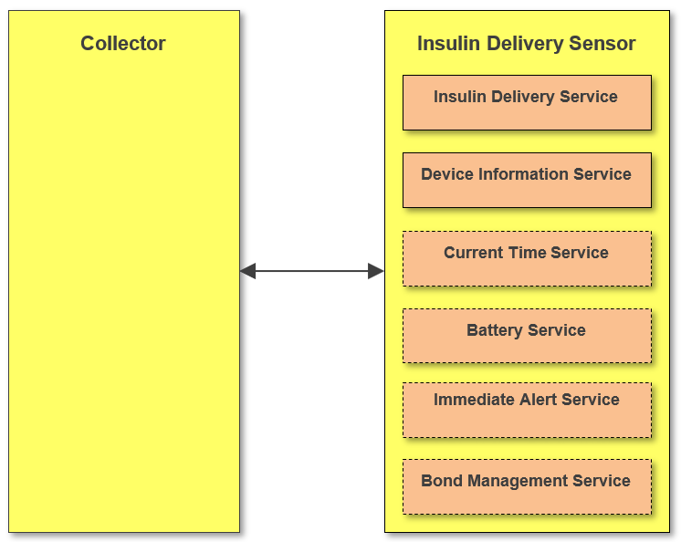
2.2. Role/Service relationships
The following diagram shows the relationships between services and the profile roles.
 |
Note
Note: Profile roles are represented by yellow boxes and services are represented by orange boxes. Services in dotted boxes are optionally instantiated.
An Insulin Delivery Sensor instantiates the Insulin Delivery Service [1], Device Information Service [2], and optionally the Current Time Service [3], Battery Service [4], Immediate Alert Service [5], and also optionally the Bond Management Service (BMS) [6].
2.3. Concurrency limitations and restrictions
If a Sensor is in connection, it shall be connected to only one Collector and there shall be no data broadcasts to multiple Collectors.
2.4. Topology limitations and restrictions
2.4.1. Topology limitations and restrictions for Low Energy
This section describes topology limitations and restrictions when the profile is to be used over Low Energy transport.
The Insulin Delivery Sensor shall use the GAP Peripheral role and may implement the GAP Central role.
The Collector shall use the GAP Central role and may implement the GAP Peripheral role.
2.5. Transport dependencies
This profile shall operate over an LE transport only. For BR/EDR (and HS) the Health Device Profile [8] is to be used. This is to avoid having two ways to send insulin delivery data over a BR/EDR transport.
3. Insulin Delivery Sensor role requirements
The Insulin Delivery Sensor shall support the GATT server role and instantiate one and only one Insulin Delivery Service [1] and one Device Information Service [2]. The Insulin Delivery Sensor may also instantiate one Current Time Service [3], one Battery Service [4], one Immediate Alert Service [5], and conditionally one Bond Management Service [6].
|
Service |
Insulin Delivery Sensor |
||||||||||||||||||||||||||||||||||||||||||||||||
|---|---|---|---|---|---|---|---|---|---|---|---|---|---|---|---|---|---|---|---|---|---|---|---|---|---|---|---|---|---|---|---|---|---|---|---|---|---|---|---|---|---|---|---|---|---|---|---|---|---|
|
Insulin Delivery Service |
M |
||||||||||||||||||||||||||||||||||||||||||||||||
|
Device Information Service |
M |
||||||||||||||||||||||||||||||||||||||||||||||||
|
Current Time Service |
O[a] |
||||||||||||||||||||||||||||||||||||||||||||||||
|
Battery Service |
O |
||||||||||||||||||||||||||||||||||||||||||||||||
|
Immediate Alert Service |
O |
||||||||||||||||||||||||||||||||||||||||||||||||
|
Bond Management Service |
C.1 |
||||||||||||||||||||||||||||||||||||||||||||||||
- C.1:
-
Mandatory if multiple bonds are supported, otherwise optional.
See Section 5.1 and Section 6.1 for additional requirements for the Insulin Delivery Sensor role.
3.1. Incremental Insulin Delivery Service requirements
3.1.1. Writable GAP Device Name characteristic
The Insulin Delivery Sensor may support the write property for the Device Name characteristic in order to allow a Collector to write a device name to the Insulin Delivery Sensor.
3.1.2. Additional requirements for Low Energy transport
This section describes additional Insulin Delivery Sensor requirements and recommendations beyond those defined in the Insulin Delivery Service when using this profile over Low Energy transport.
The following requirements that imply the inclusion of the device name or unique data in the Advertising or Scan Response Data should not apply if the Link Layer Privacy is used as specified in Bluetooth Core Specification v4.2 [14] or later.
3.1.2.1. Service UUIDs AD Type
While in a GAP Discoverable Mode for initial connection to a Collector, the Insulin Delivery Sensor should include the Insulin Delivery Service UUID defined in [10] in the Service UUID’s AD type field of the Advertising Data. This enhances the user experience as an Insulin Delivery Sensor may be identified by the Collector before initiating a connection.
3.1.2.2. Local Name AD Type
For an enhanced user experience, an Insulin Delivery Sensor should include the Local Name (containing either the complete or shortened value of the Device Name characteristic as defined in [9]) in its Advertising Data or Scan Response Data.
3.1.2.3. Appearance AD Type
For an enhanced user experience, an Insulin Delivery Sensor should include the value of the Appearance characteristic defined in [2] in its Advertising data or Scan Response data.
In the following sections, the words a “Target Address AD Type” are intended to refer to either of the defined Target Address AD Types.
3.2. Incremental Device Information Service requirements
The table below shows additional requirements and recommendations beyond those defined in the Device Information Service.
|
Device Information Service Characteristics |
Requirement |
|---|---|
|
Manufacturer Name String |
M |
|
Model Number String |
M |
|
System ID |
M |
Characteristics in this service may be transcoded by the Collector for use in an ISO/IEEE 11073 ecosystem. See the Personal Health Devices Transcoding White Paper [11] for more information. Since strings in this service are encoded as UTF-8, and ISO/IEEE 11073-20601a [12] specifies that strings are encoded as ASCII printable characters (a subset of UTF-8), characters used in string characteristics that are to be transcoded for use in an ISO/IEEE 11073 ecosystem shall be restricted to the printable ASCII character set.
If the ISO/IEEE 11073-20601 specification is updated in the future to include UTF-8 support, implementers should consider the impact of using non-ASCII characters on backward compatibility.
Note
Note: The Personal Health Devices Transcoding White Paper [11] recommends that characters outside of the printable ASCII range are translated to characters inside of the printable ASCII range as appropriate.
3.3. Incremental Bond Management Service requirements
Authorization codes shall be mandatory for all supported Bond Management Control Point (BMCP) procedures (see [6]).
4. Collector role requirements
The Collector role shall support the Insulin Delivery Service [1] and may support the Device Information Service [2], Current Time Service [3] according to the Time Profile [7], Battery Service [4], Immediate Alert Service [5], and Bond Management Service [6] on the GATT server.
|
Service |
Collector |
||||||||||||||||||||||||||||||||||||||||||||||||
|---|---|---|---|---|---|---|---|---|---|---|---|---|---|---|---|---|---|---|---|---|---|---|---|---|---|---|---|---|---|---|---|---|---|---|---|---|---|---|---|---|---|---|---|---|---|---|---|---|---|
|
Insulin Delivery Service |
M |
||||||||||||||||||||||||||||||||||||||||||||||||
|
Device Information Service |
O |
||||||||||||||||||||||||||||||||||||||||||||||||
|
Current Time Service |
O[a] |
||||||||||||||||||||||||||||||||||||||||||||||||
|
Battery Service |
O |
||||||||||||||||||||||||||||||||||||||||||||||||
|
Immediate Alert Service |
O |
||||||||||||||||||||||||||||||||||||||||||||||||
|
Bond Management Service |
O |
||||||||||||||||||||||||||||||||||||||||||||||||
This section describes the profile requirements for a Collector.
|
Profile Requirement |
Section |
Support in Collector |
|---|---|---|
|
Service Discovery |
M |
|
|
Characteristic Discovery |
M |
|
|
IDD Status Changed |
M |
|
|
IDD Status |
M |
|
|
IDD Annunciation Status |
M |
|
|
IDD Features |
M |
|
|
IDD Status Reader Control Point |
M |
|
|
IDD Command Control Point |
O |
|
|
IDD Command Data |
C.1 |
|
|
IDD Record Access Control Point |
O |
|
|
IDD History Data |
C.2 |
|
|
Bond Management Control Point |
C.3 |
|
|
Bond Management Feature |
C.3 |
- C.1:
-
Mandatory if optional IDD Command Control Point is supported, otherwise excluded
- C.2:
-
Mandatory if optional IDD Record Access Control Point is supported, otherwise excluded.
- C.3:
-
Mandatory if Bond Management Service is supported, otherwise excluded.
4.1. GATT sub-procedure requirements
Requirements in this section represent a minimum set of requirements for a Collector (Client). Other GATT sub-procedures may be used if supported by both Client and Server.
The table below summarizes additional GATT sub-procedure requirements beyond those required by all GATT Clients.
|
GATT Sub-Procedure |
Collector (Client) Requirements |
|---|---|
|
Discover All Primary Services |
C.1 |
|
Discover Primary Services by Service UUID |
C.1 |
|
Discover All Characteristics of a Service |
C.2 |
|
Discover Characteristics by UUID |
C.2 |
|
Discover All Characteristic Descriptors |
M |
|
Notifications |
M |
|
Indications |
M |
|
Read Characteristic Value |
M |
|
Write Characteristic Value |
M |
|
Reliable Writes |
C.3 |
|
Write Long Characteristic Values |
C.3 |
|
Write Without Response |
C.4 |
|
Read Characteristic Descriptors |
M |
|
Write Characteristic Descriptors |
M |
- C.1:
-
Mandatory to support at least one of these service discovery sub-procedures.
- C.2:
-
Mandatory to support at least one of these characteristic discovery sub-procedures.
- C.3:
-
Mandatory if Bond Management Service is supported, otherwise optional.
- C.4:
-
Mandatory if Immediate Alert Service is supported, otherwise optional.
4.2. Service discovery
The Collector shall use the GATT Service Discovery to discover the services according to Section 4.
The Collector shall perform primary service discovery using either the GATT Discover All Primary Services sub-procedure or the GATT Discover Primary Services by Service UUID sub-procedure.
4.3. Characteristic discovery
As required by GATT, the Collector shall be tolerant of additional optional characteristics in the service records of services used with this profile.
The Collector shall perform either the GATT Discover All Characteristics of a Service sub-procedure or the GATT Discover Characteristics by UUID sub-procedure in order to discover the characteristics of the services of this profile.
The Collector shall perform the GATT Discover All Characteristic Descriptors sub-procedure in order to discover the Client Characteristic Configuration Descriptors.
The profile requirements concerning the discovery of the Characteristics also apply to the discovery of their Client Characteristic Configuration Descriptors according to Table 4.4.
|
Profile Requirement |
Support in Collector |
||||||||||||||||||||||||||||||||||||||||||||||||
|---|---|---|---|---|---|---|---|---|---|---|---|---|---|---|---|---|---|---|---|---|---|---|---|---|---|---|---|---|---|---|---|---|---|---|---|---|---|---|---|---|---|---|---|---|---|---|---|---|---|
|
Insulin Delivery Service Characteristic Discovery |
|||||||||||||||||||||||||||||||||||||||||||||||||
|
M |
||||||||||||||||||||||||||||||||||||||||||||||||
|
M |
||||||||||||||||||||||||||||||||||||||||||||||||
|
M |
||||||||||||||||||||||||||||||||||||||||||||||||
|
M |
||||||||||||||||||||||||||||||||||||||||||||||||
|
M |
||||||||||||||||||||||||||||||||||||||||||||||||
|
O |
||||||||||||||||||||||||||||||||||||||||||||||||
|
C.1 |
||||||||||||||||||||||||||||||||||||||||||||||||
|
O |
||||||||||||||||||||||||||||||||||||||||||||||||
|
C.2 |
||||||||||||||||||||||||||||||||||||||||||||||||
|
Device Information Service Characteristic Discovery |
O |
||||||||||||||||||||||||||||||||||||||||||||||||
|
Current Time Service Characteristic Discovery |
O[a] |
||||||||||||||||||||||||||||||||||||||||||||||||
|
Battery Service Characteristic Discovery |
O |
||||||||||||||||||||||||||||||||||||||||||||||||
|
Immediate Alert Service Characteristics Discovery |
O |
||||||||||||||||||||||||||||||||||||||||||||||||
|
Bond Management Service Characteristic Discovery |
|||||||||||||||||||||||||||||||||||||||||||||||||
|
C.3 |
||||||||||||||||||||||||||||||||||||||||||||||||
|
C.3 |
||||||||||||||||||||||||||||||||||||||||||||||||
- C.1:
-
Mandatory if optional IDD Command Control Point is supported, otherwise excluded.
- C.2:
-
Mandatory if optional IDD Record Access Control Point is supported, otherwise excluded.
- C.3:
-
Mandatory if Bond Management Service is supported, otherwise excluded.
4.4. Common Insulin Delivery Service characteristic requirements
If the Insulin Delivery Sensor supports (End-to-End-Protection) E2E-Protection (E2E-Protection Supported bit is set in Flags field of IDD Features, see Section 4.9), the Collector shall increment the value of the E2E-Counter field, hereafter referred to as the transmit E2E-Counter value, of an accessed control point with each write request to that control point.
If the Collector supports E2E-Protection, it shall check if the received E2E-Counter value within the E2E‑Counter field was increased since the last access of a specific characteristic (i.e., the Insulin Delivery Sensor manages its own transmit E2E-Counter values for each characteristic). For additional details, see Section 4.15.1.1. In addition, it shall check the validity of the fields of a characteristic by checking the value of the E2E-CRC field calculated over all fields including the E2E-Counter field (see Section 1.8 in [1] for more details about E2E-Protection).
4.5. Receiving changes of the status of the insulin therapy
There are two ways that a Collector can receive changes of the insulin therapy (also see this use case Section 1):
Automatic:
Typically the Collector and the Insulin Delivery Sensor are in connection during the therapy session. So, changes are transmitted as soon as they occur if the corresponding Client Characteristic Descriptor is configured for indications. In this way, either the IDD Status Changed characteristic (see Section 4.6 ) can be indicated and then the Collector can read all relevant characteristics holding status values (e.g., IDD Status) and execute CP procedures (e.g., procedure Get Active Basal Rate Delivery of IDD Status Reader CP) or these characteristics can be configured for indications directly.
On demand:
Whenever the Collector requires updated status information, it can read the IDD Status Changed characteristic and then read all relevant characteristics or execute CP procedures providing status values (see Section 10 and Section 3.2.1.3 in [1]).
4.6. IDD Status Changed characteristic
The Collector may read the IDD Status Changed characteristic to determine status changes of the Insulin Delivery Sensor (concerning the insulin therapy and the insulin delivery device) since the last status reset performed by the Reset Status procedure of the IDD Status Reader Control Point (see Section 4.10.2).
The Collector may actively read the IDD Status Changed characteristic after reconnection or may configure the IDD Status Changed characteristic for indications to receive status changes as soon as they are raised by the Insulin Delivery Sensor.
4.7. IDD Status characteristic
The Collector may read the IDD Status characteristic to receive status values of the Insulin Delivery Sensor (concerning the insulin therapy and the insulin delivery device).
The Collector may read the status values from the IDD Status characteristic after getting a device status change signaled by one of the following bits of the Flags field of the IDD Status Changed characteristic (see Section 4.6):
-
Therapy Control State Changed
-
Operational State Changed
-
Reservoir Status Changed
The Collector may configure the IDD Status characteristic for indications to receive changed status values as soon as they are raised by the higher layer application on the Insulin Delivery Sensor (Insulin Delivery Sensor Application) that instantiates the Insulin Delivery Service (for details see Section 4.5).
4.8. IDD Annunciation Status characteristic
The Collector may read the IDD Annunciation Status characteristic to receive messages, which describe state changes of the insulin delivery device in the therapy relevant functions.
The Collector may read the status values from the IDD Annunciation Status characteristic after getting an annunciation status change signaled by the following bit of the Flags field of the IDD Status Changed characteristic (see Section 4.6):
-
Annunciation Status Changed
The Collector may also configure the IDD Annunciation Status characteristic for indications to receive changed status values as soon as they are raised by the Insulin Delivery Sensor Application (for details see Section 4.5).
4.9. IDD Features characteristic
To determine the supported features of the Insulin Delivery Sensor, the Collector shall read the IDD Features characteristic.
If the IDD Features characteristic supports indications, the Collector may configure this characteristic for indications. When the Collector receives an indication of the IDD Features characteristic, the Collector shall use the indicated value to determine the supported features again. Alternatively, the Collector may read the IDD Features characteristic each time after connecting with the Insulin Delivery Sensor. A Collector shall enable indications of the IDD Features characteristic, or it shall read the IDD Features characteristic on each connection.
The Insulin Concentration field may be used by the Collector to determine the intended insulin concentration of the insulin delivery device in International Units per milliliters (IU/mL).
The Flags field contains the following feature bits:
-
If the E2E-Protection Supported bit is set to 1, all characteristics except the IDD History Data characteristic contain an E2E-Counter field and an E2E-CRC field (IDD History Data contains the E2E-CRC field but no E2E-Counter field). In that case the Collector shall use an appropriate transmit E2E-Counter value and shall calculate the CRC if it writes to a characteristic (see Section 4.4). Otherwise the Server responds with an E2E-error (for details see Section 3.12 in [1]). The Collector may check the received E2E-Counter value and E2E-CRC if it reads a characteristic, receives notification or indications (for details see Section 4.16).
-
If the Basal Rate Supported bit is set to 1, the Collector can determine that the Insulin Delivery Sensor supports the delivery of a basal rate and also basal rate profile templates that are templates of programmed series of basal rates in the context of the insulin infusion therapy.
-
If the TBR Absolute Supported bit is set to 1, the Collector can determine that the Insulin Delivery Sensor supports an absolute temporary basal rate in International Unit per hour (IU/h).
-
If the TBR Relative Supported bit is set to 1, the Collector can determine that the Insulin Delivery Sensor supports a relative temporary basal expressed by a dimensionless scaling factor.
-
If the TBR Template Supported bit is set to 1, the Collector can determine that the Insulin Delivery Sensor supports templates to define different kinds of Temporary Basal Rates (TBR). In this case the Collector Application can provide one or more templates with TBR settings, which can be selected by the user.
-
If the Fast Bolus Supported bit is set to 1, the Collector can determine that the Insulin Delivery Sensor supports the delivery of fast boluses.
-
If the Extended Bolus Supported bit is set to 1, the Collector can determine that the Insulin Delivery Sensor supports the delivery of extended boluses.
-
If the Multiwave Bolus Supported bit is set to 1, the Collector can determine that the Insulin Delivery Sensor supports the delivery of multiwave boluses.
-
If the Bolus Delay Time Supported bit is set to 1, the Collector can determine that the Insulin Delivery Sensor supports a bolus delay time. In this case the Collector can attach a Bolus Delay Time in the parameters of the Set Bolus procedure (see Section 4.11.2.13) is executed.
-
If the Bolus Template Supported bit is set to 1, the Collector can determine that the Insulin Delivery Sensor supports templates to define different kinds of boluses. In this case the Collector Application can provide one or more templates with bolus settings which can be selected by the user.
-
If the Bolus Activation Type Supported bit is set to 1, the Collector can determine that the Insulin Delivery Sensor supports a bolus activation type, which provides additional information about the source and, as possible, the determination of the bolus amount. In this case the Collector can attach a Bolus Activation Type in the parameters of the Set Bolus procedure (see Section 4.11.2.13) is executed.
-
If the Multiple Bond Supported bit is set to 0, the Collector can determine that the Insulin Delivery Sensor supports only a single bond. Otherwise the Collector can determine that the Insulin Delivery Sensor supports multiple bonds.
-
If the ISF Profile Template Supported bit is set to 1, the Collector can determine that the Insulin Delivery Sensor supports ISF profiles and also templates to define different kinds of ISF profiles. In this case the Collector Application can provide one or more templates with ISF settings, which can be selected by the user. An ISF profile can be considered in the calculation of a bolus calculator of the Sensor or Collector Application.
-
If the I2CHO Ratio Profile Template Supported bit is set to 1, the Collector can determine that the Insulin Delivery Sensor supports I:CHO Ratio profiles and also templates to define different kinds of I:CHO Ratio profiles. In this case the Collector Application can provide one or more templates with I:CHO Ratio settings, which can be selected by the user. An I:CHO Ratio profile can be considered in the calculation of a bolus calculator of the Sensor or Collector Application.
-
If the Target Glucose Range Profile Template Supported bit is set to 1, the Collector can determine that the Insulin Delivery Sensor supports target glucose range profiles and also templates to define different kinds of target glucose range profiles. In this case the Collector Application can provide one or more templates with target glucose range settings, which can be selected by the user. A target glucose range profile can be considered in the calculation of a bolus calculator of the Sensor or Collector Application.
-
If the Insulin On Board Supported bit is set to 1, the Collector can determine that the Insulin Delivery Sensor provides the current Insulin on Board (IOB). The IOB can be considered in the calculation of a bolus calculator of the Sensor or Collector Application.
-
If the Feature Extension bit is set to 1, the Collector can determine that an additional octet is attached (bits 24 … 31), where bit 31 is used as Feature Extension bit in the same way. If this bit is set, then another octet is attached (bits 32 … 39) and so on.
If one of the feature bits above is set to False and the Collector executes a procedure in the following cases, it shall be able to handle the following Response Code Values in the Operand set to:
-
Op Code not supported if the Op Code of the procedure is mandatory for that feature (e.g., Basal Rate Supported bit is set to 0 and the Collector executes the Get Active Basal Rate Delivery procedure)
-
Invalid Operand if at least one field value in the Operand requires that feature (e.g., Extended Bolus Supported bit is set to 0 and the Collector executes the Set Bolus procedure with a Bolus Type field with value Extended in the Operand)
(See Section 3.12.4 in [1].)
4.10. IDD Status Reader Control Point
Before performing an IDD Status Reader Control Point procedure, the Collector shall configure the IDD Status Reader Control Point characteristic for indications (i.e., by writing to the Client Characteristic Configuration descriptor).
4.10.1. IDD Status Reader Control Point procedure requirements
Table 4.5 shows the requirements for the IDD Status Reader control point procedures (Op Codes):
|
Procedure (Op Code) |
Section |
Requirements |
|---|---|---|
|
Reset Status |
M |
|
|
Get Active Bolus IDs |
C.1 |
|
|
Get Active Bolus Delivery |
C.1 |
|
|
Get Active Basal Rate Delivery |
C.2 |
|
|
Get Total Daily Insulin Status |
M |
|
|
Get Counter |
O |
|
|
Get Delivered Insulin |
O |
|
|
Get Insulin On Board |
C.3 |
- C.1:
-
Mandatory if boluses are supported, otherwise excluded.
- C.2:
-
Mandatory if a basal rate is supported, otherwise excluded.
- C.3:
-
Mandatory if insulin on board is supported, otherwise excluded.
4.10.2. IDD Status Reader Control Point behavioral description
4.10.2.1. Reset Status procedure
To reset a status exposed by the IDD Status Changed characteristic, the Collector shall write the Reset Status Op Code followed by a Flags field as defined in the IDD Status Changed characteristic to the IDD Status Reader Control Point.
The Collector shall wait for the Response Code Op Code indication with Response Code Value set to Success indicating success of the operation as per the request or an error value as described in Section 4.15.5.
To get further updates by changes of the Flags field of the IDD Status Changed characteristic, the Collector shall use this procedure (for details see Section 4.6).
If a bit of the Flags Operand is set to 1, the Server will reset the corresponding status of the IDD Status Changed characteristic by setting it to 0. If a bit of the Flags Operand is set to 0, the status will be retained.
Typically the Collector is informed about status changes of the Insulin Delivery Sensor by evaluating the IDD Status Changed Flags field (e.g., Therapy Control State Changed bit set). Then the Collector reads the relevant status values (e.g., IDD Status characteristic) and finally informs the Insulin Delivery Sensor about the completed evaluation and processing by executing the Reset Status.
4.10.2.2. Get Active Bolus IDs procedure
To get the IDs of the potential seven current active boluses, the Collector shall write the Get Active Bolus IDs Op Code to the IDD Status Reader Control Point.
The Collector shall wait for the Get Active Bolus IDs Response Op Code indication with an Active Bolus ID record indicating success of the operation as per the request or a Response Code Op Code indication with an error value as described in Section 4.15.5.
The Active Bolus ID record contains the Bolus IDs of the active boluses in the order of their start time (i.e., the Bolus ID1 field contains the ID of the oldest bolus and the Bolus ID7 field the ID of the latest delivered bolus).
If the Insulin Delivery Sensor responds with a Number of Active Boluses being more than 7, the 7 Active Bolus ID fields refer to the ones with the oldest start date time. In this case the Collector may use the IDD RACP (see Section 4.13) to retrieve information about the programmed boluses by reading the Bolus Programmed Events. However this is assumed as an exceptional case.
The Collector can use this procedure after receiving an active bolus status change signaled by the Active Bolus Status Changed bit of the Flags field of the IDD Status Changed characteristic (see Section 4.6).
To get the details about a currently active bolus, the Collector shall use the Get Active Bolus Delivery procedure with the associated bolus ID.
4.10.2.3. Get Active Bolus Delivery procedure
To get delivery information about a specific active bolus, the Collector shall write the Get Active Bolus Delivery Op Code followed by a Bolus ID and a desired Bolus Value Selection to the IDD Status Reader Control Point. The Bolus Value Selection Operand specifies if the programmed, remaining (e.g., remaining insulin amount) or delivered values (e.g., already delivered insulin amount) are returned in the response of this procedure.
The Collector shall wait for the Get Active Bolus Delivery Response Op Code indication with an Active Bolus Delivery record indicating success of the operation as per the request or a Response Code Op Code indication with an error value as described in Section 4.15.5.
The Collector can use this procedure after receiving an active bolus status change signaled by the Active Bolus Status Changed bit of the Flags field of the IDD Status Changed characteristic (see Section 4.6).
The Collector shall be able to handle a Bolus Delay Time of 0xFFFF in the response if the Bolus Value Selection Operand is set to Delivered, which means that the Bolus Delay Time is not applicable with that Bolus Value Selection Operand.
4.10.2.4. Get Active Basal Rate Delivery procedure
To get the active basal rate setting including the TBR, the Collector shall write the Get Active Basal Rate Delivery Op Code to the IDD Status Reader Control Point.
The Collector shall wait for the Get Active Basal Delivery Response Op Code indication with an Active Basal Delivery record indicating success of the operation as per the request or a Response Code Op Code indication with an error value as described in Section 4.15.5.
The Collector can use this procedure after receiving an active basal rate status change signaled by the Active Basal Rate Status Changed bit of the Flags field of IDD Status Changed characteristic (see Section 4.6).
4.10.2.5. Get Total Daily Insulin Status procedure
To get the total daily delivered bolus and basal insulin from midnight until now, the Collector shall write the Get Total Daily Insulin Status Op Code to the IDD Status Reader Control Point.
The Collector shall wait for the Get Total Daily Insulin Status Response Op Code indication with a Total Daily Insulin Status record indicating success of the operation as per the request or a Response Code Op Code indication with an error value as described in Section 4.15.5.
The received total daily insulin amounts refer to the current date time of the Insulin Delivery Sensor (i.e., if the date time is changed, the insulin amounts always refer to the current date time).
The Collector can use this procedure after receiving a total daily insulin status change signaled by the Total Daily Insulin Status Changed bit of the Flags field of the IDD Status Changed characteristic (see Section 4.6).
If the insulin delivery device does not support boluses, the Collector shall be able to handle a value of 0 for the Total Daily Insulin Sum of Bolus Delivered. If the insulin delivery device does not support a basal rate, the Collector shall be able to handle a value of 0 for the Total Daily Insulin Sum of Basal Delivered field (see IDD Features Flags in Section 4.9).
4.10.2.6. Get Counter procedure
To get the value of an internal counter of the insulin delivery device, the Collector shall write the Get Counter Op Code followed by a Counter Type and Counter Value Selection field to the IDD Status Reader Control Point.
The Collector shall wait for the Get Counter Response Op Code indication with a Counter record indicating success of the operation as per the request or a Response Code Op Code indication with an error value as described in Section 4.15.5.
The Counter Value Selection field of the Operand specifies the value of the Counter Value field contained in the response from the Sensor for the Get Counter procedure. For a Counter Value Selection set to Remaining, the Counter Value is the remaining time before the requested Counter Type expires. A negative value for the remaining time means the counter has already expired. In this case, the absolute value of the remaining time provides the time since expiration. For a Counter Value Selection set to Elapsed, the Counter Value is the elapsed time since the requested Counter Type started. The elapsed time value is never negative.
An insulin delivery device may have a restricted lifetime, warranty or loaner time. This procedure shall be used by a Collector to get the remaining or elapsed values of those counters.
4.10.2.7. Get Delivered Insulin procedure
To get the amounts of the delivered bolus and basal insulin, the Collector shall write the Get Delivered Insulin Op Code to the IDD Status Reader Control Point.
The Collector shall wait for the Get Delivered Insulin Response Op Code indication with a Delivered Insulin record indicating success of the operation as per the request or a Response Code Op Code indication with an error value as described in Section 4.15.5.
A Collector can use this procedure to get a delta of the delivered insulin by executing it periodically.
If an amount exceeds a value of 80,000.00 IU, a rollover will occur on the Insulin Delivery Sensor and the Collector will receive a delivered bolus or basal amount starting from 0.
The Collector shall accept a delivered bolus or basal amount set to 0 due to a rollover by the Server if an amount exceeds a value of 80,000.00 IU.
If the Collector was connected to the Insulin Delivery Sensor previously, the Collector can detect a rollover by checking if a retrieved amount is less than the one from the previous execution of this procedure. Depending on the implementation of the Collector, the frequency it executes this procedure and the insulin amount delivered, the Collector can determine that only one rollover has occurred.
4.10.2.8. Get Insulin On Board procedure
To get the amount and remaining duration of the Insulin On Board, which has been delivered by the insulin delivery device, the Collector shall write the Get Insulin On Board Op Code to the IDD Status Reader Control Point.
The Collector shall wait for the Get Insulin On Board Response Op Code indication with an amount of Insulin On Board indicating success of the operation as per the request or a Response Code Op Code indication with an error value as described in Section 4.15.5.
4.11. IDD Command Control Point
Before performing an IDD Command Control Point procedure, the Collector shall configure the IDD Command Control Point characteristic for indications and the IDD Command Data characteristic for notifications (all via the appropriate Client Characteristic Configuration descriptor).
If the Collector executes a procedure on the IDD Command Control Point which could require more than one response from the Insulin Delivery Sensor (e.g., Read Basal Rate Profile Template), the procedure may contain one or more IDD Command Data characteristic notifications between the write to this Control Point that began the procedure and the Response Code indication of this Control Point (CP) that ends the procedure.
4.11.1. IDD Command Control Point procedure requirements
Table 4.6 shows the requirements for the IDD Command control point procedures (Op Codes):
|
Procedure (Op Code) |
Section |
Requirements |
|||||||||||||||||||||||||||||||||||||||||||||||
|---|---|---|---|---|---|---|---|---|---|---|---|---|---|---|---|---|---|---|---|---|---|---|---|---|---|---|---|---|---|---|---|---|---|---|---|---|---|---|---|---|---|---|---|---|---|---|---|---|---|
|
Set Therapy Control State |
M |
||||||||||||||||||||||||||||||||||||||||||||||||
|
Set Flight Mode |
M |
||||||||||||||||||||||||||||||||||||||||||||||||
|
Snooze Annunciation |
M |
||||||||||||||||||||||||||||||||||||||||||||||||
|
Confirm Annunciation |
M |
||||||||||||||||||||||||||||||||||||||||||||||||
|
Read Basal Rate Profile Template[a] |
C.1 |
||||||||||||||||||||||||||||||||||||||||||||||||
|
Write Basal Rate Profile Template |
C.1 |
||||||||||||||||||||||||||||||||||||||||||||||||
|
Set TBR Adjustment |
C.2 |
||||||||||||||||||||||||||||||||||||||||||||||||
|
Cancel TBR Adjustment |
C.2 |
||||||||||||||||||||||||||||||||||||||||||||||||
|
Get TBR Template |
C.3 |
||||||||||||||||||||||||||||||||||||||||||||||||
|
Set TBR Template |
C.3 |
||||||||||||||||||||||||||||||||||||||||||||||||
|
Set Bolus |
C.4 |
||||||||||||||||||||||||||||||||||||||||||||||||
|
Cancel Bolus |
C.4 |
||||||||||||||||||||||||||||||||||||||||||||||||
|
Get Available Boluses |
C.4 |
||||||||||||||||||||||||||||||||||||||||||||||||
|
Get Bolus Template |
C.5 |
||||||||||||||||||||||||||||||||||||||||||||||||
|
Set Bolus Template |
C.5 |
||||||||||||||||||||||||||||||||||||||||||||||||
|
Get Template Status and Details |
C.6 |
||||||||||||||||||||||||||||||||||||||||||||||||
|
Reset Template Status |
C.6 |
||||||||||||||||||||||||||||||||||||||||||||||||
|
Activate Profile Templates |
C.7 |
||||||||||||||||||||||||||||||||||||||||||||||||
|
Get Activated Profile Templates |
C.7 |
||||||||||||||||||||||||||||||||||||||||||||||||
|
Start Priming |
O |
||||||||||||||||||||||||||||||||||||||||||||||||
|
Stop Priming |
C.8 |
||||||||||||||||||||||||||||||||||||||||||||||||
|
Set Initial Reservoir Fill Level |
O |
||||||||||||||||||||||||||||||||||||||||||||||||
|
Reset Reservoir Insulin Operation Time |
O |
||||||||||||||||||||||||||||||||||||||||||||||||
|
Read ISF Profile Template[a] |
C.9 |
||||||||||||||||||||||||||||||||||||||||||||||||
|
Write ISF Profile Template |
C.9 |
||||||||||||||||||||||||||||||||||||||||||||||||
|
Read Insulin-to-Carbohydrate (I2CHO) Ratio Profile Template[a] |
C.10 |
||||||||||||||||||||||||||||||||||||||||||||||||
|
Write I2CHO Ratio Profile Template |
C.10 |
||||||||||||||||||||||||||||||||||||||||||||||||
|
Read Target Glucose Range Profile Template[a] |
C.11 |
||||||||||||||||||||||||||||||||||||||||||||||||
|
Write Target Glucose Range Profile Template |
C.11 |
||||||||||||||||||||||||||||||||||||||||||||||||
|
Get Max Bolus Amount |
O |
||||||||||||||||||||||||||||||||||||||||||||||||
|
Set Max Bolus Amount |
O |
||||||||||||||||||||||||||||||||||||||||||||||||
|
[a] The Server sends one or more response records by notifications of the IDD Command Data characteristic. |
|||||||||||||||||||||||||||||||||||||||||||||||||
- C.1:
-
Mandatory if a basal rate is supported, otherwise excluded.
- C.2:
-
Mandatory if TBRs are supported, otherwise excluded.
- C.3:
-
Mandatory if TBR templates are supported, otherwise excluded.
- C.4:
-
Mandatory if boluses are supported, otherwise excluded.
- C.5:
-
Mandatory if bolus templates are supported, otherwise excluded.
- C.6:
-
Mandatory if a basal rate and/or TBR templates and/or bolus templates and/or ISF profile templates and/or I:CHO ratio profile templates and/or target glucose range profile templates are supported, otherwise excluded.
- C.7:
-
Mandatory if a basal rate and/or ISF profile templates and/or I:CHO ratio profile templates and/or target glucose range profile templates are supported, otherwise excluded.
- C.8:
-
Mandatory if optional procedure “Start Priming” is implemented, otherwise excluded.
- C.9:
-
Mandatory if ISF profile templates are supported, otherwise excluded.
- C.10:
-
Mandatory if I:CHO ratio profile templates are supported, otherwise excluded.
- C.11:
-
Mandatory if target glucose range profile templates are supported, otherwise excluded.
4.11.2. IDD Command Control Point behavioral description
4.11.2.1. Common Profile Template Reading procedures behavior
This section defines the common behavior of the following IDD Command control point procedures to read profile templates. These are templates of a series of time blocks that define a specific therapy setting. Each time block contains such a therapy setting to be applied for a specific duration:
-
Read Basal Rate Profile Template procedure (see Section 4.11.2.7)
-
Read ISF Profile Template procedure (see Section 4.11.2.26)
-
Read I2CHO Ratio Profile Template procedure (see Section 4.11.2.28)
-
Read Target Glucose Range Profile Template procedure (see Section 4.11.2.30)
Before reading a profile template the Collector should ensure that this template is configured (see Section 4.11.2.18).
Depending on the number of time blocks of a profile, the entire profile (i.e., all defined time blocks of that profile) could be sent in several steps by one or many responses of the Server (i.e., in each step the IDD Command Data characteristic is notified, see Section 4.12). The Collector shall wait for the corresponding response Op Code notification (e.g., Read Basal Rate Profile Template Response) of the IDD Command Data characteristic for each response with a Profile Template record indicating success of the current step as per the request (i.e., the receipt of a Profile Template record containing one or several time blocks). Finally, the Collector shall wait for the corresponding Response Code Op Code indication (e.g., Request Op Code set to Read Basal Rate Profile Template and Response Code set to Success) of the IDD Command Control Point indicating success of the operation (i.e., the receipt of the complete profile). In case of an error, the Collector shall be able to handle a Response Code Op Code indication with an error value as described in Section 4.15.5.
4.11.2.2. Common Profile Template Writing procedures behavior
This section defines the common behavior of the following IDD Command control point procedures to write profile templates (also see Section 4.11.2.1 for an explanation of profile templates and their time blocks):
-
Write Basal Rate Profile Template procedure (see Section 4.11.2.8)
-
Write ISF Profile Template procedure (see Section 4.11.2.27)
-
Write I2CHO Ratio Profile Template procedure (see Section 4.11.2.29)
-
Write Target Glucose Range Profile Template procedure (see Section 4.11.2.31)
Before writing a profile template the Collector should ensure that this template is configurable (see Section 4.11.2.18) and that the number of time blocks does not exceed the maximum number of supported time blocks for that profile (see Get Template Status and Details procedure in Section 4.11.2.18).
Depending on the number of time blocks of a profile, the profile may be sent in several steps by one or many executions of this procedure (i.e., in each step a Profile Template record containing one or several time blocks is sent). The Collector shall use the First Time Block Number Index field of the Profile Template record to specify the index of the time blocks to be sent within the entire profile. The Collector should ensure that the First Time Block Number Index field as well as the total number of time blocks do not exceed the maximum number of supported time blocks (see Get Template Status and Details procedure in Section 4.11.2.18) and that the First Time Block Number Index field is not less than 1.
The Collector initiates a transaction (i.e., to send the first time blocks of the profile) with the first write of the Op Code of the procedure to the IDD Command control point. The bit 0 (End Transaction) of the Flags field shall be set to False except in the last procedure of the transaction when it shall be set to 1 (also see Section 4.15.3).
The Collector shall wait for a corresponding Response Op Code indication (e.g., Write Basal Rate Profile Template Response) after each execution of the procedure with a Flags field, a Profile Template Number field and a First Time Block Number Index field indicating success of the current step as per the request. When the Collector executes the procedure to send the last time block or time blocks of the profile, the Collector shall wait for a corresponding Response Op Code indication (e.g., Write Basal Rate Profile Template Response) with a Flags field with bit 0 set to 1 (Transaction Completed) and a Profile Template Number field as well as a First Time Block Number Index field indicating the success of the operation (i.e., the complete write of the profile). As soon as a template is written successfully by the Collector, its status is set to Configured by the Insulin Delivery Sensor.
If the Collector writes a profile template to the IDD Command Control Point and the profile template fails the plausibility check on the Insulin Delivery Sensor, it will receive a Response Code CP indication with the Response Code Value set to Plausibility check failed (also see Section 3.7.2.1.2 in [1]).
In case of an error the Collector shall be able to handle a Response Code Op Code indication with an error value as described in Section 4.15.5. In addition, the Collector may restart the transaction and may send the entire profile again.
4.11.2.3. Set Therapy Control State procedure
To set the therapy state of the insulin delivery device, the Collector shall write the Set Therapy Control State Op Code followed by a Therapy Control State field to the IDD Command Control Point.
The Collector shall wait for the Response Code Op Code indication with Response Code Value set to Success indicating success of the operation as per the request or an error value as described in Section 4.15.5.
4.11.2.4. Set Flight Mode procedure
To activate the flight mode of the insulin delivery device, the Collector shall write the Set Flight Mode Op Code to the IDD Command Control Point. The flight mode places the insulin delivery device to a mode accepted by the avionic authorities to allow inflight usage.
The Collector shall wait for the Response Code Op Code indication with Response Code Value set to Success indicating success of the operation as per the request or an error value as described in Section 4.15.5.
4.11.2.5. Snooze Annunciation procedure
To snooze an annunciation of the Insulin Delivery Sensor, which is expected to still be active until it is confirmed, the Collector shall write the Snooze Annunciation Op Code followed by an Annunciation Instance ID field to the IDD Command Control Point.
The Collector shall wait for the Snooze Annunciation Response Op Code indication with an Annunciation Instance ID field indicating success of the operation as per the request or a Response Code Op Code indication with an error value as described in Section 4.15.5.
The Collector should be able to handle the following changes of characteristic values as soon as this procedure is executed successfully:
-
The Annunciation Status Changed bit of the Flags field of the IDD Status Changed characteristic (see Section 4.6) will be set to 1
-
If this annunciation is made available in the IDD Annunciation Status characteristic (i.e., if there is no higher priority annunciation), the Annunciation Status field will be set to a value of Snoozed
If the snoozing time (its value is left to the implementation of the Insulin Delivery Sensor) is over, the Collector should be able to handle the following changes of characteristic values:
-
The Annunciation Status Changed bit of the Flags field of the IDD Status Changed characteristic (see Section 4.6) will be set to 1 or stays 1 if it was not reset by the Collector (see Section 4.10.2.1)
-
If this annunciation is made available in the IDD Annunciation Status characteristic (i.e., if there is no higher priority annunciation), the Annunciation Status field will be set to a value of Pending
4.11.2.6. Confirm Annunciation procedure
To confirm an annunciation of the Insulin Delivery Sensor, the Collector shall write the Confirm Annunciation Op Code followed by an Annunciation Instance ID field to the IDD Command Control Point.
The Collector shall wait for the Confirm Annunciation Response Op Code indication with an Annunciation Instance ID field indicating success of the operation as per the request or a Response Code Op Code indication with an error value as described in Section 4.15.5.
After successful execution of this procedure, the Collector should be able to handle that the Annunciation Status Changed bit of the Flags field of the IDD Status Changed characteristic (see Section 4.6) will be set to 1.
After the Collector successfully executes the Confirm Annunciation procedure, the IDD Annunciation Status characteristic does not provide information about that annunciation.
4.11.2.7. Read Basal Rate Profile Template procedure
To read a basal rate profile template of the Insulin Delivery Sensor, the Collector shall write the Read Basal Rate Profile Template Op Code followed by a Basal Rate Profile Template Number field to the IDD Command Control Point.
For the Read Basal Rate Profile Template procedure the common behavior of reading profile templates apply (see Section 4.11.2.1).
4.11.2.8. Write Basal Rate Profile Template procedure
To write a basal rate profile template to the Insulin Delivery Sensor, the Collector shall write the Write Basal Rate Profile Template Op Code followed by a Basal Rate Profile Template record to the IDD Command Control Point.
For the Write Basal Rate Profile Template procedure the common behavior of writing profile templates apply (see Section 4.11.2.2).
4.11.2.9. Set TBR Adjustment procedure
To set a new or change a currently active temporary basal rate, the Collector shall write the Set TBR Adjustment Op Code followed by a TBR record to the IDD Command Control Point.
The Collector shall wait for the Response Code Op Code indication with Response Code Value set to Success indicating success of the operation as per the request or an error value as described in Section 4.15.5.
If the Insulin Delivery Sensor supports TBR templates (see IDD Features Flags in Section 4.9), the Collector can set a TBR adjustment from a stored TBR template by attaching the TBR Template Number field in the TBR record with the value of the TBR template number to set and then shall indicate its presence by setting bit 0 of the Flags field to True (TBR Template Number Present). In this case the Insulin Delivery Sensor will use the settings of the corresponding TBR template denoted by the TBR Template Number field and ignore the values of the fields that are available in that TBR template. The Collector can read the TBR settings of that template before executing this procedure (see Section 4.11.2.11). Furthermore, before applying this TBR template the Collector should ensure that it is configured (see Section 4.11.2.18).
If the settings of a currently active TBR are to be changed (i.e., the settings are to be overwritten completely), the Collector shall set bit 2 of the Flags field to True (Change TBR). If otherwise there is currently no active TBR and a TBR shall be activated, the Collector shall set this bit to False.
4.11.2.10. Cancel TBR Adjustment procedure
To cancel a currently active TBR, the Collector shall write the Cancel TBR Adjustment Op Code to the IDD Command Control Point.
The Collector shall wait for the Response Code Op Code indication with Response Code Value set to Success indicating success of the operation as per the request or an error value as described in Section 4.15.5.
4.11.2.11. Get TBR Template procedure
Before getting a TBR template the Collector should ensure that this template is configured (see Section 4.11.2.18).
To get the parameters of specific TBR Template of the Insulin Delivery Sensor, the Collector shall write the Get TBR Template Op Code followed by a TBR Template Number field to the IDD Command Control Point.
The Collector shall wait for the Get TBR Template Response Op Code indication with a TBR Template record indicating success of the operation as per the request or a Response Code Op Code indication with an error value as described in Section 4.15.5.
4.11.2.12. Set TBR Template procedure
Before setting a TBR template the Collector shall ensure that this template is configurable (see Section 4.11.2.18).
To set the parameters of specific TBR Template of the Insulin Delivery Sensor, the Collector shall write the Set TBR Template Op Code followed by a TBR Template record to the IDD Command Control Point.
The Collector shall wait for the Set TBR Template Response Op Code indication with a TBR Template Number field indicating success of the operation as per the request or a Response Code Op Code indication with an error value as described in Section 4.15.5.
4.11.2.13. Set Bolus procedure
Before setting a bolus, the Collector can check if a bolus of a specific type is currently available by using the Get Available Boluses procedure (see Section 4.11.2.15).
To set a bolus, the Collector shall write the Set Bolus Op Code followed by a Bolus record to the IDD Command Control Point.
The Collector shall wait for the Set Bolus Response Op Code indication with a Bolus ID field of the new set bolus indicating success of the operation as per the request or a Response Code Op Code indication with an error value as described in Section 4.15.5.
If the Collector sets a bolus and the specified type is currently not available on the Insulin Delivery Sensor, it will receive a Response Code CP indication with the Response Code Value set to Maximum Bolus Number reached.
If the Insulin Delivery Sensor supports a bolus delay time (see IDD Features Flags in Section 4.9), the Client can attach the Bolus Delay Time field in the Bolus record and then shall indicate its presence by setting bit 0 of the Flags field to True (Bolus Delay Time Present).
If the Insulin Delivery Sensor supports bolus templates (see IDD Features Flags in Section 4.9), the Client can set a bolus from a stored bolus template by attaching the Bolus Template Number field in the Bolus record with the value of the bolus template number to set and then shall indicate its presence by setting bit 1 of the Flags field to True (Bolus Template Number Present). In this case the Insulin Delivery Sensor will use the settings of the corresponding Bolus template denoted by the Bolus Template Number field and ignore the values of the fields that are available in that bolus template. The Collector can read the bolus parameters of that template by executing the Get Bolus Template procedure before setting a bolus (see Section 4.11.2.16). In addition, the Collector should ensure that this bolus template is configured (see Section 4.11.2.18).
If the Insulin Delivery Sensor supports a bolus activation type (see IDD Features Flags in Section 4.9), the Client can attach the Bolus Activation Type field in the Bolus record and then shall indicate its presence by setting bit 2 of the Flags field to True (Bolus Activation Type Present).
If the Collector sets the Bolus Type to “Extended” in the Operand, it should set the Bolus Fast Amount field to 0, or otherwise it will receive an error.
If the Collector sets the Bolus Type to “Fast” in the Operand, it should set the Bolus Extended Amount and Bolus Duration fields to 0, or otherwise it will receive an error.
4.11.2.14. Cancel Bolus procedure
To cancel a set bolus, the Collector shall write the Cancel Bolus Op Code followed by a Bolus ID field to the IDD Command Control Point.
The Collector shall wait for the Cancel Bolus Response Op Code indication with a Bolus ID field of the canceled bolus indicating success of the operation as per the request or a Response Code Op Code indication with an error value as described in Section 4.15.5.
4.11.2.15. Get Available Boluses procedure
To check which bolus types are currently available, the Collector shall write the Get Available Boluses Op Code to the IDD Command Control Point.
The Collector shall wait for the Get Available Boluses Response Op Code indication with a Flags field of the available bolus types indicating success of the operation as per the request or a Response Code Op Code indication with an error value as described in Section 4.15.5.
The Collector should use this procedure before executing the Set Bolus procedure (see Section 4.11.2.13).
4.11.2.16. Get Bolus Template procedure
Before getting a bolus template the Collector should ensure that this template is configured (see Section 4.11.2.18).
To get the parameters of a bolus template, the Collector shall write the Get Bolus Template Op Code followed by a Bolus Template Number field to the IDD Command Control Point.
The Collector shall wait for the Get Bolus Template Response Op Code indication with a Bolus Template record indicating success of the operation as per the request or a Response Code Op Code indication with an error value as described in Section 4.15.5.
The Collector should use this procedure before setting a bolus based on a bolus template (see Section 4.11.2.13).
4.11.2.17. Set Bolus Template procedure
Before setting a bolus template the Collector should ensure that this template is configurable (see Section 4.11.2.18).
To set the parameters of a bolus template, the Collector shall write the Set Bolus Template Op Code followed by a Bolus Template record to the IDD Command Control Point.
The Collector shall wait for the Set Bolus Template Response Op Code indication with a Bolus Template Number field of the set bolus template indicating success of the operation as per the request or a Response Code Op Code indication with an error value as described in Section 4.15.5.
If the Insulin Delivery Sensor supports a bolus delay time (see IDD Features Flags in Section 4.9), the Client can attach the Bolus Delay Time field in the Bolus record and then shall indicate its presence by setting bit 0 of the Flags field to True (Bolus Delay Time Present).
If the Collector sets the Bolus Type to “Extended” in the Operand, it shall set the Bolus Fast Amount field to 0. If the Collector sets the Bolus Type to “Fast” in the Operand, it shall set the Bolus Extended Amount and Bolus Duration fields to 0.
4.11.2.18. Get Template Status and Details procedure
To get the status and details of all supported templates (i.e., if they are configured and / or configurable, maximum number of supported time blocks, starting template number and number of templates), the Collector shall write the Get Template Status and Details Op Code to the IDD Command Control Point.
The Collector only can read (e.g., Read Basal Rate Profile procedure, see Section 4.11.2.7), apply (e.g., Set Bolus procedure or Activate Profile Templates procedure, see Sections 4.11.2.13 and 4.11.2.20 respectively) and reset (see Section 4.11.2.19) configured templates. Otherwise the corresponding procedure will return an error. If a template is written by the Collector, then its status is set to Configured by the Insulin Delivery Sensor. The Collector shall use this procedure to check if a template is configured before reading, applying or resetting a template.
The Collector only can write configurable templates. Otherwise the corresponding procedure will return an error. Templates that are not configurable might be predefined by the Insulin Delivery Sensor and then cannot be changed by the Collector (i.e., the template is not configurable, but it is configured, because it is set by the Insulin Delivery Sensor). The Collector shall use this procedure to check if a template is configurable before writing a template.
The Collector may use this procedure to only present templates in a UI that are configured in case of reading and applying templates or that are configurable in case of writing templates.
The maximum number of supported time blocks for a Profile Template type defines the maximum number of time blocks the Collector can set for that Profile Template type when writing a template (e.g., basal rate profile template).
The starting template number and number of templates are used to determine the template number range for a template type. Each supported template type has a defined range of unique template numbers such that a template can be referred to with only its template number. For example, if the basal rate profile template type has a starting template number set to 1 and number of templates set to 3, then template numbers 1, 2, and 3 identify basal rate profile templates, and these template numbers cannot be used to identify a template of another template type.
Depending on the number of template types supported, all the template details could be sent in one or many responses of the Server. The Collector shall wait for the Get Template Status and Details Response Op Code notification of the IDD Command Data characteristic for each supported template type with a template status and details record. Once all the template status and details records have been reported for all supported template types, the Collector shall wait for the corresponding Response Code Op Code indication with Request Op Code set to Get Template Status and Details and Response Code set to Success of the IDD Command Control Point indicating success of the procedure. In case of an error the Collector shall be able to handle a Response Code Op Code indication with an error value as described in Section 4.15.5
4.11.2.19. Reset Template Status procedure
To reset the status of one or many templates (i.e., marking it or them as “not configured”), the Collector shall write the Reset Template Status Op Code followed by a Number of Templates to Reset field and a Template Numbers field to the IDD Command Control Point.
The Collector shall wait for the Reset Template Status Response Op Code indication with a Number of Templates Reset field and a Template Numbers field of the reset templates indicating success of the operation as per the request or a Response Code Op Code indication with an error value as described in Section 4.15.5.
The Collector can only reset templates that are both configurable and configured (see Section 4.11.2.18), otherwise this procedure will return an error. In addition, an active basal rate profile template, an ISF profile template, an I:CHO ratio profile template, or target glucose range profile template cannot be reset if it is in use by the Sensor Application (e.g., by a bolus calculator).
The Collector may use this procedure to remove one or more templates within a UI from a list of readable or usable templates (i.e., the UI could only show the configured templates).
4.11.2.20. Activate Profile Templates procedure
Before activating a profile template, the Collector should ensure that it is configured (see Section 4.11.2.18).
To activate profile templates on the Insulin Delivery Sensor, the Collector shall write the Activate Profile Templates Op Code followed by a Number of Profile Templates to Activate field and a Profile Template Numbers field identifying the profile templates to activate to the IDD Command Control Point.
The Collector shall wait for the Activate Profile Templates Response Op Code indication with a Number of Profile Templates Activated field and a Profile Template Numbers field indicating success of the operation as per the request or an error value as described in Section 4.15.5.
Once a basal rate profile template is activated, it cannot be deactivated, but the Collector can activate another basal rate profile template or, if the active basal rate profile is configurable, set the basal rate of the active basal rate profile template to 0 IU/h.
Once an ISF, an I:CHO ratio, or a target glucose range profile template is activated, it cannot be deactivated, but the Collector can activate another profile template of that type.
4.11.2.21. Get Activated Profile Templates procedure
To get all the currently activated profile templates, the Collector shall write the Get Activated Profile Templates Op Code to the IDD Command Control Point.
The Collector shall wait for the Get Activated Profile Templates Response Op Code indication with a Number of Activated Profile Templates field and a conditional Profile Template Numbers field indicating success of the operation as per the request or a Response Code Op Code indication with an error value as described in Section 4.15.5.
The Collector may use this procedure to get the activated profile templates which have been activated by another Collector.
The Collector shall be able to handle the following responses:
-
If no profile templates are activated on the Server, the Number of Activated Profile Templates field value is 0 and the Activated Profile Template Numbers field is not included in the response.
-
If there are activated profile templates on the Server, the Number of Activated Profile Templates field value is the total number of activated profile templates and the Activated Profile Template Numbers field value identifies these profile templates.
4.11.2.22. Start Priming procedure
To start the priming after a reservoir refill or a replacement of the infusion set, the Collector shall write the Start Priming Op Code followed by an Amount field to the IDD Command Control Point.
The Collector shall wait for the Response Code Op Code indication with Response Code Value set to Success indicating success of the operation as per the request or an error value as described in Section 4.15.5.
This procedure starts the filling of the fluidic path of the insulin delivery device with the provided amount of insulin and the Insulin Delivery Sensor stops the priming as soon as this insulin amount is delivered.
The Collector can stop the priming at any time by executing the Stop Priming procedure (see Section 4.11.2.23).
If the Collector receives an erroneous response from the Insulin Delivery Sensor (e.g., an Attribute Protocol Error code of Invalid CRC), the Collector can determine if the priming was started by reading the IDD Status characteristic (see Section 4.7) and checking if the Operational State is Priming.
4.11.2.23. Stop Priming procedure
To stop the priming after executing the Start Priming procedure (see Section 4.11.2.22), the Collector shall write the Stop Priming Op Code to the IDD Command Control Point.
The Collector shall wait for the Response Code Op Code indication with Response Code Value set to Success indicating success of the operation as per the request or an error value as described in Section 4.15.5.
If the Collector receives an erroneous response from the Insulin Delivery Sensor (e.g., an Attribute Protocol Error code of Invalid CRC), the Collector can determine if the priming was stopped by reading the IDD Status characteristic (see Section 4.7) and checking if the Operational State is not Priming anymore.
4.11.2.24. Set Initial Reservoir Fill Level procedure
To set the initial fill level of the reservoir after a reservoir refill or replacement, the Collector shall write the Set Initial Reservoir Fill Level Op Code followed by a Fill Level field to the IDD Command Control Point.
The Collector shall wait for the Response Code Op Code indication with Response Code Value set to Success indicating success of the operation as per the request or an error value as described in Section 4.15.5.
If the insulin delivery device does not have the capability to detect the initial fill level of the reservoir or the initial fill level is not predetermined, the Collector should use this procedure before requesting to deliver insulin (e.g., priming, setting a bolus).
4.11.2.25. Reset Reservoir Insulin Operation Time procedure
To reset the Reservoir Insulin Operation Time counter, the Collector shall write the Reset Reservoir Insulin Operation Time Op Code to the IDD Command Control Point.
The Collector shall wait for the Response Code Op Code indication with Response Code Value set to Success indicating success of the operation as per the request or an error value as described in Section 4.15.5.
The Collector can use the Get Counter procedure (see Section 4.10.2.6) with the Counter Type set to Reservoir Insulin Operation Time and the Counter Value Selection field set to the desired value to retrieve the Reservoir Insulin Operation Time counter (e.g., if the insulin delivery device supports a counter for the Insulin Operation Time and does not have the capability to reset that counter, the Collector should use this procedure after a reservoir refill or replacement).
4.11.2.26. Read ISF Profile Template procedure
To read an ISF profile template of the Insulin Delivery Sensor, the Collector shall write the Read ISF Profile Template Op Code followed by an ISF Profile Template Number field to the IDD Command Control Point.
For the Read ISF Profile Template procedure the common behavior of reading profile templates apply (see Section 4.11.2.1).
4.11.2.27. Write ISF Profile Template procedure
To write an ISF profile template to the Insulin Delivery Sensor, the Collector shall write the Write ISF Profile Template Op Code followed by an ISF Profile Template record to the IDD Command Control Point.
For the Write ISF Profile Template procedure the common behavior of writing profile templates apply (see Section 4.11.2.2).
4.11.2.28. Read I2CHO Ratio Profile Template procedure
To read an I:CHO ratio profile template of the Insulin Delivery Sensor, the Collector shall write the Read I2CHO Ratio Profile Template Op Code followed by an I2CHO Ratio Profile Template Number field to the IDD Command Control Point.
For the Read I2CHO Ratio Profile Template procedure the common behavior of reading profile templates apply (see Section 4.11.2.1).
4.11.2.29. Write I2CHO Ratio Profile Template procedure
To write an I:CHO ratio profile template to the Insulin Delivery Sensor, the Collector shall write the Write I2CHO Ratio Profile Template Op Code followed by an I2CHO Ratio Profile Template record to the IDD Command Control Point.
For the Write I2CHO Ratio Profile Template procedure the common behavior of writing profile templates apply (see Section 4.11.2.2).
4.11.2.30. Read Target Glucose Range Profile Template procedure
To read a target glucose range profile template of the Insulin Delivery Sensor, the Collector shall write the Read Target Glucose Range Profile Template Op Code followed by a Target Glucose Range Profile Template Number field to the IDD Command Control Point.
For the Read Target Glucose Range Profile Template procedure the common behavior of reading profile templates apply (see Section 4.11.2.1).
4.11.2.31. Write Target Glucose Range Profile Template procedure
To write a target glucose range profile template to the Insulin Delivery Sensor, the Collector shall write the Write Target Glucose Range Profile Template Op Code followed by a Target Glucose Range Profile Template record to the IDD Command Control Point.
For the Write Target Glucose Range Profile Template procedure the common behavior of writing profile templates apply (see Section 4.11.2.2).
4.11.2.32. Get Max Bolus Amount procedure
To get the maximum bolus amount, the Collector shall write the Get Max Bolus Amount Op Code to the IDD Command Control Point.
The Collector shall wait for the Get Max Bolus Amount Response Op Code indication with a Max Bolus Amount field indicating success of the operation as per the request or a Response Code Op Code indication with an error value as described in Section 4.15.5.
4.11.2.33. Set Max Bolus Amount procedure
To set the maximum bolus amount, the Collector shall write the Set Max Bolus Amount Op Code followed by a Max Bolus Amount field to the IDD Command Control Point.
The Collector shall wait for the Response Code Op Code indication with Response Code Value set to Success indicating success of the operation as per the request or an error value as described in Section 4.15.5.
4.11.2.34. IDD Command Control Point Specific Errors
If the Collector writes an Op Code to the IDD Command Control Point characteristic which requires notifications of the IDD Command Data characteristic and its Client Characteristic Configuration descriptor is not configured for notifications, it will receive a Response Code CP indication with the Attribute Protocol Application error code set to Client Characteristic Configuration Descriptor Improperly Configured.
If there is an IDD Command Control Point specific error that is also specific to certain procedures, this error is described in the procedure section.
4.12. IDD Command Data characteristic
The Collector can determine the structure of the Operand field of the IDD Command Data characteristic based on the Response Op Code field.
4.13. IDD Record Access Control Point
The IDD Record Access Control Point (IDD RACP) is based on the Record Access Control Point (RACP) and is defined in [10]. In comparison to the RACP, the values of the IDD RACP Op Codes, Operators, and the Response Code of Success are defined with Hamming distances (see [1]). Furthermore, the IDD RACP enables E2E-Protection by additional E2E-Counter and E2E-CRC fields that are attached if the Insulin Delivery Sensor supports E2E-Protection (see Section 1.8 in [1] for more details about E2E-Protection).
Before performing a IDD Record Access Control Point procedure, the Collector shall configure the IDD Record Access Control Point characteristic for indications and the IDD History Data characteristic for notifications (i.e., via the Client Characteristic Configuration descriptor).
If the Collector performs the Report Stored Records procedure, the procedure may contain one or more IDD History Data characteristic notifications between the write to this Control Point that began the procedure and the Response Code indication of this Control Point that ends the procedure.
If the Collector receives a GATT Error Response with the error code set to Procedure Already in Progress, the Collector should wait until the current IDD RACP procedure completes before executing a new procedure.
4.13.1. IDD Record Access Control Point procedure requirements
Table 4.7 shows the requirements for the IDD Record Access Control Point procedures (Op Codes, Operators, and Operands) in the context of this profile:
|
Procedure (Op Code) |
Op Code Require-ment |
Operator |
Operator Require-ment |
Operand |
Operand Requirement |
|
|---|---|---|---|---|---|---|
|
Filter Type (see Section 4.13.2.1) |
Filter Parameters |
|||||
|
Report Stored Records (see Section 4.13.2.4) |
M |
All records |
M |
Sequence Number |
No Filter Parameters Used |
M |
|
Sequence Number filtered by Reference Time Event |
O |
|||||
|
Sequence Number filtered by Non-Reference Time Event |
||||||
|
Less than or equal to |
O |
Sequence Number |
<maximum filter value> |
C.1 |
||
|
Sequence Number filtered by Reference Time Event |
O |
|||||
|
Sequence Number filtered by Non-Reference Time Event |
||||||
|
Greater than or equal to |
M |
Sequence Number |
<minimum filter value> |
M |
||
|
Sequence Number filtered by Reference Time Event |
O |
|||||
|
Sequence Number filtered by Non-Reference Time Event |
||||||
|
Within range of (inclusive) |
O |
Sequence Number |
<minimum filter value>, <maximum filter value> |
C.1 |
||
|
Sequence Number filtered by Reference Time Event |
O |
|||||
|
Sequence Number filtered by Non-Reference Time Event |
||||||
|
First record |
O |
Sequence Number |
No Filter Parameters Used |
C.1 |
||
|
Sequence Number filtered by Reference Time Event |
O |
|||||
|
Sequence Number filtered by Non-Reference Time Event |
||||||
|
Last record |
O |
Sequence Number |
No Filter Parameters Used |
C.1 |
||
|
Sequence Number filtered by Reference Time Event |
O |
|||||
|
Sequence Number filtered by Non-Reference Time Event |
||||||
|
Delete Stored Records (see Section 4.13.2.3) |
O |
All records |
C.2 |
Sequence Number |
No Filter Parameters Used |
C.3 |
|
Sequence Number filtered by Reference Time Event |
||||||
|
Sequence Number filtered by Non-Reference Time Event |
||||||
|
Less than or equal to |
O |
Sequence Number |
<maximum filter value> |
C.3 |
||
|
Sequence Number filtered by Reference Time Event |
||||||
|
Sequence Number filtered by Non-Reference Time Event |
||||||
|
Greater than or equal to |
O |
Sequence Number |
<minimum filter value> |
C.3 |
||
|
Sequence Number filtered by Reference Time Event |
||||||
|
Sequence Number filtered by Non-Reference Time Event |
||||||
|
Within range of (inclusive) |
O |
Sequence Number |
<minimum filter value>, <maximum filter value> |
C.3 |
||
|
Sequence Number filtered by Reference Time Event |
||||||
|
Sequence Number filtered by Non-Reference Time Event |
||||||
|
First record |
O |
Sequence Number |
No Filter Parameters Used |
C.3 |
||
|
Sequence Number filtered by Reference Time Event |
||||||
|
Sequence Number filtered by Non-Reference Time Event |
||||||
|
Last record |
O |
Sequence Number |
No Filter Parameters Used |
C.3 |
||
|
Sequence Number filtered by Reference Time Event |
||||||
|
Sequence Number filtered by Non-Reference Time Event |
||||||
|
Abort Operation (see Section 4.13.2.5) |
M |
Null (0x00) |
M |
No Operand Used |
N/A |
|
|
Report Number of Stored Records (see Section 4.13.2.2) |
M |
All records |
M |
Sequence Number |
No Filter Parameters Used |
M |
|
Sequence Number filtered by Reference Time Event |
O |
|||||
|
Sequence Number filtered by Non-Reference Time Event |
||||||
|
Less than or equal to |
O |
Sequence Number |
<maximum filter value> |
C.1 |
||
|
Sequence Number filtered by Reference Time Event |
O |
|||||
|
Sequence Number filtered by Non-Reference Time Event |
||||||
|
Greater than or equal to |
M |
Sequence Number |
<minimum filter value> |
M |
||
|
Sequence Number filtered by Reference Time Event |
O |
|||||
|
Sequence Number filtered by Non-Reference Time Event |
||||||
|
Within range of (inclusive) |
O |
Sequence Number |
<minimum filter value>, <maximum filter value> |
C.1 |
||
|
Sequence Number filtered by Reference Time Event |
O |
|||||
|
Sequence Number filtered by Non-Reference Time Event |
||||||
|
First record |
O |
Sequence Number |
No Filter Parameters Used |
C.3 |
||
|
Sequence Number filtered by Reference Time Event |
||||||
|
Sequence Number filtered by Non-Reference Time Event |
||||||
|
Last record |
O |
Sequence Number |
No Filter Parameters Used |
C.3 |
||
|
Sequence Number filtered by Reference Time Event |
||||||
|
Sequence Number filtered by Non-Reference Time Event |
||||||
- C.1:
-
Mandatory for this Operand if this Operator is supported, otherwise excluded. Also see Note 1 and 3.
- C.2:
-
Mandatory for this Operator if this Op Code is supported, otherwise excluded. Also see Note 2.
- C.3:
-
Mandatory for at least one of the Operands if Operator is supported, otherwise excluded. Also see Note 1 and 3.
Notes:
-
Support for a given Operand for one Op Code and Operator combination does not imply support of that Operand for other Op Code and Operator combinations.
-
Support for a given Operator for one Op Code does not imply support of that Operator for other Op Codes.
-
Where a filter type and filter parameters are used, the byte order for the Operand is specified in [1] .
4.13.2. IDD Record Access Control Point behavioral description
The Collector shall be tolerant of the Insulin Delivery Sensor adding history records while IDD RACP procedures are taking place and also between two different IDD RACP procedures.
Example:
The Collector may perform the Request Number of Stored Records procedure with the Operator set to All Stored Records, to get the total number of records currently stored by the Insulin Delivery Sensor. However if the Collector then performs a Report Stored Records procedure with the Procedure Operator set to All Stored Records, it shall be tolerant of receiving a different number of records from this procedure than the Insulin Delivery Sensor reported having stored in the response to the Report Number of Stored Records. This is due to the fact that the Insulin Delivery Sensor may have recorded new history events, in the time between the Request Number of Stored Records procedure and the Report Stored Records procedure. This is used as an example, but the Collector shall be tolerant of this happening with any IDD RACP procedure.
The Collector shall also be tolerant of the possibility that the Sensor, although required to maintain a Sequence Number continuum, may not be able to ensure a continuum in the case of any catastrophic hardware or software error that results in the Sequence Number being reset.
If the Insulin Delivery Sensor supports multiple bonds, a Collector shall be tolerant of the fact that other Collectors may alter the contents of the Insulin Delivery Sensor’s measurement database, (e.g., Collector #2 may delete records from the Insulin Delivery Sensor’s database that Collector #1 will then never be able to retrieve).
The handling of multiple bonds is vendor-specific, e.g., an Insulin Delivery Sensor may only allow certain Collectors (such as a doctor’s computer) to use the Delete Store Records procedure.
The procedures including the use of Filter Types are described in the following sections.
4.13.2.1. Filter Types
Certain IDD RACP procedures use a Filter Type that is used to determine the portion of the stored records on the Insulin Delivery Sensor that the procedure applies to. The format of the Filter Type and the IDD RACP procedures that have a Filter Type Operand is defined in [1]. The Collector may filter using either the filters Sequence Number, Sequence Number filtered by Reference Time Event or Sequence Number filtered by Non-Reference Time Event.
The Sequence Number filter is used when a procedure should apply to specific history record or a range of history records. The Sequence Number that is used is obtained from the Sequence Number field in the IDD History Data characteristic.
The Sequence Number filtered by Reference Time Event filter can be used when the Collector needs a specific range of dates and times. This filter type includes an additional filter by Reference Time Event. Due to the fact that only the Reference Time Events include absolute time stamps (all other history events contain a Time Offset field which references the previous Reference Time Event) the Collector can use the Sequence Numbers of the received Reference Time Events to request a specific range of dates and times.
The Sequence Number filtered by Non-Reference Time Event filter can be used when the Collector already received Reference Time Events by using the Filter Type Sequence Number filtered by Reference Time Event and just wants to get the missing Non-Reference Time Events to read all event types from the Insulin Delivery Sensor. In addition, this Filter Type may be used when the Collector needs to delete a specific range of events and wants to avoid that also Reference Time Events are deleted, because otherwise all events referring to the deleted Reference Time Events would lose their time stamp.
4.13.2.2. Report Number of Stored Records procedure
To request the number of stored records from an Insulin Delivery Sensor, the Collector shall use the Report Number of Stored Records procedure. To receive the number based on filter criteria, an appropriate Operator and Operand shall be used. Refer to [1] for Operand requirements when used with a specific Operator and note that in some cases, no Operand is used.
The Collector shall wait for the Number of Stored Records Response IDD RACP indication containing the number of stored records available in the Insulin Delivery Sensor as per the request. The Number of Stored Records Response IDD RACP indication ends the Report Number of Stored Records procedure. In special circumstances, a Collector may request an abort of this procedure. See Section 4.13.2.5 for details on that procedure.
If after requesting the number of stored records, the Collector receives a Response Code IDD RACP indication with a Response Code Value that represents an error condition, see Section 4.15.5 for general error handling procedures.
The value returned by the Number of Stored Records procedure is intended to be used either for the user interface (UI) on the Collector or to enable the Collector to acquire an estimate of the number of records it might receive to verify it has sufficient resources. The Collector should not rely on this value as a means of determining if new records are available from the Insulin Delivery Sensor. The Collector should always request new records by filtering with a Sequence Number or Sequence Number filtered by Reference Time Event incremented from a previous transfer session.
4.13.2.3. Delete Stored Records procedure
To request deletion of stored records within the Insulin Delivery Sensor, the Collector shall use the Delete Stored Records procedure. To delete a selected set of stored records based on filter criteria, an appropriate Operator and Operand shall be used. Refer to [1] for Operand requirements when used with a specific Operator and note that in some cases, no Operand is used.
The Collector shall wait for the Response Code IDD RACP indication with the Response Code Value set to Success indicating successful deletion of records as per the request or for the procedure to time out according to the procedure time out operation described in Section 4.15.4. In special circumstances, a Collector may require an abort of this procedure. See Section 4.13.2.5 for details on the Abort Operation procedure.
If after requesting the deletion of stored records, the Collector receives a Response Code IDD RACP indication with a Response Code Value that represents an error condition, see Section 4.15.5 for general error handling procedures.
4.13.2.4. Report Stored Record procedure
To request the transfer of stored records from the Insulin Delivery Sensor, the Collector shall use the Report Stored Records procedure. To receive a selected set of stored records based on filter criteria, an appropriate Operator and Operand shall be used. Refer to [1] for Operand requirements when used with a specific Operator and note that in some cases, no Operand is used. In special circumstances, a Collector may require an abort of this procedure. See Section 4.13.2.5 for details on that procedure.
Once all history records for a given request have been successfully indicated by the Insulin Delivery Sensor, the Insulin Delivery Sensor will send a Response Code IDD RACP indication with the Response Code Value set to Success.
The Collector may also receive a Response Code IDD RACP indication with the Response Code Value representing an error condition that occurred in processing the request. A description of specific error conditions and recommended procedures is described below. However, see Section 4.15.5 for descriptions of general error conditions.
If after requesting stored records the Collector receives a Response Code IDD RACP indication with the Response Code Value set to No Records found, this indicates that the Insulin Delivery Sensor does not have any stored records that meet the specified criteria.
If after requesting and receiving stored records the Collector receives a Response Code IDD RACP indication with the Response Code Value set to Procedure not completed this indicates that the Insulin Delivery Sensor was required to interrupt its data transfer before completion for an unspecified reason. If this occurs, the Collector should reattempt the data transfer using the same Op Code and Operator, but should modify the filter criteria in the Operand such that data already successfully received does not need to be retransmitted.
If a condition arises where a Collector is no longer able to receive the requested data, the Collector may request to abort the data transfer as described in Section 4.13.2.5.
4.13.2.5. Abort Operation procedure
To abort a procedure that a Collector initiated, the Collector shall use the Abort Operation Op Code with the Operator set to Null and no Operand.
The Collector shall then wait for the Response Code IDD RACP indication with the Response Code Value set to Success indicating successful aborting of the procedure or for the procedure to time out according to the procedure time out operation described in Section 4.15.4. Although Insulin Delivery Sensors are required to stop the data transfer after they have sent the Response Code Value of Success, they may still have some records queued for transfer. These will be sent and require acknowledgement from the Collector before the transfer will be fully terminated. The Collector may choose to process or ignore these additional records but shall be tolerant of this lag in the termination of the transfer.
The Request Op Code in the Operand of the Response Code IDD RACP indication is used to determine if a Response Code IDD RACP indication is received in response to an Abort Operation procedure, or the procedure that the Abort Operation is trying to abort. If the Abort Operation procedure is completed successfully, then the Collector will receive the Response Code IDD RACP indication with the Request Op Code in the Operand set to Abort Operation but will not receive an IDD RACP indication for the aborted procedure.
The Collector may also receive a Response Code IDD RACP indication with the Request Op Code in the Operand set to Abort Operation and the Response Code Value representing an error condition that occurred in processing the request. Though in practice not all Response Code Values may be returned for an Abort Operation procedure, a Collector shall be able to handle receiving all defined Response Code Values in response to this procedure. A description of specific error conditions and recommended procedures is described below. However, see Section 4.15.5 for descriptions of general error conditions.
If after executing the Abort Operation procedure, the Collector receives a Response Code IDD RACP indication with the Request Op Code in the Operand set to Abort Operation and the Response Code Value set to Abort unsuccessful, this indicates that the Insulin Delivery Sensor is unable to process that the running procedure has been aborted (see IDD RACP in [10]). How the Collector handles this situation is left to the implementation.
4.13.2.6. IDD RACP specific errors
If the Collector writes an Op Code to the IDD Record Access Control Point which requires notifications of the IDD History Data characteristic and its Client Characteristic Configuration descriptor is not configured for notifications, it will receive a Response Code CP indication with the Attribute Protocol Application error code set to Client Characteristic Configuration Descriptor Improperly Configured.
If the Collector writes an Operator to the IDD Record Access Control Point that is invalid, it will receive a Response Code IDD RACP indication with the Response Code Value set to Invalid Operator.
If the Collector writes an Operator to the IDD Record Access Control Point that is not supported by the Insulin Delivery Sensor (i.e., the IDD RACP Operator is not supported, see [1]), it will receive a Response Code IDD RACP indication with the Response Code Value set to Operator not supported.
If the Collector writes a Filter Type within an Operand to the IDD Record Access Control Point that is not supported by the Insulin Delivery Sensor, it will receive a Response Code IDD RACP indication with the Response Code Value set to Operand not supported.
4.14. IDD History Data characteristic
The Collector can request history data by executing the IDD Record Access Control Point procedures described in Section 4.13.
The Collector can determine the structure of the Event Data field of the IDD History Data characteristic based on the Event Type field.
4.15. Common behavior of Control Points (IDD Status Reader CP, IDD Command CP, IDD RACP)
4.15.1. Characteristic behavior
The Collector may perform a write to the control point to request a desired procedure. A procedure begins when the Collector writes a particular Op Code to the control point to perform some desired action and ends when the Collector sends a confirmation to acknowledge the control point indication sent by the Insulin Delivery Sensor at the end of the procedure. This indication includes: the Response Code, the Request Op Code and the Response Code Value or may include the corresponding response Op Code followed by a response data record as defined in [1].
4.15.1.1. Behavioral description
The Collector may write to the control point characteristic using one of the supported Op Codes in Table 4.5, Table 4.6, or Table 4.7 to request an Insulin Delivery Sensor to perform a procedure. This includes parameters that are valid within the context of that Op Code as defined in [1].
For control point procedures that require a sequence of writes (see Section 4.11.2.2 for more details) the Collector shall complete all necessary writes for that procedure before starting a different control point procedure.
If the Insulin Delivery Sensor supports E2E-Protection, the Collector shall fulfill the following requirements:
-
The Collector shall include an E2E-Counter field followed by an E2E-CRC field in the control point characteristic. There are two different types of E2E-Counter values that can be included within the E2E-Counter field: a transmit E2E-Counter value that is sent by the Collector and a received E2E-Counter value from the Insulin Delivery Sensor.
-
The Collector shall use a control point specific transmit E2E-Counter value within the E2E-Counter field for each write request to that control point characteristic
-
The Collector shall increment the transmit E2E-Counter value of a control point with each write request
-
The transmit E2E-Counter value shall start with a value of 1 at the beginning of each connection and shall have a maximum value of 255. If this upper limit is reached during the connection, the transmit E2E-Counter value shall rollover to 1 again with the next increment.
-
In addition, each increment of a transmit E2E-Counter value shall be a step of 1 such that both the Sensor and Collector can check the validity of a received E2E-Counter value in a reliable manner, especially after a rollover has occurred
-
A transmit E2E-Counter value of 0 shall be skipped, because it simplifies the implementation of the check if the last message reached the maximum value of 255
If the Collector supports E2E-Protection, it shall fulfill the following requirements:
-
The Collector shall maintain the last received E2E-Counter value for each characteristic
-
When the Collector receives an indicated response of a CP procedure, a notification, or indication of a characteristic, it shall check if the received E2E-Counter value was increased since the last response of this specific control point, last notification, or indication of that characteristic in order to detect out of sequence messages
-
The received E2E-Counter value for each characteristic shall be initialized to a value of 255 at the beginning of each connection (i.e., 255 is the previous valid received E2E-Counter value, because the first received E2E-Counter value at the beginning of each connection is 1).
Note
Note: IDD History Data is the only characteristic which does not include an E2E-Counter field because the Sequence Number field of this characteristic meets the same requirements (see Section 1.8 in [1] for more details about E2E-Protection).
4.15.2. Sequential processing of procedures of the Insulin Delivery Service
If the Collector writes to a CP characteristic, except the execution of the Abort Operation procedure of the IDD RACP, and there is already another running procedure (i.e., the response has not been indicated yet) on any CP of the Insulin Delivery Service, it will receive a Response Code CP indication with the Response Code Value set to Procedure Already in Progress.
4.15.3. Common transaction behavior of Insulin Delivery Service
A transaction is a sequence of CP procedures of the same Op Code and is started with the first write to a CP and ends with the indication of the last CP procedure. That last CP procedure is identified by the End of Transaction flag. Transactions are used in the context of writing profile templates (see Section 4.11.2.2). There can only be one transaction at the same time and transactions are independent from each other (i.e., all successful transactions prior to a failed transaction are completed and therefore the Server does not affect them. If a transaction fails or is interrupted by a different CP procedure on any CP of the Insulin Delivery Service, the Collector shall consider all data of the transaction to be discarded and should restart the transaction (e.g., in case of a failed plausibility check of the Server or if a running bolus is canceled by the Collector while writing a basal rate profile template).
4.15.4. Procedure timeout
In the context of the CP characteristic, a procedure is started when the Insulin Delivery Sensor sends the response to the Write request of the Collector for the CP characteristic. The procedure is considered to be complete when the CP characteristic is indicated with the Op Code set to Response Code, the Requested Op Code and the Response Code Value or the Op Code is set the corresponding response of the procedure followed by a response record.
A CP procedure may consist of multiple notifications of a characteristic (e.g., IDD Command Data). The procedure is completed when the CP characteristic is indicated. A procedure is considered to have timed out if a notification or an indication is not received within the ATT transaction timeout, defined as 30 seconds in Volume 3 Part F Section 3.3.3 of [9], from the start of the procedure or from the last notification that was received as a result of this procedure.
If the link is lost while a CP procedure is in progress then the procedure shall be considered to have timed out. See Section 4.15.4.1 for handling this condition.
For example, a Collector may use a timer, with the value set to the ATT transaction timeout, and start it after the write response is received from the Insulin Delivery Sensor. The timer shall be reset to the ATT transaction timeout value and restarted after every characteristic notification (e.g., of IDD Command Data). Also, the timer shall be stopped when a CP indication is received. Finally, if the timer expires then the procedure shall be considered to have failed.
4.15.4.1. CP procedure timeout handling
If a CP procedure times out (see Section 4.15.4 for details of how this may occur), then it should disconnect the link and to reconnect to the Sensor.
In case of a timeout during a profile template reading procedure of the IDD Command CP (Read Basal Rate Profile Template, Read ISF Profile Template, Read I2CHO Ratio Profile Template) the Collector may consider the received Profile Template records to be valid. However the Collector should not assume that the profile template was received completely and should check if the sum of all received time block durations is 24 h. If the received profile template is not complete (i.e., the sum of the time block durations is not 24 h), the Collector may perform the procedure again, when a new link is established.
In case of a timeout during a profile template writing procedure of the IDD Command CP (Write Basal Rate Profile Template, Write ISF Profile Template, Write I2CHO Ratio Profile Template) the Server aborts the write transaction. The Collector may then retry writing the profile template, when a new link is established (also see Section 3.7.2.1.2 in [1]). In that case the Collector may start a new transaction and may send the entire profile template again.
In the case of a procedure timeout during a Report Stored Records procedure of the IDD RACP, the Collector may consider the received history records to be valid. However the Collector should not assume that the records received consist of all of the available records on the Sensor that match the filter criteria, i.e., the Collector should assume that the records received during a Report Stored Records procedure that has timed out are an incomplete set of records based on the filter criteria. The Collector may then perform the procedure again, when a new link is established, adjusting the filter criteria based on the records received during the aborted transfer.
4.15.5. General error handling
Other than error handling procedures that are specific to certain Op Codes, the following apply:
If the Collector writes an Op Code to a control point characteristic and the Client Characteristic Configuration descriptor of the control point is not configured for indications, it will receive a Response Code CP indication with the Attribute Protocol Application error code set to Client Characteristic Configuration Descriptor Improperly Configured. In that case, to execute the procedure associated with this Op Code, the Collector shall configure the Client Characteristic Configuration descriptor of the control point for indications and write the Op Code to the control point characteristic again.
If the Collector writes an Op Code to a control point characteristic that is unsupported by the Insulin Delivery Sensor (e.g., the Op Code refers to a feature that is not supported by the Insulin Delivery Sensor, or the Op Code is an RFU value), it will receive a Response Code CP indication with the Response Code Value set to Op Code not supported.
If the Collector writes an Operand to a control point characteristic that contains at least one invalid field (e.g., invalid structure, field with RFU value, or field value is not supported by the Insulin Delivery Sensor, etc.), it will receive a Response Code CP indication with the Response Code Value set to Invalid Operand.
If the Collector writes to a control point characteristic and the procedure could not be completed for any reason, it will receive a Response Code CP indication with the Response Code Value set to Procedure not completed.
If the Collector writes to a control point characteristic and the procedure could not be executed, because it was not applicable in the current Server Application context, it will receive a Response Code CP indication with the Response Code Value set to Procedure not applicable.
If the Collector writes to a control point characteristic where an E2E-Counter is expected and doesn’t attach the E2E-Counter field or puts an invalid value in that field, it will receive an ATT Error Response with the error code set to Invalid Counter.
If the Collector writes to a control point characteristic where a CRC value is expected and puts a wrong value in the E2E-CRC field, it will receive an ATT Error Response with the error code set to Invalid CRC.
The Collector behavior in case of a received error as mentioned above is left to the implementation.
4.16. Collector behavior in case of E2E-errors
If the Collector receives the values of a characteristic by a GATT sub-procedure (e.g., Read Request, Notification or Indication) it may check the E2E-Counter (see Section 3.1.1 in [1]) and the E2E-CRC fields (see Section 3.1.2 in [1]). The Collector behavior in case of an E2E-error is implementation specific. The two following examples show possible Collector behavior in case of an E2E-error:
-
If the Collector reads the Device Status from the IDD Status characteristic and it detects a missing or invalid received E2E-Counter value or E2E-CRC, the Collector should assume that the communication between Sensor and Collector Applications has been disrupted and it can retry the GATT Read Request with an interval and maximum count which shall be defined by the Collector Application. If the maximum retry count is reached, the Collector may display a communication error message to the user (if the Collector device has a UI). The Collector Application may then provide the user the option for a retry.
-
If the Collector writes to a control point with an Op Code to trigger a bolus on the insulin delivery device and the Collector receives a successful response with a Bolus ID, but it detects a missing or invalid received E2E-Counter value or E2E-CRC, it should assume that the communication between Sensor and Collector has been disrupted. In this case the Collector can check if the bolus was really triggered by executing the Get Active Bolus IDs procedure and check if the Bolus ID received by the Set Bolus procedure refers to an Active Bolus. If that bolus is not active then the Collector can display a communication error message to the user (a UI is assumed to trigger a bolus) and let him or her decide if that bolus shall be triggered again.
4.17. Device Information Service characteristics behavior
The Collector may read the values of the Device Information Service characteristics.
4.18. Current Time Service characteristic behavior
The Collector may use the Current Time Service [3] to get and set the date time of the Insulin Delivery Sensor.
4.19. Battery Service characteristic behavior
The Collector may get the values of the Battery Service characteristics.
4.20. Immediate Alert Service characteristics behavior
The Collector may write the values of the Immediate Alert Service characteristics.
4.21. Bond Management Service characteristics behavior
The Collector may write to the Bond Management Control Point (BMCP) to control the bond(s).
The Collector may perform a write to the Bond Management Service Control Point to request a desired procedure. A procedure begins when the Collector writes the BMCP to perform some desired action and ends when the ATT Write Response is received by the Collector.
The Collector shall be able to determine the Bond Management features supported by the Insulin Delivery Sensor by reading the Bond Management (BM) Feature characteristic before starting any Bond Management Control Point procedure.
4.21.1. Delete Bond of Requesting Device procedures
If the Delete Bond of Requesting Device Procedure Supported bit of the BM Feature characteristic is set to 1, then the procedure(s) are supported by the Insulin Delivery Sensor.
The Insulin Delivery Sensor may allow the Collector to request the deletion of the bond information of the requested device’s transport from its database. In this case the Collector shall write the Op Code related to the requested transport to the BMCP. Since this profile operates over LE transport only and authorization codes are required, the Op Code shall be followed by a parameter representing the authorization code. The Collector shall wait for the ATT Write response of the Insulin Delivery Sensor for successful operation or an ATT Error Code describing the error.
If the operation is successful, the Collector shall delete the corresponding bond information in its database after the requested transport(s) are no longer active.
4.21.2. Delete all Bonds procedures
If the Delete all Bonds Procedure Supported bit of the BM Feature characteristic is set to 1, then the procedure(s) are supported by the Insulin Delivery Sensor.
The Insulin Delivery Sensor may allow the Collector to request the deletion of the bond information of the requested device’s transport from its database. In this case the Collector shall write the Op Code related to the requested transport to the BMCP. Since this profile operates over LE transport only and authorization codes are required, the Op Code shall be followed by a parameter representing the authorization code. The Collector shall wait for the ATT Write response of the Insulin Delivery Sensor for successful operation or an ATT Error Code describing the error.
If the operation is successful, the Collector shall delete all bond information of the requested transport(s) in its database after the requested transport(s) are no longer active.
4.21.3. Delete Bond of all except the Requesting Device procedures
If the Delete Bond of all except the requesting device Procedure Supported bit of the BM Feature characteristic is set to 1, then the procedure(s) are supported by the Insulin Delivery Sensor.
The Insulin Delivery Sensor may allow the Collector to request the deletion of the bond information of all but the requested device’s transport from its database. In this case the Collector shall write the Op Code related to the requested transport to the BMCP. Since this profile operates over LE transport only and authorization codes are required, the Op Code shall be followed by a parameter representing the authorization code. The Collector shall wait for the ATT Write response of the Insulin Delivery Sensor for successful operation or an ATT Error Code describing the error.
If the operation is successful, the Collector shall delete all bond information of the requested transport(s) in its database, except the bond information of the requesting device’s transport after the requested transport(s) are no longer active.
4.21.4. BMCP error handling
If the Collector writes an Operand to the Bond Management Control Point characteristic that is invalid, it will receive an ATT Error Response with the Attribute Protocol Error Code set to Insufficient Authorization.
If the Collector writes an Op Code that doesn’t fit the transportation or the Op Code is not supported on the Insulin Delivery Sensor, it will receive an ATT Error Response with the Attribute Application Error Code set to Op Code not supported.
If the Collector receives an ATT Error Response with the Attribute Application Error Code set to Operation Failed, the procedure on the Insulin Delivery Sensor was not successful and the Collector should not assume that the bond information will be deleted after the requested transport(s) are no longer active.
4.21.5. BM feature
To determine the supported procedures of the BMCP as defined in [6], the Collector shall read the BM Feature characteristic.
If the Insulin Delivery Sensor supports indication of the BM Feature characteristic, the Collector may configure this characteristic for indications. When the Collector receives an indication of the BM Feature characteristic, the Collector shall use the indicated value to determine the supported features again. Alternatively, the Collector may read the BM Feature characteristic each time after connecting with the Insulin Delivery Sensor. A Collector shall enable indications of the BM Feature characteristic, or it shall read the BM Feature characteristic on each connection before starting any Bond Management Control Point procedure.
5. Connection establishment procedures
This section describes the connection establishment and connection termination procedures used by an Insulin Delivery Sensor and Collector in certain scenarios.
The Insulin Delivery Profile supports the following scenario:
Once configured by the Collector, an Insulin Delivery Sensor will typically remain powered on during use and will enter a GAP connectable Mode and start advertising at defined time intervals. The Collector will typically execute a GAP connection establishment procedure such that it is scanning for the Insulin Delivery Sensor. When a connection is established and the Insulin Delivery Sensor is configured for notifications or indications by the Collector, the Insulin Delivery Sensor sends notifications or indications to the Collector in the case of state changes of the insulin delivery device or the insulin therapy. When the Collector is inactive for a certain period of time, the Collector typically terminates the connection.
5.1. Insulin Delivery Sensor Connection Establishment for Low Energy transport
This section describes connection procedures to address the following scenarios:
-
Section 5.1.1 describes the connection procedure if the Collector needs to initiate a connection to an unbonded Insulin Delivery Sensor.
-
Section 5.1.2 describes the connection procedure if the Collector needs to initiate a connection to a bonded Insulin Delivery Sensor.
-
Section 5.1.3 is used when the established connection is broken after a link loss.
5.1.1. Connection procedure for unbonded devices
This procedure is applicable when the Insulin Delivery Sensor connects to a Collector to which it is not yet bonded (i.e., initial connection). This is typically initiated through user interaction when a user intends to bond the Insulin Delivery Sensor with a Collector.
If a connection is not established within 30 seconds, the Insulin Delivery Sensor may either continue sending background advertising to reduce power consumption as long as it chooses or stop advertising. The advertising interval and time to perform advertising are implementation specific and should be configured with consideration for user expectations of connection establishment time using the GAP timers defined in Volume 3, Part C, Section 9.3.11 [9].
If a connection is not established within a time limit defined by the Insulin Delivery Sensor, it may exit the GAP Connectable Mode.
The table below summarizes the GAP mode requirements if the Sensor is not bonded to any Collectors:
|
GAP Modes |
Support in Insulin Delivery Sensor |
Support in Collector |
Recommended Filter Policy |
|---|---|---|---|
|
General Discoverable Mode |
C.1 |
N/A |
Attempt to connect to any Collectors |
|
Limited Discoverable Mode |
C.1 |
N/A |
|
|
Undirected Connectable Mode |
O |
N/A |
|
|
Bondable Mode |
M |
M |
N/A |
- C.1:
-
Mandatory to support at least one of these modes.
When a bond is created, refer to recommendations in Section 5.1.2.
5.1.2. Connection procedure for bonded devices
This procedure is applicable after the Insulin Delivery Sensor has bonded with the Collector using the connection procedure in Section 5.1.1 and either when the user initiates a connection.
The table below summarizes the recommended procedure if the Insulin Delivery Sensor is bonded with one or more Collectors.
|
Recommended Time |
Recommended GAP Modes for Insulin Delivery Sensor |
Recommended Filter Policy |
Remarks |
|---|---|---|---|
|
First 10 seconds |
Non-Discoverable Mode |
Attempt to connect to only bonded Collectors in Filter Accept List. |
The Filter Accept List should be used in order to accept connection requests only from the relevant bonded Collector. |
|
Undirected Connectable Mode |
|||
|
After 10 seconds |
General or Limited Discoverable Modes |
Attempt to connect to any Collectors. |
This allows bonding with a new Collector. Unbonded procedure is described in Section 5.1.1. |
|
Undirected Connectable Mode |
|||
|
Bondable Mode |
If a connection is not established within 30 seconds, the Insulin Delivery Sensor may either continue sending background advertising to reduce power consumption as long as it chooses or stop advertising.
The advertising interval and time to perform advertising are implementation specific and should be configured with consideration for user expectations of connection establishment time using the GAP timers defined in Volume 3, Part C, Section 9.3.11 [9].
If a connection is not established within a time limit defined by the Insulin Delivery Sensor, it may exit the GAP Connectable Mode.
When the Insulin Delivery Sensor is disconnected and is ready for reconnection (e.g., when the Insulin Delivery Sensor has new data to send or when commanded by the user), the Insulin Delivery Sensor should reinitiate the connection procedure (e.g., start advertising).
Refer to Section 5.1.4 for additional requirements related to support for multiple bonds.
5.1.3. Link Loss Reconnection procedure
When a connection is terminated due to link loss, the Insulin Discovery Sensor should enter GAP Undirected Connectable Mode to reconnect to the Collector.
An Insulin Delivery Sensor may attempt to reconnect to the Collector by entering the GAP Directed Connectable Mode. This mode is consuming a lot of energy, so timing is the responsibility of the implementation. After this attempt, the Insulin Delivery Sensor should switch to GAP Undirected Connectable Mode.
5.1.4. Multi-Bond considerations
An Insulin Delivery Sensor may advertise with the address of the target Collector(s) in a Target Address AD Type to enable bonded Collectors to determine if they are the intended recipient of the data. This feature is designed to avoid a situation where a bonded Collector unnecessarily responds to the Insulin Delivery Sensor advertisement intended for another bonded Collector. The applicable Public Target Address AD Type or Random Target Address AD Type format (see Table 5.3) should be used when including the address corresponding to Collector’s address type.
An Insulin Delivery Sensor may include multiple target addresses in its Advertising Data or Scan Response Data. As described in Section 5.1.2, the Insulin Delivery Sensor should also use a Filter Accept List to avoid connection with an unwanted Collector.
|
Description |
Information |
|---|---|
|
Public Target Address |
Multiples of 6 octets – 6 octets are required for each Device Address of the targeted Collector. This AD type is used when the target address is a public address. This data type shall exist only once. |
|
Random Target Address |
Multiples of 6 octets – 6 octets are required for each Device Address of the targeted Collector. This AD type is used when the target address is a random address. This data type shall exist only once. |
5.2. Collector connection establishment for Low Energy transport
This section describes connection procedures a Collector should follow to initiate a connection with an Insulin Delivery Sensor using an LE transport.
The Collector should use the GAP General Discovery procedure to discover an Insulin Delivery Sensor. If a Collector uses the GAP Limited Discovery procedure it will only be able to detect Insulin Delivery Sensors that are in the GAP Limited Discoverable Mode.
A Collector may use one of the GAP Connection procedures based on its connectivity requirements as described in Table 5.4:
|
GAP Connection Procedure |
Unbonded Collector |
Bonded Collector |
|---|---|---|
|
General Connection Establishment |
Allowed |
Allowed |
|
Direct Connection Establishment |
Allowed |
Allowed |
|
Auto Connection Establishment |
Not Allowed |
Allowed |
|
Selective Connection Establishment |
Not Allowed |
Allowed |
If a connection is not established within 30 Seconds, the Collector may either continue background scanning (to reduce power consumption) or stop scanning.
The connection interval, scan interval, scan window, and time to perform scanning are implementation specific and should be configured with consideration for user expectations of connection establishment time using the GAP timers defined in Volume 3, Part C, Section 9.3.11 [9].
If a connection is not established within a time limit defined by the Collector, the Collector may exit the connection establishment procedure.
When the connection is established, the Collector shall bond with the Insulin Delivery Sensor.
When the Collector is disconnected, it may continue scanning for advertisements from Insulin Delivery Sensors and may initiate a new connection.
5.2.1. Link Loss Reconnection procedure
When a connection is terminated due to link loss, the Collector should attempt to reconnect to the Insulin Delivery Sensor using any of the GAP Connection procedures using the connection establishment timing parameters defined in Vol. 3, Part C (GAP) section 9.3.11 [9] and the connection interval timing parameters defined in Vol. 3, Part C (GAP) section 9.3.12 [9].
6. Security considerations
This section describes the security considerations for an Insulin Delivery Sensor and Collector.
The Link Layer Privacy as specified in Bluetooth Core Specification v4.2 [14] or later should be used.
6.1. Insulin Delivery Sensor Security considerations for Low Energy
This section describes the security requirements for the Insulin Delivery Sensor for LE transport.
All supported characteristics specified by the Insulin Delivery Service shall be set to Security Mode 1 and Security Level 3.
The Insulin Delivery Sensor may support LE Secure Connections.
The Insulin Delivery Sensor shall bond with the Collector.
All characteristics specified by the Immediate Alert Service, Current Time Service, Battery Service, and Bond Management Service should be set to the same security mode and level as the characteristics in the Insulin Delivery Service.
6.2. Collector Security considerations for Low Energy
This section describes the security requirements for the Collector for LE transport.
The Collector shall support LE Security Mode 1 and Security Level 3.
The Collector may support LE Secure Connections.
The Collector shall accept any request from the Insulin Delivery Sensor as required by the services referenced by this profile.
The Collector shall bond with the Insulin Delivery Sensor.
7. Acronyms and abbreviations
Any abbreviation or acronym used in the document, but not defined in the common specification sections (e.g., Volume 1 Part B), is defined here. The list is alphabetized.
|
Abbreviation or Acronym |
Meaning |
|---|---|
|
BM |
Bond Management |
|
BMS |
Bond Management Service |
|
BMCP |
Bond Management Control Point |
|
CP |
Control Point |
|
E2E |
End-to-End |
|
I2CHO Ratio I:CHO Ratio |
Insulin-to-Carbohydrate Ratio |
|
IDD |
Insulin Delivery Device |
|
IDS |
Insulin Delivery Service |
|
IOB |
Insulin On Board |
|
ISF |
Insulin Sensitivity Factor |
|
IU (a.k.a. I.U., U, Units) |
International Units Unit of measurement for the delivered amount of insulin. IU is not part of the International System of Units. To avoid misinterpreting “l” in “IU” as “1” (One), “Units” or “U” is also common. |
|
IU/h |
International Unit per hour |
|
IU/mL |
International Unit per milliliter |
|
RACP |
Record Access Control Point |
|
TBR |
Temporary Basal Rate |
|
UI |
User Interface |
8. Glossary
|
Term |
Meaning |
|---|---|
|
Absolute Temporary Basal Rate |
A temporary basal rate on a basis of absolute IUs (e.g., 2 IU/h next 30 minutes). Also see Temporary Basal Rate. |
|
Active Basal Rate |
A basal rate that is currently being used for insulin delivery. Also see Basal Rate. |
|
Active Bolus |
A bolus that has not been completely delivered. This includes a bolus programmed with a delay time. Also see Bolus Delay Time. |
|
Activated Profile Template |
A profile template (e.g., basal rate profile template) that has been activated on the insulin delivery device or via a Client. Also see Profile Template. NoteNote: If a profile template is activated, it does not necessarily mean that its settings become active almost immediately (e.g., an active basal rate, also see Active Basal Rate). The Sensor Application may define further conditions for an activated profile template before making it active (e.g., the Therapy Control State has be in state “run”, also see Therapy Control State). |
|
Basal Rate |
The amount of insulin that is required to cover the patient’s basal, meal-independent insulin needs throughout the day (e.g., 0.6 IU per hour between 9:00 am and 2:00 pm). |
|
Basal Profile (a.k.a. Basal Rate Profile) |
If a basal rate is programmed in time blocks (e.g., hourly basal rates), the series of all time blocks is called a basal profile. Each time block describes a duration and an insulin amount. The time blocks of a basal rate profile are in a chronological order starting from midnight. The sum of the durations of the time blocks shall be 24 h (i.e., the basal profile covers a full day from midnight to midnight). Different basal profiles meet the patient’s changing insulin needs (e.g., during the week rather than on the weekend). |
|
Bolus |
The amount of insulin delivered (independent of the basal rate) to cover the intake of food (meal bolus) and to correct high blood glucose levels (correction bolus). The accumulated amounts of a meal bolus and a correction bolus could also be delivered as a single bolus. |
|
Bolus Calculator (a.k.a. Bolus Wizard) |
Part of an Insulin Delivery Sensor or Collector Application to calculate the dose for the next bolus and recommend it for delivery. This dose could consist of two parts: a meal amount and a correction amount. The meal amount is determined by the patients estimated carbohydrates for the intake of food and the correction amount is determined by the patient’s current blood glucose level. In addition, the already delivered insulin and the patient’s insulin sensitivity could be considered in the calculation. |
|
Bolus Delay Time (a.k.a. Bolus Lag Time or Bolus Lag Setting) |
The bolus delay time specifies a delay between programming a bolus and the actual delivery of the bolus. This setting is helpful for patients with delayed digestion (gastroparesis). |
|
Client Application |
The higher layer application on a GATT Client. |
|
Collector Application |
The higher layer application on a Collector. |
|
Enumeration |
Data type consisting of a set of named values. |
|
Extended Bolus (a.k.a. Slow Bolus) |
An extended Bolus delivers the programmed insulin dose over a specific period of time (e.g., 1 IU for next 30 min). This bolus type can be helpful for meals that are slowly digestible, for example, foods with complex carbohydrates or foods that are high in fat. |
|
Fast Bolus (a.k.a. Immediate Bolus) |
The fast bolus delivers the programmed insulin dose all at once (e.g., 1 IU). This bolus is suitable for meals that contain mainly fast digestible carbohydrates as well as for the correction of high blood glucose levels. |
|
I:CHO Ratio Profile (a.k.a. I2CHO Ratio Profile used for Characteristic field names) |
If an I:CHO ratio is programmed in time blocks (e.g., hourly I:CHO ratios), the series of all time blocks is called an I:CHO ratio profile. Each time block describes a duration and an I:CHO Ratio. The time blocks of an I:CHO ratio profile are in a chronological order starting from midnight. The sum of the durations of the time blocks shall be 24 hours (i.e., the I:CHO ratio profile covers a full day from midnight to midnight). |
|
Infusion Set |
Tubing system with cannula that interfaces the insulin reservoir to the body. |
|
Insulin |
A hormone that helps cells transform glucose into energy. Insulin is produced in the beta cells of the pancreas (also called islets of Langerhans). |
|
Insulin On Board (a.k.a. Bolus On Board or Active Insulin) |
The amount of bolus insulin that was previously delivered but is still active in the body. |
|
Insulin Sensitivity Factor (a.k.a. Correction Factor) |
Defines the expected decrease in blood glucose from 1 IU of insulin. It is necessary to know the blood glucose lowering effect of the insulin being given in order to determine an appropriate insulin dose. |
|
Insulin-to-Carbohydrate Ratio |
The I:CHO Ratio defines the number of CHOs (grams) covered by 1 IU of insulin. |
|
ISF Profile |
If an ISF is programmed in time blocks (e.g., hourly ISFs), the series of all time blocks is called an ISF profile. Each time block describes a duration and an ISF. The time blocks of an ISF profile are in a chronological order starting from midnight. The sum of the durations of the time blocks shall be 24 h (i.e., the ISF profile covers a full day from midnight to midnight). |
|
Maximum Bolus Amount |
The maximum bolus amount is a safety feature that limits the amount of insulin that can be delivered in a single bolus. NoteNote: It includes both the fast and extended amounts of a single bolus. See also Bolus. |
|
Multiwave Bolus |
The multiwave bolus combines a fast bolus with an extended bolus; one part of the bolus amount is delivered immediately (see Fast Bolus), while the other is delivered over a specific period of time (see Extended Bolus). This bolus is suitable for meals that contain both fast and slowly digestible carbohydrates or long meals with several courses. |
|
Operational State |
The operational state represents the operational state of the insulin delivery device in the context of running an insulin infusion therapy (e.g., priming). |
|
Priming |
Filling of the fluidic path from the reservoir to the body with insulin (e.g., after replacement of the reservoir and/or infusion set). |
|
Profile Template |
A profile template is a template of a series of time blocks that define a specific therapy setting for a duration of 24 h from midnight to midnight (e.g., Basal Rate Profile) and a subset of templates (see Template). |
|
Relative Temporary Basal Rate |
Temporary basal rate on a percentage basis (e.g., 125% for the next 30 min = TBR Adjustment Value of 1.25 for the next 30 min) relative to the basal rate profile. Also see Temporary Basal Rate. |
|
Reservoir |
The insulin supply of an insulin delivery device. |
|
Server Application |
The higher layer application on a GATT Server. |
|
Sensor Application |
The higher layer application on a Sensor that instantiates GATT Services. |
|
Template |
Templates define a specific profile (e.g., basal rate profile), TBR, or bolus (e.g., the user could define different basal profiles for workdays and the weekend). If the Server application supports several templates, the user may select the template that shall be applied. Also see Profile Template. |
|
Temporary Basal Rate |
A temporary increase or decrease of the current basal rate profile to match changing insulin needs due to increased or decreased activity level, illness, or stress. Also see Basal Rate. |
|
Therapy Control State |
The therapy control state describes the therapy state of the insulin delivery (e.g., stop, pause, run). |
|
Time Block |
Contains a specific therapy setting (e.g., Basal Rate) to be applied for a specific duration. Time blocks are used in series to define a profile (e.g., Basal Rate Profile). |
|
Transaction |
In the context of the Insulin Delivery Service, a transaction is a sequence of CP procedures of the same Op Code and ends with the indication of the last CP procedure. That last CP procedure is identified by the End of Transaction flag. |
9. References
Bibliography
[1] Insulin Delivery Service
[2] Device Information Service v1.1 or later
[3] Current Time Service v1.1 or later
[4] Battery Service
[5] Immediate Alert Service
[6] Bond Management Service
[7] Time Profile
[8] Health Device Profile v1.1 or later
[9] Bluetooth Core Specification v4.0 or later
[10] Characteristics and Descriptor descriptions are accessible via the Bluetooth SIG Assigned Numbers
[11] Personal Health Devices Transcoding White Paper v1.2 or later
[12] ISO/IEEE Std 11073-20601™ - 2008 Health Informatics - Personal Health Device Communication - Application Profile - Optimized Exchange Protocol - version 1.0 or later. This also includes ISO/IEEE Std 11073-20601a™ - 2010 - Amendment 1.
[13] Continua Design Guidelines 2015 – H.811
[14] Bluetooth Core Specification v4.2 or later
[15] Appropriate Language Mapping Table, https://www.bluetooth.com/language-mapping/Appropriate-Language-Mapping-Table
10. Appendix A – Receiving status changes of the Insulin Delivery Sensor
The following chapters show how a Collector can retrieve detailed information about the status of the Insulin Delivery Sensor in the context of this profile. Therefore, the usage of the characteristics and control points of the Insulin Delivery Service is described in case of a status change.
10.1. Change of a Flags Bit of IDD Status changed
If a Flags bit of the IDD Status Changed characteristic (see Section 4.6) changes, the Collector can get more detailed information as summarized in Table 10.1:
|
Change of Flags Bit |
Steps to Get More Detailed Information |
|---|---|
|
Therapy Control State Changed |
IDD Status (see Section 4.7):
|
|
Operational State Changed |
IDD Status (see Section 4.7):
|
|
Reservoir Status Changed |
IDD Status (see Section 4.7):
|
|
Annunciation Status Changed |
IDD Annunciation Status (see Section 4.8):
|
|
Total Daily Insulin Status Changed |
IDD Status Reader CP (see Section 4.10):
|
|
Active Basal Rate Status Changed |
IDD Status Reader CP (see Section 4.10):
|
|
Active Bolus Status Changed |
IDD Status Reader CP (see Section 4.10):
|
|
History Event Recorded |
Record Access CP (see Section 4.13):
|
The Collector shall execute the procedure Reset Status (see Section 4.10.2.1) of the IDD Status Reader CP to reset one more bits of the IDD Status Changed characteristic and to be able to receive a status change again.
10.2. Retrieval of an annunciation
If an Annunciation is retrieved from the IDD Annunciation Status characteristic (see Section 4.8), the Collector can get more detailed information as summarized in Table 10.2:
|
Annunciation Type |
Steps to Get More Detailed Information |
|---|---|
|
Reservoir Low |
IDD Status (see Section 4.7):
|
|
Battery Low |
Read values of Battery Service characteristics (see [4]) |
|
Battery Medium |
Read values of Battery Service characteristics (see [4]) |
|
Bolus Canceled |
IDD Status Reader CP (see Section 4.10):
If the Bolus ID of the canceled Bolus is known by the Collector (e.g., if it is embedded in one of the AuxInfo fields of the Annunciation, see Section 9 in [1]), it can get more information from the history of the Insulin Delivery Sensor: Record Access CP (see Section 4.13):
|
|
TBR Over |
IDD Status Reader CP (see Section 4.10):
Record Access CP (see Section 4.13):
|
|
TBR Canceled |
IDD Status Reader CP (see Section 4.10):
Record Access CP (see Section 4.13):
|
|
Max Delivery |
IDD Status Reader CP (see Section 4.10):
|
|
Date Time Issue |
Collector may use Current Time Service (see [3]) to set the date time of the Insulin Delivery Sensor |
10.3. Recording of a history event
If the Sensor detects a recorded history event (i.e., signaled by a change of the History Event Recorded bit of the Flags field of the IDD Status Changed characteristic, also see Section 10.1) it can read out the history and get status information depending on the recorded events (see Table 10.3):
|
Event Type / Compound Event Group |
Next Possible Actions of the Collector |
|---|---|
|
Reference Time with Recording Reason Date Time Loss |
Collector may use Current Time Service (see [3]) to set the date time of the Insulin Delivery Sensor |
|
Bolus Programmed |
Read event data of the Bolus Programmed compound event group to present the programming of a bolus to the user |
|
Bolus Delivered |
Read event data of the Bolus Delivered compound event group to present the termination of a bolus to the user IDD Status Reader CP (see Section 4.10):
|
|
Delivered Basal Rate Changed |
Read fields of the Delivered Basal Rate Changed event and present the changed basal rate to the user IDD Status Reader CP (see Section 4.10):
If the current active basal rate profile was changed, the Collector can retrieve the current active basal rate profile template number from the response of the Get Active Basal Rate Delivery procedure or from the response of Get Activated Profile Templates procedure and then read out the basal rate profile: IDD Command CP (see Section 4.11):
|
|
TBR Adjustment Started |
|
|
TBR Adjustment Ended |
|
|
TBR Adjustment Changed |
|
|
Priming Started |
Present the start of the priming to the user |
|
Priming Done |
Read fields of the Priming Done event and present
to the user |
11. Table of figures
Figure 2.1: Relationship between services and the two profile roles
12. Table of tables
Table 1.1: Considered Use Cases in Insulin Delivery Profile
Table 3.1: Insulin Delivery Service requirements
Table 3.2: Device Information Service requirements
Table 4.1: Collector Service requirements
Table 4.2: Collector Profile requirements
Table 4.3: Additional GATT sub-procedure requirements
Table 4.4: Profile Characteristic discovery requirements
Table 4.5: IDD Status Reader Control Point procedure requirements
Table 4.6: IDD Command Control Point procedure requirements
Table 4.7: IDD Record Access Control Point procedure requirements
Table 5.1: Low Energy GAP Mode Support
Table 5.2: Recommended Connection procedure for bonded devices
Table 5.3: Target Address AD Types
Table 5.4: Allowed GAP Connection procedures
Table 7.1: Abbreviations and acronyms
Table 10.1: Possible Actions in Case of changed Flags Bit of IDD Status Changed characteristic
Table 10.2: Possible Actions in Case of retrieved Annunciations
Table 10.3: Possible actions depending on recorded history events