-
Revision: v1.0
-
Revision Date: 2020-12-15
-
Group Prepared By: Medical Devices Working Group
Revision History
|
Revision Number |
Date |
Comments |
|---|---|---|
|
v1.0 |
2020-12-15 |
Adopted by the Bluetooth SIG Board of Directors. |
Contributors
|
Name |
Member |
|---|---|
|
Craig Carlson |
F. Hoffman-La Roche AG |
|
Torsten Robitzki |
F. Hoffman-La Roche AG |
|
Erik Moll |
Koninklijke Philips N.V. |
|
Felix Bootz |
F. Hoffman-La Roche AG |
|
Wolfgang Heck |
F. Hoffman-La Roche AG |
|
Leif-Alexandre Aschehoug |
Nordic Semiconductor ASA |
|
Laurence Richardson |
Qualcomm Technologies International, Ltd. |
|
Mathias Hater |
Renesas Electronics Europe GmbH |
|
Maarten Vervelde |
Koninklijke Philips N.V. |
Use of this specification is your acknowledgement that you agree to and will comply with the following notices and disclaimers. You are advised to seek appropriate legal, engineering, and other professional advice regarding the use, interpretation, and effect of this specification.
Use of Bluetooth specifications by members of Bluetooth SIG is governed by the membership and other related agreements between Bluetooth SIG and its members, including those agreements posted on Bluetooth SIG’s website located at www.bluetooth.com. Any use of this specification by a member that is not in compliance with the applicable membership and other related agreements is prohibited and, among other things, may result in (i) termination of the applicable agreements and (ii) liability for infringement of the intellectual property rights of Bluetooth SIG and its members. This specification may provide options, because, for example, some products do not implement every portion of the specification. Each option identified in the specification is intended to be within the bounds of the Scope as defined in the Bluetooth Patent/Copyright License Agreement (“PCLA”). Also, the identification of options for implementing a portion of the specification is intended to provide design flexibility without establishing, for purposes of the PCLA, that any of these options is a “technically reasonable non-infringing alternative.”
Use of this specification by anyone who is not a member of Bluetooth SIG is prohibited and is an infringement of the intellectual property rights of Bluetooth SIG and its members. The furnishing of this specification does not grant any license to any intellectual property of Bluetooth SIG or its members. THIS SPECIFICATION IS PROVIDED “AS IS” AND BLUETOOTH SIG, ITS MEMBERS AND THEIR AFFILIATES MAKE NO REPRESENTATIONS OR WARRANTIES AND DISCLAIM ALL WARRANTIES, EXPRESS OR IMPLIED, INCLUDING ANY WARRANTIES OF MERCHANTABILITY, TITLE, NON-INFRINGEMENT, FITNESS FOR ANY PARTICULAR PURPOSE, OR THAT THE CONTENT OF THIS SPECIFICATION IS FREE OF ERRORS. For the avoidance of doubt, Bluetooth SIG has not made any search or investigation as to third parties that may claim rights in or to any specifications or any intellectual property that may be required to implement any specifications and it disclaims any obligation or duty to do so.
TO THE MAXIMUM EXTENT PERMITTED BY APPLICABLE LAW, BLUETOOTH SIG, ITS MEMBERS AND THEIR AFFILIATES DISCLAIM ALL LIABILITY ARISING OUT OF OR RELATING TO USE OF THIS SPECIFICATION AND ANY INFORMATION CONTAINED IN THIS SPECIFICATION, INCLUDING LOST REVENUE, PROFITS, DATA OR PROGRAMS, OR BUSINESS INTERRUPTION, OR FOR SPECIAL, INDIRECT, CONSEQUENTIAL, INCIDENTAL OR PUNITIVE DAMAGES, HOWEVER CAUSED AND REGARDLESS OF THE THEORY OF LIABILITY, AND EVEN IF BLUETOOTH SIG, ITS MEMBERS OR THEIR AFFILIATES HAVE BEEN ADVISED OF THE POSSIBILITY OF THE DAMAGES.
Products equipped with Bluetooth wireless technology ("Bluetooth Products") and their combination, operation, use, implementation, and distribution may be subject to regulatory controls under the laws and regulations of numerous countries that regulate products that use wireless non-licensed spectrum. Examples include airline regulations, telecommunications regulations, technology transfer controls, and health and safety regulations. You are solely responsible for complying with all applicable laws and regulations and for obtaining any and all required authorizations, permits, or licenses in connection with your use of this specification and development, manufacture, and distribution of Bluetooth Products. Nothing in this specification provides any information or assistance in connection with complying with applicable laws or regulations or obtaining required authorizations, permits, or licenses.
Bluetooth SIG is not required to adopt any specification or portion thereof. If this specification is not the final version adopted by Bluetooth SIG’s Board of Directors, it may not be adopted. Any specification adopted by Bluetooth SIG’s Board of Directors may be withdrawn, replaced, or modified at any time. Bluetooth SIG reserves the right to change or alter final specifications in accordance with its membership and operating agreements.
Copyright © 2018–2020. All copyrights in the Bluetooth Specifications themselves are owned by Apple Inc., Ericsson AB, Intel Corporation, Lenovo (Singapore) Pte. Ltd., Microsoft Corporation, Nokia Corporation, and Toshiba Corporation. The Bluetooth word mark and logos are owned by Bluetooth SIG, Inc. Other third-party brands and names are the property of their respective owners.
1. Introduction
The Device Time Service (DTS) allows access to the real-time clock (RTC) of a device and includes the ability to synchronize the device’s RTC using a time source like GPS and to indicate when the device’s time is aligned with Coordinated Universal Time (UTC).
In the simplest form, the Device Time Server (Server) relinquishes control and allows a Device Time Client (Client) to change the time of the Server’s clock using the Time Update procedures (see Sections 3.7.2.2 and 3.7.2.3).
In the more complicated implementation of a Server, the Server is more active and evaluates the Time Update procedures from Clients. In this implementation, the Server may reject the Time Update procedures from a Client that appear to reduce the time quality of the Server’s clock or that fail to make an improvement on the Server’s time quality.
For medical devices that use the DTS and then align the device’s RTC with UTC and log time change events, Client devices have a means to determine whether timestamped data reported by the medical device is reliable and usable both immediately and across the entire healthcare ecosystem. Servers that are unable to align to UTC have diminished time quality compared to those Servers that are able to align to UTC, and this affects the usefulness of stored data on these devices. Additionally, the local time information provided by DTS allows healthcare providers to obtain valuable context information when reviewing patient’s measurements received from these Server-devices.
Handheld devices are prone to loss of their internal clocks due to several factors, which can result in these devices incorrectly reporting their time and the time of subsequently stored data. These discontinuities in the timeline of the device and the device’s stored data, make it very difficult for a connected Client to reconcile timestamps to a reference timeline. The DTS helps to resolve what might otherwise be ambiguous timestamps of stored data.
An implementation of the DTS may involve one or more Client devices that have access to qualified local time sync protocols. The DTS allows a device to report its time and for a Client to make available to the device both time and time quality information.
This specification does not include time management rules for when to update a device’s time for a specific application. This document only proposes the means to report device time, update device time, and track a device’s time and time quality. Other Generic Attribute Profile (GATT) services that store data are then able to use the DTS to enhance the timestamp reliability of their service’s stored data.
This specification describes implementing Base-Offset time in devices. Base-Offset time represents a base time, usually UTC, and local offsets for time zone and Daylight Savings Time. Readers unfamiliar with Base-Offset time concepts used in this specification benefit from reviewing Section 4, which discusses device time concepts and terms from a Base-Offset time perspective.
1.1. Conformance
If conformance to this specification is claimed, all capabilities indicated as mandatory for this specification shall be supported in the specified manner (process-mandatory). This also applies for all optional and conditional capabilities for which support is indicated.
1.2. Service dependencies
This service depends on the Generic Attribute Profile (GATT) only.
1.3. Bluetooth Core Specification release compatibility
This specification is compatible with the Bluetooth Core Specification, Version 4.2 or later [1].
1.4. GATT sub-procedure requirements
Requirements in this section represent a minimum set of requirements for the Server. Other GATT sub-procedures may be used if supported by both Client and Server. When this specification uses the terms “Server” or “Client” without reference to a specific service, the behavior being described is GATT role behavior between a central and a peripheral. Table 1.1 summarizes additional GATT sub-procedure requirements beyond those required by all GATT Servers.
|
GATT Sub-Procedure |
Requirements |
|---|---|
|
Write Characteristic Value |
M |
|
Notifications |
C.1 |
|
Indications |
M |
|
Read Characteristic Descriptors |
M |
|
Write Characteristic Descriptors |
M |
|
Exchange MTU |
C.1 |
- M:
-
Mandatory
- C.1:
-
Mandatory if the Time Change Logging feature is supported, otherwise Optional.
1.5. Transport dependencies
There are no transport restrictions imposed by this service specification. Where the term Basic Rate/Enhanced Data Rate (BR/EDR) is used throughout this document, this also includes using Alternate MAC/PHY (AMP).
1.6. Application error code
This service defines the following Attribute Protocol Application error code:
|
Name |
Error Code |
Description |
|---|---|---|
|
Invalid CRC |
0x80 |
If the End-to-End Cyclic Redundancy Check (E2E_CRC) feature is supported and a Write procedure is processed with wrong CRC value attached. |
1.7. Byte transmission order
All characteristics used with this service shall be transmitted with the least significant octet first (meaning, use little endian). All tables in this specification follow the octet ordering as defined in Section 2.2 in [3].
1.8. Signed number representations
Signed numbers are represented as two's complement.
1.9. Language
1.9.1. Language conventions
The Bluetooth SIG has established the following conventions for use of the words shall, must, will, should, may, can, is, and note in the development of specifications:
|
shall |
is required to – used to define requirements. |
|
must |
is used to express: a natural consequence of a previously stated mandatory requirement. OR an indisputable statement of fact (one that is always true regardless of the circumstances). |
|
will |
it is true that – only used in statements of fact. |
|
should |
is recommended that – used to indicate that among several possibilities one is recommended as particularly suitable, but not required. |
|
may |
is permitted to – used to allow options. |
|
can |
is able to – used to relate statements in a causal manner. |
|
is |
is defined as – used to further explain elements that are previously required or allowed. |
|
note |
Used to indicate text that is included for informational purposes only and is not required in order to implement the specification. Each note is clearly designated as a “Note” and set off in a separate paragraph. |
For clarity of the definition of those terms, see Core Specification Volume 1, Part E, Section 1.
1.9.2. Reserved for future use
Where a field in a packet, Protocol Data Unit (PDU), or other data structure is described as "Reserved for Future Use" (irrespective of whether in uppercase or lowercase), the device creating the structure shall set its value to zero unless otherwise specified. Any device receiving or interpreting the structure shall ignore that field; in particular, it shall not reject the structure because of the value of the field.
Where a field, parameter, or other variable object can take a range of values, and some values are described as "Reserved for Future Use”, a device sending the object shall not set the object to those values. A device receiving an object with such a value should reject it, and any data structure containing it, as being erroneous; however, this does not apply in a context where the object is described as being ignored or it is specified to ignore unrecognized values.
When a field value is a bit field, unassigned bits can be marked as Reserved for Future Use and shall be set to “0”. Implementations that receive a message that contains a Reserved for Future Use bit that is set to “1” shall process the message as if that bit was set to “0”, except where specified otherwise.
The acronym RFU is equivalent to Reserved for Future Use.
1.9.3. Prohibited
When a field value is an enumeration, unassigned values can be marked as “Prohibited.” These values shall never be used by an implementation, and any message received that includes a Prohibited value shall be ignored and shall not be processed and shall not be responded to.
Where a field, parameter, or other variable object can take a range of values, and some values are described as “Prohibited,” devices shall not set the object to any of those Prohibited values. A device receiving an object with such a value should reject it, and any data structure containing it, as being erroneous.
“Prohibited” is never abbreviated.
2. Service
2.1. Declaration
There shall be only one instance of the DTS in a device.
The DTS shall be instantiated as a «Primary Service».
The service Universally Unique Identifier (UUID) value shall be set to «Device Time Service» as defined in [2].
2.2. Service overview
The DTS contains the following characteristics:
-
Device Time Feature (DT Feature characteristic)
-
Device Time (DT characteristic)
-
Device Time Parameters (DT Parameters characteristic)
-
Time Change Log Data characteristic
The service also contains two additional characteristics in the form of control points (CP); the Device Time Control Point (DTCP) is used for writing time to the Server, and a Record Access Control Point (RACP) is used for reading logged information regarding time change events.
The following events can be stored in the Time Change Log Data characteristic (see Section 3.4.1.1):
-
Time Update procedures where the Server updates the values of time (Base-Offset times) and time quality.
-
Time faults where the Server lost time for any reason.
-
User Time changes (for devices that have a user interface (UI) allowing for such adjustments).
-
RTC drift that exceeds the Max_RTC_Drift_Limit (for Servers that track RTC drift).
-
Changes to the DT Parameters characteristic (for Servers that support such changes).
3. Service characteristics
The characteristic requirements of the DTS are shown in Table 3.1.
Only one instance of each characteristic is permitted within the service.
Where a characteristic can be indicated or notified, a Client Characteristic Configuration Descriptor (CCCD) shall be included in that characteristic as required by the Core Specification [1].
|
Characteristic Name |
Requirement |
Mandatory Properties |
Optional Properties |
Security Permissions |
|---|---|---|---|---|
|
Device Time Feature |
M |
Read |
Indicate, C.1 |
None |
|
Device Time Parameters |
M |
Read |
Indicate, C.2 |
None |
|
Device Time |
M |
Read, Indicate |
— |
None |
|
Device Time Control Point |
M |
Write, Indicate |
— |
None |
|
Time Change Log Data |
C.3 |
Notify |
— |
None |
|
Record Access Control Point |
C.3 |
Write, Indicate |
— |
None |
- M:
-
Mandatory
- O:
-
Optional
- C.1:
-
Mandatory if the DT Feature value can change over the lifetime of the device, otherwise Excluded.
- C.2:
-
Indication of this characteristic is Mandatory if the Displayed Formats Changeable feature or the DTCP Propose Non-Logged Time Adjustment Limit procedure is supported, otherwise Optional (see Section 3.1.1.2.11.)
- C.3:
-
Mandatory if the Time Change Logging feature is supported, otherwise Excluded.
3.1. Device Time Feature characteristic
The DT Feature characteristic is used to describe the supported features of the Server.
Requirements for this characteristic are defined in Table 3.1.
The DT Feature characteristic is identified by the value set to «Device Time Feature» as defined in [2].
The structure of the DT Feature characteristic is defined in Table 3.2.
|
Field Name |
Requirement |
Data Type |
Size (octets) |
Unit |
|---|---|---|---|---|
|
E2E_CRC |
M |
uint16 |
2 |
None |
|
DT_Features |
M |
structure |
2 |
N/A |
- M:
-
Mandatory
3.1.1. DT Feature characteristic behavior
The Server uses the DT Feature characteristic to expose the supported features of the service (see Table 3.3)
If enabled for indications, this characteristic shall be used to reveal a change to the fields within the DT Feature characteristic.
3.1.1.1. E2E_CRC field
If the Server supports the E2E-CRC feature, the value of the E2E_CRC field shall be calculated over all data fields except for the E2E_CRC field itself (for details regarding CRC calculation, see Section 2.3 of [3]). If the Server does not support the E2E-CRC feature, the E2E_CRC field of the DT Feature characteristic shall be set to 0xFFFF.
3.1.1.2. DT_Features field
The bits of the DT_Features field may either be static for the lifetime of the device or static only during a connection. If enabled for indications, any change to the value of the DT_Features field shall be indicated by the Server to bonded Clients.
If a feature is supported, the corresponding bit position is set to 1 in the DT_Features field. If a feature is not supported, the corresponding bit position is set to 0.
|
Bit Position |
Feature Name |
Description |
Requirement |
|---|---|---|---|
|
0 |
E2E-CRC |
E2E_CRC field implemented in each characteristic within the service. |
O |
|
1 |
Time Change Logging |
Time change logging is implemented to capture and preserve details of time change events. |
O |
|
2 |
Base Time Second-Fractions |
Time values include Base Time fractions of a second (16-bit fractions of a second; 1/65,536 Second). |
O |
|
3 |
Time or Date Displayed to User |
The device displays either time or date values or both. |
O |
|
4 |
Displayed Formats |
Formatting of the device’s displayed date and time is revealed using the DT Parameters characteristic. |
C.1 |
|
5 |
Displayed Formats Changeable |
The device can change the format of the displayed date or time and the Server can indicate these format changes. |
C.2 |
|
6 |
Separate User Timeline |
The device supports allowing a user to set the time or date of the device (“User-facing Time”), creating a separate timeline from the synchronized Base Time. |
O |
|
7 |
Authorization Required |
Authorization required to complete certain DTCP procedures. |
O |
|
8 |
RTC Drift Tracking |
The Server supports monitoring RTC drift after being synchronized to a time source. |
O |
|
9 |
Epoch Year 1900 |
The Server supports reporting and receiving Time Update procedures where the Base Time is based on Epoch 1900. |
C.3 |
|
10 |
Epoch Year 2000 |
The Server supports reporting and receiving Time Update procedures where the Base Time is based on Epoch 2000. |
C.3 |
|
11 |
Propose Non-Logged Time Adjustment Limit |
The Server supports changes to the DT Parameters field Non_Logged_Time_Adjustment_Limit using the DTCP. |
O |
|
12 |
Retrieve Active Time Adjustments |
The Server supports the retrieval of either non-logged Base_Time adjustments or consolidated Base_Time adjustments or both by using the DTCP to resolve a Base_Time value discrepancy. |
O |
|
13 – 15 |
RFU |
Reserved for Future Use. |
N/A |
- O:
-
Optional
- C.1:
-
Mandatory if the Time or Date Displayed to User feature is supported, otherwise Excluded.
- C.2:
-
Optional if the Displayed Formats feature is supported, otherwise Excluded.
- C.3:
-
Mandatory to support at least one of the Epoch Year 1900 or Epoch Year 2000 features (see Section 3.1.1.2.10).
3.1.1.2.1. E2E-CRC feature
If the E2E-CRC feature is supported, the Server shall calculate the E2E_CRC field value and the Server shall include the E2E_CRC field in every characteristic in the DTS, excluding the RACP characteristic.
When the E2E-CRC feature is supported, the Server shall calculate the E2E_CRC over received data and shall flag an error if the calculated value is not equal to the received E2E_CRC value (see Section 1.6).
If the Server does not support the E2E-CRC feature, then all characteristics that may contain the E2E_CRC field shall omit the E2E_CRC field, except for the DT Feature characteristic (see Section 3.1.1.1).
3.1.1.2.2. Time Change Logging feature
If the Time Change Logging feature is supported, the Server includes the Time Change Log Data characteristic and an RACP characteristic to provide for retrieving stored Time Change Log Data characteristics as records (Time_Change_Log_Data_Record fields). See Sections 3.4 and 3.8.
3.1.1.2.3. Base Time Second-Fractions feature
If the Base Time Second-Fractions feature is supported, the Server includes the Base_Time_Second_Fractions field in DT characteristic and the Time Change Log Data characteristic, if Time Change Logging is supported (see Sections 3.3 and 3.4).
When the Server does not support the Base Time Second-Fractions feature, the Server does not include the Base_Time_Second_Fractions field in the DT characteristic or the Time Change Log Data characteristic, if Time Change Logging is supported.
3.1.1.2.4. Time or Date Displayed to User feature
If the Time or Date Displayed to User feature is supported, the device supports displaying either the time or the date or both on the device and the Server reports the User Time using the User Time field of the DT characteristic with the time value in seconds of epoch time that is displayed on the device (see Section 3.3.1.6).
3.1.1.2.5. Displayed Formats feature
If the Displayed Formats feature is supported, the Server displays the date or time to a user and the Server reports the format of the displayed date and time using the Displayed_Formats field of the DT Parameters characteristic (see Section 3.2).
3.1.1.2.6. Displayed Formats Changeable feature
If the Displayed Formats Changeable feature is supported, the device supports changing the format of the displayed date and time and these formatting changes are revealed by the DT Parameters characteristic (see Section 3.2).
A Client that wants to coordinate its formatted display of the date and time with the formatted display of the Server device that has a changeable displayed format may enable the DT Parameters characteristic for indications to get indications upon change of the formatting of the date and time.
Support for this feature requires that the Server also supports the Displayed Formats feature.
3.1.1.2.7. Separate User Timeline feature
If the Separate User Timeline feature is supported, the Server supports a user timeline that may be different from the synchronized timeline of RTC revealed in the Base_Time and the device allows the user to manually set or change the displayed time and/or date of the device (see Section 3.3.1.6).
The Separate User Timeline feature may be implemented on some devices to include the ability to set specific local time values for DT characteristic fields for Time_Zone and Daylight Savings Time offset (DST_Offset).
When the Separate User Timeline feature is not supported, the Server does not report User_Time in the DT characteristic or in the Time Change Log Data characteristic because there is no parallel user-created timeline from synchronized time.
3.1.1.2.8. Authorization Required feature
If the Authorization Required feature is supported, the Server will not execute DTCP procedures requiring authorization unless an authorization process has been completed (see Table 3.15).
When a Server supports authorization, the Server may require authorization for any one or all of the following supported DTCP procedures: the Propose Time Update procedure, the Force Time Update procedure, or the Propose Non-Logged Time Adjustment Limit procedure.
This specification does not include any authorization requirements that may exist, and which may differ from these Control Point procedures. This service does not define how authorization is completed for any Control Point procedure.
For example, the Server may reject a Propose Non-Logged Time Adjustment Limit procedure if the Server supports authorization and the Client fails to provide authorization.
When the Server rejects a DTCP procedure for lack of proper authorization, the Server shall use the Rejection Flag for “requested procedure not authorized” (see Table 3.22).
3.1.1.2.9. RTC Drift Tracking feature
If the RTC Drift Tracking feature is supported, the Server reports the RTC drift of the device clock using the Accumulated_RTC_Drift field of the DT characteristic (see Section 3.3.1.7).
If the RTC Drift Tracking feature is supported, the DT Parameters characteristic contains the fields for Max_RTC_Drift_Limit and Max_Days_Until_Sync_Loss (see Section 3.2.1.3).
If the RTC Drift Tracking feature is supported, the Server updates the DT_Status bits when the Server detects that the Max_RTC_Drift_Limit has been reached (see Section 3.2.1.3).
If the RTC Drift Tracking feature is supported, and the Server supports Time Change Logging; the Server logs occurrences of Accumulated_RTC_Drift that exceed the Max_RTC_Drift_Limit.
3.1.1.2.10. Epoch year supported capability
The DTS offers devices two choices for the epoch year used for reporting time values. The Epoch Year flags of the DT_Features field affects both Base_Time and the User_Time values within the DT characteristic and the Base_Time values reported in the Time Change Log Data characteristic, if supported. Each of these characteristics require designating which epoch year the characteristic is reporting time values for, and only one Epoch Year flag can be reported for both Base_Time and User_Time because of the 1-bit Epoch Year 2000 flag within the DT characteristic (see Section 3.3.1.5.5).
For Epoch Year 1900, the 32-bit value of seconds in the Base_Time and User_Time fields will overflow in the year 2036. Devices that expect a useful lifetime that extends into the year 2036 and beyond should provide support for reporting and receiving Base Time values using the Epoch Year 2000 flag.
Certification by some organizations may require support for Epoch Year 1900. A device that supports only Epoch Year 2000 might not be able to obtain certification from these organizations.
3.1.1.2.10.1. Epoch Year 1900 feature
If the Epoch Year 1900 feature is supported, the Server supports receiving Time Updates from Clients that use Base_Time_Update values calculated from the starting time of January 1, 1900, 00:00:00 and the Server reports time values for Base_Time and User_Time based on the same Epoch Year 1900 starting time.
3.1.1.2.10.2. Epoch Year 2000 feature
If Epoch Year 2000 feature is supported, the Server supports receiving Time Update procedures from clients that use Base_Time_Update values calculated from the starting time of January 1, 2000, 00:00:00, and the Server reports time values for Base_Time and User_Time based on the same Epoch Year 2000 starting time.
3.1.1.2.11. Propose Non-Logged Time Adjustment Limit feature
If the Propose Non-Logged Time Adjustment Limit feature is supported, the Server supports writing to the Non-Logged Time Adjustment field of the DT Parameters characteristic using the appropriate DTCP Opcode (see Table 3.15).
When the Propose Non-Logged Time Adjustment Limit feature is not supported, the Server does not support the Propose Non-Logged Time Adjustment Limit procedure, and the Server shall reject such DTCP requests with the appropriate DTCP Response Code (see Table 3.21).
3.1.1.2.12. Retrieve Active Time Adjustments feature
If the Retrieve Active Time Adjustments feature is supported, the Server reports the accumulated non-logged time adjustments and consolidated time adjustments using the DTCP procedure Retrieve Active Time Adjustments procedure (see Table 3.15).
When a Server supports the Retrieve Active Time Adjustments feature, a Client has the opportunity to reconcile the Base_Time of the Server with that Client’s previously synchronized time value, even though the Server has made Base_Time adjustments by way of Time Update procedures that have no logged entry because of either non-logged time adjustments or the Server consolidating Base_Time adjustments.
When a Server does not support the Retrieve Active Time Adjustments feature, the Server should not implement either non-logged time adjustments or consolidated Base_Time changes during Time Update procedures. The Server’s present RTC state of health and accuracy cannot be immediately determined by a Client, because the Base_Time value cannot be reconciled to a previously synchronized Client’s time.
3.2. Device Time Parameters characteristic
The DT Parameters characteristic is used to reveal the Server’s capabilities and behavioral thresholds.
Requirements for this characteristic are defined in Table 3.1.
The DT Parameters characteristic is identified by the value set to «Device Time Parameters» as defined in [2].
The structure of the DT Parameters characteristic is defined in Table 3.4.
|
Field Name |
Requirement |
Data Type |
Size (octets) |
Unit |
|---|---|---|---|---|
|
E2E_CRC |
C.1 |
uint16 |
0 or 2 |
None |
|
RTC_Resolution |
M |
uint16 |
2 |
1/65,536 Second |
|
Max_RTC_Drift_Limit |
C.2 |
uint16 |
0 or 2 |
Seconds |
|
Max_Days_Until_Sync_Loss |
C.2 |
uint16 |
0 or 2 |
Days |
|
Non_Logged_Time_Adjustment_Limit |
C.3 |
uint16 |
0 or 2 |
Seconds |
|
Displayed_Formats |
C.4 |
uint16 |
0 or 2 |
N/A |
- M:
-
Mandatory
- C.1:
-
Mandatory if the E2E-CRC feature is supported, otherwise Excluded.
- C.2:
-
Mandatory if the RTC Drift Tracking feature is supported, otherwise Excluded.
- C.3:
-
Mandatory if the Time Change Logging feature is supported, otherwise Excluded.
- C.4:
-
Mandatory if the Displayed Formats feature is supported, otherwise Excluded.
The DT Parameters characteristic is 2 to 12 octets depending on the supported features.
3.2.1. DT Parameters characteristic behavior
If enabled for indications, this characteristic shall be used to reveal a change to the fields within the DT Parameters characteristic.
The Server shall indicate this characteristic immediately when a connected Client enables this characteristic for indications. After the initial enabling of indications, this characteristic will indicate upon change to the value of this characteristic.
When a bonded Client reconnects to the Server and the reconnecting Client has previously enabled indications for this characteristic, the Server shall indicate the DT Parameters characteristic if there is a change to the value of the characteristic compared to the previously disclosed value of this characteristic to this reconnected Client.
See Appendix A.1 for more information regarding the relationship and dependencies between the fields of the DT Parameters characteristic.
If the Server supports the Propose Non-Logged Time Adjustment Limit procedure, the Server may allow a change to the value of the Non-Logged Time Adjustment Limit field from an authorized Client by way of the DTCP (see Section 3.7.1).
The Server shall not indicate to the initiating Client that changes were made to the value of this characteristic when the initiating Client is performing a DTCP write procedure to this characteristic because the indication of the Control Point procedure is sufficient feedback to the initiating Client that a successful write to the characteristic has occurred. For example, if two bonded Clients (A and B) are connected to the Server, and Client A successfully performs a DTCP Propose Non-Logged Time Adjustment Limit procedure, then the Server would be responsible for not only indicating that the Propose Non-Logged Time Adjustment Limit procedure was successful to the requesting Client A, but also for indicating the change of DT Parameters characteristic to the remaining connected Client B. If Client B is bonded but not connected, the Server shall indicate this characteristic upon reconnection with Client B.
This specification provides a means for an authorized Client to change the value of one field within the DT Parameters characteristic; that field being the Non_Logged_Time_Adjustment_Limit field. There is no restriction on implementations of this service that would block the Server from changing any of the fields within this characteristic, if such changes are indicated by the DT Parameters characteristic. The change mechanism to the fields of the DT Parameters are implementation details and are not covered by this specification.
3.2.1.1. E2E_CRC field
If the service supports the E2E-CRC feature, the DT Parameters characteristic shall include an E2E_CRC field the value of which is calculated over all data fields except for the E2E_CRC field itself (see [3] for details).
3.2.1.2. RTC_Resolution field
The RTC_Resolution field describes the RTC resolution in fractions of a second. The Server shall populate this field with the value for the resolution of the Server’s RTC. The Server may declare the RTC resolution to the closest fractional-second resolution, as represented by 1/65536th of a second. When the server’s RTC resolution is less than 1/65536 of a second, the server may declare the minimum RTC_Resolution of 1/65536 of a second.
An RTC_Resolution example for a shock sensing device having 5 ms of RTC_Resolution would report a value of (0.005 s) * (65536 counts/s) = 327.7 counts ~ 328 counts. Alternatively, the RTC_Resolution example for a glucose meter utilizing an internal clock frequency of 32.768 kHz, but where the device’s software only tracks a 1-second resolution in regard to reporting time values, would show an RTC_Resolution value of 0xFFFF (65535 x 1/65536 = 0.99998 = ~1.0000).
The range of RTC_Resolution includes the value 0, which is defined as RTC_Resolution is an unknown number of fractions of a second.
3.2.1.3. Max_RTC_Drift_Limit field
When the Server supports the RTC Drift Tracking feature, the Max_RTC_Drift_Limit field shall contain the value in seconds used by the Server to determine whether the Base_Time of the device’s RTC might have drifted enough to cause a loss of time source synchronization and if aligned to UTC, loss of UTC alignment (see Section 3.3.1.7).
3.2.1.4. Max_Days_Until_Sync_Loss field
When the Server supports the RTC Drift Tracking feature, the Max_Days_Until_Sync_Loss field is a static value that shows the maximum amount of time in days that a Server can continuously run without a Time Update procedure from a qualified time source before the Server shall declare loss of synchronization with the time source, and if previously UTC aligned, loss of UTC alignment. The Max_Days_Until_Sync_Loss value is determined by the RTC’s worst-case frequency drift applied over time until the Max_RTC_Drift_Limit is reached (see Section 3.3.1.5.2).
3.2.1.5. Non_Logged_Time_Adjustment_Limit field
The Non_Logged_Time_Adjustment_Limit field contains the value used by the Server to determine whether a Base_Time change is to be logged. When the Server supports Time Change Logging, the Non_Logged_Time_Adjustment_Limit field shall be used to avoid the logging of trivial time changes caused by Time Update procedures with very small-time value changes.
Implementations may configure the value of this limit so that the Server logs all Time_Update events regardless of how small the time change is. In these implementations, the value of the Non_Logged_Time_Adjustment_Limit field is set to zero. A Server that sets the Non_Logged_Time_Adjustment_Limit field to zero may still choose to consolidate Time Update procedures and reveal those Base_Time adjustments in the Report Active Time Adjustments procedure, and these adjustments will eventually become a Time_Update event log type (see Section 3.4.1.1.1.1).
As Appendix A.1 indicates, the Non_Logged_Time_Adjustment_Limit should be a small fraction of the amount of time that would cause the Server to indicate that the time synchronization with the time source was lost, that is, when the Accumulated_RTC_Drift reaches the Max_RTC_Drift_Limit.
If the Server supports the Propose Non_Logged_Time_Adjustment_Limit feature, then Server allows an authorized Client to change the value of this field (see Sections 3.7.1.1.2 and 3.7.2.4 ).
See Appendix A.2 for a discussion regarding implementing non-logged time adjustments.
3.2.1.6. Displayed_Formats field
When the Displayed Formats feature is supported, the Server uses the Displayed_Formats field to declare the device’s format for displaying the date and time on the device.
The Server shall populate the Displayed_Formats field with the appropriate values from Table 3.5.
Support for the Displayed Formats feature is not the same as the International Organization for Standardization (ISO) standard for the representation of dates and times (ISO 8601). The ISO 8601 standard outlines the representation of dates and times in the transport of these data structures and not the displayed representation of date and time. Implementations of the DTS that use the Displayed_Formats table should be consistent when displaying a measurement with data and time formatting as when displaying date and time formatting without a displayed measurement value. The Server shall display the date and time format as revealed to the user at the time that a user would observe the measurement.
See Appendix A.3 for more information regarding Displayed_Formats.
|
Field Description |
Enumerated Values |
|---|---|
|
Displayed Date Format (LSO) |
0x00 = Graphic date representation 0x01 = MM.DD.YY (“12.31.16”) 0x02 = MM.DD.YYYY (“12.31.2016”) 0x03 = MM.DD (“12.31”) 0x04 = DD.MM.YYYY ("31.12.2016") 0x05 = DD.MM.YY ("31.12.16") 0x06 = DD.MM ("31.12") 0x07 = YYYY.MM.DD (“2016.12.31”) 0x08 = YY.MM.DD (“16.12.31”) 0x09 = YYYY.DD.MM (“2016.31.12”) 0x0A = YY.DD.MM (“16.31.12”) 0x0B = RFU 0x0C = RFU 0x0D = mmm.DD.YYYY (“Dec.31.2016”) 0x0E = mmm.DD.YY (“Dec.31.16”) 0x0F = mmm.DD (“Dec.31”) 0x10 = DD.mmm (“31.Dec”) 0x11 = DD.mmm.YY (“31.Dec.16”) 0x12 = DD.mmm.YYYY (“31.Dec.2016”) 0x13 = dd.DD or ddd.DD (“Sa.31” or “Sat.31”) 0x14 = dd.DD.mmm or ddd.DD.mmm (“Sa.31.Dez” or “Sat.31.Dec”) 0xFE = Date not displayed 0xFF = Displayed format not defined 0x15 – 0xFD are RFU |
|
Displayed Date Field Separator (MSO – Upper nibble) |
0000b = No separator (“31Dec2016”) 1000b = Space (“31 Dec 2016”) 0001b = Slash (“31/Dec/2016”) 0010b = Hyphen (“31-Dec-2016”) 0011b = Period (“31.Dec.2016”) 0100b = Comma (“31,Dec,2016”) 1010b = Displayed separator not defined 1110b = Date not displayed Values not explicitly shown are RFU |
|
Displayed Time Format (MSO – Lower nibble) |
0101b = 12h fixed length, no seconds, with AM/PM indicator (“09:05 AM”, “10:15 PM”) 0111b = 12h fixed length with seconds, with AM/PM indicator (“09:05:42 AM”, “10:15:26 PM”) 0100b = 12h fixed length, no seconds, no AM/PM indicator (“09:05”, “10:15”) 0110b = 12h fixed length with seconds, no AM/PM indicator (“09:05:42”, “10:15:26”) 0001b = 12h variable length, no seconds, with AM/PM indicator (“9:05 AM”, “10:15 PM”) 0011b = 12h variable length with seconds, with AM/PM indicator (“9:05:42 AM”, “10:15:26 PM”) 0000b = 12h variable length, no seconds, no AM/PM indicator (“9:05”, “10:15”) 0010b = 12h variable length with seconds, no AM/PM indicator (“9:05:42”, “10:15:26”) 1100b = 24h fixed length, no seconds (“09:05”, “22:15”) 1110b = 24h fixed length with seconds (“09:05:42”, “22:15:26”) 1000b = 24h variable length, no seconds (“9:05”, “22:15”) 1010b = 24h variable length with seconds (“9:05:42”, “22:15:26”) 1001b = Analog display, no seconds 1101b = Analog display with seconds 1011b = Displayed format not defined 1111b = Time not displayed |
|
Displayed Date and Time Formats not supported |
0xFFFF |
The Date Field Separator defined in Table 3.5 is shown as a period when used in the Displayed Date Format definitions row; using a period in these Displayed Date Format definitions is only for showing the order of elements within the displayed Date Field of the Server device. For example, the representation shown for the Displayed Date Format of 0x01 = MM.DD.YY in row 1 as “12.31.16” could have been represented in the table as “12/31/16.”
3.3. Device Time characteristic
The Device Time characteristic (DT characteristic) is used to both read and indicate the Server’s device time. The DT characteristic reveals the Server’s time and time status.
Requirements for this characteristic are defined in Table 3.1.
The DT characteristic is identified by the value set to «Device Time» as defined in [2].
The structure of the DT characteristic is defined in Table 3.6.
|
Field Name |
Requirement |
Data Type |
Size (octets) |
Unit |
|---|---|---|---|---|
|
E2E_CRC |
C.1 |
uint16 |
0 or 2 |
None |
|
Base_Time |
M |
uint32 |
4 |
Seconds |
|
Time_Zone |
M |
sint8 |
1 |
15 minutes |
|
DST_Offset |
M |
uint8 |
1 |
None |
|
DT_Status |
M |
structure |
2 |
None |
|
User_Time |
C.2 |
uint32 |
0 or 4 |
Seconds |
|
Accumulated_RTC_Drift |
C.3 |
uint16 |
0 or 2 |
Seconds |
|
Next_Sequence_Number |
C.4 |
uint16 |
0 or 2 |
None |
|
Base_Time_Second_Fractions |
C.5 |
uint16 |
0 or 2 |
1/65,536 Second |
- M:
-
Mandatory
- C.1:
-
Mandatory if the E2E-CRC feature is supported, otherwise Excluded.
- C.2:
-
Mandatory if Separate User Timeline feature is supported, otherwise Excluded.
- C.3:
-
Mandatory if the RTC Drift Tracking feature is supported, otherwise Excluded.
- C.4:
-
Mandatory if the Time Change Logging feature is supported, otherwise Excluded.
- C.5:
-
Mandatory if the Base Time Second Fractions feature is supported, otherwise Excluded.
The DT characteristic is 8 to 20 octets, depending on supported features.
3.3.1. Device Time characteristic behavior
The Server shall indicate this characteristic immediately to a connected Client when the connected Client enables this characteristic for indications. Thereafter, the Server shall indicate this characteristic upon a significant change to the characteristic value. A significant change in value to this characteristic is defined as any of the following changes: an abrupt Base_Time change that is not attributable to normal clock progression, user changes to User_Time, changes to local time (Time_Zone or DST_Offset), or changes to the DT_Status flags. The Server should not indicate this characteristic to the connected Client that has just performed a Time Update procedure but shall indicate this updated characteristic to other connected Clients that have enabled this characteristic for indications.
When a bonded Client reconnects to the Server, and the reconnecting Client has previously enabled indications for this characteristic, the Server shall indicate the DT characteristic if there is a significant change to the value of the characteristic compared to the previously disclosed value of this characteristic to the reconnecting Client.
The Server should become connectable after a time fault to make the Client aware of the Server’s faulted time condition so that the Client has an opportunity to correct the time fault condition (see Section Section 3.3.1.5.1).
3.3.1.1. E2E_CRC field
If the Server supports the E2E-CRC feature, the DT characteristic shall include an E2E_CRC field the value of which is calculated over all fields except for the E2E_CRC field itself (see [3] for details).
3.3.1.2. Base_Time field
The Base_Time field represents the seconds since midnight of January 1, 1900 (00:00:00.0000 on January 1, 1900) when the DT_Status flag for Epoch Year 2000 is set to 0. When the DT_Status flag for Epoch Year 2000 is set to 1; then the Base_Time field represents the seconds since January 1, 2000; 00:00:00.
Base_Time should not be confused with User_Time (see Section 3.3.1.6), which describes the time that a device user would see on a display. Base_Time is a continuous timeline that describes the reference or UTC time and does not include local offsets of Time_Zone and DST_Offset.
A device may allow a user to set the Base_Time value, for example, after a time fault, to provide time initialization values (see Section 3.3.1.5.1.1).
The range of valid Base_Time values is implementation-specific, and the server may restrict the range of Base_Time values for each supported epoch year.
See Section 3.7.1.1.1.2 regarding Time Update procedures and the Base_Time values used in those procedures.
3.3.1.3. Time_Zone field
The Time_Zone field shall have the same formatting as defined by the Time Zone characteristic described in [3]. When this specification mentions local time adjustments for Time_Zone, those local adjustments to Base_Time are defined by the Time Zone characteristic.
3.3.1.4. DST_Offset field
The DST_Offset field shall have the same formatting as defined by the DST Offset characteristic described in [3]. When this specification mentions local time adjustments for DST, those adjustments to Base_Time are defined by the DST Offset characteristic.
3.3.1.5. DT_Status field
The Device Time Status (DT_Status) field reveals the status of the current DT characteristic. The DT_Status bits are defined in Table 3.7.
|
Flag Name |
Bit Position |
Description |
|---|---|---|
|
Time Fault |
0 |
The Server is in a time-faulted state where the value of the device clock is not aligned with any external reference due to a discontinuous timeline. |
|
UTC Aligned |
1 |
The Server is synchronized with a time source that is aligned with UTC. |
|
Qualified Local Time Synchronized |
2 |
The Server is synchronized with a Qualified Local Time source. (Both Time_Zone and DST_Offset have been set by a source.) |
|
Propose Time Update Request |
3 |
The Server wants a Client to initiate a Time Update procedure using the DTCP. |
|
Epoch Year 2000 |
4 |
Flag to signal which supported epoch year is being used to express the time values reported by this characteristic. |
|
Non-Logged Time Change Active |
5 |
The Server has applied one or more non-logged time adjustments to the Base_Time, the accumulated value of which is below the Non_Logged_Time_Adjustment_Limit. |
|
Log Consolidation Active |
6 |
The Server has applied one or more consolidated time adjustments to the Base_Time that are not reflected by the most recent Time Change Log entry. |
|
RFU |
7–15 |
Reserved for Future Use |
Sections 3.3.1.5.1 to 3.3.1.5.7 describe the behaviors of the flags in the DT_Status field. Although the DT_Status field is a bit field, some combinations of flags are not allowed. For example, the UTC Aligned flag should never be set when the Time Fault flag is set.
3.3.1.5.1. Time Fault flag
The Time Fault flag shall be set to 1 when the RTC of the device is no longer on a continuous timeline. When the Time Fault bit is set to 1, the UTC Aligned and Qualified Local Time Synchronized bits shall be cleared (set to 0), (see Section 4.3).
This specification does not include the implementation details for the specific time values of the Base_Time, Base_Time_Second_Fractions, or User_Time fields after a time fault has occurred (see Sections 3.3.1.5.1.1 and 3.3.1.6).
When there is a time fault, the Propose Time Update Request flag shall also be set to 1 to indicate the Server’s desire for a Time Update procedure.
3.3.1.5.1.1. Time fault re-initialization values
After a time fault, the Server has no choice but to load an initialization value into the Base_Time field and, if supported, into the Base_Time_Second_Fractions field. The perceived quality of this initialized time value depends greatly on the algorithm that the Server uses for time tracking and its time initialization procedure. In the simplest implementation, the Server uses the Base_Time value of January 1, 1900 on every time fault, but this is generally not desirable as this leads to a vastly incorrect time value and might result in timestamped data that would overlap previous stored data and be confusing and possibly unusable.
This specification does not mandate time fault re-initialization algorithms but encourages device manufacturers to be mindful of not initializing the Server with an initialization time value that is clearly months and years from being correct. Rather than using the Epoch start date, using an improved re-initialization algorithm would have the Server initializing the Base_Time with the last known UTC Aligned time value.
3.3.1.5.2. UTC Aligned flag
The UTC Aligned flag shall only be set to 1 if the Base_Time of the Server is synchronized to a time source that is directly associated with a time reference and aligned to UTC. Examples of such time sources are Global Positioning System (GPS) and National Institute of Standards and Technology (NIST) terrestrial radio stations.
This flag shall be set to 0 if the Server has lost alignment with a UTC source (see Section 3.3.1.5.3). After loss of synchronization, the Server shall set the Propose Time Update Request bit to 1 to attempt obtaining a UTC-aligned time proposal from a Client.
UTC alignment shall be considered lost in the following situations; after a time fault, after a Server accepts a synchronization with a non-UTC aligned time source, or when the Accumulated_RTC_Drift exceeds the Max_RTC_Drift_Limit value (see Sections 3.3.1.5.1 and 3.3.1.7).
3.3.1.5.3. Qualified Local Time Synchronized flag
The Qualified Local Time Synchronized flag shall be set to 1 only when the Base_Time of the device is synchronized to a qualified time source, which is UTC-aligned and contains local time information for the Time_Zone and DST_Offset fields. Examples of such time sources include GPS and Network Time Protocol (NTP). Radio time references such as NIST are unable to provide local time information and, as such, would block the Qualified Local Time Synchronized flag bit from being set when used as a time source for Time Update procedures.
This flag shall be set to 0 if a time source is not synchronized. Synchronization to a qualified local time source shall be considered lost in the following situations; after a time fault, after a Time Update procedure with a time source that is unable to provide local time information, or when the Accumulated_RTC_Drift exceeds the Max_RTC_Drift_Limit.
After a Server loses synchronization with a qualified local time source, the Server may set the Propose Time Update Request bit to 1 to obtain qualified local time from a Client.
3.3.1.5.4. Propose Time Update Request flag
The Server uses the Propose Time Update Request flag to request a Time Update procedure from the Client by setting this flag to 1.
Other than when the RTC is in a time-faulted state, and the Propose Time Update Request bit is set to 1, the implementation determines additional instances when the Server sets this bit.
3.3.1.5.5. Epoch Year 2000 flag
When the Epoch Year 2000 bit of the DT_Status is set to 1, the Server is declaring that the time values for Base_Time and User_Time, if supported by the Server, that are expressed in this characteristic are using the epoch year of 2000.
When this bit is set to 0, the Server uses the time values based on the epoch year of 1900.
To avoid confusion or misinterpretation of data, the Server should be consistent in using epoch time values when reporting time using both the DT characteristic and the Time Change Data Log characteristic.
A Server that accepts Time Update procedures based on either Epoch Year (1900 or 2000) is not obligated to use that Client’s epoch year to report its own time or time log entries. For example, a Server may accept Time Updates based on the epoch year of 2000, but that same Server reports every DT characteristic and Time Change Log Data characteristic with an epoch year of 1900 by indicating the Time_Update event showing the DT_Status flag for Epoch Year 2000 flag as being cleared (set to 0).
The time values reported by the Server within the DT characteristic or Time Change Log Data characteristic for Base_Time and User_Time shall transcode to the correct epoch year as declared by the DT_Status bit for the Epoch Year 2000 bit.
3.3.1.5.6. Non-Logged Time Change Active flag
When the Server makes one or more change to the Base_Time during a Time Update procedures that are all, in summation below the Non_Logged_Time_Adjustment_Limit since the last log entry, the Server shall set this flag to reveal to Clients that the Base_Time of the Server may not be exactly as a Client might expect due to the unlogged Base_Time adjustment(s) (see Sections 3.4.1 and 3.4.1.26.1).
The Server shall clear this flag when the Server logs an entry in the Time Change Log. The Server’s indication of the DT characteristic to a Client is not a sufficient condition to clear this flag; the flag remains set at any time that the Server has non-logged Base_Time adjustments that are being combined and are not represented in an existing log entry (see Section 3.4.1.1.1).
3.3.1.5.7. Log Consolidation Active flag
When the Server makes one or more changes to the Base_Time since the last log entry due to log consolidation of Time Update procedures (see Section 3.4.1.1.1.1) or when the Server is consolidating Time_Fault events, the Server shall set this flag to reveal to Clients that the Base_Time of the Server may not be exactly as a Client might expect due to the unlogged Base_Time adjustment(s) or in the case of time faults, Base_Time initialization values.
The Server shall clear this flag when the Server logs an entry in the Time Change Log. The Server’s indication of the DT characteristic to a Client is not sufficient to clear this flag; the flag remains set at any time that the Server has consolidated Base_Time adjustments or when the server has one or more-time faults that are being consolidated and are not represented in an existing log entry (see Section 3.4.1.1.1.1 and 3.7.2.5).
3.3.1.6. User_Time field
If the Separate User Timeline feature is supported, then the value of the User_Time field represents the number of seconds since the epoch date as declared in the Epoch Year 2000 DT_Status flag, which reflects the device’s displayed user-facing time.
The purpose of User_Time is to allow full flexibility for a device user to adjust the time of the device while maintaining the device’s synchronization with a time source.
The User_Time is a time that does not attempt to categorize local time information into time zone and DST offset values. The Server should preserve the values for local information of Time_Zone_Update and DST_Offset_Update as obtained from Time Update procedures. If a device user can view and select Time Zone and DST Offset values, then these local values from a Time Update procedure may be directly overwritten by the user during a user time-setting action on the device.
For a Server that supports the Separate User Timeline feature, the Separate User Timeline is revealed by the behavior of the device to allow a user to adjust the user-facing time of the device at times beyond initialization and at the will of the user. For example, sometime after startup, the Server has had the opportunity to synchronize with a Client and the Server has been aligned with a time reference. The device’s user interface allows the user to adjust the time of the device. This creates a parallel time to the synchronized time reference. To preserve the synchronized Base_Time value, the user has created a User_Time that now becomes the user-facing time. Regardless of any change the device user makes to user-facing time, DTS can maintain a synchronized Base_Time value to facilitate a continuous timeline for stored data.
When a user can set the time of the device through the user interface, the application may limit the range of values to which a user can adjust the User_Time value. This specification does not address application limits placed on User_Time values. Regardless of the time value that is set by the user. The User_Time shall reflect the value that the user would see displayed on the device. User_Time is necessary to provide context for stored data.
Whether a device chooses to synchronize the User_Time with values received from a time source during a Time Update procedure is implementation-specific.
For Servers that do not support the Separate User Timeline feature, the device user may be allowed to enter time values on first installment of the battery or after a time fault, but this action alone is not support for a Separate User Timeline. For this type of Server, the first Time Update that provides time synchronization with a time reference and may, depending on the implementation, correct any user-induced time value “mistakes” and adjust the Server’s Base_Time and local offsets (Time_Zone and DST_Offset), and the User_Time is not used (User_Time field is excluded).
The time value loaded into User_Time after a time fault may synchronize to the just re-initialized current time values (Base_Time with local offsets), or the User_Time may attempt to hold the previous timeline offset from the re-initialized time values. The details of re-initialization time values for Base_Time and User Time are implementation details (see Section 3.3.1.5.1.1).
See Appendix A.4 for an example of the Server’s calculations for the User_Time field.
3.3.1.7. Accumulated_RTC_Drift field
When the Server supports the RTC Drift Tracking feature, the Server shall calculate the Accumulated_RTC_Drift value before sending an indication or responding to a read characteristic value request of the DT characteristic so that the Server reports the current accumulated drift value. The Server shall not indicate the DT characteristic solely based on normal progression of this field that is attributable to the calculated worst-case drift of the RTC (see Section 3.2.1.4).
The Accumulated_RTC_Drift field represents the present amount of accumulated drift (absolute value) in seconds that the RTC may have drifted from a qualified synchronized source since the last synchronization event. Accumulated_RTC_Drift is the worst-case RTC drift rate over a given time span.
The worst-case RTC drift rate is not revealed by any field in the DTS, but its value can be calculated from the DT Parameters that are directly affected by the worst-case RTC drift rate. These DT Parameters are Max_Days_Until_Sync_Loss and Max_RTC_Drift_Limit.
The Accumulated_RTC_Drift can be calculated by the Server based on the value of the DT Parameters for Max_RTC_Drift_Limit divided by the Max_Days_Until_Sync_Loss the Max_RTC_Drift_Limit, and if the Server was synchronized and aligned to UTC, then the Server is considered as still synchronized to the Time_Source and aligned to UTC, if previously aligned (see Appendix A.1).
If the Accumulated_RTC_Drift reaches the Max_RTC_Drift_Limit without a Time Update procedure, and the Server supports the Time Change Logging feature, then the Server logs the Max_RTC_Drift_Limit_Reached event (see Section Section 3.4.1.1). The Server shall continue to add to the Accumulated_RTC_Drift value until a Time Update procedure corrects the Server’s Base_Time and clears the Accumulated_RTC_Drift by setting its value to 0 (see Section 3.7.1.1.1).
If the Accumulated_RTC_Drift reaches Max_RTC_Drift_Limit as detected by the Server during a Time Update procedure, and the Server supports the Time Change Logging feature, then the Server shall create a separate Max_RTC_Drift_Limit_Reached event using the time values from the Time Update, shall store the Accumulated_RTC_Drift with the log entry, shall clear the Accumulated_RTC_Drift value of the DT characteristic, and shall create a separate time change event log for the just received Time Update values.
If the Accumulated_RTC_Drift reaches the Max_RTC_Drift_Limit, the Server shall clear the UTC Aligned bit of the DT_Status field by setting this bit to 0 (see Section 3.3.1.5.2). The Server should also set the Propose Time Update bit of the DT_Status field to indicate its desire to obtain a Time Update from connected Clients. If not connected, the Server should become connectable if it detects RTC drift such that the Accumulated_RTC_Drift exceeds or almost exceeds the Max_RTC_Drift_Limit specified in the DT Parameters characteristic and the DT characteristic is configured for indications. This allows a Client to connect and improve the Server’s time quality using a Time Update procedure.
If the Accumulated_RTC_Drift reaches the full value of the field’s range (0xFFFF), the Server locks this value of the Accumulated_RTC_Drift (at 0xFFFF) until the Server accepts a Time Update procedure and begins a synchronization with a time source.
When a time synchronization event that adjusts the Base_Time occurs, the Server shall clear the Accumulated_RTC_Drift field (set the value to 0), and the Accumulated_RTC_Drift will once again begin to accumulate the worst-case clock drift since the synchronization event.
3.3.1.8. Next_Sequence_Number field
When the Server supports the Time Change Logging feature, this field shall hold the Sequence_Number of the next to-be-logged time change event so that connecting Clients can readily determine whether time change events have occurred on the Server since the last connection. See Section 3.4.1.5 for more information on record numbering within the Time Change Log Data characteristic.
3.3.1.9. Base_Time_Second_Fractions field
When the Server supports the Base Time Second-Fractions feature the Base_Time_Second_Fractions field shall represent the Base Time fractions of a second of the synchronized time source in 1/65,536 seconds.
3.4. Time Change Log Data characteristic
The Time Change Log Data characteristic shall be used to send Time_Change_Log_Data_Record events as recorded by the Server when the Time Change Logging feature is supported by the Server.
Requirements for this characteristic are defined in Table 3.1.
The Time Change Log Data characteristic is identified by the value set to «Time Change Log Data» as defined in [2].
Table 3.8 shows the structure of the Time Change Log Data characteristic.
|
Field Name |
Requirement |
Data Type |
Size (octets) |
Unit |
|---|---|---|---|---|
|
Segmentation_Header |
M |
uint8 |
1 |
None |
|
Time_Change_Log_Data_Record |
M |
structure |
Varies (see Table 3.11) |
N/A |
The Segmentation_Header field is defined in Table 3.9. The structure of the Time_Change_Log_Data_Record is defined in Table 3.10.
3.4.1. Time Change Log Data characteristic behavior
When the Server supports the Time Change Logging feature, and when the Time Change Log Data characteristic is enabled for notifications, and the RACP is enabled for indications, the Server shall notify the Time Change Log Data characteristic when an RACP request is received that results in a non-empty set of Time_Change_Log_Data_Records to be reported.
The Server creates Time_Change_Log_Data_Records based on event log types (events) that affect device time or time quality as described in Section 3.4.1.1.
The size of the Time Change Log Data characteristic may exceed the number of octets that may be sent in a single notification as defined in the Attribute Protocol specification in [1]. Therefore, this service defines a mechanism for segmenting the Time Change Log Data characteristic into smaller messages so that these smaller messages may then be notified sequentially, using a stream of notifications as described in Section 3.4.1.2.1. The Server shall maximize message efficiency by filling each message to the negotiated Maximum Transmission Unit even if a data field is split between two consecutive messages. Both the default ATT_MTU size and the process of exchanging ATT_MTU sizes are described in the Core Specification [1].
3.4.1.1. Time_Change_Log_Data_Record event log types
The Server creates log entries for the following time change event log types (events) when the Time Change Logging feature is supported:
-
Time_Update event
-
Time_Fault event
-
User_Time_Change event
-
Max_RTC_Drift_Limit_Reached event
-
DT_Parameters_Changed event
The Server may combine events of the same event log type into a single log entry for Time_Updates or Time_Faults if no stored data is affected by combining those same-event log types. The fields within the Time_Change_Log_Data_Record field that the Server includes in a record for a given event type are itemized in Table 3.10.
3.4.1.1.1. Time_Update event
When the Server supports the Time Change Logging feature and the Server creates a log of a Time_Update event, the Server shall populate the fields of the Time_Change_Log_Data_Record field as defined in Table 3.10 for the Time_Update event.
When the Server does not consolidate Time_Update events from consecutive Time Update procedures from Clients, a Time_Update event will record the successful execution of a single Time Update procedure (see Section 3.7.1).
Time_Update event log type records that represent the consolidation of more than a single Time Update procedure are discussed in additional detail in Section 3.4.1.1.1.1.
A Server may update its time values based on information obtained by methods other than from a connected Client. Such methods may include proprietary GATT messaging, or a technology located internally on the device (GPS, NTP, radio, etc.) or by connectivity with other communication protocols. Any information from these alternate means that is used to change the DT characteristic, or the DT Parameters characteristic should be logged using the Time Change Log Data characteristic so that time change events can be reconstructed when necessary to support the integrity of stored data.
When logging Time_Update events that include Base_Time adjustments but don’t include consolidations or non-logged time adjustments, the Time_Change_Log_Data_Record field consists of recording the Base_Time values as follows:
-
The current Base_Time of the Server is saved as the Base_Time_Old within the Time_Change_Log_Data_Record.
-
The Base_Time_Update of the Time Update operand is saved as the Base_Time field of the Time Change Data Log record.
When logging Time_Update events that include Base_Time adjustments and consolidations (see Section 3.4.1.1.1.1) or non-logged time adjustments (see Section 3.4.1.1.1.2), the Time_Change_Log_Data_Record field consists of recording the Base_Time values as follows:
-
Both Base_Time and Base_Time_Old fields are recorded as the value of the Base_Time_Update of the Time Update operand.
-
The Active_Time_Adjustments field (see Table 3.13) contains the respective totals for Base_Time adjustments that have occurred during the present consolidation effort that are attributable to both consolidated and non-logged Base_Time adjustments.
3.4.1.1.1.1. Consolidated Time Adjustments
The Server may consolidate identical event log types of Time_Update, User_Time_Change, or Time_Fault into a single event if no stored measurements occur between the events. This means that the Server may consolidate consecutive Time Update procedures into a single log entry or consecutive time faults into a single logged event, and user time adjustments, but not a mix of these event log types.
A Server that consolidates changes to the Base_Time value during Time Update procedures shall calculate the consolidated Base_Time adjustments and store those adjustments in the Active_Time_Adjustments field (see Table 3.13) . When the Server calculates Base_Time adjustments, the Server shall use the equation and rules as shown below.
Equation 1 shows how the Server calculates Base_Time adjustment while consolidating records so that the signed value is consistent within the Active_Time_Adjustments field of the Time Change Log Data characteristic and as reported in the Retrieve Active Time Adjustments DTCP procedure (see Section 3.7.1). This equation is also used for determining the value and sign of the Accumulated_Non_Logged_Base_Time_Seconds field within the Time Change Log Data characteristic (see Section 3.4.1.1.1.2).
[Equation 1] Base_Time adjustment = New Base_Time (from Time Update) – Current Base_Time (of device)
[Rule 1] A Base_Time adjustment that moves the Base_Time forward in time is a positive value.
[Rule 2] A Base_Time adjustment that moves the Base_Time back in time is a negative value.
Servers are not required to consolidate log entries. A Server may choose to log all events as discrete log entries. Consolidation of time changes is an implementation detail that is determined by the application based on the use case and the resources available to the device. Record consolidation is a means of reducing the memory burden on the Server while not impacting the reliability (and auditability) of the Server’s timeline or of any timestamped data.
When a Server implements record consolidation by combining identical events, the Server shall use the Consolidated_Log_Counter, and the counter shall increment for each consecutive similar event log type that is consolidated into one log entry. If this counter reaches 0xFF, the Server creates the present consolidated log entry and begins a new log (and potentially becoming a consolidated log) with the Consolidated_Log_Counter reset value of 0x00.
Server implementations with limited resources should recognize that the size of the event log will grow and that the log might fill up and begin to overwrite older log entries that may be needed to support other GATT services that store timestamped data. Consolidating events can reduce the burden placed on memory when implementing the Time Change Logging feature on a device.
See Appendix A.9.1 for an example of combined consolidated logging of Base_Time adjustments.
3.4.1.1.1.2. Accumulated Non-Logged Time Adjustments exceed limit
The Server may combine the logging of Time Update procedures for non-logged time adjustments with Time Update procedures for consolidated adjustments. A Server that implements non-logged Time Update procedures, as revealed by a non-zero value for the Non_Logged_Time_Adjustment_Limit, shall accumulate Non-Logged Time Adjustments (but not consolidated time adjustments) within the Active_Time_Adjustments field using the fields for non-logged Base_Time adjustments as reported in the Retrieve Active Time Adjustments procedure, along with the Non_Logged_Time_Adjustment_Counter, which is saved in the event record.
When a Time Update involving a non-logged adjustment results in an accumulated Base_Time adjustment that would exceed the Non_Logged_Time_Adjustment_Limit, the Server shall create a Time_Update event log entry for exceeding the limit. The accumulated Base_Time adjustments shall be reported in the log entry within the field for Active_Time_Adjustments, and the Non_Logged_Time_Adjustment_Counter shall reveal the number of non-logged time adjustments that were applied to the Base_Time. The Base_Time_Old and Base_Time values are set equal during such updates, and the Retrieve Time Adjustments field contains the total Base_Time adjustments due to non-logged Base_Time adjustments, and in the case of consolidation, the consolidated Base_Time adjustments.
Immediately after the last consolidated Time Update is stored as a time change event record, the values for accumulated non-logged time adjustments and consolidated time adjustments are set to zero by the Server, along with their respective counters.
During non-logged Time Update procedures, the Base_Time is adjusted immediately on each Time Update procedure in which the adjustment is less than the Non-Logged Adjustment Time Limit.
See Appendix A.2.1 for an example of consolidating Base_Time adjustments due to Time Updates that are within the Non_Logged_Time_Adjustment_Limit. See Equation 1 within Section 3.4.1.1.1.1 for requirements regarding the signed value when making Base_Time adjustments.
3.4.1.1.2. Time_Fault event
When the Server supports the Time Change Logging feature and the Server creates a log entry of the event log type, Time_Fault event, the Server shall populate the fields of the Time_Change_Log_Data_Record field as defined in Table 3.10 for a Time_Fault event.
When the Server is consolidating Time_Fault events, the server shall increment the Consolidated_Log_Counter and when the Server has finished consolidating the present series of time fault consolidation, the value of the Consolidated_Log_Counter field is added to the RTC_Time_Fault_Counter so that the value of the accumulated time faults reflects the total number of RTC time faults experienced by the device.
If the Server should detect that the RTC_Time_Fault_Counter has overflowed, the Server creates a time change log entry for the field overflow by showing the new value for the RTC_Time_Fault_Counter and the counter continues accumulating time faults.
A Time Fault is an inevitable consequence of battery-powered devices. Power blackouts and brownouts cause resets of the device’s RTC and result in the Server having to load re-initialization time values or force the device user to set the time of the device manually before the device can be used.
In the case of re-initialization time values after a time fault (see Section 3.3.1.5.1.1) in which the user is unaware of the reinitialization time value(s), the server may choose to consolidate this time fault event with potential future time fault events until either the device stores data with timestamps or until the Server logs a different event log type (see Table 3.10).
A device that always requires a user to confirm time values after a time fault will not be able to consolidate time faults. The user interaction of approving time values results in a Time_Update event following the Time_Fault event.
In the case of re-initialization time values after a time fault in which the user confirms or sets the reinitialization time value(s), the action of the user in acknowledging the time and date values, with or without Local Time value confirmation, is considered a Time Update event log type of Time Change Log event. Before this “manual” Time_Update event being logged in the time change event log; the Server shall create a Time_Fault event log entry for the previous time faulted state (or consolidated time faulted states if not previously logged).
3.4.1.1.3. User_Time_Change event
When the Server supports both the Time Change Logging and the Separate User Timeline features, and the user changes the time of the device, the Server shall create a User_Time_Change event log type, and the Server shall populate the fields of the Time_Change_Log_Data_Record field as defined in Section 3.4 for the User_Time_Change event log type.
The Server may consolidate consecutive User_Time_Change events as long as no stored data exists between the User_Time_Change events and no other time change event log type occurs between the User_Time_Change events.
3.4.1.1.4. Max_RTC_Drift_Limit_Reached event
When the Server supports the RTC Drift Tracking feature, and the Accumulated_RTC_Drift reaches the Max_RTC_Drift_Limit, the Server creates a log entry of the Max_RTC_Drift_Limit_Reached event log type, and the Server shall populate the fields of the Time_Change_Log_Data_Record field as defined in Table 3.10 for the Max_RTC_Drift_Limit_Reached event log type
The Server shall not combine Max_RTC_Drift_Limit_Reached event log type with other event log types. The Server cannot consolidate this event log type by combining consecutive accumulation of RTC drift changes that reach the maximum limit because the Server will either continue to accumulate Accumulated_RTC_Drift or the Server will allow a Time Update procedure to clear the Accumulated_RTC_Drift field.
3.4.1.1.5. DT_Parameters_Changed event
When the Server supports the Display Formats Changeable feature or the Propose Non_Logged_Time_Adjustment_Limit procedure, and the Server changes a corresponding field of the DT Parameters characteristic, the Server shall populate the Time_Change_Log_Data_Record field with the fields as defined in Table 3.10 for the DT_Parameters_Changed event log type (see Section 3.7.2.4).
A Server may modify the fields within the DT Parameters characteristic by other means besides the DTCP. For example, changes to the Displayed_Formats field value by a user selection within the User Interface (UI) of the device. Any changes to values of the fields within the DT Parameters characteristic shall be logged using the fields that make up the log entry for the DT_Parameters_Changed event log type (see Table 3.10).
The Server shall not combine this time change event log type with other event log types. The Server shall log each DT_Parameters_Changed event log type discretely.
3.4.1.2. Segmentation_Header field
The Segmentation_Header field structure is shown in Table 3.9.
When a Time Change Log Data characteristic notification fits within a single ATT_MTU-3 message size, the notification consists of a single message with a Segmentation_Header indicating both the First Segment bit and the Last Segment bit set to 1, otherwise multiple message segments are necessary for the complete notification of that particular Time Change Log Data characteristic.
For each RACP request, the Server may initialize the Rolling Segment Number with a value as determined by the application. The Rolling Segment Number shall increment with each notification segment that is sent by the Server. When the Rolling Segment Number is equal to 63, and the Server has more segments to send to complete the RACP request, the counter shall roll over to 0 with the sending of the next consecutive notification segment.
Section 3.4.1.2.1 describes how multiple message segments are created when the notification size exceeds ATT_MTU-3 octets.
|
Bit number |
Segmentation_Header Bit Definition |
|---|---|
|
0 |
First Segment: the notification contains the first segment of content that should be concatenated by the Client to complete a record. 0 = False 1 = True |
|
1 |
Last Segment: The notification contains the last segment of content that should be concatenated by the Client to complete a record 0 = False 1 = True |
|
2 |
Rolling Segment Number – Least Significant Bit (LSB): 0 to 63 |
|
3 |
Rolling Segment Number |
|
4 |
Rolling Segment Number |
|
5 |
Rolling Segment Number |
|
6 |
Rolling Segment Number |
|
7 |
Rolling Segment Number – Most Significant Bit (MSB) |
3.4.1.2.1. Time Change Log Data characteristic segmentation
The construction of notifications of the Time Change Log Data characteristic depends on the agreed ATT_MTU size and the size of the notifications as determined by the included Event_Log_Flags fields of the Time Change Log Data notification. When the Server is processing an RACP request for records, the Server shall include the Segmentation_Header octet at the start of each Time Change Log Data notification with the record following with the fields of the record formatted as described in Table 3.10. Depending on the size of the record, as determined by the Server configuration and the event log type, the Time Change Log Data notification may consist of a single notification or several notifications. The record start and stop indicators of First Segment and Last Segment respectively, along with the Rolling Segment Counter, are used to delineate individual notification segments of a particular record within a stream of notifications and the segment order of the data stream.
Regarding the reporting of individual records, if the size of the Time Change Log Data characteristic record to be notified is greater than ATT_MTU-3, it is necessary to send multiple notifications to send the complete record. A Server that wants to optimize the sending of records should negotiate with the connected Client the MTU size that will accommodate the maximum record length for the Server’s features as revealed by Table 3.8 and Table 3.10.
For example, a Server that supports all DT Features from Table 3.3 could request an MTU size of 49 octets and have enough payload space for the largest Time Change Log Data characteristic notification consisting of an ATT notification header, a Segmentation_Header, and a Time_Change_Log_Data_Record field [(3+ 1 + 45) octets] (see Table 3.11).
The number of notifications that needs to be sent for each record can be calculated by dividing the size of the record to be transported by ATT_MTU-3 rounded up to the nearest integer, N, as represented in the steps below.
Responding to RACP requests:
-
The Server sends the records to be notified based on the RACP Request Opcode and Operand (see Section 3.8).
-
The Server checks the size of the record to be notified.
-
If N=1, the First Segment and Last Segment bits of the Segmentation_Header field shall both be set to 1. The Rolling Segment Counter is set to one greater than the counter value sent with the last notification and the record is notified.
-
If N>1, the First Segment bit of the Segmentation_Header field shall be set to 1 and the Last Segment bit shall be set to 0, and up to ATT_MTU-3 octets of the record to be transported shall be sent in this message segment to optimize the notification.
-
The Server continues to send notification segments of this record with the First Segment bit set to 0 and increments the Rolling Segment Counter with each notification segment until the last notification of the record in which the Segmentation_Header sets the Last Segment bit to 1.
-
-
-
Are there more records to send for this RACP request?
-
If YES, return to step 2 for the next record to be notified.
-
If NO, end the procedure by sending the RACP Response Code indication.
-
Figure 3.1 shows the construction of the Time Change Log Data notifications when a series of records consisting of numerous notifications are sent due to an RACP request and some of the requested records are greater than the ATT_MTU-3 size limitation.
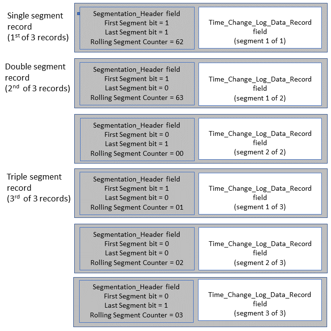 |
3.4.1.3. Time_Change_Log_Data_Record field
Table 3.10 shows the structure of the Time_Change_Log_Data_Record field used as part of the Time Change Log Data characteristic to notify time change events.
|
Event_Log_Flags (bit position) |
Field Name |
Requirement by event log type |
Data Type |
Size (Octets) |
Units |
||||
|---|---|---|---|---|---|---|---|---|---|
|
Time_Update |
Time_Fault |
User_Time_Change |
Max_RTC_Drift_Limit_Reached |
DT_Parameters_Changed |
|||||
|
N/A |
E2E_CRC |
C.1 |
C.1 |
C.1 |
C.1 |
C.1 |
uint16 |
2 |
N/A |
|
N/A |
Sequence_Number |
M |
M |
M |
M |
M |
uint16 |
2 |
None |
|
N/A |
Event_Log_Type |
M |
M |
M |
M |
M |
uint8 |
1 |
N/A |
|
N/A |
Event_Log_Flags (first column of this table) |
M |
M |
M |
M |
M |
structure |
3 |
N/A |
|
N/A |
DT_Status |
M |
M |
M |
M |
M |
structure |
2 |
N/A |
|
N/A |
DT_Status_Old |
M |
M |
E |
M |
E |
structure |
2 |
N/A |
|
N/A |
RTC_Time_Fault_Counter |
M |
M |
M |
M |
M |
uint16 |
2 |
None |
|
N/A |
Time_Zone |
M |
E |
M |
E |
E |
sint8 |
1 |
15 Minutes |
|
N/A |
DST_Offset |
M |
E |
M |
E |
E |
uint8 |
1 |
N/A |
|
N/A |
Time_Source |
M |
E |
E |
E |
E |
uint8 |
1 |
N/A |
|
N/A |
Time_Accuracy |
M |
E |
E |
E |
E |
uint8 |
1 |
1/8 Second |
|
N/A |
Base_Time |
M |
M |
M |
M |
M |
uint32 |
4 |
Seconds |
|
N/A |
Base_Time_Old |
M |
M |
E |
E |
E |
uint32 |
4 |
Seconds |
|
0 |
Accumulated_RTC_Drift |
C.2 |
E |
E |
E |
E |
uint16 |
2 |
Seconds |
|
1 |
User_Time |
E |
C.3 |
C.3 |
E |
E |
uint32 |
4 |
Seconds |
|
2 |
User_Time_Old |
E |
C.3 |
C.3 |
E |
E |
uint32 |
4 |
Seconds |
|
3 |
Base_Time_Second_Fractions |
C.4 |
C.4 |
E |
E |
E |
uint16 |
2 |
1/65,536 Second |
|
4 |
Base_Time_Second_Fractions_Old |
C.4 |
E |
E |
E |
E |
uint16 |
2 |
1/65,536 Second |
|
5 |
Non_Logged_Time_Adjustment_Limit |
E |
E |
E |
E |
C.5 |
uint16 |
2 |
Seconds |
|
6 |
Non_Logged_Time_Adjustment_Limit_Old |
E |
E |
E |
E |
C.5 |
uint16 |
2 |
Seconds |
|
7 |
Non_Logged_Time_Adjustment_Counter |
C.6 |
E |
E |
E |
E |
uint8 |
1 |
None |
|
8 |
Consolidated_Log_Counter |
C.7 |
E |
E |
E |
E |
uint8 |
1 |
None |
|
9 |
Active_Time_Adjustments |
C.8 |
E |
E |
E |
E |
structure |
7 or 11 |
N/A |
|
10 |
Displayed_Formats |
E |
E |
E |
E |
C.9 |
uint16 |
2 |
N/A |
|
11 |
Displayed_Formats_Old |
E |
E |
E |
E |
C.9 |
uint16 |
2 |
N/A |
|
12–23 |
RFU |
N/A |
N/A |
N/A |
N/A |
N/A |
N/A |
N/A |
N/A |
- M:
-
Mandatory
- E:
-
Excluded
- C.1:
-
Mandatory if the E2E-CRC feature is supported, otherwise Excluded.
- C.2:
-
Mandatory if the RTC Drift Tracking feature is supported, otherwise Excluded.
- C.3:
-
Mandatory if the Separate User Timeline feature is supported, otherwise Excluded.
- C.4:
-
Mandatory if the Base Time Second-Fractions feature is supported, otherwise Excluded.
- C.5:
-
Mandatory if the Propose Non-Logged Time Adjustment Limit feature is supported, otherwise Excluded.
- C.6:
-
Mandatory if the Non-Logged Time Change Active bit is set to 1 in the DT_Status field, otherwise Excluded.
- C.7:
-
Mandatory if the Log Consolidation Active bit is set to 1 in the DT_Status field, otherwise Excluded.
- C.8:
-
Mandatory if either the Non-Logged Time Change Active bit or the Log Consolidation Active bit is set to 1 in the DT_Status field, otherwise Excluded.
- C.9:
-
Mandatory if the Displayed_Formats Changeable feature is supported, otherwise Excluded.
The size of the Active_Time_Adjustments field is increased by 4 octets to 11 octets when the Base Time Second-Fractions feature is supported (see Table 3.13).
The Time_Change_Log_Data_Record field may be 14 to 45 octets (see Table 3.11).
Table 3.11 shows the minimum and maximum Time_Change_Log_Data_Record field size based on the time change event log type and the supported features.
|
Event log type |
|||||
|---|---|---|---|---|---|
|
Time_Update |
Time_Fault |
User_Time_Change |
Max_RTC_Drift_Limit_Reached |
DT_Parameters_Changed |
|
|
Minimum Octets per record |
24 |
16 |
16 |
16 |
14 |
|
Maximum Octets per record |
45 |
26 |
26 |
18 |
24 |
3.4.1.4. E2E_CRC field
If the service supports E2E-CRC, each Time_Change_Log_Data_Record field includes an E2E_CRC field the value of which is calculated over all data fields except for the E2E_CRC field itself (see [3] for details).
3.4.1.5. Sequence_Number field
The Sequence_Number field shall be included in the Time_Change_Log_Data_Record. The Sequence number is an unsigned integer that begins with the value 0 and increments for each logged event. When the Sequence_Number reaches 0xFFFF, it wraps back to 0x0000. The size of the time change event log is implementation-specific, and the oldest log entries shall be overwritten with the newest log entries when the time change event log reaches its maximum size.
The value of the Next_Sequence_Number field within the DT characteristic is always one greater than the value of the Sequence_Number field contained in the most recent log entry of Time_Change_Log_Data_Record.
3.4.1.6. Event_Log_Type field
The Event_Log_Type field shall be included in the Time_Change_Log_Data_Record. The Event_Log_Type field facilitates type filtering by Clients that collect records and defines the included fields of the record (event log type) to only those fields shown in Table 3.10.
|
Enumeration |
Event log type |
|---|---|
|
0x00 |
Time_Fault |
|
0x01 |
Time_Update |
|
0x02 |
User_Time_Change |
|
0x03 |
Max_RTC_Drift_Limit_Reached |
|
0x04 |
DT_Parameters_Changed |
|
0x05 – 0xFF |
RFU |
3.4.1.7. Event_Log_Flags field
The Event_Log_Flags field shall be used by the Server to signal which of the fields within the Time_Change_Log_Data_Record field are included in a specific event log type. When a bit in the flag field is set to 1, each notification shall include and populate the respective field with the appropriate value for that log entry.
See the first column of Table 3.10 for the requirements on the fields within the Time_Change_Log_Data_Record field that are conditional based on the type of time change event.
3.4.1.8. DT_Status field
The DT_Status field as defined in Section 3.3.1.5 shall accurately represent the Server’s time status when the Server logs the new time change event.
3.4.1.9. DT_Status_Old field
The DT_Status_Old field contains the DT_Status value that the Server had in affect just before the event that caused the log entry to be created.
3.4.1.10. RTC_Time_Fault_Counter field
The RTC_Time_Fault_Counter reveals the total number of time faults that has occurred on the device. The RTC_Time_Fault_Counter is a mandatory field for all log entries due to the negative impact of time faults on device time and timestamped data. The value of this field should be initialized to 0 to facilitate detection of a faulty device clock.
This field is incremented after logging a singular Time_Fault event or if the Server is consolidating Time_Fault events, then the value of the RTC_Time_Fault_Counter field is increased by the amount of the Consolidated_Log_Counter when the time fault consolidation is completed and logged (see Section 3.4.1.1.1.1).
3.4.1.11. Time_Zone field
The Time_Zone field shall contain the new value at the time of the log entry. For formatting of this field, see Section 3.3.1.3.
3.4.1.12. DST_Offset field
The DST_Offset field shall contain the new value at the time of the log entry. For formatting of this field, see Section 3.3.1.4.
3.4.1.13. Time_Source field
The Time_Source field shall have the same formatting as defined by the Time Source characteristic described in [3]. This field reveals the time source of the time values used for the time of the Time_Update event. When the log entry is the result of a time fault, and the Server does not have immediate access to a time source to re-initialize the Server’s time values to a qualified source, the Server shall record the time fault as having a Time_Source of Manual in the case where the user approves the time, or as Unknown in the case where a user does not approve the re-initialized time.
3.4.1.14. Time_Accuracy field
The Time_Accuracy field shall have the same formatting as defined by the Time Accuracy characteristic described in [3]. This is the Client’s accuracy of the Base_Time value at the time of the update.
When a Server logs a Time_Update event or logs a Time_Fault event with a Time_Source of Manual or Unknown, the Server shall log the value of Time_Accuracy as Unknown (0xFF) (see [3]).
3.4.1.15. Base_Time field
When the log entry is the result of a Time Update procedure, the Base_Time field shall always represent the time value received from a Time Update procedure regardless of whether the Server is consolidating Base_Time adjustments. The format of this field is the same as the format of the Base_Time field as defined in the DT characteristic.
When the log entry is the result of a time fault or is a consolidated time fault, the Base_Time field contains the Base_Time initialization value of the Server, which is implementation-specific (see Section 3.3.1.5.1.1).
When the log entry is not a result of a Base_Time change, the Base_Time field (and the Base_Time_Old field) represents the Server’s Base_Time at the moment of an event that required logging (for example, the user changed the User_Time by adjusting the device’s clock, or the user made a change to the Displayed_Formats).
Also refer to Section 3.4.1.16 for additional information about Base_Time for consideration regarding consolidated logging, accumulated RTC drift, or Accumulated Non-Logged Time Adjustments.
3.4.1.16. Base_Time_Old field
This field stores the Server’s present Base_Time in seconds at the time of a Time Update procedure, unless the log entry contains non-logged or consolidated Base_Time changes (see Section 3.4.1.1.1.2). The format of this field is the same as the format of the Base_Time field as defined in the DT characteristic.
When not consolidating time changes, a Server that accepts local Time Update values but rejects the Base_Time value shall use the same Base_Time value for both the Base_Time and Base_Time_Old fields to indicate that the Base_Time did not change and the Server shall also use the appropriate Rejection Flag during such Time Updates (see Table 3.22).
When the Server is consolidating time changes, and the Server accepts local Time Update values but rejects the Base_Time value, the Server shall retain the value of the Base_Time_Old to the value of the first Time Update that resulted in this consolidated record, and the Server shall also use the appropriate Rejection Flag during such consolidated Time Updates.
When the log entry is the result of an accumulation of Time Updates where the non-logged time adjustments exceeded the Non_Logged_Time_Adjustment_Limit, this field reveals the value of the Base_Time before the first Time Update adjusted the Base_Time below the Non_Logged_Time_Adjustment_Limit.
3.4.1.17. Accumulated_RTC_Drift field
The Accumulated_RTC_Drift field represents the Accumulated_RTC_Drift at the time of the event being logged. This is the accumulated drift value since the last Time Update procedure where the Base_Time has been accepted by the Server. The Accumulated_RTC_Drift field has the same format as defined in the DT characteristic.
3.4.1.18. User_Time field
The User_Time field holds the value for the new user-facing time that the user adjusted the time to. The User_Time field is the same as defined in the DT characteristic.
3.4.1.19. User_Time_Old field
The User_Time_Old field represents the user-facing time before the user made an adjustment to the User_Time. The format of this field is the same as the User_Time field as defined in the DT characteristic.
3.4.1.20. Base_Time_Second_Fractions field
When the Base_Time_Second_Fractions are supported by the Server, the Base_Time_Second_Fractions field is as defined for the DT characteristic and represents the new Base_Time_Second_Fractions of the log entry due to a time change event. The Base_Time_Second_Fractions value is the value of the Base_Time_Second_Fractions_Update accepted during a Time Update procedure or the value of Base_Time_Second_Fractions loaded by the Server at the moment of an event that required logging (see Section 3.4.1).
3.4.1.21. Base_Time_Second_Fractions_Old field
When the Server supports the Base Time Second-Fractions feature, the Base_Time_Second_Fractions_Old field shows the value of the Server’s Base_Time_Second_Fractions at the time of a Time Update or time re-initialization and follows the rules for Base_Time (see Section 3.3.1.5.1.1). The format of this field is the same as the format for the Base_Time_Second_Fractions.
3.4.1.22. Non_Logged_Time_Adjustment_Limit field
When the Server supports the Propose Non-Logged Time Adjustment Limit feature, the Non_Logged_Time_Adjustment_Limit field reveals the new value after the change to the Non_Logged_Time_Adjustment_Limit. This field has the same format as defined in the DT Parameters characteristic.
3.4.1.23. Non_Logged_Time_Adjustment_Limit_Old field
When the Server supports the Propose Non-Logged Time Adjustment Limit, the Non_Logged_Time_Adjustment_Limit_Old field reveals the old value before the change to the Non_Logged_Time_Adjustment_Limit. This field has the same format as the field as defined in the DT Parameters characteristic.
3.4.1.24. Non_Logged_Time_Adjustment_Counter field
When the Server has made adjustments to the Base_Time within the Non_Logged_Time_Adjustment_Limit, the Non_Logged_Time_Adjustment_Counter field represents the number of consolidated non-logged time adjustments that the Server performed on the Base_Time that resulted in the accumulation of Base_Time adjustments, as revealed in the Active_Time_Adjustments field as described in Section 3.4.1.1.1.2.
3.4.1.25. Consolidated_Log_Counter field
When the Server consolidates Time Faults or Time Updates to a single entry, the Consolidated_Log_Counter field represents the number of consolidated log entries of the same Log Type as described in Section 3.4.1.1.1.1.
3.4.1.26. Active_Time_Adjustments field
When the Server has made adjustments to the Base_Time value using either consolidation or non-logged time adjustments, the Active_Time_Adjustments field reveals the total of the adjustments. This structure is a group of fields that is used to both report and store Base_Time adjustments.
If the Server supports the Retrieve Active Time Adjustments feature, when either or both of the DT_Status bits for Non-Logged Time Change Active or Log Consolidation Active, when set to 1, reveals that this group of fields is available using the DTCP (see Section 3.7.1.2.1).
A Time_Change_Log_Data_Record field that contains the Active_Time_Adjustments field reveals that the Server made one or several Base_Time adjustments by either accumulated non-logged time adjustments or consolidated Base_Time adjustments or both.
The structure of the Active_Time_Adjustments field is shown in Table 3.13. The data fields that make up the Active_Time_Adjustments field are described in the following sub-sections.
|
Sub-Field Name |
Requirement |
Data Type |
Size (octets) |
Unit |
|---|---|---|---|---|
|
Accumulated_Non_Logged_Base_Time_Second_Fractions |
C.1 |
uint16 |
0 or 2 |
1/65,536 Second |
|
Accumulated_Non_Logged_Base_Time_Seconds |
M |
uint16 |
2 |
Seconds |
|
Sign of accumulated non-logged values (LSB; Bit 0) |
M |
structure |
1 |
None |
|
RFU Bits 1 to 5 |
||||
|
Epoch Span (Bit 6) |
||||
|
Sign of consolidated values (MSB; Bit 7) |
||||
|
Consolidated_Base_Time_Second_Fractions |
C.1 |
uint16 |
0 or 2 |
1/65,536 Second |
|
Consolidated_Base_Time_Seconds |
M |
uint32 |
4 |
Seconds |
- M:
-
Mandatory
- C.1:
-
Mandatory if the Base Time Second-Fractions feature is supported, otherwise Excluded.
3.4.1.26.1. Accumulated non-logged Base_Time adjustments
When the server supports the Time Change Logging feature, and the Non_Logged_Time_Adjustment_Limit is not set to 0, the Server shall use the Accumulated_Non_Logged_Base_Seconds field and the Accumulated_Non_Logged_Base_Time_Second_Fractions field (if supported) to report the value of the accumulated Base_Time adjustments that have been applied to the Base_Time due to non-logged time adjustments since the last logged time event involving a change to the Base_Time field.
When the Accumulated_Non_Logged_Base_Time_Second_Fractions field exceeds the Non_Logged_Time_Adjustment_Limit, the Server shall create a Time Change Log entry of the magnitude of the change by placing the Accumulated_Non_Logged_Base_Time_Seconds value into the Base_Time_Old and the Accumulated_Non_Logged_Base_Time_Second_Fractions value (if supported) into the Base_Time_Second_Fractions_Old field of the log entry and using the Base_Time_Update value of the last consolidated update as the Base_Time of the log entry. The rest of the log fields shall follow the Time Update event type regarding field entries of the log (see Section 3.4.1).
If the sign of accumulated non-logged values, bit 0, is set to 1, then the value of accumulated non-Logged Base_Time adjustments which is the total of both of the Accumulated_Non_Logged_Base_Time_Seconds field and the Accumulated_Non_Logged_Base_Time_Second_Fractions field (when supported) is negative so that the Base_Time value reported by the DT characteristic is less than it would have been due to accepting non-logged time adjustments. When this bit is not set, the Server’s adjustments to the Base_Time are positive and the Base_Time has been moved forward by the adjustment amounts.
3.4.1.26.2. Consolidated Base_Time adjustments
When the Server consolidates time faults or Time Update procedures to reduce event log records, the Consolidated_Base_Time_Seconds field contains the consolidated value for all Base_Time adjustments contained in this log entry as described in Section 3.4.1.1.1.1. Up until the consolidation is logged, the Consolidated_Base_Time_Seconds value can be obtained from the DTCP procedure for Retrieve Active Time Adjustments.
If the sign of consolidated values, bit 7, is set to 1, then the value of consolidated Base_Time adjustments (the total of both Consolidated_Base_Time_Seconds field and Consolidated_Base_Time_Second_Fractions field (when supported) is negative so that the Base_Time value reported by the DT characteristic is less than it would have been due to accepting Time Update procedures. When this bit is not set, the Server’s adjustments to the Base_Time value are positive and the Base_Time has been moved forward by the adjustment amounts.
The epoch span bit only applies to Servers that support both the Epoch Year 1900 feature and the Epoch Year 2000 feature. If the epoch span, bit 6, is set to 1, then the consolidation of Base_Time adjustments spans across a full epoch of seconds (0xFFFFFFFF) so that the Consolidated_Base_Time_Seconds field, and the Consolidated_Base_Time_Second_Fractions field (if supported) represents the seconds that the reported Base_Time has moved into the next epoch from the Epoch Year 2000 flag reported in the DT_Status.
An epoch span example: A Server that supports both epoch year features, reports the Base_Time value for 15:00 on January 10, 2045 (with the Epoch Year 2000 bit set to 1). The Server then accepts a Time Update procedure with the Epoch Year 2000 flag set to 0 that changes the Base_Time to 01:00 on October 5, 1901 and consolidates this time change using the Active_Time_Adjustments field.
3.4.1.27. Displayed_Formats field
The Displayed_Formats field reveals the new value from Table 3.5 after the change to the Displayed_Formats. The formatting of this field is as defined in the DT Parameters characteristic.
3.4.1.28. Displayed_Formats_Old field
The Displayed_Formats_Old field reveals the value before the change to the Displayed_Formats. The formatting of this field is the same as that of the Displayed_Formats field defined in the DT Parameters characteristic.
3.5. Common Behavior of Control Points within this service (DTCP and RACP)
3.5.1. Sequential processing of procedures
If a Control Point (CP) procedure is running and the Client sends a Write Request to execute another procedure for any CP of this service except the Abort Operation procedure of the RACP, the Server shall return an Error Response with the Attribute Protocol Application error code set to Procedure Already in Progress (see Section 3.8.3.6).
3.5.2. Procedure timeout
From the Server’s perspective, a CP procedure is started when the Server acknowledges the Write Request to the Control Point. A CP procedure is completed when the Server receives the Handle Value Confirmation for sending the indication of the CP procedure.
In the case of the RACP, procedures typically require multiple characteristic notifications followed by an indication of the control point characteristic to complete the procedure. In all cases, a procedure timeout is considered to have occurred if a notification or indication has not been sent by the Server, or if the Server has not received a Handle Value Confirmation of an indication within 30 seconds.
If the Server detects a timeout, then the Server shall stop sending any further indications and notifications related to the operation and shall consider the procedure to have failed.
If during execution of a CP procedure the connection to the Collector is lost, the procedure shall be considered to have failed and shall not resume upon the next connection. If the connection to the Collector is lost during the execution of a CP procedure, the Server should become connectable after the lost connection to allow the Client to retry a CP procedure.
3.5.3. General error handling procedure
Other than error handling procedures that are specific to certain Opcodes (see Table 3.21, Table 3.22, and Table 3.26), the following apply:
-
If an Opcode is written to the Control Point characteristic, and the CCCD of the Control Point is not configured for indications or notifications as described in the characteristic behavior for the notified Time Change Log Data characteristic, the Server shall return an error response with the Attribute Protocol Application error code set to Client Characteristic Configuration Descriptor Improperly Configured [4].
-
If the Opcode that was written to the Control Point characteristic is unsupported by the Server, or the Opcode used is marked as RFU in the CP requirements table (see Table 3.15 and Table 3.24), the Server shall indicate the Control Point with the Control Point’s response procedure, the appropriate Request Opcode, and a Response Code Value in the Operand set to Opcode Not Supported.
-
If the Operand that was written to the Control Point characteristic is invalid (for example, invalid structure or field with undefined field value), the Server shall indicate the Control Point with the Control Point’s response procedure, the appropriate Request Opcode, and a Response_Value or Response Code Value in the Operand set to Invalid Operand. Additionally, in the case of the DTCP where a detailed Rejection_Flags field is available, the Server should include at least one rejection reason (see Table 3.22).
-
If the Server was unable to complete a procedure for any reason other than those described above, the Server shall indicate, using the Control Point’s response procedure, the appropriate Request Opcode, and a Response Code Value in the Operand set to Procedure not completed (for RACP records requests that did not complete) or Operation Failed (for DTCP procedures that failed to resolve the requested DTCP procedure).
-
Certain Opcodes have specific error handling procedures as noted within the section describing the response to the Opcode.
3.5.4. Server behavior in case of E2E-CRC errors
If a Client writes to a Control Point and the Server supports E2E-CRC, the Server shall check the received E2E_CRC value. If the Server detects an error in the CRC calculation [3], the Server shall return an error response with the Attribute Protocol Application error code set to Invalid CRC (see Section 1.6).
3.5.5. Characteristic descriptors
3.5.5.1. Client Characteristic Configuration descriptor (DTCP)
When the DTCP characteristic is configured for indications, the Server shall respond to writes to this control point using the control point response; otherwise, the Server shall respond with an error for Client Characteristic Configuration Descriptor Improperly Configured [4].
3.5.5.2. Client Characteristic Configuration descriptor (RACP)
When the RACP characteristic is configured for indications, and the Time Change Log Data characteristic is configured for notifications, the Server shall respond to writes to this control point using the control point response; otherwise, the Server shall respond with an error for Client Characteristic Configuration Descriptor Improperly Configured [4].
3.6. Requirements for time-sensitive data
Both the Time Change Log Data characteristic and DT characteristic are time-sensitive characteristics. The Propose Time Update procedure, the Force Time Update procedure, and the Retrieve Active Time Adjustments procedure are all time-sensitive procedures. For the Server’s reported time values to have a certain level of reliability, the following requirements and recommendations apply:
-
The Server should be able to store at least 30-time change events in the records queue. Depending on the Server supported features, this minimum queue recommendation needs between 0.5 and 1.5 kB of nonvolatile memory (see Table 3.11).
-
If the maximum storage capacity in the Server is reached and the records queue is full, the Server shall overwrite the oldest change events first when recording new change events.
-
When transmitting stored records from the queue, the oldest events shall be sent first, followed by the next oldest events in first in first out (FIFO) order, until all stored events (as requested by the Client) have been transferred.
-
In time-critical applications, Time Update procedures should be monitored for the time of completion by both the Server and Client. Because the procedure timeout is 30 seconds, time values on their way to the Server can be up to 30 seconds old by the time they are implemented in the Server.
-
A time value requested by the Client may be old by the time it is received by the Client. Therefore, a Client may need to re-read either or both of the Server’s DT characteristic and the Active_Time_Adjustments (if implemented by the Server) when such messaging delays for time are observed by the Client in time-sensitive applications.
3.7. Device Time Control Point characteristic
The Device Time Control Point (DTCP) shall be used to execute a supported procedure on the Server.
Requirements for this characteristic are defined in Table 3.1.
The DTCP characteristic is identified by the value set to «Device Time Control Point» as defined in [2].
The structure of the DTCP characteristic is defined in Table 3.14.
|
Field Name |
Requirement |
Data Type |
Size (octets) |
Unit |
|---|---|---|---|---|
|
E2E_CRC |
C.1 |
uint16 |
0 or 2 |
None |
|
Opcode |
M |
uint8 |
1 |
N/A |
|
Operand |
C.2 |
Varies |
0 to 17 |
N/A |
- M:
-
Mandatory
- C.1:
-
Mandatory if the E2E-CRC feature is supported, otherwise Excluded.
- C.2:
-
Mandatory if the Opcode requires an Operand, otherwise Excluded (see Table 3.15).
The Opcode in Table 3.14 consists of either a Request Opcode for when the Client is requesting a procedure, or a Response Opcode for when the Server is responding to a requested procedure (see Table 3.15).
The Operand length depends on the procedure (see Table 3.15).
3.7.1. DTCP procedure requirements
Table 3.15 shows the requirements for the DTCP procedures.
The DTCP characteristic defines four Request Opcodes which are CP procedures initiated by the Client by way of a value Write Request to the DTCP handle. These Request Opcodes then trigger one of two DTCP Response Opcodes, which the Server sends as indications, including the appropriate operand in the indication to complete the procedure (see Table 3.15).
|
DTCP Request Opcodes |
Operand |
Remarks |
||
|---|---|---|---|---|
|
Value |
Procedure Name |
Requirement |
||
|
0x02 |
Propose Time Update |
M |
Operand for Time Update (see Table 3.16) |
The control point response to these opcodes is the DTCP Response. These Opcodes may require authorization if the Server supports the Authorization Required feature. |
|
0x03 |
Force Time Update |
O |
||
|
0x04 |
Propose Non-Logged Time Adjustment Limit |
C.1 |
Operand for Proposed Non-Logged Time Adjustment Limit (see Table 3.18) |
|
|
0x05 |
Retrieve Active Time Adjustments |
C.2 |
None |
The control point response to this opcode is the Report Active Time Adjustments procedure. |
|
DTCP Response Opcodes |
Operand |
Remarks |
||
|
Value |
Response Name |
Requirement |
||
|
0x07 |
Report Active Time Adjustments |
C.2 |
Operand for Report Active Time Adjustments (see Table 3.19) |
This opcode is the control point response to the Retrieve Active Time Adjustments opcode. |
|
0x09 |
DTCP Response |
M |
Operand for Response (see Table 3.20) |
This opcode is the response to the Propose Time Update procedure, Force Time Update procedure, and the Propose Non-Logged Time Adjustment Limit procedure. This opcode is also the failed response for Retrieve Active Time Adjustments. |
|
Opcode values Reserved for Future Use 0x00, 0x01, 0x06, 0x08, 0x0A – 0xFF |
||||
- M:
-
Mandatory
- O:
-
Optional
- C.1:
-
Mandatory if the Propose Non-Logged Time Adjustment Limit feature is supported, otherwise Excluded.
- C.2:
-
Mandatory if the Retrieve Active Time Adjustments feature is supported, otherwise Excluded.
3.7.1.1. DTCP Request Opcodes
This section describes the operands for the Request Opcodes of the DTCP (see Table 3.15).
3.7.1.1.1. Time Update operand
Table 3.16 shows the structure of the operand used for both of the Request Opcodes, Propose Time Update and Force Time Update.
|
Field Name |
Requirement |
Data Type |
Size (octets) |
Unit |
|---|---|---|---|---|
|
Time_Update_Flags |
M |
structure |
2 |
N/A |
|
Base_Time_Update |
M |
uint32 |
4 |
Seconds |
|
Base_Time_Second_Fractions_Update |
C.1 |
uint16 |
0 or 2 |
1/65,536 Second |
|
Time_Zone_Update |
M |
sint8 |
1 |
15 minutes |
|
DST_Offset_Update |
M |
uint8 |
1 |
None |
|
Time_Source_Update |
M |
uint8 |
1 |
None |
|
Time_Accuracy_Update |
M |
uint8 |
1 |
1/8 Second |
- M:
-
Mandatory
- C.1:
-
Mandatory if the Base Time Second-Fractions feature is supported, otherwise Excluded.
The size of the Time Update Operand is 10 or 12 octets depending on whether the Base Time Second-Fractions feature is supported.
3.7.1.1.1.1. Time_Update_Flags field
The Time_Update_Flags field reveals the status of the time information provided by the Client in the Time Update procedure. The bits of the Time_Update_Flags field are defined in Table 3.17. When a specific bit position is set, the description column describes the meaning for the Server.
|
Flag Name |
Bit Position |
Description |
|---|---|---|
|
UTC Aligned |
0 |
The Base_Time_Update value(s) of the Time Update operand are synchronized with a source that is aligned with UTC. |
|
Qualified Local Time |
1 |
The local time values provided in the Time Update operand, Time_Zone_Update and DST_Offset_Update, are synchronized with a qualified local source that has provided Qualified Local Time information. |
|
Adjust Reason; Manual Adjustment |
2 |
Manual Time Update |
|
Adjust Reason; External Adjustment |
3 |
External Reference Time Update |
|
Adjust Reason; Time Zone Adjustment |
4 |
Time Zone change |
|
Adjust Reason; DST Offset Adjustment |
5 |
DST Offset change |
|
Epoch Year 2000 |
6 |
The values expressed in this update use the Epoch Year 2000 when set to 1 and Epoch Year 1900 when set to 0. |
|
Second-Fractions Not Valid |
7 |
The value of the Base_Time_Second_Fractions_Update field is not valid and can be ignored. |
|
RFU |
8–15 |
Reserved for Future Use |
3.7.1.1.1.2. Base_Time_Update field
The Base_Time_Update field is a 4-octet field, representing the seconds since January 1, 1900 at 00:00:00.0, unless the Time Update Flag indicates the Epoch Year 2000 is set to 1, then the Base_Time_Update seconds is the accumulated seconds since January 1, 2000; 00:00:00.
3.7.1.1.1.3. Base_Time_Second_Fractions_Update field
For Servers that support the Base Time Second-Fractions feature, the Base_Time_Second_Fractions field is a 2-octet field, representing the fractions of a second of the Base_Time_Update of the synchronized time source.
3.7.1.1.1.4. Time_Zone_Update field
The Time_Zone_Update field is as defined by the Time Zone characteristic defined in [3].
3.7.1.1.1.5. DST_Offset_Update field
The DST_Offset_Update field is as defined by the DST_Offset characteristic defined in [3].
3.7.1.1.1.6. Time_Source_Update field
The Time_Source_Update field is as defined by the Time Source characteristic defined in [3].
3.7.1.1.1.7. Time_Accuracy_Update field
The Time_Accuracy_Update field is as defined by the Time Accuracy characteristic defined in [3].
3.7.1.1.2. Operand for Propose Non-Logged Time Adjustment Limit
Table 3.18 shows the structure of the Operand used for the Propose Non-Logged Time Adjustment Limit Opcode.
|
Field Name |
Requirement |
Data Type |
Size (octets) |
Unit |
|---|---|---|---|---|
|
Non_Logged_Time_Adjustment_Limit_New |
M |
uint16 |
2 |
Seconds |
- M:
-
Mandatory
3.7.1.1.2.1. Non_Logged_Time_Adjustment_Limit_New field
The Non_Logged_Time_Adjustment_Limit_New field has the same definition as Non_Logged_Time_Adjustment_Limit field used in the DT Parameters characteristic (see Section 3.2.1.5).
3.7.1.2. DTCP Response Opcodes
This section describes the Operands for the Response Opcodes available in DTCP (see Table 3.15).
3.7.1.2.1. Operand for Report Active Time Adjustments
When the Server is adjusting the Base_Time by implementing either consolidated logging or non-logged time adjustments as indicated by the appropriate bits in the DT_Status field, the Server shall support reporting these accumulated Base_Time adjustments through the DTCP procedure Retrieve Active Time Adjustments. The structure of the Operand for the Report Active Time Adjustments response is shown in Table 3.19.
|
Field Name |
Requirement |
Data Type |
Size (octets) |
Unit |
|---|---|---|---|---|
|
Base_Time_Second_Fractions |
C.1 |
uint16 |
0 or 2 |
1/65536 Second |
|
Base_Time |
M |
uint32 |
4 |
Seconds |
|
Active_Time_Adjustments (Table 3.13) |
M |
structure |
7 or 11 |
None |
- M:
-
Mandatory
- C.1:
-
Mandatory if the Base Time Second-Fractions feature is supported, otherwise Excluded.
3.7.1.2.2. Operand for DTCP Response
The DTCP Response operand for the Propose Time Update procedure, Force Time Update procedure, Propose Non-Logged Time Adjustment Limit procedure, and the failed response to Retrieve Active Time Adjustments procedure is shown in Table 3.20.
|
Operand Parameter Name |
Requirement |
Data Type |
Size (octets) |
Unit |
|---|---|---|---|---|
|
Request_Opcode (Table 3.15) |
M |
uint8 |
1 |
None |
|
Response_Value (Table 3.21) |
M |
uint8 |
1 |
None |
|
Rejection_Flags (Table 3.22) |
C.1 |
structure |
0 or 2 |
None |
- M:
-
Mandatory
- C.1:
-
Mandatory if the Response_Value is Procedure Rejected, otherwise Excluded.
3.7.1.2.2.1. DTCP Response_Values
The DTCP Response_Values for the DTCP Response_Opcode are listed in Table 3.21.
|
DTCP Response_Value |
DTCP Response Name |
Response Parameter |
Response Description |
|---|---|---|---|
|
0x00 |
Reserved for Future Use |
None |
N/A |
|
0x01 |
Success |
None |
Response to successful Time Update or Propose Non-Logged Time Adjustment Limit procedures |
|
0x02 |
Opcode Not Supported |
None |
Response if unsupported Opcode is received |
|
0x03 |
Invalid Operand |
None |
Response if Operand received does not meet the requirements of the service |
|
0x04 |
Operation Failed |
None |
Response if unable to complete a procedure for any reason |
|
0x05 |
Procedure Rejected |
Rejection_Flags (see Table 3.22) |
Response if the Opcode or Operand received does not meet requirements of the Server |
|
0x06 |
Reserved for Future Use |
None |
N/A |
|
0x07 |
Device Busy |
None |
Response if a procedure is already in progress or otherwise unavailable to execute the requested Opcode |
|
0x08 - 0xFF |
Reserved for Future Use |
None |
N/A |
3.7.1.2.2.2. Rejection_Flags for DTCP Response
Table 3.22 shows the structure of the Rejection_Flags field for Time Update and Propose Non-Logged Time Adjustment Limit procedures where the response is negative, requiring a DTCP Response Parameter in the form of rejection flags to aid in the Client identifying why the Server rejected all or part of a procedure.
The Rejection_Flags of Table 3.22 consist of a bit field. The Server shall use the Time Update Rejection_Flags field, using appropriate combinations of any of the defined bits as described in Table 3.22 with at least one flag being set.
|
Bit Position(s) |
Rejection_Flags Parameter of DTCP Response |
|---|---|
|
0 |
The Base_Time_Update value is not realistic. |
|
1 |
Requested procedure is not authorized. |
|
2 |
A required field in the Operand is out of range. |
|
3 |
Time source is not UTC aligned (and Server is aligned). |
|
4 |
Time_Accuracy_Update (Client drift) is out of range or is unknown. |
|
5 |
Time source is lower quality than presently synchronized time source (see Appendix A.5 and A.6 for additional time quality discussion). |
|
6 |
Epoch Year flag is not aligned with implementation supported features. |
|
7 |
Reserved for Future Use |
|
8 |
Lack of precision (Base_Time_Second_Fractions_Update field not provided by Client). |
|
9 |
The Base_Time_Update value(s) of the Time Update has been rejected but local time values of Time_Zone_Update and DST_Offset_Update were accepted. |
|
10 |
The local time values of Time_Zone_Update and DST_Offset_Update from the Time Update were rejected but the Base_Time_Update value(s) were accepted. |
|
11–15 |
Reserved for Future Use |
For example, the Server may use multiple flags to reject a single Time Update proposal to further aid the Client in understanding the nature of the rejection. A Time Update from a Client to a UTC-aligned Server may reveal that the Client is not UTC-aligned and that the time of the update is a year behind the present device’s UTC-aligned time. The device may choose to reject this request based on numerous reasons depending on the implementation, including the Client not being aligned to UTC, the year not being realistic based on the Server’s sense of UTC time, or the epoch year of the update does not match the Server’s supported epoch year. The Server should indicate as many discovered Rejection Flags as it can discern.
Servers shall reject any Time Updates from Clients with the Time Update status for the Epoch Year 2000 not in alignment with the Server’s supported features. The Server shall use the appropriate rejection flag from Table 3.22.
See Section Appendix A.7 for examples of rejection messaging from the Server.
3.7.2. Device Time Control Point characteristic behavior
The DTCP is used by a Client to control certain behaviors of the Server. Procedures are triggered by the Client writing one of the four Request Opcodes, which is followed by an operand that is valid within the context of the Request Opcode (see Section 3.7.1.1).
The Server responds to the Client’s DTCP procedure requests using one of the two Response Opcodes as appropriate for the Requested Opcode, which is followed by a response operand that is valid within the context of the Response Opcode (see Section 3.7.1.2).
3.7.2.1. Common behavior of Time Update procedures
This section contains Time Update behaviors that are common to both the Propose and Force update procedures.
3.7.2.1.1. Common Time Update behavior for success and failure
When the Server accepts the Time Update procedure, the Server shall indicate to the control point using the DTCP Response_Value for Success (see Table 3.21).
When the Server does not accept a Time Update procedure, the Server shall respond with the DTCP Response Code opcode (0x09), the Request_Opcode, the appropriate DTCP Response_Value (from Table 3.21), and if the Response_Value is for Procedure Rejected (0x05), the response operand includes the appropriate Rejection_Flags (from Table 3.22).
3.7.2.1.2. Common Time Update behavior and Base_Time
A Server that restricts the range of values for Base_Time and/or Base_Time_Updates that receives a Time Update procedure with an operand having a Base_Time_Update value that is outside of the restricted range of Base_Time values shall use the DTCP Response_Value for Procedure Rejected (0x05) with Rejection Flag for ‘operand out of range’ (0x02). See Section 3.3.1.2 regarding restricting the valid range of values for the Base_Time fields.
3.7.2.1.3. Common Time Update behavior and Base Time Second-Fractions
If the Server does not support the Base Time Second-Fractions feature but the operand of the Time Update procedure includes the Base_Time_Second_Fractions_Update field, the Server shall respond with a DTCP Response_Value for Invalid Operand (0x03).
If the Server supports the Base Time Second-Fractions feature but the operand of the Time Update procedure does not include the Base_Time_Second_Fractions_Update field, the Server shall respond with a DTCP Response_Value for Invalid Operand (0x03).
3.7.2.1.4. Common Time Update behavior and epoch year support
During Time Update procedures, the Base_Time_Update field of the update Operand is marked as based on one of the Epoch Year supported flags. A Server that supports both Epoch Year flags is not obligated to alternate between epoch years during Time Update procedures and may reject such updates with the appropriate Rejection Flag unless mandated to do so by an authorized client that uses the Force Time Update procedure (see Section 3.7.1.1.1).
3.7.2.2. Propose Time Update procedure
This section describes expected Server behavior when responding to the DTCP Opcode for Propose Time Update under various system configurations.
The Server may compare the quality and accuracy of the fields within the operand of a Proposed Time Update with its own time quality values and accuracy values before accepting the proposed Time Update. The Server may reject a Time Update proposal based on this comparative quality analysis. See Section A.8 for a discussion of time quality evaluation. In general terms, the Server should reject a Time Update proposal that reduces the Server’s time quality and respond to the Client with the appropriate Rejection Flag(s) set in the operand of the DTCP Response_Value for Procedure Rejected (see Table 3.21).
A Server that receives a Propose Time Update procedure with an operand that contains a valid Base_Time_Update value may use the Response Rejection Flag for Base_Time_Update is unrealistic (bit 0 is set to 0 after determining that the Base_Time_Update value appears to be too far from the expected Base_Time value to be realistic). The Server’s rejection of the Base_Time_Update value may occur whether or not the Server has restricted the range of valid values for Base_Time and whether or not the rejected Base_Time_Update value is within the Server’s restricted range.
If the Server supports the Base Time Second-Fractions feature and the Second-Fractions Not Valid bit of the Propose Time_Update_Flags is set to 1, the Server may reject the Propose Time Update using the DTCP Response_Opcode with DTCP Response_Value for Procedure Rejected (0x05) with Rejection Flags indicating Lack of Precision (0x08) and/or Base_Time_Update rejected but local time values accepted (0x09).
3.7.2.3. Force Time Update procedure
The Server shall accept all Force Time Update procedures from an authorized Client without evaluation as to the comparable quality of the Client’s time values versus the Server’s time values.
When a Server supports the Base Time Second-Fractions feature, the Second-Fractions Not Valid bit of the Time_Update_Flags being set to 1 shall not be a reason for rejection of a Force Time Update procedure.
3.7.2.4. Propose Non-Logged Time Adjustment Limit procedure
When the Server supports the Propose Non-Logged Time Adjustment Limit feature, the Server shall allow an authorized Client to initiate the DTCP procedure Propose Non-Logged Time Adjustment Limit. The Server may limit the values that an authorized Client may write to the Non-Logged Time Adjustment Limit field.
If the Server accepts the value from the Propose Non-Logged Time Adjustment procedure, and the Server supports the Time Change Logging feature, then the Server creates a time change log for this event and includes the fields as described in Table 3.10 for the DT_Parameters_Changed event (see Section 3.4.1.1.5).
The Server may reject the Propose Non-Logged Time Adjustment Limit procedure using the DTCP Response_Opcode with the Response_Value for Procedure Rejected, and the Server shall provide the appropriate Parameter Rejection Flag(s) per Table 3.22.
3.7.2.5. Retrieve Active Time Adjustments procedure
When the Server supports the Retrieve Active Time Adjustments feature, and the Server has made adjustments to the Base_Time due to log consolidations or non-logged time adjustments (see Sections 3.3.1.5.6 and 3.3.1.5.7), and the Server receives a Request_Opcode for Retrieve Active Time Adjustments, the Server shall respond with the Report Active Time Adjustment Response_Opcode using the operand as described in Table 3.19.
When the Server supports the Retrieve Active Time Adjustments feature, and the Server is not actively making unlogged-Base_Time adjustments reported by this procedure, and the Server receives a Request_Opcode for Retrieve Active Time Adjustments, the Server shall respond with the Response_Opcode for Report Active Time Adjustments with the operand described in Table 3.19 showing all the supported fields set to a value of zero as confirmation that no Base_Time adjustments are applied to the Base_Time value of the DT characteristic.
When a Server does not support the Retrieve Active Time Adjustments feature or when the Server cannot complete the procedure, the Server shall respond using the DTCP Response Code opcode with the appropriate failure Response_Value (see Table 3.21).
3.8. Record Access Control Point (RACP) characteristic
The RACP shall be used to retrieve Time Change Log Data.
Requirements for this characteristic are defined in Table 3.1.
The RACP characteristic is identified by the value set to «Record Access Control Point» as defined in [2].
Within the context of the Device Time Service, a ”record” consists of a Time Change Log Data event that may be notified either as a single notification or a series of notifications depending on the size of the stored record and the current ATT_MTU size (see Section 3.4.1.2.1).
3.8.1. Record Access Control Point (RACP) definition
The structure of RACP within the DTS is shown in Table 3.23.
|
Field Name |
Value |
Requirement |
Data Type |
Size (octets) |
Unit |
|---|---|---|---|---|---|
|
Opcode |
M |
unit8 |
1 |
None |
|
|
Operator |
M |
uint8 |
1 |
None |
|
|
Operand |
Table 3.24 and Table 3.27 |
C.1 |
structure |
0 to 5 |
None |
- M:
-
Mandatory
- C.1:
-
Mandatory for all supported operators that require a Filter Type; otherwise Excluded.
The Opcode in Table 3.23 consists of either a Request Opcode for when the Client is requesting a procedure, or a Response Opcode for when the Server is responding to a requested procedure (see Table 3.24).
3.8.2. Record Access Control Point (RACP) procedure requirements
Table 3.24 shows the requirements for the RACP procedures (opcodes, operators, and operands) in the context of the Device Time Service.
|
RACP Requests |
||||||
|---|---|---|---|---|---|---|
|
Request Opcodes |
Operator |
Operand |
||||
|
Procedure Name |
Requirement |
Name |
Requirement |
Parameters (Table 3.25) |
Requirement |
|
|
Filter_Type |
Filter_Value(s) |
|||||
|
Report Stored Records |
O |
All records |
O |
No operand |
N/A |
|
|
First record |
O |
No operand |
N/A |
|||
|
Last record |
O |
No operand |
N/A |
|||
|
Greater than or equal to |
O |
M |
<minimum Filter_Value> |
M |
||
|
Less than or equal to |
O |
M |
<maximum Filter_Value> |
M |
||
|
Within range of (inclusive) |
O |
M |
<minimum Filter_Value>, <maximum Filter_Value> |
M |
||
|
Report Number of Stored Records |
M |
All records |
M |
No operand |
||
|
First record |
M |
No operand |
||||
|
Last record |
M |
No operand |
||||
|
Less than or equal to |
M |
M |
<minimum Filter_Value> |
M |
||
|
Greater than or equal to |
M |
M |
<maximum Filter_Value> |
M |
||
|
Within range of (inclusive) |
M |
M |
<minimum Filter_Value>, <maximum Filter_Value> |
M |
||
|
Combined Report |
M |
All |
M |
No operand |
||
|
First record |
M |
No operand |
||||
|
Last record |
M |
No operand |
||||
|
Greater than or equal to |
M |
M |
<minimum Filter_Value > |
M |
||
|
Less than or equal to |
M |
M |
<maximum Filter_Value> |
M |
||
|
Within range of (inclusive) |
M |
M |
<minimum Filter_Value>, <maximum Filter_Value > |
M |
||
|
Abort Operation |
O |
Null |
M |
No operand |
||
|
RACP Responses |
||||||
|
Response Opcodes |
Operator |
Operand |
||||
|
Procedure Name |
Requirement |
Name |
Requirement |
Parameters (Table 3.25) |
Requirement |
|
|
Combined Report Response |
M |
Null |
M |
uint16 containing Number of Records |
M |
|
|
Response Code |
M |
Null |
M |
Request Opcode (this table), Response_Code_Value (see Table 3.26) |
M |
|
|
Number of Stored Records Response |
M |
Null |
M |
uint16 containing Number of Records |
M |
|
- M:
-
Mandatory
- O:
-
Optional
Table 3.25 shows the complete list of RACP operators and their associated operand definitions.
|
RACP Operator Value |
RACP Operator Name |
Operand Description |
|---|---|---|
|
0x00 |
Null |
The null operator is used as the operator for all RACP responses (see Table 3.24). |
|
0x01 |
All records |
No operand is used |
|
0x02 |
Less than or equal to |
Operand consists of the Sequence Number Filter_Type (0x01), and Filter_Value for maximum. |
|
0x03 |
Greater than or equal to |
Operand consists of the Sequence Number Filter_Type (0x01), and the Filter_Value for minimum. |
|
0x04 |
Within range of (inclusive) |
Operand consists of the Sequence Number Filter_Type (0x01) and the Filter_Value pair for; minimum, and maximum. |
|
0x05 |
First record |
No operand is used |
|
0x06 |
Last record |
No operand is used |
|
0x07–0xFF |
— |
RFU |
The operand Filter_Value parameters of minimum and maximum can be ambiguous when the Server has rolled the Sequence_Number field value. The Server is not obligated to try and make sense of a Client’s request for records when using the Filter_Value parameters and may respond with ‘no records found’ if the Client’s request does not appear to ask for a set of records that exists in the current Server’s record que.
The enumerated values for the Response_Code_Value parameter from the operand of the RACP Response Code are defined in Table 3.26.
|
Response_Code_Value |
RACP Response Name |
Response Description |
|---|---|---|
|
0x01 |
Success |
Normal response for successful operation |
|
0x02 |
Opcode Not Supported |
Normal response if unsupported opcode is received |
|
0x03 |
Invalid Operator |
Normal response if operator received does not meet the requirements of the service (for example, a Null was expected) |
|
0x04 |
Operator Not Supported |
Normal response if unsupported operator is received. |
|
0x05 |
Invalid Operand |
Normal response if operand received does not meet the requirements of the service. |
|
0x06 |
No Records Found |
Normal response if request for records resulted in no records meeting criteria. |
|
0x07 |
Abort Unsuccessful |
Normal response if request for Abort cannot be completed. |
|
0x08 |
Procedure Not Completed |
Normal response if unable to complete a procedure due to some internal Server issue (examples include device measurement initiated, resource conflict). |
|
0x09 |
Operand Not Supported |
Normal response if unsupported operand is received. |
|
0x00, 0x0A-0xFF |
Reserved for Future Use |
N/A |
3.8.3. Record Access Control Point behavioral description
Within the context of the DTS, a record (also referred to as Time Change Log entry) consists of a Time Change Log Data characteristic. Records represent time change events recorded by the Server.
The RACP controls notifications of the Time Change Log Data characteristic. Procedures are triggered by a write to the RACP characteristic value that includes an opcode specifying the operation (see Table 3.24) and an operator and operand that are valid within the context of that opcode. In a multiple-bond case, the handling of the RACP shall be consistent across all bonded Clients such that a single-Server history record database is shared by all Clients.
For RACP timeout requirements, see Section 3.5.2.
The RACP Delete Records opcode is not defined for this service. Because other services may use the DTS and may rely on Time_Change_Log_Data_Records for reconciling stored data, it is important that the Time_Change_Log_Data_Records do not get deleted.
3.8.3.1. Filter_Type parameter
Because the value of the operand is defined per service, when the RACP is used with the Device Time Service, the Filter_Type parameter of the operand is defined exclusively as ‘Sequence Number’.
In DTS, some RACP procedures have operands that require multiple parameter values to support searching of response data. When required by an operator, the Filter_Type parameter octet shall precede the applicable Filter_Value parameter octets within the operand. For example, when used with the “within range of” operator, the operand has the transmission order of; <Filter_Type><minimum Filter_Value><maximum Filter_Value>, where the Filter_Type field value is the Least Significant Octet of the operand.
See Table 3.27 for the ‘Sequence Number’ Filter_Type enumeration.
|
Operand parameter Filter_Type value |
Filter_Type Description |
|---|---|
|
0x01 |
Sequence Number |
|
0x00, 0x02 – 0xFF |
RFU |
3.8.3.2. Combined Report procedure
When the Combined Report opcode is written to the RACP the Server shall notify the requested set of stored records based on the filter criteria specified in the operator and operand. Refer to Table 3.25 for operand requirements when used with a specific operator and note that in some cases, no operand is used. The semantics of a record transfer is a “copy” of the records and not a” move” of the records so that the Server retains the original log entries.
If, during the record transfer, a new history record becomes available (in other words, after the Combined Report procedure is initiated), the Server may include this new record in the history transfer.
Once all records for a given request have been notified by the Server, the Server shall indicate the RACP with the Response Opcode for Combined Report Response, operator of Null, and the operand equal to the number of records sent (see RACP in [3]).
If the Server does not locate any records matching the request, the Server shall indicate the RACP with a Combined Response, operator of Null, and the operand set to 0.
When the Server is reporting stored records, the Server shall report records by order of first in first out (FIFO, oldest Sequence Number first).
If the operation results in an error condition, this shall be indicated using the Response Code opcode, operator of Null, Request Opcode of Combined Report, and the appropriate Response Code Value in the operand for the error condition (see Sections 3.8.3.6 and 3.5.3).
If the Server ends its data transfer of requested records before completion for any reason other than the Abort Operation procedure (see Section 3.8.3.5), the Server shall indicate the RACP with the Response Code, operator of Null, Request opcode of Combined Report, and a Response Code Value in the operand set to Procedure Not Completed.
3.8.3.3. Report Stored Records procedure
When the Report Stored Records opcode is written to the RACP, the Server shall notify the selected set of stored records based on the filter criteria specified in the operator and operand. Refer to Table 3.25 for operand requirements when used with a specific operator and note that in some cases, no operand is used. The semantics of a record transfer is a “copy” of the records and not a ”move” of the records so that the Server retains the original log entries.
If, during the record transfer, a new history record becomes available (in other words, after the Report Stored Records procedure is initiated), the Server may include this new record in the history transfer if the new record satisfies the filter criteria of the executing records request.
Once all data records for a given request have been notified by the Server, the Server shall indicate the RACP with the Response Code, operator of Null, a Request opcode of Report Stored Records, and a Response Code Value in the operand set to Success (see RACP in [3]).
If the Server does not locate any records matching the request, the Server shall indicate the RACP with the Response Code, operator of Null, Request opcode of Report Stored Records, and a Response Code Value in the operand set to No Records Found (0x06).
When the Server is reporting stored records, the Server shall report records in first in first out (FIFO) order.
If the operation results in an error condition, this shall be indicated using the Response Code, operator of Null, Request opcode of Report Stored Records, and the appropriate Response Code Value in the operand for the error condition (see Sections 3.8.3.6 and 3.5.3).
If the Server ends its data transfer of requested records before completion for any reason other than the Abort Operation procedure (see Section 3.8.3.5), the Server shall indicate the RACP with the Response Code opcode, operator of Null, Request Opcode of Report Stored Records, and a Response Code Value in the operand set to Procedure Not Completed.
3.8.3.4. Report Number of Stored Records procedure
When the Report Number of Stored Records opcode is written to the RACP, the Server shall calculate and respond with a record count based on the operator and operand values. See Table 3.25 for operand requirements when used with a specific operator and note that in some cases, no operand is used. The record count reported in the response is calculated based on the current state of the Server history record database and may change between connections as records are created or created and over-written. The response to the Report Number of Stored Records procedure is indicated using the Number of Stored Records Response.
If the Server does not locate any records matching the request, the Server shall indicate the RACP with the Number of Stored Records Response Opcode, the Null operator, and the operand set to a count of no records (0x0000).
If the operation results in an error condition, this shall be indicated using the Response Code and the appropriate Response Code Value in the operand for the error condition (see Sections 3.8.3.6 and 3.5.3).
3.8.3.5. Abort Operation procedure
When the Abort Operation opcode is written to the RACP, the Server shall stop any RACP procedures that are in progress and stop sending any further data.
Once all RACP procedures have been stopped, the Server shall indicate the RACP with the Response Code, operator of Null, Request Opcode of Abort Operation, and a Response Code Value in the operand set to Success.
If the operation results in an error condition, this shall be indicated using the Response Code, operator of Null, Request Opcode of Abort Operation, and the appropriate Response Code Value in the operand for the error condition (see Sections 3.8.3.6 and 3.5.3).
3.8.3.6. Common RACP errors
If the Filter_Type parameter value within an operand that was written to the RACP is an RFU value, the Server shall indicate the RACP with the Response Code, operator of Null, the appropriate Request Opcode, and a Response Code Value in the operand set to Operand Not Supported (see Record Access Control Point in [3]).
If the Server is unable to process the Abort Operation procedure for any reason not stated in this Section, the Server shall indicate the RACP with the Response Code, operator of Null, the appropriate Request Opcode, and a Response Code Value in the operand set to Abort Unsuccessful.
If the operator that was written to the RACP is not supported by the Server (see Table 3.25), then the Server shall indicate the RACP with the Response Code, operator of Null, the appropriate Request Opcode, and a Response Code Value in the operand set to Operator Not Supported.
If the operator that was written to the RACP is supported by the Server but is not applicable for the used opcode, the Server shall indicate the RACP with the Response Code, operator of Null, the appropriate Request Opcode, and a Response Code Value in the operand set to Invalid Operator.
If a request with an opcode other than Abort Operation is written to the RACP while the Server is performing a previously triggered RACP operation (in other words, resulting from invalid Client behavior), the Server shall return an error response with the Common Profile and Service error code of Procedure Already In Progress (see [3]).
4. Terms and concepts for Device Time
This specification is based on the concept of base-offset time being implemented in devices. There are other time keeping methods available to devices such as relative and absolute. Base-offset time provides a means to align to a time reference and to also provide for local time adjustments.
4.1. Real-time clock
A device’s time counting component is known as a real-time clock (RTC). The RTC provides a means of reporting the device’s time. Nearly all portable devices implement an RTC because access to a time reference is not readily available or practical.
When Base-Offset time representation is implemented in devices using this specification, the device uses its RTC to align with UTC as the Base Time component and combines the Base Time with an offset to achieve a local time value. The local offsets consist of both time zone and DST offsets.
4.1.1. RTC accuracy
Clock drift is the tendency of a clock to run faster or slower than a time reference. A device’s RTC accuracy is a clock error factor that over time is observed as clock drift.
The device’s RTC is expected to run with a certain and known minimum accuracy. It is important for the DTS to clearly identify this minimum clock accuracy, which is defined by the implementation. A handheld device’s RTC accuracy is typically defined in terms of parts per million (ppm). The oscillator component used in the device primarily drives clock accuracy.
To first order analysis, the worst-case RTC drift value increases with time at a constant slope. An RTC implementation with a 30 second per month accuracy would also have a 360 second per year accuracy. A device with a 1 second per day accuracy corresponds roughly to a 12-ppm oscillator.
4.2. Qualified time
From IEEE timestamp workshops:
|
A ‘qualified time’ expresses a unique time point along the Coordinated Universal Time (UTC) timescale that is the primary time standard by which the world regulates clocks and time. Continua H.812.1 Observation Upload Capability further indicates qualified time is any time synchronized to UTC ‘with or without knowledge of local time’. |
Local time is not qualified time because there is no way to determine the UTC time value from the local time value.
Qualified time is critical in handling and managing time-stamped data. Devices that create and store data must have qualified time available to the device so that stored data can be unambiguously integrated into a larger ecosystem with data from other devices regardless of whether the device experiences time faults.
Synchronizing a device to a time reference that is linked to the UTC is the only way to achieve qualified time within a device. There might be times when a time source is unable to align with the UTC, just as a remote device without access to time sources should declare that it is no longer accurately tracking (aligned to) the time source it was once synchronized with.
4.3. Base time
The Base Time of a device is represented in DTS as the Base_Time field of the DT characteristic (see Section 3.3.1.2). The Base Time of a device should be synchronized to a qualified time source that is aligned to the UTC by a Client. The Base Time of the device will always have a maximum deviation from the UTC; this is the worst-case RTC drift mentioned previously. The Base Time is meant to be kept as close to the UTC time value as necessary. Under all circumstances, the purpose of the DTS is to know the maximum deviation of the device’s Base Time to UTC or to know that the current deviation of the device’s Base Time to the UTC is unknown or a very large deviation from the UTC so that the device is not aligned to the UTC.
4.3.1. Time faults
A time fault occurs when there is an unknown shift in the timeline of a device (a discontinuity in Base Time). There are numerous causes for the occurrence of time faults, the most obvious being removal of power from the device’s RTC.
4.4. Local time offsets
The local time offsets have a constant and configurable distance to the Base Time. The purpose of local time is to give a device’s user a better understanding of the current time based on their geographic location. Therefore, the local time will usually be the device’s local time, for example Pacific Standard Time (PST) or Eastern Standard Time (EST).
4.4.1. User-facing time (User Time)
If a device displays time and allows a user to set the time of the device manually, the time will likely not align exactly to a time reference even when including local time information. In the case of a manually set time, the user has created a unique user-facing time that should not affect or degrade the UTC aligned (timeline) or local time information. If a device supports a user to set the time on the device, the device’s date and time would typically also support a User Time. The User Time needs to be stored by the Server because this is a separate timeline from the synchronized time for displaying the user-facing time and reporting to Clients this user-facing time.
Regardless of the reasons for a user adjusting the time on a device, this time adjustment needs to be accounted for without degrading the quality of the UTC-aligned Base Time and local offsets. Additionally, for the purpose of context to what a device user sees as displayed time and the ability to track user adjustments to time needs to be facilitated.
4.5. Time source
A time source is a physical clock possibly aligned to the UTC. The Base Time of the DTS should be synchronized to a qualified time source.
4.5.1. Time quality
All possible time sources are not equal in terms of quality and accuracy. Time sources that report alignment with the UTC are assigned the highest priority and quality. Time sources are expected to report their accuracy capability, which is often dominated by network delays.
Time source quality may include knowing the source type, the source accuracy, last synchronization, alignment to the UTC status, and adjustment reason (if any). The poorest time source is manually set.
4.6. Time references
There are several time references, with UTC being the most commonly accepted.
4.7. Time synchronization
Time synchronization of a device is completed by setting the device’s Base Time to a time value from a time source and assigning time quality information to that synchronization event. Time synchronization of a device may also include updating the local time information.
4.8. Time change logging
In some use cases, a device’s stored data needs to be supported with confirmation that the timestamps are reliable (aligned to the UTC). To improve timestamp reliability, time change logging allows for auditing a device’s time change history to show the details of any time changes that may have occurred during the storing of time-stamped data. Time change logging provides a means for reconstructing timelines for complex time change events and single time fault scenarios.
The DTS can track all time change events that impact a continuous timeline: local offsets (i.e., Time Zone, DST offset), user time adjustments, and time faults. Logging of similar type time change events can be combined into single log entries if stored measurements do not span the combined time change events.
5. SDP Interoperability
For services that are exposed over BR/EDR, the Server shall publish an SDP Record table as defined in the Core Specification Volume 3, Part C, Section 15.4 where the Service Class #0 value shall be set to «Device Time Service» as defined in [2].
|
Item |
Definition |
Type |
Value |
Status |
|---|---|---|---|---|
|
Service Class ID List |
– |
– |
– |
M |
|
Service Class #0 |
– |
UUID |
«Device Time» |
M |
|
Protocol Descriptor List |
– |
– |
– |
M |
|
Protocol #0 |
– |
UUID |
L2CAP |
M |
|
Parameter #0 for Protocol #0 |
PSM |
uint16 |
PSM = ATT |
M |
|
Protocol #1 |
– |
UUID |
ATT |
M |
|
BrowseGroupList |
– |
– |
PublicBrowseRoot* |
M |
* PublicBrowseRoot shall be present; however, other browse UUIDs may also be included in the list.
6. Acronyms and abbreviations
Any abbreviation or acronym used in the document but not defined in the common specification sections (for example, Volume 1 Part B among others), is defined here. The list is alphabetized.
7. References
Bibliography
[1] Bluetooth Core Specification, Version 4.2 or later
[2] Characteristic and Descriptor descriptions in the Bluetooth SIG Assigned Numbers
[3] GATT Specification Supplement, v1.0 or later
[4] Bluetooth Core Specification Supplement, v9 or later
Appendix A. Implementation notes
A.1. Relationship between fields of DT Parameters
Figure A.1 shows the relationship between the behavioral parameters within the DT Parameters characteristic. The horizontal axis shows the progression of reference time and the vertical axis shows the deviation of a device’s clock time with respect to reference time. The device’s clock time is modeled as having a constant worst-case clock drift that deviates further and further from the reference time as time passes. Eventually, the device’s clock has so much accumulated clock drift, that the device clock can no longer be considered as synchronized with the reference time.

Figure A.1 shows the reference time along the x-axis and the potential RTC drift as an absolute value along the y-axis as time progresses. The expectation of RTC behavior is that the RTC drift stays under the maximum RTC drift rate (in the green area designated Normal RTC Operating Range). In this example, the RTC accuracy limit is 5 minutes, which would under worst-case drift occur in just over 73 days.
At some point, lacking time synchronization events with a time reference, the RTC drift of a device may eventually exceed the necessary accuracy of the system that the clock is used in. If the device clock has drifted too far away from the time reference, the device clock is no longer considered to be synchronized with the time source. The exact value of this RTC accuracy limit is an implementation detail of the system. Figure A.1 shows an example value of 5 minutes for the RTC accuracy limit.
In Figure A.1, the RTC drift rate is shown as a calculation using the two DT Parameters for Maximum Drift Limit and Max Days Until Sync Loss. In a real-world application, the value of the RTC drift rate is the result of design decisions regarding clock accuracy and clock costs. The time accuracy needs of the device are reflected in the DT Parameter value of Maximum Drift Limit which is then used with the (maximum) RTC Drift rate to determine the value for the DT Parameter, Max Days Until Sync Loss.
The values for the DT Parameters’ fields for Maximum RTC Drift Limit and Non-Logged Time Adjustment Limit are implementation-specific. The value of the Non-Logged Time Adjustment Limit should be much less than (suggested to be less than or equal to 10%) of the value of the Maximum RTC Drift Limit. Failing to properly size the Non-Logged Time Adjustment Limit in relation to the Maximum RTC Drift Limit may lead to unexpected or ambiguous behavior of the Server and a loss of integrity of any timestamped data that is created based on time values reported from the Server.
A handheld device’s RTC accuracy is typically defined in terms of parts per million (ppm). Seconds per year or seconds per month are also used for easy understanding in real world terms. Saying that a device’s clock has 46-ppm accuracy is not nearly as evident as saying that it is accurate to 2 minutes per month.
To first order system analysis, the potential RTC -drift value increases over time at a constant slope. In the drift model shown in Figure A.1, the implementation reveals a 120 second per month accuracy (4 seconds per day). A device with this level of accuracy corresponds to a worst-case oscillator of approximately 46 ppm.
A.2. Senarios for Consolidating Time Update procedures
A.2.1. Senario I (accumulating trivial adjustments)
A Server is accumulating hundreds of Time Update procedures and avoiding logging because all the Base_Time adjustments are less than or equal to the non-zero value of the Non_Logged_Time_Adjustment_Limit field and the accumulation of these trivial adjustments does not exceed the Non_Logged_Time_Adjustment_Limit value, the adjustments don’t need a log entry. The Server sets the Non-Logged Time Change Active flag in the DT_Status field to let connected Clients know that the Server has made trivial adjustments to the Base_Time field value which will have no log entry to track. If the Server supports the Retrieve Active Time Adjustments feature, the Server reports the running summation of non-logged Base_Time adjustments in the sub-fields for accumulated non-logged adjustments.
A.2.2. Senario II (accumulation of trivial adjustments exceeds non-logging limit)
A server is accumulating hundreds of Time Update procedures that are all 'individually' below the Non_Logged_Time_Adjustment_Limit field value. The Server sets the Non-Logged Time Change Active flag in the DT_Status field to let connected Clients know that the Server has made adjustments to the Base_Time field value which will have no log entry to track.
If the Retrieve Active Time Adjustments feature is supported, the Server reports the running summation of non-logged Base_Time adjustments in the sub-field(s) for accumulated non-logged adjustments. Then a Time Update procedure causes the Server to make a small adjustment, the accumulation of which exceeds the Non_Logged_Time_Adjustment_Limit field value. The Server creates a Time_Update event log type of the accumulated adjustments and includes the counter value in the Non_Logged_Time_Adjustment_Counter field of the log.
A.2.3. Senario III (consolidation of non-trivial adjustments)
The server is consolidating any number of non-trivial adjustments where the Non_Logged_Time_Adjustment_Limit field value has been set to zero or a very low value (see Section 3.2.1.5). The Server sets the Log Consolidation Active flag in the DT_Status field to let connected Clients know that the Server has made adjustments to the Base_Time field value, which has no log entry to track.
If the Retrieve Active Time Adjustments feature is supported, the Server reports the running summation of consolidated Base_Time adjustments in the sub-field(s) for consolidated base time adjustments. The Server logs this consolidation of Time Update procedures when needed (due to; Server chooses to stop consolidation, an alternate event type forces logging, or timestamped data is needed to be stored).
A.2.4. Senario IV (accumulating trivial adjustments while consolidating non-trivial adjustments)
The server is consolidating any number of large adjustments that are greater than the Non_Logged_Time_Adjustment_Limit field value. The Server has additionally made numerous Base_Time adjustments that are each less than the Non_Logged_Time_Adjustment_Limit. Both consolidation and accumulation efforts are revealed by the DT_Status flags for Log Consolidation Active and Non-Logged Time Change Active being set to 1.
If the Retrieve Active Time Adjustments feature is supported, the Server reports the summation of consolidated Base_Time adjustments due to consolidation in the sub-field(s) for consolidated base time adjustments and reports the summation of non-logged Base_Time adjustments in the sub-field(s) for accumulated non-logged adjustments in the Report Active Time Adjustments response indication.
Because the Server is consolidating adjustments to the Base_Time that are non-trivial (greater than the Non_Logged_Time_Adjustment_Limit field value), the Server is not required to create log entries when the accumulated non-logged adjustments reach the Non_Logged_Time_Adjustment_Limit field value, and the Server may continue to accumulate those trivial adjustments until logging of all implemented adjustments is desired or necessary (due to; Server chooses to stop consolidation, an alternate event type forces logging, or timestamped data is needed to be stored).
A.2.5. Use case example of Non-Logged Time Adjustments
An example of a non-logged time adjustment scenario is if a glucose meter manufacturer determines that glucose measurements have a resolution significance of a few minutes. The device manufacturer sets the Maximum RTC Drift Limit to two minutes. For this example, let’s assume that a specific patient has a routine of using the glucose meter five times per day for measuring blood glucose.
Some Server implementations may request a Time Update procedure (by setting the Propose Time Update bit within the DT_Status field of the DT characteristic) before each measurement event to obtain time values from a Client, and then the Server implementation may choose to create a log entry for each of these Time Updates before or immediately after the blood glucose measurement is taken. This implementation method creates as many Time Change Log entries as stored blood glucose measurements.
The Non_Logged_Time_Adjustment_Limit field value is critical in some implementations because measurements may be interleaved with non-logged Time Updates. If the Non_Logged_Time_Adjustment_Limit is too high, perhaps it is set to 5 minutes, then the glucose measurements might become ambiguous because timestamps of measurements may jump forward or backward on the device’s timeline, changing the apparent sequence of measurement events from the actual sequence. In this case, the Client can recognize the juxtaposed measurements from the glucose meter based on the Glucose Measurement Sequence Number. More importantly, a large Non_Logged_Time_Adjustment_Limit field value might cause the glucose measurements to incorrectly align with other critical device data like an insulin pump.
In contrast, a Non_Logged_Time_Adjustment_Limit field value set too low, perhaps 5 seconds, might cause too many Time_Update log entries and be of little value while consuming large amounts of memory. A blood glucose measurement from a meter can be produced in as little as a few seconds, and a patient could rapidly repeat numerous glucose tests with Time Update procedures being stored between each of the tests. Such a time event recording is very accountable, but there is little value in checking the current time values just seconds after already having checked them.
A.3. Displayed_Formats
The Displayed Formats field is not exhaustive in the potential descriptions of displayed formats, nor does it need to be. The issue of misinterpreting data based on displayed date and time values having different formats between two devices is the critical concept for using this Device Time Service feature.
For example, “12 December 2017” may be the actual displayed format of a device, and this date representation would be indicated by the Server using the Displayed Date Format of DD.mmm.YYYY, which also represents “12 Dec 2017” and “12th December 2017.” In similar understanding, the exact separator characters (dashes, periods, commas, slashes, or backslashes) are of trivial concern because they are unlikely to lead to misinterpretation of a date or time value.
A DTS provides the Displayed Formats feature to help in avoiding misinterpretations of data when that data may be presented to a patient on separate devices with different date and time formats. Such misinterpretation of data creates a risk factor for patients when viewing such data.
Classic examples of data misinterpretation occur with date formatting such as “01/02/YYYY,” which may mean January 2 or February 1. Likewise, for time formats such as “1:15,” which may be interpreted as “1:15 AM” or “1:15 PM.”
A.4. User Time example
The Current Time of a device (as defined in [3]) being used in New York is September 4, 2017 at 4:00:00PM. The device user adjusts the device’s clock ahead by 15 minutes creating an event log type that is recorded on devices that support the Time Change Logging feature.
The User_Time value is calculated as follows:
Base Time (since 1900) + Local Offsets: 3,713,529,600 seconds (UTC) + time zone offset + DST offset
= [3,713,529,600 seconds + 5 hr. x 3600 seconds/hr. – (1 hr. x 3600 seconds/hr.)] = 3713547600 seconds
Because this log entry shows a user adjustment to time, the Base_Time reveals the time of the event and the log entry contains a User_Time value as calculated below.
Local time information is unchanged by the user changing the time by 15 minutes in the above user clock adjustment:
Time_Zone field is: 5 zone/0.25 hours = 20
DST_Offset field is = DLT (“Daylight Time”) = +1hr = 4
User_Time field is calculated as: [(Time in seconds from January 1, 1900 to the present displayed time of 4 PM) + (15 min x 60 seconds/min)]
= (3,713,529,600 seconds) + (900 seconds)
= 3,713,530,500 seconds
For this example and when the Time Change Logging feature is supported, the log entry shows the moment of the user time change as indicated by the Base_Time value in the log entry along with the other values listed above as event log entries.
A.5. Time source quality
Device time quality can be improved by effective use of good quality time sources during Time Update procedures. Table A.1 shows the relationship of device time quality due to various Bluetooth time sources [3] and device events. This table may be used for determining whether the Server would choose to accept a Propose Time Update from a Client or whether a Client should perform a Time Update procedure (especially in the use case where the Client is solely responsible for the device’s time and the Server accepts all Propose Time Updates from the Client).
|
Time Source or Event |
Device Time Quality |
Description/Definition |
|---|---|---|
|
UTC aligned, Time Reference |
5 |
Highest priority and highest time quality. The Time Source is either a Time Reference or is aligned to UTC (UTC aligned source examples; Radio Time Signal, Atomic Clock, GPS). |
|
Network Time |
4 |
Network Time Protocol. This time source might not include the correct local information. |
|
Mobile Time |
3 |
Cellular Network. Due to transmission range, this time source might not include the correct local information for the exact location of the DT server device. |
|
Manually set time |
2 |
Lowest quality and the most important for the Client to update because the source of time is from a manually set procedure and may be a wild estimate that is not connected to a time reference or Time Source. (Includes the following Bluetooth time sources: Manual and Unknown.) |
|
Synchronization lost event |
1 |
The Device Time Server has lost synchronization with the previously synchronized time source either due to clock drift over time or loss of local time information, as signified by the respective bits of the DT_Status field within the DT characteristic being set to 0 for UTC Aligned and Qualified Local Time. |
|
Time Fault event (source synchronization lost) |
0 |
A clock has lost synchronization with its Time Source (or at best was manually set after the time fault caused the loss of synchronization). Time is defaulted to a predetermined value that may be months or more away from the present time. The DT_Status field within the DT characteristic has the Time Fault flag set to 1. |
A.6. Time source accuracy and freshness
Besides quality of time source, the Server and Client should evaluate the accuracy and freshness of the time source. This might not be a significant factor in some systems, but it should not be overlooked in use cases where a few seconds of accuracy are critical. The DTS uses accuracy values from 0 to 31.5 seconds and freshness values of up to nearly 300 days, and both quality measures have defined ‘unknown’ descriptions.
A source claiming to be UTC-aligned with a Client accuracy of 10 seconds from the Reference Time and not having been refreshed for a month might be of lower quality than what the Server already has for its own time values.
A.7. Time Update rejection examples
The following Server Time Update rejection examples may be used to guide implementers in appropriate rejection messaging.
Rejection Example 1: A DTS that is UTC-aligned rejects a Proposed Time Update procedure containing a Base Time representing a day in the year 1980 (which is in fact a year that occurred decades before the device’s date of manufacture). Additionally, the Time Update indicates that the time source is not UTC-aligned. The Server responds to this Time Update request with a response message consisting of the DTCP Response (0x09) followed by the Request Opcode (Propose Time Update 0x02), followed by the Response_Value for “Procedure Rejected” (0x05), followed by the Result Parameter with Rejection Flags set to “Base Time is not realistic” and the rejection flag for “Time source is not UTC-aligned” (0x0009).
Rejection Example 2: A DTS rejects a Propose Time Update procedure containing a Time Zone value of 60 (0x3C when the range is -48 to 56) would be DTCP Response (0x09) followed by the Request Opcode (Propose Time Update 0x02) followed by the Response_Value for Procedure Rejected (0x05), followed by the DTCP Response Parameter for Time Update Rejected (Rejection Flag) with Rejection Flags set to “Required field out of range” (0x0004).
Rejection Example 3: An example of time source quality rejection is when a device was previously synchronized with GPS, and the present Time Update proposal is using a source of “’Unknown” or “Manual”. The Server responds to this Time Update request with a response message consisting of the DTCP Response (0x09) followed by the Request Opcode (Propose Time Update 0x02), followed by the Response_Value for “Procedure Rejected” (0x05), followed by the Result Parameter with Rejection Flags set to “Time source is lower quality than presently synchronized time source” and the Rejection_Flags field bit for “Time source is not UTC aligned” set to 1 (0x0020).
Rejection Example 4: Stationary devices placed throughout a remote facility are refreshed with Time Updates when the occasional Client becomes available. These remote Servers routinely reject local information from Clients as the device’s position has been fixed geographically by the manufacturer’s firmware and only the UTC associated Base Time value is of interest to the Server. In this context, the Rejection Flags are set to “The local time values from the Time Update were rejected but the Base Time value(s) were accepted” (0x0400).
A.8. Auditing device time quality
When necessary for an application, the DTS provides the means for providing information to a Client for discovering the remote device’s time quality.
The implementation of the DTS on a remote device results in a device time quality that is based on several factors, some of which are not directly attributable to the device’s RTC. The following factors affect the quality of time as reported by a device using the DTS:
-
Synchronized Time Source quality
-
Accuracy of Time Source to UTC
-
Freshness of Time Source (time since last reference update)
-
Resolution of the device’s RTC relative to Time Update values
-
The device’s RTC drift rate
-
Potential for RTC to drift at a rate greater than expected
-
Potential for time faults (due to software or hardware issues including power supply disruption)
The DTS provides methods, if implemented, for monitoring and reporting all these device time quality factors.
A.8.1. Example device time audit
An insulin pump has the DTS implemented with Time Change Logging. The DTS gets regular Time Updates from Clients. After some months of use, the DTS begins to report unusual time change fluctuations on the device as noted by the adjustments being made to the Base_Time. A Client application may then pass this information on to a cloud service to notify the user or healthcare provider that a check of the insulin pump is needed.
A.9. Creating Time Change Log Data records
The following examples may be used to guide implementers in appropriate utilization of the Time Change Log.
A.9.1. Consolidated Time Updates and reporting Consolidated Base Time Adjustments
Example of a consolidated log scenario: A device periodically connects to collectors over the course of six months. The device is moving geographically across Time Zones and is generally keeping up with local time, which is all revealed in DT characteristic and DT_Status. The following Time_Update events were consolidated into a single log entry by the device because no other event log types occurred over the span of time and no stored data had been recorded. The Base Time and Time Zone are adjusted immediately in their respective DT fields (but not logged) at each Time Update event.
|
Date of Time Update |
Epoch Year |
Individual Base Time Adjustments |
Summation of Adjustments |
New Time Zone |
|---|---|---|---|---|
|
2/14/2021 |
1900 |
5 |
5 |
-1 |
|
3/4/2021 |
1900 |
6 |
11 |
-1 |
|
4/10/2021 |
2000 |
29 |
40 |
-1 |
|
5/2/2021 |
1900 |
-40 |
0 |
-5 |
|
6/27/2021 |
1900 |
-8 |
-8 |
-2 |
|
7/12/2021 |
2000 |
19 |
11 |
-1 |
 |
For this dataset of consolidated Time Updates, if an event forced the Server to complete the log consolidation just after 5/2/2021 (or if the Server was asked the DTCP procedure for Base Time Adjustments), then the Log of the consolidations would show that the value of the Consolidated Base Time Adjustments was 0 and the Consolidated Counter was 0x04. The Time Zone of the DT would reveal that the Time Zone was at -5.
For this dataset of consolidated Time Updates, if the consolidation stopped on the last Time Update of 7/12/2021 (or if the Server was asked the DTCP procedure for Base Time Adjustments), then the Epoch Year flag of the Consolidated Base Time Adjustments should be set to 1 because the ending Base Time is not in the same epoch year as the initial consolidation to indicate that the Base Time has spanned across the epoch year.
A.9.2. Consolidated Time Updates interrupted by a User Time change
A Server is consolidating Base Time changes and accumulating non-logged time adjustments over the course of more than 25 Time Update procedures. Many of the Time Update procedures involved Base_Time adjustments were within the Non_Logged_Time_Adjustment_Limit of 10 seconds. The Server has a net accumulated value of just 40 seconds of Base_Time adjustments.
And then, the user makes a change to the user-facing time. The Server is not allowed to combine a User Time change with the Base Time changes from consolidations and non-logged time adjustments, so the Server should first log the Base_Time consolidations of all outstanding Time Updates before logging the User Time change. The Server stores the values of the last Time Update to the log, which records the last Time Update values. This consolidated record contains the last Time Update values for local time (Time Zone and DST Offset) and Base Time. The accumulated values are recorded in the Active_Time_Adjustments field. Then the Server creates the separate User Time change log entry.
A.10. Rejecting Time Update examples
The following Server Time Update rejection examples may be used to guide implementers in appropriate rejection messaging.
Example 1: A DTS that is UTC-aligned rejects a Proposed Time Update procedure containing a Base Time representing a day in the year 1980 (which is in fact a year that occurred decades before the device’s date of manufacture). Additionally, the Time Update indicates that the time source is not UTC-aligned. The Server responds to this Time Update request with a response message consisting of the DTCP Response (0x09) followed by the Request Opcode (Propose Time Update 0x02), followed by the Response_Value for “Procedure Rejected” (0x05), followed by the Result Parameter with Rejection Flags set to “Base Time is not realistic” and the rejection flag for “Time Source is not UTC-aligned” (0x0009).
Example 2: A DTS rejects a Proposed Time Update procedure containing a time zone value of 60 (0x3C when the range is -48 to 56) would result in a DTCP Response (0x09) followed by the Request Opcode (Propose Time Update 0x02), followed by the Response_Value for Procedure Rejected (0x05), followed by the DTCP Response Parameter for Time Update Rejected (Rejection Flag) with Rejection Flags set to “Required field out of range” (0x0004).
Example 3: The sensor was previously synchronized with GPS and the present Time Update proposal is using a source of “’Unknown,” “Manual”. The Server responds to this Time Update request with a response message consisting of the DTCP Response (0x09) followed by the Request Opcode (Propose Time Update 0x02), followed by the Response_Value for “Procedure Rejected” (0x05), followed by the Result Parameter with the bits of the Rejection_Flags field are set for “Time source is lower quality than presently synchronized time source” and for “Time Source is not UTC aligned” (0x0020).
Example 4: Stationary sensors placed throughout a remote facility are refreshed with Time Updates when the occasional Client becomes available. These remote Servers routinely reject local information from Clients because the sensor’s position has been fixed geographically by the manufacturer’s firmware and only the UTC associated Base Time value is of interest to the Server. In this context, the bits of the Rejection_Flags field are set for “The local time values from the Time Update were rejected but the Base Time value(s) were accepted” (0x0400).