-
Revision: v1.1.1
-
Revision Date: 2022-01-18
-
Group Prepared By: Medical Devices Working Group
Revision History
|
Revision Number |
Date |
Comments |
|---|---|---|
|
v1.0 |
2011-10-25 |
Adopted by the Bluetooth SIG Board of Directors |
|
v1.0.1 |
2019-01-21 |
Adopted by the Bluetooth SIG Board of Directors |
|
v1.1 |
2020-12-15 |
Adopted by the Bluetooth SIG Board of Directors. |
|
v1.1.1 |
2022-01-18 |
Adopted by the Bluetooth SIG Board of Directors. |
Version History
|
Versions |
Changes |
|---|---|
|
v1.0.0 to v1.0.1 |
Incorporated erratum E9145. |
|
v1.0.1 to v1.1 |
Incorporated BLP_1.1_PS. Incorporated issue ID13581, ID14660, ID14817. |
|
v1.1 to v1.1.1 |
Incorporated errata E16360, E17631, E17658. |
Acknowledgments
|
Name |
Company |
|---|---|
|
Rob Hulvey |
Broadcom |
|
Robert Hughes |
Intel Corporation |
|
Tetsu Nishimura |
Murata |
|
Dennis McCain |
Murata |
|
Amit Gupta |
CSR |
|
Joe Decuir |
CSR |
|
Erik Moll |
Koninklijke Philips N.V. |
|
Javier Espina Perez |
Koninklijke Philips N.V. |
|
Felix Bootz |
F. Hoffmann-La Roche AG |
|
Wolfgang Heck |
F. Hoffmann-La Roche |
|
Craig Carlson |
F. Hoffmann-La Roche |
|
Hideki Kondo |
Omron Healthcare Co., Ltd. |
Use of this specification is your acknowledgement that you agree to and will comply with the following notices and disclaimers. You are advised to seek appropriate legal, engineering, and other professional advice regarding the use, interpretation, and effect of this specification.
Use of Bluetooth specifications by members of Bluetooth SIG is governed by the membership and other related agreements between Bluetooth SIG and its members, including those agreements posted on Bluetooth SIG’s website located at www.bluetooth.com. Any use of this specification by a member that is not in compliance with the applicable membership and other related agreements is prohibited and, among other things, may result in (i) termination of the applicable agreements and (ii) liability for infringement of the intellectual property rights of Bluetooth SIG and its members. This specification may provide options, because, for example, some products do not implement every portion of the specification. All content within the specification, including notes, appendices, figures, tables, message sequence charts, examples, sample data, and each option identified is intended to be within the bounds of the Scope as defined in the Bluetooth Patent/Copyright License Agreement (“PCLA”). Also, the identification of options for implementing a portion of the specification is intended to provide design flexibility without establishing, for purposes of the PCLA, that any of these options is a “technically reasonable non-infringing alternative.”
Use of this specification by anyone who is not a member of Bluetooth SIG is prohibited and is an infringement of the intellectual property rights of Bluetooth SIG and its members. The furnishing of this specification does not grant any license to any intellectual property of Bluetooth SIG or its members. THIS SPECIFICATION IS PROVIDED “AS IS” AND BLUETOOTH SIG, ITS MEMBERS AND THEIR AFFILIATES MAKE NO REPRESENTATIONS OR WARRANTIES AND DISCLAIM ALL WARRANTIES, EXPRESS OR IMPLIED, INCLUDING ANY WARRANTIES OF MERCHANTABILITY, TITLE, NON-INFRINGEMENT, FITNESS FOR ANY PARTICULAR PURPOSE, OR THAT THE CONTENT OF THIS SPECIFICATION IS FREE OF ERRORS. For the avoidance of doubt, Bluetooth SIG has not made any search or investigation as to third parties that may claim rights in or to any specifications or any intellectual property that may be required to implement any specifications and it disclaims any obligation or duty to do so.
TO THE MAXIMUM EXTENT PERMITTED BY APPLICABLE LAW, BLUETOOTH SIG, ITS MEMBERS AND THEIR AFFILIATES DISCLAIM ALL LIABILITY ARISING OUT OF OR RELATING TO USE OF THIS SPECIFICATION AND ANY INFORMATION CONTAINED IN THIS SPECIFICATION, INCLUDING LOST REVENUE, PROFITS, DATA OR PROGRAMS, OR BUSINESS INTERRUPTION, OR FOR SPECIAL, INDIRECT, CONSEQUENTIAL, INCIDENTAL OR PUNITIVE DAMAGES, HOWEVER CAUSED AND REGARDLESS OF THE THEORY OF LIABILITY, AND EVEN IF BLUETOOTH SIG, ITS MEMBERS OR THEIR AFFILIATES HAVE BEEN ADVISED OF THE POSSIBILITY OF THE DAMAGES.
Products equipped with Bluetooth wireless technology ("Bluetooth Products") and their combination, operation, use, implementation, and distribution may be subject to regulatory controls under the laws and regulations of numerous countries that regulate products that use wireless non-licensed spectrum. Examples include airline regulations, telecommunications regulations, technology transfer controls, and health and safety regulations. You are solely responsible for complying with all applicable laws and regulations and for obtaining any and all required authorizations, permits, or licenses in connection with your use of this specification and development, manufacture, and distribution of Bluetooth Products. Nothing in this specification provides any information or assistance in connection with complying with applicable laws or regulations or obtaining required authorizations, permits, or licenses.
Bluetooth SIG is not required to adopt any specification or portion thereof. If this specification is not the final version adopted by Bluetooth SIG’s Board of Directors, it may not be adopted. Any specification adopted by Bluetooth SIG’s Board of Directors may be withdrawn, replaced, or modified at any time. Bluetooth SIG reserves the right to change or alter final specifications in accordance with its membership and operating agreements.
Copyright © 2011–2022. All copyrights in the Bluetooth Specifications themselves are owned by Apple Inc., Ericsson AB, Intel Corporation, Lenovo (Singapore) Pte. Ltd., Microsoft Corporation, Nokia Corporation, and Toshiba Corporation. The Bluetooth word mark and logos are owned by Bluetooth SIG, Inc. Other third-party brands and names are the property of their respective owners.
1. Introduction
1.1. Scope
The Blood Pressure Profile is used to enable a device to obtain blood pressure measurement and other data from a non-invasive blood pressure sensor that exposes the Blood Pressure Service [1].
1.2. Conformance
If conformance to this specification is claimed, all capabilities indicated as mandatory for this specification shall be supported in the specified manner (process-mandatory). This also applies for all optional and conditional capabilities for which support is indicated.
1.3. Bluetooth specification release compatibility
This specification is compatible with any Bluetooth Core Specification [2] that includes the Generic Attribute Profile (GATT) and the Bluetooth Low Energy Controller portion of the core specification.
1.4. Profile dependencies
This profile requires the Generic Attribute Profile (GATT). See [2], Volume 3, Part G.
This profile depends on the Device Time Profile (DTP) [9].
1.5. Language
1.5.1. Language conventions
The Bluetooth SIG has established the following conventions for use of the words shall, must, will, should, may, can, is, and note in the development of specifications:
|
shall |
is required to – used to define requirements. |
|
must |
is used to express: a natural consequence of a previously stated mandatory requirement. OR an indisputable statement of fact (one that is always true regardless of the circumstances). |
|
will |
it is true that – only used in statements of fact. |
|
should |
is recommended that – used to indicate that among several possibilities one is recommended as particularly suitable, but not required. |
|
may |
is permitted to – used to allow options. |
|
can |
is able to – used to relate statements in a causal manner. |
|
is |
is defined as – used to further explain elements that are previously required or allowed. |
|
note |
Used to indicate text that is included for informational purposes only and is not required in order to implement the specification. Each note is clearly designated as a “Note” and set off in a separate paragraph. |
For clarity of the definition of those terms, see Core Specification Volume 1, Part E, Section 1.
1.5.2. Reserved for Future Use
Where a field in a packet, Protocol Data Unit (PDU), or other data structure is described as "Reserved for Future Use" (irrespective of whether in uppercase or lowercase), the device creating the structure shall set its value to zero unless otherwise specified. Any device receiving or interpreting the structure shall ignore that field; in particular, it shall not reject the structure because of the value of the field.
Where a field, parameter, or other variable object can take a range of values, and some values are described as "Reserved for Future Use," a device sending the object shall not set the object to those values. A device receiving an object with such a value should reject it, and any data structure containing it, as being erroneous; however, this does not apply in a context where the object is described as being ignored or it is specified to ignore unrecognized values.
When a field value is a bit field, unassigned bits can be marked as Reserved for Future Use and shall be set to 0. Implementations that receive a message that contains a Reserved for Future Use bit that is set to 1 shall process the message as if that bit was set to 0, except where specified otherwise.
The acronym RFU is equivalent to Reserved for Future Use.
1.5.3. Prohibited
When a field value is an enumeration, unassigned values can be marked as “Prohibited.” These values shall never be used by an implementation, and any message received that includes a Prohibited value shall be ignored and shall not be processed and shall not be responded to.
Where a field, parameter, or other variable object can take a range of values, and some values are described as “Prohibited,” devices shall not set the object to any of those Prohibited values. A device receiving an object with such a value should reject it, and any data structure containing it, as being erroneous.
“Prohibited” is never abbreviated.
1.5.4. Terminology
Certain terms used in this specification have been updated and are no longer used by Bluetooth SIG. For a list of terms that have been updated and their replacement terms, see the Appropriate Language Mapping Table [12].
2. Configuration
2.1. Roles
The profile defines two roles: Blood Pressure Sensor and Collector. The Blood Pressure Sensor is the device that measures the blood pressure and the Collector is the device that receives blood pressure measurement and other data from a Blood Pressure Sensor.
-
The Blood Pressure Sensor shall be a GATT Server.
-
The Collector shall be a GATT Client.
2.2. Role/Service relationships
The following diagram shows the relationships between services and the two profile roles. Profile roles are represented by yellow boxes and services are represented by orange boxes.
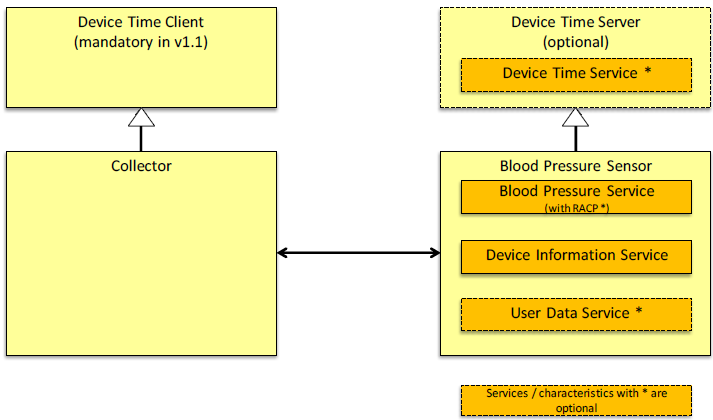
A Blood Pressure Sensor instantiates the Blood Pressure Service [1] and the Device Information Service [3].
A Blood Pressure Sensor optionally instantiates the User Data Service [10]. A Blood Pressure Sensor also optionally supports the Device Time Server role and instantiates the Device Time Service as defined by [8] and [9].
A Blood Pressure Collector may also implement the Device Time Client role as defined in [9].
In the remainder of this document, Blood Pressure Sensor is often referred to as “Sensor” and Blood Pressure Collector is referred to as “Collector.”
2.3. Concurrency limitations and restrictions
There are no concurrency limitations or restrictions for the Collector or Blood Pressure Sensor roles imposed by this profile.
2.4. Topology limitations and restrictions
The Blood Pressure Sensor shall use the GAP Peripheral role.
The Collector shall use the GAP Central role.
2.5. Transport dependencies
This profile shall operate over an LE transport only. For BR/EDR (and HS) the Health Device Profile [4] is to be used. This is to avoid having two ways to send Blood Pressure data over a BR/EDR transport.
3. Blood Pressure Sensor role requirements
The Blood Pressure Sensor shall instantiate one and only one Blood Pressure Service [1] including devices that support multiple users and multiple bonds.
An Enhanced Blood Pressure Sensor is a Blood Pressure Sensor that implements the Enhanced Blood Pressure Service as defined in [1].
The Blood Pressure Service shall be instantiated as a «Primary Service».
The Blood Pressure Sensor shall have one instance of the Device Information Service [3].
The Blood Pressure Sensor may have one instance of the Device Time Service [8].
The Blood Pressure Sensor may have one instance of the User Data Service [10].
|
Service |
Blood Pressure Sensor |
|---|---|
|
Blood Pressure Service |
M |
|
Device Information Service |
M |
|
Device Time Service |
O (see Section 3.4) |
|
User Data Service |
O |
- M:
-
Mandatory
- O:
-
Optional
See Section 5.1 and Section 6.1 for additional requirements for the Blood Pressure Sensor role.
3.1. Incremental Blood Pressure Service requirements
This section describes additional Blood Pressure Sensor requirements beyond those defined in the Blood Pressure Service.
3.1.1. Service UUIDs AD Type
While in a GAP Discoverable Mode for initial connection to a Collector, the Blood Pressure Sensor should include the Blood Pressure Service UUID defined in [11] in the Service UUIDs AD type field of the Advertising Data. This enhances the user experience as a Blood Pressure Sensor may be identified by the Collector before initiating a connection.
3.1.2. Local Name AD Type
For enhanced user experience a Blood Pressure Sensor should include the Local Name (containing either the complete or shortened value of the Device Name characteristic as defined in [2]) in its Advertising Data or Scan Response Data.
3.1.3. Writable GAP Device Name characteristic
The Blood Pressure Sensor may support the write property for the Device Name characteristic in order to allow a Collector to write a device name to the Blood Pressure Sensor.
3.1.4. Target Address AD Types
For enhanced user experience a Blood Pressure Sensor that supports multiple bonds may include either the Public Target Address AD Type or Random Target Address AD Type (see Section 5.1.5) in its Advertising Data or Scan Response Data. If a Blood Pressure Sensor does not support multiple bonds, the Blood Pressure Sensor shall not use a Target Address AD Type. As defined in the Blood Pressure Service, the value of the Multiple Bond Support bit of the Blood Pressure Feature characteristic is to be set according to the Blood Pressure Sensor’s functionality. By doing so, a Collector can determine if the Blood Pressure Sensor does not support a Target Address AD Type (i.e., if the Multiple Bond Support bit is 0) or potentially supports a Target Address AD Type (i.e., if the Multiple Bond Support bit is 1). In the following sections the words “a Target Address AD Type” is intended to refer to either of the defined Target Address AD Types.
3.1.5. Service Data AD Type
For reduced power consumption, a Blood Pressure Sensor that supports multiple users (with or without User Data Service (UDS)) should support the Service Data AD Type as follows:
When the Sensor is using Undirected Advertising, the Sensor should include the Service Data AD Type in its Advertising Data (AD) to reduce unwanted connection requests by unintended Collectors. Conversely, if the Sensor is using any form of Directed Advertising (for example, Low Duty Cycle Directed Advertising), this feature is not needed.
The definition of the Service Data payload is shown in Table 3.2 and consists of the Service Universally Unique Identifier (UUID) and a User ID List that contains a list of one or more User IDs for which the Sensor has new measurements.
The Collector can read the User ID List value to determine whether the Sensor has any new measurements since the last time they connected to avoid unnecessary connection requests. In other words, this can be used by the Collector to determine whether it should attempt to reconnect to the Sensor to receive new measurements.
|
Service UUID |
User ID List |
|---|---|
|
«Blood Pressure» |
List of one-octet User ID values |
3.2. Incremental Device Information Service requirements
Table 3.3 shows additional requirements beyond those defined in the Device Information Service.
|
Device Information Service Characteristic |
Requirement |
|---|---|
|
Manufacturer Name String |
M |
|
Model Number String |
M |
|
System ID |
O |
- M:
-
Mandatory
- O:
-
Optional
System ID is required for implementations requiring compliance with ISO/IEEE 11073-20601 [7].
Characteristics in this service may be transcoded for use in an ISO/IEEE 11073 ecosystem. See the Personal Health Devices Transcoding White Paper [6] for more information. Since strings in this service are encoded as UTF-8, and ISO/IEEE 11073-20601 [7] specifies that strings are encoded as ASCII printable characters (a subset of UTF-8), characters used in string characteristics that are to be transcoded for use in an ISO/IEEE 11073 ecosystem should be restricted to the printable ASCII character set so that the strings can be correctly displayed.
If the ISO/IEEE 11073-20601 specification is updated in the future to include UTF-8 support, implementers should consider the impact of using non-ASCII characters on backward compatibility.
3.3. Incremental User Data Service requirements
This section describes additional requirements beyond those defined in the User Data Service [10] for a Sensor supporting this service.
The User Index value shall be the same as the User ID value for all characteristics of the services on the Sensor for a given user. The User ID value is assigned by the Sensor when a new user is created and the User Index value is sent to the Collector when the Register New User procedure is initiated.
The Sensor shall maintain the value of the Database Change Increment characteristic separately for each supported User Index.
For Sensors that support multiple users with UDS, indications or notifications, including the User ID, shall not be sent unless the user has given consent via UDS consent procedure for that user (in other words, only for the user corresponding to the User Index value). If user data is deleted (via the Delete User Data procedure), only data corresponding to the User Index value shall be deleted.
Table 3.4 lists the additional requirements on UDS characteristics.
|
UDS Characteristic |
Requirement |
|---|---|
|
Date of Birth or Age |
Recommended (useful for classification of Blood Pressure and risks) |
|
First Name, Last Name |
Recommended (useful in user dialogs) |
|
Gender |
Recommended (useful for classification of Blood Pressure and risks) |
Note
Note: The UDS Characteristics that are used with the User Data Service are defined in [5].
3.4. Device Time Server Role
The Sensor may implement the Device Time Server Role as defined in the Device Time Profile [9].
A Sensor should use this method to expose a time source to Collectors.
4. Collector role requirements
The Collector shall support the Blood Pressure Service [1].
The Collector may support the Device Information Service [3].
An Enhanced Blood Pressure Collector is a Blood Pressure Collector that supports the following enhanced feature elements defined in this specification:
-
User Data Service client (see Section 4.12)
-
Device Time client (see Section 4.15)
-
Collector of Blood Pressure Records using the Record Access Control Point (see Section 4.11)
The requirements for these feature elements are marked as conditionally mandatory in the tables in this section.
|
Service |
Collector |
|---|---|
|
Blood Pressure Service |
M |
|
Device Information Service |
O |
|
Device Time Service |
C.1 (see Section 4.15) |
|
User Data Service |
C.1 |
- M:
-
Mandatory
- O:
-
Optional
- C.1:
-
Mandatory for an Enhanced Blood Pressure Collector, otherwise optional.
This section describes the profile procedure requirements for a Collector.
|
Profile Requirement |
Section |
Support in Collector |
|---|---|---|
|
Service Discovery |
M |
|
|
- Blood Pressure Service Discovery |
M |
|
|
- Device Information Service Discovery |
O |
|
|
- User Data Service Discovery |
C.1 |
|
|
Characteristic Discovery |
M |
|
|
- Blood Pressure Service Characteristic Discovery |
M |
|
|
- Device Information Service Characteristic Discovery |
O |
|
|
- User Data Service Characteristic Discovery |
C.1 |
|
|
Blood Pressure Measurement |
M |
|
|
Intermediate Cuff Pressure |
O |
|
|
Blood Pressure Feature |
M |
|
|
Device Information Service |
O |
|
|
Enhanced Blood Pressure Measurement |
C.1 |
|
|
Enhanced Intermediate Cuff Pressure |
O |
|
|
Blood Pressure Record |
C.1 |
|
|
Record Access Control Point |
C.1 |
|
|
User Data Service |
C.1 |
- M:
-
Mandatory
- O:
-
Optional
- C.1:
-
Mandatory for an Enhanced Blood Pressure Collector, otherwise optional.
The support for roles defined in other profiles are defined in Table 4.3.
|
Role Requirement |
Section |
Support by Collector |
|---|---|---|
|
Device Time Client |
C.1 |
- C.1:
-
Mandatory for an Enhanced Blood Pressure Collector, otherwise optional.
4.1. GATT sub-procedure requirements
Requirements in this section represent a minimum set of requirements for a Collector (Client). Other GATT sub-procedures may be used if supported by both Client and Server.
Table 4.4 summarizes additional GATT sub-procedure requirements beyond those required by all GATT Clients.
|
GATT Sub-Procedure |
Collector (Client) Requirements |
|---|---|
|
Discover All Primary Services |
C.1 |
|
Discover Primary Services by Service UUID |
C.1 |
|
Discover All Characteristics of a Service |
C.2 |
|
Discover Characteristics by UUID |
C.2 |
|
Discover All Characteristic Descriptors |
M |
|
Notifications |
C.3 |
|
Read Characteristic Descriptors |
M |
|
Write Characteristic Descriptors |
M |
- M:
-
Mandatory
- C.1:
-
Mandatory to support at least one of these Service Discovery sub-procedures.
- C.2:
-
Mandatory to support at least one of these Characteristic Discovery sub-procedures.
- C.3:
-
Mandatory if the Intermediate Cuff Pressure characteristic, the Enhanced Intermediate Cuff Pressure characteristic, or the Blood Pressure Record characteristic are supported.
4.2. Service discovery
In order for the Collector to discover the characteristics of the Blood Pressure Service, it shall perform primary service discovery using either the GATT Discover All Primary Services sub-procedure or the GATT Discover Primary Services by Service UUID sub-procedure. Recommended fast connection parameters and procedures for connection establishment are defined in Section 5.2.4.
4.2.1. Blood Pressure Service discovery
The Collector shall discover the Blood Pressure Service.
4.2.2. Device Information Service discovery
The Collector may discover the Device Information Service.
4.2.3. User Data Service discovery
The Collector may discover the User Data Service.
An Enhanced Blood Pressure Collector shall discover the User Data Service.
4.3. Characteristic discovery
As required by GATT, the Collector must be tolerant of additional optional characteristics in the service records of services used with this profile.
4.3.1. Blood Pressure Service Characteristic discovery
The Collector shall perform either the GATT Discover All Characteristics of a Service sub-procedure or the GATT Discover Characteristics by UUID sub-procedure in order to discover the characteristics of the service.
The Collector shall perform the GATT Discover All Characteristic Descriptors sub-procedure in order to discover the characteristic descriptors described in the following sections.
4.3.1.1. Blood Pressure Measurement characteristic
The Collector shall discover the Blood Pressure Measurement characteristic.
The Collector shall discover the Client Characteristic Configuration descriptor of the Blood Pressure Measurement characteristic.
4.3.1.2. Intermediate Cuff Pressure characteristic
The Collector may discover the Intermediate Cuff Pressure characteristic.
The Collector may discover the Client Characteristic Configuration descriptor of the Intermediate Cuff Pressure characteristic.
4.3.1.3. Blood Pressure Feature characteristic
The Collector shall discover the Blood Pressure Feature characteristic.
If the Blood Pressure Feature characteristic supports indications, the Collector shall discover the Client Characteristic Configuration descriptor of the Blood Pressure Feature characteristic.
4.3.1.4. Enhanced Blood Pressure Measurement characteristic
The Collector may discover the Enhanced Blood Pressure Measurement characteristic.
The Collector may discover the Client Characteristic Configuration descriptor of the Enhanced Blood Pressure Measurement characteristic.
An Enhanced Blood Pressure Collector shall discover the Enhanced Blood Pressure Measurement characteristic.
An Enhanced Blood Pressure Collector shall discover the Client Characteristic Configuration descriptor of the Enhanced Blood Pressure Measurement characteristic.
4.3.1.5. Enhanced Intermediate Cuff Pressure characteristic
The Collector may discover the Enhanced Intermediate Cuff Pressure characteristic.
The Collector may discover the Client Characteristic Configuration descriptor of the Enhanced Intermediate Cuff Pressure characteristic.
4.3.1.6. Blood Pressure Record characteristic
The Collector may discover the Blood Pressure Record characteristic.
The Collector may discover the Client Characteristic Configuration descriptor of the Blood Pressure Record characteristic.
An Enhanced Blood Pressure Collector shall discover the Blood Pressure Record characteristic.
An Enhanced Blood Pressure Collector shall discover the Client Characteristic Configuration descriptor of the Blood Pressure Record characteristic.
4.3.1.7. Record Access Control Point characteristic
The Collector may discover the Record Access Control Point (RACP) characteristic.
The Collector may discover the Client Characteristic Configuration descriptor of the RACP characteristic.
An Enhanced Blood Pressure Collector shall discover the RACP characteristic.
An Enhanced Blood Pressure Collector shall discover the Client Characteristic Configuration descriptor of the RACP characteristic.
4.3.2. Device Information Service characteristic discovery
The Collector may discover the characteristics of the Device Information Service.
In order for the Collector to discover the characteristics of the Device Information Service, it shall use either the GATT Discover All Characteristics of a Service sub-procedure or the GATT Discover Characteristics by UUID sub-procedure to discover all characteristics of the service.
4.3.3. User Data Service characteristic discovery
If the Sensor exposes the User Data Service, then the Collector may discover the characteristics of the User Data Service. If exposed, an Enhanced Blood Pressure Collector shall discover this service.
In order for the Collector to discover the characteristics of the User Data Service, it shall use either the GATT Discover All Characteristics of a Service sub-procedure or the GATT Discover Characteristics by UUID sub-procedure to discover all characteristics of this service.
The requirements for the Collector on User Data Service characteristic discovery are shown in Table 4.5.
|
Characteristic |
Discovery Requirements for Collector |
|---|---|
|
User Index |
C.1 |
|
Database Change Increment |
C.2 |
|
User Control Point |
C.1 |
|
Registered User |
C.3 |
|
Date of Birth |
O |
|
Age |
O |
|
First Name |
O |
|
Last Name |
O |
|
Gender |
O |
|
Other UDS characteristics |
O |
- O:
-
Optional
- C.1:
-
Mandatory for Enhanced Blood Pressure Collectors, otherwise optional.
- C.2:
-
Mandatory for Collectors that write UDS characteristics, otherwise optional.
- C.3:
-
Mandatory for Enhanced Blood Pressure Collectors and other Collectors that use the List All Users procedure, otherwise optional.
Table 4.5 includes some common optional User Data Service characteristics in the context of this Profile, but other User Data Service characteristics not listed here may also be used.
4.4. Blood Pressure Measurement
The Collector shall control the configuration of indications (i.e. via the Client Characteristic Configuration descriptor) of the Blood Pressure Measurement characteristic.
The Collector shall be able to receive multiple indications of the Blood Pressure Measurement characteristic from a Blood Pressure Sensor for the case where the Blood Pressure Sensor has stored measurements to send. Even if the Collector does not store, forward or otherwise process these indications, the Collector shall accept valid indications without error.
When a Collector requires a connection to a Blood Pressure Sensor to receive Blood Pressure Measurements it shall follow the connection procedures described in Section 5.2.
The Collector shall determine the contents of the Blood Pressure Measurement characteristic structure based on the contents of the Flags field. This allows the Collector to determine the unit of the measurement and whether or not a time stamp, Pulse Rate, User ID and Measurement Status are included.
If the Collector receives a Blood Pressure Measurement characteristic with bits of the Flags field set that are designated as Reserved for Future Use (RFU), it shall ignore those bits and continue to process the Blood Pressure Measurement characteristic normally. Since there are many types of Collectors, what a Collector does with the received RFU information is left to the implementation.
If the Collector receives a Blood Pressure Measurement characteristic with bits of the Measurement Status field set that are designated as RFU, it shall ignore those bits and continue to process the Blood Pressure Measurement characteristic normally. What a Collector does with the received RFU information is left to the implementation.
If the Collector receives a Blood Pressure Measurement characteristic with additional octets that are not recognized by the implementation, it shall ignore these extra octets. What a Collector does with the received RFU information is left to the implementation.
4.5. Intermediate Cuff Pressure
This section is applicable when the Intermediate Cuff Pressure characteristic is supported.
The Intermediate Cuff Pressure characteristic enables a Collector to receive notifications of the Intermediate Cuff Pressure characteristic from a Blood Pressure Sensor supporting this feature to show the progress of a measurement for display purposes.
The Collector shall control the configuration of notifications (i.e. via the Client Characteristic Configuration descriptor) of the Intermediate Cuff Pressure characteristic.
The Collector shall be able to receive multiple notifications of the Intermediate Cuff Pressure characteristic from the Blood Pressure Sensor. Even if the Collector does not store, forward or otherwise process these notifications, the Collector shall accept valid notifications without error.
When a Collector requires a connection to a Blood Pressure Sensor to enable Intermediate Cuff Pressure notifications, it shall follow the connection procedures described in Section 5.2.
The Collector shall determine the contents of the Intermediate Cuff Pressure characteristic structure based on the contents of the Flags field. This allows the Collector to determine the unit of the measurement and whether or not additional information such as time stamp, Pulse Rate, User ID and Measurement Status are included.
If the Collector receives a Intermediate Cuff Pressure characteristic with bits of the Flags field value that are designated as Reserved for Future Use (RFU), it shall ignore those bits and continue to process the Intermediate Cuff Pressure characteristic normally. Since there are many types of Collectors, what a Collector does with the received RFU information is left to the implementation.
If the Collector receives an Intermediate Cuff Pressure characteristic with bits of the Measurement Status field set that are designated as RFU, it shall ignore those bits and continue to process the Intermediate Cuff Pressure characteristic normally. What a Collector does with the received RFU information is left to the implementation.
If the Collector receives an Intermediate Cuff Pressure characteristic with additional octets that are not recognized by the implementation, it shall ignore these extra octets. What a Collector does with the received RFU information is left to the implementation.
4.6. Blood Pressure Feature
The Collector shall read the Blood Pressure Feature characteristic in order to determine the supported features of the Blood Pressure Sensor and to interpret the bits in the Measurement Status field of the Blood Pressure Measurement characteristic. For example if the Cuff Fit Detection feature is not supported, then the Cuff Fit Detection Flag in the Measurement Status field has no meaning. On the other hand, if the Cuff Fit Detection feature is supported, then the Cuff Fit Detection Flag will indicate that the cuff either fits properly or is too loose.
If the Body Movement Detection Support bit is set to 0 (Body Movement Detection feature not supported), the Collector shall ignore bit 0 of the Measurement Status field of the Blood Pressure Measurement characteristic (Body Movement Detection Flag).
If the Cuff Fit Detection Support bit is set to 0 (Cuff Fit Detection feature not supported), the Collector shall ignore bit 1 of the Measurement Status field of the Blood Pressure Measurement characteristic (Cuff Fit Detection Flag).
If the Irregular Pulse Detection Support bit is set to 0 (Irregular Pulse Detection feature not supported), the Collector shall ignore bit 2 of the Measurement Status field of the Blood Pressure Measurement characteristic (Irregular Pulse Detection Flag).
If the Pulse Rate Range Detection Support bit is set to 0 (Pulse Rate Range Detection feature not supported), the Collector shall ignore bits 3 and 4 of the Measurement Status field of the Blood Pressure Measurement characteristic (Pulse Rate Range Detection Flags).
If the Measurement Position Detection Support bit is set to 0 (Measurement Position Detection not supported), the Collector shall ignore bit 5 of the Measurement Status field of the Blood Pressure Measurement characteristic (Measurement Position Detection Flag).
If the Multiple Bond Support bit is set to 0 (Multiple Bonds not supported), the Collector can determine that the Blood Pressure Sensor supports only a single bond. Otherwise the Collector can determine that the Blood Pressure Sensor supports multiple bonds.
If the E2E-CRC Support bit is set to 1, then the Collector can infer that the Sensor does support an E2E-CRC in the Blood Pressure Record. Otherwise, the Collector can infer that this is not the case.
If the User Data Service Support bit is set to 1, then the Collector can infer that the User Data Service is supported by the Sensor in combination with the Blood Pressure Service and that the User Control Point needs to be used to get consent to access a user’s data. Otherwise, the Collector can infer that this is not the case.
If the User Facing Time Support bit is set to 1, then the Collector can infer that the Sensor supports a user facing time that may be reported in Enhanced Blood Pressure Measurement indications and Enhanced Intermediate Cuff Pressure notifications. Otherwise, the Collector can infer that this is not the case. The User Time as exposed by the Device Time Service [8] is an example of a user facing time.
If the Blood Pressure Sensor supports indications of the Blood Pressure Feature characteristic, a bonded Collector may configure this characteristic for indications. When the Collector receives an indication of the Blood Pressure Feature characteristic, the Collector shall use the indicated value to determine the supported features again. Alternatively, a bonded Collector may read the Blood Pressure Feature characteristic on each connection.
When indications of the Blood Pressure Feature characteristic are supported, a bonded Collector shall enable indications of the Blood Pressure Feature characteristic or it shall read the Blood Pressure Feature characteristic on each connection.
If the Collector reads Blood Pressure Feature characteristic bits that are set and designated as Reserved for Future Use (RFU), it shall ignore those bits and continue to operate normally. What a Collector does with the received RFU information is left to the implementation.
4.7. Device Information Service characteristics
The Collector may read the value of Device Information Service characteristics.
4.8. Enhanced Blood Pressure Measurement
The Collector shall control the configuration of indications (via the Client Characteristic Configuration descriptor) of the Enhanced Blood Pressure Measurement characteristic.
The Collector should not enable indications on both the Enhanced Blood Pressure Measurement characteristic and the Blood Pressure Measurement characteristic because the Collector is implementation-dependent if measurements that become available on the Sensor will be indicated once or twice to the Collector. When the Enhanced Blood Pressure Measurement characteristic is supported by the Sensor, the Collector should use this characteristic and should not use the Blood Pressure Measurement characteristic to receive measurement indications.
When a Collector requires a connection to a Blood Pressure Sensor to receive Enhanced Blood Pressure Measurements, a Collector shall follow the connection procedures described in Section 5.2.
The Collector shall determine the contents of the Enhanced Blood Pressure Measurement characteristic structure based on the contents of the Flags field. This allows the Collector to determine the unit of the measurement and whether or not a Time Stamp, Pulse Rate, User ID, Measurement Status, and User Facing Time field are included.
If the Collector receives an Enhanced Blood Pressure Measurement characteristic with bits of the Flags field set that are designated as Reserved for Future Use (RFU), then the Collector shall ignore those bits and continue to process the characteristic normally. Since there are many types of Collectors, what a Collector does with the received RFU information is left to the implementation.
If the Collector receives an Enhanced Blood Pressure Measurement characteristic with bits of the Measurement Status field set that are designated as RFU, then the Collector shall ignore those bits and continue to process the characteristic normally. What a Collector does with the received RFU information is left to the implementation.
If the Collector receives an Enhanced Blood Pressure Measurement characteristic with additional octets that are not recognized by the implementation, then the Collector shall ignore these extra octets. What a Collector does with the received RFU information is left to the implementation.
4.9. Enhanced Intermediate Cuff Pressure
This section is applicable when the Enhanced Intermediate Cuff Pressure characteristic is supported by the Collector.
The Enhanced Intermediate Cuff Pressure characteristic enables a Collector to receive notifications of the Enhanced Intermediate Cuff Pressure characteristic from a Blood Pressure Sensor supporting this feature, primarily to show the progress of a measurement for display purposes.
The Collector shall control the configuration of notifications (via the Client Characteristic Configuration descriptor) of the Enhanced Intermediate Cuff Pressure characteristic.
The Collector should not enable notifications on both the Enhanced Intermediate Cuff Pressure characteristic and the Intermediate Cuff Pressure characteristic since it is implementation dependent if measurements that become available on the Sensor will be notified once or twice to the Collector. When the Enhanced Intermediate Cuff Pressure characteristic is supported by the Sensor, the Collector should use this characteristic and should not use the Intermediate Cuff Pressure characteristic to receive measurement notifications.
When a Collector requires a connection to a Blood Pressure Sensor to enable Enhanced Intermediate Cuff Pressure notifications, the Collector shall follow the connection procedures described in Section 5.2.
The Collector shall determine the contents of the Enhanced Intermediate Cuff Pressure characteristic structure based on the contents of the Flags field. This allows the Collector to determine the unit of the measurement and whether or not additional information such as Time Stamp, Pulse Rate, User ID, Measurement Status, and User Facing Time are included.
If the Collector receives an Enhanced Intermediate Cuff Pressure characteristic with bits of the Flags field value that are designated as Reserved for Future Use (RFU), then the Collector shall ignore those bits and continue to process the characteristic normally. Since there are many types of Collectors, what a Collector does with the received RFU information is left to the implementation.
If the Collector receives an Enhanced Intermediate Cuff Pressure characteristic with bits of the Measurement Status field set that are designated as RFU, then the Collector shall ignore those bits and continue to process the characteristic normally. What a Collector does with the received RFU information is left to the implementation.
If the Collector receives an Enhanced Intermediate Cuff Pressure characteristic with additional octets that are not recognized by the implementation, then it shall ignore these extra octets. What a Collector does with the received RFU information is left to the implementation.
4.10. Blood Pressure Record
The Blood Pressure Record enables multiple collectors to collect the same sets of measurements. If the Sensor supports it, then a Collector should use the Blood Pressure Record in combination with the Record Access Control Point procedures to collect measurements from a Sensor, instead of relying on indications of the Blood Pressure Measurement characteristic and the Extended Blood Pressure Measurement characteristic.
The Collector shall control the configuration of notifications (via the Client Characteristic Configuration descriptor) of the Blood Pressure Record characteristic.
The Collector shall use the E2E-CRC feature bit in the Blood Pressure Feature to determine the presence of an E2E-CRC in the data and shall process the data as appropriate for the application.
The Collector shall use the Segmentation Header field to concatenate segments from multiple messages and to extract one UUID, Recorded Characteristic, Sequence Number, and optional E2E-CRC from this concatenation for application processing. For this, the Collector shall use the following process:
-
The Collector shall inspect the values of the First Segment and Last Segment bits of the Segmentation Header field and shall interpret the bits as shown in Table 4.6.
First Segment
Last Segment
Interpretation
1 (True)
1 (True)
This is the first and last segment.
1 (True)
0 (False)
This is the first segment of a set and more segments will follow.
0 (False)
0 (False)
This is a continuation segment and more segments will follow.
0 (False)
1 (True)
This is a continuation segment and is the last of the set.
Table 4.6. Interpretation of First Segment and Last Segment flag bits
-
If the value of the Last Segment bit of the Segmentation Header field is 0 (False), then the Collector shall wait for another notification of the Blood Pressure Record containing additional data. This step shall be repeated until the Collector receives a notification of the Blood Pressure Record characteristic in which the value of the Last Segment bit of the Segmentation Header field is 1 (True). The Collector should wait for the anticipated notification for at least one second; however, if the waiting time exceeds an implementation-specific timeout, then the Collector may abandon the procedure.
-
The Collector should inspect the Rolling Segment Counters associated with the notifications to verify that they are consecutive. If there is a discontinuity in the Rolling Segment Counters, then the Collector should discard the data and wait for a new notification to be received in which the value of the First Segment bit is 1 (True), indicating the start of a new multi-message Blood Pressure Record.
-
When an E2E-CRC is present, as indicated by the E2E-CRC feature bit in the Blood Pressures Feature, the Collector may check if this field has the correct value and may ignore the complete message if this is not the case. See [1] and [5] for the definition of the E2E-CRC.
-
The Collector shall re-assemble the data by concatenating the values of the data in the received messages, preserving the same order as indicated by the Rolling Segment Counters, with the octet received for which the First Segment bit=True as the least significant octet, and the octet received for which the Last Segment bit=True as the most significant octet.
The Collector shall then parse the re-assembled data in accordance with the definition of the Blood Pressure Record characteristic data format.
4.11. Record Access Control Point
The RACP enables multiple collectors to collect the same sets of measurements. It is the preferred way for a Collector to use the RACP procedures in combination with the Blood Pressure Record to collect measurements from a Sensor.
Before performing any RACP procedures, the Collector shall configure the RACP characteristic for indications (via the Client Characteristic Configuration descriptor).
The Collector may write to the RACP to request a desired procedure. A procedure begins when the Collector writes to the RACP to perform some desired action and ends when either a Response Code or Number of Stored Records Response RACP indication is received by the Collector.
If the Report Stored Records procedure is performed, then the procedure may contain one or more Blood Pressure Record characteristic notifications between the write to the RACP characteristic that begins the procedure and the Response Code RACP indication that ends the procedure.
If the Collector attempts to perform any defined RACP procedure other than the Abort Operation procedure before a previous procedure is complete, then the Collector receives an ATT Error Response with the error code set to Procedure Already in Progress.
The Sensor shall transmit an ATT Error Response with the error code set to Client Characteristic Configuration Descriptor Improperly Configured if the Collector attempts to request a defined RACP procedure before:
-
the Collector has configured the RACP characteristic for indications
-
and, for RACP procedures that report Blood Pressure Records, the Collector has configured the Blood Pressure Record characteristic for notifications.
The Collector should properly configure these characteristics for notifications or indications to avoid the ATT Error Response from the Sensor.
When a Collector requires a connection to a Sensor to receive Blood Pressure Records, the Collector shall follow the connection procedures described in Section 5.2.
4.11.1. Record Definition
Within the context of the Blood Pressure Service, a record is a Blood Pressure Record. Support for the RACP is mandatory for a Collector but optional for a Sensor.
4.11.2. RACP procedure requirements
The Collector shall support the Op Codes, Operator, and Filter Type combinations defined as mandatory in Table 3.3 in [1].
4.11.3. RACP behavioral description
The Collector shall write to the RACP characteristic using one of the supported Op Codes in [1] to request a Sensor to perform a procedure. This shall include an Operator and Operand that is valid within the context of that Op Code as defined in [1].
The procedures including the use of Filter Types are described in Sections 4.11.3.1–4.11.3.5.
The Collector shall be tolerant of the fact that the Sensor may add or delete measurements while RACP procedures are taking place and also between two different RACP procedures. For example, the Collector may perform the Request Number of Stored Records procedure with the Procedure Operator set to All Stored Records to get the total number of records currently stored by the Sensor. However, if the Collector then performs a Report Stored Records procedure with the Procedure Operator set to All Stored Records, then the Collector shall be tolerant of receiving a different number of records from this procedure than the Sensor reported having stored in the response to the Report Number of Stored Records. This is because the Sensor may have taken new measurements and/or deleted stored measurements through user interaction in the time between the Request Number of Stored Records procedure and the Report Stored Records procedure. This is used as an example, but the Collector shall be tolerant of this happening with any RACP procedure.
The Collector shall also be tolerant of the possibility that the Sensor, although required to maintain a Sequence Number continuum while collecting measurements, may not be able to provide a continuum in the case of any catastrophic hardware or software error that results in the Sequence Number being reset.
If the Sensor supports multiple bonds, then a Collector shall be tolerant of the fact that other Collectors may alter the contents of the Sensor’s measurement database. For example, Collector #2 may delete records from the Sensor’s database that Collector #1 will then never be able to retrieve. This will also affect the Sequence Number continuum.
The handling of multiple bonds is vendor-specific. For example, a Sensor may only allow certain bonded Collectors (such as a doctor’s computer) to use the Delete Store Records procedure, while disallowing this to other bonded Collectors (such as those of patients). The Blood Pressure Profile does not define the authorization mechanism for this scenario.
When a Sensor supports both the RACP and the User Data Service, the Collector shall use the Consent Procedure to retrieve the Blood Pressure Records for a specific user. This is defined further in Section 4.124.12.
4.11.3.1. Filter Types
Certain RACP procedures use a Filter Type that is used to determine the portion of the stored records on the Sensor to which the procedure applies. The format of the Filter Type and the RACP procedures that have a Filter Type operand is defined in [1]. The Collector may filter using the Sequence Number filter or another filter supported by the Sensor.
The Sequence Number filter is used when a procedure should apply to a specific Blood Pressure Record or a range of Blood Pressure Records. The Sequence Number used is obtained from the Sequence Number field in the Blood Pressure Record characteristic.
The Base Time or User Facing Time filter is used when a procedure should apply to a specific date and time or a range of dates and times.
The Time filters are provided to allow a mechanism for the Collector to perform RACP procedures with a given date or time or a range of dates and times. However, because the recorded time value can be corrupted (due to time faults or other problems), the Sequence Number filter should be used in most cases. For example, the Collector can use the Report Number of Stored Records procedure to obtain all records a Sensor has collected since the last record received by the Collector. The Collector can do this by using the Sequence Number filter with the Sequence Number set to the Sequence Number of the last Blood Pressure Record received by the Collector and incremented by one.
A Sensor supporting the Device Time Service [8] also reports time faults and other changes to the device time via Blood Pressure Records containing Time Change Log Data characteristic values.
4.11.3.2. Report Number of Stored Records procedure
To request the number of stored records from a Sensor, the Collector shall use the Report Number of Stored Records procedure. To receive the number based on filter criteria, an appropriate Operator and Operand shall be used. Refer to [1] for Operand requirements when used with a specific Operator; in some cases, no Operand is used.
The Collector shall wait for the Number of Stored Records Response RACP indication containing the number of stored records available in the Sensor as per the request. The Number of Stored Records Response RACP indication ends the Report Number of Stored Records procedure. In special circumstances, a Collector may require an abort of this procedure. See Section 4.11.3.5 for details on that procedure.
The Collector may also receive a Response Code RACP indication with the Response Code Value representing an error condition that occurred in processing the request. See Section 4.11.4 for general error handling procedures.
The value returned by the Number of Stored Records procedure is intended to be used for the user interface on the Collector or to enable the Collector to acquire an estimate of the number of records it might receive to determine it has sufficient resources. The Collector should not rely on this value as a means of determining whether new records are available from the Sensor. The Collector should always request new records by filtering with a Sequence Number or a Time value incremented from a previous transfer session; although Sequence Number is preferred, as this is expected to be more robust.
4.11.3.3. Report Stored Records procedure
To request the transfer of stored records from the Sensor, the Collector shall use the Report Stored Records procedure. To receive a selected set of stored records based on filter criteria, an appropriate Operator and Operand shall be used. Refer to [1] for Operand requirements when used with a specific Operator; in some cases, no Operand is used. In special circumstances, a Collector may require an abort of this procedure. See Section 4.11.3.5 for details on that procedure.
Once the Sensor has successfully indicated all records for a given request, the Sensor will send a Response Code RACP indication with the Response Code Value set to Success.
The Collector may receive a Response Code RACP indication with the Response Code Value representing an error condition that occurred in processing the request. See Section 4.11.4 for general error handling procedures. A description of specific error conditions and recommended procedures follows.
If, after requesting stored records, the Collector receives a Response Code RACP indication with the Response Code Value set to No Records Found (0x06), this indicates that the Sensor does not have any stored records that meet the specified criteria.
If, after requesting and receiving stored records, the Collector receives a Response Code RACP indication with the Response Code Value set to Procedure Not Completed (0x08), this indicates that the Sensor was required to interrupt its data transfer before completion for an unspecified reason. If this occurs, then the Collector should reattempt the data transfer using the same Op Code and Operator but should modify the filter criteria in the Operand such that data already successfully received does not need to be retransmitted.
If a condition arises where a Collector is no longer able to receive the requested data, then the Collector may request to abort the data transfer as described in Section 4.11.3.5.
4.11.3.4. Delete Stored Records procedure
To request deletion of stored records within the Sensor, the Collector shall use the Delete Stored Records procedure. To delete a selected set of stored records based on filter criteria, an appropriate Operator and Operand shall be used. Refer to [1] for Operand requirements when used with a specific Operator; in some cases, no Operand is used.
The Collector shall wait for the Response Code RACP Indication with the Response Code Value set to Success, indicating successful deletion of records, as per the request, or the Collector shall wait for the procedure to time out according to the procedure timeout operation described in Section 4.11.5. In special circumstances, a Collector may require an abort of this procedure. See Section 4.11.3.5 for details on the Abort Operation procedure.
The Collector may receive a Response Code RACP indication with the Response Code Value representing an error condition that occurred in processing the request. See Section 4.11.4 for general error handling procedures.
A Sensor may support deletion of records only for a specific authorized Collector.
4.11.3.5. Abort Operation procedure
To abort a procedure that a Collector initiated, the Collector shall use the Abort Operation Op Code with the Operator set to Null and no Operand.
The Collector shall then wait for the Response Code RACP indication with the Response Code Value set to Success, indicating successful aborting of the procedure, or the Collector shall wait for the procedure to time out according to the procedure timeout operation described in Section 4.11.5. Although Sensors must stop the data transfer after they have sent the Response Code Value of Success, they may still have some records queued for transfer. These will be sent and require acknowledgement from the Collector before the transfer will be fully terminated. The Collector may choose to process or ignore these additional records but shall be tolerant of this lag in the termination of the transfer.
The Request Op Code in the Operand of the Response Code RACP indication is used to determine if a Response Code RACP indication is received in response to an Abort Operation procedure or to the procedure that the Abort Operation is trying to abort. If the Abort Operation procedure is completed successfully, then the Sensor shall send the Response Code RACP indication with the Request Op Code in the Operand set to Abort Operation and shall not send any Response Code RACP indication for the aborted procedure.
The Collector may also receive a Response Code RACP indication with the Request Op Code in the Operand set to Abort Operation and the Response Code Value representing an error condition that occurred in processing the request. Though in practice not all Response Code Values may be returned for an Abort Operation procedure, a Collector shall be able to handle receiving all defined Response Code Values in response to this procedure. A description of specific error conditions and recommended procedures is described in Section 4.11.4. See Section 4.14 for descriptions of general error conditions.
If, after requesting the abort, the Collector receives a Response Code RACP indication with the Request Op Code in the Operand set to Abort Operation and the Response Code Value set to Abort Unsuccessful, this indicates that the Sensor is unable to process the abort.
4.11.4. RACP error handling
Other than error handling procedures that are specific to certain Op Codes, the following apply:
-
If the Collector writes an Op Code to the RACP characteristic that is unsupported by the Sensor, then the Collector will receive a Response Code RACP indication with the Response Code Value set to Op Code Not Supported (0x02).
-
If the Collector writes an Operator to the RACP characteristic that is invalid, then the Collector will receive a Response Code RACP indication with the Response Code Value set to Invalid Operator (0x03).
-
If the Collector writes an Operator to the RACP characteristic that is not supported by the Sensor, then the Collector will receive a Response Code RACP indication with the Response Code Value set to Operator Not Supported (0x04).
-
If the Collector writes an Operand to the RACP characteristic that is invalid, then the Collector will receive a Response Code RACP indication with the Response Code Value set to Invalid Operand (0x05).
-
If the Collector receives a Response Code RACP indication with the Response Code Value set to Procedure Not Completed (0x08), this indicates that the Sensor is unable to complete the procedure for some unknown reason, and the procedure shall be considered to have failed.
-
If the Collector writes a Filter Type within an Operand to the RACP characteristic that is not supported by the Sensor, then the Collector will receive a Response Code RACP indication with the Response Code Value set to Operand Not Supported (0x09).
See Section 4.14 for requirements on the Collector for handling Control Point errors.
4.11.4.1. Single record errors
In some circumstances, a received record may be invalid. This may be due to an implementation issue or a packet error caused for a variety of reasons. For increased robustness, Collectors should check for invalid records. Examples of checks include the following:
-
Check if the Segmentation Header in the different segments of a multi-message Blood Pressure Record contains a first segment, intermediate segments, and a last segment with subsequent Rolling Segment Counter values. If not, then the record is invalid.
-
Check that the value of the E2E-CRC field when present corresponds to the expected value. If not, then the record is invalid.
If an invalid record is detected, then the Collector may re-request a single record using the RACP with the Operator set to Within Range Of and the Operand set to the Sequence Number Filter Type with the minimum value of the range and maximum value of the range both set to the Sequence Number value of the invalid record. If the record is retransmitted and still found to be invalid after a number of reattempts as left to the implementation, then the Collector should discard the invalid record.
4.11.5. RACP procedure timeout
In the context of the RACP characteristic, a procedure is started when the Sensor sends the response to the Collector’s Write request for the RACP characteristic. The procedure is considered to be complete when the RACP characteristic is indicated with the Op Code set to Response Code.
An RACP procedure may consist of multiple notifications of the Blood Pressure Record characteristic. The procedure is completed when the RACP characteristic is indicated. A procedure is considered to have timed out if a notification or an indication is not received within the ATT transaction timeout, defined in Volume 2, Part F, Section 3.3.3 of [2] as 30 seconds from the start of the procedure or the last notification that was received as a result of this procedure.
If the link is lost while an RACP procedure is in progress, then the procedure shall be considered to have timed out. See Section 4.11.5.1 for handling this condition.
Therefore, a Collector shall start a timer, with the value set to the ATT transaction timeout, after the write response is received from the Sensor. The timer shall be restarted after every Blood Pressure Record notification is received. The timer shall be stopped when an RACP indication is received and the Op Code is set to Response Code. If the timer expires, then the procedure shall be considered to have failed.
4.11.5.1. Procedure timeout handling
If an RACP procedure times out (see Section 4.11.5 for details of how this may occur), then no new RACP procedure shall be started by the Collector until a new link is established with the Sensor.
In the case of a procedure timeout during a Report Stored Records procedure, the Collector may consider the received records to be valid. However, the Collector shall not assume that the records received consist of all of the available records on the Sensor that match the filter criteria; in other words, the Collector shall assume that the records received during a Report Stored Records procedure that has timed out are an incomplete set of records based on the filter criteria. The Collector may then perform the procedure again when a new link is established, adjusting the filter criteria based on the records received during the aborted transfer.
4.12. User Data Service
The UDS [10] in this profile serves to provide consent-based access to both the Blood Pressure measurement data and the User Data Service characteristics.
A Sensor using UDS may use it for some but not all of its users. The collector shall use the UDS consent procedure before retrieving Blood Pressure measurements for the users for which UDS is used. The Collector shall not use the UDS consent procedure for users for which the Sensor is not using UDS.
For Sensors that do not use UDS, the Collector shall not use the UDS consent procedure.
4.12.1. User Data Service characteristics
The Collector may read and write the value of UDS characteristics.
For UDS characteristics that exceed the negotiated ATT_MTU size (for example, UTF8-based characteristics), the Collector should use the GATT Read Long Characteristic Value sub-procedure and GATT Write Long Characteristic Value sub-procedure, respectively.
Although most Collectors are expected to support the caching of User Data Service characteristic values, this is not required. Collectors that are used in a public environment (for example, a gym with a fitness machine) will typically not cache values, but personal Collectors (for example, a smartphone, tablet, sports watch, or personal computer) typically will cache values for later use for improved efficiency.
The Collector shall use the Consent procedure defined in Section 4.12.5.2.2 to access the UDS characteristics exposed by the Sensor.
4.12.2. User Index
If a Sensor supports the User Data Service (bit 7 of the Blood Pressure Feature field is set to 1), then the Collector may read the User Index characteristic to confirm for which user the UDS characteristics are exposed before the Collector attempts to read or write any UDS characteristics.
4.12.3. Database Change Increment
The Database Change Increment characteristic is used to keep track of updates to UDS characteristics supported by both a Sensor and a Collector (in other words, updates made either through the user interface (UI) of the Sensor or through the UI of a Collector).
If the Sensor supports the Database Change Increment characteristic, it is optional for the Collector to configure the Database Change Increment characteristic for notifications except for Collectors that support the User Data Synchronization feature for which notifications become mandatory, as specified in Section 4.12.7.
A notification of the Database Change Increment characteristic alerts the Collector that a change to at least one of the values has occurred and the Collector shall read all UDS characteristic values that the two devices have in common.
If the Collector supports the User Data Synchronization feature, then the requirements in Section 4.12.7 apply.
If the Collector does not support the User Data Synchronization feature, then after the Collector has completed writing a new value to one or more UDS characteristics, the Collector shall read the Database Change Increment value from the Sensor and write the value incremented by one to the Database Change Increment characteristic of the Sensor.
A rollover of the value of the Database Change Increment characteristic is extremely unlikely over the life of the Sensor, but if a rollover occurs, this can be handled in an implementation-specific way. The implementation can, for example, ask the user to confirm the values via the UI.
4.12.4. Registered User characteristic
The Sensor uses the Registered User characteristic to communicate a Registered User Index and Registered User Name via one or more GATT indications to the Collector. The Collector can initiate this via the List All Users Procedure described in Section 4.12.5.2.4. For this procedure, the Collector shall configure the Registered User Characteristic for indications (via the Client Characteristic Configuration descriptor).
4.12.5. User Control Point characteristic
Before performing a User Control Point procedure, the Collector shall configure the User Control Point characteristic for indications (via the Client Characteristic Configuration descriptor).
The Collector may perform a write to the User Control Point to request a desired procedure. A procedure begins when the Collector writes a particular Op Code to the User Control Point to perform some desired action and ends when the Collector sends a confirmation to acknowledge the User Control Point indication sent by the Sensor at the end of the procedure. This indication includes the Response Code, Requested Op Code, and Response Value. This indication may also include a Response Parameter as defined in [10].
4.12.5.1. User Control Point procedure requirements
Table 4.7 shows the requirements for the User Control Point procedures (Op Codes) in the context of this profile.
|
Procedure (Op Code) |
Requirement |
|---|---|
|
Register New User |
C.1 |
|
Consent |
C.1 |
|
Delete User Data |
C.1 |
|
List All Users |
O.1 |
|
Delete User(s) |
O.1 |
4.12.5.2. User Control Point behavioral description
The Collector shall write to the User Control Point characteristic using one of the supported Op Codes in Table 4.7 to request a Sensor to perform a procedure. This may include a parameter that is valid within the context of that Op Code as defined in [10].
4.12.5.2.1. Register New User procedure
To register a new user in the Sensor, the Collector shall use the Register New User Op Code followed by a parameter value that represents the Consent Code defined by the user as defined in [10].
Collectors should cache the Consent Code for later use.
The Collector shall wait for the User Control Point Indication containing the Response Code with the Response Value set to Success, indicating successful operation with a Response Parameter value that represents the User Index assigned by the Sensor for the new user or an error response value.
The procedure may time out according to the procedure timeout operation described in Section 4.12.5.2.6.
See Section 4.14 for general error handling procedures.
4.12.5.2.2. Consent procedure
To request the consent of a Sensor user in order to access their UDS characteristics and Blood Pressure measurement data, the Collector shall use the Consent Op Code followed by an array of 3 uint8 parameter values that represent the User Index (1 octet) followed by the Consent Code (2 octets) defined by the user as defined in [10].
The Collector shall wait for the User Control Point Indication containing the Response Code with the Response Value set to Success, indicating successful operation or an error response value.
The procedure may time out according to the procedure timeout operation described in Section 4.12.5.2.6.
See Section 4.14 for general error handling procedures.
4.12.5.2.3. Delete User Data procedure
To request the deletion of the UDS characteristics of the Sensor, the Collector shall use the Delete User Data procedure.
The Collector shall initiate the appropriate user consent procedure, as defined in Section 4.13, to delete the user data exposed by the Sensor or, when supported by the Sensor, the Collector can use the Delete User(s) procedure.
The Collector shall wait for the User Control Point Indication containing the Response Code with the Response Value set to Success, indicating successful operation or an error response value.
The procedure may time out according to the procedure timeout operation described in Section 4.12.5.2.6.
See Section 4.14 for general error handling procedures.
4.12.5.2.4. List All Users procedure
To request a listing of all UDS registered users of a Sensor, the Collector shall use the List All Users procedure as defined in [10].
The Collector shall wait for the Response Code User Control Point Indication with the Response Value set to Success, indicating successful operation or an error response value.
For this procedure, the use of the Consent procedure is not needed.
The procedure may time out according to the procedure timeout operation described in Section 4.12.5.2.6.
See Section 4.14 for general error handling procedures.
4.12.5.2.5. Delete User(s) procedure
To request deletion of registered users of a Sensor, the Collector shall use the Delete User(s) procedure as defined in [10].
The Collector shall wait for the Response Code User Control Point Indication with the Response Value set to Success, indicating successful operation or an error response value.
For this procedure, the use of the Consent procedure is not needed.
The procedure may time out according to the procedure timeout operation described in Section 4.12.5.2.6.
See Section 4.14 for general error handling procedures.
4.12.5.2.6. User Control Point procedure timeout
In the context of the User Control Point characteristic, a procedure is started when the Collector writes a particular Op Code to the User Control Point to perform some desired action. A procedure ends when the Collector sends a confirmation to acknowledge the User Control Point indication sent by the Sensor with the Op Code set to Response Code.
In the context of the User Control Point characteristic, a procedure is not considered started and not queued in the Sensor when a write to the User Control Point results in an ATT Error Response.
A procedure is considered to have timed out if a User Control Point indication is not received within the ATT transaction timeout, defined as 30 seconds in Volume 2, Part F, Section 3.3.3 of [2], from the start of the procedure.
If the link is lost while a User Control Point procedure is in progress, then the procedure shall be considered to have timed out.
Therefore, a Collector shall start a timer with the value set to the ATT transaction timeout after the write response is received from the Sensor. The timer shall be stopped when a User Control Point indication is received and the Op Code is set to Response Code. If the timer expires, then the procedure shall be considered to have failed.
If a User Control Point procedure times out, then no new User Control Point procedure shall be started by the Collector until a new link is established with the Sensor. For a good user experience, if a User Control Point procedure times out, then the Collector should disconnect and then reconnect.
4.12.6. Other User Data Service characteristics
If the Collector supports remote updating of user data to the Sensor, such as First Name, Last Name, Gender, Age, or Date of Birth values, then the Collector shall support reading and writing to the corresponding User Data Service characteristics as defined in [5].
4.12.7. User Data Synchronization feature
The User Data Synchronization feature is optional. If supported, the requirements in this section apply.
When a connection is established, the Collector shall read the Database Change Increment characteristic value and compare it to its local (cached) value. Based on the comparison between these two values, the Collector shall perform the appropriate action defined in Table 4.8. After the synchronization procedure is completed, both the Collector and the Sensor will have the same UDS characteristic and Database Change Increment values.
|
Condition |
Action Requirement |
|---|---|
|
Database Change Increment values are equal in both the Collector and the Sensor. |
The databases are synchronized and do not require any action by the Collector. |
|
Database Change Increment value of the Sensor is greater than the value in the Collector (i.e., the user data at the Sensor is more recent). |
The Collector shall read and cache all the UDS characteristics supported by the Collector. The Collector shall also cache the Database Change Increment value for future use. |
|
Database Change Increment value of the Sensor is less than the value in the Collector (i.e., the user data at the Collector is more recent). |
The Collector shall write updated UDS characteristics to the Sensor. After the user data is updated, the Collector shall also write its local Database Change Increment value to the Sensor in order to complete the synchronization procedure. |
If the Sensor supports notifications of the Database Change Increment characteristic, then the Collector shall configure this characteristic for notifications.
When the Collector updates the cached UDS characteristics while not in a connection (for example, through its UI), the Collector shall increment the value of the cached Database Change Increment characteristic by one. This is to synchronize the UDS characteristics values with the Sensor at the next connection.
When a Collector that supports the update of UDS characteristics (for example, through its UI) is connected to a Sensor, and when the Collector updates one or more UDS characteristics values exposed by the Sensor, the Collector shall increment its local Database Change Increment value by one and write the incremented value of the Database Change Increment characteristic to the Sensor.
4.13. Data access
The Collector shall be able to use User Control Point to receive measurement data (in other words, Blood Pressure Measurement indications and Intermediate Pressure notifications or the Enhanced versions), access the UDS characteristics, and receive Blood Pressure Records through the RACP.
When the UDS is not used, a Sensor shall send all collected Blood Pressure records to any connected collector that uses the proper security mode and level.
Where UDS is used by the Sensor, the Consent Procedure shall be used to get access to the data for users registered on the Sensor via the Register New User procedure.
Table 4.9 provides an overview of the data access requirements.
|
Sensor Configuration |
Consent Requirement for Measurement Data |
Consent Requirement for UDS Characteristic Data |
|---|---|---|
|
No UDS support |
No consent possible |
N/A |
|
UDS supported and used for a user |
Consent needed |
Consent needed |
|
UDS supported but not used for a user or set of users |
No consent needed |
Consent needed |
A Sensor is a multi-user Sensor if it can record measurements for multiple users, using a User ID to distinguish them. Support for UDS improves the support for multiple users, but even a single-user Sensor may use UDS.
If the Sensor supports UDS, then the Collector shall use the Consent procedure defined in Section 4.12.5.2.2 to demonstrate consent to access the UDS characteristics.
A multi-user Sensor that supports UDS shall transmit measurement data for measurements not bound to a user, registered via UDS to any connected collector. The presence and value of the User ID in these measurements is implementation-dependent.
4.14. Control Point error handling
This section describes error handling by the Collector when using Control Point Procedures on the RACP or the User Control Point.
A Collector using control points shall be tolerant and behave appropriately (in other words, the Collector shall be able to continue to process commands and/or receive data normally) when receiving the following Control Point error codes defined in the User Data Service [10]:
-
Op Code Not Supported
-
Invalid Parameter
-
Operation Failed
-
User Not Authorized
The Collector shall also be tolerant and behave appropriately (in other words, the Collector shall be able to continue to process commands and/or receive data normally) when receiving the following ATT application error code defined in the User Data Service [10]:
-
User Data Access Not Permitted
The Collector shall also be tolerant and behave appropriately (in other words, the Collector shall be able to continue to process commands and/or receive data normally) when receiving the following ATT error codes:
-
Procedure Already in Progress
-
Client Characteristic Configuration Descriptor Improperly Configured
4.15. Device Time Client Role
The Collector may implement the Device Time Client Role as defined in the Device Time Profile [9].
An Enhanced Blood Pressure Collector shall implement the Device Time Client Role.
This complements the recommendation for a Sensor to implement the Device Time Server Role.
5. Connection establishment
This section describes the connection establishment and connection termination procedures used by a Blood Pressure Sensor and Collector in certain scenarios.
The Blood Pressure Profile supports the following scenario:
Once configured by the Collector, a Blood Pressure Sensor will typically remain powered off between uses and will only advertise and allow a Collector to connect when it has data to send. In this scenario, the Blood Pressure Sensor will enter a GAP Connectable Mode and start advertising when it has data to send to the Collector. The Collector will typically execute a GAP connection establishment procedure such that it is scanning for the Blood Pressure Sensor using a filter accept list. When a connection is established, the Blood Pressure Sensor sends one or more indications or notifications to the Collector. When the data transfer is complete the Blood Pressure Sensor typically terminates the connection.
5.1. Blood Pressure Sensor connection establishment
5.1.1. Connection procedure for unbonded devices
This procedure is applicable when the Blood Pressure Sensor connects to a Collector to which it is not bonded. This is typically initiated through user interaction when a user intends to bond the Blood Pressure Sensor with a Collector.
The Blood Pressure Sensor should use the GAP Limited Discoverable Mode with connectable undirected advertising events when establishing an initial connection. The TGAP(lim_adv_timeout) used during GAP Limited Discoverable Mode may be larger than the value specified in the Section 16, Appendix A in the GAP specification [2], but the value shall be less than or equal to 180 seconds.
It is recommended to use the advertising interval parameters in Table 5.1 during the GAP Limited Discoverable Mode. The interval values in the first row are designed to attempt fast connection during the first 30 seconds; however, if a connection is not established within that time, the interval values in the second row are designed to reduce power consumption for devices that continue to advertise.
|
Advertising Duration |
Parameter |
Value |
|---|---|---|
|
First 30 seconds (fast connection) |
Advertising Interval |
20 ms to 30 ms |
|
After 30 seconds (reduced power) |
Advertising Interval |
1 s to 2.5 s |
Notwithstanding the above, the advertising interval and time to perform advertising should be configured with consideration for user expectations of connection establishment time.
The Blood Pressure Sensor shall accept any valid values for connection interval and connection latency set by the Collector until service discovery and encryption is complete. Only after this has been completed should the Blood Pressure Sensor request to change to the preferred connection parameters that best suits its use case.
If a connection is not established within a time limit defined by the Blood Pressure Sensor, the Blood Pressure Sensor may exit the GAP discoverable mode.
The Blood Pressure Sensor should be in a bondable mode during this procedure to optimize connecting to the Collector again using the procedure described in Section 5.1.2.
If the Client Characteristic Configuration descriptor has been configured to enable indications or notifications and the Blood Pressure Sensor has no data to transfer (or no further data to transfer), then after waiting for an idle connection timeout (see Section 5.1.4), the Blood Pressure Sensor should perform the GAP Terminate Connection procedure. This allows the Collector to perform any additional required actions (e.g. read Blood Pressure Feature characteristic).
5.1.2. Connection procedure for bonded devices
This procedure is applicable after the Blood Pressure Sensor has bonded with the Collector using the connection procedure in Section 5.1.1 and either when the user initiates a connection or autonomously when a notification or indication is pending.
A Blood Pressure Sensor should enter the GAP Undirected Connectable Mode either when commanded by the user to initiate a connection to a Collector or when a Blood Pressure Sensor has one or more indications or notifications to send to a previously connected Collector.
The Blood Pressure Sensor should write the address of the target Collector in its Filter Accept List and set its controller advertising filter policy to ‘process scan and connection requests only from devices in the Filter Accept List’.
The Blood Pressure Sensor should use the recommended advertising interval values shown in Table 5.1.
The advertising interval and time to perform advertising should be configured with consideration for user expectations of connection establishment time.
Once connected, the Blood Pressure Sensor may request to change to the preferred connection parameters that best suits its use case.
If a connection is not established within a time limit defined by the Blood Pressure Sensor, the Blood Pressure Sensor may exit the GAP connectable mode.
If the Client Characteristic Configuration descriptor has been configured to enable indications or notifications and the Blood Pressure Sensor has no data to transfer (or no further data to transfer), then after waiting for an idle connection timeout (see Section 5.1.4), the Blood Pressure Sensor should perform the GAP Terminate Connection procedure. This allows the Collector to perform any additional required actions (e.g. read Blood Pressure Feature characteristic).
See Section 5.1.5 for additional requirements related to support for multiple bonds.
5.1.3. Link Loss Reconnection procedure
When a connection is terminated due to link loss, a Blood Pressure Sensor should attempt to reconnect to the Collector by entering the GAP Undirected Connectable Mode using the recommended advertising interval values shown in Table 5.1.
5.1.4. Idle connection
The Blood Pressure Sensor should perform the GAP Terminate Connection procedure if the connection is idle for more than five (5) seconds.
5.1.5. Multi-bond considerations
This section is applicable when a Blood Pressure Sensor supports multiple bonds.
A Blood Pressure Sensor supporting multiple bonds may advertise with the address of the target Collector(s) in a Target Address AD Type to enable bonded Collectors to determine if they are the intended recipient of the data. This feature is designed to avoid a situation where a bonded Collector unnecessarily responds to the Blood Pressure Sensor advertisement intended for another bonded Collector. The applicable Public Target Address AD Type format or Random Target Address AD Type format (see Table 5.2) should be used when including the address corresponding to Collector’s address type. As stated in Section 3.1.4, if the Blood Pressure Sensor does not support multiple bonds, a Target Address AD Type is not to be included in either the Advertising Data or the Scan Response Data.
If the Blood Pressure Sensor uses a Target Address AD Type and was given a random address by that Collector, the Blood Pressure Sensor shall use that address in the Random Target Address AD Type. A Blood Pressure Sensor may include multiple target addresses in its Advertising Data or Scan Response Data although the maximum number possible is four due to data size restrictions. As described in Section 5.1.2, the Blood Pressure Sensor should also use a Filter Accept List to avoid connection with an unwanted Collector.
|
Description |
Information |
|---|---|
|
Public Target Address |
Multiples of 6 octets – 6 octets are required for each Device Address of the targeted Collector. This AD type is used when the target address is a public address. |
|
Random Target Address |
Multiples of 6 octets – 6 octets are required for each Device Address of the targeted Collector. This AD type is used when the target address is a random address. |
5.1.6. Use of Service Data AD Type
This section outlines an optional procedure that is applicable when a Sensor uses the Undirected Connectable Mode and the Service Data AD Type.
The Service Data AD Type described in Section 3.1.1 provides a mechanism to reduce unwanted connection requests by unintended Collectors when Undirected Connectable Mode is used and when a Sensor has new indications to send. Refer also to Section 5.2.6 for the procedure from the Collector perspective.
When a Sensor uses undirected connectable advertisements, it should include the Service Data AD Type in its Advertising Data. The value of the User ID List field of the Service Data AD Type shall be populated with the User IDs for which the Sensor has measurements. The absence of any User ID indicates the absence of measurements. This allows each Collector to determine whether the Sensor has any new data to be collected since the last time the Collector read the User ID List field.
5.2. Collector connection establishment
5.2.1. Connection procedure for unbonded devices
This procedure is applicable for connection establishment when the Collector connects to a Blood Pressure Sensor to which it is not bonded. This is typically initiated through user interaction when a user intends to bond the Collector with the Blood Pressure Sensor.
A Collector should use the GAP Limited Discovery procedure to discover a Blood Pressure Sensor.
The Collector should use the recommended scan interval and scan window values shown in Table 5.3. For the first 30 seconds (or optionally continuously for mains powered devices), the Collector should use the first scan window / scan interval pair to attempt fast connection. However, if a connection is not established within that time, the Collector should switch to one of the other scan window / scan interval options as defined in Table 5.3 to reduce power consumption.
Once the Blood Pressure Sensor is discovered, the Collector should initiate connection using the Direct Connection Establishment procedure.
|
Scan Duration |
Parameter |
Value |
|---|---|---|
|
First 30 seconds (fast connection) |
Scan Interval |
30ms to 60ms* |
|
Scan Window |
30ms |
|
|
After 30 seconds (reduced power) - Option 1 |
Scan Interval |
1.28s |
|
Scan Window |
11.25ms |
|
|
After 30 seconds (reduced power) - Option 2 |
Scan Interval |
2.56s |
|
Scan Window |
11.25ms |
* A scan interval of 60ms is recommended when the Collector is supporting other operations to provide a 50% scan duty cycle versus 100% scan duty cycle.
Option 1 in Table 5.3 uses the same background-scanning interval used in BR/EDR so the power consumption for LE will be similar to the power consumption used for background scanning on BR/EDR. Option 2 uses a larger background-scanning interval (e.g. twice as long) than used in BR/EDR so the power consumption for LE will be less than the power consumption used for background scanning on BR/EDR. Connection times during background scanning will be longer with Option 2.
After the connection is established, the Collector should bond with the Blood Pressure Sensor during this procedure to optimize connecting to the Blood Pressure Sensor again using the procedure in Section 5.2.2. If a bond is created, the Collector should write the address of the Blood Pressure Sensor in the Collector controller’s Filter Accept List.
The Collector should configure the Client Characteristic Configuration descriptor to enable indications or notifications as needed.
The Blood Pressure Sensor typically terminates the connection if it has no data to transfer.
5.2.2. Connection procedure for bonded devices
This procedure is applicable after the Collector has bonded with the Blood Pressure Sensor using the connection procedure in Section 5.2.1 and either when the user initiates a connection or autonomously when a Collector requires measurements from a Blood Pressure Sensor.
A Collector may use one of the following GAP connection procedures based on its connectivity requirements:
-
General Connection Establishment procedure. The Collector may use this procedure when it requires measurements from one or more Blood Pressure Sensors. This procedure allows a Collector to connect to a Blood Pressure Sensor discovered during a scan without using the Filter Accept List. The Collector should decode the Target Address AD Type to attempt to get the target address as described in this section.
-
Selective Connection Establishment procedure. The Collector may use this procedure when it requires measurements from one or more Blood Pressure Sensors. This procedure allows a Collector to connect to a Blood Pressure Sensor discovered during a scan while using the Filter Accept List. The Collector should decode the Target Address AD Type to attempt to get the target address as described in this section.
-
Direct Connection Establishment procedure. The Collector may use this procedure when it requires measurements from a single (or specific) Blood Pressure Sensor. The Collector may also use this procedure for link loss reconnection described in Section 5.2.3.
-
Auto Connection Establishment procedure. The Collector may use this procedure when it requires measurements from one or more Blood Pressure Sensors. This procedure will automatically initiate connection to a Blood Pressure Sensor in the Filter Accept List. The Collector should not use this procedure if one of the Blood Pressure Sensors supports multiple bonds.
If the Collector receives an undirected connectable advertisement from a bonded Blood Pressure Sensor while performing the General or Selective Connection Establishment Procedure, and the Blood Pressure Sensor supports multiple bonds (i.e. the Multiple Bond Support bit of the Blood Pressure Feature characteristic is set to 1 meaning ‘Multiple Bonds supported’) see Section 5.2.5 for multi-bond considerations and the use of target addresses. Otherwise a Target Address AD Type will not be present in either the Advertising Data or Scan Response Data.
The Collector should use the recommended scan interval and scan window values shown in Table 5.3. When initiating connection, the Collector should use the first scan window / scan interval pair to attempt fast connection. However, if a connection is not established within 30 seconds, the Collector should switch to one of the other scan window / scan interval options as defined in Table 5.3 to reduce power consumption.
If the Collector is in background scanning, it may use the scan window / scan interval Option 1 or Option 2 to reduce power consumption.
Notwithstanding the above, the Collector should use a scan window and scan interval suitable to its power and connection time requirements. Increasing the scan window increases the power consumption, but decreases the connection time.
The scan interval and scan window should be configured with consideration for user expectations of connection establishment time.
The Collector shall start encryption after each connection creation to verify the status of the bond. If encryption fails upon connection establishment (i.e. the bond no longer exists), the Collector must, after user interaction, re-bond, perform service discovery (unless the Collector had previously determined that the Blood Pressure Sensor did not have the <<Service Changed>> characteristic), and set the Blood Pressure Sensor Client Characteristic Configuration descriptor again before using any of the services referenced by this profile in case the configuration was altered or lost.
The Blood Pressure Sensor typically terminates the connection after it has no additional data to transfer.
5.2.3. Link loss reconnection procedure
When a connection is terminated due to link loss, a Collector should attempt to reconnect to the Blood Pressure Sensor using any of the GAP connection procedures with the parameters in Table 5.3.
5.2.4. Fast connection interval
To avoid very long service discovery and encryption times, the Collector should use the connection intervals defined in Table 5.4 in the connection request.
|
Parameter |
Value |
|---|---|
|
Minimum Connection Interval |
50 ms |
|
Maximum Connection Interval |
70 ms |
At any time a lower latency is required, for example to perform key refresh or encryption setup, this should be preceded with a connection parameter update to the minimum and maximum connection interval values defined in Table 5.4 and a connection latency of zero. This fast connection interval should be maintained as long as low latency is required. After that, it should switch to the preferred connection parameters as decided by the Blood Pressure Sensor using the GAP Connection Parameter Update procedure.
5.2.5. Multi-bond considerations
If the Collector receives an undirected connectable advertisement from a bonded Blood Pressure Sensor while performing the General or Selective Connection Establishment Procedure and the Blood Pressure Sensor supports multiple bonds (i.e. the Multiple Bond Support bit of the Blood Pressure Feature characteristic is set to 1 meaning ‘Multiple Bonds supported’) then the Collector should decode the Target Address AD Type to attempt to get the target address. If supported by the Blood Pressure Sensor, this will allow the Collector to determine the intended recipient of the advertisement.
If the Advertising Data or Scan Response Data contains a Target Address AD Type;
-
If the target address is the same as the Collector’s address, the Collector should initiate a connection to the Blood Pressure Sensor using Direct Connection Establishment Procedure.
-
If the target address is not the same as the Collector’s address, the Collector should not initiate a connection to the Blood Pressure Sensor.
If the Advertising Data and Scan Response Data do not contain a Target Address AD Type, the Collector may initiate Connection to the Sensor using Direct Connection Establishment Procedure.
For the case where a Collector is associated with a Blood Pressure Sensor for multiple users, the User ID field in the Blood Pressure Measurement characteristic shall be used by the Collector to associate measurements with the correct user.
5.2.6. Use of Service Data AD Type
This section outlines an optional procedure that is applicable when a Collector supports the use of the Service Data AD Type for the Blood Pressure Service.
The Service Data AD Type described in Section 3.1.1 provides a mechanism to reduce unwanted connection requests by unintended Collectors when Undirected Connectable Mode is used and when a Sensor has new data to send. Refer to Section 5.1.6 for the procedure from the Sensor perspective.
When a Collector receives an undirected connectable advertisement from a Sensor that includes the Service Data AD Type in its Advertising Data, the Collector shall read the User ID List field of the Service Data AD Type to determine whether any new data is pending since the last time it read the User ID List field. If the value of one of the User IDs in the User ID List field matches the value assigned to that Collector, then the Collector should attempt to connect to the Sensor to receive or retrieve new measurements.
6. Security considerations
This section describes the security considerations for a Blood Pressure Sensor and Collector.
6.1. Blood Pressure Sensor security considerations
All supported characteristics specified by the Blood Pressure Service shall be set to Security Mode 1 and either Security Level 2 or 3.
The Sensor should bond with the Collector.
The Sensor should use the SM Peripheral Security Request procedure to inform the Collector of its security requirements. If the Sensor uses bonding, it shall use the SM Peripheral Security Request procedure when the Collector accesses a Blood Pressure Service characteristic with Security Mode 1 and either Security Level 2 or 3.
The Sensor should support LE Secure Connections.
All characteristics specified by the Device Information Service that are relevant to this profile should be set to the same security mode and level as the characteristics in the Blood Pressure Service.
6.2. Collector security considerations
The Collector should bond with the Sensor.
The Collector shall support LE Security Mode 1 and Security Level 2 and 3.
The Collector shall accept any request by the Sensor for a specific Security Mode and Security Level as defined by this profile for the Sensor.
The Collector should support LE Secure Connections.
7. Acronyms and abbreviations
|
Acronym/Abbreviation |
Meaning |
|---|---|
|
AD |
Advertising Data |
|
BR/EDR |
Basic Rate / Enhanced Data Rate |
|
DTP |
Device Time Profile |
|
GAP |
Generic Access Profile |
|
GATT |
Generic Attribute Profile |
|
HS |
High Speed |
|
LE |
Low Energy |
|
RACP |
Record Access Control Point |
|
RFU |
Reserved for Future Use |
|
SM |
Security Manager |
|
UDS |
User Data Service |
|
UI |
User interface |
|
UUID |
Universally Unique Identifier |
8. References
Bibliography
[1] Blood Pressure Service v1.1
[2] Bluetooth Core Specification v4.0 or later
[3] Device Information Service v1.1 or later
[4] Health Device Profile v1.0 or later
[5] GATT Specification Supplement v1.1 or later
[6] Personal Health Devices Transcoding White Paper – Version 1.6 or later – https://www.bluetooth.com/bluetooth-resources/personal-health-devices-transcoding/
[7] ISO/IEEE 11073-20601:2016 Health informatics - Personal health device communication – Part 20601: Application Profile - Optimized exchange protocol – 2016 edition or later, including published corrigenda and amendments - https://www.iso.org/standard/66717.html
[8] Device Time Service Specification v1.0 or later
[9] Device Time Profile Specification v1.0 or later
[10] User Data Service v1.1 or later
[12] Bluetooth SIG, Appropriate Language Mapping Table, https://www.bluetooth.com/language-mapping/Appropriate-Language-Mapping-Table