Revision: v1.0
Revision Date: 2021-09-14
Group Prepared By: Generic Audio Working Group
Abstract:
This service exposes an interface for Audio Stream Endpoints (ASEs), which enables clients to discover, configure, establish, and control the ASEs and their associated unicast Audio Streams.
Revision History
|
Revision Number |
Date |
Comments |
|---|---|---|
|
v1.0 |
2021-09-14 |
Adopted by the Bluetooth SIG Board of Directors. |
Contributors
|
Name |
Company |
|---|---|
|
Jonathan Tanner |
Qualcomm Technologies International, Ltd |
|
Chris Church |
Qualcomm Technologies International, Ltd |
|
Robin Heydon |
Qualcomm Technologies International, Ltd |
|
Nick Hunn |
GN Hearing A/S |
|
Søren Larsen |
Widex |
|
Markus Schnell |
Fraunhofer IIS |
|
Jeff Solum |
Starkey |
|
Masahiko Seki |
Sony |
|
Andrew Estrada |
Sony |
|
Stephan Gehring |
Sonova AG |
|
Michael Ungstrup |
Widex A/S |
|
Simon Jonghun Song |
LG Electronics, Inc. |
|
HJ Lee |
LG Electronics, Inc. |
|
Bjarne Klemmensen |
Oticon A/S |
|
Kanji Kerai |
Widex A/S |
|
Erwin Weinans |
Plantronics Inc. |
|
Scott Walsh |
Plantronics Inc. |
|
Georg Dickmann |
Sonova AG |
|
Peter Liu |
Bose Corporation |
|
Daniel Sisolak |
Bose Corporation |
|
Rasmus Abildgren |
Bose Corporation |
|
Xuemei Ouyang |
Intel Corporation |
|
Oren Haggai |
Intel Corporation |
|
Chethan Narayan Tumkur |
Intel Corporation |
|
Siegfried Lehmann |
Apple |
|
Riccardo Cavallari |
Sivantos GmbH |
|
Marcel Holtmann |
Intel Corporation |
|
Sam Geeraerts |
NXP Semiconductors |
|
Anil Kumar Vutukuru |
MindTree Limited |
|
Luiz Von Dentz |
Intel Corporation |
|
Himanshu Bhalla |
Intel Corporation |
|
Andrew Credland |
Samsung Electronics Co., Ltd |
|
Khaled Elsayed |
Synopsys |
|
Michael Rougeux |
Bose Corporation |
|
Tim Reilly |
Bose Corporation |
|
Ella Chu |
Microchip |
|
Charlie Lee |
Microchip |
|
Asbjørn Sæbø |
Nordic Semiconductor ASA |
|
David Hughes |
Broadcom |
|
Sherry Smith |
Broadcom |
|
Łukasz Rymanowski |
Codecoup |
|
Grzegorz Kołodziejczyk |
Codecoup |
|
Morteza Rahchamani |
Arm |
|
Frank Yerrace |
Microsoft |
|
Dong Jianli |
Oppo |
|
Yao Wang |
Barrot |
Use of this specification is your acknowledgement that you agree to and will comply with the following notices and disclaimers. You are advised to seek appropriate legal, engineering, and other professional advice regarding the use, interpretation, and effect of this specification.
Use of Bluetooth specifications by members of Bluetooth SIG is governed by the membership and other related agreements between Bluetooth SIG and its members, including those agreements posted on Bluetooth SIG’s website located at www.bluetooth.com. Any use of this specification by a member that is not in compliance with the applicable membership and other related agreements is prohibited and, among other things, may result in (i) termination of the applicable agreements and (ii) liability for infringement of the intellectual property rights of Bluetooth SIG and its members. This specification may provide options, because, for example, some products do not implement every portion of the specification. Each option identified in the specification is intended to be within the bounds of the Scope as defined in the Bluetooth Patent/Copyright License Agreement (“PCLA”). Also, the identification of options for implementing a portion of the specification is intended to provide design flexibility without establishing, for purposes of the PCLA, that any of these options is a “technically reasonable non-infringing alternative.”
Use of this specification by anyone who is not a member of Bluetooth SIG is prohibited and is an infringement of the intellectual property rights of Bluetooth SIG and its members. The furnishing of this specification does not grant any license to any intellectual property of Bluetooth SIG or its members. THIS SPECIFICATION IS PROVIDED “AS IS” AND BLUETOOTH SIG, ITS MEMBERS AND THEIR AFFILIATES MAKE NO REPRESENTATIONS OR WARRANTIES AND DISCLAIM ALL WARRANTIES, EXPRESS OR IMPLIED, INCLUDING ANY WARRANTIES OF MERCHANTABILITY, TITLE, NON-INFRINGEMENT, FITNESS FOR ANY PARTICULAR PURPOSE, OR THAT THE CONTENT OF THIS SPECIFICATION IS FREE OF ERRORS. For the avoidance of doubt, Bluetooth SIG has not made any search or investigation as to third parties that may claim rights in or to any specifications or any intellectual property that may be required to implement any specifications and it disclaims any obligation or duty to do so.
TO THE MAXIMUM EXTENT PERMITTED BY APPLICABLE LAW, BLUETOOTH SIG, ITS MEMBERS AND THEIR AFFILIATES DISCLAIM ALL LIABILITY ARISING OUT OF OR RELATING TO USE OF THIS SPECIFICATION AND ANY INFORMATION CONTAINED IN THIS SPECIFICATION, INCLUDING LOST REVENUE, PROFITS, DATA OR PROGRAMS, OR BUSINESS INTERRUPTION, OR FOR SPECIAL, INDIRECT, CONSEQUENTIAL, INCIDENTAL OR PUNITIVE DAMAGES, HOWEVER CAUSED AND REGARDLESS OF THE THEORY OF LIABILITY, AND EVEN IF BLUETOOTH SIG, ITS MEMBERS OR THEIR AFFILIATES HAVE BEEN ADVISED OF THE POSSIBILITY OF THE DAMAGES.
Products equipped with Bluetooth wireless technology ("Bluetooth Products") and their combination, operation, use, implementation, and distribution may be subject to regulatory controls under the laws and regulations of numerous countries that regulate products that use wireless non-licensed spectrum. Examples include airline regulations, telecommunications regulations, technology transfer controls, and health and safety regulations. You are solely responsible for complying with all applicable laws and regulations and for obtaining any and all required authorizations, permits, or licenses in connection with your use of this specification and development, manufacture, and distribution of Bluetooth Products. Nothing in this specification provides any information or assistance in connection with complying with applicable laws or regulations or obtaining required authorizations, permits, or licenses.
Bluetooth SIG is not required to adopt any specification or portion thereof. If this specification is not the final version adopted by Bluetooth SIG’s Board of Directors, it may not be adopted. Any specification adopted by Bluetooth SIG’s Board of Directors may be withdrawn, replaced, or modified at any time. Bluetooth SIG reserves the right to change or alter final specifications in accordance with its membership and operating agreements.
Copyright © 2017–2021. All copyrights in the Bluetooth Specifications themselves are owned by Apple Inc., Ericsson AB, Intel Corporation, Lenovo (Singapore) Pte. Ltd., Microsoft Corporation, Nokia Corporation, and Toshiba Corporation. The Bluetooth word mark and logos are owned by Bluetooth SIG, Inc. Other third-party brands and names are the property of their respective owners.
1. Introduction
1.1. Conformance
If conformance to this specification is claimed, all capabilities indicated as mandatory for this specification shall be supported in the specified manner (process-mandatory). This also applies for all optional and conditional capabilities for which support is indicated.
1.2. Service dependencies
This service requires the Generic Attribute Profile (GATT) described in [1] and the Published Audio Capabilities Service (PACS) [4].
1.3. Bluetooth Core Specification release compatibility
This service is compatible with Bluetooth Core Specification, Version 5.2 [1] or later.
1.4. GATT sub-procedure requirements
Requirements in this section represent a minimum set of requirements for a server. Other GATT sub‑procedures may be used if supported by both the client and server.
Table 1.1 summarizes additional GATT sub-procedure requirements beyond those required by all GATT servers on Unenhanced Attribute Protocol (ATT) bearers.
Requirements in this section are defined as “Mandatory” (M), “Optional” (O), “Excluded” (X), and “Conditional” (C.n). Conditional requirements (C.n) are listed directly below the table in which they appear.
|
GATT Sub-Procedure |
Requirements |
|---|---|
|
Write Characteristic Value |
M |
|
Write Without Response |
M |
|
Notifications |
M |
|
Read Characteristic Descriptors |
M |
|
Write Characteristic Descriptors |
M |
|
Write Long Characteristic Value |
M |
If the server supports characteristic values larger than the minimum ATT_MTU for the Unenhanced ATT bearer, then the server should support the Read Long Characteristic Values GATT sub-procedure if not already required by the Bluetooth Core Specification [1].
1.5. Transport dependencies
This specification does not impose any transport requirements. If reliability of Notifications is required (See Volume 3, Part F, Section 3.3.2 in [1]), higher layers can require Enhanced ATT bearer support.
1.6. Application error codes
This service does not define any ATT Application Error codes.
1.7. Byte transmission order
All characteristics used with this service shall be transmitted with the least significant octet (LSO) first (i.e., little endian). The LSO is identified in the characteristic definitions in Bluetooth Assigned Numbers [2].
1.8. Language
1.8.1. Language conventions
The Bluetooth SIG has established the following conventions for use of the words shall, must, will, should, may, can, is, and note in the development of specifications:
|
shall |
is required to – used to define requirements. |
|
must |
is used to express: a natural consequence of a previously stated mandatory requirement. OR an indisputable statement of fact (one that is always true regardless of the circumstances). |
|
will |
it is true that – only used in statements of fact. |
|
should |
is recommended that – used to indicate that among several possibilities one is recommended as particularly suitable, but not required. |
|
may |
is permitted to – used to allow options. |
|
can |
is able to – used to relate statements in a causal manner. |
|
is |
is defined as – used to further explain elements that are previously required or allowed. |
|
note |
Used to indicate text that is included for informational purposes only and is not required in order to implement the specification. Each note is clearly designated as a “Note” and set off in a separate paragraph. |
For clarity of the definition of those terms, see Core Specification Volume 1, Part E, Section 1.
1.8.2. Reserved for Future Use
Where a field in a packet, Protocol Data Unit (PDU), or other data structure is described as "Reserved for Future Use" (irrespective of whether in uppercase or lowercase), the device creating the structure shall set its value to zero unless otherwise specified. Any device receiving or interpreting the structure shall ignore that field; in particular, it shall not reject the structure because of the value of the field.
Where a field, parameter, or other variable object can take a range of values, and some values are described as "Reserved for Future Use," a device sending the object shall not set the object to those values. A device receiving an object with such a value should reject it, and any data structure containing it, as being erroneous; however, this does not apply in a context where the object is described as being ignored or it is specified to ignore unrecognized values.
When a field value is a bit field, unassigned bits can be marked as Reserved for Future Use and shall be set to 0. Implementations that receive a message that contains a Reserved for Future Use bit that is set to 1 shall process the message as if that bit was set to 0, except where specified otherwise.
The acronym RFU is equivalent to Reserved for Future Use.
1.8.3. Prohibited
When a field value is an enumeration, unassigned values can be marked as “Prohibited.” These values shall never be used by an implementation, and any message received that includes a Prohibited value shall be ignored and shall not be processed and shall not be responded to.
Where a field, parameter, or other variable object can take a range of values, and some values are described as “Prohibited,” devices shall not set the object to any of those Prohibited values. A device receiving an object with such a value should reject it, and any data structure containing it, as being erroneous.
“Prohibited” is never abbreviated.
1.9. Terminology
Table 1.2 defines terms that are needed to understand features used in this specification. This specification also uses terms that are defined in the Basic Audio Profile (BAP) [3], PACS [4], and Bluetooth Core Specification [1].
|
Term |
Definition |
|---|---|
|
Audio Channel |
Defined in [3] |
|
Audio Sink |
Defined in [3] |
|
Audio Source |
Defined in [3] |
|
Audio Stream Endpoint (ASE) |
The endpoint of a unicast Audio Stream, which audio data flows to or from; exists on the server |
|
ASE state machine |
Used to configure, control, and monitor the status of an ASE (see Section 3); exists on the server |
|
ASE identifier |
The identifier of an ASE; exposed by the server in ASE characteristics; denoted with the value, “ASE_ID” |
|
Connected Isochronous Group (CIG) |
Defined in Volume 6, Part B, Section 4.5.14 in [1] |
|
CIG Identifier |
Defined in Volume 6, Part B, Section 4.5.14 in [1]; denoted with the parameter, “CIG_ID” |
|
Connected Isochronous Stream (CIS) |
Defined in Volume 6, Part B, Section 4.5.13 in [1] |
|
CIS Identifier |
Defined in Volume 6, Part B, Section 4.5.13.1 in [1]; denoted with the parameter, “CIS_ID” |
|
EATT |
An ATT bearer feature introduced in Volume 3, Part F, Section 3.2.11 in [1] |
|
Enhanced ATT bearer |
An ATT bearer using the Enhanced Credit Based Flow Control Logical Link Control and Adaptation Protocol (L2CAP) channel mode introduced in Volume 3, Part A, Section 10.2 in [1] |
|
Generic Access Profile (GAP) |
Defined in Volume 3, Part C in [1] |
|
Quality of Service (QoS) |
A unicast Audio Stream includes a configuration preference for a CIS, known as QoS. QoS configuration is performed with respect to an ASE using high-level parameters that describe a certain level of user experience (see Section 5.2). QoS configuration is a recommendation from the client host to the server host; the client controller determines the QoS parameter values applied to a CIS. |
|
Metadata |
Defined in [3] |
|
PAC record |
Defined in [4] |
|
Presentation Delay |
Defined in [3] |
|
Sink ASE |
An ASE where the server acts as Audio Sink. Audio data flows to the Sink ASE. |
|
Source ASE |
An ASE where the server acts as Audio Source. Audio data flows from the Source ASE. |
|
Unenhanced ATT bearer |
An ATT bearer not using the Enhanced Credit Based Flow Control L2CAP channel mode introduced in Volume 3, Part A, Section 10.2 in [1] |
|
Unicast Audio Stream |
Defined in [3] |
2. Service
2.1. Declaration
There shall be no more than one Audio Stream Control Service (ASCS) instance on a server.
ASCS shall be a «Primary Service» and the service universally unique identifier (UUID) shall be set to «Audio Stream Control» as defined in [2].
2.2. Behavior
ASCS can be instantiated on devices that can accept the establishment of unicast Audio Streams. Examples of such devices are speakers, headsets, hearing aids, earbuds, and wireless microphones.
There are three types of characteristics used in ASCS:
-
Two types of ASE characteristics that are distinguished by the characteristic UUID: The Sink ASE characteristic and the Source ASE characteristic.
-
In this specification, the term ASE characteristic is used to refer to both the Sink ASE characteristic and the Source ASE characteristic wherever they can be used interchangeably (that is, if the description and/or behavior applies to both types of characteristics); otherwise, the characteristics are mentioned by name.
-
An ASE characteristic is used to expose the state of an individual ASE on the server to a client and any applied configuration parameters or Metadata for that ASE.
-
Sink ASE characteristics represent Sink ASEs, to which audio data can flow. The server is said to act as Audio Sink for that ASE. There can be more than one Sink ASE characteristic on the server.
-
Source ASE characteristics represent Source ASEs, from which audio data can flow. The server is said to act as Audio Source for that ASE. There can be more than one Source ASE characteristic on the server.
-
-
An ASE Control Point characteristic that clients use to configure audio codec parameters, CIS configuration parameters, and Metadata for each ASE exposed by the server.
-
The ASE Control Point characteristic is used to operate on all ASEs, distinguishing each ASE by its ASE_ID value (see Table 1.2).
-
The ASCS UUID should be included in the Service Data Advertising Data (AD) data type in advertising data transported using connectable extended advertising packets transmitted by servers supporting this specification to assist clients scanning for such devices. Higher-layer specifications can define additional service data (see Core Specification Supplement (CSS) [5]) to be included in the Service Data AD data type used in advertising data.
For all characteristics defined in this specification, arrayed parameters are specified using the following notation: ParameterA[i]. If more than one set of arrayed parameters are specified (e.g., ParameterA[i], ParameterB[i]), then, the order of the parameters are as follows (unless noted otherwise): ParameterA[0], ParameterB[0], ParameterA[1], ParameterB[1], ParameterA[2], ParameterB[2], …ParameterA[n], ParameterB[n].
3. ASE state management
Configuration, control, and status of an ASE is described in terms of an ASE state machine.
The state of an ASE is maintained by the server and is shared with a client using ASE characteristics.
Each ASE has its own instance of the ASE state machine on the server. The ASE state machine can be controlled by a client by writing to the ASE Control Point characteristic or, in some instances, autonomously controlled by the server. Changes to the state and/or parameter values of an ASE can be tracked by a client by observing changes to the ASE characteristic value.
Figure 3.1 shows the Source ASE state machine and Figure 3.2 shows the Sink ASE state machine. The oval shapes represent the states of the ASE state machines. The labelled arrows represent ASE Control operations (see Section 5 for ASE Control operation definitions), which can cause a transition of the ASE state machine and/or change the parameter values of an ASE.
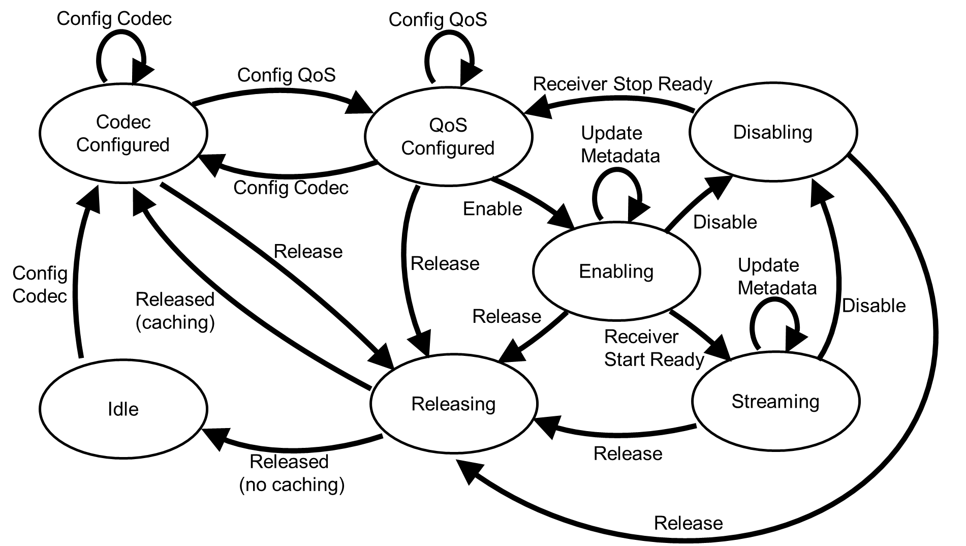
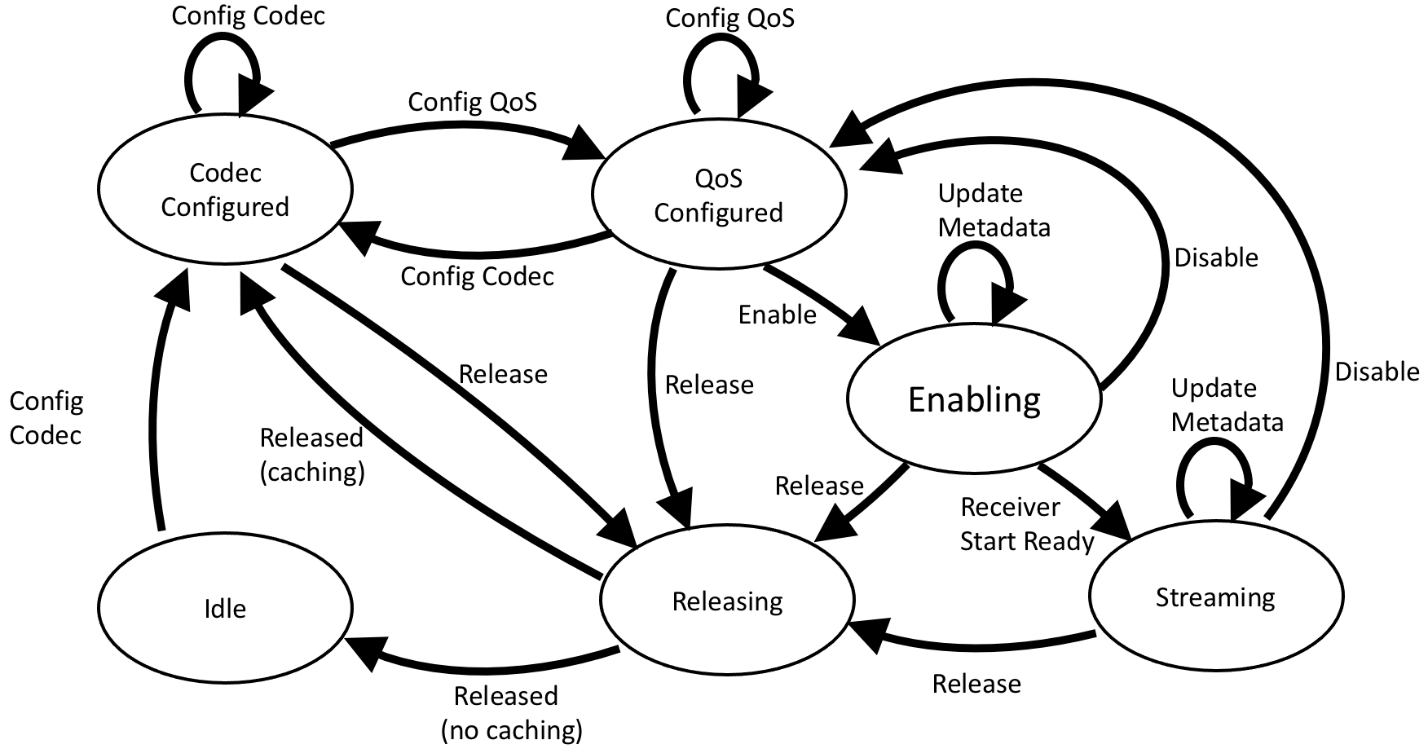
3.1. States
The states of the ASE state machine are defined in Table 3.1.
|
State |
ASE_State Value |
Description |
|---|---|---|
|
Idle |
0x00 |
The ASE has no codec configuration or QoS configuration applied. |
|
Codec Configured |
0x01 |
The ASE has a codec configuration applied. The codec configuration may have been autonomously applied by the server or it may have been requested by the client. The server is exposing its preferred QoS parameters; however, the ASE has no QoS configuration applied yet. |
|
QoS Configured |
0x02 |
The ASE has a codec configuration and a QoS configuration applied. The applied QoS configuration at the host level may be different from the actual configuration applied to a CIS by the client controller. A CIS can exist, but the ASE has not been coupled to the CIS. |
|
Enabling |
0x03 |
The ASE has a codec configuration and a QoS configuration applied and any Metadata applied by the client or server is associated with the ASE. A CIS can exist, but the ASE has not been coupled to the CIS. There is a risk of some lost audio data packets in this state if either server or client begin transmitting audio data before the ASE is in the Streaming state. |
|
Streaming |
0x04 |
The ASE has a codec configuration and a QoS configuration applied, and any Metadata applied by the client or server is associated with the ASE. The ASE is coupled to a CIS. The device acting as Audio Sink has initiated a Receiver Start Ready operation that has successfully completed and the ASE is ready to receive or transmit audio data. |
|
Disabling |
0x05 |
Applies only to Source ASE. The ASE has a codec configuration and a QoS configuration applied. Any CIS established to transport audio data for the ASE might remain established or might be disconnected however the ASE is being decoupled from the CIS. Any Metadata previously applied remains associated with the ASE in this state. The ASE remains ready to transmit audio data until the device acting as Audio Sink has initiated a Receiver Stop Ready operation that has successfully completed. |
|
Releasing |
0x06 |
Any CIS established to transport audio data for the ASE is being disconnected or has been disconnected. Any previously applied codec configuration may be cached by the server, or the server may cache a codec configuration of the server’s choosing, or the codec configuration may be removed. Any previously applied QoS configuration is no longer valid. Any Metadata previously applied is no longer associated with the ASE. |
|
– |
0x07–0xFF |
RFU |
3.2. ASE state machine transitions
Table 3.2 shows the permitted ASE state machine transitions for the Sink ASE and the Source ASE.
If the server detects link loss of a CIS for an ASE in the Streaming state or the Disabling state, the server shall immediately transition that ASE to the QoS Configured state. Link loss of a CIS for an ASE in any state other than Streaming or Disabling shall not cause a transition of the ASE state machine.
If the server detects link loss of a Bluetooth Low Energy-Asynchronous connection-oriented link (LE-ACL) for an ASE in any state, the server shall immediately transition that ASE to the Releasing state, and the server shall follow the requirements defined in Section 5.9.
If a transition is successful, the ASE state machine shall transition to the Next State, and all applicable parameters shall be updated to their new values.
If a transition is unsuccessful, the ASE state machine shall remain in the Current State, and all parameters previously applied in the Current State shall not change.
For example, if an ASE was in the Idle state and the server could not complete a Config Codec operation successfully, the ASE state machine would remain in the Idle state.
ASE state machine transitions that are not shown in Table 3.2 are invalid transitions and shall not occur.
|
ASE Type |
Current State |
ASE Control Operation |
Initiating Device |
Next State |
|---|---|---|---|---|
|
All |
Idle |
Config Codec |
Client or server |
Codec Configured |
|
All |
Codec Configured |
Config Codec |
Client or server |
Codec Configured |
|
All |
Codec Configured |
Release |
Client or server |
Releasing |
|
All |
Codec Configured |
Config QoS |
Client only |
QoS Configured |
|
All |
QoS Configured |
Config Codec |
Client or server |
Codec Configured |
|
All |
QoS Configured |
Config QoS |
Client only |
QoS Configured |
|
All |
QoS Configured |
Release |
Client or server |
Releasing |
|
All |
QoS Configured |
Enable |
Client only |
Enabling |
|
All |
Enabling |
Release |
Client or server |
Releasing |
|
All |
Enabling |
Update Metadata |
Client or server |
Enabling |
|
Source ASE |
Enabling |
Disable |
Client or server |
Disabling |
|
Sink ASE |
Enabling |
Disable |
Client or server |
QoS Configured |
|
All |
Enabling |
Receiver Start Ready |
Client or server |
Streaming |
|
All |
Streaming |
Update Metadata |
Client or server |
Streaming |
|
Source ASE |
Streaming |
Disable |
Client or server |
Disabling |
|
Sink ASE |
Streaming |
Disable |
Client or server |
QoS Configured |
|
All |
Streaming |
Release |
Client or server |
Releasing |
|
Source ASE |
Disabling |
Receiver Stop Ready |
Client only |
QoS Configured |
|
Source ASE |
Disabling |
Release |
Client or server |
Releasing |
|
All |
Releasing |
Released (no caching) |
Server only |
Idle |
|
All |
Releasing |
Released (caching) |
Server only |
Codec Configured |
4. Service characteristics
This section defines the characteristic and descriptor requirements for ASCS.
Table 4.1 provides a summary of the characteristic support requirements for ASCS.
Requirements in this section are defined as “Mandatory” (M), “Optional” (O), “Excluded” (X), and “Conditional” (C.n). Conditional statements (C.n) are listed directly below the table in which they appear.
|
Characteristic Name |
Requirement |
Mandatory Properties |
Optional Properties |
Security Permissions |
|---|---|---|---|---|
|
Sink ASE |
C.1 |
Read, Notify |
None |
Encryption required |
|
Source ASE |
C.1 |
Read, Notify |
None |
Encryption required |
|
ASE Control Point |
M |
Write, WriteWithoutResponse, Notify |
None |
Encryption required |
C.1: At least one of the Sink ASE or Source ASE characteristics shall be supported.
At least one instance of the Sink ASE characteristic shall exist on the server if the Sink ASE characteristic is supported.
At least one instance of the Source ASE characteristic shall exist on the server if the Source ASE characteristic is supported.
A single instance of the ASE Control Point characteristic shall exist on the server.
4.1. Audio Stream Endpoints
An ASE characteristic exposes information about an ASE, including the state of the ASE state machine, codec parameters, QoS parameters, and mapping information for any underlying CIS configuration.
An ASE characteristic represents the state of an ASE, which can be coupled to a CIS to establish a unicast Audio Stream. For each ASE characteristic (distinguished by their attribute handles), the server shall expose separate ASE characteristic values for each client. A client reading or being notified of an ASE characteristic value cannot gain any information about the ASE characteristic value at the same attribute handle that is exposed for a different client.
Figure 4.1 shows an example of a server exposing three Sink ASEs using one Sink ASE characteristic for three clients (Client A, Client B, and Client C). The server is exposing three Sink ASEs using a single characteristic because the server exposes separate copies of the Sink ASE characteristic value for each client irrespective of whether the actual numerical values exposed for each client are identical.
 |
In Figure 4.1, if Client A were to request the server to perform some behavior which leads to the value exposed by the server for Client A to change, the values exposed by the server for Client B and Client C would be unaffected, as shown in Figure 4.2.
 |
The server can expose a maximum of one Sink ASE per client per Sink ASE characteristic and one Source ASE per client per Source ASE characteristic, and the server should expose at a minimum the number of Sink ASE characteristics and/or Source ASE characteristics that it needs to support the number of concurrent established unicast Audio Streams that it can support for a single client.
For example, a server that can support three concurrent established unicast Audio Streams with Client A, might expose three ASE characteristics to enable this; one Sink ASE characteristic for receiving voice audio, a Source ASE characteristic for transmitting voice audio, and a second Sink ASE characteristic for receiving music audio as shown in Figure 4.3.

If the server in Figure 4.3 also interacts with Client B, Client B would also observe the server exposing three ASEs, giving a total of six ASEs exposed by the server as shown in Figure 4.4. Each client is only aware of the ASEs exposed for that client.
In the example in Figure 4.4, there are two separate ASEs being exposed—one for each client—in each ASE characteristic value. Each ASE_ID value for the Sink ASE characteristic at Handle 0x1234 is numerically identical (0x01) for both Client A and Client B. This is deliberately included in the example to illustrate that there are two separate Sink ASEs being exposed at Handle 0x1234, one for each client, which are independent of one another irrespective of whether the numerical values are the same. The server allocates ASE_ID values as it sees fit, subject to the constraints in Table 4.2.

The server should allocate local resources which can be affected by a change in the state of an ASE as it sees fit. The behavior of the server in deciding whether to accept client requests that can change the state of an ASE is left to the implementation unless otherwise defined by higher layers.
For example, the server in Figure 4.4 might not allow any ASEs exposed for Client B to change from the Idle state because the server had three ASEs in the Streaming state with the Client A, or the server might decide to release an ASE exposed for Client A from the Streaming state in order to free resources that could be allocated for Client B.
The format of the ASE characteristic is defined in Table 4.2.
|
Field |
Size (Octets) |
Description |
|---|---|---|
|
ASE_ID |
1 |
Identifier of this ASE, assigned by the server. A different ASE_ID namespace exists for each connected client. Each ASE_ID in a namespace shall be unique. Shall not change for a client if the server has a trusted relationship with that client. Shall not be assigned a value of 0x00 by the server. |
|
ASE_State |
1 |
State of the ASE with respect to the ASE state machine Value: 0x00–0x06 (see Table 3.1) All other values: RFU |
|
Additional_ASE_Parameters |
Varies |
Dependent on states defined in Table 3.1 Idle state or Releasing state: Empty (zero length) States in Table 3.1 other than the Idle state or the Releasing state: see Table 4.3, Table 4.4, or Table 4.5 All other values: RFU |
The format of the Additional_ASE_Parameters field when ASE_State = 0x01 (Codec Configured) is defined in Table 4.3.
|
Field |
Size (Octets) |
Description |
|---|---|---|
|
Framing |
1 |
Server support for unframed ISOAL PDUs 0x00: Unframed ISOAL PDUs supported 0x01: Unframed ISOAL PDUs not supported All other values: RFU |
|
Preferred_PHY |
1 |
Server preferred value for the PHY parameter to be written by the client for this ASE in the Config QoS operation defined in Section 5.2 Formatted as a bitfield 0b00000001: LE 1M PHY preferred 0b00000010: LE 2M PHY preferred 0b00000100: LE Coded PHY preferred The server may set multiple bits in the Preferred_PHY bitfield The server shall not set a bit to 1 for an unsupported PHY in the Preferred_PHY bitfield A value of 0x00 denotes no preference All other bits: RFU |
|
Preferred_Retransmission_Number |
1 |
Server preferred value for the Retransmission_Number parameter to be written by the client for this ASE in the Config QoS operation defined in Section 5.2. The Retransmission_Number parameter is defined in Volume 4, Part E, Section 7.8.97 in [1]. Range: 0x00–0xFF All other values: RFU |
|
Max_Transport_Latency |
2 |
Server preferred value for the Max_Transport_Latency parameter to be written by the client for this ASE in the Config QoS operation defined in Section 5.2. The Max_Transport_Latency parameter is defined in Volume 4, Part E, Section 7.8.97 in [1]. Range: 0x0005–0x0FA0 Units: ms All other values: RFU |
|
Presentation_Delay_Min |
3 |
Minimum server supported Presentation_Delay for this ASE Units: µs |
|
Presentation_Delay_Max |
3 |
Maximum server supported Presentation_Delay for this ASE Units: µs |
|
Preferred_Presentation_Delay_Min |
3 |
Server preferred minimum Presentation_Delay for this ASE. The server can use this parameter and Preferred_Presentation_Delay_Max to express a narrower range of its supported presentation delay that the server prefers to operate in. If nonzero, shall be ≥ Presentation_Delay_Min A value of 0x000000 indicates no preference. Units: µs |
|
Preferred_Presentation_Delay_Max |
3 |
Server preferred maximum Presentation_Delay for this ASE. The server can use this parameter and Preferred_Presentation_Delay_Min to express a narrower range of its supported presentation delay that the server prefers to operate in. If nonzero, shall be ≤ Presentation_Delay_Max A value of 0x000000 indicates no preference. Units: µs |
|
Codec_ID |
5 |
Octet 0: Coding_Format Coding_Format values are defined in Bluetooth Assigned Numbers [2]. Octet 1–2: Company_ID value Company_ID values are defined in Bluetooth Assigned Numbers [2]. Shall be 0x0000 if octet 0 is ≠ 0xFF Octet 3–4: Vendor-specific codec_ID value Shall be 0x0000 if octet 0 is ≠ 0xFF |
|
Codec_Specific_Configuration_Length |
1 |
Length of the Codec_Specific_Configuration field for this ASE |
|
Codec_Specific_Configuration |
Varies |
Codec specific configuration for this ASE Shall exist only if the Codec_Specific_Configuration_Length field is ≠ 0x00 |
The format of the Additional_ASE_Parameters field when ASE_State = 0x02 (QoS Configured) is defined in Table 4.4.
|
Field |
Size (Octets) |
Description |
|---|---|---|
|
CIG_ID |
1 |
CIG_ID parameter value for this ASE written by the client in the Config QoS operation defined in Section 5.2 |
|
CIS_ID |
1 |
CIS_ID parameter value for this ASE written by the client in the Config QoS operation defined in Section 5.2 |
|
SDU_Interval |
3 |
SDU_Interval parameter value for this ASE written by the client in the Config QoS operation defined in Section 5.2 Range: 0x0000FF–0x0FFFFF All other values: RFU |
|
Framing |
1 |
Framing parameter value for this ASE written by the client in the Config QoS operation defined in Section 5.2 0x00: Unframed 0x01: Framed All other values: RFU |
|
PHY |
1 |
PHY parameter value for this ASE written by the client in the Config QoS operation defined in Section 5.2 0b00000001: LE 1M PHY 0b00000010: LE 2M PHY 0b00000100: LE Coded PHY All other bits: RFU |
|
Max_SDU |
2 |
Max_SDU parameter value for this ASE written by the client in the Config QoS operation defined in Section 5.2 Range: 0x00–0xFFF All other values: RFU |
|
Retransmission_Number |
1 |
Retransmission_Number parameter value for this ASE written by the client in the Config QoS operation defined in Section 5.2 Range: 0x00–0xFF All other values: RFU |
|
Max_Transport_Latency |
2 |
Max_Transport_Latency parameter value for this ASE written by the client in the Config QoS operation defined in Section 5.2 Range: 0x0005–0x0FA0 Units: ms All other values: RFU |
|
Presentation_Delay |
3 |
Presentation_Delay parameter value for this ASE written by the client in the Config QoS operation defined in Section 5.2 Units: µs |
The format of the Additional_ASE_Parameters field when ASE_State = 0x03 (Enabling), 0x04 (Streaming), or 0x05 (Disabling) is defined in Table 4.5.
|
Field |
Size (Octets) |
Description |
|---|---|---|
|
CIG_ID |
1 |
CIG_ID parameter value for this ASE written by the client in the Config QoS operation defined in Section 5.2 |
|
CIS_ID |
1 |
CIS_ID parameter value for this ASE written by the client in the Config QoS operation defined in Section 5.2 |
|
Metadata_Length |
1 |
Length of the Metadata field for this ASE |
|
Metadata |
Varies |
Length-type-value (LTV)-formatted Metadata for this ASE Shall exist only if the Metadata_Length parameter value for this ASE is not 0x00 |
4.1.1. ASE behavior
An ASE characteristic (Sink ASE or Source ASE) returns its characteristic value when read by a client. The characteristics can be configured for notifications by using the GATT Write Characteristic Descriptors sub‑procedure on the Client Characteristic Configuration descriptor.
If the characteristic value exposed for a client changes when in a connection and the value of the Client Characteristic Configuration descriptor is configured for notifications, the server shall notify the new characteristic value to the client. Permitted behavioral exceptions to this requirement are defined in Section 5.3.
If the characteristic value for a bonded client changes when not in a connection and the value of the Client Characteristic Configuration descriptor is configured for notifications, the server shall notify the new characteristic value when reconnecting to the bonded client.
4.2. ASE Control Point
When written by a client, the ASE Control Point characteristic is an 8-bit enumerated value (known as the opcode) followed by zero or more parameter octets. The opcode is used by the server to determine which ASE Control operation is being initiated by the client. A notification of the ASE Control Point is used to provide a response to a client-initiated ASE Control operation.
ASE Control operations can be initiated by the server or by a client, as defined in Table 3.2.
ASE Control operations and any associated opcodes are defined in Table 4.6.
|
Opcode |
Operation |
Requirement |
Parameter |
Description |
|---|---|---|---|---|
|
0x01 |
Config Codec |
M |
Configures codec parameters for one or more ASEs. Valid only if ASE_State field = 0x00 (Idle), or 0x01 (Codec Configured), or 0x02 (QoS Configured). |
|
|
0x02 |
Config QoS |
M |
Configures preferred CIS parameters for one or more ASEs. Valid only if ASE_State field value = 0x01 (Codec Configured) or 0x02 (QoS Configured). |
|
|
0x03 |
Enable |
M |
Applies codec parameters and preferred CIS parameters, applies any Metadata, and starts coupling an ASE to a CIS for one or more ASEs. Valid only if ASE_State field value = 0x02 (QoS Configured). |
|
|
0x04 |
Receiver Start Ready |
M |
Signals that the Audio Sink is ready to receive audio data transmitted by the Audio Source, and completes coupling an ASE to a CIS. Valid only if ASE_State field value = 0x03 (Enabling). |
|
|
0x05 |
Disable |
M |
Starts decoupling a Source ASE from a CIS for one or more Source ASEs. Decouples a Sink ASE from a CIS for one or more Sink ASEs Valid only if ASE_State field value = 0x03 (Enabling) or 0x04 (Streaming). |
|
|
0x06 |
Receiver Stop Ready |
M |
Signals that the Audio Sink is ready to stop receiving audio data transmitted by the Audio Source, and completes decoupling a Source ASE from a CIS. Valid only for a Source ASE and only if ASE_State field value = 0x05 (Disabling). |
|
|
0x07 |
Update Metadata |
M |
Updates Metadata for one or more ASEs. Valid only if ASE_State field value = 0x03 (Enabling) or 0x04 (Streaming). |
|
|
0x08 |
Release |
M |
Releases resources associated with an ASE, immediately decouples the ASE from any previously coupled CIS, and tears down any CIS previously established for the ASE for one or more ASEs. Valid only if ASE_State field value = 0x01 (Codec Configured), 0x02 (QoS Configured), 0x03 (Enabling), 0x04 (Streaming), or 0x05 (Disabling). |
|
|
– |
Released |
M |
Transitions an ASE from Releasing state to the Idle state or the Codec Configured state depending on the server preference for caching a codec configuration. Allowed only when ASE_State field = 0x06 (Releasing). |
|
|
0x09-0xFF |
RFU |
– |
– |
– |
The format of the ASE Control Point characteristic value when notified is defined in Table 4.7.
|
Field |
Size (Octets) |
Description |
|---|---|---|
|
Opcode |
1 |
Opcode of the client-initiated ASE Control operation causing this response |
|
Number_of_ASEs |
1 |
Total number of ASEs the server is providing a response for If the Response_Code value is 0x01 or 0x02, Number_of_ASEs shall be set to 0xFF. |
|
ASE_ID[i] |
1 |
ASE_ID for this ASE If the Response_Code value is 0x01 or 0x02, ASE_ID shall be set to 0x00, and [i] shall be set to 0. |
|
Response_Code[i] |
1 |
Shall be set to 0x00 if the server successfully completes a client-initiated ASE Control operation, otherwise shall be set as defined in Table 5.1. If the Response_Code value is 0x01 or 0x02, [i] shall be set to 0. |
|
Reason[i] |
1 |
Shall be set to 0x00 if the server successfully completes a client-initiated ASE Control operation, otherwise shall be set as defined in Table 5.1. If the Response_Code value is 0x01 or 0x02, [i] shall be set to 0. |
4.2.1. ASE Control Point behavior
The ASE Control Point characteristic can be written by a client.
The ASE Control Point characteristic can be configured for notifications by a client by using the GATT Write Characteristic Descriptors sub-procedure on the Client Characteristic Configuration descriptor.
5. ASE Control operations
This section defines a server’s behavior when performing ASE Control operations.
If the server successfully completes a client-initiated ASE Control operation for an ASE, the server shall send a notification of the ASE Control Point characteristic value formatted as defined in Table 4.7. The server shall then perform the behavior defined in Section 5.1 through Section 5.8 for that ASE Control operation and send notifications of any ASE characteristic values written during that ASE Control operation.
If the server rejects or cannot successfully complete a client-initiated ASE Control operation for an ASE, the server shall send a notification of the ASE Control Point characteristic value formatted as defined in Table 4.7.
If the server autonomously initiates an ASE Control operation for an ASE, the server shall perform the behavior as defined in Section 5.1 through Section 5.9 for that ASE Control operation and send notifications of any ASE characteristic values written during that ASE Control operation.
The server shall not send a notification of the ASE Control Point characteristic value when completing an autonomously-initiated ASE Control operation.
A client-initiated ASE Control operation shall be defined as an invalid length operation if the Number_of_ASEs parameter value is less than 1, or if the Number_of_ASEs parameter value does not match the number of parameter arrays written by the client. A client-initiated ASE Control operation shall also be defined as an invalid length operation if the total length of all parameters written by the client is not equal to the total length of all fixed parameters plus the length of any variable length parameters for that operation as defined in Section 5.1 through Section 5.8.
Table 5.1 defines the Response_Code and Reason values that shall be used when the server rejects or cannot successfully complete a client-initiated ASE Control operation.
The server can choose to provide additional context to a client initiating an ASE Control operation by using a Response_Code value of 0x07 (Unsupported Configuration Parameter Value), 0x08 (Rejected Configuration Parameter Value), or 0x09 (Invalid Configuration Parameter Value).
When sending a Response_Code value of 0x07 (Unsupported Configuration Parameter Value), 0x08 (Rejected Configuration Parameter Value), or 0x09 (Invalid Configuration Parameter Value), if multiple Response_Code and Reason values are applicable to ASE Control operation parameter values written by a client, the server shall use the Response_Code and Reason values that apply to the error caused by the first parameter value in the array of parameter values written by the client for that ASE.
For example, if a client initiated an ASE Control operation with parameter value[0], parameter value[1], and parameter value[2], and if parameter value[1] and parameter value[2] were in error, then the server would use the Response_Code and Reason values applicable to parameter value[1].
If the client thereafter initiated a new ASE Control operation with the same opcode and with only parameter value[2] in error, the server would use the Response_Code and Reason values applicable to parameter value[2].
If the client instead initiated a new ASE Control operation with the same opcode and with parameter value[2] no longer in error, but a new error was detected in parameter value[0], and with the original error detected in parameter value[1] still present, the server would use the Response_Code and Reason values applicable to parameter value[0].
|
Response_Code |
Reason |
Description |
|---|---|---|
|
0x00 = Success |
0x00 |
The server has successfully completed the client-initiated ASE Control operation. |
|
0x01 = Unsupported Opcode |
0x00 |
The server does not support the client-initiated ASE Control operation defined by the opcode written by the client. |
|
0x02 = Invalid Length |
0x00 |
The server has detected an invalid length operation written by the client. |
|
0x03 = Invalid ASE_ID |
0x00 |
The server has detected that an ASE_ID written by the client does not match an ASE_ID in an exposed ASE characteristic value for that client. |
|
0x04 = Invalid ASE State Machine Transition |
0x00 |
The server has detected that the client-initiated ASE Control operation would cause an invalid ASE state machine transition. |
|
0x05 = Invalid ASE direction |
0x00 |
The server has detected that the client-initiated ASE Control operation is not valid for the ASE direction. |
|
0x06 = Unsupported Audio Capabilities |
0x00 |
The server has detected that the audio capabilities requested during a Config Codec operation are not supported (i.e., the server has not exposed the requested configuration in any PAC record as defined in [4]). |
|
0x07 = Unsupported Configuration Parameter Value |
0x01 = Codec_ID 0x02 = Codec_Specific_Configuration 0x03 = SDU_Interval 0x04 = Framing 0x05 = PHY 0x06 = Maximum_SDU_Size 0x07 = Retransmission_Number 0x08 = Max_Transport_Latency 0x09 = Presentation_Delay 0x0A = Invalid_ASE_CIS_Mapping All other values: RFU |
The server has detected that it does not support one or more configuration parameter values written by the client. Shall not be used when the Reason value is 0x04(Framing). |
|
0x08 = Rejected Configuration Parameter Value |
The server has rejected one or more configuration parameter values written by the client. |
|
|
0x09 = Invalid Configuration Parameter Value |
The server has detected one or more invalid configuration parameter values written by the client. |
|
|
0x0A = Unsupported Metadata |
0xXX = Value of the Metadata Type field in error |
The server has detected an unsupported Metadata Type written by the client. |
|
0x0B = Rejected Metadata |
0xXX = Value of the Metadata Type field in error |
The server has rejected a Metadata Type written by the client. |
|
0x0C = Invalid Metadata |
0xXX = Value of the Metadata Type field in error |
This Response_Code is used to inform the client that the Metadata Value is incorrectly formatted. |
|
0x0D = Insufficient Resources |
0x00 |
The server is unable to successfully complete the client-initiated ASE Control operation because of insufficient resources. |
|
0x0E = Unspecified Error |
0x00 |
The server has encountered an unspecified error. |
|
0x0F–0xFF |
RFU |
– |
5.1. Config Codec operation
When written by a client, the Config Codec operation is used to request a codec configuration with the server.
Successful completion of the Config Codec operation on the server results in the server exposing its preferred QoS parameters.
The Config Codec operation may be autonomously initiated by the server.
As defined in Table 4.6, the Config Codec operation for an ASE is valid only if the value of the ASE_State field is 0x00 (Idle), 0x01 (Codec Configured), or 0x02 (QoS Configured).
The Config Codec operation uses the format defined in Table 5.2.
|
Opcode |
Size (Octets) |
Description |
|---|---|---|
|
0x01 |
1 |
0x01 = Config Codec |
|
Parameters |
Size (Octets) |
Description |
|
Number_of_ASEs |
1 |
Total number of ASEs used in the Config Codec operation Shall be ≥ 1 |
|
ASE_ID[i] |
1 |
ASE_ID for this ASE |
|
Target_Latency[i] |
1 |
Provides context for the server to return meaningful values for QoS preferences in Codec Configured state 0x01 = Target low latency 0x02 = Target balanced latency and reliability 0x03 = Target high reliability |
|
Target_PHY[i] |
1 |
PHY parameter target to achieve the Target_Latency value 0x01: LE 1M PHY 0x02: LE 2M PHY 0x03: LE Coded PHY |
|
Codec_ID[i] |
5 |
Octet 0: Coding_Format Coding_Format values are defined in Bluetooth Assigned Numbers [2]. Octet 1–2: Company_ID value Company_ID values are defined in Bluetooth Assigned Numbers [2]. Shall be 0x0000 if octet 0 is ≠ 0xFF Octet 3–4: Vendor-specific codec_ID value Shall be 0x0000 if octet 0 is ≠ 0xFF |
|
Codec_Specific_Configuration_Length[i] |
1 |
Length of the Codec_Specific_Configuration value for this ASE |
|
Codec_Specific_Configuration[i] |
Varies |
Codec-Specific Configuration for this ASE Shall exist only if the Codec_Specific_Configuration_Length parameter value is ≠ 0x00 |
If the server accepts the requested Config Codec operation parameter values for an ASE, or if the server autonomously initiates the Config Codec operation for an ASE, the server shall:
-
Transition the ASE to the Codec Configured state and write a value of 0x01 (Codec Configured) to the ASE_State field.
-
Write the accepted or autonomously-initiated Config Codec operation parameter values to the matching Additional_ASE_Parameters fields defined in Table 4.3.
-
Write the server’s preferred values for the remaining Additional_ASE_Parameters fields defined in Table 4.3.
5.2. Config QoS operation
The Config QoS operation is used to request a CIS configuration preference with the server and to assign identifiers to the CIS.
As defined in Table 4.6, the Config QoS operation for an ASE is valid only if the value of the ASE_State field is 0x01 (Codec Configured) or 0x02 (QoS Configured).
The Config QoS operation uses the format defined in Table 5.3.
|
Opcode |
Size (Octets) |
Description |
|---|---|---|
|
0x02 |
1 |
0x02 = Config QoS |
|
Parameter |
Size (Octets) |
Description |
|
Number_of_ASEs |
1 |
Total number of ASEs used in the Config QoS operation Shall be ≥ 1 |
|
ASE_ID[i] |
1 |
ASE_ID for this ASE |
|
CIG_ID[i] |
1 |
CIG_ID parameter value written by the client for this ASE (if HCI is used, written by using the LE Set CIG Parameters command defined in Volume 4, Part E, Section 7.8.97 in [1]) |
|
CIS_ID[i] |
1 |
CIS_ID parameter value written by the client for this ASE (if HCI is used, written by using the LE Set CIG Parameters command defined in Volume 4, Part E, Section 7.8.97 in [1]) |
|
SDU_Interval[i] |
3 |
SDU_Interval parameter value written by the client for this ASE (if HCI is used, written by using the LE Set CIG Parameters command defined in Volume 4, Part E, Section 7.8.97 in [1]) Range: 0x0000FF–0x0FFFFF All other values: RFU |
|
Framing[i] |
1 |
Framing parameter value written by the client for this ASE (if HCI is used, written by using the LE Set CIG Parameters command defined in Volume 4, Part E, Section 7.8.97 in [1]) 0x00: Unframed 0x01: Framed All other values: RFU |
|
PHY[i] |
1 |
PHY parameter value written by the client for this ASE (if HCI is used, written by using the LE Set CIG Parameters command defined in Volume 4, Part E, Section 7.8.97 in [1]) 0b00000001 : LE 1M PHY 0b00000010: LE 2M PHY 0b00000100: LE Coded PHY All other bits: RFU |
|
Max_SDU[i] |
2 |
Max_SDU parameter value written by the client for this ASE (if HCI is used, written by using the LE Set CIG Parameters command defined in Volume 4, Part E, Section 7.8.97 in [1]) Range: 0x00–0x0FFF All other values: RFU |
|
Retransmission_Number[i] |
1 |
Retransmission_Number parameter written by the client for this ASE (if HCI is used, written by using the LE Set CIG Parameters command defined in Volume 4, Part E, Section 7.8.97 in [1]) Range: 0x00–0xFF All other values: RFU |
|
Max_Transport_Latency[i] |
2 |
Max_Transport_Latency parameter value written by the client for this ASE (if HCI is used, written by using the LE Set CIG Parameters command defined in Volume 4, Part, E, Section 7.8.97 in [1]) Range: 0x0005–0x0FA0 All other values: RFU |
|
Presentation_Delay[i] |
3 |
Presentation delay parameter value being requested by the client for this ASE Units: µs |
If a client requests a Config QoS operation for an ASE that would result in more than one Sink ASE having identical CIG_ID and CIS_ID parameter values for that client, or that would result in more than one Source ASE having identical CIG_ID and CIS_ID parameter values for that client, the server shall not accept the Config QoS operation for that ASE. The server shall send a notification of the ASE Control Point characteristic to the client, the server shall set the Response_Code value for that ASE to 0x09 (Invalid Parameter Value), and the server shall set the Reason value for that ASE to 0x0A (Invalid_ASE_CIS_Mapping).
If the server accepts the requested Config QoS operation parameter values for an ASE the server shall:
-
Transition the ASE to the QoS Configured state and write a value of 0x02 (QoS Configured) to the ASE_State field.
-
Write the accepted Config QoS operation parameter values to the matching Additional_ASE_Parameters fields defined in Table 4.4.
5.3. Enable operation
The Enable operation is used to request the server to enable an ASE and to provide any Metadata applicable for that ASE.
As defined in Table 4.6, the Enable operation is valid for an ASE only if the value of the ASE_State field is 0x02 (QoS Configured).
The Enable operation uses the format defined in Table 5.4.
|
Opcode |
Size (Octets) |
Description |
|---|---|---|
|
0x03 |
1 |
0x03 = Enable |
|
Parameter |
Size (Octets) |
Description |
|
Number_of_ASEs |
1 |
Total number of ASE_IDs used in the Enable operation Shall be ≥ 1 |
|
ASE_ID[i] |
1 |
ASE_ID for this ASE |
|
Metadata_Length[i] |
1 |
Length of the Metadata parameter for this ASE |
|
Metadata[i] |
Varies |
LTV-formatted Metadata for this ASE. Shall exist only if the Metadata_Length parameter value is not 0x00 |
If the server accepts the requested Enable operation parameter values for an ASE, the server shall:
-
Transition the ASE to the Enabling state and write a value of 0x03 (Enabling) to the ASE_State field.
-
If a CIS has been established and the server is acting as Audio Sink for the ASE, and if the server is ready to receive audio data transmitted by the client, the server may autonomously initiate the Receiver Start Ready, as defined in Section 5.4, without first sending a notification of the ASE characteristic value in the Enabling state.
-
-
Write the accepted Enable operation parameter values to the matching Additional_ASE_Parameters fields defined in Table 4.5.
5.4. Receiver Start Ready operation
When written by a client acting as Audio Sink, the Receiver Start Ready operation informs a server acting as Audio Source that the client is ready to consume audio data transmitted by the server.
As defined in Table 4.6, the Receiver Start Ready operation is valid for an ASE only if the value of the ASE_State field is 0x03 (Enabling) and if the device initiating the Receiver Start Ready operation is acting as Audio Sink for that ASE.
The server, when acting as Audio Sink, shall initiate the Receiver Start Ready operation autonomously to inform a client acting as Audio Source that the server is ready to consume audio data transmitted by the client.
The Receive Start Ready operation uses the format defined in Table 5.5.
|
Opcode |
Size (Octets) |
Description |
|---|---|---|
|
0x04 |
1 |
0x04 = Receiver Start Ready |
|
Parameter |
Size (Octets) |
Description |
|
Number_of_ASEs |
1 |
Total number of ASE_IDs used in the Receiver Start Ready operation Shall be ≥ 1 |
|
ASE_ID[i] |
1 |
ASE_ID for this ASE |
If the ASE_ID written by the client represents a Sink ASE, the server shall not accept the Receiver Start Ready operation for that ASE and the server shall send a notification of the ASE Control Point characteristic to the client, and the server shall set the Response_Code value for that ASE to 0x05 (Invalid ASE direction).
If the server accepts the requested Receiver Start Ready operation parameter values for an ASE, or if the server autonomously initiates the Receiver Start Ready operation for an ASE, the server shall transition the ASE to the Streaming state and write a value of 0x04 (Streaming) to the ASE_State field.
5.5. Disable operation
When written by a client, the Disable operation is used to request the server to disable an ASE.
As defined in Table 4.6, the Disable operation is valid for an ASE only if the value of the ASE_State field is 0x03 (Enabling) or 0x04 (Streaming).
The server may initiate the Disable operation autonomously.
The Disable operation uses the format defined in Table 5.6.
|
Opcode |
Size (Octets) |
Description |
|---|---|---|
|
0x05 |
1 |
0x05 = Disable |
|
Parameter |
Size (Octets) |
Description |
|
Number_of_ASEs |
1 |
Total number of ASE_IDs used in the Disable operation Shall be ≥ 1 |
|
ASE_ID[i] |
1 |
ASE_ID for this ASE |
If the server accepts the requested Disable operation parameter values for a Source ASE, or if the server autonomously initiates the Disable operation for a Source ASE, the server shall:
-
Transition the ASE to the Disabling state and write a value of 0x05 (Disabling) to the ASE_State field.
-
Write the accepted or autonomously-initiated Disable operation parameter values to the matching Additional_ASE_Parameters fields defined in Table 4.5.
If the server accepts the requested Disable operation parameter values for a Sink ASE, or if the server autonomously initiates the Disable operation for a Sink ASE, the server shall:
-
Transition the ASE to the QoS Configured state and write a value of 0x02 (QoS Configured) to the ASE_State field.
-
Write the previously accepted Config QoS operation parameter values to the matching Additional_ASE_Parameters fields defined in Table 4.4.
5.6. Receiver Stop Ready operation
When written by a client acting as Audio Sink, the Receiver Stop Ready operation is used to inform a server acting as Audio Source that the client is ready to stop consuming audio data transmitted by the server.
As defined in Table 4.6, the Receiver Stop Ready operation is valid only for a Source ASE and only if the value of the ASE_State field is 0x04 (Disabling).
The Receiver Stop Ready operation uses the format defined in Table 5.7.
|
Opcode |
Size (Octets) |
Description |
|---|---|---|
|
0x06 |
1 |
0x06 = Receiver Stop Ready |
|
Parameter |
Size (Octets) |
Description |
|
Number_of_ASEs |
1 |
Total number of ASE_IDs used in the Receiver Stop Ready operation Shall be ≥ 1 |
|
ASE_ID[i] |
1 |
ASE_ID for this ASE |
If the ASE_ID written by the client represents a Sink ASE, the server shall not accept the Receiver Stop Ready operation for that ASE and the server shall send a notification of the ASE Control Point characteristic to the client, and the server shall set the Response_Code value for that ASE to 0x05 (Invalid ASE direction).
If the server accepts the requested Receiver Stop Ready operation parameter values for a Source ASE, the server shall transition the ASE to the QoS Configured state and write a value of 0x02 (QoS Configured) to the ASE_State field, and the server shall write the previously accepted Config QoS operation parameter values to the matching Additional_ASE_Parameters fields defined in Table 4.5.
5.7. Update Metadata operation
When written by a client, the Update Metadata operation is used to provide the server with Metadata to be applied to an ASE.
As defined in Table 4.6, the Update Metadata operation is valid for an ASE only if the value of the ASE_State field is 0x03 (Enabling) or 0x04 (Streaming).
The server may initiate the Update Metadata operation autonomously.
The Update Metadata operation uses the format defined in Table 5.8.
|
Opcode |
Size (Octets) |
Description |
|---|---|---|
|
0x07 |
1 |
0x07 = Update Metadata |
|
Parameter |
Size (Octets) |
Description |
|
Number_of_ASEs |
1 |
Total number of ASE_IDs used in the Update Metadata operation Shall be ≥ 1 |
|
ASE_ID[i] |
1 |
ASE_ID for this ASE |
|
Metadata_Length[i] |
1 |
Length of the Metadata parameter for this ASE |
|
Metadata[i] |
Varies |
LTV-formatted Metadata for this ASE Shall exist only if the Metadata_Length parameter value is not 0x00 |
If the server accepts the requested Update Metadata operation parameter values for an ASE, or if the server initiates Update Metadata operation autonomously, the server shall write the accepted or autonomously-initiated Update Metadata operation parameter values to the matching Additional_ASE_Parameters fields defined in Table 4.5.
5.8. Release operation
When written by a client, the Release operation is used to request the server to release an ASE and all resources associated with that ASE.
As defined in Table 4.6, the Release operation is valid for an ASE only if the value of the ASE_State field is 0x01 (Codec Configured), 0x02 (QoS Configured), 0x03 (Enabling), 0x04 (Streaming), or 0x05 (Disabling).
The server may initiate the Release operation autonomously.
The Release operation uses the format defined in Table 5.9.
|
Opcode |
Size (Octets) |
Description |
|---|---|---|
|
0x08 |
1 |
0x08 = Release |
|
Parameter |
Size (Octets) |
Description |
|
Number_of_ASEs |
1 |
Total number of ASE_IDs to be released Shall be ≥ 1 |
|
ASE_ID[i] |
1 |
ASE_ID for this ASE |
If the server accepts the requested Release operation parameter values for an ASE, or the server autonomously initiates the Release operation for an ASE, the server shall transition the ASE to the Releasing state and write a value of 0x06 (Releasing) to the ASE_State field.
5.9. Released operation
The Released operation shall be initiated autonomously by the server if:
-
The server has detected the loss of the LE-ACL for an ASE in any state, or
-
The Release operation for an ASE has been completed and the server controller has indicated that the underlying CIS for the ASE has been torn down.
When initiating the Released operation, the server shall follow the steps in one of the following lists.
If the server wants to cache a codec configuration:
-
Transition the ASE to the Codec Configured state and write a value of 0x01 (Codec Configured) to the ASE_State field.
-
Write the configured values or the server’s preferred values for the Codec_ID, Codec_Specific_Configuration_Length, and Codec_Specific_Configuration parameters to the matching Additional_ASE_Parameters fields defined in Table 4.3.
-
Write the server’s preferred values for the remaining Additional_ASE_Parameters fields defined in Table 4.3.
If the server does not want to cache a codec configuration:
-
Transition the ASE to the Idle state and write a value of 0x00 (Idle) to the ASE_State field.
-
Delete any Additional_ASE_Parameters fields present.
6. SDP interoperability
When ASCS is supported over Basic Rate/Enhanced Data Rate (BR/EDR), the attributes defined in Table 6.1 shall be included in the Service Discovery Protocol (SDP) service record.
|
Item |
Definition |
Type |
Value |
Requirement |
|---|---|---|---|---|
|
Service Class ID List |
– |
– |
– |
M |
|
Service Class #0 |
– |
UUID |
«Audio Stream Control» |
M |
|
Protocol Descriptor List |
– |
Data Element Sequence |
– |
M |
|
Protocol #0 |
– |
UUID |
«L2CAP» |
M |
|
Parameter #0 for Protocol #0 |
Protocol/Service Multiplexer (PSM) |
uint16 |
PSM = ATT |
M |
|
Protocol #1 |
– |
UUID |
«ATT» |
M |
|
Additional Protocol Descriptor List |
– |
Data Element Sequence |
– |
C.1 |
|
Protocol Descriptor List |
– |
Data Element Sequence |
– |
C.1 |
|
Protocol #0 |
– |
UUID |
«L2CAP» |
C.1 |
|
Parameter #0 for Protocol #0 |
PSM |
uint16 |
PSM = EATT |
C.1 |
|
Protocol #1 |
– |
UUID |
«ATT» |
C.1 |
|
BrowseGroupList |
– |
– |
PublicBrowseRoot Other browse UUIDs may also be included in the list. |
M |
C.1: Mandatory to support if EATT is supported, otherwise Excluded.
7. Acronyms and abbreviations
|
Acronym/Abbreviation |
Meaning |
|---|---|
|
ACL |
Asynchronous connection-oriented link |
|
ASCS |
Audio Stream Control Service |
|
ASE |
Audio Stream Endpoint |
|
ATT |
Attribute Protocol |
|
BAP |
Basic Audio Profile |
|
BR/EDR |
Basic Rate/Enhanced Data Rate |
|
CIG |
Connected Isochronous Group |
|
CIS |
Connected Isochronous Stream |
|
EATT |
Enhanced ATT |
|
GAP |
Generic Access Profile |
|
GATT |
Generic Attribute Profile |
|
HCI |
Host Controller Interface |
|
LE |
Low Energy |
|
L2CAP |
Logical Link Control and Adaptation Protocol |
|
LSO |
least significant octet |
|
PACS |
Published Audio Capabilities Service |
|
PDU |
Protocol Data Unit |
|
PSM |
Protocol/Service Multiplexer |
|
QoS |
Quality of Service |
|
RFU |
Reserved for Future Use |
|
SDP |
Service Discovery Protocol |
|
SDU |
Service Data Unit |
|
UUID |
universally unique identifier |
8. References
[1] Bluetooth Core Specification, Version 5.2 or later
[2] Bluetooth SIG Assigned Numbers, https://www.bluetooth.com/specifications/assigned-numbers
[3] Basic Audio Profile Specification, Version 1
[4] Published Audio Capabilities Service Specification, Version 1
[5] Bluetooth Core Specification Supplement, Version 9 or later