Revision: v1.0
Revision Date: 2021-02-23
Group Prepared By: Generic Audio Working Group
Abstract:
This profile enables a microphone controller to adjust the state of microphones.
Revision History
|
Revision Number |
Date |
Comments |
|---|---|---|
|
v1.0 |
2021-02-23 |
Adopted by the Bluetooth SIG Board of Directors. |
Contributors
|
Name |
Company |
|---|---|
|
Michael Rougeux |
Bose Corporation |
|
Siegfried Lehmann |
Apple, Inc. |
|
Tim Reilly |
Bose Corporation |
|
Robin Heydon |
Qualcomm, Inc. |
|
Asbjørn Sæbø |
Nordic Semiconductor ASA |
|
Georg Dickmann |
Sonova AG |
|
Masahiko Seki |
Sony Corporation |
|
Daniel Sisolak |
Bose Corporation |
|
Oren Haggai |
Intel Corporation |
|
Frank Yerrace |
Microsoft Corporation |
|
Chris White |
Dolby Labs |
Use of this specification is your acknowledgement that you agree to and will comply with the following notices and disclaimers. You are advised to seek appropriate legal, engineering, and other professional advice regarding the use, interpretation, and effect of this specification.
Use of Bluetooth specifications by members of Bluetooth SIG is governed by the membership and other related agreements between Bluetooth SIG and its members, including those agreements posted on Bluetooth SIG’s website located at www.bluetooth.com. Any use of this specification by a member that is not in compliance with the applicable membership and other related agreements is prohibited and, among other things, may result in (i) termination of the applicable agreements and (ii) liability for infringement of the intellectual property rights of Bluetooth SIG and its members. This specification may provide options, because, for example, some products do not implement every portion of the specification. Each option identified in the specification is intended to be within the bounds of the Scope as defined in the Bluetooth Patent/Copyright License Agreement (“PCLA”). Also, the identification of options for implementing a portion of the specification is intended to provide design flexibility without establishing, for purposes of the PCLA, that any of these options is a “technically reasonable non-infringing alternative.”
Use of this specification by anyone who is not a member of Bluetooth SIG is prohibited and is an infringement of the intellectual property rights of Bluetooth SIG and its members. The furnishing of this specification does not grant any license to any intellectual property of Bluetooth SIG or its members. THIS SPECIFICATION IS PROVIDED “AS IS” AND BLUETOOTH SIG, ITS MEMBERS AND THEIR AFFILIATES MAKE NO REPRESENTATIONS OR WARRANTIES AND DISCLAIM ALL WARRANTIES, EXPRESS OR IMPLIED, INCLUDING ANY WARRANTIES OF MERCHANTABILITY, TITLE, NON-INFRINGEMENT, FITNESS FOR ANY PARTICULAR PURPOSE, OR THAT THE CONTENT OF THIS SPECIFICATION IS FREE OF ERRORS. For the avoidance of doubt, Bluetooth SIG has not made any search or investigation as to third parties that may claim rights in or to any specifications or any intellectual property that may be required to implement any specifications and it disclaims any obligation or duty to do so.
TO THE MAXIMUM EXTENT PERMITTED BY APPLICABLE LAW, BLUETOOTH SIG, ITS MEMBERS AND THEIR AFFILIATES DISCLAIM ALL LIABILITY ARISING OUT OF OR RELATING TO USE OF THIS SPECIFICATION AND ANY INFORMATION CONTAINED IN THIS SPECIFICATION, INCLUDING LOST REVENUE, PROFITS, DATA OR PROGRAMS, OR BUSINESS INTERRUPTION, OR FOR SPECIAL, INDIRECT, CONSEQUENTIAL, INCIDENTAL OR PUNITIVE DAMAGES, HOWEVER CAUSED AND REGARDLESS OF THE THEORY OF LIABILITY, AND EVEN IF BLUETOOTH SIG, ITS MEMBERS OR THEIR AFFILIATES HAVE BEEN ADVISED OF THE POSSIBILITY OF THE DAMAGES.
Products equipped with Bluetooth wireless technology ("Bluetooth Products") and their combination, operation, use, implementation, and distribution may be subject to regulatory controls under the laws and regulations of numerous countries that regulate products that use wireless non-licensed spectrum. Examples include airline regulations, telecommunications regulations, technology transfer controls, and health and safety regulations. You are solely responsible for complying with all applicable laws and regulations and for obtaining any and all required authorizations, permits, or licenses in connection with your use of this specification and development, manufacture, and distribution of Bluetooth Products. Nothing in this specification provides any information or assistance in connection with complying with applicable laws or regulations or obtaining required authorizations, permits, or licenses.
Bluetooth SIG is not required to adopt any specification or portion thereof. If this specification is not the final version adopted by Bluetooth SIG’s Board of Directors, it may not be adopted. Any specification adopted by Bluetooth SIG’s Board of Directors may be withdrawn, replaced, or modified at any time. Bluetooth SIG reserves the right to change or alter final specifications in accordance with its membership and operating agreements.
Copyright © 2019–2021. All copyrights in the Bluetooth Specifications themselves are owned by Apple Inc., Ericsson AB, Intel Corporation, Lenovo (Singapore) Pte. Ltd., Microsoft Corporation, Nokia Corporation, and Toshiba Corporation. The Bluetooth word mark and logos are owned by Bluetooth SIG, Inc. Other third-party brands and names are the property of their respective owners.
1. Introduction
This profile enables a Generic Attribute Profile (GATT) client to control and obtain the status of a microphone through the Microphone Control Service (MICS) [2]. This profile also describes the procedures used to control and obtain the status of instances of the Audio Input Control Service (AICS) [3].
1.1. Profile dependencies
This profile requires GATT.
1.2. Conformance
If conformance to this specification is claimed, all capabilities indicated as mandatory for this specification shall be supported in the specified manner (process-mandatory). This also applies for all optional and conditional capabilities for which support is indicated.
1.3. Bluetooth Core Specification release compatibility
This specification is compatible with any version of the Bluetooth Core Specification [1] that includes GATT.
1.4. Language
1.4.1. Language conventions
The Bluetooth SIG has established the following conventions for use of the words shall, must, will, should, may, can, is, and note in the development of specifications:
|
shall |
is required to – used to define requirements. |
|
must |
is used to express: a natural consequence of a previously stated mandatory requirement. OR an indisputable statement of fact (one that is always true regardless of the circumstances). |
|
will |
it is true that – only used in statements of fact. |
|
should |
is recommended that – used to indicate that among several possibilities one is recommended as particularly suitable, but not required. |
|
may |
is permitted to – used to allow options. |
|
can |
is able to – used to relate statements in a causal manner. |
|
is |
is defined as – used to further explain elements that are previously required or allowed. |
|
note |
Used to indicate text that is included for informational purposes only and is not required in order to implement the specification. Each note is clearly designated as a “Note” and set off in a separate paragraph. |
For clarity of the definition of those terms, see Core Specification Volume 1, Part E, Section 1.
1.4.2. Reserved for Future Use
Where a field in a packet, Protocol Data Unit (PDU), or other data structure is described as "Reserved for Future Use" (irrespective of whether in uppercase or lowercase), the device creating the structure shall set its value to zero unless otherwise specified. Any device receiving or interpreting the structure shall ignore that field; in particular, it shall not reject the structure because of the value of the field.
Where a field, parameter, or other variable object can take a range of values, and some values are described as "Reserved for Future Use," a device sending the object shall not set the object to those values. A device receiving an object with such a value should reject it, and any data structure containing it, as being erroneous; however, this does not apply in a context where the object is described as being ignored or it is specified to ignore unrecognized values.
When a field value is a bit field, unassigned bits can be marked as Reserved for Future Use and shall be set to 0. Implementations that receive a message that contains a Reserved for Future Use bit that is set to 1 shall process the message as if that bit was set to 0, except where specified otherwise.
The acronym RFU is equivalent to Reserved for Future Use.
1.4.3. Prohibited
When a field value is an enumeration, unassigned values can be marked as “Prohibited.” These values shall never be used by an implementation, and any message received that includes a Prohibited value shall be ignored and shall not be processed and shall not be responded to.
Where a field, parameter, or other variable object can take a range of values, and some values are described as “Prohibited,” devices shall not set the object to any of those Prohibited values. A device receiving an object with such a value should reject it, and any data structure containing it, as being erroneous.
“Prohibited” is never abbreviated.
1.4.4. Terminology
Table 1.1 defines terms that are needed to understand features used in this profile.
2. Configuration
2.1. Roles
This profile defines two roles: the Microphone Device role and the Microphone Controller role. The Microphone Device is the device that exposes controls for a microphone such as a headset. The Microphone Controller is the device that controls the microphone such as a mobile phone.
-
The Microphone Device shall be a GATT server.
-
The Microphone Controller shall be a GATT client.
2.2. Role/service relationships
Figure 2.1 shows the relationships between the services and the profile roles.
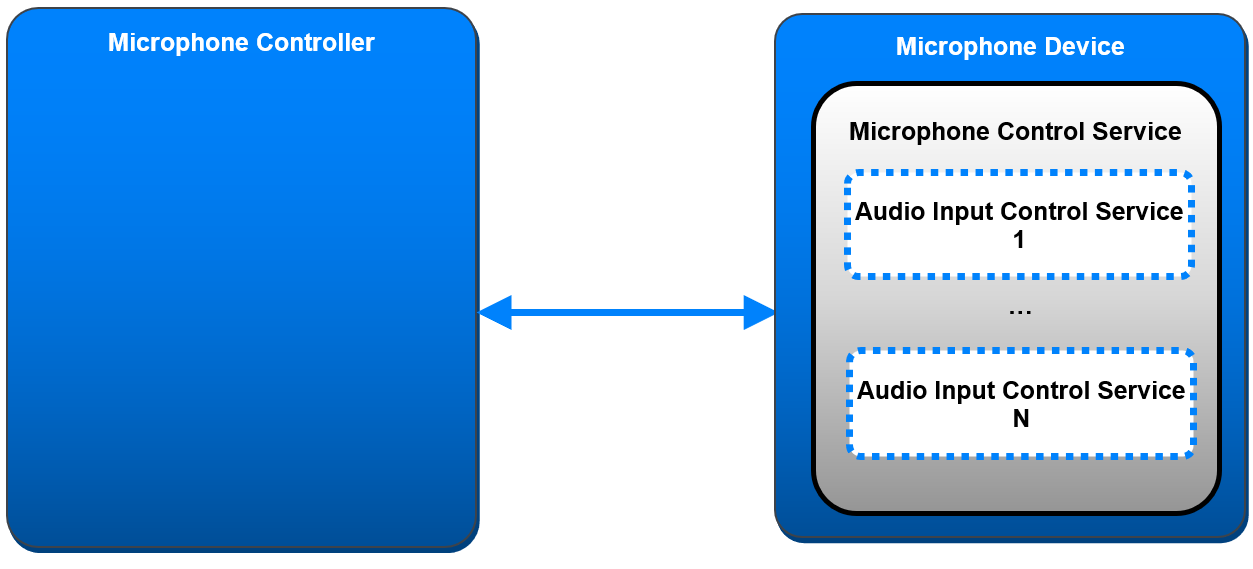
A Microphone Device instantiates one instance of MICS [2] and, optionally, one or more instances of AICS [3] included as one or more secondary services.
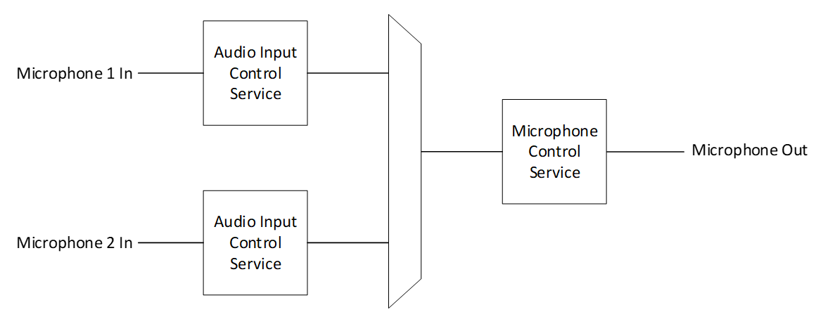
2.3. Topology
Figure 2.2 shows an example device topology for a Microphone Device using MICS and included instances of AICS.
2.4. Concurrency limitations/restrictions
There are no concurrency limitations or restrictions imposed by this profile.
3. Microphone Device role requirements
The Microphone Device shall support the GATT Server role and instantiate one instance of MICS [2], as shown in Table 3.1. The Microphone Device may instantiate zero or more instances of AICS.
Requirements in this section are defined as “Mandatory” (M), “Optional” (O), “Excluded” (X), and “Conditional” (C.n). Conditional statements (C.n) are listed directly below the table in which they appear.
|
Service |
Microphone Device |
|
|---|---|---|
|
1 |
Microphone Control Service |
M |
|
2 |
Audio Input Control Service |
O |
4. Microphone Controller role requirements
This section describes the Microphone Controller profile role requirements shown in Table 4.1. A higher-layer profile may specify additional profile role requirements.
Requirements in this section are defined as “Mandatory” (M), “Optional” (O), “Excluded” (X), and “Conditional” (C.n). Conditional statements (C.n) are listed directly below the table in which they appear.
|
Profile Requirement |
Section |
Support in Microphone Controller |
|
|---|---|---|---|
|
1 |
GATT sub-procedures |
M |
|
|
2 |
Service discovery |
M |
|
|
3 |
Characteristic discovery |
M |
|
|
4 |
MICS procedures |
M |
|
|
5 |
AICS procedures |
O |
4.1. GATT sub-procedures requirements
Requirements in this section represent a minimum set of requirements for a Microphone Controller (GATT client). Other GATT sub-procedures may be used if supported by both the GATT client and server.
Table 4.2 summarizes additional GATT sub-procedure requirements beyond those required by all GATT clients.
|
GATT Sub-Procedure |
Microphone Controller Requirements |
|
|---|---|---|
|
1 |
Discover All Primary Services |
C.1 |
|
2 |
Discover Primary Services by Service UUID |
C.1 |
|
3 |
Find Included Services |
C.2 |
|
4 |
Discover All Characteristics of a Service |
C.3 |
|
5 |
Discover Characteristics by UUID |
C.3 |
|
6 |
Discover All Characteristic Descriptors |
M |
|
7 |
Notifications |
M |
|
8 |
Read Characteristic Value |
M |
|
9 |
Write Characteristic Value |
M |
|
10 |
Read Characteristic Descriptors |
M |
|
11 |
Write Characteristic Descriptors |
M |
C.1: Mandatory to support at least one of these sub-procedures, otherwise Optional.
C.2: Mandatory if AICS procedures are supported, otherwise Optional.
C.3: Mandatory to support at least one of these sub-procedures, otherwise Optional.
4.2. Service discovery
The Microphone Controller shall use GATT Service Discovery to discover MICS.
The Microphone Controller shall perform Primary Service Discovery by using the GATT Discover All Primary Services sub-procedure or the GATT Discover Primary Services by Service UUID sub-procedure.
The Microphone Controller shall perform Relationship Discovery using the GATT Find Included Services sub-procedure to discover instances of AICS if the Microphone Controller supported AICS procedures.
4.3. Characteristic discovery
As required by GATT, the Microphone Controller shall be tolerant of additional Optional characteristics in the service records of MICS and instances of AICS.
The Microphone Controller shall perform the GATT Discover All Characteristics of a Service sub‑procedure or the GATT Discover Characteristics by UUID sub-procedure to discover the characteristics of MICS.
The Microphone Controller shall perform the GATT Discover All Characteristic Descriptors sub-procedure to discover the Client Characteristic Configuration descriptors of MICS.
The Microphone Controller shall perform the GATT Discover All Characteristics of a Service sub‑procedure or the GATT Discover Characteristics by UUID sub-procedure to discover the characteristics of instances of AICS if the Microphone Controller supported AICS procedures.
The Microphone Controller may perform the GATT Discover All Characteristic Descriptors sub-procedure to discover the Client Characteristic Configuration descriptors of instances of AICS.
4.3.1. Microphone Control Service characteristic discovery
Table 4.3 describes the MICS characteristic discovery requirements for the Microphone Controller role. A higher-layer profile may specify additional characteristic discovery requirements.
|
Characteristic |
Discovery Requirements for Microphone Controller |
|
|---|---|---|
|
1 |
Mute |
M |
4.3.2. Audio Input Control Service characteristic discovery
Table 4.4 describes the AICS characteristic discovery requirements for the Microphone Controller role. A higher-layer profile may specify additional characteristic discovery requirements.
|
Characteristic |
Discovery Requirements for Microphone Controller |
|
|---|---|---|
|
1 |
Audio Input State |
C.1 |
|
2 |
Gain Setting Properties |
C.1 |
|
3 |
Audio Input Type |
O |
|
4 |
Audio Input Status |
O |
|
5 |
Audio Input Control Point |
O |
|
6 |
Audio Input Description |
O |
C.1: Mandatory if Audio Input Control Point characteristic procedures are supported, otherwise Optional.
4.4. Microphone Control Service procedures
This section describes the Mandatory and Optional Microphone Controller procedures that are used with MICS.
Table 4.5 summarizes the MICS sub-procedure requirements. A higher-layer profile may specify additional sub-procedure requirements.
|
MICS Sub-Procedure |
Microphone Controller Requirements |
|
|---|---|---|
|
1 |
Configure Mute Notifications |
O |
|
2 |
Read Mute |
M |
|
3 |
Set Mute |
O |
4.4.1. Configure Mute Notifications sub-procedure
The Configure Mute Notifications sub-procedure is used to subscribe or unsubscribe to notifications of changes to the Mute value of the Microphone Device.
The Microphone Controller shall configure notifications of the Mute characteristic value of the Microphone Device.
4.4.2. Read Mute sub-procedure
The Read Mute sub-procedure is used to retrieve the Mute characteristic value of the Microphone Device.
The Microphone Controller shall read the Mute characteristic value of MICS.
4.4.3. Set Mute sub-procedure
The Set Mute sub-procedure is used to change the mute state of a Microphone Device.
The Microphone Controller shall write the Mute value to the Mute characteristic of the Microphone Device.
This sub-procedure controls the single mute state for the entire device. To control the mute state of individual inputs, the Microphone Controller shall use the AICS procedures in Section 4.5.
4.5. Audio Input Control Service procedures
This section describes the optional Microphone Controller procedures that are used with AICS. These procedures control individual mute states and gain levels for a Microphone Device’s audio inputs.
Table 4.6 summarizes additional AICS sub-procedure requirements. A higher-layer profile may specify additional sub-procedure requirements.
|
AICS Sub-Procedure |
Microphone Controller Requirements |
|
|---|---|---|
|
1 |
Configure Audio Input State Notifications |
C.1 |
|
2 |
Read Audio Input State |
C.1 |
|
3 |
Read Gain Setting Properties |
O |
|
4 |
Read Audio Input Type |
O |
|
5 |
Configure Audio Input Status Notifications |
O |
|
6 |
Read Audio Input Status |
O |
|
7 |
Set Gain Setting |
O |
|
8 |
Mute |
O |
|
9 |
Unmute |
O |
|
10 |
Set Manual Gain Mode |
O |
|
11 |
Set Automatic Gain Mode |
O |
|
12 |
Configure Audio Input Description Notifications |
O |
|
13 |
Read Audio Input Description |
O |
|
14 |
Set Audio Input Description |
O |
C.1: Mandatory if AICS procedures are supported.
The Microphone Controller may use the sub-procedures in this section to read, enable/disable notifications, and control the gain setting or mute state of a Microphone Device’s audio input.
4.5.1. Configure Audio Input State Notifications sub-procedure
The Configure Audio Input State Notifications sub-procedure is used to subscribe or unsubscribe to notifications of changes to the Audio Input State characteristic value of a Microphone Device.
The Microphone Controller shall configure notifications of the Audio Input State characteristic value of the Microphone Device.
4.5.2. Read Audio Input State sub-procedure
The Read Audio Input State sub-procedure is used to retrieve the Audio Input State characteristic value of a Microphone Device.
The Microphone Controller shall read the Audio Input State characteristic value of AICS.
4.5.3. Read Gain Setting Properties sub-procedure
The Read Gain Setting Properties sub-procedure is used to retrieve the Gain Setting Properties characteristic value of a Microphone Device, which contains the units and the minimum and maximum allowable values of the Gain_Setting field value.
The Microphone Controller shall read the Gain Setting Properties characteristic value of AICS.
4.5.4. Read Audio Input Type sub-procedure
The Read Audio Input Type sub-procedure is used to retrieve the type of a Microphone Device’s audio input.
The Microphone Controller shall read the Audio Input Type characteristic value of AICS.
4.5.5. Configure Audio Input Status Notifications sub-procedure
The Configure Audio Input Status Notifications sub-procedure is used to subscribe or unsubscribe to notifications of changes to the Audio Input Status characteristic value of a Microphone Device.
The Microphone Controller shall configure notifications of the Audio Input Status characteristic value of the Microphone Device.
4.5.6. Read Audio Input Status sub-procedure
The Read Audio Input Status sub-procedure is used to retrieve the status of a Microphone Device’s audio input.
The Microphone Controller shall read the Audio Input Status characteristic value of AICS.
4.5.7. Audio Input Control Point sub-procedures
The AICS Audio Input Control Point sub-procedures require the client to provide the value of the Change_Counter field of the Audio Input State characteristic value. Providing the Change_Counter field is a method of synchronization between any client and the server, where the loss of synchronization could result in unexpected behavior.
For each Audio Input Control Point sub-procedure, the Microphone Controller shall first retrieve the Change_Counter field of the Audio Input State Characteristic value using the Configure Audio Input State Notifications or Read Audio Input State sub-procedure. The Microphone Controller shall then use this value as the Change_Counter parameter of the subsequent write to the Audio Input Control Point characteristic.
If the server’s current value of the Change_Counter field differs from the client’s Change_Counter parameter, the Microphone Device rejects the command by sending an ATT Error Response with an error code set to the Application error code 0x80 (Invalid Change Counter).
In this case, the Microphone Controller may retry the sub-procedure using a more recently read or notified value of the Change_Counter field.
4.5.7.1. Set Gain Setting sub-procedure
The Set Gain Setting sub-procedure is used to change the gain setting of the Microphone Device.
If the Gain_Mode field’s value is set to Automatic, then the Microphone Controller shall not perform this procedure.
The Microphone Controller shall write the value format to the Audio Input Control Point characteristic value of the Microphone Device: Opcode parameter with the value of the Set Gain Setting opcode, followed by the Change_Counter parameter, followed by the new Gain_Setting parameter, as shown in Table 4.7.
|
Parameter 1 |
Parameter 2 |
Parameter 3 |
|---|---|---|
|
Opcode |
Change_Counter |
Gain_Setting |
The Change_Counter parameter is used as described in Section 4.5.7.
4.5.7.2. Unmute sub-procedure
The Unmute sub-procedure sets the Mute field value to Not Muted.
The Microphone Controller shall write the value format to the Audio Input Control Point characteristic value of the Microphone Device: Opcode parameter with the value of the Unmute opcode, followed by the Change_Counter parameter, as shown in Table 4.8.
|
Parameter 1 |
Parameter 2 |
|---|---|
|
Opcode |
Change_Counter |
The Change_Counter parameter is used as described in Section 4.5.7.
4.5.7.3. Mute sub-procedure
The Mute sub-procedure sets the Mute field value to Muted.
The Microphone Controller shall write the value format to the Audio Input Control Point characteristic value of the Microphone Device: Opcode parameter with the value of the Mute opcode, followed by the Change_Counter parameter, as shown in Table 4.9.
|
Parameter 1 |
Parameter 2 |
|---|---|
|
Opcode |
Change_Counter |
The Change_Counter parameter is used as described in Section 4.5.7.
4.5.7.4. Set Manual Gain Mode sub-procedure
The Set Manual Gain Mode sub-procedure sets the Gain_Mode field value to Manual.
If the Gain_Mode field of the Audio Input State characteristic value has the value Automatic Only or Manual Only, then the Microphone Controller shall not perform the Set Manual Gain Mode sub-procedure.
The Microphone Controller shall write the value format to the Audio Input Control Point characteristic value of the Microphone Device: Opcode parameter with the value of the Set Manual Gain Mode opcode, followed by the Change_Counter parameter, as shown in Table 4.10.
|
Parameter 1 |
Parameter 2 |
|---|---|
|
Opcode |
Change_Counter |
The Change_Counter parameter is used as described in Section 4.5.7.
4.5.7.5. Set Automatic Gain Mode sub-procedure
The Set Automatic Gain Mode sub-procedure sets the Gain_Mode field value to Automatic.
If the Gain_Mode field of the Audio Input State characteristic value has the value Automatic Only or Manual Only, then the Microphone Controller shall not perform the Set Automatic Gain Mode sub-procedure.
The Microphone Controller shall write the value format to the Audio Input Control Point characteristic value of the Microphone Device: Opcode parameter with the value of the Set Automatic Gain Mode opcode, followed by the Change_Counter parameter, as shown in Table 4.11.
|
Parameter 1 |
Parameter 2 |
|---|---|
|
Opcode |
Change_Counter |
The Change_Counter parameter is used as described in Section 4.5.7.
4.5.8. Configure Audio Input Description Notifications sub-procedure
The Configure Audio Input Description Notifications sub-procedure is used to subscribe or unsubscribe to notifications of changes to the Audio Input Description characteristic value of the Microphone Device.
The Microphone Controller shall configure notifications of the Audio Input Description characteristic value of the Microphone Device.
4.5.9. Read Audio Input Description sub-procedure
The Read Audio Input Description sub-procedure is used to retrieve the description of a Microphone Device’s audio input.
The Microphone Controller shall read the Audio Input Description characteristic value of AICS.
4.5.10. Set Audio Input Description sub-procedure
The Set Audio Input Description sub-procedure is used to change the description of a Microphone Device’s audio input.
The Microphone Controller shall write the description value to the Audio Input Description characteristic value of the Microphone Device.
5. Security considerations
This section describes the security requirements for devices that implement the profile roles defined in this specification. Table 5.1 captures the security requirements for the Microphone Device and Microphone Controller.
|
Security Requirement |
Microphone Controller Requirements |
Section |
Microphone Device Requirements |
Section |
|
|---|---|---|---|---|---|
|
1 |
Security Mode 1 Level 1 (SM1 L1) |
X |
X |
||
|
2 |
Security Mode 1 Level 2 (SM1 L2) |
O |
C.2 |
||
|
3 |
Security Mode 1 Level 3 (SM1 L3) |
O |
C.2 |
||
|
4 |
Security Mode 1 Level 4 (SM1 L4) |
O |
C.2 |
||
|
5 |
128b Key Entropy |
C.1 |
C.1 |
C.1: Mandatory if SM1 L2 or SM1 L3 is supported, otherwise not applicable
C.2: Mandatory to support at least one of SM1 L2 or SM1 L3 or SM1 L4
5.1. Security requirements for Low Energy
This section describes the security requirements for the Bluetooth Low Energy (LE) transport in terms of the Microphone Controller role and the Microphone Device role.
The security requirements for all characteristics defined in MICS [2] and AICS [3] shall satisfy Security Mode 1 Level 2, defined in Volume 3, Part C, Section 10.2.1 in [1].
Access to all characteristics defined in MICS [2] and AICS [3] shall require an encryption key with at least 128 bits of entropy, derived from any of the following:
-
LE Secure Connections
-
If cross-transport key derivation is used, from BR/EDR Secure Connections
-
An out-of-band (OOB) method
Link Layer Privacy, defined in Volume 6, Part B, Section 6 in [1], should be used.
5.1.1. Microphone Controller security requirements for Low Energy
The Microphone Controller shall support bondable mode, defined in Volume 3, Part C, Section 9.4.3 in [1].
The Microphone Controller shall support the bonding procedure defined in Volume 3, Part C, Section 9.4.4 in [1].
The Microphone Controller should accept the LE Security Mode and LE Security Level combination that is requested by the Microphone Device.
The Microphone Controller should only use the Security Manager (SM) Peripheral [5] Security Request procedure, defined in Volume 3, Part H, Section 2.4.6 in [1], to inform the Microphone Device of its security requirements if the Microphone Controller has bonded with the Microphone Device.
If the Microphone Controller is a BR/EDR/LE device, it should support and use cross transport key derivation, defined in Volume 3, Part C, Section 14 in [1].
5.1.2. Microphone Device security requirements for Low Energy
The Microphone Device shall support bondable mode, defined in Volume 3, Part C, Section 9.4.3 in [1].
The Microphone Device shall support the bonding procedure defined in Volume 3, Part C, Section 9.4.4 in [1].
The Microphone Device shall only accept the LE Security Mode and LE Security Level combination requested by the Microphone Controller if that combination satisfies the security requirements implemented by the Microphone Device for access to characteristics defined in MICS [2] and AICS [3].
If the Microphone Device is a BR/EDR/LE device, it should support and use cross transport key derivation, defined in Volume 3, Part C, Section 14 in [1].
The Microphone Device may request the Authorization procedure to be performed before allowing a client to access MICS and AICS. See Volume 3, Part C, Section 10.5 in [1].
5.2. Security requirements for BR/EDR
This section describes the security requirements for the BR/EDR transport.
The security requirements for all characteristics defined in MICS [2] and AICS [3] shall be Security Mode 4 Level 2, as defined in Volume 3, Part C, Section 5.2.2.8 in [1].
Access to all characteristics defined in MICS [2] and AICS [3] shall require an encryption key with at least 128 bits of entropy derived from any of the following:
-
BR/EDR Secure Connections
-
If cross-transport key derivation is used, from LE Secure Connections
-
An OOB method
In a connection, the devices should bond.
The device initiating the connection should initiate bonding. Acceptance of bonding should be supported by the device accepting the connection request.
6. Generic Access Profile requirements
Requirements in this section are defined as “Mandatory” (M), “Optional” (O), “Excluded” (X), and “Conditional” (C.n). Conditional statements (C.n) are listed directly below the table in which they appear.
6.1. Generic Access Profile requirements for Low Energy
This section describes the device discovery and LE ACL connection establishment procedures that are used by a Microphone Controller and a Microphone Device. These procedures are described in terms of the following roles:
6.1.1. Peripheral connection establishment
6.1.1.1. Connection procedure to non-bonded devices
The connection procedure to non-bonded devices is used for device discovery and connection establishment when the Peripheral accepts a connection from a Central to which it is not bonded. The connection procedure to non-bonded devices is triggered by user interaction, for example, activating a device by inserting a battery or pushing buttons. To inform the Central that the Peripheral is available for connection establishment, the Peripheral enters one of the following GAP discoverable modes:
The Peripheral shall transmit extended advertising PDUs and, unless otherwise defined by higher-layer specifications, should include the following Advertising Data (AD) data types:
If the Peripheral is a BR/EDR/LE device and is also in a discoverable mode over the BR/EDR transport as defined in Section 6.2.1, and if the Peripheral wants to assist scanning devices to represent the Peripheral as a single device at the scanning device’s user interface (UI), the Peripheral should use its Public Device Address when transmitting extended advertising PDUs as part of the connection procedure to non-bonded devices.
6.1.1.2. Connection procedure to bonded devices
The connection procedure to bonded devices is used by a Peripheral device in the Connectable mode only if the Peripheral has previously bonded with the Central device when using the connection procedure to non-bonded devices defined in Section 6.1.1.1.
When available for a connection to a bonded device, a Peripheral enters one of the following GAP connectable modes:
The Peripheral should use the advertising filter policy that was configured when bonded using the connection procedure to non-bonded devices in Section 6.1.1.1, unless the Peripheral is in the Directed Connectable mode.
6.1.1.3. Link loss reconnection procedure
When a connection is terminated because of link loss, a Peripheral should attempt to reconnect to the Central by using the procedure described in Section 6.1.1.1 or Section 6.1.1.2.
6.1.2. Central connection establishment
6.1.2.1. Device discovery
To discover one or more Peripherals, the Central uses either of the following GAP discovery procedures:
6.1.2.2. Connection procedure
A Central uses one of the following GAP connection establishment procedures based on its connectivity requirements:
-
Auto Connection Establishment procedure (as defined in Volume 3, Part C, Section 9.3.5 in [1])
-
General Connection Establishment procedure (as defined in Volume 3, Part C, Section 9.3.6 in [1])
-
Selective Connection Establishment procedure (as defined in Volume 3, Part C, Section 9.3.7 in [1])
-
Direct Connection Establishment procedure (as defined in Volume 3, Part C, Section 9.3.8 in [1])
6.1.2.3. Link loss reconnection procedure
When a connection is terminated because of link loss, a Central should attempt to reconnect to the Peripheral by using any of the GAP connection establishment procedures described in Section 6.1.2.2.
6.1.2.4. Connection interval
The connection interval can affect the latency of Microphone Controller procedures. Therefore, to reduce the latency when acting as a Microphone Controller, a connection interval should be selected in the range provided in Table 6.1.
|
Parameter |
Value |
|---|---|
|
Range for Connection Interval |
10 to 30 milliseconds |
6.2. Generic Access Profile requirements for BR/EDR
This section describes the GAP requirements for BR/EDR.
6.2.1. Modes
Modes are defined in Volume 3, Part C, Section 4 in [1].
Bondable mode should be supported.
Table 6.2 shows the support requirements for GAP modes for BR/EDR devices.
|
Mode |
Support in Microphone Device |
Support in Microphone Controller |
|---|---|---|
|
General Discoverable mode |
C.1 |
O |
|
Limited Discoverable mode |
C.1 |
O |
|
Bondable mode |
O |
O |
C.1: Mandatory to support at least one of Limited Discoverable mode or General Discoverable mode.
6.2.2. Idle Mode procedures
Idle Mode procedures are defined in Volume 3, Part C, Section 6 in [1].
The General Bonding procedure should be supported.
Table 6.3 shows the requirements for GAP Idle Mode procedures for BR/EDR devices.
|
Procedure |
Support in Microphone Device |
Support in Microphone Controller |
|---|---|---|
|
General Inquiry |
O |
M |
|
Limited Inquiry |
O |
O |
|
General Bonding |
O |
O |
6.2.3. Device discovery
BR/EDR/LE devices implementing either the Microphone Controller or Microphone Device roles shall set the value of the Class of Device (CoD) [4] field Major Service Class bit 14 to 1.
If a BR/EDR/LE device implementing the Microphone Device role is in a GAP Discoverable mode defined in Volume 3, Part C, Section 4 in [1], then unless otherwise defined by higher-layer specifications, any extended inquiry response (EIR) data sent by the device should include the following EIR data type:
-
If the Microphone Device supports MICS over BR/EDR, the Service UUID EIR data type containing the MICS [2] UUID
7. Acronyms and abbreviations
|
Acronym/Abbreviation |
Meaning |
|---|---|
|
ACL |
Asynchronous Connection-oriented [logical transport] |
|
AD |
Advertising Data |
|
AICS |
Audio Input Control Service |
|
ATT |
Attribute Protocol |
|
BR/EDR |
Basic Rate/Enhanced Data Rate |
|
CoD |
Class of Device |
|
EIR |
extended inquiry response |
|
GAP |
General Access Profile |
|
GATT |
Generic Attribute Profile |
|
LE |
Low Energy |
|
MICS |
Microphone Control Service |
|
OOB |
out-of-band |
|
PDU |
Protocol Data Unit |
|
RFU |
Reserved for Future Use |
|
UI |
user interface |
|
UUID |
universally unique identifier |
8. References
[1] Bluetooth Core Specification, Version 5.2 or later
[2] Microphone Control Service Specification, Version 1.0
[3] Audio Input Control Service Specification, Version 1.0
[4] Bluetooth SIG Assigned Numbers, https://www.bluetooth.com/specifications/assigned-numbers
[5] Appropriate Language Mapping Tables, https://www.bluetooth.com/language-mapping/Appropriate-Language-Mapping-Table