-
Revision: v1.0.1
-
Revision Date: 2022-01-18
-
Group Prepared By: Medical Devices Working Group
Revision History
|
Revision Number |
Date |
Comments |
|---|---|---|
|
v1.0.0 |
7/14/2015 |
Approved by the Bluetooth SIG BoD |
|
v1.0.1 |
2022-01-18 |
Adopted by the Bluetooth SIG Board of Directors. |
Version History
|
Versions |
Changes |
|---|---|
|
v1.0.0 to v1.0.1 |
Incorporated errata E15807, E16277, E17663, E17996. |
Acknowledgments
|
Name |
Company |
|---|---|
|
Jordan Hartmann |
Nonin Medical, Inc. |
|
Matthew Leipnitz |
Nonin Medical, Inc. |
|
Leif-Alexandre Aschehoug |
Nordic Semiconductor |
|
Wolfgang Heck |
Roche |
Use of this specification is your acknowledgement that you agree to and will comply with the following notices and disclaimers. You are advised to seek appropriate legal, engineering, and other professional advice regarding the use, interpretation, and effect of this specification.
Use of Bluetooth specifications by members of Bluetooth SIG is governed by the membership and other related agreements between Bluetooth SIG and its members, including those agreements posted on Bluetooth SIG’s website located at www.bluetooth.com. Any use of this specification by a member that is not in compliance with the applicable membership and other related agreements is prohibited and, among other things, may result in (i) termination of the applicable agreements and (ii) liability for infringement of the intellectual property rights of Bluetooth SIG and its members. This specification may provide options, because, for example, some products do not implement every portion of the specification. All content within the specification, including notes, appendices, figures, tables, message sequence charts, examples, sample data, and each option identified is intended to be within the bounds of the Scope as defined in the Bluetooth Patent/Copyright License Agreement (“PCLA”). Also, the identification of options for implementing a portion of the specification is intended to provide design flexibility without establishing, for purposes of the PCLA, that any of these options is a “technically reasonable non-infringing alternative.”
Use of this specification by anyone who is not a member of Bluetooth SIG is prohibited and is an infringement of the intellectual property rights of Bluetooth SIG and its members. The furnishing of this specification does not grant any license to any intellectual property of Bluetooth SIG or its members. THIS SPECIFICATION IS PROVIDED “AS IS” AND BLUETOOTH SIG, ITS MEMBERS AND THEIR AFFILIATES MAKE NO REPRESENTATIONS OR WARRANTIES AND DISCLAIM ALL WARRANTIES, EXPRESS OR IMPLIED, INCLUDING ANY WARRANTIES OF MERCHANTABILITY, TITLE, NON-INFRINGEMENT, FITNESS FOR ANY PARTICULAR PURPOSE, OR THAT THE CONTENT OF THIS SPECIFICATION IS FREE OF ERRORS. For the avoidance of doubt, Bluetooth SIG has not made any search or investigation as to third parties that may claim rights in or to any specifications or any intellectual property that may be required to implement any specifications and it disclaims any obligation or duty to do so.
TO THE MAXIMUM EXTENT PERMITTED BY APPLICABLE LAW, BLUETOOTH SIG, ITS MEMBERS AND THEIR AFFILIATES DISCLAIM ALL LIABILITY ARISING OUT OF OR RELATING TO USE OF THIS SPECIFICATION AND ANY INFORMATION CONTAINED IN THIS SPECIFICATION, INCLUDING LOST REVENUE, PROFITS, DATA OR PROGRAMS, OR BUSINESS INTERRUPTION, OR FOR SPECIAL, INDIRECT, CONSEQUENTIAL, INCIDENTAL OR PUNITIVE DAMAGES, HOWEVER CAUSED AND REGARDLESS OF THE THEORY OF LIABILITY, AND EVEN IF BLUETOOTH SIG, ITS MEMBERS OR THEIR AFFILIATES HAVE BEEN ADVISED OF THE POSSIBILITY OF THE DAMAGES.
Products equipped with Bluetooth wireless technology ("Bluetooth Products") and their combination, operation, use, implementation, and distribution may be subject to regulatory controls under the laws and regulations of numerous countries that regulate products that use wireless non-licensed spectrum. Examples include airline regulations, telecommunications regulations, technology transfer controls, and health and safety regulations. You are solely responsible for complying with all applicable laws and regulations and for obtaining any and all required authorizations, permits, or licenses in connection with your use of this specification and development, manufacture, and distribution of Bluetooth Products. Nothing in this specification provides any information or assistance in connection with complying with applicable laws or regulations or obtaining required authorizations, permits, or licenses.
Bluetooth SIG is not required to adopt any specification or portion thereof. If this specification is not the final version adopted by Bluetooth SIG’s Board of Directors, it may not be adopted. Any specification adopted by Bluetooth SIG’s Board of Directors may be withdrawn, replaced, or modified at any time. Bluetooth SIG reserves the right to change or alter final specifications in accordance with its membership and operating agreements.
Copyright © 2015–2022. All copyrights in the Bluetooth Specifications themselves are owned by Apple Inc., Ericsson AB, Intel Corporation, Lenovo (Singapore) Pte. Ltd., Microsoft Corporation, Nokia Corporation, and Toshiba Corporation. The Bluetooth word mark and logos are owned by Bluetooth SIG, Inc. Other third-party brands and names are the property of their respective owners.
Document Terminology
The Bluetooth SIG has adopted portions of the IEEE Standards Style Manual, which dictates use of the words “shall”, “should”, “may”, and “can” in the development of documentation, as follows:
The word shall is used to indicate mandatory requirements strictly to be followed in order to conform to the standard and from which no deviation is permitted (shall equals is required to).
The use of the word must is deprecated and shall not be used when stating mandatory requirements; must is used only to describe unavoidable situations.
The use of the word will is deprecated and shall not be used when stating mandatory requirements; will is only used in statements of fact.
The word should is used to indicate that among several possibilities one is recommended as particularly suitable, without mentioning or excluding others; or that a certain course of action is preferred but not necessarily required; or that (in the negative form) a certain course of action is deprecated but not prohibited (should equals is recommended that).
The word may is used to indicate a course of action permissible within the limits of the standard (may equals is permitted).
The word can is used for statements of possibility and capability, whether material, physical, or causal (can equals is able to).
The term Reserved for Future Use (RFU) is used to indicate Bluetooth SIG assigned values that are reserved by the Bluetooth SIG and are not otherwise available for use by implementations.
Certain terms used in this specification have been updated and are no longer used by Bluetooth SIG. For a list of terms that have been updated and their replacement terms, see the Appropriate Language Mapping Table [10].
1. Introduction
1.1. Scope
This Profile is used to enable communications between a Pulse Oximeter (PLX) and a Collector. It contains guidance for finding, connecting to, receiving measurements from, and configuring a pulse oximeter that supports this profile.
1.2. Conformance
If conformance to this specification is claimed, all capabilities indicated as mandatory for this specification shall be supported in the specified manner (process-mandatory). This also applies for all optional and conditional capabilities for which support is indicated.
1.3. Profile Dependencies
This profile requires the Generic Attribute Profile (GATT) [1].
1.4. Bluetooth Specification Release Compatibility
This specification is compatible with any Bluetooth Core Specification [1] that includes the Generic Attribute Profile (GATT).
1.5. Symbols, Conventions, and Definitions
The main physiological metric provided by a pulse oximeter is the percentage of oxygen saturation of haemoglobin (or hemoglobin), where this measurement is an estimate of the fraction of functional haemoglobin in arterial blood that is saturated with oxygen (SpO2).
In addition to SpO2, the patient’s pulse rate is indicated.
A parameter called the pulse amplitude index is used to give an indication of the strength of the signal being measured to extract physiological data from. If the pulse amplitude index is too low, a signal cannot be discerned. The values range from 0.01% to 20%.
The term “spot check” is commonly used when taking a specific type of pulse oximetry measurement. One measurement is taken and the pulse oximeter is removed. The measurement is usually considered complete once the pulse oximeter has been on the patient long enough for the signal to “settle”. This duration can be determined by the caregiver. Alternatively, some oximeters determine when the signal is stable automatically.
The term “fully qualified” is used to describe when the physiological measurement is considered settled enough to be a high quality measurement. A spot-check measurement would usually be generated once a measurement is fully qualified.
For more information on the behavior of a pulse oximeter, see [2].
2. Profile Overview
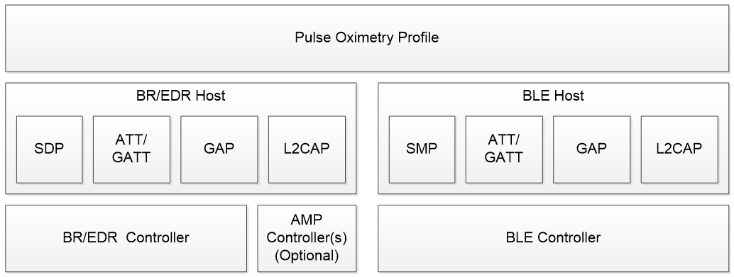
2.1. Protocol Stack
The Pulse Oximeter Profile requires GAP, ATT/GATT and L2CAP in the host volume for all transports. If implemented on a BR/EDR device, the Service Discovery Protocol (SDP) is required. If implemented on an LE device, the Security Manager Protocol (SMP) is required.
A controller for the correct transport is required, as shown in Figure 2.1.
 |
2.2. Configurations, Roles, and Modes
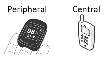
The Pulse Oximeter Profile defines two roles: a Pulse Oximeter Sensor (Sensor), which implements a GAP Peripheral role, and a Pulse Oximeter Collector (Collector), which implements a GAP Central role. The pulse oximeter will implement a GATT Server role and the Collector will implement a GATT Client role.
 |
2.3. User Scenarios
A pulse oximeter is typically used in the following scenarios.
2.3.1. Spot Check Measurements for Disease Management
In this scenario, a person with a chronic condition would use a pulse oximeter to take measurements several times a day to ensure they are getting enough oxygen. These measurements may be transmitted to a Collector immediately, or if one is not present, some pulse oximeters can store these measurements for later transmission. These measurements may be forwarded by the Collector to the patient’s caregiver.
2.3.2. Sleep Diagnostics
A pulse oximeter is often connected to a patient to monitor their oxygenation during a sleep study, to determine if the patient should be diagnosed with sleep apnea. In this scenario, a pulse oximeter is connected to a patient and gives continuous measurements, usually about once per second. In a sleep study, a short oxygen desaturation would be of interest, so the oximeter may offer a ‘fast response’ pulse rate and SpO2 metric that does not use as much averaging as usual to make these short desaturations more visible.
2.3.3. Brief Hospital Stay
While in a hospital, a patient is often outfitted with a pulse oximeter that constantly monitors their oxygen saturation. In this scenario, the pulse oximeter reports measurements typically about once per second. Since patient motion can cause readings to rapidly change, the pulse oximeter may offer a ‘slow response’ pulse rate and SpO2 metric that is more heavily averaged than usual. The pulse oximeter may also offer status information such as sensor dislodgement or excessive motion.
2.3.4. Emergency Medicine
When patients are admitted to an emergency room, they could be outfitted with a pulse oximeter with wireless connectivity. In this scenario, each patient in the room is given a pulse oximeter and wears it continuously. The oximeter reports their status continuously. This way, if a patient’s condition is declining due to their oxygenation dropping, they can be treated immediately. The oximeters are cleaned and given to a new patient after each use.
3. Profile Requirements
3.1. Configuration
3.1.1. Roles
The profile defines two roles: Sensor and Collector. The Sensor is the device that estimates the blood oxygen saturation (SpO2) and the pulse rate (PR) of a subject, and the Collector is the device that receives the pulse oximetry measurement and other related data from a Sensor.
-
The Sensor shall be a GATT Server.
-
The Collector shall be a GATT Client.
3.1.2. Role/Service Relationships
The following diagram shows the relationships between services and the two profile roles.
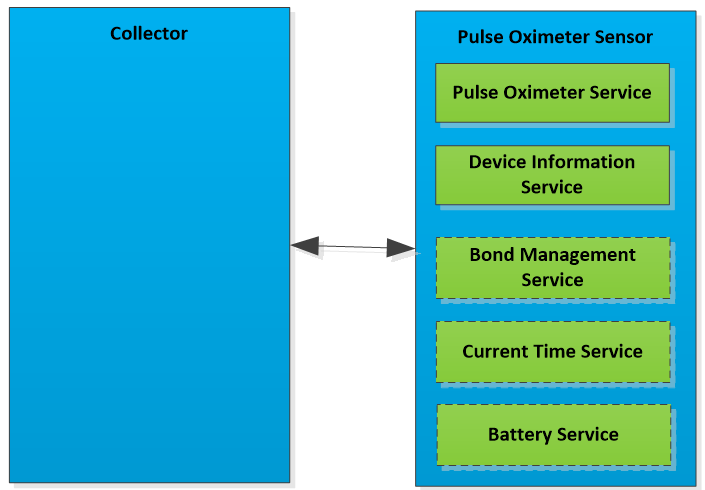 |
Note
Note: Profile roles are represented by blue boxes and services are represented by green boxes. Dashes indicate that a service is not mandatory.
A Sensor instantiates the Pulse Oximeter Service [2] and the Device Information Service [6] and, optionally, the Bond Management Service [7] the Current Time Service [8], and/or the Battery Service [9].
3.1.3. Concurrency Limitations and Restrictions
There are no concurrency limitations or restrictions for the Collector or Sensor roles imposed by this profile.
3.1.4. Topology Limitations and Restrictions
3.1.4.1. Topology Restrictions for Low Energy
The Sensor shall support the GAP Peripheral role.
The Collector shall use the GAP Central role.
3.1.4.2. Topology Restrictions for BR/EDR
There are no fixed Central or Peripheral roles in this profile.
3.1.5. Transport Dependencies
There are no transport restrictions imposed by this profile specification. Where the term BR/EDR is used throughout this document, this also includes the use of AMP.
4. Sensor Role Requirements
The Sensor shall instantiate one and only one Pulse Oximeter Service [2].
The Pulse Oximeter Service shall be instantiated as a «Primary Service».
The Sensor shall instantiate one and only one Device Information Service [6].
The Sensor may instantiate the Bond Management Service [7].
The Sensor may instantiate the Current Time Service [8].
The Sensor may instantiate the Battery Service [9].
|
Service |
Sensor |
|---|---|
|
Pulse Oximeter Service |
M |
|
Device Information Service |
M |
|
Current Time Service |
O |
|
Bond Management Service |
O |
|
Battery Service |
O |
4.1. Incremental Pulse Oximeter Service Requirements
4.1.1. Writable GAP Device Name Characteristic
The Sensor may support the write property for the Device Name characteristic in order to allow a Collector to write a device name to the Sensor.
4.1.2. Additional Requirements for Low Energy Transport
This section describes additional Sensor requirements and recommendations beyond those defined in the Pulse Oximeter Service when using this profile over a Low Energy Transport.
4.1.2.1. Service UUIDs AD Type
While in a GAP Discoverable Mode for initial connection to a Collector, the Sensor should include the «Pulse Oximeter Service» UUID defined in [3] in the Service UUIDs AD type field of the Advertising Data. This enhances the user experience as a Sensor may be identified by the Collector before initiating a connection.
4.1.2.2. Local Name AD Type
For enhanced user experience a Sensor should include the Local Name (containing either the complete or shortened value of the Device Name characteristic as defined in [3]) in its Advertising Data or Scan Response Data.
4.1.2.3. Appearance AD Type
For enhanced user experience a Sensor should include the value of the Appearance characteristic defined in [3] in its Advertising data or Scan Response data.
4.1.3. Incremental Device Information Service Requirements
The table below shows additional requirements and recommendations beyond those defined in the Device Information Service.
|
Device Information Service Characteristic |
Requirement |
|---|---|
|
Manufacturer Name String |
M |
|
Model Number String |
M |
|
Serial Number String |
O.1 |
|
System ID |
O.1 |
|
Hardware Revision String |
O.1 |
|
Software Revision String |
O.1 |
|
Firmware Revision String |
O.1 |
|
IEEE 11073-20601 Regulatory Certification Data List |
O.1 |
- O.1:
-
Characteristic inclusion is optional, but may be required for transcoding for use in ISO/IEEE 11073, see [4].
Characteristics in this service may be transcoded by the Collector for use in an ISO/IEEE 11073 ecosystem. See the Personal Health Devices Transcoding White Paper [4] for more information. Since strings in this service are encoded as UTF-8, and ISO/IEEE 11073-20601 [5] specifies that strings are encoded as ASCII printable characters (a subset of UTF-8), characters used in string characteristics that are to be transcoded for use in an ISO/IEEE 11073 ecosystem must be restricted to the printable ASCII character set in order to ensure that the strings can be correctly displayed.
If the ISO/IEEE 11073-20601 specification is updated in the future to include UTF-8 support, implementers should consider the impact of using non-ASCII characters on backward compatibility.
Note
Note: The Personal Health Devices Transcoding White Paper [4] recommends that characters outside of the printable ASCII range are translated to characters inside of the printable ASCII range as appropriate.
4.1.4. Incremental Bond Management Service Requirements
This profile does not impose any additional requirements to use the Bond Management Service [7].
4.1.5. Incremental Current Time Service Requirements
This profile does not impose any additional requirements to use the Current Time Service [8].
4.1.6. Incremental Battery Service Requirements
This profile does not impose any additional requirements to use the Battery Service [9].
5. Pulse Oximeter Collector Role Requirements
The Collector shall support the Pulse Oximeter Service [2].
The Collector may support the Device Information Service [6].
The Collector may support the Bond Management Service [7].
The Collector may support the Current Time Service [8].
The Collector may support the Battery Service [9].
|
Service |
Collector |
|---|---|
|
Pulse Oximeter Service |
M |
|
Device Information Service |
O |
|
Bond Management Service |
O |
|
Current Time Service |
O |
|
Battery Service |
O |
This section describes the profile procedure requirements for a Collector.
|
Profile Requirement |
Section |
Support in Collector |
|---|---|---|
|
Service Discovery |
M |
|
|
M |
|
|
O |
|
|
O |
|
|
O |
|
|
O |
|
|
Characteristic Discovery |
M |
|
|
M |
|
|
O |
|
|
O |
|
|
O |
|
|
O |
|
|
PLX Spot-check Measurement |
M |
|
|
PLX Continuous Measurement |
M |
|
|
PLX Features |
M |
|
|
Record Access Control Point |
O |
|
|
M |
|
|
O |
|
|
O |
|
|
O |
|
|
Bond Management Control Point |
O |
|
|
Bond Management Features |
O |
- C.1:
-
Mandatory if Spot-check measurement storage is supported, otherwise excluded
5.1. GATT Sub-Procedure Requirements
Requirements in this section represent a minimum set of requirements for a Collector (Client). Other GATT sub-procedures may be used if supported by both Client and Server.
summarizes additional GATT sub-procedure requirements beyond those required by all GATT Clients.
|
GATT Sub-Procedure |
Collector (Client) Requirements |
|---|---|
|
Discover All Primary Services |
C.1 |
|
Discover Primary Services by Service UUID |
C.1 |
|
Discover All Characteristics of a Service |
C.2 |
|
Discover Characteristics by UUID |
C.2 |
|
Discover All Characteristic Descriptors |
M |
|
Read Characteristic Value |
M |
|
Write Characteristic Value |
M |
|
Reliable Writes |
C.3 |
|
Write Long Characteristic Values |
C.3 |
|
Notifications |
M |
|
Read Characteristic Descriptors |
M |
|
Write Characteristic Descriptors |
M |
- C.1:
-
Mandatory to support at least one of these service discovery sub-procedures.
- C.2:
-
Mandatory to support at least one of these characteristic discovery sub-procedures.
- C.3
-
Mandatory if the Bond Management Service is supported, otherwise Optional.
5.2. Service Discovery
The Collector shall perform primary service discovery using either the GATT Discover All Primary Services sub-procedure or the GATT Discover Primary Services by Service UUID sub-procedure.
5.2.1. Pulse Oximeter Service Discovery
The Collector shall discover the Pulse Oximeter Service.
5.2.2. Device Information Service Discovery
The Collector may discover the Device Information Service.
5.2.3. Bond Management Service Discovery
The Collector may discover the Bond Management Service.
5.2.4. Current Time Service Discovery
The Collector may discover the Current Time Service.
5.2.5. Battery Service Discovery
The Collector may discover the Battery Service.
5.3. Characteristic Discovery
As required by GATT, the Collector shall be tolerant of additional optional characteristics in the service records of services used within this profile.
5.3.1. Pulse Oximeter Service Characteristic Discovery
The Collector shall perform either the GATT Discover All Characteristics of a Service sub-procedure or the GATT Discover Characteristics by UUID sub-procedure in order to discover the characteristics of the service.
The Collector shall perform the GATT Discover All Characteristic Descriptors sub-procedure in order to discover the characteristic descriptors described in the following sections.
5.3.1.1. PLX Spot-check Measurement Characteristic
The Collector may discover the PLX Spot-check Measurement characteristic. If the characteristic exists, the Collector shall discover the Client Characteristic Configuration descriptor.
5.3.1.2. PLX Continuous Measurement Characteristic
The Collector may discover the PLX Continuous Measurement characteristic. If the characteristic exists, the Collector shall discover the Client Characteristic Configuration descriptor.
5.3.1.3. PLX Features Characteristic
The Collector shall discover the PLX Features characteristic. If the PLX Features characteristic supports indications, the Collector shall discover the Client Characteristic Configuration descriptor.
5.3.1.4. Record Access Control Point Characteristic
The Collector may discover the Record Access Control Point characteristic. If the characteristic exists, the Collector shall discover the Client Characteristic Configuration descriptor.
5.3.2. Bond Management Service Characteristics Discovery
In order for the Collector to discover the characteristics of the Bond Management Service, it may use either the GATT Discover All Characteristics of a Service sub-procedure or the GATT Discover Characteristics by UUID sub-procedure to discover all characteristics of the service.
5.3.2.1. Bond Management Control Point Characteristic
The Collector may discover the Bond Management Control Point characteristic of the Bond Management Service.
5.3.2.2. Bond Management Feature Characteristic
The Collector may discover the Bond Management Feature characteristic of the Bond Management Service.
If the Bond Management Feature characteristic supports indications, the Collector shall discover the Client Characteristic Configuration descriptor of the Bond Management Feature characteristic.
5.3.3. Device Information Service Characteristics Discovery
The Collector may discover the characteristics of the Device Information Service.
In order for the Collector to discover the characteristics of the Device Information Service, it may use either the GATT Discover All Characteristics of a Service sub-procedure or the GATT Discover Characteristics by UUID sub-procedure to discover all characteristics of the service.
5.3.4. Current Time Service Characteristics Discovery
The Collector may discover the characteristics of the Current Time Service.
In order for the Collector to discover the characteristics of the Current Time Service, it may use either the GATT Discover All Characteristics of a Service sub-procedure or the GATT Discover Characteristics by UUID sub-procedure to discover all characteristics of the service.
5.3.5. Battery Service Characteristics Discovery
The Collector may discover the characteristics of the Battery Service.
In order for the Collector to discover the characteristics of the Battery Service, it may use either the GATT Discover All Characteristics of a Service sub-procedure or the GATT Discover Characteristics by UUID sub-procedure to discover all characteristics of the service.
5.4. PLX Spot-check Measurement Characteristic
This section is only applicable when the PLX Spot-check Measurement characteristic is supported by the Sensor.
The Collector shall determine the contents of the PLX Spot-check Measurement characteristic structure based on the contents of the Flags field. This allows the Collector to determine whether or not optional fields are present.
The Collector shall determine the features supported by the Sensor by using the PLX Features characteristic (see Section 5.6).
If the Collector receives a PLX Spot-check Measurement characteristic indication with any bits in its fields that are defined as Reserved for Future Use (RFU), it shall ignore those bits and continue to process all other fields and bits normally.
When a Collector wishes to receive temporarily stored spot-check measurements, the Collector shall use the Record Access Control Point procedures described in Section 5.7.2.
5.5. PLX Continuous Measurement Characteristic
This section is only applicable when the PLX Continuous Measurement characteristic is supported by the Sensor.
The Collector shall determine the contents of the PLX Continuous Measurement characteristic structure based on the contents of the Flags field. This allows the Collector to determine whether or not optional fields are present.
The Collector shall determine the features supported by the Sensor by using the PLX Features characteristic (see Section 5.6).
The Collector shall be able to receive periodic notifications (typically every 1-4 seconds) of the PLX Continuous Measurement characteristic from a Sensor.
If the Collector receives a PLX Continuous Measurement characteristic notification with any bits in its fields that are defined as Reserved for Future Use (RFU), it shall ignore those bits.
5.6. PLX Features Characteristic
On an initial connection, the Collector shall read the PLX Features characteristic to determine the features supported by the Sensor.
The PLX Features characteristic will be static during a connection.
If the Sensor supports indications of the PLX Features characteristic, the Collector may configure this characteristic for indications. When the Collector receives an indication of the PLX Features characteristic, the Collector shall use the indicated value to determine the supported features again. Alternatively, the Collector may read the PLX Features characteristic each time after connecting with the Sensor. A Collector shall enable indications of the PLX Features characteristic, or it shall read the PLX Features characteristic on each connection.
If the Collector receives a PLX Features characteristic with bits or values of the fields that are designated as Reserved for Future Use (RFU), it shall ignore these bits.
5.6.1. Supported Features Field
The bits in the Supported Features Field specify whether or not other high-level features are supported by the Sensor, in addition to determining whether or not optional fields are present in the PLX Features characteristic.
In many cases, this will allow the Collector to adapt to the supported features of the Sensor (e.g., unsupported features will not be shown on the user interface (UI) of the Collector). If one of the feature bits in Table 5.4 is set to 1 (meaning this feature is supported), the Collector shall assume that the related bits of the Flags field are used by the PLX Spot-check and Continuous measurement characteristics and the associated value might be shown on the UI of the Collector. Otherwise, it is unnecessary for the Collector to expect a value related to an unsupported feature.
|
Supported Features Field Bit |
Related Flags and Behaviors |
|---|---|
|
Measurement Status Support is present (bit 0) |
Measurement Status field is present in measurement characteristics Measurement Status Support field is present in the PLX Features characteristic |
|
Device and Sensor Status support is present (bit 1) |
Device and Sensor Status field is present in measurement characteristics Device and Sensor Status Support field is present in the PLX Features characteristic |
|
Measurement Storage for Spot-check measurements is supported (bit 2) |
Stored measurements can be accessed using RACP procedures |
|
Timestamp for Spot-check measurements is supported (bit 3) |
Time Stamp present in the PLX Spot-check Measurement characteristic |
|
SpO2PR-Fast metric is supported (bit 4) |
SpO2PR-Fast field is present in PLX Continuous Measurement characteristic |
|
SpO2PR-Slow metric is supported (bit 5) |
SpO2PR-Slow field is present in PLX Continuous Measurement characteristic |
|
Pulse Amplitude Index field is supported (bit 6) |
Pulse Amplitude Index field is present in measurement characteristics |
|
Multiple Bonds Supported (bit 7) |
None |
5.6.2. Measurement Status Support Field
Based on the contents of the Measurement Status Support field, the Collector shall interpret the bits in the Measurement Status field of the PLX Spot-check Measurement characteristic and the PLX Continuous Measurement characteristic.
For example, if the invalid measurement detection bit is not supported, then the “Invalid Measurement Detected” bit in the Measurement Status field has no meaning. On the other hand, if the invalid measurement detection feature is supported, then the “Invalid Measurement Detected” bit in the Measurement Status field will indicate whether or not the Sensor has detected an invalid measurement.
5.6.3. Device and Sensor Status Support Field
Based on the contents of the Device and Sensor Status Support field, the Collector shall interpret the bits in the Device and Sensor Status field of the PLX Spot-check Measurement characteristic and the PLX Continuous Measurement characteristic.
For example, if the equipment malfunction detection feature is not supported, then the “Equipment Malfunction Detected” bit in the Device and Sensor Status field has no meaning. On the other hand, if the equipment malfunction detection feature is supported, then the “Equipment Malfunction Detected” bit in the Device and Sensor Status field will indicate whether or not the Sensor has detected a malfunction.
5.7. Record Access Control Point Characteristic
The Record Access Control Point (RACP) Characteristic defined in [3] is used to access stored PLX Spot-check Measurement Characteristic values.
Before performing any RACP procedure, the Collector shall configure the RACP and the PLX Spot-check characteristics for indications (i.e. via the Client Characteristic Configuration descriptor).
The Collector may perform a write to the RACP to begin a desired procedure. A procedure begins when the Collector writes to the Sensor’s RACP to perform some desired action and ends when either a Response Code or Number of Stored Records Response RACP indication is received by the Collector.
5.7.1. Record Access Control Point Procedure Requirements
The table below shows the requirements for the RACP procedures (Op Codes, Operators and Operands) in the context of this profile:
|
Op Code |
Op Code Requirement |
Operator |
Operator Requirement |
Operand |
Operand Requirement |
|
|---|---|---|---|---|---|---|
|
Filter Type |
Filter Parameters |
|||||
|
Report Stored Records |
M |
All records |
C |
No Operand Used |
N/A |
|
|
Delete Stored Records |
O |
All records |
C |
No Operand Used |
N/A |
|
|
Abort Operation |
O |
Null (0x00) |
C |
No Operand Used |
N/A |
|
|
Report Number of Stored Records |
O |
All records |
C |
No Operand Used |
N/A |
|
|
Responses |
||||||
|
Op Code |
Op Code Requirement |
Operator |
Operator Requirement |
Operand |
Operand Requirement |
|
|
Number of Stored Records Response |
O |
Null (0x00) |
C |
UINT16 containing number of records |
M |
|
|
Response Code |
M |
Null (0x00) |
C |
Request Op Code, Response Code Value |
M |
|
- C:
-
If this Op Code is supported, this Operator is mandatory for this Op Code.
Notes:
-
Support for a given Operand for one Op Code and Operator combination does not imply support of that Operand for other Op Code and Operator combinations.
-
Support for a given Operator for one Op Code does not imply support of that Operator for other Op Codes.
5.7.2. RACP Behavioral Description
The Collector shall write to the RACP characteristic using one of the supported Op Codes to request a Sensor to perform a procedure (see [3]). This shall include an Operator and Operand that is valid within the context of that Op Code.
If the Sensor supports multiple bonds, a Collector shall be tolerant of the fact that other Collectors may alter the contents of the Sensor’s measurement database. For example, Collector #2 may delete records from the Sensor’s database that Collector #1 will then never be able to retrieve.
The handling of multiple bonds is vendor-specific, e.g. a Sensor may only allow certain Collectors (such as a doctor’s computer) to use the Delete Store Records procedure.
5.7.2.1. Report Number of Stored Records Procedure
To request the number of stored records from a Sensor, the Collector shall write the Report Number of Stored Records Op Code and the Operand set to All Records to the RACP (see Table 5.5).
The Collector shall wait for the Number of Stored Records Response RACP indication containing the number of stored records available in the Sensor. The Number of Stored Records Response RACP indication ends the Report Number of Stored Records procedure.
If after requesting the number of stored records, the Collector receives a Response Code RACP indication with a Response Code Value that represents an error condition, see Section 5.7.2.5 for general error descriptions.
The value returned by the Number of Stored Records procedure is intended to be used either for the user interface on the Collector or to enable the Collector to acquire an estimate of the number of records it might receive to ensure it has sufficient resources.
5.7.2.2. Delete Stored Records Procedure
To request deletion of stored records within the Sensor, the Collector shall write the Delete Stored Records Op Code and the Operand set to All Records to the RACP (see Table 5.5).
The Collector shall wait for the Response Code RACP Indication with the Response Code Value set to Success indicating successful deletion of records as per the request or for the procedure to time out according to the procedure time out operation described in Section 5.7.2.6.
If after requesting the deletion of stored records, the Collector receives a Response Code RACP indication with a Response Code Value that represents an error condition, see Section 5.7.2.5 for general error descriptions.
5.7.2.3. Report Stored Records Procedure
To request the transfer of stored records from the Sensor, the Collector shall write the Report Stored Records Op Code and the Operand set to All Records to the RACP (see Table 5.5).
The Sensor will indicate stored records through the PLX Spot-check characteristic.
Once all patient records for a given request have been successfully indicated by the Sensor, the Sensor will send a Response Code RACP indication with the Response Code Value set to Success.
The Collector may also receive a Response Code RACP indication with the Response Code Value representing an error condition that occurred in processing the request. A description of specific error conditions is provided below and in Section 5.7.2.5.
If after requesting stored records the Collector receives a Response Code RACP indication with the Response Code Value set to No Records found, this indicates that the Sensor does not have any stored records.
If after requesting and receiving stored records the Collector receives a Response Code RACP indication with the Response Code Value set to Procedure not completed this indicates that the Sensor was required to interrupt its data transfer before completion for an unspecified reason. This message is not sent in the event of an Abort Operation procedure (see Section 5.7.2.4) terminating the Report Stored Records procedure.
If a condition arises where a Collector is no longer able to receive the requested data, the Collector may request to abort the data transfer as described in Section 5.7.2.4.
5.7.2.4. Abort Operation Procedure
To abort a procedure that a Collector initiated, the Collector shall send the Abort Operation Op Code with the Operator set to Null and no Operand.
The Collector shall then wait for the Response Code RACP indication with the Response Code Value set to Success indicating successful aborting of the procedure or for the procedure to time out according to the procedure time out operation described in Section 5.7.2.6. Although Sensors are required to stop the data transfer after they have sent the Response Code Value of Success, they may still have some unsent records. These records will be retained for transmission in a later Report Stored Records Procedure (see Section 5.7.2.3).
The Request Op Code in the Operand of the Response Code RACP indication is used by the Collector to determine if a Response Code RACP indication is received in response to an Abort Operation procedure, or the procedure that the Abort Operation is trying to abort. If the Abort Operation procedure is completed successfully then the Sensor shall send the Response Code RACP indication with the Request Op Code in the Operand set to Abort Operation, and shall not send any Response Code RACP indication for the aborted procedure.
The Collector may also receive a Response Code RACP indication with the Request Op Code in the Operand set to Abort Operation and the Response Code Value representing an error condition that occurred in processing the request. Though in practice not all Response Code Values may be returned for an Abort Operation procedure, a Collector shall be able to handle receiving all defined Response Code Values in response to this procedure (see Section 5.7.2.5 for error response descriptions).
If after requesting the abort, the Collector receives a Response Code RACP indication with the Request Op Code in the Operand set to Abort Operation and the Response Code Value set to Abort Unsuccessful, this indicates that the Sensor is unable to process the abort. How the Collector handles this situation is left to the implementation.
5.7.2.5. RACP Errors
If the Collector writes an Operator to the RACP characteristic that is invalid, it will receive a Response Code RACP indication with the Response Code Value set to Invalid Operator.
If the Collector writes an Operator to the RACP characteristic that is not supported by the Sensor, it will receive a Response Code RACP indication with the Response Code Value set to Operator not supported.
If the Collector receives a Response Code RACP indication with the Response Code Value set to Procedure not completed, this indicates that the Sensor is unable to complete the procedure for some unknown reason, and the procedure shall be considered to have failed.
If the Collector writes a Filter Type within an Operand to the RACP characteristic that is not supported by the Sensor, it will receive a Response Code RACP indication with the Response Code Value set to Operand Not Supported.
If the Collector attempts to perform any defined RACP procedure other than the Abort Operation procedure before a previous procedure is complete and receives an ATT Error Response with the error code set to Procedure Already in Progress, the Collector shall wait until the current RACP procedure completes before starting a new procedure.
If the Collector attempts to request any defined RACP procedure before it has configured the PLX Spot-check Measurement characteristic for indications and the RACP characteristic for indications (all via the appropriate Client Characteristic Configuration descriptor) as required in previous sections, then the Sensor will transmit a ATT Error Response with the error code set to Client Characteristic Configuration Descriptor Improperly Configured. This means that the Collector has not configured the Sensor correctly.
If the Collector writes an Op Code to the RACP characteristic that is unsupported by the Sensor, it will receive a Response Code RACP indication with the Response Code Value set to Op Code Not Supported.
5.7.2.6. Procedure Timeout and Failure
In the context of the RACP characteristic, a procedure is started when the Collector writes the RACP. The procedure is considered to be complete when the RACP is indicated with the Op Code set to Response Code.
A RACP procedure may consist of multiple indications of the PLX Spot-check Measurement characteristic. The procedure is completed when the RACP is indicated. A procedure is considered to have timed out if an indication from either the RACP or the PLX Spot-check Measurement characteristic is not received within 5 seconds.
If the procedure times out, it shall be considered to have failed. If records are being played back, any that have been successfully indicated shall not be transmitted from the Sensor again.
5.8. Bond Management Service Characteristics Behavior
The Collector may write to the Bond Management Control Point to control the bond(s).
The Collector may perform a write to the Bond Management Service Control Point (BMSCP) to request a desired procedure. A procedure begins when the Collector writes the BMSCP to perform some desired action and ends when the ATT Write Response is received by the Collector.
The Collector shall determine the Bond Management features supported by the Sensor by reading the Bond Management Feature characteristic before starting any Bond Management Control Point procedure.
5.8.1. Delete Bond of Requesting Device Procedures
If the Delete Bond of Requesting Device Procedure Supported bit of the BM Feature characteristic is set to 1, then the procedure(s) are supported by the Sensor.
The Sensor may allow the Collector to request the deletion of the bond information of the requested device´s transport from its database. In this case the Collector shall write the Op Code related to the requested transport to the BMSCP. If an authorization code is required, as determined by the BM Feature characteristic (see Section 5.8.5), the Op Code shall be followed by a parameter representing the authorization code. The Collector shall wait for the ATT Write response of the Sensor for successful operation or an ATT Error Code describing the error.
If the operation is successful, the Collector shall delete the corresponding bond information in its database after the requested transport(s) are no longer active.
5.8.2. Delete all Bonds Procedures
If the Delete all Bonds Procedure Supported bit of the BM Feature characteristic is set to 1, then the procedure(s) are supported by the Sensor.
The Sensor may allow the Collector to request the deletion of the all bond information of the requested device´s transport from its database. In this case the Collector shall write the Op Code related to the requested transport to the BMSCP. If an authorization code is required, as determined by the BM Feature characteristic (see Section 5.8.5), the Op Code shall be followed by a parameter representing the authorization code. The Collector shall wait for the ATT Write response of the Sensor for successful operation or an ATT Error Code describing the error.
If the operation is successful, the Collector shall delete all bond information of the requested transport(s) in its database after the requested transport(s) are no longer active.
5.8.3. Delete Bond of all except the requesting device Procedures
If the Delete Bond of all except the requesting device Procedure Supported bit of the BM Feature characteristic is set to 1, then the procedure(s) are supported by the Sensor.
The Sensor may allow the Collector to request the deletion of the bond information of all but the requested device´s transport from its database. In this case the Collector shall write the Op Code related to the requested transport to the BMSCP. If an authorization code is required, as determined by the BM Feature characteristic (see Section 5.8.5), the Op Code shall be followed by a parameter representing the authorization code. The Collector shall wait for the ATT Write response of the Sensor for successful operation or an ATT Error Code describing the error.
If the operation is successful, the Collector shall delete all bond information of the requested transport(s) in its database, except the bond information of the requesting device´s transport after the requested transport(s) are no longer active.
5.8.4. BMSCP Error Handling
If the Collector writes an Operand to the BMSCP characteristic that is invalid, it will receive an ATT Error Response with the Attribute Protocol Error Code set to “Request Not Supported”
If the Collector writes an Op Code that does not fit the transportation requirements (e.g., an Op Code valid for BR/EDR transport is written to a single mode LE device) or the Op Code is not supported on the Sensor, it will receive an ATT Error Response with the Attribute Application Error Code set to “Op Code not supported”.
If the Collector receives an ATT Error Response with the Attribute Application Error Code set to “Operation Failed”, the procedure on the Sensor was not successful and the Collector shall not assume that the bond information will be deleted after the requested transport(s) are no longer active.
5.8.5. BM Feature Characteristic Behavior
The Collector shall read the BM Feature characteristic to determine the supported procedures of the BMSCP.
If the Sensor supports indication of the BM Feature characteristic and the Collector has discovered this characteristic, the Collector may configure this characteristic for indications. When the Collector receives an indication of the BM Feature characteristic, the Collector shall use the indicated value to determine the supported features again. Alternatively, the Collector may read the BM Feature characteristic each time after connecting with the Sensor. A Collector shall enable indications of the BM Feature characteristic, or it shall read the BM Feature characteristic on each connection before starting any Bond Management Control Point procedure.
See the following table describing relationship between BM Feature bit, transport(s) and authorization requirement, where X indicates support if the bit is set to 1:
|
Bit |
Octet |
BM Feature Bit Description |
BR/EDR Transport |
LE Transport |
Authorization required |
|---|---|---|---|---|---|
|
0 |
0 |
Delete bond of requesting device (BR/EDR and LE) |
X |
X |
|
|
1 |
0 |
Delete bond of requesting device (BR/EDR and LE) with authorization code |
X |
X |
X |
|
2 |
0 |
Delete bond of requesting device (BR/EDR transport only) |
X |
||
|
3 |
0 |
Delete bond of requesting device (BR/EDR transport only) with authorization code |
X |
X |
|
|
4 |
0 |
Delete bond of requesting device (LE transport only) |
X |
||
|
5 |
0 |
Delete bond of requesting device (LE transport only) with authorization code |
X |
X |
|
|
6 |
0 |
Delete all bonds on server (BR/EDR and LE) |
X |
X |
|
|
7 |
0 |
Delete all bonds on server (BR/EDR and LE) with authorization code |
X |
X |
X |
|
0 |
1 |
Delete all bonds on server (BR/EDR transport only) |
X |
||
|
1 |
1 |
Delete all bonds on server (BR/EDR transport only) with authorization code |
X |
X |
|
|
2 |
1 |
Delete all bonds on server (LE transport only) |
X |
||
|
3 |
1 |
Delete all bonds on server (LE transport only) with authorization code |
X |
X |
|
|
4 |
1 |
Delete bond of all except the requesting device on the server (BR/EDR and LE) |
X |
X |
|
|
5 |
1 |
Delete bond of all except the requesting device on the server (BR/EDR and LE) with authorization code |
X |
X |
X |
|
6 |
1 |
Delete bond of all except the requesting device on the server (BR/EDR transport only) |
X |
||
|
7 |
1 |
Delete bond of all except the requesting device on the server (BR/EDR transport only) with authorization code |
X |
X |
|
|
0 |
2 |
Delete bond of all except the requesting device on the server (LE transport only) |
X |
||
|
1 |
2 |
Delete bond of all except the requesting device on the server (LE transport only) with authorization code |
X |
X |
If the Collector reads BM Feature characteristic bits that are set and yet are designated as Reserved for Future Use (RFU) in [7], it shall ignore those bits and continue to operate normally as if the bits were not set.
5.9. Device Information Service Characteristics Behavior
The Collector may read the value of Device Information Service characteristics.
5.10. Current Time Service Characteristics Behavior
The Collector may read and write the characteristics in the Current Time Service.
5.11. Battery Service Characteristics Behavior
The Collector may read the characteristics in the Battery Service.
6. Connection Establishment
This section describes the connection establishment and connection termination procedures used by a Sensor and Collector in typical scenarios.
The Pulse Oximeter supports the following scenarios:
Scenario 1:
In a continuous monitoring usage, where the oximeter is being used constantly for a period of time and the PLX Continuous Measurement Characteristic’s values are of interest, the Sensor will typically remain on and in a connection for the duration of the monitoring session. The Sensor will advertise for connections when it is turned on since measurements will be available shortly.
The Collector will typically execute a GAP connection establishment procedure such that it is scanning for the Sensor. When a connection is established and the PLX Continuous Measurement Characteristic is configured for notifications by the Collector, the Sensor will send notifications to the Collector at regular intervals. When the measurement session ends, the Sensor or the Collector may end the connection (e.g. the user removes the sensor from their finger and the device shuts down, ending the connection from the Sensor side).
Scenario 2:
In a spot-check usage, the user puts the Sensor on their finger, takes a measurement, and removes it.
In this case, the Sensor would wait to advertise after it had generated its measurement, since allowing the measurement to stabilize may take 10 seconds or more. The Collector will typically execute a GAP connection establishment procedure such that it is scanning for the Sensor.
Since the measurement is ready to be transmitted, the Sensor will send the measurement as soon as the PLX Spot-Check Measurement Characteristic is configured for indications. After the measurement is successfully sent, either the Sensor or the Collector may disconnect.
If the Sensor supports the storage of spot-check measurements, it should remain in the connection for a timeout period to allow the Collector to request the playback of stored measurements.
Using Both Scenarios Simultaneously:
If the Collector configures both the PLX Spot-check Measurement characteristic and the PLX Continuous Measurement characteristics’ Client Characteristic Configuration descriptors to send measurements, the manufacturer will have to choose between recommended behaviors for each.
For example, when only the PLX Spot-check Measurement characteristic is enabled, it is recommended that the device not advertise until a fully-qualified measurement is ready. When only the PLX Continuous Measurement characteristic is enabled, it is recommended that the device start advertising as soon as it is turned on. If both characteristics are enabled, the manufacturer would likely choose to advertise as soon as the device is turned on. If a Collector automatically enables all characteristics even if it intends to only use one, it may reduce battery life of the Sensor.
6.1. Sensor Connection Establishment for Low Energy Transport
This section describes connection procedures that a Sensor should follow to initiate a connection with a Collector using an LE transport:
-
Section 6.1.1 describes the connection procedure when the Sensor is not bonded with any Collectors.
-
Section 6.1.2 describes the connection procedure when the Sensor is bonded with one or more Collectors.
-
Section 6.1.3 describes the procedure that should be followed when an established connection is broken after a link loss.
6.1.1. Connection Procedure for Unbonded Devices
This procedure is used for connection establishment when the Sensor is not bonded with any Collectors and ready for connection.
If a connection is not established within 30 seconds, the Pulse Oximeter may either continue sending background advertising to reduce power consumption as long as it chooses or stop advertising. The advertising interval and time to perform advertising are implementation specific and should be configured with consideration for user expectations of connection establishment time using the GAP timers defined in Volume 3, Part C, Section 9.3.11 [1].
If a connection is not established within a time limit defined by the Sensor, the Sensor may exit the GAP Connectable Mode.
The table below summarizes the recommended procedure if the Sensor is not bonded to any Collectors.
|
GAP Modes |
Recommended Filter Policy |
Remarks |
|---|---|---|
|
Recommended:
Required:
|
Attempt to connect to any Collectors. |
When a bond is created, refer to recommendations in Section 6.1.2.
When the Pulse Oximeter no longer requires a connection (e.g. a Spot-check measurement has been sent and no more oximetry information will be transmitted), it should perform the GAP Terminate Connection procedure.
If the Pulse Oximeter has no data to transfer (or no further data to transfer) and the connection is idle, the Pulse Oximeter should wait at least longer than the maximum connection interval (e.g., 15 seconds) before performing the GAP Terminate Connection procedure. This allows the Collector to perform any additional required actions (e.g., read the PLX Features characteristic or read and write to Current Time Service characteristics). For devices that support Man in the Middle (MITM) protection, this duration may need to be longer to allow completion of the pairing sequence.
6.1.2. Connection Procedure for Bonded Devices
This table below summarizes the recommended procedure if the Sensor is bonded with one or more Collectors.
|
Recommended Time |
Recommended GAP Modes |
Recommended Filter Policy |
Remarks |
|---|---|---|---|
|
First 10 seconds |
Non-Discoverable Mode Undirected Connectable Mode |
Attempt to connect to only bonded Collectors in Filter Accept List. |
The Filter Accept List should be used in order to accept connection requests only from the relevant bonded Collector. |
|
After 10 seconds |
General or Limited Discoverable Modes Undirected Connectable Mode Bondable Mode |
Attempt to connect to any Collectors. |
This allows bonding with a new Collector. Unbonded procedure is described in Section 6.1.1. |
If a Sensor requires a connection to a Collector that did not use a resolvable private address during bonding, it may use Low Duty Cycle Directed Advertisements in order to advertise to only the Collector for which it has data. However, it is usually not possible in practice to use Directed Advertising to connect to Collectors because many require the use of resolvable private addresses. Therefore, when a Collector used a resolvable private address during bonding and the Pulse Oximeter requires a connection to that Collector, the Sensor should use the Undirected Connectable Mode along with the Service Data AD Type described in Section 4.1.2.1 to reduce unwanted connection requests.
If a connection is not established within 30 seconds, the Sensor may either continue sending background advertising to reduce power consumption as long as it chooses, or stop advertising.
The advertising interval and time to perform advertising are implementation specific and should be configured with consideration for user expectations of connection establishment time using the GAP timers defined in Volume 3, Part C, Section 9.3.11 [1].
If a connection is not established within a time limit defined by the Pulse Oximeter, the Pulse Oximeter may exit the GAP Connectable Mode.
When the Pulse Oximeter is disconnected and the Pulse Oximeter is ready for reconnection (e.g., when the Pulse Oximeter has new data to send or when commanded by the user), the Pulse Oximeter should reinitiate the connection procedure (e.g., start advertising).
If the Pulse Oximeter has no data to transfer (or no further data to transfer) and the connection is idle, the Pulse Oximeter should wait 15 seconds (idle connection timeout) before performing the GAP Terminate Connection procedure. This allows the Collector to perform any additional required actions (e.g., read the PLX Features characteristic or read and write to the RACP). For devices that support Man in the Middle (MITM) protection, this duration may need to be longer to allow completion of the pairing sequence.
6.1.3. Link Loss Reconnection Procedure
When a connection is terminated due to link loss, the Sensor should attempt to reconnect to the Collector by entering a GAP Connectable Mode.
6.2. Collector Connection Establishment for Low Energy Transport
This section describes connection procedures a Collector should follow to initiate a connection with a Pulse Oximeter using an LE transport.
The Collector should use the GAP General Discovery procedure to discover a Pulse Oximeter. If a Collector uses the GAP Limited Discovery procedure it will only be able to detect Pulse Oximeters that are in the GAP Limited Discoverable Mode.
A Collector may use one of the GAP Connection procedures based on its connectivity requirements as described in Table 6.3:
|
GAP Connection Procedure |
Unbonded Collector |
Bonded Collector |
|---|---|---|
|
General Connection Establishment |
Allowed |
Allowed |
|
Direct Connection Establishment |
Allowed |
Allowed |
|
Auto Connection Establishment |
Not Allowed |
Allowed |
|
Selective Connection Establishment |
Not Allowed |
Allowed |
If a connection is not established within 30 Seconds, the Collector may either continue background scanning (to reduce power consumption) or stop scanning.
|
The connection interval, scan interval, scan window, and time to perform scanning are implementation specific and should be configured with consideration for user expectations of connection establishment time using the GAP timers defined in Volume 3, Part C, Section 9.3.11 [1]. |
|
|
If a connection is not established within a time limit defined by the Collector, the Collector may exit the connection establishment procedure. |
|
|
When the connection is established, the Collector shall bond with the Pulse Oximeter. |
|
|
The Collector should terminate the connection when the measurement session is terminated at the Collector by the user. |
|
|
When the Collector is disconnected, the Collector may continue scanning for advertisements from Pulse Oximeters and may initiate a new connection. |
6.2.1. Link Loss Reconnection Procedure
When a connection is terminated due to link loss, the Collector should attempt to reconnect to the Sensor using any of the GAP Connection procedures using the connection establishment timing parameters defined in Vol. 3, Part C (GAP) section 9.3.11 [1] and the connection interval timing parameters defined in Vol. 3, Part C (GAP) section 9.3.12 [1].
6.3. Connection Establishment for BR/EDR
This section describes the connection establishment and connection termination procedures used by a Sensor and Collector using BR/EDR transport. Unlike the LE Connection procedures, which describe specific connection parameters, BR/EDR connection establishment does not state requirements beyond those described in GAP based on potential interactions with other BR/EDR profiles operating concurrently on the Sensor and/or Collector. Therefore, power consumption may not be optimized for the BR/EDR transport as compared to the LE transport when no other profiles are operating over the BR/EDR transport.
When using BR/EDR, devices can utilize sniff mode to reduce power consumption; however, no particular parameters are recommended and the requirements of other profiles may be considered.
The procedures for establishing a connection between a Sensor and a Collector that do not have an existing bond and for re-establishing a connection between bonded devices use the inquiry, discovery, paging, pairing, and security procedures described in the Generic Access Profile of the Core Specification [1] and any additional GAP requirements are enumerated in Section 7 and 8.
6.3.1. Connection Procedure for Unbonded Devices
The Sensor shall use the GAP General Discoverable Mode when it is not bonded with any Collectors and is ready for a connection (e.g. when a pulse oximetry session is started).
The Collector should use the GAP General Discovery procedure to discover a Sensor to establish a connection to a Sensor which is not bonded. If a Collector uses the GAP Limited Inquiry procedure, it will only be able to detect Pulse Oximeters that are in the GAP Limited Discoverable Mode.
Either the Sensor or the Collector can establish a BR/EDR link to a remote peer device.
Once a link is established, the Collector shall discover the Pulse Oximeter Service using SDP procedures prior to establishing a GATT connection. Once the Pulse Oximeter Service is discovered and a GATT connection is established, the Collector shall discover the Pulse Oximeter Service characteristics exposed by this service using GATT Discovery procedures.
Once connected, the Collector shall configure the PLX Spot-check Measurement Characteristic for indications and/or the PLX Continuous Measurement Characteristic for notification.
The Collector should initiate bonding between the two devices.
The Sensor may disconnect the link when no more measurements will be generated, depending on the use cases of the devices and other profiles connected on either device.
6.3.2. Connection Procedure for Bonded Devices
The Sensor shall use the GAP Link Establishment Procedure to connect to any bonded Collectors when it is ready for a connection.
The Collector shall be connectable to accept a connection from a Sensor to which it is bonded.
Either the Sensor or the Collector can establish a BR/EDR link to a remote peer device.
If a higher layer determines the bond no longer exists on the remote device, the local device shall reconfigure the remote device after:
-
User interaction confirms that the user wants to re-pair with the remote device
-
Re-bonding has been performed, and Service discovery has been performed(If the local device had previously determined that the remote device did not have the «Service Changed» characteristic, then service discovery may be skipped because the service is not allowed to change per the Core Specification.)
When the Sensor no longer has data to send, it may disconnect the link, depending on the use cases of the devices and other profiles connected on either device.
The Collector should terminate the connection when the measurement session is terminated at the Collector by the user.
When the Sensor is disconnected and it is ready for reconnection (e.g., when the Sensor has new data to send when commanded by the user), the Pulse Oximeter should initiate a connection with the Collector.
If the Sensor has no data to transfer (or no further data to transfer) and the connection is idle, the Sensor should wait 5 seconds (idle connection timeout) before performing the GAP Terminate Connection procedure. This allows the Collector to perform any additional required actions (e.g., read the PLX Features characteristic or read and write to Current Time Service characteristics). For devices that support Man in the Middle (MITM) protection, this duration may need to be longer to allow completion of the pairing sequence.
6.3.3. Link Loss Reconnection Procedure
When a connection is terminated due to link loss, a Sensor should reconnect to the Collector by attempting, for an implementation-specific time, to reestablish an ACL link between the two devices. The Collector should remain Connectable for an implementation-specific time so that a Sensor can reestablish an ACL link.
7. Security Considerations
This section describes the security considerations for a Sensor and Collector.
7.1. Sensor Security Considerations for Low Energy
This section describes the security requirements for the Sensor for an LE transport.
-
All supported characteristics specified by the Pulse Oximeter Service shall be set to Security Mode 1 and Security Level 2 or higher.
-
The Sensor shall bond with the Collector.
-
The Sensor may use the SMP Peripheral Security Request command to inform the Collector of its security requirements.
-
All characteristics specified by the Device Information Service and other optional Services (see ) that are relevant to this profile should be set to the same security mode and level as the characteristics in the Pulse Oximeter Service.
7.2. Collector Security Considerations for Low Energy
This section describes the security requirements for the Collector for LE transport.
-
The Collector shall support bonding.
-
The Collector shall accept any request by the Sensor for LE Security Mode 1 and either Security Level 2 or higher.
7.3. Security Considerations for BR/EDR
As required by GAP, Security Mode 4 shall be used for connections by the Sensor and Collector.
-
The Sensor may initiate Dedicated Bonding with the Collector, however, if the Sensor supports multiple users, then it shall initiate Dedicated Bonding and shall support as many bonds as the number of supported users.
-
The Collector shall support bonding in case it is requested by the Sensor.
8. Generic Access Profile for BR/EDR
This section defines the support requirements for the capabilities as defined in the Generic Access Profile (GAP) of the Core Specification [1] when BR/EDR is used.
8.1. Modes
The Mode Procedures as defined in GAP [1] describe requirements for both Sensor and Collectors involved. This profile further refines the requirements.
-
At least General Discoverable mode or Limited Discoverable Mode shall be supported by Sensors supporting BR/EDR.
-
Bondable mode shall be supported by Sensors and Collectors
Table 8.1 shows the support status for GAP Modes in this profile.
|
Procedure |
Support in Sensor |
Support in Collector |
|---|---|---|
|
General Discoverable Mode |
C.1 |
N/A |
|
Limited Discoverable Mode |
C.1 |
N/A |
|
Bondable Mode |
M |
M |
- C.1:
-
It is mandatory to support at least one of these modes.
8.2. Idle Mode Procedures
The Idle Mode Procedures as defined in GAP [1] describe requirements for both Sensor and Collector involved. This profile further refines requirements.
General inquiry shall be supported by all the Collectors.
Limited Inquiry may be supported by Collectors.
General bonding shall be supported by all Sensors and Collectors.
|
Procedure |
Support in Sensor |
Support in Collector |
|---|---|---|
|
General Inquiry |
N/A |
M |
|
Limited Inquiry |
N/A |
O |
|
General Bonding |
M |
M |
9. Acronyms and Abbreviations
|
Abbreviation or Acronym |
Meaning |
|---|---|
|
BM |
Bond Management |
|
BMSCP |
Bond Management Control Point |
|
SpO2 |
Percent oxygen saturation of hemoglobin, as measured by a pulse oximeter. Sometimes referred to as %SpO2 in other literature. |
|
PLX |
Pulse Oximeter |
|
PR |
Pulse Rate |
|
RACP |
Record Access Control Point |
|
RFU |
Reserved for Future Use |
|
UI |
User Interface |
10. References
Bibliography
[1] Bluetooth Core Specification, Version 4.1 or later
[2] Pulse Oximeter Service, Version 1.0 or later
[3] Characteristic Descriptor descriptions are accessible via the Bluetooth SIG Assigned Numbers
[4] Personal Health Devices Transcoding Whitepaper Version 16 or later
[5] ISO/IEEE Std 11073-20601TM-2014 Health Informatics – Personal Health Device Communication – Application Profile – Optimized Exchange Protocol – version 1.0 or later. This also includes ISO/IEEE Std 11073-20601TM-2010 – Amendment 1.
[6] Device Information Service, Version 1.1 or later
[7] Bond Management Service, Version 1.0 or later
[8] Current Time Service, Version 1.1 or later
[9] Battery Service, Version 1.0 or later
[10] Appropriate Language Mapping Table, https://www.bluetooth.com/language-mapping/Appropriate-Language-Mapping-Table
11. List of Figures
A listing of the document’s figures.
Figure 2.1: Pulse Oximeter Protocol Stack
12. List of Tables
A listing of the document’s tables.
Table 4.1: Sensor Service Requirements
Table 4.2: Device Information Service Requirements
Table 5.1: Collector Service Requirements
Table 5.2: Collector Requirements
Table 5.3: Additional GATT Sub-Procedure Requirements
Table 5.4: PLX Features for Collector
Table 5.5: Collector RACP Procedure Requirements
Table 6.1: Recommended and Required Connection Modes for Unbonded Devices
Table 6.2: Recommended Connection Procedure for Bonded Devices
Table 6.3: Allowed GAP Connection Procedure
Table 8.1: BR/EDR GAP Mode Support