-
Revision: v1.1
-
Revision Date: 2023-09-12
-
Prepared By: Mesh Working Group
Revision History
|
Revision Number |
Date |
Comments |
|---|---|---|
|
v1.0 |
2017-07-13 |
Adopted by the Bluetooth SIG Board of Directors |
|
v1.0.1 |
2019-01-21 |
Adopted by the Bluetooth SIG Board of Directors |
|
v1.1 |
2023-09-12 |
Adopted by the Bluetooth SIG Board of Directors. |
Version History
|
Versions |
Changes |
|---|---|
|
v1.0.0 to v1.0.1 |
Incorporated errata E9618, E9634, E9639, E9693, E9743, E9748, E9752, E9761, E9788, E9796, E9805, E9807, E9808, E9811, E9812, E9819, E9882, E9883, E9894, E9939, E9957, E9959,E9964, E9969, E9981, E9982, E9983, E10015, E10024, E10025, E10026, E10027, E10028, E10054, E10066, E10081, E10082, E10084, E10086, E10087, E10100, E10101, E10148, E10157, E10168, E10247, E10296, E10310, E10317, E10321, E10322, E10332, E10344, E10395, E10426, E10514, E10515, E10520, E10569, E10575, E10578, E10636, E10664, E10670, E10746, E10748, E10777, E10863, E10864, E11306 |
|
v1.0.1 to v1.1 |
Changed the specification name from “Mesh Profile” to “Mesh Protocol”. Incorporated the Mesh Certificate-Based Provisioning CR, Mesh Remote Provisioning CR, Mesh Directed Forwarding CR, Mesh Private Beacons CR, Mesh Subnet Bridge CR, Mesh Profile Minor Enhancements CR, and the Mesh Profile Enhanced Provisioning Authentication CR. Incorporated errata E10635, E10950, E10974, E11128, E11173, E11176, E11206, E11207, E11213, E11249, E11256, E11271, E11272, E11273, E11275, E11276, E11301, E11302, E11309, E11310, E11322, E11329, E11341, E11345, E11358, E11359, E11384, E11392, E11394, E11414, E11415, E11416, E11627, E11700, E11712, E11737, E11799, E11802, E11836, E11850, E11901, E11922, E11936, E11940, E11976, E11977, E11978, E11991, E12006, E12013, E12046, E12079, E12092, E12111, E12154, E12226, E12277, E12390, E12403, E12426, E12439, E12543, E12556, E12579, E12581, E12582, E12586, E12587, E12781, E12825, E12834, E12871, E12975, E13008, E13010, E13030, E13084, E13101, E13124, E13171, E13217, E13331, E13430, E13433, E13443, E13446, E13506, E14731, E14734, E14743, E14745, E14804, E14814, E14815, E14885, E14921, E15011, E15080, E15106, E15155, E15210, E15335, E15456, E15457, E15458, E15499, E15696, E15755, E15875, E15889, E16334, E16350, E16386, E16391, E16402, E16408, E16436, E16462, E16701, E16827, E16847, E16870, E16871, E17029, E17059, E17093, E17158, E17203, E17215, E17341, E17345, E17348, E17364, E17369, E17376, E17624, E17955, E18051, E18071, E18117, E18131, E18137, E18181, E18316, E18469, E18487, E18491, E18741, E18932, E19041, E19118, E19250, E20514, E20541, E20554, E20568, E20574, E20586, E20596, E22321, E22354, E22468, E22717, E22761, E22766, E22942, E22979, E23258, E23406 |
Acknowledgments
|
Name |
Company |
|---|---|
|
Robin Heydon |
Qualcomm Technologies International, Ltd. |
|
Jonathan Tanner |
Qualcomm Technologies International, Ltd. |
|
Victor Zhodzishsky |
Broadcom Corporation |
|
Victor Zhodzishsky |
Cypress Semiconductor Corporation |
|
Wei Shen |
Ericsson AB |
|
Christoffer Jerkeby |
Ericsson AB |
|
Bogdan Alexandru |
NXP Semiconductors |
|
Martin Turon |
Google Inc. |
|
Robert D. Hughes |
Intel Corporation |
|
Marcel Holtmann |
Intel Corporation |
|
Brian Gix |
Intel Corporation |
|
Simon Slupik |
Silvair, Inc. |
|
Piotr Winiarczyk |
Silvair, Inc. |
|
Danilo Blasi |
STMicroelectronics |
|
Yao Wang |
Barrot Technology Co., Ltd. |
|
Rustam Kovyazin |
Motorola Solutions |
|
Uday Agarwal |
Cypress Semiconductor Corporation |
|
Vasilii Aleksandrov |
Motorola Solutions |
|
LC Ko |
MediaTek, Inc. |
|
Omkar Kulkarni |
Cypress Semiconductor Corporation |
|
Omkar Kulkarni |
Nordic Semiconductor ASA |
|
Pontus Arvidson |
Ericsson AB |
|
Ravi Kiran Bamidi |
Silvair, Inc. |
|
Robert Cragie |
ARM Ltd |
|
Piergiuseppe Di Marco |
Ericsson AB |
|
Piergiuseppe Di Marco |
Silvair, Inc. |
|
Per Elmdahl |
Ericsson AB |
|
Arvind Kandhalu |
Texas Instruments Incorporated |
|
Yiting Liao |
Intel Corporation |
|
Jingcheng Zhang |
Ericsson AB |
|
Thomas Stenersen |
Nordic Semiconductor ASA |
|
Hannu Mallat |
Silicon Laboratories |
|
Max Palumbo |
Silicon Laboratories |
|
Max Palumbo |
Katerra Inc. |
|
Jori Rintahaka |
Silicon Laboratories |
|
Kim Schulz |
Samsung Electronics Co., Ltd. |
|
Michał Budzoń |
Silvair, Inc. |
|
Luca Zappaterra |
Signify Netherlands B.V. |
|
Erik Anderlind |
KiteSpring Inc. |
Use of this specification is your acknowledgement that you agree to and will comply with the following notices and disclaimers. You are advised to seek appropriate legal, engineering, and other professional advice regarding the use, interpretation, and effect of this specification.
Use of Bluetooth specifications by members of Bluetooth SIG is governed by the membership and other related agreements between Bluetooth SIG and its members, including those agreements posted on Bluetooth SIG’s website located at www.bluetooth.com. Any use of this specification by a member that is not in compliance with the applicable membership and other related agreements is prohibited and, among other things, may result in (i) termination of the applicable agreements and (ii) liability for infringement of the intellectual property rights of Bluetooth SIG and its members. This specification may provide options, because, for example, some products do not implement every portion of the specification. All content within the specification, including notes, appendices, figures, tables, message sequence charts, examples, sample data, and each option identified is intended to be within the bounds of the Scope as defined in the Bluetooth Patent/Copyright License Agreement (“PCLA”). Also, the identification of options for implementing a portion of the specification is intended to provide design flexibility without establishing, for purposes of the PCLA, that any of these options is a “technically reasonable non-infringing alternative.”
Use of this specification by anyone who is not a member of Bluetooth SIG is prohibited and is an infringement of the intellectual property rights of Bluetooth SIG and its members. The furnishing of this specification does not grant any license to any intellectual property of Bluetooth SIG or its members. THIS SPECIFICATION IS PROVIDED “AS IS” AND BLUETOOTH SIG, ITS MEMBERS AND THEIR AFFILIATES MAKE NO REPRESENTATIONS OR WARRANTIES AND DISCLAIM ALL WARRANTIES, EXPRESS OR IMPLIED, INCLUDING ANY WARRANTIES OF MERCHANTABILITY, TITLE, NON-INFRINGEMENT, FITNESS FOR ANY PARTICULAR PURPOSE, OR THAT THE CONTENT OF THIS SPECIFICATION IS FREE OF ERRORS. For the avoidance of doubt, Bluetooth SIG has not made any search or investigation as to third parties that may claim rights in or to any specifications or any intellectual property that may be required to implement any specifications and it disclaims any obligation or duty to do so.
TO THE MAXIMUM EXTENT PERMITTED BY APPLICABLE LAW, BLUETOOTH SIG, ITS MEMBERS AND THEIR AFFILIATES DISCLAIM ALL LIABILITY ARISING OUT OF OR RELATING TO USE OF THIS SPECIFICATION AND ANY INFORMATION CONTAINED IN THIS SPECIFICATION, INCLUDING LOST REVENUE, PROFITS, DATA OR PROGRAMS, OR BUSINESS INTERRUPTION, OR FOR SPECIAL, INDIRECT, CONSEQUENTIAL, INCIDENTAL OR PUNITIVE DAMAGES, HOWEVER CAUSED AND REGARDLESS OF THE THEORY OF LIABILITY, AND EVEN IF BLUETOOTH SIG, ITS MEMBERS OR THEIR AFFILIATES HAVE BEEN ADVISED OF THE POSSIBILITY OF THE DAMAGES.
Products equipped with Bluetooth wireless technology ("Bluetooth Products") and their combination, operation, use, implementation, and distribution may be subject to regulatory controls under the laws and regulations of numerous countries that regulate products that use wireless non-licensed spectrum. Examples include airline regulations, telecommunications regulations, technology transfer controls, and health and safety regulations. You are solely responsible for complying with all applicable laws and regulations and for obtaining any and all required authorizations, permits, or licenses in connection with your use of this specification and development, manufacture, and distribution of Bluetooth Products. Nothing in this specification provides any information or assistance in connection with complying with applicable laws or regulations or obtaining required authorizations, permits, or licenses.
Bluetooth SIG is not required to adopt any specification or portion thereof. If this specification is not the final version adopted by Bluetooth SIG’s Board of Directors, it may not be adopted. Any specification adopted by Bluetooth SIG’s Board of Directors may be withdrawn, replaced, or modified at any time. Bluetooth SIG reserves the right to change or alter final specifications in accordance with its membership and operating agreements.
Copyright © 2015–2023. All copyrights in the Bluetooth Specifications themselves are owned by Apple Inc., Ericsson AB, Intel Corporation, Lenovo (Singapore) Pte. Ltd., Microsoft Corporation, Nokia Corporation, and Toshiba Corporation. The Bluetooth word mark and logos are owned by Bluetooth SIG, Inc. Other third-party brands and names are the property of their respective owners.
1. Introduction
The Mesh Protocol specification (previously named Mesh Profile, as noted in the Version History) defines fundamental requirements to enable an interoperable mesh networking solution for Bluetooth low energy wireless technology.
Terms, acronyms, and abbreviations that have a specific meaning in the context of this specification or the Bluetooth environment in general are defined or expanded upon on their first use. Defined terms that are used in this specification are listed in Section 1.5.
1.1. Conformance
Each capability of this specification shall be supported in the specified manner. This specification may provide options for design flexibility, because, for example, some products do not implement every portion of the specification. For each implementation option that is supported, it shall be supported as specified.
1.2. Bluetooth specification release compatibility
This specification shall be used with:
The Generic Attribute Profile (GATT) is required if the GATT provisioning bearer defined in Section 5.2.2 is supported or if the GATT bearer defined in Section 3.3.2 is supported.
1.3. Language
1.3.1. Language conventions
In the development of a specification, the Bluetooth SIG has established the following conventions for use of the terms “shall”, “shall not”, “should”, “should not”, “may”, “must”, and “can”. In this Bluetooth specification, the terms in Table 1.1 have the specific meanings given in that table, irrespective of other meanings that exist.
|
Term |
Definition |
|---|---|
|
shall |
—used to express what is required by the specification and is to be implemented exactly as written without deviation |
|
shall not |
—used to express what is forbidden by the specification |
|
should |
—used to express what is recommended by the specification without forbidding anything |
|
should not |
—used to indicate that something is discouraged but not forbidden by the specification |
|
may |
—used to indicate something that is permissible within the limits of the specification |
|
must |
—used to indicate either:
|
|
can |
—used to express a statement of possibility or capability |
Certain terms used in this specification have been updated and are no longer used by Bluetooth SIG. For a list of terms that have been updated and their replacement terms, see the Appropriate Language Mapping Tables [25].
1.3.1.1. Implementation alternatives
When specification content indicates that there are multiple alternatives to satisfy specification requirements, if one alternative is explained or illustrated in an example it is not intended to limit other alternatives that the specification requirements permit.
1.3.1.2. Discrepancies
It is the goal of Bluetooth SIG that specifications are clear, unambiguous, and do not contain discrepancies. However, members can report any perceived discrepancy by filing an erratum and can request a test case waiver as appropriate.
1.3.2. Reserved for Future Use
Where a field in a packet, Protocol Data Unit (PDU), or other data structure is described as "Reserved for Future Use" (irrespective of whether in uppercase or lowercase), the device creating the structure shall set its value to zero unless otherwise specified in this specification. Any device receiving or interpreting the structure shall ignore that field unless otherwise specified in this specification; in particular, it shall not reject the structure because of the value of the field.
Where a field, parameter, or other variable object can take a range of values and some values are described as "Reserved for Future Use," a device sending the object shall not set the object to those values. A device receiving an object with such a value should reject it, and any data structure containing it, as being erroneous; however, this does not apply in a context where the object is described as being ignored or it is specified to ignore unrecognized values.
When a field value is a bit field, unassigned bits can be marked as Reserved for Future Use and shall be set to 0. Implementations that receive a message that contains a Reserved for Future Use bit that is set to 1 shall process the message as if that bit was set to 0, except where specified otherwise in this specification.
The acronym RFU is equivalent to "Reserved for Future Use."
1.3.3. Prohibited
When a field value is an enumeration, unassigned values can be marked as “Prohibited.” These values shall never be used by an implementation, and any message received that includes a Prohibited value shall be ignored and shall not be processed and shall not be responded to, unless otherwise specified in this specification.
Where a field, parameter, or other variable object can take a range of values, and some values are described as “Prohibited,” devices shall not set the object to any of those Prohibited values. A device receiving an object with such a value should reject it, and any data structure containing it, as being erroneous, unless otherwise specified in this specification.
“Prohibited” is never abbreviated.
1.4. Table conventions
This section describes conventions regarding the following:
-
Requirements that are in a table
-
Indicating a cell that has no value or content
1.4.1. Requirements that are in a table
Unless otherwise stated, requirements that are in a table in this specification can be defined as "Mandatory" (M), "Optional" (O), "Excluded" (X), or "Conditional" (C.n). Conditional statements (C.n) are listed directly below the table in which they appear.
1.4.2. Indicating a cell that has no value or content
Where a cell in a table indicates an intended absence of a value or other content, the cell will contain “none” or a hyphen (i.e., a “minus” sign). Examples of this are:
-
In the “condition” column of the description of a finite state machine where a rule is unconditional
-
In the “action” column of the description of a finite state machine where a rule has no action
-
In a “restrictions” column where there are no applicable restrictions
-
In an interface description where there are no parameters of a specific type
An empty cell in a table indicates that there is no useful information that can be placed in that cell. Examples of this are:
-
In a “comments” column when there is no comment to make in a particular row
-
In a column specifying properties when the relevant item is reserved for future use (and therefore does not have any properties)
-
In a “units” column when the relevant item is unitless
1.5. Terminology
Table 1.2 lists all of the defined terms used in this specification.
|
Term |
Definition Location |
|---|---|
|
accept list |
|
|
Access message |
|
|
address |
|
|
application key (AppKey) |
|
|
beacon |
|
|
bound states |
|
|
composite state |
|
|
Configuration Manager |
|
|
device |
|
|
device key (DevKey) |
|
|
directed forwarding |
|
|
directed relay |
|
|
element |
|
|
foundation models |
|
|
friendship |
|
|
IV Index |
|
|
key identifier |
|
|
low power |
|
|
managed flooding |
|
|
mesh gateway |
|
|
Mesh Manager |
|
|
mesh network |
|
|
mesh profile |
|
|
model |
|
|
multilane path |
|
|
neighboring node |
|
|
network key (NetKey) |
|
|
Network Message Cache |
|
|
node |
|
|
obfuscation |
|
|
path |
|
|
primary element |
|
|
primary subnet |
|
|
Provisionee |
|
|
Provisioner |
|
|
provisioning |
|
|
Proxy feature |
|
|
Proxy node |
|
|
Proxy Server |
|
|
reject list |
|
|
Relay feature |
|
|
Relay node |
|
|
remote provisioning |
|
|
replay protection |
|
|
secondary element |
|
|
state |
|
|
subnet |
|
|
tagging |
|
|
term |
|
|
Transport Control message |
|
|
unprovisioned device |
|
|
unsolicited message |
2. Mesh system architecture
This section provides an overview of the mesh network operation and layered system architecture.
2.1. Layered architecture
The Mesh Protocol specification is defined as a layered architecture as shown in Figure 2.1. The architecture includes two stacks – the mesh networking stack used by mesh nodes to communicate with each other (see Sections 3, 4, and [9]), and the mesh provisioning stack (see Section 5) used to provision devices on the network.
Both stacks are built on top of the LE Physical Transport defined in the Bluetooth Core Specification (see Vol 1, Part A, Section 3.2 in [24]). Mesh profiles are optional specifications that define use cases and implementation patterns to help improve interoperability and performance of systems based on Bluetooth mesh, such as networked lighting control systems or sensor networks.
Each layer of a stack processes the given messages and may deliver the processed messages to the next layer for further processing. The processing may involve, for example, encryption, decryption, the packing or unpacking of fields, or the execution of certain behaviors as indicated by data fields in the message.
During the course of processing, a layer can attach certain metadata, called tags, to a message in order to inform subsequent layers to customize the processing of the message for specific functionality. This process of attaching metadata to a message is called tagging.
The architecture is illustrated in Figure 2.1. The layers shown in blue are defined in this specification. The layers and profiles shown in green are defined in other specifications.
 |
2.1.1. Model layer
Models are used to standardize the operation of typical user scenarios.
The model layer specifies the rules for allocating models on elements within a node.
The model layer also includes models which are defined in the Mesh Model specification [9] or in other higher-layer specifications.
2.1.2. Foundation Model layer
The foundation model layer defines the states, messages, and models required to configure and manage a mesh network.
2.1.3. Access layer
The access layer defines how higher layer applications can use the upper transport layer. It defines the format of the application data; it defines and controls the application data encryption and decryption performed in the upper transport layer; and it checks whether the incoming application data has been received in the context of the right network and application keys before forwarding it to the higher layer.
2.1.4. Upper transport layer
The upper transport layer encrypts, decrypts, and authenticates application data and is designed to provide confidentiality of Access messages. It also defines how Transport Control messages are used to manage the upper transport layer between nodes, including when used by the Friend feature and by directed forwarding functionality.
2.1.5. Lower transport layer
The lower transport layer defines how upper transport layer messages are segmented and reassembled into multiple Lower Transport PDUs to deliver large upper transport layer messages to other nodes. It also defines a single message to manage segmentation and reassembly (SAR).
2.1.6. Network layer
The network layer defines how transport messages are addressed towards one or more elements. It defines the Network PDU format that allows Transport PDUs to be transported by the bearer layer. The network layer decides whether to relay/forward Network PDUs, accept them for further processing, or reject them. It also defines how a Network PDU is encrypted and authenticated.
2.1.7. Bearer layer
The bearer layer defines how Network PDUs are transported between nodes. There are two bearers defined, the connectionless advertising bearer and the connection-oriented GATT bearer (for connections established between nodes known as a Proxy Server and a Proxy Client). Additional bearers may be defined in the future.
2.2. Overview of mesh operation
The mesh network operation defined by this specification is designed to:
-
enable messages to be sent from one element to one or more elements;
-
allow messages to be relayed via other nodes to extend the range of communication;
-
secure messages against known security attacks, including eavesdropping attacks, man-in-the-middle attacks, replay attacks, trash-can attacks, brute-force key attacks, and possible additional security attacks not documented here;
-
work on existing devices in the market today;
-
deliver messages in a timely manner;
-
continue to work when one or more devices are moved or stop operating; and
-
have built-in forward compatibility to support future versions of the Mesh Protocol specification.
Message relaying may use managed flooding, in which potentially every relay node relays the message further out, so the message is propagated in all directions. Messages are delivered over multiple hops by re-broadcasting the message at each hop to all neighboring nodes (i.e., nodes within direct radio range of each other), thus extending the range of the original message.
Alternatively, relaying may use directed forwarding (see Section 2.3.11), in which only relay nodes along a path toward the destination will relay the message until the message reaches the destination.
The node that originates the message decides whether to use managed flooding or directed forwarding.
A network message caching mechanism, also specified, is designed to prevent nodes from reprocessing Network PDUs that have already been processed. Entries corresponding to recently processed Network PDUs are added to a cached list. When a Network PDU is received, it is checked against the list and is ignored if a corresponding entry is already present. If an entry is not present, then it is added to the list so that the corresponding Network PDU can be ignored in the future. This helps prevent escalation of traffic in managed flooding as well as in directed forwarding when relays overhear repeated message transmissions. To keep the list from getting too long, an implementation limits the number of messages that are cached.
Each message includes a time to live (TTL) value that limits the number of times a message can be relayed (up to a maximum of 126 times). Each time a message is received and then relayed by a node, the TTL value is decremented by 1. This allows an originator to decide how far into the network the message is propagated.
2.2.1. Network and subnets
A mesh network consists of nodes sharing four common resources:
-
network addresses used to identify source and destination of messages (see Section 3.4.2);
-
network keys used to secure and authenticate messages at the network layer (see Section 3.9.6.3);
-
application keys used to secure and authenticate messages at the access layer (see Section 3.9.6.2); and
-
an IV Index used to extend the lifetime of the network (see Section 3.9.4).
A network can have one or more subnets that facilitate ”area” isolation (e.g., isolated hotel room subnets within a hotel network). A subnet is a group of nodes that can communicate with each other at a network layer because they share a network key. A node may belong to one or more subnets by knowing one or more network keys. At the time of provisioning, a device is provisioned to one subnet and may be added to more subnets using the Configuration Model.
A node that belongs to multiple subnets may support subnet bridge functionality. A node supporting subnet bridge functionality may be configured to retransmit messages from nodes in a subnet to nodes in other subnets, while attempts to reach unauthorized addresses are blocked. The second subnet, the one on which the messages are retransmitted, is referred to as a bridged subnet.
There is one special subnet called the primary subnet, which is based on the primary NetKey (see Section 3.9.6.4). Nodes on the primary subnet participate in the IV Update procedure (see Section 3.11.5), and propagate IV updates to other subnets, while nodes on other subnets only propagate the IV Index updates to those subnets.
The network resources are managed by a node, known as the Configuration Manager (typically a smart phone or other mobile computing device), which implements the Configuration Client model and optionally implements any of the Remote Provisioning Client and Directed Forwarding Configuration Client models. The network resources are allocated to nodes at the time of configuration. In particular, a Provisioner manages allocation of addresses to make sure no duplicate unicast addresses are allocated, whereas a Configuration Manager generates and distributes network and application keys and makes sure that devices that need to communicate with each other share proper keys for both network and access layers. The Configuration Manager also knows device keys (see Section 3.9.6.1), which are used to secure communication with each individual node, including distributing updated network and application keys.
2.2.2. Devices
In the context of this specification, a device is a Bluetooth end product. A device that is not a member of a mesh network is known as an unprovisioned device. A device that is a member of a mesh network is known as a node. A device that is used to manage the transitions between an unprovisioned device and a node is known as a Provisioner.
An unprovisioned device cannot send or receive mesh messages; however, it advertises its presence to Provisioners. The process of authenticating and providing basic information, including unicast addresses (see Section 3.4.2.2) and a network key (see Section 3.9.6.3) to an unprovisioned device is known as provisioning (see Section 2.2.3). A Provisioner will provision an unprovisioned device into a mesh network, converting the unprovisioned device into a node.
A node that implements the Configuration Client model (see Section 4.4.2) can start acting as a Configuration Manager when the Provisioner provides the node with the device keys of the nodes on the network. The Configuration Manager can then configure the nodes by providing them application keys (see Section 3.9.6.2) and setting publish and subscribe addresses (see Section 2.3.9) so that the nodes can communicate with each other.
A Configuration Manager, which is the same physical device as the Provisioner, is known as a Mesh Manager. A Configuration Manager can remove a node from a mesh network, which reverts it back to an unprovisioned device.
A device may support multiple instances of a node by offering itself to be provisioned to another mesh network after already being provisioned to a mesh network. Each instance of a mesh network is determined by addresses and a device key obtained by the device during provisioning.
2.2.3. Adding devices to a mesh network
Devices are added to a mesh network by a Provisioner, at which point they become nodes. The provisioning of devices into a mesh network differs from the point-to-point bonding and pairing that is typically used in Bluetooth wireless technology. Provisioning of devices is enabled using either a simple advertising bearer or a point-to-point GATT-based bearer. A single provisioning protocol is used over both bearers. Provisioning over an advertising-based bearer is implemented by all devices. Provisioning over a GATT-based bearer allows devices such as legacy phones (i.e., devices that do not support provisioning over an advertising bearer natively) to be Provisioners.
To assist with provisioning of multiple devices, a device has an attention timer that can be set by a Provisioner. When set to a non-zero value, the device identifies itself using any means it can. For example, the device may flash a light, make a sound, or vibrate. When the attention timer expires, the device stops identifying itself. This allows a Provisioner to send a single message to a device to cause it to identify itself and the device automatically stops identifying itself after a given time.
The protocol to run over these two bearers is a derivative of the Security Manager protocol of v4.2 of the Bluetooth Core Specification to introduce the ability to authenticate devices that have a very limited user interface, such as a light or a switch. The Security Manager protocol requires a reliable bearer, something that cannot be guaranteed by the advertising provisioning bearer; therefore the protocol used in this specification is designed to enable reliable delivery of messages independent of the bearer. The similarity to the Security Manager protocol enables significant reuse of existing code on devices that have implemented such functionality.
2.2.4. Communications support
Many current devices are unable to advertise or comprehend mesh messages without being updated. To enable these devices to communicate with a node in a mesh network without the need for an operating system update or similar hardware/software update, the specification enables the use of GATT connectivity for all existing devices.
2.2.5. Low power support
The features within this specification enable many devices in the mesh network to be battery-powered or to use techniques such as energy harvesting. Such devices may be constrained in how they can function as a part of a mesh network (e.g., devices that only send data when interacted with). This specification does not require devices to coordinate transmissions, make connections, or restart security on every connection; thus facilitating low power operation. Devices needing low power support can associate themselves with an always-on device that stores and relays messages on their behalf, using the concept known as friendship (see Section 3.6.6). However, devices that relay messages will receive messages as well as forward messages a majority of the time and are likely to use significantly more power than could be provided by typical small batteries or capacitors.
2.3. Architectural concepts
The mesh networking architecture uses several different concepts: states, messages, bindings, elements, addressing, models, publish-subscribe, mesh keys, and associations.
2.3.1. States
A state is a value representing a condition of an element or a node. A state may be valid in the context of a subnet or of one or more models.
An element exposing a state is referred to as a server. For example, the simplest server is a Generic OnOff Server, representing that it is either on or off.
An element accessing a state is referred to as a client. For example, the simplest client is a Generic OnOff Client (a binary switch) that is able to control a Generic OnOff Server via messages defined by the Generic OnOff Model.
A state that is made of two or more states is known as a composite state. For example, a color-changing lamp can control color hue separately from color saturation and brightness.
2.3.2. Bound states
When a state is bound to another state, a change in one results in a change in the other. Bound states may be from different models in one or more elements. For example, a common type of binding is between a Level state and an OnOff state: changing the Level to 0 changes the bound OnOff state to Off and changing the Level to a non-zero value changes the bound OnOff state to On.
2.3.3. Messages
All communication within a mesh network is accomplished by sending messages. There are two types of messages: Access messages and Transport Control messages.
Access messages operate on states. For each state, there is a defined set of Access messages that a server supports and a client may use to request a value of a state or to change a state. A server may also transmit unsolicited Access messages carrying information about states and/or changing states.
An Access message is defined as having an opcode, associated parameters, and behavior. An opcode may be a single octet (for special Access messages that require the maximum possible payload for parameters), 2 octets (for standard Access messages), or 3 octets (for vendor-specific Access messages).
A total Access message size, including an opcode, is determined by the underlying transport layer, which may use a SAR mechanism. To maximize performance and avoid the overhead of SAR, a design goal is to fit Access messages in a single segment. The lower transport layer provides up to 11 octets for a non-segmented message, leaving up to 10 octets that are available for parameters when using a 1-octet opcode, up to 9 octets available for parameters when using a 2-octet opcode, and up to 8 octets available for parameters when using a vendor-specific 3-octet opcode.
The lower transport layer provides a SAR mechanism capable of transporting up to 32 Access or Transport Control message segments. The maximum Upper Transport Access PDU size when using a SAR is 384 octets. This means that (excluding a TransMIC, see Section 3.9.7.1) up to 379 octets are available for parameters when using a 1-octet opcode, up to 378 octets are available for parameters when using a 2-octet opcode, and up to 377 octets are available for parameters when using a vendor-specific 3-octet opcode. The maximum Transport Control message size when using a SAR is 257 octets (including an opcode).
SAR effectively does not impose any extra overhead on the Access message per segment: a 10-octet Access message is transported as an unsegmented message, and a 20-octet message is transported as a segmented message that uses two segments.
Access message definitions contain tables of parameters. In a message payload, parameters follow an opcode, and parameter offsets are in octets unless otherwise specified.
Access messages are defined as acknowledged or unacknowledged. An acknowledged message requires a response whereas an unacknowledged message does not require a response.
Transport Control messages are associated with functionalities supported by the node. The Transport Control messages are transmitted and received by the upper transport layer. A Transport Control message is defined as having an opcode, associated parameters, and behavior. Transport Control messages use single-octet opcodes.
The lower transport layer provides a mechanism of SAR that is capable of transporting up to 32 segments of a Transport Control message.
Transport Control message definitions contain tables of parameters. In a message payload, parameters follow an opcode, and parameter offsets are in octets unless otherwise specified.
2.3.3.1. Aggregation of Access messages
The number of Access messages that need to be sent to set up complicated nodes can easily be more than 100. Each response that acknowledges an Access message is delayed by a random value from 20 to 50 milliseconds (see Section 3.7.3). For 100 Access messages, this recommendation introduces an average delay of 3.5 seconds. Additional delay is introduced by round-trip time for each request and response message.
To speed up the configuration of a node on a mesh network, aggregation of Access messages is introduced in this specification. The aggregation of messages mechanism can significantly lower configuration time for a newly provisioned device, by reducing the number of Access messages that need to be acknowledged and the round-trip time for each request and response message.
2.3.4. Elements
An element is an addressable entity on a node. Each node has at least one element, the primary element, and may have up to 254 additional secondary elements. The number and structure of elements is static and does not change throughout a term of a node (see Section 2.3.7).
The primary element is addressed using the first unicast address assigned to the node. Each additional secondary element is addressed using the subsequent addresses assigned to the node. The unicast element addresses allow nodes to identify which element on a node is transmitting or receiving a message.
If the number and structure of elements changes, for example due to a firmware update or a functionality being added by attaching a new physical component to the device, the current term of the node must end and a new term for the node must start, as required by Section 4.2.2.1.
Messages are dispatched within models based on opcodes and element addresses.
An element is not allowed to contain multiple instances of models that use the same message in the same way (for example, receive an “On” message). When multiple models within the same element use the same message, the models are said to “overlap.” To implement multiple instances of overlapping models within a single node (for example, to control multiple light fixtures that can be turned on and off), the node is required to contain multiple elements.
For example, a light fixture may have two lamps, each implementing an instance of the Light Lightness Server model and an instance of the Generic Power OnOff Server model. This requires that the node contain two elements, one for each lamp. When it receives an "On" message, the node uses the unicast address of the element to identify which instance of the Generic Power OnOff Server model the message is addressed to.
In another example, a dual-socket power strip contains two independent energy measurement sensors that can measure power consumed by an appliance connected to a socket. This would require that the node have two Sensor Data states, each in a separate element. The first element, the primary element, would be identified using the unicast address for the node and would include a state for the first energy sensor as well as states representing the configuration of the node. The second element, a secondary element, would be identified using a unicast element address and would include the state for the second energy sensor.
Each element has a GATT Bluetooth Namespace Descriptor [4] value that helps identify which part of the node this element represents. These namespace descriptor values use the same definitions as GATT. For example, the elements of the temperature sensor would use the values “inside” and “outside.”
2.3.5. Addresses
An address may be a unicast address, a virtual address, or a group address. There is also a special value to represent an unassigned address that is not used in messages.
A unicast address is allocated to an element and always represents a single element of a node during a term. There are 32767 unicast addresses per mesh network.
A virtual address is a multicast address and can represent multiple elements on one or more nodes. Each virtual address logically represents a Label UUID, which is a 128-bit value that does not have to be managed centrally. Each message sent to a Label UUID includes the full Label UUID in the message integrity check value that is used to authenticate the message. To reduce the overhead of checking every known Label UUID, a hash of the Label UUID is used. There are 16384 hash values, each of which codifies a set of virtual addresses. While there are only 16384 hash values used in a virtual address, each hash value can represent millions of possible Label UUIDs; therefore, the number of virtual addresses is considered very large.
A group address is a multicast address and can represent multiple elements on one or more nodes. There are 16384 group addresses per mesh network. There are a set of fixed group addresses that are used to address a subset of all primary elements of nodes based on the functionality of those nodes. All other group addresses are known as dynamically assigned group addresses. There are 256 fixed group addresses and 16128 dynamically assigned group addresses.
2.3.6. Models
A model defines the basic functionality of a node. A node may include multiple models. A model defines the required states (as described in Section 2.3.1), the messages that act upon those states (as described in Section 2.3.3), and any associated behavior.
A mesh application is specified using a client-server architecture communicating with a publish-subscribe paradigm. Due to the nature of mesh networks and the recognition that the configuration of behavior is performed by a Configuration Manager, an application is not defined in a single end-to-end specification such as a profile. Instead, an application is defined in a client model and a server model.
This specification defines two types of model: server models and client models:
-
Server model: A server model is composed of one or more states spanning one or more elements. The server model defines a set of mandatory messages that it can transmit or receive, the behavior required of the element when it transmits and receives such messages, and any additional behavior that occurs after messages are transmitted or received.
-
Client model: A client model defines a set of messages (both mandatory and optional) that a client uses to request, change, or consume corresponding server states, as defined by a server model. The client model does not have states.
A single device may include server models and/or client models. In addition, some models may contain both client and server functionality as described below.
This specification defines the following relationships among models:
-
Extend. When a first model inherits all states, messages and procedures of a second model, and the first model optionally contains additional states and supports additional messages and procedures not defined in the second model, the two models have an extend relationship (i.e., the first model extends the second model). The extend relationship may be hierarchical (e.g., the first model may extend a second model that extends a third model).
-
Correspond. When models share state/procedure instances and work together to achieve some functionality, they have a correspond relationship. Models that have a correspond relationship may share either state instances or state bindings; however, they may have different messages and uninherited procedures interacting with the states.
This specification defines the following types of models:
-
Base. A model that is extended by another model is called a base model.
-
Root. A model is defined as a root model if it does not extend any other models. A root model may serve as a base model for other models.
-
Extending. A model that is extending another model is called an extending model.
-
Corresponding. A model that has a correspond relationship with another model is called a corresponding model.
-
Main. A main model is a model at the end of an extension hierarchy that indicates an instance of a functionality on a node. A main model is not extended by other models within the scope of the functionality. A main model can be an extending model or a corresponding model.
For example, Figure 2.2 shows the element-model structure for a device that implements a server model (Device C) with a state and supporting messages R, S, T, X, Y, Z; and two devices that implement a client model, with Device A supporting messages X, Y, and Z and Device B supporting messages R, S, T, and Z.
 |
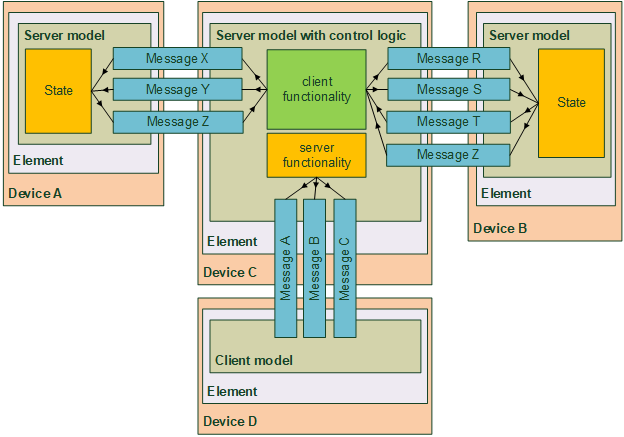
In another example, Figure 2.3 shows the element-model structure of a device that implements a model that is itself a server model and also a client of some other server models. Device C can communicate with server models as a client (supporting messages X, Y, and Z and messages R, S, and T respectively) and can communicate with client models as a server (supporting messages A, B, and C).
A lighting control model is an example of a model that includes server functionality, client functionality, and control logic. A typical lighting control model needs to function as a client to sensors (e.g., to determine occupancy and/or the ambient light level by receiving relevant sensor status messages) and to function as a server to a settings client (such as a smartphone application that configures its parameters). Control logic in such a model may then control the lighting via defined state bindings if the model is included within a light source such as a lamp or other luminaire. In addition, if the lighting controller also acts as a client for one or more light sources, the lighting controller can be implemented in a separate node rather than necessarily being included within a light source.
Models can define functions of a device as a network node, such as key management, address assignment, and relaying of messages. Models also define physical behaviors of a device built around a network node, such as power control, lighting control, and sensor data collection. There may be nodes implementing only network-related functions, such as Relay nodes or Proxy nodes, while the majority of nodes are able to interact with the physical world by means of controlling electrical power, controlling light emissions, or sensing environmental data.
A message can be used by multiple different models. Message behavior is the same in each model, enabling a common understanding among client and server models because the behavior is consistent regardless of the models that send and process the message.
Model specifications are designed to be very small and self-contained. A model may, at the specification definition time, require other models to be instantiated within the same node. This is called extending, which means a model can extend other models.
Models that do not extend other models are referred to as root models.
Model specifications are immutable: it is not possible to remove or add behavior to a model, whether the desired behavior is optional behavior or mandatory. Models are not versioned and have no feature bits. If additional behavior is required in a model, then a new extended model is defined that exposes the required behavior and can be implemented alongside the original model.
Therefore, knowledge of the models supported by an element determines the exact behavior exposed by that element.
Additionally, models may support metadata that provide additional information about a specific instance of the model. For example, the lighting control model may expose information about the purpose of the light source in the physical device.
Models may be defined and adopted by Bluetooth SIG and may be defined by vendors. Models defined by Bluetooth SIG are known as SIG adopted models, and models defined by vendors are known as vendor models. Models are identified by unique identifiers, which can be either 16 bits, for SIG adopted models, or 32 bits, for vendor models.
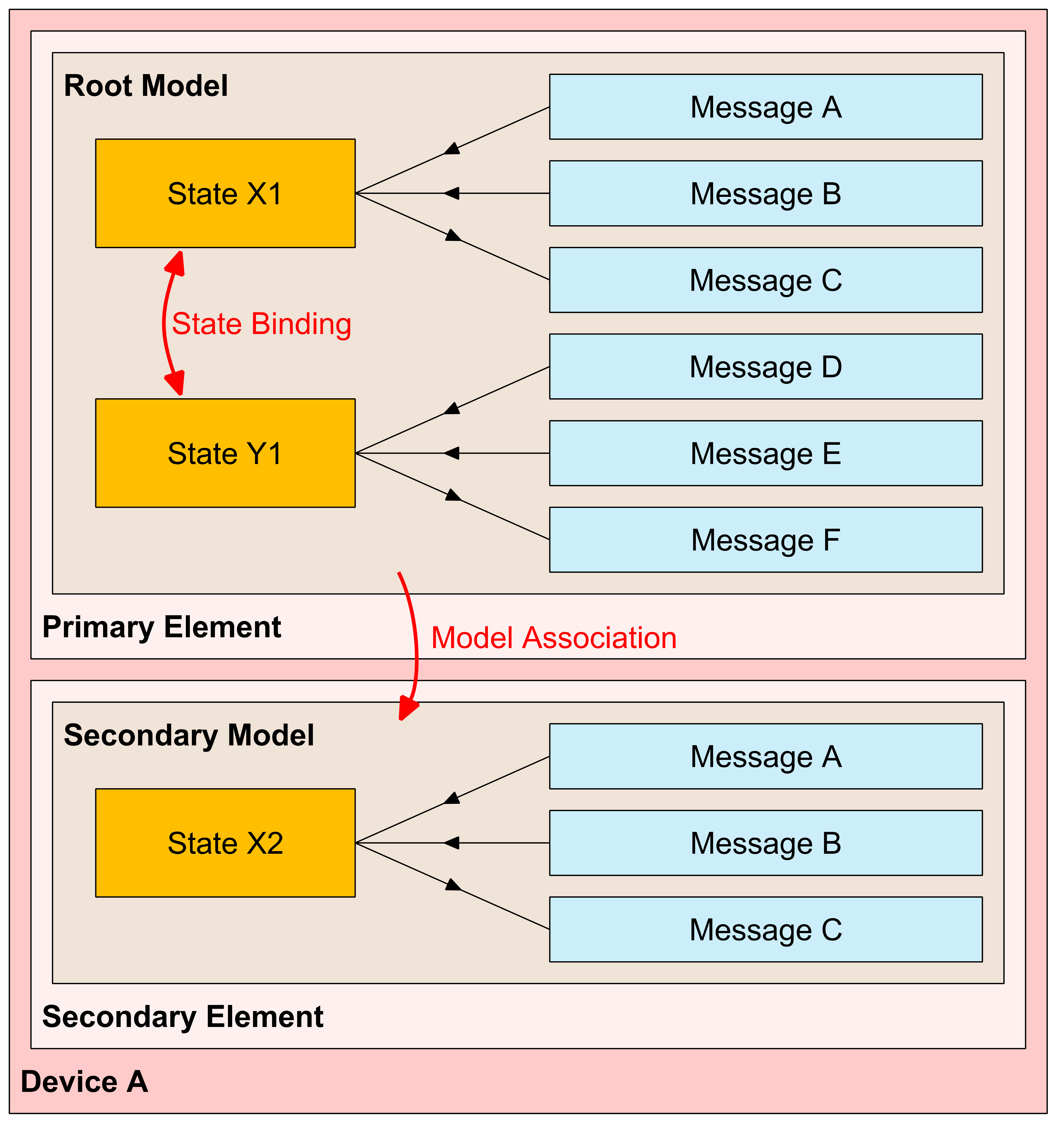
For example, Figure 2.4 shows the element-model structure of a device that implements a root model with two bound states and a set of messages operating on each state. The root model is within the primary element and is extended by the extended model that adds another state on a secondary element. Messages are not capable of differentiating among multiple instances of the same state on the same element. Therefore, when more than one instance of a given state is present on a device, each instance is required to be in a separate element. In this example, the second instance of State X is required to be located on the second element because it is the same type of a state and thus has the same types of messages serving it.
 |
This example structure can be multiplied for a composite device. For example, a composite device can have multiple instances of the same root model (or extended models), each on a separate element (or set of elements). Also, if a model (root or extended) needs more than one instance of a particular state, the states are distributed across several elements so that, at most, a single instance of any given state is on an element.
Figure 2.5 illustrates how the element-model structure of the device in Figure 2.4 might be implemented in a composite device. The element-model structure of the device is described by the Composition Data (see Section 4.2.1) that is read by a Configuration Manager after provisioning (see Section 5), using the Configuration Server model and the Configuration Client model (see Sections 4.4.1 and 4.4.2).
 |
2.3.7. Terms
A term is a period in the lifetime of a node during which the structure of the node (i.e., the features, the elements and models) and the unicast addresses of the node’s elements do not change.
Starting a new term may be necessary to support a change in the hardware configuration of a physical device, such as the attachment of an auxiliary sensor, or to support a change in subsystem configuration on the node, such as the attachment of a new gear to an intra-luminaire network. The changes are indicated by the node by populating Composition Data Page 128 (see Section 4.2.2.4) and take effect when a new term starts.
The initial term of a node on a network starts when the node is provisioned on the network.
A term ends and a new term starts when a Node Address Refresh procedure or a Node Composition Refresh procedure is executed (see Section 3.11.8).
The last term of a node on a network ends when the node is removed from the network.
2.3.8. Example device
To help explain how the arrangement of models within elements determines the state and behavior of a device, we will use a dual-socket smart power strip device (shown in Figure 2.6) as an example. This device has a single radio that has the low energy feature of Bluetooth and two independent power sockets, each capable of controlling the power output. This example includes states, messages, and models defined in the Mesh Model specification [9].
 |
The device has two elements (see Section 2.3.4) that represent each of the two power sockets. Each element has a unicast address assigned to it.
The functionality of each element is defined by the Generic Power Level Server model. The model defines a set of states on a server, as well as a set of messages that operate on the states.
A Generic Power Level Set message may be sent to the device to control the output power. The message is addressed to an element and carries the element’s address in the DST field (see Section 2.3.9).
The sockets can also be controlled by generic devices (such as a dimmer) that implement the Generic Level Client model (and do not know anything about power control). This model simply sets a desired level to zero, a maximum value, or a value in between. Power to the sockets is controlled through state binding. In each power socket, the Generic Power Actual state is bound to the Generic Level state. A Generic Level Client sends Generic Level messages to the Generic Level Server. The Generic Level state is changed, which in turn (via the defined binding) changes the Generic Power Actual state that controls the power output.
Elements can report states. In our example, each socket may report power level as well as the energy consumption of a device plugged into the socket. Energy consumption is reported using messages defined by the Sensor Server model. Each message has the element’s address, which identifies the socket, in its SRC field (see Section 3.4.4.6).
Figure 2.7 illustrates the element-model structure for the dual-socket device. Functionally, both elements of the device have identical features. The only difference is that the primary element handles the Configuration Server model, which is used for network management, in addition to the other models. Each element may have other models defined such as the Health Server model (see Section 4.4.4) or models defined in the Mesh Model specification [9].

2.3.9. Publish-subscribe and message exchange
Publication and subscription of data within the mesh network is described as using a publish-subscribe paradigm. Nodes that generate messages publish the messages to a unicast address, group address, or virtual address. Nodes that are interested in receiving the messages will subscribe to these addresses.
Generated messages are sent to destination mesh addresses that can be unicast, pre-configured group addresses, or virtual addresses. Messages can be sent as replies to other messages or can be unsolicited messages. When an instance of a model is sending a reply message, it uses the incoming message originator’s source address as the destination address. When an instance of a model is sending unsolicited messages, it uses a model publish address as the destination address. Each instance of a model within a node has a single publish address.
On the receiving side, each instance of a model within a node can subscribe to one or more group addresses or virtual addresses. Whenever a message that is addressed to a group address or a virtual address on one of the model’s subscription lists arrives, it is processed by the node. A message is also processed when its destination address is the unicast address of a receiving element or when its destination address is a fixed group address that this device is a member of. If a node has multiple elements, then the message is processed once on each of the addressed elements.
Publish addresses and subscription lists for models defined by higher layer specifications use the Model Publication and Subscription List states that are managed by the Configuration Server Model.
A node can have multiple subscriptions per instance of a model’s element, although nodes may limit the number of subscriptions that are supported. Using multiple subscription addresses allows a node to respond to messages that are published to different groups. For example, a light may be subscribed to messages sent to the bedside light group, the bedroom group, the upstairs group, and the house group.
Each message is sent from a single unicast address (an element address) and sequenced using a unique sequence number to facilitate detection of and protection against replay attacks.
2.3.10. Security
All messages are encrypted and authenticated using two types of keys. One key type is for the network layer communication, such that all communication within a mesh network would use the same network key. The other key type is for application data. Separating the keys for networking and applications allows different application keys for different purposes. This allows the creation of separate security domains for separate applications (e.g., one domain for access control to a building and another domain for ambient temperature sensing).
2.3.10.1. Application and network security
Encrypting and authenticating messages at the upper transport layer and network layer is designed to secure communications within the mesh network against eavesdroppers and malicious attacks. Each layer maintains distinct keys to allow separation between application and network entities.
Splitting application keys from network keys enables secure relay transmission of messages: Relay nodes can authenticate messages at network level without accessing the application data. For example, a light bulb acting as a Relay node should not be able to unlock doors.
The application key is used directly along with an associated application key identifier (AID) that is used in certain contexts to identify the application used. However, the network key is always used through a key derivation function to generate other keys that are used directly. Examples of such keys include EncryptionKey and PrivacyKey. This allows a single network key to be changed and all the associated values that are derived from that key to be quickly derived. As with the application key, the network key is also used to derive a network key identifier (see Section 3.9.6).
The security model defines three separate keys (the device key (DevKey), the application key (AppKey), and the network key (NetKey)) to secure the messages. When a node is given a key, it is authorized to use that key. A key that is shared between multiple nodes enables any node with that key to transmit and receive messages using that key.
The device key facilitates confidentiality and authentication of key material between a Configuration Manager and a single node. The application key facilitates confidentiality and authentication of application data sent between intended nodes. The network key facilitates privacy, confidentiality, and authenticity of network messages. A node may have knowledge of a single device key, multiple application keys, and multiple network keys.
A device key is similar to an application key in that it is designed to secure information sent by an application in the upper transport layer. However, a device key is known only by the Provisioner, the Configuration Manager, and the single node. The Configuration Manager knows the device keys for all nodes, which allows the Configuration Manager to securely distribute keys to a set of nodes by sending these keys secured with the device key for each individual node, allowing a key distribution to be targeted at only those nodes that need to know. Use of a device key is designed to protect against the “trash-can” attack (a technique to retrieve information from a disposed device that can be used to carry out an attack on a network) by allowing the distribution of new network and application keys to selected devices only.
The network key and the device keys for the nodes on the network constitute the ownership of the network. Ownership of the network may be changed by executing any of the Node Provisioning Protocol Interface procedures for every node on the network (see Section 3.11.8) and executing the Key Refresh procedure (see Section 3.11.4).
An application key can only be used with a single network key. This implies that a network key has one or more application keys associated with it. This association is known as the key binding.
The granularity of access layer security is on a per-model basis. Each server model has a set of application keys bound to it, defining the possible keys that should be used to encrypt and authenticate a message to be processed by the model. This allows multiple entities to operate certain node functions. Up to 251 application keys can be bound to a model. For example, a Light Lightness Server Model has three keys bound to it because the admin, user, and guest can all switch on a light. However, only the admin can configure the lamp, so the Configuration Server Model has only the admin application key bound to it.
2.3.10.2. Obfuscation
The network security model utilizes a privacy mechanism called obfuscation that utilizes the Advanced Encryption Standard (AES) to encrypt the source address, sequence numbers, and other header information using a PrivacyKey. The intent for obfuscation is to make tracking nodes more difficult.
2.3.10.3. Network and application key identifiers
A node may have multiple network or application keys.
By using a key identifier, it is possible to identify which subset of keys are used to secure the message. For example, instead of checking 20 keys, a node may only need to check two keys that have the same least significant bits of the key identifier. If a message is received with a key identifier that is not known, then the node can immediately discard it.
The key identifier is generated from the network or application key using a key derivation function.
This specification defines a separate identifier for the network key and application key. A network key identifier is transmitted in each Network PDU using a 7-bit value, while the AID is transmitted in each Lower Transport PDU using a 6-bit value.
2.3.10.4. Initialization vector index
A Network PDU contains a 24-bit sequence number that allows an element to transmit 16,777,216 Network PDUs. The sequence number is used in the security nonce to provide uniqueness; therefore, the sequence number cannot wrap. If an element is transmitting a new message at 2 Hz, then these sequence numbers would be exhausted after 97 days. To enable a mesh network to operate for longer periods of time than the sequence number space allows, an additional 4-octet value called the IV Index is defined that is included in the security nonce. For example, using the same 2 Hz message frequency would measure the lifetime of the network using the IV Index in billions of years.
To enable a gradual transition from one IV Index to the next, each Network PDU includes the least significant bit of the IV Index that was used to transmit the message. A node can also use an IV Update procedure to signal to peer nodes that it is updating the IV Index. This procedure takes a minimum of eight days to transition from the old IV Index to the new IV Index, thereby limiting the frequency that a node can transmit messages to 24 Hz. However, a node should not send more than 100 Network PDUs in any 10 second window, so this would typically take approximately 19 days to exhaust.
2.3.11. Directed forwarding
Directed forwarding is designed to help improve performance of a multi-hop network by selecting only a subset of nodes to relay a message from a source to a destination. This subset, including the source node and the destination node(s), constitutes a path, as defined by directed forwarding. A path is identified by a pair of addresses: a source address and a destination address. The destination address may be a unicast address, a group address, or a virtual address.
The source node of a path is the Path Origin, and each destination node of a path is a Path Target (see Section 3.6.8.1).
The Path Origin is configured to use managed flooding or directed forwarding when originating a message (see Section 3.7.3.1). Managed flooding and directed forwarding use different security materials, respectively the managed flooding security material and the directed security material, which are obtained from the same network key (see Section 3.9.6.3.1).
A directed forwarding node uses a forwarding table to store pairs of source and destination addresses for each path it is part of. There is a separate forwarding table for each subnet. When a message is received by a node that is configured to relay messages using directed forwarding, the node compares the source and destination addresses of the message against the entries in the table and retransmits the message only if there is a match. That restricts message forwarding only to nodes along an established path.
Nodes forming a path may be explicitly configured by a Configuration Manager or a path may be discovered and maintained following the request of a node that is originating messages. To help improve reliability and resilience, a path may have multiple lanes between source node and destination node(s) that take advantage of several relays overhearing a message relayed on each hop. Lanes of a path are discovered sequentially. The path discovery and maintenance policy of an originator is configured by the Configuration Manager and controls aspects such as path lifetime, verification and rediscovery cadence, the number of redundant lanes, and whether the paths are unidirectional or bidirectional.
Directed forwarding nodes, known as supporting nodes, may act on behalf of Low Power nodes or Proxy Client nodes, known as dependent nodes, to discover paths, to establish paths, and to provide path updates when the network topology changes. For more information on node dependence, see Section 3.6.8.3.
There is no limitation on the number of directed forwarding relays in a network (other than the total number of nodes). When using directed forwarding, the message forwarding load may be distributed among several nodes. Each node may function as a directed forwarding relay: the node will only relay a portion of overall traffic.
2.3.12. Friendship
Friendship is used by Low Power nodes to limit the amount of time that they need to listen. If a node cannot receive continuously, then it is possible that it will not receive mesh messages that it should be processing. This includes security updates required for maintaining the security of the network as well as the normal mesh messages.
If the Low Power node does not receive such messages, then it may not operate as desired and it may also fail to keep up-to-date with the latest security state of the network and eventually drop off the network if this security is changed without its knowledge.
Friendship is a special relationship between a Low Power node and one neighboring Friend node. These nodes must be within a single hop of each other and in the same subnet, as required by Section 3.6.6.3.1.
Friendship is first established and initiated by the Low Power node; once established, the Friend node performs a number of actions that help reduce the power consumption on the Low Power node. The Friend node maintains a Friend Queue for the Low Power node, which stores all incoming messages addressed to the Low Power node. The Friend node delivers those messages to the Low Power node when requested by the Low Power node. Also, the Friend node delivers security updates to the Low Power node.
When friendship is established between a Low Power node and one Friend node, the two nodes are considered to be “friends”.
An example topology of a mesh network illustrating Friend nodes and Low Power nodes is shown and described in Section 2.3.14.
2.3.13. Features and functionality
The capabilities of a node are determined by the features and functionality that the node supports. All nodes have the ability to transmit and receive mesh messages. Nodes can also optionally support one or more additional features, as defined by the Configuration Server model:
-
Relay feature – the ability to receive and retransmit mesh messages over the advertising bearer to enable larger networks.
-
Proxy feature – the ability to receive and retransmit mesh messages between GATT and advertising bearers.
-
Low Power feature – the ability to operate within a mesh network at significantly reduced receiver duty cycles only in conjunction with a node supporting the Friend feature.
-
Friend feature – the ability to help a node supporting the Low Power feature to operate by storing messages destined for those nodes.
A node that supports a feature may have that feature enabled or disabled, and the feature, when enabled, may be or may not be in use.
A node supporting the Relay feature may have this feature disabled, but it would still support the Relay feature, it is just that it is not performing the functionality required by that feature. A node that supports the Relay feature and has the Relay feature enabled is known as a Relay node.
Proxy functionality is supported by nodes that support relaying/forwarding of Network PDUs received by a node between GATT and advertising bearers. A node supporting the Proxy feature may have this feature disabled, but it would still support the Proxy feature, it is just that it is not performing the functionality required by that feature. A node that supports the Proxy feature and has the Proxy feature enabled is known as a Proxy node.
A node supporting the Low Power feature cannot have this feature disabled and, as required by Section 3.6.6.3, must establish a friendship with another node supporting the Friend feature before it can use the Low Power feature to reduce receiver duty cycles. A node that supports the Low Power feature and has a friendship with a node that supports the Friend feature is known as a Low Power node.
A node supporting the Friend feature may have this feature disabled, but it would still support the Friend feature, it is just that it is not performing the functionality required by that feature. A node that supports the Friend feature, has the Friend feature enabled, and has a friendship with a node that supports the Low Power feature is known as a Friend node.
Other Foundation models support additional functionality. For example, the Directed Forwarding Configuration Server model (see Section 4.4.7) supports directed forwarding functionality. Directed forwarding can be performed only among nodes in a subnet that have directed forwarding functionality enabled. A node with directed forwarding functionality enabled in a subnet is known as a Directed Forwarding node in that subnet.
Additional functionalities can be enabled or disabled in Directed Forwarding nodes:
-
directed relay functionality – the ability to participate in finding paths and relaying messages along paths
-
directed proxy functionality – the ability to establish paths on behalf of a Proxy Client
-
directed friend functionality – the ability to establish paths on behalf of a Low Power node
Directed relay functionality can be enabled or disabled in nodes that support directed forwarding. A Directed Forwarding node with directed relay functionality enabled in a subnet is known as a Directed Relay node in that subnet (see Section 3.6.8.1).
Directed proxy functionality is supported by nodes that support both the Proxy feature and directed forwarding functionality; otherwise, it is not supported. When directed proxy functionality is supported, it can be enabled or disabled. A Directed Forwarding node with directed proxy functionality enabled in a subnet is known as a Directed Proxy node in that subnet (see Section 3.6.8.1).
Directed friend functionality is supported by nodes that support both the Friend feature and directed forwarding functionality. When directed friend functionality is supported, it can be enabled or disabled. A Directed Forwarding node with directed friend functionality enabled in a subnet is known as a Directed Friend node in that subnet (see Section 3.6.8.1).
A Directed Forwarding node that supports the Low Power feature in a subnet can perform directed forwarding in that subnet if the node is not in a friendship in the same subnet, because the node behaves like a regular node while not in a friendship. If the node is in a friendship with a Directed Friend node, then directed forwarding can be performed by the Directed Friend node. If the node is in a friendship with a Friend node that does not have directed friend functionality supported and enabled, then directed forwarding cannot be performed.
Subnet bridging can be performed only by a node that has subnet bridge functionality enabled. A node with subnet bridge functionality enabled is known as a Subnet Bridge.
Private Proxy functionality is supported by nodes that support the Proxy feature, Private Network Identity advertising (see Section 7.2.2.2.4), and Mesh Private beacons (see Section 3.10.4); otherwise, Private Proxy functionality is not supported. When Private Proxy functionality is supported, it can be enabled or disabled.
On-Demand Private Proxy functionality is supported by nodes that support On-Demand Private Proxy Server model (see Section 4.4.13) and Solicitation PDU with Identification Type equal to 0x00 (see Section 6.9.1); otherwise, On-Demand Private Proxy functionality is not supported.
Node Identity functionality is supported by nodes that support exchange of Network PDUs between two nodes connected via GATT; otherwise, Node Identity functionality is not supported.
Private Node Identity functionality is supported by nodes that support Node Identity functionality and Advertising with Private Node Identity (see Section 7.2.2.2.5); otherwise, Private Node Identity functionality is not supported.
2.3.14. Topology
Nodes that support the various features described above can be formed into a mesh network. An illustration of a mesh network is shown in Figure 2.8 below.
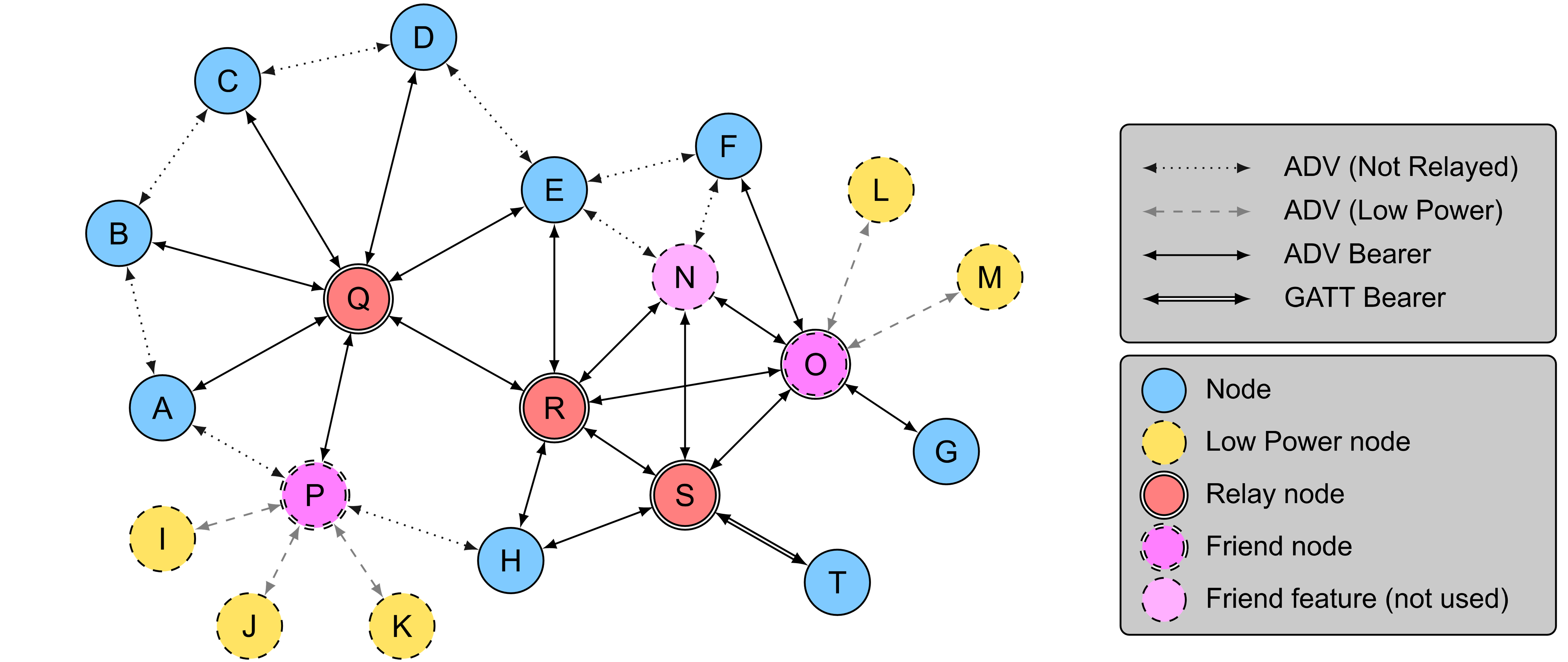
Figure 2.8 shows three Relay nodes: Q, R, and S. Although three nodes N, O, and P support the Friend feature, node N does not have any friendships, and therefore, only O and P are Friend nodes. There are five Low Power nodes: I, J, K, L, and M. Nodes I, J, and K have node P as their friend, while nodes L and M have node O as their friend. Node T is connected to the mesh network using a GATT bearer; therefore, node S retransmits all messages to and from node T.
For example, if a message is to be sent from T to L, then T will send the message to node S using the GATT bearer. Node S will retransmit this message using the advertising bearer. Nodes H, R, N, and O are within radio range of node S; therefore, they will receive this message. Node O, being the friend of node L will store the message, and if the message was a segmented message, node O will respond with an acknowledgment at the lower transport layer. Sometime later, L will poll node O to check for new messages, such that O will forward the message originally sent by T to L.

Figure 2.9 shows the same topology in Figure 2.8, used in the context of directed forwarding between a source node M and a destination node H. Node M is a Low Power node and is in friendship with node O. Node O implements directed friend functionality and establishes a 2-lane path on behalf of node M toward the destination node H. Nodes A, C, E, G, N, Q, R, and S support directed relay functionality, but only node R and node S are in the path between node M and node H. Therefore, regardless of the number of Directed Relay nodes, traffic is confined within the established paths. In this example, nodes E, G, N, and Q do not relay messages from node M to node H, even if they overhear them.
2.4. Mesh gateway
A mesh gateway is a node that is able to translate messages between the mesh network and a non-Bluetooth technology. A node may be able to send and receive mesh messages through a mesh gateway while not in the range of any of the Relay nodes. This translation is out of scope for this specification.
2.5. Concurrency limitations and restrictions
There are no concurrency limitations or restrictions for nodes imposed by this specification.
2.6. Topology limitations and restrictions
There are no topology limitations or restrictions imposed by this specification when used with the LE Physical Transport (see Vol 1, Part A, Section 3.2 in [24]).
3. Mesh networking
This section is structured as in the layered architecture that is described in Section 2.1. In addition, there are sections on mesh security and mesh network management.
3.1. Conventions
The following conventions apply to this specification.
3.1.1. Endianness and field ordering
For the network layer, lower transport layer, upper transport layer, mesh beacons, and Provisioning, all multiple-octet numeric values shall be sent in big-endian, as described in Section 3.1.1.1.
For the access layer and Foundation Models, all multiple-octet numeric values shall be little-endian as described in Section 3.1.1.2.
Where network data structures are made of multiple fields, the fields are listed in the tables from top to bottom and they appear in the corresponding figures from left to right (i.e., the top row of the table corresponds to the left of the figure). Table 3.1 shows an example data structure made up of multiple fields.
|
Field |
Size |
Field Content Description |
|---|---|---|
|
Field 0 |
4 |
The start of this field is in Octet 0 (left most octet in corresponding figure) |
|
Field 1 |
12 |
The start of this field is in Octet 0 and ends in Octet 1 |
|
Field 2 |
16 |
The start of this field is in Octet 2 and ends in Octet 3 |
In order to convert the data structure defined in a table into a series of octets in the layer that uses big-endian the following procedure is used. The binary number with N unassigned bits is created. The number of bits N in the number is equal to the sum of the number of bits of every field in the table. The most significant bits (MSbs) of the number are set to the value of Field 0 (first row of the table), then the number’s unassigned MSbs are set to the value of Field 1. This procedure is continued for consecutive fields of the table and ends when least significant bits (LSbs) of the number are set to value of last field of the table. As a final step the number is transmitted in big-endian format (i.e., most significant octet first). This is illustrated in Figure 3.1.

For example, the field 0 is 4 bits wide and has value of 0x6, field 1 is 12 bits wide and has value 0x987, and field 2 is 16 bits wide and has value of 0x1234. The value of the binary number is 0x69871234 and shall be transmitted as 0x69, 0x87, 0x12, 0x34.
In order to convert the data structure defined in a table into a series of octets in the layer that uses little-endian the following procedure is used. The binary number with N unassigned bits is created. The number of bits N in the number is equal to the sum of the number of bits of every field in the table. The LSbs of the number are set to the value of Field 0 (first row of the table), then the number’s unassigned LSbs are set to the value of Field 1. This procedure is continued for consecutive fields of the table and ends when MSbs of the number are set to the value of last field of the table. As a final step the number is transmitted in little-endian format (i.e., least significant octet first). This is illustrated in Figure 3.2.

For example, the field 0 is 4 bits wide and has a value of 0x6, field 1 is 12 bits wide and has a value of 0x987, and field 2 is 16 bits wide and has a value of 0x1234. The value of the binary number is 0x12349876 and shall be transmitted as 0x76, 0x98, 0x34, 0x12.
3.1.1.1. Big-endian
When multiple-octet values are defined as sent in big-endian (also known as “network byte order”), the conventions in this section apply. For example, the value 0x123456 shall be transmitted as 0x12, 0x34, and 0x56 (most significant octet first).
3.1.1.2. Little-endian
When multiple-octet values are defined as sent in little-endian, the conventions in this section apply. For example, the value 0x123456 shall be transmitted as 0x56, 0x34, and 0x12 (least significant octet first).
3.1.2. One-shot timers
This specification establishes definitions for terminology related to one-shot timers. A one-shot timer counts down from an initial value and when the counter reaches zero, the timer expires. The timer value is defined as the current value of the counter.
Table 3.2 establishes the definitions for actions that can be performed on a timer.
|
Action |
Description |
|---|---|
|
Start from the initial value |
The timer value is set to the initial value and the timer countdown is immediately started. |
|
Start from the current value |
The timer value is not changed and the timer countdown is immediately started. |
|
Stop |
The timer countdown is immediately stopped and the timer value is stored. |
When the timer value reaches zero, the timer countdown stops and the timer expires. The timer expiration is an event that may have a behavior defined in this specification.
Table 3.3 establishes the definitions for checking timer status.
|
Timer Status |
Description |
|---|---|
|
Is running |
The status beginning when the countdown timer starts until it stops. |
|
Is not running |
The status when the timer countdown is stopped. |
3.2. Features
This specification defines four optional features:
-
Relay feature (see Section 3.4.6.1)
-
Proxy feature (see Section 3.4.6.2)
-
Friend feature (see Section 3.6.6.3)
-
Low Power feature (see Section 3.6.6.4)
3.3. Bearers
This specification defines two mesh bearers over which mesh messages may be transported:
-
An advertising bearer (see Section 3.3.1)
-
A GATT bearer (see Section 3.3.2)
A node shall support the advertising bearer or the GATT bearer or both.
Bearers are identified by 2-octet indexes as described in Section 4.3.1.4.
3.3.1. Advertising bearer
When using the advertising bearer, a mesh packet shall be sent in the ADV_NONCONN_IND PDU (see [1]) using the Mesh Message AD type identified by «Mesh Message» as defined in [4].
The format of the Mesh Message AD type is defined in Table 3.4.
|
Field |
Size |
Description |
Req. |
|---|---|---|---|
|
Length |
1 |
Length of the AD Type and Network PDU fields |
M |
|
AD Type |
1 |
«Mesh Message» |
M |
|
Network PDU |
variable |
Network PDU |
M |
ADV_NONCONN_IND PDUs are used because there is no need to include the Flags AD Type in the advertising packets, thereby enabling two additional octets to be allocated to the Network PDU (see [5]).
To lower the probability of packet collisions on all advertising channels, the gap between consecutive packets within an Advertising Event (see [1]) and the sequence of the used primary advertising channels within an Advertising Event (see [24]) should be randomized.
A device supporting only the advertising bearer should perform passive scanning with a duty cycle as close to 100 percent as possible in order to avoid missing any incoming mesh messages or Provisioning PDUs.
All devices shall support both the Observer and Broadcaster roles, which are defined in the Generic Access Profile (GAP) [1].
3.3.2. GATT bearer
The GATT bearer is provided to enable devices that are not capable of supporting the advertising bearer to participate in a mesh network. The GATT bearer uses the Proxy protocol (see Section 6) to transmit and receive Proxy PDUs between two devices over a GATT connection.
The GATT bearer uses a characteristic to write to and receive notifications of mesh messages using the attribute protocol.
The GATT bearer defines two roles: a GATT Bearer Client and a GATT Bearer Server.
The GATT Bearer Client shall be a GATT Client and shall support the Proxy Client role (see Section 6.2.1). The GATT Bearer Server shall be a GATT Server and shall support the Proxy Server role (see Section 6.2.1).
The GATT Bearer Server shall instantiate one and only one Mesh Proxy Service, as defined in Section 7.2.
The GATT Bearer Client shall support the Mesh Proxy Service.
The GATT Bearer Client shall perform primary service discovery using either the GATT Discover All Primary Services sub-procedure or the GATT Discover Primary Services by Service UUID sub-procedure to discover the Mesh Proxy Service.
As required by the GATT profile defined in Volume 3, Part G of the Core Specification [1], the GATT Bearer Client must be tolerant of additional optional characteristics in the service records of services used with the GATT profile.
The GATT Bearer Client shall use either the GATT Discover All Characteristics of a Service sub-procedure or the GATT Discover Characteristics by UUID sub-procedure to discover the characteristics of the service.
The GATT Bearer Client shall use the GATT Discover All Characteristic Descriptors sub-procedure to discover the characteristic descriptors, which are described in the following sections.
The GATT Bearer Client shall discover the Mesh Proxy Data In characteristic, Mesh Proxy Data Out characteristic and its Client Characteristic Configuration descriptor. Once the Client Characteristic Configuration descriptor has been discovered, it shall enable notifications using this characteristic.
To send a Proxy PDU (see Section 6.3), the GATT Bearer Client shall use the Write Without Response sub-procedure to write the Proxy PDU to the GATT Bearer Server by writing to the Mesh Proxy Data In characteristic.
To receive a Proxy PDU, the GATT Bearer Client shall be able to receive multiple notifications of the Mesh Proxy Data Out characteristic. Each notification contains a single Proxy PDU.
Figure 3.3 illustrates the GATT Bearer Server and network layer (see Section 3.4) interactions.
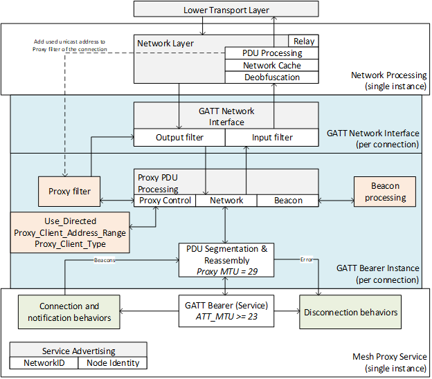
3.4. Network layer
The network layer defines the Network PDU format that allows Lower Transport PDUs to be transported by the bearer layer. It decrypts and authenticates and forwards incoming Network PDUs received on input interfaces to upper layers and/or output interfaces and encrypts and authenticates and forwards outgoing Network PDUs delivering them to output network interfaces.
3.4.1. Endianness
All multiple-octet numeric values in this layer shall be sent in big-endian, as described in Section 3.1.1.1.
3.4.2. Addresses
The network layer defines four basic types of addresses: unassigned, unicast, virtual, and group.
Addresses are 16 bits in length and are encoded as defined in Table 3.5 below.
|
Values |
Address Type |
|---|---|
|
0b0000000000000000 |
Unassigned Address |
|
0b0xxxxxxxxxxxxxxx (excluding 0b0000000000000000) |
Unicast Address |
|
0b10xxxxxxxxxxxxxx |
Virtual Address |
|
0b11xxxxxxxxxxxxxx |
Group Address |
3.4.2.1. Unassigned address
An unassigned address is an address in which the element of a node has not been configured yet or no address has been allocated. The unassigned address shall have the value 0x0000 as shown in Figure 3.4 below. This may be used, for example, to disable message publishing of a model by setting the publish address of a model to the unassigned address.
 |
An unassigned address shall not be used in the SRC field or the DST field of a Network PDU.
3.4.2.2. Unicast address
A unicast address is a unique address allocated to each element. A unicast address has bit 15 set to 0. The unicast address shall not have the value 0x0000, and therefore can have any value from 0x0001 to 0x7FFF inclusive as shown in Figure 3.5 below.
A unicast address is allocated to each element of a node for a term of the node on the network. The address allocation for the initial term is performed by a Provisioner during provisioning as described in Section 5.4.2.5. The address may be changed by executing the Node Address Refresh procedure (see Section 3.11.8.5) or the Node Composition Refresh procedure (see Section 3.11.8.6). The address may be unallocated by a Provisioner to allow the address to be reused using the procedure defined in Section 3.11.7.
 |
A unicast address shall be used in the SRC field of a Network PDU and may be used in the DST field of a Network PDU. A Network PDU sent to a unicast address shall be processed by at most one element.
3.4.2.2.1. Unicast address range format
A range of unicast addresses may be used in a message, for example, to communicate all the unicast addresses used by a node. In this case, the unicast address range format can be used to efficiently pack the range of unicast addresses. In the unicast address range format, the 15 least significant bits of the starting unicast address of the range and the number of addresses in the range are formatted as in Table 3.6.
|
Field Name |
Bits |
Description |
Req. |
|---|---|---|---|
|
LengthPresent |
1 |
Indicates the presence or absence of the RangeLength field. |
M |
|
RangeStart |
15 |
15 least significant bits of the starting unicast address |
M |
|
RangeLength |
8 |
Number of addresses in the range (0x02 – 0xFF) |
C.1 |
- C.1:
-
If the LengthPresent field value is 1, the RangeLength field shall be present; otherwise, the RangeLength field shall not be present.
The LengthPresent field indicates whether the address range contains a single address or multiple addresses. The LengthPresent field value shall be set to 1 when the number of addresses in the range of unicast addresses is greater than 1; otherwise, the LengthPresent field value shall be set to 0.
The RangeStart field shall contain the 15 least significant bits of the starting unicast address of the range of unicast addresses. The RangeStart field value shall not be 0.
If present, the RangeLength field shall contain the number of addresses in the range of unicast addresses. The valid values for the RangeLength field are 0x02 to 0xFF. The values of 0x00 and 0x01 are prohibited.
The sum of the RangeStart field value and the RangeLength field value shall not exceed 0x8000.
3.4.2.2.2. Unicast address range list
A message may contain multiple unicast address range values. For example, a unicast address range list can be used to communicate all the element addresses of Low Power nodes of a Friend node.
The values shall be serialized as shown in Figure 3.6. The length of each unicast address range value is either 2 or 3 octets depending on the LengthPresent field value within each unicast address range value.
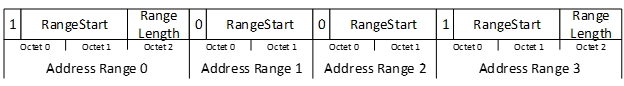
3.4.2.2.3. Matching an address to the unicast address range format
To check for the presence of a specific unicast address within the unicast address range format, the node shall convert the RangeStart field to the range start address by setting the 15 least significant bits of the range start address to the RangeStart field value and setting the most significant bit of the range start address to 0. If the LengthPresent field value is 1, the node shall compute the range end address by adding the RangeLength field value to the range start address; otherwise, the node shall increment the range start address by 1 to derive the range end address. A unicast address is matched to the unicast address range format if it is greater than or equal to the range start address and less than the range end address.
3.4.2.2.4. Converting to and from the unicast address range format
This section specifies the derivation of the primary element address and the number of secondary elements (i.e., the secondary elements count of a node) from the unicast address range format and, conversely, the derivation of the unicast address range format from the primary element address and secondary elements count.
Conversion to the unicast address range format
To derive the unicast address range format from the primary element address and the number of secondary elements, the node shall use the following procedure:
-
If the node has secondary elements, the LengthPresent field value shall be 1; otherwise, the LengthPresent field value shall be 0.
-
The RangeStart field shall be the 15 least significant bits of the primary element address of the node.
-
If the node has secondary elements, the RangeLength field value shall be the number of secondary elements plus 1; otherwise, the RangeLength field shall not be present.
For example, if a node has 5 secondary elements and the primary element address is 0x1234, then the value of the binary number of the unicast address range of the elements of the node and the sequence of octets for its transmission depend on the used endianness as follows:
-
If big-endian is used (e.g., when sending a Transport Control message), the value of the binary number is 0x923406 and is transmitted as 0x92, 0x34, 0x06.
-
If little-endian is used (e.g., when sending an Access message), the value of the binary number is 0x062469 and is transmitted as 0x69, 0x24, 0x06.
Conversion from the unicast address range format
To derive the primary element address and the number of secondary elements from the unicast address range format, the node shall use the following procedure:
-
If the LengthPresent field value is 0, the number of secondary elements is 0; otherwise, the number of secondary elements is equal to RangeLength – 1.
-
The 15 least significant bits of the primary element address of the node are equal to the RangeStart field. The most significant bit of the unicast address is always 0.
For example, if the unicast address range of a node is 0x1234, the node’s primary element address is 0x1234 and there are no secondary elements on the node.
3.4.2.3. Virtual address
A virtual address represents a set of destination addresses. Each virtual address logically represents a Label UUID, which is a 128-bit value that does not have to be managed centrally. One or more elements may be programmed to publish or subscribe to a Label UUID. The Label UUID is not transmitted and shall be used as the Additional Data field of the message integrity check value in the upper transport layer (see Section 3.9.7.1).
The virtual address is a 16-bit value that has bit 15 set to 1, bit 14 set to 0, and bits 13 to 0 set to the value of a hash. This hash is a derivation of the Label UUID such that each hash represents many Label UUIDs.
|
SALT=s1("vtad") |
|
hash=AES-CMACSALT (Label UUID) mod 214 |
When an Access message is received to a virtual address that has a matching hash, each corresponding Label UUID is used by the upper transport layer as additional data as part of the authentication of the message until a match is found.
Transport Control messages cannot use virtual addresses.
Label UUIDs may be generated randomly as defined in [6]. A Configuration Manager may assign and track virtual addresses; however, two devices can also create a virtual address using some out-of-band (OOB) mechanism. Unlike group addresses, these could be agreed upon by the devices involved and would not need to be registered in the centralized provisioning database, as they are unlikely to be duplicated.
A disadvantage of virtual addresses is that a multi-segment message is required to transfer a Label UUID to a publishing or subscribing node during configuration.
A virtual address can have any value from 0x8000 to 0xBFFF as shown in Figure 3.7 below.
 |
Note
Note: When factoring in a 32-bit MIC and the size of the hash, there is only a 1/246=1.42×10-14 likelihood that two matching virtual addresses using the same application key but different Label UUIDs will collide.
3.4.2.4. Group address
A group address is an address that is programmed into zero or more elements. A group address has bit 15 set to 1 and bit 14 set to 1, as shown in Figure 3.8 below. Group addresses in the range 0xFF00 through 0xFFFF are reserved for Fixed Group addresses (see Table 3.7), and addresses in the range 0xC000 through 0xFEFF are generally available for other usage.
 |
A group address shall only be used in the DST field of a Network PDU. A Network PDU sent to a group address shall be delivered to all the instances of models that subscribe to this group address.
There are two types of group addresses; those that can be assigned dynamically and those that are fixed. The fixed group addresses are defined in Table 3.7 below.
|
Values |
Fixed Group Address Name |
|---|---|
|
0xFFF9 |
all-ipt-border-routers |
|
0xFFFA |
all-ipt-nodes |
|
0xFFFB |
all-directed-forwarding-nodes |
|
0xFFFC |
all-proxies |
|
0xFFFD |
all-friends |
|
0xFFFE |
all-relays |
|
0xFFFF |
all-nodes |
This specification does not define any special behaviors related to values from 0xFF00 to 0xFFF8, all-ipt-border-routers, and all-ipt-nodes fixed group addresses.
3.4.3. Address validity
Table 3.8 shows which address types are valid for use in the SRC field and the DST field.
|
Address Type |
Valid in SRC Field |
Valid in DST Field |
|
|---|---|---|---|
|
Segmented and Unsegmented Control Messages (see Section 3.5.2) |
Segmented and Unsegmented Access Messages (see Section 3.5.2) |
||
|
Unassigned Address |
No |
No |
No |
|
Unicast Address |
Yes |
Yes |
Yes |
|
Virtual Address |
No |
No |
Yes |
|
Group Address |
No |
Yes |
Yes |
A fixed group address defined as Reserved for Future Use in Section 3.4.2.4 is a valid group address for the purposes of Table 3.8.
Table 3.9 shows which address types are valid for use with device keys and application keys.
|
Address Type |
Valid with Device Key |
Valid with Application Key |
|---|---|---|
|
Unassigned Address |
No |
No |
|
Unicast Address |
Yes |
Yes |
|
Virtual Address |
No |
Yes |
|
Group Address |
No |
Yes |
3.4.4. Network PDU
The mesh Network PDU format is defined in Table 3.10 and illustrated in Figure 3.9 below:
|
Field Name |
Bits |
Description |
Req. |
|---|---|---|---|
|
IVI |
1 |
Least significant bit of IV Index |
M |
|
NID |
7 |
Value derived from the NetKey used to identify the EncryptionKey and PrivacyKey used to secure this PDU |
M |
|
CTL |
1 |
Network Control |
M |
|
TTL |
7 |
Time To Live |
M |
|
SEQ |
24 |
Sequence number |
M |
|
SRC |
16 |
Source address |
M |
|
DST |
16 |
Destination address |
M |
|
TransportPDU |
8 to 128 |
Transport Protocol Data Unit |
M |
|
NetMIC |
32 or 64 |
Message Integrity Check for Network |
M |
Network PDUs are secured using keys derived from a single network key, as identified by the NID field.

Certain functionalities defined in this specification may require that a Network PDU be tagged with additional metadata. For example, tagging a Network PDU as relay is used to control the number of retransmissions of the Network PDU by the Advertising Bearer Network Interface (see Section 3.4.5.4).
3.4.4.1. IVI
The IVI field contains the least significant bit of the IV Index used in the nonce to authenticate and encrypt this Network PDU (see Section 3.9.2.11).
3.4.4.2. NID
The NID field contains a 7-bit network identifier that allows for an easier lookup of the EncryptionKey and PrivacyKey used to authenticate and encrypt this Network PDU (see Section 3.9.6.3.1).
The NID value is derived from the network key in conjunction with the EncryptionKey and PrivacyKey. It is derived differently for Network PDUs using managed flooding security material, Network PDUs using directed security material, and Network PDUs using friendship security material (see Section 3.9.6.3.1).
3.4.4.3. CTL
The CTL field is a 1-bit value that is used to determine if the Network PDU is part of a Transport Control message or an Access message, as illustrated in Table 3.11.
If the CTL field is set to 0, the NetMIC is a 32-bit field and the Lower Transport PDU contains an Access message.
If the CTL field is set to 1, the NetMIC is a 64-bit field and the Lower Transport PDU contains a Transport Control message.
|
CTL Field |
Message Type |
NetMIC Size (bits) |
|---|---|---|
|
0 |
Access message |
32 |
|
1 |
Transport Control message |
64 |
3.4.4.4. TTL
The TTL field is a 7-bit field. The TTL field values are defined in Table 3.12.
|
Value |
Description |
|---|---|
|
0 |
Network PDU has not been relayed and will not be relayed. |
|
1 |
Network PDU has been relayed and will not be relayed. |
|
2 - 126 |
Network PDU has been relayed or Network PDU has not been relayed. Network PDU can be relayed. |
|
127 |
Network PDU has not been relayed and can be relayed. |
The initial value of this field is set by the transmitting layer (lower transport layer, upper transport layer, access, foundation model, model) or an application and used by the network layer when operating as a Relay node or as a Directed Relay node.
The use of the TTL value of zero allows a node to transmit a Network PDU that it knows will not be relayed, and therefore the receiving node can determine that the sending node is a single radio link away. The use of a TTL value of one or larger cannot be used for such a determination.
3.4.4.5. SEQ
The SEQ field is a 24-bit integer. The combined SEQ field, IV Index field, and SRC field (see Section 3.4.4.6) shall be a unique value for each new Network PDU that this element originates.
3.4.4.6. SRC
The SRC field is a 16-bit value that identifies the element that originated this Network PDU. This address shall be a unicast address.
The SRC field is set by the originating element and untouched by nodes operating as a Relay node or as a Directed Relay node.
3.4.4.7. DST
The DST field is a 16-bit value that identifies the element or elements that this Network PDU is directed towards. This address shall be a unicast address, a group address, or a virtual address.
The DST field is set by the originating node and is untouched by the network layer in nodes operating as a Relay node or as a Directed Relay node.
3.4.4.8. TransportPDU
The TransportPDU field, from a network layer point of view, is a sequence of octets of data. When the CTL field value is 0, the TransportPDU field shall be a maximum of 128 bits. When the CTL field value is 1, the TransportPDU field shall be a maximum of 96 bits.
The TransportPDU field is set by the originating lower transport layer and shall not be changed by the network layer.
3.4.4.9. NetMIC
The NetMIC field is a 32-bit or 64-bit field (depending on the value of the CTL field) that authenticates that the DST and TransportPDU fields have not been changed.
When the CTL field value is 0, the size of the NetMIC field shall be 32 bits. When the CTL field value is 1, the size of the NetMIC field shall be 64 bits.
The NetMIC field value is set by the network layer at each node that transmits or relays this Network PDU.
3.4.5. Network interfaces
The network layer supports sending and receiving Network PDUs via multiple bearers. Multiple instances of a bearer may be present. Each instance of a bearer is connected to the network layer via a network interface. To allow sending Network PDUs between elements within the same node the local interface is used.
For example, a node may have three interfaces: one used to send and receive Network PDUs via an advertising bearer and two interfaces to a GATT bearer, one for each client connected via a GATT connection.
Interfaces provide input and output filters. Filters may be configured using bearer-specific PDUs or internally by services exposed on a node, such as the Mesh Proxy Service (see Section 7.2).
3.4.5.1. Interface input filter
The interface input filter determines whether an incoming Network PDU is delivered to the network layer for further processing or it is dropped.
A feature or a protocol in this specification may define an input filter. For example, the Proxy Protocol defines filters (see Section 6.4).
The input filter of the interface connected to the GATT bearer shall drop all Network PDUs that have been secured using the friendship security credentials.
3.4.5.2. Interface output filter
The interface output filter determines whether an outgoing Network PDU is delivered to a bearer or it is dropped.
A feature or a protocol in this specification may define an output filter. For example, the Proxy Protocol defines filters (see Section 6.4).
The output filter of the interface connected to advertising or GATT bearers shall drop all Network PDUs with the TTL field value set to 1 unless they contain a Network PDU that is tagged as relay.
The output filter of the interface connected to the GATT bearer shall drop all Network PDUs secured using the friendship security credentials.
3.4.5.3. Local Network Interface
A Local Network Interface allows sending Network PDUs between elements within the same node.
A node shall implement a Local Network Interface.
Upon receiving a Network PDU by a Local Network Interface, the Network PDU shall be delivered to all elements of the node.
3.4.5.4. Advertising Bearer Network Interface
When transmitting a Network PDU that is tagged as friendship, the Advertising Bearer Network Interface shall transmit the Network PDU over the advertising bearer only once.
When transmitting a Network PDU that is not tagged as friendship, the Advertising Bearer Network Interface shall transmit the Network PDU over the advertising bearer using the following configuration:
-
If the Network PDU is not using directed security material, then the relay tag is checked:
-
If the Network PDU is not tagged as relay, the number and timing of the transmissions shall be as indicated by the Network Transmit state (see Section 4.2.20).
-
If the Network PDU is tagged as relay, the number and timing of the transmissions shall be as indicated by the Relay Retransmit state (see Section 4.2.21).
-
-
If the Network PDU is using the directed security material, then the combination of relay tag and CTL field is checked:
-
If the Network PDU is not tagged as relay, and the CTL field value is equal to 0, then the number and timing of the transmissions shall be as indicated by the Directed Network Transmit state (see Section 4.2.32.2).
-
If the Network PDU is not tagged as relay, and the CTL field value is equal to 1, then the number and timing of the transmissions shall be as indicated by the Directed Control Network Transmit state (see Section 4.2.39).
-
If the Network PDU is tagged as relay, and the CTL field value is equal to 0, then the number and timing of the transmissions shall be as indicated by the Directed Relay Retransmit state (see Section 4.2.34).
-
If the Network PDU is tagged as relay, and the CTL field value is equal to 1, then the number and timing of the transmissions shall be as indicated by the Directed Control Relay Retransmit state (see Section 4.2.40).
-
When transmitting a Network PDU that is tagged as relay, the start time of the transmission should be randomized by a small interval to avoid collisions between multiple relays that have received the Network PDU at the same time. If the DST field value of the Network PDU is the all-directed-forwarding-nodes fixed group address (see Section 3.4.2.4), the start time of the transmission should be additionally randomized by an interval from 0 to 100 milliseconds.
3.4.6. Network layer behavior
3.4.6.1. Relay feature
The Relay feature is used to relay/forward Network PDUs received by a node over the advertising bearer. This feature is optional and if supported can be enabled and disabled. If the Proxy feature is supported, then both GATT and advertising bearers shall be supported.
3.4.6.2. Proxy feature
The Proxy feature is used to relay/forward Network PDUs received by a node between GATT and advertising bearers. This feature is optional and if supported can be enabled and disabled. When this feature is supported, the Advertising with Network ID (see Section 7.2.2.2.2) shall be supported and the Mesh Proxy Service (see Section 7.2) shall be contained in the GATT Server on a node; otherwise, the Mesh Proxy service may be contained in the GATT Server.
3.4.6.3. Receiving a Network PDU
A Network PDU is delivered from a bearer to the network layer via a network interface. The interface shall apply filtering rules defined by its input filter (see Section 3.4.5.1). If the Network PDU passes through the input filter, it is delivered to the network layer for further processing.
Upon receiving a Network PDU, the node shall check whether the NID field value matches one or more known NIDs. If the NID field value does not match a known NID, then the Network PDU shall be ignored. If the NID field value matches a known NID, the node shall attempt to authenticate the Network PDU using the security credentials derived from each known network key that matched. If the Network PDU does not authenticate against any known network key, then the Network PDU shall be ignored. If the Network PDU does authenticate against a network key, and the SRC and DST fields are considered valid (see Section 3.4.3), and an entry corresponding to the Network PDU is not in the Network Message Cache (see Section 3.4.6.5), then the Network PDU shall be processed by the lower transport layer.
When the Network PDU is processed by the lower transport layer, and the TTL field has a value of 2 or greater, and the destination is not a unicast address of an element on this node, then the Network PDU shall be evaluated against retransmission conditions for incoming Network PDUs as defined in Table 3.13. For a Network PDU, there may be more than one matching row in Table 3.13. If there is no row that matches the retransmission conditions, then the Network PDU shall not be retransmitted.
For each row in Table 3.13, if the Network PDU is delivered from the bearer identified in the Inbound Bearer column, and is secured using the security material identified in the Inbound Security Material column, and all conditions in the Conditions column are met, then the actions in the Additional Actions column, if present, shall be executed, and the Network PDU shall be retransmitted to network interface(s) identified by the Outbound Bearers column using the security material identified in the Outbound Security Material column. The IV Index used when retransmitting the Network PDU shall be the same IV Index as in the received Network PDU. The TTL field value of the retransmitted Network PDU shall be equal to the TTL field value of the received Network PDU decremented by 1. The network key used when retransmitting the Network PDU depends on whether the node is a Subnet Bridge node.
If the node is not a Subnet Bridge node, the network key used when retransmitting the Network PDU shall be the same network key used to secure the received Network PDU.
If the node is a Subnet Bridge node, the node shall check all the Bridging Table state entries to determine whether the Network PDU is to be bridged to different subnets.
For a given Bridging Table state entry (see Section 4.2.42), the Network PDU shall be retransmitted using the NetKey identified by NetKeyIndex2 of the entry if all the following conditions are met:
-
The SRC field value in the Network PDU matches the address of the node in the first subnet that is indicated in the Address1 field.
-
The DST field value in the Network PDU matches the address of the node in the second subnet that is indicated in the Address2 field.
-
The received Network PDU was encrypted using the NetKey identified by NetKeyIndex1 of the entry.
The Network PDU shall be retransmitted using the NetKey identified by NetKeyIndex1 of the Bridging Table state entry if all the following conditions are met:
-
The SRC field value in the Network PDU matches the address of the node in the second subnet that is indicated in the Address2 field.
-
The DST field value in the Network PDU matches the address of the node in the first subnet that is indicated in the Address1 field.
-
The received Network PDU was encrypted using the NetKey identified by NetKeyIndex2 of the entry.
-
The Directions value of the entry is 0x02.
|
Inbound Bearer |
Inbound Security Material |
Conditions |
Additional Actions |
Outbound Bearers |
Outbound Security Material |
|---|---|---|---|---|---|
|
ADV |
flooding |
Relay is enabled. |
Tag as relay |
ADV |
flooding |
|
ADV |
flooding |
Proxy is enabled. |
– |
GATT |
flooding |
|
ADV |
flooding |
Traffic is to be bridged. AND Directed forwarding is enabled. AND DST is a valid path destination. AND Path from supporting node does not exist. |
Create Path Origin State Machine AND Update replay protection list |
all bearers |
flooding |
|
ADV |
flooding |
Traffic is to be bridged. AND Directed forwarding is enabled. AND Path from supporting node exists. AND Dependent node is not listed. |
Start Directed Forwarding Dependents Update AND Update replay protection list |
all bearers |
flooding |
|
ADV |
flooding |
Traffic is to be bridged. AND Directed forwarding is enabled. AND Path from supporting node exists. AND Dependent node is listed. |
Update replay protection list |
path bearers |
directed |
|
ADV |
friendship |
Friend is enabled. AND Directed friend is disabled. |
– |
all bearers |
flooding |
|
ADV |
friendship |
Directed friend is enabled. AND DST is a valid path destination. AND Path from supporting node does not exist. |
Create Path Origin State Machine |
all bearers |
flooding |
|
ADV |
friendship |
Directed friend is enabled. AND Path from supporting node exists. AND Dependent node is not listed. |
Start Directed Forwarding Dependents Update |
all bearers |
flooding |
|
ADV |
friendship |
Directed friend is enabled. AND Path from supporting node exists. AND Dependent node is listed. |
– |
path bearers |
directed |
|
ADV |
directed |
Directed relay is enabled. AND Path exists. |
Tag as relay |
path bearers |
directed |
|
ADV |
directed |
Directed proxy is enabled. AND Path to supporting node exists. AND Dependent node is listed. |
– |
GATT |
flooding |
|
ADV |
directed |
Traffic is to be bridged. AND Directed forwarding is enabled. AND Path from supporting node does not exist. |
Create Path Origin State Machine AND Update replay protection list |
all bearers |
flooding |
|
ADV |
directed |
Traffic is to be bridged. AND Directed forwarding is enabled. AND Path from supporting node exists. AND Dependent node is not listed. |
Start Directed Forwarding Dependents Update AND Update replay protection list |
all bearers |
flooding |
|
ADV |
directed |
Traffic is to be bridged. AND Directed forwarding is enabled. AND Path exists. |
Update replay protection list |
path bearers |
directed |
|
GATT |
flooding |
Proxy is enabled. AND Directed proxy is disabled. |
– |
all bearers |
flooding |
|
GATT |
flooding |
Directed proxy is enabled. AND Directed forwarding is not selected. |
– |
all bearers |
flooding |
|
GATT |
flooding |
Directed forwarding is selected. AND DST is a valid path destination. AND Path from supporting node does not exist. |
Create Path Origin State Machine |
all bearers |
flooding |
|
GATT |
flooding |
Directed forwarding is selected. AND Path from supporting node exists. AND Dependent node is not listed. |
Start Directed Forwarding Dependents Update |
all bearers |
flooding |
|
GATT |
flooding |
Directed forwarding is selected. AND Path from supporting node exists. AND Dependent node is listed. |
– |
path bearers |
directed |
|
GATT |
directed |
Directed relay is enabled. AND Path exists. |
– |
path bearers |
directed |
|
GATT |
directed |
Traffic is to be bridged. AND Directed forwarding is enabled. AND Path from supporting node does not exist. |
Create Path Origin State Machine AND Update replay protection list |
all bearers |
flooding |
|
GATT |
directed |
Traffic is to be bridged. AND Directed forwarding is enabled. AND Path from supporting node exists. AND Dependent node is not listed. |
Start Directed Forwarding Dependents Update AND Update replay protection list |
all bearers |
flooding |
|
GATT |
directed |
Traffic is to be bridged. AND Directed forwarding is enabled. AND Path exists. |
Update replay protection list |
path bearers |
directed |
The following paragraphs define the requirements associated with each column of Table 3.13.
Inbound Bearer. The entries in the Inbound Bearer column of Table 3.13 identify the type of bearer from which the Network PDU was delivered:
-
ADV: The inbound Network PDU is delivered from the advertising bearer.
-
GATT: The inbound Network PDU is delivered from the GATT bearer.
Inbound Security Material. The entries in the Inbound Security Material column of Table 3.13 identify the type of security material used to secure the incoming Network PDU (see Section 3.9.6.3.1):
-
flooding: The inbound Network PDU is secured using managed flooding security material.
-
friendship: The inbound Network PDU is secured using friendship security material.
-
directed: The inbound Network PDU is secured using directed security material.
Conditions.Table 3.14 defines the requirements for the conditions in the Conditions column of Table 3.13.
|
Condition |
Requirements |
|---|---|
|
Proxy is enabled |
The Proxy feature is supported and enabled, or the Private Proxy functionality is supported and enabled or the On-Demand Private GATT Proxy state has a value in the range 0x01 to 0xFF (see Section 4.2.47). |
|
Relay is enabled |
The Relay feature is supported and enabled. |
|
Directed proxy is enabled |
Directed proxy functionality is enabled in the subnet from which the Network PDU is received. |
|
Directed proxy is disabled |
Directed proxy functionality is not supported or is disabled for the subnet from which the Network PDU is received. |
|
Directed forwarding is selected |
The Use_Directed connection parameter is Enabled in the subnet from which the Network PDU is received and the received Network PDU is not tagged with immutable-credentials tag. |
|
Directed forwarding is not selected |
The Use_Directed connection parameter is Disabled in the subnet from which the Network PDU is received; or the Use_Directed connection parameter is Enabled in the subnet from which the Network PDU is received and the received Network PDU is tagged with immutable-credentials tag. |
|
Traffic is to be bridged |
Subnet bridge functionality is enabled, and the Network PDU is checked for replay protection (see Section 3.9.8), and the conditions for retransmitting the Network PDU in bridged subnets are met. |
|
Path from supporting node does not exist |
The path for the Network PDU does not exist in the subnet where the Network PDU is to be retransmitted as defined in Section 3.6.8.5.1, using the primary element address of the node processing the Network PDU as the source address, and using the DST field value of the Network PDU as the destination address. |
|
Path from supporting node exists |
The path for the Network PDU exists in the subnet where the Network PDU is to be retransmitted, as defined in Section 3.6.8.5.1, by using the primary element address of the node processing the Network PDU as the source address and by using the DST field value of the Network PDU as the destination address. |
|
Path to supporting node exists |
The path for the Network PDU exists in the subnet where the Network PDU is to be retransmitted, as defined in Section 3.6.8.5.1, by using the primary element address of the node processing the Network PDU as the destination address and by using the SRC field value of the Network PDU as the source address. |
|
Path exists |
The path for the Network PDU exists in the subnet where the Network PDU is to be retransmitted as defined in Section 3.6.8.5.1, using the SRC field value of the Network PDU as the source address and the DST field value of the Network PDU as the destination address. |
|
Directed forwarding is enabled |
Directed forwarding functionality is enabled in the subnet where the Network PDU is to be retransmitted. |
|
Directed friend is enabled |
Directed friend functionality is enabled in the subnet from which the Network PDU is received. |
|
Directed friend is disabled |
Directed friend functionality is not supported or is disabled in the subnet from which the Network PDU is received. |
|
Directed relay is enabled |
Directed relay functionality is enabled in the subnet from which the Network PDU is received. |
|
Dependent node is listed |
The node is the Path Origin of the path for the Network PDU, and the SRC field value of the Network PDU is present in the Dependent_Origin_List field of the Forwarding Table entry that corresponds to the path; or the node is the Path Target of the path for the Network PDU, and the path is a two-way path, and the SRC field value of the Network PDU is present in the Dependent_Target_List field of the Forwarding Table entry that corresponds to the path; or the DST field value of the Network PDU is the all-directed-forwarding-nodes fixed group address. |
|
Dependent node is not listed |
The SRC field value of the Network PDU is absent from the Dependent_Origin_List of the Forwarding Table entry that corresponds to the path for the Network PDU. |
|
DST is a valid path destination |
The DST field value of the Network PDU is different from the all-nodes and all-relays fixed group addresses. |
Additional Actions. The entries in the Additional Actions column of Table 3.13 define actions, if any, to be taken in addition to retransmitting the inbound Network PDU:
-
Create Path Origin State Machine: If a Path Origin State Machine for the DST field value of the Network PDU does not exist, and the DST field value of the Network PDU is not the all-directed-forwarding-nodes fixed group address, the node shall instantiate a Path Origin State Machine in the Initial state for that destination (see Section 4.4.7.2).
-
Start Directed Forwarding Dependents Update: The node shall start a Directed Forwarding Dependents Update (see Section 3.6.8.2.5).
-
Tag as Relay: The retransmitted Network PDU shall be tagged as relay.
-
Update replay protection list: The node shall update the replay protection list for the subnet where the Network PDU is to be retransmitted as defined in Section 3.9.8.
Outbound Bearers. The entries in the Outbound Bearers column of Table 3.13 define the network interfaces to which the Network PDU will be retransmitted:
-
GATT: The Network PDU shall be retransmitted to all network interfaces connected to the GATT bearer.
-
ADV: The Network PDU shall be retransmitted to all network interfaces connected to the advertising bearer.
-
all bearers: The Network PDU shall be retransmitted to all network interfaces.
-
path bearers: The Network PDU shall be retransmitted to all network interfaces connected to the bearers indicated in all the Forwarding Table entries corresponding to the path (see Section 3.6.8.5.1).
Outbound Security Material. The entries in the Outbound Security Material column of Table 3.13 identify the type of security material used to secure the retransmitted Network PDU:
-
flooding: The retransmitted Network PDU shall be secured using managed flooding security material.
-
directed: The retransmitted Network PDU shall be secured using directed security material.
Figure 3.10 illustrates an example of processing steps for an incoming Network PDU.
 |
3.4.6.4. Transmitting a Network PDU
Network PDUs are transmitted by an element in the context of a mesh subnet, which is identified by a unique network key.
The IVI field shall be set to the least significant bit of the IV Index value being used to transmit for the mesh subnet.
The NID field shall be set to the NID value associated with the EncryptionKey and PrivacyKey used for encryption and obfuscation.
The CTL field shall be set by a higher layer.
The TTL field shall be set by a higher layer.
The SEQ field shall be set by the network layer to the sequence number of the element. The sequence number shall then be incremented by one for every new Network PDU.
The SRC field shall be set by the network layer to the unicast address of the element that is sending this Network PDU.
The DST field shall be set to a unicast address, a group address, or a virtual address to identify the destination element or elements and shall be set by the lower transport, upper transport, or access layer.
The TransportPDU field shall be set by a higher layer.
The NetMIC field shall be set as defined in Section 3.9.7.2.
If the Network PDU security material is not set by the network layer or any higher layer, the Network PDU shall be secured using the managed flooding security credentials.
If the Network PDU is tagged with the immutable-credentials tag (see Section 3.7.3.1), and the Network PDU is secured using the friendship security credentials, the Network PDU shall be delivered to the advertising bearer network interface.
If the Network PDU is tagged with the immutable-credentials tag (see Section 3.7.3.1), and the Network PDU is not secured using the friendship security credentials, the Network PDU shall be delivered to all network interfaces.
If the Network PDU is not tagged with the immutable-credentials tag, and directed forwarding functionality is supported and enabled in the subnet over which the Network PDU is transmitted, and the DST field is set to a unicast address, and a path from the SRC field value to the DST field value exists (see Section 3.6.8.5.1), then the Network PDU shall use the directed security credentials (see Section 3.9.6.3.1) and shall be delivered to all network interfaces connected to the bearers indicated in all the Forwarding Table entries corresponding to the path (see Section 3.6.8.5.1).
If the Network PDU is not tagged with the immutable-credentials tag, and directed forwarding functionality is supported and enabled in the subnet over which the Network PDU is transmitted, and the DST field is set to a group address or a virtual address, and a path from the SRC field value to the DST field value exists (see Section 3.6.8.5.1), and the Path_Not_Ready field (see Section 4.2.29.2) in the Forwarding Table entry for the path is set to 0, then the Network PDU shall use the directed security credentials (see Section 3.9.6.3.1) and shall be delivered to all network interfaces connected to the bearers indicated in all the Forwarding Table entries corresponding to the path (see Section 3.6.8.5.1).
Each network interface shall apply filtering rules defined by its output filter (see Section 3.4.5.2). If the Network PDU passes through the output filter, it shall be transmitted on a bearer.
3.4.6.5. Network Message Cache
In order to reduce unnecessary security checks and excessive relaying, a node shall include a Network Message Cache that stores details of all recently seen Network PDUs. If a Network PDU is received that corresponds to an entry already in the Network Message Cache, then the Network PDU shall not be processed (i.e., it shall be immediately discarded). If a Network PDU is received and that Network PDU has no corresponding entry in the Network Message Cache, then the Network PDU can be processed (e.g., checked against network security), and if it is a valid Network PDU, a corresponding entry for it shall be added in the Network Message Cache.
The node is not required to store the entire Network PDU contents in a cache entry and may store only a part of it for tracking, such as values for the SRC and SEQ fields, or others. However, this is left to the implementation as long as the condition of not processing the same Network PDU more than once is achieved within the limits of the device capabilities.
Because the TTL field value is decremented when a Network PDU is relayed, a node shall not consider the TTL field value when determining whether the Network PDU already has a corresponding cache entry. Also, because the NetMIC field value is derived using the TTL field value, a node shall not consider the NetMIC field value when determining whether the Network PDU already has a corresponding cache entry.
When the Network Message Cache is full and an entry for an incoming new Network PDU needs to be cached, an entry for the incoming new Network PDU shall replace the entry for the oldest Network PDU that is already in the Network Message Cache.
The Network Message Cache shall be able to store entries for at least two Network PDUs, although it is highly recommended to have a Network Message Cache size appropriate to the anticipated network density. The details of the incoming Network PDU processing procedure are left to the implementation.
3.4.6.6. Private Proxy functionality
The Private Proxy functionality is used to relay/forward Network PDUs received by a node between GATT and advertising bearers. This functionality is optional and if supported can be enabled and disabled. When this functionality is supported, the Proxy feature (see Section 3.4.6.2), the Private Network Identity advertising (see Section 7.2.2.2.4), the Mesh Private Beacon Server model (see Section 4.4.11), and Mesh Private beacons (see Section 3.10.4) shall be supported.
3.4.6.7. Node Identity functionality
The Node Identity functionality is used to exchange Network PDUs between two nodes connected via GATT. This functionality is optional. When this functionality is supported, the Mesh Proxy Service (see Section 7.2) shall be exposed and the Advertising with Node Identity (see Section 7.2.2.2.3) shall be supported.
3.4.6.8. Private Node Identity functionality
The Private Node Identity functionality is used to exchange Network PDUs between two nodes connected via GATT. This functionality is optional. When this functionality is supported, the Node Identity functionality (see Section 3.4.6.7), the Mesh Private Beacon Server model (see Section 4.4.11), and the Advertising with Private Node Identity (see Section 7.2.2.2.5) shall be supported.
3.4.6.9. On-Demand Private Proxy functionality
The On-Demand Private Proxy functionality is used to start Advertising with Private Network Identity (see Section 7.2.2.2.4) using the Solicitation PDU (see Section 6.9.1). This functionality is optional. When this functionality is supported, the Private Proxy functionality (see Section 3.4.6.6), On-Demand Private Proxy Server model (see Section 4.4.13), Solicitation PDU RPL Configuration Server model (see Section 4.4.17), and Solicitation PDU with Identification Type set to Proxy Solicitation with Replay Protection (see Section 6.9.1) shall be supported.
3.5. Lower transport layer
The lower transport layer takes an Upper Transport PDU from the upper transport layer and transmits those messages to a peer lower transport layer. These Upper Transport PDUs may fit into a single Lower Transport PDU or they may be segmented into multiple Lower Transport PDUs. Upon receiving messages, the lower transport layer processes Lower Transport PDUs, reassembling Upper Transport PDUs from possibly multiple PDUs and sending these up to the upper transport layer once reassembly is complete.
3.5.1. Endianness
All multiple-octet numeric values in this layer shall be sent in big-endian, as described in Section 3.1.1.1.
3.5.2. Lower Transport PDU
The Lower Transport PDU is used to transmit Upper Transport PDUs to another node.
The most significant bit of the first octet of the Lower Transport PDU is the SEG field, which is used to determine if the Lower Transport PDU is formatted as a segmented or unsegmented message.
There are four formats used, depending on the value of the CTL field in the Network PDU and the SEG field in the Lower Transport PDU as defined in Table 3.15 below.
|
CTL Field |
SEG Field |
Lower Transport PDU Format |
|---|---|---|
|
0 |
0 |
Unsegmented Access message |
|
0 |
1 |
Segmented Access message |
|
1 |
0 |
Unsegmented Control message |
|
1 |
1 |
Segmented Control message |
The SEG field values are defined in the Table 3.16.
|
Value |
Description |
|---|---|
|
0 |
Unsegmented Message |
|
1 |
Segmented Message |
3.5.2.1. Unsegmented Access message
The Unsegmented Access message is used to transport an Upper Transport Access PDU that fits into a single Network PDU. Figure 3.11 shows an illustration of an Unsegmented Access message, and Table 3.17 shows the fields for this message.
 |
|
Field |
Size |
Description |
Req. |
|---|---|---|---|
|
SEG |
1 |
Set to Unsegmented Message |
M |
|
AKF |
1 |
Application Key Flag |
M |
|
AID |
6 |
Application key identifier |
M |
|
Upper Transport Access PDU |
40 to 120 |
The Upper Transport Access PDU |
M |
The SEG field shall be set to Unsegmented Message.
The AKF and AID fields shall be set by the upper transport layer according to the application key or device key used to encrypt the Access message (see Section 3.6.4.1).
The Upper Transport Access PDU is supplied by the upper transport layer.
This message does not have a SZMIC field. The TransMIC field in the upper transport layer shall be a 32-bit field, as if the SZMIC field has the value 0.
3.5.2.2. Segmented Access message
The Segmented Access message is used to transport a complete Upper Transport Access PDU or a segment of an Upper Transport Access PDU. Figure 3.12 shows an illustration of a Segmented Access message, and Table 3.18 shows the fields for this message.

|
Field |
Size |
Description |
Req. |
|---|---|---|---|
|
SEG |
1 |
Set to Segmented Message |
M |
|
AKF |
1 |
Application Key Flag |
M |
|
AID |
6 |
Application key identifier |
M |
|
SZMIC |
1 |
Size of the TransMIC field |
M |
|
SeqZero |
13 |
Least significant bits of SeqAuth |
M |
|
SegO |
5 |
Segment Offset number |
M |
|
SegN |
5 |
Last Segment number |
M |
|
Segment m |
8 to 96 |
Segment m of the Upper Transport Access PDU |
M |
The SEG field shall be set to Segmented Message.
The SZMIC field indicates the size of the TransMIC field in the Upper Transport Access PDU. If the SZMIC field is set to 0, the TransMIC is a 32-bit field. If the SZMIC field is set to 1, the TransMIC is a 64-bit field.
The AKF and AID fields shall be set by the upper transport layer according to the application key or device key used to encrypt the Access message (see Section 3.6.4.1).
The SeqZero field shall be set by the upper transport layer.
The SegO field shall be set to the segment number (zero-based) of the segment m of this Upper Transport PDU.
The SegN field shall be set to the last segment number (zero-based) of this Upper Transport PDU.
The Segment m field, with the segment number m, shall be set to the subset of octets from the Upper Transport Access PDU. For all segments except the last segment, Segment m is octet 12*m to 12*m+11. In the last segment, Segment m is octet 12*m through the end of the message.
Every Segmented Access message for the same Upper Transport Access PDU shall have the same values for AKF, AID, SZMIC, SeqZero, and SegN fields.
3.5.2.3. Unsegmented Control message
The Unsegmented Control message is used to transport either a Segment Acknowledgment message or an Upper Transport Control PDU. Figure 3.13 shows an illustration of an Unsegmented Control message, and Table 3.19 shows the fields for this message.
 |
|
Field |
Size |
Description |
Req. |
|---|---|---|---|
|
SEG |
1 |
Set to Unsegmented Message |
M |
|
Opcode |
7 |
Set to Opcode of the Upper Transport Control PDU |
M |
|
Parameters |
0 to 88 |
Parameters for the Upper Transport Control PDU |
M |
The SEG field shall be set to Unsegmented Message.
The Opcode field values are defined in Table 3.20 and shall be set to the appropriate opcode defined in the Assigned Numbers document [4].
|
Values |
Description |
|---|---|
|
0x00 |
Reserved |
|
0x01 - 0x7F |
Opcode of the Upper Transport Control PDU |
The Parameters field is set according to the requirements of the opcode.
3.5.2.3.1. Segment Acknowledgment message
The Segment Acknowledgment message is used by the lower transport layer to acknowledge segments received by a peer lower transport layer. The Segment Acknowledgment message is illustrated in Figure 3.14 and defined in Table 3.21.

|
Field |
Size |
Description |
Req. |
|---|---|---|---|
|
SEG |
1 |
Set to Unsegmented Message |
M |
|
Opcode |
7 |
Set to 0x00 |
M |
|
OBO |
1 |
Friend on behalf of a Low Power node |
M |
|
SeqZero |
13 |
SeqZero of the Upper Transport PDU |
M |
|
RFU |
2 |
Reserved for Future Use |
M |
|
AckedSegments |
32 |
Acknowledgment for segments |
M |
The SEG field shall be set to Unsegmented Message.
The Opcode field shall be set to 0x00.
The OBO field shall be set to 0 by a node that is directly addressed by the received message and shall be set to 1 by a Friend node that is acknowledging this message on behalf of a Low Power node.
The SeqZero field shall be set to the value of the SeqZero field of the upper transport layer message being acknowledged.
The AckedSegments field shall be set to indicate the segments received. The least significant bit, bit 0, shall represent segment 0; and the most significant bit, bit 31, shall represent segment 31. If bit n is set to 1, then segment n is being acknowledged. If bit n is set to 0, then segment n is not being acknowledged. Any bits for segments larger than the SegN field value of the upper transport layer message being acknowledged shall be set to 0 and ignored upon receipt.
If the received segments were sent with the TTL field set to 0, it is recommended that the corresponding Segment Acknowledgment message is sent with the TTL field set to 0.
3.5.2.4. Segmented Control message
The Segmented Control message is used to transport a complete Upper Transport Control PDU or a segment of an Upper Transport Control PDU when the Upper Transport Control PDU will not fit into a single Network PDU. Figure 3.15 shows an illustration of a Segmented Control message, and Table 3.22 shows the fields for this message.

|
Field |
Size |
Description |
Req. |
|---|---|---|---|
|
SEG |
1 |
Set to Segmented Message |
M |
|
Opcode |
7 |
Opcode of the Upper Transport Control PDU |
M |
|
RFU |
1 |
Reserved for Future Use |
M |
|
SeqZero |
13 |
Least significant bits of SeqAuth |
M |
|
SegO |
5 |
Segment Offset number |
M |
|
SegN |
5 |
Last Segment number |
M |
|
Segment m |
8 to 64 |
Segment m of the Upper Transport Control PDU |
M |
The SEG field shall be set to Segmented Message.
The Opcode field shall be set by the upper transport layer as defined in Table 3.20 to indicate the format of the Parameters field. The value 0x00 is Reserved and shall not be transmitted and ignored upon receipt.
The SeqZero field shall be set by the upper transport layer.
The SegO field shall be set to the segment number (zero-based) of the Upper Transport PDU contained within this message.
The SegN field shall be set to the last segment number (zero-based) of this Upper Transport PDU.
The Segment m field shall be set to the subset of octets from the Upper Transport Control PDU. Segment m is octet 8*m to 8*m+7, except for the last segment where it is octet 8*m to the end of the message.
Every Segmented Control message for the same Upper Transport Control PDU shall have the same values for the Opcode, SeqZero, and SegN fields.
3.5.3. Segmentation and reassembly
To transmit Upper Transport Access PDUs larger than 15 octets, or shorter Upper Transport Access PDUs to be sent as single segment, or Upper Transport Control PDUs larger than 11 octets, or shorter Upper Transport Control PDUs to be sent as single segment, the lower transport layer segments and reassembles Upper Transport PDUs. These segments are delivered to the peer lower transport layer using a block acknowledgment scheme to minimize the number of messages that need to be transmitted by the lower transport layer.
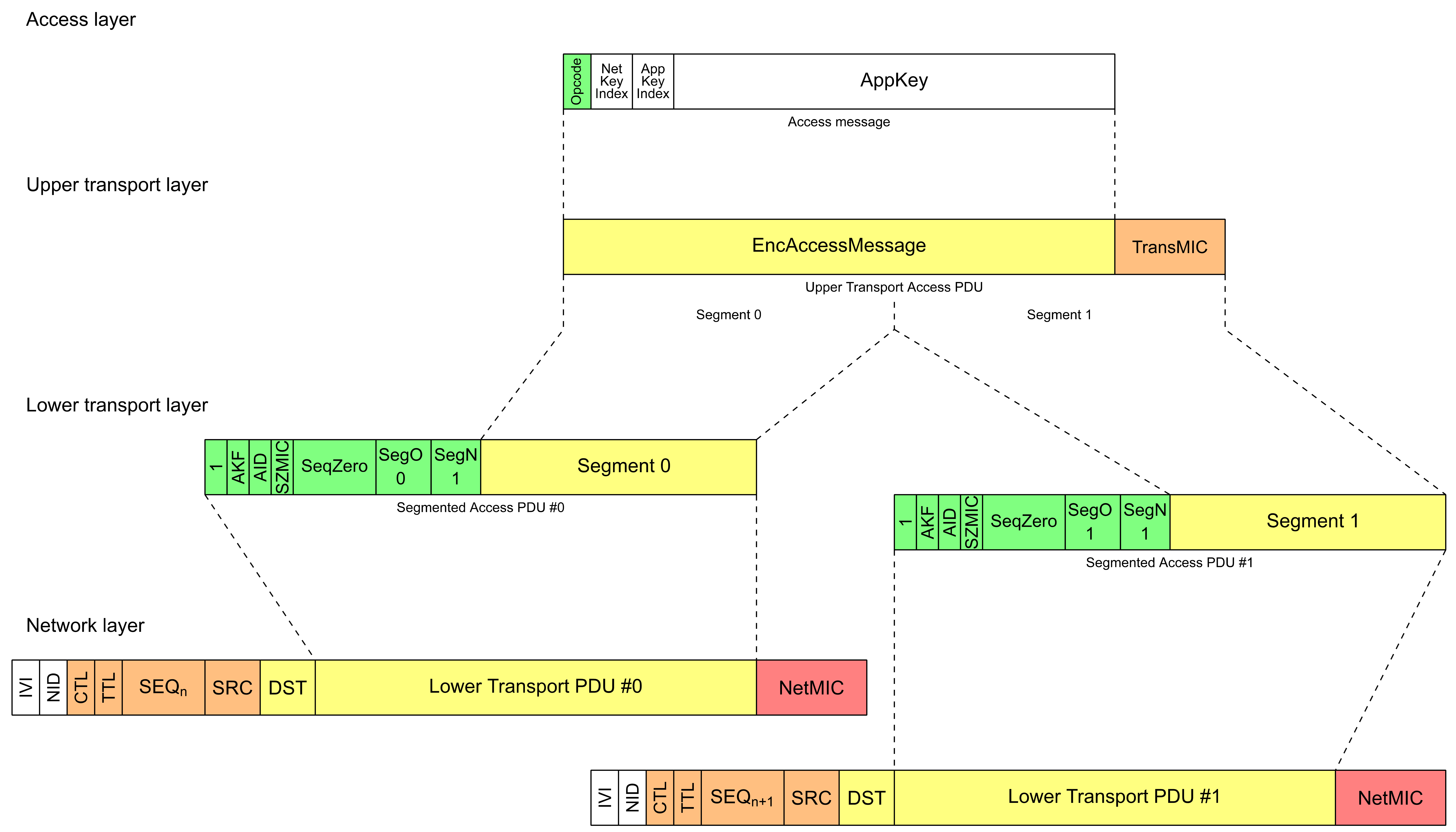
Figure 3.16 illustrates an Access message being sent that has a single-octet opcode, 3 octets for the NetKeyIndexAndAppKeyIndex field, and 16 octets for the AppKey. This means that when encrypted and authenticated with an application key, the Upper Transport Access PDU is 24 octets. This is segmented by the lower transport layer into two segments, Segment 0 and Segment 1. Each segment has a header that identifies the segment number and is then passed to the network layer, where the complete Network PDU is computed. The network layer then encrypts the Network PDU using the sequence number for that Network PDU and then obfuscates those messages so that only the NID and IVI fields are visible in clear text. Therefore, the single Access message can be delivered securely using two Network PDUs.
The process of segmentation for Upper Transport Access PDUs and Upper Transport Control PDUs is identical, and the description below considers these two PDU types to be identical except where explicitly stated.
Note
Note: The segment sizes are different for Upper Transport Access PDUs and Upper Transport Control PDUs.
3.5.3.1. Segmentation
Segmentation is performed by the lower transport layer of the transmitting node. The lower transport layer checks if an Upper Transport PDU fits into a single Lower Transport PDU. If the Upper Transport PDU fits, it is sent in a single Lower Transport PDU. If the Upper Transport PDU doesn’t fit, the lower transport layer divides the Upper Transport PDU into two or more Lower Transport PDUs.
Delivery of a segmented message is acknowledged by the lower transport layer of the receiving node. Delivery of an unsegmented message is not acknowledged. An Upper Transport PDU that fits into one Lower Transport PDU can be sent as a single-segment segmented message when acknowledgment by the lower transport layer is required.
Example: Using a single-segment segmented message can decrease the air traffic, for example, in a situation when a long multi-segment message (e.g., an Upper Transport PDU which was divided into many Lower Transport PDUs) has been transmitted, but the application acknowledgment message sent as a response to this multi-segment message was lost. Sending the application acknowledged message as a single segmented message can improve the reliability of delivery and can remove the risk associated with retransmitting the whole, long multi-segment message.
Each segment of an Upper Transport Access PDU shall be 12 octets long with the exception of the last segment, which may be shorter.
Each segment of an Upper Transport Control PDU shall be 8 octets long with the exception of the last segment, which may be shorter.
Example: When using a 32-bit TransMIC field, if an Upper Transport Access PDU is 42 octets long, then the first 12 octets, octets 0 to 11, are in segment 0; the second set of 12 octets, octets 12 to 23, are in segment 1; the third set of 12 octets, octets 24 to 35, are in segment 2; and the remaining 6 octets, octets 36 to 41, are in segment 3.
Example: If an Upper Transport Control PDU is 42 octets long, then the first 8 octets, octets 0 to 7, are in segment 0; the second set of 8 octets, octets 8 to 15, are in segment 1; the third set of 8 octets, octets 16 to 23, are in segment 2; the fourth set of 8 octets, octets 24 to 31, are in segment 3; the fifth set of 8 octets, octets 32 to 39, are in segment 4; and the remaining 2 octets, octets 40 to 41, are in segment 5.
Each segment of an Upper Transport PDU is identified by the SegO field value. The total number of segments is identified by the SegN field value. The SegO field value of the first segment equals 0. The SegO field value of the last segment equals the SegN field value.
Lower Transport PDUs derived from the same Upper Transport PDU are linked together by the common SeqAuth value. The SeqAuth value is composed of the IV Index and the sequence number of the first segment. The size of the SeqAuth value is 7 octets, where the IV Index is the four most significant octets and the sequence number is the three least significant octets. All Lower Transport PDUs from the same Upper Transport PDU shall be sent using the same IV Index from the common SeqAuth.
The least significant 13 bits of the SeqAuth value constitute the SeqZero field value. The SeqZero field is included in the segmented message and Segment Acknowledgment message to identify the Upper Transport PDU. Upon reassembling a complete Upper Transport PDU from the segments, the SeqAuth value can be retrieved from the IV Index, SeqZero, and SEQ fields included in any of the segments. The common SeqAuth value is the largest SeqAuth value for which the SeqZero field value is between SEQ – 8191 and SEQ inclusive, and the IV Index is the same.
Example: If the SEQ field value of a received message was 0x647262, the IV Index was 0x58437AF2, and the received SeqZero field value was 0x1849, then the SeqAuth value is 0x58437AF2645849.
Example: If the SEQ field value of a received message was 0x647262 and the received SeqZero field value was 0x1263, then the SeqAuth value is 0x58437AF2645263. For an Upper Transport PDU, the SeqAuth value is used to identify it.
Because of the limited size of the SeqZero field, it is not possible to send a segmented message when the SEQ field value is 8192 greater than the SeqAuth value. If a segmented message has not been acknowledged by the time that the SEQ field value is 8192 greater than the SeqAuth value, then the transmission of the Upper Transport PDU shall be canceled. Lower Transport PDUs are delivered to the network layer.
3.5.3.2. Reassembly
Reassembly is performed by the lower layer of the receiving node. When the Low Power node feature is in use, reassembly is performed by a Friend node and the Low Power node does not send any Segment Acknowledgment messages.
Upon receiving a segment from a Segmented message, the lower transport layer retrieves the SeqAuth value from the IV Index, SeqZero, and SEQ fields of this segment to check if the Upper Transport PDU has already been received.
The lower transport layer stores upcoming segments to complete the whole Upper Transport PDU. The value of the SegO field is used to determine the offset of the Lower Transport PDU within the Upper Transport PDU. The maximum size of the complete Upper Transport PDU is determined by the value of the SegN field and the size of the segment.
The lower transport layer sends Segment Acknowledgment messages to either report missing segments or report complete delivery of the Upper Transport PDU.
When all segments of the Upper Transport PDU for a given SeqAuth have been received, the Upper Transport PDU is delivered to the upper transport layer.
3.5.3.3. Segmentation behavior
3.5.3.3.1. Transmission of segments
The lower transport layer shall not transmit segmented messages for more than one Upper Transport PDU to the same destination at the same time. The lower transport layer should start to transmit segmented messages for a new Upper Transport PDU for the same destination when the transaction for the last Upper Transport PDU is completed or the message transmission has been canceled.
If the Upper Transport PDU can fit into a single Lower Transport PDU using an Unsegmented Message format and has not been tagged with the send-segmented tag, then the lower transport layer should use an unsegmented message to transmit this Upper Transport PDU.
If the Upper Transport PDU can fit into a single Lower Transport PDU using a Segmented Message format and has not been tagged with the send-segmented tag, then the lower transport layer may use a single segmented message to transmit this Upper Transport PDU.
If the Upper Transport PDU can fit into a single Lower Transport PDU using a Segmented Message format and has been tagged with the send-segmented tag, then the lower transport layer shall use a single segmented message to transmit this Upper Transport PDU.
Otherwise, two or more segmented messages shall be used.
For each transmission to a unicast address, the lower transport layer stores the destination address, the derived SeqAuth of the segmented message, the remaining number of retransmissions value, and the remaining number of retransmissions without progress value. The initial value of the retransmissions for a unicast address is the value indicated by the SAR Unicast Retransmissions Count state (see Section 4.2.48.2). The initial value of the retransmissions without progress is the value indicated by the SAR Unicast Retransmissions Without Progress Count state (see Section 4.2.48.3).
For each transmission to a group address or a virtual address, the lower transport layer stores the destination address, the derived SeqAuth of the segmented message, and the remaining number of retransmissions value. The initial value of the number of retransmissions for a group or a virtual address is the value indicated by the SAR Multicast Retransmissions Count state (see Section 4.2.48.6).
When the lower transport layer starts a new transfer of an Upper Transport PDU, it shall divide the Upper Transport PDU into segments, shall mark all of the segments as unacknowledged, and shall start transmitting the segments. Segments shall be sent in order of SegO field value, starting with the segment with the lowest value in the SegO field.
Transmission of segments shall be separated by the segment transmission interval indicated by the value of the SAR Segment Interval Step state (see Section 4.2.48.1).
When the lower transport layer starts a new transfer of an Upper Transport PDU that is destined to a unicast address, the lower transport layer shall set the remaining number of retransmissions to the initial value and shall set the remaining number of retransmissions without progress to the initial value. The lower transport layer expects a Segment Acknowledgment message from the destination, or from a Friend node on behalf of the destination.
When the lower transport layer starts a new transfer of an Upper Transport PDU that is destined to a group address or a virtual address, the lower transport layer shall set the remaining number of retransmissions to the initial value. Segment Acknowledgment messages are not sent by the destination.
When the last segment marked as unacknowledged is transmitted and the destination is a unicast address, the lower transport layer shall start a SAR Unicast Retransmissions timer. If the value of the TTL field of the message is greater than 0, the initial value of the timer shall be set according to the following formula:
|
[unicast retransmissions interval step + unicast retransmissions interval increment * (TTL − 1)] |
If the value of the TTL field of the message is 0, the initial value of the timer shall be set to the unicast retransmissions interval step.
The values of the unicast retransmissions interval step and the unicast retransmissions interval increment are indicated by the SAR Unicast Retransmissions Interval Step state (see Section 4.2.48.4) and the SAR Unicast Retransmissions Interval Increment state (see Section 4.2.48.5), respectively.
When the last segment marked as unacknowledged is transmitted, and the destination is a group address or a virtual address, the lower transport layer shall start a SAR Multicast Retransmissions timer with the initial value set to the multicast retransmissions interval. The multicast retransmissions interval is indicated by the SAR Multicast Retransmissions Interval Step state (see Section 4.2.48.7).
3.5.3.3.2. Reception of Segment Acknowledgment messages
When a Segment Acknowledgment message that is a valid acknowledgment (i.e., it meets all conditions in the Table 3.23) for the segmented message is received, then the lower transport layer shall mark as acknowledged the segments that are reported as delivered in the AckedSegments field of the Segment Acknowledgment message (see Section 3.5.2.3.1).
When a valid Segment Acknowledgment message for the segmented message is received (i.e., it meets all conditions in Table 3.23), and the SAR Unicast Retransmissions timer is running, and the Segment Acknowledgment message does not acknowledge all segments of the segmented message, and both the remaining number of retransmissions and the remaining number of retransmissions without progress are greater than 0, then the lower transport layer shall stop the SAR Unicast Retransmissions timer, shall repeat the transmission of all segments that are marked as unacknowledged, shall decrement the remaining number of retransmissions by 1, and shall start the SAR Unicast Retransmissions timer. If at least one segment is newly marked as acknowledged as a result of receiving the Segment Acknowledgment message, the lower transport layer shall set the remaining number of retransmissions without progress to the initial value. If no segment is newly marked as acknowledged, the lower transport layer shall decrement the remaining number of retransmissions without progress by 1.
When a valid Segment Acknowledgment message for the segmented message is received (i.e., it meets all conditions in Table 3.23), and the SAR Unicast Retransmissions timer is running, and the Segment Acknowledgment message acknowledges all segments of the segmented message, the transmission of the Upper Transport PDU is complete. Then the SAR Unicast Retransmissions timer shall be stopped, the number of retransmissions shall be deleted, and the number of retransmissions without progress shall be deleted. The lower transport layer shall remove the destination address and the SeqAuth stored for this segmented message and shall notify the higher layer that the transmission of the Upper Transport PDU has been completed.
When a Segment Acknowledgment message that is a valid acknowledgment for a segmented message with the AckedSegments field set to 0x00000000 is received, then the transmission of the Upper Transport PDU shall be immediately canceled, and the upper transport layer shall be notified that the transmission of the Upper Transport PDU has been canceled. The lower transport layer shall remove the destination address and the SeqAuth stored for this segmented message.
|
Condition |
|---|
|
SeqAuth derived from the SeqZero field of the Segment Acknowledgment message matches the value stored by the lower transport layer |
|
Either the source address of the Segment Acknowledgment message matches the destination address value stored by the lower transport layer, or the value of the OBO field of the Segment Acknowledgment message is 1. |
|
For the SeqAuth derived from the SeqZero field of the message, there is at least one unacknowledged segment that the AckedSegments field of the message reports as delivered |
|
The message was secured using the same NetKey that was used to secure the segmented message |
Note
Note: The reception of a Segment Acknowledgment message with the OBO field set to 1 does not mean that the segmented message has been delivered to the final destination, but only that the segmented message has been delivered to the Friend of that Low Power node. The message is stored in the Friend Queue, but the message can be discarded if other messages are received for that Low Power node or the Friendship is terminated.
3.5.3.3.3. Retransmission of segments
When the SAR Unicast Retransmissions timer expires, if both the remaining number of retransmissions and the remaining number of retransmissions without progress are greater than 0, then the lower transport layer shall repeat the transmission of all segments marked as unacknowledged and shall decrement both the remaining number of retransmissions and the remaining number of retransmissions without progress by 1.
When the last segment marked as unacknowledged is transmitted and the destination is a unicast address, the lower transport layer shall start a SAR Unicast Retransmissions timer. If the value of the TTL field of the message is greater than 0, the initial value of the timer shall be set according to the following formula:
|
[unicast retransmissions interval step + unicast retransmissions interval increment * (TTL − 1)] |
If the value of the TTL field of the message is 0, the initial value of the timer shall be set to the unicast retransmissions interval step.
The unicast retransmissions interval step value and the unicast retransmissions interval increment value are indicated by the SAR Unicast Retransmissions Interval Step state (see Section 4.2.48.4) and the SAR Unicast Retransmissions Interval Increment state (see Section 4.2.48.5), respectively.
When the SAR Unicast Retransmissions timer expires and either the remaining number of retransmissions or the remaining number of retransmissions without progress is 0, the lower transport layer shall cancel the transmission of the Upper Transport PDU, shall delete the number of retransmissions value and the number of retransmissions without progress value, shall remove the destination address and the SeqAuth stored for this segmented message, and shall notify the upper transport layer that the transmission of the Upper Transport PDU has timed out.
When the SAR Multicast Retransmissions timer expires and the remaining number of retransmissions value is greater than 0, then the lower transport layer shall repeat the transmission of all the segments of the of the Upper Transport PDU. The lower transport layer shall decrement the remaining number of retransmissions value by 1.
When the last segment marked as unacknowledged is transmitted, and the destination is a multicast address, the lower transport layer shall start a SAR Multicast Retransmissions timer with the initial value set to the multicast retransmissions interval. The multicast retransmissions interval is indicated by the SAR Multicast Retransmissions Interval Step state (see Section 4.2.48.7).
When the SAR Multicast Retransmissions timer expires and the remaining number of retransmissions value is 0, the lower transport layer shall cancel the transmission of the Upper Transport PDU, shall delete the number of retransmissions value and the number of retransmissions without progress value, shall remove the destination address stored for this segmented message, and shall notify the higher layer that the transmission of the Upper Transport PDU has been completed.
If an Upper Transport PDU is tagged with additional metadata (see Sections 3.6.5, 3.6.8.2, and 3.7.3.1) and is segmented, each Lower Transport PDU of the segmented Upper Transport PDU shall be tagged with the same metadata.
3.5.3.4. Reassembly behavior
This section only applies when the Low Power feature is not in use.
The lower transport layer stores one or more pairs of values, consisting of an AckedSegments value, which indicates segments that have already been received for a particular SeqAuth, and a Sequence Authentication value. Each such pair is associated with a source address and a destination address. The initial value for the AckedSegments is a value that indicates that no segments have been received. The initial value for the Sequence Authentication value is 0.
When the lower transport layer receives a segment of a segmented message, it shall process the segment message against the conditions in Table 3.24. Conditions are evaluated one by one starting from the first line in the table. When the condition is met, the processing ends with the Processing Result corresponding to the value in the Condition column.
When the Processing Result is Message Rejected and the message is destined to a unicast address, the lower transport layer shall respond with a Segment Acknowledgment message with the AckedSegments field set to 0x00000000.
When the Processing Result is First Segment and the destination is a group address or a virtual address, the reassembly of a new segmented message is initiated. If another reassembly is pending for the same source address and for the same destination address, the pending reassembly shall be discarded and the SAR Discard timer shall be stopped. The lower transport layer shall set the Sequence Authentication value to the SeqAuth derived from this message. Then, the lower transport layer shall set the AckedSegments value for this SeqAuth to indicate that only this segment has been received and shall start the SAR Discard timer for this SeqAuth from the initial value. The initial value of the SAR Discard timer is the discard timeout value indicated by the SAR Discard Timeout state (see Section 4.2.49.4).
When the Processing Result is First Segment and the destination is a unicast address, the reception of a new segmented message is initiated. If another reassembly is already pending for the same source address and for the same destination address, the pending reassembly shall be discarded and the SAR Discard timer and SAR Acknowledgment timer shall be stopped. The lower transport layer shall set the Sequence Authentication value to the SeqAuth derived from this message. The lower transport layer shall set the AckedSegments value for this SeqAuth to indicate that only this segment has been received and shall start the SAR Discard timer and SAR Acknowledgment timer for this SeqAuth from the initial values. The initial value of the SAR Discard timer is the discard timeout value indicated by the SAR Discard Timeout state (see Section 4.2.49.4). The initial value of the SAR Acknowledgment timer is calculated using the following formula:
|
[min(SegN + 0.5, acknowledgment delay increment) * segment reception interval] |
The acknowledgment delay increment value and the segment reception interval value are indicated by the SAR Acknowledgment Delay Increment state (see Section 4.2.49.2) and the SAR Receiver Segment Interval Step state (see Section 4.2.49.5), respectively.
When the Processing Result is Next Segment and the destination is a group address or a virtual address, the lower transport layer shall store the received segment, shall start the SAR Discard timer from the initial value, and shall set the AckedSegments value for the SeqAuth derived from this message to indicate that the segment identified by the SegO field has been received.
When the Processing Result is Next Segment and the destination is a unicast address, the lower transport layer shall store the received segment, shall start the SAR Acknowledgment timer and the SAR Discard timer from the initial values, and shall set the AckedSegments value for the SeqAuth derived from this message to indicate that the segment identified by the SegO field has been received.
When the Processing Status is SeqAuth Error or Repeated Segment, the lower transport layer shall ignore the message.
When the Processing Result is Most Recent SeqAuth, the lower transport layer shall send a Segment Acknowledgment message with the AckedSegments field set to indicate that all segments have already been delivered for that SeqAuth. The lower transport layer shall not send more than one Segment Acknowledgment message for the same SeqAuth in a period of:
|
[acknowledgment delay increment * segment reception interval] milliseconds |
The acknowledgment delay increment and the segment reception interval are indicated by the SAR Acknowledgment Retransmissions Interval state and the SAR Receiver Segment Interval Step state (see Section 4.2.49.5), respectively.
When the Processing Result is Last Segment, the transfer of the segmented message is complete. The lower transport layer shall send a Segment Acknowledgment message with the AckedSegments field set to indicate that all segments have been delivered for the Sequence Authentication value. The Segment Acknowledgment message shall use the same NetKey as the first received segment of the segmented message, and the DST field shall have the same value as the SRC field of the first received segment of the segmented message. The lower transport layer shall stop the SAR Discard timer and the SAR Acknowledgment timer and shall send the reassembled message to the upper transport layer. The lower transport layer shall store the SeqAuth and the AckedSegments value for complete transactions to be able to acknowledge a transaction when repeated segments are received. The values for the most recent transaction shall be stored, and an implementation may store the values for other recent transactions. The number of additional transactions for which values are stored is an implementation detail.
If the segments are Segmented Access messages, then the reassembled message shall be processed as defined in Section 3.6.4.2.
If the segments are Segmented Control messages, then the reassembled message shall be processed as defined in Section 3.6.5.
|
Condition |
Processing Result |
|---|---|
|
The SeqAuth calculated for the message is less than the Sequence Authentication value and the segmented message has not been received |
SeqAuth Error |
|
The SeqAuth calculated for the message is less than the Sequence Authentication value and the whole message has already been received |
Repeated Segment |
|
The SeqAuth calculated for the message is equal to the Sequence Authentication value and the whole message has already been received |
Most Recent SeqAuth |
|
The lower transport layer cannot accept the segment message because it is currently out of resources |
Message Rejected |
|
The SeqAuth value calculated for the segment message is greater than Sequence Authentication value |
First Segment |
|
The AckedSegments value for the SeqAuth calculated for the message indicates that the segment has already been received |
Repeated Segment |
|
The SAR Discard timer is expired and the reassembly for this SeqAuth is considered failed |
Late Segment |
|
The received segment message is not the first, nor the last missing segment for the SeqAuth |
Next Segment |
|
The received segment message is the last missing segment for the SeqAuth |
Last Segment |
When the SAR Acknowledgment timer expires, the lower transport layer shall send a Segment Acknowledgment message with the AckedSegments field set to the AckedSegments value for the identified SeqAuth to indicate the segments have been delivered (see Section 3.5.2.3.1). The Segment Acknowledgment message shall use the same NetKey as the first received segment of the segmented message, and the DST field shall have the same value as the SRC field of the first received segment of the segmented message.
If the number of segments in the transmission indicated by the value of SegN field is greater than the value of the SAR Segments Threshold state (see Section 4.2.49.1), the lower transport layer shall retransmit Segment Acknowledgment messages using the value of the SAR Acknowledgment Retransmissions Count state (see Section 4.2.49.3). Each retransmitted message shall include a new value for the SEQ field. Between retransmissions, the lower transport layer shall introduce a delay indicated by the value of the SAR Receiver Segment Interval Step state (see Section 4.2.49.5).
When the SAR Discard timer expires, the reassembly of the Upper Transport PDU being received is considered failed. For the SeqAuth derived from this message, the lower transport layer shall stop the SAR Acknowledgment timer, stop the SAR Discard timer, remove the AckedSegments value and discard all stored segments.
The Segment Acknowledgment message shall use the same NetKey as the first received segment of a multi-segment message, and the DST field shall have the same value as the SRC field of the first received segment of a multi-segment message.
If the device is acting as a Friend node for a Low Power node, then it shall reassemble segmented messages destined for the Low Power node and act as described, except that it shall set the OBO field to 1 in the Segment Acknowledgment message. Otherwise, the OBO field shall be set to 0.
3.5.3.5. Low Power feature reassembly behavior
This section only applies when the Low Power feature is in use.
For each source address, the lower transport layer stores an AckedSegments value which indicates segments that have already been received for a particular SeqAuth and a Sequence Authentication value. The initial value for the AckedSegments is a value that shall indicate that no segments have been received. The initial value for the Sequence Authentication is 0.
When the lower transport layer receives a segment of a segmented message, it shall process the segment against the conditions in Table 3.24. Conditions are evaluated one by one starting from the first line in the table. When the condition is met, the processing ends with the Processing Result corresponding to the value in the Condition column.
When the Processing Result is First Segment, the reassembly of a new segmented message is initiated. If another reassembly is already pending for the same source address, the pending reassembly shall be discarded. Then, the lower transport layer shall set the Sequence Authentication value to the SeqAuth derived from this message and for this SeqAuth shall set the AckedSegments value to indicate that only this segment has been received.
When the Processing Result is Next Segment, the lower transport layer shall store the received segment and set the AckedSegments value for the SeqAuth derived from this message to indicate that this segment has been received.
When the Processing Status is SeqAuth Error, Repeated Segment, or Most Recent SeqAuth, the lower transport layer shall ignore the message.
When the Processing Result is Last Segment, the transfer of the segmented message is complete. The lower transport layer shall discard the AckedSegments value and shall send the reassembled message to the upper transport layer.
If the segments are Segmented Access messages, then the reassembled message shall be processed as defined in Section 3.6.4.2.
If the segments are Segmented Control messages, then the reassembled message shall be processed as defined in Section 3.6.5.
If the friendship is terminated (see Section 3.6.6.4.2), then any previous partially received multi-segment message shall be cancelled.
3.5.4. Lower transport layer behavior
3.5.4.1. Transmitting a Lower Transport PDU
The Lower Transport PDU shall be delivered to the network layer for processing (see Section 3.4.6.4). TransportPDU field of the Network PDU shall be set to the Lower Transport PDU value.
3.5.4.2. Receiving a Lower Transport PDU
If the Lower Transport PDU is a Segmented Access message, a Segmented Control message or a Segment Acknowledgment message, then it shall be processed as defined in Section 3.5.3.2.
If the Lower Transport PDU is an Unsegmented Access message or an Unsegmented Control message, then the Upper Transport PDU shall be processed as defined in Section 3.6.4.2.
3.5.4.3. Message error procedure
When the lower transport layer receives a Segment Acknowledgment message that is not understood, then the Segment Acknowledgment message shall be ignored. A Segment Acknowledgment message that is not understood includes messages that have incorrect size.
3.5.5. Friend Queue
The Friend node shall have a Friend Queue for each friend Low Power node. The Friend Queue stores Lower Transport PDUs for a Low Power node. No field of the Lower Transport PDU shall be changed due to the message being in the Friend Queue. The CTL, TTL, SEQ, SRC, and DST fields shall be stored with the associated Lower Transport PDU.
When a Friend node receives a message on a subnet that was used for friendship establishment and that is destined for a Low Power node (i.e., the destination of the message is a unicast address of an element of the Low Power node or in the Friend Subscription List), and the TTL field has a value of 2 or greater, then the message shall be processed as follows: If the Friend Queue already contains a message with the same SEQ and SRC field values as in the received message, or if the SRC field of the received message is a unicast address of an element of the Low Power node, then the message shall not be stored in the Friend Queue. Otherwise, the TTL field value shall be decremented by 1, and the message shall be stored in the Friend Queue.
If the message is a Segmented Access message or a Segmented Control message, then the message shall only be stored into the Friend Queue after the complete Upper Transport PDU has been successfully reassembled and the Friend node has acknowledged the reception of all segments.
If the Friend Queue is full and a new message needs to be stored that is not a Friend Update message, the oldest entries other than a Friend Update message shall be discarded to make room for the new message.
Note
Note: An implementation may have to discard multiple messages to fit the new message into the Friend Queue.
If the message that is being stored is a Segment Acknowledgment message and the Friend Queue contains another Segment Acknowledgment message that has the same source and destination addresses, and the same SeqAuth value, but a lower IV Index or sequence number, then the older Segment Acknowledgment message shall be discarded.
When a Friend node becomes aware of a security update, for example by receiving a valid Secure Network beacon or a Mesh Private beacon, or as a result of a change in the Key Refresh Phase state, the Friend node shall add a Friend Update message to the Friend Queue.
When the Low Power node requests a message from the Friend Queue, the oldest entry shall be sent. Once that message has been acknowledged by the Low Power node, that entry shall be discarded.
If the Friend node is polled for a message from a Low Power node using a Friend Poll, and the Friend Queue for that node is empty, then the Friend node shall generate a new Friend Update message and add that message to the Friend Queue before sending the response, so that this Friend Update message can be sent in response to the Friend Poll message.
3.6. Upper transport layer
The upper transport layer takes an Access message from the access layer or an internally generated Transport Control message and transmits the message to a peer upper transport layer.
The Upper Transport Access PDU contains a message from the access layer. The encryption and authentication of the message is performed using an application key or device key. This allows the receiving upper transport layer to authenticate received messages.
The Upper Transport Control PDU contains a message that is internally generated by the upper transport layer. The message is only encrypted and authenticated at the network layer.
The Upper Transport Access PDU and the Upper Transport Control PDU are collectively known as Upper Transport PDUs.
3.6.1. Endianness
All multiple-octet numeric values in this layer shall be sent in big-endian, as described in Section 3.1.1.1.
3.6.2. Upper Transport Access PDU
The Upper Transport PDU is called the Upper Transport Access PDU, when the CTL field in the Network PDU is 0. The Upper Transport Access PDU contains an Access message.
The Access message is encrypted using an application key or device key, and the encrypted Access message and associated message integrity check value are combined into an Upper Transport Access PDU. The Upper Transport Access PDU fields are shown in Table 3.25 and illustrated in Figure 3.17.
|
Field Name |
Octets |
Description |
Req. |
|---|---|---|---|
|
EncAccessMessage |
1 to 380 |
The encrypted Access message |
M |
|
TransMIC |
4 or 8 |
The message integrity check value for the Access message |
M |
 |
3.6.2.1. EncAccessMessage
The Access message is supplied by the access layer. The EncAccessMessage is an Access message encrypted and authenticated as defined in Section 3.9.7.1. If the TransMIC is a 32-bit field, the Access message can be from a single octet to 380 octets in length. If the TransMIC is a 64-bit field, the Access message can be from a single octet to 376 octets in length. At the upper transport layer, this field is opaque and no information within this field may be used.
3.6.2.2. TransMIC
The Message Integrity Check for Transport (TransMIC) is a 32-bit or 64-bit field that authenticates that the Access message has not been changed. For a Segmented Access message, where the SEG field is set to 1, the size of the TransMIC field is determined by the value of the SZMIC field in the Lower Transport PDU. For Unsegmented Access messages, the TransMIC field is a 32-bit field.
Note
Note: Transport Control messages do not have a TransMIC field.
3.6.3. Upper Transport Control PDU
The Upper Transport PDU is called the Upper Transport Control PDU when the CTL field in the Network PDU is 1. The Upper Transport Control PDU contains a Transport Control message (see Section 3.6.5). A Transport Control message has a 7-bit opcode that determines the format of the parameters. This Opcode field is not included in the parameters field, but is included in the Unsegmented Control message or in each Segmented Control message.
The Upper Transport Control PDU is not authenticated at the upper transport layer and instead relies upon the authentication performed by the network layer. All Upper Transport Control PDUs use a 64-bit NetMIC field.
The lower transport layer may segment messages into smaller PDUs for delivery over the network layer. It is therefore recommended to keep Transport Control PDU payload size as reflected in Table 3.26, where the values represent the maximum useful parameter field sizes depending on the number of packets.
|
Number of Packets |
Transport Control PDU Payload Size |
|---|---|
|
1 |
11 (Unsegmented) |
|
1 |
8 (Segmented) |
|
2 |
16 |
|
3 |
24 |
|
n |
n*8 |
|
32 |
256 |
The maximum size of an Upper Transport Control PDU is 256 octets.
3.6.4. Upper transport layer behavior
3.6.4.1. Transmitting an Upper Transport PDU
All Access messages are sent in the context of an application key or a device key. The Access message shall be encrypted using this application key or device key, and the TransMIC field shall be set to the message integrity check value, as defined in Section 3.9.6. The Upper Transport Access PDU shall then be delivered to the lower transport layer for processing as defined in Section 3.5.3.3
A sequence number shall be allocated to this message. In the context of a message segmented in the lower transport layer, this sequence number corresponds to the 24 lowest bits of SeqAuth, the sequence number used for authenticating and decrypting the Access message by the receiver, as defined in Section 3.5.3.1.
The AKF and AID fields of the Lower Transport PDU shall be set according to the application key or device key used to encrypt and authenticate the Upper Transport Access PDU. If an application key is used, then the AKF field shall be set to 1 and the AID field shall be set to the AID. If the device key is used, then the AKF field shall be set to 0 and the AID field shall be set to 0b000000.
An Upper Transport Control PDU shall be delivered to the lower transport layer for processing as defined in Section 3.5.3.3.
The upper transport layer shall not transmit a new segmented Upper Transport PDU to a given destination until the previous Upper Transport PDU to that destination has been either completed or cancelled.
3.6.4.2. Receiving an Upper Transport PDU
Upon receiving an Upper Transport Access PDU, the Access message shall be decrypted, and the TransMIC field shall be authenticated against the device key or the Device Key Candidate (see Section 3.11.8.1) or the known application keys for which the AKF and AID fields match. If the Upper Transport Access PDU authenticates and it has been checked for replay attacks (see Section 3.9.8) then it is delivered to the access layer with the contextual information of this message such as the source address, destination addresses, and the keys used for decryption and authentication.
When the Device Key Candidate is available, and an Access message is decrypted using the Device Key Candidate that was delivered to the access layer, then the node shall revoke the device key, the Device Key Candidate shall become the device key, and the Device Key Candidate shall become unavailable.
Upon receiving an Upper Transport Access PDU, this PDU shall be delivered to the Access layer for processing (see Section 3.7.3.2).
Upon receiving an Upper Transport Control PDU, the destination address of the PDU shall be checked. The PDU shall be processed according to the Transport Control opcode (as defined in Sections 3.6.6, 3.6.7, and 3.6.8) if one of the following conditions is met:
-
The destination address matches a unicast address of an element of the node
-
The destination address matches a fixed group destination address specified in Table 3.27 and the corresponding condition (if any) is satisfied
|
Destination Address |
Condition |
|---|---|
|
all-directed-forwarding-nodes |
Directed forwarding functionality is enabled |
|
all-proxies |
Proxy functionality is enabled |
|
all-friends |
Friend functionality is enabled |
|
all-relays |
Relay functionality is enabled |
|
all-nodes |
– |
3.6.4.3. Message error procedure
When the upper transport layer receives a message that is not understood, then the message shall be ignored. A message that is not understood includes messages that met one or more conditions listed below:
-
The Transport Control message opcode is unknown by the receiving node.
-
The Transport Control message size for the Transport Control opcode is incorrect.
-
The Transport Control message parameters contain values that are Prohibited.
Messages that are not following segmentation requirements (see Section 3.5.3.1) are also not understood and are ignored.
3.6.5. Transport Control messages
Transport Control messages are transmitted using Upper Transport Control PDUs that can be transmitted either as a single Unsegmented Control message or as a sequence of Segmented Control messages. Unsegmented Control messages or Segmented Control messages have a 7-bit opcode field that determines the format of the parameters field. Each Transport Control message shall be sent using the smallest number of Lower Transport PDUs possible.
Opcode 0x00 is terminated at the lower transport layer as defined in Section 3.5.3 and shall not be sent by the upper transport layer. All other Transport Control messages are terminated at the upper transport layer.
When transmitting a Friend Poll, Friend Update, Friend Request, Friend Offer, Friend Subscription List Add, Friend Subscription List Remove, or Friend Subscription List Confirm message, the message shall be tagged as a friendship PDU.
The list of Transport Control messages, and their opcodes are defined in the Assigned Numbers document [4].
3.6.5.1. Friend Poll
A Friend Poll message is sent by a Low Power node to ask the Friend node to send a message that it has stored for the Low Power node.
The Friend Poll message parameters are defined in Table 3.28.
|
Field |
Size (bits) |
Description |
Req. |
|---|---|---|---|
|
Padding |
7 |
0b0000000. All other values are Prohibited. |
M |
|
FSN |
1 |
Friend Sequence Number, used to acknowledge receipt of previous messages from the Friend node to the Low Power node |
M |
The FSN field indicates the Friend Sequence Number that is used as defined in Section 3.6.6.4.2.
3.6.5.2. Friend Update
A Friend Update message is sent by a Friend node to a Low Power node to inform the Low Power node that the security parameters (see Section 3.6.6.1) for the network have changed or are changing, or that the Friend Queue is empty.
The Friend Update message parameters are defined in Table 3.29.
|
Field |
Size |
Description |
Req. |
|---|---|---|---|
|
Flags |
1 |
Contains the IV Update Flag and the Key Refresh Flag |
M |
|
IV Index |
4 |
The current IV Index value known by the Friend node |
M |
|
MD |
1 |
Indicates whether the Friend Queue is empty or not. |
M |
The Flags field format is defined in Table 3.30.
|
Bit |
Definition |
|---|---|
|
0 |
Key Refresh Flag 0: Not-In-Phase2 1: In-Phase2 |
|
1 |
IV Update Flag 0: Normal Operation 1: IV Update in Progress |
|
2–7 |
Reserved for Future Use |
The Key Refresh Flag indicates whether the Key Refresh procedure is in progress (see Section 3.11.4).
The IV Update Flag indicates whether the IV Update procedure is in progress (see Section 3.11.5).
The IV Index field contains the current IV Index.
The MD field indicates whether the Friend Queue is empty or not, as defined in Table 3.31.
|
Value |
Description |
|---|---|
|
0 |
Friend Queue is empty |
|
1 |
Friend Queue is not empty |
|
2–255 |
Prohibited |
3.6.5.3. Friend Request
A Friend Request message is sent to the all-friends group address by a Low Power node to start to find a friend.
The Friend Request message parameters are defined in Table 3.32.
|
Field |
Size |
Description |
Req. |
|---|---|---|---|
|
Criteria |
1 |
The criteria that a Friend node should support in order to participate in friendship negotiation |
M |
|
ReceiveDelay |
1 |
Receive Delay requested by the Low Power node |
M |
|
PollTimeout |
3 |
The initial value of the PollTimeout timer set by the Low Power node |
M |
|
PreviousAddress |
2 |
Unicast address of the primary element of the previous friend |
M |
|
NumElements |
1 |
Number of elements in the Low Power node |
M |
|
LPNCounter |
2 |
Number of Friend Request messages that the Low Power node has sent |
M |
The Criteria field format is defined in Table 3.33 and in Figure 3.18.
|
Field |
Size |
Description |
Req. |
|---|---|---|---|
|
RFU |
1 |
Reserved for Future Use |
M |
|
RSSIFactor |
2 |
The contribution of the received signal strength indicator (RSSI) measured by the Friend node used in the Friend Offer Delay calculation |
M |
|
ReceiveWindowFactor |
2 |
The contribution of the supported Receive Window used in the Friend Offer Delay calculation |
M |
|
MinQueueSizeLog |
3 |
The minimum number of messages that the Friend node can store in its Friend Queue |
M |
 |
The RSSIFactor field indicates the contribution of the RSSI measured by the Friend node in the Friend Offer Delay calculation (see Section 3.6.6.3.1).
The RSSIFactor field values are defined in Table 3.34.
|
Value |
RSSI Factor |
|---|---|
|
0b00 |
1 |
|
0b01 |
1.5 |
|
0b10 |
2 |
|
0b11 |
2.5 |
The ReceiveWindowFactor field indicates the contribution of the supported Receive Window used in the Friend Offer Delay calculation (see Section 3.6.6.3.1).
The ReceiveWindowFactor field values are defined in Table 3.35.
|
Value |
Receive Window Factor |
|---|---|
|
0b00 |
1 |
|
0b01 |
1.5 |
|
0b10 |
2 |
|
0b11 |
2.5 |
The MinQueueSizeLog field is defined as log2(N), where N is the minimum number of maximum size Lower Transport PDUs that the Friend node can store in its Friend Queue.
The MinQueueSizeLog field values are defined in Table 3.36.
|
Value |
Description |
|---|---|
|
0b000 |
Prohibited |
|
0b001 |
N=2 |
|
0b010 |
N=4 |
|
0b011 |
N=8 |
|
0b100 |
N=16 |
|
0b101 |
N=32 |
|
0b110 |
N=64 |
|
0b111 |
N=128 |
The ReceiveDelay field indicates the Receive Delay requested by the Low Power node.
The ReceiveDelay field values are defined in Table 3.37.
|
Value |
Description |
|---|---|
|
0x00–0x09 |
Prohibited |
|
0x0A–0xFF |
Receive Delay in units of 1 millisecond |
The PollTimeout field indicates the initial value of the Poll Timeout timer set by the Low Power node.
The PollTimeout field values are defined in Table 3.38.
|
Value |
Description |
|---|---|
|
0x000000–0x000009 |
Prohibited |
|
0x00000A–0x34BBFF |
PollTimeout in units of 100 milliseconds |
|
0x34BC00–0xFFFFFF |
Prohibited |
The PreviousAddress field indicates the previous Friend’s unicast address or the unassigned address if no previous friendship was established.
The NumElements field indicates the number of elements of the Low Power node. The value is used by the Friend node to calculate the range of unicast addresses assigned to the Low Power node using the SRC field value of the Network PDU of this message.
The NumElements field values are defined in Table 3.39.
|
Value |
Description |
|---|---|
|
0x00 |
Prohibited |
|
0x01–0xFF |
Number of elements |
The LPNCounter field indicates the number of Friend Request messages that the Low Power node has sent to date.
3.6.5.4. Friend Offer
A Friend Offer message is sent by a Friend node to a Low Power node to offer a friendship.
The Friend Offer message parameters are defined in Table 3.40.
|
Field |
Size |
Description |
Req. |
|---|---|---|---|
|
ReceiveWindow |
1 |
Receive Window value supported by the Friend node |
M |
|
QueueSize |
1 |
Size of the Friend Queue available on the Friend node |
M |
|
SubscriptionListSize |
1 |
Size of the Subscription List that can be supported by a Friend node for a Low Power node |
M |
|
RSSI |
1 |
RSSI measured by the Friend node |
M |
|
FriendCounter |
2 |
Number of Friend Offer messages that the Friend node has sent |
M |
The ReceiveWindow field indicates the Receive Window value supported by the Friend node.
The ReceiveWindow field values are defined in Table 3.41.
|
Value |
Description |
|---|---|
|
0x00 |
Prohibited |
|
0x01–0xFF |
Receive Window in units of 1 millisecond |
The QueueSize field indicates the number of messages that the Friend node can store for the Low Power node.
The SubscriptionListSize field indicates the number of entries in the Subscription List that the Friend node can support for the Low Power node.
The RSSI field contains a signed 8-bit value, and is interpreted as an indication of received signal strength measured in decibels above 1 milliwatt (dBm). This is measured by the Friend node upon receiving the Friend Request message. The value shall be 0x7F (127 dBm) if the received signal strength indication is not available.
The FriendCounter field represents the number of Friend Offer messages that the Friend node has sent.
3.6.5.5. Friend Clear
A Friend Clear message is an acknowledged message sent to the previous Friend node of a Low Power node to inform the Friend node of the removal of a friendship. This message is sent by the current Friend node of the Low Power node.
The Friend Clear message parameters are defined in Table 3.42.
|
Field |
Size |
Description |
Req. |
|---|---|---|---|
|
LPNAddress |
2 |
The unicast address of the Low Power node being removed |
M |
|
LPNCounter |
2 |
Value of the LPNCounter of the new friendship |
M |
The LPNAddress field contains the unicast address of the Low Power node that is being removed.
The LPNCounter field contains the LPNCounter value of the latest Friend Request used to establish the relationship.
3.6.5.6. Friend Clear Confirm
A Friend Clear Confirm message is sent by the previous Friend node in response to the Friend Clear message to confirm that the friendship has been terminated.
The Friend Clear Confirm message parameters are defined in Table 3.43.
|
Field |
Size |
Description |
Req. |
|---|---|---|---|
|
LPNAddress |
2 |
The unicast address of the Low Power node being removed |
M |
|
LPNCounter |
2 |
The value of the LPNCounter of the corresponding Friend Clear message |
M |
The LPNAddress field contains the unicast address of the Low Power node that was removed.
The LPNCounter field contains the LPNCounter value of the corresponding Friend Clear message.
3.6.5.7. Friend Subscription List Add
A Friend Subscription List Add message is sent by a Low Power node to a Friend node to add group addresses and virtual addresses to the Friend Subscription list (see Section 3.6.6).
The Friend Subscription List Add message parameter is defined in Table 3.44.
|
Field |
Size (octets) |
Description |
Req. |
|---|---|---|---|
|
TransactionNumber |
1 |
The number for identifying a transaction |
M |
|
AddressList |
2 * N |
List of group addresses and virtual addresses where N is the number of group addresses and virtual addresses in this message |
M |
The TransactionNumber field is used to distinguish each individual transaction (see Section 3.6.6.4.3).
The AddressList field contains a list of group addresses and virtual addresses to add to the Friend Subscription List.
3.6.5.8. Friend Subscription List Remove
A Friend Subscription List Remove message is sent by a Low Power node to a Friend node to remove group addresses and virtual addresses from the Friend Subscription List (see Section 3.6.6).
The Friend Subscription List Remove message parameters are defined in Table 3.45.
|
Field |
Size |
Description |
Req. |
|---|---|---|---|
|
TransactionNumber |
1 |
The number for identifying a transaction |
M |
|
AddressList |
2 * N |
List of group addresses and virtual addresses where N is the number of group addresses and virtual addresses in this message |
M |
The TransactionNumber field is used to distinguish each individual transaction (see Section 3.6.6.4.3).
The AddressList field contains a list of group addresses and virtual addresses to remove from the Friend Subscription List.
3.6.5.9. Friend Subscription List Confirm
A Friend Subscription List Confirm message is sent by a Friend node to a Low Power node in response to a Friend Subscription List Add message or a Friend Subscription List Remove message.
The Friend Subscription List Confirm message parameters are defined in Table 3.46.
|
Field |
Size |
Description |
Req. |
|---|---|---|---|
|
TransactionNumber |
1 |
The number for identifying a transaction |
M |
The TransactionNumber field is used to distinguish each individual transaction (see Section 3.6.6.4.3).
3.6.5.10. Heartbeat
A Heartbeat message is sent by a node to let other nodes determine topology of a subnet.
The Heartbeat message parameters are defined in Table 3.47.
|
Field |
Size |
Description |
Req. |
|---|---|---|---|
|
RFU |
1 |
Reserved for Future Use |
M |
|
InitTTL |
7 |
Initial TTL used when sending the message |
M |
|
Features |
16 |
Bit field of currently active features of the node |
M |
The InitTTL field contains the initial TTL field value used when sending the message.
The InitTTL field values are defined in Table 3.48.
|
Value |
Description |
|---|---|
|
0x00–0x7F |
Initial TTL when sending a message |
The Features field contains a bit field indicating the features the node currently uses, as defined in Section 3.1.
The Features field format is defined in Table 3.49.
|
Bit |
Feature |
Description |
|---|---|---|
|
0 |
Relay |
Relay feature (see Table 3.50) |
|
1 |
Proxy |
Proxy feature (see Table 3.50) |
|
2 |
Friend |
Friend feature (see Table 3.50) |
|
3 |
Low Power |
Low Power feature (see Table 3.50) |
|
4–15 |
RFU |
Reserved for Future Use |
Features field bits values are defined in Table 3.50.
|
Bit Value |
Description |
|---|---|
|
0 |
The feature indicated by the bit is not in use |
|
1 |
The feature indicated by the bit is in use |
3.6.5.11. PATH_REQUEST
A PATH_REQUEST message is sent by a Path Origin or by a Directed Relay node to discover a path to a destination.
The PATH_REQUEST message parameters are defined in Table 3.51.
|
Field |
Size |
Description |
Req. |
|---|---|---|---|
|
On_Behalf_Of_Dependent_Origin |
1 |
Transmitted on behalf of a dependent node of the Path Origin |
M |
|
Path_Origin_Path_Metric_Type |
3 |
Path metric type used to calculate the path metric |
M |
|
Path_Origin_Path_Lifetime |
2 |
Path lifetime associated with the path |
M |
|
Path_Discovery_Interval |
1 |
Path discovery interval |
M |
|
Prohibited |
1 |
Prohibited |
M |
|
Path_Origin_Forwarding_Number |
8 |
Forwarding number generated by the Path Origin |
M |
|
Path_Origin_Path_Metric |
8 |
Path metric associated with the path |
M |
|
Destination |
16 |
Destination address of the path |
M |
|
Path_Origin_Unicast_Addr_Range |
variable |
Path Origin unicast address range |
M |
|
Dependent_Origin_Unicast_Addr_Range |
variable |
Unicast address range of the dependent node of the Path Origin |
C.1 |
- C.1:
-
If the On_Behalf_Of_Dependent_Origin field is 1, the Dependent_Origin_Unicast_Addr_Range field shall be present; otherwise, the Dependent_Origin_Unicast_Addr_Range field shall not be present.
The On_Behalf_Of_Dependent_Origin field indicates whether or not the PATH_REQUEST message is originated by the Path Origin on behalf of a dependent node.
The Path_Origin_Path_Metric_Type field contains the value of the Path Metric Type state of the Path Origin that is stored in the Discovery Table (see Section 3.6.8.6.1).
The Path_Origin_Path_Lifetime field contains the value of the Path Lifetime state of the Path Origin that is stored in the Discovery Table (see Section 3.6.8.6.1).
The Path_Discovery_Interval field contains the value of the Path Discovery Interval state of the Path Origin that is stored in the Discovery Table (see Section 3.6.8.6.1).
The Path_Origin_Forwarding_Number field indicates the last forwarding number generated by the Path Origin, as defined in Section 3.6.8.4.
The Path_Origin_Path_Metric field indicates the path metric calculated starting from the Path Origin.
The Destination field indicates the intended destination. The value of the Destination field shall not be the unassigned address nor the all-directed-forwarding-nodes, all-nodes, or all-relays fixed group addresses.
The Path_Origin_Unicast_Addr_Range field indicates the unicast address range (see Section 3.4.2.2.1) of the Path Origin.
If present, the Dependent_Origin_Unicast_Addr_Range field indicates the unicast address range (see Section 3.4.2.2.1) of the dependent node of the Path Origin.
3.6.5.12. PATH_REPLY
A PATH_REPLY message is sent by a Path Target or by a Directed Relay node to establish a path from a Path Origin to a Path Target.
The PATH_REPLY message parameters are defined in Table 3.52.
|
Field |
Size |
Description |
Req. |
|---|---|---|---|
|
Unicast_Destination |
1 |
Flag indicating whether the PATH_REPLY message was transmitted in response to a PATH_REQUEST message with a unicast address in the Destination field |
M |
|
On_Behalf_Of_Dependent_Target |
1 |
Flag indicating whether the PATH_REPLY message was transmitted on behalf of a dependent node of the Path Target |
M |
|
Confirmation_Request |
1 |
Confirmation requested |
M |
|
Prohibited |
5 |
Prohibited |
M |
|
Path_Origin |
16 |
Primary element address of the Path Origin |
M |
|
Path_Origin_Forwarding_Number |
8 |
Forwarding number generated by the Path Origin |
M |
|
Path_Target_Unicast_Addr_Range |
variable (16 or 24) |
Path Target unicast address range |
C.1 |
|
Dependent_Target_Unicast_Addr_Range |
variable (16 or 24) |
Unicast address range of the dependent node of the Path Target |
C.2 |
- C.1:
-
If the Unicast_Destination field is 1, the Path_Target_Unicast_Addr_Range field shall be present; otherwise, the Path_Target_Unicast_Addr_Range field shall not be present.
- C.2:
-
If the Unicast_Destination field and the On_Behalf_Of_Dependent_Target field both are 1, the Dependent_Target_Unicast_Addr_Range field shall be present; otherwise, the Dependent_Target_Unicast_Addr_Range field shall not be present.
The Unicast_Destination field indicates whether or not the PATH_REPLY message is originated by a Path Target in response to a PATH_REQUEST message with a unicast address in the Destination field.
The On_Behalf_Of_Dependent_Target field indicates whether or not the PATH_REPLY message is originated by a Path Target on behalf of a dependent node.
The Confirmation_Request field indicates the Two Way Path state of the Path Target (see Section 4.2.31), if the Unicast_Destination field is 1.
The Path_Origin field indicates the primary element address of the Path Origin.
The Path_Origin_Forwarding_Number field indicates the forwarding number generated by the Path Origin, as defined in Section 3.6.8.4.
If present, the Path_Target_Unicast_Addr_Range field indicates the unicast address range (see Section 3.4.2.2.1) of the Path Target.
If present, the Dependent_Target_Unicast_Addr_Range field indicates the unicast address range (see Section 3.4.2.2.1) of the dependent node of the Path Target.
3.6.5.13. PATH_CONFIRMATION
A PATH_CONFIRMATION message is sent by a Path Origin or by a Directed Relay node to confirm that a two-way path has been established from the Path Origin to a Path Target.
The PATH_CONFIRMATION message parameters are defined in Table 3.53.
|
Field |
Size |
Description |
Req. |
|---|---|---|---|
|
Path_Origin |
16 |
Primary element address of the Path Origin |
M |
|
Path_Target |
16 |
Primary element address of the Path Target |
M |
The Path_Origin field indicates the primary element address of the Path Origin.
The Path_Target field indicates the primary element address of the Path Target.
3.6.5.14. PATH_ECHO_REQUEST
A PATH_ECHO_REQUEST message is sent by a Path Origin to validate a path from the Path Origin to a destination. The response to a PATH_ECHO_REQUEST message is a PATH_ECHO_REPLY message.
The PATH_ECHO_REQUEST message has no parameters.
3.6.5.15. PATH_ECHO_REPLY
A PATH_ECHO_REPLY message is sent by a Path Target in response to a PATH_ECHO_REQUEST message in order to confirm that a path exists from a Path Origin to the destination.
The PATH_ECHO_REPLY message parameters are defined in Table 3.54.
|
Field |
Size |
Description |
Req. |
|---|---|---|---|
|
Destination |
16 |
Destination address of the path |
M |
The Destination field indicates the intended destination. The value of the Destination field shall not be the unassigned address nor the all-directed-forwarding-nodes, all-nodes, or all-relays fixed group addresses.
3.6.5.16. DEPENDENT_NODE_UPDATE
A DEPENDENT_NODE_UPDATE message is sent by a Path Origin or by a Directed Relay node to notify nodes in a subnet that element addresses of a dependent node of the Path Origin are to be added or removed from the Forwarding Table state.
A DEPENDENT_NODE_UPDATE message is also sent by a Path Target or by a Directed Relay node to notify nodes in a subnet that element addresses of a dependent node of the Path Target are to be added or removed from the Forwarding Table state.
The DEPENDENT_NODE_UPDATE message parameters are defined in Table 3.55.
|
Field |
Size |
Description |
Req. |
|---|---|---|---|
|
Type |
1 |
Type of update |
M |
|
Prohibited |
7 |
Prohibited |
M |
|
Path_Endpoint |
16 |
Path endpoint, either the Path Origin or the Path Target |
M |
|
Dependent_Node_Unicast_Addr_Range |
variable |
Unicast address range of the dependent node of the path endpoint |
M |
The Type field indicates whether the dependent node address is added or removed. The values of the Type field are defined in Table 3.56.
|
Value |
Description |
|---|---|
|
0 |
The dependent node address is removed |
|
1 |
The dependent node address is added |
The Path_Endpoint indicates the primary element address of the Path Origin or of the Path Target that notified the nodes about the update.
The Dependent_Node_Unicast_Addr_Range field indicates the unicast address range (see Section 3.4.2.2.1) of the dependent node.
3.6.5.17. PATH_REQUEST_SOLICITATION
A PATH_REQUEST_SOLICITATION message is sent by a Directed Forwarding node or a Configuration Manager to solicit the discovery of paths from other Directed Forwarding nodes.
The PATH_REQUEST_SOLICITATION message parameter is defined in Table 3.57.
|
Field |
Size |
Description |
Req. |
|---|---|---|---|
|
Addr_List |
2 * N |
List of N destination addresses |
M |
The Addr_List field is a list of unicast addresses, group addresses, and virtual addresses that are destinations for the requested Directed Forwarding Initialization. The all-directed-forwarding-nodes, all-nodes, and all-relays fixed group addresses are Prohibited for the Addr_List field.
3.6.6. Friendship
When a Friend node is in friendship with a Low Power node, it stores Lower Transport PDUs for the Low Power node.
A Friend node may be friends with multiple Low Power nodes. A Low Power node can only be in a friendship with a single Friend node in a given subnet at a time. If a Low Power node is on multiple subnets, it can be in a friendship on each subnet with the same or a different Friend node.
3.6.6.1. Functional overview
In order to optimize the power consumption of a Low Power node, a polling mechanism is used to minimize the Low Power node’s receive window. This allows a Low Power node to receive updates from a Friend node by indicating when it is available to receive messages.
Friendship defines timing parameters that are static for the duration of a friend relationship between a Low Power node and a Friend node.
The following timing parameters are used in a friendship:
-
ReceiveDelay
-
ReceiveWindow
-
PollTimeout
The ReceiveDelay is the time between the Low Power node sending a request and listening for a response. This delay allows the Friend node time to prepare the response.
The ReceiveWindow is the time that the Low Power node listens for a response. When the Low Power node receives a message from its Friend node, it can stop listening for additional messages.
The request can be a Friend Poll message, a Friend Subscription List Add message, or a Friend Subscription List Remove message. The response to a Friend Poll message can be a Friend Update message or a stored message. The response to a Friend Subscription List Add message or a Friend Subscription List Remove message is a Friend Subscription List Confirm message.
The timing parameters are illustrated in Figure 3.19.
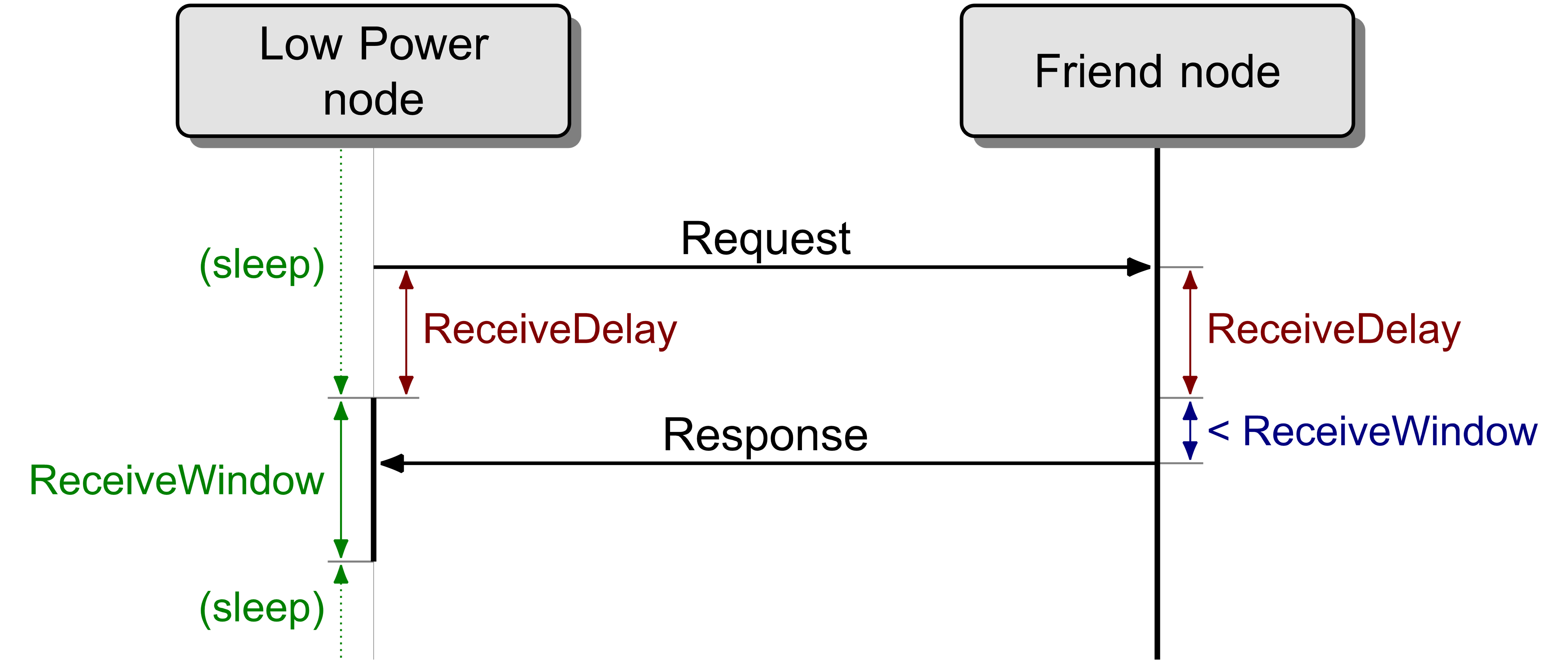 |
PollTimeout timer is used to measure time between two consecutive requests sent by the Low Power node. If no requests are received by the Friend node before the PollTimeout timer expires, then the friendship is considered terminated. This is illustrated in Figure 3.20.
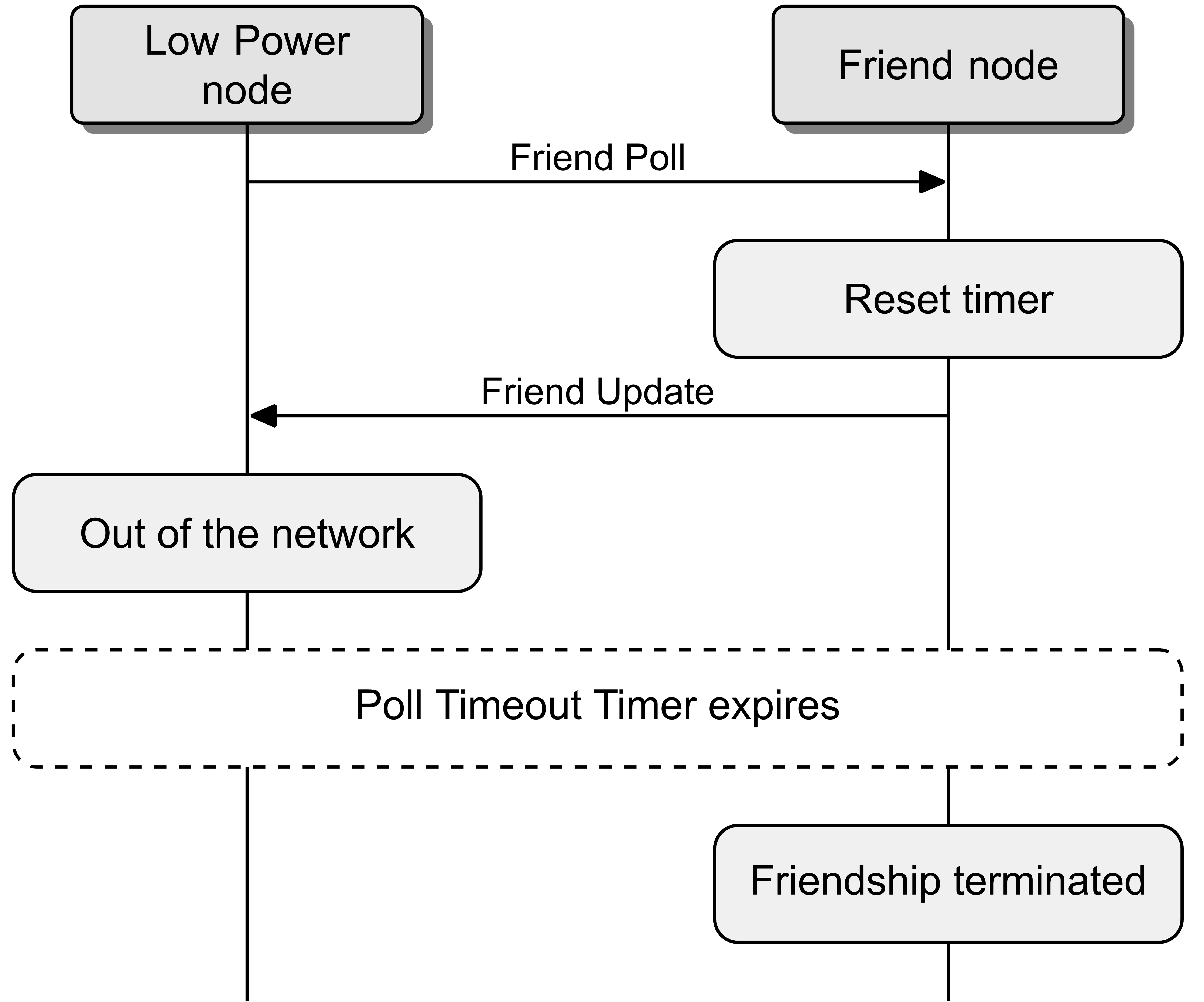 |
To establish a friendship, a node that supports the Low Power feature sends a Friend Request to the all-friends address. The message is picked up by all nodes within radio range of this node that support the Friend feature.
The Friend Request message includes a number of parameters that define the requirements that this node requires any future Friend node to support. Each of the nodes that support the Friend feature and that can support the requirements of the Friend Request message responds by sending back a Friend Offer message to the requesting node. The offers also include additional information about the capabilities of each of the offering nodes. This allows the Low Power node to determine which of these offers it will accept.
The Low Power node then sends a Friend Poll message to its chosen Friend node, and the Friend node responds with a Friend Update message. At this point, the friendship is established, as illustrated in Figure 3.21.
 |
If the Low Power node was previously a friend of another Friend node, then the new Friend node informs the old Friend node that it is now the current friend of this Low Power node (see Section 3.6.6.3.1).
After a friendship is established, the Friend node stores a Friend Subscription List for the Low Power node, which is a collection of group and virtual addresses to which the Low Power node is subscribed. This list allows the Friend node to store the messages that the Low Power node is subscribed to.
The values of the IV Index, IV Update Flag, and Key Refresh Flag for a given NetKey are known as security parameters. Whenever at least one of the values of the security parameters is changed, the new security parameters are known as security updates.
The Friend node stores all messages for the Low Power node, and also the most recent security updates for the Low Power node, in the Friend Queue. Collectively these are known as stored messages.
To obtain stored messages, the Low Power node sends Friend Poll messages and the Friend node replies with stored messages.
Messages stored in the Friend Queue are delivered to the Low Power node with acknowledgment and in order. To enable this, a Boolean Friend Sequence Number is used. This value is stored on the Low Power node and is sent in each Friend Poll message. When the Low Power node receives a message in response to a Friend Poll, and this message has been successfully authenticated using the friendship security credentials, the Low Power node shall change this Friend Sequence Number. The next time this Low Power node polls, the Friend node can send the next message. If there was no response to the Friend Poll message, then the Low Power node does not change the Friend Sequence Number and the Friend node can then determine that the last message it sent was not received and resends it.
3.6.6.2. Friendship security
When a friendship has been established between a Friend node and a Low Power node, all Network PDUs from the Friend node to the Low Power Node are secured using the friendship security material derived from the friendship security credentials (see Section 3.9.6.3.1). The friendship security credentials are exchanged during the Low Power Establishment procedure (see Section 3.6.6.4.1).
The Friend Poll, Friend Update, and Friend Subscription List Add/Remove/Confirm messages, as well as stored messages that the Friend node delivers to the Low Power node, are always secured using the friendship security material. If the Friend node is a Directed Friend node (see Section 2.3.13), friendship security credentials are used for messages that the Low Power node sends to the Friend node to be forwarded along a path (see Section 3.6.8.3). The Friend Clear and Friend Clear Confirm messages are always secured using the managed flooding security material.
Depending on the value of the Publish Friendship Credentials Flag (see Section 4.2.3.4), the Low Power node model publishes messages using either the friendship security credentials or the managed flooding security credentials (see Section 3.9.6.3.1).
All other Network PDUs are sent using the managed flooding security credentials.
Figure 3.22 illustrates messages sent using the friendship security material (dashed lines) and using the managed flooding security material (solid lines). The Low Power node starts by sending the Friend Request message using the managed flooding security credentials. A Friend node responds with a Friend Offer message, again using the managed flooding security credentials. Both the Low Power node and the Friend node are using the managed flooding security credentials as neither device is in a friendship with the other and therefore cannot use the friendship security credentials. The Low Power node accepts the offer of friendship and sends a Friend Poll to confirm this using the friendship security credentials. The Friend node will respond to this using a Friend Update message. The Low Power node can now configure the friend subscription list by using the Friend Subscription List Add message, confirmed using the Friend Subscription List Confirm message from the Friend node. Both of these messages are sent using the friendship security credentials.
Sometime later, the Friend node receives a message (InMsg) from another device that needs to be delivered to the Low Power node, so it will store this message in the Friend Queue. The Low Power node sends a Friend Poll message, secured using the friendship security material, to which the Friend node will reply with the stored InMsg.
The Low Power node then decides to send two messages: OutMsg1 and OutMsg2. OutMsg1 is sent secured using the friend security material and therefore only the Friend node will receive and relay this message. When the Friend node relays OutMsg1, the message will be retransmitted using the managed flooding security credentials. OutMsg2 is sent using the managed flooding security credentials and therefore the Friend node and any other Relay node within range of the Low Power node can relay the message. OutMsg2, when it is relayed, will be retransmitted using the managed flooding security credentials.
 |
3.6.6.3. Friend feature
The Friend feature defines three mandatory procedures: friend establishment, friend messaging, and friend management.
The Friend Update, Friend Offer, Friend Clear, Friend Clear Confirm, and Friend Subscription List Confirm messages originated by a Friend node shall be sent as Unsegmented Control messages with the SRC field set to the unicast address of the primary element of the Friend node.
3.6.6.3.1. Friend establishment
A node that supports the Friend feature and has the feature enabled, and that receives a Friend Request message (see Section 3.6.5.3), that fulfills the minimum requirements specified by the message parameters shall respond with a Friend Offer message (see Section 3.6.5.4).
If the source address of the Friend Request message is an address of a Low Power node that is currently in a friendship with the Friend node on the subnet over which the message was received, then the Friend node shall also consider the existing friendship with that Low Power node on that subnet terminated.
In the Network PDU of a Friend Offer message, the TTL field shall be set to 0 and the DST field shall be set to the SRC value in the Network PDU of the Friend Request message.
The Friend Offer message shall be sent using the managed flooding security credentials and shall be tagged with the immutable-credentials tag.
The node shall keep a Friend node counter (FriendCounter), which is a 2-octet value initialized to 0. This value shall be sent in the Friend Offer message and shall be used to derive the friendship security material if a friendship is established as a result of the Friend Offer message. After each Friend Offer message is sent, the FriendCounter value shall be incremented by 1. The FriendCounter may wrap.
The time between receiving the Friend Request message and sending the Friend Offer message is called the Friend Offer Delay and shall be computed based on the RSSIFactor field and the ReceiveWindowFactor field as defined in the Friend Request message on the supported ReceiveWindow and on the RSSI measured by the Friend node for the Friend Request message.
The Friend Offer Delay allows a Low Power node to receive Friend Offer messages from potential Friend nodes in order to determine how large the offered ReceiveWindow is, and how important the signal quality is. Some Low Power nodes will prefer Friend nodes with a very small ReceiveWindow and therefore set the ReceiveWindowFactor to be more important than the RSSIFactor. Other Low Power nodes will prefer Friends with a very good signal strength and therefore set the RSSIFactor to be more important than the ReceiveWindowFactor. This means that the Low Power node should receive Friend Offers from Friends quicker for those nodes that match the Low Power nodes requirements, reducing the power consumed by the Low Power node when searching for a Friend node.
To optimize power consumption by the LPN, the Friend Node should provide the smallest possible ReceiveWindow.
A Local Delay is computed with the formula:
|
Local Delay=ReceiveWindowFactor×ReceiveWindow-RSSIFactor×RSSI |
|
Where: |
||
|
ReceiveWindowFactor is a number from the Friend Request message ReceiveWindow is the value to be sent in the corresponding Friend Offer message RSSIFactor is a number from the Friend Request message RSSI is the received signal strength of the received Friend Request message on the Friend node |
||
If the Local Delay value is greater than 100, then the Friend Offer Delay value in milliseconds shall be set to the Local Delay value. Otherwise, the Friend Offer Delay shall be set to 100 milliseconds.
If the node receives a Friend Poll message within 1 second after sending the Friend Offer message, the friendship is established and it shall save the FSN field value from this Friend Poll message; otherwise, the establishment has failed.
The Friend node shall respond with a Friend Update message after a minimum of ReceiveDelay milliseconds and before a maximum of the sum of ReceiveDelay and ReceiveWindow milliseconds, from the reception of the Friend Poll message from the Low Power node.
In the Network PDU of a Friend Update message, the TTL field shall be set to 0.
This Friend Update message shall be sent using the friendship security credentials and shall be tagged with the immutable-credentials tag.
Figure 3.23 illustrates a friendship establishment where multiple nodes with the Friend feature enabled receive the same Friend Request message.
 |
After a friendship is established, the Friend node shall initialize a Friend Subscription List to a zero-length (empty) list and start storing messages for the Low Power node in the Friend Queue.
After a friendship has been established, if the PreviousAddress field of the Friend Request message contains a valid unicast address that is not the Friend node’s own unicast address, then the Friend node shall begin sending Friend Clear messages (see Section 3.6.5.5) to that unicast address according to the procedure below:
-
In the Network PDU of the Friend Clear message, the TTL field shall be set to 0x7F.
-
The Friend Clear message shall be sent using the managed flooding security credentials and shall be tagged with the immutable-credentials tag.
-
The first Friend Clear message shall be sent as soon as the friendship is established; at the same time, a Friend Clear Repeat timer shall be started with the period set to 1 second, and a Friend Clear Procedure timer shall be started with the period equal to two times the Friend Poll Timeout value.
-
If a Friend Clear Confirm message (see Section 3.6.5.6) is received in response to the Friend Clear message, both timers shall be stopped and the procedure is complete.
-
If the Friend Clear Repeat timer expires, a new Friend Clear message shall be sent and the timer shall be started from the initial value that is double the previous Friend Clear Repeat timer initial value. For example, after the first expiration, the period shall be set to two seconds; on the next expiration, it shall be set to four seconds, and so on.
-
If the Friend Clear Procedure timer expires, then the Friend Clear Repeat timer shall be stopped and the procedure is complete.
An example of this procedure is illustrated in Figure 3.24.
Once friendship has been established the Friend node shall communicate with the Low Power node as defined in friend messaging (see Section 3.6.6.3.2), and may be managed as defined in Friend Management (see Section 3.6.6.3.3).
 |
3.6.6.3.2. Friend messaging
When the Friend node receives a Friend Poll message from a friend Low Power node that has the same FSN field value as the last Friend Poll message received from the Low Power node, the Friend node shall respond with exactly the same message it has previously sent, unless that message has been discarded. If the previously sent message has been discarded, then the oldest entry in the Friend Queue shall be sent.
When the Friend node receives a Friend Poll message from a friend Low Power node that has a different FSN field value as the last Friend Poll message from the Low Power node, then it shall send the oldest message from the Friend Queue.
When sending a stored message to the Low Power node, it shall be sent unchanged and shall be tagged as friendship PDU. If the IV Index on the Friend node has changed, for example the node is now transmitting with a new IV Index, the messages sent to the Low Power node shall still be sent in the context of the IV Index that the Friend node received for those messages.
Note
Note: The above requirement implies that a Low Power node should collect all stored messages at least once every 96 hours, otherwise the Friend node may discard the stored messages before the Low Power node can receive them.
Each message shall be sent after a minimum of ReceiveDelay milliseconds and before a maximum of the sum of ReceiveDelay and ReceiveWindow milliseconds, from the reception of the Friend Poll message from a friend Low Power node.
If no Friend Poll, Friend Subscription List Add, or Friend Subscription List Remove messages are received by the Friend node before the PollTimeout timer expires, the friendship is terminated and the Friend node shall discard all entries in the Friend Queue.
The Friend Subscription List Confirm message shall be sent after a minimum of ReceiveDelay milliseconds and before a maximum of the sum of ReceiveDelay and ReceiveWindow milliseconds, from the reception of the Friend Subscription List Add message or the Friend Subscription List Remove message.
In the Network PDU of a Friend Subscription List Confirm message, the TTL field shall be set to 0.
The Friend Subscription List Confirm message shall be sent using the friendship security credentials and shall be tagged with the immutable-credentials tag.
When a Friend node receives a valid Friend Clear message where the LPNAddress field contains the address of a friend Low Power node, and the message is received within the Poll Timeout of the friendship with that Low Power node, the friendship is terminated, and the Friend node shall discard all related entries in the Friend Queue, and the Friend node should respond with a Friend Clear Confirm message.
A Friend Clear message is considered valid if the result of the subtraction of the value of the LPNCounter field of the Friend Request message (the one that initiated the friendship) from the value of the LPNCounter field of the Friend Clear message, modulo 65536, is in the range 0 to 255 inclusive.
If the Friend Clear message was received with a TTL field value of 0, the Network PDU of the Friend Clear Confirm message should be set to 0 as well.
The Friend Clear Confirm message shall be sent using the managed flooding security credentials and shall be tagged with the immutable-credentials tag.
3.6.6.3.3. Friend management
If the Friend node receives a Friend Subscription List Add message (see Section 3.6.5.7) from the Low Power node, it shall add the address or list of addresses contained in the message into the Friend Subscription List and shall respond with a Friend Subscription List Confirm message (see Section 3.6.5.9) setting the value of the TransactionNumber field to the same value as in the received Friend Subscription List Add message. If the Friend node is a Directed Friend node, the Friend node initiates a Directed Forwarding Solicitation procedure (see Section 3.6.8.3).
If the Friend node receives a Friend Subscription List Remove message (see Section 3.6.5.8) from the Low Power node, it shall remove the address or list of addresses contained in the message from the Friend Subscription List and shall respond with a Friend Subscription List Confirm message setting the value of the TransactionNumber field to the same value as in the received Friend Subscription List Remove message.
The Friend node shall respond with a Friend Update message after a minimum of ReceiveDelay milliseconds and before a maximum of the sum of ReceiveDelay and ReceiveWindow milliseconds, from the reception of the Friend Poll message from the Low Power node.
3.6.6.4. Low Power feature
A node that supports the Low Power feature shall support the three mandatory procedures: Low Power establishment, Low Power messaging, and Low Power management.
The Friend Poll, Friend Request, Friend Subscription List Add, and Friend Subscription List Remove messages originated by a Low Power node shall be sent as Unsegmented Control messages with the SRC field set to the unicast address of the primary element of the node that supports the Low Power feature.
3.6.6.4.1. Low Power establishment
The Low Power establishment procedure is used to establish friendship between a node supporting the Low Power feature and a node supporting the Friend feature.
This procedure is started by sending a Friend Request message.
In the Network PDU of a Friend Request message, the TTL field shall be set to 0 and the DST field shall be set to the all-friends address. The node shall keep a Low Power node counter (LPNCounter), which is a 2-octet value initialized to 0. This value shall be sent in the Friend Request message and used to derive the friendship security material if a friendship is established as a result of the Friend Request message. After each Friend Request message is sent, this value shall be incremented by 1. The LPNCounter may wrap. The Friend Request message shall be sent using the managed flooding security credentials and shall be tagged with the immutable-credentials tag.
After 100 milliseconds have passed from the Friend Request, the node should listen for up to 1 second for the Friend Offer messages sent by potential Friend nodes, and it may select one of the Friend nodes to establish a friendship. The Low Power node may accept a received Friend Offer or continue to listen for other Friend Offer messages for comparison.
If no acceptable Friend Offer message is received, the node may send a new Friend Request message. The time interval between two consecutive Friend Request messages shall be greater than 1.1 seconds.
To establish a friendship with a potential Friend that has sent a Friend Offer message, the node shall set the Friend Sequence Number to zero and shall send a Friend Poll message to the selected Friend node within 1 second after the reception of the Friend Offer message. If a Friend Update message is received in response, the friendship is established, the Low Power feature of the node supporting it is in use and the Friend feature of the node supporting it is in use.
In the Network PDU of a Friend Poll message, the TTL field shall be set to 0.
This Friend Poll message shall be sent using the friendship security credentials and shall be tagged with the immutable-credentials tag.
The node should restart the Low Power Establishment procedure if it does not receive a Friend Update message after several attempts (e.g., 6 attempts).
Multiple failures of the Low Power Establishment procedure may be an indication that the Low Power node no longer has a valid IV Index and it should initiate the IV Index Recovery procedure (see Section 3.11.6).
Once friendship has been established the Low Power node shall communicate with the Friend node as defined in Low Power messaging (see Section 3.6.6.4.2) and may manage the friendship as defined in Low Power management (see Section 3.6.6.4.3).
If the Low Power node supports directed forwarding functionality when the friendship is established in a subnet, the Low Power node shall store the current value of the Directed Forwarding state and shall set the state to 0x00 (see Section 4.2.26.1) for that subnet. When that friendship is terminated, the Low Power node shall set the Directed Forwarding state to the stored value.
3.6.6.4.2. Low Power messaging
The Low Power messaging procedure is executed by a Low Power node to receive stored messages and security updates from the Friend node.
The procedure consists of asynchronous requests from the Low Power node to the Friend node and timed responses from the Friend node to the Low Power node.
A Low Power node that is in a friendship with a Friend node shall send a Friend Poll message to the Friend node before the PollTimeout timer expires.
As a general rule, the Low Power node should continue sending Friend Poll messages until it receives a Friend Update message with the MD field set to 0. This is illustrated in Figure 3.25.
The Low Power node may terminate friendship with a Friend by sending a Friend Clear. The Friend Clear message should be sent using a TTL field value set to 0.
 |
The FSN field shall be set to the value of the Friend Sequence Number.
If the Low Power node receives a response from the Friend node, and the response is not a duplicate of the last received Lower Transport PDU, then the Low Power node shall toggle the Friend Sequence Number.
If the Low Power node does not receive a response within the ReceiveWindow, it should resend the Friend Poll message. It is recommended to resend this message 3 times, which assures a good balance between reliability and power consumption.
If no response has been received to multiple Friend Poll messages before the PollTimeout timer expires, the friendship is terminated. The Low Power node may repeat the Low Power establishment procedure.
If the Low Power node receives a Friend Update message, it shall process the Flags and IV Index fields using the same rules as if they had been received in a Secure Network beacon (see Sections 3.10.3.1, 3.11.4, and 3.11.5) or in a Mesh Private beacon (see Section 3.10.4).
3.6.6.4.3. Low Power management
The Low Power management procedure is used to manage the subscription list in a Friend node.
The Low Power node may send one or more Friend Subscription List Add messages to the Friend node containing lists of group addresses or virtual addresses to which the Low Power node is subscribed. This type of message may be sent at any time by the Low Power node when its subscriptions change.
In the Network PDU of a Friend Subscription List Add message, the TTL field shall be set to 0.
The Friend Subscription List Add message shall be sent using the friendship security credentials and shall be tagged with the immutable-credentials tag.
The Low Power node may send one or more Friend Subscription List Remove messages to the Friend node containing lists of group addresses or virtual addresses to which the Low Power node is no longer subscribed. This type of message may be sent at any time by the Low Power node when its subscriptions change.
In the Network PDU of a Friend Subscription List Remove message, the TTL field shall be set to 0.
The Friend Subscription List Remove message shall be sent using the friendship security credentials and shall be tagged with the immutable-credentials tag.
The Low Power node shall start with a TransactionNumber value set to 0x00. It shall increment the TransactionNumber for each new Friend Subscription List Add or Friend Subscription List Remove such that the TransactionNumber can be matched with the TransactionNumber field of the Friend Subscription List Confirm message.
3.6.6.5. Examples of segmentation and reassembly
The segmentation and reassembly behaviors defined in Sections 3.5.3.3 and 3.5.3.4 also apply to segmented messages sent to and from a Low Power node. The only difference is that since the Low Power node relies on the Friend Queue for all incoming messages, including segments and segment acknowledgments, the Friend node will acknowledge segmented transactions for the Low Power node.
This section provides two examples of segmentation and reassembly on the Low Power node.
3.6.6.5.1. Incoming segmented message
The message sequence chart (MSC) in Figure 3.26 is an example of a segmented message directed toward a Low Power node. The Friend node performs the reassembly separately and sends the acknowledgments needed until it receives all segments, at which point the Friend node places the segments in the Friend Queue so that they can be delivered to the Low Power node. An unsegmented message from another source is received in the middle of the transaction and is handled independently.
 |
3.6.6.5.2. Outgoing segmented message
The MSC illustrated in Figure 3.27 shows an example of a segmented message sent by the Low Power node. Since the Low Power node relies on the Friend Queue for all incoming messages, it needs to poll for the acknowledgment as well. An unsegmented message from another source is received in the middle of the transaction and is handled independently.
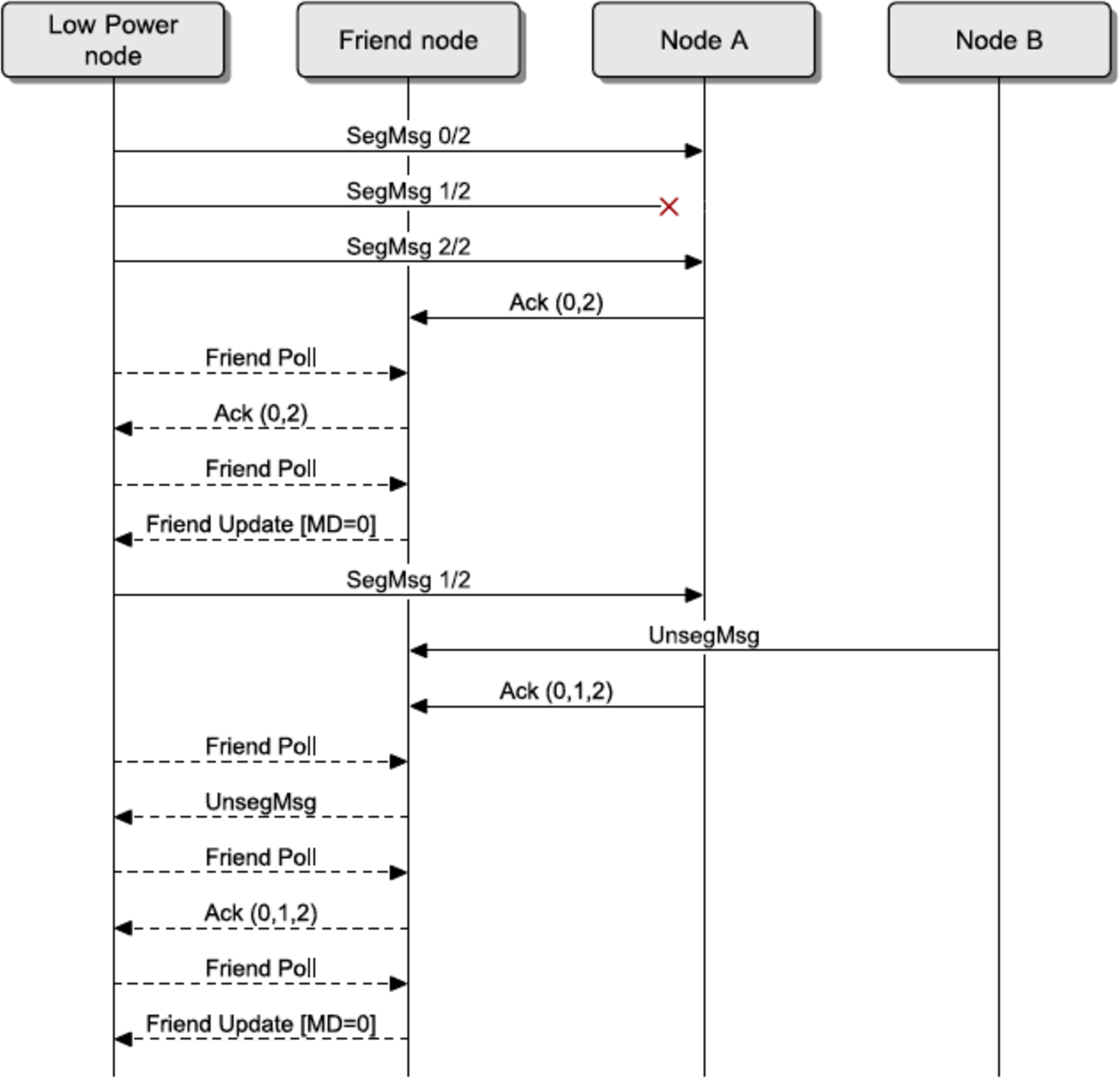 |
3.6.7. Heartbeat
Heartbeat is used to monitor nodes on a network and discover how far nodes are apart from each other.
3.6.7.1. Functional overview
In order to determine if a node is still present and active within a mesh network, it is necessary to receive a message from this node. Sending a message to each and every node in the mesh network to elicit a response would be very wasteful of energy, and therefore each node can be configured to send a single message periodically. This message is called the Heartbeat message.
The Heartbeat message can be used for three main functions. The first function is the determination that a node is still active within a mesh network. The second function is the determination of how far a node is away. The third function is the determination that a feature of the node has been enabled or disabled.
Publishing of the Heartbeat messages is configured by the Configuration Server model. Periodic Heartbeat messages can be sent a limited number of times or they can be sent indefinitely. Heartbeat messages are sent to a configured destination, and it is recommended that a group address is used for sending Heartbeat messages. The messages can also be configured with a specific TTL value.
When Heartbeat messages are received, they are counted. The number of Heartbeat messages received can help determine the reliability of the mesh network for delivering messages from the node sending Heartbeat messages.
Each Heartbeat message includes the initial TTL value used when sending the original Heartbeat message. This allows a receiving device to determine the number of times this message was retransmitted, known as the number of hops, and a record of the minimum and maximum number of hops can also be used to determine how reliable the mesh network is.
The use of Heartbeat messages can therefore be used to determine the best TTL value to use to address a given node.
Heartbeat messages also include the features of a node that are currently in use. A node can be configured to publish a triggered Heartbeat message when various features are enabled or disabled. This allows the features available on various nodes within a mesh network to be determined.
3.6.7.2. Publishing Heartbeat messages
Publishing of Heartbeat messages is controlled by the Heartbeat Publication state (see Section 4.2.18).
When the Heartbeat Publication Destination (see Section 4.2.18.1) address is set to an unassigned address, Heartbeat messages shall not be published. When the value of the Heartbeat Publication Count state (see Section 4.2.18.2) is 0x0000, periodic Heartbeat messages shall not be published.
Heartbeat messages shall be published with the DST field set to the value of the Heartbeat Publication Destination state and with the TTL field set to the value of the Heartbeat Publication TTL state (see Section 4.2.18.4).
Periodic publishing of Heartbeat messages is enabled by the Heartbeat Publication Count state (see Section 4.2.18.2). After publishing a periodic Heartbeat message, if the Heartbeat Publication Count counter is less than 0xFFFF, the Heartbeat Publication Count counter shall be decreased by 1. The counter shall stop at 0x0000. The first periodic Heartbeat message shall be published as soon as possible after the Heartbeat Publication Period state (see Section 4.2.18.3) has been configured for periodic publishing. The next periodic Heartbeat message shall be published after the number of seconds defined by the Heartbeat Publication Period state (see Section 4.2.18.3).
Triggered publishing of Heartbeat messages is enabled by the Heartbeat Publication Features state (see Section 4.2.18.5):
-
If the Relay bit is set to 1, a triggered Heartbeat message shall be published when the Relay state of a node (see Section 4.2.9) changes.
-
If the Proxy bit is set to 1, a triggered Heartbeat message shall be published when the GATT Proxy state of a node (see Section 4.2.12) changes.
-
If the Friend bit is set to 1, a triggered Heartbeat message shall be published when the Friend state of a node (see Section 4.2.14) changes.
-
If the Low Power bit is set to 1, a triggered Heartbeat message shall be published when the Low Power node establishes or loses Friendship (see Section 3.6.6.1).
3.6.7.3. Receiving Heartbeat messages
Receiving of Heartbeat messages is controlled by the Heartbeat Subscription state (see Section 4.2.19).
The Heartbeat Subscription Period state is a countdown timer identifying the number of seconds remaining for the period when Heartbeat messages are received. When the timer expires, the receiving of Heartbeat messages shall be disabled.
Heartbeat messages with the SRC field set to a value other than the Heartbeat Subscription Source state (see Section 4.2.19.1) or the DST field set to a value other than the Heartbeat Subscription Destination state (see Section 4.2.19.2) shall not be processed.
Upon receiving a Heartbeat message, the value of the Heartbeat Subscription Count state (see Section 4.2.19.3) shall be increased. The counter does not wrap. It stops counting at 0xFFFF.
Upon receiving the Heartbeat message, a hops value shall be calculated using the InitTTL value from the message, and the received Network PDU TTL field value, known as RxTTL, as follows:
|
hops=InitTTL-RxTTL+1 |
Note
Note: If the message is received directly (for example, the InitTTL value and the received Network PDU TTL field value are the same), then the hops value would be 0x01. If the message has been delivered using the maximum length path, then InitTTL would be 0x7F and the received Network PDU TTL field value would be 0x01, and therefore hops would 0x7F.
If the hops value is lower than the Heartbeat Subscription Min Hops state, it shall be set as the new value of the Heartbeat Subscription Min Hops state. If the hops value is higher than the Heartbeat Subscription Max Hops state, it shall be set as the new value of the Heartbeat Subscription Max Hops state.
3.6.8. Directed forwarding
Directed forwarding is used to establish paths between Directed Forwarding nodes as described in Section 2.3.11. Paths are established between a source node, known as the Path Origin, and one or more destination nodes, known as Path Targets, with Directed Relay nodes forwarding messages along the paths.
3.6.8.1. Functional overview of directed forwarding
In order to initiate the discovery of a path, a Path Origin sends a PATH_REQUEST message indicating its intended destination address. This procedure is named Directed Forwarding Initialization (see Section 3.6.8.2.1).
Directed Relay nodes discover the path by re-generating and broadcasting the PATH_REQUEST message until it reaches all Path Targets. When a node receives a PATH_REQUEST, it stores information about discovered paths temporarily in the Discovery Table (see Section 3.6.8.6). This procedure is named Directed Forwarding Discovery (see Section 3.6.8.2.2).
The path is made available by unicasting, hop by hop, a PATH_REPLY from each Path Target back to the Path Origin. Each Directed Forwarding node that receives the PATH_REPLY message stores path information in the Forwarding Table state (see Section 3.6.8.5). This procedure is named Directed Forwarding Establishment (see Section 3.6.8.2.3).
A PATH_REPLY may trigger the Path Origin to send a PATH_CONFIRMATION message that is propagated, hop by hop, along the path from the Path Origin to a Path Target to confirm that the path is a two-way path. This procedure is named Directed Forwarding Confirmation (see Section 3.6.8.2.4). A two-way path can be used to forward messages from the Path Origin to the Path Target (along the Forward Path) and from the Path Target to the Path Origin (along the Backward Path).
A dependent node (see Section 3.6.8.3) can use a Path Origin or a Path Target to perform directed forwarding on its behalf. By sending a DEPENDENT_NODE_UPDATE message, a Path Origin or a Path Target notifies each node along the paths either to add the dependent node addresses to its Forwarding Table entry or to remove them. This procedure is named Directed Forwarding Dependents Update (see Section 3.6.8.2.5).
A path from a Path Origin to a Path Target can be monitored by using a PATH_ECHO_REQUEST message. The Path Target responds with a PATH_ECHO_REPLY message. This procedure is named Directed Forwarding Echo (see Section 3.6.8.2.6).
A Directed Forwarding node or a Configuration Manager can solicit the discovery of paths toward unicast addresses, group addresses, or virtual addresses by using a PATH_REQUEST_SOLICITATION message. This procedure is named Directed Forwarding Solicitation (see Section 3.6.8.2.7)
Directed forwarding functionality uses a control sequence number known as the forwarding number to distinguish Transport Control messages sent by a node in the context of different Directed Forwarding Initialization procedures. The forwarding number is separate from the sequence numbers used for the message caching and the replay protection procedures (that is, the SEQ field defined in Section 3.4.4.5). The forwarding number is increased when a node initiates the discovery of a new path to any destination (see Section 3.6.8.4).
3.6.8.1.1. Multilane paths
To help improve reliability and resilience, paths may have multiple lanes that take advantage of several relays overhearing a message relayed on each hop. The number of lanes to be established is defined by the Wanted Lanes state (see Section 4.2.30). Each additional lane in a path is discovered by transmitting a PATH_REQUEST message with the same forwarding number as in the previous PATH_REQUEST after a duration of Lane Discovery Guard Interval (see Section 4.2.38.4) after the Path Discovery timer expires (see Section 3.6.8.2.1).
3.6.8.1.2. Path metrics
Path metrics are used to measure, rank, and select the best lane of a path (for example, the lane with the lowest number of hops) that messages will traverse.
This specification uses a path metric based on the hop count between the Path Origin and the Path Target. The path metric also takes into account the number of lanes that traverse the node. In this way, a longer but disjointed lane (i.e., the lane uses different intermediate nodes than other lanes in that path) might be preferred to a shorter lane using one or more of the same intermediate nodes (see Section 4.2.27.1).
Figure 3.28 shows an example of a network composed a Path Origin (PO), a Path Target (PT), and Directed Relay nodes (identified by capital letters from A to J). The Path Origin initiates a path discovery toward the Path Target and is configured to discover two lanes (Figure 3.28 (a), (b) and (c)). In the Figure 3.28 (b) and Figure 3.28 (c), white circles represent nodes that are not chosen to be part of the path between the Path Origin and the Path Target, and blue circles represent nodes that are chosen to be part of the path. The transmission of a PATH_REQUEST message from a node is represented by arrows that connect the node with its neighbors. Before transmitting a PATH_REQUEST message, every node (say A) sets the Path_Origin_Path_Metric field in the message to the path metric value (POPMA) that the node calculates as defined in Section 4.2.27.1, based on the Path_Origin_Path_Metric field in the Discovery Table (see Section 3.6.8.6), and the Lane_Counter field value (LCA), if a Forwarding Table entry corresponding to the message exists. Figure 3.28 (a) and (b) show the lowest path metric values calculated by the nodes during the discovery of the first and second lanes, respectively. During the first lane discovery illustrated in Figure 3.28 (a), nodes PO, A, and B are selected as members of the lane. During the second lane discovery illustrated in Figure 3.28 (b), nodes PO, C, D, and E are selected as members of the lane. If the Path Origin is configured to discover three lanes, nodes PO, A, and B are selected again as members of the lane during the third discovery attempt that is illustrated in Figure 3.28 (c); this suggests that, in this example network topology and using the metric defined in this specification, using two lanes is a good compromise between path redundancy and traffic generated for path discovery.
 |
 |
 |
3.6.8.1.3. Network interfaces and bearers
The network layer supports sending and receiving messages via multiple bearers, and each instance of a bearer is connected to the network layer via a network interface. To be able to support additional bearers that introduce different costs to be evaluated by the path metric, the Forwarding Table entries are associated with path bearers over which the messages are transmitted (see Section 4.2.29).
PATH_REQUEST messages may be sent over multiple bearers. The Discovery Table contains an indicator of the selected bearers over which the PATH_REPLY is expected to be sent (see Section 3.6.8.6). The Forwarding Table entries are only considered valid in the context of those bearers. Therefore, when forwarding a message along a path, the message is sent over the path bearers indicated by the Forwarding Table.
3.6.8.1.4. Group destinations
Directed forwarding supports group addresses.
During configuration of a mesh node, models of elements within the node can be subscribed to one or more group addresses. A message sent to a group address using directed forwarding is processed by the subscribed nodes that support directed forwarding (see Section 3.6.8.1).
In the Directed Forwarding Initialization procedure toward a group address, a Path Origin broadcasts a PATH_REQUEST message in which the intended destination is the group address. Each node that is subscribed to the group address behaves as a Path Target and responds with a PATH_REPLY message. Intermediate Directed Relay nodes can uniquely associate the received PATH_REPLY with the forwarded PATH_REQUEST by looking for matching entries in the Discovery Table (see Section 3.6.8.6).
Within the Directed Forwarding Establishment procedure, a lane of the path is considered established if at least one PATH_REPLY from a node that is subscribed to the group address is received (see Section 3.6.8.2.1). The Path Origin receives at most a single PATH_REPLY for the primary element of each node that is subscribed to the group address.
3.6.8.1.5. Virtual destinations
Directed forwarding supports virtual addresses, which are treated as group addresses.
If a PATH_REQUEST message is sent to an intended destination that is a virtual address, every Directed Forwarding node that authenticates the PATH_REQUEST at the network layer, and that is subscribed to a Label UUID from which the virtual address can be derived, is considered a valid Path Target and responds with a PATH_REPLY message.
There is potential for establishing paths toward nodes that are subscribed to a different Label UUID associated with the same virtual address. In this case, some messages are forwarded also toward destinations that are not subscribed to the original Label UUID.
3.6.8.1.6. Friendship and directed forwarding
To enable directed forwarding procedures for a Low Power node that does not support directed forwarding functionality, the Low Power node establishes friendship with a Directed Friend node and uses the friendship security credentials for outgoing messages. After receiving a message secured with friendship security credentials from the Low Power node, the Directed Friend node can form a node dependence (see Section 3.6.8.3).
A Directed Friend node provides discovery, management, and message forwarding for a dependent Low Power node.
3.6.8.1.7. Proxy and directed forwarding
To enable directed forwarding procedures for a Proxy Client that does not support directed forwarding functionality, the Proxy Client connects to a Directed Proxy node. The Proxy Client configures the accept list filter instantiated by the Proxy Server to let the Proxy Server determine the Proxy Client element addresses, group addresses, and virtual addresses to which the Proxy Client is subscribed (see Section 6.7).
A Directed Proxy node provides discovery, management, and message forwarding for a Proxy Client as a dependent node (see Section 3.6.8.3).
3.6.8.1.8. Fixed paths and non-fixed paths
A Configuration Manager configures Directed Forwarding nodes to enable them to establish and maintain paths dynamically using directed forwarding procedures (see Section 3.6.8.2). These paths are known as non-fixed paths. In addition, a Configuration Manager can establish and maintain a path by statically selecting nodes and configuring them through the Directed Forwarding Configuration Server model (see Section 4.4.7). Paths established in this way are known as fixed paths.
Non-fixed paths have a limited lifetime set by the Configuration Manager, whereas a fixed path persists until removed by the Configuration Manager.
3.6.8.1.9. Path resilience
In directed forwarding, only nodes constituting a path participate in relaying a message from a source to a destination. The Path Origin follows the path discovery and maintenance policy. The policy is configured by a Configuration Manager and controls aspects such as path lifetime, verification and re-discovery cadence, the number of additional lanes, and whether the paths are unidirectional or bidirectional.
A path is assumed to be valid at the time of its establishment, but it could be difficult to estimate its stability. Network topologies change, and a path can become broken at any time. Increasing the number of lanes reduces the risk of a path being broken. Detecting that a path has been broken requires the exchange of additional messages.
Paths can be broken temporarily for short periods of time. Message delivery along a lane within a path can fail because a Directed Relay node was busy transmitting messages and could not listen to the incoming traffic, or because there was a temporary local interference. Multiple lanes within a path can help reduce the probability of paths being temporarily broken.
To help balance the traffic across the network, paths are distributed by randomly selecting Directed Relay nodes among candidates that are considered equally good based on the path metric (see Section 3.6.8.2.2).
The Configuration Manager configures the network by balancing the following strategies:
-
Establish multiple lanes for each path. More lanes help provide redundancy, but they generate more traffic.
-
Validate paths by using the Directed Forwarding Echo procedure. Faster cadence of path validation reduces the time it takes to detect a broken path, but it increases network traffic overhead.
The Configuration Manager can also set the RSSI Margin (see Section 4.2.35.2) to prevent Directed Relay nodes that receive PATH_REQUEST messages at an RSSI level close to their Default RSSI Threshold (see Section 4.2.35.1) from propagating these messages and becoming part of a path.
3.6.8.1.10. Coexistence of multiple subnets
A Directed Forwarding node maintains separate tables to store information about paths discovered (see Section 3.6.8.6) and established (see Section 4.2.29) in different subnets. Some states associated with directed forwarding support multiple subnets (see Sections 4.2.26 to 4.2.32), and some other states are common to all the subnets to which the node belongs (see Sections 4.2.33 to 4.2.40). For example, a node that supports directed forwarding can have such functionality enabled in one subnet and disabled in another subnet, while the control of timing for path discovery is independent of the subnet over which the path discovery is performed.
3.6.8.1.11. Subnet Bridge and Directed Forwarding
A Subnet Bridge node provides discovery, management, and message forwarding in the subnets where traffic from a source to a destination is bridged and where directed forwarding functionality is enabled. The source node in the first of the subnets is treated as a dependent node of the Subnet Bridge node in the second of the subnets, and the destination node in the second of the subnets is treated as a dependent node of the Subnet Bridge node in the first of the subnets (see Section 3.6.8.3).
3.6.8.2. Directed forwarding procedures
This section defines the requirements for the directed forwarding procedures.
If the Directed Forwarding state (see Section 4.2.26.1) is disabled at a node in a subnet while a directed forwarding procedure is being executed in the context of that subnet, the procedure is canceled.
3.6.8.2.1. Directed Forwarding Initialization
The Directed Forwarding Initialization procedure is executed by a Path Origin to discover a new path or to add nodes to an existing path toward a destination in a given subnet.
Figure 3.29 shows the flow chart of the Directed Forwarding Initialization procedure.
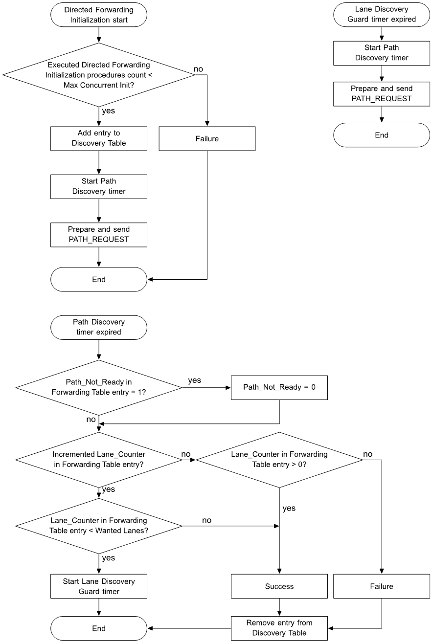 |
First, the Path Origin shall check whether or not the number of executed Directed Forwarding Initialization procedures (i.e., the number of Discovery Table entries that store the primary element address of the node in their Path_Origin field) is equal to the Max Concurrent Init state value (see Section 4.2.28.2).
If the number of executed Directed Forwarding Initialization procedures is equal to the Max Concurrent Init state value, then the Directed Forwarding Initialization procedure shall fail. Otherwise, a new entry shall be added to the Discovery Table according to Section 3.6.8.6.1, a new instance of the Path Discovery timer shall be started from the initial value set to the duration indicated by the Path Discovery Interval state value (see Section 4.2.38.3), and a PATH_REQUEST message shall be prepared and sent.
The new PATH_REQUEST shall have the following field values:
-
If the PATH_REQUEST is originated on behalf of a dependent node of the Path Origin (see Section 3.4.6.3), the On_Behalf_Of_Dependent_Origin field shall be set to 1, and the Dependent_Origin_Unicast_Addr_Range field shall be set to the unicast address range of the dependent node; otherwise, the On_Behalf_Of_Dependent_Origin field shall be set to 0.
-
The Path_Origin_Path_Metric_Type field shall be set to the Path_Origin_Path_Metric_Type field value in the Discovery Table (see Section 3.6.8.6).
-
The Path_Origin_Path_Lifetime field shall be set to the Path_Origin_Path_Lifetime field value in the Discovery Table (see Section 3.6.8.6).
-
The Path_Discovery_Interval field shall be set to the Path_Discovery_Interval field value in the Discovery Table (see Section 3.6.8.6).
-
The Path_Origin_Forwarding_Number field shall be set according to Section 3.6.8.4.
-
The Path_Origin_Path_Metric field shall be set to 0.
-
The Destination field shall be set to the unicast address, group address, or virtual address of the destination.
-
The Path_Origin_Unicast_Addr_Range field shall be set to the unicast address range (see Section 3.4.2.2.1) of the Path Origin.
The Network PDU for the new PATH_REQUEST message shall have the following configuration:
-
The DST field shall be set to the all-directed-forwarding-nodes fixed group address (see Section 3.4.2.4).
-
The TTL field shall be set to 0.
The Path Origin shall send the message using the directed security credentials of the subnet over which the message is sent and shall tag the message with the immutable-credentials tag.
When the Path Discovery timer associated with a Discovery Table entry expires, the Path Origin shall perform the following actions:
-
If the value of the Path_Not_Ready field (see Section 4.2.29.2) in the corresponding Forwarding Table state entry is 1, then the Path_Not_Ready field in the entry shall be set to 0.
-
If the Lane Counter value in the corresponding Forwarding Table state entry has been instantiated or incremented and is less than the Wanted Lanes state value (see Section 4.2.30), a Lane Discovery Guard timer shall be started from the initial value indicated by Lane Discovery Guard Interval state (see Section 4.2.38.4).
-
When the Lane Discovery Guard timer expires, a new PATH_REQUEST message shall be prepared and sent, and the Path Discovery timer shall be started from the initial value indicated by the Path Discovery Interval state value (see Section 4.2.38.3). All the fields in the new PATH_REQUEST message shall be copied from the previous PATH_REQUEST message.
-
-
If the Lane Discovery Guard timer is not running, the Discovery Table entry shall be removed, and the Directed Forwarding Initialization procedure shall complete with a success or a failure based on the comparison between the Lane Counter field value in the corresponding Forwarding Table state entry and the Wanted Lanes state value:
-
If the Lane Counter field value is greater than 0 and less than the Wanted Lanes state value (i.e., at least one lane of the path had already been established), the Directed Forwarding Initialization procedure is successful.
-
If the Lane Counter field value is equal to the Wanted Lanes state value (i.e., the last lane of the path has been established), the Directed Forwarding Initialization procedure is successful.
-
If the Lane Counter field value is 0 (i.e., no lane of the path had been established), the Directed Forwarding Initialization procedure fails.
-
3.6.8.2.2. Directed Forwarding Discovery
The Directed Forwarding Discovery procedure shall be executed by any Directed Forwarding node that receives a PATH_REQUEST message.
Figure 3.30 shows the flow chart of the Directed Forwarding Discovery procedure.
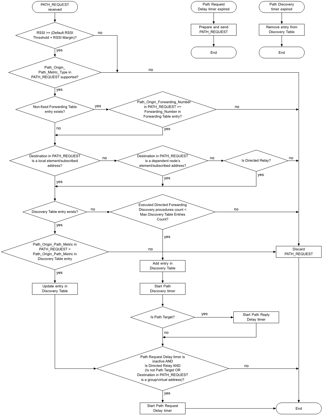
When a Directed Forwarding node receives a PATH_REQUEST message, the node shall check whether to process or discard the message.
The PATH_REQUEST message shall be discarded if any of the following conditions is met:
-
The RSSI value measured for the PATH_REQUEST message is less than the sum of the Default RSSI Threshold state value (see Section 4.2.35.1) and the RSSI Margin state value (see Section 4.2.35.2).
-
The node does not support the path metric type that is indicated in the PATH_REQUEST message Path_Origin_Path_Metric_Type field (see Section 4.2.27.1).
-
A non-fixed Forwarding Table entry corresponding to the PATH_REQUEST message exists (see Section 3.6.8.5.2), and the Path_Origin_Forwarding_Number field value in the message is less than the Forwarding_Number value in the table entry. The comparison between the Path_Origin_Forwarding_Number and the Forwarding_Number shall follow the definitions in Section 3.6.8.4.
-
Directed relay, directed friend, and directed proxy functionalities are all disabled, and the Destination field value of the PATH_REQUEST message is not an element address of the node or a group address or a virtual address that the node is subscribed to.
-
Directed relay functionality is disabled; and either directed friend functionality, directed proxy functionality, or both are enabled; and the Destination field value of the PATH_REQUEST message is not an element address of the node or of a dependent node; and the Destination field value of the PATH_REQUEST message is not a group address or a virtual address that the node or a dependent node is subscribed to.
-
A Discovery Table entry corresponding to the PATH_REQUEST message does not exist (see Section 3.6.8.6.2), and the number of Directed Forwarding Discovery procedures that are being executed in the subnet from which the PATH_REQUEST message is received (i.e., the number of non-empty Discovery Table entries in the subnet) is equal to the Max Discovery Table Entries Count state value (see Section 4.2.28.1) for the subnet.
-
A Discovery Table entry corresponding to the PATH_REQUEST message exists, and the Path_Origin_Path_Metric field value in the message is not less than the Path_Origin_Path_Metric value in the table entry.
If the PATH_REQUEST message can be processed, and a Discovery Table entry corresponding to the PATH_REQUEST message does not exist, a new Discovery Table entry shall be added according to Section 3.6.8.6.2, and the corresponding instance of the Path Discovery timer shall be started. The Path Discovery timer initial value shall be set to the duration indicated by the value of the Path_Discovery_Interval field (see Section 4.2.38.3) in the PATH_REQUEST message.
If the PATH_REQUEST message can be processed, and a Discovery Table entry corresponding to the PATH_REQUEST message exists, the Discovery Table entry shall be updated according to Section 3.6.8.6.2. The corresponding instance of the Path Discovery timer is not restarted.
If the PATH_REQUEST message can be processed, the node checks whether it is or is not a Path Target for the PATH_REQUEST message.
The node shall be a Path Target for a PATH_REQUEST message if one of the following conditions is met:
-
The Destination field value of the PATH_REQUEST message is either an element address of the node or one of the group addresses or virtual addresses that the node is subscribed to.
-
The node has a list of dependent nodes, and the Destination field value of the PATH_REQUEST message is either an element address of one of the dependent nodes or is one of the group addresses or virtual addresses that any of the dependent nodes is subscribed to.
If the node is a Path Target for the PATH_REQUEST message, and the corresponding Discovery Table entry is added, the node shall start the Path Reply Delay timer for this entry. If the Destination field value in the PATH_REQUEST message is a unicast address, the Path Reply Delay timer initial value shall be set to the Path_Reply_Delay value. If the Destination field value in the PATH_REQUEST message is a group address or a virtual address, the Path Reply Delay timer initial value shall be set to the sum of the Path_Reply_Delay value and a random delay of 0 milliseconds to 500 milliseconds.
The node processing the PATH_REQUEST message shall start a Path Request Delay timer for the corresponding Discovery Table entry if all the following conditions are met:
-
The Path Request Delay timer for the corresponding Discovery Table entry is inactive.
-
The node is a Directed Relay node.
-
One of the following conditions is met:
-
The node is not a Path Target for the PATH_REQUEST message.
-
The node is a Path Target for the PATH_REQUEST message, and the Destination field value in the PATH_REQUEST message is a group address or a virtual address.
-
When a Path Request Delay timer is started, it shall start from the initial value set to a random value in the interval [Path_Request_Delay, Path_Request_Delay + 30 ms].
When a Path Request Delay timer expires, the node shall prepare and send a new PATH_REQUEST message with the following field values:
-
The On_Behalf_Of_Dependent_Origin, Path_Origin_Path_Metric_Type, Path_Origin_Path_Lifetime, Path_Discovery_Interval, Path_Origin_Forwarding_Number, Destination, and Path_Origin_Unicast_Addr_Range fields shall have the values of the corresponding Discovery Table entry (see Section 3.6.8.6.2).
-
The Path_Origin_Path_Metric field value in the message shall be calculated from the Path_Origin_Path_Metric_Type and Path_Origin_Path_Metric values of the corresponding Discovery Table entry, according to Section 4.2.27.1.
-
If the On_Behalf_Of_Dependent_Origin value in the corresponding Discovery Table entry is 1, the Dependent_Origin_Unicast_Addr_Range field shall be derived from the Dependent_Origin value and the Dependent_Origin_Secondary_Elements_Count value of the Discovery Table entry (see Section 3.4.2.2.4).
The Network PDU for the new PATH_REQUEST message shall have the following configuration:
-
The DST field shall be set to the all-directed-forwarding-nodes fixed group address (see Section 3.4.2.4).
-
The TTL field shall be set to 0.
The node shall send the message using the directed security credentials of the subnet over which the message is sent and shall tag the message with the immutable-credentials tag.
When a Path Discovery timer expires, the corresponding Discovery Table entry shall be removed.
3.6.8.2.3. Directed Forwarding Establishment
The Directed Forwarding Establishment procedure shall be executed by a Path Target when a Path Reply Delay timer expires; the procedure also shall be executed by any Directed Forwarding node that receives a PATH_REPLY message.
Figure 3.31 illustrates the Directed Forwarding Establishment procedure.
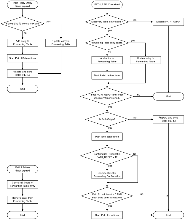
When a Path Reply Delay timer for a Discovery Table entry expires, the Path Target shall update the Forwarding Table state according to Section 3.6.8.5.3. If a new Forwarding Table entry is added, the node shall also start a Path Lifetime timer for the table entry. The Path Lifetime timer initial value shall be set to the Path_Origin_Path_Lifetime value in the Discovery Table entry.
After updating the Forwarding Table state, the node shall prepare and send a PATH_REPLY message with the following field values:
-
If the Destination value in the Discovery Table entry is a unicast address, the Unicast_Destination field shall be set to 1, and the Path_Target_Unicast_Addr_Range field shall be set to the unicast address range (see Section 3.4.2.2.1) of the Path Target. Otherwise, the Unicast_Destination field shall be set to 0 and the Path_Target_Unicast_Addr_Range field shall not be present.
-
If the Destination value in the Discovery Table entry is a unicast address, and the PATH_REPLY message is originated on behalf of a dependent node of the Path Target, the On_Behalf_Of_Dependent_Target field shall be set to 1, and the Dependent_Target_Unicast_Addr_Range field shall be set to the unicast address range of the dependent node. Otherwise, the On_Behalf_Of_Dependent_Target field shall be set to 0, and the Dependent_Target_Unicast_Addr_Range field shall not be present.
-
If the Destination value in the Discovery Table entry is a unicast address, and a Forwarding Table entry corresponding to a path from the primary element address of the node to the Path_Origin value in the Discovery Table entry does not exist (see Section 3.6.8.5.1), the Confirmation_Request field shall be set to the Two Way Path state value (see Section 4.2.31); otherwise, it shall be set to 0.
-
The Path_Origin field shall be set to the Path_Origin value in the Discovery Table entry.
-
The Path_Origin_Forwarding_Number field shall be set to the Path_Origin_Forwarding_Number value in the Discovery Table entry.
The Network PDU for the PATH_REPLY message shall have the following configuration:
-
The DST field shall be set to the Next_Toward_Path_Origin value in the Discovery Table entry.
-
The TTL field shall be set to 0.
The node shall send the message using the directed security credentials of the subnet over which the message is sent and shall tag the message with the immutable-credentials tag.
When a node receives a PATH_REPLY message, the node checks whether to process or discard the message. If a Discovery Table entry that corresponds to the received PATH_REPLY message exists (see Section 3.6.8.6.3), the received PATH_REPLY message shall be processed; otherwise, the PATH_REPLY message shall be discarded.
If the PATH_REPLY message is processed, the node shall update the Forwarding Table state according to Section 3.6.8.5.4. If the Path Lifetime timer for the Forwarding Table entry corresponding to the processed PATH_REPLY message is not running, the node shall start it. The Path Lifetime timer initial value shall be set to the Path_Origin_Path_Lifetime value in the Discovery Table entry.
If this is the first PATH_REPLY processed after the Path Discovery timer of the corresponding Discovery Table entry started, and the Path_Origin field value in the PATH_REPLY message is the primary element address of the node, then a lane of the path is considered established for the purpose of the Directed Forwarding Initialization procedure (see Section 3.6.8.2.1).
If this is the first PATH_REPLY processed after the Path Discovery timer of the corresponding Discovery Table entry started, and the Path_Origin field value in the PATH_REPLY message is the primary element address of the node, and the Confirmation_Request field value of the PATH_REPLY message is 1, then the node shall execute a Directed Forwarding Confirmation procedure (see Section 3.6.8.2.4).
If this is the first PATH_REPLY processed after the Path Discovery timer of the corresponding Discovery Table entry started, the Path_Origin field value in the PATH_REPLY message is the primary element address of the node, the Unicast_Destination field value in the PATH_REPLY message is 1, and the Unicast Echo Interval state is greater than 0 (see Section 4.2.32.1), then the node checks whether or not a Path Echo timer for the corresponding Forwarding Table entry is running. If the Path Echo timer is not running, the node shall start the Path Echo timer from the initial value set as defined in Section 4.2.32.1.
If this is the first PATH_REPLY processed after the Path Discovery timer of the corresponding Discovery Table entry started, the Path_Origin field value in the PATH_REPLY message is the primary element address of the node, the Unicast_Destination field value in the PATH_REPLY message is 0, and the Multicast Echo Interval state is greater than 0 (see Section 4.2.32.2), then the node checks whether or not a Path Echo timer for the corresponding Forwarding Table entry is running. If the Path Echo timer is not running, the node shall start the Path Echo timer from the initial value set as defined in Section 4.2.32.2.
If this is the first PATH_REPLY processed after the Path Discovery timer of the corresponding Discovery Table entry started, and the Path_Origin field value in the PATH_REPLY message is not the primary element address of the node, then the node shall prepare and send a new PATH_REPLY message in which the field values are copied from the received PATH_REPLY message.
The Network PDU for the new PATH_REPLY message shall have the following configuration:
-
The DST field shall be set to the Next_Toward_Path_Origin value in the Discovery Table entry corresponding to the received PATH_REPLY message.
-
The TTL field shall be set to 0.
The node shall send the message using the directed security credentials of the subnet over which the message is sent and shall tag the message with the immutable-credentials tag.
When a Path Lifetime timer for a Forwarding Table entry expires, the Forwarding Table entry shall be removed and all timers corresponding to the entry shall be stopped.
3.6.8.2.4. Directed Forwarding Confirmation
The Directed Forwarding Confirmation procedure shall be executed:
-
By a node that is the Path Origin indicated by the Path_Origin field in a received PATH_REPLY message with the Confirmation_Request field value of 1 after receiving the first PATH_REPLY message after the Path Discovery timer of the corresponding Discovery Table entry started.
-
By any Directed Forwarding node that receives a PATH_CONFIRMATION message.
Figure 3.32 is a flow chart illustrating the Directed Forwarding Confirmation procedure.

If the Path Origin receives a PATH_REPLY message with the Confirmation_Request field value of 1, the node shall prepare and send a PATH_CONFIRMATION message with the following field values:
-
The Path_Target field shall be set to the Destination value in the Forwarding Table entry corresponding to the received PATH_REPLY message (see Section 3.6.8.5.4).
-
The Path_Origin field shall be set to the primary element address of the Path Origin.
The Network PDU for the new PATH_CONFIRMATION message shall have the following configuration:
-
The DST field shall be set to the all-directed-forwarding-nodes fixed group address (see Section 3.4.2.4).
-
The TTL field shall be set to 0.
The Path Origin shall send the message using the directed security credentials of the subnet over which the message is sent and shall tag the message with the immutable-credentials tag.
When a Directed Forwarding node receives a PATH_CONFIRMATION message, the node checks whether to process or discard the message.
The PATH_CONFIRMATION message shall be discarded if any of the following conditions is met:
-
A non-fixed Forwarding Table entry corresponding to the PATH_CONFIRMATION message does not exist (see Section 3.6.8.5.5).
-
The Backward_Path_Validated value in the Forwarding Table entry corresponding to the PATH_CONFIRMATION message is 1, and the node is the Path Target indicated by the Path_Target field in the PATH_CONFIRMATION message.
-
The node has already sent a PATH_CONFIRMATION message after starting the Path Discovery timer for the Discovery Table entry that has the same Path_Origin and Path_Origin_Forwarding_Number values as the Forwarding Table entry that corresponds to the PATH_CONFIRMATION message. Once true, this condition shall persist until the Path Discovery timer expires.
If the received PATH_CONFIRMATION message can be processed, and the Backward_Path_Validated value in the corresponding Forwarding Table entry is 0, the table entry shall be updated as defined in Section 3.6.8.5.5. Then, if the node is not the Path Target indicated by the Path_Target field in the received PATH_CONFIRMATION message, the node shall prepare and send a new PATH_CONFIRMATION message in which the field values are copied from the received PATH_CONFIRMATION message.
A random delay from 0 to 30 milliseconds should be introduced between preparing and sending the PATH_CONFIRMATION message, to avoid collisions with messages being sent by other nodes at the same time.
The Network PDU for the new PATH_CONFIRMATION message shall have the following configuration:
-
The DST field shall be set to the all-directed-forwarding-nodes fixed group address (see Section 3.4.2.4).
-
The TTL field shall be set to 0.
The node shall send the message using the directed security credentials of the subnet over which the message is sent and shall tag the message with the immutable-credentials tag.
3.6.8.2.5. Directed Forwarding Dependents Update
The Directed Forwarding Dependents Update procedure is executed in the following contexts:
-
The procedure is executed by a Path Origin to notify the nodes along paths from that Path Origin that unicast addresses of its dependent nodes are to be added or removed from the corresponding Forwarding Table entries (see Section 3.6.8.3).
-
The procedure is executed by a Path Target to notify the nodes along paths to that Path Target that unicast addresses of its dependent nodes are to be added or removed from the corresponding Forwarding Table entries (see Section 3.6.8.3).
The conditions that trigger the Forwarding Dependents Update procedure in the contexts above are defined in Section 3.6.8.3.
The procedure shall also be executed by any Directed Forwarding node that receives a DEPENDENT_NODE_UPDATE message.
Figure 3.33 is a flow chart of the Directed Forwarding Dependents Update procedure.
 |
When the Directed Forwarding Dependents Update procedure starts, the node shall update all the Forwarding Table entries that correspond to paths with the node as a Path Origin or Path Target, as defined in Section 3.6.8.5.8.
If any Forwarding Table entries are updated, the node shall also prepare and send a DEPENDENT_NODE_UPDATE message with the following configuration:
-
The Type field shall be set to 1 if one or more addresses of a dependent node are to be added to the Forwarding Table state. If one or more addresses of a dependent node are to be removed from the Forwarding Table state, the Type field shall be set to 0.
-
The Path_Endpoint field shall be set to the primary element address of the Path Origin if the node is the Path Origin of any updated Forwarding Table entry. If the node is the Path Target of any updated Forwarding Table entry, the Path_Endpoint field shall be set to the primary element address of the Path Target.
-
The Dependent_Node_Unicast_Addr_Range field shall be set to the unicast address range (see Section 3.4.2.2.1) of the dependent node that is to be added to or to be removed from the Forwarding Table state.
The Network PDU for the DEPENDENT_NODE_UPDATE message shall have the following configuration:
-
The DST field shall be set to the all-directed-forwarding-nodes fixed group address (see Section 3.4.2.4).
-
The TTL field shall be set to 0.
The node shall send the message using the directed security credentials of the subnet over which the message is sent and shall tag the message with the immutable-credentials tag.
When a node receives a DEPENDENT_NODE_UPDATE message, the node shall check whether the Forwarding Table state contains at least one entry that corresponds to the DEPENDENT_NODE_UPDATE message (see Section 3.6.8.5.8).
Each entry that corresponds to the DEPENDENT_NODE_UPDATE message shall be updated as defined in Section 3.6.8.5.8. The node shall then send a new DEPENDENT_NODE_UPDATE message in which the field values are copied from the received DEPENDENT_NODE_UPDATE message.
The Network PDU for the new DEPENDENT_NODE_UPDATE message shall have the following configuration:
-
The DST field shall be set to the all-directed-forwarding-nodes fixed group address (see Section 3.4.2.4).
-
The TTL field shall be set to 0.
The node shall send the message using the directed security credentials of the subnet over which the message is sent and shall tag the message with the immutable-credentials tag.
If there is no Forwarding Table entry that corresponds to the DEPENDENT_NODE_UPDATE message, the message shall be discarded.
3.6.8.2.6. Directed Forwarding Echo
The Directed Forwarding Echo procedure shall be executed by a Path Origin when an instance of the Path Echo timer expires or by a Path Target when it receives a PATH_ECHO_REQUEST message in order to validate a path between the two nodes.
Figure 3.34 is a flow chart of the Directed Forwarding Echo procedure.

When the Path Echo timer corresponding to a Forwarding Table entry expires, the Path Origin shall send a PATH_ECHO_REQUEST message to the Destination value of the Forwarding Table entry in order to validate the path.
The Network PDU for the PATH_ECHO_REQUEST message shall have the following configuration:
-
The DST field shall be set to the Destination value of the Forwarding Table entry.
-
The TTL field shall be set to 0x7F.
The Path Origin shall send the message using the directed security credentials of the subnet over which the message is sent and shall tag the message with the immutable-credentials tag.
When the message is sent, an instance of the Path Echo Reply Timeout timer corresponding to the Forwarding Table entry shall be started from the initial value indicated by the default value of the Path Discovery Interval state (see Section 4.2.38.3).
When a Path Target receives a PATH_ECHO_REQUEST message, the node shall check whether a Forwarding Table entry that corresponds to the PATH_ECHO_REQUEST message exists as defined in Section 3.6.8.5.6.
If a Forwarding Table entry that corresponds to the PATH_ECHO_REQUEST message does not exist, the message shall be discarded. Otherwise, the Path Target shall prepare and send a PATH_ECHO_REPLY message to the Path Origin with the Destination field set to the DST field value of the PATH_ECHO_REQUEST message.
The Network PDU for the PATH_ECHO_REPLY message shall have the following configuration:
-
The DST field shall be set to the primary element address of the Path Origin.
-
The TTL field shall be set to 0x7F.
If the Backward_Path_Validated value in the Forwarding Table entry is 0, the Path Target shall send the message using the managed flooding security credentials of the subnet over which the message is sent; otherwise, the Path Target shall send the message using the directed security credentials of the subnet over which the message is sent.
When the Path Origin receives the PATH_ECHO_REPLY message, the node shall check whether a Forwarding Table entry that corresponds to the PATH_ECHO_REPLY message exists as defined in Section 3.6.8.5.7.
If the Forwarding Table entry that corresponds to the PATH_ECHO_REPLY message does not exist; or if the Forwarding Table entry that corresponds to the PATH_ECHO_REPLY message exists, and the corresponding Path Echo Reply Timeout timer is not running, then the PATH_ECHO_REPLY message shall be discarded.
If the Forwarding Table entry that corresponds to the PATH_ECHO_REPLY message exists, and the corresponding Path Echo Reply Timeout timer is running, then the Path Echo Reply Timeout timer shall be stopped, and the Directed Forwarding Echo procedure succeeds. In addition, if the destination is a unicast address and the Unicast Echo Interval state is greater than 0 (see Section 4.2.32.1), or if the destination is a group address or a virtual address and the Multicast Echo Interval state is greater than 0 (see Section 4.2.32.2), then the node shall start an instance of the Path Echo timer for the Forwarding Table entry from the initial value set as defined in Section 4.2.32.
When the Path Echo Reply Timeout timer expires, the Directed Forwarding Echo procedure fails.
When the Directed Forwarding Echo procedure fails, the Forwarding Table entry corresponding to the failed Directed Forwarding Echo procedure shall be deleted and the Forwarding Table Update Identifier state (see Section 4.2.29.1) shall be changed.
3.6.8.2.7. Directed Forwarding Solicitation
The Directed Forwarding Solicitation procedure is executed by a Directed Forwarding node or by a Configuration Manager to solicit the discovery of paths toward unicast addresses, group addresses, or virtual addresses.
The Directed Forwarding Solicitation procedure shall be executed by a Directed Forwarding node in any of the following contexts:
-
The Subscription List state of the Directed Forwarding node has been updated with new addresses.
-
The Directed Forwarding node receives a PATH_REQUEST_SOLICITATION message.
The procedure is also executed if the Directed Forwarding node is a supporting node, and it is notified of new group addresses or virtual addresses to which its dependent node is subscribed. The conditions that trigger the Directed Forwarding Solicitation procedure in this case are listed in Section 3.6.8.3.
The Directed Forwarding Solicitation procedure should be executed by a Path Target that may no longer be reachable via existing paths (e.g., because the device has been physically moved).
Figure 3.35 is a flow chart of the Directed Forwarding Solicitation procedure.
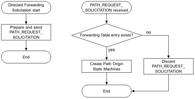
When the Directed Forwarding Solicitation procedure starts, a PATH_REQUEST_SOLICITATION message shall be prepared and sent with the following configuration:
-
The Addr_List field shall contain a list of unicast addresses, group addresses, and virtual addresses that are intended destinations of the path discovery.
The Network PDU for the PATH_REQUEST_SOLICITATION message shall have the following configuration:
-
The DST field shall be set to the all-directed-forwarding-nodes fixed group address (see Section 3.4.2.4).
-
The TTL field shall be set to 0x7F.
The Network PDU shall be sent using the directed security credentials of the subnet over which the message is sent and shall be tagged with the immutable-credentials tag.
When a node receives a PATH_REQUEST_SOLICITATION message, the node checks whether a non-fixed path entry in the Forwarding Table state that corresponds to the PATH_REQUEST_SOLICITATION message exists as defined in Section 3.6.8.5.9.
If a Forwarding Table entry that corresponds to the PATH_REQUEST_SOLICITATION message exists, the node shall delete the entry from the Forwarding Table state and shall create a Path Origin State Machine (see Section 4.4.7.2) for each of the destinations in the Addr_List field of the PATH_REQUEST_SOLICITATION message.
If a Forwarding Table entry that corresponds to the PATH_REQUEST_SOLICITATION message does not exist, the message shall be discarded.
3.6.8.2.8. Examples of Transport Control message exchange and updates to the Forwarding Table state
Figure 3.36 shows an example of the Transport Control message exchange and updates to the Forwarding Table state that are reported during Directed Forwarding Initialization, Directed Forwarding Discovery, and Directed Forwarding Establishment procedures between two nodes (Nodes A and B). Node A creates a Discovery Table entry for the path from Node A to Node B and transmits a PATH_REQUEST message. Node B receives the message, creates a Discovery Table entry for the path, and stores the address of Node A in the Next_Toward_Path_Origin field. After the Path Reply Delay timer expires, Node B creates a Forwarding Table entry for the path and transmits a PATH_REPLY message to Node A. When Node A receives the PATH_REPLY message, it creates a Forwarding Table entry for the path and starts using directed forwarding to transmit messages.

Similarly, Figure 3.37 shows an example of the exchange of Transport Control messages and updates to Forwarding Table states that are reported during the Directed Forwarding Initialization, Directed Forwarding Discovery, and Directed Forwarding Establishment procedures.
In this example, the Transport Control messages are exchanged among Node A and two other nodes (Nodes C and D), which are subscribed to group address G, via an intermediate node (Directed Relay B) in the following sequence:
-
Node A creates a Discovery Table entry for the path to group address G and transmits a PATH_REQUEST message.
-
Directed Relay B receives the message, creates a Discovery Table entry for the path, stores the address of Node A in the Next_Toward_Path_Origin field, and then forwards the PATH_REQUEST message.
-
Both Node C and Node D receive the PATH_REQUEST message and create a Forwarding Table entry associated with the path to group address G.
-
When the Path Reply Delay timer at Node C expires, Node C creates a Forwarding Table entry and transmits a PATH_REPLY message to Directed Relay B.
-
Directed Relay B creates a Forwarding Table entry and transmits a PATH_REPLY message to Node A.
-
When the Path Reply Delay timer at Node D expires, Node D creates a Forwarding Table entry and transmits a PATH_REPLY message to Directed Relay B.
Directed Relay B does not perform additional actions because it already stores a Forwarding Table entry for the path to group G.

3.6.8.3. Node dependence in directed forwarding
In directed forwarding, node dependence is a relationship between two nodes in a subnet, a dependent node and a supporting node. A supporting node performs the following actions on behalf of a dependent node:
-
Performs directed forwarding procedures.
-
Uses directed security credentials to forward messages generated by the dependent node.
A supporting node can have many dependent nodes.
Node dependence within a subnet includes the following scenarios:
-
A Low Power node has established a friendship with a Friend node that is functioning as a Directed Friend node and has sent at least one message using the friendship security credentials. The Low Power node is the dependent node. The Directed Friend node is the supporting node. Node dependence is terminated when the friendship is terminated or when directed friend functionality in the Friend node is disabled.
-
A Proxy Client is connected to a Proxy Server, and the Proxy_Client_Type parameter of the connection is Proxy Client, and the Use_Directed parameter of the connection is set to Enabled for the subnet (see Section 6.7.1), and the Proxy Client sent at least one Network PDU via the GATT connection. The Proxy Client is a dependent node. The Directed Proxy node is the supporting node. The node dependence is terminated when the proxy filter type is set to reject list, when directed proxy functionality in the Proxy Server is disabled, or when the Proxy Client disconnects.
-
A Proxy Client is connected to a Directed Proxy Server, and the Proxy_Client_Type parameter of the connection is Directed Proxy Client, and the Use_Directed parameter of the connection is set to Enabled for the subnet (see Section 6.7.1). The Directed Proxy Client is a dependent node for the subnet. The Directed Proxy node is the supporting node. The node dependence is terminated when the proxy filter type is set to reject list, when directed proxy functionality in the Proxy Server is disabled, when the Directed Proxy Client sets the Use_Directed parameter of the connection to Disabled, or when the Direct Proxy Client disconnects.
-
A node’s address is included in the Bridging Table state of a Subnet Bridge in the Address1 field or in the Address2 field (see Section 4.2.42) and directed forwarding functionality is enabled in at least one of the bridged subnets. The nodes identified by the addresses included in the Bridging Table state are dependent nodes (see Section 3.6.8.1.11). The Subnet Bridge node is the supporting node in the subnets where directed forwarding is enabled and only for addresses from which traffic is bridged or toward which traffic is bridged. Node dependence is terminated when the address of the dependent node is removed from the Bridging Table state, or subnet bridge functionality is disabled, or directed forwarding functionality of the Subnet Bridge is disabled in both subnets of the Bridging Table state entry.
Directed forwarding procedures at a supporting node can be initiated when a Network PDU is received from the dependent node, as described in Section 3.4.6.3.
If a Network PDU received from a dependent node is retransmitted by a supporting node (see Section 3.4.6.3), and a path to the destination does not exist (see Section 3.6.8.5.1), the supporting node shall create a Path Origin State Machine (see Section 4.4.7.2).
If the supporting node is a Directed Friend node, the following behaviors apply:
-
If one or more group addresses, which are different from the all-directed-forwarding-nodes, all-nodes, and all-relays fixed group addresses, or one or more virtual addresses are added to the Friend Subscription List of the supporting node (see Section 3.6.5.7), then the supporting node shall execute a Directed Forwarding Solicitation procedure (see Section 3.6.8.2.7) for a set of group addresses and virtual addresses that contains addresses that are in the Friend Subscription List and are not in the Destination field of any Forwarding Table entry for the subnet.
-
If the node dependence is terminated, and the element addresses of the dependent node are listed in at least one Forwarding Table entry of the supporting node for the subnet, then the supporting node shall execute a Directed Forwarding Dependents Update procedure for the unicast address range of the dependent node.
If the supporting node is a Directed Proxy node, the following behaviors apply:
-
If one or more group addresses, which are different from the all-directed-forwarding-nodes, all-nodes, and all-relays fixed group addresses, or one or more virtual addresses are added to the accept list filter of the supporting node (see Section 6.7), then the supporting node shall execute a Directed Forwarding Solicitation procedure (see Section 3.6.8.2.7) for a set of group addresses and virtual addresses that contains addresses that are in the accept list filter and are not in the Destination field of any Forwarding Table entry for the subnet.
-
If the node dependence is terminated, and the Proxy_Client_Type parameter of the connection is Directed Proxy Client, and at least one element address of the dependent node is listed in at least one Forwarding Table entry of the supporting node for the subnet, then the supporting node shall execute a Directed Forwarding Dependents Update procedure for the unicast address range of the dependent node for the subnet.
-
If the node dependence is terminated, and the Proxy_Client_Type parameter of the connection is Proxy Client, and at least one element address of the dependent node is listed in at least one Forwarding Table entry of the supporting node for the subnet, then the supporting node shall execute a Directed Forwarding Dependents Update procedure for each known unicast address of the dependent node for the subnet.
If the supporting node is a Subnet Bridge node, the following behaviors apply:
-
If one or more group addresses, which are different from the all-directed-forwarding-nodes, all-nodes, and all-relays fixed group addresses, or one or more virtual addresses are added to the Bridging Table state of the supporting node (see Section 4.2.42), and directed forwarding functionality is enabled in the subnet identified by NetKeyIndex1 of the added Bridging Table state entries, then the supporting node shall execute a Directed Forwarding Solicitation procedure (see Section 3.6.8.2.7) for a set of group addresses and virtual addresses that contains addresses that are in the Bridging Table state and are not in the Destination field of any Forwarding Table entry in that subnet.
-
If the node dependence is terminated, and the element addresses of the dependent node are listed in at least one Forwarding Table entry of the supporting node for the associated subnet, then the supporting node shall execute a Directed Forwarding Dependents Update procedure for the unicast address range of the dependent node.
3.6.8.3.1. MSC example
The MSC in Figure 3.38 illustrates message sequencing for a Directed Friend interacting with a Low Power Node. The friendship is established over subnet 1, and the illustrated Directed Friend is configured as a supporting node for the dependent node on the subnet 1.
 |
3.6.8.4. Forwarding number
Each node manages a forwarding number for each subnet. The forwarding number is used to distinguish Transport Control messages sent by a node in the context of different Directed Forwarding Initialization procedures. This enables discarding of outdated messages (with an old forwarding number), discovery of new lanes (with the same forwarding number), and creation of new paths (with a new forwarding number).
When a node is added to a subnet, the forwarding number for that subnet shall be set to 255. Before a Directed Forwarding Initialization procedure is executed, the forwarding number shall be set according to the following equation:
|
next forwarding number=(forwarding number+1) modulo 256 |
The following comparison shall be performed to determine whether one forwarding number is less than, equal to, or greater than another forwarding number:
-
Forwarding number a is equal to forwarding number b if a equals b.
-
Forwarding number b is greater than forwarding number a if b is one of the 127 numbers succeeding a, taking the wrap into account.
-
Forwarding number b is less than forwarding number a if b is one of the 128 numbers preceding a, taking the wrap into account.
For example, forwarding numbers 1 to 127 are greater than forwarding number 0, but forwarding numbers 128 to 255 are less than forwarding number 0.
3.6.8.5. Forwarding Table processing
A Forwarding Table stores pairs of source and destination addresses for each path that a Directed Forwarding node is part of. The node is part of a path if it is the Path Origin, the Path Target, or any intermediate Directed Relay node. The Forwarding Table is represented by the Forwarding Table state (see Section 4.2.29). The Directed Forwarding node stores a separate Forwarding Table for each subnet it belongs to. The Forwarding Table initially is empty when the node is added to a new subnet.
Each Directed Forwarding node filters Network PDUs to be retransmitted using the directed security credentials based on its Forwarding Table state (see Section 3.4.6.3). The Forwarding Table state can be updated by directed forwarding procedures that the node executes (see Section 3.6.8.1) and by configuration messages received from a Configuration Manager (see Section 4.3.5).
Section 3.6.8.5.1 defines the correspondence between a Forwarding Table entry and a path. This definition is valid for both fixed paths (i.e., the Fixed_Path value in the Forwarding Table entry is 1) and non-fixed paths (i.e., the Fixed_Path value in the Forwarding Table entry is 0).
Sections 3.6.8.5.2 through 3.6.8.5.9 describe how the processing of Transport Control messages and expiration of timers in directed forwarding results in the addition, modification, or deletion of non-fixed path entries in the Forwarding Table state.
3.6.8.5.1. Forwarding Table entry corresponding to a path
A Forwarding Table entry corresponds to a path from a source address to a destination address if one of the following conditions is met:
-
The source address is equal to any address in the range specified in the Originator Address Range entry for any row in Table 3.58, and the destination address is equal to any address in the range specified in the Destination Address Range entry for that row.
-
The Backward_Path_Validated value in the table entry is 1, and the source address is equal to any address in the range specified in the Destination Address Range entry for any row in Table 3.58, and the destination address is equal to any address in the range specified in the Originator Address Range entry for that row.
Moreover, a path shall exist for a destination address that is the all-directed-forwarding-nodes fixed group address (see Section 3.4.2.4).
|
Originator Address Range |
Destination Address Range |
|---|---|
|
Path_Origin to (Path_Origin + Path_Origin_Secondary_Elements_Count), where:
|
Destination to (Destination + Path_Target_Secondary_Elements_Count), where:
|
|
Path_Origin to (Path_Origin + Path_Origin_Secondary_Elements_Count), where:
|
DependentTarget to (DependentTarget + DependentTargetSecondaryElementsCount), where:
|
|
DependentOrigin to (DependentOrigin + DependentOriginSecondaryElementsCount), where:
|
Destination to (Destination + Path_Target_Secondary_Elements_Count), where:
|
|
DependentOrigin to (DependentOrigin + DependentOriginSecondaryElementsCount), where:
|
DependentTarget to (DependentTarget + DependentTargetSecondaryElementsCount), where:
|
3.6.8.5.2. PATH_REQUEST message received
When a PATH_REQUEST message (see Section 3.6.5.11) is received, the node derives the primary element address of the Path Origin from the Path_Origin_Unicast_Addr_Range field (see Section 3.4.2.2.4) in the message, and the node checks whether the Forwarding Table contains a non-fixed entry corresponding to the PATH_REQUEST message.
A Forwarding Table entry corresponds to the PATH_REQUEST message when all of the following conditions are met:
-
The Fixed_Path value of the Forwarding Table entry is 0.
-
The primary element address of the Path Origin is equal to the Path_Origin value of the Forwarding Table entry.
-
The Destination field value of the message is equal to any address in the range specified in the Destination Address Range entry in the first or second row of Table 3.58.
The Forwarding Table state is not updated when a PATH_REQUEST message is received.
3.6.8.5.3. Path Reply Delay timer expired
When a Path Reply Delay timer for a Discovery Table entry expires, the node checks whether the Forwarding Table contains a non-fixed entry corresponding to the Discovery Table entry.
A Forwarding Table entry corresponds to a Discovery Table entry when all of the following conditions are met:
-
The Fixed_Path value of the Forwarding Table entry is 0.
-
The Path_Origin value of the Discovery Table entry is equal to the Path_Origin value of the Forwarding Table entry.
-
The Path_Origin_Forwarding_Number value of the Discovery Table entry is equal to the Forwarding_Number value of the Forwarding Table entry.
No existing Forwarding Table entry. If the Forwarding Table does not already contain an entry that corresponds to the Discovery Table entry, then the Forwarding Table Update Identifier shall be changed (see Section 4.2.29.1), and a new entry shall be added to the Forwarding Table state.
The new Forwarding Table entry shall have the following values:
-
Fixed_Path, Backward_Path_Validated, and Path_Not_Ready: Set to 0.
-
Path_Origin, Path_Origin_Secondary_Elements_Count, Forwarding_Number, and Bearer_Toward_Path_Origin: Set to the corresponding Path_Origin, Path_Origin_Secondary_Elements_Count, Forwarding_Number, and Bearer_Toward_Path_Origin values of the Discovery Table entry.
-
Dependent_Origin_List: Initialized with the Dependent_Origin value of the Discovery Table entry if the Dependent_Origin value is not the unassigned address; otherwise, the Dependent_Origin_List is empty.
-
Dependent_Origin_Secondary_Elements_Count_List: Initialized with the Dependent_Origin_Secondary_Elements_Count value of the Discovery Table entry if the Dependent_Origin value is not the unassigned address; otherwise, the Dependent_Origin_Secondary_Elements_Count_List is empty.
-
Destination: Set to the Destination value of the Discovery Table entry if it is a group address or a virtual address; otherwise, set to the primary element address of the Path Target.
-
Path_Target_Secondary_Elements_Count: Set to the number of secondary element addresses of the Path Target if the Destination value of the Discovery Table entry is a unicast address; otherwise, set to 0.
-
Dependent_Target_List: Initialized with the primary element address of a dependent node if the Destination value of the Discovery Table entry is an element address of that dependent node; otherwise, the Dependent_Target_List is empty.
-
Dependent_Target_Secondary_Elements_Count_List: Initialized with the number of secondary element addresses of a dependent node if the Destination value of the Discovery Table entry is an element address of that dependent node; otherwise, the Dependent_Target_Secondary_Elements_Count_List is empty.
-
Bearer_Toward_Path_Target: Set to the unassigned bearer index (see Section 4.3.1.4).
-
Lane_Counter: Set to 1.
If the Forwarding Table contains other non-fixed path entries with the same Path_Origin and Destination values as in the added Forwarding Table entry, these other entries shall be removed.
Existing Forwarding Table entry. If the Forwarding Table already contains an entry that corresponds to the Discovery Table entry, then the Forwarding Table Update Identifier shall be changed (see Section 4.2.29.1), and the Forwarding Table entry shall be updated with the following values:
-
Bearer_Toward_Path_Origin: The bit representing the bearer in the Bearer_Toward_Path_Origin value of the Discovery Table entry shall be set to 1 (see Section 4.3.1.4). All the other bits shall be left unchanged.
-
Lane_Counter: Incremented by 1.
3.6.8.5.4. PATH_REPLY message received
When a PATH_REPLY message (see Section 3.6.5.12) is received, the node checks whether an existing Forwarding Table entry corresponds to the PATH_REPLY message.
A Forwarding Table entry corresponds to the PATH_REPLY message when both of the following conditions are met:
-
The Path_Origin field value in the message is equal to the Path_Origin value in the table entry.
-
The Path_Origin_Forwarding_Number field value in the message is equal to the Forwarding_Number value in the table entry.
No existing Forwarding Table entry. If the Forwarding Table does not already contain an entry that corresponds to the PATH_REPLY message, the Forwarding Table Update Identifier shall change (see Section 4.2.29.1), and a new entry shall be added to the Forwarding Table state, based on values in the Discovery Table entry that corresponds to the PATH_REPLY message (see Section 3.6.8.6.3).
The new Forwarding Table entry shall have the following values:
-
Fixed_Path and Backward_Path_Validated: Set to 0.
-
Path_Not_Ready: Set to 1 if the node is the Path Origin and the Unicast_Destination field value in the PATH_REPLY message is 0; otherwise, set to 0.
-
Path_Origin, Path_Origin_Secondary_Elements_Count, and Forwarding_Number: Set to the Path_Origin, Path_Origin_Secondary_Elements_Count, and Path_Origin_Forwarding_Number values of the Discovery Table entry.
-
Bearer_Toward_Path_Origin: Set to the Bearer_Toward_Path_Origin value of the Discovery Table entry if the node is not the Path Origin; otherwise, set to the unassigned bearer index (see Section 4.3.1.4).
-
Dependent_Origin_List: Initialized with the Dependent_Origin value of the Discovery Table entry if that value is not the unassigned address; otherwise, Dependent_Origin_List is empty.
-
Dependent_Origin_Secondary_Elements_Count_List: Initialized with the Dependent_Origin_Secondary_Elements_Count value of the Discovery Table entry if the Dependent_Origin value in the Discovery Table entry is not the unassigned address; otherwise, Dependent_Origin_Secondary_Elements_Count_List is empty.
-
Destination: Set to the Destination value of the Discovery Table entry if the Destination value is a group address or virtual address; otherwise, Destination is set to the primary element address derived from the Path_Target_Unicast_Addr_Range field in the PATH_REPLY message (see Section 3.4.2.2.4).
-
Path_Target_Secondary_Elements_Count: Set to the Path_Target_Secondary_Elements_Count value derived from the Path_Target_Unicast_Addr_Range field in the PATH_REPLY message (see Section 3.4.2.2.4) if the Unicast_Destination field value in the PATH_REPLY message is 1; otherwise, set to 0.
-
Dependent_Target_List: Initialized with the Dependent_Target value derived from the Dependent_Target_Unicast_Addr_Range field in the PATH_REPLY message (see Section 3.4.2.2.4) if the Unicast_Destination and On_Behalf_Of_Dependent_Target field values in the PATH_REPLY message both are 1; otherwise, Dependent_Target_List is empty.
-
Dependent_Target_Secondary_Elements_Count_List: Initialized with the Dependent_Target_Secondary_Elements_Count value derived from the Dependent_Target_Unicast_Addr_Range field in the PATH_REPLY message (see Section 3.4.2.2.4) if the Unicast_Destination and On_Behalf_Of_Dependent_Target field values in the PATH_REPLY message both are 1; otherwise, Dependent_Target_Secondary_Elements_Count_List is empty.
-
Bearer_Toward_Path_Target: The bit representing the bearer from which the Network PDU of the PATH_REPLY message was received shall be set to 1 (see Section 4.3.1.4). All other bits shall be set to 0.
-
Lane_Counter: Set to 1.
If the Forwarding Table contains other non-fixed path entries with the same Path_Origin and Destination values as in the added Forwarding Table entry, these other entries shall be removed.
Existing Forwarding Table entry. If the Forwarding Table already contains an entry that corresponds to the PATH_REPLY message, the Forwarding Table Update Identifier shall change (see Section 4.2.29.1), and the entry shall be updated based on values in the Discovery Table entry that corresponds to the PATH_REPLY message (see Section 3.6.8.6.3).
The updated Forwarding Table entry shall have the following values:
-
Bearer_Toward_Path_Origin: If the node is not the Path Origin, the bit representing the bearer in the Bearer_Toward_Path_Origin value of the Discovery Table entry shall be set to 1. All other bits shall be left unchanged.
-
Bearer_Toward_Path_Target: The bit representing the bearer from which the Network PDU of the PATH_REPLY message was received shall be set to 1. All other bits shall be left unchanged.
-
Lane_Counter: Shall be incremented by 1 if this is the first PATH_REPLY received after the Path Discovery timer of the corresponding Discovery Table entry started; otherwise, left unchanged.
3.6.8.5.5. PATH_CONFIRMATION message received
When a PATH_CONFIRMATION message (see Section 3.6.5.13) is received, the node checks whether an existing non-fixed Forwarding Table entry corresponds to the PATH_CONFIRMATION message.
A Forwarding Table entry corresponds to a PATH_CONFIRMATION message when the following conditions are met:
-
The Fixed_Path value of the table entry is 0.
-
The Path_Origin field value in the message is equal to the Path_Origin value in the table entry.
-
The Path_Target field value in the message is equal to the Destination value in the table entry.
If a Forwarding Table entry that corresponds to the PATH_CONFIRMATION message exists, the Backward_Path_Validated field in the table entry shall be set to 1, and the Forwarding Table Update Identifier shall change (see Section 4.2.29.1).
3.6.8.5.6. PATH_ECHO_REQUEST message received
When a PATH_ECHO_REQUEST message (see Section 3.6.5.14) is received, the node checks whether an existing non-fixed Forwarding Table entry corresponds to the PATH_ECHO_REQUEST message.
A Forwarding Table entry corresponds to a PATH_ECHO_REQUEST message when the following conditions are met:
-
The Fixed_Path value of the table entry is 0.
-
The SRC field value of the Network PDU of the message is equal to the Path_Origin value in the table entry.
-
The DST field value of the Network PDU of the message is equal to the Destination value in the table entry.
The Forwarding Table state is not updated when a PATH_ECHO_REQUEST message is received.
3.6.8.5.7. PATH_ECHO_REPLY message received
When a PATH_ECHO_REPLY message (see Section 3.6.5.15) is received, the node checks whether an existing non-fixed Forwarding Table entry corresponds to the PATH_ECHO_REPLY message.
A Forwarding Table entry corresponds to a PATH_ECHO_REPLY message when the following conditions are met:
-
The Fixed_Path value of the table entry is 0.
-
The DST field value in the Network PDU of the message is equal to the Path_Origin value in the table entry.
-
The Destination field value of the message is equal to the Destination value in the table entry.
-
The message was secured using the directed security material and the Backward_Path_Validated value in the table entry is 1; or the message was secured using the managed flooding security material and the Backward_Path_Validated value in the table entry is 0.
The Forwarding Table state is not updated when a PATH_ECHO_REPLY message is received.
3.6.8.5.8. DEPENDENT_NODE_UPDATE message received
When a DEPENDENT_NODE_UPDATE message is received (see Section 3.6.5.16), the node derives the primary element address and the number of secondary elements of a dependent node from the Dependent_Node_Unicast_Addr_Range field (see Section 3.4.2.2.4) in the message. (In this discussion, the primary element address and the number of secondary elements of the dependent node are referred to as the DependentNode and the DependentNodeSecondaryElementsCount, respectively.)
Then, the node checks whether one or more of the non-fixed existing Forwarding Table entries correspond to the DEPENDENT_NODE_UPDATE message.
A non-fixed Forwarding Table entry corresponds to a DEPENDENT_NODE_UPDATE message if one of the following conditions is met:
-
The Path_Endpoint field value in the message is equal to the Path_Origin value of the table entry, the Type field value in the message is 0, and the DependentNode is included in the Dependent_Origin_List field of the table entry.
-
The Path_Endpoint field value in the message is equal to the Path_Origin value of the table entry, the Type field value in the message is 1, and the DependentNode is not included in the Dependent_Origin_List field of the table entry.
-
The Path_Endpoint field value in the message is equal to the Destination value of the table entry, the Type field value in the message is 0, and the DependentNode is included in the Dependent_Target_List field of the table entry.
-
The Path_Endpoint field value in the message is equal to the Destination value of the table entry, the Type field value in the message is 1, the Backward_Path_Validated value of the table entry is 1, and the DependentNode is not included in the Dependent_Target_List field of the table entry.
Path endpoint is the Path Origin: If the Path_Endpoint field value in the message is equal to the Path_Origin value of the table entry, and the Type field value in the message is 0, then the node shall remove the DependentNode from the Dependent_Origin_List field of the table entry, and shall remove the corresponding value from the Dependent_Origin_Secondary_Elements_Count_List field of the table entry.
If the Path_Endpoint field value in the message is equal to the Path_Origin value of the table entry, and the Type field value in the message is 1, then the node shall add the DependentNode to the Dependent_Origin_List field of the table entry, and shall add the DependentNodeSecondaryElementsCount to the Dependent_Origin_Secondary_Elements_Count_List field of the table entry.
Path endpoint is the Path Target: If the Path_Endpoint field value in the message is equal to the Destination value of the table entry, and the Type field value in the message is 0, then the node shall remove the DependentNode from the Dependent_Target_List field of the table entry, and shall remove the corresponding value from the Dependent_Target_Secondary_Elements_Count_List field of the table entry.
If the Path_Endpoint field value in the message is equal to the Destination value of the table entry, and the Backward_Path_Validated value of the table entry is 1, and the Type field value in the message is 1, then the node shall add the DependentNode to the Dependent_Target_List field of the table entry, and shall add the DependentNodeSecondaryElementsCount to the Dependent_Target_Secondary_Elements_Count_List field of the table entry.
If the Forwarding Table is updated when a DEPENDENT_NODE_UPDATE message is received, the Forwarding Table Update Identifier shall change (see Section 4.2.29.1).
3.6.8.5.9. PATH_REQUEST_SOLICITATION message received
When a PATH_REQUEST_SOLICITATION message (see Section 3.6.5.17) is received, the node checks whether an existing non-fixed path entry in the Forwarding Table state corresponds to the PATH_REQUEST_SOLICITATION message. If a non-fixed path entry in the Forwarding Table state corresponding to the PATH_REQUEST_SOLICITATION message exists, the node shall delete the entry. If any of the Forwarding Table entries are deleted, the Forwarding Table Update Identifier shall change (see Section 4.2.29.1).
A Forwarding Table entry corresponds to the PATH_REQUEST_SOLICITATION message when the following conditions are met:
-
The Fixed_Path value in the table entry is equal to 0b0.
-
The Path_Origin value in the table entry is equal to the primary element address of the node (i.e., the node is the Path Origin of the path corresponding to the table entry).
-
The Destination value in the table entry is equal to at least one of the addresses in the Addr_List field of the message.
3.6.8.6. Discovery Table processing
Each node manages a Discovery Table containing a list of temporary entries created during a path discovery. If the node belongs to multiple subnets, then a Discovery Table is maintained for each subnet.
The format of Discovery Table entries is defined in Table 3.59.
|
Field |
Description |
|---|---|
|
Path_Origin |
Primary element address of the Path Origin |
|
Path_Origin_Secondary_Elements_Count |
Number of secondary elements of the Path Origin |
|
Dependent_Origin |
Primary element address of a dependent node of the Path Origin, if the path is discovered on behalf of that dependent node; otherwise, the unassigned address. |
|
Dependent_Origin_Secondary_Elements_Count |
Number of secondary elements of the dependent node of the Path Origin, if the path is discovered on behalf of that dependent node; otherwise, 0. |
|
Path_Origin_Forwarding_Number |
Forwarding number generated by the Path Origin for the path discovery |
|
Path_Origin_Path_Metric_Type |
Path metric type used to calculate the Path_Origin_Path_Metric field value |
|
Path_Origin_Path_Lifetime |
Path lifetime specified by the Path Origin |
|
Path_Discovery_Interval |
Path discovery interval specified by the Path Origin |
|
Path_Origin_Path_Metric |
Path metric value for the path |
|
Destination |
The unicast address, group address, or virtual address of the destination |
|
Next_Toward_Path_Origin |
Primary element address of the node selected as the next hop toward the Path Origin |
|
Bearer_Toward_Path_Origin |
Index of the bearer from which a PATH_REQUEST was received. |
The Discovery Table initially is empty. A Path Origin updates its Discovery Table when a Directed Forwarding Initialization procedure is executed. A Path Target or a Directed Relay node updates its Discovery Table when a PATH_REQUEST message is received and processed.
3.6.8.6.1. Directed Forwarding Initialization procedure executed
When a Path Origin executes a Directed Forwarding Initialization procedure, the node shall add a new entry with the following format to the Discovery Table:
-
Path_Origin: Set to the primary element address of the node.
-
Path_Origin_Secondary_Elements_Count: Set to the number of secondary elements of the node.
-
Dependent_Origin: Set to the primary element address of the dependent node of the Path Origin if the Directed Forwarding Initialization procedure is executed on behalf of that dependent node; otherwise, set to the unassigned address.
-
Dependent_Origin_Secondary_Elements_Count: Set to the number of secondary elements of the dependent node of the Path Origin if the Directed Forwarding Initialization procedure is executed on behalf of that dependent node; otherwise, set to 0.
-
Path_Origin_Forwarding_Number: Set to the forwarding number (see Section 3.6.8.4) of the Path Origin.
-
Destination: Set to the destination of the path.
-
Path_Origin_Path_Metric_Type: Set to the Path Metric Type state value (see Section 4.2.27.1).
-
Path_Origin_Path_Lifetime: Set to the time interval derived from the Path Lifetime state (see Section 4.2.27.2).
-
Path_Discovery_Interval: Set to the Path Discovery Interval state (see Section 4.2.38.3).
-
Path_Origin_Path_Metric: Set to 0.
-
Next_Toward_Path_Origin: Set to the unassigned address.
-
Bearer_Toward_Path_Origin: Set to the unassigned bearer index (see Section 4.3.1.4).
3.6.8.6.2. PATH_REQUEST message received
When a PATH_REQUEST message (see Section 3.6.5.11) is received, the node checks whether an existing Discovery Table entry corresponds to the PATH_REQUEST message.
A Discovery Table entry corresponds to the PATH_REQUEST message if both of the following conditions are met:
-
The Path_Origin field value in the message is equal to the Path_Origin value of the table entry.
-
The Path_Origin_Forwarding_Number field value in the message is equal to the Path_Origin_Forwarding_Number value of the table entry.
If no existing Discovery Table entry corresponds to the PATH_REQUEST message, a new entry shall be added to the Discovery Table in the following format:
-
Path_Origin: Set to the Path_Origin value derived from the Path_Origin_Unicast_Addr_Range field value in the PATH_REQUEST message (see Section 3.4.2.2.4).
-
Path_Origin_Secondary_Elements_Count: Set to the Path_Origin_Secondary_Elements_Count value derived from the Path_Origin_Unicast_Addr_Range field value in the PATH_REQUEST message (see Section 3.4.2.2.4).
-
Dependent_Origin: Set to the Dependent_Origin value derived from the Dependent_Origin_Unicast_Addr_Range field value in the PATH_REQUEST message (see Section 3.4.2.2.4) if the On_Behalf_Of_Dependent_Origin field value in the message is 1; otherwise, set to the unassigned address.
-
Dependent_Origin_Secondary_Elements_Count: Set to the Dependent_Origin_Secondary_Elements_Count value derived from the Dependent_Origin_Unicast_Addr_Range field value in the PATH_REQUEST message (see Section 3.4.2.2.4) if the On_Behalf_Of_Dependent_Origin field value in the message is 1; otherwise, set to 0.
-
Path_Origin_Forwarding_Number, Destination, Path_Origin_Path_Metric_Type, Path_Origin_Path_Metric, Path_Origin_Path_Lifetime, and Path_Discovery_Interval: Set to the values of the corresponding fields in the PATH_REQUEST message.
-
Next_Toward_Path_Origin: Set to the SRC field value of the Network PDU of the PATH_REQUEST message.
-
Bearer_Toward_Path_Origin: The bit representing the bearer from which the Network PDU of the PATH_REQUEST message was received shall be set to 1 (see Section 4.3.1.4). All other bits shall be set to 0.
If a Discovery Table entry corresponds to the PATH_REQUEST message, and the Path_Origin_Path_Metric value in the PATH_REQUEST message is less than the Path_Origin_Path_Metric value of the table entry, then the following values of the table entry shall be updated:
-
Path_Origin_Path_Metric: Set to the Path_Origin_Path_Metric field value of the message.
-
Next_Toward_Path_Origin: Set to the SRC field value of the Network PDU of the PATH_REQUEST message.
-
Bearer_Toward_Path_Origin: The bit representing the bearer from which the Network PDU of the PATH_REQUEST message was received shall be set to 1 (see Section 4.3.1.4). All other bits shall be set to 0.
3.6.8.6.3. PATH_REPLY message received
When a PATH_REPLY message (see Section 3.6.5.12) is received, the node checks whether an existing Discovery Table entry corresponds to the PATH_REPLY message.
A Discovery Table entry corresponds to a PATH_REPLY message when all the following conditions are met:
-
The Path_Origin field value in the message is equal to the Path_Origin value of the table entry.
-
The Path_Origin_Forwarding_Number field value in the message is equal to the Path_Origin_Forwarding_Number value of the table entry.
-
The Destination value of the table entry is a group address, a virtual address, or one of the following addresses:
-
A unicast address in the range [PathTarget, PathTarget + PathTargetSecondaryElementsCount] (i.e., an element address of the Path Target node) if the On_Behalf_Of_Dependent_Target field value in the message is 0. The PathTarget and PathTargetSecondaryElementsCount values are derived from the Path_Target_Unicast_Addr_Range field value in the message (see Section 3.4.2.2.4).
-
A unicast address in the range [DependentTarget, DependentTarget + DependentTargetSecondaryElementsCount] (i.e., an element address of the dependent node of the Path Target node) if the On_Behalf_Of_Dependent_Target field value in the message is 1. The DependentTarget and DependentTargetSecondaryElementsCount values are derived from the Dependent_Target_Unicast_Addr_Range field value in the message (see Section 3.4.2.2.4).
-
If a Discovery Table entry corresponds to a PATH_REPLY message, field values of the table entry shall be copied into the Forwarding Table state according to Section 3.6.8.5.4.
3.6.8.7. Directed forwarding constants
The following constants are defined for use in directed forwarding procedures:
-
Path_Reply_Delay: Minimum delay that a Path Target waits between the reception of a PATH_REQUEST message and the transmission of a PATH_REPLY message. The Path_Reply_Delay is 500 milliseconds.
-
Path_Request_Delay: Minimum delay that a Directed Relay node waits between the reception of a PATH_REQUEST message and the transmission of a new PATH_REQUEST message for the same path discovery. The Path_Request_Delay is 150 milliseconds.
3.7. Access layer
The access layer defines how higher-layer applications can use the upper transport layer. It defines the format of the application data; it defines and controls the application data encryption and decryption performed in the upper transport layer; and it checks whether the incoming application data has been received in the context of the right network and application keys before forwarding it to the higher layer.
3.7.1. Endianness
All multiple-octet numeric values in this layer shall be little-endian as described in Section 3.1.1.2.
3.7.2. Access message
The Access message is logically composed of the fields shown in Table 3.60.
|
Field Name |
Size |
Description |
Req. |
|---|---|---|---|
|
Opcode |
1, 2, or 3 |
Operation code |
M |
|
Parameters |
0 to 379 |
Parameters of the operation |
M |
An Access message may be sent in up to 32 segments of 12 octets each. This implies that the maximum number of octets is 384 including the TransMIC field.
With a 32-bit TransMIC field, the maximum size of the Access message is 380 octets, and therefore with a single-octet opcode, the parameters field can be up to 379 octets. With a 2-octet opcode, the parameters field can be up to 378 octets. With a 3-octet opcode, the parameters field can be up to 377 octets.
The lower transport layer may segment messages into smaller PDUs for delivery over the network layer. Table 3.61 shows the maximum useful application packet size depending on the number of packets and the size of the TransMIC field.
|
Number of Packets |
Maximum useful Access message size (octets) |
|
|---|---|---|
|
32-bit TransMIC |
64-bit TransMIC |
|
|
1 |
11 (unsegmented) |
n/a |
|
1 |
8 (segmented) |
4 (segmented) |
|
2 |
20 |
16 |
|
3 |
32 |
28 |
|
n |
(n×12)-4 |
(n×12)-8 |
|
32 |
380 |
376 |
3.7.2.1. Opcode field
The Opcode field contains an operation code (opcode). The opcode is an array of octets comprising 1, 2, or 3 octets. The first octet of the opcode determines the number of octets of the opcode thus defining the size of the Opcode field.
If the most significant bit of the first octet of the opcode is zero, then the opcode contains a single octet. If the two most significant bits of the first octet are 0b10, then the opcode contains two octets. If the two most significant bits of the first octet are 0b11, then the opcode contains three octets. This is shown in Table 3.62.
|
Opcode Format |
Description |
|---|---|
|
0xxxxxxx (excluding 01111111) |
1-octet Opcodes |
|
01111111 |
Reserved for Future Use |
|
10xxxxxx xxxxxxxx |
2-octet Opcodes |
|
11xxxxxx zzzzzzzz zzzzzzzz |
3-octet Opcodes |
The 1-octet opcodes are used for Bluetooth SIG defined models. There are 127 1-octet opcodes that can be defined and allocated by the Bluetooth SIG. Opcode 0x7F is reserved for future possible extension.
The 2-octet opcodes are used for Bluetooth SIG defined models. There are 16384 2-octet opcodes that can be defined and allocated by the Bluetooth SIG.
The 3-octet opcodes are used for manufacturer-specific opcodes. There are 64 3-octet opcodes available per company identifier. These opcodes are identified using ”x” in Table 3.62, although a company may further sub-class opcodes if desired. The company identifiers are 16-bit values defined by the Bluetooth SIG and are coded into the second and third octets of the 3-octet opcodes, identified using ”z” in Table 3.62, using endianness as defined in Section 3.7.1. The company-specific opcodes are managed by the company associated with the identifier.
For example, when the manufacturer-specific opcode is equal to 0x23 and the company identifier is equal to 0x0136 [4], then the 3-octet opcode is equal to 0xE3 0x36 0x01.
3.7.2.2. Parameters field
The Parameters field is defined individually for each opcode. The specific parameters are defined within the message definitions in Section 4.3 or in other compatible specifications (for example see [9]). The Parameters field can be zero octets in length.
3.7.3. Access layer behavior
3.7.3.1. Transmitting an Access message
There are four contexts in which an Access message is transmitted, as illustrated in Figure 3.39: the message is published by a model (arrow 1a); the message is transmitted by a model (arrow 2a) in response to message that the model received (arrow 2b); the message is transmitted as a message originated by a model (arrow 3a); or the message is transmitted as a message originated by an application (arrow 4a).
Receipt of the message may trigger a message sent back in response (arrows 1b and 4b). Each context is discussed in more detail in this section.
 |
The message is published by a model. In this case, the model is configured to publish a message in response to a local state change, to periodically indicate state value (see Section 3.7.5.1.3), to indicate the progress of a transition to a new state, or to indicate that a state transition has completed (see Section 3.7.5.1.2). If the state transition is caused by a user action, the model should publish the status message as soon as possible.
When the publication of a message is the result of a power-up, a state transition progress update, or completion of a state transition, multiple nodes may be reporting the state change at the same time. To reduce the probability of a message collision, these messages should be sent with a random delay between 20 and 500 milliseconds.
When the publication of a message is the result of periodic publishing, multiple nodes may be publishing at the same time. To reduce the probability of a message collision, these messages should be sent with a random delay between 20 and 50 milliseconds.
The parameters of the message are determined by the Model Publication state (see Section 4.2.3):
-
The DST field shall be set to the value of the Publish Address state (see Section 4.2.3.1).
-
The TTL field shall be set to the value of the Publish TTL state (see Section 4.2.3.5).
-
The use of friendship security material shall be determined by the Publish Friendship Credentials Flag state (see Section 4.2.3.4). The Low Power node using friendship security credentials can become a dependent node of a Directed Friend node (see Section 3.6.8.3).
-
The AppKey and NetKey to be used for securing the message shall be determined by the Publish AppKey Index state (see Section 4.2.3.3) and the NetKey that the AppKey is bound to.
-
The access layer retransmissions are determined by the Publish Retransmit Count state (see Section 4.2.3.6) and the Publish Retransmit Interval Steps state (see Section 4.2.3.7).
If directed forwarding functionality is supported, and the Directed Publish Policy state value for the publishing model is Directed Forwarding (see Section 4.2.37), then the message shall be tagged with the use-directed tag. If directed forwarding functionality is supported, and the Directed Publish Policy state value for the publishing model is Managed Flooding, then the message shall be tagged with the immutable-credentials tag.
The message is transmitted by a model in response to a message that it has received.
The response message shall be configured as follows:
-
The DST field shall be set to the value of the SRC field of the received message.
-
If the TTL field of the received message is greater than 0, the TTL field shall be set to the value of the Default TTL state (see Section 4.2.8).
-
If the TTL field of the received message is equal to 0, the TTL field shall be set to 0 or to the value of the Default TTL state (see Section 4.2.8). The TTL field should be set to 0.
-
The AppKey or DevKey and the NetKey values to be used for securing the response message shall be the AppKey or DevKey and the NetKey used to secure the received message.
-
The response message shall use managed flooding security credentials. However, the security credentials may be changed by a lower layer unless the received message uses the managed flooding security credentials. If the received message uses managed flooding security credentials, then the response message shall be tagged with the immutable-credentials tag, and the security credentials will not be changed by any lower layer (see Section 3.4.6.4). If the received message uses friendship security credentials, a Low Power node may use friendship security credentials for the response message; however, only a Friend node can process these response messages (see Section 3.4.6.3 and Section 3.6.8.3).
For a node that is not a Low Power node with an established friendship, the response message should be transmitted within 5 seconds after receiving the acknowledged message.
To reduce the probability of multiple nodes responding to the received message at exactly the same time, and therefore increase the probability of message delivery rather than message collisions, the node should transmit the response message with a random delay:
-
If the received message was sent to a unicast address, the node should transmit the response message with a random delay between 20 and 50 milliseconds.
-
If the received message was sent to a group address or a virtual address, the node should transmit the response message with a random delay between 20 and 500 milliseconds.
The message is transmitted as an unsolicited message originated by a model, which may trigger a response message.
The parameters of the message are determined by the model:
-
The DST field shall be set by the model.
-
The TTL field should be set by the model; if not set, the Default TTL state (see Section 4.2.8) shall be used.
-
The use of managed flooding security material or friendship security material shall be determined by the model. The Low Power node in friendship should use friendship security material.
-
The model shall determine the keys to be used to secure the message using either of the following:
-
An AppKey and the NetKey that the AppKey is bound to
-
A DevKey and a NetKey
-
The model may tag a message with additional metadata to allow or prevent lower layers from changing the security credentials of the message:
-
If the model does not add any tag to the message, the security credentials of the Access message may be changed in lower layers.
-
If directed forwarding functionality is supported, the model may indicate the preference to use directed forwarding by adding the use-directed tag to the message.
-
If the model adds the immutable-credentials tag to the message, the security credentials of the Access message shall not be changed in lower layers.
The message is transmitted as an unsolicited message originated by an application, which may trigger a response message.
The parameters of the message are determined by the application:
-
The DST field shall be set by the application.
-
The TTL field should be set by the application; if not set, the Default TTL state (see Section 4.2.8) shall be used.
-
The use of managed flooding security material or friendship security material shall be determined by the application. The Low Power node in friendship should use friendship security material.
-
The application shall determine the keys to be used to secure the message using either of the following:
-
An AppKey and the NetKey that the AppKey is bound to
-
A DevKey and a NetKey
-
The application may tag a message with additional metadata to allow or prevent lower layers from changing the security credentials of the message:
-
If the application does not add any tag to the message, the security credentials of the Access message may be changed in lower layers.
-
If directed forwarding functionality is supported, the application may indicate the preference to use directed forwarding by adding the use-directed tag to the message.
-
If the application adds the immutable-credentials tag to the message, the security credentials of the Access message shall not be changed in lower layers.
All Access messages.
The SRC field shall be set to the unicast address of the element within the node that is originating the message and shall be delivered to the upper transport layer for processing (see Section 3.6.4.1).
The message may be tagged with the send-segmented tag.
If directed forwarding functionality is supported and enabled in the subnet over which the message is transmitted, and the friendship security credentials have not been selected, and the destination is different from the all-nodes and all-relays fixed group addresses, and the TTL field has the value 2 or greater, and the message is tagged with the use-directed tag, then the element checks whether a Path Origin State Machine associated with the destination exists (see Section 4.4.7.2). If there is no existing Path Origin State Machine and no existing Forwarding Table entry for a path from the source address to the destination address (see Section 3.6.8.5.1), then the element shall instantiate a Path Origin State Machine in the Initial state for that destination.
Due to limited bandwidth available that is shared among all nodes and other Bluetooth devices, it is important to observe the volume of traffic a node is originating. A node should originate less than 100 Lower Transport PDUs in a moving 10-second window.
3.7.3.2. Receiving an Access message
A message shall be delivered to each instance of a model for processing if all the following conditions are met:
-
The Opcode indicates the message is supported by the model instance available on an element on the device.
-
Either the access layer security of the model instance is using application keys, and the model instance is bound to the AppKey used to secure the message, or the access layer security of the model is using the DevKey, and the DevKey was used to secure the message.
-
The destination address is set to any one of the following:
-
A fixed group address that is defined in Table 3.63 and meets the corresponding condition. When the fixed group address meets the corresponding condition, the message shall be delivered only to the model instance on the primary element.
-
A group address (including any of the fixed group addresses mentioned in Table 3.7, except the all-nodes address) or a virtual address that the instance of the model is subscribed to.
-
The unicast address of the element of the model instance.
-
Note
Note: A message with a fixed group address can be delivered to model instances on any element of the device, irrespective of any condition defined in Table 3.63, because the model subscription lists can contain one or more fixed group addresses.
|
Destination Address |
Condition |
|---|---|
|
all-directed-forwarding-nodes |
Directed forwarding functionality is enabled |
|
all-proxies |
Proxy functionality is enabled |
|
all-friends |
Friend functionality is enabled |
|
all-relays |
Relay functionality is enabled |
|
all-nodes |
– |
Figure 3.40 illustrates an example of processing steps for an incoming Access message.
 |
3.7.3.3. Security considerations
A message is encrypted and authenticated by the upper transport layer. Messages originated by a node shall use either the AppKey configured for the Model or the DevKey.
A response message shall always use the same DevKey or AppKey and NetKey combination used by the corresponding request message.
3.7.3.4. Message error procedure
When receiving a message that is not understood by an element, it shall ignore the message.
Note
Note: A message can be falsely identified as a valid message, passing the NetMIC and TransMIC fields authentication using a known network key and application key even though that message was sent using different keys. The decryption of that message using the wrong keys would result in a message that is not understood by the element. The probability of such a situation occurring is small but not insignificant.
A message that is not understood includes messages that have one or more of the following conditions:
-
The opcode field of the Access message is unknown by the receiving element.
-
The Access message size for the identified opcode is incorrect.
-
The parameters field of the Access message contains values that are Prohibited.
Note
Note: An element that sends an acknowledged message that is not understood by a peer node will not receive any response message.
3.7.4. Unacknowledged and acknowledged messages
At the access layer, a message is defined as unacknowledged or acknowledged.
3.7.4.1. Unacknowledged message
An unacknowledged message is transmitted when a response is not required.
For example, a message is published by a model when a state changes, or an unacknowledged message may be sent to a group address to change the states of the group members without causing multiple messages to be sent back.
There is no response to an unacknowledged message, therefore it is not possible for the sending element to determine if that message has been delivered or processed.
3.7.4.2. Acknowledged message
An acknowledged message is transmitted and acknowledged by each receiving element by responding to that message. The response is typically a status message.
If a response is not received within an arbitrary time period, the message originator may retransmit the message. The time period used is application specific.
If an element transmits a message to more than one element, for example it has set the destination address to a group address, the element may not know how many elements may respond to the message. It is not recommended to send an acknowledged message to the all-nodes address. To increase the probability of successful delivery of messages, the sending element should determine how many message retransmissions are required before it considers that all the nodes that should have received the message have actually received it.
If the element does not receive a response within a period of time known as the acknowledged message timeout, then the element may consider the message has not been delivered, without sending any additional messages.
The acknowledged message timeout should be set to a minimum of 30 seconds. The exact value is application specific.
When an acknowledged message is delivered to the model, it shall send the associated response message to acknowledge that message. The response message may include information such as state information. The response message is an unacknowledged message.
3.7.5. Publish and subscribe
A higher layer specification can describe messages containing data as being published by a model or subscribed to by a model’s element.
Publishing and subscribing is performed using destination addresses.
The configuration of the destination addresses used for publishing and subscribing is managed by the Foundation models (see Section 4).
3.7.5.1. Publish
A model publishes data if it transmits an unsolicited message to a destination address. Messages can be transmitted to destination addresses that can be unicast, group, or virtual, known as the publish addresses. Each model within a node has a single publish address.
3.7.5.1.1. State transitions
States within an element either can change instantaneously or can transition over time to a new state, as illustrated in Figure 3.41. The time from the initial state to the target state is the transition time. The time from the current state to the target state is the remaining time. When a message is received to set a new state value, this new value may not be immediately applied, but may instead be stored as a target state. The state will transition from the initial state to the target state. A status message can be sent at any time and will always include the current state even if the transition time has not elapsed. This status message may include the remaining time between the current state and the target state. When the current state reaches the target state, the state transition ends.
 |
3.7.5.1.2. State change publishing
Publishing a message on a state change is enabled by setting a Model Publication state (see Section 4.2.3) for a model. When publishing is enabled for a model, unless specified otherwise by a higher layer specification, a corresponding status message shall be published immediately after the state transition ends. For transitions that take more than 2 seconds, it is recommended to publish an additional status message within 1 second from the start of the state transition.
3.7.5.1.3. Periodic publishing
A model may be configured to send status messages periodically regardless of whether the state has changed or not. This is done by using a Publish Period (see Section 4.2.3.2). When the Publish Period is set to a non-zero value, unless specified otherwise by a higher layer specification, a status message shall be published at least once every Publish Period. When the Publish Period is set to 0, the status messages shall only be published on a state change when enabled.
3.7.5.1.4. Publish retransmissions
When a new message is being published by a model instance, all pending retransmissions of the previous message published by the model instance shall be canceled, and the model instance shall retransmit the new message as specified by the Publish Retransmit Count and Publish Retransmit Interval Steps states.
3.7.5.2. Subscribe
Each model may have one or more subscription lists (see Section 4.2.4) of one or more addresses that determines which destination addresses this model’s element subscribes to. These subscription addresses can be a group address or a virtual address.
Note
Note: A model is, in effect, always subscribed to its element unicast address as described in Section 3.7.3.2.
3.7.6. Example message sequence charts
This section shows typical message sequence charts.
3.7.6.1. Acknowledged get
Figure 3.42 shows a client getting a state of a peer element using an acknowledged get message. The server responds with the associated status message.
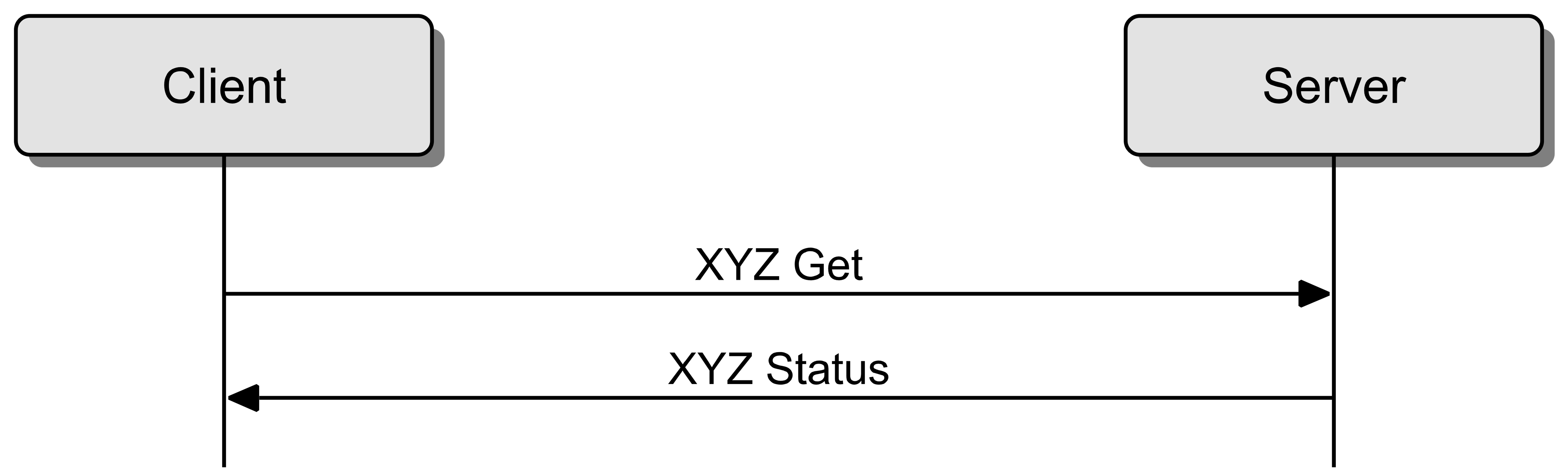 |
3.7.6.2. Acknowledged set
Figure 3.43 shows a client setting a state of a peer element with an acknowledged set message. The server responds with the associated status message. The server then publishes a status message to the model’s publish address according to the publishing rules (see Section 3.7.5.1.2). If the client is subscribed to this model’s publish address, then it will receive both status messages.
 |
3.7.6.3. Unacknowledged set
Figure 3.44 shows a client setting a state of a peer element with an unacknowledged set message. No response is sent, but the server publishes the new state information to the model’s publish address according to the publishing rules (see Section 3.7.5.1.2). If the client is subscribed to this model’s publish address, then it will receive the status message.
 |
3.7.6.4. Acknowledged set with periodic publishing
Figure 3.45 shows a client setting a state of a peer element with an acknowledged set message. The server responds with the associated status message. The server then periodically publishes the new state information to the model’s publish address, according to the periodic publishing rules (see Section 3.7.5.1.2).
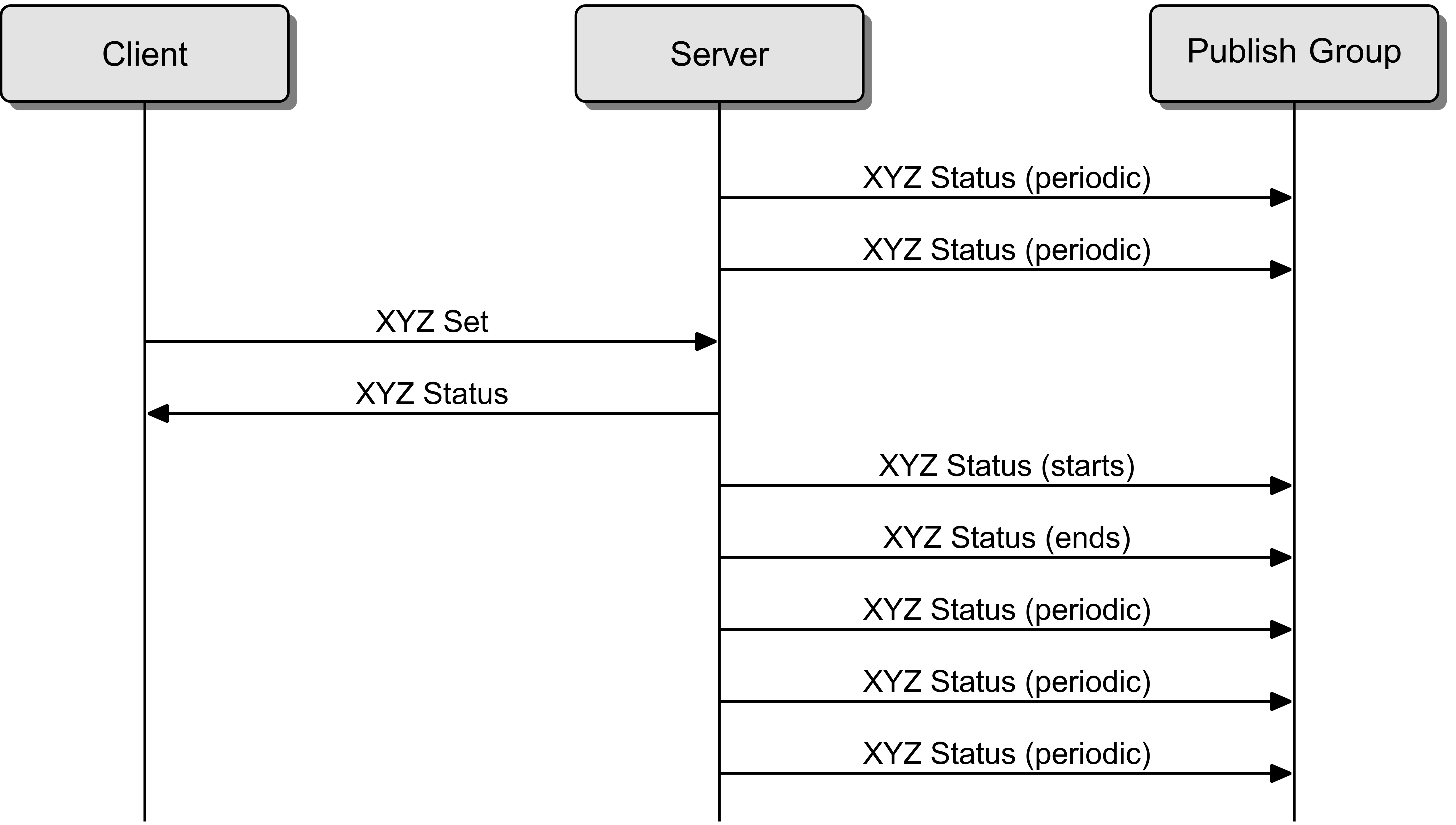 |
3.8. Model layer
Models are used to define certain functionalities supported by a node.
The model layer specifies the rules for allocating models on elements within a node.
The model layer also includes models which are defined in the Mesh Model specification [9] or in other higher-layer specifications.
3.8.1. Endianness
All multiple-octet numeric values in this layer shall be little-endian as described in Section 3.1.1.2.
3.8.2. Model identifier
A model is identified by a unique identifier. The identifier can be 16 bits in length for a Bluetooth SIG adopted model (SIG Model ID) or 32 bits in length for a Vendor Model (Vendor Model ID). See Section 4.4.23 for additional information on SIG Model IDs.
The Vendor Model ID is composed of two fields: a 16-bit Company Identifier [4] assigned by the Bluetooth SIG and a 16-bit Vendor Model Identifier assigned by the vendor. The format of each Vendor Model ID is defined in Table 3.64.
|
Field |
Size |
Description |
Req. |
|---|---|---|---|
|
Company Identifier |
2 |
16-bit Company Identifier, see [4] |
M |
|
Vendor Model Identifier |
2 |
16-bit Vendor Model Identifier assigned by the vendor |
M |
3.8.3. Functionalities
Models are grouped together in order to support functionalities (such as dimmable light or occupancy sensing).
Message dispatch from the access layer (see Section 3.7.3.2) to the model layer is based on the destination address (see Section 3.4.4.7) and the opcode of the message (see Section 3.7.2.1). Given that unicast addresses are assigned to each element on a node, an element cannot have instances of models with overlapping opcodes. Therefore, a functionality may require a set of models that must be located on different elements within a node, as required by Section 3.7.3.
To exchange messages with a Bluetooth SIG adopted model, a Vendor Model shall use the Access message defined for the Bluetooth SIG model (see Section 3.7.2).
A node supports a functionality by instantiating the main model for that functionality, which may require a set of base, extending, and corresponding models:
-
A main model may require one or more base models. A node can include multiple instances of a main model to implement the same functionality multiple times. A main model may be instantiated on either the primary element or a secondary element of a node.
-
Base models must be instantiated with the extending models and corresponding models for a functionality and must be indicated in the Composition Data of a node (see Section 4.2.2), as required in Section 3.8.4.
A base model might be extended by multiple models if unambiguous message dispatch is preserved by this extension.
For a more detailed description and examples see Section 1.4.4 in [9].
3.8.4. Model instantiation
The following rules apply to all models instantiated within a node:
-
All models shall be instantiated on a node by using the smallest number of elements to achieve the desired functionality (i.e., by using the smallest possible element index).
-
Corresponding models that cannot be instantiated on the same element as the main model, as a result of message dispatch limitations, shall be instantiated on an element with a larger element index.
-
Multiple instances of the same main model shall not interleave their corresponding models on subsequent elements. All the corresponding models for the main model shall be instantiated before the next instance of the main model.
3.9. Mesh security
This section describes how mesh security is implemented.
3.9.1. Endianness
All multiple-octet numeric values in this layer shall be marshalled in big-endian, as described in Section 3.1.1.1.
3.9.2. Security toolbox
This section describes functions that together provide a security toolbox for mesh networking.
3.9.2.1. Encryption function
The same encryption function e, as defined in Volume 3, Part H, Section 2.2.1 of the Core Specification [1], shall be used. This can be summarized as:
|
ciphertext=e(key,plaintext) |
3.9.2.2. CMAC function
RFC4493 [7] defines the Cipher-based Message Authentication Code (CMAC) function that uses AES-128 as the block cipher function, also known as AES-CMAC.
The inputs to AES-CMAC are:
|
k is the 128-bit key |
|
|
m is the variable-length data to be authenticated |
The 128-bit message authentication code (MAC) is generated[1] as follows:
|
MAC=AES-CMACk(m) |
A node can implement AES functions in the host or can use the HCI_LE_Encrypt command (see Volume 2, Part E, Section 7.8.22 of the Core Specification [1]) in order to use the AES function in the controller.
3.9.2.3. AES-CCM function
The AES-CCM function provides encryption and authentication using Counter with Cipher Block Chaining-Message Authentication Code (CCM), which shall be implemented consistent with the algorithm as defined in IETF RFC 3610 [8] in conjunction with the AES-128 block cipher as defined in NIST Publication FIPS-197 [28].
Note
Note: A description of the CCM algorithm can also be found in the NIST Special Publication 800-38C [29].
This specification defines AES-CCM as a function that takes four inputs and results in two outputs.
The inputs to AES-CCM are:
|
k is the 128-bit key |
|
|
n is a 104-bit nonce |
|
|
m is the variable-length data to be encrypted and authenticated – also known as “plaintext” |
|
|
a is the variable-length data to be authenticated – also known as “Additional Data” |
The ciphertext and mic are generated as follows:
|
ciphertext,mic=AES-CCMk(n,m,a) |
Where:
|
ciphertext is the variable-length data after it has been encrypted |
|
|
mic is the message integrity check value of m and a – also known as the “Message Authentication Code” or the encrypted authentication value U in RFC3610 [8]. |
If only the k, n, and m parameters are provided to the AES-CCM, then the additional data shall be zero length.
3.9.2.4. HMAC-SHA-256 function
RFC 2104 [26] defines HMAC, a mechanism for message authentication using cryptographic hash functions. FIPS 180-4 [27] defines the SHA-256 secure hash algorithm. The SHA-256 algorithm is used as a hash function for the HMAC mechanism for the HMAC-SHA-256 function. This specification defines HMAC-SHA-256 as a function that takes two inputs and results in one output.
The inputs to HMAC-SHA-256 are:
|
k is the 256-bit key |
|
|
m is the variable-length data to be authenticated |
The HMAC-SHA-256 function generates a 256-bit message authentication code (MAC) defined in [26] as follows:
|
HMAC-SHA-256k(m)=SHA-256((k0⊕opad) || SHA-256((k0⊕ipad) || m)) |
Where:
|
SHA-256 is the secure hash algorithm defined in [27] |
|
|
k0 is the k with the 0x00 octet appended 32 times to the end |
|
|
opad is the 0x5C octet repeated 64 times |
|
|
ipad is the 0x36 octet repeated 64 times |
|
3.9.2.5. s1 SALT generation function
The input to function s1 is:
|
M is a non-zero length octet array or ASCII encoded string |
If M is an ASCII encoded string, it shall be converted into an octet array by replacing each string character with its ASCII code preserving the order. For example, if M is the string “MESH”, this is converted into the octet array: 0x4d, 0x45, 0x53, 0x48.
ZERO is the 128-bit value:
|
0x0000 0000 0000 0000 0000 0000 0000 0000 |
The output of the salt generation function s1 is as follows:
|
s1(M)=AES-CMACZERO(M) |
3.9.2.6. s2 SALT generation function
The input to function s2 is:
|
M is a non-zero length octet array or ASCII encoded string |
ZERO is the 256-bit value:
|
0x0000 0000 0000 0000 0000 0000 0000 0000 0000 0000 0000 0000 0000 0000 0000 0000 |
The output of the salt generation function s2 is as follows:
|
s2(M)=HMAC-SHA-256ZERO(M) |
3.9.2.7. k1 derivation function
The network key material derivation function k1 is used to generate instances of IdentityKey, BeaconKey, and PrivateBeaconKey.
The definition of this key generation function makes use of the MAC function AES-CMACT with a 128-bit key T.
The inputs to function k1 are:
|
N is 0 or more octets |
|
|
SALT is 128 bits |
|
|
P is 0 or more octets |
The key (T) is computed as follows:
|
T=AES-CMACSALT(N) |
The output of the key generation function k1 is as follows:
|
k1(N, SALT, P)=AES-CMACT(P) |
3.9.2.8. k2 network key material derivation function
The network key material derivation function k2 is used to generate instances of EncryptionKey, PrivacyKey, and NID for use as managed flooding security material, friendship security material, and directed security material.
The definition of this key generation function makes use of the MAC function AES-CMACT with a 128-bit key T.
The inputs to function k2 are:
|
N is 128 bits |
|
|
P is 1 or more octets |
The key (T) is computed as follows:
|
T=AES-CMACSALT(N) |
SALT is the 128-bit value computed as follows
|
SALT=s1("smk2") |
The output of the key generation function k2 is as follows:
|
T0=empty string (zero length) |
|
|
T1=AES-CMACT (T0 || P || 0x01) |
|
|
T2=AES-CMACT (T1 || P || 0x02) |
|
|
T3=AES-CMACT (T2 || P || 0x03) |
|
|
k2(N, P)=(T1 || T2 || T3) mod 2263 |
|
3.9.2.9. k3 derivation function
The derivation function k3 is used to generate a public value of 64 bits derived from a private key.
The definition of this derivation function makes use of the MAC function AES-CMACT with a 128-bit key T.
The input to function k3 is:
|
N is 128 bits |
The key (T) is computed as follows:
|
T=AES-CMACSALT(N) |
SALT is a 128-bit value computed as follows:
|
SALT=S1("smk3") |
The output of the derivation function k3 is as follows:
|
k3(N)=AES-CMACT("id64" || 0x01) mod 264 |
3.9.2.10. k4 derivation function
The derivation function k4 is used to generate a public value of 6 bits derived from a private key.
The definition of this derivation function makes use of the MAC function AES-CMACT with a 128-bit key T.
The input to function k4 is:
|
N is 128 bits |
The key (T) is computed as follows:
|
T=AES-CMACSALT(N) |
SALT is a 128-bit value computed as follows:
|
SALT=s1("smk4") |
The output of the derivation function k4 is as follows:
|
k4(N)=AES-CMACT("id6" || 0x01) mod 26) |
3.9.2.11. k5 provisioning material derivation function
The provisioning material derivation function k5 is used to generate the 256-bit key used in provisioning.
The definition of this derivation function makes use of the MAC function HMAC-SHA-256 with a 256-bit key T.
The inputs to function k5 are:
|
N is 32 or more octets |
|
|
SALT is 256 bits |
|
|
P is 1 or more octets |
The key (T) is computed as follows:
|
T=HMAC-SHA-256SALT(N) |
The output of the derivation function k5 is as follows:
|
k5(N, SALT, P)=HMAC-SHA-256T(P) |
3.9.3. Sequence number
The sequence number, a 24-bit value contained in the SEQ field of the Network PDU, is primarily designed to protect against replay attacks. Elements within the same node may or may not share the sequence number space with each other. Having a different sequence number in each new Network PDU for every message source (identified by the unicast address contained in the SRC field) is critical for the security of the mesh network.
With a 24-bit sequence number, an element can transmit 16,777,216 messages before repeating a nonce. If an element transmits a message on average once every five seconds (representing a fairly high frequency message for known use cases), the element can transmit for 2.6 years before the nonce repeats.
Each element shall use strictly increasing sequence numbers for the Network PDUs it generates. Before the sequence number approaches the maximum value (0xFFFFFF), the element shall update the IV Index using the IV Update procedure (see Section 3.11.5). This is done to ensure that the sequence number will never wrap around.
3.9.4. IV Index
The IV Index is a 32-bit value that is a shared network resource (i.e., all nodes in a mesh network share the same value of the IV Index and use it for all subnets they belong to).
The IV Index starts at 0x00000000 and is incremented during the IV Update procedure as described in Section 3.11.5. The timing when the value is incremented does not have to be exact, since the least significant bit is communicated within every Network PDU. Since the IV Index value is a 32-bit value, a mesh network can function approximately 5 trillion years before the IV Index will wrap.
The IV Index is shared within a network via Secure Network beacons (see Section 3.10.3) or Mesh Private beacons (see Section 3.10.4). IV updates received on a subnet are processed and propagated to that subnet. The propagation happens by the device transmitting Secure Network beacons or Mesh Private beacons with the updated IV Index for that particular subnet. If a device on a primary subnet receives an update on the primary subnet, it shall propagate the IV update to all other subnets. If a device on a primary subnet receives an IV update on any other subnet, the update shall be ignored.
If a node is absent from a mesh network for a period of time, it can scan for Secure Network beacons (see Section 3.11.1) or for Mesh Private beacons, or it can use the IV Index Recovery procedure (see Section 3.11.6), and therefore set the IV Index value autonomously.
3.9.5. Nonce
The nonce is a 13-octet value that is unique for each new message encryption. There are four different nonces that are used, as shown in Table 3.65. The type of the nonce is determined by the first octet of the nonce, referred to as the Nonce Type.
|
Nonce Type |
Nonce |
Description |
|---|---|---|
|
0x00 |
Network nonce |
Used with an EncryptionKey for network authentication and encryption |
|
0x01 |
Application nonce |
Used with an application key for upper transport authentication and encryption |
|
0x02 |
Device nonce |
Used with a device key for upper transport authentication and encryption |
|
0x03 |
Proxy nonce |
Used with an EncryptionKey for proxy authentication and encryption |
|
0x04 |
Proxy solicitation nonce |
Used with an EncryptionKey for Proxy solicitation authentication and encryption |
|
0x05–0xFF |
RFU |
Reserved for Future Use |
The TTL field value is used within the network nonce but not within the application nonce, device nonce, or proxy nonce. This means that when a message is relayed and the TTL field value is decremented, the application nonce or device nonce does not change; however, the network nonce does change, allowing the authentication of the TTL field value.
The DST field value is used within the application nonce and device nonce but not in the network nonce. This means that the destination of the message is authenticated, but at the network layer the destination address is encrypted.
3.9.5.1. Network nonce
The network nonce is defined in Table 3.66 and illustrated in Figure 3.46.
|
Field |
Size |
Description |
|---|---|---|
|
Nonce Type |
1 |
0x00 |
|
CTL and TTL |
1 |
See Table 3.67 |
|
SEQ |
3 |
Sequence number |
|
SRC |
2 |
Source address |
|
Pad |
2 |
0x0000 |
|
IV Index |
4 |
IV Index |
|
Field |
Size |
Description |
|---|---|---|
|
CTL |
1 |
See Section 3.4.4.3 |
|
TTL |
7 |
See Section 3.4.4.4 |
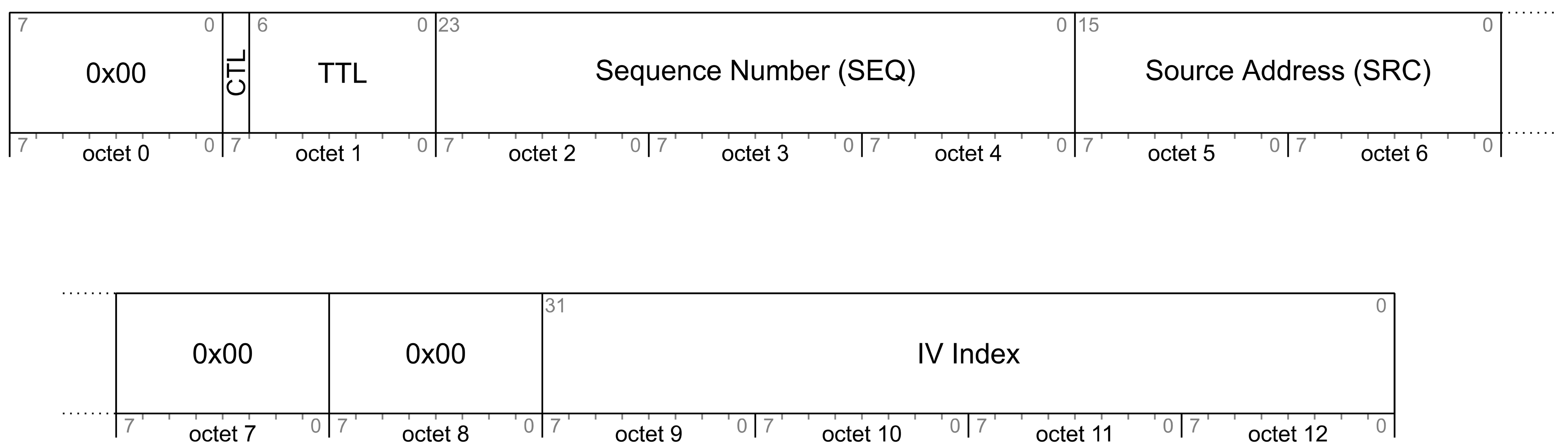
The network nonce is used with an EncryptionKey for network data authentication and encryption (see Section 3.9.7.2).
3.9.5.2. Application nonce
The application nonce is defined in Table 3.68 and illustrated in Figure 3.47.
|
Field |
Size |
Description |
|---|---|---|
|
Nonce Type |
1 |
0x01 |
|
ASZMIC and Pad |
1 |
See Table 3.69 |
|
SEQ |
3 |
Sequence number of the Access message (24 lowest bits of SeqAuth in the context of segmented messages) |
|
SRC |
2 |
Source address |
|
DST |
2 |
Destination address |
|
IV Index |
4 |
IV Index |
|
Field |
Size |
Description |
|---|---|---|
|
ASZMIC |
1 |
SZMIC field value if a Segmented Access message or 0 for all other message formats |
|
Pad |
7 |
0b0000000 |

The application nonce is used with an application key for application data authentication and encryption (see Section 3.9.6).
3.9.5.3. Device nonce
The device nonce is defined in Table 3.70 and illustrated in Figure 3.48.
|
Field |
Size |
Description |
|---|---|---|
|
Nonce Type |
1 |
0x02 |
|
ASZMIC and Pad |
1 |
See Table 3.71 |
|
SEQ |
3 |
Sequence number of the Access message (24 lowest bits of SeqAuth in the context of segmented messages) |
|
SRC |
2 |
Source address |
|
DST |
2 |
Destination address |
|
IV Index |
4 |
IV Index |
|
Field |
Size |
Description |
|---|---|---|
|
ASZMIC |
1 |
SZMIC field value if a Segmented Access message or 0 for all other message formats |
|
Pad |
7 |
0b0000000 |

The device nonce is used with a device key for application data authentication and encryption specific to a given device (see Section 3.9.6).
3.9.5.4. Proxy nonce
The proxy nonce is defined in Table 3.72 and illustrated in Figure 3.49.
|
Field |
Size |
Description |
|---|---|---|
|
Nonce Type |
1 |
0x03 |
|
Pad |
1 |
0x00 |
|
SEQ |
3 |
Sequence number |
|
SRC |
2 |
Source address |
|
Pad |
2 |
0x0000 |
|
IV Index |
4 |
IV Index |
 |
The proxy nonce is used with an EncryptionKey for proxy configuration message authentication and encryption (see Section 6.5).
3.9.5.5. Proxy solicitation nonce
The proxy solicitation nonce is defined in Table 3.73 and illustrated in Figure 3.50.
|
Field |
Size |
Description |
|---|---|---|
|
Nonce Type |
1 |
0x04 |
|
Pad |
1 |
0x00 |
|
SSEQ |
3 |
Solicitation sequence number |
|
SSRC |
2 |
Solicitation source |
|
Pad |
6 |
0x000000000000 |
 |
The proxy solicitation nonce is used with an EncryptionKey for Solicitation PDU authentication and encryption (see Section 6.8).
3.9.6. Keys
This specification defines three types of keys: device keys (DevKey), application keys (AppKey) and network keys (NetKey). AppKeys are used to secure communications at the upper transport layer and NetKeys are used to secure communications at the network layer. The keys are shared between nodes. There is also a device key (DevKey), which is a special key that is unique to each node, is known only to the node and a Configuration Manager, and is used to secure communications between the node and a Configuration Manager.
Application keys are bound to network keys. This means application keys are only used in a context of a network key they are bound to. An application key shall only be bound to a single network key. A device key is implicitly bound to all network keys.
An example of binding application keys to network keys and models is illustrated in Figure 3.51.
 |
3.9.6.1. Device key
The device key (DevKey) is an access layer key known only to the node, the Provisioner and a Configuration Manager. The device key shall be bound to every network key known to the node. Those bindings cannot be changed. An illustration of the device key derivation is shown in Figure 3.52.
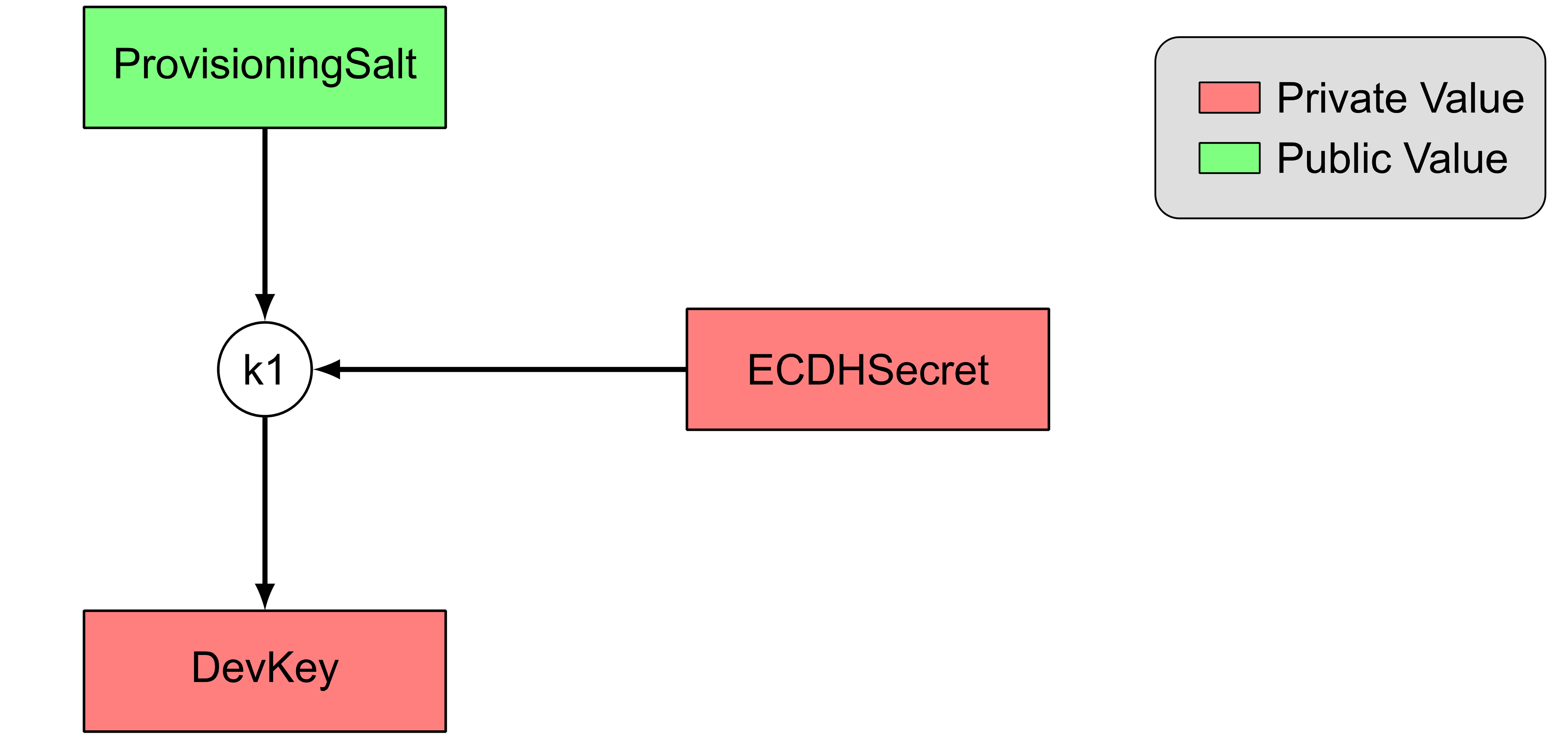 |
The DevKey shall be derived from the ECDHSecret and ProvisioningSalt as described by the formula below:
|
DevKey=k1(ECDHSecret, ProvisioningSalt, “prdk”) |
The ProvisioningSalt is defined in Section 5.4.2.5 and the ECDHSecret is defined in Section 5.4.2.3.
3.9.6.2. Application key
The application key (AppKey) shall be generated using a random number generator compatible with the requirements in Volume 2, Part H, Section 2 of the Core Specification [1].
The AID is used to identify the application key. An illustration of the AID derivation is shown in Figure 3.53.
|
AID=k4(AppKey) |
 |
3.9.6.3. Network key
The network key (NetKey) shall be generated using a random number generator compatible with the requirements in Volume 2, Part H, Section 2 of the Core Specification [1]. An illustration of the network key hierarchy is shown in Figure 3.54.
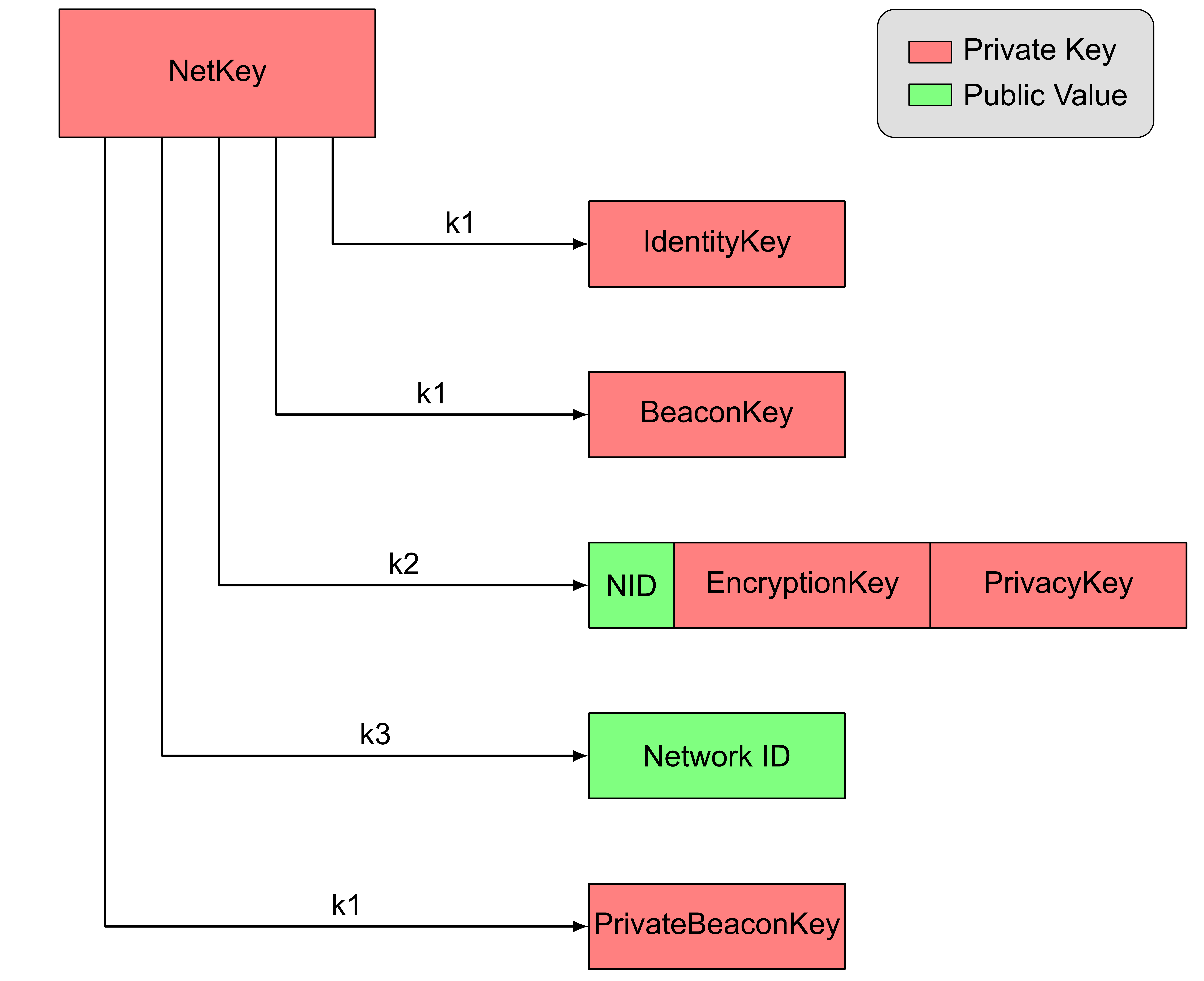 |
3.9.6.3.1. NID, EncryptionKey, and PrivacyKey
Each Network PDU is secured using security material that is composed of the NID, the EncryptionKey, and the PrivacyKey.
The NID is a 7-bit value that identifies the security material that is used to secure this Network PDU.
Note
Note: There are up to 2121 possible keys for each NID; therefore, the NID value can only provide an indication of the security material that has been used to secure this Network PDU.
The NID, EncryptionKey, and PrivacyKey are derived using the k2 function with security credentials as inputs.
The managed flooding security material is derived from the managed flooding security credentials using the following formula:
|
NID || EncryptionKey || PrivacyKey=k2(NetKey, 0x00) |
The friendship security material is derived from the friendship security credentials using the following formula:
|
NID || EncryptionKey || PrivacyKey=k2(NetKey, 0x01 || LPNAddress || FriendAddress || LPNCounter || FriendCounter) |
|
Where: |
||
|
The LPNAddress value is the unicast address set as source address in the Friend Request message that set up the friendship. The FriendAddress value is the unicast address set as source address in the Friend Offer message that set up the friendship. The LPNCounter value is the value from the LPNCounter field of the Friend Request message that set up the friendship. The FriendCounter is the value from the FriendCounter field of the Friend Offer message that set up the friendship. |
||
For Network PDUs that are sent between a Low Power node and Friend node that have a friendship relationship, the friendship security material is used.
The directed security material is derived from the directed security credentials using the following formula:
|
NID || EncryptionKey || PrivacyKey=k2(NetKey, 0x02) |
For Network PDUs that are transmitted according to directed forwarding functionality, the directed security material is used.
For all other Network PDUs, the managed flooding security material is used.
3.9.6.3.2. Network ID
The Network ID is derived from the network key such that each network key generates one Network ID. This identifier becomes public information.
|
Network ID=k3(NetKey) |
3.9.6.3.3. IdentityKey
The IdentityKey is derived from the network key such that each network key generates one IdentityKey.
|
salt=s1("nkik") |
|
|
P="id128" || 0x01 |
|
|
IdentityKey=k1(NetKey, salt, P) |
|
3.9.6.3.4. BeaconKey
The BeaconKey is derived from the network key such that each network key generates one BeaconKey.
|
salt=s1("nkbk") |
|
|
P="id128" || 0x01 |
|
|
BeaconKey=k1(NetKey, salt, P) |
|
3.9.6.3.5. PrivateBeaconKey
The PrivateBeaconKey is derived from the network key such that each network key generates a unique PrivateBeaconKey.
|
salt=s1("nkpk") |
|
|
P="id128" || 0x01 |
|
|
PrivateBeaconKey=k1(NetKey, salt, P) |
|
3.9.6.4. Global key indexes
Network and application keys are organized within the mesh network into two lists, maintained by a Configuration Manager: a list of network keys and a list of application keys. Each list is a shared mesh network resource and can accommodate up to 4096 keys. Keys are referenced using global key indexes: the NetKey Index and the AppKey Index. The key indexes are 12-bit values ranging from 0x000 to 0xFFF inclusive. A network key at index 0x000 is called the primary NetKey.
3.9.7. Message security
Messages are secured using AES-CCM at two different layers. Messages are encrypted and authenticated at the network layer and at the upper transport layer. Each message is also obfuscated to hide possible identifying information from the packets. This is illustrated in Figure 3.55.
 |
Every message has a minimum of 64 bits of authentication information associated with it. This authentication information may be split between the network layer and upper transport layer.
Some messages, known as Transport Control messages, are not authenticated at the upper transport layer and therefore have a 64-bit NetMIC field. Access messages are authenticated at the upper transport layer and therefore have a 32-bit NetMIC field. Access messages that are sent in a single unsegmented message have a 32-bit TransMIC field. Access messages that are segmented over multiple Network PDUs can have either a 32-bit or 64-bit TransMIC field. This allows a higher layer to determine the level of authentication required to securely deliver the Access message and therefore apply the appropriate size for the TransMIC field.
3.9.7.1. Upper transport layer authentication and encryption
Authentication and encryption of the Access message is performed by the upper transport layer.
The Access message is encrypted and authenticated using AES-CCM. This is identical to the way that Bluetooth low energy encryption and authentication works. An illustration of the upper transport layer encryption is shown in Figure 3.56.

If the Access message is secured using the application key, then the Access message is encrypted using the application nonce and the application key.
If the Access message is secured using the device key, then the Access message is encrypted using the device nonce and the device key.
The nonce uses the sequence number and the source address, ensuring that two different nodes cannot use the same nonce. The IV Index is used to provide significantly more nonce values than the sequence number can provide for a given node. Management of the IV Index is described in Section 3.11.5.
Note
Note: The authentication and encryption of the Access message is not dependent on the TTL field value, meaning that as the Access message is relayed through a mesh network, the Access message does not need to be re-encrypted at each hop.
When using an application key and the destination address is a virtual address:
|
EncAccessMessage, TransMIC=AES-CCMAppKey (application nonce, Access message, Label UUID) |
When using an application key and the destination address is a unicast address or a group address:
|
EncAccessMessage, TransMIC=AES-CCMAppKey (application nonce, Access message) |
When using a device key and the destination address is a unicast address:
|
EncAccessMessage, TransMIC=AES-CCMDevKey (device nonce, Access message) |
The concatenation of the encrypted Access message and the TransMIC is called the Upper Transport Access PDU:
|
Upper Transport Access PDU=EncAccessMessage || TransMIC |
3.9.7.2. Network layer authentication and encryption
The DST and the TransportPDU fields are encrypted and authenticated using AES-CCM. This is identical to the way that Bluetooth low energy encryption and authentication works.
All Network PDUs are encrypted using an EncryptionKey that is derived from a network key (see Section 3.9.6.3.1).
An illustration of the network layer encryption is shown in Figure 3.57.

The following defines how this is performed:
|
EncDST || EncTransportPDU, NetMIC=AES-CCMEncryptionKey (network nonce, DST || TransportPDU) |
3.9.7.3. Network layer obfuscation
In order to obfuscate the Network Header (CTL, TTL, SEQ, and SRC fields), these field values shall be combined with a result of a single encryption function e, designed to prevent a passive eavesdropper from determining the identity of a node by listening to Network PDUs.
The obfuscation occurs after the Message Integrity Check value for Network (NetMIC) has been calculated. The obfuscation is calculated using information available from within the Network PDU. This obfuscation is designed only to help prevent a simple passive eavesdropper from tracking nodes. A determined attacker could still discover patterns within this obfuscation that can lead to the revealing of the source address or sequence number of a node. Critically, obfuscation does not enforce that inputs to the encryption function are unique.
Obfuscation does not protect the PrivacyKey from compromise, and given the above design considerations for protection against only passive eavesdroppers, it is considered that the PrivacyKey could be compromised with sufficient time. The design of obfuscation includes the IV Index, such that when the IV Index changes, any obfuscation attacks would have to start again.
To obfuscate the Network PDU, the first seven octets of the Network PDU that have already been encrypted are combined with the IV Index and a PrivacyKey.
These first seven octets of the Network PDU that have been encrypted include both the EncDST and five octets of either the EncTransportPDU or the EncTransportPDU concatenated with the NetMIC field. These octets are known as the PrivacyRandom value.
The PrivacyKey is derived using a key derivation function from the network key (see Section 3.9.6.3.1) to protect the network key even if the PrivacyKey is compromised.
The IV Index is concatenated with the PrivacyRandom value and used along with the PrivacyKey as inputs to the encryption function e. The output of this is known as the PECB value.
The first six octets of the PECB value are then exclusive-ORed with the CTL, the TTL, the SEQ, and the SRC fields, and then become the ObfuscatedData.
The Network PDU is transmitted as the concatenation of the NID, the IVI, the ObfuscatedData, the EncDST, the EncTransportPDU, and the NetMIC fields.
An illustration of the network layer obfuscation is shown in Figure 3.58.

|
Privacy Random=(EncDST || EncTransportPDU || NetMIC)[0–6] |
|
|
Privacy Plaintext=0x0000000000 || IV Index || Privacy Random |
|
|
PECB=e (PrivacyKey, Privacy Plaintext) |
|
|
ObfuscatedData=(CTL || TTL || SEQ || SRC)⊕PECB[0–5] |
|
When reversing this, the following operations are performed:
|
Privacy Random=(EncDST || EncTransportPDU || NetMIC)[0–6] |
|
|
Privacy Plaintext=0x0000000000 || IV Index || Privacy Random |
|
|
PECB=e (PrivacyKey, Privacy Plaintext) |
|
|
(CTL || TTL || SEQ || SRC)=ObfuscatedData⊕PECB[0–5] |
|
3.9.8. Message replay protection
A message sent by a legitimate originating element can be passively received by an attacker and then replayed later without modification. This is called a replay attack.
Since the originating element has encrypted and authenticated the message using the correct keys, the receiver cannot determine whether it is under a replay attack solely by performing the message integrity checks (i.e., on the NetMIC and, if applicable, on the TransMIC).
The IVISeq value is composed of the IV Index and the sequence number of the message. The size of the IVISeq value is 7 octets, where the IV Index is the four most significant octets and the sequence number is the three least significant octets.
To increase protection against replay attacks, each element increases the IVISeq value for each new message that it sends. If a valid message has been received from an originating element with a specific IVISeq value, any future messages from the same originating element that contain an IVISeq value that is lower than or equal to the last valid IVISeq value are very likely replayed messages and shall be discarded. Therefore, messages are delivered to the access layer in ascending IVISeq value order.
If a message encrypted and authenticated with a lower IV Index value from the same originating element has been received, the message shall be discarded.
A node shall implement replay protection for all Access and Transport Control messages that are received from other elements and processed, as well as for proxy configuration messages, if applicable. A node shall be able to determine if a certain message is being replayed. If the node is not able to determine if a certain message is being replayed, the node shall ignore the message.
The check for replay protection involves checking whether the received message from an originating source address with the IVISeq value is a numerically higher number than the last valid IVISeq value from that source address. The check for replay protection is done above the network layer. If the check for replay protection reveals that a message is being replayed, the message shall be discarded; otherwise the message shall be processed.
Replay protection is organized based on a list, known as the replay protection list. This list consists of multiple entries and each entry has two fields:
-
A source address, which is the SRC field of an incoming message
-
An IVISeq value, which is composed as defined by a row in Table 3.74
|
IVISeq Label |
IVISeq Value |
|---|---|
|
Unsegmented |
The IV Index used to decrypt the incoming message and the SEQ field of the incoming message for unsegmented messages |
|
Last Segment |
The IV Index used to decrypt the incoming message and the SEQ field of the incoming last segment of an Upper Transport PDU |
|
Proxy |
The IV Index used to decrypt the incoming message and the SEQ field of the incoming message for proxy configuration messages |
The following list is a non-exhaustive list of the conditions that shall trigger checking if a message is being replayed.
-
The lower transport layer receives a Lower Transport PDU
-
The lower transport layer reassembles an Upper Transport PDU
-
A Proxy Server or a Proxy Client receives a proxy configuration message
Table 3.75 is a non-exhaustive list of the conditions that shall trigger adding a new entry to the replay protection list or updating an existing entry, using the corresponding IVISeq value defined in Table 3.74.
|
Condition |
IVISeq Label |
|---|---|
|
A received Segment Acknowledgement message is a valid message (see Section 3.5.3.3.2) |
Unsegmented |
|
A received proxy configuration message is a valid message for a Proxy Server (see Section 6.7) or for a Proxy Client (see Section 6.8) |
Proxy |
|
A received Transport Control message is a valid unsegmented message for the upper transport layer (see Section 3.6.4.2) |
Unsegmented |
|
A received Access message is a valid unsegmented message and has been delivered to a model (see Section 3.7.3.2) |
Unsegmented |
|
The Processing Result of lower transport reassembly is Last Segment (see Section 3.5.3.4) and the Transport Control message is a valid segmented message for the upper transport layer (see Section 3.6.4.2) |
Last Segment |
|
The Processing Result of lower transport reassembly is Last Segment (see Section 3.5.3.4) and the message is a valid Access message and has been delivered to a model (see Section 3.7.3.2) |
Last Segment |
In addition, a Subnet Bridge node shall implement replay protection for all Access and Transport Control messages that are sent to bridged subnets.
A Subnet Bridge node shall maintain the most recent IVISeq value for each source address authorized to send messages to bridged subnets. Messages received by the Subnet Bridge node with the IVISeq value less than or equal to the last stored value from that source address shall be discarded immediately upon reception. When a message is retransmitted to a bridged subnet, the stored IVISeq value shall be updated. In this way, bridged subnets are protected against replay attacks from other subnets.
If a node does not have enough resources to perform replay protection for a given source address, then the node shall discard the message immediately upon reception.
An implementation may perform the replay protection at any layer and in any order with respect to the message authentication steps (the network layer decryption and the transport layer decryption), in order to optimize the message processing flow, the number of cryptographic operations or the memory usage.
Figure 3.59 illustrates an example of a replay protection list implementation that handles a multi-segment message transaction which is under a replay attack. The sequence number of the last segment that has been received for this message is stored for that peer node in the replay protection list.
 |
3.10. Mesh beacons
Mesh beacons are packets advertised periodically by nodes and unprovisioned devices.
Mesh beacons are contained in a Mesh Beacon AD type. The first octet of the Mesh Beacon AD type (Beacon Type field) determines the type of beacon. Mesh beacons are forwarded to other bearers using the Proxy protocol (see Section 6).
The format of the Mesh Beacon AD type is defined in Table 3.76.
|
Field |
Size |
Description |
Req. |
|---|---|---|---|
|
Length |
1 |
Length of the AD Type, Beacon Type, and Beacon Data fields |
M |
|
AD Type |
1 |
«Mesh Beacon» |
M |
|
Beacon Type |
1 |
Mesh Beacon Type |
M |
|
Beacon Data |
variable |
Mesh Beacon Data |
M |
The format of the Mesh Beacon AD type is shown in Figure 3.60.

The Beacon Type values are defined in the Assigned Numbers document [4].
Mesh beacons shall be advertised using ADV_NONCONN_IND PDUs.
3.10.1. Endianness
All multiple-octet numeric values in mesh beacons shall be sent in big-endian, as described in Section 3.1.1.1.
3.10.2. Unprovisioned Device beacon
The Unprovisioned Device beacon is used by devices that are unprovisioned to allow them to be discovered by a Provisioner.
The format of this beacon is illustrated in Figure 3.61 and defined in Table 3.77.

|
Field |
Size |
Description |
Req. |
|---|---|---|---|
|
Beacon Type |
1 |
Unprovisioned Device beacon type (0x00) |
M |
|
Device UUID |
16 |
Device UUID uniquely identifying this device (see Section 3.11.3) |
M |
|
OOB Information |
2 |
See Table 3.78 |
M |
|
URI Hash |
4 |
Hash of the associated URI advertised with the URI AD Type |
O |
The OOB Information field shown in Table 3.78 is a uint16 value and is used to help drive the provisioning process by indicating the availability of OOB data, such as a public key of the device.
|
Bit |
Description |
|---|---|
|
0 |
Other |
|
1 |
Electronic / URI |
|
2 |
2D machine-readable code |
|
3 |
Bar code |
|
4 |
Near Field Communication (NFC) |
|
5 |
Number |
|
6 |
String |
|
7 |
Support for certificate-based provisioning |
|
8 |
Support for provisioning records |
|
9 |
Reserved for Future Use |
|
10 |
Reserved for Future Use |
|
11 |
On box |
|
12 |
Inside box |
|
13 |
On piece of paper |
|
14 |
Inside manual |
|
15 |
On device |
Along with the Unprovisioned Device beacon, the unprovisioned device may also advertise a separate non-connectable advertising packet with a URI data type (as defined in [5]) that points to OOB information such as a public key. To allow the association of the advertised URI with the Unprovisioned Device beacon, the beacon may contain an optional 4-octet URI Hash field.
The value of the URI Hash field is calculated using the following formula:
|
URI Hash=s1(URI Data)[0–3] |
The URI Data is a buffer containing the URI data type, as defined in [5].
If a device supports provisioning records (see Section 5.4.2.6), it shall set bit 8 of the OOB Information field of the Unprovisioned Device beacon to indicate this.
If a Device Certificate (as defined in Section 5.5.1) has been issued for the device and made available for retrieval (see Sections 5.4.2.6 and 5.6), the device shall also support provisioning records. The device shall set bit 7 of the OOB Information field of the Unprovisioned Device beacon to indicate the device’s support for certificate-based provisioning, and shall set bit 8 to indicate support for provisioning records.
3.10.3. Secure Network beacon
The Secure Network beacon is used by nodes to identify the subnet and its security state.
The format of this beacon is illustrated in Figure 3.62 and defined in Table 3.79.

|
Field |
Size |
Description |
Req. |
|---|---|---|---|
|
Beacon Type |
1 |
Secure Network beacon (0x01) |
M |
|
Flags |
1 |
Contains the Key Refresh Flag and IV Update Flag |
M |
|
Network ID |
8 |
Contains the value of the Network ID |
M |
|
IV Index |
4 |
Contains the current IV Index |
M |
|
Authentication Value |
8 |
Authenticates security network beacon |
M |
The Flags field is defined in Table 3.80 as:
|
Bits |
Definition |
|---|---|
|
0 |
Key Refresh Flag 0: False 1: True |
|
1 |
IV Update Flag 0: Normal Operation 1: IV Update in Progress |
|
2–7 |
Reserved for Future Use |
The Network ID field contains the Network ID of this network.
The IV Index field contains the current IV Index of this mesh network.
The Authentication Value field is computed as defined below:
|
Authentication Value=AES-CMACBeaconKey (Flags || Network ID || IV Index)[0–7] |
The generation of the Secure Network beacon is illustrated in Figure 3.63.

3.10.3.1. Secure Network beacon behavior
When a Secure Network beacon is received on a known subnet and authenticated, the node shall monitor for IV Index updates (see Section 3.11.5) and Key Refresh procedures (see Section 3.11.4). To authenticate a Secure Network beacon, a node calculates the Authentication Value as defined in Section 3.10.3 and checks if it is equal to the Authentication Value field in the received Secure Network beacon.
A Secure Network beacon may be sent for each subnet that a node is a member of to identify the subnet and inform about IV Index updates (see Section 3.11.5) and Key Refresh procedures (see Section 3.11.4).
Relay and Friend nodes should send beacons and other nodes may send beacons. The time between sending two consecutive beacons is called the Beacon Interval. An implementation may define the Beacon Interval together with a back-off procedure to prevent other nodes from overloading the network with too many beacons. The expected behavior is that each node receives one beacon for a given subnet approximately every 10 seconds.
For each subnet, to determine the Beacon Interval, the node should continuously observe beacons and keep a rolling count of the number of beacons for the subnet over a given observation period. The Beacon Interval should be determined using the formula below:
If the computed Beacon Interval is less than 10 seconds, it should be set to 10 seconds. If the computed Beacon Interval is greater than 600 seconds, it should be set to 600 seconds.
The Observation Period in seconds should typically be double the typical Beacon Interval. Each of the subnets has a separate Secure Network beacon, and therefore, the Expected Number of Beacons, Observed Number of Beacons, and Observation Period may be different for each subnet.
The Observed Number of Beacons is the number of beacons observed for this subnet over the Observation Period.
The Expected Number of Beacons is the Observation Period divided by 10 seconds.
3.10.4. Mesh Private beacon
The Mesh Private beacon is used by the nodes to identify the Key Refresh Flag (see Table 3.80), IV Update Flag (see Table 3.80), and IV Index (see Section 3.9.4) of the subnet.
The format of the beacon is shown in Figure 3.64 and defined in Table 3.81.

|
Field |
Size |
Description |
Req. |
|---|---|---|---|
|
Beacon Type |
1 |
Mesh Private beacon (0x02) |
M |
|
Random |
13 |
Random number used as an entropy for obfuscation and authentication of the Mesh Private beacon |
M |
|
Obfuscated_Private_Beacon_Data |
5 |
Obfuscated Private Beacon Data |
M |
|
Authentication_Tag |
8 |
Authentication tag for the beacon |
M |
The Random field contains a 13-octet random number that changes periodically or when the Flags or the IV Index of the network changes (see Section 3.10.4.2). Flags are defined in Table 3.80.
The Obfuscated_Private_Beacon_Data field contains the obfuscated value of the Private Beacon Data. The Private Beacon Data format is defined in the Table 3.82.
|
Field |
Size |
Description |
Req. |
|---|---|---|---|
|
Flags |
1 |
Flags as defined in Table 3.80 |
M |
|
IV Index |
4 |
Current value of the IV Index of the mesh network |
M |
The Authentication_Tag field contains the tag for authenticating the Private Beacon Data.
The Authentication_Tag generation and packet obfuscation are described in Section 3.10.4.1.
3.10.4.1. Private beacon generation
The Flags and IV Index in the Mesh Private beacon are obfuscated and authenticated using the PrivateBeaconKey. The PrivateBeaconKey is derived from the network key. The Random field in the Mesh Private beacon provides the entropy for obfuscation and authentication.
The obfuscation and authentication procedure is shown in Figure 3.65.
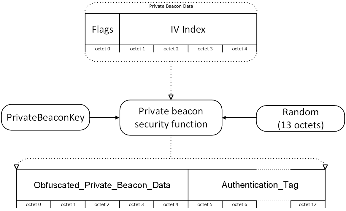 |
Section 3.10.4.1.1 defines the needed security operations for obfuscation and authentication of Mesh Private beacons.
3.10.4.1.1. Private beacon security function
The private beacon security function is used for obfuscation and authentication of Mesh Private beacons.
The private beacon security function uses a 13-octet random number for entropy in obfuscation and authentication. In the Mesh Private beacon, the 13-octet random number is contained in the Random field (see Table 3.81). The Random field is transmitted in plain text in the Mesh Private beacon.
To create the Flags field (see Table 3.82), the IV Update state of the network and the Key Refresh state of the network are formatted as defined in the Table 3.80. The Flags value is concatenated with the IV Index of the network to create the Private Beacon Data (see Table 3.82).
|
Private Beacon Data (5 octets)=Flags || IV Index |
The Private Beacon Data is obfuscated and authenticated using the PrivateBeaconKey for the subnet before it is transmitted in the Mesh Private beacon.
PrivateBeaconKey is the Private beacon key for the subnet, which is generated from the network key (see Section 3.9.6.3.5).
For Authentication_Tag generation and data obfuscation, the inputs are formatted as follows:
|
B0=0x19 || Random || 0x0005 |
|
|
C0=0x01 || Random || 0x0000 |
|
|
C1=0x01 || Random || 0x0001 |
|
|
P=Private Beacon Data || 0x0000000000000000000000 (11 octets of Zero padding) |
|
The computations for Authentication_Tag generation and obfuscation use the Encryption function e, described in Section 3.9.2.1.
The Authentication_Tag is generated using the following computations:
|
T0=e (PrivateBeaconKey, B0) |
|
|
T1=e (PrivateBeaconKey, T0⊕P) |
|
|
T2=T1⊕e (PrivateBeaconKey, C0) |
|
|
Authentication_Tag=T2[0–7] |
|
The Private Beacon Data is obfuscated as follows:
|
S=e (PrivateBeaconKey, C1) |
|
|
Obfuscated_Private_Beacon Data=(S[0–4])⊕(PrivateBeaconData) |
The Mesh Private beacon is generated from the Obfuscated_Private_Beacon_Data and Authentication_Tag as follows:
|
Mesh Private Beacon = 0x02 || Random || Obfuscated_Private_Beacon_Data || Authentication_Tag |
When a Mesh Private beacon is received, S shall be computed from Random in the Mesh Private beacon, and obfuscation shall be reversed as follows to recover the IV Update Flag, the Key Refresh Flag, and the IV Index of the network:
|
Private Beacon Data (S [0–4])⊕(Obfuscated_Private_Beacon_Data) |
To authenticate the Mesh Private beacon, the Authentication_Tag shall be computed from the Private Beacon Data and checked against the Authentication_Tag field in the Mesh Private beacon that was received.
3.10.4.2. Mesh Private beacon behavior
When a Mesh Private beacon is received, Private Beacon Data is authenticated against each known PrivateBeaconKey to identify the network. A node may cache the Random field or the Authentication_Tag field or both fields for use in filtering duplicate Mesh Private beacons.
For the identified network, the node shall monitor for IV Index updates (see Section 3.11.5) and Key Refresh procedures (see Section 3.11.4).
If the Private Beacon state (see Section 4.2.44.1) is Enable (0x01), a Mesh Private beacon shall be sent for each subnet that a node is a member of to identify the subnet and indicate IV Index updates (see Section 3.11.5) and Key Refresh procedures (see Section 3.11.4). The Random field in the Mesh Private beacon shall be regenerated as defined by the Random Update Interval Steps state (see Section 4.2.44.2). If the Flags field (see Table 3.80) or the IV Index field in the Mesh Private beacon for the subnet are different from the corresponding fields in the previously transmitted Mesh Private beacon for the subnet, then the Random field in the Mesh Private beacon shall be regenerated. Each time a Mesh Private beacon for a subnet is sent to a Proxy Client, the Random field in the Mesh Private beacon shall be regenerated. When a Mesh Private beacon is advertised, the Mesh Private beacon shall use a resolvable private address or a non-resolvable private address in the AdvA field of the advertising PDU. The address used for the AdvA field shall be regenerated whenever the Random field is regenerated. The address used for the AdvA field shall be different for each subnet.
A node supporting the Relay feature or the Friend feature should send Mesh Private beacons. The time between sending two consecutive Mesh Private beacons is called the Private Beacon Transmit Interval. An implementation may define the Private Beacon Transmit Interval together with a back-off procedure to help prevent other nodes from overloading the network with too many Mesh Private beacons. The expected behavior is that each node receives one Mesh Private beacon for a given subnet approximately every 10 seconds.
For each subnet, to determine the Private Beacon Transmit Interval, the node should continuously observe Mesh Private beacons and keep a rolling count of the number of Mesh Private beacons for the subnet over a given observation period. The Private Beacon Transmit Interval should be determined using the following formula:
|
Equation 2.
|
If the computed Private Beacon Transmit Interval is less than 10 seconds, it should be set to 10 seconds. If the computed Private Beacon Transmit Interval is greater than 600 seconds, it should be set to 600 seconds.
The Private Beacon Observation Period (in seconds) should be double the typical Private Beacon Transmit Interval. Each of the subnets has a separate Mesh Private beacon, and, therefore, the Expected Number of Mesh Private Beacons, Observed Number of Mesh Private Beacons, and Private Beacon Observation Period may differ for each subnet.
The Observed Number of Mesh Private Beacons is the number of Mesh Private beacons observed for this subnet over the Private Beacon Observation Period.
The Expected Number of Mesh Private Beacons is the Private Beacon Observation Period divided by 10 seconds.
3.11. Mesh network management
3.11.1. Mesh Network Creation procedure
To create a mesh network, a Provisioner is required. A Provisioner shall generate a network key, provide an IV Index, and allocate a unicast address.
The network key shall be generated using a random number generator, which shall be compatible with the requirements in Volume 2, Part H, Section 2 of the Core Specification [1].
The IV Index shall be set to 0x00000000.
The unicast address shall be set to a unicast address that is allocated by the Provisioner.
The mesh network is created using the above information.
The Provisioner can then find unprovisioned devices by scanning for Unprovisioned Device beacons using the Remote Provisioning Server model (see Section 4.4.5) and active or passive scanning. The Provisioner can then provision these unprovisioned devices to become nodes within the mesh network. Once these nodes have been provisioned, a node that implements the Configuration Client model (see Section 4.4.2) can start acting as a Configuration Manager when the Provisioner provides the Configuration Manager with the device keys of the nodes. The Configuration Manager can then configure the nodes by providing them application keys and setting publish and subscribe addresses so that the nodes can communicate with each other.
Note
Note: The Configuration Manager’s device key is used only when another Configuration Manager is interacting with server models that require using the device key for the access layer security.
3.11.2. Temporary guest access
It is possible to provide a node with temporary guest access to a mesh network. This is done by creating a separate guest subnet by providing a separate network key to the guest and to the nodes the guest will have access to.
Separate application keys are also provided to the guest to restrict the models that the guest has access to at the access layer.
The guest never obtains application keys or network keys used by nodes and models that are excluded from guest access. Only nodes that belong to the guest subnet will communicate with the guest node; within these nodes, only models bound to the guest application keys can be used by the guest. This allows guest access to be very finely controlled down to specific nodes and functionalities.
Guests cannot initiate IV Index updates on the primary subnet. This protects the IV Index, which is a network shared resource, from a potentially malicious behavior.
Guest access is configured by a Configuration Manager using the Configuration Server model that is secured by device keys. Multiple guests may be provided with guest access, each within their own guest subnet and model domain.
Guest access is revoked by refreshing application and network keys through the Key Refresh procedure (see Section 3.11.4).
3.11.3. Device UUID
To decrease the complexity of deploying devices, a unique Bluetooth BD_ADDR is not required for mesh operations. Instead, each device shall be assigned a unique 128-bit UUID known as the Device UUID. The standard UUID format and the associated generation procedures are defined in [6]. The Device UUID shall not change throughout the lifetime of the physical or software product.
3.11.4. Key Refresh procedure
This procedure is used when the security of one or more network keys and/or one or more of the application keys has been compromised or could be compromised.
For example, when a node is removed from the network, all remaining nodes would have their keys changed such that the removed node would not have knowledge of the new security credentials being used if that node was compromised after being disposed. This is known as the ”trash-can attack.”
The procedure allows the forced exclusion from the network of some nodes that are considered compromised or posing a security risk by not sharing the new key(s) with them. Forced exclusion is possible because the distribution of the new key(s) is based on device keys established during provisioning between a Provisioner and each node.
The procedure consists of changing the network keys, the application keys, and all the derived credentials, with a minimal disruption to the operation of the network.
Each key index within a node holds either one or two keys. If two keys are being held, then the most recently added key is referred to as the new key and the other key is referred to as the old key.
The Key Refresh procedure manages the process of changing from one key to another key for a NetKey and its associated AppKeys. AppKeys that have not been given a new key value shall not be changed when their associated NetKey is updated.
The Key Refresh procedure is independent of the IV Update procedure. Both procedures can be performed at the same time, interleaved, or at different times. The behavior of the IV Update procedure has no impact on the Key Refresh procedure, and the Key Refresh procedure has no impact on the IV Update procedure.
The Key Refresh procedure uses three phases to move a network from the current state, using only old keys, to the new state, using only new keys, as illustrated in Figure 3.66:
-
The first phase involves distributing new keys to each node. The nodes will continue to transmit using the old keys but can receive using the old keys and new keys.
-
The second phase involves transmitting a Secure Network beacon or a Mesh Private beacon that signals to the network that all nodes have the new keys. The nodes will then transmit using the new keys but can receive using the old keys and the new keys.
-
The third phase involves transmitting another Secure Network beacon or Mesh Private beacon that signals to the network that all nodes should revoke the old keys. The nodes will transmit and receive using only the new keys.
It is possible to update each NetKey independently of all other NetKeys. A Key Refresh procedure for one NetKey can be in a different phase to another Key Refresh procedure for other NetKeys.
 |
 |
As illustrated in Figure 3.67, nodes in normal operation only know a single key, Key A1. This key is used for transmitting and receiving packets. When Phase 1 (Key Distribution) is performed, each node will receive a new key that is stored in the same key index. The nodes will continue to transmit using the old key, Key A1, but will additionally receive using the new key, Key A2. Once all nodes have been informed of the new key, Phase 2 (Use New Keys) can start. This sends a signal around the network that the new key should now be used. The nodes will therefore start to transmit using the new key, Key A2, but will also receive from the old and new keys. Finally, Phase 3 (Revoke Old Keys) will revoke the old keys meaning that nodes will only transmit and receive using a single key, Key A2. After the old keys have been revoked, the nodes are back to normal operation.
To increase robustness of the Key Refresh procedure, the following requirements apply.
Processing a Config NetKey Update message.
The node shall successfully process a Config NetKey Update message for a valid NetKeyIndex if one of the following conditions is met:
-
The Key Refresh procedure has not been started and the received NetKey value is different from the current NetKey value.
-
The Key Refresh procedure is in Phase 1 and the received NetKey value is the same as the new NetKey value.
Otherwise, the Config NetKey Update message shall generate an error.
Processing a Config AppKey Update message.
The node shall successfully process a Config AppKey Update message for a valid AppKeyIndex if the Key Refresh procedure for the NetKey corresponding to the NetKeyIndex associated with the AppKey is in Phase 1 and one of the following conditions is met:
-
The received AppKey value is different from the current AppKey value.
-
The received AppKey value is the same as the new AppKey value.
Otherwise, the Config AppKey Update message shall generate an error.
3.11.4.1. Phase 1 – distribution of the new keys
The procedure is triggered by a Configuration Manager. A Configuration Manager shall determine the set of nodes that will receive the new NetKey and the new AppKeys bound to it. Any node not receiving the new keys will effectively be removed from the network in Phase 3.
The Configuration Manager shall send the new keys to each node that is selected to receive them. New keys are distributed using the Config NetKey Update message and the Config AppKey Update message, see Sections 4.3.2.32 and 4.3.2.38.
Upon receiving the new keys, the node shall store them. During this phase, the node shall transmit using the old keys and receive using both the old keys and the new keys.
The Configuration Manager should be aware that Low Power nodes may have a very high latency, and therefore new keys may take additional time to be delivered to those nodes. On receiving Segment Acknowledgments with the OBO field set to 1 to key update messages sent to a Low Power node, a Configuration Manager may perform a PollTimeout List procedure to the Low Power node's Friend node (identifying the Friend node using the value of SRC field of the Segment Acknowledgment) in order to obtain the current value of the PollTimeout timer, and schedule retries of NetKey or AppKey updates based on this value.
Upon receiving a Secure Network beacon or a Mesh Private beacon with the Key Refresh Flag set to 0 using the new NetKey in Phase 1, the node shall immediately transition to Phase 3, which effectively skips Phase 2.
When a Configuration Manager determines that all nodes that are selected to receive the new keys have received them, Phase 1 is complete and it shall transition to Phase 2.
Note
Note: The Mesh Proxy Service advertising depends on the NetKey value and will be updated upon transition from Phase 1 (see Section 7.2.2.2.1).
3.11.4.2. Phase 2 – switching to the new keys
The Configuration Manager shall either start sending a Secure Network beacon or a Mesh Private beacon with the Key Refresh Flag set to 1, secured using the new NetKey, see Section 3.10.3, or initiate the Key Refresh Phase transition by sending a Config Key Refresh Phase Set message with the Transition parameter set to 0x02 to one or more nodes.
A Relay node or Friend node, when it is in Phase 2 for a given NetKey, shall send Secure Network beacons or Mesh Private beacons for the new NetKey with the Key Refresh Flag set to 1 and it shall stop sending Secure Network beacons or Mesh Private beacons for the old NetKey.
Upon receiving a Secure Network beacon or a Mesh Private beacon or a Friend Update message with the Key Refresh Flag set to 1, or a Config Key Refresh Phase Set message with the Phase parameter set to 0x02, the node shall set the Key Refresh Phase for this NetKey to Phase 2. When in Phase 2, the node shall only transmit messages and Secure Network beacons or Mesh Private beacons using the new keys, shall receive messages using the old keys and the new keys, and shall only receive Secure Network beacons or Mesh Private beacons secured using the new NetKey.
The Configuration Manager should be aware that Low Power nodes may have a very high latency, and therefore Low Power nodes may take additional time to receive the Key Refresh Flag information from a Friend node.
When a Configuration Manager determines that all nodes that have received the new keys are in Phase 2, Phase 2 is complete and it shall transition to Phase 3.
3.11.4.3. Phase 3 – revoking old keys
The Configuration Manager shall either start sending a Secure Network beacon or a Mesh Private beacon with the Key Refresh Flag set to 0, secured using the new NetKey (see Section 3.10.3), or initiate Key Refresh Phase transition by sending a Config Key Refresh Phase Set message with the Transition parameter set to 0x03 on one or more nodes. The Configuration Manager shall revoke the old keys.
Note
Note: When a device has been recently provisioned and does not have the old keys, it will not know the old keys and therefore will not be able to revoke the old keys.
A Relay node or Friend node, when it is in Phase 3 for a given NetKey, shall send Secure Network beacons or Mesh Private beacons for the new NetKey with the Key Refresh Flag set to 0.
Upon receiving a Secure Network beacon or a Mesh Private beacon or a Friend Update message with the Key Refresh Flag set to 0 or a Config Key Refresh Phase Set message with the Transition parameter set to 0x03, the node shall revoke the old keys and shall send Secure Network beacons or Mesh Private beacons for the new NetKey with the Key Refresh Flag set to 0. The node will only transmit and receive using the new keys. It shall ignore Secure Network beacons, Mesh Private beacons, and Friend Update messages secured using the new NetKey with the Key Refresh Flag set to 1. After old keys are revoked, the Key Refresh state will be 0.
The Configuration Manager should be aware that Low Power nodes may have a very high latency, and therefore Low Power nodes may take additional time to receive the Key Refresh Flag information from a Friend node.
3.11.5. IV Update procedure
The IV Index and sequence number are used for the nonce, which is used for the authenticated encryption (AES-CCM) in both the application and network layers. To allow unique nonce values throughout the lifetime of the network, the IV Index is changed using this procedure. Therefore, it must be changed often enough to avoid repeated use of sequence numbers in the nonce. The IV Update procedure is initiated by any node that is a member of a primary subnet. This may be done when the node believes it is at risk of exhausting its sequence numbers, or it determines another node is close to exhausting its sequence numbers. The node changes its IV Index and sends an indication to other nodes in the mesh that the IV Index is being updated. This is then followed by a change back to normal operation by the same or some other node in the mesh.
Note
Note: Nodes that send messages less frequently are less likely to initiate the IV Update procedure.
On a subnet with a key index different from 0x000, at least one node shall meet all of the following conditions:
-
Either the Secure Network Beacon state is set to 1 or the Private Beacon state is set to Enable (0x01).
-
The node is a member of the primary subnet.
-
The node is receiving Secure Network beacons or Mesh Private beacons on the primary subnet.
The IV Update procedure defines two states of operation:
-
Normal Operation
-
IV Update in Progress
The IV Update Flag values are defined in Table 3.83.
|
IV Update Flag |
IV Update Procedure State of Operation |
|---|---|
|
0 |
Normal Operation |
|
1 |
IV Update in Progress |
During the Normal Operation state, the IV Update Flag in the Secure Network beacon, in the Mesh Private beacon, and in the Friend Update message shall be set to 0. When this state is active, a node shall transmit using the current IV Index and shall process messages from the current IV Index and also the current IV Index - 1.
For example, when IV Update Flag is set to 0, and the current IV Index is equal to 0x00101847, then the node shall transmit using the IV Index 0x00101847 and accept messages received using the IV Index 0x00101847 when the IVI field in the network layer is set to 1, and 0x00101846 when the IVI field in the network layer is set to 0.
If a node in Normal Operation receives a Secure Network beacon or a Mesh Private beacon with an IV index less than the last known IV Index or greater than the last known IV Index + 42, the Secure Network beacon or the Mesh Private beacon shall be ignored.
Note
Note: This requirement allows a node to be away from the network for 48 weeks. When a node is away from a network for longer than 48 weeks and the network increases the IV Index more than the node’s last known IV Index + 42, the node will not be able to communicate with the other nodes. The Provisioner can reprovision this node to restore its communication with the network.
If this node is a member of a primary subnet and receives a Secure Network beacon or a Mesh Private beacon on a secondary subnet with an IV Index greater than the last known IV Index of the primary subnet, the Secure Network beacon or the Mesh Private beacon shall be ignored.
A node shall not start an IV Update procedure more often than once every 192 hours.
After 96 hours of operating in Normal Operation, a node may initiate the IV Update procedure by transitioning to the IV Update in Progress state. When a node transitions from the Normal Operation state to the IV Update in Progress state, the IV Index on the node shall be incremented by one.
The transition from Normal Operation state to IV Update in Progress state must occur at least 96 hours before the sequence numbers are exhausted, as required by Section 3.9.3.
A node that is in Normal Operation state that receives and accepts a Secure Network beacon or a Mesh Private beacon with the IV Update Flag set to 1 (indicating the IV Update in Progress state) should transition to the IV Update in Progress state as soon as possible.
During the IV Update in Progress state, the IV Update Flag in the Secure Network beacon, in the Mesh Private beacon, and in the Friend Update message shall be set to 1. When this state is active, a node shall transmit using the current IV Index - 1 and shall process messages from the current IV Index - 1 and also the current IV Index.
For example, if the IV Index was 0x00101847 before transitioning from the Normal Operation state to the IV Update in Progress state, after transitioning, the IV Update Flag will be 1, the current IV Index will be 0x00101848, and the node shall transmit using the IV Index 0x00101847 and accept messages received using the IV Index 0x00101847 when the IVI field in the network layer is set to 1 and 0x00101848 when the IVI field in the network layer is set to 0. This allows all nodes that are in the Normal Operation state using the old IV Index to send messages to this node, and this node sends messages to those nodes that have not yet transitioned.
After at least 96 hours and before 144 hours of operating in IV Update in Progress state, the node shall transition back to the IV Normal Operation state and not change the IV Index. At the point of transition, the node shall reset its sequence numbers to 0x000000.
For example, when transitioning back to the Normal Operation state, the IV Update Flag will be 0, the current IV Index will be 0x00101848, the node shall transmit using the IV Index 0x00101848 and accept messages received using the IV Index 0x00101847 when the IVI field in the network layer is set to 1 and 0x00101848 when the IVI field in the network layer is set to 0. This allows the node to send messages to all nodes in the network whether they are also in the Normal Operation state or in the IV Update in Progress state. It also allows the node to receive messages from all nodes that are in the Normal Operation state or the IV Update in Progress state. A summary of the IV Update procedure is provided in Table 3.84 below.
|
IV Index |
IV Update Flag |
IV Update |
IV Index |
IV Index used when transmitting |
|---|---|---|---|---|
|
n |
0 |
Normal |
n-1, n |
n |
|
m (m=n+1) |
1 |
In Progress |
m-1, m |
m-1 |
|
m (m=n+1) |
0 |
Normal |
m-1, m |
m |
A node that is in the IV Update in Progress state that receives and accepts a Secure Network beacon or a Mesh Private beacon with the IV Update Flag set to 0 (indicating the Normal Operation state) should transition into the Normal Operation state as soon as possible.
A node shall defer state change from IV Update in Progress to Normal Operation, as defined by this procedure, when the node has transmitted a Segmented Access message or a Segmented Control message without receiving the corresponding Segment Acknowledgment messages. The deferred change of the state shall be executed when the appropriate Segment Acknowledgment message is received or the timeout for the delivery of this message is reached.
Note
Note: This requirement is necessary because upon completing the IV Update procedure the sequence number is reset to 0x000000 and the SeqAuth value would not be valid.
When a node is added to a network, the node is given an IV Index. If the node is added to a network when the network is in Normal operation, then it shall operate in Normal operation for at least 96 hours. If a node is added to a network while the network is in the IV Update in Progress state, then the node shall be given the new IV Index value and operate in IV Update in Progress operation without the restriction of being in this state for at least 96 hours.
3.11.5.1. IV Update test mode
To enable efficient testing of the IV Update procedure, a node shall support the IV Update test mode. The activation of the test mode shall be carried out locally (via a hardware or software interface). The IV Update test mode only removes the 96-hour limit; all other behavior of the device shall be unchanged.
Two signals are defined in the IV Update test mode:
-
Transit to IV Update in Progress signal
-
Transit to Normal signal
When the Transit to IV Update in Progress signal is received, the node shall transition to the IV Update in Progress state, ignoring the 96-hour limit.
When the Transit to Normal signal is received, the node shall transition to the Normal state, ignoring the 96-hour limit.
3.11.6. IV Index Recovery procedure
The IV Index Recovery procedure conditionally observes Secure Network beacons and Mesh Private beacons.
The IV Index Recovery procedure shall start observing Secure Network beacons and Mesh Private beacons when one of the following conditions is true:
-
If the node can determine that the IV Index Recovery procedure was not completed in the previous 192 hours
OR
-
If the node cannot determine that at least 192 hours have passed since the last IV Index Recovery procedure has completed
The observed Secure Network beacon or Mesh Private beacon is accepted for processing by the IV Index Recovery procedure, if the beacon is successfully authenticated and one of the following conditions is met:
-
The node is a member of the primary subnet and the beacon was authenticated using the primary NetKey
-
The node is not a member of the primary subnet and the beacon was authenticated using a secondary NetKey
If the observed IV Index in an accepted beacon is greater than the Current IV Index but less than or equal to the Current IV Index + 42, then the IV Index Recovery procedure shall execute the action from a row in Table 3.85 based on the values of the IV Update Procedure state, Current IV Index, observed IV Index, and observed IV Update flag, and then the procedure shall stop observing beacons and the procedure completes.
|
IV Update Procedure State |
Observed IV Index |
Observed IV Update Flag |
Action |
|---|---|---|---|
|
Normal |
Current IV Index + 1 |
1 |
Accept IV Index and IV Update flag |
|
Normal |
Current IV Index + 1 |
0 |
Accept IV Index and IV Update flag, and reset sequence numbers to 0x000000 |
|
In Progress |
Current IV Index + 1 |
0 or 1 |
Accept IV Index and IV Update flag, and reset sequence numbers to 0x000000 |
|
Normal or In Progress |
Any value from |
0 or 1 |
Accept IV Index and IV Update flag, and reset sequence numbers to 0x000000 |
After the IV Index Recovery procedure completes, the 96-hour time limits for changing the IV Update procedure state, as defined in the IV Update procedure, shall not apply.
This restriction on the frequency with which the IV Index Recovery procedure can be run is designed to help protect against an IV Index runaway resulting from misbehaving nodes. IV Index is a shared network resource and is designed to enable a mesh network to run for a very long period of time (see Section 3.9.4). But if not protected, it may be exhausted prematurely. The IV Index is protected by a consensus of nodes monitoring the Secure Network beacons and performing the IV Update procedure (see Section 3.11.5). In particular, Secure Network beacons containing out of order or bumped ahead values of IV Index are ignored by nodes that follow the IV Update procedure. This procedure triggers a node to run the IV Index Recovery procedure when out of sequence IV Index value is received, at which time the node accepts any value for the IV Index, and once it happens, the node is not allowed to accept an out of order value for the IV Index again for at least 192 hours.
Because of the infrequency with which IV Index Recovery is performed on a node, a device that stays away from the mesh network for extended periods (for example, a battery-powered doorbell button) either should be configured as a Low Power node so that it receives IV Index updates from a Friend node (see Section 3.6.6.4) or should have the Proxy Client role (see Section 6.2) so that it receives IV Index updates from a Proxy Server when it reconnects with the mesh network.
3.11.7. Node Removal procedure
In some cases, it may be necessary to remove a node from a network (e.g., for security reasons or due to the hardware and/or software failure of the node).
When the Node Removal procedure is started, the node shall delete all stored security credentials, all stored security material, the device key, and the provisioning data. If the node supports provisioning, the node shall become an unprovisioned device.
After a node is removed from a network, its unicast addresses may be reused by a Provisioner. A Provisioner shall only reuse these addresses after the current IV Index (at the time of removal) has been updated (see Section 3.11.5) in order to enable the sequence numbers to be reused.
3.11.8. Node Provisioning Protocol Interface procedures
This section defines the Node Provisioning Protocol Interface and three procedures that can be executed using the Node Provisioning Protocol Interface. The Device Key Refresh, Node Address Refresh, and Node Composition Refresh procedures are collectively known as the Node Provisioning Protocol Interface procedures. The Provisioner may use information from Composition Data Page 0 and Composition Data Page 128 (see Section 4.2.2.3) to decide whether executing any of the Node Provisioning Protocol Interface procedures is needed.
3.11.8.1. Node Provisioning Protocol Interface
The Node Provisioning Protocol Interface is an interface used by the node to route the Provisioning PDUs between the Provisioner and the layer that is executing the provisioning protocol. The Node Provisioning Protocol Interface is used when a Node Provisioning Protocol Interface procedure is executed.
Figure 3.68 illustrates how the Provisioner executes the Device Key Refresh procedure over PB-Remote provisioning bearer (see Section 5.2.3) to change the Device Key Candidate of the node.
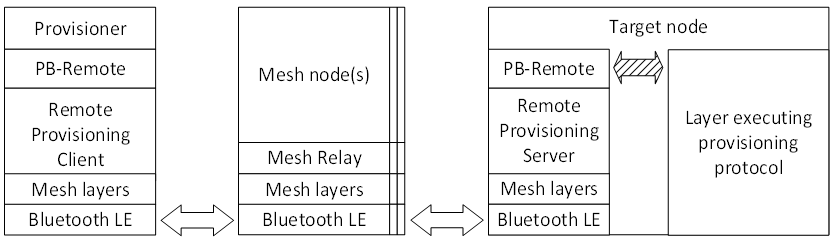 |
If PB-Remote is supported on a node, the Node Provisioning Protocol Interface procedures shall be supported. The Provisioner shall execute Node Provisioning Protocol Interface procedures over the PB-Remote provisioning bearer.
No more than one Node Provisioning Protocol Interface procedure shall be active on a node at any time.
3.11.8.2. Device Key Candidate
The Device Key Candidate is a key that can replace the device key when activated. The Device Key Candidate may be delivered to the node by using an OOB mechanism or may be generated by successfully executing the Device Key Refresh procedure. When the Device Key Candidate is available, it can be activated, and replaces the device key, as described in Section 3.6.4.2.
The Device Key Candidate delivery using an OOB mechanism can be used by models or other elements of the mesh stack and should use at least the same security level as device key generation as defined in this specification (see Section 5.4).
3.11.8.3. Common Node Provisioning Protocol Interface behaviors
This section defines common behaviors of the Node Provisioning Protocol Interface when executing the Node Provisioning Protocol Interface procedures.
At power-up, the Node Provisioning Protocol Interface shall be in a closed state. When the Node Provisioning Protocol Interface is in a closed state, it shall not pass Provisioning PDUs.
The node opens the Node Provisioning Protocol Interface when it receives a Remote Provisioning Link Open message indicating the Remote Provisioning Server itself as a destination (see Section 4.4.5.5.3.2). When the Node Provisioning Protocol Interface opens, the Provisioning PDUs received over PB-Remote are delivered over the Node Provisioning Protocol Interface to the layer that is executing the provisioning protocol on the node. The provisioning protocol processes and generates Provisioning PDUs as defined in Section 5.4.2.
The Node Provisioning Protocol Interface can be closed by the Provisioner or by the layer executing the provisioning protocol on the node. The Provisioner can close the open Node Provisioning Protocol Interface at any time by sending a Remote Provisioning Link Close message (see Section 4.3.4.12). The Reason Code received in the Remote Provisioning Link Close message shall be passed over the Node Provisioning Protocol Interface. When the layer that is executing the provisioning protocol encounters a protocol timeout error, it shall close the Node Provisioning Protocol Interface, and the node shall delete the Device Key Candidate.
3.11.8.4. Device Key Refresh procedure
The Device Key Refresh procedure is used to change the device key (DevKey) without reprovisioning a node and without a need to reconfigure the node. The Device Key Refresh procedure does not transfer a device key to the device over the air; instead, it uses the provisioning protocol to compute the Device Key Candidate (see Section 3.11.8.1). The device key value change that results from this procedure is thus performed at the same security level as is provisioning of the unprovisioned device. The Address, NetKey, NetKey Index, and IV Index that are provided using the provisioning protocol must match the values stored on the node as required by Section 3.11.8.4.1; the value of the Flags field is ignored.
Because of the time required to propagate Secure Network beacons in the network, the Flags values on the Provisioner might differ from the Flags values stored on the node. The Node Provisioning Protocol Interface procedures execute successfully in such temporarily incoherent networks.
The Device Key Refresh procedure starts with opening the Node Provisioning Protocol Interface. Then Provisioning PDUs are exchanged, and the provisioning protocol is executed. Finally, the Node Provisioning Protocol Interface is closed. The result of the Device Key Refresh procedure is the generation of a Device Key Candidate.
3.11.8.4.1. Node Provisioning Protocol Interface behavior
When the Provisioner closes the Node Provisioning Protocol Interface with the Reason Code equal to Success after delivering a Provisioning Data PDU (see Section 5.4.1.8) that can be accepted within the context of the Device Key Refresh procedure (see Table 3.86) over the Node Provisioning Protocol Interface, then the Device Key Refresh procedure succeeds, and the node shall assume that the new value of the device key is known to the Provisioner and shall store the key value as the Device Key Candidate.
When the Node Provisioning Protocol Interface receives a Provisioning Data PDU with provisioning data that cannot be accepted (see Table 3.86), then the node shall respond with a Provisioning Failed PDU (see Section 5.4.1.10) with its Error Code parameter set to Invalid Data.
When the Provisioner closes the Node Provisioning Protocol Interface with the Reason Code not equal to Success after delivering a Provisioning Data PDU (see Section 5.4.1.8) that can be accepted (see Table 3.86) over the Node Provisioning Protocol Interface, the Device Key Refresh procedure has failed, and the node shall delete the Device Key Candidate.
Table 3.86 defines the values of the Provisioning Data PDU that are required in order for the PDU to be accepted by the Node Provisioning Protocol Interface during the Device Key Refresh procedure. The Device Key Refresh procedure ignores the values of the Flags field.
|
Provisioning Data PDU field |
Node Provisioning Protocol Interface acceptance criterion |
|---|---|
|
Network Key |
The Network Key field value is equal to the stored value of a NetKey identified by the Key Index field. |
|
Key Index |
The key identified by the Key Index field is valid for this device. |
|
IV Index |
The IV Index field value is equal to the current value of the IV Index. |
|
Unicast Address |
The Unicast Address field value is equal to the unicast address of the primary element. |
3.11.8.5. Node Address Refresh procedure
The Node Address Refresh procedure is used to change the node’s device key and unicast address without reprovisioning.
Executing this procedure ends the current term of the node and starts a new term.
The NetKeys and AppKeys stored in the node are not removed during the procedure. Other configuration states may change (e.g., the Composition Data state may change upon successful procedure completion if features are added or removed [see Section 3.2]).
The unicast addresses that have been unallocated as a result of executing the Node Address Refresh procedure may be reused by a Provisioner. A Provisioner shall reuse these addresses only after the current IV Index (used for sending messages during the Node Address Refresh procedure) has been updated (see Section 3.11.5) in order to enable the sequence numbers to be reused.
The Node Address Refresh procedure starts with opening the Node Provisioning Protocol Interface. Then Provisioning PDUs are exchanged, and the provisioning protocol is executed. Finally, the Node Provisioning Protocol Interface is closed. The results of the Node Address Refresh procedure are to generate a new device key, which replaces the current DevKey, and to change the address of the primary element of the node and the address of each secondary element of the node if the node supports secondary elements.
3.11.8.5.1. Node Provisioning Protocol Interface behavior
The Provisioning Capabilities PDU (see Section 5.4.1.2) shall set the Number of Elements field to the number of elements after the Node Address Refresh procedure completes successfully.
When the Provisioner closes the Node Provisioning Protocol Interface with the Reason Code equal to Success after delivering a Provisioning Data PDU (see Section 5.4.1.8) that can be accepted within the context of the Node Address Refresh procedure (see Table 3.87) executed over the Node Provisioning Protocol Interface, then the Node Address Refresh procedure succeeds, and the node shall store the new value of the device key as the DevKey and shall assign unicast addresses to all the node’s elements, starting with the primary element, and assigning a consecutive range of addresses that begins with the provided unicast address value (see Section 5.4.2.5).
When the node does not complete address assigning successfully, the behavior defined in Section 5.4.2.5 is executed, sending a Provisioning Failed PDU with the Error Code parameter set to Cannot Assign Addresses, and the provisioning protocol fails on the node side.
The Provisioner executing the Node Address Refresh procedure may reuse addresses of removed nodes, as defined in Section 3.11.7.
When the Node Address Refresh procedure succeeds, the node shall preserve the value of the NetKey List state and AppKey List state and may change values of other Configuration Server states (see Table 4.311).
Additionally, the node shall set its states to their default values, including execution of the following steps as applicable:
-
Set the sequence number to its lowest initial value.
-
Cancel all transmission and reception of segmented messages.
-
Delete all entries in the message replay protection mechanism (see Section 3.9.8) associated with unicast addresses of all elements of the node.
-
Set the states to their default values when the default values are specified.
-
Terminate all active friendships, if applicable.
-
Copy Composition Data Page 128 to Composition Data Page 0, if applicable.
When the Node Provisioning Protocol Interface receives a Provisioning Data PDU with provisioning data that cannot be accepted (see Table 3.87), then the node shall respond with a Provisioning Failed PDU (see Section 5.4.1.10) with the Error Code parameter set to Invalid Data.
When the Provisioner closes the Node Provisioning Protocol Interface with the Reason Code not equal to Success after delivering a Provisioning Data PDU (see Section 5.4.1.8) that can be accepted (see Table 3.87) over the Node Provisioning Protocol Interface, the Node Address Refresh procedure has failed.
Table 3.87 defines the values of the Provisioning Data PDU that are required in order for the PDU to be accepted by the Node Provisioning Protocol Interface for the Node Address Refresh procedure. The Node Address Refresh procedure ignores the values of the Flags field.
|
Provisioning Data PDU field |
Node Provisioning Protocol Interface acceptance criteria |
|---|---|
|
Network Key |
The Network Key field value is equal to the stored value of a NetKey identified by the Key Index field. |
|
Key Index |
The key identified by the Key Index field is valid for this device. |
|
IV Index |
The IV Index field value is equal to the current value of the IV Index. |
|
Unicast Address |
The Unicast Address field value shall be selected such that there is no overlap between the old and new address space of the node. |
3.11.8.6. Node Composition Refresh procedure
The Node Composition Refresh procedure is used to change the device key of the node and to add or delete models or features of the node without reprovisioning.
Executing this procedure ends the current term of the node and starts a new term.
Almost all states of the node do not change during this procedure, as defined in Section 3.11.8.6.1. The Composition Data state of the node is changed.
The Node Composition Refresh procedure starts with opening the Node Provisioning Protocol Interface. Then Provisioning PDUs are exchanged, and the provisioning protocol is executed. Finally, the Node Provisioning Protocol Interface is closed. The results of the Node Composition Refresh procedure are to generate a Device Key Candidate, which replaces the current DevKey, and to change the Composition Data state of the node.
3.11.8.6.1. Node Provisioning Protocol Interface behavior
When the Provisioner closes the Node Provisioning Protocol Interface with the Reason Code equal to Success after delivering a Provisioning Data PDU (see Section 5.4.1.8) that can be accepted within the context of the Node Composition Refresh procedure (see Table 3.88) over the Node Provisioning Protocol Interface, then the Node Composition Refresh procedure succeeds, and the node shall store the key value as the Device Key Candidate and shall copy Composition Data Page 128 to Composition Data Page 0. When a model is removed as a result of the Node Composition Refresh procedure, the node shall remove all references to the deleted model. When a model is added, the node shall set the new states to default values. The values of all other states shall not change.
When the Node Provisioning Protocol Interface receives a Provisioning Data PDU with provisioning data that cannot be accepted (see Table 3.88), then the node shall respond with a Provisioning Failed PDU (see Section 5.4.1.10) with the Error Code parameter set to Invalid Data.
When the Provisioner closes the Node Provisioning Protocol Interface with the Reason Code not equal to Success after delivering a Provisioning Data PDU (see Section 5.4.1.8) that can be accepted (see Table 3.88) over the Node Provisioning Protocol Interface, the Node Composition Refresh procedure has failed, and the node shall delete the Device Key Candidate.
Table 3.88 defines the values of the Provisioning Data PDU that are required in order for the PDU to be accepted by the Node Provisioning Protocol Interface for the Node Composition Refresh procedure. The Node Composition Refresh procedure ignores the values of the Flags field.
|
Provisioning Data PDU field |
Node Provisioning Protocol Interface acceptance criterion |
|---|---|
|
Network Key |
The Network Key field value is equal to the stored value of a NetKey identified by the Key Index field. |
|
Key Index |
The key identified by the Key Index field is valid for this device. |
|
IV Index |
The IV Index field value is equal to the current value of the IV Index. |
|
Unicast Address |
The Unicast Address field value is equal to the unicast address of the primary element. |
3.12. Message processing flow
The flow of messages through the layers defined by this specification, along with key decision points, is illustrated by Figure 3.69 (upper layers), Figure 3.70 (upper transport and lower transport layers), and Figure 3.71 (bearer and network layers).
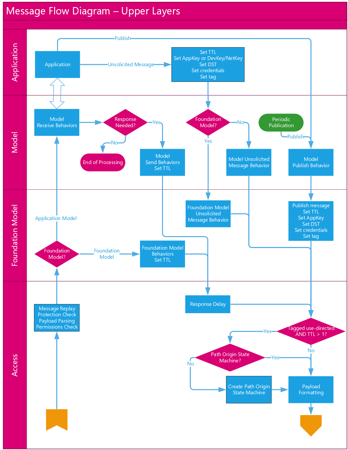 |
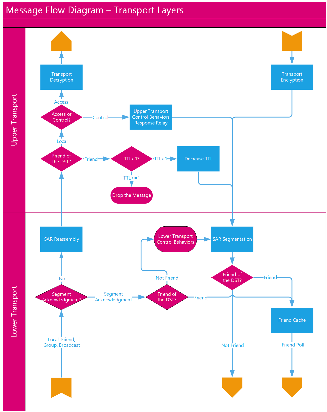 |
 |
The flow of messages through the access layer defined by this specification, along with key decision points, is illustrated by Figure 3.72.
 |
4. Foundation models
The foundation models define the access layer states, messages, and models required to configure and manage a mesh network.
4.1. Conventions
4.1.1. Endianness
All multiple-octet numeric values in this layer shall be little-endian, as described in Section 3.1.1.2.
4.1.2. Log field transformation
In order to compress two-octet values into one-octet fields, the following logarithmic transformation is used: any two-octet value is mapped onto a one-octet field value representing the largest integer n, where 2(n-1) is less than or equal to the two-octet value.
This transformation is represented in Table 4.1.
|
Log Field Value |
2-octet Value |
|---|---|
|
0x01 |
0x0001 |
|
0x02 |
0x0002–0x0003 |
|
0x03 |
0x0004–0x0007 |
|
0x04 |
0x0008–0x000F |
|
0x05 |
0x0010–0x001F |
|
0x06 |
0x0020–0x003F |
|
0x07 |
0x0040–0x007F |
|
0x08 |
0x0080–0x00FF |
|
0x09 |
0x0100–0x01FF |
|
0x0A |
0x0200–0x03FF |
|
0x0B |
0x0400–0x07FF |
|
0x0C |
0x0800–0x0FFF |
|
0x0D |
0x1000–0x1FFF |
|
0x0E |
0x2000–0x3FFF |
|
0x0F |
0x4000–0x7FFF |
|
0x10 |
0x8000–0xFFFF |
|
0x11 |
0x10000 |
4.1.3. Error handling
When a model processes an incoming message, the defined behavior may require the model to check one or more error conditions from a table of conditions (for example, see Table 4.316). These error conditions shall be checked in order, from top to bottom, starting from the first row of the table. The model shall stop checking after encountering a failed condition. Or, after not encountering a failed condition, the model shall stop checking after finishing the last row in the table.
4.2. State definitions
The state of a node is defined using one or more state definitions. This section defines states used throughout this specification.
State definitions that are not required as part of this specification are defined in the Mesh Model specification [9] and follow the same format and architecture as mesh state definitions.
If a default value is defined for a state, it represents the value of the state of the node immediately after the node is provisioned.
4.2.1. State instances for multiple subnets
If a node belongs to multiple subnets and supports a state that controls or provides information about a functionality of the node depending on the subnet, the node shall have an instance of the state for each subnet. Each state instance shall be referenced using the NetKey Index of the associated subnet.
4.2.2. Composition Data
The Composition Data state contains information about a node, the elements it includes, and the supported models. The Composition Data is composed of a number of pages of information. All Composition Data Pages not defined in this specification are reserved for future use.
The Composition Data state can be accessed by the Configuration Server model and, if the Large Composition Data Server model is supported, by that model also.
If the node does not support the Large Composition Data Server model, the size of each page shall not exceed the maximum useful Access message size (Table 3.61).
4.2.2.1. Composition Data Page 0
Composition Data Page 0 shall be present on a node. Composition Data Page 0 shall not change during a term of a node on the network.
The initial term of a node on the network shall start when the node is provisioned on the network.
A term shall end and a new term shall start when a Node Address Refresh procedure or a Node Composition Refresh procedure is successfully completed (see Section 3.11.8).
The last term of a node on the network shall end when the node is removed from the network.
The format of Composition Data Page 0 is defined in Table 4.2.
|
Field |
Size |
Description |
Req. |
|---|---|---|---|
|
CID |
2 |
Contains a 16-bit company identifier assigned by the Bluetooth SIG (the list is available at [4]) that shall not change throughout the lifetime of the physical or software product |
M |
|
PID |
2 |
Contains a 16-bit vendor-assigned product identifier that shall not change throughout the lifetime of the physical or software product |
M |
|
VID |
2 |
Contains a 16-bit vendor-assigned product software version identifier that should be updated when the product's software is updated |
M |
|
CRPL |
2 |
Contains a 16-bit value representing the minimum number of replay protection list entries in a device (see Section 3.9.8) |
M |
|
Features |
2 |
Contains a bit field indicating the device features, as defined in Table 4.3 |
M |
|
Elements |
variable |
Contains a sequence of element descriptions |
M |
The Features field contains a bit field indicating the node capabilities as defined in Section 3.2. The format of the Features field is defined in Table 4.3.
|
Bit |
Feature |
Description |
|---|---|---|
|
0 |
Relay |
Relay feature support (see Table 4.4) |
|
1 |
Proxy |
Proxy feature support (see Table 4.4) |
|
2 |
Friend |
Friend feature support (see Table 4.4) |
|
3 |
Low Power |
Low Power feature support (see Table 4.4) |
|
4–15 |
RFU |
Reserved for Future Use |
Features field bits values are defined in Table 4.4.
|
Bit Value |
Description |
|---|---|
|
0 |
The feature indicated by the bit is not supported |
|
1 |
The feature indicated by the bit is supported |
The Elements field contains a sequence of one or more element descriptions. The format of each element description is defined in Table 4.5.
|
Field |
Size |
Description |
Req. |
|---|---|---|---|
|
Loc |
2 |
Contains a location descriptor |
M |
|
NumS |
1 |
Contains a count of SIG Model IDs in this element |
M |
|
NumV |
1 |
Contains a count of Vendor Model IDs in this element |
M |
|
SIG Models |
variable |
Contains a sequence of NumS SIG Model IDs |
M |
|
Vendor Models |
variable |
Contains a sequence of NumV Vendor Model IDs |
M |
The Loc field contains a location description as defined in the GATT Bluetooth Namespace Descriptors section of the Bluetooth SIG Assigned Numbers [4]. Values not defined in the GATT Units table are Reserved for Future Use.
The SIG Models field contains a sequence of NumS SIG Model IDs. For each extended model included in this sequence, all models it extends shall also be included.
The Vendor Models field contains a sequence of NumV Vendor Model IDs.

The example in Figure 4.1 shows a Composition Data Page 0 with two elements. Each element includes the location, the number of SIG Model IDs, and the number of Vendor Model IDs. In this example, the first element has three SIG Model IDs and no Vendor Model IDs, and the second element has two SIG Model IDs and two Vendor Model IDs.
4.2.2.2. Composition Data Page 1
Composition Data Page 1 shall be present on a node. Composition Data Page 1 contains information about the relationships among models. Each model either can be a root model or can extend other models (see Section 2.3.6). Additionally, a model may have one or more corresponding models (see Section 6.4.3.1 in the Mesh Model Specification [9]).
The format of Composition Data Page 1 is defined in Table 4.6.
|
Field |
Size |
Description |
Req. |
|---|---|---|---|
|
Elements |
variable |
Contains a sequence of element descriptions |
M |
The Elements field contains a sequence of one or more element descriptions. The format of each element description is defined in Table 4.7.
|
Field |
Size |
Description |
Req. |
|---|---|---|---|
|
Number_S |
1 |
Contains a count of SIG Models Items in this element |
M |
|
Number_V |
1 |
Contains a count of Vendor Models in this element |
M |
|
SIG_Models_Items |
variable |
Contains a sequence of Number_S SIG Model Items |
M |
|
Vendor_Models_Items |
variable |
Contains a sequence of Number_V Vendor Model Items |
M |
The Number_S field indicates the number of SIG Models in the element.
The Number_V field indicates the number of Vendor Models in the element.
The SIG_Models_Items field contains a sequence of Number_S of Model Items describing SIG Models in the element. The format of a Model Item is defined in Table 4.8.
The Vendor_Models_Items contains a sequence of Number_V of Model Items describing Vendor Models in the element. The format of a Model Item is defined in Table 4.8.
Table 4.8 defines the format of the Model Item.
|
Field |
Size |
Description |
Req. |
|---|---|---|---|
|
Corresponding_Present |
1 |
Corresponding_Group_ID field indicator |
M |
|
Format |
1 |
Format of Extended_Model_Items indicator |
M |
|
Extended_Items_Count |
6 |
Number of Extended Model Items in the Extended_Model_Items field |
M |
|
Corresponding_Group_ID |
8 |
Corresponding group identifier |
C.1 |
|
Extended_Model_Items |
variable |
List of Extended Model Items |
O |
- C.1:
-
When the value of Corresponding_Present is 1, the Corresponding_Group_ID field shall be present; otherwise, the Corresponding_Group_ID field shall not be present.
The Corresponding_Present field indicates the presence of the Corresponding_Group_ID field.
The Format field shall indicate the format of each Extended Model Item in the Extended_Model_Items field. When the value of the Format field is 0, the format of the Extended Model Item is defined in Table 4.9. When the value of the Format field is 1, the format of the Extended Model Item is defined in Table 4.11.
The Extended_Items_Count field shall indicate the number of Extended Model Items in the Extended_Model_Items field.
If present, the Corresponding_Group_ID field shall indicate the Corresponding Group ID of the model. All models from one group of corresponding Models shall share the same Corresponding Group ID. Each group of corresponding models shall have a unique Corresponding Group ID.
The Extended_Model_Items field shall contain the list of Extended Model Items. All Extended Model Items shall share the same format as defined by the Format field. Each Extended Model Item indicates a model that the Model Item is extending.
Table 4.9 defines the Extended Model Item short format.
|
Field |
Size |
Description |
Req. |
|---|---|---|---|
|
Element_Offset |
3 |
Element address modifier, in the range -4 to 3 |
M |
|
Model_Item_Index |
5 |
Model Index, in the range 0 to 31 |
M |
The Element_Offset field indicates the offset to the current element address, which identifies the element. The identified element shall be supported by the node. The value of the Element_Offset field is mapped to an integer value as defined in Table 4.10.
|
Element_Offset |
Represented Value |
|---|---|
|
0 |
0 |
|
1 |
1 |
|
2 |
2 |
|
3 |
3 |
|
4 |
-4 |
|
5 |
-3 |
|
6 |
-2 |
|
7 |
-1 |
The Model_Item_Index field shall indicate a model within an element indicated by the Element_Offset field. The index of a model shall be identified using the following rules:
-
For a SIG Model, the index matches the index of the model in the SIG Models field of Composition Data Page 0 of the identified element,
-
For a Vendor Model, the index is equal to the sum of the Number_S field value and an index of the model in the Vendor Models field of Composition Data Page 0 of the identified element.
Table 4.11 defines the Extended Model Item long format.
|
Field |
Size |
Description |
Req. |
|---|---|---|---|
|
Element_Offset |
8 |
Element address modifier, in the range -128 to 127 |
M |
|
Model_Item_Index |
8 |
Model index, in the range 0 to 255 |
M |
The Element_Offset field indicates the modifier to the current element address. The identified element shall be supported by the node. The format of the field is sint8.
The Model_Item_Index field indicates a model within an element indicated by the Element_Offset field. The Model_Item_Index field shall be computed using the same rules as for the Model_Item_Index field of the Extended Model Item short format.
4.2.2.2.1. Example of Composition Data Page 1
Table 4.12 summarizes the Composition Data Page 1 entries for an example node with the following element and model relationships.
-
The node has two elements:
-
The first element contains SIG models A and B and vendor model V.
-
The second element contains SIG model C and vendor models X and Y.
-
-
The models are ordered in Composition Data Page 0 as follows:
-
First element: models A, B, V
-
Second element: models C, X, Y
-
-
Models A, C, and V are root models.
-
Model B extends model A, and model X extends model V.
-
Models B and C are corresponding models.
-
Models X and Y are corresponding models.
Composition Page 1 for this configuration is presented in Table 4.12.
|
Elements |
Index |
Model |
Model Item |
Extended Model Item |
|---|---|---|---|---|
|
Number_S is 2 |
0 |
A |
Corresponding_Present is 0 |
– |
|
1 |
B |
Corresponding_Present is 1 |
Item 0: |
|
|
2 |
V |
Corresponding_Present is 0 |
– |
|
|
Number_S is 1 |
0 |
C |
Corresponding_Present is 1 |
– |
|
1 |
X |
Corresponding_Present is 1 |
Item 0: |
|
|
2 |
Y |
Corresponding_Present is 1 |
– |
4.2.2.3. Composition Data Page 2
Composition Data Page 2 shall be present on a node if the node supports one or more mesh profile specifications (see Section 3.12, Mesh Profiles, in [4]). Composition Data Page 2 is used to indicate support for one or more mesh profile specifications (see Section 3.12, Mesh Profiles, in [4]).
The format of Composition Data Page 2 is defined in Table 4.13.
|
Field |
Size |
Description |
|---|---|---|
|
Record_List |
variable |
Contains a list of records |
The Record_List field contains a sequence of one or more entries, each indicating support for a specific mesh profile specification (see Section 3.12, Mesh Profiles, in [4]). The format of each entry is defined in Table 4.14.
|
Field |
Size |
Description |
|---|---|---|
|
Mesh_Profile_Entry |
variable |
First entry |
|
Mesh_Profile_Entry |
variable |
Second entry |
|
… |
… |
… |
|
Mesh_Profile_Entry |
variable |
Last entry |
The Mesh_Profile_Entry field format is defined in Table 4.15.
|
Field |
Size |
Description |
|---|---|---|
|
Mesh_Profile_Identifier |
2 |
Mesh profile UUID identifying the supported mesh profile specification (see Section 3.12, Mesh Profiles, in [4]) |
|
Version |
3 |
Version of the mesh profile specification (see Section 3.12, Mesh Profiles, in [4]) |
|
Num_Element_Offsets |
1 |
Total number of element offsets in the Element_Offset_List field |
|
Element_Offset_List |
variable |
List of element offsets containing models related to the supported mesh profile specification (see Section 3.12, Mesh Profiles, in [4]) |
|
Additional_Data_Len |
2 |
Length of the additional data |
|
Additional_Data |
variable |
Additional data specified in a mesh profile specification (see Section 3.12, Mesh Profiles, in [4]) that is indicated by the Mesh_Profile_Identifier field |
The Version field format is defined in Table 4.16.
|
Field |
Size |
Description |
|---|---|---|
|
Version x |
1 |
Specification major revision number |
|
Version y |
1 |
Specification minor revision number |
|
Version z |
1 |
Specification .Z revision number |
The Element_Offset_List field format is defined in Table 4.17.
|
Field |
Size |
Description |
|---|---|---|
|
Element_Offset |
1 |
First element offset |
|
Element_Offset |
1 |
Second element offset |
|
… |
… |
… |
|
Element_Offset |
1 |
Last element offset |
The Element_Offset field indicates a zero-based offset of the element, starting from the primary element, where models related to the supported mesh profile are present.
4.2.2.4. Composition Data Page 128
Composition Data Page 128 is used to indicate the structure of elements, features, and models of a node in a new term (see Section 4.2.2.1).
Composition Data Page 128 shall be present if the node supports the Remote Provisioning Server model.
The structure of Composition Data Page 128 is identical to the structure of Composition Data Page 0.
Composition Data Page 128 shall represent the contents that Composition Data Page 0 will contain in a new term.
4.2.2.5. Composition Data Page 129
Composition Data Page 129 is used to indicate information about the relationships among models on a node in a new term (see Section 4.2.2.1).
Composition Data Page 129 shall be present on a node if the node supports the Remote Provisioning Server model (see Section 4.4.5).
The structure of Composition Data Page 129 is identical to the structure of Composition Data Page 1.
Composition Data Page 129 shall represent the contents that Composition Data Page 2 (see Section 4.2.2.3) will contain in a new term.
4.2.2.6. Composition Data Page 130
Composition Data Page 130 is used to indicate support for one or more mesh profile specifications (see Section 3.12, Mesh Profiles, in [4]) on a node in a new term (see Section 4.2.2.1).
Composition Data Page 130 shall be present on a node if the node supports Composition Data Page 2 (see Section 4.2.2.3) and the Remote Provisioning Server model (see Section 4.4.5).
The structure of Composition Data Page 130 is identical to the structure of Composition Data Page 2 (see Section 4.2.2.3).
Composition Data Page 130 shall represent the contents that Composition Data Page 2 will contain in a new term.
4.2.3. Model Publication
The Model Publication state is a composite state that controls parameters of messages that are published by a model. The Model Publication state includes the following states:
-
Publish Address state
-
Publish Period state
-
Publish AppKey Index state
-
Publish Friendship Credential Flag state
-
Publish TTL state
-
Publish Retransmit Count state
-
Publish Retransmit Interval Steps state
Within an element, each model has a separate instance of Model Publication state. Models defined by higher layer specifications should use instances of the Model Publication state to control the publishing of messages.
4.2.3.1. Publish Address
The Publish Address state determines the destination address in messages sent by a model. The publish address shall be the unassigned address, a unicast address, a Label UUID, or a group address.
When the publish address is set to the unassigned address, the publication of the model is disabled and the model does not originate any unsolicited messages.
4.2.3.2. Publish Period
The Publish Period state determines the interval at which status messages are published by a model. This is a 1-octet value and consists of two fields: a 2-bit field representing the step resolution and a 6-bit field representing the number of steps. The format of this state is defined in Table 4.18.
|
Field |
Size |
Description |
Req. |
|---|---|---|---|
|
Number of Steps |
6 |
The number of steps |
M |
|
Step Resolution |
2 |
The resolution of the Number of Steps field |
M |
 |
The Step Resolution field enumerates the resolution of the Number of Steps field and the values are defined in Table 4.19.
|
Value |
Description |
|---|---|
|
0b00 |
The Step Resolution is 100 milliseconds |
|
0b01 |
The Step Resolution is 1 second |
|
0b10 |
The Step Resolution is 10 seconds |
|
0b11 |
The Step Resolution is 10 minutes |
The Number of Steps field is a value representing the number of steps and the values are defined in Table 4.20.
|
Value |
Description |
|---|---|
|
0x00 |
Publish Period is disabled |
|
0x01–0x3F |
The number of steps |
The Publish Period is calculated using the formula:
|
Publish Period=(Step Resolution)×(Number of Steps) |
For example, if the Step Resolution is 0b10 and the Number of Steps is 0x31, then the Publish Period would be 490 seconds.
4.2.3.3. Publish AppKey Index
The Publish AppKey Index state is the global AppKey Index of the application key used in messages sent by a model. The Publish AppKey Index shall be in the Model To AppKey List as defined in Section 4.2.7.
4.2.3.4. Publish Friendship Credentials Flag
The Publish Friendship Credentials Flag state is a 1-bit state controlling the credentials used to publish messages from a model. The Publish Friendship Credentials Flag values are described in Table 4.21.
|
Value |
Description |
|---|---|
|
0 |
Managed flooding security credentials or directed security credentials are used for publishing |
|
1 |
Friendship security credentials are used for publishing |
4.2.3.5. Publish TTL
The Publish TTL state determines the TTL value for outgoing messages published by the model and the values are defined in Table 4.22. Setting Publish TTL to 0xFF will make the messages use the Default TTL as defined in Section 4.2.8.
|
Value |
Description |
|---|---|
|
0x00–0x7F |
The Publish TTL value, represented as a 1-octet integer |
|
0x80–0xFE |
Prohibited |
|
0xFF |
Use Default TTL |
Note
Note: If the Publish TTL state is set to 1, the outgoing messages are published to local elements only, as defined in Section 3.4.5.
4.2.3.6. Publish Retransmit Count
The Publish Retransmit Count state is a 3-bit value controlling the number of times that a message published by a model will be retransmitted. For example, a value of 0b000 represents no retransmissions, and a value of 0b111 represents 7 retransmissions.
4.2.3.7. Publish Retransmit Interval Steps
The Publish Retransmit Interval Steps state is a 5-bit value controlling the interval between retransmissions of a message that is published by a model. The state represents the number of 50-millisecond steps that shall transpire before a message that was published by a model is retransmitted.
The retransmission interval is calculated using the following formula:
|
retransmission interval=(Publish Retransmit Interval Steps+1)×50 |
For example, a value of 0b10000 represents an interval of 850 milliseconds.
4.2.4. Subscription List
The Subscription List state is a list of group addresses and Label UUIDs.
The Subscription List is used by a model when receiving Access messages as defined in Section 3.7.3.2. It is highly recommended that models defined by higher layer specifications use instances of the Subscription List state to control the receiving of messages.
Within an element, each model has a separate instance of a Subscription List, unless the model extends another model on that element. Instances of models that extend other models (i.e., all models within an extension relation tree) shall share a single instance of a Subscription List per element.
The size of the state shall not exceed the maximum useful Access message size (Table 3.61).
4.2.5. NetKey List
The NetKey List state is an indexed list of NetKeys.
Each entry in the NetKey List holds up to two key values: the old key value and the new key value. The use of the old key and the new key values is described in the Key Refresh procedure (see Section 3.11.4).
The NetKey List shall contain a minimum of one NetKey.
The size of the state shall not exceed the maximum useful Access message size (Table 3.61).
4.2.6. AppKey List
The AppKey List state is an indexed list of AppKeys.
Each entry in the AppKey List holds an AppKey Index and up to two key values: the old key value and the new key value. The use of the old key and the new key values is described in the Key Refresh procedure (see Section 3.11.4).
The AppKey List shall contain a minimum of one AppKey.
The size of the state shall not exceed the maximum useful Access message size (Table 3.61).
4.2.7. Model To AppKey List
The Model To AppKey List state is a list of relationships between models and AppKeys. A model may be associated with one or more AppKeys.
The size of the state shall not exceed the maximum useful Access message size (Table 3.61).
4.2.8. Default TTL
The Default TTL state determines the TTL value used when sending messages. The Default TTL is applied by the access layer or by the upper transport layer unless the application or functionality specifies a TTL. The Default TTL values are defined in Table 4.23.
|
Value |
Description |
|---|---|
|
0x00, 0x02–0x7F |
The Default TTL state |
|
0x01, 0x80–0xFF |
Prohibited |
4.2.9. Relay
The Relay state indicates support for the Relay feature. If the Relay feature is supported, then this also indicates and controls whether the Relay feature is enabled or disabled. The values are defined in Table 4.24.
|
Value |
Description |
|---|---|
|
0x00 |
The node support Relay feature that is disabled |
|
0x01 |
The node supports Relay feature that is enabled |
|
0x02 |
Relay feature is not supported |
|
0x03–0xFF |
Prohibited |
If Relay feature is not supported, the Relay state value shall be 0x02 and not be changed.
If Relay feature is supported, the Relay state value 0x02 shall not be used.
4.2.10. Attention Timer
The Attention Timer state determines if the Attention Timer state is on or off. This is generally intended to allow an element to attract human attention and, among others, is used during provisioning (see Section 5.4.1.11).
An element may not support the Attention Timer. If an element does not support the Attention Timer, the Attention Timer state shall always be set to zero.
If the Attention Timer is non-zero for an element, Attention Timer state is on. If the Attention Timer is zero for an element, the Attention Timer state is off.
When the Attention Timer state is on, the value determines how long the element shall remain attracting human’s attention. The element does that by behaving in a human-recognizable way (e.g., a lamp flashes, a motor makes noise, an LED blinks). The exact behavior is implementation specific and depends on the type of device. Normal behavior of the element is still active, although the method of identification may override the physical state of the device.
The Attention Timer is a momentary state, active for a time indicated by its value, in seconds. The value is decremented every second by 1 until it reaches zero. The values for this state are defined in Table 4.25.
|
Value |
Description |
|---|---|
|
0x00 |
Off |
|
0x01–0xFF |
On, remaining time in seconds |
4.2.11. Secure Network Beacon
The Secure Network Beacon state determines if a node is periodically broadcasting Secure Network beacon messages (see Section 3.10.3). The values for this state are defined in Table 4.26.
|
Value |
Description |
|---|---|
|
0x00 |
The node is not broadcasting a Secure Network beacon |
|
0x01 |
The node is broadcasting a Secure Network beacon |
|
0x02–0xFF |
Prohibited |
4.2.12. GATT Proxy
The GATT Proxy state indicates if the Proxy feature (see Section 3.4.6.2) is supported. If the feature is supported, the state indicates and controls the Proxy feature.
If the Proxy feature is disabled and the GATT server is advertising with Node Identity (see Section 7.2.2.2.3), a GATT client device can connect over GATT to that node for configuration and control. Messages from the GATT bearer are not relayed to the advertising bearer.
The values for this state are defined in Table 4.27.
|
Value |
Name |
Description |
|---|---|---|
|
0x00 |
Disabled |
The Proxy feature is supported and disabled |
|
0x01 |
Enabled |
The Proxy feature is supported and enabled |
|
0x02 |
Not Supported |
The Proxy feature is not supported |
|
0x03–0xFF |
Prohibited |
Prohibited |
If the Proxy feature is not supported, the GATT Proxy state value shall be Not Supported and shall not be changed.
If the Proxy feature is supported, the GATT Proxy state value Not Supported shall not be used.
4.2.13. Node Identity
The Node Identity state indicates if the Node Identity functionality (see Section 3.4.6.7) is supported. If the functionality is supported, the state indicates and controls the Node Identity functionality.
The Node Identity state indicates and controls whether a node is advertising with Node Identity messages on a subnet (see Section 7.2.2.2.3). The Node Identity state is defined for each known subnet. If the Mesh Proxy Service is exposed, the node can be configured to advertise with Node Identity on a subnet (see Section 4.2.1). The values for this state are defined in Table 4.28.
|
Value |
Name |
Description |
|---|---|---|
|
0x00 |
Disabled |
Advertising with Node Identity for a subnet is stopped |
|
0x01 |
Enabled |
Advertising with Node Identity for a subnet is running |
|
0x02 |
Not Supported |
Advertising with Node Identity is not supported |
|
0x03–0xFF |
Prohibited |
Prohibited |
If the Node Identity functionality is not supported, the value of the Node Identity state value shall be Not Supported and shall not be changed.
If the Node Identity functionality is supported, the value of the Node Identity state shall be either Disabled or Enabled.
If the Node Identity functionality is supported, then the default value of the Node Identity state shall be Disabled.
4.2.14. Friend
The Friend state indicates support for the Friend feature. If Friend feature is supported, then this also indicates and controls whether Friend feature is enabled or disabled. The values for this state are defined in Table 4.29.
|
Value |
Description |
|---|---|
|
0x00 |
The node supports Friend feature that is disabled |
|
0x01 |
The node supports Friend feature that is enabled |
|
0x02 |
The Friend feature is not supported |
|
0x03–0xFF |
Prohibited |
If the Friend feature is not supported, the Friend state value shall be 0x02 and not be changed.
If the Friend feature is supported, the Friend state value 0x02 shall not be used.
If the Friend feature is supported and the Friend state changes to value 0x00 and if a node is a friend for one or more Low Power nodes, the node shall terminate all friend relationships and clear the associated Friend Queue.
4.2.15. Key Refresh Phase
The Key Refresh Phase state indicates and controls the Key Refresh procedure (see Section 3.11.4) for each NetKey in the NetKey List. The values for this state are defined in Table 4.30.
|
Value |
Description |
|---|---|
|
0x00 |
Normal operation; Key Refresh procedure is not active |
|
0x01 |
First phase of Key Refresh procedure |
|
0x02 |
Second phase of Key Refresh procedure |
|
0x03–0xFF |
Prohibited |
Table 4.31 defines all possible transitions of the Key Refresh Phase state that can be controlled using this state. All other transitions are handled internally (e.g., the transition from 0x00 to 0x01 when a device receives a key update) by Key Refresh procedure.
|
Old State |
Transition |
New State |
Description |
|---|---|---|---|
|
0x00 |
0x03 |
0x00 |
Transition 3 from Key Refresh Phase 0x00 does not cause any state change. |
|
0x01 |
0x02 |
0x02 |
Transition 2 from Key Refresh Phase 0x01 moves to Key Refresh Phase 0x02 |
|
0x01 |
0x03 |
0x00 |
Transition 3 from Key Refresh Phase 0x01 invokes Key Refresh Phase 3 and then moves to Key Refresh Phase 0x00. |
|
0x02 |
0x02 |
0x02 |
Transition 2 from Key Refresh Phase 0x02 does not cause any state change. |
|
0x02 |
0x03 |
0x00 |
Transition 3 from Key Refresh Phase 0x02 invokes Key Refresh Phase 3 and then moves to Key Refresh Phase 0x00. |
4.2.16. Health Fault
The Health Fault state is a composite state that represents a warning or an error condition of an element. The Health Fault state includes the following states:
-
Current Fault state
-
Registered Fault state
The Health Fault state is identified by Company ID and may be present in the node for more than one Company ID.
4.2.16.1. Current Fault
The Current Fault state is a 1-octet value of the most recently performed self-test and an array containing a sequence of 1-octet values, each representing the current warning or error condition of an element. The format of this state is defined in Table 4.32.
|
Field |
Size |
Description |
Req. |
|---|---|---|---|
|
Test ID |
1 |
Identifier of a most recently performed self-test |
M |
|
FaultArray |
N |
Array of current faults |
M |
Values for the Test ID are defined in Table 4.33.
|
Value |
Description |
|---|---|
|
0x00 |
Standard test |
|
0x01–0xFF |
Vendor-specific test |
The FaultArray values are Bluetooth assigned Health Fault values [4].
The FaultArray field of the Current Fault state is empty when no warning or error condition is present. The FaultArray reflects a real-time state. This means when a fault condition arises, a corresponding record is present in the FaultArray and when a fault condition is not present, the corresponding record is removed from the FaultArray automatically.
A warning indicates the state of an element that is operating within the design limits but close to them.
An error indicates that the state of an element is outside the design limits and may not perform its functions.
4.2.16.2. Registered Fault
The Registered Fault state is a 1-octet value of the most recently performed self-test and a shadow array of the FaultArray field of the Current Fault state. The format of the Registered Fault state is defined in Table 4.34.
|
Field |
Size |
Description |
Req. |
|---|---|---|---|
|
Test ID |
1 |
Identifier of a most recently performed self-test |
M |
|
FaultArray |
N |
Array of registered faults |
M |
Values for the Test ID are defined in Table 4.35.
|
Value |
Description |
|---|---|
|
0x00 |
Standard test |
|
0x01–0xFF |
Vendor-specific test |
Whenever a fault condition has been present in the Current Fault state (see Section 4.2.16.1), the corresponding record is added to the FaultArray field of the Registered Fault state. The FaultArray is cleared with a dedicated Health Fault Clear message (see Section 4.3.3.3).
4.2.17. Health Fast Period Divisor
The Health Fast Period Divisor state is a 1-octet value that controls the increased cadence of publishing Health Current Status messages.
The value range for the Health Fast Period Divisor state is 0 through 15; all other values are Prohibited. The value is used to divide the Publish Period state of the Health Server model by 2n where n is the value of the Health Fast Period Divisor state.
4.2.18. Heartbeat Publication
The Heartbeat Publication state is a composite state that controls sending of Heartbeat Transport Control messages. The Heartbeat Publication state includes the following states:
-
Heartbeat Publication Destination state
-
Heartbeat Publication Count state
-
Heartbeat Publication Period Log state
-
Heartbeat Publication TTL state
-
Heartbeat Publication Features state
-
Heartbeat Publication NetKey Index state
4.2.18.1. Heartbeat Publication Destination
The Heartbeat Publication Destination state determines the destination address for Heartbeat messages. The Heartbeat Publication Destination shall be the unassigned address, a unicast address, or a group address, all other values are Prohibited.
Note
Note: If the Heartbeat Publication Destination is set to the unassigned address, the Heartbeat messages are not being sent.
4.2.18.2. Heartbeat Publication Count
The Heartbeat Publication Count state is a 16-bit value that controls the number of periodical Heartbeat Transport Control messages to be sent. When set to 0xFFFF, it is not decremented after publication of a periodic Heartbeat message. When set to 0x0000, periodic Heartbeat messages are not published. When set to a value greater than or equal to 0x0001 or less than or equal to 0xFFFE, it is decremented after publishing a periodic Heartbeat message. Publication of a triggered Heartbeat message does not affect the Heartbeat Publication Count state.
The Heartbeat Publication Count Log is a representation of the Heartbeat Publication Count state value. The Heartbeat Publication Count Log and Heartbeat Publication Count with the value 0x00 and 0x0000 are equivalent. The Heartbeat Publication Count Log value of 0xFF is equivalent to the Heartbeat Publication count value of 0xFFFF. The Heartbeat Publication Count Log value between 0x01 and 0x11 shall represent that smallest integer n where 2(n-1) is greater than or equal to the Heartbeat Publication Count value. For example, if the Heartbeat Publication Count value is 0x0579, then the Heartbeat Publication Count Log value would be 0x0C.
The values of the Heartbeat Publication Count Log are defined in Table 4.36.
|
Value |
Description |
|---|---|
|
0x00 |
Periodic Heartbeat messages are not published |
|
0x01–0x11 |
Number of Heartbeat messages, 2(n-1), that remain to be sent |
|
0x12–0xFE |
Prohibited |
|
0xFF |
Periodic Heartbeat messages are published indefinitely |
4.2.18.3. Heartbeat Publication Period Log
The Heartbeat Publication Period Log state is an 8-bit value that controls the period between the publication of two consecutive periodic Heartbeat Transport Control messages. The value is represented as 2(n-1) seconds. For example, the value 0x04 would have a publication period of 8 seconds, and the value 0x07 would have a publication period of 64 seconds. The values for this state are defined in Table 4.37.
|
Value |
Description |
|---|---|
|
0x00 |
Periodic Heartbeat messages are not published |
|
0x01–0x11 |
Publication period represented as 2(n-1) seconds |
|
0x12–0xFF |
Prohibited |
4.2.18.4. Heartbeat Publication TTL
The Heartbeat Publication TTL state determines the TTL value used when sending Heartbeat messages. The values for this state are defined in Table 4.38.
|
Value |
Description |
|---|---|
|
0x00–0x7F |
The Heartbeat Publication TTL state |
|
0x80–0xFF |
Prohibited |
4.2.18.5. Heartbeat Publication Features
The Heartbeat Publication Features state determines the features that trigger sending Heartbeat messages when changed. The values for this state are defined in Table 4.39.
|
Bit |
Feature |
Description |
|---|---|---|
|
0 |
Relay |
Relay feature change trigger (see Table 4.40) |
|
1 |
Proxy |
Proxy feature change trigger (see Table 4.40) |
|
2 |
Friend |
Friend feature change trigger (see Table 4.40) |
|
3 |
Low Power |
Low Power feature change trigger (see Table 4.40) |
|
4–15 |
RFU |
Reserved for Future Use |
Heartbeat Publication Features state bits values are defined in Table 4.40.
|
Bit Value |
Description |
|---|---|
|
0 |
The feature change indicated by the bit does not trigger a Heartbeat message |
|
1 |
The feature change indicated by the bit triggers a Heartbeat message |
4.2.18.6. Heartbeat Publication NetKey Index
The Heartbeat Publication NetKey Index state determines the global NetKey Index of the NetKey used to send Heartbeat messages.
4.2.19. Heartbeat Subscription
The Heartbeat Subscription state is a composite state that controls receiving of Heartbeat Transport Control messages. The Heartbeat Subscription state includes the following states:
-
Heartbeat Subscription Source state
-
Heartbeat Subscription Destination state
-
Heartbeat Subscription Count state
-
Heartbeat Subscription Period Log state
-
Heartbeat Subscription Min Hops state
-
Heartbeat Subscription Max Hops state
4.2.19.1. Heartbeat Subscription Source
The Heartbeat Subscription Source state determines the source address for Heartbeat messages a node shall process. The Heartbeat Subscription Source shall be the unassigned address or a unicast address, all other values are Prohibited.
If the Heartbeat Subscription Source is set to the unassigned address, the Heartbeat messages are not being processed.
4.2.19.2. Heartbeat Subscription Destination
The Heartbeat Subscription Destination state determines the destination address for Heartbeat messages. This can be used by nodes to configure a proxy filter to allow them to receive Heartbeat messages, for example, nodes connected using a GATT bearer or in a friendship. The Heartbeat Subscription Destination shall be the unassigned address, the primary unicast address of the node, or a group address, all other values are Prohibited.
If the Heartbeat Subscription Destination is set to the unassigned address, the Heartbeat messages are not being processed.
4.2.19.3. Heartbeat Subscription Count
The Heartbeat Subscription Count state is a 16-bit counter that controls the number of Heartbeat Transport Control messages received since receiving the most recent Config Heartbeat Subscription Set message. The counter stops counting at 0xFFFF. The values for this state are defined in Table 4.41.
The Heartbeat Subscription Count Log is a representation of the Heartbeat Subscription Count state value. The Heartbeat Subscription Count Log and Heartbeat Subscription Count with the value 0x00 and 0x0000 are equivalent. The Heartbeat Subscription Count Log value of 0xFF is equivalent to the Heartbeat Subscription count value of 0xFFFF. The Heartbeat Subscription Count Log value between 0x01 and 0x10 shall represent the Heartbeat Subscription Count value, using the transformation defined in Table 4.1.
|
Value |
Description |
|---|---|
|
0x0000–0xFFFE |
Number of Heartbeat messages received |
|
0xFFFF |
More than 0xFFFE messages have been received |
4.2.19.4. Heartbeat Subscription Period
The Heartbeat Subscription Period state controls the duration for processing Heartbeat Transport Control messages. When set to 0x0000, Heartbeat messages are not processed. When set to a value greater than or equal to 0x0001, Heartbeat messages are processed.
The Heartbeat Subscription Period Log is a representation of the Heartbeat Subscription Period state value. The Heartbeat Subscription Period Log and Heartbeat Subscription Period with the value 0x00 and 0x0000 are equivalent. The Heartbeat Subscription Period Log value between 0x01 and 0x11 shall represent the Heartbeat Subscription Period value, using the transformation defined in Table 4.1.
The values of Heartbeat Subscription Period Log are defined in Table 4.42.
|
Value |
Description |
|---|---|
|
0x00 |
Heartbeat messages are not processed |
|
0x01–0x11 |
Remaining period in seconds for processing Heartbeat messages as defined in Table 4.1 |
|
0x12–0xFF |
Prohibited |
4.2.19.5. Heartbeat Subscription Min Hops
The Heartbeat Subscription Min Hops state determines the minimum hops value registered when receiving Heartbeat messages since receiving the most recent Config Heartbeat Subscription Set message. The values for this state are defined in Table 4.43.
|
Value |
Description |
|---|---|
|
0x00–0x7F |
The value of Heartbeat Subscription Min Hops state (see Section 3.6.7.3) |
|
0x80–0xFF |
Prohibited |
4.2.19.6. Heartbeat Subscription Max Hops
The Heartbeat Subscription Max Hops state determines the maximum hops value registered when receiving Heartbeat messages since receiving the most recent Config Heartbeat Subscription Set message. The values for this state are defined in Table 4.44.
|
Value |
Description |
|---|---|
|
0x00–0x7F |
The value of Heartbeat Subscription Max Hops state (see Section 3.6.7.3) |
|
0x80–0xFF |
Prohibited |
4.2.20. Network Transmit
The Network Transmit state is a composite state that controls the number and timing of the transmissions of Network PDUs originating from a node. The Network Transmit state includes the following states:
-
Network Transmit Count state
-
Network Transmit Interval Steps state
A node contains a single instance of the Network Transmit state.
4.2.20.1. Network Transmit Count
The Network Transmit Count state is a 3-bit value that controls the number of transmissions of Network PDUs that originate from the node. The number of transmissions of a Network PDU is Network Transmit Count + 1.
For example, 0b000 represents a single transmission and 0b111 represents 8 transmissions.
4.2.20.2. Network Transmit Interval Steps
The Network Transmit Interval Steps state is a 5-bit value representing the number of 10‑millisecond steps, which controls the interval between transmissions of Network PDUs originating from the node.
The transmission interval is calculated using the formula:
|
transmission interval=(Network Transmit Interval Steps+1)×10 |
Each transmission should be perturbed by a random value from 0 milliseconds to 10 milliseconds between transmissions.
For example, 0b10000 represents an interval from 170 milliseconds to 180 milliseconds between transmissions.
A bearer (for example, the advertising bearer) can impose restrictions on the set of intervals that it considers valid. Therefore, the interval used can be larger than the value of the state.
4.2.21. Relay Retransmit
The Relay Retransmit state is a composite state that controls the number and timing of the retransmissions of the Network PDUs relayed by the node. The Relay Retransmit state includes the following states:
-
Relay Retransmit Count
-
Relay Retransmit Interval Steps
A node contains a single instance of the Relay Retransmit state.
4.2.21.1. Relay Retransmit Count
The Relay Retransmit Count state is a 3-bit value that controls the number of retransmissions of Network PDUs relayed by the node. The Relay Retransmit Count + 1 is the number of times that a Network PDU is transmitted for each Network PDU that is relayed.
For example, 0b000 represents a single transmission and 0b111 represents 8 transmissions.
4.2.21.2. Relay Retransmit Interval Steps
The Relay Retransmit Interval Steps state is a 5-bit value representing the number of 10‑millisecond steps, which controls the interval between retransmissions of Network PDUs relayed by the node.
The transmission interval is calculated using the following formula:
|
transmission interval=(Relay Retransmit Interval Steps+1)×10 |
For example, 0b10000 represents an interval from 170 milliseconds to 180 milliseconds between transmissions.
A bearer (for example, the advertising bearer) can impose restrictions on the set of intervals that it considers valid. Therefore, the interval used can be larger than the value of the state.
4.2.22. PollTimeout List
The PollTimeout List state is a list of current values of PollTimeout timer of the Low Power nodes within a Friend node.
For each Low Power node, the entry in the PollTimeout List holds the current value of the PollTimeout timer. If there are multiple friendship relationships set up on multiple subnets, the value held on the list is the minimum value of all PollTimeout timers for all friendship relationships the Friend Node has established with the Low Power node.
The list is indexed by Low Power node primary element address.
|
Value |
Description |
|---|---|
|
0x000000 |
The node is no longer a Friend node of the Low Power node identified by the LPNAddress |
|
0x000001–0x000009 |
Prohibited |
|
0x00000A–0x34BBFF |
The PollTimeout timer value in units of 100 milliseconds |
|
0x34BC00–0xFFFFFF |
Prohibited |
If the Friend feature is not supported or the Friend feature is supported and disabled, the current value of the PollTimeout List state for any Low Power node shall be set to 0x000000.
If the Friend feature is supported and enabled and the Friend node has not established friendship with the Low Power node identified by a primary element address, the current value of the PollTimeout List state for that Low Power node shall be set to 0x000000.
The size of the state shall not exceed the maximum useful Access message size (Table 3.61).
4.2.23. Remote Provisioning Scan Capabilities
The Remote Provisioning Scan Capabilities state is a composite state that indicates various capabilities of scanning in the Remote Provisioning Server model. The state includes a Remote Provisioning Max Scanned Items state and a Remote Provisioning Active Scan state.
4.2.23.1. Remote Provisioning Max Scanned Items
The Remote Provisioning Max Scanned Items state indicates the maximum number of UUIDs that the Remote Provisioning Server can report during scanning. Table 4.46 defines the possible values. This state is read-only, and the state’s value is implementation-specific. The minimum value of the state is 4. The maximum value of the state is 255.
|
Value |
Description |
|---|---|
|
0x00–0x03 |
Prohibited |
|
0x04–0xFF |
Maximum number of unprovisioned devices that the Remote Provisioning Server can report |
4.2.23.2. Remote Provisioning Active Scan
The Remote Provisioning Active Scan state indicates whether the Remote Provisioning Server supports active scanning (see [2] Vol 6, Part B, Section 4.4.3.2). Table 4.47 defines possible values of the state. This state is read-only, and the state’s value is implementation-specific.
|
Value |
Description |
|---|---|
|
0x00 |
The Remote Provisioning Server does not support active scanning |
|
0x01 |
The Remote Provisioning Server supports active scanning |
|
0x02–0xFF |
Prohibited |
4.2.24. Remote Provisioning Scan Parameters
The Remote Provisioning Scan Parameters state is a composite state that indicates various parameters of scanning in the Remote Provisioning Server model. The state includes a Remote Provisioning Scan state, a Remote Provisioning Scan Items Limit state, and a Remote Provisioning Timeout state.
4.2.24.1. Remote Provisioning Scan
The Remote Provisioning Scan state enumerates the values defined in Table 4.48, which describe the state of the Remote Provisioning Scan procedure in the Remote Provisioning Server model (see Section 4.4.5.2).
|
Value |
Description |
|---|---|
|
0x00 |
Idle |
|
0x01 |
Remote Provisioning Multiple Devices Scan (not limited to one device) |
|
0x02 |
Remote Provisioning Single Device Scan (limited to one device) |
|
0x03–0xFF |
Reserved for Future Use |
4.2.24.2. Remote Provisioning Scan Items Limit
The Remote Provisioning Scan Items Limit state identifies the maximum number of items the Remote Provisioning Server may report while performing the Remote Provisioning Scan procedure. Table 4.49 defines the values of the Remote Provisioning Scan Items Limit state.
|
Value |
Description |
|---|---|
|
0x00 |
Prohibited |
|
0x01–0xFF |
Maximum number of items to be reported |
4.2.24.3. Remote Provisioning Timeout
The Remote Provisioning Timeout state indicates the maximum available time for the Remote Provisioning Scan procedure (see Section 4.4.5.2). Table 4.50 defines the values for the Remote Provisioning Timeout state.
|
Value |
Description |
|---|---|
|
0x00 |
The Remote Provisioning Scan procedure is not in progress. |
|
0x01–0xFF |
The Remote Provisioning Scan procedure is in progress. The value indicates the maximum number of seconds remaining before the scan will stop. |
4.2.25. Remote Provisioning Link Parameters
The Remote Provisioning Link Parameters state is a composite state that indicates various parameters of a provisioning link. This state includes a Remote Provisioning Link state, a Remote Provisioning Device UUID state, a Remote Provisioning Outbound PDU Count state, a Remote Provisioning Inbound PDU Count state, a Link Close Reason state, and a Link Close Status state.
4.2.25.1. Remote Provisioning Link
The Remote Provisioning Link state enumerates the values defined in Table 4.51, which describe the state of the Remote Provisioning Server model. During the execution of any of the Node Provisioning Protocol Interface procedures, the Link Opening, Outbound Packet Transfer, and Link Closing values are not used.
|
Value |
Description |
|---|---|
|
0x00 |
Idle |
|
0x01 |
Link Opening |
|
0x02 |
Link Active |
|
0x03 |
Outbound Packet Transfer |
|
0x04 |
Link Closing |
|
0x05–0xFF |
Prohibited |
4.2.25.2. Remote Provisioning Device UUID
The Remote Provisioning Device UUID state indicates either the Device UUID that the provisioning bearer is open to, or, if any of the Node Provisioning Protocol Interface procedures is in progress, the Device UUID of the Remote Provisioning Server.
4.2.25.3. Remote Provisioning Outbound PDU Count
The Remote Provisioning Outbound PDU Count state indicates the number of unique Provisioning PDUs delivered to the device being provisioned from the Remote Provisioning Server during the provisioning process, or during any Node Provisioning Protocol Interface procedure that is in progress.
4.2.25.4. Remote Provisioning Inbound PDU Count
The Remote Provisioning Inbound PDU Count state indicates the number of unique Provisioning PDUs sent to the Remote Provisioning Client during the provisioning process, or during any of the Node Provisioning Protocol Interface procedures that is in progress.
4.2.25.5. Link Close Reason
The Link Close Reason state contains the PB-ADV bearer link close Reason as defined in Table 5.16. For the bearers that do not define the link close reason, the value of the state is not defined and the state is not used.
4.2.25.6. Link Close Status
The Link Close Status state contains a status code that indicates the reason why the Remote Provisioning Server started the PB-Remote Close Link procedure (see Section 5.2.3.3.2).
4.2.26. Directed Control
The Directed Control state is a composite state that controls the directed forwarding functionality for each subnet a node is member of (see Section 4.2.1). The Directed Control state includes the Directed Forwarding, Directed Relay, Directed Proxy, Directed Proxy Use Directed Default, and Directed Friend states.
4.2.26.1. Directed Forwarding
The Directed Forwarding state controls whether directed forwarding functionality is enabled or disabled for a subnet.
The values are defined in Table 4.52.
|
Value |
Description |
|---|---|
|
0x00 |
Directed forwarding functionality is disabled for a subnet |
|
0x01 |
Directed forwarding functionality is enabled for a subnet |
|
0x02–0xFF |
Prohibited |
The default value of the Directed Forwarding state is 0x00.
4.2.26.2. Directed Relay
The Directed Relay state controls whether directed relay functionality is enabled or disabled for a subnet.
The state values are defined in Table 4.53.
|
Value |
Description |
|---|---|
|
0x00 |
Directed relay functionality is disabled for a subnet |
|
0x01 |
Directed relay functionality is enabled for a subnet |
|
0x02–0xFF |
Prohibited |
The default value of the Directed Relay state is 0x00.
4.2.26.2.1. Binding with Directed Forwarding state
When the Directed Forwarding state is set to 0x00 for a subnet, then Directed Relay state shall be set to 0x00 for the subnet.
4.2.26.3. Directed Proxy
The Directed Proxy indicates the support for directed proxy functionality for a subnet. If directed proxy functionality is supported, then this state also indicates and controls whether directed proxy functionality is enabled or disabled for a subnet.
The state values are defined in Table 4.54.
|
Value |
Description |
|---|---|
|
0x00 |
Directed proxy functionality is disabled for a subnet |
|
0x01 |
Directed proxy functionality is enabled for a subnet |
|
0x02 |
Directed proxy functionality is not supported by the node |
|
0x03–0xFF |
Prohibited |
If directed proxy functionality is not supported by the node, the default value of the Directed Proxy state shall be 0x02 and shall not be changed.
If directed proxy functionality is supported by the node, the value of the Directed Proxy state for any subnet shall not be 0x02, and the default value of the Directed Proxy state shall be 0x00.
4.2.26.3.1. Binding with Directed Forwarding state
When the Directed Forwarding state is set to 0x00 for a subnet, and directed proxy functionality is supported, then the Directed Proxy state for that subnet shall be set to 0x00 and shall not be changed.
4.2.26.3.2. Binding with GATT Proxy state
When the GATT Proxy state is set to 0x00, and directed proxy functionality is supported, then the Directed Proxy state for all subnets shall be set to 0x00 and shall not be changed.
4.2.26.4. Directed Proxy Use Directed Default
The Directed Proxy Use Directed Default state indicates and controls the default value of the Use_Directed parameter of the Directed Proxy Server (see Section 6.7.1) for a subnet.
|
Value |
Description |
|---|---|
|
0x00 |
Use_Directed is set to Disabled for a subnet when connection is created |
|
0x01 |
Use_Directed is set to Enabled for a subnet when connection is created |
|
0x02 |
Directed proxy functionality is not supported or is disabled for a subnet |
|
0x03–0xFF |
Prohibited |
If directed proxy functionality is not supported by the node, the default value of the Directed Proxy Use Directed Default state shall be 0x02 and shall not be changed.
4.2.26.4.1. Binding with Directed Proxy state
When the Directed Proxy state for a subnet is set to 0x00, the Directed Proxy Use Directed Default state for that subnet shall be set to 0x02 and shall not be changed.
4.2.26.5. Directed Friend
The Directed Friend state indicates the support for directed friend functionality. If directed friend functionality is supported, then this state also indicates and controls whether directed friend functionality is enabled or disabled for a subnet.
The state values are defined in Table 4.56.
|
Value |
Description |
|---|---|
|
0x00 |
Directed friend functionality is disabled for a subnet |
|
0x01 |
Directed friend functionality is enabled for a subnet |
|
0x02 |
Directed friend functionality is not supported by the node |
|
0x03–0xFF |
Prohibited |
If directed friend functionality is not supported by the node, the default value of the Directed Friend state shall be 0x02 and shall not be changed.
If directed friend functionality is supported by the node, the value of the Directed Friend state for any subnet shall not be 0x02, and the default value of the Directed Friend state shall be 0x00.
4.2.26.5.1. Binding with Directed Forwarding state
When the Directed Forwarding state is set to 0x00 for a subnet, and directed friend functionality is supported, then the Directed Friend state shall be set to 0x00 for that subnet.
4.2.26.5.2. Binding with Friend state
When the Friend state is set to 0x00, and directed friend functionality is supported, then the Directed Friend state for all subnets shall be set to 0x00 and shall not be changed.
4.2.27. Path Metric
The Path Metric state is a composite state that controls the type of path metric to be used to evaluate the quality of a non-fixed path in a subnet and the lifetime of non-fixed paths established in the subnet (see Section 4.2.1). It includes the Path Metric Type state and the Path Lifetime state.
4.2.27.1. Path Metric Type
The Path Metric Type state is a 3-bit value that represents the type of path metric to be used to evaluate the quality of a non-fixed path in a subnet and to rank the path accordingly when the node selects a path toward a given destination.
The values of the Path Metric Type state are defined in Table 4.57.
|
Value |
Name |
Description |
|---|---|---|
|
0b000 |
Node Count |
The node uses the Node Count metric |
|
0b001–0b111 |
RFU |
Reserved for Future Use |
The default value of the Path Metric Type state is Node Count.
The Node Count metric counts the number of hops between a Path Origin and a Path Target. If a node is traversed by multiple lanes of the path, the Node Count is incremented by the Lane_Counter value of the Forwarding Table entry.
During the Directed Forwarding Discovery procedure (see Section 3.6.8.2.2), a Path_Origin_Path_Metric value is calculated based on the current Path_Origin_Path_Metric value stored in the Discovery Table.
If a Forwarding Table entry corresponding to the received PATH_REQUEST message exists (see Section 3.6.8.5.2) with the same forwarding number, the Path_Origin_Path_Metric value shall be calculated as follows:
|
new Path_Origin_Path_Metric=current Path_Origin_Path_Metric + 1 + Lane_Counter |
Otherwise, the Path_Origin_Path_Metric value shall be calculated as follows:
|
new Path_Origin_Path_Metric=current Path_Origin_Path_Metric + 1 |
The new Path_Origin_Path_Metric value is transmitted in the PATH_REQUEST message sent by a Directed Relay node.
4.2.27.2. Path Lifetime
The Path Lifetime state is a 2-bit value that determines how long a non-fixed path originated by the node is valid. While a non-fixed path is valid, the path information is stored in a non-fixed path entry in the Forwarding Table state of the subnet. When this time elapses, the path entry is deleted from the Forwarding Table state.
The values of the Path Lifetime state are defined in Table 4.58.
|
Value |
Description |
|---|---|
|
0b00 |
Path lifetime is 12 minutes. |
|
0b01 |
Path lifetime is 2 hours. |
|
0b10 |
Path lifetime is 24 hours. |
|
0b11 |
Path lifetime is 10 days. |
The default value of the Path Lifetime state is 0b10.
4.2.28. Discovery Table Capabilities
The Discovery Table Capabilities state is a composite state that indicates the maximum number of Discovery Table entries and controls the maximum number of Directed Forwarding Initialization procedures on a node in a given subnet (see Section 4.2.1). It includes the Max Discovery Table Entries Count state and the Max Concurrent Init state.
4.2.28.1. Max Discovery Table Entries Count
The Max Discovery Table Entries Count state is a 1-octet value that indicates the maximum number of Discovery Table entries supported by the node in a given subnet. The node shall support at least two Discovery Table entries in a given subnet.
4.2.28.2. Max Concurrent Init
The Max Concurrent Init state is a 1-octet value that determines the maximum number of concurrent Directed Forwarding Initialization procedures in a node in a given subnet. 0x00 is a prohibited value for this state.
The value of the Max Concurrent Init state shall be at most the value of the Max Discovery Table Entries Count state.
The default value of the Max Concurrent Init state is 0x02, which allows at most two concurrent Directed Forwarding Initialization procedures.
4.2.29. Forwarding Table
The Forwarding Table state is a composite state that controls the transmission of Network PDUs by a Directed Forwarding node. Each node contains a Forwarding Table state for each subnet to which the node belongs (see Section 4.2.1). The Forwarding Table state includes the Forwarding Table Update Identifier state and the Forwarding Table Entries state.
4.2.29.1. Forwarding Table Update Identifier
The Forwarding Table Update Identifier state is a 16-bit value that changes after each change to the Forwarding Table Entries state (see Section 4.2.29.2). The Forwarding Table Update Identifier state is initialized to 0.
4.2.29.2. Forwarding Table Entries
The Forwarding Table Entries state is a list of entries for all paths that contain the node in a given subnet.
Each Forwarding Table entry shall have the format defined in Table 4.59.
|
Field |
Size |
Description |
Req. |
|---|---|---|---|
|
Fixed_Path |
1 |
Flag indicating whether or not the path is a fixed path |
M |
|
Backward_Path_Validated |
1 |
Flag indicating whether or not the backward path has been validated |
M |
|
Path_Not_Ready |
1 |
Flag indicating whether or not the path is ready for use. |
M |
|
RFU |
5 |
Reserved for Future Use |
M |
|
Path_Origin |
16 |
Primary element address of the Path Origin |
M |
|
Path_Origin_Secondary_ |
8 |
Number of secondary element addresses of the Path Origin |
M |
|
Dependent_Origin_List |
variable |
List of primary element addresses of dependent nodes of the Path Origin. Each list entry has a corresponding Dependent_Origin_Secondary_Elements_Count_List entry. |
M |
|
Dependent_Origin_ |
variable |
List of numbers of secondary elements of dependent nodes of the Path Origin. Each list entry has a corresponding Dependent_Origin_List entry. |
M |
|
Destination |
16 |
Primary element address of the Path Target, or the group address or the virtual address to which the Path Target is subscribed |
M |
|
Path_Target_Secondary_ |
8 |
Number of secondary elements of the Path Target |
M |
|
Dependent_Target_List |
variable |
List of primary element addresses of dependent nodes of the Path Target. Each list entry has a corresponding Dependent_Target_Secondary_Elements_Count_List entry. |
M |
|
Dependent_Target_ |
variable |
List of numbers of secondary elements of dependent nodes of the Path Target. Each list entry has a corresponding Dependent_Target_List entry. |
M |
|
Forwarding_Number |
8 |
Forwarding number of the Path Origin; if the entry is associated with a fixed path, the value is 0. |
M |
|
Lane_Counter |
8 |
Number of lanes discovered; if the entry is associated with a fixed path, the value is 1. |
M |
|
Bearer_Toward_Path_Origin |
16 |
If the node is not the Path Origin, the bearer index to be used for forwarding messages directed to the Path Origin; otherwise, the unassigned bearer index. |
M |
|
Bearer_Toward_Path_Target |
16 |
If the node is not the Path Target, the bearer index to be used for forwarding messages directed to the Path Target; otherwise, the unassigned bearer index. |
M |
In the Size entries in Table 4.59, N1 is the number of list entries in the Dependent_Origin_List, and N2 is the number of entries in the Dependent_Target_List.
The values of the Fixed_Path field are defined in Table 4.60.
|
Value |
Description |
|---|---|
|
0b0 |
The path is a non-fixed path. |
|
0b1 |
The path is a fixed path. |
The values of the Backward_Path_Validated field are defined in Table 4.61.
|
Value |
Description |
|---|---|
|
0b0 |
The backward path has not been validated, i.e., the node has not received a PATH_CONFIRMATION message for the path. |
|
0b1 |
The backward path has been validated, i.e., the node has received a PATH_CONFIRMATION message for the path. |
The values of the Path_Not_Ready field are defined in Table 4.62.
|
Value |
Description |
|---|---|
|
0b0 |
The path is ready for use |
|
0b1 |
The path is not ready for use |
The Forwarding Table Entries state is empty by default.
4.2.30. Wanted Lanes
The Wanted Lanes state is a 1-octet value that determines the number of lanes to be discovered for each path in a subnet (see Section 4.2.1). 0x00 is a prohibited value for this state.
The default value for the Wanted Lanes state is 0x01.
4.2.31. Two Way Path
The Two Way Path state is a 1-bit value that determines whether a node that is the Path Target in a subnet considers the paths as one-way or two-way paths (see Section 4.2.1).
If the state value is 0b0, each path is considered one-way and shall be used to forward messages only from the Path Origin to the Path Target.
If the state value is 0b1, each path is considered two-way and shall be used to forward messages from the Path Origin to the Path Target and from the Path Target to the Path Origin.
The default value of the Two Way Path state is 0b1.
4.2.32. Path Echo Interval
The Path Echo Interval state is a composite state consisting of the Unicast Echo Interval state and the Multicast Echo Interval state.
4.2.32.1. Unicast Echo Interval
The Unicast Echo Interval state is a 1-octet value that determines the minimum interval that a Path Origin waits after it discovers a path towards a unicast address before executing a Directed Forwarding Echo procedure to validate the same path; the state also determines the minimum interval between two Directed Forwarding Echo procedures executed for the same path.
The values of the Unicast Echo Interval state are defined in Table 4.63.
|
Value |
Description |
|---|---|
|
0x00 |
The Directed Forwarding Echo procedure is not executed for a destination that is a unicast address. |
|
0x01−0x63 |
Interval expressed as percentage of the time corresponding to the Path Lifetime state (see Section 4.2.27.2). |
|
0x64−0xFF |
Prohibited |
When the Directed Forwarding Echo procedure is executed towards a unicast address, the validation interval is calculated using the following formula:
|
validation interval=(path lifetime)×(Unicast Echo Interval)÷100 |
The default value of the Unicast Echo Interval state is 0x00.
4.2.32.2. Multicast Echo Interval
The Multicast Echo Interval state is a 1-octet value that determines the minimum interval that a Path Origin waits after it discovers a path towards a group address or a virtual address before executing a Directed Forwarding Echo procedure to validate the same path; the state also determines the minimum interval between two Directed Forwarding Echo procedures executed for the same path.
The values of the Multicast Echo Interval state are defined in Table 4.64.
|
Value |
Description |
|---|---|
|
0x00 |
The Directed Forwarding Echo procedure is not executed for a destination that is a group address or a virtual address. |
|
0x01–0x63 |
Interval expressed as percentage of the time corresponding to the Path Lifetime state (see Section 4.2.27.2). |
|
0x64–0xFF |
Prohibited |
When the Directed Forwarding Echo procedure is executed towards a group address or a virtual address, the validation interval is calculated using the following formula:
|
validation interval=(path lifetime)×(Multicast Echo Interval)÷100 |
The default value of the Multicast Echo Interval state is 0x00.
4.2.33. Directed Network Transmit
The Directed Network Transmit state is a composite state that controls the number and timing of the transmissions of Network PDUs with CTL equal to 0 that originates from either a Path Origin or a Path Target and that are secured using directed security material.
The Directed Network Transmit state includes the Directed Network Transmit Count state and the Directed Network Transmit Interval Steps state.
4.2.33.1. Directed Network Transmit Count
The Directed Network Transmit Count state is a 3-bit value that controls the number of transmissions of Network PDUs with CTL equal to 0 that originate from either a Path Origin or a Path Target and that are secured using directed security material. The number of transmissions of a Network PDU is Directed Network Transmit Count + 1.
For example, 0b000 represents a single transmission and 0b111 represents 8 transmissions.
The default value of the Directed Network Transmit Count state is 0b001 (2 transmissions).
4.2.33.2. Directed Network Transmit Interval Steps
The Directed Network Transmit Interval Steps state is a 5-bit value representing the number of 10-millisecond steps, which controls the interval between transmissions of Network PDUs with CTL equal to 0 that originates from either a Path Origin or a Path Target and that are secured using directed security material.
The transmission interval is the number of milliseconds calculated using the following formula:
|
transmission interval=(Directed Network Transmit Interval Steps+1)×10 |
Each transmission should be perturbed by a random value from 0 milliseconds to 10 milliseconds between transmissions.
For example, 0b10000 represents an interval from 170 milliseconds to 180 milliseconds between transmissions.
A bearer (for example, the advertising bearer) can impose restrictions on the set of intervals that it considers valid. Therefore, the interval used can be larger than the value of the state.
The default value of the Directed Network Transmit Interval Steps state is 0b01001 (i.e., 100 milliseconds).
4.2.34. Directed Relay Retransmit
The Directed Relay Retransmit state is a composite state that controls the number and timing of the retransmissions of Network PDUs with CTL equal to 0 relayed by a Directed Relay node and secured with directed security material.
The Directed Relay Retransmit state includes the Directed Relay Retransmit Count state and the Directed Relay Retransmit Interval Steps state.
4.2.34.1. Directed Relay Retransmit Count
The Directed Relay Retransmit Count state is a 3-bit value that controls the number of retransmissions of Network PDUs with CTL equal to 0 relayed by a Directed Relay node and secured with directed security material. The Directed Relay Retransmit Count + 1 is the number of times that a Network PDU is transmitted for each Network PDU that is relayed.
For example, 0b000 represents a single transmission and 0b111 represents 8 transmissions.
The default value of the Directed Relay Retransmit Count state is 0b010 (3 transmissions).
4.2.34.2. Directed Relay Retransmit Interval Steps
The Directed Relay Retransmit Interval Steps state is a 5-bit value representing the number of 10-millisecond steps, which controls the interval between retransmissions of Network PDUs with CTL equal to 0 relayed by a Directed Relay node and secured with directed security material.
The transmission interval is the number of milliseconds calculated using the following formula:
|
transmission interval=(Directed Relay Retransmit Interval Steps+1)×10 |
For example, 0b10000 represents an interval from 170 milliseconds to 180 milliseconds between transmissions.
The default value of the Directed Relay Retransmit Interval Steps state is 0b01001 (i.e., 100 milliseconds)
A bearer (for example, the advertising bearer) can impose restrictions on the set of intervals that it considers valid. Therefore, the interval used can be larger than the value of the state.
4.2.35. RSSI Threshold
The RSSI Threshold state is a composite state that determines the default RSSI threshold and controls the margin above the RSSI threshold that the Directed Forwarding Discovery procedure uses to filter out weak radio links.
The RSSI Threshold state includes the Default RSSI Threshold state and the RSSI Margin state.
4.2.35.1. Default RSSI Threshold
The Default RSSI Threshold state is a 1-octet signed integer in the range -128 to 127 representing the default RSSI threshold in dBm. The value is implementation specific and should be 10 dB above the receiver sensitivity.
4.2.35.2. RSSI Margin
The RSSI Margin state is a 1-octet value representing the margin (in dB) above the default RSSI threshold for which the link quality with a neighbor node is considered acceptable.
The values of the RSSI Margin state are defined in Table 4.65.
|
Value |
Description |
|---|---|
|
0x00−0x32 |
Margin above the default RSSI threshold, in dB |
|
0x33−0xFF |
Prohibited |
The default value for the RSSI Margin state is 0x14.
4.2.36. Directed Paths
The Directed Paths state is a composite state that indicates the minimum number of paths of each path type that the node supports.
The state includes the Directed Node Paths, Directed Relay Paths, Directed Proxy Paths, and Directed Friend Paths states.
4.2.36.1. Directed Node Paths
The Directed Node Paths state is a 2-octet integer that indicates the minimum number of paths that the node supports when acting as a Path Origin or as a Path Target. The value of the Directed Node Paths state shall be equal to or greater than 20.
4.2.36.2. Directed Relay Paths
The Directed Relay Paths state is a 2-octet integer that indicates the minimum number of paths that the node supports when acting as an intermediate Directed Relay node. The value of the Directed Relay Paths state shall be equal to or greater than 20.
4.2.36.3. Directed Proxy Paths
If the node supports directed proxy functionality (see Section 2.3.13), the Directed Proxy Paths state is a 2-octet integer that indicates the minimum number of paths that the node supports when acting as a Directed Proxy node. If directed proxy functionality is supported, the value of the Directed Proxy Paths state shall be equal to or greater than 20; otherwise, the Directed Proxy Paths state shall be 0.
4.2.36.4. Directed Friend Paths
If the node supports directed friend functionality (see Section 2.3.13), the Directed Friend Paths state is a 2-octet integer that indicates the minimum number of paths that the node supports when acting as a Directed Friend node. If directed friend functionality is supported, the value of the Directed Friend Paths state shall be equal to or greater than 20; otherwise, the Directed Friend Paths state shall be 0.
4.2.37. Directed Publish Policy
The Directed Publish Policy state is a 1-octet value that determines whether a model uses managed flooding or directed forwarding when publishing.
The values of the Directed Publish Policy state are defined in Table 4.66.
|
Value |
Policy Name |
Description |
|---|---|---|
|
0x00 |
Managed Flooding |
The policy is to use managed flooding when publishing. |
|
0x01 |
Directed Forwarding |
The policy is to use directed forwarding when publishing. |
|
0x02−0xFF |
RFU |
Reserved for Future Use |
The default value of the Directed Publish Policy state is 0x00.
4.2.38. Path Discovery Timing Control
The Path Discovery Timing Control state is a composite state that controls the timing of the Directed Forwarding Initialization procedure.
The Path Discovery Timing Control state includes a Path Monitoring Interval state, a Path Discovery Retry Interval state, a Path Discovery Interval state, and a Lane Discovery Guard Interval state.
4.2.38.1. Path Monitoring Interval
The Path Monitoring Interval state is a 2-octet unsigned value that controls the time interval (in seconds) during which the node collects information to determine whether or not to execute a Directed Forwarding Initialization procedure for a destination before a path to that destination expires. This state is used by the Path Origin State Machine for the destination (see Section 4.4.7.2).
The default value of the Path Monitoring Interval state is 120 seconds.
4.2.38.2. Path Discovery Retry Interval
The Path Discovery Retry Interval state is a 2-octet unsigned value that controls the time interval (in seconds) after a Directed Forwarding Initialization procedure fails before starting a new Directed Forwarding Initialization procedure for the same destination. This state is used by the Path Origin State Machine for the destination (see Section 4.4.7.2).
The default value of the Path Discovery Retry Interval state is 300 seconds.
The Configuration Manager should set the value of the Path Discovery Retry Interval to be at least the value of the Lane Discovery Guard Interval. If the Path Discovery Retry Interval is less than the Lane Discovery Guard Interval, some nodes might not participate in the subsequent Directed Forwarding Discovery procedure because of Discovery Table entries that have not expired.
4.2.38.3. Path Discovery Interval
The Path Discovery Interval state is a 1-bit value that represents the initial value of the Path Discovery timer.
The values of the Path Discovery Interval state are defined in Table 4.67.
|
Value |
Description |
|---|---|
|
0b0 |
Path discovery interval is 5 seconds |
|
0b1 |
Path discovery interval is 30 seconds |
The default value of the Path Discovery Interval state is 0b1.
4.2.38.4. Lane Discovery Guard Interval
The Lane Discovery Guard Interval state is a 1-bit value that represents the interval between the Path Discovery timer expiry and sending a PATH_REQUEST for a new lane discovery for the same path.
The values of the Lane Discovery Guard Interval state are defined in Table 4.68.
|
Value |
Description |
|---|---|
|
0b0 |
Lane discovery guard interval is 2 seconds |
|
0b1 |
Lane discovery guard interval is 10 seconds |
The default value of the Lane Discovery Guard Interval state is 0b1.
4.2.39. Directed Control Network Transmit
The Directed Control Network Transmit state is a composite state that controls the number and timing of the transmissions of Network PDUs with CTL field equal to 1 that originate from either a Path Origin or a Path Target and that are secured using directed security material.
The Directed Control Network Transmit state includes the Directed Control Network Transmit Count state and the Directed Control Network Transmit Interval Steps state.
4.2.39.1. Directed Control Network Transmit Count
The Directed Control Network Transmit Count state is a 3-bit value that controls the number of transmissions of Network PDUs with CTL field equal to 1 that originate from either a Path Origin or a Path Target and that are secured with directed security material. The number of transmissions of a Network PDU is Directed Control Network Transmit Count + 1.
For example, 0b000 represents a single transmission and 0b111 represents 8 transmissions.
The default value of the Directed Control Network Transmit Count state is 0b001 (2 transmissions).
4.2.39.2. Directed Control Network Transmit Interval Steps
The Directed Control Network Transmit Interval Steps state is a 5-bit value representing the number of 10-millisecond steps, which controls the interval between transmissions of Network PDUs with CTL field equal to 1 that originate from either a Path Origin or a Path Target and that are secured with directed security material.
The transmission interval is the number of milliseconds calculated using the following formula:
|
transmission interval=(Directed Control Network Transmit Interval Steps+1)×10 |
Each transmission should be perturbed by a random value from 0 milliseconds to 10 milliseconds between transmissions.
For example, 0b10000 represents an interval from 170 milliseconds to 180 milliseconds between transmissions.
A bearer (for example, the advertising bearer) can impose restrictions on the set of intervals that it considers valid. Therefore, the interval used can be larger than the value of the state.
The default value of the Directed Control Network Transmit Interval Steps state is 0b01001 (i.e., 100 milliseconds).
4.2.40. Directed Control Relay Retransmit
The Directed Control Relay Retransmit state is a composite state that controls the number and timing of the retransmissions of Network PDUs with CTL field equal to 1 relayed by a Directed Relay node and secured with directed security material.
The Directed Control Relay Retransmit state includes the Directed Control Relay Retransmit Count state and the Directed Control Relay Retransmit Interval Steps state.
4.2.40.1. Directed Control Relay Retransmit Count
The Directed Control Relay Retransmit Count state is a 3-bit value that controls the number of retransmissions of Network PDUs with CTL field equal to 1 relayed by a Directed Relay node and secured with directed security material. The Directed Control Relay Retransmit Count + 1 is the number of times that a Network PDU is transmitted for each Network PDU that is relayed.
For example, 0b000 represents a single transmission and 0b111 represents 8 transmissions.
The default value of the Directed Control Relay Retransmit Count state is 0b010 (3 transmissions).
4.2.40.2. Directed Control Relay Retransmit Interval Steps
The Directed Control Relay Retransmit Interval Steps state is a 5-bit value representing the number of 10-millisecond steps, which controls the interval between retransmissions of Network PDUs with CTL field equal to 1 relayed by a Directed Relay node and secured with directed security material.
The transmission interval is the number of milliseconds calculated using the following formula:
|
transmission interval=(Directed Control Relay Retransmit Interval Steps+1)×10 |
For example, 0b10000 represents an interval from 170 milliseconds to 180 milliseconds between transmissions.
The default value of the Directed Control Relay Retransmit Interval Steps state is 0b01001 (i.e., 100 milliseconds)
A bearer (for example, the advertising bearer) can impose restrictions on the set of intervals that it considers valid. Therefore, the interval used can be larger than the value of the state.
4.2.41. Subnet Bridge
The Subnet Bridge state controls whether subnet bridge functionality is enabled or disabled. The values of the Subnet Bridge state are defined in Table 4.69.
|
Value |
Description |
|---|---|
|
0x00 |
Subnet bridge functionality is disabled. |
|
0x01 |
Subnet bridge functionality is enabled. |
|
0x02–0xFF |
Prohibited |
The default value of the Subnet Bridge state shall be 0x00.
4.2.42. Bridging Table
The Bridging Table state is a list of entries. Each entry includes the NetKey Indexes of a pair of subnets, a pair of addresses in those subnets, and traffic directions for which subnet bridging is allowed. There is a single instance of a Bridging Table state for a Subnet Bridge node.
Each Bridging Table state entry shall have the format defined in Table 4.70.
|
Field |
Size |
Description |
Req. |
|---|---|---|---|
|
Directions |
8 |
Allowed directions for the bridged traffic |
M |
|
NetKeyIndex1 |
12 |
NetKey Index of the first subnet |
M |
|
NetKeyIndex2 |
12 |
NetKey Index of the second subnet |
M |
|
Address1 |
16 |
Address of the node in the first subnet |
M |
|
Address2 |
16 |
Address of the node in the second subnet |
M |
The values for the Directions field are defined in Table 4.71.
|
Value |
Description |
|---|---|
|
0x00 |
Prohibited |
|
0x01 |
Bridging is allowed only for messages with Address1 as the source address and Address2 as the destination address. |
|
0x02 |
Bridging is allowed for messages with Address1 as the source address and Address2 as the destination address, and messages with Address2 as the source address and Address1 as the destination address. |
|
0x03–0xFF |
Prohibited |
The Bridging Table state shall be empty by default.
4.2.42.1. Binding with NetKey List state
When a NetKey is deleted from the NetKey List state, and subnet bridge functionality is supported, then all the Bridging Table state entries with one of the values of the NetKeyIndex1 and NetKeyIndex2 fields that matches the NetKey Index of the deleted NetKey are removed according to the requirements in Section 4.4.1.2.9.
4.2.43. Bridging Table Size
The Bridging Table Size state is a 2-octet value indicating the maximum number of Bridging Table state entries that the Subnet Bridge node can support. Multiple Bridging Table state entries can be stored for a single pair of subnets.
The Bridging Table Size state value shall be at least 16.
4.2.44. Mesh Private Beacon
The Mesh Private Beacon state is a composite state that controls the transmission of Mesh Private beacons and the cadence of the Random field updates in the Mesh Private beacon.
4.2.44.1. Private Beacon
The Private Beacon state determines whether a node broadcasts Mesh Private beacons periodically (see Section 3.10.4.2).
The values of the state are defined in Table 4.72. The default value shall be Disable (0x00).
|
Value |
Name |
Definition |
|---|---|---|
|
0x00 |
Disable |
The node does not broadcast Mesh Private beacons. |
|
0x01 |
Enable |
The node broadcasts Mesh Private beacons. |
|
0x02–0xFF |
Prohibited |
Prohibited |
4.2.44.2. Random Update Interval Steps
The Random Update Interval Steps state determines the cadence of updates to the Random field in the Mesh Private beacon. The Random Update Interval Steps are defined in units of 10 seconds, with an approximate maximum value of 42 minutes.
The values of the Random Update Interval Steps state are defined in Table 4.73. The default value of this state shall be 60 (0x3C) (i.e., 10 minutes).
|
Value |
Definition |
|---|---|
|
0x00 |
Random field is updated for every Mesh Private beacon. |
|
0x01–0xFF |
Random field is updated at an interval (in seconds) of (10 * Random Update Interval Steps). |
4.2.45. Private GATT Proxy
The Private GATT Proxy state indicates whether the Private Proxy functionality (see Section 2.3.13) is supported. If the Private Proxy functionality is supported, the Private GATT Proxy state indicates support of and controls the Private Proxy functionality.
If the Private Proxy functionality is disabled and the GATT server is advertising with Private Node Identity (see Section 7.2.2.2.5), a GATT client device can connect over GATT to that node for configuration and control. Messages from the GATT bearer are not relayed to the advertising bearer.
The values for the Private GATT Proxy state are defined in Table 4.74.
|
Value |
Name |
Description |
|---|---|---|
|
0x00 |
Disabled |
The Private Proxy functionality is supported and disabled. |
|
0x01 |
Enabled |
The Private Proxy functionality is supported and enabled. |
|
0x02 |
Not Supported |
The Private Proxy functionality is not supported. |
|
0x03–0xFF |
Prohibited |
Prohibited |
If the Private Proxy functionality is not supported, the value of the Private GATT Proxy state shall be Not Supported and shall not be changed.
If Private Proxy functionality is supported, the value of the Private GATT Proxy state shall be either Disabled or Enabled.
If Private Proxy functionality is supported, then the default value of the Private GATT Proxy state shall be Disabled; otherwise, the default value of the Private GATT Proxy state shall be Not Supported.
4.2.45.1. Binding with GATT Proxy
If the value of the GATT Proxy state of the node is Not Supported (see Table 4.27), then the value of the Private GATT Proxy state shall be Not Supported and shall not be changed.
If the value of the GATT Proxy state of the node is Enabled (see Table 4.27), then the value of the Private GATT Proxy state shall be Disabled. Therefore, to change the Private GATT Proxy state to Enabled, the GATT Proxy state must be set to Disabled.
4.2.46. Private Node Identity
The Private Node Identity state indicates and controls whether a node is advertising with Private Node Identity messages on a subnet (see Section 7.2.2.2.5). The Private Node Identity state is defined for each known subnet. If the Mesh Proxy Service is exposed, the node can be configured to advertise with Private Node Identity on a subnet (see Section 4.2.1).
The values for the Private Node Identity state are defined in Table 4.75.
|
Value |
Name |
Description |
|---|---|---|
|
0x00 |
Disabled |
Advertising with Private Node Identity for a subnet is stopped. |
|
0x01 |
Enabled |
Advertising with Private Node Identity for a subnet is running. |
|
0x02 |
Not Supported |
Advertising with Private Node Identity is not supported. |
|
0x03–0xFF |
Prohibited |
Prohibited |
If the Private Node Identity functionality is not supported, the value of the Private Node Identity state shall be Not Supported and shall not be changed.
If the Private Node Identity functionality is supported, the value of the Private Node Identity state shall be either Disabled or Enabled.
If the Private Node Identity functionality is supported, then the default value of the Private Node Identity state shall be Disabled.
4.2.46.1. Binding with Node Identity
If the value of the Node Identity state of the node is Not Supported (see Table 4.28), then the value of the Private Node Identity state shall be Not Supported and shall not be changed.
If the value of the Node Identity state of the node for any subnet is Enabled (see Table 4.28), then the value of the Private Node Identity state shall be Disabled for each known subnet. Therefore, to change the Private Node Identity state to Enabled, the Node Identity state must be set to Disabled for all subnets.
4.2.47. On-Demand Private GATT Proxy
The On-Demand Private GATT Proxy state indicates whether advertising with Private Network Identity type (see Section 7.2) can be enabled on demand and can be triggered upon reception of a Solicitation PDU.
The value of this state determines the interval (in seconds) during which advertising with Private Network Identity type is enabled after receiving a Solicitation PDU or after a client disconnects.
The values for this state are defined in Table 4.76.
|
Value |
Description |
|---|---|
|
0x00 |
Advertising with Private Network Identity type cannot be enabled on demand |
|
0x01–0xFF |
Duration in seconds of the interval during which advertising with Private Network Identity type is enabled after receiving a Solicitation PDU or after a client disconnect |
4.2.47.1. Binding with the Private GATT Proxy state
The On-Demand Private GATT Proxy state is conditionally bound to the Private GATT Proxy state (see Section 4.2.45).
If the Private GATT Proxy state value is 0x02, the On-Demand Private GATT Proxy state value shall be set to 0x00 and shall not be changed.
4.2.48. SAR Transmitter
The SAR Transmitter state is a composite state that controls the number and timing of transmissions of segmented messages. A node shall implement the SAR Transmitter state independently of the presence of the SAR Configuration Server model.
The SAR Transmitter state includes the SAR Segment Interval Step state, the SAR Unicast Retransmissions Count state, the SAR Unicast Retransmissions Without Progress Count state, the SAR Unicast Retransmissions Interval Step state, the SAR Unicast Retransmissions Interval Increment state, the SAR Multicast Retransmissions Count state, and the SAR Multicast Retransmissions Interval Step state (see Section 4.2.48.7).
4.2.48.1. SAR Segment Interval Step
The SAR Segment Interval Step state is a 4-bit value that controls the interval between transmissions of segments of a segmented message.
The segment transmission interval is the number of milliseconds calculated using the following formula:
|
segment transmission interval=(SAR Segment Interval Step+1)×10 |
The default value of the SAR Segment Interval Step state should be 0b0101 (60 milliseconds).
4.2.48.2. SAR Unicast Retransmissions Count
The SAR Unicast Retransmissions Count state is a 4-bit value that controls the maximum number of transmissions of segments of segmented messages to a unicast destination. The maximum number of transmissions of a segment is (SAR Unicast Retransmissions Count + 1).
For example, 0b0000 represents a single transmission, and 0b0111 represents 8 transmissions.
The default value of the SAR Unicast Retransmissions Count state should be 0b0010 (3 transmissions).
4.2.48.3. SAR Unicast Retransmissions Without Progress Count
The SAR Unicast Retransmissions Without Progress Count state is a 4-bit value that controls the maximum number of transmissions of segments of segmented messages to a unicast destination without progress (i.e., without newly marking any segment as acknowledged). The maximum number of transmissions of a segment without progress is (SAR Unicast Retransmissions Without Progress Count + 1).
For example, 0b0000 represents a single transmission, and 0b0111 represents 8 transmissions.
The default value of the SAR Unicast Retransmissions Without Progress Count state should be 0b0010 (3 transmissions).
The value of this state should be set to a value greater than the value of the SAR Acknowledgement Retransmissions Count on a peer node. This helps prevent the SAR transmitter from abandoning the SAR prematurely.
4.2.48.4. SAR Unicast Retransmissions Interval Step
The SAR Unicast Retransmissions Interval Step state is a 4-bit value that controls the interval between retransmissions of segments of a segmented message for a destination that is a unicast address.
The unicast retransmissions interval step is the number of milliseconds calculated using the following formula:
|
unicast retransmissions interval=(SAR Unicast Retransmissions Interval Step+1)×25 |
The default value of the SAR Unicast Retransmissions Interval Step should be 0b0111 (200 milliseconds) or higher.
4.2.48.5. SAR Unicast Retransmissions Interval Increment
The SAR Unicast Retransmissions Interval Increment state is a 4-bit value that controls the incremental component of the interval between retransmissions of segments of a segmented message for a destination that is a unicast address.
The unicast retransmissions interval increment is the number of milliseconds calculated using the following formula:
|
unicast retransmissions interval increment=(SAR Unicast Retransmissions Interval Increment+1)×25 |
The default value of the SAR Unicast Retransmissions Interval Increment state should be 0b0001 (50 milliseconds).
4.2.48.6. SAR Multicast Retransmissions Count
The SAR Multicast Retransmissions Count state is a 4-bit value that controls the maximum number of transmissions of segments of segmented messages to a group address or a virtual address. The maximum number of transmissions of a segment is (SAR Multicast Retransmissions Count + 1).
For example, 0b0000 represents a single transmission, and 0b0111 represents 8 transmissions.
The default value of the SAR Multicast Retransmissions Count state should be 0b0010 (3 transmissions).
4.2.48.7. SAR Multicast Retransmissions Interval Step
The SAR Multicast Retransmissions Interval Step state is a 4-bit value that controls the interval between retransmissions of segments of a segmented message for a destination that is a group address or a virtual address.
The multicast retransmissions interval is the number of milliseconds calculated using the following formula:
|
multicast retransmissions interval=(SAR Multicast Retransmissions Interval Step+1)×25 |
The default value of the SAR Multicast Retransmissions Interval Step state should be 0b1001 (250 milliseconds).
4.2.49. SAR Receiver
The SAR Receiver state is a composite state that controls the number and timing of Segment Acknowledgment transmissions and the discarding of reassembly of a segmented message. The node shall implement the SAR Receiver independently of the presence of the SAR Configuration Server model.
The SAR Receiver state includes the SAR Segments Threshold state, the SAR Discard Delay state, the SAR Acknowledgment Delay Increment state, the SAR Acknowledgment Retransmissions Count state, and the SAR Receiver Segment Interval Step state.
4.2.49.1. SAR Segments Threshold
The SAR Segments Threshold state is a 5-bit value that represents the size of a segmented message in number of segments above which the Segment Acknowledgment messages are enabled.
The default value for the SAR Segments Threshold state should be 0b00011 (3 segments).
4.2.49.2. SAR Acknowledgment Delay Increment
The SAR Acknowledgment Delay Increment state is a 3-bit value that controls the interval between the reception of a new segment of a segmented message for a destination that is a unicast address and the transmission of the Segment Acknowledgment for that message.
The acknowledgment delay increment is calculated using the following formula:
|
acknowledgment delay increment=SAR Acknowledgment Delay Increment+1.5 |
The default value of the SAR Acknowledgment Delay Increment state should be 0b001 (2.5 segment transmission interval steps) or higher.
4.2.49.3. SAR Acknowledgment Retransmissions Count
The SAR Acknowledgment Retransmissions Count state is a 2-bit value that controls the number of retransmissions of Segment Acknowledgment messages sent by the lower transport layer. The maximum number of transmissions of a Segment Acknowledgment message is (SAR Acknowledgment Retransmissions Count + 1).
For example, 0b00 represents a limit of 1 transmission, and 0b11 represents a limit of 4 transmissions.
The default value of the SAR Acknowledgment Retransmissions Count state should be 0b00 (1 transmission).
4.2.49.4. SAR Discard Timeout
The SAR Discard Timeout state is a 4-bit value that controls the time that the lower transport layer waits after receiving unique segments of a segmented message before discarding that segmented message.
The discard timeout is the number of seconds calculated using the following formula:
|
discard timeout=(SAR Discard Timeout+1)×5 |
The default value of the SAR Discard Timeout state should be 0b0001 (10 seconds) or higher.
4.2.49.5. SAR Receiver Segment Interval Step
The SAR Receiver Segment Interval Step state is a 4-bit value that indicates the interval between received segments of a segmented message. This is used to control rate of transmission of Segment Acknowledgment messages.
The segment reception interval is the number of milliseconds calculated using the following formula:
|
segment reception interval=(SAR Receiver Segment Interval Step+1)×10 |
The default value of the SAR Receiver Segment Interval Step state should be 0b0101 (60 milliseconds).
4.2.50. Models Metadata
The Models Metadata state contains metadata of a node’s models. The Models Metadata state is composed of a number of pages of information. If the Large Composition Data Server model is supported, Models Metadata Page 0 is mandatory. If both the Large Composition Data Server model and the Remote Provisioning Server model are supported, then Models Metadata Page 128 is mandatory; otherwise, it is optional. All other pages are optional. All Models Metadata Pages not defined in this specification are reserved for future use.
The Models Metadata Page corresponds to the Composition Data Page with the same page number.
4.2.50.1. Models Metadata Page 0
Models Metadata Page 0 shall be present if the node supports the Large Composition Data Server model.
Composition Metadata Page 0 shall not change during a term of a node on the network (see Section 4.2.2.1).
The format of the Models Metadata Page 0 is defined in Table 4.77.
|
Field |
Size |
Description |
Req. |
|---|---|---|---|
|
Metadata_Elements |
variable |
List of metadata for models for each element |
M |
The Metadata_Elements field indicates a list of metadata for models of the elements. The order of the list shall be the same as in the corresponding Composition Data Page.
The format of each entry in the Metadata_Elements field is defined in Table 4.78.
|
Field |
Size |
Description |
Req. |
|---|---|---|---|
|
Items_Number_SIG_Models |
1 |
Number of metadata items for SIG models in the element |
M |
|
Items_Number_Vendor_Models |
1 |
Number of metadata items for vendor models in the element |
M |
|
SIG_Metadata_Items |
variable |
List of metadata items for SIG models in the element |
O |
|
Vendor_Metadata_Items |
variable |
List of metadata items for vendor models in the element |
O |
The Items_Number_SIG_Models field indicates the number of metadata items for the SIG models. The Items_Number_SIG_Models field value shall be less than or equal to the NumS field of the corresponding element in the Composition Data Page 0.
The Items_Number_Vendor_Models field indicates the number of metadata items for the vendor models. The Items_Number_Vendor_Models field value shall be less than or equal to the NumV field of the corresponding element in the Composition Data Page 0.
If present, the SIG_Metadata_Items field includes a list of metadata for SIG models in the element.
The format of each entry in the SIG_Metadata_Items field is defined in Table 4.79.
|
Field |
Size |
Description |
Req. |
|---|---|---|---|
|
Model_ID |
2 |
SIG model identifier |
M |
|
Metadata_Entries_Number |
1 |
Number of metadata entries |
M |
|
Metadata_Entries |
variable |
List of model’s metadata |
M |
The Model_ID field includes the SIG Model identifier of the model to which the metadata applies.
The Metadata_Entries_Number field includes the number of metadata items in the Metadata_Items field.
The Metadata_Items field includes a list of metadata for the model.
The format of each entry in the Metadata_Entries field is defined in Table 4.80.
|
Field |
Size |
Description |
Req. |
|---|---|---|---|
|
Metadata_Length |
2 |
Size of the Metadata field |
M |
|
Metadata_ID |
2 |
Bluetooth assigned number for the Metadata Identifier |
M |
|
Metadata |
variable |
Model’s metadata |
M |
The Metadata_Length field indicates the size in octets of the Metadata field.
The Metadata_ID field indicates the Bluetooth assigned number for the Metadata Identifier [4].
The Metadata field indicates the metadata of the corresponding model and Metadata Identifier.
If present, the Vendor_Metadata_Items field includes a list of metadata for vendor models in the element.
The format of each entry in the Vendor_Metadata_Items field is defined in Table 4.81.
|
Field |
Size |
Description |
Req. |
|---|---|---|---|
|
Model_ID |
4 |
Vendor model identifier |
M |
|
Metadata_Entries_Number |
1 |
Number of metadata entries |
M |
|
Metadata_Entries |
variable |
List of model’s metadata |
M |
The Model_ID field includes the Vendor Model identifier of the model to which the metadata applies.
The Metadata_Entries_Number field includes the number of metadata items in the Metadata_Items field.
The Metadata_Items field includes a list of metadata for the model.
The format of each entry in the Metadata_Entries field is defined in Table 4.80.
Table 4.82 defines correspondence conditions between the Model ID of the Composition Data Pages (0 and 128) and the model’s Metadata_Item of the Models Metadata Pages (0 and 128).
|
Condition |
|---|
|
Composition Data Page is equal to Models Metadata Page |
|
Elements field entry has the same index as the Metadata_Elements field entry |
The example in Figure 4.3 shows Models Metadata Page 0 with two elements. Metadata_Element #0 includes two metadata items for a SIG model and one for a vendor model for the primary element.
 |
4.2.50.2. Models Metadata Page 128
Models Metadata Page 128 contains metadata for the node’s models in a new term (see Section 4.2.2.1).
Models Metadata Page 128 shall be present if the node supports the Remote Provisioning Server model and the node supports the Large Composition Data Server model.
The structure of Models Metadata Page 128 is identical to the structure of Models Metadata Page 0.
Models Metadata Page 128 shall represent the contents that Models Metadata Page 0 will contain in a new term.
4.3. Message definitions
This section defines messages used throughout this specification. Each message has an opcode and zero or more parameters, as defined in Section 3.7.2. Messages are also defined as either unacknowledged or acknowledged. Acknowledged messages have defined responses that shall be used to confirm execution.
Message definitions that are not required as part of this specification are defined in the Mesh Model specification [9] and follow the same format and architecture as mesh message definitions.
4.3.1. Supplemental parameter requirements
This section contains supplemental requirements for the handling of some parameters. Parameter values that do not conform to these requirements shall be considered Reserved for Future Use.
4.3.1.1. Key indexes
Both NetKeys and AppKeys are 16-octets long and thus do not fit in a single-segment message. The generic segmentation and reassembly mechanism is used to transport new keys to nodes.
A Configuration Client maintains two indexed global lists of NetKeys and AppKeys – the NetKey List and AppKey List. Each key shall have a unique global index in the appropriate list and this index is used to identify that key in the module.
Global key indexes are 12 bits long. Some messages include one, two or multiple key indexes. To enable efficient packing, two key indexes are packed into three octets. Where an odd number of key indexes need to be packed, all but the last key index are packed into sequences of three octets (see Figure 4.4), and the last key index is packed into two octets (see Figure 4.5). Where an even number of key indexes need to be packed, they are all packed into sequences of three octets.
To pack two key indexes into three octets, 8 LSbs of first key index value are packed into the first octet, placing the remaining 4 MSbs into 4 LSbs of the second octet. The first 4 LSbs of the second 12-bit key index are packed into the 4 MSbs of the second octet with the remaining 8 MSbs into the third octet.
 |
To pack one key index into two octets, 8 LSbs of first key index value are packed into the first octet, placing the remaining 4 MSbs into 4 LSbs of the second octet, and the 4 MSbs of the second octet shall be set to 0.
 |
4.3.1.2. Element addresses
Messages may contain fields carrying network addresses, such as an element address, a group address, or a virtual address. Such fields may be used by the access layer and other upper layers, but shall not be used by the network layer, the lower transport layer, nor the upper transport layer.
4.3.1.3. Model identifiers
Messages may contain fields carrying Model IDs. Such fields may have a 2-octet size or a 4-octet size to accommodate either a SIG Model ID (16-bit) or a Vendor Model ID (32-bit).
4.3.1.4. Bearer index
The bearer index is a 16-bit field that identifies a bearer or a combination of bearers. Bit 0 indicates the advertising bearer, and bit 1 indicates the GATT bearer. Bits 2 to 15 of the bearer index are RFU.
An unassigned bearer index is a bearer index that does not represent any bearer. The unassigned bearer index has all bits set to 0.
4.3.2. Configuration messages
Configuration messages are used to control states that determine network-related behaviors of the node, manipulate network and application keys, as well as perform other operations that require an elevated level of security.
4.3.2.1. Config Beacon Get
A Config Beacon Get is an acknowledged message used to get the current Secure Network Beacon state of a node (see Section 4.2.11).
The response to a Config Beacon Get message is a Config Beacon Status message.
The structure of the Config Beacon Get message is defined in Table 4.83.
|
Field |
Size (octets) |
Description |
Req. |
|---|---|---|---|
|
Opcode |
2 |
The message opcode |
M |
The Opcode field shall contain the opcode value for the Config Beacon Get message defined in the Assigned Numbers document [4].
4.3.2.2. Config Beacon Set
A Config Beacon Set is an acknowledged message used to set the Secure Network Beacon state of a node (see Section 4.2.11).
The response to a Config Beacon Set message is a Config Beacon Status message.
|
Field |
Size (octets) |
Description |
Req. |
|---|---|---|---|
|
Opcode |
2 |
The message opcode |
M |
|
Beacon |
1 |
New Secure Network Beacon state |
M |
The Opcode field shall contain the opcode value for the Config Beacon Set message defined in the Assigned Numbers document [4].
The Beacon field shall provide the new Secure Network Beacon state of the node (see Section 4.2.11).
4.3.2.3. Config Beacon Status
A Config Beacon Status is an unacknowledged message used to report the current Secure Network Beacon state of a node (see Section 4.2.11).
|
Field |
Size |
Description |
Req. |
|---|---|---|---|
|
Opcode |
2 |
The message opcode |
M |
|
Beacon |
1 |
Secure Network Beacon state |
M |
The Opcode field shall contain the opcode value for the Config Beacon Status message defined in the Assigned Numbers document [4].
The Beacon field shall provide the current Secure Network Beacon state of the node (see Section 4.2.11).
4.3.2.4. Config Composition Data Get
A Config Composition Data Get is an acknowledged message used to read one page of the Composition Data (see Section 4.2.1).
The response to a Config Composition Data Get message is a Config Composition Data Status message.
|
Field |
Size |
Description |
Req. |
|---|---|---|---|
|
Opcode |
2 |
The message opcode |
M |
|
Page |
1 |
Page number of the Composition Data |
M |
The Opcode field shall contain the opcode value for the Config Composition Data Get message defined in the Assigned Numbers document [4].
The Page field shall identify the Composition Data Page number that is being read.
4.3.2.5. Config Composition Data Status
A Config Composition Data Status is an unacknowledged message used to report a single page of the Composition Data (see Section 4.2.1).
This message uses a single-octet opcode to maximize the size of a payload.
|
Field |
Size |
Description |
Req. |
|---|---|---|---|
|
Opcode |
1 |
The message opcode |
M |
|
Page |
1 |
Page number of the Composition Data |
M |
|
Data |
variable |
Composition Data for the identified page |
M |
The Opcode field shall contain the opcode value for the Config Composition Data Status message defined in the Assigned Numbers document [4].
The Page field shall identify the Composition Data Page number.
The Data field shall contain the identified single page of the Composition Data.
4.3.2.6. Config Default TTL Get
A Config Default TTL Get is an acknowledged message used to get the current Default TTL state of a node.
The response to a Config Default TTL Get message is a Config Default TTL Status message.
The structure of the Config Default TTL Get message is defined in Table 4.88.
|
Field |
Size (octets) |
Description |
Req. |
|---|---|---|---|
|
Opcode |
2 |
The message opcode |
M |
The Opcode field shall contain the opcode value for the Config Default TTL Get message defined in the Assigned Numbers document [4].
4.3.2.7. Config Default TTL Set
A Config Default TTL Set is an acknowledged message used to set the Default TTL state of a node (see Section 4.2.8).
The response to a Config Default TTL Set message is a Config Default TTL Status message.
|
Field |
Size |
Description |
Req. |
|---|---|---|---|
|
Opcode |
2 |
The message opcode |
M |
|
TTL |
1 |
New Default TTL value |
M |
The Opcode field shall contain the opcode value for the Config Default TTL Set message defined in the Assigned Numbers document [4].
The TTL field shall identify a new Default TTL for the node (see Section 4.2.8).
4.3.2.8. Config Default TTL Status
A Config Default TTL Status is an unacknowledged message used to report the current Default TTL state of a node (see Section 4.2.8).
|
Field |
Size |
Description |
Req. |
|---|---|---|---|
|
Opcode |
2 |
The message opcode |
M |
|
TTL |
1 |
Default TTL |
M |
The Opcode field shall contain the opcode value for the Config Default TTL Status message defined in the Assigned Numbers document [4].
The TTL field shall identify the Default TTL for the node, as defined in Default TTL (see Section 4.2.8).
4.3.2.9. Config GATT Proxy Get
A Config GATT Proxy Get is an acknowledged message used to get the current GATT Proxy state of a node (see Section 4.2.12).
The response to a Config GATT Proxy Get message is a Config GATT Proxy Status message.
The structure of the Config GATT Proxy Get message is defined in Table 4.91.
|
Field |
Size (octets) |
Description |
Req. |
|---|---|---|---|
|
Opcode |
2 |
The message opcode |
M |
The Opcode field shall contain the opcode value for the Config GATT Proxy Get message defined in the Assigned Numbers document [4].
4.3.2.10. Config GATT Proxy Set
A Config GATT Proxy Set is an acknowledged message used to set the GATT Proxy state of a node (see Section 4.2.12).
The response to a Config GATT Proxy Set message is a Config GATT Proxy Status message.
|
Field |
Size |
Description |
Req. |
|---|---|---|---|
|
Opcode |
2 |
The message opcode |
M |
|
GATTProxy |
1 |
New GATT Proxy state |
M |
The Opcode field shall contain the opcode value for the Config GATT Proxy Set message defined in the Assigned Numbers document [4].
The GATTProxy field shall provide the new GATT Proxy state of the node (see Section 4.2.12).
4.3.2.11. Config GATT Proxy Status
A Config GATT Proxy Status is an unacknowledged message used to report the current GATT Proxy state of a node (see Section 4.2.12).
|
Field |
Size |
Description |
Req. |
|---|---|---|---|
|
Opcode |
2 |
The message opcode |
M |
|
GATTProxy |
1 |
GATT Proxy state |
M |
The Opcode field shall contain the opcode value for the Config GATT Proxy Status message defined in the Assigned Numbers document [4].
The GATTProxy field shall provide the current GATT Proxy state of the node (see Section 4.2.12).
4.3.2.12. Config Relay Get
A Config Relay Get is an acknowledged message used to get the current Relay (see Section 4.2.9) and Relay Retransmit (see Section 4.2.21) states of a node.
The response to a Config Relay Get message is a Config Relay Status message.
The structure of the Config Relay Get message is defined in Table 4.94.
|
Field |
Size (octets) |
Description |
Req. |
|---|---|---|---|
|
Opcode |
2 |
The message opcode |
M |
The Opcode field shall contain the opcode value for the Config Relay Get message defined in the Assigned Numbers document [4].
4.3.2.13. Config Relay Set
A Config Relay Set is an acknowledged message used to set the Relay (see Section 4.2.9) and Relay Retransmit (see Section 4.2.21) states of a node.
The response to a Config Relay Set message is a Config Relay Status message.
|
Field |
Size |
Description |
Req. |
|---|---|---|---|
|
Opcode |
16 |
The message opcode |
M |
|
Relay |
8 |
Relay |
M |
|
RelayRetransmitCount |
3 |
Number of retransmissions on advertising bearer for each Network PDU relayed by the node |
M |
|
RelayRetransmitIntervalSteps |
5 |
Number of 10-millisecond steps between retransmissions |
M |
The Opcode field shall contain the opcode value for the Config Relay Set message defined in the Assigned Numbers document [4].
The Relay field shall identify the new Relay state for the node, as defined in Section 4.2.9.
The RelayRetransmitCount field shall contain a new value for the Relay Retransmit Count state of a node (see Section 4.2.21.1).
The RelayRetransmitIntervalSteps field shall contain a new value for the Relay Retransmit Interval Steps state of a node (see Section 4.2.21.2).
4.3.2.14. Config Relay Status
A Config Relay Status is an unacknowledged message used to report the current Relay (see Section 4.2.9) and Relay Retransmit (see Section 4.2.21) states of a node.
|
Field |
Size |
Description |
Req. |
|---|---|---|---|
|
Opcode |
16 |
The message opcode |
M |
|
Relay |
8 |
Relay |
M |
|
RelayRetransmitCount |
3 |
Number of retransmissions on advertising bearer for each Network PDU relayed by the node |
M |
|
RelayRetransmitIntervalSteps |
5 |
Number of 10-millisecond steps between retransmissions |
M |
The Opcode field shall contain the opcode value for the Config Relay Status message defined in the Assigned Numbers document [4].
The Relay field shall identify the current Relay state for the node, as defined in Section 4.2.9.
The RelayRetransmitCount field shall contain a new value for the Relay Retransmit Count state of a node (see Section 4.2.21.1).
The RelayRetransmitIntervalSteps field shall contain a new value for the Relay Retransmit Interval Steps state of a node (see Section 4.2.21.2).
4.3.2.15. Config Model Publication Get
A Config Model Publication Get is an acknowledged message used to get the publish address and parameters of an outgoing message that originates from a model.
The response to a Config Model Publication Get message is a Config Model Publication Status message.
|
Field |
Size (octets) |
Description |
Req. |
|---|---|---|---|
|
Opcode |
2 |
The message opcode |
M |
|
ElementAddress |
2 |
Address of the element |
M |
|
ModelIdentifier |
2 or 4 |
SIG Model ID or Vendor Model ID |
M |
The Opcode field shall contain the opcode value for the Config Model Publication Get message defined in the Assigned Numbers document [4].
The ElementAddress field is the unicast address of the element, all other address types are Prohibited.
The ModelIdentifier field is either a SIG Model ID or a Vendor Model ID that shall identify the model within the element.
4.3.2.16. Config Model Publication Set
A Config Model Publication Set is an acknowledged message used to set the Model Publication state (see Section 4.2.2.5) of an outgoing message that originates from a model.
The response to a Config Model Publication Set message is a Config Model Publication Status message.
The Config Model Publication Set message uses a single-octet opcode to maximize the size of a payload.
|
Field |
Size |
Description |
Req. |
|---|---|---|---|
|
Opcode |
8 |
The message opcode |
M |
|
ElementAddress |
16 |
Address of the element |
M |
|
PublishAddress |
16 |
Value of the publish address |
M |
|
AppKeyIndex |
12 |
Index of the application key |
M |
|
CredentialFlag |
1 |
Value of the Friendship Credential Flag |
M |
|
RFU |
3 |
Reserved for Future Use |
M |
|
PublishTTL |
8 |
Default TTL value for the outgoing messages |
M |
|
PublishPeriod |
8 |
Period for periodic status publishing |
M |
|
PublishRetransmitCount |
3 |
Number of retransmissions for each published message |
M |
|
PublishRetransmitIntervalSteps |
5 |
Number of 50-millisecond steps between retransmissions |
M |
|
ModelIdentifier |
16 or 32 |
SIG Model ID or Vendor Model ID |
M |

The Opcode field shall contain the opcode value for the Config Model Publication Set message defined in the Assigned Numbers document [4].
The ElementAddress field is the unicast address of the element, all other address types are Prohibited.
The PublishAddress field shall contain the new Publish Address state (see Section 4.2.3.1) for the model. A virtual address value of the PublishAddress field is Prohibited.
The AppKeyIndex field shall contain the new Publish AppKey Index state (see Section 4.2.3.3).
The CredentialFlag field shall contain the new Publish Friendship Credentials Flag state (see Section 4.2.3.4).
The PublishTTL field shall contain the new Publish TTL state (see Section 4.2.3.5).
The PublishPeriod field shall contain a new value for the Publish Period state (see Section 4.2.3.2).
The PublishRetransmitCount field shall contain a new value for the Publish Retransmit Count state of an element (see Section 4.2.3.6).
The PublishRetransmitIntervalSteps field shall contain a new value for the Publish Retransmit Interval Steps state of an element (see Section 4.2.3.7).
The ModelIdentifier field is either a SIG Model ID or a Vendor Model ID that shall identify the model within the element.
4.3.2.17. Config Model Publication Virtual Address Set
A Config Model Publication Virtual Address Set is an acknowledged message used to set the model Publication state (see Section 4.2.2.5) of an outgoing message that originates from a model.
The response to a Config Model Publication Virtual Address Set message is a Config Model Publication Status message.
|
Field |
Size |
Description |
Req. |
|---|---|---|---|
|
Opcode |
16 |
The message opcode |
M |
|
ElementAddress |
16 |
Address of the element |
M |
|
PublishAddress |
128 |
Value of the Label UUID publish address |
M |
|
AppKeyIndex |
12 |
Index of the application key |
M |
|
CredentialFlag |
1 |
Value of the Friendship Credential Flag |
M |
|
RFU |
3 |
Reserved for Future Use |
M |
|
PublishTTL |
8 |
Default TTL value for the outgoing messages |
M |
|
PublishPeriod |
8 |
Period for periodic status publishing |
M |
|
PublishRetransmitCount |
3 |
Number of retransmissions for each published message |
M |
|
PublishRetransmitIntervalSteps |
5 |
Number of 50-millisecond steps between retransmissions |
M |
|
ModelIdentifier |
16 or 32 |
SIG Model ID or Vendor Model ID |
M |
The Opcode field shall contain the opcode value for the Config Model Publication Virtual Address Set message defined in the Assigned Numbers document [4].
The ElementAddress field is the unicast address of the element, all other address types are Prohibited.
The PublishAddress field shall contain the Label UUID used as the new Publish Address state (see Section 4.2.3.1) for the model.
The AppKeyIndex field shall contain the new Publish AppKey Index state (see Section 4.2.3.3).
The CredentialFlag field shall contain the new Publish Friendship Credentials Flag state (see Section 4.2.3.4).
The PublishTTL field shall contain the new Publish TTL state (see Section 4.2.3.5).
The PublishPeriod field shall contain a new value for the Publish Period state (see Section 4.2.3.2).
The PublishRetransmitCount field shall contain a new value for the Publish Retransmit Count state of an element (see Section 4.2.3.6).
The PublishRetransmitIntervalSteps field shall contain a new value for the Publish Retransmit Interval Steps state of an element (see Section 4.2.3.7).
The ModelIdentifier field is either a SIG Model ID or a Vendor Model ID that shall identify the model within the element.
4.3.2.18. Config Model Publication Status
A Config Model Publication Status is an unacknowledged message used to report the model Publication state (see Section 4.2.2.5) of an outgoing message that is published by the model.
|
Field |
Size |
Description |
Req. |
|---|---|---|---|
|
Opcode |
16 |
The message opcode |
M |
|
Status |
8 |
Status Code for the requesting message |
M |
|
ElementAddress |
16 |
Address of the element |
M |
|
PublishAddress |
16 |
Value of the publish address |
M |
|
AppKeyIndex |
12 |
Index of the application key |
M |
|
CredentialFlag |
1 |
Value of the Friendship Credential Flag |
M |
|
RFU |
3 |
Reserved for Future Use |
M |
|
PublishTTL |
8 |
Default TTL value for the outgoing messages |
M |
|
PublishPeriod |
8 |
Period for periodic status publishing |
M |
|
PublishRetransmitCount |
3 |
Number of retransmissions for each published message |
M |
|
PublishRetransmitIntervalSteps |
5 |
Number of 50-millisecond steps between retransmissions |
M |
|
ModelIdentifier |
16 or 32 |
SIG Model ID or Vendor Model ID |
M |
The Opcode field shall contain the opcode value for the Config Model Publication Status message defined in the Assigned Numbers document [4].
The Status field shall identify the Status Code for the last operation on Config Model Publication parameters. The allowed values for Status codes and their meanings are documented in Section 4.3.14.
The ElementAddress field shall contain the unicast address of the element, all other address types are Prohibited.
The PublishAddress field shall contain the current Publish Address for the model. When using a Label UUID, the status message shall provide this value as the virtual address as defined in Section 3.4.2.3.
The AppKeyIndex is a global AppKey Index of the AppKey.
The CredentialFlag field shall contain the current value Publish Friendship Credentials Flag state (see Section 4.2.3.4).
The PublishTTL field shall contain the current value of the Publish TTL state (see Section 4.2.3.5) for outgoing messages published by the model within the element.
The PublishPeriod field shall contain the current value for the Publish Period state (see Section 4.2.3.2) for outgoing messages published by the model within the element.
The PublishRetransmitCount field shall contain a new value for the Publish Retransmit Count state of an element (see Section 4.2.3.6).
The PublishRetransmitIntervalSteps field shall contain a new value for the Publish Retransmit Interval Steps state of an element (see Section 4.2.3.7).
The ModelIdentifier field is either a SIG Model ID or a Vendor Model ID that shall identify the model within the element.
4.3.2.19. Config Model Subscription Add
A Config Model Subscription Add is an acknowledged message used to add an address to a Subscription List of a model (see Section 4.2.4).
The response to a Config Model Subscription Add message is a Config Model Subscription Status message.
|
Field |
Size |
Description |
Req. |
|---|---|---|---|
|
Opcode |
2 |
The message opcode |
M |
|
ElementAddress |
2 |
Address of the element |
M |
|
Address |
2 |
Value of the address |
M |
|
ModelIdentifier |
2 or 4 |
SIG Model ID or Vendor Model ID |
M |
The Opcode field shall contain the opcode value for the Config Model Subscription Add message defined in the Assigned Numbers document [4].
The ElementAddress field is the unicast address of the element, all other address types are Prohibited.
The Address field shall contain the new address to be added to the Subscription List. The unassigned address, a unicast address, the all-nodes address, and a virtual address value of the Address field are Prohibited.
The ModelIdentifier field is either a SIG Model ID or a Vendor Model ID that shall identify the model within the element.
4.3.2.20. Config Model Subscription Virtual Address Add
A Config Model Subscription Virtual Address Add is an acknowledged message used to add a Label UUID to a Subscription List of a model (see Section 4.2.4).
The response to a Config Model Subscription Virtual Address Add message is a Config Model Subscription Status message.
|
Field |
Size |
Description |
Req. |
|---|---|---|---|
|
Opcode |
2 |
The message opcode |
M |
|
ElementAddress |
2 |
Address of the element |
M |
|
Label |
16 |
Value of the Label UUID |
M |
|
ModelIdentifier |
2 or 4 |
SIG Model ID or Vendor Model ID |
M |
The Opcode field shall contain the opcode value for the Config Model Subscription Virtual Address Add message defined in the Assigned Numbers document [4].
The ElementAddress field is the unicast address of the element, all other address types are Prohibited.
The Label field shall contain the Label UUID to be added to the Subscription List.
The ModelIdentifier field is either a SIG Model ID or a Vendor Model ID that shall identify the model within the element.
4.3.2.21. Config Model Subscription Delete
A Config Model Subscription Delete is an acknowledged message used to delete a subscription address from the Subscription List of a model (see Section 4.2.4).
The response to a Config Model Subscription Delete message is a Config Model Subscription Status message.
|
Field |
Size |
Description |
Req. |
|---|---|---|---|
|
Opcode |
2 |
The message opcode |
M |
|
ElementAddress |
2 |
Address of the element |
M |
|
Address |
2 |
Value of the Address |
M |
|
ModelIdentifier |
2 or 4 |
SIG Model ID or Vendor Model ID |
M |
The Opcode field shall contain the opcode value for the Config Model Subscription Delete message defined in the Assigned Numbers document [4].
The ElementAddress field is the unicast address of the element, all other address types are Prohibited.
The Address field shall identify the address to be removed from the Subscription List. The unassigned address, a unicast address, the all-nodes address, and a virtual address value of the Address field are Prohibited.
The ModelIdentifier field either is a SIG Model ID or a Vendor Model ID that shall identify the model within the element.
4.3.2.22. Config Model Subscription Virtual Address Delete
A Config Model Subscription Virtual Address Delete is an acknowledged message used to delete a Label UUID from the Subscription List of a model (see Section 4.2.4).
The response to a Config Model Subscription Virtual Address Delete message is a Config Model Subscription Status message.
|
Field |
Size |
Description |
Req. |
|---|---|---|---|
|
Opcode |
2 |
The message opcode |
M |
|
ElementAddress |
2 |
Address of the element |
M |
|
Label |
16 |
Value of the Label UUID |
M |
|
ModelIdentifier |
2 or 4 |
SIG Model ID or Vendor Model ID |
M |
The Opcode field shall contain the opcode value for the Config Model Subscription Virtual Address Delete message defined in the Assigned Numbers document [4].
The ElementAddress field is the unicast address of the element, all other address types are Prohibited.
The Label field shall contain the Label UUID to be removed from the Subscription List.
The ModelIdentifier field is either a SIG Model ID or a Vendor Model ID that shall identify the model within the element.
4.3.2.23. Config Model Subscription Overwrite
A Config Model Subscription Overwrite is an acknowledged message used to discard the Subscription List and add an address to the cleared Subscription List of a model (see Section 4.2.4).
The response to a Config Model Subscription Overwrite message is a Config Model Subscription Status message.
|
Field |
Size |
Description |
Req. |
|---|---|---|---|
|
Opcode |
2 |
The message opcode |
M |
|
ElementAddress |
2 |
Address of the element |
M |
|
Address |
2 |
Value of the Address |
M |
|
ModelIdentifier |
2 or 4 |
SIG Model ID or Vendor Model ID |
M |
The Opcode field shall contain the opcode value for the Config Model Subscription Overwrite message defined in the Assigned Numbers document [4].
The ElementAddress field is the unicast address of the element, all other address types are Prohibited.
The Address field shall contain the address to be the only entry in the overwritten Subscription List. The unassigned address, a unicast address, the all-nodes address, and a virtual address value of the Address field are Prohibited.
The ModelIdentifier field is either a SIG Model ID or a Vendor Model ID that shall identify the model within the element.
4.3.2.24. Config Model Subscription Virtual Address Overwrite
A Config Model Subscription Virtual Address Overwrite is an acknowledged message used to discard the Subscription List and add a Label UUID to the cleared Subscription List of a model (see Section 4.2.4).
The response to a Config Model Subscription Virtual Address Overwrite message is a Config Model Subscription Status message.
|
Field |
Size |
Description |
Req. |
|---|---|---|---|
|
Opcode |
2 |
The message opcode |
M |
|
ElementAddress |
2 |
Address of the element |
M |
|
Label |
16 |
Value of the Label UUID |
M |
|
ModelIdentifier |
2 or 4 |
SIG Model ID or Vendor Model ID |
M |
The Opcode field shall contain the opcode value for the Config Model Subscription Virtual Address Overwrite message defined in the Assigned Numbers document [4].
The ElementAddress field is the unicast address of the element, all other address types are Prohibited.
The Label field shall contain the Label UUID used as the only entry in the overwritten Subscription List.
The ModelIdentifier field is either a SIG Model ID or a Vendor Model ID that shall identify the model within the element.
4.3.2.25. Config Model Subscription Delete All
A Config Model Subscription Delete All is an acknowledged message used to discard the Subscription List of a model (see Section 4.2.4).
The response to a Config Model Subscription Delete All message is a Config Model Subscription Status message.
|
Field |
Size (octets) |
Description |
Req. |
|---|---|---|---|
|
Opcode |
2 |
The message opcode |
M |
|
ElementAddress |
2 |
Address of the element |
M |
|
ModelIdentifier |
2 or 4 |
SIG Model ID or Vendor Model ID |
M |
The Opcode field shall contain the opcode value for the Config Model Subscription Delete All message defined in the Assigned Numbers document [4].
The ElementAddress field is the unicast address of the element, all other address types are Prohibited.
The ModelIdentifier field is a SIG Model ID or a Vendor Model ID that shall identify the model within the element.
4.3.2.26. Config Model Subscription Status
A Config Model Subscription Status is an unacknowledged message used to report a status of the operation on the Subscription List (see Section 4.2.4).
|
Field |
Size |
Description |
Req. |
|---|---|---|---|
|
Opcode |
2 |
The message opcode |
M |
|
Status |
1 |
Status Code for the requesting message. |
M |
|
ElementAddress |
2 |
Address of the element |
M |
|
Address |
2 |
Value of the address |
M |
|
ModelIdentifier |
2 or 4 |
SIG Model ID or Vendor Model ID |
M |
The Opcode field shall contain the opcode value for the Config Model Subscription Status message defined in the Assigned Numbers document [4].
The Status field shall identify the Status Code for the last operation on the Subscription List. The allowed values for Status codes and their meanings are documented in Section 4.3.14.
The ElementAddress field is the unicast address of the element, all other address types are Prohibited.
The value of the Address field shall contain the address that was used to modify the Subscription List or the unassigned address. When referencing the Label UUID, the virtual address shall be used. The unicast address and the all-nodes address values of the Address field are Prohibited.
The ModelIdentifier field is a SIG Model ID or a Vendor Model ID that shall identify the model within the element.
4.3.2.27. Config SIG Model Subscription Get
A Config SIG Model Subscription Get is an acknowledged message used to get the list of subscription addresses of a model within the element. This message is only for SIG Models.
The response to a Config SIG Model Subscription Get message is a Config SIG Model Subscription List message.
|
Field |
Size |
Description |
Req. |
|---|---|---|---|
|
Opcode |
2 |
The message opcode |
M |
|
ElementAddress |
2 |
Address of the element |
M |
|
ModelIdentifier |
2 |
SIG Model ID |
M |
The Opcode field shall contain the opcode value for the Config SIG Model Subscription Get message defined in the Assigned Numbers document [4].
The ElementAddress field is the unicast address of the element, all other address types are Prohibited.
The ModelIdentifier field is a SIG Model ID that shall identify the model within the element.
4.3.2.28. Config SIG Model Subscription List
A Config SIG Model Subscription List is an unacknowledged message used to report all addresses from the Subscription List of the model (see Section 4.2.4). This message is only for SIG Models.
|
Field |
Size |
Description |
Req. |
|---|---|---|---|
|
Opcode |
2 |
The message opcode |
M |
|
Status |
1 |
Status Code for the requesting message |
M |
|
ElementAddress |
2 |
Address of the element |
M |
|
ModelIdentifier |
2 |
SIG Model ID |
M |
|
Addresses |
variable |
A block of all addresses from the Subscription List |
M |
The Opcode field shall contain the opcode value for the Config SIG Model Subscription List message defined in the Assigned Numbers document [4].
The Status field shall identify the Status Code for the last operation on the Subscription List. The allowed values for Status codes and their meanings are documented in Section 4.3.14.
The ElementAddress field is the unicast address of the element, all other address types are Prohibited.
The ModelIdentifier field is a SIG Model ID that shall identify the model within the element.
The Addresses field shall identify all addresses from the Subscription List of an element. When using a Label UUID, the status message shall provide the value of the virtual address as defined in Section 3.4.2.3. The empty Subscription List results in Address field of zero length.
4.3.2.29. Config Vendor Model Subscription Get
A Config Vendor Model Subscription Get is an acknowledged message used to get the list of subscription addresses of a model within the element. This message is only for Vendor Models.
The response to a Config Vendor Model Subscription Get message is a Config Vendor Model Subscription List message.
|
Field |
Size |
Description |
Req. |
|---|---|---|---|
|
Opcode |
2 |
The message opcode |
M |
|
ElementAddress |
2 |
Address of the element |
M |
|
ModelIdentifier |
4 |
Vendor Model ID |
M |
The Opcode field shall contain the opcode value for the Config Vendor Model Subscription Get message defined in the Assigned Numbers document [4].
The ElementAddress field is the unicast address of the element, all other address types are Prohibited.
The ModelIdentifier field is a Vendor Model ID that shall identify the model within the element.
4.3.2.30. Config Vendor Model Subscription List
A Config Vendor Model Subscription List is an unacknowledged message used to report all addresses from the Subscription List of the model (see Section 4.2.4). This message is only for Vendor Models.
|
Field |
Size |
Description |
Req. |
|---|---|---|---|
|
Opcode |
2 |
The message opcode |
M |
|
Status |
1 |
Status Code for the requesting message |
M |
|
ElementAddress |
2 |
Address of the element |
M |
|
ModelIdentifier |
4 |
Vendor Model ID |
M |
|
Addresses |
variable |
A block of all addresses from the Subscription List |
M |
The Opcode field shall contain the opcode value for the Config Vendor Model Subscription List message defined in the Assigned Numbers document [4].
The Status field shall identify the Status Code for the last operation on the Subscription List. The allowed values for Status codes and their meanings are documented in Section 4.3.14.
The ElementAddress field is the unicast address of the element, all other address types are Prohibited.
The ModelIdentifier field is a Vendor Model ID that shall identify the model within the element.
The Addresses field shall identify all addresses from the Subscription List of an element. When using a Label UUID, the status message shall provide the value of the virtual address as defined in Section 3.4.2.3. The empty Subscription List results in Address field of zero length.
4.3.2.31. Config NetKey Add
A Config NetKey Add is an acknowledged message used to add a NetKey to a NetKey List (see Section 4.2.5) on a node. The added NetKey is then used by the node to authenticate and decrypt messages it receives, as well as authenticate and encrypt messages it sends.
The response to a Config NetKey Add message is a Config NetKey Status message.
|
Field |
Size |
Description |
Req. |
|---|---|---|---|
|
Opcode |
2 |
The message opcode |
M |
|
NetKeyIndex |
2 |
NetKey Index |
M |
|
NetKey |
16 |
NetKey |
M |
The Opcode field shall contain the opcode value for the Config NetKey Add message defined in the Assigned Numbers document [4].
The NetKeyIndex field shall identify the global NetKey Index of the NetKey. The NetKeyIndex field shall be encoded as defined in Section 4.3.1.1.
The NetKey field shall contain the NetKey.
4.3.2.32. Config NetKey Update
A Config NetKey Update is an acknowledged message used to update a NetKey on a node. The updated NetKey is then used by the node to authenticate and decrypt messages it receives, as well as authenticate and encrypt messages it sends, as defined by the Key Refresh procedure (see Section 3.11.4).
The response to a Config NetKey Update message is a Config NetKey Status message.
|
Field |
Size |
Description |
Req. |
|---|---|---|---|
|
Opcode |
2 |
The message opcode |
M |
|
NetKeyIndex |
2 |
Index of the NetKey |
M |
|
NetKey |
16 |
NetKey |
M |
The Opcode field shall contain the opcode value for the Config NetKey Update message defined in the Assigned Numbers document [4].
The NetKeyIndex field is an index that shall identify the global NetKey Index of the NetKey. The NetKeyIndex field shall be encoded as defined in Section 4.3.1.1.
The NetKey field shall contain the NetKey.
4.3.2.33. Config NetKey Delete
A Config NetKey Delete is an acknowledged message used to delete a NetKey on a NetKey List from a node.
The response to a Config NetKey Delete message is a Config NetKey Status message.
|
Field |
Size |
Description |
Req. |
|---|---|---|---|
|
Opcode |
2 |
The message opcode |
M |
|
NetKeyIndex |
2 |
Index of the NetKey |
M |
The Opcode field shall contain the opcode value for the Config NetKey Delete message defined in the Assigned Numbers document [4].
The NetKeyIndex field is an index that shall identify the global NetKey Index of the NetKey. The NetKeyIndex field shall be encoded as defined in Section 4.3.1.1.
4.3.2.34. Config NetKey Status
A Config NetKey Status is an unacknowledged message used to report the status of the operation on the NetKey List.
|
Field |
Size |
Description |
Req. |
|---|---|---|---|
|
Opcode |
2 |
The message opcode |
M |
|
Status |
1 |
Status Code for the requesting message |
M |
|
NetKeyIndex |
2 |
Index of the NetKey |
M |
The Opcode field shall contain the opcode value for the Config NetKey Status message defined in the Assigned Numbers document [4].
The Status field shall identify the Status Code for the last operation on the NetKey List. The allowed values for Status codes and their meanings are documented in Section 4.3.14. The Status Code shall be Success if the received request was redundant (add of an identical existing key, update of an identical updated key, or delete of a non-existent key), with no further action taken.
The NetKeyIndex field is an index that shall identify the global NetKey Index of the NetKey. The NetKeyIndex field shall be encoded as defined in Section 4.3.1.1.
4.3.2.35. Config NetKey Get
A Config NetKey Get is an acknowledged message used to report all NetKeys known to the node.
The response to a Config NetKey Get message is a Config NetKey List message.
The structure of the Config NetKey Get message is defined in Table 4.117.
|
Field |
Size (octets) |
Description |
Req. |
|---|---|---|---|
|
Opcode |
2 |
The message opcode |
M |
The Opcode field shall contain the opcode value for the Config NetKey Get message defined in the Assigned Numbers document [4].
4.3.2.36. Config NetKey List
A Config NetKey List is an unacknowledged message reporting all NetKeys known to the node.
|
Field |
Size |
Description |
Req. |
|---|---|---|---|
|
Opcode |
2 |
The message opcode |
M |
|
NetKeyIndexes |
variable |
A list of NetKey Indexes known to the node |
M |
The Opcode field shall contain the opcode value for the Config NetKey List message defined in the Assigned Numbers document [4].
The NetKeyIndexes field shall contain all NetKey Indexes that are known to the node. The NetKey Indexes shall be encoded as defined in Section 4.3.1.1.
4.3.2.37. Config AppKey Add
A Config AppKey Add is an acknowledged message used to add an AppKey to the AppKey List on a node and bind it to the NetKey identified by NetKeyIndex. The added AppKey can be used by the node only as a pair with the specified NetKey. The AppKey is used to authenticate and decrypt messages it receives, as well as authenticate and encrypt messages it sends.
The response to a Config AppKey Add message is a Config AppKey Status message.
|
Field |
Size (octets) |
Description |
Req. |
|---|---|---|---|
|
Opcode |
1 |
The message opcode |
M |
|
NetKeyIndexAndAppKeyIndex |
3 |
Index of the NetKey and index of the AppKey |
M |
|
AppKey |
16 |
AppKey value |
M |
The Opcode field shall contain the opcode value for the Config AppKey Add message defined in the Assigned Numbers document [4].
The NetKeyIndexAndAppKeyIndex field contains two indexes that shall identify the global NetKey Index of the NetKey and the global AppKey Index of the AppKey. These two indexes shall be encoded as defined in Section 4.3.1.1 using NetKey Index as first key index and AppKey Index as second key index.
The AppKey field shall contain the AppKey value identified by the AppKeyIndex.
4.3.2.38. Config AppKey Update
A Config AppKey Update is an acknowledged message used to update an AppKey value on the AppKey List on a node. The updated AppKey is used by the node to authenticate and decrypt messages it receives, as well as authenticate and encrypt messages it sends, as defined by the Key Refresh procedure (see Section 3.11.4).
The response to an Config AppKey Update message is an Config AppKey Status message.
|
Field |
Size |
Description |
Req. |
|---|---|---|---|
|
Opcode |
1 |
The message opcode |
M |
|
NetKeyIndexAndAppKeyIndex |
3 |
Index of the NetKey and index of the AppKey |
M |
|
AppKey |
16 |
New AppKey value |
M |
The Opcode field shall contain the opcode value for the Config AppKey Update message defined in the Assigned Numbers document [4].
The NetKeyIndexAndAppKeyIndex field contains two indexes that shall identify the global NetKey Index of the NetKey and the global AppKey Index of the AppKey. These two indexes shall be encoded as defined in Section 4.3.1.1 using NetKey Index as first key index and AppKey Index as second key index. The AppKeyIndex shall be bound to the NetKeyIndex.
The AppKey field shall contain the new value of the AppKey, identified by the AppKeyIndex.
4.3.2.39. Config AppKey Delete
A Config AppKey Delete is an acknowledged message used to delete an AppKey from the AppKey List on a node.
The response to a Config AppKey Delete message is a Config AppKey Status message.
|
Field |
Size |
Description |
Req. |
|---|---|---|---|
|
Opcode |
2 |
The message opcode |
M |
|
NetKeyIndexAndAppKeyIndex |
3 |
Index of the NetKey and index of the AppKey |
M |
The Opcode field shall contain the opcode value for the Config AppKey Delete message defined in the Assigned Numbers document [4].
The NetKeyIndexAndAppKeyIndex field contains two indexes that shall identify the global NetKey Index of the NetKey and the global AppKey Index of the AppKey. These two indexes shall be encoded as defined in Section 4.3.1.1 using NetKey Index as first key index and AppKey Index as second key index.
4.3.2.40. Config AppKey Status
A Config AppKey Status is an unacknowledged message used to report a status for the requesting message, based on the NetKey Index identifying the NetKey on the NetKey List and on the AppKey Index identifying the AppKey on the AppKey List.
|
Field |
Size |
Description |
Req. |
|---|---|---|---|
|
Opcode |
2 |
The message opcode |
M |
|
Status |
1 |
Status Code for the requesting message |
M |
|
NetKeyIndexAndAppKeyIndex |
3 |
Index of the NetKey and index of the AppKey |
M |
The Opcode field shall contain the opcode value for the Config AppKey Status message defined in the Assigned Numbers document [4].
The Status field shall identify the Status Code for the last operation on the AppKey List. The allowed values for Status codes and their meanings are documented in Section 4.3.14. The Status Code shall be Success if the received request was redundant (add of an identical existing key, update of an identical updated key, or delete of a non-existent key), with no further action taken.
The NetKeyIndexAndAppKeyIndex field contains two indexes that shall identify the global NetKey Index of the NetKey and the global AppKey Index of the AppKey. These two indexes shall be encoded as defined in Section 4.3.1.1 using NetKey Index as first key index and AppKey Index as second key index.
4.3.2.41. Config AppKey Get
An AppKey Get is an acknowledged message used to report all AppKeys bound to the NetKey.
The response to a Config AppKey Get message is a Config AppKey List message.
|
Field |
Size |
Description |
Req. |
|---|---|---|---|
|
Opcode |
2 |
The message opcode |
M |
|
NetKeyIndex |
2 |
Index of the NetKey |
M |
The Opcode field shall contain the opcode value for the Config AppKey Get message defined in the Assigned Numbers document [4].
The NetKeyIndex field is an index that shall identify the global NetKey Index of the NetKey. The NetKeyIndex field shall be encoded as defined in Section 4.3.1.1.
4.3.2.42. Config AppKey List
A Config AppKey List is an unacknowledged message reporting all AppKeys that are bound to the NetKey.
|
Field |
Size |
Description |
Req. |
|---|---|---|---|
|
Opcode |
2 |
The message opcode |
M |
|
Status |
1 |
Status Code for the requesting message |
M |
|
NetKeyIndex |
2 |
NetKey Index of the NetKey that the AppKeys are bound to |
M |
|
AppKeyIndexes |
variable |
A list of AppKey indexes that are bound to the NetKey identified by NetKeyIndex |
M |
The Opcode field shall contain the opcode value for the Config AppKey List message defined in the Assigned Numbers document [4].
The Status field shall identify the Status Code for the last operation on the AppKey of the NetKey. The allowed values for Status codes and their meanings are documented in Section 4.3.14.
The NetKeyIndex field is an index that shall identify the global NetKey Index of the NetKey to which the AppKeys are bound. The NetKeyIndex field shall be encoded as defined in Section 4.3.1.1.
The AppKeyIndexes field shall contain all AppKey indexes that are bound to the NetKey. The AppKey indexes shall be encoded as defined in Section 4.3.1.1.
4.3.2.43. Config Node Identity Get
A Config Node Identity Get is an acknowledged message used to get the current Node Identity state for a subnet (see Section 4.2.13).
The response to a Config Node Identity Get message is a Config Node Identity Status message.
|
Field |
Size (octets) |
Description |
Req. |
|---|---|---|---|
|
Opcode |
2 |
The message opcode |
M |
|
NetKeyIndex |
2 |
Index of the NetKey |
M |
The Opcode field shall contain the opcode value for the Config Node Identity Get message defined in the Assigned Numbers document [4].
The NetKeyIndex field is an index that shall identify the global NetKey Index of the NetKey. The NetKeyIndex field shall be encoded as defined in Section 4.3.1.1.
4.3.2.44. Config Node Identity Set
A Config Node Identity Set is an acknowledged message used to set the current Node Identity state for a subnet (see Section 4.2.13).
The response to a Config Node Identity Set message is a Config Node Identity Status message.
|
Field |
Size (octets) |
Description |
Req. |
|---|---|---|---|
|
Opcode |
2 |
The message opcode |
M |
|
NetKeyIndex |
2 |
Index of the NetKey |
M |
|
Identity |
1 |
New Node Identity state |
M |
The Opcode field shall contain the opcode value for the Config Node Identity Set message defined in the Assigned Numbers document [4].
The NetKeyIndex field is an index that shall identify the global NetKey Index of the NetKey of the Node Identity state. The NetKeyIndex field shall be encoded as defined in Section 4.3.1.1.
The Identity field shall provide the new Node Identity state of the NetKey (see Section 4.2.13).
4.3.2.45. Config Node Identity Status
A Config Node Identity Status is an unacknowledged message used to report the current Node Identity state for a subnet (see Section 4.2.13).
|
Field |
Size |
Description |
Req. |
|---|---|---|---|
|
Opcode |
2 |
The message opcode |
M |
|
Status |
1 |
Status Code for the requesting message |
M |
|
NetKeyIndex |
2 |
Index of the NetKey |
M |
|
Identity |
1 |
Node Identity state |
M |
The Opcode field shall contain the opcode value for the Config Node Identity Status message defined in the Assigned Numbers document [4].
The Status field shall identify the Status Code for the requesting message. The allowed values for Status codes and their meanings are documented in Section 4.3.14.
The NetKeyIndex field is an index that shall identify the global NetKey Index of the NetKey of the Node Identity state. The NetKeyIndex field shall be encoded as defined in Section 4.3.1.1.
The Identity field shall provide the current Node Identity state for a subnet (see Section 4.2.13).
4.3.2.46. Config Model App Bind
A Config Model App Bind is an acknowledged message used to bind an AppKey to a model.
The response to a Config Model App Bind message is a Config Model App Status message.
|
Field |
Size |
Description |
Req. |
|---|---|---|---|
|
Opcode |
2 |
The message opcode |
M |
|
ElementAddress |
2 |
Address of the element |
M |
|
AppKeyIndex |
2 |
Index of the AppKey |
M |
|
ModelIdentifier |
2 or 4 |
SIG Model ID or Vendor Model ID |
M |
The Opcode field shall contain the opcode value for the Config Model App Bind message defined in the Assigned Numbers document [4].
The ElementAddress field is the unicast address of the element, all other address types are Prohibited.
The AppKeyIndex field is an index that shall identify the global AppKey Index of the AppKey. The AppKeyIndex field shall be encoded as defined in Section 4.3.1.1.
The ModelIdentifier field is either a SIG Model ID or a Vendor Model ID that shall identify the model within the element.
4.3.2.47. Config Model App Unbind
A Config Model App Unbind is an acknowledged message used to remove the binding between an AppKey and a model.
The response to a Config Model App Unbind message is a Config Model App Status message.
|
Field |
Size |
Description |
Req. |
|---|---|---|---|
|
Opcode |
2 |
The message opcode |
M |
|
ElementAddress |
2 |
Address of the element |
M |
|
AppKeyIndex |
2 |
Index of the AppKey |
M |
|
ModelIdentifier |
2 or 4 |
SIG Model ID or Vendor Model ID |
M |
The Opcode field shall contain the opcode value for the Config Model App Unbind message defined in the Assigned Numbers document [4].
The ElementAddress field is the unicast address of the element, all other address types are Prohibited.
The AppKeyIndex field is an index that shall identify the global AppKey Index of the AppKey. The AppKeyIndex field shall be encoded as defined in Section 4.3.1.1.
The ModelIdentifier field is a SIG Model ID or a Vendor Model ID that shall identify the model within the element.
4.3.2.48. Config Model App Status
A Config Model App Status is an unacknowledged message used to report a status for the requesting message, based on the element address, the AppKeyIndex identifying the AppKey on the AppKey List, and the ModelIdentifier.
|
Field |
Size |
Description |
Req. |
|---|---|---|---|
|
Opcode |
2 |
The message opcode |
M |
|
Status |
1 |
Status Code for the requesting message |
M |
|
ElementAddress |
2 |
Address of the element |
M |
|
AppKeyIndex |
2 |
Index of the AppKey |
M |
|
ModelIdentifier |
2 or 4 |
SIG Model ID or Vendor Model ID |
M |
The Opcode field shall contain the opcode value for the Config Model App Status message defined in the Assigned Numbers document [4].
The Status field shall identify the Status Code for the requesting message. The allowed values for Status codes and their meanings are documented in Section 4.3.14. The Status Code shall be Success if the received request was redundant (bind request of existing binding, or unbind of a non-existing binding), with no further action taken.
The ElementAddress field is the unicast address of the element, all other address types are Prohibited.
The AppKeyIndex field is an index that shall identify the global AppKey Index of the AppKey. The AppKeyIndex field shall be encoded as defined in Section 4.3.1.1.
The ModelIdentifier field is a SIG Model ID or a Vendor Model ID that shall identify the model within the element.
4.3.2.49. Config SIG Model App Get
A Config SIG Model App Get is an acknowledged message used to request report of all AppKeys bound to the SIG Model.
The response to a Config SIG Model App Get message is a Config SIG Model App List message.
|
Field |
Size |
Description |
Req. |
|---|---|---|---|
|
Opcode |
2 |
The message opcode |
M |
|
ElementAddress |
2 |
Address of the element |
M |
|
ModelIdentifier |
2 |
SIG Model ID |
M |
The Opcode field shall contain the opcode value for the Config SIG Model App Get message defined in the Assigned Numbers document [4].
The ElementAddress field is the unicast address of the element, all other address types are Prohibited.
The ModelIdentifier field is a SIG Model ID that shall identify the model within the element.
4.3.2.50. Config SIG Model App List
A Config SIG Model App List is an unacknowledged message used to report all AppKeys bound to the SIG Model.
|
Field |
Size |
Description |
Req. |
|---|---|---|---|
|
Opcode |
2 |
The message opcode |
M |
|
Status |
1 |
Status Code for the requesting message |
M |
|
ElementAddress |
2 |
Address of the element |
M |
|
ModelIdentifier |
2 |
SIG Model ID |
M |
|
AppKeyIndexes |
variable |
All AppKey indexes bound to the Model |
M |
The Opcode field shall contain the opcode value for the Config SIG Model App List message defined in the Assigned Numbers document [4].
The Status field shall identify the Status Code for the requesting message. The allowed values for Status codes and their meanings are documented in Section 4.3.14.
The ElementAddress field is the unicast address of the element, all other address types are Prohibited.
The ModelIdentifier field is a SIG Model ID that shall identify the SIG model within the element.
The AppKeyIndexes field shall contain all AppKey indexes that are bound to an instance of a model. The AppKey indexes shall be encoded as defined in Section 4.3.1.1.
4.3.2.51. Config Vendor Model App Get
A Config Vendor Model App Get is an acknowledged message used to request report of all AppKeys bound to the model. This message is only for Vendor Models.
The response to a Config Vendor Model App Get message is a Config Vendor Model App List message.
|
Field |
Size |
Description |
Req. |
|---|---|---|---|
|
Opcode |
2 |
The message opcode |
M |
|
ElementAddress |
2 |
Address of the element |
M |
|
ModelIdentifier |
4 |
Vendor Model ID |
M |
The Opcode field shall contain the opcode value for the Config Vendor Model App Get message defined in the Assigned Numbers document [4].
The ElementAddress field is the unicast address of the element, all other address types are Prohibited.
The ModelIdentifier field is a Vendor Model ID that shall identify the model within the element.
4.3.2.52. Config Vendor Model App List
A Config Vendor Model App List is an unacknowledged message used to report indexes of all AppKeys bound to the model. This message is only for Vendor Models.
|
Field |
Size |
Description |
Req. |
|---|---|---|---|
|
Opcode |
2 |
The message opcode |
M |
|
Status |
1 |
Status Code for the requesting message |
M |
|
ElementAddress |
2 |
Address of the element |
M |
|
ModelIdentifier |
4 |
Vendor Model ID |
M |
|
AppKeyIndexes |
variable |
Indexes of all AppKeys bound to the model |
M |
The Opcode field shall contain the opcode value for the Config Vendor Model App List message defined in the Assigned Numbers document [4].
The Status field shall identify the Status Code for the requesting message. The allowed values for Status codes and their meanings are documented in Section 4.3.14.
The ElementAddress field is the unicast address of the element, all other address types are Prohibited.
The ModelIdentifier field is a Vendor Model ID that shall identify the model within the element.
The AppKeyIndexes field shall contain indexes of all AppKeys that are bound to an instance of a model. The AppKey indexes shall be encoded as defined in Section 4.3.1.1.
4.3.2.53. Config Node Reset
A Config Node Reset is an acknowledged message used to reset a node (other than a Provisioner) and remove it from the network.
The response to a Config Node Reset message is a Config Node Reset Status message.
The structure of the Config Node Reset message is defined in Table 4.135.
|
Field |
Size (octets) |
Description |
Req. |
|---|---|---|---|
|
Opcode |
2 |
The message opcode |
M |
The Opcode field shall contain the opcode value for the Config Node Reset message defined in the Assigned Numbers document [4].
4.3.2.54. Config Node Reset Status
A Config Node Reset Status is an unacknowledged message used to acknowledge that an element has received a Config Node Reset message.
The structure of the Config Node Reset Status message is defined in Table 4.136.
|
Field |
Size (octets) |
Description |
Req. |
|---|---|---|---|
|
Opcode |
2 |
The message opcode |
M |
The Opcode field shall contain the opcode value for the Config Node Reset Status message defined in the Assigned Numbers document [4].
4.3.2.55. Config Friend Get
A Config Friend Get is an acknowledged message used to get the current Friend state of a node (see Section 4.2.14).
The response to a Config Friend Get message is a Config Friend Status message.
The structure of the Config Friend Get message is defined in Table 4.137.
|
Field |
Size (octets) |
Description |
Req. |
|---|---|---|---|
|
Opcode |
2 |
The message opcode |
M |
The Opcode field shall contain the opcode value for the Config Friend Get message defined in the Assigned Numbers document [4].
4.3.2.56. Config Friend Set
A Config Friend Set is an acknowledged message used to set the Friend state of a node (see Section 4.2.14).
The response to a Config Friend Set message is a Config Friend Status message.
|
Field |
Size |
Description |
Req. |
|---|---|---|---|
|
Opcode |
2 |
The message opcode |
M |
|
Friend |
1 |
New Friend state |
M |
The Opcode field shall contain the opcode value for the Config Friend Set message defined in the Assigned Numbers document [4].
The Friend field shall provide the new Friend state of the node (see Section 4.2.14).
4.3.2.57. Config Friend Status
A Config Friend Status is an unacknowledged message used to report the current Friend state of a node (see Section 4.2.14).
|
Field |
Size |
Description |
Req. |
|---|---|---|---|
|
Opcode |
2 |
The message opcode |
M |
|
Friend |
1 |
Friend state |
M |
The Opcode field shall contain the opcode value for the Config Friend Status message defined in the Assigned Numbers document [4].
The Friend field shall provide the current Friend state of the node (see Section 4.2.14).
4.3.2.58. Config Key Refresh Phase Get
A Config Key Refresh Phase Get is an acknowledged message used to get the current Key Refresh Phase state of the identified network key.
The response to a Config Key Refresh Phase Get message is a Config Key Refresh Phase Status message.
|
Field |
Size |
Description |
Req. |
|---|---|---|---|
|
Opcode |
2 |
The message opcode |
M |
|
NetKeyIndex |
2 |
NetKey Index |
M |
The Opcode field shall contain the opcode value for the Config Key Refresh Phase Get message defined in the Assigned Numbers document [4].
The NetKeyIndex field shall identify the global NetKey Index of the NetKey. The NetKeyIndex field shall be encoded as defined in Section 4.3.1.1.
4.3.2.59. Config Key Refresh Phase Set
A Config Key Refresh Phase Set is an acknowledged message used to set the Key Refresh Phase state of the identified network key (see Section 4.2.15).
The response to a Config Key Refresh Phase Set message is a Config Key Refresh Phase Status message.
|
Field |
Size |
Description |
Req. |
|---|---|---|---|
|
Opcode |
2 |
The message opcode |
M |
|
NetKeyIndex |
2 |
NetKey Index |
M |
|
Transition |
1 |
New Key Refresh Phase Transition |
M |
The Opcode field shall contain the opcode value for the Config Key Refresh Phase Set message defined in the Assigned Numbers document [4].
The NetKeyIndex field shall identify the global NetKey Index of the NetKey. The NetKeyIndex field shall be encoded as defined in Section 4.3.1.1.
The Transition field shall identify the Key Refresh Phase Transitions (see Section 4.2.15, Table 4.31) allowed for each given starting state. All other transition values are Prohibited.
4.3.2.60. Config Key Refresh Phase Status
A Config Key Refresh Phase Status is an unacknowledged message used to report the current Key Refresh Phase state of the identified network key (see Section 4.2.15).
|
Field |
Size |
Description |
Req. |
|---|---|---|---|
|
Opcode |
2 |
The message opcode |
M |
|
Status |
1 |
Status Code for the requesting message |
M |
|
NetKeyIndex |
2 |
NetKey Index |
M |
|
Phase |
1 |
Key Refresh Phase State |
M |
The Opcode field shall contain the opcode value for the Config Key Refresh Phase Status message defined in the Assigned Numbers document [4].
The Status field shall identify the Status Code for the requesting message. The allowed values for Status codes and their meanings are documented in Section 4.3.14. The Status Code shall be Success if the received request was redundant (the requested phase transition has already occurred), with no further action taken.
The NetKeyIndex field shall identify the global NetKey Index of the NetKey. The NetKeyIndex field shall be encoded as defined in Section 4.3.1.1.
The Phase field shall identify the Key Refresh Phase state for the node, as defined in Key Refresh Phase (see Section 4.2.15).
4.3.2.61. Config Heartbeat Publication Get
A Config Heartbeat Publication Get is an acknowledged message used to get the current Heartbeat Publication state of an element (see Section 4.2.18).
The response to a Config Heartbeat Publication Get message is a Config Heartbeat Publication Status message.
The structure of the Config Heartbeat Publication Get message is defined in Table 4.143.
|
Field |
Size (octets) |
Description |
Req. |
|---|---|---|---|
|
Opcode |
2 |
The message opcode |
M |
The Opcode field shall contain the opcode value for the Config Heartbeat Publication Get message defined in the Assigned Numbers document [4].
4.3.2.62. Config Heartbeat Publication Set
A Config Heartbeat Publication Set is an acknowledged message used to set the current Heartbeat Publication state of an element (see Section 4.2.18).
The response to a Config Heartbeat Publication Set message is a Config Heartbeat Publication Status message.
|
Field |
Size |
Description |
Req. |
|---|---|---|---|
|
Opcode |
2 |
The message opcode |
M |
|
Destination |
2 |
Destination address for Heartbeat messages |
M |
|
CountLog |
1 |
Number of Heartbeat messages to be sent |
M |
|
PeriodLog |
1 |
Period for sending Heartbeat messages |
M |
|
TTL |
1 |
TTL to be used when sending Heartbeat messages |
M |
|
Features |
2 |
Bit field indicating features that trigger Heartbeat messages when changed |
M |
|
NetKeyIndex |
2 |
NetKey Index |
M |
The Opcode field shall contain the opcode value for the Config Heartbeat Publication Set message defined in the Assigned Numbers document [4].
The Destination field shall identify the Heartbeat Publication Destination state (see Section 4.2.18.1).
The CountLog field shall identify the Heartbeat Publication Count Log representation of the Heartbeat Publication Count state (see Section 4.2.18.2).
The PeriodLog field shall identify the Heartbeat Publication Period Log state (see Section 4.2.18.3).
The TTL field shall identify the Heartbeat Publication TTL state (see Section 4.2.18.4).
The Features field shall identify the Heartbeat Publication Features state (see Section 4.2.18.5).
The NetKeyIndex field shall identify the global NetKey Index of the NetKey. The NetKeyIndex field shall be encoded as defined in Section 4.3.1.1.
4.3.2.63. Config Heartbeat Publication Status
A Config Heartbeat Publication Status is an unacknowledged message used to report the Heartbeat Publication state of a node (see Section 4.2.18).
|
Field |
Size |
Description |
Req. |
|---|---|---|---|
|
Opcode |
1 |
The message opcode |
M |
|
Status |
1 |
Status Code for the requesting message |
M |
|
Destination |
2 |
Destination address for Heartbeat messages |
M |
|
CountLog |
1 |
Number of Heartbeat messages remaining to be sent |
M |
|
PeriodLog |
1 |
Period for sending Heartbeat messages |
M |
|
TTL |
1 |
TTL to be used when sending Heartbeat messages |
M |
|
Features |
2 |
Bit field indicating features that trigger Heartbeat messages when changed |
M |
|
NetKeyIndex |
2 |
NetKey Index |
M |
The Opcode field shall contain the opcode value for the Config Heartbeat Publication Status message defined in the Assigned Numbers document [4].
The Status field shall identify the Status Code for the requesting message. The allowed values for Status codes and their meanings are documented in Section 4.3.14.
The Destination field shall identify the Heartbeat Publication Destination state (see Section 4.2.18.1).
The CountLog field shall identify the Heartbeat Publication Count Log representation of the Heartbeat Publication Count state (see Section 4.2.18.2).
The PeriodLog field shall identify the Heartbeat Publication Period Log state (see Section 4.2.18.3).
The TTL field shall identify the Heartbeat Publication TTL state (see Section 4.2.18.4).
The Features field shall identify the Heartbeat Publication Features state (see Section 4.2.18.5).
The NetKeyIndex field shall identify the global NetKey Index of the NetKey used to publish heartbeats. The NetKeyIndex field shall be encoded as defined in Section 4.3.1.1.
4.3.2.64. Config Heartbeat Subscription Get
A Config Heartbeat Subscription Get is an acknowledged message used to get the current Heartbeat Subscription state of an element (see Section 4.2.19).
The response to a Config Heartbeat Subscription Get message is a Config Heartbeat Subscription Status message.
The structure of the Config Heartbeat Subscription Get message is defined in Table 4.146.
|
Field |
Size (octets) |
Description |
Req. |
|---|---|---|---|
|
Opcode |
2 |
The message opcode |
M |
The Opcode field shall contain the opcode value for the Config Heartbeat Subscription Get message defined in the Assigned Numbers document [4].
4.3.2.65. Config Heartbeat Subscription Set
A Config Heartbeat Subscription Set is an acknowledged message used to set the current Heartbeat Subscription state of an element (see Section 4.2.19).
The response to a Config Heartbeat Subscription Set message is a Config Heartbeat Subscription Status message.
|
Field |
Size |
Description |
Req. |
|---|---|---|---|
|
Opcode |
2 |
The message opcode |
M |
|
Source |
2 |
Source address for Heartbeat messages |
M |
|
Destination |
2 |
Destination address for Heartbeat messages |
M |
|
PeriodLog |
1 |
Period for receiving Heartbeat messages |
M |
The Opcode field shall contain the opcode value for the Config Heartbeat Subscription Set message defined in the Assigned Numbers document [4].
The Source field shall identify the Heartbeat Subscription Source state (see Section 4.2.19.1).
The Destination field shall identify the Heartbeat Subscription Destination state (see Section 4.2.19.2).
The PeriodLog field shall identify the Heartbeat Subscription Period state (see Section 4.2.19.4).
4.3.2.66. Config Heartbeat Subscription Status
A Config Heartbeat Subscription Status is an unacknowledged message used to report the Heartbeat Subscription state of a node (see Section 4.2.19).
|
Field |
Size |
Description |
Req. |
|---|---|---|---|
|
Opcode |
2 |
The message opcode |
M |
|
Status |
1 |
Status Code for the requesting message |
M |
|
Source |
2 |
Source address for Heartbeat messages |
M |
|
Destination |
2 |
Destination address for Heartbeat messages |
M |
|
PeriodLog |
1 |
Remaining Period for processing Heartbeat messages |
M |
|
CountLog |
1 |
Number of Heartbeat messages received |
M |
|
MinHops |
1 |
Minimum hops when receiving Heartbeat messages |
M |
|
MaxHops |
1 |
Maximum hops when receiving Heartbeat messages |
M |
The Opcode field shall contain the opcode value for the Config Heartbeat Subscription Status message defined in the Assigned Numbers document [4].
The Status field shall identify the Status Code for the requesting message. The allowed values for Status codes and their meanings are documented in Section 4.3.14.
The Source field shall identify the Heartbeat Subscription Source state (see Section 4.2.19.1).
The Destination field shall identify the Heartbeat Subscription Destination state (see Section 4.2.19.2).
The PeriodLog field shall identify the Heartbeat Subscription Period Log state (see Section 4.2.19.4).
The CountLog field shall identify the Heartbeat Subscription Count Log representation of the Heartbeat Subscription Count state (see Section 4.2.19.3).
The MinHops field shall identify the Heartbeat Subscription Min Hops state (see Section 4.2.19.5).
The MaxHops field shall identify the Heartbeat Subscription Max Hops state (see Section 4.2.19.6).
4.3.2.67. Config Low Power Node PollTimeout Get
A Config Low Power Node PollTimeout Get is an acknowledged message used to get the current value of PollTimeout timer of the Low Power node within a Friend node (see Section 3.6.6.1). The message is sent to a Friend node that has claimed to be handling messages by sending acknowledgments (ACKs) on behalf of the indicated Low Power node. This message should only be sent to a node that has the Friend feature supported and enabled.
The response to a Config Low Power Node PollTimeout Get message is a Config Low Power Node PollTimeout Status message.
|
Field |
Size |
Description |
Req. |
|---|---|---|---|
|
Opcode |
2 |
The message opcode |
M |
|
LPNAddress |
2 |
The unicast address of the Low Power node |
M |
The Opcode field shall contain the opcode value for the Config Low Power Node PollTimeout Get message defined in the Assigned Numbers document [4].
The LPNAddress field shall contain the primary unicast address of the Low Power node within a Friend node.
4.3.2.68. Config Low Power Node PollTimeout Status
A Config Low Power Node PollTimeout Status is an unacknowledged message used to report the current value of the PollTimeout timer of the Low Power node within a Friend node.
|
Field |
Size |
Description |
Req. |
|---|---|---|---|
|
Opcode |
2 |
The message opcode |
M |
|
LPNAddress |
2 |
The unicast address of the Low Power node |
M |
|
PollTimeout |
3 |
The current value of the PollTimeout timer of the Low Power node |
M |
The Opcode field shall contain the opcode value for the Config Low Power Node PollTimeout Status message defined in the Assigned Numbers document [4].
The LPNAddress field shall contain the primary unicast address of the Low Power node.
The PollTimeout field shall contain the current value of the PollTimeout timer of the Low Power node within a Friend node, or 0x000000 if the node is not a Friend node for the Low Power node identified by LPNAddress.
4.3.2.69. Config Network Transmit Get
A Config Network Transmit Get is an acknowledged message used to get the current Network Transmit state of a node (see Section 4.2.20).
The response to a Config Network Transmit Get message is a Config Network Transmit Status message.
The structure of the Config Network Transmit Get message is defined in Table 4.151.
|
Field |
Size (octets) |
Description |
Req. |
|---|---|---|---|
|
Opcode |
2 |
The message opcode |
M |
The Opcode field shall contain the opcode value for the Config Network Transmit Get message defined in the Assigned Numbers document [4].
4.3.2.70. Config Network Transmit Set
A Config Network Transmit Set is an acknowledged message used to set the Network Transmit state of a node (see Section 4.2.20).
The response to a Config Network Transmit Set message is a Config Network Transmit Status message.
|
Field |
Size |
Description |
Req. |
|---|---|---|---|
|
Opcode |
16 |
The message opcode |
M |
|
NetworkTransmitCount |
3 |
Number of transmissions for each Network PDU originating from the node |
M |
|
NetworkTransmitIntervalSteps |
5 |
Number of 10-millisecond steps between transmissions |
M |
The Opcode field shall contain the opcode value for the Config Network Transmit Set message defined in the Assigned Numbers document [4].
The NetworkTransmitCount field shall contain a new value for the Network Transmit Count state of a node (see Section 4.2.20.1).
The NetworkTransmitIntervalSteps field shall contain a new value for the Network Transmit Interval Steps state of a node (see Section 4.2.20.2).
4.3.2.71. Config Network Transmit Status
A Config Network Transmit Status is an unacknowledged message used to report the current Network Transmit state of a node (see Section 4.2.20).
|
Field |
Size |
Description |
Req. |
|---|---|---|---|
|
Opcode |
16 |
The message opcode |
M |
|
NetworkTransmitCount |
3 |
Number of transmissions for each Network PDU originating from the node |
M |
|
NetworkTransmitIntervalSteps |
5 |
Number of 10-millisecond steps between transmissions |
M |
The Opcode field shall contain the opcode value for the Config Network Transmit Status message defined in the Assigned Numbers document [4].
The NetworkTransmitCount field shall contain a new value for the Network Transmit Count state of a node (see Section 4.2.20.1).
The NetworkTransmitIntervalSteps field shall contain a new value for the Network Transmit Interval Steps state of a node (see Section 4.2.20.2).
4.3.3. Health messages
Health messages are used to monitor states that determine the physical condition of a node.
4.3.3.1. Health Current Status
A Health Current Status is an unacknowledged message used to report the Current Health state of an element (see Section 4.2.16.1). The message may contain several Fault fields, depending on the number of concurrently present fault conditions. If no Fault fields are present, it means no fault condition exists on an element.
The message uses a single-octet opcode to maximize the size of the FaultArray.
|
Field |
Size |
Description |
Req. |
|---|---|---|---|
|
Opcode |
1 |
The message opcode |
M |
|
Test ID |
1 |
Identifier of a most recently performed test |
M |
|
Company ID |
2 |
16-bit Bluetooth assigned Company Identifier |
M |
|
FaultArray |
N |
The FaultArray field contains a sequence of 1-octet fault values |
M |
The Opcode field shall contain the opcode value for the Health Current Status message defined in the Assigned Numbers document [4].
The Test ID field identifies a most recently performed test by the element.
The Company ID field is a Bluetooth assigned Company Identifier [4]. It shall be used to resolve vendor-specific fault codes in the Bluetooth assigned Health Fault values [4].
The FaultArray field contains a sequence of fault values, as specified in Bluetooth assigned Health Fault values [4].
4.3.3.2. Health Fault Get
A Health Fault Get is an acknowledged message used to get the current Registered Fault state identified by Company ID of an element (see Section 4.2.16.2).
The response to a Health Fault Get message is a Health Fault Status message.
|
Field |
Size |
Description |
Req. |
|---|---|---|---|
|
Opcode |
2 |
The message opcode |
M |
|
Company ID |
2 |
16-bit Bluetooth assigned Company Identifier |
M |
The Opcode field shall contain the opcode value for the Health Fault Get message defined in the Assigned Numbers document [4].
The Company ID field is a Bluetooth assigned Company identifier [4]. It shall be used to resolve specific fault codes as specified in Bluetooth assigned Health Fault values [4].
4.3.3.3. Health Fault Clear Unacknowledged
A Health Fault Clear Unacknowledged is an unacknowledged message used to clear the current Registered Fault state identified by Company ID of an element (see Section 4.2.16.2).
|
Field |
Size |
Description |
Req. |
|---|---|---|---|
|
Opcode |
2 |
The message opcode |
M |
|
Company ID |
2 |
16-bit Bluetooth assigned Company Identifier |
M |
The Opcode field shall contain the opcode value for the Health Fault Clear Unacknowledged message defined in the Assigned Numbers document [4].
The Company ID field is a Bluetooth assigned Company identifier [4]. It shall be used to resolve specific fault codes as specified in Bluetooth assigned Health Fault values [4].
4.3.3.4. Health Fault Clear
A Health Fault Clear is an acknowledged message used to clear the current Registered Fault state identified by Company ID of an element (see Section 4.2.16.2).
The response to a Health Fault Clear message is a Health Fault Status message.
|
Field |
Size |
Description |
Req. |
|---|---|---|---|
|
Opcode |
2 |
The message opcode |
M |
|
Company ID |
2 |
16-bit Bluetooth assigned Company Identifier |
M |
The Opcode field shall contain the opcode value for the Health Fault Clear message defined in the Assigned Numbers document [4].
The Company ID field is a Bluetooth assigned Company identifier [4]. It shall be used to resolve specific fault codes as specified in Bluetooth assigned Health Fault values [4].
4.3.3.5. Health Fault Test
A Health Fault Test is an acknowledged message used to invoke a self-test procedure of an element. The procedure is implementation specific and may result in changing the Health Fault state of an element (see Section 4.2.16).
The response to a Health Fault Test message is a Health Fault Status message.
|
Field |
Size |
Description |
Req. |
|---|---|---|---|
|
Opcode |
2 |
The message opcode |
M |
|
Test ID |
1 |
Identifier of a specific test to be performed |
M |
|
Company ID |
2 |
16-bit Bluetooth assigned Company Identifier |
M |
The Opcode field shall contain the opcode value for the Health Fault Test message defined in the Assigned Numbers document [4].
The Test ID field identifies a test the element should perform.
The Company ID field is a Bluetooth assigned Company Identifier [4]. It shall be used to resolve vendor-specific fault codes as specified in Bluetooth assigned Health Fault values [4].
4.3.3.6. Health Fault Test Unacknowledged
A Health Fault Test Unacknowledged is an unacknowledged message used to invoke a self-test procedure of an element. The procedure is implementation specific and may result in changing the Health Fault state of an element (see Section 4.2.16).
|
Field |
Size |
Description |
Req. |
|---|---|---|---|
|
Opcode |
2 |
The message opcode |
M |
|
Test ID |
1 |
Identifier of a specific test to be performed |
M |
|
Company ID |
2 |
16-bit Bluetooth assigned Company Identifier |
M |
The Opcode field shall contain the opcode value for the Health Fault Test Unacknowledged message defined in the Assigned Numbers document [4].
The Test ID field identifies a test the element should perform.
The Company ID field is a Bluetooth assigned Company Identifier [4]. It shall be used to resolve vendor-specific fault codes as specified in Bluetooth assigned Health Fault values [4].
4.3.3.7. Health Fault Status
A Health Fault Status is an unacknowledged message used to report the current Registered Fault state of an element (see Section 4.2.16.2). The message may contain several Fault fields, depending on the number of concurrently present fault conditions. If no Fault fields are present, it means no registered fault condition exists on an element.
The message uses a single-octet opcode to maximize the size of the FaultArray.
|
Field |
Size |
Description |
Req. |
|---|---|---|---|
|
Opcode |
1 |
The message opcode |
M |
|
Test ID |
1 |
Identifier of a most recently performed test |
M |
|
Company ID |
2 |
16-bit Bluetooth assigned Company Identifier |
M |
|
FaultArray |
N |
The FaultArray field contains a sequence of 1-octet fault values |
M |
The Opcode field shall contain the opcode value for the Health Fault Status message defined in the Assigned Numbers document [4].
The Test ID field identifies a most recently performed test by the element.
The Company ID field is a Bluetooth assigned Company Identifier [4]. It shall be used to resolve vendor-specific fault codes as specified in Bluetooth assigned Health Fault values [4].
The FaultArray field contains a sequence of fault values, as specified in Bluetooth assigned Health Fault values [4].
4.3.3.8. Health Period Get
A Health Period Get is an acknowledged message used to get the current Health Fast Period Divisor state of an element (see Section 4.2.17).
The response to a Health Period Get message is a Health Period Status message.
The structure of the Health Period Get message is defined in Table 4.161.
|
Field |
Size |
Description |
Req. |
|---|---|---|---|
|
Opcode |
2 |
The message opcode |
M |
The Opcode field shall contain the opcode value for the Health Period Get message defined in the Assigned Numbers document [4].
4.3.3.9. Health Period Set Unacknowledged
A Health Period Set Unacknowledged is an unacknowledged message used to set the current Health Fast Period Divisor state of an element (see Section 4.2.17).
|
Field |
Size |
Description |
Req. |
|---|---|---|---|
|
Opcode |
2 |
The message opcode |
M |
|
FastPeriodDivisor |
1 |
Divider for the Publish Period. Modified Publish Period is used for sending Current Health Status messages when there are active faults to communicate |
M |
The Opcode field shall contain the opcode value for the Health Period Set Unacknowledged message defined in the Assigned Numbers document [4].
The FastPeriodDivisor field shall identify the Health Fast Period Divisor state for the element (see Section 4.2.17).
4.3.3.10. Health Period Set
A Health Period Set is an acknowledged message used to set the current Health Fast Period Divisor state of an element (see Section 4.2.17).
The response to a Health Period Set message is a Health Period Status message.
|
Field |
Size |
Description |
Req. |
|---|---|---|---|
|
Opcode |
2 |
The message opcode |
M |
|
FastPeriodDivisor |
1 |
Divider for the Publish Period. Modified Publish Period is used for sending Current Health Status messages when there are active faults to communicate |
M |
The Opcode field shall contain the opcode value for the Health Period Set message defined in the Assigned Numbers document [4].
The FastPeriodDivisor field shall identify the Health Fast Period Divisor state for the element (see Section 4.2.17).
4.3.3.11. Health Period Status
A Health Period Status is an unacknowledged message used to report the Health Fast Period Divisor state of an element (see Section 4.2.17).
|
Field |
Size |
Description |
Req. |
|---|---|---|---|
|
Opcode |
2 |
The message opcode |
M |
|
FastPeriodDivisor |
1 |
Divider for the Publish Period. Modified Publish Period is used for sending Current Health Status messages when there are active faults to communicate |
M |
The Opcode field shall contain the opcode value for the Health Period Status message defined in the Assigned Numbers document [4].
The FastPeriodDivisor field shall identify the Health Fast Period Divisor state for the element (see Section 4.2.17).
4.3.3.12. Health Attention Get
A Health Attention Get is an acknowledged message used to get the current Attention Timer state of an element (see Section 4.2.10).
The response to a Health Attention Get message is an Attention Status message.
The structure of the Health Attention Get message is defined in Table 4.165.
|
Field |
Size (octets) |
Description |
Req. |
|---|---|---|---|
|
Opcode |
2 |
The message opcode |
M |
The Opcode field shall contain the opcode value for the Health Attention Get message defined in the Assigned Numbers document [4].
4.3.3.13. Health Attention Set
A Health Attention Set is an acknowledged message used to set the Attention Timer state of an element (see Section 4.2.10).
The response to a Health Attention Set message is a Health Attention Status message.
|
Field |
Size |
Description |
Req. |
|---|---|---|---|
|
Opcode |
2 |
The message opcode |
M |
|
Attention |
1 |
Value of the Attention Timer state |
M |
The Opcode field shall contain the opcode value for the Health Attention Set message defined in the Assigned Numbers document [4].
The Attention field shall identify the new Attention Timer state of an element (see Section 4.2.10).
4.3.3.14. Health Attention Set Unacknowledged
A Health Attention Set Unacknowledged is an unacknowledged message used to set the Attention Timer state of an element (see Section 4.2.10).
|
Field |
Size |
Description |
Req. |
|---|---|---|---|
|
Opcode |
2 |
The message opcode |
M |
|
Attention |
1 |
Value of the Attention Timer state |
M |
The Opcode field shall contain the opcode value for the Health Attention Set Unacknowledged message defined in the Assigned Numbers document [4].
The Attention field shall identify the new Attention Timer state of an element (see Section 4.2.10).
4.3.3.15. Health Attention Status
A Health Attention Status is an unacknowledged message used to report the current Attention Timer state of an element (see Section 4.2.10).
|
Field |
Size |
Description |
Req. |
|---|---|---|---|
|
Opcode |
2 |
The message opcode |
M |
|
Attention |
1 |
Value of the Attention Timer state |
M |
The Opcode field shall contain the opcode value for the Health Attention Status message defined in the Assigned Numbers document [4].
The Attention field shall identify the current Attention Timer state of the element (see Section 4.2.10).
4.3.4. Remote Provisioning messages
Remote Provisioning messages are used by a Remote Provisioning Client to communicate with a Remote Provisioning Server over a mesh network to find the UUID of unprovisioned devices within immediate radio range of the Remote Provisioning Server and to provision a remote unprovisioned device. Remote Provisioning messages also can be used to obtain extended information about an unprovisioned device or to execute a Device Key Refresh procedure or a Node Address Refresh procedure or a Node Composition Refresh procedure.
4.3.4.1. Remote Provisioning Scan Capabilities Get
A Remote Provisioning Scan Capabilities Get message is an acknowledged message used by the Remote Provisioning Client to get the value of the Remote Provisioning Scan Capabilities state (see Section 4.2.23).
The response to a Remote Provisioning Scan Capabilities Get message is a Remote Provisioning Scan Capabilities Status message (see Section 4.3.4.6).
The structure of the Remote Provisioning Scan Capabilities Get message is defined in Table 4.169.
|
Field |
Size (octets) |
Description |
Req. |
|---|---|---|---|
|
Opcode |
2 |
The message opcode |
M |
The Opcode field shall contain the opcode value for the Remote Provisioning Scan Capabilities Get message defined in the Assigned Numbers document [4].
4.3.4.2. Remote Provisioning Scan Capabilities Status
A Remote Provisioning Scan Capabilities Status message is an unacknowledged message used by the Remote Provisioning Server to report the current value of the Remote Provisioning Scan Capabilities state of a Remote Provisioning Server.
The structure of the Remote Provisioning Scan Capabilities Status message is defined in Table 4.170.
|
Field |
Size |
Description |
Req. |
|---|---|---|---|
|
Opcode |
2 |
The message opcode |
M |
|
MaxScannedItems |
1 |
The maximum number of UUIDs that can be reported during scanning |
M |
|
ActiveScan |
1 |
Indication if active scan is supported |
M |
The Opcode field shall contain the opcode value for the Remote Provisioning Scan Capabilities Status message defined in the Assigned Numbers document [4].
The MaxScannedItems field identifies the value of the Remote Provisioning Max Scanned Items state (see Section 4.2.23.1).
The ActiveScan field identifies the value of the Remote Provisioning Active Scan state (see Section 4.2.23.2).
4.3.4.3. Remote Provisioning Scan Get
A Remote Provisioning Scan Get message is an acknowledged message that is used by the Remote Provisioning Client to get the various scanning states of a Remote Provisioning Server model.
The response to a Remote Provisioning Scan Get message is a Remote Provisioning Scan Status message (see Section 4.3.4.6).
The structure of the Remote Provisioning Scan Get message is defined in Table 4.171.
|
Field |
Size (octets) |
Description |
Req. |
|---|---|---|---|
|
Opcode |
2 |
The message opcode |
M |
The Opcode field shall contain the opcode value for the Remote Provisioning Scan Get message defined in the Assigned Numbers document [4].
4.3.4.4. Remote Provisioning Scan Start
A Remote Provisioning Scan Start message is an acknowledged message that is used by the Remote Provisioning Client to start the Remote Provisioning Scan procedure, which finds unprovisioned devices within immediate radio range of the Remote Provisioning Server (see Section 4.4.5.2).
The response to a Remote Provisioning Scan Start message is a Remote Provisioning Scan Status message (see Section 4.3.4.6).
The structure of the Remote Provisioning Scan Start message is defined in Table 4.172.
|
Field |
Size |
Description |
Req. |
|---|---|---|---|
|
Opcode |
2 |
The message opcode |
M |
|
ScannedItemsLimit |
1 |
Maximum number of scanned items to be reported |
M |
|
Timeout |
1 |
Time limit for a scan (in seconds) |
M |
|
UUID |
16 |
Device UUID |
O |
The Opcode field shall contain the opcode value for the Remote Provisioning Scan Start message defined in the Assigned Numbers document [4].
The ScannedItemsLimit field identifies the maximum number of unprovisioned devices the Remote Provisioning Server can report while executing the Remote Provisioning Scan procedure. Value 0 indicates that the Remote Provisioning Client does not set a limit on the number of unprovisioned devices that the Remote Provisioning Server can report.
The Timeout field identifies the new value of the Remote Provisioning Timeout state (see Section 4.2.24.3). The value of the Timeout field shall not be 0.
If the UUID field is present, the Remote Provisioning Client is requesting a Single Device Scanning procedure (i.e., a scan for a specific unprovisioned device identified by the value of the UUID field). If the UUID field is absent, the Remote Provisioning Client is requesting a scan for all unprovisioned devices within immediate radio range (a Multiple Devices Scanning).
4.3.4.5. Remote Provisioning Scan Stop
A Remote Provisioning Scan Stop message is an acknowledged message that is used by the Remote Provisioning Client to terminate the Remote Provisioning Scan procedure (see Section 4.4.5.2).
The response to a Remote Provisioning Scan Stop message is a Remote Provisioning Scan Status message (see Section 4.3.4.6).
The structure of the Remote Provisioning Scan Stop message is defined in Table 4.173.
|
Field |
Size (octets) |
Description |
Req. |
|---|---|---|---|
|
Opcode |
2 |
The message opcode |
M |
The Opcode field shall contain the opcode value for the Remote Provisioning Scan Stop message defined in the Assigned Numbers document [4].
4.3.4.6. Remote Provisioning Scan Status
A Remote Provisioning Scan Status message is an unacknowledged message used by the Remote Provisioning Server to report the current value of the Remote Provisioning Scan Parameters state and the Remote Provisioning Scan state of a Remote Provisioning Server model.
The structure of the Remote Provisioning Scan Status message is defined in Table 4.174.
|
Field |
Size |
Description |
Req. |
|---|---|---|---|
|
Opcode |
2 |
The message opcode |
M |
|
Status |
1 |
Status for the requesting message |
M |
|
RPScanningState |
1 |
The Remote Provisioning Scan state value |
M |
|
ScannedItemsLimit |
1 |
Maximum number of scanned items to be reported |
M |
|
Timeout |
1 |
Time limit for a scan (in seconds) |
M |
The Opcode field shall contain the opcode value for the Remote Provisioning Scan Status message defined in the Assigned Numbers document [4].
The Status field identifies the status of the most recent operation on Remote Provisioning Scan state, as defined in Table 4.310.
The RPScanningState field identifies the value of the Remote Provisioning Scan state (see Section 4.2.24.1).
The ScannedItemsLimit field identifies the maximum number of unprovisioned devices as requested by the Remote Provisioning Client in the Remote Provisioning Scan Start message.
The Timeout field identifies the current value of the Remote Provisioning Timeout state (see Section 4.2.24.2).
4.3.4.7. Remote Provisioning Scan Report
A Remote Provisioning Scan Report message is an unacknowledged message used by the Remote Provisioning Server to report the scanned Device UUID of an unprovisioned device. Based on the Remote Provisioning Scan Reports received from multiple Remote Provisioning Servers, the Remote Provisioning Client can select the most suitable Remote Provisioning Server to execute the Extended Scan procedure and/or to provision the unprovisioned device.
The structure of the Remote Provisioning Scan Report message is defined in Table 4.175.
|
Field |
Size |
Description |
Req. |
|---|---|---|---|
|
Opcode |
2 |
The message opcode |
M |
|
RSSI |
1 |
Signed integer that is interpreted as an indication of received signal strength measured in dBm. |
M |
|
UUID |
16 |
Device UUID |
M |
|
OOB |
2 |
OOB information |
M |
|
URI Hash |
4 |
URI Hash |
O |
The Opcode field shall contain the opcode value for the Remote Provisioning Scan Report message defined in the Assigned Numbers document [4].
The RSSI field contains a signed 8-bit value and is interpreted as an indication of received signal strength measured in dBm. The Remote Provisioning Server measures the RSSI value on packets sent by the unprovisioned device. If the RSSI cannot be read, the RSSI field shall be set to 127.
The UUID field identifies the Device UUID of the unprovisioned device.
The OOB field identifies the OOB Information of the unprovisioned device (see Table 3.78).
If present, the URI Hash field identifies the URI Hash (see Section 3.10.2) of the unprovisioned device.
4.3.4.8. Remote Provisioning Extended Scan Start
A Remote Provisioning Extended Scan Start message is an unacknowledged message that is used by the Remote Provisioning Client to request additional information about a specific unprovisioned device or about the Remote Provisioning Server itself.
As a result of processing a Remote Provisioning Extended Scan Start message, the Remote Provisioning Server sends a Remote Provisioning Extended Scan Report message (see Section 4.3.4.9).
The structure of the Remote Provisioning Extended Scan Start message is defined in Table 4.176.
|
Field |
Size |
Description |
Req. |
|---|---|---|---|
|
Opcode |
2 |
The message opcode |
M |
|
ADTypeFilterCount |
1 |
Number of AD Types in the ADTypeFilter field |
M |
|
ADTypeFilter |
variable |
List of AD Types to be reported |
M |
|
UUID |
16 |
Device UUID |
O |
|
Timeout |
1 |
Time limit for a scan (in seconds) |
C.1 |
C.1: If UUID field is present, the Timeout field shall also be present; otherwise, Timeout field shall not be present.
The Opcode field shall contain the opcode value for the Remote Provisioning Extended Scan Start message defined in the Assigned Numbers document [4].
The ADTypeFilterCount field identifies the number of AD types listed in the ADTypeFilter field. The ADTypeFilterCount field value equal to 0x00 or greater than 0x10 is prohibited.
The ADTypeFilter is a list of AD types that the client is requesting. The ADTypeFilter shall not contain the Shortened Local Name AD Type, the Incomplete List of 16-bit Service UUIDs AD Type, the Incomplete List of 32-bit Service UUIDs AD Type, or the Incomplete List of 128-bit Service UUIDs AD Type. The ADTypeFilter shall not contain more than one of the same AD type values.
If the ADTypeFilter field contains the Complete Local Name AD Type, the client is requesting either the Complete Local Name or the Shortened Local Name (see Section 4.4.5.3).
If present, the UUID field identifies the Device UUID of the unprovisioned device for which additional information is requested (see Section 4.4.5.3). If the UUID field is absent, the request retrieves information about the Remote Provisioning Server (see Section 4.4.5). In the latter case, the Remote Provisioning Server ignores the Timeout field value.
The Timeout field indicates how long the Remote Provisioning Client requests the Remote Provisioning Server to collect information about the unprovisioned device identified by the UUID. Table 4.177 defines the values for the Timeout field.
|
Value |
Description |
|---|---|
|
0x00 |
Prohibited |
|
0x01−0x15 |
Length of time (in seconds) to collect information about the unprovisioned device |
|
0x16–0xFF |
Prohibited |
4.3.4.9. Remote Provisioning Extended Scan Report
A Remote Provisioning Extended Scan Report message is an unacknowledged message used by the Remote Provisioning Server to report the advertising data requested by the client in a Remote Provisioning Extended Scan Start message (see Section 4.3.4.8).
The structure of the Remote Provisioning Extended Scan Report message is defined in Table 4.178.
|
Field |
Size |
Description |
Req. |
|---|---|---|---|
|
Opcode |
2 |
The message opcode |
M |
|
Status |
1 |
Status for the requesting message |
M |
|
UUID |
16 |
Device UUID |
M |
|
OOBInformation |
2 |
OOB Information |
O |
|
AdvStructures |
variable |
Concatenated list of AD Structures that match the AD Types requested by the client in the ADTypeFilter field of the Remote Provisioning Extended Scan Start message |
C.1 |
- C.1:
-
If OOBInformation field is present, the AdvStructures field is optional; otherwise, AdvStructures field shall not be present.
The Opcode field shall contain the opcode value for the Remote Provisioning Extended Scan Report message defined in the Assigned Numbers document [4].
The Status field identifies the status of the Remote Provisioning Extended Scan Start processing, as defined in Table 4.310.
The UUID field identifies the Device UUID of either the unprovisioned device (see Section 3.11.3) or the Remote Provisioning Server.
The OOBInformation field contains the OOB Information of either the unprovisioned device (see Section 3.10.2) or the Remote Provisioning Server.
If present, the AdvStructures field contains a concatenated list of AD Structures with information requested by the Remote Provisioning Client. The value has the same format as advertising data or scan response data, as defined in [1] Vol 3, Part C, Section 11.
4.3.4.10. Remote Provisioning Link Get
A Remote Provisioning Link Get message is an acknowledged message used by the Remote Provisioning Client to get the Remote Provisioning Link state of a Remote Provisioning Server model.
The response to a Remote Provisioning Link Get message is a Remote Provisioning Link Status message (see Section 4.3.4.13).
The structure of the Remote Provisioning Link Get message is defined in Table 4.179.
|
Field |
Size (octets) |
Description |
Req. |
|---|---|---|---|
|
Opcode |
2 |
The message opcode |
M |
The Opcode field shall contain the opcode value for the Remote Provisioning Link Get message defined in the Assigned Numbers document [4].
4.3.4.11. Remote Provisioning Link Open
A Remote Provisioning Link Open message is an acknowledged message used by the Remote Provisioning Client to establish the provisioning bearer between a node supporting the Remote Provisioning Server model and an unprovisioned device, or to open the Node Provisioning Protocol Interface.
The response to a Remote Provisioning Link Open message is a Remote Provisioning Link Status message (see Section 4.3.4.13).
The structure of the Remote Provisioning Link Open message is defined in Table 4.180.
|
Field |
Size |
Description |
Req. |
|---|---|---|---|
|
Opcode |
2 |
The message opcode |
M |
|
UUID |
16 |
Device UUID |
O |
|
Link Open Timeout |
1 |
Link open timeout in seconds |
C.1 |
|
NPPI Procedure |
1 |
Node Provisioning Protocol Interface procedure |
C.2 |
- C.1:
-
If UUID field is present, the Link Open Timeout field is optional; otherwise it is excluded.
- C.2:
-
If UUID field is present, the NPPI Procedure field is prohibited; otherwise, the NPPI Procedure field is mandatory.
The Opcode field shall contain the opcode value for the Remote Provisioning Link Open message defined in the Assigned Numbers document [4].
If present, the UUID field identifies the Device UUID parameter of the PB-Remote Open Link procedure (see Section 5.2.3.3.1). If the UUID field is absent, the Remote Provisioning Server will open the Node Provisioning Protocol Interface.
If present, the Link Open Timeout field identifies Timeout parameter of the PB-Remote Open Link procedure. The Link Open Timeout field values are defined in Table 4.181.
|
Value |
Description |
|---|---|
|
0x00 |
Prohibited |
|
0x01–0x3C |
Timeout in seconds of the PB-Remote Open Link procedure. |
|
0x3D–0xFF |
Prohibited |
If present, the NPPI Procedure field identifies one of the Node Provisioning Protocol Interface procedures the Remote Provisioning Server will execute. The NPPI Procedure field values for the Remote Provisioning Link Open message are defined in Table 4.182.
|
Value |
Procedure |
Description |
|---|---|---|
|
0x00 |
Device Key Refresh |
Device Key Refresh procedure |
|
0x01 |
Node Address Refresh |
Node Address Refresh procedure |
|
0x02 |
Node Composition Refresh |
Node Composition Refresh procedure |
|
0x03–0xFF |
RFU |
Reserved for Future Use |
4.3.4.12. Remote Provisioning Link Close
A Remote Provisioning Link Close message is an acknowledged message used by the Remote Provisioning Client to close a provisioning bearer or the Node Provisioning Protocol Interface.
The response to a Remote Provisioning Link Close message is a Remote Provisioning Link Status message (see Section 4.3.4.13).
The structure of the Remote Provisioning Link Close message is defined in Table 4.183.
|
Field |
Size |
Description |
Req. |
|---|---|---|---|
|
Opcode |
2 |
The message opcode |
M |
|
Reason |
1 |
Provisioning bearer link close reason code |
M |
The Opcode field shall contain the opcode value for the Remote Provisioning Link Close message defined in the Assigned Numbers document [4].
The Reason field identifies the reason for the provisioning bearer link close. The Reason field values for the Remote Provisioning Link Close message are defined in Table 4.184.
|
Reason Code |
Reason Code Name |
Description |
|---|---|---|
|
0x00 |
Success |
The provisioning or Node Provisioning Protocol Interface procedure completed successfully. |
|
0x01 |
Prohibited |
Prohibited |
|
0x02 |
Fail |
The provisioning or Node Provisioning Protocol Interface procedure failed. |
|
0x03–0xFF |
RFU |
Reserved for Future Use |
4.3.4.13. Remote Provisioning Link Status
A Remote Provisioning Link Status message is an unacknowledged message used by the Remote Provisioning Server to acknowledge a Remote Provisioning Link Get message, a Remote Provisioning Link Open message, or a Remote Provisioning Link Close message.
The structure of the Remote Provisioning Link Status message is defined in Table 4.185.
|
Field |
Size |
Description |
Req. |
|---|---|---|---|
|
Opcode |
2 |
The message opcode |
M |
|
Status |
1 |
Status for the requesting message |
M |
|
RPState |
1 |
Remote Provisioning Link state |
M |
The Opcode field shall contain the opcode value for the Remote Provisioning Link Status message defined in the Assigned Numbers document [4].
The Status field identifies the status of the processing of the message from the client, as defined in Table 4.310.
The RPState field identifies the Remote Provisioning Link state (see Table 4.51).
4.3.4.14. Remote Provisioning Link Report
A Remote Provisioning Link Report message is an unacknowledged message used by the Remote Provisioning Server to report the state change of a provisioning bearer link or the Node Provisioning Protocol Interface.
The structure of the Remote Provisioning Link Report message is defined in Table 4.186.
|
Field |
Size |
Description |
Req. |
|---|---|---|---|
|
Opcode |
2 |
The message opcode |
M |
|
Status |
1 |
Status of the provisioning bearer or the Node Provisioning Protocol Interface |
M |
|
RPState |
1 |
Remote Provisioning Link state |
M |
|
Reason |
1 |
Link close Reason code |
O |
The Opcode field shall contain the opcode value for the Remote Provisioning Link Report message defined in the Assigned Numbers document [4].
The Status field identifies the provisioning bearer status as defined in Table 4.310.
The RPState field identifies the Remote Provisioning Link state.
If present, the Reason field identifies the reason for the provisioning bearer link close as defined in Table 5.16. The field shall be present when Status is either Link Closed by Device or Link Closed by Server and the provisioning bearer provides a Reason code. Otherwise, it shall be omitted.
4.3.4.15. Remote Provisioning PDU Send
A Remote Provisioning PDU Send message is an unacknowledged message used by the Remote Provisioning Client to deliver the Provisioning PDU to an unprovisioned device or to the Node Provisioning Protocol Interface.
A Remote Provisioning PDU Send message should be tagged with the send-segmented tag. Alternatively, the Remote Provisioning Client needs to keep track of Remote Provisioning PDU Outbound Report messages and may need to retry sending Remote Provisioning PDU Send messages.
When the Remote Provisioning server receives a Remote Provisioning PDU Send message, the server attempts to deliver a Provisioning PDU. If the Provisioning PDU is delivered, the Remote Provisioning Server sends a Remote Provisioning PDU Outbound Report message (see Section 4.3.4.16). If the Remote Provisioning Server fails to deliver the Provisioning PDU, the Remote Provisioning Link Report message is sent (see Section 4.3.4.14).
The structure of the Remote Provisioning PDU Send message is defined in Table 4.187.
|
Field |
Size |
Description |
Req. |
|---|---|---|---|
|
Opcode |
2 |
The message opcode |
M |
|
OutboundPDUNumber |
1 |
The value of the Remote Provisioning Outbound PDU Count state of the Remote Provisioning Server |
M |
|
ProvisioningPDU |
variable |
Provisioning PDU |
M |
The Opcode field shall contain the opcode value for the Remote Provisioning PDU Send message defined in the Assigned Numbers document [4].
The OutboundPDUNumber field identifies the value of the Remote Provisioning Outbound PDU Count state of the Remote Provisioning Server after successful delivery of the PDU in the ProvisioningPDU field of the message to the device being provisioned.
The ProvisioningPDU field identifies the Provisioning PDU that either will be sent to an unprovisioned device or will be processed locally if the Device Key Refresh procedure, the Node Address Refresh procedure, or the Node Composition Refresh procedure is in progress.
4.3.4.16. Remote Provisioning PDU Outbound Report
A Remote Provisioning PDU Outbound Report message is an unacknowledged message used by the Remote Provisioning Server to report completion of the delivery of the Provisioning PDUs that the Remote Provisioning Server either sends to a device that is being provisioned or processes locally during the Device Key Refresh procedure, the Node Address Refresh procedure, or the Node Composition Refresh procedure.
The structure of the Remote Provisioning PDU Outbound Report message is defined in Table 4.188.
|
Field |
Size |
Description |
Req. |
|---|---|---|---|
|
Opcode |
2 |
The message opcode |
M |
|
OutboundPDUNumber |
1 |
Remote Provisioning Outbound PDU Count state |
M |
The Opcode field shall contain the opcode value for the Remote Provisioning PDU Outbound Report message defined in the Assigned Numbers document [4].
The OutboundPDUNumber field contains the value of the Remote Provisioning Outbound PDU Count state.
4.3.4.17. Remote Provisioning PDU Report
A Remote Provisioning PDU Report message is an unacknowledged message used by the Remote Provisioning Server to report the Provisioning PDU that either was received from the device being provisioned or was generated locally during the Device Key Refresh procedure, the Node Address Refresh procedure, or the Node Composition Refresh procedure.
The structure of the Remote Provisioning PDU Report message is defined in Table 4.189.
|
Field |
Size |
Description |
Req. |
|---|---|---|---|
|
Opcode |
2 |
The message opcode |
M |
|
InboundPDUNumber |
1 |
Number of received Provisioning PDUs |
M |
|
ProvisioningPDU |
variable |
Provisioning PDU |
M |
The Opcode field shall contain the opcode value for the Remote Provisioning PDU Report message defined in the Assigned Numbers document [4].
The InboundPDUNumber field identifies the value of the Remote Provisioning Inbound PDU Count state (see Section 4.2.25.4).
The ProvisioningPDU field identifies the Provisioning PDU that was sent by an unprovisioned device or generated locally during the Device Key Refresh procedure, the Node Address Refresh procedure, or the Node Composition Refresh procedure.
4.3.5. Directed Forwarding Configuration messages
Directed Forwarding Configuration messages are exchanged between the Directed Forwarding Configuration Server and the Directed Forwarding Configuration Client models to control and monitor states that determine the behavior of Directed Forwarding nodes within one or all the subnets to which they belong.
4.3.5.1. Forwarding Table path entries format
This section describes the format used to serialize the Forwarding Table entry in the messages. The serialization format of the table entry depends on whether the entry represents a fixed path or a non-fixed path. Depending on the type of path, represented by the table entry, the serialization format is optimized by omitting the static values in the entry.
4.3.5.1.1. Forwarding Table Entry Header
The Forwarding Table Entry Header is a 16-bit data structure that encapsulates the flags and the indicators of presence and size of fields of fixed and non-fixed Forwarding Table entries. Table 4.190 defines the structure of the Forwarding Table Entry Header.
|
Field |
Size |
Description |
Req. |
|---|---|---|---|
|
Fixed_Path_Flag |
1 |
Indicates whether the table entry is a fixed path entry or a non-fixed path entry |
M |
|
Unicast_Destination_Flag |
1 |
Indicates whether or not the destination of the path is a unicast address |
M |
|
Backward_Path_Validated_Flag |
1 |
Indicates whether or not the backward path has been validated |
M |
|
Bearer_Toward_Path_Origin_Indicator |
1 |
Indicates the presence or absence of the Bearer_Toward_Path_Origin field |
M |
|
Bearer_Toward_Path_Target_Indicator |
1 |
Indicates the presence or absence of the Bearer_Toward_Path_Target field |
M |
|
Dependent_Origin_List_Size_Indicator |
2 |
Indicates the size of the Dependent_Origin_List field |
M |
|
Dependent_Target_List_Size_Indicator |
2 |
Indicates the size of the Dependent_Target_List field |
M |
|
Prohibited |
7 |
Prohibited |
M |
The Fixed_Path_Flag field indicates whether the table entry is a fixed path entry or a non-fixed path entry. The values of the Fixed_Path_Flag field are defined in Table 4.191.
|
Value |
Description |
|---|---|
|
0 |
The table entry is a non-fixed path entry |
|
1 |
The table entry is a fixed path entry |
The Unicast_Destination_Flag field indicates whether the Destination field value in the Forwarding Table entry is a unicast address or a multicast address (i.e., a group address or a virtual address). If the Unicast_Destination_Flag field value is 0, then the value of the Dependent_Target_List_Size_Indicator field shall be 0b00.
The Backward_Path_Validated_Flag field indicates whether the backward path has been validated. Backward_Path_Validated_Flag field values are defined in Table 4.192.
|
Value |
Description |
|---|---|
|
0 |
The backward path has not been validated |
|
1 |
The backward path has been validated |
The Bearer_Toward_Path_Origin_Indicator field indicates whether the node is the Path Origin for the Forwarding Table entry. Bearer_Toward_Path_Origin_Indicator field values are defined in Table 4.193.
|
Value |
Description |
|---|---|
|
0 |
The node is not the Path Origin for the Forwarding Table entry (the bearer index is the unassigned bearer index) |
|
1 |
The node is the Path Origin for the Forwarding Table entry (bearer index is not the unassigned bearer index) |
The Bearer_Toward_Path_Target_Indicator field indicates whether the node is the Path Target for the Forwarding Table entry. Bearer_Toward_Path_Target_Indicator field values are defined in Table 4.194.
|
Value |
Description |
|---|---|
|
0 |
The node is not the Path Target for the Forwarding Table entry (the bearer index is the unassigned bearer index) |
|
1 |
The node is the Path Target for the Forwarding Table entry (bearer index is not the unassigned bearer index) |
The Dependent_Origin_List_Size_Indicator field and the Dependent_Target_List_Size_Indicator field indicate the number of octets used to represent the length of the Dependent_Origin_List field and the Dependent_Target_List field in the Forwarding Table entry, respectively.
Table 4.195 defines the values of the Dependent_Origin_List_Size_Indicator and Dependent_Target_List_Size_Indicator fields.
|
Value |
Description |
|---|---|
|
0b00 |
List size is zero. |
|
0b01 |
1-octet list size field. |
|
0b10 |
2-octet list size field. |
|
0b11 |
Prohibited |
4.3.5.1.2. Fixed path entry format
Fixed path entries in the Forwarding Table are formatted as described in Table 4.196.
|
Field |
Size |
Description |
Req. |
|---|---|---|---|
|
Forwarding_Table_Entry_Header |
16 |
Forwarding Table Entry Header |
M |
|
Path_Origin_Unicast_Addr_Range |
variable |
Path Origin unicast address range |
M |
|
Dependent_Origin_List_Size |
variable |
Current number of entries in the list of dependent nodes of the Path Origin |
C.1 |
|
Bearer_Toward_Path_Origin |
16 |
Index of the bearer toward the Path Origin |
C.2 |
|
Path_Target_Unicast_Addr_Range |
variable |
Path Target unicast address range |
C.3 |
|
Multicast_Destination |
16 |
Multicast destination address |
C.4 |
|
Dependent_Target_List_Size |
variable |
Current number of entries in the list of dependent nodes of the Path Target |
C.5 |
|
Bearer_Toward_Path_Target |
16 |
Index of the bearer toward the Path Target |
C.6 |
- C.1:
-
If the value of the Dependent_Origin_List_Size_Indicator field in the Forwarding_Table_Entry_Header field is 0b01 or 0b10, then the Dependent_Origin_List_Size field shall be present; otherwise, the Dependent_Origin_List_Size field shall not be present.
- C.2:
-
If the value of the Bearer_Toward_Path_Origin_Indicator field in the Forwarding_Table_Entry_Header is 1, then the Bearer_Toward_Path_Origin field shall be present; otherwise, the Bearer_Toward_Path_Origin field shall not be present.
- C.3:
-
If the value of the Unicast_Destination_Flag field in the Forwarding_Table_Entry_Header is 1, then the Path_Target_Unicast_Addr_Range field shall be present; otherwise, the Path_Target_Unicast_Addr_Range field shall not be present.
- C.4:
-
If the value of the Unicast_Destination_Flag field in the Forwarding_Table_Entry_Header is 0, then the Multicast_Destination field shall be present; otherwise, the Multicast_Destination field shall not be present.
- C.5:
-
If the value of the Dependent_Target_List_Size_Indicator field in the Forwarding_Table_Entry_Header is 0b01 or 0b10, then the Dependent_Target_List_Size field shall be present; otherwise, the Dependent_Target_List_Size field shall not be present.
- C.6:
-
If the value of the Bearer_Toward_Path_Target_Indicator field in the Forwarding_Table_Entry_Header is 1, then the Bearer_Toward_Path_Target field shall be present; otherwise, the Bearer_Toward_Path_Target field shall not be present.
The Forwarding_Table_Entry_Header field represents the Forwarding Table Entry Header as described in the Section 4.3.5.1.1.
The Path_Origin_Unicast_Addr_Range field represents the unicast address range (see Section 3.4.2.2.1) of the Path Origin in the Forwarding Table entry.
If present, the Dependent_Origin_List_Size field represents the current number of entries in the Dependent_Origin_List field in the Forwarding Table entry.
If present, the Bearer_Toward_Path_Origin field represents the index of the bearer toward the Path Origin in the Forwarding Table entry.
If present, the Path_Target_Unicast_Addr_Range field represents the unicast address range (see Section 3.4.2.2.1) of the Destination field in the Forwarding Table entry.
If present, the Multicast_Destination field represents the group address or the virtual address of the Destination field in the Forwarding Table entry.
If present, the Dependent_Target_List_Size field represents the current number of entries in the Dependent_Target_List field in the Forwarding Table entry.
If present, the Bearer_Toward_Path_Target field represents the index of the bearer toward the Path Target in the Forwarding Table entry.
4.3.5.1.3. Non-fixed path entry format
Non-fixed path entries in the Forwarding Table are formatted as described in Table 4.197.
|
Field |
Size |
Description |
Req. |
|---|---|---|---|
|
Forwarding_Table_Entry_Header |
16 |
Forwarding Table Entry Header |
M |
|
Lane_Counter |
8 |
Number of lanes in the path |
M |
|
Path_Remaining_Time |
16 |
Path lifetime remaining |
M |
|
Path_Origin_Forwarding_Number |
8 |
Forwarding number of the Path Origin |
M |
|
Path_Origin_Unicast_Addr_Range |
variable |
Path Origin unicast address range |
M |
|
Dependent_Origin_List_Size |
variable |
Current number of entries in the list of dependent nodes of the Path Origin |
C.1 |
|
Bearer_Toward_Path_Origin |
16 |
Index of the bearer toward the Path Origin |
C.2 |
|
Path_Target_Unicast_Addr_Range |
variable |
Path Target unicast address range |
C.3 |
|
Multicast_Destination |
16 |
Multicast destination address |
C.4 |
|
Dependent_Target_List_Size |
variable |
Current number of entries in the list of dependent nodes of the Path Target |
C.5 |
|
Bearer_Toward_Path_Target |
16 |
Index of the bearer toward the Path Target |
C.6 |
- C.1:
-
If the value of the Dependent_Origin_List_Size_Indicator field in the Forwarding_Table_Entry_Header field is 0b01 or 0b10, then the Dependent_Origin_List_Size field shall be present; otherwise, the Dependent_Origin_List_Size field shall not be present.
- C.2:
-
If the value of the Bearer_Toward_Path_Origin_Indicator field in the Forwarding_Table_Entry_Header field is 1, then the Bearer_Toward_Path_Origin field shall be present; otherwise the Bearer_Toward_Path_Origin field shall not be present.
- C.3:
-
If the value of the Unicast_Destination_Flag field in the Forwarding_Table_Entry_Header field is 1, then the Path_Target_Unicast_Addr_Range field shall be present; otherwise, the Path_Target_Unicast_Addr_Range field shall not be present.
- C.4:
-
If the value of the Unicast_Destination_Flag field in the Forwarding_Table_Entry_Header field is 0, then the Multicast_Destination field shall be present; otherwise, the Multicast_Destination field shall not be present.
- C.5:
-
If the value of the Dependent_Target_List_Size_Indicator field in the Forwarding_Table_Entry_Header field is 0b01 or 0b10, then the Dependent_Target_List_Size field shall be present; otherwise, the Dependent_Target_List_Size field shall not be present.
- C.6:
-
If the value of the Bearer_Toward_Path_Target_Indicator field in the Forwarding_Table_Entry_Header field is 1, then the Bearer_Toward_Path_Target field shall be present; otherwise, the Bearer_Toward_Path_Target field shall not be present.
The Forwarding_Table_Entry_Header field represents the Forwarding Table Entry Header as described in the Section 4.3.5.1.1.
The Lane_Counter field contains a count of the number of lanes in the path.
The Path_Remaining_Time field represents the remaining path lifetime (in minutes).
The Path_Origin_Forwarding_Number field contains the forwarding number of the Path Origin.
The Path_Origin_Unicast_Addr_Range field represents the unicast address range (see Section 3.4.2.2.1) of the Path Origin.
If present, the Dependent_Origin_List_Size field represents the current number of entries in the list of dependent nodes of the Path Origin (i.e., in the Dependent_Origin_List field).
If present, the Bearer_Toward_Path_Origin field represents the index of the bearer toward the Path Origin.
If present, the Path_Target_Unicast_Addr_Range field represents the unicast address range (see Section 3.4.2.2.1) of the Path Target.
If present, the Multicast_Destination field represents the group address or virtual address of the destination.
If present, the Dependent_Target_List_Size field represents the current number of entries in the list of dependent nodes of the Path Target (i.e., in the Dependent_Target_List field).
If present, the Bearer_Toward_Path_Target field represents the index of the bearer toward the Path Target.
4.3.5.2. Finding a path entry in a Forwarding Table
Any path entry in the Forwarding Table state is uniquely identified by its Fixed_Path, Path_Origin, and Destination fields.
To identify a path entry in the Forwarding Table that corresponds to a Directed Forwarding Configuration message, the following conditions shall be met:
-
If the message contains a Fixed_Path_Flag field, the value of the Fixed_Path field of the table entry shall be equal to the value of the Fixed_Path_Flag field in the message; otherwise, the value of the Fixed_Path field of the table entry shall be implicitly determined through the behavior of the message (e.g., the FORWARDING_TABLE_DEPENDENTS_ADD message acts on fixed path entries only).
-
If the message contains a Path_Origin field, the value of the Path_Origin field of the table entry shall be equal to the value of the Path_Origin field in the message; or if the message contains a Path_Origin_Unicast_Addr_Range field, the value of the Path_Origin field of the table entry shall be equal to any address derived from the Path_Origin_Unicast_Addr_Range field in the message.
-
If the message contains a Destination field, the value of the Destination field of the table entry shall be equal to the value of the Destination field in the message; or if the message contains a Path_Target_Unicast_Addr_Range field, the value of the Destination field of the table entry shall be equal to any address derived from the Path_Target_Unicast_Address_Range field in the message; or if the message contains a Multicast_Destination field, the value of the Destination field of the table entry shall be equal to the value of the Multicast_Destination field in the message.
When the value of the Fixed_Path field in the table entry cannot be determined by the message, at most two path entries (i.e., one fixed path entry and one non-fixed path entry) shall be found in the Forwarding Table state.
4.3.5.3. DIRECTED_CONTROL_GET
A DIRECTED_CONTROL_GET message is an acknowledged message used to get the current Directed Control state of a node (see Section 4.2.26).
The response to a DIRECTED_CONTROL_GET message is a DIRECTED_CONTROL_STATUS message.
Table 4.198 defines the structure of the DIRECTED_CONTROL_GET message.
|
Field |
Size |
Description |
Req. |
|---|---|---|---|
|
Opcode |
16 |
The message opcode |
M |
|
NetKeyIndex |
16 |
NetKey Index of the NetKey used in the subnet |
M |
The Opcode field shall contain the opcode value for the DIRECTED_CONTROL_GET message defined in the Assigned Numbers document [4].
The NetKeyIndex field is the global NetKey Index of the NetKey of the subnet that is associated with the Directed Control state and is encoded as defined in Section 4.3.1.1.
4.3.5.4. DIRECTED_CONTROL_SET
A DIRECTED_CONTROL_SET message is an acknowledged message used to set the Directed Control state of a subnet (see Section 4.2.26).
The response to a DIRECTED_CONTROL_SET message is a DIRECTED_CONTROL_STATUS message.
Table 4.199 defines the structure of the DIRECTED_CONTROL_SET message.
|
Field |
Size |
Description |
Req. |
|---|---|---|---|
|
Opcode |
16 |
The message opcode |
M |
|
NetKeyIndex |
16 |
NetKey Index of the NetKey used in the subnet |
M |
|
Directed_Forwarding |
8 |
New Directed Forwarding state |
M |
|
Directed_Relay |
8 |
New Directed Relay state |
M |
|
Directed_Proxy |
8 |
New Directed Proxy state or Do Not Process value |
M |
|
Directed_Proxy_Use_Directed_Default |
8 |
New Directed Proxy Use Directed Default state or Do Not Process value |
M |
|
Directed_Friend |
8 |
New Directed Friend state or Do Not Process value |
M |
The Opcode field shall contain the opcode value for the DIRECTED_CONTROL_SET message defined in the Assigned Numbers document [4].
The NetKeyIndex field is the global NetKey Index of the NetKey of the subnet that is associated with the Directed Control state and is encoded as defined in Section 4.3.1.1.
The Directed_Forwarding field determines the new Directed Forwarding state for the identified subnet, as defined in Section 4.2.26.1.
Table 4.200 defines the values of the Directed_Forwarding field.
|
Value |
Name |
Description |
|---|---|---|
|
0x00 |
Disable |
Disables directed forwarding functionality for the identified subnet. |
|
0x01 |
Enable |
Enables directed forwarding functionality for the identified subnet. |
|
0x02−0xFF |
Prohibited |
Prohibited |
The Directed_Relay field determines the new Directed Relay state for the identified subnet, as defined in Section 4.2.26.2.
Table 4.201 defines the values of the Directed_Relay field.
|
Value |
Name |
Description |
|---|---|---|
|
0x00 |
Disable |
Disables directed relay functionality for the identified subnet. |
|
0x01 |
Enable |
Enables directed relay functionality for the identified subnet. |
|
0x02−0xFF |
Prohibited |
Prohibited |
If the value of the Directed_Proxy field is Disable or Enable, then the Directed_Proxy field determines the new Directed Proxy state for the identified subnet, as defined in Section 4.2.26.3.
Table 4.202 defines the values of the Directed_Proxy field.
|
Value |
Name |
Description |
|---|---|---|
|
0x00 |
Disable |
Indicates to disable directed proxy functionality for the identified subnet. |
|
0x01 |
Enable |
Indicates to enable directed proxy functionality for the identified subnet. |
|
0x02−0xFE |
Prohibited |
Prohibited |
|
0xFF |
Do Not Process |
The field is not processed |
If the value of the Directed_Proxy_Use_Directed_Default field is Disable or Enable, then the Directed_Proxy_Use_Directed_Default field determines the new Directed Proxy Use Directed Default state for the identified subnet, as defined in Section 4.2.26.4.
Table 4.203 defines the values of the Directed_Proxy_Use_Directed_Default field.
|
Value |
Name |
Description |
|---|---|---|
|
0x00 |
Disable |
Indicates the new default value of the Use_Directed parameter of the Directed Proxy Server for the identified subnet |
|
0x01 |
Enable |
Indicates the new default value of the Use_Directed parameter of the Directed Proxy Server for the identified subnet |
|
0x02−0xFE |
Prohibited |
Prohibited |
|
0xFF |
Do Not Process |
The field is not processed |
If the value of the Directed_Proxy field is either Do Not Process or Disabled, then the value of the Directed_Proxy_Use_Directed_Default field shall be set to Do Not Process. If the value of the Directed_Proxy field is Enable, then the value of the Directed_Proxy_Use_Directed_Default field shall be set to either Disable or Enable.
If the value of the Directed_Friend field is Disable or Enable, then the Directed_Friend field determines the new Directed Friend state for the identified subnet, as defined in Section 4.2.26.5.
Table 4.204 defines the values of the Directed_Friend field.
|
Value |
Name |
Description |
|---|---|---|
|
0x00 |
Disable |
Indicates to disable directed friend functionality for the identified subnet. |
|
0x01 |
Enable |
Indicates to enable directed friend functionality for the identified subnet. |
|
0x02−0xFE |
Prohibited |
Prohibited |
|
0xFF |
Do Not Process |
The field is not processed |
If the Directed_Forwarding field is set to Disable, then the Enable value is Prohibited for any of the Directed_Relay, Directed_Proxy, and Directed_Friend fields.
4.3.5.5. DIRECTED_CONTROL_STATUS
A DIRECTED_CONTROL_STATUS message is an unacknowledged message used to report the current Directed Control state of a subnet (see Section 4.2.26).
Table 4.205 defines the structure of the DIRECTED_CONTROL_STATUS message.
|
Field |
Size |
Description |
Req. |
|---|---|---|---|
|
Opcode |
16 |
The message opcode |
M |
|
Status |
8 |
Status code for the requesting message |
M |
|
NetKeyIndex |
16 |
NetKey Index of the NetKey used in the subnet |
M |
|
Directed_Forwarding |
8 |
Current Directed Forwarding state |
M |
|
Directed_Relay |
8 |
Current Directed Relay state |
M |
|
Directed_Proxy |
8 |
Current Directed Proxy state or 0xFF |
M |
|
Directed_Proxy_Use_Directed_Default |
8 |
Current Directed Proxy Use Directed Default state or 0xFF |
M |
|
Directed_Friend |
8 |
Current Directed Friend state or 0xFF |
M |
The Opcode field shall contain the opcode value for the DIRECTED_CONTROL_STATUS message defined in the Assigned Numbers document [4].
The Status field reports the Status code for the most recent operation on the Directed Control state. The Status codes are defined in Section 4.3.14.
The NetKeyIndex field is the global NetKey Index of the NetKey of the subnet that is associated with the Directed Control state and is encoded as defined in Section 4.3.1.1.
The Directed_Forwarding field indicates the current Directed Forwarding state for the identified subnet, as defined in Section 4.2.26.1.
The Directed_Relay field indicates the current Directed Relay state for the identified subnet, as defined in Section 4.2.26.2.
The Directed_Proxy field indicates the current Directed Proxy state for the identified subnet, as defined in Section 4.2.26.3, or reports 0xFF.
The Directed_Proxy_Use_Directed_Default field indicates the current Directed Proxy Use Directed Default state for the identified subnet, as defined in Section 4.2.26.4, or reports 0xFF.
The Directed_Friend field indicates the current Directed Friend state for the identified subnet, as defined in Section 4.2.26.5, or reports 0xFF.
4.3.5.6. PATH_METRIC_GET
A PATH_METRIC_GET message is an acknowledged message used to get the current Path Metric state of a node (see Section 4.2.27).
The response to a PATH_METRIC_GET message is a PATH_METRIC_STATUS message.
Table 4.206 defines the structure of the PATH_METRIC_GET message.
|
Field |
Size |
Description |
Req. |
|---|---|---|---|
|
Opcode |
16 |
The message opcode |
M |
|
NetKeyIndex |
16 |
NetKey Index of the NetKey used in the subnet |
M |
The Opcode field shall contain the opcode value for the PATH_METRIC_GET message defined in the Assigned Numbers document [4].
The NetKeyIndex field is the global NetKey Index of the NetKey of the subnet that is associated with the Path Metric state and is encoded as defined in Section 4.3.1.1.
4.3.5.7. PATH_METRIC_SET
A PATH_METRIC_SET message is an acknowledged message used to set the Path Metric state of a node (see Section 4.2.27).
The response to a PATH_METRIC_SET message is a PATH_METRIC_STATUS message.
Table 4.207 defines the structure of the PATH_METRIC_SET message.
|
Field |
Size |
Description |
Req. |
|---|---|---|---|
|
Opcode |
16 |
The message opcode |
M |
|
NetKeyIndex |
16 |
NetKey Index of the NetKey used in the subnet |
M |
|
Path_Metric_Type |
3 |
New Path Metric Type state |
M |
|
Path_Lifetime |
2 |
New Path Lifetime state |
M |
|
Prohibited |
3 |
Prohibited |
M |
The Opcode field shall contain the opcode value for the PATH_METRIC_SET message defined in the Assigned Numbers document [4].
The NetKeyIndex field is the global NetKey Index of the NetKey of the subnet that is associated with the Path Metric state and is encoded as defined in Section 4.3.1.1.
The Path_Metric_Type field determines the new Path Metric Type state for the node, as defined in Section 4.2.27.1.
The Path_Lifetime field determines the new Path Lifetime state for the node, as defined in Section 4.2.27.2.
4.3.5.8. PATH_METRIC_STATUS
A PATH_METRIC_STATUS message is an unacknowledged message used to report the current Path Metric state of a node (see Section 4.2.27).
Table 4.208 defines the structure of the PATH_METRIC_STATUS message.
|
Field |
Size |
Description |
Req. |
|---|---|---|---|
|
Opcode |
16 |
The message opcode |
M |
|
Status |
8 |
Status code for the requesting message |
M |
|
NetKeyIndex |
16 |
NetKey Index of the NetKey used in the subnet |
M |
|
Path_Metric_Type |
3 |
Current Path Metric Type state |
M |
|
Path_Lifetime |
2 |
Current Path Lifetime state |
M |
|
Prohibited |
3 |
Prohibited |
M |
The Opcode field shall contain the opcode value for the PATH_METRIC_STATUS message defined in the Assigned Numbers document [4].
The Status field reports the Status code for the most recent operation on the Path Metric state. The Status codes are defined in Section 4.3.14.
The NetKeyIndex field is the global NetKey Index of the NetKey of the subnet that is associated with the Path Metric state and is encoded as defined in Section 4.3.1.1.
The Path_Metric_Type field indicates the current Path Metric Type state for the node, as defined in Section 4.2.27.1.
The Path_Lifetime field indicates the current Path Lifetime state for the node, as defined in Section 4.2.27.2.
4.3.5.9. DISCOVERY_TABLE_CAPABILITIES_GET
A DISCOVERY_TABLE_CAPABILITIES_GET message is an acknowledged message used to get the current Discovery Table Capabilities state of a node (see Section 4.2.28).
The response to a DISCOVERY_TABLE_CAPABILITIES_GET message is a DISCOVERY_TABLE_CAPABILITIES_STATUS message.
Table 4.209 defines the structure of the DISCOVERY_TABLE_CAPABILITIES_GET message.
|
Field |
Size |
Description |
Req. |
|---|---|---|---|
|
Opcode |
16 |
The message opcode |
M |
|
NetKeyIndex |
16 |
NetKey Index of the NetKey used in the subnet |
M |
The Opcode field shall contain the opcode value for the DISCOVERY_TABLE_CAPABILITIES_GET message defined in the Assigned Numbers document [4].
The NetKeyIndex field is the global NetKey Index of the NetKey of the subnet that is associated with the Discovery Table Capabilities state and is encoded as defined in Section 4.3.1.1.
4.3.5.10. DISCOVERY_TABLE_CAPABILITIES_SET
A DISCOVERY_TABLE_CAPABILITIES_SET message is an acknowledged message used to set the Max Concurrent Init state of a node (see Section 4.2.28.2).
The response to a DISCOVERY_TABLE_CAPABILITIES_SET message is a DISCOVERY_TABLE_CAPABILITIES_STATUS message.
Table 4.210 defines the structure of the DISCOVERY_TABLE_CAPABILITIES_SET message.
|
Field |
Size |
Description |
Req. |
|---|---|---|---|
|
Opcode |
16 |
The message opcode |
M |
|
NetKeyIndex |
16 |
NetKey Index of the NetKey used in the subnet |
M |
|
Max_Concurrent_Init |
8 |
New Max Concurrent Init state |
M |
The Opcode field shall contain the opcode value for the DISCOVERY_TABLE_CAPABILITIES_SET message defined in the Assigned Numbers document [4].
The NetKeyIndex field is the global NetKey Index of the NetKey of the subnet that is associated with the Max Concurrent Init state and is encoded as defined in Section 4.3.1.1.
The Max_Concurrent_Init field determines the new Max Concurrent Init state for the node, as defined in Section 4.2.28.2.
4.3.5.11. DISCOVERY_TABLE_CAPABILITIES_STATUS
A DISCOVERY_TABLE_CAPABILITIES_STATUS message is an unacknowledged message used to report the current Discovery Table Capabilities state of a node (see Section 4.2.28).
Table 4.211 defines the structure of the DISCOVERY_TABLE_CAPABILITIES_STATUS message.
|
Field |
Size |
Description |
Req. |
|---|---|---|---|
|
Opcode |
16 |
The message opcode |
M |
|
Status |
8 |
Status code for the requesting message |
M |
|
NetKeyIndex |
16 |
NetKey Index of the NetKey used in the subnet |
M |
|
Max_Concurrent_Init |
8 |
Current Max Concurrent Init state |
M |
|
Max_Discovery_Table_Entries_Count |
8 |
Max Discovery Table Entries Count state |
M |
The Opcode field shall contain the opcode value for the DISCOVERY_TABLE_CAPABILITIES_STATUS message defined in the Assigned Numbers document [4].
The Status field reports the Status code for the most recent operation on the Discovery Table Capabilities state. The Status codes are defined in Section 4.3.14.
The NetKeyIndex field is the global NetKey Index of the NetKey of the subnet that is associated with the Discovery Table Capabilities state and is encoded as defined in Section 4.3.1.1.
The Max_Concurrent_Init field indicates the current Max Concurrent Init state of the node, as defined in Section 4.2.28.2.
The Max_Discovery_Table_Entries_Count field indicates the Max Discovery Table Entries Count state of the node, as defined in Section 4.2.28.1.
4.3.5.12. FORWARDING_TABLE_ADD
A FORWARDING_TABLE_ADD message is an acknowledged message used to add a fixed path entry to the Forwarding Table state of a node or to update an existing fixed path entry (see Section 4.2.29).
The response to a FORWARDING_TABLE_ADD message is a FORWARDING_TABLE_STATUS message.
Table 4.212 defines the structure of the FORWARDING_TABLE_ADD message.
|
Field |
Size |
Description |
Req. |
|---|---|---|---|
|
Opcode |
8 |
The message opcode |
M |
|
NetKeyIndex |
12 |
NetKey Index of the NetKey used in the subnet |
M |
|
Prohibited |
2 |
Prohibited |
M |
|
Unicast_Destination_Flag |
1 |
Indicates whether or not the destination of the path is a unicast address |
M |
|
Backward_Path_Validated_Flag |
1 |
Indicates whether or not the backward path has been validated |
M |
|
Path_Origin_Unicast_Addr_Range |
variable |
Unicast address range of the Path Origin |
M |
|
Path_Target_Unicast_Addr_Range |
variable |
Unicast address range of the Path Target |
C.1 |
|
Multicast_Destination |
16 |
Multicast destination address |
C.2 |
|
Bearer_Toward_Path_Origin |
16 |
Index of the bearer toward the Path Origin |
M |
|
Bearer_Toward_Path_Target |
16 |
Index of the bearer toward the Path Target |
M |
- C.1:
-
If the value of the Unicast_Destination_Flag field is 1, then the Path_Target_Unicast_Addr_Range field shall be present; otherwise, the Path_Target_Unicast_Addr_Range field shall not be present.
- C.2:
-
If the value of the Unicast_Destination_Flag field is 0, then the Multicast_Destination field shall be present; otherwise, the Multicast_Destination field shall not be present.
The Opcode field shall contain the opcode value for the FORWARDING_TABLE_ADD message defined in the Assigned Numbers document [4].
The NetKeyIndex field is the global NetKey Index of the NetKey of the subnet that is associated with the Forwarding Table state.
The Unicast_Destination_Flag field determines whether the Destination field in the Forwarding Table entry is a unicast address (Unicast_Destination_Flag = 1) or not (Unicast_Destination_Flag = 0).
The Backward_Path_Validated_Flag field determines whether the backward path is validated (Backward_Path_Validated_Flag = 1) or not (Backward_Path_Validated_Flag = 0). If the Unicast_Destination_Flag field is 0, then the Backward_Path_Validated_Flag field shall be 0.
The Path_Origin_Unicast_Addr_Range field contains the unicast address range (see Section 3.4.2.2.1) of the Path Origin in the Forwarding Table entry.
If present, the Path_Target_Unicast_Addr_Range field contains the unicast address range (see Section 3.4.2.2.1) of the Path Target in the Forwarding Table entry. Any address derived from the Path_Origin_Unicast_Addr_Range field shall be different from any address derived from the Path_Target_Unicast_Addr_Range field.
If present, the Multicast_Destination field identifies the group address or the virtual address of the Destination field in the Forwarding Table entry. The all-directed-forwarding-nodes, all-nodes, and all-relays fixed group addresses are Prohibited for the Multicast_Destination field.
The Bearer_Toward_Path_Origin field determines the index of the bearer to be used for directed forwarding toward the Path Origin in the Forwarding Table entry.
The Bearer_Toward_Path_Target field determines the index of the bearer to be used for directed forwarding toward the Path Target in the Forwarding Table entry.
4.3.5.13. FORWARDING_TABLE_DELETE
A FORWARDING_TABLE_DELETE message is an acknowledged message used to delete all the path entries from a specific Path Origin to a specific destination from the Forwarding Table state of a node (see Section 4.2.29).
The response to a FORWARDING_TABLE_DELETE message is a FORWARDING_TABLE_STATUS message.
Table 4.213 defines the structure of the FORWARDING_TABLE_DELETE message.
|
Field |
Size |
Description |
Req. |
|---|---|---|---|
|
Opcode |
16 |
The message opcode |
M |
|
NetKeyIndex |
16 |
NetKey Index of the NetKey used in the subnet |
M |
|
Path_Origin |
16 |
Primary element address of the Path Origin |
M |
|
Destination |
16 |
Destination address |
M |
The Opcode field shall contain the opcode value for the FORWARDING_TABLE_DELETE message defined in the Assigned Numbers document [4].
The NetKeyIndex field is the global NetKey Index of the NetKey of the subnet that is associated with the Forwarding Table state and is encoded as defined in Section 4.3.1.1.
The Path_Origin and Destination fields identify respectively the Path Origin and the destination of the path entries to be deleted from the Forwarding Table state. The unassigned address, group addresses, and virtual addresses are Prohibited for the Path_Origin field. The unassigned address and the all-directed-forwarding-nodes, all-nodes, and all-relays fixed group addresses are Prohibited for the Destination field. The Path_Origin and Destination fields shall not have the same value.
4.3.5.14. FORWARDING_TABLE_STATUS
A FORWARDING_TABLE_STATUS message is an unacknowledged message used to report the status of the most recent operation performed on the Forwarding Table state of a node (see Section 4.2.29).
Table 4.214 defines the structure of the FORWARDING_TABLE_STATUS message.
|
Field |
Size |
Description |
Req. |
|---|---|---|---|
|
Opcode |
16 |
The message opcode |
M |
|
Status |
8 |
Status code for the requesting message |
M |
|
NetKeyIndex |
16 |
NetKey Index of the NetKey used in the subnet |
M |
|
Path_Origin |
16 |
Primary element address of the Path Origin |
M |
|
Destination |
16 |
Destination address |
M |
The Opcode field shall contain the opcode value for the FORWARDING_TABLE_STATUS message defined in the Assigned Numbers document [4].
The Status field reports the Status code for the most recent operation on the Forwarding Table state. The Status codes are defined in Section 4.3.14.
The NetKeyIndex field is the global NetKey Index of the NetKey of the subnet that is associated with the Forwarding Table state and is encoded as defined in Section 4.3.1.1.
The other fields in Table 4.214 contain the values used in the most recent operation to add or delete an entry in the Forwarding Table state.
The Path_Origin and Destination fields identify respectively the Path Origin and the destination of the path entries that have been added to or deleted from the Forwarding Table state in the most recent operation. The unassigned address, group addresses, and virtual addresses are prohibited values for the Path_Origin field. The unassigned address is a prohibited value for the Destination field.
4.3.5.15. FORWARDING_TABLE_DEPENDENTS_ADD
A FORWARDING_TABLE_DEPENDENTS_ADD message is an acknowledged message used to add entries to the Dependent_Origin_List field or to the Dependent_Target_List field of a fixed path entry in the Forwarding Table state of a node.
The response to a FORWARDING_TABLE_DEPENDENTS_ADD message is a FORWARDING_TABLE_DEPENDENTS_STATUS message.
Table 4.215 defines the structure of the FORWARDING_TABLE_DEPENDENTS_ADD message.
|
Field |
Size |
Description |
Req. |
|---|---|---|---|
|
Opcode |
8 |
The message opcode |
M |
|
NetKeyIndex |
16 |
NetKey Index of the NetKey used in the subnet |
M |
|
Path_Origin |
16 |
Primary element address of the Path Origin |
M |
|
Destination |
16 |
Destination address |
M |
|
Dependent_Origin_Unicast_Addr_Range_List_Size |
8 |
Number of entries in the Dependent_Origin_Unicast_Addr_Range_List field of the message |
M |
|
Dependent_Target_Unicast_Addr_Range_List_Size |
8 |
Number of entries in the Dependent_Target_Unicast_Addr_Range_List field of the message |
M |
|
Dependent_Origin_Unicast_Addr_Range_List |
variable |
List of the unicast address ranges of the dependent nodes of the Path Origin |
C.1 |
|
Dependent_Target_Unicast_Addr_Range_List |
variable |
List of the unicast address ranges of the dependent nodes of the Path Target |
C.2 |
- C.1:
-
If the value of the Dependent_Origin_Unicast_Addr_Range_List_Size field is greater than 0, then the Dependent_Origin_Unicast_Addr_Range_List field shall be present; otherwise, the Dependent_Origin_Unicast_Addr_Range_List field shall not be present.
- C.2:
-
If the value of the Dependent_Target_Unicast_Addr_Range_List_Size field is greater than 0, then the Dependent_Target_Unicast_Addr_Range_List field shall be present; otherwise, the Dependent_Target_Unicast_Addr_Range_List field shall not be present.
The Opcode field shall contain the opcode value for the FORWARDING_TABLE_DEPENDENTS_ADD message defined in the Assigned Numbers document [4].
The NetKeyIndex field is the global NetKey Index of the NetKey of the subnet that is associated with the Forwarding Table state and is encoded as defined in Section 4.3.1.1.
The Path_Origin field identifies the Path Origin of the path entry. The unassigned address, group addresses, and virtual addresses are prohibited values for the Path_Origin field.
The Destination field identifies the Path Target of the path entry. The unassigned address and the all-directed-forwarding-nodes, all-nodes, and all-relays fixed group addresses are Prohibited for the Destination field. The Path_Origin and Destination fields shall not have the same value.
The Dependent_Origin_Unicast_Addr_Range_List_Size field represents the number of entries in the Dependent_Origin_Unicast_Addr_Range_List field of the message.
If the Destination field contains a unicast address, the Dependent_Target_Unicast_Addr_Range_List_Size field represents the number of entries in the Dependent_Target_Unicast_Addr_Range_List field of the message. Otherwise, values greater than 0 are prohibited for the Dependent_Target_Unicast_Addr_Range_List_Size field.
The value of either the Dependent_Origin_Unicast_Addr_Range_List_Size field or the Dependent_Target_Unicast_Addr_Range_List_Size field shall not be 0. Both the Dependent_Origin_Unicast_Addr_Range_List_Size field and the Dependent_Target_Unicast_Addr_Range_List_Size field may have a non-zero value.
If present, the Dependent_Origin_Unicast_Addr_Range_List field contains the list of unicast address ranges of the dependent nodes of the Path Origin of the path entry. Any address derived from unicast address ranges in the Dependent_Origin_Unicast_Addr_Range_List field shall be different from the Path_Origin field value and shall be different from the Destination field value.
If present, the Dependent_Target_Unicast_Addr_Range_List field contains the list of unicast address ranges of the dependent nodes of the Path Target of the path entry. Any address derived from unicast address ranges in the Dependent_Target_Unicast_Addr_Range_List field shall be different from the Path_Origin field value and shall be different from the Destination field value.
If the Dependent_Origin_Unicast_Addr_Range_List and Dependent_Target_Unicast_Addr_Range_List fields are both present, each address derived from unicast address ranges in the Dependent_Origin_Unicast_Addr_Range_List field shall be different from any address derived from unicast address ranges in the Dependent_Target_Unicast_Addr_Range_List field.
4.3.5.16. FORWARDING_TABLE_DEPENDENTS_DELETE
A FORWARDING_TABLE_DEPENDENTS_DELETE message is an acknowledged message used to delete dependent node entries from the Dependent_Origin_List field or the Dependent_Target_List field of a fixed path entry in the Forwarding Table state of a node.
The response to a FORWARDING_TABLE_DEPENDENTS_DELETE message is a FORWARDING_TABLE_DEPENDENTS_STATUS message.
Table 4.216 defines the structure of the FORWARDING_TABLE_DEPENDENTS_DELETE message.
|
Field |
Size |
Description |
Req. |
|---|---|---|---|
|
Opcode |
16 |
The message opcode |
M |
|
NetKeyIndex |
16 |
NetKey Index of the NetKey used in the subnet |
M |
|
Path_Origin |
16 |
Primary element address of the Path Origin |
M |
|
Destination |
16 |
Destination address |
M |
|
Dependent_Origin_List_Size |
8 |
Number of entries in the Dependent_Origin_List field of the message (N1) |
M |
|
Dependent_Target_List_Size |
8 |
Number of entries in the Dependent_Target_List field of the message (N2) |
M |
|
Dependent_Origin_List |
variable (16*N1) |
List of the primary element addresses of the dependent nodes of the Path Origin |
C.1 |
|
Dependent_Target_List |
variable (16*N2) |
List of the primary element addresses of the dependent nodes of the Path Target |
C.2 |
- C.1:
-
If the value of the Dependent_Origin_List_Size field is greater than 0, then the Dependent_Origin_List field shall be present; otherwise, the Dependent_Origin_List field shall not be present.
- C.2:
-
If the value of the Dependent_Target_List_Size field is greater than 0, then the Dependent_Target_List field shall be present; otherwise, the Dependent_Target_List field shall not be present.
The Opcode field shall contain the opcode value for the FORWARDING_TABLE_DEPENDENTS_DELETE message defined in the Assigned Numbers document [4].
The NetKeyIndex field is the global NetKey Index of the NetKey of the subnet that is associated with the Forwarding Table state and is encoded as defined in Section 4.3.1.1.
The Path_Origin field identifies the Path Origin of the path entry. The unassigned address, group addresses, and virtual addresses are prohibited values for the Path_Origin field.
The Destination field identifies the Path Target of the path entry. The unassigned address and the all-directed-forwarding-nodes, all-nodes, and all-relays fixed group addresses are Prohibited for the Destination field. The Path_Origin and Destination fields shall not have the same value.
The Dependent_Origin_List_Size field represents the number of entries in the Dependent_Origin_List field of the message.
If the Destination field contains a unicast address, the Dependent_Target_List_Size field represents the number of entries in the Dependent_Target_List field of the message. Otherwise, values greater than 0 are prohibited for the Dependent_Target_List_Size field.
The value of either the Dependent_Origin_List_Size field or the Dependent_Target_List_Size field shall not be 0. Both the Dependent_Origin_List_Size field and the Dependent_Target_List_Size field may have a non-zero value.
If present, the Dependent_Origin_List field contains the list of the primary element addresses of the dependent nodes of the Path Origin of the path entry. The Dependent_Origin_List field shall not contain the address indicated by the Path_Origin field and shall not contain the address indicated by the Destination field.
If present, the Dependent_Target_List field contains the list of the primary element addresses of the dependent nodes of the Path Target of the path entry. The Dependent_Target_List field shall not contain the address indicated by the Path_Origin field and shall not contain the address indicated by the Destination field.
If the Dependent_Origin_List and Dependent_Target_List fields are both present, each address in the Dependent_Origin_List field shall be different from any address in the Dependent_Target_List field.
4.3.5.17. FORWARDING_TABLE_DEPENDENTS_STATUS
A FORWARDING_TABLE_DEPENDENTS_STATUS message is an unacknowledged message used to report the status of the most recent operation performed on the Dependent_Origin_List field or the Dependent_Target_List field of a fixed path entry in the Forwarding Table state of a node.
This message is a response to a FORWARDING_TABLE_DEPENDENTS_ADD message or to a FORWARDING_TABLE_DEPENDENTS_DELETE message.
Table 4.217 defines the structure of the FORWARDING_TABLE_DEPENDENTS_STATUS message.
|
Field |
Size |
Description |
Req. |
|---|---|---|---|
|
Opcode |
16 |
The message opcode |
M |
|
Status |
8 |
Status code of the most recent operation |
M |
|
NetKeyIndex |
16 |
NetKey Index of the NetKey used in the subnet |
M |
|
Path_Origin |
16 |
Primary element address of the Path Origin |
M |
|
Destination |
16 |
Destination address |
M |
The Opcode field shall contain the opcode value for the FORWARDING_TABLE_DEPENDENTS_STATUS message defined in the Assigned Numbers document [4].
The Status field reports the Status code for the most recent operation on the Dependent_Origin_List or Dependent_Target_List fields of the fixed path entry in the Forwarding Table state. The Status codes are defined in Section 4.3.14.
The NetKeyIndex field is the global NetKey Index of the NetKey of the subnet that is associated with the Forwarding Table state and is encoded as defined in Section 4.3.1.1.
The Path_Origin field identifies the Path Origin of the path entry. The unassigned address, group addresses, and virtual addresses are prohibited values for the Path_Origin field.
The Destination field identifies the Path Target of the path entry. The unassigned address is a prohibited value for the Destination field.
4.3.5.18. FORWARDING_TABLE_ENTRIES_COUNT_GET
A FORWARDING_TABLE_ENTRIES_COUNT_GET message is an acknowledged message used to get the information about the Forwarding Table state of a node (see Section 4.2.29).
The response to a FORWARDING_TABLE_ENTRIES_COUNT_GET message is a FORWARDING_TABLE_ENTRIES_COUNT_STATUS message.
Table 4.218 defines the structure of the FORWARDING_TABLE_ENTRIES_COUNT_GET message.
|
Field |
Size |
Description |
Req. |
|---|---|---|---|
|
Opcode |
16 |
The message opcode |
M |
|
NetKeyIndex |
16 |
Index of the NetKey |
M |
The Opcode field shall contain the opcode value for the FORWARDING_TABLE_ENTRIES_COUNT_GET message defined in the Assigned Numbers document [4].
The NetKeyIndex field is the global NetKey Index of the NetKey of the subnet that is associated with the Forwarding Table state and is encoded as defined in Section 4.3.1.1.
4.3.5.19. FORWARDING_TABLE_ENTRIES_COUNT_STATUS
A FORWARDING_TABLE_ENTRIES_COUNT_STATUS message is an unacknowledged message used to report the information about the Forwarding Table state of a node (see Section 4.2.29).
This message is a response to a FORWARDING_TABLE_ENTRIES_COUNT_GET message.
Table 4.219 defines the structure of the FORWARDING_TABLE_ENTRIES_COUNT_STATUS message.
|
Field |
Size |
Description |
Req. |
|---|---|---|---|
|
Opcode |
16 |
The message opcode |
M |
|
Status |
8 |
Status code of the requesting message |
M |
|
NetKeyIndex |
16 |
Index of the NetKey |
M |
|
Forwarding_Table_Update_Identifier |
16 |
Current Forwarding Table Update Identifier state |
C.1 |
|
Fixed_Path_Entries_Count |
16 |
Number of fixed path entries in the Forwarding Table |
C.1 |
|
Non_Fixed_Path_Entries_Count |
16 |
Number of non-fixed path entries in the Forwarding Table |
C.1 |
- C.1:
-
If the value of the Status field is Success, then the Forwarding_Table_Update_Identifier, Fixed_Path_Entries_Count, and Non_Fixed_Path_Entries_Count fields shall be present; otherwise, the Forwarding_Table_Update_Identifier, Fixed_Path_Entries_Count, and Non_Fixed_Path_Entries_Count fields shall not be present.
The Opcode field shall contain the opcode value for the FORWARDING_TABLE_ENTRIES_COUNT_STATUS message defined in the Assigned Numbers document [4].
The Status field reports the Status code for the most recent FORWARDING_TABLE_ENTRIES_COUNT_GET operation on the Forwarding Table state. The Status codes are defined in Section 4.3.14.
The NetKeyIndex field is the global NetKey Index of the NetKey of the subnet that is associated with the Forwarding Table state and is encoded as defined in Section 4.3.1.1.
If present, the Forwarding_Table_Update_Identifier field indicates the current Forwarding Table Update Identifier state (see Section 4.2.29.1).
If present, the Fixed_Path_Entries_Count field indicates the number of fixed path entries in the Forwarding Table state.
If present, the Non_Fixed_Path_Entries_Count field indicates the number of non-fixed path entries in the Forwarding Table state.
4.3.5.20. FORWARDING_TABLE_ENTRIES_GET
A FORWARDING_TABLE_ENTRIES_GET message is an acknowledged message used to get a filtered set of path entries in the Forwarding Table state of a node (see Section 4.2.29). The path entries can be filtered to fixed path entries or non-fixed path entries or to path entries for a given Path Origin or destination.
The response to a FORWARDING_TABLE_ENTRIES_GET message is a FORWARDING_TABLE_ENTRIES_STATUS message.
Table 4.220 defines the structure of the FORWARDING_TABLE_ENTRIES_GET message.
|
Field |
Size |
Description |
Req. |
|---|---|---|---|
|
Opcode |
16 |
The message opcode |
M |
|
NetKeyIndex |
12 |
Index of the NetKey |
M |
|
Filter_Mask |
4 |
Filter to be applied to the Forwarding Table entries |
M |
|
Start_Index |
16 |
Start offset to read in units of Forwarding Table entries |
M |
|
Path_Origin |
16 |
Primary element address of the Path Origin |
C.1 |
|
Destination |
16 |
Destination address |
C.2 |
|
Forwarding_Table_Update_Identifier |
16 |
Last saved Forwarding Table Update Identifier state |
O |
- C.1:
-
If the Path_Origin_Match bit field in the Filter_Mask field is set to 1, then the Path_Origin field shall be present; otherwise, the Path_Origin field shall not be present.
- C.2:
-
If the Destination_Match bit field in the Filter_Mask field is set to 1, then the Destination field shall be present; otherwise, the Destination field shall not be present.
The Opcode field shall contain the opcode value for the FORWARDING_TABLE_ENTRIES_GET message defined in the Assigned Numbers document [4].
The NetKeyIndex field is the global NetKey Index of the NetKey of the subnet that is associated with the Forwarding Table state.
The Filter_Mask field indicates the filtering applied to the entries of the Forwarding Table state when reporting the status.
Table 4.221 defines the structure of the Filter_Mask field. Bits 0 and 1 of the Filter_Mask field shall not both be set to 0.
|
Bit |
Name |
Description |
|---|---|---|
|
0 |
Fixed_Paths |
Return fixed path entries (see Table 4.222) |
|
1 |
Non_Fixed_Paths |
Return non-fixed path entries (see Table 4.222) |
|
2 |
Path_Origin_Match |
Return path entries with a matching Path_Origin (see Table 4.222) |
|
3 |
Destination_Match |
Return path entries with a matching Destination (see Table 4.222) |
Filter_Mask field bits values are defined in Table 4.222.
|
Bit Value |
Description |
|---|---|
|
0 |
Indicated by the Filter_Mask bit path entries not being returned |
|
1 |
Indicated by the Filter_Mask bit path entries being returned |
The Start_Index field determines the offset in units of Forwarding Table entries to start from when reporting the filtered set of path entries of the Forwarding Table state.
If present, the Path_Origin field reports the primary element address of the Path Origin to be matched when filtering the path entries in the Forwarding Table state. The unassigned address, group addresses, and virtual addresses are prohibited values for the Path_Origin field.
If present, the Destination field reports the destination to be matched when filtering the path entries in the Forwarding Table state. The unassigned address and the all-directed-forwarding-nodes, all-nodes, and all-relays fixed group addresses are Prohibited for the Destination field.
If the Path_Origin and Destination fields are both present, the fields shall not have the same value.
If present, the Forwarding_Table_Update_Identifier field reports the last saved value of the Forwarding Table Update Identifier state (see Section 4.2.29.1).
4.3.5.21. FORWARDING_TABLE_ENTRIES_STATUS
A FORWARDING_TABLE_ENTRIES_STATUS message is an unacknowledged message used to report status information for a filtered set of path entries in the Forwarding Table state of a node (see Section 4.2.29), optionally including a list of path entries.
This message is a response to the FORWARDING_TABLE_ENTRIES_GET message.
Table 4.223 defines the structure of the FORWARDING_TABLE_ENTRIES_STATUS message.
|
Field |
Size |
Description |
Req. |
|---|---|---|---|
|
Opcode |
16 |
The message opcode |
M |
|
Status |
8 |
Status code of the requesting message |
M |
|
NetKeyIndex |
12 |
Index of the NetKey |
M |
|
Filter_Mask |
4 |
Filter applied to the Forwarding Table entries |
M |
|
Start_Index |
16 |
Start offset in units of Forwarding Table entries |
M |
|
Path_Origin |
16 |
Primary element address of the Path Origin |
C.1 |
|
Destination |
16 |
Destination address |
C.2 |
|
Forwarding_Table_Update_Identifier |
16 |
Current Forwarding Table Update Identifier state |
C.3 |
|
Forwarding_Table_Entry_List |
variable |
List of Forwarding Table entries |
O |
- C.1:
-
If the Path_Origin_Match bit field in the Filter_Mask field is set to 1, then the Path_Origin field shall be present; otherwise, the Path_Origin field shall not be present.
- C.2:
-
If the Destination_Match bit field in the Filter_Mask field is set to 1, then the Destination field shall be present; otherwise, the Destination field shall not be present.
- C.3:
-
If the value of the Status field is either Success or Obsolete Information, then the Forwarding_Table_Update_Identifier field shall be present; otherwise, the Forwarding_Table_Update_Identifier field shall not be present.
The Opcode field shall contain the opcode value for the FORWARDING_TABLE_ENTRIES_STATUS message defined in the Assigned Numbers document [4].
The Status field reports the Status code for the most recent FORWARDING_TABLE_ENTRIES_GET message. The Status codes are defined in Section 4.3.14.
The NetKeyIndex field is the global NetKey Index of the NetKey of the subnet that is associated with the Forwarding Table state.
The Filter_Mask field indicates the filtering applied to the entries of the Forwarding Table state, when reporting the status. The Filter_Mask field is described in Table 4.221. Bits 0 and 1 of the Filter_Mask field shall not both be set to 0.
The Start_Index field indicates the offset in units of Forwarding Table entries used when reporting the filtered set of path entries of the Forwarding Table state.
If present, the Path_Origin field reports the primary element address of the Path Origin that was matched when filtering the entries in the Forwarding Table state. The unassigned address, group addresses, and virtual addresses are prohibited values for the Path_Origin field.
If present, the Destination field reports the destination that was matched when filtering the entries in the Forwarding Table state. The unassigned address is a prohibited value for the Destination field.
If present, the Forwarding_Table_Update_Identifier field indicates the current Forwarding Table Update Identifier state (see Section 4.2.29.1).
If present, the Forwarding_Table_Entry_List field contains the filtered set of path entries of the Forwarding Table state. The format of the fixed path entries and non-fixed path entries in the Forwarding_Table_Entry_List field is defined in Section 4.3.5.1.
4.3.5.22. FORWARDING_TABLE_DEPENDENTS_GET
A FORWARDING_TABLE_DEPENDENTS_GET message is an acknowledged message used to get the list of unicast address ranges of dependent nodes of the Path Origin or the Path Target of a Forwarding Table entry.
The response to a FORWARDING_TABLE_DEPENDENTS_GET message is a FORWARDING_TABLE_DEPENDENTS_GET_STATUS message.
Table 4.224 defines the structure of the FORWARDING_TABLE_DEPENDENTS_GET message.
|
Field |
Size |
Description |
Req. |
|---|---|---|---|
|
Opcode |
16 |
The message opcode |
M |
|
NetKeyIndex |
12 |
Index of the NetKey |
M |
|
Dependents_List_Mask |
2 |
Filter applied to the lists of unicast address ranges for dependent nodes |
M |
|
Fixed_Path_Flag |
1 |
Flag indicating whether or not to return the unicast address ranges of dependent nodes in a fixed path entry |
M |
|
Prohibited |
1 |
Prohibited |
M |
|
Start_Index |
16 |
Start offset in units of unicast address ranges |
M |
|
Path_Origin |
16 |
Primary element address of the Path Origin |
M |
|
Destination |
16 |
Destination address |
M |
|
Forwarding_Table_Update_Identifier |
16 |
Last saved Forwarding Table Update Identifier state |
O |
The Opcode field shall contain the opcode value for the FORWARDING_TABLE_DEPENDENTS_GET message defined in the Assigned Numbers document [4].
The NetKeyIndex field is the global NetKey Index of the NetKey of the subnet that is associated with the Forwarding Table state.
The Dependents_List_Mask field determines the filter to be applied to the lists of unicast address ranges for dependent nodes. Bits 0 and 1 of the Dependents_List_Mask field shall not both be set to 0.
Table 4.225 defines the structure of the Dependents_List_Mask field.
|
Bit |
Description |
|---|---|
|
0 |
Return list of unicast address ranges of dependent nodes of the Path Origin (see Table 4.226) |
|
1 |
Return list of unicast address ranges of dependent nodes of the Path Target (see Table 4.226) |
Dependents_List_Mask field bits values are defined in Table 4.226.
|
Bit Value |
Description |
|---|---|
|
0 |
Indicated by the Dependents_List_Mask bit list of unicast address ranges not being returned |
|
1 |
Indicated by the Dependents_List_Mask bit list of unicast address ranges being returned |
The Fixed_Path_Flag field indicates whether to return the unicast address ranges of dependent nodes in a fixed path entry or in a non-fixed path entry. Fixed_Path_Flag field values are defined in Table 4.227.
|
Value |
Description |
|---|---|
|
0 |
Return the unicast address ranges of dependent nodes in a non-fixed path entry |
|
1 |
Return the unicast address ranges of dependent nodes in a fixed path entry |
The Start_Index field determines the offset in units of unicast address ranges to start from when reporting the filtered lists of unicast address ranges of dependent nodes.
The Path_Origin field reports the primary element address of the Path Origin to be matched in the Forwarding Table entry. The unassigned address, group addresses, and virtual addresses are prohibited values for the Path_Origin field.
The Destination field reports the destination to be matched in the Forwarding Table entry. The unassigned address and the all-directed-forwarding-nodes, all-nodes, and all-relays fixed group addresses are Prohibited for the Destination field. If the Destination field is a group address or a virtual address, then bit 1 in the Dependents_List_Mask (see Table 4.225) field shall be 0. The Path_Origin and Destination fields shall not have the same value.
If present, the Forwarding_Table_Update_Identifier field reports the last saved value of the Forwarding Table Update Identifier state (see Section 4.2.29.1).
4.3.5.23. FORWARDING_TABLE_DEPENDENTS_GET_STATUS
A FORWARDING_TABLE_DEPENDENTS_GET_STATUS message is an unacknowledged message used to report status information for a filtered list of unicast address ranges of dependent nodes of the Path Origin or the Path Target of a Forwarding Table entry.
The message is a response to the FORWARDING_TABLE_DEPENDENTS_GET message.
Table 4.228 defines the structure of the FORWARDING_TABLE_DEPENDENTS_GET_STATUS message.
|
Field |
Size |
Description |
Req. |
|---|---|---|---|
|
Opcode |
16 |
The message opcode |
M |
|
Status |
8 |
Status code for the requesting message |
M |
|
NetKeyIndex |
12 |
Index of the NetKey |
M |
|
Dependents_List_Mask |
2 |
Filter applied to the lists of unicast address ranges for dependent nodes |
M |
|
Fixed_Path_Flag |
1 |
Flag indicating whether or not to return the unicast address ranges of dependent nodes in a fixed path entry |
M |
|
Prohibited |
1 |
Prohibited |
M |
|
Start_Index |
16 |
Start offset in units of unicast address ranges |
M |
|
Path_Origin |
16 |
Primary element address of the Path Origin |
M |
|
Destination |
16 |
Destination address |
M |
|
Forwarding_Table_Update_Identifier |
16 |
Current Forwarding Table Update Identifier state |
C.1 |
|
Dependent_Origin_Unicast_Addr_Range_List_Size |
8 |
Number of unicast address ranges in the Dependent_Origin_Unicast_Addr_Range_List field in the message |
C.2 |
|
Dependent_Target_Unicast_Addr_Range_List_Size |
8 |
Number of unicast address ranges in the Dependent_Target_Unicast_Addr_Range_List field in the message |
C.2 |
|
Dependent_Origin_Unicast_Addr_Range_List |
variable |
List of unicast address ranges of dependent nodes of the Path Origin |
C.3 |
|
Dependent_Target_Unicast_Addr_Range_List |
variable |
List of unicast address ranges of dependent nodes of the Path Target |
C.4 |
- C.1:
-
If the value of the Status field is either Success or Obsolete Information, then the Forwarding_Table_Update_Identifier field shall be present; otherwise, the Forwarding_Table_Update_Identifier field shall not be present.
- C.2:
-
If the value of the Status field is Success, then the Dependent_Origin_Unicast_Addr_Range_List_Size and Dependent_Target_Unicast_Addr_Range_List_Size fields shall be present; otherwise, the Dependent_Origin_Unicast_Addr_Range_List_Size and Dependent_Target_Unicast_Addr_Range_List_Size fields shall not be present.
- C.3:
-
If the Dependent_Origin_Unicast_Addr_Range_List_Size field is present and its value is greater than 0, then the Dependent_Origin_Unicast_Addr_Range_List field shall be present; otherwise, the Dependent_Origin_Unicast_Addr_Range_List field shall not be present.
- C.4:
-
If the Dependent_Target_Unicast_Addr_Range_List_Size field is present and its value is greater than 0, then the Dependent_Target_Unicast_Addr_Range_List field shall be present; otherwise, the Dependent_Target_Unicast_Addr_Range_List field shall not be present.
The Opcode field shall contain the opcode value for the FORWARDING_TABLE_DEPENDENTS_GET_STATUS message defined in the Assigned Numbers document [4].
The Status field reports the Status code for the most recent FORWARDING_TABLE_DEPENDENTS_GET message. The Status codes are defined in Section 4.3.14.
The NetKeyIndex field is the global NetKey Index of the NetKey of the subnet that is associated with the Forwarding Table state.
The Dependents_List_Mask field indicates the filter applied to the lists of unicast address ranges for dependent nodes (see Table 4.225).
The Fixed_Path_Flag field indicates whether to return the unicast address ranges of dependent nodes in a fixed path entry or in a non-fixed path entry. Fixed_Path_Flag field values are defined in Table 4.229.
|
Value |
Description |
|---|---|
|
0 |
Return the unicast address ranges of dependent nodes in a non-fixed path entry |
|
1 |
Return the unicast address ranges of dependent nodes in a fixed path entry |
The Start_Index field indicates the offset in units of unicast address ranges used when reporting the filtered lists of unicast address ranges of dependent nodes.
The Path_Origin field reports the primary element address of the Path Origin that was matched in the Forwarding Table entry.
The Destination field reports the destination that was matched in the Forwarding Table entry. If the Destination field is a group address or a virtual address, then bit 1 in the Dependents_List_Mask field (see Table 4.225) shall be 0.
If present, the Forwarding_Table_Update_Identifier field indicates the current Forwarding Table Update Identifier state (see Section 4.2.29.1).
If present, the Dependent_Origin_Unicast_Addr_Range_List_Size field represents the number of unicast address ranges in the Dependent_Origin_Unicast_Addr_Range_List field in the message. If bit 0 of the Dependents_List_Mask field (see Table 4.225) is 0, then the value of the Dependent_Origin_Unicast_Addr_Range_List_Size field shall be 0, and the Dependent_Origin_Unicast_Addr_Range_List field shall not be present.
If present, the Dependent_Target_Unicast_Addr_Range_List_Size field represents the number of unicast address ranges in the Dependent_Target_Unicast_Addr_Range_List field in the message. If bit 1 of the Dependents_List_Mask field (see Table 4.225) is 0, then the value of the Dependent_Target_Unicast_Addr_Range_List_Size field shall be 0, and the Dependent_Target_Unicast_Addr_Range_List field shall not be present.
If present, the Dependent_Origin_Unicast_Addr_Range_List field contains the list of unicast address ranges of dependent nodes of the Path Origin.
If present, the Dependent_Target_Unicast_Addr_Range_List field contains the list of unicast address ranges of dependent nodes of the Path Target.
4.3.5.24. WANTED_LANES_GET
A WANTED_LANES_GET message is an acknowledged message used to get the Wanted Lanes state of a node (see Section 4.2.30).
The response to a WANTED_LANES_GET message is a WANTED_LANES_STATUS message.
Table 4.230 defines the structure of the WANTED_LANES_GET message.
|
Field |
Size |
Description |
Req. |
|---|---|---|---|
|
Opcode |
16 |
The message opcode |
M |
|
NetKeyIndex |
16 |
NetKey Index of the NetKey used in the subnet |
M |
The Opcode field shall contain the opcode value for the WANTED_LANES_GET message defined in the Assigned Numbers document [4].
The NetKeyIndex field is the global NetKey Index of the NetKey of the subnet that is associated with the Wanted Lanes state and is encoded as defined in Section 4.3.1.1.
4.3.5.25. WANTED_LANES_SET
A WANTED_LANES_SET message is an acknowledged message used to set the Wanted Lanes state of a node (see Section 4.2.30).
The response to a WANTED_LANES_SET message is a WANTED_LANES_STATUS message.
Table 4.231 defines the structure of the WANTED_LANES_SET message.
|
Field |
Size |
Description |
Req. |
|---|---|---|---|
|
Opcode |
16 |
The message opcode |
M |
|
NetKeyIndex |
16 |
NetKey Index of the NetKey used in the subnet |
M |
|
Wanted_Lanes |
8 |
New Wanted Lanes state |
M |
The Opcode field shall contain the opcode value for the WANTED_LANES_SET message defined in the Assigned Numbers document [4].
The NetKeyIndex field is the global NetKey Index of the NetKey of the subnet that is associated with the Wanted Lanes state and is encoded as defined in Section 4.3.1.1.
The Wanted_Lanes field determines the new Wanted Lanes state for the node, as defined in Section 4.2.30.
4.3.5.26. WANTED_LANES_STATUS
A WANTED_LANES_STATUS message is an unacknowledged message used to report the current Wanted Lanes state of a node (see Section 4.2.30).
Table 4.232 defines the structure of the WANTED_LANES_STATUS message.
|
Field |
Size |
Description |
Req. |
|---|---|---|---|
|
Opcode |
16 |
The message opcode |
M |
|
Status |
8 |
Status code for the requesting message |
M |
|
NetKeyIndex |
16 |
NetKey Index of the NetKey used in the subnet |
M |
|
Wanted_Lanes |
8 |
Current Wanted Lanes state |
M |
The Opcode field shall contain the opcode value for the WANTED_LANES_STATUS message defined in the Assigned Numbers document [4].
The Status field reports the Status code for the most recent operation on the Wanted Lanes state. The Status codes are defined in Section 4.3.14.
The NetKeyIndex field is the global NetKey Index of the NetKey of the subnet that is associated with the Wanted Lanes state and is encoded as defined in Section 4.3.1.1.
The Wanted_Lanes field indicates the current Wanted Lanes state for the node, as defined in Section 4.2.30.
4.3.5.27. TWO_WAY_PATH_GET
A TWO_WAY_PATH_GET message is an acknowledged message used to get the current Two Way Path state of a node (see Section 4.2.31).
The response to a TWO_WAY_PATH_GET message is a TWO_WAY_PATH_STATUS message.
Table 4.233 defines the structure of the TWO_WAY_PATH_GET message.
|
Field |
Size |
Description |
Req. |
|---|---|---|---|
|
Opcode |
16 |
The message opcode |
M |
|
NetKeyIndex |
16 |
NetKey Index of the NetKey used in the subnet |
M |
The Opcode field shall contain the opcode value for the TWO_WAY_PATH_GET message defined in the Assigned Numbers document [4].
The NetKeyIndex field is the global NetKey Index of the NetKey of the subnet that is associated with the Two Way Path state and is encoded as defined in Section 4.3.1.1.
4.3.5.28. TWO_WAY_PATH_SET
A TWO_WAY_PATH_SET message is an acknowledged message used to set the Two Way Path state of a node (see Section 4.2.31).
The response to a TWO_WAY_PATH_SET message is a TWO_WAY_PATH_STATUS message.
Table 4.234 defines the structure of the TWO_WAY_PATH_SET message.
|
Field |
Size |
Description |
Req. |
|---|---|---|---|
|
Opcode |
16 |
The message opcode |
M |
|
NetKeyIndex |
16 |
NetKey Index of the NetKey used in the subnet |
M |
|
Two_Way_Path |
1 |
New Two Way Path state |
M |
|
Prohibited |
7 |
Prohibited |
M |
The Opcode field shall contain the opcode value for the TWO_WAY_PATH_SET message defined in the Assigned Numbers document [4].
The NetKeyIndex field is the global NetKey Index of the NetKey of the subnet that is associated with the Two Way Path state and is encoded as defined in Section 4.3.1.1.
The Two_Way_Path field determines the new Two Way Path state for the node, as defined in Section 4.2.31.
4.3.5.29. TWO_WAY_PATH_STATUS
A TWO_WAY_PATH_STATUS message is an unacknowledged message used to report the current Two Way Path state of a node (see Section 4.2.31).
Table 4.235 defines the structure of the TWO_WAY_PATH_STATUS message.
|
Field |
Size |
Description |
Req. |
|---|---|---|---|
|
Opcode |
16 |
The message opcode |
M |
|
Status |
8 |
Status code for the requesting message |
M |
|
NetKeyIndex |
16 |
NetKey Index of the NetKey used in the subnet |
M |
|
Two_Way_Path |
1 |
Current Two Way Path state |
M |
|
Prohibited |
7 |
Prohibited |
M |
The Opcode field shall contain the opcode value for the TWO_WAY_PATH_STATUS message defined in the Assigned Numbers document [4].
The Status field reports the Status code for the most recent operation on the Two Way Path state. The Status codes are defined in Section 4.3.14.
The NetKeyIndex field is the global NetKey Index of the NetKey of the subnet that is associated with the Two Way Path state and is encoded as defined in Section 4.3.1.1.
The Two_Way_Path field indicates the current Two Way Path state for the node, as defined in Section 4.2.31.
4.3.5.30. PATH_ECHO_INTERVAL_GET
A PATH_ECHO_INTERVAL_GET message is an acknowledged message used to get the current Path Echo Interval state of a node (see Section 4.2.32).
The response to a PATH_ECHO_INTERVAL_GET message is a PATH_ECHO_INTERVAL_STATUS message.
Table 4.236 defines the structure of the PATH_ECHO_INTERVAL_GET message.
|
Field |
Size |
Description |
Req. |
|---|---|---|---|
|
Opcode |
16 |
The message opcode |
M |
|
NetKeyIndex |
16 |
NetKey Index of the NetKey used in the subnet |
M |
The Opcode field shall contain the opcode value for the PATH_ECHO_INTERVAL_GET message defined in the Assigned Numbers document [4].
The NetKeyIndex field is the global NetKey Index of the NetKey of the subnet that is associated with the Path Echo Interval state and is encoded as defined in Section 4.3.1.1.
4.3.5.31. PATH_ECHO_INTERVAL_SET
A PATH_ECHO_INTERVAL_SET message is an acknowledged message used to set the Path Echo Interval state of a node (see Section 4.2.32).
The response to a PATH_ECHO_INTERVAL_SET message is a PATH_ECHO_INTERVAL_STATUS message.
Table 4.237 defines the structure of the PATH_ECHO_INTERVAL_SET message.
|
Field |
Size |
Description |
Req. |
|---|---|---|---|
|
Opcode |
16 |
The message opcode |
M |
|
NetKeyIndex |
16 |
NetKey Index of the NetKey used in the subnet |
M |
|
Unicast_Echo_Interval |
8 |
New Unicast Echo Interval state or indication of no state change defined in Table 4.238 |
M |
|
Multicast_Echo_Interval |
8 |
New Multicast Echo Interval state or indication of no state change defined in Table 4.238 |
M |
The Opcode field shall contain the opcode value for the PATH_ECHO_INTERVAL_SET message defined in the Assigned Numbers document [4].
The NetKeyIndex field is the global NetKey Index of the NetKey of the subnet that is associated with the Path Echo Interval state and is encoded as defined in Section 4.3.1.1.
The Unicast_Echo_Interval field determines the new Unicast Echo Interval state for the node or indicates no change in the Unicast Echo Interval state, as defined in Table 4.238.
The Multicast_Echo_Interval field determines the new Multicast Echo Interval state for the node or indicates no change in the Multicast Echo Interval state, as defined in Table 4.238.
The Unicast_Echo_Interval field and the Multicast_Echo_Interval field values are defined in Table 4.238.
|
Value |
Description |
|---|---|
|
0x00 |
The Directed Forwarding Echo procedure is not executed for this address type. |
|
0x01−0x63 |
Interval expressed as percentage of the time corresponding to the Path Lifetime state (see Section 4.2.27.2). |
|
0x64−0xFE |
Prohibited |
|
0xFF |
No change in the state |
The Unicast_Echo_Interval field and the Multicast_Echo_Interval field both shall not be 0xFF.
4.3.5.32. PATH_ECHO_INTERVAL_STATUS
A PATH_ECHO_INTERVAL_STATUS message is an unacknowledged message used to report the current Path Echo Interval state of a node (see Section 4.2.32).
Table 4.239 defines the structure of the PATH_ECHO_INTERVAL_STATUS message.
|
Field |
Size |
Description |
Req. |
|---|---|---|---|
|
Opcode |
16 |
The message opcode |
M |
|
Status |
8 |
Status code for the requesting message |
M |
|
NetKeyIndex |
16 |
NetKey Index of the NetKey used in the subnet |
M |
|
Unicast_Echo_Interval |
8 |
Current Unicast Echo Interval state |
M |
|
Multicast_Echo_Interval |
8 |
Current Multicast Echo Interval state |
M |
The Opcode field shall contain the opcode value for the PATH_ECHO_INTERVAL_STATUS message defined in the Assigned Numbers document [4].
The Status field reports the Status code for the most recent operation on the Path Echo Interval state. The Status codes are defined in Section 4.3.14.
The NetKeyIndex field is the global NetKey Index of the NetKey of the subnet that is associated with the Path Echo Interval state and is encoded as defined in Section 4.3.1.1.
The Unicast_Echo_Interval field indicates the current Unicast Echo Interval state for the node, as defined in Section 4.2.32.1, or reports 0xFF.
The Multicast_Echo_Interval field indicates the current Multicast Echo Interval state for the node, as defined in Section 4.2.32.2, or reports 0xFF.
4.3.5.33. DIRECTED_NETWORK_TRANSMIT_GET
A DIRECTED_NETWORK_TRANSMIT_GET message is an acknowledged message used to get the current Directed Network Transmit state of a node (see Section 4.2.32.2).
The response to a DIRECTED_NETWORK_TRANSMIT_GET message is a DIRECTED_NETWORK_TRANSMIT_STATUS message.
The structure of the DIRECTED_NETWORK_TRANSMIT_GET message is defined in Table 4.240.
|
Field |
Size (octets) |
Description |
Req. |
|---|---|---|---|
|
Opcode |
2 |
The message opcode |
M |
The Opcode field shall contain the opcode value for the DIRECTED_NETWORK_TRANSMIT_GET message defined in the Assigned Numbers document [4].
4.3.5.34. DIRECTED_NETWORK_TRANSMIT_SET
A DIRECTED_NETWORK_TRANSMIT_SET message is an acknowledged message used to set the Directed Network Transmit state of a node (see Section 4.2.32.2).
The response to a DIRECTED_NETWORK_TRANSMIT_SET message is a DIRECTED_NETWORK_TRANSMIT_STATUS message.
Table 4.241 defines the structure of the DIRECTED_NETWORK_TRANSMIT_SET message.
|
Field |
Size |
Description |
Req. |
|---|---|---|---|
|
Opcode |
16 |
The message opcode |
M |
|
Directed_Network_Transmit_Count |
3 |
New Directed Network Transmit Count state |
M |
|
Directed_Network_Transmit_Interval_Steps |
5 |
New Directed Network Transmit Interval Steps state |
M |
The Opcode field shall contain the opcode value for the DIRECTED_NETWORK_TRANSMIT_SET message defined in the Assigned Numbers document [4].
The Directed_Network_Transmit_Count field determines the new Directed Network Transmit Count state for the node, as defined in Section 4.2.33.1.
The Directed_Network_Transmit_Interval_Steps field determines the new Directed Network Transmit Interval Steps state for the node, as defined in Section 4.2.33.2.
4.3.5.35. DIRECTED_NETWORK_TRANSMIT_STATUS
A DIRECTED_NETWORK_TRANSMIT_STATUS message is an unacknowledged message used to report the current Directed Network Transmit state of a node (see Section 4.2.32.2).
Table 4.242 defines the structure of the DIRECTED_NETWORK_TRANSMIT_STATUS message.
|
Field |
Size |
Description |
Req. |
|---|---|---|---|
|
Opcode |
16 |
The message opcode |
M |
|
Directed_Network_Transmit_Count |
3 |
Current Directed Network Transmit Count state |
M |
|
Directed_Network_Transmit_Interval_Steps |
5 |
Current Directed Network Transmit Interval Steps state |
M |
The Opcode field shall contain the opcode value for the DIRECTED_NETWORK_TRANSMIT_STATUS message defined in the Assigned Numbers document [4].
The Directed_Network_Transmit_Count field indicates the current Directed Network Transmit Count state for the node, as defined in Section 4.2.33.1.
The Directed_Network_Transmit_Interval_Steps field indicates the current Directed Network Transmit Interval Steps state for the node, as defined in Section 4.2.33.2.
4.3.5.36. DIRECTED_RELAY_RETRANSMIT_GET
A DIRECTED_RELAY_RETRANSMIT_GET message is an acknowledged message used to get the current Directed Relay Retransmit state of a node (see Section 4.2.34).
The response to a DIRECTED_RELAY_RETRANSMIT_GET message is a DIRECTED_RELAY_RETRANSMIT_STATUS message.
The structure of the DIRECTED_RELAY_RETRANSMIT_GET message is defined in Table 4.243.
|
Field |
Size (octets) |
Description |
Req. |
|---|---|---|---|
|
Opcode |
2 |
The message opcode |
M |
The Opcode field shall contain the opcode value for the DIRECTED_RELAY_RETRANSMIT_GET message defined in the Assigned Numbers document [4].
4.3.5.37. DIRECTED_RELAY_RETRANSMIT_SET
A DIRECTED_RELAY_RETRANSMIT_SET message is an acknowledged message used to set the Directed Relay Retransmit state of a node (see Section 4.2.34).
The response to a DIRECTED_RELAY_RETRANSMIT_SET message is a DIRECTED_RELAY_RETRANSMIT_STATUS message.
Table 4.244 defines the structure of the DIRECTED_RELAY_RETRANSMIT_SET message.
|
Field |
Size |
Description |
Req. |
|---|---|---|---|
|
Opcode |
16 |
The message opcode |
M |
|
Directed_Relay_Retransmit_Count |
3 |
New Directed Relay Retransmit Count state |
M |
|
Directed_Relay_Retransmit_Interval_Steps |
5 |
New Directed Relay Retransmit Interval Steps state |
M |
The Opcode field shall contain the opcode value for the DIRECTED_RELAY_RETRANSMIT_SET message defined in the Assigned Numbers document [4].
The Directed_Relay_Retransmit_Count field determines the new Directed Relay Retransmit Count state for the node, as defined in Section 4.2.34.1.
The Directed_Relay_Retransmit_Interval_Steps field determines the new Directed Relay Retransmit Interval Steps state for the node, as defined in Section 4.2.34.2.
4.3.5.38. DIRECTED_RELAY_RETRANSMIT_STATUS
A DIRECTED_RELAY_RETRANSMIT_STATUS message is an unacknowledged message used to report the current Directed Relay Retransmit state of a node (see Section 4.2.34).
Table 4.245 defines the structure of the DIRECTED_RELAY_RETRANSMIT_STATUS message.
|
Field |
Size |
Description |
Req. |
|---|---|---|---|
|
Opcode |
16 |
The message opcode |
M |
|
Directed_Relay_Retransmit_Count |
3 |
Current Directed Relay Retransmit Count state |
M |
|
Directed_Relay_Retransmit_Interval_Steps |
5 |
Current Directed Relay Retransmit Interval Steps state |
M |
The Opcode field shall contain the opcode value for the DIRECTED_RELAY_RETRANSMIT_STATUS message defined in the Assigned Numbers document [4].
The Directed_Relay_Retransmit_Count field indicates the current Directed Relay Retransmit Count state for the node, as defined in Section 4.2.34.1.
The Directed_Relay_Retransmit_Interval_Steps field indicates the current Directed Relay Retransmit Interval Steps state for the node, as defined in Section 4.2.34.2.
4.3.5.39. RSSI_THRESHOLD_GET
A RSSI_THRESHOLD_GET message is an acknowledged message used to get the current RSSI Threshold state of a node (see Section 4.2.35).
The response to an RSSI_THRESHOLD_GET message is an RSSI_THRESHOLD_STATUS message.
The structure of the RSSI_THRESHOLD_GET message is defined in Table 4.246.
|
Field |
Size (octets) |
Description |
Req. |
|---|---|---|---|
|
Opcode |
2 |
The message opcode |
M |
The Opcode field shall contain the opcode value for the RSSI_THRESHOLD_GET message defined in the Assigned Numbers document [4].
4.3.5.40. RSSI_THRESHOLD_SET
A RSSI_THRESHOLD_SET message is an acknowledged message used to set the RSSI Margin state of a node (see Section 4.2.35).
The response to an RSSI_THRESHOLD_SET message is an RSSI_THRESHOLD_STATUS message.
Table 4.247 defines the structure of the RSSI_THRESHOLD_SET message.
|
Field |
Size |
Description |
Req. |
|---|---|---|---|
|
Opcode |
16 |
The message opcode |
M |
|
RSSI_Margin |
8 |
New RSSI Margin state |
M |
The Opcode field shall contain the opcode value for the RSSI_THRESHOLD_SET message defined in the Assigned Numbers document [4].
The RSSI_Margin field determines the new RSSI Margin state for the node, as defined in Section 4.2.35.2.
4.3.5.41. RSSI_THRESHOLD_STATUS
A RSSI_THRESHOLD_STATUS message is an unacknowledged message used to report the current RSSI Threshold state of a node (see Section 4.2.35).
Table 4.248 defines the structure of the RSSI_THRESHOLD_STATUS message.
|
Field |
Size |
Description |
Req. |
|---|---|---|---|
|
Opcode |
16 |
The message opcode |
M |
|
Default_RSSI_Threshold |
8 |
Default RSSI Threshold state |
M |
|
RSSI_Margin |
8 |
Current RSSI Margin state |
M |
The Opcode field shall contain the opcode value for the RSSI_THRESHOLD_STATUS message defined in the Assigned Numbers document [4].
The Default_RSSI_Threshold field indicates the Default RSSI Threshold state for the node, as defined in Section 4.2.35.1.
The RSSI_Margin field indicates the current RSSI Margin state for the node, as defined in Section 4.2.35.2.
4.3.5.42. DIRECTED_PATHS_GET
A DIRECTED_PATHS_GET message is an acknowledged message used to get the Directed Paths state of a node (see Section 4.2.36).
The response to a DIRECTED_PATHS_GET message is a DIRECTED_PATHS_STATUS message.
The structure of the DIRECTED_PATHS_GET message is defined in Table 4.249.
|
Field |
Size (octets) |
Description |
Req. |
|---|---|---|---|
|
Opcode |
2 |
The message opcode |
M |
The Opcode field shall contain the opcode value for the DIRECTED_PATHS_GET message defined in the Assigned Numbers document [4].
4.3.5.43. DIRECTED_PATHS_STATUS
A DIRECTED_PATHS_STATUS message is an unacknowledged message used to report the Directed Paths state of a node (see Section 4.2.36).
Table 4.250 defines the structure of the DIRECTED_PATHS_STATUS message.
|
Field |
Size |
Description |
Req. |
|---|---|---|---|
|
Opcode |
16 |
The message opcode |
M |
|
Directed_Node_Paths |
16 |
Directed Node Paths state |
M |
|
Directed_Relay_Paths |
16 |
Directed Relay Paths state |
M |
|
Directed_Proxy_Paths |
16 |
Directed Proxy Paths state |
M |
|
Directed_Friend_Paths |
16 |
Directed Friend Paths state |
M |
The Opcode field shall contain the opcode value for the DIRECTED_PATHS_STATUS message defined in the Assigned Numbers document [4].
The Directed_Node_Paths field indicates the Directed Node Paths state for the node, as defined in Section 4.2.36.1.
The Directed_Relay_Paths field indicates the Directed Relay Paths state for the node, as defined in Section 4.2.36.2.
The Directed_Proxy_Paths field indicates the Directed Proxy Paths state for the node, as defined in Section 4.2.36.3.
The Directed_Friend_Paths field indicates the Directed Friend Paths state for the node, as defined in Section 4.2.36.4.
4.3.5.44. DIRECTED_PUBLISH_POLICY_GET
A DIRECTED_PUBLISH_POLICY_GET message is an acknowledged message used to get the Directed Publish Policy state of a model of an element of a node (see Section 4.2.37).
The response to a DIRECTED_PUBLISH_POLICY_GET message is a DIRECTED_PUBLISH_POLICY_STATUS message.
Table 4.251 defines the structure of the DIRECTED_PUBLISH_POLICY_GET message.
|
Field |
Size |
Description |
Req. |
|---|---|---|---|
|
Opcode |
16 |
The message opcode |
M |
|
Element_Addr |
16 |
Address of the element |
M |
|
Model_ID |
16 or 32 |
SIG Model ID or Vendor Model ID |
M |
The Opcode field shall contain the opcode value for the DIRECTED_PUBLISH_POLICY_GET message defined in the Assigned Numbers document [4].
The Element_Addr field reports the unicast address of the element that supports the publishing model. All other address types are Prohibited for this field.
The Model_ID field reports either a SIG Model ID or a Vendor Model ID that identifies the model within the element.
4.3.5.45. DIRECTED_PUBLISH_POLICY_SET
A DIRECTED_PUBLISH_POLICY_SET message is an acknowledged message used to set the Directed Publish Policy state of a model of an element of a node (see Section 4.2.37).
The response to a DIRECTED_PUBLISH_POLICY_SET message is a DIRECTED_PUBLISH_POLICY_STATUS message.
Table 4.252 defines the structure of the DIRECTED_PUBLISH_POLICY_SET message.
|
Field |
Size |
Description |
Req. |
|---|---|---|---|
|
Opcode |
16 |
The message opcode |
M |
|
Directed_Publish_Policy |
8 |
New Directed Publish Policy state |
M |
|
Element_Addr |
16 |
Address of the element |
M |
|
Model_ID |
16 or 32 |
SIG Model ID or Vendor Model ID |
M |
The Opcode field shall contain the opcode value for the DIRECTED_PUBLISH_POLICY_SET message defined in the Assigned Numbers document [4].
The Directed_Publish_Policy field determines the new Directed Publish Policy state for the model as defined in Section 4.2.37.
The Element_Addr field reports the unicast address of the element that supports the publishing model. All other address types are Prohibited for this field.
The Model_ID field reports either a SIG Model ID or a Vendor Model ID that identifies the model within the element.
4.3.5.46. DIRECTED_PUBLISH_POLICY_STATUS
A DIRECTED_PUBLISH_POLICY_STATUS message is an unacknowledged message used to report the current Directed Publish Policy state of a model of an element of a node (see Section 4.2.37).
Table 4.253 defines the structure of the DIRECTED_PUBLISH_POLICY_STATUS message.
|
Field |
Size |
Description |
Req. |
|---|---|---|---|
|
Opcode |
16 |
The message opcode |
M |
|
Status |
8 |
Status code for the requesting message |
M |
|
Directed_Publish_Policy |
8 |
Current Directed Publish Policy state |
M |
|
Element_Addr |
16 |
Address of the element |
M |
|
Model_ID |
16 or 32 |
SIG Model ID or Vendor Model ID |
M |
The Opcode field shall contain the opcode value for the DIRECTED_PUBLISH_POLICY_STATUS message defined in the Assigned Numbers document [4].
The Status field reports the Status code for the most recent operation on the Directed Publish Policy state. The Status codes are defined in Section 4.3.14.
The Directed_Publish_Policy field indicates the current Directed Publish Policy state for the model as defined in Section 4.2.37.
The Element_Addr field reports the unicast address of the element that supports the publishing model. All other address types are Prohibited for this field.
The Model_ID field reports either a SIG Model ID or a Vendor Model ID that identifies the model within the element.
4.3.5.47. PATH_DISCOVERY_TIMING_CONTROL_GET
A PATH_DISCOVERY_TIMING_CONTROL_GET message is an acknowledged message used to get the Path Discovery Timing Control state of a node (see Section 4.2.38).
The response to a PATH_DISCOVERY_TIMING_CONTROL_GET message is a PATH_DISCOVERY_TIMING_CONTROL_STATUS message.
The structure of the PATH_DISCOVERY_TIMING_CONTROL_GET message is defined in Table 4.254.
|
Field |
Size (octets) |
Description |
Req. |
|---|---|---|---|
|
Opcode |
2 |
The message opcode |
M |
The Opcode field shall contain the opcode value for the PATH_DISCOVERY_TIMING_CONTROL_GET message defined in the Assigned Numbers document [4].
4.3.5.48. PATH_DISCOVERY_TIMING_CONTROL_SET
A PATH_DISCOVERY_TIMING_CONTROL_SET message is an acknowledged message used to set the Path Discovery Timing Control state of a node (see Section 4.2.38).
The response to a PATH_DISCOVERY_TIMING_CONTROL_SET message is a PATH_DISCOVERY_TIMING_CONTROL_STATUS message.
Table 4.255 defines the structure of the PATH_DISCOVERY_TIMING_CONTROL_SET message.
|
Field |
Size |
Description |
Req. |
|---|---|---|---|
|
Opcode |
16 |
The message opcode |
M |
|
Path_Monitoring_Interval |
16 |
New Path Monitoring Interval state |
M |
|
Path_Discovery_Retry_Interval |
16 |
New Path Discovery Retry Interval state |
M |
|
Path_Discovery_Interval |
1 |
New Path Discovery Interval state |
M |
|
Lane_Discovery_Guard_Interval |
1 |
New Lane Discovery Guard Interval state |
M |
|
Prohibited |
6 |
Prohibited |
M |
The Opcode field shall contain the opcode value for the PATH_DISCOVERY_TIMING_CONTROL_SET message defined in the Assigned Numbers document [4].
The Path_Monitoring_Interval field determines the new Path Monitoring Interval state for the node as defined in Section 4.2.38.1.
The Path_Discovery_Retry_Interval field determines the new Path Discovery Retry Interval state for the node as defined in Section 4.2.38.2.
The Path_Discovery_Interval field determines the new Path Discovery Interval state for the node as defined in Section 4.2.38.3.
The Lane_Discovery_Guard_Interval field determines the new Lane Discovery Guard Interval state for the node as defined in Section 4.2.38.4.
4.3.5.49. PATH_DISCOVERY_TIMING_CONTROL_STATUS
A PATH_DISCOVERY_TIMING_CONTROL_STATUS message is an unacknowledged message used to report the current Path Discovery Timing Control state of a node (see Section 4.2.38).
Table 4.256 defines the structure of the PATH_DISCOVERY_TIMING_CONTROL_STATUS message.
|
Field |
Size |
Description |
Req. |
|---|---|---|---|
|
Opcode |
16 |
The message opcode |
M |
|
Path_Monitoring_Interval |
16 |
Current Path Monitoring Interval state |
M |
|
Path_Discovery_Retry_Interval |
16 |
Current Path Discovery Retry Interval state |
M |
|
Path_Discovery_Interval |
1 |
Current Path Discovery Interval state |
M |
|
Lane_Discovery_Guard_Interval |
1 |
Current Lane Discovery Guard Interval state |
M |
|
Prohibited |
6 |
Prohibited |
M |
The Opcode field shall contain the opcode value for the PATH_DISCOVERY_TIMING_CONTROL_STATUS message defined in the Assigned Numbers document [4].
The Path_Monitoring_Interval field indicates the current Path Monitoring Interval state of the node as defined in Section 4.2.38.1.
The Path_Discovery_Retry_Interval field indicates the current Path Discovery Retry Interval state of the node as defined in Section 4.2.38.2.
The Path_Discovery_Interval field determines the current Path Discovery Interval state of the node as defined in Section 4.2.38.3.
The Lane_Discovery_Guard_Interval field determines the current Lane Discovery Guard Interval state of the node as defined in Section 4.2.38.4.
4.3.5.50. DIRECTED_CONTROL_NETWORK_TRANSMIT_GET
A DIRECTED_CONTROL_NETWORK_TRANSMIT_GET message is an acknowledged message used to get the current Directed Control Network Transmit state of a node (see Section 4.2.39).
The response to a DIRECTED_CONTROL_NETWORK_TRANSMIT_GET message is a DIRECTED_CONTROL_NETWORK_TRANSMIT_STATUS message.
The structure of the DIRECTED_CONTROL_NETWORK_TRANSMIT_GET message is defined in Table 4.257.
|
Field |
Size (octets) |
Description |
Req. |
|---|---|---|---|
|
Opcode |
2 |
The message opcode |
M |
The Opcode field shall contain the opcode value for the DIRECTED_CONTROL_NETWORK_TRANSMIT_GET message defined in the Assigned Numbers document [4].
4.3.5.51. DIRECTED_CONTROL_NETWORK_TRANSMIT_SET
A DIRECTED_CONTROL_NETWORK_TRANSMIT_SET message is an acknowledged message used to set the Directed Control Network Transmit state of a node (see Section 4.2.39).
The response to a DIRECTED_CONTROL_NETWORK_TRANSMIT_SET message is a DIRECTED_CONTROL_NETWORK_TRANSMIT_STATUS message.
Table 4.258 defines the structure of the DIRECTED_CONTROL_NETWORK_TRANSMIT_SET message.
|
Field |
Size |
Description |
Req. |
|---|---|---|---|
|
Opcode |
16 |
The message opcode |
M |
|
Directed_Control_Network_Transmit_Count |
3 |
New Directed Control Network Transmit Count state |
M |
|
Directed_Control_Network_Transmit_Interval_Steps |
5 |
New Directed Control Network Transmit Interval Steps state |
M |
The Opcode field shall contain the opcode value for the DIRECTED_CONTROL_NETWORK_TRANSMIT_SET message defined in the Assigned Numbers document [4].
The Directed_Control_Network_Transmit_Count field determines the new Directed Control Network Transmit Count state for the node, as defined in Section 4.2.39.1.
The Directed_Control_Network_Transmit_Interval_Steps field determines the new Directed Control Network Transmit Interval Steps state for the node, as defined in Section 4.2.39.2.
4.3.5.52. DIRECTED_CONTROL_NETWORK_TRANSMIT_STATUS
A DIRECTED_CONTROL_NETWORK_TRANSMIT_STATUS message is an unacknowledged message used to report the current Directed Control Network Transmit state of a node (see Section 4.2.39).
Table 4.259 defines the structure of the DIRECTED_CONTROL_NETWORK_TRANSMIT_STATUS message.
|
Field |
Size |
Description |
Req. |
|---|---|---|---|
|
Opcode |
16 |
The message opcode |
M |
|
Directed_Control_Network_Transmit_Count |
3 |
Current Directed Control Network Transmit Count state |
M |
|
Directed_Control_Network_Transmit_Interval_Steps |
5 |
Current Directed Control Network Transmit Interval Steps state |
M |
The Opcode field shall contain the opcode value for the DIRECTED_CONTROL_NETWORK_TRANSMIT_STATUS message defined in the Assigned Numbers document [4].
The Directed_Control_Network_Transmit_Count field indicates the current Directed Control Network Transmit Count state for the node, as defined in Section 4.2.39.1.
The Directed_Control_Network_Transmit_Interval_Steps field indicates the current Directed Control Network Transmit Interval Steps state for the node, as defined in Section 4.2.39.2.
4.3.5.53. DIRECTED_CONTROL_RELAY_RETRANSMIT_GET
A DIRECTED_CONTROL_RELAY_RETRANSMIT_GET message is an acknowledged message used to get the current Directed Control Relay Retransmit state of a node (see Section 4.2.40).
The response to a DIRECTED_CONTROL_RELAY_RETRANSMIT_GET message is a DIRECTED_CONTROL_RELAY_RETRANSMIT_STATUS message.
The structure of the DIRECTED_CONTROL_RELAY_RETRANSMIT_GET message is defined in Table 4.260.
|
Field |
Size (octets) |
Description |
Req. |
|---|---|---|---|
|
Opcode |
2 |
The message opcode |
M |
The Opcode field shall contain the opcode value for the DIRECTED_CONTROL_RELAY_RETRANSMIT_GET message defined in the Assigned Numbers document [4].
4.3.5.54. DIRECTED_CONTROL_RELAY_RETRANSMIT_SET
A DIRECTED_CONTROL_RELAY_RETRANSMIT_SET message is an acknowledged message used to set the Directed Control Relay Retransmit state of a node (see Section 4.2.40).
The response to a DIRECTED_CONTROL_RELAY_RETRANSMIT_SET message is a DIRECTED_CONTROL_RELAY_RETRANSMIT_STATUS message.
Table 4.261 defines the structure of the DIRECTED_CONTROL_RELAY_RETRANSMIT_SET message.
|
Field |
Size |
Description |
Req. |
|---|---|---|---|
|
Opcode |
16 |
The message opcode |
M |
|
Directed_Control_Relay_Retransmit_Count |
3 |
New Directed Control Relay Retransmit Count state |
M |
|
Directed_Control_Relay_Retransmit_Interval_Steps |
5 |
New Directed Control Relay Retransmit Interval Steps state |
M |
The Opcode field shall contain the opcode value for the DIRECTED_CONTROL_RELAY_RETRANSMIT_SET message defined in the Assigned Numbers document [4].
The Directed_Control_Relay_Retransmit_Count field determines the new Directed Control Relay Retransmit Count state for the node, as defined in Section 4.2.40.1.
The Directed_Control_Relay_Retransmit_Interval_Steps field determines the new Directed Control Relay Retransmit Interval Steps state for the node, as defined in Section 4.2.40.2.
4.3.5.55. DIRECTED_CONTROL_RELAY_RETRANSMIT_STATUS
A DIRECTED_CONTROL_RELAY_RETRANSMIT_STATUS message is an unacknowledged message used to report the current Directed Control Relay Retransmit state of a node (see Section 4.2.40).
Table 4.262 defines the structure of the DIRECTED_CONTROL_RELAY_RETRANSMIT_STATUS message.
|
Field |
Size |
Description |
Req. |
|---|---|---|---|
|
Opcode |
16 |
The message opcode |
M |
|
Directed_Control_Relay_Retransmit_Count |
3 |
Current Directed Control Relay Retransmit Count state |
M |
|
Directed_Control_Relay_Retransmit_Interval_Steps |
5 |
Current Directed Control Relay Retransmit Interval Steps state |
M |
The Opcode field shall contain the opcode value for the DIRECTED_CONTROL_RELAY_RETRANSMIT_STATUS message defined in the Assigned Numbers document [4].
The Directed_Control_Relay_Retransmit_Count field indicates the current Directed Control Relay Retransmit Count state for the node, as defined in Section 4.2.40.1.
The Directed_Control_Relay_Retransmit_Interval_Steps field indicates the current Directed Control Relay Retransmit Interval Steps state for the node, as defined in Section 4.2.40.2.
4.3.6. On-Demand Private GATT Proxy messages
On-Demand Private GATT Proxy messages are used to control the On-Demand GATT Proxy state (see Section 4.2.47).
4.3.6.1. ON_DEMAND_PRIVATE_PROXY_GET
An ON_DEMAND_PRIVATE_PROXY_GET message is an acknowledged message used to get the current On-Demand Private GATT Proxy state of a node.
The response to an ON_DEMAND_PRIVATE_PROXY_GET message is an ON_DEMAND_PRIVATE_PROXY_GET_STATUS message.
The structure of the ON_DEMAND_PRIVATE_PROXY_GET message is defined in Table 4.263.
|
Field |
Size (octets) |
Description |
Req. |
|---|---|---|---|
|
Opcode |
2 |
The message opcode |
M |
The Opcode field shall contain the opcode value for the ON_DEMAND_PRIVATE_PROXY_GET message defined in the Assigned Numbers document [4].
4.3.6.2. ON_DEMAND_PRIVATE_PROXY_SET
An ON_DEMAND_PRIVATE_PROXY_SET message is an acknowledged message used to set the On-Demand Private GATT Proxy state of a node.
The response to an ON_DEMAND_PRIVATE_PROXY_SET message is an ON_DEMAND_PRIVATE_PROXY_STATUS message.
The parameters of this message are defined in Table 4.264.
|
Field |
Size |
Description |
Req. |
|---|---|---|---|
|
Opcode |
2 |
The message opcode |
M |
|
On-Demand_Private_GATT_Proxy |
1 |
New On-Demand Private GATT Proxy state |
M |
The Opcode field shall contain the opcode value for the ON_DEMAND_PRIVATE_PROXY_SET message defined in the Assigned Numbers document [4].
The On-Demand_Private_GATT_Proxy field contains the new On-Demand Private GATT Proxy state of the node.
4.3.6.3. ON_DEMAND_PRIVATE_PROXY_STATUS
An ON_DEMAND_PRIVATE_PROXY_STATUS message is an unacknowledged message used to report the current On-Demand Private GATT Proxy state of a node.
The parameters of this message are defined in Table 4.265.
|
Field |
Size |
Description |
Req. |
|---|---|---|---|
|
Opcode |
2 |
The message opcode |
M |
|
On-Demand_Private_GATT_Proxy |
1 |
GATT Proxy state |
M |
The Opcode field shall contain the opcode value for the ON_DEMAND_PRIVATE_PROXY_STATUS message defined in the Assigned Numbers document [4].
The On-Demand_Private_GATT_Proxy field indicates the current On-Demand Private GATT Proxy state of the node.
4.3.7. Solicitation PDU RPL Configuration messages
Solicitation PDU RPL Configuration messages are used to control the solicitation replay protection list of a node (see Section 6.9.2.1).
4.3.7.1. SOLICITATION_PDU_RPL_ITEMS_CLEAR
A SOLICITATION_PDU_RPL_ITEMS_CLEAR message is an acknowledged message used to remove one or more items from the solicitation replay protection list of a node.
The response to a SOLICITATION_PDU_RPL_ITEMS_CLEAR message is a SOLICITATION_PDU_RPL_ITEMS_CLEAR_STATUS message.
Table 4.266 defines the structure of the SOLICITATION_PDU_RPL_ITEMS_CLEAR message.
|
Field |
Size (octets) |
Description |
Req. |
|---|---|---|---|
|
Opcode |
2 |
The message opcode |
M |
|
Address_Range |
2 or 3 |
Unicast address range |
M |
The Opcode field shall contain the opcode value for the SOLICITATION_PDU_RPL_ITEMS_CLEAR message defined in the Assigned Numbers document [4].
The Address_Range field indicates the unicast address range (see Section 3.4.2.2.1) of the solicitation PDU sequences to be removed from the solicitation replay protection list of a node.
4.3.7.2. SOLICITATION_PDU_RPL_ITEMS_CLEAR_UNACKNOWLEDGED
A SOLICITATION_PDU_RPL_ITEMS_CLEAR_UNACKNOWLEDGED message is an unacknowledged message used to remove one or more items from the solicitation replay protection list of a node.
Table 4.267 defines the structure of the SOLICITATION_PDU_RPL_ITEMS_CLEAR_UNACKNOWLEDGED message.
|
Field |
Size (octets) |
Description |
Req. |
|---|---|---|---|
|
Opcode |
2 |
The message opcode |
M |
|
Address_Range |
2 or 3 |
Unicast address range |
M |
The Opcode field shall contain the opcode value for the SOLICITATION_PDU_RPL_ITEMS_CLEAR_UNACKNOWLEDGED message defined in the Assigned Numbers document [4].
The Address_Range field indicates the unicast address range (see Section 3.4.2.2.1) of the solicitation PDU sequences to be removed from the solicitation replay protection list of a node.
4.3.7.3. SOLICITATION_PDU_RPL_ITEMS_STATUS
A SOLICITATION_PDU_RPL_ITEMS_STATUS message is an unacknowledged message used to confirm the removal of one or more items from the solicitation replay protection list of a node.
Table 4.268 defines the structure of the SOLICITATION_PDU_RPL_ITEMS_STATUS message.
|
Field |
Size (octets) |
Description |
Req. |
|---|---|---|---|
|
Opcode |
2 |
The message opcode |
M |
|
Address_Range |
2 or 3 |
Unicast address range |
M |
The Opcode field shall contain the opcode value for the SOLICITATION_PDU_RPL_ITEMS_STATUS message defined in the Assigned Numbers document [4].
The Address_Range field indicates the unicast address range (see Section 3.4.2.2.1) of the solicitation PDU sequences removed from the solicitation replay protection list of a node.
4.3.8. SAR Configuration messages
4.3.8.1. SAR_TRANSMITTER_GET
A SAR_TRANSMITTER_GET message is an acknowledged message used to get the current SAR Transmitter state of a node.
The response to a SAR_TRANSMITTER_GET message is a SAR_TRANSMITTER_STATUS message.
The structure of the SAR_TRANSMITTER_GET message is defined in Table 4.269.
|
Field |
Size (octets) |
Description |
Req. |
|---|---|---|---|
|
Opcode |
2 |
The message opcode |
M |
The Opcode field shall contain the opcode value for the SAR_TRANSMITTER_GET message defined in the Assigned Numbers document [4].
4.3.8.2. SAR_TRANSMITTER_SET
A SAR_TRANSMITTER_SET message is an acknowledged message used to set the SAR Transmitter state of a node.
The response to a SAR_TRANSMITTER_SET message is a SAR_TRANSMITTER_STATUS message.
Table 4.270 defines the structure of the SAR_TRANSMITTER_SET message.
|
Field |
Size |
Description |
Req. |
|---|---|---|---|
|
Opcode |
16 |
The message opcode |
M |
|
SAR_Segment_Interval_Step |
4 |
New SAR Segment Interval Step state |
M |
|
SAR_Unicast_Retransmissions_Count |
4 |
New SAR Unicast Retransmissions Count state |
M |
|
SAR_Unicast_Retransmissions_Without_Progress_Count |
4 |
New SAR Unicast Retransmissions Without Progress Count state |
M |
|
SAR_Unicast_Retransmissions_Interval_Step |
4 |
New SAR Unicast Retransmissions Interval Step state |
M |
|
SAR_Unicast_Retransmissions_Interval_Increment |
4 |
New SAR Unicast Retransmissions Interval Increment state |
M |
|
SAR_Multicast_Retransmissions_Count |
4 |
New SAR Multicast Retransmissions Count state |
M |
|
SAR_Multicast_Retransmissions_Interval_Step |
4 |
New SAR Multicast Retransmissions Interval Step state |
M |
|
RFU |
4 |
Reserved for Future Use |
M |
The Opcode field shall contain the opcode value for the SAR_TRANSMITTER_SET message defined in the Assigned Numbers document [4].
The SAR_Segment_Interval_Step field determines the new SAR Segment Interval Step state for the node, as defined in Section 4.2.48.1.
The SAR_Unicast_Retransmissions_Count field determines the new SAR Unicast Retransmissions Count state for the node, as defined in Section 4.2.48.2.
The SAR_Unicast_Retransmissions_Without_Progress_Count field determines the new SAR Unicast Retransmissions Without Progress Count state for the node, as defined in Section 4.2.48.3.
The SAR_Unicast_Retransmissions_Interval_Step field determines the new SAR Unicast Retransmissions Interval Step state for the node, as defined in Section 4.2.48.4.
The SAR_Unicast_Retransmissions_Interval_Increment field determines the new SAR Unicast Retransmissions Interval Increment state for the node, as defined in Section 4.2.48.5.
The SAR_Multicast_Retransmissions_Count field determines the new SAR Multicast Retransmissions Count state for the node, as defined in Section 4.2.48.6.
The SAR_Multicast_Retransmissions_Interval_Step field determines the new SAR Multicast Retransmissions Interval Step state for the node, as defined in Section 4.2.48.7.
4.3.8.3. SAR_TRANSMITTER_STATUS
A SAR_TRANSMITTER_STATUS message is an unacknowledged message used to report the current SAR Transmitter state of a node.
Table 4.271 defines the structure of the SAR_TRANSMITTER_STATUS message.
|
Field |
Size |
Description |
Req. |
|---|---|---|---|
|
Opcode |
16 |
The message opcode |
M |
|
SAR_Segment_Interval_Step |
4 |
Current SAR Segment Interval Step state |
M |
|
SAR_Unicast_Retransmissions_Count |
4 |
Current SAR Unicast Retransmissions Count state |
M |
|
SAR_Unicast_Retransmissions_Without_Progress_Count |
4 |
Current SAR Unicast Retransmissions Without Progress Count state |
M |
|
SAR_Unicast_Retransmissions_Interval_Step |
4 |
Current SAR Unicast Retransmissions Interval Step state |
M |
|
SAR_Unicast_Retransmissions_Interval_Increment |
4 |
Current SAR Unicast Retransmissions Interval Increment state |
M |
|
SAR_Multicast_Retransmissions_Count |
4 |
Current SAR Multicast Retransmissions Count state |
M |
|
SAR_Multicast_Retransmissions_Interval_Step |
4 |
Current SAR Multicast Retransmissions Interval Step state |
M |
|
RFU |
4 |
Reserved for Future Use |
M |
The Opcode field shall contain the opcode value for the SAR_TRANSMITTER_STATUS message defined in the Assigned Numbers document [4].
The SAR_Segment_Interval_Step field indicates the current SAR Segment Interval Step state for the node, as defined in Section 4.2.48.1.
The SAR_Unicast_Retransmissions_Count field indicates the current SAR Unicast Retransmissions Count state for the node, as defined in Section 4.2.48.2.
The SAR_Unicast_Retransmissions_Without_Progress_Count field indicates the current SAR Unicast Retransmissions Without Progress Count state for the node, as defined in Section 4.2.48.3.
The SAR_Unicast_Retransmissions_Interval_Step field indicates the current SAR Unicast Retransmissions Interval Step state for the node, as defined in Section 4.2.48.4.
The SAR_Unicast_Retransmissions_Interval_Increment field indicates the current SAR Unicast Retransmissions Interval Increment state for the node, as defined in Section 4.2.48.5.
The SAR_Multicast_Retransmissions_Count field indicates the current SAR Multicast Retransmissions Count state for the node, as defined in Section 4.2.48.6.
The SAR_Multicast_Retransmissions_Interval_Step field indicates the current SAR Multicast Retransmissions Interval Step state for the node, as defined in Section 4.2.48.7.
4.3.8.4. SAR_RECEIVER_GET
A SAR_RECEIVER_GET message is an acknowledged message used to get the current SAR Receiver state of a node.
The response to a SAR_RECEIVER_GET message is a SAR_RECEIVER_STATUS message.
The structure of the SAR_RECEIVER_GET message is defined in Table 4.272.
|
Field |
Size (octets) |
Description |
Req. |
|---|---|---|---|
|
Opcode |
2 |
The message opcode |
M |
The Opcode field shall contain the opcode value for the SAR_RECEIVER_GET message defined in the Assigned Numbers document [4].
4.3.8.5. SAR_RECEIVER_SET
A SAR_RECEIVER_SET message is an acknowledged message used to set the SAR Receiver state of a node.
The response to a SAR_RECEIVER_SET message is a SAR_RECEIVER_STATUS message.
Table 4.273 defines the structure of the SAR_RECEIVER_SET message.
|
Field |
Size |
Description |
Req. |
|---|---|---|---|
|
Opcode |
16 |
The message opcode |
M |
|
SAR_Segments_Threshold |
5 |
New SAR Segments Threshold state |
M |
|
SAR_Acknowledgment_Delay_Increment |
3 |
New SAR Acknowledgment Delay Increment state |
M |
|
SAR_Discard_Timeout |
4 |
New SAR Discard Timeout state |
M |
|
SAR_Receiver_Segment_Interval_Step |
4 |
New SAR Receiver Segment Interval Step state |
M |
|
SAR_Acknowledgment_Retransmissions_Count |
2 |
New SAR Acknowledgment Retransmissions Count state |
M |
|
RFU |
6 |
Reserved for Future Use |
M |
The Opcode field shall contain the opcode value for the SAR_RECEIVER_SET message defined in the Assigned Numbers document [4].
The SAR_Segments_Threshold field determines the new SAR Segments Threshold state for the node, as defined in Section 4.2.49.1.
The SAR_Acknowledgment_Delay_Increment field determines the new SAR Acknowledgment Delay Increment state for the node, as defined in Section 4.2.49.2.
The SAR_Discard_Timeout field determines the new SAR Discard Timeout state for the node, as defined in Section 4.2.49.4.
The SAR_Receiver_Segment_Interval_Step field determines the new SAR Receiver Segment Interval Step state for the node, as defined in Section 4.2.49.5.
The SAR_Acknowledgment_Retransmissions_Count field determines the new SAR Acknowledgment Retransmissions Count state for the node, as defined in Section 4.2.49.3.
4.3.8.6. SAR_RECEIVER_STATUS
A SAR_RECEIVER_STATUS message is an unacknowledged message used to report the current SAR Receiver state of a node.
Table 4.274 defines the structure of the SAR_RECEIVER_STATUS message.
|
Field |
Size |
Description |
Req. |
|---|---|---|---|
|
Opcode |
16 |
The message opcode |
M |
|
SAR_Segments_Threshold |
5 |
Current SAR Segments Threshold state |
M |
|
SAR_Acknowledgment_Delay_Increment |
3 |
Current SAR Acknowledgment Delay Increment state |
M |
|
SAR_Discard_Timeout |
4 |
Current SAR Discard Timeout state |
M |
|
SAR_Receiver_Segment_Interval_Step |
4 |
New SAR Receiver Segment Interval Step state |
M |
|
SAR_Acknowledgment_Retransmissions_Count |
2 |
Current SAR Acknowledgment Retransmissions Count state |
M |
|
RFU |
6 |
Reserved for Future Use |
M |
The Opcode field shall contain the opcode value for the SAR_RECEIVER_STATUS message defined in the Assigned Numbers document [4].
The SAR_Segments_Threshold field indicates the current SAR Segments Threshold state for the node, as defined in Section 4.2.49.1.
The SAR_Acknowledgment_Delay_Increment field indicates the current SAR Acknowledgment Delay Increment state for the node, as defined in Section 4.2.49.2.
The SAR_Discard_Timeout field indicates the current SAR Discard Timeout state for the node, as defined in Section 4.2.49.4.
The SAR_Receiver_Segment_Interval_Step field determines the new SAR Receiver Segment Interval Step state for the node, as defined in Section 4.2.49.5.
The SAR_Acknowledgment_Retransmissions_Count field indicates the current SAR Acknowledgment Retransmissions Count state for the node, as defined in Section 4.2.49.3.
4.3.9. Opcodes Aggregator messages
4.3.9.1. Aggregator Item format
An Aggregator Item encapsulates an Access message for a given model. Multiple Aggregator Items can be concatenated in an OPCODES_AGGREGATOR_SEQUENCE message (see Section 4.3.9.2) or an OPCODES_AGGREGATOR_STATUS message (see Section 4.3.9.3).
The structure of an Aggregator Item field is defined in Table 4.275.
|
Field |
Size (bits) |
Description |
Req. |
|---|---|---|---|
|
Length_Format |
1 |
0: Length_Short field is present 1: Length_Long field is present |
M |
|
Length_Short |
7 |
Size of Opcode_And_Parameters field |
C.1 |
|
Length_Long |
15 |
Size of Opcode_And_Parameters field |
C.2 |
|
Opcode_And_Parameters |
variable |
Opcode and parameters |
M |
- C.1:
-
Included if Length_Format is 0, otherwise excluded.
- C.2:
-
Included if Length_Format is 1, otherwise excluded.
The Length_Format field indicates whether either the Length_Short field or Length_Long field is present in the message. The values of the Length_Format field are defined in Table 4.276.
|
Value |
Description |
|---|---|
|
0 |
The Length_Short field is present in the message |
|
1 |
The Length_Long field is present in the message |
If present, the Length_Short field shall indicate the length of the Opcode_And_Parameters field.
If present, the Length_Long field shall indicate the length of the Opcode_And_Parameters field.
An empty item shall be represented by setting the value of the Length_Format field to 0 and the value of the Length_Short field to 0.
The Opcode_And_Parameters field shall contain a valid opcode and parameters (contained in an unencrypted access layer message) for the given model.
4.3.9.2. OPCODES_AGGREGATOR_SEQUENCE
An OPCODES_AGGREGATOR_SEQUENCE message is an acknowledged message that the Opcodes Aggregator Client uses to encapsulate a sequence of Access messages to be processed by the Opcodes Aggregator Server.
The response to an OPCODES_AGGREGATOR_SEQUENCE message is an OPCODES_AGGREGATOR_STATUS message.
Table 4.277 defines the structure of the OPCODES_AGGREGATOR_SEQUENCE message.
|
Field |
Size (octets) |
Description |
Req. |
|---|---|---|---|
|
Opcode |
2 |
The message opcode |
M |
|
Element_Address |
2 |
The element address |
M |
|
Items |
variable |
List of items with each item represented as an Aggregator Item |
M |
The Opcode field shall contain the opcode value for the OPCODES_AGGREGATOR_SEQUENCE message defined in the Assigned Numbers document [4].
The Element_Address field is the unicast address of the element that will process the opcodes. All other address types are prohibited.
The minimum number of Items field entries included in the message is 2. Each entry in the Items field contains an Aggregator Item encapsulating an Access message for a model located in the element identified by the Element_Address field. The format of each entry of the Items field is defined in Section 4.3.9.1.
4.3.9.3. OPCODES_AGGREGATOR_STATUS
An OPCODES_AGGREGATOR_STATUS message is an unacknowledged message used to report status for the most recent operation and response messages as a result of processing the Items field in an OPCODES_AGGREGATOR_SEQUENCE message.
Table 4.278 defines the structure of the OPCODES_AGGREGATOR_STATUS message.
|
Field |
Size (octets) |
Description |
Req. |
|---|---|---|---|
|
Opcode |
2 |
The message opcode |
M |
|
Status |
1 |
– |
M |
|
Element_Address |
2 |
Element Address |
M |
|
Status_Items |
variable |
List of status items with each status item containing an unacknowledged access layer message or empty item |
O |
The Opcode field shall contain the opcode value for the OPCODES_AGGREGATOR_STATUS message defined in the Assigned Numbers document [4].
The Status field indicates the status of the most recent operation.
The Element_Address field is the unicast address of the element that processed the opcodes. All other address types are Prohibited.
If present, the Status_Items field contains a list of unacknowledged response messages corresponding to the acknowledged messages in the Items field of the OPCODES_AGGREGATOR_SEQUENCE message, or an empty message when the corresponding Item field contained an unacknowledged message. The format of a Status_Items field entry is the same as the format of the Items field defined in Section 4.3.9.1.
4.3.10. Large Composition Data messages
4.3.10.1. LARGE_COMPOSITION_DATA_GET
A LARGE_COMPOSITION_DATA_GET message is an acknowledged message used to read a portion of a page of the Composition Data (see Section 4.2.1).
The response to a LARGE_COMPOSITION_DATA_GET message is a LARGE_COMPOSITION_DATA_STATUS message.
Table 4.279 defines the structure of the LARGE_COMPOSITION_DATA_GET message.
|
Field |
Size |
Description |
Req. |
|---|---|---|---|
|
Opcode |
2 |
The message opcode |
M |
|
Page |
1 |
Page number of the Composition Data |
M |
|
Offset |
2 |
Offset within the page |
M |
The Opcode field shall contain the opcode value for the LARGE_COMPOSITION_DATA_GET message defined in the Assigned Numbers document [4].
The Page field shall identify the Composition Data Page number that is being read.
The Offset field shall identify the offset within the Composition Data Page in octets.
4.3.10.2. LARGE_COMPOSITION_DATA_STATUS
A LARGE_COMPOSITION_DATA_STATUS message is an unacknowledged message used to report a portion of a page of the Composition Data (see Section 4.2.1).
Table 4.280 defines the structure of the LARGE_COMPOSITION_DATA_STATUS message.
|
Field |
Size |
Description |
Req. |
|---|---|---|---|
|
Opcode |
2 |
The message opcode |
M |
|
Page |
1 |
Page number of the Composition Data |
M |
|
Offset |
2 |
Offset within the page |
M |
|
Total_Size |
2 |
Total size of the page |
M |
|
Data |
variable |
Composition Data for the identified portion of the page |
M |
The Opcode field shall contain the opcode value for the LARGE_COMPOSITION_DATA_STATUS message defined in the Assigned Numbers document [4].
The Page field shall identify the Composition Data Page number.
The Offset field shall identify the offset within the Composition Data Page in octets.
The Total_Size field shall identify the total size of the Composition Data Page in octets.
The Data field shall contain the identified portion of page of the Composition Data.
4.3.10.3. MODELS_METADATA_GET
A MODELS_METADATA_GET message is an acknowledged message used to read a portion of a page of the Models Metadata state (see Section 4.2.50).
The response to a MODELS_METADATA_GET message is a MODELS_METADATA_STATUS message.
Table 4.281 defines the structure of the MODELS_METADATA_GET message.
|
Field |
Size |
Description |
Req. |
|---|---|---|---|
|
Opcode |
2 |
The message opcode |
M |
|
Metadata_Page |
1 |
Page number of the Models Metadata |
M |
|
Offset |
2 |
Offset within the page |
M |
The Opcode field shall contain the opcode value for the MODELS_METADATA_GET message defined in the Assigned Numbers document [4].
The Metadata_Page field identifies the Models Metadata Page number.
The Offset field identifies the offset within the Models Metadata Page in octets.
4.3.10.4. MODELS_METADATA_STATUS
A MODELS_METADATA_STATUS message is an unacknowledged message used to report a portion of a page of the Models Metadata state (see Section 4.2.50).
Table 4.282 defines the structure of the MODELS_METADATA_STATUS message.
|
Field |
Size |
Description |
Req. |
|---|---|---|---|
|
Opcode |
2 |
The message opcode |
M |
|
Metadata_Page |
1 |
Page number of the Models Metadata Page |
M |
|
Offset |
2 |
Offset within the page |
M |
|
Total_Size |
2 |
Total size of the page |
M |
|
Data |
variable |
Models Metadata for the identified portion of the page |
M |
The Opcode field shall contain the opcode value for the MODELS_METADATA_STATUS message defined in the Assigned Numbers document [4].
The Metadata_Page field identifies the Models Metadata Page number.
The Offset field identifies the offset within the Models Metadata Page in octets.
The Total_Size field identifies the total size of the Models Metadata Page in octets.
The Data field contains the identified portion of the Models Metadata Page.
4.3.11. Bridge messages
The Bridge messages are used to configure the behavior of a Subnet Bridge node.
The Bridge messages shall be encrypted and authenticated using the DevKey of the Subnet Bridge node.
4.3.11.1. SUBNET_BRIDGE_GET
A SUBNET_BRIDGE_GET message is an acknowledged message used to get the current Subnet Bridge state of a node (see Section 4.2.41).
The response to a SUBNET_BRIDGE_GET message is a SUBNET_BRIDGE_STATUS message.
The structure of the SUBNET_BRIDGE_GET message is defined in Table 4.283.
|
Field |
Size (octets) |
Description |
Req. |
|---|---|---|---|
|
Opcode |
2 |
The message opcode |
M |
The Opcode field shall contain the opcode value for the SUBNET_BRIDGE_GET message defined in the Assigned Numbers document [4].
4.3.11.2. SUBNET_BRIDGE_SET
A SUBNET_BRIDGE_SET message is an acknowledged message used to set the Subnet Bridge state of a node (see Section 4.2.41).
The response to a SUBNET_BRIDGE_SET message is a SUBNET_BRIDGE_STATUS message.
Table 4.284 defines the structure of the SUBNET_BRIDGE_SET message.
|
Field |
Size |
Description |
Req. |
|---|---|---|---|
|
Opcode |
16 |
The message opcode |
M |
|
Subnet_Bridge |
8 |
New Subnet Bridge state |
M |
The Opcode field shall contain the opcode value for the SUBNET_BRIDGE_SET message defined in the Assigned Numbers document [4].
The Subnet_Bridge field determines the new Subnet Bridge state for the node as defined in Section 4.2.41.
4.3.11.3. SUBNET_BRIDGE_STATUS
A SUBNET_BRIDGE_STATUS message is an unacknowledged message used to report the current Subnet Bridge state of a node (see Section 4.2.41).
Table 4.285 defines the structure of the SUBNET_BRIDGE_STATUS message.
|
Field |
Size |
Description |
Req. |
|---|---|---|---|
|
Opcode |
16 |
The message opcode |
M |
|
Subnet_Bridge |
8 |
Current Subnet Bridge state |
M |
The Opcode field shall contain the opcode value for the SUBNET_BRIDGE_STATUS message defined in the Assigned Numbers document [4].
The Subnet_Bridge field indicates the current Subnet Bridge state of the node as defined in Section 4.2.41.
4.3.11.4. BRIDGING_TABLE_ADD
A BRIDGING_TABLE_ADD message is an acknowledged message used to add entries to the Bridging Table state (see Section 4.2.42) of a Subnet Bridge node.
The response to a BRIDGING_TABLE_ADD message is a BRIDGING_TABLE_STATUS message.
Table 4.286 defines the structure of the BRIDGING_TABLE_ADD message.
|
Field |
Size |
Description |
Req. |
|---|---|---|---|
|
Opcode |
16 |
The message opcode |
M |
|
Directions |
8 |
Allowed directions for the bridged traffic |
M |
|
NetKeyIndex1 |
12 |
NetKey Index of the first subnet |
M |
|
NetKeyIndex2 |
12 |
NetKey Index of the second subnet |
M |
|
Address1 |
16 |
Address of the node in the first subnet |
M |
|
Address2 |
16 |
Address of the node in the second subnet |
M |
The Opcode field shall contain the opcode value for the BRIDGING_TABLE_ADD message defined in the Assigned Numbers document [4].
The Directions field indicates the allowed directions for the bridged traffic. The values for this field are defined in Table 4.71.
Each of the NetKeyIndex1 and NetKeyIndex2 fields is the global NetKey Index of the NetKey associated with the first subnet and the second subnet, respectively. The NetKeyIndex1 and NetKeyIndex2 fields shall have different values.
The Address1 and Address2 fields identify the addresses of the nodes in the first subnet and in the second subnet, respectively. The Address1 and Address2 fields shall have different values.
The Address1 field value shall be a unicast address.
If the Directions field value is 0x01 (see Table 4.71), the unassigned address and the all-nodes fixed group address are prohibited values for the Address2 field.
If the Directions field value is 0x02 (see Table 4.71), then the Address2 field value shall be a unicast address.
4.3.11.5. BRIDGING_TABLE_REMOVE
A BRIDGING_TABLE_REMOVE message is an acknowledged message used to remove entries from the Bridging Table state (see Section 4.2.42) of a Subnet Bridge node.
The response to a BRIDGING_TABLE_REMOVE message is a BRIDGING_TABLE_STATUS message.
Table 4.287 defines the structure of the BRIDGING_TABLE_REMOVE message.
|
Field |
Size |
Description |
Req. |
|---|---|---|---|
|
Opcode |
16 |
The message opcode |
M |
|
NetKeyIndex1 |
12 |
NetKey Index of the first subnet |
M |
|
NetKeyIndex2 |
12 |
NetKey Index of the second subnet |
M |
|
Address1 |
16 |
Address of the node in the first subnet |
M |
|
Address2 |
16 |
Address of the node in the second subnet |
M |
The Opcode field shall contain the opcode value for the BRIDGING_TABLE_REMOVE message defined in the Assigned Numbers document [4].
Each of the NetKeyIndex1 and NetKeyIndex2 fields is the global NetKey Index of the NetKey associated with the first subnet and the second subnet, respectively.
The Address1 and Address2 fields identify the addresses of the nodes in the first subnet and in the second subnet, respectively.
The Address1 field value shall be the unassigned address or a unicast address.
The Address2 field value shall not be the all-nodes fixed group address.
4.3.11.6. BRIDGING_TABLE_STATUS
A BRIDGING_TABLE_STATUS message is an unacknowledged message used to report the status of the most recent operation on the Bridging Table state (see Section 4.2.42) of a Subnet Bridge node.
Table 4.288 defines the structure of the BRIDGING_TABLE_STATUS message.
|
Field |
Size |
Description |
Req. |
|---|---|---|---|
|
Opcode |
16 |
The message opcode |
M |
|
Status |
8 |
Status Code for the requesting message |
M |
|
Current_Directions |
8 |
Allowed directions for bridged traffic or bridged traffic not allowed |
M |
|
NetKeyIndex1 |
12 |
NetKey Index of the first subnet |
M |
|
NetKeyIndex2 |
12 |
NetKey Index of the second subnet |
M |
|
Address1 |
16 |
Address of the node in the first subnet |
M |
|
Address2 |
16 |
Address of the node in the second subnet |
M |
The Opcode field shall contain the opcode value for the BRIDGING_TABLE_STATUS message defined in the Assigned Numbers document [4].
The Status field reports the Status Code for the most recent operation on the Bridging Table state. The Status codes are defined in Section 4.3.14.
The Current_Directions field indicates whether the bridged traffic is allowed and, if so, the allowed directions for the bridged traffic. The values for this field are defined in Table 4.289.
|
Value |
Description |
|---|---|
|
0x00 |
Bridging is not allowed for messages between Address1 and Address2. |
|
0x01 |
Bridging is allowed only for messages with Address1 as the source address and Address2 as the destination address. |
|
0x02 |
Bridging is allowed for messages with Address1 as the source address and Address2 as the destination address, and for messages with Address2 as the source address and Address1 as the destination address. |
|
0x03–0xFF |
Prohibited |
Each of the NetKeyIndex1 and NetKeyIndex2 fields is the global NetKey Index of the NetKey associated with the first subnet and the second subnet, respectively.
The Address1 and Address2 fields identify the addresses of the nodes in the first subnet and in the second subnet, respectively.
The Address1 field value shall be the unassigned address or a unicast address.
The Address2 field value shall not be the all-nodes fixed group address.
4.3.11.7. BRIDGED_SUBNETS_GET
A BRIDGED_SUBNETS_GET message is an acknowledged message used to get a filtered set of pairs of NetKey Indexes (see Table 4.293) extracted from the Bridging Table state entries of a Subnet Bridge node.
The response to a BRIDGED_SUBNETS_GET message is a BRIDGED_SUBNETS_LIST message.
Table 4.290 defines the structure of the BRIDGED_SUBNETS_GET message.
|
Field |
Size |
Description |
Req. |
|---|---|---|---|
|
Opcode |
16 |
The message opcode |
M |
|
Filter |
2 |
Filter to be applied when reporting the set of pairs of NetKey Indexes |
M |
|
Prohibited |
2 |
Prohibited |
M |
|
NetKeyIndex |
12 |
NetKey Index of any of the subnets |
M |
|
Start_Index |
8 |
Start offset in units of pairs of NetKey Indexes to read |
M |
The Opcode field shall contain the opcode value for the BRIDGED_SUBNETS_GET message defined in the Assigned Numbers document [4].
The Filter field determines the filtering to be applied when reporting the set of pairs of NetKey Indexes extracted from the Bridging Table state entries in the response message.
Table 4.291 defines the Filter field values.
|
Value |
Description |
|---|---|
|
0b00 |
Report all pairs of NetKey Indexes extracted from the Bridging Table state entries. |
|
0b01 |
Report pairs of NetKey Indexes extracted from the Bridging Table state entries in which the NetKey Index of the first subnet (NetKeyIndex1) matches the NetKeyIndex field value. |
|
0b10 |
Report pairs of NetKey Indexes extracted from the Bridging Table state entries in which the NetKey Index of the second subnet (NetKeyIndex2) matches the NetKeyIndex field value. |
|
0b11 |
Report pairs of NetKey Indexes extracted from the Bridging Table state entries in which one of the NetKey Indexes (NetKeyIndex1 or NetKeyIndex2) matches the NetKeyIndex field. |
The NetKeyIndex field is the global NetKey Index of the NetKey to be used for filtering if the Filter field value is different from 0b00.
The Start_Index field determines the offset in units of pairs of NetKey Indexes (see Table 4.293) to start from when reporting the filtered set of pairs of NetKey Indexes extracted from the Bridging Table state entries of a Subnet Bridge.
4.3.11.8. BRIDGED_SUBNETS_LIST
A BRIDGED_SUBNETS_LIST message is an unacknowledged message used to report a filtered set of pairs of NetKey Indexes extracted from the Bridging Table state entries of a Subnet Bridge node.
This message is a response to the BRIDGED_SUBNETS_GET message.
Table 4.292 defines the structure of the BRIDGED_SUBNETS_LIST message.
|
Field |
Size |
Description |
Req. |
|---|---|---|---|
|
Opcode |
16 |
The message opcode |
M |
|
Filter |
2 |
Filter applied to the set of pairs of NetKey Indexes |
M |
|
Prohibited |
2 |
Prohibited |
M |
|
NetKeyIndex |
12 |
NetKey Index used for filtering or ignored |
M |
|
Start_Index |
8 |
Start offset in units of bridges |
M |
|
Bridged_Subnets_List |
variable (24 * N) |
Filtered set of N pairs of NetKey Indexes |
O |
The Opcode field shall contain the opcode value for the BRIDGED_SUBNETS_LIST message defined in the Assigned Numbers document [4].
The Filter field indicates the filtering applied when reporting the set of pairs of NetKey Indexes extracted from the Bridging Table state entries of the Subnet Bridge. Table 4.291 defines the Filter field values.
If used for filtering, the NetKeyIndex field is the global NetKey Index of the NetKey associated with one of the subnets.
The Start_Index field indicates the offset in units of pairs of NetKey Indexes (see Table 4.293) to start from when reporting the filtered set of pairs of NetKey Indexes extracted from the Bridging Table state entries of the Subnet Bridge.
If present, the Bridged_Subnets_List field contains the filtered set of pairs of NetKey Indexes extracted from the Bridging Table state entries of the Subnet Bridge. Each Bridged_Subnets_List field entry shall be formatted as defined in Table 4.293.
|
Field |
Size |
Description |
Req. |
|---|---|---|---|
|
NetKeyIndex1 |
12 |
NetKey Index of the first subnet |
M |
|
NetKeyIndex2 |
12 |
NetKey Index of the second subnet |
M |
4.3.11.9. BRIDGING_TABLE_GET
A BRIDGING_TABLE_GET message is an acknowledged message used to get the list of addresses and allowed traffic directions of the Bridging Table state entries (see Section 4.2.42) of a Subnet Bridge node.
The response to a BRIDGING_TABLE_GET message is a BRIDGING_TABLE_LIST message.
Table 4.294 defines the structure of the BRIDGING_TABLE_GET message.
|
Field |
Size |
Description |
Req. |
|---|---|---|---|
|
Opcode |
16 |
The message opcode |
M |
|
NetKeyIndex1 |
12 |
NetKey Index of first subnet |
M |
|
NetKeyIndex2 |
12 |
NetKey Index of second subnet |
M |
|
Start_Index |
16 |
Start offset to read in units of Bridging Table state entries |
M |
The Opcode field shall contain the opcode value for the BRIDGING_TABLE_GET message defined in the Assigned Numbers document [4].
The NetKeyIndex1 field is the global NetKey Index of the NetKey associated with the first subnet (NetKeyIndex1) in the Bridging Table state.
The NetKeyIndex2 field is the global NetKey Index of the NetKey associated with the second subnet (NetKeyIndex2) in the Bridging Table state.
The Start_Index field determines the offset in units of Bridging Table state entries (see Section 4.2.42) to start from when reporting the list of addresses and allowed traffic directions of the Bridging Table state.
4.3.11.10. BRIDGING_TABLE_LIST
A BRIDGING_TABLE_LIST message is an unacknowledged message used to report the list of addresses and allowed traffic directions of the Bridging Table state entries (see Section 4.2.42) of a Subnet Bridge node.
Table 4.295 defines the structure of the BRIDGING_TABLE_LIST message.
|
Field |
Size |
Description |
Req. |
|---|---|---|---|
|
Opcode |
16 |
The message opcode |
M |
|
Status |
8 |
Status Code for the requesting message |
M |
|
NetKeyIndex1 |
12 |
NetKey Index of the first subnet |
M |
|
NetKeyIndex2 |
12 |
NetKey Index of the second subnet |
M |
|
Start_Index |
16 |
Start offset in units of Bridging Table state entries |
M |
|
Bridged_Addresses_List |
variable |
List of bridged addresses and allowed traffic directions |
C.1 |
- C.1:
-
If the value of the Status field is Success, the Bridged_Addresses_List field shall be optional; otherwise, the Bridged_Addresses_List field shall not be present.
The Opcode field shall contain the opcode value for the BRIDGING_TABLE_LIST message defined in the Assigned Numbers document [4].
The Status field reports the Status Code for the most recent BRIDGING_TABLE_GET message. The Status codes are defined in Section 4.3.14.
Each of the NetKeyIndex1 and NetKeyIndex2 fields is the global NetKey Index of the NetKey associated with the first subnet and the second subnet, respectively.
The Start_Index field indicates the offset in units of Bridging Table state entries (see Section 4.2.42) used when reporting the list of addresses and allowed traffic directions of the Bridging Table state.
If present, the Bridged_Addresses_List field contains a portion of the addresses and allowed traffic directions of the Bridging Table state entries. The format of the Bridged_Addresses_List entry is defined in Table 4.296.
|
Field |
Size |
Description |
Req. |
|---|---|---|---|
|
Address1 |
16 |
Address of the node in the first subnet |
M |
|
Address2 |
16 |
Address of the node in the second subnet |
M |
|
Directions |
8 |
Allowed directions for bridged traffic |
M |
The Directions field values are defined in Table 4.71.
4.3.11.11. BRIDGING_TABLE_SIZE_GET
A BRIDGING_TABLE_SIZE_GET message is an acknowledged message used to get the Bridging Table Size state (see Section 4.2.43) of a Subnet Bridge node.
The response to a BRIDGING_TABLE_SIZE_GET message is a BRIDGING_TABLE_SIZE_STATUS message.
The structure of the BRIDGING_TABLE_SIZE_GET message is defined in Table 4.297.
|
Field |
Size (octets) |
Description |
Req. |
|---|---|---|---|
|
Opcode |
2 |
The message opcode |
M |
The Opcode field shall contain the opcode value for the BRIDGING_TABLE_SIZE_GET message defined in the Assigned Numbers document [4].
4.3.11.12. BRIDGING_TABLE_SIZE_STATUS
A BRIDGING_TABLE_SIZE_STATUS message is an unacknowledged message used to report the Bridging Table Size state (see Section 4.2.43) of a Subnet Bridge node.
Table 4.298 defines the structure of the BRIDGING_TABLE_SIZE_STATUS message.
|
Field |
Size |
Description |
Req. |
|---|---|---|---|
|
Opcode |
2 |
The message opcode |
M |
|
Bridging_Table_Size |
2 |
Bridging Table Size state |
M |
The Opcode field shall contain the opcode value for the BRIDGING_TABLE_SIZE_STATUS message defined in the Assigned Numbers document [4].
The Bridging_Table_Size field indicates the Bridging Table Size state of the node, as defined in Section 4.2.43.
4.3.12. Mesh Private Beacon messages
Mesh Private Beacon messages are used to control the transmission of Mesh Private beacons.
Mesh Private Beacon messages shall be encrypted and authenticated using the DevKey.
4.3.12.1. PRIVATE_BEACON_GET
A PRIVATE_BEACON_GET message is an acknowledged message used to get the current Private Beacon state (see Section 4.2.44.1) and Random Update Interval Steps state (see Section 4.2.44.2) of a node.
The response to a PRIVATE_BEACON_GET message is a PRIVATE_BEACON_STATUS message.
The structure of the PRIVATE_BEACON_GET message is defined in Table 4.299.
|
Field |
Size (octets) |
Description |
Req. |
|---|---|---|---|
|
Opcode |
2 |
The message opcode |
M |
The Opcode field shall contain the opcode value for the PRIVATE_BEACON_GET message defined in the Assigned Numbers document [4].
4.3.12.2. PRIVATE_BEACON_SET
A PRIVATE_BEACON_SET message is an acknowledged message used to set the Private Beacon state and the Random Update Interval Steps state of a node.
The response to a PRIVATE_BEACON_SET message is a PRIVATE_BEACON_STATUS message.
Table 4.300 defines the structure of the PRIVATE_BEACON_SET message.
|
Field |
Size |
Description |
Req. |
|---|---|---|---|
|
Opcode |
2 |
The message opcode |
M |
|
Private_Beacon |
1 |
New Private Beacon state |
M |
|
Random_Update_Interval_Steps |
1 |
New Random Update Interval Steps state |
O |
The Opcode field shall contain the opcode value for the PRIVATE_BEACON_SET message defined in the Assigned Numbers document [4].
The Private_Beacon field shall identify the value of the new Private Beacon state (see Section 4.2.44.1) of a node.
If present, the Random_Update_Interval_Steps field shall identify the value of the new Random Update Interval Steps state (see Section 4.2.44.2) of a node.
4.3.12.3. PRIVATE_BEACON_STATUS
A PRIVATE_BEACON_STATUS message is an unacknowledged message used to report the current Private Beacon state and Random Update Interval Steps state of a node.
This message is a response to PRIVATE_BEACON_GET message or a PRIVATE_BEACON_SET message.
Table 4.301 defines the structure of the PRIVATE_BEACON_STATUS message.
|
Field |
Size |
Description |
Req. |
|---|---|---|---|
|
Opcode |
2 |
The message opcode |
M |
|
Private_Beacon |
1 |
Current value of the Private Beacon state |
M |
|
Random_Update_Interval_Steps |
1 |
Current value of the Random Update Interval Steps state |
M |
The Opcode field shall contain the opcode value for the PRIVATE_BEACON_STATUS message defined in the Assigned Numbers document [4].
The Private_Beacon field shall identify the value of the current Private Beacon state (see Section 4.2.44.1) of a node.
The Random_Update_Interval_Steps field shall identify the value of the current Random Update Interval Steps state (see Section 4.2.44.2) of a node.
4.3.12.4. PRIVATE_GATT_PROXY_GET
A PRIVATE_GATT_PROXY_GET message is an acknowledged message used to get the current Private GATT Proxy state of a node (see Section 4.2.45).
The response to a PRIVATE_GATT_PROXY_GET message is a PRIVATE_GATT_PROXY_STATUS message.
The structure of the PRIVATE_GATT_PROXY_GET message is defined in Table 4.302.
|
Field |
Size (octets) |
Description |
Req. |
|---|---|---|---|
|
Opcode |
2 |
The message opcode |
M |
The Opcode field shall contain the opcode value for the PRIVATE_GATT_PROXY_GET message defined in the Assigned Numbers document [4].
4.3.12.5. PRIVATE_GATT_PROXY_SET
A PRIVATE_GATT_PROXY_SET message is an acknowledged message used to set the Private GATT Proxy state of a node (see Section 4.2.45).
The response to a PRIVATE_GATT_PROXY_SET message is a PRIVATE_GATT_PROXY_STATUS message.
Table 4.303 defines the structure of the PRIVATE_GATT_PROXY_SET message.
|
Field |
Size |
Description |
Req. |
|---|---|---|---|
|
Opcode |
2 |
The message opcode |
M |
|
Private_GATT_Proxy |
1 |
New Private GATT Proxy state |
M |
The Opcode field shall contain the opcode value for the PRIVATE_GATT_PROXY_SET message defined in the Assigned Numbers document [4].
The Private_GATT_Proxy field shall provide the new Private GATT Proxy state of the node (see Section 4.2.45). The value of the Private_GATT_Proxy field shall be either Disabled or Enabled, and all other values are Prohibited.
4.3.12.6. PRIVATE_GATT_PROXY_STATUS
A PRIVATE_GATT_PROXY_STATUS message is an unacknowledged message used to report the current Private GATT Proxy state of a node (see Section 4.2.45).
Table 4.304 defines the structure of the PRIVATE_GATT_PROXY STATUS message.
|
Field |
Size |
Description |
Req. |
|---|---|---|---|
|
Opcode |
2 |
The message opcode |
M |
|
Private_GATT_Proxy |
1 |
Private GATT Proxy state |
M |
The Opcode field shall contain the opcode value for the PRIVATE_GATT_PROXY_STATUS message defined in the Assigned Numbers document [4].
The Private_GATT_Proxy field shall provide the current Private GATT Proxy state of the node (see Section 4.2.45).
4.3.12.7. PRIVATE_NODE_IDENTITY_GET
A PRIVATE_NODE_IDENTITY_GET message is an acknowledged message used to get the current Private Node Identity state for a subnet (see Section 4.2.46).
The response to a PRIVATE_NODE_IDENTITY_GET message is a PRIVATE_NODE_IDENTITY_STATUS message.
Table 4.305 defines the structure of the PRIVATE_NODE_IDENTITY_GET message.
|
Field |
Size (octets) |
Description |
Req. |
|---|---|---|---|
|
Opcode |
2 |
The message opcode |
M |
|
NetKeyIndex |
2 |
Index of the NetKey |
M |
The Opcode field shall contain the opcode value for the PRIVATE_NODE_IDENTITY_GET message defined in the Assigned Numbers document [4].
The NetKeyIndex field is an index that shall identify the global NetKey Index of the NetKey. The NetKeyIndex field shall be encoded as defined in Section 4.3.1.1.
4.3.12.8. PRIVATE_NODE_IDENTITY_SET
A PRIVATE_NODE_IDENTITY_SET message is an acknowledged message used to set the current Private Node Identity state for a subnet (see Section 4.2.46).
The response to a PRIVATE_NODE_IDENTITY_SET message is a PRIVATE_NODE_IDENTITY_STATUS message.
Table 4.306 defines the structure of the PRIVATE_NODE_IDENTITY_SET message.
|
Field |
Size (octets) |
Description |
Req. |
|---|---|---|---|
|
Opcode |
2 |
The message opcode |
M |
|
NetKeyIndex |
2 |
Index of the NetKey |
M |
|
Private_Identity |
1 |
New Private Node Identity state |
M |
The Opcode field shall contain the opcode value for the PRIVATE_NODE_IDENTITY_SET message defined in the Assigned Numbers document [4].
The NetKeyIndex field is an index that shall identify the global NetKey Index of the NetKey of the Node Identity state. The NetKeyIndex field shall be encoded as defined in Section 4.3.1.1.
The Private_Identity field shall provide the new Private Node Identity state of the NetKey (see Section 4.2.46). The value of the Private_Identity field shall be either Disabled or Enabled, and all other values are Prohibited.
4.3.12.9. PRIVATE_NODE_IDENTITY_STATUS
A PRIVATE_NODE_IDENTITY_STATUS message is an unacknowledged message used to report the current Private Node Identity state for a subnet (see Section 4.2.46).
Table 4.307 defines the structure of the PRIVATE_NODE_IDENTITY_STATUS message.
|
Field |
Size |
Description |
Req. |
|---|---|---|---|
|
Opcode |
2 |
The message opcode |
M |
|
Status |
1 |
Status Code for the requesting message |
M |
|
NetKeyIndex |
2 |
Index of the NetKey |
M |
|
Private_Identity |
1 |
Private Node Identity state |
M |
The Opcode field shall contain the opcode value for the PRIVATE_NODE_IDENTITY_STATUS message defined in the Assigned Numbers document [4].
The Status field shall identify the Status Code for the requesting message. The allowed values for Status codes and their meanings are documented in Section 4.3.14.
The NetKeyIndex field is an index that shall identify the global NetKey Index of the NetKey of the Node Identity state. The NetKeyIndex field shall be encoded as defined in Section 4.3.1.1.
The Private_Identity field shall provide the current Private Node Identity state for a subnet (see Section 4.2.46).
4.3.13. Messages summary
The list of messages, and their opcodes, that are available for each of the mesh models is defined in the Assigned Numbers document [4].
4.3.14. Summary of status codes
Table 4.308 defines status codes for configuration messages (see Section 4.3.2) and health messages (see Section 4.3.3) that contain a Status parameter. Status messages are sent only in response to properly formatted messages (see Section 3.7.3.4).
|
Status Code |
Status Code Name |
|---|---|
|
0x00 |
Success |
|
0x01 |
Invalid Address |
|
0x02 |
Invalid Model |
|
0x03 |
Invalid AppKey Index |
|
0x04 |
Invalid NetKey Index |
|
0x05 |
Insufficient Resources |
|
0x06 |
Key Index Already Stored |
|
0x07 |
Invalid Publish Parameters |
|
0x08 |
Not a Subscribe Model |
|
0x09 |
Storage Failure |
|
0x0A |
Feature Not Supported |
|
0x0B |
Cannot Update |
|
0x0C |
Cannot Remove |
|
0x0D |
Cannot Bind |
|
0x0E |
Temporarily Unable to Change State |
|
0x0F |
Cannot Set |
|
0x10 |
Unspecified Error |
|
0x11 |
Invalid Binding |
|
0x12 |
Invalid Path Entry |
|
0x13 |
Cannot Get |
|
0x14 |
Obsolete Information |
|
0x15 |
Invalid Bearer |
|
0x16–0xFF |
RFU |
Table 4.309 defines the status codes for Opcodes Aggregator messages.
|
Status Code |
Status Code Name |
|---|---|
|
0x00 |
Success |
|
0x01 |
Invalid Address |
|
0x02 |
WrongAccessKey |
|
0x03 |
WrongOpCode |
|
0x04 |
MessageNotUnderstood |
|
0x05 |
ResponseOverflow |
|
0x06–0xFF |
Reserved for Future Use |
Table 4.310 defines status codes for Remote Provisioning Server messages that contain a status code.
|
Status Code |
Status Code Name |
|---|---|
|
0x00 |
Success |
|
0x01 |
Scanning Cannot Start |
|
0x02 |
Invalid State |
|
0x03 |
Limited Resources |
|
0x04 |
Link Cannot Open |
|
0x05 |
Link Open Failed |
|
0x06 |
Link Closed by Device |
|
0x07 |
Link Closed by Server |
|
0x08 |
Link Closed by Client |
|
0x09 |
Link Closed as Cannot Receive PDU |
|
0x0A |
Link Closed as Cannot Send PDU |
|
0x0B |
Link Closed as Cannot Deliver PDU Report |
|
0x0C–0xFF |
Reserved for Future Use |
4.4. Model definitions
This section defines the foundation models used throughout this specification.
Model definitions that are not required as part of this specification are defined in the Mesh Model specification [9] and follow the same format and architecture as mesh model definitions.
4.4.1. Configuration Server model
4.4.1.1. Description
The Configuration Server model is used to support the mesh configuration functionality of a node.
The Configuration Server model is a root model and a main model that does not extend any other models.
The Configuration Server model defines the state instances listed in Table 4.311 and the messages listed in Table 4.312.
The Configuration Server model shall be supported by a primary element and shall not be supported by any secondary elements. The access layer security on the Configuration Server model shall use the device key.
Table 4.311 illustrates the state bindings between the Configuration Server model states.
|
State |
Bound State |
|
|---|---|---|
|
Model |
State |
|
|
Secure Network Beacon |
– |
– |
|
Composition Data |
– |
– |
|
Default TTL |
– |
– |
|
GATT Proxy |
Configuration Server |
Node Identity |
|
Friend |
– |
– |
|
Relay |
– |
– |
|
Model Publication |
– |
– |
|
Subscription List |
– |
– |
|
NetKey List |
– |
– |
|
AppKey List |
– |
– |
|
Model To AppKey List |
– |
– |
|
Node Identity |
– |
– |
|
Key Refresh Phase |
– |
– |
|
Heartbeat Publish |
– |
– |
|
Heartbeat Subscription |
– |
– |
|
Network Transmit |
– |
– |
|
Relay Retransmit |
– |
– |
Table 4.312 lists the Configuration Server model messages. The model shall support receiving the messages marked as mandatory in the Rx column and shall support sending the messages marked as mandatory in the Tx column.
|
Element |
Model Name |
State |
Message |
Rx |
Tx |
|---|---|---|---|---|---|
|
Primary |
Configuration Server |
Secure Network Beacon |
Config Beacon Get |
M |
– |
|
Config Beacon Set |
M |
– |
|||
|
Config Beacon Status |
– |
M |
|||
|
Composition Data |
Config Composition Data Get |
M |
– |
||
|
Config Composition Data Status |
– |
M |
|||
|
Default TTL |
Config Default TTL Get |
M |
– |
||
|
Config Default TTL Set |
M |
– |
|||
|
Config Default TTL Status |
– |
M |
|||
|
GATT Proxy |
Config GATT Proxy Get |
M |
– |
||
|
Config GATT Proxy Set |
M |
– |
|||
|
Config GATT Proxy Status |
– |
M |
|||
|
Friend (see Section 4.2.14) |
Config Friend Get |
M |
– |
||
|
Config Friend Set |
M |
– |
|||
|
Config Friend Status |
– |
M |
|||
|
Relay |
Config Relay Get |
M |
– |
||
|
Config Relay Set |
M |
– |
|||
|
Config Relay Status |
– |
M |
|||
|
Model Publication |
Config Model Publication Get |
M |
– |
||
|
Config Model Publication Set |
M |
– |
|||
|
Config Model Publication Virtual Address Set |
M |
– |
|||
|
Config Model Publication Status |
– |
M |
|||
|
Subscription List |
Config Model Subscription Add |
M |
– |
||
|
Config Model Subscription Virtual Address Add |
M |
– |
|||
|
Config Model Subscription Delete |
M |
– |
|||
|
Config Model Subscription Virtual Address Delete |
M |
– |
|||
|
Config Model Subscription Virtual Address Overwrite |
M |
– |
|||
|
Config Model Subscription Overwrite |
M |
– |
|||
|
Config Model Subscription Delete All |
M |
– |
|||
|
Config Model Subscription Status |
– |
M |
|||
|
Config SIG Model Subscription Get |
M |
– |
|||
|
Config SIG Model Subscription List |
– |
M |
|||
|
Config Vendor Model Subscription Get |
M |
– |
|||
|
Config Vendor Model Subscription List |
– |
M |
|||
|
NetKey List (see Section 4.2.5) |
Config NetKey Add |
M |
– |
||
|
Config NetKey Update |
M |
– |
|||
|
Config NetKey Delete |
M |
– |
|||
|
Config NetKey Status |
– |
M |
|||
|
Config NetKey Get |
M |
– |
|||
|
Config NetKey List |
– |
M |
|||
|
AppKey List (see Section 4.2.6) |
Config AppKey Add |
M |
– |
||
|
Config AppKey Update |
M |
– |
|||
|
Config AppKey Delete |
M |
– |
|||
|
Config AppKey Status |
– |
M |
|||
|
Config AppKey Get |
M |
– |
|||
|
Config AppKey List |
– |
M |
|||
|
Model To AppKey List (see Section 4.2.7) |
Config Model App Bind |
M |
– |
||
|
Config Model App Unbind |
M |
– |
|||
|
Config Model App Status |
– |
M |
|||
|
Config SIG Model App Get |
M |
– |
|||
|
Config SIG Model App List |
– |
M |
|||
|
Config Vendor Model App Get |
M |
– |
|||
|
Config Vendor Model App List |
– |
M |
|||
|
Node Identity (see Section 4.2.13) |
Config Node Identity Get |
M |
– |
||
|
Config Node Identity Set |
M |
– |
|||
|
Config Node Identity Status |
– |
M |
|||
|
N/A |
Config Node Reset |
M |
– |
||
|
Config Node Reset Status |
– |
M |
|||
|
Key Refresh Phase (see Section 4.2.15) |
Config Key Refresh Phase Get |
M |
– |
||
|
Config Key Refresh Phase Set |
M |
– |
|||
|
Config Key Refresh Phase Status |
– |
M |
|||
|
Heartbeat Publication (see Section 4.2.18) |
Config Heartbeat Publication Get |
M |
– |
||
|
Config Heartbeat Publication Set |
M |
– |
|||
|
Config Heartbeat Publication Status |
– |
M |
|||
|
Heartbeat Subscription (see Section 4.2.19) |
Config Heartbeat Subscription Get |
M |
– |
||
|
Config Heartbeat Subscription Set |
M |
– |
|||
|
Config Heartbeat Subscription Status |
– |
M |
|||
|
Network Transmit (see Section 4.2.20) |
Config Network Transmit Get |
M |
– |
||
|
Config Network Transmit Set |
M |
– |
|||
|
Config Network Transmit Status |
– |
M |
4.4.1.2. Behavior
This section describes behaviors for states and messages for this server model.
4.4.1.2.1. Secure Network Beacon state
When an element receives a Config Beacon Get message, it shall respond with a Config Beacon Status message with the Beacon field set to the current Secure Network Beacon state.
When an element receives a Config Beacon Set message, it shall set the Secure Network Beacon state to the value of the Beacon field of the message and respond with a Config Beacon Status message with the Beacon field set to the current Secure Network Beacon state.
4.4.1.2.2. Composition Data state
When an element receives a Config Composition Data Get message with the Page field of the message containing a value of a Composition Data Page that the node contains, it shall respond with a Config Composition Data Status message with the Page field set to the page number of the Composition Data and the Data field set to the value of the largest portion of the Composition Data Page that fits in the Data field. If an element is reported in the Config Composition Data Status message, the complete list of models supported by the element shall be included in the elements description (see Table 4.5 and Table 4.7). If the complete list of models does not fit in the Data field, the element shall not be reported.
When an element receives a Config Composition Data Get message with the Page field of the message containing a reserved page number or a page number the node does not support, it shall respond with a Config Composition Data Status message with the Page field set to the largest page number of the Composition Data that the node supports and that is less than the Page field value of the received Config Composition Data Get message and with the Data field set to the value of the largest portion of the Composition Data Page for that page number that fits in the Data field. If an element is reported in a Config Composition Data Status message, the complete list of models supported by the element shall be included in the elements description (see Table 4.5 and Table 4.7). If the complete list of models does not fit in the Data field, the element shall not be reported.
Note
Note: It is possible to read all supported Composition Data Pages by reading 0xFF first, and then reading one less than the returned page number until the page number is 0x00.
4.4.1.2.3. Default TTL state
When an element receives a Config Default TTL Get message, it shall respond with a Config Default TTL Status message with the TTL field set to the current Default TTL state.
When an element receives a Config Default TTL Set message, it shall set the Default TTL state to the value of the TTL field of the message and respond with a Config Default TTL Status message with the TTL field set to the current Default TTL state.
4.4.1.2.4. GATT Proxy state
When an element receives a Config GATT Proxy Get message, it shall respond with a Config GATT Proxy Status message with the GATTProxy field set to the current GATT Proxy state.
When an element receives a Config GATT Proxy Set message and the node supports the Mesh GATT Proxy Service, it shall set the GATT Proxy state to the value of the GATTProxy field of the message and respond with a Config GATT Proxy Status message with the GATTProxy field set to the current GATT Proxy state.
When an element receives a Config GATT Proxy Set message and the node does not support the Mesh GATT Proxy Service, it shall respond with a Config GATT Proxy Status message with the GATTProxy field set to the current GATT Proxy state.
4.4.1.2.5. Friend state
When an element receives a Config Friend Get message, it shall respond with a Config Friend Status message with the Friend field set to the current Friend state.
When an element receives a Config Friend Set message and the node supports the Friend feature, it shall set the Friend state to the value of the Friend field of the message and respond with a Config Friend Status message with the Friend field set to the current Friend state.
When an element receives a Config Friend Set message and the node does not support the Friend feature, it shall respond with a Config Friend Status message with the Friend field set to the current Friend state.
4.4.1.2.6. Relay state
When an element receives a Config Relay Get message, it shall respond with a Config Relay Status message with the Relay field set to the current Relay state, and with the RelayRetransmitCount field set to the current Relay Retransmit Count state, and with the RelayRetransmitIntervalSteps field set to the current Relay Retransmit Interval Steps state.
When an element receives a Config Relay Set message and the node supports the Relay feature, it shall set the Relay state to the value of the Relay field of the message, and set the Relay Retransmit Count state to the value of the RelayRetransmitCount field of the message, and set the Relay Retransmit Interval Steps state to the value of the RelayRetransmitIntervalSteps field of the message and respond with a Config Relay Status message with the Relay field set to the current Relay state, and with the RelayRetransmitCount field set to the current Relay Retransmit Count state, and with the RelayRetransmitIntervalSteps field set to the current Relay Retransmit Interval Steps state.
When an element receives a Config Relay Set message and the node does not support the Relay feature, it shall respond with a Config Relay Status message with the Relay field set to the current Relay state, and setting the RelayRetransmitCount and RelayRetransmitIntervalSteps fields to 0x00.
4.4.1.2.7. Model Publication state
When an element receives a Config Model Publication Get message that is processed successfully (i.e., it does not result in any error conditions listed in Table 4.313), it shall respond with a Config Model Publication Status message with the current values of the identified Model Publication state, setting the ElementAddress and ModelIdentifier fields as defined by the incoming message and setting the Status field to Success. When the PublishAddress is set to the unassigned address, the values of the AppKeyIndex, CredentialFlag, PublishTTL, PublishPeriod, PublishRetransmitCount, and PublishRetransmitIntervalSteps fields shall be set to 0x00.
|
Error Condition |
Status Code Name (see Assigned Numbers document [4]) |
|---|---|
|
The model defined by ElementAddress and ModelIdentifier does not support the publish mechanism |
Invalid Publish Parameters |
|
The unicast address provided in ElementAddress is not known to the node |
Invalid Address |
|
The model identified by SIG Model ID or Vendor Model ID is not found in a given element |
Invalid Model |
|
The AppKey identified by AppKeyIndex is not known to the node or is not bound to the model identified by the ModelIdentifier |
Invalid AppKey Index |
|
The CredentialFlag cannot be set to 1 since the node does not support Low Power feature |
Feature Not Supported |
When an element receives a Config Model Publication Get message that is not successfully processed (i.e., it results in an error condition listed in Table 4.313), it shall respond with the Config Model Publication Status message, setting its fields to the values of the corresponding fields (i.e., the identically named fields) of the incoming message, setting the Status field to a status code (defined in Table 4.313), and setting all other fields to 0x00.
When an element receives a Config Model Publication Set message or a Config Model Publication Virtual Address Set message that is successfully processed (i.e., it does not result in any error conditions listed in Table 4.313), it shall update the identified Model Publication state to the corresponding field values (defined in Table 4.314) and respond with a Config Model Publication Status message with the new values of the identified Model Publication state, setting the ElementAddress and ModelIdentifier fields as defined by the incoming message and setting the Status field to Success. When the Publish Address field of a Config Model Publication Set message is set to the unassigned address, the publication of the model shall be disabled and the AppKeyIndex, CredentialFlag, PublishTTL, PublishPeriod, PublishRetransmitCount, and PublishRetransmitIntervalSteps shall be ignored.
|
State |
Message Field |
|---|---|
|
Publish AppKey Index |
AppKeyIndex |
|
Publish Friendship Credentials Flag |
CredentialFlag |
|
Publish TTL |
PublishTTL |
|
Publish Period |
PublishPeriod |
|
Publish Retransmission Count |
PublishRetransmitCount |
|
Publish Retransmit Interval Steps |
PublishRetransmitIntervalSteps |
|
Publish Address |
PublishAddress |
When an element receives a Config Model Publication Set message or a Config Model Publication Virtual Address Set message that is not successfully processed (i.e., it results in an error condition listed in Table 4.313), it shall respond with a Config Model Publication Status message setting the ElementAddress and ModelIdentifier fields to the corresponding fields of the incoming message, setting the Status field to a status code (defined in ), and setting all other fields to 0x00.
4.4.1.2.8. Subscription List state
When an element receives a Config Model Subscription Add message that is successfully processed (i.e., the processing of the message does not result in any error conditions listed in Table 4.315) and is requesting to add an address identified by the value of the Address field that is not existing in the identified Subscription List, it shall add the value of the Address field to the identified Subscription List and respond with a Config Model Subscription Status message, setting the Address, ElementAddress, and ModelIdentifier fields as defined by the incoming message and setting the Status field to Success. If it is an element of a Directed Forwarding node, the element shall trigger a Directed Forwarding Solicitation (see Section 3.6.8.2.7).
|
Error Condition |
Status Code Name (see Assigned Numbers document [4]) |
|---|---|
|
The model defined by ElementAddress and ModelIdentifier does not support subscription mechanism |
Not a Subscribe Model |
|
The device cannot store new address due to insufficient resources on device |
Insufficient Resources |
|
The unicast address provided in ElementAddress is not known to the node |
Invalid Address |
|
The model identified by SIG Model ID or Vendor Model ID is not found in a given element |
Invalid Model |
When an element receives a Config Model Subscription Add message that is successfully processed (i.e., the processing of the message does not result in any error conditions listed in Table 4.315) and is requesting to add an address identified by the value of the Address field that is existing in the identified Subscription List, it shall respond with a Config Model Subscription Status message, setting the Address, ElementAddress, and ModelIdentifier fields as defined by the incoming message and setting the Status field to Success.
When an element receives a Config Model Subscription Add message that is not successfully processed (i.e., the processing of the message results in an error condition listed in Table 4.315), it shall respond with the Config Model Subscription Status message, setting its fields to the values of the corresponding fields (i.e., the identically named fields) of the incoming message, setting the Status field to a status code (defined in Table 4.315), and setting all other fields to 0.
When an element receives a Config Model Subscription Virtual Address Add message that is successfully processed (i.e., the processing of the message does not result in any error conditions listed in Table 4.315) and is requesting to add a Label UUID identified by the value of the Label field that is not existing in the identified Subscription List, it shall add the value of the Label field to the identified Subscription List and respond with a Config Model Subscription Status message, setting the Address field to the value of the virtual address of the identified Label UUID, setting the ElementAddress and ModelIdentifier fields as defined by the incoming message, and setting the Status field to Success.
When an element receives a Config Model Subscription Virtual Address Add message that is successfully processed (i.e., the processing of the message does not result in any error conditions listed in Table 4.315) and is requesting to add a Label UUID identified by the value of the Label field that is existing in the identified Subscription List, it shall respond with a Config Model Subscription Status message, setting the Address field to the value of the virtual address of the identified Label UUID, setting the ElementAddress and ModelIdentifier fields as defined by the incoming message, and setting the Status field to Success.
When an element receives a Config Model Subscription Virtual Address Add message that is not successfully processed (i.e., the processing of the message results in an error condition listed in Table 4.315), it shall respond with the Config Model Subscription Status message, setting its fields to the values of the corresponding fields (i.e., the identically named fields) of the incoming message, setting the Address field to the value of the virtual address of the identified Label UUID, setting the Status field to a status code (defined in Table 4.315), and setting all other fields to 0.
When an element receives a Config Model Subscription Delete message that is successfully processed (i.e., the processing of the message does not result in any error conditions listed in Table 4.315) and is requesting to delete an address identified by the value of the Address field that is existing in the identified Subscription List, it shall delete the value of the Address field from the identified Subscription List and respond with a Config Model Subscription Status message, setting the Address, ElementAddress, and ModelIdentifier fields as defined by the incoming message and setting the Status field to Success.
When an element receives a Config Model Subscription Delete message that is successfully processed (i.e., the processing of the message does not result in any error conditions listed in Table 4.315) and is requesting to delete an address identified by the value of the Address field that is not existing in the identified Subscription List, it shall respond with a Config Model Subscription Status message, setting the Address, ElementAddress, and ModelIdentifier fields as defined by the incoming message and setting the Status field to Success.
When an element receives a Config Model Subscription Delete message that is not successfully processed (i.e., the processing of the message results in an error condition listed in Table 4.315), it shall respond with the Config Model Subscription Status message, setting its fields to the values of the corresponding fields of the incoming message, setting the Status field to a status code (defined in Table 4.315), and setting all other fields to 0.
When an element receives a Config Model Subscription Virtual Address Delete message that is successfully processed (i.e., the processing of the message does not result in any error conditions listed in Table 4.315) and is requesting to delete a Label UUID identified by the value of the Label field that is existing in the identified Subscription List, it shall delete the value of the Label field from the identified Subscription List and respond with a Config Model Subscription Status message, setting the Address field to the value of the virtual address of the identified Label UUID, setting the ElementAddress and ModelIdentifier fields as defined by the incoming message, and setting the Status field to Success.
When an element receives a Config Model Subscription Virtual Address Delete message that is successfully processed (i.e., the processing of the message does not result in any error conditions listed in Table 4.315) and is requesting to delete a Label UUID identified by the value of the Label field that is not existing in the identified Subscription List, it shall respond with a Config Model Subscription Status message, setting the Address field to the value of the virtual address of the identified Label UUID, setting the ElementAddress and ModelIdentifier fields as defined by the incoming message, and setting the Status field to Success.
When an element receives a Config Model Subscription Virtual Address Delete message that is not successfully processed (i.e., the processing of the message results in an error condition listed in Table 4.315), it shall respond with the Config Model Subscription Status message, setting the Address field to the value of the virtual address of the identified Label UUID, setting its fields to the values of the corresponding fields of the incoming message, setting the Status field to a status code (defined in Table 4.315), and setting all other fields to 0.
When an element receives a Config Model Subscription Overwrite message that is successfully processed (i.e., the processing of the message does not result in any error conditions listed in Table 4.315), it shall clear the identified Subscription List, add an address identified by the value of the Address field to the identified Subscription List, and respond with a Config Model Subscription Status message, setting the Address, ElementAddress, and ModelIdentifier fields as defined by the incoming message and setting the Status field to Success. If it is an element of a Directed Forwarding node, the element shall trigger a Directed Forwarding Solicitation (see Section 3.6.8.2.7).
When an element receives a Config Model Subscription Overwrite message that is not successfully processed (i.e., the processing of the message results in an error condition listed in Table 4.315), it shall respond with the Config Model Subscription Status message, setting the message fields to the values of the corresponding fields of the incoming message and setting the Status field to a status code (defined in Table 4.315).
When an element receives a Config Model Subscription Virtual Address Overwrite message that is successfully processed (i.e., the processing of the message does not result in any error conditions listed in Table 4.315), it shall clear the identified Subscription List, add the value of the Label field to the identified Subscription List, and respond with a Config Model Subscription Status message, setting the Address field to the value of the virtual address of the identified Label UUID message, setting the ElementAddress and ModelIdentifier fields as defined by the incoming message, and setting the Status field to Success.
When an element receives a Config Model Subscription Virtual Address Overwrite message that is not successfully processed (i.e., the processing of the message results in an error condition listed in Table 4.315), it shall respond with the Config Model Subscription Status message, setting its fields to the values of the corresponding fields of the incoming message, setting the Address field to the value of the virtual address of the identified Label UUID, and setting the Status field to a status code (defined in Table 4.315).
When an element receives a Config Model Subscription Delete All message that is successfully processed (i.e., the processing of the message does not result in any error conditions listed in Table 4.315), it shall clear the identified Subscription List and respond with a Config Model Subscription Status message, setting the ElementAddress and ModelIdentifier fields as defined by the incoming message, setting the Address field to unassigned address value, and setting the Status field to Success.
When an element receives a Config Model Subscription Delete All message that is not successfully processed (i.e., the processing of the message results in an error condition listed in Table 4.315), it shall respond with the Config Model Subscription Status message, setting its fields to the values of the corresponding fields of the incoming message, setting the Address field to unassigned address value, and setting the Status field to a status code (defined in Table 4.315), and setting all other fields to 0.
When an element receives a Config SIG Model Subscription Get message that is processed successfully (i.e., the processing of the message does not result in any error conditions listed in Table 4.315), it shall respond with a Config SIG Model Subscription List message with the current values of the identified Subscription List state, setting the ElementAddress and ModelIdentifier fields as defined by the incoming message and setting the Status field to Success.
When an element receives a Config Vendor Model Subscription Get message that is processed successfully (i.e., the processing of the message does not result in any error conditions listed in Table 4.315), it shall respond with a Config Vendor Model Subscription List message with the current values of the identified Subscription List state, setting the ElementAddress and ModelIdentifier fields as defined by the incoming message and setting the Status field to Success.
When an element receives a Config SIG Model Subscription Get message that is not successfully processed (i.e., the processing of the message results in an error condition listed in Table 4.315), it shall respond with the Config SIG Model Subscription List message, setting its fields to the values of the corresponding fields of the incoming message, setting the Status field to a status code (defined in Table 4.315), and setting the Addresses field to a zero-length (empty) list.
When an element receives a Config Vendor Model Subscription Get message that is not successfully processed (i.e., the processing of the message results in an error condition listed in Table 4.315), it shall respond with the Config Vendor Model Subscription List message, setting its fields to the values of the corresponding fields of the incoming message, setting the Status field to a status code (defined in Table 4.315), and setting the Addresses field to a zero-length (empty) list.
4.4.1.2.9. NetKey List state
When an element receives a Config NetKey Add message that is successfully processed (i.e., it does not result in any error conditions listed in Table 4.316), it shall add a new NetKey identified by the NetKeyIndex field to the NetKey List and respond with a Config NetKey Status message, setting the NetKeyIndex field as defined by the incoming message, and setting the Status field to Success.
Note
Note: When an element receives a Config NetKey Add message that identifies a NetKey that has already been added to the NetKey List, it responds with Success, because the result of adding the key again, with the same NetKey value, using the same NetKeyIndex will be the same as the result of adding the key the first time.
|
Error Condition |
Status Code Name (see Assigned Numbers document [4]) |
|---|---|
|
The NetKey identified by NetKeyIndex is already stored in the node and the new NetKey value is different |
Key Index Already Stored |
|
The key identified by NetKeyIndex is not valid for this device for Config NetKey Update message |
Invalid NetKey Index |
|
The node cannot store the new key due to insufficient resources |
Insufficient Resources |
|
The requested delete operation cannot be performed due to general constraints |
Cannot Remove |
|
The requested update operation cannot be performed due to general constraints |
Cannot Update |
When an element receives a Config NetKey Add message that is not successfully processed (i.e., it results in an error condition listed in Table 4.316), it shall respond with a Config NetKey Status message, setting the NetKeyIndex field as defined by the incoming message, and setting the Status field to a status code (defined in Table 4.316).
When an element receives a Config NetKey Update message that is successfully processed (i.e., it does not result in any error conditions listed in Table 4.316), it shall update the value of the NetKey identified by NetKeyIndex field and respond with a Config NetKey Status message, setting the NetKeyIndex field as defined by the incoming message, and setting the Status field to Success.
When an element receives a Config NetKey Update message that is not successfully processed (i.e., it results in an error condition listed in Table 4.316), it shall respond with a Config NetKey Status message, setting the NetKeyIndex field as defined by the incoming message, and setting the Status field to a status code (defined in Table 4.316).
When an element receives a Config NetKey Delete message that is successfully processed (i.e., it does not result in any error conditions listed in Table 4.316), it shall delete NetKey identified by NetKeyIndex field from the NetKey List, delete all AppKeys bound to the deleted NetKey, and respond with a Config NetKey Status message, setting the NetKeyIndex field as defined by the incoming message, and setting the Status field to Success.
The foundation model states bound to the deleted NetKey and AppKeys shall be updated as follows:
-
When an AppKey used in model Publication is deleted as a result of the processing of the Config NetKey Delete message, the publication for the appropriate models shall be disabled.
-
When NetKey used in Heartbeat Publication is deleted as a result of the processing of the Config NetKey Delete message, the Publication for the appropriate NetKey shall be disabled.
-
When the Mesh Proxy Service is exposed, and the NetKey of the subnet utilized in advertising with Node Identity or Private Node Identity is deleted, the Node Identity state and the Private Node Identity state of the subnet of the deleted NetKey shall be set to 0x00.
-
When a node supports directed forwarding functionality, and the functionality is enabled in a subnet corresponding to a NetKey that is deleted, the states associated with the functionality and with the subnet of the deleted NetKey shall be set to their default values (see Sections 4.2.26 to 4.2.40) and all the entries in the Forwarding Table state (see Section 4.2.29) and in the Discovery Table (see Section 3.6.8.6) shall be removed.
-
When a node supports subnet bridge functionality, and the NetKey that is deleted corresponds to any of the NetKey Indexes that are stored in the Bridging Table state of the node, all the Bridging Table state entries (see Section 4.2.42) with one of the values of the NetKeyIndex1 or NetKeyIndex2 fields that matches the NetKey Index of the deleted NetKey shall be removed.
When an element receives a Config NetKey Delete message that identifies a NetKey that is not in the NetKey List, it responds with Success, because the result of deleting a key that does not exist in the NetKey List is the same as if the key was deleted from the NetKey List.
When an element receives a Config NetKey Delete message that is not successfully processed (i.e., it results in an error condition listed in Table 4.316), it shall respond with a Config NetKey Status message, setting the NetKeyIndex field as defined by the incoming message, and setting the Status field to a status code (defined in Table 4.316).
When an element receives a Config NetKey Get message, it shall respond with a Config NetKey List message, setting the NetKeyIndexes field to a list of all indexes of NetKeys known to the node.
A NetKey shall not be deleted from the NetKey List using a message secured with this NetKey.
4.4.1.2.10. AppKey List state
When an element receives a Config AppKey Add message that is successfully processed (i.e., it does not result in any error conditions listed in Table 4.317), it shall add a new AppKey identified by AppKeyIndex field to the AppKey List, bind the new AppKey to the NetKey referenced by the NetKeyIndex, and respond with a Config AppKey Status message, setting the NetKeyIndexAndAppKeyIndex field as defined by the incoming message, and setting the Status field to Success.
Note
Note: When an element receives a Config AppKey Add message that identifies an AppKey that has already been added to the AppKey List, it responds with Success, because the result of adding the key again, with the same AppKey value, using the same AppKeyIndex will be the same as the result of adding the key the first time.
|
Error Condition |
Status Code Name (see Assigned Numbers document [4]) |
|---|---|
|
The AppKey identified by AppKeyIndex is already stored in the node and the new AppKey is different |
Key Index Already Stored |
|
The node cannot store the new key due to insufficient resources |
Insufficient Resources |
|
The key identified by AppKeyIndex is not valid for this device |
Invalid AppKey Index |
|
The key identified by NetKeyIndex is not valid for this device |
Invalid NetKey Index |
|
The requested update operation cannot be performed due to general constraints |
Cannot Update |
|
The NetKeyIndexAndAppKeyIndex combination is not valid for a Config AppKey Update message |
Invalid Binding |
|
The key identified by the AppKeyIndex is already bound to a different NetKeyIndex for a Config AppKey Add message |
Invalid NetKey Index |
When an element receives a Config AppKey Add message that is not successfully processed (i.e., it results in an error condition listed in Table 4.317), it shall respond with a Config AppKey Status message, setting the NetKeyIndexAndAppKeyIndex field as defined by the incoming message, and setting the Status field to a status code (defined in Table 4.317).
When an element receives a Config AppKey Update message that is successfully processed (i.e., it does not result in any error conditions listed in Table 4.317), it shall update the value of the AppKey identified by the AppKeyIndex field to the AppKey List and respond with a Config AppKey Status message, setting the NetKeyIndexAndAppKeyIndex field as defined by the incoming message, and setting the Status field to Success.
When an element receives a Config AppKey Update message that is not successfully processed (i.e., it results in an error condition listed in Table 4.317), it shall respond with a Config AppKey Status message, setting the NetKeyIndexAndAppKeyIndex field as defined by the incoming message, and setting the Status field to a status code (defined in Table 4.317).
When an element receives a Config AppKey Delete message that is successfully processed (i.e., it does not result in any error conditions listed in Table 4.317), it shall delete the AppKey identified by the AppKeyIndex field from the AppKey List and respond with a Config AppKey Status message, setting the NetKeyIndexAndAppKeyIndex field as defined by the incoming message, and setting the Status field to Success. When an AppKey used in Model Publication is deleted as a result of the processing of the Config AppKey Delete message, the publication for the appropriate models shall be disabled.
Note
Note: When an element receives a Config AppKey Delete message that identifies an AppKey that is not in the AppKey List, it responds with Success, because the result of deleting the key that does not exist in the AppKey List will be the same as if the key was deleted from the AppKey List.
When an element receives a Config AppKey Delete message that is not successfully processed (i.e., it results in an error condition listed in Table 4.317), it shall respond with a Config AppKey Status message, setting the NetKeyIndexAndAppKeyIndex field as defined by the incoming message, and setting the Status field to a status code (defined in Table 4.317).
When an element receives a Config AppKey Get message that is successfully processed (i.e., it does not result in any error conditions listed in Table 4.317), it shall respond with a Config AppKey List message, setting the AppKeyIndexes field to a list of all indexes of AppKeys bound to the NetKey identified by the NetKeyIndex field, setting the NetKeyIndex field as defined by the incoming message, and setting the Status field to Success.
When an element receives a Config AppKey Get message that is not successfully processed (i.e., it results in an error condition listed in Table 4.317), it shall respond with a Config AppKey List message, setting the NetKeyIndex field as defined by the incoming message, setting the Status field to a status code (defined in Table 4.317), and setting the AppKeyIndexes field to a zero-length (empty) list.
4.4.1.2.11. Model To AppKey List state
When an element receives a Config Model App Bind message that is successfully processed (i.e., it does not result in any error conditions listed in Table 4.318), it shall bind the AppKey referenced by the AppKeyIndex to the identified Model and respond with a Config Model App Status message, setting the ElementAddress, AppKeyIndex, and ModelIdentifier fields as defined by the incoming message, and setting the Status field to Success.
When an element receives a Config Model App Bind message that is not successfully processed (i.e., it results in an error condition listed in Table 4.318), it shall respond with the Config Model App Status message, setting its fields to the values of the corresponding fields (i.e., the identically named fields) of the incoming message, and setting the Status field to a status code (defined in Table 4.318).
|
Error Condition |
Status Code Name (see Assigned Numbers document [4]) |
|---|---|
|
The model identified by SIG Model ID or Vendor Model ID is not found for a given element |
Invalid Model |
|
The unicast address provided in ElementAddress is not used by the node |
Invalid Address |
|
The key identified by AppKeyIndex is not stored in the node |
Invalid AppKey Index |
|
The node cannot store new binding due to insufficient resources |
Insufficient Resources |
|
The requested bind operation cannot be performed due to general constraints |
Cannot Bind |
When an element receives a Config Model App Unbind message that is successfully processed (i.e., it does not result in any error conditions listed in Table 4.318), it shall unbind the AppKey referenced by the AppKeyIndex from the identified model and respond with a Config Model App Status message, setting the ElementAddress, AppKeyIndex, and ModelIdentifier fields as defined by the incoming message, and setting the Status field to Success. When the specified AppKeyIndex is used by the identified model as a Publish AppKeyIndex the Model Publication, the publication for the model shall be disabled.
When an element receives a Config Model App Unbind message that is not successfully processed (i.e., it results in an error condition listed in Table 4.318), it shall respond with the Config Model App Status message, setting its fields to the values of the corresponding fields of the incoming message, and setting the Status field to a status code (defined in Table 4.318).
When an element receives a Config SIG Model App Get message that is processed successfully (i.e., it does not result in any error conditions listed in Table 4.318), it shall respond with a Config SIG Model App List message with the current values of the identified Model To AppKey List, setting the ElementAddress and ModelIdentifier fields as defined by the incoming message, and setting the Status field to Success.
When an element receives a Config SIG Model App Get message that is not successfully processed (i.e., it results in an error condition listed in Table 4.318), it shall respond with the Config SIG Model App List message, setting its fields to the values of the ElementAddress and ModelIdentifier of the incoming message, setting the Status field to a status code (defined in Table 4.318), and setting the AppKeyIndexes field to a zero-length (empty) list.
When an element receives a Config Vendor Model App Get message that is processed successfully (i.e., it does not result in any error conditions listed in Table 4.318), it shall respond with a Config Vendor Model App List message with the current values of the identified Model To AppKey List, setting the ElementAddress and ModelIdentifier fields as defined by the incoming message, and setting the Status field to Success.
When an element receives a Config Vendor Model App Get message that is not successfully processed (i.e., it results in an error condition listed in Table 4.318), it shall respond with the Config Vendor Model App List message, setting its fields to the values of the ElementAddress and ModelIdentifier of the incoming message, setting the Status field to a status code (defined in Table 4.318), and setting the AppKeyIndexes field to a zero-length (empty) list.
4.4.1.2.12. Node Identity state
When an element receives a Config Node Identity Get message that is successfully processed (i.e., it does not result in any error conditions listed in Table 4.319), it shall respond with a Config Node Identity Status message with the Identity field set to the current Node Identity state identified by the NetKeyIndex field, setting the NetKeyIndex field as defined by the incoming message, and setting the Status field to Success.
|
Error Condition |
Status Code Name (see Assigned Numbers document [4]) |
|---|---|
|
The key identified by the NetKeyIndex is not valid for this device |
Invalid NetKey Index |
|
The node cannot start advertising with Node Identity since the maximum number of parallel advertising is reached |
Temporarily Unable to Change State |
When an element receives a Config Node Identity Get message that is not successfully processed (i.e., it results in any error conditions listed in Table 4.319), it shall respond with a Config Node Identity Status message, setting the NetKeyIndex field as defined by the incoming message, setting the Identity field to 0x00, and setting the Status field to a status code (defined in Table 4.319).
When an element receives a Config Node Identity Set message that is successfully processed (i.e., it does not result in any error conditions listed in Table 4.319), it shall set the Node Identity state identified by the NetKeyIndex field to the value of the Identity field of the message and respond with a Config Node Identity Status message with the Identity field set to the current Node Identity state of the NetKey, setting the NetKeyIndex field as defined by the incoming message, and setting the Status field to Success.
When an element receives a Config Node Identity Set message that is not successfully processed (i.e., it results in any error conditions listed in Table 4.319), it shall respond with a Config Node Identity Status message, setting the NetKeyIndex and Identity fields as defined by the incoming message, and setting the Status field to a status code defined in Table 4.319.
4.4.1.2.13. Reset
When an element receives a Config Node Reset message, it shall perform the Node Removal procedure (see Section 3.11.7) and respond with a Config Node Reset Status message.
4.4.1.2.14. Key Refresh Phase state
When an element receives a Config Key Refresh Phase Get message that is successfully processed (i.e., it does not result in any error conditions listed in Table 4.320), it shall respond with a Config Key Refresh Phase Status message with the Phase field set to the current Key Refresh Phase state, setting the NetKeyIndex field as defined by the incoming message, and setting the Status field to Success.
|
Error Condition |
Status Code Name (see Assigned Numbers document [4]) |
|---|---|
|
The key identified by the NetKeyIndex is not valid for this device |
Invalid NetKey Index |
When an element receives a Config Key Refresh Phase Get message that is not successfully processed (i.e., it results in any of the error conditions listed in Table 4.320), it shall respond with a Config Key Refresh Phase Status message with the Phase field set to 0x00, setting the NetKeyIndex field as defined by the incoming message, and setting the Status field to a status code (defined in Table 4.320).
When an element receives a Config Key Refresh Phase Set message that is successfully processed (i.e., it does not result in any error conditions listed in Table 4.320), it shall set the Key Refresh Phase state according to Table 4.31 and respond with a Config Key Refresh Phase Status message with the Phase field set to the current Key Refresh Phase state, setting the NetKeyIndex field as defined by the incoming message, and setting the Status field to Success.
When an element receives a Config Key Refresh Phase Set message that is not successfully processed (i.e., it results in any of the error conditions listed in Table 4.320), it shall respond with a Config Key Refresh Phase Status message with the Phase field set to 0x00, setting the NetKeyIndex field as defined by the incoming message, and setting the Status field to a status code (defined in Table 4.320).
4.4.1.2.15. Heartbeat Publication state
When an element receives a Config Heartbeat Publication Get message, it shall respond with a Config Heartbeat Publication Status message with the current values of the Heartbeat Publication state, setting the Status field to Success, setting the Destination field to the value of the Heartbeat Publication Destination state, the CountLog field to the Heartbeat Publication Count Log representation of the Heartbeat Publication Count state, the PeriodLog field to the value of the Heartbeat Publication Period Log state, the TTL field to the value of the Heartbeat Publication TTL state, the Features field to the value of the Heartbeat Publication Features state, and the NetKey Index to the value of the Heartbeat Publication NetKey Index state. When the Destination field is set to the unassigned address, the values of the CountLog, PeriodLog, TTL, and Features fields shall be set to 0x00 and NetKeyIndex field shall be set to 0x0000.
|
Error Condition |
Status Code Name (see Assigned Numbers document [4]) |
|---|---|
|
The key identified by the NetKeyIndex is not valid for this device |
Invalid NetKey Index |
When an element receives a Config Heartbeat Publication Set message that is not successfully processed (i.e., it results in any of the error conditions listed in Table 4.321), it shall respond with a Config Heartbeat Publication Status message, setting the Destination, CountLog, PeriodLog, and TTL fields to the values of corresponding fields of the incoming message and setting the Status field to a status code (defined in Table 4.321).
When an element receives a Config Heartbeat Publication Set message that is successfully processed (i.e., it does not result in any error conditions listed in Table 4.321), it shall update the Heartbeat Publication state to the corresponding field values (defined in Table 4.322) and the Heartbeat Publication Count state to the corresponding value (defined in the Table 4.323) and respond with a Config Heartbeat Publication Status message, setting the Status field to Success, setting the PeriodLog field to the value of the PeriodLog field of the Config Heartbeat Publication Set message and setting the Destination, CountLog, TTL, Features, and NetKeyIndex fields with the new values of the corresponding fields of the Heartbeat Publication state.
|
State |
Message Field |
|---|---|
|
Heartbeat Publication Destination |
Destination |
|
Heartbeat Publication Period Log |
PeriodLog |
|
Heartbeat Publication TTL |
TTL |
|
Heartbeat Publication Features |
Features |
|
Heartbeat Publication NetKey Index |
NetKeyIndex |
|
CountLog Field Value |
Heartbeat Publication Count State |
|---|---|
|
0x00 |
0x0000 |
|
0x01–0x10 |
2(CountLog-1) |
|
0x11 |
0xFFFE |
|
0x12–0xFE |
Prohibited |
|
0xFF |
0xFFFF |
4.4.1.2.16. Heartbeat Subscription state
When an element receives a Config Heartbeat Subscription Get message, it shall respond with a Config Heartbeat Subscription Status message, setting the Status field to Success, setting the CountLog field to the Heartbeat Subscription Count Log representation of the Heartbeat Subscription Count state, setting the PeriodLog field to the Heartbeat Subscription Period Log representation of the Heartbeat Subscription Period state, and setting the Source, Destination, MinHops and MaxHops fields to the current values of the corresponding fields (defined in Table 4.324) of the Heartbeat Subscription state. When the Heartbeat Subscription Source state or the Heartbeat Subscription Destination state is set to the unassigned address, the value of the Source and Destination fields of the Config Heartbeat Subscription Status message shall be set to the unassigned address and the values of the CountLog, PeriodLog, MinHops, and MaxHops fields shall be set to 0x00.
When an element receives a Config Heartbeat Subscription Set message, and at least one of the following conditions is met:
-
The Source field is set to the unassigned address.
-
The Destination field is set to the unassigned address.
-
The PeriodLog field is set to 0x00.
then the element shall perform the following actions:
-
Disable the processing of received Heartbeat messages.
-
Set the Heartbeat Subscription Source state to the unassigned address.
-
Set the Heartbeat Subscription Destination state to the unassigned address.
-
Set the Heartbeat Subscription Period state to 0x00.
-
Respond with a Config Heartbeat Subscription Status message with the following field values:
-
The Status field set to Success
-
The Source, Destination, MinHops, and MaxHops fields set to the new values of the corresponding fields of the Heartbeat Subscription state
-
The CountLog field set to the Heartbeat Subscription Count Log representation of the Heartbeat Subscription Count state
-
The PeriodLog field set to the Heartbeat Subscription Period Log representation of the Heartbeat Subscription Period state
-
When an element receives a Config Heartbeat Subscription Set message, and all of the following conditions are met:
-
The Source field is set to a unicast address.
-
The Destination field is set to a unicast address or a group address.
-
The PeriodLog field is set to a non-zero value.
then the element shall perform the following actions:
-
Update the Heartbeat Subscription state to the corresponding field values (defined in Table 4.324).
-
Set the Heartbeat Subscription Period state to the corresponding value (defined in the Table 4.325).
-
Set the Heartbeat Subscription MinHops state to 0x7F.
-
Set the Heartbeat Subscription MaxHops state to 0x00.
-
Set the Heartbeat Subscription Count state to 0x0000.
-
Enable the processing of received Heartbeat messages.
-
Respond with a Config Heartbeat Subscription Status message with the following field values:
-
The Status field set to Success
-
The Source, Destination, MinHops, and MaxHops fields set to the new values of the corresponding fields of the Heartbeat Subscription state
-
The CountLog field set to the Heartbeat Subscription Count Log representation of the Heartbeat Subscription Count state
-
The PeriodLog field set to the Heartbeat Subscription Period Log representation of the Heartbeat Subscription Period state
-
|
State |
Message Field |
|---|---|
|
Heartbeat Subscription Source |
Source |
|
Heartbeat Subscription Destination |
Destination |
|
Heartbeat Subscription Min Hops |
MinHops |
|
Heartbeat Subscription Max Hops |
MaxHops |
|
PeriodLog Field Value |
Heartbeat Subscription Period State |
|---|---|
|
0x00 |
0x0000 |
|
0x01–0x11 |
2(PeriodLog-1) |
|
0x12–0xFF |
Prohibited |
Note
Note: Using heartbeat with LPN nodes as destinations is not recommended as it may cause the Friend Queue to overflow. However, if the subscribing element is within a Low Power Node, it should update the Friend Subscription List (see Section 3.6.6.4.3).
4.4.1.2.17. PollTimeout List state
When an element receives a Config Low Power Node PollTimeout Get message, it shall respond with a Config Low Power Node PollTimeout Status message with the PollTimeout field set to the current PollTimeout List state element identified by the value of the LPNAddress field.
4.4.1.2.18. Network Transmit state
When an element receives a Config Network Transmit Get message, it shall respond with a Config Network Transmit Status message that has the NetworkTransmitCount field set to the current Network Transmit Count state and the NetworkTransmitIntervalSteps field set to the current Network Transmit Interval Steps state.
When an element receives a Config Network Transmit Set message, it shall set the Network Transmit Count state to the value of the NetworkTransmitCount field and shall set the Network Transmit Interval Steps state to the value of the NetworkTransmitIntervalSteps fields of the message and shall respond with a Config Network Transmit Status message that has the NetworkTransmitCount field set to the current Network Transmit Count state and the NetworkTransmitIntervalSteps field set to the current Network Transmit Interval Steps state.
4.4.1.3. Error handling behavior
When a node receives a message that requires it to store some information in the node’s persistent memory and the storage is not successful, the node shall use the Storage Failure as a value of the Status Code. This might be either a permanent or a temporary situation.
When an error occurs that does not correspond to an error-handling condition (see Section 4.1.3) for message behaviors for a given state, the node shall use the Unspecified Error as a value of the Status Code (see Table 4.308).
4.4.2. Configuration Client model
4.4.2.1. Description
The Configuration Client model is used to support the functionality of a node that can configure another mesh node.
The Configuration Client model is a root model and a main model that does not extend any other models. The Configuration Client model may operate on states defined by the Configuration Server model (see Section 4.4.1) using Configuration messages (see Section 4.3.2).
If supported, the Configuration Client model shall be supported by a primary element and shall not be supported by any secondary elements. The access layer security on the Configuration Client model shall use the device key of the node supporting the Configuration Server model.
Table 4.326 lists the Configuration Client model messages. The model shall support receiving the messages marked as mandatory in the Rx column and shall support sending the messages marked as mandatory in the Tx column.
|
Element |
Model Name |
Procedure |
Message |
Rx |
Tx |
|---|---|---|---|---|---|
|
Primary |
Configuration Client |
Secure Network Beacon |
Config Beacon Get |
– |
M |
|
Config Beacon Set |
– |
M |
|||
|
Config Beacon Status |
M |
– |
|||
|
Composition Data |
Config Composition Data Get |
– |
M |
||
|
Config Composition Data Status |
M |
– |
|||
|
Default TTL |
Config Default TTL Get |
– |
M |
||
|
Config Default TTL Set |
– |
M |
|||
|
Config Default TTL Status |
M |
– |
|||
|
GATT Proxy |
Config GATT Proxy Get |
– |
M |
||
|
Config GATT Proxy Set |
– |
M |
|||
|
Config GATT Proxy Status |
M |
– |
|||
|
Friend |
Config Friend Get |
– |
M |
||
|
Config Friend Set |
– |
M |
|||
|
Config Friend Status |
M |
– |
|||
|
Relay |
Config Relay Get |
– |
M |
||
|
Config Relay Set |
– |
M |
|||
|
Config Relay Status |
M |
– |
|||
|
Model Publication |
Config Model Publication Get |
– |
M |
||
|
Config Model Publication Set |
– |
M |
|||
|
Config Model Publication Virtual Address Set |
– |
M |
|||
|
Config Model Publication Status |
M |
– |
|||
|
Subscription List |
Config Model Subscription Add |
– |
M |
||
|
Config Model Subscription Virtual Address Add |
– |
M |
|||
|
Config Model Subscription Delete |
– |
M |
|||
|
Config Model Subscription Virtual Address Delete |
– |
M |
|||
|
Config Model Subscription Overwrite |
– |
M |
|||
|
Config Model Subscription Virtual Address Overwrite |
– |
M |
|||
|
Config Model Subscription Delete All |
– |
M |
|||
|
Config Model Subscription Status |
M |
– |
|||
|
Config SIG Model Subscription Get |
– |
M |
|||
|
Config SIG Model Subscription List |
M |
– |
|||
|
Config Vendor Model Subscription Get |
– |
M |
|||
|
Config Vendor Model Subscription List |
M |
– |
|||
|
NetKey List |
Config NetKey Add |
– |
M |
||
|
Config NetKey Update |
– |
M |
|||
|
Config NetKey Delete |
– |
M |
|||
|
Config NetKey Status |
M |
– |
|||
|
Config NetKey Get |
– |
M |
|||
|
Config NetKey List |
M |
– |
|||
|
AppKey List |
Config AppKey Add |
– |
M |
||
|
Config AppKey Update |
– |
M |
|||
|
Config AppKey Delete |
– |
M |
|||
|
Config AppKey Status |
M |
– |
|||
|
Config AppKey Get |
– |
M |
|||
|
Config AppKey List |
M |
– |
|||
|
Model To AppKey List |
Config Model App Bind |
– |
M |
||
|
Config Model App Unbind |
– |
M |
|||
|
Config Model App Status |
M |
– |
|||
|
Config SIG Model App Get |
– |
M |
|||
|
Config SIG Model App List |
M |
– |
|||
|
Config Vendor Model App Get |
– |
M |
|||
|
Config Vendor Model App List |
M |
– |
|||
|
Node Identity |
Config Node Identity Get |
– |
M |
||
|
Config Node Identity Set |
– |
M |
|||
|
Config Node Identity Status |
M |
– |
|||
|
Reset |
Config Node Reset |
– |
M |
||
|
Config Node Reset Status |
M |
– |
|||
|
Key Refresh Phase |
Config Key Refresh Phase Get |
– |
M |
||
|
Config Key Refresh Phase Set |
– |
M |
|||
|
Config Key Refresh Phase Status |
M |
– |
|||
|
Heartbeat Publication |
Config Heartbeat Publication Get |
– |
M |
||
|
Config Heartbeat Publication Set |
– |
M |
|||
|
Config Heartbeat Publication Status |
M |
– |
|||
|
Heartbeat Subscription |
Config Heartbeat Subscription Get |
– |
M |
||
|
Config Heartbeat Subscription Set |
– |
M |
|||
|
Config Heartbeat Subscription Status |
M |
– |
|||
|
Network Transmit |
Config Network Transmit Get |
– |
M |
||
|
Config Network Transmit Set |
– |
M |
|||
|
Config Network Transmit Status |
M |
– |
4.4.2.2. Behavior
This section describes behaviors for procedures and messages for this client model.
An element can send any Configuration Client message at any time to query or change a configuration state of a peer element.
4.4.2.2.1. Secure Network Beacon procedure
To determine the Secure Network Beacon state of a Configuration Server, a Configuration Client shall send a Config Beacon Get message. The response is a Config Beacon Status message that contains the Secure Network Beacon state.
To set the Secure Network Beacon state of a Configuration Server with acknowledgment, a Configuration Client shall send a Config Beacon Set message. The response is a Config Beacon Status message that contains the Secure Network Beacon state.
Upon receiving a Config Beacon Status message, a Configuration Client can determine the Secure Network Beacon state of a Configuration Server.
4.4.2.2.2. Composition Data procedure
The Composition Data state of a server is composed or one or more pages. To determine the Composition Data state of a Configuration Server, a Configuration Client shall send a Config Composition Data Get message with the Page field value set to 0xFF. The response is a Config Composition Data Status message that contains the last page (or a portion of that page) of the Composition Data state. If the Page field of the Config Composition Data Status message contains a non-zero value, then the Configuration Client shall send another Composition Data Get message with the Page field value set to one less than the Page field value of the Config Composition Data Status message.
4.4.2.2.3. Default TTL procedure
To determine the Default TTL state of a Configuration Server, a Configuration Client shall send a Config Default TTL Get message. The response is a Config Default TTL Status message that contains the Default TTL state.
To set the Default TTL state of a Configuration Server with acknowledgment, a Configuration Client shall send a Config Default TTL Set message. The response is a Config Default TTL Status message that contains the Default TTL state.
Upon receiving a Config Default TTL Status message, a Configuration Client can determine the current Default TTL state of a Configuration Server.
4.4.2.2.4. GATT Proxy procedure
To determine the GATT Proxy state of a Configuration Server, a Configuration Client shall send a Config GATT Proxy Get message. The response is a Config GATT Proxy Status message that contains the GATT Proxy state.
To set the GATT Proxy state of a Configuration Server with acknowledgment, a Configuration Client shall send a Config GATT Proxy Set message. The response is a Config GATT Proxy Status message that contains the GATT Proxy state.
Upon receiving a Config GATT Proxy Status message, a Configuration Client can determine the current GATT Proxy state of a Configuration Server.
4.4.2.2.5. Friend procedure
To determine the Friend state of a Configuration Server, a Configuration Client shall send a Config Friend Get message. The response is a Config Friend Status message that contains the Friend state.
To set the Friend state of a Configuration Server with acknowledgment, a Configuration Client shall send a Config Friend Set message. The response is a Config Friend Status message that contains the Friend state.
Upon receiving a Config Friend Status message, a Configuration Client can determine the Friend state of a Configuration Server.
4.4.2.2.6. Relay procedure
To determine the Relay and Relay Retransmit states of a Configuration Server, a Configuration Client shall send a Config Relay Get message. The response is a Config Relay Status message that contains the Relay and Relay Retransmit states.
To set the Relay and Relay Retransmit states of a Configuration Server with acknowledgment, a Configuration Client shall send a Config Relay Set message. The response is a Config Relay Status message that contains the Relay and Relay Retransmit states.
Upon receiving a Config Relay Status message, a Configuration Client can determine the current Relay and Relay Retransmit states of a Configuration Server.
4.4.2.2.7. Model Publication procedure
To determine the Publish Address, Publish AppKey Index, Publish Friendship Credential Flag, Publish Period, Publish Retransmit Count, Publish Retransmit Interval Steps, and Publish TTL states of a particular model within the element, a Configuration Client shall send a Config Model Publication Get message. The response is a Config Model Publication Status message that contains a status and may contain the Publish Address, Publish AppKey Index, Publish Friendship Credential Flag, Publish Period, Publish Retransmit Count, Publish Retransmit Interval Steps, and Publish TTL states.
To set the Publish Address, Publish AppKey Index, Publish Friendship Credential Flag, Publish Period, Publish Retransmit Count, Publish Retransmit Interval Steps, and Publish TTL states of a particular model within the element with acknowledgment, a Configuration Client shall send a Config Model Publication Set message. The response is a Config Model Publication Status message that contains a status and may contain the Publish Address, Publish AppKey Index, Publish Friendship Credential Flag, Publish Period, Publish Retransmit Count, Publish Retransmit Interval Steps, and Publish TTL states.
To unset the Publish Address state of a particular model within the element with acknowledgment, a Configuration Client shall send a Config Model Publication Set message with the PublishAddress field set to Unassigned and with the AppKeyIndex, CredentialFlag, PublishTTL, PublishRetransmitCount, PublishRetransmitIntervalSteps, and PublishPeriod fields set to 0.
To set the Label UUID as the Publish Address, Publish AppKey Index, Publish Friendship Credential Flag, Publish Period, and Publish TTL states of a particular model within the element with acknowledgment, a Configuration Client shall send a Config Model Publication Virtual Address Set message. The response is a Config Model Publication Status message that contains a status and may contain the Publish Address, Publish AppKey Index, Publish Friendship Credential Flag, Publish Period, Publish Retransmit Count, Publish Retransmit Interval Steps, and Publish TTL states.
Upon receiving a Config Model Publication Status message, a Configuration Client can determine the status that can be either a Success or an error (see Table 4.313). If it’s Success, the Configuration Client can also determine the current Publish Address, Publish AppKey Index, Publish Friendship Credential Flag, Publish Period, Publish Retransmit Count, Publish Retransmit Interval Steps, and Publish TTL states of a particular model within the element. If it’s an error, the Status field shall contain the error condition; and the values of the PublishAddress, AppKeyIndex, CredentialFlag, PublishPeriod, PublishRetransmitCount, PublishRetransmitIntervalSteps, and PublishTTL fields shall be discarded.
4.4.2.2.8. Subscription List procedure
To add the address to the Subscription List state of a particular model within the element with acknowledgment, a Configuration Client shall send a Config Model Subscription Add message. The response is a Config Model Subscription Status message that contains a status and may contain the added address value.
To add the Label UUID to the Subscription List state of a particular model within the element with acknowledgment, a Configuration Client shall send a Config Model Subscription Virtual Address Add message. The response is a Config Model Subscription Status message that contains a status and may contain the added corresponding virtual address value.
To delete the address from the Subscription List state of a particular model within the element with acknowledgment, a Configuration Client shall send a Config Model Subscription Delete message. The response is a Config Model Subscription Status message that contains a status and may contain the deleted address value.
To delete the Label UUID from the Subscription List state of a particular model within the element with acknowledgment, a Configuration Client shall send a Config Model Subscription Virtual Address Delete message. The response is a Config Model Subscription Status message that contains a status and may contain the deleted corresponding virtual address value.
To clear the Subscription List and add the address to the Subscription List state of a particular model within the element with acknowledgment, a Configuration Client shall send a Config Model Subscription Overwrite message. The response is a Config Model Subscription Status message that contains a status and may contain the added address value.
To clear the Subscription List and add the Label UUID to the Subscription List state of a particular model within the element with acknowledgment, a Configuration Client shall send a Config Model Subscription Virtual Address Overwrite message. The response is a Config Model Subscription Status message that contains a status and may contain the added corresponding virtual address value.
To clear the Subscription List of the Subscription List state of a particular model within the element with acknowledgment, a Configuration Client shall send a Config Model Subscription Delete All message. The response is a Config Model Subscription Status message that contains a status.
Note
Note: After adding a previously not known group address to one of the node's subscription lists, the node is not protected against a replay attack utilizing messages to that new group address. It is therefore strongly recommended that the Configuration Client run, for a brief period of time, a Heartbeat Subscription procedure on the node and a Heartbeat Publication procedure on all nodes that publish to the new group address to initialize the replay protection list of the node with the current value of the sequence numbers for all affected publishers.
Upon receiving a Config Model Subscription Status message, a Configuration Client can determine the status that can be either a Success or an error (see Table 4.315). If it’s Success, the Configuration Client may determine the address that was used to change the Subscription List state of a particular model within the element. If it’s an error, the Status field will contain the error condition.
To determine the Subscription List state of a particular SIG Model within the element, a Configuration Client shall send a Config SIG Model Subscription Get message. The response is a Config SIG Model Subscription List message that contains a status and may contain the Subscription List state.
To determine the Subscription List state of a particular Vendor Model within the element, a Configuration Client shall send a Config Vendor Model Subscription Get message. The response is a Config Vendor Model Subscription List message that contains a status and may contain the Subscription List state.
Upon receiving a Config SIG Model Subscription List message or a Config Vendor Model Subscription List message, a Configuration Client can determine the status that can be either a Success or an error (see Table 4.315). If it’s Success, the Configuration Client can also determine the current Subscription List state of a particular model within the element. If it’s an error, the Status field will contain the error condition, and the Addresses field will be set to a zero-length (empty) list.
4.4.2.2.9. NetKey List procedure
To add the NetKey identified by NetKeyIndex to the NetKey List state with acknowledgment, a Configuration Client shall send a Config NetKey Add message. The response is a Config NetKey Status message that contains a status and the NetKeyIndex value.
To update the NetKey identified by NetKeyIndex to the NetKey List state with acknowledgment, a Configuration Client shall send a Config NetKey Update message. The response is a Config NetKey Status message that contains a status and the NetKeyIndex value.
To delete the NetKey identified by NetKeyIndex to the NetKey List state with acknowledgment, a Configuration Client shall send a Config NetKey Delete message. The response is a Config NetKey Status message that contains a status and the NetKeyIndex value.
Upon receiving a Config NetKey Status message, a Configuration Client can determine the status that can be either a Success or an error (see Table 4.316) and the NetKeyIndex value. If it’s Success, the Status field will be set to Success. If it’s an error, the Status field will contain the error condition.
To determine the NetKey List of the Configuration Server, a Configuration Client shall send a Config NetKey Get message. The response is a Config NetKey List message that contains a NetKey List.
Upon receiving a Config NetKey List message, a Configuration Client can determine the current NetKey List of a Configuration Server.
4.4.2.2.10. AppKey List procedure
To add the AppKey to the AppKey List and bind it to the NetKey identified by the NetKeyIndex of a Configuration Server with acknowledgment, a Configuration Client shall send a Config AppKey Add message. The response is a Config AppKey Status message that contains a status, the added AppKey index, and the NetKeyIndex value.
To update the value of the AppKey from the AppKey List of the NetKey identified by the NetKeyIndex of a Configuration Server with acknowledgment, a Configuration Client shall send a Config AppKey Update message. The response is a Config AppKey Status message that contains a status, the added AppKey index, and the NetKeyIndex value.
To delete the AppKey from the AppKey List of the NetKey identified by the NetKeyIndex of a Configuration Server with acknowledgment, a Configuration Client shall send a Config AppKey Delete message. The response is a Config AppKey Status message that contains a status, the deleted AppKey index, and the NetKeyIndex value.
Upon receiving a Config AppKey Status message, a Configuration Client can determine the status that can be either a Success or an error (see Table 4.317). If it’s Success, the Configuration Client can determine the AppKey index that was used to change the AppKey List of the NetKey identified by the NetKeyIndex of a Configuration Server. If it’s an error, the Status field will contain the error condition.
To determine the AppKey List of the NetKey identified by the NetKeyIndex of a Configuration Server, a Configuration Client shall send a Config AppKey Get message. The response is a Config AppKey List message that contains a status and may contain the AppKey List.
Upon receiving a Config AppKey List message, a Configuration Client can determine the status that can be either a Success or an error (see Table 4.317). If it’s Success, the Configuration Client can also determine the current AppKey List of the NetKey identified by the NetKeyIndex of a Configuration Server. If it’s an error, the Status field will contain the error condition, and the AppKeyIndexes field will be set to a zero-length (empty) list.
4.4.2.2.11. Model To AppKey List procedure
To bind the AppKey to a model of a particular element of a Configuration Server with acknowledgment, a Configuration Client shall send a Config Model App Bind message. The response is a Config Model App Status message that contains a status and other fields set to the values of the corresponding fields (i.e., the identically named fields) of the incoming message.
To unbind the AppKey from a model of a particular element of a Configuration Server with acknowledgment, a Configuration Client shall send a Config Model App Unbind message. The response is a Config Model App Status message that contains a status and other fields set to the values of the corresponding fields of the incoming message.
Upon receiving a Config Model App Status message, a Configuration Client can determine the status that can be either a Success or an error (see Table 4.318). If it’s Success, the Configuration Client can also determine the values of the ElementAddress, AppKeyIndex, and ModelIdentifier that were used to change the Model To AppKey List state. If it’s an error, the Status field will contain the error condition.
To determine the Model To AppKey List of a particular SIG Model within the element, a Configuration Client shall send a Config SIG Model App Get message. The response is a Config SIG Model App List message that contains a status and may contain the Model To AppKey List.
Upon receiving a Config SIG Model App List message, a Configuration Client can determine the status that can be either a Success or an error (see Table 4.318). If it’s Success, the Configuration Client can also determine the current Model To AppKey List of a particular SIG Model within the element. If it’s an error, the Status field will contain the error condition, and the AppKeyIndexes field will be set to a zero-length (empty) list.
To determine the Model To AppKey List of a particular Vendor Model within the element, a Configuration Client shall send a Config Vendor Model App Get message. The response is a Config Vendor Model App List message that contains a status and may contain the Model To AppKey List.
Upon receiving a Config Vendor Model App List message, a Configuration Client can determine the status that can be either a Success or an error (see Table 4.318). If it’s Success, the Configuration Client can also determine the current Model To AppKey List of a particular Vendor model within the element. If it’s an error, the Status field will contain the error condition, and the AppKeyIndexes field will be set to a zero-length (empty) list.
4.4.2.2.12. Node Identity procedure
To determine the Node Identity state of the NetKey identified by the NetKeyIndex of a Configuration Server, a Configuration Client shall send a Config Node Identity Get message. The response is a Config Node Identity Status message that contains a status, NetKeyIndex value, and the Node Identity state of the NetKey.
To set the Node Identity state of the NetKey identified by the NetKeyIndex of a Configuration Server with acknowledgment, a Configuration Client shall send a Config Node Identity Set message. The response is a Config Node Identity Status message that contains a status, NetKeyIndex value, and the Node Identity state.
Upon receiving a Config Node Identity Status message, a Configuration Client can determine the status that can be either Success or an error (see Table 4.319). If it’s Success, the Configuration Client can also determine the current Node Identity state of the NetKey identified by the NetKeyIndex of a Configuration Server. If it’s an error, the Status field will contain the error condition, and the Identity field will be set to zero.
4.4.2.2.13. Reset procedure
To initiate the Node Removal procedure of a Configuration Server with acknowledgment, a Configuration Client shall send a Config Node Reset message. The response is a Config Node Reset Status message.
Upon receiving a Config Node Reset Status message, a Configuration Client can determine that the Node Removal procedure was initiated on a Configuration Server.
4.4.2.2.14. Key Refresh Phase procedure
To determine the Key Refresh Phase state of a Configuration Server, a Configuration Client shall send a Config Key Refresh Phase Get message. The response is a Config Key Refresh Phase Status message that contains a status, the NetKeyIndex value, and the Key Refresh Phase state.
To set the Key Refresh Phase state of a Configuration Server with acknowledgment, a Configuration Client shall send a Config Key Refresh Phase Set message. The response is a Config Key Refresh Phase Status message that contains a status, the NetKeyIndex value, and the Key Refresh Phase state.
Upon receiving a Config Key Refresh Phase Status message, a Configuration Client can determine the status that can be either a Success or an error (see Table 4.320). If it’s Success, the Configuration Client can also determine the current Key Refresh Phase state of the NetKey identified by the NetKeyIndex of a Configuration Server. If it’s an error, the Status field will contain the error condition.
4.4.2.2.15. Heartbeat Publication procedure
A configuration client may use the Heartbeat Publication and Heartbeat Subscription procedures to map a topology of the subnet. Using the Heartbeat Publication procedure sets one node to publish a series of Heartbeat messages (see Section 3.6.5.10), and using the Heartbeat Subscription procedure sets another node to process received Heartbeat messages and report them to the configuration client.
To determine the Heartbeat Publication Destination, Heartbeat Publication Count Log representation of the Heartbeat Publication Count state, Heartbeat Publication Period Log, Heartbeat Publication TTL, Heartbeat Publication Features, and Heartbeat NetKey Index states of a node, a Configuration Client shall send a Config Heartbeat Publication Get message. The response is a Config Heartbeat Publication Status message that contains the Heartbeat Publication Destination, Heartbeat Publication Count Log representation of the Heartbeat Publication Count state, Heartbeat Publication Period Log, Heartbeat Publication TTL, Heartbeat Publication Features and Heartbeat Publication NetKey Index states.
To set the Heartbeat Publication Destination, Heartbeat Publication Count, Heartbeat Publication Period, Heartbeat Publication TTL, Publication Features, and Publication NetKey Index of a node with acknowledgment, a Configuration Client shall send a Config Heartbeat Publication Set message. The response is a Config Heartbeat Publication Status message that contains a Status of the operation and the Heartbeat Publication Destination, Heartbeat Publication Count Log representation of the Heartbeat Publication Count state, Heartbeat Publication Period Log, Heartbeat Publication TTL, Heartbeat Publication Features, and Heartbeat Publication NetKey Index states.
Upon receiving a Config Heartbeat Publication Status message, a Configuration Client can determine the status that can be either a Success or an error (see Table 4.321). If it’s Success, the Configuration Client can also determine the current Heartbeat Publication Destination, Heartbeat Publication Count Log representation of the Heartbeat Publication Count state, Heartbeat Publication Period Log, Heartbeat Publication TTL, Heartbeat Publication Features, and Heartbeat Publication NetKey Index states of a node. If it’s an error, the Status field will contain the error condition.
4.4.2.2.16. Heartbeat Subscription procedure
To determine the Heartbeat Subscription Source, Heartbeat Subscription Destination, Heartbeat Subscription Count Log representation of the Heartbeat Subscription Count state, Heartbeat Subscription Period Log, Heartbeat Subscription Min Hops, and Heartbeat Subscription Max Hops states of a node, a Configuration Client shall send a Config Heartbeat Subscription Get message. The response is a Config Heartbeat Subscription Status message that contains the Heartbeat Subscription Source, Heartbeat Subscription Destination, Heartbeat Subscription Count Log representation of the Heartbeat Subscription Count state, Heartbeat Subscription Period Log, Heartbeat Subscription Min Hops, and Heartbeat Subscription Max Hops states.
To set the Heartbeat Subscription Source, Heartbeat Subscription Destination, Heartbeat Subscription Count, and Heartbeat Subscription Period states of a node with acknowledgment, a Configuration Client shall send a Config Heartbeat Subscription Set message. The response is a Config Heartbeat Subscription Status message that contains a Status of the operation and the Heartbeat Subscription Source, Heartbeat Subscription Destination, Heartbeat Subscription Count Log representation of the Heartbeat Subscription Count state, Heartbeat Subscription Period Log, Heartbeat Subscription Min Hops, and Heartbeat Subscription Max Hops states.
Upon receiving a Config Heartbeat Subscription Status message, a Configuration Client can determine the current Heartbeat Subscription Source, Heartbeat Subscription Destination, Heartbeat Subscription Count Log representation of the Heartbeat Subscription Count state, Heartbeat Subscription Period Log, Heartbeat Subscription Min Hops, and Heartbeat Subscription Max Hops states of a node.
4.4.2.2.17. PollTimeout List procedure
To determine the current PollTimeout List state value of a Configuration Server, a Configuration Client shall send a Config Low Power Node PollTimeout Get message with the LPNAddress field set to the primary unicast address of the Low Power node. The response is a Config Low Power Node PollTimeout Status message that contains the current value of the PollTimeout List state for that LPNAddress.
4.4.2.2.18. Network Transmit procedure
To determine the Network Transmit state of a Configuration Server, a Configuration Client shall send a Config Network Transmit Get message. The response is a Config Network Transmit Status message that contains the Network Transmit state.
To set the Network Transmit state of a Configuration Server with acknowledgment, a Configuration Client shall send a Config Network Transmit Set message. The response is a Config Network Transmit Status message that contains the Network Transmit state.
Upon receiving a Config Network Transmit Status message, a Configuration Client can determine the Network Transmit state of a Configuration Server.
4.4.3. Health Server model
4.4.3.1. Description
The Health Server model is used to support the fault reporting and identification functionality of a node.
The Health Server model is a root model and a main model that does not extend any other models.
This model shall support model publication defined in Section 4.2.2.5 and model subscription defined in Section 4.2.4. When configured for publication, the Health Server shall publish Health Current Status messages (see Section 4.4.3.2.1). The Health Server model requires one element: the Health Main element. The Health Main element contains the Health Server main model.
The Health Server model defines the state instances listed in Table 4.327 and the messages listed in Table 4.328.
The Health Server model shall be supported by a primary element and may be supported by any secondary elements. The access layer security on the Health Server model shall use application keys.
Table 4.327 illustrates the state bindings between the Health Server model states and the states of the models that the Health Server extends.
|
State |
Bound State |
|
|---|---|---|
|
Model |
State |
|
|
Current Fault |
– |
– |
|
Registered Fault |
– |
– |
|
Health Period |
– |
– |
|
Attention Timer |
– |
– |
Table 4.328 lists the Health Server model messages. The model shall support receiving the messages marked as mandatory in the Rx column and shall support sending the messages marked as mandatory in the Tx column.
|
Element |
Model Name |
State |
Message |
Rx |
Tx |
|---|---|---|---|---|---|
|
Health Main |
Health Server |
Current Fault |
Health Current Status |
– |
M |
|
Registered Fault |
Health Fault Get |
M |
– |
||
|
Health Fault Clear |
M |
– |
|||
|
Health Fault Clear Unacknowledged |
M |
– |
|||
|
Health Fault Status |
– |
M |
|||
|
Health Fault Test |
M |
– |
|||
|
Health Fault Test Unacknowledged |
M |
– |
|||
|
Health Period |
Health Period Get |
M |
– |
||
|
Health Period Set |
M |
– |
|||
|
Health Period Set Unacknowledged |
M |
– |
|||
|
Health Period Status |
– |
M |
|||
|
Attention Timer |
Health Attention Get |
M |
– |
||
|
Health Attention Set |
M |
– |
|||
|
Health Attention Set Unacknowledged |
M |
– |
|||
|
Health Attention Status |
– |
M |
4.4.3.2. Behavior
This section describes behaviors for states and messages for this server model.
4.4.3.2.1. Current Fault state
When the value of a Publish Period state is non-zero, and the FaultArray field of the Current Fault state (see Section 4.2.16.1) for any Company ID contains no records, an unsolicited Health Current Status message with the Company ID field set to one of the Company IDs supported by the Health Fault state and an empty FaultArray field shall be published as defined by the value of the Publish Period state. It is recommended that in this case the Company ID is set to the value of the CID field of the Composition Data state (see Section 4.2.1).
When the value of a Publish Period state is non-zero, and the FaultArray field of the Current Fault state (see Section 4.2.16.1) for at least one Company ID contains records, an unsolicited Health Current Status message set to the value of that Company ID and the FaultArray field containing a sequence of faults representing a sequence of faults in the FaultArray field of the Current Fault state shall be published as defined by the value of the Publish Period divided by the value represented by the Health Fast Period Divisor state, or every 100 milliseconds (the minimum Publish Period value), whichever is greater.
When there is a state change in the FaultArray field of the Current Fault state, either by removing or adding a record for any Company ID, an unsolicited Health Current Status message shall be published to indicate the change in the Current Fault state.
4.4.3.2.2. Registered Fault state
When an element receives a Health Fault Get message with the Company ID field that successfully identified the Health Fault state, it shall respond with a Health Fault Status message with the Company ID field set to the value as set in the incoming message, the Test ID field set to the identifier (ID) of the most recently performed test for the identified state, and the FaultArray field containing a sequence of faults representing a sequence of faults in the FaultArray field of the Registered Fault state (see Section 4.2.16.2).
When an element receives a Health Fault Test message with the Company ID field that successfully identified the Health Fault state, it shall perform a test indicated by the Test ID and Company ID fields and respond with a Health Fault Status message with the Company ID field set to the value as set in the incoming message, the Test ID field set to the ID of the performed test, and the FaultArray field containing a sequence of faults representing a sequence of faults in the FaultArray field of the Registered Fault state (see Section 4.2.16.2).
When an element receives a Health Fault Test Unacknowledged message with the Company ID field that successfully identified the Health Fault state, it shall perform a test indicated by the Test ID and Company ID fields.
When an element receives a Health Fault Clear message with the Company ID field that successfully identified the Health Fault state, it shall clear the identified Registered Fault state and respond with a Health Fault Status message with the Company ID field set to the value as set in the incoming message, and an empty FaultArray field.
When an element receives a Health Fault Clear Unacknowledged message with the Company ID field that successfully identified the Health Fault state, it shall clear the identified Registered Fault state.
When an element receives a Health Fault Get, Health Fault Test, Health Fault Test Unacknowledged, Health Fault Clear, or Health Fault Clear Unacknowledged message that is not successfully processed (i.e., the Company ID field does not identify any Health Fault state present in the node), it shall ignore the message.
4.4.3.2.3. Health Period states
When an element receives a Health Period Get message, it shall respond with a Health Period Status message with the FastPeriodDivisor field set to the current Health Fast Period Divisor state.
When an element receives a Health Period Set message, it shall set the Health Fast Period Divisor state to the value of the FastPeriodDivisor field, and respond with a Health Period Status message with the FastPeriodDivisor field set to the current Health Fast Period Divisor state.
When an element receives a Health Period Set Unacknowledged message, it shall set the Health Fast Period Divisor state to the value of the FastPeriodDivisor field.
4.4.3.2.4. Attention Timer state
When an element receives a Health Attention Get message, it shall respond with a Health Attention Status message with the Attention field set to the current Attention Timer state.
When an element receives a Health Attention Set message, it shall set the Attention Timer state to the value of the Attention field of the message and respond with a Health Attention Status message with the Attention field set to the current Attention Timer state.
When an element receives a Health Attention Set Unacknowledged message, it shall set the Attention Timer state to the value of the Attention field of the message.
An unsolicited Health Attention Status message with the Attention field set to the current Attention Timer state may be sent at any time.
4.4.3.3. Metadata
The Health Server model supports the Health Tests Information metadata [4].
The format of the Health Tests Information metadata is defined in Table 4.329.
|
Field |
Size (octets) |
Description |
Req. |
|---|---|---|---|
|
Test_Information_Items |
variable |
List with entries |
M |
The Test_Information_Items field contains a list of entries.
The format of the Test_Information_Items field is defined in Table 4.330.
|
Field |
Size (octets) |
Description |
|---|---|---|
|
Test_Information_Item |
variable |
First entry |
|
Test_Information_Item |
variable |
Second entry |
|
… |
… |
… |
|
Test_Information_Item |
variable |
Last entry |
The format of the Test_Information_Item field is defined in Table 4.331.
|
Field |
Size (octets) |
Description |
Req. |
|---|---|---|---|
|
CompanyID |
2 |
Company ID |
M |
|
Number_Of_Tests |
1 |
Number of supported Test IDs associated to the Company ID |
M |
|
TestIDs |
variable |
List of supported Test IDs associated to the Company ID |
M |
The CompanyID field contains the Company ID of the entry in the Health Tests Information metadata.
The Number_Of_Tests field represents the number of supported Test IDs associated with the Company ID.
The TestIDs field contains all supported Test IDs associated with the Company ID.
4.4.4. Health Client model
4.4.4.1. Description
The Health Client model is used to support the fault monitoring and node identification request functionality of a node.
The Health Client model is a root model and a main model that does not extend any other models. The Health Client model may operate on states defined by the Health Server model (see Section 4.4.3) using Health messages (see Section 4.3.3).
The Health Client model shall support model publication defined in Section 4.2.2.5 and model subscription defined in Section 4.2.4, and requires one element: the Health Main element. The Health Main element contains the Health Client main model.
If supported, the Health Client model shall be supported by a primary element and may be supported by any secondary elements. The access layer security on the Health Client model shall use application keys.
Table 4.332 lists the Health Client model messages. The model shall support receiving the messages marked as mandatory in the Rx column and shall support sending the messages marked as mandatory in the Tx column.
|
Element |
Model Name |
Procedure |
Message |
Rx |
Tx |
|---|---|---|---|---|---|
|
Health Main |
Health Client |
Current Fault |
Current Health Status |
M |
– |
|
Registered Fault |
Health Fault Get |
– |
M |
||
|
Health Fault Clear |
– |
M |
|||
|
Health Fault Clear Unacknowledged |
– |
M |
|||
|
Health Fault Status |
M |
– |
|||
|
Health Fault Test |
– |
M |
|||
|
Health Fault Test Unacknowledged |
– |
M |
|||
|
Health Period |
Health Period Get |
– |
M |
||
|
Health Period Set |
– |
M |
|||
|
Health Period Set Unacknowledged |
– |
M |
|||
|
Health Period Status |
M |
– |
|||
|
Attention Timer |
Health Attention Get |
– |
M |
||
|
Health Attention Set |
– |
M |
|||
|
Health Attention Set Unacknowledged |
– |
M |
|||
|
Health Attention Status |
M |
– |
4.4.4.2. Behavior
This section describes behaviors for procedures and messages for this client model.
An element can send any Health Client message at any time to query or change a state of a peer element.
4.4.4.2.1. Current Fault procedure
Upon receiving a Health Current Status message, a Health Client can determine the Current Fault state of a Health Server.
4.4.4.2.2. Registered Fault procedure
To determine the Registered Fault state identified by Company ID of a Health Server, a Health Client shall send a Health Fault Get message. The response is a Health Fault Status message that contains the Registered Fault state.
To execute a self-test identified by a Test ID and Company ID for a given element and determine the Registered Fault state identified by Company ID of a Health Server with acknowledgment, a Health Client shall send a Health Fault Test message. The response is a Health Fault Status message that contains the Registered Fault state identified by Company ID.
To execute a self-test identified by a Test ID and Company ID for a given element without acknowledgment, a Health Client shall send a Health Fault Test Unacknowledged message.
To clear the Registered Fault state identified by Company ID of a Health Server without acknowledgment, a Health Client shall send a Health Fault Clear Unacknowledged message.
To clear the Registered Fault state identified by Company ID of a Health Server with acknowledgment, a Health Client shall send a Health Fault Clear message. The response is a Health Fault Status message that contains the identified Registered Fault state.
Upon receiving a Health Fault Status message, a Health Client can determine the Registered Fault state of a Health Server.
4.4.4.2.3. Health Period procedure
To determine the Health Fast Period Divisor state of a Health Server, a Health Client shall send a Health Period Get message. The response is a Health Period Status message that contains the Health Fast Period Divisor state.
To set the Health Fast Period Divisor state of a Health Server without acknowledgment, a Health Client shall send a Health Period Set Unacknowledged message.
To reliably set the Health Fast Period Divisor state of a Health Server, a Health Client shall send a Health Period Set message. The response is a Health Period Status message that contains the Health Fast Period Divisor state.
Upon receiving a Health Period Status message, a Health Client can determine the Health Fast Period Divisor state of a Health Server.
4.4.4.2.4. Attention Timer procedure
To determine the Attention Timer state of a Health Server, a Health Client shall send a Health Attention Get message. The response is a Health Attention Status message that contains the Attention Timer state.
To set the Attention Timer state of a Health Server with acknowledgment, a Health Client shall send a Health Attention Set message. The response is a Health Attention Status message that contains the Attention Timer state.
To set the Attention Timer state of a Health Server without acknowledgment, a Health Client shall send a Health Attention Set Unacknowledged message.
Upon receiving a Health Attention Status message, a Health Client can determine the current Attention Timer state of a Health Server.
4.4.5. Remote Provisioning Server model
4.4.5.1. Description
The Remote Provisioning Server model is used to support the functionality of provisioning a remote device over the mesh network and to perform the Node Provisioning Protocol Interface procedures.
The Remote Provisioning Server model is a root model and a main model that does not extend any other models.
The Remote Provisioning Server model defines the state instances listed in Table 4.333 and the messages listed in Table 4.334, and requires one element: the Remote Provisioning Main element. The Remote Provisioning Main element contains the Remote Provisioning Server main model.
If supported, the Remote Provisioning Server shall be supported by a primary element and may be supported by any secondary elements. The access layer security on the Remote Provisioning Server model shall use the device key.
Table 4.333 illustrates the state bindings between the Remote Provisioning Server states and the states of the models that the Remote Provisioning Server extends.
|
State |
Bound State |
|
|---|---|---|
|
Model |
State |
|
|
Remote Provisioning Scan Capabilities |
– |
– |
|
Remote Provisioning Scan Parameters |
– |
– |
|
Remote Provisioning Link Parameters |
– |
– |
Table 4.334 lists the Remote Provisioning Server model messages. The model shall support receiving the messages marked as mandatory in the Rx column and shall support sending the messages marked as mandatory in the Tx column.
|
Element |
Model Name |
State |
Message |
Rx |
Tx |
|---|---|---|---|---|---|
|
Remote Provisioning Main |
Remote Provisioning Server |
Remote Provisioning Scan Capabilities |
Remote Provisioning Scan Capabilities Get |
M |
– |
|
Remote Provisioning Scan Capabilities Status |
– |
M |
|||
|
Remote Provisioning Scan Parameters |
Remote Provisioning Scan Get |
M |
– |
||
|
Remote Provisioning Scan Start |
M |
– |
|||
|
Remote Provisioning Scan Stop |
M |
– |
|||
|
Remote Provisioning Scan Status |
– |
M |
|||
|
Remote Provisioning Scan Report |
– |
M |
|||
|
Remote Provisioning Extended Scan Start |
M |
– |
|||
|
Remote Provisioning Extended Scan Report |
– |
M |
|||
|
Remote Provisioning Link Parameters |
Remote Provisioning Link Get |
M |
– |
||
|
Remote Provisioning Link Open |
M |
– |
|||
|
Remote Provisioning Link Close |
M |
– |
|||
|
Remote Provisioning Link Status |
– |
M |
|||
|
Remote Provisioning Link Report |
– |
M |
|||
|
Remote Provisioning PDU Send |
M |
– |
|||
|
Remote Provisioning PDU Outbound Report |
– |
M |
|||
|
Remote Provisioning PDU Report |
– |
M |
The Remote Provisioning Server supports two scan procedures: the Remote Provisioning Scan procedure (see Section 4.4.5.2) and the Remote Provisioning Extended Scan procedure (see Section 4.4.5.3).
The Remote Provisioning Scan procedure and the Remote Provisioning Extended Scan procedure are independent. For example, the Remote Provisioning Client can start the Remote Provisioning Scan procedure, and, while that procedure is being executed, can perform one or more Remote Provisioning Extended Scan procedures. Termination of the Remote Provisioning Scan procedure does not affect any Remote Provisioning Extended Scan procedures that are in progress.
4.4.5.2. Remote Provisioning Scan procedure
The Remote Provisioning Client may put the Remote Provisioning Server into the Remote Provisioning Multiple Devices Scan state to search for unprovisioned devices within immediate radio range of the Remote Provisioning Server. The Remote Provisioning Client may put the Remote Provisioning Server into the Remote Provisioning Single Device Scan state to detect if a specific unprovisioned device is present within immediate radio range of the Remote Provisioning Server.
While executing the Remote Provisioning Scan procedure, the Remote Provisioning Server collects the Device UUIDs of unprovisioned devices and passes them to the Remote Provisioning Client via Remote Provisioning Scan Report messages (see Section 4.4.5.5.1.7).
-
The Remote Provisioning Server shall only report the devices that it is capable of provisioning. That is, the Remote Provisioning Server shall only send a Remote Provisioning Scan Report message for a device under either of the following circumstances: The server receives an Unprovisioned Device beacon (see Section 3.10.2), and it supports provisioning over the PB-ADV provisioning bearer.
-
The server receives a connectable advertising packet with the Service Data for the «Mesh Provisioning Service» (see Section 7.1.2.2.1), and it supports provisioning over the PB-GATT bearer.
To reduce the probability of a collision when several Remote Provisioning Servers are sending Remote Provisioning Scan Reports to the same Remote Provisioning Client at the same time, the Remote Provisioning Server should introduce a random delay between 20 and 500 milliseconds after receiving an Unprovisioned Device beacon or a connectable advertising packet with the Service Data for the «Mesh Provisioning Service», and before sending the Remote Provisioning Scan Report.
While the Remote Provisioning Server is in the Remote Provisioning Multiple Devices Scan state or the Remote Provisioning Single Device Scan state, the server shall maintain a list of unprovisioned devices that it reported to the Remote Provisioning Client, which is used to filter out duplicates (discussed later in this section, under “Single Device vs. Multiple Devices scanning”). The list shall be cleared when the Remote Provisioning Scan Start message is received, and it may be cleared when the Remote Provisioning Server stops the scan.
Starting a scan. When the Remote Provisioning Server receives a Remote Provisioning Scan Start message with parameters that can be accepted (see Section 4.4.5.5.1.4), and the Remote Provisioning Scan state is Idle, the Server shall set Remote Provisioning Scan state either to the Remote Provisioning Multiple Devices Scan value or to the Remote Provisioning Single Device Scan value.
When setting the Remote Provisioning Scan state, the Remote Provisioning Server shall perform the following behaviors:
-
Shall save the source address and the security material (NetKey Index) of the Remote Provisioning Scan Start message, and shall use them when sending Remote Provisioning Scan Report messages. If the saved security material becomes unavailable (for example, if a NetKey is deleted), the Remote Provisioning Server shall set the Remote Provisioning Scan state to Idle and stop the scan.
-
Shall set the Remote Provisioning Timeout state to the value of the Timeout field of the Remote Provisioning Scan Start message, and shall start the scanning timer from the initial value indicated by the Remote Provisioning Timeout state.
-
Shall set the Remote Provisioning Scan state to Remote Provisioning Multiple Devices Scan value if the Remote Provisioning Scan Start message does not contain the UUID field, or shall set it to Remote Provisioning Single Device Scan value if the UUID field is present.
-
Shall set the Remote Provisioning Scan Items Limit state to the value of the ScannedItemsLimit field of the Remote Provisioning Scan Start message if the value is not zero, or shall set the Remote Provisioning Scan Item Limit state to the value of the Remote Provisioning Max Scanned Items state if the ScannedItemsLimit field value is zero.
Restarting a scan. When the Remote Provisioning Server receives a Remote Provisioning Scan Start message with parameters that can be accepted (see Section 4.4.5.5.1.4), and the Remote Provisioning Scan state is not Idle, and the source address and the security material match the saved values, then a list of unprovisioned devices that the Remote Provisioning Server reported to the Remote Provisioning Client shall be cleared, the values of the Remote Provisioning Timeout state, the Remote Provisioning Items Limit state, and the Remote Provisioning Scan state shall be updated according to the values specified in the received Remote Provisioning Scan Start message, and the scanning timer shall be started from the initial value indicated by the Remote Provisioning Timeout state.
Single Device vs. Multiple Devices scanning. If the Remote Provisioning Scan Start message specifies a Remote Provisioning Single Device Scan (the UUID field is present), then the Remote Provisioning Server shall only send information from advertising reports received from the device associated with the Device UUID that is specified in the message.
If the Remote Provisioning Scan Start message specifies a Remote Provisioning Multiple Devices Scan, then the Remote Provisioning Server shall send information about the first N unprovisioned devices, where N is the value of the Remote Provisioning Scan Items Limit state.
Successful scan completion. A Single Device Scan is considered complete when the Remote Provisioning Server sends a Remote Provisioning Scan Report for the device with the UUID specified in the Remote Provisioning Scan Start message.
A Multiple Devices Scan is considered complete when the Remote Provisioning Server sends Remote Provisioning Scan Reports for the value of the Remote Provisioning Scan Items Limit state devices.
Stopping a scan. The Remote Provisioning Server shall stop the execution of the Remote Provisioning Scan procedure (i.e., shall stop sending Remote Provisioning Scan Report messages) when it receives a Remote Provisioning Scan Stop message, or when the scanning timer expires, or when scanning is completed as specified above. If the scanning timer is running when the Remote Provisioning Server stops the Remote Provisioning Scan procedure, the scanning timer shall be stopped, and the Remote Provisioning Timeout state shall be set to zero. When the Remote Provisioning Server stops the Remote Provisioning Scan procedure, the Remote Provisioning Scan state shall be set to Idle, and the Remote Provisioning Scan Items Limit state shall be set to zero.
4.4.5.3. Remote Provisioning Extended Scan procedure
The Remote Provisioning Client may request additional information about an unprovisioned device that is not available in the Unprovisioned Device beacon or in the advertising packets with the Service Data for the «Mesh Provisioning Service» but may be available in the scan response data or additional advertising reports from the same device. For example, the client may request a Device Name or a URI for a device.
The Remote Provisioning Server shall support the Remote Provisioning Extended Scan procedure’s collecting information about a single device and may support executing multiple Remote Provisioning Extended Scan procedures in parallel collecting information about multiple devices at the same time.
Starting a scan. The Remote Provisioning server starts executing the Remote Provisioning Extended Scan procedure when it receives a Remote Provisioning Extended Scan Start message with the UUID field present, as specified in Section 4.4.5.5.2.1.
Collecting information. While the Remote Provisioning Server executes the Remote Provisioning Extended Scan procedure, it collects information received in a scan response or in advertising reports from the device associated with the specified UUID. To receive scan responses from the unprovisioned devices, the Remote Provisioning Server should perform an active scan (see [2] Vol 6, Part B, Section 4.4.3.2).
The Remote Provisioning Server shall include AD Structures received in the scan response data that match the AD Type in the ADTypeFilter field of the Remote Provisioning Extended Scan Start message.
If the ADTypeFilter field received in the Remote Provisioning Extended Scan Start message contains the URI AD Type, and URI Hash information is available in the Unprovisioned Device beacon (see Section 3.10.2), then the Remote Provisioning Server shall include ADStructures with URI data that matches the URI Hash information.
If the ADTypeFilter received in the Remote Provisioning Extended Scan Start message contains the Complete Local Name AD Type, the Remote Provisioning Server shall include AD Structure with either the Complete Local Name or the Shortened Local Name if one is available in the scan response data of the unprovisioned device.
Scan completion. The Remote Provisioning Extended Scan procedure is considered complete when one of the following conditions is satisfied:
-
The Remote Provisioning Server collects AD structures corresponding to all AD Types specified in the ADTypeFilter field of the Remote Provisioning Extended Scan Start message.
-
The timeout specified in the Timeout field of the Remote Provisioning Extended Scan Start message expires.
-
The ADTypeFilter field of the Remote Provisioning Extended Scan Start message does not contain the URI AD Type, and the Remote Provisioning Server receives and processes the scan response data from the device with Device UUID requested in the Remote Provisioning Extended Scan Start message.
-
The ADTypeFilter field of the Remote Provisioning Extended Scan Start message contains only the URI AD Type, and the Remote Provisioning Server has received an advertising report or scan response with the URI corresponding to the URI Hash of the device with the Device UUID that was requested in the Remote Provisioning Extended Scan Start message.
-
The ADTypeFilter field of the Remote Provisioning Extended Scan Start message contains only the URI AD Type, and the URI Hash is not available for the device with the Device UUID that was requested in the Remote Provisioning Extended Scan Start message.
-
The ADTypeFilter field of the Remote Provisioning Extended Scan Start message contains the URI AD Type and at least one different AD Type in the ADTypeFilter field, and the Remote Provisioning Server has received an advertising report or scan response with the URI corresponding to the URI Hash of the device with the Device UUID that was requested in the Remote Provisioning Extended Scan Start message, and the Remote Provisioning Server received the scan response from the same device.
-
The ADTypeFilter field of the Remote Provisioning Extended Scan Start message contains the URI AD Type and at least one different AD Type in the ADTypeFilter field, and the URI Hash is not available for the device with the Device UUID that was requested in the Remote Provisioning Extended Scan Start message, and the Remote Provisioning Server received the scan response from the same device.
The Remote Provisioning Server shall save the source address and the security material of the Remote Provisioning Extended Scan Start message, and shall use them when sending the Remote Provisioning Extended Scan Report message. When the saved security material is no longer available, the Remote Provisioning Server shall complete the Remote Provisioning Extended Scanning procedure.
When the Extended Remote Provisioning Scan procedure completes, the Remote Provisioning Server shall send the Remote Provisioning Extended Scan Report message (see Section 4.4.5.5.2.1), which contains obtained data. When the Remote Provisioning Extended Scan procedure completes without receiving an advertisement from the unprovisioned device, the OOBInformation and AdvStructures fields shall be skipped. When the obtained data is empty, the AdvStructures field shall be skipped. The Status field shall be set to Success.
4.4.5.4. Provisioning procedure
The Provisioning procedure is used for the following purposes:
-
To provision a device within immediate radio range of the Remote Provisioning Server.
-
To change the Device Key Candidate of the Remote Provisioning Server by using the Device Key Refresh procedure.
-
To change the Device Key Candidate and the Composition Data state of the Remote Provisioning Server by using the Node Composition Refresh procedure.
-
To change the device key and the primary element address of the Remote Provisioning Server by using the Node Address Refresh procedure.
When entering the Link Opening state, the Remote Provisioning Server shall save the source address and the security material (NetKey Index) of the Remote Provisioning Link Open message, and shall use them when sending the Remote Provisioning Link Report, the Remote Provisioning PDU Outbound Report message, and the Remote Provisioning PDU Report message.
When the saved security material is no longer available, the Remote Provisioning Server shall do one of the following:
-
If a Device Key Refresh procedure, a Node Address Refresh procedure, or a Node Composition Refresh procedure is active, the Remote Provisioning Server shall close the Node Provisioning Protocol Interface and then set the Remote Provisioning Link state to Idle.
-
If an unprovisioned device is being provisioned, the Remote Provisioning Server shall start the PB-Remote Close Link procedure and then set the Remote Provisioning Link state to Idle.
When the Remote Provisioning Client sends the first Remote Provisioning PDU Send message after the link is opened, it shall set the OutboundPDUNumber field to 1. When the Remote Provisioning Client sends consecutive Remote Provisioning PDU Send messages with a new Provisioning PDU, it shall set the OutboundPDUNumber field to the previous value incremented by 1.
To recover from a transmission error, the Remote Provisioning Client may send the Provisioning PDU Send message again with the OutboundPDUNumber and ProvisioningPDU fields set to the same values as in the previously sent Provisioning PDU Send message.
Figure 4.7 illustrates the provisioning behavior of the Remote Provisioning Server model, showing all relevant states of the model, messages processed, procedures, and state transitions that occur based on the procedure outcomes.
 |
4.4.5.4.1. Example: Provisioning PDU exchange between a Remote Provisioning Client and a Remote Provisioning Server
The message sequence chart in Figure 4.8 illustrates the beginning of the Provisioning PDU exchange between a Remote Provisioning Client and a Remote Provisioning Server, which uses PB-ADV to deliver Provisioning PDUs to an unprovisioned device. The figure also illustrates how peers recover communication after a transmission error.
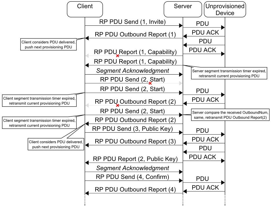 |
4.4.5.5. Behavior
This section describes behaviors for states and messages for the Remote Provisioning Server model.
When the Node Provisioning Protocol Interface closes as a result of a timeout on the layer executing the provisioning protocol and when the Remote Provisioning Link state is Link Active or Outbound Packet, the behavior specified in Section 4.4.5.5.3.5 shall be executed.
4.4.5.5.1. Remote Provisioning Scan behavior
This section describes behaviors of the Remote Provisioning Server model associated with the Remote Provisioning Scan procedure (see Section 4.4.5.2).
4.4.5.5.1.1. Receiving a Remote Provisioning Scan Capabilities Get message
When a Remote Provisioning Server receives a Remote Provisioning Scan Capabilities Get message, the Remote Provisioning Server shall respond with a Remote Provisioning Scan Capabilities Status message (see Section 4.3.4.2).
4.4.5.5.1.2. Sending a Remote Provisioning Scan Capabilities Status message
A Remote Provisioning Server shall send a Remote Provisioning Scan Capabilities Status message as a response to a Remote Provisioning Scan Capabilities Get message (see Section 4.3.4.1).
When sending a Remote Provisioning Scan Capabilities Status message, the Remote Provisioning Server shall set the message field values as defined in Table 4.335.
|
Message Field |
State |
|---|---|
|
MaxScannedItems |
Remote Provisioning Max Scanned Items |
|
ActiveScan |
Remote Provisioning Active Scan |
4.4.5.5.1.3. Receiving a Remote Provisioning Scan Get message
When a Remote Provisioning Server receives a Remote Provisioning Scan Get message, the Remote Provisioning Server shall respond with a Remote Provisioning Scan Status message (see Section 4.4.5.5.1.6) with the Status field set to Success.
4.4.5.5.1.4. Receiving a Remote Provisioning Scan Start message
The Remote Provisioning Client sends a Remote Provisioning Scan Start message to start or restart the Remote Provisioning Scan procedure.
For a Remote Provisioning Scan Start message to be accepted, the values of the message shall meet all conditions defined in Table 4.336.
|
Name |
Condition |
|---|---|
|
Items Limit |
The value of the ScannedItemsLimit field shall be less than or equal to the value of the Remote Provisioning Max Scanned Items state. |
When a Remote Provisioning Server receives a Remote Provisioning Scan Start message with values that cannot be accepted, the server shall respond with a Remote Provisioning Scan Status message with the Status field set to Scanning Cannot Start.
When the Remote Provisioning Server receives a Remote Provisioning Scan Start message with values that can be accepted (see Table 4.336), and the Remote Provisioning Scan state is not Idle, then the Remote Provisioning Server shall start the Remote Provisioning Scan Procedure as defined in Section 4.4.5.2, and shall respond with a Remote Provisioning Scan Status message (see Section 4.3.4.6) with the Status field set to Success.
When a Remote Provisioning Server receives a Remote Provisioning Scan Start message that can be accepted (see Table 4.336), and the Remote Provisioning Scan state is equal to Remote Provisioning Single Device Scan, and the source address or the security material of the message does not match values saved when the server entered the Remote Provisioning Single Device Scan state, then the Remote Provisioning Server shall respond with a Remote Provisioning Scan Status message with the Status field set to Invalid State.
When a Remote Provisioning Server receives a Remote Provisioning Scan Start message that can be accepted, and the Remote Provisioning Scan state is equal to Remote Provisioning Multiple Devices Scan, and the source address or the security material of the message does not match values saved when the server entered the Remote Provisioning Multiple Devices Scan state, then the Remote Provisioning Server shall respond with a Remote Provisioning Scan Status message with the Status field set to Invalid State.
When a Remote Provisioning Server receives a Remote Provisioning Scan Start message that can be accepted (see Table 4.336), and the Remote Provisioning Scan state is not Idle, and the source address and the security material of the message match values saved when the server entered either the Remote Provisioning Single Device Scan state or the Remote Provisioning Multiple Devices Scan state, then the Remote Provisioning Server shall restart the Remote Provisioning Scan procedure as defined in Section 4.4.5.2, and shall respond with a Remote Provisioning Scan Status message with the Status field set to Success.
4.4.5.5.1.5. Receiving a Remote Provisioning Scan Stop message
When a Remote Provisioning Server receives a Remote Provisioning Scan Stop message, it shall respond with a Remote Provisioning Scan Status message (see Section 4.4.5.5.1.6) with the Status field set to Success. When a Remote Provisioning Server receives a Remote Provisioning Scan Stop message, and the Remote Provisioning Scan state is not Idle, then the Remote Provisioning Server shall stop the Remote Provisioning Scan procedure as defined in Section 4.4.5.2.
4.4.5.5.1.6. Sending a Remote Provisioning Scan Status message
A Remote Provisioning Server shall send the Remote Provisioning Scan Status message in response to a Remote Provisioning Scan Get message, a Remote Provisioning Scan Start message, or a Remote Provisioning Scan Stop message.
The Remote Provisioning Scan Parameters state shall be mapped to the fields of the Remote Provisioning Scan Status message as defined in Table 4.337.
|
Field |
State |
|---|---|
|
RPScanningState |
Remote Provisioning Scan |
|
ScannedItemsLimit |
Remote Provisioning Scan Items Limit |
|
Timeout |
Remote Provisioning Timeout |
When a Remote Provisioning Server sends a Remote Provisioning Scan Status message in response to a Remote Provisioning Scan Get message, then the Status field shall be set as defined in Section 4.4.5.5.1.3.
When a Remote Provisioning Server sends a Remote Provisioning Scan Status message in response to a Remote Provisioning Scan Start message, then the Remote Provisioning Server shall set the message field values as defined in Section 4.4.5.5.1.4.
When a Remote Provisioning Server sends a Remote Provisioning Scan Status message in response to a Remote Provisioning Scan Stop message, then the Remote Provisioning Server shall set the message field values as defined in Section 4.4.5.5.1.5.
4.4.5.5.1.7. Sending a Remote Provisioning Scan Report message
The Remote Provisioning Scan Report message is sent as a result of the execution of the Remote Provisioning Scan procedure as defined in Section 4.4.5.2.
The Remote Provisioning Scan Report message shall be tagged with the send-segmented tag. When sending the Remote Provisioning Scan Report message, the Remote Provisioning Server shall set message fields to the following values:
-
The UUID field shall be set to the Device UUID value obtained from the unprovisioned device beacon or from the connectable advertising packet with the Service Data for the «Mesh Provisioning Service» (see Section 7.1.2.2.1).
-
The OOB field shall be set to the OOB information value.
-
The RSSI field shall be set to the measured value (see Section 4.3.4.7).
-
URI Hash field shall be set to the URI Hash when the URI Hash value is available; otherwise the field shall be excluded.
The URI Hash value is present only in the Unprovisioned Device beacon; the URI Hash is not present in a connectable advertising packet with the Service Data for the «Mesh Provisioning Service» (see Section 7.1.2.2.1).
4.4.5.5.2. Remote Provisioning Extended Scan behavior
This section describes behaviors of the Remote Provisioning Server model associated with the Remote Provisioning Extended Scan procedure (see Section 4.4.5.3).
4.4.5.5.2.1. Receiving a Remote Provisioning Extended Scan Start message
The Remote Provisioning Client sends the Remote Provisioning Extended Scan Start message to start the Remote Provisioning Extended Scan procedure for a device with a specific UUID, or to obtain information about the Remote Provisioning Server itself.
When a Remote Provisioning Server receives a Remote Provisioning Extended Scan Start message that does not contain the UUID field (i.e., the request is to obtain the information about the Remote Provisioning Server), it shall respond with a Remote Provisioning Extended Scan Report message with the Status field set to Success (see Section 4.4.5.5.2.2).
When a Remote Provisioning Server receives a Remote Provisioning Extended Scan Start message with the UUID field present (i.e., the request is to execute the Remote Provisioning Extended Scan procedure as described in Section 4.4.5.3), and it has sufficient resources to start a new procedure, the server shall start a new Remote Provisioning Extended Scan procedure, and it shall send the Remote Provisioning Extended Scan Report when the procedure completes. A new Remote Provisioning Extended Scan procedure is started even if another Remote Provisioning Extended Scan procedure with the same parameters is already running.
When a Remote Provisioning Server receives a Remote Provisioning Extended Scan Start message with the UUID field present (i.e., the request is to execute the Remote Provisioning Extended Scan procedure as described in Section 4.4.5.3), and it does not have sufficient resources to start a new procedure, the server shall respond with a Remote Provisioning Extended Scan Report message with the Status field set to Limited Resources and the OOBInformation and AdvStructures fields omitted.
4.4.5.5.2.2. Sending a Remote Provisioning Extended Scan Report message
The Remote Provisioning Extended Scan Report message is sent as a result of execution of the Remote Provisioning Extended Scan procedure (see Section 4.4.5.3), or in response to a Remote Provisioning Extended Scan Start message if the Remote Provisioning Server cannot start the Remote Provisioning Extended Scan procedure, or if the Remote Provisioning Extended Scan Start message requests the information about the Remote Provisioning Server itself.
The Remote Provisioning Extended Scan Report message shall be tagged with the send-segmented tag.
When the Remote Provisioning Server sends a Remote Provisioning Extended Scan Report message in response to a Remote Provisioning Extended Scan Start message, then the Status field shall be set as defined in Section 4.4.5.5.2.1.
When the Remote Provisioning Server sends a Remote Provisioning Extended Scan Report message after executing the Remote Provisioning Extended Scan procedure, then the Status field shall be set as defined in Section 4.4.5.3.
When the Remote Provisioning Extended Scan Report message is sent in response to a Remote Provisioning Extended Scan Start message requesting information about the Remote Provisioning Server itself, the Remote Provisioning Server shall construct the ADStructures field based on available local information. The UUID field shall be set to the Device UUID of the Remote Provisioning Server, and the OOBInformation field shall be set to the OOB Information of the Remote Provisioning Server.
When the Remote Provisioning Server sends a Remote Provisioning Extended Scan Report message as a result of executing the Remote Provisioning Extended Scan procedure, then the UUID field shall match the UUID in the corresponding Remote Provisioning Extended Scan Start message; the OOBInformation field shall be set to the OOB Information of the unprovisioned device, if available; and the ADStructures field shall contain AD structures obtained during the Remote Provisioning Extended Scan procedure as defined in Section 4.4.5.3, if available.
4.4.5.5.3. Provisioning link management behavior
This section describes link management behaviors for the Remote Provisioning Server model.
4.4.5.5.3.1. Receiving a Remote Provisioning Link Get message
When a Remote Provisioning Server receives a Remote Provisioning Link Get message, the server shall respond with a Remote Provisioning Link Status message (see Section 4.3.4.13) with the Status field set to Success.
4.4.5.5.3.2. Receiving a Remote Provisioning Link Open message
The response to a Remote Provisioning Link Open message is determined by the Remote Provisioning Link state when the message is received.
When the Remote Provisioning Link state is Idle: When a Remote Provisioning Server receives a Remote Provisioning Link Open message, and the Remote Provisioning Link state is Idle, then the Remote Provisioning Server shall set the Remote Provisioning Inbound PDU state to zero and shall set the Remote Provisioning Outbound PDU Count state to zero.
In addition, the server shall execute one of the following behavior sequences based on the presence or absence of the UUID field in the message:
-
If the UUID field is present in the Remote Provisioning Link Open message, the Remote Provisioning Server shall set the Remote Provisioning Link state to Link Opening, shall set the Remote Provisioning Device UUID state to the value of the UUID field, shall respond with a Remote Provisioning Link Status message (see Section 4.4.5.5.3.4) with the Status field set to Success, shall select the PB-GATT or PB-ADV provisioning bearer, and shall start the corresponding PB-Remote Open Link procedure using the value of the UUID field as the Device UUID parameter and the value of the Timeout field as Timeout parameter, if present.
-
If the NPPI Procedure field is present in the Remote Provisioning Link Open message, the Remote Provisioning Server shall open the Node Provisioning Protocol Interface.
-
If the Node Provisioning Protocol Interface is not opened successfully, the Remote Provisioning Server shall respond with a Remote Provisioning Link Status message with the Status field set to Link Cannot Open.
-
If the Node Provisioning Protocol Interface is opened successfully, the Remote Provisioning Server shall identify the Node Provisioning Protocol Interface procedure as defined in Table 4.338, and shall check whether the condition defined in the Additional Condition column is met.
-
If the condition is met, the Remote Provisioning Server shall start the identified Node Provisioning Protocol Interface procedure, shall set the Remote Provisioning Device UUID state to its own Device UUID, shall set the Remote Provisioning Link state to Link Active, shall respond with a Remote Provisioning Link Status message (see Section 4.4.5.5.3.4) with the Status field set to Success, and shall send a Remote Provisioning Link Report message (see Section 4.4.5.5.3.5) with the Status field set to Success and without the Reason field.
-
If the condition is not met, the Remote Provisioning Server shall close the Node Provisioning Protocol Interface, and shall respond with a Remote Provisioning Link Status message with the Status field set to Link Cannot Open.
-
|
NPPI Procedure field value |
Node Provisioning Protocol Interface procedure |
Additional condition |
|---|---|---|
|
Device Key Refresh |
Device Key Refresh procedure |
– |
|
Node Address Refresh |
Node Address Refresh procedure |
– |
|
Node Composition Refresh |
Node Composition Refresh |
Composition Data Page 128 is not equal to Composition Data Page 0. |
When the Remote Provisioning Link state is Link Opening or Link Active: When a Remote Provisioning Server receives a Remote Provisioning Link Open message, and the Remote Provisioning Link state is either Link Opening or Link Active, the server shall execute one of the following behavior sequences depending on the conditions defined in Table 4.339:
-
If all conditions defined in Table 4.339 are met, the Remote Provisioning Server shall respond with a Remote Provisioning Link Status message with the Status field set to Success.
-
If one or more conditions defined in Table 4.339 are not met, the Remote Provisioning Server shall respond with a Remote Provisioning Link Status message with the Status field set to Link Cannot Open.
|
Condition Name |
Condition |
|---|---|
|
Same Client |
Source address of the message is equal to the saved source address of the Remote Provisioning Link Open message. |
|
Same NetKey |
Network security material of the message is equal to the saved security material from the Remote Provisioning Link Open message. |
|
Same UUID |
UUID field is present and is equal to the Remote Provisioning Device UUID state; or the UUID field is absent, and the Device UUID of the Remote Provisioning Server is equal to the Remote Provisioning Device UUID state. |
|
Same NPPI Procedure |
NPPI Procedure field is present and identifies the running Node Provisioning Protocol Interface procedure. Or NPPI Procedure field is absent, and no Node Provisioning Protocol Interface procedure is currently active. |
When the Remote Provisioning Link state is Link Closing or Outbound Packet Transfer: When a Remote Provisioning Server receives a Remote Provisioning Link Open message, and the Remote Provisioning Link state is either Link Closing or Outbound Packet Transfer, then the Remote Provisioning Server shall respond with a Remote Provisioning Link Status message with the Status field set to Invalid State.
4.4.5.5.3.3. Receiving a Remote Provisioning Link Close message
The response to a Remote Provisioning Link Close message is determined by the active process (either a procedure or provisioning), if applicable, and the Remote Provisioning Link state when the message is received.
When the Remote Provisioning Link state is Idle: When a Remote Provisioning Server receives a Remote Provisioning Link Close message, and the Remote Provisioning Link state is Idle, then the Remote Provisioning Server shall respond with a Remote Provisioning Link Status message with the Status field set to Success.
When a Node Provisioning Protocol Interface procedure is active: When a Remote Provisioning Server receives a Remote Provisioning Link Close message, and a Node Provisioning Protocol Interface procedure is active, and the Remote Provisioning Link state is Link Active, and all conditions defined in Table 4.340 are met, then the Remote Provisioning Server shall do the following in sequence:
-
Shall close the Node Provisioning Protocol Interface, passing the Reason Code to the layer executing the provisioning protocol
-
Shall set the Remote Provisioning Link state to Link Closing
-
Shall respond with a Remote Provisioning Link Status message (see Section 4.4.5.5.3.4) with the Status field set to Success
-
Shall store DevKey/Unicast/Page0 changes
-
Shall set the Remote Provisioning Link state to Idle
-
Shall send a Remote Provisioning Link Report message (see Section 4.4.5.5.3.5) with the Status field set to Link Closed by Client
When a Remote Provisioning Server receives a Remote Provisioning Link Close message, and a Node Provisioning Protocol Interface procedure is active, and the Remote Provisioning Link state is Link Active, and one or more conditions defined in Table 4.340 are not met, then the Remote Provisioning Server shall respond with a Remote Provisioning Link Status message (see Section 4.4.5.5.3.4) with the Status field set to Invalid State.
|
Condition Name |
Condition |
|---|---|
|
Same Client |
Source address of the message is equal to the saved source address of the Remote Provisioning Link Close message. |
|
Same NetKey |
Network security material of the message is equal to the saved security material from the Remote Provisioning Link Close message. |
When an unprovisioned device is being provisioned: When the Remote Provisioner Server receives a Remote Provisioning Link Close message, and an unprovisioned device is being provisioned, the server’s response shall be determined by the Remote Provisioning Link state:
-
If the Remote Provisioning Link state is Link Active, Link Opening, or Outbound Packet Transfer, and one or more conditions defined in Table 4.340 are not met, then the Remote Provisioning Server shall respond with a Remote Provisioning Link Status message (see Section 4.4.5.5.3.4) with the Status field set to Invalid State.
-
If the Remote Provisioning Link state is Link Active and all conditions defined in Table 4.340 are met, then the Remote Provisioning Server shall start the PB-Remote Close Link procedure using the value of the Reason field as the Reason, shall set the Link Close Reason state to the Reason field if a reason is required for the PB-Remote Close Link procedure, shall set the Link Close Status state to Link Closed by Client, shall set the Remote Provisioning Link state to Link Closing, and shall respond with a Remote Provisioning Link Status message (see Section 4.4.5.5.3.4) with the Status field set to Success.
-
If the Remote Provisioning Link state is Link Opening and all conditions defined in Table 4.340 are met, then the Remote Provisioning Server shall stop the PB-Remote Open Link procedure, shall start the PB-Remote Close Link procedure using the value of the Reason field as the Reason, shall set the Link Close Reason state to the Reason field if a reason is required for the PB-Remote Close Link procedure, shall set the Link Close Status state to Link Closed by Client, shall set the Remote Provisioning Link state to Link Closing, and shall respond with a Remote Provisioning Link Status message with the Status field set to Success.
-
If the Remote Provisioning Link state is Outbound Packet Transfer and all conditions defined in Table 4.340 are met, then the Remote Provisioning Server shall abort all Provisioning Bearer PDU transfers, shall start the PB-Remote Close Link procedure using the value of the Reason field as the Reason, shall set the Link Close Reason state to the Reason field if a reason is required for the PB-Remote Close Link procedure, shall set the Link Close Status state to Link Closed by Client, shall set the Remote Provisioning Link state to Link Closing, and shall respond with a Remote Provisioning Link Status message with the Status field set to Success.
Remote Provisioning Link state is Link Closing: When a Remote Provisioning Server receives a Remote Provisioning Link Close message, and the Remote Provisioning Link state is Link Closing, then the Remote Provisioning Server shall respond with a Remote Provisioning Link Status message with the Status field set to Success.
Starting the PB-Remote Close Link procedure initiates additional behavior described in Section 4.4.5.5.3.5.
4.4.5.5.3.4. Sending a Remote Provisioning Link Status message
A Remote Provisioning Server shall send a Remote Provisioning Link Status message as a response to a Remote Provisioning Link Open message or a Remote Provisioning Link Close message.
When sending a Remote Provisioning Link Status message in response to a Remote Provisioning Link Open message, the Remote Provisioning Server shall set the RPState field to the current value of the Remote Provisioning Link state and shall set the Status field as defined in Section 4.4.5.5.3.2.
When sending a Remote Provisioning Link Status message in response to a Remote Provisioning Link Close message, the Remote Provisioning Server shall set the RPState field to the current value of the Remote Provisioning Link state and shall set the Status field as defined in Section 4.4.5.5.3.3.
4.4.5.5.3.5. Sending a Remote Provisioning Link Report message
When sending a Remote Provisioning Link Report message, the Remote Provisioning Server shall set the RPState field to the current value of the Remote Provisioning Link state. The Remote Provisioning Link Report message shall be tagged with the send-segmented tag.
When the Remote Provisioning Link state is Link Opening: When the Remote Provisioning Link state is Link Opening, and the PB-Remote Open Link procedure succeeds, then the Remote Provisioning Server shall start the PB-Remote Receive PDU procedure, shall set the Remote Provisioning Link state to Link Active, and shall send a Remote Provisioning Link Report message with the Status field set to Success and without the Reason field. If the PB-Remote Open Link procedure fails, then the Remote Provisioning Server shall set the Remote Provisioning Link state to Idle and shall send a Remote Provisioning Link Report message with the Status field set to Link Open Failed and without the Reason field.
When the Remote Provisioning Link state is Link Active or Outbound Packet: When the Remote Provisioning Link state is either Link Active or Outbound Packet Transfer, and the unprovisioned device closes the Provisioning Bearer link or the local layer executing the provisioning protocol closes the Node Provisioning Protocol Interface, then the Remote Provisioning Server shall set the Remote Provisioning Link state to Idle, shall abort all Provisioning Bearer PDU transfers, and shall send a Remote Provisioning Link Report message with the Status field set to Link Closed by Device and the Reason field set to the Reason provided by the Provisioning Bearer if applicable.
When the Remote Provisioning Link state is either Link Active or Outbound Packet Transfer, and the Remote Provisioning Server encounters a condition resulting in the start of the PB-Remote Close Link procedure, then the Remote Provisioning Server shall set the Remote Provisioning Link state to Link Closing, shall start the PB-Remote Close Link procedure with an appropriate Reason if applicable, shall set the Link Close Reason state to Reason if a reason is required for the PB-Remote Close Link procedure, shall set the Link Close Status to Link Closed by Server, and shall abort all Provisioning Bearer PDU transfers.
When the Remote Provisioning Link state is Link Closing: When the Remote Provisioning Link state is Link Closing, and the PB-Remote Close Link procedure completes, then the Remote Provisioning Server shall set the Remote Provisioning Link state to Idle and shall send a Remote Provisioning Link Report message with the Status field set to the Link Close Status state and the Reason field set to the Link Close Reason state if available.
4.4.5.5.4. Provisioning PDU transfer behavior
This section describes behaviors related to the transfer of Provisioning PDUs for the Remote Provisioning Server model.
4.4.5.5.4.1. Receiving a Remote Provisioning PDU Send message
When a Remote Provisioning Server receives a Remote Provisioning PDU Send message, the server’s response shall be determined by the Remote Provisioning Link state:
-
If the Remote Provisioning Link state is Link Active:
-
If the Remote Provisioning Link state is Link Active, and the value of the OutboundPDUNumber field is equal to the Remote Provisioning Outbound PDU Count state incremented by 1, then the Remote Provisioning Server shall set the Remote Provisioning Link state to Outbound Packet Transfer, and shall start the PB-Remote Send PDU procedure (see Section 5.2.3.3.3) using the value of the ProvisioningPDU field as the input parameter. Additionally, if either the Device Key Refresh procedure, the Node Address Refresh procedure, or the Node Composition Refresh procedure is active, then the Remote Provisioning Server shall send a Remote Provisioning Outbound PDU Report (see Section 4.3.4.16) as defined in Section 4.4.5.5.4.2.
-
If the Remote Provisioning Link state is Link Active, and the value of the OutboundPDUNumber field is not equal to the Remote Provisioning Outbound PDU Count state incremented by 1, then the Remote Provisioning Server shall send a Remote Provisioning Outbound PDU Report with the OutboundPDUNumber field set to the value of the Remote Provisioning Outbound PDU Count state.
-
-
If the Remote Provisioning Link state is not Link Active, then the Remote Provisioning Server shall ignore the received Remote Provisioning PDU Send message.
4.4.5.5.4.2. Sending a Remote Provisioning PDU Outbound Report message
The Remote Provisioning PDU Outbound Report message is sent to report successful transmission of a Provisioning PDU from the Remote Provisioning Server.
The Remote Provisioning PDU Outbound Report message shall be tagged with the send-segmented tag.
When the Remote Provisioning Link state is Outbound Packet Transfer, and the PB-Remote Send PDU procedure succeeds (see Section 5.2.3.3.3), then the Remote Provisioning Server shall increment the value of the Remote Provisioning Outbound PDU Count state by 1, and shall send a Remote Provisioning PDU Outbound Report with the OutboundPDUNumber field set to the value of the Remote Provisioning Outbound PDU Count state and shall set the Remote Provisioning Link state to Link Active.
When the Remote Provisioning Link state is Outbound Packet Transfer, and the PB-Remote Send PDU procedure fails, then the Remote Provisioning Server shall start the PB-Remote Close Link procedure with an appropriate Reason if applicable, shall set the Link Close Reason state to the Reason if a reason is required for the PB-Remote Close Link procedure, and shall set the Link Close Status state to Link Closed as Cannot Send PDU.
4.4.5.5.4.3. Sending a Remote Provisioning PDU Report message
The Remote Provisioning PDU Report message shall be tagged with the send-segmented tag.
When a Node Provisioning Protocol Interface procedure is active: When the Remote Provisioning Link state is Link Active, and the provisioning protocol generates a Provisioning PDU, then the Remote Provisioning Server shall increment the Remote Provisioning Inbound PDU Count state value by 1, and shall send a Remote Provisioning PDU Report message with the ProvisioningPDU field set to new Provisioning PDU and the InboundPDUNumber field set to the value of the Remote Provisioning Inbound PDU Count state.
When the delivery of the Remote Provisioning PDU Report message does not complete successfully, then the Remote Provisioning Server shall close the Node Provisioning Protocol Interface; shall set the Remote Provisioning Link state to Idle; and shall send a Remote Provisioning Link Report message (see Section 4.4.5.5.3.5) with the Status field set to Link Closed by Server.
When an unprovisioned device is being provisioned: When the Remote Provisioning Link state is either Link Active or Outbound Packet Transfer, and a new inbound Provisioning PDU has been successfully transferred using the PB-Remote Receive PDU procedure (see Section 5.2.3.3.4), then the Remote Provisioning Server shall increment the Remote Provisioning Inbound PDU Count state value by 1, and shall restart the PB-Remote Receive PDU procedure, and shall send a Remote Provisioning PDU Report message with the ProvisioningPDU field set to new Provisioning PDU and the InboundPDUNumber field set to the value of the Remote Provisioning Inbound PDU Count state.
To enable expedited recovery after an unexpected link loss between the Provisioner and the Remote Provisioning Server while the remote provisioning is in progress, the Remote Provisioning Server should monitor the status of the Remote Provisioning PDU Report delivery to the Provisioner.
When the delivery of the Remote Provisioning PDU Report does not complete successfully, then the Remote Provisioning Server should perform all of the following actions:
-
Start the PB-Remote Close Link procedure with an appropriate Reason code if applicable.
-
If a reason is required for the PB-Remote Close Link procedure, set the Link Close Reason state to the Reason.
-
Set the Link Close Status state to Link Closed as Cannot Deliver PDU Report.
Because the provisioning protocol allows two consecutive Provisioning PDUs originating from the new device, but the SAR mechanism does not allow more than one transfer of the Upper Transport PDUs between two nodes (see Section 3.5.3.1), the inbound Provisioning PDU should be cached. Because the behavior of the Remote Provisioning Server model cannot guarantee that only one message at a time will be scheduled to be sent to the client, queuing of the messages should be implemented.
4.4.6. Remote Provisioning Client model
4.4.6.1. Description
The Remote Provisioning Client model is used to support the functionality of provisioning devices into a mesh network by interacting with a mesh node that supports the Remote Provisioning Server model.
The Remote Provisioning Client is a root model and a main model that does not extend any other models. The Remote Provisioning Client may operate on states defined by the Remote Provisioning Server model (see Section 4.4.5) using Remote Provisioning messages (see Section 4.3.4), and requires one element: the Remote Provisioning Main element. The Remote Provisioning Main element contains the Remote Provisioning Client main model.
If supported, the Remote Provisioning Client shall be supported by a primary element and may be supported by any secondary elements. The access layer security on the Remote Provisioning Client model shall use the device key of the node supporting the Remote Provisioning Server model.
Table 4.341 lists the Remote Provisioning Client model messages. The model shall support receiving the messages marked as mandatory in the Rx column and shall support sending the messages marked as mandatory in the Tx column.
|
Element |
Model Name |
Procedure |
Message |
Rx |
Tx |
|---|---|---|---|---|---|
|
Remote Provisioning Main |
Remote Provisioning Client |
Remote Provisioning Scan Capabilities |
Remote Provisioning Scan Capabilities Get |
– |
M |
|
Remote Provisioning Scan Capabilities Status |
M |
– |
|||
|
Remote Provisioning Scan Parameters |
Remote Provisioning Scan Get |
– |
M |
||
|
Remote Provisioning Scan Start |
– |
M |
|||
|
Remote Provisioning Scan Stop |
– |
M |
|||
|
Remote Provisioning Scan Status |
M |
– |
|||
|
Remote Provisioning Scan Report |
M |
– |
|||
|
Remote Provisioning Extended Scan Start |
– |
M |
|||
|
Remote Provisioning Scan Extended Report |
M |
– |
|||
|
Remote Provisioning Link Parameters |
Remote Provisioning Link Get |
– |
M |
||
|
Remote Provisioning Link Open |
– |
M |
|||
|
Remote Provisioning Link Close |
– |
M |
|||
|
Remote Provisioning Link Status |
M |
– |
|||
|
Remote Provisioning Link Report |
M |
– |
|||
|
Remote Provisioning PDU Send |
– |
M |
|||
|
Remote Provisioning PDU Outbound Report |
M |
– |
|||
|
Remote Provisioning PDU Report |
M |
– |
4.4.6.2. Behavior
This section describes behaviors for procedures and messages for the Remote Provisioning Client model.
An element can send any Remote Provisioning Client message at any time to query or change a state of a peer element. The element may receive some unsolicited Remote Provisioning Server messages, and it shall process them and deliver them to the upper layer.
4.4.6.2.1. Remote Provisioning Scan procedure
This section describes behaviors of the Remote Provisioning Client model associated with the Remote Provisioning Scan procedure (see Section 4.4.5.2).
4.4.6.2.1.1. Sending a Remote Provisioning Scan Capabilities Get message
To determine the Remote Provisioning Scan Capabilities state (see Section 4.2.23) of a Remote Provisioning Server, a Remote Provisioning Client shall send a Remote Provisioning Scan Capabilities Get message. The response is a Remote Provisioning Scan Capabilities Status message (see Section 4.3.4.2).
4.4.6.2.1.2. Receiving a Remote Provisioning Scan Capabilities Status message
Upon receiving a Remote Provisioning Scan Capabilities Status message, a Remote Provisioning Client can determine the Remote Provisioning Scan Capabilities state (see Section 4.2.23) of a Remote Provisioning Server.
4.4.6.2.1.3. Sending a Remote Provisioning Scan Get message
To determine the Remote Provisioning Scan Parameters state (see Section 4.2.24) of a Remote Provisioning Server, a Remote Provisioning Client shall send a Remote Provisioning Scan Get message. The response is a Remote Provisioning Scan Status message (see Section 4.3.4.6).
4.4.6.2.1.4. Sending a Remote Provisioning Scan Start message
To start the Remote Provisioning Scan procedure, a Remote Provisioning Client shall send a Remote Provisioning Scan Start message. The response is a Remote Provisioning Scan Status message (see Section 4.3.4.6).
4.4.6.2.1.5. Sending a Remote Provisioning Scan Stop message
To stop the Remote Provisioning Scan procedure, a Remote Provisioning Client shall send a Remote Provisioning Scan Stop message. The response is a Remote Provisioning Scan Status message (see Section 4.3.4.6).
4.4.6.2.1.6. Receiving a Remote Provisioning Scan Status message
Upon receiving a Remote Provisioning Scan Status message, a Remote Provisioning Client can determine the Remote Provisioning Scan Parameters state (see Section 4.2.24) of a Remote Provisioning Server.
4.4.6.2.1.7. Receiving a Remote Provisioning Scan Report message
Upon receiving a Remote Provisioning Scan Report message, a Remote Provisioning Client can determine information about an unprovisioned device within immediate radio range of a Remote Provisioning Server.
4.4.6.2.2. Remote Provisioning Extended Scan procedure
This section describes behaviors of the Remote Provisioning Client model associated with the Remote Provisioning Extended Scan procedure (see Section 4.4.5.3).
4.4.6.2.2.1. Sending a Remote Provisioning Extended Scan Start message
To execute the scan for specific Advertisement Data (see Section 7.1.2.2.1) for a specific device, or to receive Advertisement Data from the Remote Provisioning Server itself, a Remote Provisioning Client shall send a Remote Provisioning Extended Scan Start message. The response is a Remote Provisioning Extended Scan Report message (see Section 4.3.4.9).
4.4.6.2.2.2. Receiving a Remote Provisioning Extended Scan Report message
Upon receiving a Remote Provisioning Extended Scan Report message, a Remote Provisioning Client can determine OOB Information and AD Structure values received by a Remote Provisioning Server, originating from the identified device, and matching the AD Types specified in the ADTypeFilter field of the Remote Provisioning Extended Scan Start message.
4.4.6.2.3. Provisioning link management procedures
This section describes behaviors of the Remote Provisioning Client model for managing Remote Provisioning links.
4.4.6.2.3.1. Sending a Remote Provisioning Link Get message
To determine the Remote Provisioning Link state of a Remote Provisioning Server, a Remote Provisioning Client shall send a Remote Provisioning Link Get message. The response is a Remote Provisioning Link Status message (see Section 4.3.4.13).
4.4.6.2.3.2. Sending a Remote Provisioning Link Open message
To start the Device Key Refresh procedure, the Node Address Refresh procedure, or the Node Composition Refresh procedure, the Remote Provisioning Client shall send a Remote Provisioning Link Open message with a NPPI Procedure field.
To initiate the opening of a Provisioning Bearer link, the Remote Provisioning Client shall send a Remote Provisioning Link Open message with a UUID field.
The response is a Remote Provisioning Link Status message (see Section 4.3.4.13).
4.4.6.2.3.3. Sending a Remote Provisioning Link Close message
To close a Provisioning Bearer link, a Remote Provisioning Client shall send a Remote Provisioning Link Close message. The response is a Remote Provisioning Link Status message (see Section 4.3.4.13).
4.4.6.2.3.4. Receiving a Remote Provisioning Link Status message
Upon receiving a Remote Provisioning Link Status message, a Remote Provisioning Client can determine the Remote Provisioning Link state of a Remote Provisioning Server and can determine the result of the associated requesting message, which is indicated in the Status field of the message (see Table 4.310).
4.4.6.2.3.5. Receiving a Remote Provisioning Link Report message
Upon receiving a Remote Provisioning Link Report message, a Remote Provisioning Client can determine the Remote Provisioning Link state of a Remote Provisioning Server and can determine the Link Close Status. When the Reason field is present, the Remote Provisioning Client can determine the reason why the provisioning link was closed.
4.4.6.2.4. Provisioning PDU transfer procedures
This section describes behaviors of the Remote Provisioning Client model for the transfer of Provisioning PDUs.
4.4.6.2.4.1. Sending a Remote Provisioning PDU Send message
To send a Provisioning PDU, a Remote Provisioning Client shall send a Remote Provisioning PDU Send message (see Section 4.3.4.15).
4.4.6.2.4.2. Receiving a Remote Provisioning PDU Outbound Report message
Upon receiving a Remote Provisioning PDU Outbound Report message, a Remote Provisioning Client can determine the result of the PB-Remote Send PDU procedure (see Section 5.2.3.3.3).
4.4.6.2.4.3. Receiving a Remote Provisioning PDU Report message
Upon receiving a Remote Provisioning PDU Report message, a Remote Provisioning Client can receive an output of the PB-Remote Receive PDU procedure (see Section 5.2.3.3.4).
4.4.7. Directed Forwarding Configuration Server model
4.4.7.1. Description
The Directed Forwarding Configuration Server model is used to support the configuration of the directed forwarding functionality of a node (see Section 3.6.8).
The Directed Forwarding Configuration Server model is a main model that extends the Configuration Server model.
The Directed Forwarding Configuration Server model defines the state instances listed in Table 4.342 and the messages listed in Table 4.343.
If supported, the Directed Forwarding Configuration Server model shall be supported by a primary element and shall not be supported by any secondary elements. The access layer security on the Directed Forwarding Configuration Server model shall use the device key.
Table 4.342 illustrates the state bindings between the Directed Forwarding Configuration Server model states and the states of the models that the Directed Forwarding Configuration Server extends.
|
State |
Bound State |
|
|---|---|---|
|
Model |
State |
|
|
Directed Control |
Configuration Server |
GATT Proxy |
|
Configuration Server |
Friend |
|
|
Path Metric |
– |
– |
|
Discovery Table Capabilities |
– |
– |
|
Forwarding Table |
– |
– |
|
Wanted Lanes |
– |
– |
|
Two Way Path |
– |
– |
|
Path Echo Interval |
– |
– |
|
Directed Network Transmit |
– |
– |
|
Directed Relay Retransmit |
– |
– |
|
RSSI Threshold |
– |
– |
|
Directed Paths |
– |
– |
|
Directed Publish Policy |
– |
– |
|
Path Discovery Timing Control |
– |
– |
|
Directed Control Network Transmit |
– |
– |
|
Directed Control Relay Retransmit |
– |
– |
Table 4.343 lists the Directed Forwarding Configuration Server model messages. The model shall support receiving the messages marked as mandatory in the Rx column and shall support sending the messages marked as mandatory in the Tx column.
|
Element |
Model Name |
State |
Message |
Rx |
Tx |
|---|---|---|---|---|---|
|
Directed Forwarding Main (Primary) |
Directed Forwarding Configuration Server |
Directed Control (see Section 4.2.26) |
DIRECTED_CONTROL_GET |
M |
– |
|
DIRECTED_CONTROL_SET |
M |
– |
|||
|
DIRECTED_CONTROL_STATUS |
– |
M |
|||
|
Path Metric (see Section 4.2.27) |
PATH_METRIC_GET |
M |
– |
||
|
PATH_METRIC_SET |
M |
– |
|||
|
PATH_METRIC_STATUS |
– |
M |
|||
|
Discovery Table Capabilities (see Section 4.2.28) |
DISCOVERY_TABLE_CAPABILITIES_GET |
M |
– |
||
|
DISCOVERY_TABLE_CAPABILITIES_SET |
M |
– |
|||
|
DISCOVERY_TABLE_CAPABILITIES_STATUS |
– |
M |
|||
|
Forwarding Table (see Section 4.2.29) |
FORWARDING_TABLE_ADD |
M |
– |
||
|
FORWARDING_TABLE_DELETE |
M |
– |
|||
|
FORWARDING_TABLE_STATUS |
– |
M |
|||
|
FORWARDING_TABLE_DEPENDENTS_ADD |
M |
– |
|||
|
FORWARDING_TABLE_DEPENDENTS_DELETE |
M |
– |
|||
|
FORWARDING_TABLE_DEPENDENTS_STATUS |
– |
M |
|||
|
FORWARDING_TABLE_ENTRIES_COUNT_GET |
M |
– |
|||
|
FORWARDING_TABLE_ENTRIES_COUNT_STATUS |
– |
M |
|||
|
FORWARDING_TABLE_ENTRIES_GET |
M |
– |
|||
|
FORWARDING_TABLE_ENTRIES_STATUS |
– |
M |
|||
|
FORWARDING_TABLE_DEPENDENTS_GET |
M |
– |
|||
|
FORWARDING_TABLE_DEPENDENTS_GET_STATUS |
– |
M |
|||
|
Wanted Lanes (see Section 4.2.30) |
WANTED_LANES_GET |
M |
– |
||
|
WANTED_LANES_SET |
M |
– |
|||
|
WANTED_LANES_STATUS |
– |
M |
|||
|
Two Way Path (see Section 4.2.31) |
TWO_WAY_PATH_GET |
M |
– |
||
|
TWO_WAY_PATH_SET |
M |
– |
|||
|
TWO_WAY_PATH_STATUS |
– |
M |
|||
|
Path Echo Interval (see Section 4.2.32) |
PATH_ECHO_INTERVAL_GET |
M |
– |
||
|
PATH_ECHO_INTERVAL_SET |
M |
– |
|||
|
PATH_ECHO_INTERVAL_STATUS |
– |
M |
|||
|
Directed Network Transmit (see Section 4.2.32.2) |
DIRECTED_NETWORK_TRANSMIT_GET |
M |
– |
||
|
DIRECTED_NETWORK_TRANSMIT_SET |
M |
– |
|||
|
DIRECTED_NETWORK_TRANSMIT_STATUS |
– |
M |
|||
|
Directed Relay Retransmit (see Section 4.2.34) |
DIRECTED_RELAY_RETRANSMIT_GET |
M |
– |
||
|
DIRECTED_RELAY_RETRANSMIT_SET |
M |
– |
|||
|
DIRECTED_RELAY_RETRANSMIT_STATUS |
– |
M |
|||
|
RSSI Threshold (see Section 4.2.35) |
RSSI_THRESHOLD_GET |
M |
– |
||
|
RSSI_THRESHOLD_SET |
M |
– |
|||
|
RSSI_THRESHOLD_STATUS |
– |
M |
|||
|
Directed Paths (see Section 4.2.36) |
DIRECTED_PATHS_GET |
M |
– |
||
|
DIRECTED_PATHS_STATUS |
– |
M |
|||
|
Directed Publish Policy (see Section 4.2.37) |
DIRECTED_PUBLISH_POLICY_GET |
M |
– |
||
|
DIRECTED_PUBLISH_POLICY_SET |
M |
– |
|||
|
DIRECTED_PUBLISH_POLICY_STATUS |
– |
M |
|||
|
Path Discovery Timing Control (see Section 4.2.38) |
PATH_DISCOVERY_TIMING_CONTROL_GET |
M |
– |
||
|
PATH_DISCOVERY_TIMING_CONTROL_SET |
M |
– |
|||
|
PATH_DISCOVERY_TIMING_CONTROL_STATUS |
– |
M |
|||
|
Directed Control Network Transmit (see Section 4.2.39) |
DIRECTED_CONTROL_NETWORK_TRANSMIT_GET |
M |
– |
||
|
DIRECTED_CONTROL_NETWORK_TRANSMIT_SET |
M |
– |
|||
|
DIRECTED_CONTROL_NETWORK_TRANSMIT_STATUS |
– |
M |
|||
|
Directed Control Relay Retransmit (see Section 4.2.40) |
DIRECTED_CONTROL_RELAY_RETRANSMIT_GET |
M |
– |
||
|
DIRECTED_CONTROL_RELAY_RETRANSMIT_SET |
M |
– |
|||
|
DIRECTED_CONTROL_RELAY_RETRANSMIT_STATUS |
– |
M |
4.4.7.2. Path Origin State Machine
When a Directed Forwarding node transmits a message that is tagged with the use-directed tag for a new destination (see Section 3.7.3.1), the Directed Forwarding node creates an instance of the Path Origin State Machine for that destination. The Path Origin State Machine controls the execution of a Directed Forwarding Initialization procedure for the associated destination following the occurrence of some events that are described in this section.
Figure 4.9 is a diagram of the Path Origin State Machine with its states, events, and transitions.
 |
Table 4.344 defines the timers used by the Path Origin State Machine and the corresponding values that the node shall set the timers to. If the timer is started from the initial value set to 0, the implementation shall execute the behavior associated with the expiration of the timer. For example, when the Path Monitoring Interval State is 0, setting the Path Monitoring timer results in the creation of the Path Not Needed event.
|
Timer Name |
Timer Initial Value |
Description |
|---|---|---|
|
Path Monitoring |
Path Monitoring Interval state. |
The timer defines the interval during which the use of an established path is monitored. |
|
Power Up Monitoring |
Value defined in Section 4.4.7.2.1. |
The timer defines the interval after a node is powered up during which the need for a path is verified. |
|
Path Discovery Retry |
Path Discovery Retry Interval state |
The timer defines the interval after a Directed Forwarding Initialization procedure fails during which the need for a path is verified. |
|
Path Use |
max(path discovery interval, path lifetime - path discovery interval - Path Monitoring Interval) |
The timer defines the interval during which the use of an established path is not monitored. The value of the timer is the greater of two values: either the path discovery interval (see Section 4.2.38.3) or the result of subtracting the path discovery interval and the Path Monitoring Interval (see Section 4.2.38.1) from the path lifetime (see Section 4.2.27.2). |
Table 4.345 defines the states of the Path Origin State Machine.
|
State |
Description |
|---|---|
|
Initial |
The initial state of the Path Origin State Machine. |
|
Power Up |
The state of the Path Origin State Machine at power-up. |
|
Path Discovery |
The Directed Forwarding Initialization procedure is in progress. |
|
Path In Use |
The Path Use timer is running. |
|
Path Validation |
The Directed Forwarding Echo procedure is in progress. |
|
Path Monitoring |
Either the Path Monitoring timer or the Power Up Monitoring timer is running. |
|
Path Discovery Retry Wait |
The Path Discovery Retry timer is running. |
|
Final |
The final state of the Path Origin State Machine. |
Table 4.346 defines the events that determine the transitions of the Path Origin State Machine and the conditions that generate the events.
|
Event |
Condition |
|---|---|
|
Path Needed |
One of the following conditions is met:
|
|
Path Not Needed |
One of the following conditions is met:
|
|
Power Up Executed |
The Path Origin State Machine is instantiated in the Power Up state. |
|
Path Discovery Succeeded |
The Directed Forwarding Initialization procedure for the destination completed successfully. |
|
Path Discovery Failed |
The Directed Forwarding Initialization procedure for the destination failed. |
|
Path Validation Started |
The Directed Forwarding Echo procedure for the destination started (see Section 3.6.8.2.6). |
|
Path Validation Succeeded |
The Directed Forwarding Echo procedure for the destination completed successfully. |
|
Path Validation Failed |
The Directed Forwarding Echo procedure for the destination failed. |
|
Path Removed |
The non-fixed path entry for the destination is removed from the Forwarding Table while the Path Use timer is running and a new Directed Forwarding Initialization procedure for the destination is not solicited. |
|
Path Solicited |
The non-fixed path entry for the destination is removed from the Forwarding Table while the Path Use timer is running and a new Directed Forwarding Initialization procedure for the destination is solicited. |
|
Path Monitoring Started |
The Path Use timer expired. |
Table 4.347 defines the transitions of the Path Origin State Machine and the resulting actions that the node shall execute.
|
State |
Event |
New State |
Actions |
|---|---|---|---|
|
Initial |
Path Needed |
Path Discovery |
Start the Directed Forwarding Initialization procedure |
|
Power Up |
Power Up Executed |
Path Monitoring |
Start the Power Up Monitoring timer |
|
Path Discovery |
Path Discovery Succeeded |
Path In Use |
Start the Path Use timer |
|
Path Discovery |
Path Discovery Failed |
Path Discovery Retry Wait |
Start the Path Discovery Retry timer |
|
Path Discovery Retry Wait |
Path Needed |
Path Discovery |
Start the Directed Forwarding Initialization procedure |
|
Path Discovery Retry Wait |
Path Not Needed |
Final |
Stop all timers AND Destroy the Path Origin State Machine |
|
Path In Use |
Path Monitoring Started |
Path Monitoring |
Start the Path Monitoring timer |
|
Path In Use |
Path Validation Started |
Path Validation |
– |
|
Path In Use |
Path Removed |
Final |
Stop all timers AND Destroy the Path Origin State Machine |
|
Path In Use |
Path Solicited |
Path Discovery |
Stop the Path Use timer AND Start the Directed Forwarding Initialization procedure |
|
Path Monitoring |
Path Needed |
Path Discovery |
Start the Directed Forwarding Initialization procedure |
|
Path Monitoring |
Path Not Needed |
Final |
Stop all timers AND Destroy the Path Origin State Machine |
|
Path Validation |
Path Validation Succeeded |
Path In Use |
– |
|
Path Validation |
Path Validation Failed |
Path Discovery |
Stop the Path Use timer AND Start the Directed Forwarding Initialization procedure |
4.4.7.2.1. Path Monitoring test mode
To enable efficient testing of the Path Monitoring procedure, a node shall support the Path Monitoring test mode. The activation of the test mode shall be carried out locally (via a hardware or software interface). The Path Monitoring test mode only removes the Path Use timer; all other behavior of the device shall be unchanged.
One signal is defined in the Path Monitoring test mode:
-
Transit to Path Monitoring state signal
When the Transit to Path Monitoring state signal is received, the node shall transition to the Path Monitoring state, ignoring the Path Use timer.
4.4.7.3. Power-down and power-up behavior
When a node is powered down, the Directed Forwarding Configuration Server shall remove the non-fixed path entries in the Forwarding Table state for the subnets that the node belongs to, shall destroy all instances of the Path Origin State Machine, and shall cancel all Directed Forwarding procedures.
When a node is powered up, all states of the Directed Forwarding Configuration Server model shall be restored to the values they had when the node was powered down. In addition, the node shall instantiate a Path Origin State Machine in the Power Up state for each publish address different from the all-directed-forwarding-nodes, all-nodes, and all-relays fixed group addresses of models with the Directed Publish Policy state equal to Directed Forwarding.
For the Nth instance (N>0) of the Path Origin State Machine, the Power Up Monitoring timer for the Path Monitoring state shall be started from the initial value set to a random value in the range (N-1)×2000 to (N×2000-1) in milliseconds. This helps reduce the number of concurrent directed forwarding procedures.
4.4.7.3.1. Example of power-up behavior
The following example illustrates how the Directed Publish Policy state affects power-up behavior in an example configuration.
In the example configuration, a node has four publishing models configured as follows:
-
Publishing model A is configured to publish to address X and has the Directed Publish Policy state set to Directed Forwarding.
-
Publishing model B is configured to publish to address X and has the Directed Publish Policy state set to Directed Forwarding.
-
Publishing model C is configured to publish to address Y and has the Directed Publish Policy state set to Directed Forwarding.
-
Publishing model D is configured to publish to address Z and has the Directed Publish Policy state set to Managed Flooding.
On power-up, the node instantiates two Path Origin State Machines, one for publish address X and one for publish address Y:
-
The state machine for publish address X has the Power Up Monitoring timer started from an initial value lower than 2 seconds.
-
The state machine for publish address Y has the Power Up Monitoring timer started from an initial value greater than or equal to 2 seconds and lower than 4 seconds.
4.4.7.4. Behavior
This section describes behaviors for states and messages for the Directed Forwarding Configuration Server model.
Table 4.348, referred to in the following sections, defines the error conditions for the DIRECTED_CONTROL_GET, DIRECTED_CONTROL_SET, PATH_METRIC_GET, PATH_METRIC_SET, DISCOVERY_TABLE_CAPABILITIES_GET, FORWARDING_TABLE_DELETE, FORWARDING_TABLE_ENTRIES_COUNT_GET, WANTED_LANES_GET, WANTED_LANES_SET, TWO_WAY_PATH_GET, TWO_WAY_PATH_SET, PATH_ECHO_INTERVAL_GET, and PATH_ECHO_INTERVAL_SET messages processed by the Directed Forwarding Configuration Server model.
|
Error Condition |
Status Code Name (see Assigned Numbers document [4]) |
|---|---|
|
The key identified by the NetKeyIndex is not valid for this device |
Invalid NetKey Index |
4.4.7.4.1. Directed Control state
When an element receives a DIRECTED_CONTROL_GET message that is successfully processed (i.e., it does not result in any error condition listed in Table 4.348), it shall respond with a DIRECTED_CONTROL_STATUS message with the following configuration:
-
The Status field shall be set to Success.
-
The NetKeyIndex field shall be set to NetKeyIndex field value in the received message.
-
The Directed_Forwarding field shall be set to the current Directed Forwarding state (see Section 4.2.26.1) of the subnet identified by the NetKeyIndex field.
-
The Directed_Relay field shall be set to the current Directed Relay state (see Section 4.2.26.2) of the subnet identified by the NetKeyIndex field.
-
The Directed_Proxy field shall be set to the current Directed Proxy state (see Section 4.2.26.3) of the subnet identified by the NetKeyIndex field.
-
The Directed_Proxy_Use_Directed_Default field shall be set to the current Directed Proxy Use Directed Default state (see Section 4.2.26.4) of the subnet identified by the NetKeyIndex field.
-
The Directed_Friend field shall be set to the current Directed Friend state (see Section 4.2.26.5) of the subnet identified by the NetKeyIndex field.
When an element receives a DIRECTED_CONTROL_GET message that is not successfully processed (i.e., it results in any error condition listed in Table 4.348), it shall respond with a DIRECTED_CONTROL_STATUS message with the following configuration:
-
The Status field shall be set to a status code defined in Table 4.348.
-
The NetKeyIndex field shall be set to the NetKeyIndex field value in the received message.
-
The Directed_Forwarding field shall be set to 0x00.
-
The Directed_Relay field shall be set to 0x00.
-
The Directed_Proxy field shall be set to 0x00.
-
The Directed_Proxy_Use_Directed_Default field shall be set to 0x00.
-
The Directed_Friend field shall be set to 0x00.
When an element receives a DIRECTED_CONTROL_SET message that is successfully processed (i.e., it does not result in any error condition listed in Table 4.348), the states of the subnet identified by the NetKeyIndex field in the received message shall be set according to the corresponding fields in the DIRECTED_CONTROL_SET message, as follows:
-
The Directed Forwarding state shall be set to the value of the Directed Forwarding field.
-
The Directed Relay state shall be set to the value of the Directed Relay field.
-
If the node supports directed proxy functionality, and the value of the Directed_Proxy field is Disable or Enable, then the Directed Proxy state shall be set to the value of the Directed_Proxy field, and the Directed Proxy Use Directed Default state shall be set to the value of the Directed_Proxy_Use_Directed_Default field.
-
If the node supports directed friend functionality, and the value of the Directed_Friend field is Disable or Enable, then the Directed Friend state shall be set to the value of the Directed_Friend field.
If the new value of the Directed Forwarding state is 0, then the Directed Forwarding Configuration Server shall remove the non-fixed path entries from the Forwarding Table state for the identified subnet (see Section 4.2.29), shall destroy all instances of the Path Origin State Machine (see Section 4.4.7.2) for the identified subnet, and shall cancel all Directed Forwarding procedures for the identified subnet.
The element shall also respond to a DIRECTED_CONTROL_SET message that is successfully processed with a DIRECTED_CONTROL_STATUS message with the following configuration:
-
The Status field shall be set to Success.
-
The NetKeyIndex field shall be set to the NetKeyIndex field value in the received message.
-
The Directed_Forwarding field shall be set to the current Directed Forwarding state (see Section 4.2.26.1) of the subnet identified by the NetKeyIndex field.
-
The Directed_Relay field shall be set to the current Directed Relay state (see Section 4.2.26.2) of the subnet identified by the NetKeyIndex field.
-
The Directed_Proxy field shall be set to the current Directed Proxy state (see Section 4.2.26.3) of the subnet identified by the NetKeyIndex field.
-
The Directed_Proxy_Use_Directed_Default field shall be set to the current Directed Proxy Use Directed Default state (see Section 4.2.26.4) of the subnet identified by the NetKeyIndex field.
-
The Directed_Friend field shall be set to the current Directed Friend state (see Section 4.2.26.5) of the subnet identified by the NetKeyIndex field.
When an element receives a DIRECTED_CONTROL_SET message that is not successfully processed (i.e., it results in any error condition listed in Table 4.348), it shall respond with a DIRECTED_CONTROL_STATUS message with the following configuration:
-
The Status field shall be set to a status code defined in Table 4.348.
-
The NetKeyIndex, Directed_Forwarding, Directed_Relay, Directed_Proxy, Directed_Proxy_Use_Directed_Default, and Directed_Friend fields shall be set to the values of the corresponding fields in the received message.
4.4.7.4.2. Path Metric state
When an element receives a PATH_METRIC_GET message that is successfully processed (i.e., it does not result in any error condition listed in Table 4.348), it shall respond with a PATH_METRIC_STATUS message with the following configuration:
-
The Status field shall be set to Success.
-
The NetKeyIndex field shall be set to the NetKeyIndex field value in the received message.
-
The Path_Metric_Type field shall be set to the current Path Metric Type state (see Section 4.2.27.1) of the subnet identified by the NetKeyIndex field.
-
The Path_Lifetime field shall be set to the current Path Lifetime state (see Section 4.2.27.2) of the subnet identified by the NetKeyIndex field.
When an element receives a PATH_METRIC_GET message that is not successfully processed (i.e., it results in any error condition listed in Table 4.348), it shall respond with a PATH_METRIC_STATUS message with the following configuration:
-
The Status field shall be set to the status code corresponding to the error condition as defined in Table 4.348.
-
The NetKeyIndex field shall be set to the NetKeyIndex field value in the received message.
-
The Path_Metric_Type field shall be set to 0b000.
-
The Path_Lifetime field shall be set to 0b00.
When an element receives a PATH_METRIC_SET message that is successfully processed (i.e., it does not result in any error condition listed in Table 4.348), it shall set the Path Metric Type state and the Path Lifetime state of the subnet identified by the NetKeyIndex field to the corresponding values of the Path_Metric_Type and Path_Lifetime fields in the received message. The element shall also respond with a PATH_METRIC_STATUS message with the following configuration:
-
The Status field shall be set to Success.
-
The NetKeyIndex field shall be set to the NetKeyIndex field value in the received message.
-
The Path_Metric_Type field shall be set to the current Path Metric Type state (see Section 4.2.27.1) of the subnet identified by the NetKeyIndex field.
-
The Path_Lifetime field shall be set to the current Path Lifetime state (see Section 4.2.27.2) of the subnet identified by the NetKeyIndex field.
When an element receives a PATH_METRIC_SET message that is not successfully processed (i.e., it results in any error condition listed in Table 4.348), it shall respond with a PATH_METRIC_STATUS message with the following configuration:
-
The Status field shall be set to the status code corresponding to the error condition as defined in Table 4.348.
-
The NetKeyIndex, Path_Metric_Type, and Path_Lifetime fields shall be set to the values of the corresponding fields in the received message.
4.4.7.4.3. Discovery Table Capabilities state
When an element receives a DISCOVERY_TABLE_CAPABILITIES_GET message that is successfully processed (i.e., it does not result in any error condition listed in Table 4.348), it shall respond with a DISCOVERY_TABLE_CAPABILITIES_STATUS message with the following configuration:
-
The Status field shall be set to Success.
-
The NetKeyIndex field shall be set to the NetKeyIndex field value in the received message.
-
The Max_Concurrent_Init field shall be set to the current Max Concurrent Init state (see Section 4.2.28.2) of the subnet identified by the NetKeyIndex field.
-
The Max_Discovery_Table_Entries_Count field shall be set to the Max Discovery Table Entries Count state (see Section 4.2.28.1) of the subnet identified by the NetKeyIndex field.
When an element receives a DISCOVERY_TABLE_CAPABILITIES_GET message that is not successfully processed (i.e., it results in any error condition listed in Table 4.348), it shall respond with a DISCOVERY_TABLE_CAPABILITIES_STATUS message with the following configuration:
-
The Status field shall be set to the status code corresponding to the error condition as defined in Table 4.348.
-
The NetKeyIndex field shall be set to the NetKeyIndex field value in the received message.
-
The Max_Concurrent_Init field shall be set to 0x00.
-
The Max_Discovery_Table_Entries_Count field shall be set to 0x00.
When an element receives a DISCOVERY_TABLE_CAPABILITIES_SET message that is successfully processed (i.e., it does not result in any error condition listed in Table 4.349), it shall set the Max Concurrent Init state of the subnet identified by the NetKeyIndex field to the value of the Max_Concurrent_Init field in the received message. The element shall also respond with a DISCOVERY_TABLE_CAPABILITIES_STATUS message with the following configuration:
-
The Status field shall be set to Success.
-
The NetKeyIndex field shall be set to the NetKeyIndex field value in the received message.
-
The Max_Concurrent_Init field shall be set to the current Max Concurrent Init state (see Section 4.2.28.2) of the subnet identified by the NetKeyIndex field.
-
The Max_Discovery_Table_Entries_Count field shall be set to the Max Discovery Table Entries Count state (see Section 4.2.28.1) of the subnet identified by the NetKeyIndex field.
Table 4.349 defines the error conditions for the DISCOVERY_TABLE_CAPABILITIES_SET message.
|
Error Condition |
Status Code Name (see Assigned Numbers document [4]) |
|---|---|
|
The key identified by the NetKeyIndex is not valid for this device |
Invalid NetKey Index |
|
The value of the Max_Concurrent_Init field is greater than the Max Discovery Table Entries Count state of the subnet. |
Cannot Set |
When an element receives a DISCOVERY_TABLE_CAPABILITIES_SET message that is not successfully processed (i.e., it results in any error condition listed in Table 4.349), it shall respond with a DISCOVERY_TABLE_CAPABILITIES_STATUS message with the following configuration:
-
The Status field shall be set to the status code corresponding to the error condition as defined in Table 4.349.
-
The NetKeyIndex and Max_Concurrent_Init fields shall be set to the values of the corresponding fields in the received message.
-
If the Status field is set to Invalid NetKey Index, then the Max_Discovery_Table_Entries_Count field shall be set to 0x00; otherwise, the Max_Discovery_Table_Entries_Count field shall be set to the Max Discovery Table Entries Count state (see Section 4.2.28.1) of the subnet identified by the NetKeyIndex field.
4.4.7.4.4. Forwarding Table state
When an element receives a FORWARDING_TABLE_ADD message that is successfully processed (i.e., it does not result in any error condition listed in Table 4.350), it checks whether a fixed path entry that corresponds to the received message exists in the Forwarding Table state identified by the NetKeyIndex field, according to Section 4.3.5.2.
If the fixed path entry does not exist in the table, the element shall change the value of the Forwarding Table Update Identifier (see Section 4.2.29.1) and shall add a new fixed path entry to the Forwarding Table with the following settings:
-
The Path_Origin and Path_Origin_Secondary_Elements_Count fields in the table entry shall be set, respectively, to the primary element address and to the number of secondary element addresses derived from the Path_Origin_Unicast_Addr_Range field in the message (see Section 3.4.2.2.4).
-
If the Unicast_Destination_Flag field in the message is 1, the Destination and Path_Target_Secondary_Elements_Count fields in the table entry shall be set, respectively, to the primary element address and to the number of secondary element addresses derived from the Path_Target_Unicast_Addr_Range field in the message. If the Unicast_Destination_Flag field in the message is 0, the Destination field in the table entry shall be set to the value of the Multicast_Destination field in the message, and the Path_Target_Secondary_Elements_Count field in the table entry shall be set to 0.
-
The Backward_Path_Validated field in the table entry shall be set to the value of the Backward_Path_Validated_Flag field in the message.
-
The Bearer_Toward_Path_Origin and Bearer_Toward_Path_Target fields in the table entry shall be set to the corresponding values in the message.
-
The Fixed_Path and Lane_Counter fields in the table entry shall be set to 1.
-
The Path_Not_Ready field in the table entry shall be set to 0.
-
All the other fields in the table entry shall be ignored.
If the fixed path entry exists in the table, the element shall change the value of the Forwarding Table Update Identifier (see Section 4.2.29.1) and shall update the table entry with the following settings:
-
The Backward_Path_Validated field in the table entry shall be set to the value of the Backward_Path_Validated_Flag field in the message.
-
The Bearer_Toward_Path_Origin and Bearer_Toward_Path_Target fields in the table entry shall be set to the corresponding values in the message.
The element shall also respond with a FORWARDING_TABLE_STATUS message with the following configuration:
-
The Status field shall be set to Success.
-
The NetKeyIndex field shall be set to the NetKeyIndex field value in the received message.
-
The Path_Origin field shall be set to the Path_Origin value in the table entry that has been updated.
-
The Destination field shall be set to the Destination value in the table entry that has been updated.
Table 4.350 defines the error conditions for the FORWARDING_TABLE_ADD message.
|
Error Condition |
Status Code Name (see Assigned Numbers document [4]) |
|---|---|
|
The key identified by the NetKeyIndex is not valid for this device. |
Invalid NetKey Index |
|
There is not sufficient memory to add the path entry. |
Insufficient Resources |
|
The Bearer_Toward_Path_Origin field contains the index of a bearer that is not supported or disabled by the node. |
Invalid Bearer |
|
The Bearer_Toward_Path_Target field contains the index of a bearer that is not supported or disabled by the node. |
Invalid Bearer |
|
The value of the Unicast_Destination_Flag field is 0, and the Multicast_Destination field value is one of the group addresses or virtual addresses that the node or any of its dependents are subscribed to, and the Bearer_Toward_Path_Origin field value is the unassigned bearer index. |
Invalid Bearer |
|
The value of the Unicast_Destination_Flag field is 0, and the addresses derived from the Path_Origin_Unicast_Addr_Range field are not supported by the node, and the Multicast_Destination field value is not one of the group addresses or virtual addresses that the node or any of its dependents are subscribed to, and the value of either the Bearer_Toward_Path_Target field or the Bearer_Toward_Path_Origin field is the unassigned bearer index. |
Invalid Bearer |
|
At least one of the addresses derived from the Path_Origin_Unicast_Addr_Range field is supported by the node, and either the Bearer_Toward_Path_Target field value is the unassigned bearer index or the Bearer_Toward_Path_Origin field value is not the unassigned bearer index. |
Invalid Bearer |
|
The value of the Unicast_Destination_Flag field is 1, and at least one of the addresses derived from the Path_Target_Unicast_Addr_Range field is supported by the node, and either the Bearer_Toward_Path_Origin field value is the unassigned bearer index or the Bearer_Toward_Path_Target field value is not the unassigned bearer index. |
Invalid Bearer |
|
The value of the Unicast_Destination_Flag field is 1, and the addresses derived from the Path_Origin_Unicast_Addr_Range and Path_Target_Unicast_Addr_Range fields are not supported by the node, and the value of either the Bearer_Toward_Path_Target field or the Bearer_Toward_Path_Origin field is the unassigned bearer index. |
Invalid Bearer |
When an element receives a FORWARDING_TABLE_ADD message that is not successfully processed (i.e., it results in any error condition listed in Table 4.350), it shall respond with a FORWARDING_TABLE_STATUS message with the following configuration:
-
The Status field shall be set to the status code corresponding to the error condition as defined in Table 4.350.
-
The NetKeyIndex field shall be set to the NetKeyIndex field value in the received message.
-
The Path_Origin field shall be set to the primary element address derived from the Path_Origin_Unicast_Addr_Range field in the received message.
-
If the value of the Unicast_Destination field in the received message is 1, the Destination field shall be set to the primary element address derived from the Path_Target_Unicast_Addr_Range field in the received message.
-
If the value of the Unicast_Destination field in the received message is 0, the Destination field shall be set to the Multicast_Destination field in the received message.
When an element receives a FORWARDING_TABLE_DELETE message that is successfully processed (i.e., it does not result in any error condition listed in Table 4.348), it checks whether a path entry that corresponds to the received message exists in the Forwarding Table state identified by the NetKeyIndex field, according to Section 4.3.5.2.
If one or more path entries exist, the element shall delete the entries from the Forwarding Table state and shall change the value of the Forwarding Table Update Identifier state (see Section 4.2.29.1).
The element shall also respond with a FORWARDING_TABLE_STATUS message with the following configuration:
-
The Status field shall be set to Success.
-
The NetKeyIndex, Path_Origin, and Destination fields shall be set to the values of the corresponding fields in the received message.
When an element receives a FORWARDING_TABLE_DELETE message that is not successfully processed (i.e., it results in any error condition listed in Table 4.348), it shall respond with a FORWARDING_TABLE_STATUS message with the following configuration:
-
The Status field shall be set to the status code corresponding to the error condition as defined in Table 4.348.
-
The NetKeyIndex, Path_Origin, and Destination fields shall be set to the values of the corresponding fields in the received message.
When an element receives a FORWARDING_TABLE_DEPENDENTS_ADD message that is successfully processed (i.e., it doesn’t result in any error condition listed in Table 4.351), it checks whether a fixed path entry that corresponds to the received message exists in the Forwarding Table state identified by the NetKeyIndex field, according to Section 4.3.5.2.
If a fixed path entry exists in the table, the entry shall be updated with the following settings:
-
For each unicast address range in the Dependent_Origin_Unicast_Addr_Range_List field in the received message, if the primary element address derived from the unicast address range is not included in the Dependent_Origin_List field of the table entry, then the primary element address and the number of secondary element addresses derived from the unicast address range shall be added, respectively, to the Dependent_Origin_List and Dependent_Origin_Secondary_Elements_Count fields of the table entry.
-
For each unicast address range in the Dependent_Target_Unicast_Addr_Range_List field in the received message, if the primary element address derived from the unicast address range is not included in the Dependent_Target_List field of the table entry, then the primary element address and the number of secondary element addresses derived from the unicast address range shall be added, respectively, to the Dependent_Target_List and Dependent_Target_Secondary_Elements_Count fields of the table entry.
If any address is added to the table entry, the element shall change the value of the Forwarding Table Update Identifier (see Section 4.2.29.1).
The element shall also respond with a FORWARDING_TABLE_DEPENDENTS_STATUS message with the following configuration:
-
The Status field shall be set to Success.
-
The NetKeyIndex, Path_Origin, and Destination fields shall be set to values of the corresponding fields in the received message.
Table 4.351 defines the error conditions for the FORWARDING_TABLE_DEPENDENTS_ADD message.
|
Error Condition |
Status Code Name (see Assigned Numbers document [4]) |
|---|---|
|
The key identified by the NetKeyIndex is not valid for this device. |
Invalid NetKey Index |
|
The Path_Origin field contains one of the element addresses of the node, and the Dependent_Origin_Unicast_Addr_Range_List field is present, and the node doesn’t support any of the features or functionality to be a supporting node. |
Feature Not Supported |
|
The Destination field contains one of the element addresses of the node, and the Dependent_Target_Unicast_Addr_Range_List field is present, and the node doesn’t support any of the features or functionality to be a supporting node. |
Feature Not Supported |
|
A fixed path entry that corresponds to the message does not exist. |
Invalid Path Entry |
|
There is not sufficient memory to add new dependents' addresses. |
Insufficient Resources |
When an element receives a FORWARDING_TABLE_DEPENDENTS_ADD message that is not successfully processed (i.e., it results in any error condition listed in Table 4.351), it shall respond with a FORWARDING_TABLE_DEPENDENTS_STATUS message with the following configuration:
-
The Status field shall be set to the status code corresponding to the error condition as defined in Table 4.351.
-
The NetKeyIndex, Path_Origin, and Destination fields shall be set to the values of the corresponding fields in the received message.
When an element receives a FORWARDING_TABLE_DEPENDENTS_DELETE message that is successfully processed (i.e., it doesn’t result in any error condition listed in Table 4.352), it checks whether a fixed path entry that corresponds to the received message exists in the Forwarding Table state identified by the NetKeyIndex field, according to Section 4.3.5.2.
If a fixed path entry exists in the table, the entry shall be updated with the following settings:
-
For each unicast address range in the Dependent_Origin_Unicast_Addr_Range_List field in the received message, if the primary element address derived from the unicast address range is included in the Dependent_Origin_List field of the table entry, then the primary element address and the number of secondary element addresses derived from the unicast address range shall be removed, respectively, from the Dependent_Origin_List and Dependent_Origin_Secondary_Elements_Count fields of the table entry.
-
For each unicast address range in the Dependent_Target_Unicast_Addr_Range_List field in the received message, if the primary element address derived from the unicast address range is included in the Dependent_Target_List field of the table entry, then the primary element address and the number of secondary element addresses derived from the unicast address range shall be removed, respectively, from the Dependent_Target_List and Dependent_Target_Secondary_Elements_Count fields of the table entry.
If any address is removed from the table entry, the element shall change the value of the Forwarding Table Update Identifier (see Section 4.2.29.1).
The element shall also respond with a FORWARDING_TABLE_DEPENDENTS_STATUS message with the following configuration:
-
The Status field shall be set to Success.
-
The NetKeyIndex, Path_Origin, and Destination fields shall be set to the values of the corresponding fields in the received message.
Table 4.352 defines the error conditions for the FORWARDING_TABLE_DEPENDENTS_DELETE message.
|
Error Condition |
Status Code Name (see Assigned Numbers document [4]) |
|---|---|
|
The key identified by the NetKeyIndex is not valid for this device. |
Invalid NetKey Index |
|
A fixed path entry that corresponds to the message does not exist. |
Invalid Path Entry |
When an element receives a FORWARDING_TABLE_DEPENDENTS_DELETE message that is not successfully processed (i.e., it results in any error condition listed in Table 4.352), it shall respond with a FORWARDING_TABLE_DEPENDENTS_STATUS message with the following configuration:
-
The Status field shall be set to the status code corresponding to the error condition as defined in Table 4.352.
-
The NetKeyIndex, Path_Origin, and Destination fields shall be set to the values of the corresponding fields in the received message.
When an element receives a FORWARDING_TABLE_ENTRIES_COUNT_GET message that is successfully processed (i.e., it does not result in any error condition listed in Table 4.348), it shall respond with a FORWARDING_TABLE_ENTRIES_COUNT_STATUS message with the following configuration:
-
The Status field shall be set to Success.
-
The NetKeyIndex field shall be set to the NetKeyIndex field value in the received message.
-
The Forwarding_Table_Update_Identifier field shall be set to the current Forwarding Table Update Identifier state (see Section 4.2.29.1) of the subnet identified by the NetKeyIndex field.
-
The Fixed_Path_Entries_Count and Non_Fixed_Path_Entries_Count fields shall be set, respectively, to the current number of fixed path entries and non-fixed path entries in the Forwarding Table Entries state (see Section 4.2.29.2) of the subnet identified by the NetKeyIndex field.
When an element receives a FORWARDING_TABLE_ENTRIES_COUNT_GET message that is not successfully processed (i.e., it results in any error condition listed in Table 4.348), it shall respond with a FORWARDING_TABLE_ENTRIES_COUNT_STATUS message with the following configuration:
-
The Status field shall be set to the status code corresponding to the error condition as defined in Table 4.348.
-
The NetKeyIndex field shall be set to the NetKeyIndex field value in the received message.
When an element receives a FORWARDING_TABLE_ENTRIES_GET message that is successfully processed (i.e., it does not result in any error condition listed in Table 4.353), it shall respond with a FORWARDING_TABLE_ENTRIES_STATUS message with the following configuration:
-
The Status field shall be set to Success.
-
The NetKeyIndex, Filter_Mask, and Start_Index fields shall be set to the values of the corresponding fields in the received message.
-
If the Path_Origin_Match bit in the Filter_Mask field is 1, the Path_Origin field shall be set to the Path_Origin field value in the received message.
-
If the Destination_Match bit in the Filter_Mask field is 1, the Destination field shall be set to the Destination field value in the received message.
-
The Forwarding_Table_Update_Identifier field shall be set to the current Forwarding Table Update Identifier state (see Section 4.2.29.1) of the subnet identified by the NetKeyIndex field.
-
The Forwarding_Table_Entry_List field shall contain a filtered list of path entries extracted from the Forwarding Table Entries state (see Section 4.2.29.2) of the subnet identified by the NetKeyIndex field. The filtered list includes path entries that meet the filtering conditions in the Filter_Mask field and starts with the filtered path entry indicated by the Start_Index field, considering zero-based indexing (i.e., the first filtered path entry is assigned the index 0). The fixed path entries in the Forwarding_Table_Entry_List field shall be formatted as defined in section 4.3.5.1.2. The non-fixed path entries in the Forwarding_Table_Entry_List field shall be formatted as defined in section 4.3.5.1.3.
Table 4.353 defines the error conditions for the FORWARDING_TABLE_ ENTRIES_GET message.
|
Error Condition |
Status Code Name (see Assigned Numbers document [4]) |
|---|---|
|
The key identified by the NetKeyIndex is not valid for this device. |
Invalid NetKey Index |
|
The Forwarding_Table_Update_Identifier field value in the message is not equal to the current Forwarding Table Update Identifier state identified by the NetKeyIndex field. |
Obsolete Information |
When an element receives a FORWARDING_TABLE_ENTRIES_GET message that is not successfully processed (i.e., it results in any error condition listed in Table 4.353), it shall respond with a FORWARDING_TABLE_ENTRIES_STATUS message with the following configuration:
-
The Status field shall be set to the status code corresponding to the error condition as defined in Table 4.353.
-
The NetKeyIndex, Filter_Mask, and Start_Index fields shall be set to the values of the corresponding fields in the received message.
-
If the Path_Origin_Match bit in the Filter_Mask field is 1, the Path_Origin field shall be set to the Path_Origin field value in the received message.
-
If the Destination_Match bit in the Filter_Mask field is 1, the Destination field shall be set to the Destination field value in the received message.
-
If the status is Obsolete Information, then the Forwarding_Table_Update_Identifier field shall be set to the current Forwarding Table Update Identifier state (see Section 4.2.29.1) of the subnet identified by the NetKeyIndex field.
When an element receives a FORWARDING_TABLE_DEPENDENTS_GET message that is successfully processed (i.e., it does not result in any error condition listed in Table 4.354), it shall respond with a FORWARDING_TABLE_DEPENDENTS_GET_STATUS message.
The FORWARDING_TABLE_DEPENDENTS_GET_STATUS message that is sent in response to a FORWARDING_TABLE_DEPENDENTS_GET message shall have the following configuration. The values shall be set according to the path entry in the Forwarding Table state that is identified by the NetKeyIndex field corresponding to the received message (according to Section 4.3.5.2).
-
The Status field shall be set to Success.
-
The NetKeyIndex, Dependents_List_Mask, Fixed_Path_Flag, Start_Index, Path_Origin, and Destination fields shall be set to the values of the corresponding fields in the received message.
-
The Forwarding_Table_Update_Identifier field shall be set to the current Forwarding Table Update Identifier state (see Section 4.2.29.1) of the subnet identified by the NetKeyIndex field.
-
If the Dependent_Origin_Unicast_Addr_Range_List field is present, the Dependent_Origin_Unicast_Addr_Range_List_Size field shall be set to the number of unicast address ranges in the Dependent_Origin_Unicast_Addr_Range_List field in the FORWARDING_TABLE_DEPENDENTS_GET_STATUS message; otherwise, the Dependent_Origin_Unicast_Addr_Range_List_Size field shall be set to 0.
-
If the Dependent_Target_Unicast_Addr_Range_List field is present, the Dependent_Target_Unicast_Addr_Range_List_Size field shall be set to the number of unicast address ranges in the Dependent_Target_Unicast_Addr_Range_List field in the FORWARDING_TABLE_DEPENDENTS_GET_STATUS message; otherwise, the Dependent_Target_Unicast_Addr_Range_List_Size field shall be set to 0.
-
The Dependent_Origin_Unicast_Addr_Range_List and Dependent_Target_Unicast_Addr_Range_List fields shall be set as follows, based on the Dependents_List_Mask field (see Table 4.225) and the Start_Index field in the received message:
-
If not empty, the Dependent_Origin_Unicast_Addr_Range_List field shall include a list of unicast address ranges derived from the Dependent_Origin_List field and the Dependent_Origin_Secondary_Elements_Count field of the table entry and formatted as defined in Section 3.4.2.2.2.
-
If not empty, the Dependent_Target_Unicast_Addr_Range_List field shall include a list of unicast address ranges derived from the Dependent_Target_List field and the Dependent_Target_Secondary_Elements_Count field of the table entry and formatted as defined in Section 3.4.2.2.2.
-
If bit 0 and bit 1 of the Dependents_List_Mask field are set to 1 and 0 respectively, the following configuration shall be applied:
-
The Dependent_Target_Unicast_Addr_Range_List field shall be empty.
-
If the value of the Start_Index field is less than the number of addresses in the Dependent_Origin_List field, the Dependent_Origin_Unicast_Addr_Range_List field shall start with the unicast address range indicated by the Start_Index field, considering zero-based indexing (i.e., the first unicast address range is assigned the index 0).
-
If the value of the Start_Index field is greater than or equal to the number of addresses in the Dependent_Origin_List field, the Dependent_Origin_Unicast_Addr_Range_List field shall be empty.
-
-
If bit 0 and bit 1 of the Dependents_List_Mask field are set to 0 and 1 respectively, the following configuration shall be applied:
-
The Dependent_Origin_Unicast_Addr_Range_List field shall be empty.
-
If the value of the Start_Index field is less than the number of addresses in the Dependent_Target_List field, the Dependent_Target_Unicast_Addr_Range_List field shall start with the unicast address range indicated by the Start_Index field, considering zero-based indexing (i.e., the first unicast address range is assigned the index 0).
-
If the value of the Start_Index field is greater than or equal to the number of addresses in the Dependent_Target_List field, the Dependent_Target_Unicast_Addr_Range_List field shall be empty.
-
-
If both bit 1 and bit 0 of the Dependents_List_Mask field are set to 1, the value of the Start_Index field indicates the offset in the aggregation of the Dependent_Origin_List field followed by the Dependent_Target_List field (i.e., total number of addresses in the Dependent_Origin_List and Dependent_Target_List fields).
If the value of the Start_Index field is less than the number of addresses in the Dependent_Origin_List field, the Dependent_Origin_Unicast_Addr_Range_List field shall start with the unicast address range indicated by the Start_Index field, considering zero-based indexing (i.e., the first unicast address range is assigned the index 0), and the Dependent_Target_Unicast_Addr_Range_List field shall start with the first unicast address range.
If the value of the Start_Index field is greater than or equal to the number of addresses in the Dependent_Origin_List field, and the value of the Start_Index field is less than the total number of addresses in the Dependent_Origin_List and Dependent_Target_List fields, then the Dependent_Origin_Unicast_Addr_Range_List field shall be empty and the Dependent_Target_Unicast_Addr_Range_List field shall start with the unicast address range indicated by the difference between the value of the Start_Index field and the number of addresses in the Dependent_Origin_List field, considering zero-based indexing (i.e., the first unicast address range is assigned the index 0).
If the value of the Start_Index field is greater than or equal to the total number of addresses in the Dependent_Origin_List and Dependent_Target_List fields, both the Dependent_Origin_Unicast_Addr_Range_List and Dependent_Target_Unicast_Addr_Range_List fields shall be empty.
-
Table 4.354 defines the error conditions for the FORWARDING_TABLE_ DEPENDENTS_GET message.
|
Error Condition |
Status Code Name (see Assigned Numbers document [4]) |
|---|---|
|
The key identified by the NetKeyIndex is not valid for this device. |
Invalid NetKey Index |
|
The Forwarding_Table_Update_Identifier field value in the message is not equal to the current Forwarding Table Update Identifier state identified by the NetKeyIndex field. |
Obsolete Information |
|
A path entry that corresponds to the message does not exist. |
Invalid Path Entry |
When an element receives a FORWARDING_TABLE_DEPENDENTS_GET message that is not successfully processed (i.e., it results in any error condition listed in Table 4.354), it shall respond with a FORWARDING_TABLE_DEPENDENTS_GET_STATUS message with the following configuration:
-
The Status field shall be set to the status code corresponding to the error condition as defined in Table 4.354.
-
The NetKeyIndex, Dependents_List_Mask, Fixed_Path_Flag, Start_Index, Path_Origin, and Destination fields shall be set to the values of the corresponding fields in the received message.
-
If the status is Obsolete Information, then the Forwarding_Table_Update_Identifier field shall be set to the current Forwarding Table Update Identifier state (see Section 4.2.29.1) of the subnet identified by the NetKeyIndex field.
4.4.7.4.5. Wanted Lanes state
When an element receives a WANTED_LANES_GET message that is successfully processed (i.e., it does not result in any error condition listed in Table 4.348), it shall respond with a WANTED_LANES_STATUS message with the following configuration:
-
The Status field shall be set to Success.
-
The NetKeyIndex field shall be set to the NetKeyIndex field value in the received message.
-
The Wanted_Lanes field shall be set to the current Wanted Lanes state (see Section 4.2.30) of the subnet identified by the NetKeyIndex field.
When an element receives a WANTED_LANES_GET message that is not successfully processed (i.e., it results in any error condition listed in Table 4.348), it shall respond with a WANTED_LANES_STATUS message with the following configuration:
-
The Status field shall be set to the status code corresponding to the error condition as defined in Table 4.348.
-
The NetKeyIndex field shall be set to the NetKeyIndex field value in the received message.
-
The Wanted_Lanes field shall be set to 0x00.
When an element receives a WANTED_LANES_SET message that is successfully processed (i.e., it does not result in any error condition listed in Table 4.348), it shall set the Wanted Lanes state of the subnet identified by the NetKeyIndex field to the value of the Wanted_Lanes field in the received message. The element shall also respond with a WANTED_LANES_STATUS message with the following configuration:
-
The Status field shall be set to Success.
-
The NetKeyIndex field shall be set to the NetKeyIndex field value in the received message.
-
The Wanted_Lanes field shall be set to the current Wanted Lanes state (see Section 4.2.30) of the subnet identified by the NetKeyIndex field.
When an element receives a WANTED_LANES_SET message that is not successfully processed (i.e., it results in any error condition listed in Table 4.348), it shall respond with a WANTED_LANES_STATUS message with the following configuration:
-
The Status field shall be set to the status code corresponding to the error condition as defined in Table 4.348.
-
The NetKeyIndex and Wanted_Lanes fields shall be set to the values of the corresponding fields in the received message.
4.4.7.4.6. Two Way Path state
When an element receives a TWO_WAY_PATH_GET message that is successfully processed (i.e., it does not result in any error condition listed in Table 4.348), it shall respond with a TWO_WAY_PATH_STATUS message with the following configuration:
-
The Status field shall be set to Success.
-
The NetKeyIndex field shall be set to the NetKeyIndex field value in the received message.
-
The Two_Way_Path field shall be set to the current Two Way Path state (see Section 4.2.31) of the subnet identified by the NetKeyIndex field.
When an element receives a TWO_WAY_PATH_GET message that is not successfully processed (i.e., it results in any error condition listed in Table 4.348), it shall respond with a TWO_WAY_PATH_STATUS message with the following configuration:
-
The Status field shall be set to the status code corresponding to the error condition as defined in Table 4.348.
-
The NetKeyIndex field shall be set to the NetKeyIndex field value in the received message.
-
The Two_Way_Path field shall be set to 0b0.
When an element receives a TWO_WAY_PATH_SET message that is successfully processed (i.e., it does not result in any error condition listed in Table 4.348), it shall set the Two Way Path state of the subnet identified by the NetKeyIndex field to the value of the Two_Way_Path field in the received message. The element shall respond with a TWO_WAY_PATH_STATUS message with the following configuration:
-
The Status field shall be set to Success.
-
The NetKeyIndex field shall be set to the NetKeyIndex field value in the received message.
-
The Two_Way_Path field shall be set to the current Two Way Path state (see Section 4.2.31) of the subnet identified by the NetKeyIndex field.
When an element receives a TWO_WAY_PATH_SET message that is not successfully processed (i.e., it results in any error condition listed in Table 4.348), it shall respond with a TWO_WAY_PATH_STATUS message with the following configuration:
-
The Status field shall be set to the status code corresponding to the error condition as defined in Table 4.348.
-
The NetKeyIndex and Two_Way_Path fields shall be set to the values of the corresponding fields in the received message.
4.4.7.4.7. Path Echo Interval state
When an element receives a PATH_ECHO_INTERVAL_GET message that is successfully processed (i.e., it does not result in any error condition listed in Table 4.348), it shall respond with a PATH_ECHO_INTERVAL_STATUS message with the following configuration:
-
The Status field shall be set to Success.
-
The NetKeyIndex field shall be set to the NetKeyIndex field value in the received message.
-
The Unicast_Echo_Interval field shall be set to the current Unicast Echo Interval state (see Section 4.2.32.1) of the subnet identified by the NetKeyIndex field.
-
The Multicast_Echo_Interval field shall be set to the current Multicast Echo Interval state (see Section 4.2.32.2) of the subnet identified by the NetKeyIndex field.
When an element receives a PATH_ECHO_INTERVAL_GET message that is not successfully processed (i.e., it results in any error condition listed in Table 4.348), it shall respond with a PATH_ECHO_INTERVAL_STATUS message with the following configuration:
-
The Status field shall be set to the status code corresponding to the error condition as defined in Table 4.348.
-
The NetKeyIndex field shall be set to the NetKeyIndex field value in the received message.
-
The Unicast_Echo_Interval field shall be set to 0x00.
-
The Multicast_Echo_Interval field shall be set to 0x00.
When an element receives a PATH_ECHO_INTERVAL_SET message that is successfully processed (i.e., it does not result in any error condition listed in Table 4.348), it shall modify the Path Echo Interval (see Section 4.2.32) state with the following settings:
-
If the Unicast_Echo_Interval field in the received message is not 0xFF (No change in the state), then the element shall set the Unicast Echo Interval state of the subnet identified by the NetKeyIndex field to the value of the Unicast_Echo_Interval field in the received message.
-
If the Multicast_Echo_Interval field in the received message is not 0xFF (No change in the state), then the element shall set the Multicast Echo Interval state of the subnet identified by the NetKeyIndex field to the value of the Multicast_Echo_Interval field in the received message.
The element shall also respond with a PATH_ECHO_INTERVAL_STATUS message with the following configuration:
-
The Status field shall be set to Success.
-
The NetKeyIndex field shall be set to the NetKeyIndex field value in the received message.
-
The Unicast_Echo_Interval field shall be set to the current Unicast Echo Interval state (see Section 4.2.32.1) of the subnet identified by the NetKeyIndex field.
-
The Multicast_Echo_Interval field shall be set to the current Multicast Echo Interval state (see Section 4.2.32.2) of the subnet identified by the NetKeyIndex field.
When an element receives a PATH_ECHO_INTERVAL_SET message that is not successfully processed (i.e., it results in any error condition listed in Table 4.348), it shall respond with a PATH_ECHO_INTERVAL_STATUS message with the following configuration:
-
The Status field shall be set to the status code corresponding to the error condition as defined in Table 4.348.
-
The NetKeyIndex, Unicast_Echo_Interval and Multicast_Echo_Interval fields shall be set to the values of the corresponding fields in the received message.
4.4.7.4.8. Directed Network Transmit state
When an element receives a DIRECTED_NETWORK_TRANSMIT_GET message, it shall respond with a DIRECTED_NETWORK_TRANSMIT_STATUS message with the following configuration:
-
The Directed_Network_Transmit_Count field shall be set to the current Directed Network Transmit Count state (see Section 4.2.33.1).
-
The Directed_Network_Transmit_Interval_Steps field shall be set to the current Directed Network Transmit Interval Steps state (see Section 4.2.33.2).
When an element receives a DIRECTED_NETWORK_TRANSMIT_SET message, it shall set the Directed Network Transmit Count state to the value of the Directed_Network_Transmit_Count field in the received message, and shall set the Directed Network Transmit Interval Steps state to the value of the Directed_Network_Transmit_Interval_Steps field in the received message.
In response to a DIRECTED_NETWORK_TRANSMIT_SET message, the element shall also transmit a DIRECTED_NETWORK_TRANSMIT_STATUS message with the following configuration:
-
The Directed_Network_Transmit_Count field shall be set to the current Directed Network Transmit Count state (see Section 4.2.33.1).
-
The Directed_Network_Transmit_Interval_Steps field shall be set to the current Directed Network Transmit Interval Steps state (see Section 4.2.33.2).
4.4.7.4.9. Directed Relay Retransmit state
When an element receives a DIRECTED_RELAY_RETRANSMIT_GET message, it shall respond with a DIRECTED_RELAY_RETRANSMIT_STATUS message with the following configuration:
-
The Directed_Relay_Retransmit_Count field shall be set to the current Directed Relay Retransmit Count state (see Section 4.2.34.1).
-
The Directed_Relay_Retransmit_Interval_Steps field shall be set to the current Directed Relay Retransmit Interval Steps state (see Section 4.2.34.2).
When an element receives a DIRECTED_RELAY_RETRANSMIT_SET message, it shall set the Directed Relay Retransmit Count state to the value of the Directed_Relay_Retransmit_Count field in the received message, and shall set the Directed Relay Retransmit Interval Steps state to the value of the Directed_Relay_Retransmit_Interval_Steps field in the received message.
In response to a DIRECTED_RELAY_RETRANSMIT_SET message, the element shall also transmit a DIRECTED_RELAY_RETRANSMIT_STATUS message with the following configuration:
-
The Directed_Relay_Retransmit_Count field shall be set to the current Directed Relay Retransmit Count state (see Section 4.2.34.1).
-
The Directed_Relay_Retransmit_Interval_Steps field shall be set to the current Directed Relay Retransmit Interval Steps state (see Section 4.2.34.2).
4.4.7.4.10. RSSI Threshold state
When an element receives an RSSI_THRESHOLD_GET message, it shall respond with an RSSI_THRESHOLD_STATUS message with the following configuration:
-
The Default_RSSI_Threshold field shall be set to the Default RSSI Threshold state (see Section 4.2.35.1).
-
The RSSI_Margin field shall be set to the current RSSI Margin state (see Section 4.2.35.2).
When an element receives a RSSI_THRESHOLD_SET message, it shall set the RSSI Margin state to the value of the RSSI_Margin field in the received message. The element shall also respond with a RSSI_THRESHOLD_STATUS message with the following configuration:
-
The Default_RSSI_Threshold field shall be set to the Default RSSI Threshold state (see Section 4.2.35.1).
-
The RSSI_Margin field shall be set to the current RSSI Margin state (see Section 4.2.35.1).
4.4.7.4.11. Directed Paths state
When an element receives a DIRECTED_PATHS_GET message, it shall respond with a DIRECTED_PATHS_STATUS message with the following configuration:
-
The Directed_Node_Paths field shall be set to the Directed Node Paths state (see Section 4.2.36.1).
-
The Directed_Relay_Paths field shall be set to the Directed Relay Paths state (see Section 4.2.36.2).
-
The Directed_Proxy_Paths field shall be set to the Directed Proxy Paths state (see Section 4.2.36.3).
-
The Directed_Friend_Paths field shall be set to the Directed Friend Paths state (see Section 4.2.36.4).
4.4.7.4.12. Directed Publish Policy state
When an element receives a DIRECTED_PUBLISH_POLICY_GET message that is successfully processed (i.e., it does not result in any error condition listed in Table 4.355), it shall respond with a DIRECTED_PUBLISH_POLICY_STATUS messages with the following configuration:
-
The Status field shall be set to Success.
-
The Directed_Publish_Policy field shall be set to the current value of the Directed Publish Policy state of the identified model (see Section 4.2.37).
-
The Element_Addr and Model_ID fields shall be set to the values of the corresponding fields in the received message.
Table 4.355 defines the error conditions for the DIRECTED_PUBLISH_POLICY_GET and DIRECTED_PUBLISH_POLICY_SET messages.
|
Error Condition |
Status Code Name (see Assigned Numbers document [4]) |
|---|---|
|
The model defined by the Element_Addr and Model_ID fields does not support the publish mechanism. |
Invalid Publish Parameters |
|
The unicast address provided in the Element_Addr field is not known to the node. |
Invalid Address |
|
The model identified by the Model_ID field is not found in the identified element. |
Invalid Model |
When an element receives a DIRECTED_PUBLISH_POLICY_GET message that is not successfully processed (i.e., it results in an error condition listed in Table 4.355), it shall respond with a DIRECTED_PUBLISH_POLICY_STATUS message with the following configuration:
-
The Status field shall be set to the status code corresponding to the error condition as defined in Table 4.355.
-
The Directed_Publish_Policy field shall be set to 0x00.
-
The Element_Addr and Model_ID fields shall be set to the values of the corresponding fields in the received message.
When an element receives a DIRECTED_PUBLISH_POLICY_SET message that is successfully processed (i.e., it does not result in any error condition listed in Table 4.355), it shall set the Directed Publish Policy state of the identified model to the value of the Directed_Publish_Policy field in the received message. The element shall also respond with a DIRECTED_PUBLISH_POLICY_STATUS message with the following configuration:
-
The Status field shall be set to Success.
-
The Directed_Publish_Policy field shall be set to the current Directed Publish Policy state of the identified model (see Section 4.2.37).
-
The Element_Addr and Model_ID fields shall be set to the values of the corresponding fields in the received message.
When an element receives a DIRECTED_PUBLISH_POLICY_SET message that is not successfully processed (i.e., it results in an error condition listed in Table 4.355), it shall respond with a DIRECTED_PUBLISH_POLICY_STATUS message with the following configuration:
-
The Status field shall be set to the status code corresponding to the error condition as defined in Table 4.355.
-
The Directed_Publish_Policy, Element_Addr, and Model_ID fields shall be set to the values of the corresponding fields in the received message.
4.4.7.4.13. Path Discovery Timing Control state
When an element receives a PATH_DISCOVERY_TIMING_CONTROL_GET message, it shall respond with a PATH_DISCOVERY_TIMING_CONTROL_STATUS message with the following configuration:
-
The Path_Monitoring_Interval field shall be set to the current Path Monitoring Interval state (see Section 4.2.38.1).
-
The Path_Discovery_Retry_Interval field shall be set to the current Path Discovery Retry Interval state (see Section 4.2.38.2).
-
The Path_Discovery_Interval field shall be set to the current Path Discovery Interval state (see Section 4.2.38.3).
-
The Lane_Discovery_Guard_Interval field shall be set to the current Lane Discovery Guard Interval state (see Section 4.2.38.4).
When an element receives a PATH_DISCOVERY_TIMING_CONTROL_SET message, it shall set the Path Monitoring Interval, Path Discovery Retry Interval, Path Discovery Interval, and Lane Discovery Guard Interval states to the corresponding values of the Path_Monitoring_Interval field and Lane_Discovery_Guard_Interval fields in the received message. The element shall also respond with a PATH_DISCOVERY_TIMING_CONTROL_STATUS message with the following configuration:
-
The Path_Monitoring_Interval field shall be set to the current Path Monitoring Interval state (see Section 4.2.38.1).
-
The Path_Discovery_Retry_Interval field shall be set to the current Path Discovery Retry Interval state (see Section 4.2.38.2).
-
The Path_Discovery_Interval field shall be set to the current Path Discovery Interval state (see Section 4.2.38.3).
-
The Lane_Discovery_Guard_Interval field shall be set to the current Lane Discovery Guard Interval state (see Section 4.2.38.4).
4.4.7.4.14. Directed Control Network Transmit state
When an element receives a DIRECTED_CONTROL_NETWORK_TRANSMIT_GET message, it shall respond with a DIRECTED_CONTROL_NETWORK_TRANSMIT_STATUS message with the following configuration:
-
The Directed_Control_Network_Transmit_Count field shall be set to the current Directed Control Network Transmit Count state (see Section 4.2.39.1).
-
The Directed_Control_Network_Transmit_Interval_Steps field shall be set to the current Directed Control Network Transmit Interval Steps state (see Section 4.2.39.2).
When an element receives a DIRECTED_CONTROL_NETWORK_TRANSMIT_SET message, it shall set the Directed Control Network Transmit Count state to the value of the Directed_Control_Network_Transmit_Count field in the received message, and shall set the Directed Control Network Transmit Interval Steps state to the value of the Directed_Control_Network_Transmit_Interval_Steps field in the received message.
In response to a DIRECTED_CONTROL_NETWORK_TRANSMIT_SET message, the element shall also transmit a DIRECTED_CONTROL_NETWORK_TRANSMIT_STATUS message with the following configuration:
-
The Directed_Control_Network_Transmit_Count field shall be set to the current Directed Control Network Transmit Count state (see Section 4.2.39.1).
-
The Directed_Control_Network_Transmit_Interval_Steps field shall be set to the current Directed Control Network Transmit Interval Steps state (see Section 4.2.39.2).
4.4.7.4.15. Directed Control Relay Retransmit state
When an element receives a DIRECTED_CONTROL_RELAY_RETRANSMIT_GET message, it shall respond with a DIRECTED_CONTROL_RELAY_RETRANSMIT_STATUS message with the following configuration:
-
The Directed_Control_Relay_Retransmit_Count field shall be set to the current Directed Control Relay Retransmit Count state (see Section 4.2.40.1).
-
The Directed_Control_Relay_Retransmit_Interval_Steps field shall be set to the current Directed Control Relay Retransmit Interval Steps state (see Section 4.2.40.2).
When an element receives a DIRECTED_CONTROL_RELAY_RETRANSMIT_SET message, it shall set the Directed Control Relay Retransmit Count state to the value of the Directed_Control_Relay_Retransmit_Count field in the received message, and shall set the Directed Control Relay Retransmit Interval Steps state to the value of the Directed_Control_Relay_Retransmit_Interval_Steps field in the received message.
In response to a DIRECTED_CONTROL_RELAY_RETRANSMIT_SET message, the element shall also transmit a DIRECTED_CONTROL_RELAY_RETRANSMIT_STATUS message with the following configuration:
-
The Directed_Control_Relay_Retransmit_Count field shall be set to the current Directed Control Relay Retransmit Count state (see Section 4.2.40.1).
-
The Directed_Control_Relay_Retransmit_Interval_Steps field shall be set to the current value of the Directed Control Relay Retransmit Interval Steps state (see Section 4.2.40.2).
4.4.8. Directed Forwarding Configuration Client model
4.4.8.1. Description
The Directed Forwarding Configuration Client model is used to support the functionality of a node that can configure the directed forwarding functionality of another node.
The Directed Forwarding Configuration Client model is a root model and a main model that does not extend any other models. The Directed Forwarding Configuration Client model may operate on states defined by the Directed Forwarding Configuration Server model (see Section 4.4.7) using Directed Forwarding Configuration messages (see Section 4.3.5)
If supported, the Directed Forwarding Configuration Client model shall be supported by a primary element and shall not be supported by any secondary elements. The access layer security on the Directed Forwarding Configuration Client model shall use the device key of the node supporting the Directed Forwarding Configuration Server model.
Table 4.356 lists the Directed Forwarding Configuration Client model messages. The model shall support receiving the messages marked as mandatory in the Rx column and shall support sending the messages marked as mandatory in the Tx column.
|
Element |
Model Name |
Procedure |
Message |
Rx |
Tx |
|---|---|---|---|---|---|
|
Directed |
Directed |
Directed Control |
DIRECTED_CONTROL_GET |
– |
M |
|
DIRECTED_CONTROL_SET |
– |
M |
|||
|
DIRECTED_CONTROL_STATUS |
M |
– |
|||
|
Path Metric |
PATH_METRIC_GET |
– |
M |
||
|
PATH_METRIC_SET |
– |
M |
|||
|
PATH_METRIC_STATUS |
M |
– |
|||
|
Discovery Table Capabilities |
DISCOVERY_TABLE_ |
– |
M |
||
|
DISCOVERY_TABLE_ |
– |
M |
|||
|
DISCOVERY_TABLE_ |
M |
– |
|||
|
Forwarding Table |
FORWARDING_TABLE_ADD |
– |
M |
||
|
FORWARDING_TABLE_DELETE |
– |
M |
|||
|
FORWARDING_TABLE_STATUS |
M |
– |
|||
|
FORWARDING_TABLE_ |
– |
M |
|||
|
FORWARDING_TABLE_ |
– |
M |
|||
|
FORWARDING_TABLE_ |
M |
– |
|||
|
FORWARDING_TABLE_ |
– |
M |
|||
|
FORWARDING_TABLE_ |
M |
– |
|||
|
FORWARDING_TABLE_ |
– |
M |
|||
|
FORWARDING_TABLE_ |
M |
– |
|||
|
FORWARDING_TABLE_ |
– |
M |
|||
|
FORWARDING_TABLE_ |
M |
– |
|||
|
Wanted Lanes |
WANTED_LANES_GET |
– |
M |
||
|
WANTED_LANES_SET |
– |
M |
|||
|
WANTED_LANES_STATUS |
M |
– |
|||
|
Two Way Path |
TWO_WAY_PATH_GET |
– |
M |
||
|
TWO_WAY_PATH_SET |
– |
M |
|||
|
TWO_WAY_PATH_STATUS |
M |
– |
|||
|
Path Echo |
PATH_ECHO_INTERVAL_GET |
– |
M |
||
|
PATH_ECHO_INTERVAL_SET |
– |
M |
|||
|
PATH_ECHO_INTERVAL_ |
M |
– |
|||
|
Directed Network Transmit |
DIRECTED_NETWORK_ |
– |
M |
||
|
DIRECTED_NETWORK_ |
– |
M |
|||
|
DIRECTED_NETWORK_ |
M |
– |
|||
|
Directed Relay Retransmit |
DIRECTED_RELAY_ |
– |
M |
||
|
DIRECTED_RELAY_ |
– |
M |
|||
|
DIRECTED_RELAY_ |
M |
– |
|||
|
RSSI Threshold |
RSSI_THRESHOLD_GET |
– |
M |
||
|
RSSI_THRESHOLD_SET |
– |
M |
|||
|
RSSI_THRESHOLD_STATUS |
M |
– |
|||
|
Directed Paths |
DIRECTED_PATHS_GET |
– |
M |
||
|
DIRECTED_PATHS_STATUS |
M |
– |
|||
|
Directed Publish Policy |
DIRECTED_PUBLISH_ |
– |
M |
||
|
DIRECTED_PUBLISH_ |
– |
M |
|||
|
DIRECTED_PUBLISH_ |
M |
– |
|||
|
Path Discovery Timing Control |
PATH_DISCOVERY_TIMING |
– |
M |
||
|
PATH_DISCOVERY_TIMING |
– |
M |
|||
|
PATH_DISCOVERY_TIMING |
M |
– |
|||
|
Directed Control Network Transmit |
DIRECTED_CONTROL_ |
– |
M |
||
|
DIRECTED_CONTROL_ |
– |
M |
|||
|
DIRECTED_CONTROL_ |
M |
– |
|||
|
Directed Control Relay Retransmit |
DIRECTED_CONTROL_RELAY |
– |
M |
||
|
DIRECTED_CONTROL_RELAY |
– |
M |
|||
|
DIRECTED_CONTROL_RELAY |
M |
– |
4.4.8.2. Behavior
This section describes behaviors for procedures and messages for the Directed Forwarding Configuration Client model.
An element can send any Directed Forwarding Configuration Client message at any time to query or change the states supported by the Directed Forwarding Configuration Server model of a peer node.
4.4.8.2.1. Directed Control procedure
To determine the Directed Control state of a Directed Forwarding Configuration Server in a given subnet, a Directed Forwarding Configuration Client shall send a DIRECTED_CONTROL_GET message with the NetKeyIndex field set to the NetKey Index of the NetKey used in the subnet. The response to the message is a DIRECTED_CONTROL_STATUS message that contains a status, a NetKey Index value, and may contain the value of the Directed Control state of the subnet identified by the NetKey Index value.
To set the Directed Control state of a Directed Forwarding Configuration Server in a given subnet with acknowledgment, a Directed Forwarding Configuration Client shall send a DIRECTED_CONTROL_SET message with the NetKeyIndex field set to the NetKey Index of the NetKey used in the subnet. The response to the message is a DIRECTED_CONTROL_STATUS message that contains a status, a NetKey Index value, and may contain the value of the Directed Control state of the subnet identified by the NetKey Index value.
Upon receiving a DIRECTED_CONTROL_STATUS message, a Directed Forwarding Configuration Client can determine the status, which is either Success or an error (see Table 4.348). If the status is Success, the Directed Forwarding Configuration Client can also determine the current Directed Control state of a Directed Forwarding Configuration Server in the subnet identified by the NetKeyIndex field in the received message. If the status is an error, the Status field contains the error condition.
4.4.8.2.2. Path Metric procedure
To determine the Path Metric state of a Directed Forwarding Configuration Server in a given subnet, a Directed Forwarding Configuration Client shall send a PATH_METRIC_GET message with the NetKeyIndex field set to the NetKey Index of the NetKey used in the subnet. The response to the message is a PATH_METRIC_STATUS message that contains a status, a NetKey Index value, and may contain the value of the Path Metric state of the subnet identified by the NetKey Index value.
To set the Path Metric state of a Directed Forwarding Configuration Server in a given subnet with acknowledgment, a Directed Forwarding Configuration Client shall send a PATH_METRIC_SET message with the NetKeyIndex field set to the NetKey Index of the NetKey used in the subnet. The response to the message is a PATH_METRIC_STATUS message that contains a status, a NetKey Index value, and may contain the value of the Path Metric state of the subnet identified by the NetKey Index value.
Upon receiving a PATH_METRIC_STATUS message, a Directed Forwarding Configuration Client can determine the status, which is either Success or an error (see Table 4.348). If the status is Success, the Directed Forwarding Configuration Client can also determine the current Path Metric Type and Path Lifetime states of a Directed Forwarding Configuration Server in the subnet identified by the NetKeyIndex field in the received message. If the status is an error, the Status field contains the error condition.
4.4.8.2.3. Discovery Table Capabilities procedure
To determine the Discovery Table Capabilities state of a Directed Forwarding Configuration Server in a given subnet, a Directed Forwarding Configuration Client shall send a DISCOVERY_TABLE_CAPABILITIES_GET message with the NetKeyIndex field set to the NetKey Index of the NetKey used in the subnet. The response to the message is a DISCOVERY_TABLE_CAPABILITIES_STATUS message that contains a status, a NetKey Index value, and may contain the values of the Max Concurrent Init state and the Max Discovery Table Entries Count state of the subnet identified by the NetKey Index value.
To set the Max Concurrent Init state of a Directed Forwarding Configuration Server in a given subnet with acknowledgment, a Directed Forwarding Configuration Client shall send a DISCOVERY_TABLE_CAPABILITIES_SET message with the NetKeyIndex field set to the NetKey Index of the NetKey used in the subnet. The response to the message is a DISCOVERY_TABLE_CAPABILITIES_STATUS message that contains a status, a NetKey Index value, and may contain the values of the Max Concurrent Init state and the Max Discovery Table Entries Count state of the subnet identified by the NetKey Index value.
Upon receiving a DISCOVERY_TABLE_CAPABILITIES_STATUS message, a Directed Forwarding Configuration Client can determine the status, which is either Success or an error (see Table 4.349). If the status is Success, the Directed Forwarding Configuration Client can also determine the current Max Concurrent Init state and the Max Discovery Table Entries Count state of a Directed Forwarding Configuration Server in the subnet identified by the NetKeyIndex field in the received message. If the status is an error, the Status field contains the error condition.
4.4.8.2.4. Forwarding Table procedure
The Forwarding Table procedure is used to read or change the Forwarding Table state of a Directed Forwarding Configuration Server in a given subnet.
To determine the Forwarding Table Update Identifier state of a Directed Forwarding Configuration Server in a given subnet, a Directed Forwarding Configuration Client shall send one of the following messages: FORWARDING_TABLE_ENTRIES_COUNT_GET, FORWARDING_TABLE_ENTRIES_GET, or FORWARDING_TABLE_DEPENDENTS_GET. Upon receiving the response to one of these messages, a Directed Forwarding Configuration Client can determine the status, which is either Success or an error (see Table 4.348). If the status is Success or Obsolete Information, the Directed Forwarding Configuration Client can also determine the current Forwarding Table Update Identifier state of the Directed Forwarding Configuration Server in the subnet. If the status is Obsolete Information, the Directed Forwarding Configuration Client should discard any previously saved Forwarding Table information from the Directed Forwarding Configuration Server for the identified subnet. The Directed Forwarding Configuration Client should save the value of the Forwarding_Table_Update_Identifier field.
To determine the number of path entries in the Forwarding Table state of a Directed Forwarding Configuration Server in a given subnet, a Directed Forwarding Configuration Client shall send a FORWARDING_TABLE_ENTRIES_COUNT_GET message with the NetKeyIndex field set to the NetKey Index of the subnet. The response to the message is a FORWARDING_TABLE_ENTRIES_COUNT_STATUS message that may contain the number of fixed path entries and non-fixed path entries present in the Forwarding Table state of a subnet.
Upon receiving the FORWARDING_TABLE_ENTRIES_COUNT_STATUS message, a Directed Forwarding Configuration Client can determine the status, which is either Success or an error (see Table 4.348). If the status is Success, the Directed Forwarding Configuration Client can also determine the number of fixed path entries and non-fixed path entries in the Forwarding Table state of a subnet. If the status is an error, the Status field contains the error condition.
To determine a filtered set of path entries in the Forwarding Table state of a Directed Forwarding Configuration Server in a subnet, a Directed Forwarding Configuration Client shall send a FORWARDING_TABLE_ENTRIES_GET message with the following configuration:
-
The NetKeyIndex field shall be set to the NetKey Index of the subnet.
-
The Filter_Mask field shall be set to the filter to be applied to the path entries in the Forwarding Table state.
-
The Start_Index field shall be set to the number of filtered path entries to ignore when reporting the path entries in the response, counting from the first filtered path entry.
-
If the Path_Origin_Match bit in the Filter_Mask field is set to 1, the Path_Origin field shall be set to the Path_Origin field value of the path entries to be reported in the response.
-
If the Destination_Match bit in the Filter_Mask field is set to 1, the Destination field shall be set to the Destination field value of the path entries to be reported in the response.
-
The Forwarding_Table_Update_Identifier field should be set to the most recent value of the Forwarding Table Update Identifier state of the Directed Forwarding Configuration Server, if the value is available.
The response to the FORWARDING_TABLE_ENTRIES_GET message is a FORWARDING_TABLE_ENTRIES_STATUS message that contains a filtered list of path entries in the Forwarding Table.
Upon receiving the FORWARDING_TABLE_ENTRIES_STATUS message, a Directed Forwarding Configuration Client can determine the status, which is either Success or an error (see Table 4.353). If the status is Success, the Directed Forwarding Configuration Client can determine a filtered set of path entries extracted from the Forwarding Table state of a Directed Forwarding Configuration Server for the subnet identified by the NetKeyIndex field. The path entries are reported in the Forwarding_Table_Entry_List field in the received message. The path entries are filtered as indicated by the Filter_Mask field and start with the filtered path entry following the one indicated by the Start_Index field.
To determine the list of unicast address ranges of dependent nodes of the Path Origin or the Path Target of a path entry in the Forwarding Table state of a Directed Forwarding Configuration Server in a subnet, a Directed Forwarding Configuration Client shall send a FORWARDING_TABLE_DEPENDENTS_GET message with the following configuration:
-
The NetKeyIndex field shall be set to the NetKey Index of the subnet.
-
The Dependents_List_Mask field shall be set to the filter to be applied to the lists of unicast address ranges to be reported in the response message.
-
The Fixed_Path_Flag field shall be set to 1 if the lists of unicast address ranges to be reported in the response message are read from a fixed path entry; otherwise, the Fixed_Path_Flag field shall be set to 0.
-
The Start_Index field shall be set to the number of filtered unicast address ranges to ignore in the aggregated lists of unicast address ranges indicated by the Dependents_List_Mask field, counting from the first unicast address range.
-
The Path_Origin field shall be set to the Path_Origin field value of the path entry.
-
The Destination field shall be set to the Destination field value of the path entry.
-
The Forwarding_Table_Update_Identifier field should be set to the most recent value of the Forwarding Table Update Identifier state of the Directed Forwarding Configuration Server, if the value is available.
The response to the FORWARDING_TABLE_DEPENDENTS_GET message is a FORWARDING_TABLE_DEPENDENTS_GET_STATUS message that contains filtered lists of unicast address ranges that are included in the Dependent_Origin_List and Dependent_Target_List fields of a path entry in the Forwarding Table.
Upon receiving a FORWARDING_TABLE_DEPENDENTS_GET_STATUS message, a Directed Forwarding Configuration Client can determine the status, which is either Success or an error (see Table 4.354). If the status is Success, the Directed Forwarding Configuration Client can determine filtered lists of unicast address ranges of dependent nodes of the Path Origin and the Path Target of a path entry as follows:
-
If bit 1 and bit 0 of the Dependents_List_Mask field in the message are set to 0 and 1 respectively, then the Dependent_Origin_Unicast_Addr_Range_List field, if present, includes a list of unicast address ranges of dependent nodes of the Path Origin, starting from the unicast address range indicated by the Start_Index field in the message, considering zero-based indexing (i.e., the first unicast address range is assigned the index 0).
-
If bit 1 and bit 0 of the Dependents_List_Mask field in the message are set to 1 and 0 respectively, then the Dependent_Target_Unicast_Addr_Range_List field, if present, includes a list of unicast address ranges of dependent nodes of the Path Target, starting from the unicast address range indicated by the Start_Index field in the message, considering zero-based indexing (i.e., the first unicast address range is assigned the index 0).
-
If both bit 1 and bit 0 of the Dependents_List_Mask field in the message are set to 1, the Dependent_Origin_Unicast_Addr_Range_List field, if present, includes a list of unicast address ranges of dependent nodes of the Path Origin; and the Dependent_Target_Unicast_Addr_Range_List field, if present, includes a list of unicast address ranges of dependent nodes of the Path Target. The value of the Start_Index field in the message indicates the offset in the aggregation of the Dependent_Origin_List field followed by the Dependent_Target_List field of the table entry.
To add a fixed path entry or update an existing fixed path entry in the Forwarding Table state of a Directed Forwarding Configuration Server in a given subnet with acknowledgment, a Directed Forwarding Configuration Client shall send a FORWARDING_TABLE_ADD message with the NetKeyIndex field set to the NetKey Index of the NetKey used in the subnet. The response to the message is a FORWARDING_TABLE_STATUS message that contains the value of the NetKeyIndex and indicates whether the fixed path entry was updated.
To add unicast address ranges of dependent nodes of the Path Origin and the Path Target of an existing fixed path entry in the Forwarding Table state of a Directed Forwarding Configuration Server in a given subnet with acknowledgment, a Directed Forwarding Configuration Client shall send a FORWARDING_TABLE_DEPENDENTS_ADD message with the NetKeyIndex field set to the NetKey Index of the NetKey used in the subnet. The response to the message is a FORWARDING_TABLE_DEPENDENTS_STATUS message that contains the value of the NetKeyIndex and indicates whether the unicast address ranges were added.
To delete unicast address ranges of dependent nodes of the Path Origin and the Path Target of an existing fixed path entry in the Forwarding Table state of a Directed Forwarding Configuration Server in a given subnet with acknowledgment, a Directed Forwarding Configuration Client shall send a FORWARDING_TABLE_DEPENDENTS_DELETE message with the NetKeyIndex field set to the NetKey Index of the NetKey used in the subnet. The response to the message is a FORWARDING_TABLE_DEPENDENTS_STATUS message that contains the value of the NetKeyIndex and indicates whether the unicast address ranges were deleted.
To delete path entries from the Forwarding Table state of a Directed Forwarding Configuration Server in a given subnet with acknowledgment, a Directed Forwarding Configuration Client shall send a FORWARDING_TABLE_DELETE message with the following configuration:
-
The NetKeyIndex field shall be set to the NetKey Index of the NetKey used in the subnet.
-
The Path_Origin field shall be set to the primary element address of the Path Origin of the path entries to be deleted.
-
The Destination field shall be set to the destination of the path entries to be deleted.
The response to the message is a FORWARDING_TABLE_STATUS message that contains the value of the NetKeyIndex and indicates whether the path entries were deleted.
4.4.8.2.5. Wanted Lanes procedure
To determine the Wanted Lanes state of a Directed Forwarding Configuration Server in a given subnet, a Directed Forwarding Configuration Client shall send a WANTED_LANES_GET message with the NetKeyIndex field set to the NetKey Index of the NetKey used in the subnet. The response to the message is a WANTED_LANES_STATUS message that contains a status, a NetKey Index value, and may contain the value of the Wanted Lanes state of the subnet identified by the NetKey Index value.
To set the Wanted Lanes state of a Directed Forwarding Configuration Server in a given subnet with acknowledgment, a Directed Forwarding Configuration Client shall send a WANTED_LANES_SET message with the NetKeyIndex field set to the NetKey Index of the NetKey used in the subnet. The response to the message is a WANTED_LANES_STATUS message that contains a status, a NetKey Index value, and may contain the value of the Wanted Lanes state of the subnet identified by the NetKey Index value.
Upon receiving a WANTED_LANES_STATUS message, a Directed Forwarding Configuration Client can determine the status, which is either Success or an error (see Table 4.348). If the status is Success, the Directed Forwarding Configuration Client can also determine the current Wanted Lanes state of a Directed Forwarding Configuration Server in the subnet identified by the NetKeyIndex field in the received message. If the status is an error, the Status field contains the error condition.
4.4.8.2.6. Two Way Path procedure
To determine the Two Way Path state of a Directed Forwarding Configuration Server in a given subnet, a Directed Forwarding Configuration Client shall send a TWO_WAY_PATH_GET message with the NetKeyIndex field set to the NetKey Index of the NetKey used in the subnet. The response to the message is a TWO_WAY_PATH_STATUS message that contains a status, a NetKey Index value, and may contain the value of the Two Way Path state of the subnet identified by the NetKey Index value.
To set the Two Way Path state of a Directed Forwarding Configuration Server in a given subnet with acknowledgment, a Directed Forwarding Configuration Client shall send a TWO_WAY_PATH_SET message with the NetKeyIndex field set to the NetKey Index of the NetKey used in the subnet. The response to the message is a TWO_WAY_PATH_STATUS message that contains a status, a NetKey Index value, and may contain the value of the Two Way Path state of the subnet identified by the NetKey Index value.
Upon receiving a TWO_WAY_PATH_STATUS message, a Directed Forwarding Configuration Client can determine the status, which is either Success or an error (see Table 4.348). If the status is Success, the Directed Forwarding Configuration Client can also determine the current Two Way Path state of a Directed Forwarding Configuration Server in the subnet identified by the NetKeyIndex field in the received message. If the status is an error, the Status field contains the error condition.
4.4.8.2.7. Path Echo Interval procedure
To determine the Path Echo Interval state of a Directed Forwarding Configuration Server in a given subnet, a Directed Forwarding Configuration Client shall send a PATH_ECHO_INTERVAL_GET message with the NetKeyIndex field set to the NetKey Index of the NetKey used in the subnet. The response to the message is a PATH_ECHO_INTERVAL_STATUS message that contains a status, a NetKey Index value, and may contain the value of the Path Echo Interval state of the subnet identified by the NetKey Index value.
To set the Path Echo Interval state of a Directed Forwarding Configuration Server in a given subnet with acknowledgment, a Directed Forwarding Configuration Client shall send a PATH_ECHO_INTERVAL_SET message with the NetKeyIndex field set to the NetKey Index of the NetKey used in the subnet. The response to the message is a PATH_ECHO_INTERVAL_STATUS message that contains a status, a NetKey Index value, and may contain the value of the Path Echo Interval state of the subnet identified by the NetKey Index value.
Upon receiving a PATH_ECHO_INTERVAL_STATUS message, a Directed Forwarding Configuration Client can determine the status, which is either Success or an error (see Table 4.348). If the status is Success, the Directed Forwarding Configuration Client can also determine the current Path Echo Interval state of a Directed Forwarding Configuration Server in the subnet identified by the NetKeyIndex field in the received message. If the status is an error, the Status field contains the error condition.
4.4.8.2.8. Directed Network Transmit procedure
To determine the Directed Network Transmit state of a Directed Forwarding Configuration Server, a Directed Forwarding Configuration Client shall send a DIRECTED_NETWORK_TRANSMIT_GET message. The response to the message is a DIRECTED_NETWORK_TRANSMIT_STATUS message that contains the value of the Directed Network Transmit state.
To set the Directed Network Transmit state of a Directed Forwarding Configuration Server with acknowledgment, a Directed Forwarding Configuration Client shall send a DIRECTED_NETWORK_TRANSMIT_SET message. The response to the message is a DIRECTED_NETWORK_TRANSMIT_STATUS message that contains the value of the Directed Network Transmit state.
Upon receiving a DIRECTED_NETWORK_TRANSMIT_STATUS message, a Directed Forwarding Configuration Client can determine the current Directed Network Transmit state of a Directed Forwarding Configuration Server.
4.4.8.2.9. Directed Relay Retransmit procedure
To determine the Directed Relay Retransmit state of a Directed Forwarding Configuration Server, a Directed Forwarding Configuration Client shall send a DIRECTED_RELAY_RETRANSMIT_GET message. The response to the message is a DIRECTED_RELAY_RETRANSMIT_STATUS message that contains the value of the Directed Relay Retransmit state.
To set the Directed Relay Retransmit state of a Directed Forwarding Configuration Server with acknowledgment, a Directed Forwarding Configuration Client shall send a DIRECTED_RELAY_RETRANSMIT_SET message. The response to the message is a DIRECTED_RELAY_RETRANSMIT_STATUS message that contains the value of the Directed Relay Retransmit state.
Upon receiving a DIRECTED_RELAY_RETRANSMIT_STATUS message, a Directed Forwarding Configuration Client can determine the current Directed Relay Retransmit state of a Directed Forwarding Configuration Server.
4.4.8.2.10. RSSI Threshold procedure
To determine the RSSI Threshold state of a Directed Forwarding Configuration Server, a Directed Forwarding Configuration Client shall send a RSSI_THRESHOLD_GET message. The response to the message is a RSSI_THRESHOLD_STATUS message that contains the value of the RSSI Threshold state.
To set the RSSI Margin state of a Directed Forwarding Configuration Server with acknowledgment, a Directed Forwarding Configuration Client shall send a RSSI_THRESHOLD_SET message. The response to the message is a RSSI_THRESHOLD_STATUS message that contains the value of the RSSI Threshold state.
Upon receiving a RSSI_THRESHOLD_STATUS message, a Directed Forwarding Configuration Client can determine the RSSI Threshold state of a Directed Forwarding Configuration Server.
4.4.8.2.11. Directed Paths procedure
To determine the Directed Paths state of a Directed Forwarding Configuration Server, a Directed Forwarding Configuration Client shall send a DIRECTED_PATHS_GET message. The response to the message is a DIRECTED_PATHS_STATUS message that contains the value of the Directed Paths state.
Upon receiving a DIRECTED_PATHS_STATUS message, a Directed Forwarding Configuration Client can determine the Directed Paths state of a Directed Forwarding Configuration Server.
4.4.8.2.12. Directed Publish Policy procedure
To determine the Directed Publish Policy state of a given model within an element of a Directed Forwarding Configuration Server, a Directed Forwarding Configuration Client shall send a DIRECTED_PUBLISH_POLICY_GET message. The response to the message is a DIRECTED_PUBLISH_POLICY_STATUS message that contains a status and may contain the value of the Directed Publish Policy state of the model.
To set the Directed Publish Policy state of a given model within an element of a Directed Forwarding Configuration Server, a Directed Forwarding Configuration Client shall send a DIRECTED_PUBLISH_POLICY_SET message. The response to the message is a DIRECTED_PUBLISH_POLICY_STATUS message that contains a status and may contain the value of the Directed Publish Policy state of the model.
Upon receiving a DIRECTED_PUBLISH_POLICY_STATUS message, a Directed Forwarding Configuration Client can determine the status, which is either a Success or an error (see Table 4.355). If the status is Success, the Directed Forwarding Configuration Client can also determine the current Directed Publish Policy state of a particular model within an element of a Directed Forwarding Configuration Server. If the status is an error, the Status field contains the error condition.
4.4.8.2.13. Path Discovery Timing Control procedure
To determine the Path Discovery Timing Control state of a Directed Forwarding Configuration Server, a Directed Forwarding Configuration Client shall send a PATH_DISCOVERY_TIMING_CONTROL_GET message. The response to the message is a PATH_DISCOVERY_TIMING_CONTROL_STATUS message that contains the value of the Path Discovery Timing Control state.
To set the Path Discovery Timing Control state of a Directed Forwarding Configuration Server, a Directed Forwarding Configuration Client shall send a PATH_DISCOVERY_TIMING_CONTROL_SET message. The response to the message is a PATH_DISCOVERY_TIMING_CONTROL_STATUS message that contains the value of the Path Discovery Timing Control state.
Upon receiving a PATH_DISCOVERY_TIMING_CONTROL_STATUS message, a Directed Forwarding Configuration Client can determine the Path Discovery Timing Control state of a Directed Forwarding Configuration Server.
4.4.8.2.14. Directed Control Network Transmit procedure
To determine the Directed Control Network Transmit state of a Directed Forwarding Configuration Server, a Directed Forwarding Configuration Client shall send a DIRECTED_CONTROL_NETWORK_TRANSMIT_GET message. The response to the message is a DIRECTED_CONTROL_NETWORK_TRANSMIT_STATUS message that contains the value of the Directed Control Network Transmit state.
To set the Directed Control Network Transmit state of a Directed Forwarding Configuration Server with acknowledgment, a Directed Forwarding Configuration Client shall send a DIRECTED_CONTROL_NETWORK_TRANSMIT_SET message. The response to the message is a DIRECTED_CONTROL_NETWORK_TRANSMIT_STATUS message that contains the value of the Directed Control Network Transmit state.
Upon receiving a DIRECTED_CONTROL_NETWORK_TRANSMIT_STATUS message, a Directed Forwarding Configuration Client can determine the current Directed Control Network Transmit state of a Directed Forwarding Configuration Server.
4.4.8.2.15. Directed Control Relay Retransmit procedure
To determine the Directed Control Relay Retransmit state of a Directed Forwarding Configuration Server, a Directed Forwarding Configuration Client shall send a DIRECTED_CONTROL_RELAY_RETRANSMIT_GET message. The response to the message is a DIRECTED_CONTROL_RELAY_RETRANSMIT_STATUS message that contains the value of the Directed Control Relay Retransmit state.
To set the Directed Control Relay Retransmit state of a Directed Forwarding Configuration Server with acknowledgment, a Directed Forwarding Configuration Client shall send a DIRECTED_CONTROL_RELAY_RETRANSMIT_SET message. The response to the message is a DIRECTED_CONTROL_RELAY_RETRANSMIT_STATUS message that contains the value of the Directed Control Relay Retransmit state.
Upon receiving a DIRECTED_CONTROL_RELAY_RETRANSMIT_STATUS message, a Directed Forwarding Configuration Client can determine the current Directed Control Relay Retransmit state of a Directed Forwarding Configuration Server.
4.4.9. Bridge Configuration Server model
4.4.9.1. Description
The Bridge Configuration Server model is used to support the configuration of the subnet bridge functionality of a node.
The Bridge Configuration Server model is a main model that extends the Configuration Server model.
The Bridge Configuration Server model defines the state instances listed in Table 4.357 and the messages listed in Table 4.358.
If supported, the Bridge Configuration Server model shall be supported on the primary element and shall not be supported by any secondary elements. The access layer security on the Bridge Configuration Server model shall use the device key.
Table 4.357 illustrates the state bindings between the Bridge Configuration Server model states and the states of the models that the Bridge Configuration Server extends.
|
State |
Bound State |
|
|---|---|---|
|
Model |
State |
|
|
Subnet Bridge |
– |
– |
|
Bridging Table |
Configuration Server |
NetKey List |
|
Bridging Table Size |
– |
– |
Table 4.358 lists the Bridge Configuration Server model messages. The model shall support receiving the messages marked as mandatory in the Rx column and shall support sending the messages marked as mandatory in the Tx column.
|
Element |
Model Name |
State |
Message |
Rx |
Tx |
|---|---|---|---|---|---|
|
Bridge Configuration Main (Primary) |
Bridge Configuration Server |
Subnet Bridge (see Section 4.2.41) |
SUBNET_BRIDGE_GET |
M |
– |
|
SUBNET_BRIDGE SET |
M |
– |
|||
|
SUBNET_BRIDGE_STATUS |
– |
M |
|||
|
Bridging Table (see Section 4.2.42) |
BRIDGING_TABLE_ADD |
M |
– |
||
|
BRIDGING_TABLE_REMOVE |
M |
– |
|||
|
BRIDGING_TABLE_STATUS |
– |
M |
|||
|
BRIDGED_SUBNETS_GET |
M |
– |
|||
|
BRIDGED_SUBNETS_LIST |
– |
M |
|||
|
BRIDGING_TABLE_GET |
M |
– |
|||
|
BRIDGING_TABLE_LIST |
– |
M |
|||
|
Bridging Table Size (see Section 4.2.43) |
BRIDGING_TABLE_SIZE_GET |
M |
– |
||
|
BRIDGING_TABLE_SIZE_STATUS |
– |
M |
4.4.9.2. Behavior
This section describes behaviors for states and messages for the Bridge Configuration server model.
4.4.9.2.1. Subnet Bridge state
When an element receives a SUBNET_BRIDGE_GET message, it shall respond with a SUBNET_BRIDGE_STATUS message with the Subnet_Bridge field set to the current Subnet Bridge state.
When an element receives a SUBNET_BRIDGE_SET message, it shall set the Subnet Bridge state to the Subnet_Bridge field value in the received message and shall respond with a SUBNET_BRIDGE_STATUS message with the Subnet_Bridge field set to the new Subnet Bridge state.
4.4.9.2.2. Bridging Table state
When an element receives a BRIDGING_TABLE_ADD message (see Section 4.3.11.4) that is successfully processed (i.e., it does not result in any error condition listed in Table 4.359), the element checks whether a Bridging Table state entry corresponding to the received message exists. A Bridging Table state entry corresponding to the received message exists if the values of the NetKeyIndex1, NetKeyIndex2, Address1, and Address2 fields in the entry match the values of the corresponding fields in the message.
If a Bridging Table state entry corresponding to the received message does not exist, the element shall add a new entry to the Bridging Table state with the Directions, NetKeyIndex1, NetKeyIndex2, Address1, and Address2 fields set to the values of the corresponding fields in the received message.
If a Bridging Table state entry corresponding to the received message exists, the element shall set the Directions field in the entry to the value of the Directions field in the received message.
After the element updates the Bridging Table state based on a successfully processed BRIDGING_TABLE_ADD message, the element shall respond with a BRIDGING_TABLE_STATUS message (see Section 4.3.11.6) with the following configuration:
-
The Status field shall be set to Success.
-
The Current_Directions field shall be set to the value of the Directions field in the BRIDGING_TABLE_ADD message.
-
The NetKeyIndex1, NetKeyIndex2, Address1, and Address2 fields shall be set to the values of the corresponding fields in the BRIDGING_TABLE_ADD message.
|
Error Condition |
Status Code Name (see Assigned Numbers document [4]) |
|---|---|
|
Either NetKeyIndex1 or NetKeyIndex2 is not known. |
Invalid NetKey Index |
|
There is not sufficient memory to add a Bridging Table state entry. |
Insufficient Resources |
When an element receives a BRIDGING_TABLE_ADD message that is not successfully processed (i.e., it results in any error condition listed in Table 4.359), the element shall respond with a BRIDGING_TABLE_STATUS message with the following configuration:
-
The Status field shall be set to the Status Code corresponding to the error condition as defined in Table 4.359.
-
The Current_Directions field shall be set to the value of the Directions field in the received message.
-
The NetKeyIndex1, NetKeyIndex2, Address1, and Address2 fields shall be set to the values of the corresponding fields in the received message.
When an element receives a BRIDGING_TABLE_REMOVE message (see Section 4.3.11.5) that is successfully processed (i.e., it does not result in any error condition listed in Table 4.360), it checks whether Bridging Table state entries corresponding to the received message exist. A Bridging Table state entry corresponding to the received message exists if one of the following conditions is met:
-
The values of the NetKeyIndex1, NetKeyIndex2, Address1, and Address2 fields in the entry match the values of the corresponding fields in the message.
-
The values of the NetKeyIndex1, NetKeyIndex2, and Address1 fields in the entry match the values of the corresponding fields in the message, and the Address2 field value in the message is the unassigned address.
-
The values of the NetKeyIndex1, NetKeyIndex2, and Address2 fields in the entry match the values of the corresponding fields in the message, and the Address1 field value in the message is the unassigned address.
-
The values of the NetKeyIndex1 and NetKeyIndex2 fields in the entry match the values of the corresponding fields in the message, and the values of the Address1 and Address2 fields in the message are both the unassigned address.
If Bridging Table state entries corresponding to the received message exist, the element shall remove those entries from the Bridging Table state.
After the element updates the Bridging Table state based on a successfully processed BRIDGING_TABLE_REMOVE message, the element shall respond with a BRIDGING_TABLE_STATUS message with the following configuration:
-
The Status field shall be set to Success.
-
The Current_Directions field shall be set to 0x00.
-
The NetKeyIndex1, NetKeyIndex2, Address1, and Address2 fields shall be set to the values of the corresponding fields in the BRIDGING_TABLE_REMOVE message.
|
Error Condition |
Status Code Name (see Assigned Numbers document [4]) |
|---|---|
|
Either NetKeyIndex1 or NetKeyIndex2 is not known |
Invalid NetKey Index |
When an element receives a BRIDGING_TABLE_REMOVE message that is not successfully processed (i.e., it results in any error condition listed in Table 4.360), the element shall respond with a BRIDGING_TABLE_STATUS message with the following configuration:
-
The Status field shall be set to the Status Code corresponding to the error condition as defined in Table 4.360.
-
The Current_Directions field shall be set to 0x00.
-
The NetKeyIndex1, NetKeyIndex2, Address1, and Address2 fields shall be set to the values of the corresponding fields in the received message.
When an element receives a BRIDGED_SUBNETS_GET messages (see Section 4.3.11.7), it shall respond with a BRIDGED_SUBNETS_LIST message (see Section 4.3.11.8) with the following configuration:
-
The Filter, NetKeyIndex, and Start_Index fields shall be set to the values of the corresponding fields in the received message.
-
The Bridged_Subnets_List field shall contain a filtered set of not repeated (i.e., unique) entries that are formatted as described in Table 4.293. The filtered set includes (NetKeyIndex1, NetKeyIndex2) pairs extracted from the Bridging Table state entries that meet the filtering condition in the Filter field (see Table 4.291) and starts with the filtered (NetKeyIndex1, NetKeyIndex2) pair indicated by the Start_Index field, considering zero-based indexing (i.e., the first filtered NetKey Indexes pair is assigned the index 0). If the Filter field value is 0b00, the NetKeyIndex field in the received BRIDGED_SUBNETS_GET message shall be ignored.
When an element receives a BRIDGING_TABLE_GET message (see Section 4.3.11.9) that is successfully processed (i.e., it does not result in any error condition listed in Table 4.360), it shall respond with a BRIDGING_TABLE_LIST message (see Section 4.3.11.10) with the following configuration:
-
The Status field shall be set to Success.
-
The NetKeyIndex1, NetKeyIndex2, and Start_Index fields shall be set to the values of the corresponding fields in the received message.
-
The Bridged_Addresses_List field shall contain a filtered set of entries that are extracted from the Bridging Table state (see Section 4.2.42) and that are associated with the pair of subnets identified by the NetKeyIndex1 and NetKeyIndex2 fields and that are formatted as defined in Table 4.296. The first Bridged_Addresses_List entry shall correspond to the filtered Bridging Table state entry that is indicated by the Start_Index field, considering zero-based indexing (i.e., the first filtered Bridging Table state entry is assigned the index 0).
When an element receives a BRIDGING_TABLE_GET message that is not successfully processed (i.e., it does not result in any error condition listed in Table 4.360), it shall respond with a BRIDGING_TABLE_LIST message with the following configuration:
-
The Status field shall be set to the Status Code corresponding to the error condition as defined in Table 4.360.
-
The NetKeyIndex1, NetKeyIndex2, and Start_Index fields shall be set to the values of the corresponding fields in the received message.
-
The Bridged_Addresses_List field value shall be empty.
4.4.9.2.3. Bridging Table Size state
When an element receives a BRIDGING_TABLE_SIZE_GET message, it shall respond with a BRIDGING_TABLE_SIZE_STATUS message with the Bridging_Table_Size field set to Bridging Table Size state.
4.4.10. Bridge Configuration Client model
4.4.10.1. Description
The Bridge Configuration Client model is used to support the functionality of a node that can configure the subnet bridge functionality of another node.
The Bridge Configuration Client model is a root model and a main model that does not extend any other models. The Bridge Configuration Client model may operate on states defined by the Bridge Configuration Server model (see Section 4.4.9) using Bridge messages (see Section 4.3.11).
If supported, the Bridge Configuration Client shall be supported by a primary element and shall not be supported by any secondary elements. The access layer security on the Bridge Configuration Client model shall use the device key of the node supporting the Bridge Configuration Server model.
Table 4.361 lists the Bridge Configuration Client model messages. The model shall support receiving the messages marked as mandatory in the Rx column and shall support sending the messages marked as mandatory in the Tx column.
|
Element |
Model Name |
Procedure |
Message |
Rx |
Tx |
|---|---|---|---|---|---|
|
Bridge Configuration Main (Primary) |
Bridge Configuration Client |
Subnet Bridge |
SUBNET_BRIDGE_SET |
– |
M |
|
SUBNET_BRIDGE_GET |
– |
M |
|||
|
SUBNET_BRIDGE_STATUS |
M |
– |
|||
|
Bridging Table |
BRIDGING_TABLE_ADD |
– |
M |
||
|
BRIDGING_TABLE_REMOVE |
– |
M |
|||
|
BRIDGING_TABLE_STATUS |
M |
– |
|||
|
BRIDGED_SUBNETS_GET |
– |
M |
|||
|
BRIDGED_SUBNETS_LIST |
M |
– |
|||
|
BRIDGING_TABLE_GET |
– |
M |
|||
|
BRIDGING_TABLE_LIST |
M |
– |
|||
|
Bridging Table Size |
BRIDGING_TABLE_SIZE_GET |
– |
M |
||
|
BRIDGING_TABLE_SIZE_STATUS |
M |
– |
4.4.10.2. Behavior
This section describes behaviors for procedures and messages for the Bridge Configuration Client model.
4.4.10.2.1. Subnet Bridge procedure
To determine the Subnet Bridge state of a Bridge Configuration Server, a Bridge Configuration Client shall send a SUBNET_BRIDGE_GET message. The response is a SUBNET_BRIDGE_STATUS message that contains the Subnet Bridge state.
To set the Subnet Bridge state of a Bridge Configuration Server with an acknowledgment, a Bridge Configuration Client shall send a SUBNET_BRIDGE_SET message. The response is a SUBNET_BRIDGE_STATUS message that contains the Subnet Bridge state.
Upon receiving a SUBNET_BRIDGE_STATUS message, a Bridge Configuration Client can determine the Subnet Bridge state of a Bridge Configuration Server.
4.4.10.2.2. Bridging Table procedure
To add or update an entry in the Bridging Table state of a Bridge Configuration Server with an acknowledgment, a Bridge Configuration Client shall send a BRIDGING_TABLE_ADD message. The response is a BRIDGING_TABLE_STATUS message that contains a status and the Bridging Table state entry.
To remove entries from the Bridging Table state of a Bridge Configuration Server with an acknowledgment, a Bridge Configuration Client shall send a BRIDGING_TABLE_REMOVE message. The response is a BRIDGING_TABLE_STATUS message that contains a status and a copy of the values of the fields in the BRIDGING_TABLE_REMOVE message.
Upon receiving a BRIDGING_TABLE_STATUS message, a Bridge Configuration Client can determine the status, which is either Success or one of the error codes listed in Table 4.359 and Table 4.360. If the status is Success, the Bridge Configuration Client can determine the addresses in the subnets that were used to change the Bridging Table state. If the status is an error, the Status field will contain the error condition.
To determine a filtered set of pairs of bridged subnets extracted from the Bridging Table state entries of a Bridge Configuration Server, a Bridge Configuration Client shall send a BRIDGED_SUBNETS_GET message. The response is a BRIDGED_SUBNETS_LIST message that contains a filtered set of pairs of NetKey Indexes extracted from the Bridging Table state entries. The filtered set of pairs of NetKey Indexes reported in the response message starts with the pair of NetKey Indexes that is indicated by the Start_Index field, considering zero-based indexing (i.e., the first filtered pair of NetKey Indexes is assigned the index 0).
To determine a filtered set of bridged addresses of a pair of bridged subnets formatted as described in Table 4.296 and extracted from the Bridging Table state entries of a Bridge Configuration Server corresponding to a given pair of subnets, a Bridge Configuration Client shall send a BRIDGING_TABLE_GET message. The response is a BRIDGING_TABLE_LIST message that contains a status. If the Status is Success, the Bridged_Addresses_List field of the response message contains a filtered set of pairs of bridged addresses with allowed traffic directions that are extracted from the Bridging Table state entries and that correspond to the pair of subnets indicated in the BRIDGING_TABLE_GET message. The filtered set of pairs of bridged addresses reported in the response message starts with the pair of bridged addresses that is indicated by the Start_Index field, considering zero-based numbering (i.e., the first filtered pair of bridged addresses is assigned the index 0).
4.4.10.2.3. Bridging Table Size procedure
To determine the Bridging Table Size state of a Bridge Configuration Server, a Bridge Configuration Client shall send a BRIDGING_TABLE_SIZE_GET message. The response is a BRIDGING_TABLE_SIZE_STATUS message that contains the Bridging Table Size state.
4.4.11. Mesh Private Beacon Server model
4.4.11.1. Description
The Mesh Private Beacon Server model is used to support the configuration of the Mesh Private beacons functionality of a node (see Section 3.10.4).
The Mesh Private Beacon Server model is a main model that extends the Configuration Server model.
The Mesh Private Beacon Server model defines the state instances listed in Table 4.362 and the messages listed in Table 4.363.
If supported, the Mesh Private Beacon Server model shall be supported by a primary element and shall not be supported by any secondary elements. The access layer security on the Mesh Private Beacon Server model shall use the device key.
Table 4.362 illustrates the state bindings between the Mesh Private Beacon Server model states and the states of the models that the Mesh Private Beacon Server extends.
|
State |
Bound State |
|
|---|---|---|
|
Model |
State |
|
|
Mesh Private Beacon |
– |
– |
|
Random Update Period |
– |
– |
|
Private GATT Proxy |
Configuration Server |
GATT Proxy |
|
Private Node Identity |
Configuration Server |
Node Identity |
Table 4.363 lists the Mesh Private Beacon Server model messages. The model shall support receiving the messages marked as mandatory in the Rx column and shall support sending the messages marked as mandatory in the Tx column.
|
Element |
Model Name |
State |
Message |
Rx |
Tx |
|---|---|---|---|---|---|
|
Mesh Private Beacon Main (Primary) |
Mesh Private Beacon Server |
Mesh Private Beacon |
PRIVATE_BEACON_GET |
M |
– |
|
PRIVATE_BEACON_SET |
M |
– |
|||
|
PRIVATE_BEACON_STATUS |
– |
M |
|||
|
Private GATT Proxy |
PRIVATE_GATT_PROXY_GET |
M |
– |
||
|
PRIVATE_GATT_PROXY_SET |
M |
– |
|||
|
PRIVATE_GATT_PROXY_STATUS |
– |
M |
|||
|
Private Node Identity |
PRIVATE_NODE_IDENTITY_GET |
M |
– |
||
|
PRIVATE_NODE_IDENTITY_SET |
M |
– |
|||
|
PRIVATE_NODE_IDENTITY_STATUS |
– |
M |
4.4.11.2. Behavior
This section describes behaviors for states and messages for the Mesh Private Beacon Server model.
4.4.11.2.1. Mesh Private Beacon state
When an element receives a PRIVATE_BEACON_GET message, the element shall respond with a PRIVATE_BEACON_STATUS message.
When an element receives a PRIVATE_BEACON_SET message, the element shall set the Private Beacon state (see Section 4.2.44.1) to the value of the Private_Beacon field in the message. If the Random_Update_Interval_Steps field is present in the PRIVATE_BEACON_SET message, the element shall set the Random Update Interval Steps state (see Section 4.2.44.2) to the value of the Random_Update_Interval_Steps field in the message. The element shall respond with a PRIVATE_BEACON_STATUS message.
When responding to a MESH_PRIVATE_BEACON_GET message or a MESH_PRIVATE_BEACON_SET message with a PRIVATE_BEACON_STATUS message, the Private_Beacon field shall be set to the current Private Beacon state (see Section 4.2.44.1) and the Random_Update_Interval_Steps field shall be set to the current Random Update Interval Steps state (see Section 4.2.44.2) of the node.
4.4.11.2.2. Private GATT Proxy state
When an element receives a PRIVATE_GATT_PROXY_GET message, it shall respond with a PRIVATE_GATT_PROXY_STATUS message with the Private_GATT_Proxy field set to the current Private GATT Proxy state (see Section 4.2.45).
When an element receives a PRIVATE_GATT_PROXY_SET message, and the node supports the Mesh GATT Proxy Service, the node shall set the Private GATT Proxy state to the value of the Private_GATT_Proxy field of the message (see the binding rules in Section 4.2.45.1) and shall respond with a PRIVATE_GATT_PROXY_STATUS message with the Private_GATT_Proxy field set to the current Private GATT Proxy state.
When an element receives a PRIVATE_GATT_PROXY_SET message, and the node does not support the Mesh GATT Proxy Service, the node shall respond with a PRIVATE_GATT_PROXY_STATUS message with the Private_GATT_Proxy field set to the current Private GATT Proxy state.
4.4.11.2.3. Private Node Identity state
When an element receives a PRIVATE_NODE_IDENTITY_GET message that is successfully processed (i.e., it does not result in any error conditions listed in Table 4.364), it shall respond with a PRIVATE_NODE_IDENTITY_STATUS message with the Private_Identity field set to the current Private Node Identity state (see Section 4.2.46) of the subnet identified by the NetKeyIndex field, with the NetKeyIndex field set to the corresponding value in the incoming message, and with the Status field set to Success.
|
Error Condition |
Status Code Name (see Assigned Numbers document [4]) |
|---|---|
|
The key identified by the NetKeyIndex is not valid for this device |
Invalid NetKey Index |
|
The node cannot change the Private Node Identity state due to binding with the Node Identity state (see Section 4.2.46.1). |
Temporarily Unable to Change State |
|
The node cannot start advertising due to lack of advertising resources like radio slots, buffers etc. |
Insufficient Resources |
When an element receives a PRIVATE_NODE_IDENTITY_GET message that is not successfully processed (i.e., it results in any error conditions listed in Table 4.364), it shall respond with a PRIVATE_NODE_IDENTITY_STATUS message with the NetKeyIndex field set to the corresponding value in the incoming message, with the Private_Identity field set to Disabled, and with the Status field set to a status code defined in Table 4.364.
When an element receives a PRIVATE_NODE_IDENTITY_SET message that is successfully processed (i.e., it does not result in any error conditions listed in Table 4.364), it shall set the Private Node Identity state identified by the NetKeyIndex field to the value of the Private_Identity field in the message (see the binding rules in Section 4.2.46.1) and shall respond with a PRIVATE_NODE_IDENTITY_STATUS message with the Private_Identity field set to the current Private Node Identity state of the NetKey, with the NetKeyIndex field set to the corresponding value in the incoming message, and with the Status field set to Success.
When an element receives a PRIVATE_NODE_IDENTITY_SET message that is not successfully processed (i.e., it results in any error conditions listed in Table 4.364), it shall respond with a PRIVATE_NODE_IDENTITY_STATUS message with the NetKeyIndex and Private_Identity fields set to the corresponding values in the incoming message and with the Status field set to a status code defined in Table 4.364.
4.4.12. Mesh Private Beacon Client model
4.4.12.1. Description
The Mesh Private Beacon Client model is used to support the functionality of a node that can configure the Mesh Private beacons functionality of another node (see Section 3.10.4).
The Mesh Private Beacon Client model is a root model and a main model that does not extend any other models. The Mesh Private Beacon Client model may operate on states defined by the Mesh Private Beacon Server model (see Section 4.4.11) using Mesh Private Beacon messages (see Section 4.3.12).
If supported, the Mesh Private Beacon Client model shall be supported by a primary element and shall not be supported by any secondary elements. The access layer security on the Mesh Private Beacon Client model shall use the device key of the node supporting the Mesh Private Beacon Server model.
Table 4.365 lists the Mesh Private Beacon Client model messages. The model shall support receiving the messages marked as mandatory in the Rx column and shall support sending the messages marked as mandatory in the Tx column.
|
Element |
Model Name |
Procedure |
Message |
Rx |
Tx |
|---|---|---|---|---|---|
|
Mesh Private Beacon Main (Primary) |
Mesh Private Beacon Client |
Mesh Private Beacon |
PRIVATE_BEACON_GET |
– |
M |
|
PRIVATE_BEACON_SET |
– |
M |
|||
|
PRIVATE_BEACON_STATUS |
M |
– |
|||
|
Private GATT Proxy |
PRIVATE_GATT_PROXY_GET |
– |
M |
||
|
PRIVATE_GATT_PROXY_SET |
– |
M |
|||
|
PRIVATE_GATT_PROXY_STATUS |
M |
– |
|||
|
Private Node Identity |
PRIVATE_NODE_IDENTITY_GET |
– |
M |
||
|
PRIVATE_NODE_IDENTITY_SET |
– |
M |
|||
|
PRIVATE_NODE_IDENTITY_STATUS |
M |
– |
4.4.12.2. Behavior
This section describes behaviors for procedures and messages for the Mesh Private Beacon Client model.
An element can send any Mesh Private Beacon Client message at any time to query or change a state of a peer element.
4.4.12.2.1. Mesh Private Beacon procedure
To determine the Private Beacon state (see Section 4.2.44.1) and Random Update Interval Steps state (see Section 4.2.44.2) of a node, a Mesh Private Beacon Client shall send a PRIVATE_BEACON_GET message. The response is a PRIVATE_BEACON_STATUS message that contains the Private Beacon state and the Random Update Interval Steps state of the node.
To set the Private Beacon state (see Section 4.2.44.1) and the Random Update Interval Steps state (see Section 4.2.44.2) of a node, a Mesh Private Beacon Client shall send a PRIVATE_BEACON_SET message with the Private_Beacon field (see Table 4.300) and the Random_Update_Interval_Steps field (see Table 4.300) set to the intended new values. If no change to the Random Update Interval Steps state is needed, the Random_Update_Interval_Steps field should not be present in the message. The response is a PRIVATE_BEACON_STATUS message that contains the Private Beacon state and the Random Update Interval Steps state.
Upon receiving a PRIVATE_BEACON_STATUS message, a Mesh Private Beacon Client can determine the current Private Beacon state (see Section 4.2.44.1) and the current Random Update Interval Steps state (see Section 4.2.44.2) of the node.
4.4.12.2.2. Private GATT Proxy procedure
To determine the Private GATT Proxy state of a Mesh Private Beacon Server, a Mesh Private Beacon Client shall send a PRIVATE_GATT_PROXY_GET message. The response is a PRIVATE_GATT_PROXY_STATUS message that contains the Private GATT Proxy state (see Section 4.2.45).
To set the Private GATT Proxy state of a Mesh Private Beacon Server with acknowledgment, a Mesh Private Beacon Client shall send a PRIVATE_GATT_PROXY_SET message. The response is a PRIVATE_GATT_PROXY_STATUS message that contains the Private GATT Proxy state.
Upon receiving a PRIVATE_GATT_PROXY_STATUS message, a Mesh Private Beacon Client can determine the current Private GATT Proxy state of a Mesh Private Beacon Server.
4.4.12.2.3. Private Node Identity procedure
To determine the Private Node Identity state of the NetKey identified by the NetKeyIndex of a Mesh Private Beacon Server, a Mesh Private Beacon Client shall send a PRIVATE_NODE_IDENTITY_GET message. The response is a PRIVATE_NODE_IDENTITY_STATUS message that contains a status, NetKeyIndex value, and the Private Node Identity state (see Section 4.2.46) of the NetKey.
To set the Private Node Identity state of the NetKey identified by the NetKeyIndex of a Mesh Private Beacon Server with acknowledgment, a Mesh Private Beacon Client shall send a PRIVATE_NODE_IDENTITY_SET message. The response is a PRIVATE_NODE_IDENTITY_STATUS message that contains a status, NetKeyIndex value, and the Private Node Identity state.
Upon receiving a PRIVATE_NODE_IDENTITY_STATUS message, a Mesh Private Beacon Client can determine the status, which can be either Success or an error (see Table 4.364). If the status is Success, the Mesh Private Beacon Client can also determine the current Private Node Identity state of the NetKey identified by the NetKeyIndex of a Mesh Private Beacon Server. If the status is an error, the Status field will contain the error condition, and the Private_Identity field will be set to Disabled.
4.4.13. On-Demand Private Proxy Server model
4.4.13.1. Description
The On-Demand Private Proxy Server model is used to support the configuration of the advertising with Private Network Identity type (see Section 7.2.2.2.4) functionality of a node.
The On-Demand Private Proxy Server model is a main model that extends the Mesh Private Beacon Server model and corresponds with the Solicitation PDU RPL Configuration Server model (see Section 4.4.17).
When this model is present on an element, the corresponding Solicitation PDU RPL Configuration Server model (see Section 4.4.17) shall also be present.
The On-Demand Private Proxy Server model defines the state instances listed in Table 4.366 and the messages listed in Table 4.367.
If supported, the On-Demand Private Proxy Server model shall be supported by a primary element and shall not be supported by any secondary elements. The access layer security on the On-Demand Private Proxy Server model shall use the device key.
Table 4.366 illustrates the state bindings between the On-Demand Private Proxy Server model states and the states of the models that the On-demand Private Proxy Server extends.
|
State |
Bound State |
|
|---|---|---|
|
Model |
State |
|
|
On-Demand_Private_GATT_Proxy |
Mesh Private Beacon Server |
Private GATT Proxy |
Table 4.367 lists the On-Demand Private Proxy Server model messages. The model shall support receiving the messages marked as mandatory in the Rx column and shall support sending the messages marked as mandatory in the Tx column.
|
Element |
Model Name |
State |
Message |
Rx |
Tx |
|---|---|---|---|---|---|
|
On-Demand Proxy Main (Primary) |
On-Demand Private Proxy Server |
On-Demand Private GATT Proxy |
ON_DEMAND_PRIVATE_PROXY_GET |
M |
– |
|
ON_DEMAND_PRIVATE_PROXY_SET |
M |
– |
|||
|
ON_DEMAND_PRIVATE_PROXY_STATUS |
– |
M |
4.4.13.2. Behavior
This section describes behaviors for states and messages for the On-Demand Private Proxy Server model.
4.4.13.2.1. On-Demand Private GATT Proxy state
When an element receives an ON_DEMAND_PRIVATE_PROXY_GET message, it shall respond with an ON_DEMAND_PRIVATE_PROXY_STATUS message with the On-Demand_Private_GATT_Proxy field set to the current On-Demand Private GATT Proxy state.
When an element receives an ON_DEMAND_PRIVATE_PROXY_SET message, and the Private GATT Proxy state value is set to either Disabled or Enabled, it shall set the On-Demand Private GATT Proxy state to the value of the On-Demand_Private_GATT_Proxy field of the message and shall respond with an ON_DEMAND_PRIVATE_PROXY_STATUS message with the On-Demand_Private_GATT_Proxy field set to the current On-Demand Private GATT Proxy state.
When an element receives an ON_DEMAND_PRIVATE_PROXY_SET message, and the Private GATT Proxy state value is set to Not Supported, it shall respond with an ON_DEMAND_PRIVATE_PROXY_STATUS message with the On-Demand_Private_GATT_Proxy field value set to Disabled.
4.4.14. On-Demand Private Proxy Client model
4.4.14.1. Description
The On-Demand Private Proxy Client model is used to support the functionality of a node that can configure the advertising with Private Network Identity type (see Section 7.2.2.2.4) functionality of another node (see Section 3.10.4).
The On-Demand Private Proxy Client model is a root model and a main model that does not extend any other models. The On-Demand Private Proxy Client model may operate on states defined by the On-Demand Private Proxy Server model (see Section 4.4.13) using On-Demand Private Proxy messages (see Section 4.3.6).
If supported, the On-Demand Private Proxy Client model shall be supported by a primary element and shall not be supported by any secondary elements. The access layer security on the On-Demand Private Proxy Client model shall use the device key of the node supporting the On-Demand Private Proxy Server model.
Table 4.368 lists the On-Demand Private Proxy Client model messages. The model shall support receiving the messages marked as mandatory in the Rx column and shall support sending the messages marked as mandatory in the Tx column.
|
Element |
Model Name |
Procedure |
Message |
Rx |
Tx |
|---|---|---|---|---|---|
|
On-Demand Proxy Main (Primary) |
On-Demand Private Proxy Client |
On-Demand Private GATT Proxy |
ON_DEMAND_PRIVATE_PROXY_GET |
– |
M |
|
ON_DEMAND_PRIVATE_PROXY_SET |
– |
M |
|||
|
ON_DEMAND_PRIVATE_PROXY_STATUS |
M |
– |
4.4.14.2. Behavior
This section describes behaviors for procedures and messages for the On-Demand Private Proxy Client model.
An element can send any On-Demand Private GATT Proxy message at any time to query or change a configuration state of a peer element. On-Demand Private GATT Proxy messages shall be secured using a DevKey.
4.4.14.2.1. On-Demand Private GATT Proxy procedure
To determine the On-Demand Private GATT Proxy state of an On-Demand Private Proxy Server, an On-Demand Private Proxy Client shall send an ON_DEMAND_PRIVATE_PROXY_GET message. The response is an ON_DEMAND_PRIVATE_PROXY_STATUS message that contains the On-Demand Private GATT Proxy state.
To set the On-Demand Private GATT Proxy state of an On-Demand Private GATT Proxy Server with acknowledgment, an On-Demand Private GATT Proxy Client shall send an ON_DEMAND_PRIVATE_PROXY_SET message. The response is an ON_DEMAND_PRIVATE_PROXY_STATUS message that contains the On-Demand Private GATT Proxy state.
Upon receiving an ON_DEMAND_PRIVATE_PROXY_STATUS message, an On-Demand Private Proxy Client can determine the current On-Demand Private GATT Proxy state of an On-Demand Private Proxy Server.
4.4.15. SAR Configuration Server model
4.4.15.1. Description
The SAR Configuration Server model is used to support the configuration of the segmentation and reassembly behavior of a node (see Section 3.5.3).
The SAR Configuration Server model is a root model and a main model that does not extend any other models.
The SAR Configuration Server model defines the state instances listed in Table 4.369 and the messages listed in Table 4.370.
If supported, the SAR Configuration Server model shall be supported by a primary element and shall not be supported by any secondary elements. The access layer security on the SAR Configuration Server model shall use the device key.
Table 4.369 illustrates the state bindings between the SAR Configuration Server model states and the states of the models that the SAR Configuration Server extends.
|
State |
Bound State |
|
|---|---|---|
|
Model |
State |
|
|
SAR Transmitter |
– |
– |
|
SAR Receiver |
– |
– |
Table 4.370 lists the SAR Configuration Server model messages. The model shall support receiving the messages marked as mandatory in the Rx column and shall support sending the messages marked as mandatory in the Tx column.
|
Element |
Model Name |
State |
Message |
Rx |
Tx |
|---|---|---|---|---|---|
|
SAR Configuration Main (Primary) |
SAR Configuration Server |
SAR Transmitter |
SAR_TRANSMITTER_GET |
M |
– |
|
SAR_TRANSMITTER_SET |
M |
– |
|||
|
SAR_TRANSMITTER_STATUS |
– |
M |
|||
|
SAR Receiver |
SAR_RECEIVER_GET |
M |
– |
||
|
SAR_RECEIVER_SET |
M |
– |
|||
|
SAR_RECEIVER_STATUS |
– |
M |
4.4.15.2. Behavior
This section describes behaviors for states and messages for the SAR Configuration Server model.
4.4.15.2.1. SAR Transmitter state
When an element receives a SAR_TRANSMITTER_GET message, it shall respond with a SAR_TRANSMITER_STATUS message with the following configuration:
-
The SAR_Segment_Interval_Step field shall be set to the current SAR Segment Interval Step state (see Section 4.2.48.1).
-
The SAR_Unicast_Retransmissions_Count field shall be set to the current SAR Unicast Retransmissions Count state (see Section 4.2.48.2).
-
The SAR_Unicast_Retransmissions_Without_Progress_Count field shall be set to the current SAR Unicast Retransmissions Without Progress Count state (see Section 4.2.48.3).
-
The SAR_Unicast_Retransmissions_Interval_Step field shall be set to the current SAR Unicast Retransmissions Interval Step state (see Section 4.2.48.4).
-
The SAR_Unicast_Retransmissions_Interval_Increment field shall be set to the current SAR Unicast Retransmissions Interval Increment state (see Section 4.2.48.5).
-
The SAR_Multicast_Retransmissions_Count field shall be set to the current SAR Multicast Retransmissions Count state (see Section 4.2.48.6).
-
The SAR_Multicast_Retransmissions_Interval_Step field shall be set to the current SAR Multicast Retransmissions Interval Step state (see Section 4.2.48.7).
When an element receives a SAR_TRANSMITTER_SET message, it shall set following states to the corresponding field values in the received message:
-
SAR Segment Interval Step state
-
SAR Unicast Retransmissions Count state
-
SAR Unicast Retransmissions Without Progress Count state
-
SAR Unicast Retransmissions Interval Step state
-
SAR Unicast Retransmissions Interval Increment state
-
SAR Multicast Retransmissions Count state
-
SAR Multicast Retransmissions Interval Step state
In response to a SAR_TRANSMITTER_SET message, the element shall also transmit a SAR_TRANSMITTER_STATUS message with the following configuration:
-
The SAR_Segment_Interval_Step field shall be set to the current SAR Segment Interval Step state (see Section 4.2.48.1).
-
The SAR_Unicast_Retransmissions_Count field shall be set to the current SAR Unicast Retransmissions Count state (see Section 4.2.48.2).
-
The SAR_Unicast_Retransmissions_Without_Progress_Count field shall be set to the current SAR Unicast Retransmissions Without Progress Count state (see Section 4.2.48.3).
-
The SAR_Unicast_Retransmissions_Interval_Step field shall be set to the current SAR Unicast Retransmissions Interval Step state (see Section 4.2.48.4).
-
The SAR_Unicast_Retransmissions_Interval_Increment field shall be set to the current SAR Unicast Retransmissions Interval Increment state (see Section 4.2.48.5).
-
The SAR_Multicast_Retransmissions_Count field shall be set to the current SAR Multicast Retransmissions Count state (see Section 4.2.48.6).
-
The SAR_Multicast_Retransmissions_Interval_Step field shall be set to the current SAR Multicast Retransmissions Interval Step state (see Section 4.2.48.7).
4.4.15.2.2. SAR Receiver state
When an element receives a SAR_RECEIVER_GET message, it shall respond with a SAR_RECEIVER_STATUS message with the following configuration:
-
The SAR_Segments_Threshold field shall be set to the current SAR Segments Threshold state (see Section 4.2.49.1).
-
The SAR_Discard_Timeout field shall be set to the current SAR Discard Timeout state (see Section 4.2.49.4).
-
The SAR_Acknowledgment_Delay_Increment field shall be set to the current SAR Acknowledgment Delay Increment state (see Section 4.2.49.2).
-
The SAR_Acknowledgment_Retransmissions_Count field shall be set to the current SAR Acknowledgment Retransmissions Count state (see Section 4.2.49.3).
-
The SAR_Receiver_Segment_Interval_Step field shall be set to the current SAR Receiver Segment Interval Step (see Section 4.2.49.5).
When an element receives a SAR_RECEIVER_SET message, it shall set the following states to the value corresponding value in the received message:
-
SAR Segments Threshold state
-
SAR Discard Timeout state
-
SAR Acknowledgment Delay Increment state
-
SAR Acknowledgment Retransmissions Count state
-
SAR Discard Timeout
-
SAR Receiver Segment Interval Step
In response to a SAR_RECEIVER_SET message, the element also shall transmit a SAR_RECEIVER_STATUS message with the following configuration:
-
The SAR_Segments_Threshold field shall be set to the current SAR Segments Threshold state (see Section 4.2.49.1).
-
The SAR_Discard_Timeout field shall be set to the current SAR Discard Timeout state (see Section 4.2.49.4).
-
The SAR_Acknowledgment_Delay_Increment field shall be set to the current SAR Acknowledgment Delay Increment state (see Section 4.2.49.2).
-
The SAR_Acknowledgment_Retransmissions_Count field shall be set to the current SAR Acknowledgment Retransmissions Count state (see Section 4.2.49.3).
-
The SAR_Receiver_Segment_Interval_Step field shall be set to the current SAR Receiver Segment Interval Step (see Section 4.2.49.5).
4.4.16. SAR Configuration Client model
4.4.16.1. Description
The SAR Configuration Client model is used to support the functionality of configuring the behavior of the lower transport layer of a node that supports the SAR Configuration Server model.
The SAR Configuration Client model is a root model and a main model that does not extend any other models. The SAR Configuration Client model may operate on states defined by the SAR Configuration Server model (see Section 4.4.15) using SAR Configuration messages (see Section 4.3.8).
If supported, the SAR Configuration Client model shall be supported by the primary element and shall not be supported by any secondary elements. The access layer security on the SAR Configuration Client model shall use the device key of the node supporting the SAR Configuration Server model.
Table 4.371 lists the SAR Configuration Client model messages. The model shall support receiving the messages marked as mandatory in the Rx column and shall support sending the messages marked as mandatory in the Tx column.
|
Element |
Model Name |
Procedure |
Message |
Rx |
Tx |
|---|---|---|---|---|---|
|
SAR Configuration Main (Primary) |
SAR Configuration Client |
SAR Transmitter |
SAR_TRANSMITTER_GET |
– |
M |
|
SAR_TRANSMITTER_SET |
– |
M |
|||
|
SAR_TRANSMITTER_STATUS |
M |
– |
|||
|
SAR Receiver |
SAR_RECEIVER_GET |
– |
M |
||
|
SAR_RECEIVER_SET |
– |
M |
|||
|
SAR_RECEIVER_STATUS |
M |
– |
4.4.16.2. Behavior
This section describes behaviors for procedures and messages for the SAR Configuration Client model.
An element can send any SAR Configuration Client message at any time to query or change the states supported by the SAR Configuration Server model of a peer node.
4.4.16.2.1. SAR Transmitter procedure
To determine the SAR Transmit state of a SAR Configuration Server, a SAR Configuration Client shall send a SAR_TRANSMITTER_GET message. The response to the message is a SAR_TRANSMITTER_STATUS message that contains the value of the SAR Transmitter state.
To set the SAR Transmitter state of a SAR Configuration Server with acknowledgment, a SAR Configuration Client shall send a SAR_TRANSMITTER_SET message. The response to the message is a SAR_TRANSMITTER_STATUS message that contains the value of the SAR Transmitter state.
Upon receiving a SAR_TRANSMITTER_STATUS message, a SAR Configuration Client can determine the current SAR Transmitter state of a SAR Configuration Server.
4.4.16.2.2. SAR Receiver procedure
To determine the SAR Receiver state of a SAR Configuration Server, a SAR Configuration Client shall send a SAR_RECEIVER_GET message. The response to the message is a SAR_RECEIVER_STATUS message that contains the value of the SAR Receiver state.
To set the SAR Receiver state of a SAR Configuration Server with acknowledgment, a SAR Configuration Client shall send a SAR_RECEIVER_SET message. The response to the message is a SAR_RECEIVER_STATUS message that contains the value of the SAR Receiver state.
Upon receiving a SAR_RECEIVER_STATUS message, a SAR Configuration Client can determine the current SAR Receiver state of a SAR Configuration Server.
4.4.17. Solicitation PDU RPL Configuration Server model
4.4.17.1. Description
The Solicitation PDU RPL Configuration Server model is used to support the functionality of removing items from the solicitation replay protection list of a node.
The Solicitation PDU RPL Configuration Server model corresponds with the On-Demand Private Proxy Server model (see Section 4.4.13).
If supported, the Solicitation PDU RPL Configuration Server model shall be supported by a primary element and shall not be supported by any secondary elements. The access layer security on the Solicitation PDU RPL Configuration Server model shall use the application key.
By using an application key, a multicast address may be used as a destination address for the messages defined by this model.
This model does not define any states.
Table 4.372 lists the Solicitation PDU RPL Configuration Server model messages. The model shall support receiving the messages marked as mandatory in the Rx column and shall support sending the messages marked as mandatory in the Tx column.
|
Element |
Model Name |
State |
Message |
Rx |
Tx |
|---|---|---|---|---|---|
|
Solicitation PDU RPL Configuration Main (Primary) |
Solicitation PDU RPL Configuration Server |
– |
SOLICITATION_PDU_RPL_ITEM_CLEAR |
M |
– |
|
SOLICITATION_PDU_RPL_ITEM_CLEAR_UNACKNOWLEDGED |
M |
– |
|||
|
SOLICITATION_PDU_RPL_ITEM_STATUS |
– |
M |
4.4.17.2. Behavior
This section describes behaviors for messages for the Solicitation PDU RPL Configuration Server model.
4.4.17.2.1. Receiving a SOLICITATION_PDU_RPL_ITEM_CLEAR message
When an element receives a SOLICITATION_PDU_RPL_ITEM_CLEAR message, it shall clear the solicitation replay protection list items corresponding to the addresses indicated in the Address_Range field and shall respond with a SOLICITATION_PDU_RPL_ITEM_STATUS message with the Address_Range field copied from the SOLICITATION_PDU_RPL_ITEM_CLEAR message.
4.4.17.2.2. Receiving a SOLICITATION_PDU_RPL_ITEM_CLEAR_UNACKNOWLEDGED message
When an element receives a SOLICITATION_PDU_RPL_ITEM_CLEAR_UNACKNOWLEDGED message, it shall clear the solicitation replay protection list items corresponding to the addresses indicated in the Address_Range field.
4.4.18. Solicitation PDU RPL Configuration Client model
4.4.18.1. Description
The Solicitation PDU RPL Configuration Client model is used to support the functionality of removing addresses from the solicitation replay protection list of a node that supports the Solicitation PDU RPL Configuration Server model. A Configuration Manager can use the Solicitation PDU RPL Configuration Client model to remove from the solicitation replay protection list the addresses that have been reassigned to a new node after a node was removed from the network.
The Solicitation PDU RPL Configuration Client model is a root model and a main model that does not extend any other models. The Solicitation PDU RPL Configuration Client model may be used to remove items from a solicitation replay protection list of a peer node by using Solicitation PDU RPL Configuration messages (see Section 4.3.7).
If supported, the Solicitation PDU RPL Configuration Client model shall be supported by the primary element and shall not be supported by any secondary elements. The access layer security on the Solicitation PDU RPL Configuration Client model shall use the application key.
Table 4.373 lists the Solicitation PDU RPL Configuration Client model messages. The model shall support receiving the messages marked as mandatory in the Rx column and shall support sending the messages marked as mandatory in the Tx column.
|
Element |
Model Name |
Procedure |
Message |
Rx |
Tx |
|---|---|---|---|---|---|
|
Solicitation PDU RPL Configuration Main (Primary) |
Solicitation PDU RPL Configuration Client |
Solicitation PDU RPL Items Clear |
SOLICITATION_PDU_RPL_ITEM_CLEAR |
– |
M |
|
SOLICITATION_PDU_RPL_ITEM_CLEAR_UNACKNOWLEDGED |
– |
M |
|||
|
SOLICITATION_PDU_RPL_ITEM_STATUS |
M |
– |
4.4.18.2. Behavior
This section describes behaviors for procedures and messages for the Solicitation PDU RPL Configuration Client model.
4.4.18.2.1. Solicitation PDU RPL Items Clear procedure
An element can send a SOLICITATION_PDU_RPL_ITEM_CLEAR message or a SOLICITATION_PDU_RPL_ITEM_CLEAR_UNACKNOWLEDGED message at any time to clear a range of addresses indicated by the Address_Range field from of solicitation replay protection list.
To clear a range of addresses from a solicitation replay protection list, a Solicitation PDU RPL Configuration Client shall send a SOLICITATION_PDU_RPL_ITEM_CLEAR or a SOLICITATION_PDU_RPL_ITEM_CLEAR_UNACKNOWLEDGED message. The response to the SOLICITATION_PDU_RPL_ITEM_CLEAR message is a SOLICITATION_PDU_RPL_ITEM_STATUS message.
4.4.19. Opcodes Aggregator Server model
4.4.19.1. Description
The Opcodes Aggregator Server model is used to support the functionality of processing a sequence of access layer messages.
The Opcodes Aggregator Server model is a root model that does not extend any other models.
If supported, the Opcodes Aggregator Server model shall be supported by a primary element and shall not be supported by any secondary elements. The access layer security on the Opcodes Aggregator Server model shall use the device key and application keys.
This model does not define any states.
Table 4.374 lists the Opcodes Aggregator Server model messages. The model shall support receiving the messages marked as mandatory in the Rx column and shall support sending the messages marked as mandatory in the Tx column.
|
Element |
Model Name |
State |
Message |
Rx |
Tx |
|---|---|---|---|---|---|
|
Opcodes Aggregator Main (Primary) |
Opcodes Aggregator Server |
– |
OPCODES_AGGREGATOR_SEQUENCE |
M |
– |
|
OPCODES_AGGREGATOR_STATUS |
– |
M |
4.4.19.2. Behavior
4.4.19.2.1. Message Request List Processing procedure
The Message Request List Processing procedure is used to process a list of Access messages and collects response messages in a message results list.
As an input, the procedure takes an element and a message request list. The message request list is an ordered list of Access messages contained in the Items field in an OPCODES_AGGREGATOR_SEQUENCE message. The model instance is identified by the Element_Address field and the opcode from each entry of the Items field in an OPCODES_AGGREGATOR_SEQUENCE message.
The procedure is complete when all Access messages have been successfully processed or when processing of a message results in an error condition in Table 4.375. The procedure completes with a status code that reflects the result of the operation. This status is then reported in an OPCODES_AGGREGATOR_STATUS message.
The procedure operates on the message request lists and determines a message results list. The message results list is an ordered list of Access messages that result from processing Access messages from a message request list.
When an Access message or an empty item is added to the message results list, it shall be located at the same index as the corresponding Access message from the message request list. When more than one Access message is generated as a result of single Access message processing (such as messages generated as a result of state change publication), only the response message shall be added to the message results list; the other generated messages shall be ignored.
Access messages from the message request list shall be processed in the order in which they appear in the list, starting with the Access message located at index 0. The Access message within an item and the Element_Address field uniquely identify the model instance on a node.
Each Access message shall be processed by performing the following steps:
-
When an Access message with an opcode identifying an acknowledged message is successfully processed by the identified model, the resulting Access message shall be added to the message results list.
-
When an Access message with an opcode identifying an unacknowledged message is successfully processed by the identified model, the empty item shall be added to the message results list.
-
When an Access message is not successfully processed by the identified model (i.e., it results in any of the error conditions in Table 4.375), processing of the message request list shall stop, and the procedure shall be completed by returning the current message results list and the Status set to the error condition that was encountered as defined in Table 4.375.
-
When an Access message with an opcode identifying an acknowledged message is successfully processed by the identified model, but the resulting Access message cannot be added to the message results list due to the message results list becoming too large to be transported in a single OPCODES_AGGREGATOR_STATUS message, the resulting Access message shall not be added to the message results list, processing of the message request list shall stop, and the procedure shall be completed by returning the current message results list and the Status set to ResponseOverflow.
-
When an Access message with an opcode identifying an unacknowledged message is successfully processed by the identified model, but an empty item cannot be added to the message results list due to the message results list becoming too large to be transported in a single OPCODES_AGGREGATOR_STATUS message, the empty item shall not be added to the message results list, processing of the message request list shall stop, and the procedure shall be completed by returning the current message results list and the Status set to ResponseOverflow.
-
When all Access messages are successfully processed by the identified model, the procedure shall be completed by returning the message results list and the Status set to Success.
|
Error Condition |
Status Code Name |
|---|---|
|
The OPCODES_AGGREGATOR_SEQUENCE message is encrypted with an application key, and the identified model is not bound to the same application key, or the identified model’s access layer security is not using application keys. |
WrongAccessKey |
|
The OPCODES_AGGREGATOR_SEQUENCE message is encrypted with a device key, and the identified model’s access layer security is not using a device key. |
WrongAccessKey |
|
An Access message has an opcode that is not supported by any of the models on the element identified by the Element_Address field of the OPCODES_AGGREGATOR_SEQUENCE message. |
WrongOpCode |
|
An Access message has a valid opcode but is not understood by the identified model (see Section 3.7.3.4) |
MessageNotUnderstood |
Note
Note: The error conditions in Table 4.375 imply that the Opcodes Aggregator Server model is implicitly bound to the node’s device key. Additionally, the Configuration Manager should bind the same application key to the Opcodes Aggregator Server model and to one or more desired models on one or more elements on a node for which the OPCODES_AGGREGATOR_SEQUENCE message will be sent; otherwise, the Opcodes Aggregator Server could encounter the WrongAccessKey error condition while executing this procedure.
4.4.19.2.2. Receiving an OPCODES_AGGREGATOR_SEQUENCE message
When an Opcodes Aggregator Server receives an OPCODES_AGGREGATOR_SEQUENCE message that is successfully processed (i.e., it does not result in any error condition listed in Table 4.376), the server shall populate the message request list with items copied from the OPCODES_AGGREGATOR_SEQUENCE message and shall clear the message results list. The order of the items in the message request list shall be the same as in the OPCODES_AGGREGATOR_SEQUENCE message. The Element_Address field and opcode of Item #0 shall identify the model for all the items.
When an Opcodes AggregatorIn Server receives an OPCODES_AGGREGATOR_SEQUENCE message that is not successfully processed (i.e., the error conditions are checked, starting from the first row of Table 4.376, and an error condition is satisfied), the server shall respond with an OPCODES_AGGREGATOR_STATUS message with the Status field set to the status code corresponding to the error condition as defined in Table 4.376.
|
Error Condition |
Status Code Name |
|---|---|
|
The unicast address provided in the Element_Address field is not known to the node. |
Invalid Address |
When an Opcodes Aggregator Server receives an OPCODES_AGGREGATOR_SEQUENCE message that is successfully processed (i.e., it does not result in any error condition listed in Table 4.376), the server shall start a Message Request List Processing procedure, as defined in Section 4.4.19.2.1, and shall respond with an OPCODES_AGGREGATOR_STATUS message with the Status field set as defined in Section 4.4.19.2.1.
4.4.19.2.3. Sending an OPCODES_AGGREGATOR_STATUS message
When the Opcodes Aggregator Server sends an OPCODES_AGGREGATOR_STATUS message, the Status field shall be set as defined in Section 4.4.19.2.2, the Element_Address field shall be set as in the corresponding OPCODES_AGGREGATOR_SEQUENCE message, and the Status_Items field shall be set to items in the message results list, in the same order as in the message results list.
4.4.19.2.4. Example of OPCODES_AGGREGATOR_SEQUENCE message processing
Figure 4.10 shows how the OPCODES_AGGREGATOR_SEQUENCE message is processed when the message has the following configuration:
-
The message identifies an element N.
-
The message contains four items:
-
Item A: an Access message with an opcode identifying an acknowledged message for model Z
-
Item B: an Access message with an opcode identifying an unacknowledged message for model Z
-
Item C: an Access message with parameters not understood by element N
-
Item D: an Access message with an opcode identifying an acknowledged message for model Z
-
Because the items are processed sequentially, items A and B will be processed successfully, item C will result in a processing error, and item D will not be processed.
In this case the OPCODES_AGGREGATOR_STATUS message is sent in response to the OPCODES_AGGREGATOR_SEQUENCE message and has the following configuration:
-
The Status field is set to MessageNotUnderstood.
-
The Element_Address field is set to the value of the Element_Address field in the OPCODES_AGGREGATOR_SEQUENCE message.
-
The number of reported items in the OPCODES_AGGREGATOR_STATUS message (see Section 4.3.9.3) is 2, as shown in Figure 4.10. Status_Items element #0 is set to the response to item A, and Status_Items element #1 is set to an empty item.
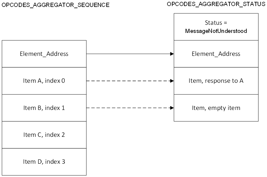 |
4.4.20. Opcodes Aggregator Client model
4.4.20.1. Description
The Opcodes Aggregator Client model is used to support the functionality of dispatching a sequence of access layer messages to nodes supporting the Opcodes Aggregator Server model.
The Opcodes Aggregator Client model is a root model and a main model that does not extend any other models.
If supported, the Opcodes Aggregator Client shall be supported by a primary element and shall not be supported by any secondary elements. The access layer security on the Opcodes Aggregator Client model shall use the device key and application keys.
Table 4.377 lists the Opcodes Aggregator Client model messages. The model shall support receiving the messages marked as mandatory in the Rx column and shall support sending the messages marked as mandatory in the Tx column.
|
Element |
Model Name |
Procedure |
Message |
Rx |
Tx |
|---|---|---|---|---|---|
|
Opcodes Aggregator Main (Primary) |
Opcodes Aggregator Client |
Dispatch sequence of Access messages |
OPCODES_AGGREGATOR_SEQUENCE |
– |
M |
|
OPCODES_AGGREGATOR_STATUS |
M |
– |
4.4.20.2. Behavior
4.4.20.2.1. Dispatch sequence of Access messages procedure
To dispatch a sequence of Access messages to an Opcodes Aggregator Server, an Opcodes Aggregator Client shall send an OPCODES_AGGREGATOR_SEQUENCE message. The response is an OPCODES_AGGREGATOR_STATUS message.
Upon receiving an OPCODES_AGGREGATOR_STATUS message, an Opcodes Aggregator Client can determine the following:
-
the status, which can be either a Success or an error
-
the index of the most recent Access message delivered to the Opcodes Aggregator Server
-
the number of successfully processed Access messages from the list
-
one or more Access messages sent as a result of the processing of Access messages.
If the status is Success, the Status is set to Success. If the status is an error or processing of one Access message resulted in error, the Status field contains the error condition.
When constructing an OPCODES_AGGREGATOR_SEQUENCE message, the Opcodes Aggregator Client should avoid the situation where the response Access messages would become too large to be transported in a single OPCODES_AGGREGATOR_STATUS message. The Opcodes Aggregator Client should consider the lengths of the response Access messages it will receive, and when necessary, send multiple OPCODES_AGGREGATOR_SEQUENCE messages instead of one.
4.4.21. Large Composition Data Server model
4.4.21.1. Description
The Large Composition Data Server model is used to support the functionality of exposing pages of Composition Data that do not fit in a Config Composition Data Status message (see Section 4.3.2.5) and to expose metadata of the model instances.
The Large Composition Data Server is a main model that extends the Configuration Server model (see Section 4.4.1).
The Large Composition Data Server model defines the state instances listed in Table 4.378 and the messages listed in Table 4.379.
If supported, the Large Composition Data Server model shall be supported by a primary element and shall not be supported by any secondary elements. The access layer security on the Large Composition Data Server model shall use the device key.
Table 4.378 illustrates the state bindings between the Large Composition Data Server model states and the states of the models that the Large Composition Data Server extends.
|
State |
Bound State |
|
|---|---|---|
|
Model |
State |
|
|
Models Metadata Page |
– |
– |
Table 4.379 lists the Large Composition Data Server model messages. The model shall support receiving the messages marked as mandatory in the Rx column and shall support sending the messages marked as mandatory in the Tx column.
|
Element |
Model Name |
State |
Message |
Rx |
Tx |
|---|---|---|---|---|---|
|
Large Composition Data Main (Primary) |
Large Composition Data Server |
– |
LARGE_COMPOSITION_DATA_GET |
M |
– |
|
LARGE_COMPOSITION_DATA_STATUS |
– |
M |
|||
|
Models Metadata Page |
MODELS_METADATA_GET |
M |
– |
||
|
MODELS_METADATA_STATUS |
– |
M |
4.4.21.2. Behavior
This section describes behaviors for states and messages for the Large Composition Data Server model.
4.4.21.2.1. Large Composition Data
When an element receives a LARGE_COMPOSITION_DATA_GET message with the Page field of the message containing a value of a Composition Data Page that the node contains, the element shall respond with a LARGE_COMPOSITION_DATA_STATUS message. The LARGE_COMPOSITION_DATA_STATUS message shall have the following configuration:
-
The Page field and the Offset field shall be set to the values of the corresponding fields in the LARGE_COMPOSITION_DATA_GET message.
-
The Total_Size field shall be set to the total size of the identified Composition Data Page.
-
If the Offset field value is less than the Total_Size field value, the Data field shall be set to the value of the portion of the identified Composition Data Page that fits in the Data field, starting from the position in number of octets indicated by the Offset field value. Otherwise, the Data field shall be empty.
When an element receives a LARGE_COMPOSITION_DATA_GET message with the Page field of the message containing a reserved page number or a page number the node does not support, it shall respond with a LARGE_COMPOSITION_DATA_STATUS message.
The response page is the page with the largest page number of the Composition Data that the node supports and that is smaller than the Page field value of the received LARGE_COMPOSITION_DATA_GET message.
The LARGE_COMPOSITION_DATA_STATUS message shall have the following configuration:
-
The Page field shall be set to the response page number.
-
The Offset field shall be set to the value of the corresponding field in the LARGE_COMPOSITION_DATA_GET message.
-
The Total_Size field shall be set to the total size of the response page.
-
If the Offset field value is less than the Total_Size field value, the Data field shall be set to the portion of the response page, starting from the position in number of octets indicated by the Offset field value. Otherwise, the Data field shall be empty.
4.4.21.2.2. Models Metadata Page state
When an element receives a MODELS_METADATA_GET message, the Large Composition Data Server model shall identify the requested Models Metadata Page and shall respond with a MODELS_METADATA_STATUS message containing the value of the requested Models Metadata Page state.
The Large Composition Data Server model shall identify the response Models Metadata Page state using the following conditions:
-
If the Page field of the message identifies a Models Metadata Page state that is present on the node, the response Models Metadata Page state is set to the identified Models Metadata Page state.
-
If the Page field of the message does not identify any Models Metadata Page state present on the node, the response Models Metadata Page state is set to the highest Models Metadata Page state that is smaller than the Page field value.
When sending the MODELS_METADATA_STATUS message, the message shall have the following configuration:
-
The Page field shall be set to the value of the response Models Metadata Page number and the Offset field shall be set to the value of the Offset field of the MODELS_METADATA _GET message.
-
The Total_Size field shall be set to the total size of the response Models Metadata Page state.
-
If the Offset field value is less than the Total_Size field value, the Data field shall be set to the value of the portion of the response Models Metadata Page state that fits in the Data field, starting from the octet position indicated by the Offset field value. Otherwise, the Data field shall be empty.
4.4.22. Large Composition Data Client model
4.4.22.1. Description
The Large Composition Data Client model is used to support the functionality of reading pages of Composition Data that do not fit in a Config Composition Data Status message (see Section 4.3.2.5) and reading the metadata of the model instances.
The Large Composition Data Client model is a root model that does not extend any other models. The Large Composition Data Client model may operate on states defined by the Large Composition Data Server model (see Section 4.4.21) using Large Composition Data messages (see Section 4.3.10).
If supported, the Large Composition Data Client model shall be supported by a primary element and shall not be supported by any secondary elements. The access layer security of the Large Composition Data Client model shall use the device key of the node supporting the Large Composition Data Server model.
Table 4.380 lists the Large Composition Data Client model messages. The model shall support receiving the messages marked as mandatory in the Rx column and shall support sending the messages marked as mandatory in the Tx column.
|
Element |
Model Name |
Procedure |
Message |
Rx |
Tx |
|---|---|---|---|---|---|
|
Large Composition Data Main (Primary) |
Large Composition Data Client |
Large Composition Data |
LARGE_COMPOSITION_DATA_GET |
– |
M |
|
LARGE_COMPOSITION_DATA_STATUS |
M |
– |
4.4.22.2. Behavior
This section describes behaviors for procedures and messages for the Large Composition Data Client model.
An element can send a LARGE_COMPOSITION_DATA_GET message at any time to query the Composition Data state of a node and can send a MODELS_METADATA_GET message at any time to query the Models Metadata state of a node. Messages for the Large Composition Data Client and Server models shall be secured using a DevKey.
4.4.22.2.1. Large Composition Data procedure
To find out a portion of a page of the Composition Data state of the Large Composition Data Server, a Large Composition Data Client shall send a LARGE_COMPOSITION_DATA_GET message. The response is a LARGE_COMPOSITION_DATA_STATUS message that contains the requested portion of the page and the total size of the page.
Upon receiving a LARGE_COMPOSITION_DATA_STATUS message, a Large Composition Data Client can determine a portion or the entire value of the requested Composition Data Page state of a Large Composition Data Server.
4.4.22.2.2. Models Metadata procedure
To find out a portion of a page of the Models Metadata state of the Large Composition Data Server, a Large Composition Data Client shall send a MODELS_METADATA_GET message. The response is a MODELS_METADATA_STATUS message that contains the requested portion of the page and the total size of the page.
Upon receiving a MODELS_METADATA_STATUS message, a Large Composition Data Client can determine a portion or the entire value of the requested Models Metadata Page state of a Large Composition Data Server.
4.4.23. Summary of Model IDs
The Model IDs for the models that are defined in this specification are defined in the Assigned Numbers document [4].
5. Provisioning
Provisioning is a process of adding an unprovisioned device to a mesh network managed by a Provisioner. A Provisioner provides the unprovisioned device with provisioning data that allows it to become a mesh node for the initial term. The provisioning data includes a network key, the current IV Index, and the unicast address for each element.
A Provisioner is typically a smart phone or other mobile computing device. Although only a single Provisioner is required on a network to do provisioning, multiple Provisioners may be used. The method to share cached data and coordinate across multiple Provisioners is implementation specific.
To provision an unprovisioned device, the provisioning bearer is established between a Provisioner and an unprovisioned device. An unprovisioned device can be identified to a Provisioner by its Device UUID and other supplementary information that may also be provided.
After the provisioning bearer is established, the Provisioner establishes a shared secret with the unprovisioned device using an Elliptic Curve Diffie-Hellman (ECDH) protocol. It then authenticates the unprovisioned device using OOB information that is specific to that unprovisioned device. Such OOB information may include a public key of the unprovisioned device, a long secret, the requirement to input a value into the unprovisioned device, or the requirement to output a value on that unprovisioned device. Such OOB information may be formatted as a signed certificate (see Section 5.5). Such OOB information also enables the authentication of that unprovisioned device. Once the unprovisioned device has been authenticated, the provisioning data is transmitted to the unprovisioned device encrypted with a key derived from that shared secret. The device key is derived from the ECDHSecret and the ProvisioningSalt.
The generic provisioning layer in Figure 5.1 illustrates how the provisioning PDUs are transmitted as transactions that can be segmented and reassembled. These transactions are sent over a provisioning bearer. The provisioning bearer defines how a session is established for the delivery of transactions from the generic provisioning layer to a single device. Finally, the bearers are in the bottom layer of the provisioning architecture.
 |
The PB-ADV bearer allows provisioning of an unprovisioned device by using an advertising bearer. The PB-GATT bearer allows provisioning of an unprovisioned device by using the Mesh Provisioning Service.
The PB-Remote bearer allows a Provisioner that is outside immediate radio range of an unprovisioned device to communicate with a node supporting the Remote Provisioning Server model that is within immediate radio range of the unprovisioned device and to use that node as a retransmitter to communicate with the unprovisioned device using PB-ADV or PB-GATT. This allows a Provisioner to provision unprovisioned devices using nodes of the mesh network. Figure 5.2 illustrates this process when the Remote Provisioning Server uses PB-ADV to provision an unprovisioned device.
 |
The Provisioner may use the Remote Provisioning Server (see Section 4.4.5) to identify unprovisioned devices within immediate radio range of the server.
As a final step, the Provisioner closes the provisioning bearer. Some provisioning bearers require that a close reason be provided when closing the bearer. The close reason is provided by the provisioning protocol. When the provisioning bearer is closed by the peer device, the close reason is provided to the provisioning protocol.
5.1. Endianness
Unless stated otherwise, all multiple-octet numeric values in this layer shall be big-endian, as described in Section 3.1.1.1.
5.2. Provisioning bearer layer
A provisioning bearer layer enables the transport of Provisioning PDUs between a Provisioner and an unprovisioned device. Three provisioning bearers are defined:
Six provisioning roles are defined:
-
PB-ADV Client
-
PB-ADV Server
-
PB-GATT Client
-
PB-GATT Server
-
PB-Remote Client
-
PB-Remote Server
An unprovisioned device may support the PB-ADV Server role and may support the PB-GATT Server role. An unprovisioned device should support both the PB-ADV Server role and the PB-GATT Server role.
A Provisioner shall support either the PB-ADV Client role or PB-GATT Client role, or both roles. If the Provisioner supports only one role, the Provisioner should support the PB-ADV Client role. The Provisioner may also support the PB-Remote Client role.
A node may support the PB-Remote Server role.
5.2.1. PB-ADV
PB-ADV is a provisioning bearer used to provision an unprovisioned device using Generic Provisioning PDUs (see Section 5.3) over the advertising channels. The provisioning mechanism is session based. An unprovisioned device shall support only one session at a time. There is no such limitation for a Provisioner. A session is established using the Link Establishment procedure (see Section 5.3.2). The PB-ADV provisioning bearer requires a reason when closing the link and provides a reason when the link is closed.
When PB-ADV is used, the Provisioner shall use the PB-ADV Client role and the unprovisioned device shall use the PB-ADV Server role.
The PB-ADV bearer is used for transmitting Generic Provisioning PDUs. The PB-ADV bearer maximum transmission unit (MTU) size is 24 octets.
When using PB-ADV, a Generic Provisioning PDU shall be sent using the PB-ADV AD type identified by «PB-ADV», as defined in [4].
A Provisioner and an unprovisioned device supporting PB-ADV should perform passive scanning with a duty cycle as close to 100 percent as possible in order to avoid missing any incoming PB-ADV PDUs.
The PB-ADV AD type contains a PB-ADV PDU field. The format of the PB-ADV AD type is defined in Table 5.1.
|
Field |
Size |
Description |
Req. |
|---|---|---|---|
|
Length |
1 |
Length of the AD Type and PB-ADV PDU fields |
M |
|
AD Type |
1 |
«PB-ADV» |
M |
|
PB-ADV PDU |
variable |
PB-ADV PDU |
M |
Any advertising data that includes the PB-ADV AD type shall use ADV_NONCONN_IND PDUs. If a node receives a PB-ADV AD type in a PDU type different from ADV_NONCONN_IND, the message shall be ignored.
The format of the PB-ADV PDU field is defined in Table 5.2.
|
Field |
Size |
Description |
Req. |
|---|---|---|---|
|
Link ID |
4 |
The identifier of a link |
M |
|
Transaction Number |
1 |
The number for identifying a transaction |
M |
|
Generic Provisioning PDU |
1–24 |
Generic Provisioning PDU being transferred |
M |
The Link ID is used to identify a link between two devices.
The Transaction Number field contains a one-octet value used to identify each individual Generic Provisioning PDU sent by the device. When a Provisioning PDU that does not fit in a single PB-ADV PDU is segmented, all segments are sent using the same Transaction Number field value. When a Provisioning PDU is retransmitted, the Transaction Number field is not changed.
Transport-specific messages are defined to establish and terminate the link between two devices (see Section 5.3.1.4). When the link is opened, the Provisioner and the unprovisioned device shall start the link timer from the initial value set to 60 seconds. When the link timer expires, the Provisioner and the unprovisioned device shall close the link. When the unprovisioned device receives any Provisioning PDU or a Link Close message, then the unprovisioned device shall stop the link timer.
The Generic Provisioning PDU field format is defined in Section 5.3.
The following rules shall be implemented when sending a PB-ADV PDU:
-
When the Generic Provisioning PDU field contains a Provisioning Bearer Control PDU, the Transaction Number field shall be set to 0 and ignored upon reception.
-
When the PB-ADV Client is sending a Provisioning PDU for the first time over an open provisioning link, it shall start with a Transaction Number field value of 0x00. The PB-ADV Client shall increment the field value by 1 for each new Provisioning PDU it is sending for the duration of the provisioning link. If the field value has reached 0x7F, it shall wrap to 0x00 on sending the next Provisioning PDU.
-
When the PB-ADV Server is sending a Provisioning PDU for the first time over an open provisioning link, it shall start with a Transaction Number field value of 0x80. The PB-ADV Server shall increment the field value by 1 for each new Provisioning PDU it is sending for the duration of the provisioning link. If the field value has reached 0xFF, it shall wrap to 0x80 on sending the next Provisioning PDU.
-
When a PB-ADV Server is receiving a Provisioning PDU, it shall set the Transaction Number field to the value of the Transaction Number field of the PB-ADV PDUs being received during the transaction.
-
When a PB-ADV Server is sending a Transaction Acknowledgement PDU, the Transaction Number field shall be set to the value of the Transaction Number field of the PB-ADV PDUs transporting the Provisioning PDU being acknowledged.
5.2.2. PB-GATT
PB-GATT is a provisioning bearer used to provision an unprovisioned device using Proxy PDUs (see Section 6.3) to encapsulate Provisioning PDUs (see Section 5.4) within the Mesh Provisioning Service (see Section 7.1). PB-GATT is provided for support when a Provisioner does not support PB-ADV due to limitations of the application interfaces.
The PB-GATT Server shall use the Provisioning Server role (see Section 6.2.2) and the PB-GATT Client shall use the Provisioning Client role (see Section 6.2.2).
When PB-GATT is used, the Provisioner shall use the PB-GATT Client role and the unprovisioned device shall use the PB-GATT Server role.
To enable very low power operation for the PB-GATT Server and allow the PB-GATT Server to calculate the Diffie-Hellman shared secret without requiring the energy to maintain an idle link, the connection interval for the connection between a PB-GATT Client and a PB-GATT Server should be between 250 and 1,000 milliseconds.
The PB-GATT Server shall be able to receive a single Proxy PDU (see Section 6.3) in a single Write Command ATT PDU.
The PB-GATT Server shall use a single Handle Value Notification ATT PDU to send Provisioning PDUs to a PB-GATT Client.
If the negotiated ATT_MTU is smaller than a required Proxy PDU size, the transmission of the Mesh Provisioning Data In and Mesh Provisioning Out characteristics always needs to be fragmented and reassembled. Each PDU shall be fully reassembled before processing.
The PB-GATT Server shall be able to receive a Proxy PDU in one or several ATT PDUs. The PB-GATT Server shall use one or several Handle Value Notification ATT PDUs to send a Proxy PDU to the PB-GATT Client depending on the size of the message and the negotiated ATT_MTU.
The Mesh Provisioning Data In and Mesh Provisioning Data Out characteristic formats use the Proxy PDU format defined in Section 6.3.1.
The PB-GATT provisioning bearer does not require a reason when closing the link and does not provide a reason when the link is closed.
Figure 5.3 illustrates the provisioning protocol, PB-GATT Server, and Mesh Provisioning Service (see Section 7.1) interactions.

The link is opened on a PB-GATT bearer when the PB-GATT Client enables notifications (by writing 0x0001) to the Mesh Provisioning Data Out Client Characteristic Configuration Descriptor after a connection is established (see Section 7.1.3.2.1). When the link is opened, the Provisioner and the unprovisioned device shall start the link timer from the initial value set to 60 seconds. When the link timer expires, the Provisioner and the unprovisioned device shall disconnect. When the Provisioner receives any Provisioning PDU or the connection between the PB-GATT Client and the PB-GATT Server closes, then the Provisioner shall stop the link timer. When the unprovisioned device receives any Provisioning PDU or the connection between the PB-GATT Client and the PB-GATT Server closes, then the unprovisioned device shall stop the link timer.
5.2.3. PB-Remote
The PB-Remote provisioning bearer uses the existing mesh network to provision an unprovisioned device that is not within immediate radio range of the Provisioner. PB-Remote uses the PB-ADV bearer (see Section 5.2.1) or the PB-GATT bearer (see Section 5.2.2) for the last hop to the unprovisioned device. PB-Remote uses one of the mesh nodes as a PB-Remote Server to manage the PB-ADV or PB-GATT bearer link on behalf of the Provisioner.
Provisioning should be done using an OOB public key when PB-Remote is used. Provisioning should not be done using Authentication with No OOB when PB-Remote is used.
When PB-Remote is supported by the Provisioner, the Provisioner shall use the PB-Remote Client role. When the node supports the Remote Provisioning Server model, the node uses the PB-Remote Server role.
PB-Remote may also be used to execute the Device Key Refresh procedure (see Section 3.11.8.4) or the Node Address Refresh procedure (see Section 3.11.8.5) or the Node Composition Refresh procedure (see Section 3.11.8.6) between the Provisioner (PB-Remote Client) and the PB-Remote Server.
Multiple instances of the PB-Remote Client can be used by the Provisioner to communicate with many nodes implementing the PB-Remote Server, thus providing the capability to provision many unprovisioned devices at the same time. The PB-Remote Server can only communicate with one PB-Remote Client and can only open one supported provisioning bearer at a time.
 |
The PB-Remote provisioning bearer requires a reason when closing the link. When a PB-Remote Server uses the PB-ADV bearer for the last hop to the device being provisioned and the PB-ADV link is closed, the PB-Remote bearer provides a close reason. When the PB-Remote Server uses the PB-GATT bearer, the provided reason is not used when closing the link. The PB-Remote Client is not aware whether the PB-ADV or PB-GATT bearer is used by the PB-Remote Server, so providing a reason is mandatory.
5.2.3.1. PB-Remote Client
The PB-Remote Client is a provisioning device that controls the provisioning process. The PB-Remote Client uses the Remote Provisioning Client model. The PB-Remote Client can choose which PB-Remote Server device to communicate with, can instruct the PB-Remote Server to start scanning for unprovisioned devices, and can instruct the PB-Remote Server to establish a provisioning link with the chosen unprovisioned device. After the Provisioning Bearer link is established, the PB-Remote Client runs the provisioning protocol by executing the PB-Remote’s Send PDU procedure (see Section 5.2.3.3.3) and the PB-Remote Server executes the PB-Remote’s Receive PDU procedure (see Section 5.2.3.3.4).
5.2.3.2. PB-Remote Server
The PB-Remote Server is a mesh node that supports the Remote Provisioning Server model. The PB-Remote Server uses the Remote Provisioning Scan procedure to scan for unprovisioned devices. The server uses the Remote Provisioning Extended Scan procedure to obtain additional information about unprovisioned devices and uses the Provisioning Bearer protocol to establish a Provisioning Bearer link with an unprovisioned device. After a Provisioning Bearer link is established, the PB-Remote Server transports Provisioning PDUs between the PB-Remote Client and the connected Provisioning Bearer protocol.
5.2.3.3. PB-Remote procedures
The PB-Remote Server may support multiple provisioning bearers, but the server shall use only one provisioning bearer at a time. Each provisioning bearer defines different steps that are needed to open or close the bearer connection and to send or receive the Provisioning PDU over the bearer. The subsections 5.2.3.3.1 through 5.2.3.3.4 define common names for these bearer specific steps, thus defining the PB-Remote procedures.
5.2.3.3.1. PB-Remote Open Link procedure
The PB-Remote Open Link procedure is used to establish a connection between the PB-Remote Server and the unprovisioned device. The PB-Remote Server initializes the connection. The procedure accepts the UUID of the device that the provisioning bearer will be open to as a Device UUID parameter and an optional Timeout parameter. The Timeout parameter is expressed in seconds and the valid range is from 1 to 60 seconds with one second granularity. The default value of the Timeout parameter is 10 seconds. The procedure succeeds or fails depending on the outcome of the opening of a provisioning bearer. The time before the procedure fails via timeout shall be set to the value of the Timeout parameter.
Table 5.3 defines Success and Fail results for the PB-Remote Open Link procedure.
|
Provisioning Bearer |
Procedure Success |
Procedure Fail |
|---|---|---|
|
PB-ADV |
The Link Establishment procedure (see Section 5.3.2) establishes a session. |
The Link Establishment procedure does not establish a session. |
|
PB-GATT |
The PB-GATT Client successfully opens a connection to the PB-GATT Server (see Section 5.2.2). |
The PB-GATT Client is unable to open a connection to the PB-GATT Server. |
5.2.3.3.2. PB-Remote Close Link procedure
The PB-Remote Close Link procedure is used to close a connection between a PB-Remote Server and the unprovisioned device. The procedure accepts one parameter: Reason. Some provisioning bearers require the Reason parameter to close the connection. This procedure always succeeds. Table 5.4 defines results for the PB-Remote Close Link procedure for each provisioning bearer.
|
Provisioning bearer |
Procedure |
|---|---|
|
PB-ADV |
Link close step of the Link Establishment procedure (see Section 5.3.2). |
|
PB-GATT |
Closing a connection between a PB-GATT Client and a PB-GATT Server (see Section 5.2.2). |
5.2.3.3.3. PB-Remote Send PDU procedure
The PB-Remote Send PDU procedure is used to send a Provisioning PDU from the PB-Remote Server over an open provisioning bearer to the unprovisioned device. The procedure accepts one parameter: Provisioning PDU. The procedure can either succeed or fail depending on the outcome of the Provisioning PDU delivery.
Table 5.5 defines the results for the PB-Remote Send PDU procedure.
|
Provisioning Bearer |
Procedure Success |
Procedure Fail |
|---|---|---|
|
PB-ADV |
The Provisioning PDU is delivered successfully from the Provisioning Server to the unprovisioned device using the PB-ADV provisioning bearer (see Section 5.3.3) |
The Provisioning PDU delivery from the Provisioning Server to the unprovisioned device using the PB-ADV bearer fails. |
|
PB-GATT |
The Provisioning PDU is delivered successfully from the PB-Remote Server acting as the PB-GATT Client to the unprovisioned device (PB-GATT Server) using the PB-GATT bearer (see Section 5.2.2). |
The Provisioning PDU delivery from the PB-Remote Server to the unprovisioned device using the PB-GATT bearer fails. |
5.2.3.3.4. PB-Remote Receive PDU procedure
The PB-Remote Receive PDU procedure is used to receive a Provisioning PDU sent from the unprovisioned device to the PB-Remote Server over an open provisioning bearer. When the PB-ADV bearer is used, the PB-Remote Server uses the PB-ADV Client for this procedure. When the PB-GATT bearer is used, the server uses the PB-GATT Client. The procedure either succeeds or fails depending on the outcome of the PDU reception by the PB-Remote Server. The output of the procedure is the received Provisioning PDU.
The procedure is canceled when the open provisioning bearer is closed.
Table 5.6 defines the results for the PB-Remote Receive PDU procedure.
|
Provisioning Bearer |
Procedure Success |
Procedure Fail |
|---|---|---|
|
PB-ADV |
The Provisioning PDU is delivered successfully from the unprovisioned device to the PB-Remote Server using the PB-ADV bearer (see Section 5.3.3). |
The Provisioning PDU delivery from the unprovisioned device to the PB-Remote Server using the PB-ADV bearer fails. |
|
PB-GATT |
The Provisioning PDU is delivered successfully to the PB-Remote Server acting as the PB-GATT Client from the unprovisioned device (PB-GATT Server) using the PB-GATT bearer (see Section 5.2.2). |
The Provisioning PDU delivery from unprovisioned device to the PB-Remote Server using the PB-GATT bearer fails. |
5.3. Generic provisioning layer
The generic provisioning layer is responsible for transport of Generic Provisioning PDUs over an unreliable connectionless provisioning bearer. This layer also defines Generic Provisioning PDUs.
The Generic Provisioning PDU format consists of a Generic Provisioning Control (GPC) field followed by a variable-length Generic Provisioning Payload field as illustrated in Figure 5.5 and defined in Table 5.7.

|
Field |
Size |
Description |
Req. |
|---|---|---|---|
|
Generic Provisioning Control |
1–17 |
Generic Provisioning Control field |
M |
|
Generic Provisioning Payload |
0–64 |
Generic Provisioning Payload (segments of the Provisioning PDU) |
M |
The two least significant bits of the first octet of the Generic Provisioning Control field contain a Generic Provisioning Control Format (GPCF) field that determines the format of the Generic Provisioning Control field. The GPCF field is an enumeration with the values shown in Table 5.8.
|
Value |
Description |
|---|---|
|
0b00 |
Transaction Start |
|
0b01 |
Transaction Acknowledgment |
|
0b10 |
Transaction Continuation |
|
0b11 |
Provisioning Bearer Control |
The format of the GPC field for each format type is defined in Section 5.3.1.
5.3.1. Generic Provisioning PDU types
5.3.1.1. Transaction Start PDU
A Transaction Start PDU is used to start the transmission of a segmented message. The Generic Provisioning Control field of a Transaction Start PDU is illustrated in Figure 5.6 and shown in Table 5.9.

|
Field |
Size |
Description |
Req. |
|---|---|---|---|
|
SegN |
6 |
The last segment number |
M |
|
GPCF |
2 |
Set to Transaction Start |
M |
|
TotalLength |
16 |
The number of octets in the Provisioning PDU |
M |
|
FCS |
8 |
Frame Check Sequence of the Provisioning PDU |
M |
The SegN field shall be set to the last segment number (zero-based) of this transaction.
The GPCF field shall be set to Transaction Start.
The TotalLength field shall be set to the number of octets in the Provisioning PDU.
When transmitted using PB-ADV, the FCS field is calculated as defined by 3GPP TS 27.010 with the Polynomial (x8 + x2 + x1 + 1) and is calculated over the Provisioning PDU only.
The Generic Provisioning Payload shall contain segment 0 of the Provisioning PDU.
5.3.1.2. Transaction Acknowledgment PDU
A Transaction Acknowledgment PDU is used to acknowledge a Provisioning PDU. The Generic Provisioning Control field of a Transaction Acknowledgment PDU is illustrated in Figure 5.7 and shown in Table 5.10.
 |
|
Field |
Size |
Description |
Req. |
|---|---|---|---|
|
Padding |
6 |
0b000000; all other values Prohibited |
M |
|
GPCF |
2 |
Set to Transaction Acknowledgment |
M |
The GPCF field shall be set to Transaction Acknowledgment.
The Generic Provisioning Payload is zero length.
5.3.1.3. Transaction Continuation PDU
A Transaction Continuation PDU is used to send additional segments of a Provisioning PDU. The Generic Provisioning Control field of a Transaction Continuation PDU is illustrated in Figure 5.8 and shown in Table 5.11.
 |
|
Field |
Size |
Description |
Req. |
|---|---|---|---|
|
SegmentIndex |
6 |
Segment number of the transaction |
M |
|
GPCF |
2 |
Set to Transaction Continuation |
M |
The SegmentIndex field shall be set to the segment number contained within this PDU.
The GPCF field shall be set to Transaction Continuation.
The Generic Provisioning Payload shall contain segment SegmentIndex of the Provisioning PDU.
5.3.1.4. Provisioning Bearer Control
A Provisioning Bearer Control PDU is used to manage sessions on bearers that have no inherent session management. The Generic Provisioning Control field of a Provisioning Bearer Control PDU is illustrated in Figure 5.9 and shown in Table 5.12. The Provisioning Bearer Control PDUs are defined in the following sections.
 |
|
Field |
Size |
Description |
Req. |
|---|---|---|---|
|
BearerOpcode |
6 |
The opcode for the provisioning bearer control PDUs |
M |
|
GPCF |
2 |
Set to Provisioning Bearer Control |
M |
|
Parameters |
variable |
Parameters defined by each BearerOpcode |
M |
The BearerOpcode values are defined in Table 5.13.
|
Value |
Message |
Description |
|---|---|---|
|
0x00 |
Link Open |
Open a session on a bearer with an unprovisioned device |
|
0x01 |
Link ACK |
Acknowledge a session on a bearer |
|
0x02 |
Link Close |
Close a session on a bearer |
|
0x03–0x3F |
RFU |
Reserved for Future Use |
The GPCF field shall be set to Provisioning Bearer Control.
The Generic Provisioning Payload is zero length.
The Parameters of each message are defined in the sections that follow.
5.3.1.4.1. Link Open message
A Link Open message is used to establish a link between a Provisioner and an unprovisioned device. The unprovisioned device shall acknowledge this message with the Link ACK message.
The Parameters field for the Link Open message is defined in Table 5.14 and the message is illustrated in Figure 5.10.
|
Field |
Size |
Description |
Req. |
|---|---|---|---|
|
Device UUID |
16 |
This is the Device UUID of the chosen unprovisioned device |
M |
 |
5.3.1.4.2. Link ACK message
A Link ACK message is sent to acknowledge the receipt of the Link Open message.
There are no Parameters for this message.
The Link ACK message is illustrated in Figure 5.11.
 |
5.3.1.4.3. Link Close message
A Link Close message is used to close a link. Since this message is not acknowledged, the sender shall repeat this message at least three times. Both sides of the link may send this message. This message shall be accepted and processed regardless of the setting of the Reason field.
The Parameters field for the Link Close message is defined in Table 5.15 and the message is illustrated in Figure 5.12.
|
Field |
Size |
Description |
Req. |
|---|---|---|---|
|
Reason |
1 |
The reason for closing the link |
M |
The Reason field values are defined in Table 5.16.
|
Value |
Reason |
Description |
|---|---|---|
|
0x00 |
Success |
The provisioning was successful |
|
0x01 |
Timeout |
The provisioning transaction timed out |
|
0x02 |
Fail |
The provisioning failed |
|
0x03–0xFF |
Unrecognized |
Unrecognized reason that may be defined in the future. |
 |
5.3.2. Link Establishment procedure
The Link Establishment procedure is used to establish a session for a bearer that does not have inherent session management. A session is identified by using a Link ID that is static for the duration of the session and shall be randomly generated to prevent collisions between sessions.
A link is established between a Provisioner and an unprovisioned device for sending provisioning messages. The unprovisioned device is identified by a Device UUID (see Section 3.11.3).
The Provisioner shall scan for unprovisioned devices. Upon receiving an Unprovisioned Device beacon, the Provisioner may establish a link with the unprovisioned device identified by the Device UUID.
The link is open for the unprovisioned device when the unprovisioned device sends a Link ACK for the Link Open message. The link is open for the Provisioner when a Link ACK is received with the Link ID equal to the Link ID sent in the Link Open message. The unprovisioned device is being provisioned when the link is open and the unprovisioned device has received any Provisioning PDU.
When the link is open, the unprovisioned device shall ignore Generic Provisioning PDUs with the Link ID not equal to the Link ID received in the Link Open message.
When the link is not open, and the unprovisioned device receives a Link Open message, then the unprovisioned device shall accept this message by replying with a Link ACK message with the same Link ID set in the PB-ADV PDU. When the link is open, and the unprovisioned device is not being provisioned, and the unprovisioned device receives a Link Open message with the same Link ID, then the unprovisioned device shall reply with a Link ACK message with the same Link ID set in the PB-ADV PDU. When the link is open, the unprovisioned device shall ignore all Provisioning Bearer Control PDUs received with a different Link ID.
To open a link, the Provisioner shall start the link establishment timer from the initial value set to 60 seconds, and then shall start sending Link Open messages. The Provisioner may cancel this procedure at any time. The Link Open message contains the Device UUID of the unprovisioned device. On PB-ADV, the PB-ADV PDU format includes a Link ID field.
When the link establishment timer expires, the link is considered not open and the procedure may be restarted. When the link is open, the Provisioner shall stop the link establishment timer.
The link may be closed at any time after link establishment by sending the Link Close message. Either side of the link may send the Link Close message.
The Link Open, Link ACK, and Link Close messages are defined in Section 5.3.1.4.
The message sequence for establishment of a link by ID between a Provisioner and an unprovisioned device is illustrated by Figure 5.13 below.
 |
5.3.3. Generic Provisioning behavior
Each Generic Provisioning PDU shall be sent after a random delay between 20 and 50 milliseconds.
Each Provisioning PDU (see Section 5.4) is transmitted as a separate transaction. A transaction may be composed of one or more segments.
The number of segments required to send a Provisioning PDU is determined by the size of the Provisioning PDU. Segments are indexed from 0 to 63. Segment 0 shall be sent using a Transaction Start PDU. All other segments shall be sent using a Transaction Continuation PDU. Each segment of the Provisioning PDU is placed into the Generic Provisioning Payload field of the respective Generic Provisioning PDU.
Each bearer has its own constraints on the maximum size of a Generic Provisioning PDU that can be transmitted by that bearer. Each Generic Provisioning PDU shall be the length of the full MTU for that bearer, except for the last segment of a transaction.
The sender shall send all segments of a transaction in sequence. If the sender does not receive a Transaction Acknowledgment message, the sender shall retransmit all segments of a transaction.
If the sender receives a Transaction Acknowledgment message, then the transaction has completed.
If the sender receives a message with other PDU types, then the message shall be ignored.
When the first message in a transaction is sent, the sender shall start the acknowledgment timer with an initial value of 30 seconds. When the Transaction Acknowledgment message for the transaction is received, the sender shall stop the acknowledgment timer. When the acknowledgment timer expires, the sender shall cancel the transaction, cancel the provisioning process, and close the link.
The receiver shall determine the number of segments for a transaction from the Transaction Start PDU.
On the PB-ADV bearer, when the receiver has received all segments of a transaction, the receiver shall calculate the FCS for the received Provisioning PDU, and if it matches the FCS field in the Transaction Start PDU, it shall send a Transaction Acknowledgment PDU after a random delay between 20 and 50 milliseconds.
When a Transaction Acknowledgment PDU has been sent for a given transaction and another segment of the same transaction has been received, another Transaction Acknowledgment PDU shall be sent and the received segment shall be ignored.
5.4. Provisioning protocol
This section defines requirements for Provisioning PDUs, behavior, and security.
The provisioning protocol defines two roles:
-
Provisioner
-
Provisionee
The Provisioner is a device that initiates the provisioning protocol. The Provisionee is a device that participates in the execution of the provisioning protocol with the Provisioner, upon request from the Provisioner.
5.4.1. Provisioning PDUs
The Provisioning PDUs are used to communicate between a Provisioner and a Provisionee.
The first octet of the Provisioning PDU is the Type field and defines the format of the Parameters of the Provisioning PDU.
The Provisioning PDU format is defined in Table 5.17 and illustrated in Figure 5.14.
|
Field |
Size |
Description |
Req. |
|---|---|---|---|
|
Padding |
2 |
0b00. All other values are Prohibited |
M |
|
Type |
6 |
Provisioning PDU Type value (see the Assigned Numbers document [4]) |
M |
|
Parameters |
variable |
Message parameters |
M |
 |
The Provisioning PDU Type values are defined in the Assigned Numbers document [4].
5.4.1.1. Provisioning Invite
A Provisioner sends a Provisioning Invite PDU to indicate to the intended Provisionee that the provisioning process is starting. The format of the parameters for the Provisioning Invite PDU is defined in Table 5.18.
|
Field |
Size |
Description |
Req. |
|---|---|---|---|
|
Attention Duration |
1 |
Attention Timer state (See Section 4.2.10) |
M |
5.4.1.2. Provisioning Capabilities
The Provisionee sends a Provisioning Capabilities PDU to indicate its supported provisioning capabilities to a Provisioner. The format of the parameters for the Provisioning Capabilities PDU is defined in Table 5.19.
|
Field |
Size |
Description |
Req. |
|---|---|---|---|
|
Number of Elements |
1 |
Number of elements supported by the Provisionee |
M |
|
Algorithms |
2 |
Supported algorithms and other capabilities (see Table 5.21) |
M |
|
Public Key Type |
1 |
Supported public key types (see Table 5.22) |
M |
|
OOB Type |
1 |
Supported OOB Types (see Table 5.23) |
M |
|
Output OOB Size |
1 |
Maximum size of Output OOB supported (see Table 5.24) |
M |
|
Output OOB Action |
2 |
Supported Output OOB Actions (see Table 5.25) |
M |
|
Input OOB Size |
1 |
Maximum size in octets of Input OOB supported (see Table 5.26) |
M |
|
Input OOB Action |
2 |
Supported Input OOB Actions (see Table 5.27) |
M |
The Number of Elements values are defined in Table 5.20.
|
Value |
Description |
|---|---|
|
0x00 |
Prohibited |
|
0x01–0xFF |
Number of elements supported by the Provisionee |
The Algorithms values are defined in Table 5.21.
|
Bit |
Name |
|---|---|
|
0 |
BTM_ECDH_P256_CMAC_AES128_AES_CCM |
|
1 |
BTM_ECDH_P256_HMAC_SHA256_AES_CCM |
|
2–15 |
Reserved for Future Use |
The BTM_ECDH_P256_HMAC_SHA256_AES_CCM bit of the Algorithms field shall be set to 1 by a Provisionee. Other sections of this specification may introduce further requirements for the value of this field.
The Public Key Type values are defined in Table 5.22.
|
Bit |
Description |
|---|---|
|
0 |
Public Key OOB information available |
|
1–7 |
Reserved for Future Use |
The size of the Public Key OOB information is determined by the selected Algorithm.
The OOB Type values are defined in Table 5.23.
|
Bit |
Description |
|---|---|
|
0 |
Static OOB information available |
|
1 |
Only OOB authenticated provisioning supported |
|
2–7 |
Reserved for Future Use |
If bit 1 of the OOB Type field is set to 1, bit 0 of the Algorithms field shall be set to 0 and at least one of the conditions listed below shall be met:
-
Bit 0 of the OOB Type field is set to 1.
-
The Output OOB Size field is not equal to 0x00.
-
The Input OOB Size field is not equal to 0x00.
The maximum size of the Static OOB information is 32 octets. The data type for the Static OOB information shall be Binary, Numeric, or Alphanumeric.
The Output OOB Size defines the number of digits that can be output (e.g., displayed or spoken) when the value Output Numeric is set and Output Alphanumeric is not set in the Output OOB Action field (see Table 5.25). The Output OOB Size defines the number of digits and uppercase letters that can be output when the value Output Numeric is not set and Output Alphanumeric is set in the Output OOB Action field. The Output OOB Size defines the number of digits and uppercase letters that can be output when the value Output Numeric is set and Output Alphanumeric is set in the Output OOB Action field. The Output OOB Size values are defined in Table 5.24.
|
Value |
Description |
|---|---|
|
0x00 |
The Provisionee does not support Output OOB |
|
0x01–0x08 |
Maximum size of Output OOB supported by the Provisionee |
|
0x09–0xFF |
Reserved for Future Use |
The Output OOB Action values are defined in Table 5.25.
|
Bit |
Description |
Data Type |
|---|---|---|
|
0 |
Blink |
Numeric |
|
1 |
Beep |
Numeric |
|
2 |
Vibrate |
Numeric |
|
3 |
Output Numeric |
Numeric |
|
4 |
Output Alphanumeric |
Alphanumeric |
|
5–15 |
Reserved for Future Use |
n/a |
The Input OOB Size defines the number of digits that can be entered when the value Input Numeric is set and Input Alphanumeric is not set in the Input OOB Action field (see Table 5.27). The Input OOB Size defines the number of digits and uppercase letters that can be entered when the value Input Numeric is not set and Input Alphanumeric is set in the Input OOB Action field. The Input OOB Size defines the number of digits and uppercase letters that can be entered when the value Input Numeric is set and Input Alphanumeric is set in the Input OOB Action field. The Input OOB Size values are defined in Table 5.26.
|
Value |
Description |
|---|---|
|
0x00 |
The Provisionee does not support Input OOB |
|
0x01–0x08 |
Maximum size of Input OOB supported by the Provisionee |
|
0x09–0xFF |
Reserved for Future Use |
The Input OOB Actions are defined in Table 5.27.
|
Bit |
Description |
Data Type |
|---|---|---|
|
0 |
Push |
Numeric |
|
1 |
Twist |
Numeric |
|
2 |
Input Numeric |
Numeric |
|
3 |
Input Alphanumeric |
Alphanumeric |
|
4–15 |
Reserved for Future Use |
n/a |
5.4.1.3. Provisioning Start
A Provisioner sends a Provisioning Start PDU to indicate the method it has selected from the options in the Provisioning Capabilities PDU. The format of the parameters for the Provisioning Start PDU is defined in Table 5.28.
|
Field |
Size |
Description |
Req. |
|---|---|---|---|
|
Algorithm |
1 |
The algorithm used for provisioning (see Table 5.29) |
M |
|
Public Key |
1 |
Public Key used (see Table 5.30) |
M |
|
Authentication Method |
1 |
Authentication Method used (see Table 5.31) |
M |
|
Authentication Action |
1 |
Selected Output OOB Action (see Table 5.32) or Input OOB Action (see Table 5.34) or 0x00 |
M |
|
Authentication Size |
1 |
Size of the Output OOB used (see Table 5.33) or size of the Input OOB used (see Table 5.35) or 0x00 |
M |
The Algorithm values are defined in Table 5.29.
|
Value |
Description |
|---|---|
|
0x00 |
BTM_ECDH_P256_CMAC_AES128_AES_CCM |
|
0x01 |
BTM_ECDH_P256_HMAC_SHA256_AES_CCM |
|
0x02–0xFF |
Reserved for Future Use |
The Public Key values are defined in Table 5.30.
|
Value |
Description |
|---|---|
|
0x00 |
No OOB Public Key is used |
|
0x01 |
OOB Public Key is used |
|
0x02–0xFF |
Reserved for Future Use |
The Authentication Method field values are defined in Table 5.31.
|
Value |
Name |
Description |
|---|---|---|
|
0x00 |
Authentication with No OOB |
No OOB authentication is used |
|
0x01 |
Authentication with Static OOB |
Static OOB authentication is used |
|
0x02 |
Authentication with Output OOB |
Output OOB authentication is used |
|
0x03 |
Authentication with Input OOB |
Input OOB authentication is used |
|
0x04–0xFF |
Prohibited |
Prohibited |
When the Authentication Method field value is Authentication with No OOB, the Authentication Action field shall be set to 0x00 and the Authentication Size field shall be set to 0x00.
When the Authentication Method field value is Authentication with Static OOB, the Authentication Size shall be set to 0x00 and the Authentication Action field shall be set to 0x00. The data type shall be transferred using an OOB technology.
When the Authentication Method field value is Authentication with Output OOB, the values defined in Table 5.32 and Table 5.33 shall be used to determine the data type, the Authentication Action, and the Authentication Size.
The Output OOB Action values for the Authentication Action field are defined in Table 5.32.
|
Value |
Description |
Data Type |
|---|---|---|
|
0x00 |
Blink |
Numeric |
|
0x01 |
Beep |
Numeric |
|
0x02 |
Vibrate |
Numeric |
|
0x03 |
Output Numeric |
Numeric |
|
0x04 |
Output Alphanumeric |
Alphanumeric |
|
0x05–0xFF |
Reserved for Future Use |
– |
The Output OOB Size for the Authentication Size field values are defined in Table 5.33.
|
Value |
Description |
|---|---|
|
0x00 |
Prohibited |
|
0x01–0x08 |
The Output OOB Size to be used |
|
0x09–0xFF |
Reserved for Future Use |
When the Authentication Method field value is Authentication with Input OOB, the values defined in Table 5.34 and Table 5.35 shall be used to determine the data type, the Authentication Action and the Authentication Size.
The Input OOB Action values for the Authentication Action field are defined in Table 5.34.
|
Value |
Description |
Data Type |
|---|---|---|
|
0x00 |
Push |
Numeric |
|
0x01 |
Twist |
Numeric |
|
0x02 |
Input Numeric |
Numeric |
|
0x03 |
Input Alphanumeric |
Alphanumeric |
|
0x04–0xFF |
Reserved for Future Use |
– |
The Input OOB Size values for the Authentication Size field are defined in Table 5.35.
|
Value |
Description |
|---|---|
|
0x00 |
Prohibited |
|
0x01–0x08 |
The Input OOB size to be used |
|
0x09–0xFF |
Reserved for Future Use |
5.4.1.4. Provisioning Public Key
The Provisioner sends a Provisioning Public Key PDU to deliver the public key to be used in the ECDH calculations. The format of the parameters for the Provisioning Public Key PDU is defined in Table 5.36.
|
Field |
Size |
Description |
Req. |
|---|---|---|---|
|
Public Key X |
32 |
The X component of P-256 elliptic curve public key |
M |
|
Public Key Y |
32 |
The Y component of P-256 elliptic curve public key |
M |
5.4.1.5. Provisioning Input Complete
The Provisionee sends a Provisioning Input Complete PDU when the user completes the input operation.
There are no parameters for the Provisioning Input Complete PDU.
5.4.1.6. Provisioning Confirmation
The Provisioner or the Provisionee sends a Provisioning Confirmation PDU to its peer to confirm the values exchanged so far, including the OOB Authentication value and the random number that has yet to be exchanged. The format of the parameters for the Provisioning Confirmation PDU is defined in Table 5.37.
|
Field |
Size |
Description |
Req. |
|---|---|---|---|
|
Confirmation |
16 or 32 |
The values exchanged so far including the OOB Authentication value |
M |
If the PDU is sent by the Provisioner, the Confirmation field shall contain the ConfirmationProvisioner value.
If the PDU is sent by the Provisionee, the Confirmation field shall contain the ConfirmationDevice value.
The size of the Confirmation field, the ConfirmationProvisioner value, and the ConfirmationDevice value are defined in Section 5.4.2.4.1.
5.4.1.7. Provisioning Random
The Provisioner or the Provisionee sends a Provisioning Random PDU to enable its peer device to validate the confirmation. The format of the parameters for the Provisioning Random PDU is defined in Table 5.38.
|
Field |
Size |
Description |
Req. |
|---|---|---|---|
|
Random |
16 or 32 |
The final input to the confirmation |
M |
If the PDU is sent by the Provisioner, the Random field shall contain the RandomProvisioner value.
If the PDU is sent by the Provisionee, the Random field shall contain the RandomDevice value.
The size of the Random field, the RandomProvisioner value, and the RandomDevice value are defined in Section 5.4.2.4.1.
5.4.1.8. Provisioning Data
The Provisioner sends a Provisioning Data PDU to deliver provisioning data to a Provisionee. The format of the parameters for the Provisioning Data PDU is defined in Table 5.39.
|
Field |
Size |
Description |
Req. |
|---|---|---|---|
|
Encrypted Provisioning Data |
25 |
An encrypted and authenticated network key, NetKey Index, Key Refresh Flag, IV Update Flag, current value of the IV Index, and unicast address of the primary element (see Section 5.4.2.5) |
M |
|
Provisioning Data MIC |
8 |
PDU Integrity Check value |
M |
5.4.1.9. Provisioning Complete
The Provisionee sends a Provisioning Complete PDU to indicate that it has successfully received and processed the provisioning data.
There are no parameters for the Provisioning Complete PDU.
5.4.1.10. Provisioning Failed
The Provisionee sends a Provisioning Failed PDU if it fails to process a received provisioning protocol PDU. The format of the parameters for the Provisioning Failed PDU is defined in Table 5.40.
|
Field |
Size |
Description |
Req. |
|---|---|---|---|
|
Error Code |
1 |
This represents a specific error in the provisioning protocol encountered by a Provisionee |
M |
The provisioning error codes are defined in Table 5.41.
|
Value |
Name |
Description |
|---|---|---|
|
0x00 |
Prohibited |
Prohibited |
|
0x01 |
Invalid PDU |
The provisioning protocol PDU is not recognized by the Provisionee |
|
0x02 |
Invalid Format |
The arguments of the protocol PDUs are outside expected values or the length of the PDU is different than expected |
|
0x03 |
Unexpected PDU |
The PDU received was not expected at this moment of the procedure |
|
0x04 |
Confirmation Failed |
The computed confirmation value was not successfully verified |
|
0x05 |
Out of Resources |
The provisioning protocol cannot be continued due to insufficient resources in the Provisionee |
|
0x06 |
Decryption Failed |
The Data block was not successfully decrypted |
|
0x07 |
Unexpected Error |
An unexpected error occurred that may not be recoverable |
|
0x08 |
Cannot Assign Addresses |
The Provisionee cannot assign consecutive unicast addresses to all elements |
|
0x09 |
Invalid Data |
The Data block contains values that cannot be accepted because of general constraints |
|
0x0A–0xFF |
RFU |
Reserved for Future Use |
5.4.1.11. Provisioning Record Request
The Provisioner sends a Provisioning Record Request PDU to request a provisioning record fragment (a part of a provisioning record; see Section 5.4.2.6) from the Provisionee. The format of the parameters for the Provisioning Record Request PDU is defined in Table 5.42.
|
Field |
Size |
Description |
Req. |
|---|---|---|---|
|
Record ID |
2 |
Identifies the provisioning record for which the request is made (see Section 5.4.2.6). |
M |
|
Fragment Offset |
2 |
The starting offset of the requested fragment in the provisioning record data |
M |
|
Fragment Maximum Size |
2 |
The maximum size of the provisioning record fragment that the Provisioner can receive |
M |
A Provisionee may contain multiple provisioning records, and the Record ID field specifies the record that is being requested.
The Fragment Offset field value indicates the starting offset for the provisioning record data fragment in the Provisioning Record Response PDU that corresponds to the Provisioning Record Request. The Fragment Offset field values are in the range 0, indicating the first octet of the provisioning record data, to the provisioning record data length (in bytes) minus 1, indicating the last octet of the provisioning record data.
The Fragment Maximum Size field specifies the maximum fragment size that the Provisioner can accept. The choice of the value is affected by the provisioning bearer that is being used. A value of 0x0000 is Prohibited.
5.4.1.12. Provisioning Record Response
The Provisionee sends a Provisioning Record Response PDU in response to a Provisioning Record Request PDU. The format of the parameters for the Provisioning Record Response PDU is defined in Table 5.43.
|
Field |
Size |
Description |
Req. |
|---|---|---|---|
|
Status |
1 |
Indicates whether or not the request was handled successfully (see Table 5.44). |
M |
|
Record ID |
2 |
Identifies the provisioning record whose data fragment is sent in the response (see Section 5.4.2.6). |
M |
|
Fragment Offset |
2 |
The starting offset of the data fragment in the provisioning record data |
M |
|
Total Length |
2 |
Total length of the provisioning record data stored on the Provisionee |
M |
|
Data |
N |
Provisioning record data fragment |
O |
Table 5.44 defines status codes for the Provisioning Record Response PDU.
|
Status Code |
Status Code Name |
|---|---|
|
0x00 |
Success |
|
0x01 |
Requested Record Is Not Present |
|
0x02 |
Requested Offset Is Out Of Bounds |
|
0x03–0xFF |
Reserved for Future Use |
The value of the Record ID field of the Provisioning Record Response PDU shall be set to the value of the Record ID field of the corresponding Provisioning Record Request PDU.
The value of the Fragment Offset field of the Provisioning Record Response PDU shall be set to the value of the Fragment Offset field of the corresponding Provisioning Record Request PDU.
If the value of the Status field of the Provisioning Record Response PDU is either Success or Requested Offset Is Out Of Bounds, the Total Length field indicates the length of provisioning record data that the Provisionee has for the provisioning record specified by the Record ID field of the Provisioning Record Response PDU.
If the value of the Status field of the Provisioning Record Response PDU is Requested Record Is Not Present, the Total Length field shall be set to 0x0000.
The Data field contains a fragment of the provisioning record specified by the Record ID field of the Provisioning Record Response PDU.
If the value of the Status field of the Provisioning Record Response PDU is not Success, the Data field shall be empty.
If the value of the Status field of the Provisioning Record Response PDU is Success, the fragment shall start at the position given by the Fragment Offset field of the Provisioning Record Response PDU.
The length of the fragment shall not exceed the value in the Fragment Maximum Size field of the corresponding Provisioning Record Request PDU. The fragment may be shorter than the value of the Fragment Maximum Size field if less data is available or if the Provisionee cannot create a message of the requested size because of memory limitations or some other limiting factor.
5.4.1.13. Provisioning Records Get
The Provisioner sends a Provisioning Records Get PDU to request the list of IDs of the provisioning records that are stored on a Provisionee.
There are no parameters for the Provisioning Records Get PDU.
5.4.1.14. Provisioning Records List
The Provisionee sends a Provisioning Records List PDU in response to a Provisioning Records Get PDU. The format of the parameters for the Provisioning Records List PDU is defined in Table 5.45.
|
Field |
Size |
Description |
Req. |
|---|---|---|---|
|
Provisioning Extensions |
2 |
Bitmask indicating the provisioning extensions supported by the Provisionee (see Table 5.46) |
M |
|
Records List |
variable |
Lists the Record IDs of the provisioning records stored on the Provisionee (see Section 5.4.2.6) |
O |
Table 5.46 defines provisioning extension values.
|
Bit |
Description |
|---|---|
|
0–15 |
Reserved for Future Use |
The value of the Provisioning Extensions field of the Provisioning Records List PDU indicates the provisioning extensions supported by the Provisionee.
The Records List field of the Provisioning Records List PDU shall list the 16-bit Record IDs of the provisioning records that are stored on the Provisionee. If no provisioning records are stored on the Provisionee, the field shall be empty.
5.4.2. Provisioning behavior
Provisioning is performed using a five-step process: beaconing, invitation, exchanging public keys, authentication, and distribution of the provisioning data, as illustrated by Figure 5.15.
 |
5.4.2.1. Beaconing
A device that supports PB-ADV, has not been provisioned, and is not in the process of being provisioned, shall advertise the Unprovisioned Device beacon, as defined in Section 3.10.2, otherwise a device shall not advertise the Unprovisioned Device beacon. When a device has not been provisioned, it is recommended to use anonymous advertising [2], a non-resolvable private address, or a resolvable private address. This beacon may indicate availability of OOB data that allows a Provisioner to prompt the user to collect this OOB data before the next step.
A device that supports PB-GATT, has not been provisioned, and is not in the process of being provisioned, must advertise the Mesh Provisioning Service as required by Section 7.1.2.2.1.
5.4.2.2. Invitation
After establishing a provisioning bearer, a Provisioner shall send a Provisioning Invite PDU and the Provisionee shall respond with a Provisioning Capabilities PDU. The Provisioning Invite PDU includes an Attention Duration field for the primary element of the Provisionee and any other elements where the Attention Timer state (described in Section 4.2.10) is present. The Attention Duration field is used to determine how long elements take to identify themselves using the Attention Timer. If the provisioning bearer is dropped, the Provisionee shall set the Attention Timer state of the primary element, and any other elements where the Attention Timer is present, to 0x00 (Off). This Provisioning Capabilities PDU shall include information on the number of supported elements that are present in Composition Data Page 0 (see Section 4.2.2.1), the set of security algorithms supported, the availability of its public key using an OOB technology, the ability for this device to output a value to the user, the ability for this device to allow a value to be input by the user, and if the device has a block of OOB data that can be used for authentication.
Optionally, after establishing a provisioning bearer, a Provisioner may retrieve provisioning record information from the device (see Section 5.4.2.6) before sending a Provisioning Invite PDU.
The message sequence for provisioning invitation is illustrated by Figure 5.16 below.
 |
5.4.2.3. Exchanging public keys
This step has two possibilities depending on the availability of the Provisionee public key on the Provisioner side. Combined with the three possibilities of the authentication step (see Section 5.4.2.4), there are six possible exchange/authentication paths.
Once the Provisioner has determined that it can provision the Provisionee, it shall send a Provisioning Start PDU that details which of the six possible paths that the Provisioner has chosen to use.
Upon receiving the Provisioning Start PDU from the Provisioner, the Provisionee shall set the Attention Timers present on the device to 0x00.
If bit 1 of the OOB Type field of the Provisioning Capabilities PDU is set to 1 (Only OOB authenticated provisioning supported) and any of the following conditions is met:
-
the Algorithm field of the Provisioning Start PDU is not set to BTM_ECDH_P256_CMAC_AES128_AES_CCM and the Provisioning Start PDU has the Authentication Method field set to the Authentication with No OOB value
-
the Algorithm field is set to BTM_ECDH_P256_CMAC_AES128_AES_CCM
the provisioning protocol shall fail and the message shall be treated by the Provisionee as an error in the provisioning protocol.
The Provisioner shall support all Algorithm values as defined in Table 5.29. The Provisioner shall select a single algorithm from those offered to it by the New Device in the Provisioning Capability PDU. If the Provisioner does not understand a bit set in this algorithm bit field, it shall ignore that bit and only select from the algorithms it does understand. The Provisioner should choose the strongest algorithm. The Provisioner shall not use BTM_ECDH_P256_CMAC_AES128_AES_CCM if another algorithm is supported by the Provisionee.
If the Provisioner cannot retrieve the public key using an OOB technology or the Provisioner has not accessed the Provisionee's public key via an OOB technology, or if the Provisioner does not use an OOB public key, then the Provisioner sets the Public Key field in the Provisioning Start PDU to zero and the public keys are exchanged between the Provisioner and the Provisionee. For each such exchange, a new key pair shall be generated by the Provisioner and the Provisionee.
The Provisionee shall send its generated public key if the Public Key field in the Provisioning Start PDU is set to zero.
The message sequence for public key exchange when the Provisionee public key is unknown is illustrated by Figure 5.17.
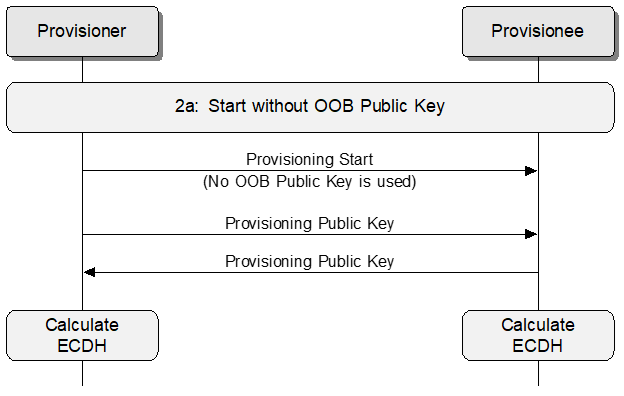 |
Otherwise, if the public key is available using an OOB technology and the Provisioner has accessed the device's public key via an OOB technology, then the Provisioner sets the Public Key field in the Provisioning Start PDU to 1, and a new key pair shall be generated by the Provisioner, and the public key of the generated key pair shall be transmitted from the Provisioner to the Provisionee, and the public key read from the device using the appropriate OOB technology shall be used.
A Provisionee’s public key that is contained in a Device Certificate as specified in Section 5.5.1, and retrievable from the device over an established provisioning bearer (see Section 5.4.2.6) or retrievable from the Internet (see Section 5.6), is considered to be available using an OOB technology when the Provisioner supports certificate-based provisioning.
The message sequence for public key exchange when the unprovisioned device public key is OOB is illustrated by Figure 5.18.
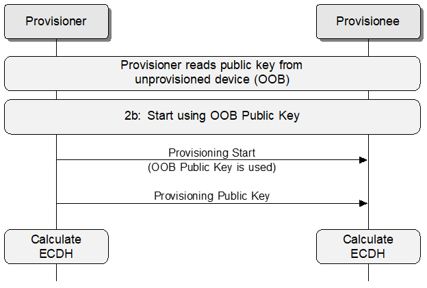 |
The Provisioner and the Provisionee shall check whether the public key provided by the peer device or obtained OOB is valid (see Section 5.4.3.1).
When the Provisioner receives an invalid public key or a public key that is equal to the Provisioner public key, then provisioning shall fail, and the Provisioner shall act as described in Section 5.4.4. When the Provisionee receives an invalid public key or a public key that is equal to the Provisionee public key, then provisioning shall fail and the Provisionee shall act as described in Section 5.4.4 and should indicate the Invalid Format Error Code in the Provisioning Failed PDU.
After the public key is known and has been validated, the ECDHSecret shall be computed using the following formula:
|
ECDHSecret=P256(private key, peer public key) |
After the ECDHSecret is computed, the Provisioner and the Provisionee shall delete its private-public key pair that was generated in this step.
5.4.2.4. Authentication
5.4.2.4.1. AuthValue computation
Once the public key exchange has been performed, a confirmation exchange followed by a random number exchange is performed. The confirmation values are a cryptographic hash of all the values exchanged so far, the random number that is yet to be revealed, and the AuthValue. Once the random numbers are exchanged, each device authenticates its peer.
The authentication value from the Authentication Method (Authentication with Output OOB, Authentication with Input OOB, or Authentication with Static OOB) is used in the AuthValue for the purpose of computing the confirmation value. If the Algorithm field is BTM_ECDH_P256_CMAC_AES128_AES_CCM, the confirmation value of the Provisioner is a 128-bit value, the confirmation value of the Provisionee is a 128-bit value, and they are computed using:
|
ConfirmationProvisioner=AES-CMACConfirmationKey (RandomProvisioner || AuthValue) |
|
ConfirmationProvisioner=AES-CMACConfirmationKey (RandomDevice || AuthValue) |
Where:
|
ConfirmationKey=k1(ECDHSecret, ConfirmationSalt, "prck") |
|
ConfirmationSalt=s1(ConfirmationInputs) |
|
ConfirmationInputs=ProvisioningInvitePDUValue || ProvisioningCapabilitiesPDUValue || ProvisioningStartPDUValue || PublicKeyProvisioner || PublicKeyDevice |
If the Algorithm field is BTM_ECDH_P256_HMAC_SHA256_AES_CCM, the confirmation value of the Provisioner is a 256-bit value, the confirmation value of the Provisionee is a 256-bit value, and they are computed using:
|
ConfirmationProvisioner=HMAC-SHA-256ConfirmationKey (RandomProvisioner) |
|
ConfirmationDevice=HMAC-SHA-256ConfirmationKey (RandomDevice) |
Where:
|
ConfirmationKey=k5(ECDHSecret || AuthValue, ConfirmationSalt, "prck256") |
|
ConfirmationSalt=s2(ConfirmationInputs) |
|
ConfirmationInputs=ProvisionionInvitePDUValue || ProvisioningCapabilitiesPDUValue || ProvisioningStartPDUValue || PublicKeyProvisioner || PublicKeyDevice |
The ProvisioningInvitePDUValue is the value of the Provisioning Invite PDU fields (excluding the opcode) that was sent or received.
The ProvisioningCapabilitiesPDUValue is the value of the Provisioning Capabilities PDU fields (excluding the opcode) that was sent or received.
The ProvisioningStartPDUValue is the value of the Provisioning Start PDU fields (excluding the opcode) that was sent or received.
The PublicKeyProvisioner is the value of the Public Key X and Public Key Y fields from the Public Key PDU that was sent by the Provisioner.
The PublicKeyDevice is the value of the Public Key X and Public Key Y fields from the Public Key PDU that was sent by the Provisionee or from the delivered OOB public key.
The RandomProvisioner is a string of random bits generated by the Provisioner’s random number generator. The random number generator shall be compatible with the requirements in Volume 2, Part H, Section 2 of the Core Specification [1]. If the Algorithm field is BTM_ECDH_P256_CMAC_AES128_AES_CCM, the RandomProvisioner is a 128-bit value. If the Algorithm field is BTM_ECDH_P256_HMAC_SHA256_AES_CCM, the RandomProvisioner is a 256-bit value.
The RandomDevice is a string of random bits generated by the Provisionee’s random number generator. The random number generator shall be compatible with the requirements in Volume 2, Part H, Section 2 of the Core Specification [1]. If the Algorithm field is BTM_ECDH_P256_CMAC_AES128_AES_CCM, the RandomDevice is a 128-bit value. If the Algorithm field is BTM_ECDH_P256_HMAC_SHA256_AES_CCM, the RandomDevice is a 256-bit value.
If the Algorithm field is BTM_ECDH_P256_CMAC_AES128_AES_CCM, the AuthValue is a 128-bit value. If the Algorithm field is BTM_ECDH_P256_HMAC_SHA256_AES_CCM, the AuthValue is a 256-bit value. The computation of AuthValue depends on the data type. There are three data type values defined: Binary, Numeric, and Alphanumeric.
If the Authentication Method field value is Authentication with No OOB, the data type is Numeric, and the authentication value is 0.
If the Authentication Method field value is Authentication with Static OOB, the data type and authentication value are transferred using an OOB technology.
If the Authentication Method field value is Authentication with Output OOB, the data type is defined by the Output OOB Action (see Table 5.32) and the authentication value is transferred using the mechanism defined by the Authentication Action.
If the Authentication Method field value is Authentication with Input OOB, the data type is defined by the Input OOB Action (see Table 5.34) and the authentication value is transferred using the mechanism defined by the Authentication Action.
Data type Binary If the data type is Binary, the authentication value is an array of octets. The authentication value array shall be copied to the AuthValue. If the authentication value is shorter than the defined AuthValue size, the remaining bits shall be set to 0. If the authentication value is longer than the defined AuthValue size, the array shall be trimmed by removing octets with indexes higher than needed.
For example, if the Algorithm field is BTM_ECDH_P256_CMAC_AES128_AES_CCM and the authentication value is [0x12, 0x34, 0x56], the AuthValue is an array consisting of [0x12, 0x34, 0x56, 0x00, 0x00, 0x00, 0x00, 0x00, 0x00, 0x00, 0x00, 0x00, 0x00, 0x00, 0x00, 0x00], and if the Algorithm field is BTM_ECDH_P256_HMAC_SHA256_AES_CCM and the authentication value is [0x78, 0x9A, 0xBC, 0xDE], the AuthValue is an array consisting of [0x78, 0x9A, 0xBC, 0xDE, 0x00, 0x00, 0x00, 0x00, 0x00, 0x00, 0x00, 0x00, 0x00, 0x00, 0x00, 0x00, 0x00, 0x00, 0x00, 0x00, 0x00, 0x00, 0x00, 0x00, 0x00, 0x00, 0x00, 0x00, 0x00, 0x00, 0x00, 0x00].
For example, if the Algorithm field is BTM_ECDH_P256_CMAC_AES128_AES_CCM and the authentication value is [0x00, 0x01, 0x02, 0x03, 0x04, 0x05, 0x06, 0x07, 0x08, 0x09, 0x0A, 0x0B, 0x0C, 0x0D, 0x0E, 0x0F, 0x10, 0x11, 0x12, 0x13], the AuthValue is an array consisting of [0x00, 0x01, 0x02, 0x03, 0x04, 0x05, 0x06, 0x07, 0x08, 0x09, 0x0A, 0x0B, 0x0C, 0x0D, 0x0E, 0x0F].
Data type Numeric If the data type is Numeric and the Algorithm field is BTM_ECDH_P256_CMAC_AES128_AES_CCM, the authentication value is a number and shall be represented as an unsigned 128-bit value. If the data type is Numeric and the Algorithm field is BTM_ECDH_P256_HMAC_SHA256_AES_CCM, the authentication value is a number and shall be represented as an unsigned 256-bit value.
For example, if the Algorithm field is BTM_ECDH_P256_CMAC_AES128_AES_CCM and the Authentication with Output OOB method is used with the Output OOB Action as Blink and the output is a value of 5 (authentication value), then the AuthValue shall be 0x00000000000000000000000000000005. The AuthValue is then encoded as defined in Section 5.1 to compute the confirmation values, resulting in an array consisting of [0x00, 0x00, 0x00, 0x00, 0x00, 0x00, 0x00, 0x00, 0x00, 0x00, 0x00, 0x00, 0x00, 0x00, 0x00, 0x05].
For example, if the Algorithm field is BTM_ECDH_P256_CMAC_AES128_AES_CCM and the Authentication with Output OOB method is used with the Output OOB Action as Output Numeric and the displayed number is 019655 (authentication value), then the AuthValue shall be 0x00000000000000000000000000004CC7. The AuthValue is then encoded as defined in Section 5.1 to compute the confirmation values, resulting in an array consisting of [0x00, 0x00, 0x00, 0x00, 0x00, 0x00, 0x00, 0x00, 0x00, 0x00, 0x00, 0x00, 0x00, 0x00, 0x4C, 0xC7].
For example, if the Algorithm field is BTM_ECDH_P256_CMAC_AES128_AES_CCM and the Authentication with No OOB method is used, the authentication value shall be set to 0x00000000000000000000000000000000, which means it is not authenticated, resulting in an AuthValue array consisting of [0x00, 0x00, 0x00, 0x00, 0x00, 0x00, 0x00, 0x00, 0x00, 0x00, 0x00, 0x00, 0x00, 0x00, 0x00, 0x00].
Data type Alphanumeric If the data type is Alphanumeric, the authentication value is an array of octets constructed from a string of ASCII codes of the characters. The authentication value array shall be copied to the AuthValue. If the authentication value is shorter than the defined AuthValue size, the remaining octets shall be set to 0. If the authentication value is longer than the defined AuthValue size, the array shall be trimmed by removing octets with indexes higher than needed.
For example, if the Algorithm field is BTM_ECDH_P256_CMAC_AES128_AES_CCM and the Authentication with Output OOB method is used with the Output OOB Action as Output Alphanumeric and the displayed string is ”123ABC” (authentication value), then the AuthValue shall be 0x31323341424300000000000000000000, resulting in an array consisting of [0x31, 0x32, 0x33, 0x41, 0x42, 0x43, 0x00, 0x00, 0x00, 0x00, 0x00, 0x00, 0x00, 0x00, 0x00, 0x00].
5.4.2.4.2. Confirmation and random number exchange
To complete confirmation and random number exchange, the Provisioner and the Provisionee shall follow these steps:
-
When the confirmation value of the Provisioner is computed, the Provisioner shall send the ConfirmationProvisioner value to the Provisionee using the Provisioning Confirmation PDU.
-
When the Provisionee receives the Provisioning Confirmation PDU from the Provisioner, it shall compare the ConfirmationProvisioner and the ConfirmationDevice values.
-
If the values are not equal, the Provisionee shall send the ConfirmationDevice value to the Provisioner using the Provisioning Confirmation PDU.
-
If the values are equal, the provisioning protocol shall fail, and the Provisionee shall act as described in Section 5.4.4 and should indicate the Invalid Format Error Code in the Provisioning Failed PDU.
-
-
When the Provisioner receives the Provisioning Confirmation PDU from the Provisionee, it shall compare the ConfirmationProvisioner and the ConfirmationDevice values.
-
If the values are not equal, the Provisioner shall send the RandomProvisioner value to the Provisionee using the Provisioning Random PDU.
-
If the values are equal, the provisioning protocol shall fail, and the Provisioner shall act as described in Section 5.4.4.
-
-
When the Provisionee receives the Provisioning Random PDU from the Provisioner, it shall compute the ConfirmationProvisioner value by using the received RandomProvisioner value.
-
If the ConfirmationProvisioner value received is equal to the computed ConfirmationProvisioner, the Provisioner is authenticated, and the Provisionee shall send the RandomDevice value to the Provisioner using the Provisioning Random PDU.
-
If the ConfirmationProvisioner value received is not equal to the computed ConfirmationProvisioner, the provisioning protocol shall fail, and the Provisionee shall act as described in Section 5.4.4 and should indicate the Confirmation Failed Error Code in the Provisioning Failed PDU.
-
-
When the Provisioner receives the Provisioning Random PDU from the Provisionee, it shall compute the ConfirmationDevice value by using the received RandomDevice value.
-
If the ConfirmationDevice value received is equal to the computed ConfirmationDevice, the Provisionee is authenticated.
-
If the ConfirmationDevice value received is not equal to the computed ConfirmationDevice, the provisioning protocol shall fail, and the Provisioner shall act as described in Section 5.4.4.
-
5.4.2.4.3. Authentication with Output OOB
If Output OOB authentication is used, then the Provisioning Start PDU would include a request to output either a single-digit or multiple-digit value on the Provisionee device by using a prescribed action. Examples of output actions may include making a noise, blinking a light, voice, or displaying symbols on a display.
For example, if the unprovisioned device is a door lock that includes an LED, then it would be possible to use the Output OOB authentication with the action that would blink that LED.
When the Authentication Method field value is Authentication with Output OOB and when the Output OOB Action for the Authentication Action value is equal to Blink, Beep, or Vibrate, then the Provisionee shall select a random integer between 1 and 10Authentication Size - 1 inclusive. That random number shall be output as a sequence of events (e.g., by blinking, beeping, or vibrating with a duty cycle of 500 milliseconds on and 500 milliseconds off) with a gap of at least 3 seconds between sequences to allow the user to determine the end of the sequence. When the Output OOB Action for the Authentication Action value is equal to Output Numeric, then the value is output (e.g., displayed or spoken) using a number of digits (i.e., ASCII character codes 0x30 to 0x39) determined by the Authentication Size value. When the Output OOB Action for the Authentication Action value is equal to Output Alphanumeric, then the value is output using a number of ASCII digits and uppercase letters (i.e., ASCII character codes 0x30 to 0x39 and 0x41 to 0x5A) determined by the Authentication Size value.
The user of the Provisioner shall input the number observed to authenticate that Provisionee.
Once input of the number has been performed, a confirmation exchange followed by a random number exchange is performed (see Section 5.4.2.4.2). The confirmation values are a cryptographic hash of all the values exchanged so far, the random number that is yet to be revealed, and the number that has been input. Once the random numbers are exchanged, each device can authenticate its peer.
The message sequence for Authentication with Output OOB is illustrated by Figure 5.19.
 |
5.4.2.4.4. Authentication with Input OOB
When the Authentication Method field value is Authentication with Input OOB and when the Input OOB Action for the Authentication Action value is equal to Push, then the Provisioner shall select a random integer between 1 and 10Authentication Size -1 inclusive. That random number shall be input by the number of push actions. When the Input OOB Action for the Authentication Action value is equal to Twist, then the Provisioner shall select a random integer between 1 and 10Authentication Size -1 inclusive. That random number shall be input by the number of twist actions until the value on the control has been entered. When the Input OOB Action for the Authentication Action value is equal to Input Numeric, the value is input by entering a number of digits (probably using a numeric keyboard) determined by the Authentication Size value. When the Input OOB Action for the Authentication Action value is equal to Input Alphanumeric, the value is input by entering a number of ASCII digits and uppercase letters (probably using an alphanumeric keyboard) determined by the Authentication Size value.
The Provisioner shall then prompt the user to input that value into the Provisionee device by using an appropriate action.
When the Input OOB Action for the Authentication Action value is equal to Push or Twist, the value is considered to have been input after no further input actions are detected for more than 5 seconds. When the Input OOB Action for the Authentication Action value is equal to Input Numeric or Input Alphanumeric, the value is considered to have been input locally on that device (e.g., by pressing an Enter key).
For example, if the unprovisioned device is a light switch, then it would allow the user to input the random number by pressing a button an appropriate number of times.
Once input of the number has been performed, the Provisionee shall send the Provisioning Input Complete PDU to the Provisioner to confirm that the Provisionee has an input value. A confirmation exchange followed by a random number exchange is performed (see Section 5.4.2.4.2). The confirmation values are a cryptographic hash of all the values exchanged so far, the random number that is yet to be revealed, and the number that has been input. Once the random numbers are exchanged, each device can authenticate its peer.
The message sequence for Authentication with Input OOB is illustrated by Figure 5.20.
 |
5.4.2.4.5. Authentication with No OOB and Authentication with Static OOB
When the Authentication Method field value is Authentication with No OOB or the Authentication Method field value is Authentication with Static OOB then the Provisioner shall immediately use the confirmation and random number exchanges (see Section 5.4.2.4.2). If a static OOB value is available, then this value shall be included as part of the confirmation value. If no static OOB value is available, then this value shall have a value of zero.
The message sequence for Authentication with Static OOB or Authentication with No OOB is illustrated by Figure 5.21.
 |
5.4.2.5. Distribution of provisioning data
Once the Provisionee has been authenticated, the Provisioner and Provisionee shall use the calculated Diffie-Hellman shared secret ECDHSecret and generate a session key from that shared secret. That session key shall then be used to encrypt and authenticate the provisioning data. The Provisioner then shall send the Provisioning Data PDU containing the encrypted and authenticated provisioning data to the Provisionee.
The provisioning data format is described in Table 5.47.
|
Field |
Size |
Description |
Req. |
|---|---|---|---|
|
Network Key |
16 |
NetKey |
M |
|
Key Index |
2 |
Index of the NetKey |
M |
|
Flags |
1 |
Flags bitmask |
M |
|
IV Index |
4 |
Current value of the IV Index |
M |
|
Unicast Address |
2 |
Unicast address of the primary element |
M |
The Network Key shall contain the NetKey.
The Key Index field shall identify the global NetKey Index of the NetKey and shall be encoded as defined in Section 4.3.1.1.
The values of the Flags field are defined in Table 5.48.
|
Bits |
Definition |
|---|---|
|
0 |
Key Refresh Flag 0: Key Refresh Phase 0 1: Key Refresh Phase 2 |
|
1 |
IV Update Flag 0: Normal Operation 1: IV Update in Progress |
|
2–7 |
Reserved for Future Use |
The IV Index field shall contain the current value of the IV Index.
The Unicast Address shall contain the Unicast Address of the primary element of the node being added to the network.
The Session key shall be derived using the formula:
|
ProvisioningSalt=s1(ConfirmationSalt || RandomProvisioner || RandomDevice) |
|
SessionKey=k1(ECDHSecret, ProvisioningSalt, "prsk") |
The nonce shall be the 13 least significant octets of:
|
SessionNonce=k1(ECDHSecret, ProvisioningSalt, "prsn") |
The provisioning data shall be encrypted and authenticated using:
|
Provisioning Data=Network Key || Key Index || Flags || IV Index || Unicast Address |
|
Encrypted Provisioning Data, Provisioning Data MIC=AES-CCMSessionKey (SessionNonce, Provisioning Data) |
The size of the Provisioning Data MIC is 8 octets.
The Encrypted Provisioning Data and Provisioning Data MIC shall be used as fields in the Provisioning Data PDU. The Provisioner shall send the Provisioning Data PDU to the Provisionee.
The Provisionee shall then compute the device key as defined in Section 3.9.6.1
The message sequence for distribution of provisioning data is illustrated by Figure 5.22 below.
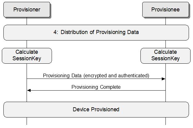 |
The Provisioner and Provisionee calculate the device key using the k1 key derivation function based on the established Diffie-Hellman shared secret ECDHSecret.
Upon receiving the Provisioning Data PDU from the Provisioner, the Provisionee shall decrypt and authenticate the provisioning data. Upon successful authentication of the provisioning data, the Provisionee shall set the network key (identified by the Key Index), set the IV Index, set the IV Update procedure state based on the IV Update Flag, set the Key Refresh Phase based on the Key Refresh Flag, and assign unicast addresses to all device elements starting from the primary element and using a consecutive range of addresses starting from the provided unicast address value. Upon successful completion of the address assigning procedure, the Provisionee shall respond with a Provisioning Complete PDU to confirm that it has been provisioned. If the address assigning cannot be successfully completed, the Provisionee shall assume that provisioning failed and respond with a Provisioning Failed PDU with the Error Code parameter set to Cannot Assign Addresses.
Note
Note: After processing the Provisioning Data PDU from the Provisioner, the 96-hour time limits for changing the IV Update procedure state, as defined in the IV Update procedure, do not apply.
Upon receiving the Provisioning Complete PDU from the Provisionee, the Provisioner shall assume that the provisioning process is completed successfully and the Provisionee is using a consecutive range of address starting from the value of the unicast address. The length of the address range is reported to the Provisioner in Provisioning Capabilities PDU (see Section 5.4.1.2). As a final step in procedure, the Provisioner shall disconnect the provisioning bearer. The Provisionee is now a node in the mesh network.
The Provisioner shall not reuse unicast addresses that have been allocated to a Provisionee and sent in a Provisioning Data PDU unless the node to which the unicast addresses were previously assigned has been removed from the network and the current IV Index (in use during the Node Removal procedure) has been updated, as required in Section 3.11.7, or the Node Address Refresh procedure was executed and the current IV Index (in use during the Node Address Refresh procedure) has been updated, as required in Section 3.11.8.5.
5.4.2.6. Provisioning record retrieval over a provisioning bearer
Provisioning records are read-only data items that the Provisioner may retrieve from the Provisionee after establishing a provisioning bearer. The Provisioner may use the information contained within provisioning record data to manage the provisioning process. Provisioning records are defined in Section 5.4.2.6.3.
Each provisioning record is identified by a 16-bit Record ID, which is an assigned number. See Table 5.52 for the defined Record IDs.
5.4.2.6.1. Provisioning record list retrieval
The Provisioner may retrieve the list of the Record IDs of the provisioning records stored on the Provisionee over an established provisioning bearer by sending a Provisioning Records Get PDU (see Section 5.4.1.13).
To retrieve the Record ID list, the Provisioner shall send a Provisioning Records Get PDU before it sends a Provisioning Invite PDU. A Provisionee that supports provisioning records shall respond to a Provisioning Records Get PDU with a Provisioning Records List PDU. The Provisioner shall not send a new PDU until it has received a Provisioning Records List PDU in response to the previously sent request.
When a Provisionee receives a Provisioning Records Get PDU, and the Provisioning Invite PDU has not already been received after the most recent establishment of a provisioning bearer, then the Provisionee shall respond with a Provisioning Records List PDU with the fields set as defined in Section 5.4.1.14.
When a Provisionee receives a Provisioning Records Get PDU, and the Provisioning Invite PDU has already been received after the most recent establishment of a provisioning bearer, this indicates that provisioning failed. The Provisionee shall respond with a Provisioning Failed PDU with the Error Code field set to Unexpected PDU.
Table 5.49 defines error conditions that lead to provisioning failure for processing a Provisioning Records Get PDU.
|
Error Condition |
Status Code Name (see Table 5.41) |
|---|---|
|
A Provisioning Records Get PDU was received after a Provisioning Invite PDU was received in the same provisioning session |
Unexpected PDU |
5.4.2.6.2. Provisioning record data retrieval
The Provisioner may retrieve provisioning record data stored on the Provisionee over an established provisioning bearer by sending Provisioning Record Request PDUs (see Section 5.4.1.11).
To retrieve a record, the Provisioner shall send Provisioning Record Request PDUs before sending a Provisioning Invite PDU. A Provisionee that supports provisioning records shall respond to a Provisioning Record Request PDU with a Provisioning Record Response PDU. The Provisioner shall not send a new PDU until it has received a Provisioning Record Response PDU in response to the previously sent request.
The Provisioner may issue Provisioning Record Request PDUs multiple times in order to retrieve all fragments needed to reconstruct provisioning record data fully or in order to retrieve all records stored on a Provisionee.
When a Provisionee receives a Provisioning Record Request PDU, and the Provisioning Invite PDU has not already been received after the most recent establishment of a provisioning bearer, and the Provisioning Record Request PDU message is processed successfully (i.e., the received request meets all request validation conditions listed in Table 5.50), then the Provisionee shall respond with a Provisioning Record Response PDU with the Status field set to Success and the other fields set as defined in Section 5.4.1.12.
When a Provisionee receives a Provisioning Record Request PDU, and the Provisioning Invite PDU has not already been received after the most recent establishment of a provisioning bearer, and the Provisioning Record Request PDU message is not processed successfully (i.e., the received request does not meet all request validation conditions listed in Table 5.50), then the Provisionee shall respond with a Provisioning Record Response PDU with the Status field set as defined in Table 5.50 and the other fields set as defined in Section 5.4.1.12.
Table 5.50 defines request validation conditions for processing a Provisioning Record Request PDU and the status codes used when validation conditions are not met.
|
Request Validation Condition |
Status Code Name (see Table 5.41) |
|---|---|
|
The record identified by the Record ID field is present on the device |
Requested Record Is Not Present |
|
The Fragment Offset field value is smaller than Total Length of the identified record |
Requested Offset Is Out Of Bounds |
When the Provisionee responds with a Provisioning Record Response PDU with the Status field set as defined in Table 5.50, provisioning of the Provisionee does not fail. The Provisioner can continue sending Provisioning Record Request PDUs, or can send a Provisioning Invite PDU.
When a Provisionee receives a Provisioning Record Request PDU, and the Provisioning Invite PDU has already been received after the most recent establishment of a provisioning bearer, this indicates that provisioning failed. The Provisionee shall respond with a Provisioning Failed PDU with the Error Code field set to Unexpected PDU.
Table 5.51 defines error conditions that result in provisioning failure for processing a Provisioning Record Request PDU.
|
Error Condition |
Status Code Name (see Table 5.41) |
|---|---|
|
A Provisioning Record Request PDU was received after a Provisioning Invite PDU was received in the same provisioning session |
Unexpected PDU |
The message sequence for retrieving the provisioning records list and provisioning record data is illustrated by Figure 5.23.
 |
5.4.2.6.3. Provisioning records
This section contains the record definitions for the provisioning records. A summary of the provisioning records is shown in Table 5.52.
|
Record ID |
Name |
Requirement |
|---|---|---|
|
0x0000 |
Certificate-Based Provisioning Base URI |
C.1 |
|
0x0001 |
Device Certificate |
C.1 |
|
0x0002 |
Intermediate Certificate 1 |
O |
|
0x0003 |
Intermediate Certificate 2 |
O |
|
0x0004 |
Intermediate Certificate 3 |
O |
|
0x0005 |
Intermediate Certificate 4 |
O |
|
0x0006 |
Intermediate Certificate 5 |
O |
|
0x0007 |
Intermediate Certificate 6 |
O |
|
0x0008 |
Intermediate Certificate 7 |
O |
|
0x0009 |
Intermediate Certificate 8 |
O |
|
0x000A |
Intermediate Certificate 9 |
O |
|
0x000B |
Intermediate Certificate 10 |
O |
|
0x000C |
Intermediate Certificate 11 |
O |
|
0x000D |
Intermediate Certificate 12 |
O |
|
0x000E |
Intermediate Certificate 13 |
O |
|
0x000F |
Intermediate Certificate 14 |
O |
|
0x0010 |
Intermediate Certificate 15 |
O |
|
0x0011 |
Complete Local Name |
O |
|
0x0012 |
Appearance |
O |
- C.1:
-
If certificate-based provisioning is supported, the support of at least one of Certificate-Based Provisioning Base URI or Device Certificate records is mandatory, and the presence of the other is optional; otherwise, both records are optional
5.4.2.6.3.1. Certificate-Based Provisioning Base URI record
The Certificate-Based Provisioning Base URI record represents the base URI of the location from which the Provisioner may retrieve the Device Certificate of a Provisionee, as well as optional intermediate certificates. The full Certificate-Based Provisioning URI is constructed from the Certificate-Based Provisioning Base URI and query parameters appended to it (see Section 5.6.1).
The data contained in the Certificate-Based Provisioning Base URI is formatted as defined in [5] for the URI data type.
5.4.2.6.3.2. Device Certificate record
The Device Certificate record represents the Device Certificate of a Provisionee, which is stored on the Provisionee itself.
The data contained in the Device Certificate record is an X.509 certificate formatted using Distinguished Encoding Rules (DER).
5.4.2.6.3.3. Intermediate Certificate records (Intermediate Certificate 1, Intermediate Certificate 2, … Intermediate Certificate 15)
The Intermediate Certificate records represent intermediate certificates that are used to check the Device Certificate of the Provisionee, which is stored on the Provisionee itself.
There are 15 intermediate certificate records, ranging from Intermediate Certificate 1 record to Intermediate Certificate 15 record.
The data contained in an Intermediate Certificate record is an X.509 certificate formatted using DER.
5.4.2.6.3.4. Complete Local Name record
The Complete Local Name record represents the complete local name of the Provisionee. The format of the record shall be as defined in [5] for the Complete Local Name data type. The value of the record shall be the same as the local name assigned to the Provisionee.
5.4.2.6.3.5. Appearance record
The Appearance record represents the external appearance of the Provisionee. The format of the record shall be as defined in [5] for the Appearance data type. The value of the record shall be the same as the Appearance characteristic, as defined in [1].
5.4.2.6.4. Certificate-Based Provisioning Base URI retrieval over a provisioning bearer
If the Provisionee supports certificate-based provisioning (see Section 5.5) and the Device Certificate (see Section 5.5.1), along with any number of intermediate certificates, is available on a server on the Internet, the Provisionee shall store the Certificate-Based Provisioning Base URI for the certificate server (see Section 5.6.1) in the Certificate-Based Provisioning Base URI record.
The Provisioner may use the mechanism defined in Section 5.4.2.6 to retrieve the Certificate-Based Provisioning Base URI record value. After the Provisioner retrieves the Certificate-Based Provisioning Base URI, it shall follow the procedure defined in Section 5.6 to retrieve the Device Certificate and any intermediate certificates it needs before provisioning the Provisionee and shall then follow the procedure defined in Section 5.5 to provision the Provisionee.
5.4.2.6.5. Provisioning certificate retrieval over a provisioning bearer
If the Provisionee supports certificate-based provisioning (see Section 5.5) and stores its Device Certificate (see Section 5.5.1), along with zero to 15 intermediate certificates, on the device, the Provisionee shall store the certificate data in the records associated with the certificates (see Table 5.53).
The Provisioner may use the mechanism defined in Section 5.4.2.6 to retrieve values of provisioning records associated with the certificates stored on the Provisionee. After the Provisioner retrieves the certificates, it shall follow the procedure defined in Section 5.5 to provision the Provisionee.
Table 5.53 defines records assigned to certificates.
|
Record |
Description |
|---|---|
|
Device Certificate |
The Device Certificate, which contains the device public key |
|
Intermediate Certificate 1 |
The first intermediate certificate, which, if present, is used to sign the Device Certificate |
|
Intermediate Certificate 2 |
The second intermediate certificate, which, if present, is used to sign the first intermediate certificate |
|
Intermediate Certificate 3 .. Intermediate Certificate 15 |
The Nth intermediate certificate, which, if present, is used to sign the preceding intermediate certificate |
If the Provisionee supports certificate-based provisioning and stores its Device Certificate as a provisioning record, it may also store as many as 15 intermediate certificates as additional provisioning records. The intermediate certificates are stored in an ordered list indexed from 1 to N, where N is the number of stored intermediate certificates. The intermediate certificate stored with index 1 shall be used to validate the Device Certificate. When more than one intermediate certificate is stored, the certificate stored with index M shall be used to validate a certificate stored with index M - 1.
The first intermediate certificate is associated with the Intermediate Certificate 1 record, the second intermediate certificate is associated with the Intermediate Certificate 2 record and so on, up to the fifteenth intermediate certificate which is associated with the Intermediate Certificate 15 record.
When retrieving intermediate certificates, the Provisioner should retrieve the value of the Intermediate Certificate 1 record first, and, when needed, retrieve other intermediate certificate record values in sequential order.
Root certificates shall not be stored on the Provisionee. If the Provisionee responds to a Provisioning Record Request with root certificate data, the Provisioner shall treat that as a provisioning error (see Section 5.4.4).
The Provisioner shall acquire the root certificate, as well as any intermediate certificates not stored on the Provisionee, by a mechanism other than the ones defined in Section 5.4.2.6 and Section 5.6.
5.4.3. Provisioning security
All devices and Provisioners shall support the P-256 elliptic curve (see Section 5.4.3.1).
5.4.3.1. NIST P-256 elliptic curve definition
The P-256 elliptic curve is defined in FIPS 186-4 [10].
Elliptic curves are specified by p, a, and b in the form of:
|
E: y2=x3+ax+b (mod p) |
For each value of b, a unique curve can be developed. For the P-256 elliptic curve:
|
a=mod (-3,p) |
|
b is defined and its method of generation can be verified by using SHA-1 (with a given seed s and using b2 c=-27 (mod p)) |
The following parameters are given:
-
The prime modulus p, order r, base point x-coordinate Gx, base point y- coordinate Gy.
-
The integers p and r are given in decimal numeral; bit strings and field elements are given in hex.
p = 115792089210356248762697446949407573530086143415290314195533631308867097853951
r = 115792089210356248762697446949407573529996955224135760342422259061068512044369
b = 5ac635d8 aa3a93e7 b3ebbd55 769886bc 651d06b0 cc53b0f6 3bce3c3e 27d2604b
Gx = 6b17d1f2 e12c4247 f8bce6e5 63a440f2 77037d81 2deb33a0 f4a13945 d898c296
Gy = 4fe342e2 fe1a7f9b 8ee7eb4a 7c0f9e16 2bce3357 6b315ece cbb64068 37bf51f5
The function P256 is defined as follows. Given an integer u, 0<u<r, and a point V on the curve E, the value P256(u, V) is computed as the x-coordinate of the uth multiple uV of the point V.
The private keys shall be between 1 and r/2, where r is the Order of the Abelian Group on the elliptic curve (i.e., between 1 and 2256/2).
A valid public key Q=(XQ, YQ) is one where XQ and YQ are both in the range 0 to p - 1 and satisfy the equation (YQ)2=(XQ)3+aXQ+b (mod p) in the relevant curve’s finite field.
Note
Note: For additional information about public key validation, see NIST Special Publication 800-56A, Revision 3 [11].
5.4.3.2. Provisioning key derivation
Figure 5.24 and Figure 5.25 illustrate the derivation of the provisioning keys.
 |

5.4.4. Provisioning errors
When the provisioning protocol fails for any reason, the Provisionee shall permanently delete any stored details. There is no recovery procedure and the whole provisioning procedure is started from the beginning if the Provisioner chooses to do so. The provisioning protocol treats fields in messages with Prohibited values as errors. The protocol is asymmetric when handling fields with Reserved for Future Use values.
When the Provisionee or the Provisioner receives a message with a field set to a value that is Prohibited or with a bit set to 1 within a bitfield indicated as Prohibited, the provisioning protocol shall fail and the message shall be treated as an error in the provisioning protocol.
When the Provisionee receives a message with a field set to a value that is Reserved for Future Use or with a bit set to 1 within a bitfield indicated as Reserved for Future Use, the provisioning protocol shall fail and the message shall be treated as an error in the provisioning protocol.
The provisioning protocol is asymmetric when handling protocol errors. When the Provisioner encounters an error other than a timeout in the provisioning protocol, it shall immediately disconnect the provisioning bearer, providing the Fail reason. When the provisioning bearer closes unexpectedly, provisioning has failed.
When the Provisionee encounters an error other than a timeout in the provisioning protocol, the device shall send the Provisioning Failed PDU with an appropriate Error Code and shall wait for the closing of the provisioning bearer. At this time, any provisioning protocol PDU received from the Provisioner is considered unexpected.
When the Provisionee or Provisioner encounters an error not defined by the provisioning protocol (e.g., out-of-memory, out-of-battery, or procedure canceled through the user interface), the device may close the provisioning bearer.
The Provisioner, upon receiving the Provisioning Failed PDU, shall assume that the provisioning failed and immediately disconnect the provisioning bearer.
The Provisioner and the Provisionee use the provisioning timer during the provisioning protocol PDU exchanges. The provisioning timer initial value shall be set to a minimum of 60 seconds. When the Authentication Method field value is Authentication with Output OOB or Authentication with Input OOB, the provisioning timer initial value shall be set to a minimum of 120 seconds to allow sufficient time for users to interact with the Provisioner or the Provisionee.
The Provisioner shall start the provisioning timer from the initial value when the Provisioner sends the first Provisioning PDU. The Provisionee shall start the provisioning timer from the initial value when the Provisionee receives the first Provisioning PDU. The provisioning timer shall start from the initial value whenever a provisioning protocol PDU is sent or received.
When the provisioning process is completed successfully, the provisioning timer shall be stopped. When the provisioning timer expires, then provisioning fails, the provisioning bearer shall be disconnected with the Timeout reason, the Provisioner shall send a Provisioning Failed PDU, and the Provisionee shall not send a Provisioning Failed PDU.
5.5. Certificate-based provisioning
When a device stores the Certificate-Based Provisioning Base URI (see Section 5.6.1) as a provisioning record, the Certificate-Based Provisioning Base URI shall be retrievable from the device over an established provisioning bearer using the procedure defined in Section 5.4.2.6. In that case, the certificate data associated with the device shall be retrievable from the server indicated in the Certificate-Based Provisioning Base URI using the procedure defined in Section 5.6, and the certificate data shall be retrieved before the Provisioner sends a Provisioning Invite PDU to the Provisionee.
When a device stores its Device Certificate and any intermediate certificates on the device as provisioning records, the certificate data associated with the device shall be retrievable from the device over an established provisioning bearer using the procedure defined in Section 5.4.2.6, and the certificate data shall be retrieved before the Provisioner sends a Provisioning Invite PDU to the Provisionee.
The certificate data contains the Device Certificate and can contain intermediate certificates. Section 5.5.1 defines requirements for a Device Certificate.
5.5.1. Device Certificate
The phrase “Device Certificate” as specified in this document means a type of public key certificate with a specific format that contains the OOB Public Key of a device, as well as the UUID of the device and the identity of the vendor that manufactured the device.
A Device Certificate is an X.509 certificate, as defined in ITU-T X.509 [19], formatted as specified in Section 5.5.1.1.
The trust anchor (the entity for which trust is implicit and not derived from some higher authority) of the Public Key Infrastructure (PKI) used in signing the Device Certificate shall either be a certification authority (CA) root certificate or a vendor root certificate. Intermediate certificates between the root certificate and the Device Certificate may be present.
The Provisioner shall use the Certification Path Validation procedure defined in IETF RFC 5280 [12], and updated by IETF RFC 6818 [30], IETF RFC 8398 [31], and IETF RFC 8399 [32], to validate the Device Certificate before using the contained OOB Public Key in provisioning the device.
Device Certificates can be renewed. How Device Certificate renewals are processed is out of the scope of this specification.
Device Certificates can be revoked during their validity period. How Device Certificate revocations are processed is out of the scope of this specification.
5.5.1.1. Certificate format
The format of an X.509 certificate used in a PKI is defined in IETF RFC 5280 [12] and IETF RFC 6818 [30]. Constraints on certificate fields, when used in a Device Certificate for provisioning a node on a Bluetooth mesh network, are defined in Sections 5.5.1.1.1 through 5.5.1.1.4.26.
Provisioners may enforce additional constraints.
5.5.1.1.1. tbsCertificate field
The tbsCertificate (“to be signed” certificate) field shall be composed as defined in IETF RFC 5280 [12], with the additional constraints for its components as defined in 5.5.1.1.4.1 through 5.5.1.1.4.25.
5.5.1.1.2. signatureAlgorithm field
The signatureAlgorithm field shall be set to the value “ecdsa-with-SHA256”, as defined in IETF RFC 5758 [13].
5.5.1.1.3. signatureValue field
The signatureValue field shall contain the computed signature value as defined in IETF RFC 5280 [12].
5.5.1.1.4. tbsCertificate field components
Constraints on the fields contained in the tbsCertificate field are described in the Sections 5.5.1.1.4.1 through 5.5.1.1.4.25.
5.5.1.1.4.1. version field
The version field shall be set to decimal value 2 (“v3”).
5.5.1.1.4.2. serialNumber field
The serialNumber field shall meet the requirements defined in IETF RFC 5280 [12].
5.5.1.1.4.3. signature field
The signature field shall meet the requirements as defined in IETF RFC 5280 [12].
5.5.1.1.4.4. issuer field
As defined in IETF RFC 5280 [12], the issuer field identifies the signer of the Device Certificate.
5.5.1.1.4.5. validity field
The validity field shall meet the requirements defined in IETF RFC 5280 [12], with the following additional constraints:
-
The notBefore time value should be no earlier than the manufacturing date of the device.
-
The notAfter time value shall be chosen by the vendor. The vendor should take into consideration the expected lifetime of the device as well as the certificate renewal and revocation policies associated with the Device Certificate.
5.5.1.1.4.6. subject field
The subject field shall contain a valid distinguished name (DN), with the following restrictions:
-
The Organization Name field of the DN shall be set to the name of the vendor organization.
-
The Common Name field of the DN shall contain the Device UUID formatted in the canonical fields-and-hyphens format specified in ITU-T X.667 [14].
-
The Common Name field of the DN should contain the device’s CID value (see Section 4.2.2.1). If present, the CID value shall be represented with the prefix “BCID:”, which shall be immediately followed by the CID value encoded using four hexadecimal digits in big-endian format.
-
The Common Name field of the DN should contain the device’s PID value (see Section 4.2.2.1). If present, the PID value shall be represented with the prefix “BPID:”, which shall be immediately followed by the PID value encoded using four hexadecimal digits in big-endian format.
-
The Device UUID, CID representation, and PID representation shall be separated from each other using white-space characters.
For example, assume that the Device UUID is b09dc847-5408-40cc-9c54-0fe8c87429e7, the device CID value is 32769, and the device PID value is 4095. These would be encoded as the following Common Name:
b09dc847-5408-40cc-9c54-0fe8c87429e7 BCID:8001 BPID:03ff
-
Before using the OOB Public Key in the certificate when provisioning the device, the Provisioner shall check that the Device UUID in the Common Name field of the DN matches the UUID of the device being provisioned.
-
The Provisioner may additionally check the Device UUID in the Common Name field of the DN in other ways. For example, the Provisioner could check the Device UUID against an accept list of Device UUIDs, if available.
-
If present in the Common Name field of the DN, the CID value shall match the CID value recorded in the device’s composition data page 0.
-
If present in the Common Name field of the DN, the PID value shall match the PID value recorded in the device’s composition data page 0.
-
If the CID value is present in the Common Name field of the DN, the PID value shall also be present. Likewise, if the PID value is present in the Common Name field of the DN, the CID value shall also be present.
-
A Provisioner may reject a certificate that does not contain the CID value and the PID value.
-
Other fields of the DN may be checked by the Provisioner.
5.5.1.1.4.7. subjectPublicKeyInfo field
The subjectPublicKeyInfo field shall be set as defined in IETF RFC 5280 [12], with the following constraints:
5.5.1.1.4.8. issuerUniqueID field
The issuerUniqueID field should not be present.
5.5.1.1.4.9. subjectUniqueID field
The subjectUniqueID field should not be present.
5.5.1.1.4.10. Authority key identifier extension
An authority key identifier extension may be present. If present, the authority key identifier shall be used as defined in IETF RFC 5280 [12] without additional constraints.
5.5.1.1.4.11. Subject key identifier extension
A subject key identifier extension may be present. If present, the subject key identifier shall be used as defined in IETF RFC 5280 [12] without additional constraints.
5.5.1.1.4.12. Key usage extension
A key usage extension shall be present. The keyAgreement bit defined in IETF RFC 5280 [12] shall be set in the extension. No other bits shall be set in the extension.
5.5.1.1.4.13. Certificate policies extension
A certificate policies extension should be present. If present, the certificate policies extension shall be marked as critical and shall be used as defined in IETF RFC 5280 [12] and IETF RFC 6818 [30] without additional constraints.
A Provisioner may reject a Device Certificate that does not contain the certificate policies extension.
5.5.1.1.4.14. Policy mappings extension
A policy mappings extension shall not be present.
5.5.1.1.4.15. Subject alternative name extension
A subject alternative name extension shall not be present.
5.5.1.1.4.16. Issuer alternative name extension
An issuer alternative name extension may be present. If present, the issuer alternative name extension shall be used as defined in IETF RFC 5280 [12] without additional constraints.
5.5.1.1.4.17. Subject directory attribute extension
A subject directory attribute extension may be present. If present, the subject directory attribute extension shall be used as defined in IETF RFC 5280 [12] without additional constraints.
5.5.1.1.4.18. Basic constraints extension
The basic constraints extension shall be present. The cA field value shall be present in the extension and shall be set to FALSE. The pathLenConstraint field shall not be present in the extension.
5.5.1.1.4.19. Name constraints extension
The name constraints extension shall not be present.
5.5.1.1.4.20. Policy constraints extension
The policy constraints extension shall not be present.
5.5.1.1.4.21. Extended key usage extension
The extended key usage extension shall not be present.
5.5.1.1.4.22. CRL distribution points extension
The certificate revocation list (CRL) distribution points extension may be present. If present, the CRL distribution points extension shall be used as defined in IETF RFC 5280 [12] without additional constraints.
5.5.1.1.4.23. Inhibit anyPolicy extension
The inhibit anyPolicy extension shall not be present.
5.5.1.1.4.24. Freshest CRL extension
The freshest CRL extension may be present. If present, the freshest CRL extension shall be used as defined in IETF RFC 5280 [12] without additional constraints.
5.5.1.1.4.25. Authority information access extension
The authority information access extension may be present. If present, the authority information access extension shall be used as defined in IETF RFC 5280 [12] without additional constraints.
5.5.1.1.4.26. Subject information access extension
The subject information access extension may be present. If present, the subject information access extension shall be used as defined in IETF RFC 5280 [12] without additional constraints.
5.5.2. Acquiring root and intermediate certificates
A Device Certificate may be issued either by a CA or by the device vendor. The root certificate of the certificate chain used in signing the Device Certificate may be owned either by a CA or by the vendor.
To perform path validation for the Device Certificate, the Provisioner needs the root certificate as well as any intermediate certificates used in issuing the Device Certificate.
Root and intermediate certificates of CAs usually are provided by the platform on which the Provisioner runs (e.g., by the mobile operating system). If the platform does not provide the CA root certificate or intermediate certificates needed for validation, the Provisioner can use a mechanism other than the ones defined in Section 5.4.2.6 and Section 5.6 to acquire those certificates before starting to provision devices.
Vendor root and intermediate certificates typically are not provided by the platform and are acquired from the vendor. Vendor intermediate certificates may be retrieved from the vendor by the retrieval mechanism used for Device Certificates (see Section 5.6) or over an established provisioning bearer using Provisioning Record Request PDUs (see Section 5.4.1.11). The Provisioner can use a mechanism other than the ones defined in Section 5.4.2.6 and Section 5.6 to acquire the vendor root and intermediate certificates.
5.6. Device Certificate retrieval over the Internet
Sections 5.6.1 through 5.6.4 define how Device Certificates shall be retrieved over the Internet. The Device Certificates shall be retrieved using HTTP over Transport Layer Security (TLS) [22]. The Device Certificate shall be referenced by Certificate-Based Provisioning URI, which may be constructed from the query parameters, such as the Device UUID, and the Certificate-Based Provisioning Base URI obtained from a provisioning record (see Section 5.4.2.6.1), an NFC tag (see Section 5.7.1), or a two-dimensional barcode (see Section 5.7.2).
The Provisioner can check the server authenticity before making a request for certificate data. Likewise, the server can check the Provisioner authenticity and also control the Provisioner’s access to the certificate data. The methods used for checking peer authenticity and controlling access to data are outside the scope of this specification.
5.6.1. Certificate-Based Provisioning URI construction
Because the space available in a provisioning record, NFC tag, or 2D barcode can be limited, the Provisioner shall treat the acquired Certificate-Based Provisioning Base URI as a base only. The Provisioner shall append a query string component, which shall identify the device and the content to be retrieved, to the Certificate-Based Provisioning Base URI to construct the full Certificate-Based Provisioning URI.
The query string component shall be composed of one or more queries that consist of key-value pairs. An equal sign (ASCII character 61) shall separate a key from its value. Key-value pairs shall be separated from each other by an ampersand (ASCII character 38).
5.6.1.1. UUID query
The UUID query identifies the device for which data is being requested.
The UUID query shall appear one time in the query string.
The query key for the UUID query shall be “uuid”.
The query value shall be the Device UUID in the canonical format defined in ITU-T X.667 [14].
5.6.1.2. Content queries
Multiple data items may be available for a given device. Content queries identify the data items that are requested to be retrieved by use of query values specified in Sections 5.6.1.2.1 through 5.6.1.2.3.
Content queries are optional, and may appear multiple times in the query string. If no content query is specified in the request, the request shall apply to all data that the server has for the device specified by the UUID query.
The query key for the content query shall be “content”.
5.6.1.2.1. Device Certificate query
The query value “device-certificate” specifies that the Device Certificate shall be retrieved.
5.6.1.2.2. Intermediate certificate query
The query value “vendor-intermediate-certs” specifies that a vendor’s intermediate certificates in the certificate chain, which are needed for path validation of the Device Certificate, shall be retrieved. The response shall not contain any root certificates; receiving a root certificate as a response from a server shall be an error that causes provisioning to be terminated.
5.6.1.2.3. Vendor-specific content query
The content query may contain vendor-specific content, and its retrieval is indicated by vendor-specific query values. A vendor-specific content query value shall begin with a prefix that consists of the vendor’s Bluetooth company identifier (see Bluetooth SIG Company Identifiers [4]) encoded as four hexadecimal digits in big-endian format (i.e., most significant octet first) and a minus sign (ASCII character 45) so that the vendor can be unambiguously identified and name clashes can be avoided. Vendor-specific content shall not affect certificate path validation.
For example, assume that the Device UUID is “b09dc847-5408-40cc-9c54-0fe8c87429e7” and the URI that the device has stored in the Certificate-Based Provisioning Base URI is “https://mesh.example.com/oob”. The Provisioner combines these to make the following Certificate-Based Provisioning URI for retrieving the Device Certificate and a vendor-specific “metadata” content item with the hexadecimal company ID “0xabcd”:
|
|
5.6.2. Content types
The following Multipurpose Internet Mail Extensions (MIME) content types shall be used for OOB data:
-
application/pkix-cert, as specified in IETF RFC 2585 [15], for X.509 certificates encoded in DER format
-
multipart/mixed for delivery of multiple data items in one response (for example, an X.509 certificate followed by vendor-specific metadata)
A response to a query for the intermediate certificates that are needed to validate the device public key certificate shall use the multipart/mixed content type; each intermediate certificate shall be one part of the multipart response.
Defining the content types of vendor-specific data items is outside the scope of this specification.
5.6.3. Request
HTTP version 1.1 (HTTP/1.1) shall be used when making a request. The format of an HTTP/1.1 request is defined in IETF RFC 7231 [21].
The GET request method shall be used.
The Certificate-Based Provisioning Base URI schema, and by extension the Certificate-Based Provisioning URI schema, shall be “https://”. As defined in IETF RFC 7230 [20], the schema is case-insensitive.
5.6.3.1. Request headers
The format of the request headers is defined in the HTTP/1.1 specifications [20][21], with the additional requirements and constraints that are defined in Section 5.6.3.1.1 through Section 5.6.3.1.3.
5.6.3.1.1. Accept header
The Accept header shall either specify the content types that the Provisioner supports for the items it has requested or shall have the value “*/*”, indicating all content types are accepted.
The Provisioner shall process only data with the “application/pkix-cert” content type as a certificate. The Provisioner may indicate support for other content types, such as “text/html”, if it can process those content types. For example, a Provisioner might use the “text/html” content type when rendering a server error page for the user.
If the Provisioner requests multiple data items, it shall be able to handle a MIME multipart response.
5.6.3.1.2. Accept-Charset and Accept-Language headers
If the Provisioner is requesting information that might be localized (e.g., vendor-specific device metadata), it may indicate support for particular character sets and languages by using the Accept-Charset header and the Accept-Language header, respectively.
5.6.3.1.3. Connection header
If the Provisioner requests data for multiple devices in quick succession, it should use HTTP/1.1 [20] persistent connections. In this case, the Connection header value “close” shall not be used.
5.6.4. Response
The Provisioner shall interpret the following status codes to have the following semantics:
-
200 OK: Request has succeeded, and the requested data will be delivered at least partially. If the Provisioner requests multiple data items by specifying the content query key multiple times, a 200 OK status code will be returned as long as even one requested data item can be found; it is up to the Provisioner to determine whether it can work with less data than it requested.
-
404 Not Found: The Device UUID is not valid, or none of the requested data items is available for the device.
-
405 Method Not Allowed: The request method was something other than GET.
-
410 Gone: The data has been invalidated at the server (e.g., because of certificate revocation) and is not available.
-
501 Not Implemented: The request contained a query key or query value not known by the server.
Other status codes may be used as needed; this specification does not define any semantic requirements for those status codes. HTTP status codes are defined in IETF RFC 7231 [21].
5.6.4.1. Response headers
Response headers shall be interpreted by the Provisioner according to the HTTP specifications [20][21].
5.6.4.2. Response body
The response body shall be interpreted by the Provisioner according to the HTTP specifications [20][21].
If the response body contains unexpected or erroneous data in any of its parts, the whole response shall be considered invalid by the Provisioner, and the Provisioner shall not proceed with provisioning the device.
If an error occurred when processing a request, the server may send a message (e.g., an HTML page, along with the error code) if it can determine that the Provisioner can accept such content, as indicated by the Accept header in the request. The message may be localized based on the Accept-Charset and Accept-Language headers sent by the Provisioner.
5.7. Additional Certificate-Based Provisioning Base URI sources
In addition to provisioning records, a Certificate-Based Provisioning Base URI may originate from additional sources—e.g., an NFC tag or a two-dimensional barcode associated with the device.
5.7.1. Certificate-Based Provisioning Base URI stored on an NFC tag
Instead of being read from a provisioning record, the Certificate-Based Provisioning Base URI may be read from an NFC tag associated with the device (e.g., a tag on the device itself or on the packaging for the device).
NFC tag contents shall be formatted according to NFC Forum specifications [16][17][18].
5.7.1.1. URI and Smart Poster records
The smallest NFC tags can hold tens of bytes of data, which is enough for storing a short URI. A tag shall hold an NFC Data Exchange Format (NDEF) message containing either a URI record or a Smart Poster record as defined by the NFC Forum specifications [17][18], and the Provisioner shall retrieve the actual OOB data over the Internet based on the Certificate-Based Provisioning Base URI value read from an NFC tag as it would do when retrieving the Certificate-Based Provisioning URI Base value from the device.
The URI or Smart Poster record on the tag shall contain the Certificate-Based Provisioning Base URI appended with a query component with the “uuid” key-value pair filled in with the Device UUID value, so that the Provisioner can read both the Certificate-Based Provisioning Base URI and the Device UUID from the same source.
After the Provisioner has acquired both the Certificate-Based Provisioning Base URI and the Device UUID, the Provisioner shall proceed with establishing a provisioning session for the device identified by the Device UUID and retrieving OOB data over the Internet as defined in Sections 5.6.1 through 5.6.4.
The Provisioner may use the additional data on a Smart Poster record in an application-specific manner—e.g., for displaying a message to the end user.
5.7.2. Certificate-Based Provisioning Base URI stored on a two-dimensional barcode
Two-dimensional barcode technologies typically provide several encodings (e.g., ASCII text, binary data, and Unicode text) and error correction algorithms for the contained data. However, they do not necessarily provide any explicit means for recording application-level metadata such as the content type of the data. It is often left to the application reading the barcode to understand the semantics of the data based on the appearance of the contents. For example, a URI can be recognized by the schema prefix that it contains (such as “https://”).
Any two-dimensional barcode technology that can be used to store a text string encoded in ASCII, in a subset of ASCII, or in binary format, and that allows automatic URI recognition by the URI schema prefix in the text string, may be used to store the URI.
5.7.2.1. URI encoding
Instead of being read from a provisioning record, the Certificate-Based Provisioning Base URI may be read from a two-dimensional barcode associated with the device (e.g., on the device itself or in its packaging).
The Certificate-Based Provisioning Base URI shall be identified by its schema prefix, which is “https://”.
The barcode shall contain the Certificate-Based Provisioning Base URI appended with a query component with the “uuid” key-value pair filled in with the Device UUID value, so that the Provisioner can read both the Certificate-Based Provisioning Base URI and the Device UUID from the same source.
Note
Note: The benefit of reading the Certificate-Based Provisioning Base URI with a Device UUID from a barcode is that the user has a tangible physical object associated with the device that is being provisioned (the device itself, its packaging, or, for example, a paper slip in the packaging), which might be preferable to choosing a beaconing device in the Provisioner’s user interface.
After the Provisioner has acquired both the Certificate-Based Provisioning Base URI and the Device UUID, the Provisioner shall proceed with establishing a provisioning session for the device identified by the Device UUID and retrieving OOB data over the Internet as defined in Sections 5.6.1 through 5.6.4.
By choosing the most efficient encoding that is able to output all of the characters required for the URI (including semicolons and slashes needed for the schema), the implementation can reduce the physical space needed for the 2D barcode.
5.8. Pre-fetched out-of-band data
In some environments, an Internet connection is not available. To enable provisioning in a non-connected environment, the OOB data may be retrieved in advance if the Provisioner knows the UUIDs of the devices that are to be provisioned. Because each Device Certificate contains the Device UUID in the Subject Name field, the Provisioner can match the correct Device Certificate with the Device UUID that is read from an Unprovisioned Device beacon sent by a device waiting to be provisioned.
If certificates are retrieved in advance, there is a possibility that a certificate can be revoked after retrieval but before provisioning happens. In the absence of up-to-date certificate revocation information, the period after which pre-fetched certificates are considered stale and no longer valid for provisioning is implementation-specific.
6. Proxy protocol
The Proxy protocol enables nodes to send and receive Network PDUs, mesh beacons, proxy configuration messages and Provisioning PDUs over a connection-oriented bearer.
For example, a node could support GATT but not be able to advertise the Mesh Message AD Type. This node will establish a GATT connection with another node that supports the GATT bearer and the advertising bearer, using the Proxy protocol to forward messages between these bearers.
6.1. Endianness
Unless stated otherwise, all multiple-octet numeric values in this protocol shall be big-endian, as described in Section 3.1.1.1.
6.2. Proxy PDU roles
The Proxy protocol defines two main roles: the Proxy PDU Server role and the Proxy PDU Client role.
The Proxy PDU Server role supports a connection-oriented bearer server and Proxy protocol. The Proxy PDU Client role supports a connection-oriented bearer client and Proxy protocol.
6.2.1. Mesh GATT bearer roles
This section defines Proxy PDU roles that are specific to the mesh GATT bearer (see Section 3.3.2).
The Proxy Server is a node that supports the Proxy PDU Server role, the Mesh Proxy Service (see Section 7.2), a mesh bearer using the Proxy protocol, and at least one other mesh bearer. For example, the Proxy Server can forward mesh messages between the advertising bearer and the GATT bearer.
The Proxy Client supports the Proxy PDU Client role and a mesh bearer using the Proxy protocol. For example, the Proxy Client can use the GATT bearer to send mesh messages to a node that supports the advertising bearer.
6.2.1.1. Directed Proxy roles
Two roles are defined for directed proxy functionality: the Directed Proxy Server role and the Directed Proxy Client role.
The Directed Proxy Server is a Proxy Server that supports directed proxy functionality (see Section 2.3.13). The Directed Proxy Server shall support processing of the DIRECTED_PROXY_CAPABILITIES_STATUS and DIRECTED_PROXY_CONTROL messages (see Section 6.7.1).
The Directed Proxy Client is a Proxy Client that supports behavior described in Section 6.8.1. The Directed Proxy Client shall support processing of the DIRECTED_PROXY_CAPABILITIES_STATUS and DIRECTED_PROXY_CONTROL messages.
The Directed Proxy Client may support directed forwarding. If a Proxy Client is a Directed Proxy Client and it does not support directed forwarding, it can act as a dependent node (see Section 3.6.8.3) of a Directed Proxy Server to establish and maintain paths.
If the Proxy Client supports directed forwarding, it shall support the Directed Proxy Client role (i.e., processing of the DIRECTED_PROXY_CAPABILITIES_STATUS and DIRECTED_PROXY_CONTROL messages).
6.2.2. Provisioning PB-GATT bearer roles
This section defines Proxy PDU roles that are specific to the PB-GATT provisioning bearer (see Section 5.2.2).
The Provisioning Server is a node that supports the Proxy PDU Server and Mesh Provisioning Service (see Section 7.1).
The Provisioning Client is a node that supports the Proxy PDU Client and supports transporting Provisioning PDUs using the Proxy protocol.
6.3. Proxy PDU
A Proxy PDU Client and a Proxy PDU Server exchange Proxy PDUs. Proxy PDUs can contain Network PDUs, mesh beacons, proxy configuration messages or Provisioning PDUs. A single Proxy PDU can contain a full message or a segment of a message. The size of the Proxy PDU is determined by the user of the Proxy protocol. For example, the GATT bearer defines the size of the Proxy PDU based on the ATT_MTU.
6.3.1. PDU format
The format of a Proxy PDU is illustrated in Figure 6.1 and defined in Table 6.1.

|
Field Name |
Size |
Description |
Req. |
|---|---|---|---|
|
SAR |
2 |
Message segmentation and reassembly information |
M |
|
MessageType |
6 |
Type of message contained in the PDU |
M |
|
Data |
variable |
Full message or message segment |
M |
The SAR field shown in Table 6.2 identifies the message segmentation and defines the contents of the Data field:
|
Value |
Description |
|---|---|
|
0b00 |
Data field contains a complete message |
|
0b01 |
Data field contains the first segment of a message |
|
0b10 |
Data field contains a continuation segment of a message |
|
0b11 |
Data field contains the last segment of a message |
The MessageType field identifies the type of message contained in the Proxy PDU. The MessageType values are defined in Table 6.3.
|
Type |
Name |
Description |
|---|---|---|
|
0x00 |
Network PDU |
The message is a Network PDU as defined in Section 3.4.4. |
|
0x01 |
Mesh Beacon |
The message is a mesh beacon as defined in Section 3.10. |
|
0x02 |
Proxy Configuration |
The message is a proxy configuration message as defined in Section 6.6. |
|
0x03 |
Provisioning PDU |
The message is a Provisioning PDU as defined in Section 5.4.1. |
|
0x04–0x3F |
RFU |
Reserved for Future Use. |
The Data field contains a message defined by the MessageType field segmented as defined by the SAR field.
6.3.2. Behavior
Upon receiving a message with the Message Type field set to a value that is Reserved for Future Use or a value that is not supported by the Proxy PDU Server, the Proxy PDU Server shall ignore this message.
Upon receiving a message with the Message Type field set to a value that is Reserved for Future Use or a value that is not supported by the Proxy PDU Client, the Proxy PDU Client shall ignore this message.
6.3.2.1. Segmentation
Messages sent using the Proxy protocol may be larger than an individual Proxy PDU. To enable such messages to be transmitted, segmentation and reassembly is used.
When sending a message that is less than or equal to the maximum size of a Proxy PDU, the SAR field shall be set to 0b00 and the Data field shall contain the complete message.
When sending a message that is greater than the maximum size of a Proxy PDU, the message is divided into segments that will fill each Proxy PDU except for the last Proxy PDU that may or may not be filled. These segments shall be sent in order and the SAR field of the first segment shall be set to 0b01, the SAR field of the last segment shall be set to 0b11, and all other segments shall have the SAR field set to 0b10.
6.3.2.2. Reassembly
Upon receiving a message with an unexpected value of the SAR field, the Proxy PDU Server shall disconnect.
Upon receiving a Proxy PDU matching one of the following conditions, the Proxy PDU Server shall disconnect:
-
The MessageType field equal to a Network PDU and the Data field longer than the maximal size of a Network PDU (see Section 3.4.4)
-
The MessageType field equal to a Mesh Beacon and the Data field longer than the maximal size of a Mesh Beacon (see Section 3.10)
-
The MessageType field equal to a Proxy Configuration and the Data field longer than the maximal size of a proxy configuration message (see Section 6.6)
-
The MessageType field equal to a Provisioning PDU and the Data field longer than the maximal size of a supported Provisioning PDU (see Section 5.4.1)
The timeout for the SAR transfer is 20 seconds. When the timeout expires, the Proxy PDU Server shall disconnect.
Upon receiving a message with an unexpected value of the SAR field, the Proxy PDU Client shall disconnect.
Upon receiving a Proxy PDU matching one of the following conditions, the Proxy PDU Client shall disconnect:
-
The MessageType field equal to a Network PDU and the Data field longer than the maximal size of a Network PDU (see Section 3.4.4)
-
The MessageType field equal to a Mesh Beacon and the Data field longer than the maximal size of a Mesh Beacon (see Section 3.10)
-
The MessageType field equal to a Proxy Configuration and the Data field longer than the maximal size of a proxy configuration message (see Section 6.6)
-
The MessageType field equal to a Provisioning PDU and the Data field longer than the maximal size of a supported Provisioning PDU (see Section 5.4.1)
The timeout for the SAR transfer is 20 seconds. When the timeout expires, the Proxy PDU Client shall disconnect.
6.4. Proxy filtering
In order to reduce the number of Network PDUs exchanged between a Proxy Client and a Proxy Server, a proxy filter can be used.
The output filter of the network interface (see Section 3.4.5) instantiated by the Proxy Server can be configured by the Proxy Client. This allows the Proxy Client to explicitly request to receive only mesh messages with certain destination addresses. For example, a Proxy Client that is subscribed to a group address may want to only receive packets addressed to the unicast address of one of its elements and to that group address. Thus, the Proxy Client has full control over the packets it receives using the Proxy protocol.
6.4.1. Filter types
A proxy filter can be either an accept list filter or a reject list filter.
An accept list filter has an associated accept list, which is a list of destination addresses that are of interest to the Proxy Client. The accept list filter blocks all destination addresses except those that have been added to the accept list.
A reject list filter has an associated reject list, which is a list of destination addresses that the Proxy Client does not want to receive. The reject list filter accepts all destination addresses except those that have been added to the reject list.
The accept list filter with an empty list is the default filter type. The Proxy Client can change the filter type as well as configure the addresses in the proxy filter.
6.5. Proxy Privacy parameter
The Proxy Privacy parameter controls the privacy of the Proxy Server over the connection. The Proxy Privacy parameter can be set to either Enabled (0x01) or Disabled (0x00) for the connection.
When the Proxy Privacy parameter for the connection is Enabled (0x01), the Proxy Server sends Mesh Private beacons over the connection.
When the Proxy Privacy parameter for the connection is Disabled (0x00), the Proxy Server sends Secure Network beacons over the connection.
The value of the Proxy Privacy parameter is controlled by the type of proxy connection, which is dependent on the bearer used by the proxy connection.
The value of the Proxy Privacy parameter for GATT Proxy bearer is defined in the Section 7.2.2.2.6.
6.6. Proxy configuration messages
In addition to Network PDUs, mesh beacons and Provisioning PDUs, the Proxy Client and Proxy Server can exchange proxy configuration messages using the Proxy protocol.
Proxy configuration messages are used to configure the proxy filters and the connection parameters of a Directed Proxy Server for a subnet.
The format of a proxy configuration message is identical to a Network PDU as defined in Table 3.10.
The CTL field shall be set to 1.
The TTL field shall be set to 0.
The DST field shall be set to the unassigned address.
The TransportPDU field shall be formatted as shown in Table 6.4 and shall be secured using the managed flooding security credentials as defined in Section 3.9.6.3.1 with the proxy nonce as defined in Section 3.9.5.4.
|
Field Name |
Size |
Description |
Req. |
|---|---|---|---|
|
Opcode |
1 |
Message opcode |
M |
|
Parameters |
0–11 |
Message parameters |
M |
The Opcode field values are defined in Table 6.5:
|
Value |
Opcode |
Description |
|---|---|---|
|
0x00 |
Set Filter Type |
Sent by a Proxy Client to set the proxy filter type. |
|
0x01 |
Add Addresses To Filter |
Sent by a Proxy Client to add addresses to the proxy filter list. |
|
0x02 |
Remove Addresses From Filter |
Sent by a Proxy Client to remove addresses from the proxy filter list. |
|
0x03 |
Filter Status |
Acknowledgment by a Proxy Server to a Proxy Client to report the status of the proxy filter list. |
|
0x04 |
DIRECTED_PROXY_CAPABILITIES_STATUS |
Sent by a Directed Proxy Server to report the status of its capabilities for a subnet. |
|
0x05 |
DIRECTED_PROXY_CONTROL |
Sent by a Directed Proxy Client to set connection parameters of the Directed Proxy for a subnet. |
|
0x06–0xFF |
RFU |
Reserved for Future Use |
The Parameters field is specific to each opcode and is defined in the following subsections.
6.6.1. Set Filter Type
A Set Filter Type message can be sent by a Proxy Client to change the proxy filter type and clear the proxy filter list.
The parameters of this message are defined in Table 6.6:
|
Field |
Size |
Description |
Req. |
|---|---|---|---|
|
FilterType |
1 |
The proxy filter type. |
M |
The values for the FilterType field are defined in Table 6.7:
|
Value |
Description |
|---|---|
|
0x00 |
Accept list filter |
|
0x01 |
Reject list filter |
|
0x02–0xFF |
Prohibited |
6.6.2. Add Addresses to Filter
An Add Addresses to Filter message is sent by a Proxy Client to add destination addresses to the proxy filter list.
The parameters of this message are defined in Table 6.8:
|
Field |
Size |
Description |
Req. |
|---|---|---|---|
|
AddressArray |
2 * N |
List of addresses where N is the number of addresses in this message. |
M |
The AddressArray field contains a sequence of addresses to be added to the proxy filter list. It may contain any combination of unicast addresses, virtual addresses, and group addresses. The field size is parameterized by parameter N, and the N is an integer in the range 0 to 5 inclusive.
Note
Note: Each address in the AddressArray is a 16-bit value and therefore the 16-bit virtual address and not the Label UUID is used.
6.6.3. Remove Addresses from Filter
A Remove Addresses from Filter message is sent by a Proxy Client to remove destination addresses from the proxy filter list.
The parameters of this message are defined in Table 6.9:
|
Field |
Size |
Description |
Req. |
|---|---|---|---|
|
AddressArray |
2 * N |
List of addresses where N is the number of addresses in this message. |
M |
The AddressArray field contains a sequence of addresses to be removed from the proxy filter list. It may contain any combination of unicast addresses, virtual addresses, or group addresses. The field size is parameterized by parameter N, and the N is an integer in the range 0 to 5 inclusive.
Note
Note: Each address in the AddressArray is a 16-bit value and therefore the 16-bit virtual address and not the Label UUID is used.
6.6.4. Filter Status
A Filter Status message is sent by a Proxy Server to report the status of the proxy filter.
The parameters of this message are defined in Table 6.10:
|
Field |
Size |
Description |
Req. |
|---|---|---|---|
|
FilterType |
1 |
Accept list or reject list. |
M |
|
ListSize |
2 |
Number of addresses in the proxy filter list. |
M |
The values for the FilterType field are defined in Table 6.7.
The ListSize field contains the number of addresses in the proxy filter list.
6.6.5. DIRECTED_PROXY_CAPABILITIES_STATUS
A DIRECTED_PROXY_CAPABILITIES_STATUS message is sent by a Directed Proxy Server to report current Directed Proxy capabilities in a subnet.
The parameters of this message are defined in Table 6.11.
|
Field |
Size |
Description |
Req. |
|---|---|---|---|
|
Directed_Proxy |
1 |
Current Directed Proxy state |
M |
|
Use_Directed |
1 |
Indicates whether directed forwarding is used for messages from the Proxy Client |
M |
The Directed_Proxy field indicates the current Directed Proxy state for the identified subnet, as defined in Section 4.2.26.3.
The Use_Directed field indicates whether or not the Directed Proxy Server uses directed forwarding for retransmitting Network PDUs originated from the Proxy Client.
Table 6.12 defines the values of the Use_Directed field.
|
Value |
Name |
Description |
|---|---|---|
|
0x00 |
Disable |
Directed forwarding is not used for Proxy Client messages. |
|
0x01 |
Enable |
Directed forwarding is used for Proxy Client messages. |
|
0x02−0xFF |
Prohibited |
Prohibited |
6.6.6. DIRECTED_PROXY_CONTROL
A DIRECTED_PROXY_CONTROL message is sent by a Directed Proxy Client to set whether or not the Directed Proxy Server uses directed forwarding for Directed Proxy Client messages for a specified range of unicast addresses.
The parameters of this message are defined in Table 6.13.
|
Field |
Size |
Description |
Req. |
|---|---|---|---|
|
Use_Directed |
1 |
Indicates whether directed forwarding is used for messages from the Directed Proxy Client. |
M |
|
Proxy_Client_Unicast_Addr_Range |
variable |
Unicast address range of the Directed Proxy Client |
C.1 |
- C.1:
-
If the Use_Directed field is set to Enabled, the Proxy_Client_Unicast_Addr_Range field shall be present; otherwise, the Proxy_Client_Unicast_Addr_Range field shall not be present.
The Use_Directed field determines whether or not the Directed Proxy Server uses directed forwarding for Directed Proxy Client messages.
Table 6.14 defines the values of the Use_Directed field.
|
Value |
Name |
Description |
|---|---|---|
|
0x00 |
Disable |
Directed forwarding will not be used for Directed Proxy Client messages. |
|
0x01 |
Enable |
Directed forwarding will be used for Directed Proxy Client messages. |
|
0x02−0xFF |
Prohibited |
Prohibited |
If present, the Proxy_Client_Unicast_Addr_Range field contains the unicast address range (see Section 3.4.2.2.1) for which the Directed Proxy Server will use directed forwarding for all Directed Proxy Client messages.
6.7. Proxy Server behavior
When a Proxy Client connects to a Proxy Server, a new instance of the GATT bearer is connected to the network layer via a network interface (see Section 3.4.5).
Upon connection, the Proxy Server shall initialize the proxy filter as an accept list filter and the accept list shall be empty.
If the proxy filter is an accept list filter, upon receiving a Proxy PDU containing a valid Network PDU from the Proxy Client, the Proxy Server shall add the unicast address contained in the SRC field of the Network PDU to the accept list.
If the proxy filter is a reject list filter, upon receiving a Proxy PDU containing a valid Network PDU from the Proxy Client, the Proxy Server shall remove the unicast address contained in the SRC field of the Network PDU from the reject list.
Upon connection, the Proxy Server shall evaluate the Proxy Privacy parameter (for GATT Proxy bearer see Section 7.2.2.2.6) for the connection and the Proxy Server shall retain the value of the Proxy Privacy parameter for the lifetime of the connection. The Proxy Server shall send a mesh beacon for each known subnet to the Proxy Client, as defined in Table 6.15.
Upon successfully processing a Secure Network Beacon or a Mesh Private beacon with a new value for the IV Index field or the Flags field, the Proxy Server shall send a mesh beacon to the Proxy Client, as defined in Table 6.15.
Upon successfully generating a Secure Network Beacon or a Mesh Private beacon with a new value for the IV Index field or the Flags field, the Proxy Server shall send a mesh beacon to the Proxy Client, as defined in Table 6.15.
When the Proxy Server is added to a new subnet, the server shall send a mesh beacon for that subnet to the Proxy Client, as defined in Table 6.15.
|
Proxy Privacy parameter |
Behavior |
|---|---|
|
Not Supported |
Send Secure Network beacon |
|
Disabled |
Send Secure Network beacon |
|
Enabled |
Send Mesh Private beacon |
Upon receiving a Secure Network Beacon from the Proxy Client, the Proxy Server shall process it as defined in Section 3.10.3.1.
If Mesh Private beacons are supported, upon receiving a Mesh Private beacon from the Proxy Client, the Proxy Server shall process it as defined in Section 3.10.4.2.
When sending a proxy configuration message, a Proxy Server shall set the SRC field to the unicast address of its primary element and the SEQ field shall use the sequence number of its primary element.
If a Proxy Server receives a Set Filter Type message, it shall set the proxy filter type as requested in the message parameter, and it shall clear the proxy filter list. The Proxy Server shall then respond with a Filter Status message.
If the Proxy Server receives an Add Addresses to Filter message, then it shall add these addresses to the proxy filter list and shall respond with a Filter Status message. If one or more addresses contained in the message are already in the list, the Proxy Server shall not add these addresses. If the Proxy Server runs out of space in the proxy filter list, the Proxy Server shall not add these addresses. If the AddressArray field contains the unassigned address, the Proxy Server shall ignore that address.
If the Proxy Server receives a Remove Addresses from Filter message, it shall remove these addresses from the proxy filter list and shall respond with a Filter Status message. If one or more addresses contained in the message were not in the list, the Proxy Server shall ignore these addresses. If the AddressArray field contains the unassigned address, the Proxy Server shall ignore that address.
When the Proxy Server responds to a Set Filter Type message, or an Add Addresses to Filter message, or a Remove Addresses from Filter message with the Filter Status message, the Filter Status message shall be secured with the same network security credentials as were used for the received message.
Upon receiving a proxy configuration message with the Opcode field set to a value that is Reserved for Future Use, the Proxy Server shall ignore this message.
If the proxy filter is an accept list filter, and the Proxy Server is a Directed Proxy node in a subnet (see Section 2.3.13), then the Proxy Server operates as a supporting node for its Proxy Client according to Section 3.6.8.3.
6.7.1. Directed Proxy Server behavior
The behavior of Directed Proxy Server for each connection is controlled by the following parameters:
-
Use_Directed—Controls usage of Directed Proxy for the current connection on each subnet known to the Directed Proxy Server. The Use_Directed parameter can be set either to Enabled (0x01) or Disabled (0x00). Upon connection, the value of the Use_Directed parameter for a subnet shall be set to 0x01 if the value of the Directed Proxy Use Directed Default state for the subnet (see Section 4.2.26.4) is 0x01; otherwise, the value of the Use_Directed parameter for the subnet shall be set to 0x00.
-
Proxy_Client_Address_Range—Indicates the unicast address range in a subnet for which the Directed Proxy Server uses directed forwarding. The Proxy_Client_Address_Range can be set either to a unicast address range (as defined in Section 3.4.2.2.4) or to the Unassigned value (specified by the implementer). Upon connection, the value of the Proxy_Client_Address_Range shall be set to Unassigned for all known subnets.
-
Proxy_Client_Type—Indicates the type of Proxy Client: Proxy Client, Directed Proxy Client, Reject List Client, or Unset. Upon connection, the value of the Proxy_Client_Type shall be set to Unset.
Upon connection, the Directed Proxy Server shall send a DIRECTED_PROXY_CAPABILITIES_STATUS message for each known subnet to the Proxy Client.
When the Directed Proxy Server is added to a new subnet, and the Proxy_Client_Type parameter for the connection is either Unset or Directed_Proxy_Client, then the Directed Proxy Server shall send a DIRECTED_PROXY_CAPABILITIES_STATUS message for that subnet to the Proxy Client.
When the Directed Proxy Server is deleted from a subnet, and the Proxy_Client_Type parameter for the connection is either Unset or Directed_Proxy_Client, then the Directed Proxy Server shall set the Use_Directed parameter of the connection for the deleted subnet to 0x00, shall set the Proxy_Client_Address_Range parameter of the connection for the deleted subnet to the Unassigned value, and shall send a DIRECTED_PROXY_CAPABILITIES_STATUS message for the deleted subnet to the Proxy Client.
When the Directed Proxy state (see Section 4.2.26.3) of the Directed Proxy Server is changed from enabled to disabled on a subnet, and the Proxy_Client_Type parameter for the connection is either Unset or Directed_Proxy_Client, then the Directed Proxy Server shall set the Use_Directed parameter of the connection for the subnet to 0x00, shall set the Proxy_Client_Address_Range parameter of the connection for the subnet to the Unassigned value, and shall send a DIRECTED_PROXY_CAPABILITIES_STATUS message for the subnet to the Proxy Client.
When the Directed Proxy state (see Section 4.2.26.3) of the Directed Proxy Server is changed from disabled to enabled on a subnet, and the Proxy_Client_Type parameter for the connection is either Unset or Directed_Proxy_Client, then the Directed Proxy Server shall send a DIRECTED_PROXY_CAPABILITIES_STATUS message for the subnet to the Proxy Client.
When sending a DIRECTED_PROXY_CAPABILITIES_STATUS message for a subnet, the Directed Proxy Server shall set the Directed_Proxy field to the value of the Directed Proxy state of the subnet (see Section 4.2.26.3), and shall set the Use_Directed field to the value of the Use_Directed parameter of the connection for the subnet. The DIRECTED_PROXY_CAPABILITIES_STATUS message shall be secured with the managed flooding security credentials, as defined in Section 3.9.6.3.1, for the corresponding subnet.
If the Directed Proxy Server receives a DIRECTED_PROXY_CONTROL message, and the node identifies the subnet from the network security credentials which were used to successfully decrypt and authenticate the message, and the value of the Proxy_Client_Type parameter is either Unset or Directed Proxy Client, and the value of the Directed Proxy state for the identified subnet is 0x01, then the Directed Proxy Server shall set the Use_Directed parameter to the value of the Use_Directed field of the received message for the identified subnet. If the value of the Use_Directed field of the received message is Enabled, and the Directed Proxy state for the identified subnet is 0x01, then the Directed Proxy Server shall set the Proxy_Client_Address_Range parameter for the identified subnet to the value of the Proxy_Client_Unicast_Address_Range field of the received message. The Directed Proxy Server also shall respond with the DIRECTED_PROXY_CAPABILITIES_STATUS message for the identified subnet.
If the Directed Proxy Server receives a DIRECTED_PROXY_CONTROL message, and the Proxy_Client_Type parameter is either Reject List Client or Proxy Client, then the Directed Proxy Server shall ignore the message.
When a new connection is established between a Proxy Client and the Directed Proxy Server, and the first message received from the Proxy Client is a successfully processed DIRECTED_PROXY_CONTROL message, then the Directed Proxy Server shall set the Proxy_Client_Type parameter to Directed Proxy Client, shall set the Use_Directed parameter to Disable for all subnets known to the Directed Proxy Server except the subnet identified by the received message; otherwise, the Directed Proxy Server shall set the Proxy_Client_Type parameter to Proxy Client.
If the proxy filter is set to reject list filter, the Directed Proxy Server shall set the Proxy_Client_Type parameter to Reject List Client and shall set the Use_Directed parameter for all subnets known to the Directed Proxy Server to Disabled. If the Proxy_Client_Type parameter is Reject List Client when a proxy connection is established, the value of the parameter cannot be changed during the connection.
If the Directed Proxy Server receives a valid Network PDU from the Directed Proxy Client, and the value of the Use_Directed parameter of the connection for the subnet identified by the Network PDU is Enabled, and the source address of the Network PDU is outside the unicast address range defined by the Proxy_Client_Address_Range parameter, then the Directed Proxy Server shall tag the Network PDU with the immutable-credentials tag.
When the value of the Proxy_Client_Type parameter is Proxy Client, each unicast address in the accept list shall be considered a primary element address of a separate dependent node that has no secondary elements. For example, when the accept list contains two unicast addresses, the supporting node might execute the Directed Forwarding Initialization procedure (see Section 3.6.8.2.1) for each unicast address.
Additional behavior associated with the retransmission of Network PDUs at a Directed Proxy Server is described in Section 3.4.6.3. Behavior associated with the execution of Directed Forwarding procedures at a Directed Proxy Server on behalf of connected Directed Proxy Clients or Proxy Clients is described in Section 3.6.8.3.
6.8. Proxy Client behavior
When a Proxy Client connects to a Proxy Server, a new instance of the GATT bearer is connected to the network layer via a network interface (see Section 3.4.5).
The Proxy Client may send proxy configuration messages to configure the proxy filter.
When sending a proxy configuration message, the Proxy Client shall set the SRC field to the unicast address of its primary element and the SEQ field shall use the sequence number of its primary element. The Proxy Client can determine the state of the proxy filter list when it receives a Filter Status message.
Upon receiving a proxy configuration message with the Opcode field set to a value that is Reserved for Future Use, the Proxy Client shall ignore this message.
Upon receiving a Secure Network Beacon from the Proxy Server, the Proxy Client shall process it as defined in Section 3.10.3.1. If Mesh Private beacons are supported, upon receiving a Mesh Private beacon from the Proxy Server, the Proxy Client shall process it as defined in Section 3.10.4.2.
6.8.1. Directed Proxy Client behavior
The Directed Proxy Client can determine the capabilities of a Directed Proxy for a subnet when it receives a DIRECTED_PROXY_CAPABILITIES_STATUS message. If the Directed Proxy Client receives a DIRECTED_PROXY_CAPABILITIES_STATUS message, the Directed Proxy Client identifies the subnet from the network security credentials which were used to successfully decrypt and authenticate the message, and determines the value of the Directed Proxy state for the identified subnet from the Directed_Proxy field of the received message, and determines the Use_Directed parameter of the connection for the identified subnet from the value of the Use_Directed field of the received message.
The Directed Proxy Client may send a DIRECTED_PROXY_CONTROL message to control the Use_Directed and Proxy_Client_Address_Range parameters of a Directed Proxy Server for a subnet. The DIRECTED_PROXY_CONTROL message shall be secured with the managed flooding security credentials, as defined in Section 3.9.6.3.1, for the corresponding subnet.
6.9. Proxy solicitation
A Proxy Client may use the GAP General Discoverable mode with non-connectable non-scannable undirected advertising events to send Solicitation PDUs (see Section 6.9.1) to solicit a Proxy Server that supports the Private Proxy functionality to start advertising with Private Network Identity type (see Section 7.2).
6.9.1. Solicitation PDU
A Solicitation PDU is a non-connectable, undirected advertising PDU with a Service UUID AD Type that includes the «Mesh Proxy Solicitation Service» and a Service Data AD Type that carries network layer information for the Mesh Proxy Solicitation Service.
The Solicitation PDU has the format described in Table 6.16.
|
AD Type |
Size (octets) |
Requirement |
Comments |
|---|---|---|---|
|
«Incomplete List of 16-bit Service UUIDs» or «Complete List of 16-bit Service UUIDs» |
variable (4 or more) |
M |
Includes «Mesh Proxy Solicitation Service» |
|
«Service Data» |
22 |
M |
Service Data AD Type for «Mesh Proxy Solicitation Service» followed by additional service data for this service |
The format of additional service data for the «Mesh Proxy Solicitation Service» is defined in Table 6.17.
|
Field |
Size |
Description |
Req. |
|---|---|---|---|
|
Identification Type |
1 |
See Table 6.18 |
M |
|
Identification Parameters |
variable |
Format determined by Identification Type field |
M |
The Identification Type field values are defined in Table 6.18.
|
Type Value |
Description |
|---|---|
|
0x00 |
Proxy Solicitation with Replay Protection type |
|
0x01–0xFF |
Reserved for Future Use |
The format of the Identification Parameters for the «Mesh Proxy Solicitation Service» when advertising with the Identification Type set to Proxy Solicitation with Replay Protection is identical to a Network PDU as defined in Section 3.4.4. The Solicitation PDU shall have the following configuration:
-
The IVI field shall be set to 0.
-
The CTL field shall be set to 1.
-
The TTL field shall be set to 0.
-
The SRC field shall be set to the solicitation source (see Section 6.9.1.1).
-
The DST field can be set to the unassigned address.
-
The SEQ field shall be set to the solicitation sequence number of the solicitation source used (see Section 6.9.1.1).
-
The TransportPDU field shall be empty.
The Solicitation PDU shall be secured using the managed flooding security material (see Section 3.9.7) and the proxy solicitation nonce (see Section 3.9.5.5). The IV Index is not used to secure the Solicitation PDU.
Because the Solicitation PDU uses only the format of the Network PDU, the DST field is ignored upon reception.
A node shall implement solicitation replay protection for all Solicitation PDU messages that are successfully processed.
6.9.1.1. Solicitation source and solicitation number
A Proxy Client may use the primary address or any of the secondary addresses as the solicitation source (SSRC) for a Solicitation PDU.
A Proxy Client manages a 24-bit solicitation sequence number (SSEQ) for each solicitation source used. The solicitation sequence number is used for replay protection for Solicitation PDUs. When a Proxy Client is provisioned, the solicitation sequence number shall be set to 0 for each solicitation source. When a Solicitation PDU is generated, the solicitation sequence number for the solicitation source used in the message shall be increased by one. When the solicitation sequence number reaches the maximum value (0xFFFFFF), the element shall no longer generate Solicitation PDUs.
6.9.2. Behavior
6.9.2.1. Solicitation replay protection list
Each node supporting Solicitation PDU reception shall implement the solicitation replay protection list. The solicitation replay protection list persistently stores items consisting of a solicitation source and a solicitation number. The solicitation replay protection list is used to reject Solicitation PDUs that were already processed by a node.
The Solicitation PDU is a valid message when the SSRC field and SSEQ field combination is valid. The SSRC field and SSEQ field combination is valid when one of the following conditions is met:
-
The SSRC field value is stored in the solicitation replay protection list and the SSEQ field value is bigger than the corresponding stored solicitation sequence number.
-
The SSRC field value is not stored in the solicitation replay protection list and the solicitation replay protection list can store a new pair containing a solicitation source and a solicitation sequence number.
When the valid Solicitation PDU message was processed by the node, the SSRC field and SSEQ field of the message shall be stored by the node in the solicitation replay protection list.
6.9.2.2. Reception of a valid Solicitation PDU
A node that receives a valid Solicitation PDU shall enter the GAP General Discoverable mode with connectable undirected advertising events and shall advertise the Service Data associated with the Private Network Identity type (see Section 7.2) when all of the following conditions are met:
-
The Proxy feature and the Private Proxy functionality are both disabled at the node.
-
The On-Demand Private GATT Proxy state has a value in the range 0x01 to 0xFF.
-
The PDU authenticates against a known network key.
The node shall no longer advertise the Service Data associated with the Private Network Identity type (see Section 7.2) upon GATT connection or when no GATT client connects to this node after a period determined by the On-Demand Private GATT Proxy state from the reception of the Solicitation PDU and the Private Proxy functionality is disabled.
6.10. MSC examples
6.10.1. Accept list filtering
The MSC shown in Figure 6.2 illustrates the accept list filtering performed by the Proxy Server, as configured by the Proxy Client.
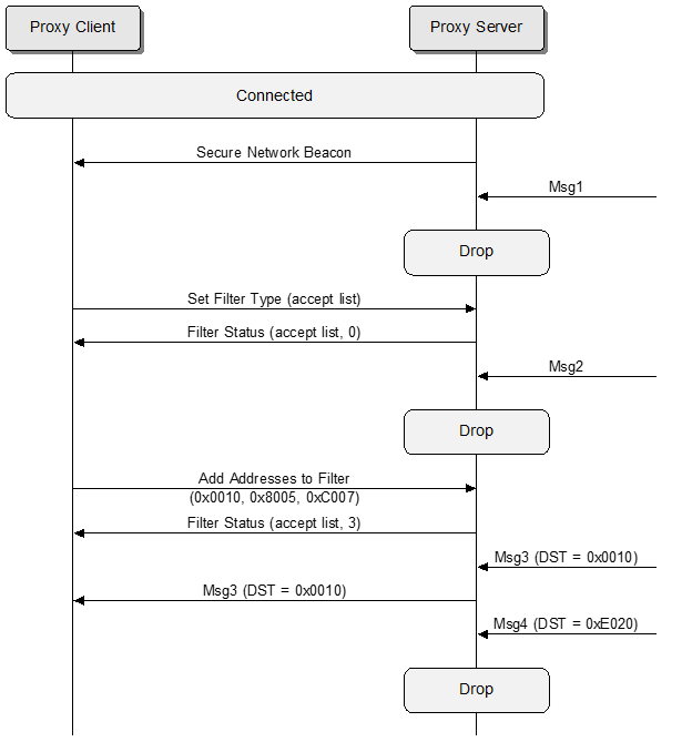
6.10.2. Reject list filtering
The MSC shown in Figure 6.3 illustrates the reject list filtering performed by the Proxy Server, as configured by the Proxy Client.
 |
6.10.3. Directed Proxy Server interacting with a Proxy Client
The MSC shown in Figure 6.4 illustrates a Directed Proxy Server interacting with a Proxy Client. The Directed Proxy Server is configured to be a supporting node for the dependent node on subnet #1 but to not become a supporting node for subnet #2.
 |
6.10.4. Directed Proxy Client interacting with a Directed Proxy Server
The MSCs shown in Figure 6.5 and Figure 6.6 illustrate a Directed Proxy Client interacting with a Directed Proxy Server. The Directed Proxy Server is configured to be a supporting node for the dependent node on subnet #1 but to not become a supporting node for subnet #2. The Directed Proxy Client sends a DIRECTED_PROXY_CONTROL message to change the configuration of the Directed Proxy Server for the connection: the Directed Proxy Server becomes a supporting node for subnet #2 but not for subnet #1.
 |
 |
6.10.5. Simultaneous interactions between a Proxy Server and both a Proxy Client and a Directed Proxy Client
The MSC shown in Figure 6.7 illustrates a Directed Proxy Server interacting simultaneously with both a Proxy Client and a Directed Proxy Client. The Directed Proxy Server is configured to be a supporting node for dependent nodes on subnet #1 but to not be a supporting node for subnet #2.
The Directed Proxy Client sends a DIRECTED_PROXY_CONTROL message to change the configuration of the Directed Proxy Server for the connection: the Directed Proxy Server becomes a supporting node for subnet #2 but not for subnet #1. At the same time, the Directed Proxy Server is a supporting node for subnet #1 but not for subnet #2 for the Proxy Client.
 |
6.10.6. Proxy solicitation
The MSC shown in Figure 6.8 illustrates the Proxy solicitation performed by the Proxy Client to a Proxy Server.
 |
7. Mesh GATT services
This section defines two GATT-based services: The Mesh Provisioning Service and the Mesh Proxy Service.
A device may support the Mesh Provisioning Service or the Mesh Proxy Service or both. If both are supported, only one of these services shall be exposed in the GATT database at a time.
The endianness of all multiple-octet numeric values shall be the same as the endianness defined in GATT (see [Vol 3], Part G, Section 2.4, in [24]).
7.1. Mesh Provisioning Service
7.1.1. Introduction
The Mesh Provisioning Service allows a PB-GATT Client to provision a PB-GATT Server to allow it to participate in the mesh network.
7.1.1.1. Conformance
Each capability of this specification shall be supported in the specified manner. This specification may provide options for design flexibility, because, for example, some products do not implement every portion of the specification. For each implementation option that is supported, it shall be supported as specified.
7.1.1.2. Service dependency
This service has no dependencies on other GATT-based services.
7.1.1.3. Bluetooth specification release compatibility
This service is compatible with any Bluetooth Core Specification that includes GATT and the Bluetooth Low Energy Controller portions of the Core Specification.
-
Bluetooth Core Specification 4.2 or later [1].
7.1.1.4. GATT sub-procedure requirements
Requirements in this section represent a minimum set of requirements for a server. Other GATT sub-procedures may be used if supported by both client and server.
Table 7.1 summarizes additional GATT sub-procedures required beyond those required by all GATT servers.
|
GATT Sub-procedure |
Requirements |
|---|---|
|
Write Without Response |
M |
|
Notifications |
M |
|
Write Characteristic Descriptors |
M |
7.1.1.5. Transport dependencies
The PB-GATT Provisioning Service operates over the LE Physical Transport only. The specified functionality enables devices to participate in low energy mesh networks, and therefore support for the LE Physical Transport is required.
7.1.1.6. Application error codes
No application error codes are defined by this service.
7.1.2. Service requirements
7.1.2.1. Declaration
The Mesh Provisioning Service shall be instantiated as a «Primary Service».
There shall only be one instance of the Mesh Provisioning Service on an unprovisioned PB-GATT Server.
After the PB-GATT Server has been provisioned, the Mesh Provisioning Service on that PB-GATT Server shall cease to be present in the GATT database for that GATT Client as long as the node remains provisioned.
The Service UUID shall be set to «Mesh Provisioning Service», as defined in [4].
7.1.2.2. Behaviors
The Mesh Provisioning Service may be used by a PB-GATT Client to provision a PB-GATT Server to participate in a mesh network.
7.1.2.2.1. Advertising
The PB-GATT Server is only active and advertising when the device is not provisioned. The PB-GATT Server shall be discoverable by using connectable and scannable undirected advertising events in the format described in Table 7.2.
|
AD Type |
Total Length |
Requirement |
Comments |
|---|---|---|---|
|
«Flags» |
3 |
M |
– |
|
«Incomplete List of 16-bit Service UUIDs» or «Complete List of 16-bit Service UUIDs» |
variable (4 or more) |
M |
Include «Mesh Provisioning Service» |
|
«Service Data» |
22 |
M |
Service Data AD Type for «Mesh Provisioning Service» followed by Service Data for this service |
The format of the Service Data for the «Mesh Provisioning Service» is defined in Table 7.3 and illustrated in Figure 7.1.
|
Field |
Size |
Description |
Req. |
|---|---|---|---|
|
Device UUID |
16 |
See Section 3.11.3 |
M |
|
OOB Information |
2 |
See Table 3.78 |
M |
The format of the Device UUID field is defined in Section 3.11.3.
The format of the OOB Information field is uint16 and is defined in Table 3.78.

If PB-ADV Server is supported, an unprovisioned PB-GATT Server that supports PB-GATT has to interleave the connectable advertising for PB-GATT with the Unprovisioned Device beacon (see Section 3.10.2).
It is required to include the Service UUID List to allow discovery of the Mesh Provisioning Service.
URI, Appearance, TX Power Level, and Local Name AD types may optionally be included in the scan response data. The PB-GATT Server should support these data types to allow a PB-GATT Client to enhance the user experience while provisioning.
If the device supports provisioning records (see Section 5.4.2.6), and the PB-GATT provisioning bearer is supported by the device, the Provisioning Server shall set bit 8 of the OOB Information field of the PB-GATT Service Data advertisements.
If a Device Certificate (as defined in Section 5.5.1) has been issued for the device and made available for retrieval (see Sections 5.4.2.6 and 5.6), the device shall also support provisioning records. The Provisioning Server shall set bit 7 of the OOB Information field of the Service Data to indicate device’s support for certificate-based provisioning, and shall set bit 8 to indicate support for provisioning records.
7.1.2.2.2. ATT_MTU
The PB-GATT Server should support an ATT_MTU size equal to or larger than 69 octets to accommodate the longest known Provisioning message (see Section 5.3).
7.1.3. Mesh Provisioning Service characteristics
The characteristics shown in Table 7.4 are exposed in the Mesh Provisioning Service. Only one instance of each characteristic is permitted within this service. The characteristic formats and UUIDs are defined in [4].
Where a characteristic can be notified, a Client Characteristic Configuration descriptor shall be included in that characteristic as required by the Core Specification [1].
|
Characteristic Name |
Requirement |
Mandatory Properties |
Optional Properties |
Security Permissions |
|---|---|---|---|---|
|
Mesh Provisioning Data In |
M |
Write Without Response |
None |
Writeable with or without authentication or authorization when unprovisioned |
|
Mesh Provisioning Data Out |
M |
Notify |
None |
Notifiable with or without authentication or authorization when unprovisioned |
7.1.3.1. Mesh Provisioning Data In characteristic
The Mesh Provisioning Data In characteristic can be written to send a Proxy PDU message (see Section 6.3.1) containing Provisioning PDU (see Section 5.3) to the PB-GATT Server.
The Mesh Provisioning Data In characteristic is identified using the UUID «Mesh Provisioning Data In», as defined in [4].
The characteristic value is 66 octets long to accommodate the longest known Proxy PDU containing Provisioning PDU.
7.1.3.1.1. Characteristic behavior
The Mesh Provisioning Data In characteristic is used to transmit Proxy PDU message containing Provisioning PDU from a PB-GATT Client to a PB-GATT Server.
A PB-GATT Server is not required to support bonding.
The Mesh Provisioning Data In characteristic shall support Proxy PDU messages containing Provisioning PDUs and shall not support other Proxy PDU type messages.
7.1.3.2. Mesh Provisioning Data Out characteristic
The Mesh Provisioning Data Out characteristic can be notified to send a Proxy PDU message containing Provisioning PDU from a PB-GATT Server to a PB-GATT Client.
The Mesh Provisioning Data Out characteristic is identified using the UUID «Mesh Provisioning Data Out», as defined in [4].
The characteristic value is 66 octets long to accommodate the longest known Proxy PDU message containing Provisioning PDU.
7.1.3.2.1. Characteristic behavior
The Mesh Provisioning Data Out characteristic is used to Proxy PDU message containing Provisioning PDU from a PB-GATT Server to a PB-GATT Client.
A PB-GATT Server is not required to support bonding. As a bonding relationship is not established between the PB-GATT Client and the PB-GATT Server, the PB-GATT Client shall enable notifications (write value 0x0001) to the Mesh Provisioning Data Out Client Characteristic Configuration Descriptor after a connection is established and before sending the first message of the Proxy PDU.
The Mesh Provisioning Data Out characteristic shall support Proxy PDU messages containing Provisioning PDUs and shall not support other Proxy PDU type messages.
7.2. Mesh Proxy Service
7.2.1. Introduction
The Mesh Proxy Service is used to enable a node to send and receive Proxy PDUs via the GATT bearer.
The Mesh Proxy Service is contained in the GATT Server on a node if any of the following features or functionalities are supported:
-
Proxy feature (see Section 3.4.6.2)
-
Private Proxy functionality (see Section 3.4.6.6)
-
Node Identity functionality (see Section 3.4.6.7)
-
Private Node Identity functionality (see Section 3.4.6.8)
7.2.1.1. Conformance
Each capability of this specification shall be supported in the specified manner. This specification may provide options for design flexibility, because, for example, some products do not implement every portion of the specification. For each implementation option that is supported, it shall be supported as specified.
7.2.1.2. Service dependency
This service has no dependencies on other GATT-based services.
7.2.1.3. Bluetooth specification release compatibility
This service is compatible with any Bluetooth Core Specification that includes GATT and the Bluetooth Low Energy Controller portions of the Core Specification.
-
Bluetooth Core Specification 4.2 or later [1].
7.2.1.4. GATT sub-procedure requirements
Requirements in this section represent a minimum set of requirements for a server. Other GATT sub-procedures may be used if supported by both client and server.
Table 7.5 summarizes additional GATT sub-procedures required beyond those required by all GATT servers.
|
GATT Sub-procedure |
Requirements |
|---|---|
|
Write Without Response |
M |
|
Notifications |
M |
|
Write Characteristic Descriptors |
M |
7.2.1.5. Transport dependencies
The Mesh Proxy Service operates over the LE Physical Transport only. The specified functionality enables devices to participate in low energy mesh networks, and therefore support for the LE Physical Transport is required.
7.2.1.6. Application error codes
No application error codes are defined by this service.
7.2.2. Service requirements
7.2.2.1. Declaration
The Mesh Proxy Service shall be instantiated as a «Primary Service».
A device shall only have one instance of the Mesh Proxy Service.
The Service UUID shall be set to «Mesh Proxy Service», as defined in [4].
7.2.2.2. Behaviors
The Node Identity state or the Private Node Identity state for any subnet (see Section 4.2.13 and Section 4.2.46) indicates if the Mesh Proxy Service is exposed.
If the Node Identity state for any subnet is 0x00 or 0x01, the Mesh Proxy Service shall be present in the GATT database of a provisioned device and the rules for advertising and the GATT characteristics behavior apply as discussed in the following sections.
If the Private Node Identity state for any subnet is Disable (0x00) or Enable (0x01), the Mesh Proxy Service shall be present in the GATT database of a provisioned device, and the rules for advertising and the GATT characteristics behavior apply as discussed in the following subsections from 7.2.2.2.1 to 7.2.2.2.5.
If the Node Identity state or the Private Node Identity state for any subnet is 0x02, the Mesh Proxy Service shall not be present in the GATT database, and the UUID for "Mesh Proxy Service" shall not be indicated in the advertisements.
7.2.2.2.1. Advertising
The server shall be discoverable by using connectable and scannable undirected advertising events in the format described in Table 7.6.
|
AD Type |
Total Length |
Requirement |
Comments |
|---|---|---|---|
|
«Flags» |
3 |
M |
|
|
«Incomplete List of 16-bit Service UUIDs» or «Complete List of 16-bit Service UUIDs» |
variable (4 or more) |
M |
Include «Mesh Proxy Service» |
|
«Service Data» |
13 or 21 |
M |
Service Data AD Type for «Mesh Proxy Service» followed by Service Data for this service |
The format of Service Data for the «Mesh Proxy Service» is defined in Table 7.7.
|
Field |
Size |
Description |
Req. |
|---|---|---|---|
|
Identification Type |
1 |
See Table 7.8 |
M |
|
Identification Parameters |
variable |
Format determined by Identification Type field |
M |
The Identification Type field values are defined in Table 7.8.
|
Type Value |
Description |
|---|---|
|
0x00 |
Network ID type |
|
0x01 |
Node Identity type |
|
0x02 |
Private Network Identity type |
|
0x03 |
Private Node Identity type |
|
0x04–0xFF |
Reserved for Future Use |
A node that supports the Proxy feature and has the GATT Proxy state enabled shall support advertising with Network ID.
A node that supports the Proxy feature and has the Private GATT Proxy state (see Section 4.2.45) enabled shall support advertising with Private Network Identity.
A node that does not support the Proxy feature or has the GATT Proxy state disabled shall not advertise with Network ID.
A node that does not support the Proxy feature or has the Private GATT Proxy state (see Section 4.2.45) disabled shall not advertise with Private Network Identity.
The proxy advertising behavior is summarized in the Table 7.9.
|
GATT Proxy state |
Private GATT Proxy state |
Advertising |
|---|---|---|
|
0x00 |
Does Not Exist |
No Proxy Advertising |
|
0x00 |
Disable (0x00) |
No Proxy Advertising |
|
0x00 |
Enable (0x01) |
Private Network Identity |
|
0x01 |
Does Not Exist or Disable (0x00) |
Network ID |
|
0x02 |
Does Not Exist or Not Supported (0x02) |
No Proxy Advertising |
Note
Note: In Table 7.9, Does Not Exist indicates that the Private GATT Proxy state is not present on the node.
A node may advertise with Node Identity or Private Node Identity regardless of the Proxy feature being supported or enabled.
The node identity advertising behavior is summarized in the Table 7.10.
|
Node Identity state |
Private Node Identity state |
Advertising |
|---|---|---|
|
0x00 |
Does Not Exist |
No Identity Advertising |
|
0x00 |
Disable (0x00) |
No Identity Advertising |
|
0x00 |
Enable (0x01) |
Private Node Identity |
|
0x01 |
Does Not Exist or Disable (0x00) |
Node Identity |
|
0x02 |
Does Not Exist or Not Supported (0x02) |
No Identity Advertising |
Note
Note: In Table 7.10, Does Not Exist indicates that the Private Node Identity state is not present on the node.
The Identification Parameters for each Identification Type is defined in the subsections below.
The «Mesh Proxy Service» shall be included in the Incomplete List of 16-bit Service UUIDs or the Complete List of 16-bit Service UUIDs.
7.2.2.2.2. Advertising with Network ID
The format of the Service Data for the «Mesh Proxy Service» when Advertising with Network ID is defined in Table 7.11 and illustrated in Figure 7.2.
When a server is a member of multiple subnets, it shall interleave the advertising of each subnet. The duration of the advertising is not limited.
|
Field |
Size |
Description |
Req. |
|---|---|---|---|
|
Identification Type |
1 |
0x00 (Network ID type) |
M |
|
Network ID |
8 |
Identifies the network |
M |

The Network ID field shall be set as defined in Section 3.9.6.3.2.
7.2.2.2.3. Advertising with Node Identity
Advertising with Node Identity is used to identify a node based on the unicast address of the primary element and the network key of a subnet to which the node belongs. This can be useful when large amounts of data need to be delivered to a node via GATT for cases when the node cannot be easily identified or is not advertising. This advertisement may be used to initiate a GATT connection to the selected node.
If PB-GATT is supported and the Mesh Proxy Service is present, immediately after provisioning is completed using PB-GATT (see Section 5.2.2), the Node Identity state shall be set to enabled in order to enable advertising the Mesh Proxy Service with Node Identity for the subnet the node has been provisioned to.
When the server starts advertising as a result of user interaction, the server shall interleave the advertising of each subnet it is a member of. When the server starts advertising as a result of the Node Identity state being set to enabled, the server shall only advertise using the subnet that it was enabled on.
When the server starts advertising for a subnet as a result of user interaction, or as a result of the Node Identity state being set to enabled, the Node Identity timer corresponding to the subnet shall be stopped, if it is running, and started with the period set to 60 seconds. When the Node Identity timer expires, the server shall stop advertising for the corresponding subnet and set the Node Identity state to disabled.
If the server stops advertising for a subnet with Node Identity before the corresponding Node Identity timer expires, for example because the server does not have sufficient resources to advertise during a connection, or it supports only a single connection, the server should resume advertising for a subnet when it is able to do so while the corresponding Node Identity timer is still running. The Node Identity timer shall not be stopped or started when advertising stops or resumes while the timer is running.
When the server is advertising for a subnet with Node Identity, the Node Identity state for the subnet shall indicate that the server is advertising. When the server is not advertising for a subnet with Node Identity, the Node Identity state for the subnet shall indicate that the server is not advertising.
The format of the Service Data for the «Mesh Proxy Service» when Advertising with Node Identity is defined in Table 7.12 and illustrated in Figure 7.3.
|
Field |
Size |
Description |
Req. |
|---|---|---|---|
|
Identification Type |
1 |
0x01 (Node Identity type) |
M |
|
Hash |
8 |
Function of the included random number and identity information. |
M |
|
Random |
8 |
64-bit random number |
M |

The Hash field is calculated as shown below:
|
Hash=e(IdentityKey, Padding || Random || Address) mod 264 |
Where:
|
Padding – 48 bits of padding, all bits set to 0. Random – 64-bit random value. Address – The unicast address of the node. |
The Random field is the 64-bit random value used in the Hash field calculation.
The creation of the encrypted node identity is illustrated in Figure 7.4.
 |
7.2.2.2.4. Advertising with Private Network Identity
The format of the Service Data for the «Mesh Proxy Service» when Advertising with Private Network Identity is defined in Table 7.13 and illustrated in Figure 7.5. Private Network Identity advertising is controlled by the Private GATT Proxy state (see Section 4.2.45).
When the server starts advertising with Private Network Identity as a result of the reception of a Solicitation PDU (see Section 6.9.1), the server shall only advertise the subnet corresponding to the network key that is used to authenticate the Solicitation PDU; otherwise, the server shall interleave the advertising of each of its subnets. The duration of the advertising is not limited.
|
Field |
Size |
Description |
Req. |
|---|---|---|---|
|
Identification Type |
1 |
0x02 (Private Network Identity type) |
M |
|
Hash |
8 |
Function of the included random number and identity information |
M |
|
Random |
8 |
64-bit random number |
M |

The Hash field is calculated as shown below:
|
Hash=e(IdentityKey, NetworkID || Random) mod 264 |
Where:
|
NetworkID – 64 bits of Network ID (See Section 3.9.6.3.2) Random – 64-bit random value |
The Random field is the 64-bit random value used in the Hash field calculation.
The Random field should be updated every 10 minutes. The Private Network Identity advertisements shall use a resolvable private address or a non-resolvable private address in the AdvA field of the advertising PDU. The address used for the AdvA field shall be regenerated whenever the Random field is regenerated. The address used for the AdvA field shall be different for each subnet.
The creation of Private Network Identity is illustrated in Figure 7.6.

7.2.2.2.5. Advertising with Private Node Identity
Advertising with Private Node Identity is used to identify a node based on the unicast address of the primary element and the network key of a subnet to which the node belongs. This can be useful when large amounts of data need to be delivered to a node via GATT for cases when the node cannot be easily identified or is not advertising. This advertisement may be used to initiate a GATT connection to the selected node.
The Private Node Identity advertising is controlled by the Private Node Identity state (see Section 4.2.46). The Private Node Identity state also indicates whether a server is advertising with Private Node Identity or not.
When the server starts advertising with Private Node Identity as a result of user interaction, the server shall interleave the advertising of each subnet it is a member of. When the server starts advertising as a result of the Private Node Identity state being set to enabled, the server shall only advertise with Private Node Identity for the subnet that the Private Node Identity state was enabled on.
When the server starts advertising for a subnet as a result of user interaction, or as a result of the Private Node Identity state being set to enabled, the Private Node Identity timer corresponding to the subnet shall be stopped, if it is running, and started with the period set to 60 seconds. When the Private Node Identity timer expires, the server shall stop advertising for the corresponding subnet and set the Private Node Identity state to disabled.
If the server stops advertising with Private Node Identity for a subnet before the corresponding Private Node Identity timer expires, for example because the server does not have sufficient resources to advertise during a connection, or it supports only a single connection, the server should resume advertising for a subnet when it is able to do so while the corresponding Private Node Identity timer is still running. The Private Node Identity timer shall not be stopped or started when advertising stops or resumes while the timer is running.
When the server is advertising with Private Node Identity for a subnet, the Private Node Identity state for the subnet shall indicate that the server is advertising. When the server is not advertising with Private Node Identity for a subnet, the Private Node Identity state for the subnet shall indicate that the server is not advertising.
The format of the Service Data for the «Mesh Proxy Service» when Advertising with Private Node Identity is defined in Table 7.14 and illustrated in Figure 7.7.
|
Field |
Size |
Description |
Req. |
|---|---|---|---|
|
Identification Type |
1 |
0x03 (Private Node Identity type) |
M |
|
Hash |
8 |
Function of the included random number and identity information |
M |
|
Random |
8 |
64-bit random number |
M |

The Hash field is calculated as shown below:
|
Hash=e(IdentityKey, Padding || 0x03 || Random) mod 264 |
Where:
|
Padding – 40 bits of padding, all bits set to 0 Random – 64-bit random value Address – The unicast address of the node |
The Random field is the 64-bit random value used in the Hash field calculation.
The Random field shall be regenerated each time the server starts advertising with Private Node Identity. The Private Node Identity advertisements shall use a resolvable private address or a non-resolvable private address in the AdvA field of the advertising PDU. The address used for the AdvA field shall be regenerated whenever the Random field is regenerated. The address used for the AdvA field shall be different for each subnet.
The creation of the encrypted node identity is illustrated in Figure 7.8.

7.2.2.2.6. Proxy Privacy parameter for GATT Proxy bearer
When either the GATT Proxy state or the Node Identity state is enabled, the Proxy Privacy parameter (see Section 6.5) for the connection shall be Disabled.
When both the GATT Proxy state and the Node Identity state are disabled, and either the Private GATT Proxy state or the Private Node Identity state is enabled, the Proxy Privacy parameter (see Section 6.5) for the connection shall be Enabled.
7.2.2.2.7. ATT_MTU
The server should support an ATT_MTU size equal to or larger than 33 octets to be able to pass the content of a full Proxy PDU (see Section 6.5).
7.2.3. Mesh Proxy Service characteristics
The characteristics shown in Table 7.15 are exposed by the server. Only one instance of each characteristic is permitted within this service. The characteristic formats and UUIDs are defined in [4].
Where a characteristic can be notified, a Client Characteristic Configuration descriptor shall be included in that characteristic as required by the Core Specification [1].
|
Characteristic Name |
Requirement |
Mandatory |
Optional |
Security |
|---|---|---|---|---|
|
Mesh Proxy Data In |
M |
Write Without Response |
None |
Writeable with or without authentication or authorization when Proxy Service enabled |
|
Mesh Proxy Data Out |
M |
Notify |
None |
Notifiable with or without authentication or authorization when Proxy Service enabled |
7.2.3.1. Mesh Proxy Data In characteristic
The Mesh Proxy Data In characteristic is used by the client to send Proxy PDUs (see Section 6.3) to the server.
The Mesh Proxy Data In characteristic is identified using the UUID «Mesh Proxy Data In», as defined in [4]. The characteristic value has the same format as the Proxy PDU.
7.2.3.1.1. Characteristic behavior
When the client sends a Proxy PDU to the server by executing a GATT Write Without Response procedure on this characteristic, the Attribute Value field of the ATT Write Command packet contains the Proxy PDU.
The Mesh Proxy Data In characteristic shall support Proxy PDU messages containing Network PDUs, mesh beacons, and proxy configuration messages and shall not support other Proxy PDU type messages.
7.2.3.2. Mesh Proxy Data Out characteristic
The Mesh Proxy Data Out characteristic is used by the server to send Proxy PDUs to the client.
The Mesh Proxy Data Out characteristic is identified using the UUID «Mesh Proxy Data Out», as defined in [4]. The characteristic value has the same format as the Proxy PDU.
The Mesh Proxy Data Out characteristic shall support Proxy PDU messages containing Network PDUs, mesh beacons, and proxy configuration messages and shall not support other Proxy PDU type messages.
7.2.3.2.1. Characteristic behavior
As a bonding relationship is not required between the client and the server, the client will enable notifications (write value 0x0001) to the Mesh Proxy Data Out Client Characteristic Configuration Descriptor after a connection is established.
The server can send a Proxy PDU to the client by executing a GATT Notification procedure on this characteristic. The Attribute Value field of the ATT Handle Value Notification packet contains the Proxy PDU.
The Mesh Proxy Data Out characteristic shall support Proxy PDU message containing Network PDUs, mesh beacons, and proxy configuration messages and shall not support other Proxy PDU type messages.
8. Sample data
This section provides sample data that can be used to verify implementations. The security keys and the UUIDs provided as sample data shall not be used by implementations.
8.1. Security sample data
In this section, all derivations are from the following keys:
|
AppKey |
: |
3216d1509884b533248541792b877f98 |
|
NetKey |
: |
f7a2a44f8e8a8029064f173ddc1e2b00 |
|
DevKey (1201) |
: |
37c612c4a2d337cb7b98355531b3617f |
8.1.1. s1 SALT generation function
The s1 function is used to generate a 128-bit value, typically known as a “salt” from a sequence of octets. In this case, the sequence of octets is the ASCII string ”test”.
|
s1 (test) |
: |
b73cefbd641ef2ea598c2b6efb62f79c |
8.1.2. k1 function
The k1 function is used to convert some input key material into some output key material that uses two inputs, known as salt and info.
|
k1 N |
: |
3216d1509884b533248541792b877f98 |
|
k1 SALT |
: |
2ba14ffa0df84a2831938d57d276cab4 |
|
k1 P |
: |
5a09d60797eeb4478aada59db3352a0d |
|
k1 T |
: |
c764bea25cf9738b08956ea3c712d5af |
|
k1 |
: |
f6ed15a8934afbe7d83e8dcb57fcf5d7 |
8.1.3. k2 function (managed flooding)
The k2 function is used to convert the managed flooding security credentials, NetKey as N into the managed flooding security material, NID, EncryptionKey, and PrivacyKey.
|
k2 N |
: |
f7a2a44f8e8a8029064f173ddc1e2b00 |
|
k2 P |
: |
00 |
|
k2 s1(smk2) |
: |
4f90480c1871bfbffd16971f4d8d10b1 |
|
k2 T |
: |
2ea6467aa3378c4c545eda62935b9b86 |
|
k2 T0 |
: |
|
|
k2 T1 |
: |
82bea685dc2f1deec255ac643741f5ff |
|
k2 T2 |
: |
9f589181a0f50de73c8070c7a6d27f46 |
|
k2 T3 |
: |
4c715bd4a64b938f99b453351653124f |
|
NID |
: |
7f |
|
EncryptionKey |
: |
9f589181a0f50de73c8070c7a6d27f46 |
|
PrivacyKey |
: |
4c715bd4a64b938f99b453351653124f |
8.1.4. k2 function (friendship)
The k2 function is also used to convert the friendship security credentials, NetKey as N, LPNAddress, FriendAddress, LPNCounter, and FriendCounter into the friendship security material, NID, EncryptionKey, and PrivacyKey.
|
LPNAddress |
: |
0203 |
|
FriendAddress |
: |
0405 |
|
LPNCounter |
: |
0607 |
|
FriendCounter |
: |
0809 |
|
k2 N |
: |
f7a2a44f8e8a8029064f173ddc1e2b00 |
|
k2 P |
: |
010203040506070809 |
|
k2 s1(smk2) |
: |
4f90480c1871bfbffd16971f4d8d10b1 |
|
k2 T |
: |
2ea6467aa3378c4c545eda62935b9b86 |
|
k2 T0 |
: |
|
|
k2 T1 |
: |
3a6b950f56718c1eab2c600a92d4e9f3 |
|
k2 T2 |
: |
11efec0642774992510fb5929646df49 |
|
k2 T3 |
: |
d4d7cc0dfa772d836a8df9df5510d7a7 |
|
NID |
: |
73 |
|
EncryptionKey |
: |
11efec0642774992510fb5929646df49 |
|
PrivacyKey |
: |
d4d7cc0dfa772d836a8df9df5510d7a7 |
8.1.5. k3 function
The k3 function is used to generate a 64-bit Network ID used to identify the mesh network in public messages such as a Secure Network beacon.
|
k3 N |
: |
f7a2a44f8e8a8029064f173ddc1e2b00 |
|
k3 SALT |
: |
0036443503f195cc8a716e136291c302 |
|
k3 T |
: |
6da9698c95f500e4edce3bb47f92754f |
|
k3 CMAC(“id64”||0x01) |
: |
3527c5985f0c05ccff046958233db014 |
|
Network ID |
: |
ff046958233db014 |
8.1.6. k4 function
The k4 function is used to generate an AID from an application key.
|
k4 N |
: |
3216d1509884b533248541792b877f98 |
|
k4 SALT |
: |
0e9ac1b7cefa66874c97ee54ac5f49be |
|
k4 T |
: |
62e5d9240cdb3bb0b2743207ea2d6276 |
|
k4 CMAC(“id6”||0x01) |
: |
1431ea1afeb05224ab892a0217ccab38 |
|
AID |
: |
38 |
8.2. Mesh key derivation sample data
In this section, all derivations are from the following keys. These are the same keys used in the mesh message sample data.
|
AppKey |
: |
63964771734fbd76e3b40519d1d94a48 |
|
NetKey |
: |
7dd7364cd842ad18c17c2b820c84c3d6 |
|
DevKey (1201) |
: |
9d6dd0e96eb25dc19a40ed9914f8f03f |
8.2.1. Application key AID
The application key’s AID is calculated using the k4 function.
|
k4 N |
: |
63964771734fbd76e3b40519d1d94a48 |
|
k4 SALT |
: |
0e9ac1b7cefa66874c97ee54ac5f49be |
|
k4 T |
: |
921cb4f908cc5932e1d7b059fc163ce6 |
|
k4 CMAC(“id6”||0x01) |
: |
5f79cf09bbdab560e7f1ee404fd341a6 |
|
AID |
: |
26 |
8.2.2. EncryptionKey and PrivacyKey (managed flooding)
The NID, EncryptionKey, and PrivacyKey for a normal mesh message sent using the managed flooding security credentials.
|
k2 N |
: |
7dd7364cd842ad18c17c2b820c84c3d6 |
|
k2 P |
: |
00 |
|
k2 s1(smk2) |
: |
4f90480c1871bfbffd16971f4d8d10b1 |
|
k2 T |
: |
39885e0463bafd54ca6e495b1001515a |
|
k2 T0 |
: |
|
|
k2 T1 |
: |
88dad4892e81fecbe061ebd3fb093268 |
|
k2 T2 |
: |
0953fa93e7caac9638f58820220a398e |
|
k2 T3 |
: |
8b84eedec100067d670971dd2aa700cf |
|
NID |
: |
68 |
|
EncryptionKey |
: |
0953fa93e7caac9638f58820220a398e |
|
PrivacyKey |
: |
8b84eedec100067d670971dd2aa700cf |
8.2.3. EncryptionKey and PrivacyKey (friendship)
The NID, EncryptionKey, and PrivacyKey for a mesh message between a Friend node and a Low Power node sent using the friendship security credentials.
|
LPNAddress |
: |
1201 |
|
FriendAddress |
: |
2345 |
|
LPNCounter |
: |
0000 |
|
FriendCounter |
: |
072f |
|
k2 N |
: |
7dd7364cd842ad18c17c2b820c84c3d6 |
|
k2 P |
: |
01120123450000072f |
|
k2 s1(smk2) |
: |
4f90480c1871bfbffd16971f4d8d10b1 |
|
k2 T |
: |
39885e0463bafd54ca6e495b1001515a |
|
k2 T0 |
: |
|
|
k2 T1 |
: |
d91a3b3c63b5c50a98c838e52a4bc0de |
|
k2 T2 |
: |
be635105434859f484fc798e043ce40e |
|
k2 T3 |
: |
5d396d4b54d3cbafe943e051fe9a4eb8 |
|
NID |
: |
5e |
|
EncryptionKey |
: |
be635105434859f484fc798e043ce40e |
|
PrivacyKey |
: |
5d396d4b54d3cbafe943e051fe9a4eb8 |
8.2.4. EncryptionKey and PrivacyKey (Directed)
The NID, EncryptionKey, and PrivacyKey for a mesh message between two Directed Forwarding nodes sent using the directed security credentials.
|
k2 N |
: |
7dd7364cd842ad18c17c2b820c84c3d6 |
|
k2 P |
: |
02 |
|
k2 s1(smk2) |
: |
4f90480c1871bfbffd16971f4d8d10b1 |
|
k2 T |
: |
39885e0463bafd54ca6e495b1001515a |
|
k2 T0 |
: |
|
|
k2 T1 |
: |
c9521c6bb2e56117ecffbdf9aa77b70d |
|
k2 T2 |
: |
b47a02c6cc9b4ac4cb9b88e765c9ade4 |
|
k2 T3 |
: |
9bf7ab5a5ad415fbd77e07bb808f4865 |
|
NID |
: |
0d |
|
EncryptionKey |
: |
b47a02c6cc9b4ac4cb9b88e765c9ade4 |
|
PrivacyKey |
: |
9bf7ab5a5ad415fbd77e07bb808f4865 |
8.2.5. Network ID
The Network ID used to identify this NetKey, for example, in a Secure Network beacon.
|
k3 N |
: |
7dd7364cd842ad18c17c2b820c84c3d6 |
|
k3 SALT |
: |
0036443503f195cc8a716e136291c302 |
|
k3 T |
: |
36b82fd0fc400e797977bd12d08a4782 |
|
k3 CMAC(“id64”||0x01) |
: |
ca296bcee3ccc2d33ecaff672f673370 |
|
Network ID |
: |
3ecaff672f673370 |
8.2.6. IdentityKey
The Identify key used to help identify the device in the Mesh Proxy Service’s Service Data using Node Identity.
|
k1 N |
: |
7dd7364cd842ad18c17c2b820c84c3d6 |
|
k1 SALT |
: |
f8795a1aabf182e4f163d86e245e19f4 |
|
k1 P |
: |
696431323801 |
|
k1 T |
: |
55efb6c898c2a38bc9bd0a6097bff966 |
|
IdentityKey |
: |
84396c435ac48560b5965385253e210c |
8.2.7. BeaconKey
The Beacon key is used to help secure the Secure Network beacon.
|
k1 N |
: |
7dd7364cd842ad18c17c2b820c84c3d6 |
|
k1 SALT |
: |
2c24619ab793c1233f6e226738393dec |
|
k1 P |
: |
696431323801 |
|
k1 T |
: |
829816cd429fde7d238b56d8bf771efb |
|
BeaconKey |
: |
5423d967da639a99cb02231a83f7d254 |
8.2.8. PrivateBeaconKey
The PrivateBeaconKey is used to help secure the Mesh Private beacon. The samples in the following subsections show examples of PrivateBeaconKey generation from NetKey.
8.2.8.1. Sample #1
|
NetKey |
: |
3bbb6f1fbd53e157417f308ce7aec58f |
|
k1 P |
: |
696431323801 |
|
k1 SALT |
: |
2c8b71fb5d95e86cfb753bfee3ab934f |
|
k1 T |
: |
3ce1266ffb0a64fac224f9e46e49ad86 |
|
PrivateBeaconKey |
: |
ca478cdac626b7a8522d7272dd124f26 |
8.2.8.2. Sample #2
|
NetKey |
: |
db662f48d477740621f5e301cdd69611 |
|
k1 P |
: |
696431323801 |
|
k1 SALT |
: |
2c8b71fb5d95e86cfb753bfee3ab934f |
|
k1 T |
: |
1af86c79ab70760441fa7a96bd452ec9 |
|
PrivateBeaconKey |
: |
0f30694a3a91b616a48a54701053cb90 |
8.3. Mesh message sample data
In this section, all messages are secured using the following keys:
|
AppKey |
: |
63964771734fbd76e3b40519d1d94a48 |
|
NetKey |
: |
7dd7364cd842ad18c17c2b820c84c3d6 |
|
DevKey (1201) |
: |
9d6dd0e96eb25dc19a40ed9914f8f03f |
The messages below show a typical set of transactions used by a Low Power node that are intended to show multiple examples of mesh messages.
8.3.1. Message #1
This shows an example of a new node that supports the Low Power feature attempting to find a Friend node. It does this by sending a Friend Request with its requirements to the all-friends address using a TTL of zero.
|
Transport Control message |
|||
|
Opcode |
: |
03 (Friend Request) |
|
|
Criteria |
: |
4b |
|
|
ReceiveDelay |
: |
50 |
|
|
PollTimeout |
: |
057e40 |
|
|
PreviousAddress |
: |
0000 |
|
|
NumElements |
: |
01 |
|
|
LPNCounter |
: |
0000 |
|
|
UpperTransportControlPDU |
||
|
TTL |
: |
00 |
|
SEQ |
: |
000001 |
|
SRC |
: |
1201 |
|
DST |
: |
fffd |
|
UpperTransportPDU |
: |
4b50057e400000010000 |
|
LowerTransportUnsegmentedControlPDU |
||
|
CTL |
: |
01 |
|
TTL |
: |
00 |
|
SEQ |
: |
000001 |
|
SRC |
: |
1201 |
|
DST |
: |
fffd |
|
SEG |
: |
00 |
|
Opcode |
: |
03 |
|
Header |
: |
03 |
|
UpperTransportPDU |
: |
4b50057e400000010000 |
|
LowerTransportPDU |
: |
034b50057e400000010000 |
|
NetworkPDU |
||||||||
|
IVindex |
: |
12345678 |
||||||
|
NetKey |
: |
7dd7364cd842ad18c17c2b820c84c3d6 |
||||||
|
CTL |
: |
01 |
||||||
|
TTL |
: |
00 |
||||||
|
SEQ |
: |
000001 |
||||||
|
SRC |
: |
1201 |
||||||
|
DST |
: |
fffd |
||||||
|
LowerTransportPDU |
: |
034b50057e400000010000 |
||||||
|
NID |
: |
68 |
||||||
|
EncryptionKey |
: |
0953fa93e7caac9638f58820220a398e |
||||||
|
PrivacyKey |
: |
8b84eedec100067d670971dd2aa700cf |
||||||
|
Network nonce |
: |
00800000011201000012345678 |
||||||
|
IVI NID |
: |
68 |
||||||
|
CTL TTL |
: |
80 |
||||||
|
SEQ |
: |
000001 |
||||||
|
SRC |
: |
1201 |
||||||
|
DST |
: |
fffd |
||||||
|
TransportPDU |
: |
034b50057e400000010000 |
||||||
|
NetMIC Size |
: |
64 bits |
||||||
|
EncDST || EncTransportPDU |
: |
b5e5bfdacbaf6cb7fb6bff871f |
||||||
|
NetMIC |
: |
035444ce83a670df |
||||||
|
Obfuscation |
||
|
Privacy Plaintext |
: |
000000000012345678b5e5bfdacbaf6c |
|
PECB |
: |
6ca487507564 |
|
CTL||TTL||SEQ||SRC |
: |
800000011201 |
|
NetworkPDU |
: |
68eca487516765b5e5bfdacbaf6cb7fb6bff871f035444ce83a670df |
8.3.2. Message #2
A node that supports the Friend feature responds to the Friend Request with a Friend Offer.
|
Transport Control message |
|||
|
Opcode |
: |
04 (Friend Offer) |
|
|
ReceiveWindow |
: |
32 |
|
|
QueueSize |
: |
03 |
|
|
SubListSize |
: |
08 |
|
|
RSSI |
: |
ba (-70) |
|
|
FriendCounter |
: |
072f |
|
|
UpperTransportControlPDU |
||
|
TTL |
: |
00 |
|
SEQ |
: |
014820 |
|
SRC |
: |
2345 |
|
DST |
: |
1201 |
|
UpperTransportPDU |
: |
320308ba072f |
|
LowerTransportUnsegmentedControlPDU |
||
|
CTL |
: |
01 |
|
TTL |
: |
00 |
|
SEQ |
: |
014820 |
|
SRC |
: |
2345 |
|
DST |
: |
1201 |
|
SEG |
: |
00 |
|
Opcode |
: |
04 |
|
Header |
: |
04 |
|
UpperTransportPDU |
: |
320308ba072f |
|
LowerTransportPDU |
: |
04320308ba072f |
|
NetworkPDU |
||||||||
|
IVindex |
: |
12345678 |
||||||
|
NetKey |
: |
7dd7364cd842ad18c17c2b820c84c3d6 |
||||||
|
CTL |
: |
01 |
||||||
|
TTL |
: |
00 |
||||||
|
SEQ |
: |
014820 |
||||||
|
SRC |
: |
2345 |
||||||
|
DST |
: |
1201 |
||||||
|
LowerTransportPDU |
: |
04320308ba072f |
||||||
|
NID |
: |
68 |
||||||
|
EncryptionKey |
: |
0953fa93e7caac9638f58820220a398e |
||||||
|
PrivacyKey |
: |
8b84eedec100067d670971dd2aa700cf |
||||||
|
Network nonce |
: |
00800148202345000012345678 |
||||||
|
IVI NID |
: |
68 |
||||||
|
CTL TTL |
: |
80 |
||||||
|
SEQ |
: |
014820 |
||||||
|
SRC |
: |
2345 |
||||||
|
DST |
: |
1201 |
||||||
|
TransportPDU |
: |
04320308ba072f |
||||||
|
NetMIC Size |
: |
64 bits |
||||||
|
EncDST || EncTransportPDU |
: |
79d7dbc0c9b4d43eeb |
||||||
|
NetMIC |
: |
ec129d20a620d01e |
||||||
|
Obfuscation |
||
|
Privacy Plaintext |
: |
00000000001234567879d7dbc0c9b4d4 |
|
PECB |
: |
54c96e094e3c |
|
CTL||TTL||SEQ||SRC |
: |
800148202345 |
|
NetworkPDU |
: |
68d4c826296d7979d7dbc0c9b4d43eebec129d20a620d01e |
8.3.3. Message #3
Another node supporting the Friend feature responds with another Friend Offer. This Friend Offer has a smaller queue size and a significantly worse RSSI figure than the other Friend Offer message.
|
Transport Control message |
|||
|
Opcode |
: |
04 (Friend Offer) |
|
|
ReceiveWindow |
: |
fa |
|
|
QueueSize |
: |
02 |
|
|
SubListSize |
: |
05 |
|
|
RSSI |
: |
a6 (-90) |
|
|
FriendCounter |
: |
000a |
|
|
UpperTransportControlPDU |
||
|
TTL |
: |
00 |
|
SEQ |
: |
2b3832 |
|
SRC |
: |
2fe3 |
|
DST |
: |
1201 |
|
UpperTransportPDU |
: |
fa0205a6000a |
|
LowerTransportUnsegmentedControlPDU |
||
|
CTL |
: |
01 |
|
TTL |
: |
00 |
|
SEQ |
: |
2b3832 |
|
SRC |
: |
2fe3 |
|
DST |
: |
1201 |
|
SEG |
: |
00 |
|
Opcode |
: |
04 |
|
Header |
: |
04 |
|
UpperTransportPDU |
: |
fa0205a6000a |
|
LowerTransportPDU |
: |
04fa0205a6000a |
|
NetworkPDU |
||||||||
|
IVindex |
: |
12345678 |
||||||
|
NetKey |
: |
7dd7364cd842ad18c17c2b820c84c3d6 |
||||||
|
CTL |
: |
01 |
||||||
|
TTL |
: |
00 |
||||||
|
SEQ |
: |
2b3832 |
||||||
|
SRC |
: |
2fe3 |
||||||
|
DST |
: |
1201 |
||||||
|
LowerTransportPDU |
: |
04fa0205a6000a |
||||||
|
NID |
: |
68 |
||||||
|
EncryptionKey |
: |
0953fa93e7caac9638f58820220a398e |
||||||
|
PrivacyKey |
: |
8b84eedec100067d670971dd2aa700cf |
||||||
|
Network nonce |
: |
00802b38322fe3000012345678 |
||||||
|
IVI NID |
: |
68 |
||||||
|
CTL TTL |
: |
80 |
||||||
|
SEQ |
: |
2b3832 |
||||||
|
SRC |
: |
2fe3 |
||||||
|
DST |
: |
1201 |
||||||
|
TransportPDU |
: |
04fa0205a6000a |
||||||
|
NetMIC Size |
: |
64 bits |
||||||
|
EncDST || EncTransportPDU |
: |
53273086b8c5ee00bd |
||||||
|
NetMIC |
: |
d9cfcc62a2ddf572 |
||||||
|
Obfuscation |
||
|
Privacy Plaintext |
: |
00000000001234567853273086b8c5ee |
|
PECB |
: |
5a2d13fb4211 |
|
CTL||TTL||SEQ||SRC |
: |
802b38322fe3 |
|
NetworkPDU |
: |
68da062bc96df253273086b8c5ee00bdd9cfcc62a2ddf572 |
8.3.4. Message #4
The node sends a Friend Poll to confirm the friendship with one of the Friend nodes.
|
Transport Control message |
|||
|
Opcode |
: |
01 (Friend Poll) |
|
|
FSN |
: |
0 |
|
|
UpperTransportControlPDU |
||
|
TTL |
: |
00 |
|
SEQ |
: |
000002 |
|
SRC |
: |
1201 |
|
DST |
: |
2345 |
|
UpperTransportPDU |
: |
00 |
|
LowerTransportUnsegmentedControlPDU |
||
|
CTL |
: |
01 |
|
TTL |
: |
00 |
|
SEQ |
: |
000002 |
|
SRC |
: |
1201 |
|
DST |
: |
2345 |
|
SEG |
: |
00 |
|
Opcode |
: |
01 |
|
Header |
: |
01 |
|
UpperTransportPDU |
: |
00 |
|
LowerTransportPDU |
: |
0100 |
|
NetworkPDU |
||||||||
|
IVindex |
: |
12345678 |
||||||
|
NetKey |
: |
7dd7364cd842ad18c17c2b820c84c3d6 |
||||||
|
LPNAddress |
: |
1201 |
||||||
|
FriendAddress |
: |
2345 |
||||||
|
LPNCounter |
: |
0000 |
||||||
|
FriendCounter |
: |
072f |
||||||
|
CTL |
: |
01 |
||||||
|
TTL |
: |
00 |
||||||
|
SEQ |
: |
000002 |
||||||
|
SRC |
: |
1201 |
||||||
|
DST |
: |
2345 |
||||||
|
LowerTransportPDU |
: |
0100 |
||||||
|
NID |
: |
5e |
||||||
|
EncryptionKey |
: |
be635105434859f484fc798e043ce40e |
||||||
|
PrivacyKey |
: |
5d396d4b54d3cbafe943e051fe9a4eb8 |
||||||
|
Network nonce |
: |
00800000021201000012345678 |
||||||
|
IVI NID |
: |
5e |
||||||
|
CTL TTL |
: |
80 |
||||||
|
SEQ |
: |
000002 |
||||||
|
SRC |
: |
1201 |
||||||
|
DST |
: |
2345 |
||||||
|
TransportPDU |
: |
0100 |
||||||
|
NetMIC Size |
: |
64 bits |
||||||
|
EncDST || EncTransportPDU |
: |
b0e5d0ad |
||||||
|
NetMIC |
: |
970d579a4e88051c |
||||||
|
Obfuscation |
||
|
Privacy Plaintext |
: |
000000000012345678b0e5d0ad970d57 |
|
PECB |
: |
04eba0902a0e |
|
CTL||TTL||SEQ||SRC |
: |
800000021201 |
|
NetworkPDU |
: |
5e84eba092380fb0e5d0ad970d579a4e88051c |
8.3.5. Message #5
The Friend node confirms this friendship with a Friend Update message. The two nodes are now friends.
|
Transport Control message |
|||
|
Opcode |
: |
02 (Friend Update) |
|
|
Flags |
: |
00 |
|
|
IV Index |
: |
12345678 |
|
|
MD |
: |
00 |
|
|
UpperTransportControlPDU |
||
|
TTL |
: |
00 |
|
SEQ |
: |
014834 |
|
SRC |
: |
2345 |
|
DST |
: |
1201 |
|
UpperTransportPDU |
: |
001234567800 |
|
LowerTransportUnsegmentedControlPDU |
||
|
CTL |
: |
01 |
|
TTL |
: |
00 |
|
SEQ |
: |
014834 |
|
SRC |
: |
2345 |
|
DST |
: |
1201 |
|
SEG |
: |
00 |
|
Opcode |
: |
02 |
|
Header |
: |
02 |
|
UpperTransportPDU |
: |
001234567800 |
|
LowerTransportPDU |
: |
02001234567800 |
|
NetworkPDU |
||||||||
|
IVindex |
: |
12345678 |
||||||
|
NetKey |
: |
7dd7364cd842ad18c17c2b820c84c3d6 |
||||||
|
LPNAddress |
: |
1201 |
||||||
|
FriendAddress |
: |
2345 |
||||||
|
LPNCounter |
: |
0000 |
||||||
|
FriendCounter |
: |
072f |
||||||
|
CTL |
: |
01 |
||||||
|
TTL |
: |
00 |
||||||
|
SEQ |
: |
014834 |
||||||
|
SRC |
: |
2345 |
||||||
|
DST |
: |
1201 |
||||||
|
LowerTransportPDU |
: |
02001234567800 |
||||||
|
NID |
: |
5e |
||||||
|
EncryptionKey |
: |
be635105434859f484fc798e043ce40e |
||||||
|
PrivacyKey |
: |
5d396d4b54d3cbafe943e051fe9a4eb8 |
||||||
|
Network nonce |
: |
00800148342345000012345678 |
||||||
|
IVI NID |
: |
5e |
||||||
|
CTL TTL |
: |
80 |
||||||
|
SEQ |
: |
014834 |
||||||
|
SRC |
: |
2345 |
||||||
|
DST |
: |
1201 |
||||||
|
TransportPDU |
: |
02001234567800 |
||||||
|
NetMIC Size |
: |
64 bits |
||||||
|
EncDST || EncTransportPDU |
: |
5c39da1792b1fee9ec |
||||||
|
NetMIC |
: |
74b786c56d3a9dee |
||||||
|
Obfuscation |
||
|
Privacy Plaintext |
: |
0000000000123456785c39da1792b1fe |
|
PECB |
: |
2fd7bd08609e |
|
CTL||TTL||SEQ||SRC |
: |
800148342345 |
|
NetworkPDU |
: |
5eafd6f53c43db5c39da1792b1fee9ec74b786c56d3a9dee |
8.3.6. Message #6
A Configuration Client sends a Config AppKey Add message to the Low Power node. This message is sent in two segments.
|
Access message |
||
|
Opcode |
: |
00 (Config AppKey Add) |
|
NetKeyIndex |
: |
456 |
|
AppKeyIndex |
: |
123 |
|
AppKey |
: |
63964771734fbd76e3b40519d1d94a48 |
|
Access message |
: |
0056341263964771734fbd76e3b40519d1d94a48 |
|
UpperTransportAccessPDU |
||
|
IV Index |
: |
12345678 |
|
DevKey |
: |
9d6dd0e96eb25dc19a40ed9914f8f03f |
|
TTL |
: |
04 |
|
SEQ |
: |
3129ab |
|
SRC |
: |
0003 |
|
DST |
: |
1201 |
|
Application nonce |
: |
02003129ab0003120112345678 |
|
EncAccessMessage |
: |
ee9dddfd2169326d23f3afdfcfdc18c52fdef772 |
|
TransMIC Size |
: |
32 bits |
|
TransMIC |
: |
e0e17308 |
|
UpperTransportPDU |
: |
ee9dddfd2169326d23f3afdfcfdc18c52fdef772e0e17308 |
|
Segment#0 |
: |
ee9dddfd2169326d23f3afdf |
|
Segment#1 |
: |
cfdc18c52fdef772e0e17308 |
|
LowerTransportSegmentedAccessPDU |
||
|
CTL |
: |
00 |
|
TTL |
: |
04 |
|
SEQ |
: |
3129ab |
|
SRC |
: |
0003 |
|
DST |
: |
1201 |
|
SEG |
: |
01 |
|
AKF |
: |
00 |
|
AID |
: |
00 |
|
SZMIC |
: |
00 |
|
SeqZero |
: |
9ab |
|
SegO |
: |
00 |
|
SegN |
: |
01 |
|
Header |
: |
8026ac01 |
|
Segment#0 |
: |
ee9dddfd2169326d23f3afdf |
|
LowerTransportPDU |
: |
8026ac01ee9dddfd2169326d23f3afdf |
|
NetworkPDU |
||||||||
|
IVindex |
: |
12345678 |
||||||
|
NetKey |
: |
7dd7364cd842ad18c17c2b820c84c3d6 |
||||||
|
CTL |
: |
00 |
||||||
|
TTL |
: |
04 |
||||||
|
SEQ |
: |
3129ab |
||||||
|
SRC |
: |
0003 |
||||||
|
DST |
: |
1201 |
||||||
|
LowerTransportPDU |
: |
8026ac01ee9dddfd2169326d23f3afdf |
||||||
|
NID |
: |
68 |
||||||
|
EncryptionKey |
: |
0953fa93e7caac9638f58820220a398e |
||||||
|
PrivacyKey |
: |
8b84eedec100067d670971dd2aa700cf |
||||||
|
Network nonce |
: |
00043129ab0003000012345678 |
||||||
|
IVI NID |
: |
68 |
||||||
|
CTL TTL |
: |
04 |
||||||
|
SEQ |
: |
3129ab |
||||||
|
SRC |
: |
0003 |
||||||
|
DST |
: |
1201 |
||||||
|
TransportPDU |
: |
8026ac01ee9dddfd2169326d23f3afdf |
||||||
|
NetMIC Size |
: |
32 bits |
||||||
|
EncDST || EncTransportPDU |
: |
0afba8c63d4e686364979deaf4fd40961145 |
||||||
|
NetMIC |
: |
|
939cda0e |
|||||
|
Obfuscation |
||
|
Privacy Plaintext |
: |
0000000000123456780afba8c63d4e68 |
|
PECB |
: |
ce84ec9f8a20 |
|
CTL||TTL||SEQ||SRC |
: |
043129ab0003 |
|
NetworkPDU |
: |
68cab5c5348a230afba8c63d4e686364979deaf4fd40961145939cda0e |
|
LowerTransportSegmentedAccessPDU |
||
|
CTL |
: |
00 |
|
TTL |
: |
04 |
|
SEQ |
: |
3129ac |
|
SRC |
: |
0003 |
|
DST |
: |
1201 |
|
SEG |
: |
01 |
|
AKF |
: |
00 |
|
AID |
: |
00 |
|
SZMIC |
: |
00 |
|
SeqZero |
: |
3129ab |
|
SegO |
: |
01 |
|
SegN |
: |
01 |
|
Header |
: |
8026ac21 |
|
Segment#1 |
: |
cfdc18c52fdef772e0e17308 |
|
LowerTransportPDU |
: |
8026ac21cfdc18c52fdef772e0e17308 |
|
NetworkPDU |
||||||||
|
IVindex |
: |
12345678 |
||||||
|
NetKey |
: |
7dd7364cd842ad18c17c2b820c84c3d6 |
||||||
|
CTL |
: |
00 |
||||||
|
TTL |
: |
04 |
||||||
|
SEQ |
: |
3129ac |
||||||
|
SRC |
: |
0003 |
||||||
|
DST |
: |
1201 |
||||||
|
LowerTransportPDU |
: |
8026ac21cfdc18c52fdef772e0e17308 |
||||||
|
NID |
: |
68 |
||||||
|
EncryptionKey |
: |
0953fa93e7caac9638f58820220a398e |
||||||
|
PrivacyKey |
: |
8b84eedec100067d670971dd2aa700cf |
||||||
|
Network nonce |
: |
00043129ac0003000012345678 |
||||||
|
IVI NID |
: |
68 |
||||||
|
CTL TTL |
: |
04 |
||||||
|
SEQ |
: |
3129ac |
||||||
|
SRC |
: |
0003 |
||||||
|
DST |
: |
1201 |
||||||
|
TransportPDU |
: |
8026ac21cfdc18c52fdef772e0e17308 |
||||||
|
NetMIC Size |
: |
32 bits |
||||||
|
EncDST || EncTransportPDU |
: |
6cae0c032bf0746f44f1b8cc8ce5edc57e55 |
||||||
|
NetMIC |
: |
beed49c0 |
||||||
|
Obfuscation |
||
|
Privacy Plaintext |
: |
0000000000123456786cae0c032bf074 |
|
PECB |
: |
12249c714a87 |
|
CTL||TTL||SEQ||SRC |
: |
043129ac0003 |
|
NetworkPDU |
: |
681615b5dd4a846cae0c032bf0746f44f1b8cc8ce5edc57e55beed49c0 |
8.3.7. Message #7
A friend of the destination acknowledges only one of the segments.
|
Transport Control message |
|||
|
Opcode |
: |
00 (Segment Acknowledgment) |
|
|
OBO |
: |
01 |
|
|
SeqZero |
: |
09ab |
|
|
BlockAck |
: |
00000002 |
|
|
UpperTransportControlPDU |
||
|
TTL |
: |
0b |
|
SEQ |
: |
014835 |
|
SRC |
: |
2345 |
|
DST |
: |
0003 |
|
UpperTransportPDU |
: |
a6ac00000002 |
|
LowerTransportUnsegmentedControlPDU |
||
|
CTL |
: |
01 |
|
TTL |
: |
0b |
|
SEQ |
: |
014835 |
|
SRC |
: |
2345 |
|
DST |
: |
0003 |
|
SEG |
: |
00 |
|
Opcode |
: |
00 |
|
Header |
: |
00 |
|
UpperTransportPDU |
: |
a6ac00000002 |
|
LowerTransportPDU |
: |
00a6ac00000002 |
|
NetworkPDU |
||||||||
|
IVindex |
: |
12345678 |
||||||
|
NetKey |
: |
7dd7364cd842ad18c17c2b820c84c3d6 |
||||||
|
CTL |
: |
01 |
||||||
|
TTL |
: |
0b |
||||||
|
SEQ |
: |
014835 |
||||||
|
SRC |
: |
2345 |
||||||
|
DST |
: |
0003 |
||||||
|
LowerTransportPDU |
: |
00a6ac00000002 |
||||||
|
NID |
: |
68 |
||||||
|
EncryptionKey |
: |
0953fa93e7caac9638f58820220a398e |
||||||
|
PrivacyKey |
: |
8b84eedec100067d670971dd2aa700cf |
||||||
|
Network nonce |
: |
008b0148352345000012345678 |
||||||
|
IVI NID |
: |
68 |
||||||
|
CTL TTL |
: |
8b |
||||||
|
SEQ |
: |
014835 |
||||||
|
SRC |
: |
2345 |
||||||
|
DST |
: |
0003 |
||||||
|
TransportPDU |
: |
00a6ac00000002 |
||||||
|
NetMIC Size |
: |
64 bits |
||||||
|
EncDST || EncTransportPDU |
: |
0d0d730f94d7f3509d |
||||||
|
NetMIC |
: |
f987bb417eb7c05f |
||||||
|
Obfuscation |
||
|
Privacy Plaintext |
: |
0000000000123456780d0d730f94d7f3 |
|
PECB |
: |
6f77fd62bfdd |
|
CTL||TTL||SEQ||SRC |
: |
8b0148352345 |
|
NetworkPDU |
: |
68e476b5579c980d0d730f94d7f3509df987bb417eb7c05f |
8.3.8. Message #8
The Configuration Client receives the segment acknowledgment and retransmits the unacknowledged segment.
|
NID |
: |
68 |
||||||
|
EncryptionKey |
: |
0953fa93e7caac9638f58820220a398e |
||||||
|
PrivacyKey |
: |
8b84eedec100067d670971dd2aa700cf |
||||||
|
Network nonce |
: |
00043129ad0003000012345678 |
||||||
|
IVI NID |
: |
68 |
||||||
|
CTL TTL |
: |
04 |
||||||
|
SEQ |
: |
3129ad |
||||||
|
SRC |
: |
0003 |
||||||
|
DST |
: |
1201 |
||||||
|
TransportPDU |
: |
8026ac01ee9dddfd2169326d23f3afdf |
||||||
|
NetMIC Size |
: |
32 bits |
||||||
|
EncDST || EncTransportPDU |
: |
0e2f91add6f06e66006844cec97f973105ae |
||||||
|
NetMIC |
: |
2534f958 |
||||||
|
Obfuscation |
||
|
Privacy Plaintext |
: |
0000000000123456780e2f91add6f06e |
|
PECB |
: |
499b4bcac2cc |
|
CTL||TTL||SEQ||SRC |
: |
043129ad0003 |
|
NetworkPDU |
: |
684daa6267c2cf0e2f91add6f06e66006844cec97f973105ae2534f958 |
8.3.9. Message #9
The Friend node receives this last segment and sends an acknowledgment of this last segment.
|
Transport Control message |
|||
|
Opcode |
: |
00 (Segment Acknowledgment) |
|
|
OBO |
: |
01 |
|
|
SeqZero |
: |
09ab |
|
|
BlockAck |
: |
00000003 |
|
|
UpperTransportControlPDU |
||
|
TTL |
: |
0b |
|
SEQ |
: |
014836 |
|
SRC |
: |
2345 |
|
DST |
: |
0003 |
|
UpperTransportPDU |
: |
a6ac00000003 |
|
LowerTransportUnsegmentedControlPDU |
||
|
CTL |
: |
01 |
|
TTL |
: |
0b |
|
SEQ |
: |
014836 |
|
SRC |
: |
2345 |
|
DST |
: |
0003 |
|
SEG |
: |
00 |
|
Opcode |
: |
00 |
|
Header |
: |
00 |
|
UpperTransportPDU |
: |
a6ac00000003 |
|
LowerTransportPDU |
: |
00a6ac00000003 |
|
NetworkPDU |
||||||||
|
IVindex |
: |
12345678 |
||||||
|
NetKey |
: |
7dd7364cd842ad18c17c2b820c84c3d6 |
||||||
|
CTL |
: |
01 |
||||||
|
TTL |
: |
0b |
||||||
|
SEQ |
: |
014836 |
||||||
|
SRC |
: |
2345 |
||||||
|
DST |
: |
0003 |
||||||
|
LowerTransportPDU |
: |
00a6ac00000003 |
||||||
|
NID |
: |
68 |
||||||
|
EncryptionKey |
: |
0953fa93e7caac9638f58820220a398e |
||||||
|
PrivacyKey |
: |
8b84eedec100067d670971dd2aa700cf |
||||||
|
Network nonce |
: |
008b0148362345000012345678 |
||||||
|
IVI NID |
: |
68 |
||||||
|
CTL TTL |
: |
8b |
||||||
|
SEQ |
: |
014836 |
||||||
|
SRC |
: |
2345 |
||||||
|
DST |
: |
0003 |
||||||
|
TransportPDU |
: |
00a6ac00000003 |
||||||
|
NetMIC Size |
: |
64 bits |
||||||
|
EncDST || EncTransportPDU |
: |
d85d806bbed248614f |
||||||
|
NetMIC |
: |
938067b0d983bb7b |
||||||
|
Obfuscation |
||
|
Privacy Plaintext |
: |
000000000012345678d85d806bbed248 |
|
PECB |
: |
25c52fdb6a44 |
|
CTL||TTL||SEQ||SRC |
: |
8b0148362345 |
|
NetworkPDU |
: |
68aec467ed4901d85d806bbed248614f938067b0d983bb7b |
8.3.10. Message #10
Sometime later, the Low Power node polls its Friend node to check for more stored messages.
|
Transport Control message |
|||
|
Opcode |
: |
01 (Friend Poll) |
|
|
FSN |
: |
1 |
|
|
UpperTransportControlPDU |
||
|
TTL |
: |
00 |
|
SEQ |
: |
000003 |
|
SRC |
: |
1201 |
|
DST |
: |
2345 |
|
UpperTransportPDU |
: |
01 |
|
LowerTransportUnsegmentedControlPDU |
||
|
CTL |
: |
01 |
|
TTL |
: |
00 |
|
SEQ |
: |
000003 |
|
SRC |
: |
1201 |
|
DST |
: |
2345 |
|
SEG |
: |
00 |
|
Opcode |
: |
01 |
|
Header |
: |
01 |
|
UpperTransportPDU |
: |
01 |
|
LowerTransportPDU |
: |
0101 |
|
NetworkPDU |
||||||||
|
IVindex |
: |
12345678 |
||||||
|
NetKey |
: |
7dd7364cd842ad18c17c2b820c84c3d6 |
||||||
|
LPNAddress |
: |
1201 |
||||||
|
FriendAddress |
: |
2345 |
||||||
|
LPNCounter |
: |
0000 |
||||||
|
FriendCounter |
: |
072f |
||||||
|
CTL |
: |
01 |
||||||
|
TTL |
: |
00 |
||||||
|
SEQ |
: |
000003 |
||||||
|
SRC |
: |
1201 |
||||||
|
DST |
: |
2345 |
||||||
|
LowerTransportPDU |
: |
0101 |
||||||
|
NID |
: |
5e |
||||||
|
EncryptionKey |
: |
be635105434859f484fc798e043ce40e |
||||||
|
PrivacyKey |
: |
5d396d4b54d3cbafe943e051fe9a4eb8 |
||||||
|
Network nonce |
: |
00800000031201000012345678 |
||||||
|
IVI NID |
: |
5e |
||||||
|
CTL TTL |
: |
80 |
||||||
|
SEQ |
: |
000003 |
||||||
|
SRC |
: |
1201 |
||||||
|
DST |
: |
2345 |
||||||
|
TransportPDU |
: |
0101 |
||||||
|
NetMIC Size |
: |
64 bits |
||||||
|
EncDST || EncTransportPDU |
: |
7777ed35 |
||||||
|
NetMIC |
: |
5afaf66d899c1e3d |
||||||
|
Obfuscation |
||
|
Privacy Plaintext |
: |
0000000000123456787777ed355afaf6 |
|
PECB |
: |
fb78656b679e |
|
CTL||TTL||SEQ||SRC |
: |
800000031201 |
|
NetworkPDU |
: |
5e7b786568759f7777ed355afaf66d899c1e3d |
8.3.11. Message #11
The Friend node responds to this poll with the first segment of the stored message.
|
NID |
: |
5e |
||||||
|
EncryptionKey |
: |
be635105434859f484fc798e043ce40e |
||||||
|
PrivacyKey |
: |
5d396d4b54d3cbafe943e051fe9a4eb8 |
||||||
|
Network nonce |
: |
00033129ad0003000012345678 |
||||||
|
IVI NID |
: |
5e |
||||||
|
CTL TTL |
: |
03 |
||||||
|
SEQ |
: |
3129ad |
||||||
|
SRC |
: |
0003 |
||||||
|
DST |
: |
1201 |
||||||
|
TransportPDU |
: |
8026ac01ee9dddfd2169326d23f3afdf |
||||||
|
NetMIC Size |
: |
32 bits |
||||||
|
EncDST || EncTransportPDU |
: |
d5e708a20ecfd98ddfd32de80befb400213d |
||||||
|
NetMIC |
: |
98468322 |
||||||
|
Obfuscation |
||
|
Privacy Plaintext |
: |
000000000012345678d5e708a20ecfd9 |
|
PECB |
: |
e55a21d1fb5c |
|
CTL||TTL||SEQ||SRC |
: |
033129ad0003 |
|
NetworkPDU |
: |
5ee66b087cfb5fd5e708a20ecfd98ddfd32de80befb400213d98468322 |
8.3.12. Message #12
The Low Power node didn't receive that message, so polls again for the same message with the FSN value having the same value as last time.
|
Transport Control message |
|||
|
Opcode |
: |
01 (Friend Poll) |
|
|
FSN |
: |
1 |
|
|
UpperTransportControlPDU |
||
|
TTL |
: |
00 |
|
SEQ |
: |
000004 |
|
SRC |
: |
1201 |
|
DST |
: |
2345 |
|
UpperTransportPDU |
: |
01 |
|
LowerTransportUnsegmentedControlPDU |
||
|
CTL |
: |
01 |
|
TTL |
: |
00 |
|
SEQ |
: |
000004 |
|
SRC |
: |
1201 |
|
DST |
: |
2345 |
|
SEG |
: |
00 |
|
Opcode |
: |
01 |
|
Header |
: |
01 |
|
UpperTransportPDU |
: |
01 |
|
LowerTransportPDU |
: |
0101 |
|
NetworkPDU |
||||||||
|
IVindex |
: |
12345678 |
||||||
|
NetKey |
: |
7dd7364cd842ad18c17c2b820c84c3d6 |
||||||
|
LPNAddress |
: |
1201 |
||||||
|
FriendAddress |
: |
2345 |
||||||
|
LPNCounter |
: |
0000 |
||||||
|
FriendCounter |
: |
072f |
||||||
|
CTL |
: |
01 |
||||||
|
TTL |
: |
00 |
||||||
|
SEQ |
: |
000004 |
||||||
|
SRC |
: |
1201 |
||||||
|
DST |
: |
2345 |
||||||
|
LowerTransportPDU |
: |
0101 |
||||||
|
NID |
: |
5e |
||||||
|
EncryptionKey |
: |
be635105434859f484fc798e043ce40e |
||||||
|
PrivacyKey |
: |
5d396d4b54d3cbafe943e051fe9a4eb8 |
||||||
|
Network nonce |
: |
00800000041201000012345678 |
||||||
|
IVI NID |
: |
5e |
||||||
|
CTL TTL |
: |
80 |
||||||
|
SEQ |
: |
000004 |
||||||
|
SRC |
: |
1201 |
||||||
|
DST |
: |
2345 |
||||||
|
TransportPDU |
: |
0101 |
||||||
|
NetMIC Size |
: |
64 bits |
||||||
|
EncDST || EncTransportPDU |
: |
ae214660 |
||||||
|
NetMIC |
: |
87599c2426ce9a35 |
||||||
|
Obfuscation |
||
|
Privacy Plaintext |
: |
000000000012345678ae21466087599c |
|
PECB |
: |
0a18fc6a5f04 |
|
CTL||TTL||SEQ||SRC |
: |
800000041201 |
|
NetworkPDU |
: |
5e8a18fc6e4d05ae21466087599c2426ce9a35 |
8.3.13. Message #13
The Friend node responds with the same message as last time.
|
NID |
: |
5e |
||||||
|
EncryptionKey |
: |
be635105434859f484fc798e043ce40e |
||||||
|
PrivacyKey |
: |
5d396d4b54d3cbafe943e051fe9a4eb8 |
||||||
|
Network nonce |
: |
00033129ad0003000012345678 |
||||||
|
IVI NID |
: |
5e |
||||||
|
CTL TTL |
: |
03 |
||||||
|
SEQ |
: |
3129ad |
||||||
|
SRC |
: |
0003 |
||||||
|
DST |
: |
1201 |
||||||
|
TransportPDU |
: |
8026ac01ee9dddfd2169326d23f3afdf |
||||||
|
NetMIC Size |
: |
32 bits |
||||||
|
EncDST || EncTransportPDU |
: |
d5e708a20ecfd98ddfd32de80befb400213d |
||||||
|
NetMIC |
: |
98468322 |
||||||
|
Obfuscation |
||
|
Privacy Plaintext |
: |
000000000012345678d5e708a20ecfd9 |
|
PECB |
: |
e55a21d1fb5c |
|
CTL||TTL||SEQ||SRC |
: |
033129ad0003 |
|
NetworkPDU |
: |
5ee66b087cfb5fd5e708a20ecfd98ddfd32de80befb400213d98468322 |
8.3.14. Message #14
The Low Power node received the retransmitted stored message. Because that message is not a Friend Update with the MD field set to 0, it sends another Friend Poll to obtain the next message.
|
Transport Control message |
|||
|
Opcode |
: |
01 (Friend Poll) |
|
|
FSN |
: |
0 |
|
|
UpperTransportControlPDU |
||
|
TTL |
: |
00 |
|
SEQ |
: |
000005 |
|
SRC |
: |
1201 |
|
DST |
: |
2345 |
|
UpperTransportPDU |
: |
00 |
|
LowerTransportUnsegmentedControlPDU |
||
|
CTL |
: |
01 |
|
TTL |
: |
00 |
|
SEQ |
: |
000005 |
|
SRC |
: |
1201 |
|
DST |
: |
2345 |
|
SEG |
: |
00 |
|
Opcode |
: |
01 |
|
Header |
: |
01 |
|
UpperTransportPDU |
: |
00 |
|
LowerTransportPDU |
: |
0100 |
|
NetworkPDU |
||||||||
|
IVindex |
: |
12345678 |
||||||
|
NetKey |
: |
7dd7364cd842ad18c17c2b820c84c3d6 |
||||||
|
LPNAddress |
: |
1201 |
||||||
|
FriendAddress |
: |
2345 |
||||||
|
LPNCounter |
: |
0000 |
||||||
|
FriendCounter |
: |
072f |
||||||
|
CTL |
: |
01 |
||||||
|
TTL |
: |
00 |
||||||
|
SEQ |
: |
000005 |
||||||
|
SRC |
: |
1201 |
||||||
|
DST |
: |
2345 |
||||||
|
LowerTransportPDU |
: |
0100 |
||||||
|
NID |
: |
5e |
||||||
|
EncryptionKey |
: |
be635105434859f484fc798e043ce40e |
||||||
|
PrivacyKey |
: |
5d396d4b54d3cbafe943e051fe9a4eb8 |
||||||
|
Network nonce |
: |
00800000051201000012345678 |
||||||
|
IVI NID |
: |
5e |
||||||
|
CTL TTL |
: |
80 |
||||||
|
SEQ |
: |
000005 |
||||||
|
SRC |
: |
1201 |
||||||
|
DST |
: |
2345 |
||||||
|
TransportPDU |
: |
0100 |
||||||
|
NetMIC Size |
: |
64 bits |
||||||
|
EncDST || EncTransportPDU |
: |
7d3ae62a |
||||||
|
NetMIC |
: |
3c75dff683dce24e |
||||||
|
Obfuscation |
||
|
Privacy Plaintext |
: |
0000000000123456787d3ae62a3c75df |
|
PECB |
: |
8bbaf92e4e8e |
|
CTL||TTL||SEQ||SRC |
: |
800000051201 |
|
NetworkPDU |
: |
5e0bbaf92b5c8f7d3ae62a3c75dff683dce24e |
8.3.15. Message #15
The Friend node responds with the next message in the friend queue.
|
NID |
: |
5e |
||||||
|
EncryptionKey |
: |
be635105434859f484fc798e043ce40e |
||||||
|
PrivacyKey |
: |
5d396d4b54d3cbafe943e051fe9a4eb8 |
||||||
|
Network nonce |
: |
00033129ac0003000012345678 |
||||||
|
IVI NID |
: |
5e |
||||||
|
CTL TTL |
: |
03 |
||||||
|
SEQ |
: |
3129ac |
||||||
|
SRC |
: |
0003 |
||||||
|
DST |
: |
1201 |
||||||
|
TransportPDU |
: |
8026ac21cfdc18c52fdef772e0e17308 |
||||||
|
NetMIC Size |
: |
32 bits |
||||||
|
EncDST || EncTransportPDU |
: |
f1d29805664d235eacd707217dedfe78497f |
||||||
|
NetMIC |
: |
efec7391 |
||||||
|
Obfuscation |
||
|
Privacy Plaintext |
: |
000000000012345678f1d29805664d23 |
|
PECB |
: |
abeb9ca27ee4 |
|
CTL||TTL||SEQ||SRC |
: |
033129ac0003 |
|
NetworkPDU |
: |
5ea8dab50e7ee7f1d29805664d235eacd707217dedfe78497fefec7391 |
8.3.16. Message #16
The Low Power node has now received the complete Config AppKey Add message, so it responds to the segmented message with a status message. This is sent directly to the Configuration Client.
|
Access message |
||
|
Opcode |
: |
8003 (Config AppKey Status) |
|
Status |
: |
00 |
|
NetKeyIndex |
: |
456 |
|
AppKeyIndex |
: |
123 |
|
Access message |
: |
800300563412 |
|
UpperTransportAccessPDU |
||
|
IV Index |
: |
12345678 |
|
DevKey |
: |
9d6dd0e96eb25dc19a40ed9914f8f03f |
|
TTL |
: |
0b |
|
SEQ |
: |
000006 |
|
SRC |
: |
1201 |
|
DST |
: |
0003 |
|
Application nonce |
: |
02000000061201000312345678 |
|
EncAccessMessage |
: |
89511bf1d1a8 |
|
TransMIC Size |
: |
32 bits |
|
TransMIC |
: |
1c11dcef |
|
UpperTransportPDU |
: |
89511bf1d1a81c11dcef |
|
LowerTransportUnsegmentedAccessPDU |
||
|
CTL |
: |
00 |
|
TTL |
: |
0b |
|
SEQ |
: |
000006 |
|
SRC |
: |
1201 |
|
DST |
: |
0003 |
|
SEG |
: |
00 |
|
AFK |
: |
00 |
|
AID |
: |
00 |
|
Header |
: |
00 |
|
UpperTransportPDU |
: |
89511bf1d1a81c11dcef |
|
LowerTransportPDU |
: |
0089511bf1d1a81c11dcef |
|
NetworkPDU |
||||||||
|
IVindex |
: |
12345678 |
||||||
|
NetKey |
: |
7dd7364cd842ad18c17c2b820c84c3d6 |
||||||
|
CTL |
: |
00 |
||||||
|
TTL |
: |
0b |
||||||
|
SEQ |
: |
000006 |
||||||
|
SRC |
: |
1201 |
||||||
|
DST |
: |
0003 |
||||||
|
LowerTransportPDU |
: |
0089511bf1d1a81c11dcef |
||||||
|
NID |
: |
68 |
||||||
|
EncryptionKey |
: |
0953fa93e7caac9638f58820220a398e |
||||||
|
PrivacyKey |
: |
8b84eedec100067d670971dd2aa700cf |
||||||
|
Network nonce |
: |
000b0000061201000012345678 |
||||||
|
IVI NID |
: |
68 |
||||||
|
CTL TTL |
: |
0b |
||||||
|
SEQ |
: |
000006 |
||||||
|
SRC |
: |
1201 |
||||||
|
DST |
: |
0003 |
||||||
|
TransportPDU |
: |
0089511bf1d1a81c11dcef |
||||||
|
NetMIC Size |
: |
32 bits |
||||||
|
EncDST || EncTransportPDU |
: |
6b9be7f5a642f2f98680e61c3a |
||||||
|
NetMIC |
: |
8b47f228 |
||||||
|
Obfuscation |
||
|
Privacy Plaintext |
: |
0000000000123456786b9be7f5a64287 |
|
PECB |
: |
b037280f9de9 |
|
CTL||TTL||SEQ||SRC |
: |
0b0000061201 |
|
NetworkPDU |
: |
68e80e5da5af0e6b9be7f5a642f2f98680e61c3a8b47f228 |
8.3.17. Message #17
A Relay node receives the message from the Low Power node and relays it, decrementing the TTL value.
|
NID |
: |
68 |
||||||
|
EncryptionKey |
: |
0953fa93e7caac9638f58820220a398e |
||||||
|
PrivacyKey |
: |
8b84eedec100067d670971dd2aa700cf |
||||||
|
Network nonce |
: |
000a0000061201000012345678 |
||||||
|
IVI NID |
: |
68 |
||||||
|
CTL TTL |
: |
0a |
||||||
|
SEQ |
: |
000006 |
||||||
|
SRC |
: |
1201 |
||||||
|
DST |
: |
0003 |
||||||
|
TransportPDU |
: |
0089511bf1d1a81c11dcef |
||||||
|
NetMIC Size |
: |
32 bits |
||||||
|
EncDST || EncTransportPDU |
: |
2a80d381b91f824dd4f0a3cd54 |
||||||
|
NetMIC |
: |
cea23b7a |
||||||
|
Obfuscation |
||
|
Privacy Plaintext |
: |
0000000000123456782a80d381b91f82 |
|
PECB |
: |
b8bd2c18096e |
|
CTL||TTL||SEQ||SRC |
: |
0a0000061201 |
|
NetworkPDU |
: |
68b2bd2c1e1b6f2a80d381b91f824dd4f0a3cd54cea23b7a |
8.3.18. Message #18
The Low Power node sends a Health Current Status message indicating that there are no faults.
|
Access message |
||
|
Opcode |
: |
04 (Health Current Status) |
|
TestID: |
: |
00 |
|
CompanyID |
: |
0000 |
|
Faults |
: |
00 |
|
Access message |
: |
0400000000 |
|
UpperTransportAccessPDU |
||
|
IV Index |
: |
12345678 |
|
AppKey |
: |
63964771734fbd76e3b40519d1d94a48 |
|
TTL |
: |
03 |
|
SEQ |
: |
000007 |
|
SRC |
: |
1201 |
|
DST |
: |
ffff |
|
Application nonce |
: |
01000000071201ffff12345678 |
|
EncAccessMessage |
: |
5a8bde6d91 |
|
TransMIC Size |
: |
32 bits |
|
TransMIC |
: |
06ea078a |
|
UpperTransportPDU |
: |
5a8bde6d9106ea078a |
|
LowerTransportUnsegmentedAccessPDU |
||
|
CTL |
: |
00 |
|
TTL |
: |
03 |
|
SEQ |
: |
000007 |
|
SRC |
: |
1201 |
|
DST |
: |
ffff |
|
SEG |
: |
00 |
|
AKF |
: |
01 |
|
AID |
: |
26 |
|
Header |
: |
66 |
|
UpperTransportPDU |
: |
5a8bde6d9106ea078a |
|
LowerTransportPDU |
: |
665a8bde6d9106ea078a |
|
NetworkPDU |
||||||||
|
IVindex |
: |
12345678 |
||||||
|
NetKey |
: |
7dd7364cd842ad18c17c2b820c84c3d6 |
||||||
|
CTL |
: |
00 |
||||||
|
TTL |
: |
03 |
||||||
|
SEQ |
: |
000007 |
||||||
|
SRC |
: |
1201 |
||||||
|
DST |
: |
ffff |
||||||
|
LowerTransportPDU |
: |
665a8bde6d9106ea078a |
||||||
|
NID |
: |
68 |
||||||
|
EncryptionKey |
: |
0953fa93e7caac9638f58820220a398e |
||||||
|
PrivacyKey |
: |
8b84eedec100067d670971dd2aa700cf |
||||||
|
Network nonce |
: |
00030000071201000012345678 |
||||||
|
IVI NID |
: |
68 |
||||||
|
CTL TTL |
: |
03 |
||||||
|
SEQ |
: |
000007 |
||||||
|
SRC |
: |
1201 |
||||||
|
DST |
: |
ffff |
||||||
|
TransportPDU |
: |
665a8bde6d9106ea078a |
||||||
|
NetMIC Size |
: |
32 bits |
||||||
|
EncDST || EncTransportPDU |
: |
5673728a627fb938535508e2 |
||||||
|
NetMIC |
: |
1a6baf57 |
||||||
|
Obfuscation |
||
|
Privacy Plaintext |
: |
0000000000123456785673728a627fb9 |
|
PECB |
: |
4bcba430940f |
|
CTL||TTL||SEQ||SRC |
: |
030000071201 |
|
NetworkPDU |
: |
6848cba437860e5673728a627fb938535508e21a6baf57 |
8.3.19. Message #19
The Low Power node sends another Health Current Status message indicating that there are three faults: Battery Low Warning, Power Supply Interrupted Warning, and Supply Voltage Too Low Warning.
|
Access message |
||
|
Opcode |
: |
04 (Health Current Status) |
|
TestID |
: |
00 |
|
CompanyID |
: |
0000 |
|
Faults |
: |
010703 |
|
Access message |
: |
04000000010703 |
|
UpperTransportAccessPDU |
||
|
IV Index |
: |
12345678 |
|
AppKey |
: |
63964771734fbd76e3b40519d1d94a48 |
|
TTL |
: |
03 |
|
SEQ |
: |
000009 |
|
SRC |
: |
1201 |
|
DST |
: |
ffff |
|
Application nonce |
: |
01000000091201ffff12345678 |
|
EncAccessMessage |
: |
ca6cd88e698d12 |
|
TransMIC Size |
: |
32 bits |
|
TransMIC |
: |
65f43fc5 |
|
UpperTransportPDU |
: |
ca6cd88e698d1265f43fc5 |
|
LowerTransportUnsegmentedAccessPDU |
||
|
CTL |
: |
00 |
|
TTL |
: |
03 |
|
SEQ |
: |
000009 |
|
SRC |
: |
1201 |
|
DST |
: |
ffff |
|
SEG |
: |
00 |
|
AKF |
: |
01 |
|
AID |
: |
26 |
|
Header |
: |
66 |
|
UpperTransportPDU |
: |
ca6cd88e698d1265f43fc5 |
|
LowerTransportPDU |
: |
66ca6cd88e698d1265f43fc5 |
|
NetworkPDU |
||||||||
|
IVindex |
: |
12345678 |
||||||
|
NetKey |
: |
7dd7364cd842ad18c17c2b820c84c3d6 |
||||||
|
CTL |
: |
00 |
||||||
|
TTL |
: |
03 |
||||||
|
SEQ |
: |
000009 |
||||||
|
SRC |
: |
1201 |
||||||
|
DST |
: |
ffff |
||||||
|
LowerTransportPDU |
: |
66ca6cd88e698d1265f43fc5 |
||||||
|
NID |
: |
68 |
||||||
|
EncryptionKey |
: |
0953fa93e7caac9638f58820220a398e |
||||||
|
PrivacyKey |
: |
8b84eedec100067d670971dd2aa700cf |
||||||
|
Network nonce |
: |
00030000091201000012345678 |
||||||
|
IVI NID |
: |
68 |
||||||
|
CTL TTL |
: |
03 |
||||||
|
SEQ |
: |
000009 |
||||||
|
SRC |
: |
1201 |
||||||
|
DST |
: |
ffff |
||||||
|
TransportPDU |
: |
66ca6cd88e698d1265f43fc5 |
||||||
|
NetMIC Size |
: |
32 bits |
||||||
|
EncDST || EncTransportPDU |
: |
3010a05e1b23a926023da75d25ba |
||||||
|
NetMIC |
: |
91793736 |
||||||
|
Obfuscation |
||
|
Privacy Plaintext |
: |
0000000000123456783010a05e1b23a9 |
|
PECB |
: |
120edee5ca3d |
|
CTL||TTL||SEQ||SRC |
: |
030000091201 |
|
NetworkPDU |
: |
68110edeecd83c3010a05e1b23a926023da75d25ba91793736 |
8.3.20. Message #20
The Low Power node sends the Health Current Status message with the same three faults.
|
Access message |
||
|
Opcode |
: |
04 (Health Current Status) |
|
TestID |
: |
00 |
|
CompanyID |
: |
0000 |
|
Faults |
: |
010703 |
|
Access message |
: |
04000000010703 |
|
UpperTransportAccessPDU |
||
|
IV Index |
: |
12345677 |
|
AppKey |
: |
63964771734fbd76e3b40519d1d94a48 |
|
TTL |
: |
03 |
|
SEQ |
: |
070809 |
|
SRC |
: |
1234 |
|
DST |
: |
ffff |
|
Application nonce |
: |
01000708091234ffff12345677 |
|
EncAccessMessage |
: |
9c9803e110fea9 |
|
TransMIC Size |
: |
32 bits |
|
TransMIC |
: |
29e9542d |
|
UpperTransportPDU |
: |
9c9803e110fea929e9542d |
|
LowerTransportUnsegmentedAccessPDU |
||
|
CTL |
: |
00 |
|
TTL |
: |
03 |
|
SEQ |
: |
070809 |
|
SRC |
: |
1234 |
|
DST |
: |
ffff |
|
SEG |
: |
00 |
|
AKF |
: |
01 |
|
AID |
: |
26 |
|
Header |
: |
66 |
|
Segment#0 |
: |
9c9803e110fea929e9542d |
|
LowerTransportPDU |
: |
669c9803e110fea929e9542d |
|
NetworkPDU |
||||||||
|
IVindex |
: |
12345677 |
||||||
|
NetKey |
: |
7dd7364cd842ad18c17c2b820c84c3d6 |
||||||
|
CTL |
: |
00 |
||||||
|
TTL |
: |
03 |
||||||
|
SEQ |
: |
070809 |
||||||
|
SRC |
: |
1234 |
||||||
|
DST |
: |
ffff |
||||||
|
LowerTransportPDU |
: |
669c9803e110fea929e9542d |
||||||
|
NID |
: |
68 |
||||||
|
EncryptionKey |
: |
0953fa93e7caac9638f58820220a398e |
||||||
|
PrivacyKey |
: |
8b84eedec100067d670971dd2aa700cf |
||||||
|
Network nonce |
: |
00030708091234000012345677 |
||||||
|
IVI NID |
: |
e8 |
||||||
|
CTL TTL |
: |
03 |
||||||
|
SEQ |
: |
070809 |
||||||
|
SRC |
: |
1234 |
||||||
|
DST |
: |
ffff |
||||||
|
TransportPDU |
: |
669c9803e110fea929e9542d |
||||||
|
NetMIC Size |
: |
32 bits |
||||||
|
EncDST || EncTransportPDU |
: |
8c3dc87344a16c787f6b08cc897c |
||||||
|
NetMIC |
: |
941a5368 |
||||||
|
Obfuscation |
||
|
Privacy Plaintext |
: |
0000000000123456778c3dc87344a16c |
|
PECB |
: |
5fcd59ebfaad |
|
CTL||TTL||SEQ||SRC |
: |
030708091234 |
|
NetworkPDU |
: |
e85cca51e2e8998c3dc87344a16c787f6b08cc897c941a5368 |
8.3.21. Message #21
The Low Power node sends a vendor command to a group address.
|
Company ID: 0x000A - Cambridge Silicon Radio (See Bluetooth Assigned Numbers) |
|
Vendor Opcode: 0x15 |
|
Access message |
||
|
Opcode |
: |
0x15 : 0x000a (Opcode 15 : Company ID 000a) |
|
Params |
: |
48656c6c6f |
|
Access message |
: |
d50a0048656c6c6f |
|
UpperTransportAccessPDU |
||
|
IV Index |
: |
12345677 |
|
AppKey |
: |
63964771734fbd76e3b40519d1d94a48 |
|
TTL |
: |
03 |
|
SEQ |
: |
07080a |
|
SRC |
: |
1234 |
|
DST |
: |
c105 |
|
Application nonce |
: |
010007080a1234c10512345677 |
|
EncAccessMessage |
: |
4d92e9dfcf3ab85b |
|
TransMIC Size |
: |
32 bits |
|
TransMIC |
: |
6e8fcf03 |
|
UpperTransportPDU |
: |
4d92e9dfcf3ab85b6e8fcf03 |
|
LowerTransportUnsegmentedAccessPDU |
||
|
CTL |
: |
00 |
|
TTL |
: |
03 |
|
SEQ |
: |
07080a |
|
SRC |
: |
1234 |
|
DST |
: |
c105 |
|
SEG |
: |
00 |
|
AKF |
: |
01 |
|
AID |
: |
26 |
|
Header |
: |
66 |
|
UpperTransportPDU |
: |
4d92e9dfcf3ab85b6e8fcf03 |
|
LowerTransportPDU |
: |
664d92e9dfcf3ab85b6e8fcf03 |
|
NetworkPDU |
||||||||
|
IVindex |
: |
12345677 |
||||||
|
NetKey |
: |
7dd7364cd842ad18c17c2b820c84c3d6 |
||||||
|
CTL |
: |
00 |
||||||
|
TTL |
: |
03 |
||||||
|
SEQ |
: |
07080a |
||||||
|
SRC |
: |
1234 |
||||||
|
DST |
: |
c105 |
||||||
|
LowerTransportPDU |
: |
664d92e9dfcf3ab85b6e8fcf03 |
||||||
|
NID |
: |
68 |
||||||
|
EncryptionKey |
: |
0953fa93e7caac9638f58820220a398e |
||||||
|
PrivacyKey |
: |
8b84eedec100067d670971dd2aa700cf |
||||||
|
Network nonce |
: |
000307080a1234000012345677 |
||||||
|
IVI NID |
: |
e8 |
||||||
|
CTL TTL |
: |
03 |
||||||
|
SEQ |
: |
07080a |
||||||
|
SRC |
: |
1234 |
||||||
|
DST |
: |
c105 |
||||||
|
TransportPDU |
: |
664d92e9dfcf3ab85b6e8fcf03 |
||||||
|
NetMIC Size |
: |
32 bits |
||||||
|
EncDST || EncTransportPDU |
: |
a4d61157bb76352ea6307eebfe0f30 |
||||||
|
NetMIC |
: |
b83500e9 |
||||||
|
Obfuscation |
||
|
Privacy Plaintext |
: |
000000000012345677a4d61157bb7635 |
|
PECB |
: |
4d88b60a2d6c |
|
CTL||TTL||SEQ||SRC |
: |
0307080a1234 |
|
NetworkPDU |
: |
e84e8fbe003f58a4d61157bb76352ea6307eebfe0f30b83500e9 |
8.3.22. Message #22
The Low Power node sends a vendor command to a virtual address.
|
Access message |
||
|
Opcode |
: |
15 : 000a (Vendor 15 : 000a) |
|
Params |
: |
48656c6c6f |
|
Access message |
: |
d50a0048656c6c6f |
|
UpperTransportAccessPDU |
||
|
IV Index |
: |
12345677 |
|
AppKey |
: |
63964771734fbd76e3b40519d1d94a48 |
|
TTL |
: |
03 |
|
SEQ |
: |
07080b |
|
SRC |
: |
1234 |
|
Label UUID |
: |
0073e7e4d8b9440faf8415df4c56c0e1 |
|
DST (Virtual Address) |
: |
b529 |
|
Application nonce |
: |
010007080b1234b52912345677 |
|
EncAccessMessage |
: |
3871b904d4315263 |
|
TransMIC Size |
: |
32 bits |
|
TransMIC |
: |
16ca48a0 |
|
UpperTransportPDU |
: |
3871b904d431526316ca48a0 |
|
LowerTransportUnsegmentedAccessPDU |
||
|
CTL |
: |
00 |
|
TTL |
: |
03 |
|
SEQ |
: |
07080b |
|
SRC |
: |
1234 |
|
DST |
: |
b529 |
|
SEG |
: |
00 |
|
AKF |
: |
01 |
|
AID |
: |
26 |
|
Header |
: |
66 |
|
UpperTransportPDU |
: |
3871b904d431526316ca48a0 |
|
LowerTransportPDU |
: |
663871b904d431526316ca48a0 |
|
NetworkPDU |
||||||||
|
IVindex |
: |
12345677 |
||||||
|
NetKey |
: |
7dd7364cd842ad18c17c2b820c84c3d6 |
||||||
|
CTL |
: |
00 |
||||||
|
TTL |
: |
03 |
||||||
|
SEQ |
: |
07080b |
||||||
|
SRC |
: |
1234 |
||||||
|
DST |
: |
b529 |
||||||
|
LowerTransportPDU |
: |
343871b904d431526316ca48a0 |
||||||
|
NID |
: |
68 |
||||||
|
EncryptionKey |
: |
0953fa93e7caac9638f58820220a398e |
||||||
|
PrivacyKey |
: |
8b84eedec100067d670971dd2aa700cf |
||||||
|
Network nonce |
: |
000307080b1234000012345677 |
||||||
|
IVI NID |
: |
e8 |
||||||
|
CTL TTL |
: |
03 |
||||||
|
SEQ |
: |
07080b |
||||||
|
SRC |
: |
1234 |
||||||
|
DST |
: |
b529 |
||||||
|
TransportPDU |
: |
663871b904d431526316ca48a0 |
||||||
|
NetMIC Size |
: |
32 bits |
||||||
|
EncDST || EncTransportPDU |
: |
ed31f3fdcf88a411135fea55df730b |
||||||
|
NetMIC |
: |
6b28e255 |
||||||
|
Obfuscation |
||
|
Privacy Plaintext |
: |
000000000012345677ed31f3fdcf88a4 |
|
PECB |
: |
db5ba6c5e3d7 |
|
CTL||TTL||SEQ||SRC |
: |
0307080b1234 |
|
NetworkPDU |
: |
e8d85caecef1e3ed31f3fdcf88a411135fea55df730b6b28e255 |
8.3.23. Message #23
The Low Power node sends a vendor command to a different virtual address.
|
Access message |
||
|
Opcode |
: |
15 : 000a (Vendor 15 : 000a) |
|
Params |
: |
48656c6c6f |
|
Access message |
: |
d50a0048656c6c6f |
|
UpperTransportAccessPDU |
||
|
IV Index |
: |
12345677 |
|
AppKey |
: |
63964771734fbd76e3b40519d1d94a48 |
|
TTL |
: |
03 |
|
SEQ |
: |
07080c |
|
SRC |
: |
1234 |
|
Label UUID |
: |
f4a002c7fb1e4ca0a469a021de0db875 |
|
DST (Virtual Address) |
: |
9736 |
|
Application nonce |
: |
010007080c1234973612345677 |
|
EncAccessMessage |
: |
2456db5e3100eef6 |
|
TransMIC Size |
: |
32 bits |
|
TransMIC |
: |
5daa7a38 |
|
UpperTransportPDU |
: |
2456db5e3100eef65daa7a38 |
|
LowerTransportUnsegmentedAccessPDU |
||
|
CTL |
: |
00 |
|
TTL |
: |
03 |
|
SEQ |
: |
07080c |
|
SRC |
: |
1234 |
|
DST |
: |
9736 |
|
SEG |
: |
00 |
|
AKF |
: |
01 |
|
AID |
: |
26 |
|
Header |
: |
66 |
|
UpperTransportPDU |
: |
2456db5e3100eef65daa7a38 |
|
LowerTransportPDU |
: |
662456db5e3100eef65daa7a38 |
|
NetworkPDU |
||||||||
|
IVindex |
: |
12345677 |
||||||
|
NetKey |
: |
7dd7364cd842ad18c17c2b820c84c3d6 |
||||||
|
CTL |
: |
00 |
||||||
|
TTL |
: |
03 |
||||||
|
SEQ |
: |
07080c |
||||||
|
SRC |
: |
1234 |
||||||
|
DST |
: |
9736 |
||||||
|
LowerTransportPDU |
: |
342456db5e3100eef65daa7a38 |
||||||
|
NID |
: |
68 |
||||||
|
EncryptionKey |
: |
0953fa93e7caac9638f58820220a398e |
||||||
|
PrivacyKey |
: |
8b84eedec100067d670971dd2aa700cf |
||||||
|
Network nonce |
: |
000307080c1234000012345677 |
||||||
|
IVI NID |
: |
e8 |
||||||
|
CTL TTL |
: |
03 |
||||||
|
SEQ |
: |
07080c |
||||||
|
SRC |
: |
1234 |
||||||
|
DST |
: |
9736 |
||||||
|
TransportPDU |
: |
662456db5e3100eef65daa7a38 |
||||||
|
NetMIC Size |
: |
32 bits |
||||||
|
EncDST || EncTransportPDU |
: |
7a9d696d3dd16a75489696f0b70c71 |
||||||
|
NetMIC |
: |
1b881385 |
||||||
|
Obfuscation |
||
|
Privacy Plaintext |
: |
0000000000123456777a9d696d3dd16a |
|
PECB |
: |
74a385d9ec19 |
|
CTL||TTL||SEQ||SRC |
: |
0307080c1234 |
|
NetworkPDU |
: |
e877a48dd5fe2d7a9d696d3dd16a75489696f0b70c711b881385 |
8.3.24. Message #24
The Low Power node sends a vendor command to a virtual address using a 64-bit TransMIC.
|
Company ID: 0x000A - Cambridge Silicon Radio (See Bluetooth Assigned Numbers) |
|
Vendor Opcode: 0x2A |
|
Access message |
||
|
Vendor Opcode |
: |
0x2A : 0x000A (Opcode 2a : Company ID 000a) |
|
Params |
: |
576f726c64 |
|
Access message |
: |
ea0a00576f726c64 |
|
UpperTransportAccessPDU |
||
|
IV Index |
: |
12345677 |
|
AppKey |
: |
63964771734fbd76e3b40519d1d94a48 |
|
TTL |
: |
03 |
|
SEQ |
: |
07080d |
|
SRC |
: |
1234 |
|
Label UUID |
: |
f4a002c7fb1e4ca0a469a021de0db875 |
|
DST (Virtual Address) |
: |
9736 |
|
Application nonce |
: |
018007080d1234973612345677 |
|
EncAccessMessage |
: |
c3c51d8e476b28e3 |
|
TransMIC Size |
: |
64 bits |
|
TransMIC |
: |
aa5001f31c01cea6 |
|
UpperTransportPDU |
: |
c3c51d8e476b28e3aa5001f31c01cea6 |
|
Segment#0 |
: |
c3c51d8e476b28e3aa5001f3 |
|
Segment#1 |
: |
1c01cea6 |
|
LowerTransportSegmentedAccessPDU |
||
|
CTL |
: |
00 |
|
TTL |
: |
03 |
|
SEQ |
: |
07080d |
|
SRC |
: |
1234 |
|
DST |
: |
9736 |
|
SEG |
: |
01 |
|
AKF |
: |
01 |
|
AID |
: |
26 |
|
SZMIC |
: |
01 |
|
SeqZero |
: |
80d |
|
SegO |
: |
00 |
|
SegN |
: |
01 |
|
Header |
: |
e6a03401 |
|
Segment#0 |
: |
c3c51d8e476b28e3aa5001f3 |
|
LowerTransportPDU |
: |
e6a03401c3c51d8e476b28e3aa5001f3 |
|
NetworkPDU |
||||||||
|
IVindex |
: |
12345677 |
||||||
|
NetKey |
: |
7dd7364cd842ad18c17c2b820c84c3d6 |
||||||
|
CTL |
: |
00 |
||||||
|
TTL |
: |
03 |
||||||
|
SEQ |
: |
07080d |
||||||
|
SRC |
: |
1234 |
||||||
|
DST |
: |
9736 |
||||||
|
LowerTransportPDU |
: |
e6a03401c3c51d8e476b28e3aa5001f3 |
||||||
|
NID |
: |
68 |
||||||
|
EncryptionKey |
: |
0953fa93e7caac9638f58820220a398e |
||||||
|
PrivacyKey |
: |
8b84eedec100067d670971dd2aa700cf |
||||||
|
Network nonce |
: |
000307080d1234000012345677 |
||||||
|
IVI NID |
: |
e8 |
||||||
|
CTL TTL |
: |
03 |
||||||
|
SEQ |
: |
07080d |
||||||
|
SRC |
: |
1234 |
||||||
|
DST |
: |
9736 |
||||||
|
TransportPDU |
: |
e6a03401c3c51d8e476b28e3aa5001f3 |
||||||
|
NetMIC Size |
: |
32 bits |
||||||
|
EncDST || EncTransportPDU |
: |
94e998b4081f47a35251fdd3896d99e4db48 |
||||||
|
NetMIC |
: |
9b918599 |
||||||
|
Obfuscation |
||
|
Privacy Plaintext |
: |
00000000001234567794e998b4081f47 |
|
PECB |
: |
61496db69e23 |
|
CTL||TTL||SEQ||SRC |
: |
0307080d1234 |
|
NetworkPDU |
: |
e8624e65bb8c1794e998b4081f47a35251fdd3896d99e4db489b918599 |
|
LowerTransportSegmentedAccessPDU |
||
|
CTL |
: |
00 |
|
TTL |
: |
03 |
|
SEQ |
: |
07080e |
|
SRC |
: |
1234 |
|
DST |
: |
9736 |
|
SEG |
: |
01 |
|
AKF |
: |
01 |
|
AID |
: |
26 |
|
SZMIC |
: |
01 |
|
SeqZero |
: |
80d |
|
SegO |
: |
01 |
|
SegN |
: |
01 |
|
Header |
: |
e6a03421 |
|
Segment#1 |
: |
1c01cea6 |
|
LowerTransportPDU |
: |
e6a034211c01cea6 |
|
NetworkPDU |
||||||||
|
IVindex |
: |
12345677 |
||||||
|
NetKey |
: |
7dd7364cd842ad18c17c2b820c84c3d6 |
||||||
|
CTL |
: |
00 |
||||||
|
TTL |
: |
03 |
||||||
|
SEQ |
: |
07080e |
||||||
|
SRC |
: |
1234 |
||||||
|
DST |
: |
9736 |
||||||
|
LowerTransportPDU |
: |
e6a034211c01cea6 |
||||||
|
NID |
: |
68 |
||||||
|
EncryptionKey |
: |
0953fa93e7caac9638f58820220a398e |
||||||
|
PrivacyKey |
: |
8b84eedec100067d670971dd2aa700cf |
||||||
|
Network nonce |
: |
000307080e1234000012345677 |
||||||
|
IVI NID |
: |
e8 |
||||||
|
CTL TTL |
: |
03 |
||||||
|
SEQ |
: |
07080e |
||||||
|
SRC |
: |
1234 |
||||||
|
DST |
: |
9736 |
||||||
|
TransportPDU |
: |
e6a034211c01cea6 |
||||||
|
NetMIC Size |
: |
32 bits |
||||||
|
EncDST || EncTransportPDU |
: |
dc2f4dd6fb4db33a6c08 |
||||||
|
NetMIC |
: |
8d023b47 |
||||||
|
Obfuscation |
||
|
Privacy Plaintext |
: |
000000000012345677dc2f4dd6fb4db3 |
|
PECB |
: |
a4d7f8acf876 |
|
CTL||TTL||SEQ||SRC |
: |
0307080e1234 |
|
NetworkPDU |
: |
e8a7d0f0a2ea42dc2f4dd6fb4db33a6c088d023b47 |
8.4. Beacon sample data
The following beacon sample data shows examples of beacons.
8.4.1. Unprovisioned device beacon (without URI)
This shows an example of an unprovisioned device. This device has some OOB information that is an ASCII-string written on a piece of paper and on the device itself.
|
Device UUID |
: |
70cf7c9732a345b691494810d2e9cbf4 |
|
OOB |
: |
String, on piece of paper, on device |
|
OOB Information |
: |
a040 |
|
Beacon |
: |
0070cf7c9732a345b691494810d2e9cbf4a040 |
8.4.2. Unprovisioned device beacon (with URI)
This shows an example of an unprovisioned device that also includes some OOB information as a number on the inside of the manual, and also a URI-hash that can be used to help identify the device.
|
Device UUID |
: |
70cf7c9732a345b691494810d2e9cbf4 |
|
OOB |
: |
Number, Inside Manual |
|
OOB Information |
: |
4020 |
|
URI |
: |
https://www.example.com/meshuri |
|
URI Data |
: |
172f2f7777772e6578616d706c652e636f6d2f6d657368757269 |
|
URI Hash |
: |
d36b25b8f8a600bd055c73049ef82227 |
|
Beacon |
: |
0070cf7c9732a345b691494810d2e9cbf44020d36b25b8 |
8.4.3. Secure Network beacon
This shows an example of a Secure Network beacon that includes the IV Index for a given network key. There are now key refresh or IV updates occurring at this time.
|
IV Update Flag |
: |
0 |
|
Key Refresh Flag |
: |
0 |
|
NetKey |
: |
7dd7364cd842ad18c17c2b820c84c3d6 |
|
IV Index |
: |
12345678 |
|
Flags |
: |
00 |
|
Network ID |
: |
3ecaff672f673370 |
|
Message |
: |
003ecaff672f67337012345678 |
|
BeaconKey |
: |
5423d967da639a99cb02231a83f7d254 |
|
Authentication Value |
: |
8ea261582f364f6f3c74ef80336ca17e |
|
|
|
|
|
Beacon |
: |
01003ecaff672f673370123456788ea261582f364f6f |
8.4.4. Secure Network beacon (IV update in progress)
This shows an example Secure Network beacon that would be sent when the IV Index is being updated. In this example, the IV Index has been incremented and the IV Update Flag is set.
|
IV Update Flag |
: |
1 |
|
Key Refresh Flag |
: |
0 |
|
NetKey |
: |
7dd7364cd842ad18c17c2b820c84c3d6 |
|
IV Index |
: |
12345679 |
|
Flags |
: |
02 |
|
Network ID |
: |
3ecaff672f673370 |
|
Message |
: |
023ecaff672f67337012345679 |
|
BeaconKey |
: |
5423d967da639a99cb02231a83f7d254 |
|
Authentication Value |
: |
c2af80ad072a135c28cf843369887039 |
|
|
|
|
|
Beacon |
: |
01023ecaff672f67337012345679c2af80ad072a135c |
8.4.5. Secure Network beacon (IV update complete)
This shows an example of a Secure Network beacon after the IV Index has been updated. The IV Index has the same value as the previous Secure Network beacon, but the IV Update Flag is now cleared.
|
IV Update Flag |
: |
0 |
|
Key Refresh Flag |
: |
0 |
|
NetKey |
: |
7dd7364cd842ad18c17c2b820c84c3d6 |
|
IV Index |
: |
12345679 |
|
Flags |
: |
00 |
|
Network ID |
: |
3ecaff672f673370 |
|
Message |
: |
003ecaff672f67337012345679 |
|
BeaconKey |
: |
5423d967da639a99cb02231a83f7d254 |
|
Authentication Value |
: |
c62f09e4c957f59d96f506f64604bfc1 |
|
|
|
|
|
Beacon |
: |
01003ecaff672f67337012345679c62f09e4c957f59d |
8.4.6. Mesh Private Beacon
The following sections show examples of Mesh Private beacons that includes the IV Update Flag, Key Refresh Flag, and IV Index for a given network key.
8.4.6.1. IV update in Progress
|
Random |
: |
435f18f85cf78a3121f58478a5 |
|
Key Refresh Flag |
: |
00 |
|
IV Update Flag |
: |
01 |
|
IVindex |
: |
1010abcd |
|
NetKey |
: |
f7a2a44f8e8a8029064f173ddc1e2b00 |
|
k1 P |
: |
696431323801 |
|
k1 Salt |
: |
2c8b71fb5d95e86cfb753bfee3ab934f |
|
PrivateBeaconKey |
: |
6be76842460b2d3a5850d4698409f1bb |
|
Flags |
: |
02 |
|
Private Beacon Data |
: |
021010abcd |
|
Obfuscated_Private_Beacon_Data |
: |
61e488e7cb |
|
Authentication_Tag |
: |
f3174f022a514741 |
|
Payload |
: |
435f18f85cf78a3121f58478a561e488e7cbf3174f022a514741 |
|
Private Beacon |
: |
1c2b02435f18f85cf78a3121f58478a561e488e7cbf3174f022a514741 |
8.4.6.2. IV update complete
|
Random |
: |
1b998f82927535ea6f3076f422 |
|
Key Refresh Flag |
: |
00 |
|
IV Update Flag |
: |
00 |
|
IVindex |
: |
00000000 |
|
NetKey |
: |
3bbb6f1fbd53e157417f308ce7aec58f |
|
k1 P |
: |
696431323801 |
|
k1 Salt |
: |
2c8b71fb5d95e86cfb753bfee3ab934f |
|
PrivateBeaconKey |
: |
ca478cdac626b7a8522d7272dd124f26 |
|
Flags |
: |
00 |
|
Private Beacon Data |
: |
0000000000 |
|
Obfuscated_Private_Beacon_Data |
: |
ce827408ab |
|
Authentication_Tag |
: |
2f0ffb94cf97f881 |
|
Payload |
: |
1b998f82927535ea6f3076f422ce827408ab2f0ffb94cf97f881 |
|
Private Beacon |
: |
1c2b021b998f82927535ea6f3076f422ce827408ab2f0ffb94cf97f881 |
8.5. Provisioning Service sample data
The following sample data shows the advertising data for a Provisioning Service advertisement.
8.5.1. Mesh Provisioning Service advertising service data
This sample data shows that the device has some OOB information as a number that is printed inside of the manual.
|
Device UUID |
: |
70cf7c9732a345b691494810d2e9cbf4 |
|
OOB |
: |
Number, Inside Manual |
|
OOB Information |
: |
4020 |
|
Adv Len |
: |
15 |
||||
|
Adv (Service Data) |
: |
16 |
||||
|
Mesh Provisioning UUID |
: |
1827 |
||||
|
Device UUID |
: |
70cf7c9732a345b691494810d2e9cbf4 |
||||
|
OOB Information |
: |
4020 |
||||
|
ADV Data |
: |
1516271870cf7c9732a345b691494810d2e9cbf42040 |
||||
8.6. Mesh Proxy Service sample data
The following sample data shows Mesh Proxy service sample data.
8.6.1. Service data using Network ID
This shows the advertising data used to broadcast the Network ID of a network that can be accessed through a Mesh Proxy service. This would be used to allow a device to connect to a specific mesh network.
|
NetKey |
: |
7dd7364cd842ad18c17c2b820c84c3d6 |
||||||||||
|
Adv Len |
: |
0c |
||||||||||
|
Adv (Service Data) |
: |
16 |
||||||||||
|
Mesh Proxy UUID |
: |
1828 |
||||||||||
|
Type |
: |
00 |
||||||||||
|
Network ID |
: |
3ecaff672f673370 |
||||||||||
|
ADV Data |
: |
0c162818003ecaff672f673370 |
||||||||||
8.6.2. Service data using Node Identity
This shows the advertising data used to broadcast the identity of a node in a private manner that can be accessed through a Mesh Proxy service. This would be used to allow a device to connect to a specific node.
|
NetKey |
: |
7dd7364cd842ad18c17c2b820c84c3d6 |
|||||
|
Source Address |
: |
1201 |
|||||
|
Random |
: |
34ae608fbbc1f2c6 |
|||||
|
Nonce |
: |
00000000000034ae608fbbc1f2c61201 |
|||||
|
IdentityKey |
: |
84396c435ac48560b5965385253e210c |
|||||
|
Adv Len |
: |
14 |
|||||
|
Adv (Service Data) |
: |
16 |
|||||
|
Mesh Proxy UUID |
: |
1828 |
|||||
|
Type |
: |
01 |
|||||
|
Hash |
: |
00861765aefcc57b |
|||||
|
Random |
: |
34ae608fbbc1f2c6 |
|||||
|
ADV Data |
: |
141628180100861765aefcc57b34ae608fbbc1f2c6 |
|||||
8.6.3. Service data using Private Network Identity
This shows the advertising data used to broadcast the identity of a network in a private manner that can be accessed through a Mesh Proxy service. This would be used to allow a device to connect to a specific mesh network.
|
NetKey |
: |
7dd7364cd842ad18c17c2b820c84c3d6 |
|||||
|
Random |
: |
34ae608fbbc1f2c6 |
|||||
|
IdentityKey |
: |
84396c435ac48560b5965385253e210c |
|||||
|
Network ID |
: |
3ecaff672f673370 |
|||||
|
e plaintext |
: |
3ecaff672f67337034ae608fbbc1f2c6 |
|||||
|
IdentityHash |
: |
a19967973d8094ecd30f7229ef045435 |
|||||
|
Adv Len |
: |
14 |
|||||
|
Adv (Service Data) |
: |
|
16 |
||||
|
Mesh Proxy UUID |
: |
|
|
1828 |
|||
|
Type |
: |
|
|
|
02 |
||
|
Hash |
: |
|
|
|
|
d30f7229ef045435 |
|
|
Random |
: |
|
|
|
|
|
34ae608fbbc1f2c6 |
|
ADV Data |
: |
1416281802d30f7229ef04543534ae608fbbc1f2c6 |
|||||
8.6.4. Service data using Private Node Identity
This shows the advertising data used to broadcast the identity of a node in a private manner that can be accessed through a Mesh Proxy service. This would be used to allow a device to connect to a specific node.
|
NetKey |
: |
7dd7364cd842ad18c17c2b820c84c3d6 |
|||||
|
Source Address |
: |
1201 |
|||||
|
Random |
: |
34ae608fbbc1f2c6 |
|||||
|
IdentityKey |
: |
84396c435ac48560b5965385253e210c |
|||||
|
e plaintext |
: |
00000000000334ae608fbbc1f2c61201 |
|||||
|
IdentityHash |
: |
2eba33b59d60593e2c64a8cbca65bfe1 |
|||||
|
Adv Len |
: |
14 |
|||||
|
Adv (Service Data) |
: |
|
16 |
||||
|
Mesh Proxy UUID |
: |
|
|
1828 |
|||
|
Type |
: |
|
|
|
03 |
||
|
Hash |
: |
|
|
|
|
2c64a8cbca65bfe1 |
|
|
Random |
: |
|
|
|
|
|
34ae608fbbc1f2c6 |
|
ADV Data |
: |
14162818032c64a8cbca65bfe134ae608fbbc1f2c6 |
|||||
8.7. PB-ADV provisioning sample data
The following sample data shows a complete set of provisioning transactions over PB-ADV. The following sample data is based on the provisioning and device private keys documented below.
|
Prov Private Key |
: |
06a516693c9aa31a6084545d0c5db641b48572b97203ddffb7ac73f7d0457663 |
|
Prov Public Key |
: |
2c31a47b5779809ef44cb5eaaf5c3e43d5f8faad4a8794cb987e9b03745c78dd |
|
|
|
919512183898dfbecd52e2408e43871fd021109117bd3ed4eaf8437743715d4f |
|
Device Private Key |
: |
529aa0670d72cd6497502ed473502b037e8803b5c60829a5a3caa219505530ba |
|
Device Public Key |
: |
f465e43ff23d3f1b9dc7dfc04da8758184dbc966204796eccf0d6cf5e16500cc |
|
|
|
0201d048bcbbd899eeefc424164e33c201c2b010ca6b4d43a8a155cad8ecb279 |
|
Prov ECDH |
: |
ab85843a2f6d883f62e5684b38e307335fe6e1945ecd19604105c6f23221eb69 |
|
Device ECDH |
: |
ab85843a2f6d883f62e5684b38e307335fe6e1945ecd19604105c6f23221eb69 |
|
Prov Random |
: |
8b19ac31d58b124c946209b5db1021b9 |
|
Device Random |
: |
55a2a2bca04cd32ff6f346bd0a0c1a3a |
8.7.1. PB-ADV Link Open
The Provisioner, after receiving the Mesh Provisioning Service advertising data, will send a Link Open message including the Device UUID of the new device.
|
Link Open |
|
Device UUID |
: |
70cf7c9732a345b691494810d2e9cbf4 |
|
Provisioning Control |
|
LinkID |
: |
23af5850 |
|
|
Transaction |
: |
|
00 |
|
Opcode |
: |
00 (Link Open) |
|
|
Message |
: |
23af5850000370cf7c9732a345b691494810d2e9cbf4 |
|
8.7.2. PB-ADV Link ACK
The new device will respond with a Link ACK to confirm that it is accepting this Link Open. All other messages after this point will use this LinkID to identify this session until the Link Close message is received.
|
Link ACK |
|
Provisioning Control |
|
LinkID |
: |
23af5850 |
|
|
Transaction |
: |
|
00 |
|
Opcode |
: |
01 (Link ACK) |
|
|
Message |
: |
23af58500007 |
|
8.7.3. PB-ADV Provisioning Invite
The Provisioner will invite the new device to join the mesh network. This includes a duration for which the new device will attract attention of the user such that the user knows which new device is currently being provisioned. In this case, the duration is 0 seconds, meaning that the Provisioner didn’t need the new device to make itself known to the user.
|
Provisioning Invite |
|
Attention Duration |
: |
00 (0 seconds) |
|
Message |
: |
0000 |
|
LinkID |
: |
23af5850 |
|
|
Transaction |
: |
|
00 |
|
Segment0 |
: |
0000 |
|
SegN |
: |
00 |
|
TotalLength |
: |
0002 |
|
FCS |
: |
14 |
|
Message0 |
: |
23af585000000002140000 |
8.7.3.1. PB-ADV Transaction Ack
The Provisioner acknowledges the invite transaction.
|
PBADV Transaction Acknowledge |
|
LinkID |
: |
23af5850 |
|
|
Transaction |
: |
|
00 |
|
Message |
: |
23af58500001 |
|
8.7.4. PB-ADV Provisioning Capabilities
The new device responds to the invite by sending its capabilities. The new device has only one element, supports the P-256 elliptic curve, and has no OOB information or input or output capabilities.
|
Provisioning Capabilities |
|
Number of Elements |
: |
01 |
|
Algorithms |
: |
0001 |
|
Public Key Type |
: |
00 |
|
OOB Type |
: |
00 |
|
Output OOB Size |
: |
00 |
|
Output OOB Action |
: |
0000 |
|
Input OOB Size |
: |
00 |
|
Input OOB Action |
: |
0000 |
|
Message |
: |
010100010000000000000000 |
|
LinkID |
: |
23af5850 |
|
|
Transaction |
: |
|
80 |
|
Segment0 |
: |
010100010000000000000000 |
|
|
SegN |
: |
00 |
|
|
TotalLength |
: |
000c |
|
|
FCS |
: |
d6 |
|
|
Message0 |
: |
23af58508000000cd6010100010000000000000000 |
|
8.7.4.1. PB-ADV Transaction Ack
The Provisioner acknowledges the capabilities transaction.
|
PBADV Transaction Acknowledge |
|
LinkID |
: |
23af5850 |
|
|
Transaction |
: |
|
80 |
|
Message |
: |
23af58508001 |
|
8.7.5. PB-ADV Provisioning Start
The Provisioner upon receiving the capabilities, sends a provisioning start message stating the algorithm and authentication method to use.
|
Provisioning Start |
|
Algorithm |
: |
00 |
|
Public Key |
: |
0000 |
|
Authentication Method |
: |
00 |
|
Authentication Action |
: |
00 |
|
Authentication Size |
: |
00 |
|
Message |
: |
020000000000 |
|
LinkID |
: |
23af5850 |
|
|
Transaction |
: |
|
01 |
|
Segment0 |
: |
020000000000 |
|
|
SegN |
: |
00 |
|
|
TotalLength |
: |
0006 |
|
|
FCS |
: |
64 |
|
|
Message0 |
: |
23af58500100000664020000000000 |
|
8.7.5.1. PB-ADV Transaction Ack
The new device acknowledges this start transaction.
|
PBADV Transaction Acknowledge |
|
LinkID |
: |
23af5850 |
|
|
Transaction |
: |
|
01 |
|
Message |
: |
23af58500101 |
|
8.7.6. PB-ADV Provisioning Public Key (Provisioner)
The Provisioner sends its public key to the new device. This message contains the 512-bit public key, and is therefore transmitted using three segments in three messages.
|
Provisioning Start |
|
Public Key X |
: |
2c31a47b5779809ef44cb5eaaf5c3e43d5f8faad4a8794cb987e9b03745c78dd |
|
Public Key Y |
: |
919512183898dfbecd52e2408e43871fd021109117bd3ed4eaf8437743715d4f |
|
Message |
: |
032c31a47b5779809ef44cb5eaaf5c3e43d5f8faad4a8794cb987e9b03745c78 |
|
|
|
dd919512183898dfbecd52e2408e43871fd021109117bd3ed4eaf8437743715d 4f |
|
LinkID |
: |
23af5850 |
|
|
Transaction |
: |
|
02 |
|
Segment0 |
: |
032c31a47b5779809ef44cb5eaaf5c3e43d5f8fa |
|
Segment1 |
: |
ad4a8794cb987e9b03745c78dd919512183898dfbecd52 |
|
Segment2 |
: |
e2408e43871fd021109117bd3ed4eaf8437743715d4f |
|
SegN |
: |
02 |
|
TotalLength |
: |
0041 |
|
FCS |
: |
d1 |
|
Message0 |
: |
23af585002080041d1032c31a47b5779809ef44cb5eaaf5c3e43d5f8fa |
|
Message1 |
: |
23af58500206ad4a8794cb987e9b03745c78dd919512183898dfbecd52 |
|
Message2 |
: |
23af5850020ae2408e43871fd021109117bd3ed4eaf8437743715d4f |
8.7.6.1. PB-ADV Transaction Ack
Once the new device receives all the segments of the provisioning public key transaction, it will send the acknowledgment for that transaction.
|
PBADV Transaction Acknowledge |
|
LinkID |
: |
23af5850 |
|
|
Transaction |
: |
|
02 |
|
Message |
: |
23af58500201 |
|
8.7.7. PB-ADV Provisioning Public Key (Device)
The device sends its public key to the Provisioner. This is again a multi-segment transaction.
|
Provisioning Start |
|
Public Key X |
: |
f465e43ff23d3f1b9dc7dfc04da8758184dbc966204796eccf0d6cf5e16500cc |
|
Public Key Y |
: |
0201d048bcbbd899eeefc424164e33c201c2b010ca6b4d43a8a155cad8ecb279 |
|
Message |
: |
03f465e43ff23d3f1b9dc7dfc04da8758184dbc966204796eccf0d6cf5e16500 |
|
|
|
cc0201d048bcbbd899eeefc424164e33c201c2b010ca6b4d43a8a155cad8ecb279 |
|
LinkID |
: |
23af5850 |
|
|
Transaction |
: |
|
81 |
|
Segment0 |
: |
03f465e43ff23d3f1b9dc7dfc04da8758184dbc9 |
|
Segment1 |
: |
66204796eccf0d6cf5e16500cc0201d048bcbbd899eeef |
|
Segment2 |
: |
c424164e33c201c2b010ca6b4d43a8a155cad8ecb279 |
|
SegN |
: |
02 |
|
TotalLength |
: |
0041 |
|
FCS |
: |
10 |
|
Message0 |
: |
23af5850810800411003f465e43ff23d3f1b9dc7dfc04da8758184dbc9 |
|
Message1 |
: |
23af5850810666204796eccf0d6cf5e16500cc0201d048bcbbd899eeef |
|
Message2 |
: |
23af5850810ac424164e33c201c2b010ca6b4d43a8a155cad8ecb279 |
8.7.7.1. PB-ADV Transaction Ack
The Provisioner sends a transaction acknowledgment when it receives all the segments of the public key transaction.
|
PBADV Transaction Acknowledge |
|
LinkID |
: |
23af5850 |
|
|
Transaction |
: |
|
81 |
|
Message |
: |
23af58508101 |
|
8.7.8. PB-ADV Provisioning Confirmation (Provisioner)
The Provisioner will calculate a confirmation value that is based off of all the information already exchanged, a random number that has not been exchanged yet, and an authentication value that is communicated OOB. As this provisioning is not using any authentication, the AuthValue is set to 0.
|
InvitePDUValue |
: |
00 |
|
CapabilitiesPDUValue |
: |
0100010000000000000000 |
|
StartPDUValue |
: |
0000000000 |
|
ProvisionerPublicKey |
: |
2c31a47b5779809ef44cb5eaaf5c3e43d5f8faad4a8794cb987e9b03745c78dd |
|
|
|
919512183898dfbecd52e2408e43871fd021109117bd3ed4eaf8437743715d4f |
|
DevicePublicKey |
: |
f465e43ff23d3f1b9dc7dfc04da8758184dbc966204796eccf0d6cf5e16500cc |
|
|
|
0201d048bcbbd899eeefc424164e33c201c2b010ca6b4d43a8a155cad8ecb279 |
|
ConfirmationInputs |
: |
00010001000000000000000000000000002c31a47b5779809ef44cb5eaaf5c3e |
|
|
|
43d5f8faad4a8794cb987e9b03745c78dd919512183898dfbecd52e2408e4387 |
|
|
|
1fd021109117bd3ed4eaf8437743715d4ff465e43ff23d3f1b9dc7dfc04da875 |
|
|
|
8184dbc966204796eccf0d6cf5e16500cc0201d048bcbbd899eeefc424164e33 |
|
|
|
c201c2b010ca6b4d43a8a155cad8ecb279 |
|
ConfirmationSalt |
: |
5faabe187337c71cc6c973369dcaa79a |
|
ECDHSecret |
: |
ab85843a2f6d883f62e5684b38e307335fe6e1945ecd19604105c6f23221eb69 |
|
k1 N |
: |
ab85843a2f6d883f62e5684b38e307335fe6e1945ecd19604105c6f23221eb69 |
|
k1 SALT |
: |
5faabe187337c71cc6c973369dcaa79a |
|
k1 P |
: |
7072636b |
|
k1 T |
: |
ace84c6f002e0b4c23467e75687bae8f |
|
ConfirmationKey |
: |
e31fe046c68ec339c425fc6629f0336f |
|
RandomProvisioner |
: |
8b19ac31d58b124c946209b5db1021b9 |
|
AuthValue |
: |
00000000000000000000000000000000 |
|
Provisioning Confirmation |
|
Confirmation |
: |
b38a114dfdca1fe153bd2c1e0dc46ac2 |
|
|
Message |
: |
05b38a114dfdca1fe153bd2c1e0dc46ac2 |
|
|
LinkID |
: |
23af5850 |
|
|
Transaction |
: |
|
03 |
|
Segment0 |
: |
05b38a114dfdca1fe153bd2c1e0dc46ac2 |
|
SegN |
: |
00 |
|
TotalLength |
: |
0011 |
|
FCS |
: |
d1 |
|
Message0 |
: |
23af585003000011d105b38a114dfdca1fe153bd2c1e0dc46ac2 |
8.7.8.1. PB-ADV Transaction Ack
The new device will acknowledge the confirmation transaction.
|
PBADV Transaction Acknowledge |
|
LinkID |
: |
23af5850 |
|
|
Transaction |
: |
|
03 |
|
Message |
: |
23af58500301 |
|
8.7.9. PB-ADV Provisioning Confirmation (Device)
The new device will send its confirmation value using all the information that it has exchanged so far, the authentication value communicated OOB, and a random number that has not been disclosed yet.
|
InvitePDUValue |
: |
00 |
|
CapabilitiesPDUValue |
: |
0100010000000000000000 |
|
StartPDUValue |
: |
0000000000 |
|
ProvisionerPublicKey |
: |
2c31a47b5779809ef44cb5eaaf5c3e43d5f8faad4a8794cb987e9b03745c78dd |
|
|
|
919512183898dfbecd52e2408e43871fd021109117bd3ed4eaf8437743715d4f |
|
DevicePublicKey |
: |
f465e43ff23d3f1b9dc7dfc04da8758184dbc966204796eccf0d6cf5e16500cc |
|
|
|
0201d048bcbbd899eeefc424164e33c201c2b010ca6b4d43a8a155cad8ecb279 |
|
ConfirmationInputs |
: |
00010001000000000000000000000000002c31a47b5779809ef44cb5eaaf5c3e |
|
|
|
43d5f8faad4a8794cb987e9b03745c78dd919512183898dfbecd52e2408e4387 |
|
|
|
1fd021109117bd3ed4eaf8437743715d4ff465e43ff23d3f1b9dc7dfc04da875 |
|
|
|
8184dbc966204796eccf0d6cf5e16500cc0201d048bcbbd899eeefc424164e33 |
|
|
|
c201c2b010ca6b4d43a8a155cad8ecb279 |
|
ConfirmationSalt |
: |
5faabe187337c71cc6c973369dcaa79a |
|
ECDHSecret |
: |
ab85843a2f6d883f62e5684b38e307335fe6e1945ecd19604105c6f23221eb69 |
|
k1 N |
: |
ab85843a2f6d883f62e5684b38e307335fe6e1945ecd19604105c6f23221eb69 |
|
k1 SALT |
: |
5faabe187337c71cc6c973369dcaa79a |
|
k1 P |
: |
7072636b |
|
k1 T |
: |
ace84c6f002e0b4c23467e75687bae8f |
|
ConfirmationKey |
: |
e31fe046c68ec339c425fc6629f0336f |
|
RandomDevice |
: |
55a2a2bca04cd32ff6f346bd0a0c1a3a |
|
AuthValue |
: |
00000000000000000000000000000000 |
|
Provisioning Confirmation |
|
Confirmation |
: |
eeba521c196b52cc2e37aa40329f554e |
|
Message |
: |
05eeba521c196b52cc2e37aa40329f554e |
|
LinkID |
: |
23af5850 |
|
|
Transaction |
: |
|
82 |
|
Segment0 |
: |
05eeba521c196b52cc2e37aa40329f554e |
|
SegN |
: |
00 |
|
TotalLength |
: |
0011 |
|
FCS |
: |
ec |
|
Message0 |
: |
23af585082000011ec05eeba521c196b52cc2e37aa40329f554e |
8.7.9.1. PB-ADV Transaction Ack
The Provisioner will acknowledge the confirmation transaction from the new device.
|
PBADV Transaction Acknowledge |
|
LinkID |
: |
23af5850 |
|
|
Transaction |
: |
|
82 |
|
Message |
: |
23af58508201 |
|
8.7.10. PB-ADV Provisioning Random (Provisioner)
The Provisioner will now expose its random number used to generate its confirmation value that it has previously committed to.
|
Provisioning Random |
|
Random |
: |
8b19ac31d58b124c946209b5db1021b9 |
|
Message |
: |
068b19ac31d58b124c946209b5db1021b9 |
|
LinkID |
: |
23af5850 |
|
|
Transaction |
: |
|
04 |
|
Segment0 |
: |
068b19ac31d58b124c946209b5db1021b9 |
|
SegN |
: |
00 |
|
TotalLength |
: |
0011 |
|
FCS |
: |
d3 |
|
Message0 |
: |
23af585004000011d3068b19ac31d58b124c946209b5db1021b9 |
8.7.10.1. PB-ADV Transaction Ack
The new device acknowledges this random number transaction.
|
PBADV Transaction Acknowledge |
|
LinkID |
: |
23af5850 |
|
|
Transaction |
: |
|
04 |
|
Message |
: |
23af58500401 |
|
8.7.11. PB-ADV Provisioning Random (Device)
The new device now sends its random number to the Provisioner.
|
Provisioning Random |
|
Random |
: |
55a2a2bca04cd32ff6f346bd0a0c1a3a |
|
Message |
: |
0655a2a2bca04cd32ff6f346bd0a0c1a3a |
|
LinkID |
: |
23af5850 |
|
|
Transaction |
: |
|
83 |
|
Segment0 |
: |
0655a2a2bca04cd32ff6f346bd0a0c1a3a |
|
SegN |
: |
00 |
|
TotalLength |
: |
0011 |
|
FCS |
: |
59 |
|
Message0 |
: |
23af585083000011590655a2a2bca04cd32ff6f346bd0a0c1a3a |
8.7.11.1. PB-ADV Transaction Ack
The Provisioner acknowledges receiving this random number transaction from the new device.
|
PBADV Transaction Acknowledge |
|
LinkID |
: |
23af5850 |
|
|
Transaction |
: |
|
83 |
|
Message |
: |
23af58508301 |
|
8.7.12. PB-ADV Provisioning Data
The Provisioner can now provide the provisioning data required by the new device to become a node in a mesh network. This includes a NetKey along with a network key index, the current IV Index of this network key, and the unicast address of the first element of this node, and therefore all the subsequent addresses of additional elements. This data is encrypted and authenticated using a session key derived from the ECDH shared secret. This data requires two segments to communicate.
|
ConfirmationSalt |
: |
5faabe187337c71cc6c973369dcaa79a |
|
|
Random Provisioner |
: |
8b19ac31d58b124c946209b5db1021b9 |
|
|
Random Device |
: |
55a2a2bca04cd32ff6f346bd0a0c1a3a |
|
|
ProvisioningInputs |
: |
5faabe187337c71cc6c973369dcaa79a8b19ac31d58b124c946209b5db |
|
|
|
|
1021b955a2a2bca04cd32ff6f346bd0a0c1a3a |
|
|
ProvisioningSalt |
: |
a21c7d45f201cf9489a2fb57145015b4 |
|
|
DeviceKey |
: |
0520adad5e0142aa3e325087b4ec16d8 |
|
|
SessionKey |
: |
c80253af86b33dfa450bbdb2a191fea3 |
|
|
Nonce |
: |
|
da7ddbe78b5f62b81d6847487e |
|
NetKey |
: |
efb2255e6422d330088e09bb015ed707 |
|
|
NetKeyIndex |
: |
0567 |
|
|
Flags |
: |
00 |
|
|
IVIndex |
: |
01020304 |
|
|
UnicastAddress |
: |
0b0c |
|
|
ProvisioningData |
: |
efb2255e6422d330088e09bb015ed707056700010203040b0c |
|
|
Encrypted Provisioning Data |
: |
d0bd7f4a89a2ff6222af59a90a60ad58acfe3123356f5cec29 |
|
|
Provisioning Data MIC |
: |
73e0ec50783b10c7 |
|
|
Provisioning Data |
|
EncProvisioningData |
: |
d0bd7f4a89a2ff6222af59a90a60ad58acfe3123356f5cec29 |
|
ProvisioningDataMIC |
: |
73e0ec50783b10c7 |
|
Message |
: |
07d0bd7f4a89a2ff6222af59a90a60ad58acfe3123356f5cec2973e0ec |
|
|
|
50783b10c7 |
|
LinkID |
: |
23af5850 |
|
|
Transaction |
: |
|
05 |
|
Segment0 |
: |
07d0bd7f4a89a2ff6222af59a90a60ad58acfe31 |
|
Segment1 |
: |
23356f5cec2973e0ec50783b10c7 |
|
SegN |
: |
01 |
|
TotalLength |
: |
0022 |
|
FCS |
: |
8b |
|
Message0 |
: |
23af5850050400228b07d0bd7f4a89a2ff6222af59a90a60ad58acfe31 |
|
Message1 |
: |
23af5850050623356f5cec2973e0ec50783b10c7 |
8.7.12.1. PB-ADV Transaction Ack
The new device acknowledges the reception of the provisioning data transaction.
|
PBADV Transaction Acknowledge |
|
LinkID |
: |
23af5850 |
|
|
Transaction |
: |
|
05 |
|
Message |
: |
23af58500501 |
|
8.7.13. PB-ADV Provisioning Complete
The new device now indicates that it has successfully received and processed the provisioning data.
|
Provisioning Complete |
|
Message |
: |
08 |
|
|
LinkID |
: |
23af5850 |
|
|
Transaction |
: |
|
84 |
|
Segment0 |
: |
08 |
|
|
SegN |
: |
00 |
|
|
TotalLength |
: |
0001 |
|
|
FCS |
: |
3e |
|
|
Message0 |
: |
23af5850840000013e08 |
|
8.7.13.1. PB-ADV Transaction Ack
The Provisioner acknowledges receiving the provisioning complete transaction from the new device.
|
PBADV Transaction Acknowledge |
|
LinkID |
: |
23af5850 |
|
|
Transaction |
: |
|
84 |
|
Message |
: |
23af58508401 |
|
8.7.14. PB-ADV Link Close
Finally, the Provisioner closes the PB-ADV session by using the Link Close message.
|
Link Close |
|
Reason |
: |
00 |
|
Provisioning Control |
|
LinkID |
: |
23af5850 |
|
|
Transaction |
: |
|
00 |
|
Opcode |
: |
02 (Link Close) |
|
|
Message |
: |
23af5850000b00 |
|
8.8. PB-GATT SAR sample data
The Provisioner is using PB-GATT to transport Provisioning PDU. The ATT_MTU is 23. The Type is Provisioning Public Key (0x03) and the value of the Parameters is:
|
Provisioning PDU Type |
: |
03 (Provisioning Public Key) |
|
Public Key X |
: |
2c31a47b5779809ef44cb5eaaf5c3e43d5f8faad4a8794cb987e9b03745c78dd |
|
Public Key Y |
: |
919512183898dfbecd52e2408e43871fd021109117bd3ed4eaf8437743715d4f |
8.8.1. 1st segment
|
ATT Opcode |
: |
52 (Write Command) |
|
ATT Handle |
: |
0003 |
|
ATT Value |
: |
43032c31a47b5779809ef44cb5eaaf5c3e43d5f8 |
8.8.2. 2nd segment
|
ATT Opcode |
: |
52 (Write Command) |
|
ATT Handle |
: |
0003 |
|
ATT Value |
: |
83faad4a8794cb987e9b03745c78dd9195121838 |
8.8.3. 3rd segment
|
ATT Opcode |
: |
52 (Write Command) |
|
ATT Handle |
: |
0003 |
|
ATT Value |
: |
8398dfbecd52e2408e43871fd021109117bd3ed4 |
8.8.4. 4th segment
|
ATT Opcode |
: |
52 (Write Command) |
|
ATT Handle |
: |
0003 |
|
ATT Value |
: |
c3eaf8437743715d4f |
8.9. Proxy configuration message sample data
The following sample data shows examples of proxy configuration messages.
8.9.1. Set Filter Type
The Proxy client is configuring Proxy to use accept list filtering.
|
CTL |
: |
01 |
|
ProxyFilterPkt |
: |
0000 |
|
NetKey |
: |
d1aafb2a1a3c281cbdb0e960edfad852 |
||||||
|
NID |
: |
10 |
||||||
|
EncryptionKey |
: |
3a4fe84a6cc2c6a766ea93f1084d4039 |
||||||
|
PrivacyKey |
: |
f695fcce709ccface4d8b7a1e6e39d25 |
||||||
|
IV Index |
: |
12345678 |
||||||
|
Proxy nonce |
: |
03000000010001000012345678 |
||||||
|
IVI NID |
: |
10 |
||||||
|
CTL TTL |
: |
|
80 |
|||||
|
SEQ |
: |
|
|
000001 |
||||
|
SRC |
: |
|
|
|
0001 |
|||
|
DST |
: |
|
|
|
|
0000 |
||
|
TransportPDU |
: |
|
|
0000 |
||||
|
NetMIC Size |
: |
64 bits |
||||||
|
EncDST || EncTransportPDU |
: |
|
|
|
|
8b8c2851 |
||
|
NetMIC |
: |
|
|
|
|
|
|
2e792d3711f4b526 |
|
Obfuscation |
|
Privacy Plaintext |
: |
0000000000123456788b8c28512e792d |
|
PECB |
: |
b86bd60ffbba6ca41e7109226f247a16 |
|
CTL||TTL||SEQ||SRC |
: |
800000010001 |
|
ProxyMessage |
: |
10386bd60efbbb8b8c28512e792d3711f4b526 |
|
ProxyPDU |
: |
0210386bd60efbbb8b8c28512e792d3711f4b526 |
8.9.2. DIRECTED_PROXY_CAPABILITIES_STATUS
A Directed Proxy Server sends a DIRECTED_PROXY_CAPABILITIES_STATUS message to report that directed proxy functionality is enabled and directed forwarding is used for retransmitting messages received from the Proxy Client over a subnet.
|
CTL |
: |
01 |
|
DirProxyCapsStatus |
: |
040101 |
|
NetKey |
: |
7dd7364cd842ad18c17c2b820c84c3d6 |
||||||
|
NID |
: |
68 |
||||||
|
EncryptionKey |
: |
0953fa93e7caac9638f58820220a398e |
||||||
|
PrivacyKey |
: |
8b84eedec100067d670971dd2aa700cf |
||||||
|
IV Index |
: |
12345678 |
||||||
|
Proxy nonce |
: |
0300df03f00405000012345678 |
||||||
|
IVI NID |
: |
68 |
||||||
|
CTL TTL |
: |
|
80 |
|||||
|
SEQ |
: |
|
|
df03f0 |
||||
|
SRC |
: |
|
|
|
0405 |
|||
|
DST |
: |
|
|
|
|
0000 |
||
|
TransportPDU |
: |
|
|
040101 |
||||
|
NetMIC Size |
: |
64 bits |
||||||
|
EncDST || EncTransportPDU |
: |
|
|
|
|
0f6d4e5324 |
||
|
NetMIC |
: |
|
|
|
|
|
|
d385b9ef75d6936b |
|
Obfuscation |
|
PrivacyRandom |
: |
0000000000123456780f6d4e5324d385 |
|
PECB |
: |
ba30e23c2a16947faba01d88f8428317 |
|
preObfuscation |
: |
80df03f00405 |
|
ProxyMessage |
: |
683aefe1cc2e130f6d4e5324d385b9ef75d6936b |
|
ProxyPDU |
: |
02683aefe1cc2e130f6d4e5324d385b9ef75d6936b |
8.9.3. DIRECTED_PROXY_CONTROL
A Directed Proxy Client sends a DIRECTED_PROXY_CONTROL message to configure the Directed Proxy Server to use directed forwarding for retransmitting messages received from the Directed Proxy Client over a subnet and originated by an element address within the provided unicast address range.
|
CTL |
: |
01 |
|
UseDirected |
: |
01 |
|
ProxyClientStartAddr |
: |
0607 |
|
ProxyClientNumElem |
: |
03 |
|
DirProxyCtrl |
: |
0501860703 |
|
NetKey |
: |
7dd7364cd842ad18c17c2b820c84c3d6 |
||||||
|
NID |
: |
68 |
||||||
|
EncryptionKey |
: |
0953fa93e7caac9638f58820220a398e |
||||||
|
PrivacyKey |
: |
8b84eedec100067d670971dd2aa700cf |
||||||
|
IV Index |
: |
12345678 |
||||||
|
Proxy nonce |
: |
0300df04000607000012345678 |
||||||
|
IVI NID |
: |
68 |
||||||
|
CTL TTL |
: |
|
80 |
|||||
|
SEQ |
: |
|
|
df0400 |
||||
|
SRC |
: |
|
|
|
0607 |
|||
|
DST |
: |
|
|
|
|
0000 |
||
|
TransportPDU |
: |
|
|
0501860703 |
||||
|
NetMIC Size |
: |
64 bits |
||||||
|
EncDST || EncTransportPDU |
: |
|
|
|
|
02896f29a0ace2 |
||
|
NetMIC |
: |
|
|
|
|
|
|
f0360a19bb04890d |
|
Obfuscation |
|
PrivacyRandom |
: |
00000000001234567802896f29a0ace2 |
|
PECB |
: |
0048b82c42b228e298a389e5f55b3ddf |
|
preObfuscation |
: |
80df04000607 |
|
ProxyMessage |
: |
688097bc2c44b502896f29a0ace2f0360a19bb04890d |
|
ProxyPDU |
: |
02688097bc2c44b502896f29a0ace2f0360a19bb04890d |
8.10. Composition Data sample data
This section provides examples of sample data for Composition Data pages states.
8.10.1. Composition Data Page 0 sample data
This sample represents an example of Composition Data Page 0 (see Section 4.2.2.1). The data below is a sequence of octets.
|
0C001A0001000800030000010501000000800100001003103F002A00 |
To help with parsing of this sequence of octets, it has been formatted with appropriate spacing characters.
|
0C00 1A00 0100 0800 0300 0001 05 01 0000 0080 0100 0010 0310 3F002A00 |
Note
Note: The composition data is little-endian.
The above Composition Data Page 0 can be described as follows:
-
CID is 0x000C
-
PID is 0x001A
-
VID is 0x0001
-
CRPL is 0x0008
-
Features is 0x0003 – Relay and Friend features.
-
Loc is “front” – 0x0100
-
NumS is 5
-
NumV is 1
-
The Bluetooth SIG Models supported are:
-
0x0000, 0x8000, 0x0001, 0x1000, 0x1003
-
-
The Vendor Models supported are:
-
Company Identifier 0x003F and Model Identifier 0x002A
-
8.10.2. Composition Data Page 1 sample data
This sample represents an example of Composition Data Page 1 (see Section 4.2.2.2). The data below is a sequence of octets and represents the example from Section 4.2.2.2.1.
|
02010005000000010201000501170101 |
To help with parsing of this sequence of octets, the octets have been formatted with the appropriate spacing characters.
|
02 01 00 050000 00 01 02 0100 050117 0101 |
Table 8.1 presents raw value inputs and encoded fields for the example Composition Data Page 1.
|
Element |
Field or model |
Raw values |
Encoded field |
|---|---|---|---|
|
Element 1 |
Number_S |
02 |
02 |
|
Number_V |
01 |
01 |
|
|
ModelA |
00, 00, 00 |
00 |
|
|
ModelB |
01, 00, 01, 00, 00, 00 |
050000 |
|
|
ModelV |
00, 00, 00 |
00 |
|
|
Element 2 |
Number_S |
01 |
01 |
|
Number_V |
02 |
02 |
|
|
ModelC |
01, 00, 00, 00 |
0100 |
|
|
ModelX |
01, 00, 01, 01, 07, 02 |
050117 |
|
|
ModelY |
01, 00, 00, 01 |
0101 |
8.11. Certificate-based provisioning sample data
This section provides examples of sample data for various aspects of certificate-based provisioning, including certificate encoding, Certificate-Based Provisioning URI construction, and HTTP messaging.
8.11.1. Device UUID
The following Device UUID, shown in hexadecimal digits, is used in all of the sample data for certificate-based provisioning:
|
b0 9d c8 47 54 08 40 cc 9c 54 0f e8 c8 74 29 e7 |
8.11.1.1. Canonical string representation
The following is the string representation of the Device UUID used in the sample data. The sample Device UUID is based on the UUID format in [14].
|
b09dc847-5408-40cc-9c54-0fe8c87429e7 |
8.11.2. Device Certificate
This section provides an example of a Device Certificate, along with the corresponding device private key, which would be stored internally on the device and used when provisioning the device.
The device private key, in Privacy-Enhanced Mail (PEM) format, is as follows:
|
-----BEGIN EC PARAMETERS----- |
|
BggqhkjOPQMBBw== |
|
-----END EC PARAMETERS----- |
|
-----BEGIN EC PRIVATE KEY----- |
|
MHcCAQEEIJYX5gCdXJn853I/OPzB3EObLfIWkRyLY+tcxSb9+SppoAoGCCqGSM49 |
|
AwEHoUQDQgAEjQKXzLPnx2sVLg+wJeTnHjkpoPCdK4xF8Wi4fhYEHeRLAky4BjT8 |
|
0HBsJKgz7dsutXFRUQMWyYk+5LS8hfbeWQ== |
|
-----END EC PRIVATE KEY----- |
The Device Certificate structure and its PEM encoding are as follows. Note that the Common Name identifies the device as well as the device CID and PID values. The policy defined in the certificate policies extension is a NIST test policy.
|
Certificate: |
|||||
|
|
Data: |
||||
|
|
|
Version: 3 (0x2) |
|||
|
|
|
Serial Number: 4096 (0x1000) |
|||
|
|
Signature Algorithm: ecdsa-with-SHA256 |
||||
|
|
|
Issuer: C=FI, ST=Uusimaa, L=Espoo, O=Example Company, OU=Embedded Devices, |
|||
|
CN=Example CA |
|||||
|
|
|
Validity |
|||
|
|
|
|
Not Before: Mar 30 08:18:40 2023 GMT |
||
|
|
|
|
Not After : Mar 29 08:18:40 2024 GMT |
||
|
|
|
Subject: C=FI, ST=Uusimaa, L=Espoo, O=Example Company, OU=Embedded Devices, |
|||
|
CN=b09dc847-5408-40cc-9c54-0fe8c87429e7 BCID:8001 BPID:03ff |
|||||
|
|
|
Subject Public Key Info: |
|||
|
|
|
|
Public Key Algorithm: id-ecPublicKey |
||
|
|
|
|
|
Public-Key: (256 bit) |
|
|
|
|
|
|
pub: |
|
|
|
|
|
|
|
04:8d:02:97:cc:b3:e7:c7:6b:15:2e:0f:b0:25:e4: |
|
|
|
|
|
|
e7:1e:39:29:a0:f0:9d:2b:8c:45:f1:68:b8:7e:16: |
|
|
|
|
|
|
04:1d:e4:4b:02:4c:b8:06:34:fc:d0:70:6c:24:a8: |
|
|
|
|
|
|
33:ed:db:2e:b5:71:51:51:03:16:c9:89:3e:e4:b4: |
|
|
|
|
|
|
bc:85:f6:de:59 |
|
|
|
|
|
ASN1 OID: prime256v1 |
|
|
|
|
|
|
NIST CURVE: P-256 |
|
|
|
|
X509v3 extensions: |
|||
|
|
|
|
X509v3 Basic Constraints: |
||
|
|
|
|
|
CA:FALSE |
|
|
|
|
|
X509v3 Key Usage: |
||
|
|
|
|
|
Key Agreement |
|
|
|
|
|
X509v3 Subject Key Identifier: |
||
|
|
|
|
|
28:BC:42:6A:68:DB:63:96:70:85:71:E4:CF:C9:72:1C:E9:8B:68:15 |
|
|
|
|
|
X509v3 Authority Key Identifier: |
||
|
|
|
|
|
keyid:87:73:70:B7:D3:04:A1:05:EC:0D:0F:CD:4D:40:59:73:63:20:DD:43 |
|
|
|
|||||
|
|
|
|
X509v3 Certificate Policies: critical |
||
|
|
|
|
|
Policy: 2.16.840.1.101.3.2.1.48.1 |
|
|
|
|||||
|
|
Signature Algorithm: ecdsa-with-SHA256 |
||||
|
|
|
30:45:02:21:00:a1:d6:e9:78:79:5d:2f:6a:36:8f:d6:ab:f5: |
|||
|
|
|
b3:e1:17:ae:2f:04:7d:56:a0:0a:3a:90:7d:25:42:74:a0:47 |
|||
|
|
|
c2:02:20:2d:ac:81:29:8c:21:ac:75:2e:16:13:39:b0:68:bb: |
|||
|
|
|
b9:d0:54:9b:f5:0d:94:7b:bd:8d:0e:11:a7:18:d6:c4:77 |
|||
|
-----BEGIN CERTIFICATE----- |
|
MIIChzCCAi2gAwIBAgICEAAwCgYIKoZIzj0EAwIweTELMAkGA1UEBhMCRkkxEDAO |
|
BgNVBAgMB1V1c2ltYWExDjAMBgNVBAcMBUVzcG9vMRgwFgYDVQQKDA9FeGFtcGxl |
|
IENvbXBhbnkxGTAXBgNVBAsMEEVtYmVkZGVkIERldmljZXMxEzARBgNVBAMMCkV4 |
|
YW1wbGUgQ0EwHhcNMjMwMzMwMDgxODQwWhcNMjQwMzI5MDgxODQwWjCBpzELMAkG |
|
A1UEBhMCRkkxEDAOBgNVBAgMB1V1c2ltYWExDjAMBgNVBAcMBUVzcG9vMRgwFgYD |
|
VQQKDA9FeGFtcGxlIENvbXBhbnkxGTAXBgNVBAsMEEVtYmVkZGVkIERldmljZXMx |
|
QTA/BgNVBAMMOGIwOWRjODQ3LTU0MDgtNDBjYy05YzU0LTBmZThjODc0MjllNyBC |
|
Q0lEOjgwMDEgQlBJRDowM2ZmMFkwEwYHKoZIzj0CAQYIKoZIzj0DAQcDQgAEjQKX |
|
zLPnx2sVLg+wJeTnHjkpoPCdK4xF8Wi4fhYEHeRLAky4BjT80HBsJKgz7dsutXFR |
|
UQMWyYk+5LS8hfbeWaN2MHQwCQYDVR0TBAIwADALBgNVHQ8EBAMCAwgwHQYDVR0O |
|
BBYEFCi8Qmpo22OWcIVx5M/Jchzpi2gVMB8GA1UdIwQYMBaAFIdzcLfTBKEF7A0P |
|
zU1AWXNjIN1DMBoGA1UdIAEB/wQQMA4wDAYKYIZIAWUDAgEwATAKBggqhkjOPQQD |
|
AgNIADBFAiEAodbpeHldL2o2j9ar9bPhF64vBH1WoAo6kH0lQnSgR8ICIC2sgSmM |
|
Iax1LhYTObBou7nQVJv1DZR7vY0OEacY1sR3 |
|
-----END CERTIFICATE----- |
DER-formatted Device Certificate contents in hexadecimal are shown below. Note that the first column is a hexadecimal offset value, not part of the actual data.
0000000 30 82 02 87 30 82 02 2d a0 03 02 01 02 02 02 10
0000010 00 30 0a 06 08 2a 86 48 ce 3d 04 03 02 30 79 31
0000020 0b 30 09 06 03 55 04 06 13 02 46 49 31 10 30 0e
0000030 06 03 55 04 08 0c 07 55 75 73 69 6d 61 61 31 0e
0000040 30 0c 06 03 55 04 07 0c 05 45 73 70 6f 6f 31 18
0000050 30 16 06 03 55 04 0a 0c 0f 45 78 61 6d 70 6c 65
0000060 20 43 6f 6d 70 61 6e 79 31 19 30 17 06 03 55 04
0000070 0b 0c 10 45 6d 62 65 64 64 65 64 20 44 65 76 69
0000080 63 65 73 31 13 30 11 06 03 55 04 03 0c 0a 45 78
0000090 61 6d 70 6c 65 20 43 41 30 1e 17 0d 32 33 30 33
00000a0 33 30 30 38 31 38 34 30 5a 17 0d 32 34 30 33 32
00000b0 39 30 38 31 38 34 30 5a 30 81 a7 31 0b 30 09 06
00000c0 03 55 04 06 13 02 46 49 31 10 30 0e 06 03 55 04
00000d0 08 0c 07 55 75 73 69 6d 61 61 31 0e 30 0c 06 03
00000e0 55 04 07 0c 05 45 73 70 6f 6f 31 18 30 16 06 03
00000f0 55 04 0a 0c 0f 45 78 61 6d 70 6c 65 20 43 6f 6d
0000100 70 61 6e 79 31 19 30 17 06 03 55 04 0b 0c 10 45
0000110 6d 62 65 64 64 65 64 20 44 65 76 69 63 65 73 31
0000120 41 30 3f 06 03 55 04 03 0c 38 62 30 39 64 63 38
0000130 34 37 2d 35 34 30 38 2d 34 30 63 63 2d 39 63 35
0000140 34 2d 30 66 65 38 63 38 37 34 32 39 65 37 20 42
0000150 43 49 44 3a 38 30 30 31 20 42 50 49 44 3a 30 33
0000160 66 66 30 59 30 13 06 07 2a 86 48 ce 3d 02 01 06
0000170 08 2a 86 48 ce 3d 03 01 07 03 42 00 04 8d 02 97
0000180 cc b3 e7 c7 6b 15 2e 0f b0 25 e4 e7 1e 39 29 a0
0000190 f0 9d 2b 8c 45 f1 68 b8 7e 16 04 1d e4 4b 02 4c
00001a0 b8 06 34 fc d0 70 6c 24 a8 33 ed db 2e b5 71 51
00001b0 51 03 16 c9 89 3e e4 b4 bc 85 f6 de 59 a3 76 30
00001c0 74 30 09 06 03 55 1d 13 04 02 30 00 30 0b 06 03
00001d0 55 1d 0f 04 04 03 02 03 08 30 1d 06 03 55 1d 0e
00001e0 04 16 04 14 28 bc 42 6a 68 db 63 96 70 85 71 e4
00001f0 cf c9 72 1c e9 8b 68 15 30 1f 06 03 55 1d 23 04
0000200 18 30 16 80 14 87 73 70 b7 d3 04 a1 05 ec 0d 0f
0000210 cd 4d 40 59 73 63 20 dd 43 30 1a 06 03 55 1d 20
0000220 01 01 ff 04 10 30 0e 30 0c 06 0a 60 86 48 01 65
0000230 03 02 01 30 01 30 0a 06 08 2a 86 48 ce 3d 04 03
0000240 02 03 48 00 30 45 02 21 00 a1 d6 e9 78 79 5d 2f
0000250 6a 36 8f d6 ab f5 b3 e1 17 ae 2f 04 7d 56 a0 0a
0000260 3a 90 7d 25 42 74 a0 47 c2 02 20 2d ac 81 29 8c
0000270 21 ac 75 2e 16 13 39 b0 68 bb b9 d0 54 9b f5 0d
0000280 94 7b bd 8d 0e 11 a7 18 d6 c4 77
8.11.3. Out-of-band data delivery over the Internet
This section provides examples of Certificate-Based Provisioning URI construction, as well as an example HTTP request and response for retrieving certificate data from a server.
8.11.3.1. Certificate-Based Provisioning URI
If the domain name for the vendor’s server that contains the OOB data is “mesh.example.com” and the path for the data is simply “/oob”, the following Certificate-Based Provisioning Base URI would be used:
|
|
https://mesh.example.com/oob |
The following sample Certificate-Based Provisioning URI retrieves the Device Certificate only for the device identified by the UUID query:
|
|
https://mesh.example.com/oob?uuid=b09dc847-5408-40cc-9c54-0fe8c87429e7&content=device-certificate |
The following sample Certificate-Based Provisioning URI retrieves all data that the server has for the device identified by the UUID query:
|
|
https://mesh.example.com/oob?uuid=b09dc847-5408-40cc-9c54-0fe8c87429e7 |
8.11.3.2. Request
The following sample is an example of an HTTP request for a certificate:
|
GET /oob?uuid=b09dc847-5408-40cc-9c54-0fe8c87429e7&content=device-certificate HTTP/1.1 |
|
Accept: */* |
|
Accept-Encoding: identity |
|
Host: mesh.example.com |
8.11.3.3. Response
The following sample is an example of an HTTP response with a certificate in DER format as the payload:
|
HTTP/1.1 200 OK |
|
Content-Type: application/pkix-cert |
|
Date: Mon, 17 Oct 2022 09:26:15 GMT |
|
Last-Modified: Mon, 17 Oct 2022 09:26:15 GMT |
|
Content-Length: 685 |
|
[DER contents redacted for brevity] |
8.11.4. NFC tag contents
This section provides examples of URI data encoded as NFC NDEF messages that can be written on NFC tags.
8.11.4.1. URI record
If the domain name of the certificate server is “mesh.example.com” and the URI path for certificate data is “/oob”, the Certificate-Based Provisioning Base URI “https://mesh.example.com/oob” appended with a query component with the device UUID filled in would be represented as an NFC URI record containing the following hexadecimal bytes. Note that whitespace and comments (identified by a semicolon followed by the explanatory text) are not part of the message contents.
|
d1 01 3f |
; |
Record header |
|
55 |
; |
Record type |
|
04 6d 65 73 68 2e 65 78 61 6d 70 6c 65 2e 63 6f |
; |
Record payload |
|
6d 2f 6f 6d 62 3f 75 75 69 64 3d 62 30 39 64 63 |
; |
(encoded URI) |
|
38 34 37 2d 35 34 30 38 2d 34 30 63 63 2d 39 63 |
; |
|
|
35 34 2d 30 66 65 38 63 38 37 34 32 39 65 37 |
; |
|
The URI record above is also a self-contained NDEF message, which can be written to an NFC tag as it is. For details of the NDEF message structure, refer to [16]; for details of the URI record structure, refer to [18].
8.11.5. Barcode contents
This section provides examples of QR codes that contain Certificate-Based Provisioning URI information. The technology and the encoding parameters in the examples were chosen only to illustrate a potential implementation, and are not requirements. The choice of technology and encoding parameters is an implementation detail.
8.11.5.1. Certificate-Based Provisioning URI
In Figure 8.1, the image is the QR code generated for the Certificate-Based Provisioning Base URI https://mesh.example.com/oob, appended with a UUID query containing the Device UUID. The QR code has been generated with a medium level of error correction using 8-bit encoding.
 |
If the Certificate-Based Provisioning Base URI path is uppercase, or if the server can handle the URI path in a case-insensitive manner, the string “HTTPS://MESH.EXAMPLE.COM/OOB” can be encoded using mostly alphanumeric encoding in a smaller space, as illustrated by the image in Figure 8.2.
 |
8.12. Subnet bridging sample data
This section provides sample data that can be used to verify implementations of subnet bridge functionality.
8.12.1. SUBNET_BRIDGE_GET
A Bridge Configuration Client sends a SUBNET_BRIDGE_GET message to a Bridge Configuration Server to read its Subnet Bridge state.
|
Access message |
|
Opcode |
: |
80b1 (SUBNET_BRIDGE_GET) |
|
Access message |
: |
80b1 |
|
UpperTransportAccessPDU |
|
IVindex |
: |
12345678 |
|
DevKey |
: |
9d6dd0e96eb25dc19a40ed9914f8f03f |
|
TTL |
: |
7f |
|
SEQ |
: |
df0410 |
|
SRC |
: |
0405 |
|
DST |
: |
0607 |
|
Device nonce |
: |
0200df04100405060712345678 |
|
EncAccessMessage |
: |
18b0 |
|
TransMIC Size |
: |
32 bits |
|
TransMIC |
: |
b6618b2b |
|
UpperTransportPDU |
: |
18b0b6618b2b |
|
LowerTransportUnsegmentedAccessPDU |
|
CTL |
: |
00 |
|
|
TTL |
: |
7f |
|
|
SEQ |
: |
df0410 |
|
|
SRC |
: |
0405 |
|
|
DST |
: |
0607 |
|
|
SEG |
: |
00 |
|
|
AKF |
: |
00 |
|
|
AID |
: |
00 |
|
|
Header |
: |
00 |
|
|
UpperTransportPDU |
: |
18b0b6618b2b |
|
|
LowerTransportPDU |
: |
0018b0b6618b2b |
|
|
NetworkPDU |
|
IVindex |
: |
12345678 |
|||||
|
NetKey |
: |
7dd7364cd842ad18c17c2b820c84c3d6 |
|||||
|
CTL |
: |
00 |
|||||
|
TTL |
: |
7f |
|||||
|
SEQ |
: |
df0410 |
|||||
|
SRC |
: |
0405 |
|||||
|
DST |
: |
0607 |
|||||
|
LowerTransportPDU |
: |
0018b0b6618b2b |
|||||
|
NID |
: |
68 |
|||||
|
EncryptionKey |
: |
0953fa93e7caac9638f58820220a398e |
|||||
|
PrivacyKey |
: |
8b84eedec100067d670971dd2aa700cf |
|||||
|
Network nonce |
: |
007fdf04100405000012345678 |
|||||
|
IVI NID |
: |
68 |
|||||
|
CTL TTL |
: |
|
7f |
||||
|
SEQ |
: |
|
|
df0410 |
|||
|
SRC |
: |
|
|
|
0405 |
||
|
DST |
: |
|
|
|
|
0607 |
|
|
TransportPDU |
: |
|
|
|
|
|
0018b0b6618b2b |
|
NetMIC Size |
: |
32 bits |
|||||
|
EncDST || EncTransportPDU |
: |
|
|
|
|
5a9b96d5df3adcdb54 |
|
|
NetMIC |
: |
|
|
|
|
|
13db54b8 |
|
Obfuscation |
|
Privacy Plaintext |
: |
0000000000123456785a9b96d5df3adc |
|
PECB |
: |
213725c8edc91fd0b28b9a774c4cd63b |
|
CTL||TTL||SEQ||SRC |
: |
7fdf04100405 |
|
NetworkPDU |
: |
685ee821d8e9cc5a9b96d5df3adcdb5413db54b8 |
8.12.2. SUBNET_BRIDGE_SET
A Bridge Configuration Client sends a SUBNET_BRIDGE_SET message to a Bridge Configuration Server to enable subnet bridge functionality.
|
Access message |
|
Opcode |
: |
80b2 (SUBNET_BRIDGE_SET) |
|
Subnet_Bridge |
: |
01 (enabled) |
|
Access message |
: |
80b201 |
|
UpperTransportAccessPDU |
|
IVindex |
: |
12345678 |
|
DevKey |
: |
9d6dd0e96eb25dc19a40ed9914f8f03f |
|
TTL |
: |
7f |
|
SEQ |
: |
df0420 |
|
SRC |
: |
0405 |
|
DST |
: |
0607 |
|
Device nonce |
: |
0200df04200405060712345678 |
|
EncAccessMessage |
: |
4b39a5 |
|
TransMIC Size |
: |
32 bits |
|
TransMIC |
: |
9c510751 |
|
UpperTransportPDU |
: |
4b39a59c510751 |
|
LowerTransportUnsegmentedAccessPDU |
|
CTL |
: |
00 |
|
|
TTL |
: |
7f |
|
|
SEQ |
: |
df0420 |
|
|
SRC |
: |
0405 |
|
|
DST |
: |
0607 |
|
|
SEG |
: |
00 |
|
|
AKF |
: |
00 |
|
|
AID |
: |
00 |
|
|
Header |
: |
00 |
|
|
UpperTransportPDU |
: |
4b39a59c510751 |
|
|
LowerTransportPDU |
: |
004b39a59c510751 |
|
|
NetworkPDU |
|
IVindex |
: |
12345678 |
|||||
|
NetKey |
: |
7dd7364cd842ad18c17c2b820c84c3d6 |
|||||
|
CTL |
: |
00 |
|||||
|
TTL |
: |
7f |
|||||
|
SEQ |
: |
df0420 |
|||||
|
SRC |
: |
0405 |
|||||
|
DST |
: |
0607 |
|||||
|
LowerTransportPDU |
: |
004b39a59c510751 |
|||||
|
NID |
: |
68 |
|||||
|
EncryptionKey |
: |
0953fa93e7caac9638f58820220a398e |
|||||
|
PrivacyKey |
: |
8b84eedec100067d670971dd2aa700cf |
|||||
|
Network nonce |
: |
007fdf04200405000012345678 |
|||||
|
IVI NID |
: |
68 |
|||||
|
CTL TTL |
: |
|
7f |
||||
|
SEQ |
: |
|
|
df0420 |
|||
|
SRC |
: |
|
|
|
0405 |
||
|
DST |
: |
|
|
|
|
0607 |
|
|
TransportPDU |
: |
|
|
|
|
|
004b39a59c510751 |
|
NetMIC Size |
: |
32 bits |
|||||
|
EncDST || EncTransportPDU |
: |
|
|
|
|
8841181f05eaf128c7c8 |
|
|
NetMIC |
: |
|
|
|
|
|
1e1af02c |
|
Obfuscation |
|
Privacy Plaintext |
: |
0000000000123456788841181f05eaf1 |
|
PECB |
: |
0948f1e69d358dd7fb0d667ff00fc3eb |
|
CTL||TTL||SEQ||SRC |
: |
7fdf04200405 |
|
NetworkPDU |
: |
687697f5c699308841181f05eaf128c7c81e1af02c |
8.12.3. SUBNET_BRIDGE_STATUS
A Bridge Configuration Server receives a SUBNET_BRIDGE_GET message or a SUBNET_BRIDGE_SET message from a Bridge Configuration Client and responds with a SUBNET_BRIDGE_STATUS message.
|
Access message |
|
Opcode |
: |
80b3 (SUBNET_BRIDGE_STATUS) |
|
Subnet_Bridge |
: |
01 (enabled) |
|
Access message |
: |
80b301 |
|
UpperTransportAccessPDU |
|
IVindex |
: |
12345678 |
|
DevKey |
: |
9d6dd0e96eb25dc19a40ed9914f8f03f |
|
TTL |
: |
7f |
|
SEQ |
: |
df0430 |
|
SRC |
: |
0607 |
|
DST |
: |
0405 |
|
Device nonce |
: |
0200df04300607040512345678 |
|
EncAccessMessage |
: |
426c2a |
|
TransMIC Size |
: |
32 bits |
|
TransMIC |
: |
5b3a9ac6 |
|
UpperTransportPDU |
: |
426c2a5b3a9ac6 |
|
LowerTransportUnsegmentedAccessPDU |
|
CTL |
: |
00 |
|
|
TTL |
: |
7f |
|
|
SEQ |
: |
df0430 |
|
|
SRC |
: |
0607 |
|
|
DST |
: |
0405 |
|
|
SEG |
: |
00 |
|
|
AKF |
: |
00 |
|
|
AID |
: |
00 |
|
|
Header |
: |
00 |
|
|
UpperTransportPDU |
: |
426c2a5b3a9ac6 |
|
|
LowerTransportPDU |
: |
00426c2a5b3a9ac6 |
|
|
NetworkPDU |
|
IVindex |
: |
12345678 |
|||||
|
NetKey |
: |
7dd7364cd842ad18c17c2b820c84c3d6 |
|||||
|
CTL |
: |
00 |
|||||
|
TTL |
: |
7f |
|||||
|
SEQ |
: |
df0430 |
|||||
|
SRC |
: |
0607 |
|||||
|
DST |
: |
0405 |
|||||
|
LowerTransportPDU |
: |
00426c2a5b3a9ac6 |
|||||
|
NID |
: |
68 |
|||||
|
EncryptionKey |
: |
0953fa93e7caac9638f58820220a398e |
|||||
|
PrivacyKey |
: |
8b84eedec100067d670971dd2aa700cf |
|||||
|
Network nonce |
: |
007fdf04300607000012345678 |
|||||
|
IVI NID |
: |
68 |
|||||
|
CTL TTL |
: |
|
7f |
||||
|
SEQ |
: |
|
|
df0430 |
|||
|
SRC |
: |
|
|
|
0607 |
||
|
DST |
: |
|
|
|
|
0405 |
|
|
TransportPDU |
: |
|
|
|
|
|
00426c2a5b3a9ac6 |
|
NetMIC Size |
: |
32 bits |
|||||
|
EncDST || EncTransportPDU |
: |
|
|
|
|
c74097ec51d32b554ff4 |
|
|
NetMIC |
: |
|
|
|
|
|
cf513a18 |
|
Obfuscation |
|
Privacy Plaintext |
: |
000000000012345678c74097ec51d32b |
|
PECB |
: |
1759a7a2a9552245edceb0e51be266c8 |
|
CTL||TTL||SEQ||SRC |
: |
7fdf04300607 |
|
NetworkPDU |
: |
686886a392af52c74097ec51d32b554ff4cf513a18 |
8.12.4. BRIDGING_TABLE_ADD
A Bridge Configuration Client sends a BRIDGING_TABLE_ADD message to a Bridge Configuration Server to add or update an entry in the Bridging Table state.
|
Access message |
|
Opcode |
: |
80b4 (BRIDGING_TABLE_ADD) |
|
Directions |
: |
02 (both directions) |
|
NetKeyIndex1 |
: |
123 |
|
NetKeyIndex2 |
: |
456 |
|
Address1 |
: |
0aaa |
|
Address2 |
: |
0bbb |
|
Access message |
: |
80b402236145aa0abb0b |
|
UpperTransportAccessPDU |
|
IVindex |
: |
12345678 |
|
DevKey |
: |
9d6dd0e96eb25dc19a40ed9914f8f03f |
|
TTL |
: |
7f |
|
SEQ |
: |
df0440 |
|
SRC |
: |
0405 |
|
DST |
: |
0607 |
|
Device nonce |
: |
0200df04400405060712345678 |
|
EncAccessMessage |
: |
a68f8ac9d4a2ee3ecb52 |
|
TransMIC Size |
: |
32 bits |
|
TransMIC |
: |
388821a9 |
|
UpperTransportPDU |
: |
a68f8ac9d4a2ee3ecb52388821a9 |
|
LowerTransportUnsegmentedAccessPDU |
|
CTL |
: |
00 |
|
|
TTL |
: |
7f |
|
|
SEQ |
: |
df0440 |
|
|
SRC |
: |
0405 |
|
|
DST |
: |
0607 |
|
|
SEG |
: |
00 |
|
|
AKF |
: |
00 |
|
|
AID |
: |
00 |
|
|
Header |
: |
00 |
|
|
UpperTransportPDU |
: |
a68f8ac9d4a2ee3ecb52388821a9 |
|
|
LowerTransportPDU |
: |
00a68f8ac9d4a2ee3ecb52388821a9 |
|
|
NetworkPDU |
|
IVindex |
: |
12345678 |
|||||
|
NetKey |
: |
7dd7364cd842ad18c17c2b820c84c3d6 |
|||||
|
CTL |
: |
00 |
|||||
|
TTL |
: |
7f |
|||||
|
SEQ |
: |
df0440 |
|||||
|
SRC |
: |
0405 |
|||||
|
DST |
: |
0607 |
|||||
|
LowerTransportPDU |
: |
00a68f8ac9d4a2ee3ecb52388821a9 |
|||||
|
NID |
: |
68 |
|||||
|
EncryptionKey |
: |
0953fa93e7caac9638f58820220a398e |
|||||
|
PrivacyKey |
: |
8b84eedec100067d670971dd2aa700cf |
|||||
|
Network nonce |
: |
007fdf04400405000012345678 |
|||||
|
IVI NID |
: |
68 |
|||||
|
CTL TTL |
: |
|
7f |
||||
|
SEQ |
: |
|
|
df0440 |
|||
|
SRC |
: |
|
|
|
0405 |
||
|
DST |
: |
|
|
|
|
0607 |
|
|
TransportPDU |
: |
|
|
|
|
|
00a68f8ac9d4a2ee3ecb52388821a9 |
|
NetMIC Size |
: |
32 bits |
|||||
|
EncDST || EncTransportPDU |
: |
|
|
|
|
a2fee57d9aad3e6f1c634cd470ddb6b5cd |
|
|
NetMIC |
: |
|
|
|
|
|
c18edfe2 |
|
Obfuscation |
|
Privacy Plaintext |
: |
000000000012345678a2fee57d9aad3e |
|
PECB |
: |
3e5a290bae10509fcb0b2fa82e5f70b8 |
|
CTL||TTL||SEQ||SRC |
: |
7fdf04400405 |
|
NetworkPDU |
: |
6841852d4baa15a2fee57d9aad3e6f1c634cd470ddb6b5cdc18edfe2 |
8.12.5. BRIDGING_TABLE_REMOVE
A Bridge Configuration Client sends a BRIDGING_TABLE_REMOVE message to a Bridge Configuration Server to remove an entry from the Bridging Table state.
|
Access message |
|
Opcode |
: |
80b5 (BRIDGING_TABLE_REMOVE) |
|
NetKeyIndex1 |
: |
123 |
|
NetKeyIndex2 |
: |
456 |
|
Address1 |
: |
0aaa |
|
Address2 |
: |
0bbb |
|
Access message |
: |
80b5236145aa0abb0b |
|
UpperTransportAccessPDU |
|
IVindex |
: |
12345678 |
|
DevKey |
: |
9d6dd0e96eb25dc19a40ed9914f8f03f |
|
TTL |
: |
7f |
|
SEQ |
: |
df0450 |
|
SRC |
: |
0405 |
|
DST |
: |
0607 |
|
Device nonce |
: |
0200df04500405060712345678 |
|
EncAccessMessage |
: |
5cc0e1ae66c89d37d2 |
|
TransMIC Size |
: |
32 bits |
|
TransMIC |
: |
0cf6551d |
|
UpperTransportPDU |
: |
5cc0e1ae66c89d37d20cf6551d |
|
LowerTransportUnsegmentedAccessPDU |
|
CTL |
: |
00 |
|
|
TTL |
: |
7f |
|
|
SEQ |
: |
df0450 |
|
|
SRC |
: |
0405 |
|
|
DST |
: |
0607 |
|
|
SEG |
: |
00 |
|
|
AKF |
: |
00 |
|
|
AID |
: |
00 |
|
|
Header |
: |
00 |
|
|
UpperTransportPDU |
: |
5cc0e1ae66c89d37d20cf6551d |
|
|
LowerTransportPDU |
: |
005cc0e1ae66c89d37d20cf6551d |
|
|
NetworkPDU |
|
IVindex |
: |
12345678 |
|||||
|
NetKey |
: |
7dd7364cd842ad18c17c2b820c84c3d6 |
|||||
|
CTL |
: |
00 |
|||||
|
TTL |
: |
7f |
|||||
|
SEQ |
: |
df0450 |
|||||
|
SRC |
: |
0405 |
|||||
|
DST |
: |
0607 |
|||||
|
LowerTransportPDU |
: |
005cc0e1ae66c89d37d20cf6551d |
|||||
|
NID |
: |
68 |
|||||
|
EncryptionKey |
: |
0953fa93e7caac9638f58820220a398e |
|||||
|
PrivacyKey |
: |
8b84eedec100067d670971dd2aa700cf |
|||||
|
Network nonce |
: |
007fdf04500405000012345678 |
|||||
|
IVI NID |
: |
68 |
|||||
|
CTL TTL |
: |
|
7f |
||||
|
SEQ |
: |
|
|
df0450 |
|||
|
SRC |
: |
|
|
|
0405 |
||
|
DST |
: |
|
|
|
|
0607 |
|
|
TransportPDU |
: |
|
|
|
|
|
005cc0e1ae66c89d37d20cf6551d |
|
NetMIC Size |
: |
32 bits |
|||||
|
EncDST || EncTransportPDU |
: |
|
|
|
|
fa3c9ad67cf0c9a084fed9414844287c |
|
|
NetMIC |
: |
|
|
|
|
|
b28daca2 |
|
Obfuscation |
|
Privacy Plaintext |
: |
000000000012345678fa3c9ad67cf0c9 |
|
PECB |
: |
f56130d26d7e8bc9c43d3021c953e9cb |
|
CTL||TTL||SEQ||SRC |
: |
7fdf04500405 |
|
NetworkPDU |
: |
688abe3482697bfa3c9ad67cf0c9a084fed9414844287cb28daca2 |
8.12.6. BRIDGING_TABLE_STATUS
A Bridge Configuration Server receives a BRIDGING_TABLE_REMOVE message from a Bridge Configuration Client and responds with a BRIDGING_TABLE_STATUS message.
|
Access message |
|
Opcode |
: |
80b6 (BRIDGING_TABLE_STATUS) |
|
Status |
: |
00 (Success) |
|
Current_Directions |
: |
00 (no direction) |
|
NetKeyIndex1 |
: |
123 |
|
NetKeyIndex2 |
: |
456 |
|
Address1 |
: |
0aaa |
|
Address2 |
: |
0bbb |
|
Access message |
: |
80b60000236145aa0abb0b |
|
UpperTransportAccessPDU |
|
IVindex |
: |
12345678 |
|
DevKey |
: |
9d6dd0e96eb25dc19a40ed9914f8f03f |
|
TTL |
: |
7f |
|
SEQ |
: |
df0460 |
|
SRC |
: |
0607 |
|
DST |
: |
0405 |
|
Device nonce |
: |
0200df04600607040512345678 |
|
EncAccessMessage |
: |
772ee99a84a87b296a7fa3 |
|
TransMIC Size |
: |
32 bits |
|
TransMIC |
: |
4b429b1d |
|
UpperTransportPDU |
: |
772ee99a84a87b296a7fa34b429b1d |
|
LowerTransportUnsegmentedAccessPDU |
|
CTL |
: |
00 |
|
|
TTL |
: |
7f |
|
|
SEQ |
: |
df0460 |
|
|
SRC |
: |
0607 |
|
|
DST |
: |
0405 |
|
|
SEG |
: |
00 |
|
|
AKF |
: |
00 |
|
|
AID |
: |
00 |
|
|
Header |
: |
00 |
|
|
UpperTransportPDU |
: |
772ee99a84a87b296a7fa34b429b1d |
|
|
LowerTransportPDU |
: |
00772ee99a84a87b296a7fa34b429b1d |
|
|
NetworkPDU |
|
IVindex |
: |
12345678 |
|||||
|
NetKey |
: |
7dd7364cd842ad18c17c2b820c84c3d6 |
|||||
|
CTL |
: |
00 |
|||||
|
TTL |
: |
7f |
|||||
|
SEQ |
: |
df0460 |
|||||
|
SRC |
: |
0607 |
|||||
|
DST |
: |
0405 |
|||||
|
LowerTransportPDU |
: |
00772ee99a84a87b296a7fa34b429b1d |
|||||
|
NID |
: |
68 |
|||||
|
EncryptionKey |
: |
0953fa93e7caac9638f58820220a398e |
|||||
|
PrivacyKey |
: |
8b84eedec100067d670971dd2aa700cf |
|||||
|
Network nonce |
: |
007fdf04600607000012345678 |
|||||
|
IVI NID |
: |
68 |
|||||
|
CTL TTL |
: |
|
7f |
||||
|
SEQ |
: |
|
|
df0460 |
|||
|
SRC |
: |
|
|
|
0607 |
||
|
DST |
: |
|
|
|
|
0405 |
|
|
TransportPDU |
: |
|
|
|
|
|
00772ee99a84a87b296a7fa34b429b1d |
|
NetMIC Size |
: |
32 bits |
|||||
|
EncDST || EncTransportPDU |
: |
|
|
|
|
5e3c223fdabec9ac2da45dd156114810c8aa |
|
|
NetMIC |
: |
|
|
|
|
|
bb906e72 |
|
Obfuscation |
|
Privacy Plaintext |
: |
0000000000123456785e3c223fdabec9 |
|
PECB |
: |
5e73a51cf5d360ee89a14845fcd9aadf |
|
CTL||TTL||SEQ||SRC |
: |
7fdf04600607 |
|
NetworkPDU |
: |
6821aca17cf3d45e3c223fdabec9ac2da45dd156114810c8aabb906e72 |
8.12.7. BRIDGED_SUBNETS_GET
A Bridge Configuration Client sends a BRIDGED_SUBNETS_GET message to a Bridge Configuration Server to get a filtered list of NetKey Indexes pairs extracted from the Bridging Table state.
|
Access message |
|
Opcode |
: |
80b6 (BRIDGED_SUBNETS_GET) |
|
Filter |
: |
1 |
|
NetKeyIndex |
: |
123 |
|
Start_Index |
: |
00 |
|
Access message |
: |
80b7311200 |
|
UpperTransportAccessPDU |
|
IVindex |
: |
12345678 |
|
DevKey |
: |
9d6dd0e96eb25dc19a40ed9914f8f03f |
|
TTL |
: |
7f |
|
SEQ |
: |
df0470 |
|
SRC |
: |
0405 |
|
DST |
: |
0607 |
|
Device nonce |
: |
0200df04700405060712345678 |
|
EncAccessMessage |
: |
23a1542d07 |
|
TransMIC Size |
: |
32 bits |
|
TransMIC |
: |
90a51f95 |
|
UpperTransportPDU |
: |
23a1542d0790a51f95 |
|
LowerTransportUnsegmentedAccessPDU |
|
CTL |
: |
00 |
|
|
TTL |
: |
7f |
|
|
SEQ |
: |
df0470 |
|
|
SRC |
: |
0405 |
|
|
DST |
: |
0607 |
|
|
SEG |
: |
00 |
|
|
AKF |
: |
00 |
|
|
AID |
: |
00 |
|
|
Header |
: |
00 |
|
|
UpperTransportPDU |
: |
23a1542d0790a51f95 |
|
|
LowerTransportPDU |
: |
0023a1542d0790a51f95 |
|
|
NetworkPDU |
|
IVindex |
: |
12345678 |
|||||
|
NetKey |
: |
7dd7364cd842ad18c17c2b820c84c3d6 |
|||||
|
CTL |
: |
00 |
|||||
|
TTL |
: |
7f |
|||||
|
SEQ |
: |
df0470 |
|||||
|
SRC |
: |
0405 |
|||||
|
DST |
: |
0607 |
|||||
|
LowerTransportPDU |
: |
0023a1542d0790a51f95 |
|||||
|
NID |
: |
68 |
|||||
|
EncryptionKey |
: |
0953fa93e7caac9638f58820220a398e |
|||||
|
PrivacyKey |
: |
8b84eedec100067d670971dd2aa700cf |
|||||
|
Network nonce |
: |
007fdf04700405000012345678 |
|||||
|
IVI NID |
: |
68 |
|||||
|
CTL TTL |
: |
|
7f |
||||
|
SEQ |
: |
|
|
df0470 |
|||
|
SRC |
: |
|
|
|
0405 |
||
|
DST |
: |
|
|
|
|
0607 |
|
|
TransportPDU |
: |
|
|
|
|
|
0023a1542d0790a51f95 |
|
NetMIC Size |
: |
32 bits |
|||||
|
EncDST || EncTransportPDU |
: |
|
|
|
|
5581a47b26b0d671b1a88cb5 |
|
|
NetMIC |
: |
|
|
|
|
|
f7dc655b |
|
Obfuscation |
|
Privacy Plaintext |
: |
0000000000123456785581a47b26b0d6 |
|
PECB |
: |
af01a3ead51349a6b03c797cf6c329ec |
|
CTL||TTL||SEQ||SRC |
: |
7fdf04700405 |
|
NetworkPDU |
: |
68d0dea79ad1165581a47b26b0d671b1a88cb5f7dc655b |
8.12.8. BRIDGED_SUBNETS_LIST
A Bridge Configuration Server receives a BRIDGED_SUBNETS_GET message from a Bridge Configuration Client and responds with a BRIDGED_SUBNETS_LIST message. The message is sent in two segments.
|
Access message |
|
Opcode |
: |
80b8 (BRIDGED_SUBNETS_LIST) |
||
|
Filter |
: |
1 |
||
|
NetKeyIndex |
: |
123 |
||
|
Start_Index |
: |
00 |
||
|
Bridged_Subnets_List |
||||
|
|
(#00) |
NetKeyIndex1 |
: |
123 |
|
|
|
NetKeyIndex2 |
: |
456 |
|
|
(#01) |
NetKeyIndex1 |
: |
123 |
|
|
|
NetKeyIndex2 |
: |
789 |
|
Access message |
: |
80b8311200236145239178 |
||
|
UpperTransportAccessPDU |
|
IVindex |
: |
12345678 |
|
DevKey |
: |
9d6dd0e96eb25dc19a40ed9914f8f03f |
|
TTL |
: |
7f |
|
SEQ |
: |
df0480 |
|
SRC |
: |
0607 |
|
DST |
: |
0405 |
|
Device nonce |
: |
0200df04800607040512345678 |
|
EncAccessMessage |
: |
e882efc004e2bd903e46ae |
|
TransMIC Size |
: |
32 bits |
|
TransMIC |
: |
014f4a8f |
|
UpperTransportPDU |
: |
e882efc004e2bd903e46ae014f4a8f |
|
Segment#00 |
: |
e882efc004e2bd903e46ae01 |
|
Segment#01 |
: |
4f4a8f |
|
LowerTransportSegmentedAccessPDU |
|
CTL |
: |
00 |
|
|
TTL |
: |
7f |
|
|
SEQ |
: |
df0480 |
|
|
SRC |
: |
0607 |
|
|
DST |
: |
0405 |
|
|
SEG |
: |
01 |
|
|
AKF |
: |
00 |
|
|
AID |
: |
00 |
|
|
SZMIC |
: |
00 |
|
|
SeqZero |
: |
0480 |
|
|
SegO |
: |
00 |
|
|
SegN |
: |
01 |
|
|
Header |
: |
80120001 |
|
|
Segment#00 |
: |
e882efc004e2bd903e46ae01 |
|
|
LowerTransportPDU |
: |
80120001e882efc004e2bd903e46ae01 |
|
|
NetworkPDU |
|
IVindex |
: |
12345678 |
|||||
|
NetKey |
: |
7dd7364cd842ad18c17c2b820c84c3d6 |
|||||
|
CTL |
: |
00 |
|||||
|
TTL |
: |
7f |
|||||
|
SEQ |
: |
df0480 |
|||||
|
SRC |
: |
0607 |
|||||
|
DST |
: |
0405 |
|||||
|
LowerTransportPDU |
: |
80120001e882efc004e2bd903e46ae01 |
|||||
|
NID |
: |
68 |
|||||
|
EncryptionKey |
: |
0953fa93e7caac9638f58820220a398e |
|||||
|
PrivacyKey |
: |
8b84eedec100067d670971dd2aa700cf |
|||||
|
Network nonce |
: |
007fdf04800607000012345678 |
|||||
|
IVI NID |
: |
68 |
|||||
|
CTL TTL |
: |
|
7f |
||||
|
SEQ |
: |
|
|
df0480 |
|||
|
SRC |
: |
|
|
|
0607 |
||
|
DST |
: |
|
|
|
|
0405 |
|
|
TransportPDU |
: |
|
|
|
|
|
80120001e882efc004e2bd903e46ae01 |
|
NetMIC Size |
: |
32 bits |
|||||
|
EncDST || EncTransportPDU |
: |
|
|
|
|
32242b358a924a1853198dfee8c00fc8b182 |
|
|
NetMIC |
: |
|
|
|
|
|
e033df41 |
|
Obfuscation |
|
Privacy Plaintext |
: |
00000000001234567832242b358a924a |
|
PECB |
: |
710638dbc0c70df438314443cf1828fb |
|
CTL || TTL || SEQ || SRC |
: |
7fdf04800607 |
|
NetworkPDU |
: |
680ed93c5bc6c032242b358a924a1853198dfee8c00fc8b182e033df41 |
|
LowerTransportSegmentedAccessPDU |
|
CTL |
: |
00 |
|
|
TTL |
: |
7f |
|
|
SEQ |
: |
df0481 |
|
|
SRC |
: |
0607 |
|
|
DST |
: |
0405 |
|
|
SEG |
: |
01 |
|
|
AKF |
: |
00 |
|
|
AID |
: |
00 |
|
|
SZMIC |
: |
00 |
|
|
SeqZero |
: |
0480 |
|
|
SegO |
: |
01 |
|
|
SegN |
: |
01 |
|
|
Header |
: |
80120021 |
|
|
Segment#01 |
: |
|
4f4a8f |
|
LowerTransportPDU |
: |
801200214f4a8f |
|
|
NetworkPDU |
|
IVindex |
: |
12345678 |
|||||
|
NetKey |
: |
7dd7364cd842ad18c17c2b820c84c3d6 |
|||||
|
CTL |
: |
00 |
|||||
|
TTL |
: |
7f |
|||||
|
SEQ |
: |
df0481 |
|||||
|
SRC |
: |
0607 |
|||||
|
DST |
: |
0405 |
|||||
|
LowerTransportPDU |
: |
801200214f4a8f |
|||||
|
NID |
: |
68 |
|||||
|
EncryptionKey |
: |
0953fa93e7caac9638f58820220a398e |
|||||
|
PrivacyKey |
: |
8b84eedec100067d670971dd2aa700cf |
|||||
|
Network nonce |
: |
007fdf04810607000012345678 |
|||||
|
IVI NID |
: |
68 |
|||||
|
CTL TTL |
: |
|
7f |
||||
|
SEQ |
: |
|
|
df0481 |
|||
|
SRC |
: |
|
|
|
0607 |
||
|
DST |
: |
|
|
|
|
0405 |
|
|
TransportPDU |
: |
|
|
|
|
|
801200214f4a8f |
|
NetMIC Size |
: |
32 bits |
|||||
|
EncDST || EncTransportPDU |
: |
|
|
|
|
ae381b126f72e7eb1d |
|
|
NetMIC |
: |
|
|
|
|
|
04968a3d |
|
Obfuscation |
|
Privacy Plaintext |
: |
000000000012345678ae381b126f72e7 |
|
PECB |
: |
9b3be8f90ac7191b9a2fdce77cc2fec9 |
|
CTL||TTL||SEQ||SRC |
: |
7fdf04810607 |
|
NetworkPDU |
: |
68e4e4ec780cc0ae381b126f72e7eb1d04968a3d |
8.12.9. BRIDGING_TABLE_GET
A Bridge Configuration Client sends a BRIDGING_TABLE_GET message to a Bridge Configuration Server to get a filtered list of the Bridging Table state entries.
|
Access message |
|
Opcode |
: |
80b9 (BRIDGING_TABLE_GET) |
|
NetKeyIndex1 |
: |
123 |
|
NetKeyIndex2 |
: |
456 |
|
Start_Index |
: |
0000 |
|
Access message |
: |
80b92361450000 |
|
UpperTransportAccessPDU |
|
IVindex |
: |
12345678 |
|
DevKey |
: |
9d6dd0e96eb25dc19a40ed9914f8f03f |
|
TTL |
: |
7f |
|
SEQ |
: |
df0490 |
|
SRC |
: |
0405 |
|
DST |
: |
0607 |
|
Device nonce |
: |
0200df04900405060712345678 |
|
EncAccessMessage |
: |
5afcefddd74091 |
|
TransMIC Size |
: |
32 bits |
|
TransMIC |
: |
11d92b23 |
|
UpperTransportPDU |
: |
5afcefddd7409111d92b23 |
|
LowerTransportUnsegmentedAccessPDU |
|
CTL |
: |
00 |
|
|
TTL |
: |
7f |
|
|
SEQ |
: |
df0490 |
|
|
SRC |
: |
0405 |
|
|
DST |
: |
0607 |
|
|
SEG |
: |
00 |
|
|
AKF |
: |
00 |
|
|
AID |
: |
00 |
|
|
Header |
: |
00 |
|
|
UpperTransportPDU |
: |
5afcefddd7409111d92b23 |
|
|
LowerTransportPDU |
: |
005afcefddd7409111d92b23 |
|
|
NetworkPDU |
|
IVindex |
: |
12345678 |
|||||
|
NetKey |
: |
7dd7364cd842ad18c17c2b820c84c3d6 |
|||||
|
CTL |
: |
00 |
|||||
|
TTL |
: |
7f |
|||||
|
SEQ |
: |
df0490 |
|||||
|
SRC |
: |
0405 |
|||||
|
DST |
: |
0607 |
|||||
|
LowerTransportPDU |
: |
005afcefddd7409111d92b23 |
|||||
|
NID |
: |
68 |
|||||
|
EncryptionKey |
: |
0953fa93e7caac9638f58820220a398e |
|||||
|
PrivacyKey |
: |
8b84eedec100067d670971dd2aa700cf |
|||||
|
Network nonce |
: |
007fdf04900405000012345678 |
|||||
|
IVI NID |
: |
68 |
|||||
|
CTL TTL |
: |
|
7f |
||||
|
SEQ |
: |
|
|
df0490 |
|||
|
SRC |
: |
|
|
|
0405 |
||
|
DST |
: |
|
|
|
|
0607 |
|
|
TransportPDU |
: |
|
|
|
|
|
005afcefddd7409111d92b23 |
|
NetMIC Size |
: |
32 bits |
|||||
|
EncDST || EncTransportPDU |
: |
|
|
|
|
a8f77dfdc72477cd52a79430468f |
|
|
NetMIC |
: |
|
|
|
|
|
b4aa33a4 |
|
Obfuscation |
|
Privacy Plaintext |
: |
000000000012345678a8f77dfdc72477 |
|
PECB |
: |
65e5d73970888c077a42692e5649a98c |
|
CTL || TTL || SEQ || SRC |
: |
7fdf04900405 |
|
NetworkPDU |
: |
681a3ad3a9748da8f77dfdc72477cd52a79430468fb4aa33a4 |
8.12.10. BRIDGING_TABLE_LIST
A Bridge Configuration Server receives a BRIDGING_TABLE_GET message from a Bridge Configuration Client and responds with a BRIDGING_TABLE_LIST message. The message is sent in three segments.
|
Access message |
|
Opcode |
: |
80ba (BRIDGING_TABLE_LIST) |
||
|
Status |
: |
00 (Success) |
||
|
NetKeyIndex1 |
: |
123 |
||
|
NetKeyIndex2 |
: |
456 |
||
|
Start_Index |
: |
0000 |
||
|
Bridged_Addresses_List |
||||
|
|
(#00) |
Address1 |
: |
0aaa |
|
|
|
Address2 |
: |
0bbb |
|
|
|
Directions |
: |
02 (both directions) |
|
|
(#01) |
Address1 |
: |
0aaa |
|
|
|
Address2 |
: |
0ccc |
|
|
|
Directions |
: |
01 (from Address1 to Address2) |
|
|
(#02) |
Address1 |
: |
0ddd |
|
|
|
Address2 |
: |
0ccc |
|
|
|
Directions |
: |
02 (both directions) |
|
Access message |
: |
80ba002361450000aa0abb0b02aa0acc0c01dd0dcc0c02 |
||
|
UpperTransportAccessPDU |
|
IVindex |
: |
12345678 |
|
DevKey |
: |
9d6dd0e96eb25dc19a40ed9914f8f03f |
|
TTL |
: |
7f |
|
SEQ |
: |
df04a0 |
|
SRC |
: |
0607 |
|
DST |
: |
0405 |
|
Device nonce |
: |
0200df04a00607040512345678 |
|
EncAccessMessage |
: |
33138340c63603fbd056c7fd891c39c4a6431d9e4fb947 |
|
TransMIC Size |
: |
32 bits |
|
TransMIC |
: |
cea57b7b |
|
UpperTransportPDU |
: |
33138340c63603fbd056c7fd891c39c4a6431d9e4fb947cea57b7b |
|
Segment#00 |
: |
33138340c63603fbd056c7fd |
|
Segment#01 |
: |
891c39c4a6431d9e4fb947ce |
|
Segment#02 |
: |
a57b7b |
|
LowerTransportSegmentedAccessPDU |
|
CTL |
: |
00 |
|
|
TTL |
: |
7f |
|
|
SEQ |
: |
df04a0 |
|
|
SRC |
: |
0607 |
|
|
DST |
: |
0405 |
|
|
SEG |
: |
01 |
|
|
AKF |
: |
00 |
|
|
AID |
: |
00 |
|
|
SZMIC |
: |
00 |
|
|
SeqZero |
: |
04a0 |
|
|
SegO |
: |
00 |
|
|
SegN |
: |
02 |
|
|
Header |
: |
80128002 |
|
|
Segment#00 |
: |
33138340c63603fbd056c7fd |
|
|
LowerTransportPDU |
: |
8012800233138340c63603fbd056c7fd |
|
|
NetworkPDU |
|
IVindex |
: |
12345678 |
|||||
|
NetKey |
: |
7dd7364cd842ad18c17c2b820c84c3d6 |
|||||
|
CTL |
: |
00 |
|||||
|
TTL |
: |
7f |
|||||
|
SEQ |
: |
df04a0 |
|||||
|
SRC |
: |
0607 |
|||||
|
DST |
: |
0405 |
|||||
|
LowerTransportPDU |
: |
8012800233138340c63603fbd056c7fd |
|||||
|
NID |
: |
68 |
|||||
|
EncryptionKey |
: |
0953fa93e7caac9638f58820220a398e |
|||||
|
PrivacyKey |
: |
8b84eedec100067d670971dd2aa700cf |
|||||
|
Network nonce |
: |
007fdf04a00607000012345678 |
|||||
|
IVI NID |
: |
68 |
|||||
|
CTL TTL |
: |
|
7f |
||||
|
SEQ |
: |
|
|
df04a0 |
|||
|
SRC |
: |
|
|
|
0607 |
||
|
DST |
: |
|
|
|
|
0405 |
|
|
TransportPDU |
: |
|
|
|
|
|
8012800233138340c63603fbd056c7fd |
|
NetMIC Size |
: |
32 bits |
|||||
|
EncDST || EncTransportPDU |
: |
|
|
|
|
b6720d5b9b7ac1ccb468d1aee55420a4a74c |
|
|
NetMIC |
: |
|
|
|
|
|
9b6c7f1c |
|
Obfuscation |
|
Privacy Plaintext |
: |
000000000012345678b6720d5b9b7ac1 |
|
PECB |
: |
892f613f2533969d6615ea7235cc9f0b |
|
CTL || TTL || SEQ || SRC |
: |
7fdf04a00607 |
|
NetworkPDU |
: |
68f6f0659f2334b6720d5b9b7ac1ccb468d1aee55420a4a74c9b6c7f1c |
|
LowerTransportSegmentedAccessPDU |
|
CTL |
: |
00 |
|
|
TTL |
: |
7f |
|
|
SEQ |
: |
df04a1 |
|
|
SRC |
: |
0607 |
|
|
DST |
: |
0405 |
|
|
SEG |
: |
01 |
|
|
AKF |
: |
00 |
|
|
AID |
: |
00 |
|
|
SZMIC |
: |
00 |
|
|
SeqZero |
: |
04a0 |
|
|
SegO |
: |
01 |
|
|
SegN |
: |
02 |
|
|
Header |
: |
80128022 |
|
|
Segment#01 |
: |
891c39c4a6431d9e4fb947ce |
|
|
LowerTransportPDU |
: |
80128022891c39c4a6431d9e4fb947ce |
|
|
NetworkPDU |
|
IVindex |
: |
12345678 |
|||||
|
NetKey |
: |
7dd7364cd842ad18c17c2b820c84c3d6 |
|||||
|
CTL |
: |
00 |
|||||
|
TTL |
: |
7f |
|||||
|
SEQ |
: |
df04a1 |
|||||
|
SRC |
: |
0607 |
|||||
|
DST |
: |
0405 |
|||||
|
LowerTransportPDU |
: |
80128022891c39c4a6431d9e4fb947ce |
|||||
|
NID |
: |
68 |
|||||
|
EncryptionKey |
: |
0953fa93e7caac9638f58820220a398e |
|||||
|
PrivacyKey |
: |
8b84eedec100067d670971dd2aa700cf |
|||||
|
Network nonce |
: |
007fdf04a10607000012345678 |
|||||
|
IVI NID |
: |
68 |
|||||
|
CTL TTL |
: |
|
7f |
||||
|
SEQ |
: |
|
|
df04a1 |
|||
|
SRC |
: |
|
|
|
0607 |
||
|
DST |
: |
|
|
|
|
0405 |
|
|
TransportPDU |
: |
|
|
|
|
|
80128022891c39c4a6431d9e4fb947ce |
|
NetMIC Size |
: |
32 bits |
|||||
|
EncDST || EncTransportPDU |
: |
|
|
|
|
d92402cca50bab611a23e691f21532b32273 |
|
|
NetMIC |
: |
|
|
|
|
|
6d2ca780 |
|
Obfuscation |
|
Privacy Plaintext |
: |
000000000012345678d92402cca50bab |
|
PECB |
: |
852dd12de522933b8705278c5a2ea382 |
|
CTL||TTL||SEQ||SRC |
: |
7fdf04a10607 |
|
NetworkPDU |
: |
68faf2d58ce325d92402cca50bab611a23e691f21532b322736d2ca780 |
|
LowerTransportSegmentedAccessPDU |
|
CTL |
: |
00 |
|
|
TTL |
: |
7f |
|
|
SEQ |
: |
df04a2 |
|
|
SRC |
: |
0607 |
|
|
DST |
: |
0405 |
|
|
SEG |
: |
01 |
|
|
AKF |
: |
00 |
|
|
AID |
: |
00 |
|
|
SZMIC |
: |
00 |
|
|
SeqZero |
: |
04a0 |
|
|
SegO |
: |
02 |
|
|
SegN |
: |
02 |
|
|
Header |
: |
80128042 |
|
|
Segment#02 |
: |
a57b7b |
|
|
LowerTransportPDU |
: |
80128042a57b7b |
|
|
NetworkPDU |
|
IVindex |
: |
12345678 |
|||||
|
NetKey |
: |
7dd7364cd842ad18c17c2b820c84c3d6 |
|||||
|
CTL |
: |
00 |
|||||
|
TTL |
: |
7f |
|||||
|
SEQ |
: |
df04a2 |
|||||
|
SRC |
: |
0607 |
|||||
|
DST |
: |
0405 |
|||||
|
LowerTransportPDU |
: |
80128042a57b7b |
|||||
|
NID |
: |
68 |
|||||
|
EncryptionKey |
: |
0953fa93e7caac9638f58820220a398e |
|||||
|
PrivacyKey |
: |
8b84eedec100067d670971dd2aa700cf |
|||||
|
Network nonce |
: |
007fdf04a20607000012345678 |
|||||
|
IVI NID |
: |
68 |
|||||
|
CTL TTL |
: |
|
7f |
||||
|
SEQ |
: |
|
|
df04a2 |
|||
|
SRC |
: |
|
|
|
0607 |
||
|
DST |
: |
|
|
|
|
0405 |
|
|
TransportPDU |
: |
|
|
|
|
|
80128042a57b7b |
|
NetMIC Size |
: |
32 bits |
|||||
|
EncDST || EncTransportPDU |
: |
|
|
|
|
7b79793e3c5ea123f0 |
|
|
NetMIC |
: |
|
|
|
|
|
5340bacc |
|
Obfuscation |
|
Privacy Plaintext |
: |
0000000000123456787b79793e3c5ea1 |
|
PECB |
: |
3cbf0fa26b7e256c3ff4a9c24495ad96 |
|
CTL || TTL || SEQ || SRC |
: |
7fdf04a20607 |
|
NetworkPDU |
: |
6843600b006d797b79793e3c5ea123f05340bacc |
8.12.11. BRIDGING_TABLE_SIZE_GET
A Bridge Configuration Client sends a BRIDGING_TABLE_SIZE_GET message to a Bridge Configuration Server to read the Bridging Table Size state.
|
Access message |
|
Opcode |
: |
80bb (BRIDGING_TABLE_SIZE_GET) |
||
|
Access message |
: |
80bb |
||
|
UpperTransportAccessPDU |
|
IVindex |
: |
12345678 |
|
DevKey |
: |
9d6dd0e96eb25dc19a40ed9914f8f03f |
|
TTL |
: |
7f |
|
SEQ |
: |
df04b0 |
|
SRC |
: |
0405 |
|
DST |
: |
0607 |
|
Device nonce |
: |
0200df04b00405060712345678 |
|
EncAccessMessage |
: |
6bda |
|
TransMIC Size |
: |
32 bits |
|
TransMIC |
: |
d8446576 |
|
UpperTransportPDU |
: |
6bdad8446576 |
|
LowerTransportUnsegmentedAccessPDU |
|
CTL |
: |
00 |
|
|
TTL |
: |
7f |
|
|
SEQ |
: |
df04b0 |
|
|
SRC |
: |
0405 |
|
|
DST |
: |
0607 |
|
|
SEG |
: |
00 |
|
|
AKF |
: |
00 |
|
|
AID |
: |
00 |
|
|
Header |
: |
00 |
|
|
UpperTransportPDU |
: |
6bdad8446576 |
|
|
LowerTransportPDU |
: |
006bdad8446576 |
|
|
NetworkPDU |
|
IVindex |
: |
12345678 |
|||||
|
NetKey |
: |
7dd7364cd842ad18c17c2b820c84c3d6 |
|||||
|
CTL |
: |
00 |
|||||
|
TTL |
: |
7f |
|||||
|
SEQ |
: |
df04b0 |
|||||
|
SRC |
: |
0405 |
|||||
|
DST |
: |
0607 |
|||||
|
LowerTransportPDU |
: |
006bdad8446576 |
|||||
|
NID |
: |
68 |
|||||
|
EncryptionKey |
: |
0953fa93e7caac9638f58820220a398e |
|||||
|
PrivacyKey |
: |
8b84eedec100067d670971dd2aa700cf |
|||||
|
Network nonce |
: |
007fdf04b00405000012345678 |
|||||
|
IVI NID |
: |
68 |
|||||
|
CTL TTL |
: |
|
7f |
||||
|
SEQ |
: |
|
|
df04b0 |
|||
|
SRC |
: |
|
|
|
0405 |
||
|
DST |
: |
|
|
|
|
0607 |
|
|
TransportPDU |
: |
|
|
|
|
|
006bdad8446576 |
|
NetMIC Size |
: |
32 bits |
|||||
|
EncDST || EncTransportPDU |
: |
|
|
|
|
0868603e8c88880066 |
|
|
NetMIC |
: |
|
|
|
|
|
10589fbe |
|
Obfuscation |
|
Privacy Plaintext |
: |
0000000000123456780868603e8c8888 |
|
PECB |
: |
7b0050c1d349e8e7cea97ddd7c102bb2 |
|
CTL||TTL||SEQ||SRC |
: |
7fdf04b00405 |
|
NetworkPDU |
: |
6804df5471d74c0868603e8c8888006610589fbe |
8.12.12. BRIDGING_TABLE_SIZE_STATUS
A Bridge Configuration Server receives a BRIDGING_TABLE_SIZE_GET message from a Bridge Configuration Client and responds with a BRIDGING_TABLE_SIZE_STATUS message.
|
Access message |
|
Opcode |
: |
80bc (BRIDGING_TABLE_SIZE_STATUS) |
|
Bridging_Table_Size |
: |
0100 |
|
Access message |
: |
80bc0001 |
|
UpperTransportAccessPDU |
|
IVindex |
: |
12345678 |
|
DevKey |
: |
9d6dd0e96eb25dc19a40ed9914f8f03f |
|
TTL |
: |
7f |
|
SEQ |
: |
df04c0 |
|
SRC |
: |
0607 |
|
DST |
: |
0405 |
|
Device nonce |
: |
0200df04c00607040512345678 |
|
EncAccessMessage |
: |
a5f01428 |
|
TransMIC Size |
: |
32 bits |
|
TransMIC |
: |
53761e58 |
|
UpperTransportPDU |
: |
a5f0142853761e58 |
|
LowerTransportUnsegmentedAccessPDU |
|
CTL |
: |
00 |
|
|
TTL |
: |
7f |
|
|
SEQ |
: |
df04c0 |
|
|
SRC |
: |
0607 |
|
|
DST |
: |
0405 |
|
|
SEG |
: |
00 |
|
|
AKF |
: |
00 |
|
|
AID |
: |
00 |
|
|
Header |
: |
00 |
|
|
UpperTransportPDU |
: |
a5f0142853761e58 |
|
|
LowerTransportPDU |
: |
00a5f0142853761e58 |
|
|
NetworkPDU |
|
IVindex |
: |
12345678 |
|||||
|
NetKey |
: |
7dd7364cd842ad18c17c2b820c84c3d6 |
|||||
|
CTL |
: |
00 |
|||||
|
TTL |
: |
7f |
|||||
|
SEQ |
: |
df04c0 |
|||||
|
SRC |
: |
0607 |
|||||
|
DST |
: |
0405 |
|||||
|
LowerTransportPDU |
: |
00a5f0142853761e58 |
|||||
|
NID |
: |
68 |
|||||
|
EncryptionKey |
: |
0953fa93e7caac9638f58820220a398e |
|||||
|
PrivacyKey |
: |
8b84eedec100067d670971dd2aa700cf |
|||||
|
Network nonce |
: |
007fdf04c00607000012345678 |
|||||
|
IVI NID |
: |
68 |
|||||
|
CTL TTL |
: |
|
7f |
||||
|
SEQ |
: |
|
|
df04c0 |
|||
|
SRC |
: |
|
|
|
0607 |
||
|
DST |
: |
|
|
|
|
0405 |
|
|
TransportPDU |
: |
|
|
|
|
|
00a5f0142853761e58 |
|
NetMIC Size |
: |
32 bits |
|||||
|
EncDST || EncTransportPDU |
: |
|
|
|
|
0fbd2168a5dc0bbae2543a |
|
|
NetMIC |
: |
|
|
|
|
|
47bb53c5 |
|
Obfuscation |
|
Privacy Plaintext |
: |
0000000000123456780fbd2168a5dc0b |
|
PECB |
: |
cdf89ffd2a6ac08d5315177cbbf29938 |
|
CTL||TTL||SEQ||SRC |
: |
7fdf04c00607 |
|
NetworkPDU |
: |
68b2279b3d2c6d0fbd2168a5dc0bbae2543a47bb53c5 |
8.13. Provisioning Record Retrieval
This sample represents a part of a message exchange over PB-ADV for querying provisioning records and retrieving the device certificate record contents from an unprovisioned device.
The provisioning link has been opened, and the link ID is 0x1289ef.
The Provisioner is requesting the device certificate, so the Device Certificate Record ID is being used in the Provisioning Record Request PDU.
The Provisioner is requesting the certificate in 58-byte fragments.
The length of the device certificate data is 695 bytes. The certificate data is the sample data presented in Section 8.11.2.
8.13.1. PB-ADV Provisioning Records Get
The Provisioner requests the list of provisioning records the unprovisioned device supports.
|
Provisioning Records Get |
|
|
|
Message : 0c |
|
|
|
LinkID : 001289ef |
|
Transaction : 00 |
|
|
|
Segment0 : 0c |
|
SegN : 00 |
|
PDU Length : 0001 |
|
FCS : 39 |
|
Message0 : 001289ef00000001390c |
8.13.2. PB-ADV Transaction Ack
The unprovisioned device acknowledges the transaction for requesting provisioning records.
|
PBADV Transaction Acknowledge |
|
|
|
LinkID : 001289ef |
|
Transaction : 00 |
|
Message : 001289ef0001 |
8.13.3. PB-ADV Provisioning Records List
The unprovisioned device responds with the list of provisioning records it supports. In this case, the device stores the Device Certificate record and one Intermediate Certificate record.
|
Provisioning Records List |
|
|
|
Extensions : 0000 (no extensions) |
|
Records List : 00010002 (Device Certificate, Intermediate Certificate 1) |
|
Message : 0d000000010002 |
|
|
|
LinkID : 001289ef |
|
Transaction : 80 |
|
|
|
Segment0 : 0d000000010002 |
|
SegN : 00 |
|
PDU Length : 0007 |
|
FCS : f1 |
|
Message0 : 001289ef80000007f10d000000010002 |
8.13.4. PB-ADV Transaction Ack
The Provisioner acknowledges the transaction for provisioning records list.
|
PBADV Transaction Acknowledge |
|
|
|
LinkID : 001289ef |
|
Transaction : 80 |
|
Message : 001289ef8001 |
8.13.5. PB-ADV Device Certificate Record Request
The Provisioner requests a 58-byte fragment of the Device Certificate record starting at offset 0.
|
Provisioning Record Request |
|
|
|
Record ID : 0001 |
|
Fragment Offset : 0000 |
|
Fragment Maximum Size : 003a |
|
Message : 0a00010000003a |
|
|
|
LinkID : 001289ef |
|
Transaction : 01 |
|
|
|
Segment0 : 0a00010000003a |
|
SegN : 00 |
|
PDU Length : 0007 |
|
FCS : 94 |
|
Message0 : 001289ef01000007940a00010000003a |
8.13.6. PB-ADV Transaction Ack
The unprovisioned device acknowledges the transaction for requesting Device Certificate record fragment.
|
PBADV Transaction Acknowledge |
|
|
|
LinkID : 001289ef |
|
Transaction : 01 |
|
Message : 001289ef0101 |
8.13.7. PB-ADV Device Certificate Record Response
The unprovisioned device responds to the certificate request by sending the first 58 bytes of the Device Certificate record stored on the device.
|
Provisioning Record Response |
|
|
|
Status : 00 |
|
Record ID : 0001 |
|
Fragment Offset : 0000 |
|
Total Length : 02b8 |
|
Data : |
|
308202b43082025aa00302010202021000300a06082a8648ce3d0403023081a7310b3009060355040613024649311 |
|
0300e06035504080c075575 |
|
Message : |
|
0b0001000002b8308202b43082025aa00302010202021000300a06082a8648ce3d0403023081a7310b30090603550 |
|
406130246493110300e06035504080c075575 |
|
LinkID : 001289ef |
|
Transaction : 81 |
|
Segment0 : 0b000001000002b8308202b43082025aa0030201 |
|
Segment1 : 0202021000300a06082a8648ce3d0403023081a7310b30 |
|
Segment2 : 090603550406130246493110300e06035504080c075575 |
|
SegN : 02 |
|
PDU Length : 0042 |
|
FCS : ce |
|
Message0 : 001289ef81080042ce0b000001000002b8308202b43082025aa0030201 |
|
Message1 : 001289ef81060202021000300a06082a8648ce3d0403023081a7310b30 |
|
Message2 : 001289ef810a090603550406130246493110300e06035504080c075575 |
8.13.8. PB-ADV Transaction Ack
The Provisioner acknowledges the transaction for the first fragment of the Device Certificate record.
After this, the Provisioner will issue more requests for Device Certificate record fragments at increasing offsets until the whole record has been retrieved.
After retrieving the Device Certificate record, the Provisioner will retrieve the Intermediate Certificate 1 record in the same manner if it needs the record.
|
PBADV Transaction Acknowledge |
|
|
|
LinkID : 001289ef |
|
Transaction : 81 |
|
Message : 001289ef8101 |
8.14. Models Metadata sample data
This sample represents an example of Models Metadata Page 0 (see Section 4.2.50.1).
|
02010000010700010000112233445566010001040002000011223336010100010600030000112233445500013601020001050004000011223344 |
To help with parsing of this sequence of octets, the octets have been formatted with the appropriate spacing characters.
|
02 01 0000 01 0700 0100 00112233445566 0100 01 0400 0200 00112233 3601 0100 01 0600 0300 001122334455 00 01 3601 0200 01 0500 0400 0011223344 |
The above Models Metadata Page 0 can be described as follows:
Element 1:
-
Items_Number_SIG_Models field is 0x02
-
Items_Number_Vendor_Models field is 0x01
-
Metadata Item for SIG Model 1:
-
SIG Model ID is 0x0000
-
Metadata Entries Number is 0x01
-
Metadata Length is 0x0007
-
Metadata ID is 0x0001
-
Metadata is 0x00112233445566
-
-
-
Metadata Item for SIG Model 2:
-
SIG Model ID is 0x0001
-
Metadata Entries Number is 0x01
-
Metadata Length is 0x0004
-
Metadata ID is 0x0002
-
Metadata is 0x00112233
-
-
-
Metadata Item for Vendor Model 1:
-
Company ID is 0x0136
-
Vendor Model ID is 0x0001
-
Metadata Entries Number is 0x01
-
Metadata Length is 0x0006
-
Metadata ID is 0x0003
-
Metadata is 0x001122334455
-
-
Element 2:
-
Items_Number_SIG_Models field is 0x00
-
Items_Number_Vendor_Models field is 0x01
-
Metadata Item for SIG Model 1:
-
Company ID is 0x0136
-
Vendor Model ID is 0x0002
-
Metadata Entries Number is 0x01
-
Metadata Length is 0x0005
-
Metadata ID is 0x0004
-
Metadata is 0x 0011223344
-
-
8.15. Proxy solicitation sample data
A Solicitation PDU is an undirected advertising PDU with a Service UUID AD Type that includes the «Mesh Proxy Solicitation Service» and a Service Data AD Type that carries network layer information for the Mesh Proxy Solicitation Service.
The sample data for Solicitation PDU:
|
CTL |
: |
01 |
|
SEG |
: |
00 |
|
NetKey |
: |
18eed9c2a56add85049ffc3c59ad0e12 |
||||||
|
NID |
: |
74 |
||||||
|
EncryptionKey |
: |
5a3e94de21e0427d0ac97df472fb566c |
||||||
|
PrivacyKey |
: |
ae3df330624a3458b893c16f2ef0a17c |
||||||
|
IV Index |
: |
00000000 |
||||||
|
Proxy solicitation nonce |
: |
04000000010031000000000000 |
||||||
|
NID |
: |
74 |
||||||
|
TTL |
: |
00 |
||||||
|
SEQ |
: |
000001 |
||||||
|
SRC |
: |
0031 |
||||||
|
DST |
: |
0000 |
||||||
|
EncDST |
: |
3525 |
||||||
|
NetMIC |
: |
63afe281ff9497ef |
||||||
|
Obfuscation |
||
|
PrivacyRandom |
: |
000000000000000000352563afe281ff |
|
PECB |
: |
babfe810ce18a0929d4a43afa2da2e3a |
|
preObfuscation |
: |
800000010031 |
|
Solicitation PDU |
: |
743abfe811ce29352563afe281ff9497ef |
|
Identification Type |
: |
00 |
|
Identification Par. |
: |
743abfe811ce29352563afe281ff9497ef |
|
Service Data |
: |
00743abfe811ce29352563afe281ff9497ef |
8.16. Directed forwarding sample data
This section provides examples of sample data that can be used to verify implementations.
8.16.1. PATH_REQUEST without dependent node addresses and address range lengths
A Directed Forwarding node sends a PATH_REQUEST message as a Path Origin to discover a path. Dependent node addresses and address range lengths are not present. Path metric type, path lifetime, and path discovery interval are set to their respective default values.
|
Transport Control message |
|
Opcode |
: |
0b (PATH_REQUEST) |
|
On_Behalf_Of_Dependent_Origin |
: |
00 |
|
Path_Origin_Path_Metric_Type |
: |
00 |
|
Path_Origin_Path_Lifetime |
: |
02 |
|
Path_Discovery_Interval |
: |
01 |
|
Path_Origin_Forwarding_Number |
: |
0c |
|
Path_Origin_Path_Metric |
: |
00 |
|
Destination |
: |
0607 |
|
Path_Origin_Unicast_Addr_Range |
: |
(primary:0405, range_length:01) |
|
UpperTransportControlPDU |
|
TTL |
: |
00 |
|
SEQ |
: |
df0000 |
|
SRC |
: |
0405 |
|
DST |
: |
fffb |
|
UpperTransportPDU |
: |
0a0c0006070405 |
|
LowerTransportUnsegmentedControlPDU |
|
CTL |
: |
01 |
|
|
TTL |
: |
00 |
|
|
SEQ |
: |
df0000 |
|
|
SRC |
: |
0405 |
|
|
DST |
: |
fffb |
|
|
SEG |
: |
00 |
|
|
Opcode |
: |
0b |
|
|
Header |
: |
0b |
|
|
UpperTransportPDU |
: |
0a0c0006070405 |
|
|
LowerTransportPDU |
: |
0b0a0c0006070405 |
|
|
NetworkPDU |
|
IVindex |
: |
12345678 |
|||||
|
NetKey |
: |
7dd7364cd842ad18c17c2b820c84c3d6 |
|||||
|
CTL |
: |
01 |
|||||
|
TTL |
: |
00 |
|||||
|
SEQ |
: |
df0000 |
|||||
|
SRC |
: |
0405 |
|||||
|
DST |
: |
fffb |
|||||
|
LowerTransportPDU |
: |
0b0a0c0006070405 |
|||||
|
Security Material |
: |
directed security material |
|||||
|
NID |
: |
0d |
|||||
|
EncryptionKey |
: |
b47a02c6cc9b4ac4cb9b88e765c9ade4 |
|||||
|
PrivacyKey |
: |
9bf7ab5a5ad415fbd77e07bb808f4865 |
|||||
|
Network nonce |
: |
0080df00000405000012345678 |
|||||
|
IVI NID |
: |
0d |
|
|
|
|
|
|
CTL TTL |
: |
|
80 |
|
|
|
|
|
SEQ |
: |
|
|
df0000 |
|||
|
SRC |
: |
|
|
|
0405 |
||
|
DST |
: |
|
|
|
|
fffb |
|
|
TransportPDU |
: |
|
|
|
|
|
0b0a0c0006070405 |
|
NetMIC Size |
: |
64 bits |
|||||
|
EncDST || EncTransportPDU |
: |
|
|
|
|
705434e686764132357a |
|
|
NetMIC |
: |
|
|
|
|
|
|
|
135e042c1e6773df |
|||||||
|
Obfuscation |
|
Privacy Plaintext |
: |
000000000012345678705434e6867641 |
|
PECB |
: |
40ed7de1151860165aac234e7c56440c |
|
CTL||TTL||SEQ||SRC |
: |
80df00000405 |
|
NetworkPDU |
: |
|
|
0dc0327de1111d705434e686764132357a135e042c1e6773df |
||
8.16.2. PATH_REQUEST with dependent node addresses and address range lengths
A Directed Forwarding node sends a PATH_REQUEST message as a Path Origin to discover a path on behalf of a dependent node. Address range lengths are set. Path metric type, path lifetime, and path discovery interval are set to their respective default values.
|
Transport Control message |
|
Opcode |
: |
0b (PATH_REQUEST) |
|
On_Behalf_Of_Dependent_Origin |
: |
01 |
|
Path_Origin_Path_Metric_Type |
: |
00 |
|
Path_Origin_Path_Lifetime |
: |
02 |
|
Path_Discovery_Interval |
: |
01 |
|
Path_Origin_Forwarding_Number |
: |
0c |
|
Path_Origin_Path_Metric |
: |
00 |
|
Destination |
: |
0607 |
|
Path_Origin_Unicast_Addr_Range |
: |
(primary:0405, range_length:06) |
|
Dependent_Origin_Unicast_Addr_Range |
: |
(primary:0777, range_length:03) |
|
UpperTransportControlPDU |
|
TTL |
: |
00 |
|
SEQ |
: |
df0010 |
|
SRC |
: |
0405 |
|
DST |
: |
fffb |
|
UpperTransportPDU |
: |
8a0c000607840506877703 |
|
LowerTransportUnsegmentedControlPDU |
|
CTL |
: |
01 |
|
|
TTL |
: |
00 |
|
|
SEQ |
: |
df0010 |
|
|
SRC |
: |
0405 |
|
|
DST |
: |
fffb |
|
|
SEG |
: |
00 |
|
|
Opcode |
: |
0b |
|
|
Header |
: |
0b |
|
|
UpperTransportPDU |
: |
|
8a0c000607840506877703 |
|
LowerTransportPDU |
: |
0b8a0c000607840506877703 |
|
|
NetworkPDU |
|
IVindex |
: |
12345678 |
|||||
|
NetKey |
: |
7dd7364cd842ad18c17c2b820c84c3d6 |
|||||
|
CTL |
: |
01 |
|||||
|
TTL |
: |
00 |
|||||
|
SEQ |
: |
df0010 |
|||||
|
SRC |
: |
0405 |
|||||
|
DST |
: |
fffb |
|||||
|
LowerTransportPDU |
: |
0b8a0c000607840506877703 |
|||||
|
Security Material |
: |
directed security material |
|||||
|
NID |
: |
0d |
|||||
|
EncryptionKey |
: |
b47a02c6cc9b4ac4cb9b88e765c9ade4 |
|||||
|
PrivacyKey |
: |
9bf7ab5a5ad415fbd77e07bb808f4865 |
|||||
|
Network nonce |
: |
0080df00100405000012345678 |
|||||
|
IVI NID |
: |
0d |
|
|
|
|
|
|
CTL TTL |
: |
|
80 |
|
|
|
|
|
SEQ |
: |
|
|
df0010 |
|||
|
SRC |
: |
|
|
|
0405 |
||
|
DST |
: |
|
|
|
|
fffb |
|
|
TransportPDU |
: |
|
|
|
|
|
0b8a0c000607840506877703 |
|
NetMIC Size |
: |
64 bits |
|||||
|
EncDST || EncTransportPDU |
: |
|
|
|
|
4d4461df33cc61383559915f940d |
|
|
NetMIC |
: |
|
|
|
|
|
|
|
200b340c24003226 |
|||||||
|
Obfuscation |
|
Privacy Plaintext |
: |
0000000000123456784d4461df33cc61 |
|
PECB |
: |
49eedbe51773e294bb3d7496178c8e32 |
|
CTL||TTL||SEQ||SRC |
: |
80df00100405 |
|
NetworkPDU |
: |
|
|
0dc931dbf513764d4461df33cc61383559915f940d200b340c24003226 |
||
8.16.3. PATH_REPLY without dependent node addresses and address range lengths
A Directed Forwarding node sends a PATH_REPLY message as a Path Target in response to a PATH_REQUEST message. Dependent node addresses and address range lengths are not present.
|
Transport Control message |
|
Opcode |
: |
0c (PATH_REPLY) |
|
Unicast_Destination |
: |
01 |
|
On_Behalf_Of_Dependent_Target |
: |
00 |
|
Confirmation_Request |
: |
00 |
|
Path_Origin |
: |
0405 |
|
Path_Origin_Forwarding_Number |
: |
0c |
|
Path_Target_Unicast_Addr_Range |
: |
(primary:0607, range_length:01) |
|
UpperTransportControlPDU |
|
TTL |
: |
00 |
|
SEQ |
: |
df0020 |
|
SRC |
: |
0607 |
|
DST |
: |
1234 |
|
UpperTransportPDU |
: |
8004050c0607 |
|
LowerTransportUnsegmentedControlPDU |
|
CTL |
: |
01 |
|
|
TTL |
: |
00 |
|
|
SEQ |
: |
df0020 |
|
|
SRC |
: |
0607 |
|
|
DST |
: |
1234 |
|
|
SEG |
: |
00 |
|
|
Opcode |
: |
0c |
|
|
Header |
: |
0c |
|
|
UpperTransportPDU |
: |
8004050c0607 |
|
|
LowerTransportPDU |
: |
0c8004050c0607 |
|
|
NetworkPDU |
|
IVindex |
: |
12345678 |
|||||
|
NetKey |
: |
7dd7364cd842ad18c17c2b820c84c3d6 |
|||||
|
CTL |
: |
01 |
|||||
|
TTL |
: |
00 |
|||||
|
SEQ |
: |
df0020 |
|||||
|
SRC |
: |
0607 |
|||||
|
DST |
: |
1234 |
|||||
|
LowerTransportPDU |
: |
0c8004050c0607 |
|||||
|
Security Material |
: |
directed security material |
|||||
|
NID |
: |
0d |
|||||
|
EncryptionKey |
: |
b47a02c6cc9b4ac4cb9b88e765c9ade4 |
|||||
|
PrivacyKey |
: |
9bf7ab5a5ad415fbd77e07bb808f4865 |
|||||
|
Network nonce |
: |
0080df00200607000012345678 |
|||||
|
IVI NID |
: |
0d |
|
|
|
|
|
|
CTL TTL |
: |
|
80 |
|
|
|
|
|
SEQ |
: |
|
|
df0020 |
|||
|
SRC |
: |
|
|
|
0607 |
||
|
DST |
: |
|
|
|
|
1234 |
|
|
TransportPDU |
: |
|
|
|
|
|
0c8004050c0607 |
|
NetMIC Size |
: |
64 bits |
|||||
|
EncDST || EncTransportPDU |
: |
|
|
|
|
53e0647c7259d25c68 |
|
|
NetMIC |
: |
|
|
|
|
|
|
|
a6c2a12fd8015eee |
|||||||
|
Obfuscation |
|
Privacy Plaintext |
: |
00000000001234567853e0647c7259d2 |
|
PECB |
: |
c283b35b728a10bd991b947cce1ec265 |
|
CTL||TTL||SEQ||SRC |
: |
80df00200607 |
|
NetworkPDU |
: |
|
|
0d425cb37b748d53e0647c7259d25c68a6c2a12fd8015eee |
||
|
0d425cb37b748d53e0647c7259d25c68a6c2a12fd8015eee |
8.16.4. PATH_REPLY with dependent node addresses and address range lengths
A Directed Forwarding node sends a PATH_REPLY message as a Path Target in response to a PATH_REQUEST message on behalf of a dependent node. Address range lengths are set. The reception of the PATH_REPLY message is to be confirmed by the Path Origin.
|
Transport Control message |
|
Opcode |
: |
0c (PATH_REPLY) |
|
Unicast_Destination |
: |
01 |
|
On_Behalf_Of_Dependent_Target |
: |
01 |
|
Confirmation_Request |
: |
01 |
|
Path_Origin |
: |
0405 |
|
Path_Origin_Forwarding_Number |
: |
0c |
|
Path_Target_Unicast_Addr_Range |
: |
(primary:0666, range_length:05) |
|
Dependent_Target_Unicast_Addr_Range |
: |
(primary:0607, range_length:04) |
|
UpperTransportControlPDU |
|
TTL |
: |
00 |
|
SEQ |
: |
df0030 |
|
SRC |
: |
0666 |
|
DST |
: |
1234 |
|
UpperTransportPDU |
: |
e004050c866605860704 |
|
LowerTransportUnsegmentedControlPDU |
|
CTL |
: |
01 |
|
|
TTL |
: |
00 |
|
|
SEQ |
: |
df0030 |
|
|
SRC |
: |
0666 |
|
|
DST |
: |
1234 |
|
|
SEG |
: |
00 |
|
|
Opcode |
: |
0c |
|
|
Header |
: |
0c |
|
|
UpperTransportPDU |
: |
e004050c866605860704 |
|
|
LowerTransportPDU |
: |
0ce004050c866605860704 |
|
|
NetworkPDU |
|
IVindex |
: |
12345678 |
|||||
|
NetKey |
: |
7dd7364cd842ad18c17c2b820c84c3d6 |
|||||
|
CTL |
: |
01 |
|||||
|
TTL |
: |
00 |
|||||
|
SEQ |
: |
df0030 |
|||||
|
SRC |
: |
0666 |
|||||
|
DST |
: |
1234 |
|||||
|
LowerTransportPDU |
: |
0ce004050c866605860704 |
|||||
|
Security Material |
: |
directed security material |
|||||
|
NID |
: |
0d |
|||||
|
EncryptionKey |
: |
b47a02c6cc9b4ac4cb9b88e765c9ade4 |
|||||
|
PrivacyKey |
: |
9bf7ab5a5ad415fbd77e07bb808f4865 |
|||||
|
Network nonce |
: |
0080df00300666000012345678 |
|||||
|
IVI NID |
: |
0d |
|
|
|
|
|
|
CTL TTL |
: |
|
80 |
|
|
|
|
|
SEQ |
: |
|
|
df0030 |
|||
|
SRC |
: |
|
|
|
0666 |
||
|
DST |
: |
|
|
|
|
1234 |
|
|
TransportPDU |
: |
|
|
|
|
|
0ce004050c866605860704 |
|
NetMIC Size |
: |
64 bits |
|||||
|
EncDST || EncTransportPDU |
: |
|
|
|
|
5a3d39ab72cbed9251d7f974b9 |
|
|
NetMIC |
: |
|
|
|
|
|
|
|
86b61f404decbbc9 |
|||||||
|
Obfuscation |
|
Privacy Plaintext |
: |
0000000000123456785a3d39ab72cbed |
|
PECB |
: |
127316975db08b331c93bd0124cfbfd5 |
|
CTL||TTL||SEQ||SRC |
: |
80df00300666 |
|
NetworkPDU |
: |
|
|
0d92ac16a75bd65a3d39ab72cbed9251d7f974b986b61f404decbbc9 |
||
8.16.5. PATH_CONFIRMATION
A Directed Forwarding node sends a PATH_CONFIRMATION message as a Path Origin to confirm that a two-way path is established.
|
Transport Control message |
|
Opcode |
: |
0d (PATH_CONFIRMATION) |
|
Path_Origin |
: |
0405 |
|
Path_Target |
: |
0607 |
|
UpperTransportControlPDU |
|
TTL |
: |
00 |
|
SEQ |
: |
df0040 |
|
SRC |
: |
0405 |
|
DST |
: |
fffb |
|
UpperTransportPDU |
: |
04050607 |
|
LowerTransportUnsegmentedControlPDU |
|
CTL |
: |
01 |
|
|
TTL |
: |
00 |
|
|
SEQ |
: |
df0040 |
|
|
SRC |
: |
0405 |
|
|
DST |
: |
fffb |
|
|
SEG |
: |
00 |
|
|
Opcode |
: |
0d |
|
|
Header |
: |
0d |
|
|
UpperTransportPDU |
: |
04050607 |
|
|
LowerTransportPDU |
: |
0d04050607 |
|
|
NetworkPDU |
|
IVindex |
: |
12345678 |
||||||
|
NetKey |
: |
7dd7364cd842ad18c17c2b820c84c3d6 |
||||||
|
CTL |
: |
01 |
||||||
|
TTL |
: |
00 |
||||||
|
SEQ |
: |
df0040 |
||||||
|
SRC |
: |
0405 |
||||||
|
DST |
: |
fffb |
||||||
|
LowerTransportPDU |
: |
0d04050607 |
||||||
|
Security Material |
: |
directed security material |
||||||
|
NID |
: |
0d |
||||||
|
EncryptionKey |
: |
b47a02c6cc9b4ac4cb9b88e765c9ade4 |
||||||
|
PrivacyKey |
: |
9bf7ab5a5ad415fbd77e07bb808f4865 |
||||||
|
Network nonce |
: |
0080df00400405000012345678 |
||||||
|
IVI NID |
: |
0d |
||||||
|
CTL TTL |
: |
|
80 |
|||||
|
SEQ |
: |
|
|
df0040 |
||||
|
SRC |
: |
|
|
|
0405 |
|||
|
DST |
: |
|
|
|
|
fffb |
||
|
TransportPDU |
: |
|
|
|
|
|
0d04050607 |
|
|
NetMIC Size |
: |
64 bits |
||||||
|
EncDST || EncTransportPDU |
: |
|
|
|
|
fc6a9039ed3e7b |
||
|
NetMIC |
: |
|
|
|
|
|
|
b98fd9525c749c11 |
|
Obfuscation |
|
Privacy Plaintext |
: |
000000000012345678fc6a9039ed3e7b |
|
PECB |
: |
fbb6a25dd0108745a67c0d6bf7d5635a |
|
CTL||TTL||SEQ||SRC |
: |
80df00400405 |
|
NetworkPDU |
: |
0d7b69a21dd415fc6a9039ed3e7bb98fd9525c749c11 |
8.16.6. PATH_ECHO_REQUEST
A Path Origin sends a PATH_ECHO_REQUEST message to a Path Target to validate a path.
|
Transport Control message |
|
Opcode |
: |
0e (PATH_ECHO_REQUEST) |
|
UpperTransportControlPDU |
|
TTL |
: |
7f |
|
SEQ |
: |
df0050 |
|
SRC |
: |
0405 |
|
DST |
: |
0607 |
|
UpperTransportPDU |
: |
|
|
LowerTransportUnsegmentedControlPDU |
|
CTL |
: |
01 |
|
|
TTL |
: |
7f |
|
|
SEQ |
: |
df0050 |
|
|
SRC |
: |
0405 |
|
|
DST |
: |
0607 |
|
|
SEG |
: |
00 |
|
|
Opcode |
: |
0e |
|
|
Header |
: |
0e |
|
|
UpperTransportPDU |
: |
|
|
|
LowerTransportPDU |
: |
0e |
|
|
NetworkPDU |
|
IVindex |
: |
12345678 |
||||||
|
NetKey |
: |
7dd7364cd842ad18c17c2b820c84c3d6 |
||||||
|
CTL |
: |
01 |
||||||
|
TTL |
: |
7f |
||||||
|
SEQ |
: |
df0050 |
||||||
|
SRC |
: |
0405 |
||||||
|
DST |
: |
0607 |
||||||
|
LowerTransportPDU |
: |
0e |
||||||
|
Security Material |
: |
directed security material |
||||||
|
NID |
: |
0d |
||||||
|
EncryptionKey |
: |
b47a02c6cc9b4ac4cb9b88e765c9ade4 |
||||||
|
PrivacyKey |
: |
9bf7ab5a5ad415fbd77e07bb808f4865 |
||||||
|
Network nonce |
: |
00ffdf00500405000012345678 |
||||||
|
IVI NID |
: |
0d |
||||||
|
CTL TTL |
: |
|
ff |
|||||
|
SEQ |
: |
|
|
df0050 |
||||
|
SRC |
: |
|
|
|
0405 |
|||
|
DST |
: |
|
|
|
|
0607 |
||
|
TransportPDU |
: |
|
|
|
|
|
0e |
|
|
NetMIC Size |
: |
64 bits |
||||||
|
EncDST || EncTransportPDU |
: |
|
|
|
|
217537 |
||
|
NetMIC |
: |
|
|
|
|
|
|
f1d03a8c14e2ef98 |
|
Obfuscation |
|
Privacy Plaintext |
: |
000000000012345678217537f1d03a8c |
|
PECB |
: |
b0949fe874325c54a3700df317d7c627 |
|
CTL||TTL||SEQ||SRC |
: |
ffdf00500405 |
|
NetworkPDU |
: |
0d4f4b9fb87037217537f1d03a8c14e2ef98 |
8.16.7. PATH_ECHO_REPLY
A Path Target sends a PATH_ECHO_REPLY message to a Path Origin in response to a PATH_ECHO_REQUEST message.
|
Transport Control message |
|
Opcode |
: |
0f (PATH_ECHO_REPLY) |
|
Destination |
: |
0405 |
|
UpperTransportControlPDU |
|
TTL |
: |
7f |
|
SEQ |
: |
df0060 |
|
SRC |
: |
0607 |
|
DST |
: |
0405 |
|
UpperTransportPDU |
: |
0405 |
|
LowerTransportUnsegmentedControlPDU |
|
CTL |
: |
01 |
|
|
TTL |
: |
7f |
|
|
SEQ |
: |
df0060 |
|
|
SRC |
: |
0607 |
|
|
DST |
: |
0405 |
|
|
SEG |
: |
00 |
|
|
Opcode |
: |
0f |
|
|
Header |
: |
0f |
|
|
UpperTransportPDU |
: |
0405 |
|
|
LowerTransportPDU |
: |
0f0405 |
|
|
NetworkPDU |
|
IVindex |
: |
12345678 |
||||||
|
NetKey |
: |
7dd7364cd842ad18c17c2b820c84c3d6 |
||||||
|
CTL |
: |
01 |
||||||
|
TTL |
: |
7f |
||||||
|
SEQ |
: |
df0060 |
||||||
|
SRC |
: |
0607 |
||||||
|
DST |
: |
0405 |
||||||
|
LowerTransportPDU |
: |
0f0405 |
||||||
|
Security Material |
: |
directed security material |
||||||
|
NID |
: |
0d |
||||||
|
EncryptionKey |
: |
b47a02c6cc9b4ac4cb9b88e765c9ade4 |
||||||
|
PrivacyKey |
: |
9bf7ab5a5ad415fbd77e07bb808f4865 |
||||||
|
Network nonce |
: |
00ffdf00600607000012345678 |
||||||
|
IVI NID |
: |
0d |
||||||
|
CTL TTL |
: |
|
ff |
|||||
|
SEQ |
: |
|
|
df0060 |
||||
|
SRC |
: |
|
|
|
0607 |
|||
|
DST |
: |
|
|
|
|
0405 |
||
|
TransportPDU |
: |
|
|
|
|
|
0f0405 |
|
|
NetMIC Size |
: |
64 bits |
||||||
|
EncDST || EncTransportPDU |
: |
|
|
|
|
ca969a1d03 |
||
|
NetMIC |
: |
|
|
|
|
|
|
f52e0ca18ba056d3 |
|
Obfuscation |
|
Privacy Plaintext |
: |
000000000012345678ca969a1d03f52e |
|
PECB |
: |
3fe1e3abe41e377edace1791def6e038 |
|
CTL||TTL||SEQ||SRC |
: |
ffdf00600607 |
|
NetworkPDU |
: |
0dc03ee3cbe219ca969a1d03f52e0ca18ba056d3 |
8.16.8. DEPENDENT_NODE_UPDATE with dependent node address to remove
A Path Origin sends a DEPENDENT_NODE_UPDATE message to notify that a dependent node address is removed.
|
Transport Control message |
|
Opcode |
: |
10 (DEPENDENT_NODE_UPDATE) |
|
Type |
: |
00 (remove) |
|
Path_Endpoint |
: |
0405 |
|
Dependent_Node_Unicast_Addr_Range |
: |
(primary:0abc, range_length:01) |
|
UpperTransportControlPDU |
|
TTL |
: |
00 |
|
SEQ |
: |
df0070 |
|
SRC |
: |
0405 |
|
DST |
: |
fffb |
|
UpperTransportPDU |
: |
0004050abc |
|
LowerTransportUnsegmentedControlPDU |
|
CTL |
: |
01 |
|
|
TTL |
: |
00 |
|
|
SEQ |
: |
df0070 |
|
|
SRC |
: |
0405 |
|
|
DST |
: |
fffb |
|
|
SEG |
: |
00 |
|
|
Opcode |
: |
10 |
|
|
Header |
: |
10 |
|
|
UpperTransportPDU |
: |
0004050abc |
|
|
LowerTransportPDU |
: |
100004050abc |
|
|
NetworkPDU |
|
IVindex |
: |
12345678 |
||||||
|
NetKey |
: |
7dd7364cd842ad18c17c2b820c84c3d6 |
||||||
|
CTL |
: |
01 |
||||||
|
TTL |
: |
00 |
||||||
|
SEQ |
: |
df0070 |
||||||
|
SRC |
: |
0405 |
||||||
|
DST |
: |
fffb |
||||||
|
LowerTransportPDU |
: |
100004050abc |
||||||
|
Security Material |
: |
directed security material |
||||||
|
NID |
: |
0d |
||||||
|
EncryptionKey |
: |
b47a02c6cc9b4ac4cb9b88e765c9ade4 |
||||||
|
PrivacyKey |
: |
9bf7ab5a5ad415fbd77e07bb808f4865 |
||||||
|
Network nonce |
: |
0080df00700405000012345678 |
||||||
|
IVI NID |
: |
0d |
||||||
|
CTL TTL |
: |
|
80 |
|||||
|
SEQ |
: |
|
|
df0070 |
||||
|
SRC |
: |
|
|
|
0405 |
|||
|
DST |
: |
|
|
|
|
fffb |
||
|
TransportPDU |
: |
|
|
|
|
|
100004050abc |
|
|
NetMIC Size |
: |
64 bits |
||||||
|
EncDST || EncTransportPDU |
: |
|
|
|
|
20643759c86d1d22 |
||
|
NetMIC |
: |
|
|
|
|
|
|
9817761fb8353ef3 |
|
Obfuscation |
|
Privacy Plaintext |
: |
00000000001234567820643759c86d1d |
|
PECB |
: |
ed2f8d7a78135e236ac3cf336a41a70f |
|
CTL||TTL||SEQ||SRC |
: |
80df00700405 |
|
NetworkPDU |
: |
0d6df08d0a7c1620643759c86d1d229817761fb8353ef3 |
8.16.9. DEPENDENT_NODE_UPDATE with dependent node address to add
A Path Origin sends a DEPENDENT_NODE_UPDATE message to notify that a dependent node address is added. The dependent node supports secondary elements.
|
Transport Control message |
|
Opcode |
: |
10 (DEPENDENT_NODE_UPDATE) |
|
Type |
: |
01 (add) |
|
Path_Endpoint |
: |
0405 |
|
Dependent_Node_Unicast_Addr_Range |
: |
(primary:0def, range_length:03) |
|
UpperTransportControlPDU |
|
TTL |
: |
00 |
|
SEQ |
: |
df0080 |
|
SRC |
: |
0405 |
|
DST |
: |
fffb |
|
UpperTransportPDU |
: |
8004058def03 |
|
LowerTransportUnsegmentedControlPDU |
|
CTL |
: |
01 |
|
|
TTL |
: |
00 |
|
|
SEQ |
: |
df0080 |
|
|
SRC |
: |
0405 |
|
|
DST |
: |
fffb |
|
|
SEG |
: |
00 |
|
|
Opcode |
: |
10 |
|
|
Header |
: |
10 |
|
|
UpperTransportPDU |
: |
8004058def03 |
|
|
LowerTransportPDU |
: |
108004058def03 |
|
|
NetworkPDU |
|
IVindex |
: |
12345678 |
||||||
|
NetKey |
: |
7dd7364cd842ad18c17c2b820c84c3d6 |
||||||
|
CTL |
: |
01 |
||||||
|
TTL |
: |
00 |
||||||
|
SEQ |
: |
df0080 |
||||||
|
SRC |
: |
0405 |
||||||
|
DST |
: |
fffb |
||||||
|
LowerTransportPDU |
: |
108004058def03 |
||||||
|
Security Material |
: |
directed security material |
||||||
|
NID |
: |
0d |
||||||
|
EncryptionKey |
: |
b47a02c6cc9b4ac4cb9b88e765c9ade4 |
||||||
|
PrivacyKey |
: |
9bf7ab5a5ad415fbd77e07bb808f4865 |
||||||
|
Network nonce |
: |
0080df00800405000012345678 |
||||||
|
IVI NID |
: |
0d |
||||||
|
CTL TTL |
: |
|
80 |
|||||
|
SEQ |
: |
|
|
df0080 |
||||
|
SRC |
: |
|
|
|
0405 |
|||
|
DST |
: |
|
|
|
|
fffb |
||
|
TransportPDU |
: |
|
|
|
|
|
108004058def03 |
|
|
NetMIC Size |
: |
64 bits |
||||||
|
EncDST || EncTransportPDU |
: |
|
|
|
|
144bc9dd860a6ab250 |
||
|
NetMIC |
: |
|
|
|
|
|
|
|
|
dc817b6ac2db0bf1 |
||||||||
|
Obfuscation |
|
Privacy Plaintext |
: |
000000000012345678144bc9dd860a6a |
|
PECB |
: |
e3bab400f30026ea0d76983586b6c4ff |
|
CTL||TTL||SEQ||SRC |
: |
80df00800405 |
|
NetworkPDU |
: |
|
|
0d6365b480f705144bc9dd860a6ab250dc817b6ac2db0bf1 |
||
8.16.10. PATH_REQUEST_SOLICITATION
A Path Target sends a PATH_REQUEST_SOLICITATION message to solicit the creation of a Directed Originating Path State Machine for a group address the Path Target has subscribed to. The message reports an address list containing a single group address.
|
Transport Control message |
|
Opcode |
: |
11 (PATH_REQUEST_SOLICITATION) |
|
Addr_List |
: |
c000 |
|
UpperTransportControlPDU |
|
TTL |
: |
00 |
|
SEQ |
: |
df0090 |
|
SRC |
: |
0607 |
|
DST |
: |
fffb |
|
UpperTransportPDU |
: |
c000 |
|
LowerTransportUnsegmentedControlPDU |
|
CTL |
: |
01 |
|
|
TTL |
: |
00 |
|
|
SEQ |
: |
df0090 |
|
|
SRC |
: |
0607 |
|
|
DST |
: |
fffb |
|
|
SEG |
: |
00 |
|
|
Opcode |
: |
11 |
|
|
Header |
: |
11 |
|
|
UpperTransportPDU |
: |
c000 |
|
|
LowerTransportPDU |
: |
11c000 |
|
|
NetworkPDU |
|
IVindex |
: |
12345678 |
||||||
|
NetKey |
: |
7dd7364cd842ad18c17c2b820c84c3d6 |
||||||
|
CTL |
: |
01 |
||||||
|
TTL |
: |
00 |
||||||
|
SEQ |
: |
df0090 |
||||||
|
SRC |
: |
0607 |
||||||
|
DST |
: |
fffb |
||||||
|
LowerTransportPDU |
: |
11c000 |
||||||
|
Security Material |
: |
directed security material |
||||||
|
NID |
: |
0d |
||||||
|
EncryptionKey |
: |
b47a02c6cc9b4ac4cb9b88e765c9ade4 |
||||||
|
PrivacyKey |
: |
9bf7ab5a5ad415fbd77e07bb808f4865 |
||||||
|
Network nonce |
: |
0080df00700405000012345678 |
||||||
|
IVI NID |
: |
0d |
||||||
|
CTL TTL |
: |
|
80 |
|||||
|
SEQ |
: |
|
|
df0090 |
||||
|
SRC |
: |
|
|
|
0607 |
|||
|
DST |
: |
|
|
|
|
fffb |
||
|
TransportPDU |
: |
|
|
|
|
|
11c000 |
|
|
NetMIC Size |
: |
64 bits |
||||||
|
EncDST || EncTransportPDU |
: |
|
|
|
|
240b7087b8 |
||
|
NetMIC |
: |
|
|
|
|
|
|
2d3e1b96e0fa6e56 |
|
Obfuscation |
|
Privacy Plaintext |
: |
000000000012345678240b7087b82d3e |
|
PECB |
: |
aa384de8ec64d47e36129ac3f662655c |
|
CTL||TTL||SEQ||SRC |
: |
80df00900607 |
|
NetworkPDU |
: |
0d2ae74d78ea63240b7087b82d3e1b96e0fa6e56 |
8.16.11. DIRECTED_CONTROL_GET
A Directed Forwarding Configuration Client sends a DIRECTED_CONTROL_GET message to a Directed Forwarding Configuration Server to read its Directed Control state.
|
Access message |
|
Opcode |
: |
807b (DIRECTED_CONTROL_GET) |
|
NetKeyIndex |
: |
0123 |
|
Access message |
: |
807b2301 |
|
UpperTransportAccessPDU |
|
IVindex |
: |
12345678 |
|
DevKey |
: |
9d6dd0e96eb25dc19a40ed9914f8f03f |
|
TTL |
: |
07 |
|
SEQ |
: |
df00a0 |
|
SRC |
: |
0405 |
|
DST |
: |
0607 |
|
Device nonce |
: |
0200df00a00405060712345678 |
|
EncAccessMessage |
: |
2b8c08d2 |
|
TransMIC Size |
: |
32 bits |
|
TransMIC |
: |
a19d092f |
|
UpperTransportPDU |
: |
2b8c08d2a19d092f |
|
LowerTransportUnsegmentedAccessPDU |
|
CTL |
: |
00 |
|
|
TTL |
: |
07 |
|
|
SEQ |
: |
df00a0 |
|
|
SRC |
: |
0405 |
|
|
DST |
: |
0607 |
|
|
SEG |
: |
00 |
|
|
AKF |
: |
00 |
|
|
AID |
: |
00 |
|
|
Header |
: |
00 |
|
|
UpperTransportPDU |
: |
2b8c08d2a19d092f |
|
|
LowerTransportPDU |
: |
002b8c08d2a19d092f |
|
|
NetworkPDU |
|
IVindex |
: |
12345678 |
||||||
|
NetKey |
: |
7dd7364cd842ad18c17c2b820c84c3d6 |
||||||
|
CTL |
: |
00 |
||||||
|
TTL |
: |
07 |
||||||
|
SEQ |
: |
df00a0 |
||||||
|
SRC |
: |
0405 |
||||||
|
DST |
: |
0607 |
||||||
|
LowerTransportPDU |
: |
002b8c08d2a19d092f |
||||||
|
NID |
: |
68 |
||||||
|
EncryptionKey |
: |
0953fa93e7caac9638f58820220a398e |
||||||
|
PrivacyKey |
: |
8b84eedec100067d670971dd2aa700cf |
||||||
|
Network nonce |
: |
0007df00a00405000012345678 |
||||||
|
IVI NID |
: |
68 |
||||||
|
CTL TTL |
: |
|
07 |
|||||
|
SEQ |
: |
|
|
df00a0 |
||||
|
SRC |
: |
|
|
|
0405 |
|||
|
DST |
: |
|
|
|
|
0607 |
||
|
TransportPDU |
: |
|
|
|
|
|
002b8c08d2a19d092f |
|
|
NetMIC Size |
: |
32 bits |
||||||
|
EncDST || EncTransportPDU |
: |
|
|
|
|
59d97fe6f6705ef5228715 |
||
|
NetMIC |
: |
|
|
|
|
|
|
5f1823c3 |
|
Obfuscation |
|
Privacy Plaintext |
: |
00000000001234567859d97fe6f6705e |
|
PECB |
: |
1793c29f8b8293106b8cb60e31fc2860 |
|
CTL||TTL||SEQ||SRC |
: |
07df00a00405 |
|
NetworkPDU |
: |
68104cc23f8f8759d97fe6f6705ef52287155f1823c3 |
8.16.12. DIRECTED_CONTROL_SET
A Directed Forwarding Configuration Client sends a DIRECTED_CONTROL_SET message to a Directed Forwarding Configuration Server to enable both the directed forwarding and directed friend functionalities and to disable directed relay functionality.
|
Access message |
|
Opcode |
: |
807c (DIRECTED_CONTROL_SET) |
|
|
NetKeyIndex |
: |
0123 |
|
|
Directed_Forwarding |
: |
01 (enabled) |
|
|
Directed_Relay |
: |
00 (disabled) |
|
|
Directed_Proxy |
: |
ff (ignored) |
|
|
Directed_Proxy_Use_Directed_Default |
: |
ff (ignored) |
|
|
Directed_Friend |
: |
01 (enabled) |
|
|
Access message |
: |
807c23010100ffff01 |
|
|
UpperTransportAccessPDU |
|
IVindex |
: |
12345678 |
|
DevKey |
: |
9d6dd0e96eb25dc19a40ed9914f8f03f |
|
TTL |
: |
07 |
|
SEQ |
: |
df00b0 |
|
SRC |
: |
0405 |
|
DST |
: |
0607 |
|
Device nonce |
: |
0200df00b00405060712345678 |
|
EncAccessMessage |
: |
eb00f9c3a40ec128d8 |
|
TransMIC Size |
: |
32 bits |
|
TransMIC |
: |
961ef64f |
|
UpperTransportPDU |
: |
eb00f9c3a40ec128d8961ef64f |
|
LowerTransportUnsegmentedAccessPDU |
|
CTL |
: |
00 |
|
|
TTL |
: |
07 |
|
|
SEQ |
: |
df00b0 |
|
|
SRC |
: |
0405 |
|
|
DST |
: |
0607 |
|
|
SEG |
: |
00 |
|
|
AKF |
: |
00 |
|
|
AID |
: |
00 |
|
|
Header |
: |
00 |
|
|
UpperTransportPDU |
: |
eb00f9c3a40ec128d8961ef64f |
|
|
LowerTransportPDU |
: |
00eb00f9c3a40ec128d8961ef64f |
|
|
NetworkPDU |
|
IVindex |
: |
12345678 |
||||||
|
NetKey |
: |
7dd7364cd842ad18c17c2b820c84c3d6 |
||||||
|
CTL |
: |
00 |
||||||
|
TTL |
: |
07 |
||||||
|
SEQ |
: |
df00b0 |
||||||
|
SRC |
: |
0405 |
||||||
|
DST |
: |
0607 |
||||||
|
LowerTransportPDU |
: |
00eb00f9c3a40ec128d8961ef64f |
||||||
|
NID |
: |
68 |
||||||
|
EncryptionKey |
: |
0953fa93e7caac9638f58820220a398e |
||||||
|
PrivacyKey |
: |
8b84eedec100067d670971dd2aa700cf |
||||||
|
Network nonce |
: |
0007df00b00405000012345678 |
||||||
|
IVI NID |
: |
68 |
||||||
|
CTL TTL |
: |
|
07 |
|||||
|
SEQ |
: |
|
|
df00b0 |
||||
|
SRC |
: |
|
|
|
0405 |
|||
|
DST |
: |
|
|
|
|
0607 |
||
|
TransportPDU |
: |
|
|
|
|
|
00eb00f9c3a40ec128d8961ef64f |
|
|
NetMIC Size |
: |
32 bits |
||||||
|
EncDST || EncTransportPDU |
: |
|
|
|
|
d082104b2275a91a1086295df2740272 |
||
|
NetMIC |
: |
|
|
|
|
|
|
633327e7 |
|
Obfuscation |
|
Privacy Plaintext |
: |
000000000012345678d082104b2275a9 |
|
PECB |
: |
7d52b2e1d9bb5b4f6514f175e308984d |
|
CTL||TTL||SEQ||SRC |
: |
07df00b00405 |
|
NetworkPDU |
: |
687a8db251ddbed082104b2275a91a1086295df2740272633327e7 |
8.16.13. DIRECTED_CONTROL_STATUS
A Directed Forwarding Configuration Server receives a DIRECTED_CONTROL_GET message or a DIRECTED_CONTROL_SET message from a Directed Forwarding Configuration Client and responds with a DIRECTED_CONTROL_STATUS message.
|
Access message |
|
Opcode |
: |
807d (DIRECTED_CONTROL_STATUS) |
|
|
Status |
: |
00 (Success) |
|
|
NetKeyIndex |
: |
0123 |
|
|
Directed_Forwarding |
: |
01 (enabled) |
|
|
Directed_Relay |
: |
00 (disabled) |
|
|
Directed_Proxy |
: |
02 (not supported) |
|
|
Directed_Proxy_Use_Directed_Default |
: |
02 (not supported) |
|
|
Directed_Friend |
: |
01 (supported and enabled) |
|
|
Access message |
: |
807d0023010100020201 |
|
|
UpperTransportAccessPDU |
|
IVindex |
: |
12345678 |
|
DevKey |
: |
9d6dd0e96eb25dc19a40ed9914f8f03f |
|
TTL |
: |
07 |
|
SEQ |
: |
df00c0 |
|
SRC |
: |
0607 |
|
DST |
: |
0405 |
|
Device nonce |
: |
0200df00c00607040512345678 |
|
EncAccessMessage |
: |
d62fbb61810b123b483d |
|
TransMIC Size |
: |
32 bits |
|
TransMIC |
: |
3acb3447 |
|
UpperTransportPDU |
: |
d62fbb61810b123b483d3acb3447 |
|
LowerTransportUnsegmentedAccessPDU |
|
CTL |
: |
00 |
|
|
TTL |
: |
07 |
|
|
SEQ |
: |
df00c0 |
|
|
SRC |
: |
0607 |
|
|
DST |
: |
0405 |
|
|
SEG |
: |
00 |
|
|
AKF |
: |
00 |
|
|
AID |
: |
00 |
|
|
Header |
: |
00 |
|
|
UpperTransportPDU |
: |
d62fbb61810b123b483d3acb3447 |
|
|
LowerTransportPDU |
: |
00d62fbb61810b123b483d3acb3447 |
|
|
NetworkPDU |
|
IVindex |
: |
12345678 |
||||||
|
NetKey |
: |
7dd7364cd842ad18c17c2b820c84c3d6 |
||||||
|
CTL |
: |
00 |
||||||
|
TTL |
: |
07 |
||||||
|
SEQ |
: |
df00c0 |
||||||
|
SRC |
: |
0607 |
||||||
|
DST |
: |
0405 |
||||||
|
LowerTransportPDU |
: |
00d62fbb61810b123b483d3acb3447 |
||||||
|
NID |
: |
68 |
||||||
|
EncryptionKey |
: |
0953fa93e7caac9638f58820220a398e |
||||||
|
PrivacyKey |
: |
8b84eedec100067d670971dd2aa700cf |
||||||
|
Network nonce |
: |
0007df00c00607000012345678 |
||||||
|
IVI NID |
: |
68 |
||||||
|
CTL TTL |
: |
|
07 |
|||||
|
SEQ |
: |
|
|
df00c0 |
||||
|
SRC |
: |
|
|
|
0607 |
|||
|
DST |
: |
|
|
|
|
0405 |
||
|
TransportPDU |
: |
|
|
|
|
|
00d62fbb61810b123b483d3acb3447 |
|
|
NetMIC Size |
: |
32 bits |
||||||
|
EncDST || EncTransportPDU |
: |
|
|
|
|
13215846ad49a7c046bd42ad5d98da5925 |
||
|
NetMIC |
: |
|
|
|
|
|
|
852a0635 |
|
Obfuscation |
|
Privacy Plaintext |
: |
00000000001234567813215846ad49a7 |
|
PECB |
: |
392fb8ac8c84e73223a6dcf2444f4d0e |
|
CTL||TTL||SEQ||SRC |
: |
07df00c00607 |
|
NetworkPDU |
: |
683ef0b86c8a8313215846ad49a7c046bd42ad5d98da5925852a0635 |
8.16.14. PATH_METRIC_GET
A Directed Forwarding Configuration Client sends a PATH_METRIC_GET message to a Directed Forwarding Configuration Server.
|
Access message |
|
Opcode |
: |
807e (PATH_METRIC_GET) |
|
NetKeyIndex |
: |
0123 |
|
Access message |
: |
807e2301 |
|
UpperTransportAccessPDU |
|
IVindex |
: |
12345678 |
|
DevKey |
: |
9d6dd0e96eb25dc19a40ed9914f8f03f |
|
TTL |
: |
07 |
|
SEQ |
: |
df00d0 |
|
SRC |
: |
0405 |
|
DST |
: |
0607 |
|
Device nonce |
: |
0200df00d00405060712345678 |
|
EncAccessMessage |
: |
2ba8e020 |
|
TransMIC Size |
: |
32 bits |
|
TransMIC |
: |
20c7ae6b |
|
UpperTransportPDU |
: |
2ba8e02020c7ae6b |
|
LowerTransportUnsegmentedAccessPDU |
|
CTL |
: |
00 |
|
|
TTL |
: |
07 |
|
|
SEQ |
: |
df00d0 |
|
|
SRC |
: |
0405 |
|
|
DST |
: |
0607 |
|
|
SEG |
: |
00 |
|
|
AKF |
: |
00 |
|
|
AID |
: |
00 |
|
|
Header |
: |
00 |
|
|
UpperTransportPDU |
: |
2ba8e02020c7ae6b |
|
|
LowerTransportPDU |
: |
002ba8e02020c7ae6b |
|
|
NetworkPDU |
|
IVindex |
: |
12345678 |
||||||
|
NetKey |
: |
7dd7364cd842ad18c17c2b820c84c3d6 |
||||||
|
CTL |
: |
00 |
||||||
|
TTL |
: |
07 |
||||||
|
SEQ |
: |
df00d0 |
||||||
|
SRC |
: |
0405 |
||||||
|
DST |
: |
0607 |
||||||
|
LowerTransportPDU |
: |
002ba8e02020c7ae6b |
||||||
|
NID |
: |
68 |
||||||
|
EncryptionKey |
: |
0953fa93e7caac9638f58820220a398e |
||||||
|
PrivacyKey |
: |
8b84eedec100067d670971dd2aa700cf |
||||||
|
Network nonce |
: |
0007df00d00405000012345678 |
||||||
|
IVI NID |
: |
68 |
||||||
|
CTL TTL |
: |
|
07 |
|||||
|
SEQ |
: |
|
|
df00d0 |
||||
|
SRC |
: |
|
|
|
0405 |
|||
|
DST |
: |
|
|
|
|
0607 |
||
|
TransportPDU |
: |
|
|
|
|
|
002ba8e02020c7ae6b |
|
|
NetMIC Size |
: |
32 bits |
||||||
|
EncDST || EncTransportPDU |
: |
|
|
|
|
eef52902b1855fc035dd98 |
||
|
NetMIC |
: |
|
|
|
|
|
|
71d43409 |
|
Obfuscation |
|
Privacy Plaintext |
: |
000000000012345678eef52902b1855f |
|
PECB |
: |
8b824af58a55ddfb7b48099b05bb5d10 |
|
CTL||TTL||SEQ||SRC |
: |
07df00d00405 |
|
NetworkPDU |
: |
688c5d4a258e50eef52902b1855fc035dd9871d43409 |
8.16.15. PATH_METRIC_SET
A Directed Forwarding Configuration Client sends a PATH_METRIC_SET message to a Directed Forwarding Configuration Server to set the path metric type to Node Count and set the path lifetime to 12 minutes.
|
Access message |
|
Opcode |
: |
807f (PATH_METRIC_SET) |
|
NetKeyIndex |
: |
0123 |
|
Path_Metric_Type |
: |
00 (Node Count) |
|
Path_Lifetime |
: |
00 (12 minutes) |
|
Access message |
: |
807f230100 |
|
UpperTransportAccessPDU |
|
IVindex |
: |
12345678 |
|
DevKey |
: |
9d6dd0e96eb25dc19a40ed9914f8f03f |
|
TTL |
: |
07 |
|
SEQ |
: |
df00e0 |
|
SRC |
: |
0405 |
|
DST |
: |
0607 |
|
Device nonce |
: |
0200df00e00405060712345678 |
|
EncAccessMessage |
: |
37e9906fbb |
|
TransMIC Size |
: |
32 bits |
|
TransMIC |
: |
d2a82c24 |
|
UpperTransportPDU |
: |
37e9906fbbd2a82c24 |
|
LowerTransportUnsegmentedAccessPDU |
|
CTL |
: |
00 |
|
|
TTL |
: |
07 |
|
|
SEQ |
: |
df00e0 |
|
|
SRC |
: |
0405 |
|
|
DST |
: |
0607 |
|
|
SEG |
: |
00 |
|
|
AKF |
: |
00 |
|
|
AID |
: |
00 |
|
|
Header |
: |
00 |
|
|
UpperTransportPDU |
: |
37e9906fbbd2a82c24 |
|
|
LowerTransportPDU |
: |
0037e9906fbbd2a82c24 |
|
|
NetworkPDU |
|
IVindex |
: |
12345678 |
||||||
|
NetKey |
: |
7dd7364cd842ad18c17c2b820c84c3d6 |
||||||
|
CTL |
: |
00 |
||||||
|
TTL |
: |
07 |
||||||
|
SEQ |
: |
df00e0 |
||||||
|
SRC |
: |
0405 |
||||||
|
DST |
: |
0607 |
||||||
|
LowerTransportPDU |
: |
0037e9906fbbd2a82c24 |
||||||
|
NID |
: |
68 |
||||||
|
EncryptionKey |
: |
0953fa93e7caac9638f58820220a398e |
||||||
|
PrivacyKey |
: |
8b84eedec100067d670971dd2aa700cf |
||||||
|
Network nonce |
: |
0007df00e00405000012345678 |
||||||
|
IVI NID |
: |
68 |
||||||
|
CTL TTL |
: |
|
07 |
|||||
|
SEQ |
: |
|
|
df00e0 |
||||
|
SRC |
: |
|
|
|
0405 |
|||
|
DST |
: |
|
|
|
|
0607 |
||
|
TransportPDU |
: |
|
|
|
|
|
0037e9906fbbd2a82c24 |
|
|
NetMIC Size |
: |
32 bits |
||||||
|
EncDST || EncTransportPDU |
: |
|
|
|
|
2f4a367c39f5d6453ee78c96 |
||
|
NetMIC |
: |
|
|
|
|
|
|
d905f2fe |
|
Obfuscation |
|
Privacy Plaintext |
: |
0000000000123456782f4a367c39f5d6 |
|
PECB |
: |
75ab432276c5e8cbf88c2221d1f745b9 |
|
CTL||TTL||SEQ||SRC |
: |
07df00e00405 |
|
NetworkPDU |
: |
68727443c272c02f4a367c39f5d6453ee78c96d905f2fe |
8.16.16. PATH_METRIC_STATUS
A Directed Forwarding Configuration Server receives a PATH_METRIC_GET message or a PATH_METRIC_SET message from a Directed Forwarding Configuration Client and responds with a PATH_METRIC_STATUS message.
|
Access message |
|
Opcode |
: |
8080 (PATH_METRIC_STATUS) |
|
Status |
: |
00 (Success) |
|
NetKeyIndex |
: |
0123 |
|
Path_Metric_Type |
: |
00 (Node Count) |
|
Path_Lifetime |
: |
00 (1 hour) |
|
Access message |
: |
808000230100 |
|
UpperTransportAccessPDU |
|
IVindex |
: |
12345678 |
|
DevKey |
: |
9d6dd0e96eb25dc19a40ed9914f8f03f |
|
TTL |
: |
07 |
|
SEQ |
: |
df00f0 |
|
SRC |
: |
0607 |
|
DST |
: |
0405 |
|
Device nonce |
: |
0200df00f00607040512345678 |
|
EncAccessMessage |
: |
84e86cec5e86 |
|
TransMIC Size |
: |
32 bits |
|
TransMIC |
: |
a0888cbc |
|
UpperTransportPDU |
: |
84e86cec5e86a0888cbc |
|
LowerTransportUnsegmentedAccessPDU |
|
CTL |
: |
00 |
|
|
TTL |
: |
07 |
|
|
SEQ |
: |
df00f0 |
|
|
SRC |
: |
0607 |
|
|
DST |
: |
0405 |
|
|
SEG |
: |
00 |
|
|
AKF |
: |
00 |
|
|
AID |
: |
00 |
|
|
Header |
: |
00 |
|
|
UpperTransportPDU |
: |
84e86cec5e86a0888cbc |
|
|
LowerTransportPDU |
: |
0084e86cec5e86a0888cbc |
|
|
NetworkPDU |
|
IVindex |
: |
12345678 |
||||||
|
NetKey |
: |
7dd7364cd842ad18c17c2b820c84c3d6 |
||||||
|
CTL |
: |
00 |
||||||
|
TTL |
: |
07 |
||||||
|
SEQ |
: |
df00f0 |
||||||
|
SRC |
: |
0607 |
||||||
|
DST |
: |
0405 |
||||||
|
LowerTransportPDU |
: |
0084e86cec5e86a0888cbc |
||||||
|
NID |
: |
68 |
||||||
|
EncryptionKey |
: |
0953fa93e7caac9638f58820220a398e |
||||||
|
PrivacyKey |
: |
8b84eedec100067d670971dd2aa700cf |
||||||
|
Network nonce |
: |
0007df00f00607000012345678 |
||||||
|
IVI NID |
: |
68 |
||||||
|
CTL TTL |
: |
|
07 |
|||||
|
SEQ |
: |
|
|
df00f0 |
||||
|
SRC |
: |
|
|
|
0607 |
|||
|
DST |
: |
|
|
|
|
0405 |
||
|
TransportPDU |
: |
|
|
|
|
|
0084e86cec5e86a0888cbc |
|
|
NetMIC Size |
: |
32 bits |
||||||
|
EncDST || EncTransportPDU |
: |
|
|
|
|
b0c611929dc36301d77588e735 |
||
|
NetMIC |
: |
|
|
|
|
|
|
b917eb3a |
|
Obfuscation |
|
Privacy Plaintext |
: |
000000000012345678b0c611929dc363 |
|
PECB |
: |
bb207c84454e6fa890d3a5a58ab210ee |
|
CTL||TTL||SEQ||SRC |
: |
07df00f00607 |
|
NetworkPDU |
: |
68bcff7c744349b0c611929dc36301d77588e735b917eb3a |
8.16.17. DISCOVERY_TABLE_CAPABILITIES_GET
A Directed Forwarding Configuration Client sends a DISCOVERY_TABLE_CAPABILITIES_GET message to a Directed Forwarding Configuration Server.
|
Access message |
|
Opcode |
: |
8081 (DISCOVERY_TABLE_CAPABILITIES_GET) |
|
NetKeyIndex |
: |
0123 |
|
Access message |
: |
80812301 |
|
UpperTransportAccessPDU |
|
IVindex |
: |
12345678 |
|
DevKey |
: |
9d6dd0e96eb25dc19a40ed9914f8f03f |
|
TTL |
: |
07 |
|
SEQ |
: |
df0100 |
|
SRC |
: |
0405 |
|
DST |
: |
0607 |
|
Device nonce |
: |
0200df01000405060712345678 |
|
EncAccessMessage |
: |
1a32f8be |
|
TransMIC Size |
: |
32 bits |
|
TransMIC |
: |
a6d7ca11 |
|
UpperTransportPDU |
: |
1a32f8bea6d7ca11 |
|
LowerTransportUnsegmentedAccessPDU |
|
CTL |
: |
00 |
|
|
TTL |
: |
07 |
|
|
SEQ |
: |
df0100 |
|
|
SRC |
: |
0405 |
|
|
DST |
: |
0607 |
|
|
SEG |
: |
00 |
|
|
AKF |
: |
00 |
|
|
AID |
: |
00 |
|
|
Header |
: |
00 |
|
|
UpperTransportPDU |
: |
1a32f8bea6d7ca11 |
|
|
LowerTransportPDU |
: |
001a32f8bea6d7ca11 |
|
|
NetworkPDU |
|
IVindex |
: |
12345678 |
||||||
|
NetKey |
: |
7dd7364cd842ad18c17c2b820c84c3d6 |
||||||
|
CTL |
: |
00 |
||||||
|
TTL |
: |
07 |
||||||
|
SEQ |
: |
df0100 |
||||||
|
SRC |
: |
0405 |
||||||
|
DST |
: |
0607 |
||||||
|
LowerTransportPDU |
: |
001a32f8bea6d7ca11 |
||||||
|
NID |
: |
68 |
||||||
|
EncryptionKey |
: |
0953fa93e7caac9638f58820220a398e |
||||||
|
PrivacyKey |
: |
8b84eedec100067d670971dd2aa700cf |
||||||
|
Network nonce |
: |
0007df01000405000012345678 |
||||||
|
IVI NID |
: |
68 |
||||||
|
CTL TTL |
: |
|
07 |
|||||
|
SEQ |
: |
|
|
df0100 |
||||
|
SRC |
: |
|
|
|
0405 |
|||
|
DST |
: |
|
|
|
|
0607 |
||
|
TransportPDU |
: |
|
|
|
|
|
001a32f8bea6d7ca11 |
|
|
NetMIC Size |
: |
32 bits |
||||||
|
EncDST || EncTransportPDU |
: |
|
|
|
|
f6cf82d66e956954c1b7c0 |
||
|
NetMIC |
: |
|
|
|
|
|
|
30d441de |
|
Obfuscation |
|
Privacy Plaintext |
: |
000000000012345678f6cf82d66e9569 |
|
PECB |
: |
1485fa3e85308b14391250459dfe324a |
|
CTL||TTL||SEQ||SRC |
: |
07df01000405 |
|
NetworkPDU |
: |
68135afb3e8135f6cf82d66e956954c1b7c030d441de |
8.16.18. DISCOVERY_TABLE_CAPABILITIES_SET
A Directed Forwarding Configuration Client sends a DISCOVERY_TABLE_CAPABILITIES_SET message to a Directed Forwarding Configuration Server to set the maximum number of concurrent Directed Forwarding Initialization operations to 8.
|
Access message |
|
Opcode |
: |
8082 (DISCOVERY_TABLE_CAPABILITIES_SET) |
|
NetKeyIndex |
: |
0123 |
|
Max_Concurrent_Init |
: |
08 |
|
Access message |
: |
8082230108 |
|
UpperTransportAccessPDU |
|
IVindex |
: |
12345678 |
|
DevKey |
: |
9d6dd0e96eb25dc19a40ed9914f8f03f |
|
TTL |
: |
07 |
|
SEQ |
: |
df0110 |
|
SRC |
: |
0405 |
|
DST |
: |
0607 |
|
Device nonce |
: |
0200df01100405060712345678 |
|
EncAccessMessage |
: |
478d52d5b9 |
|
TransMIC Size |
: |
32 bits |
|
TransMIC |
: |
aa09010d |
|
UpperTransportPDU |
: |
478d52d5b9aa09010d |
|
LowerTransportUnsegmentedAccessPDU |
|
CTL |
: |
00 |
|
|
TTL |
: |
07 |
|
|
SEQ |
: |
df0110 |
|
|
SRC |
: |
0405 |
|
|
DST |
: |
0607 |
|
|
SEG |
: |
00 |
|
|
AKF |
: |
00 |
|
|
AID |
: |
00 |
|
|
Header |
: |
00 |
|
|
UpperTransportPDU |
: |
478d52d5b9aa09010d |
|
|
LowerTransportPDU |
: |
00478d52d5b9aa09010d |
|
|
NetworkPDU |
|
IVindex |
: |
12345678 |
||||||
|
NetKey |
: |
7dd7364cd842ad18c17c2b820c84c3d6 |
||||||
|
CTL |
: |
00 |
||||||
|
TTL |
: |
07 |
||||||
|
SEQ |
: |
df0110 |
||||||
|
SRC |
: |
0405 |
||||||
|
DST |
: |
0607 |
||||||
|
LowerTransportPDU |
: |
00478d52d5b9aa09010d |
||||||
|
NID |
: |
68 |
||||||
|
EncryptionKey |
: |
0953fa93e7caac9638f58820220a398e |
||||||
|
PrivacyKey |
: |
8b84eedec100067d670971dd2aa700cf |
||||||
|
Network nonce |
: |
0007df01100405000012345678 |
||||||
|
IVI NID |
: |
68 |
||||||
|
CTL TTL |
: |
|
07 |
|||||
|
SEQ |
: |
|
|
df0110 |
||||
|
SRC |
: |
|
|
|
0405 |
|||
|
DST |
: |
|
|
|
|
0607 |
||
|
TransportPDU |
: |
|
|
|
|
|
00478d52d5b9aa09010d |
|
|
NetMIC Size |
: |
32 bits |
||||||
|
EncDST || EncTransportPDU |
: |
|
|
|
|
001f682125bfeb4877949a55 |
||
|
NetMIC |
: |
|
|
|
|
|
|
6bbaa49c |
|
Obfuscation |
|
Privacy Plaintext |
: |
000000000012345678001f682125bfeb |
|
PECB |
: |
47684d309bc9ff0f20205cc0dc8d24fc |
|
CTL||TTL||SEQ||SRC |
: |
07df01100405 |
|
NetworkPDU |
: |
6840b74c209fcc001f682125bfeb4877949a556bbaa49c |
8.16.19. DISCOVERY_TABLE_CAPABILITIES_STATUS
A Directed Forwarding Configuration Server receives a DISCOVERY_TABLE_CAPABILITIES_GET message or a DISCOVERY_TABLE_CAPABILITIES_SET message from a Directed Forwarding Configuration Client and responds with a DISCOVERY_TABLE_CAPABILITIES_STATUS message.
|
Access message |
|
Opcode |
: |
8083 (DISCOVERY_TABLE_CAPABILITIES_STATUS) |
|
Status |
: |
00 (Success) |
|
NetKeyIndex |
: |
0123 |
|
Max_Concurrent_Init |
: |
08 |
|
Max_Discovery_Table_Entries_Count |
: |
20 |
|
Access message |
: |
80830023010820 |
|
UpperTransportAccessPDU |
|
IVindex |
: |
12345678 |
|
DevKey |
: |
9d6dd0e96eb25dc19a40ed9914f8f03f |
|
TTL |
: |
07 |
|
SEQ |
: |
df0120 |
|
SRC |
: |
0607 |
|
DST |
: |
0405 |
|
Device nonce |
: |
0200df01200607040512345678 |
|
EncAccessMessage |
: |
5c43fd0f362cac |
|
TransMIC Size |
: |
32 bits |
|
TransMIC |
: |
bb3ef827 |
|
UpperTransportPDU |
: |
5c43fd0f362cacbb3ef827 |
|
LowerTransportUnsegmentedAccessPDU |
|
CTL |
: |
00 |
|
|
TTL |
: |
07 |
|
|
SEQ |
: |
df0120 |
|
|
SRC |
: |
0607 |
|
|
DST |
: |
0405 |
|
|
SEG |
: |
00 |
|
|
AKF |
: |
00 |
|
|
AID |
: |
00 |
|
|
Header |
: |
00 |
|
|
UpperTransportPDU |
: |
5c43fd0f362cacbb3ef827 |
|
|
LowerTransportPDU |
: |
005c43fd0f362cacbb3ef827 |
|
|
NetworkPDU |
|
IVindex |
: |
12345678 |
||||||
|
NetKey |
: |
7dd7364cd842ad18c17c2b820c84c3d6 |
||||||
|
CTL |
: |
00 |
||||||
|
TTL |
: |
07 |
||||||
|
SEQ |
: |
df0120 |
||||||
|
SRC |
: |
0607 |
||||||
|
DST |
: |
0405 |
||||||
|
LowerTransportPDU |
: |
005c43fd0f362cacbb3ef827 |
||||||
|
NID |
: |
68 |
||||||
|
EncryptionKey |
: |
0953fa93e7caac9638f58820220a398e |
||||||
|
PrivacyKey |
: |
8b84eedec100067d670971dd2aa700cf |
||||||
|
Network nonce |
: |
0007df01200607000012345678 |
||||||
|
IVI NID |
: |
68 |
||||||
|
CTL TTL |
: |
|
07 |
|||||
|
SEQ |
: |
|
|
df0120 |
||||
|
SRC |
: |
|
|
|
0607 |
|||
|
DST |
: |
|
|
|
|
0405 |
||
|
TransportPDU |
: |
|
|
|
|
|
005c43fd0f362cacbb3ef827 |
|
|
NetMIC Size |
: |
32 bits |
||||||
|
EncDST || EncTransportPDU |
: |
|
|
|
|
a875f3250924e0d4524ff57158ed |
||
|
NetMIC |
: |
|
|
|
|
|
|
5f29b033 |
|
Obfuscation |
|
Privacy Plaintext |
: |
000000000012345678a875f3250924e0 |
|
PECB |
: |
5a12ff0eba0c7aee7541d7c71ca0dfb6 |
|
CTL||TTL||SEQ||SRC |
: |
07df01200607 |
|
NetworkPDU |
: |
685dcdfe2ebc0ba875f3250924e0d4524ff57158ed5f29b033 |
8.16.20. FORWARDING_TABLE_ADD
A Directed Forwarding Configuration Client sends a FORWARDING_TABLE_ADD message to a Directed Forwarding Configuration Server to add a fixed path entry for a destination identified by a unicast address. The path is a two-way path. Both the Path Origin and the Path Target have secondary elements and dependent nodes. The message is sent in two segments.
|
Access message |
|
Opcode |
: |
8084 (FORWARDING_TABLE_ADD) |
|
NetKeyIndex |
: |
123 |
|
Unicast_Destination |
: |
01 |
|
Backward_Path_Validated_Flag |
: |
01 |
|
Path_Origin_Unicast_Addr_Range |
: |
(primary:1234, range_length:03) |
|
Path_Target_Unicast_Addr_Range |
: |
(primary:5678, range_length:05) |
|
Bearer_Toward_Path_Origin |
: |
0001 |
|
Bearer_Toward_Path_Target |
: |
0001 |
|
Access message |
: |
808423c1692403f1ac0501000100 |
|
UpperTransportAccessPDU |
|
IVindex |
: |
12345678 |
|
DevKey |
: |
9d6dd0e96eb25dc19a40ed9914f8f03f |
|
TTL |
: |
07 |
|
SEQ |
: |
df0130 |
|
SRC |
: |
0405 |
|
DST |
: |
0607 |
|
Device nonce |
: |
0200df01300405060712345678 |
|
EncAccessMessage |
: |
e87bd369eba1e23878afea57b48c |
|
TransMIC Size |
: |
32 bits |
|
TransMIC |
: |
fa576d52 |
|
UpperTransportPDU |
: |
e87bd369eba1e23878afea57b48cfa576d52 |
|
Segment#00 |
: |
e87bd369eba1e23878afea57 |
|
Segment#01 |
: |
b48cfa576d52 |
|
LowerTransportSegmentedAccessPDU |
|
CTL |
: |
00 |
|
|
TTL |
: |
07 |
|
|
SEQ |
: |
df0130 |
|
|
SRC |
: |
0405 |
|
|
DST |
: |
0607 |
|
|
SEG |
: |
01 |
|
|
AKF |
: |
00 |
|
|
AID |
: |
00 |
|
|
SZMIC |
: |
00 |
|
|
SeqZero |
: |
0130 |
|
|
SegO |
: |
00 |
|
|
SegN |
: |
01 |
|
|
Header |
: |
8004c001 |
|
|
Segment#00 |
: |
e87bd369eba1e23878afea57 |
|
|
LowerTransportPDU |
: |
8004c001e87bd369eba1e23878afea57 |
|
|
NetworkPDU |
|
IVindex |
: |
12345678 |
||||||
|
NetKey |
: |
7dd7364cd842ad18c17c2b820c84c3d6 |
||||||
|
CTL |
: |
00 |
||||||
|
TTL |
: |
07 |
||||||
|
SEQ |
: |
df0130 |
||||||
|
SRC |
: |
0405 |
||||||
|
DST |
: |
0607 |
||||||
|
LowerTransportPDU |
: |
8004c001e87bd369eba1e23878afea57 |
||||||
|
NID |
: |
68 |
||||||
|
EncryptionKey |
: |
0953fa93e7caac9638f58820220a398e |
||||||
|
PrivacyKey |
: |
8b84eedec100067d670971dd2aa700cf |
||||||
|
Network nonce |
: |
0007df01300405000012345678 |
||||||
|
IVI NID |
: |
68 |
||||||
|
CTL TTL |
: |
|
07 |
|||||
|
SEQ |
: |
|
|
df0130 |
||||
|
SRC |
: |
|
|
|
0405 |
|||
|
DST |
: |
|
|
|
|
0607 |
||
|
TransportPDU |
: |
|
|
|
|
|
8004c001e87bd369eba1e23878afea57 |
|
|
NetMIC Size |
: |
32 bits |
||||||
|
EncDST || EncTransportPDU |
: |
|
|
|
|
229dd0fc7aded502842a604aecf5771e4ff2 |
||
|
NetMIC |
: |
|
|
|
|
|
|
6192f90c |
|
Obfuscation |
|
Privacy Plaintext |
: |
000000000012345678229dd0fc7aded5 |
|
PECB |
: |
05fae2e0ef3b31edd97cb3ae7072f74d |
|
CTL || TTL || SEQ ||SRC |
: |
07df01300405 |
|
NetworkPDU |
: |
680225e3d0eb3e229dd0fc7aded502842a604aecf5771e4ff26192f90c |
|
LowerTransportSegmentedAccessPDU |
|
CTL |
: |
00 |
|
|
TTL |
: |
07 |
|
|
SEQ |
: |
df0131 |
|
|
SRC |
: |
0405 |
|
|
DST |
: |
0607 |
|
|
SEG |
: |
01 |
|
|
AKF |
: |
00 |
|
|
AID |
: |
00 |
|
|
SZMIC |
: |
00 |
|
|
SeqZero |
: |
0130 |
|
|
SegO |
: |
01 |
|
|
SegN |
: |
01 |
|
|
Header |
: |
8004c021 |
|
|
Segment#01 |
: |
b48cfa576d52 |
|
|
LowerTransportPDU |
: |
8004c021b48cfa576d52 |
|
|
NetworkPDU |
|
IVindex |
: |
12345678 |
||||||
|
NetKey |
: |
7dd7364cd842ad18c17c2b820c84c3d6 |
||||||
|
CTL |
: |
00 |
||||||
|
TTL |
: |
07 |
||||||
|
SEQ |
: |
df0131 |
||||||
|
SRC |
: |
0405 |
||||||
|
DST |
: |
0607 |
||||||
|
LowerTransportPDU |
: |
8004c021b48cfa576d52 |
||||||
|
NID |
: |
68 |
||||||
|
EncryptionKey |
: |
0953fa93e7caac9638f58820220a398e |
||||||
|
PrivacyKey |
: |
8b84eedec100067d670971dd2aa700cf |
||||||
|
Network nonce |
: |
0007df01310405000012345678 |
||||||
|
IVI NID |
: |
68 |
||||||
|
CTL TTL |
: |
|
07 |
|||||
|
SEQ |
: |
|
|
df0131 |
||||
|
SRC |
: |
|
|
|
0405 |
|||
|
DST |
: |
|
|
|
|
0607 |
||
|
TransportPDU |
: |
|
|
|
|
|
8004c021b48cfa576d52 |
|
|
NetMIC Size |
: |
32 bits |
||||||
|
EncDST || EncTransportPDU |
: |
|
|
|
|
8c7b4bc8ca37c8be7677f6d5 |
||
|
NetMIC |
: |
|
|
|
|
|
|
dcdc84db |
|
Obfuscation |
|
Privacy Plaintext |
: |
0000000000123456788c7b4bc8ca37c8 |
|
PECB |
: |
695c73dfc67b6b9f91613b2c76abca85 |
|
CTL || TTL || SEQ || SRC |
: |
07df01310405 |
|
NetworkPDU |
: |
686e8372eec27e8c7b4bc8ca37c8be7677f6d5dcdc84db |
8.16.21. FORWARDING_TABLE_DELETE
A Directed Forwarding Configuration Client sends a FORWARDING_TABLE_DELETE message to a Directed Forwarding Configuration Server to remove a path entry for a destination identified by a unicast address.
|
Access message |
|
Opcode |
: |
8085 (FORWARDING_TABLE_DELETE) |
|
NetKeyIndex |
: |
0123 |
|
Path_Origin |
: |
1234 |
|
Destination |
: |
5678 |
|
Access message |
: |
8085230134127856 |
|
UpperTransportAccessPDU |
|
IVindex |
: |
12345678 |
|
DevKey |
: |
9d6dd0e96eb25dc19a40ed9914f8f03f |
|
TTL |
: |
07 |
|
SEQ |
: |
df0140 |
|
SRC |
: |
0405 |
|
DST |
: |
0607 |
|
Device nonce |
: |
0200df01400405060712345678 |
|
EncAccessMessage |
: |
d3f30126ba2094cb |
|
TransMIC Size |
: |
32 bits |
|
TransMIC |
: |
3f967cb5 |
|
UpperTransportPDU |
: |
d3f30126ba2094cb3f967cb5 |
|
LowerTransportUnsegmentedAccessPDU |
|
CTL |
: |
00 |
|
|
TTL |
: |
07 |
|
|
SEQ |
: |
df0140 |
|
|
SRC |
: |
0405 |
|
|
DST |
: |
0607 |
|
|
SEG |
: |
00 |
|
|
AKF |
: |
00 |
|
|
AID |
: |
00 |
|
|
Header |
: |
00 |
|
|
UpperTransportPDU |
: |
d3f30126ba2094cb3f967cb5 |
|
|
LowerTransportPDU |
: |
00d3f30126ba2094cb3f967cb5 |
|
|
NetworkPDU |
|
IVindex |
: |
12345678 |
||||||
|
NetKey |
: |
7dd7364cd842ad18c17c2b820c84c3d6 |
||||||
|
CTL |
: |
00 |
||||||
|
TTL |
: |
07 |
||||||
|
SEQ |
: |
df0140 |
||||||
|
SRC |
: |
0405 |
||||||
|
DST |
: |
0607 |
||||||
|
LowerTransportPDU |
: |
00d3f30126ba2094cb3f967cb5 |
||||||
|
NID |
: |
68 |
||||||
|
EncryptionKey |
: |
0953fa93e7caac9638f58820220a398e |
||||||
|
PrivacyKey |
: |
8b84eedec100067d670971dd2aa700cf |
||||||
|
Network nonce |
: |
0007df01400405000012345678 |
||||||
|
IVI NID |
: |
68 |
||||||
|
CTL TTL |
: |
|
07 |
|||||
|
SEQ |
: |
|
|
df0140 |
||||
|
SRC |
: |
|
|
|
0405 |
|||
|
DST |
: |
|
|
|
|
0607 |
||
|
TransportPDU |
: |
|
|
|
|
|
00d3f30126ba2094cb3f967cb5 |
|
|
NetMIC Size |
: |
32 bits |
||||||
|
EncDST || EncTransportPDU |
: |
|
|
|
|
3ba4bd594adcdd2f12deaba95c4a13 |
||
|
NetMIC |
: |
|
|
|
|
|
|
93df59d7 |
|
Obfuscation |
|
Privacy Plaintext |
: |
0000000000123456783ba4bd594adcdd |
|
PECB |
: |
6740f42f6cf64dddbc04de118820b588 |
|
CTL||TTL||SEQ||SRC |
: |
07df01400405 |
|
NetworkPDU |
: |
68609ff56f68f33ba4bd594adcdd2f12deaba95c4a1393df59d7 |
8.16.22. FORWARDING_TABLE_STATUS
A Directed Forwarding Configuration Server receives a FORWARDING_TABLE_ADD message or a FORWARDING_TABLE_DELETE message from a Directed Forwarding Configuration Client and responds with a FORWARDING_TABLE_STATUS message with Status equal to Success.
|
Access message |
|
Opcode |
: |
8086 (FORWARDING_TABLE_STATUS) |
|
Status |
: |
00 (Success) |
|
NetKeyIndex |
: |
0123 |
|
Path_Origin |
: |
1234 |
|
Destination |
: |
5678 |
|
Access message |
: |
808600230134127856 |
|
UpperTransportAccessPDU |
|
IVindex |
: |
12345678 |
|
DevKey |
: |
9d6dd0e96eb25dc19a40ed9914f8f03f |
|
TTL |
: |
07 |
|
SEQ |
: |
df0150 |
|
SRC |
: |
0607 |
|
DST |
: |
0405 |
|
Device nonce |
: |
0200df01500607040512345678 |
|
EncAccessMessage |
: |
37a4992a82bfd136be |
|
TransMIC Size |
: |
32 bits |
|
TransMIC |
: |
2d94927c |
|
UpperTransportPDU |
: |
37a4992a82bfd136be2d94927c |
|
Segment#00 |
: |
37a4992a82bfd136be2d9492 |
|
Segment#01 |
: |
7c |
|
LowerTransportSegmentedAccessPDU |
|
CTL |
: |
00 |
|
|
TTL |
: |
07 |
|
|
SEQ |
: |
df0150 |
|
|
SRC |
: |
0607 |
|
|
DST |
: |
0405 |
|
|
SEG |
: |
01 |
|
|
AKF |
: |
00 |
|
|
AID |
: |
00 |
|
|
SZMIC |
: |
00 |
|
|
SeqZero |
: |
0150 |
|
|
SegO |
: |
00 |
|
|
SegN |
: |
01 |
|
|
Header |
: |
80054001 |
|
|
Segment#00 |
: |
37a4992a82bfd136be2d9492 |
|
|
LowerTransportPDU |
: |
8005400137a4992a82bfd136be2d9492 |
|
|
NetworkPDU |
|
IVindex |
: |
12345678 |
||||||
|
NetKey |
: |
7dd7364cd842ad18c17c2b820c84c3d6 |
||||||
|
CTL |
: |
00 |
||||||
|
TTL |
: |
07 |
||||||
|
SEQ |
: |
df0150 |
||||||
|
SRC |
: |
0607 |
||||||
|
DST |
: |
0405 |
||||||
|
LowerTransportPDU |
: |
8005400137a4992a82bfd136be2d9492 |
||||||
|
NID |
: |
68 |
||||||
|
EncryptionKey |
: |
0953fa93e7caac9638f58820220a398e |
||||||
|
PrivacyKey |
: |
8b84eedec100067d670971dd2aa700cf |
||||||
|
Network nonce |
: |
0007df01500607000012345678 |
||||||
|
IVI NID |
: |
68 |
||||||
|
CTL TTL |
: |
|
07 |
|||||
|
SEQ |
: |
|
|
df0150 |
||||
|
SRC |
: |
|
|
|
0607 |
|||
|
DST |
: |
|
|
|
|
0405 |
||
|
TransportPDU |
: |
|
|
|
|
|
8005400137a4992a82bfd136be2d9492 |
|
|
NetMIC Size |
: |
32 bits |
||||||
|
EncDST || EncTransportPDU |
: |
|
|
|
|
d14b93381618952e6de17e7a5bdb7633f1ec |
||
|
NetMIC |
: |
|
|
|
|
|
|
84629dcb |
|
Obfuscation |
|
Privacy Plaintext |
: |
000000000012345678d14b9338161895 |
|
PECB |
: |
0436d85b3ce599fda15d7a251b4b8e5a |
|
CTL || TTL || SEQ || SRC |
: |
07df01500607 |
|
NetworkPDU |
: |
6803e9d90b3ae2d14b93381618952e6de17e7a5bdb7633f1ec84629dcb |
|
LowerTransportSegmentedAccessPDU |
|
CTL |
: |
00 |
|
|
TTL |
: |
07 |
|
|
SEQ |
: |
df0151 |
|
|
SRC |
: |
0607 |
|
|
DST |
: |
0405 |
|
|
SEG |
: |
01 |
|
|
AKF |
: |
00 |
|
|
AID |
: |
00 |
|
|
SZMIC |
: |
00 |
|
|
SeqZero |
: |
0150 |
|
|
SegO |
: |
01 |
|
|
SegN |
: |
01 |
|
|
Header |
: |
80054021 |
|
|
Segment#01 |
: |
7c |
|
|
LowerTransportPDU |
: |
800540217c |
|
|
NetworkPDU |
|
IVindex |
: |
12345678 |
||||||
|
NetKey |
: |
7dd7364cd842ad18c17c2b820c84c3d6 |
||||||
|
CTL |
: |
00 |
||||||
|
TTL |
: |
07 |
||||||
|
SEQ |
: |
df0151 |
||||||
|
SRC |
: |
0607 |
||||||
|
DST |
: |
0405 |
||||||
|
LowerTransportPDU |
: |
800540217c |
||||||
|
NID |
: |
68 |
||||||
|
EncryptionKey |
: |
0953fa93e7caac9638f58820220a398e |
||||||
|
PrivacyKey |
: |
8b84eedec100067d670971dd2aa700cf |
||||||
|
Network nonce |
: |
0007df01510607000012345678 |
||||||
|
IVI NID |
: |
68 |
||||||
|
CTL TTL |
: |
|
07 |
|||||
|
SEQ |
: |
|
|
df0151 |
||||
|
SRC |
: |
|
|
|
0607 |
|||
|
DST |
: |
|
|
|
|
0405 |
||
|
TransportPDU |
: |
|
|
|
|
|
800540217c |
|
|
NetMIC Size |
: |
32 bits |
||||||
|
EncDST || EncTransportPDU |
: |
|
|
|
|
1a5080350ae01b |
||
|
NetMIC |
: |
|
|
|
|
|
|
2456d17c |
|
Obfuscation |
|
Privacy Plaintext |
: |
0000000000123456781a5080350ae01b |
|
PECB |
: |
37436786dabd94d39d77ce1e213bcad6 |
|
CTL || TTL || SEQ || SRC |
: |
07df01510607 |
|
NetworkPDU |
: |
68309c66d7dcba1a5080350ae01b2456d17c |
8.16.23. FORWARDING_TABLE_DEPENDENTS_ADD
A Directed Forwarding Configuration Client sends a FORWARDING_TABLE_DEPENDENTS_ADD message to a Directed Forwarding Configuration Server to add dependent node addresses to a fixed path entry. The message is sent in three segments.
|
Access message |
|
Opcode |
: |
8087 (FORWARDING_TABLE_DEPENDENTS_ADD) |
||
|
NetKeyIndex |
: |
0123 |
||
|
Path_Origin |
: |
1234 |
||
|
Destination |
: |
5678 |
||
|
Dependent_Origin_Unicast_Addr_Range_List_Size |
: |
02 |
||
|
Dependent_Target_Unicast_Addr_Range_List_Size |
: |
03 |
||
|
Dependent_Origin_Unicast_Addr_Range_List |
: |
|
||
|
|
(#00) |
Dependent_Origin_Unicast_Addr_Range |
: |
(primary:12aa, range_length:04) |
|
|
(#01) |
Dependent_Origin_Unicast_Addr_Range |
: |
(primary:12bb, range_length:01) |
|
Dependent_Target_Unicast_Addr_Range_List |
: |
|
||
|
|
(#00) |
Dependent_Target_Unicast_Addr_Range |
: |
(primary:56aa, range_length:02) |
|
|
(#01) |
Dependent_Target_Unicast_Addr_Range |
: |
(primary:56bb, range_length:06) |
|
|
(#02) |
Dependent_Target_Unicast_Addr_Range |
: |
(primary:56cc, range_length:01) |
|
Access message |
: |
80872301341278560203552504762555ad0277ad0698ad |
||
|
UpperTransportAccessPDU |
|
IVindex |
: |
12345678 |
|
DevKey |
: |
9d6dd0e96eb25dc19a40ed9914f8f03f |
|
TTL |
: |
07 |
|
SEQ |
: |
df0160 |
|
SRC |
: |
0405 |
|
DST |
: |
0607 |
|
Device nonce |
: |
0200df01600405060712345678 |
|
EncAccessMessage |
: |
ccebc7db8a4456b3c90aa14470afee3498b853147ceebd |
|
TransMIC Size |
: |
32 bits |
|
TransMIC |
: |
461e105f |
|
UpperTransportPDU |
: |
ccebc7db8a4456b3c90aa14470afee3498b853147ceebd461e105f |
|
Segment#00 |
: |
ccebc7db8a4456b3c90aa144 |
|
Segment#01 |
: |
70afee3498b853147ceebd46 |
|
Segment#02 |
: |
1e105f |
|
LowerTransportSegmentedAccessPDU |
|
CTL |
: |
00 |
|
|
TTL |
: |
07 |
|
|
SEQ |
: |
df0160 |
|
|
SRC |
: |
0405 |
|
|
DST |
: |
0607 |
|
|
SEG |
: |
01 |
|
|
AKF |
: |
00 |
|
|
AID |
: |
00 |
|
|
SZMIC |
: |
00 |
|
|
SeqZero |
: |
0160 |
|
|
SegO |
: |
00 |
|
|
SegN |
: |
02 |
|
|
Header |
: |
80058002 |
|
|
Segment#00 |
: |
|
ccebc7db8a4456b3c90aa144 |
|
LowerTransportPDU |
: |
80058002ccebc7db8a4456b3c90aa144 |
|
|
NetworkPDU |
|
IVindex |
: |
12345678 |
||||||
|
NetKey |
: |
7dd7364cd842ad18c17c2b820c84c3d6 |
||||||
|
CTL |
: |
00 |
||||||
|
TTL |
: |
07 |
||||||
|
SEQ |
: |
df0160 |
||||||
|
SRC |
: |
0405 |
||||||
|
DST |
: |
0607 |
||||||
|
LowerTransportPDU |
: |
80058002ccebc7db8a4456b3c90aa144 |
||||||
|
NID |
: |
68 |
||||||
|
EncryptionKey |
: |
0953fa93e7caac9638f58820220a398e |
||||||
|
PrivacyKey |
: |
8b84eedec100067d670971dd2aa700cf |
||||||
|
Network nonce |
: |
0007df01600405000012345678 |
||||||
|
IVI NID |
: |
68 |
||||||
|
CTL TTL |
: |
|
07 |
|||||
|
SEQ |
: |
|
|
df0160 |
||||
|
SRC |
: |
|
|
|
0405 |
|||
|
DST |
: |
|
|
|
|
0607 |
||
|
TransportPDU |
: |
|
|
|
|
|
80058002ccebc7db8a4456b3c90aa144 |
|
|
NetMIC Size |
: |
32 bits |
||||||
|
EncDST || EncTransportPDU |
: |
|
|
|
|
2d76d5a1df8ef32bd14a98b375abfcda815c |
||
|
NetMIC |
: |
|
|
|
|
|
|
a144631c |
|
Obfuscation |
|
Privacy Plaintext |
: |
0000000000123456782d76d5a1df8ef3 |
|
PECB |
: |
4cbc87860d1fc67db7540a57763ba0d5 |
|
CTL || TTL || SEQ || SRC |
: |
07df01600405 |
|
NetworkPDU |
: |
684b6386e6091a2d76d5a1df8ef32bd14a98b375abfcda815ca144631c |
|
LowerTransportSegmentedAccessPDU |
|
CTL |
: |
00 |
|
|
TTL |
: |
07 |
|
|
SEQ |
: |
df0161 |
|
|
SRC |
: |
0405 |
|
|
DST |
: |
0607 |
|
|
SEG |
: |
01 |
|
|
AKF |
: |
00 |
|
|
AID |
: |
00 |
|
|
SZMIC |
: |
00 |
|
|
SeqZero |
: |
0160 |
|
|
SegO |
: |
01 |
|
|
SegN |
: |
02 |
|
|
Header |
: |
80058022 |
|
|
Segment#01 |
: |
|
70afee3498b853147ceebd46 |
|
LowerTransportPDU |
: |
8005802270afee3498b853147ceebd46 |
|
|
NetworkPDU |
|
IVindex |
: |
12345678 |
||||||
|
NetKey |
: |
7dd7364cd842ad18c17c2b820c84c3d6 |
||||||
|
CTL |
: |
00 |
||||||
|
TTL |
: |
07 |
||||||
|
SEQ |
: |
df0161 |
||||||
|
SRC |
: |
0405 |
||||||
|
DST |
: |
0607 |
||||||
|
LowerTransportPDU |
: |
80058002ccebc7db8a4456b3c90aa144 |
||||||
|
NID |
: |
68 |
||||||
|
EncryptionKey |
: |
0953fa93e7caac9638f58820220a398e |
||||||
|
PrivacyKey |
: |
8b84eedec100067d670971dd2aa700cf |
||||||
|
Network nonce |
: |
0007df01600405000012345678 |
||||||
|
IVI NID |
: |
68 |
||||||
|
CTL TTL |
: |
|
07 |
|||||
|
SEQ |
: |
|
|
df0160 |
||||
|
SRC |
: |
|
|
|
0405 |
|||
|
DST |
: |
|
|
|
|
0607 |
||
|
TransportPDU |
: |
|
|
|
|
|
80058002ccebc7db8a4456b3c90aa144 |
|
|
NetMIC Size |
: |
32 bits |
||||||
|
EncDST || EncTransportPDU |
: |
|
|
|
|
edd1d9299d34829ad158fd0d854c8fa987b7 |
||
|
NetMIC |
: |
|
|
|
|
|
|
f911c281 |
|
Obfuscation |
|
Privacy Plaintext |
: |
000000000012345678edd1d9299d3482 |
|
PECB |
: |
2684f64b160c9604c94fa4ec37df56fb |
|
CTL || TTL || SEQ || SRC |
: |
07df01600405 |
|
NetworkPDU |
: |
68215bf72a1209edd1d9299d34829ad158fd0d854c8fa987b7f911c281 |
|
LowerTransportSegmentedAccessPDU |
|
CTL |
: |
00 |
|
|
TTL |
: |
07 |
|
|
SEQ |
: |
df0162 |
|
|
SRC |
: |
0405 |
|
|
DST |
: |
0607 |
|
|
SEG |
: |
01 |
|
|
AKF |
: |
00 |
|
|
AID |
: |
00 |
|
|
SZMIC |
: |
00 |
|
|
SeqZero |
: |
0160 |
|
|
SegO |
: |
02 |
|
|
SegN |
: |
02 |
|
|
Header |
: |
80058042 |
|
|
Segment#02 |
: |
|
1e105f |
|
LowerTransportPDU |
: |
800580421e105f |
|
|
NetworkPDU |
|
IVindex |
: |
12345678 |
||||||
|
NetKey |
: |
7dd7364cd842ad18c17c2b820c84c3d6 |
||||||
|
CTL |
: |
00 |
||||||
|
TTL |
: |
07 |
||||||
|
SEQ |
: |
df0162 |
||||||
|
SRC |
: |
0405 |
||||||
|
DST |
: |
0607 |
||||||
|
LowerTransportPDU |
: |
800580421e105f |
||||||
|
NID |
: |
68 |
||||||
|
EncryptionKey |
: |
0953fa93e7caac9638f58820220a398e |
||||||
|
PrivacyKey |
: |
8b84eedec100067d670971dd2aa700cf |
||||||
|
Network nonce |
: |
0007df01610405000012345678 |
||||||
|
IVI NID |
: |
68 |
||||||
|
CTL TTL |
: |
|
07 |
|||||
|
SEQ |
: |
|
|
df0162 |
||||
|
SRC |
: |
|
|
|
0405 |
|||
|
DST |
: |
|
|
|
|
0607 |
||
|
TransportPDU |
: |
|
|
|
|
|
800580421e105f |
|
|
NetMIC Size |
: |
32 bits |
||||||
|
EncDST || EncTransportPDU |
: |
|
|
|
|
20fb1e346c14e4978b |
||
|
NetMIC |
: |
|
|
|
|
|
|
2144ef9f |
|
Obfuscation |
|
Privacy Plaintext |
: |
00000000001234567820fb1e346c14e4 |
|
PECB |
: |
a4ef12910e12143f740f33ac9b40a4dc |
|
CTL || TTL || SEQ || SRC |
: |
07df01610405 |
|
NetworkPDU |
: |
68a33013f30a1720fb1e346c14e4978b2144ef9f |
8.16.24. FORWARDING_TABLE_DEPENDENTS_DELETE
A Directed Forwarding Configuration Client sends a FORWARDING_TABLE_DEPENDENTS_DELETE message to a Directed Forwarding Configuration Server to remove dependent node addresses from a fixed path entry. The message is sent in two segments.
|
Access message |
|
Opcode |
: |
8088 (FORWARDING_TABLE_DEPENDENTS_DELETE) |
|
NetKeyIndex |
: |
0123 |
|
Path_Origin |
: |
1234 |
|
Destination |
: |
5678 |
|
Dependent_Origin_List_Size |
: |
01 |
|
Dependent_Target_List_Size |
: |
01 |
|
Dependent_Origin_List |
: |
12aa |
|
Dependent_Target_List |
: |
56cc |
|
Access message |
: |
80882301341278560101aa12cc56 |
|
UpperTransportAccessPDU |
|
IVindex |
: |
12345678 |
|
DevKey |
: |
9d6dd0e96eb25dc19a40ed9914f8f03f |
|
TTL |
: |
07 |
|
SEQ |
: |
df0170 |
|
SRC |
: |
0405 |
|
DST |
: |
0607 |
|
Device nonce |
: |
0200df01700405060712345678 |
|
EncAccessMessage |
: |
78c257101e4fb3897213660da9c4 |
|
TransMIC Size |
: |
32 bits |
|
TransMIC |
: |
52adce5a |
|
UpperTransportPDU |
: |
78c257101e4fb3897213660da9c452adce5a |
|
Segment#00 |
: |
78c257101e4fb3897213660d |
|
Segment#01 |
: |
a9c452adce5a |
|
LowerTransportSegmentedAccessPDU |
|
CTL |
: |
00 |
|
|
TTL |
: |
07 |
|
|
SEQ |
: |
df0170 |
|
|
SRC |
: |
0405 |
|
|
DST |
: |
0607 |
|
|
SEG |
: |
01 |
|
|
AKF |
: |
00 |
|
|
AID |
: |
00 |
|
|
SZMIC |
: |
00 |
|
|
SeqZero |
: |
0170 |
|
|
SegO |
: |
00 |
|
|
SegN |
: |
01 |
|
|
Header |
: |
8005c001 |
|
|
Segment#00 |
: |
|
78c257101e4fb3897213660d |
|
LowerTransportPDU |
: |
8005c00178c257101e4fb3897213660d |
|
|
NetworkPDU |
|
IVindex |
: |
12345678 |
||||||
|
NetKey |
: |
7dd7364cd842ad18c17c2b820c84c3d6 |
||||||
|
CTL |
: |
00 |
||||||
|
TTL |
: |
07 |
||||||
|
SEQ |
: |
df0170 |
||||||
|
SRC |
: |
0405 |
||||||
|
DST |
: |
0607 |
||||||
|
LowerTransportPDU |
: |
8005c00178c257101e4fb3897213660d |
||||||
|
NID |
: |
68 |
||||||
|
EncryptionKey |
: |
0953fa93e7caac9638f58820220a398e |
||||||
|
PrivacyKey |
: |
8b84eedec100067d670971dd2aa700cf |
||||||
|
Network nonce |
: |
0007df01700405000012345678 |
||||||
|
IVI NID |
: |
68 |
||||||
|
CTL TTL |
: |
|
07 |
|||||
|
SEQ |
: |
|
|
df0170 |
||||
|
SRC |
: |
|
|
|
0405 |
|||
|
DST |
: |
|
|
|
|
0607 |
||
|
TransportPDU |
: |
|
|
|
|
|
8005c00178c257101e4fb3897213660d |
|
|
NetMIC Size |
: |
32 bits |
||||||
|
EncDST || EncTransportPDU |
: |
|
|
|
|
c81c1441d3aad595f9044276045138ac69d7 |
||
|
NetMIC |
: |
|
|
|
|
|
|
beb8ebbd |
|
Obfuscation |
|
Privacy Plaintext |
: |
000000000012345678c81c1441d3aad5 |
|
PECB |
: |
f3fae9f0b1bac2c8bef7b2597e5cd444 |
|
CTL || TTL || SEQ || SRC |
: |
07df01700405 |
|
NetworkPDU |
: |
684b6386e6091a2d76d5a1df8ef32bd14a98b375abfcda815ca144631c |
|
LowerTransportSegmentedAccessPDU |
|
CTL |
: |
00 |
|
|
TTL |
: |
07 |
|
|
SEQ |
: |
df0161 |
|
|
SRC |
: |
0405 |
|
|
DST |
: |
0607 |
|
|
SEG |
: |
01 |
|
|
AKF |
: |
00 |
|
|
AID |
: |
00 |
|
|
SZMIC |
: |
00 |
|
|
SeqZero |
: |
0160 |
|
|
SegO |
: |
01 |
|
|
SegN |
: |
02 |
|
|
Header |
: |
80058022 |
|
|
Segment#01 |
: |
|
70afee3498b853147ceebd46 |
|
LowerTransportPDU |
: |
8005802270afee3498b853147ceebd46 |
|
|
NetworkPDU |
|
IVindex |
: |
12345678 |
||||||
|
NetKey |
: |
7dd7364cd842ad18c17c2b820c84c3d6 |
||||||
|
CTL |
: |
00 |
||||||
|
TTL |
: |
07 |
||||||
|
SEQ |
: |
df0161 |
||||||
|
SRC |
: |
0405 |
||||||
|
DST |
: |
0607 |
||||||
|
LowerTransportPDU |
: |
8005802270afee3498b853147ceebd46 |
||||||
|
NID |
: |
68 |
||||||
|
EncryptionKey |
: |
0953fa93e7caac9638f58820220a398e |
||||||
|
PrivacyKey |
: |
8b84eedec100067d670971dd2aa700cf |
||||||
|
Network nonce |
: |
0007df01710405000012345678 |
||||||
|
IVI NID |
: |
68 |
||||||
|
CTL TTL |
: |
|
07 |
|||||
|
SEQ |
: |
|
|
df0161 |
||||
|
SRC |
: |
|
|
|
0405 |
|||
|
DST |
: |
|
|
|
|
0607 |
||
|
TransportPDU |
: |
|
|
|
|
|
8005802270afee3498b853147ceebd46 |
|
|
NetMIC Size |
: |
32 bits |
||||||
|
EncDST || EncTransportPDU |
: |
|
|
|
|
edd1d9299d34829ad158fd0d854c8fa987b7 |
||
|
NetMIC |
: |
|
|
|
|
|
|
f911c281 |
|
Obfuscation |
|
Privacy Plaintext |
: |
000000000012345678edd1d9299d3482 |
|
PECB |
: |
2684f64b160c9604c94fa4ec37df56fb |
|
CTL || TTL || SEQ || SRC |
: |
07df01610405 |
|
NetworkPDU |
: |
68215bf72a1209edd1d9299d34829ad158fd0d854c8fa987b7f911c281 |
|
LowerTransportSegmentedAccessPDU |
|
CTL |
: |
00 |
|
|
TTL |
: |
07 |
|
|
SEQ |
: |
df0162 |
|
|
SRC |
: |
0405 |
|
|
DST |
: |
0607 |
|
|
SEG |
: |
01 |
|
|
AKF |
: |
00 |
|
|
AID |
: |
00 |
|
|
SZMIC |
: |
00 |
|
|
SeqZero |
: |
0160 |
|
|
SegO |
: |
02 |
|
|
SegN |
: |
02 |
|
|
Header |
: |
80058042 |
|
|
Segment#02 |
: |
|
1e105f |
|
LowerTransportPDU |
: |
800580421e105f |
|
|
NetworkPDU |
|
IVindex |
: |
12345678 |
||||||
|
NetKey |
: |
7dd7364cd842ad18c17c2b820c84c3d6 |
||||||
|
CTL |
: |
00 |
||||||
|
TTL |
: |
07 |
||||||
|
SEQ |
: |
df0162 |
||||||
|
SRC |
: |
0405 |
||||||
|
DST |
: |
0607 |
||||||
|
LowerTransportPDU |
: |
800580421e105f |
||||||
|
NID |
: |
68 |
||||||
|
EncryptionKey |
: |
0953fa93e7caac9638f58820220a398e |
||||||
|
PrivacyKey |
: |
8b84eedec100067d670971dd2aa700cf |
||||||
|
Network nonce |
: |
0007df01620405000012345678 |
||||||
|
IVI NID |
: |
68 |
||||||
|
CTL TTL |
: |
|
07 |
|||||
|
SEQ |
: |
|
|
df0162 |
||||
|
SRC |
: |
|
|
|
0405 |
|||
|
DST |
: |
|
|
|
|
0607 |
||
|
TransportPDU |
: |
|
|
|
|
|
800580421e105f |
|
|
NetMIC Size |
: |
32 bits |
||||||
|
EncDST || EncTransportPDU |
: |
|
|
|
|
20fb1e346c14e4978b |
||
|
NetMIC |
: |
|
|
|
|
|
|
2144ef9f |
|
Obfuscation |
|
Privacy Plaintext |
: |
00000000001234567820fb1e346c14e4 |
|
PECB |
: |
a4ef12910e12143f740f33ac9b40a4dc |
|
CTL || TTL || SEQ || SRC |
: |
07df01620405 |
|
NetworkPDU |
: |
68a33013f30a1720fb1e346c14e4978b2144ef9f |
8.16.25. FORWARDING_TABLE_DEPENDENTS_STATUS
A Directed Forwarding Configuration Server receives a FORWARDING_TABLE_DEPENDENTS_DELETE message from a Directed Forwarding Configuration Client and responds with a FORWARDING_TABLE_DEPENDENTS_STATUS message with Status equal to Success.
|
Access message |
|
Opcode |
: |
8089 (FORWARDING_TABLE_DEPENDENTS_STATUS) |
|
Status |
: |
00 (Success) |
|
NetKeyIndex |
: |
0123 |
|
Path_Origin |
: |
1234 |
|
Destination |
: |
5678 |
|
Access message |
: |
808900230134127856 |
|
UpperTransportAccessPDU |
|
IVindex |
: |
12345678 |
|
DevKey |
: |
9d6dd0e96eb25dc19a40ed9914f8f03f |
|
TTL |
: |
07 |
|
SEQ |
: |
df0180 |
|
SRC |
: |
0607 |
|
DST |
: |
0405 |
|
Device nonce |
: |
0200df01800607040512345678 |
|
EncAccessMessage |
: |
fc48b80dd522cf3a68 |
|
TransMIC Size |
: |
32 bits |
|
TransMIC |
: |
ce790306 |
|
UpperTransportPDU |
: |
fc48b80dd522cf3a68ce790306 |
|
LowerTransportUnsegmentedAccessPDU |
|
CTL |
: |
00 |
|
|
TTL |
: |
07 |
|
|
SEQ |
: |
df0180 |
|
|
SRC |
: |
0607 |
|
|
DST |
: |
0405 |
|
|
SEG |
: |
00 |
|
|
AKF |
: |
00 |
|
|
AID |
: |
00 |
|
|
Header |
: |
00 |
|
|
UpperTransportPDU |
: |
|
fc48b80dd522cf3a68ce790306 |
|
LowerTransportPDU |
: |
00fc48b80dd522cf3a68ce790306 |
|
|
NetworkPDU |
|
IVindex |
: |
12345678 |
||||||
|
NetKey |
: |
7dd7364cd842ad18c17c2b820c84c3d6 |
||||||
|
CTL |
: |
00 |
||||||
|
TTL |
: |
07 |
||||||
|
SEQ |
: |
df0180 |
||||||
|
SRC |
: |
0607 |
||||||
|
DST |
: |
0405 |
||||||
|
LowerTransportPDU |
: |
00fc48b80dd522cf3a68ce790306 |
||||||
|
NID |
: |
68 |
||||||
|
EncryptionKey |
: |
0953fa93e7caac9638f58820220a398e |
||||||
|
PrivacyKey |
: |
8b84eedec100067d670971dd2aa700cf |
||||||
|
Network nonce |
: |
0007df01800607000012345678 |
||||||
|
IVI NID |
: |
68 |
||||||
|
CTL TTL |
: |
|
07 |
|||||
|
SEQ |
: |
|
|
df0180 |
||||
|
SRC |
: |
|
|
|
0607 |
|||
|
DST |
: |
|
|
|
|
0405 |
||
|
TransportPDU |
: |
|
|
|
|
|
00fc48b80dd522cf3a68ce790306 |
|
|
NetMIC Size |
: |
32 bits |
||||||
|
EncDST || EncTransportPDU |
: |
|
|
|
|
aa1254eeba0c7e92a9da4a7e957f2509 |
||
|
NetMIC |
: |
|
|
|
|
|
|
3e1f8bab |
|
Obfuscation |
|
Privacy Plaintext |
: |
000000000012345678aa1254eeba0c7e |
|
PECB |
: |
f0470e13c29828b74e6b79761ae09640 |
|
CTL||TTL||SEQ||SRC |
: |
07df01800607 |
|
NetworkPDU |
: |
68f7980f93c49faa1254eeba0c7e92a9da4a7e957f25093e1f8bab |
8.16.26. FORWARDING_TABLE_DEPENDENTS_GET
A Directed Forwarding Configuration Client sends a FORWARDING_TABLE_DEPENDENTS_GET message to a Directed Forwarding Configuration Server to get the list of dependent node addresses in a path entry.
|
Access message |
|
Opcode |
: |
808a (FORWARDING_TABLE_DEPENDENTS_GET) |
|
NetKeyIndex |
: |
0123 |
|
Dependents_List_Mask |
: |
03 |
|
Fixed_Path_Flag |
: |
01 |
|
Start_Index |
: |
0000 |
|
Path_Origin |
: |
1234 |
|
Destination |
: |
5678 |
|
Forwarding_Table_Update_Identifier |
: |
abcd |
|
Access message |
: |
808a2371000034127856cdab |
|
UpperTransportAccessPDU |
|
IVindex |
: |
12345678 |
|
DevKey |
: |
9d6dd0e96eb25dc19a40ed9914f8f03f |
|
TTL |
: |
07 |
|
SEQ |
: |
df0190 |
|
SRC |
: |
0405 |
|
DST |
: |
0607 |
|
Device nonce |
: |
0200df01900405060712345678 |
|
EncAccessMessage |
: |
8f7188c87cbaf3d8f9932297 |
|
TransMIC Size |
: |
32 bits |
|
TransMIC |
: |
c6aa8984 |
|
UpperTransportPDU |
: |
8f7188c87cbaf3d8f9932297c6aa8984 |
|
Segment#00 |
: |
8f7188c87cbaf3d8f9932297 |
|
Segment#01 |
: |
c6aa8984 |
|
LowerTransportSegmentedAccessPDU |
|
CTL |
: |
00 |
|
|
TTL |
: |
07 |
|
|
SEQ |
: |
df0190 |
|
|
SRC |
: |
0405 |
|
|
DST |
: |
0607 |
|
|
SEG |
: |
01 |
|
|
AKF |
: |
00 |
|
|
AID |
: |
00 |
|
|
SZMIC |
: |
00 |
|
|
SeqZero |
: |
0190 |
|
|
SegO |
: |
00 |
|
|
SegN |
: |
01 |
|
|
Header |
: |
80064001 |
|
|
Segment#00 |
: |
|
8f7188c87cbaf3d8f9932297 |
|
LowerTransportPDU |
: |
800640018f7188c87cbaf3d8f9932297 |
|
|
NetworkPDU |
|
IVindex |
: |
12345678 |
||||||
|
NetKey |
: |
7dd7364cd842ad18c17c2b820c84c3d6 |
||||||
|
CTL |
: |
00 |
||||||
|
TTL |
: |
07 |
||||||
|
SEQ |
: |
df0190 |
||||||
|
SRC |
: |
0405 |
||||||
|
DST |
: |
0607 |
||||||
|
LowerTransportPDU |
: |
800640018f7188c87cbaf3d8f9932297 |
||||||
|
NID |
: |
68 |
||||||
|
EncryptionKey |
: |
0953fa93e7caac9638f58820220a398e |
||||||
|
PrivacyKey |
: |
8b84eedec100067d670971dd2aa700cf |
||||||
|
Network nonce |
: |
0007df01900405000012345678 |
||||||
|
IVI NID |
: |
68 |
||||||
|
CTL TTL |
: |
|
07 |
|||||
|
SEQ |
: |
|
|
df0190 |
||||
|
SRC |
: |
|
|
|
0405 |
|||
|
DST |
: |
|
|
|
|
0607 |
||
|
TransportPDU |
: |
|
|
|
|
|
800640018f7188c87cbaf3d8f9932297 |
|
|
NetMIC Size |
: |
32 bits |
||||||
|
EncDST || EncTransportPDU |
: |
|
|
|
|
c466d0c30f01aa9f2bf2986e46ab0db13182 |
||
|
NetMIC |
: |
|
|
|
|
|
|
7bbb5632 |
|
Obfuscation |
|
Privacy Plaintext |
: |
000000000012345678c466d0c30f01aa |
|
PECB |
: |
10c775b0f6fb9d1df8d01ca036e42fa8 |
|
CTL || TTL || SEQ || SRC |
: |
07df01900405 |
|
NetworkPDU |
: |
6817187420f2fec466d0c30f01aa9f2bf2986e46ab0db131827bbb5632 |
|
LowerTransportSegmentedAccessPDU |
|
CTL |
: |
00 |
|
|
TTL |
: |
07 |
|
|
SEQ |
: |
df0191 |
|
|
SRC |
: |
0405 |
|
|
DST |
: |
0607 |
|
|
SEG |
: |
01 |
|
|
AKF |
: |
00 |
|
|
AID |
: |
00 |
|
|
SZMIC |
: |
00 |
|
|
SeqZero |
: |
0190 |
|
|
SegO |
: |
01 |
|
|
SegN |
: |
01 |
|
|
Header |
: |
80064021 |
|
|
Segment#01 |
: |
|
c6aa8984 |
|
LowerTransportPDU |
: |
80064021c6aa8984 |
|
|
NetworkPDU |
|
IVindex |
: |
12345678 |
||||||
|
NetKey |
: |
7dd7364cd842ad18c17c2b820c84c3d6 |
||||||
|
CTL |
: |
00 |
||||||
|
TTL |
: |
07 |
||||||
|
SEQ |
: |
df0191 |
||||||
|
SRC |
: |
0405 |
||||||
|
DST |
: |
0607 |
||||||
|
LowerTransportPDU |
: |
80064021c6aa8984 |
||||||
|
NID |
: |
68 |
||||||
|
EncryptionKey |
: |
0953fa93e7caac9638f58820220a398e |
||||||
|
PrivacyKey |
: |
8b84eedec100067d670971dd2aa700cf |
||||||
|
Network nonce |
: |
0007df01910405000012345678 |
||||||
|
IVI NID |
: |
68 |
||||||
|
CTL TTL |
: |
|
07 |
|||||
|
SEQ |
: |
|
|
df0191 |
||||
|
SRC |
: |
|
|
|
0405 |
|||
|
DST |
: |
|
|
|
|
0607 |
||
|
TransportPDU |
: |
|
|
|
|
|
80064021c6aa8984 |
|
|
NetMIC Size |
: |
32 bits |
||||||
|
EncDST || EncTransportPDU |
: |
|
|
|
|
705f4a24fb5c4d99ea1e |
||
|
NetMIC |
: |
|
|
|
|
|
|
6ad03e61 |
|
Obfuscation |
|
Privacy Plaintext |
: |
000000000012345678705f4a24fb5c4d |
|
PECB |
: |
30ffcf20ac383ab6c38682035cbd3d7b |
|
CTL || TTL || SEQ || SRC |
: |
07df01910405 |
|
NetworkPDU |
: |
683720ceb1a83d705f4a24fb5c4d99ea1e6ad03e61 |
8.16.27. FORWARDING_TABLE_DEPENDENTS_GET_STATUS
A Directed Forwarding Configuration Server receives a FORWARDING_TABLE_DEPENDENTS_GET message from a Directed Forwarding Configuration Client and responds with a FORWARDING_TABLE_DEPENDENTS_GET_STATUS. The message is sent in three segments.
|
Access message |
|
Opcode |
: |
808b (FORWARDING_TABLE_DEPENDENTS_GET_STATUS) |
||
|
Status |
: |
00 (Success) |
||
|
NetKeyIndex |
: |
0123 |
||
|
Dependents_List_Mask |
: |
03 |
||
|
Fixed_Path_Flag |
: |
01 |
||
|
Start_Index |
: |
0000 |
||
|
Path_Origin |
: |
1234 |
||
|
Destination |
: |
5678 |
||
|
Forwarding_Table_Update_Identifier |
: |
abcd |
||
|
Dependent_Origin_Unicast_Addr_Range_List_Size |
: |
02 |
||
|
Dependent_Target_Unicast_Addr_Range_List_Size |
: |
03 |
||
|
Dependent_Origin_Unicast_Addr_Range_List |
: |
|
||
|
|
(#00) |
Dependent_Origin_Unicast_Addr_Range |
: |
(primary:12aa, range_length:02) |
|
|
(#01) |
Dependent_Origin_Unicast_Addr_Range |
: |
(primary:12bb, range_length:03) |
|
Dependent_Target_Unicast_Addr_Range_List |
: |
|
||
|
|
(#00) |
Dependent_Target_Unicast_Addr_Range |
: |
(primary:56aa, range_length:01) |
|
|
(#01) |
Dependent_Target_Unicast_Addr_Range |
: |
(primary:56bb, range_length:02) |
|
|
(#02) |
Dependent_Target_Unicast_Addr_Range |
: |
(primary:56cc, range_length:03) |
|
Access message |
: |
808b002371000034127856cdab020355250277250354ad77ad0299ad03 |
||
|
UpperTransportAccessPDU |
|
IVindex |
: |
12345678 |
|
DevKey |
: |
9d6dd0e96eb25dc19a40ed9914f8f03f |
|
TTL |
: |
07 |
|
SEQ |
: |
df01a0 |
|
SRC |
: |
0405 |
|
DST |
: |
0607 |
|
Device nonce |
: |
0200df01a00405060712345678 |
|
EncAccessMessage |
: |
48e05fa2a97734ce48fb970f6aefc8261bc12d8a0e8662df7851801604 |
|
TransMIC Size |
: |
32 bits |
|
TransMIC |
: |
7a45e7a0 |
|
UpperTransportPDU |
: |
48e05fa2a97734ce48fb970f6aefc8261bc12d8a0e8662df78518016047a45e7a0 |
|
Segment#00 |
: |
48e05fa2a97734ce48fb970f |
|
Segment#01 |
: |
6aefc8261bc12d8a0e8662df |
|
Segment#02 |
: |
78518016047a45e7a0 |
|
LowerTransportSegmentedAccessPDU |
|
CTL |
: |
00 |
|
|
TTL |
: |
07 |
|
|
SEQ |
: |
df01a0 |
|
|
SRC |
: |
0405 |
|
|
DST |
: |
0607 |
|
|
SEG |
: |
01 |
|
|
AKF |
: |
00 |
|
|
AID |
: |
00 |
|
|
SZMIC |
: |
00 |
|
|
SeqZero |
: |
01a0 |
|
|
SegO |
: |
00 |
|
|
SegN |
: |
02 |
|
|
Header |
: |
80068002 |
|
|
Segment#00 |
: |
|
48e05fa2a97734ce48fb970f |
|
LowerTransportPDU |
: |
8006800248e05fa2a97734ce48fb970f |
|
|
NetworkPDU |
|
IVindex |
: |
12345678 |
||||||
|
NetKey |
: |
7dd7364cd842ad18c17c2b820c84c3d6 |
||||||
|
CTL |
: |
00 |
||||||
|
TTL |
: |
07 |
||||||
|
SEQ |
: |
df01a0 |
||||||
|
SRC |
: |
0405 |
||||||
|
DST |
: |
0607 |
||||||
|
LowerTransportPDU |
: |
8006800248e05fa2a97734ce48fb970f |
||||||
|
NID |
: |
68 |
||||||
|
EncryptionKey |
: |
0953fa93e7caac9638f58820220a398e |
||||||
|
PrivacyKey |
: |
8b84eedec100067d670971dd2aa700cf |
||||||
|
Network nonce |
: |
0007df01a00405000012345678 |
||||||
|
IVI NID |
: |
68 |
||||||
|
CTL TTL |
: |
|
07 |
|||||
|
SEQ |
: |
|
|
df01a0 |
||||
|
SRC |
: |
|
|
|
0405 |
|||
|
DST |
: |
|
|
|
|
0607 |
||
|
TransportPDU |
: |
|
|
|
|
|
8006800248e05fa2a97734ce48fb970f |
|
|
NetMIC Size |
: |
32 bits |
||||||
|
EncDST || EncTransportPDU |
: |
|
|
|
|
50cf373a8fba289a4295c00d0342b1c8029a |
||
|
NetMIC |
: |
|
|
|
|
|
|
83d87e31 |
|
Obfuscation |
|
Privacy Plaintext |
: |
00000000001234567850cf373a8fba28 |
|
PECB |
: |
528c5be5f934bd8212ce768bb06edd44 |
|
CTL || TTL || SEQ || SRC |
: |
07df01a00405 |
|
NetworkPDU |
: |
6855535a45fd3150cf373a8fba289a4295c00d0342b1c8029a83d87e31 |
|
LowerTransportSegmentedAccessPDU |
|
CTL |
: |
00 |
|
|
TTL |
: |
07 |
|
|
SEQ |
: |
df01a1 |
|
|
SRC |
: |
0405 |
|
|
DST |
: |
0607 |
|
|
SEG |
: |
01 |
|
|
AKF |
: |
00 |
|
|
AID |
: |
00 |
|
|
SZMIC |
: |
00 |
|
|
SeqZero |
: |
01a0 |
|
|
SegO |
: |
01 |
|
|
SegN |
: |
02 |
|
|
Header |
: |
80068022 |
|
|
Segment#01 |
: |
|
6aefc8261bc12d8a0e8662df |
|
LowerTransportPDU |
: |
800680226aefc8261bc12d8a0e8662df |
|
|
NetworkPDU |
|
IVindex |
: |
12345678 |
||||||
|
NetKey |
: |
7dd7364cd842ad18c17c2b820c84c3d6 |
||||||
|
CTL |
: |
00 |
||||||
|
TTL |
: |
07 |
||||||
|
SEQ |
: |
df01a1 |
||||||
|
SRC |
: |
0405 |
||||||
|
DST |
: |
0607 |
||||||
|
LowerTransportPDU |
: |
800680226aefc8261bc12d8a0e8662df |
||||||
|
NID |
: |
68 |
||||||
|
EncryptionKey |
: |
0953fa93e7caac9638f58820220a398e |
||||||
|
PrivacyKey |
: |
8b84eedec100067d670971dd2aa700cf |
||||||
|
Network nonce |
: |
0007df01a10405000012345678 |
||||||
|
IVI NID |
: |
68 |
||||||
|
CTL TTL |
: |
|
07 |
|||||
|
SEQ |
: |
|
|
df01a1 |
||||
|
SRC |
: |
|
|
|
0405 |
|||
|
DST |
: |
|
|
|
|
0607 |
||
|
TransportPDU |
: |
|
|
|
|
|
800680226aefc8261bc12d8a0e8662df |
|
|
NetMIC Size |
: |
32 bits |
||||||
|
EncDST || EncTransportPDU |
: |
|
|
|
|
5a1e0e8c2b0ed5a0ad21aa16c2fbfea0f148 |
||
|
NetMIC |
: |
|
|
|
|
|
|
670c9ba4 |
|
Obfuscation |
|
Privacy Plaintext |
: |
0000000000123456785a1e0e8c2b0ed5 |
|
PECB |
: |
20fb663e2bb01ac93844c34afc417c8d |
|
CTL || TTL || SEQ || SRC |
: |
07df01a10405 |
|
NetworkPDU |
: |
682724679f2fb55a1e0e8c2b0ed5a0ad21aa16c2fbfea0f148670c9ba4 |
|
LowerTransportSegmentedAccessPDU |
|
CTL |
: |
00 |
|
|
TTL |
: |
07 |
|
|
SEQ |
: |
df01a2 |
|
|
SRC |
: |
0405 |
|
|
DST |
: |
0607 |
|
|
SEG |
: |
01 |
|
|
AKF |
: |
00 |
|
|
AID |
: |
00 |
|
|
SZMIC |
: |
00 |
|
|
SeqZero |
: |
01a0 |
|
|
SegO |
: |
02 |
|
|
SegN |
: |
02 |
|
|
Header |
: |
80068042 |
|
|
Segment#02 |
: |
|
78518016047a45e7a0 |
|
LowerTransportPDU |
: |
8006804278518016047a45e7a0 |
|
|
NetworkPDU |
|
IVindex |
: |
12345678 |
||||||
|
NetKey |
: |
7dd7364cd842ad18c17c2b820c84c3d6 |
||||||
|
CTL |
: |
00 |
||||||
|
TTL |
: |
07 |
||||||
|
SEQ |
: |
df01a2 |
||||||
|
SRC |
: |
0405 |
||||||
|
DST |
: |
0607 |
||||||
|
LowerTransportPDU |
: |
8006804278518016047a45e7a0 |
||||||
|
NID |
: |
68 |
||||||
|
EncryptionKey |
: |
0953fa93e7caac9638f58820220a398e |
||||||
|
PrivacyKey |
: |
8b84eedec100067d670971dd2aa700cf |
||||||
|
Network nonce |
: |
0007df01a20405000012345678 |
||||||
|
IVI NID |
: |
68 |
||||||
|
CTL TTL |
: |
|
07 |
|||||
|
SEQ |
: |
|
|
df01a2 |
||||
|
SRC |
: |
|
|
|
0405 |
|||
|
DST |
: |
|
|
|
|
0607 |
||
|
TransportPDU |
: |
|
|
|
|
|
8006804278518016047a45e7a0 |
|
|
NetMIC Size |
: |
32 bits |
||||||
|
EncDST || EncTransportPDU |
: |
|
|
|
|
6c25bec07bd01f73eb6641c4762174 |
||
|
NetMIC |
: |
|
|
|
|
|
|
840f3984 |
|
Obfuscation |
|
Privacy Plaintext |
: |
0000000000123456786c25bec07bd01f |
|
PECB |
: |
1e57a9478ea75b3c5a6410aaf33a7123 |
|
CTL || TTL || SEQ || SRC |
: |
07df01a20405 |
|
NetworkPDU |
: |
681988a8e58aa26c25bec07bd01f73eb6641c4762174840f3984 |
8.16.28. FORWARDING_TABLE_ENTRIES_COUNT_GET
A Directed Forwarding Configuration Client sends a FORWARDING_TABLE_ENTRIES_COUNT_GET message to a Directed Forwarding Configuration Server to get the size of the fixed path entry list and the size of the non-fixed path entry list.
|
Access message |
|
Opcode |
: |
808c (FORWARDING_TABLE_ENTRIES_COUNT_GET) |
|
NetKeyIndex |
: |
0123 |
|
Access message |
: |
808c2301 |
|
UpperTransportAccessPDU |
|
IVindex |
: |
12345678 |
|
DevKey |
: |
9d6dd0e96eb25dc19a40ed9914f8f03f |
|
TTL |
: |
07 |
|
SEQ |
: |
df01b0 |
|
SRC |
: |
0405 |
|
DST |
: |
0607 |
|
Device nonce |
: |
0200df01b00405060712345678 |
|
EncAccessMessage |
: |
94aadfc2 |
|
TransMIC Size |
: |
32 bits |
|
TransMIC |
: |
efbe7cb5 |
|
UpperTransportPDU |
: |
94aadfc2efbe7cb5 |
|
LowerTransportUnsegmentedAccessPDU |
|
CTL |
: |
00 |
|
|
TTL |
: |
07 |
|
|
SEQ |
: |
df01b0 |
|
|
SRC |
: |
0405 |
|
|
DST |
: |
0607 |
|
|
SEG |
: |
00 |
|
|
AKF |
: |
00 |
|
|
AID |
: |
00 |
|
|
Header |
: |
00 |
|
|
UpperTransportPDU |
: |
|
94aadfc2efbe7cb5 |
|
LowerTransportPDU |
: |
0094aadfc2efbe7cb5 |
|
|
NetworkPDU |
|
IVindex |
: |
12345678 |
||||||
|
NetKey |
: |
7dd7364cd842ad18c17c2b820c84c3d6 |
||||||
|
CTL |
: |
00 |
||||||
|
TTL |
: |
07 |
||||||
|
SEQ |
: |
df01b0 |
||||||
|
SRC |
: |
0405 |
||||||
|
DST |
: |
0607 |
||||||
|
LowerTransportPDU |
: |
0094aadfc2efbe7cb5 |
||||||
|
NID |
: |
68 |
||||||
|
EncryptionKey |
: |
0953fa93e7caac9638f58820220a398e |
||||||
|
PrivacyKey |
: |
8b84eedec100067d670971dd2aa700cf |
||||||
|
Network nonce |
: |
0007df01b00405000012345678 |
||||||
|
IVI NID |
: |
68 |
||||||
|
CTL TTL |
: |
|
07 |
|||||
|
SEQ |
: |
|
|
df01b0 |
||||
|
SRC |
: |
|
|
|
0405 |
|||
|
DST |
: |
|
|
|
|
0607 |
||
|
TransportPDU |
: |
|
|
|
|
|
0094aadfc2efbe7cb5 |
|
|
NetMIC Size |
: |
32 bits |
||||||
|
EncDST || EncTransportPDU |
: |
|
|
|
|
f5296d87545c4ac65cfae6 |
||
|
NetMIC |
: |
|
|
|
|
|
|
c6a17638 |
|
Obfuscation |
|
Privacy Plaintext |
: |
000000000012345678f5296d87545c4a |
|
PECB |
: |
11cf5cf5d61b874d1ce37e67bb5953f1 |
|
CTL||TTL||SEQ||SRC |
: |
07df01b00405 |
|
NetworkPDU |
: |
6816105d45d21ef5296d87545c4ac65cfae6c6a17638 |
8.16.29. FORWARDING_TABLE_ENTRIES_COUNT_STATUS
A Directed Forwarding Configuration Server receives a FORWARDING_TABLE_ENTRIES_COUNT_GET message from a Directed Forwarding Configuration Client and responds with a FORWARDING_TABLE_ENTRIES_COUNT_STATUS message with Status equal to Success.
|
Access message |
|
Opcode |
: |
808d (FORWARDING_TABLE_ENTRIES_COUNT_STATUS) |
|
Status |
: |
00 (Success) |
|
NetKeyIndex |
: |
0123 |
|
Forwarding_Table_Update_Identifier |
: |
abcd |
|
Fixed_Path_Entries_Count |
: |
0001 |
|
Non_Fixed_Path_Entries_Count |
: |
0002 |
|
Access message |
: |
808d002301cdab01000200 |
|
UpperTransportAccessPDU |
|
IVindex |
: |
12345678 |
|
DevKey |
: |
9d6dd0e96eb25dc19a40ed9914f8f03f |
|
TTL |
: |
07 |
|
SEQ |
: |
df01c0 |
|
SRC |
: |
0607 |
|
DST |
: |
0405 |
|
Device nonce |
: |
0200df01c00607040512345678 |
|
EncAccessMessage |
: |
04e2aaa0d1cc9079d4926e |
|
TransMIC Size |
: |
32 bits |
|
TransMIC |
: |
b2f241e5 |
|
UpperTransportPDU |
: |
04e2aaa0d1cc9079d4926eb2f241e5 |
|
LowerTransportUnsegmentedAccessPDU |
|
CTL |
: |
00 |
|
|
TTL |
: |
07 |
|
|
SEQ |
: |
df01c0 |
|
|
SRC |
: |
0607 |
|
|
DST |
: |
0405 |
|
|
SEG |
: |
00 |
|
|
AKF |
: |
00 |
|
|
AID |
: |
00 |
|
|
Header |
: |
00 |
|
|
UpperTransportPDU |
: |
|
04e2aaa0d1cc9079d4926eb2f241e5 |
|
LowerTransportPDU |
: |
0004e2aaa0d1cc9079d4926eb2f241e5 |
|
|
NetworkPDU |
|
IVindex |
: |
12345678 |
||||||
|
NetKey |
: |
7dd7364cd842ad18c17c2b820c84c3d6 |
||||||
|
CTL |
: |
00 |
||||||
|
TTL |
: |
07 |
||||||
|
SEQ |
: |
df01c0 |
||||||
|
SRC |
: |
0607 |
||||||
|
DST |
: |
0405 |
||||||
|
LowerTransportPDU |
: |
0004e2aaa0d1cc9079d4926eb2f241e5 |
||||||
|
NID |
: |
68 |
||||||
|
EncryptionKey |
: |
0953fa93e7caac9638f58820220a398e |
||||||
|
PrivacyKey |
: |
8b84eedec100067d670971dd2aa700cf |
||||||
|
Network nonce |
: |
0007df01c00607000012345678 |
||||||
|
IVI NID |
: |
68 |
||||||
|
CTL TTL |
: |
|
07 |
|||||
|
SEQ |
: |
|
|
df01c0 |
||||
|
SRC |
: |
|
|
|
0607 |
|||
|
DST |
: |
|
|
|
|
0405 |
||
|
TransportPDU |
: |
|
|
|
|
|
0004e2aaa0d1cc9079d4926eb2f241e5 |
|
|
NetMIC Size |
: |
32 bits |
||||||
|
EncDST || EncTransportPDU |
: |
|
|
|
|
327651584f5bab567260df2fb6d372b6eb3f |
||
|
NetMIC |
: |
|
|
|
|
|
|
fc3f8181 |
|
Obfuscation |
|
Privacy Plaintext |
: |
000000000012345678327651584f5bab |
|
PECB |
: |
a5bd57fb7a09171e7efbc85559695421 |
|
CTL||TTL||SEQ||SRC |
: |
07df01c00607 |
|
NetworkPDU |
: |
68a262563b7c0e327651584f5bab567260df2fb6d372b6eb3ffc3f8181 |
8.16.30. FORWARDING_TABLE_ENTRIES_GET
A Directed Forwarding Configuration Client sends a FORWARDING_TABLE_ENTRIES_GET message to a Directed Forwarding Configuration Server to get the list of fixed path entries and non-fixed path entries from any Path Origin to any destination.
|
Access message |
|
Opcode |
: |
808e (FORWARDING_TABLE_ENTRIES_GET) |
|
|
NetKeyIndex |
: |
0123 |
|
|
Filter_Mask |
: |
|
|
|
|
Fixed_Paths |
: |
01 |
|
|
Non_Fixed_Paths |
: |
01 |
|
|
Path_Origin_Match |
: |
00 |
|
|
Destination_Match |
: |
00 |
|
Start_Index |
: |
0000 |
|
|
Forwarding_Table_Update_Identifier |
: |
abcd |
|
|
Access message |
: |
808e23310000cdab |
|
|
UpperTransportAccessPDU |
|
IVindex |
: |
12345678 |
|
DevKey |
: |
9d6dd0e96eb25dc19a40ed9914f8f03f |
|
TTL |
: |
07 |
|
SEQ |
: |
df01d0 |
|
SRC |
: |
0405 |
|
DST |
: |
0607 |
|
Device nonce |
: |
0200df01d00405060712345678 |
|
EncAccessMessage |
: |
60792b074f64ba9a |
|
TransMIC Size |
: |
32 bits |
|
TransMIC |
: |
116e3ee1 |
|
UpperTransportPDU |
: |
60792b074f64ba9a116e3ee1 |
|
LowerTransportUnsegmentedAccessPDU |
|
CTL |
: |
00 |
|
|
TTL |
: |
07 |
|
|
SEQ |
: |
df01d0 |
|
|
SRC |
: |
0405 |
|
|
DST |
: |
0607 |
|
|
SEG |
: |
00 |
|
|
AKF |
: |
00 |
|
|
AID |
: |
00 |
|
|
Header |
: |
00 |
|
|
UpperTransportPDU |
: |
|
60792b074f64ba9a116e3ee1 |
|
LowerTransportPDU |
: |
0060792b074f64ba9a116e3ee1 |
|
|
NetworkPDU |
|
IVindex |
: |
12345678 |
||||||
|
NetKey |
: |
7dd7364cd842ad18c17c2b820c84c3d6 |
||||||
|
CTL |
: |
00 |
||||||
|
TTL |
: |
07 |
||||||
|
SEQ |
: |
df01d0 |
||||||
|
SRC |
: |
0405 |
||||||
|
DST |
: |
0607 |
||||||
|
LowerTransportPDU |
: |
0060792b074f64ba9a116e3ee1 |
||||||
|
NID |
: |
68 |
||||||
|
EncryptionKey |
: |
0953fa93e7caac9638f58820220a398e |
||||||
|
PrivacyKey |
: |
8b84eedec100067d670971dd2aa700cf |
||||||
|
Network nonce |
: |
0007df01d00405000012345678 |
||||||
|
IVI NID |
: |
68 |
||||||
|
CTL TTL |
: |
|
07 |
|||||
|
SEQ |
: |
|
|
df01d0 |
||||
|
SRC |
: |
|
|
|
0405 |
|||
|
DST |
: |
|
|
|
|
0607 |
||
|
TransportPDU |
: |
|
|
|
|
|
0060792b074f64ba9a116e3ee1 |
|
|
NetMIC Size |
: |
32 bits |
||||||
|
EncDST || EncTransportPDU |
: |
|
|
|
|
dca60a478662d827a30fbb64811ab0 |
||
|
NetMIC |
: |
|
|
|
|
|
|
16574629 |
|
Obfuscation |
|
Privacy Plaintext |
: |
000000000012345678dca60a478662d8 |
|
PECB |
: |
dde6d076d9c34b152a562bcdbef513c3 |
|
CTL||TTL||SEQ||SRC |
: |
07df01d00405 |
|
NetworkPDU |
: |
68da39d1a6ddc6dca60a478662d827a30fbb64811ab016574629 |
8.16.31. FORWARDING_TABLE_ENTRIES_STATUS
A Directed Forwarding Configuration Server receives a FORWARDING_TABLE_ENTRIES_GET message from a Directed Forwarding Configuration Client and responds with a FORWARDING_TABLE_ENTRIES_STATUS message that reports a fixed path entry to a unicast destination, a non-fixed path entry to a unicast destination, and a non-fixed path entry to a multicast destination. The message is sent in five segments.
|
Access message |
|
Opcode |
: |
808f (FORWARDING_TABLE_ENTRIES_STATUS) |
||
|
Status |
: |
00 (Success) |
||
|
NetKeyIndex |
: |
0123 |
||
|
Filter_Mask |
: |
|
||
|
|
Fixed_Paths |
: |
01 |
|
|
|
Non_Fixed_Paths |
: |
01 |
|
|
|
Path_Origin_Match |
: |
00 |
|
|
|
Destination_Match |
: |
00 |
|
|
Start_Index |
: |
0000 |
||
|
Forwarding_Table_Update_Identifier |
: |
abcd |
||
|
Forwarding_Table_Entry_List[0] |
: |
|
||
|
|
Forwarding_Table_Entry_Header |
: |
|
|
|
|
|
Fixed_Path_Flag |
: |
01 |
|
|
|
Unicast_Destination |
: |
01 |
|
|
|
Backward_Path_Validated_Flag |
: |
01 |
|
|
|
Bearer_Toward_Path_Origin_Indicator |
: |
01 |
|
|
|
Bearer_Toward_Path_Target_Indicator |
: |
01 |
|
|
|
Dependent_Origin_List_Size_Indicator |
: |
01 |
|
|
|
Dependent_Target_List_Size_Indicator |
: |
01 |
|
|
Path_Origin_Unicast_Addr_Range |
: |
(primary:1234, range_length:03) |
|
|
|
Dependent_Origin_List_Size |
: |
02 |
|
|
|
Bearer_Toward_Path_Origin |
: |
0001 |
|
|
|
Path_Target_Unicast_Addr_Range |
: |
(primary:5678, range_length:05) |
|
|
|
Dependent_Target_List_Size |
: |
03 |
|
|
|
Bearer_Toward_Path_Target |
: |
0001 |
|
|
Forwarding_Table_Entry_List[1] |
: |
|
||
|
|
Forwarding_Table_Entry_Header |
: |
|
|
|
|
|
Fixed_Path_Flag |
: |
00 |
|
|
|
Unicast_Destination |
: |
01 |
|
|
|
Backward_Path_Validated_Flag |
: |
01 |
|
|
|
Bearer_Toward_Path_Origin_Indicator |
: |
01 |
|
|
|
Bearer_Toward_Path_Target_Indicator |
: |
00 |
|
|
|
Dependent_Origin_List_Size_Indicator |
: |
01 |
|
|
|
Dependent_Target_List_Size_Indicator |
: |
01 |
|
|
Lane_Counter |
: |
02 |
|
|
|
Path_Remaining_Time |
: |
0014 |
|
|
|
Path_Origin_Forwarding_Number |
: |
0c |
|
|
|
Path_Origin_Unicast_Addr_Range |
: |
(primary:0405, range_length:06) |
|
|
|
Dependent_Origin_List_Size |
: |
01 |
|
|
|
Bearer_Toward_Path_Origin |
: |
0001 |
|
|
|
Path_Target_Unicast_Addr_Range |
: |
(primary:0607, range_length:05) |
|
|
|
Dependent_Target_List_Size |
: |
01 |
|
|
Forwarding_Table_Entry_List[2] |
: |
|
||
|
|
Forwarding_Table_Entry_Header |
: |
|
|
|
|
|
Fixed_Path_Flag |
: |
00 |
|
|
|
Unicast_Destination |
: |
00 |
|
|
|
Backward_Path_Validated_Flag |
: |
00 |
|
|
|
Bearer_Toward_Path_Origin_Indicator |
: |
01 |
|
|
|
Bearer_Toward_Path_Target_Indicator |
: |
01 |
|
|
|
Dependent_Origin_List_Size_Indicator |
: |
00 |
|
|
|
Dependent_Target_List_Size_Indicator |
: |
00 |
|
|
Lane_Counter |
: |
01 |
|
|
|
Path_Remaining_Time |
: |
002d |
|
|
|
Path_Origin_Forwarding_Number |
: |
0d |
|
|
|
Path_Origin_Unicast_Addr_Range |
: |
(primary:0405, range_length:06) |
|
|
|
Bearer_Toward_Path_Origin |
: |
0001 |
|
|
|
Multicast_Destination |
: |
c000 |
|
|
|
Bearer_Toward_Path_Target |
: |
0001 |
|
|
Access message |
: |
|
||
|
808f0023310000cdabbf00692403020100f1ac05030100ae000214000c0b08060101000f0c05011800012d000d0b0806010000c00100 |
||||
|
UpperTransportAccessPDU |
|
IVindex |
: |
12345678 |
|
DevKey |
: |
9d6dd0e96eb25dc19a40ed9914f8f03f |
|
TTL |
: |
07 |
|
SEQ |
: |
df01e0 |
|
SRC |
: |
0607 |
|
DST |
: |
0405 |
|
Device nonce |
: |
0200df01e00607040512345678 |
|
EncAccessMessage |
: |
|
|
c33f46475df1a8413612311277ccebef27d8bda77eab1898d8c6c9f7cbb7c2e6a316f26b4eab5296ee6a2c3a0b08567da4c3d133e9db |
||
|
TransMIC Size |
: |
32 bits |
|
TransMIC |
: |
f0f13a3f |
|
UpperTransportPDU |
: |
|
|
c33f46475df1a8413612311277ccebef27d8bda77eab1898d8c6c9f7cbb7c2e6a316f26b4eab5296ee6a2c3a0b08567da4c3d133e9dbf0f13a3f |
||
|
Segment#00 |
: |
c33f46475df1a84136123112 |
|
Segment#01 |
: |
77ccebef27d8bda77eab1898 |
|
Segment#02 |
: |
d8c6c9f7cbb7c2e6a316f26b |
|
Segment#03 |
: |
4eab5296ee6a2c3a0b08567d |
|
Segment#04 |
: |
a4c3d133e9dbf0f13a3f |
|
LowerTransportSegmentedAccessPDU |
|
CTL |
: |
00 |
|
|
TTL |
: |
07 |
|
|
SEQ |
: |
df01e0 |
|
|
SRC |
: |
0607 |
|
|
DST |
: |
0405 |
|
|
SEG |
: |
01 |
|
|
AKF |
: |
00 |
|
|
AID |
: |
00 |
|
|
SZMIC |
: |
00 |
|
|
SeqZero |
: |
01e0 |
|
|
SegO |
: |
00 |
|
|
SegN |
: |
04 |
|
|
Header |
: |
80078004 |
|
|
Segment#00 |
: |
|
c33f46475df1a84136123112 |
|
LowerTransportPDU |
: |
80078004c33f46475df1a84136123112 |
|
|
NetworkPDU |
|
IVindex |
: |
12345678 |
||||||
|
NetKey |
: |
7dd7364cd842ad18c17c2b820c84c3d6 |
||||||
|
CTL |
: |
00 |
||||||
|
TTL |
: |
07 |
||||||
|
SEQ |
: |
df01e0 |
||||||
|
SRC |
: |
0607 |
||||||
|
DST |
: |
0405 |
||||||
|
LowerTransportPDU |
: |
80078004c33f46475df1a84136123112 |
||||||
|
NID |
: |
68 |
||||||
|
EncryptionKey |
: |
0953fa93e7caac9638f58820220a398e |
||||||
|
PrivacyKey |
: |
8b84eedec100067d670971dd2aa700cf |
||||||
|
Network nonce |
: |
0007df01e00607000012345678 |
||||||
|
IVI NID |
: |
68 |
||||||
|
CTL TTL |
: |
|
07 |
|||||
|
SEQ |
: |
|
|
df01e0 |
||||
|
SRC |
: |
|
|
|
0607 |
|||
|
DST |
: |
|
|
|
|
0405 |
||
|
TransportPDU |
: |
|
|
|
|
|
80078004c33f46475df1a84136123112 |
|
|
NetMIC Size |
: |
32 bits |
||||||
|
EncDST || EncTransportPDU |
: |
|
|
|
|
cc339eabe291df59e1c7cf2a12f2b8bf7587 |
||
|
NetMIC |
: |
|
|
|
|
|
|
ecfedad9 |
|
Obfuscation |
|
Privacy Plaintext |
: |
000000000012345678cc339eabe291df |
|
PECB |
: |
2d48edf40d39f7240d4d09b12b1b9892 |
|
CTL || TTL || SEQ || SRC |
: |
07df01e00607 |
|
NetworkPDU |
: |
682a97ec140b3ecc339eabe291df59e1c7cf2a12f2b8bf7587ecfedad9 |
|
LowerTransportSegmentedAccessPDU |
|
CTL |
: |
00 |
|
|
TTL |
: |
07 |
|
|
SEQ |
: |
df01e1 |
|
|
SRC |
: |
0607 |
|
|
DST |
: |
0405 |
|
|
SEG |
: |
01 |
|
|
AKF |
: |
00 |
|
|
AID |
: |
00 |
|
|
SZMIC |
: |
00 |
|
|
SeqZero |
: |
01e0 |
|
|
SegO |
: |
01 |
|
|
SegN |
: |
04 |
|
|
Header |
: |
80078024 |
|
|
Segment#01 |
: |
|
77ccebef27d8bda77eab1898 |
|
LowerTransportPDU |
: |
8007802477ccebef27d8bda77eab1898 |
|
|
NetworkPDU |
|
IVindex |
: |
12345678 |
||||||
|
NetKey |
: |
7dd7364cd842ad18c17c2b820c84c3d6 |
||||||
|
CTL |
: |
00 |
||||||
|
TTL |
: |
07 |
||||||
|
SEQ |
: |
df01e1 |
||||||
|
SRC |
: |
0607 |
||||||
|
DST |
: |
0405 |
||||||
|
LowerTransportPDU |
: |
8007802477ccebef27d8bda77eab1898 |
||||||
|
NID |
: |
68 |
||||||
|
EncryptionKey |
: |
0953fa93e7caac9638f58820220a398e |
||||||
|
PrivacyKey |
: |
8b84eedec100067d670971dd2aa700cf |
||||||
|
Network nonce |
: |
0007df01e10607000012345678 |
||||||
|
IVI NID |
: |
68 |
||||||
|
CTL TTL |
: |
|
07 |
|||||
|
SEQ |
: |
|
|
df01e1 |
||||
|
SRC |
: |
|
|
|
0607 |
|||
|
DST |
: |
|
|
|
|
0405 |
||
|
TransportPDU |
: |
|
|
|
|
|
8007802477ccebef27d8bda77eab1898 |
|
|
NetMIC Size |
: |
32 bits |
||||||
|
EncDST || EncTransportPDU |
: |
|
|
|
|
b6e3bdb24821e4aa75a178254a7d03e04481 |
||
|
NetMIC |
: |
|
|
|
|
|
|
665867a0 |
|
Obfuscation |
|
Privacy Plaintext |
: |
000000000012345678b6e3bdb24821e4 |
|
PECB |
: |
4ff535e932bf7a2ea64b099927c494da |
|
CTL || TTL || SEQ || SRC |
: |
07df01e10607 |
|
NetworkPDU |
: |
68482a340834b8b6e3bdb24821e4aa75a178254a7d03e04481665867a0 |
|
LowerTransportSegmentedAccessPDU |
|
CTL |
: |
00 |
|
|
TTL |
: |
07 |
|
|
SEQ |
: |
df01e2 |
|
|
SRC |
: |
0607 |
|
|
DST |
: |
0405 |
|
|
SEG |
: |
01 |
|
|
AKF |
: |
00 |
|
|
AID |
: |
00 |
|
|
SZMIC |
: |
00 |
|
|
SeqZero |
: |
01e0 |
|
|
SegO |
: |
02 |
|
|
SegN |
: |
04 |
|
|
Header |
: |
80078044 |
|
|
Segment#02 |
: |
|
d8c6c9f7cbb7c2e6a316f26b |
|
LowerTransportPDU |
: |
80078044d8c6c9f7cbb7c2e6a316f26b |
|
|
NetworkPDU |
|
IVindex |
: |
12345678 |
||||||
|
NetKey |
: |
7dd7364cd842ad18c17c2b820c84c3d6 |
||||||
|
CTL |
: |
00 |
||||||
|
TTL |
: |
07 |
||||||
|
SEQ |
: |
df01e2 |
||||||
|
SRC |
: |
0607 |
||||||
|
DST |
: |
0405 |
||||||
|
LowerTransportPDU |
: |
80078044d8c6c9f7cbb7c2e6a316f26b |
||||||
|
NID |
: |
68 |
||||||
|
EncryptionKey |
: |
0953fa93e7caac9638f58820220a398e |
||||||
|
PrivacyKey |
: |
8b84eedec100067d670971dd2aa700cf |
||||||
|
Network nonce |
: |
0007df01e20607000012345678 |
||||||
|
IVI NID |
: |
68 |
||||||
|
CTL TTL |
: |
|
07 |
|||||
|
SEQ |
: |
|
|
df01e2 |
||||
|
SRC |
: |
|
|
|
0607 |
|||
|
DST |
: |
|
|
|
|
0405 |
||
|
TransportPDU |
: |
|
|
|
|
|
80078044d8c6c9f7cbb7c2e6a316f26b |
|
|
NetMIC Size |
: |
32 bits |
||||||
|
EncDST || EncTransportPDU |
: |
|
|
|
|
038bbd0fa5f592b929747b017d0fb7f0292b |
||
|
NetMIC |
: |
|
|
|
|
|
|
da0c7c08 |
|
Obfuscation |
|
Privacy Plaintext |
: |
000000000012345678038bbd0fa5f592 |
|
PECB |
: |
d4a205b930f70e502851e7eef179cbcc |
|
CTL || TTL || SEQ || SRC |
: |
07df01e20607 |
|
NetworkPDU |
: |
68d37d045b36f0038bbd0fa5f592b929747b017d0fb7f0292bda0c7c08 |
|
LowerTransportSegmentedAccessPDU |
|
CTL |
: |
00 |
|
|
TTL |
: |
07 |
|
|
SEQ |
: |
df01e3 |
|
|
SRC |
: |
0607 |
|
|
DST |
: |
0405 |
|
|
SEG |
: |
01 |
|
|
AKF |
: |
00 |
|
|
AID |
: |
00 |
|
|
SZMIC |
: |
00 |
|
|
SeqZero |
: |
01e0 |
|
|
SegO |
: |
03 |
|
|
SegN |
: |
04 |
|
|
Header |
: |
80078064 |
|
|
Segment#03 |
: |
|
4eab5296ee6a2c3a0b08567d |
|
LowerTransportPDU |
: |
800780644eab5296ee6a2c3a0b08567d |
|
|
NetworkPDU |
|
IVindex |
: |
12345678 |
||||||
|
NetKey |
: |
7dd7364cd842ad18c17c2b820c84c3d6 |
||||||
|
CTL |
: |
00 |
||||||
|
TTL |
: |
07 |
||||||
|
SEQ |
: |
df01e3 |
||||||
|
SRC |
: |
0607 |
||||||
|
DST |
: |
0405 |
||||||
|
LowerTransportPDU |
: |
800780644eab5296ee6a2c3a0b08567d |
||||||
|
NID |
: |
68 |
||||||
|
EncryptionKey |
: |
0953fa93e7caac9638f58820220a398e |
||||||
|
PrivacyKey |
: |
8b84eedec100067d670971dd2aa700cf |
||||||
|
Network nonce |
: |
0007df01e30607000012345678 |
||||||
|
IVI NID |
: |
68 |
||||||
|
CTL TTL |
: |
|
07 |
|||||
|
SEQ |
: |
|
|
df01e3 |
||||
|
SRC |
: |
|
|
|
0607 |
|||
|
DST |
: |
|
|
|
|
0405 |
||
|
TransportPDU |
: |
|
|
|
|
|
800780644eab5296ee6a2c3a0b08567d |
|
|
NetMIC Size |
: |
32 bits |
||||||
|
EncDST || EncTransportPDU |
: |
|
|
|
|
62c9976de32be43dac3003e13bd75b48a3d0 |
||
|
NetMIC |
: |
|
|
|
|
|
|
97326d0d |
|
Obfuscation |
|
Privacy Plaintext |
: |
00000000001234567862c9976de32be4 |
|
PECB |
: |
1cd8e42dec77272ad13c19aedfa56cce |
|
CTL || TTL || SEQ || SRC |
: |
07df01e30607 |
|
NetworkPDU |
: |
681b07e5ceea7062c9976de32be43dac3003e13bd75b48a3d097326d0d |
|
LowerTransportSegmentedAccessPDU |
|
CTL |
: |
00 |
|
|
TTL |
: |
07 |
|
|
SEQ |
: |
df01e4 |
|
|
SRC |
: |
0607 |
|
|
DST |
: |
0405 |
|
|
SEG |
: |
01 |
|
|
AKF |
: |
00 |
|
|
AID |
: |
00 |
|
|
SZMIC |
: |
00 |
|
|
SeqZero |
: |
01e0 |
|
|
SegO |
: |
04 |
|
|
SegN |
: |
04 |
|
|
Header |
: |
80078084 |
|
|
Segment#04 |
: |
|
a4c3d133e9dbf0f13a3f |
|
LowerTransportPDU |
: |
80078084a4c3d133e9dbf0f13a3f |
|
|
NetworkPDU |
|
IVindex |
: |
12345678 |
||||||
|
NetKey |
: |
7dd7364cd842ad18c17c2b820c84c3d6 |
||||||
|
CTL |
: |
00 |
||||||
|
TTL |
: |
07 |
||||||
|
SEQ |
: |
df01e4 |
||||||
|
SRC |
: |
0607 |
||||||
|
DST |
: |
0405 |
||||||
|
LowerTransportPDU |
: |
80078084a4c3d133e9dbf0f13a3f |
||||||
|
NID |
: |
68 |
||||||
|
EncryptionKey |
: |
0953fa93e7caac9638f58820220a398e |
||||||
|
PrivacyKey |
: |
8b84eedec100067d670971dd2aa700cf |
||||||
|
Network nonce |
: |
0007df01e40607000012345678 |
||||||
|
IVI NID |
: |
68 |
||||||
|
CTL TTL |
: |
|
07 |
|||||
|
SEQ |
: |
|
|
df01e4 |
||||
|
SRC |
: |
|
|
|
0607 |
|||
|
DST |
: |
|
|
|
|
0405 |
||
|
TransportPDU |
: |
|
|
|
|
|
80078084a4c3d133e9dbf0f13a3f |
|
|
NetMIC Size |
: |
32 bits |
||||||
|
EncDST || EncTransportPDU |
: |
|
|
|
|
610a77caee0801355ab8511e4c6a9a8d |
||
|
NetMIC |
: |
|
|
|
|
|
|
88fd1afe |
|
Obfuscation |
|
Privacy Plaintext |
: |
000000000012345678610a77caee0801 |
|
PECB |
: |
c1420443ac3792d268f6962bbfea673b |
|
CTL || TTL || SEQ || SRC |
: |
07df01e40607 |
|
NetworkPDU |
: |
68c69d05a7aa30610a77caee0801355ab8511e4c6a9a8d88fd1afe |
8.16.32. WANTED_LANES_GET
A Directed Forwarding Configuration Client sends a WANTED_LANES_GET message to a Directed Forwarding Configuration Server.
|
Access message |
|
Opcode |
: |
8090 (WANTED_LANES_GET) |
|
NetKeyIndex |
: |
0123 |
|
Access message |
: |
80902301 |
|
UpperTransportAccessPDU |
|
IVindex |
: |
12345678 |
|
DevKey |
: |
9d6dd0e96eb25dc19a40ed9914f8f03f |
|
TTL |
: |
07 |
|
SEQ |
: |
df01f0 |
|
SRC |
: |
0405 |
|
DST |
: |
0607 |
|
Device nonce |
: |
0200df01f00405060712345678 |
|
EncAccessMessage |
: |
d2addc32 |
|
TransMIC Size |
: |
32 bits |
|
TransMIC |
: |
3fe81403 |
|
UpperTransportPDU |
: |
d2addc323fe81403 |
|
LowerTransportUnsegmentedAccessPDU |
|
CTL |
: |
00 |
|
|
TTL |
: |
07 |
|
|
SEQ |
: |
df01f0 |
|
|
SRC |
: |
0405 |
|
|
DST |
: |
0607 |
|
|
SEG |
: |
00 |
|
|
AKF |
: |
00 |
|
|
AID |
: |
00 |
|
|
Header |
: |
00 |
|
|
UpperTransportPDU |
: |
|
d2addc323fe81403 |
|
LowerTransportPDU |
: |
00d2addc323fe81403 |
|
|
NetworkPDU |
|
IVindex |
: |
12345678 |
||||||
|
NetKey |
: |
7dd7364cd842ad18c17c2b820c84c3d6 |
||||||
|
CTL |
: |
00 |
||||||
|
TTL |
: |
07 |
||||||
|
SEQ |
: |
df01f0 |
||||||
|
SRC |
: |
0405 |
||||||
|
DST |
: |
0607 |
||||||
|
LowerTransportPDU |
: |
00d2addc323fe81403 |
||||||
|
NID |
: |
68 |
||||||
|
EncryptionKey |
: |
0953fa93e7caac9638f58820220a398e |
||||||
|
PrivacyKey |
: |
8b84eedec100067d670971dd2aa700cf |
||||||
|
Network nonce |
: |
0007df01f00405000012345678 |
||||||
|
IVI NID |
: |
68 |
||||||
|
CTL TTL |
: |
|
07 |
|||||
|
SEQ |
: |
|
|
df01f0 |
||||
|
SRC |
: |
|
|
|
0405 |
|||
|
DST |
: |
|
|
|
|
0607 |
||
|
TransportPDU |
: |
|
|
|
|
|
00d2addc323fe81403 |
|
|
NetMIC Size |
: |
32 bits |
||||||
|
EncDST || EncTransportPDU |
: |
|
|
|
|
19e0c0f7b56963a718022a |
||
|
NetMIC |
: |
|
|
|
|
|
|
ed3d66fe |
|
Obfuscation |
|
Privacy Plaintext |
: |
00000000001234567819e0c0f7b56963 |
|
PECB |
: |
9c8fe936f6d8e441433588164570d52c |
|
CTL || TTL || SEQ || SRC |
: |
07df01f00405 |
|
NetworkPDU |
: |
689b50e8c6f2dd19e0c0f7b56963a718022aed3d66fe |
8.16.33. WANTED_LANES_SET
A Directed Forwarding Configuration Client sends a WANTED_LANES_SET message to a Directed Forwarding Configuration Server to set the number of wanted lanes to 2.
|
Access message |
|
Opcode |
: |
8091 (WANTED_LANES_SET) |
|
NetKeyIndex |
: |
0123 |
|
Wanted_Lanes |
: |
02 |
|
Access message |
: |
8091230102 |
|
UpperTransportAccessPDU |
|
IVindex |
: |
12345678 |
|
DevKey |
: |
9d6dd0e96eb25dc19a40ed9914f8f03f |
|
TTL |
: |
07 |
|
SEQ |
: |
df0200 |
|
SRC |
: |
0405 |
|
DST |
: |
0607 |
|
Device nonce |
: |
0200df02000405060712345678 |
|
EncAccessMessage |
: |
9114c492b9 |
|
TransMIC Size |
: |
32 bits |
|
TransMIC |
: |
3e772a05 |
|
UpperTransportPDU |
: |
9114c492b93e772a05 |
|
LowerTransportUnsegmentedAccessPDU |
|
CTL |
: |
00 |
|
|
TTL |
: |
07 |
|
|
SEQ |
: |
df0200 |
|
|
SRC |
: |
0405 |
|
|
DST |
: |
0607 |
|
|
SEG |
: |
00 |
|
|
AKF |
: |
00 |
|
|
AID |
: |
00 |
|
|
Header |
: |
00 |
|
|
UpperTransportPDU |
: |
|
9114c492b93e772a05 |
|
LowerTransportPDU |
: |
009114c492b93e772a05 |
|
|
NetworkPDU |
|
IVindex |
: |
12345678 |
||||||
|
NetKey |
: |
7dd7364cd842ad18c17c2b820c84c3d6 |
||||||
|
CTL |
: |
00 |
||||||
|
TTL |
: |
07 |
||||||
|
SEQ |
: |
df0200 |
||||||
|
SRC |
: |
0405 |
||||||
|
DST |
: |
0607 |
||||||
|
LowerTransportPDU |
: |
009114c492b93e772a05 |
||||||
|
NID |
: |
68 |
||||||
|
EncryptionKey |
: |
0953fa93e7caac9638f58820220a398e |
||||||
|
PrivacyKey |
: |
8b84eedec100067d670971dd2aa700cf |
||||||
|
Network nonce |
: |
0007df02000405000012345678 |
||||||
|
IVI NID |
: |
68 |
||||||
|
CTL TTL |
: |
|
07 |
|||||
|
SEQ |
: |
|
|
df0200 |
||||
|
SRC |
: |
|
|
|
0405 |
|||
|
DST |
: |
|
|
|
|
0607 |
||
|
TransportPDU |
: |
|
|
|
|
|
009114c492b93e772a05 |
|
|
NetMIC Size |
: |
32 bits |
||||||
|
EncDST || EncTransportPDU |
: |
|
|
|
|
2c50ebf1217b60bd8e341b8e |
||
|
NetMIC |
: |
|
|
|
|
|
|
937be35f |
|
Obfuscation |
|
Privacy Plaintext |
: |
0000000000123456782c50ebf1217b60 |
|
PECB |
: |
cdf8a3ef1bf65a69b64897714efdc3ce |
|
CTL || TTL || SEQ || SRC |
: |
07df02000405 |
|
NetworkPDU |
: |
68ca27a1ef1ff32c50ebf1217b60bd8e341b8e937be35f |
8.16.34. WANTED_LANES_STATUS
A Directed Forwarding Configuration Server receives a WANTED_LANES_GET message or a WANTED_LANES_SET message from a Directed Forwarding Configuration Client and responds with a WANTED_LANES_STATUS message.
|
Access message |
|
Opcode |
: |
8092 (WANTED_LANES_STATUS) |
|
Status |
: |
00 (Success) |
|
NetKeyIndex |
: |
0123 |
|
Wanted_Lanes |
: |
02 |
|
Access message |
: |
809200230102 |
|
UpperTransportAccessPDU |
|
IVindex |
: |
12345678 |
|
DevKey |
: |
9d6dd0e96eb25dc19a40ed9914f8f03f |
|
TTL |
: |
07 |
|
SEQ |
: |
df0210 |
|
SRC |
: |
0405 |
|
DST |
: |
0607 |
|
Device nonce |
: |
0200df02100405060712345678 |
|
EncAccessMessage |
: |
5084b4df6a89 |
|
TransMIC Size |
: |
32 bits |
|
TransMIC |
: |
841f73ce |
|
UpperTransportPDU |
: |
5084b4df6a89841f73ce |
|
LowerTransportUnsegmentedAccessPDU |
|
CTL |
: |
00 |
|
|
TTL |
: |
07 |
|
|
SEQ |
: |
df0210 |
|
|
SRC |
: |
0405 |
|
|
DST |
: |
0607 |
|
|
SEG |
: |
00 |
|
|
AKF |
: |
00 |
|
|
AID |
: |
00 |
|
|
Header |
: |
00 |
|
|
UpperTransportPDU |
: |
|
5084b4df6a89841f73ce |
|
LowerTransportPDU |
: |
005084b4df6a89841f73ce |
|
|
NetworkPDU |
|
IVindex |
: |
12345678 |
||||||
|
NetKey |
: |
7dd7364cd842ad18c17c2b820c84c3d6 |
||||||
|
CTL |
: |
00 |
||||||
|
TTL |
: |
07 |
||||||
|
SEQ |
: |
df0210 |
||||||
|
SRC |
: |
0405 |
||||||
|
DST |
: |
0607 |
||||||
|
LowerTransportPDU |
: |
005084b4df6a89841f73ce |
||||||
|
NID |
: |
68 |
||||||
|
EncryptionKey |
: |
0953fa93e7caac9638f58820220a398e |
||||||
|
PrivacyKey |
: |
8b84eedec100067d670971dd2aa700cf |
||||||
|
Network nonce |
: |
0007df02100405000012345678 |
||||||
|
IVI NID |
: |
68 |
||||||
|
CTL TTL |
: |
|
07 |
|||||
|
SEQ |
: |
|
|
df0210 |
||||
|
SRC |
: |
|
|
|
0405 |
|||
|
DST |
: |
|
|
|
|
0607 |
||
|
TransportPDU |
: |
|
|
|
|
|
005084b4df6a89841f73ce |
|
|
NetMIC Size |
: |
32 bits |
||||||
|
EncDST || EncTransportPDU |
: |
|
|
|
|
96205f1771c646f5d2ac4c7afd |
||
|
NetMIC |
: |
|
|
|
|
|
|
31f0c744 |
|
Obfuscation |
|
Privacy Plaintext |
: |
00000000001234567896205f1771c646 |
|
PECB |
: |
788cfc1d34fa840abdd07ef67750805c |
|
CTL||TTL||SEQ||SRC |
: |
07df02100405 |
|
NetworkPDU |
: |
687f53fe0d30ff96205f1771c646f5d2ac4c7afd31f0c744 |
8.16.35. TWO_WAY_PATH_GET
A Directed Forwarding Configuration Client sends a TWO_WAY_PATH_GET message to a Directed Forwarding Configuration Server.
|
Access message |
|
Opcode |
: |
8093 (TWO_WAY_PATH_GET) |
|
NetKeyIndex |
: |
0123 |
|
Access message |
: |
80932301 |
|
UpperTransportAccessPDU |
|
IVindex |
: |
12345678 |
|
DevKey |
: |
9d6dd0e96eb25dc19a40ed9914f8f03f |
|
TTL |
: |
07 |
|
SEQ |
: |
df0220 |
|
SRC |
: |
0405 |
|
DST |
: |
0607 |
|
Device nonce |
: |
0200df02200405060712345678 |
|
EncAccessMessage |
: |
f580b18f |
|
TransMIC Size |
: |
32 bits |
|
TransMIC |
: |
86d47006 |
|
UpperTransportPDU |
: |
f580b18f86d47006 |
|
LowerTransportUnsegmentedAccessPDU |
|
CTL |
: |
00 |
|
|
TTL |
: |
07 |
|
|
SEQ |
: |
df0220 |
|
|
SRC |
: |
0405 |
|
|
DST |
: |
0607 |
|
|
SEG |
: |
00 |
|
|
AKF |
: |
00 |
|
|
AID |
: |
00 |
|
|
Header |
: |
00 |
|
|
UpperTransportPDU |
: |
|
f580b18f86d47006 |
|
LowerTransportPDU |
: |
00f580b18f86d47006 |
|
|
NetworkPDU |
|
IVindex |
: |
12345678 |
||||||
|
NetKey |
: |
7dd7364cd842ad18c17c2b820c84c3d6 |
||||||
|
CTL |
: |
00 |
||||||
|
TTL |
: |
07 |
||||||
|
SEQ |
: |
df0220 |
||||||
|
SRC |
: |
0405 |
||||||
|
DST |
: |
0607 |
||||||
|
LowerTransportPDU |
: |
00f580b18f86d47006 |
||||||
|
NID |
: |
68 |
||||||
|
EncryptionKey |
: |
0953fa93e7caac9638f58820220a398e |
||||||
|
PrivacyKey |
: |
8b84eedec100067d670971dd2aa700cf |
||||||
|
Network nonce |
: |
0007df02200405000012345678 |
||||||
|
IVI NID |
: |
68 |
||||||
|
CTL TTL |
: |
|
07 |
|||||
|
SEQ |
: |
|
|
df0220 |
||||
|
SRC |
: |
|
|
|
0405 |
|||
|
DST |
: |
|
|
|
|
0607 |
||
|
TransportPDU |
: |
|
|
|
|
|
00f580b18f86d47006 |
|
|
NetMIC Size |
: |
32 bits |
||||||
|
EncDST || EncTransportPDU |
: |
|
|
|
|
2f1c97e36e519ffe0c7a6e |
||
|
NetMIC |
: |
|
|
|
|
|
|
3b129eb4 |
|
Obfuscation |
|
Privacy Plaintext |
: |
0000000000123456782f1c97e36e519f |
|
PECB |
: |
e52f7190e9785cf96205e33d92812d23 |
|
CTL||TTL||SEQ||SRC |
: |
07df02200405 |
|
NetworkPDU |
: |
68e2f073b0ed7d2f1c97e36e519ffe0c7a6e3b129eb4 |
8.16.36. TWO_WAY_PATH_SET
A Directed Forwarding Configuration Client sends a TWO_WAY_PATH_SET message to a Directed Forwarding Configuration Server to not allow the node to send messages along the paths for which the node is the Path Target.
|
Access message |
|
Opcode |
: |
8094 (TWO_WAY_PATH_SET) |
|
NetKeyIndex |
: |
0123 |
|
Two_Way_Path |
: |
00 |
|
Access message |
: |
8094230100 |
|
UpperTransportAccessPDU |
|
IVindex |
: |
12345678 |
|
DevKey |
: |
9d6dd0e96eb25dc19a40ed9914f8f03f |
|
TTL |
: |
07 |
|
SEQ |
: |
df0230 |
|
SRC |
: |
0405 |
|
DST |
: |
0607 |
|
Device nonce |
: |
0200df02300405060712345678 |
|
EncAccessMessage |
: |
4044755e75 |
|
TransMIC Size |
: |
32 bits |
|
TransMIC |
: |
13342708 |
|
UpperTransportPDU |
: |
4044755e7513342708 |
|
LowerTransportUnsegmentedAccessPDU |
|
CTL |
: |
00 |
|
|
TTL |
: |
07 |
|
|
SEQ |
: |
df0230 |
|
|
SRC |
: |
0405 |
|
|
DST |
: |
0607 |
|
|
SEG |
: |
00 |
|
|
AKF |
: |
00 |
|
|
AID |
: |
00 |
|
|
Header |
: |
00 |
|
|
UpperTransportPDU |
: |
|
4044755e7513342708 |
|
LowerTransportPDU |
: |
004044755e7513342708 |
|
|
NetworkPDU |
|
IVindex |
: |
12345678 |
||||||
|
NetKey |
: |
7dd7364cd842ad18c17c2b820c84c3d6 |
||||||
|
CTL |
: |
00 |
||||||
|
TTL |
: |
07 |
||||||
|
SEQ |
: |
df0230 |
||||||
|
SRC |
: |
0405 |
||||||
|
DST |
: |
0607 |
||||||
|
LowerTransportPDU |
: |
004044755e7513342708 |
||||||
|
NID |
: |
68 |
||||||
|
EncryptionKey |
: |
0953fa93e7caac9638f58820220a398e |
||||||
|
PrivacyKey |
: |
8b84eedec100067d670971dd2aa700cf |
||||||
|
Network nonce |
: |
0007df02300405000012345678 |
||||||
|
IVI NID |
: |
68 |
||||||
|
CTL TTL |
: |
|
07 |
|||||
|
SEQ |
: |
|
|
df0230 |
||||
|
SRC |
: |
|
|
|
0405 |
|||
|
DST |
: |
|
|
|
|
0607 |
||
|
TransportPDU |
: |
|
|
|
|
|
004044755e7513342708 |
|
|
NetMIC Size |
: |
32 bits |
||||||
|
EncDST || EncTransportPDU |
: |
|
|
|
|
582bef32253b5dcbce3d05ce |
||
|
NetMIC |
: |
|
|
|
|
|
|
bb4ffdae |
|
Obfuscation |
|
Privacy Plaintext |
: |
000000000012345678582bef32253b5d |
|
PECB |
: |
8eb709ba264d4c3fcf498830c8adb7a8 |
|
CTL||TTL||SEQ||SRC |
: |
07df02300405 |
|
NetworkPDU |
: |
6889680b8a2248582bef32253b5dcbce3d05cebb4ffdae |
8.16.37. TWO_WAY_PATH_STATUS
A Directed Forwarding Configuration Server receives a TWO_WAY_PATH_GET message or a TWO_WAY_PATH_SET message from a Directed Forwarding Configuration Client and responds with a TWO_WAY_PATH_STATUS message.
|
Access message |
|
Opcode |
: |
8095 (TWO_WAY_PATH_STATUS) |
|
Status |
: |
00 (Success) |
|
NetKeyIndex |
: |
0123 |
|
Two_Way_Path |
: |
00 |
|
Access message |
: |
809500230100 |
|
UpperTransportAccessPDU |
|
IVindex |
: |
12345678 |
|
DevKey |
: |
9d6dd0e96eb25dc19a40ed9914f8f03f |
|
TTL |
: |
07 |
|
SEQ |
: |
df0240 |
|
SRC |
: |
0405 |
|
DST |
: |
0607 |
|
Device nonce |
: |
0200df02400405060712345678 |
|
EncAccessMessage |
: |
1a3411c157f5 |
|
TransMIC Size |
: |
32 bits |
|
TransMIC |
: |
0428e471 |
|
UpperTransportPDU |
: |
1a3411c157f50428e471 |
|
LowerTransportUnsegmentedAccessPDU |
|
CTL |
: |
00 |
|
|
TTL |
: |
07 |
|
|
SEQ |
: |
df0240 |
|
|
SRC |
: |
0405 |
|
|
DST |
: |
0607 |
|
|
SEG |
: |
00 |
|
|
AKF |
: |
00 |
|
|
AID |
: |
00 |
|
|
Header |
: |
00 |
|
|
UpperTransportPDU |
: |
|
1a3411c157f50428e471 |
|
LowerTransportPDU |
: |
001a3411c157f50428e471 |
|
|
NetworkPDU |
|
IVindex |
: |
12345678 |
||||||
|
NetKey |
: |
7dd7364cd842ad18c17c2b820c84c3d6 |
||||||
|
CTL |
: |
00 |
||||||
|
TTL |
: |
07 |
||||||
|
SEQ |
: |
df0240 |
||||||
|
SRC |
: |
0405 |
||||||
|
DST |
: |
0607 |
||||||
|
LowerTransportPDU |
: |
001a3411c157f50428e471 |
||||||
|
NID |
: |
68 |
||||||
|
EncryptionKey |
: |
0953fa93e7caac9638f58820220a398e |
||||||
|
PrivacyKey |
: |
8b84eedec100067d670971dd2aa700cf |
||||||
|
Network nonce |
: |
0007df02400405000012345678 |
||||||
|
IVI NID |
: |
68 |
||||||
|
CTL TTL |
: |
|
07 |
|||||
|
SEQ |
: |
|
|
df0240 |
||||
|
SRC |
: |
|
|
|
0405 |
|||
|
DST |
: |
|
|
|
|
0607 |
||
|
TransportPDU |
: |
|
|
|
|
|
001a3411c157f50428e471 |
|
|
NetMIC Size |
: |
32 bits |
||||||
|
EncDST || EncTransportPDU |
: |
|
|
|
|
02ebb7bbb6ec3b3254bf9fab43 |
||
|
NetMIC |
: |
|
|
|
|
|
|
9ecf472c |
|
Obfuscation |
|
Privacy Plaintext |
: |
00000000001234567802ebb7bbb6ec3b |
|
PECB |
: |
b3752c8ff0ea2bca9d1bf77b1103e699 |
|
CTL||TTL||SEQ||SRC |
: |
07df02400405 |
|
NetworkPDU |
: |
68b4aa2ecff4ef02ebb7bbb6ec3b3254bf9fab439ecf472c |
8.16.38. PATH_ECHO_INTERVAL_GET
A Directed Forwarding Configuration Client sends a PATH_ECHO_INTERVAL_GET message to a Directed Forwarding Configuration Server.
|
Access message |
|
Opcode |
: |
8096 (PATH_ECHO_INTERVAL_GET) |
|
NetKeyIndex |
: |
0123 |
|
Access message |
: |
80962301 |
|
UpperTransportAccessPDU |
|
IVindex |
: |
12345678 |
|
DevKey |
: |
9d6dd0e96eb25dc19a40ed9914f8f03f |
|
TTL |
: |
07 |
|
SEQ |
: |
df0250 |
|
SRC |
: |
0405 |
|
DST |
: |
0607 |
|
Device nonce |
: |
0200df02500405060712345678 |
|
EncAccessMessage |
: |
f86a3f99 |
|
TransMIC Size |
: |
32 bits |
|
TransMIC |
: |
b3bfcaa8 |
|
UpperTransportPDU |
: |
f86a3f99b3bfcaa8 |
|
LowerTransportUnsegmentedAccessPDU |
|
CTL |
: |
00 |
|
|
TTL |
: |
07 |
|
|
SEQ |
: |
df0250 |
|
|
SRC |
: |
0405 |
|
|
DST |
: |
0607 |
|
|
SEG |
: |
00 |
|
|
AKF |
: |
00 |
|
|
AID |
: |
00 |
|
|
Header |
: |
00 |
|
|
UpperTransportPDU |
: |
|
f86a3f99b3bfcaa8 |
|
LowerTransportPDU |
: |
00f86a3f99b3bfcaa8 |
|
|
NetworkPDU |
|
IVindex |
: |
12345678 |
||||||
|
NetKey |
: |
7dd7364cd842ad18c17c2b820c84c3d6 |
||||||
|
CTL |
: |
00 |
||||||
|
TTL |
: |
07 |
||||||
|
SEQ |
: |
df0250 |
||||||
|
SRC |
: |
0405 |
||||||
|
DST |
: |
0607 |
||||||
|
LowerTransportPDU |
: |
00f86a3f99b3bfcaa8 |
||||||
|
NID |
: |
68 |
||||||
|
EncryptionKey |
: |
0953fa93e7caac9638f58820220a398e |
||||||
|
PrivacyKey |
: |
8b84eedec100067d670971dd2aa700cf |
||||||
|
Network nonce |
: |
0007df02500405000012345678 |
||||||
|
IVI NID |
: |
68 |
||||||
|
CTL TTL |
: |
|
07 |
|||||
|
SEQ |
: |
|
|
df0250 |
||||
|
SRC |
: |
|
|
|
0405 |
|||
|
DST |
: |
|
|
|
|
0607 |
||
|
TransportPDU |
: |
|
|
|
|
|
00f86a3f99b3bfcaa8 |
|
|
NetMIC Size |
: |
32 bits |
||||||
|
EncDST || EncTransportPDU |
: |
|
|
|
|
022a91298c8fe49cd22a05 |
||
|
NetMIC |
: |
|
|
|
|
|
|
21c07239 |
|
Obfuscation |
|
Privacy Plaintext |
: |
000000000012345678022a91298c8fe4 |
|
PECB |
: |
a8fa5039aa21821b93d326b48ce1d3a5 |
|
CTL||TTL||SEQ||SRC |
: |
07df02500405 |
|
NetworkPDU |
: |
68af255269ae24022a91298c8fe49cd22a0521c07239 |
8.16.39. PATH_ECHO_INTERVAL_SET
A Directed Forwarding Configuration Client sends a PATH_ECHO_INTERVAL_SET message to a Directed Forwarding Configuration Server to allow the execution of the Directed Forwarding Echo operation and set the interval between two Directed Forwarding Echo procedures to the 20% of a path lifetime, for both the unicast address destinations and the group address or the virtual address destinations.
|
Access message |
|
Opcode |
: |
8097 (PATH_ECHO_INTERVAL_SET) |
|
NetKeyIndex |
: |
0123 |
|
Unicast_Echo_Interval |
: |
14 (20%) |
|
Multicast_Echo_Interval |
: |
14 (20%) |
|
Access message |
: |
809723011414 |
|
UpperTransportAccessPDU |
|
IVindex |
: |
12345678 |
|
DevKey |
: |
9d6dd0e96eb25dc19a40ed9914f8f03f |
|
TTL |
: |
07 |
|
SEQ |
: |
df0260 |
|
SRC |
: |
0405 |
|
DST |
: |
0607 |
|
Device nonce |
: |
0200df02600405060712345678 |
|
EncAccessMessage |
: |
71f675260918 |
|
TransMIC Size |
: |
32 bits |
|
TransMIC |
: |
de8878a7 |
|
UpperTransportPDU |
: |
71f675260918de8878a7 |
|
LowerTransportUnsegmentedAccessPDU |
|
CTL |
: |
00 |
|
|
TTL |
: |
07 |
|
|
SEQ |
: |
df0260 |
|
|
SRC |
: |
0405 |
|
|
DST |
: |
0607 |
|
|
SEG |
: |
00 |
|
|
AKF |
: |
00 |
|
|
AID |
: |
00 |
|
|
Header |
: |
00 |
|
|
UpperTransportPDU |
: |
|
71f675260918de8878a7 |
|
LowerTransportPDU |
: |
0071f675260918de8878a7 |
|
|
NetworkPDU |
|
IVindex |
: |
12345678 |
||||||
|
NetKey |
: |
7dd7364cd842ad18c17c2b820c84c3d6 |
||||||
|
CTL |
: |
00 |
||||||
|
TTL |
: |
07 |
||||||
|
SEQ |
: |
df0260 |
||||||
|
SRC |
: |
0405 |
||||||
|
DST |
: |
0607 |
||||||
|
LowerTransportPDU |
: |
0071f675260918de8878a7 |
||||||
|
NID |
: |
68 |
||||||
|
EncryptionKey |
: |
0953fa93e7caac9638f58820220a398e |
||||||
|
PrivacyKey |
: |
8b84eedec100067d670971dd2aa700cf |
||||||
|
Network nonce |
: |
0007df02600405000012345678 |
||||||
|
IVI NID |
: |
68 |
||||||
|
CTL TTL |
: |
|
07 |
|||||
|
SEQ |
: |
|
|
df0260 |
||||
|
SRC |
: |
|
|
|
0405 |
|||
|
DST |
: |
|
|
|
|
0607 |
||
|
TransportPDU |
: |
|
|
|
|
|
0071f675260918de8878a7 |
|
|
NetMIC Size |
: |
32 bits |
||||||
|
EncDST || EncTransportPDU |
: |
|
|
|
|
9f44d668a4275663d97f46d1a1 |
||
|
NetMIC |
: |
|
|
|
|
|
|
00e95cc2 |
|
Obfuscation |
|
Privacy Plaintext |
: |
0000000000123456789f44d668a42756 |
|
PECB |
: |
8f34238cfc9ede4e36f3dd5903ecc89b |
|
CTL||TTL||SEQ||SRC |
: |
07df02600405 |
|
NetworkPDU |
: |
6888eb21ecf89b9f44d668a4275663d97f46d1a100e95cc2 |
8.16.40. PATH_ECHO_INTERVAL_STATUS
A Directed Forwarding Configuration Server receives a PATH_ECHO_INTERVAL_GET message or a PATH_ECHO_INTERVAL_SET message from a Directed Forwarding Configuration Client and responds with a PATH_ECHO_INTERVAL_STATUS message.
|
Access message |
|
Opcode |
: |
8098 (PATH_ECHO_INTERVAL_SET) |
|
Status |
: |
00 (Success) |
|
NetKeyIndex |
: |
0123 |
|
Unicast_Echo_Interval |
: |
14 (20%) |
|
Multicast_Echo_Interval |
: |
14 (20%) |
|
Access message |
: |
80980023011414 |
|
UpperTransportAccessPDU |
|
IVindex |
: |
12345678 |
|
DevKey |
: |
9d6dd0e96eb25dc19a40ed9914f8f03f |
|
TTL |
: |
07 |
|
SEQ |
: |
df0270 |
|
SRC |
: |
0405 |
|
DST |
: |
0607 |
|
Device nonce |
: |
0200df02700405060712345678 |
|
EncAccessMessage |
: |
bccc501afc9f40 |
|
TransMIC Size |
: |
32 bits |
|
TransMIC |
: |
d4a23efa |
|
UpperTransportPDU |
: |
bccc501afc9f40d4a23efa |
|
LowerTransportUnsegmentedAccessPDU |
|
CTL |
: |
00 |
|
|
TTL |
: |
07 |
|
|
SEQ |
: |
df0270 |
|
|
SRC |
: |
0405 |
|
|
DST |
: |
0607 |
|
|
SEG |
: |
00 |
|
|
AKF |
: |
00 |
|
|
AID |
: |
00 |
|
|
Header |
: |
00 |
|
|
UpperTransportPDU |
: |
|
bccc501afc9f40d4a23efa |
|
LowerTransportPDU |
: |
00bccc501afc9f40d4a23efa |
|
|
NetworkPDU |
|
IVindex |
: |
12345678 |
||||||
|
NetKey |
: |
7dd7364cd842ad18c17c2b820c84c3d6 |
||||||
|
CTL |
: |
00 |
||||||
|
TTL |
: |
07 |
||||||
|
SEQ |
: |
df0270 |
||||||
|
SRC |
: |
0405 |
||||||
|
DST |
: |
0607 |
||||||
|
LowerTransportPDU |
: |
00bccc501afc9f40d4a23efa |
||||||
|
NID |
: |
68 |
||||||
|
EncryptionKey |
: |
0953fa93e7caac9638f58820220a398e |
||||||
|
PrivacyKey |
: |
8b84eedec100067d670971dd2aa700cf |
||||||
|
Network nonce |
: |
0007df02700405000012345678 |
||||||
|
IVI NID |
: |
68 |
||||||
|
CTL TTL |
: |
|
07 |
|||||
|
SEQ |
: |
|
|
df0270 |
||||
|
SRC |
: |
|
|
|
0405 |
|||
|
DST |
: |
|
|
|
|
0607 |
||
|
TransportPDU |
: |
|
|
|
|
|
00bccc501afc9f40d4a23efa |
|
|
NetMIC Size |
: |
32 bits |
||||||
|
EncDST || EncTransportPDU |
: |
|
|
|
|
bc2e14d917af9fc73230e97f23db |
||
|
NetMIC |
: |
|
|
|
|
|
|
f54908a9 |
|
Obfuscation |
|
Privacy Plaintext |
: |
000000000012345678bc2e14d917af9f |
|
PECB |
: |
bd8002cb17af9d16977abd628a5f9a6c |
|
CTL||TTL||SEQ||SRC |
: |
07df02700405 |
|
NetworkPDU |
: |
68ba5f00bb13aabc2e14d917af9fc73230e97f23dbf54908a9 |
8.16.41. DIRECTED_NETWORK_TRANSMIT_GET
A Directed Forwarding Configuration Client sends a DIRECTED_NETWORK_TRANSMIT_GET message to a Directed Forwarding Configuration Server to read its Directed Network Transmit state.
|
Access message |
|
Opcode |
: |
8099 (DIRECTED_NETWORK_TRANSMIT_GET) |
|
Access message |
: |
8099 |
|
UpperTransportAccessPDU |
|
IVindex |
: |
12345678 |
|
DevKey |
: |
9d6dd0e96eb25dc19a40ed9914f8f03f |
|
TTL |
: |
07 |
|
SEQ |
: |
df0280 |
|
SRC |
: |
0405 |
|
DST |
: |
0607 |
|
Device nonce |
: |
0200df02800405060712345678 |
|
EncAccessMessage |
: |
e61f |
|
TransMIC Size |
: |
32 bits |
|
TransMIC |
: |
9c3816ba |
|
UpperTransportPDU |
: |
e61f9c3816ba |
|
LowerTransportUnsegmentedAccessPDU |
|
CTL |
: |
00 |
|
|
TTL |
: |
07 |
|
|
SEQ |
: |
df0280 |
|
|
SRC |
: |
0405 |
|
|
DST |
: |
0607 |
|
|
SEG |
: |
00 |
|
|
AKF |
: |
00 |
|
|
AID |
: |
00 |
|
|
Header |
: |
00 |
|
|
UpperTransportPDU |
: |
|
e61f9c3816ba |
|
LowerTransportPDU |
: |
00e61f9c3816ba |
|
|
NetworkPDU |
|
IVindex |
: |
12345678 |
||||||
|
NetKey |
: |
7dd7364cd842ad18c17c2b820c84c3d6 |
||||||
|
CTL |
: |
00 |
||||||
|
TTL |
: |
07 |
||||||
|
SEQ |
: |
df0280 |
||||||
|
SRC |
: |
0405 |
||||||
|
DST |
: |
0607 |
||||||
|
LowerTransportPDU |
: |
00e61f9c3816ba |
||||||
|
NID |
: |
68 |
||||||
|
EncryptionKey |
: |
0953fa93e7caac9638f58820220a398e |
||||||
|
PrivacyKey |
: |
8b84eedec100067d670971dd2aa700cf |
||||||
|
Network nonce |
: |
0007df02800405000012345678 |
||||||
|
IVI NID |
: |
68 |
||||||
|
CTL TTL |
: |
|
07 |
|||||
|
SEQ |
: |
|
|
df0280 |
||||
|
SRC |
: |
|
|
|
0405 |
|||
|
DST |
: |
|
|
|
|
0607 |
||
|
TransportPDU |
: |
|
|
|
|
|
00e61f9c3816ba |
|
|
NetMIC Size |
: |
32 bits |
||||||
|
EncDST || EncTransportPDU |
: |
|
|
|
|
cf4b24c0867c7a8cd9 |
||
|
NetMIC |
: |
|
|
|
|
|
|
4ea473d2 |
|
Obfuscation |
|
Privacy Plaintext |
: |
000000000012345678cf4b24c0867c7a |
|
PECB |
: |
70653c8ff65b840df5ef5dbc8c8df0a6 |
|
CTL||TTL||SEQ||SRC |
: |
07df02800405 |
|
NetworkPDU |
: |
6877ba3e0ff25ecf4b24c0867c7a8cd94ea473d2 |
8.16.42. DIRECTED_NETWORK_TRANSMIT_SET
A Directed Forwarding Configuration Client sends a DIRECTED_NETWORK_TRANSMIT_SET message to a Directed Forwarding Configuration Server to set to 3 the number of retransmissions of Network PDUs with CTL equal to 0 originated by the node and sent along paths, and to set the minimum interval between transmissions to 170 milliseconds.
|
Access message |
|
Opcode |
: |
809a (DIRECTED_NETWORK_TRANSMIT_SET) |
|
Directed_Network_Transmit_Count |
: |
03 |
|
Directed_Network_Transmit_Interval_Steps |
: |
10 (170 ms) |
|
Access message |
: |
809a83 |
|
UpperTransportAccessPDU |
|
IVindex |
: |
12345678 |
|
DevKey |
: |
9d6dd0e96eb25dc19a40ed9914f8f03f |
|
TTL |
: |
07 |
|
SEQ |
: |
df0290 |
|
SRC |
: |
0405 |
|
DST |
: |
0607 |
|
Device nonce |
: |
0200df02900405060712345678 |
|
EncAccessMessage |
: |
b4651b |
|
TransMIC Size |
: |
32 bits |
|
TransMIC |
: |
68d89822 |
|
UpperTransportPDU |
: |
b4651b68d89822 |
|
LowerTransportUnsegmentedAccessPDU |
|
CTL |
: |
00 |
|
|
TTL |
: |
07 |
|
|
SEQ |
: |
df0290 |
|
|
SRC |
: |
0405 |
|
|
DST |
: |
0607 |
|
|
SEG |
: |
00 |
|
|
AKF |
: |
00 |
|
|
AID |
: |
00 |
|
|
Header |
: |
00 |
|
|
UpperTransportPDU |
: |
|
b4651b68d89822 |
|
LowerTransportPDU |
: |
00b4651b68d89822 |
|
|
NetworkPDU |
|
IVindex |
: |
12345678 |
||||||
|
NetKey |
: |
7dd7364cd842ad18c17c2b820c84c3d6 |
||||||
|
CTL |
: |
00 |
||||||
|
TTL |
: |
07 |
||||||
|
SEQ |
: |
df0290 |
||||||
|
SRC |
: |
0405 |
||||||
|
DST |
: |
0607 |
||||||
|
LowerTransportPDU |
: |
00b4651b68d89822 |
||||||
|
NID |
: |
68 |
||||||
|
EncryptionKey |
: |
0953fa93e7caac9638f58820220a398e |
||||||
|
PrivacyKey |
: |
8b84eedec100067d670971dd2aa700cf |
||||||
|
Network nonce |
: |
0007df02900405000012345678 |
||||||
|
IVI NID |
: |
68 |
||||||
|
CTL TTL |
: |
|
07 |
|||||
|
SEQ |
: |
|
|
df0290 |
||||
|
SRC |
: |
|
|
|
0405 |
|||
|
DST |
: |
|
|
|
|
0607 |
||
|
TransportPDU |
: |
|
|
|
|
|
00b4651b68d89822 |
|
|
NetMIC Size |
: |
32 bits |
||||||
|
EncDST || EncTransportPDU |
: |
|
|
|
|
28699a7753541406d94e |
||
|
NetMIC |
: |
|
|
|
|
|
|
959d22ba |
|
Obfuscation |
|
Privacy Plaintext |
: |
00000000001234567828699a77535414 |
|
PECB |
: |
59c438dbc81195ac08f00e3d18290eac |
|
CTL||TTL||SEQ||SRC |
: |
07df02900405 |
|
NetworkPDU |
: |
685e1b3a4bcc1428699a7753541406d94e959d22ba |
8.16.43. DIRECTED_NETWORK_TRANSMIT_STATUS
A Directed Forwarding Configuration Server receives a DIRECTED_NETWORK_TRANSMIT_GET message or a DIRECTED_NETWORK_TRANSMIT_SET message from a Directed Forwarding Configuration Client and responds with a DIRECTED_NETWORK_TRANSMIT_STATUS message.
|
Access message |
|
Opcode |
: |
809b (DIRECTED_NETWORK_TRANSMIT_STATUS) |
|
Directed_Network_Transmit_Count |
: |
03 |
|
Directed_Network_Transmit_Interval_Steps |
: |
10 (170 ms) |
|
Access message |
: |
809b83 |
|
UpperTransportAccessPDU |
|
IVindex |
: |
12345678 |
|
DevKey |
: |
9d6dd0e96eb25dc19a40ed9914f8f03f |
|
TTL |
: |
07 |
|
SEQ |
: |
df02a0 |
|
SRC |
: |
0607 |
|
DST |
: |
0405 |
|
Device nonce |
: |
0200df02a00607040512345678 |
|
EncAccessMessage |
: |
01020d |
|
TransMIC Size |
: |
32 bits |
|
TransMIC |
: |
7519db9b |
|
UpperTransportPDU |
: |
01020d7519db9b |
|
LowerTransportUnsegmentedAccessPDU |
|
CTL |
: |
00 |
|
|
TTL |
: |
07 |
|
|
SEQ |
: |
df02a0 |
|
|
SRC |
: |
0607 |
|
|
DST |
: |
0405 |
|
|
SEG |
: |
00 |
|
|
AKF |
: |
00 |
|
|
AID |
: |
00 |
|
|
Header |
: |
00 |
|
|
UpperTransportPDU |
: |
|
01020d7519db9b |
|
LowerTransportPDU |
: |
0001020d7519db9b |
|
|
NetworkPDU |
|
IVindex |
: |
12345678 |
||||||
|
NetKey |
: |
7dd7364cd842ad18c17c2b820c84c3d6 |
||||||
|
CTL |
: |
00 |
||||||
|
TTL |
: |
07 |
||||||
|
SEQ |
: |
df02a0 |
||||||
|
SRC |
: |
0607 |
||||||
|
DST |
: |
0405 |
||||||
|
LowerTransportPDU |
: |
0001020d7519db9b |
||||||
|
NID |
: |
68 |
||||||
|
EncryptionKey |
: |
0953fa93e7caac9638f58820220a398e |
||||||
|
PrivacyKey |
: |
8b84eedec100067d670971dd2aa700cf |
||||||
|
Network nonce |
: |
0007df02a00607000012345678 |
||||||
|
IVI NID |
: |
68 |
||||||
|
CTL TTL |
: |
|
07 |
|||||
|
SEQ |
: |
|
|
df02a0 |
||||
|
SRC |
: |
|
|
|
0607 |
|||
|
DST |
: |
|
|
|
|
0405 |
||
|
TransportPDU |
: |
|
|
|
|
|
0001020d7519db9b |
|
|
NetMIC Size |
: |
32 bits |
||||||
|
EncDST || EncTransportPDU |
: |
|
|
|
|
87b37571c1fd02592fad |
||
|
NetMIC |
: |
|
|
|
|
|
|
ab9ab507 |
|
Obfuscation |
|
Privacy Plaintext |
: |
00000000001234567887b37571c1fd02 |
|
PECB |
: |
f20412a1979ec7aeeba4f1d7347466b1 |
|
CTL||TTL||SEQ||SRC |
: |
07df02a00607 |
|
NetworkPDU |
: |
68f5db1001919987b37571c1fd02592fadab9ab507 |
8.16.44. DIRECTED_RELAY_RETRANSMIT_GET
A Directed Forwarding Configuration Client sends a DIRECTED_RELAY_RETRANSMIT_GET message to a Directed Forwarding Configuration Server to read its Directed Relay Retransmit state.
|
Access message |
|
Opcode |
: |
809c (DIRECTED_RELAY_RETRANSMIT_GET) |
|
Access message |
: |
809c |
|
UpperTransportAccessPDU |
|
IVindex |
: |
12345678 |
|
DevKey |
: |
9d6dd0e96eb25dc19a40ed9914f8f03f |
|
TTL |
: |
07 |
|
SEQ |
: |
df02b0 |
|
SRC |
: |
0405 |
|
DST |
: |
0607 |
|
Device nonce |
: |
0200df02b00405060712345678 |
|
EncAccessMessage |
: |
e5bc |
|
TransMIC Size |
: |
32 bits |
|
TransMIC |
: |
4df32df6 |
|
UpperTransportPDU |
: |
e5bc4df32df6 |
|
LowerTransportUnsegmentedAccessPDU |
|
CTL |
: |
00 |
|
|
TTL |
: |
07 |
|
|
SEQ |
: |
df02b0 |
|
|
SRC |
: |
0405 |
|
|
DST |
: |
0607 |
|
|
SEG |
: |
00 |
|
|
AKF |
: |
00 |
|
|
AID |
: |
00 |
|
|
Header |
: |
00 |
|
|
UpperTransportPDU |
: |
|
e5bc4df32df6 |
|
LowerTransportPDU |
: |
00e5bc4df32df6 |
|
|
NetworkPDU |
|
IVindex |
: |
12345678 |
||||||
|
NetKey |
: |
7dd7364cd842ad18c17c2b820c84c3d6 |
||||||
|
CTL |
: |
00 |
||||||
|
TTL |
: |
07 |
||||||
|
SEQ |
: |
df02b0 |
||||||
|
SRC |
: |
0405 |
||||||
|
DST |
: |
0607 |
||||||
|
LowerTransportPDU |
: |
00e5bc4df32df6 |
||||||
|
NID |
: |
68 |
||||||
|
EncryptionKey |
: |
0953fa93e7caac9638f58820220a398e |
||||||
|
PrivacyKey |
: |
8b84eedec100067d670971dd2aa700cf |
||||||
|
Network nonce |
: |
0007df02b00405000012345678 |
||||||
|
IVI NID |
: |
68 |
||||||
|
CTL TTL |
: |
|
07 |
|||||
|
SEQ |
: |
|
|
df02b0 |
||||
|
SRC |
: |
|
|
|
0405 |
|||
|
DST |
: |
|
|
|
|
0607 |
||
|
TransportPDU |
: |
|
|
|
|
|
00e5bc4df32df6 |
|
|
NetMIC Size |
: |
32 bits |
||||||
|
EncDST || EncTransportPDU |
: |
|
|
|
|
be63e8ea463e9aca9c |
||
|
NetMIC |
: |
|
|
|
|
|
|
ea5588c4 |
|
Obfuscation |
|
Privacy Plaintext |
: |
000000000012345678be63e8ea463e9a |
|
PECB |
: |
d48e56dae17c9f59746fef68382a78c7 |
|
CTL||TTL||SEQ||SRC |
: |
07df02b00405 |
|
NetworkPDU |
: |
68d351546ae579be63e8ea463e9aca9cea5588c4 |
8.16.45. DIRECTED_RELAY_RETRANSMIT_SET
A Directed Forwarding Configuration Client sends a DIRECTED_RELAY_RETRANSMIT_SET message to a Directed Forwarding Configuration Server to set to 3 the number of retransmissions of Network PDUs with CTL equal to 0 relayed by the node along paths, and to set the minimum interval between transmissions to 170 milliseconds.
|
Access message |
|
Opcode |
: |
809d (DIRECTED_RELAY_RETRANSMIT_SET) |
|
Directed_Relay_Retransmit_Count |
: |
03 |
|
Directed_Relay_Retransmit_Interval_Steps |
: |
10 (170 ms) |
|
Access message |
: |
809d83 |
|
UpperTransportAccessPDU |
|
IVindex |
: |
12345678 |
|
DevKey |
: |
9d6dd0e96eb25dc19a40ed9914f8f03f |
|
TTL |
: |
07 |
|
SEQ |
: |
df02c0 |
|
SRC |
: |
0405 |
|
DST |
: |
0607 |
|
Device nonce |
: |
0200df02c00405060712345678 |
|
EncAccessMessage |
: |
0627d5 |
|
TransMIC Size |
: |
32 bits |
|
TransMIC |
: |
50adbeec |
|
UpperTransportPDU |
: |
0627d550adbeec |
|
LowerTransportUnsegmentedAccessPDU |
|
CTL |
: |
00 |
|
|
TTL |
: |
07 |
|
|
SEQ |
: |
df02c0 |
|
|
SRC |
: |
0405 |
|
|
DST |
: |
0607 |
|
|
SEG |
: |
00 |
|
|
AKF |
: |
00 |
|
|
AID |
: |
00 |
|
|
Header |
: |
00 |
|
|
UpperTransportPDU |
: |
|
0627d550adbeec |
|
LowerTransportPDU |
: |
000627d550adbeec |
|
|
NetworkPDU |
|
IVindex |
: |
12345678 |
||||||
|
NetKey |
: |
7dd7364cd842ad18c17c2b820c84c3d6 |
||||||
|
CTL |
: |
00 |
||||||
|
TTL |
: |
07 |
||||||
|
SEQ |
: |
df02c0 |
||||||
|
SRC |
: |
0405 |
||||||
|
DST |
: |
0607 |
||||||
|
LowerTransportPDU |
: |
000627d550adbeec |
||||||
|
NID |
: |
68 |
||||||
|
EncryptionKey |
: |
0953fa93e7caac9638f58820220a398e |
||||||
|
PrivacyKey |
: |
8b84eedec100067d670971dd2aa700cf |
||||||
|
Network nonce |
: |
0007df02c00405000012345678 |
||||||
|
IVI NID |
: |
68 |
||||||
|
CTL TTL |
: |
|
07 |
|||||
|
SEQ |
: |
|
|
df02c0 |
||||
|
SRC |
: |
|
|
|
0405 |
|||
|
DST |
: |
|
|
|
|
0607 |
||
|
TransportPDU |
: |
|
|
|
|
|
000627d550adbeec |
|
|
NetMIC Size |
: |
32 bits |
||||||
|
EncDST || EncTransportPDU |
: |
|
|
|
|
03b8147d2d4ba5c0ee19 |
||
|
NetMIC |
: |
|
|
|
|
|
|
cc069181 |
|
Obfuscation |
|
Privacy Plaintext |
: |
00000000001234567803b8147d2d4ba5 |
|
PECB |
: |
286d9442467a86ebb795bdf65912fa5b |
|
CTL||TTL||SEQ||SRC |
: |
07df02c00405 |
|
NetworkPDU |
: |
682fb29682427f03b8147d2d4ba5c0ee19cc069181 |
8.16.46. DIRECTED_RELAY_RETRANSMIT_STATUS
A Directed Forwarding Configuration Server receives a DIRECTED_RELAY_RETRANSMIT_GET message or a DIRECTED_RELAY_RETRANSMIT_SET message from a Directed Forwarding Configuration Client and responds with a DIRECTED_RELAY_RETRANSMIT_STATUS message.
|
Access message |
|
Opcode |
: |
809e (DIRECTED_RELAY_RETRANSMIT_STATUS) |
|
Directed_Relay_Retransmit_Count |
: |
03 |
|
Directed_Relay_Retransmit_Interval_Steps |
: |
10 (170 ms) |
|
Access message |
: |
809e83 |
|
UpperTransportAccessPDU |
|
IVindex |
: |
12345678 |
|
DevKey |
: |
9d6dd0e96eb25dc19a40ed9914f8f03f |
|
TTL |
: |
07 |
|
SEQ |
: |
df02d0 |
|
SRC |
: |
0607 |
|
DST |
: |
0405 |
|
Device nonce |
: |
0200df02d00607040512345678 |
|
EncAccessMessage |
: |
e2f581 |
|
TransMIC Size |
: |
32 bits |
|
TransMIC |
: |
cdb99405 |
|
UpperTransportPDU |
: |
e2f581cdb99405 |
|
LowerTransportUnsegmentedAccessPDU |
|
CTL |
: |
00 |
|
|
TTL |
: |
07 |
|
|
SEQ |
: |
df02d0 |
|
|
SRC |
: |
0607 |
|
|
DST |
: |
0405 |
|
|
SEG |
: |
00 |
|
|
AKF |
: |
00 |
|
|
AID |
: |
00 |
|
|
Header |
: |
00 |
|
|
UpperTransportPDU |
: |
|
e2f581cdb99405 |
|
LowerTransportPDU |
: |
00e2f581cdb99405 |
|
|
NetworkPDU |
|
IVindex |
: |
12345678 |
||||||
|
NetKey |
: |
7dd7364cd842ad18c17c2b820c84c3d6 |
||||||
|
CTL |
: |
00 |
||||||
|
TTL |
: |
07 |
||||||
|
SEQ |
: |
df02d0 |
||||||
|
SRC |
: |
0607 |
||||||
|
DST |
: |
0405 |
||||||
|
LowerTransportPDU |
: |
00e2f581cdb99405 |
||||||
|
NID |
: |
68 |
||||||
|
EncryptionKey |
: |
0953fa93e7caac9638f58820220a398e |
||||||
|
PrivacyKey |
: |
8b84eedec100067d670971dd2aa700cf |
||||||
|
Network nonce |
: |
0007df02d00607000012345678 |
||||||
|
IVI NID |
: |
68 |
||||||
|
CTL TTL |
: |
|
07 |
|||||
|
SEQ |
: |
|
|
df02d0 |
||||
|
SRC |
: |
|
|
|
0607 |
|||
|
DST |
: |
|
|
|
|
0405 |
||
|
TransportPDU |
: |
|
|
|
|
|
00e2f581cdb99405 |
|
|
NetMIC Size |
: |
32 bits |
||||||
|
EncDST || EncTransportPDU |
: |
|
|
|
|
109cd772a70ffb99fd64 |
||
|
NetMIC |
: |
|
|
|
|
|
|
db49df2d |
|
Obfuscation |
|
Privacy Plaintext |
: |
000000000012345678109cd772a70ffb |
|
PECB |
: |
70e6917e4d58ff2458f80c1a866d7d00 |
|
CTL||TTL||SEQ||SRC |
: |
07df02d00607 |
|
NetworkPDU |
: |
68773993ae4b5f109cd772a70ffb99fd64db49df2d |
8.16.47. RSSI_THRESHOLD_GET
A Directed Forwarding Configuration Client sends a RSSI_THRESHOLD_GET message to a Directed Forwarding Configuration Server.
|
Access message |
|
Opcode |
: |
809f (RSSI_THRESHOLD_GET) |
|
Access message |
: |
809f |
|
UpperTransportAccessPDU |
|
IVindex |
: |
12345678 |
|
DevKey |
: |
9d6dd0e96eb25dc19a40ed9914f8f03f |
|
TTL |
: |
07 |
|
SEQ |
: |
df02e0 |
|
SRC |
: |
0405 |
|
DST |
: |
0607 |
|
Device nonce |
: |
0200df02e00405060712345678 |
|
EncAccessMessage |
: |
62f2 |
|
TransMIC Size |
: |
32 bits |
|
TransMIC |
: |
9cf8686f |
|
UpperTransportPDU |
: |
62f29cf8686f |
|
LowerTransportUnsegmentedAccessPDU |
|
CTL |
: |
00 |
|
|
TTL |
: |
07 |
|
|
SEQ |
: |
df02e0 |
|
|
SRC |
: |
0405 |
|
|
DST |
: |
0607 |
|
|
SEG |
: |
00 |
|
|
AKF |
: |
00 |
|
|
AID |
: |
00 |
|
|
Header |
: |
00 |
|
|
UpperTransportPDU |
: |
|
62f29cf8686f |
|
LowerTransportPDU |
: |
0062f29cf8686f |
|
|
NetworkPDU |
|
IVindex |
: |
12345678 |
||||||
|
NetKey |
: |
7dd7364cd842ad18c17c2b820c84c3d6 |
||||||
|
CTL |
: |
00 |
||||||
|
TTL |
: |
07 |
||||||
|
SEQ |
: |
df02e0 |
||||||
|
SRC |
: |
0405 |
||||||
|
DST |
: |
0607 |
||||||
|
LowerTransportPDU |
: |
0062f29cf8686f |
||||||
|
NID |
: |
68 |
||||||
|
EncryptionKey |
: |
0953fa93e7caac9638f58820220a398e |
||||||
|
PrivacyKey |
: |
8b84eedec100067d670971dd2aa700cf |
||||||
|
Network nonce |
: |
0007df02e00405000012345678 |
||||||
|
IVI NID |
: |
68 |
||||||
|
CTL TTL |
: |
|
07 |
|||||
|
SEQ |
: |
|
|
df02e0 |
||||
|
SRC |
: |
|
|
|
0405 |
|||
|
DST |
: |
|
|
|
|
0607 |
||
|
TransportPDU |
: |
|
|
|
|
|
0062f29cf8686f |
|
|
NetMIC Size |
: |
32 bits |
||||||
|
EncDST || EncTransportPDU |
: |
|
|
|
|
8b48198810a096b4a3 |
||
|
NetMIC |
: |
|
|
|
|
|
|
7e8db7b8 |
|
Obfuscation |
|
Privacy Plaintext |
: |
0000000000123456788b48198810a096 |
|
PECB |
: |
c15f555ed4e71a63bb53144064f68663 |
|
CTL||TTL||SEQ||SRC |
: |
07df02e00405 |
|
NetworkPDU |
: |
68c68057bed0e28b48198810a096b4a37e8db7b8 |
8.16.48. RSSI_THRESHOLD_SET
A Directed Forwarding Configuration Client sends a RSSI_THRESHOLD_SET message to a Directed Forwarding Configuration Server to set the RSSI margin above the default RSSI threshold to 15 dB.
|
Access message |
|
Opcode |
: |
80a0 (RSSI_THRESHOLD_SET) |
|
RSSI_Margin |
: |
0f (15 dB) |
|
Access message |
: |
80a00f |
|
UpperTransportAccessPDU |
|
IVindex |
: |
12345678 |
|
DevKey |
: |
9d6dd0e96eb25dc19a40ed9914f8f03f |
|
TTL |
: |
07 |
|
SEQ |
: |
df02f0 |
|
SRC |
: |
0405 |
|
DST |
: |
0607 |
|
Device nonce |
: |
0200df02f00405060712345678 |
|
EncAccessMessage |
: |
237dc5 |
|
TransMIC Size |
: |
32 bits |
|
TransMIC |
: |
5e18e360 |
|
UpperTransportPDU |
: |
237dc55e18e360 |
|
LowerTransportUnsegmentedAccessPDU |
|
CTL |
: |
00 |
|
|
TTL |
: |
07 |
|
|
SEQ |
: |
df02f0 |
|
|
SRC |
: |
0405 |
|
|
DST |
: |
0607 |
|
|
SEG |
: |
00 |
|
|
AKF |
: |
00 |
|
|
AID |
: |
00 |
|
|
Header |
: |
00 |
|
|
UpperTransportPDU |
: |
|
237dc55e18e360 |
|
LowerTransportPDU |
: |
00237dc55e18e360 |
|
|
NetworkPDU |
|
IVindex |
: |
12345678 |
||||||
|
NetKey |
: |
7dd7364cd842ad18c17c2b820c84c3d6 |
||||||
|
CTL |
: |
00 |
||||||
|
TTL |
: |
07 |
||||||
|
SEQ |
: |
df02f0 |
||||||
|
SRC |
: |
0405 |
||||||
|
DST |
: |
0607 |
||||||
|
LowerTransportPDU |
: |
00237dc55e18e360 |
||||||
|
NID |
: |
68 |
||||||
|
EncryptionKey |
: |
0953fa93e7caac9638f58820220a398e |
||||||
|
PrivacyKey |
: |
8b84eedec100067d670971dd2aa700cf |
||||||
|
Network nonce |
: |
0007df02f00405000012345678 |
||||||
|
IVI NID |
: |
68 |
||||||
|
CTL TTL |
: |
|
07 |
|||||
|
SEQ |
: |
|
|
df02f0 |
||||
|
SRC |
: |
|
|
|
0405 |
|||
|
DST |
: |
|
|
|
|
0607 |
||
|
TransportPDU |
: |
|
|
|
|
|
00237dc55e18e360 |
|
|
NetMIC Size |
: |
32 bits |
||||||
|
EncDST || EncTransportPDU |
: |
|
|
|
|
57bfefa92be6780a8338 |
||
|
NetMIC |
: |
|
|
|
|
|
|
ee1e1779 |
|
Obfuscation |
|
Privacy Plaintext |
: |
00000000001234567857bfefa92be678 |
|
PECB |
: |
e7cbcd00dd6033a838b14c070237146b |
|
CTL||TTL||SEQ||SRC |
: |
07df02f00405 |
|
NetworkPDU |
: |
68e014cff0d96557bfefa92be6780a8338ee1e1779 |
8.16.49. RSSI_THRESHOLD_STATUS
A Directed Forwarding Configuration Server receives a RSSI_THRESHOLD_GET message or a RSSI_THRESHOLD_SET message from a Directed Forwarding Configuration Client and responds with a RSSI_THRESHOLD_STATUS message.
|
Access message |
|
Opcode |
: |
80a1 (RSSI_THRESHOLD_STATUS) |
|
Default_RSSI_Threshold |
: |
b0 (-80 dBm) |
|
RSSI_Margin |
: |
0f (15 dB) |
|
Access message |
: |
80a1b00f |
|
UpperTransportAccessPDU |
|
IVindex |
: |
12345678 |
|
DevKey |
: |
9d6dd0e96eb25dc19a40ed9914f8f03f |
|
TTL |
: |
07 |
|
SEQ |
: |
df0300 |
|
SRC |
: |
0405 |
|
DST |
: |
0607 |
|
Device nonce |
: |
0200df03000405060712345678 |
|
EncAccessMessage |
: |
e2443314 |
|
TransMIC Size |
: |
32 bits |
|
TransMIC |
: |
c47df688 |
|
UpperTransportPDU |
: |
e2443314c47df688 |
|
LowerTransportUnsegmentedAccessPDU |
|
CTL |
: |
00 |
|
|
TTL |
: |
07 |
|
|
SEQ |
: |
df0300 |
|
|
SRC |
: |
0405 |
|
|
DST |
: |
0607 |
|
|
SEG |
: |
00 |
|
|
AKF |
: |
00 |
|
|
AID |
: |
00 |
|
|
Header |
: |
00 |
|
|
UpperTransportPDU |
: |
|
e2443314c47df688 |
|
LowerTransportPDU |
: |
00e2443314c47df688 |
|
|
NetworkPDU |
|
IVindex |
: |
12345678 |
||||||
|
NetKey |
: |
7dd7364cd842ad18c17c2b820c84c3d6 |
||||||
|
CTL |
: |
00 |
||||||
|
TTL |
: |
07 |
||||||
|
SEQ |
: |
df0300 |
||||||
|
SRC |
: |
0405 |
||||||
|
DST |
: |
0607 |
||||||
|
LowerTransportPDU |
: |
00e2443314c47df688 |
||||||
|
NID |
: |
68 |
||||||
|
EncryptionKey |
: |
0953fa93e7caac9638f58820220a398e |
||||||
|
PrivacyKey |
: |
8b84eedec100067d670971dd2aa700cf |
||||||
|
Network nonce |
: |
0007df03000405000012345678 |
||||||
|
IVI NID |
: |
68 |
||||||
|
CTL TTL |
: |
|
07 |
|||||
|
SEQ |
: |
|
|
df0300 |
||||
|
SRC |
: |
|
|
|
0405 |
|||
|
DST |
: |
|
|
|
|
0607 |
||
|
TransportPDU |
: |
|
|
|
|
|
00e2443314c47df688 |
|
|
NetMIC Size |
: |
32 bits |
||||||
|
EncDST || EncTransportPDU |
: |
|
|
|
|
b731db64d73139164e8d53 |
||
|
NetMIC |
: |
|
|
|
|
|
|
06314603 |
|
Obfuscation |
|
Privacy Plaintext |
: |
000000000012345678b731db64d73139 |
|
PECB |
: |
472a14e6b3eff7f94f5ecac6b82f8bbf |
|
CTL||TTL||SEQ||SRC |
: |
07df03000405 |
|
NetworkPDU |
: |
6840f517e6b7eab731db64d73139164e8d5306314603 |
8.16.50. DIRECTED_PATHS_GET
A Directed Forwarding Configuration Client sends a DIRECTED_PATHS_GET message to a Directed Forwarding Configuration Server.
|
Access message |
|
Opcode |
: |
80a2 (DIRECTED_PATHS_GET) |
|
Access message |
: |
80a2 |
|
UpperTransportAccessPDU |
|
IVindex |
: |
12345678 |
|
DevKey |
: |
9d6dd0e96eb25dc19a40ed9914f8f03f |
|
TTL |
: |
07 |
|
SEQ |
: |
df0310 |
|
SRC |
: |
0405 |
|
DST |
: |
0607 |
|
Device nonce |
: |
0200df03100405060712345678 |
|
EncAccessMessage |
: |
597a |
|
TransMIC Size |
: |
32 bits |
|
TransMIC |
: |
2cf8be56 |
|
UpperTransportPDU |
: |
597a2cf8be56 |
|
LowerTransportUnsegmentedAccessPDU |
|
CTL |
: |
00 |
|
|
TTL |
: |
07 |
|
|
SEQ |
: |
df0310 |
|
|
SRC |
: |
0405 |
|
|
DST |
: |
0607 |
|
|
SEG |
: |
00 |
|
|
AKF |
: |
00 |
|
|
AID |
: |
00 |
|
|
Header |
: |
00 |
|
|
UpperTransportPDU |
: |
|
597a2cf8be56 |
|
LowerTransportPDU |
: |
00597a2cf8be56 |
|
|
NetworkPDU |
|
IVindex |
: |
12345678 |
||||||
|
NetKey |
: |
7dd7364cd842ad18c17c2b820c84c3d6 |
||||||
|
CTL |
: |
00 |
||||||
|
TTL |
: |
07 |
||||||
|
SEQ |
: |
df0310 |
||||||
|
SRC |
: |
0405 |
||||||
|
DST |
: |
0607 |
||||||
|
LowerTransportPDU |
: |
00597a2cf8be56 |
||||||
|
NID |
: |
68 |
||||||
|
EncryptionKey |
: |
0953fa93e7caac9638f58820220a398e |
||||||
|
PrivacyKey |
: |
8b84eedec100067d670971dd2aa700cf |
||||||
|
Network nonce |
: |
0007df03100405000012345678 |
||||||
|
IVI NID |
: |
68 |
||||||
|
CTL TTL |
: |
|
07 |
|||||
|
SEQ |
: |
|
|
df0310 |
||||
|
SRC |
: |
|
|
|
0405 |
|||
|
DST |
: |
|
|
|
|
0607 |
||
|
TransportPDU |
: |
|
|
|
|
|
00597a2cf8be56 |
|
|
NetMIC Size |
: |
32 bits |
||||||
|
EncDST || EncTransportPDU |
: |
|
|
|
|
5a83b4d5f9c0163029 |
||
|
NetMIC |
: |
|
|
|
|
|
|
4354263d |
|
Obfuscation |
|
Privacy Plaintext |
: |
0000000000123456785a83b4d5f9c016 |
|
PECB |
: |
c5d03e33f862ba1211c17a9f110679d2 |
|
CTL||TTL||SEQ||SRC |
: |
07df03100405 |
|
NetworkPDU |
: |
68c20f3d23fc675a83b4d5f9c01630294354263d |
8.16.51. DIRECTED_PATHS_STATUS
A Directed Forwarding Configuration Server receives a DIRECTED_PATHS_GET message from a Directed Forwarding Configuration Client and responds with a DIRECTED_PATHS_STATUS message.
|
Access message |
|
Opcode |
: |
80a3 (DIRECTED_PATHS_STATUS) |
|
Directed_Node_Paths |
: |
0014 (20) |
|
Directed_Relay_Paths |
: |
0014 (20) |
|
Directed_Proxy_Paths |
: |
0014 (20) |
|
Directed_Friend_Paths |
: |
0014 (20) |
|
Access message |
: |
80a31400140014001400 |
|
UpperTransportAccessPDU |
|
IVindex |
: |
12345678 |
|
DevKey |
: |
9d6dd0e96eb25dc19a40ed9914f8f03f |
|
TTL |
: |
07 |
|
SEQ |
: |
df0320 |
|
SRC |
: |
0405 |
|
DST |
: |
0607 |
|
Device nonce |
: |
0200df03200405060712345678 |
|
EncAccessMessage |
: |
15e6110547e0efe885ab |
|
TransMIC Size |
: |
32 bits |
|
TransMIC |
: |
e68ed5ae |
|
UpperTransportPDU |
: |
15e6110547e0efe885abe68ed5ae |
|
LowerTransportUnsegmentedAccessPDU |
|
CTL |
: |
00 |
|
|
TTL |
: |
07 |
|
|
SEQ |
: |
df0320 |
|
|
SRC |
: |
0405 |
|
|
DST |
: |
0607 |
|
|
SEG |
: |
00 |
|
|
AKF |
: |
00 |
|
|
AID |
: |
00 |
|
|
Header |
: |
00 |
|
|
UpperTransportPDU |
: |
|
15e6110547e0efe885abe68ed5ae |
|
LowerTransportPDU |
: |
0015e6110547e0efe885abe68ed5ae |
|
|
NetworkPDU |
|
IVindex |
: |
12345678 |
||||||
|
NetKey |
: |
7dd7364cd842ad18c17c2b820c84c3d6 |
||||||
|
CTL |
: |
00 |
||||||
|
TTL |
: |
07 |
||||||
|
SEQ |
: |
df0320 |
||||||
|
SRC |
: |
0405 |
||||||
|
DST |
: |
0607 |
||||||
|
LowerTransportPDU |
: |
0015e6110547e0efe885abe68ed5ae |
||||||
|
NID |
: |
68 |
||||||
|
EncryptionKey |
: |
0953fa93e7caac9638f58820220a398e |
||||||
|
PrivacyKey |
: |
8b84eedec100067d670971dd2aa700cf |
||||||
|
Network nonce |
: |
0007df03200405000012345678 |
||||||
|
IVI NID |
: |
68 |
||||||
|
CTL TTL |
: |
|
07 |
|||||
|
SEQ |
: |
|
|
df0320 |
||||
|
SRC |
: |
|
|
|
0405 |
|||
|
DST |
: |
|
|
|
|
0607 |
||
|
TransportPDU |
: |
|
|
|
|
|
0015e6110547e0efe885abe68ed5ae |
|
|
NetMIC Size |
: |
32 bits |
||||||
|
EncDST || EncTransportPDU |
: |
|
|
|
|
cc16936486acc553c5ece93513e54b9361 |
||
|
NetMIC |
: |
|
|
|
|
|
|
872b9fde |
|
Obfuscation |
|
Privacy Plaintext |
: |
000000000012345678cc16936486acc5 |
|
PECB |
: |
b865cee02008da2fee72ed8084f6926c |
|
CTL||TTL||SEQ||SRC |
: |
07df03200405 |
|
NetworkPDU |
: |
68bfbacdc0240dcc16936486acc553c5ece93513e54b9361872b9fde |
8.16.52. DIRECTED_PUBLISH_POLICY_GET
A Directed Forwarding Configuration Client sends a DIRECTED_PUBLISH_POLICY_GET message to a Directed Forwarding Configuration Server.
|
Access message |
|
Opcode |
: |
80a4 (DIRECTED_PUBLISH_POLICY_GET) |
|
Element_Addr |
: |
0607 |
|
Model_ID |
: |
1004 (Generic Default Transition Time) |
|
Access message |
: |
80a407060410 |
|
UpperTransportAccessPDU |
|
IVindex |
: |
12345678 |
|
DevKey |
: |
9d6dd0e96eb25dc19a40ed9914f8f03f |
|
TTL |
: |
07 |
|
SEQ |
: |
df0330 |
|
SRC |
: |
0405 |
|
DST |
: |
0607 |
|
Device nonce |
: |
0200df03300405060712345678 |
|
EncAccessMessage |
: |
9ed13cf4d1e1 |
|
TransMIC Size |
: |
32 bits |
|
TransMIC |
: |
8c8b6fb5 |
|
UpperTransportPDU |
: |
9ed13cf4d1e18c8b6fb5 |
|
LowerTransportUnsegmentedAccessPDU |
|
CTL |
: |
00 |
|
|
TTL |
: |
07 |
|
|
SEQ |
: |
df0330 |
|
|
SRC |
: |
0405 |
|
|
DST |
: |
0607 |
|
|
SEG |
: |
00 |
|
|
AKF |
: |
00 |
|
|
AID |
: |
00 |
|
|
Header |
: |
00 |
|
|
UpperTransportPDU |
: |
|
9ed13cf4d1e18c8b6fb5 |
|
LowerTransportPDU |
: |
009ed13cf4d1e18c8b6fb5 |
|
|
NetworkPDU |
|
IVindex |
: |
12345678 |
||||||
|
NetKey |
: |
7dd7364cd842ad18c17c2b820c84c3d6 |
||||||
|
CTL |
: |
00 |
||||||
|
TTL |
: |
07 |
||||||
|
SEQ |
: |
df0330 |
||||||
|
SRC |
: |
0405 |
||||||
|
DST |
: |
0607 |
||||||
|
LowerTransportPDU |
: |
009ed13cf4d1e18c8b6fb5 |
||||||
|
NID |
: |
68 |
||||||
|
EncryptionKey |
: |
0953fa93e7caac9638f58820220a398e |
||||||
|
PrivacyKey |
: |
8b84eedec100067d670971dd2aa700cf |
||||||
|
Network nonce |
: |
0007df03300405000012345678 |
||||||
|
IVI NID |
: |
68 |
||||||
|
CTL TTL |
: |
|
07 |
|||||
|
SEQ |
: |
|
|
df0330 |
||||
|
SRC |
: |
|
|
|
0405 |
|||
|
DST |
: |
|
|
|
|
0607 |
||
|
TransportPDU |
: |
|
|
|
|
|
009ed13cf4d1e18c8b6fb5 |
|
|
NetMIC Size |
: |
32 bits |
||||||
|
EncDST || EncTransportPDU |
: |
|
|
|
|
0b49fc1c88cdd068d5bdfb5cb4 |
||
|
NetMIC |
: |
|
|
|
|
|
|
da0cd7b3 |
|
Obfuscation |
|
Privacy Plaintext |
: |
0000000000123456780b49fc1c88cdd0 |
|
PECB |
: |
54717ed965eea7b4509b313390d6b773 |
|
CTL||TTL||SEQ||SRC |
: |
07df03300405 |
|
NetworkPDU |
: |
6853ae7de961eb0b49fc1c88cdd068d5bdfb5cb4da0cd7b3 |
8.16.53. DIRECTED_PUBLISH_POLICY_SET
A Directed Forwarding Configuration Client sends a DIRECTED_PUBLISH_POLICY_SET message to a Directed Forwarding Configuration Server to configure its Generic Default Transition Time model to publish with directed forwarding.
|
Access message |
|
Opcode |
: |
80a5 (DIRECTED_PUBLISH_POLICY_SET) |
|
Directed_Publish_Policy |
: |
01 (Directed Forwarding) |
|
Element_Addr |
: |
0607 |
|
Model_ID |
: |
1004 (Generic Default Transition Time) |
|
Access message |
: |
80a50107060410 |
|
UpperTransportAccessPDU |
|
IVindex |
: |
12345678 |
|
DevKey |
: |
9d6dd0e96eb25dc19a40ed9914f8f03f |
|
TTL |
: |
07 |
|
SEQ |
: |
df0340 |
|
SRC |
: |
0405 |
|
DST |
: |
0607 |
|
Device nonce |
: |
0200df03400405060712345678 |
|
EncAccessMessage |
: |
bdfa8dcce2c877 |
|
TransMIC Size |
: |
32 bits |
|
TransMIC |
: |
99f88343 |
|
UpperTransportPDU |
: |
bdfa8dcce2c87799f88343 |
|
LowerTransportUnsegmentedAccessPDU |
|
CTL |
: |
00 |
|
|
TTL |
: |
07 |
|
|
SEQ |
: |
df0340 |
|
|
SRC |
: |
0405 |
|
|
DST |
: |
0607 |
|
|
SEG |
: |
00 |
|
|
AKF |
: |
00 |
|
|
AID |
: |
00 |
|
|
Header |
: |
00 |
|
|
UpperTransportPDU |
: |
|
bdfa8dcce2c87799f88343 |
|
LowerTransportPDU |
: |
00bdfa8dcce2c87799f88343 |
|
|
NetworkPDU |
|
IVindex |
: |
12345678 |
||||||
|
NetKey |
: |
7dd7364cd842ad18c17c2b820c84c3d6 |
||||||
|
CTL |
: |
00 |
||||||
|
TTL |
: |
07 |
||||||
|
SEQ |
: |
df0340 |
||||||
|
SRC |
: |
0405 |
||||||
|
DST |
: |
0607 |
||||||
|
LowerTransportPDU |
: |
00bdfa8dcce2c87799f88343 |
||||||
|
NID |
: |
68 |
||||||
|
EncryptionKey |
: |
0953fa93e7caac9638f58820220a398e |
||||||
|
PrivacyKey |
: |
8b84eedec100067d670971dd2aa700cf |
||||||
|
Network nonce |
: |
0007df03400405000012345678 |
||||||
|
IVI NID |
: |
68 |
||||||
|
CTL TTL |
: |
|
07 |
|||||
|
SEQ |
: |
|
|
df0340 |
||||
|
SRC |
: |
|
|
|
0405 |
|||
|
DST |
: |
|
|
|
|
0607 |
||
|
TransportPDU |
: |
|
|
|
|
|
00bdfa8dcce2c87799f88343 |
|
|
NetMIC Size |
: |
32 bits |
||||||
|
EncDST || EncTransportPDU |
: |
|
|
|
|
587670208fd6ba97fd7fe0daa08c |
||
|
NetMIC |
: |
|
|
|
|
|
|
89b37aff |
|
Obfuscation |
|
Privacy Plaintext |
: |
000000000012345678587670208fd6ba |
|
PECB |
: |
24cf534b2d2b92080e44311838f8a761 |
|
CTL||TTL||SEQ||SRC |
: |
07df03400405 |
|
NetworkPDU |
: |
682310500b292e587670208fd6ba97fd7fe0daa08c89b37aff |
8.16.54. DIRECTED_PUBLISH_POLICY_STATUS
A Directed Forwarding Configuration Server receives a DIRECTED_PUBLISH_POLICY_GET message or a DIRECTED_PUBLISH_POLICY_SET message from a Directed Forwarding Configuration Client and responds with a DIRECTED_PUBLISH_POLICY_STATUS message.
|
Access message |
|
Opcode |
: |
80a6 (DIRECTED_PUBLISH_POLICY_STATUS) |
|
Status |
: |
00 (Success) |
|
Directed_Publish_Policy |
: |
01 (Directed Forwarding) |
|
Element_Addr |
: |
0607 |
|
Model_ID |
: |
1004 (Generic Default Transition Time) |
|
Access message |
: |
80a6000107060410 |
|
UpperTransportAccessPDU |
|
IVindex |
: |
12345678 |
|
DevKey |
: |
9d6dd0e96eb25dc19a40ed9914f8f03f |
|
TTL |
: |
07 |
|
SEQ |
: |
df0350 |
|
SRC |
: |
0405 |
|
DST |
: |
0607 |
|
Device nonce |
: |
0200df03500405060712345678 |
|
EncAccessMessage |
: |
a4e2c4ecbfb16c1e |
|
TransMIC Size |
: |
32 bits |
|
TransMIC |
: |
2319829c |
|
UpperTransportPDU |
: |
a4e2c4ecbfb16c1e2319829c |
|
LowerTransportUnsegmentedAccessPDU |
|
CTL |
: |
00 |
|
|
TTL |
: |
07 |
|
|
SEQ |
: |
df0350 |
|
|
SRC |
: |
0405 |
|
|
DST |
: |
0607 |
|
|
SEG |
: |
00 |
|
|
AKF |
: |
00 |
|
|
AID |
: |
00 |
|
|
Header |
: |
00 |
|
|
UpperTransportPDU |
: |
|
a4e2c4ecbfb16c1e2319829c |
|
LowerTransportPDU |
: |
00a4e2c4ecbfb16c1e2319829c |
|
|
NetworkPDU |
|
IVindex |
: |
12345678 |
||||||
|
NetKey |
: |
7dd7364cd842ad18c17c2b820c84c3d6 |
||||||
|
CTL |
: |
00 |
||||||
|
TTL |
: |
07 |
||||||
|
SEQ |
: |
df0350 |
||||||
|
SRC |
: |
0405 |
||||||
|
DST |
: |
0607 |
||||||
|
LowerTransportPDU |
: |
00a4e2c4ecbfb16c1e2319829c |
||||||
|
NID |
: |
68 |
||||||
|
EncryptionKey |
: |
0953fa93e7caac9638f58820220a398e |
||||||
|
PrivacyKey |
: |
8b84eedec100067d670971dd2aa700cf |
||||||
|
Network nonce |
: |
0007df03500405000012345678 |
||||||
|
IVI NID |
: |
68 |
||||||
|
CTL TTL |
: |
|
07 |
|||||
|
SEQ |
: |
|
|
df0350 |
||||
|
SRC |
: |
|
|
|
0405 |
|||
|
DST |
: |
|
|
|
|
0607 |
||
|
TransportPDU |
: |
|
|
|
|
|
00a4e2c4ecbfb16c1e2319829c |
|
|
NetMIC Size |
: |
32 bits |
||||||
|
EncDST || EncTransportPDU |
: |
|
|
|
|
6339d294c02c247ff214b2a5d90cb0 |
||
|
NetMIC |
: |
|
|
|
|
|
|
26f229c9 |
|
Obfuscation |
|
Privacy Plaintext |
: |
0000000000123456786339d294c02c24 |
|
PECB |
: |
15aff99653cfb9e031259bc5a963689c |
|
CTL||TTL||SEQ||SRC |
: |
07df03500405 |
|
NetworkPDU |
: |
681270fac657ca6339d294c02c247ff214b2a5d90cb026f229c9 |
8.16.55. PATH_DISCOVERY_TIMING_CONTROL_GET
A Directed Forwarding Configuration Client sends a PATH_DISCOVERY_TIMING_CONTROL_GET message to a Directed Forwarding Configuration Server.
|
Access message |
|
Opcode |
: |
80a7 (PATH_DISCOVERY_TIMING_CONTROL_GET) |
|
Access message |
: |
80a7 |
|
UpperTransportAccessPDU |
|
IVindex |
: |
12345678 |
|
DevKey |
: |
9d6dd0e96eb25dc19a40ed9914f8f03f |
|
TTL |
: |
07 |
|
SEQ |
: |
df0360 |
|
SRC |
: |
0405 |
|
DST |
: |
0607 |
|
Device nonce |
: |
0200df03600405060712345678 |
|
EncAccessMessage |
: |
6255 |
|
TransMIC Size |
: |
32 bits |
|
TransMIC |
: |
0f04a8fa |
|
UpperTransportPDU |
: |
62550f04a8fa |
|
LowerTransportUnsegmentedAccessPDU |
|
CTL |
: |
00 |
|
|
TTL |
: |
07 |
|
|
SEQ |
: |
df0360 |
|
|
SRC |
: |
0405 |
|
|
DST |
: |
0607 |
|
|
SEG |
: |
00 |
|
|
AKF |
: |
00 |
|
|
AID |
: |
00 |
|
|
Header |
: |
00 |
|
|
UpperTransportPDU |
: |
|
62550f04a8fa |
|
LowerTransportPDU |
: |
0062550f04a8fa |
|
|
NetworkPDU |
|
IVindex |
: |
12345678 |
||||||
|
NetKey |
: |
7dd7364cd842ad18c17c2b820c84c3d6 |
||||||
|
CTL |
: |
00 |
||||||
|
TTL |
: |
07 |
||||||
|
SEQ |
: |
df0360 |
||||||
|
SRC |
: |
0405 |
||||||
|
DST |
: |
0607 |
||||||
|
LowerTransportPDU |
: |
0062550f04a8fa |
||||||
|
NID |
: |
68 |
||||||
|
EncryptionKey |
: |
0953fa93e7caac9638f58820220a398e |
||||||
|
PrivacyKey |
: |
8b84eedec100067d670971dd2aa700cf |
||||||
|
Network nonce |
: |
0007df03600405000012345678 |
||||||
|
IVI NID |
: |
68 |
||||||
|
CTL TTL |
: |
|
07 |
|||||
|
SEQ |
: |
|
|
df0360 |
||||
|
SRC |
: |
|
|
|
0405 |
|||
|
DST |
: |
|
|
|
|
0607 |
||
|
TransportPDU |
: |
|
|
|
|
|
0062550f04a8fa |
|
|
NetMIC Size |
: |
32 bits |
||||||
|
EncDST || EncTransportPDU |
: |
|
|
|
|
58834404b04e7b6334 |
||
|
NetMIC |
: |
|
|
|
|
|
|
2e53ad53 |
|
Obfuscation |
|
Privacy Plaintext |
: |
00000000001234567858834404b04e7b |
|
PECB |
: |
759bede5d4a2d94e3a51365644c1b429 |
|
CTL||TTL||SEQ||SRC |
: |
07df03600405 |
|
NetworkPDU |
: |
687244ee85d0a758834404b04e7b63342e53ad53 |
8.16.56. PATH_DISCOVERY_TIMING_CONTROL_SET
A Directed Forwarding Configuration Client sends a PATH_DISCOVERY_TIMING_CONTROL_SET message to a Directed Forwarding Configuration Server to set the interval of collection of confirmations of the use of a path to 300 seconds, and to set the interval between a failing path discovery attempt and a new attempt to 500 seconds, and to set the interval between the Path Discovery timer expiry and a new path discovery attempt to 2 seconds.
|
Access message |
|
Opcode |
: |
80a8 (PATH_DISCOVERY_TIMING_CONTROL_SET) |
|
Path_Monitoring_Interval |
: |
012c |
|
Path_Discovery_Retry_Interval |
: |
01f4 |
|
Path_Discovery_Interval |
: |
01 |
|
Lane_Discovery_Guard_Interval |
: |
00 |
|
Access message |
: |
80a82c01f40101 |
|
UpperTransportAccessPDU |
|
IVindex |
: |
12345678 |
|
DevKey |
: |
9d6dd0e96eb25dc19a40ed9914f8f03f |
|
TTL |
: |
07 |
|
SEQ |
: |
df0370 |
|
SRC |
: |
0405 |
|
DST |
: |
0607 |
|
Device nonce |
: |
0200df03700405060712345678 |
|
EncAccessMessage |
: |
52660e6a34039b |
|
TransMIC Size |
: |
32 bits |
|
TransMIC |
: |
61cd5b74 |
|
UpperTransportPDU |
: |
52660e6a34039b61cd5b74 |
|
LowerTransportUnsegmentedAccessPDU |
|
CTL |
: |
00 |
|
|
TTL |
: |
07 |
|
|
SEQ |
: |
df0370 |
|
|
SRC |
: |
0405 |
|
|
DST |
: |
0607 |
|
|
SEG |
: |
00 |
|
|
AKF |
: |
00 |
|
|
AID |
: |
00 |
|
|
Header |
: |
00 |
|
|
UpperTransportPDU |
: |
|
52660e6a34039b61cd5b74 |
|
LowerTransportPDU |
: |
0052660e6a34039b61cd5b74 |
|
|
NetworkPDU |
|
IVindex |
: |
12345678 |
||||||
|
NetKey |
: |
7dd7364cd842ad18c17c2b820c84c3d6 |
||||||
|
CTL |
: |
00 |
||||||
|
TTL |
: |
07 |
||||||
|
SEQ |
: |
df0370 |
||||||
|
SRC |
: |
0405 |
||||||
|
DST |
: |
0607 |
||||||
|
LowerTransportPDU |
: |
0052660e6a34039b61cd5b74 |
||||||
|
NID |
: |
68 |
||||||
|
EncryptionKey |
: |
0953fa93e7caac9638f58820220a398e |
||||||
|
PrivacyKey |
: |
8b84eedec100067d670971dd2aa700cf |
||||||
|
Network nonce |
: |
0007df03700405000012345678 |
||||||
|
IVI NID |
: |
68 |
||||||
|
CTL TTL |
: |
|
07 |
|||||
|
SEQ |
: |
|
|
df0370 |
||||
|
SRC |
: |
|
|
|
0405 |
|||
|
DST |
: |
|
|
|
|
0607 |
||
|
TransportPDU |
: |
|
|
|
|
|
0052660e6a34039b61cd5b74 |
|
|
NetMIC Size |
: |
32 bits |
||||||
|
EncDST || EncTransportPDU |
: |
|
|
|
|
6731cd28ef66f133b150963333f1 |
||
|
NetMIC |
: |
|
|
|
|
|
|
3dc21126 |
|
Obfuscation |
|
Privacy Plaintext |
: |
0000000000123456786731cd28ef66f1 |
|
PECB |
: |
1bfdfb61f3d45480baeb476a9b0521f6 |
|
CTL||TTL||SEQ||SRC |
: |
07df03700405 |
|
NetworkPDU |
: |
681c22f811f7d16731cd28ef66f133b150963333f13dc21126 |
8.16.57. PATH_DISCOVERY_TIMING_CONTROL_STATUS
A Directed Forwarding Configuration Server receives a PATH_DISCOVERY_TIMING_CONTROL_GET message or a PATH_DISCOVERY_TIMING_CONTROL_SET message from a Directed Forwarding Configuration Client and responds with a PATH_DISCOVERY_TIMING_CONTROL_STATUS message.
|
Access message |
|
Opcode |
: |
80a9 (PATH_DISCOVERY_TIMING_CONTROL_STATUS) |
|
Path_Monitoring_Interval |
: |
012c |
|
Path_Discovery_Retry_Interval |
: |
01f4 |
|
Path_Discovery_Interval |
: |
01 |
|
Lane_Discovery_Guard_Interval |
: |
00 |
|
Access message |
: |
80a92c01f40101 |
|
UpperTransportAccessPDU |
|
IVindex |
: |
12345678 |
|
DevKey |
: |
9d6dd0e96eb25dc19a40ed9914f8f03f |
|
TTL |
: |
07 |
|
SEQ |
: |
df0380 |
|
SRC |
: |
0405 |
|
DST |
: |
0607 |
|
Device nonce |
: |
0200df03800405060712345678 |
|
EncAccessMessage |
: |
4036029d49076c |
|
TransMIC Size |
: |
32 bits |
|
TransMIC |
: |
21aba03e |
|
UpperTransportPDU |
: |
4036029d49076c21aba03e |
|
LowerTransportUnsegmentedAccessPDU |
|
CTL |
: |
00 |
|
|
TTL |
: |
07 |
|
|
SEQ |
: |
df0380 |
|
|
SRC |
: |
0405 |
|
|
DST |
: |
0607 |
|
|
SEG |
: |
00 |
|
|
AKF |
: |
00 |
|
|
AID |
: |
00 |
|
|
Header |
: |
00 |
|
|
UpperTransportPDU |
: |
|
4036029d49076c21aba03e |
|
LowerTransportPDU |
: |
004036029d49076c21aba03e |
|
|
NetworkPDU |
|
IVindex |
: |
12345678 |
||||||
|
NetKey |
: |
7dd7364cd842ad18c17c2b820c84c3d6 |
||||||
|
CTL |
: |
00 |
||||||
|
TTL |
: |
07 |
||||||
|
SEQ |
: |
df0380 |
||||||
|
SRC |
: |
0405 |
||||||
|
DST |
: |
0607 |
||||||
|
LowerTransportPDU |
: |
004036029d49076c21aba03e |
||||||
|
NID |
: |
68 |
||||||
|
EncryptionKey |
: |
0953fa93e7caac9638f58820220a398e |
||||||
|
PrivacyKey |
: |
8b84eedec100067d670971dd2aa700cf |
||||||
|
Network nonce |
: |
0007df03800405000012345678 |
||||||
|
IVI NID |
: |
68 |
||||||
|
CTL TTL |
: |
|
07 |
|||||
|
SEQ |
: |
|
|
df0380 |
||||
|
SRC |
: |
|
|
|
0405 |
|||
|
DST |
: |
|
|
|
|
0607 |
||
|
TransportPDU |
: |
|
|
|
|
|
004036029d49076c21aba03e |
|
|
NetMIC Size |
: |
32 bits |
||||||
|
EncDST || EncTransportPDU |
: |
|
|
|
|
f839337a8930ba2ccf0bf8f125b4 |
||
|
NetMIC |
: |
|
|
|
|
|
|
343f2f37 |
|
Obfuscation |
|
Privacy Plaintext |
: |
000000000012345678f839337a8930ba |
|
PECB |
: |
9b97b5d94a7307a06635b5ca9865c610 |
|
CTL||TTL||SEQ||SRC |
: |
07df03800405 |
|
NetworkPDU |
: |
689c48b6594e76f839337a8930ba2ccf0bf8f125b4343f2f37 |
8.16.58. DIRECTED_CONTROL_NETWORK_TRANSMIT_GET
A Directed Forwarding Configuration Client sends a DIRECTED_CONTROL_NETWORK_TRANSMIT_GET message to a Directed Forwarding Configuration Server to read its Directed Control Network Transmit state.
|
Access message |
|
Opcode |
: |
80ab (DIRECTED_CONTROL_NETWORK_TRANSMIT_GET) |
|
Access message |
: |
80ab |
|
UpperTransportAccessPDU |
|
IVindex |
: |
12345678 |
|
DevKey |
: |
9d6dd0e96eb25dc19a40ed9914f8f03f |
|
TTL |
: |
07 |
|
SEQ |
: |
df0390 |
|
SRC |
: |
0405 |
|
DST |
: |
0607 |
|
Device nonce |
: |
0200df03900405060712345678 |
|
EncAccessMessage |
: |
5c5c |
|
TransMIC Size |
: |
32 bits |
|
TransMIC |
: |
6fc827c5 |
|
UpperTransportPDU |
: |
5c5c6fc827c5 |
|
LowerTransportUnsegmentedAccessPDU |
|
CTL |
: |
00 |
|
|
TTL |
: |
07 |
|
|
SEQ |
: |
df0390 |
|
|
SRC |
: |
0405 |
|
|
DST |
: |
0607 |
|
|
SEG |
: |
00 |
|
|
AKF |
: |
00 |
|
|
AID |
: |
00 |
|
|
Header |
: |
00 |
|
|
UpperTransportPDU |
: |
|
5c5c6fc827c5 |
|
LowerTransportPDU |
: |
005c5c6fc827c5 |
|
|
NetworkPDU |
|
IVindex |
: |
12345678 |
||||||
|
NetKey |
: |
7dd7364cd842ad18c17c2b820c84c3d6 |
||||||
|
CTL |
: |
00 |
||||||
|
TTL |
: |
07 |
||||||
|
SEQ |
: |
df0390 |
||||||
|
SRC |
: |
0405 |
||||||
|
DST |
: |
0607 |
||||||
|
LowerTransportPDU |
: |
005c5c6fc827c5 |
||||||
|
NID |
: |
68 |
||||||
|
EncryptionKey |
: |
0953fa93e7caac9638f58820220a398e |
||||||
|
PrivacyKey |
: |
8b84eedec100067d670971dd2aa700cf |
||||||
|
Network nonce |
: |
0007df03900405000012345678 |
||||||
|
IVI NID |
: |
68 |
||||||
|
CTL TTL |
: |
|
07 |
|||||
|
SEQ |
: |
|
|
df0390 |
||||
|
SRC |
: |
|
|
|
0405 |
|||
|
DST |
: |
|
|
|
|
0607 |
||
|
TransportPDU |
: |
|
|
|
|
|
005c5c6fc827c5 |
|
|
NetMIC Size |
: |
32 bits |
||||||
|
EncDST || EncTransportPDU |
: |
|
|
|
|
f0a485544f7792d87d |
||
|
NetMIC |
: |
|
|
|
|
|
|
dae600f8 |
|
Obfuscation |
|
Privacy Plaintext |
: |
000000000012345678f0a485544f7792 |
|
PECB |
: |
480cdce96e57aadcefff1c829d0703e8 |
|
CTL||TTL||SEQ||SRC |
: |
07df03900405 |
|
NetworkPDU |
: |
684fd3df796a52f0a485544f7792d87ddae600f8 |
8.16.59. DIRECTED_CONTROL_NETWORK_TRANSMIT_SET
A Directed Forwarding Configuration Client sends a DIRECTED_CONTROL_NETWORK_TRANSMIT_SET message to a Directed Forwarding Configuration Server to set to 3 the number of retransmissions of Network PDUs with CTL equal to 1 originated by the node and sent along paths, and to set the minimum interval between transmissions to 170 milliseconds.
|
Access message |
|
Opcode |
: |
80ac (DIRECTED_CONTROL_NETWORK_TRANSMIT_SET) |
|
Directed_Control_Network_Transmit_Count |
: |
03 |
|
Directed_Control_Network_Transmit_Interval_Steps |
: |
10 (170 ms) |
|
Access message |
: |
80ac83 |
|
UpperTransportAccessPDU |
|
IVindex |
: |
12345678 |
|
DevKey |
: |
9d6dd0e96eb25dc19a40ed9914f8f03f |
|
TTL |
: |
07 |
|
SEQ |
: |
df03a0 |
|
SRC |
: |
0405 |
|
DST |
: |
0607 |
|
Device nonce |
: |
0200df03a00405060712345678 |
|
EncAccessMessage |
: |
c350ad |
|
TransMIC Size |
: |
32 bits |
|
TransMIC |
: |
f67ddd65 |
|
UpperTransportPDU |
: |
c350adf67ddd65 |
|
LowerTransportUnsegmentedAccessPDU |
|
CTL |
: |
00 |
|
|
TTL |
: |
07 |
|
|
SEQ |
: |
df03a0 |
|
|
SRC |
: |
0405 |
|
|
DST |
: |
0607 |
|
|
SEG |
: |
00 |
|
|
AKF |
: |
00 |
|
|
AID |
: |
00 |
|
|
Header |
: |
00 |
|
|
UpperTransportPDU |
: |
|
c350adf67ddd65 |
|
LowerTransportPDU |
: |
00c350adf67ddd65 |
|
|
NetworkPDU |
|
IVindex |
: |
12345678 |
||||||
|
NetKey |
: |
7dd7364cd842ad18c17c2b820c84c3d6 |
||||||
|
CTL |
: |
00 |
||||||
|
TTL |
: |
07 |
||||||
|
SEQ |
: |
df03a0 |
||||||
|
SRC |
: |
0405 |
||||||
|
DST |
: |
0607 |
||||||
|
LowerTransportPDU |
: |
00c350adf67ddd65 |
||||||
|
NID |
: |
68 |
||||||
|
EncryptionKey |
: |
0953fa93e7caac9638f58820220a398e |
||||||
|
PrivacyKey |
: |
8b84eedec100067d670971dd2aa700cf |
||||||
|
Network nonce |
: |
0007df03a00405000012345678 |
||||||
|
IVI NID |
: |
68 |
||||||
|
CTL TTL |
: |
|
07 |
|||||
|
SEQ |
: |
|
|
df03a0 |
||||
|
SRC |
: |
|
|
|
0405 |
|||
|
DST |
: |
|
|
|
|
0607 |
||
|
TransportPDU |
: |
|
|
|
|
|
00c350adf67ddd65 |
|
|
NetMIC Size |
: |
32 bits |
||||||
|
EncDST || EncTransportPDU |
: |
|
|
|
|
7b1a6a1039ccc42ea812 |
||
|
NetMIC |
: |
|
|
|
|
|
|
64598598 |
|
Obfuscation |
|
Privacy Plaintext |
: |
0000000000123456787b1a6a1039ccc4 |
|
PECB |
: |
4c38286ec509bceec06bc2d720e84f1c |
|
CTL||TTL||SEQ||SRC |
: |
07df03a00405 |
|
NetworkPDU |
: |
684be72bcec10c7b1a6a1039ccc42ea81264598598 |
8.16.60. DIRECTED_CONTROL_NETWORK_TRANSMIT_STATUS
A Directed Forwarding Configuration Server receives a DIRECTED_CONTROL_NETWORK_TRANSMIT_GET message or a DIRECTED_CONTROL_NETWORK_TRANSMIT_SET message from a Directed Forwarding Configuration Client and responds with a DIRECTED_CONTROL_NETWORK_TRANSMIT_STATUS message.
|
Access message |
|
Opcode |
: |
80ad (DIRECTED_CONTROL_NETWORK_TRANSMIT_STATUS) |
|
Directed_Control_Network_Transmit_Count |
: |
03 |
|
Directed_Control_Network_Transmit_Interval_Steps |
: |
10 (170 ms) |
|
Access message |
: |
80ad83 |
|
UpperTransportAccessPDU |
|
IVindex |
: |
12345678 |
|
DevKey |
: |
9d6dd0e96eb25dc19a40ed9914f8f03f |
|
TTL |
: |
07 |
|
SEQ |
: |
df03b0 |
|
SRC |
: |
0607 |
|
DST |
: |
0405 |
|
Device nonce |
: |
0200df03b00607040512345678 |
|
EncAccessMessage |
: |
42be7f |
|
TransMIC Size |
: |
32 bits |
|
TransMIC |
: |
5124bac5 |
|
UpperTransportPDU |
: |
42be7f5124bac5 |
|
LowerTransportUnsegmentedAccessPDU |
|
CTL |
: |
00 |
|
|
TTL |
: |
07 |
|
|
SEQ |
: |
df03b0 |
|
|
SRC |
: |
0607 |
|
|
DST |
: |
0405 |
|
|
SEG |
: |
00 |
|
|
AKF |
: |
00 |
|
|
AID |
: |
00 |
|
|
Header |
: |
00 |
|
|
UpperTransportPDU |
: |
|
42be7f5124bac5 |
|
LowerTransportPDU |
: |
0042be7f5124bac5 |
|
|
NetworkPDU |
|
IVindex |
: |
12345678 |
||||||
|
NetKey |
: |
7dd7364cd842ad18c17c2b820c84c3d6 |
||||||
|
CTL |
: |
00 |
||||||
|
TTL |
: |
07 |
||||||
|
SEQ |
: |
df03b0 |
||||||
|
SRC |
: |
0607 |
||||||
|
DST |
: |
0405 |
||||||
|
LowerTransportPDU |
: |
0042be7f5124bac5 |
||||||
|
NID |
: |
68 |
||||||
|
EncryptionKey |
: |
0953fa93e7caac9638f58820220a398e |
||||||
|
PrivacyKey |
: |
8b84eedec100067d670971dd2aa700cf |
||||||
|
Network nonce |
: |
0007df03b00607000012345678 |
||||||
|
IVI NID |
: |
68 |
||||||
|
CTL TTL |
: |
|
07 |
|||||
|
SEQ |
: |
|
|
df03b0 |
||||
|
SRC |
: |
|
|
|
0607 |
|||
|
DST |
: |
|
|
|
|
0405 |
||
|
TransportPDU |
: |
|
|
|
|
|
0042be7f5124bac5 |
|
|
NetMIC Size |
: |
32 bits |
||||||
|
EncDST || EncTransportPDU |
: |
|
|
|
|
2a7280d2bd04dc3a9683 |
||
|
NetMIC |
: |
|
|
|
|
|
|
da0b7d77 |
|
Obfuscation |
|
Privacy Plaintext |
: |
0000000000123456782a7280d2bd04dc |
|
PECB |
: |
f49f0844001cd66d79a23af3af5875f1 |
|
CTL||TTL||SEQ||SRC |
: |
07df03b00607 |
|
NetworkPDU |
: |
68f3400bf4061b2a7280d2bd04dc3a9683da0b7d77 |
8.16.61. DIRECTED_CONTROL_RELAY_RETRANSMIT_GET
A Directed Forwarding Configuration Client sends a DIRECTED_CONTROL_RELAY_RETRANSMIT_GET message to a Directed Forwarding Configuration Server to read its Directed Control Relay Retransmit state.
|
Access message |
|
Opcode |
: |
80ae (DIRECTED_CONTROL_RELAY_RETRANSMIT_GET) |
|
Access message |
: |
80ae |
|
UpperTransportAccessPDU |
|
IVindex |
: |
12345678 |
|
DevKey |
: |
9d6dd0e96eb25dc19a40ed9914f8f03f |
|
TTL |
: |
07 |
|
SEQ |
: |
df03c0 |
|
SRC |
: |
0405 |
|
DST |
: |
0607 |
|
Device nonce |
: |
0200df03c00405060712345678 |
|
EncAccessMessage |
: |
c75a |
|
TransMIC Size |
: |
32 bits |
|
TransMIC |
: |
c1b75832 |
|
UpperTransportPDU |
: |
c75ac1b75832 |
|
LowerTransportUnsegmentedAccessPDU |
|
CTL |
: |
00 |
|
|
TTL |
: |
07 |
|
|
SEQ |
: |
df03c0 |
|
|
SRC |
: |
0405 |
|
|
DST |
: |
0607 |
|
|
SEG |
: |
00 |
|
|
AKF |
: |
00 |
|
|
AID |
: |
00 |
|
|
Header |
: |
00 |
|
|
UpperTransportPDU |
: |
|
c75ac1b75832 |
|
LowerTransportPDU |
: |
00c75ac1b75832 |
|
|
NetworkPDU |
|
IVindex |
: |
12345678 |
||||||
|
NetKey |
: |
7dd7364cd842ad18c17c2b820c84c3d6 |
||||||
|
CTL |
: |
00 |
||||||
|
TTL |
: |
07 |
||||||
|
SEQ |
: |
df03c0 |
||||||
|
SRC |
: |
0405 |
||||||
|
DST |
: |
0607 |
||||||
|
LowerTransportPDU |
: |
00c75ac1b75832 |
||||||
|
NID |
: |
68 |
||||||
|
EncryptionKey |
: |
0953fa93e7caac9638f58820220a398e |
||||||
|
PrivacyKey |
: |
8b84eedec100067d670971dd2aa700cf |
||||||
|
Network nonce |
: |
0007df03c00405000012345678 |
||||||
|
IVI NID |
: |
68 |
||||||
|
CTL TTL |
: |
|
07 |
|||||
|
SEQ |
: |
|
|
df03c0 |
||||
|
SRC |
: |
|
|
|
0405 |
|||
|
DST |
: |
|
|
|
|
0607 |
||
|
TransportPDU |
: |
|
|
|
|
|
00c75ac1b75832 |
|
|
NetMIC Size |
: |
32 bits |
||||||
|
EncDST || EncTransportPDU |
: |
|
|
|
|
ce292660fc6fbacebb |
||
|
NetMIC |
: |
|
|
|
|
|
|
1d383d4d |
|
Obfuscation |
|
Privacy Plaintext |
: |
000000000012345678ce292660fc6fba |
|
PECB |
: |
17ed71fe7db0fdf95f7ef8da4c041d9f |
|
CTL||TTL||SEQ||SRC |
: |
07df03c00405 |
|
NetworkPDU |
: |
681032723e79b5ce292660fc6fbacebb1d383d4d |
8.16.62. DIRECTED_CONTROL_RELAY_RETRANSMIT_SET
A Directed Forwarding Configuration Client sends a DIRECTED_CONTROL_RELAY_RETRANSMIT_SET message to a Directed Forwarding Configuration Server to set to 3 the number of retransmissions of Network PDUs with CTL equal to 1 relayed by the node along paths, and to set the minimum interval between transmissions to 170 milliseconds.
|
Access message |
|
Opcode |
: |
80af (DIRECTED_CONTROL_RELAY_RETRANSMIT_SET) |
|
Directed_Control_Relay_Retransmit_Count |
: |
03 |
|
Directed_Control_Network_Transmit_Interval_Steps |
: |
10 (170 ms) |
|
Access message |
: |
80af83 |
|
UpperTransportAccessPDU |
|
IVindex |
: |
12345678 |
|
DevKey |
: |
9d6dd0e96eb25dc19a40ed9914f8f03f |
|
TTL |
: |
07 |
|
SEQ |
: |
df03d0 |
|
SRC |
: |
0405 |
|
DST |
: |
0607 |
|
Device nonce |
: |
0200df03d00405060712345678 |
|
EncAccessMessage |
: |
146b87 |
|
TransMIC Size |
: |
32 bits |
|
TransMIC |
: |
4bb5517e |
|
UpperTransportPDU |
: |
146b874bb5517e |
|
LowerTransportUnsegmentedAccessPDU |
|
CTL |
: |
00 |
|
|
TTL |
: |
07 |
|
|
SEQ |
: |
df03d0 |
|
|
SRC |
: |
0405 |
|
|
DST |
: |
0607 |
|
|
SEG |
: |
00 |
|
|
AKF |
: |
00 |
|
|
AID |
: |
00 |
|
|
Header |
: |
00 |
|
|
UpperTransportPDU |
: |
|
146b874bb5517e |
|
LowerTransportPDU |
: |
00146b874bb5517e |
|
|
NetworkPDU |
|
IVindex |
: |
12345678 |
||||||
|
NetKey |
: |
7dd7364cd842ad18c17c2b820c84c3d6 |
||||||
|
CTL |
: |
00 |
||||||
|
TTL |
: |
07 |
||||||
|
SEQ |
: |
df03d0 |
||||||
|
SRC |
: |
0405 |
||||||
|
DST |
: |
0607 |
||||||
|
LowerTransportPDU |
: |
00146b874bb5517e |
||||||
|
NID |
: |
68 |
||||||
|
EncryptionKey |
: |
0953fa93e7caac9638f58820220a398e |
||||||
|
PrivacyKey |
: |
8b84eedec100067d670971dd2aa700cf |
||||||
|
Network nonce |
: |
0007df03d00405000012345678 |
||||||
|
IVI NID |
: |
68 |
||||||
|
CTL TTL |
: |
|
07 |
|||||
|
SEQ |
: |
|
|
df03d0 |
||||
|
SRC |
: |
|
|
|
0405 |
|||
|
DST |
: |
|
|
|
|
0607 |
||
|
TransportPDU |
: |
|
|
|
|
|
00146b874bb5517e |
|
|
NetMIC Size |
: |
32 bits |
||||||
|
EncDST || EncTransportPDU |
: |
|
|
|
|
e31728d3bc62468278d6 |
||
|
NetMIC |
: |
|
|
|
|
|
|
ea674365 |
|
Obfuscation |
|
Privacy Plaintext |
: |
000000000012345678e31728d3bc6246 |
|
PECB |
: |
3b1bef5d6abd148e22d8de720bd90843 |
|
CTL||TTL||SEQ||SRC |
: |
07df03d00405 |
|
NetworkPDU |
: |
683cc4ec8d6eb8e31728d3bc62468278d6ea674365 |
8.16.63. DIRECTED_CONTROL_RELAY_RETRANSMIT_STATUS
A Directed Forwarding Configuration Server receives a DIRECTED_CONTROL_RELAY_RETRANSMIT_GET message or a DIRECTED_CONTROL_RELAY_RETRANSMIT_SET message from a Directed Forwarding Configuration Client and responds with a DIRECTED_CONTROL_RELAY_RETRANSMIT_STATUS message.
|
Access message |
|
Opcode |
: |
80b0 (DIRECTED_CONTROL_RELAY_RETRANSMIT_STATUS) |
|
Directed_Control_Relay_Retransmit_Count |
: |
03 |
|
Directed_Control_Network_Transmit_Interval_Steps |
: |
10 (170 ms) |
|
Access message |
: |
80b083 |
|
UpperTransportAccessPDU |
|
IVindex |
: |
12345678 |
|
DevKey |
: |
9d6dd0e96eb25dc19a40ed9914f8f03f |
|
TTL |
: |
07 |
|
SEQ |
: |
df03e0 |
|
SRC |
: |
0607 |
|
DST |
: |
0405 |
|
Device nonce |
: |
0200df03e00607040512345678 |
|
EncAccessMessage |
: |
224256 |
|
TransMIC Size |
: |
32 bits |
|
TransMIC |
: |
04b8f99c |
|
UpperTransportPDU |
: |
22425604b8f99c |
|
LowerTransportUnsegmentedAccessPDU |
|
CTL |
: |
00 |
|
|
TTL |
: |
07 |
|
|
SEQ |
: |
df03e0 |
|
|
SRC |
: |
0607 |
|
|
DST |
: |
0405 |
|
|
SEG |
: |
00 |
|
|
AKF |
: |
00 |
|
|
AID |
: |
00 |
|
|
Header |
: |
00 |
|
|
UpperTransportPDU |
: |
|
22425604b8f99c |
|
LowerTransportPDU |
: |
0022425604b8f99c |
|
|
NetworkPDU |
|
IVindex |
: |
12345678 |
||||||
|
NetKey |
: |
7dd7364cd842ad18c17c2b820c84c3d6 |
||||||
|
CTL |
: |
00 |
||||||
|
TTL |
: |
07 |
||||||
|
SEQ |
: |
df03e0 |
||||||
|
SRC |
: |
0607 |
||||||
|
DST |
: |
0405 |
||||||
|
LowerTransportPDU |
: |
0022425604b8f99c |
||||||
|
NID |
: |
68 |
||||||
|
EncryptionKey |
: |
0953fa93e7caac9638f58820220a398e |
||||||
|
PrivacyKey |
: |
8b84eedec100067d670971dd2aa700cf |
||||||
|
Network nonce |
: |
0007df03e00607000012345678 |
||||||
|
IVI NID |
: |
68 |
||||||
|
CTL TTL |
: |
|
07 |
|||||
|
SEQ |
: |
|
|
df03e0 |
||||
|
SRC |
: |
|
|
|
0607 |
|||
|
DST |
: |
|
|
|
|
0405 |
||
|
TransportPDU |
: |
|
|
|
|
|
0022425604b8f99c |
|
|
NetMIC Size |
: |
32 bits |
||||||
|
EncDST || EncTransportPDU |
: |
|
|
|
|
b97c432aa45a59cec70d |
||
|
NetMIC |
: |
|
|
|
|
|
|
5e12a87e |
|
Obfuscation |
|
Privacy Plaintext |
: |
000000000012345678b97c432aa45a59 |
|
PECB |
: |
88caf0f987447b883cfcac8ab6d05b2f |
|
CTL||TTL||SEQ||SRC |
: |
07df03e00607 |
|
NetworkPDU |
: |
688f15f3198143b97c432aa45a59cec70d5e12a87e |
8.17. Provisioning sample data
The following sample data shows provisioning security functions’ computations.
8.17.1. BTM_ECDH_P256_CMAC_AES128_AES_CCM algorithm
The following sample data shows a provisioning security functions computation when the Algorithm field is BTM_ECDH_P256_CMAC_AES128_AES_CCM.
|
ProvisioningInvite |
: |
00 |
|
ProvisioningCapabilities |
: |
0100010000000000000000 |
|
ProvisioningStart |
: |
0000000000 |
|
PublicKeyProvisionerX |
: |
2c31a47b5779809ef44cb5eaaf5c3e43d5f8faad4a8794cb987e9b03745c78dd |
|
PublicKeyProvisionerY |
: |
919512183898dfbecd52e2408e43871fd021109117bd3ed4eaf8437743715d4f |
|
PrivateKeyProvisioner |
: |
06a516693c9aa31a6084545d0c5db641b48572b97203ddffb7ac73f7d0457663 |
|
PublicKeyDeviceX |
: |
f465e43ff23d3f1b9dc7dfc04da8758184dbc966204796eccf0d6cf5e16500cc |
|
PublicKeyDeviceY |
: |
0201d048bcbbd899eeefc424164e33c201c2b010ca6b4d43a8a155cad8ecb279 |
|
PrivateKeyDevice |
: |
529aa0670d72cd6497502ed473502b037e8803b5c60829a5a3caa219505530ba |
|
ECDHSecret |
: |
ab85843a2f6d883f62e5684b38e307335fe6e1945ecd19604105c6f23221eb69 |
|
ConfirmationInputs |
: |
00010001000000000000000000000000002c31a47b5779809ef44cb5eaaf5c3e |
|
|
|
43d5f8faad4a8794cb987e9b03745c78dd919512183898dfbecd52e2408e4387 |
|
|
|
1fd021109117bd3ed4eaf8437743715d4ff465e43ff23d3f1b9dc7dfc04da875 |
|
|
|
8184dbc966204796eccf0d6cf5e16500cc0201d048bcbbd899eeefc424164e33 |
|
|
|
c201c2b010ca6b4d43a8a155cad8ecb279 |
|
S1 M |
: |
00010001000000000000000000000000002c31a47b5779809ef44cb5eaaf5c3e |
|
|
|
43d5f8faad4a8794cb987e9b03745c78dd919512183898dfbecd52e2408e4387 |
|
|
|
1fd021109117bd3ed4eaf8437743715d4ff465e43ff23d3f1b9dc7dfc04da875 |
|
|
|
8184dbc966204796eccf0d6cf5e16500cc0201d048bcbbd899eeefc424164e33 |
|
|
|
c201c2b010ca6b4d43a8a155cad8ecb279 |
|
S1 ZERO |
: |
00000000000000000000000000000000 |
|
ConfirmationSalt |
: |
5faabe187337c71cc6c973369dcaa79a |
|
K1 N |
: |
ab85843a2f6d883f62e5684b38e307335fe6e1945ecd19604105c6f23221eb69 |
|
K1 SALT |
: |
5faabe187337c71cc6c973369dcaa79a |
|
K1 T |
: |
ace84c6f002e0b4c23467e75687bae8f |
|
K1 P |
: |
7072636b |
|
ConfirmationKey |
: |
e31fe046c68ec339c425fc6629f0336f |
|
AuthValue |
: |
00000000000000000000000000000000 |
|
RandomProvisioner |
: |
8b19ac31d58b124c946209b5db1021b9 |
|
ConfirmationProvisionerInput |
: |
8b19ac31d58b124c946209b5db1021b900000000000000000000000000000000 |
|
ConfirmationProvisioner |
: |
b38a114dfdca1fe153bd2c1e0dc46ac2 |
|
RandomDevice |
: |
55a2a2bca04cd32ff6f346bd0a0c1a3a |
|
ConfirmationDeviceInput |
: |
55a2a2bca04cd32ff6f346bd0a0c1a3a00000000000000000000000000000000 |
|
ConfirmationDevice |
: |
eeba521c196b52cc2e37aa40329f554e |
|
ProvisioningSaltInput |
: |
5faabe187337c71cc6c973369dcaa79a8b19ac31d58b124c946209b5db1021b9 |
|
|
|
55a2a2bca04cd32ff6f346bd0a0c1a3a |
|
S1 M |
: |
5faabe187337c71cc6c973369dcaa79a8b19ac31d58b124c946209b5db1021b9 |
|
|
|
55a2a2bca04cd32ff6f346bd0a0c1a3a |
|
S1 ZERO |
: |
00000000000000000000000000000000 |
|
K1 N |
: |
ab85843a2f6d883f62e5684b38e307335fe6e1945ecd19604105c6f23221eb69 |
|
K1 SALT |
: |
a21c7d45f201cf9489a2fb57145015b4 |
|
K1 T |
: |
97f950b2d08dd315f96ed3e3b7f25a90 |
|
K1 P |
: |
7072736b |
|
SessionKey |
: |
c80253af86b33dfa450bbdb2a191fea3 |
|
K1 N |
: |
ab85843a2f6d883f62e5684b38e307335fe6e1945ecd19604105c6f23221eb69 |
|
K1 SALT |
: |
a21c7d45f201cf9489a2fb57145015b4 |
|
K1 T |
: |
97f950b2d08dd315f96ed3e3b7f25a90 |
|
K1 P |
: |
7072736e |
|
SessionNonceFull |
: |
c5e02eda7ddbe78b5f62b81d6847487e |
|
SessionNonce |
: |
da7ddbe78b5f62b81d6847487e |
|
NetworkKey |
: |
efb2255e6422d330088e09bb015ed707 |
|
NetKeyIndex |
: |
0567 |
|
Flags |
: |
00 |
|
IVindex |
: |
01020304 |
|
UnicastAddress |
: |
0b0c |
|
Data |
: |
efb2255e6422d330088e09bb015ed707056700010203040b0c |
|
DataEncrypted |
: |
d0bd7f4a89a2ff6222af59a90a60ad58acfe3123356f5cec29 |
|
DataMIC |
: |
73e0ec50783b10c7 |
|
K1 N |
: |
ab85843a2f6d883f62e5684b38e307335fe6e1945ecd19604105c6f23221eb69 |
|
K1 SALT |
: |
a21c7d45f201cf9489a2fb57145015b4 |
|
K1 T |
: |
97f950b2d08dd315f96ed3e3b7f25a90 |
|
K1 P |
: |
7072646b |
|
DeviceKey |
: |
0520adad5e0142aa3e325087b4ec16d8 |
8.17.2. BTM_ECDH_P256_HMAC_SHA256_AES_CCM algorithm
The following sample data shows a provisioning security functions computation when the Algorithm field is BTM_ECDH_P256_HMAC_SHA256_AES_CCM.
|
ProvisioningInvite |
: |
00 |
|
ProvisioningCapabilities |
: |
0100030001000000000000 |
|
ProvisioningStart |
: |
0100010000 |
|
PublicKeyProvisionerX |
: |
2c31a47b5779809ef44cb5eaaf5c3e43d5f8faad4a8794cb987e9b03745c78dd |
|
PublicKeyProvisionerY |
: |
919512183898dfbecd52e2408e43871fd021109117bd3ed4eaf8437743715d4f |
|
PrivateKeyProvisioner |
: |
06a516693c9aa31a6084545d0c5db641b48572b97203ddffb7ac73f7d0457663 |
|
PublicKeyDeviceX |
: |
f465e43ff23d3f1b9dc7dfc04da8758184dbc966204796eccf0d6cf5e16500cc |
|
PublicKeyDeviceY |
: |
0201d048bcbbd899eeefc424164e33c201c2b010ca6b4d43a8a155cad8ecb279 |
|
PrivateKeyDevice |
: |
529aa0670d72cd6497502ed473502b037e8803b5c60829a5a3caa219505530ba |
|
ECDHSecret |
: |
ab85843a2f6d883f62e5684b38e307335fe6e1945ecd19604105c6f23221eb69 |
|
ConfirmationInputs |
: |
00010003000100000000000001000100002c31a47b5779809ef44cb5eaaf5c3e |
|
|
|
43d5f8faad4a8794cb987e9b03745c78dd919512183898dfbecd52e2408e4387 |
|
|
|
1fd021109117bd3ed4eaf8437743715d4ff465e43ff23d3f1b9dc7dfc04da875 |
|
|
|
8184dbc966204796eccf0d6cf5e16500cc0201d048bcbbd899eeefc424164e33 |
|
|
|
c201c2b010ca6b4d43a8a155cad8ecb279 |
|
S2 M |
: |
00010003000100000000000001000100002c31a47b5779809ef44cb5eaaf5c3e |
|
|
|
43d5f8faad4a8794cb987e9b03745c78dd919512183898dfbecd52e2408e4387 |
|
|
|
1fd021109117bd3ed4eaf8437743715d4ff465e43ff23d3f1b9dc7dfc04da875 |
|
|
|
8184dbc966204796eccf0d6cf5e16500cc0201d048bcbbd899eeefc424164e33 |
|
|
|
c201c2b010ca6b4d43a8a155cad8ecb279 |
|
S2 ZERO |
: |
0000000000000000000000000000000000000000000000000000000000000000 |
|
ConfirmationSalt |
: |
a71141ba8cb6b40f4f52b622e1c091614c73fc308f871b78ca775e769bc3ae69 |
|
K5 N |
: |
ab85843a2f6d883f62e5684b38e307335fe6e1945ecd19604105c6f23221eb69 |
|
|
|
906d73a3c7a7cb3ff730dca68a46b9c18d673f50e078202311473ebbe253669f |
|
K5 SALT |
: |
a71141ba8cb6b40f4f52b622e1c091614c73fc308f871b78ca775e769bc3ae69 |
|
K5 P |
: |
7072636b323536 |
|
K5 T |
: |
bb73fb226a7a26c196f3f649bf8d208eca77ae956fc31a5ab51a47267ad41815 |
|
ConfirmationKey |
: |
210c3c448152e8d59ef742aa7d22ee5ba59a38648bda6bf05c74f3e46fc2c0bb |
|
AuthValue |
: |
906d73a3c7a7cb3ff730dca68a46b9c18d673f50e078202311473ebbe253669f |
|
RandomProvisioner |
: |
36f968b94a13000e64b223576390db6bcc6d62f02617c369ee3f5b3e89df7e1f |
|
ConfirmationProvisionerInput : |
||
|
36f968b94a13000e64b223576390db6bcc6d62f02617c369ee3f5b3e89df7e1f |
||
|
ConfirmationProvisioner |
: |
c99b54617ae646f5f32cf7e1ea6fcc49fd69066078eba9580fa6c7031833e6c8 |
|
RandomDevice |
: |
5b9b1fc6a64b2de8bece53187ee989c6566db1fc7dc8580a73dafdd6211d56a5 |
|
ConfirmationDeviceInput |
: |
5b9b1fc6a64b2de8bece53187ee989c6566db1fc7dc8580a73dafdd6211d56a5 |
|
ConfirmationDevice |
: |
56e3722d291373d38c995d6f942c02928c96abb015c233557d7974b6e2df662b |
|
ProvisioningSaltInput |
: |
a71141ba8cb6b40f4f52b622e1c091614c73fc308f871b78ca775e769bc3ae69 |
|
|
|
36f968b94a13000e64b223576390db6bcc6d62f02617c369ee3f5b3e89df7e1f |
|
|
|
5b9b1fc6a64b2de8bece53187ee989c6566db1fc7dc8580a73dafdd6211d56a5 |
|
S1 M |
: |
a71141ba8cb6b40f4f52b622e1c091614c73fc308f871b78ca775e769bc3ae69 |
|
|
|
36f968b94a13000e64b223576390db6bcc6d62f02617c369ee3f5b3e89df7e1f |
|
|
|
5b9b1fc6a64b2de8bece53187ee989c6566db1fc7dc8580a73dafdd6211d56a5 |
|
S1 ZERO |
: |
00000000000000000000000000000000 |
|
K1 N |
: |
ab85843a2f6d883f62e5684b38e307335fe6e1945ecd19604105c6f23221eb69 |
|
K1 SALT |
: |
d1cb10ad8d51286067e348fc4b692122 |
|
K1 T |
: |
360fab51f3d7b90c41e2abeee866e57b |
|
K1 P |
: |
7072736b |
|
SessionKey |
: |
df4a494da3d45405e402f1d6a6cea338 |
|
K1 N |
: |
ab85843a2f6d883f62e5684b38e307335fe6e1945ecd19604105c6f23221eb69 |
|
K1 SALT |
: |
d1cb10ad8d51286067e348fc4b692122 |
|
K1 T |
: |
360fab51f3d7b90c41e2abeee866e57b |
|
K1 P |
: |
7072736e |
|
SessionNonceFull |
: |
caee0611b987db2ae41fbb9e96b80446 |
|
SessionNonce |
: |
11b987db2ae41fbb9e96b80446 |
|
NetworkKey |
: |
efb2255e6422d330088e09bb015ed707 |
|
NetKeyIndex |
: |
0567 |
|
Flags |
: |
00 |
|
IVindex |
: |
01020304 |
|
UnicastAddress |
: |
0b0c |
|
Data |
: |
efb2255e6422d330088e09bb015ed707056700010203040b0c |
|
DataEncrypted |
: |
f9df98cbb736be1f600659ac4c37821a82db31e410a03de769 |
|
DataMIC |
: |
3a2a0428fbdaf321 |
|
K1 N |
: |
ab85843a2f6d883f62e5684b38e307335fe6e1945ecd19604105c6f23221eb69 |
|
K1 SALT |
: |
d1cb10ad8d51286067e348fc4b692122 |
|
K1 T |
: |
360fab51f3d7b90c41e2abeee866e57b |
|
K1 P |
: |
7072646b |
|
DeviceKey |
: |
2770852a737cf05d8813768f22af3a2d |
9. Acronyms and abbreviations
|
Acronym/Abbreviation |
Meaning |
|---|---|
|
ACK |
acknowledgment |
|
AD |
advertising data |
|
AES |
Advanced Encryption Standard |
|
AID |
application key identifier |
|
CA |
certification authority |
|
CMAC |
Cipher-based Message Authentication Code |
|
CRL |
certificate revocation list |
|
dBm |
decibels above 1 milliwatt |
|
DER |
Distinguished Encoding Rules |
|
DN |
distinguished name |
|
ECDH |
Elliptic Curve Diffie-Hellman |
|
FIPS |
Federal Information Processing Standards |
|
GAP |
Generic Access Profile |
|
GATT |
Generic Attribute Profile |
|
ID |
identifier |
|
LSb |
least significant bit |
|
MAC |
message authentication code |
|
MIME |
Multipurpose Internet Mail Extensions |
|
MSb |
most significant bit |
|
MSC |
message sequence chart |
|
MTU |
maximum transmission unit |
|
NDEF |
NFC Data Exchange Format |
|
NFC |
Near Field Communication |
|
OID |
object identifier |
|
OOB |
out-of-band |
|
PDU |
Protocol Data Unit |
|
PEM |
Privacy-Enhanced Mail |
|
PKI |
Public Key Infrastructure |
|
RFU |
Reserved for Future Use |
|
RSSI |
received signal strength indicator |
|
SAR |
segmentation and reassembly |
|
TTL |
time to live |
10. References
Bibliography
[1] Bluetooth Core Specification, Version 4.2 or later
[2] Bluetooth Core Specification, Version 5.0 or later
[3] Bluetooth Core Specification, Addendum 6
[4] Bluetooth SIG Assigned Numbers, http://www.bluetooth.com/specifications/assigned-numbers
[5] Core Specification Supplement (CSS), Version 11 or later
[6] Internet Engineering Task Force (IETF), “Request for Comments (RFC) 4122 – A Universally Unique IDentifier (UUID) URN Namespace”, July 2005, https://tools.ietf.org/html/rfc4122
[7] IETF, “RFC 4493 – The AES-CMAC Algorithm”, June 2006, https://tools.ietf.org/html/rfc4493
[8] IETF, “RFC 3610 – Counter with CBC-MAC (CCM)”, September 2003, https://tools.ietf.org/html/rfc3610
[9] Mesh Model Specification, Version 1.1 or later
[10] National Institute of Standards and Technology (NIST), “Federal Information Processing Standards (FIPS) PUB 186-4 – Digital Signature Standard (DSS)”, July 2013, https://doi.org/10.6028/NIST.FIPS.186-4
[11] NIST, “Special Publication 800-56A – Recommendation for Pair-Wise Key-Establishment Schemes Using Discrete Logarithm Cryptography, Revision 3”, April 2018, https://doi.org/10.6028/NIST.SP.800-56Ar3
[12] IETF, “RFC 5280 – Internet X.509 Public Key Infrastructure Certificate and Certificate Revocation List (CRL) Profile”, May 2008, https://tools.ietf.org/html/rfc5280
[13] IETF, “RFC 5758 – Internet X.509 Public Key Infrastructure: Additional Algorithms and Identifiers for DSA and ECDSA”, January 2010, https://tools.ietf.org/html/rfc5758
[14] International Telecommunication Union (ITU), “ITU-T X.667 – Information technology – Open Systems Interconnection – Procedures for the operation of OSI Registration Authorities: Generation and registration of Universally Unique Identifiers (UUIDs) and their use as ASN.1 object identifier components”, September 2004, https://www.itu.int/ITU-T/studygroups/com17/oid/X.667-E.pdf
[15] IETF, “RFC 2585 – Internet X.509 Public Key Infrastructure Operational Protocols: FTP and HTTP”, May 1999, https://tools.ietf.org/html/rfc2585
[16] Near Field Communication (NFC) Forum, “Data Exchange Format (NDEF) Technical Specification”, https://nfc-forum.org/product/nfc-data-exchange-format-ndef-technical-specification/
[17] NFC Forum, “Smart Poster Record Type Definition Technical Specification”, https://nfc-forum.org/product/smart-poster-record-type-definition-technical-specification/
[18] NFC Forum, “URI Record Type Definition Technical Specification”, https://nfc-forum.org/product/nfc-uri-record-type-definition-technical-specification/
[19] ITU, “ITU-T X.509 – Information technology – Open Systems Interconnection – The Directory: Public-key and attribute certificate frameworks”, October 2019, http://handle.itu.int/11.1002/1000/14033
[20] IETF, “RFC 7230 – Hypertext Transfer Protocol (HTTP/1.1): Message Syntax and Routing”, June 2014, https://tools.ietf.org/html/rfc7230
[21] IETF, “RFC 7231 – Hypertext Transfer Protocol (HTTP/1.1): Semantics and Content”, June 2014, https://tools.ietf.org/html/rfc7231
[22] IETF, “RFC 2818 – HTTP Over TLS”, May 2000, https://tools.ietf.org/html/rfc2818
[23] IETF, “RFC 5480 – Elliptic Curve Cryptography Subject Public Key Information”, March 2009, https://tools.ietf.org/html/rfc5480
[24] Bluetooth Core Specification, Version 5.1 or later
[25] Bluetooth SIG, “Appropriate Language Mapping Tables”, https://www.bluetooth.com/language-mapping/Appropriate-Language-Mapping-Table
[26] IETF, “RFC 2104 – HMAC: Keyed-Hashing for Message Authentication”, February 1997, https://tools.ietf.org/html/rfc2104
[27] NIST, “FIPS PUB 180-4 – Secure Hash Standard (SHS)”, August 2015, https://doi.org/10.6028/NIST.FIPS.180-4
[28] NIST, "Specification for the ADVANCED ENCRYPTION STANDARD (AES)", November 2001, https://doi.org/10.6028/NIST.FIPS.197
[29] NIST, "Recommendation for Block Cipher Modes of Operation: The CCM Mode for Authentication and Confidentiality", May 2004, https://doi.org/10.6028/NIST.SP.800-38C
[30] IETF, "RFC 6818 – Updates to the Internet X.509 Public Key Infrastructure Certificate and Certificate Revocation List (CRL) Profile", January 2013, https://tools.ietf.org/html/rfc6818
[31] IETF, "RFC 8398 – Internationalized Email Addresses in X.509 Certificates", May 2018, https://tools.ietf.org/html/rfc8398
[32] IETF, "RFC 8399 – Internationalization Updates to RFC 5280", May 2018, https://tools.ietf.org/html/rfc8399
[33] IETF, "RFC 8813 – Clarifications for Elliptic Curve Cryptography Subject Public Key Information", August 2020, https://tools.ietf.org/html/rfc8813
[1] This is using the same notation used in other Bluetooth specifications. This is functionally the same as the notation in RFC 4493, where MAC=AES‑CMAC(k, m).