-
Revision: v1.0.1
-
Revision Date: 2022-01-18
-
Group Prepared By: Medical Devices Working Group
Revision History
|
Revision Number |
Date |
Comments |
|---|---|---|
|
v1.0 |
2018-07-24 |
Adopted by the Bluetooth SIG Board of Directors. |
|
v1.0.1 |
2022-01-18 |
Adopted by the Bluetooth SIG Board of Directors. |
Version History
|
Versions |
Changes |
|---|---|
|
v1.0 to v1.0.1 |
Incorporated errata E16246, E17501, E17662. |
Acknowledgments
|
Name |
Member |
|---|---|
|
Harald Prinzhorn |
F. Hoffmann-La Roche AG |
|
Christian Luszick |
F. Hoffmann-La Roche AG |
|
Dirk Jung |
F. Hoffmann-La Roche AG |
|
Manfred Jung |
Stollmann E+V GmbH |
|
Melanie Yeung |
University Health Network |
|
Victor Zhodzishsky |
Broadcom Corporation |
|
Jordan Hartmann |
Nonin Medical, Inc |
|
Nathaniel Hamming |
F. Hoffmann-La Roche AG |
|
Craig Carlson |
F. Hoffmann-La Roche AG |
|
Leif-Alexandre Aschehoug |
Nordic Semiconductor ASA |
|
Wolfgang Heck |
F. Hoffmann-La Roche AG |
|
Christoph Fischer |
F. Hoffmann-La Roche AG |
|
Kris Holtzclaw |
Medtronic Inc. |
Use of this specification is your acknowledgement that you agree to and will comply with the following notices and disclaimers. You are advised to seek appropriate legal, engineering, and other professional advice regarding the use, interpretation, and effect of this specification.
Use of Bluetooth specifications by members of Bluetooth SIG is governed by the membership and other related agreements between Bluetooth SIG and its members, including those agreements posted on Bluetooth SIG’s website located at www.bluetooth.com. Any use of this specification by a member that is not in compliance with the applicable membership and other related agreements is prohibited and, among other things, may result in (i) termination of the applicable agreements and (ii) liability for infringement of the intellectual property rights of Bluetooth SIG and its members. This specification may provide options, because, for example, some products do not implement every portion of the specification. All content within the specification, including notes, appendices, figures, tables, message sequence charts, examples, sample data, and each option identified is intended to be within the bounds of the Scope as defined in the Bluetooth Patent/Copyright License Agreement (“PCLA”). Also, the identification of options for implementing a portion of the specification is intended to provide design flexibility without establishing, for purposes of the PCLA, that any of these options is a “technically reasonable non-infringing alternative.”
Use of this specification by anyone who is not a member of Bluetooth SIG is prohibited and is an infringement of the intellectual property rights of Bluetooth SIG and its members. The furnishing of this specification does not grant any license to any intellectual property of Bluetooth SIG or its members. THIS SPECIFICATION IS PROVIDED “AS IS” AND BLUETOOTH SIG, ITS MEMBERS AND THEIR AFFILIATES MAKE NO REPRESENTATIONS OR WARRANTIES AND DISCLAIM ALL WARRANTIES, EXPRESS OR IMPLIED, INCLUDING ANY WARRANTIES OF MERCHANTABILITY, TITLE, NON-INFRINGEMENT, FITNESS FOR ANY PARTICULAR PURPOSE, OR THAT THE CONTENT OF THIS SPECIFICATION IS FREE OF ERRORS. For the avoidance of doubt, Bluetooth SIG has not made any search or investigation as to third parties that may claim rights in or to any specifications or any intellectual property that may be required to implement any specifications and it disclaims any obligation or duty to do so.
TO THE MAXIMUM EXTENT PERMITTED BY APPLICABLE LAW, BLUETOOTH SIG, ITS MEMBERS AND THEIR AFFILIATES DISCLAIM ALL LIABILITY ARISING OUT OF OR RELATING TO USE OF THIS SPECIFICATION AND ANY INFORMATION CONTAINED IN THIS SPECIFICATION, INCLUDING LOST REVENUE, PROFITS, DATA OR PROGRAMS, OR BUSINESS INTERRUPTION, OR FOR SPECIAL, INDIRECT, CONSEQUENTIAL, INCIDENTAL OR PUNITIVE DAMAGES, HOWEVER CAUSED AND REGARDLESS OF THE THEORY OF LIABILITY, AND EVEN IF BLUETOOTH SIG, ITS MEMBERS OR THEIR AFFILIATES HAVE BEEN ADVISED OF THE POSSIBILITY OF THE DAMAGES.
Products equipped with Bluetooth wireless technology ("Bluetooth Products") and their combination, operation, use, implementation, and distribution may be subject to regulatory controls under the laws and regulations of numerous countries that regulate products that use wireless non-licensed spectrum. Examples include airline regulations, telecommunications regulations, technology transfer controls, and health and safety regulations. You are solely responsible for complying with all applicable laws and regulations and for obtaining any and all required authorizations, permits, or licenses in connection with your use of this specification and development, manufacture, and distribution of Bluetooth Products. Nothing in this specification provides any information or assistance in connection with complying with applicable laws or regulations or obtaining required authorizations, permits, or licenses.
Bluetooth SIG is not required to adopt any specification or portion thereof. If this specification is not the final version adopted by Bluetooth SIG’s Board of Directors, it may not be adopted. Any specification adopted by Bluetooth SIG’s Board of Directors may be withdrawn, replaced, or modified at any time. Bluetooth SIG reserves the right to change or alter final specifications in accordance with its membership and operating agreements.
Copyright © 2013–2022. All copyrights in the Bluetooth Specifications themselves are owned by Apple Inc., Ericsson AB, Intel Corporation, Lenovo (Singapore) Pte. Ltd., Microsoft Corporation, Nokia Corporation, and Toshiba Corporation. The Bluetooth word mark and logos are owned by Bluetooth SIG, Inc. Other third-party brands and names are the property of their respective owners.
1. Introduction
The Insulin Delivery Service (IDS) exposes the control capability and the status of an Insulin Delivery Device running an insulin infusion therapy. The user needs to know the current status of the insulin therapy whenever the user does something that may influence their insulin need. A Collector device usually provides status information (e.g., a status screen on a graphical user interface (UI)) to support the user of an Insulin Delivery Device with the latest information. The control capability enables the support of the insulin therapy by adapting therapy parameters (e.g., the basal rate profile) and allows the remote operation of the insulin therapy as well as the remote operation for device maintenance (e.g., priming).
This document is not intended to specify the Client or Server application, but it specifies the protocol for the data exchange between those applications. The Insulin Delivery Service provides the means for that. Therefore, the description of the behavior of the Client and Server is limited to the protocol level. The behavior on the application level shall be specified separately by vendors of Insulin Delivery Devices and is implementation specific.
1.1. Conformance
If conformance to this specification is claimed, all capabilities indicated as mandatory for this specification shall be supported in the specified manner (process-mandatory). This also applies for all optional and conditional capabilities for which support is indicated.
1.2. Language
1.2.1. Language conventions
The Bluetooth SIG has established the following conventions for use of the words shall, must, will, should, may, can, is, and note in the development of specifications:
|
shall |
is required to – used to define requirements. |
|
must |
is a natural consequence of – used only to describe unavoidable situations. |
|
will |
it is true that – only used in statements of fact. |
|
should |
is recommended that – used to indicate that among several possibilities one is recommended as particularly suitable, but not required. |
|
may |
is permitted to – used to allow options. |
|
can |
is able to – used to relate statements in a causal manner. |
|
is |
is defined as – used to further explain elements that are previously required or allowed. |
|
note |
Used to indicate text that is included for informational purposes only and is not required in order to implement the specification. Each note is clearly designated as a “Note” and set off in a separate paragraph. |
For clarity of the definition of those terms, see Core Specification Volume 1, Part E, Section 1.
1.2.2. Reserved for Future Use
Where a field in a packet, Protocol Data Unit (PDU), or other data structure is described as "Reserved for Future Use" (irrespective of whether in uppercase or lowercase), the device creating the structure shall set its value to zero unless otherwise specified. Any device receiving or interpreting the structure shall ignore that field; in particular, it shall not reject the structure because of the value of the field.
Where a field, parameter, or other variable object can take a range of values, and some values are described as "Reserved for Future Use," a device sending the object shall not set the object to those values. A device receiving an object with such a value should reject it, and any data structure containing it, as being erroneous; however, this does not apply in a context where the object is described as being ignored or it is specified to ignore unrecognized values.
When a field value is a bit field, unassigned bits can be marked as Reserved for Future Use and shall be set to 0. Implementations that receive a message that contains a Reserved for Future Use bit that is set to 1 shall process the message as if that bit was set to 0, except where specified otherwise.
The acronym RFU is equivalent to Reserved for Future Use.
1.2.3. Prohibited
When a field value is an enumeration, unassigned values can be marked as “Prohibited.” These values shall never be used by an implementation, and any message received that includes a Prohibited value shall be ignored and shall not be processed and shall not be responded to.
Where a field, parameter, or other variable object can take a range of values, and some values are described as “Prohibited,” devices shall not set the object to any of those Prohibited values. A device receiving an object with such a value should reject it, and any data structure containing it, as being erroneous.
“Prohibited” is never abbreviated.
1.3. Service dependencies
This service is not dependent upon any other services.
1.4. GATT sub-procedure requirements
Requirements in this section represent a minimum set of requirements for an Insulin Delivery Device (Server). Other GATT sub-procedures may be used if supported by both Client and Server.
Table 1.1 below summarizes additional GATT sub-procedure requirements beyond those required by all GATT Servers.
|
GATT Sub-Procedure |
Requirements |
|---|---|
|
Write Characteristic Values |
M |
|
Notifications |
M |
|
Indications |
M |
|
Read Characteristic Descriptors |
M |
|
Write Characteristic Descriptors |
M |
1.5. Transport dependencies
This service shall operate over LE transport only. For BR/EDR (and HS) the Health Device Profile [1] is to be used.
1.6. Byte transmission order
All characteristic values used with this service shall be transmitted with the least significant octet first (i.e., little endian). The least significant octet is identified in the characteristic definitions in [3].
1.7. Application error codes
This service defines the following Attribute Protocol Application Error codes:
|
Name |
Error Code |
Description |
|---|---|---|
|
Invalid CRC |
0x81 |
If E2E-Protection is supported and a Write procedure is processed with wrong Cyclic Redundancy Check (CRC) value attached. |
|
Invalid Counter |
0x82 |
If E2E-Protection is supported and a Write procedure is processed with an invalid Counter (invalid if missing or equal or less than the last value). |
1.8. E2E-Protection
Some portions of the communication path between the Sensor and Collector could include devices or software that do not have data integrity and data unambiguity between the Sensor and Collector Applications outside the Bluetooth data transfer. (e.g., a Bluetooth dongle connected via USB). If data integrity and data unambiguity is needed, a system called E2E-Protection may be necessary. E2E-Protection system uses a count of messages and a CRC of messages to facilitate data integrity and data unambiguity. If the Server supports E2E-Protection, all characteristics shall contain an E2E-CRC field and / or E2E-Counter field. The order of these fields and the presence of the E2E-Counter field are described in each characteristic section. See Section 3.1 for details about the E2E-Counter field and E2E-CRC field.
See Section 3.12 for the Server behavior in case of End-to-End (E2E) errors.
2. Service
The Insulin Delivery Service should be instantiated as a «Primary Service».
The service UUID shall be set to the UUID value assigned to Insulin Delivery Service as defined in [3].
3. Service characteristics
The characteristic requirements in an instance of the Insulin Delivery Service are shown in Table 3.1. Unless otherwise specified, only one instance of each characteristic is permitted within this service.
|
Characteristic Name |
Requirement |
Mandatory Properties |
Optional Properties |
Security Permissions |
Section |
|---|---|---|---|---|---|
|
IDD Status Changed |
M |
Read, Indicate |
Authorization required |
||
|
IDD Status |
M |
Read, Indicate |
Authorization required |
||
|
IDD Annunciation Status |
M |
Read, Indicate |
Authorization required |
||
|
IDD Features |
M |
Read |
Indicate C.3 |
Authorization required |
|
|
IDD Status Reader Control Point |
M |
Write, Indicate |
Authorization required |
||
|
IDD Command Control Point |
O |
Write, Indicate |
Authorization required |
||
|
IDD Command Data |
C.1 |
Notify |
Authorization required |
||
|
IDD Record Access Control Point |
O |
Write, Indicate |
Authorization required |
||
|
IDD History Data |
C.2 |
Notify |
Authorization required |
- C.1:
-
Mandatory if the optional IDD Command Control Point is included, otherwise excluded.
- C.2:
-
Mandatory if the optional IDD Record Access Control Point is included, otherwise excluded.
- C.3:
-
The Indicate property shall be supported for the IDD Features characteristic if the value of the IDD Features characteristic can change over the lifetime of the device, otherwise Excluded for this service.
- Note 1:
-
Properties not listed as Mandatory or Optional are Excluded.
- Note 2:
-
Where a characteristic can be indicated and/or notified, a Client Characteristic Configuration descriptor shall be included in that characteristic as required by the Core Specification [1]. In that case, the Client Characteristic Configuration descriptor shall have the same security permissions as the characteristic.
3.1. Common characteristic fields
The following sections describe characteristic fields that are included in all characteristics of this Service depending of the supported features as exposed by the IDD Features characteristic (see Section 3.5).
3.1.1. E2E-Counter field
If the Server supports E2E-Protection (i.e., the E2E-Protection Supported bit is set in the Flags field of the IDD Features characteristic, see Section 3.5), an E2E-Counter field shall be included in all characteristics except the IDD History Data characteristic (see also Section 3.10.4.5).
The E2E-Counter field, when used correctly, provides that messages are received in the correct order. This field contains its own uint8 counter. There are two different types of E2E-Counter values that can be included within the E2E-Counter field: a transmit E2E-Counter value that is sent by the Server and a received E2E-Counter value from the Client.
The Server shall increment the transmit E2E-Counter value of a characteristic with each read response, indication, and notification of that characteristic. In addition, the Server shall increment the transmit E2E-Counter value of a control point with each indicated response to an executed control point procedure.
The transmit E2E-Counter value for each characteristic on both the Server and Client shall start with a value of 1 at the beginning of each connection and shall have a maximum value of 255. If this upper limit is reached during the connection, the transmit E2E-Counter value shall roll over to 1 again with the next increment.
In addition, each increment of a transmit E2E-Counter value shall be a step of 1 such that both the Server and Client can check the validity of a received E2E-Counter value in a reliable manner, especially after a rollover has occurred. A transmit E2E-Counter value of 0 shall be skipped because it simplifies the implementation of the check if the last message reached the maximum value of 255.
The Server shall maintain the last received E2E-Counter value for each control point characteristic to check that any newly received E2E-Counter value for that characteristic was increased since the last write request of the Client. The received E2E-Counter value for each characteristic shall be initialized to a value of 255 at the beginning of each connection (i.e., 255 is the previous valid received E2E-Counter value, because the first received E2E-Counter value at the beginning of each connection is 1).
See Section 3.15 for details how an out of sequence message can be detected by checking the received E2E-Counter value.
3.1.2. E2E-CRC field
If the Server supports E2E-Protection, all fields of a characteristic shall be secured by a CRC calculated over all fields of the characteristic payload, including the E2E-Counter field, except for the E2E-CRC field itself. See Section 3.15 for details.
The IDD History Data characteristic does not include an E2E-Counter field, and therefore it is not part of the E2E-CRC calculation.
3.2. IDD Status Changed
The IDD Status Changed characteristic is comprised of status changes of the insulin therapy and the Insulin Delivery Device.
It is left to the implementation of the Server Application when status changes related to an insulin delivery (Reservoir Remaining Amount, Total Daily Insulin Status) are triggered. For example, basal insulin is delivered within a time block (defined by the basal rate profile), but depending on the specific implementation, the actual delivery may be distributed over several points in time within that block to provide a continuous basal insulin flow.
The Server shall retain the status of a bit of the Flags field until its value is reset by the Collector (i.e., by executing procedure Reset Status, see Section 3.6.2.1).
3.2.1. Characteristic behavior
3.2.1.1. Flags field
The Flags field shall be included in the IDD Status Changed characteristics.
The Flags field indicates status changes of the insulin therapy and the Insulin Delivery Device.
Reserved for Future Use (RFU) bits in the Flags field shall be set to 0.
3.2.1.2. E2E-Counter field and E2E-CRC field (optional)
If the device supports E2E-Protection (E2E-Protection Supported bit is set in Flags field of IDD Features), an E2E-Counter field followed by an E2E-CRC field shall be included in the IDD Status Changed characteristic.
3.2.1.3. Mapping of IDD Status Changed Flags to Status Value characteristics and CP procedures
The following characteristics or control points can be accessed to get status values corresponding to the bits of the Flags field of the IDD Status Changed characteristic:
-
IDD Status (see Section 3.3)
-
IDD Annunciation Status (see Section 3.4)
-
IDD Status Reader Control Point (see Section 3.6)
-
IDD Record Access Control Point (see Section 3.9)
If an IDD Status Changed Flags field indicates a change in at least one of the bits, the Server shall provide the new information in the corresponding characteristic or response of a control point procedure:
3.2.1.3.1. Mapping to IDD status
The Server shall provide new status values in the IDD Status characteristic as signaled by the bits of the IDD Status Changed Flags field according to Table 3.2:
|
IDD Status Changed Flags Bit |
Fields of IDD Status Characteristic |
|---|---|
|
Therapy Control State Changed |
Therapy Control State |
|
Operational State Changed |
Operational State |
|
Reservoir Status Changed |
Reservoir Remaining Amount |
3.2.1.3.2. Mapping to IDD Annunciation status
The Server shall provide new status values in the IDD Annunciation Status characteristic as signaled by the bits of the IDD Status Changed Flags field according to Table 3.3:
|
IDD Status Changed Flags Bit |
Fields of IDD Annunciation Status Characteristic |
|---|---|
|
Annunciation Status Changed |
Annunciation Instance ID |
3.2.1.3.3. Mapping to IDD Status Reader CP Procedures
The Server shall provide new status values by the IDD Status Reader CP procedures as signaled by the bits of the IDD Status Changed Flags field according to Table 3.4. For details about the Operands of the Op Code responses, see Section 3.6.1.
|
IDD Status Changed Flags Bit |
IDD Status Reader CP Procedure |
|---|---|
|
Total Daily Insulin Status Changed |
Get Total Daily Insulin Status |
|
Active Basal Rate Status Changed |
Get Active Basal Rate Delivery |
|
Active Bolus Status Changed |
Get Active Bolus IDs |
3.2.1.3.4. Mapping to IDD Record Access Control Point (RACP) Procedures
The Server shall provide new status values by the IDD RACP procedures as signaled by the bits of the IDD Status Changed Flags field according to Table 3.5. For details about the Operands of the Op Code responses, see Section 3.9.3.
|
Flags Bit Name |
IDD Record Access Control Point Procedure |
|---|---|
|
History Event Recorded |
Report Stored Records |
3.3. IDD Status
The IDD Status characteristic is comprised of status values of the Insulin Delivery Device and the insulin therapy.
3.3.1. Characteristic behavior
3.3.1.1. Therapy Control State field
The Therapy Control State field shall be included in the IDD Status characteristics.
The Therapy Control State field describes the therapy state of the insulin delivery (e.g., stop, pause, run).
3.3.1.2. Operational State field
The Operational State field shall be included in the IDD Status characteristics.
The Operational State field represents the operational state of the Insulin Delivery Device in the context of running an insulin infusion therapy (e.g., priming).
3.3.1.3. Reservoir Remaining Amount field
The Reservoir Remaining Amount field shall be included in the IDD Status characteristics.
The Reservoir Remaining Amount field represents the remaining amount of insulin in the reservoir in IU. If the Reservoir is not attached (i.e., Reservoir Attached bit of Flags field is set to False), the Reservoir Remaining Amount shall be set to NaN.
The update frequency of the Reservoir Remaining Amount field is left to the implementation.
3.3.1.4. Flags field
The Flags field shall be included in the IDD Status characteristics.
The Flags field exposes status bits of the Insulin Delivery Device (e.g., Reservoir Attached bit).
Reserved for Future Use (RFU) bits in the Flags field shall be set to 0.
3.3.1.5. E2E-Counter field and E2E-CRC field (optional)
If the device supports E2E-Protection (E2E-Protection Supported bit is set in Flags field of IDD Features), an E2E-Counter field followed by an E2E-CRC field shall be included in the IDD Status characteristic.
3.4. IDD Annunciation Status
The IDD Annunciation Status characteristic is a variable length structure comprising of messages that describe state changes of the Insulin Delivery Device and in the therapy relevant functions. The IDD Annunciation Status characteristic shall provide the active annunciation (i.e., any unconfirmed) as determined by the Server Application (e.g., with highest priority). If there is no unconfirmed annunciation or there has not been an annunciation yet, bit 0 of the Flags field shall be set to 0 (i.e., no subsequent fields are attached).
3.4.1. Characteristic behavior
3.4.1.1. Flags field
The Flags field shall be included in the IDD Annunciation Status characteristics.
Reserved for Future Use (RFU) bits in the Flags field shall be set to 0.
The Flags field indicates the presence of the annunciation and optional AuxInfo fields in the IDD Annunciation Status record.
3.4.1.2. Annunciation Instance ID field
If the Annunciation Present bit of the Flags field is set to 1, the Annunciation Instance ID field shall be included in the IDD Annunciation Status characteristics.
The Annunciation Instance ID field is a unique identifier created by the Server application for all annunciations that occur in the course of time.
3.4.1.3. Annunciation Type field
If the Annunciation Present bit of the Flags field is set to 1, the Annunciation Type field shall be included in the IDD Annunciation Status characteristics.
This Annunciation Type field describes the kind of annunciation in the scope of the Server application.
3.4.1.4. Annunciation Status field
If the Annunciation Present bit of the Flags field is set to 1, the Annunciation Status field shall be included in the IDD Annunciation Status characteristics.
This Annunciation Status field represents the current status of an annunciation.
3.4.1.5. AuxInfo fields
The AuxInfo fields shall be included in the IDD Annunciation Status characteristics if they are indicated by the Flags field.
The AuxInfo fields describe details of an annunciation (e.g., to display additional information to the user). The underlying data and data format of these fields are defined by the Server Application. See Section 9 for different examples of how these fields could be used by the manufacturer of an Insulin Delivery Device.
3.4.1.6. Mandatory Use of AuxInfo fields in context of temperature annunciation type
If the IDD Annunciation Status characteristic exposes an annunciation of type Temperature or the Server records such an annunciation in the history, the following requirements apply to the fields AuxInfo1 - AuxInfo4 of the IDD Annunciation Status characteristic and accordingly of the Annunciation Status Changed Part 1 of 2 and Annunciation Status Changed Part 2 of 2 events:
|
LSO ↓ |
||||||
|---|---|---|---|---|---|---|
|
Requirement |
Meaning |
Data Type |
Size (octets) |
Unit |
Byte Order |
|
|
AuxInfo1 |
M |
Value |
SFLOAT |
2 |
As specified by bit 0 of Temperature Flags |
LSO…MSO |
|
AuxInfo2 |
M |
Temperature Flags |
8 bit |
1 |
None |
LSO…MSO |
|
Context |
Enumeration of uint8 |
1 |
None |
|||
|
AuxInfo3 |
O1 |
Lower Bound |
SFLOAT |
2 |
As specified by bit 0 of Temperature Flags |
LSO…MSO |
|
AuxInfo4 |
O1 |
Upper Bound |
SFLOAT |
2 |
As specified by bit 0 of Temperature Flags |
LSO…MSO |
|
MSO ↑ |
||||||
1 This field is optional, but if it is attached, it shall be indicated via Flags field.
3.4.1.6.1. AuxInfo1 Value field
The AuxInfo1 field shall contain the value of the temperature in the unit specified by bit 0 of the Temperature Flags field inside the AuxInfo2 field.
3.4.1.6.2. AuxInfo2 Temperature Flags field
The first octet of the AuxInfo2 field shall contain a Temperature Flags field:
|
Bit |
Definition |
Description |
|---|---|---|
|
0 |
Unit |
If this bit is set, the unit is Celsius; otherwise Fahrenheit. |
|
6 |
Status Too Low |
If this bit is set, the temperature is less than the lower bound. |
|
7 |
Status Too High |
If this bit is set, the temperature is greater than the upper bound. |
|
All other bits |
RFU |
None |
Note
Note: The bits in the table above are defined as: 0 = False and 1 = True
If the temperature is considered to be in range, both bits Status Too Low and Status to High shall not be set.
3.4.1.6.3. AuxInfo2 Context field
The second octet of the AuxInfo2 field shall contain a Context field.
3.4.1.6.4. AuxInfo2 Context values
The following values are defined for the AuxInfo2 Context field:
|
Description |
Value |
Meaning |
|---|---|---|
|
Generic Device |
0x0F |
The reported temperature refers to the Insulin Delivery Device in general. |
|
Insulin |
0x33 |
The reported temperature refers to the insulin delivered by the Insulin Delivery Device in general (e.g. the insulin in the reservoir). |
|
RFU |
All not already defined Hamming code values within 0x00 and 0xFF |
All values in this table which are not defined above and do match a Hamming code value in the range of 0x00 and 0xFF are reserved for future use. |
|
Prohibited |
All other values |
All values not defined above are prohibited. |
3.4.1.6.5. AuxInfo3 Lower Bound field
The AuxInfo3 field shall contain the value of the lower bound of the temperature. The unit shall be specified by bit 0 of the Temperature Flags field inside the AuxInfo2 field.
3.4.1.6.6. AuxInfo4 Upper Bound field
The AuxInfo4 field shall contain the value of the upper bound of the temperature. The unit shall be specified by bit 0 of the Temperature Flags field inside the AuxInfo2 field.
3.4.1.7. E2E-Counter field and E2E-CRC field (optional)
If the device supports E2E-Protection (E2E-Protection Supported bit is set in Flags field of IDD Features), an E2E-Counter field followed by an E2E-CRC field shall be included in the IDD Annunciation Status characteristic.
3.5. IDD Features
The IDD Features characteristic shall be used to describe the supported features of the Server.
The value of the IDD Features characteristic shall be static during a connection.
3.5.1. Characteristic behavior
When read or indicated, the IDD Features characteristic gives a value that is used by a Client to determine the supported features of the Server.
When the Client Characteristic Configuration descriptor is configured for indications and the supported features of the Server have changed, the IDD Features characteristic shall be indicated to any bonded Collectors after reconnection.
3.5.1.1. E2E-CRC field and E2E-Counter field
An E2E-CRC field followed by an E2E-Counter field shall be added at the beginning of the IDD Features characteristic even if the Server does not implement E2E-Protection. This allows a future extension with new feature bits of the Flags field of IDD Features.
If the Server does not support E2E-Protection (E2E-Protection Supported bit is not set in Flags field of IDD Features), the E2E-CRC field shall be set to 0xFFFF and the E2E-Counter shall be set to 0.
3.5.1.2. Insulin Concentration field
The Insulin Concentration field shall be included in the IDD Features characteristic to expose the intended insulin concentration of the Insulin Delivery Device in IU/mL.
3.5.1.3. Flags field
The Flags field shall be included in the IDD Features characteristics.
If the corresponding feature is supported, the Supported Feature bit shall be set to 1, otherwise it shall be set to 0. This applies to the following features:
-
E2E-Protection: If supported, the E2E-Protection Supported bit shall be set to 1, otherwise it shall be set to 0. If E2E-Protection is supported, all characteristics (i.e., not just the IDD Features characteristic) shall contain an E2E-CRC field and / or E2E-Counter field (see Sections 3.1.1 and 3.1.2).
-
Basal Rate: If supported, the Basal Rate Supported bit shall be set to 1, otherwise it shall be set to 0. If the Server supports the Basal Rate feature, it shall also support templates of basal rate profiles.
-
Temporary Basal Rate (TBR) Absolute: If supported, the TBR Absolute Supported bit shall be set to 1, otherwise it shall be set to 0.
-
TBR Relative: If supported, the TBR Relative Supported bit shall be set to 1, otherwise it shall be set to 0.
-
TBR Template: If supported, the TBR Template Supported bit shall be set to 1, otherwise it shall be set to 0.
-
Fast Bolus: If supported, the Fast Bolus Supported bit shall be set to 1, otherwise it shall be set to 0.
-
Extended Bolus: If supported, the Extended Bolus Supported bit shall be set to 1, otherwise it shall be set to 0.
-
Multiwave Bolus: If supported, the Multiwave Bolus Supported bit shall be set to 1, otherwise it shall be set to 0.
-
Bolus Delay Time: If supported, the Bolus Delay Time Supported bit shall be set to 1, otherwise it shall be set to 0.
-
Bolus Template: If supported, the Bolus Template Supported bit shall be set to 1, otherwise it shall be set to 0.
-
Bolus Activation Type: If supported, the Bolus Activation Type Supported bit shall be set to 1, otherwise it shall be set to 0.
-
Multiple Bond: If supported, the Multiple Bond Supported bit shall be set to 1, otherwise it shall be set to 0.
-
(Insulin Sensitivity Factor) ISF Profile Template: If supported, the ISF Profile Template Supported bit shall be set to 1, otherwise it shall be set to 0. If the Server supports the ISF Profile Template feature, a specific ISF Profile Template can be considered in the calculation of a bolus calculator of the Server or Client Application.
-
Insulin-to-Carbohydrate (I2CHO) Ratio Profile Template: If supported, the I2CHO Ratio Profile Template Supported bit shall be set to 1, otherwise it shall be set to 0. If the Server supports the I2CHO Ratio Profile Template feature, a specific Insulin-to-Carbohydrate (I:CHO) Ratio Profile Template can be considered in the calculation of a bolus calculator of the Server or Client Application.
-
Target Glucose Range Profile Template: If supported, the Target Glucose Range Profile Template Supported bit shall be set to 1, otherwise it shall be set to 0. If the Server supports the Target Glucose Range Profile Template feature, a specific Target Glucose Range Profile Template can be considered in the calculation of a bolus calculator of the Server or Client Application.
-
Insulin On Board (IOB): If supported, the Insulin On Board Supported bit shall be set to 1, otherwise it shall be set to 0. If the Server supports the Insulin On Board feature, the IOB can be considered in the calculation of a bolus calculator of the Server or Client Application.
Reserved for Future Use (RFU) bits in the Flags field shall be set to 0.
The Feature Extension bit shall be set to 0.
If the Feature Extension bit is required to be set to 1 in a future version of this Service, an additional octet is attached (bits 24 … 31), where bit 31 will be used as Feature Extension bit in the same way. If this bit is set, then another octet is attached (bits 32 … 39) and so on. This is defined to allow future extension of the characteristic.
3.6. IDD Status Reader Control Point
The IDD Status Reader Control Point provides insulin therapy relevant status information (e.g., currently running boluses or current basal rate).
The Server shall confirm the end of an executed procedure by indicating the IDD Status Reader Control Point.
3.6.1. IDD Status Reader Control Point procedure requirements
The table below shows the requirements for the IDD Status Reader Control Point procedures concerning the request Op Codes and Operands in the context of this service:
|
Op Code |
Procedure Section |
Op Code Requirement |
Operand |
Operand Requirement |
|---|---|---|---|---|
|
Reset Status |
M |
Flags as defined in characteristic IDD Status Changed |
M |
|
|
Get Active Bolus IDs |
C.1 |
N/A |
N/A |
|
|
Get Active Bolus Delivery |
C.1 |
|
M |
|
|
Get Active Basal Rate Delivery |
C.2 |
N/A |
N/A |
|
|
Get Total Daily Insulin Status |
M |
N/A |
N/A |
|
|
Get Counter |
O |
|
M |
|
|
Get Delivered Insulin |
O |
N/A |
N/A |
|
|
Get Insulin On Board |
C.5 |
N/A |
N/A |
|
|
Responses |
||||
|
Op Code |
Procedure Section |
Op Code Requirement |
Operand |
Operand Requirement |
|
Response Code |
N/A |
M |
|
M |
|
Get Active Bolus IDs Response |
C.1 |
Active Bolus IDs record:
|
M |
|
|
Get Active Bolus Delivery Response |
C.1 |
Active Bolus Delivery record:
|
M |
|
|
Get Active Basal Rate Delivery Response |
C.2 |
Active Basal Rate Delivery record:
|
M |
|
|
Get Total Daily Insulin Status Response |
M |
Total Daily Insulin Status record:
|
M |
|
|
Get Counter Response |
C.3 |
Counter record:
|
M |
|
|
Get Delivered Insulin Response |
C.4 |
Delivered Insulin record:
|
M |
|
|
Get Insulin On Board Response |
C.5 |
Insulin On Board record:
|
M |
|
- C.1:
-
Mandatory if the Insulin Delivery Device supports boluses (see IDD Features Flags in Section 3.5.1.3), otherwise excluded.
- C.2:
-
Mandatory if the Insulin Delivery Device supports a basal rate (see IDD Features Flags in Section 3.5.1.3), otherwise excluded.
- C.3:
-
Mandatory if optional Op Code Get Counter is included, otherwise excluded.
- C.4:
-
Mandatory if optional Op Code Get Delivered Insulin is included, otherwise excluded.
- C.5:
-
Mandatory if the Insulin Delivery Device supports insulin on board (see IDD Features Flags in Section 3.5.1.3), otherwise excluded.
3.6.2. IDD Status Reader Control Point behavioral description
If the device supports E2E-Protection (E2E-Protection Supported bit is set in Flags field of IDD Features), an E2E-Counter field followed by an E2E-CRC field shall be included in the IDD Status Reader Control Point characteristic.
If E2E-Protection is supported, the Server shall check the E2E-Counter and E2E-CRC and handle errors as defined in Section 3.12.
3.6.2.1. Reset Status procedure
If the Reset Status Op Code is written to the IDD Status Reader Control Point with an Operand containing a Flags field, the Server shall reset the status exposed by the IDD Status Changed characteristic. If a bit of the Flags Operand is set to 1, the corresponding status shall be reset (any change to the Flags field of the IDD Status Changed characteristic may be indicated if a Client configured it for indications). If the bit is set to 0, the status shall be retained. The Server shall confirm the status reset by indicating the IDD Status Reader Control Point with a Response Code Op Code, a Request Op Code of Reset Status and Response Code Value of Success.
If the operation results in an error condition, this shall be indicated using Response Code Op Code, Request Op Code of Reset Status, and the appropriate Response Code Value in the Operand for the error condition as described in Section 3.11.4.
3.6.2.2. Get Active Bolus IDs procedure
If the Get Active Bolus IDs Op Code is written to the IDD Status Reader Control Point, the Server Application shall determine the IDs of the currently Active Boluses and the Server shall indicate the IDD Status Reader Control Point with a Get Active Bolus IDs Response Op Code and an Active Bolus IDs record. The Bolus ID fields shall be set in chronological order by their start date time of the delivery (i.e., the point time at which the bolus was set plus the Bolus Delay Time, see Section 3.7.2.12.) So, the Bolus ID1 field shall contain the ID of the oldest Active Bolus and Bolus ID7 shall contain the ID of the most current Active Bolus.
Due to the default MTU size, the Server can only send seven IDs of Active Boluses in the response. If there are more than seven Active Boluses at the same time, the Server shall send the seven Bolus IDs with the oldest start date time of the delivery. However, this is assumed as an exceptional case.
If the operation results in an error condition, this shall be indicated using Response Code Op Code, Request Op Code of Get Active Bolus IDs, and the appropriate Response Code Value in the Operand for the error condition as described in Section 3.11.4.
3.6.2.3. Get Active Bolus Delivery procedure
If the Get Active Bolus Delivery Op Code is written to the IDD Status Reader Control Point with an Operand containing a Bolus ID and a Bolus Value Selection field, the Server shall look up the corresponding Active Bolus and indicate the IDD Status Reader Control Point with a Get Active Bolus Delivery Response Op Code and an Active Bolus Delivery record.
The Server shall indicate the IDD Status Reader Control Point with a Response Code Op Code, a Request Op Code of Get Active Bolus Delivery and Response Code Value in the Operand set to Procedure not applicable in the following cases:
-
The Operand that was sent with a Get Active Bolus Delivery Op Code specifies a Bolus ID of a bolus, which is not an Active Bolus.
-
The Operand that was sent with a Get Active Bolus Delivery Op Code specifies a Bolus ID of a bolus, which does not exist (i.e., the Server Application has never assigned that Bolus ID to a set bolus).
If the Bolus Value Selection Operand is set to an RFU value, the Server shall indicate the IDD Status Reader Control Point with a Response Code Op Code, a Request Op Code of Get Active Bolus Delivery, and a Response Code Value in the Operand set to Invalid Operand.
If the Bolus Value Selection Operand is set to Delivered and the Bolus Delay Time field is present (i.e., Bolus Delay Time Present bit is set in Flags field), the Server shall set the Bolus Delay Time field to 0xFFFF to signal that the Bolus Delay Time is not applicable with that Bolus Value Selection Operand.
If the Bolus Type within the Active Bolus Delivery record is set to “Fast”, the Server shall set the Bolus Duration and the Bolus Extended Amount to 0.
If the Bolus Type within the Active Bolus Delivery record is set to “Extended”, the Server shall set the Bolus Fast Amount to 0.
If the operation results in an error condition, this shall be indicated using Response Code Op Code, Request Op Code of Get Active Bolus Delivery, and the appropriate Response Code Value in the Operand for the error condition as described in Section 3.11.4.
3.6.2.4. Get Active Basal Rate Delivery procedure
If the Get Active Basal Rate Delivery Op Code is written to the IDD Status Reader Control Point, the Server shall indicate the IDD Status Reader Control Point with a Get Active Basal Rate Delivery Response Op Code and an Active Basal Rate Delivery record.
If there is no currently active basal rate, the Server shall indicate the IDD Status Reader Control Point with a Response Code Op Code, a Request Op Code of Get Active Basal Rate Delivery, and a Response Code Value in the Operand set to Procedure not applicable.
If the operation results in an error condition, this shall be indicated using Response Code Op Code, Request Op Code of Get Active Basal Rate Delivery, and the appropriate Response Code Value in the Operand for the error condition as described in Section 3.11.4.
3.6.2.5. Get Total Daily Insulin Status procedure
If the Get Total Daily Insulin Status Op Code is written to the IDD Status Reader Control Point, the Server shall indicate the IDD Status Reader Control Point with a Get Total Daily Insulin Status Response Op Code and a Total Daily Insulin Status record.
The Total Daily Insulin Status record contains the total daily delivered bolus and basal insulin from midnight until now based on the current date time of the Server (i.e., if the date time is changed, the insulin amounts always refer to the current date time).
If the Insulin Delivery Device does not support boluses, the Server shall set the Total Daily Insulin Sum of Bolus Delivered field to 0. If the Insulin Delivery Device does not support a basal rate, the Server shall set the Total Daily Insulin Sum of Basal Delivered field to 0 (see IDD Features Flags in Section 3.5.1.3).
If the operation results in an error condition, this shall be indicated using Response Code Op Code, Request Op Code of Get Total Daily Insulin Status, and the appropriate Response Code Value in the Operand for the error condition as described in Section 3.11.4.
3.6.2.6. Get Counter procedure
If the Get Counter Op Code is written to the IDD Status Reader Control Point with an Operand containing a Counter Type and Counter Value Selection field, the Server shall indicate the IDD Status Reader Control Point with a Get Counter Response Op Code and a Counter record.
The Server shall indicate the IDD Status Reader Control Point with a Response Code Op Code, a Request Op Code of Get Counter, and a Response Code Value in the Operand set to Invalid Operand in the following cases:
-
The Counter Type is set to an RFU value or is not supported by the Server.
-
The Counter Value Selection for the Counter Type is set to a RFU value, or is not supported by the Server.
If the operation results in an error condition, this shall be indicated using a Response Code Op Code, a Request Op Code of Get Counter, and the appropriate Response Code Value in the Operand for the error condition as described in Section 3.11.4.
3.6.2.7. Get Delivered Insulin procedure
If the Get Delivered Insulin Op Code is written to the IDD Status Reader Control Point, the Server shall indicate the IDD Status Reader Control Point with a Get Delivered Insulin Response Op Code and a Delivered Insulin record.
If the Bolus Amount Delivered field or Basal Amount Delivered field exceeds the value of 80,000.00 IU, the Server shall roll over this value to 0.
The underlying data type of FLOAT for these amounts has an upper limit of 83,886.07 if a precision of two decimal places is required. In a worst case scenario, it is assumed that 200 IU can be delivered per day, which means that this limit is reached in 419 days. The value of 80,000.00 is chosen to provide a convenient implementation.
It is left to the implementation of the Server Application if the delivered bolus insulin amount (exposed by the Bolus Amount Delivered field) is updated at the end or during the bolus delivery. For example, the delivered bolus amount could be updated after the delivery of the fast part of a multiwave bolus and a second time after the delivery of the extended part, or not until the complete delivery of the extended part.
If a bolus is canceled for any reason, the effective delivered insulin amount is included in the calculation of the Bolus Amount Delivered field.
The update frequency of the delivered basal insulin amount (exposed by the Basal Amount Delivered field) is left to the implementation of the Server Application (e.g., at the end of a basal rate time block and with each TBR).
If the operation results in an error condition, this shall be indicated using a Response Code Op Code, a Request Op Code of Get Delivered Insulin, and the appropriate Response Code Value in the Operand for the error condition as described in Section 3.11.4.
3.6.2.8. Get Insulin On Board procedure
If the Get Insulin On Board Op Code is written to the IDD Status Reader Control Point, the Server shall indicate the IDD Status Reader Control Point with a Get Insulin On Board Response Op Code and an Insulin On Board record.
If the operation results in an error condition, this shall be indicated using a Response Code Op Code, a Request Op Code of Get Insulin On Board, and the appropriate Response Code Value in the Operand for the error condition as described in Section 3.11.4.
3.7. IDD Command Control Point
The IDD Command Control Point provides procedures to support the insulin therapy by adapting therapy parameters to operate the insulin therapy remotely and to perform a remote operation of the device maintenance.
If a procedure is executed on the IDD Command Control Point which requires more than one response from the Server to get the requested information (e.g., Read Basal Rate Profile Template), the Server shall send the responses by notifications of the IDD Command Data characteristic and shall indicate the IDD Command Control Point to confirm the end of the executed procedure.
3.7.1. IDD Command Control Point procedure requirements
The table below shows the requirements for the IDD Command Control Point procedures concerning the request Op Codes and Operands in the context of this service:
|
Category |
Op Code |
Procedure Section |
Op Code Requirement |
Operand |
Operand Requirement |
|---|---|---|---|---|---|
|
Device State |
Set Therapy Control State |
M |
Therapy Control State |
M |
|
|
Set Flight Mode |
M |
N/A |
N/A |
||
|
Annunciations |
Snooze Annunciation |
M |
Annunciation Instance ID |
M |
|
|
Confirm Annunciation |
M |
Annunciation Instance ID |
M |
||
|
Basal Rate Profile Template |
Read Basal Rate Profile Template |
C.1 |
Basal Rate Profile Template Number |
M |
|
|
Write Basal Rate Profile Template |
C.1 |
Basal Rate Profile Template record:
|
M |
||
|
Temporary Basal Rate |
Set TBR Adjustment |
C.2 |
TBR record:
|
M |
|
|
Cancel TBR Adjustment |
C.2 |
N/A |
N/A |
||
|
Get TBR Template |
C.3 |
TBR Template Number |
M |
||
|
Set TBR Template |
C.3 |
TBR Template record:
|
M |
||
|
Bolus |
Set Bolus |
C.4 |
Bolus record:
|
M |
|
|
Cancel Bolus |
C.4 |
Bolus ID |
M |
||
|
Get Available Boluses |
C.4 |
N/A |
N/A |
||
|
Get Bolus Template |
C.5 |
Bolus Template Number |
M |
||
|
Set Bolus Template |
C.5 |
Bolus Template record:
|
M |
||
|
Get Max Bolus Amount |
O |
N/A |
N/A |
||
|
Set Max Bolus Amount |
O |
Max Bolus Amount |
M |
||
|
Template Handling |
Get Template Status and Details |
C.6 |
N/A |
N/A |
|
|
Reset Template Status |
C.6 |
|
M |
||
|
Activate Profile Templates |
C.7 |
|
M |
||
|
Get Activated Profile Templates |
C.7 |
N/A |
N/A |
||
|
Device Maintenance |
Start Priming |
O |
Amount |
M |
|
|
Stop Priming |
C.8 |
N/A |
N/A |
||
|
Set Initial Reservoir Fill Level |
O |
Fill Level |
M |
||
|
Reset Reservoir Insulin Operation Time |
O |
N/A |
N/A |
||
|
ISF Profile Template |
Read ISF Profile Template |
C.9 |
ISF Profile Template Number |
M |
|
|
Write ISF Profile Template |
C.9 |
ISF Profile Template record:
|
M |
||
|
I:CHO Ratio Profile Template |
Read I2CHO Ratio Profile Template |
C.10 |
I2CHO Ratio Profile Template Number |
M |
|
|
Write I2CHO Ratio Profile Template |
C.10 |
I2CHO Ratio Profile Template record:
|
M |
||
|
Target Glucose Range Profile Template |
Read Target Glucose Range Profile Template |
C.11 |
Target Glucose Range Profile Template Number |
M |
|
|
Write Target Glucose Range Profile Template |
C.11 |
Target Glucose Range Profile Template record:
|
M |
||
|
Responses |
|||||
|
N/A |
Response Code |
N/A |
M |
|
M |
|
Annunciations |
Snooze Annunciation Response |
M |
Annunciation Instance ID |
M |
|
|
Confirm Annunciation Response |
M |
Annunciation Instance ID |
M |
||
|
Basal Rate Profile Template |
Read Basal Rate Profile Template Response1 |
C.1 |
N/A |
N/A |
|
|
Write Basal Rate Profile Template Response |
C.1 |
|
M |
||
|
Temporary Basal Rate |
Get TBR Template Response |
C.3 |
TBR Template record:
|
M |
|
|
Set TBR Template Response |
C.3 |
TBR Template Number |
M |
||
|
Bolus |
Set Bolus Response |
C.4 |
Bolus ID |
M |
|
|
Cancel Bolus Response |
C.4 |
Bolus ID |
M |
||
|
Get Available Boluses Response |
C.4 |
Flags |
M |
||
|
Get Bolus Template Response |
C.5 |
Bolus Template record:
|
M |
||
|
Set Bolus Template Response |
C.5 |
Bolus Template Number |
M |
||
|
Get Max Bolus Amount Response |
C.12 |
Max Bolus Amount |
N/A |
||
|
Template Handling |
Get Template Status and Details Response1 |
C.6 |
Template status and details record:
|
M |
|
|
Reset Template Status Response |
C.6 |
|
M |
||
|
Activate Profile Templates Response |
C.7 |
|
M |
||
|
Get Activated Profile Templates Response |
C.7 |
|
M |
||
|
ISF Profile Template |
Read ISF Profile Template Response1 |
C.9 |
N/A |
N/A |
|
|
Write ISF Profile Template Response |
C.9 |
|
M |
||
|
I:CHO Ratio Profile Template |
Read I2CHO Ratio Profile Template Response1 |
C.10 |
N/A |
N/A |
|
|
Write I2CHO Ratio Profile Template Response |
C.10 |
|
M |
||
|
Target Glucose Range Profile Template |
Read Target Glucose Range Profile Template Response1 |
C.11 |
N/A |
N/A |
|
|
Write Target Glucose Range Profile Template Response |
C.11 |
|
M |
||
- C.1:
-
Mandatory if the Insulin Delivery Device supports basal rate profile templates (see IDD Features Flags in Section 3.5.1.3), otherwise excluded.
- C.2:
-
Mandatory if the Insulin Delivery Device supports TBRs (see IDD Features Flags in Section 3.5.1.3), otherwise excluded.
- C.3:
-
Mandatory if the Insulin Delivery Device supports TBR templates (see IDD Features Flags in Section 3.5.1.3), otherwise excluded.
- C.4:
-
Mandatory if the Insulin Delivery Device supports boluses (see IDD Features Flags in Section 3.5.1.3), otherwise excluded.
- C.5:
-
Mandatory if the Insulin Delivery Device supports bolus templates (see IDD Features Flags in Section 3.5.1.3), otherwise excluded.
- C.6:
-
Mandatory if the Insulin Delivery Device supports any of the following features: basal rate profile templates, TBR templates, bolus templates, ISF profile templates, I:CHO ratio profile templates, target glucose range profile templates (see IDD Features Flags in Section 3.5.1.3), otherwise excluded.
- C.7:
-
Mandatory if the Insulin Delivery Device supports any of the following features: basal rate profile templates, ISF profile templates, I:CHO ratio profile templates, target glucose range profile templates (see IDD Features Flags in Section 3.5.1.3), otherwise excluded.
- C.8:
-
Mandatory if optional procedure “Start Priming” is implemented, otherwise excluded.
- C.9:
-
Mandatory if the Insulin Delivery Device supports ISF profile templates (see IDD Features Flags in Section 3.5.1.3), otherwise excluded.
- C.10:
-
Mandatory if the Insulin Delivery Device supports I:CHO ratio profile templates (see IDD Features Flags in Section 3.5.1.3), otherwise excluded.
- C.11:
-
Mandatory if the Insulin Delivery Device supports target glucose range profile templates (see IDD Features Flags in Section 3.5.1.3), otherwise excluded.
- C.12:
-
Mandatory if optional procedure “Get Max Bolus Amount” is implemented, otherwise excluded.
1 This Op Code is not used in the context of the IDD Command CP, but instead is used in the context of the IDD Command Data characteristic. The Server sends one or more response records by notifications of the IDD Command Data characteristic and sets the Response Op Code field of IDD Command Data characteristic to this Op Code. For details, see the referenced procedure section and Section 3.8.1.3 for Response Op Code Specific Operands, and see Section 10.1 for an example.
3.7.2. IDD Command Control Point behavioral description
If the Insulin Delivery Device supports E2E-Protection (E2E-Protection Supported bit is set in Flags field of IDD Features), an E2E-Counter field followed by an E2E-CRC field shall be included in the IDD Command Control Point characteristic.
If E2E-Protection is supported, the Server shall check the E2E-Counter and E2E-CRC and handle errors as defined in Section 3.12.
3.7.2.1. Common Profile Template Procedures behavioral description
This section defines the common behavior and error conditions of procedures to read and write a profile template. A profile template can be a template of the following profile types:
-
Basal Rate Profile
-
ISF Profile
-
I:CHO Ratio Profile
-
Target Glucose Range Profile
3.7.2.1.1. Reading Profile Template procedures
This section defines the common behavior and error conditions of the following IDD Command CP procedures to read profile templates:
-
Read Basal Rate Profile Template Procedure (see Section 3.7.2.6)
-
Read ISF Profile Template Procedure (see Section 3.7.2.25)
-
Read I2CHO Ratio Profile Template Procedure (see Section 3.7.2.27)
-
Read Target Glucose Range Template Procedure (see Section 3.7.2.29)
See Section 10.1 for an example of reading a basal rate profile template.
If the Operand that was sent with a read template profile procedure Op Code (e.g., Read Basal Rate Profile) specifies a Template Number that is out of range, the Server shall indicate the IDD Command Control Point with a Response Code Op Code, a Request Op Code of the sent Op Code (e.g., Read Basal Rate Profile Template), and a Response Code Value in the Operand set to Parameter out of Range.
If the Operand that was sent with a procedure Op Code (e.g., Read Basal Rate Profile) specifies a Template Number that is not configured (see Section 3.7.2.17), the Server shall indicate the IDD Command Control Point with a Response Code Op Code, a Request Op Code of the sent Op Code (e.g., Read Basal Rate Profile Template), and a Response Code Value in the Operand set to Procedure not applicable.
If the operation results in an error condition, this shall be indicated using a Response Code Op Code, a Request Op Code of the sent Op Code (e.g., Read Basal Rate Profile Template), and the appropriate Response Code Value in the Operand for the error condition as described in Sections 3.7.2.33 and 3.11.4.
3.7.2.1.2. Writing Profile Template procedures
This section defines the common behavior and error conditions of the following IDD Command CP procedures to write profile templates:
-
Write Basal Rate Profile Template Procedure (see Section 3.7.2.7)
-
Write ISF Profile Template Procedure (see Section 3.7.2.26)
-
Write I2CHO Ratio Profile Template Procedure (see Section 3.7.2.28)
-
Write Target Glucose Range Profile Template Procedure (see Section 3.7.2.30)
See Section 10.2 for an example of writing a basal rate profile template.
If a Profile Template writing procedure is executed successfully (e.g., Write Basal Rate Profile Template Procedure), the Server shall set that template status to Configured (also see Sections 3.7.2.17 and 3.7.2.18).
Transaction Handling for Writing Profile Templates:
Due to the default MTU size, a Profile Template record could comprise up to three time blocks of the profile. Depending on the overall number of time blocks, the Server shall be able to handle one or more executions of this procedure with different values of the First Time Block Number Index field, which describes the index of the first sent time block of this Profile Template record within the entire profile template.
The Server receives all time blocks of the entire Profile Template within a transaction (see Section 3.11.2) and shall handle the transaction in the following way:
-
The Server shall perform a plausibility check after each received Profile Template Record within a transaction (see below).
-
The Server shall perform a plausibility check at the end of a transaction (see below).
-
The Server shall discard all data of a transaction in case of any error (see below) and in case of an interruption of another CP procedure (see Section 3.11.2) and then end the transaction.
The following paragraphs describe the plausibility checks and the error handling within a transaction:
Plausibility Check After Each Received Profile Template Record:
The Server shall complete the following plausibility checks after each received Profile Template record:
-
The Profile Template Number is consistent within the transaction.
-
Each time block is only sent once within the transaction.
If this plausibility check is successful, the Server shall indicate the IDD Command Control Point with the corresponding response Op Code (e.g., Write Basal Rate Profile Template Response), a Flags field with bit 0 (Transaction Completed) set to False, a Profile Template Number field, and a First Time Block Number Index field that denotes the received First Time Block Number Index value. Otherwise, see Error Handling for a Transaction.
Plausibility Checks at the End of a Transaction:
When the Client indicates the end of the transaction, the Server shall perform the following plausibility checks:
-
The sum of all time block durations is 24 hours (i.e., all time blocks have been received and the profile is complete).
-
There are no gaps between the time blocks (e.g., a wrong First Time Block Number Index was provided by the Client).
If these checks are successful, the Server shall indicate the IDD Command Control Point with the corresponding response Op Code (e.g., Write Basal Rate Profile Template Response), a Flags field with bit 0 (Transaction Completed) set to 1, a Profile Template Number field, and a First Time Block Number Index field. Otherwise, see Error Handling for a Transaction.
Error Handling for a Transaction:
If one of the plausibility checks fails (see Plausibility Check after each received Profile Template Record and Plausibility Checks at the End of a Transaction), the Server shall indicate the IDD Command Control Point with a Response Code Op Code, a Request Op Code of the sent Op Code (e.g., Write Basal Rate Profile Template), and a Response Code Value in the Operand set to Plausibility check failed.
If the Server could not write a time block within a transaction, it shall indicate the IDD Command Control Point with a Response Code Op Code, a Request Op Code of the sent Op Code (e.g., Write Basal Rate Profile Template), and a Response Code Value in the Operand set to Procedure not completed.
If the Operand that was sent with a write profile template procedure Op Code (e.g., Write Basal Rate Profile Template) specifies a Template Number that is out of range, or if the First Time Block Number Index or the given time blocks exceeds the maximum number of supported time blocks per profile (see Section 3.7.2.17), or if the First Time Block Number Index is less than 1, then the Server shall indicate the IDD Command Control Point with a Response Code Op Code, a Request Op Code of the sent Op Code (e.g., Write Basal Rate Profile Template), and a Response Code Value in the Operand set to Parameter out of Range.
If the Operand that was sent with a write profile template procedure Op Code (e.g., Write Basal Rate Profile Template) specifies a Template Number that is not configurable (see Section 3.7.2.17), the Server shall indicate the IDD Command Control Point with a Response Code Op Code, a Request Op Code of the sent Op Code (e.g., Write Basal Rate Profile Template), and a Response Code Value in the Operand set to Procedure not applicable.
If the operation results in an error condition, this shall be indicated using a Response Code Op Code, a Request Op Code of the sent Op Code (e.g., Write Basal Rate Profile Template), and the appropriate Response Code Value in the Operand for the error condition as described in Section 3.11.4.
3.7.2.2. Set Therapy Control State procedure
If the Set Therapy Control State Op Code is written to the IDD Command Control Point with an Operand containing a Therapy Control State, the Server shall set the therapy control state of the Insulin Delivery Device as provided by the Operand. The Server shall confirm the new therapy control state by indicating the IDD Command Control Point with a Response Code Op Code, a Request Op Code of Set Therapy Control State, and a Response Code Value of Success.
If the therapy control state could not be set in the current application context (e.g., the Therapy Control State is set to Run although there is no inserted insulin reservoir), the Server shall indicate the IDD Command Control Point with a Response Code Op Code, a Request Op Code of Set Therapy Control State, and a Response Code Value in the Operand set to Procedure not applicable.
If the Therapy Control State is set to Undetermined or an RFU, the Server shall indicate the IDD Command Control Point with a Response Code Op Code, a Request Op Code of Set Therapy Control State, and a Response Code Value in the Operand set to Invalid Operand.
If the operation results in an error condition, this shall be indicated using a Response Code Op Code, a Request Op Code of Set Therapy Control State, and the appropriate Response Code Value in the Operand for the error condition as described in Section 3.11.4.
3.7.2.3. Set Flight Mode procedure
If the Set Flight Mode Op Code is written to the IDD Command Control Point, the Server activates the flight mode of the Insulin Delivery Device by placing the Insulin Delivery Device into a mode accepted by the avionic authorities to allow inflight usage of the Insulin Delivery Device. The Server shall confirm the receipt of this command by indicating the IDD Command Control Point with a Response Code Op Code, a Request Op Code of Set Flight Mode, and a Response Code Value of Success.
If the operation results in an error condition, this shall be indicated using a Response Code Op Code, a Request Op Code of Set Flight Mode, and the appropriate Response Code Value in the Operand for the error condition as described in Section 3.11.4.
3.7.2.4. Snooze Annunciation procedure
If the Snooze Annunciation Op Code is written to the IDD Command Control Point with an Operand containing an Annunciation Instance ID, the Server shall:
-
Set the Annunciation Status field of the IDD Annunciation Status characteristic (see Section 3.4) to value of Snoozed if this annunciation is made available.
-
Set the Annunciation Status Changed bit of the Flags field of the IDD Status Changed characteristic (see Section 3.1) to True.
-
Finally, snooze the corresponding annunciation, which shall still be active until it is confirmed, and indicate the IDD Command Control Point with a Snooze Annunciation Response Op Code and the Annunciation Instance ID of the snoozed annunciation.
The snoozing time is a limited amount of time and its value is implementation specific. As soon as the snoozing time is over, the Server shall:
-
Set the Annunciation Status field of the IDD Annunciation Status characteristic (see Section 3.4) to value of Pending if this annunciation is made available.
-
Set the Annunciation Status Changed bit of the Flags field of the IDD Status Changed characteristic (see Section 3.1) to True.
If the Operand that was sent with a Snooze Annunciation Op Code specifies an Annunciation Instance ID that does not exist (i.e., the Server Application has never assigned that Annunciation ID to an occurred annunciation) or is already confirmed, the Server shall indicate the IDD Command Control Point with a Response Code Op Code, a Request Op Code of Snooze Annunciation, and a Response Code Value in the Operand set to Procedure not applicable.
If the operation results in an error condition, this shall be indicated using a Response Code Op Code, a Request Op Code of Snooze Annunciation, and the appropriate Response Code Value in the Operand for the error condition as described in Section 3.11.4.
3.7.2.5. Confirm Annunciation procedure
If the Confirm Annunciation Op Code is written to the IDD Command Control Point with an Operand containing an Annunciation Instance ID, the Server shall:
-
No longer provide information about this annunciation in the IDD Annunciation Status characteristic (see Section 3.4) when it is read by the Client.
-
Set the Annunciation Status Changed bit of the Flags field of the IDD Status Changed characteristic (see Section 3.4) to True.
-
Finally, indicate the IDD Command Control Point with a Confirm Annunciation Response Op Code and the Annunciation Instance ID of the confirmed annunciation.
If the Operand that was sent with a Confirm Annunciation Op Code specifies an Annunciation Instance ID that does not exist (i.e., the Server Application has never assigned that Annunciation ID to an occurred annunciation) or is already confirmed, the Server shall indicate the IDD Command Control Point with a Response Code Op Code, a Request Op Code of Confirm Annunciation, and a Response Code Value in the Operand set to Procedure not applicable.
If the operation results in an error condition, this shall be indicated using a Response Code Op Code, a Request Op Code of Confirm Annunciation, and the appropriate Response Code Value in the Operand for the error condition as described in Section 3.11.4.
3.7.2.6. Read Basal Rate Profile Template procedure
If the Read Basal Rate Profile Template Op Code is written to the IDD Command Control Point with an Operand containing a Basal Rate Profile Template Number, the Server shall notify the IDD Command Data characteristic (see Section 3.8) until all time blocks of the basal rate profile have been sent. The Server shall indicate the IDD Command Control Point after notifying the last response. Each notification of the IDD Command Data characteristic shall contain a Read Basal Rate Profile Template Response Op Code and a Basal Rate Profile Template record (see Section 3.8.1.4). Due to the default MTU size, a Basal Rate Profile Template record could comprise up to three time blocks of the basal rate profile. Depending on the overall number of time blocks, the Server shall send one or more responses. The Server shall confirm the completion of the procedure by indicating the IDD Command Control Point with a Response Code Op Code and a Response Code Value of Success.
For the Read Basal Rate Profile Template Procedure, the common behavior of reading profile templates and their error conditions apply (see Section 3.7.2.1.1).
3.7.2.7. Write Basal Rate Profile Template procedure
If the Write Basal Rate Profile Template Op Code is written to the IDD Command Control Point with an Operand containing a Basal Rate Profile Template record, the Server shall write the time blocks within that record to the basal rate profile specified by the Basal Rate Profile Template.
For the Write Basal Rate Profile Template procedure, the common behavior of writing profile templates and their error conditions apply (see Section 3.7.2.1.2).
3.7.2.8. Set TBR Adjustment procedure
If the Set TBR Adjustment Op Code is written to the IDD Command Control Point with an Operand containing a TBR record, the Server shall activate a temporary basal rate based on the provided TBR settings and indicate the IDD Command Control Point with a Response Code Op Code, a Request Op Code of Set TBR Adjustment, and a Response Code Value of Success.
If the Server supports TBR templates and the TBR record contains a TBR Template Number field, the Server shall use the settings of that TBR template and ignore the values of the Set TBR Adjustment Operand fields that are also available in that TBR template.
If the Operand that was sent with a Set TBR Adjustment Op Code specifies a TBR Adjustment Value, a TBR Duration, or a TBR Template Number that is out of range, the Server shall indicate the IDD Command Control Point with a Response Code Op Code, a Request Op Code of Set TBR Adjustment, and a Response Code Value in the Operand set to Parameter out of Range.
The Server shall indicate the IDD Command Control Point with a Response Code Op Code, a Request Op Code of Set TBR Adjustment, and a Response Code Value in the Operand set to Procedure not applicable in the following cases:
-
A new TBR should be set although there is a currently active TBR.
-
An active TBR should be changed although there is currently no active TBR.
-
The TBR Template Number denotes a template that is not configured (see Section 3.7.2.17).
The Server shall indicate the IDD Command Control Point with a Response Code Op Code, a Request Op Code of Set TBR Adjustment, and a Response Code Value in the Operand set to Invalid Operand in the following cases:
-
If the TBR Type is set to Undetermined, set to an RFU value, or is not supported by the Server.
-
The TBR Template Number Present bit of the Flags field is set to 1 although the Server does not support TBR templates.
If the operation results in an error condition, this shall be indicated using a Response Code Op Code, a Request Op Code of Set TBR Adjustment, and the appropriate Response Code Value in the Operand for the error condition as described in Section 3.11.4.
3.7.2.9. Cancel TBR Adjustment procedure
If the Cancel TBR Adjustment Op Code is written to the IDD Command Control Point, the Server shall cancel the currently active TBR and indicate the IDD Command Control Point with a Response Code Op Code, a Request Op Code of Cancel TBR Adjustment, and a Response Code Value of Success.
If there is currently no active TBR, the Server shall indicate the IDD Command Control Point with a Response Code Op Code, a Request Op Code of Cancel TBR Adjustment, and a Response Code Value in the Operand set to Procedure not applicable.
If the operation results in an error condition, this shall be indicated using a Response Code Op Code, a Request Op Code of Cancel TBR Adjustment, and the appropriate Response Code Value in the Operand for the error condition as described in Section 3.11.4.
3.7.2.10. Get TBR Template procedure
If the Get TBR Template Op Code is written to the IDD Command Control Point with an Operand containing a TBR Template Number, the Server shall indicate the IDD Command Control Point with a Get TBR Template Response Op Code and a TBR template record.
If the Operand that was sent with a Get TBR Template Op Code specifies a TBR Template Number that is out of range, the Server shall indicate the IDD Command Control Point with a Response Code Op Code, a Request Op Code of Get TBR Template, and a Response Code Value in the Operand set to Parameter out of Range.
If the Operand that was sent with a Get TBR Template Op Code specifies a TBR Template Number of a template that is not configured (see Section 3.7.2.17), the Server shall indicate the IDD Command Control Point with a Response Code Op Code, a Request Op Code of Get TBR Template, and a Response Code Value in the Operand set to Procedure not applicable.
If the operation results in an error condition, this shall be indicated using a Response Code Op Code, a Request Op Code of Get TBR Template, and the appropriate Response Code Value in the Operand for the error condition as described in Section 3.11.4.
3.7.2.11. Set TBR Template procedure
If the Set TBR Template Op Code is written to the IDD Command Control Point with an Operand containing a TBR template record, the Server shall write the settings of the TBR template record to the template with the corresponding TBR Template Number, set that template status to Configured (also see Sections 3.7.2.17 and 3.7.2.18), and then indicate the IDD Command Control Point with a Set TBR Template Response Op Code and TBR Template Number of the set TBR template.
If the Operand that was sent with a Set TBR Template Op Code specifies a TBR Template Number, a TBR Adjustment Value, or a TBR Duration that is out of range, the Server shall indicate the IDD Command Control Point with a Response Code Op Code, a Request Op Code of Set TBR Template, and a Response Code Value in the Operand set to Parameter out of Range.
If the Operand that was sent with a Set TBR Template Op Code specifies a TBR Type that is set to Undetermined or an RFU value, the Server shall indicate the IDD Command Control Point with a Response Code Op Code, a Request Op Code of Set TBR Template, and a Response Code Value in the Operand set to Invalid Operand.
The Server shall indicate the IDD Command Control Point with a Response Code Op Code, a Request Op Code of Set TBR Template, and a Response Code Value in the Operand set to Procedure not applicable if the TBR Template Number denotes a template that is not configurable (see Section 3.7.2.17).
The Server shall indicate the IDD Command Control Point with a Response Code Op Code, a Request Op Code of Set TBR Template, and a Response Code Value in the Operand set to Invalid Operand in the following cases:
-
The TBR Type is set to Undetermined, set to an RFU value, or is not supported by the Server.
If the operation results in an error condition, this shall be indicated using a Response Code Op Code, a Request Op Code of Set TBR Template, and the appropriate Response Code Value in the Operand for the error condition as described in Section 3.11.4.
3.7.2.12. Set Bolus procedure
If the Set Bolus Op Code is written to the IDD Command Control Point with an Operand containing a bolus record, the Server shall set a bolus with the provided settings and indicate the IDD Command Control Point with a Set Bolus Response Op Code and the Bolus ID of the set bolus. The Bolus ID shall be created by the Server Application as a unique identifier for the programmed bolus.
If the Server supports bolus templates and the bolus record contains a Bolus Template Number field, the Server shall use the settings of that bolus template and ignore the values of the Set Bolus Operand fields that are also available in that bolus template.
If the bolus of the specified type is currently not available, the Server shall indicate the IDD Command Control Point with a Response Code Op Code, a Request Op Code of Set Bolus, and a Response Code Value in the Operand set to Maximum Bolus Number reached.
The Server shall indicate the IDD Command Control Point with a Response Code Op Code, a Request Op Code of Set Bolus, and a Response Code Value in the Operand set to Procedure not applicable in the following cases:
-
The Bolus Template Number denotes a template that is not configured (see Section 3.7.2.17).
If the Operand that was sent with a Set Bolus Op Code specifies a Bolus Fast Amount, a Bolus Extended Amount, a Bolus Duration, a Bolus Delay Time, or a Bolus Template Number that is out of range, the Server shall indicate the IDD Command Control Point with a Response Code Op Code, a Request Op Code of Set Bolus, and a Response Code Value in the Operand set to Parameter out of Range.
The Server shall indicate the IDD Command Control Point with a Response Code Op Code, a Request Op Code of Set Bolus, and a Response Code Value in the Operand set to Invalid Operand in the following cases:
-
The Bolus Type is set to Undetermined, set to an RFU value, or is not supported by the Server.
-
Bolus Fast Amount is not 0 if Bolus Type is “Extended”.
-
Bolus Extended Amount is not 0 if Bolus Type is “Fast”.
-
Bolus Duration is not 0 if Bolus Type is “Fast”.
-
The Bolus Delay Time Present bit of the Flags field is set to 1 although the Server does not support a bolus delay time.
-
The Bolus Template Number Present bit of the Flags field is set to 1 although the Server does not support bolus templates.
-
The Bolus Activation Type Present bit of the Flags field is set to 1 although the Server does not support a bolus activation type.
If the operation results in an error condition, this shall be indicated using a Response Code Op Code, a Request Op Code of Set Bolus, and the appropriate Response Code Value in the Operand for the error condition as described in Section 3.11.4.
3.7.2.13. Cancel Bolus procedure
If the Cancel Bolus Op Code is written to the IDD Command Control Point with a Bolus ID field, the Server shall cancel the bolus identified by the specified Bolus ID and indicate the IDD Command Control Point with a Cancel Bolus Response Op Code and the Bolus ID of the canceled bolus.
If the Operand that was sent with a Cancel Bolus Op Code specifies an invalid Bolus ID (e.g., a Bolus ID that does not exist (i.e., the Server Application has never assigned that Bolus ID to a set bolus) or identifies a bolus that is not currently active), the Server shall indicate the IDD Command Control Point with a Response Code Op Code, a Request Op Code of Cancel Bolus, and a Response Code Value in the Operand set to Procedure not applicable.
If the operation results in an error condition, this shall be indicated using a Response Code Op Code, a Request Op Code of Cancel Bolus, and the appropriate Response Code Value in the Operand for the error condition as described in Section 3.11.4.
3.7.2.14. Get Available Boluses procedure
If the Get Available Boluses Op Code is written to the IDD Command Control Point, the Server shall check which bolus types are currently available to be set and indicate the IDD Command Control Point with a Get Available Boluses Response Op Code and a Flags field.
If the operation results in an error condition, this shall be indicated using a Response Code Op Code, a Request Op Code of Get Available Boluses, and the appropriate Response Code Value in the Operand for the error condition as described in Section 3.11.4.
3.7.2.15. Get Bolus Template procedure
If the Get Bolus Template Op Code is written to the IDD Command Control Point with an Operand containing a Bolus Template Number, the Server shall indicate the IDD Command Control Point with a Get Bolus Template Response Op Code and a bolus template record.
If the Operand that was sent with a Get Bolus Template Op Code specifies a Bolus Template Number that is out of range, the Server shall indicate the IDD Command Control Point with a Response Code Op Code, a Request Op Code of Get Bolus Template, and a Response Code Value in the Operand set to Parameter out of Range.
If the Operand that was sent with a Get Bolus Template Op Code specifies a Bolus Template Number of a template that is not configured (see Section 3.7.2.17), the Server shall indicate the IDD Command Control Point with a Response Code Op Code, a Request Op Code of Get Bolus Template, and a Response Code Value in the Operand set to Procedure not applicable.
If the operation results in an error condition, this shall be indicated using a Response Code Op Code, a Request Op Code of Get Bolus Template, and the appropriate Response Code Value in the Operand for the error condition as described in Section 3.11.4.
3.7.2.16. Set Bolus Template procedure
If the Set Bolus Template Op Code is written to the IDD Command Control Point with an Operand containing a Bolus Template record, the Server shall write the settings of the bolus template record to the template with the corresponding Bolus Template Number, set that template status to Configured (also see Sections 3.7.2.17 and 3.7.2.18), and then indicate the IDD Command Control Point with a Set Bolus Template Response Op Code and the Bolus Template Number of the set bolus template.
If a Bolus Template writing procedure is executed successfully (e.g., Write Basal Rate Profile Template Procedure), the Server shall set that template status to Configured (also see Sections 3.7.2.17 and 3.7.2.18).
The Server shall indicate the IDD Command Control Point with a Response Code Op Code, a Request Op Code of Set Bolus Template, and a Response Code Value in the Operand set to Procedure not applicable in the following cases:
-
The Bolus Template Number denotes a template that is not configurable (see Section 3.7.2.17).
If the Operand that was sent with a Set Bolus Op Code specifies a Bolus Fast Amount, a Bolus Extended Amount, a Bolus Duration, a Bolus Delay Time, or a Bolus Template Number that is out of range, the Server shall indicate the IDD Command Control Point with a Response Code Op Code, a Request Op Code of Set Bolus Template, and a Response Code Value in the Operand set to Parameter out of Range.
The Server shall indicate the IDD Command Control Point with a Response Code Op Code, a Request Op Code of Set Bolus Template, and a Response Code Value in the Operand set to Invalid Operand in the following cases:
-
The Bolus Type is set to Undetermined, set to an RFU value, or is not supported by the Server.
-
Bolus Fast Amount is not 0 if Bolus Type is “Extended”.
-
Bolus Extended Amount is not 0 if Bolus Type is “Fast”.
-
Bolus Duration is not 0 if Bolus Type is “Fast”.
-
The Bolus Delay Time Present bit of the Flags field is set to 1 although the Server does not support a bolus delay time.
If the operation results in an error condition, this shall be indicated using a Response Code Op Code, a Request Op Code of Set Bolus Template, and the appropriate Response Code Value in the Operand for the error condition as described in Section 3.11.4.
3.7.2.17. Get Template Status and Details procedure
If the Get Template Status and Details Op Code is written to the IDD Command Control Point, the Server shall notify the IDD Command Data characteristic (see Section 3.8) until all supported template status and details records have been sent. The Server shall indicate the IDD Command Control Point after notifying the last template status and details record. Each notification of the IDD Command Data shall contain a Get Template Status and Details Response Op Code and a supported template status and details record (see Section 3.8.1.8). The Server shall confirm the completion of the procedure by indicating the IDD Command Control Point with a Response Code Op Code and Response Code Value of Success.
See Section 11 for an example of getting the template status and details.
Only configured templates can be read, applied, or reset (see Section 3.7.2.18) by the Client, and only configurable templates can be written by the Client. The Server may predefine a template and then mark it as Configured (by setting the corresponding bit of the Flags field to True) if it shall be:
-
readable (e.g., the Read Basal Rate Profile Template Procedure can be executed with that template, also see common behavior of reading profile templates in Section 3.7.2.1.1),
-
applicable (e.g., the Set Bolus Procedure or Activate Profile Templates Procedure can be executed with that template, see Sections 3.7.2.12 and 3.7.2.19 respectively), and
-
resettable (i.e., the Reset Template Status Procedure can be executed, see Section 3.7.2.18)
by the Client.
The Server may also predefine a template (i.e., in that case the Server shall mark that template as Configured and mark it as Not Configurable by setting the corresponding bit of the Flags field to False) to prevent a Client from changing its parameters.
If the operation results in an error condition, this shall be indicated using a Response Code Op Code, a Request Op Code of Get Template Status and Details, and the appropriate Response Code Value in the Operand for the error condition as described in Section 3.11.4.
3.7.2.18. Reset Template Status procedure
If the Reset Template Status Op Code is written to the IDD Command Control Point with an Operand containing a Number of Templates to Reset field and a Template Numbers field, the Server shall mark the templates identified by the Template Numbers field as Not Configured and indicate the IDD Command Control Point with a Reset Template Status Response Op Code, a Number of Templates Reset field, and a Template Numbers field of the reset template(s).
The Server shall indicate the IDD Command Control Point with a Response Code Op Code, a Request Op Code of Reset Template Status, and a Response Code Value in the Operand set to Procedure not applicable in the following cases:
-
A template specified by the Template Numbers field is not valid (e.g., the Template Number does not identify a template available on the Server. See Section 3.7.2.17 for more details.)
-
A template specified by the Template Numbers field is not configured (see Section 3.7.2.17) because it was never configured or already reset.
-
A template specified by the Template Numbers field is not configurable (see Section 3.7.2.17) and therefore cannot be reset.
-
A template specified by the Template Numbers field is a currently activated profile template.
If the operation results in an error condition, this shall be indicated using a Response Code Op Code, a Request Op Code of Reset Template Status, and the appropriate Response Code Value in the Operand for the error condition as described in Section 3.11.4.
In case of any error condition of the operation (e.g., if at least one profile template in the Operand could not be reset for any reason or is invalid), the Server shall discard all data of the procedure and shall not reset any profile template.
3.7.2.19. Activate Profile Templates procedure
If the Activate Profile Templates Op Code is written to the IDD Command Control Point with an Operand containing a Number of Profile Templates to Activate field and a Profile Template Numbers field, the Server shall activate the profile templates identified by the Profile Template Numbers field and indicate the IDD Command Control Point with an Active Profile Templates Response Op Code, a Number of Profile Templates Activated field, and a Profile Template Numbers field.
The Server shall indicate the IDD Command Control Point with a Response Code Op Code, a Request Op Code of Activate Profile Templates, and a Response Code Value in the Operand set to Procedure not applicable in the following cases:
-
A profile template specified by the Profile Template Numbers field is not valid (e.g., the profile template number does not identify a profile template available on the Server. See Section 3.7.2.17 for more details.)
-
A profile template specified by the Profile Template Numbers field is not configured (see Section 3.7.2.17).
If the operation results in an error condition, this shall be indicated using a Response Code Op Code, a Request Op Code of Activate Profile Templates, and the appropriate Response Code Value in the Operand for the error condition as described in Section 3.11.4.
In case of any error condition of the operation (e.g., if at least one profile template in the Operand could not be activated for any reason or is invalid), the Server shall discard all data of the procedure and shall not activate any profile template.
3.7.2.20. Get Activated Profile Templates procedure
If the Get Activated Profile Templates Op Code is written to the IDD Command Control Point, the Server shall indicate the IDD Command Control Point with a Get Activated Profile Templates Response Op Code, a Number of Activated Profile Templates field, and a Profile Template Numbers field of the currently activated profile templates.
If there are currently no activated profile templates, the Server shall set the Number of Activated Profile Templates field to 0 and not include the Profile Template Numbers field in the response.
If the operation results in an error condition, this shall be indicated using a Response Code Op Code, a Request Op Code of Get Activated Profile Template, and the appropriate Response Code Value in the Operand for the error condition as described in Section 3.11.4.
3.7.2.21. Start Priming procedure
If the Start Priming Op Code is written to the IDD Command Control Point with an Operand containing an Amount field, the Server shall start the priming of the fluidic path of the Insulin Delivery Device by starting the delivery of the provided amount of insulin and indicate the IDD Command Control Point with a Response Code Op Code, a Request Op Code of Start Priming, and a Response Code Value of Success.
The Server shall stop the priming as soon as the provided insulin amount is delivered.
If the Operand that was sent with a Start Priming Op Code specifies an amount that is out of range, the Server shall indicate the IDD Command Control Point with a Response Code Op Code, a Request Op Code of Start Priming, and a Response Code Value in the Operand set to Parameter out of Range.
If the operation results in an error condition, this shall be indicated using a Response Code Op Code, a Request Op Code of Start Priming, and the appropriate Response Code Value in the Operand for the error condition as described in Section 3.11.4.
3.7.2.22. Stop Priming procedure
If the Stop Priming Op Code is written to the IDD Command Control Point, the Server shall stop the priming immediately and indicate the IDD Command Control Point with a Response Code Op Code, a Request Op Code of Stop Priming, and a Response Code Value of Success.
If the priming was not started before by executing the Start Priming procedure (see Section 3.7.2.19), or the priming was already finished (i.e., the provided amount of insulin to fill the fluidic path was delivered completely), the Server shall indicate the IDD Command Control Point with a Response Code Op Code, a Request Op Code of Stop Priming, and a Response Code Value in the Operand set to Procedure not applicable.
If the operation results in an error condition, this shall be indicated using a Response Code Op Code, a Request Op Code of Stop Priming, and the appropriate Response Code Value in the Operand for the error condition as described in Section 3.11.4.
3.7.2.23. Set Initial Reservoir Fill Level procedure
If the Set Initial Reservoir Fill Level Op Code is written to the IDD Command Control Point with an Operand containing a Fill Level field, the Server shall set the fill level of the reservoir to the provided insulin level and indicate the IDD Command Control Point with a Response Code Op Code, a Request Op Code of Set Initial Reservoir Fill Level, and a Response Code Value of Success.
If the Operand that was sent with a Set Initial Reservoir Fill Level Op Code specifies a fill level that is out of range, the Server shall indicate the IDD Command Control Point with a Response Code Op Code, a Request Op Code of Set Initial Reservoir Fill Level, and a Response Code Value in the Operand set to Parameter out of Range.
If the operation results in an error condition, this shall be indicated using a Response Code Op Code, a Request Op Code of Set Initial Reservoir Fill Level, and the appropriate Response Code Value in the Operand for the error condition as described in Section 3.11.4.
3.7.2.24. Reset Reservoir Insulin Operation Time
If the Reset Reservoir Insulin Operation Time Op Code is written to the IDD Command Control Point, the Server shall reset the Reservoir Insulin Operation Time counter (retrieved by procedure Get Counter of IDD Status Reader CP with Counter Type Reservoir Insulin Operation Time) and indicate the IDD Command Control Point with a Response Code Op Code, a Request Op Code of Reset Reservoir Insulin Operation Time, and a Response Code Value of Success. The reset of the Reservoir Insulin Operation Time counter shall be done by setting the Remaining counter value to the default of the Server Application and the Elapsed counter value to 0.
If the operation results in an error condition, this shall be indicated using a Response Code Op Code, a Request Op Code of Reset Reservoir Insulin Operation Time, and the appropriate Response Code Value in the Operand for the error condition as described in Section 3.11.4.
3.7.2.25. Read ISF Profile Template procedure
If the Read ISF Profile Template Op Code is written to the IDD Command Control Point with an Operand containing an ISF Profile Template Number, the Server shall notify the IDD Command Data characteristic (see Section 3.8) until all time blocks of the ISF profile have been sent. The Server shall indicate the IDD Command Control Point after notifying the last response. Each notification of the IDD Command Data characteristic shall contain a Read ISF Profile Template Response Op Code and an ISF Profile Template record (see Section 3.8.1.5). Due to the default MTU size, an ISF Profile Template record could comprise up to three time blocks of the ISF profile. Depending on the overall number of time blocks, the Server shall send one or more responses. The Server shall confirm the completion of the procedure by indicating the IDD Command Control Point with a Response Code Op Code and a Response Code Value of Success.
For the Read ISF Profile Template Procedure, the common behavior of reading profile templates and their error conditions apply (see Section 3.7.2.1.1).
The reading sequence (i.e., writing to IDD Command CP, receiving of notifications, and final indication) of ISF profiles is the same as with basal rate profiles.
3.7.2.26. Write ISF Profile Template procedure
If the Write ISF Profile Template Op Code is written to the IDD Command Control Point with an Operand containing an ISF Profile Template record, the Server shall write the time blocks within that record to the ISF profile specified by the ISF Profile Template.
For the Write ISF Profile Template procedure, the common behavior of writing profile templates and their error conditions apply (see Section 3.7.2.1.2).
The writing sequence (i.e., writing to IDD Command CP, receiving of notifications, and final indication) of ISF profiles is the same as with basal rate profiles.
3.7.2.27. Read I2CHO Ratio Profile Template procedure
If the Read I2CHO Ratio Profile Template Op Code is written to the IDD Command Control Point with an Operand containing an I2CHO Ratio Profile Template Number, the Server shall notify the IDD Command Data characteristic (see Section 3.8) until all time blocks of the I:CHO ratio profile have been sent. The Server shall indicate the IDD Command Control Point after notifying the last response. Each notification of the IDD Command Data characteristic shall contain a Read I2CHO Ratio Profile Template Response Op Code and an I2CHO Ratio Profile Template record (see Section 3.8.1.6). Due to the default MTU size, an I:CHO Ratio Profile Template record could comprise up to three time blocks of the I:CHO ratio profile. Depending on the overall number of time blocks, the Server shall send one or more responses. The Server shall confirm the completion of the procedure by indicating the IDD Command Control Point with a Response Code Op Code and a Response Code Value of Success.
For the Read I2CHO Ratio Profile Template Procedure, the common behavior of reading profile templates and their error conditions apply (see Section 3.7.2.1.1).
The reading sequence (i.e., writing to IDD Command CP, receiving of notifications, and final indication) of I:CHO ratio profiles is the same as with basal rate profiles.
3.7.2.28. Write I2CHO Ratio Profile Template procedure
If the Write I2CHO Ratio Profile Template Op Code is written to the IDD Command Control Point with an Operand containing an I2CHO Ratio Profile Template record, the Server shall write the time blocks within that record to the I:CHO ratio profile specified by the I:CHO Profile Template.
For the Write I2CHO Ratio Profile Template Procedure, the common behavior of writing profile templates and their error conditions apply (see Section 3.7.2.1.2).
The writing sequence (i.e., writing to IDD Command CP, receiving of notifications, and final indication) of I:CHO ratio profiles is the same as with basal rate profiles.
3.7.2.29. Read Target Glucose Range Profile Template procedure
If the Read Target Glucose Range Profile Template Op Code is written to the IDD Command Control Point with an Operand containing a Target Glucose Range Profile Template Number, the Server shall notify the IDD Command Data characteristic (see Section 3.8) until all time blocks of the target glucose range profile have been sent. The Server shall indicate the IDD Command Control Point after notifying the last response. Each notification of the IDD Command Data characteristic shall contain a Read Target Glucose Range Profile Template Response Op Code and a Target Glucose Range Profile Template record (see Section 3.8.1.7). Due to the default MTU size, a Target Glucose Range Profile Template record could comprise up to three time blocks of the target glucose range profile. Depending on the overall number of time blocks, the Server shall send one or more responses. The Server shall confirm the completion of the procedure by indicating the IDD Command Control Point with a Response Code Op Code and a Response Code Value of Success.
For the Read Target Glucose Range Profile Template Procedure, the common behavior of reading profile templates and their error conditions apply (see Section 3.7.2.1.1).
The reading sequence (i.e., writing to IDD Command CP, receiving of notifications, and final indication) of target glucose range profiles is the same as with basal rate profiles.
3.7.2.30. Write Target Glucose Range Profile Template procedure
If the Write Target Glucose Range Profile Template Op Code is written to the IDD Command Control Point with an Operand containing a Target Glucose Range Profile Template record, the Server shall write the time blocks within that record to the target glucose range profile specified by the Target Glucose Range Profile Template.
For the Write Target Glucose Range Profile Template Procedure, the common behavior of writing profile templates and their error conditions apply (see Section 3.7.2.1.2).
The writing sequence (i.e., writing to IDD Command CP, receiving of notifications, and final indication) of target glucose range profiles is the same as with basal rate profiles.
3.7.2.31. Get Max Bolus Amount procedure
If the Get Max Bolus Amount Op Code is written to the IDD Command Control Point, the Server shall indicate the IDD Command Control Point with a Get Max Bolus Amount Response Op Code and a Max Bolus Amount field.
If the operation results in an error condition, this shall be indicated using a Response Code Op Code, a Request Op Code of Get Max Bolus Amount, and the appropriate Response Code Value in the Operand for the error condition as described in Section 3.11.4.
3.7.2.32. Set Max Bolus Amount procedure
If the Set Max Bolus Amount Op Code is written to the IDD Command Control Point with an Operand containing a Max Bolus Amount field, the Server shall set the maximum bolus amount to that value and indicate the IDD Command Control Point with a Response Code Op Code, a Request Op Code of Set Max Bolus Amount, and a Response Code Value of Success.
If the Operand that was sent with a Set Max Bolus Amount Op Code specifies a maximum bolus amount that is out of range, the Server shall indicate the IDD Command Control Point with a Response Code Op Code, a Request Op Code of Set Max Bolus Amount, and a Response Code Value in the Operand set to Parameter out of Range.
If the operation results in an error condition, this shall be indicated using a Response Code Op Code, a Request Op Code of Set Max Bolus Amount, and the appropriate Response Code Value in the Operand for the error condition as described in Section 3.11.4.
3.7.2.33. IDD Command CP specific errors
If the Op Code that was written to the Control Point characteristic requires notifications of the IDD Command Data characteristic and its Client Characteristic Configuration descriptor is not configured for notifications, the Server shall return an error response with the Attribute Protocol Application error code set to Client Characteristic Configuration Descriptor Improperly Configured.
3.8. IDD Command Data
The IDD Command Data characteristic is comprised of response records from executed procedures of the IDD Command Control Point.
3.8.1. Characteristic behavior
When the Client Characteristic Descriptor of the IDD Command Data characteristic is configured for notifications, the IDD Command Control Point shall be used to control notifications of this characteristic.
3.8.1.1. Response Op Code field
The Response Op Code field shall be included in the IDD Command Data characteristics.
The Response Op Code field contains the Response Op Code of the executed procedure of the IDD Command Control Point.
3.8.1.2. Operand field
The Operand field shall be included in the IDD Command Data characteristics.
The Operand field is comprised of the response data depending on the specific Op Code of the Response Op Code field (see Section 3.8.1.3).
3.8.1.3. Response Op Code specific Operands in context of Insulin Delivery Service
The following chapters describe the structure of the Operand field depending on the Response Op Code of the executed procedure on the IDD Command Control Point.
3.8.1.4. Operand of Read Basal Rate Profile Template Response
The Operand of the Read Basal Rate Profile Template Response Op Code could contain up to three time blocks, which are described by their durations in minutes and their rates in International Unit per hour (IU/h). Depending on the overall number of time blocks and due to the default MTU size, several records may be notified to the IDD Command Data characteristic to read a complete basal rate profile. Therefore, the First Time Block Number Index field is used to describe the index of the first sent time block of this Operand within the entire basal rate profile (i.e., the index of the second time block shall be calculated by adding a value of 1 to that field and a value of 2 shall be added to get the index of the third time block).
The Operand is comprised of a Flags field that signals the presence of the fields of the second and third time blocks within this record, a Basal Rate Profile Template Number field that is the basal rate profile template number of the read basal rate profile, and a First Time Block Number Index field that represents the index of the following time blocks fields within the entire basal rate profile. The Operand is closed by the fields with the durations and amounts of the (up to) three time blocks.
|
LSO ↓ |
|||||
|---|---|---|---|---|---|
|
Requirement |
Data Type |
Size (octets) |
Unit |
Byte Order |
|
|
Flags |
M |
8 bit |
1 |
None |
N/A |
|
Basal Rate Profile Template Number |
M |
uint8 |
1 |
None |
N/A |
|
First Time Block Number Index |
M |
uint8 |
1 |
None |
N/A |
|
First Duration |
M |
uint16 |
2 |
minutes |
LSO…MSO |
|
First Rate |
M |
SFLOAT |
2 |
IU/h |
LSO…MSO |
|
Second Duration |
C.1 |
uint16 |
2 |
minutes |
LSO…MSO |
|
Second Rate |
C.1 |
SFLOAT |
2 |
IU/h |
LSO…MSO |
|
Third Duration |
C.2 |
uint16 |
2 |
minutes |
LSO…MSO |
|
Third Rate |
C.2 |
SFLOAT |
2 |
IU/h |
LSO…MSO |
|
MSO ↑ |
|||||
- C.1:
-
Attached if bit 0 of Flags field is set, otherwise excluded.
- C.2:
-
Attached if bit 1 of Flags field is set, otherwise excluded.
3.8.1.4.1. Flags field
|
Bit |
Definition |
Description |
|---|---|---|
|
0 |
Second Time Block Present |
If this bit is set, the fields Second Duration and Second Rate are present. |
|
1 |
Third Time Block Present |
If this bit is set, the fields Third Duration and Third Rate are present. |
|
2 – 7 |
RFU |
None |
Note
Note: The bits in the table above are defined as: 0 = False and 1 = True
3.8.1.5. Operand of Read ISF Profile Template Response
The Operand of the Read ISF Profile Template Response Op Code could contain up to three time blocks, which are described by their durations in minutes and their insulin sensitivity factors in milligram per deciliter (mg/dL). Depending on the overall number of time blocks and due to the default MTU size, several records may be notified to the IDD Command Data characteristic to read a complete ISF profile. Therefore, the First Time Block Number Index field is used to describe the index of the first sent time block of this Operand within the entire ISF profile (i.e., the index of the second time block shall be calculated by adding a value of 1 to that field and a value of 2 shall be added to get the index of the third time block).
The Operand is comprised of a Flags field that signals the presence of the fields of the second and third time blocks within this record, an ISF Profile Template Number field that is the ISF profile template number of the read ISF profile, and a First Time Block Number Index field that represents the index of the following time blocks fields within the entire ISF profile. The Operand is closed by the fields with the durations and insulin sensitivity factors of the (up to) three time blocks.
|
LSO ↓ |
|||||
|---|---|---|---|---|---|
|
Requirement |
Data Type |
Size (octets) |
Unit |
Byte Order |
|
|
Flags |
M |
8 bit |
1 |
None |
N/A |
|
ISF Profile Template Number |
M |
uint8 |
1 |
None |
N/A |
|
First Time Block Number Index |
M |
uint8 |
1 |
None |
N/A |
|
First Duration |
M |
uint16 |
2 |
minutes |
LSO…MSO |
|
First ISF |
M |
SFLOAT |
2 |
mg/dL |
LSO…MSO |
|
Second Duration |
C.1 |
uint16 |
2 |
minutes |
LSO…MSO |
|
Second ISF |
C.1 |
SFLOAT |
2 |
mg/dL |
LSO…MSO |
|
Third Duration |
C.2 |
uint16 |
2 |
minutes |
LSO…MSO |
|
Third ISF |
C.2 |
SFLOAT |
2 |
mg/dL |
LSO…MSO |
|
MSO ↑ |
|||||
- C.1:
-
Attached if bit 0 of Flags field is set, otherwise excluded.
- C.2:
-
Attached if bit 1 of Flags field is set, otherwise excluded.
3.8.1.5.1. Flags field
|
Bit |
Definition |
Description |
|---|---|---|
|
0 |
Second Time Block Present |
If this bit is set, the fields Second Duration and Second ISF are present. |
|
1 |
Third Time Block Present |
If this bit is set, the fields Third Duration and Third ISF are present. |
|
2 – 7 |
RFU |
None |
Note
Note: The bits in the table above are defined as: 0 = False and 1 = True
3.8.1.6. Operand of Read I2CHO Ratio Profile Template Response
The Operand of the Read I2CHO Ratio Profile Template Response Op Code could contain up to three time blocks that are described by their durations in minutes and their insulin-to-carbohydrate ratios in gram. Depending on the overall number of time blocks and due to the default MTU size, several records may be notified to the IDD Command Data characteristic to read a complete I:CHO ratio profile. Therefore, the First Time Block Number Index field is used to describe the index of the first sent time block of this Operand within the entire I:CHO ratio profile (i.e., the index of the second time block shall be calculated by adding a value of 1 to that field and a value of 2 shall be added to get the index of the third time block).
The Operand is comprised of a Flags field that signals the presence of the fields of the second and third time blocks within this record, an I2CHO Ratio Profile Template Number field that is the I:CHO ratio profile template number of the read I:CHO ratio profile, and a First Time Block Number Index field that represents the index of the following time blocks fields within the entire I:CHO ratio profile. The Operand is closed by the fields with the durations and insulin-to-carbohydrate ratios of the (up to) three time blocks.
|
LSO ↓ |
|||||
|---|---|---|---|---|---|
|
Requirement |
Data Type |
Size (octets) |
Unit |
Byte Order |
|
|
Flags |
M |
8 bit |
1 |
None |
N/A |
|
I2CHO Ratio Profile Template Number |
M |
uint8 |
1 |
None |
N/A |
|
First Time Block Number Index |
M |
uint8 |
1 |
None |
N/A |
|
First Duration |
M |
uint16 |
2 |
minutes |
LSO…MSO |
|
First I2CHO Ratio |
M |
SFLOAT |
2 |
grams |
LSO…MSO |
|
Second Duration |
C.1 |
uint16 |
2 |
minutes |
LSO…MSO |
|
Second I2CHO Ratio |
C.1 |
SFLOAT |
2 |
grams |
LSO…MSO |
|
Third Duration |
C.2 |
uint16 |
2 |
minutes |
LSO…MSO |
|
Third I2CHO Ratio |
C.2 |
SFLOAT |
2 |
grams |
LSO…MSO |
|
MSO ↑ |
|||||
- C.1:
-
Attached if bit 0 of Flags field is set, otherwise excluded.
- C.2:
-
Attached if bit 1 of Flags field is set, otherwise excluded.
3.8.1.6.1. Flags field
|
Bit |
Definition |
Description |
|---|---|---|
|
0 |
Second Time Block Present |
If this bit is set, the fields Second Duration and Second I2CHO Ratio are present. |
|
1 |
Third Time Block Present |
If this bit is set, the fields Third Duration and Third I2CHO Ratio are present. |
|
2 – 7 |
RFU |
None |
Note
Note: The bits in the table above are defined as: 0 = False and 1 = True
3.8.1.7. Operand of Read Target Glucose Range Profile Template Response
The Operand of the Read Target Glucose Range Profile Template Response Op Code could contain up to two time blocks that are described by their durations in minutes and their lower and upper target glucose limits in mg/dL. Depending on the overall number of time blocks and due to the default MTU size, several records may be notified to the IDD Command Data characteristic to read a complete target glucose range profile. Therefore, the First Time Block Number Index field is used to describe the index of the first sent time block of this Operand within the entire target glucose range profile (i.e., the index of the second time block shall be calculated by adding a value of 1 to that field).
The Operand is comprised of a Flags field that signals the presence of the fields of the second time block within this record, a Target Glucose Range Profile Template Number field that is the target glucose range profile template number of the read target glucose range profile, and a First Time Block Number Index field that represents the index of the following time blocks fields within the entire target glucose range profile. The Operand is closed by the fields with the durations and lower and upper target glucose limits of the (up to) two time blocks.
|
LSO ↓ |
|||||
|---|---|---|---|---|---|
|
Requirement |
Data Type |
Size (octets) |
Unit |
Byte Order |
|
|
Flags |
M |
8 bit |
1 |
None |
N/A |
|
Target Glucose Range Profile Template Number |
M |
uint8 |
1 |
None |
N/A |
|
First Time Block Number Index |
M |
uint8 |
1 |
None |
N/A |
|
First Duration |
M |
uint16 |
2 |
minutes |
LSO…MSO |
|
First Lower Target Glucose Limit |
M |
SFLOAT |
2 |
mg/dL |
LSO…MSO |
|
First Upper Target Glucose Limit |
M |
SFLOAT |
2 |
mg/dL |
LSO…MSO |
|
Second Duration |
C.1 |
uint16 |
2 |
minutes |
LSO…MSO |
|
Second Lower Target Glucose Limit |
C.1 |
SFLOAT |
2 |
mg/dL |
LSO…MSO |
|
Second Upper Target Glucose Limit |
C.1 |
SFLOAT |
2 |
mg/dL |
LSO…MSO |
|
MSO ↑ |
|||||
- C.1:
-
Attached if bit 0 of Flags field is set, otherwise excluded.
3.8.1.7.1. Flags field
|
Bit |
Definition |
Description |
|---|---|---|
|
0 |
Second Time Block Present |
If this bit is set, the fields Second Duration, Second Lower Target Glucose Limit, and Second Upper Target Glucose Limit are present. |
|
1 – 7 |
RFU |
None |
Note
Note: The bits in the table above are defined as: 0 = False and 1 = True
3.8.1.8. Operand of Get Template Status and Details Response
Depending on the supported template types, which are identified in the IDD Features characteristic, multiple template status and details records may be notified to the IDD Command Data characteristic (i.e., a response is notified for each supported template type).
Each template has a unique number such that the template type can be identified by the template number. That is, if the Server Application supports only basal rate profile templates and ISF profile templates, the template number of any of the basal rate or ISF profile templates is unique across all basal rate and ISF profile templates. For example, a basal rate profile template has a template number value of 0x01. Using this template number value in any procedure or history event would reference that basal rate profile template.
Each template type supported by the Server Application is allotted a range of unique template numbers and it is up to the Server Application to specify these ranges. The template type has a starting template number and number of templates, which determine the starting location and length of that template type’s template number range. For example, a template type with starting template number of 1 and number of templates of 3 would identify its templates by the template numbers 1, 2 and 3.
The Operand of the Get Template Status and Details Response Op Code is comprised of a Template Type field, a Starting Template Number field, a Number of Templates field, a Max Number of Supported Time Blocks field, and a Configured and Configurable Flags field.
|
LSO ↓ |
|||||
|---|---|---|---|---|---|
|
Requirement |
Data Type |
Size (octets) |
Unit |
Byte Order |
|
|
Template Type |
M |
Enumeration of uint8 |
1 |
None |
N/A |
|
Starting Template Number |
M |
uint8 |
1 |
None |
N/A |
|
Number of Templates |
M |
uint8 |
1 |
None |
N/A |
|
Max Number of Supported Time Blocks |
M1 |
uint8 |
1 |
None |
N/A |
|
Configurable and Configured Flags |
M |
Array of 2bit |
1 to 11 |
None |
LSO…MSO |
|
MSO ↑ |
|||||
1 Shall be set to 0 if the Template Type field value is not a Profile Template type
3.8.1.8.1. Template Type values
The following values are defined for the Template Type field:
|
Description |
Value |
|---|---|
|
Undetermined |
0x0F |
|
Basal Rate Profile Template |
0x33 |
|
TBR Template |
0x3C |
|
Bolus Template |
0x55 |
|
ISF Profile Template |
0x5A |
|
I2CHO Ratio Profile Template |
0x66 |
|
Target Glucose Range Profile Template |
0x96 |
|
RFU |
All not already defined Hamming code values within 0x00 and 0xFF |
|
Prohibited |
All other values |
3.8.1.8.2. Starting Template Number field
The Starting Template Number field value is the template number of the first template of the template type identified in the Template Type field.
3.8.1.8.3. Number of Templates field
The Number of Templates field value is the total number of templates for the reported template type supported by the Server Application.
3.8.1.8.4. Max Number of Supported Time Blocks field
The Max Number of Supported Time Blocks field is the maximum number of time blocks of the requested template type that is supported by the Server Application. The value of this field depends on the Template Type field in Section 3.8.1.8.1. If the template type is not a Profile Template type, the value of the Max Number of Supported Time Blocks field shall be set to 0; otherwise this field shall not be set to 0.
3.8.1.8.5. Configurable and Configured Flags field
The Configurable and Configured Flags field is an array of 2 bit values where the first bit is the configurable status of the template and the second bit is the configured status of the template. If the configurable bit, bit 0, is set to 1 (= True), then this template is configurable and can be configured by the Collector Application. If the configured bit, bit 1, is set to 1 (= True), then this template is configured and does contain data. The total number of elements in this array is the value of the Number of Templates field in Section 3.8.1.8.3. A padding of bits (set to 0) shall be appended if the number of elements of the Configurable and Configured Flags field does not fill a whole number of octets.
3.8.1.9. E2E-Counter field and E2E-CRC field (optional)
If the device supports E2E-Protection (E2E-Protection Supported bit is set in Flags field of IDD Features), an E2E-Counter field followed by an E2E-CRC field shall be included in the IDD Command Data characteristic.
3.9. IDD Record Access Control Point
The IDD Record Access Control Point (IDD RACP) is based on the Record Access Control Point (RACP) and is defined in [3]. The IDD RACP is used for basic management and access of the history database of the Server including historical data of the insulin therapy, device state changes, and annunciations.
In comparison to the RACP, the values of the IDD RACP Op Codes (see Section 3.9.3.1), Operators (see Section 3.9.3.2), and the Response Code of Success (see Section 3.9.3.3) are defined with Hamming distances to cover the aspect of functional safety, which must be implemented by Sensor and Collector Applications for Insulin Delivery Devices (see Section 5). Furthermore, the IDD RACP enables E2E-Protection (see Section 1.8) by additional E2E-Counter and E2E-CRC fields that are attached if the device supports E2E-Protection.
If the Client executes a procedure on the IDD Record Access Control Point, the Server shall send the requested information by notifications of the IDD History Data characteristic (see Section 3.10) and shall indicate the IDD Record Access Control Point to confirm the end of executed procedure.
3.9.1. Structure
The structure is as follows:
|
LSO ↓ |
|||||
|---|---|---|---|---|---|
|
Requirement |
Data Type |
Size (octets) |
Unit |
Byte Order |
|
|
Op Code (see Table 3.25) |
M |
Enumeration of uint8 |
1 |
None |
N/A |
|
Operator (see Table 3.26) |
M |
Enumeration of uint8 |
1 |
None |
N/A |
|
Operand (see Table 3.22) |
C.1 |
Variable |
0 to 9 |
None |
LSO…MSO |
|
E2E-Counter |
C.2 |
uint8 |
1 |
N/A |
N/A |
|
E2E-CRC |
C.2 |
uint16 |
2 |
N/A |
LSO…MSO |
|
MSO ↑ |
|||||
- C.1:
-
Mandatory depending on Operator, otherwise excluded.
- C.2:
-
Mandatory if device supports E2E-Protection (Bit 0 is set in Flags field of IDD Features), otherwise excluded.
3.9.2. History record definition
Within the context of the Insulin Delivery Service, a history record consists of an IDD History Data characteristic value according to Section 3.10. The device implementing the Server shall persistently store the history record data for retrieval by Clients.
3.9.3. IDD Record Access Control Point procedure requirements
Table 3.22 shows the requirements for the IDD Record Access Control Point procedures (Op Codes and Operands) in the context of this service:
|
Op Code (see Table 3.25) |
Op Code Requirement |
Operator (see Table 3.26) |
Operator Requirement |
Operand |
Operand Requirement |
|
|---|---|---|---|---|---|---|
|
Filter Type (see Table 3.24) |
Filter Parameters (see Table 3.23) |
|||||
|
Report Stored Records |
M |
All records |
M |
Sequence Number |
No Filter Parameters Used |
M |
|
Sequence Number filtered by Reference Time Event |
O |
|||||
|
Sequence Number filtered by Non-Reference Time Event |
||||||
|
Less than or equal to |
O |
Sequence Number |
<maximum filter value> |
C.1 |
||
|
Sequence Number filtered by Reference Time Event |
O |
|||||
|
Sequence Number filtered by Non-Reference Time Event |
||||||
|
Greater than or equal to |
M |
Sequence Number |
<minimum filter value> |
M |
||
|
Sequence Number filtered by Reference Time Event |
O |
|||||
|
Sequence Number filtered by Non-Reference Time Event |
||||||
|
Within range of (inclusive) |
O |
Sequence Number |
<minimum filter value>, <maximum filter value> |
C.1 |
||
|
Sequence Number filtered by Reference Time Event |
O |
|||||
|
Sequence Number filtered by Non-Reference Time Event |
O |
|||||
|
First record |
O |
Sequence Number |
No Filter Parameters Used |
C.1 |
||
|
Sequence Number filtered by Reference Time Event |
O |
|||||
|
Sequence Number filtered by Non-Reference Time Event |
||||||
|
Last record |
O |
Sequence Number |
No Filter Parameters Used |
C.1 |
||
|
Sequence Number filtered by Reference Time Event |
O |
|||||
|
Sequence Number filtered by Non-Reference Time Event |
||||||
|
Delete Stored Records |
O |
All records |
C.2 |
Sequence Number |
No Filter Parameters Used |
C.3 |
|
Sequence Number filtered by Reference Time Event |
||||||
|
Sequence Number filtered by Non-Reference Time Event |
||||||
|
Less than or equal to |
O |
Sequence Number |
<maximum filter value> |
C.3 |
||
|
Sequence Number filtered by Reference Time Event |
||||||
|
Sequence Number filtered by Non-Reference Time Event |
||||||
|
Greater than or equal to |
O |
Sequence Number |
<minimum filter value> |
C.3 |
||
|
Sequence Number filtered by Reference Time Event |
||||||
|
Sequence Number filtered by Non-Reference Time Event |
||||||
|
Within range of (inclusive) |
O |
Sequence Number |
<minimum filter value>, <maximum filter value> |
C.3 |
||
|
Sequence Number filtered by Reference Time Event |
||||||
|
Sequence Number filtered by Non-Reference Time Event |
||||||
|
First record |
O |
Sequence Number |
No Filter Parameters Used |
C.3 |
||
|
Sequence Number filtered by Reference Time Event |
||||||
|
Sequence Number filtered by Non-Reference Time Event |
||||||
|
Last record |
O |
Sequence Number |
No Filter Parameters Used |
C.3 |
||
|
Sequence Number filtered by Reference Time Event |
||||||
|
Sequence Number filtered by Non-Reference Time Event |
||||||
|
Abort Operation |
M |
Null (0x0F) |
M |
No Operand Used |
N/A |
|
|
Report Number of Stored Records |
M |
All records |
M |
Sequence Number |
No Filter Parameters Used |
M |
|
Sequence Number filtered by Reference Time Event |
O |
|||||
|
Sequence Number filtered by Non-Reference Time Event |
||||||
|
Less than or equal to |
O |
Sequence Number |
<maximum filter value> |
C.1 |
||
|
Sequence Number filtered by Reference Time Event |
O |
|||||
|
Sequence Number filtered by Non-Reference Time Event |
||||||
|
Greater than or equal to |
M |
Sequence Number |
<minimum filter value> |
M |
||
|
Sequence Number filtered by Reference Time Event |
O |
|||||
|
Sequence Number filtered by Non-Reference Time Event |
||||||
|
Within range of (inclusive) |
O |
Sequence Number |
<minimum filter value>, <maximum filter value> |
C.1 |
||
|
Sequence Number filtered by Reference Time Event |
O |
|||||
|
Sequence Number filtered by Non-Reference Time Event |
||||||
|
First record |
O |
Sequence Number |
No Filter Parameters Used |
C.3 |
||
|
Sequence Number filtered by Reference Time Event |
||||||
|
Sequence Number filtered by Non-Reference Time Event |
||||||
|
Last record |
O |
Sequence Number |
No Filter Parameters Used |
C.3 |
||
|
Sequence Number filtered by Reference Time Event |
||||||
|
Sequence Number filtered by Non-Reference Time Event |
||||||
|
Responses |
||||||
|
Op Code |
Op Code Requirement |
Operator |
Operator Requirement |
Operand |
Operand Requirement |
|
|
Number of Stored Records Response |
M |
Null (0x0F) |
M |
uint32 containing number of records |
M |
|
|
Response Code |
M |
Null (0x0F) |
M |
Request Op Code, |
M |
|
- C.1:
-
If this Operator is supported, this Operand is mandatory for this Operator, otherwise excluded. Also see Note 1.
- C.2:
-
If this Op Code is supported, this Operator is mandatory for this Op Code, otherwise excluded. Also see Note 2.
- C.3:
-
If this Operator is supported, at least one of the Operands is mandatory for this Operator, otherwise excluded. Also see Note 1.
Notes:
-
Support for a given Operand for one Op Code and Operator combination does not imply support of that Operand for other Op Code and Operator combinations.
-
Support for a given Operator for one Op Code does not imply support of that Operator for other Op Codes.
-
Where a filter type and filter parameters are used, the byte order for the Operand is specified in subsection 3.9.3.1.
Table 3.23 shows the relationships between IDD RACP Operators and Operands:
|
Procedure Operator |
Operand Description |
|---|---|
|
Null |
An Operand is used only in the case of the responses Number of Stored Records Response and Response Code as shown in Table 3.22. |
|
All records |
Operand represents Filter Type (see Table 3.24) |
|
Less than or equal to |
Operand represents Filter Type (see Table 3.24) and maximum field value |
|
Greater than or equal to |
Operand represents Filter Type (see Table 3.24) and minimum field value |
|
Within range of (inclusive) |
Operand represents Filter Type (see Table 3.24) and minimum field value, maximum field value pair |
|
First record |
Operand represents Filter Type (see Table 3.24) |
|
Last record |
Operand represents Filter Type (see Table 3.24) |
Note that when using the ‘within range of’ Operator, the minimum value of the range shall be a less than or equal to the maximum value of the range regardless of the Filter Type used in the Operand.
The following table shows the Filter Types that apply to the Operators listed in Table 3.23. Within the Operand, the Filter Type specifies the field of the IDD History Data characteristic value upon which the filtering is based. See Section 3.9.3.1 for further information.
|
Operand Filter Type Value |
Filter Type Description |
Meaning |
|---|---|---|
|
0x0F |
Sequence Number |
The history records are filtered based on their Sequence Number |
|
0x33 |
Sequence Number filtered by Reference Time Event |
The history records are filtered based on their Sequence Number and on both Event Types Reference Time Event and Reference Time Base Offset Event |
|
0x3C |
Sequence Number filtered by Non-Reference Time Event |
The history records are filtered based on their Sequence Number and on all Event Types that are not Reference Time Event and not Reference Time Base Offset Event |
|
All not already defined Hamming code values within 0x00 and 0xFF |
RFU |
All values in this table which are not defined above and do match a Hamming code value in the range of 0x00 and 0xFF are reserved for future use. |
|
All other values |
Prohibited |
All values not defined above are prohibited. |
3.9.3.1. Op Codes in context of Insulin Delivery Service
The Op Codes of the IDD RACP are defined in Table 3.25:
|
Op Code Value |
Definition |
Operator |
Operand |
Description |
|---|---|---|---|---|
|
0x0F |
Response Code |
Null (value of 0x0F from Table 3.26) |
Request Op Code, Response Code Value (see Table 3.27) |
Response to corresponding Op Code. |
|
0x33 |
Report Stored Records |
An appropriate value from Table 3.26 |
Filter parameters (as appropriate to Operator and this service) |
Gets the selected set of stored history records based on the filter criteria specified in the Operator and Operand. The response to this control point is Response Code. |
|
0x3C |
Delete Stored Records |
An appropriate value from Table 3.26 |
Filter parameters (as appropriate to Operator and this service) |
Deletes the specified history records based on Operator and Operand values. The response to this control point is Response Code. |
|
0x55 |
Abort Operation |
Null (value of 0x0F from Table 3.26) |
Not included |
Stops any IDD RACP procedures currently in progress. The response to this control point is Response Code. |
|
0x5A |
Report Number of Stored Records |
An appropriate value from Table 3.26 |
Filter parameters (as appropriate to Operator and this service) |
Calculates and responds with a history record count based on filter criteria and Operator and Operand values. The normal response to this control point is Report Number Of Stored Records Response. For error conditions, the response is Response Code. |
|
0x66 |
Number of Stored Records Response |
Null (value of 0x0F from Table 3.26) |
Number of Records (Field size defined by this service) |
This is the normal response to Report Number Of Stored Records. |
|
All not already defined Hamming code values within 0x00 and 0xFF |
RFU |
N/A |
N/A |
All values in this table which are not defined above and do match a Hamming code value in the range of 0x00 and 0xFF are reserved for future use. |
|
All other values |
Prohibited |
N/A |
N/A |
All values not defined above are prohibited. |
3.9.3.2. Operators
The Operator values associated with the IDD RACP are defined in Table 3.26:
|
Operator Value |
Definition |
Description |
|---|---|---|
|
0x0F |
Null |
Value used for Op Codes that do not have an Operator. |
|
0x33 |
All records |
All stored history records. |
|
0x3C |
Less than or equal to |
History records less than or equal to specified Operand. |
|
0x55 |
Greater than or equal to |
History records greater than or equal to specified Operand. |
|
0x5A |
Within range of (inclusive) |
Inclusive range of history records specified by Operand. |
|
0x66 |
First record |
Oldest history record. |
|
0x69 |
Last record |
Most recent history record. |
|
All not already defined Hamming code values within 0x00 and 0xFF |
RFU |
All values in this table which are not defined above and do match a Hamming code value in the range of 0x00 and 0xFF are reserved for future use. |
|
All other values |
Prohibited |
All values not defined above are prohibited. |
3.9.3.3. Response Codes
The Response Code Values associated with the IDD Record Access Control Point are defined in [3]:
|
Response Code Value |
Definition |
Description |
|---|---|---|
|
0x02 – 0x09 |
Range of Error Codes |
Same range of Error Codes defined for IDD RACP in [3] to be used in Insulin Delivery Service. |
|
0x0A |
Procedure not applicable |
Normal response if the procedure cannot be executed because it is not applicable in the current Server Application context. |
|
0xF0 |
Success |
Normal response for successful procedure in Insulin Delivery Service. |
|
All not already defined values with a Hamming distance of 4 bits to 0xF0 |
RFU |
All not already defined values with a Hamming distance of 4 bits to Response Code Value of Success = 0xF0 are reserved for future use. |
|
All other values |
Prohibited |
Values not having a Hamming distance of 4 bits to Response Code Value of Success = 0xF0 shall not be defined and are prohibited. |
3.9.4. IDD Record Access Control Point behavioral description
The IDD Record Access Control Point controls notifications of the IDD History Data characteristic values and other data operations. Procedures are triggered by a Write to this characteristic value that includes an Op Code specifying the operation (see Table 3.22) and an Operator and Operand that are valid within the context of that Op Code (see Table 3.23). In a multiple-bond case, the handling of the Control Point shall be consistent across all bonds, i.e., there is a single Server history record database that is shared by all Clients.
If the device supports E2E-Protection (E2E-Protection Supported bit is set in Flags field of IDD Features), an E2E-Counter field and an E2E-CRC field shall be included in the IDD Record Access Control Point characteristic.
If E2E-Protection is supported, the Server shall check the E2E-Counter and E2E-CRC and handle errors as defined in Section 3.12.
3.9.4.1. Filter Types
A Filter Type field is defined to enable the flexibility to filter based on different criteria (i.e., Sequence Number, Sequence Number filtered by Reference Time Event, or Sequence Number filtered by Non-Reference Time Event).
All Procedure Operators except Null require a Filter Type as part of the Operand. This is used to specify the field in the IDD History Data characteristic value that is used to perform the filtering. When used, the Filter Type byte shall precede the applicable filter parameter(s) within the Operand. For example, when used with the ‘within range of’ Operator, the Operand has the format <Filter Type><minimum><maximum>, where Filter Type is the Least Significant Octet of the Operand. See Table 3.24 for a list of valid Filter Type values.
When using a Filter Type, the format of the Operand is the Filter Type followed by the applicable Sequence Number value or value pair depending upon the Operator.
3.9.4.2. Report Number of Stored Records procedure
When the Report Number of Stored Records Op Code is written to the IDD Record Access Control Point, the Server shall calculate and respond with a record count in uint32 format based on Filter Type criteria and Operator and Operand values. Refer to Table 3.23 for Operand requirements when used with a specific Operator and note that in some cases, no Operand is used. The record count reported in the response is calculated based on the current state of the Server history record database and may change between connections or after records are cleared. The response is indicated using the Number of Stored Records Response Op Code.
If the Server does not locate any records matching the filter criteria of the request, the Server shall indicate the IDD Record Access Control Point with a Number of Stored Records Response Op Code and the Operand set to 0x0000 0000.
If the operation results in an error condition, this shall be indicated using the Response Code Op Code and the appropriate Response Code Value in the Operand for the error condition (see Sections 3.9.4.6 and 3.11.4).
3.9.4.3. Delete Stored Records procedure
When the Delete Stored Records Op Code is written to the IDD Record Access Control Point, the Server may delete the specified history records based on Operator and Operand values. The history records may be permanently deleted from the Server history database. Refer to Table 3.23 for Operand requirements when used with a specific Operator and note that in some cases, no Operand is used. The Server shall indicate this characteristic with a Response Code Op Code, a Request Op Code of Delete Stored Records, and a Response Code Value of Success if the records were successfully deleted from the Server history record database.
If the Server does not locate any records matching the Filter Type criteria of the request, the Server shall indicate the IDD Record Access Control Point with a Response Code Op Code, a Request Op Code of Delete Stored Records, and a Response Code Value in the Operand set to No Records Found.
If a history record is part of a compound event group (see Section 3.10.1), it shall only be deleted if the Operator and Operand include all events within that group. This helps recorded actions (e.g., Bolus Delivered Events) keep all relevant event data. If not all events of a group are included, the Server shall indicate the IDD Record Access Control Point with a Response Code Op Code, a Request Op Code of Delete Stored Records, and a Response Code Value in the Operand set to Procedure not applicable (see Table 3.27).
If the operation results in an error condition, this shall be indicated using the Response Code Op Code, Request Op Code of Delete Stored Records, and the appropriate Response Code Value in the Operand for the error condition (see Sections 3.9.4.6 and 3.11.4).
3.9.4.4. Report Stored Records procedure
When the Report Stored Records Op Code is written to the IDD Record Access Control Point, the Server shall notify the selected set of stored patient records based on the filter criteria specified in the Operator and Operand. Refer to Table 3.23 for Operand requirements when used with a specific Operator and note that in some cases, no Operand is used. The semantics of a record transfer is a ‘copy’ of the records and not a ‘move’ of the records.
If during the record transfer a new history record becomes available (i.e., after the Report Stored Records procedure is initiated), the Server may include this new record in the history transfer.
Note
Note: A profile using this service is required to verify Clients are tolerant of the possibility that additional records will be received than might have been expected.
Once all data records for a given request have been notified by the Server, the Server shall indicate the IDD Record Access Control Point with a Response Code Op Code, a Request Op Code of Report Stored Records, and a Response Code Value in the Operand set to Success (see IDD RACP in [3]).
If the Server does not locate any records matching the Filter Type criteria of the request, the Server shall indicate the IDD Record Access Control Point with a Response Code Op Code, Request Op Code of Report Stored Records, and a Response Code Value in the Operand set to No Records Found.
If the operation results in an error condition, this shall be indicated using the Response Code Op Code, Request Op Code of Report Stored Records, and the appropriate Response Code Value in the Operand for the error condition (see Sections 3.9.4.6 and 3.11.4).
If the Server is required to interrupt its data transfer before completion for any reason other than the Abort Operation procedure (see Section 3.9.4.5), the Server shall indicate the IDD Record Access Control Point with a Response Code Op Code, Request Op Code of Report Stored Records, and a Response Code Value in the Operand set to Procedure not completed.
3.9.4.5. Abort Operation procedure
When the Abort Operation Op Code is written to the IDD Record Access Control Point, the Server shall stop any IDD RACP procedures currently in progress and make a best effort to stop sending any further data.
Once all IDD RACP procedures have been stopped, the Server shall indicate the IDD Record Access Control Point with a Response Code Op Code, Request Op Code of Abort Operation, and a Response Code Value in the Operand set to Success.
If the operation results in an error condition, this shall be indicated using the Response Code Op Code, Request Op Code of Abort Operation, and the appropriate Response Code Value in the Operand for the error condition (see Sections 3.9.4.6 and 3.11.4).
3.9.4.6. IDD RACP specific errors
If the Filter Type within an Operand that was written to the IDD RACP characteristic is not supported by the Server or is an RFU value, the Server shall indicate the IDD RACP with a Response Code Op Code, the appropriate Request Op Code, and a Response Code Value in the Operand set to Operand not supported (see IDD RACP in [3]).
If the Server is unable to process the Abort Operation procedure for any reason not stated here, the Server shall indicate the IDD RACP with a Response Code Op Code, the appropriate Request Op Code, and a Response Code Value in the Operand set to Abort unsuccessful (see IDD RACP in [3]).
If the Operator that was written to the IDD RACP is not supported by the Server or is an RFU value, the Server shall indicate the IDD RACP with a Response Code Op Code, the appropriate Request Op Code, and a Response Code Value in the Operand set to Operator not supported (see IDD RACP in [3]).
If the Operator that was written to the IDD RACP is supported by the Server but is not applicable for the used Op Code, the Server shall indicate the IDD RACP with a Response Code Op Code, the appropriate Request Op Code, and a Response Code Value in the Operand set to Invalid Operator (see IDD RACP in [3]).
If the Op Code that was written to the IDD RACP requires notifications of the IDD History Data characteristic and its Client Characteristic Configuration descriptor is not configured for notifications, the Server shall return an error response with the Attribute Protocol Application error code set to Client Characteristic Configuration Descriptor Improperly Configured (see IDD RACP in [3]).
If a request with an Op Code other than Abort Operation is written to the IDD RACP while the Server is performing a previously triggered IDD RACP operation (i.e., resulting from invalid Client behavior), the Server shall return an error response with the Attribute Protocol Application error code set to Procedure Already In Progress (see IDD RACP in [3]).
3.10. IDD History Data
The IDD History Data characteristic is comprised of response records from executed procedures of the IDD Record Access Control Point.
3.10.1. Compound event groups
The IDD History Data characteristic value is comprised of a history event of a specific type. There are several event types that belong to a group of events. Each group describes a specific compound event in the history and shall be stored by the Server in several history records with different event types of that group to fit the default MTU size.
The events of the same group shall be recorded in a sequence with increased Sequence Number field values (increased by 1 after each event) and the same Relative Offset field value (i.e., the events of the same group have the same time stamp).
Table 3.28 shows the different groups of compound events and the recording order of the contained history events:
|
Compound Event Group |
Required Events and their Order (Event Types as specified in IDD History Data in [3]) |
|---|---|
|
Bolus Calculated |
Bolus Calculated Part 1 of 2 Bolus Calculated Part 2 of 2 |
|
Bolus Programmed |
Bolus Programmed Part 1 of 2 Bolus Programmed Part 2 of 2 |
|
Bolus Delivered |
Bolus Delivered Part 1 of 2 Bolus Delivered Part 2 of 2 |
|
TBR Adjustment Started |
TBR Adjustment Started Delivered Basal Rate Changed |
|
TBR Adjustment Ended |
TBR Adjustment Ended Delivered Basal Rate Changed |
|
TBR Adjustment Changed |
TBR Adjustment Changed Delivered Basal Rate Changed |
|
Basal Rate Profile Template Changed |
Sequence of Basal Rate Profile Template Time Block Changed events. Each event is comprised of a single time block of the Basal Rate Profile Template. The Server shall record the full profile. Therefore, the number of events within this group always corresponds to the number of time blocks of the changed basal rate profile template. Also see Section 3.10.3. |
|
ISF Profile Template Changed |
Sequence of ISF Profile Template Time Block Changed events. Each event is comprised of a single time block of the ISF Profile Template. The Server shall record the full profile. Therefore, the number of events within this group always corresponds to the number of time blocks of the changed ISF profile template. Also see Section 3.10.3. |
|
I:CHO Ratio Profile Template Changed |
Sequence of I2CHO Ratio Profile Template Time Block Changed events. Each event is comprised of a single time block of the I:CHO Ratio Profile Template. The Server shall record the full profile. Therefore, the number of events within this group always corresponds to the number of time blocks of the changed I:CHO ratio profile template. Also see Section 3.10.3. |
|
Target Glucose Range Profile Template Changed |
Sequence of Target Glucose Range Profile Template Time Block Changed events. Each event is comprised of a single time block of the Target Glucose Range Profile Template. The Server shall record the full profile. Therefore, the number of events within this group always corresponds to the number of time blocks of the changed target glucose range profile template. Also see Section 3.10.3. |
|
Annunciation Status Changed |
Annunciation Status Changed Part 1 of 2 Annunciation Status Changed Part 2 of 2 |
|
Bolus Template Changed |
Bolus Template Changed Part 1 of 2 Bolus Template Changed Part 2 of 2 |
3.10.2. Recording criteria of events
Table 3.29 shows the criteria when events of a specific type are recorded by the Server:
|
Event Type |
Event Recording Criteria |
|---|---|
|
Reference Time |
The Reference Time event is an absolute time stamp referenced by all event types by their Relative Offset field. This event shall be used by the Server if the Insulin Delivery Device uses absolute time (i.e., in that case, the Reference Time Base Offset event shall not be used). It should be recorded:
Note: This event should be recorded periodically (e.g., each full hour). See examples in Sections 12.1 and 12.2. |
|
Reference Time Base Offset |
The Reference Time Base Offset event is a Base Offset time stamp referenced by all event types by their Relative Offset field. This event shall be used by the Server if the Insulin Delivery Device uses base offset time (i.e., in that case, the Reference Time event shall not be used). It should be recorded:
Note: This event should be recorded periodically (e.g., each full hour). |
|
Bolus Calculated Part 1 of 21 |
The Bolus Calculation events should be recorded if a Bolus is calculated by a Bolus Calculator within the application of the Insulin Delivery Device. |
|
Bolus Calculated Part 2 of 21 |
|
|
Bolus Programmed Part 1 of 21 |
The Bolus Programmed events should be recorded if a Bolus is programmed on the Insulin Delivery Device or via a Client (i.e., procedure Set Bolus is executed on the IDD Command CP). See example in Section 12.3. |
|
Bolus Programmed Part 2 of 21 |
|
|
Bolus Delivered Part 1 of 21 |
The Bolus Delivered events should be recorded if the delivery of bolus is terminated (i.e., the programmed amounts including the extended amount of an extended or multiwave bolus has been delivered completely or partly if the bolus was canceled by the user or due to an error). See example in Section 12.3. |
|
Bolus Delivered Part 2 of 21 |
|
|
Delivered Basal Rate Changed |
This event should be recorded in every case that affects the delivery of the basal rate (e.g., a new time block in the basal rate profile is entered; the basal rate profile is reconfigured; a TBR starts, changes, or stops; the Therapy Control State of the device changes from Run to another state or vice versa). |
|
TBR Adjustment Started2 |
This event should be recorded if a TBR is started via the Insulin Delivery Device or via a Client (i.e., procedure Set TBR Adjustment is executed on the IDD Command CP with Change TBR bit set to False). See example in Section 12.4. |
|
TBR Adjustment Ended2 |
This event should be recorded if a TBR ended (i.e., end of programmed duration or canceled). See example in Section 12.4. |
|
TBR Adjustment Changed2 |
This event should be recorded if an active TBR is changed via the Insulin Delivery Device or via a Client (i.e., procedure Set TBR Adjustment is executed on the IDD Command CP with Change TBR bit set to 1). See example in Section 12.4. |
|
Profile Template Activated |
This event should be recorded if any profile template is activated via the Insulin Delivery Device or via a Client (i.e., procedure Activate Profile Templates is executed on the IDD Command CP). If a profile template was not activated previously, the Server shall set the Old Profile Template Number field to 0. |
|
Basal Rate Profile Template Time Block Changed |
See common recording criteria of profile changed events in Section 3.10.3 and example in Section 12.5. |
|
Total Daily Insulin Delivery |
This event should be recorded at midnight determined by the date time of the Insulin Delivery Device. Note: The time stamp of this event may have another date than the day the event is recorded for (i.e., the patient changed the date of the Insulin Delivery Device). If the date time was changed and this event is recorded, the Server shall set the Date Time Changed Warning bit of the Flags field to True. |
|
Therapy Control State Changed |
This event should be recorded with each change of the therapy control state of the Insulin Delivery Device. |
|
Operational State Changed |
This event should be recorded with each change of the operational state of the Insulin Delivery Device. |
|
Reservoir Remaining Amount Changed |
This event should be recorded with each change of the remaining amount of the reservoir. The frequency of recording this event is implementation specific. |
|
Annunciation Status Changed Part 1 of 21 |
The Annunciation Status Changed events should be recorded if a new annunciation is reported. Also see Section 3.4.1.6 for requirements in context of annunciations of type Temperature. |
|
Annunciation Status Changed Part 2 of 21 |
|
|
ISF Profile Template Time Block Changed |
See common recording criteria of profile changed events in Section 3.10.3 |
|
I2CHO Ratio Profile Template Time Block Changed |
See common recording criteria of profile changed events in Section 3.10.3 |
|
Target Glucose Range Profile Template Time Block Changed |
See common recording criteria of profile changed events in Section 3.10.3 |
|
Priming Started |
This event should be recorded if the priming of the Insulin Delivery Device is started (e.g., by executing the Start Priming procedure on the IDD Command CP, see Section 3.7.2.21). |
|
Priming Done |
This event should be recorded if the priming of the Insulin Delivery Device is terminated (i.e., aborted by the user, the programmed insulin amount for the priming was delivered completely, or an error occurred that stopped the priming). |
|
Data Corruption |
If the Insulin Delivery Device detects corrupt events in the history memory, a Data Corruption event should be inserted (e.g., if the E2E-CRC is wrong). If this event is recorded, the Server shall set its Sequence Number to 0xFFFF FFFF. Note: If the Client reads a Data Corruption event from the Server, it can detect that the data corruption (e.g., wrong E2E-CRC) occurred on the Insulin Delivery Device. If the Server does not use the Data Corruption event and just sends an event with a wrong E2E-CRC, the Collector cannot determine if the data corruption was on the Insulin Delivery Device or somewhere else (e.g., on a Bluetooth dongle connected to a PC). |
|
Pointer Event |
This event is a placeholder to align the history events exposed by the IDD RACP with the events of a possible proprietary manufacturer History CP in the case that the absolute time stamp of those events are equal (i.e., the aligned events can have continuous Sequence Numbers even if a proprietary History CP uses its own Sequence Numbers). |
|
Bolus Template Changed Part 1 of 2 |
This event should be recorded if the settings of a bolus template are changed via the Insulin Delivery Device or via a Client (i.e., procedure Set Bolus Template is executed on the IDD Command CP). |
|
Bolus Template Changed Part 2 of 2 |
|
|
TBR Template Changed |
This event should be recorded if the settings of a TBR template are changed via the Insulin Delivery Device or via a Client (i.e., procedure Set TBR Template is executed on the IDD Command CP). |
|
Max Bolus Amount Changed |
This event should be recorded if the setting of the maximum bolus amount was changed via the Insulin Delivery Device or via a Client (i.e., procedure Set Max Bolus Amount is executed on the IDD Command CP). |
1 The event is split in two parts and the second part is mandatory if the first part is recorded. Part two shall have the Sequence Number of the first part increased by 1. Both events shall have the same Relative Offset value (see Section 3.10.1).
2 This event shall have a corresponding Delivered Basal Rate Changed event with a Sequence Number of this event increased by 1. Both events shall have the same Relative Offset value (see Section 3.10.1).
3.10.3. Common recording criteria of profile change events
This section defines the common recording criteria for the following profile change events:
-
Basal Rate Profile Template Time Block Changed
-
ISF Profile Template Time Block Changed
-
I2CHO Ratio Profile Template Time Block Changed
-
Target Glucose Range Profile Template Time Block Changed
An event of the type above shall be recorded in a sequence for all time blocks if any setting of a specific profile is changed via the Server or via a Client (e.g., procedure Write Basal Rate Profile Template is executed on the IDD Command CP):
-
The events shall have the same Relative Offset value
-
An event belonging to the same profile shall have a Sequence Number of the previous event of this profile incremented by 1
-
The Server shall always record the full profile (i.e., not just the changed time blocks) and therefore the sum of all time block durations shall be 24 hours
3.10.4. Characteristic behavior
When the Client Characteristic Descriptor of the IDD History Data characteristic is configured for notifications, the IDD Record Access Control Point shall be used to control notifications of this characteristic.
The IDD History Data characteristic contains time-sensitive data, thus the requirements for time-sensitive data and data storage defined in Section 3.13 apply.
3.10.4.1. Event Type field
The Event Type field shall be included in the IDD History Data characteristics.
The Event Type field describes the type of event that belongs to a history record.
3.10.4.2. Sequence Number field
The Sequence Number field shall be included in the IDD History Data characteristics.
The Sequence Number is an unsigned 32-bit integer, which shall be assigned to each IDD History Data characteristic value to maintain the chronological order of the history records in the Server history database. The initial default value shall be 0x0000 0000. The use of a Reference Time Event and Relative Offset for this purpose cannot be relied upon due to the potential for user induced date and time errors or catastrophic time based errors that may occur due to a battery failure.
The last Sequence Number used should be stored in non-volatile memory to keep a continuum in case of a reset or battery failure. In addition, the Sequence Number shall not be reset back to the default when the database is cleared through the Delete Stored Records procedure, as discussed in Section 3.9.4.3.
The Sequence Number shall be incremented by 1 for each successive IDD History Data characteristic value. The maximum value for Sequence Number permitted is 0xFFFF FFFF. Assuming up to 1500 history events per month, the maximum value of the Sequence Number would be reached in about 238 K years. Since product life expectancy of an Insulin Delivery Device is about 5 years (i.e., about 90 K history events), this value significantly exceeds that expectation. This value is not permitted to roll over, although a reset of the Sequence Number back to zero might occur due to non-volatile memory failure or other catastrophic hardware or software errors within the Sensor.
Note that some gaps in sequence numbers may exist in the internal storage of a Server in some situations. For example, this can occur if the user locally deleted one or more entries at the user interface or if a Client deleted some entries using the Delete Stored Records command via the IDD Record Access Control Point.
Note that the value of a sequence number in the IDD History Data characteristic shall not be changed due to for example, patient record deletions or other actions.
3.10.4.3. Relative Offset field
The Relative Offset field shall be included in the IDD History Data characteristics.
The Relative Offset field is defined as an unsigned 16-bit integer and represents the elapsed time in seconds since the last recorded Reference Time event. The Relative Offset value shall be 0x0000 if the date time of the Insulin Delivery Device was set for the very first time or has been lost (e.g., due to a battery replacement or a battery failure).
The Relative Offset field is used in conjunction with the last recorded Reference Time event to represent the absolute date time of this history record. This absolute date time of the history record is the sum of the date time stored within the Event Data field of the latest Reference Time event and the Relative Offset field.
3.10.4.4. Event Data field
The Event Data field shall be included in the IDD History Data characteristic.
The Event Data field is comprised of the event data depending on the specific event type of the Event Type field.
3.10.4.5. E2E-CRC field (optional)
If the device supports E2E-Protection (E2E-Protection Supported bit is set in Flags field of IDD Features), an E2E-CRC field shall be included in the IDD History Data characteristic.
An E2E-Counter field shall not be included because the Sequence Number field of this characteristic meets the same requirements.
3.11. Common behavior of CPs (IDD Status Reader CP, IDD Command CP, IDD RACP)
3.11.1. Sequential processing of procedures
If a CP procedure is running and the Client executes another procedure on any CP of this service except the Abort Operation Procedure of the IDD RACP, the Server shall return an error response with the Attribute Protocol Application error code set to Procedure Already in Progress (Also see Section 3.9.4.6).
3.11.2. Common transaction behavior
A transaction is a sequence of CP procedures of the same Op Code and is started with the first write to a CP and ends with the indication of the last CP procedure. That last CP procedure is identified by the End of Transaction flag. Transactions are used in the context of writing profile templates (see Section 3.7.2.1.2). There can only be one transaction at the same time and transactions are independent from each other (i.e., all successful transactions prior to a failed transaction are completed and therefore the Server shall let them remain unaffected). If a transaction fails (e.g., due to a failed plausibility check of the Server) or is interrupted by a different CP procedure on any CP of this service (e.g., if a running bolus is canceled by the Client while writing a basal rate profile template), the Server shall discard all data of the transaction and end the transaction.
3.11.3. Procedure timeout
In the context of the Control Point characteristic, a procedure is started when a write to the Control Point characteristic is successfully completed. When a procedure is complete, the Server indicates the Control Point characteristic with the Op Code set to the corresponding Response Code, and the Request Op Code and the Response Code Value or the Op Code is set to the corresponding response Op Code of the procedure followed by a response data record.
A CP procedure may consist of multiple characteristic notifications (e.g., notifications of IDD Command Data or IDD History Data) followed by an indication of the Control Point characteristic. When the Server transmits an indication of the Control Point characteristic, the response is considered to have timed out if the acknowledgement is not received within the ATT transaction timeout, defined as 30 seconds in Volume 3 Part F Section 3.3.3 of [1]. If a timeout occurs, the Server shall stop sending any further indications and notifications related to the operation and consider the procedure to have failed.
3.11.4. General error handling procedures
Other than error handling procedures that are specific to certain Op Codes, the following apply:
-
If an Op Code is written to the Control Point characteristic and the Client Characteristic Configuration descriptor of the Control Point is not configured for indications, the Server shall return an error response with the Attribute Protocol Application error code set to Client Characteristic Configuration Descriptor Improperly Configured.
-
If the Op Code that was written to the Control Point characteristic is unsupported by the Server (e.g., the procedure refers to a feature that is not supported by the Server, or the Op Code is an RFU value), the Server shall indicate the Control Point with a Response Code Op Code, the appropriate Request Op Code, and a Response Code Value in the Operand set to Op Code not supported.
-
If the Operand that was written to the Control Point characteristic contains at least one invalid field (e.g., invalid structure, field with RFU value, or field value is not supported by the Server, etc.), the Server shall indicate the Control Point with a Response Code Op Code, the appropriate Request Op Code, and a Response Code Value in the Operand set to Invalid Operand.
-
If the Server could not execute a procedure because it was not applicable in the current Server Application context, the Server shall indicate the Control Point with a Response Code Op Code, the appropriate Request Op Code, and a Response Code Value in the Operand set to Procedure not applicable.
-
If the Server was unable to complete a procedure for any other reason than those described above, the Server shall indicate the Control Point with a Response Code Op Code, the appropriate Request Op Code, and a Response Code Value in the Operand set to Procedure not completed.
3.12. Server behavior in case of E2E-Errors
If a Client writes to a control point and the Server supports E2E-Protection, the Server shall check the received E2E-Counter value (see Section 3.1.1 and if it is missing or invalid, the Server shall indicate the control point with an Attribute Protocol Application error code set to Invalid Counter as Response Code Value (see Section 1.7).
If a Client writes to a control point and the Server detects an error in the CRC calculation (see Section 3.1.2), it shall return an error response with the Attribute Protocol Application error code set to Invalid CRC.
3.13. Requirements for time-sensitive data
The IDD History Data characteristic is a time-sensitive characteristic value. For this characteristic value, the following requirements and recommendations apply:
-
The Server should be able to store several thousand history records.
-
If the maximum storage capacity in the Server is reached, the Server should overwrite the oldest records first when acquiring new records.
-
When transmitting stored data, the oldest data shall be sent first followed by the next oldest data (in FIFO order) until all stored data (as requested by the Client) has been transferred.
3.14. Special short float value requirements
IEEE 11073-20601 [4] defines the short floating point data type. The value Not a Number (NaN) is used to report an invalid result from a computation step.
3.15. E2E Counter check
A received E2E-Counter value within an E2E-Counter field (see Section 3.1.1) can be used by the Server and Client to detect an out of sequence message by evaluating the following condition:
|
Current Received E2E–Counter Value – (Last Received E2E–Counter Value mod 255) = 1 |
3.16. E2E-CRC calculation
The E2E-CRC, hereafter referred to as the CRC, is defined using a CRC-CCITT generator polynomial g(D)=D16+D12+D5+1 (i.e., 210041 in octal representation) .The calculation is done in the same way as specified in Volume 2, Part B, Section 7.1.2 in [1], but instead of the UAP the seed of 0xFFFF shall be used.
The CRC shift register shall be filled with 1s before calculating the CRC. Octets shall be fed through the CRC generator least significant bit first.
The most significant parity octet shall be transmitted first (where the CRC shift register is viewed as shifting from the least significant bit towards the most significant bit). Therefore, the transmission order of the parity octets within the CRC shift register is as follows:
x[8], x[9], …, x[15], x[0], x[1]…; x[7] (last)
where x[15] corresponds to the highest power CRC coefficient and x[0] corresponds to the lowest power coefficient. The switch shall be set in position 1 while the data is shifted in. After the last bit has entered the Linear Feedback Shift Register (LFSR), the switch (S) shall be set in position 2, and the register contents shall be read out.

The computation for a sample with 10 bytes of data is the following:
data[0] = 0x3E
data[1] = 0x01
data[2] = 0x02
data[3] = 0x03
data[4] = 0x04
data[5] = 0x05
data[6] = 0x06
data[7] = 0x07
data[8] = 0x08
data[9] = 0x09
|
CRC[0] = 0x01 |
Note
Note: Also see Volume 2, Part B, Section 7.1.2 in [1] for more details. For E2E-CRC, the Linear Feedback Shift Register is initially loaded with a seed of 0xFFFF instead of the UAP and the calculation is done in the same way.
4. Characteristic information
The following characteristics are related to the Insulin Delivery Service.
4.1. IDD Status Changed
The IDD Status Changed characteristic is identified using the UUID «IDD Status Changed», as defined in [3].
The IDD Status Changed characteristic contains status changes of the Insulin Delivery Device and the insulin therapy comprising a Flags field, an optional E2E-Counter field, and an optional E2E-CRC field.
|
LSO ↓ |
|||||
|---|---|---|---|---|---|
|
Requirement |
Data Type |
Size (octets) |
Unit |
Byte Order |
|
|
Flags |
M |
16 bit |
2 |
None |
LSO…MSO |
|
E2E-Counter |
C.1 |
uint8 |
1 |
N/A |
N/A |
|
E2E-CRC |
C.1 |
uint16 |
2 |
N/A |
LSO…MSO |
|
MSO ↑ |
|||||
- C.1:
-
Mandatory if device supports E2E-Protection (Bit 0 is set in Flags field of IDD Features), otherwise excluded.
4.1.1. Flags field
|
Flags fit Bit |
Definition |
Description |
|---|---|---|
|
0 |
Therapy Control State Changed |
If this bit is set, the therapy control state of the Insulin Delivery Device changed. |
|
1 |
Operational State Changed |
If this bit is set, the operational state of the Insulin Delivery Device changed. |
|
2 |
Reservoir Status Changed |
If this bit is set, the status of the insulin reservoir changed (caused by a reservoir change or the delivery of insulin). |
|
3 |
Annunciation Status Changed |
If this bit is set, a new annunciation was created by the Server application. |
|
4 |
Total Daily Insulin Status Changed |
If this bit is set, the total daily insulin amount changed due to a bolus or basal delivery. The bit shall be set at the end of an effective delivery. |
|
5 |
Active Basal Rate Status Changed |
If this bit is set, the current basal rate changed due to a new basal rate value (e.g., caused by a changed basal rate profile, reaching of a time block with another basal rate value or by a TBR). |
|
6 |
Active Bolus Status Changed |
If this bit is set, a new bolus was initiated or the status of current Active Bolus changed. |
|
7 |
History Event Recorded |
If this bit is set, a new event has been recorded in the history. |
|
All other bits |
RFU |
None |
Note
Note: The bits in the table above are defined as: 0 = False and 1 = True
4.2. IDD Status
The IDD Status characteristic is identified using the UUID «IDD Status», as defined in [3].
The IDD Status characteristic contains status values of the Insulin Delivery Device and the insulin therapy comprising an optional E2E-Counter field and an optional E2E-CRC field.
|
LSO ↓ |
|||||
|---|---|---|---|---|---|
|
Requirement |
Data Type |
Size (octets) |
Unit |
Byte Order |
|
|
Therapy Control State |
M |
Enumeration of uint8 |
1 |
None |
N/A |
|
Operational State |
M |
Enumeration of uint8 |
1 |
None |
N/A |
|
Reservoir Remaining Amount |
M |
SFLOAT |
2 |
IU |
LSO…MSO |
|
Flags |
M |
8 bit |
1 |
None |
N/A |
|
E2E-Counter |
C.1 |
uint8 |
1 |
N/A |
N/A |
|
E2E-CRC |
C.1 |
uint16 |
2 |
N/A |
LSO…MSO |
|
MSO ↑ |
|||||
- C.1:
-
Mandatory if device supports E2E-Protection (Bit 0 is set in Flags field of IDD Features), otherwise excluded.
4.2.1. Therapy Control State field
The Therapy Control State field describes the therapy state of the Insulin Delivery Device.
4.2.1.1. Therapy Control State values
The following values are defined for the Therapy Control State field:
|
Description |
Value |
Meaning |
|---|---|---|
|
Undetermined |
0x0F |
The operational state is undetermined. |
|
Stop |
0x33 |
The insulin infusion therapy is stopped but the Insulin Delivery Device can still be configured (e.g., priming). |
|
Pause |
0x3C |
The insulin infusion therapy is paused (i.e., the device does not deliver insulin related to the therapy but delivers the missed amount of insulin after leaving state Pause and entering state Run). Typically the Pause state is limited to several minutes and can be used, for example, to bridge the time during a reservoir change. |
|
Run |
0x55 |
The insulin infusion therapy is running (i.e., the device delivers insulin related to the therapy). The Insulin Delivery Device cannot be configured in the Run state (e.g., priming). |
|
RFU |
All not already defined Hamming code values within 0x00 and 0xFF |
All values in this table which are not defined above and do match a Hamming code value in the range of 0x00 and 0xFF are reserved for future use. |
|
Prohibited |
All other values |
All values not defined above are prohibited. |
4.2.2. Operational State field
The Operational State field represents the operational state of the Insulin Delivery Device in the context of running an insulin infusion therapy.
4.2.2.1. Operational State values
The following values are defined for the Operational State field:
|
Description |
Value |
Meaning |
|---|---|---|
|
Undetermined |
0x0F |
The operational state is undetermined. |
|
Off |
0x33 |
The Insulin Delivery Device is switched off and no functionality is available (i.e., no delivery and no configuration is possible). |
|
Standby |
0x3C |
No insulin is delivered and resuming from this state is faster than from state Off (e.g., the device is being set to a state to save energy). |
|
Preparing |
0x55 |
The Insulin Delivery Device prepares the insulin infusion therapy. For example, the Insulin Delivery Device rewinds the piston rod to enable the insertion of a new reservoir or performs a sniffing by detecting the position of the plunger in the reservoir (related to insulin pumps with cartridge). |
|
Priming |
0x5A |
The Insulin Delivery Device fills the fluidic path from the reservoir to the body with insulin (e.g., after replacement of the reservoir and/or infusion set). |
|
Waiting |
0x66 |
The Insulin Delivery Device waits for an interaction (e.g., waiting for the infusion set to be connected to the body after priming or waiting for a user confirmation of a reported error). |
|
Ready |
0x96 |
The Insulin Delivery Device is ready for the insulin infusion therapy. |
|
RFU |
All not already defined Hamming code values within 0x00 and 0xFF |
All values in this table which are not defined above and do match a Hamming code value in the range of 0x00 and 0xFF are reserved for future use. |
|
Prohibited |
All other values |
All values not defined above are prohibited. |
4.2.3. Reservoir Remaining Amount field
The Reservoir Remaining Amount field represents the remaining amount of insulin in the reservoir in IU as an SFLOAT data type defined in [4].
4.2.4. Flags field
|
Bit |
Definition |
Description |
|---|---|---|
|
0 |
Reservoir Attached |
If this bit is set, the reservoir is attached to the Insulin Delivery Device. |
|
All other bits |
RFU |
None |
Note
Note: The bits in the table above are defined as: 0 = False and 1 = True
4.3. IDD Annunciation Status
The IDD Annunciation Status characteristic is identified using the UUID «IDD Annunciation Status», as defined in [3].
The IDD Annunciation Status characteristic is a variable length structure comprising of a Flags field, the annunciation information, optional up to five auxiliary information fields describing annunciation details, and is closed by an optional E2E-Counter field and E2E-CRC field.
The presence of the AuxInfo fields depends on the Flags field value.
The minimum length of the IDD Annunciation Status record is 1 octet and the maximum length is 19 octets.
|
LSO ↓ |
|||||
|---|---|---|---|---|---|
|
Requirement |
Data Type |
Size (octets) |
Unit |
Byte Order |
|
|
Flags |
M |
8 bit |
1 |
None |
N/A |
|
Annunciation Instance ID |
C.1 |
uint16 |
2 |
None |
LSO…MSO |
|
Annunciation Type |
C.1 |
Enumeration of uint16 |
2 |
None |
LSO…MSO |
|
Annunciation Status |
C.1 |
Enumeration of uint8 |
1 |
None |
N/A |
|
AuxInfo1 |
C.1 |
Binary Object |
2 |
None |
LSO…MSO |
|
AuxInfo2 |
C.1 |
Binary Object |
2 |
None |
LSO…MSO |
|
AuxInfo3 |
C.1 |
Binary Object |
2 |
None |
LSO…MSO |
|
AuxInfo4 |
C.1 |
Binary Object |
2 |
None |
LSO…MSO |
|
AuxInfo5 |
C.1 |
Binary Object |
2 |
None |
LSO…MSO |
|
E2E-Counter |
C.2 |
uint8 |
1 |
N/A |
N/A |
|
E2E-CRC |
C.2 |
uint16 |
2 |
N/A |
LSO…MSO |
|
MSO ↑ |
|||||
- C.1:
-
Mandatory if field is indicated via Flags field, otherwise excluded.
- C.2:
-
Mandatory if device supports E2E-Protection (Bit 0 is set in Flags field of IDD Features), otherwise excluded.
4.3.1. Flags field
The Flags field signals the presence of the Annunciation and AuxInfo fields. The bits of the Flags field are defined as follows:
|
Bit |
Definition |
Description |
|---|---|---|
|
0 |
Annunciation Present |
If this bit is set, the fields Annunciation Instance ID, Annunciation Type, and Annunciation Status are present (i.e., there is a currently active or already confirmed annunciation). This bit shall not be set if there has not been an annunciation yet. |
|
1 |
AuxInfo1 Present |
If this bit is set, the AuxInfo1 field is present. |
|
2 |
AuxInfo2 Present |
If this bit is set, the AuxInfo2 field is present. |
|
3 |
AuxInfo3 Present |
If this bit is set, the AuxInfo3 field is present. |
|
4 |
AuxInfo4 Present |
If this bit is set, the AuxInfo4 field is present. |
|
5 |
AuxInfo5 Present |
If this bit is set, the AuxInfo5 field is present. |
|
All other bits |
RFU |
None |
Note
Note: The bits in the table above are defined as: 0 = False and 1 = True
4.3.2. Annunciation Instance ID field
The Annunciation Instance ID field represents a unique identifier as a uint16 data type created by the Server application for all annunciations that occur in the course of time.
4.3.3. Annunciation Type field
The Annunciation Type field describes the kind of annunciation in the scope of the Server application as a uint16 data type.
4.3.3.1. Annunciation Type values
The following values are defined for the Annunciation Type field:
|
Description |
Value |
Meaning |
|---|---|---|
|
System Issue |
0x000F |
A general device fault or system error occurred (e.g., electronical or software error). |
|
Mechanical Issue |
0x0033 |
A mechanical error occurred. |
|
Occlusion Detected |
0x003C |
An occlusion occurred (e.g., clogging of infusion set). |
|
Reservoir Issue |
0x0055 |
An error related to the replacement or functioning of the reservoir occurred. |
|
Reservoir Empty |
0x005A |
The reservoir is empty. |
|
Reservoir Low |
0x0066 |
The reservoir fill level reached a defined low threshold. |
|
Priming Issue |
0x0069 |
There is a priming issue after replacement of reservoir and/or infusion set (e.g., infusion set has not been primed). |
|
Infusion Set Incomplete |
0x0096 |
The physical connection between infusion set (including tubing and/or cannula) and the Insulin Delivery Device is incomplete. |
|
Infusion Set Detached |
0x0099 |
The infusion set (including tubing and/or cannula) is not attached to the body. |
|
Power Source Insufficient |
0x00A5 |
The Insulin Delivery Device has insufficient power to charge the device (i.e., the device cannot properly function). |
|
Battery Empty |
0x00AA |
The Insulin Delivery Device has no operational runtime left. The user shall be informed. |
|
Battery Low |
0x00C3 |
The Insulin Delivery Device has a low operational runtime (e.g., the battery charge level reached a defined low threshold, the battery is depleted, or the battery voltage is less than full strength). The user shall be informed. |
|
Battery Medium |
0x00CC |
The Insulin Delivery Device has a medium operational runtime. This annunciation should be reported at half of the operational runtime. |
|
Battery Full |
0x00F0 |
The Insulin Delivery Device has a full operational runtime. This annunciation should be reported at full operational runtime. |
|
Temperature out of range |
0x00FF |
The temperature is outside of the normal operating range. |
|
Air pressure out of range |
0x0303 |
The air pressure is outside of the normal operating range (e.g., altitude). |
|
Bolus Canceled |
0x030C |
A running bolus was canceled (e.g., Insulin Delivery Device changed from run to standby mode). |
|
TBR Over |
0x0330 |
The temporary basal rate expired (i.e., the programmed duration is over). |
|
TBR Canceled |
0x033F |
The temporary basal rate canceled (e.g., device changed from run to standby mode). |
|
Max Delivery |
0x0356 |
The delivery reached a defined high threshold based on maximum bolus and maximum basal rates. |
|
Date Time Issue |
0x0359 |
The date time of the device was never set or has been lost (e.g., due to a battery replacement). |
|
Temperature |
0x0365 |
The Insulin Delivery Device reports a temperature measurement. |
|
Manufacturer Reserved Hamming Code Value Range1 |
0xF000 – 0xFFF0 |
All Hamming codes values in the range of 0xF000 and 0xFFF0 are manufacturer reserved. All non-Hamming codes values within this range are prohibited. |
|
RFU |
All not already defined Hamming code values within 0x0000 and 0xFFFF |
All values in this table which are not defined above and do match a Hamming code value in the range of 0x0000 and 0xFFFF are reserved for future use. |
|
Prohibited |
All other values |
All values not defined above are prohibited. |
1 The Manufacturer Reserved range of Annunciation Types Values shall be used by manufacturers of Insulin Delivery Devices to define custom annunciations in addition to the already defined values. This value range is based on the private range for code blocks or partitions as defined in [6]. All non-Hamming codes values within this range are prohibited.
4.3.4. Annunciation Status field
The Annunciation Status field represents the current status of an annunciation.
4.3.5. Annunciation Status values
The following values are defined for the Annunciation Status field:
|
Description |
Value |
Meaning |
|---|---|---|
|
Undetermined |
0x0F |
The status of the annunciation is undetermined. |
|
Pending |
0x33 |
The annunciation is currently pending and requires a user action for snoozing or confirmation. |
|
Snoozed |
0x3C |
The annunciation was noticed by the user and is set to pop up again at a short time later (i.e., a snoozed annunciation is still active). The time span shall be defined by the Server application. |
|
Confirmed |
0x55 |
The annunciation was confirmed by the user (i.e., a confirmed annunciation is not active anymore). |
|
RFU |
All not already defined Hamming code values within 0x00 and 0xFF |
All values in this table which are not defined above and do match a Hamming code value in the range of 0x00 and 0xFF are reserved for future use. |
|
Prohibited |
All other values |
All values not defined above are prohibited. |
4.3.6. AuxInfo fields
There are up to 5 optional auxiliary information fields to describe details of an annunciation (e.g., to display additional information to the user, such as the remaining amount of insulin in case of a low reservoir level). The data type of the AuxInfo fields is a binary object with a size of 2 octets. The underlying data and data format of these fields are defined by the Server application.
4.4. IDD Features
The IDD Features characteristic is identified using the UUID «IDD Features», as defined in [3].
The IDD Features characteristic exposes the supported features of the Insulin Delivery Device, which is comprised of an E2E-CRC field, E2E-Counter field, Insulin Concentration field, and a Flags field.
The structure of the IDD Features characteristic is defined below:
|
LSO ↓ |
|||||
|---|---|---|---|---|---|
|
Requirement |
Data Type |
Size (octets) |
Unit |
Byte Order |
|
|
E2E-CRC1 |
M |
uint16 |
2 |
N/A |
LSO…MSO |
|
E2E-Counter1 |
M |
uint8 |
1 |
N/A |
N/A |
|
Insulin Concentration |
M |
SFLOAT |
2 |
IU/mL |
LSO…MSO |
|
Flags |
M |
24 bit |
3 |
None |
LSO…MSO |
|
MSO ↑ |
|||||
1 The E2E-CRC field shall be set to 0xFFFF and the E2E-Counter to 0 if the E2E-Protection Supported bit of the Flags field is not set.
4.4.1. Insulin Concentration field
The Insulin Concentration field represents the concentration of insulin in the reservoir information to identify the insulin concentration of the Insulin Delivery Device. The unit of insulin concentration is international unit per milliliter (IU/mL). For example, U100 designates an insulin concentration of 100 international unit per milliliter of insulin solution.
4.4.2. Flags field
|
Bit |
Definition |
Description |
|---|---|---|
|
0 |
E2E-Protection Supported |
If this bit is set, an E2E-Protection is attached to all characteristics. |
|
1 |
Basal Rate Supported |
If this bit is set, the Insulin Delivery Device supports the delivery of a basal rate including support for profile templates to define different basal rate profiles. |
|
2 |
TBR Absolute Supported |
If this bit is set, the Insulin Delivery Device supports an absolute temporary basal rate in IU/h. |
|
3 |
TBR Relative Supported |
If this bit is set, the Insulin Delivery Device supports a relative temporary basal rate expressed by a dimensionless scaling factor. |
|
4 |
TBR Template Supported |
If this bit is set, the Insulin Delivery Device supports templates to define different TBRs with preset values. |
|
5 |
Fast Bolus Supported |
If this bit is set, the Insulin Delivery Device has the capability to deliver fast boluses. |
|
6 |
Extended Bolus Supported |
If this bit is set, the Insulin Delivery Device has the capability to deliver extended boluses. |
|
7 |
Multiwave Bolus Supported |
If this bit is set, the Insulin Delivery Device has the capability to deliver multiwave boluses. |
|
8 |
Bolus Delay Time Supported |
If this bit is set, the Insulin Delivery Device supports a bolus delay time in minutes. |
|
9 |
Bolus Template Supported |
If this bit is set, the Insulin Delivery Device supports templates to define boluses (of same or different type) with preset values. |
|
10 |
Bolus Activation Type Supported |
If this bit is set, the Insulin Delivery Device supports a bolus activation type, which provides additional information about the source, and if possible, the determination of the bolus amount. |
|
11 |
Multiple Bond Supported |
If this bit is set, the Insulin Delivery Device supports multiple bonded devices. |
|
12 |
ISF Profile Template Supported |
If this bit is set, the Insulin Delivery Device supports profile templates to define different ISF profiles. |
|
13 |
I2CHO Ratio Profile Template Supported |
If this bit is set, the Insulin Delivery Device supports profile templates to define different I:CHO Ratio profiles. |
|
14 |
Target Glucose Range Profile Template Supported |
If this bit is set, the Insulin Delivery Device supports target glucose range profile templates to define different target glucose range profiles. |
|
15 |
Insulin On Board Supported |
If this bit is set, the Insulin Delivery Device enables Clients to get the current insulin on board. |
|
23 |
Feature Extension |
If the Feature Extension bit is set, an additional octet is attached (bits 24 … 31), where bit 31 shall be used as Feature Extension bit in the same way. If this bit is set, then another octet is attached (bits 32 … 39) and so on. This is defined to allow future extension of the characteristic. |
|
All other bits |
RFU |
None |
Note
Note: The bits in the table above are defined as: 0 = False and 1 = True
4.5. IDD Status Reader Control Point
The IDD Status Reader Control Point is identified using the UUID «IDD Status Reader Control Point», as defined in [3].
This control point is used with a service to provide the ability to read detailed therapy relevant status information from an Insulin Delivery Device.
The structure of the IDD Status Reader Control Point is defined below:
|
LSO ↓ |
|||||
|---|---|---|---|---|---|
|
Requirement |
Data Type |
Size (octets) |
Unit |
Byte Order |
|
|
Op Code (see Op Code Values in Table 4.14) |
M |
Enumeration of uint16 |
2 |
None |
LSO…MSO |
|
Operand (value defined per Service) |
M |
Variable |
0 to 15 |
None |
LSO…MSO |
|
E2E-Counter |
C.1 |
uint8 |
1 |
N/A |
N/A |
|
E2E-CRC |
C.1 |
uint16 |
2 |
N/A |
LSO…MSO |
|
MSO ↑ |
|||||
- C.1:
-
Mandatory if device supports E2E-Protection (Bit 0 is set in Flags field of IDD Features), otherwise excluded.
4.5.1. Op Codes
The Op Code values from 0x0303 - 0x0F3C are reserved for the IDD Status Reader CP to allow 100 Op Codes with Hamming distance of 4. Other Control Points in the context of the Insulin Delivery Service use other ranges to avoid overlaps of the Op Code values and to keep the Hamming distances across all CP Op Codes. The Op Codes of this characteristic are defined as follows:
|
Op Code |
Definition |
Operand Section |
Description |
|---|---|---|---|
|
0x0000 –0x00FF |
Prohibited |
N/A |
Reserved for IDD RACP and therefore prohibited |
|
0x0100 –0x0302 |
Prohibited |
N/A |
Prohibited to keep Hamming distance of CP Op Codes in Insulin Delivery Service |
|
0x0303 |
Response Code |
See Section 4.5.2.1 |
|
|
0x030C |
Reset Status |
Resets the status exposed by the IDD Status Changed characteristic. The response to this control point is Response Code. |
|
|
0x0330 |
Get Active Bolus IDs |
N/A |
Gets the IDs of all Active Boluses (up to 7 Bolus IDs can be retrieved). The normal response to this control point is Get Active Bolus ID Response. For error conditions, the response is Response Code. |
|
0x033F |
Get Active Bolus IDs Response |
This is the normal response to Get Active Bolus IDs. |
|
|
0x0356 |
Get Active Bolus Delivery |
Gets information about an Active Bolus identified by the given ID. The normal response to this control point is Get Active Bolus Delivery Response. For error conditions, the response is Response Code. |
|
|
0x0359 |
Get Active Bolus Delivery Response |
This is the normal response to Get Active Bolus Delivery. |
|
|
0x0365 |
Get Active Basal Rate Delivery |
N/A |
Gets the current active basal rate setting, including the TBR. The normal response to this control point is Get Active Basal Rate Delivery Response. For error conditions, the response is Response Code. |
|
0x036A |
Get Active Basal Rate Delivery Response |
This is the normal response to Get Active Basal Rate Delivery. |
|
|
0x0395 |
Get Total Daily Insulin Status |
N/A |
Gets the total daily delivered bolus and basal insulin from midnight until now. When the day is done and as soon as midnight is reached, the total daily delivered amounts are reset. The normal response to this control point is Get Total Daily Insulin Status Response. For error conditions, the response is Response Code. |
|
0x039A |
Get Total Daily Insulin Status Response |
This is the normal response to Get Total Daily Insulin Status. |
|
|
0x03A6 |
Get Counter |
Gets the value about an internal counter of the Insulin Delivery Device (e.g., the remaining warranty). The normal response to this control point is Get Counter Response. For error conditions, the response is Response Code. |
|
|
0x03A9 |
Get Counter Response |
This is the normal response to procedure Get Counter. |
|
|
0x03C0 |
Get Delivered Insulin |
Gets the delivered amount of bolus and basal insulin since the last rollover of these amounts. The Server rollover behavior shall be defined per Service. The normal response to this control point is Get Delivered Insulin Response. For error conditions, the response is Response Code. |
|
|
0x03CF |
Get Delivered Insulin Response |
This is the normal response to procedure Get Delivered Insulin. |
|
|
0x03F3 |
Get Insulin On Board |
N/A |
Gets the insulin on board, which has been delivered by the Insulin Delivery Device. The normal response to this control point is Get Insulin On Board Response. For error conditions, the response is Response Code. |
|
0x03FC |
Get Insulin On Board Response |
This is the normal response to procedure Get Insulin On Board. |
|
|
0x03FD –0x0504 |
Prohibited |
N/A |
Prohibited to keep Hamming distance of CP Op Codes in Insulin Delivery Service |
|
0x0505 – 0x0F3C |
RFU |
N/A |
Hamming code values reserved for IDD Status Reader CP |
|
0x0F3D –0x0F54 |
Prohibited |
N/A |
Prohibited to keep Hamming distance of CP Op Codes in Insulin Delivery Service |
|
0x0F55 – 0x1B7D |
Prohibited |
N/A |
Reserved for IDD Command CP and therefore prohibited |
|
All not already defined Hamming code values within 0x0000 and 0xFFFF |
RFU |
N/A |
All values in this table which are not defined above and do match a Hamming code value in the range of 0x0000 and 0xFFFF are reserved for future use. |
|
All other values |
Prohibited |
N/A |
All values not defined above are prohibited. |
4.5.2. Operands
4.5.2.1. Response Code
The Operand of the Response Code Op Code is comprised of a Request Op Code field (the Op Code of the requested procedure) and a Response Code Value field.
|
LSO ↓ |
|||||
|---|---|---|---|---|---|
|
Requirement |
Data Type |
Size (octets) |
Unit |
Byte Order |
|
|
Request Op Code |
M |
uint16 |
2 |
None |
LSO…MSO |
|
Response Code Value |
M |
uint8 |
1 |
None |
N/A |
|
MSO ↑ |
|||||
The Response Code Values associated with the IDD Status Reader CP are the following:
|
Response Code Value |
Definition |
Description |
|---|---|---|
|
0x0F |
Success |
Normal response for successful procedure. |
|
0x70 |
Op Code not supported |
Normal response if unsupported Op Code is received. |
|
0x71 |
Invalid Operand |
Normal response if Operand received does not meet the requirements of the service. |
|
0x72 |
Procedure not completed |
Normal response if unable to complete a procedure for any reason. |
|
0x73 |
Parameter out of range |
Normal response if Operand received does not meet the range requirements of the service. |
|
0x74 |
Procedure not applicable |
Normal response if the procedure cannot be executed because it is not applicable in the current Server Application context. |
|
All not already defined values with a Hamming distance of 4 bits to 0x0F |
RFU |
All not already defined values with a Hamming distance of 4 bits to Response Code Value of Success = 0x0F are reserved for future use. |
|
All other values |
Prohibited |
Values not having a Hamming distance of 4 bits to Response Code Value of Success =0xF0 shall not be defined and are prohibited. |
4.5.2.2. Reset Status
The Operand of the Reset Status Op Code is comprised of a Flags field of the IDD Status Changed characteristic. A specific status can be reset by setting the corresponding bit to 1 (= True). If a bit is set to 0 (= False), the corresponding status will be retained.
|
LSO ↓ |
|||||
|---|---|---|---|---|---|
|
Requirement |
Data Type |
Size (octets) |
Unit |
Byte Order |
|
|
Flags |
M |
As defined in Section 4.1.1 |
As defined in Section 4.1.1 |
None |
LSO…MSO |
|
MSO ↑ |
|||||
4.5.2.3. Get Active Bolus IDs
The Get Active Bolus IDs Op Code has no Operand.
4.5.2.4. Get Active Bolus IDs Response
The Operand of the Get Active Bolus IDs Response Op Code is comprised of a Number of Active Boluses field and Bolus ID fields of up to seven currently Active Boluses. The Bolus ID fields represent unique identifiers of the currently Active Boluses that have been created by the Server application at the programming of those boluses.
|
LSO ↓ |
|||||
|---|---|---|---|---|---|
|
Requirement |
Data Type |
Size (octets) |
Unit |
Byte Order |
|
|
Number of Active Boluses |
M |
uint8 |
1 |
None |
N/A |
|
Bolus ID1 |
C.1 |
uint16 |
2 |
None |
LSO…MSO |
|
Bolus ID2 |
C.2 |
uint16 |
2 |
None |
LSO…MSO |
|
Bolus ID3 |
C.3 |
uint16 |
2 |
None |
LSO…MSO |
|
Bolus ID4 |
C.4 |
uint16 |
2 |
None |
LSO…MSO |
|
Bolus ID5 |
C.5 |
uint16 |
2 |
None |
LSO…MSO |
|
Bolus ID6 |
C.6 |
uint16 |
2 |
None |
LSO…MSO |
|
Bolus ID7 |
C.7 |
uint16 |
2 |
None |
LSO…MSO |
|
MSO ↑ |
|||||
- C.1:
-
Attached if at least 1 bolus is active, otherwise excluded.
- C.2:
-
Attached if at least 2 boluses are active, otherwise excluded.
- C.3:
-
Attached if at least 3 boluses are active, otherwise excluded.
- C.4:
-
Attached if at least 4 boluses are active, otherwise excluded.
- C.5:
-
Attached if at least 5 boluses are active, otherwise excluded.
- C.6:
-
Attached if at least 6 boluses are active, otherwise excluded.
- C.7:
-
Attached if at least 7 boluses are active, otherwise excluded.
4.5.2.5. Get Active Bolus Delivery
The Operand of the Get Active Bolus Delivery Op Code is comprised of a Bolus ID field and a Bolus Value Selection field:
|
LSO ↓ |
|||||
|---|---|---|---|---|---|
|
Requirement |
Data Type |
Size (octets) |
Unit |
Byte Order |
|
|
Bolus ID |
M |
uint16 |
2 |
None |
LSO…MSO |
|
Bolus Value Selection |
M |
Enumeration of uint8 |
1 |
None |
N/A |
|
MSO ↑ |
|||||
4.5.2.5.1. Bolus ID field
The Bolus ID field represents a unique identifier as a uint16 data type created by the Server Application for a programmed bolus.
4.5.2.5.2. Bolus Value Selection values
The following values are defined for the Bolus Value Selection field:
|
Description |
Value |
|---|---|
|
Programmed |
0x0F |
|
Remaining |
0x33 |
|
Delivered |
0x3C |
|
RFU |
All not already defined Hamming code values within 0x00 and 0xFF |
|
Prohibited |
All other values |
4.5.2.6. Get Active Bolus Delivery Response
The Operand of the Get Active Bolus Delivery Response Op Code has the following structure:
|
LSO ↓ |
|||||
|---|---|---|---|---|---|
|
Requirement |
Data Type |
Size (octets) |
Unit |
Byte Order |
|
|
Flags |
M |
8 bit |
1 |
None |
N/A |
|
Bolus ID |
M |
uint16 |
2 |
None |
LSO…MSO |
|
Bolus Type |
M |
Enumeration of uint8 |
1 |
None |
N/A |
|
Bolus Fast Amount1 |
M |
SFLOAT |
2 |
IU |
LSO…MSO |
|
Bolus Extended Amount2 |
M |
SFLOAT |
2 |
IU |
LSO…MSO |
|
Bolus Duration3 |
M |
uint16 |
2 |
minutes |
LSO…MSO |
|
Bolus Delay Time |
C.1 |
uint16 |
2 |
minutes |
LSO…MSO |
|
Bolus Template Number |
C.2 |
uint8 |
1 |
None |
N/A |
|
Bolus Activation Type |
C.3 |
Enumeration of uint8 |
1 |
None |
N/A |
|
MSO ↑ |
|||||
- C.1:
-
Mandatory if Bolus Delay Time Present bit of Flags field is set to 1, otherwise excluded.
- C.2:
-
Mandatory if Bolus Template Number Present bit of Flags field is set to 1, otherwise excluded.
- C.3:
-
Mandatory if Bolus Activation Type Present bit of Flags field is set to 1, otherwise excluded.
1 The Bolus Fast Amount field shall be set to 0 if Bolus Type is set to “Extended”.
2 The Bolus Extended Amount field shall be set to 0 if Bolus Type is set to “Fast”.
3 The Bolus Duration field shall be set to 0 if Bolus Type is set to “Fast”.
4.5.2.6.1. Flags field
See Section 4.6.2.18.1.
4.5.2.6.2. Bolus ID field
The Bolus ID field represents a unique identifier as a uint16 data type created by the Server application for a programmed bolus.
4.5.2.6.3. Bolus Type values
The following values are defined for the Bolus Type field:
|
Description |
Value |
|---|---|
|
Undetermined |
0x0F |
|
Fast |
0x33 |
|
Extended |
0x3C |
|
Multiwave |
0x55 |
|
RFU |
All not already defined Hamming code values within 0x00 and 0xFF |
|
Prohibited |
All other values |
4.5.2.6.4. Bolus Fast Amount field
The Bolus Fast Amount field represents the fast amount of the bolus.
-
If the Bolus Value Selection Operand is set to “Programmed”, this field contains the programmed fast amount of bolus.
-
If the Bolus Value Selection Operand is set to “Remaining”, this field contains the currently remaining fast amount.
-
If the Bolus Value Selection Operand is set to “Delivered”, this field contains the already delivered fast amount of the bolus.
-
The Bolus Fast Amount field shall have a value of 0 if Bolus Type is “Extended”.
4.5.2.6.5. Bolus Extended Amount field
The Bolus Extended Amount field represents the extended amount of the bolus.
-
If the Bolus Value Selection Operand is set to “Programmed”, this field contains the programmed extended amount of the bolus.
-
If the Bolus Value Selection Operand is set to “Remaining”, this field contains the currently remaining extended amount.
-
If the Bolus Value Selection Operand is set to “Delivered”, this field contains the already delivered extended amount of the bolus.
-
The Bolus Extended Amount field shall have a value of 0 if Bolus Type is “Fast”.
4.5.2.6.6. Bolus Duration field
-
If the Bolus Value Selection Operand is set to “Programmed”, this field contains the programmed duration of the bolus.
-
If the Bolus Value Selection Operand is set to “Remaining”, this field contains the currently remaining duration.
-
If the Bolus Value Selection Operand is set to “Delivered”, this field contains the elapsed time since the programming of the bolus.
-
The Bolus Duration field shall have a value of 0 if Bolus Type is set to “Fast”.
4.5.2.6.7. Bolus Delay Time
-
If the Bolus Value Selection Operand is set to “Programmed”, this field contains the programmed delay time of the bolus.
-
If the Bolus Value Selection Operand is set to “Remaining”, this field contains the currently remaining delay time until the delivery of the bolus.
-
If the Bolus Value Selection Operand is set to “Delivered”, this field is not applicable and the value shall be set to 0xFFFF.
4.5.2.6.8. Bolus Activation Type values
See Section 4.6.2.18.3.
4.5.2.7. Get Active Basal Rate Delivery
The Get Active Basal Rate Delivery Op Code has no Operand.
4.5.2.8. Get Active Basal Rate Delivery Response
The Operand of the Get Active Basal Rate Delivery Response Op Code has the following structure:
|
LSO ↓ |
|||||
|---|---|---|---|---|---|
|
Requirement |
Data Type |
Size (octets) |
Unit |
Byte Order |
|
|
Flags |
M |
8 bit |
1 |
None |
N/A |
|
Active Basal Rate Profile Template Number |
M |
uint8 |
1 |
None |
N/A |
|
Active Basal Rate Current Config Value1 |
M |
SFLOAT |
2 |
IU/h |
LSO…MSO |
|
TBR Type |
C.1 |
Enumeration of uint8 |
1 |
None |
N/A |
|
TBR Adjustment Value2 |
C.1 |
SFLOAT |
2 |
IU/h or None2 |
LSO…MSO |
|
TBR Duration Programmed |
C.1 |
uint16 |
2 |
minutes |
LSO…MSO |
|
TBR Duration Remaining |
C.1 |
uint16 |
2 |
minutes |
LSO…MSO |
|
TBR Template Number |
C.2 |
uint8 |
1 |
None |
N/A |
|
Basal Delivery Context |
C.3 |
Enumeration of uint8 |
1 |
None |
N/A |
|
MSO ↑ |
|||||
- C.1:
-
Mandatory if TBR Present bit of Flags field is set to 1, otherwise excluded.
- C.2:
-
Mandatory if TBR Present bit and TBR Template Number Present bit of Flags field are set to 1, otherwise excluded.
- C.3:
-
Mandatory if Basal Delivery Context Present bit of Flags field is set to 1, otherwise excluded.
1 The Active Basal Rate Current Config Value field represents the configured basal rate value of the current active basal rate profile within the current active time block. The current active time block is determined by the Server application by the current time of the Insulin Delivery Device. The Active Basal Rate Current Config Value always contains the originally programmed basal rate value regardless of an active TBR.
2 The TBR Adjustment Value field refers to the Active Basal Rate Current Config Value field. If the TBR is absolute (i.e., TBR Type is set to “Absolute”), the TBR Adjustment Value field contains the temporary basal rate as the absolute value in IU/h. If the TBR is relative (i.e., TBR Type is set to “Relative”), the TBR Adjustment Value field contains a dimensionless scaling factor (in this case, the adjusted basal rate value can be calculated by the Collector Application).
Note
Note: Only one TBR regardless of its type (Relative or Absolute) can be active at the same time. If a TBR is currently active and another TBR is set, it will overwrite the previous setting.
4.5.2.8.1. Flags field
|
Bit |
Definition |
Description |
|---|---|---|
|
0 |
TBR Present |
If this bit is set, there is an active TBR. In this case, the fields TBR Type, TBR Adjustment Value, TBR Duration Programmed, and TBR Duration Remaining are present. |
|
1 |
TBR Template Number Present |
If this bit and the TBR Present bit are set, the TBR Template Number field is present. |
|
2 |
Basal Delivery Context Present |
If this bit is set, the Basal Delivery Context field is present. |
|
All other bits |
RFU |
None |
Note
Note: The bits in the table above are defined as: 0 = False and 1 = True
4.5.2.8.2. TBR Type values
The following values are defined for the TBR Type field:
|
Description |
Value |
|---|---|
|
Undetermined |
0x0F |
|
Absolute |
0x33 |
|
Relative |
0x3C |
|
RFU |
All not already defined Hamming code values within 0x00 and 0xFF |
|
Prohibited |
All other values |
4.5.2.8.3. Basal Delivery Context values
The following values are defined for the Basal Delivery Context field:
|
Description |
Value |
Meaning |
|---|---|---|
|
Undetermined |
0x0F |
The basal delivery context is undetermined. |
|
Device Based |
0x33 |
The current basal rate was set directly on the Insulin Delivery Device (e.g., an active basal rate reached a new time block, the user changed the active basal rate profile or triggered a TBR directly on the device). |
|
Remote Control |
0x3C |
The current basal rate was set via a remote control (i.e., an external device). For example, the user changed the active basal rate profile or triggered a TBR via a remote control. |
|
Artificial Pancreas (AP) Controller |
0x55 |
The current basal rate was set by an AP Controller (i.e., an external automated device) as part of an Artificial Pancreas Device System (APDS). |
|
RFU |
All not already defined Hamming code values within 0x00 and 0xFF |
All values in this table which are not defined above and do match a Hamming code value in the range of 0x00 and 0xFF are reserved for future use. |
|
Prohibited |
All other values |
All values not defined above are prohibited. |
4.5.2.9. Get Total Daily Insulin Status
The Get Total Daily Insulin Status Op Code has no Operand.
4.5.2.10. Get Total Daily Insulin Status Response
The Operand of the Get Total Daily Insulin Status Response Op Code has the following structure:
|
LSO ↓ |
|||||
|---|---|---|---|---|---|
|
Requirement |
Data Type |
Size (octets) |
Unit |
Byte Order |
|
|
Total Daily Insulin Sum of Bolus Delivered1 |
M |
SFLOAT |
2 |
IU |
LSO…MSO |
|
Total Daily Insulin Sum of Basal Delivered2 |
M |
SFLOAT |
2 |
IU |
LSO…MSO |
|
Total Daily Insulin Sum of Bolus and Basal Delivered3 |
M |
SFLOAT |
2 |
IU |
LSO…MSO |
|
MSO ↑ |
|||||
1 This field shall be set to 0 if the Insulin Delivery Device does not support boluses (i.e., Bits 5, 6, 7 are not set in Flags field of IDD Features)
2 This field shall be set to 0 if the Insulin Delivery Device does not support a basal rate (i.e., Bit 1 is not set in Flags field of IDD Features)
3 This field may not be the exact sum of Total Daily Insulin Sum of Bolus Delivered field and Total Daily Insulin Sum of Basal Delivered field due to SFLOAT limited precision and related rounding
4.5.2.11. Get Counter
The Operand of the Get Counter Op Code is comprised of a Counter Type field and a Counter Value Selection field:
|
LSO ↓ |
|||||
|---|---|---|---|---|---|
|
Requirement |
Data Type |
Size (octets) |
Unit |
Byte Order |
|
|
Counter Type |
M |
Enumeration of uint8 |
1 |
None |
N/A |
|
Counter Value Selection |
M |
Enumeration of uint8 |
1 |
None |
N/A |
|
MSO ↑ |
|||||
4.5.2.11.1. Counter Type values
The following values are defined for the Counter Type field:
|
Description |
Value |
Meaning |
|---|---|---|
|
IDD Lifetime |
0x0F |
This counter provides the lifetime of the Insulin Delivery Device. It can be used if the device shall have a limited lifetime for operation. |
|
IDD Warranty Time |
0x33 |
This counter provides the warranty time of the Insulin Delivery Device. It can be used if the device shall have a limited warranty time. |
|
IDD Loaner Time |
0x3C |
This counter provides the loaner time of the Insulin Delivery Device. It can be used if the device is loaned for a limited time. |
|
Reservoir Insulin Operation Time |
0x55 |
This counter provides the operation time of the insulin in the reservoir. It can be used to warn the user when the insulin in the reservoir gets too old. |
|
RFU |
All not already defined Hamming code values within 0x00 and 0xFF |
All values in this table which are not defined above and do match a Hamming code value in the range of 0x00 and 0xFF are reserved for future use. |
|
Prohibited |
All other values |
All values not defined above are prohibited. |
4.5.2.11.2. Counter Value Selection values
The following values are defined for the Counter Value Selection field:
|
Description |
Value |
|---|---|
|
Remaining |
0x0F |
|
Elapsed |
0x33 |
|
RFU |
All not already defined Hamming code values within 0x00 and 0xFF |
|
Prohibited |
All other values |
4.5.2.12. Get Counter Response
The Operand of the Get Counter Response Op Code is comprised of the Counter Type, Counter Value Selection and a Counter Value:
|
LSO ↓ |
|||||
|---|---|---|---|---|---|
|
Requirement |
Data Type |
Size (octets) |
Unit |
Byte Order |
|
|
Counter Type |
M |
Enumeration of uint8 |
1 |
None |
N/A |
|
Counter Value Selection |
M |
Enumeration of uint8 |
1 |
None |
N/A |
|
Counter Value |
M |
int32 |
4 |
minutes |
LSO…MSO |
|
MSO ↑ |
|||||
4.5.2.12.1. Counter Type values
See Section 4.5.2.11.1.
4.5.2.12.2. Counter Value Selection values
See Section 4.5.2.11.2.
4.5.2.12.3. Counter Value field
The Counter Value field represents the current value for the requested Counter Type and Counter Value Selection fields in the Get Counter request.
If the Counter Value Selection field in the Get Counter request is set to Remaining, this field contains the remaining time before the requested Counter Type expires. The remaining time value of a counter decrements from a predefined value (e.g., manufacturer defined). This value may be negative and in this case, its absolute value is the time since expiration of the counter.
If the Counter Value Selection field in the Get Counter request is set to Elapsed, this field contains the elapsed time since the counter of the requested Counter Type started. The elapsed time value of a counter increments from 0 and thus cannot be a negative value.
4.5.2.13. Get Delivered Insulin
The Get Delivered Insulin Op Code has no Operand.
4.5.2.14. Get Delivered Insulin Response
The Operand of the Get Delivered Insulin Response Op Code has the following structure:
|
LSO ↓ |
|||||
|---|---|---|---|---|---|
|
Requirement |
Data Type |
Size (octets) |
Unit |
Byte Order |
|
|
Bolus Amount Delivered |
M |
FLOAT |
4 |
IU |
LSO…MSO |
|
Basal Amount Delivered |
M |
FLOAT |
4 |
IU |
LSO…MSO |
|
MSO ↑ |
|||||
4.5.2.14.1. Bolus Amount Delivered field
The Bolus Amount Delivered field exposes the delivered bolus insulin since the last rollover of this amount. The Server rollover behavior shall be defined per Service.
4.5.2.14.2. Basal Amount Delivered field
The Basal Amount Delivered field exposes the delivered basal insulin since the last rollover of this amount. The Server rollover behavior shall be defined per Service.
4.5.2.15. Get Insulin On Board
The Get Insulin On Board Op Code has no Operand.
4.5.2.16. Get Insulin On Board Response
The Operand of the Get Insulin On Board Response Op Code has the following structure:
|
LSO ↓ |
|||||
|---|---|---|---|---|---|
|
Requirement |
Data Type |
Size (octets) |
Unit |
Byte Order |
|
|
Flags |
M |
8 bit |
1 |
None |
N/A |
|
Insulin On Board |
M |
SFLOAT |
2 |
IU |
LSO…MSO |
|
Remaining Duration |
C.1 |
uint16 |
2 |
minutes |
LSO…MSO |
|
MSO ↑ |
|||||
- C.1:
-
Mandatory if Remaining Duration Present bit of Flags field is set to 1, otherwise excluded.
4.5.2.16.1. Flags field
|
Bit |
Definition |
Description |
|---|---|---|
|
0 |
Remaining Duration Present |
If this bit is set, the Remaining Duration field is present. |
|
All other bits |
RFU |
None |
Note
Note: The bits in the table above are defined as: 0 = False and 1 = True
4.5.2.16.2. Insulin On Board field
The Insulin On Board field represents the amount of bolus insulin that was previously delivered but is still active in the body.
4.5.2.16.3. Remaining Duration field
The Remaining Duration field represents the remaining time until the Insulin On Board is not active in the body anymore.
4.6. IDD Command Control Point
The IDD Command Control Point is identified using the UUID «IDD Command Control Point», as defined in [3].
This control point is used with a service to provide the ability to support the insulin therapy by adapting therapy parameters to enable the remote operation of the insulin therapy as well as the remote operation for device maintenance.
The structure of the IDD Command Control Point is defined below:
|
LSO ↓ |
|||||
|---|---|---|---|---|---|
|
Requirement |
Data Type |
Size (octets) |
Unit |
Byte Order |
|
|
Op Code (see Op Code Values in Table 4.36) |
M |
Enumeration of uint16 |
2 |
None |
LSO…MSO |
|
Operand (value defined per Service) |
M |
Variable |
0 to 15 |
None |
LSO…MSO |
|
E2E-Counter |
C.1 |
uint8 |
1 |
N/A |
N/A |
|
E2E-CRC |
C.1 |
uint16 |
2 |
N/A |
LSO…MSO |
|
MSO ↑ |
|||||
- C.1:
-
Mandatory if device supports E2E-Protection (Bit 0 is set in Flags field of IDD Features), otherwise excluded.
4.6.1. Op Codes
The Op Code values from 0x0F55 - 0x1B7D are reserved for the IDD Command CP to allow 100 Op Codes with Hamming distance of 4. Other Control Points in the context of the Insulin Delivery Service use other ranges to avoid overlaps of the Op Code values and to keep the Hamming distances across all CP Op Codes. The Op Codes of this characteristic are defined as follows:
|
Op Code |
Definition |
Operand Section |
Description |
|---|---|---|---|
|
0x0000 –0x00FF |
Prohibited |
N/A |
Reserved for IDD RACP and therefore prohibited |
|
0x0100 –0x0302 |
Prohibited |
N/A |
Prohibited to keep Hamming distance of CP Op Codes in Insulin Delivery Service |
|
0x0303 – 0x0F3C |
Prohibited |
N/A |
Reserved for IDD Status Reader CP and therefore prohibited |
|
0x0F3D –0x0F54 |
Prohibited |
N/A |
Prohibited to keep Hamming distance of CP Op Codes in Insulin Delivery Service |
|
0x0F55 |
Response Code |
See Section 4.6.2.1 |
|
|
0x0F5A |
Set Therapy Control State |
Set the therapy control state of the Insulin Delivery Device. The response to this control point is Response Code. |
|
|
0x0F66 |
Set Flight Mode |
N/A |
Activates the flight mode of the Insulin Delivery Device. The response to this control point is Response Code. |
|
0x0F69 |
Snooze Annunciation |
Snoozes an annunciation for a limited amount of time. The normal response to this control point is Snooze Annunciation Response. For error conditions, the response is Response Code. |
|
|
0x0F96 |
Snooze AnnunciationResponse |
This is the normal response to Snooze Annunciation. |
|
|
0x0F99 |
Confirm Annunciation |
Confirms an annunciation on the Server Application and removes this specific annunciation from the list of currently active annunciations on the Server Application. The normal response to this control point is Confirm Annunciation Response. For error conditions, the response is Response Code. |
|
|
0x0FA5 |
Confirm AnnunciationResponse |
This is the normal response to Confirm Annunciation. |
|
|
0x0FAA |
Read Basal Rate Profile Template |
Reads a specific Basal Rate Profile Template. The response to this control point is Response Code. |
|
|
0x0FC3 |
Read Basal Rate Profile Template Response |
This response is used to report one or more time blocks of a Basal Rate Profile Template. |
|
|
0x0FCC |
Write Basal Rate Profile Template |
Writes a specific Basal Rate Profile Template. The normal response to this control point is Write Basal Rate Profile Template Response. For error conditions, the response is Response Code. |
|
|
0x0FF0 |
Write Basal Rate Profile Template Response |
This is the normal response to Write Basal Rate Profile Template. |
|
|
0x0FFF |
Set TBR Adjustment |
Sets a new or changes a currently active TBR. The response to this control point is Response Code. |
|
|
0x1111 |
Cancel TBR Adjustment |
N/A |
Cancels a currently active TBR. The response to this control point is Response Code. |
|
0x111E |
Get TBR Template |
Gets the parameters of a specific TBR template. The normal response to this control point is Get TBR Template Response. For error conditions, the response is Response Code. |
|
|
0x1122 |
Get TBR Template Response |
This is the normal response to Get TBR Template. |
|
|
0x112D |
Set TBR Template |
Sets the parameters of a specific TBR template. The normal response to this control point is Set TBR Template Response. For error conditions, the response is Response Code. |
|
|
0x1144 |
Set TBR Template Response |
This is the normal response to Set TBR Template. |
|
|
0x114B |
Set Bolus |
Sets a bolus with the specified parameters. The normal response to this control point is Set Bolus Response. For error conditions, the response is Response Code. |
|
|
0x1177 |
Set Bolus Response |
This is the normal response to Set Bolus. |
|
|
0x1178 |
Cancel Bolus |
Cancels a bolus with the specified Bolus ID. The normal response to this control point is Cancel Bolus Response. For error conditions, the response is Response Code. |
|
|
0x1187 |
Cancel Bolus Response |
This is the normal response to Cancel Bolus. |
|
|
0x1188 |
Get Available Boluses |
N/A |
Gets the currently available bolus types. The normal response to this control point is Get Available Boluses Response. For error conditions, the response is Response Code. |
|
0x11B4 |
Get Available Boluses Response |
This is the normal response to Get Available Boluses. |
|
|
0x11BB |
Get Bolus Template |
Gets the parameters of a specific bolus template. The normal response to this control point is Get Bolus Template Response. For error conditions, the response is Response Code. |
|
|
0x11D2 |
Get Bolus Template Response |
This is the normal response to Get Bolus Template. |
|
|
0x11DD |
Set Bolus Template |
Sets the parameters of a specific bolus template. The normal response to this control point is Set Bolus Template Response. For error conditions, the response is Response Code. |
|
|
0x11E1 |
Set Bolus Template Response |
This is the normal response to Set Bolus Template. |
|
|
0x11EE |
Get Template Status and Details |
Gets the status and details of all the supported template types (i.e., if they are configured and / or configurable, the max number of supported time blocks and the template number range). The normal response to this control point is Get Template Status and Details Response. For error conditions, the response is Response Code. |
|
|
0x1212 |
Get Template Status and Details Response |
This is the normal response to Get Template Status and Details. |
|
|
0x121D |
Reset Template Status |
Resets the status of one or many templates by marking them as Not Configured. The normal response to this control point is Reset Template Status Response. For error conditions, the response is Response Code. |
|
|
0x1221 |
Reset Template Status Response |
This is the normal response to Reset Template Status. |
|
|
0x122E |
Activate Profile Templates |
Activates profile templates. The normal response to this control point is Activate Profile Templates Response. For error conditions, the response is Response Code. |
|
|
0x1247 |
Activate Profile Templates Response |
This is the normal response to Activate Profile Templates. |
|
|
0x1248 |
Get Activated Profile Templates |
Gets all the currently activated profile templates (e.g., basal rate profile template). The normal response to this control point is Get Activated Profile Templates Response. For error conditions, the response is Response Code. |
|
|
0x1274 |
Get Activated Profile Templates Response |
This is the normal response to Get Activated Profile Templates. |
|
|
0x127B |
Start Priming |
Starts the priming of the fluidic path of the Insulin Delivery Device with the provided amount of insulin. The priming is stopped as soon as that amount is delivered. The response to this control point is Response Code. |
|
|
0x1284 |
Stop Priming |
N/A |
Stops the priming of the fluidic path of the Insulin Delivery Device immediately. The response to this control point is Response Code. |
|
0x128B |
Set Initial Reservoir Fill Level |
Sets the initial fill level of the reservoir after refill or replacement. The response to this control point is Response Code. |
|
|
0x12B7 |
Reset Reservoir Insulin Operation Time |
N/A |
Resets the counter Reservoir Insulin Operation Time (retrieved by procedure Get Counter of IDD Status Reader CP with Counter Type Reservoir Insulin Operation Time). The response to this control point is Response Code. |
|
0x12B8 |
Read ISF Profile Template |
Reads a specific ISF Profile Template. The response to this control point is Response Code. |
|
|
0x12D1 |
Read ISF Profile Template Response |
This response is used to report one or more time blocks of an ISF Profile Template. |
|
|
0x12DE |
Write ISF Profile Template |
Writes a specific ISF Profile Template. The normal response to this control point is Write ISF Profile Template Response. For error conditions, the response is Response Code. |
|
|
0x12E2 |
Write ISF Profile Template Response |
This is the normal response to Write ISF Profile Template. |
|
|
0x12ED |
Read I2CHO Ratio Profile Template |
Reads a specific I:CHO Ratio Profile Template. The response to this control point is Response Code. |
|
|
0x1414 |
Read I2CHO Ratio Profile Template Response |
This response is used to report one or more time blocks of an I:CHO Ratio Profile Template. |
|
|
0x141B |
Write I2CHO Ratio Profile Template |
Writes a specific I:CHO Ratio Profile Template. The normal response to this control point is Write I2CHO Ratio Profile Template Response. For error conditions, the response is Response Code. |
|
|
0x1427 |
Write I2CHO Ratio Profile Template Response |
This is the normal response to Write I2CHO Ratio Profile Template. |
|
|
0x1428 |
Read Target Glucose Range Profile Template |
Reads a specific Target Glucose Range Profile Template. The response to this control point is Response Code. |
|
|
0x1441 |
Read Target Glucose Range Profile Template Response |
This response is used to report one or more time blocks of a Target Glucose Range Profile Template. |
|
|
0x144E |
Write Target Glucose Range Profile Template |
Writes a specific Target Glucose Range Profile Template. The normal response to this control point is Write Target Glucose Range Profile Template Response. For error conditions, the response is Response Code. |
|
|
0x1472 |
Write Target Glucose Range Profile Template Response |
This is the normal response to Write Target Glucose Range Profile Template. |
|
|
0x147D |
Get Max Bolus Amount |
N/A |
Gets the maximum bolus amount that can be delivered in a single bolus. |
|
0x1482 |
Get Max Bolus Amount Response |
This is the normal response to Get Max Bolus Amount. |
|
|
0x148D |
Set Max Bolus Amount |
Sets the maximum bolus amount that can be delivered in a single bolus |
|
|
0x148E –0x14B0 |
Prohibited |
N/A |
Prohibited to keep Hamming distance of CP Op Codes in Insulin Delivery Service |
|
0x14B1 –0x1B7D |
RFU |
N/A |
Hamming code values reserved for IDD Command CP |
|
All not already defined Hamming code values within 0x0000 and 0xFFFF |
RFU |
N/A |
All values in this table which are not defined above and do match a Hamming code value in the range of 0x0000 and 0xFFFF are reserved for future use. |
|
All other values |
Prohibited |
N/A |
All values not defined above are prohibited. |
4.6.2. Operands
4.6.2.1. Response Code
The Operand of the Response Code Op Code is comprised of a Request Op Code field (the Op Code of the requested procedure) and a Response Code Value field.
|
LSO ↓ |
|||||
|---|---|---|---|---|---|
|
Requirement |
Data Type |
Size (octets) |
Unit |
Byte Order |
|
|
Request Op Code |
M |
uint16 |
2 |
None |
LSO…MSO |
|
Response Code Value |
M |
uint8 |
1 |
None |
N/A |
|
MSO ↑ |
|||||
The Response Code Values associated with the IDD Command CP are the following:
|
Response Code Value |
Definition |
Description |
|---|---|---|
|
0x0F |
Success |
Normal response for successful procedure. |
|
0x70 |
Op Code not supported |
Normal response if unsupported Op Code is received. |
|
0x71 |
Invalid Operand |
Normal response if Operand received does not meet the requirements of the service. |
|
0x72 |
Procedure not completed |
Normal response if unable to complete a procedure for any reason. |
|
0x73 |
Parameter out of range |
Normal response if Operand received does not meet the range requirements of the service. |
|
0x74 |
Procedure not applicable |
Normal response if the procedure cannot be executed because it is not applicable in the current Server Application context. |
|
0x75 |
Plausibility check failed |
Normal response if a transaction consisting of several procedures was not completed by the Server because the parameters provided by the Client to perform this transaction has been invalid or inconsistent. |
|
0x76 |
Maximum Bolus Number reached |
Normal response if the maximum number of boluses of a specific type is reached when executing the Set Bolus procedure. The maximum available number of boluses depends on the implementation of Insulin Delivery Device and which boluses are already running. |
|
All not already defined values with a Hamming distance of 4 bits to 0x0F |
RFU |
All not already defined values with a Hamming distance of 4 bits to Response Code Value of Success = 0x0F are reserved for future use. |
|
All other values |
Prohibited |
Values not having a Hamming distance of 4 bits to Response Code Value of Success = 0x0F shall not be defined and are prohibited. |
4.6.2.2. Set Therapy Control State
The Operand of the Set Therapy Control State Op Code is comprised of a Therapy Control State field:
|
LSO ↓ |
|||||
|---|---|---|---|---|---|
|
Requirement |
Data Type |
Size (octets) |
Unit |
Byte Order |
|
|
Therapy Control State |
M |
Enumeration of uint8 |
1 |
None |
N/A |
|
MSO ↑ |
|||||
4.6.2.2.1. Therapy Control State values
See Section 4.2.1.1 for the Therapy Control State values.
4.6.2.3. Set Flight Mode
The Set Flight Mode Op Code has no Operand.
4.6.2.4. Snooze Annunciation
The Operand of the Snooze Annunciation Op Code is comprised of an Annunciation Instance ID field:
|
LSO ↓ |
|||||
|---|---|---|---|---|---|
|
Requirement |
Data Type |
Size (octets) |
Unit |
Byte Order |
|
|
Annunciation Instance ID |
M |
uint16 |
2 |
None |
LSO…MSO |
|
MSO ↑ |
|||||
4.6.2.5. Snooze Annunciation Response
The Operand of the Snooze Annunciation Response Op Code is comprised of an Annunciation Instance ID field, which is the Annunciation Instance ID of the snoozed annunciation.
|
LSO ↓ |
|||||
|---|---|---|---|---|---|
|
Requirement |
Data Type |
Size (octets) |
Unit |
Byte Order |
|
|
Annunciation Instance ID |
M |
uint16 |
2 |
None |
LSO…MSO |
|
MSO ↑ |
|||||
4.6.2.6. Confirm Annunciation
The Operand of the Confirm Annunciation Op Code is comprised of an Annunciation Instance ID field:
|
LSO ↓ |
|||||
|---|---|---|---|---|---|
|
Requirement |
Data Type |
Size (octets) |
Unit |
Byte Order |
|
|
Annunciation Instance ID |
M |
uint16 |
2 |
None |
LSO…MSO |
|
MSO ↑ |
|||||
4.6.2.7. Confirm Annunciation Response
The Operand of Confirm Annunciation Response Op Code is comprised of an Annunciation Instance ID field, which is the Annunciation Instance ID of the confirmed annunciation.
|
LSO ↓ |
|||||
|---|---|---|---|---|---|
|
Requirement |
Data Type |
Size (octets) |
Unit |
Byte Order |
|
|
Annunciation Instance ID |
M |
uint16 |
2 |
None |
LSO…MSO |
|
MSO ↑ |
|||||
4.6.2.8. Read Basal Rate Profile Template
The Operand of the Read Basal Rate Profile Template Op Code is comprised of a Basal Rate Profile Template Number field:
|
LSO ↓ |
|||||
|---|---|---|---|---|---|
|
Requirement |
Data Type |
Size (octets) |
Unit |
Byte Order |
|
|
Basal Rate Profile Template Number |
M |
uint8 |
1 |
None |
N/A |
|
MSO ↑ |
|||||
4.6.2.9. Read Basal Rate Profile Template Response
The Read Basal Rate Profile Template Response Op Code has no Operand in the context of the IDD Command Control Point, but there is an Operand in the context of the IDD Command Data characteristic, which is defined in the Insulin Delivery Service (see Section 3.8.1.4).
4.6.2.10. Write Basal Rate Profile Template
The Operand of the Write Basal Rate Profile Template Op Code could contain up to three time blocks which are described by their durations in minutes and their rates in IU/h. Depending on the overall number of time blocks and due to the default MTU size, several executions of the Write Basal Rate Profile Template procedure may be required to write the complete basal rate profile. Therefore, the First Time Block Number Index field is used to describe the index of the first sent time block of this Operand within the entire basal rate profile (i.e., the index of the second time block shall be calculated by adding a value of 1 to that field and a value of 2 shall be added to get the index of the third time block). That field is set to a value in the range of 1 till the maximum number of supported time blocks of the basal rate profile template.
The Operand is comprised of a Flags field that signals the end of the write transaction and the presence of the fields of the second and third time block within this record, and a First Time Block Number Index field that represents the index of the following time blocks within the entire basal rate profile. The Operand is closed by the fields with the durations and rates of the (up to) three time blocks.
|
LSO ↓ |
|||||
|---|---|---|---|---|---|
|
Requirement |
Data Type |
Size (octets) |
Unit |
Byte Order |
|
|
Flags |
M |
8 bit |
1 |
None |
N/A |
|
Basal Rate Profile Template Number |
M |
uint8 |
1 |
None |
N/A |
|
First Time Block Number Index |
M |
uint8 |
1 |
None |
N/A |
|
First Duration |
M |
uint16 |
2 |
minutes |
LSO…MSO |
|
First Rate |
M |
SFLOAT |
2 |
IU/h |
LSO…MSO |
|
Second Duration |
C.1 |
uint16 |
2 |
minutes |
LSO…MSO |
|
Second Rate |
C.1 |
SFLOAT |
2 |
IU/h |
LSO…MSO |
|
Third Duration |
C.2 |
uint16 |
2 |
minutes |
LSO…MSO |
|
Third Rate |
C.2 |
SFLOAT |
2 |
IU/h |
LSO…MSO |
|
MSO ↑ |
|||||
- C.1:
-
Attached if bit 1 of Flags field is set, otherwise excluded.
- C.2:
-
Attached if bit 2 of Flags field is set, otherwise excluded.
4.6.2.10.1. Flags field
|
Bit |
Definition |
Description |
|---|---|---|
|
0 |
End Transaction |
If this bit is set, it signals the Server that all time blocks of the basal rate profile have been sent (i.e., the basal rate profile is complete). It shall only be set if the last time blocks of the basal rate profile are sent. |
|
1 |
Second Time Block Present |
If this bit is set, the fields Second Duration and Second Rate are present. |
|
2 |
Third Time Block Present |
If this bit is set, the fields Third Duration and Third Rate are present. |
|
All other bits |
RFU |
None |
Note
Note: The bits in the table above are defined as: 0 = False and 1 = True
4.6.2.11. Write Basal Rate Profile Template Response
The Operand of the Write Basal Rate Profile Template Response Op Code is comprised of a Flags fields that signals the completion of the write transaction, a Basal Rate Profile Template Number field that is the basal rate profile template number of the written basal rate profile, and a First Time Block Number Index field that is the index of the first sent time block of this Operand within the entire basal rate profile.
|
LSO ↓ |
|||||
|---|---|---|---|---|---|
|
Requirement |
Data Type |
Size (octets) |
Unit |
Byte Order |
|
|
Flags |
M |
8 bit |
1 |
None |
N/A |
|
Basal Rate Profile Template Number |
M |
uint8 |
1 |
None |
N/A |
|
First Time Block Number Index |
M |
uint8 |
1 |
None |
N/A |
|
MSO ↑ |
|||||
4.6.2.11.1. Flags field
|
Bit |
Definition |
Description |
|---|---|---|
|
0 |
Transaction Completed |
If this bit is set, the basal rate profile passed the plausibility checks of the Server and was written successfully (i.e., the write transaction of all time blocks of the basal rate profile completed). |
|
All other bits |
RFU |
None |
Note
Note: The bits in the table above are defined as: 0 = False and 1 = True
4.6.2.12. Set TBR Adjustment
The Operand of the Set TBR Adjustment Op Code has the following structure:
|
LSO ↓ |
|||||
|---|---|---|---|---|---|
|
Requirement |
Data Type |
Size (octets) |
Unit |
Byte Order |
|
|
Flags |
M |
8 bit |
1 |
None |
N/A |
|
TBR Type |
M |
Enumeration of uint8 |
1 |
None |
N/A |
|
TBR Adjustment Value1 |
M |
SFLOAT |
2 |
IU/h or None1 |
LSO…MSO |
|
TBR Duration |
M |
uint16 |
2 |
minutes |
LSO…MSO |
|
TBR Template Number |
C.1 |
uint8 |
1 |
None |
N/A |
|
TBR Delivery Context |
C.2 |
Enumeration of uint8 |
1 |
None |
N/A |
|
MSO ↑ |
|||||
- C.1:
-
Attached if bit 0 of Flags field is set, otherwise excluded.
- C.2:
-
Attached if bit 1 of Flags field is set, otherwise excluded.
1 If the TBR is absolute (i.e., TBR Type is set to “Absolute”), the TBR Adjustment Value field contains the temporary basal rate as the absolute value in IU/h. If the TBR is relative (i.e., TBR Type is set to “Relative”), the TBR Adjustment Value field contains a dimensionless scaling factor.
4.6.2.12.1. Flags field
|
Bit |
Definition |
Description |
|---|---|---|
|
0 |
TBR Template Number Present |
If this bit is set, the TBR Template Number field is present. |
|
1 |
TBR Delivery Context Present |
If this bit is set, the TBR Delivery Context field is present. |
|
2 |
Change TBR |
If this bit is set, a currently active TBR shall be completely overwritten with the changed settings; otherwise a new TBR shall be activated (i.e., the changed settings are new settings and are not based on the settings of the currently active TBR). |
|
All other bits |
RFU |
None |
Note
Note: The bits in the table above are defined as: 0 = False and 1 = True
4.6.2.12.2. TBR Type values
See Section 4.5.2.8.2.
4.6.2.12.3. TBR Adjustment Value field
If the TBR is absolute (i.e., TBR Type is set to “Absolute”), the TBR Adjustment Value field contains the temporary basal rate as the absolute value in IU/h. If the TBR is relative (i.e., TBR Type is set to “Relative”), the TBR Adjustment Value field contains a dimensionless scaling factor.
4.6.2.12.4. TBR Delivery Context values
The following values are defined for the Basal Delivery Context field:
|
Description |
Value |
Meaning |
|---|---|---|
|
Undetermined |
0x0F |
The delivery context is undetermined. |
|
Device Based |
0x33 |
The TBR was initiated directly on the Insulin Delivery Device (e.g., the user triggers a TBR directly on the device). |
|
Remote Control |
0x3C |
The TBR was initiated via a remote control (i.e., an external device). For example, the user triggers a TBR via a remote control. |
|
AP Controller |
0x55 |
The TBR was initiated by an AP Controller (i.e., an external automated device) as part of an APDS. |
|
RFU |
All not already defined Hamming code values within 0x00 and 0xFF |
All values in this table which are not defined above and do match a Hamming code value in the range of 0x00 and 0xFF are reserved for future use. |
|
Prohibited |
All other values |
All values not defined above are prohibited. |
4.6.2.13. Cancel TBR Adjustment
The Cancel TBR Adjustment Op Code has no Operand.
4.6.2.14. Get TBR Template
The Operand of the Get TBR Template Op Code is comprised of a TBR Template Number field:
|
LSO ↓ |
|||||
|---|---|---|---|---|---|
|
Requirement |
Data Type |
Size (octets) |
Unit |
Byte Order |
|
|
TBR Template Number |
M |
uint8 |
1 |
None |
N/A |
|
MSO ↑ |
|||||
4.6.2.15. Get TBR Template Response
The Operand of the Get TBR Template Response Op Code has the following structure:
|
LSO ↓ |
|||||
|---|---|---|---|---|---|
|
Requirement |
Data Type |
Size (octets) |
Unit |
Byte Order |
|
|
TBR Template Number |
M |
uint8 |
1 |
None |
N/A |
|
TBR Type |
M |
Enumeration of uint8 |
1 |
None |
N/A |
|
TBR Adjustment Value1 |
M |
SFLOAT |
2 |
IU/h or None1 |
LSO…MSO |
|
TBR Duration |
M |
uint16 |
2 |
minutes |
LSO…MSO |
|
MSO ↑ |
|||||
1 If the TBR is absolute (i.e., TBR Type is set to “Absolute”), the TBR Adjustment Value field contains the temporary basal rate as the absolute value in IU/h. If the TBR is relative (i.e., TBR Type is set to “Relative”), the TBR Adjustment Value field contains a dimensionless scaling factor.
4.6.2.15.1. TBR Type values
4.6.2.16. Set TBR Template
The Operand of the Set TBR Template Op Code has the following structure:
|
LSO ↓ |
|||||
|---|---|---|---|---|---|
|
Requirement |
Data Type |
Size (octets) |
Unit |
Byte Order |
|
|
TBR Template Number |
M |
uint8 |
1 |
None |
N/A |
|
TBR Type |
M |
Enumeration of uint8 |
1 |
None |
N/A |
|
TBR Adjustment Value1 |
M |
SFLOAT |
2 |
IU/h or None1 |
LSO…MSO |
|
TBR Duration |
M |
uint16 |
2 |
minutes |
LSO…MSO |
|
MSO ↑ |
|||||
1 If the TBR is absolute (i.e., TBR Type is set to “Absolute”), the TBR Adjustment Value field contains the temporary basal rate as the absolute value in IU/h. If the TBR is relative (i.e., TBR Type is set to “Relative”), the TBR Adjustment Value field contains a dimensionless scaling factor.
4.6.2.16.1. TBR Type values
4.6.2.17. Set TBR Template Response
The Operand of the Set TBR Template Response Op Code is comprised of a TBR Template Number field:
|
LSO ↓ |
|||||
|---|---|---|---|---|---|
|
Requirement |
Data Type |
Size (octets) |
Unit |
Byte Order |
|
|
TBR Template Number |
M |
uint8 |
1 |
None |
N/A |
|
MSO ↑ |
|||||
4.6.2.18. Set Bolus
The Operand of the Set Bolus Op Code has the following structure:
|
LSO ↓ |
|||||
|---|---|---|---|---|---|
|
Requirement |
Data Type |
Size (octets) |
Unit |
Byte Order |
|
|
Flags |
M |
8 bit |
1 |
None |
N/A |
|
Bolus Type |
M |
Enumeration of uint8 |
1 |
None |
N/A |
|
Bolus Fast Amount1 |
M |
SFLOAT |
2 |
IU |
LSO…MSO |
|
Bolus Extended Amount2 |
M |
SFLOAT |
2 |
IU |
LSO…MSO |
|
Bolus Duration3 |
M |
uint16 |
2 |
minutes |
LSO…MSO |
|
Bolus Delay Time |
C.1 |
uint16 |
2 |
minutes |
LSO…MSO |
|
Bolus Template Number |
C.2 |
uint8 |
1 |
None |
N/A |
|
Bolus Activation Type |
C.3 |
Enumeration of uint8 |
1 |
None |
N/A |
|
MSO ↑ |
|||||
- C.1:
-
Attached if bit 0 of Flags field is set, otherwise excluded.
- C.2:
-
Attached if bit 1 of Flags field is set, otherwise excluded.
- C.3:
-
Attached if bit 2 of Flags field is set, otherwise excluded.
1 The Bolus Fast Amount field shall be set to 0 if Bolus Type is set to “Extended”.
2 The Bolus Extended Amount field shall be set to 0 if Bolus Type is set to “Fast”.
3 The Bolus Duration field shall be set to 0 if Bolus Type is set to “Fast”.
4.6.2.18.1. Flags field
|
Bit |
Definition |
Description |
|---|---|---|
|
0 |
Bolus Delay Time Present |
If this bit is set, the Bolus Delay Time field is present. |
|
1 |
Bolus Template Number Present |
If this bit is set, the Bolus Template Number field is present. |
|
2 |
Bolus Activation Type Present |
If this bit is set, the Bolus Activation Type field is present. |
|
3 |
Bolus Delivery Reason Correction |
If this bit is set, the reason for the bolus is the correction of a high blood glucose level. |
|
4 |
Bolus Delivery Reason Meal |
If this bit is set, the reason for the bolus is to cover the intake of food. |
|
All other bits |
RFU |
None |
Note
Note: The bits in the table above are defined as: 0 = False and 1 = True
4.6.2.18.2. Bolus Type values
See Section 4.5.2.6.3.
4.6.2.18.3. Bolus Activation Type values
The Bolus Activation Type provides additional information about the source and when possible, the determination of the bolus amount.
The following values are defined for the Bolus Activation Type field:
|
Description |
Value |
Meaning |
|---|---|---|
|
Undetermined |
0x0F |
The activation type is undetermined. |
|
Manual Bolus |
0x33 |
The bolus was defined by the user. |
|
Recommended Bolus |
0x3C |
The bolus was recommended by a calculation algorithm (e.g., a bolus calculator) and confirmed by the user. |
|
Manually Changed Recommended Bolus |
0x55 |
The user changed a recommended bolus. |
|
Commanded Bolus |
0x5A |
The bolus was activated without user interaction (e.g., by an APDS) |
|
RFU |
All not already defined Hamming code values within 0x00 and 0xFF |
All values in this table which are not defined above and do match a Hamming code value in the range of 0x00 and 0xFF are reserved for future use. |
|
Prohibited |
All other values |
All values not defined above are prohibited. |
4.6.2.19. Set Bolus Response
The Operand of the Set Bolus Response Op Code is comprised of a Bolus ID field of the programmed bolus that represents a unique identifier as a uint16 data type created by the Server application:
|
LSO ↓ |
|||||
|---|---|---|---|---|---|
|
Requirement |
Data Type |
Size (octets) |
Unit |
Byte Order |
|
|
Bolus ID |
M |
uint16 |
2 |
None |
LSO…MSO |
|
MSO ↑ |
|||||
4.6.2.19.1. Bolus ID field
The Bolus ID field represents a unique identifier as a uint16 data type created by the Server Application for a programmed bolus.
4.6.2.20. Cancel Bolus
The Operand of the Cancel Bolus Op Code is comprised of a Bolus ID field:
|
LSO ↓ |
|||||
|---|---|---|---|---|---|
|
Requirement |
Data Type |
Size (octets) |
Unit |
Byte Order |
|
|
Bolus ID |
M |
uint16 |
2 |
None |
LSO…MSO |
|
MSO ↑ |
|||||
4.6.2.20.1. Bolus ID field
The Bolus ID field represents a unique identifier as a uint16 data type created by the Server Application for a programmed bolus.
4.6.2.21. Cancel Bolus Response
The Operand of the Cancel Bolus Response Op Code is comprised of a Bolus ID field:
|
LSO ↓ |
|||||
|---|---|---|---|---|---|
|
Requirement |
Data Type |
Size (octets) |
Unit |
Byte Order |
|
|
Bolus ID |
M |
uint16 |
2 |
None |
LSO…MSO |
|
MSO ↑ |
|||||
4.6.2.21.1. Bolus ID field
The Bolus ID field represents a unique identifier as a uint16 data type created by the Server Application for a programmed bolus.
4.6.2.22. Get Available Boluses
The Get Available Boluses Op Code has no Operand.
4.6.2.23. Get Available Boluses Response
The Operand of the Get Available Boluses Response Op Code is comprised of a Flags field that indicates the currently available bolus types that can be set:
|
LSO ↓ |
|||||
|---|---|---|---|---|---|
|
Requirement |
Data Type |
Size (octets) |
Unit |
Byte Order |
|
|
Flags |
M |
8 bit |
1 |
None |
N/A |
|
MSO ↑ |
|||||
4.6.2.23.1. Flags field
|
Bit |
Definition |
Description |
|---|---|---|
|
0 |
Fast Bolus Available |
If this bit is set, a fast bolus is currently available to be set. |
|
1 |
Extended Bolus Available |
If this bit is set, an extended bolus is currently available to be set. |
|
2 |
Multiwave Bolus Available |
If this bit is set, a multiwave bolus is currently available to be set. |
|
All other bits |
RFU |
None |
Note
Note: The bits in the table above are defined as: 0 = False and 1 = True
4.6.2.24. Get Bolus Template
The Operand of the Get Bolus Template Op Code is comprised of a Bolus Template Number field:
|
LSO ↓ |
|||||
|---|---|---|---|---|---|
|
Requirement |
Data Type |
Size (octets) |
Unit |
Byte Order |
|
|
Bolus Template Number |
M |
uint8 |
1 |
None |
N/A |
|
MSO ↑ |
|||||
4.6.2.25. Get Bolus Template Response
The Operand of the Get Bolus Template Response Op Code has the following structure:
|
LSO ↓ |
|||||
|---|---|---|---|---|---|
|
Requirement |
Data Type |
Size (octets) |
Unit |
Byte Order |
|
|
Bolus Template Number |
M |
uint8 |
1 |
None |
N/A |
|
Flags |
M |
8 bit |
1 |
None |
N/A |
|
Bolus Type |
M |
Enumeration of uint8 |
1 |
None |
N/A |
|
Bolus Fast Amount1 |
M |
SFLOAT |
2 |
IU |
LSO…MSO |
|
Bolus Extended Amount2 |
M |
SFLOAT |
2 |
IU |
LSO…MSO |
|
Bolus Duration3 |
M |
uint16 |
2 |
minutes |
LSO…MSO |
|
Bolus Delay Time |
C.1 |
uint16 |
2 |
minutes |
LSO…MSO |
|
MSO ↑ |
|||||
- C.1:
-
Attached if bit 0 of Flags field is set, otherwise excluded.
1 The Bolus Fast Amount field is set to 0 if Bolus Type is set to “Extended”.
2 The Bolus Extended Amount field is set to 0 if Bolus Type is set to “Fast”.
3 The Bolus Duration field is set to 0 if Bolus Type is set to “Fast”.
4.6.2.25.1. Flags field
|
Bit |
Definition |
Description |
|---|---|---|
|
0 |
Bolus Delay Time Present |
If this bit is set, the Bolus Delay Time field is present. |
|
1 |
Bolus Delivery Reason Correction |
If this bit is set, the reason for the bolus is the correction of a high blood glucose level. |
|
2 |
Bolus Delivery Reason Meal |
If this bit is set, the reason for the bolus is to cover the intake of food. |
|
All other bits |
RFU |
None |
Note
Note: The bits in the table above are defined as: 0 = False and 1 = True
4.6.2.25.2. Bolus Type values
See Section 4.5.2.6.3.
4.6.2.26. Set Bolus Template
The Operand of the Set Bolus Template Op Code has the following structure:
|
LSO ↓ |
|||||
|---|---|---|---|---|---|
|
Requirement |
Data Type |
Size (octets) |
Unit |
Byte Order |
|
|
Bolus Template Number |
M |
uint8 |
1 |
None |
N/A |
|
Flags |
M |
8 bit |
1 |
None |
N/A |
|
Bolus Type |
M |
Enumeration of uint8 |
1 |
None |
N/A |
|
Bolus Fast Amount1 |
M |
SFLOAT |
2 |
IU |
LSO…MSO |
|
Bolus Extended Amount2 |
M |
SFLOAT |
2 |
IU |
LSO…MSO |
|
Bolus Duration3 |
M |
uint16 |
2 |
minutes |
LSO…MSO |
|
Bolus Delay Time |
C.1 |
uint16 |
2 |
minutes |
LSO…MSO |
|
MSO ↑ |
|||||
- C.1:
-
Attached if bit 0 of Flags field is set, otherwise excluded.
1 The Bolus Fast Amount field shall be set to 0 if Bolus Type is set to “Extended”.
2 The Bolus Extended Amount field shall be set to 0 if Bolus Type is set to “Fast”.
3 The Bolus Duration field shall be set to 0 if Bolus Type is set to “Fast”.
4.6.2.26.1. Flags field
See Section 4.6.2.25.1.
4.6.2.26.2. Bolus Type values
See Section 4.5.2.6.3.
4.6.2.27. Set Bolus Template Response
The Operand of the Set Bolus Template Response Op Code is comprised of a Bolus Template Number field:
|
LSO ↓ |
|||||
|---|---|---|---|---|---|
|
Requirement |
Data Type |
Size (octets) |
Unit |
Byte Order |
|
|
Bolus Template Number |
M |
uint8 |
1 |
None |
N/A |
|
MSO ↑ |
|||||
4.6.2.28. Get Template Status and Details
The Get Template Status and Details Op Code has no Operand.
4.6.2.29. Get Template Status and Details Response
The Get Template Status and Details Response Op Code has no Operand in the context of the IDD Command Control Point, but there is an Operand in the context of the IDD Command Data characteristic, which is defined in the Insulin Delivery Service (see Section 3.8.1.8).
4.6.2.30. Reset Template Status
The Operand of the Reset Template Status Op Code is comprised of a Number of Templates to Reset and an array of Template Numbers field:
|
LSO ↓ |
|||||
|---|---|---|---|---|---|
|
Requirement |
Data Type |
Size (octets) |
Unit |
Byte Order |
|
|
Number of Templates to Reset |
M |
uint8 |
1 |
None |
N/A |
|
Template Numbers |
M |
Array of uint8 |
1 to 14 |
None |
LSO…MSO |
|
MSO ↑ |
|||||
4.6.2.30.1. Number of Templates to Reset field
The Number of Templates to Reset field value is the total number of templates included in the request to be reset.
4.6.2.30.2. Template Numbers field
The Template Numbers field value is an array of template numbers to be reset. The total number of elements in this array is the value of the Number of Templates to Reset field in 4.6.2.30.1.
4.6.2.31. Reset Template Status Response
The Operand of the Reset Template Status Response Op Code is comprised of a Number of Templates to Reset and an array of Template Numbers field:
|
LSO ↓ |
|||||
|---|---|---|---|---|---|
|
Requirement |
Data Type |
Size (octets) |
Unit |
Byte Order |
|
|
Number of Templates Reset |
M |
uint8 |
1 |
None |
N/A |
|
Template Numbers |
M |
Array of uint8 |
1 to 14 |
None |
LSO…MSO |
|
MSO ↑ |
|||||
4.6.2.31.1. Number of Templates Reset field
The Number of Templates Reset field value is the total number of templates that were reset.
4.6.2.31.2. Template Numbers field
The Template Numbers field value is an array of template numbers that were reset. The total number of elements in this array is the value of the Number of Templates Reset field in 4.6.2.31.1.
4.6.2.32. Activate Profile Templates
The Operand of the Activate Profile Templates Op Code is comprised of a Number of Profile Templates to Activate and an array of Profile Template Numbers field:
|
LSO ↓ |
|||||
|---|---|---|---|---|---|
|
Requirement |
Data Type |
Size (octets) |
Unit |
Byte Order |
|
|
Number of Profile Templates to Activate |
M |
uint8 |
1 |
None |
N/A |
|
Profile Template Numbers |
M |
Array of uint8 |
1 to 14 |
None |
LSO…MSO |
|
MSO ↑ |
|||||
4.6.2.32.1. Number of Profile Templates to Activate field
The Number of Profile Templates to Activate field value is the total number of profile templates to be activated.
4.6.2.32.2. Profile Template Numbers field
The Profile Template Numbers field value is an array of profile template numbers to be activated. The total number of elements in this array is the value of the Number of Profile Templates field in Section 4.6.2.32.1.
4.6.2.33. Activate Profile Templates Response
The Operand of the Activate Profile Templates Response Op Code is comprised of a Number of Profile Templates Activated field and an array of Profile Template Numbers field:
|
LSO ↓ |
|||||
|---|---|---|---|---|---|
|
Requirement |
Data Type |
Size (octets) |
Unit |
Byte Order |
|
|
Number of Profile Templates Activated |
M |
uint8 |
1 |
None |
N/A |
|
Profile Template Numbers |
M |
Array of uint8 |
1 to 14 |
None |
LSO…MSO |
|
MSO ↑ |
|||||
4.6.2.33.1. Number of Profile Templates Activated
The Number of Profile Templates Activated field value shall be the total number of profile templates that were activated by an Activate Profile Templates procedure in Section 4.6.2.32.
4.6.2.33.2. Profile Template Numbers
The Profile Template Numbers field is an array of the profile template numbers that were activated. The total number of elements in this array is the value of the Number of Profile Templates Activated field in Section 4.6.2.33.1.
4.6.2.34. Get Activated Profile Templates
The Get Activated Profile Templates Op Code has no Operand.
4.6.2.35. Get Activated Profile Templates Response
The Operand of the Get Activated Profile Templates Response Op Code is comprised of a Number of Activated Profile Templates and an array of Profile Template Numbers field:
|
LSO ↓ |
|||||
|---|---|---|---|---|---|
|
Requirement |
Data Type |
Size (octets) |
Unit |
Byte Order |
|
|
Number of Activated Profile Templates |
M |
uint8 |
1 |
None |
N/A |
|
Profile Template Numbers |
C.1 |
Array of uint8 |
1 to 14 |
None |
LSO…MSO |
|
MSO ↑ |
|||||
- C.1:
-
Attached if the Number of Activated Profile Templates field is greater than 0, otherwise excluded.
4.6.2.36. Start Priming
The Operand of the Start Priming Op Code is comprised of an Amount field:
|
LSO ↓ |
|||||
|---|---|---|---|---|---|
|
Requirement |
Data Type |
Size (octets) |
Unit |
Byte Order |
|
|
Amount |
M |
SFLOAT |
2 |
IU |
LSO…MSO |
|
MSO ↑ |
|||||
4.6.2.37. Stop Priming
The Stop Priming Op Code has no Operand.
4.6.2.38. Set Initial Reservoir Fill Level
The Operand of the Set Initial Reservoir Fill Level Op Code is comprised of a Fill Level field:
|
LSO ↓ |
|||||
|---|---|---|---|---|---|
|
Requirement |
Data Type |
Size (octets) |
Unit |
Byte Order |
|
|
Fill Level |
M |
SFLOAT |
2 |
IU |
LSO…MSO |
|
MSO ↑ |
|||||
4.6.2.39. Reset Reservoir Insulin Operation Time
The Reset Reservoir Insulin Operation Time Op Code has no Operand.
4.6.2.40. Read ISF Profile Template
The Operand of the Read ISF Profile Template Op Code is comprised of an ISF Profile Template Number field:
|
LSO ↓ |
|||||
|---|---|---|---|---|---|
|
Requirement |
Data Type |
Size (octets) |
Unit |
Byte Order |
|
|
ISF Profile Template Number |
M |
uint8 |
1 |
None |
N/A |
|
MSO ↑ |
|||||
4.6.2.41. Read ISF Profile Template Response
The Read ISF Profile Template Response Op Code has no Operand in the context of the IDD Command Control Point, but there is an Operand in the context of the IDD Command Data characteristic, which is defined in the Insulin Delivery Service (see Section 3.8.1.5).
4.6.2.42. Write ISF Profile Template
The Operand of the Write ISF Profile Template Op Code could contain up to three time blocks, which are described by their durations in minutes and their insulin sensitivity factors in mg/dL. Depending on the overall number of time blocks and due to the default MTU size, several executions of the Write ISF Profile Template procedure may be required to write the complete ISF profile. Therefore, the First Time Block Number Index field is used to describe the index of the first sent time block of this Operand within the entire ISF profile (i.e., the index of the second time block shall be calculated by adding a value of 1 to that field and a value of 2 shall be added to get the index of the third time block). That field is set to a value in the range of 1 till the maximum number of supported time blocks of the ISF profile template.
The Operand is comprised of a Flags field that signals the end of the write transaction and the presence of the fields of the second and third time block within this record, an ISF Profile Template Number field, and a First Time Block Number Index field that represents the index of the following time blocks within the entire ISF profile. The Operand is closed by the fields with the durations and insulin sensitivity factors of the (up to) three time blocks.
|
LSO ↓ |
|||||
|---|---|---|---|---|---|
|
Requirement |
Data Type |
Size (octets) |
Unit |
Byte Order |
|
|
Flags |
M |
8 bit |
1 |
None |
N/A |
|
ISF Profile Template Number |
M |
uint8 |
1 |
None |
N/A |
|
First Time Block Number Index |
M |
uint8 |
1 |
None |
N/A |
|
First Duration |
M |
uint16 |
2 |
minutes |
LSO…MSO |
|
First ISF |
M |
SFLOAT |
2 |
mg/dL |
LSO…MSO |
|
Second Duration |
C.1 |
uint16 |
2 |
minutes |
LSO…MSO |
|
Second ISF |
C.1 |
SFLOAT |
2 |
mg/dL |
LSO…MSO |
|
Third Duration |
C.2 |
uint16 |
2 |
minutes |
LSO…MSO |
|
Third ISF |
C.2 |
SFLOAT |
2 |
mg/dL |
LSO…MSO |
|
MSO ↑ |
|||||
- C.1:
-
Attached if bit 1 of Flags field is set, otherwise excluded.
- C.2:
-
Attached if bit 2 of Flags field is set, otherwise excluded.
4.6.2.42.1. Flags field
|
Bit |
Definition |
Description |
|---|---|---|
|
0 |
End Transaction |
If this bit is set, it indicates to the Server that all time blocks of the ISF profile have been sent (i.e., the ISF profile is complete). It shall only be set if the last time blocks of the ISF profile are sent. |
|
1 |
Second Time Block Present |
If this bit is set, the fields Second Duration and Second ISF are present. |
|
2 |
Third Time Block Present |
If this bit is set, the fields Third Duration and Third ISF are present. |
|
All other bits |
RFU |
None |
Note
Note: The bits in the table above are defined as: 0 = False and 1 = True
4.6.2.43. Write ISF Profile Template Response
The Operand of the Write ISF Profile Template Response Op Code is comprised of a Flags fields that signals the completion of the write transaction, an ISF Profile Template Number field that is the ISF profile template number of the written ISF profile, and a First Time Block Number Index field that is the offset of the first sent time block of the record within the entire ISF profile.
|
LSO ↓ |
|||||
|---|---|---|---|---|---|
|
Requirement |
Data Type |
Size (octets) |
Unit |
Byte Order |
|
|
Flags |
M |
8 bit |
1 |
None |
N/A |
|
ISF Profile Template Number |
M |
uint8 |
1 |
None |
N/A |
|
First Time Block Number Index |
M |
uint8 |
1 |
None |
N/A |
|
MSO ↑ |
|||||
4.6.2.43.1. Flags field
|
Bit |
Definition |
Description |
|---|---|---|
|
0 |
Transaction Completed |
If this bit is set, the ISF profile passed the plausibility checks of the Server and was written successfully (i.e., the write transaction of all time blocks of the ISF profile completed). |
|
All other bits |
RFU |
None |
Note
Note: The bits in the table above are defined as: 0 = False and 1 = True
4.6.2.44. Read I2CHO Ratio Profile Template
The Operand of the Read I2CHO Ratio Profile Template Op Code is comprised of an I2CHO Ratio Profile Template Number field:
|
LSO ↓ |
|||||
|---|---|---|---|---|---|
|
Requirement |
Data Type |
Size (octets) |
Unit |
Byte Order |
|
|
I2CHO Ratio Profile Template Number |
M |
uint8 |
1 |
None |
N/A |
|
MSO ↑ |
|||||
4.6.2.45. Read I2CHO Ratio Profile Template Response
The Read I2CHO Ratio Profile Template Response Op Code has no Operand in the context of the IDD Command Control Point, but there is an Operand in the context of the IDD Command Data characteristic, which is defined in the Insulin Delivery Service (see Section 3.8.1.6).
4.6.2.46. Write I2CHO Ratio Profile Template
The Operand of the Write I2CHO Ratio Profile Template Op Code could contain up to three time blocks, which are described by their durations in minutes and their insulin-to-carbohydrate ratios in grams. Depending on the overall number of time blocks and due to the default MTU size, several executions of the Write I2CHO Ratio Profile Template procedure may be required to write the complete I:CHO ratio profile. Therefore, the First Time Block Number Index field is used to describe the index of the first sent time block of this Operand within the entire I:CHO ratio profile (i.e., the index of the second time block can be calculated by adding a value of 1 to that field and a value of 2 shall be added to get the index of the third time block). That field is set to a value in the range of 1 till the maximum number of supported time blocks of the I:CHO ratio profile template.
The Operand is comprised of a Flags field that signals the end of the write transaction and the presence of the fields of the second and third time block within this record, an I2CHO Ratio Profile Template Number field, and a First Time Block Number Index field that represents the index of the following time blocks within the entire I:CHO ratio profile. The Operand is closed by the fields with the durations and insulin-to-carbohydrate ratios of the (up to) three time blocks.
|
LSO ↓ |
|||||
|---|---|---|---|---|---|
|
Requirement |
Data Type |
Size (octets) |
Unit |
Byte Order |
|
|
Flags |
M |
8 bit |
1 |
None |
N/A |
|
I2CHO Ratio Profile Template Number |
M |
uint8 |
1 |
None |
N/A |
|
First Time Block Number Index |
M |
uint8 |
1 |
None |
N/A |
|
First Duration |
M |
uint16 |
2 |
minutes |
LSO…MSO |
|
First I2CHO Ratio |
M |
SFLOAT |
2 |
grams |
LSO…MSO |
|
Second Duration |
C.1 |
uint16 |
2 |
minutes |
LSO…MSO |
|
Second I2CHO Ratio |
C.1 |
SFLOAT |
2 |
grams |
LSO…MSO |
|
Third Duration |
C.2 |
uint16 |
2 |
minutes |
LSO…MSO |
|
Third I2CHO Ratio |
C.2 |
SFLOAT |
2 |
grams |
LSO…MSO |
|
MSO ↑ |
|||||
- C.1:
-
Attached if bit 1 of Flags field is set, otherwise excluded.
- C.2:
-
Attached if bit 2 of Flags field is set, otherwise excluded.
4.6.2.46.1. Flags field
|
Bit |
Definition |
Description |
|---|---|---|
|
0 |
End Transaction |
If this bit is set, it indicates to the Server that all time blocks of the I:CHO ratio profile have been sent (i.e., the I:CHO ratio profile is complete). It shall only be set if the last time blocks of the I:CHO ratio profile are sent. |
|
1 |
Second Time Block Present |
If this bit is set, the fields Second Duration and Second I2CHO Ratio are present. |
|
2 |
Third Time Block Present |
If this bit is set, the fields Third Duration and Third I2CHO Ratio are present. |
|
All other bits |
RFU |
None |
Note
Note: The bits in the table above are defined as: 0 = False and 1 = True
4.6.2.47. Write I2CHO Ratio Profile Template Response
The Operand of the Write I2CHO Ratio Profile Template Response Op Code is comprised of a Flags fields that signals the completion of the write transaction, an I2CHO Ratio Profile Template Number field that is the I:CHO ratio profile template number of the written I:CHO profile, and a First Time Block Number Index field that is the offset of the first sent time block of the record within the entire I:CHO ratio profile.
|
LSO ↓ |
|||||
|---|---|---|---|---|---|
|
Requirement |
Data Type |
Size (octets) |
Unit |
Byte Order |
|
|
Flags |
M |
8 bit |
1 |
None |
N/A |
|
I2CHO Ratio Profile Template Number |
M |
uint8 |
1 |
None |
N/A |
|
First Time Block Number Index |
M |
uint8 |
1 |
None |
N/A |
|
MSO ↑ |
|||||
4.6.2.47.1. Flags field
|
Bit |
Definition |
Description |
|---|---|---|
|
0 |
Transaction Completed |
If this bit is set, the I:CHO ratio profile passed the plausibility checks of the Server and was written successfully (i.e., the write transaction of all time blocks of the I:CHO ratio profile completed). |
|
All other bits |
RFU |
None |
Note
Note: The bits in the table above are defined as: 0 = False and 1 = True
4.6.2.48. Read Target Glucose Range Profile Template
The Operand of the Read Target Glucose Range Profile Template Op Code is comprised of a Target Glucose Range Profile Template Number field:
|
LSO ↓ |
|||||
|---|---|---|---|---|---|
|
Requirement |
Data Type |
Size (octets) |
Unit |
Byte Order |
|
|
Target Glucose Range Profile Template Number |
M |
uint8 |
1 |
None |
N/A |
|
MSO ↑ |
|||||
4.6.2.49. Read Target Glucose Range Profile Template Response
The Read Target Glucose Range Profile Template Response Op Code has no Operand in the context of the IDD Command Control Point, but there is an Operand in the context of the IDD Command Data characteristic, which is defined in the Insulin Delivery Service (see Section 3.8.1.7).
4.6.2.50. Write Target Glucose Range Profile Template
The Operand of the Write Target Glucose Range Profile Template Op Code could contain up to two time blocks, which are described by their durations in minutes and their lower and upper target glucose limits in mg/dL. Depending on the overall number of time blocks and due to the default MTU size, several executions of the Write Target Glucose Range Profile Template procedure may be required to write the complete target glucose range profile. Therefore, the First Time Block Number Index field is used to describe the index of the first sent time block of this Operand within the entire target glucose range profile (i.e., the index of the second time block can be calculated by adding a value of 1 to that field). That field is set to a value in the range of 1 till the maximum number of supported time blocks of the target glucose range profile template.
The Operand is comprised of a Flags field that signals the end of the write transaction and the presence of the fields of the second time block within this record, a Target Glucose Range Profile Template Number field, and a First Time Block Number Index field that represents the index of the following time blocks within the entire target glucose range profile. The Operand is closed by the fields with the durations and lower and upper target glucose limits of the (up to) two time blocks.
|
LSO ↓ |
|||||
|---|---|---|---|---|---|
|
Requirement |
Data Type |
Size (octets) |
Unit |
Byte Order |
|
|
Flags |
M |
8 bit |
1 |
None |
N/A |
|
Target Glucose Range Profile Template Number |
M |
uint8 |
1 |
None |
N/A |
|
First Time Block Number Index |
M |
uint8 |
1 |
None |
N/A |
|
First Duration |
M |
uint16 |
2 |
minutes |
LSO…MSO |
|
First Lower Target Glucose Limit |
M |
SFLOAT |
2 |
mg/dL |
LSO…MSO |
|
First Upper Target Glucose Limit |
M |
SFLOAT |
2 |
mg/dL |
LSO…MSO |
|
Second Duration |
C.1 |
uint16 |
2 |
minutes |
LSO…MSO |
|
Second Lower Target Glucose Limit |
C.1 |
SFLOAT |
2 |
mg/dL |
LSO…MSO |
|
Second Upper Target Glucose Limit |
C.1 |
SFLOAT |
2 |
mg/dL |
LSO…MSO |
|
MSO ↑ |
|||||
- C.1:
-
Attached if bit 1 of Flags field is set, otherwise excluded.
4.6.2.50.1. Flags field
|
Bit |
Definition |
Description |
|---|---|---|
|
0 |
End Transaction |
If this bit is set, it indicates to the Server that all time blocks of the target glucose range profile have been sent (i.e., the target glucose range profile is complete). It shall only be set if the last time blocks of the target glucose range profile are sent. |
|
1 |
Second Time Block Present |
If this bit is set, the fields Second Duration, Second Lower Target Glucose Limit, and Second Upper Target Glucose Limit are present. |
|
All other bits |
RFU |
None |
Note
Note: The bits in the table above are defined as: 0 = False and 1 = True
4.6.2.51. Write Target Glucose Range Profile Template Response
The Operand of the Write Target Glucose Range Profile Template Response Op Code is comprised of a Flags fields that signals the completion of the write transaction, a Target Glucose Range Profile Template Number field that is the target glucose range profile template number of the written target glucose range profile, and a First Time Block Number Index field that is the offset of the first sent time block of the record within the entire target glucose range profile.
|
LSO ↓ |
|||||
|---|---|---|---|---|---|
|
Requirement |
Data Type |
Size (octets) |
Unit |
Byte Order |
|
|
Flags |
M |
8 bit |
1 |
None |
N/A |
|
Target Glucose Range Profile Template Number |
M |
uint8 |
1 |
None |
N/A |
|
First Time Block Number Index |
M |
uint8 |
1 |
None |
N/A |
|
MSO ↑ |
|||||
4.6.2.51.1. Flags field
|
Bit |
Definition |
Description |
|---|---|---|
|
0 |
Transaction Completed |
If this bit is set, the target glucose range profile passed the plausibility checks of the Server and was written successfully (i.e., the write transaction of all time blocks of the target glucose range profile completed). |
|
All other bits |
RFU |
None |
Note
Note: The bits in the table above are defined as: 0 = False and 1 = True
4.6.2.52. Get Max Bolus Amount
The Get Max Bolus Amount Op Code has no Operand.
4.6.2.53. Get Max Bolus Amount Response
The Operand of the Get Max Bolus Amount Response Op Code is comprised of a Max Bolus Amount field:
|
LSO ↓ |
|||||
|---|---|---|---|---|---|
|
Requirement |
Data Type |
Size (octets) |
Unit |
Byte Order |
|
|
Max Bolus Amount |
M |
SFLOAT |
2 |
IU |
LSO…MSO |
|
MSO ↑ |
|||||
4.6.2.54. Set Max Bolus Amount
The Operand of the Set Max Bolus Amount Op Code is comprised of a Max Bolus Amount field:
|
LSO ↓ |
|||||
|---|---|---|---|---|---|
|
Requirement |
Data Type |
Size (octets) |
Unit |
Byte Order |
|
|
Max Bolus Amount |
M |
SFLOAT |
2 |
IU |
LSO…MSO |
|
MSO ↑ |
|||||
4.7. IDD Command Data
The IDD Command Data characteristic is identified using the UUID «IDD Command Data», as defined in [3].
The IDD Command Data characteristic is a variable length structure comprising of a Response Op Code field and an Operand field from executed procedures of the IDD Command Control Point, an optional E2E-Counter field, and an optional E2E-CRC field.
If a CP procedure of the IDD Command Control Point responds with more than one record, the IDD Command Data characteristic can be notified with each of those records.
The minimum length of the IDD Command Data record is 2 octets and the maximum length is 20 octets.
|
LSO ↓ |
|||||
|---|---|---|---|---|---|
|
Requirement |
Data Type |
Size (octets) |
Unit |
Byte Order |
|
|
Response Op Code (see response Op Code Values of IDD Command CP in Table 4.36) |
M |
Enumeration of uint16 |
2 |
None |
LSO…MSO |
|
Operand (value defined per Service) |
M |
Variable |
0 to 15 |
None |
LSO…MSO |
|
E2E-Counter |
C.1 |
uint8 |
1 |
N/A |
N/A |
|
E2E-CRC |
C.1 |
uint16 |
2 |
N/A |
LSO…MSO |
|
MSO ↑ |
|||||
- C.1:
-
Mandatory if device supports E2E-Protection (Bit 0 is set in Flags field of IDD Features), otherwise excluded.
4.7.1. Response Op Code field
The Response Op Code field contains the corresponding response Op Code of the executed procedure on the IDD Command Control Point (see Section 4.6.1).
4.7.2. Operand field
The structure of the Operand field depends on the executed procedure on the IDD Command Control Point (i.e., the Response Op Code field) and is defined per Service (see Section 3.8.1.3).
4.8. IDD Record Access Control Point
The IDD Record Access Control Point is based on the Record Access Control Point and identified using the Universally Unique Identifier (UUID) «IDD Record Access Control Point», as defined in [3].
This control point is used by the Insulin Delivery Service to provide basic management functionality of the history database of the Insulin Delivery Device including historical data of the insulin therapy, device state changes, and annunciations. This enables functions including counting records, transmitting records, and clearing records based on filter criterion. The filter criterion in the Operand field is defined by the service that references this characteristic, as is the format of a history record and the sequence of transferred history records.
4.9. IDD History Data
The IDD History Data characteristic is identified using the UUID «IDD History Data», as defined in [3].
The IDD History Data characteristic is a variable length structure comprising of an Event Type field, a Sequence Number field, a Relative Offset field, an Event Data field corresponding to the Event Type field, and an optional E2E-CRC field.
If a CP procedure of the IDD Record Access Control Point responds with more than one record, the IDD History Data characteristic can be notified with each of those records.
The minimum length of the IDD History Data record is 8 octets and the maximum length is 20 octets.
|
LSO ↓ |
|||||
|---|---|---|---|---|---|
|
Requirement |
Data Type |
Size (octets) |
Unit |
Byte Order |
|
|
Event Type (see Event Type Values in Table 4.95) |
M |
Enumeration of uint16 |
2 |
None |
LSO…MSO |
|
Sequence Number |
M |
uint32 |
4 |
None |
LSO…MSO |
|
Relative Offset |
M |
uint16 |
2 |
seconds |
LSO…MSO |
|
Event Data |
M |
Variable |
0 to 10 |
None |
LSO…MSO |
|
E2E-CRC |
C.1 |
uint16 |
2 |
N/A |
LSO…MSO |
|
MSO ↑ |
|||||
- C.1:
-
Mandatory if device supports E2E-Protection (Bit 0 is set in Flags field of IDD Features), otherwise excluded.
Note
Note: A conditional E2E-Counter field is not included in the IDD History Data characteristic because the Sequence Number field contains an ascending counter for the event records (see Section 4.9.2).
4.9.1. Event Type field
The Event Type field contains the type of event that belongs to a history record.
The following values are defined for the Event Type field:
|
Description |
Value |
Event Data Section |
|---|---|---|
|
Reference Time |
0x000F |
|
|
Reference Time Base Offset |
0x0033 |
|
|
Bolus Calculated Part 1 of 21 |
0x003C |
|
|
Bolus Calculated Part 2 of 21 |
0x0055 |
|
|
Bolus Programmed Part 1 of 21 |
0x005A |
|
|
Bolus Programmed Part 2 of 21 |
0x0066 |
|
|
Bolus Delivered Part 1 of 21 |
0x0069 |
|
|
Bolus Delivered Part 2 of 21 |
0x0096 |
|
|
Delivered Basal Rate Changed |
0x0099 |
|
|
TBR Adjustment Started2 |
0x00A5 |
|
|
TBR Adjustment Ended2 |
0x00AA |
|
|
TBR Adjustment Changed2 |
0x00C3 |
|
|
Profile Template Activated |
0x00CC |
|
|
Basal Rate Profile Template Time Block Changed |
0x00F0 |
|
|
Total Daily Insulin Delivery |
0x00FF |
|
|
Therapy Control State Changed |
0x0303 |
|
|
Operational State Changed |
0x030C |
|
|
Reservoir Remaining Amount Changed |
0x0330 |
|
|
Annunciation Status Changed Part 1 of 2 |
0x033F |
|
|
Annunciation Status Changed Part 2 of 2 |
0x0356 |
|
|
ISF Profile Template Time Block Changed |
0x0359 |
|
|
I2CHO Ratio Profile Template Time Block Changed |
0x0365 |
|
|
Target Glucose Range Profile Template Time Block Changed |
0x036A |
|
|
Priming Started |
0x0395 |
|
|
Priming Done |
0x039A |
|
|
Data Corruption |
0x03A6 |
|
|
Pointer Event |
0x03A9 |
|
|
Bolus Template Changed Part 1 of 2 |
0x03C0 |
|
|
Bolus Template Changed Part 2 of 2 |
0x03CF |
|
|
TBR Template Changed |
0x03F3 |
|
|
Max Bolus Amount Changed |
0x03FC |
|
|
Manufacturer Reserved Hamming Code Value Range1 |
0xF000 – 0xFFF0 |
N/A |
|
RFU |
All not already defined Hamming code values within 0x0000 and 0xFFFF |
N/A |
|
Prohibited |
All other values |
N/A |
1 The Manufacturer Reserved range of Event Types Values shall be used by manufacturers of Insulin Delivery Devices to define custom events in addition to the already defined values. This value range is based on the private range for code blocks or partitions as defined in [6]. All non-Hamming codes values within this range are prohibited.
4.9.2. Sequence Number
The Sequence Number field contains a unique number for each event to enable storing of events during the entire lifetime of the Insulin Delivery Device.
4.9.3. Relative Offset
The Relative Offset field contains the elapsed time in seconds since the last recorded Reference Time event. If the Relative Offset is 0x0000, the date time was set for the very first time or has been lost.
4.9.4. Event Data
The following chapters describe the structure of the Event Data field depending on the Event Type.
4.9.4.1. Reference Time
The Event Data of the Reference Time event is comprised of a Recording Reason field and an absolute time stamp that is referenced by all event types by their Relative Offset field. The absolute time stamp consists of a Date Time field, a Time Zone field, and a DST Offset field.
|
LSO ↓ |
|||||
|---|---|---|---|---|---|
|
Requirement |
Data Type |
Size (octets) |
Unit |
Byte Order |
|
|
Recording Reason |
M |
Enumeration of uint8 |
1 |
None |
N/A |
|
Date Time1 |
M |
Defined in [3] |
7 |
Smallest unit in seconds |
Defined in [3] |
|
Time Zone2 |
M |
Defined in [3] |
1 |
Defined in [3] |
Defined in [3] |
|
DST Offset3 |
M |
Defined in [3] |
1 |
Defined in [3] |
Defined in [3] |
|
MSO ↑ |
|||||
1 The Date Time field is in the same format and units as the Date Time characteristic as defined in [3].
2 The Time Zone field is in the same format and units as the Time Zone characteristic as defined in [3].
3 The DST Offset field is in the same format and units as the DST Offset characteristic as defined in [3].
4.9.4.1.1. Recording Reason field
The Recording Reason field specifies the reason why the Reference Time event was recorded.
4.9.4.1.2. Recording Reason values
The following values are defined for the Recording Reason field of the Reference Time event:
|
Description |
Value |
Meaning |
|---|---|---|
|
Undetermined |
0x0F |
The reason is undetermined. |
|
Set Date Time |
0x33 |
The date time of the Insulin Delivery Device was changed (i.e., at least one of the fields – Date Time, Time Zone, or DST Offset changed). |
|
Periodic Recording |
0x3C |
The Reference Time event was recorded periodically (e.g., at each full hour). |
|
Date Time Loss |
0x55 |
The Insulin Delivery Device lost its date time (e.g., due to battery replacement).That is, the date time of the device is set to its default value and the Relative Offset field of the Reference Time event is 0. |
|
RFU |
All not already defined Hamming code values within 0x00 and 0xFF |
All values in this table which are not defined above and do match a Hamming code value in the range of 0x00 and 0xFF are reserved for future use. |
|
Prohibited |
All other values |
All values not defined above are prohibited. |
4.9.4.2. Reference Time Base Offset
The Event Data of the Reference Time Base Offset event is comprised of a Recording Reason field and a Base Offset time stamp which is referenced by all event types by their Relative Offset field. The Base Offset time stamp consists of a Base Time field and a Time Offset field.
|
LSO ↓ |
|||||
|---|---|---|---|---|---|
|
Requirement |
Data Type |
Size (octets) |
Unit |
Byte Order |
|
|
Recording Reason |
M |
Enumeration of uint8 |
1 |
None |
N/A |
|
Base Time1 |
M |
Defined in [3] |
7 |
Smallest unit in seconds |
Defined in [3] |
|
Time Offset2 |
M |
sint16 |
2 |
minutes |
LSO…MSO |
|
MSO ↑ |
|||||
1 The Base Time field is in the same format and units as the Date Time characteristic as defined in [3].
2 The Time Offset field is in the same format and units as the Time Offset field of the Glucose Measurement characteristic as defined in [3].
4.9.4.2.1. Recording Reason field
The Recording Reason field specifies the reason why the Reference Time Base Offset event was recorded.
4.9.4.2.2. Recording Reason values
The following values are defined for the Recording Reason field of the Reference Time Base Offset event:
|
Description |
Value |
Meaning |
|---|---|---|
|
Undetermined |
0x0F |
The reason is undetermined. |
|
Set Date Time |
0x33 |
The date time of the Insulin Delivery Device was changed (i.e., at least one of the fields – Base Time or Time Offset changed). |
|
Periodic Recording |
0x3C |
The Reference Time event was recorded periodically (e.g., at each full hour). |
|
Date Time Loss |
0x55 |
The Insulin Delivery Device lost its date time (e.g., due to battery replacement). That is, the date time of the device is set to its default value and the Relative Offset field of the Reference Time event is 0. |
|
RFU |
All not already defined Hamming code values within 0x00 and 0xFF |
All values in this table which are not defined above and do match a Hamming code value in the range of 0x00 and 0xFF are reserved for future use. |
|
Prohibited |
All other values |
All values not defined above are prohibited. |
4.9.4.3. Bolus Calculated Part 1 of 2
The Event Data of the Bolus Calculated Part 1 of 2 event is comprised of fields for the recommended bolus amounts determined by a Bolus Calculator as part of the application of the Insulin Delivery Device.
|
LSO ↓ |
|||||
|---|---|---|---|---|---|
|
Requirement |
Data Type |
Size (octets) |
Unit |
Byte Order |
|
|
Recommended Fast Amount Meal |
M |
SFLOAT |
2 |
IU |
LSO…MSO |
|
Recommended Fast Amount Correction |
M |
SFLOAT |
2 |
IU |
LSO…MSO |
|
Recommended Extended Amount Meal |
M |
SFLOAT |
2 |
IU |
LSO…MSO |
|
Recommended Extended Amount Correction |
M |
SFLOAT |
2 |
IU |
LSO…MSO |
|
MSO ↑ |
|||||
4.9.4.4. Bolus Calculated Part 2 of 2
The Event Data of the Bolus Calculated Part 2 of 2 event is comprised of fields for the patient’s confirmed bolus amounts of a Bolus Calculator as part of the application of the Insulin Delivery Device.
|
LSO ↓ |
|||||
|---|---|---|---|---|---|
|
Requirement |
Data Type |
Size (octets) |
Unit |
Byte Order |
|
|
Confirmed Fast Amount Meal |
M |
SFLOAT |
2 |
IU |
LSO…MSO |
|
Confirmed Fast Amount Correction |
M |
SFLOAT |
2 |
IU |
LSO…MSO |
|
Confirmed Extended Amount Meal |
M |
SFLOAT |
2 |
IU |
LSO…MSO |
|
Confirmed Extended Amount Correction |
M |
SFLOAT |
2 |
IU |
LSO…MSO |
|
MSO ↑ |
|||||
4.9.4.5. Bolus Programmed Part 1 of 2
The Event Data of the Bolus Programmed Part 1 of 2 event is comprised of the first part of the settings of a programmed bolus.
|
LSO ↓ |
|||||
|---|---|---|---|---|---|
|
Requirement |
Data Type |
Size (octets) |
Unit |
Byte Order |
|
|
Bolus ID |
M |
uint16 |
2 |
None |
LSO…MSO |
|
Bolus Type |
M |
Enumeration of uint8 |
1 |
None |
N/A |
|
Programmed Bolus Fast Amount1 |
M |
SFLOAT |
2 |
IU |
LSO…MSO |
|
Programmed Bolus Extended Amount2 |
M |
SFLOAT |
2 |
IU |
LSO…MSO |
|
Programmed Bolus Duration3 |
M |
uint16 |
2 |
minutes |
LSO…MSO |
|
MSO ↑ |
|||||
1 The Programmed Bolus Fast Amount field shall be set to 0 if Bolus Type is set to “Extended”.
2 The Programmed Bolus Extended Amount field shall be set to 0 if Bolus Type is set to “Fast”.
3 The Programmed Bolus Duration field shall be set to 0 if Bolus Type is set to “Fast”.
4.9.4.5.1. Bolus ID field
The Bolus ID field represents a unique identifier as a uint16 data type created by the Server Application for a programmed bolus.
4.9.4.5.2. Bolus Type values
See Section 4.5.2.6.3.
4.9.4.6. Bolus Programmed Part 2 of 2
The Event Data of the Bolus Programmed Part 2 of 2 event is comprised of the second part of the settings of a programmed bolus.
|
LSO ↓ |
|||||
|---|---|---|---|---|---|
|
Requirement |
Data Type |
Size (octets) |
Unit |
Byte Order |
|
|
Flags |
M |
8 bit |
1 |
None |
N/A |
|
Bolus Delay Time |
C.1 |
uint16 |
2 |
minutes |
LSO…MSO |
|
Bolus Template Number |
C.2 |
uint8 |
1 |
None |
N/A |
|
Bolus Activation Type |
C.3 |
Enumeration of uint8 |
1 |
None |
N/A |
|
MSO ↑ |
|||||
- C.1:
-
Attached if bit 0 of Flags field is set, otherwise excluded.
- C.2:
-
Attached if bit 1 of Flags field is set, otherwise excluded.
- C.3:
-
Attached if bit 2 of Flags field is set, otherwise excluded.
4.9.4.6.1. Flags field
See Section 4.6.2.18.1.
4.9.4.6.2. Bolus Activation Type values
See Section 4.6.2.18.3.
4.9.4.7. Bolus Delivered Part 1 of 2
The Event Data of the Bolus Delivered Part 1 of 2 event is comprised of the first part of the information about a delivered bolus.
|
LSO ↓ |
|||||
|---|---|---|---|---|---|
|
Requirement |
Data Type |
Size (octets) |
Unit |
Byte Order |
|
|
Bolus ID |
M |
uint16 |
2 |
None |
LSO…MSO |
|
Bolus Type |
M |
Enumeration of uint8 |
1 |
None |
N/A |
|
Delivered Bolus Fast Amount1 |
M |
SFLOAT |
2 |
IU |
LSO…MSO |
|
Delivered Bolus Extended Amount2 |
M |
SFLOAT |
2 |
IU |
LSO…MSO |
|
Effective Bolus Duration3 |
M |
uint16 |
2 |
minutes |
LSO…MSO |
|
MSO ↑ |
|||||
1 The Delivered Bolus Fast Amount field shall be set to 0 if Bolus Type is set to “Extended”.
2 The Delivered Bolus Extended Amount field shall be set to 0 if Bolus Type is set to “Fast”.
3 The Effective Bolus Duration field shall be set to 0 if Bolus Type is set to “Fast”.
4.9.4.7.1. Bolus ID field
The Bolus ID field represents a unique identifier as a uint16 data type created by the Server Application for a programmed bolus.
4.9.4.7.2. Bolus Type values
See Section 4.5.2.6.3.
4.9.4.7.3. Delivered Bolus Fast Amount field
The Delivered Bolus Fast Amount field contains the effective delivered fast amount after termination of the bolus delivery.
4.9.4.7.4. Delivered Bolus Extended Amount field
The Delivered Bolus Extended Amount field contains the effective delivered extended amount after termination of the bolus delivery.
4.9.4.7.5. Effective Bolus Duration field
The Effective Bolus Duration field contains the effective duration of an extended or multiwave bolus from the start of the bolus to the termination. This duration shall be set to 0 in case of a fast bolus.
4.9.4.8. Bolus Delivered Part 2 of 2
The Event Data of the Bolus Delivered Part 2 of 2 event is comprised of the second part of the information about a delivered bolus.
|
LSO ↓ |
|||||
|---|---|---|---|---|---|
|
Requirement |
Data Type |
Size (octets) |
Unit |
Byte Order |
|
|
Flags |
M |
8 bit |
1 |
None |
N/A |
|
Bolus Start Time Offset |
M |
uint32 |
4 |
seconds |
LSO…MSO |
|
Bolus Activation Type |
C.1 |
Enumeration of uint8 |
1 |
None |
N/A |
|
Bolus End Reason |
C.2 |
Enumeration of uint8 |
1 |
None |
N/A |
|
Annunciation Instance ID |
C.3 |
uint16 |
2 |
None |
LSO…MSO |
|
MSO ↑ |
|||||
- C.1:
-
Attached if bit 0 of Flags field is set, otherwise excluded.
- C.2:
-
Attached if bit 1 of Flags field is set, otherwise excluded.
- C.3:
-
Attached if bit 2 of Flags field is set, otherwise excluded.
4.9.4.8.1. Flags field
|
Bit |
Definition |
Description |
|---|---|---|
|
0 |
Bolus Activation Type Present |
If this bit is set, the Bolus Activation Type field is present. |
|
1 |
Bolus End Reason Present |
If this bit is set, the Bolus End Reason field is present. |
|
2 |
Annunciation Instance ID Present |
If this bit is set, the Annunciation Instance ID field is present. |
|
All other bits |
RFU |
None |
Note
Note: The bits in the table above are defined as: 0 = False and 1 = True
4.9.4.8.2. Bolus Start Time Offset field
The Bolus Start Time Offset field describes the start time of the bolus delivery in relative time since the timestamp of the corresponding Bolus Programmed Part 1 of 2 event in seconds (i.e., the Bolus ID fields of these events have the same value).
4.9.4.8.3. Bolus Activation Type values
See Section 4.6.2.18.3.
4.9.4.8.4. Bolus End Reason values
The following values are defined for the Bolus End Reason field:
|
Description |
Value |
Meaning |
|---|---|---|
|
Undetermined |
0x0F |
The reason why the bolus ended is undetermined. |
|
Programmed Amount Delivered |
0x33 |
The programmed amount was delivered completely. |
|
Canceled |
0x3C |
The bolus was canceled by an interaction (e.g., by the user via a remote control or the device itself). |
|
Error Abort |
0x55 |
The bolus was aborted due to an error. |
|
RFU |
All not already defined Hamming code values within 0x00 and 0xFF |
All values in this table which are not defined above and do match a Hamming code value in the range of 0x00 and 0xFF are reserved for future use. |
|
Prohibited |
All other values |
All values not defined above are prohibited. |
4.9.4.8.5. Annunciation Instance ID field
An annunciation corresponding to this event occurred and this field represents the unique identifier of that annunciation. See Section 4.3.2.
4.9.4.9. Delivered Basal Rate Changed
The Event Data of the Delivered Basal Rate Changed is comprised of information about the old basal rate, the new basal rate, and a context of the basal delivery.
|
LSO ↓ |
|||||
|---|---|---|---|---|---|
|
Requirement |
Data Type |
Size (octets) |
Unit |
Byte Order |
|
|
Flags |
M |
8 bit |
1 |
None |
N/A |
|
Old Basal Rate Value |
M |
SFLOAT |
2 |
IU/h |
LSO…MSO |
|
New Basal Rate Value |
M |
SFLOAT |
2 |
IU/h |
LSO…MSO |
|
Basal Delivery Context |
C.1 |
Enumeration of uint8 |
1 |
None |
N/A |
|
MSO ↑ |
|||||
- C.1:
-
Attached if bit 0 of Flags field is set, otherwise excluded.
4.9.4.9.1. Flags field
|
Bit |
Definition |
Description |
|---|---|---|
|
0 |
Basal Delivery Context Present |
If this bit is set, the Basal Delivery Context field is present. |
|
All other bits |
RFU |
None |
Note
Note: The bits in the table above are defined as: 0 = False and 1 = True
4.9.4.9.2. Old Basal Rate Value field
The Old Basal Rate Value field contains the previous basal rate before the change that triggered the recording of the Delivered Basal Rate Changed event.
4.9.4.9.3. New Basal Rate Value field
The New Basal Rate Value field contains the new basal rate to which the previous one was changed.
4.9.4.9.4. Basal Delivery Context values
See Section 4.5.2.8.3.
4.9.4.10. TBR Adjustment Started
The Event Data of the TBR Adjustment Started event is comprised of the settings of a started TBR.
|
LSO ↓ |
|||||
|---|---|---|---|---|---|
|
Requirement |
Data Type |
Size (octets) |
Unit |
Byte Order |
|
|
Flags |
M |
8 bit |
1 |
None |
N/A |
|
TBR Type |
M |
Enumeration of uint8 |
1 |
None |
N/A |
|
TBR Adjustment Value1 |
M |
SFLOAT |
2 |
IU/h or None1 |
LSO…MSO |
|
TBR Duration Programmed |
M |
uint16 |
2 |
minutes |
LSO…MSO |
|
TBR Template Number |
C.1 |
uint8 |
1 |
None |
N/A |
|
MSO ↑ |
|||||
- C.1:
-
Attached if bit 0 of Flags field is set, otherwise excluded.
1 If the TBR is absolute (i.e., TBR Type is set to “Absolute”), the TBR Adjustment Value field contains the temporary basal rate as the absolute value in IU/h. If the TBR is relative (i.e., TBR Type is set to “Relative”), the TBR Adjustment Value field contains a dimensionless scaling factor.
4.9.4.10.1. Flags field
|
Bit |
Definition |
Description |
|---|---|---|
|
0 |
TBR Template Number Present |
If this bit is set, the TBR Template Number field is present. |
|
All other bits |
RFU |
None |
Note
Note: The bits in the table above are defined as: 0 = False and 1 = True
4.9.4.10.2. TBR Type values
See Section 4.5.2.8.2.
4.9.4.11. TBR Adjustment Ended
The Event Data of the TBR Adjustment Ended event is comprised of information about an ended TBR.
|
LSO ↓ |
|||||
|---|---|---|---|---|---|
|
Requirement |
Data Type |
Size (octets) |
Unit |
Byte Order |
|
|
Flags |
M |
8 bit |
1 |
None |
N/A |
|
Last Set TBR Type |
M |
Enumeration of uint8 |
1 |
None |
N/A |
|
Effective TBR Duration |
M |
uint16 |
2 |
minutes |
LSO…MSO |
|
TBR End Reason |
M |
Enumeration of uint8 |
1 |
None |
N/A |
|
Last Set TBR Template Number |
C.1 |
uint8 |
1 |
None |
N/A |
|
Annunciation Instance ID |
C.2 |
uint16 |
2 |
None |
LSO…MSO |
|
MSO ↑ |
|||||
- C.1:
-
Attached if bit 0 of Flags field is set, otherwise excluded.
- C.2:
-
Attached if bit 1 of Flags field is set, otherwise excluded.
4.9.4.11.1. Flags field
|
Bit |
Definition |
Description |
|---|---|---|
|
0 |
Last Set TBR Template Number Present |
If this bit is set, the Last Set TBR Template Number field is present. |
|
1 |
Annunciation Instance ID Present |
If this bit is set, the Annunciation Instance ID field is present. |
|
All other bits |
RFU |
None |
Note
Note: The bits in the table above are defined as: 0 = False and 1 = True
4.9.4.11.2. Last Set TBR Type values
See Section 4.5.2.8.2.
4.9.4.11.3. Effective TBR Duration field
The Effective TBR Duration field contains the effective duration of the TBR since its start (i.e., since the time stamp of the corresponding TBR Adjustment Started event) until its termination if the programmed duration is over, the TBR is canceled by the user, or it is aborted due to an error.
4.9.4.11.4. TBR End Reason values
The following values are defined for the TBR End Reason field:
|
Description |
Value |
Meaning |
|---|---|---|
|
Undetermined |
0x0F |
The reason why the TBR ended is undetermined. |
|
Programmed Duration Over |
0x33 |
The programmed duration of the TBR is over. |
|
Canceled |
0x3C |
The TBR was canceled by an interaction (e.g., by the user via a remote control or the device itself). |
|
Error Abort |
0x55 |
The TBR was aborted due to an error. |
|
RFU |
All not already defined Hamming code values within 0x00 and 0xFF |
All values in this table which are not defined above and do match a Hamming code value in the range of 0x00 and 0xFF are reserved for future use. |
|
Prohibited |
All other values |
All values not defined above are prohibited. |
4.9.4.11.5. Annunciation Instance ID field
An annunciation corresponding to this event occurred and this field represents the unique identifier of that annunciation. See Section 4.3.2.
4.9.4.12. TBR Adjustment Changed
The Event Data of the TBR Adjustment Changed event is comprised of the change settings of a currently active TBR.
|
LSO ↓ |
|||||
|---|---|---|---|---|---|
|
Requirement |
Data Type |
Size (octets) |
Unit |
Byte Order |
|
|
Flags |
M |
8 bit |
1 |
None |
N/A |
|
TBR Type |
M |
Enumeration of uint8 |
1 |
None |
N/A |
|
TBR Adjustment Value1 |
M |
SFLOAT |
2 |
IU/h or None1 |
LSO…MSO |
|
TBR Duration Programmed |
M |
uint16 |
2 |
minutes |
LSO…MSO |
|
Elapsed TBR Duration Since Last Change or Start |
M |
uint16 |
2 |
minutes |
LSO…MSO |
|
TBR Template Number |
C.1 |
uint8 |
1 |
None |
N/A |
|
MSO ↑ |
|||||
- C.1:
-
Attached if bit 0 of Flags field is set, otherwise excluded.
1 If the TBR is absolute (i.e., TBR Type is set to “Absolute”), the TBR Adjustment Value field contains the temporary basal rate as the absolute value in IU/h. If the TBR is relative (i.e., TBR Type is set to “Relative”), the TBR Adjustment Value field contains a dimensionless scaling factor.
4.9.4.12.1. Flags field
See Section 4.9.4.10.1.
4.9.4.12.2. TBR Type values
See Section 4.5.2.8.2.
4.9.4.12.3. Elapsed Time Since Last TBR Change or Start field
The Elapsed Time Since Last TBR Change or Start field contains the elapsed time of the TBR from its last change (i.e., since the time stamp of the previous TBR Adjustment Changed event), or if there was no previous change, from its start (i.e., since the time stamp of the corresponding TBR Adjustment Started event) until this change.
4.9.4.13. Profile Template Activated
The Event Data of the Profile Template Activated event is comprised of a Profile Template Type field, an Old Profile Template Number field, and a New Profile Template Number field. The old profile template number denotes the previously activated profile template and the new profile template number denotes the currently activated profile template.
|
LSO ↓ |
|||||
|---|---|---|---|---|---|
|
Requirement |
Data Type |
Size (octets) |
Unit |
Byte Order |
|
|
Profile Template Type |
M |
uint8 |
1 |
None |
N/A |
|
Old Profile Template Number1 |
M |
uint8 |
1 |
None |
N/A |
|
New Profile Template Number |
M |
uint8 |
1 |
None |
N/A |
|
MSO ↑ |
|||||
1 If a profile template was not activated previously, the value of the Old Profile Template Number is set to 0.
4.9.4.13.1. Profile Template Type values
The following values are defined for the Profile Template Type field:
|
Description |
Value |
|---|---|
|
Undetermined |
0x0F |
|
Basal Rate Profile Template |
0x33 |
|
ISF Profile Template |
0x3C |
|
I2CHO Ratio Profile Template |
0x55 |
|
Target Glucose Range Profile Template |
0x5A |
|
RFU |
All not already defined Hamming code values within 0x00 and 0xFF |
|
Prohibited |
All other values |
4.9.4.14. Basal Rate Profile Template Time Block Changed
The Event Data of the Basal Rate Profile Template Time Block Changed event is comprised of a Basal Rate Profile Template Number field that contains the Template Number of the changed Basal Rate Profile Template, and a Time Block Number field that represents the number of the time block within the entire basal rate profile. The event is closed by the fields with the duration and amount of the time block. The Time Block Number field is set to a value in the range of 1 till the maximum number of supported time blocks of the basal rate profile template.
|
LSO ↓ |
|||||
|---|---|---|---|---|---|
|
Requirement |
Data Type |
Size (octets) |
Unit |
Byte Order |
|
|
Basal Rate Profile Template Number |
M |
uint8 |
1 |
None |
N/A |
|
Time Block Number |
M |
uint8 |
1 |
None |
N/A |
|
Duration |
M |
uint16 |
2 |
minutes |
LSO…MSO |
|
Rate |
M |
SFLOAT |
2 |
IU/h |
LSO…MSO |
|
MSO ↑ |
|||||
4.9.4.15. Total Daily Insulin Delivery
The Event Data of the Total Daily Insulin Delivery event is comprised of a Flags field, a Total Daily Insulin Sum of Bolus Delivered field with the sum of the delivered bolus insulin amount, and a Total Daily Insulin Sum of Basal Delivered field containing the sum of the delivered basal insulin amount. It is closed by the Year, Month, and Day fields that describe the day this event was recorded for.
|
LSO ↓ |
|||||
|---|---|---|---|---|---|
|
Requirement |
Data Type |
Size (octets) |
Unit |
Byte Order |
|
|
Flags |
M |
8 bit |
1 |
None |
N/A |
|
Total Daily Insulin Sum of Bolus Delivered1 |
M |
SFLOAT |
2 |
IU |
LSO…MSO |
|
Total Daily Insulin Sum of Basal Delivered2 |
M |
SFLOAT |
2 |
IU |
LSO…MSO |
|
Year3 |
M |
Defined in [3] |
2 |
Smallest unit in years |
Defined in [3] |
|
Month4 |
M |
Defined in [3] |
1 |
Smallest unit in months |
Defined in [3] |
|
Day5 |
M |
Defined in [3] |
1 |
Smallest unit in days |
Defined in [3] |
|
MSO ↑ |
|||||
1 The Total Daily Insulin Sum of Bolus Delivered field shall be set to 0 if the Insulin Delivery Device does not support a basal rate (Bit 1 is not set in Flags field of IDD Features).
2 The Total Daily Insulin Sum of Basal Delivered field shall be set to 0 if the Insulin Delivery Device does not support boluses (Bits 5, 6 and 7 are not set in Flags field of IDD Features).
3 The Year field is in the same format and has the same units as the Year field of the Date Time characteristic, as defined in [3].
4 The Month field is in the same format and has the same units as the Month field of the Date Time characteristic, as defined in [3].
5 The Day field is in the same format and has the same units as the Day field of the Date Time characteristic, as defined in [3].
4.9.4.15.1. Flags field
|
Bit |
Definition |
Description |
|---|---|---|
|
0 |
Date Time Changed Warning |
If this bit is set, the date time of the Insulin Delivery Device will have changed since the last recorded Total Daily Insulin Delivery Event. |
|
All other bits |
RFU |
None |
Note
Note: The bits in the table above are defined as: 0 = False and 1 = True
4.9.4.16. Therapy Control State Changed
The Event Data of the Therapy Control State Changed event is comprised of a Therapy Control State field that describes the therapy control state of the Insulin Delivery Device at the time this event is recorded.
|
LSO ↓ |
|||||
|---|---|---|---|---|---|
|
Requirement |
Data Type |
Size (octets) |
Unit |
Byte Order |
|
|
Old Therapy Control State |
M |
Enumeration of uint8 |
1 |
None |
N/A |
|
New Therapy Control State |
M |
Enumeration of uint8 |
1 |
None |
N/A |
|
MSO ↑ |
|||||
4.9.4.16.1. Therapy Control State values
See Section 4.2.1.1.
4.9.4.17. Operational State Changed
The Event Data of the Operational State Changed event is comprised of an Operational State field that describes the operational state of the Insulin Delivery Device at the time this event was recorded.
|
LSO ↓ |
|||||
|---|---|---|---|---|---|
|
Requirement |
Data Type |
Size (octets) |
Unit |
Byte Order |
|
|
Old Operational State |
M |
Enumeration of uint8 |
1 |
None |
N/A |
|
New Operational State |
M |
Enumeration of uint8 |
1 |
None |
N/A |
|
MSO ↑ |
|||||
4.9.4.17.1. Operational State values
See Section 4.2.2.1.
4.9.4.18. Reservoir Remaining Amount Changed
The Event Data of the Reservoir Remaining Amount Changed event is comprised of a Reservoir Remaining Amount field that describes the remaining insulin amount in the reservoir at the time this event was recorded.
|
LSO ↓ |
|||||
|---|---|---|---|---|---|
|
Requirement |
Data Type |
Size (octets) |
Unit |
Byte Order |
|
|
Reservoir Remaining Amount |
M |
SFLOAT |
2 |
IU |
LSO…MSO |
|
MSO ↑ |
|||||
4.9.4.19. Annunciation Status Changed Part 1 of 2
The Event Data of the Annunciation Status Changed Part 1 of 2 event is comprised of a Flags field, an Annunciation Instance ID field, an Annunciation Type field, an Annunciation Status field, and optional AuxInfo1 and AuxInfo2 fields.
|
LSO ↓ |
|||||
|---|---|---|---|---|---|
|
Requirement |
Data Type |
Size (octets) |
Unit |
Byte Order |
|
|
Flags |
M |
8 bit |
1 |
None |
N/A |
|
Annunciation Instance ID |
M |
uint16 |
2 |
None |
LSO…MSO |
|
Annunciation Type |
M |
Enumeration of uint16 |
2 |
None |
LSO…MSO |
|
Annunciation Status |
M |
Enumeration of uint8 |
1 |
None |
N/A |
|
AuxInfo1 |
C.1 |
Binary Object |
2 |
None |
LSO…MSO |
|
AuxInfo2 |
C.1 |
Binary Object |
2 |
None |
LSO…MSO |
|
MSO ↑ |
|||||
- C.1:
-
Mandatory if field is indicated via Flags field, otherwise excluded.
4.9.4.19.1. Flags field
|
Bit |
Definition |
Description |
|---|---|---|
|
0 |
AuxInfo1 Present |
If this bit is set, the AuxInfo1 field is present. |
|
1 |
AuxInfo2 Present |
If this bit is set, the AuxInfo2 field is present. |
|
All other bits |
RFU |
None |
Note
Note: The bits in the table above are defined as: 0 = False and 1 = True
4.9.4.19.2. Annunciation Instance ID field
See Section 4.3.2.
4.9.4.19.3. Annunciation Type field
See Section 4.3.3.
4.9.4.19.4. Annunciation Type values
See Section 4.3.3.1.
4.9.4.19.5. Annunciation Status field
The Annunciation Status field represents the work status of an annunciation.
4.9.4.19.6. Annunciation Status values
See Section 4.3.5.
4.9.4.19.7. AuxInfo1 and AuxInfo2 field
The AuxInfo1 field is the first and the AuxInfo2 field the second of the (up to) five auxiliary information fields of an annunciation that describe details of the annunciation (also see Section 4.3.6). The Annunciation Status Changed Part 2 of 2 event contains the other three AuxInfo fields.
4.9.4.20. Annunciation Status Changed Part 2 of 2
The Event Data of the Annunciation Status Changed Part 2 of 2 event is comprised of a Flags field and up to three of the five auxiliary information fields of an annunciation that describe annunciation details (also see Section 4.3.6). The IDD Annunciation Status Changed Part 1 of 2 event contains the first two AuxInfo fields.
|
LSO ↓ |
|||||
|---|---|---|---|---|---|
|
Requirement |
Data Type |
Size (octets) |
Unit |
Byte Order |
|
|
Flags |
M |
8 bit |
1 |
None |
N/A |
|
AuxInfo3 |
C.1 |
Binary Object |
2 |
None |
LSO…MSO |
|
AuxInfo4 |
C.1 |
Binary Object |
2 |
None |
LSO…MSO |
|
AuxInfo5 |
C.1 |
Binary Object |
2 |
None |
LSO…MSO |
|
MSO ↑ |
|||||
- C.1:
-
Mandatory if field is indicated via Flags field, otherwise excluded.
4.9.4.20.1. Flags field
|
Bit |
Definition |
Description |
|---|---|---|
|
0 |
AuxInfo3 Present |
If this bit is set, the AuxInfo3 field is present. |
|
1 |
AuxInfo4 Present |
If this bit is set, the AuxInfo4 field is present. |
|
2 |
AuxInfo5 Present |
If this bit is set, the AuxInfo5 field is present. |
|
All other bits |
RFU |
None |
Note
Note: The bits in the table above are defined as: 0 = False and 1 = True
4.9.4.21. ISF Profile Template Time Block Changed
The Event Data of the ISF Profile Template Time Block Changed event is comprised of an ISF Profile Template Number field that contains the Template Number of the changed ISF Profile Template, and a Time Block Number field that represents the number of the time block within the entire ISF profile. The event is closed by the fields with the duration and ISF of the time block. The Time Block Number field is set to a value in the range of 1 till the maximum number of supported time blocks of the ISF profile template.
|
LSO ↓ |
|||||
|---|---|---|---|---|---|
|
Requirement |
Data Type |
Size (octets) |
Unit |
Byte Order |
|
|
ISF Profile Template Number |
M |
uint8 |
1 |
None |
N/A |
|
Time Block Number |
M |
uint8 |
1 |
None |
N/A |
|
Duration |
M |
uint16 |
2 |
minutes |
LSO…MSO |
|
ISF |
M |
SFLOAT |
2 |
mg/dL |
LSO…MSO |
|
MSO ↑ |
|||||
4.9.4.22. I2CHO Ratio Profile Template Time Block Changed
The Event Data of the Change I2CHO Ratio Profile Template Time Block event is comprised of an I2CHO Ratio Profile Template Number field that contains the Template Number of the changed I:CHO Ratio Profile Template, and a Time Block Number field that represents the number of the time block within the entire I:CHO ratio profile. The event is closed by the fields with the duration and I:CHO ratio of the time block. The Time Block Number field is set to a value in the range of 1 till the maximum number of supported time blocks of the I:CHO ratio profile template.
|
LSO ↓ |
|||||
|---|---|---|---|---|---|
|
Requirement |
Data Type |
Size (octets) |
Unit |
Byte Order |
|
|
I2CHO Ratio Profile Template Number |
M |
uint8 |
1 |
None |
N/A |
|
Time Block Number |
M |
uint8 |
1 |
None |
N/A |
|
Duration |
M |
uint16 |
2 |
minutes |
LSO…MSO |
|
I2CHO Ratio |
M |
SFLOAT |
2 |
grams |
LSO…MSO |
|
MSO ↑ |
|||||
4.9.4.23. Target Glucose Range Profile Template Time Block Changed
The Event Data of the Target Glucose Range Profile Template Time Block event is comprised of a Target Glucose Profile Template Number field that contains the Template Number of the changed Target Glucose Range Profile Template, and a Time Block Number field that represents the number of the time block within the entire target glucose range profile. The event is closed by the fields with the duration and lower and upper target glucose limits of the time block. The Time Block Number field is set to a value in the range of 1 till the maximum number of supported time blocks of the target glucose range profile template.
|
LSO ↓ |
|||||
|---|---|---|---|---|---|
|
Requirement |
Data Type |
Size (octets) |
Unit |
Byte Order |
|
|
Target Glucose Range Profile Template Number |
M |
uint8 |
1 |
None |
N/A |
|
Time Block Number |
M |
uint8 |
1 |
None |
N/A |
|
Duration |
M |
uint16 |
2 |
minutes |
LSO…MSO |
|
Lower Target Glucose Limit |
M |
SFLOAT |
2 |
mg/dL |
LSO…MSO |
|
Upper Target Glucose Limit |
M |
SFLOAT |
2 |
mg/dL |
LSO…MSO |
|
MSO ↑ |
|||||
4.9.4.24. Priming Started
The Event Data of the Priming Started event is comprised of a Programmed Amount field:
|
LSO ↓ |
|||||
|---|---|---|---|---|---|
|
Requirement |
Data Type |
Size (octets) |
Unit |
Byte Order |
|
|
Programmed Amount |
M |
SFLOAT |
2 |
IU |
LSO…MSO |
|
MSO ↑ |
|||||
4.9.4.24.1. Programmed Amount field
The Programmed Amount field contains the programmed amount of the priming in IU.
4.9.4.25. Priming Done
The Event Data of the Priming Done event is comprised of a Flags field, a Delivered Amount field, and a Reason of Termination field. It is closed by an optional Annunciation Instance ID field:
|
LSO ↓ |
|||||
|---|---|---|---|---|---|
|
Requirement |
Data Type |
Size (octets) |
Unit |
Byte Order |
|
|
Flags |
M |
8 bit |
1 |
None |
N/A |
|
Delivered Amount |
M |
SFLOAT |
2 |
IU |
LSO…MSO |
|
Reason of Termination |
M |
Enumeration of uint8 |
1 |
None |
N/A |
|
Annunciation Instance ID |
C.1 |
uint16 |
2 |
None |
LSO…MSO |
|
MSO ↑ |
|||||
- C.1:
-
Mandatory if field is indicated via Flags field, otherwise excluded.
4.9.4.25.1. Flags field
|
Bit |
Definition |
Description |
|---|---|---|
|
0 |
Annunciation Instance ID Present |
If this bit is set, the Annunciation Instance ID field is present. |
|
All other bits |
RFU |
None |
Note
Note: The bits in the table above are defined as: 0 = False and 1 = True
4.9.4.25.2. Delivered Amount field
The Delivered Amount field contains the delivered amount of the programmed amount since the start of the priming in IU.
4.9.4.25.3. Reason of Termination field
The Recording of Termination field specifies the reason why the Priming Done event was recorded.
4.9.4.25.4. Reason of Termination values
The following values are defined for the Reason of Termination field:
|
Description |
Value |
Meaning |
|---|---|---|
|
Undetermined |
0x0F |
The termination reason of the priming is undetermined. |
|
Aborted by User |
0x33 |
The user aborted the priming of the Insulin Delivery Device (i.e., procedure Stop Priming was executed or the priming was aborted directly on the Insulin Delivery Device). |
|
Programmed Amount Reached |
0x3C |
The priming volume of the programmed amount provided by the Start Priming procedure was reached. |
|
Error Abort |
0x55 |
The priming was aborted due to an error. |
|
RFU |
All not already defined Hamming code values within 0x00 and 0xFF |
All values in this table which are not defined above and do match a Hamming code value in the range of 0x00 and 0xFF are reserved for future use. |
|
Prohibited |
All other values |
All values not defined above are prohibited. |
4.9.4.25.5. Annunciation Instance ID field
An annunciation occurred during priming and stopped the priming procedure (e.g., Mechanical Issue), and this field represents the unique identifier of that annunciation. See Section 4.3.2.
4.9.4.26. Data Corruption
The Data Corruption event has no Event Data.
4.9.4.27. Pointer Event
The Pointer Event has no Event Data.
4.9.4.28. Bolus Template Changed Part 1 of 2
The Event Data of the Bolus Template Changed Part 1 of 2 event is comprised of the first part of the settings of a changed bolus template.
|
LSO ↓ |
|||||
|---|---|---|---|---|---|
|
Requirement |
Data Type |
Size (octets) |
Unit |
Byte Order |
|
|
Bolus Template Number |
M |
uint8 |
1 |
None |
N/A |
|
Bolus Type |
M |
Enumeration of uint8 |
1 |
None |
N/A |
|
Bolus Fast Amount1 |
M |
SFLOAT |
2 |
IU |
LSO…MSO |
|
Bolus Extended Amount2 |
M |
SFLOAT |
2 |
IU |
LSO…MSO |
|
Bolus Duration3 |
M |
uint16 |
2 |
minutes |
LSO…MSO |
|
MSO ↑ |
|||||
1 The Bolus Fast Amount field shall be set to 0 if Bolus Type is set to “Extended”.
2 The Bolus Extended Amount field shall be set to 0 if Bolus Type is set to “Fast”.
3 The Bolus Duration field shall be set to 0 if Bolus Type is set to “Fast”.
4.9.4.28.1. Bolus Type values
See Section 4.5.2.6.3.
4.9.4.29. Bolus Template Changed Part 2 of 2
The Event Data of the Bolus Template Changed Part 2 of 2 event is comprised of the second part of the settings of a changed bolus template.
|
LSO ↓ |
|||||
|---|---|---|---|---|---|
|
Requirement |
Data Type |
Size (octets) |
Unit |
Byte Order |
|
|
Flags |
M |
8 bit |
1 |
None |
N/A |
|
Bolus Delay Time |
C.1 |
uint16 |
2 |
minutes |
LSO…MSO |
|
MSO ↑ |
|||||
- C.1:
-
Mandatory if field is indicated via Flags field, otherwise excluded.
4.9.4.29.1. Flags field
See Section 4.6.2.25.1.
4.9.4.30. TBR Template Changed
The Event Data of the TBR Template Changed event is comprised of the settings of a changed TBR template.
|
LSO ↓ |
|||||
|---|---|---|---|---|---|
|
Requirement |
Data Type |
Size (octets) |
Unit |
Byte Order |
|
|
TBR Template Number |
M |
uint8 |
1 |
None |
N/A |
|
TBR Type |
M |
Enumeration of uint8 |
1 |
None |
N/A |
|
TBR Adjustment Value1 |
M |
SFLOAT |
2 |
IU/h or None1 |
LSO…MSO |
|
TBR Duration |
M |
uint16 |
2 |
minutes |
LSO…MSO |
|
MSO ↑ |
|||||
1 If the TBR is absolute (i.e., TBR Type is set to “Absolute”), the TBR Adjustment Value field contains the temporary basal rate as the absolute value in IU/h. If the TBR is relative (i.e., TBR Type is set to “Relative”), the TBR Adjustment Value field contains a dimensionless scaling factor.
4.9.4.30.1. TBR Type values
See Section 4.5.2.8.2.
4.9.4.31. Max Bolus Amount Changed
The Event Data of the Max Bolus Amount Changed event is comprised of an Old Max Bolus Amount field and a New Max Bolus Amount field:
|
LSO ↓ |
|||||
|---|---|---|---|---|---|
|
Requirement |
Data Type |
Size (octets) |
Unit |
Byte Order |
|
|
Old Max Bolus Amount |
M |
SFLOAT |
2 |
IU |
LSO…MSO |
|
New Max Bolus Amount |
M |
SFLOAT |
2 |
IU |
LSO…MSO |
|
MSO ↑ |
|||||
5. Implementation notes
Sensor and Collector Applications for Insulin Delivery Devices must implement functional safety. A method designed to achieve this is the use of Hamming codes for enumerations. In an effort to minimize possible bit errors (e.g., caused by electromagnetic fields) during the transcoding of enumerations from non-Hamming to Hamming code representations, all enumerations included in the characteristics are already defined with a Hamming distance of 4 bits. The gaps between the Hamming code values are prohibited and shall not be used. Furthermore, the value of 0 is skipped to provide that an initialization of a value was really done. With the Hamming distance of 4 bits there can be 15 different Hamming code values within 0x00 and 0xFF and 2047 different Hamming code values within 0x0000 and 0xFFFF.
Enumerations that represent response codes have a Hamming distance of 4 bits between the response code of success and the codes describing errors. For instance, the Hamming distance between the error codes is defined as 1 bit to get a maximum utilization while ensuring at the same time a high safety due to the greater Hamming distance to the success code.
The CP Op Codes are defined with Hamming distances across all control points of the service, because the control points are accessed by the Server and Client application via handles (provided by the Bluetooth Stack) and it cannot be assumed that these handles have a Hamming distance. For each control point in the context of the Insulin Delivery Service, a range of CP Op Code values is reserved to allow future extensions with consecutive numbering.
All enumerations contain a value of “Undetermined” except in the cases were an enumeration is only used in an Operand of a procedure to provide a consistent definition and to simplify the implementation of the Server (e.g., initialization).
The following list shows Hamming code values in the range of 0x0000 and 0xFFFF that shall be used within this service:
|
Hamming Code # |
Hamming Code Value |
|
|---|---|---|
|
0001 |
0x000F |
0000 0000 0000 1111 |
|
0002 |
0x0033 |
0000 0000 0011 0011 |
|
0003 |
0x003C |
0000 0000 0011 1100 |
|
0004 |
0x0055 |
0000 0000 0101 0101 |
|
0005 |
0x005A |
0000 0000 0101 1010 |
|
0006 |
0x0066 |
0000 0000 0110 0110 |
|
0007 |
0x0069 |
0000 0000 0110 1001 |
|
0008 |
0x0096 |
0000 0000 1001 0110 |
|
0009 |
0x0099 |
0000 0000 1001 1001 |
|
0010 |
0x00A5 |
0000 0000 1010 0101 |
|
0011 |
0x00AA |
0000 0000 1010 1010 |
|
0012 |
0x00C3 |
0000 0000 1100 0011 |
|
0013 |
0x00CC |
0000 0000 1100 1100 |
|
0014 |
0x00F0 |
0000 0000 1111 0000 |
|
0015 |
0x00FF |
0000 0000 1111 1111 |
|
0016 |
0x0303 |
0000 0011 0000 0011 |
|
0017 |
0x030C |
0000 0011 0000 1100 |
|
0018 |
0x0330 |
0000 0011 0011 0000 |
|
0019 |
0x033F |
0000 0011 0011 1111 |
|
0020 |
0x0356 |
0000 0011 0101 0110 |
|
0021 |
0x0359 |
0000 0011 0101 1001 |
|
0022 |
0x0365 |
0000 0011 0110 0101 |
|
0023 |
0x036A |
0000 0011 0110 1010 |
|
0024 |
0x0395 |
0000 0011 1001 0101 |
|
0025 |
0x039A |
0000 0011 1001 1010 |
|
0026 |
0x03A6 |
0000 0011 1010 0110 |
|
0027 |
0x03A9 |
0000 0011 1010 1001 |
|
0028 |
0x03C0 |
0000 0011 1100 0000 |
|
0029 |
0x03CF |
0000 0011 1100 1111 |
|
0030 |
0x03F3 |
0000 0011 1111 0011 |
|
… |
… |
…. |
|
2040 |
0xFF96 |
1111 1111 1001 0110 |
|
2041 |
0xFF99 |
1111 1111 1001 1001 |
|
2042 |
0xFFA5 |
1111 1111 1010 0101 |
|
2043 |
0xFFAA |
1111 1111 1010 1010 |
|
2044 |
0xFFC3 |
1111 1111 1100 0011 |
|
2045 |
0xFFCC |
1111 1111 1100 1100 |
|
2046 |
0xFFF0 |
1111 1111 1111 0000 |
|
2047 |
0xFFFF |
1111 1111 1111 1111 |
6. Acronyms and abbreviations
Any abbreviation or acronym used in the document, but not defined in the common specification sections (e.g., Volume 1 Part B), is defined here. The list is alphabetized.
|
Abbreviation or Acronym |
Meaning |
|---|---|
|
AP |
Artificial Pancreas |
|
APDS |
Artificial Pancreas Device System |
|
BOB |
Bolus On Board |
|
CGM |
Continuous Glucose Monitor |
|
CRC |
Cyclic Redundancy Check |
|
DST |
Daylight Saving Time |
|
E2E |
End to End |
|
I2CHO Ratio |
Insulin-to-Carbohydrate Ratio |
|
IDD |
Insulin Delivery Device |
|
IDS |
Insulin Delivery Service |
|
IOB |
Insulin On Board |
|
ISF |
Insulin Sensitivity Factor |
|
IU (a.k.a I.U., U, Units) |
International Units Unit of measurement for the delivered amount of insulin. IU is not part of the International System of Units. To avoid misinterpreting “l” in “IU” as “1” (One), “Units” or “U” is also common. |
|
IU/h |
International Unit per hour |
|
IU/mL |
International Unit per milliliter |
|
mg/dL |
Milligram per deciliter |
|
NaN |
Not a Number |
|
RACP |
Record Access Control Point |
|
SFLOAT |
16-bit word comprising of a signed 4-bit integer exponent followed by a signed 12-bit mantissa, each in two’s-complement form as defined in [4]. |
|
TBR |
Temporary Basal Rate |
|
UI |
User Interface |
|
UUID |
Universally Unique Identifier |
7. Glossary
|
Term |
Meaning |
|---|---|
|
Absolute Temporary Basal Rate |
A temporary basal rate on a basis of absolute IUs (e.g., 2 IU/h next 30 minutes). Also see Temporary Basal Rate. |
|
Active Basal Rate |
A basal rate that is currently being used for insulin delivery. Also see Basal Rate. |
|
Active Bolus |
A bolus that has not been completely delivered. This includes a bolus programmed with a delay time. Also see Bolus Delay Time. |
|
Activated Profile Template |
A profile template (e.g., basal rate profile template) that has been activated on the Insulin Delivery Device or via a Client. Also see Profile Template. Note: If a profile template is activated, it does not necessarily mean that its settings become active almost immediately (e.g., an active basal rate, also see Active Basal Rate). The Sensor Application may define further conditions for an activated profile template before making it active (e.g., the Therapy Control State has be in state “run”, also see Therapy Control State). |
|
Artificial Pancreas Device System |
“APDSs link a [Continuous Glucose Monitor (CGM)] to an insulin pump and automatically reduce or increase insulin infusion based upon specified thresholds of measured interstitial glucose. The APDS parts are designed to communicate with each other to automate the process of maintaining blood glucose concentrations at or near a specified target or range and minimize the incidence and severity of hypoglycemic (dangerously low blood sugar) and hyperglycemic (dangerously high blood sugar) events.” [5] |
|
Basal Rate |
The amount of insulin that is required to cover the patient’s basal, meal-independent insulin needs throughout the day (e.g., 0.6 IU per hour between 9:00 am and 2:00 pm). |
|
Basal Profile (a.k.a. Basal Rate Profile) |
If a basal rate is programmed in time blocks (e.g., hourly basal rates), the series of all time blocks is called a basal profile. Each time block describes a duration and an insulin amount. The time blocks of a basal rate profile are in a chronological order starting from midnight. The sum of the durations of the time blocks shall be 24 h (i.e., the basal profile covers a full day from midnight to midnight). Different basal profiles meet the patient’s changing insulin needs (e.g., during the week rather than on the weekend). |
|
Bolus |
The amount of insulin delivered (independent of the basal rate) to cover the intake of food (meal bolus) and to correct high blood glucose levels (correction bolus). The accumulated amounts of a meal bolus and a correction bolus could also be delivered as a single bolus. |
|
Bolus Calculator (a.k.a. Bolus Wizard) |
Part of an Insulin Delivery Sensor or Collector Application to calculate the dose for the next bolus and recommend it for delivery. This dose could consist of two parts: a meal amount and a correction amount. The meal amount is determined by the patient’s estimated carbohydrates for the intake of food and the correction amount is determined by the patient’s current blood glucose level. In addition, the already delivered insulin and the patient’s insulin sensitivity could be considered in the calculation. |
|
Bolus Delay Time (a.k.a. Bolus Lag Time or Bolus Lag Setting) |
The bolus delay time specifies a delay between programming a bolus and the actual delivery of the bolus. This setting is helpful for patients with delayed digestion (gastroparesis). |
|
Client Application |
The higher layer application on a GATT Client. |
|
Collector Application |
The higher layer application on a Collector. |
|
Enumeration |
Data type consisting of a set of named values. |
|
Extended Bolus (a.k.a. Slow Bolus) |
An extended Bolus delivers the programmed insulin dose over a specific period of time (e.g., 1 IU for the next 30 min). This bolus type can be helpful for meals that are slowly digestible, for example, foods with complex carbohydrates or foods that are high in fat. |
|
Fast Bolus (a.k.a. Immediate Bolus) |
The fast bolus delivers the programmed insulin dose all at once (e.g., 1 IU). This bolus is suitable for meals that contain mainly fast digestible carbohydrates as well as for the correction of high blood glucose levels. |
|
I:CHO Ratio Profile (a.k.a. I2CHO Ratio Profile used for Characteristic field names) |
If an I:CHO ratio is programmed in time blocks (e.g., hourly I:CHO ratios), the series of all time blocks is called an I:CHO ratio profile. Each time block describes a duration and an I:CHO Ratio. The time blocks of an I:CHO ratio profile are in a chronological order starting from midnight. The sum of the durations of the time blocks shall be 24 hours (i.e., the I:CHO ratio profile covers a full day from midnight to midnight). |
|
Infusion Set |
Tubing system with cannula that interfaces the insulin reservoir to the body. |
|
Insulin |
A hormone that helps cells transform glucose into energy. Insulin is produced in the beta cells of the pancreas (also called islets of Langerhans). |
|
Insulin On Board (a.k.a. Bolus On Board (BOB) or Active Insulin) |
The amount of bolus insulin that was previously delivered but is still active in the body. |
|
Insulin Sensitivity Factor (a.k.a. Correction Factor) |
Defines the expected decrease in blood glucose from 1 IU of insulin. It is necessary to know the blood glucose lowering effect of the insulin being given in order to determine an appropriate insulin dose. |
|
Insulin-to-Carbohydrate Ratio |
The I:CHO Ratio defines the number of CHOs (grams) covered by 1 IU of insulin. |
|
ISF Profile |
If an ISF is programmed in time blocks (e.g., hourly ISFs), the series of all time blocks is called an ISF profile. Each time block describes a duration and an ISF. The time blocks of an ISF profile are in a chronological order starting from midnight. The sum of the durations of the time blocks shall be 24 h (i.e., the ISF profile covers a full day from midnight to midnight). |
|
Maximum Bolus Amount |
The maximum bolus amount is a safety feature that limits the amount of insulin that can be delivered in a single bolus. Note: It includes both the fast and extended amounts of a single bolus. See also Bolus. |
|
Multiwave Bolus |
The multiwave bolus combines a fast bolus with an extended bolus; one part of the bolus amount is delivered immediately (see Fast Bolus), while the other is delivered over a specific period of time (see Extended Bolus). This bolus is suitable for meals that contain both fast and slowly digestible carbohydrates or long meals with several courses. |
|
Operational State |
The operational state represents the operational state of the Insulin Delivery Device in the context of running an insulin infusion therapy (e.g., priming). |
|
Priming |
Filling of the fluidic path from the reservoir to the body with insulin (e.g., after replacement of the reservoir and/or infusion set). |
|
Profile Template |
A profile template is a template of a series of time blocks that define a specific therapy setting for a duration of 24 h from midnight to midnight (e.g., Basal Rate Profile) and a subset of templates (see Template). |
|
Relative Temporary Basal Rate |
Temporary basal rate on a percentage basis (e.g., 125% for the next 30 min = TBR Adjustment Value of 1.25 for the next 30 min) relative to the basal rate profile. Also see Temporary Basal Rate. |
|
Reservoir |
The insulin supply of an Insulin Delivery Device. |
|
Rewinding |
The insulin pump rewinds the piston rod to enable the insertion of a new reservoir (related to insulin pumps with cartridge). |
|
Server Application |
The higher layer application on a GATT Server. |
|
Sensor Application |
The higher layer application on a Sensor that instantiates GATT Services. |
|
Sniffing |
The insulin pump detects the position of the plunger in the reservoir (related to insulin pumps with cartridge). |
|
Template |
Templates define a specific profile (e.g., basal rate profile), TBR, or bolus (e.g., the user could define different basal profiles for workdays and the weekend). If the Server application supports several templates, the user may select the template that shall be applied. Also see Profile Template. |
|
Temporary Basal Rate |
A temporary increase or decrease of the current basal rate profile to match changing insulin needs due to increased or decreased activity level, illness, or stress. Also see Basal Rate. |
|
Therapy Control State |
The therapy control state describes the therapy state of the insulin delivery (e.g., stop, pause, run). |
|
Time Block |
Contains a specific therapy setting (e.g., Basal Rate) to be applied for a specific duration. Time blocks are used in series to define a profile (e.g., Basal Rate Profile). |
|
Transaction |
In the context of the Insulin Delivery Service, a transaction is a sequence of CP procedures of the same Op Code and ends with the indication of the last CP procedure. That last CP procedure is identified by the End of Transaction flag. |
8. References
[1] Health Device Profile v1.1 or later
[2] Bluetooth Core Specification v4.0
[3] Characteristic and Descriptor descriptions are accessible via the Bluetooth SIG Assigned Numbers
[4] IEEE Std 11073-20601™ - 2008 Health Informatics - Personal Health Device Communication - Application Profile - Optimized Exchange Protocol - version 1.0 or later, Annex A, Short floating point data type
[5] Guidance for Industry and Food and Drug Administration Staff - The Content of Investigational Device Exemption (IDE) and Premarket Approval (PMA) Applications for Artificial Pancreas Device Systems - November 9, 2012
[6] IEEE Std 11073-10101™ - 2004 Health Informatics - Point-of-care medical device communication - Nomenclature
9. Appendix A - Examples of AuxInfo fields
Below are examples showing the usage of the AuxInfo fields of the IDD Annunciation Status characteristic (see Section 3.4). The AuxInfo fields can be used by a manufacturer of an Insulin Delivery Device to describe details of an annunciation (i.e., the underlying data and data format of these fields are defined by the Server Application). Table 9.1 and Table 9.2 show examples of an Annunciation Type used with different AuxInfo values. If the size of a value of an AuxInfo field is less than the predefined size of 2 octets, a padding (e.g., 0x00) should be used. If on the other hand the size of a value is greater than the size of one AuxInfo field, several AuxInfo fields can be spanned.
|
Annunciation Type |
AuxInfo Field |
AuxInfo Value1 |
Size (octets)2 |
Byte Order2 |
|---|---|---|---|---|
|
Bolus Canceled |
AuxInfo1 |
Bolus ID |
2 |
LSO…MSO |
|
AuxInfo2 |
Bolus Type |
1 |
LSO…MSO |
|
|
0x00 (padding) |
1 |
|||
|
AuxInfo3 |
Programmed Bolus Fast and Extended Amount [IU; SFLOAT] |
2 |
LSO…MSO |
|
|
AuxInfo4 |
Delivered Bolus Fast and Extended Amount [IU; SFLOAT] |
2 |
LSO…MSO |
|
|
AuxInfo5 |
Effective Bolus Duration [minutes; uint16] |
2 |
LSO…MSO |
|
Annunciation Type |
AuxInfo Field |
AuxInfo Value1 |
Size (octets)2 |
Byte Order2 |
|---|---|---|---|---|
|
Bolus Canceled |
AuxInfo1 |
Delivered Bolus Fast and Extended Amount [IU; FLOAT] |
4 |
LSO…MSO |
|
AuxInfo2 |
LSO…MSO |
|||
|
AuxInfo3 |
Effective Bolus Duration [minutes; uint16] |
2 |
LSO…MSO |
|
|
AuxInfo4 |
Bolus ID |
2 |
LSO…MSO |
|
|
AuxInfo5 |
N/A |
2 |
LSO…MSO |
1 The value of the AuxInfo field and unit depend on the specific implementation.
2 The size and byte order of the AuxInfo fields are predetermined by the IDD Annunciation Status characteristic as defined in [3].
10. Appendix B – Examples of accessing a basal rate profile
The following chapters show examples of reading and writing a basal rate profile.
Table 10.1 shows an example of a basal rate profile with five time blocks that is used in Figure 10.1 and Figure 10.2 to illustrate the reading and writing sequences of this profile, defined as Basal Rate Profile Template 1.
|
Time Block # |
Duration [min] |
Rate [IU/h] |
|---|---|---|
|
1 |
180 |
1.0 |
|
2 |
330 |
1.5 |
|
3 |
345 |
2.0 |
|
4 |
345 |
0.5 |
|
5 |
240 |
1.0 |
10.1. Reading a basal rate profile
Figure 10.1 shows an example of a basal rate profile reading sequence with values from Table 10.1, defined as Basal Rate Profile Template 1.
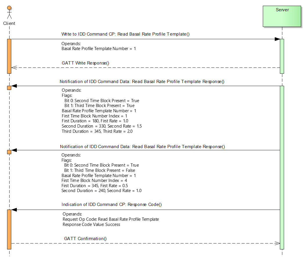
10.2. Writing a basal rate profile
Figure 10.2 shows an example of a basal rate profile writing sequence with values from Table 10.1, defined as Basal Rate Profile Template 1.
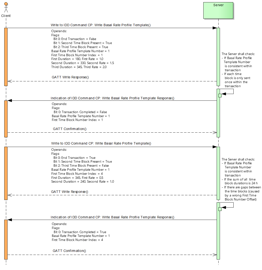
11. Appendix C – Example of getting template status and details
Table 11.1 shows an example of a basal rate profile and ISF profile template status and details, and Figure 11.1 depicts getting template status and details for all supported template types. In this case, two template types are supported; a basal rate profile template type and an ISF profile template type. The basal rate profile template numbers range from 1 to 3 inclusively and the ISF profile template numbers range from 4 to 5. Both template types allow for a maximum number of 24 time blocks. The configurable and configured status of a template is defined by an array of flags. Only configured templates can be read, applied, or reset by the Client, and only configurable templates can be written by the Client. See Sections 3.7.2.17 and 3.8.1.8 for additional details.
|
Template Type |
Starting Template Number |
Number of Templates |
Max Number of Supported Time Blocks |
Configurable |
Configured |
|---|---|---|---|---|---|
|
Basal Rate Profile Template |
1 |
3 |
24 |
[Yes, No, Yes] |
[No, Yes, Yes] |
|
ISF Profile Template |
4 |
2 |
24 |
[Yes, Yes] |
[No, No] |
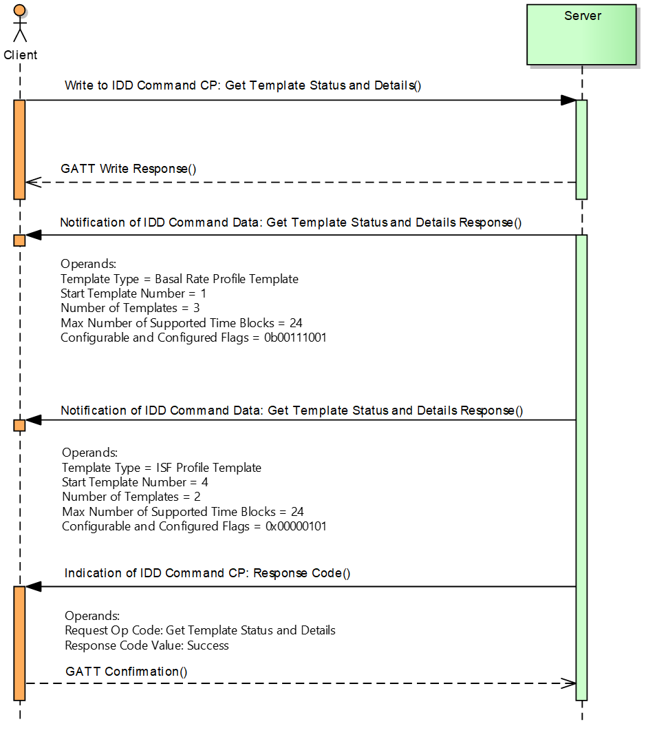
12. Appendix D - Examples of recorded events
The following chapters show examples of recorded events that can be retrieved by Clients.
12.1. Setting of the Date Time
Table 12.1 shows the recording of two date time settings (represented by Reference Time events) and two bolus deliveries. The first Reference Time event is the very first event in the history, and the second is recorded because the user changed the date time.
|
Event Type |
Sequence Number |
Relative Offset |
Event Data |
Calculated Time Stamp1 |
|---|---|---|---|---|
|
|
0 |
0 |
Recording Reason: |
2014-01-01, 12:00:00 PM |
|
... |
… |
… |
… |
… |
|
Bolus Delivered Part 1 of 2 |
5 |
30 |
Bolus ID = 1 … |
2014-01-01, 12:00:30 PM |
|
… |
… |
… |
... |
… |
|
|
10 |
3600 |
Recording Reason: |
2014-01-01, 01:00:00 PM = + 3600 s |
|
Bolus Delivered Part 1 of 2 |
11 |
10 |
Bolus ID = 2 … |
2014-01-01, 11:00:10 AM |
|
… |
… |
… |
… |
… |
1 The absolute time stamp of a single event can be calculated by a Client by using the previous Reference Time event.
The following figure shows an event histogram that might be created by a Server or Client Application based on the history table above:
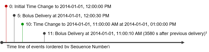
1 An application can calculate the interval between two therapy events in case of a time change: 3580 s = 3600 s + 10 s – 30 s
12.2. Date Time Loss
Table 12.2 shows the recording of two date time settings (represented by Reference Time events) and two annunciations. The first Reference Time event is recorded due to a date time loss (i.e., the device sets its default date time), and the second one is recorded because the user set the correct date time.
|
Event Type |
Sequence Number |
Relative Offset |
Event Data |
Calculated Time Stamp1 |
|---|---|---|---|---|
|
... |
… |
… |
… |
… |
|
|
99 |
0 |
Recording Reason: |
2005-01-01, 12:00:00 AM |
|
... |
… |
… |
… |
… |
|
Annunciation Status Changed Part 1 of 2 |
110 |
30 |
… |
2005-01-01, 12:00:30 AM |
|
… |
… |
… |
... |
… |
|
|
120 |
7638 |
Recording Reason: |
2005-01-01, 02:07:18 AM = + 7638 s |
|
Annunciation Status Changed Part 1 of 2 |
121 |
10 |
… |
2014-01-01, 11:00:10 AM |
|
… |
… |
… |
… |
… |
1 The absolute time stamp of a single event can be calculated by a Client by using the previous Reference Time event.
The following figure shows an event histogram that might be created by a Server or Client Application based on the history table above:
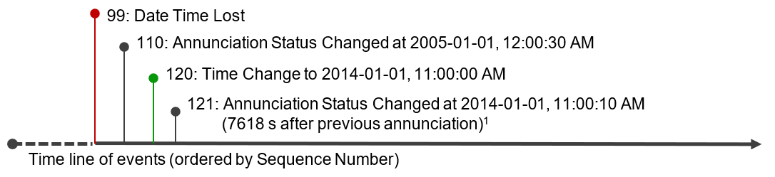
1 An application can recalculate the absolute time when the date time was lost if the Insulin Delivery Device is able to determine the Relative Offset of the new Reference Time event: 08:52:42 AM = 11:00:00 PM – 7638 s
12.3. Bolus programming and delivery
Table 12.3 shows the recording of a bolus programming and its delivery that is handled by compound event groups (see Section 3.10.1). It means that the Bolus Programmed and Bolus Delivered Events are each recorded in two parts. Both event parts are recorded with a Sequence Number increased by 1 and same Relative Offset field value.
The first event in this example is a periodically recorded Reference Time event (Sequence Number 5). After that, the user programmed a multiwave bolus with a duration of 2 minutes and a bolus delay time of 1 minute (Bolus Programmed Part 1 and 2, Sequence Number 10 and 11). Two minutes later, another periodical Reference Time event (Sequence Number 50) is recorded. Finally, three minutes after the programming of the multiwave bolus, its extended part is delivered completely (Bolus Delivered Part 1 and 2, Sequence Number 51 and 52).
The delivery of the bolus in this example was started one minute after its programming, and this time stamp can be calculated by using the time stamp of the corresponding Bolus Programmed Part 1 of 2 event (i.e., programming and delivery events have the same Bolus ID field values) and adding the Bolus Start Time Offset field value of the Bolus Delivered Part 2 of 2 event:
12:59:00 PM = 12:58:00 PM + 60 s
Note
Note: The delay of the delivery of a bolus does not match the programmed bolus delay time in all cases. For example, the Insulin Delivery Device may be set to Therapy Control State “Stop” due to a mechanical issue and be set to “Run” again after that issue is solved.
|
Event Type |
Sequence Number |
Relative Offset |
Event Data |
Calculated Time Stamp1 |
|---|---|---|---|---|
|
|
5 |
3600 |
Recording Reason: |
2014-01-01, 12:00:00 PM |
|
... |
… |
… |
… |
… |
|
Bolus Programmed Part 1 of 2 |
10 |
3480 |
Bolus ID = 1 |
2014-01-01 12:58:00 PM |
|
Bolus Programmed Part 2 of 2 |
11 |
3480 |
Flags: |
2014-01-01 12:58:00 PM |
|
… |
… |
… |
... |
… |
|
|
50 |
3600 |
Recording Reason: |
2014-01-01, 01:00:00 PM = + 3600 s |
|
Bolus Delivered Part 1 of 2 |
51 |
60 |
Bolus ID = 1 |
2014-01-01, 01:01:00 PM |
|
Bolus Delivered Part 2 of 2 |
52 |
60 |
Bolus Start Time Offset = |
2014-01-01, 01:01:00 PM |
1 The absolute time stamp of a single event can be calculated by a Client by using the previous Reference Time event.
12.4. TBR adjustment
Table 12.4 shows the recording of a TBR adjustment that is handled by compound event groups (see Section 3.10.1). It means that the TBR Adjustment Started, TBR Adjustment Changed, and TBR Adjustment Ended events are each recorded with a subsequent Delivered Basal Rate Changed event with a Sequence Number increased by 1 and same Relative Offset field value.
The first event in this example is a periodically recorded Reference Time event (at 12:00:00 PM). After that, the user started a relative TBR at 12:01:00 PM with a factor of 1.1 and a duration of 30 min (TBR Adjustment Started event, Sequence No 10). This means that the Insulin Delivery Device adjusted the basal rate from 10 IU/h to 11 IU/h (Delivered Basal Rate Changed event, Sequence No 11).
Then the user changed the settings of the active TBR (i.e., the settings of the currently active TBR are overwritten completely) at 12:02:00 PM by increasing the factor from 1.1 to 1.2 and keeping the programmed duration of 30 minutes (TBR Adjustment Changed event, Sequence No 15). This changed the current Basal Rate from 11 IU/h to 12 IU/h (Delivered Basal Rate Changed event, Sequence No 16). The elapsed time from the start of the TBR until its change is one minute.
Finally, the changed TBR is over after 30 minutes at 12:32:00 PM (TBR Adjustment Ended event, Sequence No 20) and the initial basal rate of 10 IU/h before the TBR is restored (Delivered Basal Rate Changed event, Sequence No 21). The settings of the changed TBR had been effective for 30 min until the programmed duration was over.
The complete TBR from its start at 12:01:00 PM, its change at 12:02:00 PM, and until its end at 12:32:00 PM had a duration of 31 minutes.
|
Event Type |
Sequence Number |
Relative Offset |
Event Data |
|---|---|---|---|
|
Reference Time |
5 |
3600 |
Recording Reason: Periodic Recording |
|
TBR Adjustment Started |
10 |
60 |
Flags |
|
Delivered Basal Rate Changed |
11 |
60 |
Flags: |
|
TBR Adjustment Changed |
15 |
120 |
Flags |
|
Delivered Basal Rate Changed |
16 |
120 |
Flags: |
|
TBR Adjustment Ended |
20 |
1920 |
Flags: Last Set TBR Type = Relative |
|
Delivered Basal Rate Changed |
21 |
1920 |
Flags: |
12.5. Change of Basal Rate Profile Template
Table 12.5 shows the recording of a change of a basal rate profile template that is handled as a compound event group (see Section 3.10.1). It means that the full profile shall be recorded as a sequence of Change Basal Rate Time Blocks events and the durations of these time blocks shall be 24 h. In addition, the events are recorded with a Sequence Number increased by 1 and the same Relative Offset field value.
The recorded basal rate profile is the example from Section 10 with 5 time blocks. The first event is a periodically Reference Time event. After that, the sequence of Change Basal Rate Profile Time Block events are recorded.
|
Event Type |
Sequence Number |
Relative Offset |
Event Data |
|---|---|---|---|
|
Reference Time |
5 |
3600 |
Recording Reason: |
|
Basal Rate Profile Template Time Block Changed |
10 |
30 |
Basal Rate Profile Template Number = 1 |
|
Basal Rate Profile Template Time Block Changed |
11 |
30 |
Basal Rate Profile Template Number = 1 |
|
Basal Rate Profile Template Time Block Changed |
12 |
30 |
Basal Rate Profile Template Number = 1 |
|
Basal Rate Profile Template Time Block Changed |
13 |
30 |
Basal Rate Profile Template Number = 1 |
|
Basal Rate Profile Template Time Block Changed |
14 |
30 |
Basal Rate Profile Template Number = 1 |
13. Table of figures
Figure 3.1: LFSR Circuit generating the CRC
Figure 10.1: Example of reading a basal rate profile with values from Table 10.1
Figure 10.2: Example of writing a basal rate profile with values from Table 10.1
Figure 11.1: Example of getting the template status and details with values from Table 11.1
Figure 12.1: Exemplary Application Event Histogram corresponding to Table 12.1
Figure 12.2: Exemplary Application Event Histogram corresponding to Table 12.2
14. Table of tables
Table 1.1: Additional GATT sub-procedure requirements
Table 1.2: Attribute Protocol Application Error codes defined by this service
Table 3.1: Insulin Delivery Service characteristics
Table 3.2: Mapping of IDD Status Changed Flags to IDD Status characteristic
Table 3.3: Mapping of IDD Status Changed Flags to IDD Annunciation Status characteristic
Table 3.4: Mapping of IDD Status Changed Flags to IDD Status Reader CP procedures
Table 3.5: Mapping of IDD Status Changed Flags to IDD RACP procedures
Table 3.6: Mandatory use of AuxInfo fields in context of annunciation type temperature
Table 3.7: AuxInfo2 Temperature Flags field
Table 3.8: AuxInfo2 Context values
Table 3.9: IDD Status Reader CP Procedure Requirements for Requests
Table 3.10: IDD Command CP Procedure Requirements for Requests
Table 3.11: IDD Command Data Read Basal Rate Profile Template Response Operand
Table 3.12: Read Basal Rate Profile Template Response Operand Flags field
Table 3.13: IDD Command Data Read ISF Profile Template Response Operand
Table 3.14: Read ISF Profile Template Response Operand Flags field
Table 3.15: IDD Command Data Read I2CHO Ratio Profile Template Response Operand
Table 3.16: Read I2CHO Ratio Profile Template Response Operand Flags field
Table 3.17: IDD Command Data Read Target Glucose Range Profile Template Response Operand
Table 3.18: Read I2CHO Ratio Profile Template Response Operand Flags Field
Table 3.19: IDD Command CP Get Supported Template Details and Status Response Operand
Table 3.20: Get Supported Template Details and Status Response Operand Template Type
Table 3.21: IDD Record Access Control Point
Table 3.22: IDD RACP Procedure Requirements
Table 3.23: IDD RACP Procedure Operator and Operand Relationships
Table 3.24: IDD RACP Filter Types
Table 3.26: IDD RACP Operators
Table 3.27: IDD RACP Response Code Values
Table 3.28: Compound event groups of IDD History Data Event Types
Table 3.29: Recording criteria of events
Table 4.1: IDD Status Changed Record
Table 4.2: IDD Status Changed Flags
Table 4.4: Therapy Control State values
Table 4.5: Operational State values
Table 4.7: IDD Annunciation Status Record
Table 4.8: IDD Annunciation Status Flags field
Table 4.9 Annunciation Type values
Table 4.10: Annunciation Status values
Table 4.11: IDD Features record
Table 4.12: IDD Features Flags
Table 4.13: IDD Status Reader Control Point
Table 4.14: IDD Status Reader CP Op Codes
Table 4.15: IDD Status Reader CP Response Code Operand
Table 4.16: IDD Status Reader CP Response Code values
Table 4.17: IDD Status Reader CP Reset Status Operand
Table 4.18: IDD Status Reader CP Get Active Bolus IDs Response Operand
Table 4.19: IDD Status Reader CP Get Active Bolus Delivery Operand
Table 4.20: Bolus Value Selection Values
Table 4.21: IDD Status Reader CP Get Active Bolus IDs Response Operand
Table 4.23: IDD Status Reader CP Get Active Basal Rate Delivery Response Operand
Table 4.24: Get Active Basal Rate Delivery Response Operand Flags field
Table 4.26: Basal Delivery Context values
Table 4.27: IDD Status Reader CP Get Total Daily Insulin Status Response Operand
Table 4.28: IDD Status Reader CP Get Counter Operand
Table 4.29: Counter Type values
Table 4.30: Counter Type values
Table 4.31: IDD Status Reader CP Get Counter Response Operand
Table 4.32: IDD Status Reader CP Get Delivered Insulin Response Operand
Table 4.33: IDD Status Reader CP Get Insulin On Board Response Operand
Table 4.34: Get Insulin On Board Response Operand Flags field
Table 4.35: IDD Command Control Point
Table 4.36: IDD Command CP Op Codes
Table 4.37: IDD Command CP Response Code Operand
Table 4.38: IDD Command CP Response Code values
Table 4.39: IDD Command CP Set Therapy Control State Operand
Table 4.40: IDD Command CP Snooze Annunciation Operand
Table 4.41: IDD Command CP Snooze Annunciation Response Operand
Table 4.42: IDD Command CP Confirm Annunciation Operand
Table 4.43: IDD Command CP Confirm Annunciation Response Operand
Table 4.44: IDD Command CP Read Basal Rate Profile Template Operand
Table 4.45: IDD Command CP Write Basal Rate Profile Template Operand
Table 4.46: Write Basal Rate Profile Template Operand Flags field
Table 4.47: IDD Command CP Write Basal Rate Profile Template Response Operand
Table 4.48: Write Basal Rate Profile Template Response Operand Flags field
Table 4.49: IDD Command CP Set TBR Adjustment Operand
Table 4.50: Set TBR Adjustment Operand Flags field
Table 4.51: TBR Delivery Context Values
Table 4.52: IDD Command CP Get TBR Template Operand
Table 4.53: IDD Command CP Get TBR Template Response Operand
Table 4.54: IDD Command CP Set TBR Template Operand
Table 4.55: IDD Command CP Set TBR Template Response Operand
Table 4.56: IDD Command CP Set Bolus Operand
Table 4.57: Set Bolus Operand Flags field
Table 4.58: Bolus Activation Type values
Table 4.59: IDD Command CP Set Bolus Response Operand
Table 4.60: IDD Command CP Cancel Bolus Operand
Table 4.61: IDD Command CP Cancel Bolus Response Operand
Table 4.62: IDD Command CP Get Available Boluses Response Operand
Table 4.63: Get Available Boluses Response Operand Flags field
Table 4.64: IDD Command CP Get Bolus Template Operand
Table 4.65: IDD Command CP Get Bolus Template Response Operand
Table 4.66: Get Bolus Template Operand Flags field
Table 4.67: IDD Command CP Set Bolus Template Operand
Table 4.68: IDD Command CP Set Bolus Template Response Operand
Table 4.69: IDD Command CP Reset Template Status Operand
Table 4.70: IDD Command CP Reset Template Status Response Operand
Table 4.71: IDD Command CP Activate Profile Templates Operand
Table 4.72: IDD Command CP Activate Profile Templates Response Operand
Table 4.73: IDD Command CP Get Activated Profile Templates Response Operand
Table 4.74: IDD Command CP Start Priming Operand
Table 4.75: IDD Command CP Set Initial Reservoir Fill Level Operand
Table 4.76: IDD Command CP Read ISF Profile Template Operand
Table 4.77: IDD Command CP Write ISF Profile Template Operand
Table 4.78: Write ISF Profile Template Operand Flags field
Table 4.79: IDD Command CP Write ISF Profile Template Response Operand
Table 4.80: Write ISF Profile Template Response Operand Flags field
Table 4.81: IDD Command CP Read I2CHO Ratio Profile Template Operand
Table 4.82: IDD Command CP Write I2CHO Ratio Profile Template Operand
Table 4.83: Write I2CHO Ratio Profile Template Operand Flags field
Table 4.84: IDD Command CP Write I2CHO Ratio Profile Template Response Operand
Table 4.85: Write I2CHO Ratio Profile Template Response Operand Flags field
Table 4.86: IDD Command CP Read Target Glucose Range Profile Template Operand
Table 4.87: IDD Command CP Write Target Glucose Range Profile Template Operand
Table 4.88: Write Target Glucose Range Profile Template Operand Flags field
Table 4.89: IDD Command CP Write Target Glucose Range Profile Template Response Operand
Table 4.90: Write Target Glucose Range Profile Template Response Operand Flags field
Table 4.91: IDD Command CP Get Max Bolus Amount Response Operand
Table 4.92: IDD Command CP Set Max Bolus Amount Operand
Table 4.93: IDD Command Data Record
Table 4.94: IDD History Data record
Table 4.96: IDD History Data Reference Time Event
Table 4.97: Recording Reason values
Table 4.98: IDD History Data Reference Time Event
Table 4.99: Recording Reason values
Table 4.100: IDD History Data Bolus Calculated Part 1 of 2 event
Table 4.101: IDD History Data Bolus Calculated Part 2 of 2 event
Table 4.102: IDD History Data Bolus Programmed Part 1 of 2 event
Table 4.103: IDD History Data Bolus Programmed Part 2 of 2 event
Table 4.104: IDD History Data Bolus Delivered Part 1 of 2 event
Table 4.105: IDD History Data Bolus Delivered Part 2 of 2 event
Table 4.106: Bolus Delivered Part 2 of 2 event Flags field
Table 4.107: Bolus End Reason values
Table 4.108: IDD History Data Change Basal Rate Event
Table 4.109: Delivered Basal Rate Changed Event Flags field
Table 4.110: IDD History Data TBR Adjustment Started event
Table 4.111: TBR Adjustment Started Event Flags field
Table 4.112: IDD History Data TBR Adjustment Ended event
Table 4.113: TBR Adjustment Ended Event Flags field
Table 4.114: TBR End Reason values
Table 4.115: IDD History Data TBR Adjustment Changed event
Table 4.116: IDD History Data Profile Template Activated event
Table 4.117: Profile Template Type values
Table 4.118: IDD History Data Basal Rate Profile Template Time Block Changed event
Table 4.119: IDD History Data Total Daily Insulin Delivery event
Table 4.120: Total Daily Insulin Delivery Event Flags field
Table 4.121: IDD History Data Therapy Control State Changed event
Table 4.122: IDD History Data Operational State Changed event
Table 4.123: IDD History Data Reservoir Remaining Amount Changed Event
Table 4.124: IDD History Data Annunciation Status Changed Part 1 of 2 event
Table 4.125: IDD History Data Annunciation Status Changed Part 1 of 2 event Flags field
Table 4.126: IDD History Data Annunciation Status Changed Part 2 of 2 event
Table 4.127: Annunciation Status Changed Part 2 of 2 event Flags field
Table 4.128: IDD History Data ISF Profile Template Time Block Changed Event
Table 4.129: IDD History Data Change I2CHO Ratio Profile Template Time Block Changed Event
Table 4.130: IDD History Data Change Target Glucose Profile Template Time Block Changed event
Table 4.131: IDD History Data Priming Started event
Table 4.132: IDD History Data Priming Done event
Table 4.133: Priming Done Event Flags field
Table 4.134: Reason of Termination Values
Table 4.135: IDD History Data Bolus Template Changed Part 1 of 2 event
Table 4.136: IDD History Data Bolus Template Changed Part 2 of 2 event
Table 4.137: IDD History Data TBR Template Changed event
Table 4.138: IDD History Data Max Bolus Amount Changed event
Table 5.1: Hamming Codes Values with distance of 4 within 0x0000 and 0xFFFF
Table 6.1: Abbreviations and acronyms
Table 9.1: Example A for Usage of AuxInfo fields
Table 9.2: Example B for Usage of AuxInfo fields
Table 10.1: Example of a basal rate profile with 5 time blocks
Table 11.1: Example of template details for basal rate and ISF profile template types
Table 12.1: Example of recording the Setting of the Date Time
Table 12.2: Example of recording a Date Time Loss
Table 12.3: Example of recording a bolus programming and delivery
Table 12.4: Example of recording a TBR adjustment
Table 12.5: Example of recording the Change of a Basal Rate Profile Template