-
Revision: v1.0
-
Revision Date: 2020-12-15
-
Group Prepared By: Medical Devices Working Group
Revision History
|
Revision Number |
Date |
Comments |
|---|---|---|
|
v1.0 |
2020-12-15 |
Adopted by the Bluetooth SIG Board of Directors. |
Contributors
|
Name |
Company |
|---|---|
|
Craig Carlson |
F. Hoffman-La Roche AG |
|
Torsten Robitzki |
F. Hoffman-La Roche AG |
|
Felix Bootz |
F. Hoffman-La Roche AG |
|
Wolfgang Heck |
F. Hoffman-La Roche AG |
|
Leif-Alexandre Aschehoug |
Nordic Semiconductor ASA |
|
Laurence Richardson |
Qualcomm Technologies International, Ltd. |
|
Erik Moll |
Koninklijke Philips N.V. |
|
Mathias Hater |
Renesas Electronics Europe GmbH |
|
Maarten Vervelde |
Koninklijke Philips N.V. |
Use of this specification is your acknowledgement that you agree to and will comply with the following notices and disclaimers. You are advised to seek appropriate legal, engineering, and other professional advice regarding the use, interpretation, and effect of this specification.
Use of Bluetooth specifications by members of Bluetooth SIG is governed by the membership and other related agreements between Bluetooth SIG and its members, including those agreements posted on Bluetooth SIG’s website located at www.bluetooth.com. Any use of this specification by a member that is not in compliance with the applicable membership and other related agreements is prohibited and, among other things, may result in (i) termination of the applicable agreements and (ii) liability for infringement of the intellectual property rights of Bluetooth SIG and its members. This specification may provide options, because, for example, some products do not implement every portion of the specification. Each option identified in the specification is intended to be within the bounds of the Scope as defined in the Bluetooth Patent/Copyright License Agreement (“PCLA”). Also, the identification of options for implementing a portion of the specification is intended to provide design flexibility without establishing, for purposes of the PCLA, that any of these options is a “technically reasonable non-infringing alternative.”
Use of this specification by anyone who is not a member of Bluetooth SIG is prohibited and is an infringement of the intellectual property rights of Bluetooth SIG and its members. The furnishing of this specification does not grant any license to any intellectual property of Bluetooth SIG or its members. THIS SPECIFICATION IS PROVIDED “AS IS” AND BLUETOOTH SIG, ITS MEMBERS AND THEIR AFFILIATES MAKE NO REPRESENTATIONS OR WARRANTIES AND DISCLAIM ALL WARRANTIES, EXPRESS OR IMPLIED, INCLUDING ANY WARRANTIES OF MERCHANTABILITY, TITLE, NON-INFRINGEMENT, FITNESS FOR ANY PARTICULAR PURPOSE, OR THAT THE CONTENT OF THIS SPECIFICATION IS FREE OF ERRORS. For the avoidance of doubt, Bluetooth SIG has not made any search or investigation as to third parties that may claim rights in or to any specifications or any intellectual property that may be required to implement any specifications and it disclaims any obligation or duty to do so.
TO THE MAXIMUM EXTENT PERMITTED BY APPLICABLE LAW, BLUETOOTH SIG, ITS MEMBERS AND THEIR AFFILIATES DISCLAIM ALL LIABILITY ARISING OUT OF OR RELATING TO USE OF THIS SPECIFICATION AND ANY INFORMATION CONTAINED IN THIS SPECIFICATION, INCLUDING LOST REVENUE, PROFITS, DATA OR PROGRAMS, OR BUSINESS INTERRUPTION, OR FOR SPECIAL, INDIRECT, CONSEQUENTIAL, INCIDENTAL OR PUNITIVE DAMAGES, HOWEVER CAUSED AND REGARDLESS OF THE THEORY OF LIABILITY, AND EVEN IF BLUETOOTH SIG, ITS MEMBERS OR THEIR AFFILIATES HAVE BEEN ADVISED OF THE POSSIBILITY OF THE DAMAGES.
Products equipped with Bluetooth wireless technology ("Bluetooth Products") and their combination, operation, use, implementation, and distribution may be subject to regulatory controls under the laws and regulations of numerous countries that regulate products that use wireless non-licensed spectrum. Examples include airline regulations, telecommunications regulations, technology transfer controls, and health and safety regulations. You are solely responsible for complying with all applicable laws and regulations and for obtaining any and all required authorizations, permits, or licenses in connection with your use of this specification and development, manufacture, and distribution of Bluetooth Products. Nothing in this specification provides any information or assistance in connection with complying with applicable laws or regulations or obtaining required authorizations, permits, or licenses.
Bluetooth SIG is not required to adopt any specification or portion thereof. If this specification is not the final version adopted by Bluetooth SIG’s Board of Directors, it may not be adopted. Any specification adopted by Bluetooth SIG’s Board of Directors may be withdrawn, replaced, or modified at any time. Bluetooth SIG reserves the right to change or alter final specifications in accordance with its membership and operating agreements.
Copyright © 2018–2020. All copyrights in the Bluetooth Specifications themselves are owned by Apple Inc., Ericsson AB, Intel Corporation, Lenovo (Singapore) Pte. Ltd., Microsoft Corporation, Nokia Corporation, and Toshiba Corporation. The Bluetooth word mark and logos are owned by Bluetooth SIG, Inc. Other third-party brands and names are the property of their respective owners.
1. Introduction
The Device Time Profile (DTP) allows a Device Time Client (Client) to interact with a Device Time Server (Server) on a device that supports the Device Time Service (DTS) for the purpose of providing the Server device’s time and time quality information.
This profile allows a Client to use two separate Control Points (CP) to perform time management procedures with a Server. One CP allows a Client to provide for time synchronization with the Server device and to modify some of the Server device’s time management parameters. The other CP allows the Client to audit time change events that the Server experienced to help the Client reconcile timestamped data received from the Server device.
As medical devices become more connected through their interfaces and the historical electronic measurement data collected by these medical devices is passed on to electronic health record systems, it’s becoming increasingly more important for the timestamps associated with this stored data to be on the same unbroken timeline. An electronic health record will be the container of all patient data, including measurement data from multiple devices of similar type (e.g., multiple blood glucose meters) and multiple device types (e.g., blood glucose meters, insulin pumps, weight scales, heart rate monitors, etc.) For a health care provider to effectively use this patient data for analysis and treatment, the timestamps associated with all this data, as received from numerous devices, must be on a single unbroken timeline.
Note that the DTS can be implemented in any device which would benefit from having reliable time values for use by a Client that implements the DTP for evaluating the Server device’s reported time and timestamped data.
The fundamental goal of the DTP is to provide a means for a Client to synchronize the time between the Client and a Server device with quality time values based on a reference source, and then be able to evaluate the Server device’s time quality with respect to accuracy and reliability as time passes. If the Server device displays time to the patient, then the time displayed on the device will have contextual meaning to the patient that may affect immediate therapy decisions or could affect retrospective analysis by clinicians.
Finally, industry organizations such as the Institute of Electrical and Electronic Engineers (IEEE) and Personal Connected Health Alliance (PCHA) have selected Coordinated Universal Time (UTC) to be used as the timeline for reporting time and timestamped data. It is critical for a Client implementing the DTP to have access to a time reference that is aligned to UTC and use this reference to set the time on the remote device.
For a more thorough description of time management concepts and behaviors for devices, see Section 4 “Terms and Concepts for Device Time” in [1]. See Appendix A of this specification to review examples of Device Time use cases for medical devices.
Table 1.1 summarizes various use cases involving device time and indicates which characteristics of the DTS pertain to each use case.
|
Use Case |
Device Time Service Characteristics |
Section |
|---|---|---|
|
Initial connection Determine supported features and real-time clock (RTC) capability of the DTS:
Retrieve Server’s operational parameters for behaviors:
|
Device Time Feature |
|
|
Device Time Parameters |
||
|
Get device time values and status states:
|
Device Time |
|
|
Update time of Server (may require authorization from Server)
Modify the Server’s time update and logging behavior (may require authorization from Server)
Discover any consolidated time updates not yet logged
|
Device Time Control Point (DTCP) |
|
|
Audit time change events:
|
Time Change Log Data and Record Access Control Point (RACP) |
4.8 and |
1.1. Profile dependencies
This profile depends on the Generic Attribute Profile (GATT) and requires the Client to pass time values and time quality information to the Device Time Server (Server).
1.2. Conformance
If conformance to this specification is claimed, all capabilities indicated as mandatory for this specification shall be supported in the specified manner (process-mandatory). This also applies for all optional and conditional capabilities for which support is indicated.
1.3. Bluetooth Core Specification release compatibility
This specification is compatible with any Bluetooth Core Specification that includes the Generic Attribute Profile (GATT) and the LE controller (see Volume 1, Part A, Section 2 of [2]).
1.4. Language
1.4.1. Language conventions
The Bluetooth SIG has established the following conventions for use of the words shall, must, will, should, may, can, is, and note in the development of specifications:
|
shall |
is required to – used to define requirements. |
|
must |
is used to express: a natural consequence of a previously stated mandatory requirement. OR an indisputable statement of fact (one that is always true regardless of the circumstances). |
|
will |
it is true that – only used in statements of fact. |
|
should |
is recommended that – used to indicate that among several possibilities one is recommended as particularly suitable, but not required. |
|
may |
is permitted to – used to allow options. |
|
can |
is able to – used to relate statements in a causal manner. |
|
is |
is defined as – used to further explain elements that are previously required or allowed. |
|
note |
Used to indicate text that is included for informational purposes only and is not required in order to implement the specification. Each note is clearly designated as a “Note” and set off in a separate paragraph. |
For clarity of the definition of those terms, see Core Specification Volume 1, Part E, Section 1.
1.4.2. Reserved for Future Use
Where a field in a packet, Protocol Data Unit (PDU), or other data structure is described as "Reserved for Future Use" (irrespective of whether in uppercase or lowercase), the device creating the structure shall set its value to zero unless otherwise specified. Any device receiving or interpreting the structure shall ignore that field; in particular, it shall not reject the structure because of the value of the field.
Where a field, parameter, or other variable object can take a range of values, and some values are described as "Reserved for Future Use," a device sending the object shall not set the object to those values. A device receiving an object with such a value should reject it, and any data structure containing it, as being erroneous; however, this does not apply in a context where the object is described as being ignored or it is specified to ignore unrecognized values.
When a field value is a bit field, unassigned bits can be marked as Reserved for Future Use and shall be set to 0. Implementations that receive a message that contains a Reserved for Future Use bit that is set to 1 shall process the message as if that bit was set to 0, except where specified otherwise.
The acronym RFU is equivalent to Reserved for Future Use.
1.4.3. Prohibited
When a field value is an enumeration, unassigned values can be marked as “Prohibited.” These values shall never be used by an implementation, and any message received that includes a Prohibited value shall be ignored and shall not be processed and shall not be responded to.
Where a field, parameter, or other variable object can take a range of values, and some values are described as “Prohibited,” devices shall not set the object to any of those Prohibited values. A device receiving an object with such a value should reject it, and any data structure containing it, as being erroneous.
“Prohibited” is never abbreviated.
2. Configuration
The architecture of the DTP and its relationship to the DTS are described in this section. For simplification, the DTP configuration is described as a singular service of a device.
2.1. Roles
The DTP defines two roles: Client and Server. The Server is the device whose time values and time parameters may be controlled by the Client.
-
The Server shall be a GATT Server.
-
The Client shall be a GATT Client.
2.2. Service/profile relationships
Figure 2.1 shows the relationships between DTS and DTP roles.
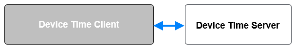
In the relationship diagram, the Client role is represented by the gray box and the Server role is represented by the white box.
The Client consists of a GATT Client and an application that uses the GATT Client.
Figure 2.2 shows just one of numerous system configurations possible when using the DTS.
The example DTS system shown in Figure 2.2 has a Server that reports data to three Clients. Only one of the Clients has authorization to perform some functions on the Server. In this example, the authorized Client is allowed to perform Time Update procedures and synchronize the time values of the authorized Client with the Server. The two Clients that are not authorized to perform any Time Update procedures may read the time value and time quality from the Server.

2.3. Concurrency limitations/restrictions
There are no concurrency limitations or restrictions imposed by this profile for the role of Client or Server.
2.4. Topology limitations/restrictions
2.4.1. Topology limitations/restrictions for Low Energy
This section describes topology limitations and restrictions when the profile is used over Bluetooth Low Energy (LE) transport.
-
The Server shall use the GAP Peripheral role over LE transport.
-
The Client shall use the GAP Central role over LE transport.
2.5. Transport dependencies
There is no transport dependency defined by this profile.
3. Device Time Server role requirements
The Server shall instantiate only one instance of the DTS [1].
|
Service |
Server |
|---|---|
|
Device Time Service |
M |
- M:
-
Mandatory
3.1. Incremental Device Time Server requirements
There are no additional requirements for the Server.
4. Device Time Client role requirements
|
Service |
Client |
|---|---|
|
Device Time Service [1] |
M |
- M:
-
Mandatory
The Client shall support interaction with a Server that implements the DTS.
Table 4.2 describes the profile requirements for a Client.
|
Profile Requirement |
Section |
Support in Client |
|---|---|---|
|
Service Discovery |
- |
- |
|
M |
|
|
Characteristic Discovery |
- |
- |
|
M |
|
|
Device Time Feature |
M |
|
|
Device Time Parameters |
M |
|
|
Device Time |
M |
|
|
Device Time Control Point |
O |
|
|
Record Access Control Point |
O |
|
|
Time Change Log Data |
C.1 |
- M:
-
Mandatory
- O:
-
Optional
- C.1:
-
Mandatory if the Client supports RACP, otherwise Excluded.
4.1. GATT sub-procedure requirements
Requirements in this section represent a minimum set of requirements for a Client. Other GATT sub-procedures may be used if supported by both the client and server.
Table 4.3 summarizes additional GATT sub-procedure requirements beyond those required by all GATT clients.
|
GATT Sub-Procedure |
Client Requirements |
|---|---|
|
Discover All Primary Services |
C.1 |
|
Discover Primary Services by Service UUID |
C.1 |
|
Discover All Characteristics of a Service |
C.2 |
|
Discover Characteristics by UUID |
C.2 |
|
Discover All Characteristic Descriptors |
M |
|
Notifications |
C.3 |
|
Indications |
M |
|
Read Characteristic Value |
M |
|
Write Characteristic Value |
C.4 |
|
Read Characteristic Descriptors |
M |
|
Write Characteristic Descriptors |
M |
|
Exchange Maximum Transmission Unit (MTU) |
C.3 |
- M:
-
Mandatory
- O:
-
Optional
- C.1:
-
Mandatory to support at least one of these Service Discovery sub-procedures.
- C.2:
-
Mandatory to support at least one of these Characteristic Discovery sub-procedures.
- C.3:
-
Mandatory if the Client supports RACP, otherwise Optional.
- C.4:
-
Mandatory if the Client supports either Control Point, otherwise Optional.
4.2. Service discovery
When using the Low Energy transport, the Client shall perform primary service discovery using either the GATT Discover All Primary Services sub-procedure or the GATT Discover Primary Services by Service UUID sub-procedure.
When using the BR/EDR transport, the Client shall perform service discovery by retrieving the Service Discovery Protocol (SDP) record of the DTS [1].
4.2.1. Device Time Service discovery
The Client shall discover the DTS.
4.3. Characteristic discovery
As required by GATT, the Client shall tolerate additional optional characteristics in the service records of services used with this profile.
Where a characteristic can be indicated and/or notified as described in the DTS [1], the Client shall discover the Client Characteristic Configuration Descriptor (CCCD) of that characteristic as required by the Core Specification [2].
4.3.1. Device Time Service characteristic discovery
The Client shall perform either the GATT Discover All Characteristics of a Service sub-procedure or the GATT Discover Characteristics by UUID sub-procedure to discover the characteristics of the service.
The Client should read and evaluate the DT Feature characteristic to learn what fields are to be expected within each DTS characteristic before reading the other characteristics of the DTS or enabling indications and notifications for characteristics.
The Client shall perform the GATT Discover All Characteristic Descriptors sub-procedure to discover the characteristic descriptors as revealed in the remainder of this section.
4.3.1.1. Device Time Feature characteristic
The Client shall discover the DT Feature characteristic. The Client shall tolerate additional octets that may be reported for this characteristic.
The Client shall discover the CCCD of the DT Feature characteristic.
4.3.1.2. Device Time Parameters characteristic
The Client shall discover the DT Parameters characteristic.
The Client shall discover the CCCD of the DT Parameters characteristic.
4.3.1.3. Device Time characteristic
The Client shall discover the DT characteristic.
The Client shall discover the CCCD of the DT characteristic.
4.3.1.4. DTCP characteristic
If supported, the Client shall discover the DTCP characteristic.
If supported, the Client shall discover the CCCD of the DTCP characteristic.
4.3.1.5. Time Change Log Data characteristic
If supported, the Client shall discover the Time Change Log Data characteristic.
If supported, the Client shall discover the CCCD of the Time Change Log Data characteristic.
4.3.1.6. RACP characteristic
If supported, the Client shall discover the RACP characteristic.
If supported, the Client shall discover the CCCD of the RACP characteristic.
4.4. Common Device Time Service characteristic requirements
If the Server supports End-to-End Cyclic Redundancy Check (E2E-CRC) as revealed in the DT Features, and the Client supports E2E-CRC validation of received data, then the Client may check the validity of the fields of a characteristic by checking the value of the E2E_CRC field calculated over all fields (for details regarding CRC calculation, see Section 2.3 in [3]). If the Client determines that there is an E2E-CRC error, the Client may handle the error as guided by the application. Note that a Client may use any received E2E_CRC field value for improving data integrity, but this is an application detail and is not a requirement of this profile.
If the Server supports the E2E-CRC feature as revealed in the DT Features, the Client shall calculate and insert the calculated E2E_CRC field value for any characteristic or procedure that the Client writes to the Server that contains an E2E_CRC field.
4.5. Device Time Feature characteristic behavior
The DT Feature characteristic contains information about the Server capabilities and features. The Client shall read the DT Feature characteristic to determine the supported features of the Server. The DT Feature characteristic always contains two fields: E2E-CRC and DT Features. A Client that receives a characteristic response that is longer than the documented characteristic value shall ignore additional octets for future compatibility.
4.5.1. E2E_CRC field
The E2E_CRC field of the DT Feature characteristic is always present in this characteristic. When the Server supports the E2E-CRC feature, the Client can use the E2E_CRC field value to validate the DT Feature characteristic; otherwise, the Client may ignore the default value received as defined in [1].
4.5.2. DT_Features field
Server support for a particular DT Features capability is indicated by the corresponding feature bit set to 1. If the Client receives the DT Feature characteristic with RFU bits set to 1 within the DT_Features field, the Client shall ignore those bits for future compatibility as described in Section 1.4.2.
If the Server supports indication of the DT Feature characteristic, the Client may configure the CCCD of this characteristic for indications.
4.5.2.1. E2E-CRC feature
If the Server supports the E2E-CRC feature, the Client can use the E2E_CRC field of all received Server characteristics to determine whether the received value is correct. Additionally, the Client shall calculate and include the E2E_CRC field when writing to the DTCP.
If the E2E-CRC feature is not supported by the Server, the Client shall not include the E2E_CRC field when writing to the DTCP.
4.5.2.2. Time Change Logging feature
If the Server supports the Time Change Logging feature, the Client may use the RACP to retrieve the Time Change Log Data characteristic.
4.5.2.3. Base Time Second-Fractions feature
If the Server supports the Base Time Second-Fractions feature, the Client may use the 16-bit fractions of seconds value contained in the DT characteristic and Time Change Log Data characteristic, and the Client shall include the Base_Time_Second_Fractions_Update field value when performing Time Update procedures using the DTCP.
If the Server supports the Base Time Second-Fractions feature but Base Time Second-Fractions are not available to the Client during Time Update procedures, then the Client shall set the value of the Base_Time_Second_Fractions_Update field to 0x0000 for Time Update procedures and shall set the Client Second-Fractions not Valid bit to 1 in the Time_Update_Flags field of the Time Update Operand.
If the Server does not support the Base Time Second-Fractions feature, the Client shall not include the Base_Time_Second_Fractions_Update field in the Time Update operand.
4.5.2.4. Time or Date Displayed to User feature
If the Server supports both the Time or Date Displayed to User feature, and the Displayed Formats feature, then the Client may use the DT Parameters field of Displayed_Formats to present the Service device’s displayed data in a similar date and time format on the Client device.
4.5.2.5. Displayed Formats feature
If the Server supports the Displayed Formats feature, the Client can read the DT Parameters characteristic to discover the DT Parameters’ Displayed_Formats field to learn of the Server device’s displayed formats. The Client can align its displayed formats to that of the Server device to avoid the situation of a user misinterpreting data viewed due to differences in the displayed formats between the Server device and the Client device.
If the Displayed Format bit is set to 0, the Client may not be able to learn of the Server device’s displayed formats for date and time; therefore, the Client may not be able to align its display with the format of the Server device’s displayed data.
4.5.2.6. Displayed Formats Changeable feature
If the Server supports the Displayed Formats Changeable feature, the Client can monitor the DT Parameters field for Displayed_Formats to determine whether the Server device has made a change to the formatting of the displayed date and time. The Client may enable the DT Parameters characteristic for indications if it chooses to monitor the displayed formatting of time and date of the device.
This specification does not include application behavior for the Client action, if any, that the Client performs after receiving user displayed date and time formats or changed date and time formats.
4.5.2.7. Separate User Timeline feature
If the Server supports the Separate User Timeline feature, the Client can read the User_Time field of the DT characteristic to obtain the user-facing time of the device, and the Client may align its displayed date and time formats to that of the Server.
If the Server does not support the Separate User Timeline feature, the Client may not be able to determine the user-facing time of the device and may not be able to align the Client’s displayed data with a reference timeline.
4.5.2.8. Authorization Required feature
If the Server supports the Authorization Required feature, the Client might be required to wait for and participate in an authorization procedure before certain DTCP procedures are performed (see [1] for the procedures that may require authorization).
If the Server does not support the Authorization Required feature, the Client may access all supported DT Features without an additional authorization procedure.
4.5.2.9. RTC Drift Tracking feature
If the Server supports the RTC Drift Tracking feature, the Client may monitor and utilize the associated RTC drift fields of Accumulated_RTC_Drift from the DT characteristic and Max_RTC_Drift_Limit and Max_Days_Until_Sync_Loss from the DT Parameters characteristic. The Client may enable the DT characteristic and DT Parameters characteristic for indications so that the Client can be made aware of changes to these RTC drift values.
Additionally, when the RTC Drift Tracking feature is supported by the Server, and the Server supports the Time Change Logging feature, the Client may also evaluate the device’s RTC drift behavior when reviewing records reported by the Time Change Log Data characteristic using RACP.
4.5.2.10. Epoch Year features
The Epoch Year 1900 feature and Epoch Year 2000 feature along with the Epoch Year 2000 flag of the DT Status field of the DT characteristic shall set the requirements for Client behavior for interpreting the time values within the DT characteristic and Client behavior during Time Update procedures as detailed in Section 4.7.2.
4.5.2.11. Propose Non-Logged Time Adjustment Limit feature
If the Server supports the Propose Non-Logged Time Adjustment Limit feature, the Client may, if authorized by the Server, change the value of the Non_Logged_Time_Adjustment_Limit field within the DT Parameters characteristic by using the Propose Non-Logged Time Adjustment Limit procedure of the DTCP to write to this field of the DT Parameters characteristic.
If the Server does not support the Propose Non-Logged Time Adjustment Limit feature, the Client will not be able to write to the Non_Logged_Time_Adjustment_Limit field of the DT Parameters characteristic (see Section 4.9.7).
4.5.2.12. Retrieve Active Time Adjustments feature
If the Server supports the Retrieve Active Time Adjustments feature, the Client may use the DTCP procedure for Retrieve Active Time Adjustments, which may allow the Client to accurately reconcile the Server’s synchronized time with the Client.
If the Server does not support the Retrieve Active Time Adjustments feature, the Client will not be able to reconcile Base_Time field value discrepancies due to unlogged Time Update procedure adjustments applied to the Base_Time field by the Server (see Sections 4.7.2.4 and 4.9.8).
4.6. Device Time Parameters characteristic behavior
When used with the DT Feature characteristic, the DT Parameters characteristic describes the behavior of the Server. The Client may read the DT Parameters characteristic to receive the current value of this characteristic.
The format of the fields within the DT Parameters characteristic are described in [1].
The Client may configure the CCCD of the DT Parameters characteristic for indications.
If a Client takes action or modifies its behavior based on a change to any field of the DT Parameters, then the Client shall enable this characteristic for indications.
4.6.1. E2E_CRC field
If the Server supports the E2E-CRC feature, the E2E_CRC field is included and contains the value of the calculated CRC for the DT Parameters characteristic. The application may use the E2E_CRC to determine whether the DT Parameters characteristic value received by the application has bit errors.
4.6.2. RTC_Resolution field
Clients may use the value of the RTC_Resolution field to understand a Server’s clock resolution limitations when the Server reports time values. The Client should provide time values in Time Update procedures at the same, or better, resolution than that of the RTC_Resolution field value.
4.6.3. Max_RTC_Drift_Limit field
If the Server supports the RTC Drift Tracking feature, the Client may read the Max_RTC_Drift_Limit field value to understand the Server’s behavior when the Server evaluates a Propose Time Update procedure from the Client.
The Client can evaluate the device’s RTC drift over time by comparing the DT characteristic’s Accumulated_RTC_Drift field value to the DT Parameter characteristic’s Max_RTC_Drift_Limit field value, and then evaluate the urgency of the need for a time synchronization with the Server using a Time Update procedure.
The Client application may evaluate whether to perform a Time Update procedure to synchronize the Server with a time reference and zero out the Server’s Accumulated_RTC_Drift. field value. However, the Client should also be careful to evaluate the value of the current Accumulated_RTC_Drift so that the Max_Days_Until_Sync_Loss field value is not reached. The Client should also be careful to not perform Time Update procedures to correct minor time value discrepancies or to force the Server to log trivial time change updates.
The Client may receive Device Time Status (DT_Status) reports indicating that the Server’s time is no longer UTC aligned due to reaching the Max_RTC_Drift_Limit field value time duration. A device that has been in storage, been placed into airplane mode, or that has lost one or more Bluetooth pairings may exhibit such behavior.
4.6.4. Max_Days_Until_Sync_Loss field
If the Server supports the RTC Drift Tracking feature, the Client may read the Max_Days_Until_Sync_Loss field value that the Server will use to signal the timeframe of when it will lose time source synchronization in the absence of a Time Update procedure (see also Section 4.9.3).
For example, a Max_Days_Until_Sync_Loss field value of 90 days when the Max_RTC_Drift_Limit field value is 300 seconds would reveal that the device had a 4 second per day worst-case RTC drift. A Client may optionally use this drift rate value to compare the Server’s reported Base_Time field value with the expected Base_Time of the Server to determine whether the Server’s clock is running properly (see Appendix A in [1]).
This specification does not include application behavior for auditing of the Server’s clock.
Clients that attempt to determine the precise RTC behavior of the Server should retrieve Base_Time adjustments using the DTCP Retrieve Active Time Adjustments Procedure. A Server might have non-logged Base_Time adjustments, and a Client may check the DT_Status field to see if the flags for Non-Logged Time Change Active or Log Consolidation Active are set. The Client may retrieve these Base_Time adjustments using the DTCP (see also Section 4.9.8).
4.6.5. Non_Logged_Time_Adjustment_Limit field
If the Server supports the Time Change Logging feature, the Client may read the Non_Logged_Time_Adjustment_Limit field to evaluate the Server’s logging behavior during Time Update procedures that involve small Base_Time adjustments. The Client may discover that the Server may not log Time Update procedures that change the Base_Time of the Server by less than the Non_Logged_Time_Adjustment_Limit.
The Non_Logged_Time_Adjustment_Limit field value of 0 means that the Server creates a Time Change Log Data entry for every change to the Base Time unless the Server is consolidating log entries (see Section 4.7.2.4.2).
When the value of the Non_Logged_Time_Adjustment_Limit field value is not 0, the Client should be aware that a Server might have undergone one or more Time Update procedures that were not logged due to the Base_Time change being less than the Non_Logged_Time_Adjustment_Limit. Such non-logged time adjustments might appear to be a device clock drift issue, when in fact they are an artifact of the Server saving memory by not logging these small Base_Time adjustments during Time Update procedures.
An indication of the DT Parameters revealing a change in the value of the Non_Logged_Time_Adjustment_Limit field allows the Client to become aware of a change to the Non_Logged_Time_Adjustment_Limit field.
4.6.6. Displayed Formats field
If the Server supports the Displayed Formats feature, the Client may discover the Server’s presently configured display formatting about date and time by reading the Displayed Formats field. An indication of the DT Parameters revealing a change in the value of the Displayed Formats field allows the Client to become aware of displayed format changes for date or time.
4.7. Device Time characteristic behavior
The Client may read the Device Time (DT) characteristic to obtain the Server’s device time along with time status information.
The Client may configure the CCCD of the DT characteristic for indications to allow the Server to indicate this characteristic due to any time value changes beyond normal clock progression (Base_Time field advancing by normal RTC clock ticks or the accumulation of RTC drift as it increases with time).
The format of the fields within the DT characteristic are described in [1].
4.7.1. E2E_CRC field
If the Server supports the E2E-CRC feature, the E2E_CRC field is present and contains the value of the calculated CRC for the DT characteristic. The application may use the E2E-CRC to evaluate the validity of the reported DT characteristic value.
4.7.2. DT_Status field
The DT_Status field reveals the state of the Server’s time quality and synchronization state. The DT_Status field may also reveal potential adjustments to the Server’s Base_Time. When the DT characteristic is indicated by the Server, the Client should evaluate the DT_Status field before evaluating accuracy or correctness of the reported time values of this characteristic to understand the state of the device’s time and to aid in the determination of whether action is needed on the part of the Client. The criteria that a Client uses to evaluate the time values reported by the Server is application behavior and depends on the implementation.
4.7.2.1. Client behavior for time faults reported by the Server
When the Time Fault bit in the DT_Status is set to 1, the Client shall initiate the Propose Time Update procedure as described in Section 4.9.4. The Time Update procedure allows the Client to correct the Server’s time-faulted condition with a time source that may be aligned to the UTC, which allows the Server’s time and subsequent time-stamped data to be recognized universally. The Client can then retrieve stored measurements and use the Server’s just reported Base_Time value along with the Time Fault event record to adjust the timestamps of all stored measurements since the last time fault by the amount of adjustment necessary to correct the Server’s just reported Base_Time value.
4.7.2.2. Client behavior for Propose Time Update Request bit set by the Server
When the Client receives the DT characteristic from the Server with the DT_Status indicating that the Propose Time Update Request bit is set to 1, the Client shall initiate the Propose Time Update procedure as described in Section 4.9.4.
If the Propose Time Update Request bit is not set, the Client should avoid invoking the Propose Time Update procedure to a UTC-Aligned Server. In this case, the Server is indicating to the Client that it is satisfied with the present time value that it has, which may have been recently received from a Time Update procedure.
Clients should tolerate Servers that do and don’t set the Propose Time Update Request bit on a continuous basis. For example, some Servers will want to avoid unnecessary Time Update procedures and the logging effort that may be incurred from those updates and will not seek Time Update procedures for longer periods of elapsed time. Other Servers will request a Propose Time Update procedure on every re-connection with Clients regardless of the time between those re-connections.
There are situations where the Client should ignore the Propose Time Update Request bit not being set to 1 and proceed with a Propose Time Update procedure, such as:
-
When the Client observes that the time quality of its time source is superior to the presently reported time quality of the Server (see Appendix A in [1]), the Client should proceed with a Propose Time Update procedure. An example of time quality would be that the Server is synchronized but not UTC Aligned, but the Client has a UTC-aligned source to offer.
-
When the Client observes that the Server local time values for Time Zone and DST as reported by the Server are not as expected for the region that the Server device is located, the Client should proceed with a Propose Time Update procedure to allow the Server to accept the local time adjustments (and the Server may possibly accept the Base_Time_Update value as well).
4.7.2.3. Epoch Year 2000 flag
The Client can use the reported Epoch Year 2000 flag to determine the Server’s configuration and the implemented epoch for determining date and the time of the Server.
4.7.2.4. Base_Time adjustment flags
Some Servers may attempt to reduce the number of time change log entries by implementing the Non_Logged_Time_Adjustment_Limit. Additionally, some Servers may choose to implement time change log consolidation. The Base_Time adjustment flags within the DT_Status field for Non-Logged Time Change Active and Log Consolidation Active reveal to the Client that the reported Base_Time value has been adjusted without a log entry being created.
After receiving a Base_Time value, the Client may also check if the flags for Non-Logged Time Change Active and Log Consolidation Active are set to 1. If either flag is set to 1, the reported Base_Time has adjustments to its Base_Time due to one or both of these adjustment types. If the Server supports the Retrieve Active Time Adjustments feature, the Client can retrieve the implemented Base_Time adjustment(s) using the DTCP. The Client can then calculate the raw or unadjusted Base_Time by adjusting the Server’s initially reported Base_Time with the adjustment values from the Retrieve Active Time Adjustments procedure (see Section 4.9.8).
The Client will not be able to determine the operating accuracy of the Server’s clock due to Base_Time adjustments made using either consolidation or the Non_Logged_Time_Adjustment_Limit if the Server does not support the Retrieve Active Time Adjustments feature. However, the Client will be able to see that the Server has made such adjustments by observing the Base_Time adjustment flags within the DT_Status field. A Client’s need for auditing the Server’s clock synchronization with the Client is application-specific.
4.7.2.4.1. Non-Logged Time Change Active
The Client may use the Non-Logged Time Change Active flag to determine whether the Server is presently reporting a Base_Time value that does not match the Client’s expected Base_Time value due to adjustments that the Server has made that are less than the Non_Logged_Time_Adjustment_Limit (see Sections 4.7.2.4 and 4.9.8).
4.7.2.4.2. Log Consolidation Active
The Client may use the Log Consolidation Active flag to determine whether the Server is presently reporting a Base_Time value that has adjustments to the Base_Time that the Server has made that are being consolidated, or time faults that are being consolidated but these consolidations are not yet revealed by a log entry. In the case of consolidated Time Update procedures, the magnitude of these Base_Time changes may span across more than an Epoch range (32 bits of seconds) as revealed by the Epoch span bit of the Active_Time_Adjustments field.
When the Log Consolidation Active bit is set and the DT_Status reveals that the Server is in a time fault state, the Client will know that there is no log entry for the present time fault condition.
The Client may desire knowledge of the latest Time_Fault event and may choose to force the Server to log the consolidated time fault by causing the Server to log a different time change log event type if supported by the Server. Client behavior in regard to discovery of consolidated Time_Fault events is an application behavior not detailed by this specification (see Sections 4.7.2.4 and 4.9.8).
4.7.3. User_Time field
If the Server supports the Separate User Timeline feature, the User Time field reveals the user-facing time of the Server device. The Client shall consider the User Time as a parallel and offset timeline to that of the Base_Time of the Server’s synchronized Device Time.
The Client’s use of the Server’s User Time is implementation-specific. Since User Time may differ from a device’s UTC-aligned local time, the Client may need to take care as to which time value is displayed in the situation where stored measurements may have meaning to a device’s user from the perspective of the displayed value (User Time) rather than the device’s synchronized time value, which is likely hidden from the user.
4.7.4. Accumulated_RTC_Drift field
If the Server supports the RTC Drift Tracking feature, the Client may use the Accumulated_RTC_Drift field value to determine the present amount of accumulated drift that the Server’s RTC clock may have drifted from a synchronized source since the Server’s last Time Update (synchronization event). The Client may use this value to determine the need for a Time Update procedure. The Client’s use of the Accumulated RTC Drift field value in determining whether the Server’s clock is running correctly or whether to send a Time Update is implementation behavior.
4.7.5. Next_Sequence_Number field
If the Server supports the Time Change Logging feature, the Client may use the Next_Sequence_Number field to be alerted to time change events that occurred on the Server since the last connection.
If the Server supports Time Change Logging feature and the Client finds that the Server has time changes as revealed by a Next_Sequence_Number field value that is greater than that of the last synchronization with the Client, the Client may query the change log for more information. The Client’s use of the time change log in auditing or reconciling device time discrepancies or the timestamps of stored data is application-specific behavior.
4.7.6. Base_Time_Second_Fractions field
If the Server supports the Base Time Seconds Fractions feature, the Client may use the Base_Time_Second_Fractions field to obtain the RTC of the Server with fractions of a second resolution.
4.8. Time Change Log Data characteristic behavior
The Time Change Log Data characteristic reveals the historical time changes logged by the Server due to changes in time value, time quality, and DT Parameters.
Clients can use the Segmentation_Header field within the notifications of the Time Change Log Data characteristic to properly reconstruct individual records of time change events by piecing together the Time_Change_Log_Data_Record field of multi-segmented records.
Clients can then use the Time_Change_Log_Data_Record field within the notifications of Time Change Log Data characteristic to verify timestamps of stored measurements, to audit time change events on the Server, and to evaluate the operational stability of the Server’s clock over extended periods of time.
The Client shall read the DT Feature characteristic to obtain information about whether the Server supports time change logging and the supported time change logging methods implemented by the Server as further specified in the DT Parameters to understand the supported logging fields and thresholds.
Before performing an RACP procedure, the Client shall configure the CCCD for notifications to request records of this characteristic through the Record Access Control Point (see Section 4.10).
When the Client requires Time Change Log Data characteristic data, the Client shall follow the Record Access Control Point procedures described in Section 4.10.
The format of the fields within the Time Change Log Data characteristic and their conditional presence in a logged event based on the time change event log type are described in [1].
The Client should be aware that numerous time change events of a similar type may be consolidated to a single time change event log entry by the Server for either Time_Update or Time_Fault events (but not mixed type) if no stored measurements occur between the consolidated events. Time change record consolidation details are described in [1].
The Client’s use of Time Change Log Data characteristic to audit the operational stability of the Server or to validate timestamped data is implementation behavior that depends on the application.
The Client shall tolerate Time Change Log Data entries that require multiple notifications due to their size exceeding the presently connected MTU limit as described in [1].
The Client should avoid frequently requesting large amounts of records from the Server (e.g., asking for all stored log entries on every reconnection).
When requesting groups of records, the Client should determine the total number of stored records and efficiently retrieve only the necessary records.
4.8.1. E2E_CRC field
If the Server supports the E2E-CRC feature, the E2E_CRC field is present and contains the value of the calculated CRC for the record contained in the notified Time Change Log Data characteristic. The application may use the E2E_CRC field value to evaluate the validity of each received record.
4.8.2. Event_Log_Flags field
The Client can use the Event_Log_Flags field to determine the conditional data fields of the Time_Change_Log_Data_Record structure that are needed to fully describe the time change event that has been logged [1].
4.9. DTCP characteristic behavior
The DTCP characteristic shall be used by the Client to write time values and time quality information to the Server, to write to the DT Parameters characteristic, and to retrieve Base_Time value adjustments that have yet to be logged.
The format of the fields within the DTCP characteristic are described in [1].
The Client should read the DT Feature characteristic to discover Server-supported features and DTCP procedures before attempting to initiate a DTCP procedure.
Before performing a DTCP procedure, the Client shall configure the CCCD of the DTCP characteristic for indications.
4.9.1. Device Time Control Point procedure requirements
Table 4.4 shows the requirements for the DTCP procedures in the context of this profile.
|
Procedure |
Section |
Requirements |
|---|---|---|
|
Propose Time Update |
M |
|
|
Force Time Update |
O |
|
|
Propose Non-Logged Time Adjustment Limit |
O |
|
|
Retrieve Active Time Adjustments |
O |
- M:
-
Mandatory
- O:
-
Optional
4.9.2. E2E_CRC field
If the Server supports the E2E-CRC feature, the E2E_CRC field is present and contains the value of the calculated CRC for the DTCP, including opcode and operand.
4.9.3. Time Update behavior
This section describes the expected Client behavior for both the Propose Time Update and the Force Time Update procedures.
The Client should take care during Time Update procedures to not reduce the Server’s time quality as described in Appendix A.5 in [1]. This is especially critical when a Server may have access to more than one Client, and some Clients may have access to more reliable or higher quality time sources.
Regardless of the status of the Propose Time Update Request bit of the DT characteristic, a Client may, if authorized, use the Force Time Update procedure if the Client wants to improve the accuracy of, or modify the Server device’s time to force a time synchronization between the two devices (see Sections 4.9.4 and 4.9.5).
4.9.3.1. Operand rules for Time Update procedures
The behavior of the Time_Update_Flags field is defined as follows:
-
The UTC Aligned flag shall be set when the Client can confirm that the time source is aligned with the UTC (may be done by time source recognition; Global Positioning System (GPS) would be UTC-capable).
-
The Qualified Local Time flag shall be set when the Client can confirm that the time source is synchronized with qualified local time information. When the Time Source is GPS, this condition is satisfied.
-
The Client shall not set the UTC alignment bit if any of the following conditions are present on the Client: Adjust Reason is Manual Adjustment, Time Source is “Manual,” or Time Accuracy is either greater than 31.625 seconds or “unknown.”
-
If the Server supports only the Epoch Year 1900 feature and the Epoch Year 2000 flag of the DT_Status field is set to 0, the Client shall only initiate Time Update procedures to the Server with Base_Time_Update field values based on the Epoch start year of 1900.
-
If the Server supports only the Epoch Year 2000 feature and the Epoch Year 2000 flag of the DT_Status field is set to 1, the Client shall only initiate Propose Time Update procedures to the Server with Base_Time_Update field values based on the Epoch start year of 2000.
-
If the Server supports both the Epoch Year 1900 feature and the Epoch Year 2000 feature, then the Client should evaluate the effective Epoch Year 2000 flag within the DT_Status field as reported by the DT characteristic and use the revealed epoch year for Time Update procedures. The Client should avoid alternating between Epoch Years 1900 and 2000 when performing Time Update procedures to Servers that support both epoch years.
-
If the Client does not support the Base Time Second-Fractions feature but the Server does, the Client shall set the Second-Fractions Not Valid bit to 1 in the Time_Update_Flags field to reveal to the Server that the 0 value in the Base_Time_Second_Fractions_Update field of the Time Update operand is not an actual value.
The Time Update adjustment reason coding within the Time_Update_Flags field uses the same update adjustment reason coding as is used in the Current Time characteristic defined in [3].
4.9.3.2. Caution for time-sensitive data
Numerous factors affect or limit accuracy of time values. This specification does not address enabling of highly accurate time values of time-sensitive data.
4.9.4. Propose Time Update
The Client may receive Device Time indications with the Propose Time Update Request bit set. Upon receiving such Time Update requests, the Client shall invoke the Propose Time Update procedure at least once, even if that Time Update procedure is of lower time quality, since the Server can evaluate all time values and time quality attributes and may reject some or all of the Time Update.
Generally, the Client should avoid sending unsolicited Propose Time Update procedures to Servers that have not set the Propose Time Update Request flag. However, the Client may invoke the Propose Time Update procedure at any time that the application warrants that a time synchronization procedure be performed.
Regardless of whether the Client was asked to propose a Time Update or whether the Client attempted a time synchronization on its own using a Propose Time Update procedure, the Server may reject the Time Update proposal and provide a rejection reason(s), as revealed in the Rejection Flags of the operand. The Client can then use the just received rejection flags to evaluate the next action to be taken, if any.
4.9.5. Force Time Update
An authorized Client may invoke the Force Time Update procedure. A Client may receive a Procedure Response from the Server that rejects the Force Time Update if the Client is not authorized or if the operand of the Force Time Update is invalid. This specification does not include implementation details for how authorization is achieved.
4.9.6. Time Update responses from Server
The Client should evaluate the received DTCP Response for each invoked Time Update request and determine the appropriate action to any update procedure error response from the Server (see Operand for DTCP Response in [1]).
|
Example: |
The Client sends a Propose Time Update to a Server and the Client receives the following Update Response (with numeric values as described in [1]; |
|
DTCP Response, |
|
|
Request Opcode: Propose Time Update, |
|
|
Response Value: Procedure Rejected, |
|
|
Rejection Flags: Time Source is not UTC-aligned (and the Server is aligned). |
In the above example where the Propose Time Update procedure is rejected based on not being UTC-aligned, the Client should not attempt to initiate another Propose Time Update procedure until the Client is able to receive a reference Time Update from a UTC-aligned time source.
4.9.7. Propose Non-Logged Time Adjustment Limit
If the Server supports the Propose Non-Logged Time Adjustment Limit feature and the Client is authorized, the Client may write the Non_Logged_Time_Adjustment_Limit field of the DT Parameters characteristic using the DTCP.
This procedure may require authorization from the Server, and a Client may receive a DTCP Response_Value of Procedure Rejected due to a lack of authorization. The authorization effort is implementation-specific.
4.9.8. Retrieve Active Time Adjustments
If the Server supports the Retrieve Active Time Adjustments feature, and if the Client receives a Base_Time field value from the DT characteristic with either of the Base_Time adjustment flags of the DT_Status field for Non-Logged Time Change Active or Log Consolidation Active, the Client may choose to obtain these Base_Time adjustment values (see Section 4.7.2.4).
4.10. Record Access Control Point characteristic behavior
Before performing any RACP procedure, the Client shall configure the RACP characteristic for indications via the CCCD and configure the Time Change Log Data characteristic for notifications.
The Client shall perform a write to the RACP to execute a desired procedure. A procedure begins when the Client writes to the RACP characteristic to perform some desired action and ends when either a Response Code or Number of Stored Records Response RACP indication is received by the Client.
If the procedure performed is the Combined Report or the Report Stored Records procedure, the procedure may contain one or more Time Change Log Data notifications between the write to the RACP characteristic that began the procedure and the Response Code indication that ends the procedure.
After starting an RACP procedure, the Client shall wait until the procedure completes before starting a new procedure other than the Abort Operation procedure.
4.10.1. Record definition
Within the context of DTS, a record (also referred to as Time Change Log entry) consists of a Time_Change_Log_Data_Record field within the Time Change Log Data characteristic. Records represent time change events recorded by the Server. For more information, see [1] regarding time change event types and the format of the Time Change Log Data characteristic notifications.
4.10.2. Receiving multiple message notifications
The Client should tolerate multiple message notifications of a single record from the Server, as some Servers may not be able to fit a restricted MTU size and the Client may need to buffer several notification messages to reconstruct a single record. The Segmentation_Header field and the Event_Log_Flags field along with the First Segment and Last Segment bits will be helpful in reconstructing individual records (see [1] regarding the structure of Time Change Log Data notifications).
4.10.3. RACP procedure requirements
The Client may need to implement the RACP depending on the application. Table 4.5 shows the requirements for the RACP procedures in the context of this profile.
|
Procedure |
Section |
Requirements |
|---|---|---|
|
Combined Report |
M |
|
|
Report Stored Records |
O |
|
|
Report Number of Stored Records |
M |
|
|
Abort Operation |
O |
- M:
-
Mandatory
- O:
-
Optional
4.10.4. RACP behavioral description
When the Client desires to learn of a device’s Time Change Log events, the Client shall write to the RACP characteristic using one of the supported procedures from Table 4.5 to request a Server to perform a procedure. A Client’s RACP procedure request shall include an operator and if required, an operand with the parameters; Filter_Type set to Sequence Number and the desired Filter_Value(s). Refer to [1] for operand requirements when used with a specific operator and note that in some cases, no filter value is used.
The Client shall tolerate the fact that the RACP procedures may result in the reporting of records with missing Sequence Numbers.
The Server’s record queue is affected by the queue size, whether the record queue has been overwritten, whether the Sequence Number has rolled over, or whether there are missing records. These factors affect the Server’s response to records requests, especially when the requests contain Filter_Value(s). The Client should be aware of this.
4.10.4.1. Filter_Type field
Where a filter type is required by the RACP, a Filter_Type field value for Sequence Number shall be used.
4.10.4.2. Combined Report procedure
The Client can use the Combined Report procedure to both request the transfer of stored records from the Server and to obtain the number of stored records. Refer to [1] for operand requirements when used with a specific operator and note that in some cases, no filter value is used.
The Client shall wait for the Combined Report Response indication containing the number of stored records sent for the RACP request. This indicates that all data records for a given request have been notified by the Server and that the number of records notified has been indicated, and this ends the Combined Report Response procedure.
The Client may also receive a Response Code indication with a Response Code Value representing an error condition that occurred in processing the Combined Report request. Specific error conditions and recommended procedures are described in the following paragraphs of this section; see Section 4.11.2 for descriptions of general error conditions.
If, after requesting stored records, the Client receives a Combined Report Response Opcode, operator of Null, and with the operand number of records sent set to 0, this indicates that the Server does not have any stored records that meet the specified criteria.
If, after requesting and receiving stored records, the Client receives a Response Code indication with the Response Code Value set to Procedure not Completed, this indicates that the Server was required to interrupt its data transfer before completion for an unspecified reason. If this occurs, the Client should reattempt the data transfer using the same opcode and operator but should modify the filter criteria in the operand such that data already successfully received does not need to be retransmitted.
In special circumstances, a Client may require an abort of this procedure (see Section 4.10.4.5 for more details).
4.10.4.3. Report Stored Records procedure
To request the transfer of stored records from the Server, the Client may use the Report Stored Records procedure. Refer to [1] for operand requirements when used with a specific operator and note that in some cases, no filter value is used.
The Client shall wait for the Response Code indication with the Response Code Value set to Success. This indicates that all data records for a given request have been successfully notified by the Server and ends the Report Stored Records procedure.
The Client may also receive a Response Code indication with a Response Code Value representing an error condition that occurred in processing the Report Stored Records request. Specific error conditions and recommended procedures are described in the following paragraphs of this section; see Section 4.11.2 for descriptions of general error conditions.
If, after requesting stored records, the Client receives a Response Code indication with the Response Code Value set to No Records Found, this indicates that the Server does not have any stored records that meet the specified criteria.
If, after requesting and receiving stored records, the Client receives a Response Code indication with the Response Code Value set to Procedure Not Completed, this indicates that the Server was required to interrupt its data transfer before completion for an unspecified reason. If this occurs, the Client should reattempt the data transfer using the same opcode and operator but should modify the filter criteria in the operand such that data already successfully received does not need to be retransmitted.
In special circumstances, a Client may require an abort of this procedure (see Section 4.10.4.5 for more details).
4.10.4.4. Report Number of Stored Records procedure
To request the number of stored records from a Server, the Client shall use the Report Number of Stored Records procedure.
The Client shall wait for the Number of Stored Records Response RACP indication containing the number of stored records available in the Server as per the request. The Number of Stored Records Response RACP indication ends the Report Number of Stored Records procedure.
The value returned by the Report Number of Stored Records procedure is most useful to the Client to understand the Server’s record queue size and to help make appropriate records request based on the Server’s record queue and the resources available to the Client to receive stored records.
The Client should not rely on the reported value for “All” records as a means of determining whether new records are available from the Device. The Client should request newer records by filtering with a Sequence Number of the last known Sequence Number from a previous transfer session.
4.10.4.5. Abort Operation procedure
To abort an RACP procedure, the Client shall use the Abort Operation opcode with the operator set to Null and no operand.
The Client shall then wait for the Response Code indication with the Response Code Value set to Success, indicating the procedure was successfully aborted or for the procedure to time out according to the procedure time out operation described in Section 4.11.1. Although Devices shall stop the data transfer after they have been sent the Abort opcode, they may still have some records queued for transfer. These records may be sent before the transfer is fully terminated. The Client may choose to process or ignore these additional records but shall tolerate this lag in the termination of the transfer.
The Request Opcode in the operand of the Response Code indication is used to determine whether a Response Code indication is received in response to an Abort Operation procedure or the procedure that the Client is trying to abort. If the Abort Operation procedure is completed successfully, then the Client receives the Response Code indication with the Request Opcode in the operand set to Abort Operation.
The Client may also receive a Response Code indication with the Request Opcode in the operand set to Abort Operation and a Response Code Value representing an error condition that occurred in processing the request. Even though in practice not all Response Code Values may be returned for an Abort Operation procedure, a Client shall be able to handle receiving all defined Response Code Values in response to this procedure. Specific error conditions and recommended procedures are described in the next paragraph of this section; see Section 4.11.2 for descriptions of general error conditions.
If, after requesting the abort, the Client receives a Response Code indication with the Request Opcode in the operand set to Abort Operation and the Response Code Value set to Abort Unsuccessful, this indicates that the Server was unable to process the abort.
4.10.4.6. RACP specific errors
If the Client writes an operator to the RACP characteristic that is invalid for the procedure being requested, the Client will receive a Response Code indication with the Response Code Value set to Invalid Operator.
If the Client writes an operator to the RACP characteristic that is not supported by the Server, the Client will receive a Response Code indication with the Response Code Value set to Operator Not Supported.
If the Client writes a Filter_Type other than Sequence Number, the Client will receive a Response Code indication with the Response Code Value set to Operand Not Supported.
If the Client receives a Response Code indication with the Response Code Value set to Procedure Not Completed, this indicates that the Server is unable to complete the procedure for some unknown reason, and the procedure shall be considered to have failed.
4.11. Common behavior of control points (DTCP and RACP)
4.11.1. Procedure timeout
From the Client perspective and in the context of the Control Points (CP) characteristics of this profile, a CP procedure timer is started when the Client receives the “success” response to the Client’s write request to the CP characteristic. The procedure is considered complete when the Client receives the CP characteristic indication from the Server. The Response Opcode of the indication from the Server will depend on the procedure type and response type.
In the case of an RACP procedure that may consist of multiple notifications in the form of notification segments of the Time Change Log Data characteristic, a procedure is considered to have timed out if the Client has not received a notification or an indication within 30 seconds from the start of the procedure or from the last notification that was received.
If the link is lost while a CP procedure is in progress, then the procedure shall be considered to have timed out. See Section 4.11.1.1 for information about handling this condition.
Thus, a Client should start a 30-second timer after the write response is received from the Server. The timer shall be restarted after every characteristic notification segment. The timer shall be stopped when a CP indication is received. If the timer expires, then the procedure shall be considered to have failed due to procedure “timeout.”
4.11.1.1. CP procedure timeout handling
If a CP procedure times out as described in Section 4.11.1, the Client should not attempt the procedure again, but should disconnect the link and attempt to reconnect.
In the case of a procedure timeout during the reporting of stored records by either the Report Stored Records procedure or the Combined Report procedure, the Client may consider the received log entries and measurement records to be valid, but the reported records may not be the complete set of records requested. The Client may perform the procedure again, either on a second attempt or when a new link is established, adjusting the records request based on the records previously received during the timed out transfer.
4.11.2. General error handling for Control Points
What the Client does after receiving an error code is left to the implementation, but a prudent response is a second attempt at the CP procedure that resulted in the error response.
4.11.2.1. Configuration Errors
If an opcode is written to the DTCP characteristic or the RACP characteristic and the CCCD for the CP is not configured for indications, and in the case of the RACP characteristic, the CCCD for the Time Change Log Data characteristic is not configured for notifications, then the Client can expect that the Server will return an error response with the Attribute Protocol Application error code set to Client Characteristic Configuration Descriptor Improperly Configured [4].
4.11.2.2. Opcode Errors
Other than error handling procedures that are specific to certain opcodes, if the Client writes an opcode to the CP characteristic that is unsupported by the Server, the Client will receive a Response Code CP indication with the Response Code Value set to Opcode Not Supported.
4.11.2.3. Operand Errors
If the Client writes an operand to the CP characteristic that is invalid, the Client will receive a Response Code CP indication with the Response Code Value set to Invalid Operand.
4.11.2.4. E2E-CRC Errors
If the Client writes to a CP characteristic where a CRC value is expected and the E2E_CRC field is not included, the Client will receive an ATT Error Response with the error code set to Invalid CRC. See Section 3.5.4 in DTS [1].
If the Client writes to a CP characteristic where a CRC value is expected and the wrong value is included in the E2E_CRC field, the Client will receive an ATT Error Response with the error code set to Invalid CRC.
5. Security considerations
This section describes the security considerations for a Server and Client.
5.1. Server security considerations for Low Energy
The Server should bond with the Client.
The characteristics of the DTS should be set to the security mode and level as required by the application.
5.2. Client security considerations for Low Energy
The Client should bond with the Server device that supports DTS.
The Client shall accept any security request from the Server as required by the Server device.
5.3. Security considerations for BR/EDR
As required by GAP, Security mode 4 (service level enforced security) shall be used for connections established between a Server and a Client.
The Client should bond with the Server device with the Authentication_Requirements parameter set to man-in-the-middle (MITM) Protection required – General Bonding.
6. Acronyms and abbreviations
The following alphabetized list of abbreviations and acronyms are used in this specification. Acronyms and abbreviations used but not defined in this specification (including the table below) have the meanings given to them in the Bluetooth Core Specification.
|
Acronym/Abbreviation |
Meaning |
|---|---|
|
BR/EDR |
Basic Rate/Enhanced Date Rate |
|
CCCD |
Client Characteristic Configuration Descriptor |
|
CP |
Control Points |
|
DST |
Daylight Saving Time |
|
DT |
Device Time |
|
DTCP |
Device Time Control Point |
|
DTP |
Device Time Profile |
|
DTS |
Device Time Service |
|
E2E-CRC |
End-to-End Cyclic Redundancy Check |
|
GLS |
Glucose Service |
|
GPS |
Global Positioning System |
|
NTP/NTPS |
Network Time Protocol/Network Time Protocol Server |
|
PCHA |
Personal Connected Health Alliance |
|
POX |
Portable Finger Pulse Oximeter |
|
RACP |
Record Access Control Point |
|
RTC |
Real-time clock |
|
UTC |
Coordinated Universal Time |
7. References
Bibliography
[1] Device Time Service (DTS)
[2] Bluetooth Core Specification, Version 4.2 or later
[3] GATT Specification Supplement, v1.0 or later
[4] Bluetooth Core Specification Supplement, v9 or later
Appendix A. Example use case scenarios
A.1. Glucose meter use case with Device Time Service
An example patient takes four regularly scheduled blood glucose tests per day and occasionally tests their blood glucose at other times of the day. This patient has two blood glucose devices (each with the DTS) that both connect to a mobile device (acting as Device Time Client) throughout the day. One of the patient’s glucose meters remains at the place of employment. The other glucose meter is used primarily in the patient’s home. The time sources of the glucose meters vary slightly. The glucose meter at work receives time information from a Network Time Protocol Server (NTPS) since the work phone gets to be tethered to the work Wi-Fi network. The patient’s home glucose meter receives time information from several sources depending on where it is taken by the patient. Sometimes the time source is NTP through Wi-Fi and sometimes GPS or mobile based.
Outside the scope of this example, the glucose measurements originating from the glucose meter along with the patient’s insulin pen injection data is collected on the patient’s monitoring portal to which the patient’s doctor has access, and the timestamped data must be on the same continuous timeline to be meaningful. Since the insulin pen is using DTS with similar Clients, the patient has a high probability of synchronized data between the blood glucose meter and the insulin pen.
Since glucose levels do not change very rapidly, measurement timestamps with time accuracies of even several minutes may be acceptable in an implementation if the measurement order is correct. The DT Features reveal that the Server does not support Second-Fractions.
From a user experience perspective, the supported DT Features reveal that the glucose meter allows the user to view time and allows changing the displayed date and time format.
The glucose meter uses the Propose Time Update Request flag on every connection to check on and update its own clock by comparing the proposed time quality from the connected Client with its own time quality and allowing updates when those Time Update procedures would improve the Server’s time quality. The insulin pen has a simpler user interface and Server implementation and allows the Client to write time with the Force Time Update procedure when Time Updates are needed.
The glucose meter stores time fault information with the appropriate stored records so that a Client can attempt to reconstruct the correct timestamps for the afflicted stored records. The glucose meter also stores the log sequence number into the first stored glucose measurement that is affected by that log entry.
DT Parameters (for Glucose Service (GLS)/Insulin use case):
Max_Days_Until_Sync_Loss = 75 days = 300s/4s/day, worst-case four seconds drift per day
Non_Logged_Time_Adjustment_Limit = 20 seconds
Max_RTC_Drift_Limit = 300 seconds (5 minutes)
The glucose patient gets numerous Time Update procedures on both Devices (blood glucose and insulin pen) each day from the home Wi-Fi, GPS, and office Wi-Fi. The home Wi-Fi occasionally is unable to report alignment with UTC, but it does report synchronization to an NTPS. Nearly all the Time Update procedures involve Base_Time adjustments less than 2 seconds (below the Non_Logged_Time_Adjustment_Limit), so these Time Updates are not logged. These adjustments appear to be due to Time Update propagation delays or trivial adjustments. Since the Servers can combine Time Update procedures, the Server’s memory is more likely to have a complete change log history for audit purposes.
The patient’s work involves some vehicle travel across a Time Zone boundary, but neither the glucose meter nor the insulin pen display Time Zone (or DST) details and these time change events do not trigger user notifications. If these Devices receive a device Time Update causing the Time Zone to change multiple times without a timestamped result, the Server will combine the Time Zone changes into a single event log entry and increment the Time Zone counter within that log entry, again saving valuable Device memory so that a complete change log history may be available.
The glucose meter displays the time to the glucose meter user. Before the glucose meter user can run a blood glucose test, the glucose meter user can either agree to the time as displayed on the device or the user must adjust the displayed time to the patient’s understanding of time. The glucose meter was manufactured and set up with UTC time, but the distribution region for this glucose meter covers five Time Zones. Since this glucose meter does not show the details of Local Time values, the user will adjust the Device’s displayed time to match the Local Time of the patient. For this instance, the user adjusted the displayed time by two hours and seven minutes. The Local Offsets are not adjusted as the meter user has no means for adjusting Time Zone or DST, only the displayed time. The Server will store the difference between the Server’s Base_Time (which is UTC-aligned at the time of manufacture), the Local Offsets (as set at the factory), and the user adjusted time as a User-Facing Time. The user is then allowed to run a blood glucose test and the Glucose Service stores the value of the patient’s blood glucose test.
At some point in the future, the glucose meter is paired to a phone and the glucose meter gets a Time Update from the phone. The Time Update from the phone results in a modification of the Device’s displayed time by about six minutes. The Base_Time is aligned with UTC (assuming a UTC reference is available) and the Local Information is updated in the Local Offsets. In this case, the User Time is aligned with the combined time values for UTC and local offsets. Since this Device supports user notifications of time changes, the user is notified that the glucose meter’s time has changed and the displayed notification on the glucose meter shows the updated time value before being dismissed by the patient.
The patient uses the blood glucose meter and insulin pen system for several months. On the next endocrinologist visit, all the glucose meter records are used from the patient’s devices even though one set of data comes from a broken timeline. The stored blood glucose measurements before the time fault were all aligned to UTC. After the time fault occurred, the stored records were timestamped with unaligned time values, but when the blood glucose meter connected to a Client and received a Time Update, the time change event log shows how far from UTC the blood glucose meter’s time was. All records are thus reconciled to UTC either directly or by coincident timestamp and are marked accordingly.
A.2. Pulse oximeter use case with Device Time Service
A home care patient takes numerous measurements during the day using a portable finger pulse oximeter (POX) device (with the DTS). The patient often takes measurements both before and immediately after an inhaler treatment. The patient needs to know that the original treatment was sufficient to achieve the patient’s target oxygen level; otherwise, a second treatment is implemented.
This patient also uses an activity monitor (also with the DTS) and that data is combined with the patient’s POX data to create a profile for review by caregivers.
Since the oxygen levels may change in seconds due to physical activity and therapy, the system of activity monitor and pulse oximeter need to have good time synchronization with a time reference to achieve good timestamps.
The pulse oximeter allows the Client to control its time, and in this implementation, the Propose Time Update Request bit is always set to 1. The Server wants a connected Client to propose a Time Update procedure, which all Clients are authorized to use for this POX.
The pulse oximeter does not display user notifications for time change events, as it does not display time. This pulse oximeter does not log time change events, but this model is configurable and, when used in a hospital setting, event logging is enabled.
DT Parameters (for POX/Activity Monitor use case):
Max_Days_Until_Sync_Loss = 60 days = 60s/1s/day, worst-case one second per day drift
Non_Logged_Time_Adjustment_Limit = 4 seconds
Max_RTC_Drift_Limit = 60 seconds