-
Revision: v1.0.1
-
Revision Date: 2022-06-21
-
Prepared By: Generic Audio Working Group
Revision History
|
Revision Number |
Date |
Comments |
|---|---|---|
|
v1.0 |
2021-03-23 |
Adopted by the Bluetooth SIG Board of Directors. |
|
v1.0.1 |
2022-06-21 |
Adopted by the Bluetooth SIG Board of Directors. |
Version History
|
Versions |
Changes |
|---|---|
|
v1.0 to v1.0.1 |
Incorporated errata E17455, E18769, E18772, E18873. |
Acknowledgments
|
Name |
Company |
|---|---|
|
Riccardo Cavallari |
Sivantos GmbH |
|
Stefan Mijovic |
Sivantos GmbH |
|
Georg Dickmann |
Sonova AG |
|
Scott Walsh |
Plantronics Inc. |
|
Leif-Alexandre Aschehoug |
Nordic Semiconductor ASA |
|
Stephan Gehring |
Sonova AG |
|
Oren Haggai |
Intel Corporation |
|
Khaled Elsayed |
Synopsys, Inc. |
|
Rasmus Abildgren |
Bose Corporation |
|
Andrew Credland |
Samsung Electronics Co., Ltd. |
|
Jeff Solum |
Starkey Hearing Technologies |
|
Nick Hunn |
GN Hearing A/S |
|
Masahiko Seki |
Sony Corporation |
|
Bjarne Klemmensen |
Demant A/S |
Use of this specification is your acknowledgement that you agree to and will comply with the following notices and disclaimers. You are advised to seek appropriate legal, engineering, and other professional advice regarding the use, interpretation, and effect of this specification.
Use of Bluetooth specifications by members of Bluetooth SIG is governed by the membership and other related agreements between Bluetooth SIG and its members, including those agreements posted on Bluetooth SIG’s website located at www.bluetooth.com. Any use of this specification by a member that is not in compliance with the applicable membership and other related agreements is prohibited and, among other things, may result in (i) termination of the applicable agreements and (ii) liability for infringement of the intellectual property rights of Bluetooth SIG and its members. This specification may provide options, because, for example, some products do not implement every portion of the specification. All content within the specification, including notes, appendices, figures, tables, message sequence charts, examples, sample data, and each option identified is intended to be within the bounds of the Scope as defined in the Bluetooth Patent/Copyright License Agreement (“PCLA”). Also, the identification of options for implementing a portion of the specification is intended to provide design flexibility without establishing, for purposes of the PCLA, that any of these options is a “technically reasonable non-infringing alternative.”
Use of this specification by anyone who is not a member of Bluetooth SIG is prohibited and is an infringement of the intellectual property rights of Bluetooth SIG and its members. The furnishing of this specification does not grant any license to any intellectual property of Bluetooth SIG or its members. THIS SPECIFICATION IS PROVIDED “AS IS” AND BLUETOOTH SIG, ITS MEMBERS AND THEIR AFFILIATES MAKE NO REPRESENTATIONS OR WARRANTIES AND DISCLAIM ALL WARRANTIES, EXPRESS OR IMPLIED, INCLUDING ANY WARRANTIES OF MERCHANTABILITY, TITLE, NON-INFRINGEMENT, FITNESS FOR ANY PARTICULAR PURPOSE, OR THAT THE CONTENT OF THIS SPECIFICATION IS FREE OF ERRORS. For the avoidance of doubt, Bluetooth SIG has not made any search or investigation as to third parties that may claim rights in or to any specifications or any intellectual property that may be required to implement any specifications and it disclaims any obligation or duty to do so.
TO THE MAXIMUM EXTENT PERMITTED BY APPLICABLE LAW, BLUETOOTH SIG, ITS MEMBERS AND THEIR AFFILIATES DISCLAIM ALL LIABILITY ARISING OUT OF OR RELATING TO USE OF THIS SPECIFICATION AND ANY INFORMATION CONTAINED IN THIS SPECIFICATION, INCLUDING LOST REVENUE, PROFITS, DATA OR PROGRAMS, OR BUSINESS INTERRUPTION, OR FOR SPECIAL, INDIRECT, CONSEQUENTIAL, INCIDENTAL OR PUNITIVE DAMAGES, HOWEVER CAUSED AND REGARDLESS OF THE THEORY OF LIABILITY, AND EVEN IF BLUETOOTH SIG, ITS MEMBERS OR THEIR AFFILIATES HAVE BEEN ADVISED OF THE POSSIBILITY OF THE DAMAGES.
Products equipped with Bluetooth wireless technology ("Bluetooth Products") and their combination, operation, use, implementation, and distribution may be subject to regulatory controls under the laws and regulations of numerous countries that regulate products that use wireless non-licensed spectrum. Examples include airline regulations, telecommunications regulations, technology transfer controls, and health and safety regulations. You are solely responsible for complying with all applicable laws and regulations and for obtaining any and all required authorizations, permits, or licenses in connection with your use of this specification and development, manufacture, and distribution of Bluetooth Products. Nothing in this specification provides any information or assistance in connection with complying with applicable laws or regulations or obtaining required authorizations, permits, or licenses.
Bluetooth SIG is not required to adopt any specification or portion thereof. If this specification is not the final version adopted by Bluetooth SIG’s Board of Directors, it may not be adopted. Any specification adopted by Bluetooth SIG’s Board of Directors may be withdrawn, replaced, or modified at any time. Bluetooth SIG reserves the right to change or alter final specifications in accordance with its membership and operating agreements.
Copyright © 2018–2022. All copyrights in the Bluetooth Specifications themselves are owned by Apple Inc., Ericsson AB, Intel Corporation, Lenovo (Singapore) Pte. Ltd., Microsoft Corporation, Nokia Corporation, and Toshiba Corporation. The Bluetooth word mark and logos are owned by Bluetooth SIG, Inc. Other third-party brands and names are the property of their respective owners.
1. Introduction
The Coordinated Set Identification Profile (CSIP) can be used by devices to be discovered as part of one or more Coordinated Sets.
A Coordinated Set is defined as a group of devices that are configured to support a specific scenario. Examples of Coordinated Sets include a pair of hearing aids, a pair of earbuds, or a speaker set that receives multi-channel audio and that reacts to control commands in a coordinated way (e.g., volume up and volume down). Other examples of Coordinated Sets include a group of sensor nodes (e.g., electrocardiogram (EKG) leads, tire pressure sensors, etc.) that trigger a specific measurement when instructed by a client device.
CSIP is agnostic to the actual features and functions implemented by the members of the Coordinated Set. The purpose of CSIP is to specify a mechanism to discover a Coordinated Set and its members, and to specify how a device can be discovered as part of one or more Coordinated Sets. CSIP also specifies a way to grant exclusive access to the Coordinated Set to a client such that race conditions can be avoided when multiple clients want to access the Coordinated Set at the same time.
1.1. Profile dependencies
This profile requires the Generic Attribute Profile (GATT), as defined in Volume 3, Part G in the Bluetooth Core Specification [2].
1.2. Conformance
If conformance to this specification is claimed, all capabilities indicated as mandatory for this specification shall be supported in the specified manner (process-mandatory). This also applies for all optional and conditional capabilities for which support is indicated.
1.3. Bluetooth Core Specification release compatibility
This profile is compatible with the Bluetooth Core Specification Version 4.2 or later [2].
1.4. Language
1.4.1. Language conventions
The Bluetooth SIG has established the following conventions for use of the words shall, must, will, should, may, can, is, and note in the development of specifications:
|
shall |
is required to - used to define requirements |
|
must |
is used to express: a natural consequence of a previously stated mandatory requirement. OR an indisputable statement of fact (one that is always true regardless of the circumstances). |
|
will |
it is true that – only used in statements of fact. |
|
should |
is recommended that – used to indicate that among several possibilities one is recommended as particularly suitable, but not required. |
|
may |
is permitted to – used to allow options. |
|
can |
is able to – used to relate statements in a causal manner. |
|
is |
is defined as – used to further explain elements that are previously required or allowed. |
|
note |
Used to indicate text that is included for informational purposes only and is not required in order to implement the specification. Each note is clearly designated as a “Note” and set off in a separate paragraph. |
For clarity of the definition of those terms, see Core Specification Volume 1, Part E, Section 1.
1.4.2. Reserved for Future Use
Where a field in a packet, Protocol Data Unit (PDU), or other data structure is described as "Reserved for Future Use" (irrespective of whether in uppercase or lowercase), the device creating the structure shall set its value to zero unless otherwise specified. Any device receiving or interpreting the structure shall ignore that field; in particular, it shall not reject the structure because of the value of the field.
Where a field, parameter, or other variable object can take a range of values, and some values are described as "Reserved for Future Use," a device sending the object shall not set the object to those values. A device receiving an object with such a value should reject it, and any data structure containing it, as being erroneous; however, this does not apply in a context where the object is described as being ignored or it is specified to ignore unrecognized values.
When a field value is a bit field, unassigned bits can be marked as Reserved for Future Use and shall be set to 0. Implementations that receive a message that contains a Reserved for Future Use bit that is set to 1 shall process the message as if that bit was set to 0, except where specified otherwise.
The acronym RFU is equivalent to Reserved for Future Use.
1.4.3. Prohibited
When a field value is an enumeration, unassigned values can be marked as “Prohibited.” These values shall never be used by an implementation, and any message received that includes a Prohibited value shall be ignored and shall not be processed and shall not be responded to.
Where a field, parameter, or other variable object can take a range of values, and some values are described as “Prohibited,” devices shall not set the object to any of those Prohibited values. A device receiving an object with such a value should reject it, and any data structure containing it, as being erroneous.
“Prohibited” is never abbreviated.
1.5. Terminology
Table 1.1 defines terms that are needed to understand features used in this profile.
|
Term |
Definition |
|---|---|
|
Coordinated Set |
A group of devices that are configured to support a specific scenario. |
|
Set Coordinator |
A device that discovers a Coordinated Set and its Set Members and can be granted exclusive access to the Set Members. |
|
Set Members |
The devices that are part of the same Coordinated Set. |
2. Configuration
2.1. Roles
This profile defines two roles: the Set Coordinator role and the Set Member role, as shown in Figure 2.1.
The Set Coordinator role is implemented in the device that discovers a Coordinated Set and its Set Members. A Coordinated Set consists of one or more Set Members.

The Set Member role is a device that is part of the Coordinated Set. Together with the other members of the set, the Set Member role shares common set identification information and takes part in coordinated use cases, as defined by another profile or a higher‑layer specification.
-
The Set Coordinator role shall be a GATT client.
-
The Set Member role shall be a GATT server.
2.2. Role/service relationships
In Figure 2.1, profile roles are represented by blue boxes and services are represented by gray boxes.
A Set Member instantiates the Coordinated Set Identification Service (CSIS) [1].
2.3. Concurrency limitations/restrictions
This profile does not impose concurrency limitations or restrictions for the Set Coordinator or Set Member.
2.4. Topology limitations/restrictions
The following sections describe topology limitations and restrictions when the profile is used over Bluetooth Low Energy (LE) transport and Basic Rate/Enhanced Data Rate (BR/EDR) transport.
2.4.1. Topology limitations/restrictions for the Low Energy transport
The Set Member shall use the Generic Access Profile (GAP) Peripheral role (see Volume 3, Part C, Section 2.2.2 in [2]).
The Set Coordinator shall use the GAP Central role.
2.4.2. Topology limitations/restrictions for the BR/EDR transport
The Set Member shall use the GAP B-party role (inquiry scanner device) during the Coordinated Set Discovery procedure (see Section 4.6.1) and Set Members Discovery procedure (see Section 4.6.2).
The Set Coordinator shall use the GAP A-party role (inquirer device) during the Coordinated Set Discovery procedure (see Section 4.6.1) and Set Members Discovery procedure (see Section 4.6.2).
There are no topology limitations/restrictions for the connection establishment between a Set Coordinator and a Set Member that are bonded.
2.5. Transport dependencies
This profile does not impose transport dependencies. However, a higher‑layer specification may impose additional requirements.
3. Set Member role requirements
This section describes the profile role requirements for a Set Member.
A Set Member shall instantiate one CSIS [1] for each Coordinated Set that the Set Member is a member of.
If a Set Member contains more than one instance of CSIS, then the Set Member shall include each instance of CSIS from another service. The service that includes the instance of CSIS provides context for the functions that the Coordinated Set coordinates.
A service shall not include more than one CSIS instance.
If a Set Member contains only one instance of CSIS, then the Set Member should not include the instance of CSIS from another service.
Table 3.1 shows the service requirement for the Set Member role.
Requirements in this section are defined as “Mandatory” (M), “Optional” (O), “Excluded” (X), and “Conditional” (C.n). Conditional statements (C.n) are listed directly below the table in which they appear.
|
Service |
Set Member |
|---|---|
|
Coordinated Set Identification Service |
M |
3.1. Incremental Coordinated Set Identification Service requirements
This section describes additional requirements beyond those defined in CSIS [1].
3.1.1. RSI AD Type
When using this profile over the LE transport, Set Members in the GAP Peripheral role shall include the RSI AD Type (defined in [1]) in the Advertising Data or Scan Response Data.
If a Set Member is part of more than one Coordinated Set, the Set Member may advertise more than one RSI AD Type, one for each Coordinated Set the Set Member is part of. How a Set Member advertises multiple RSI AD Types is implementation-specific. For example, a Set Member may include multiple RSI AD Types in the Advertising Data or Scan Response Data, or the Set Member may use multiple advertising sets or other methods.
When using this profile over the BR/EDR transport, Set Members in the GAP B-party role shall include the RSI AD Type (defined in [1]) in the Extended Inquiry Response Data.
If a Set Member is part of more than one Coordinated Set, the Set Member may include more than one RSI AD Type in the Extended Inquiry Response Data.
3.1.2. Set Identity Resolving Key characteristic
If a Set Member instantiates more than one instance of CSIS, the Set Member shall assign different values of the Set Identity Resolving Key (SIRK) to each instance.
3.1.3. Coordinated Set Size characteristic
When supported, the Coordinated Set Size characteristic value shall be the same across all instances of CSIS that have been assigned the same SIRK value on Set Members belonging to the same Coordinated Set.
4. Set Coordinator role requirements
This section describes the profile role requirements for a Set Coordinator.
Requirements in this section are defined as “Mandatory” (M), “Optional” (O), “Excluded” (X), and “Conditional” (C.n). Conditional statements (C.n) are listed directly below the table in which they appear.
|
Profile Requirement |
Section |
Support in Set Coordinator |
|---|---|---|
|
Service Discovery |
M |
|
|
Characteristic Discovery |
M |
|
|
Coordinated Set Discovery procedure |
M |
|
|
Set Members Discovery procedure |
M |
|
|
Resolvable Set Identifier Resolution |
Section 4.9 in [1] |
M |
|
SIRK decryption function |
Section 4.6 in [1] |
C.1 |
|
Lock Request procedure |
C.1 |
|
|
Lock Release procedure |
C.1 |
|
|
Ordered Access procedure |
M |
C.1: Mandatory if Bondable mode is supported (see Volume 3, Part C, Section 4.3.2 and Section 9.4.3 in [2]), otherwise Excluded.
4.1. GATT sub-procedure requirements
Requirements in this section represent a minimum set of requirements for a Set Coordinator (client). Other GATT sub-procedures may be used if supported by both the client and server.
Table 4.2 summarizes additional GATT sub-procedure requirements beyond those required by all GATT clients.
|
Item |
GATT Sub-Procedure |
Set Coordinator Requirements |
|---|---|---|
|
1 |
Discover All Primary Services |
C.1 |
|
2 |
Discover Primary Services by Service UUID |
C.1 |
|
3 |
Discover All Characteristic Descriptors |
M |
|
4 |
Find Included Services |
M |
|
5 |
Discover All Characteristics of a Service |
C.2 |
|
6 |
Discover Characteristics by UUID |
C.2 |
|
7 |
Read Characteristic Value |
M |
|
8 |
Write Characteristic Value |
M |
|
9 |
Notifications |
O |
|
10 |
Read Characteristic Descriptors |
M |
|
11 |
Write Characteristic Descriptors |
C.3 |
- C.1:
-
Mandatory to support at least one of these Service Discovery sub-procedures, otherwise Optional.
- C.2:
-
Mandatory to support at least one of these Characteristic Discovery sub-procedures, otherwise Optional.
- C.3:
-
Mandatory if the Notifications sub-procedure is supported, otherwise Excluded.
4.2. Service discovery
When using the LE transport, the Set Coordinator shall perform primary service discovery using either the GATT Discover All Primary Services sub-procedure or the GATT Discover Primary Services by Service UUID sub-procedure.
The Set Coordinator shall discover CSIS.
4.3. Characteristic discovery
Where a characteristic is discovered that can be indicated or notified, the Set Coordinator may also discover the associated Client Characteristic Configuration descriptor.
The Set Coordinator shall use either the GATT Discover All Characteristics of a Service sub-procedure or the GATT Discover Characteristics by UUID sub-procedure to discover the characteristics of CSIS.
The Set Coordinator shall use the GATT Discover All Characteristic Descriptors sub-procedure to discover the characteristic descriptors.
Table 4.3 lists the discovery requirements for the Set Coordinator.
|
Characteristic |
Discovery requirements for Set Coordinator |
|---|---|
|
Set Identity Resolving Key |
M |
|
Coordinated Set Size |
M |
|
Set Member Lock |
M |
|
Set Member Rank |
M |
4.4. Set Identity Resolving Key characteristic
If the Set Member supports Notifications of the Set Identity Resolving Key characteristic, the Set Coordinator may register for notifications.
When the Set Coordinator receives a notification of the Set Identity Resolving Key characteristic, the Set Coordinator should execute the Set Member Discovery procedure (see Section 4.6.2).
4.5. Coordinated Set Size characteristic
The number of Set Members that are part of the Coordinated Set is exposed by the value of the Coordinated Set Size characteristic.
If the Set Member supports Notifications of the Coordinated Set Size characteristic, the Set Coordinator may register for notifications.
When the Set Coordinator receives a notification of the Coordinated Set Size characteristic, the Set Coordinator should execute the Set Member Discovery procedure (see Section 4.6.2).
4.6. Coordinated Set Identification Service procedures
This section describes the procedures that are used with CSIS.
4.6.1. Coordinated Set Discovery procedure
The Coordinated Set Discovery procedure is used to discover the identity of a Coordinated Set. The identity of a Coordinated Set is represented by the SIRK, which is exposed in encrypted form or in plain text by the value of the Set Identity Resolving Key characteristic.
The Set Coordinator shall identify at least one Set Member of the Coordinated Set that it is interested in by using the Set Member’s advertising data or by other means that are not described in this specification. If a Set Member exposes more than one instance of CSIS (i.e., the Set Member is part of more than one Coordinated Set), the Set Coordinator shall use the Find Included Services GATT sub-procedure (to find the included service declarations) to identify the instance of CSIS that corresponds to the Coordinated Set of interest.
To obtain the value of the SIRK, the Set Coordinator shall read the Set Identity Resolving Key characteristic.
If the Set Member exposes a SIRK in encrypted form (i.e., the Type field of the Set Identity Resolving Key characteristic is equal to 0x00), then the Set Coordinator shall obtain the value of the SIRK by using the SIRK decryption function sdf specified in Section 4.6 in [1] by setting the input parameter EncSIRK equal to the Value field of the Set Identity Resolving Key characteristic.
If the Set Member exposes a SIRK in plain text (i.e., the Type field of the Set Identity Resolving Key characteristic is equal to 0x01), the Set Coordinator shall obtain the SIRK directly from the Value field of the Set Identity Resolving Key characteristic, that is SIRK = Value.
The Set Coordinator shall read the Set Member Rank characteristic, if supported by the Set Member.
The Set Coordinator shall read the Coordinated Set Size characteristic, if supported by the Set Member.
The SIRK and size of the Coordinated Set may also be obtained by using an out-of-band (OOB) procedure.
The size of the Coordinated Set may be specified by a higher‑layer specification.
The Coordinated Set Discovery procedure is considered completed with success when the Set Coordinator has obtained the SIRK value and, if exposed by the Set Member, the Set Member Rank and Coordinated Set Size characteristics values.
The Coordinated Set Discovery procedure is unsuccessful when any of the following events occurs:
-
The Set Coordinator has failed to obtain the SIRK by reading the Set Identity Resolving Key characteristic or by using an OOB procedure.
-
The Set Coordinator has failed to read Set Member Rank characteristic, if exposed by the Set Member.
-
The Set Coordinator has failed to read the Coordinated Set Size characteristic, if exposed by the Set Member.
4.6.2. Set Members Discovery procedure
After obtaining the SIRK of a Coordinated Set, the Set Coordinator can discover its Set Members using the Set Members Discovery procedure.
To discover the members of the Coordinated Set, the Set Coordinator may set a timer to TCSIP(set_member_discovery_timeout) and shall perform the GAP Limited Discovery procedure or the General Discovery procedure when using the LE transport, or shall perform the Device Discovery procedure when using the BR/EDR transport to receive Resolvable Set Identifier (RSI) data sent by Set Members formatted according to the RSI AD Type (as defined in [1]). The Set Member may send more than one advertising set containing the RSI AD Type, therefore the Set Coordinator should disable filtering of duplicate advertising reports unless specified by another profile.
The Set Coordinator shall use the Resolvable Set Identifier Resolution function (as defined in [1]) to resolve received RSIs using the SIRK of the Coordinated Set previously obtained with the Coordinated Set Discovery procedure or with an OOB procedure that is not defined in this profile.
If the RSI advertised by a Set Member can be successfully resolved, the Set Coordinator shall connect to that Set Member, pair, and obtain the SIRK exposed by the Set Member, as described in Section 4.6.1.
The Set Coordinator can consider a Set Member as discovered as part of the Coordinated Set, if the value of the SIRK it exposes is equal to the SIRK of that Coordinated Set obtained during the Coordinated Set Discovery procedure. If the value is different, the Set Coordinator shall not consider the Set Member as part of the Coordinator Set and should discard the pairing.
Once a Set Member has been discovered, and the timer TCSIP(set_member_discovery_timeout) is set, the Set Coordinator shall reset this timer.
The Set Members Discovery procedure is considered complete after one of the following events, whichever occurs first:
-
All Set Members are discovered. The Set Coordinator can use the value of the Coordinated Set Size characteristic, or the information provided by other means, to establish when all Set Members are discovered. If the timer TCSIP(set_member_discovery_timeout) is set, the Set Coordinator shall stop the timer.
-
The timer TCSIP(set_member_discovery_timeout) expires.
-
The application terminates the procedure.
The value of the timer TCSIP(set_member_discovery_timeout) may be defined by a higher‑layer specification. The value of the timer TCSIP(set_member_discovery_timeout) should be 10 seconds.
4.6.3. Lock Request procedure
The Set Coordinator may use the Lock Request procedure to acquire exclusive access to specific resources of the Set Members, as specified by a higher-layer specification. The Lock Request procedure is initiated by a higher‑layer specification to avoid undesired race conditions caused by multiple Set Coordinators executing a subsequent procedure with the Set Members.
A higher‑layer specification may require the Set Coordinator to perform the Lock Request procedure with only a subset of Set Members. Using only a subset of Set Members could happen when one or more Set Members is out of range or turned off, or when a use case requires only a subset of Set Members.
To maximize the probability that Set Coordinators start the Lock Request procedure from the Set Members with Set Member Rank characteristic value 0x01, implementations or higher-layer specifications should allocate the Set Member Rank characteristic value 0x01 to the Set Member that is required in most of the use cases.
To perform the Lock Request procedure, the Set Coordinator shall write Locked to the value of the Set Member Lock characteristic on the Set Members that are required by the higher-layer specification. The Set Members could be all Set Members of the Coordinated Set or a subset of the Coordinated Set. The Set Coordinator shall start from the Set Member with the lowest value of the Set Member Rank characteristic of the discovered Set Members and shall proceed in order of increasing rank.
If all involved Set Members reply with a Write Response, then the Lock Request procedure is considered successfully completed, and the Set Coordinator is said to have obtained the lock of the Coordinated Set.
If one Set Member replies with the Attribute Protocol Application error code Lock Denied (see [1]), the Set Coordinator shall not write to the value of the Set Member Lock characteristic of the remaining Set Members and shall perform the Lock Release procedure with all Set Members that have already granted the lock.
The Set Coordinator may register for notifications on the Set Member Lock characteristic of the Set Member that replied with the error code Lock Denied or Lock Already Granted.
When the Set Member Lock characteristic value is notified and its value is Unlocked, the Set Coordinator may start the Lock Request procedure again.
If the Set Member notifies the Set Member Lock characteristic with a value set to Unlocked before the Set Coordinator registers for notifications, the Set Coordinator will not be notified of the Coordinated Set being unlocked, which may lead to undesired behavior. Therefore, to enable the Set Coordinator to be notified of the Coordinated Set being unlocked, the Set Coordinator may register for notifications on the Set Member Lock characteristic before starting the Lock Request procedure, or the Set Coordinator may reattempt the Lock Request procedure after an implementation-specific amount of time.
A higher-layer specification may define which procedures are allowed and which are not allowed by a Set Member with one or more instances of CSIS in the locked state. If a Set Member exposes multiple instances of CSIS, the way to preserve shared resources, if any, is implementation-specific.
As stated in Table 4.1, the Lock Request procedure cannot be executed by a Set Coordinator that does not support Bondable mode, or when a Set Coordinator and Set Member are not bonded. If the Lock Request procedure cannot be executed, the Ordered Access procedure (see Section 4.6.5) can be used.
4.6.4. Lock Release procedure
The Lock Release procedure is used to release the lock of a Coordinated Set so that a Set Coordinator can be granted exclusive access to the Coordinated Set again.
The Set Coordinator shall use the Lock Release procedure if the Set Coordinator has previously obtained the lock of the Coordinated Set with the Lock Request procedure. The Lock Release procedure is initiated by a higher‑layer specification.
To perform the Lock Release procedure, the Set Coordinator shall write Unlocked to the value of the Set Member Lock characteristic on all Set Members of the Coordinated Set. The Set Coordinator shall start from the Set Member with the highest value of the Set Member Rank characteristic and shall proceed in order of decreasing rank.
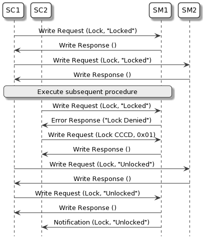
Figure 4.1 shows an example of Set Coordinator SC1 performing the Lock Request and Lock Release procedures. SC1 successfully obtains the lock from SM1 and SM2. When Set Coordinator SC2 attempts to acquire the lock, Set Member SM1 replies with the error code Lock Denied because SC1 already has the lock. SC2 then enables notifications for the Set Member Lock characteristic on SM1. SM1 notifies SC2 when the lock is available again.
4.6.5. Ordered Access procedure
If the Set Coordinator and Set Members are not bonded, the Lock Request procedure cannot be used; in this case, the Ordered Access procedure may be used to reduce the probability of undesired race conditions caused by multiple Set Coordinators executing a procedure (which is referred to as Procedure_A) with the Set Members. For example, Procedure_A could be writing a control point on the Set Members.
In the Ordered Access procedure, the Set Coordinator shall read the value of the Set Member Lock characteristic, if present, from all Set Members with which the Set Coordinator intends to execute Procedure_A. The Set Coordinator shall read the value of the Set Member Lock characteristic, starting from the Set Member with the lowest value of the Set Member Rank characteristic, and shall proceed in order of increasing rank.
As soon as one Set Member replies with the value of the Set Member Lock characteristic set to Locked, the Set Coordinator may register for notifications on the Set Member Lock characteristic and shall not execute Procedure_A with the Set Members. When the Set Member notifies the Set Member Lock characteristic with a value set to Unlocked, the Set Coordinator may restart the Ordered Access procedure.
If the value of the Set Member Lock characteristic is set to Unlocked on all Set Members with which the Set Coordinator intends to execute Procedure_A, the Set Coordinator shall execute Procedure_A, starting from the Set Member with the lowest value of the Set Member Rank characteristic and shall proceed in order of increasing rank.
5. Connection establishment procedures
Connection establishment requirements may be specified by a higher‑layer specification; if this is not the case, GAP connection modes and procedures shall be used (see Volume 3, Part C in [2]).
6. Security considerations
This section describes the security requirements for devices that implement the profile roles defined in this specification.
Table 6.1 captures the security requirements for the Set Coordinator and Set Member.
Requirements in this section are defined as “Mandatory” (M), “Optional” (O), “Excluded” (X), and “Conditional” (C.n). Conditional statements (C.n) are listed directly below the table in which they appear.
|
Security Requirement |
Set Coordinator Requirements |
Section |
Set Member Requirements |
Section |
|---|---|---|---|---|
|
Security Mode 1 Level 1 (SM1 L1) |
X |
X |
||
|
Security Mode 1 Level 2 (SM1 L2) |
O |
C.2 |
||
|
Security Mode 1 Level 3 (SM1 L3) |
O |
C.2 |
||
|
Security Mode 1 Level 4 (SM1 L4) |
O |
C.2 |
||
|
128b Key Entropy |
C.1 |
C.1 |
- C.1:
-
Mandatory if SM1 L2 or SM1 L3 is supported, otherwise not applicable.
- C.2:
-
Mandatory to support at least one of SM1 L2, SM1 L3, or SM1 L4.
6.1. Security requirements for Low Energy
This section describes the security requirements for the LE transport in terms of the Set Coordinator role and the Set Member role.
The security requirements for all characteristics defined in CSIS [1] shall satisfy Security Mode 1 Level 2, defined in Volume 3, Part C, Section 10.2.1 in [2].
Access to all characteristics defined in CSIS shall require an encryption key with at least 128 bits of entropy, derived from any of the following:
-
LE Secure Connections
-
BR/EDR Secure Connections, if Cross-Transport Key Derivation (CTKD), as defined in Volume 3, Part C, Section 14.1 in [2], is used
-
OOB method
Privacy, as defined in Volume 3, Part C, Section 10.7 in [2], should be used.
6.1.1. Set Coordinator security requirements for Low Energy
The Set Coordinator should support Bondable mode, defined in Volume 3, Part C, Section 9.4.3 in [2].
The Set Coordinator should support the bonding procedure defined in Volume 3, Part C, Section 9.4.4 in [2].
The Set Coordinator should accept the LE Security Mode and the LE Security Level combination that is requested by the Set Member. If the Set Coordinator is a BR/EDR/LE device, the Set Coordinator shall support CTKD.
If the Set Coordinator is a BR/EDR/LE device and is generating an LE Long Term Key (LTK) defined in Volume 3, Part H, Section 2.3 in [2], and the Set Coordinator does not have a BR/EDR link key, the Set Coordinator should use CTKD to derive a BR/EDR link key to help avoid a poor user experience of requiring to pair a second time.
If the Set Coordinator is using Privacy, the Set Coordinator shall distribute its Identity Address (IA) and Identity Resolution Key (IRK) [2].
6.1.2. Set Member security requirements for Low Energy
The Set Member should support Bondable mode defined in Volume 3, Part C, Section 9.4.3 in [2].
The Set Member should support the bonding procedure defined in Volume 3, Part C, Section 9.4.4 in [2].
The Set Member shall only accept the LE Security Mode and LE Security Level combination requested by the Set Coordinator if that combination satisfies the security requirements implemented by the Set Member for access to characteristics defined in CSIS [1].
If the Set Member is a BR/EDR/LE device, the Set Member shall support CTKD.
If the Set Member is a BR/EDR/LE device and is generating an LE LTK, and the Set Member does not have a BR/EDR link key, the Set Member should use CTKD to derive a BR/EDR link key to help avoid a poor user experience of requiring to pair a second time.
If the Set Member is using Privacy, the Set Member shall distribute its Identity Address (IA) and Identity Resolving Key (IRK) [2].
A privacy-enabled Set Member shall generate a new RSI value every time the private address changes. In this way, the renewal period of the RSI will be identical to the renewal period of the private address. This avoids the private address from being tracked through RSI changes or the RSI being tracked through private address changes.
If host-based privacy is used, a new RSI value shall be generated every time the timer TGAP(private_addr_int) expires (see Volume 3, Part C, Table A.1 in [2]).
A privacy-enabled Set Member should only advertise RSI values derived from a SIRK that is exposed in encrypted form.
A privacy-enabled Set Member should advertise RSI values only when in the GAP Limited Discoverable mode (see Volume 3, Part C, Section 9.2.3 in [2]).
If privacy is not enabled, the RSI may not change, or the RSI renewal period may be defined by a higher‑layer specification.
6.2. Security requirements for BR/EDR
This section describes the security requirements for the BR/EDR transport.
The Set Member security requirements for all characteristics defined in CSIS shall be Security Mode 4 Level 2, as defined in Volume 3, Part C, Section 5.2.2.8 in [2]. Access by a Set Coordinator to all characteristics defined in CSIS shall require an encryption key with at least 128 bits of entropy derived from any of the following:
-
BR/EDR Secure Connections
-
LE Secure Connections, if CTKD is used
-
OOB method
BR/EDR/LE devices shall support CTKD, and if privacy is in use, BR/EDR/LE devices shall distribute their IAs and IRKs.
If the device is a BR/EDR/LE device and is generating a link key, and if the device does not have an LE LTK, the device should use CTKD to derive an LE LTK to help avoid a poor user experience of requiring to pair a second time.
6.3. Security requirements for BR/EDR and LE
This section describes the security requirements that apply to both BR/EDR and LE transport.
A Set Member that supports the Just Works association model during the pairing procedure should inform the user when the Set Member is available for pairing and when pairing has succeeded (e.g., by blinking an LED, playing a tone, vibrating, etc.)
A user action should bring a Set Member that only supports the Just Works association model into a state in which the Set Member accepts pairing requests from a Set Coordinator (e.g., by requiring the user to press a button, power cycle the device, etc.)
If a Set Member uses a SIRK value that is exposed in encrypted form, then all the other Set Members of the Coordinated Set shall not expose the same SIRK value in plain text.
7. Generic Access Profile for BR/EDR
This section describes the GAP requirements for BR/EDR devices.
Requirements in this section are defined as “Mandatory” (M), “Optional” (O), “Excluded” (X), and “Conditional” (C.n). Conditional statements (C.n) are listed directly below the table in which they appear.
7.1. Modes
Modes are defined in Volume 3, Part C, Section 4 in [2].
The Set Member and the Set Coordinator shall support the Limited Discoverable mode or the General Discoverable mode.
The Set Member and the Set Coordinator should support Bondable mode.
Table 7.1 shows the support requirements for GAP modes for BR/EDR devices.
|
Mode |
Support in Set Member |
Support in Set Coordinator |
|---|---|---|
|
General Discoverable mode |
C.1 |
X |
|
Limited Discoverable mode |
C.1 |
X |
|
Bondable mode |
O |
O |
- C.1:
-
Mandatory to support at least one of the Limited Discoverable mode or the General Discoverable mode.
7.2. Idle Mode procedures
Idle Mode procedures are defined in Volume 3, Part C, Section 6 in [2].
The Set Coordinator shall support the General Inquiry procedure and may support the Limited Inquiry procedure.
The Set Member and the Set Coordinator should support the General Bonding procedure.
Table 7.2 shows the requirements for GAP Idle Mode procedures for BR/EDR devices.
|
Procedure |
Support in Set Member |
Support in Set Coordinator |
|---|---|---|
|
General Inquiry |
X |
M |
|
Limited Inquiry |
X |
O |
|
General Bonding |
O |
O |
8. Acronyms and abbreviations
|
Acronym/Abbreviation |
Meaning |
|---|---|
|
BR/EDR |
Basic Rate/Enhanced Data Rate |
|
CSIP |
Coordinated Set Identification Profile |
|
CSIS |
Coordinated Set Identification Service |
|
EKG |
electrocardiogram |
|
GAP |
Generic Access Profile |
|
GATT |
Generic Attribute Profile |
|
IA |
Identity Address |
|
IRK |
Identity Resolving Key |
|
LE |
Low Energy |
|
OOB |
out-of-band |
|
PDU |
Protocol Data Unit |
|
RFU |
Reserved for Future Use |
|
RSI |
Resolvable Set Identifier |
|
SIRK |
Set Identity Resolving Key |
|
UUID |
universally unique identifier |
9. References
Bibliography
[1] Coordinated Set Identification Service Specification, Version 1.0
[2] Bluetooth Core Specification, Version 4.2 or later