-
Revision: v1.0.2
-
Revision Date: 2022-01-18
-
Group Prepared By: Medical Devices Working Group
Revision History
|
Revision Number |
Date |
Comments |
|---|---|---|
|
V1.0.0 |
2014-11-18 |
Adopted by the Bluetooth SIG BoD |
|
d1.0.1 |
2015-11-19 |
ESR09 Approved by BARB (integrated E6423 and E6155) |
|
v1.0.1 |
2015-12-15 |
Adopted by the Bluetooth SIG BoD |
|
v1.0.2 |
2022-01-18 |
Adopted by the Bluetooth SIG Board of Directors. |
Version History
|
Versions |
Changes |
|---|---|
|
v1.0.0 to v1.0.1 |
Incorporated errata E6155, E6423. |
|
v1.0.1 to v1.0.2 |
Incorporated errata E16239, E16243, E17414. |
Acknowledgments
|
Name |
Company |
|---|---|
|
Robert Hughes |
Intel Corporation |
|
Ray Strickland |
Roche |
|
Ralf Schmitz |
Roche |
|
Felix Bootz |
Roche |
|
Wolfgang Heck |
Roche |
|
Krishna Shingala |
Mindtree |
|
Laurence Richardson |
CSR |
|
Leif-Alexandre Aschehoug |
Nordic Semiconductor |
|
Shawn Larvenz |
Dexcom |
|
Nathaniel Hamming |
University Health Network |
|
Melanie Yeung |
University Health Network |
|
Jordan Hartmann |
Nonin Medical, Inc. |
Use of this specification is your acknowledgement that you agree to and will comply with the following notices and disclaimers. You are advised to seek appropriate legal, engineering, and other professional advice regarding the use, interpretation, and effect of this specification.
Use of Bluetooth specifications by members of Bluetooth SIG is governed by the membership and other related agreements between Bluetooth SIG and its members, including those agreements posted on Bluetooth SIG’s website located at www.bluetooth.com. Any use of this specification by a member that is not in compliance with the applicable membership and other related agreements is prohibited and, among other things, may result in (i) termination of the applicable agreements and (ii) liability for infringement of the intellectual property rights of Bluetooth SIG and its members. This specification may provide options, because, for example, some products do not implement every portion of the specification. All content within the specification, including notes, appendices, figures, tables, message sequence charts, examples, sample data, and each option identified is intended to be within the bounds of the Scope as defined in the Bluetooth Patent/Copyright License Agreement (“PCLA”). Also, the identification of options for implementing a portion of the specification is intended to provide design flexibility without establishing, for purposes of the PCLA, that any of these options is a “technically reasonable non-infringing alternative.”
Use of this specification by anyone who is not a member of Bluetooth SIG is prohibited and is an infringement of the intellectual property rights of Bluetooth SIG and its members. The furnishing of this specification does not grant any license to any intellectual property of Bluetooth SIG or its members. THIS SPECIFICATION IS PROVIDED “AS IS” AND BLUETOOTH SIG, ITS MEMBERS AND THEIR AFFILIATES MAKE NO REPRESENTATIONS OR WARRANTIES AND DISCLAIM ALL WARRANTIES, EXPRESS OR IMPLIED, INCLUDING ANY WARRANTIES OF MERCHANTABILITY, TITLE, NON-INFRINGEMENT, FITNESS FOR ANY PARTICULAR PURPOSE, OR THAT THE CONTENT OF THIS SPECIFICATION IS FREE OF ERRORS. For the avoidance of doubt, Bluetooth SIG has not made any search or investigation as to third parties that may claim rights in or to any specifications or any intellectual property that may be required to implement any specifications and it disclaims any obligation or duty to do so.
TO THE MAXIMUM EXTENT PERMITTED BY APPLICABLE LAW, BLUETOOTH SIG, ITS MEMBERS AND THEIR AFFILIATES DISCLAIM ALL LIABILITY ARISING OUT OF OR RELATING TO USE OF THIS SPECIFICATION AND ANY INFORMATION CONTAINED IN THIS SPECIFICATION, INCLUDING LOST REVENUE, PROFITS, DATA OR PROGRAMS, OR BUSINESS INTERRUPTION, OR FOR SPECIAL, INDIRECT, CONSEQUENTIAL, INCIDENTAL OR PUNITIVE DAMAGES, HOWEVER CAUSED AND REGARDLESS OF THE THEORY OF LIABILITY, AND EVEN IF BLUETOOTH SIG, ITS MEMBERS OR THEIR AFFILIATES HAVE BEEN ADVISED OF THE POSSIBILITY OF THE DAMAGES.
Products equipped with Bluetooth wireless technology ("Bluetooth Products") and their combination, operation, use, implementation, and distribution may be subject to regulatory controls under the laws and regulations of numerous countries that regulate products that use wireless non-licensed spectrum. Examples include airline regulations, telecommunications regulations, technology transfer controls, and health and safety regulations. You are solely responsible for complying with all applicable laws and regulations and for obtaining any and all required authorizations, permits, or licenses in connection with your use of this specification and development, manufacture, and distribution of Bluetooth Products. Nothing in this specification provides any information or assistance in connection with complying with applicable laws or regulations or obtaining required authorizations, permits, or licenses.
Bluetooth SIG is not required to adopt any specification or portion thereof. If this specification is not the final version adopted by Bluetooth SIG’s Board of Directors, it may not be adopted. Any specification adopted by Bluetooth SIG’s Board of Directors may be withdrawn, replaced, or modified at any time. Bluetooth SIG reserves the right to change or alter final specifications in accordance with its membership and operating agreements.
Copyright © 2012–2022. All copyrights in the Bluetooth Specifications themselves are owned by Apple Inc., Ericsson AB, Intel Corporation, Lenovo (Singapore) Pte. Ltd., Microsoft Corporation, Nokia Corporation, and Toshiba Corporation. The Bluetooth word mark and logos are owned by Bluetooth SIG, Inc. Other third-party brands and names are the property of their respective owners.
Document Terminology
The Bluetooth SIG has adopted portions of the IEEE Standards Style Manual, which dictates use of the words “shall’’, “should”, “may”, and “can” in the development of documentation, as follows:
The word shall is used to indicate mandatory requirements strictly to be followed in order to conform to the standard and from which no deviation is permitted (shall equals is required to).
The use of the word must is deprecated and shall not be used when stating mandatory requirements; must is used only to describe unavoidable situations.
The use of the word will is deprecated and shall not be used when stating mandatory requirements; will is only used in statements of fact.
The word should is used to indicate that among several possibilities one is recommended as particularly suitable, without mentioning or excluding others; or that a certain course of action is preferred but not necessarily required; or that (in the negative form) a certain course of action is deprecated but not prohibited (should equals is recommended that).
The word may is used to indicate a course of action permissible within the limits of the standard (may equals is permitted).
The word can is used for statements of possibility and capability, whether material, physical, or causal (can equals is able to).
The term Reserved for Future Use (RFU) is used to indicate Bluetooth SIG assigned values that are reserved by the Bluetooth SIG and are not otherwise available for use by implementations.
1. Introduction
The Continuous Glucose Monitoring (CGM) Service exposes glucose measurement and other data related to a personal CGM sensor for healthcare applications.
1.1. Conformance
If conformance to this specification is claimed, all capabilities indicated as mandatory for this specification shall be supported in the specified manner (process-mandatory). This also applies for all optional and conditional capabilities for which support is indicated.
1.2. Service Dependency
This service is not dependent upon any other services.
1.3. Bluetooth Core Specification Release Compatibility
This specification is compatible with the Bluetooth Core Specification V4.0 as amended by CSA3 and CSS v2, or later.
1.4. GATT Sub-Procedure Requirements
Requirements in this section represent a minimum set of requirements for a CGM Sensor (Server). Other GATT sub-procedures may be used if supported by both Client and Server.
The table below summarizes additional GATT sub-procedure requirements beyond those required by all GATT Servers.
|
GATT Sub-Procedure |
Requirements |
|---|---|
|
Write Characteristic Values |
M |
|
Notifications |
M |
|
Indications |
M |
|
Read Characteristic Descriptors |
M |
|
Write Characteristic Descriptors |
M |
1.5. Transport Dependencies
There are no transport restrictions imposed by this service specification. For BR/EDR (and HS), the Health Device Profile [2] is recommended to be used. Where the term BR/EDR is used throughout this document, this also includes the optional use of AMP.
1.6. Byte Transmission Order
All characteristic values used with this service shall be transmitted with the least significant octet first (i.e., little endian). The least significant octet is identified in the characteristic definitions in [3].
1.7. Glucose Unit Conversion
All CGM measurement values and blood glucose concentration of calibration values shall be transmitted in the unit mg/dL only.
The client may convert received values to mmol/L, (e.g., for internal use or visualization). If the client converts glucose values the conversion factor shall be:
|
value [mg/dL] = 18.02 * value [mmol/L]. |
Note that the conversion factor is compliant to the Continua blood glucose meter specification [5].
1.8. Error Codes
This service defines the following Attribute Protocol Application Error codes:
|
Name |
Error Code |
Description |
|---|---|---|
|
Missing CRC |
0x80 |
If E2E-CRC is supported and a Write procedure is processed without CRC attached |
|
Invalid CRC |
0x81 |
If E2E-CRC is supported and a Write procedure is processed with incorrect or invalid CRC value attached |
2. Service Declaration
The CGM Service is recommended to be instantiated as a «Primary Service».
The service UUID shall be set to the UUID value assigned to «CGM Service» as defined in [3].
3. Service Characteristics
The characteristic requirements of the CGM Service are shown in Table 3.1. Unless otherwise specified, only one instance of each characteristic is permitted within each service.
|
Characteristic Name |
Requirement |
Mandatory Properties |
Optional Properties |
Security Permissions |
|---|---|---|---|---|
|
CGM Measurement |
M |
Notify |
Authentication required |
|
|
CGM Measurement - Client Characteristic Configuration descriptor |
M |
Write (Read *) |
Authentication required |
|
|
CGM Feature |
M |
Read |
Indicate C.1 |
Authentication required |
|
CGM Status |
M |
Read |
Authentication required |
|
|
CGM Session Start Time |
M |
Read, Write |
Authentication required |
|
|
CGM Session Run Time |
M |
Read |
Authentication required |
|
|
Record Access Control Point |
M |
Indicate, Write |
Authentication required |
|
|
Record Access Control Point – Client Characteristic Configuration descriptor |
M |
Write (Read *) |
Authentication required |
|
|
CGM Specific Ops Control Point |
M |
Indicate, Write |
Authentication required |
|
|
CGM Specific Ops Control Point – Client Characteristic Configuration descriptor |
M |
Write (Read *) |
Authentication required |
- C.1:
-
The Indicate property shall be supported for the CGM Feature characteristic if the value of the CGM Feature characteristic can change over the lifetime of the device, otherwise Excluded for this service.
- Notes:
-
(Read *): Readable with no authentication or authorization already defined in [1].
The CGM Measurement characteristic is a variable length structure containing one or more CGM Measurement records, each comprising:
-
a Size Field
-
a Flags Field
-
a Glucose Concentration Field
-
a Time Offset Field (i.e., relative time)
-
a Sensor Status Annunciation Field (optional)
-
a CGM Trend Information Field (optional)
-
a CGM Quality Field (optional)
-
a E2E-CRC Field (optional)
- Note:
-
The presence of an optional field is shown either by the corresponding bit in the CGM Features characteristic or by the content of the Flags field (e.g. if the device supports E2E-CRC, the E2E-CRC Supported bit in the CGM Features characteristic shall be set to 1 and the CGM Measurement characteristic shall contain an E2E-CRC Field). The CRC calculation shall include all fields except the CRC field itself.
If the device supports CGM Trend information, the CGM Trend Information supported bit in the CGM Features characteristic shall be set to 1. The CGM Measurement record shall contain the CGM Trend Information Field when the value of bit 0 in the Flags Field is set to 1. If set to 0 the CGM Measurement record shall not contain a CGM Trend Information Field.
CGM Quality has similar behavior. (see Section 3.2.1.1 for details)
It is required to read the CGM Feature characteristic first to enable correct interpretation of the CGM Measurement characteristic value.
The CGM Measurement record defines a patient record to be accessed using the Record Access Control Point.
3.1.
3.1.1. Characteristic Behavior
There are two ways that a client can receive notifications of the CGM Measurement Characteristic value: periodic and requested. The Client Characteristic Descriptor is required to be configured for notifications in both cases:
-
Periodic Notifications:
If a CGM session is running, the CGM Sensor measures the glucose level periodically in a device specific interval (Measurement time interval). When the CGM Communication Interval is set for periodic communication (see Section 3.7.2.1), the CGM Sensor periodically sends notifications of the most recent CGM measurements that have occurred since the last communication interval notification.
-
Requested Notifications:
If a CGM session is running and the client misses some CGM measurements (e.g., due to link loss, or the CGM session is stopped), the client may write to the Record Access Control Point characteristic to request specific data from the patient record database, which triggers immediate notifications of the CGM Measurement characteristic value.
The Glucose Measurement characteristic value contains time-sensitive data, thus the requirements for time-sensitive data and data storage defined in Section 3.9 apply.
3.1.1.1. Size Field
The Size Field represents the size of the CGM Measurement record in an UINT 8. The minimum size is 6 octets and is enlarged if more octets are indicated by the Flags Field (Sensor Status Annunciation Field, CGM Trend Information Field and CGM Quality Field) and the optional E2E-CRC Field. The Size Field itself is included in the length calculation.
3.1.1.2. Flags Field
The Flags Field indicates the presence of optional fields and the Sensor Status Annunciation Field in the CGM Measurement record.
3.1.1.3. CGM Glucose Concentration Field
The CGM Glucose Concentration field contains the CGM glucose concentration in a SFLOAT data type. The SFLOAT-Type is a 16-bit word comprising a signed 4-bit integer exponent followed by a signed 12-bit Mantissa.
Note that the unit of the CGM Glucose concentration is in mg/dL only.
3.1.1.4. Time Offset Field
The Time Offset field is used in conjunction with the CGM Session Start Time to represent the time difference of the separate CGM measurements in relation to the session start time. Note that this Time Offset field serves also as a sequence number for the client, allowing the client to identify gaps / missing results in the data stream.
The Time Offset field is defined as a UINT 16 according to the byte transmission order, defined in Section 1.6, representing the number of minutes the user-facing time differs from the Session Start Time. The default initial value shall be 0x0000. The Time Offset field shall be incremented by the measurement interval with each CGM measurement record (see Section 3.7.2.1).
See also Section 3.6.3.4 for requirements related to the use of this field in the first transmitted patient record when using the Record Access Control Point.
3.1.1.5. Sensor Status Annunciation Field
The Sensor Status Annunciation field may form part of the CGM Measurement record. This field has a variable length between 1 and 3 octets. If one or more bits in the Sensor Status Annunciation field are set to “1” the Sensor Status Annunciation field shall form part of every CGM Measurement Record to which it applies.
|
Bit |
Octet |
|---|---|
|
0 … 7 |
Status |
|
8 … 15 |
Cal/Temp |
|
16 … 23 |
Warning |
The presence of the octets of the Sensor Status Annunciation Field shall depend on the corresponding bit in the Flags Field.
Bits defined as Reserved for Future Use (RFU) in the Sensor Status Annunciation field in [3] shall be set to “0”.
There shall be only an octet attached in which at least one bit number is set to “1”. For example:
If Bit 17 is set to “1” and all other Bits are set to “0”, the Warning octet forms part of the CGM Measurement Record and Bit 5 of the Flags Field is set to “1”, announcing the presence of Warning octet of the Sensor Status Annunciation Field.
If Bit 3, Bit 12 and Bit 17 are set to “1”, then Status, Cal/Temp and Warning octets of the Sensor Status Annunciation Field are attached to the CGM Measurement Record. Bit 5, Bit 6 and Bit 7 of the Flags Field are set to “1”, announcing the presence of Status, Cal/Temp and Warning octets of the Sensor Status Annunciation Field.
3.1.1.6. CGM Trend Information Field
If the device supports CGM Trend information (CGM-Trend-Information Supported bit is set in CGM Features), this field may be included in the record. The presence of this field in a record is indicated by the Flags Field. This field contains the CGM Trend information in (mg/dL)/min as an SFLOAT data type.
3.1.1.7. CGM Quality Field
If the device supports CGM Quality (CGM-Quality Supported bit is set in CGM Features), this field may be included in the CGM measurement record. The presence of this field in a CGM measurement record is indicated by the Flags Field. This field contains the CGM Quality information in % as an SFLOAT data type.
3.1.1.8. E2E-CRC Field
If the device supports E2E-safety (E2E-CRC Supported bit is set in CGM Features), the measurement shall be protected by a CRC calculated over all fields, see Section 3.11 for details.
If E2E-safety is supported and an error occurs, the error codes as defined in Section 1.8 shall be used.
3.1.2. Characteristic Descriptors
3.1.2.1. Client Characteristic Configuration Descriptor
The Client Characteristic Configuration descriptor shall be included in the CGM Measurement characteristic definition.
3.2. CGM Feature
The CGM Feature characteristic is used to describe the supported features of the Server.
3.2.1. Characteristic Behavior
When read or indicated, the CGM Feature characteristic gives a value that is used by a Client to determine the supported features of the Server. Additionally, the CGM Feature contains the CGM Type-Sample Location field: This field is the combination of the Type field and the Sample Location field and is static for a CGM sensor.
The CGM Feature characteristic shall be static during a connection.
When the Client Characteristic Configuration descriptor is configured for indications and the supported features of the Server have changed, the CGM Feature characteristic shall be indicated to any bonded Collectors after reconnection.
3.2.1.1. CGM Feature Field
If the Calibration feature is supported, the Calibration Supported Feature bit shall be set to 1, otherwise it shall be set to 0. When supported, the corresponding bit in the Sensor Status Annunciation Field (Calibration required, Calibration recommended and Calibration not allowed) shall be used to show whether or not a calibration is needed or recommended. When not supported, the corresponding bit in the Sensor Status Annunciation Field shall be set to 0.
If the Patient High/Low Alert feature is supported, the Patient High/Low Alert Supported Feature bit shall be set to 1, otherwise it shall be set to 0. When supported, the corresponding bit in the Sensor Status Annunciation Field (Sensor result higher than Patient High level / Sensor result lower than Patient Low level) shall be used to show whether or not a Glucose Concentration value that is too high or too low was detected during a measurement. When not supported, the corresponding Flags in the Sensor Status Annunciation Field shall be set to 0.
If the Hypo Alert feature is supported, the Hypo Alert Supported Feature bit shall be set to 1, otherwise it shall be set to 0. When supported, the corresponding bit in the Sensor Status Annunciation Field (Sensor result lower than Hypo level) shall be used to show whether or not a Glucose Concentration value that is too low was detected during a measurement. When not supported, the corresponding bit in the Sensor Status Annunciation Field shall be set to 0.
If the Hyper Alert feature is supported, the Hyper Alert Supported Feature bit shall be set to 1, otherwise it shall be set to 0. When supported, the corresponding bit in the Sensor Status Annunciation Field (Sensor result higher than Hyper level) shall be used to show whether or not a Glucose Concentration value that is too high was detected during a measurement. When not supported, the corresponding Flag in the Sensor Status Annunciation Field shall be set to 0.
If the Rate of Increase/Decrease Alert feature is supported, the Rate of Increase/Decrease Alert Supported Feature bit shall be set to 1, otherwise it shall be set to 0. When supported, the corresponding bit in the Sensor Status Annunciation Field (Sensor Rate of Increase exceeded / Sensor Rate of Decrease exceeded) shall be used to show whether or not a Glucose rate of change that is too high or too low was detected during a measurement. When not supported, the corresponding bit in the Sensor Status Annunciation Field shall be set to 0.
If the Device Specific Alert feature is supported, the Device Specific Alert Supported Feature bit shall be set to 1, otherwise it shall be set to 0. When supported, the corresponding bit in the Sensor Status Annunciation Field shall be used to show whether or not a CGM Sensor device specific alert was detected. For example, a device specific alert has occurred in the sensor, therefore a device specific action is necessary on the client. The meaning of this bit is vendor specific. When not supported, the corresponding bit in the Sensor Status Annunciation Field shall be set to 0.
If the Sensor Malfunction Detection feature is supported, the Sensor Malfunction Detection Supported Feature bit shall be set to 1, otherwise it shall be set to 0. When supported, the corresponding bit in the Sensor Status Annunciation Field (Sensor malfunction or faulting at time of measurement) shall be used to show whether or not a Sensor malfunction or fault was detected during a measurement. When not supported, the corresponding bit in the Sensor Status Annunciation Field shall be set to 0.
If the Sensor Temperature High-Low Detection feature is supported, the Sensor Temperature High-Low Detection Supported Feature bit shall be set to 1, otherwise it shall be set to 0. When supported, the corresponding bits in the Sensor Status Annunciation Field (Sensor temperature too high for valid test/result at time of measurement, and Sensor temperature too low for valid test/result at time of measurement) shall be used to show whether or not a Sensor temperature that is too high or too low was detected during a measurement. When not supported, the corresponding bits in the Sensor Status Annunciation Field shall be set to 0.
If the Sensor Result High-Low Detection feature is supported, the Sensor Result High-Low Detection Supported Feature bit shall be set to 1, otherwise it shall be set to 0. When supported, the corresponding bits in the Sensor Status Annunciation Field (Sensor result higher than the device can process or above a Sensor threshold, and Sensor result lower than the device can process or below a Sensor threshold) shall be used to show whether or not a Sensor result that is higher or lower than the device can process was detected during a measurement. When not supported, the corresponding bits in the Sensor Status Annunciation Field shall be set to 0.
If the Low Battery Detection feature is supported, the Low Battery Detection Supported Feature bit shall be set to 1, otherwise it shall be set to 0. When supported, the corresponding bit in the Sensor Status Annunciation Field (Device battery low) shall be used to show whether or not a low battery condition was detected. When not supported, the corresponding bit in the Sensor Status Annunciation Field shall be set to 0.
If the Sensor Type Error Detection feature is supported, the Sensor Type Error Detection Supported Feature bit shall be set to 1, otherwise it shall be set to 0. When supported, the corresponding bit in the Sensor Status Annunciation Field (Sensor type incorrect for device) shall be used to show whether or not an incorrect sensor type for the device was detected at session start. When not supported, the corresponding bit in the Sensor Status Annunciation Field shall be set to 0.
If the General Device Fault feature is supported, the General Device Fault Supported Feature bit shall be set to 1, otherwise it shall be set to 0. When supported, the corresponding bit in the Sensor Status Annunciation Field shall be used to show whether or not a CGM Sensor general device fault was detected. When not supported, the corresponding bit in the Sensor Status Annunciation Field shall be set to 0. For example an electronic fault in hardware occurred, not directly related to measurement, such as CRC errors, storage errors, radio errors, or others.
If the E2E-CRC feature is supported, the E2E-CRC Supported Feature bit shall be set to 1, otherwise it shall be set to 0. If E2E-CRC is supported, the CGM Measurement characteristic, the CGM Status characteristic, the CGM Session Start Time characteristic, the CGM Session Run Time characteristic and the CGM Specific Ops Control Point characteristic shall contain an E2E-CRC field.
If the Multiple Bond feature is supported, the Multiple Bond Supported Feature bit shall be set to 1, otherwise it shall be set to 0.
If the Multiple Session feature is supported, the Multiple Session Supported Feature bit shall be set to 1, otherwise it shall be set to 0.
If the CGM Trend Information feature is supported, the CGM Trend Information Supported Feature bit shall be set to 1, otherwise it shall be set to 0. If CGM Trend Information is supported, the CGM Measurement characteristic may contain a CGM Trend Information field.
If the CGM Quality feature is supported, the CGM Quality Supported Feature bit shall be set to 1, otherwise it shall be set to 0. If CGM Quality is supported, the CGM Measurement characteristic may contain a CGM Quality field.
Bits defined as Reserved for Future Use (RFU) in the CGM Feature characteristic shall be set to 0.
3.2.1.2. CGM Feature Type-Sample Location Field
The Type-Sample Location field for the CGM values is part of the CGM Feature because the Type-Sample Location is static for the CGM session. Thus, the client needs to read it once only (e.g., to be read at initial connection time).
The Type-Sample Location field is an octet (8 bit) and is comprised of two fields, each a 4 bit nibble, where the least significant nibble contains the Type and the most significant nibble contains the Sample Location.
3.2.1.3. E2E-CRC Field
If the device supports E2E-safety (E2E-CRC Supported bit is set in CGM Features), the CGM Feature shall be protected by a CRC calculated over all data, see Section 3.11 for details.
This field is mandatory in this characteristic. If the device doesn’t support E2E-safety, the value of the field shall be set to 0xFFFF.
If E2E-safety is supported and an error occurs, the error codes as defined in Section 1.8 shall be used.
3.3. CGM Status
The CGM Status allows the client to actively request the status from the CGM Sensor, particularly when the CGM measurement is not running and the status cannot be given in the measurement result in the Status Annunciation Field.
3.3.1. Time Offset Field
The Time Offset Field shall specify the actual relative time difference to the session start time.
3.3.2. CGM Status Field
The structure of the CGM Status Field shall be identical to the structure of the Sensor Status Annunciation Field, as defined in Section 3.1.1.5. The meaning of the different bits is mostly explained in Section 3.2.1.1 except for the following bits:
-
Time synchronization between sensor and client required:
If this bit is set to 1, the Session Start Time is not set or the information is lost.
-
Session stopped:
If the CGM session is stopped, this bit is set (e.g., to allow another client to detect the status).
3.3.3. E2E-CRC Field (optional)
If the device supports E2E-safety (E2E-CRC-Supported bit is set in CGM Features), the CGM Status shall be protected by a CRC calculated over all fields, see Section 3.11 for details.
If E2E-safety is supported and an error occurs, the error codes as defined in Section 1.8 shall be used.
3.4. CGM Session Start Time
3.4.1. Session Start Time Field
The Session Start Time Field defines the time of the initial CGM measurement. The absolute time of the first CGM measurement taken is not known, so the Server stores each CGM measurement with a relative time stamp (Time Offset), starting with 0 for the first measurement (Session Start).
Upon initial connection, if the device supports an automatic start of the CGM session (e.g., at power on), or after the Start Session procedure, the Client shall write its current time to this characteristic and the Server shall calculate and store the Session Start Time using the time of the client and its own current relative time value.
3.4.2. Time Zone Field
To know an absolute Time, it is necessary to know the Time Zone to which the Session Start Time is related to. If unknown, the field shall be set to a value of -128. See definition of Time Zone Characteristic in [3].
3.4.3. DST Offset Field
To know an absolute Time, it is also necessary to know the Daylight Saving setting. If unknown, the field shall be set to a value of 255. See definition of DST Offset Characteristic in [3].
3.4.4. E2E-CRC Field (optional)
If the device supports E2E-safety (E2E-CRC Supported bit is set in CGM Features), the CGM Session Start Time shall be protected by a CRC calculated over all fields, see Section 3.11 for details.
If E2E-safety is supported and an error occurs, the error codes as defined in Section 1.8 shall be used.
3.4.5. Supplementary Details
The Session Start procedure will clear the CGM measurement database, so the Session Start Time characteristic is cleared too.
The Session Start Time shall be the (static) reference time for the system during a single CGM session, (i.e., particularly for the user-facing time) only the Client is responsible to take actions in case of time-deviation (e.g., warn the user about these time deviations).
The CGM Session Start Time field is in the same format and units as the Date Time characteristic [3].
Some remarks for the client:
The user-facing time (i.e., the time of measurement with respect to the user of the device) is the sum of the Session Start Time and the current measurement Time Offset value. The Session Start time is calculated and set by the server at the particular time of the initial connection and should not be changed afterwards. It serves as the base time of the system (e.g., in case of manual time changes on the client or in case of a different time of a second, temporarily connected client). The user-facing time of the client should be synchronized to the Session Start time.
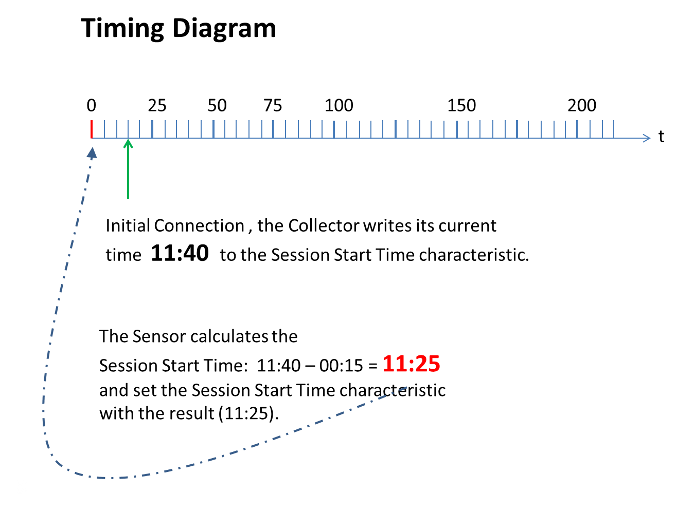 |
The figure above is an example to visualize the procedure of setting the CGM Session Start Time initiated by a write to the CGM Start Time characteristic. The time values are simplified and not in the specified format to get a better readability.
3.5. CGM Session Run Time
3.5.1. CGM Session Run Time Field
The CGM Session Run Time shall define the expected run time of the CGM session. Typically CGM Sensors have a limited run time which they are approved for. However, this characteristic should enable a prediction of the run time depending on physiological effects in future devices.
The CGM Session Run Time is a relative time, based on the CGM Session Start Time.
3.5.2. E2E-CRC Field (optional)
If the device supports E2E-safety (E2E-CRC Supported bit is set in CGM Features), the CGM Session Start Time shall be protected by a CRC calculated over all fields, see Section 3.11 for details.
If E2E-safety is supported and an error occurs, the error codes as defined in Section 1.8 shall be used.
3.6. Record Access Control Point
The Record Access Control Point is defined by the Glucose Service. Due to reuse of this control point, there is no E2E-CRC possible for this control point.
3.6.1. Record Definition
Within the context of the CGM Service, a CGM record consists of a CGM Measurement characteristic value, according to Section 3.1.1.
3.6.2. Record Access Control Point Procedure Requirements
The table below shows the requirements for the Record Access Control Point (RACP) procedures (Op Codes, Operators and Operands) in the context of this service:
|
Op Code |
Op Code Requirement |
Operator |
Operator Requirement |
Operand |
Operand Requirement |
|
|---|---|---|---|---|---|---|
|
Filter Type (see Table 3.5) |
Filter Parameters (see Table 3.4) |
|||||
|
Report Stored Records |
M |
All records |
M |
No Operand Used |
N/A |
|
|
Less than or equal to |
O |
Time Offset |
<maximum filter value> |
C.1 |
||
|
Greater than or equal to |
M |
Time Offset |
<minimum filter value> |
M |
||
|
Within range of (inclusive) |
O |
Time Offset |
<minimum filter value>, <maximum filter value> |
C.1 |
||
|
First record |
O |
No Operand Used |
N/A |
|||
|
Last record |
O |
No Operand Used |
N/A |
|||
|
Delete Stored Records |
O |
All records |
C.2 |
No Operand Used |
N/A |
|
|
Less than or equal to |
O |
Time Offset |
<maximum filter value> |
C.1 |
||
|
Greater than or equal to |
O |
Time Offset |
<minimum filter value> |
C.1 |
||
|
Within range of (inclusive) |
O |
Time Offset |
<minimum filter value>, <maximum filter value> |
C.1 |
||
|
First record |
O |
No Operand Used |
N/A |
|||
|
Last record |
O |
No Operand Used |
N/A |
|||
|
Abort Operation |
M |
Null (0x00) |
M |
No Operand Used |
N/A |
|
|
Report Number of Stored Records |
M |
All records |
M |
No Operand Used |
N/A |
|
|
Less than or equal to |
O |
Time Offset |
<maximum filter value> |
C.1 |
||
|
Greater than or equal to |
M |
Time Offset |
<minimum filter value> |
M |
||
|
Within range of (inclusive) |
O |
Time Offset |
<minimum filter value>, <maximum filter value> |
C.1 |
||
|
First record |
O |
No Operand Used |
N/A |
|||
|
Last record |
O |
No Operand Used |
N/A |
|||
|
Responses |
||||||
|
Op Code |
Op Code Requirement |
Operator |
Operator Requirement |
Operand |
Operand Requirement |
|
|
Number of Stored Records Response |
M |
Null (0x00) |
M |
UINT16 containing number of records |
M |
|
|
Response Code |
M |
Null (0x00) |
M |
Request Op Code, Response Code Value |
M |
|
- C.1
-
If this Operator is supported, this Operand is mandatory for this Operator. See also Note 1.
- C.2
-
If this Op Code is supported, this Operator is mandatory for this Op Code. See also Note 2.
Notes:
-
Support for a given Operand for one Op Code and Operator combination does not imply support of that Operand for other Op Code and Operator combinations.
-
Support for a given Operator for one Op Code does not imply support of that Operator for other Op Codes.
-
Where a filter type and filter parameters are used, the byte order for the Operand is specified in Section 3.6.3.1.
Table 3.4 shows the relationships between RACP Operators and Operands.
|
Procedure Operator |
Operand Description |
|---|---|
|
Null |
An Operand is used only in the case of the responses Number of Stored Records Response and Response Code as shown in Table 3.3. |
|
All records |
No Operand used |
|
Less than or equal to |
Operand represents Filter Type (see Table 3.5) and maximum field value |
|
Greater than or equal to |
Operand represents Filter Type (see Table 3.5) and minimum field value |
|
Within range of (inclusive) |
Operand represents Filter Type (see Table 3.5) and minimum field value, maximum field value pair |
|
First record |
No Operand used |
|
Last record |
No Operand used |
Note that when using the ‘within range of’ Operator, the minimum value of the range shall be a less than or equal to the maximum value of the range regardless of the Filter Type used in the Operand.
The following table shows the Filter Types that apply to three of the Operators listed in Table 3.4 (i.e., less than or equal to, greater than or equal to, and within range of). Within the Operand, the Filter Type specifies the field of the CGM Measurement characteristic value upon which the filtering is based. See Section 3.6.3.1 for further information. The usage of Filter Type User Facing Time (0x02) shall not be used in the context of the CGM service. This Filter Type is present to reuse reason only. For the CGM service, only Time Offset (0x01) is allowed to be used, it is handled like the sequence number.
|
Operand Filter Type Value |
Filter Type Description |
|---|---|
|
0x00 |
Reserved for future use |
|
0x01 |
Time Offset |
|
0x02 * |
User Facing Time (Base Time + Offset Time) * |
|
0x02 – 0xFF |
Reserved for future use |
* within CGM Service not allowed
3.6.3. Record Access Control Point Behavioral Description
The Record Access Control Point shall be used to control notifications of the CGM Measurement and other data operations. Procedures are triggered by a Write to this characteristic value that includes an Op Code specifying the operation (see Table 3.3) and an Operator and Operand that are valid within the context of that Op Code (see Table 3.4). In a multiple-bond case, the handling of the Control Point shall be consistent across all bonds (i.e., there is a single database that is shared by all clients).
3.6.3.1. Filter Types
Since the value of the Operand is defined per service, when the Record Access Control Point is used with the CGM Service, a Filter Type field is defined to enable the flexibility to filter based on different criteria. In the context of the CGM service, only Filter Type 0x01 (Time Offset) is allowed to be used.
If the Filter Type used within CGM Service is 0x02, the Server shall indicate the Control Point with a Response Code Op Code and Response Code Value in the Operand set to Operand not supported (see RACP in [3]).
Some Procedure Operators (i.g., less than or equal to, greater than or equal to, and within range of) require a Filter Type as part of the Operand. This is used to specify the field in the CGM Measurement characteristic value that is used to perform the filtering. When used, the Filter Type byte shall precede the applicable filter parameter(s) within the Operand. For example, when used with the ‘within range of’ Operator, the Operand has the format <Filter Type><minimum><maximum> where Filter Type is the Least Significant Octet of the Operand. See Table 3.5 for a list of valid Filter Type values.
When using the Time Offset Filter Type, the format of the Operand is the Time Offset Filter Type value followed by the applicable Time Offset value or value pair depending upon the Operator.
3.6.3.2. Report Number of Stored Records procedure
When the Report Number of Stored Records Op Code is written to the Record Access Control Point, the Server shall calculate and respond with a record count in UINT16 format based on filter criteria, Operator and Operand values. Refer to Table 3.4 for Operand requirements when used with a specific Operator and note that in some cases, no Operand is used. The record count reported in the response is calculated based on the current state of the sensor database, and may change between connections or after records are cleared. The response is indicated using the Number of Stored Records Response Op Code.
If the Server does not locate any records matching the filter criteria of the request, the Server shall indicate the Record Access Control Point with a Number of Stored Records Response Op Code and the Operand set to 0x0000.
If the operation results in an error condition, this shall be indicated using the Response Code Op Code and the appropriate Response Code Value in the Operand for the error condition (see Sections 3.6.3.6 and 3.8).
3.6.3.3. Delete Stored Records procedure
When the Delete Stored Records Op Code is written to the Record Access Control Point, the Server may delete the specified patient records based on Operator and Operand values. Deletion of records may be a permanent deletion of records from the patient database. Refer to Table 3.4 for Operand requirements when used with a specific Operator and note that in some cases, no Operand is used. The Server shall indicate this characteristic with a Response Code Value of Success if the records were successfully deleted from the patient record database (see RACP in [3]).
If the Server does not locate any records matching the filter criteria of the request, the Server shall indicate the Record Access Control Point with a Response Code Op Code and Response Code Value in the Operand set to No Records Found (see RACP in [3]).
If the operation results in an error condition, this shall be indicated using the Response Code Op Code and the appropriate Response Code Value in the Operand for the error condition (see Sections 3.6.3.6 and 3.8).
3.6.3.4. Report Stored Records procedure
When the Report Stored Records Op Code is written to the Record Access Control Point, the Server shall notify the selected set of stored patient records based on the filter criteria specified in the Operator and Operand. Refer to Table 3.4 for Operand requirements when used with a specific Operator and note that in some cases, no Operand is used. The semantics of a record transfer is a ‘copy’ of the records and not a ‘move’ of the records.
Once all data records for a given request have been notified by the Server, the Server shall indicate the Record Access Control Point with a Response Code Op Code and Response Code Value in the Operand set to Success (see RACP in [3]).
If the Server does not locate any records matching the filter criteria of the request, the Server shall indicate the Record Access Control Point with a Response Code Op Code and Response Code Value in the Operand set to No Records Found (see RACP in [3]).
If the operation results in an error condition, this shall be indicated using the Response Code Op Code and the appropriate Response Code Value in the Operand for the error condition (see Sections 3.6.3.6 and 3.8).
If the Server is required to interrupt its data transfer before completion for any reason, the Server shall indicate the Record Access Control Point with a Response Code Op Code and Response Code Value in the Operand set to Procedure not completed (see RACP in [3]).
3.6.3.5. Abort Operation procedure
When the Abort Operation Op Code is written to the Record Access Control Point, the Server shall stop any RACP procedures currently in progress and shall make a best effort to stop sending any further data.
Once all RACP procedures have been stopped, the Server shall indicate the Record Access Control Point with a Response Code Op Code and Response Code Value in the Operand set to Success (see RACP in [3]).
If the operation results in an error condition, this shall be indicated using the Response Code Op Code and the appropriate Response Code Value in the Operand for the error condition (see Sections 3.6.3.6 and 3.8).
3.6.3.6. RACP Specific Errors
If the Filter Type within an Operand that was written to the Control Point characteristic is not supported by the Server, the Server shall indicate the Control Point with a Response Code Op Code and Response Code Value in the Operand set to Operand Not Supported (see RACP in [3]).
If the Server is unable to complete a procedure for any reason not stated here, the Server shall indicate the Control Point with a Response Code Op Code and Response Code Value in the Operand set to Procedure not completed (see RACP in [3]).
If the Server is unable to process the Abort Operation procedure for any reason not stated here, the Server shall indicate the Control Point with a Response Code Op Code and Response Code Value in the Operand set to Abort unsuccessful (see RACP in [3]).
If a request with an Op Code other than Abort Operation is written to the Control Point while the Server is performing a previously triggered RACP operation (i.e., resulting from invalid Client behavior), the Server shall return an error response with the Attribute Protocol Application error code set to Procedure Already In Progress (see RACP in [3]).
If the Op Code that was written to the Control Point characteristic requests record notifications and the Client Characteristic Configuration descriptor is not configured for notifications, the Server shall return an error response with the Attribute Protocol Application error code set to Client Characteristic Configuration Descriptor Improperly Configured.
If the Operator that was written to the Control Point characteristic is not supported by the Server, the Server shall indicate the Control Point with a Response Code Op Code and Response Code Value in the Operand set to Operator Not Supported (see RACP in [3]).
If the Operator that was written to the Control Point characteristic is invalid, the Server shall indicate the Control Point with a Response Code Op Code and Response Code Value in the Operand set to Invalid Operator (see RACP in [3]).
3.7. CGM Specific Ops Control Point
The Client shall perform a write to the CGM Specific Ops Control Point to request a desired CGM specific procedure at the Server.
3.7.1. CGM Specific Ops Control Point Procedure Requirements
The table below shows the requirements for the CGM Specific Ops Control Point procedures (Op Codes and Operands) in the context of this service:
|
Op Code |
Op Code Requirement |
Operand |
Operand Requirement |
|---|---|---|---|
|
Set CGM communication interval |
M |
UINT8 containing Communication Interval in minutes |
M |
|
Get CGM communication interval |
M |
N.A. |
N.A. |
|
Set Glucose Calibration value |
C.1 |
Operand as defined in [3] |
M |
|
Get Glucose Calibration value |
C.1 |
UINT16 containing Calibration Data Record Number |
M |
|
Set Patient High Alert Level |
C.2 |
SFLOAT containing level in mg/dL |
M |
|
Get Patient High Alert Level |
C.2 |
N.A. |
N.A. |
|
Set Patient Low Alert Level |
C.2 |
SFLOAT containing level in mg/dL |
M |
|
Get Patient Low Alert Level |
C.2 |
N.A |
N.A. |
|
Set Hypo Alert Level |
C.3 |
SFLOAT containing level in mg/dL |
M |
|
Get Hypo Alert Level |
C.4 |
N.A |
N.A |
|
Set Hyper Alert Level |
C.5 |
SFLOAT containing level in mg/dL |
M |
|
Get Hyper Alert Level |
C.6 |
N.A |
N.A |
|
Set Rate of Decrease Alert Level |
C.7 |
SFLOAT containing level in mg/dL/min |
M |
|
Get Rate of Decrease Alert Level |
C.8 |
N.A |
N.A |
|
Set Rate of Increase Alert Level |
C.7 |
SFLOAT containing level in mg/dL/min |
M |
|
Get Rate of Increase Alert Level |
C.8 |
N.A |
N.A |
|
Reset Device Specific Alert |
C.9 |
N.A |
N.A |
|
Start Session |
C.10 |
N.A |
N.A |
|
Stop Session |
C.10 |
N.A |
N.A |
|
Responses |
|||
|
Op Code |
Op Code Requirement |
Operand |
Operand Requirement |
|
Communication Interval Response |
M |
UINT8 containing communication interval in minutes |
M |
|
Calibration Value Response |
C.1. |
Calibration Record as defined in [3] |
M |
|
Patient High Alert Level Response |
C.2 |
SFLOAT containing alert level in mg/dL |
M |
|
Patient Low Alert Level Response |
C.2 |
SFLOAT containing alert level in mg/dL |
M |
|
Hypo Alert Level Response |
C.4 |
SFLOAT containing alert level in mg/dL |
M |
|
Hyper Alert Level Response |
C.6 |
SFLOAT containing alert level in mg/dL |
M |
|
Rate of Decrease Alert Level Response |
C.8 |
SFLOAT containing alert level in mg/dL/min |
M |
|
Rate of Increase Alert Level Response |
C.8 |
SFLOAT containing alert level in mg/dL/min |
M |
|
Response |
M |
Request Op Code, Response Code Value |
M |
- C.1:
-
If Calibration is supported, this Op code is mandatory otherwise excluded
- C.2:
-
If Patient High/Low Alert is supported this Op Code is mandatory otherwise excluded
- C.3:
-
If Hypo Alert is supported, this Op code is optional otherwise excluded
- C.4:
-
If Hypo Alert is supported, this Op code is mandatory otherwise excluded
- C.5:
-
If Hyper Alert is supported, this Op code is optional otherwise excluded
- C.6:
-
If Hyper Alert is supported, this Op code is mandatory otherwise excluded
- C.7:
-
If Rate of Increase/Decrease Alert is supported, this Op code is optional otherwise excluded
- C.8:
-
If Rate of Increase/Decrease Alert is supported, this Op code is mandatory otherwise excluded
- C.9:
-
If Device Specific Alert is supported, this Opcode is mandatory otherwise excluded
- C.10:
-
If Multiple Session is supported, this Op Code is mandatory otherwise optional
3.7.2. CGM Specific Ops Control Point Behavioral Description
The client shall write the CGM Specific Ops Control Point characteristic using one of the supported Op Codes in Table 3.6 to request a CGM Sensor to perform a procedure. This may include parameters that are valid within the context of that Op Code as defined in [3].
If the device supports E2E-safety (E2E-CRC Supported bit is set in CGM Features), the CGM Specific Ops Control Point shall be protected by a CRC calculated over all fields.
If an error in the CRC calculation is detected the Server shall return an error response with the Attribute Protocol Application error code set to Invalid CRC. If the CRC is not present, the Server shall return an error response with the Attribute Protocol Application error code set to Missing CRC. See Section 1.8 for error code definition.
3.7.2.1. CGM Communication Interval procedures
When the Set CGM Communication Interval Op Code is written to the CGM Specific Ops Control Point, the Server shall change the time interval after which the CGM Measurement characteristic is sent to the client.
If the Operand that was sent with a Set CGM Communication Interval Op Code is 0x00, the Server may disable the periodic communication. If the Operand that was sent is 0xFF, the Server shall change its communication interval time to the fastest interval supported by the device. Otherwise the Server shall change its communication interval time according to the Operand value.
The Server shall indicate this characteristic with a Response Code Value of Success if the communication interval was successfully changed.
- Note:
-
If periodic communication is disabled and Sensor disconnects, there is still a periodic advertisement sent to allow a reconnection.
When the Get CGM Communication Interval Op Code is written to the CGM Specific Ops Control Point, the Server shall look up the current value that is stored.
The Server shall indicate the CGM Communication Interval Response Op Code with the Operand set to current used value.
If the operation results in an error condition, this shall be indicated using the Response Code Op Code and the appropriate Response Code Value in the Operand for the error condition as described in Section 3.8.2.
3.7.2.2. Glucose Calibration procedures
This subsection is only relevant if the Calibration supported bit in the CGM Feature Characteristic is set to 1.
The Glucose Calibration Operand is a fixed length structure containing the Calibration Glucose Concentration of Calibration field, the Calibration Time field, the Calibration Type-Sample Location field, the Next Calibration Time field, the Calibration Data Record Number field and the Calibration Status field. This structure is named Calibration Data Record.
|
LSO |
MSO |
|
Glucose Concentration of Calibration |
Calibration Time |
Calibration Type-Sample Location |
Next Calibration Time |
Calibration Data Record Number |
Calibration Status |
||
|---|---|---|---|---|---|---|---|
|
Byte Order |
LSO...MSO |
LSO…MSO |
N/A |
LSO...MSO |
LSO…MSO |
N/A |
|
|
Data type |
SFLOAT |
UINT16 |
4 bit |
4 bit |
UINT16 |
UINT16 |
8 bit |
|
Size |
2 octets |
2 octets |
1 octet |
2 octets |
2 octets |
1 octet |
|
|
Units |
mg/dL |
minutes |
None |
minutes |
N/A |
N/A |
|
Where LSO = Least Significant Octet and MSO = Most Significant Octet.
The Glucose Concentration of Calibration field is a SFLOAT value, according to the byte transmission order, as defined in Section 1.6.
The glucose concentration value is transmitted in mg/dL only.
The Calibration Time represents the time the calibration value has been measured as relative offset to the Session Start Time in minutes.
Each Glucose Calibration Data record shall contain a Type-Sample Location field that is identical to the CGM Type-Sample Location field in Section 3.2.1.2.
Upon a calibration, the Server may inform the Client about the next required calibration time by a relative time value in minutes. The Next Calibration Time field is a 16-bit unsigned integer value, according to the byte transmission order, as defined in Section 1.6, representing the relative offset to the Session Start Time when the next calibration is required by the Server. A value of 0x0000 means that a calibration is required instantly.
The Calibration Data Record Number field is a 16-bit unsigned integer value, according to the byte transmission order, as defined in Section 1.6 Each Calibration record is identified by a number. A get operation with an operand of 0xFFFF in this field will return the last Calibration Data stored. A value of “0” in this field represents no calibration value is stored. This field is ignored during a Set Glucose Calibration value procedure.
The fields in the Calibration Data Record number 0 shall be set to the following values: Glucose Concentration of Calibration = NaN, Calibration Time = 0, Calibration Data Record Number = 0. For all other fields, the value used is left to the implementation.
The Calibration Status field is an 8-bit field, representing the status of the calibration procedure of the Server related to the Calibration Data Record. This field is ignored during the Set Glucose Calibration value procedure. The value of this field represents the status of the calibration process of the Server.
When the Set Glucose Calibration Value Op Code is written to the CGM Specific Ops Control Point and all values of the fields are within the specified ranges, the Server shall store the data and indicate the CGM Specific Ops Control Point with a Response Code Op Code and a Response Value of Success.
If the Calibration Process running on the Server needs time to finish after indicating the response, the Server shall set the Calibration Process Pending bit in the Calibration Status field in the CGM Status characteristic to make the Collector aware of this situation. The Server shall reset the Calibration Process Pending bit once the Calibration Process is completed.
Each Glucose Calibration Data record shall be indexed by the Calibration Data Record Number which is incremented with every successful Set Glucose Calibration Value procedure.
When the Get Glucose Calibration Value Op Code is written to the CGM Specific Ops Control Point with an Operand containing the Number of the Calibration Data Record, the Server shall look up the corresponding Calibration Data Record stored. The response shall be indicated using the Glucose Calibration Value Response Op Code and the appropriate Response Value.
The Server may not be able to store all calibration data records due to limitation in storage. If the Get Glucose Calibration Value Op Code is written to the CGM Specific Ops Control Point with an Operand containing a Number of the Calibration Data Record the Server doesn´t have in its database anymore, the Server shall indicate the CGM Specific Ops Control Point with a Response Code Op Code and a Response Value of Parameter Out of Range.
If the operation results in an error condition, this shall be indicated using the Response Code Op Code and the appropriate Response Code Value in the Operand for the error condition as described in Section 3.8.2.
3.7.2.3. Patient High/Low Alert Level procedures
This subsection is only relevant if the Patient High/Low Alerts supported bit in the CGM Feature Characteristic is set to 1.
When the Set Patient High Alert Level Op Code is written to the CGM Specific Ops Control Point, the Server shall change the Patient High Alert level against which a CGM measurement is compared to.
If the Operand that was sent with a Set Patient High Alert Level Op Code is outside the supported range of the Server, the Server shall indicate the CGM Specific Ops Control Point with a Response Code Op Code and Response Code Value in the Operand set to Parameter out of Range otherwise the Server shall change its upper comparison level according to the Operand value and indicate the CGM Specific Ops Control Point with a Response Code Op Code and a Response Value of Success.
When the Set Patient Low Alert Level Op Code is written to the CGM Specific Ops Control Point, the Server shall change the Patient Low Alert level against which a CGM measurement is compared to.
If the Operand that was sent with a Set Patient Low Alert Level Op Code is outside the supported range of the Server, the Server shall indicate the CGM Specific Ops Control Point with a Response Code Op Code and Response Code Value in the Operand set to Parameter out of Range, otherwise the Server shall change its lower comparison level according to the Operand value and indicate the CGM Specific Ops Control Point with a Response Code Op Code and a Response Value of Success.
When CGM measurements are higher than the Patient High Alert level or lower than the Patient Low Alert level, the corresponding bit in the Sensor Status Annunciation Field is set to true.
When the Get Patient High Alert Level Op Code is written to the CGM Specific Ops Control Point, the Server shall look up the current Value for the Patient High Alert Level stored. The response shall be indicated using the Patient High Alert Level Response Op Code and the appropriate Response Value.
When the Get Patient Low Alert Level Op Code is written to the CGM Specific Ops Control Point, the Server shall look up the current Value for the Patient Low Alert Level stored. The response shall be indicated using the Patient Low Alert Level Response Op Code and the appropriate Response Value.
If the operation results in an error condition, this shall be indicated using the Response Code Op Code and the appropriate Response Code Value in the Operand for the error condition as described in Section 3.8.2.
3.7.2.4. Hypo Alert procedures
This subsection is only relevant if the Hypo Alert supported bit in the CGM Feature Characteristic is set to 1.
When the Set Hypo Alert Level Op Code is written to the CGM Specific Ops Control Point, the Server may change the Hypo Alert level against which a CGM measurement is compared to.
- Note:
-
If the Op Code is not supported by the Server (e.g., an optional Op Code), this shall be indicated using the Response Code Op Code and the Response Code Value in the Operand set to Op Code not supported.
If the Operand that was sent with a Set Hypo Alert Level Op Code is outside the supported range of the Server, the Server shall indicate the CGM Specific Ops Control Point with a Response Code Op Code and Response Code Value in the Operand set to Parameter out of Range, otherwise the Server shall change its comparison level according to the Operand value and indicate the CGM Specific Ops Control Point with a Response Code Op Code and a Response Value of Success.
When CGM measurements are lower than the Hypo Alert level, the corresponding bit in the Sensor Status Annunciation Field is set to true.
If the operation results in an error condition, this shall be indicated using the Response Code Op Code and the appropriate Response Code Value in the Operand for the error condition as described in Section 3.8.2.
When the Get Hypo Alert Level Op Code is written to the CGM Specific Ops Control Point, the Server shall look up the current Value for the Hypo Alert Level stored. The response shall be indicated using the Hypo Alert Level Response Op Code and the appropriate Response Value
3.7.2.5. Hyper Alert procedures
This subsection is only relevant if the Hyper Alert supported bit in the CGM Feature Characteristic is set to 1.
When the Set Hyper Alert Level Op Code is written to the CGM Specific Ops Control Point, the Server may change the Hyper Alert level against which a CGM measurement is compared to.
- Note:
-
If the Op Code is not supported by the Server (e.g., an optional Op Code), this shall be indicated using the Response Code Op Code and the Response Code Value in the Operand set to Op Code not supported.
If the Operand that was sent with a Set Hyper Alert Level Op Code is outside the supported range of the Server, the Server shall indicate the CGM Specific Ops Control Point with a Response Code Op Code and Response Code Value in the Operand set to Parameter out of Range, otherwise the Server shall change its comparison level according to the Operand value and indicate the CGM Specific Ops Control Point with a Response Code Op Code and a Response Value of Success.
When CGM measurements are higher than the Hyper Alert level, the corresponding bit in the Sensor Status Annunciation Field is set to true.
If the operation results in an error condition, this shall be indicated using the Response Code Op Code and the appropriate Response Code Value in the Operand for the error condition as described in Section 3.8.2.
When the Get Hyper Alert Level Op Code is written to the CGM Specific Ops Control Point, the Server shall look up the current Value for the Hyper Alert Level stored. The response shall be indicated using the Hyper Alert Level Response Op Code and the appropriate Response Value
3.7.2.6. Rate of Increase/Decrease Alert Level procedures
This subsection is only relevant if the Rate of Increase/Decrease Alerts supported bit in the CGM Feature Characteristic is set to 1.
When the Set Rate of Increase Alert Level Op Code or the Set Rate of Decrease Alert Level Op Code is written to the CGM Specific Ops Control Point, the Server may change the Rate of Increase Alert level or the Rate of Decrease Alert level against which a CGM measurement is compared to.
- Note:
-
If the Op Code is not supported by the Server (e.g., an optional Op Code), this shall be indicated using the Response Code Op Code and the Response Code Value in the Operand set to Op Code not supported.
If the Operand that was sent with a Set Rate Of Increase Alert Level Op Code or a Set Rate of Decrease Alert Level Op Code is outside the supported range of the Server, the Server shall indicate the CGM Specific Ops Control Point with a Response Code Op Code and Response Code Value in the Operand set to Parameter out of Range, otherwise the Server shall change its comparison level according to the Operand value and indicate the CGM Specific Ops Control Point with a Response Code Op Code and a Response Value of Success.
When the change rate of the glucose is higher than the Rate of Increase Alert level or lower than the Rate of Decrease Alert level, the corresponding bit in the Sensor Status Annunciation Field is set to true.
When the Get Rate of Increase Alert Level Op Code is written to the CGM Specific Ops Control Point, the Server shall look up the current Value for the Rate of Increase Alert Level stored. The response shall be indicated using the Rate of Increase Alert Level Response Op Code and the appropriate Response Value.
When the Get Rate of Decrease Alert Level Op Code is written to the CGM Specific Ops Control Point, the Server shall look up the current Value for the Rate of Decrease Alert Level stored. The response shall be indicated using the Rate of Decrease Alert Level Response Op Code and the appropriate Response Value
If the operation results in an error condition, this shall be indicated using the Response Code Op Code and the appropriate Response Code Value in the Operand for the error condition as described in Section 3.8.2.
3.7.2.7. Reset Device Specific Alert procedure
This subsection is only relevant if the Device Specific Alert supported bit in the CGM Feature Characteristic is set to 1.
When the Op Code for Reset Device Specific Alert is written to the CGM Specific Ops Control Point, the sensor resets the Device Specific Alert Bit in CGM Status and Status Annunciation Field.
- Note:
-
If the Op Code is not supported by the Server (e.g., Device Specific Alert is not latched), this shall be indicated using the Response Code Op Code and the Response Code Value in the Operand set to Op Code not supported.
3.7.2.8. Start Session procedure
When the Op Code for Start Session is written to the CGM Specific Ops Control Point, the sensor deletes all data from the previous session and starts the measurement.
The Server shall indicate the start of measurement with a Response Code Value of Success if the measurement was successfully started.
If the operation results in an error condition, this shall be indicated using the Response Code Op Code and the appropriate Response Code Value in the Operand for the error condition as described in Section 3.8.2.
- Note:
-
It will be the responsibility of the client to retrieve all data before a new session is started.
3.7.2.9. Stop Session procedure
When the Op Code for Stop Session is written to the CGM Specific Ops Control Point, the measurement is stopped. The Server shall indicate the stoppage of measurement with a Response Code Value of Success if the measurement was successfully stopped and set the corresponding bit in the Sensor Status Annunciation Field to true.
If the Op Code for Stop Session is written to the CGM Specific Ops Control Point and the measurement was already stopped, the Server shall indicate a Response Code Value of Op Code not supported.
If the operation results in an error condition, this shall be indicated using the Response Code Op Code and the appropriate Response Code Value in the Operand for the error condition as described in Section 3.8.2.
3.8. Common Behavior of Control Points (RACP, CGMCP)
3.8.1. Procedure Timeout
In the context of the Control Point characteristic, a procedure is started when a write to the Control Point characteristic is successfully completed. When a procedure is complete, the Server indicates the Control Point characteristic with the Op Code set to the corresponding Response Code (is defined to be a value or a status).
A Control Point procedure may consist of multiple characteristic notifications followed by an indication of the Control Point characteristic. When the Server transmits an indication of the Control Point characteristic, the response is considered to have timed out if the acknowledgement is not received within the ATT transaction timeout, defined as 30 seconds in Volume 2 Part F Section 3.3.3 of [1]. If a timeout occurs, the Server shall stop sending any further indications and notifications related to the operation and consider the procedure to have failed.
3.8.2. General Error Handling procedures
Other than error handling procedures that are specific to certain Op Codes, the following apply:
If an Op Code is written to the Control Point characteristic and the Client Characteristic Configuration descriptor of the Control Point is not configured for indications, the Server shall return an error response with the Attribute Protocol Application error code set to Client Characteristic Configuration Descriptor Improperly Configured.
If the Op Code that was written to the Control Point characteristic is unsupported by the Server, the Server shall indicate the Control Point with a Response Code Op Code and Response Code Value in the Operand set to Op Code Not Supported.
If the Operand that was written to the Control Point characteristic is invalid, the Server shall indicate the Control Point with a Response Code Op Code and Response Code Value in the Operand set to Invalid Operand.
3.8.3. Completion of Procedures
If a procedure is started with a write to the Control Point characteristic and is not completed before new measurements are ready to be notified, the procedure shall first be completed and then the measurement records shall be notified.
3.8.4. Characteristic Descriptors
3.8.4.1. Client Characteristic Configuration Descriptor
The Client Characteristic Configuration descriptor shall be included in the Control Point characteristic definition.
3.9. Requirements for Time-Sensitive Data
The CGM Measurement characteristic is a time-sensitive characteristic value. For this characteristic value, the following requirements and recommendations apply:
-
The Server should be able to store several hundred data measurements.
-
If the maximum storage capacity in the Server is reached, the Server should overwrite the oldest records first when acquiring new records.
-
When transmitting stored data, the oldest data shall be sent first followed by the next oldest data (in FIFO order) until all stored data (as requested by the Client) has been transferred.
3.10. Special Short Float Value Requirements
The following special short float values are defined in IEEE 11073-20601[4]
|
Special Short Value |
Value |
|---|---|
|
NaN (not a number) |
0x07FF |
|
NRes (not at this resolution) |
0x0800 |
|
+ INFINITY |
0x07FE |
|
- INFINITY |
0X0802 |
|
Reserved for future use |
0x0801 |
NaN is used to report an invalid result from a computation step or to indicate missing data due to the hardware´s inability to provide a valid measurement, perhaps from sensor perturbation.
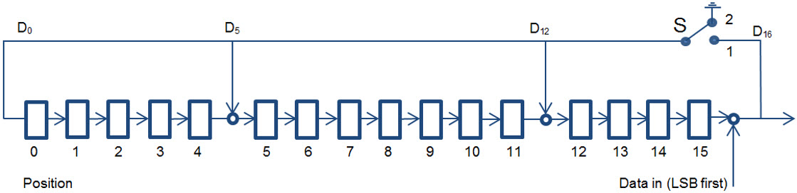
3.11. CRC Calculation
The CRC is defined using a CRC-CCITT generator polynomial g(D)=D16+D12+D5+1 (i.e., 210041 in octal representation) with a seed of 0xFFFF.
The CRC shift register is filled with 1s before calculating the CRC. Octets are fed through the CRC generator least significant bit first.
The most significant parity octet is transmitted first (where the CRC shift register is viewed as shifting from the least significant bit towards the most significant bit). Therefore, the transmission order of the parity octets within the CRC shift register is as follows:
x[8], x[9], …, x[15], x[0], x[1]…; x[7] (last)
where x[15] correspondents to the highest power CRC coefficient and x[0] corresponds to the lowest power coefficient.
The switch shall be set in position 1 while the data is shifted in. After the last bit has entered the Linear Feedback Shift Register (LSFR), the switch (S) shall be set in position 2, and the register contents shall be read out.
The computation for a sample with 10 bytes of data is the following:
data[0] = 0x3E
data[1] = 0x01
data[2] = 0x02
data[3] = 0x03
data[4] = 0x04
data[5] = 0x05
data[6] = 0x06
data[7] = 0x07
data[8] = 0x08
data[9] = 0x09
→ CRC = 01 2F
- Note:
-
See also Volume 2, part B, section 7.1.2 in [1] for more details. For E2E-CRC the Linear Feedback Shift Register is initially loaded with a seed of 0xFFFF instead of the UAP and the calculation is done in the same way.
4. SDP Interoperability
If this service is exposed over BR/EDR, then it shall have the following SDP record:
|
Item |
Definition |
Type |
Value |
Status |
|---|---|---|---|---|
|
Service Class ID List |
M |
|||
|
Service Class #0 |
UUID |
«Continuous Glucose Monitoring » |
M |
|
|
Protocol Descriptor List |
M |
|||
|
Protocol #0 |
UUID |
L2CAP |
M |
|
|
Parameter #0 for Protocol #0 |
PSM |
UINT16 |
PSM = ATT |
M |
|
Protocol #1 |
UUID |
ATT |
M |
|
|
BrowseGroupList |
PublicBrowseRoot* |
M |
* PublicBrowseRoot shall be present; however, other browse UUIDs may also be included in the list.
5. Acronyms and Abbreviations
Any abbreviation or acronym used in the document, but not defined in the common specification sections (e.g., Volume 1 Part B), is defined here. The list is alphabetized.
|
Abbreviation or Acronym |
Meaning |
|---|---|
|
BR/EDR |
Basic Rate / Enhanced Data Rate |
|
CGMCP |
CGM Specific Ops Control Point |
|
CP |
Control Point |
|
HS |
High Speed |
|
NaN |
Not a Number |
|
NRes |
Not at this Resolution |
|
RACP |
Record Access Control Point |
6. References
Bibliography
[1] Bluetooth Core Specification v4.0 as amended by CSA3 and CSS v2 or later
[2] Health Device Profile v1.0
[3] Characteristic and Descriptor descriptions are accessible via the Bluetooth SIG Assigned Numbers
[4] ISO/IEEE Std 11073-20601™- 2008 Health Informatics - Personal Health Device Communication - Part 20601: Application Profile - Optimized Exchange Protocol - version 1.0 or later. This also includes ISO/IEEE 11073-20601:2010 (E)
[5] ISO/IEEE Std IEEE 11073-10417™-2011 Device specialization - Glucose meter