-
Revision: v1.0.2
-
Revision Date: 2022-01-18
-
Group Prepared By: Medical Devices Working Group
Revision History
|
Revision Number |
Date |
Comments |
|---|---|---|
|
V1.0.0 |
2014-11-18 |
Approved by the Bluetooth SIG BoD |
|
d1.0.1 |
2015-11-19 |
ESR09 (integrated E6173) |
|
v1.0.1 |
2015-12-15 |
Adopted by the Bluetooth SIG BoD |
|
v1.0.2 |
2022-01-18 |
Adopted by the Bluetooth SIG Board of Directors. |
Version History
|
Versions |
Changes |
|---|---|
|
v1.0.0 to v1.0.1 |
Incorporated erratum E6173. |
|
v1.0.1 to v1.0.2 |
Incorporated errata E15780, E16275, E17659, E18105. |
Acknowledgments
|
Name |
Company |
|---|---|
|
Ray Strickland |
Roche |
|
Ralf Schmitz |
Roche |
|
Felix Bootz |
Roche |
|
Wolfgang Heck |
Roche |
|
Krishna Shingala |
Mindtree |
|
Laurence Richardson |
CSR |
|
Leif-Alexandre Aschehoug |
Nordic Semiconductor |
|
Nathaniel Hamming |
University Health Network |
|
Melanie Yeung |
University Health Network |
|
Jordan Hartmann |
Nonin Medical, Inc. |
Use of this specification is your acknowledgement that you agree to and will comply with the following notices and disclaimers. You are advised to seek appropriate legal, engineering, and other professional advice regarding the use, interpretation, and effect of this specification.
Use of Bluetooth specifications by members of Bluetooth SIG is governed by the membership and other related agreements between Bluetooth SIG and its members, including those agreements posted on Bluetooth SIG’s website located at www.bluetooth.com. Any use of this specification by a member that is not in compliance with the applicable membership and other related agreements is prohibited and, among other things, may result in (i) termination of the applicable agreements and (ii) liability for infringement of the intellectual property rights of Bluetooth SIG and its members. This specification may provide options, because, for example, some products do not implement every portion of the specification. All content within the specification, including notes, appendices, figures, tables, message sequence charts, examples, sample data, and each option identified is intended to be within the bounds of the Scope as defined in the Bluetooth Patent/Copyright License Agreement (“PCLA”). Also, the identification of options for implementing a portion of the specification is intended to provide design flexibility without establishing, for purposes of the PCLA, that any of these options is a “technically reasonable non-infringing alternative.”
Use of this specification by anyone who is not a member of Bluetooth SIG is prohibited and is an infringement of the intellectual property rights of Bluetooth SIG and its members. The furnishing of this specification does not grant any license to any intellectual property of Bluetooth SIG or its members. THIS SPECIFICATION IS PROVIDED “AS IS” AND BLUETOOTH SIG, ITS MEMBERS AND THEIR AFFILIATES MAKE NO REPRESENTATIONS OR WARRANTIES AND DISCLAIM ALL WARRANTIES, EXPRESS OR IMPLIED, INCLUDING ANY WARRANTIES OF MERCHANTABILITY, TITLE, NON-INFRINGEMENT, FITNESS FOR ANY PARTICULAR PURPOSE, OR THAT THE CONTENT OF THIS SPECIFICATION IS FREE OF ERRORS. For the avoidance of doubt, Bluetooth SIG has not made any search or investigation as to third parties that may claim rights in or to any specifications or any intellectual property that may be required to implement any specifications and it disclaims any obligation or duty to do so.
TO THE MAXIMUM EXTENT PERMITTED BY APPLICABLE LAW, BLUETOOTH SIG, ITS MEMBERS AND THEIR AFFILIATES DISCLAIM ALL LIABILITY ARISING OUT OF OR RELATING TO USE OF THIS SPECIFICATION AND ANY INFORMATION CONTAINED IN THIS SPECIFICATION, INCLUDING LOST REVENUE, PROFITS, DATA OR PROGRAMS, OR BUSINESS INTERRUPTION, OR FOR SPECIAL, INDIRECT, CONSEQUENTIAL, INCIDENTAL OR PUNITIVE DAMAGES, HOWEVER CAUSED AND REGARDLESS OF THE THEORY OF LIABILITY, AND EVEN IF BLUETOOTH SIG, ITS MEMBERS OR THEIR AFFILIATES HAVE BEEN ADVISED OF THE POSSIBILITY OF THE DAMAGES.
Products equipped with Bluetooth wireless technology ("Bluetooth Products") and their combination, operation, use, implementation, and distribution may be subject to regulatory controls under the laws and regulations of numerous countries that regulate products that use wireless non-licensed spectrum. Examples include airline regulations, telecommunications regulations, technology transfer controls, and health and safety regulations. You are solely responsible for complying with all applicable laws and regulations and for obtaining any and all required authorizations, permits, or licenses in connection with your use of this specification and development, manufacture, and distribution of Bluetooth Products. Nothing in this specification provides any information or assistance in connection with complying with applicable laws or regulations or obtaining required authorizations, permits, or licenses.
Bluetooth SIG is not required to adopt any specification or portion thereof. If this specification is not the final version adopted by Bluetooth SIG’s Board of Directors, it may not be adopted. Any specification adopted by Bluetooth SIG’s Board of Directors may be withdrawn, replaced, or modified at any time. Bluetooth SIG reserves the right to change or alter final specifications in accordance with its membership and operating agreements.
Copyright © 2012–2022. All copyrights in the Bluetooth Specifications themselves are owned by Apple Inc., Ericsson AB, Intel Corporation, Lenovo (Singapore) Pte. Ltd., Microsoft Corporation, Nokia Corporation, and Toshiba Corporation. The Bluetooth word mark and logos are owned by Bluetooth SIG, Inc. Other third-party brands and names are the property of their respective owners.
Document Terminology
The Bluetooth SIG has adopted portions of the IEEE Standards Style Manual, which dictates use of the words “shall’’, “should’’, “may’’, and “can’’ in the development of documentation, as follows:
The word shall is used to indicate mandatory requirements strictly to be followed in order to conform to the standard and from which no deviation is permitted (shall equals is required to).
The use of the word must is deprecated and shall not be used when stating mandatory requirements; must is used only to describe unavoidable situations.
The use of the word will is deprecated and shall not be used when stating mandatory requirements; will is only used in statements of fact.
The word should is used to indicate that among several possibilities one is recommended as particularly suitable, without mentioning or excluding others; or that a certain course of action is preferred but not necessarily required; or that (in the negative form) a certain course of action is deprecated but not prohibited (should equals is recommended that).
The word may is used to indicate a course of action permissible within the limits of the standard (may equals is permitted).
The word can is used for statements of possibility and capability, whether material, physical, or causal (can equals is able to).
The term Reserved for Future Use (RFU) is used to indicate Bluetooth SIG assigned values that are reserved by the Bluetooth SIG and are not otherwise available for use by implementations.
Certain terms used in this specification have been updated and are no longer used by Bluetooth SIG. For a list of terms that have been updated and their replacement terms, see the Appropriate Language Mapping Table [9].
1. Introduction
The CGM Profile is used to enable a device to obtain glucose measurement and other data from a CGM Sensor that exposes the CGM Service [1].
1.1. Profile Dependencies
This profile requires the Generic Attribute Profile (GATT).
1.2. Conformance
If conformance to this specification is claimed, all capabilities indicated as mandatory for this specification shall be supported in the specified manner (process-mandatory). This also applies for all optional and conditional capabilities for which support is indicated.
1.3. Bluetooth Specification Release Compatibility
This specification is compatible with any Bluetooth Core Specification [2] that includes the Generic Attribute Profile (GATT).
2. Configuration
2.1. Roles
The profile defines two roles: CGM Sensor and Collector. The CGM Sensor is the device that measures the Glucose level concentration and the Collector is the device that receives the Glucose measurement and other related data from a CGM Sensor.
-
The CGM Sensor shall be a GATT Server.
-
The Collector shall be a GATT Client.
At any given time, a CGM Sensor shall be connected to only one Collector
2.2. Role/Service Relationships
The following diagram shows the relationships between service and profile roles.
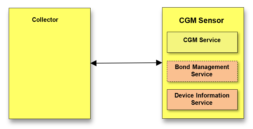 |
Note: Profile roles are represented by yellow boxes and services are represented by orange boxes.
A CGM Sensor instantiates the CGM Service [1], the Device Information Service, [3] and optionally the Bond Management Service [8].
2.3. Concurrency Limitations and Restrictions
There are no concurrency limitations or restrictions for the Collector or CGM Sensor roles imposed by this profile.
2.4. Topology Limitations and Restrictions
2.4.1. Topology Restrictions for Low Energy
This section describes topology limitations and restrictions when the profile is to be used over Low Energy transport.
The CGM Sensor shall use the GAP Peripheral role.
The Collector shall use the GAP Central role.
2.4.2. Topology Limitations and Restrictions for BR/EDR
This section describes topology limitations and restrictions when the profile is to be used over BR/EDR transport.
There are no fixed Central or Peripheral roles in the profile.
2.5. Transport Dependencies
There are no transport restrictions imposed by this profile specification.
Where the term BR/EDR is used throughout this document, this also includes the use of AMP.
Since IEEE 11073 Personal Health Device standards represent the dominant data standard for personal healthcare devices, it is recommended to use the Health Device Profile [4] for BR/EDR.
3. CGM Sensor Role Requirements
The CGM Sensor shall instantiate one and only one CGM Service [1].
The CGM Sensor shall instantiate the Device Information Service [3].
The CGM Sensor may instantiate the Bond Management Service [8].
|
Service |
CGM Sensor |
|---|---|
|
CGM Service |
M |
|
Bond Management Service |
C1 |
|
Device Information Service |
M |
- C.1:
-
Mandatory if multiple bonds are supported by server, otherwise optional.
See Section 5.1 and Section 6.1 for additional requirements for the CGM Sensor role.
3.1. Incremental CGM Service Requirements
3.1.1. Writable GAP Device Name characteristic
The CGM Sensor may support the write property for the Device Name characteristic in order to allow a Collector to write a device name to the CGM Sensor.
3.1.2. Additional Requirements for Low Energy Transport
This section describes additional CGM Sensor requirements and recommendations beyond those defined in the CGM Service when using this profile over Low Energy transport.
3.1.2.1. Service UUIDs AD Type
While in a GAP Discoverable Mode for initial connection to a Collector, the CGM Sensor should include the «CGM Service» UUID defined in [5] in the Service UUIDs AD type field of the Advertising Data. This enhances the user experience as a CGM Sensor may be identified by the Collector before initiating a connection.
3.1.2.2. Local Name AD Type
For enhanced user experience, a CGM Sensor should include the Local Name (containing either the complete or shortened value of the Device Name characteristic as defined in [2]) in its Advertising Data or Scan Response Data.
3.1.2.3. Appearance AD Type
For enhanced user experience, a CGM Sensor should include the value of the Appearance characteristic defined in [3] in its Advertising data or Scan Response data.
3.1.2.4. Target Address AD Types
For enhanced user experience, a CGM Sensor may include either the Public Target Address AD Type or Random Target Address AD Type (see Section 5.1.4) in its Advertising Data or Scan Response Data.
In the following sections, the words “a Target Address AD Type” are intended to refer to either of the defined Target Address AD Types.
3.2. Incremental Device Information Service Requirements
The table below shows additional requirements and recommendations beyond those defined in the Device Information Service.
|
Device Information Service Characteristic |
Requirement |
|---|---|
|
Manufacturer Name String |
M |
|
Model Number String |
M |
|
System ID |
M |
Characteristics in this service may be transcoded by the Collector for use in an ISO/IEEE 11073 ecosystem. See the Personal Health Devices Transcoding White Paper [6] for more information. Since strings in this service are encoded as UTF-8, and ISO/IEEE 11073-20601a [7] specifies that strings are encoded as ASCII printable characters (a subset of UTF-8), characters used in string characteristics that are to be transcoded for use in an ISO/IEEE 11073 ecosystem shall be restricted to the printable ASCII character set in order to ensure that the strings can be correctly displayed.
If the ISO/IEEE 11073-20601 specification is updated in the future to include UTF-8 support, implementers should consider the impact of using non-ASCII characters on backward compatibility.
Note: The Personal Health Devices Transcoding White Paper [6] recommends that characters outside of the printable ASCII range are translated to characters inside of the printable ASCII range as appropriate.
3.3. Incremental Bond Management Service Requirements
The table below shows additional requirements beyond those defined in the Bond Management Service.
|
Bond Management Service Characteristic |
Requirement |
|---|---|
|
Bond Management Control Point |
M |
|
Bond Management Features |
M |
4. Collector Role Requirements
The Collector shall support the CGM Service [1].
The Collector may support the Bond Management Service [8].
The Collector may support the Device Information Service [3].
|
Service |
Collector |
|---|---|
|
CGM Service |
M |
|
Bond Management Service |
C.1 |
|
Device Information Service |
O |
- C.1:
-
Mandatory if Multiple Bond feature is supported, otherwise optional
This section describes the profile procedure requirements for a Collector.
|
Profile Requirement |
Section |
Support in Collector |
|---|---|---|
|
Service Discovery |
M |
|
|
M |
|
|
O |
|
|
C.1 |
|
|
Characteristic Discovery |
M |
|
|
M |
|
|
O |
|
|
C.1 |
|
|
CGM Measurement |
M |
|
|
CGM Feature |
M |
|
|
CGM Status |
M |
|
|
CGM Session Start Time |
M |
|
|
CGM Session Run Time |
M |
|
|
Record Access Control Point |
M |
|
|
Report Stored Records |
M |
|
|
Delete Stored Records |
O |
|
|
Abort Operation |
O |
|
|
Report Number of Stored Records |
O |
|
|
CGM Specific Ops Control Point |
M |
|
|
Set CGM Communication Interval |
O |
|
|
Get CGM Communication Interval |
M |
|
|
Set Glucose Calibration value |
C.2 |
|
|
Get Glucose Calibration Value |
C.2 |
|
|
Set Patient High Alert Level |
O |
|
|
Get Patient High Alert Level |
O |
|
|
Set Patient Low Alert Level |
O |
|
|
Get Patient Low Alert Level |
O |
|
|
Set Hypo Alert Level |
O |
|
|
Get Hypo Alert Level |
O |
|
|
Set Hyper Alert Level |
O |
|
|
Get Hyper Alert Level |
O |
|
|
Set Rate of Decrease Alert Level |
O |
|
|
Get Rate of Decrease Alert Level |
O |
|
|
Set Rate of Increase Alert Level |
O |
|
|
Get Rate of Increase Alert Level |
O |
|
|
Reset Device Specific Alert |
C.3 |
|
|
Start the Session |
O |
|
|
Stop the Session |
O |
|
|
Bond Management Control Point |
C.1 |
|
|
Bond Management Feature |
C.1 |
- C.1:
-
Mandatory if Multiple Bond feature is supported, otherwise optional
- C.2:
-
Mandatory if the Calibration feature is supported, otherwise optional
- C.3:
-
Mandatory if the Device Specific Alert feature is supported, otherwise optional
4.1. GATT Sub-Procedure Requirements
Requirements in this section represent a minimum set of requirements for a Collector (Client). Other GATT sub-procedures may be used if supported by both Client and Server.
The table below summarizes additional GATT sub-procedure requirements beyond those required by all GATT Clients.
|
GATT Sub-Procedure |
Collector (Client) Requirements |
|---|---|
|
Discover All Primary Services |
C1 |
|
Discover Primary Services by Service UUID |
C1 |
|
Discover All Characteristics of a Service |
C2 |
|
Discover Characteristics by UUID |
C2 |
|
Discover All Characteristic Descriptors |
M |
|
Notifications |
M |
|
Indications |
M |
|
Read Characteristic Value |
M |
|
Write Characteristic Value |
M |
|
Reliable Writes |
C.3 |
|
Write Long Characteristic Values |
C.3 |
|
Read Characteristic Descriptors |
M |
|
Write Characteristic Descriptors |
M |
- C.1:
-
Mandatory to support at least one of these service discovery sub-procedures.
- C.2:
-
Mandatory to support at least one of these characteristic discovery sub-procedures.
- C.3:
-
Mandatory if Bond Management Service is supported.
4.2. Service Discovery
When using the Low Energy transport, the Collector shall perform primary service discovery using either the GATT Discover All Primary Services sub-procedure or the GATT Discover Primary Services by Service UUID sub-procedure. Recommended fast connection parameters and procedures for connection establishment are defined in Section 5.2.4.
When using BR/EDR transport, the Collector shall perform service discovery by retrieving the SDP record of the CGM Service [1]. The SDP record can be found in section 4 of [1].
4.2.1. CGM Service Discovery
The Collector shall discover the CGM Service.
4.2.2. Bond Management Service Discovery
The Collector may discover the Bond Management Service.
4.2.3. Device Information Service Discovery
The Collector may discover the Device Information Service.
4.3. Characteristic Discovery
As required by GATT, the Collector must be tolerant of additional optional characteristics in the service records of services used with this profile.
4.3.1. CGM Service Characteristic Discovery
The Collector shall perform either the GATT Discover All Characteristics of a Service sub-procedure or the GATT Discover Characteristics by UUID sub-procedure in order to discover the characteristics of the service.
The Collector shall perform the GATT Discover All Characteristic Descriptors sub-procedure in order to discover the characteristic descriptors described in the following sections.
4.3.1.1. CGM Measurement Characteristic
The Collector shall discover the CGM Measurement characteristic.
The Collector shall discover the Client Characteristic Configuration descriptor of the CGM Measurement characteristic.
4.3.1.2. CGM Feature Characteristic
The Collector shall discover the CGM Feature characteristic.
If the CGM Feature characteristic supports indications, the Collector shall discover the Client Characteristic Configuration descriptor of the CGM Feature characteristic.
4.3.1.3. CGM Status Characteristic
The Collector shall discover the CGM Status characteristic.
4.3.1.4. CGM Session Start Time Characteristic
The Collector shall discover the CGM Session Start Time characteristic.
4.3.1.5. CGM Session Run Time Characteristic
The Collector shall discover the CGM Run Time characteristic.
4.3.1.6. Record Access Control Point Characteristic
The Collector shall discover the Record Access Control Point characteristic.
The Collector shall discover the Client Characteristic Configuration descriptor of the Record Access Control Point characteristic.
4.3.1.7. CGM Specific Ops Control Point Characteristic
The Collector shall discover the CGM Specific Ops Control Point characteristic.
The Collector shall discover the Client Characteristic Configuration descriptor of the CGM Specific Ops Control Point characteristic.
4.3.2. Bond Management Service Characteristics Discovery
In order for the Collector to discover the characteristics of the Bond Management Service, it may use either the GATT Discover All Characteristics of a Service sub-procedure or the GATT Discover Characteristics by UUID sub-procedure to discover all characteristics of the service.
4.3.2.1. Bond Management Control Point Characteristic
The Collector may discover the Bond Management Control Point characteristic of the Bond Management Service.
4.3.2.2. Bond Management Features Characteristic
The Collector may discover the Bond Management Feature characteristic of the Bond Management Service.
4.3.3. Device Information Service Characteristics Discovery
The Collector may discover the characteristics of the Device Information Service.
In order for the Collector to discover the characteristics of the Device Information Service, it may use either the GATT Discover All Characteristics of a Service sub-procedure or the GATT Discover Characteristics by UUID sub-procedure to discover all characteristics of the service.
4.4. CGM Measurement Characteristic Behavior
The Collector shall control the configuration of notifications (i.e., via the Client Characteristic Configuration descriptor) of the CGM Measurement characteristic.
The CGM Measurement characteristic is a variable length structure. The Collector shall be able to receive notifications of the CGM Measurement characteristic from the CGM Sensor at regular intervals. The collector shall be able to receive more than one characteristic value in a single notification; the size of each record within the notification is contained in the first octet of the record.
When a Collector requires a connection to a CGM Sensor to receive CGM Measurements, it shall follow the connection procedures described in Section 5.
The Collector shall determine the features supported by the CGM Sensor by reading the CGM Feature characteristic (see Section 4.5).
If configured, the Collector may alert the user when CGM Measurements are no longer received (e.g., due to link loss). Once the data is again received (e.g., the link is restored), the Collector may fetch the missing data and continue in its normal way of data display.
When a Collector requires dedicated CGM measurement data, it shall follow the Record Access Control Point procedures described in Section 4.9.
If the Collector receives a CGM Measurement characteristic with bits or values of the optional Sensor Status Annunciation field that are designated as Reserved for Future Use (RFU) in [5], it shall ignore those bits and continue to process the other fields of the CGM Measurement characteristic normally.
4.5. CGM Feature Characteristic Behavior
The Collector shall read the CGM Feature characteristic to determine the supported features of the CGM Sensor in order to interpret the bits in the Sensor Status Annunciation field of the CGM Measurement characteristic.
If the CGM Sensor supports indication of the CGM Feature characteristic, the Collector may configure this characteristic for indications. When the Collector receives an indication of the CGM Feature characteristic, the Collector shall use the indicated value to determine the supported features again. Alternatively, the Collector may read the CGM Feature characteristic each time after connecting with the CGM Sensor. A Collector shall enable indications of the CGM Feature characteristic, or it shall read the CGM Feature characteristic on each connection.
If the E2E-CRC Supported bit is set to 1 (True), some characteristics contain a CRC-field the Collector shall calculate when writing to the characteristic and may verify CRC when reading. Otherwise the CRC-calculation is not supported and the fields are not included except the CGM Feature characteristic.
If the Calibration Supported bit is set to 0 (False), the Collector shall ignore the Calibration Required bit of the Sensor Status Annunciation field of the CGM Measurement and the CGM Status characteristic. Otherwise the Collector may initiate the calibration of the CGM Sensor, see Section 4.10.2.2.
If the Patient High/Low Alert Supported bit is set to 0 (False), the Collector shall ignore the Sensor Result Higher Than Patient High Level bit and the Sensor Result Lower Than Patient Low Level bit of the Sensor Status Annunciation field of the CGM Measurement and the CGM Status characteristic. Otherwise the Collector may set the threshold levels, see Section 4.10.2.3.
If the Hypo Alert Supported bit is set to 0 (False), the Collector shall ignore the Sensor Result Lower Than Hypo Level bit of the Sensor Status Annunciation field of the CGM Measurement and the CGM Status characteristic. Otherwise the Collector may set the appropriate level as described in Section 4.10.2.4.
If the Hyper Alert Supported bit is set to 0 (False), the Collector shall ignore the Sensor Result Higher Than Hyper Level bit of the Sensor Status Annunciation field of the CGM Measurement and the CGM Status characteristic. Otherwise the Collector may set the appropriate level as described in Section 4.10.2.5.
If the Rate Of Increase/Decrease Alert Supported bit is set to 0 (False), the Collector shall ignore the Sensor Rate Of Increase Exceeded bit and the Sensor Rate Of Decrease Exceeded bit of the Sensor Status Annunciation field of the CGM Measurement and the CGM Status characteristic. Otherwise the Collector may set the appropriate level as described in Section 4.10.2.6.
If the Device Specific Alert Supported bit is set to 0 (False), the Collector shall ignore the Device Specific Alert bit of the Sensor Status Annunciation field of the CGM Measurement and the CGM Status characteristic. Otherwise the Collector may reset the Device Specific Alert as described in Section 4.10.2.7.
If the Sensor Malfunction Detection Supported bit is set to 0 (False), the Collector shall ignore the Sensor Malfunction bit of the Sensor Status Annunciation field of the CGM Measurement and the CGM Status characteristic. Otherwise the Collector may discard the measurement.
If the Sensor Temperature High-Low Detection Supported bit is set to 0 (False), the Collector shall ignore the Sensor Temperature Too High for Valid Test/Result at Time of Measurement bit and the Sensor Temperature Too Low for Valid Test/Result at Time of Measurement bit of the Sensor Status Annunciation field of the CGM Measurement and the CGM Status characteristic. Otherwise the Collector may discard the measurement.
If the Sensor Result High-Low Detection Supported bit is set to 0 (False), the Collector shall ignore the Sensor Result Higher Than the Device Can Process bit and the Sensor Result Lower Than the Device Can Process bit of the Sensor Status Annunciation field of the CGM Measurement and the CGM Status characteristic. Otherwise the Collector may discard the measurement.If the Low Battery Detection Supported bit is set to 0 (False), the Collector shall ignore the Device Battery Low bit of the Sensor Status Annunciation field of the CGM Measurement and the CGM Status characteristic. Otherwise the Collector may discard the measurement and/or may show the associated state on its UI.
If the Sensor Type Error Detection Supported bit is set to 0 (False), the Collector shall ignore the Sensor Type Incorrect For Device bit of the Sensor Status Annunciation field of the CGM Measurement and the CGM Status characteristic. Otherwise the Collector may stop the CGM session as described in Section 4.10.2.9.
If the General Device Fault Supported bit is set to 0 (False), the Collector shall ignore the General Device Fault Has Occurred in the Sensor bit of the Sensor Status Annunciation field of the CGM Measurement and the CGM Status characteristic. Otherwise the Collector may discard the measurement and/or may show the associated state on his UI.
If the Multiple Bond Supported bit is set to 0 (False), the Collector can assume that the CGM Sensor supports only a single bond. Otherwise the Collector can assume that the CGM Sensor supports multiple bonds.
If the Multiple sessions Supported bit is set to 0 (False), the Collector can assume that the CGM Sensor supports only a single CGM session. Otherwise the Collector can assume that the CGM Sensor supports multiple CGM sessions.
If the CGM Trend Information Supported bit is set to 1 (True), the CGM Measurement characteristic may contain a CGM Trend Information field. Otherwise, it is unnecessary for the Collector to expect a CGM Trend value.
If the CGM Quality Supported bit is set to 1 (True), the CGM Measurement characteristic may contain a CGM Quality field. Otherwise, it is unnecessary for the Collector to expect a CGM Quality value.
Additionally, the CGM Feature characteristic states the sample type and the location of the CGM measurement in the Type-Sample Location field. The Collector may use this information within its UI.
If the Collector reads or receives the CGM Feature characteristic with bits that are set and yet are designated as Reserved for Future Use (RFU) in [5], the Collector shall ignore those bits and continue to operate normally as if the bits were not set.
4.6. CGM Status Characteristic Behavior
The Collector may read the CGM Status characteristic to determine the current status of the CGM Sensor. The CGM Status allows the Collector to read the status from the CGM Sensor at any time, particularly when the CGM measurement is not running and the status cannot be obtained in the measurement result in the Status Annunciation Field.
It also allows the Collector to read the actual relative time difference to the session start time.
If the CGM Sensor supports E2E-CRC, the Collector may check the validity of CGM Status by checking the CRC calculated over all fields; see Section 3.11 in [1] for more details. What the Collector does if a CRC error is detected is left to the implementation.
If the Collector reads CGM Status characteristic bits that are set and yet are designated as Reserved for Future Use (RFU) in [5], it shall ignore those bits and continue to operate normally as if the bits were not set.
4.7. CGM Session Start Time Characteristic Behavior
The Collector shall send its actual time (user facing time) to the CGM Sensor to enable the CGM Sensor to calculate its Session Start Time. This should be done at least once after a Session is started.
The Collector may read the Session Start Time characteristic to determine the CGM Sensors measurement starting time. This time is the base offset for every measurement characteristic that is sent from the CGM Sensor; thus the Session Start time may be the common base time for the system (i.e., also for other Collectors).
The Session Start Time field is in the same format and units as the Date Time characteristic defined in [5].
The Time Zone field is in the same format and units as the Time Zone characteristic defined in [5].
The DST Offset field is in the same format and units as the DST Offset characteristic defined in [5].
If the Time Zone and DST Offset is not known, the Collector shall use the predetermined values defined in [5] for this purpose.
If the CGM Sensor supports E2E-CRC, the Collector may check the validity of CGM Session Start Time by checking the CRC calculated over all fields; see section 3.11 in [1] for more details. What the Collector does if a CRC error is detected is left to the implementation.
4.8. CGM Session Run Time Characteristic Behavior
The Collector may read the CGM Session Run Time characteristic to determine the time the CGM Session will run. This time is static for most devices but could be dynamically corrected in future devices. The Collector may check the CGM Session Run Time in intervals to warn the user of an unexpected end of the CGM session.
If the CGM Sensor supports E2E-CRC, the Collector may check the validity of CGM Session Run Time by checking the CRC calculated over all fields; see Section 3.11 in [1] for more details. What the Collector does if a CRC error is detected is left to the implementation.
4.9. Record Access Control Point Characteristic Behavior
The Record Access Control Point characteristic defined in [5] is reused.
Before performing any Record Access Control Point procedure, the Collector shall configure the Record Access Control Point (RACP) characteristic for indications (i.e., via the Client Characteristic Configuration descriptor).
The Collector may perform a write to the Record Access Control Point to request a desired procedure. A procedure begins when the Collector writes to the RACP to perform some desired action and ends when either a Response Code or Number of Stored Records Response RACP indication is received by the Collector.
If the procedure performed is the Report Stored Records procedure, the procedure may contain one or more CGM Measurement characteristic notifications between the write to the RACP characteristic that began the procedure and the Response Code RACP indication that ends the procedure.
If the Collector attempts to perform any defined Record Access Control Point procedure other than the Abort Operation procedure before a previous procedure is complete and receives a GATT Error Response with the error code set to Procedure Already in Progress, the Collector shall wait until the current RACP procedure completes before starting a new procedure.
If the Collector attempts to request any defined Record Access Control Point procedure before it has configured the CGM Measurement characteristic for notifications and the Record Access Control Point characteristic for indications (all via the appropriate Client Characteristic Configuration descriptor) as required in previous sections, then the CGM Sensor will transmit a GATT Error Response with the error code set to Client Characteristic Configuration Descriptor Improperly Configured. This means that the Collector has not configured the CGM Sensor correctly. The Collector shallconfigure these characteristics for notifications or indications where appropriate, as defined by other portions of this document.
See Section 4.10 for an example of how the RACP can be used in the context of the CGM Profile.
4.9.1. Record Access Control Point Procedure Requirements
Table 4.4 below shows the requirements for the Record Access Control Point procedures (Op Codes, Operators and Operands) in the context of this profile:
|
Op Code |
Op Code Requirement |
Operator |
Operator Requirement |
Operand |
Operand Requirement |
|
|---|---|---|---|---|---|---|
|
Filter Type |
Filter Parameters |
|||||
|
Report Stored Records |
M |
All records |
M |
No Operand Used |
N/A |
|
|
Less than or equal to |
O |
Time Offset |
<maximum filter value> |
C.1 |
||
|
Greater than or equal to |
M |
Time Offset |
<minimum filter value> |
M |
||
|
Within range of (inclusive) |
O |
Time Offset |
<minimum filter value>, <maximum filter value> |
C.1 |
||
|
First record |
O |
No Operand Used |
N/A |
|||
|
Last record |
O |
No Operand Used |
N/A |
|||
|
Delete Stored Records |
O |
All records |
C.2 |
No Operand Used |
N/A |
|
|
Less than or equal to |
O |
Time Offset |
<maximum filter value> |
C.1 |
||
|
Greater than or equal to |
O |
Time Offset |
<minimum filter value> |
C.1 |
||
|
Within range of (inclusive) |
O |
Time Offset |
<minimum filter value>, <maximum filter value> |
C.1 |
||
|
First record |
O |
No Operand Used |
N/A |
|||
|
Last record |
O |
No Operand Used |
N/A |
|||
|
Abort Operation |
M |
Null (0x00) |
M |
No Operand Used |
N/A |
|
|
Report Number of Stored Records |
M |
All records |
M |
No Operand Used |
N/A |
|
|
Less than or equal to |
O |
Time Offset |
<maximum filter value> |
C.1 |
||
|
Greater than or equal to |
M |
Time Offset |
<minimum filter value> |
M |
||
|
Within range of (inclusive) |
O |
Time Offset |
<minimum filter value>, <maximum filter value> |
C.1 |
||
|
First record |
O |
No Operand Used |
N/A |
|||
|
Last record |
O |
No Operand Used |
N/A |
|||
- C.1:
-
If this Operator is supported, this Operand is mandatory for this Operator. See also Note 1.
- C.2:
-
If this Op Code is supported, this Operator is mandatory for this Op Code. See also Note 2.
Notes:
-
Support for a given Operand for one Op Code and Operator combination does not imply support of that Operand for other Op Code and Operator combinations.
-
Support for a given Operator for one Op Code does not imply support of that Operator for other Op Codes.
-
Where a filter type and filter parameters are used, the byte order for the Operand is specified [1].
4.9.2. RACP Behavioral Description
The Collector shall write to the RACP characteristic using one of the supported Op Codes to request a CGM Sensor to perform a procedure (see [5]). This shall include an Operator and Operand that is valid within the context of that Op Code as defined in [1].
The procedures including the use of Filter Types are described in the following sections.
The Collector shall be tolerant of the fact that, for example, the CGM Sensor may add measurements while RACP procedures are taking place and also between two different RACP procedures.
Example:
The Collector may perform the Request Number of Stored Records procedure with the Operator set to All Stored Records, to get the total number of records currently stored by the CGM Sensor. However, if the Collector then performs a Report Stored Records procedure with the Procedure Operator set to All Stored Records, it shall be tolerant of receiving a different number of records from this procedure than the CGM Sensor reported having stored in the response to the Report Number of Stored Records. This is due to the fact that the CGM Sensor may have taken new measurements in the time between the Request Number of Stored Records procedure and the Report Stored Records procedure. This is used as an example, but the Collector shall be tolerant of this happening with any RACP procedure.
If the CGM Sensor supports multiple bonds, a Collector shall be tolerant of the fact that other Collectors may alter the contents of the CGM Sensor’s measurement database (e.g., Collector #2 may delete records from the CGM Sensor’s database that Collector #1 will then never be able to retrieve).
The handling of multiple bonds is vendor-specific (e.g., a CGM Sensor may only allow certain Collectors, such as a doctor’s computer, to use the Delete Store Records procedure).
4.9.2.1. Filter Types
Certain RACP procedures use a Filter Type that is used to determine the portion of the stored records on the CGM Sensor that the procedure applies to. The format of the Filter Type and the RACP procedures that have a Filter Type operand is defined in [1]. The Collector may filter using the Time Offset filter. The Time Offset filter is used when a procedure should apply to a specific CGM Measurement record or a range of CGM Measurement records. The Time Offset Number that is used is obtained from the Time Offset field in the CGM Measurement characteristic.
4.9.2.2. Report Number of Stored Records Procedure
To request the number of stored records from a CGM Sensor, the Collector shall use the Report Number of Stored Records procedure. To receive the number based on filter criteria, an appropriate Operator and Operand shall be used. Refer to [1] for Operand requirements when used with a specific Operator and note that in some cases, no Operand is used.
The Collector shall wait for the Number of Stored Records Response RACP indication containing the number of stored records available in the CGM Sensor as per the request. The Number of Stored Records Response RACP indication ends the Report Number of Stored Records procedure. In special circumstances, a Collector may request an abort of this procedure. See Section 4.9.2.5 for details on that procedure.
If after requesting the number of stored records, the Collector receives a Response Code RACP indication with a Response Code Value that represents an error condition, see Section 4.11.2 for general error handling procedures.
The value returned by the Number of Stored Records procedure is intended to be used either for the user interface on the Collector or to enable the Collector to acquire an estimate of the number of records it might receive to ensure it has sufficient resources. The Collector should not rely on this value as a means of determining if new records are available from the CGM Sensor. The Collector should always request new records by filtering with a Time Offset field.
4.9.2.3. Delete Stored Records Procedure
To request deletion of stored records within the CGM Sensor, the Collector shall use the Delete Stored Records procedure. To delete a selected set of stored records based on filter criteria, an appropriate Operator and Operand shall be used. Refer to [1] for Operand requirements when used with a specific Operator and note that in some cases, no Operand is used.
The Collector shall wait for the Response Code RACP Indication with the Response Code Value set to Success indicating successful deletion of records as per the request or for the procedure to time out according to the procedure time out operation described in Section 4.11.1. In special circumstances, a Collector may require an abort of this procedure. See Section 4.9.2.5 for details on the Abort Operation procedure.
If after requesting the deletion of stored records, the Collector receives a Response Code RACP indication with a Response Code Value that represents an error condition, see Section 4.11.2 for general error handling procedures.
4.9.2.4. Report Stored Records Procedure
To request the transfer of stored records from the CGM Sensor, the Collector shall use the Report Stored Records procedure on the “Record Access Control Point”. To receive a selected set of stored records based on filter criteria, an appropriate Operator and Operand shall be used. Refer to [1] for Operand requirements when used with a specific Operator and note that in some cases, no Operand is used. In special circumstances, a Collector may require an abort of this procedure. See Section 4.9.2.5 for details on that procedure.
Once all patient records for a given request have been successfully indicated by the CGM Sensor, the CGM Sensor will send a Response Code RACP indication with the Response Code Value set to Success.
The Collector may also receive a Response Code RACP indication with the Response Code Value representing an error condition that occurred in processing the request. A description of specific error conditions and recommended procedures is described below. For descriptions of general error conditions, see Section 4.11.2.
If after requesting stored records, the Collector receives a Response Code RACP indication with the Response Code Value set to No Records found, this indicates that the CGM Sensor does not have any stored records that meet the specified criteria.
If after requesting and receiving stored records, the Collector receives a Response Code RACP indication with the Response Code Value set to Procedure not completed, this indicates that the CGM Sensor was required to interrupt its data transfer before completion for an unspecified reason. If this occurs, the Collector should reattempt the data transfer using the same Op Code and Operator, but should modify the filter criteria in the Operand such that data already successfully received does not need to be retransmitted.
If a condition arises where a Collector is no longer able to receive the requested data, the Collector may request to abort the data transfer as described in Section 4.9.2.5.
4.9.2.5. Abort Operation Procedure
To abort a procedure that a Collector initiated, the Collector shall use the Abort Operation Op Code with the Operator set to Null and no Operand.
The Collector shall then wait for the Response Code RACP indication with the Response Code Value set to Success indicating successful aborting of the procedure or for the procedure to time out according to the procedure time out operation described in Section 4.11.1. Although CGM Sensors are required to stop the data transfer after they have sent the Response Code Value of Success, they may still have some records queued for transfer. These will be sent and require acknowledgement from the Collector before the transfer will be fully terminated. The Collector may choose to process or ignore these additional records but shall be tolerant of this lag in the termination of the transfer.
The Request Op Code in the Operand of the Response Code RACP indication is used to determine if a Response Code RACP indication is received in response to an Abort Operation procedure, or the procedure that the Abort Operation is trying to abort. If the Abort Operation procedure is completed successfully, then the CGM Sensor shall send the Response Code RACP indication with the Request Op Code in the Operand set to Abort Operation, and shall not send any Response Code RACP indication for the aborted procedure.
The Collector may also receive a Response Code RACP indication with the Request Op Code in the Operand set to Abort Operation and the Response Code Value representing an error condition that occurred in processing the request. Though in practice not all Response Code Values may be returned for an Abort Operation procedure, a Collector shall be able to handle receiving all defined Response Code Values in response this procedure. A description of specific error conditions and recommended procedures is described below. For descriptions of general error conditions, see Section 4.11.2.
If after requesting the abort, the Collector receives a Response Code RACP indication with the Request Op Code in the Operand set to Abort Operation and the Response Code Value set to Abort Unsuccessful, this indicates that the CGM Sensor is unable to process the abort (see RACP in [5]). How the Collector handles this situation is left to the implementation.
4.9.2.6. RACP Specific Errors
If the Collector writes an Operator to the Record Access Control Point characteristic that is invalid, it will receive a Response Code RACP indication with the Response Code Value set to Invalid Operator.
If the Collector writes an Operator to the Record Access Control Point characteristic that is not supported by the CGM Sensor, it will receive a Response Code RACP indication with the Response Code Value set to Operator not supported.
If the Collector receives a Response Code RACP indication with the Response Code Value set to Procedure not completed, this indicates that the CGM Sensor is unable to complete the procedure for some unknown reason, and the procedure shall be considered to have failed.
If the Collector writes a Filter Type within an Operand to the Record Access Control Point characteristic that is not supported by the CGM Sensor, it will receive a Response Code RACP indication with the Response Code Value set to Operand Not Supported.
4.10. CGM Specific Ops Control Point Characteristic Behavior
Before performing any CGM Specific Ops Control Point procedure, the Collector shall configure the CGM Specific Ops Control Point (CGMCP) characteristic for indications (i.e., via the Client Characteristic Configuration descriptor).
The Collector may perform a write to the CGM Specific Ops Control Point to request a desired procedure. A procedure begins when the Collector writes the CGMCP to perform some desired action and ends when a Response Code indication is received by the Collector.
4.10.1. CGM Specific Ops Control Point Procedure Requirements
The table below shows the requirements for the CGM Specific Ops Control Point (CGMCP) procedures in the context of this profile:
|
Op Code |
Requirement |
Operand |
|---|---|---|
|
Set CGM communication interval |
M |
UINT8 containing Communication Interval in minutes |
|
Get CGM communication interval |
M |
N.A. |
|
Set Glucose Calibration value |
C.1 |
Operand as defined in [5] |
|
Get Glucose Calibration value |
C.1 |
Operand as defined in [5] |
|
Set Patient High Alert Level |
C.2 |
SFLOAT containing level in mg/dL |
|
Get Patient High Alert Level |
C.2 |
N.A. |
|
Set Patient Low Alert Level |
C.2 |
SFLOAT containing level in mg/dL |
|
Get Patient Low Alert Level |
C.2 |
N.A |
|
Set Hypo Alert Level |
C.3 |
SFLOAT containing level in mg/dL |
|
Get Hypo Alert Level |
C.4 |
N.A |
|
Set Hyper Alert Level |
C.5 |
SFLOAT containing level in mg/dL |
|
Get Hyper Alert Level |
C.6 |
N.A |
|
Set Rate of Decrease Alert Level |
C.7 |
SFLOAT containing level in mg/dL/min |
|
Get Rate of Decrease Alert Level |
C.8 |
N.A |
|
Set Rate of Decrease Alert Level |
C.7 |
SFLOAT containing level in mg/dL/min |
|
Get Rate of Decrease Alert Level |
C.8 |
N.A |
|
Reset Device Specific Alert |
C,9 |
N.A |
|
Start Session |
C.10 |
N.A |
|
Stop Session |
C.10 |
N.A |
- C.1:
-
If Calibration Supported bit in CGM Feature characteristic is set to 1, this Op code is mandatory otherwise excluded
- C.2:
-
If Patient High/Low Alert Supported bit in CGM Feature characteristic is set to 1, this Op Code is optional otherwise excluded
- C.3:
-
If Hypo Alert Supported bit in CGM Feature characteristic is set to 1, this Op code is optional otherwise excluded
- C.4:
-
If Hypo Alert Supported bit in CGM Feature characteristic is set to 1, this Op code is mandatory otherwise excluded
- C.5:
-
If Hyper Alert Supported bit in CGM Feature characteristic is set to 1, this Op code is optional otherwise excluded
- C.6:
-
If Hyper Alert Supported bit in CGM Feature characteristic is set to 1, this Op code is mandatory otherwise excluded
- C.7:
-
If Rate of Increase/Decrease Alert Supported bit in CGM Feature characteristic is set to 1, this Op code is optional otherwise excluded
- C.8:
-
If Rate of Increase/Decrease Alert Supported bit in CGM Feature characteristic is set to 1, this Op code is mandatory otherwise excluded
- C.9:
-
If Device Specific Alert Supported bit in CGM Feature characteristic is set to 1, this Op code is mandatory otherwise excluded
- C.10:
-
If Multiple Session Supported bit in CGM Feature characteristic is set to 1, this Op Code is mandatory otherwise optional
4.10.2. CGM Specific Ops Control Point Behavioral Description
The Collector shall write to CGM Specific Ops Control Point characteristic using one of the supported Op Codes in Table 4.5 to request a CGM Sensor to perform a procedure. This may include parameters that are valid within the context of that Op Code as defined in [1].
If the CGM Sensor supports E2E-safety (E2E-CRC Supported bit is set in CGM Features), the Collector shall protect all Op Codes and Operands by a CRC. For computation of the CRC, see section 3.11 in [1].
4.10.2.1. CGM Communication Interval Procedure
To request a specific setting of the CGM Communication Interval value, the Collector shall write the Set CGM Communication Interval Op Code to the CGM Specific Ops Control Point followed by a UINT8 parameter. For example, writing a parameter of 0x05 will set the CGM Communication Interval value to 5 minutes within the CGM Sensor.
The Collector shall wait for the Response Code Op Code indication with Response Code Value set to Success indicating success of the operation as per the request or an error value as described in Section 4.11.2.
4.10.2.2. Glucose Calibration Procedures
If the Calibration Supported bit of the CGM Feature characteristic is set to 1, then this procedure is supported by the CGM Sensor.
To calibrate the CGM Sensor, the Collector shall write the Set Glucose Calibration Value Op Code to the CGM Specific Ops Control Point followed by parameter that represents the Glucose Calibration data.
The Glucose Calibration parameter is a fixed length structure containing:
-
the Calibration Glucose Concentration field
-
the Calibration Time
-
the Calibration Type-Sample Location field
-
the Next Calibration Time field
-
the Calibration Data Record Number
-
the Calibration Status field
The content of the Next Calibration Time field may be ignored or changed by the CGM Sensor. This is left to the implementation.
The content of the Calibration Data Record Number field that was sent with a Set Glucose Calibration Value Op Code will be ignored by the Sensor; the value of this field will be incremented by the CGM Sensor with each Calibration record stored.
The value of the Next Calibration Time field represents the time where next calibration is required as an offset to the Session Start time. If the value that was sent with a Set Glucose Calibration Value Op Code is between 0x0001 and 0xFFFE, the CGM Sensor may change its calibration time according to the Operand value. The value 0xFFFF disables the calibration reminder (i.e., reminder functionality on the Client) until a value not equal to 0xFFFF is transmitted again.
Note: With a value of 0x0000, the CGM Sensor expects the new calibration as soon as possible.
The content of the Calibration Status field that was sent with a Set Glucose Calibration Value Op Code will be ignored by the CGM Sensor. The value of this field will be determined by the CGM Sensor after completion of the internal calibration process. As long as this process is not finished, the Calibration Pending bit in the Calibration Status field is set to 1. If the CGM Sensor supports E2E-safety (E2E-CRC Supported bit is set in CGM Features), the value of the Calibration Status field shall be used for CRC calculation, even if the value itself is ignored. What the Collector does in this case if a CRC error is detected is left to the implementation.
The Collector shall wait for the Response Code Op Code indication with Response Code Value set to Success indicating success of the operation as per the request or an error value as described in Section 4.11.2.
After the Response Code Op Code Indication with Response Code Value is set to Success, the Collector should check the status of the calibration by a read of the last Calibration Data Record. If the Calibration Data Record is rejected or is out of range, there may be the need for a new calibration.
To request a Calibration Data Record, the Collector shall write the Get Glucose Calibration Value Op Code to the CGM Specific Ops Control Point followed by an UINT16 parameter, representing the record number. With a parameter of 0xFFFF, the Collector will receive the last Calibration Data Record stored in the CGM Sensor. A value of “0” represents no calibration value stored in CGM Sensor.
4.10.2.3. Patient High/Low Alert Procedures
If the Patient High/Low Alerts Supported bit of the CGM Feature characteristic is set to 1, then these procedures are supported by the CGM Sensor.
To request a specific setting of the alert levels, the Collector shall write the Set Patient High Alert Level Op Code or the Set Patient Low Alert Level Op Code followed by a SFLOAT parameter. For example, writing a parameter of 500 to the Patient High Alert Level will set the comparison level to a value of 500 mg/dl.
The Collector shall wait for the Response Code Op Code indication with Response Code Value set to Success indicating success of the operation as per the request or an error value as described in Section 4.11.2.
To get the actual stored values for these parameters, the Collector shall write the Get Patient High Alert Level Op Code to the control point and wait for the Patient High Alert Level Response indication with the value for the Patient High Level, or write the Get Patient Low Alert Level Op Code to the control point and wait for the Patient Low Alert Level Response indication with the value for the Patient Low Level.
4.10.2.4. Hypo Alert Procedures
If the Hypo Alert Supported bit of the CGM Feature characteristic is set to 1, then this procedure is supported by the CGM Sensor.
The CGM Sensor may allow the Collector to request a specific setting of the alert level. In this case the Collector shall write the Set Hypo Alert Level Op Code followed by a SFLOAT parameter. For example, writing a parameter of 50 to the Hypo Alert Level will set the comparison level to a value of 50 mg/dl.
The Collector shall wait for the Response Code Op Code indication with Response Code Value set to Success indicating success of the operation as per the request or an error value as described in Section 4.11.2
If the CGM Sensor has a hard coded value for the Hypo Alert, than this procedure is not supported and the CGM Sensor returns the corresponding error as described in Section 4.11.2.
To get the actual stored values for this parameter the Collector shall write the Get Hypo Alert Level Op Code to the control point and wait for the Hypo Alert Level Response indication with the value for the Hypo Level.
4.10.2.5. Hyper Alert Procedures
If the Hyper Alert Supported bit of the CGM Feature characteristic is set to 1, then this procedure is supported by the CGM Sensor
The CGM Sensor may allow the Collector to request a specific setting of the alert level. In this case the Collector shall write the Set Hyper Alert Level Op Code followed by a SFLOAT parameter. For example, writing a parameter of 300 to the Hyper Alert Level will set the comparison level to a value of 300 mg/dl.
The Collector shall wait for the Response Code Op Code indication with Response Code Value set to Success indicating success of the operation as per the request or an error value as described in Section 4.11.2.
If the CGM Sensor has a hard coded value for the Hyper Alert, than this procedure is not supported and the CGM Sensor returns the corresponding error as described in Section 4.11.2.
To get the actual stored values for this parameter the Collector shall write the Get Hyper Alert Level Op Code to the control point and wait for the Hyper Alert Level Response indication with the value for the Hyper Level.
4.10.2.6. Rate of Increase/Decrease Alert Procedures
If the Rate of Increase/Decrease Alert Supported bit of the CGM Feature characteristic is set to 1, then this procedure is supported by the CGM Sensor
The CGM Sensor may allow the Collector to request a specific setting of the Rate of Increase Alert level. In this case the Collector shall write the Set Rate of Increase Alert Level Op Code followed by a SFLOAT parameter. For example, writing a parameter of 2 to the Rate of Increase Alert Level will set the comparison level to a value of +2 mg/dl/min.
The Collector shall wait for the Response Code Op Code indication with Response Code Value set to Success indicating success of the operation as per the request or an error value as described in Section 4.11.2.
If the CGM Sensor has a hard coded value for the Rate of Increase Alert, than this procedure is not supported and the CGM Sensor returns the corresponding error as described in Section 4.11.2.
To get the actual stored values for this parameter the Collector shall write the Get Rate of Increase Alert Level Op Code to the control point and wait for the Rate of Increase Alert Level Response indication with the value for the Rate of Increase Level.
The CGM Sensor may allow the Collector to request a specific setting of the Rate of Decrease Alert level. In this case the Collector shall write the Set Rate of Decrease Alert Level Op Code followed by a SFLOAT parameter. For example, writing a parameter of -2 to the Rate of Decrease Alert Level will set the comparison level to a value of -2 mg/dl/min.
The Collector shall wait for the Response Code Op Code indication with Response Code Value set to Success indicating success of the operation as per the request or an error value as described in Section 4.11.2.
If the CGM Sensor has a hard coded value for the Rate of Decrease Alert, then this procedure is not supported and the CGM Sensor returns the corresponding error as described in Section 4.11.2.
To get the actual stored values for this parameter the Collector shall write the Get Rate of Decrease Alert Level Op Code to the control point and wait for the Rate of Decrease Alert Level Response indication with the value for the Rate of Decrease Level.
4.10.2.7. Reset Device Specific Alert Procedure
To request the reset of the Device Specific Alert, the Collector shall write the Reset Device Specific Alert Op Code to the CGM Specific Ops Control Point. The CGM Sensor then will reset the Device Specific Alert, if supported. If the Op Code is not supported by the CGM Sensor (e.g. Device Specific Alert is not latched), the CGM Sensor shall send an indication using the Response Code Op Code and the Response Code Value in the Operand set to Op Code not supported.
The Collector shall wait for the Response Code Op Code indication with Response Code Value set to Success indicating success of the operation as per the request or an error value as described in Section 4.11.2.
4.10.2.8. Start Session Procedure
To start the CGM session the Collector shall write the Op Code for Start Session to the CGM Specific Ops Control Point. The CGM Sensor then deletes all data from previous session and starts the measurement.
The Collector shall wait for the Response Code Op Code indication with Response Code Value set to Success indicating success of the operation as per the request or an error value as described in Section 4.11.2.
4.10.2.9. Stop Session Procedure
To stop the CGM session the Collector shall write the Op Code for Stop Session to the CGM Specific Ops Control Point. The CGM Sensor then stops the measurement.
The Collector shall wait for the Response Code Op Code indication with Response Code Value set to Success indicating success of the operation as per the request or an error value as described in Section 4.11.2.
4.11. Common Behavior of Control Points (RACP, CGMCP)
4.11.1. Procedure Timeout
In the context of the Control Point (CP) characteristics, a procedure is started when the CGM Sensor sends the response to the Collector’s Write request for the CP characteristic. The procedure is considered to be complete when the CP characteristic is indicated with the Op Code set to Response Code.
A CP procedure may consist of multiple notifications of the CGM Measurement characteristic. The procedure is completed when the CP characteristic is indicated. A procedure is considered to have timed out if a notification or an indication is not received within the ATT transaction timeout, defined as 30 seconds in Volume 2 Part F Section 3.3.3 of [2], from the start of the procedure or from the last notification that was received as a result of this procedure.
If the link is lost while a CP procedure is in progress then the procedure shall be considered to have timed out. See Section 4.11.1 for handling this condition.
Thus a Collector shall start a timer, with the value set to the ATT transaction timeout, after the write response is received from the CGM Sensor. The timer shall be restarted after every CGM Measurement is received. The timer shall be stopped when a CP indication is received and the Op Code is set to Response Code. If the timer expires then the procedure shall be considered to have failed.
4.11.1.1. CP Procedure Timeout Handling
If a CP procedure times out (see Section 4.11.1 for details of how this may occur) then it is recommended to disconnect the link and to reconnect to the CGM Sensor.
In the case of a procedure timeout during a Report Stored Records procedure, the Collector may consider the received CGM Measurement records to be valid. However the Collector shall not assume that the records received consist of all of the available records on the CGM Sensor that match the filter criteria, i.e., the Collector shall assume that the records received during a Report Stored Records procedure that has timed out are an incomplete set of records based on the filter criteria. The Collector may then perform the procedure again, when a new link is established, adjusting the filter criteria based on the records received during the aborted transfer.
4.11.2. General Error Handling
Other than error handling procedures that are specific to certain Op Codes, the following apply:
If an Op Code is written to the Control Point characteristic and the Client Characteristic Configuration descriptor of the Control Point is not configured for indications, the CGM Sensor shall return an error response with the Attribute Protocol Application error code set to Client Characteristic Configuration Descriptor Improperly Configured.
In this case the Collector shall configure the Control Point for indications and repeat the procedure.
If the Collector writes an Op Code to the Control Point characteristic that is unsupported by the CGM Sensor, it will receive a Response Code CP indication with the Response Code Value set to Op Code not supported.
If the Collector writes an Operand to the Control Point characteristic that is invalid, it will receive a Response Code CP indication with the Response Code Value set to Invalid Operand.
If the Collector writes to a Control Point characteristic where a CRC value is expected and doesn´t append the E2E-CRC field, it will receive an ATT Error Response with the error code set to Missing CRC.
If the Collector writes to a Control Point characteristic where a CRC value is expected and put a wrong value in the E2E-CRC field, it will receive an ATT Error Response with the error code set to Invalid CRC.
What the Collector does when receiving one of the error codes is left to the implementation.
4.12. Bond Management Service Characteristics Behavior
The Collector may write to the Bond Management Control Point to control the bond(s).
The Collector may perform a write to the Bond Management Control Point to request a desired procedure. A procedure begins when the Collector writes the BMCP to perform some desired action and ends when the ATT Write Response is received by the Collector.
The Collector shall determine the Bond Management features supported by the CGM Sensor by reading the Bond Management Feature characteristic before starting any Bond Management Control Point procedure.
4.12.1. Delete Bond of Requesting Device Procedures
If the Delete Bond of Requesting Device Procedure Supported bit of the Bond Management Feature characteristic is set to 1, then the procedure(s) are supported by the CGM Sensor
The CGM Sensor may allow the Collector to request the deletion of the bond information of the requested device´s transport from its database. In this case the Collector shall write the Op Code related to the requested transport to the BMCP. If an authorization code is required, as determined by the Bond Management Feature characteristic (see Section 4.12.5), the Op Code shall be followed by a parameter representing the authorization code. The Collector shall wait for the ATT Write response of the CGM Sensor for successful operation or an ATT Error Code describing the error.
If the operation is successful, the Collector shall delete the corresponding bond information in its database after the requested transport(s) are no longer active.
4.12.2. Delete all Bonds Procedures
If the Delete all Bonds Procedure Supported bit of the Bond Management Feature characteristic is set to 1, then the procedure(s) are supported by the CGM Sensor
The CGM Sensor may allow the Collector to request the deletion of the bond information of the requested device´s transport from its database. In this case the Collector shall write the Op Code related to the requested transport to the BMCP. If an authorization code is required, as determined by the Bond Management Feature characteristic (see Section 4.12.5), the Op Code shall be followed by a parameter representing the authorization code. The Collector shall wait for the ATT Write response of the CGM Sensor for successful operation or an ATT Error Code describing the error.
If the operation is successful, the Collector shall delete all bond information of the requested transport(s) in its database after the requested transport(s) are no longer active.
4.12.3. Delete Bond of all except the requesting device Procedures
If the Delete Bond of all except the requesting device Procedure Supported bit of the Bond Management Feature characteristic is set to 1, then the procedure(s) are supported by the CGM Sensor
The CGM Sensor may allow the Collector to request the deletion of the bond information of all but the requested device´s transport from its database. In this case the Collector shall write the Op Code related to the requested transport to the BMCP. If an authorization code is required, as determined by the Bond Management Feature characteristic (see Section 4.12.5), the Op Code shall be followed by a parameter representing the authorization code. The Collector shall wait for the ATT Write response of the CGM Sensor for successful operation or an ATT Error Code describing the error.
If the operation is successful, the Collector shall delete all bond information of the requested transport(s) in its database, except the bond information of the requesting device´s transport after the requested transport(s) are no longer active.
4.12.4. BMCP Error Handling
If the Collector writes an Operand to the Bond Management Control Point characteristic that is invalid, it will receive an ATT Error Response with the Attribute Protocol Error Code set to “Insufficient Authorization”
If the Collector writes an Op Code that doesn´t fit the transportation requirements (e.g. an Op Code valid for BR/EDR transport is written to a single mode LE device) or the Op Code is not supported on the CGM Sensor, it will receive an ATT Error Response with the Attribute Application Error Code set to “Op Code not supported”.
What the Collector does when receiving one of these error codes is left to the implementation.
If the Collector receives an ATT Error Response with the Attribute Application Error Code set to “Operation Failed”, the procedure on the CGM Sensor was not successful and the Collector shall not assume that the bond information will be deleted after the requested transport(s) are no longer active.
4.12.5. Bond Management Feature Characteristic Behavior
The Collector shall read the Bond Management Feature characteristic to determine the supported procedures of the BMCP.
If the CGM Sensor supports indication of the Bond Management Feature characteristic, the Collector may configure this characteristic for indications. When the Collector receives an indication of the Bond Management Feature characteristic, the Collector shall use the indicated value to determine the supported procedures of the BMCP again. Alternatively, the Collector may read the Bond Management Feature characteristic each time after connecting with the CGM Sensor. A Collector shall enable indications of the Bond Management Feature characteristic, or it shall read the Bond Management Feature characteristic on each connection.
See the following table describing relationship between BM Feature bit, transport(s) and authorization requirement:
|
Bit |
Octet |
BM Feature Bit Description |
BR/EDR |
LE |
Authorization required |
|---|---|---|---|---|---|
|
0 |
0 |
Delete bond of requesting device (BR/EDR and LE) |
X |
X |
|
|
1 |
0 |
Delete bond of requesting device (BR/EDR and LE) with authorization code |
X |
X |
X |
|
2 |
0 |
Delete bond of requesting device (BR/EDR transport only) |
X |
||
|
3 |
0 |
Delete bond of requesting device (BR/EDR transport only) with authorization code |
X |
X |
|
|
4 |
0 |
Delete bond of requesting device (LE transport only) |
X |
||
|
5 |
0 |
Delete bond of requesting device (LE transport only) with authorization code |
X |
X |
|
|
6 |
0 |
Delete all bonds on server (BR/EDR and LE) |
X |
X |
|
|
7 |
0 |
Delete all bonds on server (BR/EDR and LE) with authorization code |
X |
X |
X |
|
0 |
1 |
Delete all bonds on server (BR/EDR transport only) |
X |
||
|
1 |
1 |
Delete all bonds on server (BR/EDR transport only) with authorization code |
X |
X |
|
|
2 |
1 |
Delete all bonds on server (LE transport only) |
X |
||
|
3 |
1 |
Delete all bonds on server (LE transport only) with authorization code |
X |
X |
|
|
4 |
1 |
Delete bond of all except the requesting device on the server (BR/EDR and LE) |
X |
X |
|
|
5 |
1 |
Delete bond of all except the requesting device on the server (BR/EDR and LE) with authorization code |
X |
X |
X |
|
6 |
1 |
Delete bond of all except the requesting device on the server (BR/EDR transport only) |
X |
||
|
7 |
1 |
Delete bond of all except the requesting device on the server (BR/EDR transport only) with authorization code |
X |
X |
|
|
0 |
2 |
Delete bond of all except the requesting device on the server (LE transport only) |
X |
||
|
1 |
2 |
Delete bond of all except the requesting device on the server (LE transport only) with authorization code |
X |
X |
If the Collector reads Bond Management Feature characteristic bits that are set and yet are designated as Reserved for Future Use (RFU) in [8], it shall ignore those bits and continue to operate normally as if the bits were not set.
4.13. Device Information Service Characteristics Behavior
The Collector may read the value of Device Information Service characteristics.
5. Connection Establishment
This section describes the connection establishment and connection termination procedures used by a CGM Sensor and Collector in certain scenarios.
The Continuous Glucose Monitoring Profile supports the following scenarios:
Scenario I:
Once configured by the Collector, a CGM Sensor will typically remain powered on during use and will periodically send data to the Collector. The CGM Sensor will enter a GAP Connectable Mode and start advertising when it has data to send to the Collector. The Collector will typically execute a GAP connection establishment procedure such that it is scanning for the CGM Sensor. When a connection is established and the CGM Sensor is configured for notifications by the Collector, the CGM Sensor shall send notifications to the Collector at regular intervals. When the CGM session ends, the Collector typically terminates the connection.
Scenario II:
Due to energy limitations the Scenario I may not be feasible for a CGM Sensor, so the CGM Sensor will enter a GAP Connectable Mode and start advertising when it has data to send to the Collector. The Collector will typically execute a GAP connection establishment procedure such that it is scanning for the CGM Sensor. When a connection is established the CGM Sensor sends one or more indications or notifications to the Collector. When the data transfer is complete the CGM Sensor typically terminates the connection.
5.1. CGM Sensor Connection Establishment
This section describes connection procedures to address the following scenarios:
-
Section 5.1.1 describes the connection procedure when the CGM Sensor does not support bonding or if the CGM Sensor supports bonding but is not bonded with any Collector.
-
Section 5.1.2 describes the connection procedure when the CGM Sensor is bonded with one or more Collectors.
-
Section 5.1.3 is used when the established connection is broken after a link loss.
5.1.1. Connection Procedure for Unbonded Devices
This procedure is applicable when the CGM Sensor connects to a Collector to which it is not yet bonded (i.e. initial connection). This is typically initiated through user interaction when a user intends to bond the CGM Sensor with a Collector.
The CGM Sensor should use the GAP General Discoverable Mode with connectable undirected advertising events when establishing an initial connection. It is recommended to use the advertising interval parameters in Table 5.1. The interval values in the first row are designed to attempt fast connection during the first 30 seconds; however, if a connection is not established within that time, the interval values in the second row are designed to reduce power consumption for devices that continue to advertise.
|
Advertising Duration |
Parameter |
Value |
|---|---|---|
|
First 30 seconds (fast connection) |
Advertising Interval |
30 ms to 300 ms |
|
After 30 seconds (reduced power) |
Advertising Interval |
1 s to 10.24 s |
Notwithstanding the above, the advertising interval and time to perform advertising should be configured with consideration for user expectations of connection establishment time.
The CGM Sensor shall accept any valid values for connection interval and connection latency set by the Collector until service discovery and encryption is complete. Only after this has been completed should the CGM Sensor request to change to the preferred connection parameters that best suits its use case.
If a connection is not established within a time limit defined by the CGM Sensor, the CGM Sensor may exit the GAP discoverable mode.
The CGM Sensor shall be in a bondable mode during this procedure to optimize connecting to the Collector again using the procedure described in Section 5.1.2.
If a bond is created, the CGM Sensor should write the Bluetooth device address of the Collector in the CGM Sensor controller´s Filter Accept List and set the CGM Sensor controller´s advertising filter policy to process scan and connection requests only from devices in the Filter Accept List.
When not in a connection for a “Waiting Time” as defined in Table 5.2, the CGM Sensor may reset the CGM Sensor controller´s advertising filter policy to process all scan and connection requests. This will allow another Collector to connect.
|
Parameter |
Value |
|---|---|
|
Waiting Time |
30 s to 600 s |
5.1.2. Connection Procedure for Bonded Devices
This procedure is applicable after the CGM Sensor has bonded with the Collector using the connection procedure in Section 5.1.1 and either when the user initiates a connection or autonomously when new measurements have been taken.
A CGM Sensor should use the GAP Undirected Connectable Mode either when commanded by the user to initiate a connection to a Collector or when a CGM Sensor has one or more measurements to send to a previously connected Collector. For a time as defined in Table 5.2 (Waiting Time) a Filter Accept List containing addresses of only bonded devices should be used to allow only active bonded Collectors to establish a connection. After this time the Filter Accept List should no longer be used to allow connection with other Collectors.
It is recommended to use the advertising interval parameters in Table 5.1. The interval values in the first row are designed to attempt fast connection during the first 30 seconds; however, if a connection is not established within that time, the interval values in the second row are designed to reduce power consumption for devices that continue to advertise.
The advertising interval and time to perform advertising should be configured with consideration for user expectations of connection establishment time.
Once connected, the CGM Sensor may request a change to the preferred connection parameters that best suits its use case.
Refer to Section 5.1.4 for additional requirements related to support for multiple bonds.
5.1.3. Link Loss Reconnection Procedure
When a connection is terminated due to link loss, the CGM Sensor should enter GAP Undirected Connectable Mode using the recommended advertising interval values shown in Table 5.1.
A CGM Sensor may attempt to reconnect to the Collector by entering the GAP Directed Connectable Mode. This mode consumes a lot of energy, so time spent in this mode is the responsibility of the implementation. After this attempt, the CGM Sensor should switch to GAP Undirected Connectable Mode using the recommended advertising interval values shown in Table 5.1.
5.1.4. Multi-Bond Considerations
A CGM Sensor may advertise with the address of the target Collector(s) in a Target Address AD Type to enable bonded Collectors to determine if they are the intended recipient of the data. This feature is designed to avoid a situation where a bonded Collector unnecessarily responds to the CGM Sensor advertisement intended for another bonded Collector. The applicable Public Target Address AD Type or Random Target Address AD Type format (see Table 5.3) should be used when including the address corresponding to Collector’s address type.
A CGM Sensor may include multiple target addresses in its Advertising Data or Scan Response Data. As described in Section 5.1.2, the CGM Sensor should also use a Filter Accept List to avoid connection with an unwanted Collector.
|
Description |
Information |
|---|---|
|
Public Target Address |
Multiples of 6 octets – 6 octets are required for each Device Address of the targeted Collector. This AD type is used when the target address is a public address. This data type shall exist only once. |
|
Random Target Address |
Multiples of 6 octets – 6 octets are required for each Device Address of the targeted Collector. This AD type is used when the target address is a random address. This data type shall exist only once. |
5.2. Collector Connection Establishment for Low Energy Transport
This section describes connection procedures to address the following scenarios:
-
Section 5.2.1 describes the connection procedure if the Collector needs to initiate a connection to an unbonded CGM Sensor.
-
Section 5.2.2 describes the connection procedure if the Collector needs to initiate a connection to a bonded CGM Sensor.
-
Section 5.2.3 is used when the established connection is broken after a link loss.
5.2.1. Connection Procedure for Unbonded Devices
This procedure is applicable for connection establishment when the Collector connects to a CGM Sensor to which it is not yet bonded (i.e. initial connection). This is typically initiated through user interaction when a user intends to bond the Collector with the CGM Sensor.
The Collector should use the GAP General Discovery procedure to discover a CGM Sensor.
The Collector should use the recommended scan interval and scan window values shown in Table 5.4. For the first 30 seconds (or optionally continuously for mains powered devices), the Collector should use the first scan window / scan interval pair to attempt fast connection. However, if a connection is not established within that time, the Collector should switch to one of the other scan window / scan interval options as defined below to reduce power consumption.
Once the CGM Sensor is discovered, the Collector should initiate connection using the Direct Connection Establishment procedure.
|
Scan Duration |
Parameter |
Value |
|---|---|---|
|
First 30 seconds (fast connection) |
Scan Interval |
30ms to 60ms* |
|
Scan Window |
30ms |
|
|
After 30 seconds (reduced power) - Option 1 |
Scan Interval |
1.28s |
|
Scan Window |
11.25ms |
|
|
After 30 seconds (reduced power) - Option 2 |
Scan Interval |
2.56s |
|
Scan Window |
11.25ms |
* A scan interval of 60ms is recommended when the Collector is supporting other operations to provide a 50% scan duty cycle versus 100% scan duty cycle.
Option 1 in the table above uses the same background scanning interval used in BR/EDR so the power consumption for LE will be similar to the power consumption used for background scanning on BR/EDR. Option 2 uses a larger background scanning interval (e.g. twice as long) than used in BR/EDR so the power consumption for LE will be less than the power consumption used for background scanning on BR/EDR. Connection times during background scanning will be longer with Option 2.
After the connection is established, the Collector shall bond with the CGM Sensor during this procedure to optimize connecting to the CGM Sensor again using the procedure in Section 5.2.2. Once a bond is created, the Collector should write the address of the CGM Sensor in the Collector controller’s Filter Accept List.
The Collector shall configure the Client Characteristic Configuration descriptor to enable notifications or indications as needed.
The Collector should terminate the connection when the CGM session is ended or terminated by the user.
5.2.2. Connection Procedure for Bonded Devices
This procedure is applicable after the Collector has bonded with the CGM Sensor using the connection procedure in Section 5.2.1 and either when the user initiates a connection or autonomously when a Collector requires measurements from a CGM Sensor.
A Collector may use one of the following GAP connection procedures based on its connectivity requirements:
-
General Connection Establishment Procedure. The Collector may use this procedure when it requires measurements from a CGM Sensor. This procedure allows a Collector to connect to a CGM Sensor discovered during a scan without using the Filter Accept List. The Collector should decode the Target Address AD Type to attempt to get the target address as described below in this section.
-
Selective Connection Establishment Procedure. The Collector may use this procedure when it requires measurements from a CGM Sensor. This procedure allows a Collector to connect to a CGM Sensor discovered during a scan while using the Filter Accept List. The Collector should decode the Target Address AD Type to attempt to get the target address as described below in this section.
-
Direct Connection Establishment Procedure. The Collector may use this procedure when it requires measurements from a CGM Sensor. The Collector may also use this procedure for link loss reconnection described in Section 5.2.3.
-
Auto Connection Establishment Procedure. The Collector may use this procedure when it requires measurements from a CGM Sensor. This procedure will automatically initiate connection to a CGM Sensor in the Filter Accept List.
The Collector should use the recommended scan interval and scan window values shown in Table 5.4. When initiating connection, the Collector should use the first scan window / scan interval pair to attempt fast connection. However, if a connection is not established within 30 seconds, the Collector should switch to one of the other scan window / scan interval options as defined in Table 5.4 to reduce power consumption.
If the Collector is in background scanning, it may use the scan window / scan interval Option 1 or Option 2 to reduce power consumption.
Notwithstanding the above, the Collector should use a scan window and scan interval suitable to its power and connection time requirements. Increasing the scan window increases the power consumption, but decreases the connection time.
The scan interval and scan window should be configured with consideration for user expectations of connection establishment time.
The Collector shall start encryption after each connection creation to verify the status of the bond. If encryption fails upon connection establishment (i.e. the bond no longer exists), the Collector shall, after user interaction, re-bond, perform service discovery (unless the Collector had previously determined that the CGM Sensor did not have the «Service Changed» characteristic), and set the CGM Sensor Client Characteristic Configuration descriptors again before using any of the services referenced by this profile in case the configuration was altered or lost.
5.2.3. Link Loss Reconnection Procedure
When a connection is terminated due to link loss, a Collector should attempt to reconnect to the CGM Sensor using any of the GAP connection procedures with the parameters in Table 5.4.
5.2.4. Fast Connection Interval
To avoid very long service discovery and encryption times, the Collector should use the connection interval limits defined in Table 5.5 in the connection request.
|
Parameter |
Value |
|---|---|
|
Minimum Connection Interval |
30 ms |
|
Maximum Connection Interval |
100 ms |
At any time a lower latency is required, for example to perform key refresh or encryption setup, this should be preceded with a connection parameter update to the minimum and maximum connection interval values defined in Table 5.5 and a connection latency of zero. This fast connection interval should be maintained as long as low latency is required. After that, it should switch to the preferred connection parameters as decided by the CGM Sensor using the GAP Connection Parameter Update procedure.
5.3. Connection Establishment for BR/EDR
This section describes the connection establishment and connection termination procedures used by a CGM Sensor and Collector using BR/EDR transport. Unlike the LE Connection procedures, which describe specific connection parameters, BR/EDR connection establishment does not state requirements beyond those described in GAP based on potential interactions with other BR/EDR profiles operating concurrently on the CGM Sensor and/or Collector. Therefore, power consumption may not be optimized for the BR/EDR transport as compared to the LE transport when no other profiles are operating over the BR/EDR transport.
When using BR/EDR, devices can utilize sniff mode to reduce power consumption; however no particular parameters are recommended and the requirements of other profiles may be considered.
5.3.1. Connection Procedure
The procedures for establishing a connection between a CGM Sensor and a CGM Collector that do not have an existing bond and for re-establishing a connection between bonded devices use the inquiry, discovery, paging, pairing and security procedures described in Generic Access Profile of the Core Specification and any additional GAP requirements enumerated in sections 6 and 7.
5.3.1.1. Connection Procedure for Unbonded Devices
The CGM Sensor shall use the GAP General Discoverable Mode when is not bonded with any Collectors and is ready for a connection (e.g. when CGM session is started).
The Collector should use the GAP General Discovery procedure to discover a CGM Sensor to establish a connection to a CGM Sensor which is not bonded.
Either the CGM Sensor or the Collector can establish a BR/EDR link to a remote peer device.
Once a link is established, the Collector shall discover the CGM Service using SDP procedures prior to establishing a GATT connection.
Once the CGM Service is discovered and a GATT connection is established, the Collector shall discover the CGM Service characteristics exposed by this service using GATT Discovery procedures.
Once connected and the CGM Service is discovered, the Collector shall configure the CGM Measurement characteristic for notification.
The Collector should initiate bonding between the two devices. If a bond is created, the Collector should cache the SDP Service Record for the CGM Service.
The CGM Sensor may disconnect the link when no measurements are taken any more, depending on the use cases of the devices and other profiles connected on either device.
5.3.1.2. Connection Procedure for bonded Devices
The CGM Sensor shall use the GAP Link Establishment Procedure to connect to any bonded Collectors when it is ready for a connection. The Collector should be connectable to accept a connection from a CGM Sensor to which it is bonded.
Either the CGM Sensor or the Collector can establish a BR/EDR link to a remote peer device.
If a higher layer determines the bond no longer exists on the remote device, the local device shall reconfigure the remote device after
-
user interaction confirms that the user wants to re-pair with the remote device,
-
re-bonding has been performed, and
-
Service discovery has been performed.
If the local device had previously determined that the remote device did not have the «Service Changed» characteristic then service discovery may be skipped.
5.3.2. Link Loss Reconnection Procedure
When a connection is terminated due to link loss, a CGM Sensor should reconnect to the Collector by attempting, for an implementation-specific time, to reestablish an ACL link between the two devices. The Collector should remain Connectable for an implementation-specific time so that a CGM Sensor can reestablish an ACL link.
6. Security Considerations
This section describes the security considerations for a CGM Sensor and Collector.
6.1. CGM Sensor Security Considerations for Low Energy
This section describes the security requirements for the CGM Sensor for LE transport.
All supported characteristics specified by the CGM Service shall be set to Security Mode 1 and either Security Level 2 or 3.
The CGM Sensor shall bond with the Collector.
The CGM Sensor shall use the Security Manager Peripheral Security Request procedure to inform the Collector of its security requirements.
All characteristics specified by the Device Information Service and by the Bond Management Service that are relevant to this profile should be set to the same security mode and level as the characteristics in the CGM Service.
6.2. Collector Security Considerations for Low Energy
This section describes the security requirements for the Collector for LE transport.
The Collector shall bond with the CGM Sensor.
The Collector shall accept any request by the CGM Sensor for LE Security Mode 1 and either Security Level 2 or 3.
6.3. Security Considerations for BR/EDR
As required by GAP, Security Mode 4 shall be used for connections by CGM Sensor and Collector.
-
The Collector and the CGM Sensor should bond
-
Acceptance of Bonding should be supported by all CGM Sensors and Collectors
-
Initiation of Bonding should be supported by Collectors
7. Generic Access Profile for BR/EDR
This section defines the support requirements for the capabilities as defined in the Generic Access Profile of the Core Specification [2] when BR/EDR is used.
7.1. Modes
The Mode Procedures as defined in GAP describe requirements for both CGM Sensor and Collectors involved. This profile further refines the requirements.
-
General Discoverable mode shall be supported by CGM Sensors supporting BR/EDR.
-
Bondable mode shall be supported by CGM Sensors and Collectors
Table 7.1 shows the support status for GAP Modes in this profile.
|
Procedure |
Support in CGM Sensor |
Support in Collector |
|---|---|---|
|
General Discoverable Mode |
M |
X |
7.2. Idle Mode Procedures
The Idle Mode Procedures as defined in GAP describe requirements for both CGM Sensor and Collector involved. This profile further refines requirements.
General inquiry shall be supported by all Collectors
General bonding shall be supported by all CGM Sensors and Collectors
Table 7.2 shows the support status for Idle Mode procedures within this profile.
|
Procedure |
Support in CGM Sensor |
Support in Collector |
|---|---|---|
|
General Inquiry |
X |
M |
8. Acronyms and Abbreviations
Any abbreviation or acronym used in the document, but not defined in the common specification sections (e.g., Volume 1 Part B), is defined here. The list is alphabetized.
|
Acronym/Abbreviation |
Meaning |
|---|---|
|
BM |
Bond Management |
|
BMCP |
Bond Management Control Point |
|
BMS |
Bond Management Service |
|
BR/EDR |
Basic Rate / Enhanced Data Rate |
|
CGM |
Continuous Glucose Monitoring |
|
CGMCP |
CGM Specific Ops Control Point |
|
CP |
Control Point |
|
HS |
High Speed |
|
RACP |
Record Access Control Point |
9. References
Bibliography
[1] CGM Service
[2] Bluetooth Core Specification v4.0 as amended by CSA3 and CSS v2 or later
[3] Device Information Service v1.1 or later
[4] Health Device Profile v1.0 or later
[5] Characteristic and Descriptor descriptions are accessible via the Bluetooth SIG Assigned Numbers
[6] Personal Health Devices Transcoding White Paper v1.2 or later
[7] ISO/IEEE Std 11073-20601™- 2008 Health Informatics - Personal Health Device Communication - Application Profile - Optimized Exchange Protocol - version 1.0 or later. This also includes ISO/IEEE Std 11073-20601a™- 2010 – Amendment 1.
[8] Bond Management Service v1.0 or later
[9] Appropriate Language Mapping Table, https://www.bluetooth.com/language-mapping/Appropriate-Language-Mapping-Table
Appendix A. Example of Record Access Control Point Usage
Below is an example showing the use of the RACP in the context of the CGM Profile:
-
At 04 October 2011 12:40:00 pm (user-facing time internal to the CGM Sensor i.e., Base Time + Time Offset), the Client requests records for the first time and requests the number of all records stored in the device.
-
The Client writes Op Code 0x04 to request number of records with an Operator of 0x01 meaning “all records” and no Operand.
-
The CGM Sensor indicates back Op Code 0x05, an Operator of 0x00 (meaning “Null”) and Operand containing the number of all records (0x00F7 in this example)
-
-
Immediately after that, the Client requests a report of stored records.
-
The Client writes Op Code 0x01 to request all records with an Operator of 0x01 meaning “all records” and no Operand.
-
The Server notifies all records (Series of CGM Measurement characteristics followed sometimes by Status Annunciation characteristics) where the total number of CGM Measurement characteristics totals 0x00F7.
-
The CGM Sensor indicates Op Code 0x06 with an Operator of 0x00 (meaning “Null”) and Operand of 0x01, 0x01 meaning “successful response to Op Code 0x01”.
-
The Client stores the Sequence Number of the last received record for future use (0x00F7 since this was the first use and with the assumption in this example that the sequence number of the first record is 0x0001).
-
Since this is a critical application, the Client performs some post-processing checks to make sure no major inconsistencies to the Base Time or Time Offset occurred. The Client also checks to see if any numbers in the sequence are missing.
-
-
Several days later, the Client requests a report of records since the last update.
-
The Client writes Op Code 0x01 to request records with an Operator of 0x03 meaning “greater than or equal to” and an Operand set to Filter Type 0x01, 0x00F8) that is one number in the sequence more than the Sequence Number from the last record it received.
-
The CGM Sensor notifies all records that have accrued since the last request.
-
The CGM Sensor indicates Op Code 0x06 with an Operator of 0x00 (meaning “Null”) and Operand of 0x05, 0x01 meaning “successful response to Op Code 0x05”.
-